Fujita Laboratory Tokyo Institute of Technology Tokyo Institute of Technology Introduction to An MPC/Hybrid System Approach to Traction Control FL08-17-1 2008/11/10 Norio Iwabuchi 2 Fujita Laboratory Tokyo Institute of Technology Tokyo Institute of Technology Outline 1. Introduction 2. Modeling of Vehicle 3. An MPC/Hybrid System 4. Simulations and Experiments 5. Conclusions and Future Works 3 Fujita Laboratory Tokyo Institute of Technology Tokyo Institute of Technology Outline Trend Period ’80s ’80s~’90s Demand Technology maturity of vehicle mechanism ¾(Twin calibrator) ¾(Power steering) ¾(Independent suspension) ¾(Disk brake) ¾(Automatic transmission) ¾etc Disc break Independent suspension Computerization of vehicle ¾Electronic control engine ¾Anti-lock brake system (ABS) ¾Steering of Four-wheel-drive vehicle ¾Active suspension Semi-active suspension ¾Traction control system (TCS) Emission gas purification Advancement of mobility Advancement of safety 4WD vehicle active suspension 計測と制御 2006 Vol.45 川邊 4 Fujita Laboratory Tokyo Institute of Technology Tokyo Institute of Technology Outline 2000s~ Informatization of vehicle ¾Automated driving ¾Intelligent transport system (ITS) ¾Various drive assist systems •(Car navigation) •Adaptive cruise control •Lane keeping assist system Trend Period Demand 計測と制御 2006 Vol.45 川邊 Informatization of vehicle Realization of low fuel consumption・ Automation of vehicle ¾Continuously variable transmission (CVT) ¾Hybrid electric vehicle ¾Fuel cell vehicle ¾X-by-wire Steer-by-wire Reduction of CO 2 Reduction of traffic accident/traffic victim Ease traffic jam 5 Fujita Laboratory Tokyo Institute of Technology Tokyo Institute of Technology Introduction Vehicle Engine Traction Drivability Powertrain etc control a vehicle motion under wheels slip. 6 Fujita Laboratory Tokyo Institute of Technology Tokyo Institute of Technology Introduction 9 Improve a driver’s ability to control a vehicle under adverse external conditions. 9 Prevent the wheel from slipping by maximizing the tractive force . 9 Improve vehicle stability and steerability. Traction control problems Objective 9 Maximize the tractive torque while preserving the stability of the system

Welcome message from author
This document is posted to help you gain knowledge. Please leave a comment to let me know what you think about it! Share it to your friends and learn new things together.
Transcript

Fujita LaboratoryTokyo Institute of Technology
Tokyo Institute of Technology
Introduction to An MPC/Hybrid System Approach to Traction Control
FL08-17-12008/11/10
Norio Iwabuchi
2Fujita LaboratoryTokyo Institute of Technology
Tokyo Institute of Technology
Outline
1. Introduction
2. Modeling of Vehicle
3. An MPC/Hybrid System
4. Simulations and Experiments
5. Conclusions and Future Works
3Fujita LaboratoryTokyo Institute of Technology
Tokyo Institute of Technology
Outline
Trend
Period ’80s ’80s~’90s
Demand
Technology maturity of vehicle mechanism
(Twin calibrator)
(Power steering)
(Independent suspension)
(Disk brake)
(Automatic transmission)
etc
Disc breakIndependent suspension
Computerization ofvehicleElectronic control engine
Anti-lock brake system (ABS)
Steering of Four-wheel-drivevehicle
Active suspensionSemi-active suspension
Traction control system (TCS)
Emission gas purification
Advancement of mobility
Advancement of safety
4WD vehicle
active suspension
計測と制御 2006 Vol.45 川邊
4Fujita LaboratoryTokyo Institute of Technology
Tokyo Institute of Technology
Outline
2000s~Informatization of vehicle
Automated driving
Intelligent transport system (ITS)
Various drive assist systems
•(Car navigation)
•Adaptive cruise control
•Lane keeping assist system
Trend
Period
Demand
計測と制御 2006 Vol.45 川邊
Informatization of vehicle
Realization of low fuel consumption・Automation of vehicle
Continuously variable transmission (CVT)
Hybrid electric vehicle
Fuel cell vehicle
X-by-wire
Steer-by-wire
Reduction of CO2
Reduction of traffic accident/traffic victim
Ease traffic jam
5Fujita LaboratoryTokyo Institute of Technology
Tokyo Institute of Technology
Introduction
Vehicle
Engine
Traction
Drivability
Powertrain
etc
control a vehicle motion under wheels slip.control a vehicle motion under wheels slip.
6Fujita LaboratoryTokyo Institute of Technology
Tokyo Institute of Technology
Introduction
Improve a driver’s ability to control a vehicle under adverse external conditions.Prevent the wheel from slipping by maximizing the tractive force .Improve vehicle stability and steerability.
Traction control problems
ObjectiveMaximize the tractive torque while preserving the stability of the system

7Fujita LaboratoryTokyo Institute of Technology
Tokyo Institute of Technology
Slip Target Zone
Introduction
Hybrid MPC Controller
Overall traction control scheme.
Typical behavior of lateral and longitudinal tire forces.
①A device that estimates the road surface condition and consequently generates a desire wheel slip
②A traction controller that regulates the wheel slip at the desired value.
①②
8Fujita LaboratoryTokyo Institute of Technology
Tokyo Institute of Technology
1.Outline
1. Introduction
2. Modeling of Vehicle
3. An MPC/Hybrid System
4. Simulations and Experiments
5. Conclusions and Future Works
9Fujita LaboratoryTokyo Institute of Technology
Tokyo Institute of Technology
Modeling of Vehicle
・・・・・
Example of model
10Fujita LaboratoryTokyo Institute of Technology
Tokyo Institute of Technology
Modeling of Vehicle
Manifold/Fueling
Engine Drivelinegear
Front wheel
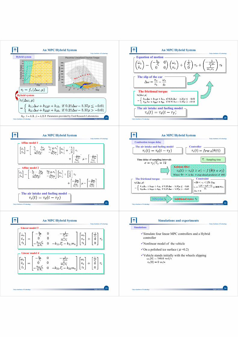
Equation of motion
:Engine speed:Actual combustion torque
:Desired combustion torque
:Vehicle speed
:Total driveline gear ratiobetween and
:Tire radius:Frictional torque on the tire
:Combined engine/wheelinertia:Engine damping:Vehicle mass
Simple FWD vehicle model FWD : Front-Wheel-Driven
11Fujita LaboratoryTokyo Institute of Technology
Tokyo Institute of Technology
Modeling of Vehicle
1. The wheel dynamics under the effect of the combustion toque and of the friction torque
2. Longitudinal motion dynamics of the vehicle
The air intake and fueling model
:time:Fueling to combustion puredelay period
Manifold/Fueling
Engine Drivelinegear
Front wheel
Manifold/Fueling
Engine Drivelinegear
Front wheel
12Fujita LaboratoryTokyo Institute of Technology
Tokyo Institute of Technology
Modeling of Vehicle
• The fuel combustion delay is modeled as a pure delay. • Neglect the intake manifold dynamics.• Neglect the effect of the speed variation on the torque.• The clutch is locked.• The vehicle is a front-wheel-driven.
Assumption
The intake manifold(six-cylinder engine)

13Fujita LaboratoryTokyo Institute of Technology
Tokyo Institute of Technology
Modeling of Vehicle
Active PassiveA front-wheel-driven vehicle
The front wheel : estimate The rear wheel : estimate
The slip of the car
Manifold/Fueling
Engine Drivelinegear
Front wheel
Manifold/Fueling
Engine Drivelinegear
Front wheel
:The slip of the car
14Fujita LaboratoryTokyo Institute of Technology
Tokyo Institute of Technology
Modeling of Vehicle
Measured tire traction torque for three different road conditions
The frictional torque:coefficient of friction depends on the road-tire conditions:nonlinear function of and
concrete
snow
ice
Trac
tion
Torq
ue
Slip
15Fujita LaboratoryTokyo Institute of Technology
Tokyo Institute of Technology
Modeling of Vehicle
The frictional torque
Equation of motion
The air intake and fueling model
The slip of the car
16Fujita LaboratoryTokyo Institute of Technology
Tokyo Institute of Technology
Outline
1. Introduction
2. Modeling of Vehicle
3. An MPC/Hybrid System
4. Simulations and Experiments
5. Conclusions and Future Works
17Fujita LaboratoryTokyo Institute of Technology
Tokyo Institute of Technology
An MPC/Hybrid System
MLD system PWA system
Mixed logic dynamical system Pieacewise affine system
System
Possible to use the HYSDEL compiler and multiparametricprogramming algorithms.
Constrains are embedded in the control problem.
Much less supervision by logical construct than PID controller
Handle more accurate models and include additional constraint without changing the design flow.
Hybrid system
Hybrid systemConstraint
&
18Fujita LaboratoryTokyo Institute of Technology
Tokyo Institute of Technology
An MPC/Hybrid System
Constrained Optimal Control
Mixed logic dynamical system Pieacewise affine system
Mixed integer linear program (MILP)
Impossible to solve on standard automotive control hardware at each step.
Multi-parametric mixed integer linear program (mp-MILP)
Compute online Compute offline
Control law (piecewise affine form)
ControllerConstraint
Parameters : T=5, Q=50, R=1
19Fujita LaboratoryTokyo Institute of Technology
Tokyo Institute of Technology
An MPC/Hybrid System
Hybrid system
:Parameters provided by Ford Research Laboratories
concrete
snow
ice
Trac
tion
Torq
ue
Slip
Slip
Trac
tion
Torq
uePiecewise Linearlized Traction TorqueHybrid system
20Fujita LaboratoryTokyo Institute of Technology
Tokyo Institute of Technology
An MPC/Hybrid System
The slip of the car
Equation of motion
The air intake and fueling model
The frictional torque
21Fujita LaboratoryTokyo Institute of Technology
Tokyo Institute of Technology
An MPC/Hybrid System
The air intake and fueling model
Affine model 1
Affine model 2
22Fujita LaboratoryTokyo Institute of Technology
Tokyo Institute of Technology
Constraint
The air intake and fueling model
An MPC/Hybrid System
:Sampling time
Combustion torque delay
Time delay of sampling intervals
Controller
Kalman filter
The frictional torqueWhere is the -step ahead predictor of
Differentiate Additional states
23Fujita LaboratoryTokyo Institute of Technology
Tokyo Institute of Technology
An MPC/Hybrid System
Linear model 3
Linear model 4
24Fujita LaboratoryTokyo Institute of Technology
Tokyo Institute of Technology
Simulations and experiments
Simulations
Simulate four linear MPC controllers and a Hybrid controller
Nonlinear model of the vehicle
On a polished ice surface (μ=0.2)
Vehicle stands initially with the wheels slipping
25Fujita LaboratoryTokyo Institute of Technology
Tokyo Institute of Technology
Simulations and experiments
Time (s) Time (s)
Engi
ne to
rque
co
mm
and
Engi
ne to
rque
co
mm
and
slip
(rad
/s)
slip
(rad
/s)
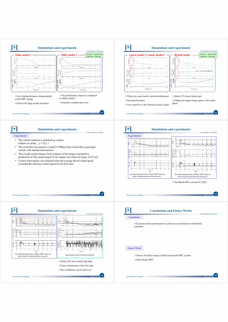
Affine model 1 Affine model 2 dot line : desired slipsolid line : slip trace
Very bad performance independently of the MPC tuning
Find in the large model mismatch
The performance improves compared to affine model 1
Generate a steady-state error
26Fujita LaboratoryTokyo Institute of Technology
Tokyo Institute of Technology
Simulations and experiments
Engi
ne to
rque
co
mm
and
Engi
ne to
rque
co
mm
and
slip
(rad
/s)
slip
(rad
/s)
Time (s) Time (s)
dot line : desired slipsolid line : slip trace
Hybrid model Linear model 3, Linear model 4
These two cases lead to similar performance
Good performance
Very sensitive to the frictional torque model
About 21% lower initial spin
Additional engine torque pulse in the initial phase
27Fujita LaboratoryTokyo Institute of Technology
Tokyo Institute of Technology
Simulations and experiments
The vehicle tested on a polished ice surface.(indoor ice arena, )The controller was tested in a small (1390kg) fornt-wheel-drive passenger vehicle with manual transmission.The overall system latency from issuance of the torque command to production of the actual torque by the engine was relatively large. (0.25 [s])Control intervention was initiated when the average driven wheel speed exceeded the reference wheel speed for the first time.
Experiments
28Fujita LaboratoryTokyo Institute of Technology
Tokyo Institute of Technology
Simulations and experiments
Experiments
(a) Experimental results of linear MPC based on linear model4(ramp and slip reference)
(b) Experimental results of linear MPC based on linear model4 (sinusoidal slip reference)
The Bandwidth is around 0.5 [Hz]
29Fujita LaboratoryTokyo Institute of Technology
Tokyo Institute of Technology
Simulations and experiments
(b) Experimental results of linear MPC based on linear model4 (sinusoidal slip reference)
Experimental result of hybrid controller
About 20% lower initial slip peak.
Faster containment of the first spin.
The oscillations can be observed
30Fujita LaboratoryTokyo Institute of Technology
Tokyo Institute of Technology
Conclusions and Future Works
Conclusion
Good and robust performance is achieved on polished ice with hybrid controller.
Future Work
Survey the thesis using a hybrid system and MPC system.
More Study MPT.
Related Documents