F.L. Lewis, Assoc. Director for Rese Moncrief-O’Donnell Endowed Chair Head, Controls, Sensors, MEMS Grou Automation & Robotics Research Institute (ARRI) The University of Texas at Arlington Wireless Sensor Networks for Monitoring Machinery, Human Biofunctions, and BCW Agents Sponsored by IEEE Singapore SMC, R&A, and Control Chapters Organized and invited by Professor Sam Ge, NUS

F.L. Lewis, Assoc. Director for Research Moncrief-O’Donnell Endowed Chair Head, Controls, Sensors, MEMS Group Automation & Robotics Research Institute.
Dec 26, 2015
Welcome message from author
This document is posted to help you gain knowledge. Please leave a comment to let me know what you think about it! Share it to your friends and learn new things together.
Transcript
F.L. Lewis, Assoc. Director for ResearchMoncrief-O’Donnell Endowed Chair
Head, Controls, Sensors, MEMS Group
Automation & Robotics Research Institute (ARRI)The University of Texas at Arlington
Wireless Sensor Networks for Monitoring Machinery, Human Biofunctions, and BCW Agents
Sponsored byIEEE Singapore SMC, R&A, and Control Chapters
Organized and invited by Professor Sam Ge, NUS

Automation & Robotics Research Institute (ARRI)The University of Texas at Arlington
F.L. Lewis, Assoc. Director for ResearchMoncrief-O’Donnell Endowed Chair
Head, Controls, Sensors, MEMS Group
http://ARRI.uta.edu/acs
Wireless Sensor Networks

Wireless MEMS Sensor Networks
• Machinery monitoring & Condition-Based Maintenance (CBM / PHM / RUL)
• Remote site biochemical warfare (BCW) toxin monitoring
• Personnel monitoring and secure area denial
• Optical MEMS human biosensors
New Initiative at ARRI$180K in ARO/ UTA/ Texas funding to set up ARRI MEMS lab $240K in MEMS & Network related Grants from NSF and ARO
Contact Frank [email protected]
http://arri.uta.edu/acs
Contact Frank [email protected]
http://arri.uta.edu/acs
http://mems.uta.edu
C&C UserInterface forwireless networks-
Wireless
Data Collection Networks
Wireless Sensor
Machine Monitoring
Security Personnel and Vehicle Monitoring
C
O O
HH2O
h+
h+
h+
H2OC
O O
H
C
O O
H
C
O O
H
h+
C
O O
H
C
O O
H
C
O O
H
C
O O
H
C
O O
H
C
O O
H
e-
e-
e-
e-
TiO2TiO2
Ni
C
O O
H
C
O O
HH2O
h+
h+h+
h+
H2OC
O O
H
C
O O
H
C
O O
H
C
O O
H
C
O O
H
C
O O
H
C
O O
H
h+
C
O O
H
C
O O
H
C
O O
H
C
O O
H
C
O O
H
C
O O
H
C
O O
H
C
O O
H
C
O O
H
C
O O
H
C
O O
H
C
O O
H
e-
e-
e-
e-
TiO2TiO2
Ni
Biochemical Monitoring
EnvironmentalMonitoring

PDA
BSC(Base Station
Controller, Preprocessing)BST
WirelessSensor
Machine Monitoring
Medical Monitoring
Wireless SensorWireless
Data Collection Networks
Wireless(Wi-Fi 802.11 2.4GHz
BlueToothCellular Network, -
CDMA, GSM)
Printer
Wireland(Ethernet WLAN,
Optical)
Animal Monitoring
Vehicle Monitoring
Online monitoring Server
transmitter
Any where, any time to access
Notebook Cellular Phone PC
Ship Monitoring
Wireless Sensor Networks
RovingHumanmonitor
Data Distribution Network
Management Center(Database large storage,
analysis)Data Acquisition
Network

Paul Baran, Rand Corp.Network of Networks

Principal Problems in Army Communications
Paul Baran, Rand Corp.

• COTS Wireless Sensors Berkeley Crossbow Microstrain• Wireless Networks Cellular network WLAN Other short range RF networks Multiple linked networks
Wireless CBM Research Areas• Sensor Technology MEMS ?• Node Technology DSP Power RF link• Remote Access Terminals Wireless PDA, Wireless Laptop Cellphone, Internet• Data management Sensor data storage DSP Data Access• Fault & Diagnostic Decision-Making• Alarming

Cellular Technologies
2G Systems
2.5G Systems
3G Systems
Other Short-range Technologies
Home RF
Bluetooth
IrDA
IEEE 802.11
Wireless LAN Technology
• 2.4 GHz Wireless LAN
• 5 GHz Wireless LAN
• Ad-hoc Mode
• Infrastructure Mode
Which Technology?
IEEE 1451 Standard for Smart Sensor Networks
Long Range Technologies
Cordless Telephony (cellphone) Internet

Berkeley Crossbow
Sensor
Crossbow transceiver
Which Hardware?
Crossbow Berkeley Motes
Berkeley Crossbow
Sensor
Crossbow transceiver
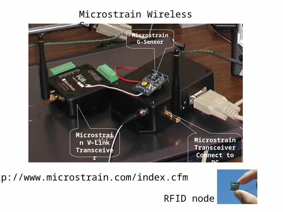
Microstrain V-Link
Transceiver
MicrostrainTransceiver
Connect to PC
MicrostrainG-Sensor
Microstrain Wireless Sensors
RFID node
http://www.microstrain.com/index.cfm
MicrostrainG-Sensor
MicrostrainTransceiver
Connect to PC
Microstrain V-Link
Transceiver

http://www.pctechguide.com/29network.htm
FDDI- Fibre Distributed Data Interface specifies a 100 Mbit/s token-passing, dual-ring LAN using fibre-optic cable.
Network Topology
Self Healing Net – Dual Ring

http://www.fiber-optics.info/articles/its-networks.htm
Bus Network with Backbone Interconnections Between Different Network Types
Token Ring Network Topology Self-healing Ring TopologyTwo rings
Star Network Topology
Network Topology

Ethernet LANFDDI: Fiber Distributed Data Interface100 Mbps
Moshe Zalcberg and Benny Matityaho, Tel Aviv Universityhttp://www2.rad.com/networks/1994/networks/preface.htm

Paul Baran, Rand Corp.The Spider Web Net

Paul Baran, Rand Corp.
Centralized, Decentralized, Distributed
Neighbor Connectivity and RedundancyNetwork Topology
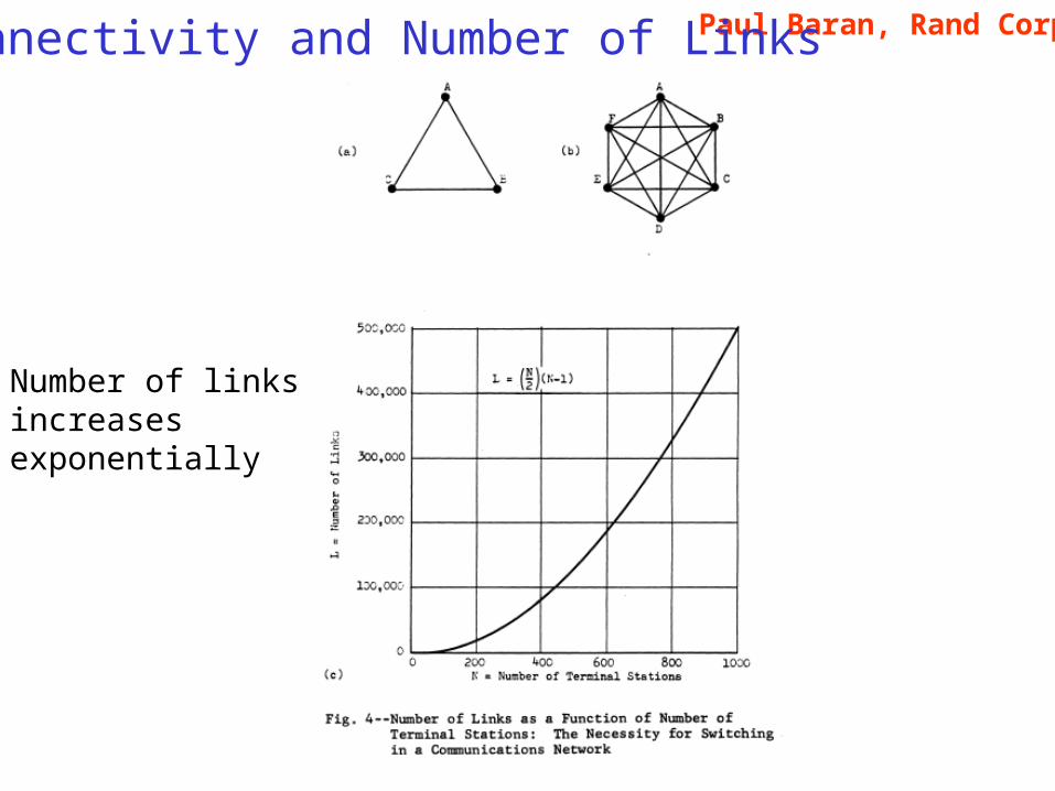
Paul Baran, Rand Corp.Connectivity and Number of Links
Number of links increases exponentially
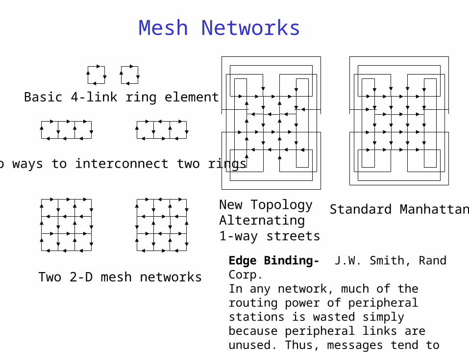
Basic 4-link ring element
Two ways to interconnect two rings
Two 2-D mesh networks
Mesh Networks
Standard ManhattanNew TopologyAlternating 1-way streets
Edge Binding- J.W. Smith, Rand Corp.In any network, much of the routing power of peripheral stations is wasted simply because peripheral links are unused. Thus, messages tend to reflect off the boundary into the interior or to move parallel to the periphery.

The Problem of Complexity
Communication Protocols in a network must be restricted and organized to avoid Complexity problems
e.g. in Manufacturing The general job shop allows part flows between all machines The Flow Line allows part flows only along specific Paths
We have shown that the job shop is NP-complete
but the reentrant flow line is of polynomial complexity
Think of the military chain of command

Hierarchical Networks
Hierarchical ClusteringDual-Ring Hierarchical
Structure for level 2
Designation of Primary Communication Ring
Hierarchical Clustering of 8x8 meshshowing level 3 primary communication ring
Hierarchical Clustering of 8x8 meshshowing all four communication rings
4 x 4 Mesh Net
Disable some links
Same structure--ConsistentHierarchy

Disable some links to reduce complexity
The disabled links can be used as backups in case of failures
Note- this dual ring structureIs a self-healing ring

EthernetEthernet was developed in the mid 1970's by the Xerox Corporation, and in 1979 Digital Equipment Corporation DEC) and Intel joined forces with Xerox to standardise the system. The Institute of Electrical and Electronic Engineers (IEEE) released the official Ethernet standard in 1983 called the IEEE 802.3 after the name of the working group responsible for its development, and in 1985 version 2 (IEEE 802.3a) was released. This second version is commonly known as "Thin Ethernet" or 10Base2, in this case the maximum length is 185m even though the "2" suggest that it should be 200m.
Fast EthernetFast Ethernet was officially adopted in the summer of 1995, two years after a group of leading network companies had formed the Fast Ethernet Alliance to develop the standard. Operating at ten times the speed of regular 10Base-T Ethernet, Fast Ethernet - also known as 100BaseT - retains the same CSMA/CD protocol and Category 5 cabling support as its predecessor higher bandwidth and introduces new features such as full-duplex operation and auto-negotiation.
http://www.pctechguide.com/29network.htm

http://www.pctechguide.com/29network.htm
FDDIDeveloped by the American National Standards Institute (ANSI) standards committee in the mid-1980s - at a time when high-speed engineering workstations were beginning to tax the bandwidth of existing LANs based on Ethernet and Token Ring - the Fibre Distributed Data Interface (FDDI) specifies a 100 Mbit/s token-passing, dual-ring LAN using fibre-optic cable.
Token RingIn 1984, IBM introduced the 4 Mbit/s Token Ring network. Instead of the normal plug and socket arrangement of male and female gendered connectors, the IBM data connector (IDC) was a sort of hermaphrodite, designed to mate with itself. Although the IBM Cabling System is to this day regarded as a very high quality and robust data communication media, its large size and cost - coupled with the fact that with only 4 cores it was less versatile than 8-core UTP - saw Token Ring continue fall behind Ethernet in the popularity stakes. It remains IBM's primary LAN technology however and the compatible and almost identical IEEE 802.5 specification continues to shadow IBM's Token Ring development.

Gigabit EthernetThe next step in Ethernet's evolution was driven by the Gigabit Ethernet Alliance, formed in 1996. The ratification of associated Gigabit Ethernet standards was completed in the summer of 1999, specifying a physical layer that uses a mixture of proven technologies from the original Ethernet Specification and the ANSI X3T11 Fibre Channel Specification:
Use of the same variable-length (64- to 1514-byte packets) IEEE 802.3 frame format found in Ethernet and Fast Ethernet is key to the ease with which existing lower-speed Ethernet devices can be connected to Gigabit Ethernet devices, using LAN switches or routers to adapt one physical line speed to the other.
http://www.pctechguide.com/29network.htm

Client-ServerClient-server networking architectures became popular in the late 1980s and early 1990s as many applications were migrated from centralised minicomputers and mainframes to networks of personal computers. The design of applications for a distributed computing environment required that they effectively be divided into two parts: client (front end) and server (back end). The network architecture on which they were implemented mirrored this client-server model, with a user's PC (the client) typically acting as the requesting machine and a more powerful server machine - to which it was connected via either a LAN or a WAN - acting as the supplying machine.

Peer-to-peerIn a Peer-to-peer networking architecture each computer (workstation) has equivalent capabilities and responsibilities. There is no server, and computers simply connect with each other in a workgroup to share files, printers, and Internet access. It is practical for workgroups of a dozen or less computers, making it common in many SOHO environments, where each PC acts as an independent workstation that stores data on its own hard drive but which can share it with all other PCs on the network.
P2P computingBy early 2000 a revolution was underway in an entirely new form of peer-to-peer computing. Sparked by the phenomenal success of a number of highly publicised applications, "P2P computing" - as it is commonly referred to - heralded a new computing model for the Internet age and had achieved considerable traction with mainstream computer users and members of the PC industry in a very short space of time.
The Napster MP3 music file sharing application went live in September 1999, and attracted more than 20 million users by mid-2000

IEEE 802.11The Institute of Electrical and Electronics Engineers (IEEE) ratified the original 802.11 specification in 1997 as the standard for WLANs. That version of 802.11 provided for 1 Mbit/s and 2 Mbit/s data rates and a set of fundamental signalling methods and other services. The data rates supported by the original 802.11 standard were too slow to support most general business requirements with and did little to encourage the adoption of WLANs. Recognising the critical need to support higher data-transmission rates, the autumn of 1999 saw the IEEE ratify the 802.11b standard (also known as 802.11 High Rate) for transmissions of up to 11 Mbit/s.

http://www.erg.abdn.ac.uk/users/gorry/course/intro-pages/osi-example.html
The OSI reference model specifies standards for describing "Open Systems Interconnection" with the term 'open' chosen to emphasise the fact that by using these international standards, a system may be defined which is open to all other systems obeying the same standards throughout the world. The definition of a common technical language has been a major catalyst to the standardisation of communications protocols and the functions of a protocol layer.
OSI- Open Systems Interconnection

http://www.cs.cf.ac.uk/User/O.F.Rana/data-comms/comms-lec1.pdf

http://ieee1451.nist.gov/intro.htm
ProblemTransducers, defined here as sensors or actuators, serve a wide variety of industry's needs- manufacturing, industrial control, automotive, aerospace, building, and biomedicine are but a few. Many sensor control networks or fieldbus implementations are currently available.
A problem for transducer manufacturers is the large number of networks on the market today. Currently, it is too costly for transducer manufacturers to make unique smart transducers for each network on the market. Therefore a universally accepted transducer interface standard, the IEEE P1451 standard, is proposed to be developed to address these issues.
Objective of IEEE 1451 The objective of this project is to develop a smart transducer interface standard IEEE 1451. This standard is to make it easier for transducer manufacturers to develop smart devices and to interface those devices to networks, systems, and instruments by incorporating existing and emerging sensor- and networking technologies.
IEEE 1451 Standard for Smart Sensor Networks

History of IEEE-1451 In September 1993, the National Institute of Standards and Technology (NIST) and the Institute of Electrical and Electronics Engineers (IEEE)'s Technical Committee on Sensor Technology of the Instrumentation and Measurement Society co-sponsored a meeting to discuss smart sensor communication interfaces and the possibility of creating a standard interface. The response was to establish a common communication interface for smart transducers. Four technical working groups have been formed to address different aspects of the interface standard.
P1451.1 working group aims at defining a common object model for smart transducers along with interface specifications for the components of the model. P1451.2 working group aims at defining a smart transducer interface module (STIM), a transducer electronic data sheet (TEDS), and a digital interface to access the data. P1451.3 working group aims at defining a digital communication interface for distributed multidrop systems. P1451.4 working group aims at defining a mixed-mode communication protocol for smart transducers. The working groups created the concept of smart sensors to control networks interoperability and to ease the connectivity of sensors and actuators into a device or field network.
http://ieee1451.nist.gov/intro.htm


Network Independent
Hardware interface

Conway & Heffernan, Univ. Limerickhttp://wwww.ul.ie/~pei
IEEE 1451 Standard for Smart Sensor Networks
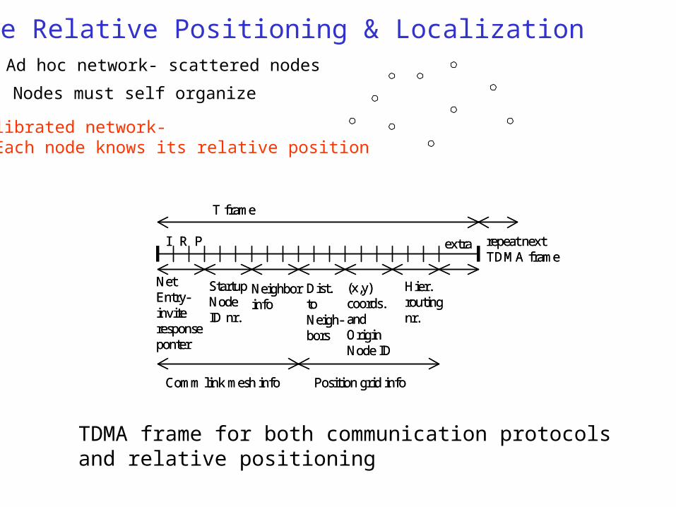
NetEntry-inviteresponseponter
StartupNodeID nr.
Neighborinfo
I R P
Dist.toNeigh-bors
Comm link mesh info Position grid info
(x,y) coords.and OriginNode ID
Hier.routingnr.
extra
T frame
repeat nextTDMA frame
NetEntry-inviteresponseponter
StartupNodeID nr.
Neighborinfo
I R P
Dist.toNeigh-bors
Comm link mesh info Position grid info
(x,y) coords.and OriginNode ID
Hier.routingnr.
extra
T frame
repeat nextTDMA frame
TDMA frame for both communication protocols and relative positioning
Node Relative Positioning & LocalizationAd hoc network- scattered nodes
Nodes must self organize
Calibrated network- Each node knows its relative position

1 2d12 x
a. Two nodes- define x & y axes
y
b. 3 node closed kinematic chain-compute (x3, y3)
O 1 2d12 x
d23d13
3
y
x3
y3
213x23
O1 2d12 x1 2d12 x
a. Two nodes- define x & y axes
y
b. 3 node closed kinematic chain-compute (x3, y3)
O 1 2d12 x
d23d13
3
y
x3
y3
213x23
O 1 2d12 x
d23d13
3
y
x3
y3
213x23
O
Integrating new nodes into relative positioning grid
1 2A12 x’
A23
A13
3
y’
O’
x
y
O
TOO’
A14
A34
A24
4
1 2A12 x’
A23
A13
3
y’
O’
x
y
O
TOO’
A14
A34
A24
4
Recursive closed-kinematic chain procedure for integrating new nodes
10ii
i
pRA
One can write the relative location in frame O of the new point 3 in two ways. The triangle shown in the figure is a closed kinematic chain of the sort studied in [Liu and Lewis 1993, 1994]. The solution is obtained by requiring that the two maps T13 and T123 be exact at point 3.
Kinematicstransformation

j
Njcjf sdTcjTtwts )()( /
where w(t) is the basic pulse of duration approx. 1ns, often a wavelet or a Gaussian monocycle, and Tf is the frame or pulse repetition time. In a multi-node environment, catastrophic collisions are avoided by using a pseudorandom sequence cj to shift pulses within the frame to different compartments, and the compartment size is Tc sec. Data is transmitted using digital pulse position modulation (PPM), where if the data bit is 0 the pulse is not shifted, and if the data bit is 1 the pulse is shifted by d. The same data bit is transmitted Ns times, allowing for very reliable communications with low probability of error.
Ultra Wideband Sensor WebUWB
Precise time of flight measurement is possible.
Use UWB for all three: Communications Node Relative positioning Target localization

1 2
3
T
dd2
d3
x
yy
1 2
3
T
d d2
d3
x
x’y’
213
a. Target, transmitter node, and 2 receiving nodes b. Ellipsoid solution for multi-static target localizing
1 2
3
T
dd2
d3
x
y
1 2
3
T
dd2
d3
x
yy
1 2
3
T
d d2
d3
x
x’y’
213
1 2
3
T
d d2
d3
x
x’y’
213
a. Target, transmitter node, and 2 receiving nodes b. Ellipsoid solution for multi-static target localizing
Multi-Static Radar Target Localization
22122 ,2/,2/)( sabdsdda
Intersection of two ellipses with semimajor and semiminor axes
Simultaneous solution of two quadratic equations, one for each ellipse
1
1
BXX
AXXT
T
Uses time of flight
gives position of target.
Related Documents