Fixed Displacement Radial Piston Staffa Motor HMB Series Precision Machinery Company QUALITY HYDRAULICS LTD WHINBANK PARK WHINBANK ROAD AYCLIFFE INDUSTRIAL PARK NEWTON AYCLIFFE CO. DURHAM DL5 6AY TEL. 01325 317755 FAX. 01325 320245 EMAIL [email protected]

Welcome message from author
This document is posted to help you gain knowledge. Please leave a comment to let me know what you think about it! Share it to your friends and learn new things together.
Transcript
Fixed Displacement Radial Piston Staffa Motor
HMB Series
Precision Machinery Company
QUALITY HYDRAULICS LTD WHINBANK PARK WHINBANK ROAD AYCLIFFE INDUSTRIAL PARK NEWTON AYCLIFFECO. DURHAM DL5 6AY
TEL. 01325 317755FAX. 01325 320245EMAIL [email protected]
1
Specifications and Features 2
1. Ordering Code
1-1. Model Coding 3
1-2. Shaft Options 4
1-3. Main Port Connection Options 5
2. Technical Information
2-1. Performance Data 6 - 10
2-2. Volumetric Efficiency Data 11
2-3. Shaft Power Calculations 12
2-4. Functional Symbols 13
2-5. Shaft Stress Limits 14
2-6. Bearing Life Notes 15
2-7. Circuit and Application Notes 16 - 18
2-8. Motor Operation at Low Temperatures 19
2-9. Freewheeling Notes 20
2-10. Crankcase Drain Connections 21
2-11. Installation Data 22
3. Dimensions
3-1. HMB010 Installation 23 - 24
3-2. HMB030 Installation 25 - 31
3-3. HMB045 Installation 32 - 37
3-4. HMB060/080 Installation 38 - 42
3-5. HMB100 Installation 43 - 47
3-6. HM(HD)B125 Installation 48 - 55
3-7. HM(HD)B 150/200 Installation 56 - 63
3-8. HM(HD)B270 Installation 64 - 69
3-9. HM(HD)B325 Installation 70 - 75
3-9. HMHDB400 Installation 76 - 77
3-8. Speed Sensing Options 78
CONTENTS
2
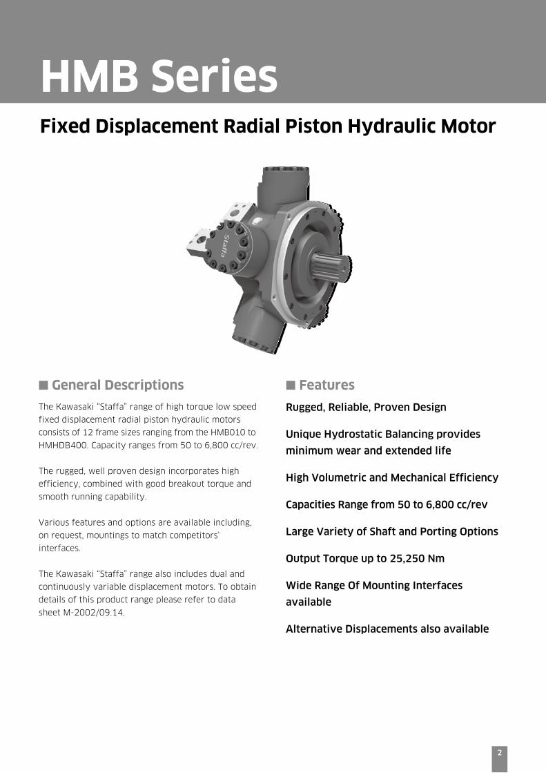
■ General Descriptions
The Kawasaki “Staffa” range of high torque low speed
fixed displacement radial piston hydraulic motors
consists of 12 frame sizes ranging from the HMB010 to
HMHDB400. Capacity ranges from 50 to 6,800 cc/rev.
The rugged, well proven design incorporates high
efficiency, combined with good breakout torque and
smooth running capability.
Various features and options are available including,
on request, mountings to match competitors’
interfaces.
The Kawasaki “Staffa” range also includes dual and
continuously variable displacement motors. To obtain
details of this product range please refer to data
sheet M-2002/09.14.
■ Features
Rugged, Reliable, Proven Design
Unique Hydrostatic Balancing provides
minimum wear and extended life
High Volumetric and Mechanical Efficiency
Capacities Range from 50 to 6,800 cc/rev
Large Variety of Shaft and Porting Options
Output Torque up to 25,250 Nm
Wide Range Of Mounting Interfaces
available
Alternative Displacements also available
Fixed Displacement Radial Piston Hydraulic Motor
HMB Series
3
HMB MOTORS
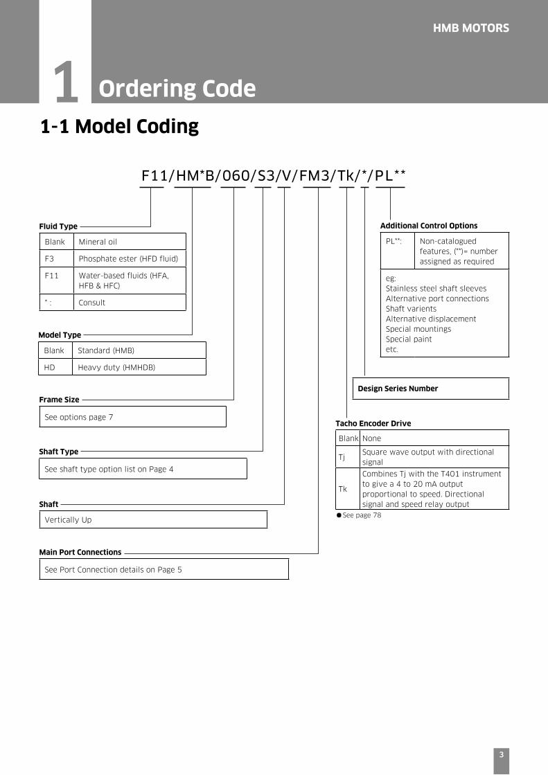
F11/HM*B/060/S3/V/FM3/Tk/*/PL**
1 Ordering Code
Fluid Type
Blank Mineral oil
F3 Phosphate ester (HFD fluid)
F11 Water-based fluids (HFA, HFB & HFC)
* : Consult
Model Type
Blank Standard (HMB)
HD Heavy duty (HMHDB)
Frame Size
See options page 7
Design Series Number
Main Port Connections
See Port Connection details on Page 5
Shaft Type
See shaft type option list on Page 4
Additional Control Options
PL**: Non-catalogued features, (**)= number assigned as required
eg:Stainless steel shaft sleevesAlternative port connectionsShaft varientsAlternative displacementSpecial mountingsSpecial paintetc.
1-1 Model Coding
Tacho Encoder Drive
Blank None
TjSquare wave output with directional signal
Tk
Combines Tj with the T401 instrument to give a 4 to 20 mA output proportional to speed. Directional signal and speed relay outputShaft
Vertically Up •See page 78
4
HMB MOTORS
4
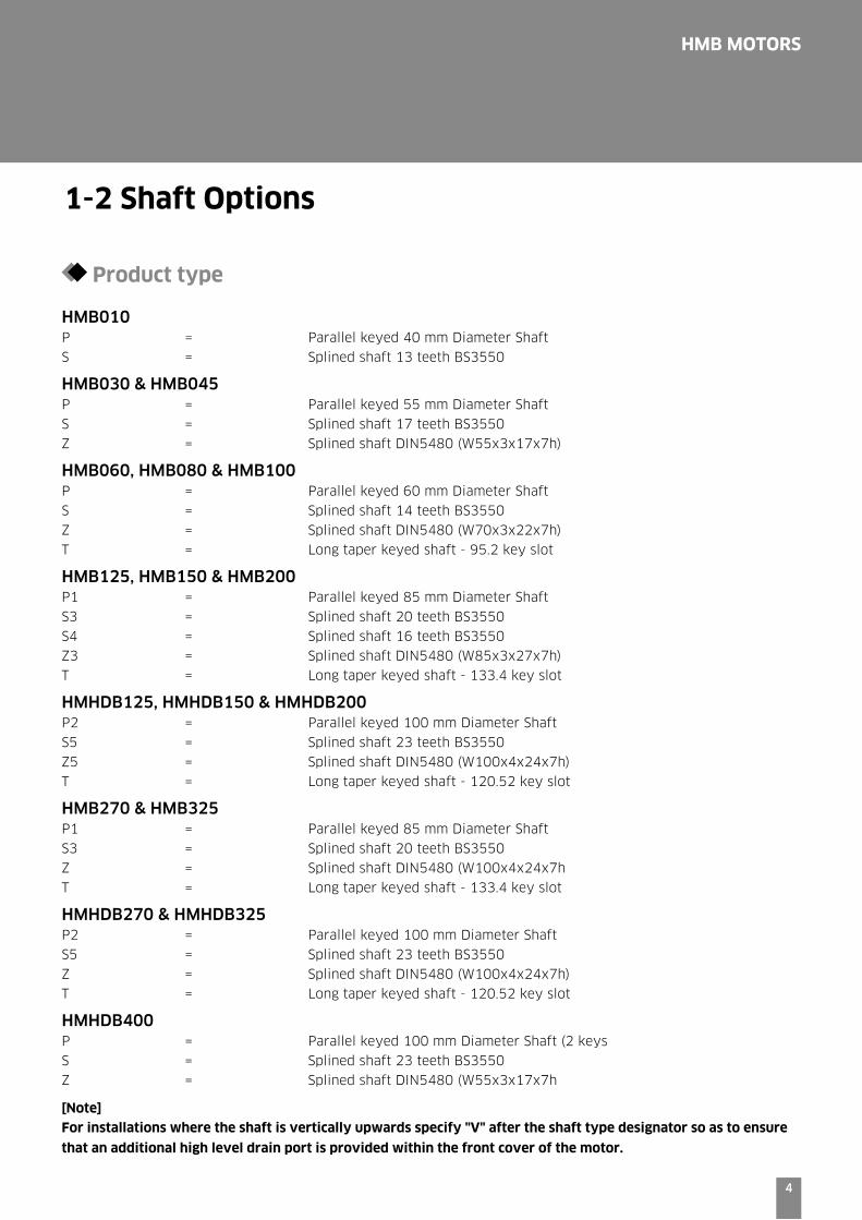
1-2 Shaft Options
Product type
HMB010P = Parallel keyed 40 mm Diameter Shaft
S = Splined shaft 13 teeth BS3550
HMB030 & HMB045P = Parallel keyed 55 mm Diameter Shaft
S = Splined shaft 17 teeth BS3550
Z = Splined shaft DIN5480 (W55x3x17x7h)
HMB060, HMB080 & HMB100P = Parallel keyed 60 mm Diameter Shaft
S = Splined shaft 14 teeth BS3550
Z = Splined shaft DIN5480 (W70x3x22x7h)
T = Long taper keyed shaft - 95.2 key slot
HMB125, HMB150 & HMB200P1 = Parallel keyed 85 mm Diameter Shaft
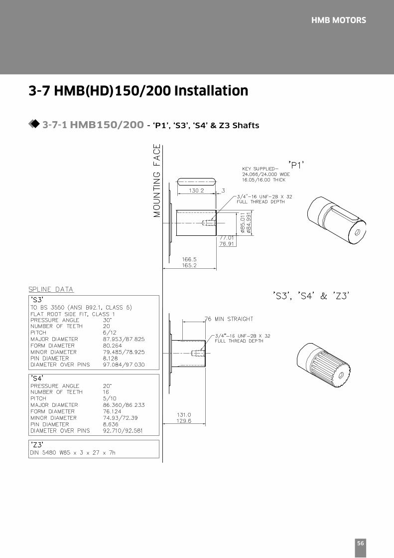
S3 = Splined shaft 20 teeth BS3550
S4 = Splined shaft 16 teeth BS3550
Z3 = Splined shaft DIN5480 (W85x3x27x7h)
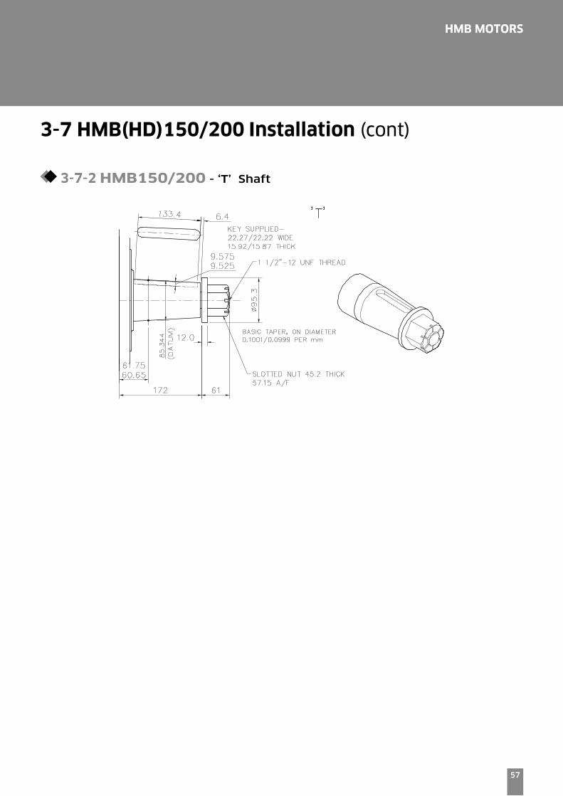
T = Long taper keyed shaft - 133.4 key slot
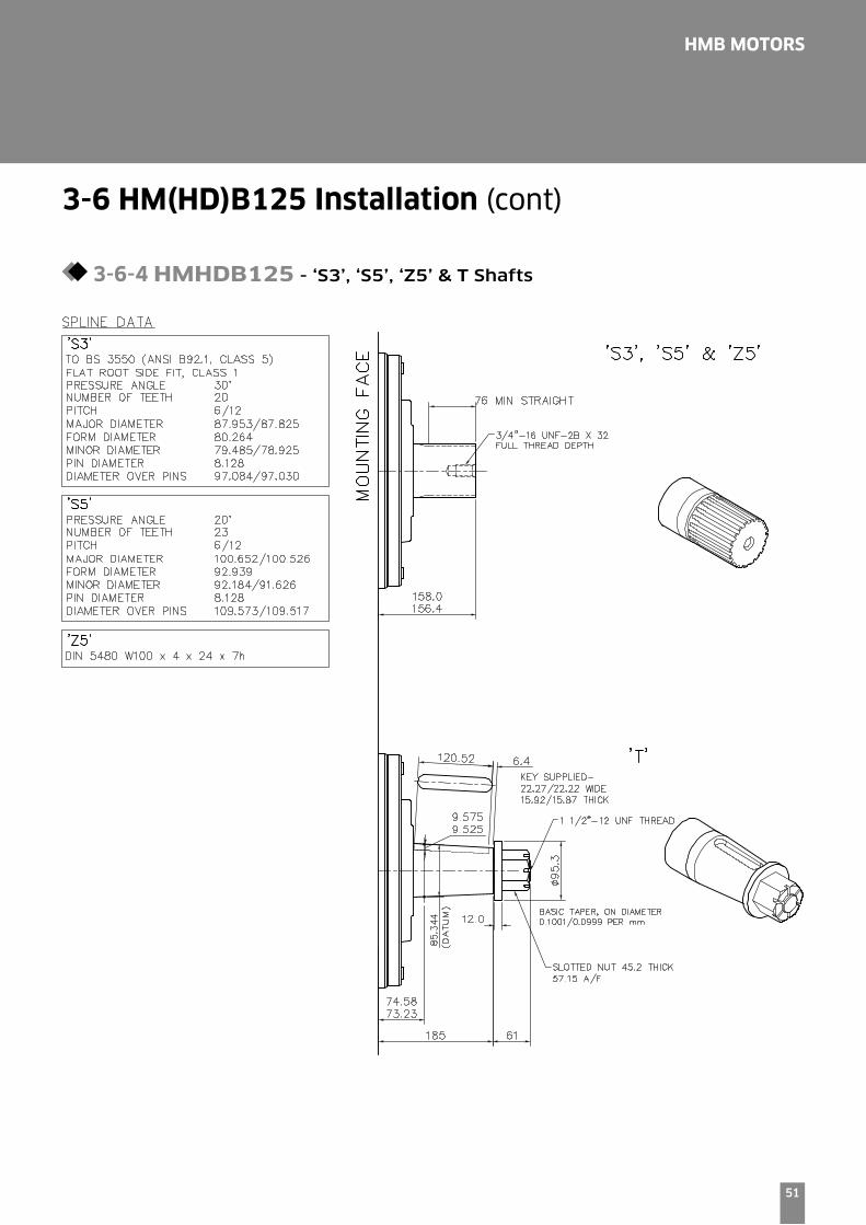
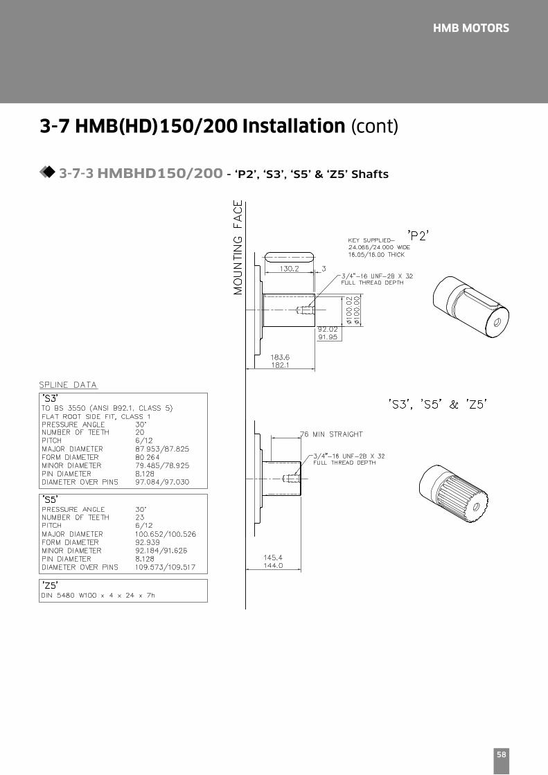
HMHDB125, HMHDB150 & HMHDB200P2 = Parallel keyed 100 mm Diameter Shaft
S5 = Splined shaft 23 teeth BS3550
Z5 = Splined shaft DIN5480 (W100x4x24x7h)
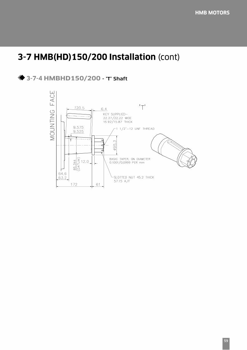
T = Long taper keyed shaft - 120.52 key slot
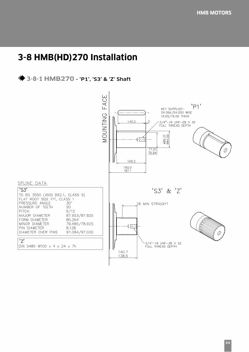
HMB270 & HMB325P1 = Parallel keyed 85 mm Diameter Shaft
S3 = Splined shaft 20 teeth BS3550
Z = Splined shaft DIN5480 (W100x4x24x7h
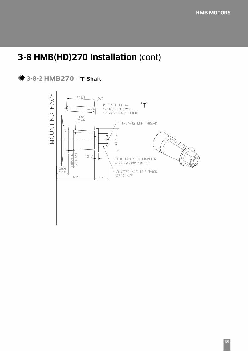
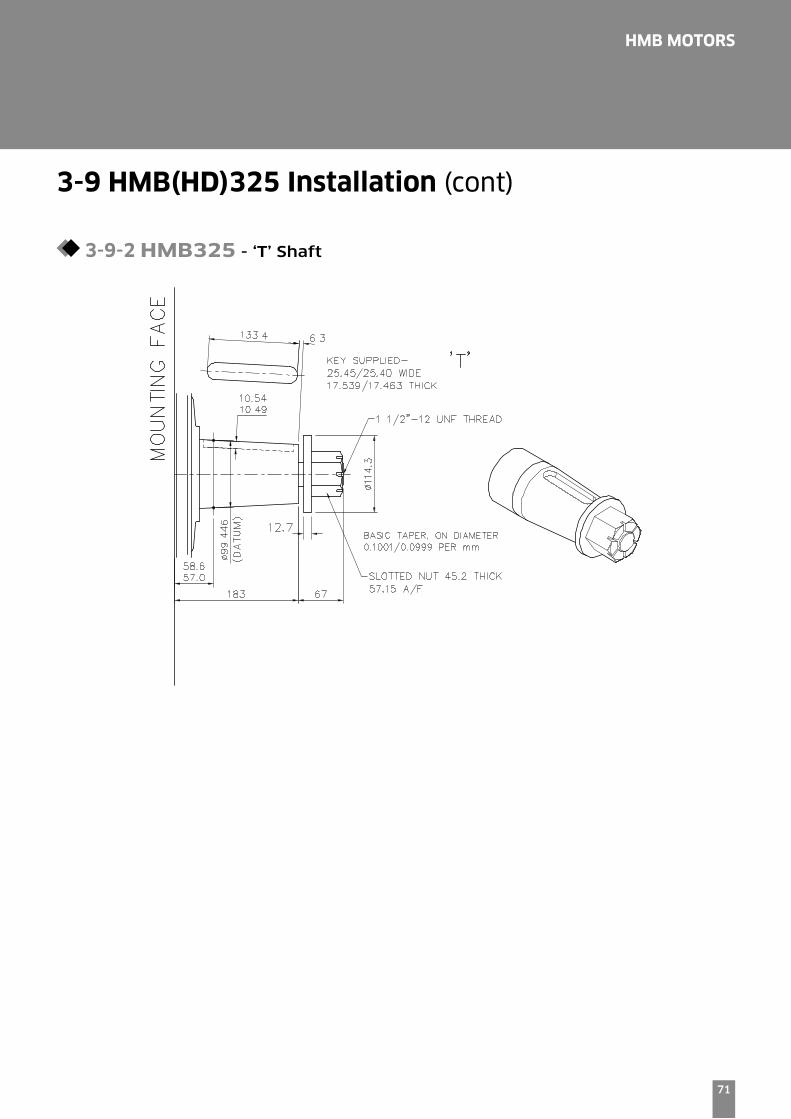
T = Long taper keyed shaft - 133.4 key slot
HMHDB270 & HMHDB325P2 = Parallel keyed 100 mm Diameter Shaft
S5 = Splined shaft 23 teeth BS3550
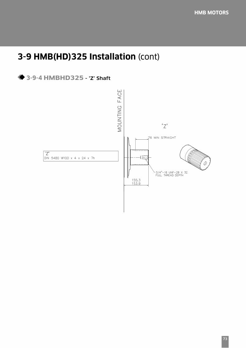
Z = Splined shaft DIN5480 (W100x4x24x7h)
T = Long taper keyed shaft - 120.52 key slot
HMHDB400P = Parallel keyed 100 mm Diameter Shaft (2 keys
S = Splined shaft 23 teeth BS3550
Z = Splined shaft DIN5480 (W55x3x17x7h
[Note]
For installations where the shaft is vertically upwards specify "V" after the shaft type designator so as to ensure
that an additional high level drain port is provided within the front cover of the motor.

5
HMB MOTORS
1-3 Main Port Connections Options
Product type
HMB010Blank = Two, four bolt flange ports of 20 mm Ø
HMB030 Monobloc Blank = Rear entry ports G ¾" (BSPF)
F = Side port SAE 1" 4-Bolt (UNC) flange
FM = Side port SAE 1" 4-Bolt (Metric) flange
HMB045 Monobloc Blank = Rear entry ports G 1" (BSPF)
D = Dual entry ports G 1" (BSPF)
HMB030/045 Two part build (TPB)
See detail below
HMB060/080/100F2 = SAE 1" 4-Bolt (UNC) flanges
FM2 = SAE 1" 4-Bolt (Metric) flanges
S03 = 6-Bolt (UNF) flange. (Staffa original valve housing)
F3 = SAE 1¼ 4-Bolt (UNC) flanges
FM3 = SAE 1¼" 4-Bolt (Metric) flanges
S04 = 6 Bolt (UNF) flanges. (Staffa original valve housing)
HMB125/150/200 + Heavy Duty Variants Details F2 = SAE 1" 4-Bolt (UNC) flanges
FM2 = SAE 1" 4-Bolt (Metric) flanges
S03 = 6-Bolt (UNF) flange. (Staffa original valve housing)
F3 = SAE 1¼ 4-Bolt (UNC) flanges
FM3 = SAE 1¼" 4-Bolt (Metric) flanges
S04 = 6 Bolt (UNF) flanges. (Staffa original valve housing)
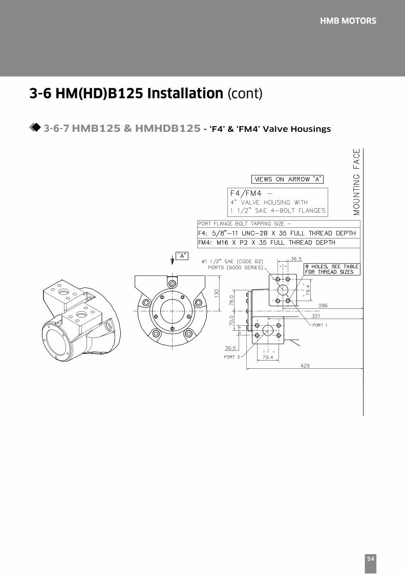
F4 = SAE 1¼" 4-Bolt (UNC) flanges
FM4 = SAE 1½" 4-Bolt (Metric) flanges
HM(HD)B270/325 + Heavy Duty VariantsF4 = SAE 1½" 4-Bolt (UNC) flanges
FM4 = SAE 1½" 4-Bolt (Metric) flanges
S04 = 6 Bolt (UNF) flanges. (Staffa original valve housing)
HMHDB400Blank = Combined 6-Bolt flange and 4-Bolt SAE connection
Ports 'B' and 'C' 6-Bolt UNF flange
Ports 'A' and 'C' SAE, 2" 4-Bolt UNF flanges
S045 = 2 x 6-Bolts (UNF) flanges (2 inlet and 2 outlet ports available)
6
HMB MOTORS
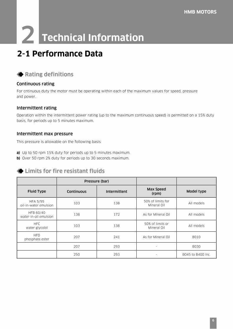
2-1 Performance Data
Rating definitions
Continuous rating
For cntinuous duty the motor must be operating within each of the maximum values for speed, pressure
and power.
Intermittent rating
Operation within the intermittent power rating (up to the maximum continuous speed) is permitted on a 15% duty
basis, for periods up to 5 minutes maximum.
Intermittent max pressure
This pressure is allowable on the following basis:
a) Up to 50 rpm 15% duty for periods up to 5 minutes maximum.
b) Over 50 rpm 2% duty for periods up to 30 seconds maximum.
Limits for fire resistant fluids
Pressure (bar)
Fluid Type Continuous IntermittentMax Speed
(rpm)Model type
HFA 5/95 oil-in-water emulsion
103 13850% of limits for
Mineral OilAll models
HFB 60/40 water-in-oil emulsion
138 172 As for Mineral Oil All models
HFC water glycolol
103 13850% of limits or
Mineral OilAll models
HFD phosphate ester
207 241 As for Mineral Oil B010
207 293 - B030
250 293 - B045 to B400 inc.
2 Technical Information
7
HMB MOTORS
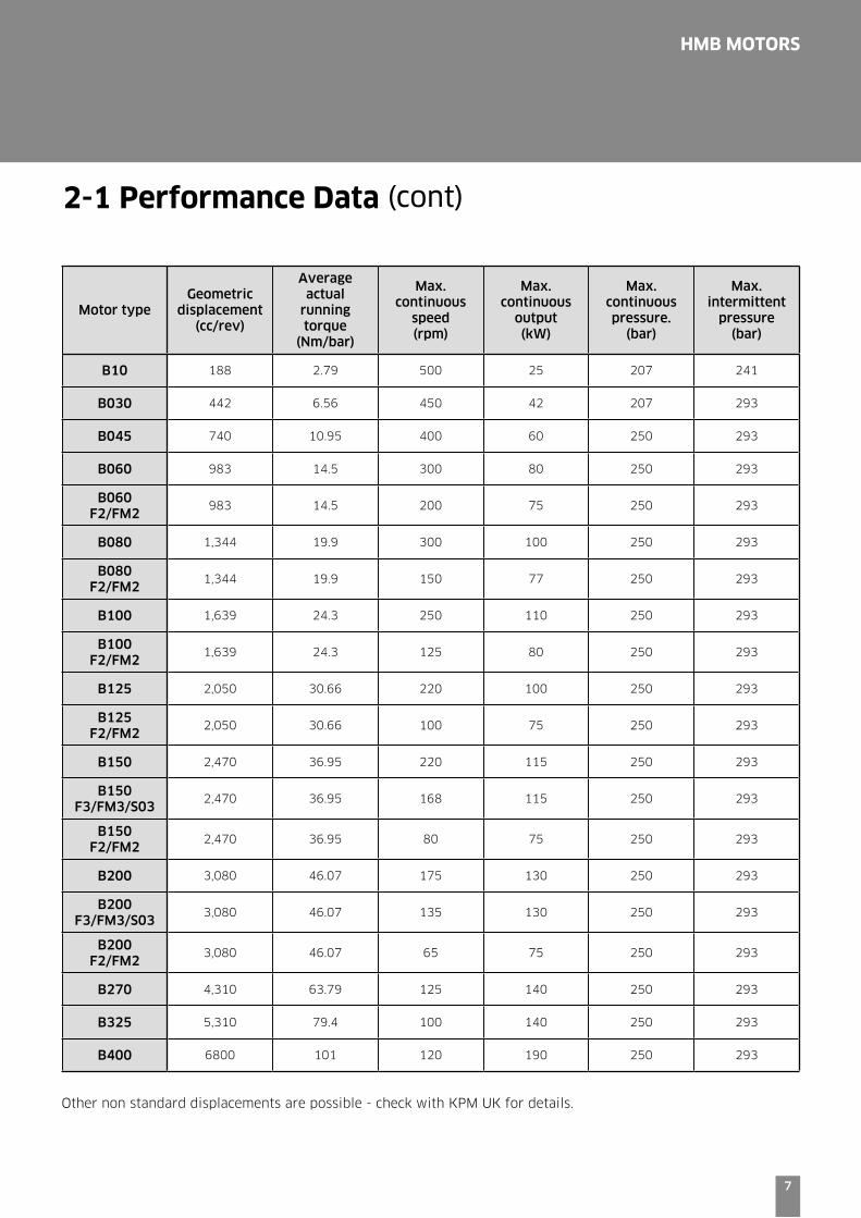
Motor typeGeometric
displacement(cc/rev)
Averageactual
runningtorque
(Nm/bar)
Max.continuous
speed(rpm)
Max.continuous
output(kW)
Max.continuouspressure.
(bar)
Max.intermittent
pressure(bar)
B10 188 2.79 500 25 207 241
B030 442 6.56 450 42 207 293
B045 740 10.95 400 60 250 293
B060 983 14.5 300 80 250 293
B060 F2/FM2
983 14.5 200 75 250 293
B080 1,344 19.9 300 100 250 293
B080 F2/FM2
1,344 19.9 150 77 250 293
B100 1,639 24.3 250 110 250 293
B100 F2/FM2
1,639 24.3 125 80 250 293
B125 2,050 30.66 220 100 250 293
B125 F2/FM2
2,050 30.66 100 75 250 293
B150 2,470 36.95 220 115 250 293
B150F3/FM3/S03
2,470 36.95 168 115 250 293
B150 F2/FM2
2,470 36.95 80 75 250 293
B200 3,080 46.07 175 130 250 293
B200F3/FM3/S03
3,080 46.07 135 130 250 293
B200 F2/FM2
3,080 46.07 65 75 250 293
B270 4,310 63.79 125 140 250 293
B325 5,310 79.4 100 140 250 293
B400 6800 101 120 190 250 293
Other non standard displacements are possible - check with KPM UK for details.
2-1 Performance Data (cont)
8
HMB MOTORS
0
500
1000
1500
2000
2500
3000
3500
4000
Torq
ue
Nm
0
400
200
600
800
1000
1200
1400
1600
1800
2000
Torq
ue
Nm
0
100
200
300
400
500
600
700
Torq
ue
Nm
Output power kW22.4 44.7 70.8
Output power kW5kw 10kw 15kw 20kw 25kw Output power kW
7.4514.9
22.429.8 37.2
Output power kW14.9 29.8 44.8 59.7
69 bar
103 bar
138 bar
172 bar
207 bar
250 bar
276 bar
69 bar
103 bar
138 bar
172 bar
207 bar
241 bar
276 bar
69 bar
103 bar
138 bar
172 bar
207 bar
241 bar
69 bar
103 bar
138 bar
172 bar
207 bar
250 bar
276 bar
0
500
1000
1500
2000
2500
3000
3500
Torq
ue
Nm
0 50 100 150 200 250 300Shaft speed (r/min)
0 100 200 300 400 Shaft speed (r/min)
0 100 200 300 400 500 Shaft speed (r/min)
0 100 200 300 400 500 Shaft speed (r/min)
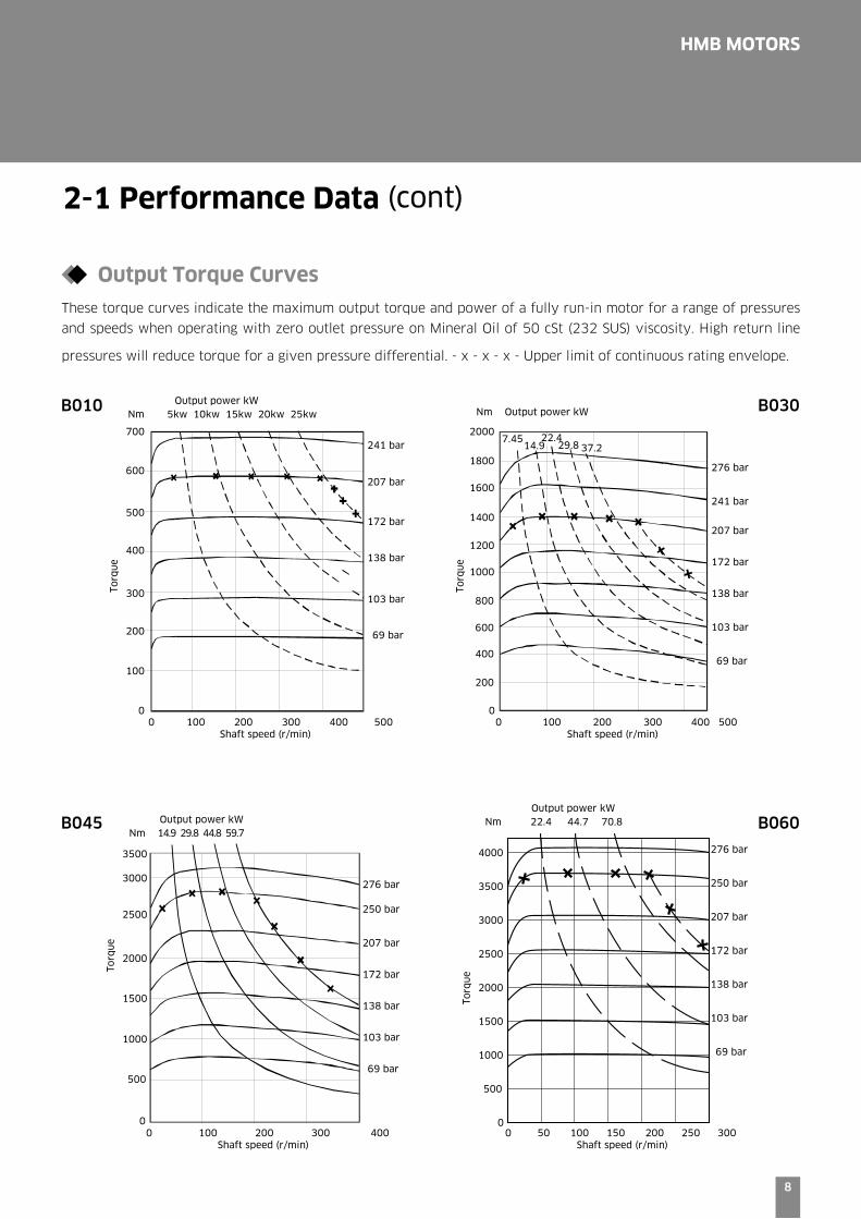
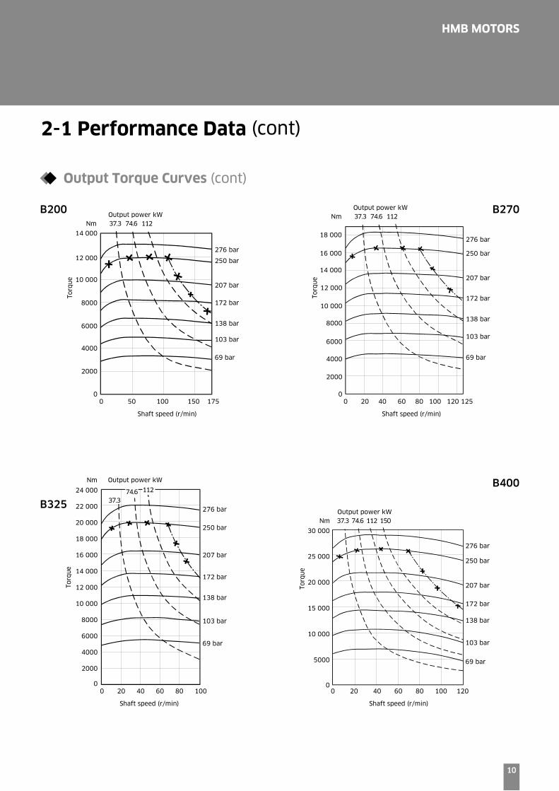
2-1 Performance Data (cont)
B010 B030
B045 B060
Output Torque Curves
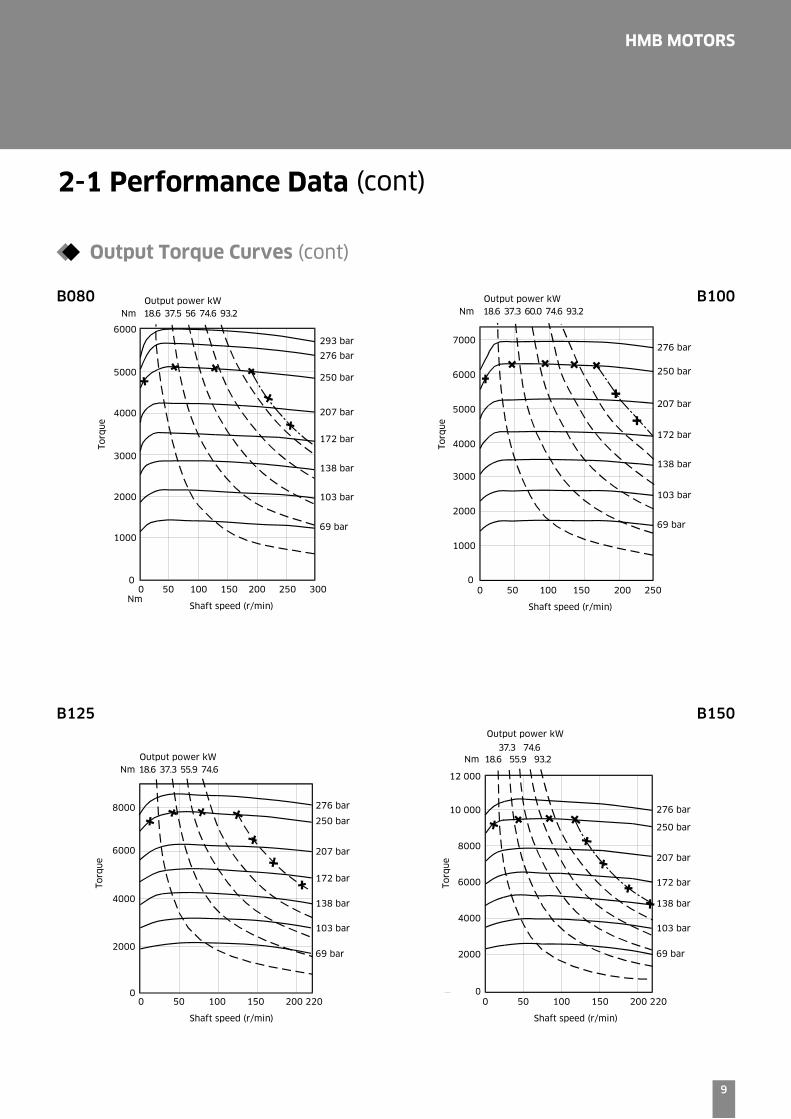
These torque curves indicate the maximum output torque and power of a fully run-in motor for a range of pressures
and speeds when operating with zero outlet pressure on Mineral Oil of 50 cSt (232 SUS) viscosity. High return line
pressures will reduce torque for a given pressure differential. - x - x - x - Upper limit of continuous rating envelope.
9
HMB MOTORS
6000
6000
7000
5000
4000
3000
2000
1000
0
5000
4000
3000
2000
1000
0
Torq
ue
Torq
ue
4000
2000
0
6000
8000
Torq
ue
Torq
ue
Nm NmOutput power kW18.6 37.5 56 74.6 93.2
Output power kW18.6 37.3 55.9 74.6
Output power kW
18.6 55.9 93.2 37.3 74.6
Output power kW18.6 37.3 60.0 74.6 93.2
0 50 100 150 200 220
Shaft speed (r/min)
0 50 100 150 200 220
Shaft speed (r/min)
0 50 100 150 200 250 300
Shaft speed (r/min)
0 50 100 150 200 250
Shaft speed (r/min)
293 bar
276 bar
250 bar
207 bar
172 bar
138 bar
103 bar
69 bar
276 bar
250 bar
207 bar
172 bar
138 bar
103 bar
69 bar
276 bar
250 bar
207 bar
172 bar
138 bar
103 bar
69 bar
276 bar
250 bar
207 bar
172 bar
138 bar
103 bar
69 bar
Nm
Nm12 000
10 000
8000
6000
4000
2000
0
Nm
B080 B100
B125 B150
2-1 Performance Data (cont)
Output Torque Curves (cont)
10
HMB MOTORS
Nm Output power kW
Torq
ue
12 000
10 000
14 000
8000
6000
4000
2000
0
Torq
ue
12 000
10 000
16 000
14 000
18 000
8000
6000
4000
2000
0
Torq
ue
5000
10 000
15 000
20 000
25 000
30 000
0
Torq
ue
2000
4000
6000
8000
10 000
12 000
14 000
16 000
18 000
20 000
22 000
24 000
0
NmOutput power kW37.3 74.6 112
NmOutput power kW37.3 74.6 112
37.374.6 112
Output power kW37.3 74.6 112 150 Nm
276 bar
250 bar
207 bar
172 bar
138 bar
103 bar
69 bar
276 bar
250 bar
207 bar
172 bar
138 bar
103 bar
69 bar
276 bar
250 bar
207 bar
172 bar
138 bar
103 bar
69 bar
276 bar
250 bar
207 bar
172 bar
138 bar
103 bar
69 bar
0 20 40 60 80 100
Shaft speed (r/min)
0 20 40 60 80 100 120
Shaft speed (r/min)
0 20 40 60 80 100 120 125
Shaft speed (r/min)
0 50 100 150 175
Shaft speed (r/min)
B200 B270
B325
B400
2-1 Performance Data (cont)
Output Torque Curves (cont)
11
HMB MOTORS
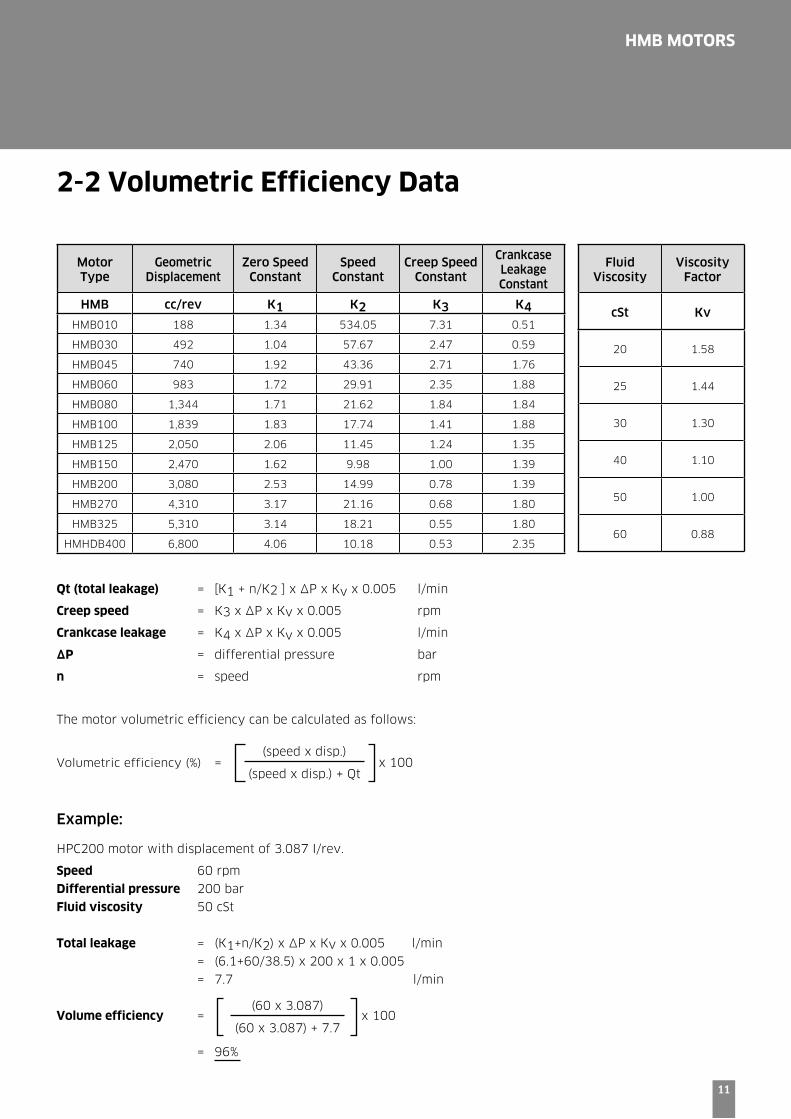
2-2 Volumetric Efficiency Data
Motor Type
Geometric Displacement
Zero Speed Constant
Speed Constant
Creep Speed Constant
Crankcase Leakage Constant
HMB cc/rev K1 K2 K3 K4HMB010 188 1.34 534.05 7.31 0.51
HMB030 492 1.04 57.67 2.47 0.59
HMB045 740 1.92 43.36 2.71 1.76
HMB060 983 1.72 29.91 2.35 1.88
HMB080 1,344 1.71 21.62 1.84 1.84
HMB100 1,839 1.83 17.74 1.41 1.88
HMB125 2,050 2.06 11.45 1.24 1.35
HMB150 2,470 1.62 9.98 1.00 1.39
HMB200 3,080 2.53 14.99 0.78 1.39
HMB270 4,310 3.17 21.16 0.68 1.80
HMB325 5,310 3.14 18.21 0.55 1.80
HMHDB400 6,800 4.06 10.18 0.53 2.35
Fluid Viscosity
Viscosity Factor
cSt Kv
20 1.58
25 1.44
30 1.30
40 1.10
50 1.00
60 0.88
Qt (total leakage) = [K1 + n/K2 ] x ∆P x Kv x 0.005 l/min
Creep speed = K3 x ∆P x Kv x 0.005 rpm
Crankcase leakage = K4 x ∆P x Kv x 0.005 l/min
∆P = differential pressure bar
n = speed rpm
The motor volumetric efficiency can be calculated as follows:
Volumetric efficiency (%) = x 100
Example:
HPC200 motor with displacement of 3.087 I/rev.
Speed 60 rpm
Differential pressure 200 bar
Fluid viscosity 50 cSt
Total leakage = (K1+n/K2) x ∆P x Kv x 0.005 l/min
= (6.1+60/38.5) x 200 x 1 x 0.005
= 7.7 l/min
Volume efficiency = x 100
= 96%
(speed x disp.)
(speed x disp.) + Qt
(60 x 3.087)
(60 x 3.087) + 7.7

12
HMB MOTORS
2-3 Shaft Power Calculation
Example: (see page 7):
HMB270:
Firstly, to find the maximum differential pressure ∆P at rated speed:
Rated shaft power (W): 140,000
Average actual running torque (Nm/bar): 63.79
Rated shaft speed (rpm): 125
140,000=63.79 x ∆P x 125 x 2 x p/60
∆P=167 bar (max.)
Secondly, to find the maximum speed at rated pressure :
Rated shaft power (W) : 140,000
Average actual running torque (Nm/bar) : 63.79
Rated pressure (bar) : 250
140,000=63.79 x 250 x n x 2 x p/60
n=83 rpm (max.)
In summary, operating the motor within its shaft power limit, at rated speed, would give a maximum pressure of
167 bar, and operating the motor at rated pressure, would give a maximum speed of 83 rpm.
Notes
1) The maximum calculated speed is based on a rated inlet pressure of 250 bar.
2) The maximum shaft power is only allowable if the motor drain temperature remains below 80 C.
3) The maximum calculated differential pressure assumes that the low pressure motor port is less than 30 bar.

13
HMB MOTORS
2-4 Functional Symbols
HMB010-
HMB030(Monobloc)
-S04-
HMB270
HMB325
HMB045-**
(Monobloc)
HMHDB400-**-
S045
HMB045-**D-
(Monobloc)
HMHDB400-**-
S045
-F(M)2-;-S03-;-S04-
HMB030-045(TPB)
HMB060/080
HMB100/125
HMB150/200
HMHDB400-**-
Removable plug
-F(M)3-; F(M)4-
HMB030*/045*(TPB)
HMB060/080
HMB100/125
HMB150/200
*F(M)3 ONLY
Dual ports
14
HMB MOTORS
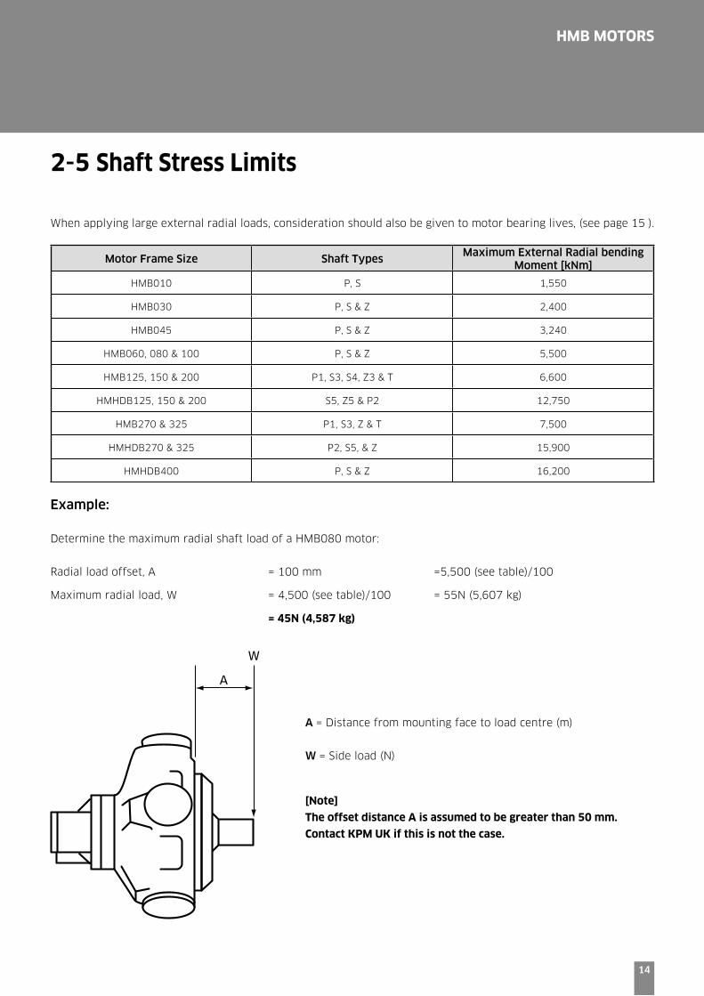
2-5 Shaft Stress Limits
When applying large external radial loads, consideration should also be given to motor bearing lives, (see page 15 ).
Motor Frame Size Shaft TypesMaximum External Radial bending
Moment [kNm]
HMB010 P, S 1,550
HMB030 P, S & Z 2,400
HMB045 P, S & Z 3,240
HMB060, 080 & 100 P, S & Z 5,500
HMB125, 150 & 200 P1, S3, S4, Z3 & T 6,600
HMHDB125, 150 & 200 S5, Z5 & P2 12,750
HMB270 & 325 P1, S3, Z & T 7,500
HMHDB270 & 325 P2, S5, & Z 15,900
HMHDB400 P, S & Z 16,200
Example:
Determine the maximum radial shaft load of a HMB080 motor:
Radial load offset, A = 100 mm =5,500 (see table)/100
Maximum radial load, W = 4,500 (see table)/100 = 55N (5,607 kg)
= 45N (4,587 kg)
A
W
A = Distance from mounting face to load centre (m)
W = Side load (N)
[Note]
The offset distance A is assumed to be greater than 50 mm.
Contact KPM UK if this is not the case.
15
HMB MOTORS
2-6 Bearing Life Notes
Consideration should be given to the required motor bearing life in terms of bearing service life. The factors that
will determine bearing life include:
1) Duty cycle - time spent on and off load 2) Speed
3) Differential pressure
4) Fluid viscosity, type, cleanliness and temperature
5) External radial shaft load
6) External axial shaft load
[Note]
A heavy duty HM(HD)B motor can be ordered to further improve bearing life.
Consult KPM UK if you need a detailed bearing life calculation.
16
HMB MOTORS
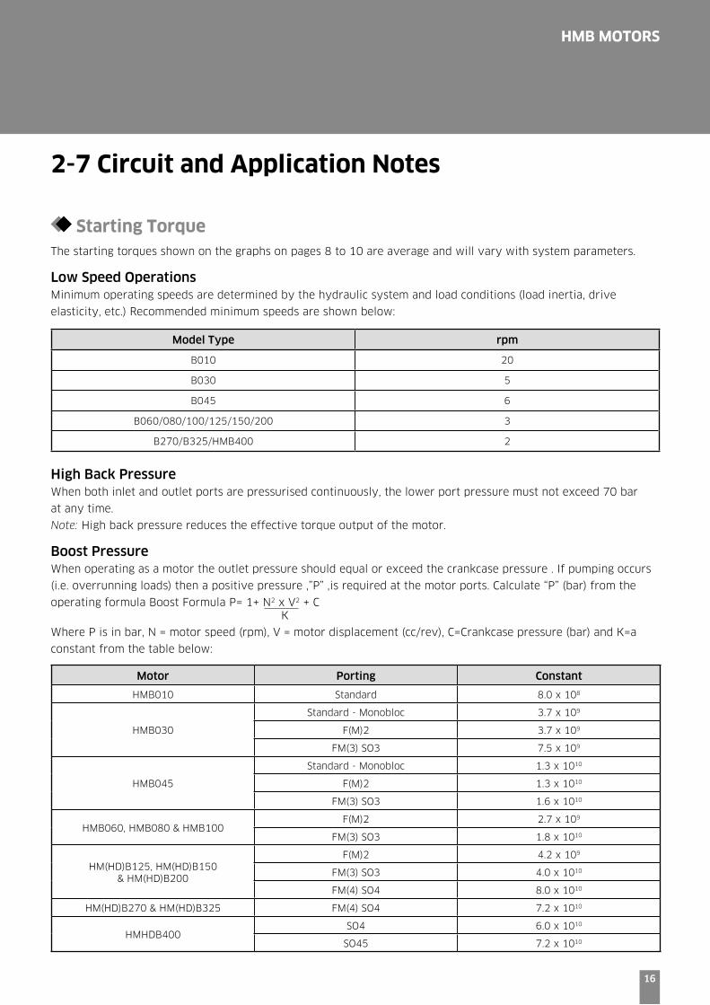
2-7 Circuit and Application Notes
Starting TorqueThe starting torques shown on the graphs on pages 8 to 10 are average and will vary with system parameters.
Low Speed OperationsMinimum operating speeds are determined by the hydraulic system and load conditions (load inertia, drive
elasticity, etc.) Recommended minimum speeds are shown below:
Model Type rpm
B010 20
B030 5
B045 6
B060/080/100/125/150/200 3
B270/B325/HMB400 2
High Back PressureWhen both inlet and outlet ports are pressurised continuously, the lower port pressure must not exceed 70 bar
at any time.
Note: High back pressure reduces the effective torque output of the motor.
Boost PressureWhen operating as a motor the outlet pressure should equal or exceed the crankcase pressure . If pumping occurs
(i.e. overrunning loads) then a positive pressure ,”P” ,is required at the motor ports. Calculate “P” (bar) from the
operating formula Boost Formula P= 1+ N2 x V2 + C K
Where P is in bar, N = motor speed (rpm), V = motor displacement (cc/rev), C=Crankcase pressure (bar) and K=a
constant from the table below:
Motor Porting Constant
HMB010 Standard 8.0 x 10⁸
HMB030
Standard - Monobloc 3.7 x 10⁹
F(M)2 3.7 x 10⁹
FM(3) SO3 7.5 x 10⁹
HMB045
Standard - Monobloc 1.3 x 10¹⁰
F(M)2 1.3 x 10¹⁰
FM(3) SO3 1.6 x 10¹⁰
HMB060, HMB080 & HMB100F(M)2 2.7 x 10⁹
FM(3) SO3 1.8 x 10¹⁰
HM(HD)B125, HM(HD)B150 & HM(HD)B200
F(M)2 4.2 x 10⁹
FM(3) SO3 4.0 x 10¹⁰
FM(4) SO4 8.0 x 10¹⁰
HM(HD)B270 & HM(HD)B325 FM(4) SO4 7.2 x 10¹⁰
HMHDB400SO4 6.0 x 10¹⁰
SO45 7.2 x 10¹⁰
17
HMB MOTORS
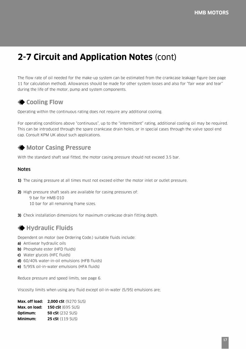
The flow rate of oil needed for the make-up system can be estimated from the crankcase leakage figure (see page
11 for calculation method). Allowances should be made for other system losses and also for “fair wear and tear”
during the life of the motor, pump and system components.
Cooling Flow
Operating within the continuous rating does not require any additional cooling.
For operating conditions above “continuous”, up to the “intermittent” rating, additional cooling oil may be required.
This can be introduced through the spare crankcase drain holes, or in special cases through the valve spool end
cap. Consult KPM UK about such applications.
Motor Casing Pressure
With the standard shaft seal fitted, the motor casing pressure should not exceed 3.5 bar.
Notes
1) The casing pressure at all times must not exceed either the motor inlet or outlet pressure.
2) High pressure shaft seals are available for casing pressures of:
9 bar for HMB 010
10 bar for all remaining frame sizes.
3) Check installation dimensions for maximum crankcase drain fitting depth.
Hydraulic Fluids
Dependent on motor (see Ordering Code.) suitable fluids include:
a) Antiwear hydraulic oils
b) Phosphate ester (HFD fluids)
c) Water glycols (HFC fluids)
d) 60/40% water-in-oil emulsions (HFB fluids)
e) 5/95% oil-in-water emulsions (HFA fluids)
Reduce pressure and speed limits, see page 6.
Viscosity limits when using any fluid except oil-in-water (5/95) emulsions are;
Max. off load: 2,000 cSt (9270 SUS)
Max. on load: 150 cSt (695 SUS)
Optimum: 50 cSt (232 SUS)
Minimum: 25 cSt (119 SUS)
2-7 Circuit and Application Notes (cont)

18
HMB MOTORS
Mineral Oil recommendations
The fluid should be a good hydraulic grade, non-
detergent Mineral Oil. It should contain anti-oxidant, antifoam and demulsifying additives. It should contain antiwear or EP additives. Automatic transmission fluids and motor oils are not recommended.
Temperature limits
Ambient min. -30°C (-22°F)
Ambient max. + 70°C (158°F)Max. operating temperature range.Mineral Oil Water-containingMin -20°C (-4°F) +10°C (50°F)Max. + 80°C (175°F) +54°C (130°F)
Note: To obtain optimum services life from both fluid and hydraulic systems components, a fluid operating temperature of 40°C is recommended.
Filtration
Full flow filtration (open circuit), or full boost flow
filtration (close circuit) to ensure system cleanliness to
ISO4406/1986 code 18/14 or cleaner.
Noise levels
The airborne noise level is less than 66.7 dB(A) DIN
(&) dB (A) NFPA) through the “continuous” operating
envelope. Where noise is a critical factor, installation
resonances can be reduced by isolating the motor by
elastomeric means from the structure and the return
line installation. Potential return line resonances
originating from liquid borne noise can be further
attenuated by providing a return line back pressure of
2 to 5 bar.
Polar Moment of Inertia & Mass:
Model TypePolar moment of Inertia
(kg.m2)(Typical data)
Mass (kg)(Approx. all models)
HMB010 0.0076 40
HMB030 0.0150 73
HMB045 0.0470 120
HMB060 0.0500 144
HMB080 0.0600 144
HMB100 0.0760 144
HMB125 0.2200 217
HMB150 0.2500 265
HMB200 0.2700 265
HMB270 0.4900 420
HMB325 0.5000 429
HMHDB400 - SO4 0.5400 481
HMHDB400 - SO45 0.5400 510
2-7 Circuit and Application Notes (cont)
19
HMB MOTORS
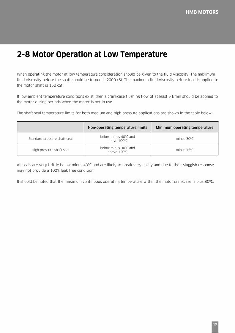
2-8 Motor Operation at Low Temperature
When operating the motor at low temperature consideration should be given to the fluid viscosity. The maximum
fluid viscosity before the shaft should be turned is 2000 cSt. The maximum fluid viscosity before load is applied to
the motor shaft is 150 cSt.
If low ambient temperature conditions exist, then a crankcase flushing flow of at least 5 I/min should be applied to
the motor during periods when the motor is not in use.
The shaft seal temperature limits for both medium and high pressure applications are shown in the table below.
Non-operating temperature limits Minimum operating temperature
Standard pressure shaft sealbelow minus 400C and
above 1000Cminus 300C
High pressure shaft sealbelow minus 300C and
above 1200Cminus 150C
All seals are very brittle below minus 400C and are likely to break very easily and due to their sluggish response
may not provide a 100% leak free condition.
It should be noted that the maximum continuous operating temperature within the motor crankcase is plus 80OC.
20
HMB MOTORS
2-9 Freewheeling Notes
All Staffa motors can be used in freewheeling applications.
In all circumstances it is essential that the motor is unloaded (A and B ports connected together) and that the
circuit is boosted.
The required boost pressure will be dependent on the required speed and displacement conditions.
It should be noted that for ‘HMB’ series motors, to achieve freewheel, large flows will have to re-circulate around
the motor.
This will require a large re-circulating valve and consideration of circuit cooling as the motor will generate a large
braking torque.
It is for these reasons that ‘HMC’ or ‘HPC’ series motors are the preferred option for freewheeling applications.
See catalogues M-2002/09.14 and M-2003/09.14 for details.
21
HMB MOTORS
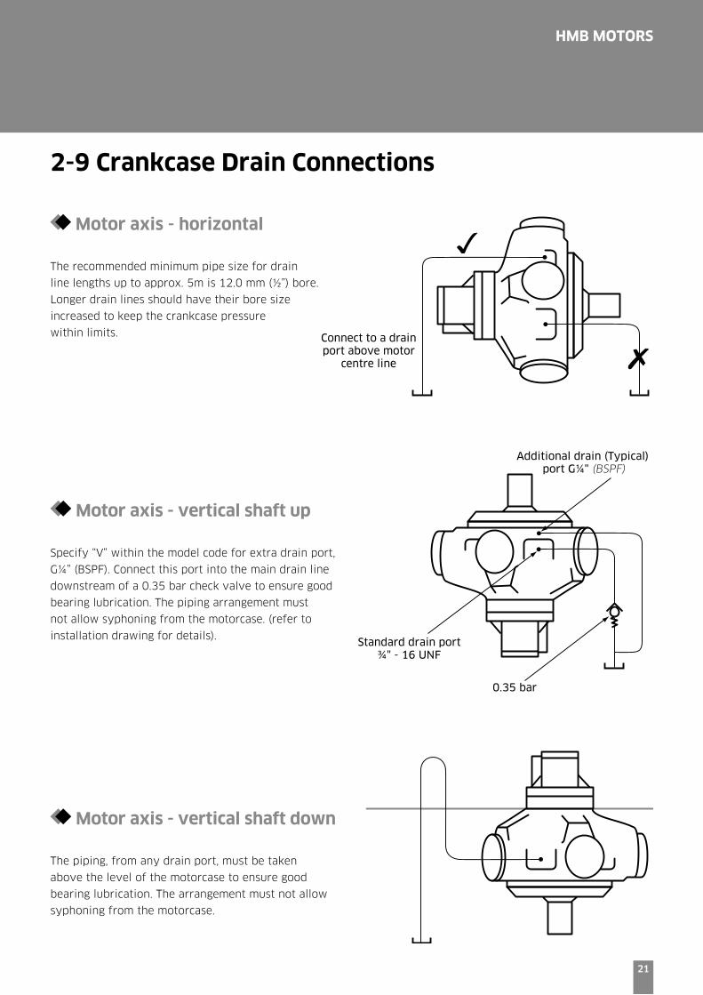
Motor axis - horizontal
The recommended minimum pipe size for drain
line lengths up to approx. 5m is 12.0 mm (½”) bore.
Longer drain lines should have their bore size
increased to keep the crankcase pressure
within limits.
Motor axis - vertical shaft up
Specify “V” within the model code for extra drain port,
G¼” (BSPF). Connect this port into the main drain line
downstream of a 0.35 bar check valve to ensure good
bearing lubrication. The piping arrangement must
not allow syphoning from the motorcase. (refer to
installation drawing for details).
Motor axis - vertical shaft down The piping, from any drain port, must be taken
above the level of the motorcase to ensure good
bearing lubrication. The arrangement must not allow
syphoning from the motorcase.
Additional drain (Typical) port G¼" (BSPF)
Standard drain port ¾" - 16 UNF
0.35 bar
Connect to a drain port above motor
centre line
2-9 Crankcase Drain Connections
22
HMB MOTORS
2-10 Installation Data
Spigot
The motor should be located by the mounting spigot on a flat, robust surface using correctly sized bolts.
The diametrical clearance between the motor spigot and the mounting must not exceed 0.15 mm. If the application
incurs shock loading, frequent reversing or high speed running , then high tensile bolts should be used, including
one fitted bolt.
Bolt Torque
The recommended torque wrench setting for bolts are as follows:
M12 97 +/- 7 Nm
M14 160 +/- 21 Nm
M18 312 +/- 14 Nm
M20 407 +/- 14 Nm
M24 690 +/- 27 Nm
½" UNF 97 +/- 7 Nm
⅝" UNF 265 +/- 14 Nm
¾" bolts 393 +/- 14 Nm
1" 810 +/- 27 Nm
Shaft Coupling:
Where the motor is solidly coupled to a shaft having independent bearings the shaft must be aligned to within
0.13 mm TIR.

HMB MOTORS
23
3 Dimensions
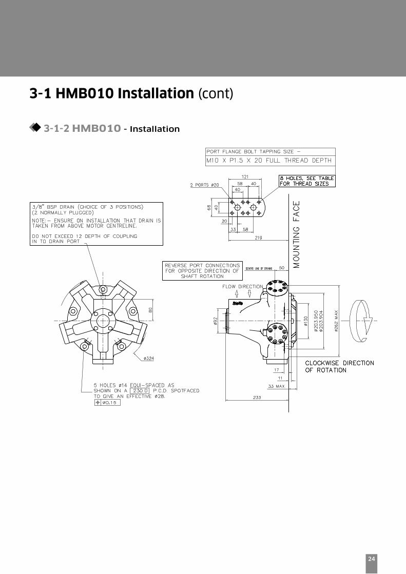
3-1 HMB010 Installation
3-1-1 HMB010 - 'P' & 'S' Shafts
24
HMB MOTORS
3-1 HMB010 Installation (cont)
3-1-2 HMB010 - Installation

25
HMB MOTORS
3-2 HMB030 Installation
3-2-1 HMB030 Monobloc - ‘P’, ‘S’ & ‘Z’ Shafts
26
HMB MOTORS
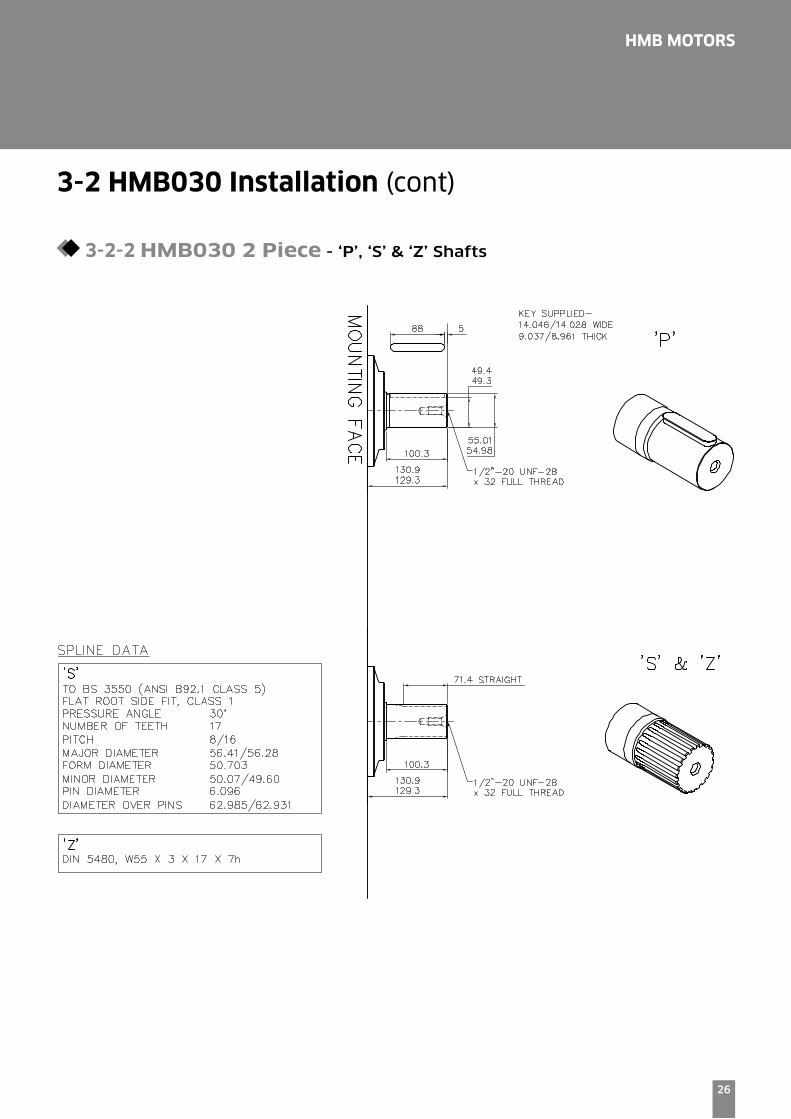
3-2 HMB030 Installation (cont)
3-2-2 HMB030 2 Piece - ‘P’, ‘S’ & ‘Z’ Shafts

27
HMB MOTORS
3-2 HMB030 Installation (cont)
3-2-3 HMB030 2 Piece - ‘SO3’, ‘F2’ & ‘FM2’ Valve Housings
28
HMB MOTORS
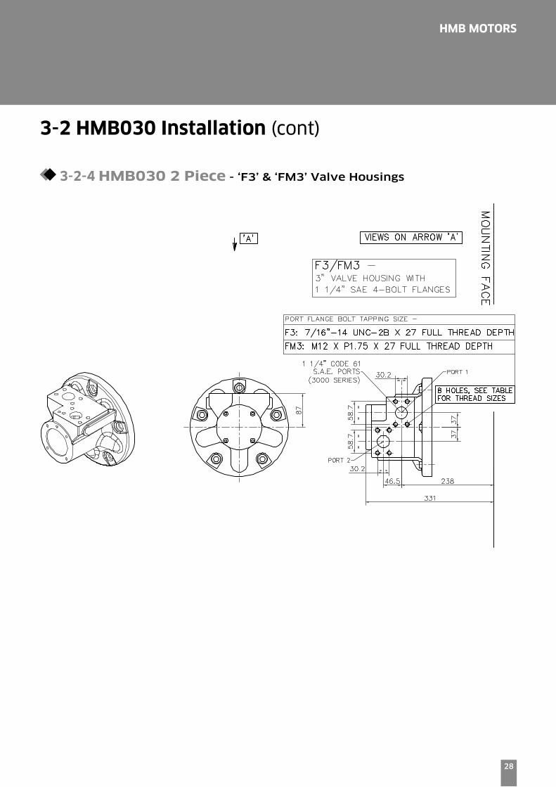
3-2 HMB030 Installation (cont)
3-2-4 HMB030 2 Piece - ‘F3’ & ‘FM3’ Valve Housings

29
HMB MOTORS
3-2 HMB030 Installation (cont)
3-2-5 HMB030 2 Piece - Installation

30
HMB MOTORS
3-2 HMB030 Installation (cont)
3-2-6 HMB030 Monobloc - Rear Port Installation
31
HMB MOTORS
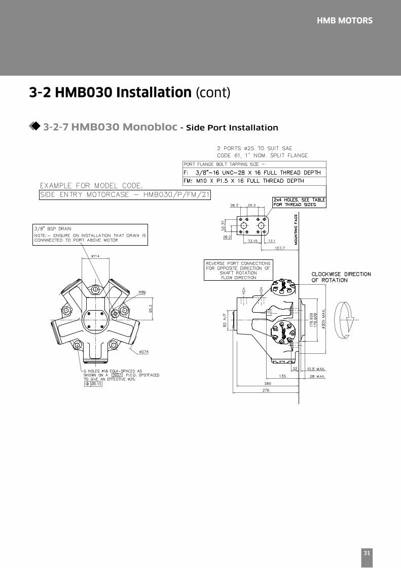
3-2 HMB030 Installation (cont)
3-2-7 HMB030 Monobloc - Side Port Installation

32
HMB MOTORS
3-3 HMB045 Installation
3-3-1 HMB045 Monobloc - ‘P’, ‘S’ & ‘Z’ Shafts
33
HMB MOTORS
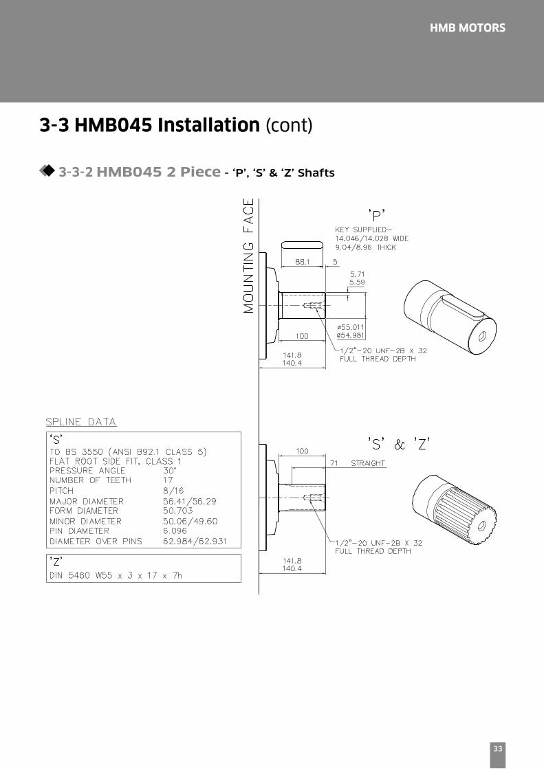
3-3 HMB045 Installation (cont)
3-3-2 HMB045 2 Piece - ‘P’, ‘S’ & ‘Z’ Shafts

34
HMB MOTORS
3-3 HMB045 Installation (cont)
3-3-3 HMB045 2 Piece - ‘SO3’, ‘F2’ & ‘FM2’ Valve Housings
35
HMB MOTORS
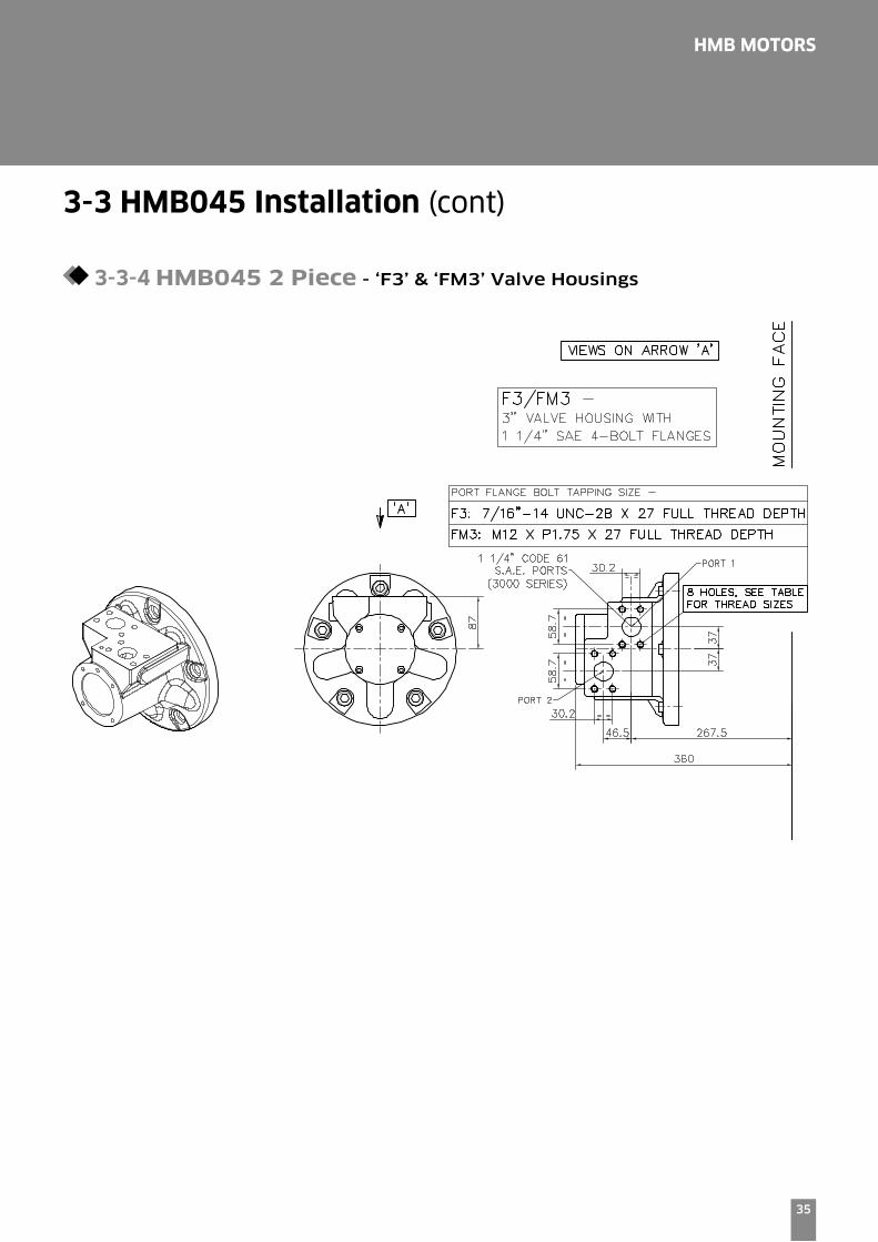
3-3 HMB045 Installation (cont)
3-3-4 HMB045 2 Piece - ‘F3’ & ‘FM3’ Valve Housings
36
HMB MOTORS
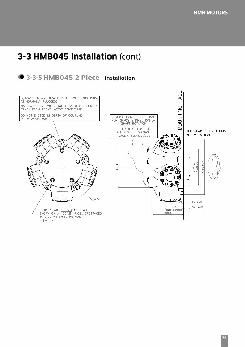
3-3 HMB045 Installation (cont)
3-3-5 HMB045 2 Piece - Installation
37
HMB MOTORS
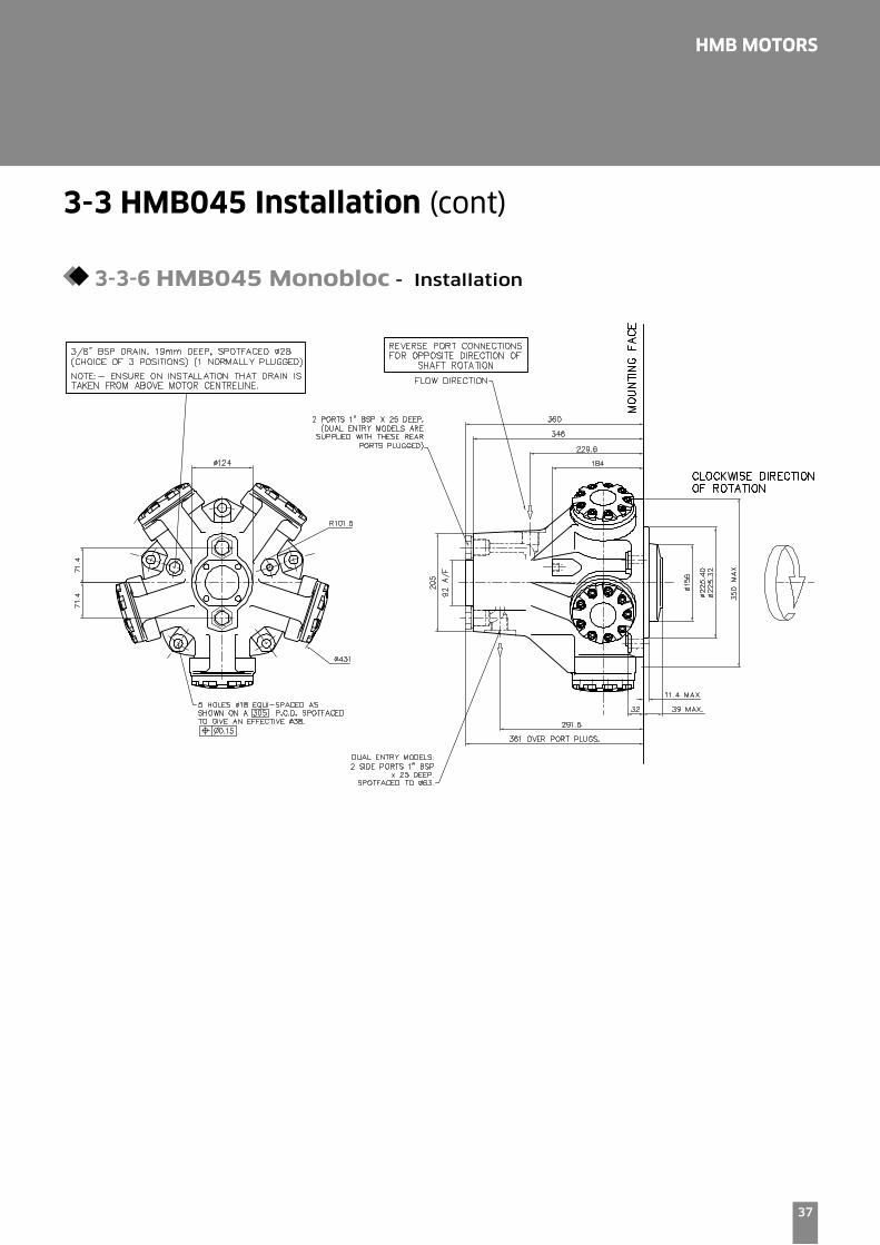
3-3 HMB045 Installation (cont)
3-3-6 HMB045 Monobloc - Installation

38
HMB MOTORS
3-4 HMB060/080 Installation
3-4-1 HMB060/080 - ‘P’, ‘S’ & ‘Z’ Shafts
39
HMB MOTORS
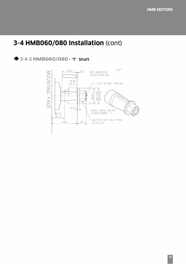
3-4 HMB060/080 Installation (cont)
3-4-2 HMB060/080 - ‘T’ Shaft

40
HMB MOTORS
3-4 HMB060/080 Installation (cont)
3-4-3 HMB060/080 - ‘SO3’, ‘F2’ & ‘FM2’ Valve Housings
41
HMB MOTORS
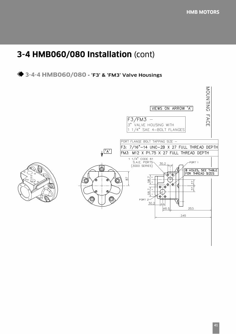
3-4 HMB060/080 Installation (cont)
3-4-4 HMB060/080 - ‘F3’ & ‘FM3’ Valve Housings
42
HMB MOTORS
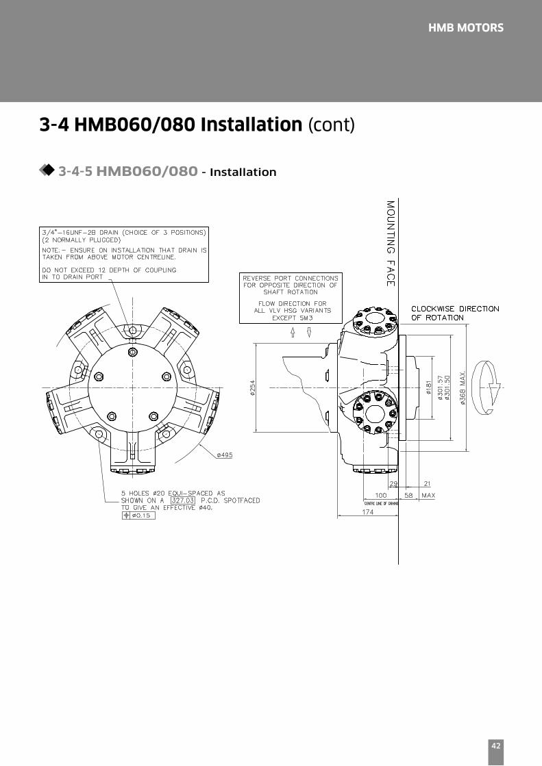
3-4 HMB060/080 Installation (cont)
3-4-5 HMB060/080 - Installation
43
HMB MOTORS
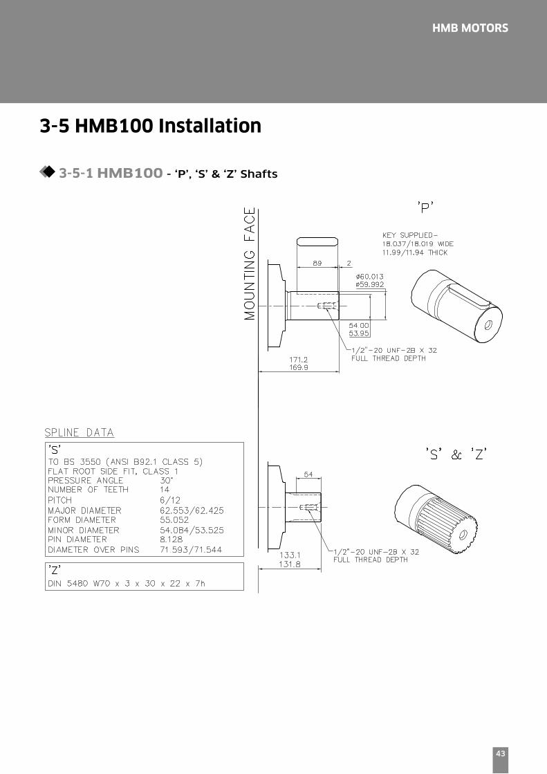
3-5 HMB100 Installation
3-5-1 HMB100 - ‘P’, ‘S’ & ‘Z’ Shafts

44
HMB MOTORS
3-5 HMB100 Installation (cont)
3-5-2 HMB100 - ‘T’ Shaft

45
HMB MOTORS
3-5 HMB100 Installation (cont)
3-5-3 HMB100 - ‘SO3’, ‘F2’ & ‘FM2’ Valve Housings

46
HMB MOTORS
3-5 HMB100 Installation (cont)
3-5-4 HMB100 - ‘F3’ & ‘FM3’ Valve Housings

47
HMB MOTORS
3-5 HMB100 Installation (cont)
3-5-5 HMB100 - Installation

48
HMB MOTORS
3-6 HM(HD)B125 Installation
3-6-1 HMB125 - ‘P1’, ‘S3’, ‘S4’ & ‘Z3’ Shafts
49
HMB MOTORS
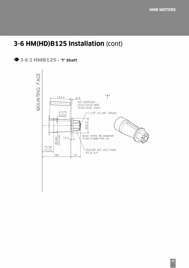
3-6 HM(HD)B125 Installation (cont)
3-6-2 HMB125 - ‘T’ Shaft
50
HMB MOTORS
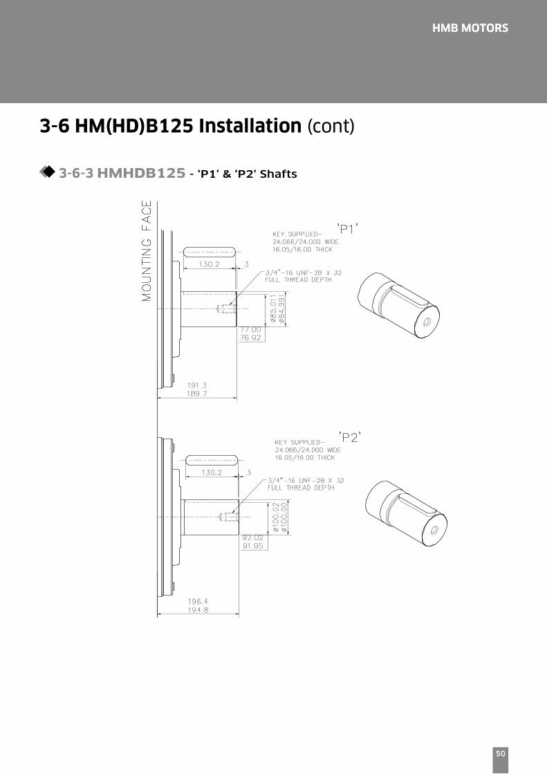
3-6 HM(HD)B125 Installation (cont)
3-6-3 HMHDB125 - ‘P1’ & ‘P2’ Shafts
51
HMB MOTORS
3-6 HM(HD)B125 Installation (cont)
3-6-4 HMHDB125 - ‘S3’, ‘S5’, ‘Z5’ & T Shafts

52
HMB MOTORS
3-6 HM(HD)B125 Installation (cont)
3-6-5 HMB125 & HMHDB125 - ‘SO3’ & ‘SO4’ Valve Housings

53
HMB MOTORS
3-6 HM(HD)B125 Installation (cont)
3-6-6 HMB125 & HMHDB125 - ‘F2’, ‘FM2’, ‘F3’ & ‘FM3’ Valve Housings
54
HMB MOTORS
3-6 HM(HD)B125 Installation (cont)
3-6-7 HMB125 & HMHDB125 - ‘F4’ & ‘FM4’ Valve Housings
55
HMB MOTORS
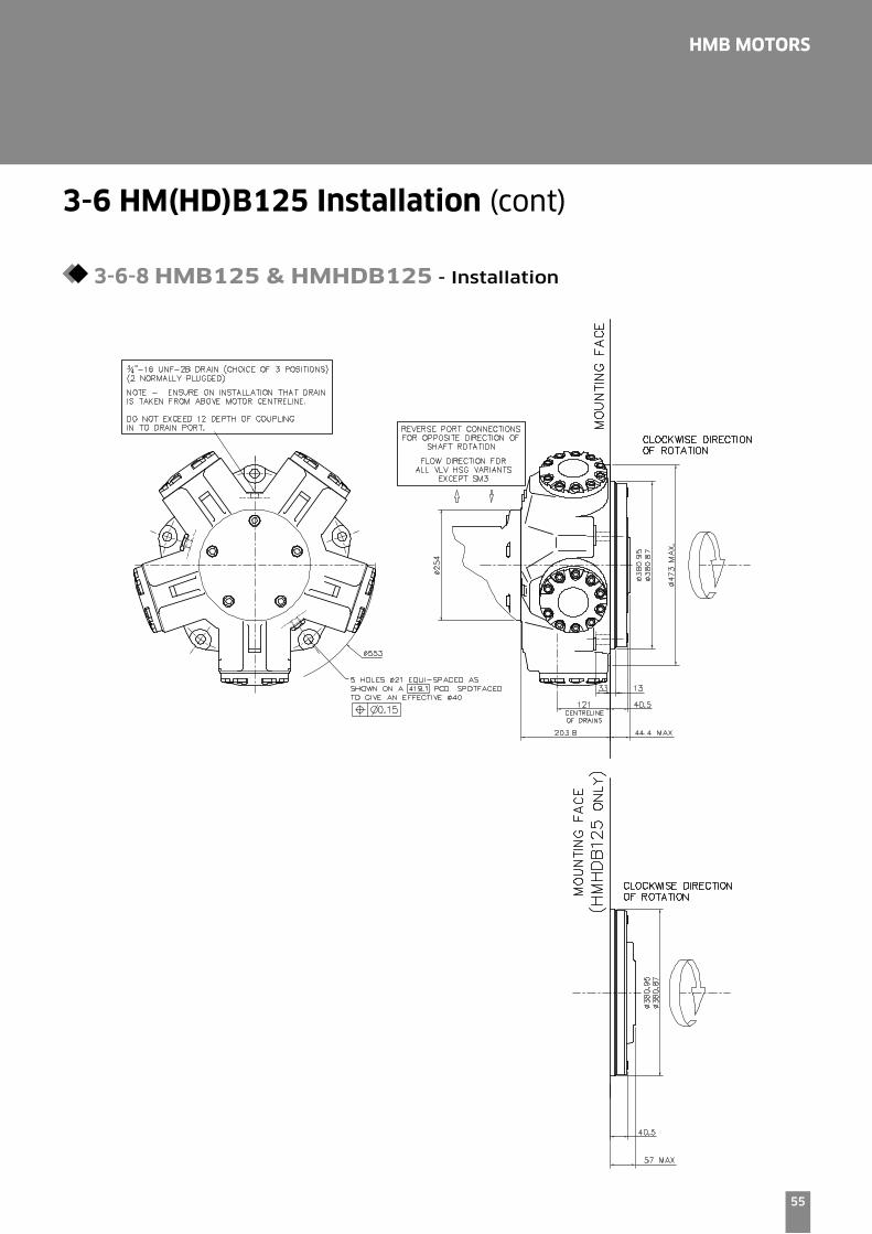
3-6 HM(HD)B125 Installation (cont)
3-6-8 HMB125 & HMHDB125 - Installation
56
HMB MOTORS
3-7 HMB(HD)150/200 Installation
3-7-1 HMB150/200 - ‘P1’, ‘S3’, ‘S4’ & Z3 Shafts
57
HMB MOTORS
3-7 HMB(HD)150/200 Installation (cont)
3-7-2 HMB150/200 - ‘T’ Shaft
58
HMB MOTORS
3-7 HMB(HD)150/200 Installation (cont)
3-7-3 HMBHD150/200 - ‘P2’, ‘S3’, ‘S5’ & ‘Z5’ Shafts
59
HMB MOTORS
3-7 HMB(HD)150/200 Installation (cont)
3-7-4 HMBHD150/200 - ‘T’ Shaft

60
HMB MOTORS
3-7-5 HMB150/200 & HMBHD150/200 - ‘SO3’ & ‘S04’ Valve Housings
3-7 HMB(HD)150/200 Installation (cont)
61
HMB MOTORS
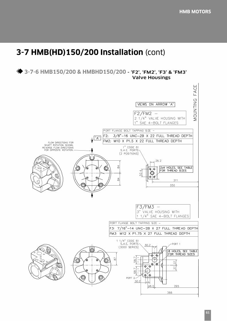
3-7-6 HMB150/200 & HMBHD150/200 - ‘F2’, ‘FM2’, ‘F3’ & ‘FM3’ Valve Housings
3-7 HMB(HD)150/200 Installation (cont)

62
HMB MOTORS
3-7-7 HMB150/200 & HMBHD150/200 - ‘F4’ & ‘FM4’ Valve Housings
3-7 HMB(HD)150/200 Installation (cont)

63
HMB MOTORS
3-7 HMB(HD)150/200 Installation (cont)
3-7-8 HMB150/200 & HMBHD150/200 - Installation
64
HMB MOTORS
3-8 HMB(HD)270 Installation
3-8-1 HMB270 - ‘P1’, ‘S3’ & ‘Z’ Shaft
65
HMB MOTORS
3-8 HMB(HD)270 Installation (cont)
3-8-2 HMB270 - ‘T’ Shaft

66
HMB MOTORS
3-8 HMB(HD)270 Installation (cont)
3-8-3 HMBHD270 - ‘P2’ & ‘S5’ Shafts

67
HMB MOTORS
3-8 HMB(HD)270 Installation (cont)
3-8-4 HMBHD270 - ‘Z’ Shaft

68
HMB MOTORS
3-8 HMB(HD)270 Installation (cont)
3-8-5 HMB270 & HMHDB270 - ‘F4’, ‘FM4’ & ‘SO4’ Valve Housings

69
HMB MOTORS
3-8 HMB(HD)270 Installation (cont)
3-8-6 HMB270 & HMBHD270 - Installation

70
HMB MOTORS
3-9 HMB(HD)325 Installation
3-9-1 HMB325 - ‘P1’, ‘S3’ & ‘Z’ Shafts
71
HMB MOTORS
3-9 HMB(HD)325 Installation (cont)
3-9-2 HMB325 - ‘T’ Shaft

72
HMB MOTORS
3-9 HMB(HD)325 Installation (cont)
3-9-3 HMBHD325 - ‘P2’ & ‘S5’ Shafts
73
HMB MOTORS
3-9 HMB(HD)325 Installation (cont)
3-9-4 HMBHD325 - ‘Z’ Shaft
74
HMB MOTORS
3-9 HMB(HD)325 Installation (cont)
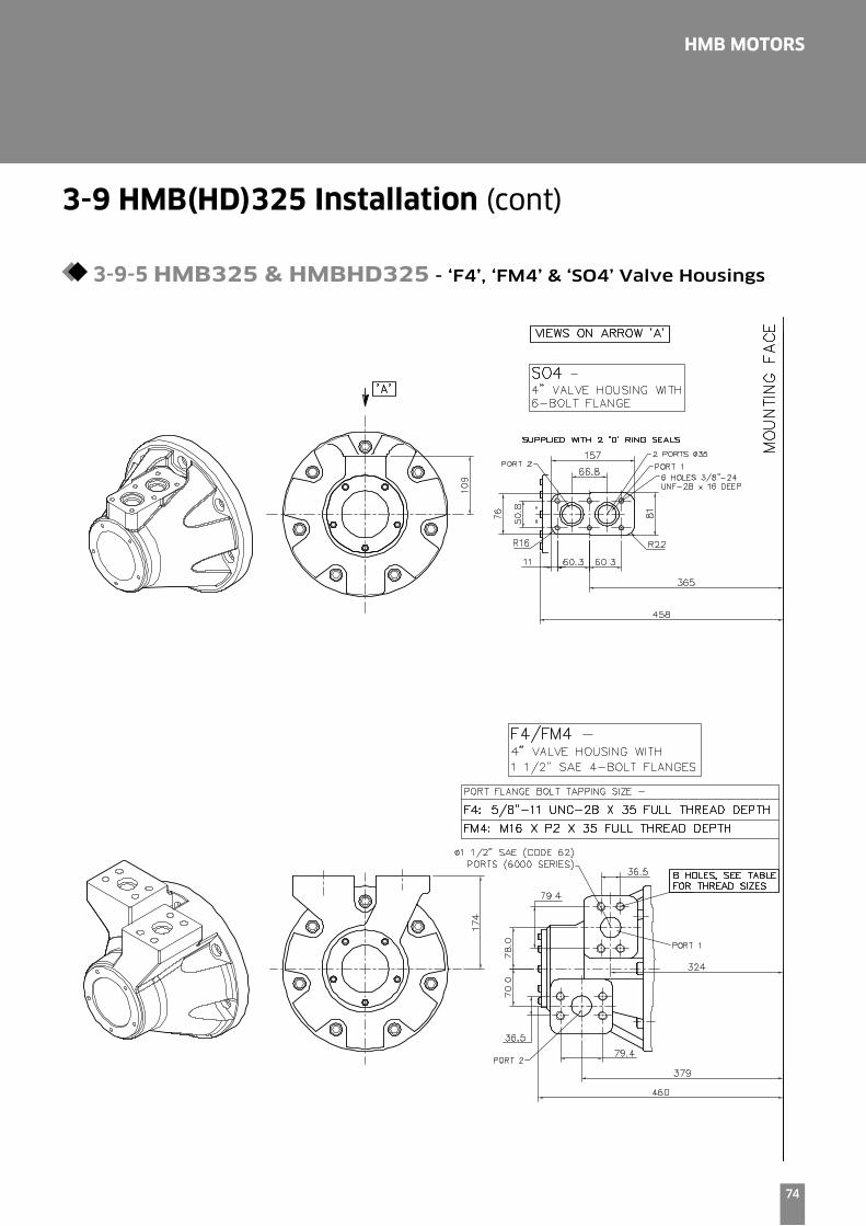
3-9-5 HMB325 & HMBHD325 - ‘F4’, ‘FM4’ & ‘SO4’ Valve Housings
75
HMB MOTORS
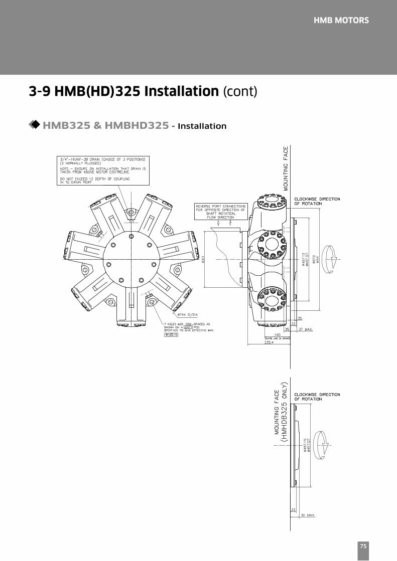
3-9 HMB(HD)325 Installation (cont)
HMB325 & HMBHD325 - Installation
76
HMB MOTORS
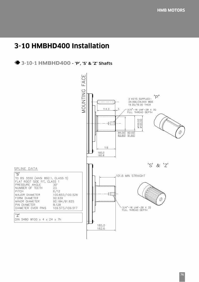
3-10 HMBHD400 Installation
3-10-1 HMBHD400 - ‘P’, ‘S’ & ‘Z’ Shafts

77
HMB MOTORS
3-10 HMBHD400 Installation (cont)
3-10-2 HMBHD400 - Installation

78
HMB MOTORS
Tj speed sensor with Tk readout option
5m
505
27
.0
M12x18H
ca.Ø
5.5
32
41
1 +V, BROWN
2 SIGNAL 2, BLACK
3 SIGNAL 1/D, WHITE
4 GND, BLUE
SCREEN
BLACK
BLUE
WHITE
BROWN
REVISION A - 17.08.06
HPC - ALL FRAME SIZESEXAMPLE FOR MODEL CODE -
HPC125/S/125/100/FM3/X/Tj/71
JAQUET SPEED SENSOR
TO SUIT: F3/FM3/SO3 TO SUIT: F4/FM4/SO430.4
M8 x 16 CAP SCREW
17.00
Ø115
SPEED SENSORØ146.0
M8 x 16 CAP SCREW
17.00
SPEED SENSOR 40.3
'Tj'
Tj Speed Sensor Technical Specification
The Tj speed sensor is a hall effect dual channel speed probe
that can provide feedback of both speed and direction.
Signal Outputs: Square wave plus directional signal
Power Supply: 8 to 32 V @ 40 mA
Protection class: IP68
Output frequency: 16 pulses/revolution
Installation Details
Tk Output Module
The Tk option consists of the Tj speed sensor together
with the optional T401 output module.
The addition of the T401 module provides a software
configured single channel tachometer and relay with a
0/4-20 mA analogue current output.
The software and calibration cable is also provided.
3-11 Speed Sensing Options
Related Documents