1 Fisheye Distortion Rectification from Deep Straight Lines Zhu-Cun Xue, Nan Xue, Gui-Song Xia Abstract—This paper presents a novel line-aware rectification network (LaRecNet) to address the problem of fisheye distortion rectification based on the classical observation that straight lines in 3D space should be still straight in image planes. Specifically, the proposed LaRecNet contains three sequential modules to (1) learn the distorted straight lines from fisheye images; (2) estimate the distortion parameters from the learned heatmaps and the image appearance; and (3) rectify the input images via a proposed differentiable rectification layer. To better train and evaluate the proposed model, we create a synthetic line-rich fisheye (SLF) dataset that contains the distortion parameters and well-annotated distorted straight lines of fisheye images. The proposed method enables us to simultaneously calibrate the geometric distortion parameters and rectify fisheye images. Extensive experiments demonstrate that our model achieves state-of-the-art performance in terms of both geometric accuracy and image quality on several evaluation metrics. In particular, the images rectified by LaRecNet achieve an average reprojection error of 0.33 pixels on the SLF dataset and produce the highest peak signal-to-noise ratio (PSNR) and structure similarity index (SSIM) compared with the groundtruth. Index Terms—Fisheye Distortion Rectification, Fisheye Camera Calibration, Deep Learning, Straight Line Constraint ✦ 1 I NTRODUCTION Fisheye cameras enable us to capture images with an ultrawide field of view (FoV) and have the potential to ben- efit many machine vision tasks, such as structure from mo- tion (SfM), simultaneous localization and mapping (SLAM) and autonomous driving, by perceiving a well-conditioned scene coverage with fewer images than would otherwise be required. However, the ultrawide FoV characteristics of fisheye cameras are usually achieved by nonlinear map- ping functions [1]–[3], which always lead to severe ge- ometric distortions to the sensed images and harm the subsequent vision computing process, e.g., 3D reconstruc- tions and recognition. Therefore, when developing vision systems equipped with fisheye cameras [4]–[7], it is often a prerequisite to estimate the camera parameters and rectify the geometric distortions. In this paper, we address the problem of rectifying geometric distortions in fisheye images, which is commonly studied as a coupled problem of camera calibration [8]– [13]. Given a specified model of image formation (e.g., the perspective camera model), the distortion parameters are regarded as parts of the camera intrinsics and then estimated from the 2D-3D correspondences established by using certain predefined calibration patterns (e.g., cubes and planar checkerboards). The geometric distortions in images are subsequently rectified with the estimated camera intrin- sics. However, the methods of this category have to face the problem of establishing the 2D-3D correspondences, which is the vital factor for the calibration/rectification accuracy and often requires laborious computations [8], [9]. To overcome the abovementioned drawbacks, self- calibration methods [14]–[23] have addressed the problem based on geometric invariant features (e.g., straight lines, vanishing points, conics) of images instead of using known All the authors are with Department of Computer Science and State Key Lab. LIESMARS, Wuhan University, Wuhan, 430072, China. E-mail: {zhucun.xue, xuenan, guisong.xia}@whu.edu.cn Straighten the Distorted Lines Learning to Rectification LaRecNet LaRecNet Fig. 1. Geometric constraint in fisheye images: the distorted lines gen- erated by fisheye projection should be straight in normal perspective images. This paper investigates how to efficiently embed this geometric constraint into deep models for fisheye image rectification. 3D information of scenes. Studies of these approaches have reported promising performances on fisheye distortion rec- tification when the specified geometric features in fisheye images can be accurately detected. Nevertheless, it is worth noticing that the involved detection of the geometric fea- tures in fisheye images itself is another challenging problem in computer vision. Recently, the problem of distortion rectification has been renewed by deep learning techniques due to their strong capacity of visual feature representation [24], [25]. Instead of explicitly detecting the geometric features in fisheye images, these methods rectify images from learned semantic cues. Although significant improvements have been obtained, the deep models trained only with semantic-level supervision arXiv:2003.11386v1 [cs.CV] 25 Mar 2020

Welcome message from author
This document is posted to help you gain knowledge. Please leave a comment to let me know what you think about it! Share it to your friends and learn new things together.
Transcript

1
Fisheye Distortion Rectification fromDeep Straight Lines
Zhu-Cun Xue, Nan Xue, Gui-Song Xia
Abstract—This paper presents a novel line-aware rectification network (LaRecNet) to address the problem of fisheye distortionrectification based on the classical observation that straight lines in 3D space should be still straight in image planes. Specifically,the proposed LaRecNet contains three sequential modules to (1) learn the distorted straight lines from fisheye images; (2) estimatethe distortion parameters from the learned heatmaps and the image appearance; and (3) rectify the input images via a proposeddifferentiable rectification layer. To better train and evaluate the proposed model, we create a synthetic line-rich fisheye (SLF) datasetthat contains the distortion parameters and well-annotated distorted straight lines of fisheye images. The proposed method enables usto simultaneously calibrate the geometric distortion parameters and rectify fisheye images. Extensive experiments demonstrate that ourmodel achieves state-of-the-art performance in terms of both geometric accuracy and image quality on several evaluation metrics. Inparticular, the images rectified by LaRecNet achieve an average reprojection error of 0.33 pixels on the SLF dataset and produce thehighest peak signal-to-noise ratio (PSNR) and structure similarity index (SSIM) compared with the groundtruth.
Index Terms—Fisheye Distortion Rectification, Fisheye Camera Calibration, Deep Learning, Straight Line Constraint
F
1 INTRODUCTION
Fisheye cameras enable us to capture images with anultrawide field of view (FoV) and have the potential to ben-efit many machine vision tasks, such as structure from mo-tion (SfM), simultaneous localization and mapping (SLAM)and autonomous driving, by perceiving a well-conditionedscene coverage with fewer images than would otherwisebe required. However, the ultrawide FoV characteristics offisheye cameras are usually achieved by nonlinear map-ping functions [1]–[3], which always lead to severe ge-ometric distortions to the sensed images and harm thesubsequent vision computing process, e.g., 3D reconstruc-tions and recognition. Therefore, when developing visionsystems equipped with fisheye cameras [4]–[7], it is often aprerequisite to estimate the camera parameters and rectifythe geometric distortions.
In this paper, we address the problem of rectifyinggeometric distortions in fisheye images, which is commonlystudied as a coupled problem of camera calibration [8]–[13]. Given a specified model of image formation (e.g.,the perspective camera model), the distortion parametersare regarded as parts of the camera intrinsics and thenestimated from the 2D-3D correspondences established byusing certain predefined calibration patterns (e.g., cubes andplanar checkerboards). The geometric distortions in imagesare subsequently rectified with the estimated camera intrin-sics. However, the methods of this category have to face theproblem of establishing the 2D-3D correspondences, whichis the vital factor for the calibration/rectification accuracyand often requires laborious computations [8], [9].
To overcome the abovementioned drawbacks, self-calibration methods [14]–[23] have addressed the problembased on geometric invariant features (e.g., straight lines,vanishing points, conics) of images instead of using known
All the authors are with Department of Computer Science and StateKey Lab. LIESMARS, Wuhan University, Wuhan, 430072, China. E-mail:zhucun.xue, xuenan, [email protected]
Straighten the Distorted Lines
Learning to Rectification
LaRecNet
LaRecNet
Fig. 1. Geometric constraint in fisheye images: the distorted lines gen-erated by fisheye projection should be straight in normal perspectiveimages. This paper investigates how to efficiently embed this geometricconstraint into deep models for fisheye image rectification.
3D information of scenes. Studies of these approaches havereported promising performances on fisheye distortion rec-tification when the specified geometric features in fisheyeimages can be accurately detected. Nevertheless, it is worthnoticing that the involved detection of the geometric fea-tures in fisheye images itself is another challenging problemin computer vision.
Recently, the problem of distortion rectification has beenrenewed by deep learning techniques due to their strongcapacity of visual feature representation [24], [25]. Instead ofexplicitly detecting the geometric features in fisheye images,these methods rectify images from learned semantic cues.Although significant improvements have been obtained, thedeep models trained only with semantic-level supervision
arX
iv:2
003.
1138
6v1
[cs
.CV
] 2
5 M
ar 2
020
2
Conv ⋯
Stack
PRM
PRM
Conv
Deco
nv
1×1
Conv
c
Soft
max
Conv
Resn
et L1
-L4 ↑
↑↑↑
𝐼𝐼𝑟𝑟
𝐼𝐼𝑓𝑓
DLP c
Resnet L1-L4 𝐼𝐼𝑟𝑟
Mul
ti-Sc
ale
Calib
ratio
n
Attentive Uncertainty Regularization
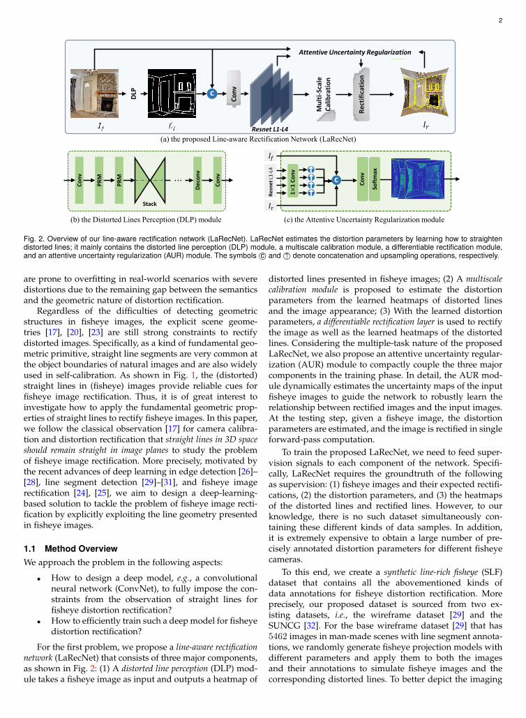
(a) the proposed Line-aware Rectification Network (LaRecNet)
(b) the Distorted Lines Perception (DLP) module (c) the Attentive Uncertainty Regularization module
Conv
Rect
ifica
tion
Fig. 2. Overview of our line-aware rectification network (LaRecNet). LaRecNet estimates the distortion parameters by learning how to straightendistorted lines; it mainly contains the distorted line perception (DLP) module, a multiscale calibration module, a differentiable rectification module,and an attentive uncertainty regularization (AUR) module. The symbols c© and ↑© denote concatenation and upsampling operations, respectively.
are prone to overfitting in real-world scenarios with severedistortions due to the remaining gap between the semanticsand the geometric nature of distortion rectification.
Regardless of the difficulties of detecting geometricstructures in fisheye images, the explicit scene geome-tries [17], [20], [23] are still strong constraints to rectifydistorted images. Specifically, as a kind of fundamental geo-metric primitive, straight line segments are very common atthe object boundaries of natural images and are also widelyused in self-calibration. As shown in Fig. 1, the (distorted)straight lines in (fisheye) images provide reliable cues forfisheye image rectification. Thus, it is of great interest toinvestigate how to apply the fundamental geometric prop-erties of straight lines to rectify fisheye images. In this paper,we follow the classical observation [17] for camera calibra-tion and distortion rectification that straight lines in 3D spaceshould remain straight in image planes to study the problemof fisheye image rectification. More precisely, motivated bythe recent advances of deep learning in edge detection [26]–[28], line segment detection [29]–[31], and fisheye imagerectification [24], [25], we aim to design a deep-learning-based solution to tackle the problem of fisheye image recti-fication by explicitly exploiting the line geometry presentedin fisheye images.
1.1 Method OverviewWe approach the problem in the following aspects:
• How to design a deep model, e.g., a convolutionalneural network (ConvNet), to fully impose the con-straints from the observation of straight lines forfisheye distortion rectification?
• How to efficiently train such a deep model for fisheyedistortion rectification?
For the first problem, we propose a line-aware rectificationnetwork (LaRecNet) that consists of three major components,as shown in Fig. 2: (1) A distorted line perception (DLP) mod-ule takes a fisheye image as input and outputs a heatmap of
distorted lines presented in fisheye images; (2) A multiscalecalibration module is proposed to estimate the distortionparameters from the learned heatmaps of distorted linesand the image appearance; (3) With the learned distortionparameters, a differentiable rectification layer is used to rectifythe image as well as the learned heatmaps of the distortedlines. Considering the multiple-task nature of the proposedLaRecNet, we also propose an attentive uncertainty regular-ization (AUR) module to compactly couple the three majorcomponents in the training phase. In detail, the AUR mod-ule dynamically estimates the uncertainty maps of the inputfisheye images to guide the network to robustly learn therelationship between rectified images and the input images.At the testing step, given a fisheye image, the distortionparameters are estimated, and the image is rectified in singleforward-pass computation.
To train the proposed LaRecNet, we need to feed super-vision signals to each component of the network. Specifi-cally, LaRecNet requires the groundtruth of the followingas supervision: (1) fisheye images and their expected rectifi-cations, (2) the distortion parameters, and (3) the heatmapsof the distorted lines and rectified lines. However, to ourknowledge, there is no such dataset simultaneously con-taining these different kinds of data samples. In addition,it is extremely expensive to obtain a large number of pre-cisely annotated distortion parameters for different fisheyecameras.
To this end, we create a synthetic line-rich fisheye (SLF)dataset that contains all the abovementioned kinds ofdata annotations for fisheye distortion rectification. Moreprecisely, our proposed dataset is sourced from two ex-isting datasets, i.e., the wireframe dataset [29] and theSUNCG [32]. For the base wireframe dataset [29] that has5462 images in man-made scenes with line segment annota-tions, we randomly generate fisheye projection models withdifferent parameters and apply them to both the imagesand their annotations to simulate fisheye images and thecorresponding distorted lines. To better depict the imaging

3
process of fisheye cameras, we further enlarge the datasetby rendering the 3D models of the SUNCG dataset [32] withreal fisheye lenses in 3D virtual spaces. With the help of theline-rich characteristics of the proposed SLF dataset, we areable to train the proposed LaRecNet and finally approachthe problem of fisheye distortion rectification by explicitlyexploiting the line geometry. Moreover, the proposed SLFdataset provides a geometric-toward way to evaluate therectification methods.
In the experiments, we demonstrate the effectiveness ofour proposed method for fisheye distortion rectification.Qualitatively, LaRecNet rectifies the distorted lines to bestraight even in images with severe geometric distortions.Quantitatively, our proposed method achieves state-of-the-art performance on several evaluation metrics. In particular,the average reprojection error (RPE) between the correctedimages obtained by LaRecNet and the groundtruth imagesis 0.33 pixels on the SLF dataset, and the images recti-fied by LaRecNet achieve the highest image quality of alltested approaches in both the peak signal-to-noise ratio(PSNR) and structure similarity index (SSIM). Comparedwith the preliminary version of our work [33], we exploitan AUR module to compactly couple the different modulesof LaRecNet in the training phase. The enhanced versionof our proposed method obtains 1.6% and 3.4% relativeimprovements on the PSNR and SSIM metrics, respectively,while reducing the RPE from 0.48 pixels to 0.33 pixels. Asystematic ablation study is performed to further justify theproposed method.
1.2 Our Contributions
Our work is distinguished by the following three aspects offisheye distortion rectification:
• We propose an end-to-end deep model to imposedeep line constraints onto the rectification pro-cess of geometric distortions in fisheye images,which achieves state-of-the-art performance on sev-eral evaluation metrics.
• In the learning process of distortion rectification, wepropose a multiscale calibration block to balance thenonlinear distribution of the geometric distortions.Moreover, the proposed attentive uncertainty regu-larizer exploits the attention mechanism of distor-tion rectification to obtain an uncertainty map forthe initial rectification, which further improves theperformance of our method.
• We propose a large-scale fisheye image dataset totrain deep networks and evaluate the effectivenessand efficiency of distortion rectification for fisheyeimages with line geometry.
The remainder of this paper is organized as follows.Sec. 2 briefly recalls the research related to our work. Sec. 3introduces the preliminary knowledge of fisheye projectionmodels. Based on the general projection model of the fisheyelens, we present the technical details of our proposed LaRec-Net in Sec. 4, and the SLF dataset is presented in Sec. 5. Theexperimental results and comparisons are given in Sec. 6.Finally, we draw some conclusions in Sec. 7.
2 RELATED WORK
2.1 Distortion Rectification in Digital Images
The classic pipeline for rectifying geometric distortions inimages often involves the following steps: (1) seeking asuitable camera model to characterize the geometric distor-tions; (2) estimating the parameters to fully depict imageformation; and (3) rectifying the distorted images accordingto the estimated camera model. In this section, we recall therelated works on distortion rectification in the abovemen-tioned aspects.
Camera Models with Distortions. In early work, e.g., [34],geometric distortions were modeled by derivations of thepinhole camera model. These models can effectively dealwith geometric distortions from cameras with small FoVs,while they always fail to handle the cases of fisheye camerasthat have large FoVs. Considering that fisheye lenses aredesigned to capture the entire hemisphere in front of thecamera by using special mapping functions [35], genericcamera models have been proposed to approximate suchmapping functions. Specifically, Kannala and Brandt [11]presented a polynomial camera model to approximate theprojection of real lenses. Subsequently, Tardif et al. [36] usedthe distortion center and distortion circle to model cameraswith radially symmetric distortion. Although the distortionsof real lenses can be characterized better with more ad-vanced camera models, the large number of parameters andthe nonlinearity involved in the camera models often leadto difficulties in the parameter estimation. In this paper, wedesign a deep rectification layer to estimate the parametersof the polynomial generic camera model [11]. As we shallsee, the proposed rectification layer is differentiable andenables us to estimate the distortion parameters and rectifyfisheye images in an end-to-end manner.
Parameter Estimation for Calibration. Given a specifiedcamera model, one needs to estimate its parameters to fullycharacterize the imaging formation. The existing methodsfor parameter estimation can be approximately classifiedinto two categories: (1) manual calibration methods withknown 3D scene information and (2) self-calibration meth-ods relying on the geometric properties of images. Manualcalibration methods can estimate the parameters accurately,e.g., [1], [8], [11], [13], [36]; however, they require an ex-pensive calibration apparatus and elaborate setup to ensurethat the 3D information of scenes is sufficiently accurate.To make the calibration process more flexible, some self-calibration methods [14]–[16] have aimed to use point cor-respondences and multiview geometry to estimate the inter-nal parameters and external camera motions without know-ing the 3D information of scenes. Different from those meth-ods with multiview images, the self-calibration approacheswith single-view images attempted to utilize geometric fea-tures (e.g., straight lines, conics) of images to recover theinternal parameters [17], [20], [21], [23], [37]. Specifically, apioneering work [17] proposed that the straight line seg-ments in the real world should maintain their line propertyeven after the projection of the fisheye lens. Along thisaxis, Bukhari et al. [21] recently proposed using an extendedHough transform of lines to correct radial distortions. Witha similar assumption, “plumb-lines” have also been used

4
to rectify geometric distortions in fisheye images [20], [22],[23]. Although these types of calibration methods are simpleand effective, their performances depend heavily on theaccuracy of geometric object detection results. Our workin this paper follows the same observations as suggestedin [17], while we propose a deep ConvNet to handle theaforementioned problems and and perform more accuratedistorted line extraction in fisheye images.
2.2 Distortion Rectification with Deep LearningRecently, the problem of rectifying geometric distortions infisheye images with the single-view setting has been ad-vanced by deep-learning-based methods [24], [25]. Rong etal. [24] employed ConvNets to regress the distortion pa-rameters from the input distorted images and then usedthe estimated parameters to rectify images. Subsequently,FishEyeRecNet [25] introduced scene parsing semantics intothe rectification network and enabled ones to rectify imagesin an end-to-end manner. Although some promising resultshave been reported by these approaches, it is not clear whichkind of high-level geometric information learned from theirnetworks are important for fisheye image rectification. Inthis paper, we aim to open the black box of previousdeep-learning-based rectification methods by incorporatingstraight lines as an explicit constraint that is common tosee in manmade environments. Compared with the previ-ous methods that use only deep features without learninggeometry, our proposed method significantly improves theperformance of fisheye image rectification.
3 PRELIMINARY TO DISTORTION RECTIFICATION
In this paper, we use a radially symmetric generic cameramodel [11] to depict the distortions of fisheye images. Asshown in Fig. 3, suppose we have a fisheye camera anda pinhole camera located at the original point in the 3Dworld with the same orientation, principle point (u0, v0)T
and number of pixels per unit distance mu,mv in the x andy directions, respectively. The fisheye camera follows thegeneric camera model [11],
Rf (θ) =n∑
i=1
kiθ2i−1, n = 1, 2, 3, 4, . . . , (1)
where kii are the parameters for the camera model, andθ is the angle between the incoming ray and the principleaxis of the camera. As reported in [11], the image formationof a fisheye lens can be approxmated by this model whenn reaches 5. Therefore, we take the sum of the first fivepolynomial terms as our final fisheye projection model inthis paper.
A pinhole camera with focal length f follows the per-spective projection model
Rp(θ) = f tan θ. (2)
With different projection models, a 3D scene point Pc =(X,Y, Z) passes through the optical center and yields twoimage points pd = (xd, yd)T ∈ R2 by the fisheye cameraand p = (x, y)T ∈ R2 by the pinhole camera, denoted by
p = Rp(θ)(cosφ, sinφ)T ,
pd = Rf (θ)(cosφ, sinφ)T ,(3)
Fig. 3. Camera projection. p and pd are the projection points of the pointPc through pinhole and fisheye lens respectively.
where (θ, φ)T is the direction of the incoming ray, withφ as the angle between the x-axis and the incoming ray.Assuming that the pixel coordinate system is orthogonal,we obtain the pixel coordinate pf = (u, v)T in the fisheyeimage converted from the image coordinate pd as(
uv
)=
(mu 00 mv
)pd +
(u0
v0
), (4)
where mu,mv are the number of pixels per unit distance inthe x and y directions, respectively.
Eqn. (3) implies that a point p = (x, y)T in the imageplane of the pinhole camera model conveys the incomingray with direction (θ, φ)T from the 3D scene point to theoptical center of the camera. With the direction (θ, φ)T ofthe incoming ray, it is straightforward to obtain the corre-sponding location in the fisheye image plane.
Thus, with the projection models of fisheye camerasand the target perspective camera available, the geometricdistortions in fisheye images can be rectified according toEqn. (3) once the distortion parameters
k = (k1, k2, k3, k4, k5,mu,mv, u0, v0)T
are estimated. For any given fisheye image, we follow thisfisheye projection model and learn the parameters k forrectification. Notably, this setting is simple and considersmainly the radially symmetric distortion, while as shown inthe experimental section, it can suitably handle most of thegeometric distortions in fisheye images.
4 LINE-AWARE RECTIFICATION NETWORK
This section presents the proposed LaRecNet, which aims toapproximate the process of rectifying geometric distortionsin fisheye images by learning to calibrate straight lines infisheye images via ConvNets.
4.1 Network ArchitectureAs illustrated in Fig. 2, the proposed LaRecNet is composedmainly of a distorted line perception module, a multiscale cali-bration module, and a rectification layer. Thus, given an inputfisheye image If : Ω 7→ R3 in RGB-color with sizeH×W on
5
Con
v3x3
Con
v3x3
Poo
ling
Fc-s
1
Fc-s
2
Fc2
Fc3
global parameters 2048 2048 1024 512 9
512 9
local parameters
MSE Loss
Filt
er
5 final parametersc
Poo
ling
[𝑘𝑘11, 𝑘𝑘21, … , 𝑘𝑘51]kloc1 :
[𝑘𝑘12, 𝑘𝑘22, … , 𝑘𝑘52]kloc2 :
[𝑘𝑘13, 𝑘𝑘23, … , 𝑘𝑘53]kloc3 :
[𝑘𝑘14, 𝑘𝑘24, … , 𝑘𝑘54]kloc4 :
[𝑘𝑘15, 𝑘𝑘25, … , 𝑘𝑘55]kloc5 :
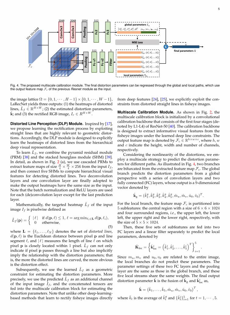
Fig. 4. The proposed multiscale calibration module. The final distortion parameters can be regressed through the global and local paths, which usethe output feature map Fc of the previous Resnet module as the input.
the image lattice Ω = 0, 1, · · · , H−1×0, 1, · · · ,W −1,LaRecNet yields three outputs: (1) the heatmaps of distortedlines, Lf ∈ RH×W ; (2) the estimated distortion parameters,k; and (3) the rectified RGB image, Ir ∈ RH×W .
Distorted Line Perception (DLP) Module. Inspired by [17],we propose learning the rectification process by exploitingstraight lines that are highly relevant to geometric distor-tions. Accordingly, the DLP module is designed to explicitlylearn the heatmaps of distorted lines from the hierarchicaldeep visual representation.
To learn Lf , we combine the pyramid residual module(PRM) [38] and the stacked hourglass module (SHM) [39].In detail, as shown in Fig. 2 (a), we use cascaded PRMs toextract feature maps of size H
4 ×W4 ×256 from the input If ,
and then connect five SHMs to compute hierarchical visualfeatures for detecting distorted lines. Two deconvolutionlayers and one convolution layer are finally adopted tomake the output heatmaps have the same size as the input.Note that the batch normalization and ReLU layers are usedfor each (de)convolution layer except for the last predictionlayer.
Mathematically, the targeted heatmap Lf of the inputimage If is pixelwise defined as
Lf (p) =
| ` | if d(p, `) ≤ 1, ` = arg min`i∈L d(p, `i),0 otherwise,
(5)where L = `1, . . . , `N denotes the set of distorted lines,d(p, `) is the Euclidean distance between pixel p and linesegment `, and | ` | measures the length of line ` on whichpixel p is closely located within 1 pixel. Lf can not onlyindicate if pixel p passes through a line but also implicitlyimply the relationship with the distortion parameters; thatis, the more the distorted lines are curved, the more obviousis the distortion effect.
Subsequently, we use the learned Lf as a geometricconstraint for estimating the distortion parameters. Moreprecisely, we use the predicted Lf as an additional channelof the input image If , and the concatenated tensors arefed into the multiscale calibration block for estimating thedistortion parameters. Note that unlike other deep-learning-based methods that learn to rectify fisheye images directly
from deep features [24], [25], we explicitly exploit the con-straints from distorted straight lines in fisheye images.
Multiscale Calibration Module. As shown in Fig. 2, themultiscale calibration block is initialized by a convolutionalcalibration backbone that consists of the first four stages (de-noted by L1-L4) of ResNet-50 [40]. The calibration backboneis designed to extract informative visual features from thefisheye images under the learned deep line constraints. Theoutput feature map is denoted by Fc ∈ Rh×w×c, where h,wand c indicate the height, width and number of channels,respectively.
Considering the nonlinearity of the distortions, we em-ploy a multiscale strategy to predict the distortion parame-ters for different paths. As illustrated in Fig. 4, two branchesare bifurcated from the extracted feature map Fc. The globalbranch predicts the distortion parameters from a globalperspective with a series of convolution layers and twofully connected (FC) layers, whose output is a 9-dimensionalvector denoted by
kg = (kg1 , kg2 , k
g3 , k
g4 , k
g5 , mu, mv, u0, v0)T .
For the local branch, the feature map Fc is partitioned into5 subfeatures: the central region with a size of 6× 6× 1024and four surrounded regions, i.e., the upper left, the lowerleft, the upper right and the lower right, respectively, withthe size of 5× 5× 1024.
Then, these five sets of subfeatures are fed into twoFC layers and a linear filter separately to predict the localparameters, denoted by
Kloc =
ki
loc =(ki1, k
i2, . . . , k
i5
)T5
i=1
.
Since mu,mv and u0, v0 are related to the entire image,the local branches do not predict these parameters. Theparameter settings of these two FC layers and the poolinglayer are the same as those in the global branch, and thesefive local streams share the same weights. The final outputdistortion parameter k is the fusion of kg and ki
loc as,
k =(k1, . . . , k5, mu, mv, u0, v0
)T,
where kt is the average of kgt and kit5i=1 for t = 1, · · · , 5.
6
Rectification Layer. This layer serves as a bridge betweenthe distortion parameters and images. In the forward com-putation, the rectification layer transforms a fisheye imageIf according to the distortion parameter k to yield a rectifiedimage Ir . More precisely, a pixel pf = (u, v)T in If and itscorresponding pixel pr = (ur, vr)T in Ir are related by
pf = T (pr; k) = Rf (θ) · pr
‖pr‖2+ (u0, v0)T , (6)
where T ( · ; k) denotes the forward fisheye projection func-tion with parameters k.
The rectified image Ir can be obtained by using bilinearinterpolation according to Eqn. (6). Due to the differentia-bility of the bilinear interpolation, it is possible to optimizethe distortion parameter by computing the loss between therectified images Ir and the corresponding groundtruth IG.In the implementation, we calculate the gradient from theloss function with respect to the distortion parameter kd
based on the chain rule.
4.2 Loss Functions and Uncertainty RegularizerTo train LaRecNet, we employ different loss functions forthe several output items. Furthermore, we present an atten-tive uncertainty regularizer to compactly couple the differ-ent components of LaRecNet, which helps the network tofocus on the challenging regions for rectification during thetraining.
Loss for Learning Distorted Line Heatmaps. Since theline segments are zero-measure in the image domain, mostvalues of the learning target Lf defined in Eqn. (5) are 0. Toavoid the potential sample-imbalance issue between zero-values and nonzero-values of Lf , we use a weighted lossfunction to train the DLP module. Specifically, the pixelspassing any distorted line segment are collected into thepositive set Ω+, and the remains are collected into thenegative set Ω−, with Ω = Ω+ ∪ Ω−. Thus, a weighted l2regression loss can be defined as
Lline =|Ω−||Ω|
∑p∈Ω+
D(p) +|Ω+||Ω|
∑p∈Ω−
D(p), (7)
where D(p) = ‖Lf (p) − Lf (p)‖22 with Lf (p) as thegroundtruth of distorted line segments.
Loss for Learning the Distortion Parameters. The mul-tiscale calibration block outputs a 9-dimension global pa-rameter kg and 5 local parameters Kloc = ki
loc5i=1 witheach ki
loc as a 5-dimension vector, as well as the fused 9-dimension parameters k. We use the MSE loss for trainingand a weight vector ω of 9 dimensions to rescale themagnitude between different components of the distortionparameters. More precisely, given the groundtruth parame-ters kG, for the output kg, we define the loss Lglo as
Lglo =1
9
∥∥∥ω · (kg − kG)∥∥∥2
2. (8)
The loss for the local parameters is defined as
Lloc =1
25
5∑i=1
∥∥∥ω[1:5] · (kiloc − k
[1:5]G )
∥∥∥2
2, (9)
where kiloc is the i-th vector of the predicted local param-
eters and a[1:5] is an operator that incorporates the rst 5components of a vector a as a subvector. Similar to the lossLglo, the loss function Lfus is computed to learn the fuseddistortion parameters k. The overall loss of the estimationof distortion parameters Lpara is
Lpara = λfusLfus + λgloLglo + λlocLloc, (10)
where λfus, λglo and λloc are the weights to balance thedifferent loss items. We set λfus = 2, λglo = 1 and λloc = 1 inour experiments.
Loss of Geometric Constraints. Although Lpara constrainsthe network to fit the optimal distortion parameters, the useof Lpara alone is susceptible to trapping in a local minimum.Therefore, considering that the geometric structure can pro-vide a strong constraint to boost performance, we design afunction Sk,kG
( · ) to calculate the geometric errors betweenthe rectified image Ir (using the fused distortion parame-ters k) and the groundtruth image IG (using groundtruthparameters kG),
Sk,kG(pf ) =
∥∥∥T −1(pf ; k)− T −1(pf ; kG)∥∥∥
1, (11)
where pf is the pixel coordinates of fisheye image If andT −1( · ; k) is the inverse of the fisheye projection T ( · ; k)described in Eqn. (6).
To make the network focus on the distorted lines, we alsouse the target heatmap of the distorted lines Lf to weightthe geometric errors during training. The geometric error ofthe pixels in Ω+ should have a large weight because theyare more geometrically meaningful than the pixels in Ω−.Therefore, the total loss function of the geometric constraintsis written as
Lgeo =λm
|Ω|∑
pf∈Ω+
Sk,kG(pf ) +
1
|Ω|∑
pf∈Ω−
Sk,kG(pf ), (12)
where λm is the weight for positive pixels in the fisheyeimages. In our experiments, λm is set to 2.
Attentive Uncertainty Regularization. Considering thatthe uncertainty of estimation in the distorted line mapLf could result in deviations of distortion parameters andresidual distortion in Ir , the AUR module is proposed tocompensate for the rectification error and achieve a morerobust optimization result by exploiting the attention mech-anism during rectification. The proposed AUR module isinspired by the uncertainty estimation of multitask learn-ing [41] and incorporates the uncertainty into the rectifica-tion task to improve the learned heatmaps of distorted lines.
The architecture of this AUR module is shown inFig. 2 (c). Technically, we first select intermediate featuresfrom each stage’s output of the ResNet (containing theL1-L4 four layers) and then send each of them through aconvolution layer with a 1 × 1 kernel size to downscalethe number of channels. Subsequently, bilinear upsamplingoperations with corresponding scale factors are used toobtain four groups of feature maps of a fixed size: FCi ∈RH×W×C(i = 1, 2, 3, 4). Then the input RGB fisheye imageIf , the generated rectified image Ir , and all the multichannelfeatures FCi are concatenated as a new feature map denotedby F
′
C , which is fed into a convolution layer followed by a

7
Fig. 5. The uncertainty map UA learned from the attentive regularization module. Left: RGB fisheye images. Middle: the learned uncertainty mapUA in different epochs. Right: The groundtruth images.
softmax activation function to predict the uncertainty mapUA:
UA = Softmax(F′
CWA + bA), (13)
where Softmax(·) is the channel-wise softmax function usedfor normalization. Then, we couple the uncertainty map UA
with the image rectification loss Lpix = ‖Ir − IG‖1 to obtainthe attentive regularization as
Lpix ← Lpix/UA + logUA, (14)
where Ir is the rectified image and IG is the correspondinggroundtruth of Ir.
As shown in Fig. 5, the uncertainty of all pixels in therectified image is uniform at the beginning of training.With more epochs being invloved, the number of pixelsfar from the geometrically salient regions decreases rapidly.After several epochs, the network focuses on the challengingregions for learning.
4.3 Training SchemeThe whole training procedure consists of two phases. Inthe first phase, we optimize the DLP block with the lossfunction Lline defined in Eqn. (7), and we subsequently fixthe parameters of the DLP block when it converges. Then,LaRecNet is trained to learn the distortion parameters andthe rectification process in the second phase. The total lossfunction of the second phase is defined as
L = λparaLpara + λgeoLgeo + λpixLpix, (15)
where λpara, λgeo, and λpix are the weights to balance thedifferent terms. The implementation details are described inSection 6.1.
5 SYNTHETIC LINERICH FISHEYE (SLF) DATASET
The main difference between our proposed network andprevious deep methods for fisheye image rectification is theline constraint, which requires a dataset that contains theannotations of (distorted) line segments for fisheye imagesand the rectified images, as well as the groundtruth ofdistortion parameters. However, to our knowledge, thereis no such large-scale dataset that can satisfy all the above
requirements. Thanks to the recently released datasets [29],[32] for geometric vision tasks, we create a new SLF datasetbased on the 2D wireframes and 3D surface models of man-made environments for fisheye lens calibration and imagerectification. As shown in Fig. 6, our proposed SLF datasetcontains two collections, termed the distorted wireframecollection (D-Wireframe) and the fisheye SUNCG collection(Fish-SUNCG). For D-Wiframe, each data point is obtainedby distorting the original images and the corresponding linesegment annotations with randomly generated distortionparameters. For Fish-SUNCG, we create the data points bysimulating the imaging process of fisheye lenses.
Distorted Wireframe Collection (D-Wireframe). For anyimage in the wireframes dataset [29] that contains 5462normal perspective images and corresponding line segmentannotations, we randomly generate 8 different sets of dis-tortion parameters to obtain fisheye images and the dis-torted lines according to Eqn. (1). In summary, D-Wireframecontains 41, 848 data samples. According to the originalsplitting of the wireframe dataset with 5000 and 462 imagesfor training and testing, this collection has 40000 trainingsamples and 1863 testing samples.
Fisheye SUNCG Collection (Fish-SUNCG). Although D-Wireframe provides many data samples for training, the ar-tificial distortion converted from normal perspective imagescannot fully represent the fisheye distortion distributionsin the real scenarios. To address this problem, we furtherenrich the dataset by simulating the imaging process offisheye lenses in the virtual 3D environments provided bySUNCG dataset [32]. The images obtained in this way arecollected into Fish-SUNCG.
With the help of the 3D models of SUNCG [32] thatcontain over 45K virtual 3D scenes with manually createdrealistic room and furniture layouts, we randomly selecta scene in SUNCG and set up a virtual camera equippedwith a fisheye and a perspective lens, respectively. Then,by using Blender [42], Fish-SUNCG is built with pairedfisheye and perspective images, as shown in Fig. 6. Forline segment generation, we remove the texture of the 3Dmodels to obtain wireframe models of 3D objects, and the

8
Fig. 6. Data samples from the SLF dataset: D-Wireframe (left) and Fish-SUNCG (right). For D-Wireframe, the normal images can be convertedto any type of fisheye image using random distortion parameters k; forFish-SUNCG, given a randomly selected perspective from the virtualrendering scene, the fisheye projection image and the perspective im-age under this view can be generated simultaneously.
2D wireframe map of the object is generated following per-spective imaging. Then, we manually remove the redundantedges that do not belong to the straight edges of the objects.Finally, paired line maps (the distorted lines in the fisheyeimage and the straight lines in the perspective image) aregenerated through the projection transformation betweenthe fisheye lens and the perspective lens. Since we are ableto control the image formation without metric errors, thedata samples can be used to train our network withoutinformation losses. In the end, by rendering in 1,000 scenes,Fish-SUNCG contains 6,000 samples for training and 300samples for testing.
In summary, our proposed SLF dataset contains 46,000training samples and 2,163 testing samples, which consistsof two collections: D-Wireframe and Fish-SUNCG, denotedas SLFwf and SLFsun, respectively.
6 EXPERIMENTS AND ANALYSIS
6.1 Implementation DetailsFollowing the training scheme described above, the DLPmodule is trained first by using the fisheye images and the
corresponding heatmaps of distorted lines. Once the DLPmodule converges, we fix the weights of the DLP moduleand train the remaining components of LaRecNet. The inputsize for our network is set as 320 × 320 for both trainingand testing. The weight parameters in Eqn. (15) are set asλgeo = 100, λpix = λpara = 1, and the balance parametersare set as ω = ω1 = 0.1, ω2 = 0.1, ω3 = 0.5, ω4 = 1, ω5 =1, ω6 = 0.1, ω7 = 0.1, ω8 = 0.1, ω9 = 0.1.
For optimization, stochastic gradient descent (SGD) isused to train the network with an initial learning rate 0.001in both training phases. The learning rate is decayed by afactor of 10 after 50 epochs. In the first phase, the DLPmodule converges after 100 epochs. In the second phase, theloss function reaches a plateau after 150 epochs of learning.Our network is implemented with PyTorch [43].
6.2 Benchmark Datasets
Our proposed SLF dataset contains two collections: SLFwfand SLFsun. We train the proposed LaRecNet on the trainingsplit of the entire SLF dataset as the baseline. Moreover, wetrain the network on these two collections independently tofurther justify that these two parts are complementary toachieve better performance.
For evaluation, we first test our method and the previousstate-of-the-art methods on the testing split of the SLFdataset. Then, we test these methods on a public dataset [44]that contains both synthetic and real-world video sequencestaken by fisheye cameras. We call the dataset proposedin [44] the fisheye video dataset for the simplicity of repre-sentation. Finally, we fetch some fisheye images withoutavailable groundtruth from the Internet to qualitativelyverify the generalization ability of our proposed method.
6.3 Evaluation Metrics
Previously, the PSNR and SSIM evaluation metrics wereused to quantitatively evaluate the rectified images. Thesetwo metrics are usually used for image restoration; however,they cannot precisely measure the geometric accuracy ofrectified images. To address this problem, we take the dis-tortion parameters into account to design two new metricsto evaluate this accuracy.
PSNR and SSIM for Rectified Images. The two metricsare widely used to describe the degree of pixel blurring andstructure distortion, so we use them here to compare therectified fisheye images with the groundtruth. Larger valuesof the PSNR and SSIM [45] indicate better rectificationresults.
Precision-vs-Recall for the Rectified Heatmaps of Lines.Benefiting from the line-rich characteristics of our proposedSLF dataset, we are able to measure the geometric accu-racy by comparing the rectified heatmaps of distorted lineswith the groundtruth of line segments. Motivated by theevaluation protocols used for edge detection [46] and linesegment detection [29], [30], we use the precision and recallto measure if the pixels on the distorted lines are still onthe straight lines after rectification. Denoting the rectifiedheatmap of the distorted lines by Lr , we use the matchingstrategy proposed in [46] to match the edge pixels with the

9
(a) Fisheye (b) Distorted Lines (c) Bukhari [21] (d) AlemnFlores [22] (e) Rong [24] (f) Ours (g) GT
Fig. 7. Distortion line rectification results of various methods. From left to right are the input RGB fisheye images, the distorted lines detected infisheye images, the rectified results by different methods [21], [22], [24], our proposed method, and the groundtruths.
Fig. 8. The precision-recall curves of different rectification methods forthe line map rectification [21], [22], [24].
groundtruth LG. Then, we calculate the precision and recallby
Precision = |P ∩G|/|P |, Recall = |P ∩G|/|G|, (16)
where P is the set of edge pixels in Lr , G is the set of edgepixels in the groundtruth LG and P ∩G is the set of the cor-rectly rectified edge pixels. Since the values of the heatmapsLr and LG are lengths of the line segments, we apply a setof thresholds τ ∈ 5, 10, 20, 40, 80, 120, 160, 200, 240, 255to the heatmap Lr to obtain the edge pixels of the linesegments with lengths smaller than τ , which yields a para-metric precision-recall curve for evaluation. The overall
performance is calculated by the maximal F-score of everypair of precision and recall, denoted by
F =2 · Precision · RecallPrecision + Recall
. (17)
Furthermore, we calculate the RPE of the distance ofthe rectified pixels of fisheye images to the groundtruth tomeasure the geometric accuracy of the rectification results.
Reprojection Error (RPE). The RPE is usually used toquantify the distance between an estimation of a 2D/3Dpoint and its true projection position. Given the real distor-tion parameters k and the estimated ones k, we rectify anypixel pf of the fisheye image and calculate the RPE as
γ(pf ;k, k) =∥∥∥T −1(pf ;k)− T −1(pf ; k)
∥∥∥2, (18)
where T −1 maps a pixel of a fisheye image into the domainof the rectified image. The averaged RPE over all the pixelsis used to measure the geometric accuracy for the estimateddistortion parameters.
6.4 Main Results
In this section, we compare the proposed LaRecNet withthe state-of-the-art methods [21], [22], [24] on our proposedSLF dataset, the fisheye video dataset [44] and the imagesfetched from the Internet. More experimental results can beseen in https://xuezhucun.github.io/LaRecNet.

10
6.4.1 Results on the SLF DatasetWe report the quantitative evaluation results of the previ-ous state-of-the-art methods and the proposed LaRecNetin Tab. 1. Since the proposed SLF dataset has two collec-tions SLFwf and SLFsun, we additionally train LaRecNet onSLFwf and SLFsun, respectively. For FishRectNet [25], weuse the evaluation results of the PSNR and SSIM presentedin their paper for comparison, which is associated withthe nonpublic source codes and datasets of the project.According to the results presented in Tab. 1 and Figs. 7 to 9,our proposed method obtains significant improvements inall the evaluation metrics, regardless of the training set weselected. In the next we discuss the experimental results ontwo aspects of the geometric accuracy and the image qualityof the rectification results.
Geometric Accuracy. A straightforward way to evaluatethe rectified images is to observe whether the distorted linescan be straightened after rectification. Ideally, the projectionsof straight lines from space to the camera remain straight. Accord-ingly, we use the line segments in the proposed SLF datasetfor evaluation. In Fig. 7, the rectified heatmaps of lines aredisplayed for qualitative evaluation. Benefiting from theexplicit exploitation of the line geometry and end-to-endlearning, our method obtains the best performance of all thetested methods for rectifying the distorted lines. By contrast,there still exist some obvious distortions in the results ofother methods. Moreover, we evaluate the rectification re-sults based on the metrics of the F-score and precision-recallcurves of the heatmaps of lines, reported in Fig. 8 and Tab. 1.The precision-recall curves show that the rectified distortionlines obtained by our proposed method are the closest to theoriginal geometry relative to other methods in the accuracyas represented by the F-score (F-value=0.821), which alsodemonstrates that our proposed LaRecNet is far superior toother methods in the aspect of geometric accuracy. Finally,we use the estimated parameters by different methods tocalculate the RPEs for every pixel in the fisheye images. Asreported in Tab. 1, only the proposed method can preciselyrectify the pixels in the fisheye images with an error of lessthan 0.5 pixels.
TABLE 1Quantitative evaluation on the proposed SLF dataset with the metricsof the PSNR, SSIM, F-score and RPE. For our method, the baselinemodel is trained on all the training samples of the SLF dataset. Themodels trained on the collections of SLFwf and SLFsun are indicated
with the corresponding suffixes.
Method PSNR SSIM F RPEBukhari [21] 9.34 0.18 0.29 164.75AlemnFlores [22] 10.23 0.26 0.30 125.42Rong et al. [24] 12.92 0.32 0.33 121.69FishRectNet [44]* 14.96 0.41 N/A N/A
Our method (SLF) 28.06 0.90 0.82 0.33Our method (SLFwf) 24.73 0.77 0.81 0.38Our method (SLFsun) 15.03 0.43 0.30 25.42
Image Quality. We also evaluate the proposed method byfollowing the previous evaluation protocols used in [24],[25], which can reflect the quality of the rectified images. Theresults in Tab. 1 demonstrate that our method is clearly su-perior to other methods and achieves the best performanceon the PSNR and SSIM metrics. Qualitatively, we display
TABLE 2Quantitative evaluation on the fisheye video dataset [44] with the
metrics of PSNR, SSIM, and RPE. For our method, the baseline modelis trained on all the training samples of the SLF dataset. The modelstrained on the collections of SLFwf and SLFsun are indicated with the
corresponding suffixes.
Method PSNR SSIM RPEBukhari [21] 9.84 0.16 156.3AlemnFlores [22] 10.72 0.30 125.31Rong et al. [24] 11.81 0.30 125.31
Our method (SLF) 22.34 0.82 1.68Our method (SLFwf) 19.86 0.67 1.91Our method (SLFsun) 11.34 0.39 120.12
the rectified images on the SLF dataset in Fig. 9. Specifically,we select the testing images with different types of fisheyedistortion (e.g., full-frame fisheye images, full circle fisheyeimages and drum fisheye images) for visualization. Theresults show that our method accurately rectifies the fisheyeimages, while other methods cannot handle various typesof distortion and obtain incorrect rectification results.
6.4.2 Results on the Fisheye Video DatasetTo further justify our proposed method, we use the fisheyevideo dataset proposed in [44] for evaluation. Note thatwe only perform the evaluation without tuning the trainedmodels on the SLF dataset. In this dataset, we perform thecomparison only on the metrics of PSNR, SSIM and RPEdue to the lack of annotations of distorted lines. To obtainthe groundtruth of the fisheye video dataset, we use thecalibration toolbox [47] to estimate internal and externalparameters from the video of the calibration pattern inthis dataset. As shown in Fig. 10, our proposed baselinemodel can accurately rectify the fisheye video sequences insingle forward-pass computation. Quantitatively, we reportthe PSNR, SSIM and RPE for different methods in Tab. 2.It can be concluded that our proposed method has the bestperformance in distortion rectification, while other methodscannot robustly rectify the video sequences.
For the model trained only on SLFsun collection, theperformance is not accurate since the training images aretaken from the virtual 3D environments. By contrast, the col-lection SLFwf can improve the performance by a significantmargin since the sourced images are taken from real-worldenvironments. By utilizing all the training samples of theSLF dataset, we achieve the best performance.
6.4.3 Results on Internet ImagesConsidering that the images in [44] are still limited, wealso fetch fisheye images with different types of distortionfrom the Internet for comparison. As shown in Fig. 11, ourproposed method has excellent rectification performanceeven for real fisheye images fetched from the Internet, whichverifies that our network has strong rectification ability andhas the potential to be used for uncontrolled environmentswithout tuning.
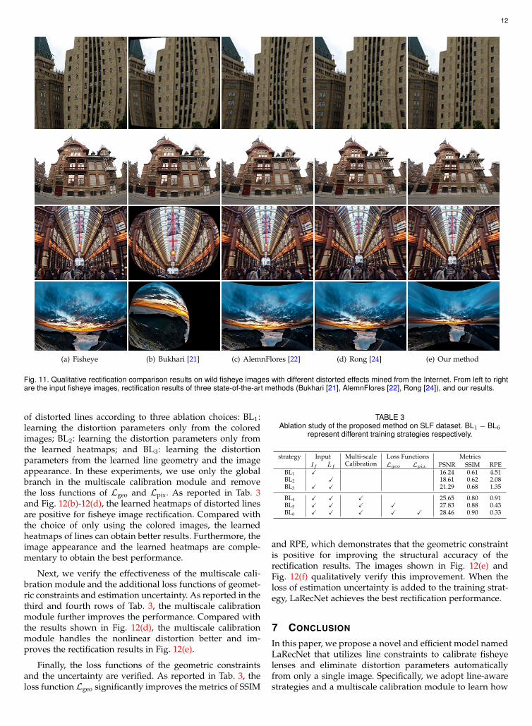
6.5 Ablation StudyWe conduct ablation studies on the proposed SLF dataset tojustify the design decisions of our proposed network. First,we verify the effectiveness of using the learned heatmaps

11
(a) Fisheye (b) Bukhari [21] (c) AlemnFlores [22] (d) Rong [24] (e) Ours (f) GT
Fig. 9. Qualitative comparison results of fisheye image rectification on SLFwf and SLFsun. From left to right are the input fisheye images, rectificationresults of three state-of-the-art methods (Bukhari [21], AlemnFlores [22], Rong [24]), our results and the groundtruth images.
(a) Fisheye (b) Bukhari [21] (c) AlemnFlores [22] (d) Rong [24] (e) Ours (f) GT
Fig. 10. Qualitative rectification comparison results on a real fisheye dataset [44]. From left to right are the input fisheye images, rectification resultsof three state-of-the-art methods (Bukhari [21], AlemnFlores [22], Rong [24]), our results and the groundtruth images.
12
(a) Fisheye (b) Bukhari [21] (c) AlemnFlores [22] (d) Rong [24] (e) Our method
Fig. 11. Qualitative rectification comparison results on wild fisheye images with different distorted effects mined from the Internet. From left to rightare the input fisheye images, rectification results of three state-of-the-art methods (Bukhari [21], AlemnFlores [22], Rong [24]), and our results.
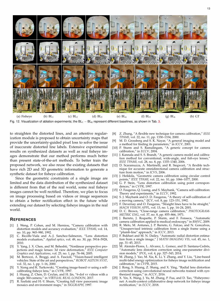
of distorted lines according to three ablation choices: BL1:learning the distortion parameters only from the coloredimages; BL2: learning the distortion parameters only fromthe learned heatmaps; and BL3: learning the distortionparameters from the learned line geometry and the imageappearance. In these experiments, we use only the globalbranch in the multiscale calibration module and removethe loss functions of Lgeo and Lpix. As reported in Tab. 3and Fig. 12(b)-12(d), the learned heatmaps of distorted linesare positive for fisheye image rectification. Compared withthe choice of only using the colored images, the learnedheatmaps of lines can obtain better results. Furthermore, theimage appearance and the learned heatmaps are comple-mentary to obtain the best performance.
Next, we verify the effectiveness of the multiscale cali-bration module and the additional loss functions of geomet-ric constraints and estimation uncertainty. As reported in thethird and fourth rows of Tab. 3, the multiscale calibrationmodule further improves the performance. Compared withthe results shown in Fig. 12(d), the multiscale calibrationmodule handles the nonlinear distortion better and im-proves the rectification results in Fig. 12(e).
Finally, the loss functions of the geometric constraintsand the uncertainty are verified. As reported in Tab. 3, theloss function Lgeo significantly improves the metrics of SSIM
TABLE 3Ablation study of the proposed method on SLF dataset. BL1 − BL6
represent different training strategies respectively.
strategy Input Multi-scaleCalibration
Loss Functions MetricsIf Lf Lgeo Lpix PSNR SSIM RPE
BL1 X 16.24 0.61 4.51BL2 X 18.61 0.62 2.08BL3 X X 21.29 0.68 1.35
BL4 X X X 25.65 0.80 0.91BL5 X X X X 27.83 0.88 0.43BL6 X X X X X 28.46 0.90 0.33
and RPE, which demonstrates that the geometric constraintis positive for improving the structural accuracy of therectification results. The images shown in Fig. 12(e) andFig. 12(f) qualitatively verify this improvement. When theloss of estimation uncertainty is added to the training strat-egy, LaRecNet achieves the best rectification performance.
7 CONCLUSION
In this paper, we propose a novel and efficient model namedLaRecNet that utilizes line constraints to calibrate fisheyelenses and eliminate distortion parameters automaticallyfrom only a single image. Specifically, we adopt line-awarestrategies and a multiscale calibration module to learn how
13
(a) Fisheye (b) BL1 (c) BL2 (d) BL3 (e) BL4 (f) BL5 (g) BL6 (h) GT
Fig. 12. Visualization of ablation experiments; the BL1 − BL6 represent different baselines, as shown in Tab. 3.
to straighten the distorted lines, and an attentive regular-ization module is proposed to obtain uncertainty maps thatprovide the uncertainty-guided pixel loss to solve the issueof inaccurate distorted line labels. Extensive experimentalresults on synthesized datasets as well as real fisheye im-ages demonstrate that our method performs much betterthan present state-of-the-art methods. To better train theproposed network, we also reuse the existing datasets thathave rich 2D and 3D geometric information to generate asynthetic dataset for fisheye calibration.
Since the geometric constraints of a single image arelimited and the data distribution of the synthesized datasetis different from that of the real world, some real fisheyeimages cannot be well rectified. Therefore, we plan to focuson image processing based on videos or image sequencesto obtain a better rectification effect in the future whileextending our dataset by selecting fisheye images in the realworld.
REFERENCES
[1] J. Weng, P. Cohen, and M. Herniou, “Camera calibration withdistortion models and accuracy evaluation,” IEEE TPAMI, vol. 14,no. 10, pp. 965–980, 1992.
[2] C. Ricolfe-Viala and A.-J. Sanchez-Salmeron, “Lens distortionmodels evaluation,” Applied optics, vol. 49, no. 30, pp. 5914–5928,2010.
[3] Y. Yang, J. X. Chen, and M. Beheshti, “Nonlinear perspective pro-jections and magic lenses: 3d view deformation,” IEEE ComputerGraphics and Applications, vol. 25, no. 1, pp. 76–84, 2005.
[4] M. Bertozzi, A. Broggi, and A. Fascioli, “Vision-based intelligentvehicles: State of the art and perspectives,” ROBOT AUTON SYST,vol. 32, no. 1, pp. 1–16, 2000.
[5] Y. Xiong and K. Turkowski, “Creating image-based vr using a self-calibrating fisheye lens,” in CVPR, 1997.
[6] J. Huang, Z. Chen, D. Ceylan, and H. Jin, “6-dof vr videos with asingle 360-camera,” in VIRTUAL REAL-LONDON, 2017.
[7] R. Szeliski and H.-Y. Shum, “Creating full view panoramic imagemosaics and environment maps,” in SIGGRAPH, 1997.
[8] Z. Zhang, “A flexible new technique for camera calibration,” IEEETPAMI, vol. 22, no. 11, pp. 1330–1334, 2000.
[9] M. D. Grossberg and S. K. Nayar, “A general imaging model anda method for finding its parameters,” in ICCV, 2001.
[10] P. Sturm and S. Ramalingam, “A generic concept for cameracalibration,” in ECCV, 2004.
[11] J. Kannala and S. S. Brandt, “A generic camera model and calibra-tion method for conventional, wide-angle, and fish-eye lenses,”IEEE TPAMI, vol. 28, no. 8, pp. 1335–1340, 2006.
[12] D. Scaramuzza, A. Martinelli, and R. Siegwart, “A flexible tech-nique for accurate omnidirectional camera calibration and struc-ture from motion,” in ICVS, 2006.
[13] J. Heikkila, “Geometric camera calibration using circular controlpoints,” IEEE TPAMI, vol. 22, no. 10, pp. 1066–1077, 2000.
[14] G. P. Stein, “Lens distortion calibration using point correspon-dences,” in CVPR, 1997.
[15] O. Faugeras, Q. Luong, and S. Maybank, “Camera self-calibration:Theory and experiments,” in ECCV, 1992.
[16] S. J. Maybank and O. D. Faugeras, “A theory of self-calibration ofa moving camera,” IJCV, vol. 8, pp. 123–151, 1992.
[17] F. Devernay and O. Faugeras, “Straight lines have to be straight,”MACH VISION APPL, vol. 13, no. 1, pp. 14–24, 2001.
[18] D. C. Brown, “Close-range camera calibration,” PHOTOGRAM-METRIC ENG, vol. 37, no. 8, pp. 855–866, 1971.
[19] J. Barreto, J. Roquette, P. Sturm, and F. Fonseca, “Automaticcamera calibration applied to medical endoscopy,” in BMVC, 2009.
[20] R. Melo, M. Antunes, J. P. Barreto, G. Falcao, and N. Goncalves,“Unsupervised intrinsic calibration from a single frame using a”plumb-line” approach,” in ICCV, 2013.
[21] F. Bukhari and M. N. Dailey, “Automatic radial distortion estima-tion from a single image,” J MATH IMAGING VIS, vol. 45, no. 1,pp. 31–45, 2013.
[22] M. Aleman-Flores, L. Alvarez, L. Gomez, and D. Santana-Cedres,“Automatic lens distortion correction using one-parameter divi-sion models,” IPOL, vol. 4, pp. 327–343, 2014.
[23] M. Zhang, J. Yao, M. Xia, K. Li, Y. Zhang, and Y. Liu, “Line-basedmulti-label energy optimization for fisheye image rectification andcalibration,” in CVPR, 2015.
[24] J. Rong, S. Huang, Z. Shang, and X. Ying, “Radial lens distortioncorrection using convolutional neural networks trained with syn-thesized images,” in ACCV, 2016.
[25] X. Yin, X. Wang, J. Yu, M. Zhang, P. Fua, and D. Tao, “Fisheyerec-net: A multi-context collaborative deep network for fisheye imagerectification,” in ECCV, 2018.
14
[26] S. Xie and Z. Tu, “Holistically-nested edge detection,” IJCV, vol.125, no. 1-3, pp. 3–18, 2017.
[27] K. Maninis, J. Pont-Tuset, P. Arbelaez, and L. V. Gool, “Convo-lutional oriented boundaries: From image segmentation to high-level tasks,” IEEE TPAMI, vol. 40, no. 4, pp. 819–833, 2018.
[28] Y. Liu, M. Cheng, X. Hu, J. Bian, L. Zhang, X. Bai, and J. Tang,“Richer convolutional features for edge detection,” IEEE TPAMI,vol. 41, no. 8, pp. 1939–1946, 2019.
[29] K. Huang, Y. Wang, Z. Zhou, T. Ding, S. Gao, and Y. Ma, “Learningto parse wireframes in images of man-made environments,” inCVPR, 2018.
[30] N. Xue, S. Bai, F.-D. Wang, G.-S. Xia, T. Wu, L. Zhang, and P. H.Torr, “Learning regional attraction for line segment detection,”IEEE TPAMI, pp. 1–1, 2019.
[31] N. Xue, T. Wu, S. Bai, F.-D. Wang, G.-S. Xia, L. Zhang, and P. H.Torr, “Holistically-attracted wireframe parsing,” in CVPR, 2020.
[32] S. Song, F. Yu, A. Zeng, A. X. Chang, M. Savva, and T. Funkhouser,“Semantic scene completion from a single depth image,” in CVPR,2017.
[33] Z.-C. Xue, N. Xue, G.-S. Xia, and W. Shen, “Learning to calibratestraight lines for fisheye image rectification,” in CVPR, 2019.
[34] J. P. Snyder, Flattening the earth: two thousand years of map projections.University of Chicago Press, 1997.
[35] K. Miyamoto, “Fish eye lens,” JOSA, vol. 54, no. 8, pp. 1060–1061,1964.
[36] J. Tardif, P. F. Sturm, M. Trudeau, and S. Roy, “Calibration ofcameras with radially symmetric distortion,” IEEE TPAMI, vol. 31,no. 9, pp. 1552–1566, 2009.
[37] J. P. Barreto and H. Araujo, “Geometric properties of centralcatadioptric line images and their application in calibration,” IEEETPAMI, vol. 27, no. 8, pp. 1327–1333, 2005.
[38] D. Han, J. Kim, and J. Kim, “Deep pyramidal residual networks,”in CVPR, 2017.
[39] A. Newell, K. Yang, and J. Deng, “Stacked hourglass networks forhuman pose estimation,” in ECCV, 2016.
[40] K. He, X. Zhang, S. Ren, and J. Sun, “Deep residual learning forimage recognition,” in CVPR, 2016.
[41] A. Kendall, Y. Gal, and R. Cipolla, “Multi-task learning usinguncertainty to weigh losses for scene geometry and semantics,”in CVPR, 2018.
[42] Blender Online Community, “Blender - a 3d modelling and render-ing package,” Blender Foundation, Blender Institute Amsterdam,2014.
[43] A. Paszke, S. Gross, F. Massa, A. Lerer, J. Bradbury, G. Chanan,T. Killeen, and Z. Lin, “Pytorch: An imperative style, high-performance deep learning library,” in NeuraIPS, 2019.
[44] A. Eichenseer and A. Kaup, “A data set providing synthetic andreal-world fisheye video sequences,” in ICASSP, 2016.
[45] Z. Wang, A. C. Bovik, H. R. Sheikh, and E. P. Simoncelli, “Imagequality assessment: from error visibility to structural similarity,”IEEE TIP, vol. 13, no. 4, pp. 600–612, 2004.
[46] D. R. Martin, C. C. Fowlkes, and J. Malik, “Learning to detectnatural image boundaries using local brightness, color, and texturecues,” IEEE TPAMI, vol. 26, no. 5, pp. 530–549, 2004.
[47] D. Scaramuzza, A. Martinelli, and R. Siegwart, “A toolbox foreasily calibrating omnidirectional cameras,” in IROS, 2006.
Related Documents