www.Fisher.com Fisherr 1051 and 1052 Style F and G Size 40, 60, and 70 Rotary Actuators Contents Introduction 1 ................................. Scope of Manual 1 ............................. Description 3 ................................. Specifications 3 ............................... Educational Services 3 ......................... Installation 4 .................................. Actuator Mounting 5 .......................... Valve Flow Direction 8 ......................... Loading Connection 8 .......................... Turnbuckle Adjustment 8 ....................... 1052 Spring Adjustment 9 ...................... Initial Setting 9 ............................ Stroking Range 10 ......................... Principle of Operation 10 ....................... Maintenance 10 ................................ Disassembly 11 ............................... Assembly 13 .................................. Changing Actuator Mounting 16 ................. Top-Mounted Handwheels and Adjustable Travel Stops 17 ....................... Principle of Operation for Handwheels 17 ......... Handwheel Maintenance and Adjustable Travel Stop 18 .............................. Locking Mechanism 20 .......................... Installing the Locking Mechanism 20 ............. Operating the Locking Mechanism 21 ............ Pipe-Away Vent 23 .............................. Parts Ordering 24 ............................... Parts Reference 24 .............................. Figure 1. Fisher Vee-Ball™ Valve with 1052 Actuator and FIELDVUE™ DVC6200 Digital Valve Controller W8502-3 Introduction Scope of Manual This instruction manual includes installation, adjustment, maintenance, and parts ordering information for the Fisher 1051 (size 40 and 60) and 1052 (Size 40, 60, and 70) pneumatic piston rotary actuator with F and G mounting adaptations (see figure 1). Instruction Manual D100319X012 1051 and 1052 F & G Actuators October 2012

Welcome message from author
This document is posted to help you gain knowledge. Please leave a comment to let me know what you think about it! Share it to your friends and learn new things together.
Transcript

www.Fisher.com
Fisherr 1051 and 1052 Style F and GSize 40, 60, and 70 Rotary ActuatorsContentsIntroduction 1. . . . . . . . . . . . . . . . . . . . . . . . . . . . . . . . .Scope of Manual 1. . . . . . . . . . . . . . . . . . . . . . . . . . . . .Description 3. . . . . . . . . . . . . . . . . . . . . . . . . . . . . . . . .Specifications 3. . . . . . . . . . . . . . . . . . . . . . . . . . . . . . .Educational Services 3. . . . . . . . . . . . . . . . . . . . . . . . .Installation 4. . . . . . . . . . . . . . . . . . . . . . . . . . . . . . . . . .Actuator Mounting 5. . . . . . . . . . . . . . . . . . . . . . . . . .Valve Flow Direction 8. . . . . . . . . . . . . . . . . . . . . . . . .Loading Connection 8. . . . . . . . . . . . . . . . . . . . . . . . . .Turnbuckle Adjustment 8. . . . . . . . . . . . . . . . . . . . . . .1052 Spring Adjustment 9. . . . . . . . . . . . . . . . . . . . . .
Initial Setting 9. . . . . . . . . . . . . . . . . . . . . . . . . . . .Stroking Range 10. . . . . . . . . . . . . . . . . . . . . . . . .
Principle of Operation 10. . . . . . . . . . . . . . . . . . . . . . .Maintenance 10. . . . . . . . . . . . . . . . . . . . . . . . . . . . . . . .Disassembly 11. . . . . . . . . . . . . . . . . . . . . . . . . . . . . . .Assembly 13. . . . . . . . . . . . . . . . . . . . . . . . . . . . . . . . . .Changing Actuator Mounting 16. . . . . . . . . . . . . . . . .Top-Mounted Handwheels andAdjustable Travel Stops 17. . . . . . . . . . . . . . . . . . . . . . .Principle of Operation for Handwheels 17. . . . . . . . .Handwheel Maintenance and AdjustableTravel Stop 18. . . . . . . . . . . . . . . . . . . . . . . . . . . . . .
LockingMechanism 20. . . . . . . . . . . . . . . . . . . . . . . . . .Installing the LockingMechanism 20. . . . . . . . . . . . .Operating the LockingMechanism 21. . . . . . . . . . . .Pipe-Away Vent 23. . . . . . . . . . . . . . . . . . . . . . . . . . . . . .Parts Ordering 24. . . . . . . . . . . . . . . . . . . . . . . . . . . . . . .Parts Reference 24. . . . . . . . . . . . . . . . . . . . . . . . . . . . . .
Figure 1. Fisher Vee-Ball™ Valve with 1052 Actuatorand FIELDVUE™DVC6200 Digital Valve Controller
W8502-3
Introduction
Scope of ManualThis instructionmanual includes installation, adjustment, maintenance, and parts ordering information for the Fisher1051 (size 40 and 60) and 1052 (Size 40, 60, and 70) pneumatic piston rotary actuator with F and Gmountingadaptations (see figure 1).
InstructionManualD100319X012
1051 and 1052 F & G ActuatorsOctober 2012

InstructionManualD100319X012
1051 and 1052 F & GActuatorsOctober 2012
2
Table 1. 1051 and 1052 Actuator Specifications
Operation
Direct Acting: Increasing loading pressure extendsthe diaphragm rod out of the spring barrelService:1051: For on-off or throttling service with positioner1052: For on-off or throttling service with or without apositioner
Actuator Sizes
1051:J 40 andJ 601052:J 40,J 60, andJ 70
MaximumDiaphragm Sizing Pressure(1)
Size 40: 4.5 bar (65 psig)Size 60: 2.8 bar (40 psig)Size 70: 3.8 bar (55 psig)
MaximumDiaphragm Casing Pressure(3)
Size 40: 5.2 bar (75 psig)Size 60: 3.4 bar (50 psig)Size 70: 4.5 bar (65 psig)
MaximumValve Shaft Rotation
90 degrees rotation (standard) travel stop, or 60degrees (optional) travel stop for 1051 and 1052actuators, or 75 degrees (optional) travel stop for1052 actuators
Valve Shaft Diameters, mm (Inches)
Size 40:J 12.7 (1/2),J 15.9 (5/8),J 19.1 (3/4),J 22.2 (7/8),J 25.4 (1), orJ 31.8, (1-1/4)
Size 60:J 19.1 (3/4),J 22.2 (7/8),J 25.4 (1),J 31.8 (1-1/4),J 38.1 (1-1/2),J 44.5 (1-3/4), orJ 50.8 (2)
Size 70:J 31.8 (1-1/4),J 38.1 (1-1/2),J 44.5(1-3/4), orJ 50.8 (2)
Stroking Time
Dependent on actuator size, rotation, spring rate,initial spring compression, and supply pressure. Ifstroking time is critical, consult your Emerson ProcessManagement sales office
Material Temperature Capabilities(2)
NBR (Nitrile) Diaphragm: -40 to 82_C (-40 to 180_F)VMQ (Silicone) Diaphragm: -40 to 149_C (-40 to300_F)NBR O-Rings: -40 to 82_C (-40 to 180_F), NBR O-ringsare used in optional top-mounted handwheel,adjustable down travel stop, and adjustable up travelstop assemblies
Travel Indication
Graduated disc and pointer combination located onactuator end of valve shaft
Pressure Connections
Standard: 1/4 NPT internal threadOptional:J 1/2 orJ 3/4 NPT internal, andJ 3/4 NPT internal thread for pipe-away vent
Mounting Positions
See figure 3.
ApproximateWeights
See table 2.
Additional Specifications
For casing pressure ranges and formaterialidentification of the parts, see the Parts List
1. Use this value to determine themaximum torque output allowed.2. The pressure/temperature limits in this manual and any applicable standard or code limitation for valve should not be exceeded.3. This maximum casing pressure is not to be used for normal operating pressure. Its purpose is to allow for typical regulator supply settings and/or relief valve tolerances.
The Gmounting adaptation is for 7600 and 9500 valves, and the Fmounting adaptation is for all other eccentric discor Vee-Ball valves. Also, this instructionmanual provides information for the optional top-mounted handwheel, up anddown travel stops, lockingmechanism, and pipe-away vent.
Instructions for the control valve, positioner, accessories, and other sizes of actuators are covered in separateinstructionmanuals.
Top-Mounted handwheels can be applied for infrequent service as amanual handwheel actuator. Also, an adjustableup travel stop can be added to the actuator to limit its stroke in the upward direction, or an adjustable down travelstop can be added to limit actuator stroke in the downward direction.

InstructionManualD100319X012
1051 and 1052 F & G ActuatorsOctober 2012
3
Do not install, operate, or maintain a 1051 or 1052 actuator without being fully trained and qualified in valve, actuator,and accessory installation, operation, andmaintenance. To avoid personal injury or property damage, it is importantto carefully read, understand, and follow all the contents of this manual, including all safety cautions and warnings. Ifyou have any questions about these instructions, contact your Emerson Process Management sales office beforeproceeding.
Figure 2. Typical 1052 Actuator Adjustable Spring Seat
W4742-1
SPRING
SPRING SEAT
SPRING ADJUSTER
Description1051 and 1052 diaphragm rotary actuators are pneumatic spring-return actuators for use with rotary-shaft controlvalves. The 1051 actuator can be used for on-off service, or it can be used for throttling service when equipped with avalve positioner. The 1052 actuator can be used for on-off service, or it can be used for throttling service whenequipped with or without a valve positioner. The 1052 actuator spring is adjustable (see figure 2).
Table 2. Approximate ActuatorWeights
SIZE1051 1052 TOP-MOUNTEDHANDWHEEL
Kg Lb Kg Lb Kg Lb
406070
4389- - -
94197- - -
4592123
99203272
7.31121
162447
SpecificationsSpecifications are shown in table 1. Specifications for actuator operation, as it originally comes from the factory, arestamped on the nameplate attached to the actuator.
Educational ServicesFor information on available courses for Fisher 1051 and 1052 Style F and G size 40, 60, and 70 rotary actuators, as wellas a variety of other products, contact:
Emerson Process ManagementEducational Services, RegistrationP.O. Box 190; 301 S. 1st Ave.Marshalltown, IA 50158-2823Phone: 800-338-8158 orPhone: 641-754-3771FAX: 641-754-3431e-mail: [email protected]

InstructionManualD100319X012
1051 and 1052 F & GActuatorsOctober 2012
4
InstallationWhen an actuator and valve body are shipped together, the actuator is normally mounted on the valve. Follow thevalve body instructions when installing the control valve in the pipeline, and then perform the procedures presented inthe Loading Connection section. If the actuator is shipped separately or if it is necessary tomount the actuator on thevalve, perform the procedures presented in the Actuator Mounting section. And, if the actuator requires a pipe-awayvent, or if a retrofit pipe-away kit needs to be installed, refer to the Pipe-Away Vent section.
WARNING
Alwayswear protective gloves, clothing, and eyewear when performing any installation operations. Be aware of pinchingparts during installation operations.Checkwith your process or safety engineer for any additional measures thatmust be taken to protect against processmedia.
If installing into an existing application, also refer to theWARNING at the beginning of theMaintenance section in thisinstructionmanual.
Table 3. Recommended Bolting Torques
DESCRIPTION, KEYNUMBER
ACTUATOR SIZE
40 60 70
Size NSm lbfSft Size NSm lbfSft Size NSm lbfSft
Diaphragm Casing, 5 3/8-24 27 20 3/8-24 27 20 3/8-24 27 20
Casing to spring barrel, 7 3/8-16 41 30 3/8-16 41 30 1/2-13 102 75
Diaphragm to rod, 9(1051)
1/2-13 34 25 3/4-10 102 75 - - - 102 75
Diaphragm to rod, 9(1052)
1/2-20 34 25 3/4-16 102 75 3/4-16 102 75
Rod end bearing, 16 1/2-20 34 25 5/8-18 61 45 3/4-16 102 75
Turnbuckle to lever, 18 1/2-13 81 60 5/8-11 163 120 3/4-10 271 200
Spring barrel to housing,21
5/16-18 23 17 7/16-14 68 50 5/8-18 68 50
Housing to yoke, 23 3/8-16 34 25 1/2-13 81 60 1/2-13 81 60
Travel stop to lever, 28 1/2-13 81 60 5/8-11 163 120 3/4-10 271 200
Side of housing, 344200/PMV
3/8-16 34 25 1/2-13 81 60 1/2-13 81 60
Handwheel top, 54 1/2-20 34 25 5/8-18 34 25 - - - 34 25
Diaphragm head torod/Adjustable downtravel stop, 54 (1051)
1/2-13 27 20 3/4-10 66 49 - - - 69 51
Diaphragm head torod/Adjustable downtravel stop, 54 (1052)
1/2-20 27 20 3/4-16 66 49 3/4-16 69 51
Rod end to turnbuckle, 58 3/4-16-LH 102 75 7/8-14-LH 163 120 7/8-14-LH 163 120
Handwheel to actuator,141
3/8-16 41 30 3/8-16 41 30 1/2-13 81 60
CAUTION
To avoid parts damage, do not use an operating pressure that exceeds theMaximumDiaphragmCasing Pressure (table 1)or produces a torque greater than theMaximumAllowable Valve Shaft Torque (see Catalog 14). Use pressure-limiting orpressure-relieving devices to prevent the diaphragm casing pressure from exceeding its limit.To avoid parts damage, do not stroke the actuator while cover (key 33) is off.

InstructionManualD100319X012
1051 and 1052 F & G ActuatorsOctober 2012
5
Actuator MountingUse the following steps to connect a valve and an actuator. Key numbers are shown in figure 8 for 1051 actuators andin figure 9 for 1052 actuators.
WARNING
To avoid personal injury, perform the steps in theWARNING at the beginning of theMaintenance section to isolate thecontrol valve and actuator.
1. Unscrew cap screws andwashers (keys 34 and 63), and remove the cover (key 33).
2. Refer to figure 3 for availablemounting styles and positions. Whenmounting on a Vee-Ball V150, V200 or V300valve, check the valvemanual to determine if it is Series B. The actuator is normally positioned vertically with thevalve in a horizontal pipeline (see figure 3).
MOUNTING ACTION(1)
VALVE SERIES ORDESIGN VALVE SERIES OR DESIGN
BALL/PLUGROTATION TO
CLOSEV250 V150, V200 & V300
CV500V500
DISC/BALLROTATION TO
CLOSEV250
8510B, 8532,8560& 9500
Right-Hand PDTCPDTO
CCWCCW
AB
AB
AB
CWCW
NANA
BA
Left-Hand PDTCPDTO
CCWCCW
NANA
DC
DC
CWCW
CD
CD
Left-Hand(Optional)(2)
PDTCPDTO
CWCW
NANA
CD
NANA
NANA
NANA
NANA
1. PDTC–Push-down-to-close, and PDTO–Push-down-to-open.2. A left hand ball will be required for the NPS 3 through 12 Series B and the NPS 14 to 20, with or without attenuator.
WARNING
To avoid personal injury or property damage, the 1052 size 70 actuator, due to its weight, must be externally supported ifmounted in the horizontal position.
3. Whenmounting the actuators, make sure that the bushing (key 67) and valve shaft are in-line so that the bushingwill slide onto the valve shaft without damage.
4. Mount the actuator on the valve body and secure it with the valvemounting screws. The torque for 1/2 to 1-inchshafts is 88 NSm (65 lbfSft); for 1-1/4 to 1-1/2 inch shafts is 136 NSm (100 lbfSft); for 1-3/4 to 2-inch shafts is 183NSm (135 lbfSft).
CAUTION
Exceeding any torque requirementmay impair the safe operation of this actuator by causing broken or damaged parts.Refer to table 3 for the bolting torque requirements.
5. Screw the left-hand threaded locknut (key 58) onto the diaphragm rod (key 10) as far as possible.
6. Screw the turnbuckle (key 57) as far as it will go onto the actuator rod.
7. Screw the locknut (key 16) as far as it will go onto the rod end bearing (key 17). Thread this assembly completelyinto the turnbuckle (key 57).

InstructionManualD100319X012
1051 and 1052 F & GActuatorsOctober 2012
6
Figure 3. Mounting Styles and Positions for the 1051 and 1052 Actuator
1
NOTES:POSITION 1 IS STANDARD; POSITIONS 2 THROUGH 4
(SHOWN IN DOTTED LINES) ARE ALTERNATIVES.1
STYLE D
STYLE C
STYLE B
STYLE A
RIGHT-HANDMOUNTING43A6505-A
A1584-3
STYLE A STYLE B
STYLE D STYLE C
FLOW
FLOW
RIGHT-HANDMOUNTING
LEFT-HANDMOUNTING
POSITION 1 POSITION 1
POSITION 1 POSITION 1
4
3
2 4
3
2
4
3
2 4
3
2LEFT-HANDMOUNTING
1
11
8. If the lever (key 27) is attached to the rod end bearing, remove the cap screw and hex nut (keys 18 and 19).
9. If the 1052 spring adjustment has been changed, complete the Initial Setting portion of the 1052 SpringAdjustment section before proceeding.
10. Consult the appropriate valve instructionmanual's Installation section for lever/valve shaft orientationmarks, andslide the lever into place (see figure 4). Clampwith the cap screw (key 28).
11. Rotate the lever (key 27) to align with the rod end bearing (key 17). This connection can be aided bymoving theactuator off its up travel stop with a regulated air source and adjusting the turnbuckle (key 57) slightly.
12. Apply sealant (key 77) or equivalent thread-locking compound to the threads of the cap screw (key 18).
13. Connect the lever (key 27) and the rod end bearing (key 17) with the cap screw and hex nut (keys 18 and 19).Tighten the cap screw to the recommended bolt torque shown in table 3.
14. Note the valve position and direction of rotation. Position the travel indicator (key 37) accordingly.
a. If no handwheel actuator is to be used, position the travel indicator (key 37) according to the valve position justnoted. Replace the cover (key 33), and secure with washers and cap screws (keys 34 and 63). If holes in the coverand housing (key 20) do not align, temporarily loosen the cap screws (key 23), and shift the housing slightly.
InstructionManualD100319X012
1051 and 1052 F & G ActuatorsOctober 2012
7
CAUTION
To avoid parts damage, do not stroke the actuator while the cover (key 33) is off.
b. If a manual handwheel actuator is to be used, refer to the separate handwheel actuator instructionmanual formounting instructions.
15. Replace the cover (key 33), and secure with cap screws and washers (keys 34 and 63). If the holes in the cover andhousing (key 20) do not align, use a regulated air source tomove the actuator slightly off the up travel stop. If thehole alignment cannot be obtained in this manner, temporarily loosen the cap screws (key 23), and shift thehousing slightly.
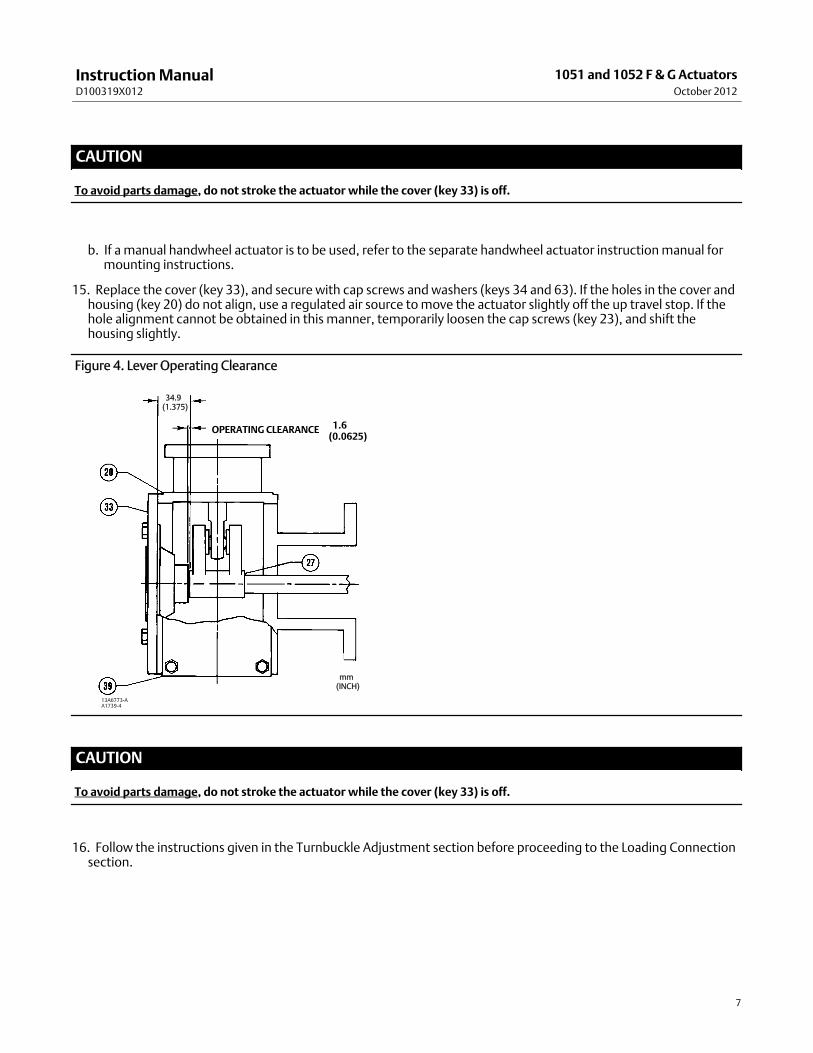
Figure 4. Lever Operating Clearance
34.9(1.375)
1.6(0.0625)
OPERATING CLEARANCE
13A6773-AA1739-4
mm(INCH)
CAUTION
To avoid parts damage, do not stroke the actuator while the cover (key 33) is off.
16. Follow the instructions given in the Turnbuckle Adjustment section before proceeding to the Loading Connectionsection.

InstructionManualD100319X012
1051 and 1052 F & GActuatorsOctober 2012
8
Valve Flow DirectionValve construction can change the flow direction for a control valve assembly. It is important to observe the flowdirection in all valve applications before installing the valve in the pipeline (see figure 3). Refer to the appropriate valvebulletin or instructionmanual.
Note
Observe all warnings and cautions provided in the appropriate valve instructionmanual Installation section.
Loading Connection1. Connect the loading pressure piping to the pressure connection in the top of the diaphragm casing.
a. For size 40 through 60 actuators: Run either 1/4 NPT pipe or 3/8 inch tubing between the 1/4 NPT pressureconnection and the instrument.
b. For size 70 actuators: Run either pipe or tubing between the pressure connection and the instrument. Ifnecessary, remove the 1/4 inch bushing in the pressure connection to increase connection size.
2. Keep the length of pipe or tubing as short as possible to avoid transmission lag in the control signal. If an accessory(such as a volume booster or a valve positioner) is used, be sure that the accessory is properly connected to theactuator. If a valve positioner is part of the assembly, the pressure connection to the actuator will normally bemadeat the factory.
Table 4. Wrench Size Required for Turnbuckle Adjustment, InchesACTUATOR TURNBUCKLE
(KEY 57) LOWER LOCKNUT (KEY 16) UPPER LOCKNUT (KEY 58)Type Size
1051 & 1052 4060
1-1/81-5/16
3/415/16
1-1/81-5/16
1052 70 1-5/16 1-1/8 1-5/16
3. When the control valve is completely installed and connected to the instrument, check for correct action(air-to-open or air-to-close) tomatch the controlling instrument. For successful operation, the actuator stem andvalve shaft mustmove freely in response to the loading pressure change on the diaphragm.
Adjustment
Turnbuckle AdjustmentCorrect turnbuckle adjustment ensures that the valve is correctly closed when the actuator is against its travel stops.The turnbuckle adjustment is the only adjustment necessary on the 1051 actuator. Key numbers are shown in figure 8for 1051 actuators and in figure 9 for 1052 actuators.
For accurate adjustment to the zero-degree valve disc or ball position, remove the valve from the pipeline. Refer to thevalve instructionmanual for instructions.
A regulated air supply will be required to stroke the actuator. Refer to table 4 for the sizes of the three open-endwrenches required for this procedure.
InstructionManualD100319X012
1051 and 1052 F & G ActuatorsOctober 2012
9
1. Remove the access plate (key 59). Also remove themachine screws (key 60), if present.
Note
For themost accurate adjustment of the actuator, do not remove the cover (key 33) during this procedure.
2. Loosen the lower locknut (key 16).
3. Make sure the actuator housing (key 20) is clear of any tools or other instruments that could obstruct the actuatorstroke path. Pressure the diaphragm casing enough to stroke the actuator down so that the left-hand threadedupper locknut (key 58) is accessible through the access opening. Loosen the locknut.
4. Consult the appropriate valve instructionmanual for determining the closed position of the valve. Then use one ofthe following:
a. Push-down-to-close–Slowly stroke the actuator to the down travel stop. Adjust the turnbuckle (key 57) until thevalve is in the closed position. Lock this adjustment with the left-hand threaded locknut (key 58). Stroke theactuator to themid-travel position, and tighten the locknut (key 16).
b. Push-down-to-open–Release all pressure from the diaphragm casing, making sure the diaphragm is against itsup travel stop. Be sure that the optional handwheel is adjusted to its topmost position so that the zero position ofthe actuator and valve can be reached simultaneously. Check the valve position. Stroke the actuator so theturnbuckle (key 57) is accessible through the access opening. Adjust the linkage. Release pressure to theactuator, and check the new adjustment. Continue this procedure until the valve is in the closed position whenthe actuator is resting on its up travel stop. Stroke the actuator to themid-travel position, and tighten thelocknut (key 16). Stroke the actuator, and tighten the left-hand threaded locknut (key 58).
5. Replace the access plate (key 59).
6. Loosen the self-tapping screws (key 38), adjust the travel indicator (key 37), and re-tighten the self-tapping screws.
1052 Spring Adjustment
Initial SettingThe 1052 nameplate specifies an initial spring setting, which is the initial setting adjusted into the actuator spring.Initial setting is the casing pressure at which the diaphragm and diaphragm rod begin tomove away from the up travelstop with the actuator disconnected from the valve. (With the actuator connected to the valve and pressure applied tothe valve, a higher pressure will be required to start actuator travel).
The initial setting was selected (based upon the service conditions specified when the actuator was ordered) so that,when the actuator and valve are in service, the valve will seat properly and full travel will be obtained within adiaphragm casing range of 0 to 1.2, 0 to 2.3, 0 to 2.8, or 0 to 3.8 bar (0 to 18, 0 to 33, 0 to 40, or 0 to 55 psig)depending on specific actuator size and construction.
If the actuator has been disassembled or if the spring adjustment was changed, and it is desired tomatch the initialsetting stated on the nameplate, make sure the rod end bearing (key 17, figure 8 or 9) has been disconnected from thelever (key 27, figure 8 or 9). Adjust the spring so that the diaphragm rod just starts to travel at the spring set pressurespecified on the nameplate.
Be sure the rod end bearing does not hit the lever as the diaphragm and diaphragm rodmove away from the up travelstop. To adjust the spring, insert a round rod into one of the holes in the lower bearing seat (key 73, figure 9). Holediameter is 9.5mm (3/8 inch) for size 40 actuators, 15.9mm (5/8 inch) for size 60 actuators, and 19.1mm (3/4 inch)for size 70 actuators. Rotate the bearing seat tomove it toward the casing to increase initial setting or away from thecasing to decrease initial setting (keys 1 and 2, figure 9).

InstructionManualD100319X012
1051 and 1052 F & GActuatorsOctober 2012
10
Stroking RangeThe initial spring setting listed on the nameplate has been determined to be the optimum setting, and it is notrecommended tomake spring adjustments that will cause this value to change or be exceeded. Forpush-down-to-open valve action, the initial spring setting is themaximum allowable to provide themaximum springclosing force.
CAUTION
Any increase of this settingwill over-stress the spring at full travel andmay shorten the fatigue life of the spring.
For push-down-to-close valve action, the initial spring set has been determined to be the optimum balance betweenthe air-to-close and the spring-to-open breakout torque.
If the 1052 actuator is to be changed from one valve action to another (i.e., push-down-to-close topush-down-to-open), first, refer to the table for key 11 in the Parts List section to determine the proper initial springsetting; then, adjust the unit according to the procedures in the Initial Settings portion of the 1052 Spring Adjustmentsection.
Principle of OperationThe diaphragm rodmoves down as loading pressure is increased on top of the diaphragm. As the loading pressure isdecreased, the spring forces the diaphragm rod upward.
The spring and diaphragm have been selected tomeet the requirements of the application and, in service, theactuator should produce full travel of the valve with the diaphragm pressure as indicated on the nameplate.
Consult the separate positioner instructionmanual for actuator principle of operation with positioner.
MaintenanceActuator parts are subject to normal wear andmust be inspected and replaced as necessary. The frequency ofinspection and replacement depends upon the severity of service conditions. Key numbers are shown in figure 8 for1051 actuators and in figure 9 for 1052 actuators.
WARNING
Avoid personal injury or property damage from sudden release of process pressure or uncontrolledmovement of parts.Before performing anymaintenance operations:
D Do not remove the actuator from the valvewhile the valve is still pressurized.
D Always wear protective gloves, clothing, and eyewearwhen performing anymaintenance operations to avoid personalinjury. Be aware of pinching parts duringmaintenance operations.
D Disconnect any operating lines providing air pressure, electric power, or a control signal to the actuator. Be sure theactuator cannot suddenly open or close the valve.

InstructionManualD100319X012
1051 and 1052 F & G ActuatorsOctober 2012
11
D Use bypass valves or completely shut off the process to isolate the valve from process pressure. Relieve process pressurefrom both sides of the valve. Drain the processmedia from both sides of the valve.
D Vent the power actuator loading pressure and relieve any actuator spring precompression.
D Use lock-out procedures to be sure that the abovemeasures stay in effect while youwork on the equipment.
D The valve packing boxmay contain process fluids that are pressurized, even when the valve has been removed from thepipeline. Process fluidsmay spray out under pressurewhen removing the packing hardware or packing rings, or whenloosening the packing box pipe plug.
D Checkwith your process or safety engineer for any additional measures thatmust be taken to protect against processmedia.
CAUTION
To avoid parts damage, do not stroke the actuator while cover (key 33) is off.
DisassemblyThe following procedure describes how to completely disassemble the actuator. When inspecting and replacing parts,perform only those steps necessary to accomplish the repair.
Do not, under ordinary circumstances, remove the cap screws (keys 7, 8, and 21) at this time.
CAUTION
Cap screw (key 18)must be disengaged from the lever (key 27) before removing the diaphragm casing (key 1). Failure to dosowill allow the spring precompression to rotate the valve beyond its fully open or closed position. This could causedamage to the valve components and/or seal.
1. Perform the steps in theWARNING at the beginning of theMaintenance section to isolate the control valve andactuator.
2. Remove the tubing or piping from the top of the actuator.
3. Remove the positioner, if used. If necessary, refer to the positioner instructionmanual for removal instructions.
4. Unscrew the cap screws andwashers (keys 34 and 63), and remove the cover (key 33).
5. Remove the retaining ring (key 30), and slide the hub (key 29) from the cover. If necessary, remove the travelindicator (key 37) from the hub (key 29).
6. Inspect, and if necessary, replace the cover bushing (key 31). Remove the travel indicator scale (key 35) byremoving the self-tapping screws (key 36). Press the bushing out of the cover (key 33).
7. Remove the cap screw and hex nut (keys 18 and 19).
8. Make note of the lever/valve shaft orientation, and then loosen the cap screw (key 28).
CAUTION
When removing the actuator from the valve, do not use a hammer or similar tool to drive the lever (key 27) off the valveshaft. Driving the lever could damage internal valve parts. On some valve types, driving the lever off the shaft couldmove

InstructionManualD100319X012
1051 and 1052 F & GActuatorsOctober 2012
12
the valve disc or ball and bearings away from the centered position, causing subsequent damage to valve parts as the valveis operated.
Awheel puller may be used to remove the lever. It is okay to tap thewheel puller screw lightly to loosen the lever, buthitting the screwwith excessive force could also damage valve parts or disrupt the centered position of the valve disc andbearings.
9. Rotate the handwheel (if one is used) counterclockwise until the handwheel is not compressing the spring (key 11).
WARNING
To avoid personal injury from pre-compressed spring force suddenly thrusting the upper diaphragm casing (key 1) awayfrom the actuator, relieve 1052 spring compression, or carefully remove 1051 casing cap screws before proceeding further.
10. To relieve spring compression:
a. For 1051 actuators:
D Loosen, but do not remove, all casing cap screws and hex nuts (keys 5 and 6). Make sure there is no spring force tothe upper diaphragm casing.
D Unscrew and remove the cap screws and hex nuts (keys 5 and 6), and then remove the upper diaphragm casing andthe diaphragm (key 3).
b. For 1052 actuators:
D Insert a round rod into one of the holes in the lower bearing seat (key 73). Use the rod to rotate the lower bearingseat, andmove it away from the actuator casings. Continue rotating the lower bearing seat until springcompression is completely removed. Rod hole diameter is 9.5mm (3/8 inch) for size 40 actuators, 15.9mm (5/8inch) for size 60 actuators, and 19.1mm (3/4 inch) for size 70 actuators.
D Unscrew and remove the cap screws and hex nuts (keys 5 and 6), and then remove the upper diaphragm casing andthe diaphragm (key 3).
11. Removing the diaphragm plate (key 4):
a. For 1051 actuators:
D Pull the diaphragm plate (key 4) and attached parts out of the actuator. The spring (key 11), diaphragm rod (key10), cap screw (key 9), spring seat (key 13), hex nut (key 58), turnbuckle (key 57), hex nut (key 16), and rod endbearing (key 17) will be attached to the diaphragm head assembly.
D The diaphragm plate (key 4)may be wedged against the diaphragm rod (key 10), thereby preventing the springcompression from being relieved as the cap screw (key 9) is loosened.
WARNING
Dislodge the diaphragmplate (key 4) from the diaphragm rod (key 10) before completely removing the cap screw (key 9).Failure to complywith this requirement could cause personal injury due to the sudden release of spring compression.
D Dislodge the diaphragm plate (key 4) from the diaphragm rod (key 10) by loosening the cap screw (key 9) one fullturn and tapping the underside of the diaphragm plate until it follows the cap screw as it is being removed. Failure

InstructionManualD100319X012
1051 and 1052 F & G ActuatorsOctober 2012
13
to check for this condition before completely removing the cap screw (key 9) could cause personal injury due to thesudden release of spring compression.
D Slowly remove the cap screw (key 9) while making sure that the diaphragm head assembly is following the capscrew disassembly. Note--Make sure that spring load is zero before the cap screw is completely removed. See theWARNING on the preceding page. If necessary, separate the remaining parts of the assembly.
b. For 1052 actuators:
(1.) Remove the rod end bearing (key 17), the hex nut (key 16), turnbuckle (key 57), and the hex nut (key 58)from the diaphragm rod (key 10).
(2.) Pull the diaphragm plate (key 4) and attached parts out of the actuator. Then remove the cap screw (key9) to separate the diaphragm plate and the diaphragm rod.
(3.) Proceed as appropriate:
D For Size 40 and 60 actuators: Remove the actuator spring (key 11) from the actuator. If it is necessary to remove theadjusting screw (key 74) from the spring barrel during this procedure, heat the base of the adjusting screw to 177_C(350_F) long enough for the thread-locking compound (key 77) to lose its holding strength. Then, unscrew theadjusting screw from the spring barrel. If the spring seat and the lower bearing seat (keys 13 and 73) are to bereplaced, unscrew the lower bearing seat from the adjusting screw, and then remove the thrust bearing and thebearing races (keys 71 and 72) from the lower bearing seat.
D For Size 70 actuators: Remove the actuator spring (key 11) from the actuator. Remove the cap screws (key 21), thenremove the spring barrel (key 12) from the actuator housing. If it is necessary to remove the spring adjustmentparts, loosen the set screw (key 75), and unscrew the spring adjusting screw (key 74) from the spring barrel (key12).
12. Unscrew the cap screws (key 23), and remove the actuator housing assembly (key 20).
13. Unbolt themounting yoke (key 22) from the valve.
14. Check the bushing (key 67) in themounting yoke. Press out and replace the bushing if necessary.
AssemblyThis procedure assumes that the actuator was completely disassembled. If the actuator was not completelydisassembled, start these instructions at the appropriate step. This procedure also assumes that the valve is removedfrom the pipeline for ease in actuator assembly and adjustment.
Key numbers are shown in figure 8 for 1051 actuators and in figure 9 for 1052 actuators.
1. Installing the spring barrel (key 12):
a. For 1051 actuators: Place the spring barrel onto the housing (key 2). Secure the spring barrel with cap screws (key21). Tighten the cap screws to the torque value shown in table 3.
b. For 1052 actuators: If the spring barrel (key 12) was removed from the housing (key 20), align the spring barrel tothe housing as described below to ensure that the offset hole in the base of the spring barrel will be locatedproperly.
D For Size 40 and 60 actuators: Note that one of the accessory mounting bosses on the spring barrel is closer to thediaphragm end of the spring barrel. Place the spring barrel onto the housing with the upper boss (the one closer tothe diaphragm end) on the same side as the boss located on the housing (see figures 8 and 9). This ensures properpositioning of the offset hole. Secure the spring barrel with cap screws (key 21). On final assembly, tighten thescrews to the torque value shown in table 3.

InstructionManualD100319X012
1051 and 1052 F & GActuatorsOctober 2012
14
D For Size 70 actuators: The spring barrel need not be aligned in any particular position when placing it on the housing.
2. If the bushing (key 67) was removed, press in the new bushing. The end of the bushing should be flush with thebottom of the recess in themounting yoke (key 22).
3. Slide themounting yoke over the valve shaft, and secure it to the valve with the valvemounting cap screws.
4. Tighten the valvemounting cap screws to the bolting torque listed in step 6 of the Installation procedures.
WARNING
Exceeding any torque requirementmay impair the safe operation of the actuator and lead to possible personal injury orproperty damage.
5. Refer to figure 4 for the desired orientation of the housing (key 20). Secure the housing to themounting yoke withcap screws (key 23).
6. Coat with lithium grease (key 93) on the cap screw threads (key 9), and the tapered end of the diaphragm rod (key10).
7. Proceed as appropriate:
a. For 1051 actuators (see figure 8)
D Assemble the diaphragm rod, spring seat (key 13), spring (key 11), and diaphragm plate (key 4), and secure with thecap screw (key 9). Tightening the cap screwwill compress the spring. Be certain the tapered end of the diaphragmrod is seated in the corresponding hole in the diaphragm plate, that the spring is seated in the spring seat, and thatthe cap screw is tightened to the torque specified in table 3.
D Install the hex nut (key 58), turnbuckle (key 57), hex nut (key 16), and rod end bearing (key 17) onto the diaphragmrod.
D Be certain the travel stops (key 8) are located as shown in figure 5.
D Install the diaphragm plate and attached parts into the actuator.
D Be sure the warning nameplate (key 56) is in place. Install the diaphragm (key 3) and the upper diaphragm casing(key 1). Install the cap screws and hex nuts (keys 5 and 6). Tighten the cap screws evenly in a crisscross pattern tocompress the spring and secure the upper diaphragm casing. Refer to table 3 for torque values.
b. For 1052 actuators (see figure 9):
D For actuator designs without a set screw (key 75) in the spring barrel (key 12): if the adjusting screw and attached partswere removed, first clean and then lubricate the upper threads of the adjusting screw (key 74) with lithium grease(key 76) as shown in figure 9. Install the lower bearing seat (key 73), the thrust bearing (key 71), the thrust bearingraces (key 72), and the spring seat (key 13) onto the adjusting screw.
D First, clean and then coat the lower end of the adjusting screwwith sealant (key 77) or equivalent thread-lockingcompound as shown in figure 9, and install the entire assembly into the spring barrel (key 12). Let the adjustingscrew stand undisturbed for at least two hours after installation to allow the thread-locking compound to cure.
CAUTION
Apply lubricant to the upper threads and thread-locking compound to the lower threads of the adjusting screw. Do notoverlap the coat of lubricant with the coat of thread-locking compound since this will adversely affect the performancequality of both substances.
InstructionManualD100319X012
1051 and 1052 F & G ActuatorsOctober 2012
15
D For actuator designs with a set screw (key 75), if the adjusting screw (key 74) and attached parts were removed,lubricate the threads of the adjusting screwwith lithium grease (key 76). Install the lower bearing seat (key 73), thethrust bearing (key 71), the thrust bearing races (key 72), and the spring seat (key 13) onto the adjusting screw.Install this assembly into the spring barrel (key 12). Secure the adjusting screwwith the set screw (key 75).
8. Coat the tapered end of the diaphragm rod (key 10) and the threads of the cap screw (key 9) with lithium grease(key 76). Bolt the diaphragm plate to the diaphragm rod.
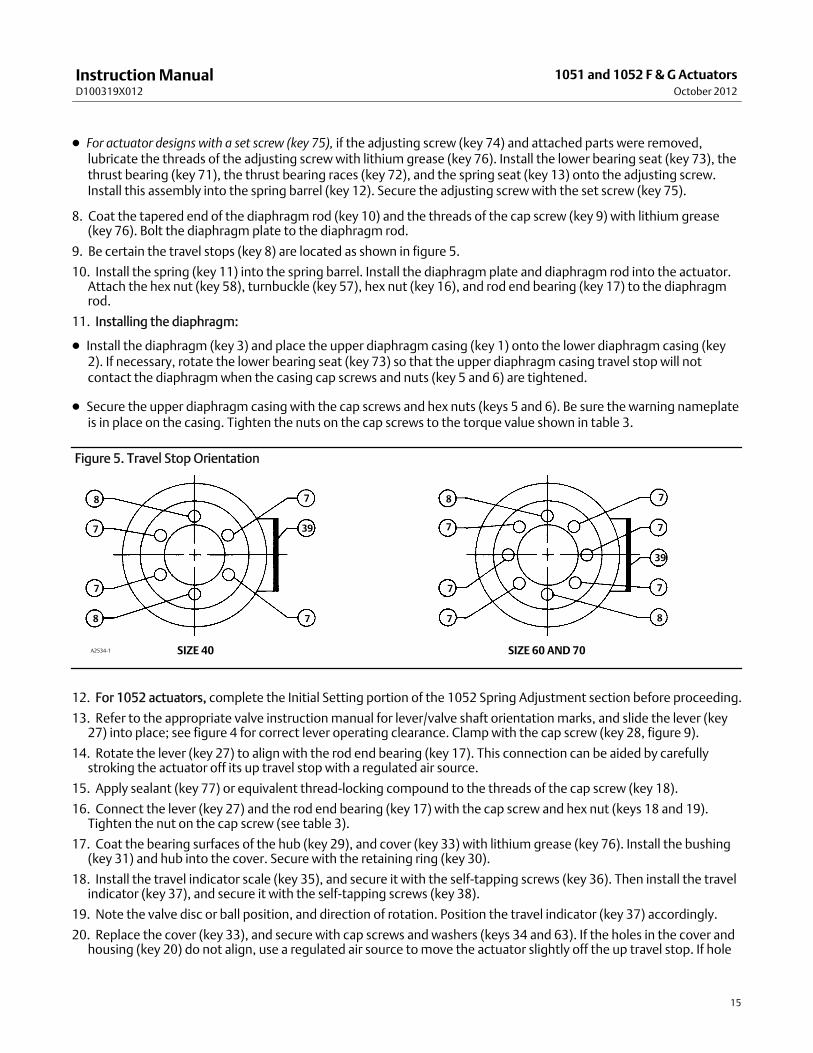
9. Be certain the travel stops (key 8) are located as shown in figure 5.
10. Install the spring (key 11) into the spring barrel. Install the diaphragm plate and diaphragm rod into the actuator.Attach the hex nut (key 58), turnbuckle (key 57), hex nut (key 16), and rod end bearing (key 17) to the diaphragmrod.
11. Installing the diaphragm:
D Install the diaphragm (key 3) and place the upper diaphragm casing (key 1) onto the lower diaphragm casing (key2). If necessary, rotate the lower bearing seat (key 73) so that the upper diaphragm casing travel stop will notcontact the diaphragmwhen the casing cap screws and nuts (key 5 and 6) are tightened.
D Secure the upper diaphragm casing with the cap screws and hex nuts (keys 5 and 6). Be sure the warning nameplateis in place on the casing. Tighten the nuts on the cap screws to the torque value shown in table 3.
Figure 5. Travel Stop Orientation
SIZE 40A2534-1 SIZE 60 AND 70
8
8
8
8
7
7
7
7
7
7
7
7
7
7
39
39
12. For 1052 actuators, complete the Initial Setting portion of the 1052 Spring Adjustment section before proceeding.
13. Refer to the appropriate valve instructionmanual for lever/valve shaft orientationmarks, and slide the lever (key27) into place; see figure 4 for correct lever operating clearance. Clampwith the cap screw (key 28, figure 9).
14. Rotate the lever (key 27) to align with the rod end bearing (key 17). This connection can be aided by carefullystroking the actuator off its up travel stop with a regulated air source.
15. Apply sealant (key 77) or equivalent thread-locking compound to the threads of the cap screw (key 18).
16. Connect the lever (key 27) and the rod end bearing (key 17) with the cap screw and hex nut (keys 18 and 19).Tighten the nut on the cap screw (see table 3).
17. Coat the bearing surfaces of the hub (key 29), and cover (key 33) with lithium grease (key 76). Install the bushing(key 31) and hub into the cover. Secure with the retaining ring (key 30).
18. Install the travel indicator scale (key 35), and secure it with the self-tapping screws (key 36). Then install the travelindicator (key 37), and secure it with the self-tapping screws (key 38).
19. Note the valve disc or ball position, and direction of rotation. Position the travel indicator (key 37) accordingly.
20. Replace the cover (key 33), and secure with cap screws and washers (keys 34 and 63). If the holes in the cover andhousing (key 20) do not align, use a regulated air source tomove the actuator slightly off the up travel stop. If hole
InstructionManualD100319X012
1051 and 1052 F & GActuatorsOctober 2012
16
alignment cannot be obtained in this manner, temporarily loosen cap screws (key 23), and shift the housingslightly.
CAUTION
To avoid parts damage, do not stroke the actuator while cover (key 33) is off.
21. If a valve positioner is to be used, consult the separate valve positioner instructionmanual for proper positionerinstallation.
22. Follow the instructions in the Turnbuckle Adjustment section.
Changing Actuator MountingThe actuator is normally positioned vertically in a horizontal pipeline. However, four mounting styles and fourpositions for each style are possible (see figure 3).
Note
Due to its weight, the 1052, size 70 actuator must be externally supported if mounted in the horizontal position.
Correct lever/valve shaft positioning is important to ensure proper valve action. Consult the appropriate valveinstructionmanual.
Style A is right-handmounted, while style D is left-handmounted. In all other ways, the styles A and D are identical.
Style B is right-handmounted, while style C is left-handmounted. In all other ways, the styles B and C are identical.
Use the following procedure along with figures 8 and 9, for key number references, to convert from styles A and D tostyles B and C or vice versa or to change themounting position.
WARNING
To avoid personal injury, perform the steps in theWARNING at the beginning of theMaintenance section to isolate thecontrol valve and actuator.
1. Remove the tubing or piping from the top of the actuator.
2. Remove the cover (key 33) by unscrewing and removing the cap screws and washers (keys 34 and 63).
3. Unscrew cap screw (key 18). Loosen cap screw (key 28).
CAUTION
When removing the actuator from the valve body, do not use a hammer or similar tool to drive the lever (key 27) oractuator off the valve shaft. Driving the lever or actuator could damage internal valve parts. On some valve types, driving

InstructionManualD100319X012
1051 and 1052 F & G ActuatorsOctober 2012
17
the lever (key 27) couldmove the valve disc and bearings away from the centered position causing subsequent damage tovalve parts.Awheel puller may be used to remove the lever. It is okay to tap thewheel puller screw lightly to loosen the lever, buthitting the screwwith excessive force could also damage valve parts or disrupt the centered position of the valve disc andbearings.
4. If changing styles,
D Unscrew cap screws (key 23), and remove the actuator housing (key 20) from themounting yoke (key 22).
D Rotate the housing 180 degrees, maintaining the appropriate position (1, 2, 3, or 4), and place the actuator ontothemounting yoke (key 22).
5. If changing positions, unscrew cap screws (key 23), and rotate the actuator housing to the desired position.6. Secure actuator housing (key 20) to themounting yoke (key 22) with cap screws (key 23). Consult table 3 forappropriate bolt torques.
7. Consult the appropriate valve instructionmanual for lever/valve shaft orientationmarks, and slide the lever (key 27)into place; see figure 4 for correct lever operating clearance. Clampwith the cap screw (key 28).
8. Rotate the lever (key 27) to align with the rod end bearing (key 17). This connection can be aided by stroking theactuator off its up travel stop with a regulated air source.
9. Apply sealant (key 77) or equivalent thread-locking compound to the threads of the cap screw (key 18).10. Connect the lever (key 27) and the rod end bearing (key 17) with the cap screw and hex nut (keys 18 and 19).Tighten cap screw to the recommended bolt torque shown in table 3. This connection can be aided by stroking theactuator from its up travel stop with a regulated air source.
11. Note the valve position and direction of rotation. Position the travel indicator (key 37) accordingly. Replace thecover (key 33), and secure it with cap screws andwashers (keys 34 and 63).
D If the holes in the cover and housing (key 20) do not align, use a regulated air source tomove the actuator slightlyoff the up travel stop.
D If hole alignment cannot be obtained in this manner, temporarily loosen cap screws (key 23) and shift the housingslightly.
CAUTION
To avoid parts damage, do not stroke the actuator while cover (key 33) is off.
12. Follow the instructions given in the Turnbuckle Adjustment section.
Top-Mounted Handwheels and Adjustable Travel Stops
Principle of Operation for Handwheels
NoteIf repeated or daily manual operation is expected or desired, the unit should be equipped with amanual handwheel actuator. Referto the separatemanual handwheel actuator instructionmanual for mounting instructions.
InstructionManualD100319X012
1051 and 1052 F & GActuatorsOctober 2012
18
Top-Mounted Handwheel Assembly is attached to a special upper diaphragm casing (key 1, figures 8 and 9) with capscrews (key 141, figure 10). A hex nut (key 137, figure 11) locks the handwheel in position. Turning the handwheel(key 51, figure 10) clockwise into the upper diaphragm casing forces the pusher (key 135, figure 10) against thediaphragm and diaphragm plate (keys 3 and 4, figures 8 and 9) to compress the spring (key 11, figures 8 and 9) andmove the diaphragm rod downward.
Turning the handwheel counterclockwise allows the actuator spring tomove the diaphragm rod upward.
D If the valve is push-down-to-close, full opening can be restricted by positioning the handwheel at the desiredposition.
D If the valve is push-down-to-open, full closing of the valve can be restricted by use of the handwheel.
Adjustable Up Travel Stop (figure 11) limits the actuator stroke in the upward direction. Tomake adjustments, firstrelieve actuator loading pressure before removing the closing cap (key 187) as it is a pressure retaining part. Removethe closing cap (key 187). Also, for size 70 actuators, the hex nut (key 137) must be loosened. Then turn the stem (key133) clockwise into the diaphragm case tomove the actuator stem downward or counterclockwise to allow the springtomove the actuator stem upward.
D If the valve has push-down-to-close action, full opening can be restricted by the position of the adjustable travelstop. Or,
D If the valve has push-down-to-open action, full closing can be restricted by the position of the adjustable travel stop.
For size 70, tighten the hex nut and replace the closing cap after adjustment.
Adjustable Down Travel Stop (figure 12) limits the actuator stroke in the downward direction. Tomake adjustments,first relieve actuator loading pressure before removing the closing cap (key 187) as it is a pressure retaining part.Remove the closing cap (key 187). Loosen the hex jam nut (key 189) and either turn the hex nut (key 63 for size 40 and70 actuators; or key 54 for size 60 actuators) down on the stem (key 133) to limit travel, or up on the stem to allowmore travel. Lock the jam nut against the hex nut, and replace the closing cap after the adjustment has beenmade.
Handwheel Maintenance and Adjustable Travel StopIf loading pressure seems to be leaking from either the handwheel or adjustable up stop, the O-rings (key 138 and 139,figures 10 and 11)may need replacement. If the adjustable down stop leaks, the O-ring (key 139, figure 12) may needreplacement or possibly the closing cap (key 187, figure 11) is not tight. To tighten the closing cap, apply a good gradeof thread sealant to the closing cap threads.
For ease of operation, the stem threads (key 133, figures 10, 11, and 12) may need an occasional application of lithiumgrease (key 241). A grease fitting (key 169, figures 10 and 11) is provided for this purpose in the size 70. The size 70may also need to have the thrust bearing (key 175, figures 10 and 11) packed with lithium grease (key 241). Travelstops for the smaller casings can be lubricated between the stem and pusher (key 135, figures 10 and 11) with lithiumgrease (key 241).
The following disassembly procedures are separated where appropriate between the top-mounted handwheel andadjustable up travel stop assemblies (figures 10 and 11) and the adjustable down travel stop assembly (figure 12).
WARNING
To avoid personal injury, perform the steps in theWARNING at the beginning of theMaintenance section to isolate thecontrol valve and actuator.

InstructionManualD100319X012
1051 and 1052 F & G ActuatorsOctober 2012
19
1. Remove the tubing or pipe from the handwheel body (key 142, figures 10, 11, and 12).
WARNING
To avoid personal injury from the pre-compressed spring force thrusting the upper diaphragm casing (key 1, figures 8 and9) away from the actuator, either relieve 1052 spring compression, or carefully remove 1051 casing cap screws byfollowing the instructions that are referenced in the steps below before removing the casing.
2. Relieve all actuator spring compression by following the procedures presented in the Disassembly portion of theMaintenance section. Then, rotate either the handwheel (key 51, figure 10) or the travel stop stem (key 133, figures11 and 12) counterclockwise until the handwheel or travel stop assembly is no longer compressing the spring.
CAUTION
For 1051 actuators with eccentric disc valves and push-down-to-open action, the cap screw (key 18, figure 8) should bedisengaged from the lever (key 27, figure 9) before removing the diaphragm casing (key 1, figure 8) as specified in thefollowing steps. Failure to do sowill allow the spring precompression to rotate the valve beyond its closed position. Thiscould cause damage to the valve seal, seat, or other valve components.
3. Proceed as appropriate:
For Adjustable Up Travel Stops:
a. Remove the upper diaphragm casing (key 1, figures 8 and 9) by following steps 1, 3, 7, 9, 10, and 11 of theDisassembly portion of theMaintenance section.
b. Remove the cap screws (key 141, figures 10 and 11), and separate the assembly from the upper casing.
c. Loosen the locknut (key 137, figure 10), or remove the closing cap (key 187, figure 11).
d. Turn the stem (key 133, figures 10 and 11) clockwise out of the valve body. On handwheel assemblies, the cotterpin and hex nut (keys 247 and 54, figure 10) will have to be removed so that the handwheel (key 51, figure 10)and locknut can be taken off the stem first.
e. Remove and inspect the O-rings (keys 138 and 139, figures 10 and 11); replace them if necessary.
f. To complete disassembly:
For sizes 40 and 60: Drive out the groove pin (key 140, figures 10 and 11), and slide the pusher (key 135, figures10 and 11) off the stem.
For size 70: The pusher unit is held to the stem by a retaining screw (key 174, figures 10, 11 or 12). Removing theretaining screw and pusher exposes the thrust bearing (key 175, figures 10 and 11) for inspection.
For Adjustable Down Travel Stops:
Key numbers are shown in figure 12 unless otherwise noted. For ease of operation, the stem (key 133) threadsmayneed an occasional application of lubricant.
a. Remove the closing cap (key 187), and unscrew the jam nut and hex nut (keys 189 and 63 for size 40 and 70actuators; or keys 189 and 43 for size 60 actuators) off the stem (key 133).
b. Remove the upper diaphragm casing (key 1, figures 8 and 9) and travel stop body (key 142) by following steps 1,3, 7, 9, 10, and 11 of the Disassembly portion of the Actuator Maintenance section.
InstructionManualD100319X012
1051 and 1052 F & GActuatorsOctober 2012
20
c. Unscrew cap screws (key 141), and remove the body from the diaphragm case.
d. Check the condition of the O-ring (key 139), and replace it if necessary.
e. Loosen the hex nut (key 54), and then unscrew the travel stop stem (key 133) out of the actuator stem. Thelower diaphragm plate (key 82) can now be removed and the rest of the actuator disassembled.
4. Reassemble by reversing the order of the disassembly steps, being sure to apply lubricant as previously mentionedand as shown by the lubrication boxes (key 241) in figures 10 and 11. For size 70 handwheels or up travel stopassemblies, coat the threads of the retaining screws (key 174, figures 10 and 11) with sealant (key 242) orequivalent thread-locking compound.
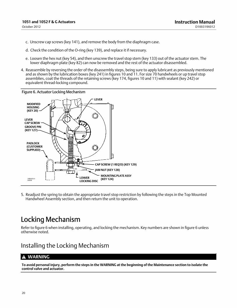
Figure 6. Actuator LockingMechanism
MODIFIEDHOUSING(KEY 20)
PADLOCK(CUSTOMERSUPPLIED)
CAP SCREW (1 REQ'D) (KEY 129)
LEVER
34B0458-AA6808
LEVERCAP SCREWGROOVE PIN(KEY 127)
JAMNUT (KEY 128)
MOUNTINGPLATEASSY(KEY 124)LOWER
LOCKINGDISC
5. Readjust the spring to obtain the appropriate travel stop restriction by following the steps in the TopMountedHandwheel Assembly section, and then return the unit to operation.
LockingMechanismRefer to figure 6 when installing, operating, and locking themechanism. Key numbers are shown in figure 6 unlessotherwise noted.
Installing the LockingMechanism
WARNING
To avoid personal injury, perform the steps in theWARNING at the beginning of theMaintenance section to isolate thecontrol valve and actuator.
InstructionManualD100319X012
1051 and 1052 F & G ActuatorsOctober 2012
21
1. To add the lockingmechanism to an existing actuator, contact your Emerson Process Management sales office topurchase the required parts. The required parts are the lockingmechanism and amodified actuator housing.
2. To remove the old housing, use the Disassembly procedures in theMaintenance section.
3. Attach themounting plate (key 123) to themodified housing (key 20) as shown in figure 6. Attach it with the capscrew (key 129). Make sure the hole in the center of themounting plate lines up with the large tapped hole in thehousing.
4. Make sure the jam nut (key 128) is threaded onto the threaded bolt before threading it into the housing.
5. After the bolt is threaded into the housing, install the groove pin (key 127) into the end of the bolt. (Note: Thegroove pin will prevent the threaded bolt from being totally unthreaded from the actuator housing.)
6. Make sure that the bolt is not threaded in so far that it will interfere with reassembly of the actuator.
7. Reassemble actuator using the Assembly procedure in theMaintenance section.
8. Make sure the actuator diaphragm rod is retracted fully. This will be the locked position of the valve. For apush-down-to-close valve and actuator, the valve will be fully open when locked. For a push-down-to-open valveand actuator, the valve will be fully closed when locked.
9. Screw the threaded bolt into the housing until it contacts the head on the lever cap screw (see figure 6).
10. Insert the padlock (customer supplied) to connect themounting plate (key 123) with the lower locking disc on themounting plate assembly (key 124). Youmight have to back off the lower locking disc a slight amount to line up theholes for the padlock.
CAUTION
In the larger sized actuators, the layers of themounting plate assemblymay be far enough apart that youwill need topurchase a padlockwith a longer loop. Do not attempt to force the layers closer to fit a small looped padlock, as propertydamagemay result.
11. Tighten the jam nut (key 128) against themounting plate.
Operating the LockingMechanism
To Unlock the Actuator1. Remove the padlock. Loosen the jam nut (key 128), and unscrew the threaded bolt until it is stopped by the groovepin (key 127) in the threaded bolt.
CAUTION
For normal operation of the actuator, the threaded bolt must be unscrewed far enough so that the actuator lever will notcontact the bolt, which could lead to property damage.
2. If you are going to leave the bolt threaded into the housing, lock it by tightening the jam nut (key 128) against themounting plate so that it cannot be screwed into the housing and interfere with normal actuator operation.

InstructionManualD100319X012
1051 and 1052 F & GActuatorsOctober 2012
22
Figure 7. Pipe Away Vent Assembly
NOTE:FOR FIELD CONVERSION OF 1052 ACTUATORS, ATTACH COVER(KEY 141) OVER THE SPRING BARREL ADJUSTMENT OPENINGWITHSELF-TAPPING SCREWS (KEY 142). USE KEY 141 AS ADRILLING TEMPLATE. USE DRILL SIZE 2.6 mm (A #37 DRILL)(0.104-INCH) BY 9.6mm (0.38-INCH) DEEP.j APPLY SEALANT
34B4646-B
4.00
3.25
34B4646-B
DRILL SIZE IS 3.7 TO 4.0 BY 14.2mmDEEP (0.145TO 0.158 BY 0.56-INCH). TAP SIZE IS 10-24UNC-2B BY 9.6mm (0.38-INCH) DEEP, 4 HOLES
DRILLING AND TAPPING PATTERNACCESS PLATE ASSEMBLY
1052 SPRING BARRELACCESS COVER
NOTE:FOR FIELD CONVERSION , DRILL AND TAP HOLE PATTERN IFHOUSINGHAS ANON-METALLIC ACCESS PLATE. USE KEY 137ASA DRILLING TEMPLATE IF DESIRED. OR, USE THE DIMENSIONSPROVIDED IN THIS FIGURE FOR DRILLING AND TAPPING.j APPLY SEALANT
34B4646-B
ACCESS PLATE ASSEMBLYMOUNTING YOKE AND COVER ASSEMBLY
34B4646-B
3/4 NPT VENTCONNECTION
TRAVELINDICATOR
NOTE:INSTALL THE HEX HEAD PLUG (KEY 140) INTO THE VENT OPENING LOCATED IN THE ACTUATORHOUSING.
40B3945-B
HOUSING VENT PLUG LOCATION
NOTE:IF ACCESSORIES ARE NOT INSTALLEDON THEMOUNTING BOSS,INSTALL CAP SCREWS (KEY 143) TO PLUGOPENINGS. AMOUNTING BOSS IS LOCATEDON BOTH SIDES OF THE SPRING BARREL.
32A9325-F
ACCESSORIESMOUNTING BOSS
6.4(0.25)
mm(INCH)
0

InstructionManualD100319X012
1051 and 1052 F & G ActuatorsOctober 2012
23
To Lock the Actuator1. Make sure the actuator diaphragm rod is retracted fully. This will be the locked position of the valve. For apush-down-to-close valve and actuator, the valve will be fully open when locked. For a push-down-to-open valveand actuator, the valve will be fully closed when locked.
2. Make sure the jam nut (key 128) is loose. Screw the threaded bolt into the housing until it contacts the head on thelever cap screw (see figure 6).
3. Rotate the threaded bolt until one of the holes in the lower locking disc (which is welded to the bolt) is in line withthe hole in themounting plate (key 123). Tighten the jam nut against themounting plate.
4. Lock the plate and disc together with a padlock. (The padlock is customer supplied.)
Pipe-Away Vent
WARNING
If a flammable or hazardous gas is being used as a supplymedium, personal injury, or property damage could result fromfire or explosion of accumulated gas. A remote vent pipe cannot be relied upon to vent all gases from the installed location.Provide adequate ventilation for the actuator/positioner assembly. Comply with local and regional codes, and keep thevent pipeline as short as possiblewith few bends.
Some applications require venting of gas from the rotary actuator housing. The 3610 Series positioners vent into theactuator housing, and from there, the gas has numerous avenues of escape.
Note
This modification is NOT intended to be a leak-proof or pressure-tight design. It is intended to aid in containing the gas that ventsfrom the positioner and allow for connection of piping to carry it away.
Take care that an adequate vent pipe size is used. This is particularly important with the larger size actuators that havefast stroking speed requirements. In these situations, large quantities of gas can be vented very quickly through thepositioner, and adequate pipe-away capability must be obtained. Keep the vent piping as short as possible with fewbends.
Refer to the Disassembly and Assembly steps in theMaintenance section to gain access to the following parts. Keynumbers are shown in figure 7 unless otherwise noted.
Bushings–Remove themounting yoke bushing (key 67), and the end plate cover bushing (key 31, figures 8 and 9).Replace themwith the pipe-away vent parts, as shown in figure 7. Themounting yoke bushing (key 132) is a two-piecebushing with an O-ring (key 133). The end plate cover completes the assembly with a two-piece bushing (key 134)with an O-ring (key 135).
Travel Indicator–A gasket (key 136) is placed under the travel indicator plate. Remove the indicator plate (key 37,figures 8 and 9), install the gasket (key 136) as shown in figure 7.
Access Plate Assembly–Amodifiedmetal access plate assembly (key 137) is provided with a 3/4 NPT vent connectionas shown in figure 7. If the actuator had a plastic access plate, it will be necessary to drill and tap the actuator housing

InstructionManualD100319X012
1051 and 1052 F & GActuatorsOctober 2012
24
to install themachine screws (key 138) as shown in figure 7. Use the drilling and tapping pattern shown in figure 7, oruse the holes in the access plate as a template tomark holes.
When finished with all maintenance procedures requiring the access plate assembly (key 137) to be removed, use thesealant (key 139) provided with the kit to seal the plate in place.
Housing Vent Plug–A vent is provided in the housing design. To plug this opening, the pipe-away vent kit provides ahex pipe plug (key 140) for this opening, as shown in figure 7. Install the hex plug (key 140) into this opening andtighten it.
Accessories Mounting Boss–If accessories are not installed on themounting boss, install cap screws (key 143) to plugopenings. The location to install the cap screws (key 143) is shown in figure 7. Amounting boss is located on bothsides of the spring barrel (key 12, figures 8 and 9).
1052 Spring Barrel Access Cover–For field conversion of 1052 actuators, attach the cover (key 141) over the springbarrel adjustment opening with self-tapping screws (key 142). Use key 141 as a drilling template. Drill size is 2.6mm (A#37 drill) (0.104-inches) by 9.6mm (0.38-inches) deep.
Parts OrderingWhen corresponding with your Emerson Process Management sales office about this equipment, refer to the serialnumber found on the actuator nameplate (key 41, figures 8 and 10). Also, specify the complete 11-character partnumber from the following parts list when ordering replacement parts. The Size 70 actuator is available only in 1052actuators.
WARNING
Use only genuine Fisher replacement parts. Components that are not supplied by Emerson Process Management shouldnot, under any circumstances, be used in any Fisher valve, because theymay void your warranty, might adversely affect theperformance of the valve, and could cause personal injury and property damage.
Parts Kits
Top-Mounted Handwheel Retrofit KitsKit provides parts to add a top-mounted handwheel. Kit Number 1 includes the handwheel assembly only. Kit Number2 includes Kit Number 1 and a new upper case (key 1) that is required tomount the handwheel assembly.
Kit Number 1
Key Description Part Number
Size 40 38A1213X032Size 60 38A1213X062Size 70 1052 only CV8010X0052
Kit Number 2Key Description Part Number
Size 40 38A1213X072Size 60, 38A1213X022Size 70 1052 only CV8010X0062
InstructionManualD100319X012
1051 and 1052 F & G ActuatorsOctober 2012
25
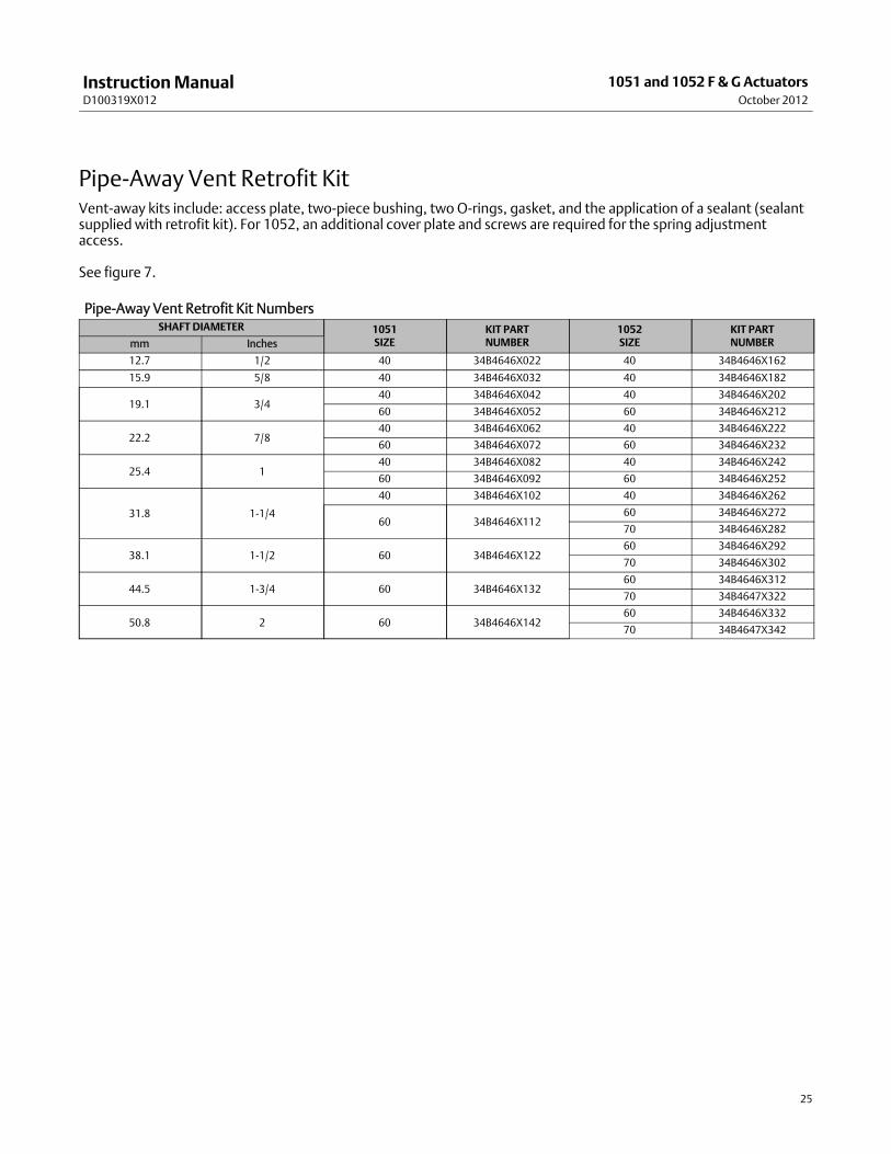
Pipe-Away Vent Retrofit KitVent-away kits include: access plate, two-piece bushing, two O-rings, gasket, and the application of a sealant (sealantsupplied with retrofit kit). For 1052, an additional cover plate and screws are required for the spring adjustmentaccess.
See figure 7.
Pipe-Away Vent Retrofit Kit NumbersSHAFT DIAMETER 1051
SIZEKIT PARTNUMBER
1052SIZE
KIT PARTNUMBERmm Inches
12.7 1/2 40 34B4646X022 40 34B4646X162
15.9 5/8 40 34B4646X032 40 34B4646X182
19.1 3/440 34B4646X042 40 34B4646X202
60 34B4646X052 60 34B4646X212
22.2 7/840 34B4646X062 40 34B4646X222
60 34B4646X072 60 34B4646X232
25.4 140 34B4646X082 40 34B4646X242
60 34B4646X092 60 34B4646X252
31.8 1-1/4
40 34B4646X102 40 34B4646X262
60 34B4646X11260 34B4646X272
70 34B4646X282
38.1 1-1/2 60 34B4646X12260 34B4646X292
70 34B4646X302
44.5 1-3/4 60 34B4646X13260 34B4646X312
70 34B4647X322
50.8 2 60 34B4646X14260 34B4646X332
70 34B4647X342

InstructionManualD100319X012
1051 and 1052 F & GActuatorsOctober 2012
26
Figure 8. Typical 1051 Actuator Assembly
j APPLY LUBRICANT/SEALANT
55A9255-B
Parts List
NotePart numbers are shown for recommended spares only. For partnumbers not shown, contact your Emerson Process Management salesoffice.
Common Parts (Figures 8 and 9)Key Description Part Number
1 Casing, upper2 Diaphragm Casing, lower (steel zn pl)
Key Description Part Number
3* Diaphragm,molded (NBR/nylon)Standardw/handwheel, or w/adj up stopSize 40 2E670002202Size 60 2E859702202Size 70 2N126902202w/adj down stopSize 40 2E669902202Size 60 2E859802202Size 70 2N130902202
VMQ/polyesterStandardw/handwheel, or w/adj up stopSize 40 2E6700X0012Size 60 2E8597X0032Size 70 2N1269X0012
*Recommended spare parts

InstructionManualD100319X012
1051 and 1052 F & G ActuatorsOctober 2012
27
Figure 8. Typical 1051 Actuator Assembly (Continued)
j APPLY LUBRICANT/SEALANT55A9255-BB2679
Key Description Part Number
w/adj down stopSize 40 2E6699X0042Size 60 2E8598X0012Size 70 2N1309X0012
4 DiaphragmHead5 Screw, Cap, Hex Hd,
Size 40 (12 req'd)Size 60 (16 req'd)Size 70 (24 req'd)
6 Nut, HexSize 40 (16 req'd)Size 60 (24 req'd)Size 70 (28 req'd)
7 Screw, Cap, Hex HdSize 40 (4 req'd)Size 60 (6 req'd)Size 70 (10 req'd)
Key Description Part Number
8 Stop, Travel (2 req'd)9 Screw, Cap, Hex Socket10 Diaphragm Rod11 Spring See following table12 Spring Barrel13 Spring Seat See following table16 Nut, Hex17 Bearing Rod End18 Screw, Cap, Hex Hd19 Nut, Hex, Jam20 Housing20 Modified Housing21 Screw, Cap, Hex Hd (4 req'd)22 Yoke, Mounting23 Screw, Cap, Hex Hd (4 req'd)27 Lever28 Screw, Cap, Hex Hd
*Recommended spare parts

InstructionManualD100319X012
1051 and 1052 F & GActuatorsOctober 2012
28
Key Description Part Number
29 Hub30 Ring, Retaining, Ext31* Bushing
Size 40 12A9373X012Sizes 60 & 70 12A9374X012
33 Cover34 Screw, Cap, Hex Hd
w/o switches, w/ TopWorxtDXPM21GNEB, 4200,w/BZE6-2RN or DTE6-2RN SW,w/micro switch w/90 deg, or w/ 3710 positioner(4 req'd)w/NAMCO or LSA/LSX switches, w/1 or 2 GO switches,w/ LSA/LSX sw, or w/NAMCO or LSA/LSX switch(2 req'd)
35 Scale, Indicator36 Screw, Self Tapping (2 req'd)37 Travel Indicator38 Self-Tapping Screw (2 req'd)38 Machine Screw (2 req'd)39 Plate, Cover40 Screw, Cap, Hex Hd (4 req'd)41 Nameplate42 Screw, Drive (4 req'd)56 Warning Label57 Turnbuckle58 Nut, Hex, Jam59 Plate, Access63 Washer, Plain
Size 40 (4 req'd)Size 60 & 70 (2 req'd)
67* Bushing See following table71 Bearing, Thrust72 Bearing Race (2 req'd)73 Bearing Seat74 Screw, Adjusting76 Lithium grease lubricant77 Thread locking sealant78 Screw, Cap
9.5 & 12.7mm (3/8 & 1/2 inch) Shafts (2 req'd)15.9 thru 50.4 mm (5/8 thru 2-inch) Shafts (4 req'd)
82 DiaphragmHead, lower83 Plug, Protective- - - Pipe Bushing (not shown)144 Warning Nameplate146 Spacer
Top-Mounted Handwheel(Figure 10)51 Handwheel54 Nut, Hex, Slotted133 Stem135 Plate, Pusher137 Nut, Hex, Jam138* O-Ring, (NBR)
Size 40 1D237506992Size 60 1B885506992Size 70 1C415706992
Key Description Part Number
139* O-ring, (NBR)Size 40 1D267306992Size 60 1D547106992Size 70 1D269106992
140* Pin, GrooveCarbon Steel-PlatedSize 40 1F118028992S31600 (316 SST)Size 60 1B627035072
141 Screw, Cap, Hex HdSize 40 (6 req'd)Size 60 (8 req'd)Size 70 (12 req'd)
142 Body164 Body Extension169 Grease Fitting171 Washer, plain174 Retaining Screw175 Bearing, Thrust176 Bearing Race, Thrust, 1052 Size 70 only (2 req'd)241 Lithium grease lubricant242 Thread locking sealant244 Anti-seize lubricant246 Spacer247 Pin, Cotter
Adjustable Up Travel Stop(Figure 11)133 Stem135 Plate, Pusher137 Nut, travel stop138* O-Ring, (NBR)
Size 40 1D237506992Size 60 1B885506992Size 70 1C415706992
139* O-Ring, (NBR)Size 40 1D267306992Size 60 1D547106992Size 70 1D269106992
140* Pin, Groovecarbon steel-platedSize 40 1F118028992S31600 (316 SST)Size 60 1B627035072
141 Screw, Cap, Hex HdSize 40 (6 req'd)Size 60 (8 req'd)Size 70 (12 req'd)
142 Body164 Body Extension169 Grease Fitting171 Spacer174 Retaining Screw175 Bearing, Thrust176 Bearing Race, Thrust, 1052 Size 70 only (2 req'd)187 Travel Stop Cap241 Lithium grease lubricant242 Thread locking sealant
*Recommended spare parts
InstructionManualD100319X012
1051 and 1052 F & G ActuatorsOctober 2012
29
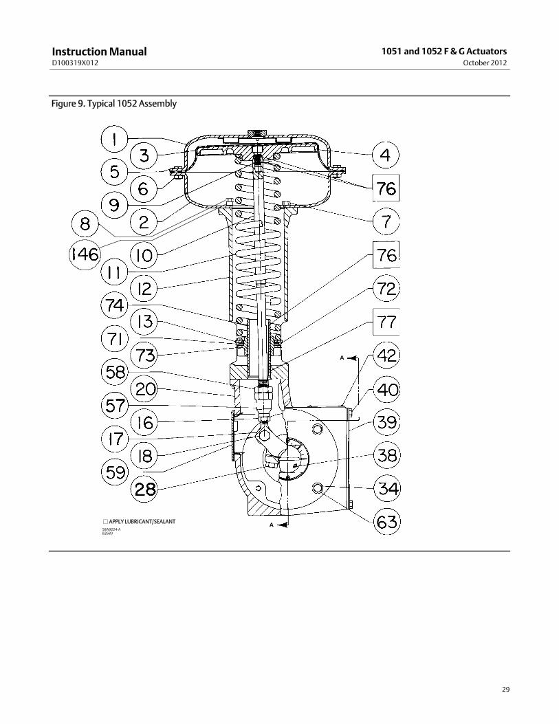
Figure 9. Typical 1052 Assembly
58A9224-AB2680
j APPLY LUBRICANT/SEALANTA
A
InstructionManualD100319X012
1051 and 1052 F & GActuatorsOctober 2012
30
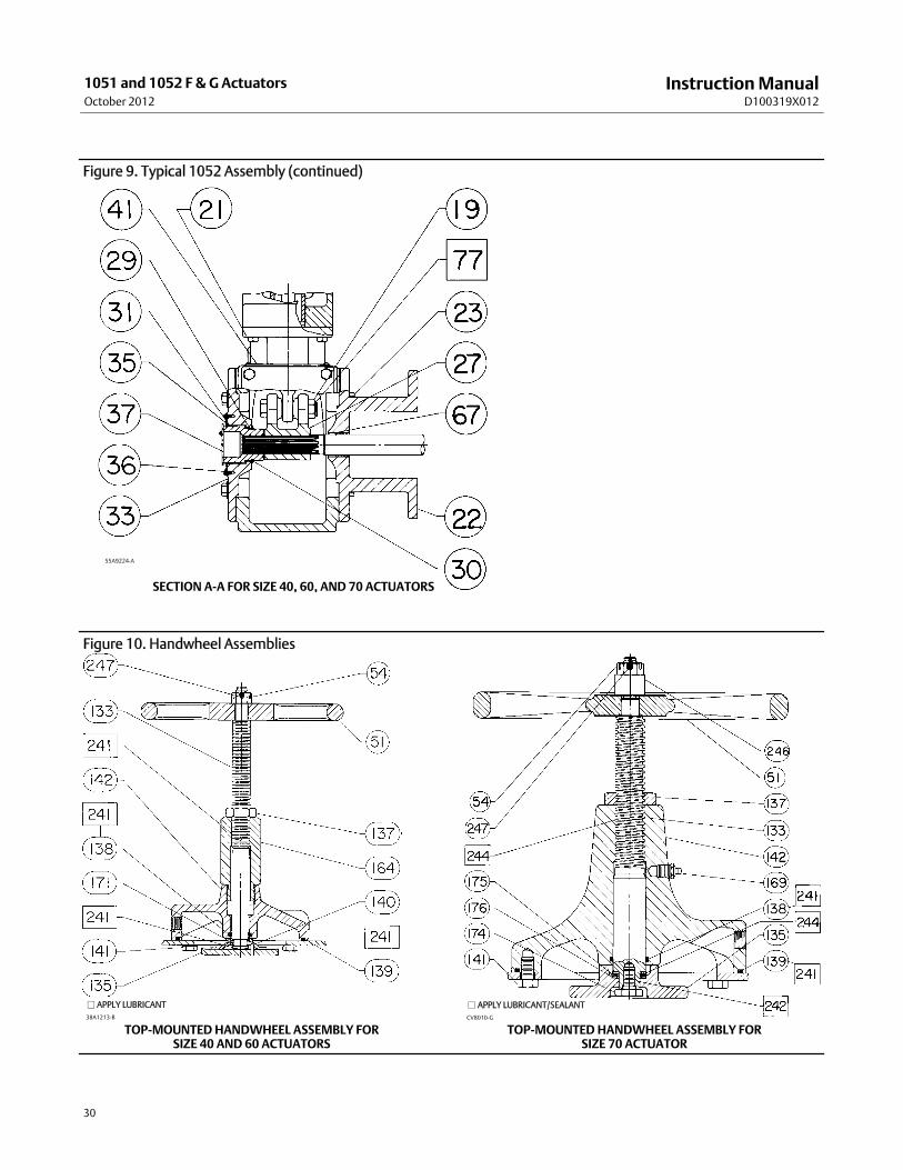
Figure 9. Typical 1052 Assembly (continued)
55A9224-A
SECTION A-A FOR SIZE 40, 60, AND 70 ACTUATORS
Figure 10. Handwheel Assemblies
CV8010-G
j APPLY LUBRICANT/SEALANT
TOP-MOUNTED HANDWHEEL ASSEMBLY FORSIZE 70 ACTUATOR
TOP-MOUNTED HANDWHEEL ASSEMBLY FORSIZE 40 AND 60 ACTUATORS
38A1213-B
j APPLY LUBRICANT
InstructionManualD100319X012
1051 and 1052 F & G ActuatorsOctober 2012
31
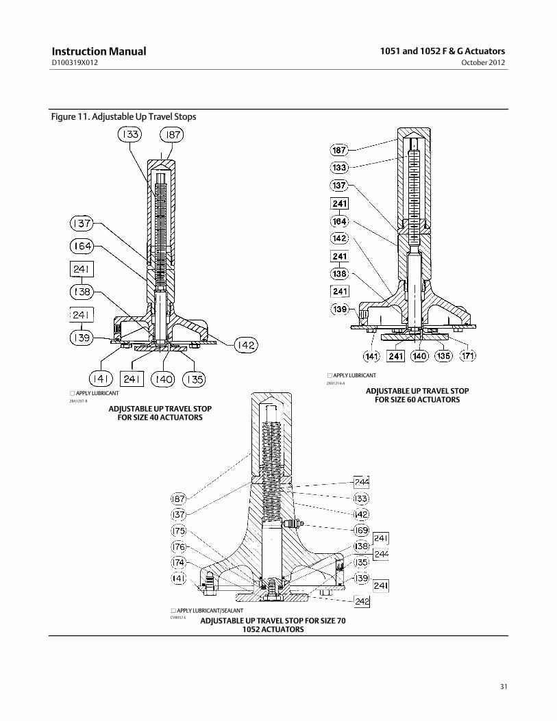
Figure 11. Adjustable Up Travel Stops
CV8057-E
j APPLY LUBRICANT/SEALANT
ADJUSTABLE UP TRAVEL STOP FOR SIZE 701052 ACTUATORS
28A1207-B
j APPLY LUBRICANT
ADJUSTABLE UP TRAVEL STOPFOR SIZE 40 ACTUATORS
28A1214-A
j APPLY LUBRICANT
ADJUSTABLE UP TRAVEL STOPFOR SIZE 60 ACTUATORS

InstructionManualD100319X012
1051 and 1052 F & GActuatorsOctober 2012
32
Figure 12. Adjustable Down Travel Stop
NOTE:FOR SIZE 60 ACTUATORS, A SECONDHEX NUT (KEY 54) IS USED IN THE PLACE OF THE HEX NUT (KEY 63)
38B5654-BA7238
Adjustable Down Travel Stop(Figure 12)Key Description Part Number
54 Nut, HexSize 40 (1 req'd)Size 60 & 70 (2 req'd)
63 Flange Nut133 Travel Stop Stem134 Washer (plain carbon steel)139* O-Ring (NBR)
Size 40 1D267306992Size 60 1D547106992Size 70 1D269106992
141 Screw, Cap, Hex Hd (steel zn pl)Size 40 (6 req'd)Size 60 (8 req'd)Size 70 (12 req'd)
142 Travel Stop Body187 Travel Stop Cap189 Nut, Hex, Jam
Size 40 & 60 (1 req'd)Size 70 (2 req'd)
241 Lithium grease lubricant
Locking Assembly (Figure 6)(Size 40, 60, and 70 Actuators)123 Mounting Plate124 Mounting Plate Assembly127 Groove Pin128 JamNut129 Cap Screw
Pipe-Away Vent (Figure 7)
NoteComplete retrofit kits are listed at the beginning of the parts list. Use thislisting for individual replacement parts
Key Description Part Number
132* Lined Bushing (steel/PTFE) yoke side12.7mm (1/2 inch) dia. shaft (2 req'd) 1U90259940215.9mm (5/8 inch) dia. shaft (2 req'd) 14B4642X01219.1mm (3/4 inch) dia. shaft (2 req'd) F191834811222.2mm (7/8 inch) dia. shaft (2 req'd) 14B4631X01225.4mm (1-inch) dia. shaft (2 req'd) 14B4632X01231.8mm (1-1/4 inch) dia. shaft (2 req'd) 14B4633X01238.1mm (1-1/2 inch) dia. shaft (2 req'd) 14B4634X01244.5mm (1-3/4 inch) dia. shaft (2 req'd) 14B4635X01250.8mm (2-inch) dia. shaft (2 req'd) G1668548112
133* O-Ring (NBR)12.7mm (1/2 inch) dia. shaft 1J4888X005215.9mm (5/8 inch) dia. shaft 11A8741X05219.1mm (3/4 inch) dia. shaft 1F4636X003222.2mm (7/8 inch) dia. shaft 10A3805X01225.4mm (1-inch) dia. shaft 10A8217X04231.8mm (1-1/4 inch) dia. shaft 14A6981X01238.1mm (1-1/2 inch) dia. shaft 1F1153X001244.5mm (1-3/4 inch) dia. shaft 1P1676X001250.8mm (2-inch) dia. shaft 10A3800X012
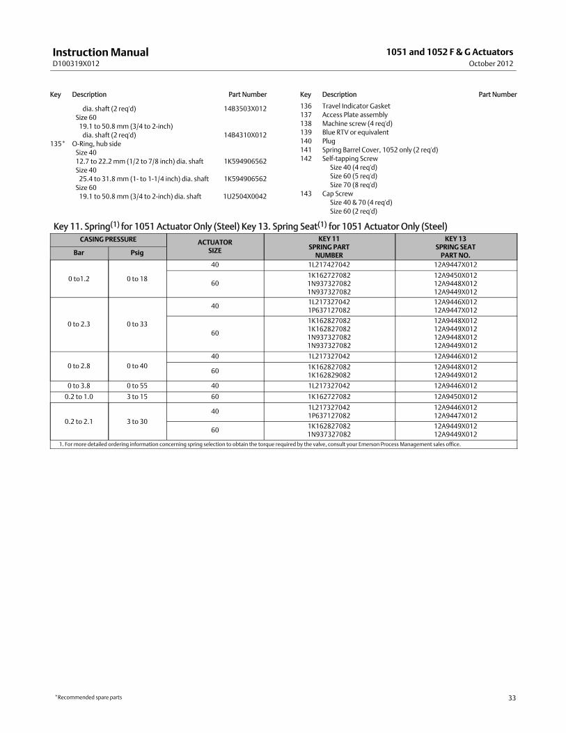
134* Bushing (steel/PTFE) hub sideSize 4012.7 to 22.2 mm (1/2 to 7/8 inch)dia. shaft (2 req'd) 14B3503X012
Size 4025.4 to 31.8mm (1- to 1-1/4 inch)
*Recommended spare parts
InstructionManualD100319X012
1051 and 1052 F & G ActuatorsOctober 2012
33
Key Description Part Number
dia. shaft (2 req'd) 14B3503X012Size 6019.1 to 50.8 mm (3/4 to 2-inch)dia. shaft (2 req'd) 14B4310X012
135* O-Ring, hub sideSize 4012.7 to 22.2mm (1/2 to 7/8 inch) dia. shaft 1K594906562Size 4025.4 to 31.8 mm (1- to 1-1/4 inch) dia. shaft 1K594906562Size 6019.1 to 50.8 mm (3/4 to 2-inch) dia. shaft 1U2504X0042
Key Description Part Number
136 Travel Indicator Gasket137 Access Plate assembly138 Machine screw (4 req'd)139 Blue RTV or equivalent140 Plug141 Spring Barrel Cover, 1052 only (2 req'd)142 Self-tapping Screw
Size 40 (4 req'd)Size 60 (5 req'd)Size 70 (8 req'd)
143 Cap ScrewSize 40 & 70 (4 req'd)Size 60 (2 req'd)
Key 11. Spring(1) for 1051 Actuator Only (Steel) Key 13. Spring Seat(1) for 1051 Actuator Only (Steel)CASING PRESSURE ACTUATOR
SIZE
KEY 11SPRING PARTNUMBER
KEY 13SPRING SEATPART NO.Bar Psig
0 to1.2 0 to 18
40 1L217427042 12A9447X012
601K1627270821N9373270821N937327082
12A9450X01212A9448X01212A9449X012
0 to 2.3 0 to 33
40 1L2173270421P637127082
12A9446X01212A9447X012
60
1K1628270821K1628270821N9373270821N937327082
12A9448X01212A9449X01212A9448X01212A9449X012
0 to 2.8 0 to 4040 1L217327042 12A9446X012
60 1K1628270821K162829082
12A9448X01212A9449X012
0 to 3.8 0 to 55 40 1L217327042 12A9446X012
0.2 to 1.0 3 to 15 60 1K162727082 12A9450X012
0.2 to 2.1 3 to 3040 1L217327042
1P63712708212A9446X01212A9447X012
60 1K1628270821N937327082
12A9449X01212A9449X012
1. For more detailed ordering information concerning spring selection to obtain the torque required by the valve, consult your Emerson Process Management sales office.
*Recommended spare parts

InstructionManualD100319X012
1051 and 1052 F & GActuatorsOctober 2012
34
Key 11. Spring(1) for 1052 Actuators Only (Steel)
CASING PRESSURE ACTUATORSIZE
INITIAL SPRING COMPRESSION KEY 11SPRING PARTNUMBER
Push-down-to-open Push-down-to-close
Bar Psig Bar Psig Bar Psig
0 to1.20 to 18 40 0.2
0.33.04.3
0.20.2
3.03.0
1L2174270421P637127082
0 to 18 60 0.30.2
3.73.5
0.20.2
3.03.0
1K1627270821N937327082
0 to 2.3
0 to 33 400.30.40.3
4.36.04.4
0.30.20.2
4.33.03.0
1P6371270821L2173270421N844027082
0 to 33 600.20.50.5
3.57.06.8
0.20.20.2
3.53.03.0
1N9373270821K1628270821P270227042
0 to 33 70 0.7 10.1 0.2 3.0 1R676027082
0 to 2.8
0 to 40 40 0.30.4
4.46.0
0.20.2
3.03.0
1N8440270821L217327042
0 to 40 60 0.50.5
6.87.0
0.20.2
3.03.1
1P2702270421K162827082
0 to 40 70 0.7 10.1 0.2 3.3 1R676027082
0 to 3.80 to 55 40 0.3 4.4 0.2 3.5 1N844027082
0 to 55 70 0.7 10.1 0.7 10.1 1R676027082
0.2 to 1.03 to 15 40 - - - - - - 0.2 3.0 1L217427042
3 to 15 60 0.3 3.7 0.2 3.0 1K162727082
0.2 to 2.1
3 to 30 400.30.4- - -
4.36.0- - -
0.30.20.2
4.33.03.0
1P6371270821L2173270421N844027082
3 to 30 600.20.5- - -
3.57.0- - -
0.20.20.2
3.53.03.0
1N9373270821K1628270821P270227042
3 to 30 70 0.7 10.1 0.2 3.0 1R6760270821. For more detailed ordering information concerning spring selection to obtain the torque required by the valve, consult your Emerson Process Management sales office.

InstructionManualD100319X012
1051 and 1052 F & G ActuatorsOctober 2012
35
Keys 22 and 67*.Mounting Yoke Assembly
VALVE DESIGNACTUATOR
SIZEVALVE SHAFT DIAMETER KEY 22 YOKE
CAST IRON(1)KEY 67
BUSHING, PTFEmm Inches
CV500, V150, V200, V250, V300,8510, 8532, and 8560
4012.715.919.1
1/25/83/4
12A9799X0A212A9799X0B212A9799X0C2
- - -- - -- - -
1U90259940212A9555X01212A9556X012
4022.225.431.8
7/81
1-1/4
12A9799X0E212A9799X0G212A9799X112
- - -- - -- - -
12A9557X01212A9775X01212A9558X012
6019.122.225.4
3/47/81
12A9799X0D212A9799X0F212A9799X0H2
- - -- - -- - -
12A9556X01212A9557X01212A9775X012
60 and 70
31.838.144.550.8
1-1/41-1/21-3/42
12A9799X0J212A9799X0K212A9799X0L212A9799X0M2
- - -- - -- - -- - -
12A9558X01212A9559X01210A3848X01212A9715X012
9500 for GMounting
4012.715.919.1
1/25/83/4
- - -- - -- - -
32A9755X01232A9742X01232A9743X012
1U90259940212A9555X01212A9556X012
40 25.431.8
11-1/4
- - -- - -
32A9757X01232A9746X012
12A9575X01212A9558X012
60 19.125.4
3/41
- - -- - -
32A9750X01232A9778X012
12A9556X01212A9775X012
60 and 70
31.838.144.550.8
1-1/41-1/21-3/42
- - -- - -- - -- - -
32A9753X01232A9754X01235A9704X01235A9705X012
12A9558X01212A9559X01212A9560X01212A9561X012
1. The yokes in this column are available as yoke-bushing assemblies, However, the bushings are available as replacement parts.
*Recommended spare parts

InstructionManualD100319X012
1051 and 1052 F & GActuatorsOctober 2012
36
Emerson Process ManagementMarshalltown, Iowa 50158 USASorocaba, 18087 BrazilChatham, Kent ME4 4QZUKDubai, United Arab EmiratesSingapore 128461 Singapore
www.Fisher.com
The contents of this publication are presented for informational purposes only, and while every effort has beenmade to ensure their accuracy, they are notto be construed as warranties or guarantees, express or implied, regarding the products or services described herein or their use or applicability. All sales aregoverned by our terms and conditions, which are available upon request. We reserve the right tomodify or improve the designs or specifications of suchproducts at any time without notice.
E 1976, 2012 Fisher Controls International LLC. All rights reserved.
Fisher, Vee-Ball, FIELDVUE, and TopWorx aremarks owned by one of the companies in the Emerson Process Management business unit of Emerson ElectricCo. Emerson Process Management, Emerson, and the Emerson logo are trademarks and servicemarks of Emerson Electric Co. All other marks are theproperty of their respective owners.
Neither Emerson, Emerson Process Management, nor any of their affiliated entities assumes responsibility for the selection, use ormaintenanceof any product. Responsibility for proper selection, use, andmaintenance of any product remains solely with the purchaser and end user.
Related Documents