www.Fisher.com Fisher r EZ Sliding- Stem Control Valve Fisher EZ valves (figures 1 and 2) are used for throttling or on-off control of a wide variety of liquids and gases. The single-port, globe-style body design offers quick-change trim and a post-guided, unbalanced valve plug. The EZ valve is used in chemical or hydrocarbon processing applications or wherever control of non-lubricating, viscous, or other hard-to-handle fluids is required. Metal-to-metal seating is standard for all general applications over a wide range of pressure drops and temperatures. Metal-to-PTFE seating is optional for stringent shutoff requirements. The easy-et Valve Family EZ valve bodies are part of the versatile easy-e family of industrial control valves. easy-e valve bodies share the following characteristics: D Multiple trim material choices D Trim temperature capability with standard metal seats to 427_C (800_F) D FGM gaskets D Interchangeable, restricted-capacity trims and full-sized trims to match variable process flow demands W21742/IL Figure 1. Fisher EZ Valve with 657 Actuator Product Bulletin 51.1:EZ D100025X012 March 2010 EZ Valve

Welcome message from author
This document is posted to help you gain knowledge. Please leave a comment to let me know what you think about it! Share it to your friends and learn new things together.
Transcript

www.Fisher.com
Fisher� EZ Sliding-Stem Control ValveFisher EZ valves (figures 1 and 2) are used forthrottling or on-off control of a wide variety of liquidsand gases. The single-port, globe-style body designoffers quick-change trim and a post-guided,unbalanced valve plug. The EZ valve is used inchemical or hydrocarbon processing applications orwherever control of non-lubricating, viscous, or otherhard-to-handle fluids is required.
Metal-to-metal seating is standard for all generalapplications over a wide range of pressure dropsand temperatures. Metal-to-PTFE seating is optionalfor stringent shutoff requirements.
The easy-e� Valve Family
EZ valve bodies are part of the versatile easy-efamily of industrial control valves. easy-e valvebodies share the following characteristics:
� Multiple trim material choices
� Trim temperature capability with standard metalseats to 427�C (800�F)
� FGM gaskets
� Interchangeable, restricted-capacity trims andfull-sized trims to match variable process flowdemands
W2174�2/IL
Figure 1. Fisher EZ Valve with 657 Actuator
Product Bulletin51.1:EZD100025X012March 2010 EZ Valve

EZ ValveProduct Bulletin
51.1:EZMarch 2010
2
ContentsFeatures 2. . . . . . . . . . . . . . . . . . . . . . . . . . . . . . . . . ENVIRO-SEAL� and HIGH-SEAL
Packing Systems 3. . . . . . . . . . . . . . . . . . . . . . . . ENVIRO-SEAL and HIGH-SEAL
Features 4. . . . . . . . . . . . . . . . . . . . . . . . . . . . . . . Micro-Flute Valve Plugs for
Minimum Leakage 7. . . . . . . . . . . . . . . . . . . . . . . Class VI Shutoff Capabilities 6. . . . . . . . . . . . . . . . . Tables
Class VI Shutoff 6. . . . . . . . . . . . . . . . . . . . . . . . Class VI Trim Materials 6. . . . . . . . . . . . . . . Material Cross Reference 7. . . . . . . . . . . . . Typical Combinations of
Metal Trim Parts 7. . . . . . . . . . . . . . . . . . . Construction Materials &
Temperature Limits 9. . . . . . . . . . . . . . . . . Valve Body/Trim
Temperature Capabilities 10. . . . . . . . . . Bonnet Selection Guidelines 12. . . . . . . . . . Maximum Allowable Pressure Drops 12. . . Gasket Selection Guidelines 13. . . . . . . . . . Maximum Allowable Pressure Drops for
Gasket Materials 14. . . . . . . . . . . . . . . . . . Maximum Flow Coefficients 16. . . . . . . . . . . Port Diameters, Valve Plug Travel, and
Stem and Yoke Boss Diameters 16. . . . . Typical Combinations of
Trim Parts 16. . . . . . . . . . . . . . . . . . . . . . . Bolting Materials and
Temperature Limits 17. . . . . . . . . . . . . . . . Ordering Information 17. . . . . . . . . . . . . . . . . . . . . . Dimensions 17. . . . . . . . . . . . . . . . . . . . . . . . . . . . . . Coefficients 20. . . . . . . . . . . . . . . . . . . . . . . . . . . . . . Specifications 25. . . . . . . . . . . . . . . . . . . . . . . . . . . . ENVIRO-SEAL Packing System
Specifications 27. . . . . . . . . . . . . . . . . . . . . . . . . .
� Different valve plug styles that provideparticular flow characteristics for highly-specializedapplications. Standard plugs are available with thefollowing flow characteristics:
� quick-opening� linear� equal percentage
� Optional constructions allow materialcompatibility with NACE MR0175 / ISO 15156 andMR0103. Contact your Emerson ProcessManagement sales office for details.
� 316 stainless steel packing box parts arestandard (including packing flange, studs, and nuts)
Features� Trim Designed for Stability—Post guiding
provides valve plug stability with less chance of asticking valve plug due to non-lubricating or stickyprocess fluids or build-up of entrained solids. Postguiding stabilizes the valve plug at all points in itstravel range to reduce vibration, mechanical noise,and trim wear.
� Performance+ Seat Ring—Flow-straightening,vaned seat ring is available in full port and firstreduction port sizes. It offers excellent open- andclosed-loop performance and may be used as adirect replacement for the non-vaned seat ring. TheFisher valve division recommends that thePerformance+ seat ring be used for non-viscous,flow-up, liquid applications.
� Compliance with the Clean Air Act—ENVIRO-SEAL packing systems (figure 4) thatprovide an improved stem seal to help prevent theloss of process fluid are available. These packingsystems feature PTFE, Graphite ULF, or duplexpacking with live-loading for reduced packingmaintenance.
� Reliability—The process fluid flows throughthe trim, flushing away solid deposits above andbelow the guide bushing, thus reducing thepossibility of a sticking valve plug.
� Easy Maintenance—Quick-change trim, with aclamped-in seat ring, reduces the disassembly time.The valve body can stay in the pipeline duringremoval of trim parts for inspection or maintenance.
� Application Flexibility—Low-flowrequirements can be satisfied with standardrestricted-capacity trim or with Micro-Form,Micro-Flute, or Micro-Flow valve plugs. If flowrequirements change, the valve can be converted tofull-sized trim.
� Economy—Streamlined flow passages providegreater capacities than most globe valves of thesame line size.

EZ ValveProduct Bulletin51.1:EZMarch 2010
3
35A7592-EW7027-3 / IL
Figure 2. Fisher EZ Sectional with Optional Drain Plug
� Compliance with European Standards—Valves are available with dimensions specified byEN/DIN standards. See figure 7.
� Sour Service Capability— Unless otherwisenoted, references are to NACE MR0175-2002.Optional materials are available to meet NACEMR0103 and NACE MR0175 / ISO 15156. Materialrequirements under these standards vary by editionand year of issue; the specific standard must bespecified.
ENVIRO-SEAL, HIGH-SEAL Packing SystemsENVIRO-SEAL and HIGH-SEAL packing systems
offer exceptional sealing capabilities. These systemseasily install in your existing valves or can bepurchased with new valves. These systems offer animproved method of sealing your process toconserve valuable process fluid. The long-life andreliability of these systems also help to reduce yourmaintenance costs and downtime.
For applications requiring compliance withenvironmental protection regulations, the uniqueENVIRO-SEAL packing system (figure 4) and, forhazardous service, the ENVIRO-SEAL bellows sealsystem (figure 3) are offered. The emission controlpacking system helps to keep emissionconcentrations below the EPA 100 ppm requirement.

EZ ValveProduct Bulletin
51.1:EZMarch 2010
4
For an excellent stem seal in applications that arenot environmentally-sensitive, the HIGH-SEALGraphite ULF packing system (figure 4) is offered.The HIGH-SEAL packing system provides excellentsealing at pressure/temperature ratings beyondENVIRO-SEAL limits. ENVIRO-SEAL systems mayalso be applied for excellent stem sealing in higherpressure/temperature applications not requiring EPAcompliance.
ENVIRO-SEAL packing systems, available withPTFE, Graphite ULF, or duplex packing, and theHIGH-SEAL Graphite ULF packing system featurelive-loading and unique packing-ring arrangementsfor long-term, consistent sealing performance.
ENVIRO-SEAL, HIGH-SEAL Features
� Excellent Sealing Capabilities—The packingsystem provides excellent sealing, guiding, andtransmission of loading force. The excellent sealingof the ENVIRO-SEAL system can control emissionsto below the EPA (Environmental Protection Agency)minimum of 100 ppm (parts per million).
� Improved Service Life—ENVIRO-SEAL andHIGH-SEAL system design, very smooth stemsurface, and live-loading combine to give you longservice with very low maintenance. The externallive-loading provides a constant load over the life ofthe packing material, which greatly reduces yourneed for packing box adjustment and maintenance.
� Easy Installation in Existing Valves—Allparts needed to install the systems in existing valvesare available in a convenient kit.
W5800-2*A/IL
PACKING
ANTI-ROTATORPIN
PURGE-MONITORINGCONNECTION
PROTECTIVESHROUD
BELLOWS
VALVE PLUGCONNECTION
VALVE PLUG
Figure 3. Fisher EZ Valve with ENVIRO-SEAL Bellows SealBonnet
� Adaptable to Many Applications—ENVIRO-SEAL systems are available with PTFE orGraphite ULF packing for 9.5 through 31.8 mm (3/8through 1-1/4 inch) diameter valve stems.HIGH-SEAL systems with Graphite ULF packing areavailable for 9.5 through 50.8 mm (3/8 through2-inch) diameter valve stems. StandardENVIRO-SEAL packing systems can be used invacuum service with packing rings in standardorientation. It is not necessary to reverse theENVIRO-SEAL PTFE packing rings.

EZ ValveProduct Bulletin51.1:EZMarch 2010
5
W7018 / IL
W8532-1
FOLLOWER
PACKINGBOXSTUD
PACKING
SPRINGS
W8533-1
PACKINGBOXSTUD
FOLLOWER
PACKING
SPRING
W5803�3 / IL
SPRINGS
ANTI�EXTRUSIONRING
LANTERNRING
PACKINGBOXSTUDS
PACKINGRING
VALVEBONNET
TYPICAL ENVIRO-SEAL PACKING SYSTEMWITH PTFE PACKING
TYPICAL ENVIRO-SEAL PACKING SYSTEMWITH GRAPHITE ULF PACKING
TYPICAL HIGH-SEAL PACKING SYSTEMWITH GRAPHITE ULF PACKING
TYPICAL ENVIRO-SEAL PACKING SYSTEMWITH DUPLEX PACKING
Figure 4. ENVIRO-SEAL and HIGH-SEAL Packing Systems

EZ ValveProduct Bulletin
51.1:EZMarch 2010
6
Class VI Shutoff CapabilitiesEZ valves with metal seat and PTFE soft seatconstructions can provide ANSI/FCI Class VI shutoffcapabilities. See tables 1 and 2.
Table 1. Class VI Shutoff Availability
Valve Port Size, Inches Seat Minimum SeatLoad
EZ � 4 Metal 300 lbs/lineal inch
EZ � 4 PTFE See Catalog 14
Table 2. Class VI Trim Materials
VALVECAGE/SEAT RING
RETAINER VALVE PLUG SEAT RINGTRIM TEMPERATURE LIMIT
�C �F
EZ
CF8M (316 SST)S31600/CoCr-A seat w/standard beveled seat
S31600 w/ radiusedseat (special design)
Not a limiting factor Not a limiting factor
CF8MS31600/CoCr-A seat
and guide w/ standardbeveled seat
S31600 w/ radiusedseat (special design)
Not a limiting factor Not a limiting factor
CF8MS31600 w/ PTFE disk
seatS31600 w/ standard
beveled seat�29 to 149 �20 to 300
CB7CU-1S41600 w/ PTFE disk
seatS41600 w/ standard
beveled seat�29 to 204 �20 to 400
NOTES:ALSO APPLIES TO TRIMS 101C, 127C,
137C, 151C, 153C, 154C, AND 158C.ALSO APPLIES TO TRIMS 104C, 128C,
129C, 139C, 152C, 155C, 156C, AND 157C.TRIM SELECTIONS REQUIRING CLASS VI SHUTOFF ARE LIMITED TO �29�C (�20�F)
MINIMUM TEMPERATURE. SOME PTFE SEAT CONSTRUCTIONS CAN BE USED TO �73�C(�100�F) MINIMUM TEMPERATURE IF CLASS VI SHUTOFF IS NOT REQUIRED. SEE TABLE 7FOR ADDITIONAL VALVE BODY/TRIM TEMPERATURE LIMITATIONS.
A6415-1
2
1
1
2
3
3
Figure 5. Pressure Drop / Temperature Capabilities for PTFE Seat Trim

EZ ValveProduct Bulletin51.1:EZMarch 2010
7
Micro-Flute Valve Plugs for MinimumLeakageThe EZ valve can be furnished with PTFEcomposition-seat Micro-Flute valve plugs for Class VIshutoff per ANSI/FCI 70-2 and IEC 60534-4.
These valve plugs are available on NPS 1/2 to 2
valves with a 9.5 mm (3/8 inch) stem diameter, 9.5mm (3/8 inch) actuator-stem connection, and 6.4 mm(0.25 inch) seat ring port diameter. These plugshave the same flow coefficients as standardMicro-Flute plugs. Standard seat rings are used.
The valve plugs have a screwed retainer that holdsthe seat disk and valve plug tip to the valve stem.
Table 3. Material Cross ReferenceStandard Designation Other Designation Standard Designation Other Designation
CB7Cu-1S17400CF8MS31600CoCr-AR30006Alloy 6B
17-4 PH Stainless Steel, Cast17-4 PH Stainless Steel316 Stainless Steel, Cast316 Stainless SteelAlloy 6 HardfacingAlloy 6, CastAlloy 6, Wrought
WC9N04400N05500M35-1S31603S41600WCC
Chrome-Moly Steel, CastAlloy 400Alloy K500Alloy 400 Cast316L Stainless Steel416 Stainless SteelWCC Steel, Cast
Table 4. Typical Combinations of Metal Trim Parts for Equal Percentage (Including Micro-Form), Linear, and Quick Opening Valve Plugs
TrimDesignation
ValvePlug
ValveStem
SeatRing
Seat RingRetainer
Disk Seat andRetainer for
Optional PTFE-SeatConstruction
GuideBushing
101(1)S41600(416 stainless steel)hardened
S31600(316 stainless steel)
S41600hardened
CB7Cu-1(17-4 PHstainless steel)
S41600S17400(17-4 PHstainless steel)
104S31600(316 stainless steel)
S31600 S31600 CB7Cu-1 S31600 S17400
120 N05500 N05500 N05500 M35-1 N05500 N05500
127S31600 w/CoCr-Aseat & guide
S31600S31600w/CoCr-A seat
CF8M(316 stainless steel)
- - - Alloy 6B
128S31600w/CoCr-A seat
S31600S31600w/CoCr-A seat
CF8M - - - Alloy 6B
129(2) S31600 S31600 S31600 CF8M S31600 Alloy 6B
137S31600w/CoCr-Aseat & guide
S31600S31600w/CoCr-A seat
CB7Cu-1 - - - S17400
139S31600w/CoCr-A seat
S31600S31600w/CoCr-A seat
CB7Cu-1 - - - S17400
1. Standard trim for cast iron, WCC, and WC9 valve bodies, except Micro-Flow and Micro-Flute.2. Standard trim for CF8M valve body.

EZ ValveProduct Bulletin
51.1:EZMarch 2010
8
Table 5. Typical Combinations of Metal Trim Parts for Micro-Flute and Micro-Flow Valve Plugs (These Constructions Do Not UseGuide Bushing)
TrimDesignation
ValvePlug
ValveStem
SeatRing
Seat RingRetainer
Disk Seat andRetainer for
Optional PTFE-SeatConstruction(1)
151S41600(416 stainless steel)hardened
S31600(316 stainless steel)
S41600 hardenedCB7Cu-1(17-4 PH stainless steel)
- - -
152(2)
S31600(316 stainless steel)w/CoCr-A seat, R30006tip
S31600 S31600 CB7Cu-1 S31600
153 N05500 N05500 N05500 M35-1 N05500
154S31600 w/CoCr-Aseat, R30006 tip
S31600S31600w/CoCr-A seat & bore
CF8M(316 stainless steel)
- - -
155S31600 w/CoCr-Aseat, R30006 tip
S31600S31600w/CoCr-A seat(3) CF8M - - -
156S31600 w/CoCr-Aseat, R30006 tip
S31600 S31600 CF8M S31600
157S31600 w/CoCr-Aseat, R30006 tip
S31600S31600w/CoCr-A seat(3) CB7Cu-1 - - -
158S31600 w/CoCr-Aseat, R30006 tip
S31600S31600w/CoCr-A seat & bore
CB7Cu-1 - - -
1. Micro-Flute constructions.2. Standard trim for Micro-Flow and Micro-Flute constructions in cast iron, WCC, CF8M, and WC9 valve bodies.3. Micro-Flute and Micro-Flow valve plugs have a CoCr-A seat and R30006 tip, but are not recommended for erosive service without the additional use of CoCr-A on the seat and boreof the seat ring.

EZ ValveProduct Bulletin51.1:EZMarch 2010
9
Table 6. Construction Materials and Temperature Limits
PARTMATERIAL
TEMPERATURECAPABILITIES
�C �F
Body-to-bonnetbolting.See table17 forNACEboltingmaterialsandtemperatures
Cast iron valve body Cap screws Steel SAE Grade 5 �29 232(1) �20 450(1)
WCC steel bodyStuds Steel SA-193-B7
�29 427 �20 800Nuts Steel SA-194-2H (lubricated)
CF8M (316 stainlesssteel) body
Studs Steel SA-193-B7 (standard)�48 427 �55 800
Nuts Steel SA-194-2H (standard)
Studs 304 stainless steel SA-320-B8�198 38 �325 100
Nuts 304 stainless steel SA-194-8
Studs 316 stainless steel SA-193-B8M (strain hardened)�198 427 �325 800
Nuts 316 stainless steel SA-194-8M (lubricated)
Seat disk (optional) PTFE �73 204 �100 400
Bonnet andseat ringgasket
S31600 (316 stainless steel)/graphite(2) �198 593(4) �325 1100(4)
PTFE-coated N04400 (optional for trim 120) �73 149 �100 300
Spiral woundgaskets
N04400/PTFE (optional for trims 120 & 153) �73 149 �100 300
N06600/graphite (FGM) standard �198 593(4) �325 1100(4)
ShimS31600
These materials notlimiting factors
N04400 (standard for trims 120 & 153)These materials not
limiting factors
Packing flange studs and nuts whenused with standard bonnet
S31600 �198 593 �325 1100
Packing(temperaturesshown arematerialtemperaturecapabilities).See table 8for properbonnetselection
PTFE V-ring �40 232 �40 450
PTFE/composition �73 232 �100 450
Graphite ribbon/filament �198 538(5) �325 1000(5)
Graphite ribbon for high-temperature oxidizing service �198 649 �325 1200
Packingfollower
S31600(2) �198 593 �325 1100
N04400 (optional for trims 120 & 153) �198 482 �325 900
Packing spring S31600 �198 593 �325 1100
Lantern ring(for doublepacking)
S31600(3) �198 593 �325 1100
N04400 (standard for trims 120 & 153) �198 482 �325 900
Packing boxring
S31600(3) �198 593 �325 1100
N04400 �198 482 �325 9001. Temperature limit for bodies with screwed end connections is 208�C (406�F).2. Standard for all trim.3. Standard for all trim except for trim 120 and 153.4. Except 427�C (800�F) for oxidizing service.5. Except 371�C (700�F) for oxidizing service.
EZ ValveProduct Bulletin
51.1:EZMarch 2010
10
Table 7. Valve Body/Trim Temperature Capabilities for Metal Trim Parts
VALVE BODYMATERIAL
VALVE BODY SIZE,NPS
TEMPERATURE CAPABILITIES
Trim for Equal Percentage(Including Micro-Form), Linear,and Quick Opening Valve Plugs
Trim for Micro-Flute andMicro-Flow Valve Plugs
TrimDesignation
�C �F TrimDesignation
�C �F
Min Max Min Max Min Max Min Max
Cast iron
1/2, 3/4, 1, 1-1/2, or 2
101 �29 232 �20 450 151 �29 232 �20 450
120 �73 232 �100 450 153 �73 232 �100 450
87, 127, 137 �73 232 �100 450 154, 158 �73 232 �100 450
85, 86, 128, 129 �73 232(1) �100 450(1) - - - - - - - - - - - - - - -
139, 104 �73 232(1) �100 450(1) 152, 155, 156, 157 �73 149 �100 300
3 or 4
101 �29 232 �20 450 - - - - - - - - - - - - - - -
104, 139 �73 232(1) �100 450(1) - - - - - - - - - - - - - - -
120 �73 232 �100 450 - - - - - - - - - - - - - - -
87, 127 �73 232 �100 450 - - - - - - - - - - - - - - -
85, 86, 128, 129 �73 232(1) �100 450(1) - - - - - - - - - - - - - - -
137 �73 232 �100 450 - - - - - - - - - - - - - - -
WCC steel
1/2, 3/4, 1, 1-1/2, or 2
101 �29 427 �20 800 151 �29 316 �20 600
104, 139 �29 427(1) �20 800(1) 152, 157 �29 149 �20 300
120 �29 316 �20 600 153 �29 316 �20 600
87, 127 �29 260 �20 500 154 �29 427 �20 800
86, 128 �29 260(1) �20 500(1) - - - - - - - - - - - - - - -
85, 129 �29 260(1) �20 500(1) 156 �29 149 �20 300
137 �29 427 �20 800 158 �29 427 �20 800
3
101 �29 427 �20 800 - - - - - - - - - - - - - - -
104, 139 �29 371(1) �20 700(1) - - - - - - - - - - - - - - -
120 �29 316 �20 600 - - - - - - - - - - - - - - -
87, 127 �29 371 �20 700 - - - - - - - - - - - - - - -
85, 86, 128, 129 �29 371(1) �20 700(1) - - - - - - - - - - - - - - -
137 �29 371 �20 700 - - - - - - - - - - - - - - -
4
101 �29 427 �20 800 - - - - - - - - - - - - - - -
104, 139 �29 371(1) �20 700(1) - - - - - - - - - - - - - - -
120 �29 316 �20 600 - - - - - - - - - - - - - - -
87, 127 �29 338 �20 640 - - - - - - - - - - - - - - -
85, 86, 128, 129 �29 338(1) �20 640(1) - - - - - - - - - - - - - - -
137 �29 371 �20 700 - - - - - - - - - - - - - - -
CF8M(316 stainless steel)
1/2, 3/4, 1, or 1-1/2
101 �29 354 �20 670 151 �29 316 �20 600
104 �101 371(1) �150 700(1) 152 �101 149 �150 300
120 �198 316 �325 600 153 �198 316 �325 600
87, 127 �198 260 �325 500 154 �198 593 �325 1100
86, 128 �198 260(1) �325 500(1) - - - - - - - - - - - - - - -
85, 129 �198 260(1) �325 500(1) 156 �198 149 �325 300
137 �101 371 �150 700 158 �101 371 �150 700
139 �101 371(1) �150 700(1) 157 �101 149 �150 300
2
101 �29 288 �20 550 151 �29 288 �20 550
104 �101 299(1) �150 570(1) 152 �101 149 �150 300
120 �198 316 �325 600 153 �198 316 �325 600
87, 127 �198 260 �325 500 154 �198 593 �325 1100
86, 128 �198 260(1) �325 500(1) - - - - - - - - - - - - - - -
85, 129 �198 260(1) �325 500(1) 156 �198 149 �325 300
137 �101 299 �150 570 158 �101 299 �150 570
139 �101 299(1) �150 570(1) 157 �101 149 �150 300
-continued-

EZ ValveProduct Bulletin51.1:EZMarch 2010
11
Table 7. Valve Body/Trim Temperature Capabilities for Metal Trim Parts (Continued)
VALVE BODYMATERIAL
VALVE BODY SIZE,NPS
TEMPERATURE CAPABILITIES
Trim for Equal Percentage(Including Micro-Form), Linear,and Quick Opening Valve Plugs
Trim for Micro-Flute andMicro-Flow Valve Plugs
TrimDesignation
�C �F TrimDesignation
�C �F
Min Max Min Max Min Max Min Max
CF8M(316 stainless steel)
3
101 �29 216 �20 420 - - - - - - - - - - - - - - -
104, 139 �101 227(1) �150 440(1) - - - - - - - - - - - - - - -
120 �198 316 �325 600 - - - - - - - - - - - - - - -
87, 127 �198 377 �325 700 - - - - - - - - - - - - - - -
85, 86, 128, 129 �198 377(1) �325 700(1) - - - - - - - - - - - - - - -
137 �101 227 �150 440 - - - - - - - - - - - - - - -
4
101 �29 177 �20 350 - - - - - - - - - - - - - - -
104, 139 �101 182(1) �100 360(1) - - - - - - - - - - - - - - -
120 �198 316 �325 600 - - - - - - - - - - - - - - -
87, 127 �198 371 �325 700 - - - - - - - - - - - - - - -
85, 86, 128, 129 �198 371(1) �325 700(1) - - - - - - - - - - - - - - -
137 �101 182 �100 360 - - - - - - - - - - - - - - -
WC9 chrome molysteel
1/2, 3/4, 1, 1-1/2, or 2
101 �29 427 �20 800 151 �29 316 �20 600
104 �29 427(1) �20 800(1) 152 �29 149 �20 300
120 �29 316 �20 600 153 �29 316 �20 600
87, 127 �29 260 �20 500 154 �29 565 �20 1050(2)
86, 128 �29 260(1) �20 500(1) - - - - - - - - - - - - - - -
85, 129 �29 260(1) �20 500(1) 156 �29 149 �20 300
137 �29 427 �20 800 158 �29 427 �20 800(1)
139 �29 427(1) �20 800(1) 157 �29 149 �20 300
3
101 �29 427 �20 800 - - - - - - - - - - - - - - -
104, 139 �29 371(1) �20 700(1) - - - - - - - - - - - - - - -
120 �29 316 �20 600 - - - - - - - - - - - - - - -
87, 127 �29 343 �20 650 - - - - - - - - - - - - - - -
85, 86, 128, 129 �29 343(1) �20 650(1) - - - - - - - - - - - - - - -
137 �29 371 �20 700 - - - - - - - - - - - - - - -
4
101 �29 427 �20 800 - - - - - - - - - - - - - - -
104, 139 �29 371(1) �20 700(1) - - - - - - - - - - - - - - -
120 �29 316 �20 600 - - - - - - - - - - - - - - -
87, 127 �29 316 �20 450 - - - - - - - - - - - - - - -
85, 86, 128, 129 �29 232(1) �20 450(1) - - - - - - - - - - - - - - -
137 �29 371 �20 700 - - - - - - - - - - - - - - -1. With non-lubricating fluids, temperature is limited to 149�C (300�F).2. For NPS 2 valve body, maximum temperature is 466�C (870�F).

EZ ValveProduct Bulletin
51.1:EZMarch 2010
12
Table 8. Bonnet Selection Guidelines
BONNET STYLE PACKING MATERIALIN-BODY PROCESS TEMPERATURE LIMITS(1)
�C �F
Plain:� Standard for NPS 1/2, 3/4, 1, and 1-1/2inch valves with 2-1/8 inch yoke bossdiameter� Standard for NPS 2, 3, and 4valves with 2-13/16 inch yoke bossdiameter� Optional for NPS 2, 3, and 4valves with 3-9/16 inch yoke bossdiameter
PTFE V-ring �18 to 232 0 to 450
PTFE/Composition �18 to 232 0 to 450
Graphite ribbon/filament�18 to maximum shownin table 6
0 to maximum shownin table 6
Style 1 Cast Extension:� Optional for all valve sizes.Check yoke boss diameter
PTFE V-ring�46 to 427 �50 to 800
PTFE/Composition
Graphite ribbon/filament�46 to maximum shownin table 6
�50 to maximum shownin table 6
Style 2 Cast Extension:� Optional for all valve sizes.Check yoke boss diameter
PTFE V-ring�101 to 427 �150 to 800
PTFE/Composition
Graphite ribbon/filament�101 to maximum shownin table 6
�150 to maximum shownin table 6
ENVIRO-SEAL bellows seal bonnet
PTFEFor exceptional stem sealing capabilities. SeeBulletin 59.1:070, ENVIRO-SEAL Bellows SealBonnets, for pressure/temperature ratings.
GraphiteFor exceptional stem sealing capabilities. SeeBulletin 59.1:070, ENVIRO-SEAL Bellows SealBonnets, for pressure/temperature ratings.
1. These in-body process temperatures assume an outside, ambient temperature of 21�C (70�F) and no insulation on the bonnet. When using any packing at low process temperatures,a cast extension bonnet may have to be used to prevent packing damage which could result from the formation of valve stem frost. Material selection for trim and other components willalso be limiting factors.
Table 9. Maximum Allowable Pressure Drops per Trim Designation for Equal Percentage (Including Micro-Form), Linear, and QuickOpening Valve Plugs
TRIMDESIGNATION
VALVEPLUG
VALVESTEM
SEATRING
SEAT RINGRETAINER
GUIDEBUSHING
SHUTOFFPRESSURE
DROP
FLOWINGPRESSURE
DROP
Bar Psig Bar Psid
101S41600(416 stainless steel)hardened
S31600(316 stainless steel)
S41600hardened
CB7Cu-1(17-4 PHstainless steel)
S17400(17-4 PHstainless steel)
103 1500 103 1500
104S31600(316 stainless steel)
S31600 S31600 CB7Cu-1 S17400 21 300(1) 103 1500
120 N05500 N05500 N05500 M35-1 N05500 55 800(1) 103 1500
87, 127S31600 w/CoCr-Aseat & guide
S31600S31600w/CoCr-A seat
CF8M(316 stainless steel)
Alloy 6B 103 1500 103 1500
86, 128S31600w/CoCr-A seat
S31600S31600w/CoCr-A seat
CF8M Alloy 6B 103 1500 103 1500
85, 129 S31600 S31600 S31600 CF8M Alloy 6B 21 300(1) 103 1500
137S31600w/CoCr-Aseat & guide
S31600S31600w/CoCr-A seat
CB7Cu-1 S17400 103 1500 103 1500
139S31600w/CoCr-A seat
S31600S31600w/CoCr-A seat
CB7Cu-1 S17400 103 1500 103 1500
1. Trims 104, 120, and 129 may be used up to 103 bar (1500 psid) with clean dry gas.

EZ ValveProduct Bulletin51.1:EZMarch 2010
13
Table 10. Maximum Allowable Pressure Drops per Trim Designation for Micro-Flute and Micro-Flow Valve Plugs
TRIMDESIGNATION
VALVEPLUG
VALVESTEM
SEATRING
SEAT RINGRETAINER
SHUTOFFPRESSURE
DROP
FLOWINGPRESSURE
DROPBar Psig Bar Psid
151S41600(416 stainless steel)hardened
S31600(316 stainless steel)
S41600 hardenedCB7Cu-1(17-4 PH stainless steel)
103 1500 103 1500
152
S31600(316 stainless steel)w/CoCr-A seat,R30006 tip
S31600 S31600 CB7Cu-1 21 300(1) 103 1500
153 N05500 N05500 N05500 M35-1 55 800(1) 103 1500
87, 154S31600 w/CoCr-Aseat, R30006 tip
S31600S31600w/CoCr-A seat & bore
CF8M(316 stainless steel)
103 1500 103 1500
86, 155S31600 w/CoCr-Aseat, R30006 tip
S31600S31600w/CoCr-A seat
CF8M 103 1500 103 1500
85, 156S31600 w/CoCr-Aseat, R30006 tip
S31600 S31600 CF8M 21 300(1) 103 1500
157S31600 w/CoCr-Aseat, R30006 tip
S31600S31600w/CoCr-A seat
CB7Cu-1 103 1500 103 1500
158S31600 w/CoCr-Aseat, R30006 tip
S31600S31600w/CoCr-A seat & bore
CB7Cu-1 103 1500 103 1500
1. Trims 152, 153, and 156 may be used up to 103 bar (1500 psid) with clean dry gas.
Table 11. Gasket Selection Guidelines(1)
Gasket Set Seat Ring Gasket Bonnet Gasket SpiralWound Gasket
Shim TemperatureCapabilities
2(2) 316 SST/graphiteflat sheet
316 SST/graphiteflat sheet
N06600/graphite S31600�198 to 593�C(3)
(�325 to 1100�F)(3)
3 PTFE-coated N04400 PTFE-coated N04400 N04400/PTFE N04400�73 to 149�C
(�100 to 300�F)1. See Bulletin 59.1:070, ENVIRO-SEAL Bellows Seal Bonnets, for bellows gasket information.2. FGM gasket set.3. Except 427�C (800�F) for oxidizing service.

EZ ValveProduct Bulletin
51.1:EZMarch 2010
14
Table 12. Maximum Allowable Pressure Drops (Flow Up Only)(1) for Gasket Materials (NPS 1/2 through 1-1/2 Valves)
TEMPER-
ATURE,�C(4)(5)
BAR(2)(3)
Valve Body Size, NPS
1/2, 3/4, & 1 1-1/2
Port Diameter, mm
4.8& 6.4
9.5 12.7 19.1 25.4 4.8& 6.4
9.5 12.7 19.1 25.4 38.1
N04400/Composition Spiral Wound Gasket (Gasket Set 4)
�253 to 3893
67.656.5
68.357.2
69.057.9
72.460.0
76.564.1
58.649.0
59.049.3
59.349.6
61.351.0
63.453.1
72.460.0
149204232
47.643.442.1
48.343.842.6
49.044.143.1
51.046.244.8
53.849.047.6
41.437.936.5
41.837.936.7
42.137.936.9
43.439.338.3
44.840.739.6
51.046.244.8
N06600/Graphite Spiral Wound Gasket (Gasket Set 2) or N04400/PTFE Spiral Wound Gasket (Gasket Set 3)(5)
�253 to 3893149204
94.589.685.581.4
96.291.487.283.1
97.993.188.984.8
104.198.694.589.6
11410810398.6
77.973.870.366.9
79.074.571.468.0
80.075.272.469.0
82.778.675.271.0
87.682.779.375.2
10599.394.590.3
260316371427
78.676.573.871.0
80.477.975.272.4
82.179.376.573.8
86.984.181.478.6
95.292.488.986.2
64.862.760.758.6
65.563.461.459.3
66.264.162.160.0
69.066.964.862.1
73.171.068.366.2
87.684.881.478.6
TEMPER-
ATURE,�F(4)(5)
PSI(2)(3)
Port Diameter, Inches
0.1875& 0.25
0.375 0.5 0.75 1 0.1875& 0.25
0.375 0.5 0.75 1 1.5
N04400/Composition Spiral Wound Gasket (Gasket Set 4)
�425 to 100200
980820
990830
1000840
1050870
1110930
850710
855715
860720
890740
920770
1050870
300400450
690630610
700635618
710640625
740670650
780710690
600550530
605550535
610550535
630570555
650590575
740670650
N06600/Graphite Spiral Wound Gasket (Gasket Set 2) or N04400/PTFE Spiral Wound Gasket (Gasket Set 3)(5)
�425 to 100200300400
1370130012401180
1395132512651205
1420135012901230
1510143013701300
1660157015001430
113010701020970
114510801035985
1160109010501000
1200114010901030
1270120011501090
1520144013701310
500600700800
1140111010701030
1165113010901050
1190115011101070
1260122011801140
1380134012901250
940910880850
950920890860
960930900870
1000970940900
10601030990960
1270123011801140
1. EZ should not be used in flow down service including on-off applications.2. Pressure drop cannot exceed maximum inlet pressure as indicated in the specifications on page 24.3. The trim may be further limited by maximum pressure drops listed in tables 9 and 10.4. Pressure drops at intermediate temperatures may be interpolated.5. Maximum temperature capability of PTFE-coated N04400 gaskets as used in gasket set 3 is 149�C (300�F).

EZ ValveProduct Bulletin51.1:EZMarch 2010
15
Table 13. Maximum Allowable Pressure Drops (Flow Up Only)(1) for Gasket Materials (NPS 2 through 4 Valves)
TEMPER-
ATURE,�C(4)(5)
BAR(2)(3)
Valve Body Size, NPS
2 3 4
Port Diameter, mm
4.8& 6.4
9.5 12.7 19.1 25.4 50.8 50.8 76.2 50.8 101.6
N04400/Composition Spiral Wound Gasket (Gasket Set 4)
�253 to 3893
52.443.4
52.843.8
53.144.1
54.545.5
55.846.9
70.358.6
55.246.2
70.358.6
49.040.7
73.861.4
149204232
37.233.832.8
37.233.832.8
37.233.832.8
37.934.533.4
39.335.934.8
49.644.843.4
38.635.234.1
49.645.544.1
34.531.030.3
51.746.945.5
N06600/Graphite Spiral Wound Gasket (Gasket Set 2) or N04400/PTFE Spiral Wound Gasket (Gasket Set 3)(5)
�253 to 3893149204
67.663.460.757.9
68.264.161.458.3
68.764.862.158.6
70.366.963.460.7
73.169.666.262.7
10195.891.786.9
69.666.262.760.0
97.292.488.383.4
65.562.158.655.8
11410810397.9
260316371427
55.854.552.450.3
56.554.952.851.0
57.255.253.151.7
58.656.555.253.1
61.459.357.255.2
84.181.478.675.8
57.956.554.552.4
81.478.675.873.1
54.552.451.049.0
94.591.788.385.5
TEMPER-
ATURE,�F(4)(5)
PSI(2)(3)
Port Diameter, Inches
0.1875& 0.25
0.375 0.5 0.75 1 2 2 3 2 4
N04400/Composition Spiral Wound Gasket (Gasket Set 4)
�425 to 100200
760630
765635
770640
790660
810680
1020850
800670
1020850
710590
1070890
300400450
540490475
540490475
540490475
550500485
570520505
720650630
560510495
720660640
500450440
750680660
N06600/Graphite Spiral Wound Gasket (Gasket Set 2) or N04400/PTFE Spiral Wound Gasket (Gasket Set 3)(5)
�425 to 100200300400
980920880840
985930890845
990940900850
1020970920880
10601010960910
1470139013301260
1010960910870
1410134012801210
950900850810
1650156014901420
500600700800
810790760730
820795765740
830800770750
850820800770
890860830800
1220118011401100
840820790760
1180114011001060
790760740710
1370133012801240
1. EZ should not be used in flow down service including on-off applications.2. Pressure drop cannot exceed maximum inlet pressure as indicated in the specifications on page 24.3. The trim may be further limited by maximum pressure drops listed in tables 9 and 10.4. Pressure drops at intermediate temperatures may be interpolated.5. Maximum temperature capability of PTFE-coated N04400 gaskets as used in gasket set 3 is 149�C (300�F).

EZ ValveProduct Bulletin
51.1:EZMarch 2010
16
Table 14. Maximum Flow Coefficient for Full-Sized Trim with Equal PercentageCharacteristic and Normal Flow Direction(1)
Valve Body Size, NPS Cv at Max Valve Plug Travel
1/2 4.47
3/4 9.00
1 13.2
1-1/2 28.1
2 53.8
3 114
4 190
1. Flow coefficients for linear and quick-opening valve plugs normally are somewhat greater.
Table 15. Port Diameters, Valve Plug Travel, and Stem and Yoke Boss Diameters
VALVE BODYSIZE, NPS
PORT DIAMETER, mmMAX VALVE
PLUG TRAVEL,mm
VALVE STEM AND YOKE BOSSDIAMETERS, mm
EqualPercentage(1)
QuickOpening
LinearStandard Optional
Stem YokeBoss
Stem YokeBoss
1/2 or 3/4 4.8(2), 6.4(3), 9.5, 12.7, 19.1, 25.4 25.4 - - -
19 9.5 54 12.7 711 4.8(2), 6.4(3), 9.5, 12.7, 19.1, 25.4 25.4 25.4
1-1/2 4.8(2), 6.4(3), 9.5, 12.7, 19.1, 25.4, 38.1 38.1 38.1
2 4.8(2), 6.4(3), 9.5, 12.7, 19.1, 25.4, 50.8 50.8 50.8 29
12.7 71 19.1 903 50.8, 76.2 76.2 76.2 38
4 50.8, 101.6 101.6 101.6 51
Inches
1/2 or 3/4 0.1875(2), 0.25(3), 0.375, 0.5, 0.75, 1 1 - - -
0.75 3/8 2-1/8 1/2 2-13/161 0.1875(2), 0.25(3), 0.375, 0.5, 0.75, 1 1 1
1-1/2 0.1875(2), 0.25(3), 0.375, 0.5, 0.75, 1, 1.5 1.5 1.5
2 0.1875(2), 0.25(3), 0.375, 0.5, 0.75, 1, 2 2 2 1.125
1/2 2-13/16 3/4 3-9/163 2, 3 3 3 1.5
4 2, 4 4 4 21. 6.4 through 19.1 mm (0.25 through 0.75-inch) port diameters use Micro-Form valve plug.2. Micro-Flow valve plug.3. Also available in 1-flute and 3-flute Micro-Flute valve plugs.
Table 16. Typical Combinations of Metal Trim Parts for Equal Percentage (Including Micro-Form), Linear, and Quick Opening ValvePlugs for Compatibility with NACE MR0175 / ISO 15156 and MR0103 Specifications, Environmental Restrictions Apply, Refer toStandard
TrimDesignation
Valve Plug Seat RingRetainer
Bushing Seat Ring
Valve Stem, PackingFollower, Lantern Ring,
Packing Box Ring,Pins, and
Disk Retainer
85S31600(316 stainless steel)
CF8M(316 stainless steel)
Alloy 6B S31600
S20910(Valve Stem)
S31600(All Other Parts)
85C(1) S31600/PTFE CF8M Alloy 6B S31600
86S31600w/CoCr-A seat
CF8M Alloy 6B S31600/CoCr-A
87S31600w/CoCr-A seat & guide
CF8M Alloy 6B S31600/CoCr-A
87C(1) S31600/PTFEw/CoCr-A guide
CF8M Alloy 6B S31600
1. 85C and 87C are trims for PTFE-seat construction.

EZ ValveProduct Bulletin51.1:EZMarch 2010
17
Table 17. Bolting Materials and Temperature Limits for Bolting Compliance with NACE MR0175-2002, NACE MR0175/ISO 15156,and NACE MR0103. Environmental restrictions may apply.
VALVE BODYMATERIAL
BOLTING MATERIAL
TEMPERATURECAPABILITIES
�C �F
Min Max Min Max
Non-exposed bolting (Standard)
WCC andCF8M (316 SST)
Studs Steel SA-193-B7�48(1) 427 �55(1) 800
Nuts Steel SA-194-2H
Exposed bolting (Optional)Requires Derating of Valve(2) When These Body-to-Bonnet Bolting Materials are Used
WCC andCF8M
Studs Steel SA-193-B7M�48(1) 427 �55(1) 800
Nuts Steel SA-194-2HM1. �29�C (�20�F) with WCC valve body material.2. Derating is not required for CL300 valves. Derating is required for valves rated at CL600 and above. Contact your Emerson Process Management sales office for assistance indetermining the derating of valves when these body-to-bonnet bolting materials are used.
NOTES:FOR A AND G DIMENSIONS, SEE FIGURE 7.B=A/2.
12
12B7185�AA6115-1/IL
Figure 6. ENVIRO-SEAL Bellows Seal Bonnet Dimensions(also see table 18)
Table 18. ENVIRO-SEAL Bellows Seal Bonnet Dimensions
VALVESIZE, NPS
D
ENVIRO�SEAL Bellows Seal Bonnet
Stem Diameter, mm Stem Diameter, Inches
9.5 12.7 19.0 3/8 1/2 3/4
1 321 - - - - - - 12.62 - - - - - -
1-1/2 317 - - - - - - 12.50 - - - - - -
2 - - - 384 - - - - - - 15.12 - - -
3 - - - 518 518 - - - 20.38 20.38
4 - - - 541 - - - - - - 21.31 - - -
Ordering InformationInlet pressure and temperature must always belimited by the applicable ASMEpressure/temperature rating. Pressure dropinformation for various trim material combinations isprovided in tables 10 and 11. Pressure dropinformation for gasket materials is listed in tables 12and 13. The maximum allowable pressure drop forthe application must not exceed the lowest valueindicated for the combination of materials selected.

EZ ValveProduct Bulletin
51.1:EZMarch 2010
18
Table 19. Standard Dimensions
VALVE SIZE, NPS
D
PlainBonnet
Extension Bonnet
Style 1 Style 2
Stem Diameter, mm
9.5 12.7 19.0 9.5 12.7 19.0 9.5 12.7 19.0
1/2 or 3/4 127 149 - - - 213 251 - - - 303 319 - - -
1 127 149 - - - 213 251 - - - 303 319 - - -
1-1/2 124 146 - - - 210 248 - - - 300 316 - - -
2 - - - 165 162 - - - 267 272 - - - 465 - - -
3 - - - 191 187 - - - 292 297 - - - 495 487
4 - - - 221 217 - - - 322 327 - - - 526 518
Stem Diameter, Inches
3/8 1/2 3/4 3/8 1/2 3/4 3/8 1/2 3/4
1/2 or 3/4 5.00 5.88 - - - 8.38 9.88 - - - 11.94 12.56 - - -
1 5.00 5.88 - - - 8.38 9.88 - - - 11.94 12.56 - - -
1-1/2 4.88 5.75 - - - 8.25 9.75 - - - 11.81 12.44 - - -
2 - - - 6.50 6.38 - - - 10.50 10.69 - - - 18.31 - - -
3 - - - 7.50 7.38 - - - 11.50 11.69 - - - 19.50 19.19
4 - - - 8.69 8.56 - - - 12.69 12.88 - - - 20.69 21.38
Table 20. Standard Dimensions
VALVE SIZE, NPS
A
G (MAX)Scrdor
SWE
CL125FF orCL150
RF
CL150RTJ
CL250RF orCL300
RF
CL300RTJ
BWor
CL600RF
CL600RTJ PN16-40(1) PN63-100(1)
mm
1/2 or 3/4 165 - - - - - - - - - - - - - - - - - - - - - - - - 55
1 210 184 197 197 210 210 210 160 230 60
1-1/2 251 222 235 235 248 251 251 200 260 71
2 286 254 267 267 282 286 289 230 300 78
3 - - - 298 311 317 333 337 340 310 380 97
4 - - - 353 365 368 384 394 397 350 430 129
Inches
1/2 or 3/4 6.50 - - - - - - - - - - - - - - - - - -
Seemm
Seemm
2.12
1 8.25 7.25 7.75 7.75 8.25 8.25 8.25 2.38
1-1/2 9.88 8.75 9.25 9.25 9.75 9.88 9.88 2.81
2 11.25 10.00 10.50 10.50 11.12 11.25 11.38 3.06
3 - - - 11.75 12.25 12.50 13.12 13.25 13.38 3.81
4 - - - 13.88 14.38 14.50 15.12 15.50 15.62 5.061. Valves which meet EN flange standards and have DN face-to-face dimensions are available only from Europe. Valves which meet EN flange standards but not DN face-to-facestandards are available in the US. Consult your Emerson Process Management sales office.

EZ ValveProduct Bulletin51.1:EZMarch 2010
19
A
G
D
MATCH LINEFORACTUATOR
1
1
B
AR4967�AA0925�2 / IL
NOTES:
B �
A2 EZ VALVE BODY
Figure 7. Standard Dimensions (also see tables 19 and 20)
EZ ValveProduct Bulletin
51.1:EZMarch 2010
20
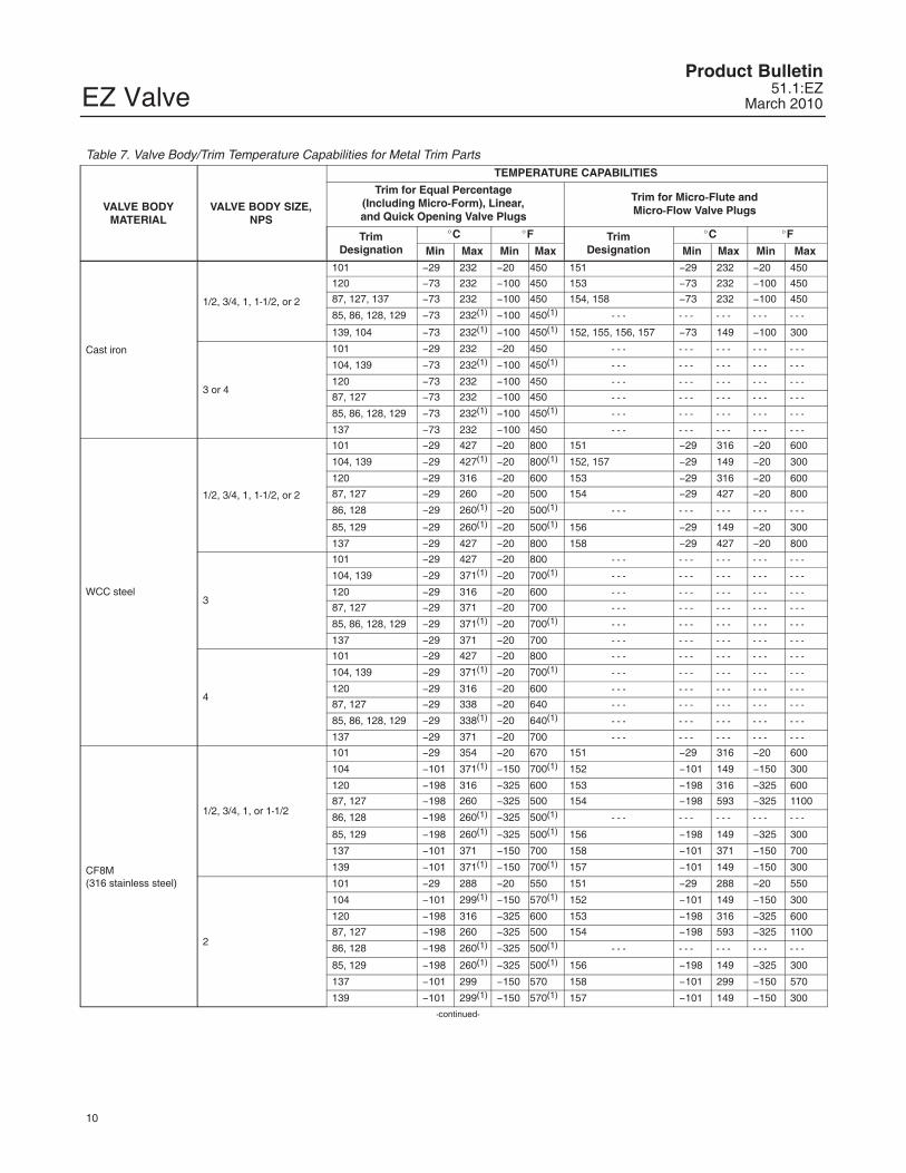
CoefficientsTable 21. Fisher EZ, Quick Opening Valve Plug
Quick Opening - Flow Up Quick OpeningCharacteristic
ValveSize,NPS
PortDiameter
MaximumTravel(1)
FlowCoeffi-cient
Coeffs. for6 mm
(0.25 Inch)Travel(2)
Valve Opening—Percent of Total TravelFL
(3)
mm Inches mm Inches 10 20 30 40 50 60 70 80 90 100
1/2 25.4 1 19 0.75
Cv - - - 1.76 3.29 4.29 4.44 4.44 4.44 4.44 4.44 4.44 4.44 0.83
Kv - - - 1.52 2.85 3.71 3.84 3.84 3.84 3.84 3.84 3.84 3.84 - - -
XT - - - 0.364 0.649 0.764 0.863 0.894 0.894 0.894 0.894 0.894 0.894 - - -
3/4 25.4 1 19 0.75
Cv - - - 3.85 7.19 9.40 9.72 9.72 9.72 9.72 9.72 9.72 9.72 0.88
Kv - - - 3.33 6.22 8.13 8.41 8.41 8.41 8.41 8.41 8.41 8.41 - - -
XT - - - 0.314 0.559 0.654 0.742 0.769 0.769 0.769 0.769 0.769 0.769 - - -
1 25.4 1 19 0.75
Cv 14.7 4.39 10.3 14.0 15.5 16.2 16.6 16.8 16.8 16.9 16.9 0.94
Kv 12.7 3.80 8.91 12.1 13.4 14.0 14.4 14.5 14.5 14.6 14.6 - - -
XT 14.7 0.400 0.449 0.523 0.539 0.535 0.512 0.500 0.500 0.494 0.494 - - -
Fd - - - 0.20 0.29 0.39 0.48 0.50 0.50 0.50 0.50 0.50 0.50 - - -
1-1/2
38.1 1.5 19 0.75
Cv 22.6 5.64 11.9 20.6 27.4 30.5 32.4 33.4 33.7 34.1 34.2 0.96
Kv 19.5 4.88 10.3 17.8 23.7 26.4 28.0 28.9 29.2 29.5 29.6 - - -
XT 22.6 0.623 0.734 0.726 0.814 0.843 0.857 0.861 0.860 0.853 0.848 - - -
Fd - - - 0.16 0.24 0.32 0.39 0.45 0.50 0.50 0.50 0.50 0.50 - - -
25.4(4)
1(4) 19 0.75
Cv 15.7 4.17 8.94 14.6 17.4 18.3 18.8 18.9 19.0 19.1 19.4 0.90
Kv 13.6 3.61 7.73 12.6 15.1 15.8 16.3 16.3 16.4 16.5 16.8 - - -
XT 15.7 0.617 0.791 0.793 0.904 0.925 0.924 0.922 0.915 0.905 0.878 - - -
2
50.8 2 29 1.125
Cv 34.0 13.0 30.1 44.3 52.4 56.4 57.8 58.4 58.5 58.6 58.6 0.94
Kv 29.4 11.2 26.0 38.3 45.3 48.8 50.0 50.5 50.6 50.7 50.7 - - -
XT 34.0 0.548 0.663 0.765 0.813 0.818 0.833 0.831 0.836 0.834 0.834 - - -
Fd - - - 0.17 0.28 0.36 0.43 0.49 0.50 0.50 0.50 0.50 0.50 - - -
25.4(4)
1(4) 19 0.75
Cv 15.8 4.35 9.79 14.9 16.6 17.3 17.5 17.5 17.6 17.7 17.9 0.86
Kv 13.7 3.76 8.47 12.9 14.4 15.0 15.1 15.1 15.2 15.3 15.5 - - -
XT 15.8 0.524 0.594 0.695 0.877 0.937 0.944 0.958 0.952 0.942 0.921 - - -
3
76.2 3 38 1.5
Cv 53.8 30.8 65.1 92.4 110 118 123 126 128 129 129 0.91
Kv 46.5 26.6 56.3 79.9 95.2 102 106 109 111 112 112 - - -
XT 53.8 0.672 0.714 0.713 0.742 0.784 0.785 0.783 0.776 0.774 0.774 - - -
Fd - - - 0.17 0.27 0.35 0.42 0.47 0.50 0.50 0.50 0.50 0.50 - - -
50.8(4)
2(4) 29 1.125
Cv 32.2 9.99 27.6 44.9 61.0 71.9 78.4 83.1 86.2 87.5 88.4 0.95
Kv 27.9 8.64 23.9 38.8 52.8 62.2 67.8 71.9 74.6 75.7 76.5 - - -
XT 32.2 0.527 0.511 0.652 0.720 0.780 0.820 0.814 0.798 0.790 0.779 - - -
4
101.6 4 51 2
Cv 68.2 50.8 116 159 185 201 212 219 222 223 223 0.88
Kv 59.0 43.9 100 138 160 174 183 189 192 193 193 - - -
XT 68.2 0.733 0.653 0.724 0.805 0.809 0.816 0.809 0.812 0.831 0.835 - - -
Fd - - - 0.18 0.28 0.36 0.42 0.48 0.50 0.50 0.50 0.50 0.50 - - -
50.8(4)
2(4) 29 1.125
Cv 37.4 13.5 32.3 52.2 66.2 74.4 81.1 85.0 85.8 86.3 86.7 0.85
Kv 32.4 11.7 27.9 45.2 57.3 64.4 70.2 73.5 74.2 74.6 75.0 - - -
XT 37.4 0.490 0.556 0.609 0.672 0.793 0.772 0.728 0.714 0.711 0.704 - - -1. When using Fisher 655-EZ as a control valve for on-off service, the maximum travel for sizing purposes is 19 mm (0.75 inch).2. When sizing self-operated regulators, use coefficients listed for 6 mm (0.25 inch) travel.3. At 100% travel.4. Restricted trim.
The flow coefficients shown on this page are appropriate for EZ-C valves.

EZ ValveProduct Bulletin51.1:EZMarch 2010
21
Table 22. Fisher EZ, Linear Valve Plug
Linear - Flow Up LinearCharacteristic
ValveSize,NPS
Port Diameter
MaximumTravel(1)
FlowCoeffi-cient
Valve Opening—Percent of Total TravelFL
(1)
mm Inches mm Inches 10 20 30 40 50 60 70 80 90 100
1 25.4 1 19 0.75
Cv 2.21 3.87 5.29 6.56 8.2 9.82 11.1 12.1 13.0 13.6 0.96
Kv 1.91 3.35 4.58 5.67 7.09 8.49 9.60 10.5 11.2 11.8 - - -
XT 0.638 0.601 0.638 0.634 0.638 0.629 0.636 0.680 0.769 0.834 - - -
1-1/2
38.1 1.5 19 0.75
Cv 3.99 7.53 11.1 14.8 18.7 22.5 25.8 29.2 31.2 31.9 0.96
Kv 3.45 6.51 9.6 12.8 16.2 19.5 22.3 25.3 27.0 27.6 - - -
XT 0.633 0.651 0.657 0.691 0.674 0.674 0.696 0.704 0.757 0.818 - - -
25.4(2)
1(2) 19 0.75
Cv 1.96 3.42 4.94 6.11 7.8 9.3 10.9 13 15.1 16.7 0.96
Kv 1.70 2.96 4.27 5.29 6.75 8.04 9.43 11.2 13.1 14.4 - - -
XT 0.469 0.578 0.600 0.690 0.652 0.655 0.637 0.625 0.719 0.796 - - -
2
50.8 2 29 1.125
Cv 6.08 11.9 18.0 24.1 30.1 36.4 42.8 49.9 52.0 52.4 0.95
Kv 5.26 10.3 15.6 20.8 26.0 31.5 37.0 43.2 45.0 45.3 - - -
XT 0.560 0.644 0.655 0.675 0.701 0.724 0.779 0.773 0.862 0.924 - - -
25.4(2)
1(2) 19 0.75
Cv 1.88 3.41 4.95 6.49 8.06 9.67 11.23 12.79 14.35 15.7 0.94
Kv 1.63 2.95 4.28 5.61 6.97 8.36 9.71 11.1 12.4 13.6 - - -
XT 0.609 0.593 0.597 0.624 0.621 0.626 0.642 0.633 0.750 0.910 - - -
3
76.2 3 38 1.5
Cv 15.4 29.6 43.4 58.3 71.8 83.9 93.8 103 108 110.4 0.92
Kv 13.3 25.6 37.5 50.4 62.1 72.6 81.1 89.1 93.4 95.5 - - -
XT 0.622 0.642 0.692 0.691 0.690 0.721 0.759 0.788 0.839 0.888 - - -
50.8(2)
2(2) 29 1.125
Cv 6.59 13.3 20.7 28.1 36.0 44.0 55.6 67.5 76.2 80.4 0.94
Kv 5.70 11.5 17.9 24.3 31.1 38.1 48.1 58.4 65.9 69.5 - - -
XT 0.564 0.500 0.522 0.609 0.577 0.594 0.563 0.582 0.677 0.749 - - -
4
101.6 4 51 2
Cv 21.3 39.7 57.5 75.8 100 129 157 180 199 209 0.89
Kv 18.4 34.3 49.7 65.6 86.5 112 136 156 172 181 - - -
XT 0.554 0.628 0.684 0.723 0.665 0.608 0.677 0.826 0.862 0.866 - - -
50.8(2)
2(2) 29 1.125
Cv 6.16 12.8 20.0 27.8 36.1 45.1 58.8 67.5 78.8 86.8 0.90
Kv 5.33 11.1 17.3 24.0 31.2 39.0 50.9 58.4 68.2 75.1 - - -
XT 0.740 0.644 0.642 0.619 0.602 0.605 0.552 0.614 0.644 0.736 - - -1. At 100% travel.2. Restricted trim.
Notes: The coefficients shown on this page are also appropriate for EZ-C valves.

EZ ValveProduct Bulletin
51.1:EZMarch 2010
22
Table 23. Fisher EZ, Equal Percentage Valve Plug
Equal Percentage - Flow Up Equal PercentageCharacteristic
ValveSize,NPS
PortDiameter
MaximumTravel
FlowCoeffi-cient
Valve Opening—Percent of Total TravelFL
(1)
mm Inches mm Inches 10 20 30 40 50 60 70 80 90 100
1 25.4 1 19 0.75
Cv 0.79 1.25 1.80 2.53 3.63 5.28 7.59 10.7 12.7 13.2 0.96
Kv 0.683 1.08 1.56 2.19 3.14 4.57 6.57 9.26 11.0 11.4 - - -
XT 0.641 0.634 0.598 0.586 0.584 0.596 0.646 0.680 0.757 0.886 - - -
Fd 0.091 0.11 0.13 0.16 0.19 0.24 0.30 0.37 0.43 0.50 - - -
1-1/2
38.1 1.5 19 0.75
Cv 0.795 1.23 1.91 2.95 4.30 6.46 9.84 16.4 22.2 28.1 0.97
Kv 0.688 1.06 1.65 2.55 3.72 5.59 8.51 14.2 19.2 24.3 - - -
XT 0.726 0.676 0.733 0.645 0.589 0.558 0.597 0.653 0.777 0.840 - - -
Fd 0.077 0.086 0.10 0.12 0.15 0.17 0.22 0.27 0.34 0.40 - - -
25.4(2)
1(2) 19 0.75
Cv 0.770 1.23 1.78 2.58 3.67 5.54 8.30 12.0 15.1 17.3 0.98
Kv 0.666 1.06 1.54 2.23 3.17 4.79 7.18 10.4 13.1 15.0 - - -
XT 0.654 0.619 0.601 0.605 0.561 0.534 0.518 0.575 0.704 0.861 - - -
2
50.8 2 29 1.125
Cv 1.65 2.61 4.30 6.62 11.1 20.7 32.8 44.7 50.0 53.8 0.95
Kv 1.43 2.26 3.72 5.73 9.60 17.9 28.4 38.7 43.3 46.5 - - -
XT 0.655 0.581 0.520 0.559 0.552 0.529 0.653 0.801 0.903 0.899 - - -
Fd 0.069 0.085 0.11 0.13 0.18 0.23 0.30 0.37 0.44 0.50 - - -
25.4(2)
1(2) 19 0.75
Cv 1.02 1.50 2.05 2.78 3.90 5.57 8.16 11.8 14.5 15.9 0.92
Kv 0.882 1.30 1.77 2.40 3.37 4.82 7.06 10.2 12.5 13.8 - - -
XT 0.596 0.616 0.600 0.580 0.572 0.555 0.523 0.547 0.671 0.905 - - -
3
76.2 3 38 1.5
Cv 3.11 5.77 9.12 13.7 21.7 36.0 60.4 86.4 104 114 0.92
Kv 2.69 4.99 7.89 11.9 18.8 31.1 52.2 74.7 90.0 98.6 - - -
XT 0.619 0.595 0.598 0.619 0.594 0.563 0.586 0.729 0.778 0.781 - - -
Fd 0.062 0.081 0.10 0.12 0.16 0.20 0.26 0.33 0.40 0.46 - - -
50.8(2)
2(2) 29 1.125
Cv 2.11 3.11 4.58 6.76 10.7 20.7 34.3 48.3 61.5 71.6 0.92
Kv 1.83 2.69 3.96 5.85 9.26 17.9 29.7 41.8 53.2 61.9 - - -
XT 0.874 0.699 0.643 0.626 0.587 0.451 0.493 0.587 0.648 0.734 - - -
4
101.6 4 51 2
Cv 4.90 8.19 13.5 20.1 31.2 52.6 96.7 140 170 190 0.90
Kv 4.24 7.08 11.7 17.4 27.0 45.5 83.6 121 147 164 - - -
XT 0.594 0.573 0.560 0.568 0.572 0.564 0.532 0.707 0.807 0.834 - - -
Fd 0.052 0.065 0.080 0.10 0.13 0.17 0.23 0.31 0.38 0.44 - - -
50.8(2)
2(2) 29 1.125
Cv 1.96 3.05 4.43 6.98 11.9 22.3 36.7 50.9 61.8 72.7 0.92
Kv 1.70 2.64 3.83 6.04 10.3 19.3 31.7 44.0 53.5 62.9 - - -
XT 0.619 0.575 0.624 0.610 0.678 0.639 0.646 0.673 0.778 0.781 - - -1. At 100% travel.2. Restricted trim.
Notes: The coefficients shown on this page are appropriate for EZ-C valves.

EZ ValveProduct Bulletin51.1:EZMarch 2010
23
Table 24. Fisher EZ, Micro-Form Valve Plug
Micro-Form - Flow Up Equal PercentageCharacteristic
ValveSize,NPS
PortDiameter
MaximumTravel
FlowCoeffi-cient
Valve Opening—Percent of Total TravelFL
(1)
mm Inches mm Inches 5 10 20 30 40 50 60 70 80 90 100
All Sizes1/2 - 2 6.4 0.25 19 0.75
Cv 0.075 0.088 0.124 0.175 0.236 0.327 0.464 0.641 0.881 1.22 1.52 0.88
Kv 0.065 0.076 0.107 0.151 0.204 0.283 0.401 0.554 0.762 1.06 1.31 - - -
XT 0.804 0.771 0.717 0.658 0.645 0.620 0.585 0.596 0.596 0.603 0.647 - - -
1/2
9.5 0.375 19 0.75
Cv 0.102 0.134 0.202 0.313 0.448 0.613 0.879 1.27 1.77 2.47 3.00 0.93
Kv 0.088 0.116 0.175 0.271 0.388 0.530 0.760 1.10 1.53 2.14 2.59 - - -
XT 0.766 0.711 0.679 0.618 0.602 0.588 0.564 0.580 0.599 0.593 0.723 - - -
12.7 0.5 19 0.75
Cv 0.137 0.193 0.324 0.496 0.737 1.07 1.52 2.13 2.93 3.89 4.52 0.94
Kv 0.119 0.167 0.280 0.429 0.638 0.926 1.31 1.84 2.53 3.36 3.91 - - -
XT 0.739 0.689 0.631 0.595 0.603 0.602 0.592 0.604 0.636 0.687 0.754 - - -
3/4
9.5 0.375 19 0.75
Cv 0.101 0.131 0.205 0.312 0.446 0.618 0.882 1.28 1.80 2.45 3.03 0.93
Kv 0.087 0.113 0.177 0.270 0.386 0.535 0.763 1.11 1.56 2.12 2.62 - - -
XT 0.807 0.751 0.642 0.655 0.616 0.597 0.603 0.601 0.607 0.650 0.736 - - -
12.7 0.5 19 0.75
Cv 0.133 0.190 0.318 0.486 0.732 1.07 1.52 2.15 3.07 4.20 5.06 0.94
Kv 0.115 0.164 0.275 0.420 0.633 0.926 1.31 1.86 2.66 3.63 4.38 - - -
XT 0.780 0.720 0.655 0.628 0.606 0.598 0.598 0.596 0.596 0.636 0.722 - - -
19.1 0.75 19 0.75
Cv 0.276 0.373 0.617 0.948 1.44 2.14 3.10 4.43 6.14 7.58 8.35 0.87
Kv 0.239 0.323 0.534 0.820 1.25 1.85 2.68 3.83 5.31 6.56 7.22 - - -
XT 0.734 0.702 0.618 0.634 0.605 0.607 0.646 0.670 0.699 0.730 0.693 - - -
1
9.5 0.375 19 0.75
Cv 0.099 0.129 0.199 0.308 0.448 0.620 0.882 1.29 1.80 2.43 3.07 0.89
Kv 0.086 0.112 0.172 0.266 0.388 0.536 0.763 1.12 1.56 2.10 2.66 - - -
XT 0.795 0.747 0.663 0.641 0.593 0.569 0.568 0.560 0.571 0.624 0.662 - - -
12.7 0.5 19 0.75
Cv 0.133 0.189 0.319 0.492 0.735 1.08 1.53 2.12 2.99 4.17 4.91 0.93
Kv 0.115 0.163 0.276 0.426 0.636 0.934 1.32 1.83 2.59 3.61 4.25 - - -
XT 0.787 0.728 0.639 0.628 0.591 0.573 0.585 0.600 0.618 0.645 0.803 - - -
19.1 0.75 19 0.75
Cv 0.276 0.374 0.622 0.965 1.47 2.17 3.15 4.57 6.52 8.17 8.84 0.97
Kv 0.239 0.324 0.538 0.835 1.27 1.88 2.72 3.95 5.64 7.07 7.65 - - -
XT 0.723 0.687 0.614 0.588 0.560 0.571 0.596 0.603 0.624 0.750 0.919 - - -
1-1/2 and 2
9.5 0.375 19 0.75
Cv 0.096 0.121 0.190 0.302 0.435 0.600 0.864 1.26 1.80 2.56 3.20 0.84
Kv 0.083 0.105 0.164 0.261 0.376 0.519 0.747 1.09 1.56 2.21 2.77 - - -
XT 0.923 0.915 0.763 0.699 0.657 0.640 0.624 0.608 0.596 0.594 0.648 - - -
12.7 0.5 19 0.75
Cv 0.145 0.199 0.323 0.503 0.735 1.07 1.54 2.14 3.08 4.36 5.18 0.91
Kv 0.125 0.172 0.279 0.435 0.636 0.926 1.33 1.85 2.66 3.77 4.48 - - -
XT 0.851 0.748 0.686 0.640 0.617 0.627 0.602 0.607 0.607 0.573 0.705 - - -
19.1 0.75 19 0.75
Cv 0.336 0.434 0.683 1.00 1.49 2.21 3.18 4.61 6.73 8.88 10.2 0.92
Kv 0.291 0.375 0.591 0.865 1.29 1.91 2.75 3.99 5.82 7.68 8.82 - - -
XT 0.784 0.747 0.625 0.636 0.596 0.578 0.603 0.593 0.591 0.680 0.796 - - -1. At 100% travel.
Notes: The coefficients on this page are also appropriate for EZ-C valves.
EZ ValveProduct Bulletin
51.1:EZMarch 2010
24
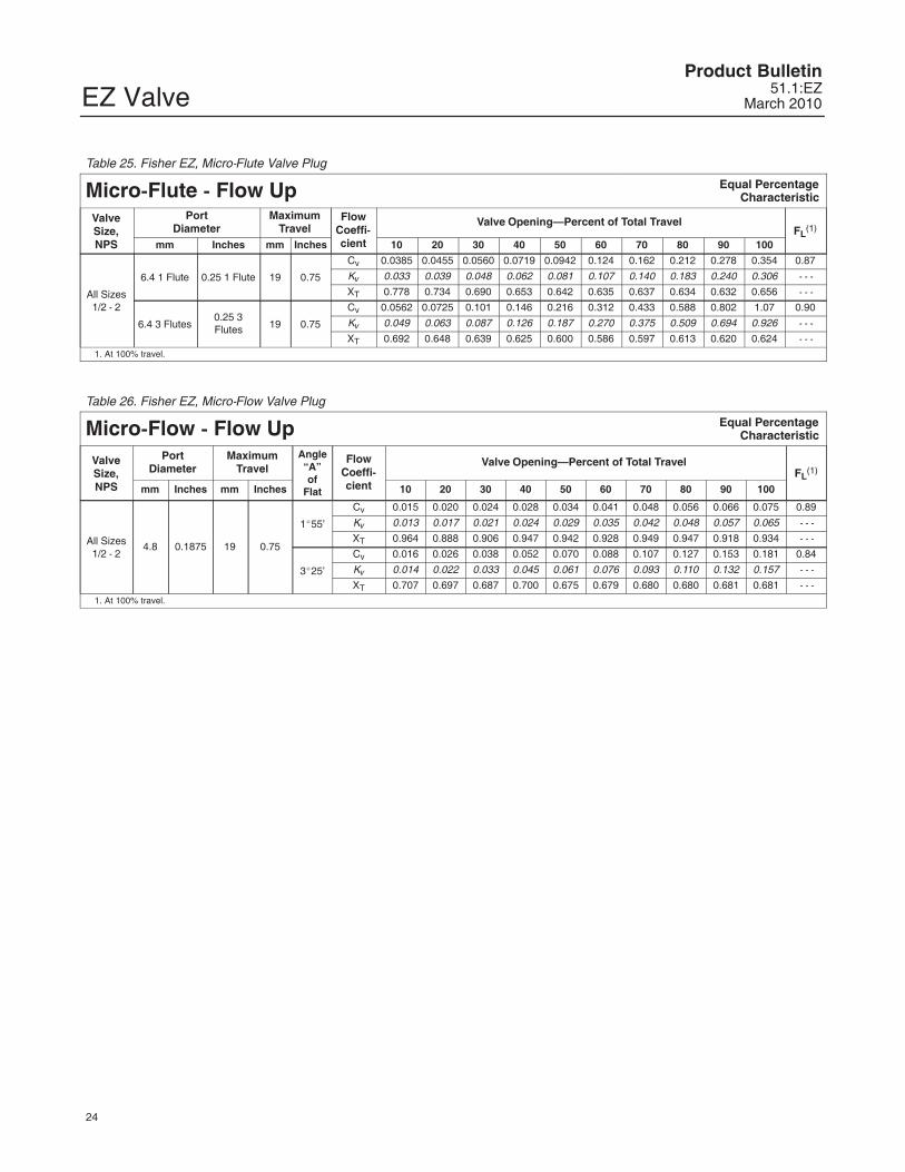
Table 25. Fisher EZ, Micro-Flute Valve Plug
Micro-Flute - Flow Up Equal PercentageCharacteristic
ValveSize,NPS
PortDiameter
MaximumTravel
FlowCoeffi-cient
Valve Opening—Percent of Total TravelFL
(1)
mm Inches mm Inches 10 20 30 40 50 60 70 80 90 100
All Sizes1/2 - 2
6.4 1 Flute 0.25 1 Flute 19 0.75
Cv 0.0385 0.0455 0.0560 0.0719 0.0942 0.124 0.162 0.212 0.278 0.354 0.87
Kv 0.033 0.039 0.048 0.062 0.081 0.107 0.140 0.183 0.240 0.306 - - -
XT 0.778 0.734 0.690 0.653 0.642 0.635 0.637 0.634 0.632 0.656 - - -
6.4 3 Flutes0.25 3Flutes 19 0.75
Cv 0.0562 0.0725 0.101 0.146 0.216 0.312 0.433 0.588 0.802 1.07 0.90
Kv 0.049 0.063 0.087 0.126 0.187 0.270 0.375 0.509 0.694 0.926 - - -
XT 0.692 0.648 0.639 0.625 0.600 0.586 0.597 0.613 0.620 0.624 - - -1. At 100% travel.
Table 26. Fisher EZ, Micro-Flow Valve Plug
Micro-Flow - Flow Up Equal PercentageCharacteristic
ValveSize,NPS
PortDiameter
MaximumTravel
Angle“A”of
Flat
FlowCoeffi-cient
Valve Opening—Percent of Total TravelFL
(1)
mm Inches mm Inches 10 20 30 40 50 60 70 80 90 100
All Sizes1/2 - 2
4.8 0.1875 19 0.75
1�55’
Cv 0.015 0.020 0.024 0.028 0.034 0.041 0.048 0.056 0.066 0.075 0.89
Kv 0.013 0.017 0.021 0.024 0.029 0.035 0.042 0.048 0.057 0.065 - - -
XT 0.964 0.888 0.906 0.947 0.942 0.928 0.949 0.947 0.918 0.934 - - -
3�25’
Cv 0.016 0.026 0.038 0.052 0.070 0.088 0.107 0.127 0.153 0.181 0.84
Kv 0.014 0.022 0.033 0.045 0.061 0.076 0.093 0.110 0.132 0.157 - - -
XT 0.707 0.697 0.687 0.700 0.675 0.679 0.680 0.680 0.681 0.681 - - -1. At 100% travel.

EZ ValveProduct Bulletin51.1:EZMarch 2010
25
SpecificationsValve Sizes
NPS � 1/2, � 3/4, � 1, � 1-1/2, � 2, � 3, and� 4
End Connection Styles(1, 2)
Cast Iron Valves.Flanged: NPS 1 through 4, � CL125 flat-face or� CL250 raised-face flanges per ASME B16.1Steel and Stainless Steel Valves.Flanged: � CL150, CL300, or CL600 raised-face(RF) or ring-type joint (RTJ) flanges per ASME B16.5Screwed or Socket Welding: NPS 1/2 through 2,consistent with ASME B16.11Buttwelding (schedule 40 or 80): NPS 1 through 4, consistent with ASME B16.25
Maximum Inlet Pressure and Temperatures(1, 2)
As listed below, unless limited by maximumpressure drop or material temperature capabilitiesCast Iron Valves.Flanged: Consistent with CL125B or CL250Bpressure-temperature ratings per ASME B16.1Steel and Stainless Steel Valves.Flanged: Consistent with CL150, CL300, andCL600(3) per ASME B16.34Screwed or Welding: Consistent with CL600(3) perASME B16.34
Maximum Pressure Drops(2)
Same as maximum inlet pressure for specificconstruction defined above, except where furtherlimited as shown in tables 8, 9, and 11. For softseats on NACE service, see figure 5.
Shutoff Classification Per ANSI/FCI 70-2and IEC 60534-4
Metal Seating: Class IV is standard. Class V isoptional.PTFE Composition Seating: Class VI
Construction Materials
Body and Bonnet: � Cast iron, � WCC steel,� CF8M (316 stainless steel), � WC9 chrome
moly steel, or � other materials upon requestTrim Materials: See tables 3, 4, 5, and 15.All Other Parts: See tables 6 and 10
Material Temperature Capabilities(2)
Body-Trim Combinations: See table 7.Bolting for NACE MR0175 / ISO 15156 andMR0103: See table 17.All Other Parts: See tables 6 and 10
Flow Characteristics
� Equal percentage, � quick opening, and� linear. With soft seat, equal percentage isstandard
Flow Direction
Up through the seat ring
Flow Coefficients and Noise Level Predictions
See table 14 and Catalog 12
Port Diameters and Valve Plug Travels
See table 15
Yoke Boss and Stem Diameters
See table 15
Typical Bonnet Styles
� Plain or � extension. See figure 7 for standarddimensions� ENVIRO-SEAL bellows seal bonnet. See figure3. Also, see Bulletin 59.1:070, ENVIRO-SEALBellows Seal Bonnets, for more information.
- continued -

EZ ValveProduct Bulletin
51.1:EZMarch 2010
26
Specifications (continued)Packing Arrangements
Standard Material: Single PTFE V-ringOptional Materials: See table 6.ENVIRO-SEAL Packing Systems: See figure 4.ENVIRO-SEAL Packing Systems in vacuumservice: Standard ENVIRO-SEAL packingsystems can be used in vacuum service withpacking rings in standard orientation. Do notreverse the ENVIRO-SEAL PTFE packing rings.Also, see Bulletin 59.1:061, ENVIRO-SEALPacking Systems for Sliding-Stem Valves, formore information.
Approximate Weights
NPS 1/2, 3/4 valves: 9 kg (20 lb)
NPS 1 valve: 11 kg (25 lb)NPS 1-1/2 valve: 18 kg (40 lb)NPS 2 valve: 36 kg (80 lb)NPS 3 valve: 54 kg (120 lb)NPS 4 valve: 75 kg (165 lb)
Valve Dimensions
See figure 7. � ENVIRO-SEAL bellows sealbonnet dimensions, figure 6
Additional Options
� Lubricator or � lubricator/isolating valve forpacking lubrication and � valve body drain plug
1. EN (or other) ratings and end connections can usually be supplied; consult your Emerson Process Management sales office.2. Do not exceed the pressure/temperature limits in this bulletin. Any applicable standard or code limitations should not be exceeded.3. Certain bonnet bolting material selections may require a CL600 easy-e valve assembly to be derated. Contact your Emerson Process Management sales office for more information.

EZ ValveProduct Bulletin51.1:EZMarch 2010
27
ENVIRO-SEAL Packing System SpecificationsApplicable Stem Diameters
� 9.5 mm (3/8 inches), � 12.7 (1/2), � 19.1 (3/4)diameter valve stems
Maximum Pressure/Temperature Limits(1)
To Meet the EPA Fugitive Emission Standardof 100 PPM(2).
For ENVIRO-SEAL PTFE and ENVIRO-SEALDuplex packing systems: full CL300 up to 232�C(450�F)For ENVIRO-SEAL Graphite ULF packing: 104bar (1500 psig) at 316�C (600�F)
Construction MaterialsPTFE Packing Systems.Packing Ring and Lower Wiper: PTFE V-ring(3).
Male and Female Adaptor Rings: Carbon-filledPTFE V-ringGraphite ULF Packing Systems: Graphite ringsAnti-Extrusion Washer: Filled PTFE (notrequired for Graphite ULF packing)Lantern Ring: S31600 (316 stainless steel) (notrequired for Graphite ULF packing)Packing Box Flange: S31600Spring: � 17-7PH stainless steel or � N07718Packing Follower: S31600 lined withcarbon-filled PTFEPacking Box Studs: Strain-hardened 316stainless steelPacking Box Nuts: 316 stainless steel SA194Grade 8M
1. Refer to the valve specifications in this bulletin for pressure/temperature limits of valve parts. Do not exceed the pressure/temperature rating of the valve. Do not exceed any applicable codeor standard limitation.2. The Environmental Protection Agency (EPA) has set a limit of 100 parts per million (ppm) for fugitive emissions from a valve in selected VOC (Volatile Organic Compound) services.3. In vacuum service, it is not necessary to reverse the ENVIRO-SEAL PTFE packing rings.

EZ ValveProduct Bulletin
51.1:EZMarch 2010
28
Note
Neither Emerson, Emerson ProcessManagement, nor any of their affiliatedentities assumes responsibility for theselection, use, or maintenance of anyproduct. Responsibility for theselection, use, and maintenance of anyproduct remains with the purchaserand end user.
Emerson Process Management Marshalltown, Iowa 50158 USASorocaba, 18087 BrazilChatham, Kent ME4 4QZ UKDubai, United Arab EmiratesSingapore 128461 Singapore
�Fisher Controls International LLC 1979, 2010; All Rights Reserved
www.Fisher.com
The contents of this publication are presented for informational purposes only, and while every effort has been made to ensure their accuracy, theyare not to be construed as warranties or guarantees, express or implied, regarding the products or services described herein or their use orapplicability. All sales are governed by our terms and conditions, which are available upon request. We reserve the right to modify or improve thedesigns or specifications of such products at any time without notice. Neither Emerson, Emerson Process Management, nor any of their affiliatedentities assumes responsibility for the selection, use or maintenance of any product. Responsibility for proper selection, use, and maintenance ofany product remains solely with the purchaser and end user.
Fisher, easy-e, and ENVIRO-SEAL are marks owned by one of the companies in the Emerson Process Management business division of EmersonElectric Co. Emerson Process Management, Emerson, and the Emerson logo are trademarks and service marks of Emerson Electric Co. All othermarks are the property of their respective owners.
Related Documents