Fisher Architecture, LLC Wicomico Airport Maintenance Facility 2020050 000000 - TABLE OF CONTENTS Page 1 of 2 SECTION 000000 - TABLE OF CONTENTS SPECIFICATIONS GROUP General Requirements Subgroup Division 03 - Concrete (2) Division Name Description 03 30 00 Cast-In-Place Concrete ……………….. Slab-on-grade and elevated floor slabs 03 35 00 Concrete Finishing ………………….... Garage flooring Division 04 - Masonry (1) Division Name Description 04 22 00 Concrete Unit Masonry…………….…. Exterior walls Division 07 - Thermal and Moisture Protection (12) Division Name Description 07 41 13 Metal Roof Panels Roofing Division 09 - Finishes Division Name Description 09 29 00 Gypsum Board………………………… Interior finish layer; walls & ceilings 09 30 13 Ceramic Tiling……………………...…. Non-Absorbent Surface required locations 09 65 13 Resilient Base and Accessories ………. Edge conditions where walls meet floors 09 65 19 Resilient Tile Flooring…………………Flooring throughout unless noted otherwise 09 91 23 Interior Painting………………………..Wall and Ceiling Finish Division 22 - Plumbing Division Name 22 05 13 Common Motor Requirements for Plumbing Equipment 22 05 53 Identification for Plumbing Piping and Equipment 22 07 19 Plumbing Piping Insulation 22 10 05 Plumbing Piping 22 10 06 Plumbing Piping Specialties 22 30 00 Plumbing Equipment 23 40 00 Plumbing Fixtures Division 23 - Heating, Ventilating, and Air-Conditioning (HVAC) Division Name 23 05 53 Identification for HVAC Piping and Equipment 23 05 93 Testing, Adjusting, and Balancing for HVAC 23 07 13 Duct Insulation 23 23 00 Refrigerant Piping 23 31 00 HVAC Ducts and Casings 23 33 00 Air Duct Accessories

Welcome message from author
This document is posted to help you gain knowledge. Please leave a comment to let me know what you think about it! Share it to your friends and learn new things together.
Transcript
Fisher Architecture, LLC Wicomico Airport Maintenance Facility 2020050
000000 - TABLE OF CONTENTS Page 1 of 2
SECTION 000000 - TABLE OF CONTENTS SPECIFICATIONS GROUP
General Requirements Subgroup
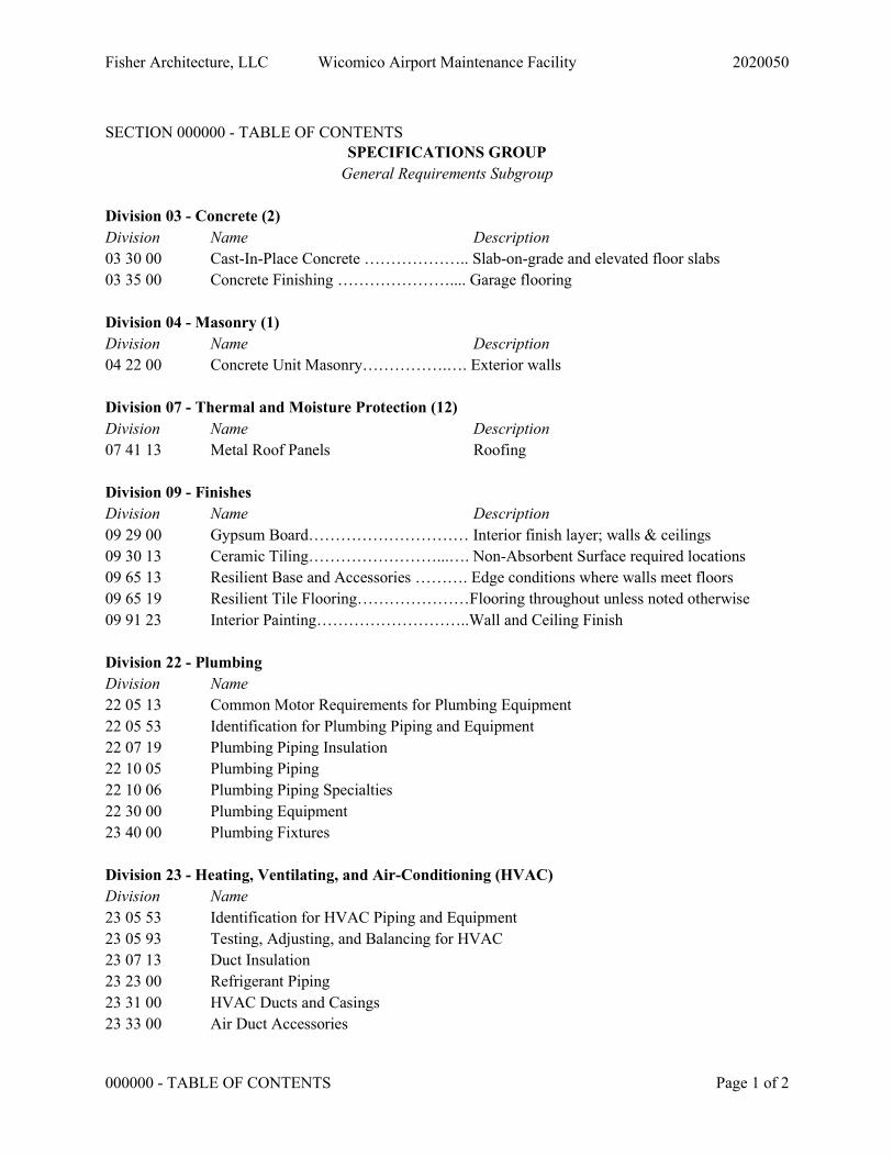
Division 03 - Concrete (2) Division Name Description 03 30 00 Cast-In-Place Concrete ……………….. Slab-on-grade and elevated floor slabs 03 35 00 Concrete Finishing ………………….... Garage flooring Division 04 - Masonry (1) Division Name Description 04 22 00 Concrete Unit Masonry…………….…. Exterior walls Division 07 - Thermal and Moisture Protection (12) Division Name Description 07 41 13 Metal Roof Panels Roofing Division 09 - Finishes Division Name Description 09 29 00 Gypsum Board………………………… Interior finish layer; walls & ceilings 09 30 13 Ceramic Tiling……………………...…. Non-Absorbent Surface required locations 09 65 13 Resilient Base and Accessories ………. Edge conditions where walls meet floors 09 65 19 Resilient Tile Flooring…………………Flooring throughout unless noted otherwise 09 91 23 Interior Painting………………………..Wall and Ceiling Finish Division 22 - Plumbing Division Name 22 05 13 Common Motor Requirements for Plumbing Equipment 22 05 53 Identification for Plumbing Piping and Equipment 22 07 19 Plumbing Piping Insulation 22 10 05 Plumbing Piping 22 10 06 Plumbing Piping Specialties 22 30 00 Plumbing Equipment 23 40 00 Plumbing Fixtures Division 23 - Heating, Ventilating, and Air-Conditioning (HVAC) Division Name 23 05 53 Identification for HVAC Piping and Equipment 23 05 93 Testing, Adjusting, and Balancing for HVAC 23 07 13 Duct Insulation 23 23 00 Refrigerant Piping 23 31 00 HVAC Ducts and Casings 23 33 00 Air Duct Accessories
Fisher Architecture, LLC Wicomico Airport Maintenance Facility 2020050
000000 - TABLE OF CONTENTS Page 2 of 2
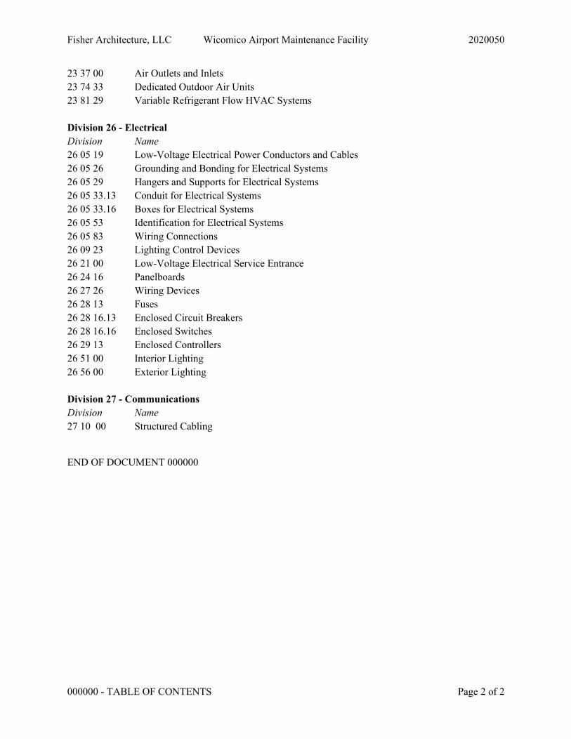
23 37 00 Air Outlets and Inlets 23 74 33 Dedicated Outdoor Air Units 23 81 29 Variable Refrigerant Flow HVAC Systems Division 26 - Electrical Division Name 26 05 19 Low-Voltage Electrical Power Conductors and Cables 26 05 26 Grounding and Bonding for Electrical Systems 26 05 29 Hangers and Supports for Electrical Systems 26 05 33.13 Conduit for Electrical Systems 26 05 33.16 Boxes for Electrical Systems 26 05 53 Identification for Electrical Systems 26 05 83 Wiring Connections 26 09 23 Lighting Control Devices 26 21 00 Low-Voltage Electrical Service Entrance 26 24 16 Panelboards 26 27 26 Wiring Devices 26 28 13 Fuses 26 28 16.13 Enclosed Circuit Breakers 26 28 16.16 Enclosed Switches 26 29 13 Enclosed Controllers 26 51 00 Interior Lighting 26 56 00 Exterior Lighting Division 27 - Communications Division Name 27 10 00 Structured Cabling
END OF DOCUMENT 000000

Fisher Architecture, LLC Wicomico Airport Maintenance Facility 2020050
033000 - CAST-IN-PLACE CONCRETE Page 1 of 10
SECTION 033000 - CAST-IN-PLACE CONCRETE
PART 1 - GENERAL
1.1 SUMMARY
A. Section includes cast-in-place concrete, including formwork, reinforcement, concrete materials, mixture design, placement procedures, and finishes.
B. Related Requirements:
1. Section 312000 "Earth Moving" for drainage fill under slabs-on-grade.
1.2 ACTION SUBMITTALS
A. Product Data: For each type of product.
B. Design Mixtures: For each concrete mixture.
C. Steel Reinforcement Shop Drawings: Placing Drawings that detail fabrication, bending, and placement.
1.3 INFORMATIONAL SUBMITTALS
A. Material certificates.
B. Material test reports.
C. Formwork Shop Drawings: Prepared by or under the supervision of a qualified professional engineer, detailing fabrication, assembly, and support of formwork.
D. Floor surface flatness and levelness measurements indicating compliance with specified tolerances.
1.4 QUALITY ASSURANCE
A. Manufacturer Qualifications: A firm experienced in manufacturing ready-mixed concrete products and that complies with ASTM C 94/C 94M requirements for production facilities and equipment.
1. Manufacturer certified according to NRMCA's "Certification of Ready Mixed Concrete Production Facilities."
B. Testing Agency Qualifications: An independent agency, acceptable to authorities having jurisdiction, qualified according to ASTM C 1077 and ASTM E 329 for testing indicated.
Fisher Architecture, LLC Wicomico Airport Maintenance Facility 2020050
033000 - CAST-IN-PLACE CONCRETE Page 2 of 10
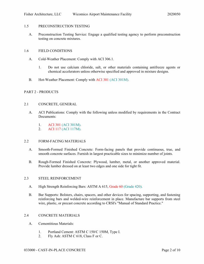
1.5 PRECONSTRUCTION TESTING
A. Preconstruction Testing Service: Engage a qualified testing agency to perform preconstruction testing on concrete mixtures.
1.6 FIELD CONDITIONS
A. Cold-Weather Placement: Comply with ACI 306.1.
1. Do not use calcium chloride, salt, or other materials containing antifreeze agents or chemical accelerators unless otherwise specified and approved in mixture designs.
B. Hot-Weather Placement: Comply with ACI 301 (ACI 301M).
PART 2 - PRODUCTS
2.1 CONCRETE, GENERAL
A. ACI Publications: Comply with the following unless modified by requirements in the Contract Documents:
1. ACI 301 (ACI 301M). 2. ACI 117 (ACI 117M).
2.2 FORM-FACING MATERIALS
A. Smooth-Formed Finished Concrete: Form-facing panels that provide continuous, true, and smooth concrete surfaces. Furnish in largest practicable sizes to minimize number of joints.
B. Rough-Formed Finished Concrete: Plywood, lumber, metal, or another approved material. Provide lumber dressed on at least two edges and one side for tight fit.
2.3 STEEL REINFORCEMENT
A. High Strength Reinforcing Bars: ASTM A 615, Grade 60 (Grade 420).
B. Bar Supports: Bolsters, chairs, spacers, and other devices for spacing, supporting, and fastening reinforcing bars and welded-wire reinforcement in place. Manufacture bar supports from steel wire, plastic, or precast concrete according to CRSI's "Manual of Standard Practice."
2.4 CONCRETE MATERIALS
A. Cementitious Materials:
1. Portland Cement: ASTM C 150/C 150M, Type I. 2. Fly Ash: ASTM C 618, Class F or C.
Fisher Architecture, LLC Wicomico Airport Maintenance Facility 2020050
033000 - CAST-IN-PLACE CONCRETE Page 3 of 10
3. Slag Cement: ASTM C 989/C 989M, Grade 100 or 120. 4. Blended Hydraulic Cement: ASTM C 595/C 595M, Type IS, portland blast-furnace slag
cement. 5. All concrete shall be ready-mix and proportioned on the basis of laboratory trial mixture
or field test data or both according to ACI 301 and ACI 318.
B. Normal-Weight Aggregates: ASTM C 33/C 33M, graded.
1. Maximum Coarse-Aggregate Size: 3/4 inch (19 mm) nominal. 2. Fine Aggregate: Free of materials with deleterious reactivity to alkali in cement.
C. Lightweight Aggregate: ASTM C 330/C 330M, 3/4-inch (19-mm) nominal maximum aggregate size.
D. Air-Entraining Admixture: ASTM C 260/C 260M.
E. Chemical Admixtures: Certified by manufacturer to be compatible with other admixtures and that do not contribute water-soluble chloride ions exceeding those permitted in hardened concrete. Do not use calcium chloride or admixtures containing calcium chloride.
1. Water-Reducing Admixture: ASTM C 494/C 494M, Type A. 2. Retarding Admixture: ASTM C 494/C 494M, Type B. 3. Water-Reducing and Retarding Admixture: ASTM C 494/C 494M, Type D. 4. High-Range, Water-Reducing Admixture: ASTM C 494/C 494M, Type F. 5. High-Range, Water-Reducing and Retarding Admixture: ASTM C 494/C 494M, Type G. 6. Plasticizing and Retarding Admixture: ASTM C 1017/C 1017M, Type II.
F. Water: ASTM C 94/C 94M and potable.
2.5 FIBER REINFORCEMENT
A. Synthetic Micro-Fiber: Monofilament polypropylene micro-fibers engineered and designed for use in concrete, complying with ASTM C 1116/C 1116M, Type III, 1/2 to 1-1/2 inches (13 to 38 mm) long.
B. Synthetic Micro-Fiber: Fibrillated polypropylene micro-fibers engineered and designed for use in concrete, complying with ASTM C 1116/C 1116M, Type III, 1 to 2-1/4 inches (25 to 57 mm) long.
2.6 WATERSTOPS
A. Flexible Rubber Waterstops: CE CRD-C 513, with factory-installed metal eyelets, for embedding in concrete to prevent passage of fluids through joints. Factory fabricate corners, intersections, and directional changes.
B. Chemically Resistant Flexible Waterstops: Thermoplastic elastomer rubber waterstops with factory-installed metal eyelets, for embedding in concrete to prevent passage of fluids through joints; resistant to oils, solvents, and chemicals. Factory fabricate corners, intersections, and directional changes.
Fisher Architecture, LLC Wicomico Airport Maintenance Facility 2020050
033000 - CAST-IN-PLACE CONCRETE Page 4 of 10
C. Flexible PVC Waterstops: CE CRD-C 572, with factory-installed metal eyelets, for embedding in concrete to prevent passage of fluids through joints. Factory fabricate corners, intersections, and directional changes.
D. Self-Expanding Butyl Strip Waterstops: Manufactured rectangular or trapezoidal strip, butyl rubber with sodium bentonite or other hydrophilic polymers, for adhesive bonding to concrete, 3/4 by 1 inch (19 by 25 mm).
E. Self-Expanding Rubber Strip Waterstops: Manufactured rectangular or trapezoidal strip, bentonite-free hydrophilic polymer-modified chloroprene rubber, for adhesive bonding to concrete, 3/8 by 3/4 inch (10 by 19 mm).
2.7 VAPOR RETARDERS
A. Sheet Vapor Retarder: ASTM E 1745, Class A. Include manufacturer's recommended adhesive or pressure-sensitive tape.
B. Sheet Vapor Retarder: ASTM E 1745, Class B, except with maximum water-vapor permeance of. Include manufacturer's recommended adhesive or pressure-sensitive tape.
C. Sheet Vapor Retarder: ASTM E 1745, Class C, except with maximum water-vapor permeance of. Include manufacturer's recommended adhesive or pressure-sensitive joint tape.
D. Sheet Vapor Retarder: Polyethylene sheet, ASTM D 4397, not less than 10 mils (0.25 mm) thick.
2.8 CURING MATERIALS
A. Evaporation Retarder: Waterborne, monomolecular film forming, manufactured for application to fresh concrete.
B. Absorptive Cover: AASHTO M 182, Class 2, burlap cloth made from jute or kenaf, weighing approximately 9 oz./sq. yd. (305 g/sq. m) when dry.
C. Moisture-Retaining Cover: ASTM C 171, polyethylene film or white burlap-polyethylene sheet.
D. Water: Potable.
E. Clear, Waterborne, Membrane-Forming Curing Compound: ASTM C 309, Type 1, Class B, dissipating.
F. Clear, Waterborne, Membrane-Forming Curing Compound: ASTM C 309, Type 1, Class B, nondissipating, certified by curing compound manufacturer to not interfere with bonding of floor covering.
G. Clear, Waterborne, Membrane-Forming Curing Compound: ASTM C 309, Type 1, Class B, 18 to 25 percent solids, nondissipating, certified by curing compound manufacturer to not interfere with bonding of floor covering.
Fisher Architecture, LLC Wicomico Airport Maintenance Facility 2020050
033000 - CAST-IN-PLACE CONCRETE Page 5 of 10
H. Clear, Solvent-Borne, Membrane-Forming Curing and Sealing Compound: ASTM C 1315, Type 1, Class A.
I. Clear, Waterborne, Membrane-Forming Curing and Sealing Compound: ASTM C 1315, Type 1, Class A.
2.9 RELATED MATERIALS
A. Expansion- and Isolation-Joint-Filler Strips: ASTM D 1751, asphalt-saturated cellulosic fiber or ASTM D 1752, cork or self-expanding cork.
2.10 CONCRETE MIXTURES, GENERAL
A. Prepare design mixtures for each type and strength of concrete, proportioned on the basis of laboratory trial mixture or field test data, or both, according to ACI 301 (ACI 301M).
B. Cementitious Materials: Use fly ash, pozzolan, slag cement, and silica fume as needed to reduce the total amount of portland cement, which would otherwise be used, by not less than 40 percent.
C. Admixtures: Use admixtures according to manufacturer's written instructions.
1. Use water-reducing or plasticizing admixture in concrete, as required, for placement and workability.
2. Use water-reducing and -retarding admixture when required by high temperatures, low humidity, or other adverse placement conditions.
3. Use water-reducing admixture in pumped concrete, concrete for heavy-use industrial slabs and parking structure slabs, concrete required to be watertight, and concrete with a w/c ratio below 0.50.
2.11 CONCRETE MIXTURES FOR BUILDING ELEMENTS
A. Normal-Weight Concrete:
1. Minimum Compressive Strength: 3500 psi (24.1 MPa) 3000 psi (20.7 MPa) at 28 days. 2. Maximum W/C Ratio: 0.50. 3. Slump Limit: 4 inches (100 mm), plus or minus 1 inch (25 mm). 4. Air Content: 5.5 percent, plus or minus 1.5 percent at point of delivery for 1-1/2-inch
(38-mm) nominal maximum aggregate size. 5. Air Content: 6 percent, plus or minus 1.5 percent at point of delivery for 3/4-inch (19-
mm) nominal maximum aggregate size. 6. Air Content: Do not allow air content of trowel-finished floors to exceed 3 percent. 7. Synthetic Micro-Fiber: Uniformly disperse in concrete mixture at manufacturer's
recommended rate, but not less than a rate of 1.0 lb/cu. yd. (0.60 kg/cu. m).
2.12 FABRICATING REINFORCEMENT
A. Fabricate steel reinforcement according to CRSI's "Manual of Standard Practice."
Fisher Architecture, LLC Wicomico Airport Maintenance Facility 2020050
033000 - CAST-IN-PLACE CONCRETE Page 6 of 10
2.13 CONCRETE MIXING
A. Ready-Mixed Concrete: Measure, batch, mix, and deliver concrete according to ASTM C 94/C 94M and ASTM C 1116/C 1116M, and furnish batch ticket information.
1. When air temperature is between 85 and 90 deg F (30 and 32 deg C), reduce mixing and delivery time from 1-1/2 hours to 75 minutes; when air temperature is above 90 deg F (32 deg C), reduce mixing and delivery time to 60 minutes.
PART 3 - EXECUTION
3.1 FORMWORK INSTALLATION
A. Design, erect, shore, brace, and maintain formwork, according to ACI 301 (ACI 301M), to support vertical, lateral, static, and dynamic loads, and construction loads that might be applied, until structure can support such loads.
B. Construct formwork so concrete members and structures are of size, shape, alignment, elevation, and position indicated, within tolerance limits of ACI 117 (ACI 117M).
C. Chamfer exterior corners and edges of permanently exposed concrete.
3.2 EMBEDDED ITEM INSTALLATION
A. Place and secure anchorage devices and other embedded items required for adjoining work that is attached to or supported by cast-in-place concrete. Use setting drawings, templates, diagrams, instructions, and directions furnished with items to be embedded.
3.3 VAPOR-RETARDER INSTALLATION
A. Sheet Vapor Retarders: Place, protect, and repair sheet vapor retarder according to ASTM E 1643 and manufacturer's written instructions.
1. Lap joints 6 inches (150 mm) and seal with manufacturer's recommended tape.
3.4 STEEL REINFORCEMENT INSTALLATION
A. General: Comply with CRSI's "Manual of Standard Practice" for fabricating, placing, and supporting reinforcement.
1. Do not cut or puncture vapor retarder. Repair damage and reseal vapor retarder before placing concrete.
3.5 JOINTS
A. General: Construct joints true to line with faces perpendicular to surface plane of concrete.
Fisher Architecture, LLC Wicomico Airport Maintenance Facility 2020050
033000 - CAST-IN-PLACE CONCRETE Page 7 of 10
B. Construction Joints: Install so strength and appearance of concrete are not impaired, at locations indicated or as approved by Architect.
C. Contraction Joints in Slabs-on-Grade: Form weakened-plane contraction joints, sectioning concrete into areas as indicated. Construct contraction joints for a depth equal to at least one-fourth of concrete thickness as follows:
1. Grooved Joints: Form contraction joints after initial floating by grooving and finishing each edge of joint to a radius of 1/8 inch (3.2 mm). Repeat grooving of contraction joints after applying surface finishes. Eliminate groover tool marks on concrete surfaces.
2. Sawed Joints: Form contraction joints with power saws equipped with shatterproof abrasive or diamond-rimmed blades. Cut 1/8-inch- (3.2-mm-) wide joints into concrete when cutting action does not tear, abrade, or otherwise damage surface and before concrete develops random contraction cracks.
D. Isolation Joints in Slabs-on-Grade: After removing formwork, install joint-filler strips at slab junctions with vertical surfaces, such as column pedestals, foundation walls, grade beams, and other locations, as indicated.
3.6 WATERSTOP INSTALLATION
A. Waterstops: Install in construction joints and at other locations indicated, according to manufacturer's written instructions.
3.7 CONCRETE PLACEMENT
A. Before placing concrete, verify that installation of formwork, reinforcement, and embedded items is complete and that required inspections are completed.
B. Deposit concrete continuously in one layer or in horizontal layers of such thickness that no new concrete is placed on concrete that has hardened enough to cause seams or planes of weakness. If a section cannot be placed continuously, provide construction joints as indicated. Deposit concrete to avoid segregation.
1. Consolidate placed concrete with mechanical vibrating equipment according to ACI 301 (ACI 301M).
3.8 FINISHING FORMED SURFACES
A. Rough-Formed Finish: As-cast concrete texture imparted by form-facing material with tie holes and defects repaired and patched. Remove fins and other projections that exceed specified limits on formed-surface irregularities.
1. Apply to concrete surfaces not exposed to public view.
B. Smooth-Formed Finish: As-cast concrete texture imparted by form-facing material, arranged in an orderly and symmetrical manner with a minimum of seams. Repair and patch tie holes and defects. Remove fins and other projections that exceed specified limits on formed-surface irregularities.
Fisher Architecture, LLC Wicomico Airport Maintenance Facility 2020050
033000 - CAST-IN-PLACE CONCRETE Page 8 of 10
1. Apply to concrete surfaces exposed to public view, to receive a rubbed finish, or to be covered with a coating or covering material applied directly to concrete.
C. Rubbed Finish: Apply the following to smooth-formed-finished as-cast concrete where indicated:
1. Smooth-Rubbed Finish: Not later than one day after form removal, moisten concrete surfaces and rub with carborundum brick or another abrasive until producing a uniform color and texture. Do not apply cement grout other than that created by the rubbing process.
2. Grout-Cleaned Finish: Wet concrete surfaces and apply grout of a consistency of thick paint to coat surfaces and fill small holes. Mix 1 part portland cement to 1-1/2 parts fine sand with a 1:1 mixture of bonding admixture and water. Add white portland cement in amounts determined by trial patches, so color of dry grout matches adjacent surfaces. Scrub grout into voids and remove excess grout. When grout whitens, rub surface with clean burlap and keep surface damp by fog spray for at least 36 hours.
3. Cork-Floated Finish: Wet concrete surfaces and apply a stiff grout. Mix 1 part portland cement and 1 part fine sand with a 1:1 mixture of bonding agent and water. Add white portland cement in amounts determined by trial patches, so color of dry grout matches adjacent surfaces. Compress grout into voids by grinding surface. In a swirling motion, finish surface with a cork float.
D. Related Unformed Surfaces: At tops of walls, horizontal offsets, and similar unformed surfaces adjacent to formed surfaces, strike off smooth and finish with a texture matching adjacent formed surfaces. Continue final surface treatment of formed surfaces uniformly across adjacent unformed surfaces unless otherwise indicated.
3.9 FINISHING FLOORS AND SLABS
A. General: Comply with ACI 302.1R recommendations for screeding, restraightening, and finishing operations for concrete surfaces. Do not wet concrete surfaces.
B. Scratch Finish: While still plastic, texture concrete surface that has been screeded and bull-floated or darbied. Use stiff brushes, brooms, or rakes to produce a profile amplitude of 1/4 inch (6 mm) in one direction.
1. Apply scratch finish to surfaces indicated and to receive mortar setting beds for bonded cementitious floor finishes.
C. Float Finish: Consolidate surface with power-driven floats or by hand floating if area is small or inaccessible to power-driven floats. Restraighten, cut down high spots, and fill low spots. Repeat float passes and restraightening until surface is left with a uniform, smooth, granular texture.
1. Apply float finish to surfaces to receive trowel finish and to be covered with fluid-applied or sheet waterproofing, built-up or membrane roofing, or sand-bed terrazzo.
D. Trowel Finish: After applying float finish, apply first troweling and consolidate concrete by hand or power-driven trowel. Continue troweling passes and restraighten until surface is free of
Fisher Architecture, LLC Wicomico Airport Maintenance Facility 2020050
033000 - CAST-IN-PLACE CONCRETE Page 9 of 10
trowel marks and uniform in texture and appearance. Grind smooth any surface defects that would telegraph through applied coatings or floor coverings.
1. Apply a trowel finish to surfaces exposed to view or to be covered with resilient flooring, carpet, ceramic or quarry tile set over a cleavage membrane, paint, or another thin-film-finish coating system.
2. Finish and measure surface, so gap at any point between concrete surface and an unleveled, freestanding, 10-ft.- (3.05-m-) long straightedge resting on two high spots and placed anywhere on the surface does not exceed 3/16 inch (4.8 mm).
E. Trowel and Fine-Broom Finish: Apply a first trowel finish to surfaces where ceramic or quarry tile is to be installed by either thickset or thinset method. While concrete is still plastic, slightly scarify surface with a fine broom.
1. Comply with flatness and levelness tolerances for trowel-finished floor surfaces.
F. Broom Finish: Apply a broom finish to exterior concrete platforms, steps, ramps, and elsewhere as indicated.
1. Immediately after float finishing, slightly roughen trafficked surface by brooming with fiber-bristle broom perpendicular to main traffic route. Coordinate required final finish with Architect before application.
3.10 CONCRETE PROTECTING AND CURING
A. General: Protect freshly placed concrete from premature drying and excessive cold or hot temperatures. Comply with ACI 306.1 for cold-weather protection and ACI 301 (ACI 301M) for hot-weather protection during curing.
B. Evaporation Retarder: Apply evaporation retarder to unformed concrete surfaces if hot, dry, or windy conditions cause moisture loss approaching 0.2 lb/sq. ft. x h (1 kg/sq. m x h) before and during finishing operations. Apply according to manufacturer's written instructions after placing, screeding, and bull floating or darbying concrete, but before float finishing.
C. Formed Surfaces: Cure formed concrete surfaces, including underside of beams, supported slabs, and other similar surfaces. If forms remain during curing period, moist cure after loosening forms. If removing forms before end of curing period, continue curing for remainder of curing period.
D. Cure concrete according to ACI 308.1, by one or a combination of the following methods:
1. Moisture Curing: Keep surfaces continuously moist for not less than seven days. 2. Moisture-Retaining-Cover Curing: Cover concrete surfaces with moisture-retaining cover
for curing concrete, placed in widest practicable width, with sides and ends lapped at least 12 inches (300 mm), and sealed by waterproof tape or adhesive. Cure for not less than seven days. Immediately repair any holes or tears during curing period, using cover material and waterproof tape.
3. Curing Compound: Apply uniformly in continuous operation by power spray or roller according to manufacturer's written instructions. Recoat areas subjected to heavy rainfall
Fisher Architecture, LLC Wicomico Airport Maintenance Facility 2020050
033000 - CAST-IN-PLACE CONCRETE Page 10 of 10
within three hours after initial application. Maintain continuity of coating and repair damage during curing period.
a. Removal: After curing period has elapsed, remove curing compound without damaging concrete surfaces by method recommended by curing compound manufacturer unless manufacturer certifies curing compound does not interfere with bonding of floor covering used on Project.
4. Curing and Sealing Compound: Apply uniformly to floors and slabs indicated in a continuous operation by power spray or roller according to manufacturer's written instructions. Recoat areas subjected to heavy rainfall within three hours after initial application. Repeat process 24 hours later and apply a second coat. Maintain continuity of coating and repair damage during curing period.
3.11 CONCRETE SURFACE REPAIRS
A. Defective Concrete: Repair and patch defective areas when approved by Architect. Remove and replace concrete that cannot be repaired and patched to Architect's approval.
3.12 FIELD QUALITY CONTROL
A. Special Inspections: Owner will engage a qualified testing and inspecting agency to perform field tests and inspections and prepare test reports.
END OF SECTION 033000
Fisher Architecture, LLC Wicomico Airport Maintenance Facility 2020050
033500 - CONCRETE FINISHING Page 1 of 5
SECTION 033500 - CONCRETE FINISHING
PART 1 GENERAL
1.1 SECTION INCLUDES
A. Decorative Concrete Floor Finish Systems:
1. Permanent concrete acid stain for interior or exterior concrete. 2. Polymer stain for interior and exterior horizontal and vertical surfaces. 3. Sealer for interior concrete floor surfaces. 4. Acrylic polymer wax for interior concrete floor surfaces. 5. Concrete floor sealer. 6. Clear penetrant for concrete finishes. 7. Cleaners for surface preparation.
B. High Performance Coatings:
1. Polyaspartic coatings. 2. Polyurethane coatings. 3. Epoxy coatings.
1.2 RELATED SECTIONS
A. Section 03 30 00 - Cast-in-Place Concrete.
B. Section 09 91 23 - Interior Painting.
1.3 REFERENCES
A. ASTM D 2240 - Standard Test Method for Rubber Property Durometer Hardness.
B. South Coast Air Quality Management District (SCAQMD) Rule 13 (2008).
C. SSPC-SP1 - Solvent Cleaning.
D. SSPC-SP2 - Hand Tool Cleaning.
E. SSPC-SP3 - Power Tool Cleaning.
F. SSPC-SP6/NACE 3 - Commercial Blast Cleaning.
1.4 SUBMITTALS
A. Submit under provisions of Section 01 30 00 - Administrative Requirements.
B. Product Data: Manufacturer's data sheets on each product to be used, including:
1. Surface preparation instructions and recommendations.
Fisher Architecture, LLC Wicomico Airport Maintenance Facility 2020050
033500 - CONCRETE FINISHING Page 2 of 5
2. Storage and handling requirements and recommendations. 3. Installation methods.
C. Selection Samples: For each finish product specified, two complete sets of color chips representing manufacturer's full range of available colors and patterns.
D. Verification Samples: For each finish product specified, two samples, minimum size 6 inches (150 mm) square representing actual product, color, and patterns.
E. Installer's Project References: Submit list of successfully completed projects, including project name and location, name of architect, and type and quantity of finish systems applied.
F. Maintenance Instructions: Submit manufacturer's maintenance and cleaning instructions.
1.5 QUALITY ASSURANCE
A. Installer Qualifications:
1. Successful experience in application of similar finish systems. 2. Employ persons trained for application of finish systems.
B. Mock-Up: Provide a mock-up for evaluation of surface preparation techniques and application workmanship.
1. Finish areas designated by Architect. 2. Do not proceed with remaining work until workmanship, color, and sheen are
approved by Architect. 3. Refinish mock-up area as required to produce acceptable work.
C. Single Source Responsibility: Materials shall be products of a single manufacturer.
D. Pre-installation Meeting: Convene a meeting before the start of the application of. Require attendance of parties directly affecting work of this section, including Contractor, Architect, and applicator. Review surface preparation, application, protection, and coordination with other work.
1.6 DELIVERY, STORAGE, AND HANDLING
A. Store products in manufacturer's unopened packaging until ready for installation.
B. Concrete Floor Wax and Concrete Floor Sealer: Keep away from ignition sources. Do not allow to freeze.
C. Handling: Protect materials during handling and application to prevent damage or contamination.
1.7 PROJECT CONDITIONS
A. Maintain environmental conditions (temperature, humidity, and ventilation) within limits
Fisher Architecture, LLC Wicomico Airport Maintenance Facility 2020050
033500 - CONCRETE FINISHING Page 3 of 5
recommended by manufacturer for optimum results. Do not install products under environmental conditions outside manufacturer's recommended limits.
B. Exterior Surfaces: Do not apply materials in wet weather.
C. Concrete Floor Sealer: Do not apply when air or surface temperature is below 55 degrees F (13 degrees C).
1.8 SEQUENCING
A. Prepare surface and apply coatings after other interior finish work is completed and before baseboards and trim are installed.
PART 2 PRODUCTS
2.1 SEALER
A. Floor Sealer: Kemiko Clear-A-Thane as manufactured by Epmar Corporation.
1. Type: Acrylic Urethane Sealer. 2. Interior/Exterior. 3. Solids Content: 30 percent. 4. U.V. resistant. 5. Resistant to blushing. 6. Clear gloss/satin. 7. VOC compliant. 8. Quick drying.
B. Floor Sealer: Kemiko Stone Tone Sealer II as manufactured by Epmar Corporation.
1. Type: Acrylic Water-based Sealer. 2. Solids Content: 30 percent. 3. Non-yellowing. 4. Clear gloss. 5. VOC compliant. 6. Quick drying.
2.2 CLEANER
A. Water Base Cleaner (alkaline concentrate in water): Kemiko Neutra Clean as manufactured by Epmar Corporation.
1. Type: Industrial strength, low VOC, high performance water base sodium metasilicate cleaner for the preparation of bare concrete and coated substrates, staining, sealing, and recoating.
2. Biodegradable with low odor. 3. Used to neutralize Kemiko Concrete Acid Stains.

Fisher Architecture, LLC Wicomico Airport Maintenance Facility 2020050
033500 - CONCRETE FINISHING Page 4 of 5
PART 3 EXECUTION
3.1 EXAMINATION
A. Do not begin installation until substrates have been properly prepared.
B. If substrate preparation is the responsibility of another installer, notify Architect of unsatisfactory preparation before proceeding.
3.2 PREPARATION FOR CONCRETE SUBSTRATES
A. Clean surfaces thoroughly prior to installation.
B. Prepare surfaces using the methods recommended by the manufacturer for achieving the best result for the substrate under the project conditions.
C. Protection: Protect walls and surrounding surfaces not to receive finish.
D. Concrete shall be as specified in Section 03 30 00 - Cast-in-Place Concrete. Verify concrete is a minimum of 28 days old.
E. Confirm that concrete surface is clean, dry, structurally sound, and free from dirt, dust, oil, grease, solvents, paint, wax, asphalt, concrete curing compounds, sealing compounds, surface hardeners, bond breakers, adhesive residue, and other surface contaminants.
F. Do not acid wash or use heavy alkali cleaners.
3.3 CLEANING OF CONCRETE SUBSTRATES
A. Bare Concrete: Apply water base cleaner to substrate and let stand for 2 to 3 minutes. Work into surface with brooms, brushes or floor scrubbing machines. Do not allow cleaner to dry on floor. Rinse with clean water and repeat cleaning operation until substrate is free of contaminants. Substrate shall be allowed to dry thoroughly prior to coating application.
B. Existing Coatings/Sealers: Apply water base cleaner to substrate and let stand for 5 to 10 minutes. Do not allow cleaner to dry on floor. Rinse with clean water and repeat cleaning operation until substrate is free of contaminants. Substrate shall be allowed to dry thoroughly prior to coating application. Stripping of acrylic sealers may result from cleaning operation. Test compatibility with existing sealers if scheduled to remain.
C. Reduction:
1. Light Duty: 1 part Kemiko Neutra Clean to 10 part water. 2. Medium Duty: 1 part Kemiko Neutra Clean to 5 part water. 3. Heavy Duty: 1 part Kemiko Neutra Clean to 2 part water.
Fisher Architecture, LLC Wicomico Airport Maintenance Facility 2020050
033500 - CONCRETE FINISHING Page 5 of 5
3.4 FLOOR SEALER APPLICATION FOR CONCRETE SUBSTRATES
A. Apply sealer in accordance with manufacturer's instructions at locations indicated on the drawings.
B. Do not dilute sealer.
C. Apply sealer in a thin uniform film.
D. Apply second coat of sealer if required by manufacturer's instructions. Apply second coat after first coat is dry.
E. Keep sealer film build-up to a minimum.
F. Keep material containers closed when not in use to avoid contamination.
3.5 PROTECTION
A. Protect finishes from damage during construction.
B. Protect concrete surfaces from foot traffic for a minimum of 24 hours. Avoid washing concrete surfaces for a minimum of 48 hours.
C. Touch-up, repair or replace damaged products before Substantial Completion.
END OF SECTION 033500

Fisher Architecture, LLC Wicomico Airport Maintenance Facility 2020050
042000 - UNIT MASONRY Page 1 of 12
SECTION 042000 - UNIT MASONRY
PART 1 - GENERAL
1.1 SUMMARY
A. Section Includes:
1. Concrete masonry units. 2. Concrete building brick. 3. Decorative concrete masonry units. 4. Pre-faced concrete masonry units.
1.2 DEFINITIONS
A. CMU(s): Concrete masonry unit(s).
B. Reinforced Masonry: Masonry containing reinforcing steel in grouted cells.
1.3 ACTION SUBMITTALS
A. Product Data: For each type of product.
B. Shop Drawings: For reinforcing steel. Detail bending, lap lengths, and placement of unit masonry reinforcing bars. Comply with ACI 315.
C. Samples for Verification: For each type and color of exposed masonry unit and colored mortar.
1.4 INFORMATIONAL SUBMITTALS
A. Material Certificates: For each type and size of product. For masonry units, include data on material properties.
B. Mix Designs: For each type of mortar and grout. Include description of type and proportions of ingredients.
1. Include test reports for mortar mixes required to comply with property specification. Test according to ASTM C109/C109M for compressive strength, ASTM C1506 for water retention, and ASTM C91/C91M for air content.
2. Include test reports, according to ASTM C1019, for grout mixes required to comply with compressive strength requirement.
Fisher Architecture, LLC Wicomico Airport Maintenance Facility 2020050
042000 - UNIT MASONRY Page 2 of 12
1.5 FIELD CONDITIONS
A. Cold-Weather Requirements: Do not use frozen materials or materials mixed or coated with ice or frost. Do not build on frozen substrates. Remove and replace unit masonry damaged by frost or by freezing conditions. Comply with cold-weather construction requirements contained in TMS 602/ACI 530.1/ASCE 6.
B. Hot-Weather Requirements: Comply with hot-weather construction requirements contained in TMS 602/ACI 530.1/ASCE 6.
PART 2 - PRODUCTS
2.1 UNIT MASONRY, GENERAL
A. Masonry Standard: Comply with TMS 602/ACI 530.1/ASCE 6, except as modified by requirements in the Contract Documents.
B. Defective Units: Referenced masonry unit standards may allow a certain percentage of units to contain chips, cracks, or other defects exceeding limits stated. Do not use units where such defects are exposed in the completed Work.
C. Fire-Resistance Ratings: Comply with requirements for fire-resistance-rated assembly designs indicated.
1. Where fire-resistance-rated construction is indicated, units shall be listed and labeled by a qualified testing agency acceptable to authorities having jurisdiction.
2.2 CONCRETE MASONRY UNITS
A. Shapes: Provide shapes indicated and as follows, with exposed surfaces matching exposed faces of adjacent units unless otherwise indicated.
1. Provide special shapes for lintels, corners, jambs, sashes, movement joints, headers, bonding, and other special conditions.
B. Integral Water Repellent: Provide units made with integral water repellent for exposed units.
C. CMUs: ASTM C90.
1. Unit Compressive Strength: Provide units with minimum average net-area compressive strength of 2800 psi (19.3 MPa)
2. Density Classification: Normal weight unless otherwise indicated.
2.3 CONCRETE LINTELS
A. Concrete Lintels: ASTM C1623, matching CMUs in color, texture, and density classification; and with reinforcing bars indicated.

Fisher Architecture, LLC Wicomico Airport Maintenance Facility 2020050
042000 - UNIT MASONRY Page 3 of 12
2.4 MORTAR AND GROUT MATERIALS
A. Portland Cement: ASTM C150/C150M, Type I or II, except Type III may be used for cold-weather construction. Provide natural color or white cement as required to produce mortar color indicated.
B. Hydrated Lime: ASTM C207, Type S.
C. Portland Cement-Lime Mix: Packaged blend of portland cement and hydrated lime containing no other ingredients.
D. Masonry Cement: ASTM C91/C91M.
E. Aggregate for Mortar: ASTM C144.
1. For joints less than 1/4 inch (6 mm) thick, use aggregate graded with 100 percent passing the No. 16 (1.18-mm) sieve.
2. White-Mortar Aggregates: Natural white sand or crushed white stone. 3. Colored-Mortar Aggregates: Natural sand or crushed stone of color necessary to produce
required mortar color.
F. Aggregate for Grout: ASTM C404.
G. Epoxy Pointing Mortar: ASTM C395, epoxy-resin-based material formulated for use as pointing mortar for glazed or pre-faced masonry units (and approved for such use by manufacturer of units); in color indicated or, if not otherwise indicated, as selected by Architect from manufacturer's colors.
H. Cold-Weather Admixture: Nonchloride, noncorrosive, accelerating admixture complying with ASTM C494/C494M, Type C, and recommended by manufacturer for use in masonry mortar of composition indicated.
I. Water-Repellent Admixture: Liquid water-repellent mortar admixture intended for use with CMUs containing integral water repellent from same manufacturer.
J. Water: Potable.
2.5 REINFORCEMENT
A. Uncoated-Steel Reinforcing Bars: ASTM A615/A615M or ASTM A996/A996M, Grade 60 (Grade 420).
B. Masonry-Joint Reinforcement, General: ASTM A951/A951M.
1. Interior Walls: Hot-dip galvanized carbon steel. 2. Exterior Walls: Hot-dip galvanized carbonsteel. 3. Spacing of Cross Rods, Tabs, and Cross Ties: Not more than 16 inches (407 mm) o.c. 4. Provide in lengths of not less than 10 feet (3 m), with prefabricated corner and tee units.
C. Masonry-Joint Reinforcement for Single-Wythe Masonry: Truss type with single pair of side rods.
Fisher Architecture, LLC Wicomico Airport Maintenance Facility 2020050
042000 - UNIT MASONRY Page 4 of 12
2.6 TIES AND ANCHORS
A. General: Ties and anchors shall extend at least 1-1/2 inches (38 mm) into veneer but with at least a 5/8-inch (16-mm) cover on outside face.
B. Materials: Provide ties and anchors specified in this article that are made from materials that comply with the following unless otherwise indicated:
1. Hot-Dip Galvanized, Carbon-Steel Wire: ASTM A82/A82M, with ASTM A153/A153M, Class B-2 coating.
2. Steel Sheet, Galvanized after Fabrication: ASTM A1008/A1008M, Commercial Steel, with ASTM A153/A153M, Class B coating.
3. Steel Plates, Shapes, and Bars: ASTM A36/A36M.
C. Individual Wire Ties: Rectangular units with closed ends and not less than 4 inches (100 mm) wide.
1. Wire: Fabricate from 3/16-inch- (4.76-mm-) diameter, hot-dip galvanized-steel wire.
D. Adjustable Anchors for Connecting to Structural Steel Framing: Provide anchors that allow vertical or horizontal adjustment but resist tension and compression forces perpendicular to plane of wall.
1. Anchor Section for Welding to Steel Frame: Crimped 1/4-inch- (6.35-mm-) diameter, hot-dip galvanized-steel wire.
2. Tie Section: Triangular-shaped wire tie made from 0.25-inch- (6.35-mm-) diameter, hot-dip galvanized-steel wire.
E. Partition Top Anchors: 0.105-inch- (2.66-mm-) thick metal plate with a 3/8-inch- (9.5-mm-) diameter metal rod 6 inches (152 mm) long welded to plate and with closed-end plastic tube fitted over rod that allows rod to move in and out of tube. Fabricate from steel, hot-dip galvanized after fabrication.
F. Rigid Anchors: Fabricate from steel bars 1-1/2 inches (38 mm) wide by 1/4 inch (6.35 mm) thick by 24 inches (610 mm) long, with ends turned up 2 inches (51 mm) or with cross pins unless otherwise indicated.
1. Corrosion Protection: Hot-dip galvanized to comply with ASTM A153/A153M.
2.7 EMBEDDED FLASHING MATERIALS
A. Metal Flashing: Provide metal flashing complying with SMACNA's "Architectural Sheet Metal Manual" and as follows:
1. Stainless Steel: ASTM A240/A240M or ASTM A666, Type 304, 0.016 inch (0.40 mm) thick.
2. Copper: ASTM B370, Temper H00, cold-rolled copper sheet, 16-oz./sq. ft. (4.9-kg/sq. m) weight or 0.0216 inch (0.55 mm) thick or ASTM B370, Temper H01, high-yield copper sheet, 12-oz./sq. ft. (3.7-kg/sq. m) weight or 0.0162 inch (0.41 mm) thick.
Fisher Architecture, LLC Wicomico Airport Maintenance Facility 2020050
042000 - UNIT MASONRY Page 5 of 12
3. Fabricate continuous flashings in sections 96 inches (2400 mm) long minimum, but not exceeding 12 feet (3.7 m). Provide splice plates at joints of formed, smooth metal flashing.
4. Fabricate metal drip edges from stainless steel. Extend at least 3 inches (76 mm) into wall and 1/2 inch (13 mm) out from wall, with outer edge bent down 30 degrees and hemmed.
5. Fabricate metal sealant stops from stainless steel. Extend at least 3 inches (76 mm) into wall and out to exterior face of wall. At exterior face of wall, bend metal back on itself for 3/4 inch (19 mm) and down into joint 1/4 inch (6 mm) to form a stop for retaining sealant backer rod.
6. Fabricate metal expansion-joint strips from stainless steel to shapes indicated.
B. Flexible Flashing: Use one of the following unless otherwise indicated:
1. Copper-Laminated Flashing: 7-oz./sq. ft. (2-kg/sq. m) copper sheet bonded between two layers of glass-fiber cloth. Use only where flashing is fully concealed in masonry.
2. Rubberized-Asphalt Flashing: Composite flashing product consisting of a pliable, adhesive rubberized-asphalt compound, bonded to a high-density, cross-laminated polyethylene film to produce an overall thickness of not less than 0.040 inch (1.02 mm)
3. Butyl Rubber Flashing: Composite, self-adhesive, flashing product consisting of a pliable, butyl rubber compound, bonded to a high-density polyethylene film, aluminum foil, or spunbonded polyolefin to produce an overall thickness of not less than 0.040 inch (1.0 mm).
4. Elastomeric Thermoplastic Flashing: Composite flashing product consisting of a polyester-reinforced ethylene interpolymer alloy.
5. EPDM Flashing: Sheet flashing product made from ethylene-propylene-diene terpolymer, complying with ASTM D4637/D4637M, 0.040 inch (1.02 mm) thick.
C. Solder and Sealants for Sheet Metal Flashings: As specified in Section 076200 "Sheet Metal Flashing and Trim."
D. Adhesives, Primers, and Seam Tapes for Flashings: Flashing manufacturer's standard products or products recommended by flashing manufacturer for bonding flashing sheets to each other and to substrates.
2.8 MISCELLANEOUS MASONRY ACCESSORIES
A. Compressible Filler: Premolded filler strips complying with ASTM D1056, Grade 2A1; compressible up to 35 percent; of width and thickness indicated.
B. Preformed Control-Joint Gaskets: Made from styrene-butadiene-rubber compound, complying with ASTM D2000, Designation M2AA-805 or PVC, complying with ASTM D2287, Type PVC-65406 and designed to fit standard sash block and to maintain lateral stability in masonry wall; size and configuration as indicated.
Fisher Architecture, LLC Wicomico Airport Maintenance Facility 2020050
042000 - UNIT MASONRY Page 6 of 12
C. Bond-Breaker Strips: Asphalt-saturated felt complying with ASTM D226/D226M, Type I (No. 15 asphalt felt).
D. Weep/Cavity Vent Products: Use the following unless otherwise indicated:
1. Mesh Weep/Vent: Free-draining mesh; made from polyethylene strands, full height and width of head joint and depth 1/8 inch (3 mm) less than depth of outer wythe; in color selected from manufacturer's standard.
E. Cavity Drainage Material: Free-draining mesh, made from polymer strands that will not degrade within the wall cavity. 1. Configuration: Provide one of the following:
a. Strips, full depth of cavity and 10 inches (250 mm) high, with dovetail shaped notches 7 inches (175 mm) deep that prevent clogging with mortar droppings.
b. Strips, not less than [3/4 inch (19 mm)] [1-1/2 inches (38 mm)] thick and 10 inches (250 mm) high, with dimpled surface designed to catch mortar droppings and prevent weep holes from clogging with mortar.
c. Sheets or strips full depth of cavity and installed to full height of cavity. d. Sheets or strips not less than 3/4 inch (19 mm thick and installed to full height of
cavity, with additional strips 4 inches (100 mm) high at weep holes and thick enough to fill entire depth of cavity and prevent weep holes from clogging with mortar.
2.9 MASONRY-CELL FILL
A. Loose-Fill Insulation: Perlite complying with ASTM C549, Type II (surface treated for water repellency and limited moisture absorption) or Type IV (surface treated for water repellency and to limit dust generation).
B. Lightweight-Aggregate Fill: ASTM C331/C331M.
2.10 MASONRY CLEANERS
A. Proprietary Acidic Cleaner: Manufacturer's standard-strength cleaner designed for removing mortar/grout stains, efflorescence, and other new construction stains from new masonry without discoloring or damaging masonry surfaces. Use product expressly approved for intended use by cleaner manufacturer and manufacturer of masonry units being cleaned.
2.11 MORTAR AND GROUT MIXES
A. General: Do not use admixtures, including pigments, air-entraining agents, accelerators, retarders, water-repellent agents, antifreeze compounds, or other admixtures unless otherwise indicated.
1. Do not use calcium chloride in mortar or grout. 2. Use portland cement-lime or masonry cement mortar unless otherwise indicated. 3. For exterior masonry, use portland cement-lime or masonry cement mortar.
Fisher Architecture, LLC Wicomico Airport Maintenance Facility 2020050
042000 - UNIT MASONRY Page 7 of 12
4. For reinforced masonry, use portland cement-lime or masonry cement mortar. 5. Add cold-weather admixture (if used) at same rate for all mortar that will be exposed to
view, regardless of weather conditions, to ensure that mortar color is consistent.
B. Preblended, Dry Mortar Mix: Furnish dry mortar ingredients in form of a preblended mix. Measure quantities by weight to ensure accurate proportions, and thoroughly blend ingredients before delivering to Project site.
C. Mortar for Unit Masonry: Comply with ASTM C270. Provide the following types of mortar for applications stated unless another type is indicated[ or needed to provide required compressive strength of masonry].
1. For masonry below grade or in contact with earth, use Type M. 2. For reinforced masonry, use Type S 3. For exterior, above-grade, load-bearing and nonload-bearing walls and parapet walls; for
interior load-bearing walls; for interior nonload-bearing partitions; and for other applications where another type is not indicated, use Type N.
4. For interior nonload-bearing partitions, Type O may be used instead of Type N.
D. Grout for Unit Masonry: Comply with ASTM C476.
1. Use grout of type indicated or, if not otherwise indicated, of type (fine or coarse) that will comply with TMS 602/ACI 530.1/ASCE 6 for dimensions of grout spaces and pour height.
2. Proportion grout in accordance with ASTM C476, Table 1 or paragraph 4.2.2 for specified 28-day compressive strength indicated, but not less than 2000 psi (14 MPa)].
3. Provide grout with a slump of 8 to 11 inches (200 to 280 mm as measured according to ASTM C143/C143M.
PART 3 - EXECUTION
3.1 INSTALLATION, GENERAL
A. Use full-size units without cutting if possible. If cutting is required to provide a continuous pattern or to fit adjoining construction, cut units with motor-driven saws; provide clean, sharp, unchipped edges. Allow units to dry before laying unless wetting of units is specified. Install cut units with cut surfaces and, where possible, cut edges concealed.
B. Select and arrange units for exposed unit masonry to produce a uniform blend of colors and textures. Mix units from several pallets or cubes as they are placed.
C. Wetting of Brick: Wet brick before laying if initial rate of absorption exceeds 30 g/30 sq. in. (30 g/194 sq. cm) per minute when tested according to ASTM C67. Allow units to absorb water so they are damp but not wet at time of laying.

Fisher Architecture, LLC Wicomico Airport Maintenance Facility 2020050
042000 - UNIT MASONRY Page 8 of 12
3.2 TOLERANCES
A. Dimensions and Locations of Elements:
1. For dimensions in cross section or elevation, do not vary by more than plus 1/2 inch (12 mm) or minus 1/4 inch (6 mm).
2. For location of elements in plan, do not vary from that indicated by more than plus or minus 1/2 inch (12 mm).
3. For location of elements in elevation, do not vary from that indicated by more than plus or minus 1/4 inch (6 mm) in a story height or 1/2 inch (12 mm) total.
B. Lines and Levels:
1. For bed joints and top surfaces of bearing walls, do not vary from level by more than 1/4 inch in 10 feet (6 mm in 3 m), or 1/2-inch (12-mm) maximum.
2. For conspicuous horizontal lines, such as lintels, sills, parapets, and reveals, do not vary from level by more than 1/8 inch in 10 feet (3 mm in 3 m), 1/4 inch in 20 feet (6 mm in 6 m), or 1/2-inch (12-mm) maximum.
3. For vertical lines and surfaces, do not vary from plumb by more than 1/4 inch in 10 feet (6 mm in 3 m), 3/8 inch in 20 feet (9 mm in 6 m), or 1/2-inch (12-mm) maximum.
4. For conspicuous vertical lines, such as external corners, door jambs, reveals, and expansion and control joints, do not vary from plumb by more than 1/8 inch in 10 feet (3 mm in 3 m), 1/4 inch in 20 feet (6 mm in 6 m), or 1/2-inch (12-mm) maximum.
5. For lines and surfaces, do not vary from straight by more than 1/4 inch in 10 feet (6 mm in 3 m), 3/8 inch in 20 feet (9 mm in 6 m), or 1/2-inch (12-mm) maximum.
C. Joints:
1. For bed joints, do not vary from thickness indicated by more than plus or minus 1/8 inch (3 mm), with a maximum thickness limited to 1/2 inch (12 mm).
2. For head and collar joints, do not vary from thickness indicated by more than plus 3/8 inch (9 mm) or minus 1/4 inch (6 mm).
3. For exposed head joints, do not vary from thickness indicated by more than plus or minus 1/8 inch (3 mm).
3.3 LAYING MASONRY WALLS
A. Lay out walls in advance for accurate spacing of surface bond patterns with uniform joint thicknesses and for accurate location of openings, movement-type joints, returns, and offsets. Avoid using less-than-half-size units, particularly at corners, jambs, and, where possible, at other locations.
B. Bond Pattern for Exposed Masonry: Unless otherwise indicated, lay exposed masonry in running bond; do not use units with less-than-nominal 4-inch (100-mm) horizontal face dimensions at corners or jambs.
C. Built-in Work: As construction progresses, build in items specified in this and other Sections. Fill in solidly with masonry around built-in items.
D. Fill space between steel frames and masonry solidly with mortar unless otherwise indicated.

Fisher Architecture, LLC Wicomico Airport Maintenance Facility 2020050
042000 - UNIT MASONRY Page 9 of 12
E. Fill cores in hollow CMUs with grout 24 inches (600 mm) under bearing plates, beams, lintels, posts, and similar items unless otherwise indicated.
3.4 MORTAR BEDDING AND JOINTING
A. Lay CMUs as follows:
1. Bed face shells in mortar and make head joints of depth equal to bed joints. 2. Bed webs in mortar in all courses of piers, columns, and pilasters. 3. Bed webs in mortar in grouted masonry, including starting course on footings. 4. Fully bed entire units, including areas under cells, at starting course on footings where
cells are not grouted.
B. Lay solid masonry unitswith completely filled bed and head joints; butter ends with sufficient mortar to fill head joints and shove into place. Do not deeply furrow bed joints or slush head joints.
C. Lay structural clay tile as follows:
1. Lay vertical-cell units with full head joints unless otherwise indicated. Provide bed joints with full mortar coverage on face shells and webs.
2. Lay horizontal-cell units with full bed joints unless otherwise indicated. Keep drainage channels, if any, free of mortar. Form head joints with sufficient mortar so excess will be squeezed out as units are placed in position. Butter both sides of units to be placed, or butter one side of unit already in place and one side of unit to be placed.
3. Maintain joint thicknesses indicated except for minor variations required to maintain bond alignment. If not indicated, lay walls with 1/4- to 3/8-inch- (6- to 10-mm-) thick joints.
D. Rake out mortar joints at pre-faced CMUs to a uniform depth of 1/4 inch (6 mm) and point with epoxy mortar to comply with epoxy-mortar manufacturer's written instructions.
E. Tool exposed joints slightly concave when thumbprint hard, using a jointer larger than joint thickness unless otherwise indicated.
F. Cut joints flush for masonry walls to receive plaster or other direct-applied finishes (other than paint) unless otherwise indicated.
3.5 MASONRY-JOINT REINFORCEMENT
A. General: Install entire length of longitudinal side rods in mortar with a minimum cover of 5/8 inch (16 mm) on exterior side of walls, 1/2 inch (13 mm) elsewhere. Lap reinforcement a minimum of 6 inches (150 mm).
1. Space reinforcement not more than 16 inches (406 mm) o.c. 2. Space reinforcement not more than 8 inches (203 mm) o.c. in foundation walls and
parapet walls.

Fisher Architecture, LLC Wicomico Airport Maintenance Facility 2020050
042000 - UNIT MASONRY Page 10 of 12
3. Provide reinforcement not more than 8 inches (203 mm) above and below wall openings and extending 12 inches (305 mm) beyond openings in addition to continuous reinforcement.
B. Interrupt joint reinforcement at control and expansion joints unless otherwise indicated.
C. Provide continuity at wall intersections by using prefabricated T-shaped units.
D. Provide continuity at corners by using prefabricated L-shaped units.
3.6 FLASHING, WEEP HOLES, AND CAVITY VENTS
A. General: Install embedded flashing and weep holes in masonry at shelf angles, lintels, ledges, other obstructions to downward flow of water in wall, and where indicated.
B. Install flashing as follows unless otherwise indicated:
1. Prepare masonry surfaces so they are smooth and free from projections that could puncture flashing. Where flashing is within mortar joint, place through-wall flashing on sloping bed of mortar and cover with mortar. Before covering with mortar, seal penetrations in flashing with adhesive, sealant, or tape as recommended by flashing manufacturer.
2. At multiwythe masonry walls, including cavity walls, extend flashing through outer wythe, turned up a minimum of [4 inches (100 mm)] [8 inches (200 mm)], and through inner wythe to within 1/2 inch (13 mm) of the interior face of wall in exposed masonry. Where interior face of wall is to receive furring or framing, carry flashing completely through inner wythe and turn flashing up approximately 2 inches (50 mm) on interior face.
3. At lintels and shelf angles, extend flashing a minimum of 6 inches (150 mm) into masonry at each end. At heads and sills, extend flashing 6 inches (150 mm) at ends and turn up not less than 2 inches (50 mm) to form end dams.
4. Install metal drip edges beneath flexible flashing at exterior face of wall. Stop flexible flashing 1/2 inch (13 mm) back from outside face of wall, and adhere flexible flashing to top of metal drip edge.
5. Install metal flashing termination beneath flexible flashing at exterior face of wall. Stop flexible flashing 1/2 inch (13 mm) back from outside face of wall, and adhere flexible flashing to top of metal flashing termination.
C. Install weep holes in exterior wythes and veneers in head joints of first course of masonry immediately above embedded flashing.
1. Use specified weep/cavity vent productsto form weep holes. 2. Space weep holes 24 inches (600 mm) o.c. unless otherwise indicated. 3. Cover cavity side of weep holes with plastic insect screening at cavities insulated with
loose-fill insulation.
Fisher Architecture, LLC Wicomico Airport Maintenance Facility 2020050
042000 - UNIT MASONRY Page 11 of 12
3.7 REINFORCED UNIT MASONRY
A. Temporary Formwork and Shores: Construct formwork and shores as needed to support reinforced masonry elements during construction.
1. Construct formwork to provide shape, line, and dimensions of completed masonry as indicated. Make forms sufficiently tight to prevent leakage of mortar and grout. Brace, tie, and support forms to maintain position and shape during construction and curing of reinforced masonry.
2. Do not remove forms and shores until reinforced masonry members have hardened sufficiently to carry their own weight and that of other loads that may be placed on them during construction.
B. Placing Reinforcement: Comply with requirements in TMS 602/ACI 530.1/ASCE 6.
C. Grouting: Do not place grout until entire height of masonry to be grouted has attained enough strength to resist grout pressure.
1. Comply with requirements in TMS 602/ACI 530.1/ASCE 6 for cleanouts and for grout placement, including minimum grout space and maximum pour height.
2. Limit height of vertical grout pours to not more than 60 inches (1520 mm)
3.8 FIELD QUALITY CONTROL
A. Testing and Inspecting: Owner will engage special inspectors to perform tests and inspections and prepare reports. Allow inspectors access to scaffolding and work areas as needed to perform tests and inspections. Retesting of materials that fail to comply with specified requirements shall be done at Contractor's expense.
B. Inspections: Special inspections according to Level [B] [C] in TMS 402/ACI 530/ASCE 5.
1. Begin masonry construction only after inspectors have verified proportions of site-prepared mortar.
2. Place grout only after inspectors have verified compliance of grout spaces and of grades, sizes, and locations of reinforcement.
3. Place grout only after inspectors have verified proportions of site-prepared grout.
C. Testing Prior to Construction: One set of tests.
D. Testing Frequency: One set of tests for each 5000 sq. ft. (464 sq. m) of wall area or portion thereof.
E. Mortar Aggregate Ratio Test (Proportion Specification): For each mix provided, according to ASTM C780.
F. Mortar Test (Property Specification): For each mix provided, according to ASTM C780. Test mortar for [mortar air content] [and] [compressive strength].
G. Grout Test (Compressive Strength): For each mix provided, according to ASTM C1019.
Fisher Architecture, LLC Wicomico Airport Maintenance Facility 2020050
042000 - UNIT MASONRY Page 12 of 12
3.9 REPAIRING, POINTING, AND CLEANING
A. In-Progress Cleaning: Clean unit masonry as work progresses by dry brushing to remove mortar fins and smears before tooling joints.
B. Final Cleaning: After mortar is thoroughly set and cured, clean exposed masonry as follows:
1. Remove large mortar particles by hand with wooden paddles and nonmetallic scrape hoes or chisels.
2. Test cleaning methods on sample wall panel; leave one-half of panel uncleaned for comparison purposes.
3. Protect adjacent surfaces from contact with cleaner. 4. Wet wall surfaces with water before applying cleaners; remove cleaners promptly by
rinsing surfaces thoroughly with clear water. 5. Clean brick by bucket-and-brush hand-cleaning method described in BIA Technical
Notes 20. 6. Clean masonry with a proprietary acidic cleaner applied according to manufacturer's
written instructions.
3.10 MASONRY WASTE DISPOSAL
A. Waste Disposal as Fill Material: Dispose of clean masonry waste, including excess or soil-contaminated sand, waste mortar, and broken masonry units, by crushing and mixing with fill material as fill is placed.
1. Do not dispose of masonry waste as fill within 18 inches (450 mm) of finished grade.
B. Masonry Waste Recycling: Return broken CMUs not used as fill to manufacturer for recycling.
C. Excess Masonry Waste: Remove excess clean masonry waste that cannot be used as fill, as described above or recycled, and other masonry waste, and legally dispose of off Owner's property.
END OF SECTION 042000
Fisher Architecture, LLC Wicomico Airport Maintenance Facility 2020050
07 41 13 METAL ROOF PANELS Page 1 of 6
SECTION 07 41 13 - METAL ROOF PANELS
PART 1 - GENERAL
1.1 SECTION INCLUDES
A. Mechanically-seamed, standing seam metal roof panels, with related metal trim and accessories.
1.2 REFERENCES
A. American Architectural Manufacturer's Association (AAMA): www.aamanet.org:
1. AAMA 621 - Voluntary Specifications for High Performance Organic Coatings on Coil Coated Architectural Hot Dipped Galvanized (HDG) & Zinc-Aluminum Coated Steel Substrates.
2. AAMA 809.2 - Voluntary Specification Non-Drying Sealants.
B. ASTM International (ASTM): www.astm.org:
1. ASTM A 653 - Specification for Steel Sheet, Zinc-Coated (Galvanized) or Zinc-Iron Alloy-Coated (Galvannealed) by the Hot-Dip Process.
2. ASTM A 755 - Specification for Steel Sheet, Metallic Coated by the Hot-Dip Process and Prepainted by the Coil-Coating Process for Exterior Exposed Building Products.
3. ASTM A 792/A 792M - Standard Specification for Steel Sheet, 55 % Aluminum-Zinc Alloy-Coated by the Hot-Dip Process.
4. ASTM A 980 - Standard Specification for Steel, Sheet, Carbon, Ultra High Strength Cold Rolled. 5. ASTM C 645 - Specification for Nonstructural Steel Framing Members. 6. ASTM D 226 - Standard Specification for Asphalt-Saturated Organic Felt Used in Roofing and
Waterproofing. 7. ASTM D 1003 - Standard Test Method for Haze and Luminous Transmittance of Transparent
Plastics. 8. ASTM D 2244 - Test Method for Calculation of Color Differences from Instrumentally Measured
Color Coordinates. 9. ASTM D 4214 - Test Methods for Evaluating Degree of Chalking of Exterior Paint Films. 10. ASTM E 1592 - Standard Test Method for Structural Performance of Sheet Metal Roof and Siding
Systems by Uniform Static Air Pressure Difference. 11. ASTM E 1646 - Standard Test Method for Water Penetration of Exterior Metal Roof Panel
Systems by Uniform Static Air Pressure Difference. 12. ASTM E 1680 - Standard Test Method for Rate of Air Leakage Through Exterior Metal Roof
Panel Systems. 13. ASTM E 1980 - Practice for Calculating Solar Reflectance Index of Horizontal and Low-Sloped
Opaque Surfaces.
1.3 QUALITY ASSURANCE
A. Manufacturer/Source: Provide metal roof panel assembly and accessories from a single manufacturer providing fixed-base roll forming, and accredited under IAS AC 472 Part B.
B. Manufacturer Qualifications: Approved manufacturer listed in this Section with minimum five years experience in manufacture of similar products in successful use in similar applications.
1.4 ACTION SUBMITTALS
A. Product Data: Manufacturer’s data sheets for specified products.
Fisher Architecture, LLC Wicomico Airport Maintenance Facility 2020050
07 41 13 METAL ROOF PANELS Page 2 of 6
B. Samples for Initial Selection: For each exposed product specified including sealants. Provide representative color charts of manufacturer's full range of colors.
1.5 INFORMATIONAL SUBMITTALS
A. Product Test Reports: Indicating compliance of products with requirements, witnessed by a professional engineer.
B. Qualification Information: For Installer firm and Installer’s field supervisor.
C. Manufacturer's Warranty: Sample copy of manufacturer's standard warranty.
1.6 CLOSEOUT SUBMITTALS
A. Maintenance data.
B. Manufacturer's Warranty: Executed copy of manufacturer's standard warranty.
1.7 DELIVERY, STORAGE, AND HANDLING
A. Protect products of metal panel system during shipping, handling, and storage to prevent staining, denting, deterioration of components or other damage. Protect panels and trim bundles during shipping.
1. Deliver, unload, store, and erect metal panel system and accessory items without misshaping panels or exposing panels to surface damage from weather or construction operations.
2. Store in accordance with Manufacturer's written instructions. Provide wood collars for stacking and handling in the field.
1.8 COORDINATION
A. Coordinate sizes, profiles, and locations of roof curbs and other roof-mounted equipment and roof penetrations, based upon sizes of actual selected equipment.
1.9 WARRANTY
A. Special Manufacturer’s Warranty: On manufacturer’s standard form, in which manufacturer agrees to repair or replace metal panel assemblies that fail in materials and workmanship within one year from date of Substantial Completion.
B. Special Weathertightness Warranty: On manufacturer’s standard form, in which manufacturer agrees to repair or replace metal panel assemblies that fail to remain weathertight, including leaks, without monetary limitation within 20 years from date of Substantial Completion.
C. Special Panel Finish Warranty: On Manufacturer’s standard form, in which Manufacturer agrees to repair or replace metal panels that evidence deterioration of factory-applied finish within 25 years from date of Substantial Completion, including:
1. Fluoropolymer Two- Coat System:
a. Color fading in excess of 5Hunter units per ASTM D 2244. b. Chalking in excess of No. 8 rating per ASTM D 4214. c. Failure of adhesion, peeling, checking, or cracking.
Fisher Architecture, LLC Wicomico Airport Maintenance Facility 2020050
07 41 13 METAL ROOF PANELS Page 3 of 6
PART 2 - PRODUCTS
2.1 MANUFACTURER
A. Basis of Design Manufacturer: MBCI Metal Roof and Wall Systems, Division of NCI Group, Inc.; Houston TX. Tel: (877)713-6224; Email: [email protected]; Web: www.mbci.com.
1. Provide basis of design product[, or comparable product approved by Architect prior to bid].
2.2 PERFORMANCE REQUIREMENTS
A. General: Provide metal roof panel system meeting performance requirements as determined by application of specified tests by a qualified testing facility on manufacturer's standard assemblies
B. Structural Performance: Provide metal panel assemblies capable of withstanding the effects of indicated loads and stresses within limits and under conditions indicated:
1. Wind Loads: Determine loads based on uniform pressure, importance factor, exposure category, and basic wind speed indicated on drawings.
a. Wind Uplift Testing: Certify capacity of metal panels by actual testing of proposed assembly per ASTM E 1592.
2. Snow Loads: As indicated. 3. Deflection Limits: Withstand inward and outward wind-load design pressures in accordance with
applicable building code with maximum deflection of 1/120 of the span with no evidence of failure.
C. Wind Uplift Resistance: Comply with UL 580
D. Air Infiltration, ASTM E 1680: Maximum 0.25 cfm/sq. ft. (1.27 L/s per sq. m) at static-air-pressure difference of 6.24 lbf/sq. ft. (300 Pa).
E. Water Penetration Static Pressure, ASTM E 1646: No uncontrolled water penetration at a static pressure of 12 lbf/sq. ft. (575 Pa).
F. Thermal Movements: Allow for thermal movements from variations in both ambient and internal temperatures. Accommodate movement of support structure caused by thermal expansion and contraction. Allow for deflection and design for thermal stresses caused by temperature differences from one side of the panel to the other.
2.3 METAL ROOF PANELS
A. Mechanically-seamed, Concealed Fastener, Metal Roof Panels: Structural metal roof panel consisting of formed metal sheet with vertical ribs at panel edges, installed by lapping and mechanically interlocking edges of adjacent panels, and attaching panels to supports using concealed clips and fasteners in a weathertight installation.
1. Basis of Design: MBCI, BattenLok HS, www.mbci.com/battenlokHS.html.
2. Aluminum-Zinc Alloy-Coated Steel Sheet: ASTM A 792/A 792M, structural quality, Grade 50, Coating Class AZ50 (Grade 340, Coating Class AZM150), prepainted by the coil-coating process per ASTM A 755/A 755M..
a. Nominal Coated Thickness: 22 gage
b. Panel Surface: Smooth with striations in pan
Fisher Architecture, LLC Wicomico Airport Maintenance Facility 2020050
07 41 13 METAL ROOF PANELS Page 4 of 6
c. Exterior Finish: Modified silicone-polyester two-coat system d. Color: As selected by Architect from manufacturer's standard colors
3. Panel Width: 12 inches (305 mm) 4. Panel Seam Height: 2 inch (50.8 mm). 5. Joint Type: Mechanically seamed.
2.4 METAL ROOF PANEL ACCESSORIES
A. General: Provide complete metal roof panel assembly incorporating trim, copings, fasciae, gutters and downspouts, and miscellaneous flashings, in manufacturer's standard profiles. Provide required fasteners, closure strips, thermal spacers, splice plates, support plates, and sealants as indicated in manufacturer's written instructions.
B. Flashing and Trim: Match material, thickness, and finish of metal panel face sheet.
C. Panel Clips: Provide panel clip of type specified, at spacing indicated on approved shop drawings.
1. Two-piece Floating: ASTM C 645, with ASTM A 653/A 653M, G90 (Z180) hot-dip galvanized zinc coating, configured for concealment in panel joints, and identical to clips utilized in tests demonstrating compliance with performance requirements.
2. Single-Piece Fixed: ASTM A 653/A 653M, G90 (Z180) hot-dip galvanized zinc coating, configured for concealment in panel joints, and identical to clips utilized in tests demonstrating compliance with performance requirements.
D. Panel Fasteners: Self-tapping screws and other acceptable corrosion-resistant fasteners recommended by roof panel manufacturer. Where exposed fasteners cannot be avoided, supply fasteners with EPDM or neoprene gaskets, with heads matching color of metal panels by means of factory-applied coating.
E. Joint Sealers: Manufacturer's standard or recommended liquid and preformed sealers and tapes, and as follows:
1. Factory-Applied Seam Sealant: Manufacturer's standard hot-melt type. 2. Tape Sealers: Manufacturer's standard non-curing butyl tape, AAMA 809.2.
F. Steel Sheet Miscellaneous Framing Components: ASTM C 645, with ASTM A 653/A 653M, G60 (Z180) hot-dip galvanized zinc coating.
G. Light Transmitting Panel: Manufacturer's standard UV-resistant translucent panel, 16 inch (610 mm) wide, white, with haze value of not less than 90 percent when measured per ASTM D 1003.
H. Roof Accessories: Approved by metal roof panel manufacturer. Refer to Section 07 72 00 "Roof Accessories" for requirements for roof accessories.
2.5 FABRICATION
A. General: Provide factory fabricated and finished metal panels and accessories meeting performance requirements, indicated profiles, and structural requirements.
B. Fabricate metal panel joints configured to accept factory-applied sealant providing weathertight seal and preventing metal-to-metal contact and minimizing noise resulting from thermal movement.
C. Form panels in continuous lengths for full length of detailed runs, except where otherwise indicated on approved shop drawings.
Fisher Architecture, LLC Wicomico Airport Maintenance Facility 2020050
07 41 13 METAL ROOF PANELS Page 5 of 6
D. Sheet Metal Flashing and Trim: Fabricate flashing and trim to comply with manufacturer's written instructions, approved shop drawings, and project drawings. Form from materials matching metal panel substrate and finish.
2.6 FINISHES
A. Finishes, General: Prepare, pretreat, and apply coating to exposed metal surfaces to comply with coating and resin manufacturers' written instructions.
B. Modified Silicone-Polyester Two-Coat System: 0.20 – 0.25 mil primer with 0.7 – 0.8 mil color coat[, meeting solar reflectance index requirements].
1. Basis of Design: MBCI, Signature 200.
C. Interior Finish: 0.5 mil (0.013 mm) total dry film thickness consisting of primer coat and wash coat of manufacturer's standard light-colored acrylic or polyester backer finish.
PART 3 - EXECUTION
3.1 EXAMINATION
A. Examine metal panel system substrate and supports with Installer present. Inspect for erection tolerances and other conditions that would adversely affect installation of metal panel installation.
1. Inspect metal panel support substrate to determine if support components are installed as indicated on approved shop drawings. Confirm presence of acceptable supports at recommended spacing to match installation requirements of metal panels.
2. Panel Support Tolerances: Confirm that panel supports are within tolerances acceptable to metal panel system manufacturer but not greater than the following:
a. 1/4 inch (6 mm) in 20 foot (6.1 m) in any direction. b. 3/8 inch (9 mm) over any single roof plane.
B. Correct out-of-tolerance work and other deficient conditions prior to proceeding with insulated metal roof panel system installation.
3.2 PREPARATION
A. Miscellaneous Supports: Install subframing, girts, furring, and other miscellaneous panel support members according to ASTM C 754 and manufacturer's written instructions.
B. Flashings: Provide flashings as required to complete metal roof panel system. Install in accordance with Section 07 62 00 "Sheet Metal Flashing and Trim" and approved shop drawings.
3.3 METAL PANEL INSTALLATION
A. Mechanically-Seamed, Standing Seam Metal Roof Panels: Install weathertight metal panel system in accordance with manufacturer's written instructions, approved shop drawings, and project drawings. Install metal roof panels in orientation, sizes, and locations indicated, free of waves, warps, buckles, fastening stresses, and distortions. Anchor panels and other components securely in place. Provide for thermal and structural movement.
B. Attach panels to supports using clips, screws, fasteners, and sealants recommended by manufacturer and indicated on approved shop drawings.

Fisher Architecture, LLC Wicomico Airport Maintenance Facility 2020050
07 41 13 METAL ROOF PANELS Page 6 of 6
1. Fasten metal panels to supports with concealed clips at each location indicated on approved shop drawings, with spacing and fasteners recommended by manufacturer.
2. Seamed Joint: Crimp standing seams with manufacturer-approved, motorized seamer tool so clip, metal roof panel, and factory-applied sealant are completely engaged.
3. Provide weatherproof jacks for pipe and conduit penetrating metal panels of types recommended by manufacturer.
4. Dissimilar Materials: Where elements of metal panel system will come into contact with dissimilar materials, treat faces and edges in contact with dissimilar materials as recommended by manufacturer.
3.4 ACCESSORY INSTALLATION
A. General: Install metal panel trim, flashing, and accessories using recommended fasteners and joint sealers, with positive anchorage to building, and with weather tight mounting. Provide for thermal expansion. Coordinate installation with flashings and other components.
1. Install components required for a complete metal panel assembly, including trim, copings, flashings, sealants, closure strips, and similar items.
2. Comply with details of assemblies utilized to establish compliance with performance requirements and manufacturer's written installation instructions.
3. Provide concealed fasteners except where noted on approved shop drawings. 4. Set units true to line and level as indicated. Install work with laps, joints, and seams that will be
permanently weather resistant.
B. Joint Sealers: Install joint sealers where indicated and where required for weathertight performance of metal panel assemblies, in accordance with manufacturer's written instructions.
1. Prepare joints and apply sealants per requirements of Division 07 Section "Joint Sealants."
3.5 CLEANING AND PROTECTION
A. Remove temporary protective films immediately in accordance with metal roof panel manufacturer's instructions. Clean finished surfaces as recommended by metal roof panel manufacturer.
B. Replace damaged panels and accessories that cannot be repaired to the satisfaction of the Architect.
END OF SECTION
Fisher Architecture, LLC Wicomico Airport Maintenance Facility 2020050
092900 - GYPSUM BOARD Page 1 of 5
SECTION 092900 - GYPSUM BOARD
PART 1 - GENERAL
1.1 SUMMARY
A. Section Includes:
1. Interior gypsum board. 2. Tile backing panels.
1.2 ACTION SUBMITTALS
A. Product Data: For each type of product.
B. Samples: For each texture finish indicated on same backing indicated for Work.
PART 2 - PRODUCTS
2.1 PERFORMANCE REQUIREMENTS
A. Fire-Resistance-Rated Assemblies: For fire-resistance-rated assemblies, provide materials and construction identical to those tested in assembly indicated according to ASTM E119 by an independent testing agency.
B. STC-Rated Assemblies: For STC-rated assemblies, provide materials and construction identical to those tested in assembly indicated according to ASTM E90 and classified according to ASTM E413 by an independent testing agency.
2.2 GYPSUM BOARD, GENERAL
A. Size: Provide maximum lengths and widths available that will minimize joints in each area and that correspond with support system indicated.
2.3 INTERIOR GYPSUM BOARD
A. Gypsum Wallboard: ASTM C1396/C1396M.
1. Manufacturers: Subject to compliance with requirements, available manufacturers offering products that may be incorporated into the Work include, but are not limited to, the following:
a. American Gypsum. b. CertainTeed Corporation.
Fisher Architecture, LLC Wicomico Airport Maintenance Facility 2020050
092900 - GYPSUM BOARD Page 2 of 5
c. Georgia-Pacific Gypsum LLC. d. USG Corporation.
2. Thickness: 5/8 inch (15.9 mm). 3. Long Edges: Tapered.
B. Gypsum Board, Type X: ASTM C1396/C1396M.
1. Manufacturers: Subject to compliance with requirements, available manufacturers offering products that may be incorporated into the Work include, but are not limited to, the following:
a. American Gypsum. b. CertainTeed Corporation. c. Georgia-Pacific Gypsum LLC. d. USG Corporation.
2. Thickness: 5/8 inch (15.9 mm). 3. Long Edges: Tapered.
C. Mold-Resistant Gypsum Board: ASTM C1396/C1396M. With moisture- and mold-resistant core and paper surfaces.
1. Basis-of-Design Product: Subject to compliance with requirements, provide comparable product by one of the following:
a. American Gypsum. b. CertainTeed Gypsum. c. Georgia-Pacific Gypsum LLC. d. National Gypsum Company. e. USG Corporation.
2. Core: 5/8 inch (15.9 mm), Type X. 3. Long Edges: Tapered. 4. Mold Resistance: ASTM D3273, score of 10 as rated according to ASTM D3274.
2.4 TILE BACKING PANELS
A. Cementitious Backer Units: ANSI A118.9 and ASTM C1288 or ASTM C1325, with manufacturer's standard edges.
1. Manufacturers: Subject to compliance with requirements, provide products by one of the following:
a. CertainTeed Corporation. b. James Hardie Building Products, Inc. c. USG Corporation.
2. Thickness: 5/8 inch (15.9 mm). 3. Mold Resistance: ASTM D3273, score of 10 as rated according to ASTM D3274.

Fisher Architecture, LLC Wicomico Airport Maintenance Facility 2020050
092900 - GYPSUM BOARD Page 3 of 5
2.5 TRIM ACCESSORIES
A. Interior Trim: ASTM C1047.
1. Material: Galvanized or aluminum-coated steel sheet, rolled zinc, plastic, or paper-faced galvanized-steel sheet.
2. Shapes:
a. Cornerbead. b. Bullnose bead. c. LC-Bead: J-shaped; exposed long flange receives joint compound. d. L-Bead: L-shaped; exposed long flange receives joint compound. e. U-Bead: J-shaped; exposed short flange does not receive joint compound. f. Expansion (control) joint. g. Curved-Edge Cornerbead: With notched or flexible flanges.
2.6 JOINT TREATMENT MATERIALS
A. General: Comply with ASTM C475/C475M.
B. Joint Tape:
1. Interior Gypsum Board: Paper. 2. Glass-Mat Gypsum Sheathing Board: 10-by-10 glass mesh. 3. Tile Backing Panels: As recommended by panel manufacturer.
C. Joint Compound for Interior Gypsum Board: For each coat, use formulation that is compatible with other compounds applied on previous or for successive coats.
1. Prefilling: At open joints, rounded or beveled panel edges, and damaged surface areas, use setting-type taping compound.
2. Embedding and First Coat: For embedding tape and first coat on joints, fasteners, and trim flanges, use drying-type, all-purpose compound.
a. Use setting-type compound for installing paper-faced metal trim accessories.
3. Fill Coat: For second coat, use drying-type, all-purpose compound. 4. Finish Coat: For third coat, use setting-type, sandable topping compound.
2.7 AUXILIARY MATERIALS
A. General: Provide auxiliary materials that comply with referenced installation standards and manufacturer's written instructions.
B. Laminating Adhesive: Adhesive or joint compound recommended for directly adhering gypsum panels to continuous substrate.
C. Steel Drill Screws: ASTM C1002 unless otherwise indicated.
Fisher Architecture, LLC Wicomico Airport Maintenance Facility 2020050
092900 - GYPSUM BOARD Page 4 of 5
1. Use screws complying with ASTM C954 for fastening panels to steel members from 0.033 to 0.112 inch (0.84 to 2.84 mm) thick.
2. For fastening cementitious backer units, use screws of type and size recommended by panel manufacturer.
D. Sound-Attenuation Blankets: ASTM C665, Type I (blankets without membrane facing) produced by combining thermosetting resins with mineral fibers manufactured from glass, slag wool, or rock wool.
1. Fire-Resistance-Rated Assemblies: Comply with mineral-fiber requirements of assembly.
E. Acoustical Sealant: Manufacturer's standard nonsag, paintable, nonstaining latex sealant complying with ASTM C834. Product effectively reduces airborne sound transmission through perimeter joints and openings in building construction as demonstrated by testing representative assemblies according to ASTM E90.
1. Manufacturers: Subject to compliance with requirements, provide products by one of the following:
a. Accumetric LLC. b. Grabber Construction Products. c. USG Corporation.
F. Thermal Insulation: As specified in Section 072100 "Thermal Insulation."
G. Vapor Retarder: As specified in Section 072600 "Vapor Retarders."
PART 3 - EXECUTION
3.1 APPLYING AND FINISHING PANELS
A. Examine panels before installation. Reject panels that are wet, moisture damaged, and mold damaged.
B. Comply with ASTM C840.
C. Isolate perimeter of gypsum board applied to non-load-bearing partitions at structural abutments. Provide 1/4- to 1/2-inch- (6.4- to 12.7-mm-) wide spaces at these locations and trim edges with edge trim where edges of panels are exposed. Seal joints between edges and abutting structural surfaces with acoustical sealant.
D. For trim with back flanges intended for fasteners, attach to framing with same fasteners used for panels. Otherwise, attach trim according to manufacturer's written instructions.
E. Prefill open joints, rounded or beveled edges, and damaged surface areas.
F. Apply joint tape over gypsum board joints, except for trim products specifically indicated as not intended to receive tape.

Fisher Architecture, LLC Wicomico Airport Maintenance Facility 2020050
092900 - GYPSUM BOARD Page 5 of 5
G. Gypsum Board Finish Levels: Finish panels to levels indicated below and according to ASTM C840:
1. Level 1: Ceiling plenum areas, concealed areas, and where indicated. 2. Level 2: Panels that are substrate for tile. 3. Level 3: At all visible areas that are within the building.
H. Cementitious Backer Units: Finish according to manufacturer's written instructions.
3.2 PROTECTION
A. Protect installed products from damage from weather, condensation, direct sunlight, construction, and other causes during remainder of the construction period.
B. Remove and replace panels that are wet, moisture damaged, and mold damaged.
END OF SECTION 092900
Fisher Architecture, LLC Wicomico Airport Maintenance Facility 2020050
093013 - CERAMIC TILING Page 1 of 7
SECTION 093013 - CERAMIC TILING
PART 1 - GENERAL
1.1 SUMMARY
A. Section Includes:
1. Ceramic mosaic tile. 2. Quarry tile. 3. Pressed floor tile. 4. Porcelain tile. 5. Glazed wall tile. 6. Stone thresholds. 7. Tile backing panels. 8. Waterproof membrane. 9. Crack isolation membrane. 10. Metal edge strips.
1.2 ACTION SUBMITTALS
A. Product Data: For each type of product.
B. Samples
1.3 INFORMATIONAL SUBMITTALS
A. Qualification Data: For Installer.
1.4 MAINTENANCE MATERIAL SUBMITTALS
A. Furnish extra materials that match and are from same production runs as products installed and that are packaged with protective covering for storage and identified with labels describing contents.
1. Tile and Trim Units: Furnish quantity of full-size units equal to 3 percent of amount installed for each type, composition, color, pattern, and size indicated.
1.5 QUALITY ASSURANCE
A. Installer Qualifications:
1. Installer is a Five-Star member of the National Tile Contractors Association or a Trowel of Excellence member of the Tile Contractors' Association of America.
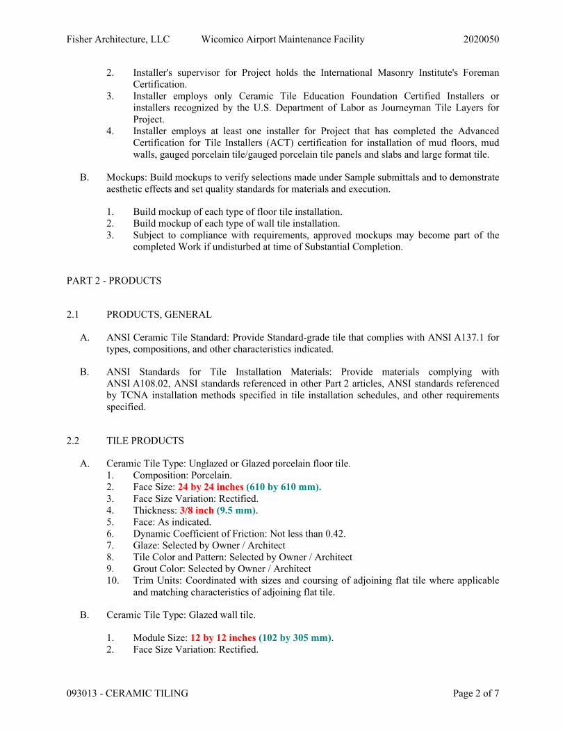
Fisher Architecture, LLC Wicomico Airport Maintenance Facility 2020050
093013 - CERAMIC TILING Page 2 of 7
2. Installer's supervisor for Project holds the International Masonry Institute's Foreman Certification.
3. Installer employs only Ceramic Tile Education Foundation Certified Installers or installers recognized by the U.S. Department of Labor as Journeyman Tile Layers for Project.
4. Installer employs at least one installer for Project that has completed the Advanced Certification for Tile Installers (ACT) certification for installation of mud floors, mud walls, gauged porcelain tile/gauged porcelain tile panels and slabs and large format tile.
B. Mockups: Build mockups to verify selections made under Sample submittals and to demonstrate aesthetic effects and set quality standards for materials and execution.
1. Build mockup of each type of floor tile installation. 2. Build mockup of each type of wall tile installation. 3. Subject to compliance with requirements, approved mockups may become part of the
completed Work if undisturbed at time of Substantial Completion.
PART 2 - PRODUCTS
2.1 PRODUCTS, GENERAL
A. ANSI Ceramic Tile Standard: Provide Standard-grade tile that complies with ANSI A137.1 for types, compositions, and other characteristics indicated.
B. ANSI Standards for Tile Installation Materials: Provide materials complying with ANSI A108.02, ANSI standards referenced in other Part 2 articles, ANSI standards referenced by TCNA installation methods specified in tile installation schedules, and other requirements specified.
2.2 TILE PRODUCTS
A. Ceramic Tile Type: Unglazed or Glazed porcelain floor tile. 1. Composition: Porcelain. 2. Face Size: 24 by 24 inches (610 by 610 mm). 3. Face Size Variation: Rectified. 4. Thickness: 3/8 inch (9.5 mm). 5. Face: As indicated. 6. Dynamic Coefficient of Friction: Not less than 0.42. 7. Glaze: Selected by Owner / Architect 8. Tile Color and Pattern: Selected by Owner / Architect 9. Grout Color: Selected by Owner / Architect 10. Trim Units: Coordinated with sizes and coursing of adjoining flat tile where applicable
and matching characteristics of adjoining flat tile.
B. Ceramic Tile Type: Glazed wall tile.
1. Module Size: 12 by 12 inches (102 by 305 mm). 2. Face Size Variation: Rectified.
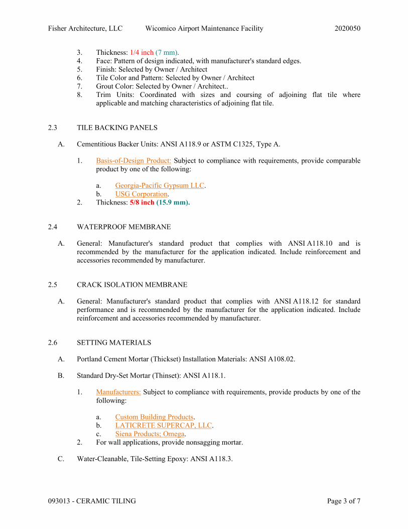
Fisher Architecture, LLC Wicomico Airport Maintenance Facility 2020050
093013 - CERAMIC TILING Page 3 of 7
3. Thickness: 1/4 inch (7 mm). 4. Face: Pattern of design indicated, with manufacturer's standard edges. 5. Finish: Selected by Owner / Architect 6. Tile Color and Pattern: Selected by Owner / Architect 7. Grout Color: Selected by Owner / Architect.. 8. Trim Units: Coordinated with sizes and coursing of adjoining flat tile where
applicable and matching characteristics of adjoining flat tile.
2.3 TILE BACKING PANELS
A. Cementitious Backer Units: ANSI A118.9 or ASTM C1325, Type A.
1. Basis-of-Design Product: Subject to compliance with requirements, provide comparable product by one of the following:
a. Georgia-Pacific Gypsum LLC. b. USG Corporation.
2. Thickness: 5/8 inch (15.9 mm).
2.4 WATERPROOF MEMBRANE
A. General: Manufacturer's standard product that complies with ANSI A118.10 and is recommended by the manufacturer for the application indicated. Include reinforcement and accessories recommended by manufacturer.
2.5 CRACK ISOLATION MEMBRANE
A. General: Manufacturer's standard product that complies with ANSI A118.12 for standard performance and is recommended by the manufacturer for the application indicated. Include reinforcement and accessories recommended by manufacturer.
2.6 SETTING MATERIALS
A. Portland Cement Mortar (Thickset) Installation Materials: ANSI A108.02.
B. Standard Dry-Set Mortar (Thinset): ANSI A118.1.
1. Manufacturers: Subject to compliance with requirements, provide products by one of the following:
a. Custom Building Products. b. LATICRETE SUPERCAP, LLC. c. Siena Products; Omega.
2. For wall applications, provide nonsagging mortar.
C. Water-Cleanable, Tile-Setting Epoxy: ANSI A118.3.
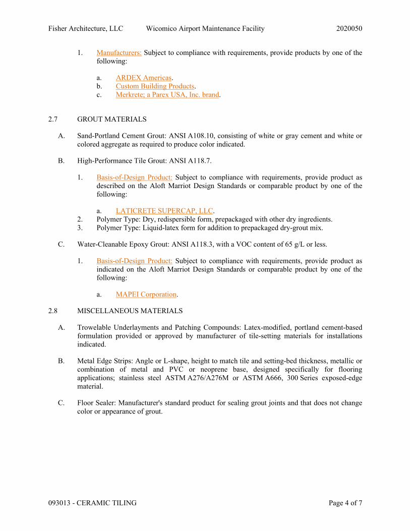
Fisher Architecture, LLC Wicomico Airport Maintenance Facility 2020050
093013 - CERAMIC TILING Page 4 of 7
1. Manufacturers: Subject to compliance with requirements, provide products by one of the following:
a. ARDEX Americas. b. Custom Building Products. c. Merkrete; a Parex USA, Inc. brand.
2.7 GROUT MATERIALS
A. Sand-Portland Cement Grout: ANSI A108.10, consisting of white or gray cement and white or colored aggregate as required to produce color indicated.
B. High-Performance Tile Grout: ANSI A118.7.
1. Basis-of-Design Product: Subject to compliance with requirements, provide product as described on the Aloft Marriot Design Standards or comparable product by one of the following:
a. LATICRETE SUPERCAP, LLC. 2. Polymer Type: Dry, redispersible form, prepackaged with other dry ingredients. 3. Polymer Type: Liquid-latex form for addition to prepackaged dry-grout mix.
C. Water-Cleanable Epoxy Grout: ANSI A118.3, with a VOC content of 65 g/L or less.
1. Basis-of-Design Product: Subject to compliance with requirements, provide product as indicated on the Aloft Marriot Design Standards or comparable product by one of the following:
a. MAPEI Corporation.
2.8 MISCELLANEOUS MATERIALS
A. Trowelable Underlayments and Patching Compounds: Latex-modified, portland cement-based formulation provided or approved by manufacturer of tile-setting materials for installations indicated.
B. Metal Edge Strips: Angle or L-shape, height to match tile and setting-bed thickness, metallic or combination of metal and PVC or neoprene base, designed specifically for flooring applications; stainless steel ASTM A276/A276M or ASTM A666, 300 Series exposed-edge material.
C. Floor Sealer: Manufacturer's standard product for sealing grout joints and that does not change color or appearance of grout.

Fisher Architecture, LLC Wicomico Airport Maintenance Facility 2020050
093013 - CERAMIC TILING Page 5 of 7
PART 3 - EXECUTION
3.1 EXAMINATION
A. Examine substrates, areas, and conditions where tile will be installed, with Installer present, for compliance with requirements for installation tolerances and other conditions affecting performance of the Work.
1. Verify that substrates for setting tile are firm; dry; clean; free of coatings that are incompatible with tile-setting materials, including curing compounds and other substances that contain soap, wax, oil, or silicone; and comply with flatness tolerances required by ANSI A108.01 for installations indicated.
2. Verify that concrete substrates for tile floors installed with bonded mortar bed or thinset mortar comply with surface finish requirements in ANSI A108.01 for installations indicated.
B. Proceed with installation only after unsatisfactory conditions have been corrected.
3.2 PREPARATION
A. Fill cracks, holes, and depressions in concrete substrates for tile floors installed with thinset mortar with trowelable leveling and patching compound specifically recommended by tile-setting material manufacturer.
B. Where indicated, prepare substrates to receive waterproof membrane by applying a reinforced mortar bed that complies with ANSI A108.1A and is sloped 1/4 inch per foot (1:50) toward drains.
C. Blending: For tile exhibiting color variations, verify that tile has been factory blended and packaged so tile units taken from one package show same range of colors as those taken from other packages and match approved Samples. If not factory blended, either return to manufacturer or blend tiles at Project site before installing.
3.3 INSTALLATION
A. Comply with TCNA's "Handbook for Ceramic, Glass, and Stone Tile Installation" for TCNA installation methods specified in tile installation schedules. Comply with parts of the ANSI A108 series "Specifications for Installation of Ceramic Tile" that are referenced in TCNA installation methods, specified in tile installation schedules, and apply to types of setting and grouting materials used.
1. For the following installations, follow procedures in the ANSI A108 series of tile installation standards for providing 95 percent mortar coverage: a. Tile floors in wet areas. b. Tile floors in laundries. c. Tile floors consisting of tiles 8 by 8 inches (200 by 200 mm) or larger. d. Tile floors consisting of rib-backed tiles.
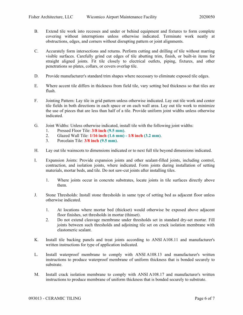
Fisher Architecture, LLC Wicomico Airport Maintenance Facility 2020050
093013 - CERAMIC TILING Page 6 of 7
B. Extend tile work into recesses and under or behind equipment and fixtures to form complete covering without interruptions unless otherwise indicated. Terminate work neatly at obstructions, edges, and corners without disrupting pattern or joint alignments.
C. Accurately form intersections and returns. Perform cutting and drilling of tile without marring visible surfaces. Carefully grind cut edges of tile abutting trim, finish, or built-in items for straight aligned joints. Fit tile closely to electrical outlets, piping, fixtures, and other penetrations so plates, collars, or covers overlap tile.
D. Provide manufacturer's standard trim shapes where necessary to eliminate exposed tile edges.
E. Where accent tile differs in thickness from field tile, vary setting bed thickness so that tiles are flush.
F. Jointing Pattern: Lay tile in grid pattern unless otherwise indicated. Lay out tile work and center tile fields in both directions in each space or on each wall area. Lay out tile work to minimize the use of pieces that are less than half of a tile. Provide uniform joint widths unless otherwise indicated.
G. Joint Widths: Unless otherwise indicated, install tile with the following joint widths: 1. Pressed Floor Tile: 3/8 inch (9.5 mm). 2. Glazed Wall Tile: 1/16 inch (1.6 mm) - 1/8 inch (3.2 mm). 3. Porcelain Tile: 3/8 inch (9.5 mm).
H. Lay out tile wainscots to dimensions indicated or to next full tile beyond dimensions indicated.
I. Expansion Joints: Provide expansion joints and other sealant-filled joints, including control, contraction, and isolation joints, where indicated. Form joints during installation of setting materials, mortar beds, and tile. Do not saw-cut joints after installing tiles.
1. Where joints occur in concrete substrates, locate joints in tile surfaces directly above them.
J. Stone Thresholds: Install stone thresholds in same type of setting bed as adjacent floor unless otherwise indicated.
1. At locations where mortar bed (thickset) would otherwise be exposed above adjacent floor finishes, set thresholds in mortar (thinset).
2. Do not extend cleavage membrane under thresholds set in standard dry-set mortar. Fill joints between such thresholds and adjoining tile set on crack isolation membrane with elastomeric sealant.
K. Install tile backing panels and treat joints according to ANSI A108.11 and manufacturer's written instructions for type of application indicated.
L. Install waterproof membrane to comply with ANSI A108.13 and manufacturer's written instructions to produce waterproof membrane of uniform thickness that is bonded securely to substrate.
M. Install crack isolation membrane to comply with ANSI A108.17 and manufacturer's written instructions to produce membrane of uniform thickness that is bonded securely to substrate.
Fisher Architecture, LLC Wicomico Airport Maintenance Facility 2020050
093013 - CERAMIC TILING Page 7 of 7
END OF SECTION 093013
Fisher Architecture, LLC Wicomico Airport Maintenance Facility 2020050
096513 - RESILIENT BASE AND ACCESSORIES Page 1 of 3
SECTION 096513 - RESILIENT BASE AND ACCESSORIES
PART 1 - GENERAL
1.1 SUMMARY
A. Section Includes: 1. Vinyl base. 2. Vinyl molding accessories.
1.2 ACTION SUBMITTALS
A. Product Data: For each type of product.
B. Sustainable Design Submittals:
C. Samples: For each exposed product and for each color and texture specified.
PART 2 - PRODUCTS
2.1 VINYL BASE Copy this article and re-edit for each product.
A. Basis-of-Design Product: Subject to compliance with requirements, provide product indicated on Drawings or comparable product by one of the following:
1. Johnsonite; a Tarkett company.
B. Product Standard: ASTM F1861, Type TV (vinyl, thermoplastic).
1. Group: I solid, homogeneous. 2. Style and Location:
a. Style A, Straight: Provide in areas with carpet.
C. Minimum Thickness: 0.375 inch (9.52 mm).
D. Height: 4.5 inches (114 mm).
E. Lengths: Cut lengths 96 inches (2438 mm) long.
F. Outside Corners: Preformed.
G. Inside Corners: Preformed.
H. Colors and Patterns: As selected by Owner / Architect

Fisher Architecture, LLC Wicomico Airport Maintenance Facility 2020050
096513 - RESILIENT BASE AND ACCESSORIES Page 2 of 3
2.2 INSTALLATION MATERIALS
A. Trowelable Leveling and Patching Compounds: Latex-modified, portland-cement-based or blended hydraulic-cement-based formulation provided or approved by resilient-product manufacturer for applications indicated.
B. Adhesives: Water-resistant type recommended by resilient-product manufacturer for resilient products and substrate conditions indicated.
PART 3 - EXECUTION
3.1 PREPARATION
A. Prepare substrates according to manufacturer's written instructions to ensure adhesion of resilient products.
B. Concrete Substrates for Resilient Base: Prepare horizontal surfaces according to ASTM F710.
1. Verify that substrates are dry and free of curing compounds, sealers, and hardeners. 2. Remove substrate coatings and other substances that are incompatible with adhesives and
that contain soap, wax, oil, or silicone, using mechanical methods recommended by manufacturer. Do not use solvents.
3. Alkalinity and Adhesion Testing: Perform tests recommended by manufacturer. Proceed with installation only after substrate alkalinity falls within range on pH scale recommended by manufacturer in writing, but not less than 5 or more than 9 pH.
4. Moisture Testing: Perform tests so that each test area does not exceed 200 sq. ft. (18.6 sq. m), and perform no fewer than three tests in each installation area and with test areas evenly spaced in installation areas.
a. Anhydrous Calcium Chloride Test: ASTM F1869. Proceed with installation only after substrates have maximum moisture-vapor-emission rate of 3 lb of water/1000 sq. ft. (1.36 kg of water/92.9 sq. m) in 24 hours.
b. Relative Humidity Test: Using in-situ probes, ASTM F2170. Proceed with installation only after substrates have a maximum [75] percent relative humidity level measurement.
C. Fill cracks, holes, and depressions in substrates with trowelable leveling and patching compound; remove bumps and ridges to produce a uniform and smooth substrate.
D. Do not install resilient products until materials are the same temperature as space where they are to be installed.
E. Immediately before installation, sweep and vacuum clean substrates to be covered by resilient products.
3.2 RESILIENT BASE INSTALLATION
A. Comply with manufacturer's written instructions for installing resilient base.
Fisher Architecture, LLC Wicomico Airport Maintenance Facility 2020050
096513 - RESILIENT BASE AND ACCESSORIES Page 3 of 3
B. Apply resilient base to walls, columns, pilasters, casework and cabinets in toe spaces, and other permanent fixtures in rooms and areas where base is required.
C. Install resilient base in lengths as long as practical without gaps at seams and with tops of adjacent pieces aligned.
D. Tightly adhere resilient base to substrate throughout length of each piece, with base in continuous contact with horizontal and vertical substrates.
E. Do not stretch resilient base during installation.
F. On masonry surfaces or other similar irregular substrates, fill voids along top edge of resilient base with manufacturer's recommended adhesive filler material.
G. Preformed Corners: Install preformed corners before installing straight pieces.
H. Job-Formed Corners:
1. Outside Corners: Use straight pieces of maximum lengths possible and form with returns not less than 3 inches (76 mm) in length.
a. Form without producing discoloration (whitening) at bends.
2. Inside Corners: Use straight pieces of maximum lengths possible and form with returns not less than 3 inches (76 mm) in length.
a. Miter or cope corners to minimize open joints.
3.3 CLEANING AND PROTECTION
A. Comply with manufacturer's written instructions for cleaning and protecting resilient products.
B. Cover resilient products subject to wear and foot traffic until Substantial Completion.
END OF SECTION 096513
Fisher Architecture, LLC Wicomico Airport Maintenance Facility 2020050
096519 - 1
SECTION 096519 - RESILIENT TILE FLOORING
PART 1 - GENERAL
1.1 SUMMARY
A. Section Includes: 1. Vinyl composition floor tile.
1.2 ACTION SUBMITTALS
A. Product Data: For each type of product.
B. Samples: For each exposed product and for each color and pattern specified.
1.3 CLOSEOUT SUBMITTALS
A. Maintenance data.
1.4 QUALITY ASSURANCE
A. Installer Qualifications: An entity that employs installers and supervisors who are competent in techniques required by manufacturer for floor tile installation.
PART 2 - PRODUCTS
2.1 PERFORMANCE REQUIREMENTS
A. Fire-Test-Response Characteristics: For resilient floor tile, as determined by testing identical products according to ASTM E 648 or NFPA 253 by a qualified testing agency.
1. Critical Radiant Flux Classification: Class I, not less than 0.45 W/sq. cm.
2.2 VINYL COMPOSITION FLOOR TILE
A. Tile Standard: ASTM F 1066, Class 1, solid color.
B. Wearing Surface: Embossed.
C. Thickness: 0.125 inch.
D. Size: 12 by 12 inches.
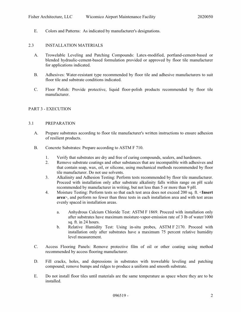
Fisher Architecture, LLC Wicomico Airport Maintenance Facility 2020050
096519 - 2
E. Colors and Patterns: As indicated by manufacturer's designations.
2.3 INSTALLATION MATERIALS
A. Trowelable Leveling and Patching Compounds: Latex-modified, portland-cement-based or blended hydraulic-cement-based formulation provided or approved by floor tile manufacturer for applications indicated.
B. Adhesives: Water-resistant type recommended by floor tile and adhesive manufacturers to suit floor tile and substrate conditions indicated.
C. Floor Polish: Provide protective, liquid floor-polish products recommended by floor tile manufacturer.
PART 3 - EXECUTION
3.1 PREPARATION
A. Prepare substrates according to floor tile manufacturer's written instructions to ensure adhesion of resilient products.
B. Concrete Substrates: Prepare according to ASTM F 710.
1. Verify that substrates are dry and free of curing compounds, sealers, and hardeners. 2. Remove substrate coatings and other substances that are incompatible with adhesives and
that contain soap, wax, oil, or silicone, using mechanical methods recommended by floor tile manufacturer. Do not use solvents.
3. Alkalinity and Adhesion Testing: Perform tests recommended by floor tile manufacturer. Proceed with installation only after substrate alkalinity falls within range on pH scale recommended by manufacturer in writing, but not less than 5 or more than 9 pH.
4. Moisture Testing: Perform tests so that each test area does not exceed 200 sq. ft. <Insert area>, and perform no fewer than three tests in each installation area and with test areas evenly spaced in installation areas.
a. Anhydrous Calcium Chloride Test: ASTM F 1869. Proceed with installation only after substrates have maximum moisture-vapor-emission rate of 3 lb of water/1000 sq. ft. in 24 hours.
b. Relative Humidity Test: Using in-situ probes, ASTM F 2170. Proceed with installation only after substrates have a maximum 75 percent relative humidity level measurement.
C. Access Flooring Panels: Remove protective film of oil or other coating using method recommended by access flooring manufacturer.
D. Fill cracks, holes, and depressions in substrates with trowelable leveling and patching compound; remove bumps and ridges to produce a uniform and smooth substrate.
E. Do not install floor tiles until materials are the same temperature as space where they are to be installed.
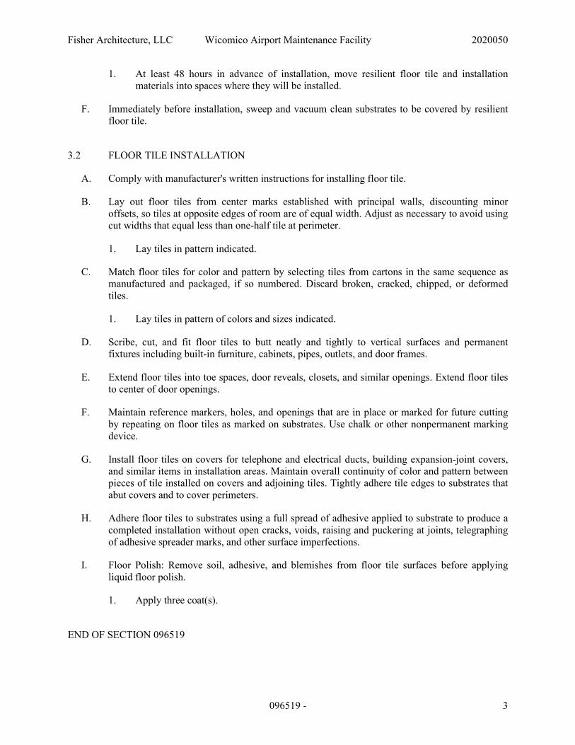
Fisher Architecture, LLC Wicomico Airport Maintenance Facility 2020050
096519 - 3
1. At least 48 hours in advance of installation, move resilient floor tile and installation materials into spaces where they will be installed.
F. Immediately before installation, sweep and vacuum clean substrates to be covered by resilient floor tile.
3.2 FLOOR TILE INSTALLATION
A. Comply with manufacturer's written instructions for installing floor tile.
B. Lay out floor tiles from center marks established with principal walls, discounting minor offsets, so tiles at opposite edges of room are of equal width. Adjust as necessary to avoid using cut widths that equal less than one-half tile at perimeter.
1. Lay tiles in pattern indicated.
C. Match floor tiles for color and pattern by selecting tiles from cartons in the same sequence as manufactured and packaged, if so numbered. Discard broken, cracked, chipped, or deformed tiles.
1. Lay tiles in pattern of colors and sizes indicated.
D. Scribe, cut, and fit floor tiles to butt neatly and tightly to vertical surfaces and permanent fixtures including built-in furniture, cabinets, pipes, outlets, and door frames.
E. Extend floor tiles into toe spaces, door reveals, closets, and similar openings. Extend floor tiles to center of door openings.
F. Maintain reference markers, holes, and openings that are in place or marked for future cutting by repeating on floor tiles as marked on substrates. Use chalk or other nonpermanent marking device.
G. Install floor tiles on covers for telephone and electrical ducts, building expansion-joint covers, and similar items in installation areas. Maintain overall continuity of color and pattern between pieces of tile installed on covers and adjoining tiles. Tightly adhere tile edges to substrates that abut covers and to cover perimeters.
H. Adhere floor tiles to substrates using a full spread of adhesive applied to substrate to produce a completed installation without open cracks, voids, raising and puckering at joints, telegraphing of adhesive spreader marks, and other surface imperfections.
I. Floor Polish: Remove soil, adhesive, and blemishes from floor tile surfaces before applying liquid floor polish.
1. Apply three coat(s).
END OF SECTION 096519
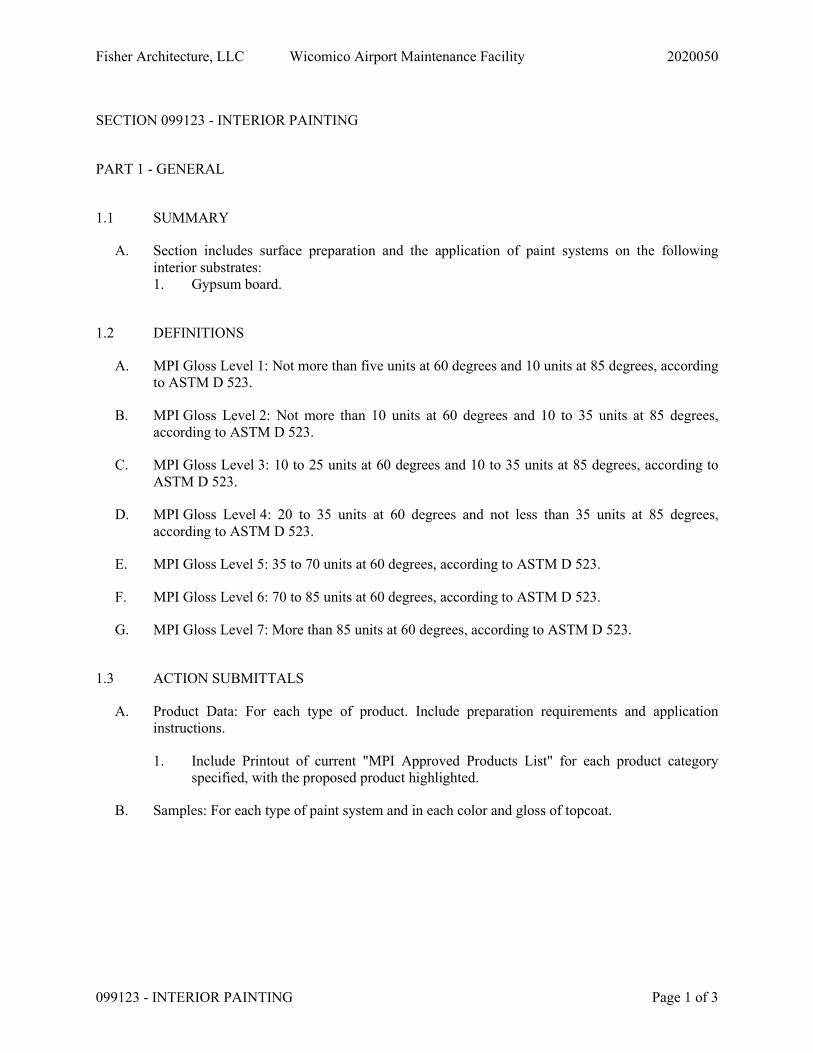
Fisher Architecture, LLC Wicomico Airport Maintenance Facility 2020050
099123 - INTERIOR PAINTING Page 1 of 3
SECTION 099123 - INTERIOR PAINTING
PART 1 - GENERAL
1.1 SUMMARY
A. Section includes surface preparation and the application of paint systems on the following interior substrates: 1. Gypsum board.
1.2 DEFINITIONS
A. MPI Gloss Level 1: Not more than five units at 60 degrees and 10 units at 85 degrees, according to ASTM D 523.
B. MPI Gloss Level 2: Not more than 10 units at 60 degrees and 10 to 35 units at 85 degrees, according to ASTM D 523.
C. MPI Gloss Level 3: 10 to 25 units at 60 degrees and 10 to 35 units at 85 degrees, according to ASTM D 523.
D. MPI Gloss Level 4: 20 to 35 units at 60 degrees and not less than 35 units at 85 degrees, according to ASTM D 523.
E. MPI Gloss Level 5: 35 to 70 units at 60 degrees, according to ASTM D 523.
F. MPI Gloss Level 6: 70 to 85 units at 60 degrees, according to ASTM D 523.
G. MPI Gloss Level 7: More than 85 units at 60 degrees, according to ASTM D 523.
1.3 ACTION SUBMITTALS
A. Product Data: For each type of product. Include preparation requirements and application instructions.
1. Include Printout of current "MPI Approved Products List" for each product category specified, with the proposed product highlighted.
B. Samples: For each type of paint system and in each color and gloss of topcoat.
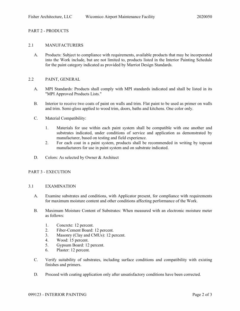
Fisher Architecture, LLC Wicomico Airport Maintenance Facility 2020050
099123 - INTERIOR PAINTING Page 2 of 3
PART 2 - PRODUCTS
2.1 MANUFACTURERS
A. Products: Subject to compliance with requirements, available products that may be incorporated into the Work include, but are not limited to, products listed in the Interior Painting Schedule for the paint category indicated as provided by Marriot Design Standards.
2.2 PAINT, GENERAL
A. MPI Standards: Products shall comply with MPI standards indicated and shall be listed in its "MPI Approved Products Lists."
B. Interior to receive two coats of paint on walls and trim. Flat paint to be used as primer on walls and trim. Semi-gloss applied to wood trim, doors, baths and kitchens. One color only.
C. Material Compatibility:
1. Materials for use within each paint system shall be compatible with one another and substrates indicated, under conditions of service and application as demonstrated by manufacturer, based on testing and field experience.
2. For each coat in a paint system, products shall be recommended in writing by topcoat manufacturers for use in paint system and on substrate indicated.
D. Colors: As selected by Owner & Architect
PART 3 - EXECUTION
3.1 EXAMINATION
A. Examine substrates and conditions, with Applicator present, for compliance with requirements for maximum moisture content and other conditions affecting performance of the Work.
B. Maximum Moisture Content of Substrates: When measured with an electronic moisture meter as follows:
1. Concrete: 12 percent. 2. Fiber-Cement Board: 12 percent. 3. Masonry (Clay and CMUs): 12 percent. 4. Wood: 15 percent. 5. Gypsum Board: 12 percent. 6. Plaster: 12 percent.
C. Verify suitability of substrates, including surface conditions and compatibility with existing finishes and primers.
D. Proceed with coating application only after unsatisfactory conditions have been corrected.
Fisher Architecture, LLC Wicomico Airport Maintenance Facility 2020050
099123 - INTERIOR PAINTING Page 3 of 3
1. Application of coating indicates acceptance of surfaces and conditions.
3.2 PREPARATION
A. Comply with manufacturer's written instructions and recommendations in "MPI Architectural Painting Specification Manual" applicable to substrates and paint systems indicated.
B. Remove hardware, covers, plates, and similar items already in place that are removable and are not to be painted. If removal is impractical or impossible because of size or weight of item, provide surface-applied protection before surface preparation and painting.
1. After completing painting operations, use workers skilled in the trades involved to reinstall items that were removed. Remove surface-applied protection if any.
3.3 APPLICATION
A. Apply paints according to manufacturer's written instructions and recommendations in "MPI Architectural Painting Specification Manual."
B. Apply paints to produce surface films without cloudiness, spotting, holidays, laps, brush marks, roller tracking, runs, sags, ropiness, or other surface imperfections. Cut in sharp lines and color breaks.
3.4 INTERIOR PAINTING SCHEDULE
A. Gypsum Board Substrates:
1. Institutional Low-Odor/VOC Latex System MPI INT 9.2M:
a. Intermediate Coat: Latex, interior, institutional low odor/VOC, matching topcoat. b. Topcoat: Latex, interior, institutional low odor/VOC, flat (MPI Gloss
Level 5), MPI #143.
END OF SECTION 099123
Fisher Architecture, LLC Wicomico Airport Maintenance Facility 2020050
22 0513 - COMMON MOTOR REQUIREMENTS FORPLUMBING EQUIPMENT Page 1 of 2
SECTION 22 0513 - COMMON MOTOR REQUIREMENTS FOR PLUMBING EQUIPMENT
PART 1 GENERAL
1.1 SECTION INCLUDES
A. General construction and requirements.
B. Applications.
C. Single phase electric motors.
1.2 RELATED REQUIREMENTS
A. Section 26 0583 - Wiring Connections: Electrical characteristics and wiring connections.
1.3 REFERENCE STANDARDS
A. NFPA 70 - National Electrical Code Most Recent Edition Adopted by Authority HavingJurisdiction, Including All Applicable Amendments and Supplements.
1.4 SUBMITTALS
A. Product Data: Provide wiring diagrams with electrical characteristics and connectionrequirements.
B. Manufacturer's Installation Instructions: Indicate setting, mechanical connections, lubrication,and wiring instructions.
1.5 DELIVERY, STORAGE, AND HANDLING
A. Protect motors stored on site from weather and moisture by maintaining factory covers andsuitable weather-proof covering.
PART 2 PRODUCTS
2.1 GENERAL CONSTRUCTION AND REQUIREMENTS
A. Electrical Service: Refer to Section 26 0583 for required electrical characteristics.
B. Visible Nameplate: Indicating motor horsepower, voltage, phase, cycles, RPM, full load amps,locked rotor amps, frame size, manufacturer's name and model number, service factor, powerfactor, efficiency.
C. Wiring Terminations:
1. Provide terminal lugs to match branch circuit conductor quantities, sizes, and materialsindicated. Enclose terminal lugs in terminal box sized to NFPA 70, threaded for conduit.
Fisher Architecture, LLC Wicomico Airport Maintenance Facility 2020050
22 0513 - COMMON MOTOR REQUIREMENTS FORPLUMBING EQUIPMENT Page 2 of 2
2. For fractional horsepower motors where connection is made directly, provide threadedconduit connection in end frame.
2.2 APPLICATIONS
PART 3 EXECUTION
3.1 INSTALLATION
A. Install in accordance with manufacturer's instructions.
B. Install securely on firm foundation. Mount ball bearing motors with shaft in any position.
C. Check line voltage and phase and ensure agreement with nameplate.
END OF SECTION
Fisher Architecture, LLC Wicomico Airport Maintenance Facility 2020050
22 0553 - IDENTIFICATION FOR PLUMBING PIPING ANDEQUIPMENT Page 1 of 3
SECTION 22 0553 - IDENTIFICATION FOR PLUMBING PIPING AND EQUIPMENT
PART 1 GENERAL
1.1 SECTION INCLUDES
A. Nameplates.
B. Tags.
C. Pipe markers.
D. Ceiling tacks.
1.2 SUBMITTALS
A. List: Submit list of wording, symbols, letter size, and color coding for mechanicalidentification.
B. Product Data: Provide manufacturers catalog literature for each product required.
C. Manufacturer's Installation Instructions: Indicate special procedures, and installation.
D. Project Record Documents: Record actual locations of tagged valves.
PART 2 PRODUCTS
2.1 IDENTIFICATION APPLICATIONS
A. Automatic Controls: Tags. Key to control schematic.
B. Major Control Components: Nameplates.
C. Piping: Pipe markers .
D. Pumps: Nameplates.
E. Small-sized Equipment: Tags.
F. Tanks: Nameplates.
G. Valves: Tags and ceiling tacks where located above lay-in ceiling.
2.2 NAMEPLATES
A. Description: Laminated three-layer plastic with engraved letters.
1. Letter Color: White.
2. Letter Height: 1/4 inch.

Fisher Architecture, LLC Wicomico Airport Maintenance Facility 2020050
22 0553 - IDENTIFICATION FOR PLUMBING PIPING ANDEQUIPMENT Page 2 of 3
3. Background Color: Black.
4. Plastic: Conform to ASTM D709.
2.3 TAGS
A. Plastic Tags: Laminated three-layer plastic with engraved black letters on light contrastingbackground color. Tag size minimum 1-1/2 inch diameter.
B. Metal Tags: Brass with stamped letters; tag size minimum 1-1/2 inch diameter with smoothedges.
2.4 PIPE MARKERS
A. Plastic Pipe Markers: Factory fabricated, flexible, semi- rigid plastic, preformed to fit aroundpipe or pipe covering; minimum information indicating flow direction arrow and identificationof fluid being conveyed.
B. Plastic Tape Pipe Markers: Flexible, vinyl film tape with pressure sensitive adhesive backingand printed markings.
C. Color code as follows:
1. Potable, Cooling, Boiler, Feed, Other Water: Green with white letters.
2. Flammable Fluids: Yellow with black letters.
2.5 CEILING TACKS
A. Description: Steel with 3/4 inch diameter color coded head.
B. Color code as follows:
1. Plumbing Valves: Green.
PART 3 EXECUTION
3.1 PREPARATION
A. Degrease and clean surfaces to receive adhesive for identification materials.
3.2 INSTALLATION
A. Install plastic nameplates with corrosive-resistant mechanical fasteners, or adhesive. Applywith sufficient adhesive to ensure permanent adhesion and seal with clear lacquer.
B. Install tags with corrosion resistant chain.
C. Install plastic pipe markers in accordance with manufacturer's instructions.
Fisher Architecture, LLC Wicomico Airport Maintenance Facility 2020050
22 0553 - IDENTIFICATION FOR PLUMBING PIPING ANDEQUIPMENT Page 3 of 3
D. Install plastic tape pipe markers complete around pipe in accordance with manufacturer'sinstructions.
E. Use tags on piping 3/4 inch diameter and smaller.
1. Identify service, flow direction, and pressure.
2. Locate identification not to exceed 20 feet on straight runs including risers and drops,adjacent to each valve and Tee, at each side of penetration of structure or enclosure, and ateach obstruction.
F. Locate ceiling tacks to locate valves or dampers above lay-in panel ceilings. Locate in cornerof panel closest to equipment.
END OF SECTION

Fisher Architecture, LLC Wicomico Airport Maintenance Facility 2020050
22 0719 - PLUMBING PIPING INSULATION Page 1 of 4
SECTION 22 0719 - PLUMBING PIPING INSULATION
PART 1 GENERAL
1.1 SECTION INCLUDES
A. Piping insulation.
B. Jackets and accessories.
1.2 RELATED REQUIREMENTS
A. Section 22 1005 - Plumbing Piping: Placement of hangers and hanger inserts.
B. Section 23 2300 - Refrigerant Piping: Placement of inserts.
1.3 REFERENCE STANDARDS
A. ASTM B209 - Standard Specification for Aluminum and Aluminum-Alloy Sheet and Plate2014.
B. ASTM B209M - Standard Specification for Aluminum and Aluminum-Alloy Sheet and Plate(Metric) 2014.
C. ASTM C177 - Standard Test Method for Steady-State Heat Flux Measurements and ThermalTransmission Properties by Means of the Guarded-Hot-Plate Apparatus 2019.
D. ASTM C518 - Standard Test Method for Steady-State Thermal Transmission Properties byMeans of the Heat Flow Meter Apparatus 2017.
E. ASTM C534/C534M - Standard Specification for Preformed Flexible Elastomeric CellularThermal Insulation in Sheet and Tubular Form 2020.
F. ASTM C585 - Standard Practice for Inner and Outer Diameters of Thermal Insulation forNominal Sizes of Pipe and Tubing 2010 (Reapproved 2016).
G. ASTM C591 - Standard Specification for Unfaced Preformed Rigid Cellular PolyisocyanurateThermal Insulation 2020.
H. ASTM D1056 - Standard Specification for Flexible Cellular Materials-Sponge or ExpandedRubber 2014.
I. ASTM D2842 - Standard Test Method for Water Absorption of Rigid Cellular Plastics 2019.
J. ASTM E84 - Standard Test Method for Surface Burning Characteristics of Building Materials2020.
K. ASTM E96/E96M - Standard Test Methods for Water Vapor Transmission of Materials 2016.
Fisher Architecture, LLC Wicomico Airport Maintenance Facility 2020050
22 0719 - PLUMBING PIPING INSULATION Page 2 of 4
L. UL 723 - Standard for Test for Surface Burning Characteristics of Building Materials CurrentEdition, Including All Revisions.
1.4 SUBMITTALS
A. Product Data: Provide product description, thermal characteristics, list of materials andthickness for each service, and locations.
B. Manufacturer's Instructions: Indicate installation procedures that ensure acceptableworkmanship and installation standards will be achieved.
1.5 QUALITY ASSURANCE
A. Manufacturer Qualifications: Company specializing in manufacturing the Products specified inthis section with not less than three years of documented experience.
1.6 DELIVERY, STORAGE, AND HANDLING
A. Accept materials on site, labeled with manufacturer's identification, product density, andthickness.
1.7 FIELD CONDITIONS
A. Maintain ambient conditions required by manufacturers of each product.
B. Maintain temperature before, during, and after installation for minimum of 24 hours.
PART 2 PRODUCTS
2.1 REGULATORY REQUIREMENTS
A. Surface Burning Characteristics: Flame spread index/Smoke developed index of 25/50,maximum, when tested in accordance with ASTM E84 or UL 723.
2.2 POLYISOCYANURATE CELLULAR PLASTIC
A. Insulation Material: ASTM C591, rigid molded modified polyisocyanurate cellular plastic.
1. Dimension: Comply with requirements of ASTM C585.
2. 'K' Value: 0.18 at 75 degrees F, when tested in accordance with ASTM C518.
3. Water Absorption: 0.5 percent by volume, maximum, when tested in accordance withASTM D2842.
4. Moisture Vapor Transmission: 4.0 perm in.
5. Connection: Waterproof vapor barrier adhesive.
Fisher Architecture, LLC Wicomico Airport Maintenance Facility 2020050
22 0719 - PLUMBING PIPING INSULATION Page 3 of 4
2.3 POLYETHYLENE
A. Insulation: Flexible closed-cell polyethylene tubing, slit lengthwise for installation, complyingwith applicable requirements of ASTM D1056.
1. 'K' Value: ASTM C177; 0.25 at 75 degrees F.
2. Maximum Service Temperature: 200 degrees F.
3. Density: 2 lb/cu ft.
4. Maximum Moisture Absorption: 1.0 percent by volume.
5. Moisture Vapor Permeability: 0.05 perm inch, when tested in accordance with ASTME96/E96M.
6. Connection: Contact adhesive.
2.4 FLEXIBLE ELASTOMERIC CELLULAR INSULATION
A. Insulation: Preformed flexible elastomeric cellular rubber insulation complying with ASTMC534/C534M Grade 1; use molded tubular material wherever possible.
1. Minimum Service Temperature: Minus 40 degrees F.
2. Maximum Service Temperature: 220 degrees F.
3. Connection: Waterproof vapor barrier adhesive.
B. Elastomeric Foam Adhesive: Air dried, contact adhesive, compatible with insulation.
2.5 JACKETS
A. PVC Plastic.
1. Jacket: One piece molded type fitting covers and sheet material, off-white color.
a. Minimum Service Temperature: 0 degrees F.
b. Maximum Service Temperature: 150 degrees F.
c. Moisture Vapor Permeability: 0.002 perm inch, maximum, when tested inaccordance with ASTM E96/E96M.
d. Thickness: 10 mil.
e. Connections: Brush on welding adhesive.
B. Aluminum Jacket: ASTM B209 (ASTM B209M) formed aluminum sheet.
1. Thickness: 0.016 inch sheet.
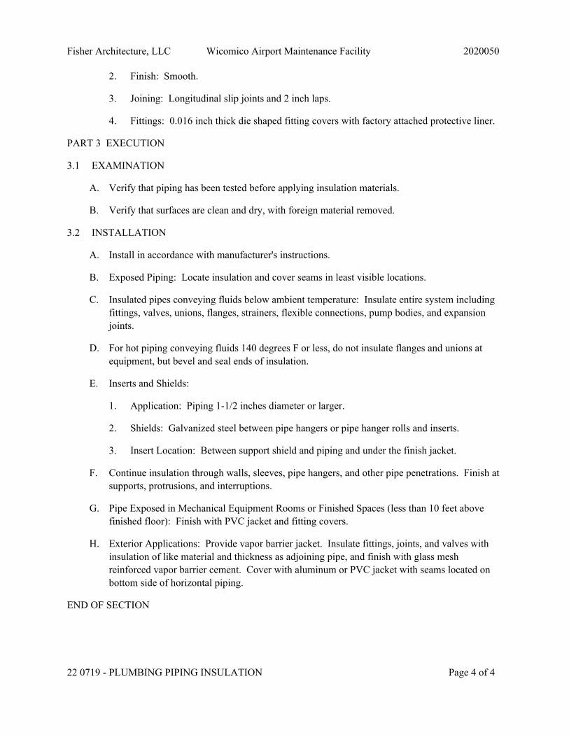
Fisher Architecture, LLC Wicomico Airport Maintenance Facility 2020050
22 0719 - PLUMBING PIPING INSULATION Page 4 of 4
2. Finish: Smooth.
3. Joining: Longitudinal slip joints and 2 inch laps.
4. Fittings: 0.016 inch thick die shaped fitting covers with factory attached protective liner.
PART 3 EXECUTION
3.1 EXAMINATION
A. Verify that piping has been tested before applying insulation materials.
B. Verify that surfaces are clean and dry, with foreign material removed.
3.2 INSTALLATION
A. Install in accordance with manufacturer's instructions.
B. Exposed Piping: Locate insulation and cover seams in least visible locations.
C. Insulated pipes conveying fluids below ambient temperature: Insulate entire system includingfittings, valves, unions, flanges, strainers, flexible connections, pump bodies, and expansionjoints.
D. For hot piping conveying fluids 140 degrees F or less, do not insulate flanges and unions atequipment, but bevel and seal ends of insulation.
E. Inserts and Shields:
1. Application: Piping 1-1/2 inches diameter or larger.
2. Shields: Galvanized steel between pipe hangers or pipe hanger rolls and inserts.
3. Insert Location: Between support shield and piping and under the finish jacket.
F. Continue insulation through walls, sleeves, pipe hangers, and other pipe penetrations. Finish atsupports, protrusions, and interruptions.
G. Pipe Exposed in Mechanical Equipment Rooms or Finished Spaces (less than 10 feet abovefinished floor): Finish with PVC jacket and fitting covers.
H. Exterior Applications: Provide vapor barrier jacket. Insulate fittings, joints, and valves withinsulation of like material and thickness as adjoining pipe, and finish with glass meshreinforced vapor barrier cement. Cover with aluminum or PVC jacket with seams located onbottom side of horizontal piping.
END OF SECTION
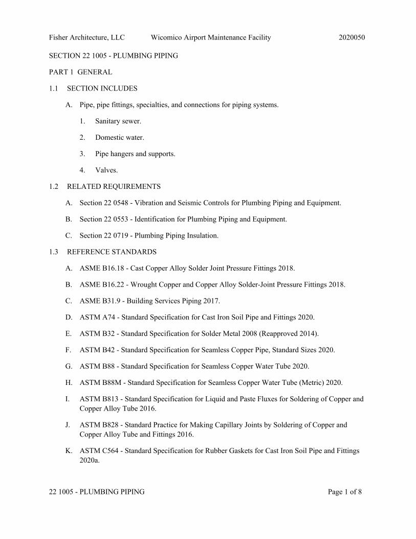
Fisher Architecture, LLC Wicomico Airport Maintenance Facility 2020050
22 1005 - PLUMBING PIPING Page 1 of 8
SECTION 22 1005 - PLUMBING PIPING
PART 1 GENERAL
1.1 SECTION INCLUDES
A. Pipe, pipe fittings, specialties, and connections for piping systems.
1. Sanitary sewer.
2. Domestic water.
3. Pipe hangers and supports.
4. Valves.
1.2 RELATED REQUIREMENTS
A. Section 22 0548 - Vibration and Seismic Controls for Plumbing Piping and Equipment.
B. Section 22 0553 - Identification for Plumbing Piping and Equipment.
C. Section 22 0719 - Plumbing Piping Insulation.
1.3 REFERENCE STANDARDS
A. ASME B16.18 - Cast Copper Alloy Solder Joint Pressure Fittings 2018.
B. ASME B16.22 - Wrought Copper and Copper Alloy Solder-Joint Pressure Fittings 2018.
C. ASME B31.9 - Building Services Piping 2017.
D. ASTM A74 - Standard Specification for Cast Iron Soil Pipe and Fittings 2020.
E. ASTM B32 - Standard Specification for Solder Metal 2008 (Reapproved 2014).
F. ASTM B42 - Standard Specification for Seamless Copper Pipe, Standard Sizes 2020.
G. ASTM B88 - Standard Specification for Seamless Copper Water Tube 2020.
H. ASTM B88M - Standard Specification for Seamless Copper Water Tube (Metric) 2020.
I. ASTM B813 - Standard Specification for Liquid and Paste Fluxes for Soldering of Copper andCopper Alloy Tube 2016.
J. ASTM B828 - Standard Practice for Making Capillary Joints by Soldering of Copper andCopper Alloy Tube and Fittings 2016.
K. ASTM C564 - Standard Specification for Rubber Gaskets for Cast Iron Soil Pipe and Fittings2020a.

Fisher Architecture, LLC Wicomico Airport Maintenance Facility 2020050
22 1005 - PLUMBING PIPING Page 2 of 8
L. ASTM D1785 - Standard Specification for Poly(Vinyl Chloride) (PVC) Plastic Pipe, Schedules40, 80, and 120 2015, with Editorial Revision (2018).
M. ASTM D2241 - Standard Specification for Poly (Vinyl Chloride) (PVC) Pressure-Rated Pipe(SDR Series) 2015.
N. ASTM D2466 - Standard Specification for Poly(Vinyl Chloride) (PVC) Plastic Pipe Fittings,Schedule 40 2017.
O. ASTM D2564 - Standard Specification for Solvent Cements for Poly(Vinyl Chloride) (PVC)Plastic Piping Systems 2012 (Reapproved 2018).
P. ASTM D2665 - Standard Specification for Poly(Vinyl Chloride) (PVC) Plastic Drain, Waste,and Vent Pipe and Fittings 2014.
Q. ASTM D2846/D2846M - Standard Specification for Chlorinated Poly(Vinyl Chloride) (CPVC)Plastic Hot- and Cold-Water Distribution Systems 2019a.
R. ASTM D2855 - Standard Practice for the Two-Step (Primer & Solvent Cement) Method ofJoining Poly (Vinyl Chloride) (PVC) or Chlorinated Poly (Vinyl Chloride) (CPVC) Pipe andPiping Components with Tapered Sockets 2015.
S. ASTM D3034 - Standard Specification for Type PSM Poly(Vinyl Chloride) (PVC) Sewer Pipeand Fittings 2016.
T. ASTM F437 - Standard Specification for Threaded Chlorinated Poly(Vinyl Chloride) (CPVC)Plastic Pipe Fittings, Schedule 80 2015.
U. ASTM F438 - Standard Specification for Socket-Type Chlorinated Poly(Vinyl Chloride)(CPVC) Plastic Pipe Fittings, Schedule 40 2017.
V. ASTM F439 - Standard Specification for Chlorinated Poly (Vinyl Chloride) (CPVC) PlasticPipe Fittings, Schedule 80 2019.
W. ASTM F441/F441M - Standard Specification for Chlorinated Poly(Vinyl Chloride) (CPVC)Plastic Pipe, Schedules 40 and 80 2015.
X. ASTM F442/F442M - Standard Specification for Chlorinated Poly(Vinyl Chloride) (CPVC)Plastic Pipe (SDR-PR) 2019.
Y. ASTM F493 - Standard Specification for Solvent Cements for Chlorinated Poly (VinylChloride) (CPVC) Plastic Pipe and Fittings 2014.
Z. MSS SP-58 - Pipe Hangers and Supports - Materials, Design, Manufacture, Selection,Application, and Installation 2018.
AA. MSS SP-110 - Ball Valves Threaded, Socket-Welding, Solder Joint, Grooved and Flared Ends2010.

Fisher Architecture, LLC Wicomico Airport Maintenance Facility 2020050
22 1005 - PLUMBING PIPING Page 3 of 8
BB. NSF 61 - Drinking Water System Components - Health Effects 2019.
CC. NSF 372 - Drinking Water System Components - Lead Content 2016.
1.4 QUALITY ASSURANCE
A. Perform work in accordance with applicable codes.
B. Valves: Manufacturer's name and pressure rating marked on valve body.
C. Identify pipe with marking including size, ASTM material classification, ASTM specification,potable water certification, water pressure rating.
1.5 FIELD CONDITIONS
A. Do not install underground piping when bedding is wet or frozen.
PART 2 PRODUCTS
2.1 GENERAL REQUIREMENTS
A. Potable Water Supply Systems: Provide piping, pipe fittings, and solder and flux (if used), thatcomply with NSF 61 and NSF 372 for maximum lead content; label pipe and fittings.
2.2 SANITARY SEWER PIPING, BURIED WITHIN 5 FEET OF BUILDING
A. Cast Iron Pipe: ASTM A74 extra heavy weight.
1. Fittings: Cast iron.
2. Joints: Hub-and-spigot, CISPI HSN compression type with ASTM C564 neoprenegaskets or lead and oakum.
B. PVC Pipe: ASTM D2665 or ASTM D3034.
1. Fittings: PVC.
2. Joints: Solvent welded, with ASTM D2564 solvent cement.
2.3 SANITARY SEWER PIPING, ABOVE GRADE
A. Cast Iron Pipe: ASTM A74, service weight.
1. Fittings: Cast iron.
2. Joint Seals: ASTM C564 neoprene gaskets, or lead and oakum.
B. PVC Pipe: ASTM D1785 Schedule 40, or ASTM D2241 SDR 26 with not less than 150 psipressure rating.
1. Fittings: ASTM D2466, PVC.

Fisher Architecture, LLC Wicomico Airport Maintenance Facility 2020050
22 1005 - PLUMBING PIPING Page 4 of 8
2. Joints: Solvent welded, with ASTM D2564 solvent cement.
2.4 DOMESTIC WATER PIPING, BURIED WITHIN 5 FEET OF BUILDING
A. Copper Pipe: ASTM B42, hard drawn.
1. Fittings: ASME B16.18, cast copper alloy or ASME B16.22 wrought copper and bronze.
2. Joints: ASTM B32, alloy Sn95 solder.
2.5 DOMESTIC WATER PIPING, ABOVE GRADE
A. Copper Tube: ASTM B88 (ASTM B88M), Type K (A), Drawn (H).
1. Fittings: ASME B16.18, cast copper alloy or ASME B16.22, wrought copper and bronze.
2. Joints: ASTM B32, alloy Sn95 solder.
3. Mechanical Press Sealed Fittings: Double pressed type, NSF 61 and NSF 372 approved orcertified, utilizing EPDM, non toxic synthetic rubber sealing elements.
B. CPVC Pipe: ASTM D2846/D2846M, ASTM F441/F441M, or ASTM F442/F442M.
1. Fittings: CPVC; ASTM D2846/D2846M, ASTM F437, ASTM F438, or ASTM F439.
2. Joints: ASTM D2846/D2846M, solvent weld with ASTM F493 solvent cement.
2.6 PIPE HANGERS AND SUPPORTS
A. Provide hangers and supports that comply with MSS SP-58.
1. If type of hanger or support for a particular situation is not indicated, select appropriatetype using MSS SP-58 recommendations.
2. Overhead Supports: Individual steel rod hangers attached to structure or to trapezehangers.
3. Trapeze Hangers: Welded steel channel frames attached to structure.
4. Vertical Pipe Support: Steel riser clamp.
B. Plumbing Piping - Drain, Waste, and Vent:
1. Hangers for Pipe Sizes 1/2 Inch to 1-1/2 Inches: Malleable iron, adjustable swivel, splitring.
2. Hangers for Pipe Sizes 2 Inches and Over: Carbon steel, adjustable, clevis.
3. Wall Support for Pipe Sizes to 3 Inches: Cast iron hook.
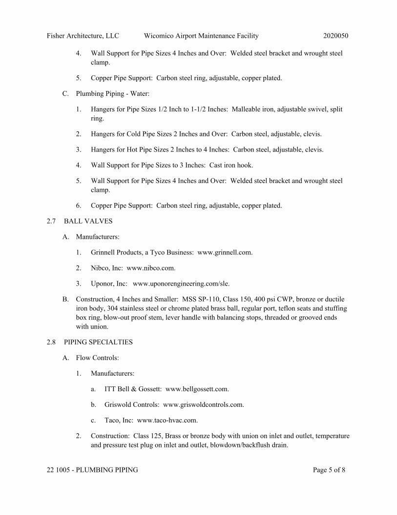
Fisher Architecture, LLC Wicomico Airport Maintenance Facility 2020050
22 1005 - PLUMBING PIPING Page 5 of 8
4. Wall Support for Pipe Sizes 4 Inches and Over: Welded steel bracket and wrought steelclamp.
5. Copper Pipe Support: Carbon steel ring, adjustable, copper plated.
C. Plumbing Piping - Water:
1. Hangers for Pipe Sizes 1/2 Inch to 1-1/2 Inches: Malleable iron, adjustable swivel, splitring.
2. Hangers for Cold Pipe Sizes 2 Inches and Over: Carbon steel, adjustable, clevis.
3. Hangers for Hot Pipe Sizes 2 Inches to 4 Inches: Carbon steel, adjustable, clevis.
4. Wall Support for Pipe Sizes to 3 Inches: Cast iron hook.
5. Wall Support for Pipe Sizes 4 Inches and Over: Welded steel bracket and wrought steelclamp.
6. Copper Pipe Support: Carbon steel ring, adjustable, copper plated.
2.7 BALL VALVES
A. Manufacturers:
1. Grinnell Products, a Tyco Business: www.grinnell.com.
2. Nibco, Inc: www.nibco.com.
3. Uponor, Inc: www.uponorengineering.com/sle.
B. Construction, 4 Inches and Smaller: MSS SP-110, Class 150, 400 psi CWP, bronze or ductileiron body, 304 stainless steel or chrome plated brass ball, regular port, teflon seats and stuffingbox ring, blow-out proof stem, lever handle with balancing stops, threaded or grooved endswith union.
2.8 PIPING SPECIALTIES
A. Flow Controls:
1. Manufacturers:
a. ITT Bell & Gossett: www.bellgossett.com.
b. Griswold Controls: www.griswoldcontrols.com.
c. Taco, Inc: www.taco-hvac.com.
2. Construction: Class 125, Brass or bronze body with union on inlet and outlet, temperatureand pressure test plug on inlet and outlet, blowdown/backflush drain.

Fisher Architecture, LLC Wicomico Airport Maintenance Facility 2020050
22 1005 - PLUMBING PIPING Page 6 of 8
3. Calibration: Control flow within 5 percent of selected rating, over operating pressurerange of 10 times minimum pressure required for control, maximum minimum pressure3.5 psi.
PART 3 EXECUTION
3.1 EXAMINATION
A. Verify that excavations are to required grade, dry, and not over-excavated.
3.2 PREPARATION
A. Ream pipe and tube ends. Remove burrs. Bevel plain end ferrous pipe.
B. Remove scale and dirt, on inside and outside, before assembly.
C. Prepare piping connections to equipment with flanges or unions.
3.3 INSTALLATION
A. Install in accordance with manufacturer's instructions.
B. Provide non-conducting dielectric connections wherever jointing dissimilar metals.
C. Route piping in orderly manner and maintain gradient. Route parallel and perpendicular towalls.
D. Install piping to maintain headroom, conserve space, and not interfere with use of space.
E. Provide access where valves and fittings are not exposed.
F. Provide support for utility meters in accordance with requirements of utility companies.
G. Copper Pipe and Tube: Make soldered joints in accordance with ASTM B828, using specifiedsolder, and flux meeting ASTM B813; in potable water systems use flux also complying withNSF 61 and NSF 372.
H. PVC Pipe: Make solvent-welded joints in accordance with ASTM D2855.
I. Sleeve pipes passing through partitions, walls and floors.
J. Inserts:
1. Provide inserts for placement in concrete formwork.
2. Where concrete slabs form finished ceiling, locate inserts flush with slab surface.
K. Pipe Hangers and Supports:
1. Install in accordance with ASME B31.9.
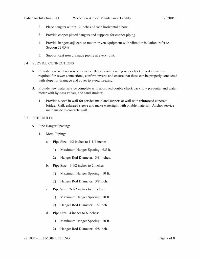
Fisher Architecture, LLC Wicomico Airport Maintenance Facility 2020050
22 1005 - PLUMBING PIPING Page 7 of 8
2. Place hangers within 12 inches of each horizontal elbow.
3. Provide copper plated hangers and supports for copper piping.
4. Provide hangers adjacent to motor driven equipment with vibration isolation; refer toSection 22 0548.
5. Support cast iron drainage piping at every joint.
3.4 SERVICE CONNECTIONS
A. Provide new sanitary sewer services. Before commencing work check invert elevationsrequired for sewer connections, confirm inverts and ensure that these can be properly connectedwith slope for drainage and cover to avoid freezing.
B. Provide new water service complete with approved double check backflow preventer and watermeter with by-pass valves, and sand strainer.
1. Provide sleeve in wall for service main and support at wall with reinforced concretebridge. Calk enlarged sleeve and make watertight with pliable material. Anchor servicemain inside to concrete wall.
3.5 SCHEDULES
A. Pipe Hanger Spacing:
1. Metal Piping:
a. Pipe Size: 1/2 inches to 1-1/4 inches:
1) Maximum Hanger Spacing: 6.5 ft.
2) Hanger Rod Diameter: 3/8 inches.
b. Pipe Size: 1-1/2 inches to 2 inches:
1) Maximum Hanger Spacing: 10 ft.
2) Hanger Rod Diameter: 3/8 inch.
c. Pipe Size: 2-1/2 inches to 3 inches:
1) Maximum Hanger Spacing: 10 ft.
2) Hanger Rod Diameter: 1/2 inch.
d. Pipe Size: 4 inches to 6 inches:
1) Maximum Hanger Spacing: 10 ft.
2) Hanger Rod Diameter: 5/8 inch.
Fisher Architecture, LLC Wicomico Airport Maintenance Facility 2020050
22 1005 - PLUMBING PIPING Page 8 of 8
2. Plastic Piping:
a. All Sizes:
1) Maximum Hanger Spacing: 6 ft.
2) Hanger Rod Diameter: 3/8 inch.
END OF SECTION
Fisher Architecture, LLC Wicomico Airport Maintenance Facility 2020050
22 1006 - PLUMBING PIPING SPECIALTIES Page 1 of 4
SECTION 22 1006 - PLUMBING PIPING SPECIALTIES
PART 1 GENERAL
1.1 SECTION INCLUDES
A. Drains.
B. Cleanouts.
C. Hose bibbs.
D. Hydrants.
E. Refrigerator valve and recessed box.
F. Back water valves.
G. Backflow preventers.
H. Double check valve assemblies.
I. Water hammer arrestors.
J. Mixing valves.
1.2 RELATED REQUIREMENTS
A. Section 22 1005 - Plumbing Piping.
B. Section 22 3000 - Plumbing Equipment.
C. Section 22 4000 - Plumbing Fixtures.
1.3 REFERENCE STANDARDS
A. ASME A112.6.3 - Floor and Trench Drains 2019.
B. ASME A112.6.4 - Roof, Deck, and Balcony Drains 2008 (Reaffirmed 2012).
C. ASSE 1012 - Performance Requirements for Backflow Preventers with an IntermediateAtmospheric Vent 2009.
D. ASSE 1019 - Performance Requirements for Wall Hydrant with Backflow Protection andFreeze Resistance 2011 (Reaffirmed 2016).
E. NSF 61 - Drinking Water System Components - Health Effects 2019.
F. NSF 372 - Drinking Water System Components - Lead Content 2016.
Fisher Architecture, LLC Wicomico Airport Maintenance Facility 2020050
22 1006 - PLUMBING PIPING SPECIALTIES Page 2 of 4
1.4 QUALITY ASSURANCE
A. Manufacturer Qualifications: Company specializing in manufacturing the Products specified inthis section with not less than three years documented experience.
PART 2 PRODUCTS
2.1 GENERAL REQUIREMENTS
A. Specialties in Potable Water Supply Systems: Provide products that comply with NSF 61 andNSF 372 for maximum lead content.
2.2 DRAINS
A. Floor Drain (FD-1):
1. ASME A112.6.3; lacquered cast iron or stainless steel, two piece body with doubledrainage flange, weep holes, reversible clamping collar, and round, adjustable nickel-bronze strainer.
2.3 CLEANOUTS
A. Manufacturers:
1. Jay R. Smith Manufacturing Company: www.jayrsmith.com.
2. Josam Company: www.josam.com.
3. Zurn Industries, LLC: www.zurn.com.
B. Cleanouts at Interior Finished Floor Areas (CO-3):
1. Lacquered cast iron body with anchor flange, reversible clamping collar, threaded topassembly, and round gasketed scored cover in service areas and round gasketed depressedcover to accept floor finish in finished floor areas.
C. Cleanouts at Interior Finished Wall Areas (CO-4):
1. Line type with lacquered cast iron body and round epoxy coated gasketed cover, andround stainless steel access cover secured with machine screw.
2.4 HYDRANTS
A. Manufacturers:
1. Arrowhead Brass & Plumbing, LLC: www.arrowheadbrass.com.
2. Jay R. Smith Manufacturing Company: www.jayrsmith.com.
3. Zurn Industries, LLC: www.zurn.com.

Fisher Architecture, LLC Wicomico Airport Maintenance Facility 2020050
22 1006 - PLUMBING PIPING SPECIALTIES Page 3 of 4
B. Wall Hydrants:
1. ASSE 1019; freeze resistant, self-draining type with chrome plated wall plate hose threadspout, handwheel, and integral vacuum breaker.
2.5 REFRIGERATOR VALVE AND RECESSED BOX
A. Box Manufacturers:
1. IPS Corporation/Water-Tite: www.ipscorp.com.
2. Oatey Supply Chain Services, Inc: www.oatey.com.
B. Valve Manufacturers:
1. IPS Corporation/Water-Tite: www.ipscorp.com.
2. Zurn Industries, LLC: www.zurn.com.
2.6 BACK WATER VALVES
A. Manufacturers:
1. Jay R. Smith Manufacturing Company: www.jayrsmith.com.
2. Savko Plastic Pipe & Fittings, Inc: www.savko.com.
3. Zurn Industries, LLC: www.zurn.com.
B. Cast Iron Back Water Valves: ASME A112.6.4; lacquered cast iron body and cover, brassvalve, extension sleeve, and access cover.
C. Plastic Back Water Valves: ABS body and valve, extension sleeve, and access cover.
2.7 DOUBLE CHECK VALVE ASSEMBLIES
A. Manufacturers:
1. Conbraco Industries, Inc: www.apollovalves.com.
2. Watts Regulator Company, a part of Watts Water Technologies: www.wattsregulator.com.
3. Zurn Industries, LLC: www.zurn.com.
B. Double Check Valve Assemblies:
1. ASSE 1012; Bronze body with corrosion resistant internal parts and stainless steel springs;two independently operating check valves with intermediate atmospheric vent.

Fisher Architecture, LLC Wicomico Airport Maintenance Facility 2020050
22 1006 - PLUMBING PIPING SPECIALTIES Page 4 of 4
2.8 WATER HAMMER ARRESTORS
A. Manufacturers:
1. Jay R. Smith Manufacturing Company: www.jayrsmith.com.
2. Watts Regulator Company, a part of Watts Water Technologies: www.wattsregulator.com.
3. Zurn Industries, LLC: www.zurn.com.
2.9 MIXING VALVES
A. Thermostatic Mixing Valves:
1. Valve: Chrome plated cast brass body, stainless steel or copper alloy bellows, integraltemperature adjustment.
2. Accessories:
a. Check valve on inlets.
b. Volume control shut-off valve on outlet.
PART 3 EXECUTION
3.1 INSTALLATION
A. Install in accordance with manufacturer's instructions.
B. Extend cleanouts to finished floor or wall surface. Lubricate threaded cleanout plugs withmixture of graphite and linseed oil. Ensure clearance at cleanout for rodding of drainagesystem.
C. Install floor cleanouts at elevation to accommodate finished floor.
D. Install approved portable water protection devices on plumbing lines where contamination ofdomestic water may occur; on boiler feed water lines, janitor rooms, fire sprinkler systems,premise isolation, irrigation systems, flush valves, interior and exterior hose bibbs.
E. Pipe relief from backflow preventer to nearest drain.
F. Install water hammer arrestors complete with accessible isolation valve on hot and cold watersupply piping to lavatory sinks.
END OF SECTION
Fisher Architecture, LLC Wicomico Airport Maintenance Facility 2020050
22 3000 - PLUMBING EQUIPMENT Page 1 of 3
SECTION 22 3000 - PLUMBING EQUIPMENT
PART 1 GENERAL
1.1 SECTION INCLUDES
A. Water Heaters:
1. Commercial electric.
B. In-line circulator pumps.
1.2 REFERENCE STANDARDS
A. ICC (IPC) - International Plumbing Code Most Recent Edition Adopted by Authority HavingJurisdiction, Including All Applicable Amendments and Supplements.
B. UL 174 - Standard for Household Electric Storage Tank Water Heaters Current Edition,Including All Revisions.
C. UL 778 - Standard for Motor-Operated Water Pumps Current Edition, Including All Revisions.
1.3 SUBMITTALS
A. Product Data:
1. Provide dimension drawings of water heaters indicating components and connections toother equipment and piping.
2. Indicate pump type, capacity, power requirements.
3. Provide certified pump curves showing pump performance characteristics with pump andsystem operating point plotted. Include NPSH curve when applicable.
4. Provide electrical characteristics and connection requirements.
B. Operation and Maintenance Data: Include operation, maintenance, and inspection data,replacement part numbers and availability, and service depot location and telephone number.
C. Warranty Documentation: Submit manufacturer warranty and ensure that forms have beencompleted in Owner's name and registered with manufacturer.
1.4 QUALITY ASSURANCE
A. Manufacturer Qualifications: Company specializing in manufacturing the type of productsspecified in this section, with minimum three years of documented experience.
B. Certifications:
1. Electric Water Heaters: UL listed and labeled to UL 174.
Fisher Architecture, LLC Wicomico Airport Maintenance Facility 2020050
22 3000 - PLUMBING EQUIPMENT Page 2 of 3
2. Products Requiring Electrical Connection: Listed and classified by UnderwritersLaboratories Inc., as suitable for the purpose specified and indicated.
C. Identification: Provide pumps with manufacturer's name, model number, and rating/capacityidentified by permanently attached label.
1.5 DELIVERY, STORAGE, AND HANDLING
A. Provide temporary inlet and outlet caps. Maintain caps in place until installation.
1.6 WARRANTY
A. Provide five year manufacturer warranty for domestic water heaters.
PART 2 PRODUCTS
2.1 WATER HEATERS
A. Commercial Electric:
1. Type: Factory-assembled and wired, electric, vertical storage.
2. Tank: Glass lined welded steel; 4 inch diameter inspection port, thermally insulated withminimum 2 inches glass fiber encased in corrosion-resistant steel jacket; baked-on enamelfinish.
3. Controls: Automatic immersion water thermostat; externally adjustable temperature rangefrom 60 to 180 degrees F, flanged or screw-in nichrome elements, high temperature limitthermostat.
4. Accessories:
a. Water Connections: Brass.
b. Drain valve.
c. Temperature and Pressure Relief Valve: ASME labeled.
5. Heating Elements: Flange-mounted immersion elements; individual elements sheathedwith Incoloy corrosion-resistant metal alloy, rated less than 75 W/sq in.
2.2 ELECTRICAL WORK
A. Provide electrical motor driven equipment specified complete with motors, motor starters,controls, and wiring.
B. Supply manual or automatic control and protective or signal devices required for the operationspecified, and any control wiring required for controls and devices not shown.
Fisher Architecture, LLC Wicomico Airport Maintenance Facility 2020050
22 3000 - PLUMBING EQUIPMENT Page 3 of 3
PART 3 EXECUTION
3.1 INSTALLATION
A. Install plumbing equipment in accordance with manufacturer's instructions, as required bycode, and complying with conditions of certification, if any.
B. Coordinate with plumbing piping and related electrical work to achieve operating system.
END OF SECTION

Fisher Architecture, LLC Wicomico Airport Maintenance Facility 2020050
22 4000 - PLUMBING FIXTURES Page 1 of 6
SECTION 22 4000 - PLUMBING FIXTURES
PART 1 GENERAL
1.1 SECTION INCLUDES
A. Water closets.
B. Lavatories.
C. Sinks.
D. Service sinks.
E. Under-lavatory pipe supply covers.
F. Showers.
G. Emergency showers.
1.2 RELATED REQUIREMENTS
A. Section 22 1005 - Plumbing Piping.
B. Section 22 1006 - Plumbing Piping Specialties.
C. Section 22 3000 - Plumbing Equipment.
1.3 REFERENCE STANDARDS
A. ADA Standards - Americans with Disabilities Act (ADA) Standards for Accessible Design2010.
B. ASHRAE Std 18 - Methods of Testing for Rating Drinking-Water Coolers with Self-ContainedMechanical Refrigeration. 2013.
C. ASME A112.18.1 - Plumbing Supply Fittings 2018, with Errata.
D. ASME A112.19.2 - Ceramic Plumbing Fixtures 2018.
E. ASME A112.19.3 - Stainless Steel Plumbing Fixtures 2017.
F. ASME A112.19.5 - Flush Valves and Spuds for Water Closets, Urinals, and Tanks 2017.
G. ASSE 1070 - Performance Requirements for Water Temperature Limiting Devices 2015.
H. ICC A117.1 - Accessible and Usable Buildings and Facilities 2017.
I. NSF 61 - Drinking Water System Components - Health Effects 2019.
J. NSF 372 - Drinking Water System Components - Lead Content 2016.
Fisher Architecture, LLC Wicomico Airport Maintenance Facility 2020050
22 4000 - PLUMBING FIXTURES Page 2 of 6
1.4 SUBMITTALS
A. Product Data: Provide catalog illustrations of fixtures, sizes, rough-in dimensions, utility sizes,trim, and finishes.
B. Maintenance Data: Include fixture trim exploded view and replacement parts lists.
C. Warranty: Submit manufacturer warranty and ensure forms have been completed in Owner'sname and registered with manufacturer.
D. Maintenance Materials: Furnish the following for Owner's use in maintenance of project.
1. Extra Faucet Washers: Two sets of each type and size.
2. Extra Lavatory Supply Fittings: Two sets of each type and size.
3. Extra Toilet Seats: Two of each type and size.
1.5 QUALITY ASSURANCE
A. Manufacturer Qualifications: Company specializing in manufacturing the type of productsspecified in this section, with minimum three years of documented experience.
1.6 DELIVERY, STORAGE, AND HANDLING
A. Accept fixtures on site in factory packaging. Inspect for damage.
B. Protect installed fixtures from damage by securing areas and by leaving factory packaging inplace to protect fixtures and prevent use.
1.7 WARRANTY
A. Provide five year manufacturer warranty for electric water cooler.
PART 2 PRODUCTS
2.1 GENERAL
A. Potable Water Systems: Provide plumbing fittings and faucets that comply with NSF 61 andNSF 372 for maximum lead content; label pipe and fittings.
B. Refer to drawings/schedules for fixture types and model numbers.
2.2 TANK TYPE WATER CLOSETS
A. Tank Type Water Closet Manufacturers:
1. American Standard, Inc : www.americanstandard-us.com/#sle.
2. DXV by American Standard, Inc : www.dxv.com/#sle.
Fisher Architecture, LLC Wicomico Airport Maintenance Facility 2020050
22 4000 - PLUMBING FIXTURES Page 3 of 6
3. Gerber Plumbing Fixtures LLC : www.gerberonline.com/#sle.
4. Kohler Company : www.kohler.com/#sle.
5. Zurn Industries, Inc : www.zurn.com/#sle.
B. Bowl: ASME A112.19.2; floor mounted, vitreous china reverse trap, close-coupled closetcombination with regular rim, insulated vitreous china closet tank with fittings and leverflushing valve, bolt caps.
1. Water Consumption: Maximum 1.6 gallons per flush.
C. Seat Manufacturers:
1. American Standard, Inc : www.americanstandard-us.com/#sle.
2. Bemis Manufacturing Company : www.bemismfg.com/#sle.
3. Church Seat Company : www.churchseats.com/#sle.
4. Olsonite : www.olsonite.com/#sle.
D. Seat: Solid white plastic, open front, brass bolts, with cover.
2.3 LAVATORIES
A. Lavatory Manufacturers:
1. American Standard, Inc : www.americanstandard-us.com/#sle.
2. Gerber Plumbing Fixtures LLC : www.gerberonline.com/#sle.
3. Kohler Company : www.kohler.com/#sle.
4. Zurn Industries, Inc : www.zurn.com/#sle.
B. Vitreous China Under-Mount Basin: ASME A112.19.2; vitreous china under-mount lavatory,front overflow, mounting kit and template by manufacturer.
C. Supply Faucet Manufacturers:
1. American Standard, Inc : www.americanstandard-us.com/#sle.
2. Kohler Company : www.kohler.com/#sle.
3. Zurn Industries, Inc : www.zurn.com/#sle.
D. Supply Faucet: ASME A112.18.1; chrome plated combination supply fitting with pop-upwaste, water economy aerator with maximum flow of 0.5 gallon per minute (low-flow) ,indexed handles .

Fisher Architecture, LLC Wicomico Airport Maintenance Facility 2020050
22 4000 - PLUMBING FIXTURES Page 4 of 6
2.4 SINKS
A. Double Compartment Bowl: ASME A112.19.3; 33 by 22 by [_____] inch outside dimensions20 gage, 0.0359 inch thick, Type 302 stainless steel, self rimming and undercoated, with ledgeback drilled for trim.
1. Drain: 3-1/2 inch crumb cup and tailpiece.
2.5 UNDER-LAVATORY PIPE SUPPLY COVERS
A. Manufacturers:
1. Plumberex Specialty Products, Inc : www.plumberex.com/#sle.
B. Basis of Design: Plumberex Specialty Products, Inc; www.plumberex.com/#sle.
1. Under-Lavatory Covers with Snap-Lock Fasteners (Molded): Plumberex Pro-Extreme.
C. General:
1. Insulate exposed drainage piping including hot, cold and tempered water supplies underlavatories or sinks per ADA Standards.
2. Construction: 1/8 inch PVC with antimicrobial, antifungal and UV resistant properties.
a. Comply with ASTM C1822 Type III for covers on accessible lavatory piping.
b. Comply with ASME A112.18.9 for covers on accessible lavatory piping.
c. Comply with ICC A117.1.
3. Color: High gloss white.
4. Fasteners: Reusable, snap-locking fasteners with no sharp or abrasive external surfaces.No cable ties allowed.
2.6 SHOWERS
A. Trim: ASME A112.18.1; concealed shower supply with pressure balanced mixing valves,integral service stops, bent shower arm with adjustable spray ball joint shower head withmaximum flow, and escutcheon.
2.7 SERVICE SINKS
A. Bowl: 24 by 24 by 10 inch high white molded stone, floor mounted, with one inch wideshoulders, vinyl bumper guard, stainless steel strainer.
B. Trim: ASME A112.18.1 exposed wall type supply with cross handles, spout wall brace,vacuum breaker, hose end spout, strainers, eccentric adjustable inlets, integral screwdriver stopswith covering caps and adjustable threaded wall flanges.

Fisher Architecture, LLC Wicomico Airport Maintenance Facility 2020050
22 4000 - PLUMBING FIXTURES Page 5 of 6
C. Accessories:
1. 5 feet of 1/2 inch diameter plain end reinforced plastic hose.
2. Hose clamp hanger.
3. Mop hanger.
PART 3 EXECUTION
3.1 EXAMINATION
A. Verify that walls and floor finishes are prepared and ready for installation of fixtures.
B. Verify that electric power is available and of the correct characteristics.
C. Confirm that millwork is constructed with adequate provision for the installation of counter toplavatories and sinks.
3.2 PREPARATION
A. Rough-in fixture piping connections in accordance with minimum sizes indicated in fixturerough-in schedule for particular fixtures.
3.3 INSTALLATION
A. Install each fixture with trap, easily removable for servicing and cleaning.
B. Install components level and plumb.
C. Install and secure fixtures in place with wall supports and bolts.
D. Solidly attach water closets to floor with lag screws. Lead flashing is not intended hold fixturein place.
3.4 INTERFACE WITH WORK OF OTHER SECTIONS
A. Review millwork shop drawings. Confirm location and size of fixtures and openings beforerough-in and installation.
3.5 ADJUSTING
A. Adjust stops or valves for intended water flow rate to fixtures without splashing, noise, oroverflow.
3.6 CLEANING
A. Clean plumbing fixtures and equipment.
Fisher Architecture, LLC Wicomico Airport Maintenance Facility 2020050
22 4000 - PLUMBING FIXTURES Page 6 of 6
3.7 PROTECTION
A. Protect installed products from damage due to subsequent construction operations.
B. Repair or replace damaged products before Date of Substantial Completion.
END OF SECTION
Fisher Architecture, LLC Wicomico Airport Maintenance Facility 2020050
23 0553 - IDENTIFICATION FOR HVAC PIPING ANDEQUIPMENT Page 1 of 3
SECTION 23 0553 - IDENTIFICATION FOR HVAC PIPING AND EQUIPMENT
PART 1 GENERAL
1.1 SECTION INCLUDES
A. Nameplates.
B. Tags.
C. Adhesive-backed duct markers.
D. Ceiling tacks.
1.2 SUBMITTALS
A. Chart and Schedule: Submit valve chart and schedule, including valve tag number, location,function, and valve manufacturer's name and model number.
B. Project Record Documents: Record actual locations of tagged valves.
PART 2 PRODUCTS
2.1 IDENTIFICATION APPLICATIONS
A. Air Handling Units: Nameplates.
B. Air Terminal Units: Tags.
C. Automatic Controls: Tags. Key to control schematic.
D. Control Panels: Nameplates.
E. Dampers: Ceiling tacks, where located above lay-in ceiling.
F. Ductwork: Nameplates.
G. Instrumentation: Tags.
H. Major Control Components: Nameplates.
I. Piping: Tags.
J. Small-sized Equipment: Tags.
K. Thermostats: Nameplates.
2.2 NAMEPLATES
A. Letter Color: White.
Fisher Architecture, LLC Wicomico Airport Maintenance Facility 2020050
23 0553 - IDENTIFICATION FOR HVAC PIPING ANDEQUIPMENT Page 2 of 3
B. Letter Height: 1/4 inch.
C. Background Color: Black.
2.3 TAGS
A. Plastic Tags: Laminated three-layer plastic with engraved black letters on light contrastingbackground color. Tag size minimum 1-1/2 inch diameter.
B. Metal Tags: Brass with stamped letters; tag size minimum 1-1/2 inch diameter with smoothedges.
C. Valve Tag Chart: Typewritten letter size list in anodized aluminum frame.
2.4 ADHESIVE-BACKED DUCT MARKERS
A. Material: High gloss acrylic adhesive-backed vinyl film 0.0032 inch; printed with UV andchemical resistant inks.
B. Style: Individual Label.
C. Color: Yellow/Black.
2.5 CEILING TACKS
A. Description: Steel with 3/4 inch diameter color coded head.
B. Color code as follows:
1. HVAC Equipment: Yellow.
2. Fire Dampers and Smoke Dampers: Red.
PART 3 EXECUTION
3.1 PREPARATION
A. Degrease and clean surfaces to receive adhesive for identification materials.
3.2 INSTALLATION
A. Install nameplates with corrosive-resistant mechanical fasteners, or adhesive. Apply withsufficient adhesive to ensure permanent adhesion and seal with clear lacquer.
B. Install tags with corrosion resistant chain.
C. Install plastic pipe markers in accordance with manufacturer's instructions.
D. Install plastic tape pipe markers complete around pipe in accordance with manufacturer'sinstructions.

Fisher Architecture, LLC Wicomico Airport Maintenance Facility 2020050
23 0553 - IDENTIFICATION FOR HVAC PIPING ANDEQUIPMENT Page 3 of 3
E. Use tags on piping 3/4 inch diameter and smaller.
1. Identify service, flow direction, and pressure.
2. Install in clear view and align with axis of piping.
3. Locate identification not to exceed 20 feet on straight runs including risers and drops,adjacent to each valve and Tee, at each side of penetration of structure or enclosure, and ateach obstruction.
F. Install ductwork with plastic nameplates. Identify with air handling unit identification numberand area served. Locate identification at air handling unit, at each side of penetration ofstructure or enclosure, and at each obstruction.
G. Locate ceiling tacks to locate valves or dampers above lay-in panel ceilings. Locate in cornerof panel closest to equipment.
END OF SECTION

Fisher Architecture, LLC Wicomico Airport Maintenance Facility 2020050
23 0593 - TESTING, ADJUSTING, AND BALANCING FORHVAC Page 1 of 6
SECTION 23 0593 - TESTING, ADJUSTING, AND BALANCING FOR HVAC
PART 1 GENERAL
1.1 SECTION INCLUDES
A. Testing, adjustment, and balancing of air systems.
B. Measurement of final operating condition of HVAC systems.
1.2 REFERENCE STANDARDS
A. ASHRAE Std 111 - Measurement, Testing, Adjusting, and Balancing of Building HVACSystems 2008 (Reaffirmed 2017).
B. NEBB (TAB) - Procedural Standards for Testing Adjusting and Balancing of EnvironmentalSystems 2015, with Errata (2017).
C. SMACNA (TAB) - HVAC Systems Testing, Adjusting and Balancing 2002.
1.3 SUBMITTALS
A. See Section 01 3000 - Administrative Requirements, for submittal procedures.
B. TAB Plan: Submit a written plan indicating the testing, adjusting, and balancing standard to befollowed and the specific approach for each system and component.
1. Submit to Architect.
2. Include at least the following in the plan:
a. List of all air flow, water flow, sound level, system capacity and efficiencymeasurements to be performed and a description of specific test procedures,parameters, formulas to be used.
b. Copy of field checkout sheets and logs to be used, listing each piece of equipment tobe tested, adjusted and balanced with the data cells to be gathered for each.
c. Discussion of what notations and markings will be made on the duct and pipingdrawings during the process.
d. Final test report forms to be used.
e. Procedures for formal deficiency reports, including scope, frequency and distribution.
C. Final Report: Indicate deficiencies in systems that would prevent proper testing, adjusting, andbalancing of systems and equipment to achieve specified performance.
1. Revise TAB plan to reflect actual procedures and submit as part of final report.

Fisher Architecture, LLC Wicomico Airport Maintenance Facility 2020050
23 0593 - TESTING, ADJUSTING, AND BALANCING FORHVAC Page 2 of 6
2. Submit draft copies of report for review prior to final acceptance of Project. Provide finalcopies for Architect and for inclusion in operating and maintenance manuals.
3. Include actual instrument list, with manufacturer name, serial number, and date ofcalibration.
4. Form of Test Reports: Where the TAB standard being followed recommends a reportformat use that; otherwise, follow ASHRAE Std 111.
5. Units of Measure: Report data in I-P (inch-pound) units only.
PART 2 PRODUCTS - NOT USED
PART 3 EXECUTION
3.1 GENERAL REQUIREMENTS
A. Perform total system balance in accordance with one of the following:
1. NEBB Procedural Standards for Testing Adjusting Balancing of Environmental Systems.
2. SMACNA (TAB).
B. Begin work after completion of systems to be tested, adjusted, or balanced and complete workprior to Substantial Completion of the project.
C. Where HVAC systems and/or components interface with life safety systems, including fire andsmoke detection, alarm, and control, coordinate scheduling and testing and inspectionprocedures with the authorities having jurisdiction.
D. TAB Agency Qualifications:
1. Company specializing in the testing, adjusting, and balancing of systems specified in thissection.
2. Having minimum of three years documented experience.
3. Certified by one of the following:
a. NEBB, National Environmental Balancing Bureau: www.nebb.org/#sle.
b. TABB, The Testing, Adjusting, and Balancing Bureau of National EnergyManagement Institute: www.tabbcertified.org/#sle.
E. TAB Supervisor and Technician Qualifications: Certified by same organization as TABagency.
Fisher Architecture, LLC Wicomico Airport Maintenance Facility 2020050
23 0593 - TESTING, ADJUSTING, AND BALANCING FORHVAC Page 3 of 6
3.2 EXAMINATION
A. Verify that systems are complete and operable before commencing work. Ensure the followingconditions:
1. Systems are started and operating in a safe and normal condition.
2. Temperature control systems are installed complete and operable.
3. Proper thermal overload protection is in place for electrical equipment.
4. Final filters are clean and in place. If required, install temporary media in addition to finalfilters.
5. Duct systems are clean of debris.
6. Fans are rotating correctly.
7. Fire and volume dampers are in place and open.
8. Air coil fins are cleaned and combed.
9. Access doors are closed and duct end caps are in place.
10. Air outlets are installed and connected.
11. Duct system leakage is minimized.
B. Beginning of work means acceptance of existing conditions.
3.3 PREPARATION
A. Hold a pre-balancing meeting at least one week prior to starting TAB work.
B. Provide additional balancing devices as required.
3.4 ADJUSTMENT TOLERANCES
A. Air Handling Systems: Adjust to within plus or minus 5 percent of design for supply systemsand plus or minus 10 percent of design for return and exhaust systems.
B. Air Outlets and Inlets: Adjust total to within plus 10 percent and minus 5 percent of design tospace. Adjust outlets and inlets in space to within plus or minus 10 percent of design.
3.5 AIR SYSTEM PROCEDURE
A. Adjust air handling and distribution systems to provide required or design supply, return, andexhaust air quantities at site altitude.
B. Measure air quantities at air inlets and outlets.
Fisher Architecture, LLC Wicomico Airport Maintenance Facility 2020050
23 0593 - TESTING, ADJUSTING, AND BALANCING FORHVAC Page 4 of 6
C. Use volume control devices to regulate air quantities only to extend that adjustments do notcreate objectionable air motion or sound levels. Effect volume control by duct internal devicessuch as dampers and splitters.
D. Measure static air pressure conditions on air supply units, including filter and coil pressuredrops, and total pressure across the fan. Make allowances for 50 percent loading of filters.
E. Adjust outside air automatic dampers, outside air, return air, and exhaust dampers for designconditions.
3.6 SCOPE
A. Test, adjust, and balance the following:
1. Air Cooled Refrigerant Condensers.
2. Packaged Terminal Air Conditioning Units.
3. Unit Air Conditioners.
4. Fans.
5. Air Terminal Units.
6. Air Inlets and Outlets.
3.7 MINIMUM DATA TO BE REPORTED
A. Electric Motors:
1. Manufacturer.
2. Model/Frame.
3. HP/BHP.
4. Phase, voltage, amperage; nameplate, actual, no load.
5. RPM.
6. Starter size, rating, heater elements.
7. Sheave Make/Size/Bore.
B. Air Cooled Condensers:
1. Identification/number.
2. Location.

Fisher Architecture, LLC Wicomico Airport Maintenance Facility 2020050
23 0593 - TESTING, ADJUSTING, AND BALANCING FORHVAC Page 5 of 6
3. Manufacturer.
4. Model number.
5. Serial number.
6. Entering DB air temperature, design and actual.
7. Leaving DB air temperature, design and actual.
8. Number of compressors.
C. Air Moving Equipment:
1. Location.
2. Manufacturer.
3. Model number.
4. Serial number.
5. Air flow, specified and actual.
6. Return air flow, specified and actual.
7. Outside air flow, specified and actual.
8. Total static pressure (total external), specified and actual.
9. Inlet pressure.
10. Discharge pressure.
11. Sheave Make/Size/Bore.
12. Number of Belts/Make/Size.
13. Fan RPM.
D. Return Air/Outside Air:
1. Identification/location.
2. Design air flow.
3. Actual air flow.
4. Design return air flow.

Fisher Architecture, LLC Wicomico Airport Maintenance Facility 2020050
23 0593 - TESTING, ADJUSTING, AND BALANCING FORHVAC Page 6 of 6
5. Actual return air flow.
6. Design outside air flow.
7. Actual outside air flow.
8. Return air temperature.
9. Outside air temperature.
E. Exhaust Fans:
1. Location.
2. Manufacturer.
3. Model number.
4. Serial number.
5. Air flow, specified and actual.
F. Terminal Unit Data:
1. Manufacturer.
2. Type, constant, variable, single, dual duct.
3. Identification/number.
4. Location.
5. Model number.
6. Size.
7. Minimum design air flow.
8. Maximum design air flow.
9. Maximum actual air flow.
END OF SECTION
Fisher Architecture, LLC Wicomico Airport Maintenance Facility 2020050
23 0713 - DUCT INSULATION Page 1 of 4
SECTION 23 0713 - DUCT INSULATION
PART 1 GENERAL
1.1 SECTION INCLUDES
A. Duct insulation.
B. Insulation jackets.
1.2 REFERENCE STANDARDS
A. ASTM B209 - Standard Specification for Aluminum and Aluminum-Alloy Sheet and Plate2014.
B. ASTM B209M - Standard Specification for Aluminum and Aluminum-Alloy Sheet and Plate(Metric) 2014.
C. ASTM C518 - Standard Test Method for Steady-State Thermal Transmission Properties byMeans of the Heat Flow Meter Apparatus 2017.
D. ASTM C553 - Standard Specification for Mineral Fiber Blanket Thermal Insulation forCommercial and Industrial Applications 2013 (Reapproved 2019).
E. ASTM C612 - Standard Specification for Mineral Fiber Block and Board Thermal Insulation2014 (Reapproved 2019).
F. ASTM E84 - Standard Test Method for Surface Burning Characteristics of Building Materials2020.
G. ASTM E96/E96M - Standard Test Methods for Water Vapor Transmission of Materials 2016.
H. UL 723 - Standard for Test for Surface Burning Characteristics of Building Materials CurrentEdition, Including All Revisions.
1.3 SUBMITTALS
A. Product Data: Provide product description, thermal characteristics, list of materials andthickness for each service, and locations.
B. Manufacturer's Instructions: Indicate installation procedures necessary to ensure acceptableworkmanship and that installation standards will be achieved.
1.4 QUALITY ASSURANCE
A. Manufacturer Qualifications: Company specializing in manufacturing products of the typespecified in this section with not less than three years of documented experience.

Fisher Architecture, LLC Wicomico Airport Maintenance Facility 2020050
23 0713 - DUCT INSULATION Page 2 of 4
1.5 DELIVERY, STORAGE, AND HANDLING
A. Accept materials on site in original factory packaging, labelled with manufacturer'sidentification, including product density and thickness.
B. Protect insulation from weather and construction traffic, dirt, water, chemical, and mechanicaldamage, by storing in original wrapping.
1.6 FIELD CONDITIONS
A. Maintain ambient temperatures and conditions required by manufacturers of adhesives, mastics,and insulation cements.
B. Maintain temperature during and after installation for minimum period of 24 hours.
PART 2 PRODUCTS
2.1 REGULATORY REQUIREMENTS
A. Surface Burning Characteristics: Flame spread index/Smoke developed index of 25/50,maximum, when tested in accordance with ASTM E84 or UL 723.
2.2 GLASS FIBER, FLEXIBLE
A. Insulation: ASTM C553; flexible, noncombustible blanket.
1. 'K' value: 0.36 at 75 degrees F, when tested in accordance with ASTM C518.
2. Maximum Service Temperature: 1200 degrees F.
3. Maximum Water Vapor Absorption: 5.0 percent by weight.
B. Vapor Barrier Jacket:
1. Kraft paper with glass fiber yarn and bonded to aluminized film.
2. Moisture Vapor Permeability: 0.02 perm inch, when tested in accordance with ASTME96/E96M.
3. Secure with pressure sensitive tape.
2.3 GLASS FIBER, RIGID
A. Insulation: ASTM C612; rigid, noncombustible blanket.
1. 'K' Value: 0.24 at 75 degrees F, when tested in accordance with ASTM C518.
2. Maximum Service Temperature: 450 degrees F.
3. Maximum Water Vapor Absorption: 5.0 percent.
Fisher Architecture, LLC Wicomico Airport Maintenance Facility 2020050
23 0713 - DUCT INSULATION Page 3 of 4
4. Maximum Density: 8.0 lb/cu ft.
B. Vapor Barrier Jacket:
1. Kraft paper with glass fiber yarn and bonded to aluminized film.
2. Moisture Vapor Permeability: 0.02 perm inch, when tested in accordance with ASTME96/E96M.
3. Secure with pressure sensitive tape.
2.4 JACKETS
A. Canvas Jacket: UL listed 6 oz/sq yd plain weave cotton fabric treated with dilute fire retardantlagging adhesive.
1. Lagging Adhesive:
a. Compatible with insulation.
B. Aluminum Jacket: ASTM B209 (ASTM B209M).
1. Thickness: 0.016 inch sheet.
2. Finish: Smooth.
3. Joining: Longitudinal slip joints and 2 inch laps.
4. Fittings: 0.016 inch thick die shaped fitting covers with factory attached protective liner.
5. Metal Jacket Bands: 3/8 inch wide; 0.015 inch thick aluminum.
6. Metal Jacket Bands: 3/8 inch wide; 0.010 inch thick stainless steel.
PART 3 EXECUTION
3.1 EXAMINATION
A. Verify that ducts have been tested before applying insulation materials.
B. Verify that surfaces are clean, foreign material removed, and dry.
3.2 INSTALLATION
A. Install in accordance with manufacturer's instructions.
B. Insulated ducts conveying air below ambient temperature:
1. Provide insulation with vapor barrier jackets.
2. Finish with tape and vapor barrier jacket.

Fisher Architecture, LLC Wicomico Airport Maintenance Facility 2020050
23 0713 - DUCT INSULATION Page 4 of 4
3. Continue insulation through walls, sleeves, hangers, and other duct penetrations.
4. Insulate entire system including fittings, joints, flanges, fire dampers, flexible connections,and expansion joints.
C. Insulated ducts conveying air above ambient temperature:
1. Provide with or without standard vapor barrier jacket.
2. Insulate fittings and joints. Where service access is required, bevel and seal ends ofinsulation.
D. Ducts Exposed in Mechanical Equipment Rooms or Finished Spaces: Finish with rigid fiberinsulation.
E. Exterior Applications: Provide insulation with vapor barrier jacket. Cover with with calkedaluminum jacket with seams located on bottom side of horizontal duct section.
F. External Duct Insulation Application:
1. Secure insulation with vapor barrier with wires and seal jacket joints with vapor barrieradhesive or tape to match jacket.
2. Secure insulation without vapor barrier with staples, tape, or wires.
3. Install without sag on underside of duct. Use adhesive or mechanical fasteners wherenecessary to prevent sagging. Lift duct off trapeze hangers and insert spacers.
4. Seal vapor barrier penetrations by mechanical fasteners with vapor barrier adhesive.
5. Stop and point insulation around access doors and damper operators to allow operationwithout disturbing wrapping.
END OF SECTION
Fisher Architecture, LLC Wicomico Airport Maintenance Facility 2020050
23 2300 - REFRIGERANT PIPING Page 1 of 4
SECTION 23 2300 - REFRIGERANT PIPING
PART 1 GENERAL
1.1 SECTION INCLUDES
A. Piping.
B. Refrigerant.
C. Moisture and liquid indicators.
D. Valves.
E. Strainers.
F. Filter-driers.
G. Flexible connections.
1.2 REFERENCE STANDARDS
A. ASME B16.22 - Wrought Copper and Copper Alloy Solder-Joint Pressure Fittings 2018.
B. ASME B16.26 - Cast Copper Alloy Fittings for Flared Copper Tubes 2018.
C. ASME B31.5 - Refrigeration Piping and Heat Transfer Components 2020.
D. ASTM B88 - Standard Specification for Seamless Copper Water Tube 2020.
E. ASTM B88M - Standard Specification for Seamless Copper Water Tube (Metric) 2020.
F. ASTM B280 - Standard Specification for Seamless Copper Tube for Air Conditioning andRefrigeration Field Service 2020.
G. AWS A5.8M/A5.8 - Specification for Filler Metals for Brazing and Braze Welding 2011(Amended 2012).
1.3 SUBMITTALS
A. Product Data: Provide general assembly of specialties, including manufacturers catalogueinformation. Provide manufacturers catalog data including load capacity.
B. Shop Drawings: Indicate schematic layout of system, including equipment, critical dimensions,and sizes.
C. Test Reports: Indicate results of leak test, acid test.
D. Manufacturer's Installation Instructions: Indicate support, connection requirements, andisolation for servicing.

Fisher Architecture, LLC Wicomico Airport Maintenance Facility 2020050
23 2300 - REFRIGERANT PIPING Page 2 of 4
1.4 QUALITY ASSURANCE
A. Designer Qualifications: Design piping system under direct supervision of a ProfessionalEngineer experienced in design of this type of work and licensed in Maryland.
1.5 DELIVERY, STORAGE, AND HANDLING
A. Deliver and store piping and specialties in shipping containers with labeling in place.
B. Protect piping and specialties from entry of contaminating material by leaving end caps andplugs in place until installation.
C. Dehydrate and charge components such as piping and receivers, seal prior to shipment, untilconnected into system.
PART 2 PRODUCTS
2.1 PIPING
A. Copper Tube: ASTM B280, H58 hard drawn or O60 soft annealed.
1. Fittings: ASME B16.22 wrought copper.
2. Joints: Braze, AWS A5.8M/A5.8 BCuP silver/phosphorus/copper alloy.
B. Copper Tube to 7/8 inch OD: ASTM B88 (ASTM B88M), Type K (A), annealed.
1. Fittings: ASME B16.26 cast copper.
2. Joints: Flared.
2.2 REFRIGERANT
A. Refrigerant: Use only refrigerants that have ozone depletion potential (ODP) of zero and globalwarming potential (GWP) of less than 50.
2.3 MOISTURE AND LIQUID INDICATORS
A. Indicators: Single port type, UL listed, with copper or brass body, flared or solder ends, sightglass, color coded paper moisture indicator with removable element cartridge and plastic cap;for maximum temperature of 200 degrees F and maximum working pressure of 500 psi.
2.4 FLEXIBLE CONNECTORS
A. Corrugated stainless steel hose with single layer of stainless steel exterior braiding, minimum 9inches long with copper tube ends; for maximum working pressure of 500 psi.
Fisher Architecture, LLC Wicomico Airport Maintenance Facility 2020050
23 2300 - REFRIGERANT PIPING Page 3 of 4
PART 3 EXECUTION
3.1 PREPARATION
A. Ream pipe and tube ends. Remove burrs. Bevel plain end ferrous pipe.
B. Remove scale and dirt on inside and outside before assembly.
C. Prepare piping connections to equipment with flanges or unions.
3.2 INSTALLATION
A. Install refrigeration specialties in accordance with manufacturer's instructions.
B. Route piping in orderly manner, with plumbing parallel to building structure, and maintaingradient.
C. Install piping to conserve building space and avoid interference with use of space.
D. Group piping whenever practical at common elevations and locations. Slope piping onepercent in direction of oil return.
E. Install piping to allow for expansion and contraction without stressing pipe, joints, or connectedequipment.
F. Inserts:
1. Provide inserts for placement in concrete formwork.
2. Provide inserts for suspending hangers from reinforced concrete slabs and sides ofreinforced concrete beams.
3. Provide hooked rod to concrete reinforcement section for inserts carrying pipe over 4inches.
4. Where concrete slabs form finished ceiling, locate inserts flush with slab surface.
5. Where inserts are omitted, drill through concrete slab from below and provide through-bolt with recessed square steel plate and nut above slab.
G. Pipe Hangers and Supports:
1. Install in accordance with ASME B31.5.
2. Support horizontal piping as indicated.
3. Install hangers to provide minimum 1/2 inch space between finished covering andadjacent work.
4. Place hangers within 12 inches of each horizontal elbow.
Fisher Architecture, LLC Wicomico Airport Maintenance Facility 2020050
23 2300 - REFRIGERANT PIPING Page 4 of 4
H. Arrange piping to return oil to compressor. Provide traps and loops in piping, and providedouble risers as required. Slope horizontal piping 0.40 percent in direction of flow.
I. Flood piping system with nitrogen when brazing.
J. Install flexible connectors at right angles to axial movement of compressor, parallel tocrankshaft.
K. Fully charge completed system with refrigerant after testing.
END OF SECTION
Fisher Architecture, LLC Wicomico Airport Maintenance Facility 2020050
23 3100 - HVAC DUCTS AND CASINGS Page 1 of 3
SECTION 23 3100 - HVAC DUCTS AND CASINGS
PART 1 GENERAL
1.1 SECTION INCLUDES
A. Metal ductwork.
1.2 REFERENCE STANDARDS
A. ASTM A653/A653M - Standard Specification for Steel Sheet, Zinc-Coated (Galvanized) orZinc-Iron Alloy-Coated (Galvannealed) by the Hot-Dip Process 2020.
B. ASTM E84 - Standard Test Method for Surface Burning Characteristics of Building Materials2020.
C. NFPA 90A - Standard for the Installation of Air-Conditioning and Ventilating Systems 2018.
D. SMACNA (DCS) - HVAC Duct Construction Standards Metal and Flexible 2005 (Revised2009).
E. UL 181 - Standard for Factory-Made Air Ducts and Air Connectors current edition, includingall revisions.
1.3 QUALITY ASSURANCE
A. Manufacturer Qualifications: Company specializing in manufacturing the type of productsspecified in this section, with minimum three years of documented experience.
1.4 FIELD CONDITIONS
A. Do not install duct sealants when temperatures are less than those recommended by sealantmanufacturers.
B. Maintain temperatures within acceptable range during and after installation of duct sealants.
PART 2 PRODUCTS
2.1 DUCT ASSEMBLIES
A. Regulatory Requirements: Construct ductwork to NFPA 90A standards.
B. Ducts: Galvanized steel, unless otherwise indicated.
C. Low Pressure Supply (Heating Systems): 1/2 inch w.g. pressure class, galvanized steel.
D. Low Pressure Supply (System with Cooling Coils): 1/2 inch w.g. pressure class, galvanizedsteel.
E. Medium and High Pressure Supply: 1/2 inch w.g. pressure class, galvanized steel.

Fisher Architecture, LLC Wicomico Airport Maintenance Facility 2020050
23 3100 - HVAC DUCTS AND CASINGS Page 2 of 3
F. Return and Relief: 1/2 inch w.g. pressure class, galvanized steel.
G. General Exhaust: 1/2 inch w.g. pressure class, galvanized steel.
H. Outside Air Intake: 1/2 inch w.g. pressure class, galvanized steel.
I. Combustion Air: 1/2 inch w.g. pressure class, galvanized steel.
2.2 MATERIALS
A. Galvanized Steel for Ducts: Hot-dipped galvanized steel sheet, ASTM A653/A653M FS TypeB, with G60/Z180 coating.
B. Joint Sealers and Sealants: Non-hardening, water resistant, mildew and mold resistant.
1. Type: Heavy mastic or liquid used alone or with tape, suitable for joint configuration andcompatible with substrates, and recommended by manufacturer for pressure class of ducts.
2. Surface Burning Characteristics: Flame spread index of zero and smoke developed indexof zero, when tested in accordance with ASTM E84.
3. For Use With Flexible Ducts: UL labeled.
2.3 DUCTWORK FABRICATION
A. Fabricate and support in accordance with SMACNA (DCS) and as indicated.
B. Provide duct material, gages, reinforcing, and sealing for operating pressures indicated.
C. Increase duct sizes gradually, not exceeding 15 degrees divergence wherever possible;maximum 30 degrees divergence upstream of equipment and 45 degrees convergencedownstream.
D. Fabricate continuously welded round and oval duct fittings in accordance with SMACNA(DCS).
E. Where ducts are connected to exterior wall louvers and duct outlet is smaller than louver frame,provide blank-out panels sealing louver area around duct. Use same material as duct, paintedblack on exterior side; seal to louver frame and duct.
2.4 MANUFACTURED DUCTWORK AND FITTINGS
A. Flexible Ducts: UL 181, Class 1, aluminum laminate and polyester film with latex adhesivesupported by helically wound spring steel wire.
1. Pressure Rating: 10 inches WG positive and 1.0 inches WG negative.
2. Maximum Velocity: 4000 fpm.
3. Temperature Range: Minus 20 degrees F to 210 degrees F.
Fisher Architecture, LLC Wicomico Airport Maintenance Facility 2020050
23 3100 - HVAC DUCTS AND CASINGS Page 3 of 3
PART 3 EXECUTION
3.1 INSTALLATION
A. Install, support, and seal ducts in accordance with SMACNA (DCS).
B. During construction provide temporary closures of metal or taped polyethylene on openductwork to prevent construction dust from entering ductwork system.
C. Duct sizes indicated are inside clear dimensions. For lined ducts, maintain sizes inside lining.
D. Locate ducts with sufficient space around equipment to allow normal operating andmaintenance activities.
E. Connect terminal units to supply ducts directly or with one foot maximum length of flexibleduct. Do not use flexible duct to change direction.
F. At exterior wall louvers, seal duct to louver frame and install blank-out panels.
END OF SECTION

Fisher Architecture, LLC Wicomico Airport Maintenance Facility 2020050
23 3300 - AIR DUCT ACCESSORIES Page 1 of 3
SECTION 23 3300 - AIR DUCT ACCESSORIES
PART 1 GENERAL
1.1 SECTION INCLUDES
A. Air turning devices/extractors.
B. Duct access doors.
C. Flexible duct connections.
D. Volume control dampers.
E. Miscellaneous products:
1. Duct opening closure film.
1.2 RELATED REQUIREMENTS
A. Section 23 3100 - HVAC Ducts and Casings.
1.3 REFERENCE STANDARDS
A. NFPA 90A - Standard for the Installation of Air-Conditioning and Ventilating Systems 2018.
B. SMACNA (DCS) - HVAC Duct Construction Standards Metal and Flexible 2005 (Revised2009).
1.4 SUBMITTALS
A. Product Data: Provide for shop fabricated assemblies including volume control dampers. Include electrical characteristics and connection requirements.
B. Shop Drawings: Indicate for shop fabricated assemblies including volume control dampers.
C. Manufacturer's Installation Instructions: Provide instructions for fire dampers.
1.5 QUALITY ASSURANCE
A. Manufacturer Qualifications: Company specializing in manufacturing the type of productsspecified in this section, with minimum three years of documented experience.
PART 2 PRODUCTS
2.1 AIR TURNING DEVICES/EXTRACTORS
A. Multi-blade device with blades aligned in short dimension; steel construction; with individuallyadjustable blades, mounting straps.

Fisher Architecture, LLC Wicomico Airport Maintenance Facility 2020050
23 3300 - AIR DUCT ACCESSORIES Page 2 of 3
2.2 DUCT ACCESS DOORS
A. Fabricate in accordance with SMACNA (DCS) and as indicated.
2.3 FLEXIBLE DUCT CONNECTIONS
A. Fabricate in accordance with SMACNA (DCS) and as indicated.
B. Flexible Duct Connections: Fabric crimped into metal edging strip.
1. Fabric: UL listed fire-retardant neoprene coated woven glass fiber fabric to NFPA 90A,minimum density 30 oz per sq yd.
C. Maximum Installed Length: 14 inch.
2.4 VOLUME CONTROL DAMPERS
A. Fabricate in accordance with SMACNA (DCS) and as indicated.
B. Multi-Blade Damper: Fabricate of opposed blade pattern with maximum blade sizes 8 by 72inch. Assemble center and edge crimped blades in prime coated or galvanized channel framewith suitable hardware.
1. Blade: 18 gage, 0.0478 inch, minimum.
2.5 MISCELLANEOUS PRODUCTS
A. Duct Opening Closure Film: Mold-resistant, self-adhesive film to keep debris out of ductsduring construction.
1. Thickness: 2 mils.
2. High tack water based adhesive.
3. UV stable light blue color.
PART 3 EXECUTION
3.1 PREPARATION
A. Verify that electric power is available and of the correct characteristics.
3.2 INSTALLATION
A. Install accessories in accordance with manufacturer's instructions, NFPA 90A, and followSMACNA (DCS). Refer to Section 23 3100 for duct construction and pressure class.
B. At fans and motorized equipment associated with ducts, provide flexible duct connectionsimmediately adjacent to the equipment.

Fisher Architecture, LLC Wicomico Airport Maintenance Facility 2020050
23 3300 - AIR DUCT ACCESSORIES Page 3 of 3
C. At equipment supported by vibration isolators, provide flexible duct connections immediatelyadjacent to the equipment.
D. Provide balancing dampers at points on supply, return, and exhaust systems where branches aretaken from larger ducts as required for air balancing. Install minimum 2 duct widths from ducttake-off.
E. Provide balancing dampers on duct take-off to diffusers, grilles, and registers, regardless ofwhether dampers are specified as part of the diffuser, grille, or register assembly.
END OF SECTION

Fisher Architecture, LLC Wicomico Airport Maintenance Facility 2020050
23 3700 - AIR OUTLETS AND INLETS Page 1 of 3
SECTION 23 3700 - AIR OUTLETS AND INLETS
PART 1 GENERAL
1.1 SECTION INCLUDES
A. Diffusers.
B. Registers/grilles.
1.2 SUBMITTALS
A. Product Data: Provide data for equipment required for this project. Review outlets and inletsas to size, finish, and type of mounting prior to submission. Submit schedule of outlets andinlets showing type, size, location, application, and noise level.
PART 2 PRODUCTS
2.1 MANUFACTURERS
A. American Louver Company; ALC Grilles and Registers: www.americanlouver.com/#sle.
B. Hart & Cooley, Inc: www.hartandcooley.com.
C. Krueger: www.krueger-hvac.com.
D. Price Industries: www.price-hvac.com.
E. Titus: www.titus-hvac.com.
F. Tuttle and Bailey: www.tuttleandbailey.com/sle.
2.2 RECTANGULAR CEILING DIFFUSERS
A. Type: Provide square and rectangular, multi-louvered diffuser to discharge air in four waypattern.
B. Connections: As indicated on drawings.
C. Frame: Provide surface mount type. In plaster ceilings, provide plaster frame and ceilingframe.
D. Fabrication: Steel with baked enamel finish.
E. Color: As selected by Architect from manufacturer's standard range.
F. Accessories: Provide radial opposed blade volume control damper; gaskets for surfacemounted diffusers with damper adjustable from diffuser face.
Fisher Architecture, LLC Wicomico Airport Maintenance Facility 2020050
23 3700 - AIR OUTLETS AND INLETS Page 2 of 3
2.3 PERFORATED FACE CEILING DIFFUSERS
A. Type: Perforated face with fully adjustable pattern and removable face.
B. Frame: Surface mount type. In plaster ceilings, provide plaster frame and ceiling frame.
C. Fabrication: Steel with steel frame and baked enamel finish.
D. Color: As selected by Architect from manufacturer's standard range.
E. Accessories: Radial opposed blade damper and multi-louvered equalizing grid with damperadjustable from diffuser face.
2.4 CEILING SUPPLY REGISTERS/GRILLES
A. Type: Streamlined and individually adjustable curved blades to discharge air along face ofgrille, two-way deflection.
B. Frame: 1-1/4 inch margin with countersunk screw mounting and gasket.
C. Construction: Made of aluminum extrusions with factory enamel finish.
D. Color: As selected by Architect from manufacturer's standard range.
E. Damper: Integral, gang-operated, opposed blade type with removable key operator, operablefrom face.
2.5 CEILING EXHAUST AND RETURN REGISTERS/GRILLES
A. Type: Streamlined blades, 3/4 inch minimum depth, 3/4 inch maximum spacing, with bladesset at 45 degrees, vertical face.
B. Frame: 1-1/4 inch margin with countersunk screw mounting.
C. Fabrication: Steel with 20 gage, 0.0359 inch minimum frames and 22 gage, 0.0299 inchminimum blades, steel and aluminum with 20 gage, 0.0359 inch minimum frame, or aluminumextrusions, with factory baked enamel finish.
D. Color: To be selected by Architect from manufacturer's standard range.
E. Damper: Integral, gang-operated, opposed blade type with removable key operator, operablefrom face where not individually connected to exhaust fans.
2.6 WALL SUPPLY REGISTERS/GRILLES
A. Type: Streamlined and individually adjustable blades, 3/4 inch minimum depth, 3/4 inchmaximum spacing with spring or other device to set blades, vertical face, double deflection.
B. Frame: 1 inch margin with countersunk screw mounting and gasket.
Fisher Architecture, LLC Wicomico Airport Maintenance Facility 2020050
23 3700 - AIR OUTLETS AND INLETS Page 3 of 3
C. Fabrication: Steel with 20 gage, 0.0359 inch minimum frames and 22 gage, 0.0299 inchminimum blades, steel and aluminum with 20 gage, 0.0359 inch minimum frame, or aluminumextrusions, with factory baked enamel finish.
D. Color: To be selected by Architect from manufacturer's standard range.
E. Damper: Integral, gang-operated opposed blade type with removable key operator, operablefrom face.
2.7 WALL EXHAUST AND RETURN REGISTERS/GRILLES
A. Type: Streamlined blades, 3/4 inch minimum depth, 3/4 inch maximum spacing, with spring orother device to set blades, vertical face.
B. Frame: 1 inch margin with countersunk screw mounting.
C. Fabrication: Steel frames and blades, with factory baked enamel finish.
D. Color: To be selected by Architect from manufacturer's standard range.
E. Damper: Integral, gang-operated, opposed blade type with removable key operator, operablefrom face.
PART 3 EXECUTION
3.1 INSTALLATION
A. Install in accordance with manufacturer's instructions.
B. Check location of outlets and inlets and make necessary adjustments in position to conformwith architectural features, symmetry, and lighting arrangement.
C. Install diffusers to ductwork with air tight connection.
D. Provide balancing dampers on duct take-off to diffusers, and grilles and registers, despitewhether dampers are specified as part of the diffuser, or grille and register assembly.
END OF SECTION

Fisher Architecture, LLC Wicomico Airport Maintenance Facility 2020050
23 7433 - DEDICATED OUTDOOR AIR UNITS Page 1 of 3
SECTION 23 7433 - DEDICATED OUTDOOR AIR UNITS
PART 1 GENERAL
1.1 SECTION INCLUDES
A. Direct fired make-up air heater.
B. Cooling coil section and compressor-condenser unit.
C. Controls.
1.2 REFERENCE STANDARDS
A. AHRI 210/240 - Standard for Performance Rating of Unitary Air-Conditioning and Air-SourceHeat Pump Equipment 2008, Including All Addenda.
B. AHRI 520 - Performance Rating of Positive Displacement Condensing Units 2004.
C. ASHRAE Std 23.1 - Methods for Performance Testing Positive Displacement RefrigerantCompressors and Condensing Units that Operate at Subcritical Pressures of the Refrigerant2019.
D. ASHRAE Std 90.1 I-P - Energy Standard for Buildings Except Low-Rise Residential BuildingsMost Recent Edition Adopted by Authority Having Jurisdiction, Including All ApplicableAmendments and Supplements.
E. NFPA 90A - Standard for the Installation of Air-Conditioning and Ventilating Systems 2018.
F. UL 207 - Standard for Refrigerant-Containing Components and Accessories, NonelectricalCurrent Edition, Including All Revisions.
1.3 SUBMITTALS
A. Product Data: Provide data with dimensions, duct and service connections, accessories,controls, electrical nameplate data, and wiring diagrams.
B. Shop Drawings: Indicate dimensions, duct and service connections, accessories, controls,electrical nameplate data, and wiring diagrams.
C. Operation And Maintenance Data: Include manufacturer's descriptive literature, operatinginstructions, installation instructions, maintenance and repair data, and parts listing.
D. Warranty: Submit manufacturers warranty and ensure forms have been filled out in Owner'sname and registered with manufacturer.
1.4 WARRANTY
A. Provide five year manufacturers warranty for compressor/condenser unit.

Fisher Architecture, LLC Wicomico Airport Maintenance Facility 2020050
23 7433 - DEDICATED OUTDOOR AIR UNITS Page 2 of 3
PART 2 PRODUCTS
2.1 MANUFACTURED UNITS
A. Unit: Outdoor unit with refrigeration package .
1. Construction and Ratings: In accordance with AHRI 210/240 and UL 207. Testing: ASHRAE Std 23.1.
2. Performance Ratings: Energy Efficiency Rating (EER)/Coefficient of Performance (COP)not less than requirements of ASHRAE Std 90.1.
2.2 FABRICATION
A. Casing and Components: Steel panels, 18 gage, 0.0478 reinforced with structural angles andchannels to ensure rigidity; access panels to burner and blower motor assemblies from eitherside of unit.
B. Outdoor Installation: Weatherproofed casing, with intake louver or hood.
2.3 BURNERS
A. Assembly: For propane gas, capable of modulating turn down ratio of 25:1, including electricmodulating main gas valve, motorized shut down valve, main and pilot gas regulators, pilotelectric gas valve, manual shut-off valve and pilot adjustment valve.
2.4 FAN
A. Fan: Statically and dynamically balanced centrifugal fan mounted on solid steel shaft withheavy duty self-aligning pre-lubricated ball bearings and V-belt drive with matching motorsheaves and belts.
2.5 CONTROLS
A. Controls: Pre-wire unit for connection of power supply. Field wiring from unit to remotecontrol panel makes unit operative.
B. Remote Control Panel: On-off-auto switch, summer-winter switch, heat-off-cool switch,indicating lights for supply fan, exhaust fan, pilot operation, burner operation, lockoutindication, and clogged filter indication.
C. Interlocks: Unit to start when exhaust fan is running. Burner to operate when flow switchlocated in exhaust duct proves flow. Exhaust fan speed control with inlet damper and burnerprofile damper to provide dual volume air capacity.
2.6 REFRIGERATION PACKAGE
A. Evaporator Coil: Copper tube aluminum fin coil assembly with alternate row circuiting, andwith galvanized drain pan and thermostatic expansion valve.
Fisher Architecture, LLC Wicomico Airport Maintenance Facility 2020050
23 7433 - DEDICATED OUTDOOR AIR UNITS Page 3 of 3
B. Compressor: Two AHRI 520 hermetic, 3600 rpm maximum resiliently with positivelubrication, crankcase heater, high pressure control, low pressure control, motor overloadprotection, service valves and drier.
C. Condenser: AHRI 520 aluminum fin and copper tube coil, direct drive axial fan resilientlymounted, galvanized fan guard.
D. Operating Controls: Low voltage, adjustable room thermostat controls compressor andcondenser fan to maintain room temperature setting. Provide hot gas bypass on one compressorcircuit.
E. Disconnect Switch: Factory mount disconnect switch on equipment under provisions of 260583
PART 3 EXECUTION
3.1 INSTALLATION
A. Install in accordance with manufacturer's instructions.
B. Install to NFPA 90A.

Fisher Architecture, LLC Wicomico Airport Maintenance Facility 2020050
23 8129 - VARIABLE REFRIGERANT FLOW HVAC SYSTEMS Page 1 of 12
SECTION 23 8129 - VARIABLE REFRIGERANT FLOW HVAC SYSTEMS
PART 1 GENERAL
1.1 SECTION INCLUDES
A. Variable refrigerant volume HVAC system includes:
1. Outdoor/condensing unit(s).
2. Indoor/evaporator units.
3. Branch selector units.
4. Refrigerant piping.
5. Control panels.
6. Control wiring.
1.2 REFERENCE STANDARDS
A. AHRI 210/240 - Standard for Performance Rating of Unitary Air-Conditioning and Air-SourceHeat Pump Equipment 2008, Including All Addenda.
B. ASCE 7 - Minimum Design Loads and Associated Criteria for Buildings and Other StructuresMost Recent Edition Cited by Referring Code or Reference Standard.
C. ASHRAE Std 90.1 I-P - Energy Standard for Buildings Except Low-Rise Residential BuildingsMost Recent Edition Adopted by Authority Having Jurisdiction, Including All ApplicableAmendments and Supplements.
D. ITS (DIR) - Directory of Listed Products current edition.
E. NFPA 70 - National Electrical Code Most Recent Edition Adopted by Authority HavingJurisdiction, Including All Applicable Amendments and Supplements.
F. UL 1995 - Heating and Cooling Equipment Current Edition, Including All Revisions.
1.3 SUBMITTALS
A. Product Data: Submit manufacturer's standard data sheets showing the following for each itemof equipment, marked to correlate to equipment item markings shown in the contractdocuments:
1. Outdoor/Central Units:
a. Refrigerant Type and Size of Charge.
b. Cooling Capacity: Btu/h.
Fisher Architecture, LLC Wicomico Airport Maintenance Facility 2020050
23 8129 - VARIABLE REFRIGERANT FLOW HVAC SYSTEMS Page 2 of 12
c. Heating Capacity: Btu/h.
d. Cooling Input Power: Btu/h.
e. Heating Input Power: Btu/h.
f. Operating Temperature Range, Cooling and Heating.
g. Air Flow: Cubic feet per minute.
h. Fan Curves.
i. External Static Pressure (ESP): Inches WG.
j. Sound Pressure Level: dB(A).
k. Electrical Data:
1) Maximum Circuit Amps (MCA).
2) Maximum Fuse Amps (MFA).
3) Maximum Starting Current (MSC).
4) Full Load Amps (FLA).
5) Total Over Current Amps (TOCA).
6) Fan Motor: HP.
l. Weight and Dimensions.
m. Maximum number of indoor units that can be served.
n. Maximum refrigerant piping run from outdoor/condenser unit to indoor/evaporatorunit.
o. Maximum height difference between outdoor/condenser unit to indoor/evaporatorunit, both above and below.
p. Control Options.
2. Indoor/Evaporator Units:
a. Cooling Capacity: Btu/h.
b. Heating Capacity: Btu/h.
c. Cooling Input Power: Btu/h.
d. Heating Input Power: Btu/h.

Fisher Architecture, LLC Wicomico Airport Maintenance Facility 2020050
23 8129 - VARIABLE REFRIGERANT FLOW HVAC SYSTEMS Page 3 of 12
e. Air Flow: Cubic feet per minute.
f. Fan Curves.
g. External Static Pressure (ESP): Inches WG.
h. Sound Pressure level: dB(A).
i. Electrical Data:
1) Maximum Circuit Amps (MCA).
2) Maximum Fuse Amps (MFA).
3) Maximum Starting Current (MSC).
4) Full Load Amps (FLA).
5) Total Over Current Amps (TOCA).
6) Fan Motor: HP.
j. Maximum Lift of Built-in Condensate Pump.
k. Weight and Dimensions.
l. Control Options.
3. Control Panels: Complete description of options, control points, zones/groups.
B. Shop Drawings: Installation drawings custom-made for this project; include as-designedHVAC layouts, locations of equipment items, refrigerant piping sizes and locations, condensatepiping sizes and locations, remote sensing devices, control components, electrical connections,control wiring connections. Include:
1. Detailed piping diagrams, with branch balancing devices.
2. Condensate piping routing, size, and pump connections.
3. Detailed power wiring diagrams.
4. Detailed control wiring diagrams.
5. Locations of required access through fixed construction.
6. Drawings required by manufacturer.
C. Design Data:
1. Provide design calculations showing that system will achieve performance specified.

Fisher Architecture, LLC Wicomico Airport Maintenance Facility 2020050
23 8129 - VARIABLE REFRIGERANT FLOW HVAC SYSTEMS Page 4 of 12
2. Provide design data required by ASHRAE Std 90.1.
D. Operating and Maintenance Data:
1. Manufacturer's complete standard instructions for each unit of equipment and controlpanel.
2. Custom-prepared system operation, troubleshooting, and maintenance instructions andrecommendations.
3. Identification of replaceable parts and local source of supply.
E. Warranty: Executed warranty, made out in Owner's name.
F. Project Record Documents: Record the following:
1. As-installed routing of refrigerant piping and condensate piping.
2. Locations of access panels.
3. Locations of control panels.
1.4 QUALITY ASSURANCE
A. Manufacturer Qualifications:
1. Company that has been manufacturing variable refrigerant volume heat pump equipmentfor at least 5 years.
B. Installer Qualifications: Trained and approved by manufacturer of equipment.
1.5 DELIVERY, STORAGE AND HANDLING
A. Deliver, store, and handle equipment and refrigerant piping according to manufacturer'srecommendations.
1.6 WARRANTY
A. Compressors: Provide manufacturer's warranty for six (6) years from date of installation. During the stated period, should any part fail due to defects in material and workmanship, itshall be repaired or replaced at the discretion of Daikin AC (Americas), Inc. according toDaikin's terms and conditions. All warranty service work shall be preformed by a Daikinfactory trained service professional.
PART 2 PRODUCTS
2.1 MANUFACTURERS
A. Systems designed and manufactured by other manufacturers will be considered by Owner underthe terms described for substitutions with the following exceptions:
Fisher Architecture, LLC Wicomico Airport Maintenance Facility 2020050
23 8129 - VARIABLE REFRIGERANT FLOW HVAC SYSTEMS Page 5 of 12
1. Substitution requests will be considered only if required submittal data is complete; seearticle SUBMITTALS above.
2. Contractor (not equipment supplier) shall certify that the use of the substitute system andequipment will not require changes to other work or re-design by Architect.
3. Contractor or HVAC subcontractor shall certify that the substitute system will achieve theperformance specified.
2.2 HVAC SYSTEM DESIGN
A. System Operation: Heating and cooling, simultaneously.
1. Zoning: Provide capability for temperature control for each individual indoor/evaporatorunit independently of all other units.
2. Zoning: Provide heating/cooling selection for each individual indoor/evaporator unitindependently of all other units.
a. Exception: Where indicated, multiple indoor/evaporator units may be controlled ingroups.
3. Provide a complete functional system that achieves the specified performance based onthe specified design conditions and that is designed and constructed according to theequipment manufacturer's requirements.
4. Conditioned spaces are shown on drawings.
5. Outdoor/Condenser unit locations are shown on drawings.
6. Indoor/Evaporator unit locations are shown on drawings.
7. Branch selector unit locations are shown on the drawings.
8. Required equipment unit capacities are shown on the drawings.
9. Refrigerant piping sizes are not shown on drawings.
10. Connect equipment to condensate piping provided by others; condensate piping is shownon drawings.
B. Operating Temperature Ranges:
1. Simultaneous Heating and Cooling Operating Range: minus 4 degrees F to 60 degrees Fdry bulb.
2. Cooling Mode Operating Range: minus 4 degrees F to 110 degrees F dry bulb.
3. Heating Mode Operating Range: 0 degrees F to 77 degrees F dry bulb; minus 4 degrees Fto 60 degrees F wet bulb; without low ambient controls or auxiliary heat source.

Fisher Architecture, LLC Wicomico Airport Maintenance Facility 2020050
23 8129 - VARIABLE REFRIGERANT FLOW HVAC SYSTEMS Page 6 of 12
C. Refrigerant Piping Lengths: Provide equipment capable of serving system with followingpiping lengths without any oil traps:
1. Minimum Piping Length from Outdoor/Central Unit(s) to Furthest Terminal Unit: 540feet, actual; 620 feet, equivalent.
2. Total Combined Liquid Line Length: 3280 feet, minimum.
3. Maximum Vertical Distance Between Outdoor/Central Unit(s) and Terminal Units: 295feet.
D. Control Wiring Lengths:
1. Between Outdoor/Condenser Unit and Indoor/Evaporator Unit: 6,665 feet, minimum.
2. Between Outdoor/Condenser Unit and Central Controller: 3,330 feet, minimum.
3. Between Indoor/Evaporator Unit and Remote Controller: 1,665 feet.
E. Controls: Provide the following control interfaces:
1. For Each Indoor/Evaporator Unit: One wall-mounted wired "local" controller, withtemperature sensor; locate where indicated.
2. Remote, multizone on/off control panels sufficient to control all units; locate wheredirected.
3. One central remote control panel for entire system; locate where directed.
F. Local Controllers: Wall-mounted, wired, containing temperature sensor.
2.3 EQUIPMENT
A. All Units: Factory assembled, wired, and piped and factory tested for function and safety.
1. Refrigerant: R-410A.
2. Performance Certification: AHRI Certified; www.ahrinet.org.
3. Safety Certification: Tested to UL 1995 by UL or Intertek-ETL, listed in ITS (DIR), andbearing the certification label.
4. Provide units capable of serving the zones indicated.
5. Energy Efficiency: Report EER and COP based on tests conducted at “full load” inaccordance with AHRI 210/240 or alternate test method approved by U.S. Department ofEnergy.
6. Outdoor Units: Units and their supports designed and installed to resist wind pressuresdefined in ASCE 7.
Fisher Architecture, LLC Wicomico Airport Maintenance Facility 2020050
23 8129 - VARIABLE REFRIGERANT FLOW HVAC SYSTEMS Page 7 of 12
B. Electrical Characteristics:
1. Power - Condensing Units: 208 to 230 Volts, 3-phase, 60 Hz.
2. Power - Branch Selector Units: 208 to 230 Volts, single phase, 60 Hz.
3. Power - Indoor Units: 208 to 230 Volts, single phase, 60 Hz.
4. 208-230 Voltage Range: 187 to 253 volts.
5. Control: 16 volts DC.
C. Refrigerant Piping:
1. Insulate each refrigerant line individually between the condensing and indoor units.
2.4 OUTDOOR/CONDENSING UNITS
A. Outdoor/Condensing Units: Air-cooled DX refrigeration units, designed specifically for usewith indoor/evaporator units; factory assembled and wired with all necessary electronic andrefrigerant controls; modular design for ganging multiple units.
1. Refrigeration Circuit: Scroll compressors, motors, fans, condenser coil, electronicexpansion valves, solenoid valves, 4-way valve, distribution headers, capillaries, filters,shut off valves, oil separators, service ports and refrigerant regulator.
2. Refrigerant: Factory charged.
3. Variable Volume Control: Modulate compressor capacity automatically to maintainconstant suction and condensing pressures while varying refrigerant volume to suitheating/cooling loads.
4. Capable of being installed with wiring and piping to the left, right, rear or bottom.
5. Capable of heating operation at low end of operating range as specified, without additionallow ambient controls or auxiliary heat source; during heating operation, reverse cycle(cooling mode) oil return or defrost is not permitted, due to potential reduction in spacetemperature.
6. Sound Pressure Level: As specified, measured at 3 feet from front of unit; provide nightsetback sound control as a standard feature; three selectable sound level steps of 55 dB, 50dB, and 45 dB, maximum.
7. Power Failure Mode: Automatically restart operation after power failure without loss ofprogrammed settings.
8. Provide refrigerant auto-charging feature and refrigerant charge check function.
Fisher Architecture, LLC Wicomico Airport Maintenance Facility 2020050
23 8129 - VARIABLE REFRIGERANT FLOW HVAC SYSTEMS Page 8 of 12
9. Safety Devices: High pressure sensor and switch, low pressure sensor/switch, controlcircuit fuses, crankcase heaters, fusible plug, overload relay, inverter overload protector,thermal protectors for compressor and fan motors, over current protection for the inverterand anti-recycling timers.
10. Provide refrigerant sub-cooling to ensure the liquid refrigerant does not flash whensupplying to us indoor units.
11. Oil Recovery Cycle: Automatic, occurring 2 hours after start of operation and then every8 hours of operation; maintain continuous heating during oil return operation.
12. Controls: Provide contacts for electrical demand shedding.
B. Unit Cabinet: Weatherproof and corrosion resistant; rust-proofed mild steel panels coated withbaked enamel finish.
1. Designed to allow side-by-side installation with minimum spacing.
C. Fans: One or more direct-drive propeller type, vertical discharge, with multiple speedoperation via DC (digitally commutating) inverter.
1. Provide minimum of 2 fans for each condensing unit.
2. External Static Pressure: Factory set at 0.12 in WG, minimum.
3. Indoor Mounted Air-Cooled Units: External static pressure field set at 0.32 in WG,minimum; provide for mounting of field-installed ducts.
4. Fan Airflow: As indicated for specific equipment.
5. Fan Motors: Factory installed; permanently lubricated bearings; inherent protection; fanguard; output as indicated for specific equipment.
D. Condenser Coils: Copper tubes expanded into aluminum fins to form mechanical bond; wafflelouver fin and rifled bore tube design to ensure high efficiency performance.
1. Corrosion Protection: Fins coated with anti-corrosion acrylic resin and hydrophilic filmtype E1; pipe plates coated with powdered polyester powder coating of 2.0 to 3.0 micronsthickness.
E. Compressors: Scroll type, hermetically sealed, variable speed inverter-driven and fixed speedin combination to suit total capacity; minimum of one variable speed, inverter drivencompressor per condenser unit; minimum of two compressors per condenser unit; capable ofcontrolling capacity within range of 6 percent to 100 percent of total capacity.
1. Variable Speed Control: Capable of changing the speed to follow the variations in totalcooling and heating load as determined by the suction gas pressure; high/low pressurescalculated by samplings of evaporator and condenser temperatures every 20 seconds, withcompressor capacity adjusted to eliminate deviation from target value by changing
Fisher Architecture, LLC Wicomico Airport Maintenance Facility 2020050
23 8129 - VARIABLE REFRIGERANT FLOW HVAC SYSTEMS Page 9 of 12
inverter frequency or on/off setting of fixed speed compressors.
2. Multiple Condenser Modules: Balance total operation hours of compressors by means ofduty cycling function, providing for sequential starting of each module at each start/stopcycle, completion of oil return, and completion of defrost, or every 8 hours.
3. Failure Mode: In the event of compressor failure, operate remaining compressor(s) atproportionally reduced capacity; provide microprocessor and associated controlsspecifically designed to address this condition.
4. Inverter Driven Compressors: PVM inverter driven, highly efficient reluctance DC(digitally commutating), hermetically sealed scroll “G2-type” with maximum speed of7,980 rpm.
5. Provide each compressor with crankcase heater, high pressure safety switch, and internalthermal overload protector.
6. Provide oil separators and intelligent oil management system.
7. Provide spring mounted vibration isolators.
2.5 BRANCH SELECTOR UNITS
A. Branch Selector Units: Concealed boxes designed specifically for this type of system to controlheating/cooling mode selection of downstream units; consisting of electronic expansion valves,subcooling heat exchanger, refrigerant control piping and electronics to facilitatecommunications between unit and main processor and between branch unit andindoor/evaporator units.
1. Casing: Galvanized steel sheet; with flame and heat resistant foamed polyethylene soundand thermal insulation.
2. Refrigerant Connections: Braze type.
2.6 INDOOR/EVAPORATOR UNITS
A. All Indoor/Evaporator Units: Factory assembled and tested DX fan-coil units, with electronicproportional expansion valve, control circuit board, factory wiring and piping, self-diagnostics,auto-restart function, 3-minute fused time delay, and test run switch.
1. Refrigerant: Refrigerant circuits factory-charged with dehydrated air, for field charging.
2. Temperature Control Mechanism: Return air thermistor and computerized Proportional-Integral-Derivative (PID) control of superheat.
3. Coils: Direct expansion type constructed from copper tubes expanded into aluminum finsto form a mechanical bond; waffle louver fin and high heat exchange, rifled bore tubedesign; factory tested.
Fisher Architecture, LLC Wicomico Airport Maintenance Facility 2020050
23 8129 - VARIABLE REFRIGERANT FLOW HVAC SYSTEMS Page 10 of 12
a. Provide thermistor on liquid and gas lines.
4. Fans: Direct-drive, with statically and dynamically balanced impellers; high and lowspeeds unless otherwise indicated; motor thermally protected.
5. Return Air Filter: Washable long-life net filter with mildew proof resin, unless otherwiseindicated.
6. Condensate Drainage: Built-in condensate drain pan with PVC drain connection.
a. Units With Built-In Condensate Pumps: Provide condensate safety shutoff andalarm.
b. Units Without Built-In Condensate Pump: Provide built-in condensate float switchand wiring connections.
7. Cabinet Insulation: Sound absorbing foamed polystyrene and polyethylene insulation.
B. Recessed Ceiling Units - 3 FT by 3 FT: Four-way airflow cassette with central return air grille,for installation in a fixed ceiling.
1. Face Size: 33 inches square, nominal.
2. Exposed Housing: White, impact resistant, with washable decoration panel.
3. Supply Airflow Adjustment:
a. Via motorized louvers which can be horizontally and vertically adjusted from 0 to 90degrees.
b. Field-modifiable to 3-way and 2-way airflow.
c. Three auto-swing positions, including standard, draft prevention and ceiling stainprevention.
4. Return Air Filter: Manufacturer's standard.
5. Minimum Capacity: As indicated on drawings.
6. Condensate Pump: Built-in, with lift of 21 inches, minimum.
C. Recessed Ceiling Units - 2 FT by 2 FT: Four-way airflow cassette with central return air grille,sized for installation in standard 24 by 24 inch lay-in ceiling grid.
1. Exposed Housing: White, impact resistant, with washable decoration panel.
2. Supply Airflow Adjustment:
a. Via motorized louvers which can be horizontally and vertically adjusted from 0 to 90degrees.

Fisher Architecture, LLC Wicomico Airport Maintenance Facility 2020050
23 8129 - VARIABLE REFRIGERANT FLOW HVAC SYSTEMS Page 11 of 12
b. Field-modifiable to 3-way and 2-way airflow.
c. Three auto-swing positions, including standard, draft prevention and ceiling stainprevention.
3. Condensate Pump: Built-in, with lift of 21 inches, minimum.
D. Concealed-In-Ceiling Units: Ducted horizontal discharge and return; galvanized steel cabinet.
1. Return Air Filter: Manufacturer's standard.
2. Provide external static pressure switch adjustable for high efficiency filter operation
3. Condensate Pump: Built-in, with lift of 9 inches, minimum.
4. Switch box accessible from side or bottom.
E. Wall Surface-Mounted Units: Finished white casing, with removable front grille; foamedpolystyrene and polyethylene sound insulation; wall mounting plate; polystyrene condensatedrain pan.
1. Airflow Control: Auto-swing louver that closes automatically when unit stops; five (5)steps of discharge angle, set using remote controller; upon restart, discharge angledefaulting to same angle as previous operation.
2. Condensate Pump: Built-in, concealed.
3. Condensate Drain Connection: Back, with piping concealed in wall.
4. Fan: Direct-drive cross-flow type.
PART 3 EXECUTION
3.1 EXAMINATION
A. Verify that required electrical services have been installed and are in the proper locations priorto starting installation.
B. Verify that condensate piping has been installed and is in the proper location prior to startinginstallation.
C. Notify Architect if conditions for installation are unsatisfactory.
3.2 INSTALLATION
A. Install in accordance with manufacturer's instructions.
B. Install refrigerant piping in accordance with equipment manufacturer's instructions.
C. Perform wiring in accordance with NFPA 70, National Electric Code (NEC).

Fisher Architecture, LLC Wicomico Airport Maintenance Facility 2020050
23 8129 - VARIABLE REFRIGERANT FLOW HVAC SYSTEMS Page 12 of 12
D. Coordinate with installers of systems and equipment connecting to this system.
3.3 FIELD QUALITY CONTROL
A. Provide manufacturer's field representative to inspect installation prior to startup.
3.4 SYSTEM STARTUP
A. Provide manufacturer's field representative to perform system startup.
B. Prepare and start equipment and system in accordance with manufacturer's instructions andrecommendations.
C. Adjust equipment for proper operation within manufacturer's published tolerances.
3.5 CLEANING
A. Clean exposed components of dirt, finger marks, and other disfigurements.
3.6 CLOSEOUT ACTIVITIES
A. Demonstrate proper operation of equipment to Owner's designated representative.
B. Training: Train Owner's personnel on operation and maintenance of system.
1. Use operation and maintenance manual as training reference, supplemented withadditional training materials as required.
2. Provide minimum of two hours of training.
3. Instructor: Manufacturer's training personnel.
4. Location: At project site.
3.7 PROTECTION
A. Protect installed components from subsequent construction operations.
B. Replace exposed components broken or otherwise damaged beyond repair.
END OF SECTION
Fisher Architecture, LLC Wicomico Airport Maintenance Facility 2020050
26 0519 - LOW-VOLTAGE ELECTRICAL POWERCONDUCTORS AND CABLES Page 1 of 15
SECTION 26 0519 - LOW-VOLTAGE ELECTRICAL POWER CONDUCTORS AND CABLES
PART 1 GENERAL
1.1 SECTION INCLUDES
A. Single conductor building wire.
B. Underground feeder and branch-circuit cable.
C. Service entrance cable.
D. Metal-clad cable.
E. Wiring connectors.
F. Electrical tape.
G. Heat shrink tubing.
H. Wire pulling lubricant.
I. Cable ties.
1.2 RELATED REQUIREMENTS
A. Section 07 8400 - Firestopping.
B. Section 26 0526 - Grounding and Bonding for Electrical Systems: Additional requirements forgrounding conductors and grounding connectors.
C. Section 26 0553 - IDENTIFICATION FOR ELECTRICAL SYSTEMS: Identificationproducts and requirements.
D. Section 26 2100 - Low-Voltage Electrical Service Entrance: Additional requirements forelectrical service conductors.
1.3 REFERENCE STANDARDS
A. ASTM B3 - Standard Specification for Soft or Annealed Copper Wire 2013 (Reapproved2018).
B. ASTM B8 - Standard Specification for Concentric-Lay-Stranded Copper Conductors, Hard,Medium-Hard, or Soft 2011 (Reapproved 2017).
C. ASTM B33 - Standard Specification for Tin-Coated Soft or Annealed Copper Wire forElectrical Purposes 2010, with Editorial Revision (2020).
Fisher Architecture, LLC Wicomico Airport Maintenance Facility 2020050
26 0519 - LOW-VOLTAGE ELECTRICAL POWERCONDUCTORS AND CABLES Page 2 of 15
D. ASTM B787/B787M - Standard Specification for 19 Wire Combination Unilay-StrandedCopper Conductors for Subsequent Insulation 2004 (Reapproved 2020).
E. ASTM D3005 - Standard Specification for Low-Temperature Resistant Vinyl Chloride PlasticPressure-Sensitive Electrical Insulating Tape 2017.
F. ASTM D4388 - Standard Specification for Nonmetallic Semi-Conducting and ElectricallyInsulating Rubber Tapes 2013.
G. FS A-A-59544 - Cable and Wire, Electrical (Power, Fixed Installation); Federal Specification2008a (Validated 2019).
H. NECA 1 - Standard for Good Workmanship in Electrical Construction 2015.
I. NECA 120 - Standard for Installing Armored Cable (AC) and Metal-Clad Cable (MC) 2012.
J. NECA 121 - Standard for Installing Nonmetallic-Sheathed Cable (Type NM-B) andUnderground Feeder and Branch-Circuit Cable (Type UF) 2007.
K. NEMA WC 70 - Power Cables Rated 2000 Volts or Less for the Distribution of ElectricalEnergy 2009.
L. NFPA 70 - National Electrical Code Most Recent Edition Adopted by Authority HavingJurisdiction, Including All Applicable Amendments and Supplements.
M. UL 44 - Thermoset-Insulated Wires and Cables Current Edition, Including All Revisions.
N. UL 83 - Thermoplastic-Insulated Wires and Cables Current Edition, Including All Revisions.
O. UL 486A-486B - Wire Connectors Current Edition, Including All Revisions.
P. UL 486C - Splicing Wire Connectors Current Edition, Including All Revisions.
Q. UL 486D - Sealed Wire Connector Systems Current Edition, Including All Revisions.
R. UL 493 - Thermoplastic-Insulated Underground Feeder and Branch-Circuit Cables CurrentEdition, Including All Revisions.
S. UL 510 - Polyvinyl Chloride, Polyethylene, and Rubber Insulating Tape Current Edition,Including All Revisions.
T. UL 854 - Service-Entrance Cables Current Edition, Including All Revisions.
U. UL 1569 - Metal-Clad Cables Current Edition, Including All Revisions.
1.4 ADMINISTRATIVE REQUIREMENTS
A. Coordination:
Fisher Architecture, LLC Wicomico Airport Maintenance Facility 2020050
26 0519 - LOW-VOLTAGE ELECTRICAL POWERCONDUCTORS AND CABLES Page 3 of 15
1. Coordinate sizes of raceways, boxes, and equipment enclosures installed under othersections with the actual conductors to be installed, including adjustments for conductorsizes increased for voltage drop.
2. Coordinate with electrical equipment installed under other sections to provideterminations suitable for use with the conductors to be installed.
3. Notify Architect of any conflicts with or deviations from the contract documents. Obtaindirection before proceeding with work.
1.5 SUBMITTALS
A. See Section 01 3000 - Administrative Requirements, for submittal procedures.
B. Product Data: Provide manufacturer's standard catalog pages and data sheets for conductorsand cables, including detailed information on materials, construction, ratings, listings, andavailable sizes, configurations, and stranding.
1.6 QUALITY ASSURANCE
A. Conform to requirements of NFPA 70.
1.7 DELIVERY, STORAGE, AND HANDLING
A. Receive, inspect, handle, and store conductors and cables in accordance with manufacturer'sinstructions.
PART 2 PRODUCTS
2.1 CONDUCTOR AND CABLE APPLICATIONS
A. Do not use conductors and cables for applications other than as permitted by NFPA 70 andproduct listing.
B. Provide single conductor building wire installed in suitable raceway unless otherwise indicated,permitted, or required.
C. Nonmetallic-sheathed cable is not permitted.
D. Underground feeder and branch-circuit cable is permitted only as follows:
1. Where not otherwise restricted, may be used:
a. For damp, wet, or corrosive locations as a substitute for NFPA 70, Type NMCnonmetallic-sheathed cable, when nonmetallic-sheathed cable is permitted.
E. Service entrance cable is permitted only as follows:
1. Where not otherwise restricted, may be used:
Fisher Architecture, LLC Wicomico Airport Maintenance Facility 2020050
26 0519 - LOW-VOLTAGE ELECTRICAL POWERCONDUCTORS AND CABLES Page 4 of 15
a. For underground service entrance, installed in raceway.
F. Armored cable is not permitted.
G. Metal-clad cable is permitted only as follows:
1. Where not otherwise restricted, may be used:
a. Where concealed above accessible ceilings for final connections from junction boxesto luminaires.
1) Maximum Length: 6 feet.
b. Where concealed in hollow stud walls and above accessible ceilings for branchcircuits up to 20 A.
2. In addition to other applicable restrictions, may not be used:
a. Unless approved by Owner.
b. Where not approved for use by the authority having jurisdiction.
c. Where exposed to view.
d. Where exposed to damage.
e. For damp, wet, or corrosive locations, unless provided with a PVC jacket listed assuitable for those locations.
f. For isolated ground circuits, unless provided with an additional isolated/insulatedgrounding conductor.
2.2 CONDUCTOR AND CABLE GENERAL REQUIREMENTS
A. Provide products that comply with requirements of NFPA 70.
B. Provide products listed, classified, and labeled as suitable for the purpose intended.
C. Provide new conductors and cables manufactured not more than one year prior to installation.
D. Unless specifically indicated to be excluded, provide all required conduit, boxes, wiring,connectors, etc. as required for a complete operating system.
E. Comply with NEMA WC 70.
F. Thermoplastic-Insulated Conductors and Cables: Listed and labeled as complying with UL 83.
G. Thermoset-Insulated Conductors and Cables: Listed and labeled as complying with UL 44.
H. Conductors for Grounding and Bonding: Also comply with Section 26 0526.
Fisher Architecture, LLC Wicomico Airport Maintenance Facility 2020050
26 0519 - LOW-VOLTAGE ELECTRICAL POWERCONDUCTORS AND CABLES Page 5 of 15
I. Conductors and Cables Installed Where Exposed to Direct Rays of Sun: Listed and labeled assunlight resistant.
J. Conductors and Cables Installed Exposed in Spaces Used for Environmental Air (only wherespecifically permitted): Plenum rated, listed and labeled as suitable for use in return airplenums.
K. Conductor Material:
1. Provide copper conductors only. Aluminum conductors are not acceptable for this project.Conductor sizes indicated are based on copper.
2. Copper Conductors: Soft drawn annealed, 98 percent conductivity, uncoated copperconductors complying with ASTM B3, ASTM B8, or ASTM B787/B787M unlessotherwise indicated.
3. Tinned Copper Conductors: Comply with ASTM B33.
L. Minimum Conductor Size:
1. Branch Circuits: 12 AWG.
a. Exceptions:
1) 20 A, 120 V circuits longer than 75 feet: 10 AWG, for voltage drop.
2) 20 A, 120 V circuits longer than 150 feet: 8 AWG, for voltage drop.
2. Control Circuits: 14 AWG.
M. Where conductor size is not indicated, size to comply with NFPA 70 but not less thanapplicable minimum size requirements specified.
N. Conductor Color Coding:
1. Color code conductors as indicated unless otherwise required by the authority havingjurisdiction. Maintain consistent color coding throughout project.
2. Color Coding Method: Integrally colored insulation.
a. Conductors size 4 AWG and larger may have black insulation color coded usingvinyl color coding electrical tape.
3. Color Code:
a. 208Y/120 V, 3 Phase, 4 Wire System:
1) Phase A: Black.
Fisher Architecture, LLC Wicomico Airport Maintenance Facility 2020050
26 0519 - LOW-VOLTAGE ELECTRICAL POWERCONDUCTORS AND CABLES Page 6 of 15
2) Phase B: Red.
3) Phase C: Blue.
4) Neutral/Grounded: White.
b. Equipment Ground, All Systems: Green.
2.3 SINGLE CONDUCTOR BUILDING WIRE
A. Manufacturers:
1. Copper Building Wire:
a. Cerro Wire LLC: www.cerrowire.com/#sle.
b. Encore Wire Corporation: www.encorewire.com/#sle.
c. Southwire Company: www.southwire.com/#sle.
d. Substitutions: See Section 01 6000 - Product Requirements.
B. Description: Single conductor insulated wire.
C. Conductor Stranding:
1. Feeders and Branch Circuits:
a. Size 10 AWG and Smaller: Solid.
b. Size 8 AWG and Larger: Stranded.
2. Control Circuits: Stranded.
D. Insulation Voltage Rating: 600 V.
E. Insulation:
1. Copper Building Wire: Type THHN/THWN or THHN/THWN-2, except as indicatedbelow.
a. Size 4 AWG and Larger: Type XHHW-2.
b. Installed Underground: Type XHHW-2.
2.4 UNDERGROUND FEEDER AND BRANCH-CIRCUIT CABLE
A. Manufacturers:
1. Cerro Wire LLC: www.cerrowire.com/#sle.
Fisher Architecture, LLC Wicomico Airport Maintenance Facility 2020050
26 0519 - LOW-VOLTAGE ELECTRICAL POWERCONDUCTORS AND CABLES Page 7 of 15
2. Encore Wire Corporation: www.encorewire.com/#sle.
3. Southwire Company: www.southwire.com/#sle.
4. Substitutions: See Section 01 6000 - Product Requirements.
B. Description: NFPA 70, Type UF multiple-conductor cable listed and labeled as complyingwith UL 493, Type UF-B.
C. Provide equipment grounding conductor unless otherwise indicated.
D. Conductor Stranding:
1. Size 10 AWG and Smaller: Solid.
2. Size 8 AWG and Larger: Stranded.
E. Insulation Voltage Rating: 600 V.
2.5 SERVICE ENTRANCE CABLE
A. Manufacturers:
1. Copper Service Entrance Cable:
a. Cerro Wire LLC: www.cerrowire.com/#sle.
b. Encore Wire Corporation: www.encorewire.com/#sle.
c. Southwire Company: www.southwire.com/#sle.
d. Substitutions: See Section 01 6000 - Product Requirements.
B. Service Entrance Cable for Underground Use: NFPA 70, Type USE single-conductor cablelisted and labeled as complying with UL 854, Type USE-2 and with UL 44 TypeRHH/RHW-2.
C. Conductor Stranding: Stranded.
D. Insulation Voltage Rating: 600 V.
2.6 METAL-CLAD CABLE
A. Manufacturers:
1. AFC Cable Systems Inc: www.afcweb.com/#sle.
2. Encore Wire Corporation: www.encorewire.com/#sle.
3. Southwire Company: www.southwire.com/#sle.
Fisher Architecture, LLC Wicomico Airport Maintenance Facility 2020050
26 0519 - LOW-VOLTAGE ELECTRICAL POWERCONDUCTORS AND CABLES Page 8 of 15
4. Substitutions: See Section 01 6000 - Product Requirements.
B. Description: NFPA 70, Type MC cable listed and labeled as complying with UL 1569, andlisted for use in classified firestop systems to be used.
C. Conductor Stranding:
1. Size 10 AWG and Smaller: Solid.
2. Size 8 AWG and Larger: Stranded.
D. Insulation Voltage Rating: 600 V.
E. Insulation: Type THHN, THHN/THWN, or THHN/THWN-2.
F. Grounding: Full-size integral equipment grounding conductor.
1. Provide additional isolated/insulated grounding conductor where indicated or required.
G. Armor: Steel, interlocked tape.
H. Provide PVC jacket applied over cable armor where indicated or required for environment ofinstalled location.
2.7 WIRING CONNECTORS
A. Description: Wiring connectors appropriate for the application, suitable for use with theconductors to be connected, and listed as complying with UL 486A-486B or UL 486C asapplicable.
B. Connectors for Grounding and Bonding: Comply with Section 26 0526.
C. Wiring Connectors for Splices and Taps:
1. Copper Conductors Size 8 AWG and Smaller: Use twist-on insulated spring connectors.
2. Copper Conductors Size 6 AWG and Larger: Use mechanical connectors or compressionconnectors.
D. Wiring Connectors for Terminations:
1. Provide terminal lugs for connecting conductors to equipment furnished with terminationsdesigned for terminal lugs.
2. Provide compression adapters for connecting conductors to equipment furnished withmechanical lugs when only compression connectors are specified.
3. Where over-sized conductors are larger than the equipment terminations canaccommodate, provide connectors suitable for reducing to appropriate size, but not less

Fisher Architecture, LLC Wicomico Airport Maintenance Facility 2020050
26 0519 - LOW-VOLTAGE ELECTRICAL POWERCONDUCTORS AND CABLES Page 9 of 15
than required for the rating of the overcurrent protective device.
4. Provide motor pigtail connectors for connecting motor leads in order to facilitatedisconnection.
5. Copper Conductors Size 8 AWG and Larger: Use mechanical connectors or compressionconnectors where connectors are required.
6. Stranded Conductors Size 10 AWG and Smaller: Use crimped terminals for connectionsto terminal screws.
7. Conductors for Control Circuits: Use crimped terminals for all connections.
E. Do not use push-in wire connectors as a substitute for twist-on insulated spring connectors.
F. Twist-on Insulated Spring Connectors: Rated 600 V, 221 degrees F for standard applicationsand 302 degrees F for high temperature applications; pre-filled with sealant and listed ascomplying with UL 486D for damp and wet locations.
1. Manufacturers:
a. 3M: www.3m.com/#sle.
b. Ideal Industries, Inc: www.idealindustries.com/#sle.
c. NSI Industries LLC: www.nsiindustries.com/#sle.
d. Substitutions: See Section 01 6000 - Product Requirements.
G. Mechanical Connectors: Provide bolted type or set-screw type.
1. Manufacturers:
a. Burndy LLC: www.burndy.com.
b. Ilsco: www.ilsco.com/#sle.
c. Thomas & Betts Corporation: www.tnb.com/#sle.
d. Substitutions: See Section 01 6000 - Product Requirements.
H. Compression Connectors: Provide circumferential type or hex type crimp configuration.
1. Manufacturers:
a. Burndy LLC: www.burndy.com.
b. Ilsco: www.ilsco.com/#sle.
c. Thomas & Betts Corporation: www.tnb.com/#sle.
Fisher Architecture, LLC Wicomico Airport Maintenance Facility 2020050
26 0519 - LOW-VOLTAGE ELECTRICAL POWERCONDUCTORS AND CABLES Page 10 of 15
d. Substitutions: See Section 01 6000 - Product Requirements.
I. Crimped Terminals: Nylon-insulated, with insulation grip and terminal configuration suitablefor connection to be made.
1. Manufacturers:
a. Burndy LLC: www.burndy.com.
b. Ilsco: www.ilsco.com/#sle.
c. Thomas & Betts Corporation: www.tnb.com/#sle.
d. Substitutions: See Section 01 6000 - Product Requirements.
2.8 WIRING ACCESSORIES
A. Electrical Tape:
1. Manufacturers:
a. 3M: www.3m.com/#sle.
b. Plymouth Rubber Europa: www.plymouthrubber.com/#sle.
c. Substitutions: See Section 01 6000 - Product Requirements.
2. Vinyl Color Coding Electrical Tape: Integrally colored to match color code indicated;listed as complying with UL 510; minimum thickness of 7 mil; resistant to abrasion,corrosion, and sunlight; suitable for continuous temperature environment up to 221degrees F.
3. Vinyl Insulating Electrical Tape: Complying with ASTM D3005 and listed as complyingwith UL 510; minimum thickness of 7 mil; resistant to abrasion, corrosion, and sunlight;conformable for application down to 0 degrees F and suitable for continuous temperatureenvironment up to 221 degrees F.
4. Rubber Splicing Electrical Tape: Ethylene Propylene Rubber (EPR) tape, complying withASTM D4388; minimum thickness of 30 mil; suitable for continuous temperatureenvironment up to 194 degrees F and short-term 266 degrees F overload service.
5. Electrical Filler Tape: Rubber-based insulating moldable putty, minimum thickness of125 mil; suitable for continuous temperature environment up to 176 degrees F.
6. Moisture Sealing Electrical Tape: Insulating mastic compound laminated to flexible, all-weather vinyl backing; minimum thickness of 90 mil.
Fisher Architecture, LLC Wicomico Airport Maintenance Facility 2020050
26 0519 - LOW-VOLTAGE ELECTRICAL POWERCONDUCTORS AND CABLES Page 11 of 15
B. Heat Shrink Tubing: Heavy-wall, split-resistant, with factory-applied adhesive; rated 600 V;suitable for direct burial applications; listed as complying with UL 486D.
C. Oxide Inhibiting Compound: Listed; suitable for use with the conductors or cables to beinstalled.
1. Manufacturers:
a. Ideal Industries, Inc: www.idealindustries.com/#sle.
b. Ilsco: www.ilsco.com/#sle.
c. Substitutions: See Section 01 6000 - Product Requirements.
D. Wire Pulling Lubricant: Listed; suitable for use with the conductors or cables to be installedand suitable for use at the installation temperature.
1. Manufacturers:
a. 3M: www.3m.com/#sle.
b. American Polywater Corporation: www.polywater.com/#sle.
c. Ideal Industries, Inc: www.idealindustries.com/#sle.
d. Substitutions: See Section 01 6000 - Product Requirements.
E. Cable Ties: Material and tensile strength rating suitable for application.
PART 3 EXECUTION
3.1 EXAMINATION
A. Verify that interior of building has been protected from weather.
B. Verify that work likely to damage wire and cable has been completed.
C. Verify that raceways, boxes, and equipment enclosures are installed and are properly sized toaccommodate conductors and cables in accordance with NFPA 70.
D. Verify that field measurements are as indicated.
E. Verify that conditions are satisfactory for installation prior to starting work.
3.2 PREPARATION
A. Clean raceways thoroughly to remove foreign materials before installing conductors and cables.
Fisher Architecture, LLC Wicomico Airport Maintenance Facility 2020050
26 0519 - LOW-VOLTAGE ELECTRICAL POWERCONDUCTORS AND CABLES Page 12 of 15
3.3 INSTALLATION
A. Circuiting Requirements:
1. Unless dimensioned, circuit routing indicated is diagrammatic.
2. When circuit destination is indicated without specific routing, determine exact routingrequired.
3. Arrange circuiting to minimize splices.
4. Maintain separation of wiring for emergency systems in accordance with NFPA 70.
5. Circuiting Adjustments: Unless otherwise indicated, when branch circuits are shown asseparate, combining them together in a single raceway is permitted, under the followingconditions:
a. Provide no more than six current-carrying conductors in a single raceway. Dedicatedneutral conductors are considered current-carrying conductors.
b. Increase size of conductors as required to account for ampacity derating.
c. Size raceways, boxes, etc. to accommodate conductors.
6. Common Neutrals: Unless otherwise indicated, sharing of neutral/grounded conductorsamong up to three single phase branch circuits of different phases installed in the sameraceway is permitted where not otherwise prohibited, except for the following:
a. Branch circuits fed from ground fault circuit interrupter (GFCI) circuit breakers.
b. Branch circuits fed from feed-through protection of GFI receptacles.
c. Branch circuits with dimming controls.
d. Branch circuits with isolated grounding conductor.
7. Provide oversized neutral/grounded conductors where indicated.
B. Install products in accordance with manufacturer's instructions.
C. Perform work in accordance with NECA 1 (general workmanship).
D. Install underground feeder and branch-circuit cable (Type UF-B) in accordance with NECA121.
E. Install metal-clad cable (Type MC) in accordance with NECA 120.
F. Installation in Raceway:
Fisher Architecture, LLC Wicomico Airport Maintenance Facility 2020050
26 0519 - LOW-VOLTAGE ELECTRICAL POWERCONDUCTORS AND CABLES Page 13 of 15
1. Tape ends of conductors and cables to prevent infiltration of moisture and othercontaminants.
2. Pull all conductors and cables together into raceway at same time.
3. Do not damage conductors and cables or exceed manufacturer's recommended maximumpulling tension and sidewall pressure.
4. Use suitable wire pulling lubricant where necessary, except when lubricant is notrecommended by the manufacturer.
G. Exposed Cable Installation (only where specifically permitted):
1. Route cables parallel or perpendicular to building structural members and surfaces.
2. Protect cables from physical damage.
H. Paralleled Conductors: Install conductors of the same length and terminate in the same manner.
I. Secure and support conductors and cables in accordance with NFPA 70 using suitable supportsand methods approved by the authority having jurisdiction. Provide independent support frombuilding structure. Do not provide support from raceways, piping, ductwork, or other systems.
1. Installation Above Suspended Ceilings: Do not provide support from ceiling supportsystem. Do not provide support from ceiling grid or allow conductors and cables to lay onceiling tiles.
2. Installation in Vertical Raceways: Provide supports where vertical rise exceedspermissible limits.
J. Terminate cables using suitable fittings.
1. Metal-Clad Cable (Type MC):
a. Use listed fittings.
b. Cut cable armor only using specialized tools to prevent damaging conductors orinsulation. Do not use hacksaw or wire cutters to cut armor.
K. Install conductors with a minimum of 12 inches of slack at each outlet.
L. Where conductors are installed in enclosures for future termination by others, provide aminimum of 5 feet of slack.
M. Neatly train and bundle conductors inside boxes, wireways, panelboards and other equipmentenclosures.
Fisher Architecture, LLC Wicomico Airport Maintenance Facility 2020050
26 0519 - LOW-VOLTAGE ELECTRICAL POWERCONDUCTORS AND CABLES Page 14 of 15
N. Group or otherwise identify neutral/grounded conductors with associated ungroundedconductors inside enclosures in accordance with NFPA 70.
O. Make wiring connections using specified wiring connectors.
1. Make splices and taps only in accessible boxes. Do not pull splices into raceways or makesplices in conduit bodies or wiring gutters.
2. Remove appropriate amount of conductor insulation for making connections withoutcutting, nicking or damaging conductors.
3. Do not remove conductor strands to facilitate insertion into connector.
4. Clean contact surfaces on conductors and connectors to suitable remove corrosion, oxides,and other contaminates. Do not use wire brush on plated connector surfaces.
5. Mechanical Connectors: Secure connections according to manufacturer's recommendedtorque settings.
6. Compression Connectors: Secure connections using manufacturer's recommended toolsand dies.
P. Insulate splices and taps that are made with uninsulated connectors using methods suitable forthe application, with insulation and mechanical strength at least equivalent to unsplicedconductors.
1. Dry Locations: Use insulating covers specifically designed for the connectors, electricaltape, or heat shrink tubing.
a. For taped connections, first apply adequate amount of rubber splicing electrical tapeor electrical filler tape, followed by outer covering of vinyl insulating electrical tape.
2. Damp Locations: Use insulating covers specifically designed for the connectors, electricaltape, or heat shrink tubing.
a. For connections with insulating covers, apply outer covering of moisture sealingelectrical tape.
b. For taped connections, follow same procedure as for dry locations but apply outercovering of moisture sealing electrical tape.
Q. Insulate ends of spare conductors using vinyl insulating electrical tape.
R. Field-Applied Color Coding: Where vinyl color coding electrical tape is used in lieu ofintegrally colored insulation as permitted in Part 2 under "Color Coding", apply halfoverlapping turns of tape at each termination and at each location conductors are accessible.
S. Identify conductors and cables in accordance with Section 26 0553.
Fisher Architecture, LLC Wicomico Airport Maintenance Facility 2020050
26 0519 - LOW-VOLTAGE ELECTRICAL POWERCONDUCTORS AND CABLES Page 15 of 15
T. Install firestopping to preserve fire resistance rating of partitions and other elements, usingmaterials and methods specified in Section 07 8400.
U. Unless specifically indicated to be excluded, provide final connections to all equipment anddevices, including those furnished by others, as required for a complete operating system.
3.4 FIELD QUALITY CONTROL
A. See Section 01 4000 - Quality Requirements, for additional requirements.
B. Correct deficiencies and replace damaged or defective conductors and cables.
END OF SECTION


Fisher Architecture, LLC Wicomico Airport Maintenance Facility 2020050
26 0526 - GROUNDING AND BONDING FOR ELECTRICALSYSTEMS Page 1 of 8
SECTION 26 0526 - GROUNDING AND BONDING FOR ELECTRICAL SYSTEMS
PART 1 GENERAL
1.1 SECTION INCLUDES
A. Grounding and bonding requirements.
B. Conductors for grounding and bonding.
C. Connectors for grounding and bonding.
D. Ground bars.
E. Ground rod electrodes.
1.2 RELATED REQUIREMENTS
A. Section 26 0519 - Low-Voltage Electrical Power Conductors and Cables: Additionalrequirements for conductors for grounding and bonding, including conductor color coding.
1. Includes oxide inhibiting compound.
B. Section 26 0553 - IDENTIFICATION FOR ELECTRICAL SYSTEMS: Identificationproducts and requirements.
1.3 REFERENCE STANDARDS
A. NECA 1 - Standard for Good Workmanship in Electrical Construction 2015.
B. NEMA GR 1 - Grounding Rod Electrodes and Grounding Rod Electrode Couplings 2017.
C. NETA ATS - Acceptance Testing Specifications for Electrical Power Equipment and Systems2017.
D. NFPA 70 - National Electrical Code Most Recent Edition Adopted by Authority HavingJurisdiction, Including All Applicable Amendments and Supplements.
E. UL 467 - Grounding and Bonding Equipment Current Edition, Including All Revisions.
1.4 ADMINISTRATIVE REQUIREMENTS
A. Coordination:
1. Verify exact locations of underground metal water service pipe entrances to building.
2. Coordinate the work with other trades to provide steel reinforcement complying withspecified requirements for concrete-encased electrode.

Fisher Architecture, LLC Wicomico Airport Maintenance Facility 2020050
26 0526 - GROUNDING AND BONDING FOR ELECTRICALSYSTEMS Page 2 of 8
3. Notify Architect of any conflicts with or deviations from the contract documents. Obtaindirection before proceeding with work.
B. Sequencing:
1. Do not install ground rod electrodes until final backfill and compaction is complete.
1.5 SUBMITTALS
A. See Section 01 3000 - Administrative Requirements for submittals procedures.
B. Product Data: Provide manufacturer's standard catalog pages and data sheets for grounding andbonding system components.
C. Shop Drawings:
1. Indicate proposed arrangement for signal reference grids. Include locations of items to bebonded and methods of connection.
D. Project Record Documents: Record actual locations of grounding electrode system componentsand connections.
1.6 QUALITY ASSURANCE
A. Conform to requirements of NFPA 70.
B. Maintain at the project site a copy of each referenced document that prescribes executionrequirements.
1.7 DELIVERY, STORAGE, AND HANDLING
A. Receive, inspect, handle, and store products in accordance with manufacturer's instructions.
PART 2 PRODUCTS
2.1 GROUNDING AND BONDING REQUIREMENTS
A. Do not use products for applications other than as permitted by NFPA 70 and product listing.
B. Unless specifically indicated to be excluded, provide all required components, conductors,connectors, conduit, boxes, fittings, supports, accessories, etc. as necessary for a completegrounding and bonding system.
C. Where conductor size is not indicated, size to comply with NFPA 70 but not less thanapplicable minimum size requirements specified.
D. Grounding System Resistance:
Fisher Architecture, LLC Wicomico Airport Maintenance Facility 2020050
26 0526 - GROUNDING AND BONDING FOR ELECTRICALSYSTEMS Page 3 of 8
1. Achieve specified grounding system resistance under normally dry conditions unlessotherwise approved by Architect. Precipitation within the previous 48 hours does notconstitute normally dry conditions.
E. Grounding Electrode System:
1. Provide connection to required and supplemental grounding electrodes indicated to formgrounding electrode system.
a. Provide continuous grounding electrode conductors without splice or joint.
b. Install grounding electrode conductors in raceway where exposed to physicaldamage. Bond grounding electrode conductor to metallic raceways at each end withbonding jumper.
2. Metal Underground Water Pipe(s):
a. Provide connection to underground metal domestic and fire protection (wherepresent) water service pipe(s) that are in direct contact with earth for at least 10 feet atan accessible location not more than 5 feet from the point of entrance to the building.
b. Provide bonding jumper(s) around insulating joints/pipes as required to make pipeelectrically continuous.
c. Provide bonding jumper around water meter of sufficient length to permit removal ofmeter without disconnecting jumper.
3. Metal In-Ground Support Structure:
a. Provide connection to metal in-ground support structure that is in direct contact withearth in accordance with NFPA 70.
4. Concrete-Encased Electrode:
a. Provide connection to concrete-encased electrode consisting of not less than 20 feetof either steel reinforcing bars or bare copper conductor not smaller than 4 AWGembedded within concrete foundation or footing that is in direct contact with earth inaccordance with NFPA 70.
5. Ground Rod Electrode(s):
a. Provide three electrodes in an equilateral triangle configuration unless otherwiseindicated or required.
b. Space electrodes not less than 10 feet from each other and any other groundelectrode.
Fisher Architecture, LLC Wicomico Airport Maintenance Facility 2020050
26 0526 - GROUNDING AND BONDING FOR ELECTRICALSYSTEMS Page 4 of 8
c. Where location is not indicated, locate electrode(s) at least 5 feet outside buildingperimeter foundation as near as possible to electrical service entrance; wherepossible, locate in softscape (uncovered) area.
6. Provide additional ground electrode(s) as required to achieve specified groundingelectrode system resistance.
7. Ground Bar: Provide ground bar, separate from service equipment enclosure, for commonconnection point of grounding electrode system bonding jumpers as permitted in NFPA70. Connect grounding electrode conductor provided for service-supplied systemgrounding to this ground bar.
a. Ground Bar Size: 1/4 by 2 by 12 inches unless otherwise indicated or required.
b. Where ground bar location is not indicated, locate in accessible location as near aspossible to service disconnect enclosure.
c. Ground Bar Mounting Height: 18 inches above finished floor unless otherwiseindicated.
8. Ground Riser: Provide common grounding electrode conductor not less than 3/0 AWGfor tap connections to multiple separately derived systems as permitted in NFPA 70.
F. Service-Supplied System Grounding:
1. For each service disconnect, provide grounding electrode conductor to connect neutral(grounded) service conductor to grounding electrode system. Unless otherwise indicated,make connection at neutral (grounded) bus in service disconnect enclosure.
2. For each service disconnect, provide main bonding jumper to connect neutral (grounded)bus to equipment ground bus where not factory-installed. Do not make any otherconnections between neutral (grounded) conductors and ground on load side of servicedisconnect.
G. Bonding and Equipment Grounding:
1. Provide bonding for equipment grounding conductors, equipment ground busses, metallicequipment enclosures, metallic raceways and boxes, device grounding terminals, and othernormally non-current-carrying conductive materials enclosing electricalconductors/equipment or likely to become energized as indicated and in accordance withNFPA 70.
2. Provide insulated equipment grounding conductor in each feeder and branch circuitraceway. Do not use raceways as sole equipment grounding conductor.
3. Where circuit conductor sizes are increased for voltage drop, increase size of equipmentgrounding conductor proportionally in accordance with NFPA 70.

Fisher Architecture, LLC Wicomico Airport Maintenance Facility 2020050
26 0526 - GROUNDING AND BONDING FOR ELECTRICALSYSTEMS Page 5 of 8
4. Unless otherwise indicated, connect wiring device grounding terminal to branch circuitequipment grounding conductor and to outlet box with bonding jumper.
5. Terminate branch circuit equipment grounding conductors on solidly bonded equipmentground bus only. Do not terminate on neutral (grounded) or isolated/insulated ground bus.
6. Provide bonding jumper across expansion or expansion/deflection fittings provided toaccommodate conduit movement.
7. Provide bonding for interior metal piping systems in accordance with NFPA 70. Thisincludes, but is not limited to:
a. Metal water piping where not already effectively bonded to metal underground waterpipe used as grounding electrode.
b. Metal gas piping.
c. Metal process piping.
8. Provide bonding for interior metal air ducts.
9. Provide bonding and equipment grounding for pools and fountains and associatedequipment in accordance with NFPA 70.
H. Communications Systems Grounding and Bonding:
1. Provide intersystem bonding termination at service equipment or metering equipmentenclosure and at disconnecting means for any additional buildings or structures inaccordance with NFPA 70.
2. Provide bonding jumper in raceway from intersystem bonding termination to eachcommunications room or backboard and provide ground bar for termination.
a. Bonding Jumper Size: 6 AWG, unless otherwise indicated or required.
b. Raceway Size: 3/4 inch trade size unless otherwise indicated or required.
c. Ground Bar Size: 1/4 by 2 by 12 inches unless otherwise indicated or required.
d. Ground Bar Mounting Height: 18 inches above finished floor unless otherwiseindicated.
2.2 GROUNDING AND BONDING COMPONENTS
A. General Requirements:
1. Provide products listed, classified, and labeled as suitable for the purpose intended.
2. Provide products listed and labeled as complying with UL 467 where applicable.
Fisher Architecture, LLC Wicomico Airport Maintenance Facility 2020050
26 0526 - GROUNDING AND BONDING FOR ELECTRICALSYSTEMS Page 6 of 8
B. Conductors for Grounding and Bonding, in Addition to Requirements of Section 26 0526:
1. Use insulated copper conductors unless otherwise indicated.
a. Exceptions:
1) Use bare copper conductors where installed underground in direct contact withearth.
2) Use bare copper conductors where directly encased in concrete (not in raceway).
C. Connectors for Grounding and Bonding:
1. Description: Connectors appropriate for the application and suitable for the conductorsand items to be connected; listed and labeled as complying with UL 467.
2. Unless otherwise indicated, use exothermic welded connections for underground,concealed and other inaccessible connections.
3. Unless otherwise indicated, use mechanical connectors, compression connectors, orexothermic welded connections for accessible connections.
4. Manufacturers - Mechanical and Compression Connectors:
a. Advanced Lightning Technology (ALT): www.altfab.com.
b. Harger Lightning & Grounding: www.harger.com.
c. Thomas & Betts Corporation: www.tnb.com.
d. Substitutions: See Section 01 6000 - Product Requirements.
5. Manufacturers - Exothermic Welded Connections:
a. Cadweld, a brand of Erico International Corporation: www.erico.com.
b. ThermOweld, a brand of Continental Industries, Inc: www.thermoweld.com.
c. Substitutions: See Section 01 6000 - Product Requirements.
D. Ground Bars:
1. Description: Copper rectangular ground bars with mounting brackets and insulators.
2. Size: As indicated.
3. Holes for Connections: As indicated or as required for connections to be made.
4. Manufacturers:
Fisher Architecture, LLC Wicomico Airport Maintenance Facility 2020050
26 0526 - GROUNDING AND BONDING FOR ELECTRICALSYSTEMS Page 7 of 8
a. Advanced Lightning Technology (ALT): www.altfab.com.
b. Erico International Corporation: www.erico.com.
c. Harger Lightning & Grounding: www.harger.com.
d. ThermOweld, a brand of Continental Industries, Inc: www.thermoweld.com.
e. Substitutions: See Section 01 6000 - Product Requirements.
E. Ground Rod Electrodes:
1. Comply with NEMA GR 1.
2. Material: Copper-bonded (copper-clad) steel.
3. Size: 3/4 inch diameter by 10 feet length, unless otherwise indicated.
4. Manufacturers:
a. Advanced Lightning Technology (ALT): www.altfab.com.
b. Erico International Corporation: www.erico.com.
c. Galvan Industries, Inc: www.galvanelectrical.com.
d. Harger Lightning & Grounding: www.harger.com.
e. Substitutions: See Section 01 6000 - Product Requirements.
F. Oxide Inhibiting Compound: Comply with Section 26 0519.
PART 3 EXECUTION
3.1 EXAMINATION
A. Verify that work likely to damage grounding and bonding system components has beencompleted.
B. Verify that field measurements are as indicated.
C. Verify that conditions are satisfactory for installation prior to starting work.
3.2 INSTALLATION
A. Install products in accordance with manufacturer's instructions.
B. Perform work in accordance with NECA 1 (general workmanship).

Fisher Architecture, LLC Wicomico Airport Maintenance Facility 2020050
26 0526 - GROUNDING AND BONDING FOR ELECTRICALSYSTEMS Page 8 of 8
C. Ground Rod Electrodes: Unless otherwise indicated, install ground rod electrodes vertically.Where encountered rock prohibits vertical installation, install at 45 degree angle or buryhorizontally in trench at least 30 inches (750 mm) deep in accordance with NFPA 70 or installat 45 degree angle or bury horizontally in trench at least 30 inches (750 mm) deep inaccordance with NFPA 70.
1. Outdoor Installations: Unless otherwise indicated, install with top of rod 6 inches belowfinished grade.
2. Indoor Installations: Unless otherwise indicated, install with 4 inches of top of rodexposed.
D. Make grounding and bonding connections using specified connectors.
1. Remove appropriate amount of conductor insulation for making connections withoutcutting, nicking or damaging conductors. Do not remove conductor strands to facilitateinsertion into connector.
2. Remove nonconductive paint, enamel, or similar coating at threads, contact points, andcontact surfaces.
3. Exothermic Welds: Make connections using molds and weld material suitable for theitems to be connected in accordance with manufacturer's recommendations.
4. Mechanical Connectors: Secure connections according to manufacturer's recommendedtorque settings.
5. Compression Connectors: Secure connections using manufacturer's recommended toolsand dies.
E. Identify grounding and bonding system components in accordance with Section 26 0553.
3.3 FIELD QUALITY CONTROL
A. See Section 01 4000 - Quality Requirements, for additional requirements.
B. Inspect and test in accordance with NETA ATS except Section 4.
C. Perform inspections and tests listed in NETA ATS, Section 7.13.
D. Perform ground electrode resistance tests under normally dry conditions. Precipitation withinthe previous 48 hours does not constitute normally dry conditions.
E. Investigate and correct deficiencies where measured ground resistances do not comply withspecified requirements.
END OF SECTION

Fisher Architecture, LLC Wicomico Airport Maintenance Facility 2020050
26 0529 - HANGERS AND SUPPORTS FOR ELECTRICALSYSTEMS Page 1 of 7
SECTION 26 0529 - HANGERS AND SUPPORTS FOR ELECTRICAL SYSTEMS
PART 1 GENERAL
1.1 SECTION INCLUDES
A. Support and attachment components for equipment, conduit, cable, boxes, and other electricalwork.
1.2 RELATED REQUIREMENTS
A. Section 03 3000 - Cast-in-Place Concrete: Concrete equipment pads.
B. Section 05 5000 - Metal Fabrications: Materials and requirements for fabricated metal supports.
C. Section 26 0533.13 - Conduit for Electrical Systems: Additional support and attachmentrequirements for conduits.
D. Section 26 0533.16 - Boxes for Electrical Systems: Additional support and attachmentrequirements for boxes.
E. Section 26 5100 - Interior Lighting: Additional support and attachment requirements forinterior luminaires.
F. Section 26 5600 - Exterior Lighting: Additional support and attachment requirements forexterior luminaires.
1.3 REFERENCE STANDARDS
A. ASTM A123/A123M - Standard Specification for Zinc (Hot-Dip Galvanized) Coatings on Ironand Steel Products 2017.
B. ASTM A153/A153M - Standard Specification for Zinc Coating (Hot-Dip) on Iron and SteelHardware 2016a.
C. ASTM B633 - Standard Specification for Electrodeposited Coatings of Zinc on Iron and Steel2019.
D. MFMA-4 - Metal Framing Standards Publication 2004.
E. NECA 1 - Standard for Good Workmanship in Electrical Construction 2015.
F. NFPA 70 - National Electrical Code Most Recent Edition Adopted by Authority HavingJurisdiction, Including All Applicable Amendments and Supplements.
1.4 ADMINISTRATIVE REQUIREMENTS
A. Coordination:
Fisher Architecture, LLC Wicomico Airport Maintenance Facility 2020050
26 0529 - HANGERS AND SUPPORTS FOR ELECTRICALSYSTEMS Page 2 of 7
1. Coordinate sizes and arrangement of supports and bases with the actual equipment andcomponents to be installed.
2. Coordinate the work with other trades to provide additional framing and materialsrequired for installation.
3. Coordinate compatibility of support and attachment components with mounting surfacesat the installed locations.
4. Coordinate the arrangement of supports with ductwork, piping, equipment and otherpotential conflicts installed under other sections or by others.
5. Notify Architect of any conflicts with or deviations from the contract documents. Obtaindirection before proceeding with work.
B. Sequencing:
1. Do not install products on or provide attachment to concrete surfaces until concrete hasfully cured in accordance with Section 03 3000.
1.5 SUBMITTALS
A. See Section 01 3000 - Administrative Requirements, for submittal procedures.
B. Product Data: Provide manufacturer's standard catalog pages and data sheets for metal channel(strut) framing systems, non-penetrating rooftop supports, and post-installed concrete andmasonry anchors.
C. Shop Drawings: Include details for fabricated hangers and supports where materials ormethods other than those indicated are proposed for substitution.
1.6 QUALITY ASSURANCE
A. Comply with NFPA 70.
B. Comply with applicable building code.
C. Maintain at the project site a copy of each referenced document that prescribes executionrequirements.
1.7 DELIVERY, STORAGE, AND HANDLING
A. Receive, inspect, handle, and store products in accordance with manufacturer's instructions.
PART 2 PRODUCTS
2.1 SUPPORT AND ATTACHMENT COMPONENTS
A. General Requirements:
Fisher Architecture, LLC Wicomico Airport Maintenance Facility 2020050
26 0529 - HANGERS AND SUPPORTS FOR ELECTRICALSYSTEMS Page 3 of 7
1. Provide all required hangers, supports, anchors, fasteners, fittings, accessories, andhardware as necessary for the complete installation of electrical work.
2. Provide products listed, classified, and labeled as suitable for the purpose intended, whereapplicable.
3. Where support and attachment component types and sizes are not indicated, select inaccordance with manufacturer's application criteria as required for the load to besupported. Include consideration for vibration, equipment operation, and shock loadswhere applicable.
4. Do not use products for applications other than as permitted by NFPA 70 and productlisting.
5. Do not use wire, chain, or perforated pipe strap for permanent supports unless specificallyindicated or permitted.
6. Steel Components: Use corrosion resistant materials suitable for the environment whereinstalled.
a. Indoor Dry Locations: Use zinc-plated steel or approved equivalent unless otherwiseindicated.
b. Outdoor and Damp or Wet Indoor Locations: Use galvanized steel, stainless steel, orapproved equivalent unless otherwise indicated.
c. Zinc-Plated Steel: Electroplated in accordance with ASTM B633.
d. Galvanized Steel: Hot-dip galvanized after fabrication in accordance with ASTMA123/A123M or ASTM A153/A153M.
B. Materials for Metal Fabricated Supports: Comply with Section 05 5000.
C. Conduit and Cable Supports: Straps, clamps, etc. suitable for the conduit or cable to besupported.
1. Conduit Straps: One-hole or two-hole type; steel or malleable iron.
2. Conduit Clamps: Bolted type unless otherwise indicated.
3. Manufacturers:
a. Cooper Crouse-Hinds, a division of Eaton Corporation: www.cooperindustries.com.
b. Erico International Corporation: www.erico.com.
c. O-Z/Gedney, a brand of Emerson Industrial Automation: www.emersonindustrial.com.

Fisher Architecture, LLC Wicomico Airport Maintenance Facility 2020050
26 0529 - HANGERS AND SUPPORTS FOR ELECTRICALSYSTEMS Page 4 of 7
d. Thomas & Betts Corporation: www.tnb.com.
e. Substitutions: See Section 01 6000 - Product Requirements.
D. Outlet Box Supports: Hangers, brackets, etc. suitable for the boxes to be supported.
1. Manufacturers:
a. Cooper Crouse-Hinds, a division of Eaton Corporation: www.cooperindustries.com.
b. Erico International Corporation: www.erico.com.
c. O-Z/Gedney, a brand of Emerson Industrial Automation: www.emersonindustrial.com.
d. Thomas & Betts Corporation: www.tnb.com.
e. Substitutions: See Section 01 6000 - Product Requirements.
E. Metal Channel (Strut) Framing Systems: Factory-fabricated continuous-slot metal channel(strut) and associated fittings, accessories, and hardware required for field-assembly ofsupports.
1. Comply with MFMA-4.
2. Channel Material:
a. Indoor Dry Locations: Use painted steel, zinc-plated steel, or galvanized steel.
b. Outdoor and Damp or Wet Indoor Locations: Use galvanized steel.
3. Minimum Channel Thickness: Steel sheet, 12 gage, 0.1046 inch.
4. Minimum Channel Dimensions: 1-5/8 inch width by 13/16 inch height.
5. Manufacturers:
a. Cooper B-Line, a division of Eaton Corporation: www.cooperindustries.com.
b. Thomas & Betts Corporation: www.tnb.com.
c. Unistrut, a brand of Atkore International Inc: www.unistrut.com.
d. Substitutions: See Section 01 6000 - Product Requirements.
e. Source Limitations: Furnish channels (struts) and associated fittings, accessories, andhardware produced by a single manufacturer.
F. Hanger Rods: Threaded zinc-plated steel unless otherwise indicated.
Fisher Architecture, LLC Wicomico Airport Maintenance Facility 2020050
26 0529 - HANGERS AND SUPPORTS FOR ELECTRICALSYSTEMS Page 5 of 7
1. Minimum Size, Unless Otherwise Indicated or Required:
a. Equipment Supports: 1/2 inch diameter.
b. Single Conduit up to 1 inch (27 mm) trade size: 1/4 inch diameter.
c. Single Conduit larger than 1 inch (27 mm) trade size: 3/8 inch diameter.
d. Trapeze Support for Multiple Conduits: 3/8 inch diameter.
e. Outlet Boxes: 1/4 inch diameter.
f. Luminaires: 1/4 inch diameter.
G. Anchors and Fasteners:
1. Unless otherwise indicated and where not otherwise restricted, use the anchor and fastenertypes indicated for the specified applications.
2. Plastic and lead anchors are not permitted.
3. Powder-actuated fasteners are permitted only as follows:
a. Where approved by Architect.
4. Hammer-driven anchors and fasteners are not permitted.
5. Post-Installed Concrete and Masonry Anchors: Evaluated and recognized by ICCEvaluation Service, LLC (ICC-ES) for compliance with applicable building code.
6. Manufacturers - Mechanical Anchors:
a. Hilti, Inc: www.us.hilti.com.
b. ITW Red Head, a division of Illinois Tool Works, Inc: www.itwredhead.com.
c. Powers Fasteners, Inc: www.powers.com.
d. Simpson Strong-Tie Company Inc: www.strongtie.com.
e. Substitutions: See Section 01 6000 - Product Requirements.
7. Manufacturers - Powder-Actuated Fastening Systems:
a. Hilti, Inc: www.us.hilti.com.
b. ITW Ramset, a division of Illinois Tool Works, Inc: www.ramset.com.
c. Powers Fasteners, Inc: www.powers.com.

Fisher Architecture, LLC Wicomico Airport Maintenance Facility 2020050
26 0529 - HANGERS AND SUPPORTS FOR ELECTRICALSYSTEMS Page 6 of 7
d. Simpson Strong-Tie Company Inc: www.strongtie.com.
e. Substitutions: See Section 01 6000 - Product Requirements.
PART 3 EXECUTION
3.1 EXAMINATION
A. Verify that mounting surfaces are ready to receive support and attachment components.
B. Verify that conditions are satisfactory for installation prior to starting work.
3.2 INSTALLATION
A. Install products in accordance with manufacturer's instructions.
B. Perform work in accordance with NECA 1 (general workmanship).
C. Install anchors and fasteners in accordance with ICC Evaluation Services, LLC (ICC-ES)evaluation report conditions of use where applicable.
D. Provide independent support from building structure. Do not provide support from piping,ductwork, or other systems.
E. Unless specifically indicated or approved by Architect, do not provide support from suspendedceiling support system or ceiling grid.
F. Unless specifically indicated or approved by Architect, do not provide support from roof deck.
G. Do not penetrate or otherwise notch or cut structural members without approval of StructuralEngineer.
H. Equipment Support and Attachment:
1. Use metal fabricated supports or supports assembled from metal channel (strut) to supportequipment as required.
2. Use metal channel (strut) secured to studs to support equipment surface-mounted onhollow stud walls when wall strength is not sufficient to resist pull-out.
3. Use metal channel (strut) to support surface-mounted equipment in wet or damp locationsto provide space between equipment and mounting surface.
4. Unless otherwise indicated, mount floor-mounted equipment on properly sized 4 inch highconcrete pad constructed in accordance with Section 03 3000.
5. Securely fasten floor-mounted equipment. Do not install equipment such that it relies onits own weight for support.
Fisher Architecture, LLC Wicomico Airport Maintenance Facility 2020050
26 0529 - HANGERS AND SUPPORTS FOR ELECTRICALSYSTEMS Page 7 of 7
I. Conduit Support and Attachment: Also comply with Section 26 0533.13.
J. Box Support and Attachment: Also comply with Section 26 0533.16.
K. Interior Luminaire Support and Attachment: Also comply with Section 26 5100.
L. Secure fasteners according to manufacturer's recommended torque settings.
M. Remove temporary supports.
N. Identify independent electrical component support wires above accessible ceilings (only wherespecifically indicated or permitted) in accordance with NFPA 70.
3.3 FIELD QUALITY CONTROL
A. Inspect support and attachment components for damage and defects.
B. Repair cuts and abrasions in galvanized finishes using zinc-rich paint recommended bymanufacturer. Replace components that exhibit signs of corrosion.
C. Correct deficiencies and replace damaged or defective support and attachment components.
END OF SECTION

Fisher Architecture, LLC Wicomico Airport Maintenance Facility 2020050
26 0533.13 - CONDUIT FOR ELECTRICAL SYSTEMS Page 1 of 14
SECTION 26 0533.13 - CONDUIT FOR ELECTRICAL SYSTEMS
PART 1 GENERAL
1.1 SECTION INCLUDES
A. Galvanized steel rigid metal conduit (RMC).
B. Intermediate metal conduit (IMC).
C. PVC-coated galvanized steel rigid metal conduit (RMC).
D. Flexible metal conduit (FMC).
E. Liquidtight flexible metal conduit (LFMC).
F. Electrical metallic tubing (EMT).
G. Rigid polyvinyl chloride (PVC) conduit.
H. Conduit fittings.
I. Accessories.
1.2 RELATED REQUIREMENTS
A. Section 03 3000 - Cast-in-Place Concrete: Concrete encasement of conduits.
B. Section 07 8400 - Firestopping.
C. Section 26 0519 - Low-Voltage Electrical Power Conductors and Cables: Metal clad cable(Type MC), armored cable (Type AC), and manufactured wiring systems, including usespermitted.
D. Section 26 0526 - Grounding and Bonding for Electrical Systems.
1. Includes additional requirements for fittings for grounding and bonding.
E. Section 26 0529 - Hangers and Supports for Electrical Systems.
F. Section 26 0533.23 - Surface Raceways for Electrical Systems.
G. Section 26 0553 - IDENTIFICATION FOR ELECTRICAL SYSTEMS: Identificationproducts and requirements.
H. Section 26 2100 - Low-Voltage Electrical Service Entrance: Additional requirements forelectrical service conduits.
I. Section 27 1000 - Structured Cabling: Additional requirements for communications systemsconduits.
Fisher Architecture, LLC Wicomico Airport Maintenance Facility 2020050
26 0533.13 - CONDUIT FOR ELECTRICAL SYSTEMS Page 2 of 14
J. Section 31 2316 - Excavation.
K. Section 31 2316.13 - Trenching: Excavating, bedding, and backfilling.
L. Section 31 2323 - Fill: Bedding and backfilling.
M. Section 33 7119 - Electrical Underground Ducts, Ductbanks, and Manholes.
1.3 REFERENCE STANDARDS
A. ANSI C80.1 - American National Standard for Electrical Rigid Steel Conduit (ERSC) 2015.
B. ANSI C80.3 - American National Standard for Electrical Metallic Tubing -- Steel (EMT-S)2015.
C. ANSI C80.6 - American National Standard for Electrical Intermediate Metal Conduit (EIMC)2018.
D. NECA 1 - Standard for Good Workmanship in Electrical Construction 2015.
E. NECA 101 - Standard for Installing Steel Conduits (Rigid, IMC, EMT) 2013.
F. NECA 111 - Standard for Installing Nonmetallic Raceways (RNC, ENT, LFNC) 2017.
G. NEMA FB 1 - Fittings, Cast Metal Boxes, and Conduit Bodies for Conduit, Electrical MetallicTubing, and Cable 2014.
H. NEMA RN 1 - Polyvinyl-Chloride (PVC) Externally Coated Galvanized Rigid Steel Conduitand Intermediate Metal Conduit 2018.
I. NEMA TC 2 - Electrical Polyvinyl Chloride (PVC) Conduit 2013.
J. NEMA TC 3 - Polyvinyl Chloride (PVC) Fittings for Use with Rigid PVC Conduit and Tubing2016.
K. NFPA 70 - National Electrical Code Most Recent Edition Adopted by Authority HavingJurisdiction, Including All Applicable Amendments and Supplements.
L. UL 1 - Flexible Metal Conduit Current Edition, Including All Revisions.
M. UL 6 - Electrical Rigid Metal Conduit-Steel Current Edition, Including All Revisions.
N. UL 360 - Liquid-Tight Flexible Steel Conduit Current Edition, Including All Revisions.
O. UL 514B - Conduit, Tubing, and Cable Fittings Current Edition, Including All Revisions.
P. UL 651 - Schedule 40, 80, Type EB and A Rigid PVC Conduit and Fittings Current Edition,Including All Revisions.
Q. UL 797 - Electrical Metallic Tubing-Steel Current Edition, Including All Revisions.
Fisher Architecture, LLC Wicomico Airport Maintenance Facility 2020050
26 0533.13 - CONDUIT FOR ELECTRICAL SYSTEMS Page 3 of 14
R. UL 1242 - Electrical Intermediate Metal Conduit-Steel Current Edition, Including AllRevisions.
1.4 ADMINISTRATIVE REQUIREMENTS
A. Coordination:
1. Coordinate minimum sizes of conduits with the actual conductors to be installed,including adjustments for conductor sizes increased for voltage drop.
2. Coordinate the arrangement of conduits with structural members, ductwork, piping,equipment and other potential conflicts installed under other sections or by others.
3. Verify exact conduit termination locations required for boxes, enclosures, and equipmentinstalled under other sections or by others.
4. Coordinate the work with other trades to provide roof penetrations that preserve theintegrity of the roofing system and do not void the roof warranty.
5. Notify Architect of any conflicts with or deviations from the contract documents. Obtaindirection before proceeding with work.
B. Sequencing:
1. Do not begin installation of conductors and cables until installation of conduit is completebetween outlet, junction and splicing points.
1.5 SUBMITTALS
A. See Section 01 3000 - Administrative Requirements for submittals procedures.
B. Product Data: Provide manufacturer's standard catalog pages and data sheets for conduits andfittings.
1.6 QUALITY ASSURANCE
A. Conform to requirements of NFPA 70.
B. Maintain at the project site a copy of each referenced document that prescribes executionrequirements.
1.7 DELIVERY, STORAGE, AND HANDLING
A. Receive, inspect, handle, and store conduit and fittings in accordance with manufacturer'sinstructions.
Fisher Architecture, LLC Wicomico Airport Maintenance Facility 2020050
26 0533.13 - CONDUIT FOR ELECTRICAL SYSTEMS Page 4 of 14
PART 2 PRODUCTS
2.1 CONDUIT APPLICATIONS
A. Do not use conduit and associated fittings for applications other than as permitted by NFPA 70and product listing.
B. Unless otherwise indicated and where not otherwise restricted, use the conduit types indicatedfor the specified applications. Where more than one listed application applies, comply with themost restrictive requirements. Where conduit type for a particular application is not specified,use galvanized steel rigid metal conduit.
C. Underground:
1. Under Slab on Grade: Use galvanized steel rigid metal conduit, intermediate metalconduit (IMC), PVC-coated galvanized steel rigid metal conduit, or rigid PVC conduit.
2. Exterior, Direct-Buried: Use galvanized steel rigid metal conduit, intermediate metallicconduit (IMC), PVC-coated galvanized steel rigid metal conduit, or rigid PVC conduit.
3. Where steel conduit is installed in direct contact with earth where soil has a resistivity ofless than 2000 ohm-centimeters or is characterized as severely corrosive based on soilsreport or local experience, use corrosion protection tape to provide supplementarycorrosion protection or use PVC-coated galvanized steel rigid metal conduit.
2.2 CONDUIT REQUIREMENTS
A. Provide all conduit, fittings, supports, and accessories required for a complete raceway system.
B. Provide products listed, classified, and labeled as suitable for the purpose intended.
C. Minimum Conduit Size, Unless Otherwise Indicated:
1. Branch Circuits: 3/4 inch (21 mm) trade size.
2. Control Circuits: 1/2 inch (16 mm) trade size.
3. Flexible Connections to Luminaires: 3/8 inch (12 mm) trade size.
4. Underground, Interior: 1 inch (27 mm) trade size.
5. Underground, Exterior: 1 inch (27 mm) trade size.
D. Where conduit size is not indicated, size to comply with NFPA 70 but not less than applicableminimum size requirements specified.
2.3 GALVANIZED STEEL RIGID METAL CONDUIT (RMC)
A. Manufacturers:

Fisher Architecture, LLC Wicomico Airport Maintenance Facility 2020050
26 0533.13 - CONDUIT FOR ELECTRICAL SYSTEMS Page 5 of 14
1. Allied Tube & Conduit: www.alliedeg.com/#sle.
2. Republic Conduit: www.republic-conduit.com/#sle.
3. Wheatland Tube Company: www.wheatland.com/#sle.
4. Substitutions: See Section 01 6000 - Product Requirements.
B. Description: NFPA 70, Type RMC galvanized steel rigid metal conduit complying with ANSIC80.1 and listed and labeled as complying with UL 6.
C. Fittings:
1. Manufacturers:
a. Bridgeport Fittings Inc: www.bptfittings.com/#sle.
b. O-Z/Gedney, a brand of Emerson Industrial Automation: www.emersonindustrial.com/#sle.
c. Thomas & Betts Corporation: www.tnb.com/#sle.
d. Substitutions: See Section 01 6000 - Product Requirements.
2. Non-Hazardous Locations: Use fittings complying with NEMA FB 1 and listed andlabeled as complying with UL 514B.
3. Material: Use steel or malleable iron.
4. Connectors and Couplings: Use threaded type fittings only. Threadless set screw andcompression (gland) type fittings are not permitted.
2.4 INTERMEDIATE METAL CONDUIT (IMC)
A. Manufacturers:
1. Allied Tube & Conduit: www.alliedeg.com/#sle.
2. Republic Conduit: www.republic-conduit.com/#sle.
3. Wheatland Tube Company: www.wheatland.com/#sle.
4. Substitutions: See Section 01 6000 - Product Requirements.
B. Description: NFPA 70, Type IMC galvanized steel intermediate metal conduit complying withANSI C80.6 and listed and labeled as complying with UL 1242.
C. Fittings:
1. Manufacturers:
Fisher Architecture, LLC Wicomico Airport Maintenance Facility 2020050
26 0533.13 - CONDUIT FOR ELECTRICAL SYSTEMS Page 6 of 14
a. Bridgeport Fittings Inc: www.bptfittings.com/#sle.
b. O-Z/Gedney, a brand of Emerson Industrial Automation: www.emersonindustrial.com/#sle.
c. Thomas & Betts Corporation: www.tnb.com/#sle.
d. Substitutions: See Section 01 6000 - Product Requirements.
2. Non-Hazardous Locations: Use fittings complying with NEMA FB 1 and listed andlabeled as complying with UL 514B.
3. Material: Use steel or malleable iron.
4. Connectors and Couplings: Use threaded type fittings only. Threadless set screw andcompression (gland) type fittings are not permitted.
2.5 PVC-COATED GALVANIZED STEEL RIGID METAL CONDUIT (RMC)
A. Manufacturers:
1. Thomas & Betts Corporation: www.tnb.com.
2. Robroy Industries: www.robroy.com.
3. Substitutions: See Section 01 6000 - Product Requirements.
B. Description: NFPA 70, Type RMC galvanized steel rigid metal conduit with external polyvinylchloride (PVC) coating complying with NEMA RN 1 and listed and labeled as complying withUL 6.
C. Exterior Coating: Polyvinyl chloride (PVC), nominal thickness of 40 mil.
D. PVC-Coated Fittings:
1. Manufacturer: Same as manufacturer of PVC-coated conduit to be installed.
2. Non-Hazardous Locations: Use fittings listed and labeled as complying with UL 514B.
3. Material: Use steel or malleable iron.
4. Exterior Coating: Polyvinyl chloride (PVC), minimum thickness of 40 mil.
E. PVC-Coated Supports: Furnish with exterior coating of polyvinyl chloride (PVC), minimumthickness of 15 mil.
2.6 FLEXIBLE METAL CONDUIT (FMC)
A. Manufacturers:
1. AFC Cable Systems, Inc: www.afcweb.com.
Fisher Architecture, LLC Wicomico Airport Maintenance Facility 2020050
26 0533.13 - CONDUIT FOR ELECTRICAL SYSTEMS Page 7 of 14
2. Electri-Flex Company: www.electriflex.com.
3. International Metal Hose: www.metalhose.com.
4. Substitutions: See Section 01 6000 - Product Requirements.
B. Description: NFPA 70, Type FMC standard wall steel flexible metal conduit listed and labeledas complying with UL 1, and listed for use in classified firestop systems to be used.
C. Fittings:
1. Manufacturers:
a. Bridgeport Fittings Inc: www.bptfittings.com/#sle.
b. O-Z/Gedney, a brand of Emerson Industrial Automation: www.emersonindustrial.com/#sle.
c. Thomas & Betts Corporation: www.tnb.com/#sle.
d. Substitutions: See Section 01 6000 - Product Requirements.
2. Description: Fittings complying with NEMA FB 1 and listed and labeled as complyingwith UL 514B.
3. Material: Use steel or malleable iron.
2.7 LIQUIDTIGHT FLEXIBLE METAL CONDUIT (LFMC)
A. Manufacturers:
1. AFC Cable Systems, Inc: www.afcweb.com.
2. Electri-Flex Company: www.electriflex.com.
3. International Metal Hose: www.metalhose.com.
4. Substitutions: See Section 01 6000 - Product Requirements.
B. Description: NFPA 70, Type LFMC polyvinyl chloride (PVC) jacketed steel flexible metalconduit listed and labeled as complying with UL 360.
C. Fittings:
1. Manufacturers:
a. Bridgeport Fittings Inc: www.bptfittings.com/#sle.
b. O-Z/Gedney, a brand of Emerson Industrial Automation: www.emersonindustrial.com/#sle.

Fisher Architecture, LLC Wicomico Airport Maintenance Facility 2020050
26 0533.13 - CONDUIT FOR ELECTRICAL SYSTEMS Page 8 of 14
c. Thomas & Betts Corporation: www.tnb.com/#sle.
d. Substitutions: See Section 01 6000 - Product Requirements.
2. Description: Fittings complying with NEMA FB 1 and listed and labeled as complyingwith UL 514B.
3. Material: Use steel or malleable iron.
2.8 ELECTRICAL METALLIC TUBING (EMT)
A. Manufacturers:
1. Allied Tube & Conduit: www.alliedeg.com.
2. Republic Conduit: www.republic-conduit.com/#sle.
3. Wheatland Tube Company: www.wheatland.com.
4. Substitutions: See Section 01 6000 - Product Requirements.
B. Description: NFPA 70, Type EMT steel electrical metallic tubing complying with ANSI C80.3and listed and labeled as complying with UL 797.
C. Fittings:
1. Manufacturers:
a. Bridgeport Fittings Inc: www.bptfittings.com/#sle.
b. O-Z/Gedney, a brand of Emerson Industrial Automation: www.emersonindustrial.com/#sle.
c. Thomas & Betts Corporation: www.tnb.com/#sle.
d. Substitutions: See Section 01 6000 - Product Requirements.
2. Description: Fittings complying with NEMA FB 1 and listed and labeled as complyingwith UL 514B.
3. Material: Use steel or malleable iron.
4. Connectors and Couplings: Use compression (gland) type.
a. Do not use indenter type connectors and couplings.
b. Do not use set-screw type connectors and couplings.
5. Damp or Wet Locations (where permitted): Use fittings listed for use in wet locations.
Fisher Architecture, LLC Wicomico Airport Maintenance Facility 2020050
26 0533.13 - CONDUIT FOR ELECTRICAL SYSTEMS Page 9 of 14
6. Embedded Within Concrete (where permitted): Use fittings listed as concrete-tight.Fittings that require taping to be concrete-tight are acceptable.
2.9 RIGID POLYVINYL CHLORIDE (PVC) CONDUIT
A. Manufacturers:
1. Cantex Inc: www.cantexinc.com/#sle.
2. Carlon, a brand of Thomas & Betts Corporation: www.carlon.com/#sle.
3. JM Eagle: www.jmeagle.com/#sle.
4. Substitutions: See Section 01 6000 - Product Requirements.
B. Description: NFPA 70, Type PVC rigid polyvinyl chloride conduit complying with NEMA TC2 and listed and labeled as complying with UL 651; Schedule 40 unless otherwise indicated,Schedule 80 where subject to physical damage; rated for use with conductors rated 90 degreesC.
C. Fittings:
1. Manufacturer: Same as manufacturer of conduit to be connected.
2. Description: Fittings complying with NEMA TC 3 and listed and labeled as complyingwith UL 651; material to match conduit.
2.10 ACCESSORIES
A. Corrosion Protection Tape: PVC-based, minimum thickness of 20 mil.
B. Conduit Joint Compound: Corrosion-resistant, electrically conductive; suitable for use with theconduit to be installed.
C. Solvent Cement for PVC Conduit and Fittings: As recommended by manufacturer of conduitand fittings to be installed.
D. Pull Strings: Use nylon cord with average breaking strength of not less than 200 pound-force.
PART 3 EXECUTION
3.1 EXAMINATION
A. Verify that field measurements are as indicated.
B. Verify that mounting surfaces are ready to receive conduits.
C. Verify that conditions are satisfactory for installation prior to starting work.
Fisher Architecture, LLC Wicomico Airport Maintenance Facility 2020050
26 0533.13 - CONDUIT FOR ELECTRICAL SYSTEMS Page 10 of 14
3.2 INSTALLATION
A. Install products in accordance with manufacturer's instructions.
B. Perform work in accordance with NECA 1 (general workmanship).
C. Install galvanized steel rigid metal conduit (RMC) in accordance with NECA 101.
D. Install intermediate metal conduit (IMC) in accordance with NECA 101.
E. Install PVC-coated galvanized steel rigid metal conduit (RMC) using only tools approved bythe manufacturer.
F. Install rigid polyvinyl chloride (PVC) conduit in accordance with NECA 111.
G. Conduit Routing:
1. Unless dimensioned, conduit routing indicated is diagrammatic.
2. When conduit destination is indicated without specific routing, determine exact routingrequired.
3. Conceal all conduits unless specifically indicated to be exposed.
4. Conduits in the following areas may be exposed, unless otherwise indicated:
a. Electrical rooms.
b. Mechanical equipment rooms.
c. Within joists in areas with no ceiling.
5. Unless otherwise approved, do not route conduits exposed:
a. Across floors.
b. Across roofs.
c. Across top of parapet walls.
d. Across building exterior surfaces.
6. Conduits installed underground or embedded in concrete may be routed in the shortestpossible manner unless otherwise indicated. Route all other conduits parallel orperpendicular to building structure and surfaces, following surface contours wherepractical.
7. Arrange conduit to maintain adequate headroom, clearances, and access.
8. Arrange conduit to provide no more than the equivalent of four 90 degree bends betweenpull points.
Fisher Architecture, LLC Wicomico Airport Maintenance Facility 2020050
26 0533.13 - CONDUIT FOR ELECTRICAL SYSTEMS Page 11 of 14
9. Arrange conduit to provide no more than 150 feet between pull points.
10. Arrange conduit to prevent moisture traps. Provide drain fittings at low points and atsealing fittings where moisture may collect.
11. Maintain minimum clearance of 6 inches between conduits and piping for other systems.
12. Maintain minimum clearance of 12 inches between conduits and hot surfaces. Thisincludes, but is not limited to:
a. Heaters.
b. Hot water piping.
c. Flues.
13. Group parallel conduits in the same area together on a common rack.
H. Conduit Support:
1. Secure and support conduits in accordance with NFPA 70 and Section 26 0529 usingsuitable supports and methods approved by the authority having jurisdiction.
2. Provide independent support from building structure. Do not provide support from piping,ductwork, or other systems.
3. Installation Above Suspended Ceilings: Do not provide support from ceiling supportsystem. Do not provide support from ceiling grid or allow conduits to lay on ceiling tiles.
4. Use conduit strap to support single surface-mounted conduit.
a. Use clamp back spacer with conduit strap for damp and wet locations to providespace between conduit and mounting surface.
5. Use metal channel (strut) with accessory conduit clamps to support multiple parallelsurface-mounted conduits.
6. Use conduit clamp to support single conduit from beam clamp or threaded rod.
7. Use trapeze hangers assembled from threaded rods and metal channel (strut) withaccessory conduit clamps to support multiple parallel suspended conduits.
8. Use non-penetrating rooftop supports to support conduits routed across rooftops (onlywhere approved).
9. Use of spring steel conduit clips for support of conduits is permitted only as follows:
a. Support of electrical metallic tubing (EMT) up to 1 inch (27 mm) trade sizeconcealed above accessible ceilings and within hollow stud walls.

Fisher Architecture, LLC Wicomico Airport Maintenance Facility 2020050
26 0533.13 - CONDUIT FOR ELECTRICAL SYSTEMS Page 12 of 14
10. Use of wire for support of conduits is permitted only as follows:
a. For securing conduits to studs in hollow stud walls.
b. For suspending conduits supported by spring steel conduit clips (only wherespecifically indicated or permitted).
11. Where conduit support intervals specified in NFPA 70 and NECA standards differ,comply with the most stringent requirements.
I. Connections and Terminations:
1. Use approved zinc-rich paint or conduit joint compound on field-cut threads of galvanizedsteel conduits prior to making connections.
2. Where two threaded conduits must be joined and neither can be rotated, use three-piececouplings or split couplings. Do not use running threads.
3. Use suitable adapters where required to transition from one type of conduit to another.
4. Provide drip loops for liquidtight flexible conduit connections to prevent drainage ofliquid into connectors.
5. Terminate threaded conduits in boxes and enclosures using threaded hubs or double locknuts for dry locations and raintight hubs for wet locations.
6. Provide insulating bushings or insulated throats at all conduit terminations to protectconductors.
7. Secure joints and connections to provide maximum mechanical strength and electricalcontinuity.
J. Penetrations:
1. Do not penetrate or otherwise notch or cut structural members, including footings andgrade beams, without approval of Structural Engineer.
2. Make penetrations perpendicular to surfaces unless otherwise indicated.
3. Provide sleeves for penetrations as indicated or as required to facilitate installation. Setsleeves flush with exposed surfaces unless otherwise indicated or required.
4. Conceal bends for conduit risers emerging above ground.
5. Seal interior of conduits entering the building from underground at first accessible point toprevent entry of moisture and gases.
6. Where conduits penetrate waterproof membrane, seal as required to maintain integrity ofmembrane.
Fisher Architecture, LLC Wicomico Airport Maintenance Facility 2020050
26 0533.13 - CONDUIT FOR ELECTRICAL SYSTEMS Page 13 of 14
7. Make penetrations for roof-mounted equipment within associated equipment openings andcurbs where possible to minimize roofing system penetrations. Where penetrations arenecessary, seal as indicated or as required to preserve integrity of roofing system andmaintain roof warranty. Include proposed locations of penetrations and methods forsealing with submittals.
8. Provide metal escutcheon plates for conduit penetrations exposed to public view.
9. Install firestopping to preserve fire resistance rating of partitions and other elements, usingmaterials and methods specified in Section 07 8400.
K. Underground Installation:
1. Minimum Cover, Unless Otherwise Indicated or Required:
a. Underground, Exterior: 24 inches.
b. Under Slab on Grade: 12 inches to bottom of slab.
2. Provide underground warning tape in accordance with Section 26 0553 along entireconduit length.
L. Concrete Encasement: Where conduits not otherwise embedded within concrete are indicatedto be concrete-encased, provide concrete in accordance with Section 03 3000 with minimumconcrete cover of 3 inches on all sides unless otherwise indicated.
M. Conduit Movement Provisions: Where conduits are subject to movement, provide expansionand expansion/deflection fittings to prevent damage to enclosed conductors or connectedequipment. This includes, but is not limited to:
1. Where conduits cross structural joints intended for expansion, contraction, or deflection.
2. Where calculated in accordance with NFPA 70 for rigid polyvinyl chloride (PVC) conduitinstalled above ground to compensate for thermal expansion and contraction.
3. Where conduits are subject to earth movement by settlement or frost.
N. Condensation Prevention: Where conduits cross barriers between areas of potential substantialtemperature differential, provide sealing fitting or approved sealing compound at an accessiblepoint near the penetration to prevent condensation.
1. Where conduits pass from outdoors into conditioned interior spaces.
2. Where conduits pass from unconditioned interior spaces into conditioned interior spaces.
O. Provide pull string in all empty conduits and in conduits where conductors and cables are to beinstalled by others. Leave minimum slack of 12 inches at each end.
P. Provide grounding and bonding in accordance with Section 26 0526.
Fisher Architecture, LLC Wicomico Airport Maintenance Facility 2020050
26 0533.13 - CONDUIT FOR ELECTRICAL SYSTEMS Page 14 of 14
Q. Identify conduits in accordance with Section 26 0553.
3.3 FIELD QUALITY CONTROL
A. See Section 01 4000 - Quality Requirements, for additional requirements.
B. Repair cuts and abrasions in galvanized finishes using zinc-rich paint recommended bymanufacturer. Replace components that exhibit signs of corrosion.
C. Where coating of PVC-coated galvanized steel rigid metal conduit (RMC) contains cuts orabrasions, repair in accordance with manufacturer's instructions.
D. Correct deficiencies and replace damaged or defective conduits.
3.4 CLEANING
A. Clean interior of conduits to remove moisture and foreign matter.
3.5 PROTECTION
A. Immediately after installation of conduit, use suitable manufactured plugs to provide protectionfrom entry of moisture and foreign material and do not remove until ready for installation ofconductors.
END OF SECTION
Fisher Architecture, LLC Wicomico Airport Maintenance Facility 2020050
26 0533.16 - BOXES FOR ELECTRICAL SYSTEMS Page 1 of 9
SECTION 26 0533.16 - BOXES FOR ELECTRICAL SYSTEMS
PART 1 GENERAL
1.1 SECTION INCLUDES
A. Outlet and device boxes up to 100 cubic inches, including those used as junction and pullboxes.
B. Cabinets and enclosures, including junction and pull boxes larger than 100 cubic inches.
C. Underground boxes/enclosures.
1.2 RELATED REQUIREMENTS
A. Section 07 8400 - Firestopping.
B. Section 08 3100 - Access Doors and Panels: Panels for maintaining access to concealed boxes.
C. Section 26 0526 - Grounding and Bonding for Electrical Systems.
D. Section 26 0529 - Hangers and Supports for Electrical Systems.
E. Section 26 0533.13 - Conduit for Electrical Systems:
1. Conduit bodies and other fittings.
2. Additional requirements for locating boxes to limit conduit length and/or number of bendsbetween pulling points.
F. Section 26 0533.23 - Surface Raceways for Electrical Systems:
1. Accessory boxes designed specifically for surface raceway systems.
G. Section 26 0553 - IDENTIFICATION FOR ELECTRICAL SYSTEMS: Identificationproducts and requirements.
H. Section 26 2726 - Wiring Devices:
1. Wall plates.
2. Additional requirements for locating boxes for wiring devices.
I. Section 26 2813 - Fuses: Spare fuse cabinets.
J. Section 27 1000 - Structured Cabling: Additional requirements for communications systemsoutlet boxes.
1.3 REFERENCE STANDARDS
A. NECA 1 - Standard for Good Workmanship in Electrical Construction 2015.

Fisher Architecture, LLC Wicomico Airport Maintenance Facility 2020050
26 0533.16 - BOXES FOR ELECTRICAL SYSTEMS Page 2 of 9
B. NECA 130 - Standard for Installing and Maintaining Wiring Devices 2010.
C. NEMA FB 1 - Fittings, Cast Metal Boxes, and Conduit Bodies for Conduit, Electrical MetallicTubing, and Cable 2014.
D. NEMA OS 1 - Sheet-Steel Outlet Boxes, Device Boxes, Covers, and Box Supports 2013.
E. NEMA OS 2 - Nonmetallic Outlet Boxes, Device Boxes, Covers and Box Supports 2013.
F. NEMA 250 - Enclosures for Electrical Equipment (1000 Volts Maximum) 2018.
G. NFPA 70 - National Electrical Code Most Recent Edition Adopted by Authority HavingJurisdiction, Including All Applicable Amendments and Supplements.
H. SCTE 77 - Specification for Underground Enclosure Integrity 2017.
I. UL 50 - Enclosures for Electrical Equipment, Non-Environmental Considerations CurrentEdition, Including All Revisions.
J. UL 50E - Enclosures for Electrical Equipment, Environmental Considerations Current Edition,Including All Revisions.
K. UL 514A - Metallic Outlet Boxes Current Edition, Including All Revisions.
L. UL 514C - Nonmetallic Outlet Boxes, Flush-Device Boxes, and Covers Current Edition,Including All Revisions.
1.4 ADMINISTRATIVE REQUIREMENTS
A. Coordination:
1. Coordinate the work with other trades to avoid placement of ductwork, piping, equipment,or other potential obstructions within the dedicated equipment spaces and workingclearances for electrical equipment required by NFPA 70.
2. Coordinate arrangement of electrical equipment with the dimensions and clearancerequirements of the actual equipment to be installed.
3. Coordinate minimum sizes of boxes with the actual installed arrangement of conductors,clamps, support fittings, and devices, calculated according to NFPA 70.
4. Coordinate minimum sizes of pull boxes with the actual installed arrangement ofconnected conduits, calculated according to NFPA 70.
5. Coordinate the placement of boxes with millwork, furniture, devices, equipment, etc.installed under other sections or by others.
6. Coordinate the work with other trades to preserve insulation integrity.

Fisher Architecture, LLC Wicomico Airport Maintenance Facility 2020050
26 0533.16 - BOXES FOR ELECTRICAL SYSTEMS Page 3 of 9
7. Coordinate the work with other trades to provide walls suitable for installation of flush-mounted boxes where indicated.
8. Notify Architect of any conflicts with or deviations from the contract documents. Obtaindirection before proceeding with work.
1.5 SUBMITTALS
A. See Section 01 3000 - Administrative Requirements, for submittal procedures.
B. Product Data: Provide manufacturer's standard catalog pages and data sheets for cabinets andenclosures, boxes for hazardous (classified) locations, floor boxes, and undergroundboxes/enclosures.
C. Manufacturer's Installation Instructions: Indicate application conditions and limitations of usestipulated by product testing agency. Include instructions for storage, handling, protection,examination, preparation, and installation of product.
D. Maintenance Materials: Furnish the following for Owner's use in maintenance of project.
1. See Section 01 6000 - Product Requirements, for additional provisions.
2. Keys for Lockable Enclosures: Two of each different key.
1.6 QUALITY ASSURANCE
A. Conform to requirements of NFPA 70.
B. Maintain at the project site a copy of each referenced document that prescribes executionrequirements.
1.7 DELIVERY, STORAGE, AND HANDLING
A. Receive, inspect, handle, and store products in accordance with manufacturer's instructions.
PART 2 PRODUCTS
2.1 BOXES
A. General Requirements:
1. Do not use boxes and associated accessories for applications other than as permitted byNFPA 70 and product listing.
2. Provide all boxes, fittings, supports, and accessories required for a complete racewaysystem and to accommodate devices and equipment to be installed.
3. Provide products listed, classified, and labeled as suitable for the purpose intended.
Fisher Architecture, LLC Wicomico Airport Maintenance Facility 2020050
26 0533.16 - BOXES FOR ELECTRICAL SYSTEMS Page 4 of 9
4. Where box size is not indicated, size to comply with NFPA 70 but not less than applicableminimum size requirements specified.
5. Provide grounding terminals within boxes where equipment grounding conductorsterminate.
B. Outlet and Device Boxes Up to 100 cubic inches, Including Those Used as Junction and PullBoxes:
1. Use sheet-steel boxes for dry locations unless otherwise indicated or required.
2. Use cast iron boxes or cast aluminum boxes for damp or wet locations unless otherwiseindicated or required; furnish with compatible weatherproof gasketed covers.
3. Use cast iron boxes or cast aluminum boxes where exposed galvanized steel rigid metalconduit or exposed intermediate metal conduit (IMC) is used.
4. Use nonmetallic boxes where exposed rigid PVC conduit is used.
5. Use suitable concrete type boxes where flush-mounted in concrete.
6. Use suitable masonry type boxes where flush-mounted in masonry walls.
7. Use raised covers suitable for the type of wall construction and device configurationwhere required.
8. Use shallow boxes where required by the type of wall construction.
9. Do not use "through-wall" boxes designed for access from both sides of wall.
10. Sheet-Steel Boxes: Comply with NEMA OS 1, and list and label as complying with UL514A.
11. Cast Metal Boxes: Comply with NEMA FB 1, and list and label as complying with UL514A; furnish with threaded hubs.
12. Nonmetallic Boxes: Comply with NEMA OS 2, and list and label as complying with UL514C.
13. Boxes for Supporting Luminaires and Ceiling Fans: Listed as suitable for the type andweight of load to be supported; furnished with fixture stud to accommodate mounting ofluminaire where required.
14. Boxes for Ganged Devices: Use multigang boxes of single-piece construction. Do not usefield-connected gangable boxes.
15. Minimum Box Size, Unless Otherwise Indicated:
Fisher Architecture, LLC Wicomico Airport Maintenance Facility 2020050
26 0533.16 - BOXES FOR ELECTRICAL SYSTEMS Page 5 of 9
a. Wiring Devices (Other Than Communications Systems Outlets): 4 inch square by1-1/2 inch deep (100 by 38 mm) trade size.
b. Communications Systems Outlets: 4 inch square by 2-1/8 inch (100 by 54 mm) tradesize.
c. Ceiling Outlets: 4 inch octagonal or square by 1-1/2 inch deep (100 by 38 mm) tradesize.
16. Wall Plates: Comply with Section 26 2726.
17. Manufacturers:
a. Cooper Crouse-Hinds, a division of Eaton Corporation: www.cooperindustries.com.
b. Hubbell Incorporated; Bell Products: www.hubbell-rtb.com.
c. Hubbell Incorporated; RACO Products: www.hubbell-rtb.com.
d. O-Z/Gedney, a brand of Emerson Industrial Automation: www.emersonindustrial.com.
e. Thomas & Betts Corporation: www.tnb.com.
f. Substitutions: See Section 01 6000 - Product Requirements.
C. Cabinets and Enclosures, Including Junction and Pull Boxes Larger Than 100 cubic inches:
1. Comply with NEMA 250, and list and label as complying with UL 50 and UL 50E, or UL508A.
2. NEMA 250 Environment Type, Unless Otherwise Indicated:
a. Indoor Clean, Dry Locations: Type 1, painted steel.
b. Outdoor Locations: Type 3R, painted steel.
3. Junction and Pull Boxes Larger Than 100 cubic inches:
a. Provide screw-cover enclosures unless otherwise indicated.
4. Cabinets and Hinged-Cover Enclosures, Other Than Junction and Pull Boxes:
a. Provide lockable hinged covers, all locks keyed alike unless otherwise indicated.
b. Back Panels: Painted steel, removable.
5. Finish for Painted Steel Enclosures: Manufacturer's standard grey unless otherwiseindicated.
6. Manufacturers:

Fisher Architecture, LLC Wicomico Airport Maintenance Facility 2020050
26 0533.16 - BOXES FOR ELECTRICAL SYSTEMS Page 6 of 9
a. Cooper B-Line, a division of Eaton Corporation: www.cooperindustries.com.
b. Hoffman, a brand of Pentair Technical Products: www.hoffmanonline.com.
c. Hubbell Incorporated; Wiegmann Products: www.hubbell-wiegmann.com.
d. Substitutions: See Section 01 6000 - Product Requirements.
D. Underground Boxes/Enclosures:
1. Description: In-ground, open bottom boxes furnished with flush, non-skid covers withlegend indicating type of service and stainless steel tamper resistant cover bolts.
2. Size: As indicated on drawings.
3. Depth: As required to extend below frost line to prevent frost upheaval, but not less than12 inches.
4. Provide logo on cover to indicate type of service.
5. Applications:
a. Sidewalks and Landscaped Areas Subject Only to Occasional NondeliberateVehicular Traffic: Use polymer concrete enclosures, with minimum SCTE 77 Tier 8load rating.
b. Do not use polymer concrete enclosures in areas subject to deliberate vehiculartraffic.
6. Polymer Concrete Underground Boxes/Enclosures: Comply with SCTE 77.
a. Manufacturers:
1) Hubbell Incorporated; Quazite Products; [______]: www.hubbellpowersystems.com/#sle.
2) MacLean Highline; [__________]: www.macleanhighline.com/#sle.
3) Oldcastle Precast, Inc; [__________]: www.oldcastleprecast.com/#sle.
b. Combination fiberglass/polymer concrete boxes/enclosures are acceptable.
PART 3 EXECUTION
3.1 EXAMINATION
A. Verify that field measurements are as indicated.
B. Verify that mounting surfaces are ready to receive boxes.
C. Verify that conditions are satisfactory for installation prior to starting work.

Fisher Architecture, LLC Wicomico Airport Maintenance Facility 2020050
26 0533.16 - BOXES FOR ELECTRICAL SYSTEMS Page 7 of 9
3.2 INSTALLATION
A. Install products in accordance with manufacturer's instructions.
B. Install boxes in accordance with NECA 1 (general workmanship) and, where applicable, NECA130, including mounting heights specified in those standards where mounting heights are notindicated.
C. Arrange equipment to provide minimum clearances in accordance with manufacturer'sinstructions and NFPA 70.
D. Provide separate boxes for emergency power and normal power systems.
E. Unless otherwise indicated, provide separate boxes for line voltage and low voltage systems.
F. Flush-mount boxes in finished areas unless specifically indicated to be surface-mounted.
G. Unless otherwise indicated, boxes may be surface-mounted where exposed conduits areindicated or permitted.
H. Box Locations:
1. Locate boxes to be accessible. Provide access panels in accordance with Section 08 3100as required where approved by the Architect.
2. Unless dimensioned, box locations indicated are approximate.
3. Locate boxes as required for devices installed under other sections or by others.
4. Locate boxes so that wall plates do not span different building finishes.
5. Locate boxes so that wall plates do not cross masonry joints.
6. Unless otherwise indicated, where multiple outlet boxes are installed at the same locationat different mounting heights, install along a common vertical center line.
7. Do not install flush-mounted boxes on opposite sides of walls back-to-back. Provideminimum 6 inches horizontal separation unless otherwise indicated.
8. Fire Resistance Rated Walls: Install flush-mounted boxes such that the required fireresistance will not be reduced.
9. Locate junction and pull boxes as indicated, as required to facilitate installation ofconductors, and to limit conduit length and/or number of bends between pulling points inaccordance with Section 26 0533.13.
I. Box Supports:
1. Secure and support boxes in accordance with NFPA 70 and Section 26 0529 using suitablesupports and methods approved by the authority having jurisdiction.
Fisher Architecture, LLC Wicomico Airport Maintenance Facility 2020050
26 0533.16 - BOXES FOR ELECTRICAL SYSTEMS Page 8 of 9
2. Provide independent support from building structure except for cast metal boxes (otherthan boxes used for fixture support) supported by threaded conduit connections inaccordance with NFPA 70. Do not provide support from piping, ductwork, or othersystems.
3. Installation Above Suspended Ceilings: Do not provide support from ceiling grid orceiling support system.
4. Use far-side support to secure flush-mounted boxes supported from single stud in hollowstud walls. Repair or replace supports for boxes that permit excessive movement.
J. Install boxes plumb and level.
K. Flush-Mounted Boxes:
1. Install boxes in noncombustible materials such as concrete, tile, gypsum, plaster, etc. sothat front edge of box or associated raised cover is not set back from finished surface morethan 1/4 inch or does not project beyond finished surface.
2. Install boxes in combustible materials such as wood so that front edge of box or associatedraised cover is flush with finished surface.
3. Repair rough openings around boxes in noncombustible materials such as concrete, tile,gypsum, plaster, etc. so that there are no gaps or open spaces greater than 1/8 inch at theedge of the box.
L. Install boxes as required to preserve insulation integrity.
M. Underground Boxes/Enclosures:
1. Install enclosure on gravel base, minimum 6 inches deep.
2. Flush-mount enclosures located in concrete or paved areas.
3. Mount enclosures located in landscaped areas with top at 1 inch above finished grade.
4. Install additional bracing inside enclosures in accordance with manufacturer's instructionsto minimize box sidewall deflections during backfilling. Backfill with cover bolted inplace.
N. Install permanent barrier between ganged wiring devices when voltage between adjacentdevices exceeds 300 V.
O. Install firestopping to preserve fire resistance rating of partitions and other elements, usingmaterials and methods specified in Section 07 8400.
P. Close unused box openings.
Fisher Architecture, LLC Wicomico Airport Maintenance Facility 2020050
26 0533.16 - BOXES FOR ELECTRICAL SYSTEMS Page 9 of 9
Q. Install blank wall plates on junction boxes and on outlet boxes with no devices or equipmentinstalled or designated for future use.
R. Provide grounding and bonding in accordance with Section 26 0526.
S. Identify boxes in accordance with Section 26 0553.
3.3 CLEANING
A. Clean interior of boxes to remove dirt, debris, plaster and other foreign material.
3.4 PROTECTION
A. Immediately after installation, protect boxes from entry of moisture and foreign material untilready for installation of conductors.
END OF SECTION

Fisher Architecture, LLC Wicomico Airport Maintenance Facility 2020050
26 0553 - IDENTIFICATION FOR ELECTRICAL SYSTEMS Page 1 of 11
SECTION 26 0553 - IDENTIFICATION FOR ELECTRICAL SYSTEMS
PART 1 GENERAL
1.1 SECTION INCLUDES
A. Electrical identification requirements.
B. Identification nameplates and labels.
C. Wire and cable markers.
D. Voltage markers.
E. Underground warning tape.
F. Floor marking tape.
G. Warning signs and labels.
1.2 RELATED REQUIREMENTS
A. Section 26 0519 - Low-Voltage Electrical Power Conductors and Cables: Color coding forpower conductors and cables 600 V and less; vinyl color coding electrical tape.
B. Section 26 2300 - Low-Voltage Switchgear: Factory-installed mimic bus.
C. Section 27 1000 - Structured Cabling: Identification for communications cabling and devices.
1.3 REFERENCE STANDARDS
A. NFPA 70 - National Electrical Code Most Recent Edition Adopted by Authority HavingJurisdiction, Including All Applicable Amendments and Supplements.
B. NFPA 70E - Standard for Electrical Safety in the Workplace 2018.
C. UL 969 - Marking and Labeling Systems Current Edition, Including All Revisions.
1.4 ADMINISTRATIVE REQUIREMENTS
A. Coordination:
1. Verify final designations for equipment, systems, and components to be identified prior tofabrication of identification products.
B. Sequencing:
1. Do not conceal items to be identified, in locations such as above suspended ceilings, untilidentification products have been installed.
2. Do not install identification products until final surface finishes and painting are complete.
Fisher Architecture, LLC Wicomico Airport Maintenance Facility 2020050
26 0553 - IDENTIFICATION FOR ELECTRICAL SYSTEMS Page 2 of 11
1.5 SUBMITTALS
A. See Section 01 3000 - Administrative Requirements for submittals procedures.
B. Product Data: Provide manufacturer's standard catalog pages and data sheets for each product.
1.6 QUALITY ASSURANCE
A. Conform to requirements of NFPA 70.
1.7 FIELD CONDITIONS
A. Do not install adhesive products when ambient temperature is lower than recommended bymanufacturer.
PART 2 PRODUCTS
2.1 IDENTIFICATION REQUIREMENTS
A. Identification for Equipment:
1. Use identification nameplate to identify each piece of electrical distribution and controlequipment and associated sections, compartments, and components.
a. Panelboards:
1) Identify ampere rating.
2) Identify voltage and phase.
3) Identify power source and circuit number. Include location when not withinsight of equipment.
4) Identify main overcurrent protective device. Use identification label forpanelboards with a door. For power distribution panelboards without a door, useidentification nameplate.
5) Use typewritten circuit directory to identify load(s) served for panelboards witha door. Identify spares and spaces using pencil.
6) For power panelboards without a door, use identification nameplate to identifyload(s) served for each branch device. Do not identify spares and spaces.
b. Enclosed switches, circuit breakers, and motor controllers:
1) Identify voltage and phase.
2) Identify power source and circuit number. Include location when not withinsight of equipment.
Fisher Architecture, LLC Wicomico Airport Maintenance Facility 2020050
26 0553 - IDENTIFICATION FOR ELECTRICAL SYSTEMS Page 3 of 11
c. Time Switches:
1) Identify load(s) served and associated circuits controlled.
d. Enclosed Contactors:
1) Identify ampere rating.
2) Identify voltage and phase.
3) Identify coil voltage.
4) Identify load(s) and associated circuits controlled.
e. Transfer Switches:
1) Identify voltage and phase.
2) Identify power source and circuit number for both normal power source andstandby power source. .
3) Identify load(s) served. Include location when not within sight of equipment.
4) Identify short circuit current rating based on the specific overcurrent protectivedevice type and settings protecting the transfer switch.
2. Emergency System Equipment:
a. Use identification label or voltage marker to identify emergency system equipment inaccordance with NFPA 70.
b. Use identification label at each piece of service equipment to identify type andlocation of on-site emergency power sources.
3. Use handwritten text using indelible marker on inside of door at each fused switch toidentify required NEMA fuse class and size.
4. Use floor marking tape to identify required equipment working clearances where indicatedor where required by the authority having jurisdiction.
5. Arc Flash Hazard Warning Labels: Use warning labels to identify arc flash hazards forelectrical equipment, such as switchboards, panelboards, industrial control panels, metersocket enclosures, and motor control centers that are likely to require examination,adjustment, servicing, or maintenance while energized.
a. Minimum Size: 3.5 by 5 inches.
b. Legend: Include orange header that reads "WARNING", followed by the wordmessage "Arc Flash and Shock Hazard; Appropriate PPE Required; Do not operatecontrols or open covers without appropriate personal protection equipment; Failure to
Fisher Architecture, LLC Wicomico Airport Maintenance Facility 2020050
26 0553 - IDENTIFICATION FOR ELECTRICAL SYSTEMS Page 4 of 11
comply may result in injury or death; Refer to NFPA 70E for minimum PPErequirements" or approved equivalent.
B. Identification for Conductors and Cables:
1. Color Coding for Power Conductors 600 V and Less: Comply with Section 26 0519.
2. Identification for Communications Conductors and Cables: Comply with Section 271000.
3. Use identification nameplate or identification label to identify color code for ungroundedand grounded power conductors inside door or enclosure at each piece of feeder orbranch-circuit distribution equipment.
4. Use wire and cable markers to identify circuit number or other designation indicated forpower, control, and instrumentation conductors and cables at the following locations:
a. At each source and load connection.
b. Within boxes when more than one circuit is present.
c. Within equipment enclosures when conductors and cables enter or leave theenclosure.
5. Use wire and cable markers to identify connected grounding electrode system componentsfor grounding electrode conductors.
C. Identification for Boxes:
1. Use color coded boxes or vinyl color coding electrical tape to identify systems other thannormal power system.
a. For exposed boxes in public areas, do not color code.
D. Identification for Devices:
1. Identification for Communications Devices: Comply with Section 27 1000.
2. Use identification label to identify fire alarm system devices.
3. Use identification label to identify receptacles protected by upstream GFI protection,where permitted.
E. Identification for Luminaires:
2.2 IDENTIFICATION NAMEPLATES AND LABELS
A. Identification Nameplates:
1. Materials:
Fisher Architecture, LLC Wicomico Airport Maintenance Facility 2020050
26 0553 - IDENTIFICATION FOR ELECTRICAL SYSTEMS Page 5 of 11
a. Indoor Clean, Dry Locations: Use plastic nameplates.
b. Outdoor Locations: Use plastic, stainless steel, or aluminum nameplates suitable forexterior use.
2. Plastic Nameplates: Two-layer or three-layer laminated acrylic or electrically non-conductive phenolic with beveled edges; minimum thickness of 1/16 inch; engraved text.
3. Stainless Steel Nameplates: Minimum thickness of 1/32 inch; engraved or laser-etchedtext.
4. Aluminum Nameplates: Anodized; minimum thickness of 1/32 inch; engraved or laser-etched text.
5. Mounting Holes for Mechanical Fasteners: Two, centered on sides for sizes up to 1 inchhigh; Four, located at corners for larger sizes.
B. Identification Labels:
1. Materials: Use self-adhesive laminated plastic labels; UV, chemical, water, heat, andabrasion resistant.
2. Text: Use factory pre-printed or machine-printed text. Do not use handwritten text unlessotherwise indicated.
C. Format for Equipment Identification:
1. Minimum Size: 1 inch by 2.5 inches.
2. Legend:
a. System designation where applicable:
1) Emergency Power System: Identify with text "EMERGENCY".
2) Fire Alarm System: Identify with text "FIRE ALARM".
b. Equipment designation or other approved description.
c. Other information as indicated.
3. Text: All capitalized unless otherwise indicated.
4. Minimum Text Height:
a. System Designation: 1 inch.
b. Equipment Designation: 1/2 inch.
c. Other Information: 1/4 inch.
Fisher Architecture, LLC Wicomico Airport Maintenance Facility 2020050
26 0553 - IDENTIFICATION FOR ELECTRICAL SYSTEMS Page 6 of 11
5. Color:
a. Normal Power System: White text on black background.
b. Emergency Power System: White text on red background.
c. Fire Alarm System: White text on red background.
D. Format for General Information and Operating Instructions:
1. Minimum Size: 1 inch by 2.5 inches.
2. Legend: Include information or instructions indicated or as required for proper and safeoperation and maintenance.
3. Text: All capitalized unless otherwise indicated.
4. Minimum Text Height: 1/4 inch.
5. Color: Black text on white background unless otherwise indicated.
a. Exceptions:
1) Provide white text on red background for general information or operationalinstructions for emergency systems.
2) Provide white text on red background for general information or operationalinstructions for fire alarm systems.
E. Format for Caution and Warning Messages:
1. Minimum Size: 2 inches by 4 inches.
2. Legend: Include information or instructions indicated or as required for proper and safeoperation and maintenance.
3. Text: All capitalized unless otherwise indicated.
4. Minimum Text Height: 1/2 inch.
5. Color: Black text on yellow background unless otherwise indicated.
F. Format for Control Device Identification:
1. Minimum Size: 3/8 inch by 1.5 inches.
2. Legend: Load controlled or other designation indicated.
3. Text: All capitalized unless otherwise indicated.
4. Minimum Text Height: 3/16 inch.
Fisher Architecture, LLC Wicomico Airport Maintenance Facility 2020050
26 0553 - IDENTIFICATION FOR ELECTRICAL SYSTEMS Page 7 of 11
5. Color: Black text on clear background.
G. Format for Fire Alarm Device Identification:
1. Minimum Size: 3/8 inch by 1.5 inches.
2. Legend: Designation indicated and device zone or address.
3. Text: All capitalized unless otherwise indicated.
4. Minimum Text Height: 3/16 inch.
5. Color: Red text on white background.
2.3 WIRE AND CABLE MARKERS
A. Manufacturers:
1. Brady Corporation: www.bradyid.com.
2. HellermannTyton: www.hellermanntyton.com.
3. Panduit Corp: www.panduit.com/#sle.
4. Substitutions: See Section 01 6000 - Product Requirements.
B. Markers for Conductors and Cables: Use wrap-around self-adhesive vinyl cloth, wrap-aroundself-adhesive vinyl self-laminating, heat-shrink sleeve, plastic sleeve, plastic clip-on, or vinylsplit sleeve type markers suitable for the conductor or cable to be identified.
C. Markers for Conductor and Cable Bundles: Use plastic marker tags secured by nylon cableties.
D. Legend: Power source and circuit number or other designation indicated.
E. Text: Use factory pre-printed or machine-printed text, all capitalized unless otherwiseindicated.
1. Do not use handwritten text.
F. Minimum Text Height: 1/8 inch.
G. Color: Black text on white background unless otherwise indicated.
2.4 VOLTAGE MARKERS
A. Manufacturers:
1. Brady Corporation: www.bradyid.com.
2. Brimar Industries, Inc: www.brimar.com/#sle.
Fisher Architecture, LLC Wicomico Airport Maintenance Facility 2020050
26 0553 - IDENTIFICATION FOR ELECTRICAL SYSTEMS Page 8 of 11
3. Seton Identification Products: www.seton.com.
4. Substitutions: See Section 01 6000 - Product Requirements.
B. Markers for Conduits: Use factory pre-printed self-adhesive vinyl, self-adhesive vinyl cloth, orvinyl snap-around type markers.
C. Markers for Boxes and Equipment Enclosures: Use factory pre-printed self-adhesive vinyl orself-adhesive vinyl cloth type markers.
D. Minimum Size:
1. Markers for Conduits: As recommended by manufacturer for conduit size to be identified.
2. Markers for Pull Boxes: 1 1/8 by 4 1/2 inches.
3. Markers for Junction Boxes: 1/2 by 2 1/4 inches.
E. Legend:
1. Markers for Voltage Identification: Highest voltage present.
2. Markers for System Identification:
a. Emergency Power System: Text "EMERGENCY".
b. Other Systems: Type of service.
F. Color: Black text on orange background unless otherwise indicated.
2.5 UNDERGROUND WARNING TAPE
A. Manufacturers:
1. Brady Corporation: www.bradyid.com.
2. Brimar Industries, Inc: www.brimar.com/#sle.
3. Seton Identification Products: www.seton.com.
4. Substitutions: See Section 01 6000 - Product Requirements.
B. Materials: Use non-detectable type polyethylene tape suitable for direct burial, unlessotherwise indicated.
1. Exception: Use foil-backed detectable type tape where required by serving utility orwhere directed by Owner.
C. Non-detectable Type Tape: 6 inches wide, with minimum thickness of 4 mil.
Fisher Architecture, LLC Wicomico Airport Maintenance Facility 2020050
26 0553 - IDENTIFICATION FOR ELECTRICAL SYSTEMS Page 9 of 11
D. Foil-backed Detectable Type Tape: 3 inches wide, with minimum thickness of 5 mil, unlessotherwise required for proper detection.
E. Legend: Type of service, continuously repeated over full length of tape.
F. Color:
1. Tape for Buried Power Lines: Black text on red background.
2. Tape for Buried Communication, Alarm, and Signal Lines: Black text on orangebackground.
2.6 FLOOR MARKING TAPE
A. Manufacturers:
1. Brady Corporation: www.bradyid.com.
2. Brimar Industries, Inc: www.brimar.com/#sle.
3. Seton Identification Products: www.seton.com.
4. Substitutions: See Section 01 6000 - Product Requirements.
B. Floor Marking Tape for Equipment Working Clearance Identification: Self-adhesive vinyl orpolyester tape with overlaminate, 3 inches wide, with alternating black and white stripes.
2.7 WARNING SIGNS AND LABELS
A. Manufacturers:
1. Brimar Industries, Inc: www.brimar.com/#sle.
2. Clarion Safety Systems, LLC: www.clarionsafety.com.
3. Seton Identification Products: www.seton.com.
4. Substitutions: See Section 01 6000 - Product Requirements.
B. Comply with ANSI Z535.2 or ANSI Z535.4 as applicable.
C. Warning Signs:
1. Materials:
a. Indoor Dry, Clean Locations: Use factory pre-printed rigid plastic or self-adhesivevinyl signs.
b. Outdoor Locations: Use factory pre-printed rigid aluminum signs.
2. Rigid Signs: Provide four mounting holes at corners for mechanical fasteners.

Fisher Architecture, LLC Wicomico Airport Maintenance Facility 2020050
26 0553 - IDENTIFICATION FOR ELECTRICAL SYSTEMS Page 10 of 11
3. Minimum Size: 7 by 10 inches unless otherwise indicated.
D. Warning Labels:
1. Materials: Use factory pre-printed or machine-printed self-adhesive polyester or self-adhesive vinyl labels; UV, chemical, water, heat, and abrasion resistant; produced usingmaterials recognized to UL 969.
a. Do not use labels designed to be completed using handwritten text.
2. Machine-Printed Labels: Use thermal transfer process printing machines and accessoriesrecommended by label manufacturer.
3. Minimum Size: 2 by 4 inches unless otherwise indicated.
PART 3 EXECUTION
3.1 PREPARATION
A. Clean surfaces to receive adhesive products according to manufacturer's instructions.
3.2 INSTALLATION
A. Install products in accordance with manufacturer's instructions.
B. Install identification products to be plainly visible for examination, adjustment, servicing, andmaintenance. Unless otherwise indicated, locate products as follows:
1. Surface-Mounted Equipment: Enclosure front.
2. Flush-Mounted Equipment: Inside of equipment door.
3. Free-Standing Equipment: Enclosure front; also enclosure rear for equipment with rearaccess.
4. Elevated Equipment: Legible from the floor or working platform.
5. Branch Devices: Adjacent to device.
6. Interior Components: Legible from the point of access.
7. Conduits: Legible from the floor.
8. Boxes: Outside face of cover.
9. Conductors and Cables: Legible from the point of access.
10. Devices: Outside face of cover.
C. Install identification products centered, level, and parallel with lines of item being identified.

Fisher Architecture, LLC Wicomico Airport Maintenance Facility 2020050
26 0553 - IDENTIFICATION FOR ELECTRICAL SYSTEMS Page 11 of 11
D. Secure nameplates to exterior surfaces of enclosures using stainless steel screws and to interiorsurfaces using self-adhesive backing or epoxy cement.
1. Do not use adhesives on exterior surfaces except where substrate cannot be penetrated.
E. Install self-adhesive labels and markers to achieve maximum adhesion, with no bubbles orwrinkles and edges properly sealed.
F. Install underground warning tape above buried lines with one tape per trench at 3 inches belowfinished grade.
G. Secure rigid signs using stainless steel screws.
H. Mark all handwritten text, where permitted, to be neat and legible.
3.3 FIELD QUALITY CONTROL
A. See Section 01 4000 - Quality Requirements, for additional requirements.
B. Replace self-adhesive labels and markers that exhibit bubbles, wrinkles, curling or other signsof improper adhesion.
END OF SECTION


Fisher Architecture, LLC Wicomico Airport Maintenance Facility 2020050
26 0583 - WIRING CONNECTIONS Page 1 of 2
SECTION 26 0583 - WIRING CONNECTIONS
PART 1 GENERAL
1.1 SECTION INCLUDES
A. Electrical connections to equipment.
1.2 RELATED REQUIREMENTS
A. Section 26 0519 - Low-Voltage Electrical Power Conductors and Cables.
B. Section 26 0533.13 - Conduit for Electrical Systems.
C. Section 26 0533.16 - Boxes for Electrical Systems.
D. Section 26 2726 - Wiring Devices.
E. Section 26 2816.16 - Enclosed Switches.
F. Section 26 2913 - Enclosed Controllers.
1.3 REFERENCE STANDARDS
A. NFPA 70 - National Electrical Code Most Recent Edition Adopted by Authority HavingJurisdiction, Including All Applicable Amendments and Supplements.
1.4 ADMINISTRATIVE REQUIREMENTS
A. Coordination:
1. Obtain and review shop drawings, product data, manufacturer's wiring diagrams, andmanufacturer's instructions for equipment furnished under other sections.
2. Determine connection locations and requirements.
B. Sequencing:
1. Install rough-in of electrical connections before installation of equipment is required.
2. Make electrical connections before required start-up of equipment.
1.5 SUBMITTALS
A. See Section 01 3000 - Administrative Requirements, for submittal procedures.
1.6 QUALITY ASSURANCE
A. Conform to requirements of NFPA 70.
B. Products: Listed, classified, and labeled as suitable for the purpose intended.
Fisher Architecture, LLC Wicomico Airport Maintenance Facility 2020050
26 0583 - WIRING CONNECTIONS Page 2 of 2
PART 2 PRODUCTS
2.1 MATERIALS
A. Disconnect Switches: As specified in Section 26 2816.16.
B. Wiring Devices: As specified in Section 26 2726.
C. Flexible Conduit: As specified in Section 26 0533.13.
D. Wire and Cable: As specified in Section 26 0519.
E. Boxes: As specified in Section 26 0533.16.
PART 3 EXECUTION
3.1 EXAMINATION
A. Verify that equipment is ready for electrical connection, wiring, and energization.
3.2 ELECTRICAL CONNECTIONS
A. Make electrical connections in accordance with equipment manufacturer's instructions.
B. Make conduit connections to equipment using flexible conduit. Use liquidtight flexible conduitwith watertight connectors in damp or wet locations.
C. Connect heat producing equipment using wire and cable with insulation suitable fortemperatures encountered.
D. Provide receptacle outlet to accommodate connection with attachment plug.
E. Provide cord and cap where field-supplied attachment plug is required.
F. Install suitable strain-relief clamps and fittings for cord connections at outlet boxes andequipment connection boxes.
G. Install disconnect switches, controllers, control stations, and control devices to completeequipment wiring requirements.
H. Install terminal block jumpers to complete equipment wiring requirements.
I. Install interconnecting conduit and wiring between devices and equipment to completeequipment wiring requirements.
END OF SECTION
Fisher Architecture, LLC Wicomico Airport Maintenance Facility 2020050
26 0923 - LIGHTING CONTROL DEVICES Page 1 of 10
SECTION 26 0923 - LIGHTING CONTROL DEVICES
PART 1 GENERAL
1.1 SECTION INCLUDES
A. Occupancy sensors.
B. Time switches.
C. Outdoor photo controls.
1.2 RELATED REQUIREMENTS
A. Section 26 0526 - Grounding and Bonding for Electrical Systems.
B. Section 26 0529 - Hangers and Supports for Electrical Systems
C. Section 26 0533.16 - Boxes for Electrical Systems.
D. Section 26 0553 - IDENTIFICATION FOR ELECTRICAL SYSTEMS: Identificationproducts and requirements.
E. Section 26 2726 - Wiring Devices: Devices for manual control of lighting, including wallswitches, wall dimmers, and fan speed controllers.
1. Includes finish requirements for wall controls specified in this section.
2. Includes accessory receptacles, switches, dimmers and wall plates, to match lightingcontrols specified in this section.
F. Section 26 5100 - Interior Lighting.
G. Section 26 5600 - Exterior Lighting.
1.3 REFERENCE STANDARDS
A. NECA 1 - Standard for Good Workmanship in Electrical Construction 2015.
B. NECA 130 - Standard for Installing and Maintaining Wiring Devices 2010.
C. NEMA 250 - Enclosures for Electrical Equipment (1000 Volts Maximum) 2018.
D. NFPA 70 - National Electrical Code Most Recent Edition Adopted by Authority HavingJurisdiction, Including All Applicable Amendments and Supplements.
E. UL 773A - Nonindustrial Photoelectric Switches for Lighting Control Current Edition,Including All Revisions.
F. UL 916 - Energy Management Equipment Current Edition, Including All Revisions.

Fisher Architecture, LLC Wicomico Airport Maintenance Facility 2020050
26 0923 - LIGHTING CONTROL DEVICES Page 2 of 10
G. UL 917 - Clock-Operated Switches Current Edition, Including All Revisions.
1.4 ADMINISTRATIVE REQUIREMENTS
A. Coordination:
1. Coordinate the placement of lighting control devices with millwork, furniture, equipment,etc. installed under other sections or by others.
2. Coordinate the placement of wall switch occupancy sensors with actual installed doorswings.
3. Coordinate the placement of occupancy sensors with millwork, furniture, equipment orother potential obstructions to motion detection coverage installed under other sections orby others.
4. Coordinate the placement of photo sensors for daylighting controls with windows,skylights, and luminaires to achieve optimum operation. Coordinate placement withductwork, piping, equipment, or other potential obstructions to light level measurementinstalled under other sections or by others.
5. Notify Architect of any conflicts or deviations from the contract documents to obtaindirection prior to proceeding with work.
B. Sequencing:
1. Do not install lighting control devices until final surface finishes and painting arecomplete.
1.5 SUBMITTALS
A. See Section 01 3000 - Administrative Requirements, for submittal procedures.
B. Product Data: Include ratings, configurations, standard wiring diagrams, dimensions, colors,service condition requirements, and installed features.
1. Occupancy Sensors: Include detailed motion detection coverage range diagrams.
C. Field Quality Control Reports.
D. Manufacturer's Installation Instructions: Include application conditions and limitations of usestipulated by product testing agency. Include instructions for storage, handling, protection,examination, preparation, and installation of product.
E. Operation and Maintenance Data: Include detailed information on device programming andsetup.
F. Project Record Documents: Record actual installed locations and settings for lighting controldevices.
Fisher Architecture, LLC Wicomico Airport Maintenance Facility 2020050
26 0923 - LIGHTING CONTROL DEVICES Page 3 of 10
1.6 QUALITY ASSURANCE
A. Conform to requirements of NFPA 70.
B. Maintain at the project site a copy of each referenced document that prescribes executionrequirements.
1.7 DELIVERY, STORAGE, AND PROTECTION
A. Store products in a clean, dry space in original manufacturer's packaging in accordance withmanufacturer's written instructions until ready for installation.
1.8 WARRANTY
A. See Section 01 7800 - Closeout Submittals, for additional warranty requirements.
B. Provide five year manufacturer warranty for all occupancy sensors.
PART 2 PRODUCTS
2.1 LIGHTING CONTROL DEVICES - GENERAL REQUIREMENTS
A. Provide products listed, classified, and labeled as suitable for the purpose intended.
B. Unless specifically indicated to be excluded, provide all required conduit, wiring, connectors,hardware, components, accessories, etc. as required for a complete operating system.
C. The Hyatt Place requires an exterior lighting control system using an EZ-MAX Plus 24 RelayPanel by Leviton. Exterior lighting circuitry passes through this relay panel. The panel iscontrolled via a field-located exterior mounted photo-control. Provide materials andaccessories required for a complete system and satisfactory operation. See contract documentdrawing, sheet E-004, for additional information.
D. The Hyatt Place requires an interior lighting control system using a "Luma-Net" System byLeviton. It serves the main public spaces of the first floor. The areas include but are notlimited to the Host, the Vestibule and Lobby, the Elevator Lobby, the Gallery Area, theLounge-Bar-Cafe-Kitchen Dining areas. The System includes but is not limited to Multi-ZoneController/Dimmer Stations, Dimmer Stations, Power Extenders for Dimming and an 8-ButtomPre-Set Station. Provide materials and accessories required for a complete system andsatisfactory operation. See contract document drawing, sheet E-003, for additional information.
2.2 OCCUPANCY SENSORS
A. Manufacturers:
1. Hubbell Building Automation, Inc: www.hubbellautomation.com
2. Lutron Electronics Company, Inc: www.lutron.com/sle.

Fisher Architecture, LLC Wicomico Airport Maintenance Facility 2020050
26 0923 - LIGHTING CONTROL DEVICES Page 4 of 10
3. Sensor Switch Inc: www.sensorswitch.com.
4. WattStopper: www.wattstopper.com.
5. Substitutions: See Section 01 6000 - Product Requirements.
B. All Occupancy Sensors:
1. Description: Factory-assembled commercial specification grade devices for indoor usecapable of sensing both major motion, such as walking, and minor motion, such as smalldesktop level movements, according to published coverage areas, for automatic control ofload indicated.
2. Sensor Technology:
a. Passive Infrared/Ultrasonic Dual Technology Occupancy Sensors: Designed todetect occupancy using a combination of both passive infrared and ultrasonictechnologies.
3. Provide LED to visually indicate motion detection with separate color LEDs for eachsensor type in dual technology units.
4. Operation: Unless otherwise indicated, occupancy sensor to turn load on when occupantpresence is detected and to turn load off when no occupant presence is detected during anadjustable turn-off delay time interval.
5. Dual Technology Occupancy Sensors: Field configurable turn-on and hold-on activationwith settings for activation by either or both sensing technologies.
6. Turn-Off Delay: Field adjustable, with time delay settings up to 30 minutes.
7. Sensitivity: Field adjustable.
8. Compatibility (Non-Dimming Sensors): Suitable for controlling incandescent lighting,low-voltage lighting with electronic and magnetic transformers, fluorescent lighting withelectronic and magnetic ballasts, and fractional motor loads, with no minimum loadrequirements.
9. Load Rating for Line Voltage Occupancy Sensors: As required to control the loadindicated on drawings.
C. Wall Switch Occupancy Sensors:
1. All Wall Switch Occupancy Sensors:
a. Description: Occupancy sensors designed for installation in standard wall box atstandard wall switch mounting height with a field of view of 180 degrees, integratedmanual control capability, and no leakage current to load in off mode.
Fisher Architecture, LLC Wicomico Airport Maintenance Facility 2020050
26 0923 - LIGHTING CONTROL DEVICES Page 5 of 10
b. Unless otherwise indicated or required to control the load indicated on drawings,provide line voltage units with self-contained relay.
c. Operation: Field selectable to operate either as occupancy sensor (automatic on/off)or as vacancy sensor (manual-on/automatic off).
d. Manual-Off Override Control: When used to turn off load while in automatic-onmode, unit to revert back to automatic mode after no occupant presence is detectedduring the delayed-off time interval.
e. Finish: Color to be selectedby the Architect..
2. Passive Infrared/Ultrasonic Dual Technology Wall Switch Occupancy Sensors: Capableof detecting motion within an area of 900 square feet.
D. Ceiling Mounted Occupancy Sensors:
1. All Ceiling Mounted Occupancy Sensors:
a. Description: Low profile occupancy sensors designed for ceiling installation.
b. Unless otherwise indicated or required to control the load indicated on drawings,provide low voltage units, for use with separate compatible accessory power packs.
c. Provide field selectable setting for disabling LED motion detector visual indicator.
d. Occupancy sensor to be field selectable as either manual-on/automatic-off orautomatic on/off.
e. Finish: White unless otherwise indicated.
2. Passive Infrared/Ultrasonic Dual Technology Ceiling Mounted Occupancy Sensors:
a. Standard Range Sensors: Capable of detecting motion within an area of 450 squarefeet at a mounting height of 9 feet, with a field of view of 360 degrees.
E. Power Packs for Low Voltage Occupancy Sensors:
1. Description: Plenum rated, self-contained low voltage class 2 transformer and relaycompatible with specified low voltage occupancy sensors for switching of line voltageloads.
2. Provide quantity and configuration of power and slave packs with all associated wiringand accessories as required to control the load indicated on drawings.
3. Input Supply Voltage: Dual rated for 120/277 V ac.
4. Load Rating: As required to control the load indicated on drawings.
Fisher Architecture, LLC Wicomico Airport Maintenance Facility 2020050
26 0923 - LIGHTING CONTROL DEVICES Page 6 of 10
2.3 TIME SWITCHES
A. Manufacturers:
1. Intermatic, Inc: www.intermatic.com.
2. Tork, a division of NSI Industries LLC: www.tork.com.
3. Substitutions: See Section 01 6000 - Product Requirements.
4. Source Limitations: Furnish products produced by a single manufacturer and obtainedfrom a single supplier.
B. Digital Electronic Time Switches:
1. Description: Factory-assembled solid state programmable controller with LCD display,listed and labeled as complying with UL 916 or UL 917.
2. Program Capability:
a. Astronomic Time Switches: Single channel, capable of different schedule for eachday of the week with additional holiday schedule available to override normalschedule for selected days and field-configurable astronomic feature to automaticallyadjust for seasonal changes in sunrise and sunset times.
3. Schedule Capacity: Not less than 16 programmable on/off operations.
4. Provide automatic daylight savings time and leap year compensation.
5. Provide power outage backup to retain programming and maintain clock.
6. Manual override: Capable of overriding current schedule both permanently andtemporarily until next scheduled event.
7. Input Supply Voltage: As indicated on the drawings.
8. Output Switch Configuration: As required to control the load indicated on drawings.
9. Output Switch Contact Ratings: As required to control the load indicated on drawings.
10. Provide lockable enclosure; environmental type per NEMA 250 as specified for thefollowing installation locations:
a. Indoor clean, dry locations: Type 1.
b. Outdoor locations: Type 3R.
11. Provide flush-mounted unit where indicated, where mounted in public areas, or wheremounted adjacent to flush-mounted equipment.

Fisher Architecture, LLC Wicomico Airport Maintenance Facility 2020050
26 0923 - LIGHTING CONTROL DEVICES Page 7 of 10
2.4 OUTDOOR PHOTO CONTROLS
A. Manufacturers:
1. Intermatic, Inc: www.intermatic.com.
2. Tork, a division of NSI Industries LLC: www.tork.com.
3. Substitutions: See Section 01 6000 - Product Requirements.
4. Source Limitations: Furnish products produced by a single manufacturer and obtainedfrom a single supplier.
B. Stem-Mounted Outdoor Photo Controls:
1. Description: Direct-wired photo control unit with threaded conduit mounting stem andfield-adjustable swivel base, listed and labeled as complying with UL 773A.
2. Housing: Weatherproof, impact resistant polycarbonate.
3. Photo Sensor: Cadmium sulfide.
4. Provide external sliding shield for field adjustment of light level activation.
5. Light Level Activation: 1 to 5 footcandles turn-on and 3 to 1 turn-off to turn-on ratio withdelayed turn-off.
6. Voltage: As required to control the load indicated on the drawings.
7. Failure Mode: Fails to the on position.
8. Load Rating: As required to control the load indicated on the drawings.
9. Provide accessory wall-mounting bracket where indicated or as required to completeinstallation.
PART 3 EXECUTION
3.1 EXAMINATION
A. Verify that field measurements are as indicated.
B. Verify that outlet boxes are installed in proper locations and at proper mounting heights and areproperly sized to accommodate devices and conductors in accordance with NFPA 70.
C. Verify that openings for outlet boxes are neatly cut and will be completely covered by devicesor wall plates.
D. Verify that final surface finishes are complete, including painting.

Fisher Architecture, LLC Wicomico Airport Maintenance Facility 2020050
26 0923 - LIGHTING CONTROL DEVICES Page 8 of 10
E. Verify that branch circuit wiring installation is completed, tested, and ready for connection tolighting control devices.
F. Verify that the service voltage and ratings of lighting control devices are appropriate for theservice voltage and load requirements at the location to be installed.
G. Verify that conditions are satisfactory for installation prior to starting work.
3.2 PREPARATION
A. Provide extension rings to bring outlet boxes flush with finished surface.
B. Clean dirt, debris, plaster, and other foreign materials from outlet boxes.
3.3 INSTALLATION
A. Install lighting control devices in accordance with NECA 1 (general workmanship) and, whereapplicable, NECA 130, including mounting heights specified in those standards unlessotherwise indicated.
B. Coordinate locations of outlet boxes provided under Section 26 0533.16 as required forinstallation of lighting control devices provided under this section.
1. Mounting Heights: Unless otherwise indicated, as follows:
a. Wall Switch Occupancy Sensors: 48 inches above finished floor.
2. Orient outlet boxes for vertical installation of lighting control devices unless otherwiseindicated.
3. Locate wall switch occupancy sensors on strike side of door with edge of wall plate 3inches from edge of door frame. Where locations are indicated otherwise, notify Architectto obtain direction prior to proceeding with work.
C. Install lighting control devices in accordance with manufacturer's instructions.
D. Unless otherwise indicated, connect lighting control device grounding terminal or conductor tobranch circuit equipment grounding conductor and to outlet box with bonding jumper.
E. Install lighting control devices plumb and level, and held securely in place.
F. Where required and not furnished with lighting control device, provide wall plate in accordancewith Section 26 2726.
G. Provide required supports in accordance with Section 26 0529.
H. Where applicable, install lighting control devices and associated wall plates to fit completelyflush to mounting surface with no gaps and rough opening completely covered without strainon wall plate. Repair or reinstall improperly installed outlet boxes or improperly sized rough

Fisher Architecture, LLC Wicomico Airport Maintenance Facility 2020050
26 0923 - LIGHTING CONTROL DEVICES Page 9 of 10
openings. Do not use oversized wall plates in lieu of meeting this requirement.
I. Identify lighting control devices in accordance with Section 26 0553.
J. Occupancy Sensor Locations:
1. Location Adjustments: Locations indicated are diagrammatic and only intended toindicate which rooms or areas require devices. Provide quantity and locations as requiredfor complete coverage of respective room or area based on manufacturer'srecommendations for installed devices.
2. Locate ultrasonic and dual technology passive infrared/ultrasonic occupancy sensors aminimum of 4 feet from air supply ducts or other sources of heavy air flow and as permanufacturer's recommendations, in order to minimize false triggers.
K. Outdoor Photo Control Locations:
1. Where possible, locate outdoor photo controls with photo sensor facing north. If northfacing photo sensor is not possible, install with photo sensor facing east, west, or down.
2. Locate outdoor photo controls so that photo sensors do not face artificial light sources,including light sources controlled by the photo control itself.
L. Install outdoor photo controls so that connections are weatherproof. Do not install photocontrols with conduit stem facing up in order to prevent infiltration of water into the photocontrol.
M. Lamp Burn-In: Operate lamps at full output for minimum of 100 hours or prescribed period permanufacturer's recommendations prior to use with any dimming controls. Replace lamps thatfail prematurely due to improper lamp burn-in.
N. Unless otherwise indicated, install power packs for lighting control devices above accessibleceiling or above access panel in inaccessible ceiling near the sensor location.
O. Where indicated, install separate compatible wall switches for manual control interface withlighting control devices or associated power packs.
P. Unless otherwise indicated, install switches on load side of power packs so that switch does notturn off power pack.
3.4 FIELD QUALITY CONTROL
A. See Section 01 4000 - Quality Requirements, for additional requirements.
B. Inspect each lighting control device for damage and defects.
C. Test occupancy sensors to verify proper operation, including time delays and ambient lightthresholds where applicable. Verify optimal coverage for entire room or area. Record testresults in written report to be included with submittals.
Fisher Architecture, LLC Wicomico Airport Maintenance Facility 2020050
26 0923 - LIGHTING CONTROL DEVICES Page 10 of 10
D. Test time switches to verify proper operation.
E. Test outdoor photo controls to verify proper operation, including time delays where applicable.
F. Correct wiring deficiencies and replace damaged or defective lighting control devices.
3.5 ADJUSTING
A. Adjust devices and wall plates to be flush and level.
B. Adjust occupancy sensor settings to minimize undesired activations while optimizing energysavings, and to achieve desired function as indicated or as directed by Architect.
C. Where indicated or as directed by Architect, install factory masking material or adjust integralblinders on passive infrared (PIR) and dual technology occupancy sensor lenses to blockundesired motion detection.
D. Adjust time switch settings to achieve desired operation schedule as indicated or as directed byArchitect. Record settings in written report to be included with submittals.
E. Adjust external sliding shields on outdoor photo controls under optimum lighting conditions toachieve desired turn-on and turn-off activation as indicated or as directed by Architect.
3.6 CLEANING
A. Clean exposed surfaces to remove dirt, paint, or other foreign material and restore to matchoriginal factory finish.
3.7 CLOSEOUT ACTIVITIES
A. See Section 01 7800 - Closeout Submittals, for closeout submittals.
B. See Section 01 7900 - Demonstration and Training, for additional requirements.
C. Demonstration: Demonstrate proper operation of lighting control devices to Architect, andcorrect deficiencies or make adjustments as directed.
D. Training: Train Owner's personnel on operation, adjustment, programming, and maintenanceof lighting control devices.
1. Use operation and maintenance manual as training reference, supplemented withadditional training materials as required.
2. Location: At project site.
END OF SECTION

Fisher Architecture, LLC Wicomico Airport Maintenance Facility 2020050
26 2100 - LOW-VOLTAGE ELECTRICAL SERVICEENTRANCE Page 1 of 4
SECTION 26 2100 - LOW-VOLTAGE ELECTRICAL SERVICE ENTRANCE
PART 1 GENERAL
1.1 SECTION INCLUDES
A. Electrical service requirements.
1.2 RELATED REQUIREMENTS
A. Section 03 3000 - Cast-in-Place Concrete: Materials and installation requirements for cast-in-place concrete equipment pads.
B. Section 26 0519 - Low-Voltage Electrical Power Conductors and Cables.
C. Section 26 0526 - Grounding and Bonding for Electrical Systems.
D. Section 26 0533.13 - Conduit for Electrical Systems.
E. Section 26 0553 - IDENTIFICATION FOR ELECTRICAL SYSTEMS: Identificationproducts and requirements.
F. Section 26 2416 - Panelboards: Service entrance equipment.
G. Section 26 3213 - Engine Generators: Emergency/standby power systems for interconnectionwith normal utility electrical supply.
H. Section 26 3600 - Transfer Switches: Service entrance equipment.
I. Section 31 2316.13 - Trenching: Excavating, bedding, and backfilling.
1.3 DEFINITIONS
A. Service Point: The point of connection between the facilities of the serving utility and thepremises wiring as defined in NFPA 70, and as designated by the Utility Company.
1.4 REFERENCE STANDARDS
A. IEEE C2 - National Electrical Safety Code 2017.
B. NECA 1 - Standard for Good Workmanship in Electrical Construction 2015.
C. NFPA 70 - National Electrical Code Most Recent Edition Adopted by Authority HavingJurisdiction, Including All Applicable Amendments and Supplements.
1.5 ADMINISTRATIVE REQUIREMENTS
A. No later than two weeks following date of the Agreement, notify Utility Company ofanticipated date of service.
Fisher Architecture, LLC Wicomico Airport Maintenance Facility 2020050
26 2100 - LOW-VOLTAGE ELECTRICAL SERVICEENTRANCE Page 2 of 4
B. Coordination:
1. Verify the following with Utility Company representative:
a. Utility Company requirements, including division of responsibility.
b. Exact location and details of utility point of connection.
c. Utility easement requirements.
d. Utility Company charges associated with providing service.
2. Coordinate the work with other trades to avoid placement of other utilities or obstructionswithin the spaces dedicated for electrical service and associated equipment.
3. Coordinate arrangement of service entrance equipment with the dimensions and clearancerequirements of the actual equipment to be installed.
4. Coordinate the work with other installers to provide communication lines required forUtility Company meters.
5. Notify Architect of any conflicts with or deviations from the contract documents. Obtaindirection before proceeding with work.
C. Arrange for Utility Company to provide permanent electrical service. Prepare and submitdocumentation required by Utility Company.
D. Utility Company charges associated with providing permanent service to be paid by Owner.
E. Preinstallation Meeting: Convene one week prior to commencing work of this section toreview service requirements and details with Utility Company representative.
F. Scheduling:
1. Arrange for inspections necessary to obtain Utility Company approval of installation.
1.6 SUBMITTALS
A. See Section 01 3000 - Administrative Requirements, for submittal procedures.
B. Utility Company letter of availability for providing electrical service to project.
C. Product Data: Provide manufacturer's standard catalog pages and data sheets for each product.Include ratings, configurations, standard wiring diagrams, outline and support pointdimensions, finishes, weights, service condition requirements, and installed features.
D. Shop Drawings: Include dimensioned plan views and sections indicating locations andarrangement of Utility Company and service entrance equipment, metering provisions, requiredclearances, and proposed service routing.
Fisher Architecture, LLC Wicomico Airport Maintenance Facility 2020050
26 2100 - LOW-VOLTAGE ELECTRICAL SERVICEENTRANCE Page 3 of 4
1. Obtain Utility company approval of shop drawings prior to submittal.
E. Drawings prepared by Utility Company.
F. Project Record Documents: Record actual locations of equipment and installed service routing.
1.7 QUALITY ASSURANCE
A. Comply with the following:
1. IEEE C2 (National Electrical Safety Code).
2. NFPA 70 (National Electrical Code).
3. The requirements of the Utility Company.
4. The requirements of the local authorities having jurisdiction.
B. Maintain at the project site a copy of each referenced document that prescribes executionrequirements.
C. Products: Listed, classified, and labeled as suitable for the purpose intended.
1.8 DELIVERY, STORAGE, AND HANDLING
A. Receive, inspect, handle, and store products in accordance with manufacturer's instructions.
B. Store products indoors in a clean, dry space having a uniform temperature to preventcondensation (including outdoor rated products which are not weatherproof until completelyand properly installed). Maintain factory wrapping or provide an additional heavy canvas orheavy plastic cover to protect units from dirt, water, construction debris, and traffic.
C. Handle products carefully to avoid damage to internal components, enclosure, and finish.
PART 2 PRODUCTS
2.1 ELECTRICAL SERVICE REQUIREMENTS
A. Provide new electrical service consisting of all required conduits, conductors, equipment,metering provisions, supports, accessories, etc. as necessary for connection between UtilityCompany point of supply and service entrance equipment.
B. Electrical Service Characteristics: As indicated on drawings.
C. Utility Company: As indicated on drawings.
D. Division of Responsibility: As indicated on drawings.
E. Products Furnished by Contractor: Comply with Utility Company requirements.
Fisher Architecture, LLC Wicomico Airport Maintenance Facility 2020050
26 2100 - LOW-VOLTAGE ELECTRICAL SERVICEENTRANCE Page 4 of 4
PART 3 EXECUTION
3.1 EXAMINATION
A. Verify that ratings and configurations of service entrance equipment are consistent with theindicated requirements.
B. Verify that conditions are satisfactory for installation prior to starting work.
3.2 PREPARATION
A. Verify and mark locations of existing underground utilities.
3.3 INSTALLATION
A. Install products in accordance with manufacturer's instructions and Utility Companyrequirements.
B. Perform work in accordance with NECA 1 (general workmanship).
C. Arrange equipment to provide minimum clearances and required maintenance access.
D. Construct cast-in-place concrete pads for utility equipment in accordance with Utility Companyrequirements and Section 03 3000.
E. Provide required protective bollards in accordance with Utility Company requirements.
F. Provide required support and attachment components in accordance with Section 26 0529.
G. Provide grounding and bonding for service entrance equipment in accordance with Section 260526.
H. Identify service entrance equipment, including main service disconnect(s) in accordance withSection 26 0553.
3.4 PROTECTION
A. Protect installed equipment from subsequent construction operations.
END OF SECTION
Fisher Architecture, LLC Wicomico Airport Maintenance Facility 2020050
26 2416 - PANELBOARDS Page 1 of 9
SECTION 26 2416 - PANELBOARDS
PART 1 GENERAL
1.1 SECTION INCLUDES
A. Power distribution panelboards.
B. Lighting and appliance panelboards.
C. Overcurrent protective devices for panelboards.
1.2 RELATED REQUIREMENTS
A. Section 26 0526 - Grounding and Bonding for Electrical Systems.
B. Section 26 0529 - Hangers and Supports for Electrical Systems.
C. Section 26 0553 - IDENTIFICATION FOR ELECTRICAL SYSTEMS: Identificationproducts and requirements.
1.3 REFERENCE STANDARDS
A. FS W-C-375 - Circuit Breakers, Molded Case; Branch Circuit and Service 2013e (Amended2017).
B. NECA 1 - Standard for Good Workmanship in Electrical Construction 2015.
C. NECA 407 - Standard for Installing and Maintaining Panelboards 2015.
D. NEMA 250 - Enclosures for Electrical Equipment (1000 Volts Maximum) 2018.
E. NEMA PB 1 - Panelboards 2011.
F. NEMA PB 1.1 - General Instructions for Proper Installation, Operation and Maintenance ofPanelboards Rated 600 Volts or Less 2013.
G. NETA ATS - Acceptance Testing Specifications for Electrical Power Equipment and Systems2017.
H. NFPA 70 - National Electrical Code Most Recent Edition Adopted by Authority HavingJurisdiction, Including All Applicable Amendments and Supplements.
I. UL 50 - Enclosures for Electrical Equipment, Non-Environmental Considerations CurrentEdition, Including All Revisions.
J. UL 50E - Enclosures for Electrical Equipment, Environmental Considerations Current Edition,Including All Revisions.
K. UL 67 - Panelboards Current Edition, Including All Revisions.
Fisher Architecture, LLC Wicomico Airport Maintenance Facility 2020050
26 2416 - PANELBOARDS Page 2 of 9
L. UL 489 - Molded-Case Circuit Breakers, Molded-Case Switches and Circuit BreakerEnclosures Current Edition, Including All Revisions.
M. UL 943 - Ground-Fault Circuit-Interrupters Current Edition, Including All Revisions.
N. UL 1053 - Ground-Fault Sensing and Relaying Equipment Current Edition, Including AllRevisions.
O. UL 1699 - Arc-Fault Circuit-Interrupters Current Edition, Including All Revisions.
1.4 ADMINISTRATIVE REQUIREMENTS
A. Coordination:
1. Coordinate the work with other trades to avoid placement of ductwork, piping, equipment,or other potential obstructions within the dedicated equipment spaces and workingclearances for electrical equipment required by NFPA 70.
2. Coordinate arrangement of electrical equipment with the dimensions and clearancerequirements of the actual equipment to be installed.
3. Coordinate the work with other trades to provide walls suitable for installation of flush-mounted panelboards where indicated.
4. Verify with manufacturer that conductor terminations are suitable for use with theconductors to be installed.
5. Notify Architect of any conflicts with or deviations from the contract documents. Obtaindirection before proceeding with work.
1.5 SUBMITTALS
A. See Section 01 3000 - Administrative Requirements, for submittal procedures.
B. Product Data: Provide manufacturer's standard catalog pages and data sheets for panelboards,enclosures, overcurrent protective devices, and other installed components and accessories.
C. Manufacturer's Installation Instructions: Indicate application conditions and limitations of usestipulated by product testing agency. Include instructions for storage, handling, protection,examination, preparation, and installation of product.
D. Maintenance Data: Include information on replacement parts and recommended maintenanceprocedures and intervals.
E. Maintenance Materials: Furnish the following for Owner's use in maintenance of project.
1. See Section 01 6000 - Product Requirements, for additional provisions.
2. Panelboard Keys: Two of each different key.

Fisher Architecture, LLC Wicomico Airport Maintenance Facility 2020050
26 2416 - PANELBOARDS Page 3 of 9
1.6 QUALITY ASSURANCE
A. Conform to requirements of NFPA 70.
B. Maintain at the project site a copy of each referenced document that prescribes executionrequirements.
1.7 DELIVERY, STORAGE, AND HANDLING
A. Receive, inspect, handle, and store panelboards in accordance with manufacturer's instructionsand NECA 407.
B. Store in a clean, dry space. Maintain factory wrapping or provide an additional heavy canvasor heavy plastic cover to protect units from dirt, water, construction debris, and traffic.
C. Handle carefully in accordance with manufacturer's written instructions to avoid damage topanelboard internal components, enclosure, and finish.
PART 2 PRODUCTS
2.1 MANUFACTURERS
A. Eaton Corporation: www.eaton.com.
B. General Electric Company: www.geindustrial.com.
C. Schneider Electric; Square D Products: www.schneider-electric.us.
D. Siemens Industry, Inc: www.usa.siemens.com.
E. Substitutions: See Section 01 6000 - Product Requirements.
F. Source Limitations: Furnish panelboards and associated components produced by the samemanufacturer as the other electrical distribution equipment used for this project and obtainedfrom a single supplier.
2.2 PANELBOARDS - GENERAL REQUIREMENTS
A. Provide products listed, classified, and labeled as suitable for the purpose intended.
B. Unless otherwise indicated, provide products suitable for continuous operation under thefollowing service conditions:
1. Altitude: Less than 6,600 feet.
2. Ambient Temperature:
a. Panelboards Containing Circuit Breakers: Between 23 degrees F and 104 degrees F.
C. Short Circuit Current Rating:

Fisher Architecture, LLC Wicomico Airport Maintenance Facility 2020050
26 2416 - PANELBOARDS Page 4 of 9
1. Provide panelboards with listed short circuit current rating not less than the available faultcurrent at the installed location as indicated on the drawings.
D. Mains: Configure for top or bottom incoming feed as indicated or as required for theinstallation.
E. Branch Overcurrent Protective Devices: Replaceable without disturbing adjacent devices.
F. Bussing: Sized in accordance with UL 67 temperature rise requirements.
1. Provide fully rated neutral bus unless otherwise indicated, with a suitable lug for eachfeeder or branch circuit requiring a neutral connection.
2. Provide solidly bonded equipment ground bus in each panelboard, with a suitable lug foreach feeder and branch circuit equipment grounding conductor.
3. Provide separate isolated/insulated ground bus where indicated or where isolatedgrounding conductors are provided.
G. Conductor Terminations: Suitable for use with the conductors to be installed.
H. Enclosures: Comply with NEMA 250, and list and label as complying with UL 50 and UL50E.
1. Environment Type per NEMA 250: Unless otherwise indicated, as specified for thefollowing installation locations:
a. Indoor Clean, Dry Locations: Type 1.
b. Outdoor Locations: Type 3R.
2. Boxes: Galvanized steel unless otherwise indicated.
a. Provide wiring gutters sized to accommodate the conductors to be installed.
3. Fronts:
a. Fronts for Surface-Mounted Enclosures: Same dimensions as boxes.
b. Fronts for Flush-Mounted Enclosures: Overlap boxes on all sides to conceal roughopening.
c. Finish for Painted Steel Fronts: Manufacturer's standard grey unless otherwiseindicated.
4. Lockable Doors: All locks keyed alike unless otherwise indicated.
I. Future Provisions: Prepare all unused spaces for future installation of devices includingbussing, connectors, mounting hardware and all other required provisions.
Fisher Architecture, LLC Wicomico Airport Maintenance Facility 2020050
26 2416 - PANELBOARDS Page 5 of 9
J. Ground Fault Protection: Where ground-fault protection is indicated, provide system listed andlabeled as complying with UL 1053.
1. Where electronic circuit breakers equipped with integral ground fault protection are used,provide separate neutral current sensor where applicable.
K. Multi-Section Panelboards: Provide enclosures of the same height, with feed-through lugs orsub-feed lugs and feeders as indicated or as required to interconnect sections.
L. Load centers are not acceptable.
2.3 POWER DISTRIBUTION PANELBOARDS
A. Description: Panelboards complying with NEMA PB 1, power and feeder distribution type,circuit breaker type, and listed and labeled as complying with UL 67; ratings, configurationsand features as indicated on the drawings.
B. Conductor Terminations:
1. Main and Neutral Lug Material: Copper, suitable for terminating copper conductors only.
2. Main and Neutral Lug Type: Mechanical.
C. Bussing:
1. Phase and Neutral Bus Material: Copper.
2. Ground Bus Material: Copper.
D. Circuit Breakers:
1. Provide bolt-on type.
2. Provide thermal magnetic circuit breakers unless otherwise indicated.
3. Provide electronic trip circuit breakers where indicated.
E. Enclosures:
1. Provide surface-mounted enclosures unless otherwise indicated.
2. Fronts: Provide trims to cover access to load terminals, wiring gutters, and other liveparts, with exposed access to overcurrent protective device handles.
3. Provide clear plastic circuit directory holder mounted on inside of door.
2.4 LIGHTING AND APPLIANCE PANELBOARDS
A. Description: Panelboards complying with NEMA PB 1, lighting and appliance branch circuittype, circuit breaker type, and listed and labeled as complying with UL 67; ratings,

Fisher Architecture, LLC Wicomico Airport Maintenance Facility 2020050
26 2416 - PANELBOARDS Page 6 of 9
configurations and features as indicated on the drawings.
B. Conductor Terminations:
1. Main and Neutral Lug Material: Copper, suitable for terminating copper conductors only.
2. Main and Neutral Lug Type: Mechanical.
C. Bussing:
1. Phase Bus Connections: Arranged for sequential phasing of overcurrent protectivedevices.
2. Phase and Neutral Bus Material: Copper.
3. Ground Bus Material: Copper.
D. Circuit Breakers: Thermal magnetic bolt-on type unless otherwise indicated.
E. Enclosures:
1. Provide surface-mounted or flush-mounted enclosures as indicated.
2. Fronts: Provide lockable hinged door with concealed hinges for access to overcurrentprotective device handles without exposing live parts.
3. Provide clear plastic circuit directory holder mounted on inside of door.
2.5 OVERCURRENT PROTECTIVE DEVICES
A. Molded Case Circuit Breakers:
1. Description: Quick-make, quick-break, over center toggle, trip-free, trip-indicating circuitbreakers listed and labeled as complying with UL 489, and complying with FS W-C-375where applicable; ratings, configurations, and features as indicated on the drawings.
2. Interrupting Capacity:
a. Provide circuit breakers with interrupting capacity as required to provide the shortcircuit current rating indicated, but not less than:
1) 10,000 rms symmetrical amperes at 240 VAC or 208 VAC.
b. Fully Rated Systems: Provide circuit breakers with interrupting capacity not less thanthe short circuit current rating indicated.
3. Conductor Terminations:
a. Provide compression lugs where indicated.
b. Lug Material: Aluminum, suitable for terminating aluminum or copper conductors.

Fisher Architecture, LLC Wicomico Airport Maintenance Facility 2020050
26 2416 - PANELBOARDS Page 7 of 9
4. Thermal Magnetic Circuit Breakers: For each pole, furnish thermal inverse time trippingelement for overload protection and magnetic instantaneous tripping element for shortcircuit protection.
5. Multi-Pole Circuit Breakers: Furnish with common trip for all poles.
6. Provide the following circuit breaker types where indicated:
a. Ground Fault Circuit Interrupter (GFCI) Circuit Breakers: Listed as complying withUL 943, class A for protection of personnel.
b. Arc-Fault Circuit Interrupter (AFCI) Circuit Breakers: Combination type listed ascomplying with UL 1699.
c. Current Limiting Circuit Breakers: Without using fusible elements, designed to limitthe let-through energy to a value less than the energy of a one-half cycle wave of thesymmetrical prospective current when operating within its current limiting range.
7. Provide listed switching duty rated circuit breakers with SWD marking for all branchcircuits serving fluorescent lighting.
8. Do not use tandem circuit breakers.
9. Provide multi-pole circuit breakers for multi-wire branch circuits as required by NFPA 70.
10. Provide the following features and accessories where indicated or where required tocomplete installation:
a. Shunt Trip: Provide coil voltage as required for connection to indicated trip actuator.
b. Handle Pad-Lock Provision: For locking circuit breaker handle in OFF position.
PART 3 EXECUTION
3.1 EXAMINATION
A. Verify that field measurements are as indicated.
B. Verify that the ratings and configurations of the panelboards and associated components areconsistent with the indicated requirements.
C. Verify that mounting surfaces are ready to receive panelboards.
D. Verify that conditions are satisfactory for installation prior to starting work.
3.2 INSTALLATION
A. Perform work in accordance with NECA 1 (general workmanship).
B. Install products in accordance with manufacturer's instructions.

Fisher Architecture, LLC Wicomico Airport Maintenance Facility 2020050
26 2416 - PANELBOARDS Page 8 of 9
C. Install panelboards in accordance with NECA 407 and NEMA PB 1.1.
D. Arrange equipment to provide minimum clearances in accordance with manufacturer'sinstructions and NFPA 70.
E. Provide required supports in accordance with Section 26 0529.
F. Install panelboards plumb.
G. Install flush-mounted panelboards so that trims fit completely flush to wall with no gaps andrough opening completely covered.
H. Mount panelboards such that the highest position of any operating handle for circuit breakers orswitches does not exceed 79 inches above the floor or working platform.
I. Provide minimum of six spare 1 inch trade size conduits out of each flush-mounted panelboardstubbed into accessible space above ceiling and below floor.
J. Provide grounding and bonding in accordance with Section 26 0526.
1. Terminate branch circuit equipment grounding conductors on solidly bonded equipmentground bus only. Do not terminate on isolated/insulated ground bus.
2. Terminate branch circuit isolated grounding conductors on isolated/insulated ground busonly. Do not terminate on solidly bonded equipment ground bus.
K. Install all field-installed branch devices, components, and accessories.
L. Where accessories are not self-powered, provide control power source as indicated or asrequired to complete installation.
M. Multi-Wire Branch Circuits: Group grounded and ungrounded conductors together in thepanelboard as required by NFPA 70.
N. Set field-adjustable circuit breaker tripping function settings as indicated.
O. Set field-adjustable ground fault protection pickup and time delay settings as indicated.
P. Provide filler plates to cover unused spaces in panelboards.
Q. Provide circuit breaker lock-on devices to prevent unauthorized personnel from de-energizingessential loads where indicated. Also provide for the following:
1. Emergency and night lighting circuits.
2. Fire detection and alarm circuits.
3. Communications equipment circuits.
4. Intrusion detection and access control system circuits.
Fisher Architecture, LLC Wicomico Airport Maintenance Facility 2020050
26 2416 - PANELBOARDS Page 9 of 9
5. Video surveillance system circuits.
R. Identify panelboards in accordance with Section 26 0553.
3.3 FIELD QUALITY CONTROL
A. See Section 01 4000 - Quality Requirements, for additional requirements.
B. Inspect and test in accordance with NETA ATS, except Section 4.
C. Molded Case Circuit Breakers: Perform inspections and tests listed in NETA ATS, Section7.6.1.1 for all main circuit breakers. Tests listed as optional are not required.
D. Ground Fault Protection Systems: Test in accordance with manufacturer's instructions asrequired by NFPA 70.
E. Test GFCI circuit breakers to verify proper operation.
F. Test AFCI circuit breakers to verify proper operation.
G. Test shunt trips to verify proper operation.
H. Correct deficiencies and replace damaged or defective panelboards or associated components.
3.4 ADJUSTING
A. Adjust tightness of mechanical and electrical connections to manufacturer's recommendedtorque settings.
B. Adjust alignment of panelboard fronts.
C. Load Balancing: For each panelboard, rearrange circuits such that the difference between eachmeasured steady state phase load does not exceed 20 percent and adjust circuit directoriesaccordingly. Maintain proper phasing for multi-wire branch circuits.
3.5 CLEANING
A. Clean dirt and debris from panelboard enclosures and components according to manufacturer'sinstructions.
B. Repair scratched or marred exterior surfaces to match original factory finish.
END OF SECTION

Fisher Architecture, LLC Wicomico Airport Maintenance Facility 2020050
26 2726 - WIRING DEVICES Page 1 of 8
SECTION 26 2726 - WIRING DEVICES
PART 1 GENERAL
1.1 SECTION INCLUDES
A. Wall switches.
B. Wall dimmers.
C. Fan speed controllers.
D. Receptacles.
E. Wall plates.
1.2 RELATED REQUIREMENTS
A. Section 26 0519 - Low-Voltage Electrical Power Conductors and Cables: Manufactured wiringsystems for use with access floor boxes with compatible pre-wired connectors.
B. Section 26 0526 - Grounding and Bonding for Electrical Systems.
C. Section 26 0533.16 - Boxes for Electrical Systems.
D. Section 26 0553 - IDENTIFICATION FOR ELECTRICAL SYSTEMS: Identificationproducts and requirements.
E. Section 26 0923 - Lighting Control Devices: Devices for automatic control of lighting,including occupancy sensors, in-wall time switches, and in-wall interval timers.
F. Section 27 1000 - Structured Cabling: Voice and data jacks.
1.3 REFERENCE STANDARDS
A. FS W-C-596 - Connector, Electrical, Power, General Specification for 2017h.
B. FS W-S-896 - Switches, Toggle (Toggle and Lock), Flush-mounted (General Specification)2017g.
C. NECA 1 - Standard for Good Workmanship in Electrical Construction 2015.
D. NECA 130 - Standard for Installing and Maintaining Wiring Devices 2010.
E. NEMA WD 1 - General Color Requirements for Wiring Devices 1999 (Reaffirmed 2015).
F. NEMA WD 6 - Wiring Devices - Dimensional Specifications 2016.
G. NFPA 70 - National Electrical Code Most Recent Edition Adopted by Authority HavingJurisdiction, Including All Applicable Amendments and Supplements.
Fisher Architecture, LLC Wicomico Airport Maintenance Facility 2020050
26 2726 - WIRING DEVICES Page 2 of 8
H. UL 20 - General-Use Snap Switches Current Edition, Including All Revisions.
I. UL 498 - Attachment Plugs and Receptacles Current Edition, Including All Revisions.
J. UL 514D - Cover Plates for Flush-Mounted Wiring Devices Current Edition, Including AllRevisions.
K. UL 943 - Ground-Fault Circuit-Interrupters Current Edition, Including All Revisions.
L. UL 1472 - Solid-State Dimming Controls Current Edition, Including All Revisions.
M. UL 1917 - Solid-State Fan Speed Controls Current Edition, Including All Revisions.
1.4 ADMINISTRATIVE REQUIREMENTS
A. Coordination:
1. Coordinate the placement of outlet boxes with millwork, furniture, equipment, etc.installed under other sections or by others.
2. Coordinate wiring device ratings and configurations with the electrical requirements ofactual equipment to be installed.
3. Coordinate the placement of outlet boxes for wall switches with actual installed doorswings.
4. Coordinate the installation and preparation of uneven surfaces, such as split face block, toprovide suitable surface for installation of wiring devices.
5. Notify Architect of any conflicts or deviations from the contract documents to obtaindirection prior to proceeding with work.
B. Sequencing:
1. Do not install wiring devices until final surface finishes and painting are complete.
1.5 SUBMITTALS
A. See Section 01 3000 - Administrative Requirements, for submittal procedures.
B. Product Data: Provide manufacturer's catalog information showing dimensions, colors, andconfigurations.
1.6 QUALITY ASSURANCE
A. Conform to requirements of NFPA 70.
B. Products: Listed, classified, and labeled as suitable for the purpose intended.

Fisher Architecture, LLC Wicomico Airport Maintenance Facility 2020050
26 2726 - WIRING DEVICES Page 3 of 8
1.7 DELIVERY, STORAGE, AND PROTECTION
A. Store in a clean, dry space in original manufacturer's packaging until ready for installation.
PART 2 PRODUCTS
2.1 WIRING DEVICE APPLICATIONS
A. Provide wiring devices suitable for intended use and with ratings adequate for load served.
B. For single receptacles installed on an individual branch circuit, provide receptacle with ampererating not less than that of the branch circuit.
C. Provide weather resistant GFCI receptacles with specified weatherproof covers for receptaclesinstalled outdoors or in damp or wet locations.
D. Provide tamper resistant receptacles for receptacles installed in guest rooms.
E. Provide GFCI protection for receptacles installed within 6 feet of sinks.
F. Provide GFCI protection for receptacles installed in kitchens.
G. Provide GFCI protection for receptacles serving electric drinking fountains.
H. Unless noted otherwise, do not use combination switch/receptacle devices.
2.2 WIRING DEVICE FINISHES
A. Provide wiring device and wall plate finishes as be as directed by the Architect withverification by the Owner's Representative.
2.3 WALL SWITCHES
A. Manufacturers:
1. Hubbell Incorporated: www.hubbell-wiring.com.
2. Leviton Manufacturing Company, Inc: www.leviton.com.
3. Pass & Seymour, a brand of Legrand North America, Inc: www.legrand.us
4. Substitutions: See Section 01 6000 - Product Requirements.
B. Wall Switches - General Requirements: AC only, quiet operating, general-use snap switcheswith silver alloy contacts, complying with NEMA WD 1 and NEMA WD 6, and listed ascomplying with UL 20and where applicable FS W-S-896; types as indicated on the drawings.
1. Wiring Provisions: Terminal screws for side wiring and screw actuated binding clamp forback wiring with separate ground terminal screw.
Fisher Architecture, LLC Wicomico Airport Maintenance Facility 2020050
26 2726 - WIRING DEVICES Page 4 of 8
C. Standard Wall Switches: Commercial specification grade, 20 A, 120/277 V with standardtoggle type switch actuator and maintained contacts; single pole single throw, double polesingle throw, three way, or four way as indicated on the drawings.
2.4 RECEPTACLES
A. Manufacturers:
1. Hubbell Incorporated: www.hubbell-wiring.com.
2. Leviton Manufacturing Company, Inc: www.leviton.com.
3. Lutron Electronics Company, Inc; Designer Style: www.lutron.com/#sle.
4. Pass & Seymour, a brand of Legrand North America, Inc: www.legrand.us
5. Substitutions: See Section 01 6000 - Product Requirements.
6. Source Limitations: Where wall controls are furnished as part of lighting control system,provide accessory matching receptacles and wallplates by the same manufacturer inlocations indicated.
B. Receptacles - General Requirements: Self-grounding, complying with NEMA WD 1 andNEMA WD 6, and listed as complying with UL 498and where applicable FS W-C-596; typesas indicated on the drawings.
1. Wiring Provisions: Terminal screws for side wiring or screw actuated binding clamp forback wiring with separate ground terminal screw.
2. NEMA configurations specified are according to NEMA WD 6.
C. GFCI Receptacles:
1. GFCI Receptacles - General Requirements: Self-testing, with feed-through protection andlight to indicate ground fault tripped condition and loss of protection; listed as complyingwith UL 943, class A.
a. Provide test and reset buttons of same color as device.
2. Standard GFI Receptacles: Commercial specification grade, duplex, 20A, 125V, NEMA5-20R, rectangular decorator style.
3. Weather Resistant GFI Receptacles: Commercial specification grade, duplex, 20A, 125V,NEMA 5-20R, rectangular decorator style, listed and labeled as weather resistant typecomplying with UL 498 Supplement SE suitable for installation in damp or wet locations.
2.5 WALL PLATES
A. Manufacturers:
Fisher Architecture, LLC Wicomico Airport Maintenance Facility 2020050
26 2726 - WIRING DEVICES Page 5 of 8
1. Hubbell Incorporated: www.hubbell-wiring.com.
2. Leviton Manufacturing Company, Inc: www.leviton.com.
3. Lutron Electronics Company, Inc: www.lutron.com.
4. Pass & Seymour, a brand of Legrand North America, Inc: www.legrand.us
5. Substitutions: See Section 01 6000 - Product Requirements.
6. Source Limitations: Where wall controls are furnished as part of lighting control system,provide accessory matching receptacles and wallplates by the same manufacturer inlocations indicated.
B. Wall Plates: Comply with UL 514D.
1. Configuration: One piece cover as required for quantity and types of correspondingwiring devices.
2. Material and finish: As directed by Architect with verification by the Owner'sRepresentative.
3. Size: Standard.
4. Screws: Metal with slotted heads finished to match wall plate finish.
C. Weatherproof Covers for Damp Locations: Gasketed, cast aluminum, with self-closing hingedcover and corrosion-resistant screws; listed as suitable for use in wet locations with coverclosed.
PART 3 EXECUTION
3.1 EXAMINATION
A. Verify that field measurements are as indicated.
B. Verify that outlet boxes are installed in proper locations and at proper mounting heights and areproperly sized to accommodate devices and conductors in accordance with NFPA 70.
C. Verify that wall openings are neatly cut and will be completely covered by wall plates.
D. Verify that final surface finishes are complete, including painting.
E. Verify that branch circuit wiring installation is completed, tested, and ready for connection towiring devices.
F. Verify that conditions are satisfactory for installation prior to starting work.
Fisher Architecture, LLC Wicomico Airport Maintenance Facility 2020050
26 2726 - WIRING DEVICES Page 6 of 8
3.2 PREPARATION
A. Provide extension rings to bring outlet boxes flush with finished surface.
B. Clean dirt, debris, plaster, and other foreign materials from outlet boxes.
3.3 INSTALLATION
A. Perform work in accordance with NECA 1 (general workmanship) and, where applicable,NECA 130, including mounting heights specified in those standards unless otherwise indicated.
B. Coordinate locations of outlet boxes provided under Section 26 0533.16 as required forinstallation of wiring devices provided under this section.
1. Mounting Heights: Unless otherwise indicated, as follows:
a. Wall Switches: 48 inches above finished floor.
b. Receptacles: 18 inches above finished floor or 6 inches above counter.
2. Orient outlet boxes for vertical installation of wiring devices unless otherwise indicated.
3. Where multiple receptacles, wall switches, or wall dimmers are installed at the samelocation and at the same mounting height, gang devices together under a common wallplate.
4. Locate wall switches on strike side of door with edge of wall plate 3 inches from edge ofdoor frame. Where locations are indicated otherwise, notify Architect to obtain directionprior to proceeding with work.
5. Locate receptacles for electric drinking fountains concealed behind drinking fountainaccording to manufacturer's instructions.
C. Install wiring devices in accordance with manufacturer's instructions.
D. Install permanent barrier between ganged wiring devices when voltage between adjacentdevices exceeds 300 V.
E. Where required, connect wiring devices using pigtails not less than 6 inches long. Do notconnect more than one conductor to wiring device terminals.
F. Connect wiring devices by wrapping conductor clockwise 3/4 turn around screw terminal andtightening to proper torque specified by the manufacturer. Where present, do not use push-inpressure terminals that do not rely on screw-actuated binding.
G. Unless otherwise indicated, connect wiring device grounding terminal to branch circuitequipment grounding conductor and to outlet box with bonding jumper.
Fisher Architecture, LLC Wicomico Airport Maintenance Facility 2020050
26 2726 - WIRING DEVICES Page 7 of 8
H. Provide GFCI receptacles with integral GFCI protection at each location indicated. Do not usefeed-through wiring to protect downstream devices.
I. Install wiring devices plumb and level with mounting yoke held rigidly in place.
J. Install wall switches with OFF position down.
K. Install wall dimmers to achieve full rating specified and indicated after derating for ganging asinstructed by manufacturer.
L. Do not share neutral conductor on branch circuits utilizing wall dimmers.
M. Install vertically mounted receptacles with grounding pole on top and horizontally mountedreceptacles with grounding pole on left.
N. Install wall plates to fit completely flush to wall with no gaps and rough opening completelycovered without strain on wall plate. Repair or reinstall improperly installed outlet boxes orimproperly sized rough openings. Do not use oversized wall plates in lieu of meeting thisrequirement.
O. Install blank wall plates on junction boxes and on outlet boxes with no wiring devices installedor designated for future use.
P. Identify wiring devices in accordance with Section 26 0553.
3.4 FIELD QUALITY CONTROL
A. See Section 01 4000 - Quality Requirements, for additional requirements.
B. Inspect each wiring device for damage and defects.
C. Operate each wall switch, wall dimmer, and fan speed controller with circuit energized to verifyproper operation.
D. Test each receptacle to verify operation and proper polarity.
E. Test each GFCI receptacle for proper tripping operation according to manufacturer'sinstructions.
F. Correct wiring deficiencies and replace damaged or defective wiring devices.
3.5 ADJUSTING
A. Adjust devices and wall plates to be flush and level.
B. Adjust presets for wall dimmers according to manufacturer's instructions as directed byArchitect.
Fisher Architecture, LLC Wicomico Airport Maintenance Facility 2020050
26 2726 - WIRING DEVICES Page 8 of 8
3.6 CLEANING
A. Clean exposed surfaces to remove dirt, paint, or other foreign material and restore to matchoriginal factory finish.
END OF SECTION

Fisher Architecture, LLC Wicomico Airport Maintenance Facility 2020050
26 2813 - FUSES Page 1 of 3
SECTION 26 2813 - FUSES
PART 1 GENERAL
1.1 SECTION INCLUDES
A. Fuses.
B. Spare fuse cabinet.
1.2 RELATED REQUIREMENTS
A. Section 26 0553 - IDENTIFICATION FOR ELECTRICAL SYSTEMS: Identificationproducts and requirements.
B. Section 26 2416 - Panelboards: Fusible switches.
C. Section 26 2816.16 - Enclosed Switches: Fusible switches.
1.3 REFERENCE STANDARDS
A. NEMA FU 1 - Low Voltage Cartridge Fuses 2012.
B. NFPA 70 - National Electrical Code Most Recent Edition Adopted by Authority HavingJurisdiction, Including All Applicable Amendments and Supplements.
C. UL 248-1 - Low-Voltage Fuses - Part 1: General Requirements Current Edition, Including AllRevisions.
D. UL 248-8 - Low-Voltage Fuses - Part 8: Class J Fuses Current Edition, Including AllRevisions.
E. UL 248-10 - Low-Voltage Fuses - Part 10: Class L Fuses Current Edition, Including AllRevisions.
F. UL 248-12 - Low-Voltage Fuses - Part 12: Class R Fuses Current Edition, Including AllRevisions.
1.4 ADMINISTRATIVE REQUIREMENTS
A. Coordination:
1. Coordinate fuse clips furnished in equipment provided under other sections forcompatibility with indicated fuses.
a. Fusible Switches for Panelboards: See Section 26 2416.
b. Fusible Enclosed Switches: See Section 26 2816.16.

Fisher Architecture, LLC Wicomico Airport Maintenance Facility 2020050
26 2813 - FUSES Page 2 of 3
2. Coordinate fuse requirements according to manufacturer's recommendations andnameplate data for actual equipment to be installed.
3. Notify Architect of any conflicts with or deviations from the contract documents. Obtaindirection before proceeding with work.
1.5 SUBMITTALS
A. See Section 01 3000 - Administrative Requirements, for submittal procedures.
B. Product Data: Provide manufacturer's standard data sheets including voltage and currentratings, interrupting ratings, time-current curves, and current limitation curves.
1. Spare Fuse Cabinet: Include dimensions.
C. Maintenance Materials: Furnish the following for Owner's use in maintenance of project.
1. Extra Fuses: One set(s) of three for each type and size installed.
2. Fuse Pullers: One set(s) compatible with each type and size installed.
3. Spare Fuse Cabinet Keys: Two.
1.6 QUALITY ASSURANCE
A. Conform to requirements of NFPA 70.
PART 2 PRODUCTS
2.1 MANUFACTURERS
A. Bussmann, a division of Eaton Corporation: www.cooperindustries.com.
B. Littelfuse, Inc: www.littelfuse.com.
C. Mersen: ep-us.mersen.com.
D. Substitutions: See Section 01 6000 - Product Requirements.
2.2 APPLICATIONS
A. General Purpose Branch Circuits: Class RK1, time-delay.
B. Individual Motor Branch Circuits: Class RK1, time-delay.
2.3 FUSES
A. Provide products listed, classified, and labeled as suitable for the purpose intended.
B. Unless specifically indicated to be excluded, provide fuses for all fusible equipment as requiredfor a complete operating system.
Fisher Architecture, LLC Wicomico Airport Maintenance Facility 2020050
26 2813 - FUSES Page 3 of 3
C. Provide fuses of the same type, rating, and manufacturer within the same switch.
D. Comply with UL 248-1.
E. Unless otherwise indicated, provide cartridge type fuses complying with NEMA FU 1, Classand ratings as indicated.
F. Voltage Rating: Suitable for circuit voltage.
G. Class R Fuses: Comply with UL 248-12.
H. Provide the following accessories where indicated or where required to complete installation:
1. Fuseholders: Compatible with indicated fuses.
2. Fuse Reducers: For adapting indicated fuses to permit installation in switch designed forfuses with larger ampere ratings.
2.4 SPARE FUSE CABINET
A. Description: Wall-mounted sheet metal cabinet with shelves and hinged door with cylinderlock, suitably sized to store spare fuses and fuse pullers specified.
B. Finish: Manufacturer's standard, factory applied grey finish unless otherwise indicated.
PART 3 EXECUTION
3.1 EXAMINATION
A. Verify that fuse ratings are consistent with circuit voltage and manufacturer's recommendationsand nameplate data for equipment.
B. Verify that mounting surfaces are ready to receive spare fuse cabinet.
C. Verify that conditions are satisfactory for installation prior to starting work.
3.2 INSTALLATION
A. Do not install fuses until circuits are ready to be energized.
B. Install fuses with label oriented such that manufacturer, type, and size are easily read.
C. Install spare fuse cabinet where indicated.
D. Identify spare fuse cabinet in accordance with Section 26 0553.
END OF SECTION

Fisher Architecture, LLC Wicomico Airport Maintenance Facility 2020050
26 2816.13 - ENCLOSED CIRCUIT BREAKERS Page 1 of 5
SECTION 26 2816.13 - ENCLOSED CIRCUIT BREAKERS
PART 1 GENERAL
1.1 SECTION INCLUDES
A. Enclosed circuit breakers.
1.2 RELATED REQUIREMENTS
A. Section 26 0526 - Grounding and Bonding for Electrical Systems.
B. Section 26 0529 - Hangers and Supports for Electrical Systems.
C. Section 26 0553 - IDENTIFICATION FOR ELECTRICAL SYSTEMS: Identificationproducts and requirements.
1.3 REFERENCE STANDARDS
A. FS W-C-375 - Circuit Breakers, Molded Case; Branch Circuit and Service 2013e (Amended2017).
B. NECA 1 - Standard for Good Workmanship in Electrical Construction 2015.
C. NEMA 250 - Enclosures for Electrical Equipment (1000 Volts Maximum) 2018.
D. NETA ATS - Acceptance Testing Specifications for Electrical Power Equipment and Systems2017.
E. NFPA 70 - National Electrical Code Most Recent Edition Adopted by Authority HavingJurisdiction, Including All Applicable Amendments and Supplements.
F. UL 50 - Enclosures for Electrical Equipment, Non-Environmental Considerations CurrentEdition, Including All Revisions.
G. UL 50E - Enclosures for Electrical Equipment, Environmental Considerations Current Edition,Including All Revisions.
H. UL 489 - Molded-Case Circuit Breakers, Molded-Case Switches and Circuit BreakerEnclosures Current Edition, Including All Revisions.
1.4 ADMINISTRATIVE REQUIREMENTS
A. Coordination:
1. Coordinate work with other trades. Avoid placement of ductwork, piping, equipment, orother potential obstructions within dedicated equipment spaces and within workingclearances for electrical equipment required by NFPA 70.
Fisher Architecture, LLC Wicomico Airport Maintenance Facility 2020050
26 2816.13 - ENCLOSED CIRCUIT BREAKERS Page 2 of 5
2. Coordinate arrangement of electrical equipment with the dimensions and clearancerequirements of the actual equipment to be installed.
3. Coordinate the work with other trades to provide walls suitable for installation of enclosedcircuit breakers where indicated.
4. Verify with manufacturer that conductor terminations are suitable for use with theconductors to be installed.
5. Notify Architect of any conflicts with or deviations from the contract documents. Obtaindirection before proceeding with work.
1.5 SUBMITTALS
A. See Section 01 3000 - Administrative Requirements, for submittal procedures.
B. Product Data: Provide manufacturer's standard catalog pages and data sheets for circuitbreakers, enclosures, and other installed components and accessories.
C. Shop Drawings: Indicate outline and support point dimensions, voltage and current ratings,short circuit current ratings, conduit entry locations, conductor terminal information, andinstalled features and accessories.
D. Maintenance Data: Include information on replacement parts and recommended maintenanceprocedures and intervals.
1.6 QUALITY ASSURANCE
A. Conform to requirements of NFPA 70.
B. Maintain at the project site a copy of each referenced document that prescribes executionrequirements.
1.7 DELIVERY, STORAGE, AND HANDLING
A. Store in a clean, dry space. Maintain factory wrapping or provide an additional heavy canvasor heavy plastic cover to protect units from dirt, water, construction debris, and traffic.
B. Handle carefully in accordance with manufacturer's written instructions to avoid damage toenclosed circuit breaker internal components, enclosure, and finish.
PART 2 PRODUCTS
2.1 MANUFACTURERS
A. Eaton Corporation: www.eaton.com.
B. General Electric Company: www.geindustrial.com.
C. Schneider Electric; Square D Products: www.schneider-electric.us.
Fisher Architecture, LLC Wicomico Airport Maintenance Facility 2020050
26 2816.13 - ENCLOSED CIRCUIT BREAKERS Page 3 of 5
D. Siemens Industry, Inc: www.usa.siemens.com.
E. Substitutions: See Section 01 6000 - Product Requirements.
F. Source Limitations: Furnish enclosed circuit breakers and associated components produced bythe same manufacturer as the other electrical distribution equipment used for this project andobtained from a single supplier.
2.2 ENCLOSED CIRCUIT BREAKERS
A. Description: Units consisting of molded case circuit breakers individually mounted inenclosures.
B. Provide products listed, classified, and labeled as suitable for the purpose intended.
C. Unless otherwise indicated, provide products suitable for continuous operation under thefollowing service conditions:
1. Altitude: Less than 6,600 feet.
2. Ambient Temperature: Between 23 degrees F and 104 degrees F.
D. Conductor Terminations: Suitable for use with the conductors to be installed.
E. Provide thermal magnetic circuit breakers unless otherwise indicated.
F. Provide insulated, groundable fully rated solid neutral assembly where a neutral connection isrequired, with a suitable lug for terminating each neutral conductor.
G. Provide solidly bonded equipment ground bus in each enclosed circuit breaker, with a suitablelug for terminating each equipment grounding conductor.
H. Enclosures: Comply with NEMA 250, and list and label as complying with UL 50 and UL50E.
1. Environment Type per NEMA 250: Unless otherwise indicated, as specified for thefollowing installation locations:
a. Indoor Clean, Dry Locations: Type 1.
b. Outdoor Locations: Type 3R.
2. Finish for Painted Steel Enclosures: Manufacturer's standard, factory applied grey unlessotherwise indicated.
3. Provide surface-mounted enclosures unless otherwise indicated.
I. Provide externally operable handle with means for locking in the OFF position.

Fisher Architecture, LLC Wicomico Airport Maintenance Facility 2020050
26 2816.13 - ENCLOSED CIRCUIT BREAKERS Page 4 of 5
2.3 MOLDED CASE CIRCUIT BREAKERS
A. Description: Quick-make, quick-break, over center toggle, trip-free, trip-indicating circuitbreakers listed and labeled as complying with UL 489and complying with FS W-C-375 whereapplicable; ratings, configurations, and features as indicated on the drawings.
B. Interrupting Capacity:
1. Provide circuit breakers with interrupting capacity as required to provide the short circuitcurrent rating indicated, but not less than:
a. 10,000 rms symmetrical amperes at 240 VAC or 208 VAC.
2. Fully Rated Systems: Provide circuit breakers with interrupting capacity not less than theshort circuit current rating indicated.
C. Conductor Terminations:
1. Provide mechanical lugs unless otherwise indicated.
2. Lug Material: Aluminum, suitable for terminating aluminum or copper conductors.
D. Thermal Magnetic Circuit Breakers: For each pole, furnish thermal inverse time trippingelement for overload protection and magnetic instantaneous tripping element for short circuitprotection.
E. Multi-Pole Circuit Breakers: Furnish with common trip for all poles.
PART 3 EXECUTION
3.1 EXAMINATION
A. Verify that field measurements are as indicated.
B. Verify that the ratings of the enclosed circuit breakers are consistent with the indicatedrequirements.
C. Verify that mounting surfaces are ready to receive enclosed circuit breakers.
D. Verify that conditions are satisfactory for installation prior to starting work.
3.2 INSTALLATION
A. Install products in accordance with manufacturer's instructions.
B. Perform work in accordance with NECA 1 (general workmanship).
C. Arrange equipment to provide minimum clearances in accordance with manufacturer'sinstructions and NFPA 70.
Fisher Architecture, LLC Wicomico Airport Maintenance Facility 2020050
26 2816.13 - ENCLOSED CIRCUIT BREAKERS Page 5 of 5
D. Provide required supports in accordance with Section 26 0529.
E. Install enclosed circuit breakers plumb.
F. Except where indicated to be mounted adjacent to the equipment they supply, mount enclosedcircuit breakers such that the highest position of the operating handle does not exceed 79 inchesabove the floor or working platform.
G. Provide grounding and bonding in accordance with Section 26 0526.
H. Identify enclosed circuit breakers in accordance with Section 26 0553.
3.3 FIELD QUALITY CONTROL
A. See Section 01 4000 - Quality Requirements, for additional requirements.
B. Inspect and test in accordance with manufacturer's instructions and NETA ATS, except Section4.
C. Perform inspections and tests listed in NETA ATS, Section 7.6.1.1 for circuit breakers used forservice entrance. Tests listed as optional are not required.
D. Correct deficiencies and replace damaged or defective enclosed circuit breakers.
3.4 ADJUSTING
A. Adjust tightness of mechanical and electrical connections to manufacturer's recommendedtorque settings.
3.5 CLEANING
A. Clean dirt and debris from circuit breaker enclosures and components according tomanufacturer's instructions.
B. Repair scratched or marred exterior surfaces to match original factory finish.
END OF SECTION


Fisher Architecture, LLC Wicomico Airport Maintenance Facility 2020050
26 2816.16 - ENCLOSED SWITCHES Page 1 of 5
SECTION 26 2816.16 - ENCLOSED SWITCHES
PART 1 GENERAL
1.1 SECTION INCLUDES
A. Enclosed safety switches.
1.2 RELATED REQUIREMENTS
A. Section 26 0526 - Grounding and Bonding for Electrical Systems.
B. Section 26 0529 - Hangers and Supports for Electrical Systems.
C. Section 26 0553 - IDENTIFICATION FOR ELECTRICAL SYSTEMS: Identificationproducts and requirements.
D. Section 26 2813 - Fuses.
E. Section 26 3600 - Transfer Switches: Automatic and non-automatic switches listed for use astransfer switch equipment.
1.3 REFERENCE STANDARDS
A. NECA 1 - Standard for Good Workmanship in Electrical Construction 2015.
B. NEMA 250 - Enclosures for Electrical Equipment (1000 Volts Maximum) 2018.
C. NEMA KS 1 - Heavy Duty Enclosed and Dead-Front Switches (600 Volts Maximum) 2013.
D. NETA ATS - Acceptance Testing Specifications for Electrical Power Equipment and Systems2017.
E. NFPA 70 - National Electrical Code Most Recent Edition Adopted by Authority HavingJurisdiction, Including All Applicable Amendments and Supplements.
F. UL 50 - Enclosures for Electrical Equipment, Non-Environmental Considerations CurrentEdition, Including All Revisions.
G. UL 50E - Enclosures for Electrical Equipment, Environmental Considerations Current Edition,Including All Revisions.
H. UL 98 - Enclosed and Dead-Front Switches Current Edition, Including All Revisions.
1.4 ADMINISTRATIVE REQUIREMENTS
A. Coordination:
1. Coordinate the work with other trades. Avoid placement of ductwork, piping, equipment,or other potential obstructions within the dedicated equipment spaces and within working
Fisher Architecture, LLC Wicomico Airport Maintenance Facility 2020050
26 2816.16 - ENCLOSED SWITCHES Page 2 of 5
clearances for electrical equipment required by NFPA 70.
2. Coordinate arrangement of electrical equipment with the dimensions and clearancerequirements of the actual equipment to be installed.
3. Verify with manufacturer that conductor terminations are suitable for use with theconductors to be installed.
4. Notify Architect of any conflicts with or deviations from the contract documents. Obtaindirection before proceeding with work.
1.5 SUBMITTALS
A. See Section 01 3000 - Administrative Requirements, for submittal procedures.
B. Product Data: Provide manufacturer's standard catalog pages and data sheets for enclosedswitches and other installed components and accessories.
C. Shop Drawings: Indicate outline and support point dimensions, voltage and current ratings,short circuit current ratings, conduit entry locations, conductor terminal information, andinstalled features and accessories.
D. Maintenance Data: Include information on replacement parts and recommended maintenanceprocedures and intervals.
1.6 QUALITY ASSURANCE
A. Conform to requirements of NFPA 70.
B. Maintain at the project site a copy of each referenced document that prescribes executionrequirements.
1.7 DELIVERY, STORAGE, AND HANDLING
A. Store in a clean, dry space. Maintain factory wrapping or provide an additional heavy canvasor heavy plastic cover to protect units from dirt, water, construction debris, and traffic.
B. Handle carefully in accordance with manufacturer's written instructions to avoid damage toenclosed switch internal components, enclosure, and finish.
PART 2 PRODUCTS
2.1 MANUFACTURERS
A. Eaton Corporation: www.eaton.com.
B. General Electric Company: www.geindustrial.com.
C. Schneider Electric; Square D Products: www.schneider-electric.us.
Fisher Architecture, LLC Wicomico Airport Maintenance Facility 2020050
26 2816.16 - ENCLOSED SWITCHES Page 3 of 5
D. Siemens Industry, Inc: www.usa.siemens.com.
E. Substitutions: See Section 01 6000 - Product Requirements.
F. Source Limitations: Furnish enclosed switches and associated components produced by thesame manufacturer as the other electrical distribution equipment used for this project andobtained from a single supplier.
2.2 ENCLOSED SAFETY SWITCHES
A. Description: Quick-make, quick-break enclosed safety switches listed and labeled ascomplying with UL 98; heavy duty; ratings, configurations, and features as indicated on thedrawings.
B. Provide products listed, classified, and labeled as suitable for the purpose intended.
C. Unless otherwise indicated, provide products suitable for continuous operation under thefollowing service conditions:
1. Altitude: Less than 6,600 feet.
2. Ambient Temperature: Between -22 degrees F and 104 degrees F.
D. Horsepower Rating: Suitable for connected load.
E. Voltage Rating: Suitable for circuit voltage.
F. Provide with switch blade contact position that is visible when the cover is open.
G. Fuse Clips for Fusible Switches: As required to accept fuses indicated.
1. Where NEMA Class R fuses are installed, provide rejection feature to prevent installationof fuses other than Class R.
H. Conductor Terminations: Suitable for use with the conductors to be installed.
I. Provide insulated, groundable fully rated solid neutral assembly where a neutral connection isrequired, with a suitable lug for terminating each neutral conductor.
J. Provide solidly bonded equipment ground bus in each enclosed safety switch, with a suitablelug for terminating each equipment grounding conductor.
K. Enclosures: Comply with NEMA 250, and list and label as complying with UL 50 and UL50E.
1. Environment Type per NEMA 250: Unless otherwise indicated, as specified for thefollowing installation locations:
a. Indoor Clean, Dry Locations: Type 1.
Fisher Architecture, LLC Wicomico Airport Maintenance Facility 2020050
26 2816.16 - ENCLOSED SWITCHES Page 4 of 5
b. Outdoor Locations: Type 3R.
2. Finish for Painted Steel Enclosures: Manufacturer's standard, factory applied grey unlessotherwise indicated.
L. Provide safety interlock to prevent opening the cover with the switch in the ON position withcapability of overriding interlock for testing purposes.
M. Heavy Duty Switches:
1. Comply with NEMA KS 1.
2. Conductor Terminations:
a. Provide mechanical lugs unless otherwise indicated.
b. Lug Material: Aluminum, suitable for terminating aluminum or copper conductors.
3. Provide externally operable handle with means for locking in the OFF position, capable ofaccepting three padlocks.
a. Provide means for locking handle in the ON position where indicated.
PART 3 EXECUTION
3.1 EXAMINATION
A. Verify that field measurements are as indicated.
B. Verify that the ratings of the enclosed switches are consistent with the indicated requirements.
C. Verify that mounting surfaces are ready to receive enclosed safety switches.
D. Verify that conditions are satisfactory for installation prior to starting work.
3.2 INSTALLATION
A. Install products in accordance with manufacturer's instructions.
B. Perform work in accordance with NECA 1 (general workmanship).
C. Arrange equipment to provide minimum clearances in accordance with manufacturer'sinstructions and NFPA 70.
D. Provide required supports in accordance with Section 26 0529.
E. Install enclosed switches plumb.
F. Except where indicated to be mounted adjacent to the equipment they supply, mount enclosedswitches such that the highest position of the operating handle does not exceed 79 inches abovethe floor or working platform.
Fisher Architecture, LLC Wicomico Airport Maintenance Facility 2020050
26 2816.16 - ENCLOSED SWITCHES Page 5 of 5
G. Provide grounding and bonding in accordance with Section 26 0526.
H. Provide fuses complying with Section 26 2813 for fusible switches as indicated or as requiredby equipment manufacturer's recommendations.
I. Identify enclosed switches in accordance with Section 26 0553.
3.3 FIELD QUALITY CONTROL
A. See Section 01 4000 - Quality Requirements, for additional requirements.
B. Inspect and test in accordance with NETA ATS, except Section 4.
C. Perform inspections and tests listed in NETA ATS, Section 7.5.1.1.
D. Correct deficiencies and replace damaged or defective enclosed safety switches or associatedcomponents.
3.4 ADJUSTING
A. Adjust tightness of mechanical and electrical connections to manufacturer's recommendedtorque settings.
3.5 CLEANING
A. Clean dirt and debris from switch enclosures and components according to manufacturer'sinstructions.
B. Repair scratched or marred exterior surfaces to match original factory finish.
END OF SECTION

Fisher Architecture, LLC Wicomico Airport Maintenance Facility 2020050
26 2913 - ENCLOSED CONTROLLERS Page 1 of 7
SECTION 26 2913 - ENCLOSED CONTROLLERS
PART 1 GENERAL
1.1 SECTION INCLUDES
A. Enclosed NEMA controllers for low-voltage (600 V and less) applications:
B. Overcurrent protective devices for motor controllers, including overload relays.
1.2 RELATED REQUIREMENTS
A. Section 26 0526 - Grounding and Bonding for Electrical Systems.
B. Section 26 0529 - Hangers and Supports for Electrical Systems.
C. Section 26 0553 - IDENTIFICATION FOR ELECTRICAL SYSTEMS: Identificationproducts and requirements.
D. Section 26 2813 - Fuses: Fuses for fusible switches.
1.3 REFERENCE STANDARDS
A. IEEE C57.13 - IEEE Standard Requirements for Instrument Transformers 2016.
B. NECA 1 - Standard for Good Workmanship in Electrical Construction 2015.
C. NEMA 250 - Enclosures for Electrical Equipment (1000 Volts Maximum) 2018.
D. NEMA ICS 2 - Industrial Control and Systems Controllers, Contactors and Overload RelaysRated 600 Volts 2000, with Errata (2008).
E. NEMA ICS 6 - Industrial Control and Systems: Enclosures 1993 (Reaffirmed 2016).
F. NEMA KS 1 - Heavy Duty Enclosed and Dead-Front Switches (600 Volts Maximum) 2013.
G. NETA ATS - Acceptance Testing Specifications for Electrical Power Equipment and Systems2017.
H. NFPA 70 - National Electrical Code Most Recent Edition Adopted by Authority HavingJurisdiction, Including All Applicable Amendments and Supplements.
I. UL 98 - Enclosed and Dead-Front Switches Current Edition, Including All Revisions.
J. UL 489 - Molded-Case Circuit Breakers, Molded-Case Switches and Circuit BreakerEnclosures Current Edition, Including All Revisions.
K. UL 60947-1 - Low-Voltage Switchgear and Controlgear - Part 1: General Rules CurrentEdition, Including All Revisions.
Fisher Architecture, LLC Wicomico Airport Maintenance Facility 2020050
26 2913 - ENCLOSED CONTROLLERS Page 2 of 7
L. UL 60947-4-1 - Low-Voltage Switchgear and Controlgear - Part 4-1: Contactors and Motor-starters - Electromechanical Contactors and Motor-starters Current Edition, Including AllRevisions.
1.4 ADMINISTRATIVE REQUIREMENTS
A. Coordination:
1. Coordinate the work with other trades to avoid placement of ductwork, piping, equipment,or other potential obstructions within the dedicated equipment spaces and workingclearances required by NFPA 70.
2. Coordinate the work to provide motor controllers and associated overload relays suitablefor use with the actual motors to be installed.
3. Coordinate the work to provide controllers and associated wiring suitable for interfacewith control devices to be installed.
4. Coordinate arrangement of electrical equipment with the dimensions and clearancerequirements of the actual equipment to be installed.
5. Verify with manufacturer that conductor terminations are suitable for use with theconductors to be installed.
6. Notify Architect of any conflicts with or deviations from the contract documents. Obtaindirection before proceeding with work.
1.5 SUBMITTALS
A. See Section 01 3000 - Administrative Requirements, for submittal procedures.
B. Product Data: Provide manufacturer's standard catalog pages and data sheets for motorcontrollers, enclosures, overcurrent protective devices, and other installed components andaccessories.
C. Shop Drawings: Indicate dimensions, voltage, controller sizes, short circuit current ratings,conduit entry locations, conductor terminal information, and installed features and accessories.
1. Clearly indicate whether proposed short circuit current ratings are fully rated or, whereacceptable, series rated systems.
2. Include documentation of listed series ratings upon request.
3. Include documentation demonstrating selective coordination upon request.
D. Maintenance Materials: Furnish the following for Owner's use in maintenance of project.
1. See Section 01 6000 - Product Requirements, for additional provisions.
Fisher Architecture, LLC Wicomico Airport Maintenance Facility 2020050
26 2913 - ENCLOSED CONTROLLERS Page 3 of 7
1.6 QUALITY ASSURANCE
A. Conform to requirements of NFPA 70.
1.7 DELIVERY, STORAGE, AND HANDLING
A. Store in a clean, dry space. Maintain factory wrapping or provide an additional heavy canvasor heavy plastic cover to protect units from dirt, water, construction debris, and traffic.
B. Handle carefully in accordance with manufacturer's written instructions to avoid damage tointernal components, enclosure, and finish.
1.8 FIELD CONDITIONS
A. Maintain field conditions within required service conditions during and after installation.
PART 2 PRODUCTS
2.1 MANUFACTURERS
A. Eaton Corporation: www.eaton.com.
B. General Electric Company: www.geindustrial.com.
C. Schneider Electric; Square D Products: www.schneider-electric.us.
D. Siemens Industry, Inc; [__________]: www.usa.siemens.com/#sle.
E. Substitutions: See Section 01 6000 - Product Requirements.
F. Source Limitations: Furnish enclosed motor controllers and associated components producedby a single manufacturer and obtained from a single supplier.
1. Motor-starting switches without overload protection may be produced by the samemanufacturer as the wiring devices used for this project.
2.2 ENCLOSED CONTROLLERS
A. Provide enclosed controller assemblies consisting of all required components, control powertransformers, instrumentation and control wiring, accessories, etc. as necessary for a completeoperating system.
B. Provide products listed, classified, and labeled as suitable for the purpose intended.
C. Description: Enclosed controllers complying with NEMA ICS 2, and listed and labeled ascomplying with UL 60947-1 and UL 60947-4-1; ratings, configurations and features asindicated on the drawings.
D. Service Conditions:
Fisher Architecture, LLC Wicomico Airport Maintenance Facility 2020050
26 2913 - ENCLOSED CONTROLLERS Page 4 of 7
1. Provide controllers and associated components suitable for operation under the followingservice conditions without derating:
a. Altitude:
1) Class 1 Km Equipment (devices utilizing power semiconductors, e.g. variablefrequency controllers): Less than 3,300 feet.
2) Class 2 Km Equipment (electromagnetic and manual devices): Less than 6,600feet.
b. Ambient Temperature: Between 32 degrees F and 104 degrees F.
2. Provide controllers and associated components suitable for operation at indicated ratingsunder the service conditions at the installed location.
E. Short Circuit Current Rating:
1. Provide controllers with listed short circuit current rating not less than the available faultcurrent at the installed location as indicated on the drawings.
2. Listed series ratings are acceptable, except where not permitted by motor contributionaccording to NFPA 70.
3. Label equipment utilizing series ratings as required by NFPA 70.
F. Conductor Terminations: Suitable for use with the conductors to be installed.
G. Enclosures:
1. Comply with NEMA ICS 6.
2. Environment Type per NEMA 250: Unless otherwise indicated, as specified for thefollowing installation locations:
a. Indoor Clean, Dry Locations: Type 1 or Type 12.
b. Outdoor Locations: Type 3R or Type 4.
3. Finish: Manufacturer's standard unless otherwise indicated.
H. Instrument Transformers:
1. Comply with IEEE C57.13.
2. Select suitable ratio, burden, and accuracy as required for connected devices.
3. Current Transformers: Connect secondaries to shorting terminal blocks.
4. Potential Transformers: Include primary and secondary fuses with disconnecting means.
Fisher Architecture, LLC Wicomico Airport Maintenance Facility 2020050
26 2913 - ENCLOSED CONTROLLERS Page 5 of 7
2.3 OVERCURRENT PROTECTIVE DEVICES
A. Overload Relays:
1. Provide overload relays and, where applicable, associated current elements/heaters,selected according to actual installed motor nameplate data, in accordance withmanufacturer's recommendations and NFPA 70; include consideration for motor servicefactor and ambient temperature correction, where applicable.
2. Inverse-Time Trip Class Rating: Class 20 unless otherwise indicated or required.
3. Trip-free operation.
4. Visible trip indication.
5. Resettable.
a. Employ manual reset unless otherwise indicated.
b. Do not employ automatic reset with two-wire control.
B. Fusible Disconnect Switches:
1. Description: Quick-make, quick-break, dead-front fusible switch units complying withNEMA KS 1, and listed and labeled as complying with UL 98; ratings, configurations, andfeatures as indicated on the drawings.
2. Fuse Clips: As required to accept indicated fuses.
3. Provide externally operable handle with means for locking in the OFF position. Providemeans for locking switch cover in the closed position. Provide safety interlock to preventopening the cover with the switch in the ON position with capability of overridinginterlock for testing purposes.
C. Circuit Breakers:
1. Interrupting Capacity (not applicable to motor circuit protectors):
a. Provide circuit breakers with interrupting capacity as required to provide the shortcircuit current rating indicated, but not less than specified minimum requirements.
b. Fully Rated Systems: Provide circuit breakers with interrupting capacity not less thanthe short circuit current rating indicated.
c. Series Rated Systems: Provide circuit breakers listed in combination with upstreamdevices to provide interrupting rating not less than the short circuit current ratingindicated.
2. Molded Case Circuit Breakers:

Fisher Architecture, LLC Wicomico Airport Maintenance Facility 2020050
26 2913 - ENCLOSED CONTROLLERS Page 6 of 7
a. Description: Quick-make, quick-break, over center toggle, trip-free, trip-indicatingcircuit breakers; listed and labeled as complying with UL 489; ratings,configurations, and features as indicated on the drawings.
1) Provide thermal magnetic circuit breakers unless otherwise indicated.
b. Thermal Magnetic Circuit Breakers: For each pole, furnish thermal inverse timetripping element for overload protection and magnetic instantaneous tripping elementfor short circuit protection.
PART 3 EXECUTION
3.1 EXAMINATION
A. Verify that ratings of enclosed controllers are consistent with the indicated requirements.
B. Verify that mounting surfaces are ready to receive enclosed controllers.
C. Verify that conditions are satisfactory for installation prior to starting work.
3.2 INSTALLATION
A. Install products in accordance with manufacturer's instructions.
B. Install controllers in accordance with NECA 1 (general workmanship).
C. Arrange equipment to provide minimum clearances in accordance with manufacturer'sinstructions and NFPA 70.
D. Provide required support and attachment components in accordance with Section 26 0529.
E. Install enclosed controllers plumb and level.
F. Provide grounding and bonding in accordance with Section 26 0526.
G. Install all field-installed devices, components, and accessories.
H. Provide fuses complying with Section 26 2813 for fusible switches as indicated.
I. Where accessories are not self-powered, provide control power source as indicated or asrequired to complete installation.
J. Set field-adjustable controllers and associated components according to installed motorrequirements, in accordance with manufacturer's recommendations and NFPA 70.
K. Identify enclosed controllers in accordance with Section 26 0553.
3.3 FIELD QUALITY CONTROL
A. See Section 01 4000 - Quality Requirements, for additional requirements.
Fisher Architecture, LLC Wicomico Airport Maintenance Facility 2020050
26 2913 - ENCLOSED CONTROLLERS Page 7 of 7
B. Inspect and test in accordance with NETA ATS, except Section 4.
C. Motor Starters: Perform inspections and tests listed in NETA ATS, Section 7.16.1.1. Testslisted as optional are not required.
D. Fusible Switches: Perform inspections and tests listed in NETA ATS, Section 7.5.1.1.
E. Molded Case Circuit Breakers: Perform inspections and tests listed in NETA ATS, Section7.6.1.1 for circuit breakers larger than [_____] amperes. Tests listed as optional are notrequired.
F. Correct deficiencies and replace damaged or defective enclosed controllers or associatedcomponents.
3.4 ADJUSTING
A. Adjust tightness of mechanical and electrical connections to manufacturer's recommendedtorque settings.
3.5 CLEANING
A. Clean dirt and debris from controller enclosures and components according to manufacturer'sinstructions.
B. Repair scratched or marred exterior surfaces to match original factory finish.
3.6 CLOSEOUT ACTIVITIES
A. See Section 01 7800 - Closeout Submittals, for closeout submittals.
3.7 PROTECTION
A. Protect installed enclosed controllers from subsequent construction operations.
END OF SECTION

Fisher Architecture, LLC Wicomico Airport Maintenance Facility 2020050
26 5100 - INTERIOR LIGHTING Page 1 of 6
SECTION 26 5100 - INTERIOR LIGHTING
PART 1 GENERAL
1.1 SECTION INCLUDES
A. Interior luminaires.
B. Emergency lighting units.
C. Exit signs.
D. Ballasts and drivers.
E. Lamps.
F. Luminaire accessories.
1.2 RELATED REQUIREMENTS
A. Section 26 0533.16 - Boxes for Electrical Systems.
B. Section 26 0553 - IDENTIFICATION FOR ELECTRICAL SYSTEMS: Identificationproducts and requirements.
C. Section 26 0918 - Remote Control Switching Devices: Remote controls for lighting, includingnetwork lighting controls, programmable relay panels, and remote control switching relays.
D. Section 26 0919 - Enclosed Contactors: Lighting contactors.
E. Section 26 0923 - Lighting Control Devices: Automatic controls for lighting includingoccupancy sensors, outdoor motion sensors, time switches, outdoor photo controls, anddaylighting controls.
F. Section 26 2726 - Wiring Devices: Manual wall switches and wall dimmers.
G. Section 26 5600 - Exterior Lighting.
1.3 REFERENCE STANDARDS
A. ANSI C82.11 - American National Standard for Lamp Ballasts - High Frequency FluorescentLamp Ballasts - Supplements 2017.
B. IES LM-80 - Approved Method: Measuring Luminous Flux and Color Maintenance of LEDPackages, Arrays, and Modules 2015, with Errata (2017).
C. NECA 1 - Standard for Good Workmanship in Electrical Construction 2015.
D. NECA/IESNA 500 - Standard for Installing Indoor Commercial Lighting Systems 2006.
E. NECA/IESNA 502 - Standard for Installing Industrial Lighting Systems 2006.
Fisher Architecture, LLC Wicomico Airport Maintenance Facility 2020050
26 5100 - INTERIOR LIGHTING Page 2 of 6
F. NEMA LE 4 - Recessed Luminaires, Ceiling Compatibility 2012.
G. NFPA 70 - National Electrical Code Most Recent Edition Adopted by Authority HavingJurisdiction, Including All Applicable Amendments and Supplements.
H. NFPA 101 - Life Safety Code Most Recent Edition Adopted by Authority Having Jurisdiction,Including All Applicable Amendments and Supplements.
I. UL 924 - Emergency Lighting and Power Equipment Current Edition, Including All Revisions.
J. UL 935 - Fluorescent-Lamp Ballasts Current Edition, Including All Revisions.
K. UL 1598 - Luminaires Current Edition, Including All Revisions.
L. UL 8750 - Light Emitting Diode (LED) Equipment for Use in Lighting Products CurrentEdition, Including All Revisions.
1.4 ADMINISTRATIVE REQUIREMENTS
A. Coordination:
1. Coordinate the installation of luminaires with mounting surfaces installed under othersections or by others. Coordinate the work with placement of supports, anchors, etc.required for mounting. Coordinate compatibility of luminaires and associated trims withmounting surfaces at installed locations.
2. Coordinate the placement of luminaires with structural members, ductwork, piping,equipment, diffusers, fire suppression system components, and other potential conflictsinstalled under other sections or by others.
3. Coordinate the placement of exit signs with furniture, equipment, signage or otherpotential obstructions to visibility installed under other sections or by others.
4. Notify Architect of any conflicts or deviations from the contract documents to obtaindirection prior to proceeding with work.
1.5 SUBMITTALS
A. See Section 01 3000 - Administrative Requirements, for submittal procedures.
B. Product Data: Provide manufacturer's standard catalog pages and data sheets including detailedinformation on luminaire construction, dimensions, ratings, finishes, mounting requirements,listings, service conditions, photometric performance, installed accessories, and ceilingcompatibility; include model number nomenclature clearly marked with all proposed features.
1. LED Luminaires:
a. Include estimated useful life, calculated based on IES LM-80 test data.
Fisher Architecture, LLC Wicomico Airport Maintenance Facility 2020050
26 5100 - INTERIOR LIGHTING Page 3 of 6
2. Ballasts: Include wiring diagrams and list of compatible lamp configurations.
3. Lamps: Include rated life, color temperature, color rendering index (CRI), and initial andmean lumen output.
4. Fluorescent Emergency Power Supply Unit: Include list of compatible lampconfigurations and associated lumen output.
C. Certificates for Dimming Ballasts: Manufacturer's documentation of compatibility withdimming controls to be installed.
D. Manufacturer's Installation Instructions: Indicate application conditions and limitations of usestipulated by product testing agency. Include instructions for storage, handling, protection,examination, preparation, and installation of product.
E. Operation and Maintenance Data: Instructions for each product including information onreplacement parts.
1.6 QUALITY ASSURANCE
A. Conform to requirements of NFPA 70.
B. Maintain at the project site a copy of each referenced document that prescribes executionrequirements.
1.7 DELIVERY, STORAGE, AND PROTECTION
A. Receive, handle, and store products according to NECA/IESNA 500 (commercial lighting),NECA/IESNA 502 (industrial lighting), and manufacturer's written instructions.
B. Keep products in original manufacturer's packaging and protect from damage until ready forinstallation.
PART 2 PRODUCTS
2.1 LUMINAIRE TYPES
A. Furnish products as indicated in luminaire schedule included on the drawings.
2.2 LAMPS
A. Manufacturers:
1. General Electric Company/GE Lighting: www.gelighting.com.
2. Osram Sylvania: www.sylvania.com.
3. Philips Lighting Company: www.lighting.philips.com.
4. Substitutions: See Section 01 6000 - Product Requirements.

Fisher Architecture, LLC Wicomico Airport Maintenance Facility 2020050
26 5100 - INTERIOR LIGHTING Page 4 of 6
5. Manufacturer Limitations: Where possible, provide lamps produced by a singlemanufacturer.
6. Where a specific manufacturer or model is indicated elsewhere in the luminaire scheduleor on the drawings, substitutions are not permitted unless explicitly indicated.
B. Lamps - General Requirements:
1. Unless explicitly excluded, provide new, compatible, operable lamps in each luminaire.
2. Verify compatibility of specified lamps with luminaires to be installed. Where lamps arenot specified, provide lamps per luminaire manufacturer's recommendations.
3. Minimum Efficiency: Provide lamps complying with all current applicable federal andstate lamp efficiency standards.
4. Color Temperature Consistency: Unless otherwise indicated, for each type of lampfurnish products which are consistent in perceived color temperature. Replace lamps thatare determined by the Architect to be inconsistent in perceived color temperature.
2.3 ACCESSORIES
A. Tube Guards for Linear Fluorescent Lamps: Provide clear virgin polycarbonate sleeves withendcaps where indicated.
PART 3 EXECUTION
3.1 EXAMINATION
A. Verify that field measurements are as indicated.
B. Verify that outlet boxes are installed in proper locations and at proper mounting heights and areproperly sized to accommodate conductors in accordance with NFPA 70.
C. Verify that suitable support frames are installed where required.
D. Verify that branch circuit wiring installation is completed, tested, and ready for connection toluminaires.
E. Verify that conditions are satisfactory for installation prior to starting work.
3.2 PREPARATION
A. Provide extension rings to bring outlet boxes flush with finished surface.
B. Clean dirt, debris, plaster, and other foreign materials from outlet boxes.
Fisher Architecture, LLC Wicomico Airport Maintenance Facility 2020050
26 5100 - INTERIOR LIGHTING Page 5 of 6
3.3 INSTALLATION
A. Coordinate locations of outlet boxes provided under Section 26 0533.16 as required forinstallation of luminaires provided under this section.
B. Perform work in accordance with NECA 1 (general workmanship).
C. Install products in accordance with manufacturer's instructions.
D. Install luminaires securely, in a neat and workmanlike manner, as specified in NECA 500(commercial lighting) and NECA 502 (industrial lighting).
E. Install luminaires plumb and square and aligned with building lines and with adjacentluminaires.
F. Suspended Ceiling Mounted Luminaires:
1. Do not use ceiling tiles to bear weight of luminaires.
2. Do not use ceiling support system to bear weight of luminaires unless ceiling supportsystem is certified as suitable to do so.
3. Secure surface-mounted and recessed luminaires to ceiling support channels or framingmembers or to building structure.
4. Secure pendant-mounted luminaires to building structure.
5. Secure lay-in luminaires to ceiling support channels using listed safety clips at fourcorners.
6. In addition to ceiling support wires, provide two galvanized steel safety wire(s), minimum12 gage, connected from opposing corners of each recessed luminaire to buildingstructure.
7. See appropriate Division 9 section where suspended grid ceiling is specified for additionalrequirements.
G. Recessed Luminaires:
1. Install trims tight to mounting surface with no visible light leakage.
2. Non-IC Rated Luminaires: Maintain required separation from insulation and combustiblematerials according to listing.
3. Luminaires Recessed in Fire-Rated Ceilings: Install using accessories and firestoppingmaterials to meet regulatory requirements for fire rating.
H. Suspended Luminaires:
Fisher Architecture, LLC Wicomico Airport Maintenance Facility 2020050
26 5100 - INTERIOR LIGHTING Page 6 of 6
1. Install using the suspension method indicated, with support lengths and accessories asrequired for specified mounting height.
I. Install accessories furnished with each luminaire.
J. Bond products and metal accessories to branch circuit equipment grounding conductor.
K. Install lamps in each luminaire.
3.4 FIELD QUALITY CONTROL
A. See Section 01 4000 - Quality Requirements, for additional requirements.
B. Inspect each product for damage and defects.
C. Operate each luminaire after installation and connection to verify proper operation.
D. Correct wiring deficiencies and repair or replace damaged or defective products. Repair orreplace excessively noisy ballasts as determined by Architect.
3.5 ADJUSTING
A. Aim and position adjustable luminaires to achieve desired illumination as indicated or asdirected by Architect. Secure locking fittings in place.
B. Exit Signs with Field-Selectable Directional Arrows: Set as indicated or as required to properlydesignate egress path as directed by Architect or authority having jurisdiction.
3.6 CLEANING
A. Clean surfaces according to NECA 500 (commercial lighting), NECA 502 (industrial lighting),and manufacturer's instructions to remove dirt, fingerprints, paint, or other foreign material andrestore finishes to match original factory finish.
3.7 CLOSEOUT ACTIVITIES
A. See Section 01 7800 - Closeout Submittals, for closeout submittals.
B. Just prior to Substantial Completion, replace all lamps that have failed.
3.8 PROTECTION
A. Protect installed luminaires from subsequent construction operations.
END OF SECTION
Fisher Architecture, LLC Wicomico Airport Maintenance Facility 2020050
26 5600 - EXTERIOR LIGHTING Page 1 of 4
SECTION 26 5600 - EXTERIOR LIGHTING
PART 1 GENERAL
1.1 SECTION INCLUDES
A. Exterior luminaires.
1.2 RELATED REQUIREMENTS
A. Section 26 0526 - Grounding and Bonding for Electrical Systems.
B. Section 26 0533.16 - Boxes for Electrical Systems.
C. Section 26 0923 - Lighting Control Devices: Automatic controls for lighting including outdoormotion sensors, time switches, and outdoor photo controls.
D. Section 26 0650.16 - Lighting Fixture Schedule.
E. Section 26 5100 - Interior Lighting.
1.3 REFERENCE STANDARDS
A. NECA 1 - Standard for Good Workmanship in Electrical Construction 2015.
B. NECA/IESNA 501 - Standard for Installing Exterior Lighting Systems 2006.
C. NEMA LE 4 - Recessed Luminaires, Ceiling Compatibility 2012.
D. NFPA 70 - National Electrical Code Most Recent Edition Adopted by Authority HavingJurisdiction, Including All Applicable Amendments and Supplements.
E. UL 935 - Fluorescent-Lamp Ballasts Current Edition, Including All Revisions.
F. UL 1598 - Luminaires Current Edition, Including All Revisions.
G. UL 8750 - Light Emitting Diode (LED) Equipment for Use in Lighting Products CurrentEdition, Including All Revisions.
1.4 ADMINISTRATIVE REQUIREMENTS
A. Coordination:
1. Notify Architect of any conflicts or deviations from the contract documents to obtaindirection prior to proceeding with work.
1.5 SUBMITTALS
A. See Section 01 3000 - Administrative Requirements, for submittal procedures.
Fisher Architecture, LLC Wicomico Airport Maintenance Facility 2020050
26 5600 - EXTERIOR LIGHTING Page 2 of 4
B. Product Data: Provide manufacturer's standard catalog pages and data sheets including detailedinformation on luminaire construction, dimensions, ratings, finishes, mounting requirements,listings, service conditions, photometric performance, weight, effective projected area (EPA),and installed accessories; include model number nomenclature clearly marked with allproposed features.
C. Manufacturer's Installation Instructions: Indicate application conditions and limitations of usestipulated by product testing agency. Include instructions for storage, handling, protection,examination, preparation, installation, and starting of product.
D. Operation and Maintenance Data: Instructions for each product including information onreplacement parts.
1.6 QUALITY ASSURANCE
A. Conform to requirements of NFPA 70.
B. Maintain at the project site a copy of each referenced document that prescribes executionrequirements.
1.7 DELIVERY, STORAGE, AND HANDLING
A. Receive, handle, and store products according to NECA/IESNA 501 and manufacturer's writteninstructions.
B. Keep products in original manufacturer's packaging and protect from damage until ready forinstallation.
1.8 WARRANTY
A. See Section 01 7800 - Closeout Submittals, for additional warranty requirements.
B. Provide three year manufacturer warranty for all LED luminaires, including drivers.
PART 2 PRODUCTS
2.1 LUMINAIRE TYPES
A. Furnish products as indicated in luminaire schedule included on the drawings.
2.2 LUMINAIRES
A. Manufacturers:
1. As indicated on the "Lighting Fixture Schedule" in the project's contract documents..
2. Substitutions: See Section 01 6000 - Product Requirements.
B. Provide products that comply with requirements of NFPA 70.
Fisher Architecture, LLC Wicomico Airport Maintenance Facility 2020050
26 5600 - EXTERIOR LIGHTING Page 3 of 4
C. Provide products that are listed and labeled as complying with UL 1598, where applicable.
D. Provide products listed, classified, and labeled as suitable for the purpose intended.
E. Unless otherwise indicated, provide complete luminaires including lamp(s) and all sockets,ballasts, reflectors, lenses, housings and other components required to position, energize andprotect the lamp and distribute the light.
F. Unless specifically indicated to be excluded, provide all required conduit, boxes, wiring,connectors, hardware, poles, foundations, supports, trims, accessories, etc. as necessary for acomplete operating system.
G. Provide products suitable to withstand normal handling, installation, and service without anydamage, distortion, corrosion, fading, discoloring, etc.
PART 3 EXECUTION
3.1 EXAMINATION
A. Verify that field measurements are as indicated.
B. Verify that outlet boxes are installed in proper locations and at proper mounting heights and areproperly sized to accommodate conductors in accordance with NFPA 70.
C. Verify that suitable support frames are installed where required.
D. Verify that branch circuit wiring installation is completed, tested, and ready for connection toluminaires.
E. Verify that conditions are satisfactory for installation prior to starting work.
3.2 PREPARATION
A. Provide extension rings to bring outlet boxes flush with finished surface.
B. Clean dirt, debris, plaster, and other foreign materials from outlet boxes.
3.3 INSTALLATION
A. Coordinate locations of outlet boxes provided under Section 26 0533.16 as required forinstallation of luminaires provided under this section.
B. Perform work in accordance with NECA 1 (general workmanship).
C. Install products in accordance with manufacturer's instructions.
D. Install luminaires in accordance with NECA/IESNA 501.
E. Install luminaires plumb and square and aligned with building lines and with adjacentluminaires.
Fisher Architecture, LLC Wicomico Airport Maintenance Facility 2020050
26 5600 - EXTERIOR LIGHTING Page 4 of 4
F. Install accessories furnished with each luminaire.
G. Bond products and metal accessories to branch circuit equipment grounding conductor.
H. Install lamps in each luminaire.
3.4 FIELD QUALITY CONTROL
A. See Section 01 4000 - Quality Requirements, for additional requirements.
B. Inspect each product for damage and defects.
C. Operate each luminaire after installation and connection to verify proper operation.
D. Correct wiring deficiencies and repair or replace damaged or defective products. Repair orreplace excessively noisy ballasts as determined by Architect.
3.5 ADJUSTING
A. Aim and position adjustable luminaires to achieve desired illumination as indicated or asdirected by Architect. Secure locking fittings in place.
3.6 CLEANING
A. Clean surfaces according to NECA/IESNA 501 and manufacturer's instructions to remove dirt,fingerprints, paint, or other foreign material and restore finishes to match original factory finish.
3.7 CLOSEOUT ACTIVITIES
A. See Section 01 7800 - Closeout Submittals, for closeout submittals.
B. Just prior to Substantial Completion, replace all lamps that have failed.
3.8 PROTECTION
A. Protect installed luminaires from subsequent construction operations.
END OF SECTION
Fisher Architecture, LLC Wicomico Airport Maintenance Facility 2020050
27 1000 - STRUCTURED CABLING Page 1 of 4
SECTION 27 1000 - STRUCTURED CABLING
PART 1 GENERAL
1.1 SECTION INCLUDES
A. Communications system design requirements.
B. Communications outlets.
1.2 RELATED REQUIREMENTS
A. Section 07 8400 - Firestopping.
B. Section 26 0526 - Grounding and Bonding for Electrical Systems.
C. Section 26 0533.13 - Conduit for Electrical Systems.
D. Section 26 0533.16 - Boxes for Electrical Systems.
1.3 REFERENCE STANDARDS
A. TIA-606 - Administration Standard for Telecommunications Infrastructure 2017c.
B. TIA-606-B - Administration Standard for Telecommunications Infrastructure Rev B, 2012(with Addenda; 2015).
C. UL 514C - Nonmetallic Outlet Boxes, Flush-Device Boxes, and Covers Current Edition,Including All Revisions.
1.4 ADMINISTRATIVE REQUIREMENTS
A. Coordination:
1. Coordinate requirements for service entrance and entrance facilities with CommunicationsService Provider.
2. Coordinate the work with other trades to avoid placement of other utilities or obstructionswithin the spaces dedicated for communications equipment.
3. Coordinate arrangement of communications equipment with the dimensions and clearancerequirements of the actual equipment to be installed.
B. Arrange for Communications Service Provider to provide service.
C. Preinstallation Meeting: Convene one week prior to commencing work of this section toreview service requirements and details with Communications Service Provider representative.
1.5 SUBMITTALS
A. See Section 01 3000 - Administrative Requirements, for submittal procedures.
Fisher Architecture, LLC Wicomico Airport Maintenance Facility 2020050
27 1000 - STRUCTURED CABLING Page 2 of 4
B. Product Data: Provide manufacturer's standard catalog pages and data sheets for each product.
C. Field Test Reports.
1.6 QUALITY ASSURANCE
A. Products: Listed, classified, and labeled as suitable for the purpose intended.
1.7 DELIVERY, STORAGE, AND HANDLING
A. Store products in manufacturer's unopened packaging until ready for installation.
B. Keep stored products clean and dry.
1.8 WARRANTY
A. See Section 01 7800 - Closeout Submittals, for additional warranty requirements.
B. Correct defective Work within a 2 year period after Date of Substantial Completion.
PART 2 PRODUCTS
2.1 SYSTEM DESIGN
A. Provide a complete permanent system of cabling and pathways for voice and datacommunications, including cables, conduits and wireways, pull wires, support structures,enclosures and cabinets, and outlets.
1. Provide connection devices that are rated for operation under conditions of 32 to 140degrees F at relative humidity of 0 to 95 percent, noncondensing.
2. In this project, the term plenum is defined as return air spaces above ceilings, inside ducts,under raised floors, and other air-handling spaces.
B. Main Distribution Frame (MDF): Centrally located support structure for terminating horizontalcables that extend to telecommunications outlets, functioning as point of presence to externalservice provider.
1. Locate main distribution frame in Storage - 124.
2. Capacity: As required to terminate all cables required by design criteria plus minimum 25percent spare space.
C. Cabling to Outlets: Specified horizontal cabling, wired in star topology to distribution framelocated at center hub of star; also referred to as "links".
2.2 COMMUNICATIONS OUTLETS
A. Outlet Boxes: Comply with Section 26 0533.16.
Fisher Architecture, LLC Wicomico Airport Maintenance Facility 2020050
27 1000 - STRUCTURED CABLING Page 3 of 4
1. Provide depth as required to accommodate cable manufacturer's recommended minimumconductor bend radius.
B. Wall Plates:
1. Comply with system design standards and UL 514C.
2. Accepts modular jacks/inserts.
3. Capacity:
2.3 IDENTIFICATION PRODUCTS
A. Comply with TIA-606.
B. Comply with TIA-606-B.
PART 3 EXECUTION
3.1 INSTALLATION - GENERAL
A. Comply with Communication Service Provider requirements.
B. Install firestopping to preserve fire resistance rating of partitions and other elements, usingmaterials and methods specified in Section 07 8400.
3.2 INSTALLATION OF PATHWAYS
A. Install pathways with the following minimum clearances:
1. 48 inches from motors, generators, frequency converters, transformers, x-ray equipment,and uninterruptible power systems.
2. 12 inches from power conduits and cables and panelboards.
3. 5 inches from fluorescent and high frequency lighting fixtures.
4. 6 inches from flues, hot water pipes, and steam pipes.
B. Outlet Boxes:
1. Coordinate locations of outlet boxes provided under Section 26 0533.16 as required forinstallation of telecommunications outlets provided under this section.
3.3 INSTALLATION OF EQUIPMENT AND CABLING
A. Cabling:
1. Do not bend cable at radius less than manufacturer's recommended bend radius; forunshielded twisted pair use bend radius of not less than 4 times cable diameter.

Fisher Architecture, LLC Wicomico Airport Maintenance Facility 2020050
27 1000 - STRUCTURED CABLING Page 4 of 4
2. Do not over-cinch or crush cables.
3. Do not exceed manufacturer's recommended cable pull tension.
4. When installing in conduit, use only lubricants approved by cable manufacturer and do notchafe or damage outer jacket.
B. Service Loops (Slack or Excess Length): Provide the following minimum extra length of cable,looped neatly:
1. At Distribution Frames: 120 inches.
C. Identification:
1. Use wire and cable markers to identify cables at each end.
2. Use manufacturer-furnished label inserts, identification labels, or engraved wallplate toidentify each jack at communications outlets with unique identifier.
3.4 FIELD QUALITY CONTROL
A. See Section 01 4000 - Quality Requirements, for additional requirements.
B. Comply with inspection and testing requirements of specified installation standards.
C. Visual Inspection:
1. Inspect cable jackets for certification markings.
2. Inspect cable terminations for color coded labels of proper type.
3. Inspect outlet plates and patch panels for complete labels.
D. Final Testing: After all work is complete, including installation of telecommunications outlets,and telephone dial tone service is active, test each voice jack for dial tone.
END OF SECTION
Related Documents