Black River Pump Station Improvements, Phase 1 (E00544E18) Fish Exclusion and Fish Passage Document Version 4 February 26, 2020 Prepared for King County Water and Land Resources Division Document Title

Welcome message from author
This document is posted to help you gain knowledge. Please leave a comment to let me know what you think about it! Share it to your friends and learn new things together.
Transcript
Black River Pump Station Improvements, Phase 1 (E00544E18)
Fish Exclusion and Fish Passage
Document Version 4
February 26, 2020
Prepared for King County Water and Land Resources Division
Document Title
Fish Exclusion and Fish Passage
Document No. BI0512191046SEA
Project Name
Project No: D3164900 Document Title: Fish Exclusion and Fish Passage Document No.: BI0512191046SEA Revision: Document Version 4 Date: February 26, 2020 Client Name: King County Water and Land Resources Division Project Manager: Hans Ehlert Author: James Kapla, Aaron George File Name: BRPS_FINAL_500.3_FishPassage_v4.docx Jacobs Engineering Group Inc. 1100 112th Avenue NE, Suite 500 Bellevue, Washington 98004 United States T +1.425.453.5000 www.jacobs.com
Document History and Status
Revision Date Description By Review Approved
1 5/142019 Review Draft A. George, J. Kapla,
G. Ritchotte
R. Wielick, M. Ewbank, L. Karpack
H. Ehlert
2 7/30/2019 Revised Draft A. George G. Ritchotte
J. Kapla H. Ehlert
3 1/16/2020 Revised Draft A. George W. Bennett
J. Kapla H. Ehlert
4 2/26/2020 Final A. George G. Ritchotte
J. Kapla W. Bennett
H. Ehlert
Fish Exclusion and Fish Passage
Document No. BI0512191046SEA i
Contents Acronyms and Abbreviations .................................................................................................................... v
Executive Summary .................................................................................................................................. vii 1. Introduction, Background, and Purpose .................................................................................. 1-1
1.1 Introduction ...................................................................................................................... 1-1 1.2 Background ...................................................................................................................... 1-1 1.3 Regulatory Background ................................................................................................... 1-2 1.4 Purpose ............................................................................................................................ 1-3
2. Design Considerations ............................................................................................................... 2-1 2.1 Watershed Context .......................................................................................................... 2-1 2.2 Hydrology and Hydraulics ................................................................................................ 2-1
2.2.1 Black River Streamflows ..................................................................................... 2-2 2.2.2 Forebay Water Surface Elevation ....................................................................... 2-6 2.2.3 Tailwater Water Surface Elevation ...................................................................... 2-7 2.2.4 Data Gaps and Future Action ............................................................................. 2-9
2.3 Fish Biology ...................................................................................................................... 2-9 2.3.1 Species ............................................................................................................... 2-9 2.3.2 Life Stages – Chinook ....................................................................................... 2-11 2.3.3 Life Stages – Other ........................................................................................... 2-13 2.3.4 Timing ............................................................................................................... 2-14 2.3.5 Abundance ........................................................................................................ 2-15 2.3.6 Habitat ............................................................................................................... 2-16 2.3.7 Data Gaps/Future Action .................................................................................. 2-17
2.4 Water Quality ................................................................................................................. 2-18 2.4.1 Water Temperature ........................................................................................... 2-18 2.4.2 Dissolved Oxygen ............................................................................................. 2-18 2.4.3 Salinity ............................................................................................................... 2-18 2.4.4 Data Gaps/Future Action .................................................................................. 2-19
3. Existing Facility and Operations ............................................................................................... 3-1 3.1 Pump Station .................................................................................................................... 3-1 3.2 Fish Exclusion and Downstream Fish Passage Facilities ................................................ 3-4
3.2.1 Fish Exclusion ..................................................................................................... 3-5 3.2.2 Downstream Fish Passage ................................................................................. 3-6 3.2.3 Current Operations ............................................................................................. 3-7 3.2.4 Compliance with Regulatory Criteria and Guidelines ......................................... 3-7 3.2.5 Data Gaps and Future Action ............................................................................. 3-9
3.3 Upstream Fish Passage Facility .................................................................................... 3-10 3.3.1 Upstream Fish Passage .................................................................................... 3-10 3.3.2 Existing Operations and Conditions .................................................................. 3-10 3.3.3 Compliance with Regulatory Criteria and Guidelines ....................................... 3-11 3.3.4 Data Gaps and Future Action ........................................................................... 3-13
4. Fish Exclusion and Downstream Fish Passage Concepts ..................................................... 4-1 4.1 Concept D-1: Status Quo Repair of Existing Fish Exclusion and Downstream Passage
Facility .............................................................................................................................. 4-1 4.1.1 Preliminary Concept Development ..................................................................... 4-1
4.2 Concept D-2: Modifications to Existing Fish Exclusion and Downstream Fish Passage Facilities ........................................................................................................................... 4-3
Fish Exclusion and Fish Passage
ii Document No. BI0512191046SEA
4.2.1 Preliminary Concept Development ..................................................................... 4-3 4.2.2 Detailed Concept Development .......................................................................... 4-5 4.2.3 Data Gaps/Future Action .................................................................................... 4-5
4.3 Concept D-3: Diagonal Screen in Forebay with Pumped Bypass ................................... 4-6 4.3.1 Preliminary Concept Development ..................................................................... 4-6 4.3.2 Detailed Concept Development .......................................................................... 4-7
Concept D-4/U-4: Baffled Channel with Operational Modifications ............................... 4-12 4.4 Error! Bookmark not defined.
4.4.1 Preliminary Concept Development ................................................................... 4-12 4.4.2 Detailed Concept Development ........................................................................ 4-12 4.4.3 Data Gaps/Future Action .................................................................................. 4-14
4.5 Summary ........................................................................................................................ 4-14
5. Upstream Fish Passage Concepts ............................................................................................ 5-1 5.1 Concept U-1: Status Quo Repair of Existing Upstream Fish Passage Facility ................ 5-1
5.1.1 Preliminary Concept Development ..................................................................... 5-1 5.2 Concept U-2: Modifications to Existing Upstream Fish Passage Facility ........................ 5-1
5.2.1 Preliminary Concept Development ..................................................................... 5-1 5.2.2 Detailed Concept Development .......................................................................... 5-4
5.3 Concept U-3: Vertical Slot Fishway with False Weir ........................................................ 5-5 5.3.1 Preliminary Concept Development ..................................................................... 5-5
5.4 Concept D-4/U-4: Baffled Channel with Operational Modifications ................................. 5-5 5.5 Summary .......................................................................................................................... 5-5
6. Permitting and Construction Considerations .......................................................................... 6-1 6.1 Permitting Considerations ................................................................................................ 6-1 6.2 Construction Considerations ............................................................................................ 6-1
7. Capital Construction Costs ........................................................................................................ 7-1
8. Summary ...................................................................................................................................... 8-1 8.1 Recommended Next Steps .............................................................................................. 8-1
8.1.1 Address Critical Data Gaps ................................................................................. 8-1 8.1.2 Potential Early Actions ........................................................................................ 8-2
9. References ................................................................................................................................... 9-1
Appendixes A Regulatory Background B Hydraulic Calculations C Compliance with Regulatory Criteria and Guidelines D Construction Cost Estimates E Manufacturer Equipment Information
Tables Table 2-1. Key Design Streamflows for Black River Pump Station ........................................................... 2-5 Table 2-2. Key Design Water Surface Elevations at the Black River Pump Station .................................. 2-8 Table 2-3. Federal and State Listing Status and Presence of Salmonid Species within the Black River
Watershed ................................................................................................................................... 2-10 Table 2-4. Black River Pump Station Fish Count Data Summary ........................................................... 2-15 Table 2-5. Summary of Potential Fish Habitat in Black River Watershed ............................................... 2-17 Table 2-6. Potential Water Quality Data Sources for Future Review ...................................................... 2-19 Table 3-1. Black River Pump Station Pump Overview .............................................................................. 3-1 Table 3-2. Black River Pump Station Historical Pump Operations ............................................................ 3-3
Fish Exclusion and Fish Passage
Document No. BI0512191046SEA iii
Table 3-3. Black River Pump Station Pumping Limitations per Green River Management Agreement .... 3-4 Table 3-4. Estimated Existing Fish Screen Approach Velocities at BRPS ................................................ 3-5 Table 3-5. Key Noncompliant Criteria and Guidelines for Fish Exclusion and Downstream Fish
Passage at BRPS ......................................................................................................................... 3-8 Table 3-6. Key Noncompliant Criteria and Guidelines for Upstream Fish Passage at Black River
Pump Station ............................................................................................................................... 3-11 Table 4-1. Project Elements Included in Concepts D-1 and D-2 to Improve Existing Downstream
Passage and Exclusion at BRPS .................................................................................................. 4-2 Table 4-2. Summary of Fish Exclusion and Downstream Fish Passage Concepts at BRPS .................. 4-14 Table 4-3. Correction of Key Noncompliant Criteria and Guidelines for Fish Exclusion and
Downstream Fish Passage at BRPS .......................................................................................... 4-16 Table 5-1. Project Elements included in Concepts U-1 and U-2 to Improve Existing Upstream
Passage at BRPS ......................................................................................................................... 5-2 Table 5-2. Summary of Upstream Fish Passage Concepts for BRPS ...................................................... 5-6 Table 5-3. Correction of Key Noncompliant Criteria and Guidelines for Upstream Fish Passage
at BRPS ........................................................................................................................................ 5-7 Table 6-1. Summary of Anticipated Permits for Implementing Fish Exclusion and Fish Passage
Concepts at BRPS ........................................................................................................................ 6-2 Table 7-1. Capital Construction Costs for Selected Concepts for BRPS .................................................. 7-1
Exhibits Exhibit 2-1. 95-Percent Exceedance Inflow to the BRPS per 1998 HSPF Model ..................................... 2-2
Exhibit 2-2. 5 Percent Exceedance Inflow to the BRPS per 1998 HSPF Model ........................................ 2-3
Exhibit 2-3. Provisional Flow Duration Curve; King County Stream Gage 03G - Springbrook Creek at Grady Way and BRPS Inflow Estimate ......................................................................................... 2-4
Exhibit 2-4. Stage-Frequency Curves - Forebay, Tailwater, and Water Surface Differential at BRPS ..... 2-7
Exhibit 2-5. Green/Duwamish River Chinook Juvenile Rearing Trajectories ........................................... 2-11
Exhibit 2-6. Salmonid Migration Timing in the Green/Duwamish River ................................................... 2-14
Figures (assembled at the end of this report) Figure 1-1. Vicinity Map Figure 1-2. Site Plan Figure 1-3. Black River Pumping Plant Facility Site Plan Figure 2-1. BRPS Section Figure 3-1. Black River Pumping Plant Downstream Fish Passage Facility Figure 3-2. Black River Pumping Plant Upstream Fish Passage Facility Figure 4-1. Concept D-2: Modifications to the Existing Downstream Passage System - Plan Figure 4-2. Concept D-2: Modifications to the Existing Downstream Passage System - Section Figure 4-3. Concept D-3: Diagonal Screen - Plan Figure 4-4. Concept D-3: Diagonal Screen - Section A-A Figure 4-5. Concept D-3: Diagonal Screen - Section B-B Figure 4-6. Concept D-3: Diagonal Screen - Section C-C Figure 4-7. Concept D-4/U-4: Baffled Channel with Operational Modifications - Plan Figure 4-8. Concept D-4/U-4: Baffled Channel with Operational Modifications - Section Figure 4-9. Concept D-4/U-4: Baffled Channel with Operational Modifications - West Elevation Figure 5-1. Concept U-2: Modifications to the Existing Upstream Passage System – Fish Ladder Figure 5-2. Concept U-2: Modifications to the Existing Upstream Passage System – False Weir to
Upstream Forebay Figure 5-3. Concept U-2: Modifications to the Existing Upstream Passage System – Example False Weir
Details Figure 5-4. Concept U-3: Vertical Slot Fishway – Plan Figure 5-5. Concept U-3: Vertical Slot Fishway – Details - Typical Pool Plan and Section

Document No. BI0512191046SEA v
Acronyms and Abbreviations % percent °C degrees Celsius AACE Association for the Advancement of Cost Engineering (now AACE International) ADFG Alaska Department of Fish and Game AWS auxiliary water supply BIBI Benthic Index of Biotic Integrity BMP best management practice BRPS Black River Pump Station C2 compressor no. 2 cfs cubic feet per second DO dissolved oxygen Ecology Washington State Department of Ecology FCV-8 flood control valve no. 8 FEMA Federal Emergency Management Agency FIS flood insurance study FPE fish passage efficiency fps feet or foot per second FR Federal Register GRBP Green River Basin Program H:V horizontal to vertical ratio hp horsepower HSPF Hydrological Simulation Program-Fortran ID identification mg/L milligrams per liter NAVD88 1988 North American Vertical Datum NGVD29 1929 National Geodetic Vertical Datum NHC Northwest Hydraulic Consultants NMFS National Marine Fisheries Service O&M operations and maintenance P pump SCADA supervisory control and data acquisition SCS Soil Conservation Service (now Natural Resources Conservation Service) SG sluice gate SMG Springbrook, Mill, and Garrison Creeks SV solenoid valve TM technical memorandum TMDL total maximum daily load US/U.S. United States USACE Unites States Army Corps of Engineers USDA United States Department of Agriculture
Fish Exclusion and Fish Passage
vi Document No. BI0512191046SEA
USFWS United States Fish and Wildlife Service VERTCON North American Vertical Datum Conversion VFD variable frequency drive WA Washington WDFW Washington State Department of Fish and Wildlife WLRD Water and Land Resources Division (King County) WRIA Water Resource Inventory Area WSE Watershed Science & Engineering WSEL water surface elevation WTD Wastewater Treatment Division (King County)
Document No. BI0512191046SEA vii
Executive Summary The Black River Pump Station (BRPS) is a critical element of the Green River flood control system and has operated continuously since 1972. As the service provider to the King County Flood Control District, the King County Department of Natural Resources and Parks, Water and Land Resources Division is undertaking a comprehensive program to replace or refurbish major components of the BRPS. This work includes evaluating the existing fish exclusion and fish passage facilities consistent with the following goals of the King County Flood Hazard Management Plan (King County, 2007 and 2013):
• Reduce the risks from flood and channel migration hazards • Avoid or minimize environmental impacts of flood hazard management • Reduce long-terms costs of flood hazard management
The fish exclusion and fish passage evaluation includes assessing the existing facilities as well as identifying and developing concepts to improve performance in accordance with current criteria and guidelines.
King County sponsored the BRPS design and construction by the Natural Resources Conservation Service (formerly Soil Conservation Service) in 1970, with operations commencing in 1972. After almost 50 years of continuous operation, the BRPS requires significant rehabilitation to meet current standards and ensure safe, reliable, and efficient operations. The planning, design, and implementation of upgrades is anticipated to occur over approximately 10 years. This includes work in seven major Capital Improvement Project (CIP) categories, which are groups of work elements with technical similarities that can be managed, sequenced, and scheduled collectively. The seven CIP categories are:
• Replace High-Use Engines • Perform Seismic and Structural Improvements • Replace Control Building • Upgrade Mechanical Systems • Improve Fish Passage/Fish Exclusion • Replace Large Engines • Provide Sediment Management
Initial work expected to be completed by 2021 includes the following tasks:
• Design and replace the three most frequently used flood control pump engines referred to as the high-use engines to ensure continued operation.
• Analyze the geotechnical and structural stability of the pump station and develop remediation concepts.
• Evaluate the existing fish exclusion and fish passage systems for compliance with current design criteria and regulatory requirements, and develop and evaluate concepts to improve fish facility performance.
More detailed planning and descriptions of work within each CIP category are provided in the BRPS Capital Project Strategy Technical Memorandum (Jacobs, 2019).
The BRPS is located on the Black River near its confluence with the Green River. The combined rivers form the Duwamish River, which flows into Elliott Bay and the Puget Sound. Key fish species of concern in the basin include Chinook salmon, steelhead, and bull trout. Other species include coho, chum, sockeye, and pink salmon; cutthroat trout; and Pacific lamprey.
The BRPS was built before Puget Sound Chinook and Puget Sound steelhead were listed as threatened per the Endangered Species Act. The BRPS is a barrier to volitional fish passage, and mechanical systems are required to pass migrating fish upstream or downstream past the structure. These systems were state-of-the-art when installed, but no longer meet current fish exclusion/passage design criteria or guidelines, and may not provide safe, timely, and efficient fish passage under all conditions.
Fish Exclusion and Fish Passage
viii Document No. BI0512191046SEA
The BRPS includes eight flood control pumps with a combined pumping capacity of approximately 3,000 cubic feet per second (cfs). Existing fish exclusion and fish passage facilities include the following:
• Fish exclusion screens consisting of wire mesh screen panels within the pump bays at each of the high-use flood control pumps
• A downstream fish passage facility consisting of fish ports located in the intake pier walls and an airlift system discharging to a gravity bypass pipe to the tailwater.
• An upstream fish passage facility consisting of an Alaska steeppass fishway, false weir, and fish return flume to the forebay.
A variety of opportunities exist to improve fish exclusion and fish passage at the BRPS and ensure that ongoing pump station operation minimizes and avoids environmental impacts.
Key deficiencies associated with the existing systems include the following:
• Fish exclusion
– Screen material and opening size does not meet current criteria. – Water velocities approaching the screens exceed criteria during some operational scenarios and
flow is oriented perpendicular to the screen face with no sweeping velocity. – Provisions for cleaning the screens are inadequate and are controlled by timers, as opposed to
monitoring the hydraulic differential which can indicate screen blockage due to debris accumulation.
• Downstream fish passage
– System does not meet current attraction flow and velocity criteria – Flow control at entrances is insufficient. – Pipe and entrance sizing is restrictive, excluding larger fish. – Downstream fish counter can physically block larger fish due to small opening sizes and has high
likelihood of false readings due to debris. • Upstream fish passage
– Auxiliary water supply is variable and provides inconsistent fish attraction to the entrance. – The hydraulic differential at the false weir does not meet criteria. – The return flume on the upstream side of the pump station does not meet hydraulic criteria and is
undersized. – Alaska steeppass fishways are typically not accepted as the primary route of passage for
permanent fishway installations.
Seven preliminary concepts were evaluated for improved fish exclusion and fish passage at BRPS. Following a workshop with King County staff in March 2019, four concepts were selected for further consideration including the following:
• D-2 Modifications to Existing Fish Exclusion and Downstream Fish Passage Facilities
• D-3 Diagonal Screen in Forebay with Pumped Bypass
• U-2 Modifications to Existing Upstream Fish Passage Facility
• U-4/D-4 Baffled Channel with Operational Modifications (provides both upstream and downstream passage)
Concepts D-2 and U-2 would modify to enhance the performance of the existing fish passage facilities, with moderate capital, and operations and maintenance (O&M) costs. This includes replacement of the existing airlift system with fish-friendly screw centrifugal pumps and modifications to the steeppass attraction water system.
Document No. BI0512191046SEA ix
Concept D-3 could provide good fish passage efficiencies, with high capital and O&M costs. This concept requires construction of a large structure in the forebay and provisions to address variable flood protection pumping and periods of low streamflows in the Black River.
Concept U-4/D-4 has the potential to provide both downstream and upstream volitional passage with moderate capital and low O&M costs. An increase in the normal forebay operating water surface elevation (WSEL) would further enhance fish passage with an associated reduction in pump energy consumption.
Critical data gaps at this conceptual stage of the project include the following:
• Limited fish count data are currently available and preclude the accurate characterization of fish species, abundance, timing and life stage for use in defining the baseline biological condition.
• The condition of the existing downstream fish passage facility conveyance piping is unknown and is difficult to access for inspection and maintenance.
• Limited understanding exists concerning how the BRPS forebay WSELs and Black River streamflows affect upstream stormwater conveyance systems and infrastructure.
Planned early actions for advancing the project and addressing the critical data gaps noted above may include the following:
• Outreach with tribes and key stakeholders
• Minor equipment repairs and revisions to current O&M practices to enhance fish passage in the near-term, including replacement of the airlift system control valve and adjustment of the false weir water supply
• Video inspection of the downstream fish passage facility conveyance piping
• Field measurement and confirmation of the existing stream gage rating curve for Springbrook Creek at Grady Way
• Installation of a continuous stage recorder in Springbrook Creek at I-405
• Installation of modern fish counting equipment (both downstream and upstream)
• Testing of the existing fish passage systems (both downstream and upstream) to establish baseline fish passage efficiency and characterize any injuries and/or mortalities
Following input from Tribes and stakeholders, some or all the concepts presented herein will be refined and further developed to guide the evaluation of alternatives. The comprehensive technical solution may consist of one or more of the proposed concepts, and additional evaluation is required to confirm feasibility.

Fish Exclusion and Fish Passage
Document No. BI0512191046SEA 1-1
1. Introduction, Background, and Purpose 1.1 Introduction
The Black River Pump Station (BRPS) is a critical component of the Green River flood control system and has operated continuously since 1972. As the service provider to the King County Flood Control District, the King County Department of Natural Resources and Parks, Water and Land Resources Division (WLRD) is undertaking a comprehensive program to replace or refurbish major components of the BRPS. Given the scope and nature of the work proposed for the primary flood control systems, WLRD anticipates that fish exclusion and fish passage improvements will also be required. This report provides an assessment of the existing fish exclusion and fish passage facilities, as well as identifies and develops concepts to improve performance in accordance with current criteria and guidelines.
1.2 Background King County sponsored the design and construction of the BRPS by the Natural Resources Conservation Service (formerly Soil Conservation Service [SCS]) in 1970, with operations commencing in 1972. After almost 50 years of continuous operation, the BRPS requires significant rehabilitation to meet current standards and to ensure safe, reliable, and efficient operations. The planning, design, and implementation of upgrades is anticipated to occur over approximately 10 years. This includes work in seven major Capital Improvement Project (CIP) categories, which are groups of work elements with technical similarities that can be managed, sequenced, and scheduled collectively. The seven CIP categories are:
• Replace High-Use Engines • Perform Seismic and Structural Improvements • Replace Control Building • Upgrade Mechanical Systems • Improve Fish Passage/Fish Exclusion • Replace Large Engines • Provide Sediment Management
Initial work expected to be completed by 2021 includes the following tasks:
• Design and replace the three most frequently used flood control pump engines referred to as the high-use engines to ensure continued operation.
• Analyze the geotechnical and structural stability of the pump station and develop remediation concepts.
• Evaluate the existing fish exclusion and fish passage systems for compliance with current design criteria and regulatory requirements, and develop and evaluate concepts to improve fish facility performance.
More detailed planning and descriptions of work within each CIP category are provided in the BRPS Capital Project Strategy Technical Memorandum (Jacobs, 2019).
The fish exclusion and fish passage facilities are being evaluated in conjunction with the BRPS improvements project. Proposed modifications will be considered and implemented in accordance with the following goals of the 2006 King County Flood Hazard Management Plan (King County, 2007 and 2013):
• Reduce the risks from flood and channel migration hazards. • Avoid or minimize the environmental impacts of flood hazard management. • Reduce the long-term costs of flood hazard management.
Fish Exclusion and Fish Passage
1-2 Document No. BI0512191046SEA
The BRPS is located on the Black River near its confluence with the Green River (Figure 1-1, Vicinity Map; all figures are assembled at the end of this report). The combined rivers form the Duwamish River, which flows into Elliott Bay and the Puget Sound. Key fish species of concern in the basin include Chinook salmon (Oncorhynchus tshawytscha), steelhead (O. mykiss), and bull trout (Salvelinus confluentus). Other species include coho (O. kisutsch), chum (O. keta), sockeye, (O. nerka), pink salmon (O. gorbuscha), cutthroat trout (O. clarkia), and Pacific lamprey (Lampetra tridentata).
The Black River was historically the outlet of Lake Washington and included the Cedar River as a tributary. However, in 1912 the lower Cedar River was relocated to discharge directly into Lake Washington. In 1916 Lake Washington was lowered by approximately 9 feet, disconnecting the Black River from Lake Washington and rerouting the outflow from the Lake through the Montlake Cut into Lake Union. Today, the Black River drains a 25-square-mile urban watershed. Tributaries include Springbrook, Mill, Garrison, Rolling Hills, and Panther Creeks, with a total combined stream length of approximately 54 miles, of which approximately 17.2 miles are accessible to anadromous fish (Harza, 1995).
The BRPS facility is a 40-foot-tall reinforced concrete dam and pump station that prevents tidal and flood flows in the Green River from inundating the levee-protected valley floor, including portions of the cities of Renton, Kent, and Tukwila. The BRPS protects properties with a total assessed value in excess of $4.4 billion.
BRPS was built prior to the Endangered Species Act listing of Puget Sound Chinook and Puget Sound steelhead. The BRPS is a barrier to fish, and fishways are required to pass migrating fish upstream or downstream past the structure. These systems do not meet current fish exclusion/passage design criteria or guidelines, and may not provide safe, timely and efficient fish passage under all conditions.
Eight vertical turbine pumps lift the streamflow from the Black River into the Green River with a capacity of approximately 3,000 cubic feet per second (cfs). The following fish exclusion and fish passage facilities were provided as part of the original BRPS construction and continue to be operated today (Figure 1-2, Site Plan):
• Fish exclusion screens consisting of wire mesh screen panels within the pump bays at each of the high-use flood control pumps;
• A downstream fish passage facility consisting of fish ports located in the intake pier walls and an airlift system discharging to a gravity bypass pipe to the tailwater; and
• An upstream fish passage facility consisting of an Alaska steeppass fishway, false weir, and fish return flume to the forebay.
A plan view schematic including layout of the existing pump bays, pumps, and both the downstream and upstream fish passage facilities at BRPS is provided as Figure 1-3. This figure is modified from a figure originally produced as part of the Comprehensive Fisheries Assessment of the Springbrook, Mill and Garrison Creek Watershed for the City of Kent (Harza, 1995).
1.3 Regulatory Background
The BRPS was constructed in 1972 by the U.S. Department of Agriculture (USDA) SCS, now known as the Natural Resources Conservation Service. King County is responsible for operating and maintaining this flood control facility.
Design and construction of the BRPS occurred prior to promulgation of the federal Clean Water Act, Endangered Species Act, and other important environmental legislation. A variety of federal, state, and local regulations currently apply to the project generally, as well as the fish facilities in particular. Detailed discussion of specific regulations related to implementation of fish passage and exclusion improvements at BRPS are provided in Appendix A. It should be noted that the BRPS was not identified as a barrier per the Dam Assessment Report completed as part of the Washington State Department of Fish and Wildlife (WDFW) Fish Passage and Diversion Screening Inventory Database (WDFW, 2016).
Fish Exclusion and Fish Passage
Document No. BI0512191046SEA 1-3
1.4 Purpose
The purpose of this report is to accomplish the following:
• Document the existing fish exclusion and fish passage facilities at the BRPS, including conformance with current regulatory criteria and guidelines.
• Evaluate available hydrologic and hydraulic data, pump operations data, fish passage operations data, fisheries data, and aquatic habitat data.
• Identify preliminary concepts for providing improved fish exclusion, downstream fish passage, and upstream fish passage.
• Further evaluate the feasibility of concepts that could improve fish exclusion and/or fish passage in coordination with flood management objectives while meeting tribal, stakeholder, and regulatory requirements.
• Document information needs, data gaps, and next steps associated with further analysis and development of the concepts.

Fish Exclusion and Fish Passage
Document No. BI0512191046SEA 2-1
2. Design Considerations This section presents relevant design information and criteria for the BRPS, including watershed context, hydraulics and hydrology, fish biology, and water quality information.
2.1 Watershed Context
The Springbrook, Mill, and Garrison Creek (SMG) watersheds are tributary to the Black River immediately upstream of the BRPS (Figure 1-1). Springbrook Creek is the primary drainage within the watershed, with Mill Creek and Garrison Creek being tributaries that combine with Springbrook Creek before entering the historic Black River channel. Downstream of BRPS, the Black River combines with the Green River, with the confluence forming the Duwamish River. The Duwamish River continues north and west, emptying into Elliot Bay and the Puget Sound in the City of Seattle. The SMG watershed is located to the east of the Green River, primarily in the cities of Renton and Kent in King County, Washington. All descriptions of the SMG watershed herein are summarized from the Final Report Comprehensive Fisheries Assessment of the Mill Creek, Garrison Creek and Springbrook System (Harza, 1995), and Section 3.3 of the Water Resource Inventory Area 9 (WRIA 9) report, Habitat Limiting Factors and Reconnaissance Assessment Report (King County, 2000a).
The watershed totals approximately 15,763 acres, with two primary zones of relatively similar size defined by the topography of the Green River valley. One zone is characterized as the valley floor in the western part of the watershed, nearest to the Green River. The other zone is characterized as the foothill zone, found in the eastern part of the watershed with higher elevation and steeper slopes being typical. The elevation of the watershed ranges from near sea level at the valley floor up to approximately 525 feet above sea level in the foothills. Slopes range from zero to 70 percent, with flat slopes typical near the valley floor and steeper slopes being present in the foothills zone. These steeper slopes in the foothills zone are primarily in the upper areas of Mill Creek, and are indicative of steep canyons in the upland sources of the creek which are not accessible as fish habitat.
Panther Lake is the only significant lake in the watershed and drains via Panther Creek to Springbrook Creek. Several smaller ponds and wetland areas exist throughout.
Land use within the watershed varies by zone, with commercial and industrial development dominating the valley floor, and residential development most prevalent in the foothills zone. All of these development types have increased steadily in recent decades, thereby converting pervious area to impervious area within the watershed. With increased impervious area, potential point and nonpoint sources of pollution have increased, resulting in increased runoff and potential water quality effects which are discussed further in Section 2.4.
2.2 Hydrology and Hydraulics
Key hydrologic and hydraulic parameters affecting fish exclusion and fish passage at BRPS include streamflow in the Black River as well as WSELs in both the Black River (forebay) and outlet channel to the Green River (tailwater).
All elevations presented in this report are on the North American Vertical Datum of 1988 (NAVD88). The construction record drawings are on the National Geodetic Vertical Datum of 1929 (NGVD29). The datum conversion at the pump station location is as follows, as determined in the North American Vertical Datum Conversion (VERTCON) tool available from the National Geodetic Survey and confirmed by PGS Surveyors:
NAVD88 = NGVD29 + 3.547 feet
Fish Exclusion and Fish Passage
2-2 Document No. BI0512191046SEA
2.2.1 Black River Streamflows
The Black River drains an urban watershed with contributing streamflows from SMG, Rolling Hills, and Panther Creeks. Streamflow from the watershed must be pumped at the BRPS to be conveyed downstream into the Green/Duwamish River. No gravity bypass or other outlets exist. Existing streamflow data are available via previous hydrologic modeling efforts and stream gage records.
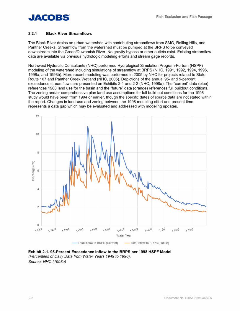
Northwest Hydraulic Consultants (NHC) performed Hydrological Simulation Program-Fortran (HSPF) modeling of the watershed including simulations of streamflow at BRPS (NHC, 1991, 1992, 1994, 1996, 1998a, and 1998b). More recent modeling was performed in 2005 by NHC for projects related to State Route 167 and Panther Creek Wetland (NHC, 2005). Depictions of the annual 95- and 5-percent exceedance streamflows are presented on Exhibits 2-1 and 2-2 (NHC, 1998a). The “current” data (blue) references 1988 land use for the basin and the “future” data (orange) references full buildout conditions. The zoning and/or comprehensive plan land use assumptions for full build out conditions for the 1998 study would have been from 1994 or earlier, though the specific dates of source data are not stated within the report. Changes in land-use and zoning between the 1998 modeling effort and present time represents a data gap which may be evaluated and addressed with modeling updates.
Exhibit 2-1. 95-Percent Exceedance Inflow to the BRPS per 1998 HSPF Model (Percentiles of Daily Data from Water Years 1949 to 1996). Source: NHC (1998a)
Fish Exclusion and Fish Passage
Document No. BI0512191046SEA 2-3
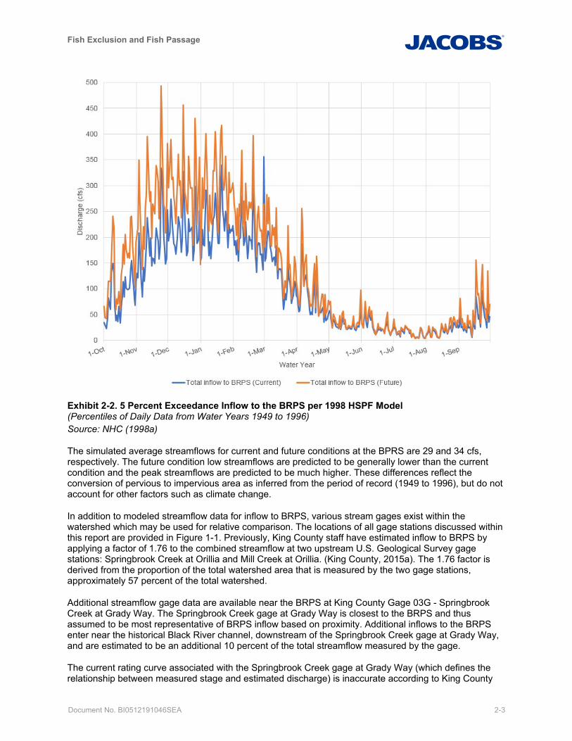
Exhibit 2-2. 5 Percent Exceedance Inflow to the BRPS per 1998 HSPF Model (Percentiles of Daily Data from Water Years 1949 to 1996) Source: NHC (1998a)
The simulated average streamflows for current and future conditions at the BPRS are 29 and 34 cfs, respectively. The future condition low streamflows are predicted to be generally lower than the current condition and the peak streamflows are predicted to be much higher. These differences reflect the conversion of pervious to impervious area as inferred from the period of record (1949 to 1996), but do not account for other factors such as climate change.
In addition to modeled streamflow data for inflow to BRPS, various stream gages exist within the watershed which may be used for relative comparison. The locations of all gage stations discussed within this report are provided in Figure 1-1. Previously, King County staff have estimated inflow to BRPS by applying a factor of 1.76 to the combined streamflow at two upstream U.S. Geological Survey gage stations: Springbrook Creek at Orillia and Mill Creek at Orillia. (King County, 2015a). The 1.76 factor is derived from the proportion of the total watershed area that is measured by the two gage stations, approximately 57 percent of the total watershed.
Additional streamflow gage data are available near the BRPS at King County Gage 03G - Springbrook Creek at Grady Way. The Springbrook Creek gage at Grady Way is closest to the BRPS and thus assumed to be most representative of BRPS inflow based on proximity. Additional inflows to the BRPS enter near the historical Black River channel, downstream of the Springbrook Creek gage at Grady Way, and are estimated to be an additional 10 percent of the total streamflow measured by the gage.
The current rating curve associated with the Springbrook Creek gage at Grady Way (which defines the relationship between measured stage and estimated discharge) is inaccurate according to King County
Fish Exclusion and Fish Passage
2-4 Document No. BI0512191046SEA
engineers. The low end of the rating curve is particularly impacted, and as a result, streamflows may not be accurately represented by a simple stage-discharge rating (Bean, 2019c). Changes to the stream channel cross-section and roughness over time due to sedimentation and vegetation growth are believed to be the primary cause of inaccuracies. Beavers are also known to be occasionally present in the area and their activity can further restrict conveyance capacity. Revision of the rating curve at the Springbrook Creek gage at Grady Way to obtain improved estimates of streamflow is identified as a data gap/future action item at the end of this section.
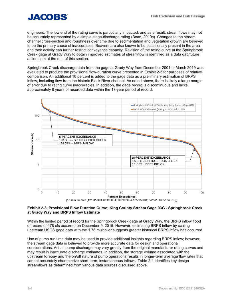
Springbrook Creek discharge data from the gage at Grady Way from December 2001 to March 2019 was evaluated to produce the provisional flow-duration curve presented in Exhibit 2-3 for purposes of relative comparison. An additional 10 percent is added to the gage data as a preliminary estimation of BRPS inflow, including flow from the historic Black River channel. As noted above, there is likely a large margin of error due to rating curve inaccuracies. In addition, the gage record is discontinuous and lacks approximately 6 years of recorded data within the 17-year period of record.
Exhibit 2-3. Provisional Flow Duration Curve; King County Stream Gage 03G - Springbrook Creek at Grady Way and BRPS Inflow Estimate
Within the limited period of record for the Springbrook Creek gage at Grady Way, the BRPS inflow flood of record of 478 cfs occurred on December 9, 2015. However, estimating BRPS inflow by scaling upstream USGS gage data with the 1.76 multiplier suggests greater historical BRPS inflow has occurred.
Use of pump run time data may be used to provide additional insights regarding BRPS inflow; however, the stream gage data is believed to provide more accurate data for design and operational considerations. Actual pump discharge may vary greatly from the original manufacturer rating curves and may result in inaccurate discharge estimates. In addition, the storage volume associated with the upstream forebay and the on/off nature of pump operations results in longer-term average flow rates that cannot accurately characterize short-term, instantaneous inflows. Table 2-1 identifies key design streamflows as determined from various data sources discussed above.
Fish Exclusion and Fish Passage
Document No. BI0512191046SEA 2-5
Table 2-1. Key Design Streamflows for Black River Pump Station
Design Event
Black River Pump Station Inflow (cfs)
FEMA FIS a NHC Model b
King County Gage 03G,
Springbrook Creek at
Grady Way c
0.2-Percent annual chance exceedance flood (500-year flood) d 1,730 N/A N/A
1-Percent annual chance exceedance flood (100-year flood) d 1,230 1,111 N/A
10-Percent annual chance exceedance flood (10-year flood) d 650 743 N/A
5-Percent exceedance e N/A 130 168
50-Percent exceedance e N/A 9.0 26
95-Percent exceedance e N/A 2.7 6.1
Notes: a Source: FEMA (2017) b Source: NHC (1996 and 1998a). NHC Model values reflect “current” conditions from the time of study, as opposed to modeled “future” full buildout conditions. c Source: Adapted from King County (2019) gage data; 10 percent added to recorded gage flow to estimate BRPS inflow. d Annual chance exceedance event (that is, 1 in 500 chance of exceedance in any given year for the 500-year flood) e Percent exceedance on an average annual basis
cfs cubic feet per second FEMA Federal Emergency Management Agency FIS flood insurance study N/A not available NHC Northwest Hydraulic Consultants
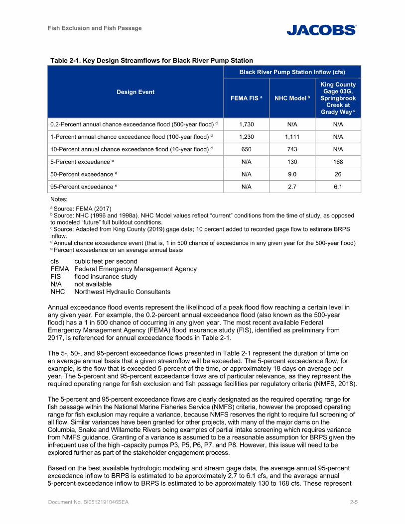
Annual exceedance flood events represent the likelihood of a peak flood flow reaching a certain level in any given year. For example, the 0.2-percent annual exceedance flood (also known as the 500-year flood) has a 1 in 500 chance of occurring in any given year. The most recent available Federal Emergency Management Agency (FEMA) flood insurance study (FIS), identified as preliminary from 2017, is referenced for annual exceedance floods in Table 2-1.
The 5-, 50-, and 95-percent exceedance flows presented in Table 2-1 represent the duration of time on an average annual basis that a given streamflow will be exceeded. The 5-percent exceedance flow, for example, is the flow that is exceeded 5-percent of the time, or approximately 18 days on average per year. The 5-percent and 95-percent exceedance flows are of particular relevance, as they represent the required operating range for fish exclusion and fish passage facilities per regulatory criteria (NMFS, 2018).
The 5-percent and 95-percent exceedance flows are clearly designated as the required operating range for fish passage within the National Marine Fisheries Service (NMFS) criteria, however the proposed operating range for fish exclusion may require a variance, because NMFS reserves the right to require full screening of all flow. Similar variances have been granted for other projects, with many of the major dams on the Columbia, Snake and Willamette Rivers being examples of partial intake screening which requires variance from NMFS guidance. Granting of a variance is assumed to be a reasonable assumption for BRPS given the infrequent use of the high -capacity pumps P3, P5, P6, P7, and P8. However, this issue will need to be explored further as part of the stakeholder engagement process.
Based on the best available hydrologic modeling and stream gage data, the average annual 95-percent exceedance inflow to BRPS is estimated to be approximately 2.7 to 6.1 cfs, and the average annual 5-percent exceedance inflow to BRPS is estimated to be approximately 130 to 168 cfs. These represent
Fish Exclusion and Fish Passage
2-6 Document No. BI0512191046SEA
the lower and upper limits, respectively, of the required operating range for the BRPS fish exclusion and fish passage facilities. The variability in these values indicates the relative uncertainty between available information sources, underscoring the need for further refinement prior to design.
2.2.2 Forebay Water Surface Elevation
Forebay WSEL data are collected by the BRPS supervisory control and data acquisition (SCADA) system, and data from August 2009 to present were evaluated. Because all Black River streamflows must be pumped at the BRPS, the forebay WSEL is highly influenced by the pump operation setpoints (minimum and maximum WSEL’s for pump operation). The normal forebay operating range is from 6.1 to 7.6 feet NAVD88.
The existing upstream fish passage facility is understood to utilize a large portion of streamflow during summer low-flow conditions (fishway pump P9 capacity of 8 cfs vs. estimated 95 percent exceedance streamflow of 2.7 to 6.1 cfs). An analysis of the WSEL data and anecdotal information from King County Wastewater Treatment Division (WTD) operators provide no indication that the forebay has approached the fishway pump P9 low shutoff elevation of 3.6 feet NAVD88. All data near this WSEL were found to be a result of bubbler data error, faulty operation of pump P1 (in 2014 when pumping did not shut off at the correct WSEL), or periods in 2016 when the forebay was dewatered for sediment removal. Therefore, there is no indication that the pump P9 discharge has exceeded dry condition streamflows (Bean, 2019b and 2019c).
Flooding is historically known to occur on Springbrook Creek where it passes below I-405 (at Oakesdale Avenue). A floodwall at this location has a minimum top elevation of 17.29 feet NAVD88 as measured by a preliminary survey completed in April 2019. King County WTD staff have anecdotally reported backwater very near the wall crest when the BRPS forebay water surface was approximately 12.5 feet NAVD88. King County WLRD staff also indicated that the top elevation of the Oakesdale Avenue floodwall below I-405 was just shown to be 13.23 feet NAVD88 in the HEC-RAS model for lower Springbrook Creek used in the FEMA FIS (King County, 2015a), a discrepancy of approximately 4.3 feet from the recent topographic survey. A future survey will confirm the top of wall crest elevation with a closed level loop back to the BRPS, to minimize the potential for errors.
Per the FEMA flood insurance study flood profile for Springbrook Creek (FEMA, 2017), the floodwall is over-topped during the 100-year streamflow event, with an estimated WSEL of 19.0 feet NAVD88 at Springbrook Creek at I-405. The Springbrook Creek flood profile indicates that approximately 7.0 feet of hydraulic differential exists between Springbrook Creek at I-405 and the confluence of with the BRPS forebay storage pond during a 10-year flood, while only 0.5-foot differential exists during a 100-year flood. Although not completed as part of this report, further confirmation of the hydraulic differential may be pursued in future project planning and designthrough comparison of stream gage data for Springbrook Creek at Grady Way with water levels recorded in the BRPS forebay over the same time period, and/or reviewing and updating the hydraulic modeling used for preparation of the FIS.
The FEMA flood profiles were developed in consideration of two operational scenarios, one with the BRPS pumps operating without restriction (conveyance scenario), and another with the pumps curtailed at 875 cfs due to flooding in the Green River (storage scenario). The published 100-year flood profile reflects the higher WSEL of the two scenarios (storage scenario), while the 10-year flood profile is based on the conveyance scenario alone because the storage scenario was determined to cause a negligible rise for this recurrence interval. Both profiles also assume partial obstruction of the box culvert at Southwest Grady Way.
Further analysis will be required to accurately correlate normal BRPS forebay WSELs with Springbrook Creek at I-405 WSELs. However, based on the published flood profiles and in consideration of the associated operational scenarios, a BRPS forebay WSEL on the order of approximately 10 to 11 feet NAVD88 may cause the floodwall to be over-topped during a 10-year event. A BRPS forebay WSEL in this range can occur during events requiring the use of one or more of the five high-capacity pumps (P3, P5, P6, P7, and P8). These high-capacity pumps are started in response to a high-water alarm that is
Fish Exclusion and Fish Passage
Document No. BI0512191046SEA 2-7
triggered by a forebay WSEL of 9.55 NAVD88. Normally, the forebay will continue to rise, perhaps by a foot or more, while staff are dispatched and equipment is activated.
While the potential for flooding during large storm events exists and warrants further analysis, there is room for operational flexibility during normal to low flow periods to allow a higher forebay WSEL than maintained by current operations. Operational controls could be implemented to allow for the optimization of BRPS pond elevations during normal to low inflows, while improving upon the status quo flood protection during high inflow flood events. This may allow for some operational flexibility with regard to selected fish passage concepts that benefit from operations at a slightly higher normal operating forebay WSEL.
Forebay WSEL data will be compared to additional stage and discharge data from the Springbrook Creek gage at Grady Way as they become available. The gage at Grady Way is located approximately 1,150 feet downstream from the Oakesdale Avenue floodwall beneath I-405. Conversion from the gage datum to NAVD88 is as follows:
NAVD88 = Gage Datum + 6.38 feet
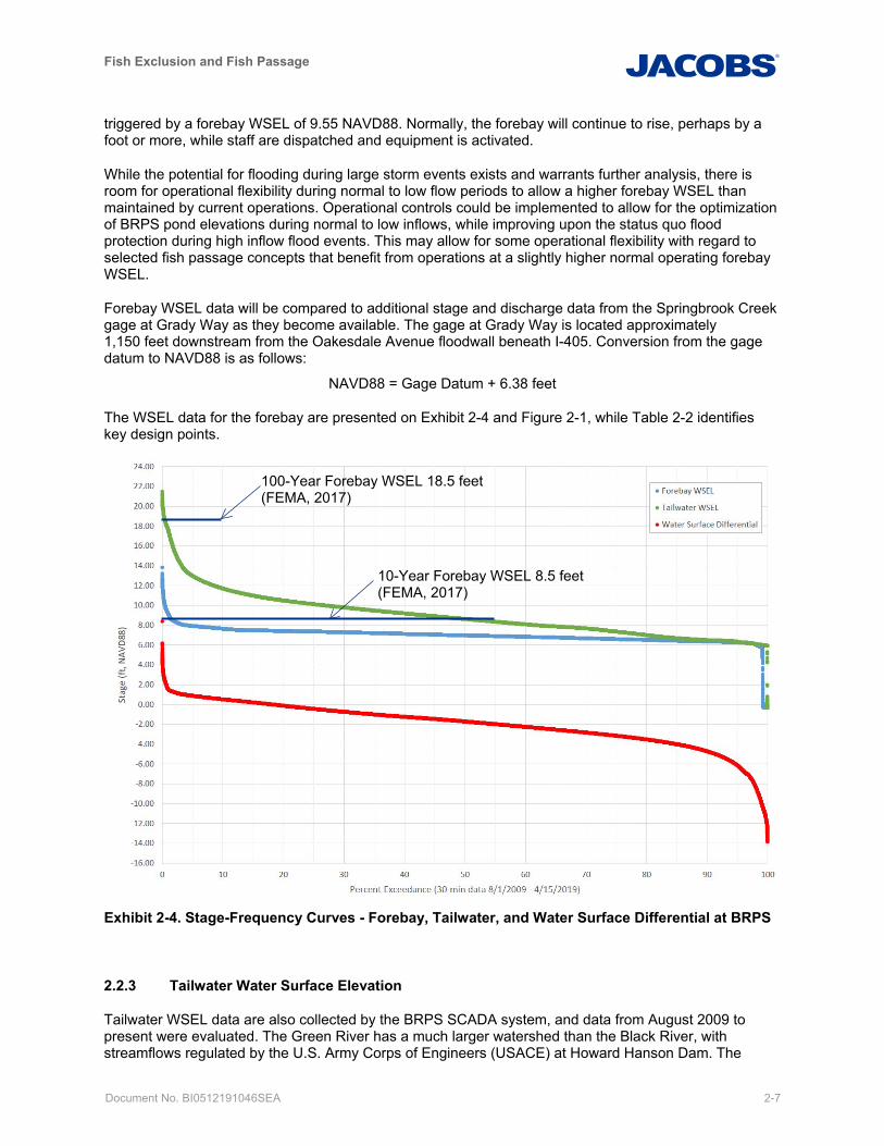
The WSEL data for the forebay are presented on Exhibit 2-4 and Figure 2-1, while Table 2-2 identifies key design points.
Exhibit 2-4. Stage-Frequency Curves - Forebay, Tailwater, and Water Surface Differential at BRPS
2.2.3 Tailwater Water Surface Elevation
Tailwater WSEL data are also collected by the BRPS SCADA system, and data from August 2009 to present were evaluated. The Green River has a much larger watershed than the Black River, with streamflows regulated by the U.S. Army Corps of Engineers (USACE) at Howard Hanson Dam. The
100-Year Forebay WSEL 18.5 feet (FEMA, 2017)
10-Year Forebay WSEL 8.5 feet (FEMA, 2017)
Fish Exclusion and Fish Passage
2-8 Document No. BI0512191046SEA
tailwater WSEL fluctuates considerably on both a daily and seasonal basis due to tides, streamflow in the Green/Duwamish River downstream and storm events in the upstream watershed. The WSEL data for the tailwater are presented on Exhibits 2-4 and 2-1, while Table 2-2 identifies key design points.
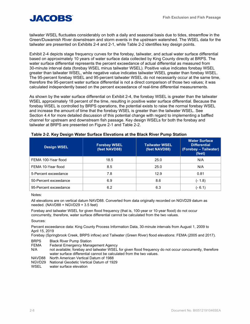
Exhibit 2-4 depicts stage frequency curves for the forebay, tailwater, and actual water surface differential based on approximately 10 years of water surface data collected by King County directly at BRPS. The water surface differential represents the percent exceedance of actual differential as measured from 30-minute interval data (forebay WSEL minus tailwater WSEL). Positive value indicates forebay WSEL greater than tailwater WSEL, while negative value indicates tailwater WSEL greater than forebay WSEL. The 95-percent forebay WSEL and 95-percent tailwater WSEL do not necessarily occur at the same time, therefore the 95-percent water surface differential is not a direct comparison of those two values; it was calculated independently based on the percent exceedance of real-time differential measurements.
As shown by the water surface differential on Exhibit 2-4, the forebay WSEL is greater than the tailwater WSEL approximately 18 percent of the time, resulting in positive water surface differential. Because the forebay WSEL is controlled by BRPS operations, the potential exists to raise the normal forebay WSEL and increase the amount of time that the forebay WSEL is greater than the tailwater WSEL. See Section 4.4 for more detailed discussion of this potential change with regard to implementing a baffled channel for upstream and downstream fish passage. Key design WSELs for both the forebay and tailwater at BRPS are presented on Figure 2-1 and Table 2-2.
Table 2-2. Key Design Water Surface Elevations at the Black River Pump Station
Design WSEL Forebay WSEL (feet NAVD88)
Tailwater WSEL (feet NAVD88)
Water Surface Differential
(Forebay – Tailwater) (feet)
FEMA 100-Year flood 18.5 25.0 N/A
FEMA 10-Year flood 8.5 25.0 N/A
5-Percent exceedance 7.8 12.9 0.81
50-Percent exceedance 6.9 8.6 (- 1.8)
95-Percent exceedance 6.2 6.3 (- 6.1)
Notes: All elevations are on vertical datum NAVD88. Converted from data originally recorded on NGVD29 datum as needed. (NAVD88 = NGVD29 + 3.5 feet) Forebay and tailwater WSEL for given flood frequency (that is, 100-year or 10-year flood) do not occur concurrently, therefore, water surface differential cannot be calculated from the two values. Sources: Percent exceedance data: King County Process Information Data, 30-minute intervals from August 1, 2009 to April 15, 2019 Forebay (Springbrook Creek, BRPS inflow) and Tailwater (Green River) flood elevations: FEMA (2005 and 2017). BRPS Black River Pump Station FEMA Federal Emergency Management Agency N/A not available; forebay and tailwater WSEL for given flood frequency do not occur concurrently, therefore
water surface differential cannot be calculated from the two values. NAVD88 North American Vertical Datum of 1988 NGVD29 National Geodetic Vertical Datum of 1929 WSEL water surface elevation
Fish Exclusion and Fish Passage
Document No. BI0512191046SEA 2-9
2.2.4 Data Gaps and Future Action
The following additional information will likely be required to fully evaluate the performance of the existing facility and proposed concepts:
• The top of the Oakesdale Avenue floodwall crest at I-405 should be surveyed with a closed level loop to the pump station to ensure that the potential for errors is mitigated.
• Streamflow information from the Springbrook Creek gage at Grady Way should be collected and evaluated, including revising the existing rating curve and potentially implementing an ongoing program to update the rating curve on a regular basis if data are desired for long-term use by the County for BRPS operations.
• The hydraulic differential between Springbrook Creek at I-405 and the BRPS forebay may be confirmed through the following measures:
– Compare existing stream gage data for Springbrook Creek at Grady Way with water levels recorded at the BRPS forebay over the same time period.
– Install a continuous stage recorder on Springbrook Creek at I-405 to allow direct comparison with forebay WSELs and streamflow data. Relatively inexpensive telemetry packages are available, including a cellular link and website interface for real-time evaluation of data and custom alerts as desired.
– Review and/or update of the hydraulic modeling used for the FEMA FIS regarding flood profiles, or new independent modeling for confirmation.
• Discussions should be held with the City of Renton and others to identify any other potential concerns associated with a higher forebay operating WSEL aside from those documented at the Oakesdale Avenue floodwall at I-405. This includes gaining a better understanding of upstream infrastructure, design assumptions, sensitivity to operations at BRPS, and the feasibility of mitigating any adverse impacts.
• The 2005 HSPF model could be updated to account for any changed conditions and to allow for additional calibration with conditions observed in the field. Changed conditions may include land-use, zoning and climate-related changes.
• The most applicable design and operating criteria for the BRPS, including design inflows, storage and pumping capacity (including redundancy), should be confirmed
• The potential effects of climate change on BRPS design inflows for the 50-year design period should also be evaluated.
2.3 Fish Biology
Characterization of fish present in the Black River watershed including species, life stage, timing, abundance and available habitat is critical for evaluating the performance of the existing fish passage facilities and proposed future modifications. Known information is presented in the text that follows.
2.3.1 Species
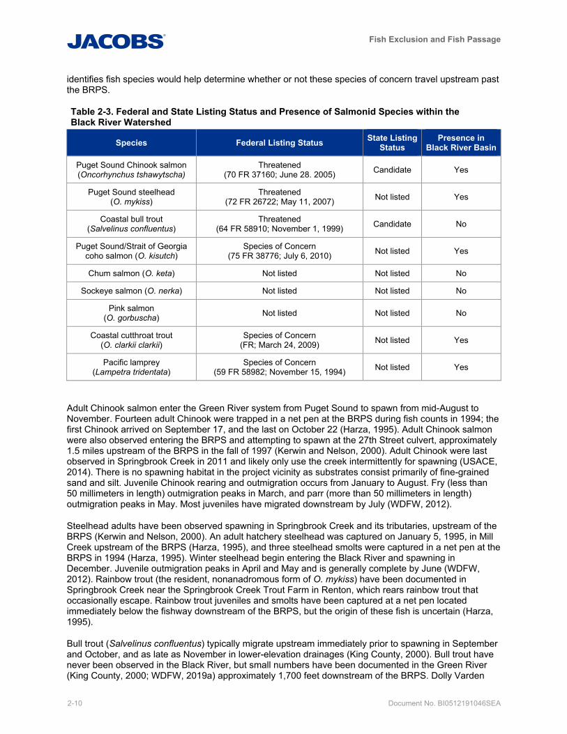
The Black River watershed provides important habitat for multiple salmonid species (Table 2-3), including Endangered Species Act-listed Puget Sound Chinook salmon (federally listed as threatened) and Puget Sound steelhead (federally listed as threatened), as well as coho (a federal species of concern) and cutthroat trout. Pacific lamprey (a State candidate species, and federal species of concern) may also be found in the watershed. WDFW does not document bull trout (federally listed as threatened), chum (O. keta), sockeye (O. nerka), or pink salmon (O. gorbuscha) in the Black River and these species are unlikely to be found in the basin currently, although they likely occurred there historically . These species do occur in the Green River, and despite the partial fish passage barrier presented by the BRPS, these species could access the Black River and potentially occur upstream of the BRPS (WDFW, 2019a). Their presence in the Black River is unknown due to a lack of data. The installation of a video fish counter that
Fish Exclusion and Fish Passage
2-10 Document No. BI0512191046SEA
identifies fish species would help determine whether or not these species of concern travel upstream past the BRPS.
Table 2-3. Federal and State Listing Status and Presence of Salmonid Species within the Black River Watershed
Species Federal Listing Status State Listing Status
Presence in Black River Basin
Puget Sound Chinook salmon (Oncorhynchus tshawytscha)
Threatened (70 FR 37160; June 28. 2005) Candidate Yes
Puget Sound steelhead (O. mykiss)
Threatened (72 FR 26722; May 11, 2007) Not listed Yes
Coastal bull trout (Salvelinus confluentus)
Threatened (64 FR 58910; November 1, 1999) Candidate No
Puget Sound/Strait of Georgia coho salmon (O. kisutch)
Species of Concern (75 FR 38776; July 6, 2010) Not listed Yes
Chum salmon (O. keta) Not listed Not listed No
Sockeye salmon (O. nerka) Not listed Not listed No
Pink salmon (O. gorbuscha) Not listed Not listed No
Coastal cutthroat trout (O. clarkii clarkii)
Species of Concern (FR; March 24, 2009) Not listed Yes
Pacific lamprey (Lampetra tridentata)
Species of Concern (59 FR 58982; November 15, 1994) Not listed Yes
Adult Chinook salmon enter the Green River system from Puget Sound to spawn from mid-August to November. Fourteen adult Chinook were trapped in a net pen at the BRPS during fish counts in 1994; the first Chinook arrived on September 17, and the last on October 22 (Harza, 1995). Adult Chinook salmon were also observed entering the BRPS and attempting to spawn at the 27th Street culvert, approximately 1.5 miles upstream of the BRPS in the fall of 1997 (Kerwin and Nelson, 2000). Adult Chinook were last observed in Springbrook Creek in 2011 and likely only use the creek intermittently for spawning (USACE, 2014). There is no spawning habitat in the project vicinity as substrates consist primarily of fine-grained sand and silt. Juvenile Chinook rearing and outmigration occurs from January to August. Fry (less than 50 millimeters in length) outmigration peaks in March, and parr (more than 50 millimeters in length) outmigration peaks in May. Most juveniles have migrated downstream by July (WDFW, 2012).
Steelhead adults have been observed spawning in Springbrook Creek and its tributaries, upstream of the BRPS (Kerwin and Nelson, 2000). An adult hatchery steelhead was captured on January 5, 1995, in Mill Creek upstream of the BRPS (Harza, 1995), and three steelhead smolts were captured in a net pen at the BRPS in 1994 (Harza, 1995). Winter steelhead begin entering the Black River and spawning in December. Juvenile outmigration peaks in April and May and is generally complete by June (WDFW, 2012). Rainbow trout (the resident, nonanadromous form of O. mykiss) have been documented in Springbrook Creek near the Springbrook Creek Trout Farm in Renton, which rears rainbow trout that occasionally escape. Rainbow trout juveniles and smolts have been captured at a net pen located immediately below the fishway downstream of the BRPS, but the origin of these fish is uncertain (Harza, 1995).
Bull trout (Salvelinus confluentus) typically migrate upstream immediately prior to spawning in September and October, and as late as November in lower-elevation drainages (King County, 2000). Bull trout have never been observed in the Black River, but small numbers have been documented in the Green River (King County, 2000; WDFW, 2019a) approximately 1,700 feet downstream of the BRPS. Dolly Varden
Fish Exclusion and Fish Passage
Document No. BI0512191046SEA 2-11
(S. malma), a very similar species, have been observed in the Springbrook Creek system (Harza, 1995) indicating that bull trout could be present in the Black River watershed.
Coho salmon and cutthroat trout have also been trapped at several locations in the basin (Kerwin and Nelson, 2000). The Black River and Springbrook Creek contain documented coho rearing habitat (WDFW, 2019a) and coho and cutthroat have been observed spawning in Springbrook Creek and its tributaries (Kerwin and Nelson, 2000).
Other studies have documented the presence of three-spine stickleback (Gasterosteus aculeatus), nonnative pumpkinseed sunfish (Lepomus gibbosus), speckled dace (Millicoma daces), lamprey (Lampetra sp.), and sculpin (Cottidae sp.) (sculpin and lamprey not identified to species) (Harza, 1995).
2.3.2 Life Stages – Chinook
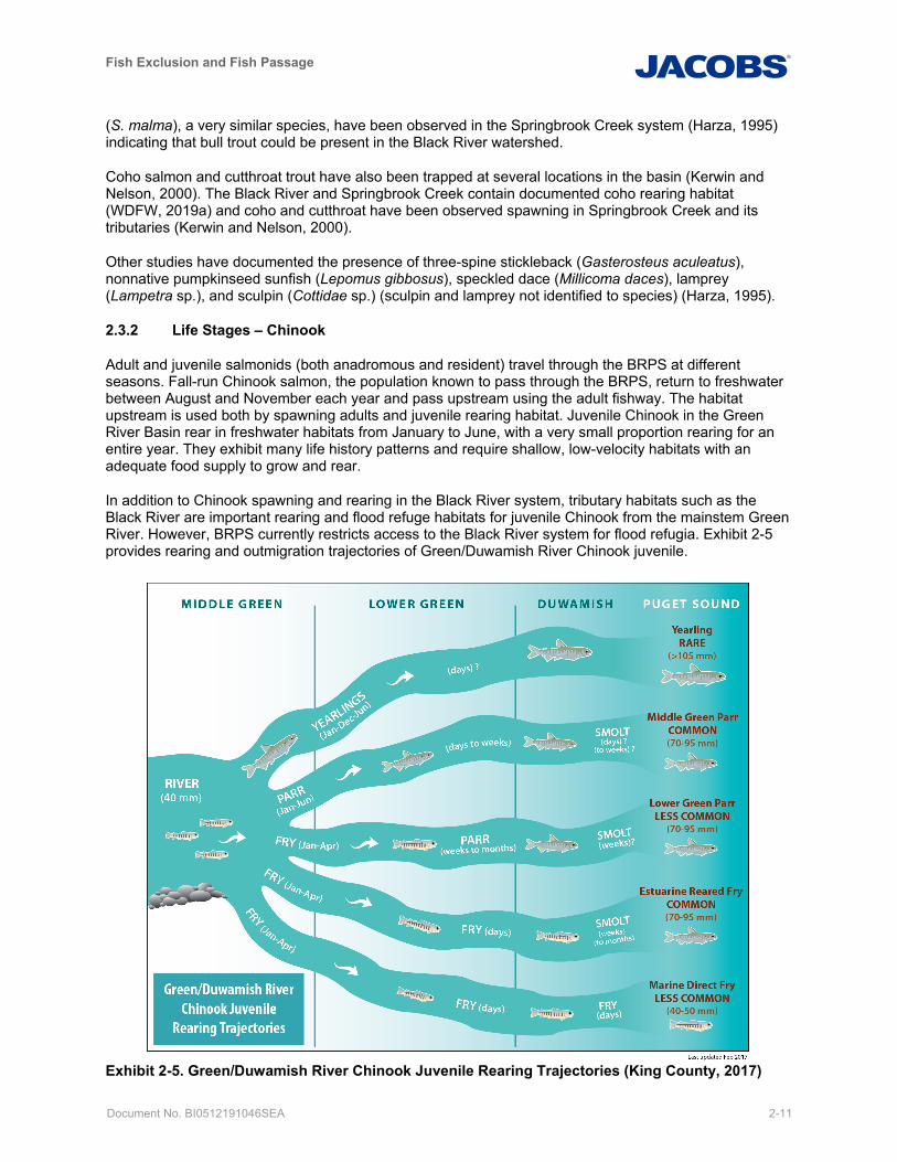
Adult and juvenile salmonids (both anadromous and resident) travel through the BRPS at different seasons. Fall-run Chinook salmon, the population known to pass through the BRPS, return to freshwater between August and November each year and pass upstream using the adult fishway. The habitat upstream is used both by spawning adults and juvenile rearing habitat. Juvenile Chinook in the Green River Basin rear in freshwater habitats from January to June, with a very small proportion rearing for an entire year. They exhibit many life history patterns and require shallow, low-velocity habitats with an adequate food supply to grow and rear.
In addition to Chinook spawning and rearing in the Black River system, tributary habitats such as the Black River are important rearing and flood refuge habitats for juvenile Chinook from the mainstem Green River. However, BRPS currently restricts access to the Black River system for flood refugia. Exhibit 2-5 provides rearing and outmigration trajectories of Green/Duwamish River Chinook juvenile.
Exhibit 2-5. Green/Duwamish River Chinook Juvenile Rearing Trajectories (King County, 2017)
Fish Exclusion and Fish Passage
2-12 Document No. BI0512191046SEA
2.3.2.1 Historical Conditions
Historically the lower Green River subbasin (called the White River before the diversion of the White River into the Puyallup River basin in 1906) featured a single-thread mainstem with natural levees built above the floodplain as a result of the valley’s glacial history, low gradient, and sediment deposition (Collins and Sheikh, 2005). Before diversion of the White River and hydromodification of the lower Green River, tributaries draining the extensive depressional areas of the floodplain dominated the channel edge of the lower Green River. During relatively small flood events, the river overflowed its banks into the low-lying floodplain, creating a network of ephemeral streams that supplied water to the wetlands and tributaries within the valley (King County, 2005). These tributaries accounted for approximately one-third of the total channel area and 62 percent of total channel length in the lower Green River (King County, 2005; Collins and Sheikh, 2005). These historical areas likely served as important flood refuge and rearing habitats for juvenile Chinook salmon (Oncorhynchus tshawytscha) and other salmonids.
2.3.2.2 Human Modifications
Changes in land use and river hydromodification have severely reduced and limited salmon habitat throughout the Green River basin. These modifications in the lower Green River, including the diversion of two rivers, a large flood control dam in the upper watershed, pump stations, and flood-containment levees and revetments have gradually disconnected the floodplain, off-channel habitats, and tributaries from the mainstem. With flow management at the dam, the current 100-year flow in the Green River equals a roughly 2-year historical flow (King County, 2010). Only about 18 percent of the historical lower Green River floodplain area is now connected to the river during a 100-year flood event, with much of the ‘connected’ floodplain only connected at very high flows (King County, 2017a). Fish access has been restricted by levees, culverts, pump stations, and flap/flood gates and other structures that have reduced the availability of these habitats for rearing, ultimately reducing juvenile salmon productivity and distribution (King County, 2005).
2.3.2.3 Salmon Population Status
Due to these and many other factors, the Chinook salmon population in the Green River has declined from an average of 2,412 adult spawners between 1969 and 2018, to 1,209 between 2014 and 2018. Due to the risk of extinction, Puget Sound Fall Chinook (including Green River) were listed by the NMFS as a threatened species under the Endangered Species Act in March 1999. In addition, returns of natural origin Chinook are likely exaggerated by the effects of adult hatchery Chinook spawning in the river. The percentage of hatchery fish spawning in the river has shown an increasing trend between 2002 and 2018, with a recent 5-year average of 72 percent.
2.3.2.4 Limiting Factors
Washington Department of Fish and Wildlife has found evidence of a density-dependent relationship between adult spawner abundance and the number of juveniles that leave the river as parr; the ones that live in the river longer before outmigrating to the ocean. This suggests that parr production is limited to the carrying capacity of the current available habitat (Anderson and Topping, 2017). This finding is important because parr contribute to adult returns at rates that are disproportionate to their abundance.
Specifically, roughly half of the juvenile Chinook salmon that leave the Green River do so as parr, but more than nine out of ten returning adults originate from parr. For example, WDFW (WDFW, 2018a) found that although Chinook that had outmigrated as fry only made up 1 to 5 percent of the total adult return from 2015 to 2017, those same fish (outmigrating fry between 2010 and 2014) made up an average of 52 percent of the total Chinook subyearling outmigration (WDFW, 2018b). This research indicates that Chinook parr, which made up an average of 48 percent of the Chinook subyearling outmigration between 2010 and 2014, produced 93 to 95 percent of the adult returns between 2015 and 2017. This research suggests that increasing rearing habitat in the Green River basin would increase parr numbers and, therefore, adult Chinook returns. In the highly developed lower Green river, non-natal
Fish Exclusion and Fish Passage
Document No. BI0512191046SEA 2-13
tributary streams, such as the Black River, may provide important additional rearing habitat for higher parr production.
Populations of Chinook salmon are differentiated according to the season of spawning migration (Myers et al., 1998). Fall-run Chinook salmon, the population found in Black River, return to freshwater later in the year and typically spawn in the lower reaches of tributary streams (Myers et al., 1998).
2.3.3 Life Stages – Other
O. mykiss has two alternate life history strategies: the anadromous form (steelhead) and the nonanadromous resident form (rainbow trout). The two life-history strategies often overlap in distribution and are difficult to tell apart until steelhead take on a silver coloration during smoltification to prepare for ocean migration. Either form may give rise to offspring exhibiting either resident or migratory behavior. Steelhead, like other anadromous salmonids, emerge from redds in freshwater streams and rivers, spend a portion of their life at sea, and then return to freshwater to spawn (Myers et al., 2015). Steelhead exhibit two general types of life-history strategies: winter-run steelhead return from the ocean between January and June and typically spawn within a few weeks; summer-run steelhead migrate into natal streams during the late spring and summer and hold in deep freshwater pools of rivers and streams for up to 9 months before spawning in late-winter/early-spring of the following year (WDFW, 2011). Both life history strategies may be found in the Black River. Steelhead differ from the other the four anadromous salmonids found in the Green River in that they do not always die after spawning. Instead adults may spawn in multiple years, requiring upstream and downstream adult passage in tributary streams (coastal cutthroat trout also may spawn in multiple years).
Like steelhead, bull trout express both resident and migratory life history strategies. Resident forms of bull trout complete their entire life cycle in the tributary or nearby streams in which they spawn and rear. Migratory anadromous bull trout spawn in tributary streams where juvenile fish rear for 1 to 4 years before migrating to the ocean (Cavender, 1978). Resident and migratory forms may be found together and either form may give rise to offspring exhibiting either resident or migratory behavior (Rieman and McIntyre, 1993). Although they have been documented in the Green River, bull trout are not observed in the Black River upstream or downstream of the BRPS.
Coho, chum, and pink salmon have unique life history characteristics that vary by species. Most juvenile coho salmon remain in freshwater rearing habitat for approximately 18 months; spend 18 months in the ocean; then return to natal streams to spawn at the age of 3 years (Sandercock, 1991). Chum salmon do not have a long freshwater residency (Salo, 1991). They emerge and migrate downstream at night and typically have a longer estuarine residency (Salo, 1991), although extended rearing of chum salmon (through mid-May) has been observed in the Green River Basin. The anadromous form of sockeye salmon spends one or more growing season in streams or lakes before outmigration to the ocean (Burgner, 1991). Pink salmon are distinguished from other Pacific salmon by having a fixed two-year life span (Heard, 1999). Pink salmon observed at the BRPS would be odd-year pink salmon (WDFW, 2019a), meaning they spawn in odd years. After emergence, pink salmon fry migrate quickly downstream, spending less time in freshwater after leaving gravel than other salmon species (Heard, 1999). While coho, chum, sockeye, and pink salmon are all found throughout the Green River, only coho are observed upstream and downstream of the BRPS in the Black River.
The coastal cutthroat life history may be one of the most complex, with three recognized life-history forms: nonmigratory, freshwater-migratory, and saltwater-migratory. The nonmigratory life-history form are generally found in small streams and headwater tributaries. The freshwater-migratory life-history form includes fish that migrate entirely within freshwater. The saltwater-migratory coastal cutthroat trout is the only anadromous form and migrates from freshwater natal areas in the late winter and spring to feed in marine environments during the summer. They reenter freshwater in the winter to feed, seek refuge, or spawn, sometimes returning to the ocean in the spring (USFWS, 2019). The nonmigratory life-history form are most likely to be present within the Black River basin, although the life-history forms are malleable and individual fish are known to move from one life history form to another within their lifespan. Similar to steelhead, adult cutthroat trout, including the coastal form, do not always die after spawning so
Fish Exclusion and Fish Passage
2-14 Document No. BI0512191046SEA
may spawn in multiple years. Coastal cutthroat trout are observed in the Black River, upstream and downstream of the BRPS, as well as the Green River.
2.3.4 Timing
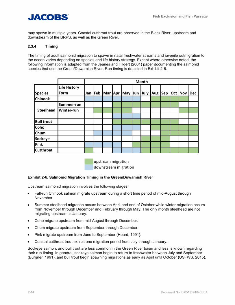
The timing of adult salmonid migration to spawn in natal freshwater streams and juvenile outmigration to the ocean varies depending on species and life history strategy. Except where otherwise noted, the following information is adapted from the Jeanes and Hilgert (2001) paper documenting the salmonid species that use the Green/Duwamish River. Run timing is depicted in Exhibit 2-6.
Exhibit 2-6. Salmonid Migration Timing in the Green/Duwamish River
Upstream salmonid migration involves the following stages:
• Fall-run Chinook salmon migrate upstream during a short time period of mid-August through November.
• Summer steelhead migration occurs between April and end of October while winter migration occurs from November through December and February through May. The only month steelhead are not migrating upstream is January.
• Coho migrate upstream from mid-August through December.
• Chum migrate upstream from September through December.
• Pink migrate upstream from June to September (Heard, 1991).
• Coastal cutthroat trout exhibit one migration period from July through January.
Sockeye salmon, and bull trout are less common in the Green River basin and less is known regarding their run timing. In general, sockeye salmon begin to return to freshwater between July and September (Burgner, 1991), and bull trout begin spawning migrations as early as April until October (USFWS, 2015).
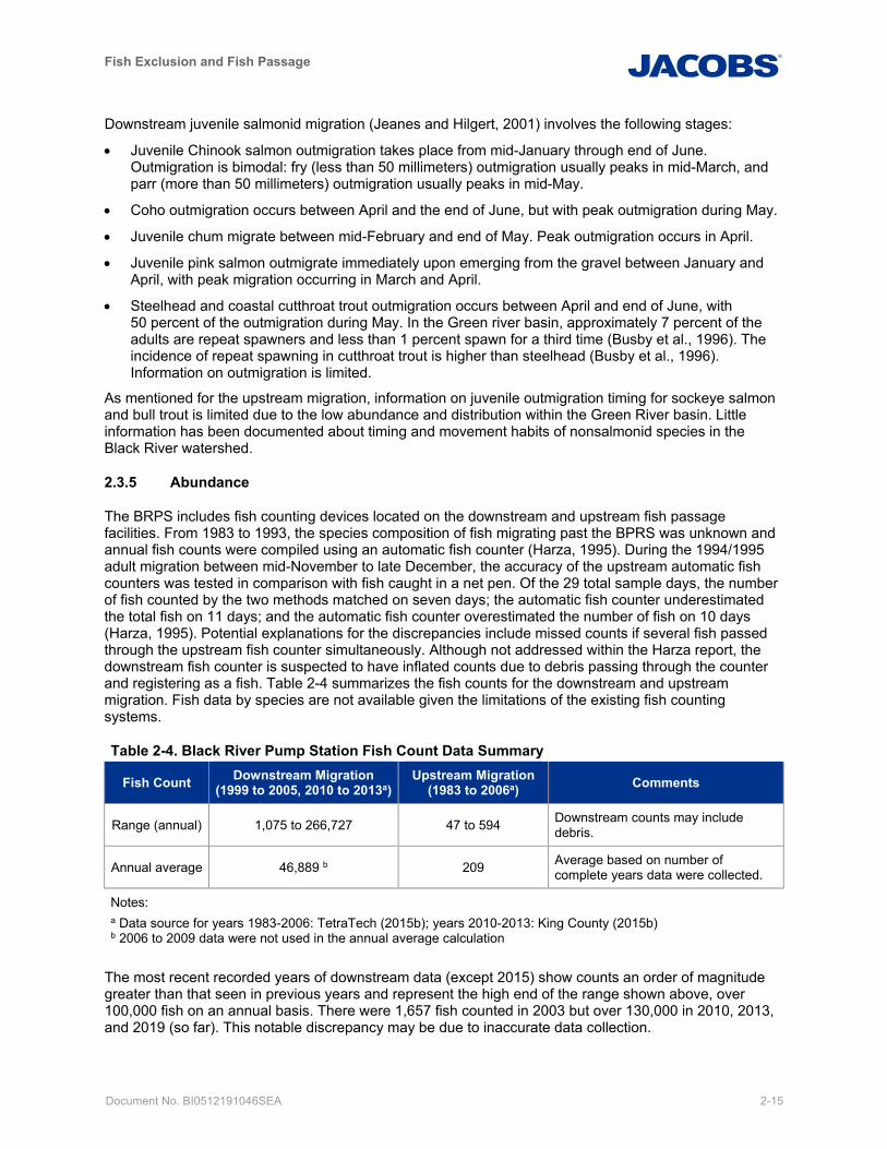
Fish Exclusion and Fish Passage
Document No. BI0512191046SEA 2-15
Downstream juvenile salmonid migration (Jeanes and Hilgert, 2001) involves the following stages:
• Juvenile Chinook salmon outmigration takes place from mid-January through end of June. Outmigration is bimodal: fry (less than 50 millimeters) outmigration usually peaks in mid-March, and parr (more than 50 millimeters) outmigration usually peaks in mid-May.
• Coho outmigration occurs between April and the end of June, but with peak outmigration during May.
• Juvenile chum migrate between mid-February and end of May. Peak outmigration occurs in April.
• Juvenile pink salmon outmigrate immediately upon emerging from the gravel between January and April, with peak migration occurring in March and April.
• Steelhead and coastal cutthroat trout outmigration occurs between April and end of June, with 50 percent of the outmigration during May. In the Green river basin, approximately 7 percent of the adults are repeat spawners and less than 1 percent spawn for a third time (Busby et al., 1996). The incidence of repeat spawning in cutthroat trout is higher than steelhead (Busby et al., 1996). Information on outmigration is limited.
As mentioned for the upstream migration, information on juvenile outmigration timing for sockeye salmon and bull trout is limited due to the low abundance and distribution within the Green River basin. Little information has been documented about timing and movement habits of nonsalmonid species in the Black River watershed.
2.3.5 Abundance
The BRPS includes fish counting devices located on the downstream and upstream fish passage facilities. From 1983 to 1993, the species composition of fish migrating past the BPRS was unknown and annual fish counts were compiled using an automatic fish counter (Harza, 1995). During the 1994/1995 adult migration between mid-November to late December, the accuracy of the upstream automatic fish counters was tested in comparison with fish caught in a net pen. Of the 29 total sample days, the number of fish counted by the two methods matched on seven days; the automatic fish counter underestimated the total fish on 11 days; and the automatic fish counter overestimated the number of fish on 10 days (Harza, 1995). Potential explanations for the discrepancies include missed counts if several fish passed through the upstream fish counter simultaneously. Although not addressed within the Harza report, the downstream fish counter is suspected to have inflated counts due to debris passing through the counter and registering as a fish. Table 2-4 summarizes the fish counts for the downstream and upstream migration. Fish data by species are not available given the limitations of the existing fish counting systems.
Table 2-4. Black River Pump Station Fish Count Data Summary
Fish Count Downstream Migration (1999 to 2005, 2010 to 2013a)
Upstream Migration (1983 to 2006a) Comments
Range (annual) 1,075 to 266,727 47 to 594 Downstream counts may include debris.
Annual average 46,889 b 209 Average based on number of complete years data were collected.
Notes: a Data source for years 1983-2006: TetraTech (2015b); years 2010-2013: King County (2015b) b 2006 to 2009 data were not used in the annual average calculation
The most recent recorded years of downstream data (except 2015) show counts an order of magnitude greater than that seen in previous years and represent the high end of the range shown above, over 100,000 fish on an annual basis. There were 1,657 fish counted in 2003 but over 130,000 in 2010, 2013, and 2019 (so far). This notable discrepancy may be due to inaccurate data collection.
Fish Exclusion and Fish Passage
2-16 Document No. BI0512191046SEA
2.3.6 Habitat
The BRPS is located on the western edge of the Black River Riparian Forest and Wetland, a 92-acre riparian wetland reserve owned by the City of Renton. The reserve is bordered to the south by Monster Road and to the north by railroad tracks and a concrete recycling facility. Riparian vegetation within the reserve consists primarily of black cottonwood (Populus balsamifera), big-leaf maple (Acer macrophyllum), red alder (Alnus rubra), willow species (Salix spp.), Pacific dogwood (Cornus nuttallii), cattail (Typhus latifolia), Himalayan blackberry, and reed canarygrass.
The BRPS impounds the river, creating a large, slow-moving pool that extends approximately 1,600 feet upstream of the BRPS. Little large woody debris is found in the channel, and no undercut banks or off-channel habitat are found. Substrates consist primarily of fine-grained sand and silt. A floating boom was installed across the forebay in 2010 to capture large trash and debris (thousands of pallets) associated with warnings from the USACE. At the time, geotechnical concerns caused the USACE to limit flood control operations at Howard Hanson Dam upstream, and they warned those downstream to prepare for major levee overflow. Fortunately, no major flood occurred before the USACE was able to resolve the geotechnical concerns, so the influx of pallets did not come. Unfortunately, the boom has not proved very effective with the more typical wood and debris. Removal of floating wood and debris from the BRPS forebay is an ongoing challenge for WTD operations staff.
Aquatic vegetation is limited to cattails and yellow flag iris (Iris pseudacorus) at the water’s edge and a few isolated patches of pondweed (Potamogeton spp.). Algae was observed floating on the water surface during a site visit in July 2014.
The Black River watershed is highly urbanized. Land use consists primarily of commercial and industrial properties, with a dense network of roads. Remaining areas of natural vegetation are fragmented, due to surrounding development within the cities of Renton and Tukwila. Riparian strips along the Black River, Springbrook Creek, and the Green River are the primary wildlife migration and movement corridors connecting these patches of vegetation. A narrow vegetated corridor along Springbrook Creek provides some connectivity of riparian habitat to other wetland systems to the south within the Green River valley, but this corridor is disrupted by several road and highway crossings. The Black River has a thin vegetated riparian corridor that connects to the Green River corridor, linking upstream and downstream riparian habitats along the Green River; however, most natural riparian areas have been replaced by commercial and industrial development.
A total of approximately 54 stream miles exist within the watershed upstream of BRPS as measured from the King County watercourse geographic information system GIS layers (TetraTech, 2015b). Potential fish habitat, defined as stream reaches with continuously wetted channels (Harza, 1995), is summarized in terms of miles of stream channel in Table 2-5. Approximately one-third of the total stream miles in the watershed are identified as potential habitat. Most available habitat would provide rearing and foraging opportunities.
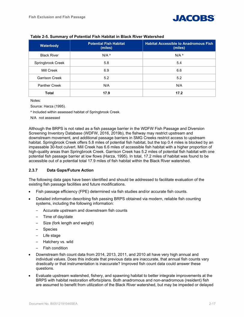
Fish Exclusion and Fish Passage
Document No. BI0512191046SEA 2-17
Table 2-5. Summary of Potential Fish Habitat in Black River Watershed
Waterbody Potential Fish Habitat (miles)
Habitat Accessible to Anadromous Fish (miles)
Black River N/A a N/A a
Springbrook Creek 5.8 5.4
Mill Creek 6.9 6.6
Garrison Creek 5.2 5.2
Panther Creek N/A N/A
Total 17.9 17.2
Notes: Source: Harza (1995). a Included within assessed habitat of Springbrook Creek.
N/A not assessed
Although the BRPS is not rated as a fish passage barrier in the WDFW Fish Passage and Diversion Screening Inventory Database (WDFW, 2016, 2019b), the fishway may restrict upstream and downstream movement, and additional passage barriers in SMG Creeks restrict access to upstream habitat. Springbrook Creek offers 5.8 miles of potential fish habitat, but the top 0.4 miles is blocked by an impassable 30-foot culvert. Mill Creek has 6.6 miles of accessible fish habitat with a higher proportion of high-quality areas than Springbrook Creek. Garrison Creek has 5.2 miles of potential fish habitat with one potential fish passage barrier at low flows (Harza, 1995). In total, 17.2 miles of habitat was found to be accessible out of a potential total 17.9 miles of fish habitat within the Black River watershed.
2.3.7 Data Gaps/Future Action
The following data gaps have been identified and should be addressed to facilitate evaluation of the existing fish passage facilities and future modifications.
• Fish passage efficiency (FPE) determined via fish studies and/or accurate fish counts.
• Detailed information describing fish passing BRPS obtained via modern, reliable fish counting systems, including the following information:
– Accurate upstream and downstream fish counts – Time of day/date – Size (fork length and weight) – Species – Life stage – Hatchery vs. wild – Fish condition
• Downstream fish count data from 2014, 2013, 2011, and 2010 all have very high annual and individual values. Does this indicate that previous data are inaccurate, that annual fish counts vary drastically or that instrumentation is inaccurate? Improved fish count data could answer these questions.
• Evaluate upstream watershed, fishery, and spawning habitat to better integrate improvements at the BRPS with habitat restoration efforts/plans. Both anadromous and non-anadromous (resident) fish are assumed to benefit from utilization of the Black River watershed, but may be impeded or delayed
Fish Exclusion and Fish Passage
2-18 Document No. BI0512191046SEA
by BRPS during migration. Therefore, efforts to better quantify fish remaining in the watershed due to the lack of adequate downstream fish passage may be beneficial.
• Survival of fish passing through the un-screened large Waukesha pumps is not well understood; however, some aquatic organisms may be able to pass safely through the large flow passages within these pumps. Passage via these pumps may contribute to inaccuracies in fish count data, which could be evaluated with fish tagging and/or survival studies. However, the combined use of these pumps is approximately 4 hours per year, so any impact to fish count data associated with their operation is likely very small due to the limited operation.
• Characterization of fish utilization of the Black River between the BRPS and Green River confluence.
2.4 Water Quality
The Black River is listed as impaired on the Washington state Clean Water Act Section 303(d) list for fecal coliform and is listed as a water of concern for dissolved oxygen (DO), temperature, and bis(2-ethylhexyl)phthalate (Washington State Department of Ecology [Ecology], 2019). Sediment samples collected by King County indicate that the sediment contains levels of arsenic, cadmium, and total petroleum hydrocarbons that exceed the Model Toxics Control Act Method A or B cleanup levels for unrestricted land use (King County, 2008). In addition, sediment exceeds freshwater sediment quality criteria for total petroleum hydrocarbon TPH, bis(2-ethylhexyl) phthalate, polychlorinated biphenyls, arsenic, cadmium, and nickel. Road runoff over the years is the likely source of most contaminants. Background turbidity levels in the river are approximately 10 nephelometric turbidity units, based on measurements taken by King County upstream of the BRPS (King County, 2010a and 2010b).
2.4.1 Water Temperature
Average water temperature in July and August between 2000 and 2019 at King County’s Springbrook Creek water quality monitoring site, about 0.50 mile upstream from the pump station, was 16.8 degrees Celsius (°C), sometimes exceeding 20°C (King County, 2020). Summer water temperatures at the BRPS have also been measured at over 20°C (Kerwin and Nelson, 2000). Chinook salmon and steelhead grow more slowly in water temperatures above 18°C and avoid water temperatures above 20°C (Carter, 2005). Bull trout abundance declines substantially in streams with water temperatures between 15°C and 20°C (75 FR 63897).Ecology has listed the Black River as Category 4A, a water body that already has an U.S. Environmental Protection Agency-approved total maximum daily load (TMDL) plan in place and implemented (Ecology, 2019). Black River was listed on the 303(d) list in 1996 and 1998 for temperature, but due to fewer excursions above the 17.5° C criteria, the listings for 2004, 2008 and 2012 were set at Category 2 (Ecology, 2019). Ecology Category 2 waters are waters of concern. Waters in this category have some evidence of a water quality problem, but not enough to show persistent impairment. Water quality measurements were collected from various locations upstream of the BRPS.
2.4.2 Dissolved Oxygen
Between 2000 and 2019, dissolved oxygen (DO) concentrations at the Springbrook Creek water quality monitoring site averaged 3.5 milligrams pepr liter (mg/L) in July and August. In 5 of those years, DO concentrations fell below 3 mg/L; and only three measurements exceeded 5 mg/L (King County, 2020). Steelhead prefer DO concentrations greater than 6 mg/L (Ecology, 2002), and juvenile steelhead and Chinook actively avoid areas with DO levels lower than 4.5 mg/L (Carter, 2005). Long-term exposure to concentrations lower than 3.3 mg/L is fatal to juvenile salmonids (Ecology, 2002).
2.4.3 Salinity
The upper extent of the saltwater wedge in the Duwamish/Green River extends approximately 10.2 miles upstream from the mouth of the Duwamish to the Foster Bridge, under conditions of low streamflow and high tide levels (Stoner, 1972). This point is approximately 1.7 miles downstream from the confluence of the Black River and Green River and indicates that saltwater will likely not reach the BRPS tailwater.
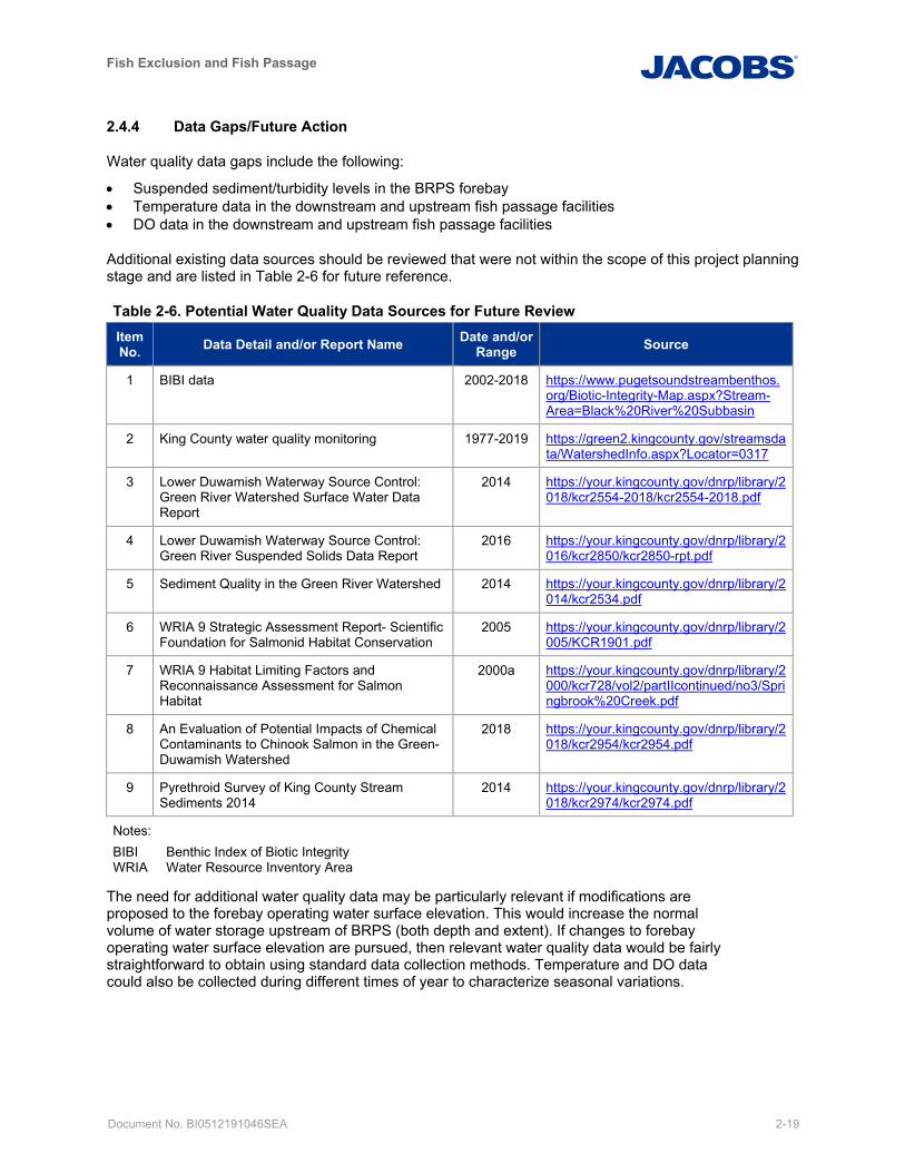
Fish Exclusion and Fish Passage
Document No. BI0512191046SEA 2-19
2.4.4 Data Gaps/Future Action
Water quality data gaps include the following:
• Suspended sediment/turbidity levels in the BRPS forebay • Temperature data in the downstream and upstream fish passage facilities • DO data in the downstream and upstream fish passage facilities
Additional existing data sources should be reviewed that were not within the scope of this project planning stage and are listed in Table 2-6 for future reference.
Table 2-6. Potential Water Quality Data Sources for Future Review Item No. Data Detail and/or Report Name Date and/or
Range Source
1 BIBI data 2002-2018 https://www.pugetsoundstreambenthos.org/Biotic-Integrity-Map.aspx?Stream-Area=Black%20River%20Subbasin
2 King County water quality monitoring 1977-2019 https://green2.kingcounty.gov/streamsdata/WatershedInfo.aspx?Locator=0317
3 Lower Duwamish Waterway Source Control: Green River Watershed Surface Water Data Report
2014 https://your.kingcounty.gov/dnrp/library/2018/kcr2554-2018/kcr2554-2018.pdf
4 Lower Duwamish Waterway Source Control: Green River Suspended Solids Data Report
2016 https://your.kingcounty.gov/dnrp/library/2016/kcr2850/kcr2850-rpt.pdf
5 Sediment Quality in the Green River Watershed 2014 https://your.kingcounty.gov/dnrp/library/2014/kcr2534.pdf
6 WRIA 9 Strategic Assessment Report- Scientific Foundation for Salmonid Habitat Conservation
2005 https://your.kingcounty.gov/dnrp/library/2005/KCR1901.pdf
7 WRIA 9 Habitat Limiting Factors and Reconnaissance Assessment for Salmon Habitat
2000a https://your.kingcounty.gov/dnrp/library/2000/kcr728/vol2/partIIcontinued/no3/Springbrook%20Creek.pdf
8 An Evaluation of Potential Impacts of Chemical Contaminants to Chinook Salmon in the Green-Duwamish Watershed
2018 https://your.kingcounty.gov/dnrp/library/2018/kcr2954/kcr2954.pdf
9 Pyrethroid Survey of King County Stream Sediments 2014
2014 https://your.kingcounty.gov/dnrp/library/2018/kcr2974/kcr2974.pdf
Notes: BIBI Benthic Index of Biotic Integrity WRIA Water Resource Inventory Area
The need for additional water quality data may be particularly relevant if modifications are proposed to the forebay operating water surface elevation. This would increase the normal volume of water storage upstream of BRPS (both depth and extent). If changes to forebay operating water surface elevation are pursued, then relevant water quality data would be fairly straightforward to obtain using standard data collection methods. Temperature and DO data could also be collected during different times of year to characterize seasonal variations.

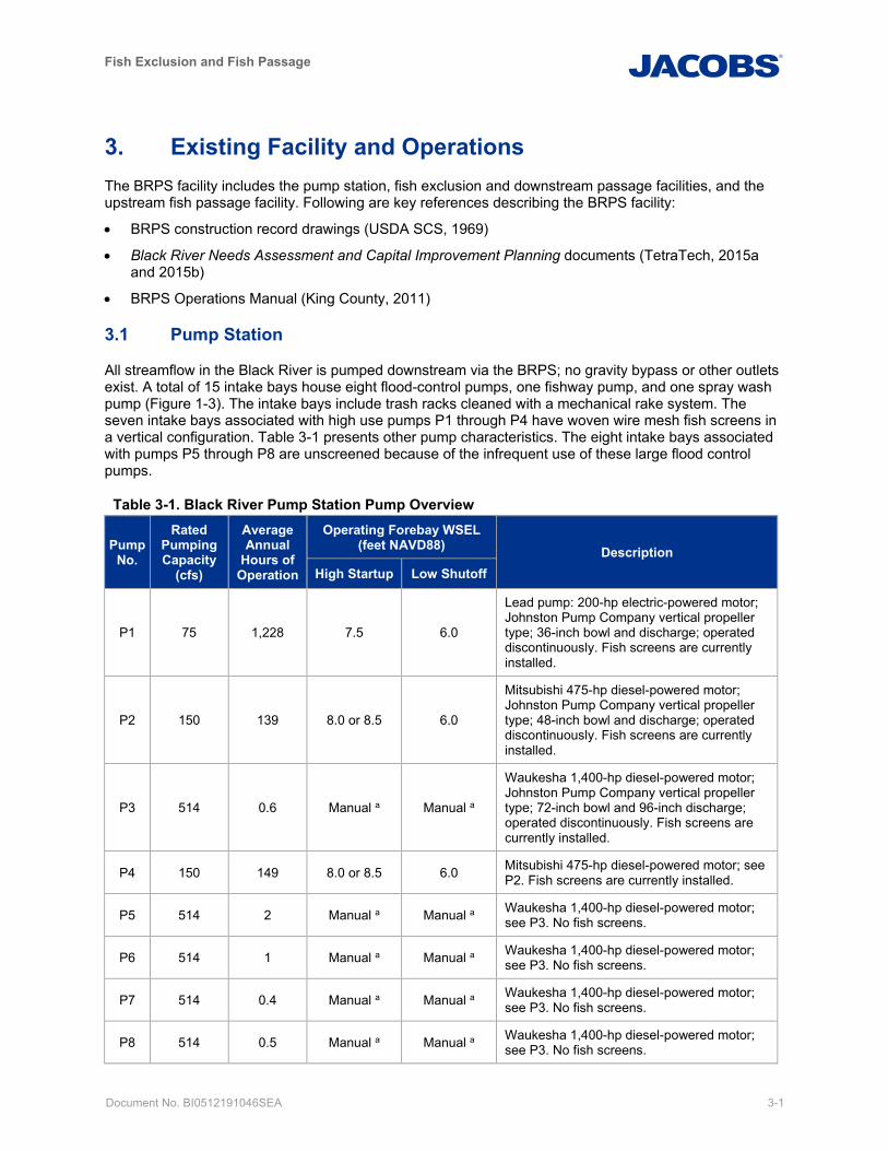
Fish Exclusion and Fish Passage
Document No. BI0512191046SEA 3-1
3. Existing Facility and Operations The BRPS facility includes the pump station, fish exclusion and downstream passage facilities, and the upstream fish passage facility. Following are key references describing the BRPS facility:
• BRPS construction record drawings (USDA SCS, 1969)
• Black River Needs Assessment and Capital Improvement Planning documents (TetraTech, 2015a and 2015b)
• BRPS Operations Manual (King County, 2011)
3.1 Pump Station
All streamflow in the Black River is pumped downstream via the BRPS; no gravity bypass or other outlets exist. A total of 15 intake bays house eight flood-control pumps, one fishway pump, and one spray wash pump (Figure 1-3). The intake bays include trash racks cleaned with a mechanical rake system. The seven intake bays associated with high use pumps P1 through P4 have woven wire mesh fish screens in a vertical configuration. Table 3-1 presents other pump characteristics. The eight intake bays associated with pumps P5 through P8 are unscreened because of the infrequent use of these large flood control pumps.
Table 3-1. Black River Pump Station Pump Overview
Pump No.
Rated Pumping Capacity
(cfs)
Average Annual
Hours of Operation
Operating Forebay WSEL (feet NAVD88) Description
High Startup Low Shutoff
P1 75 1,228 7.5 6.0
Lead pump: 200-hp electric-powered motor; Johnston Pump Company vertical propeller type; 36-inch bowl and discharge; operated discontinuously. Fish screens are currently installed.
P2 150 139 8.0 or 8.5 6.0
Mitsubishi 475-hp diesel-powered motor; Johnston Pump Company vertical propeller type; 48-inch bowl and discharge; operated discontinuously. Fish screens are currently installed.
P3 514 0.6 Manual a Manual a
Waukesha 1,400-hp diesel-powered motor; Johnston Pump Company vertical propeller type; 72-inch bowl and 96-inch discharge; operated discontinuously. Fish screens are currently installed.
P4 150 149 8.0 or 8.5 6.0 Mitsubishi 475-hp diesel-powered motor; see P2. Fish screens are currently installed.
P5 514 2 Manual a Manual a Waukesha 1,400-hp diesel-powered motor; see P3. No fish screens.
P6 514 1 Manual a Manual a Waukesha 1,400-hp diesel-powered motor; see P3. No fish screens.
P7 514 0.4 Manual a Manual a Waukesha 1,400-hp diesel-powered motor; see P3. No fish screens.
P8 514 0.5 Manual a Manual a Waukesha 1,400-hp diesel-powered motor; see P3. No fish screens.
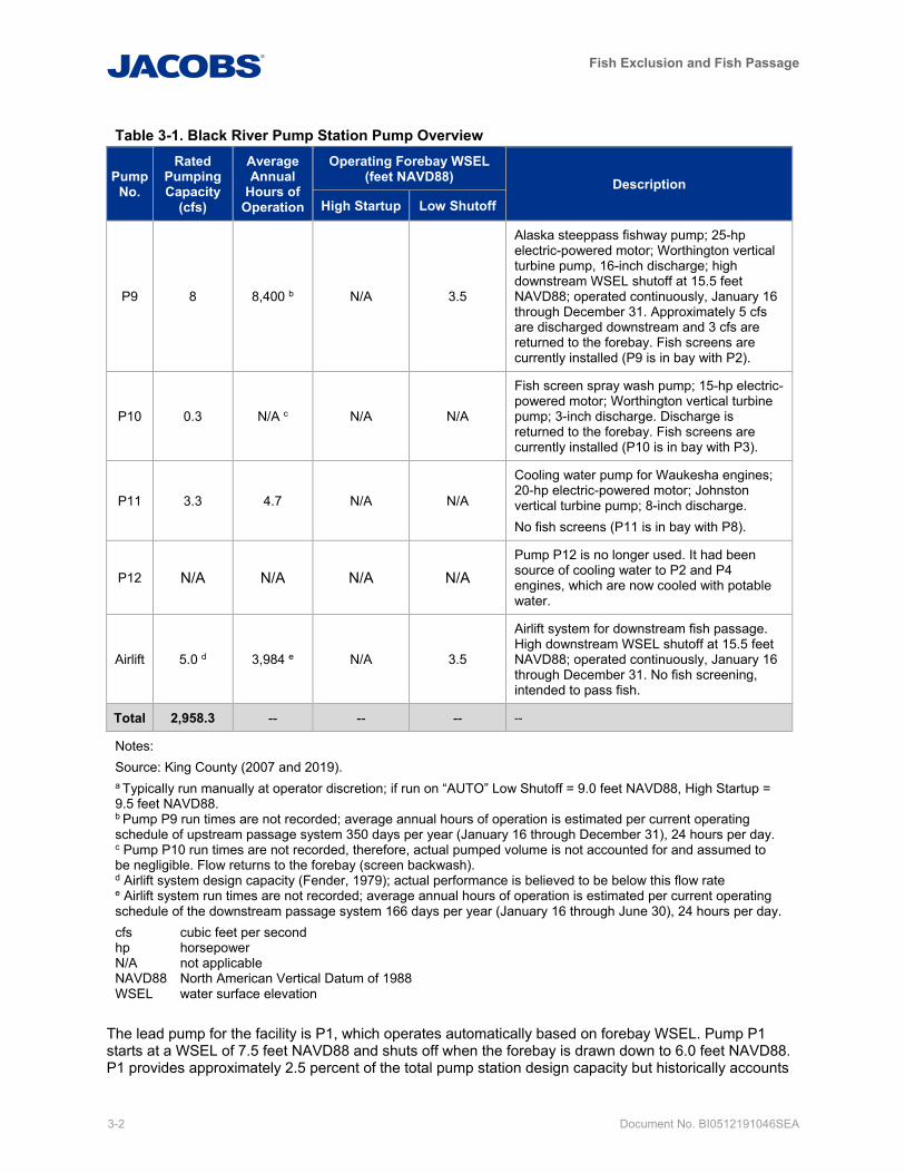
Fish Exclusion and Fish Passage
3-2 Document No. BI0512191046SEA
Table 3-1. Black River Pump Station Pump Overview
Pump No.
Rated Pumping Capacity
(cfs)
Average Annual
Hours of Operation
Operating Forebay WSEL (feet NAVD88) Description
High Startup Low Shutoff
P9 8 8,400 b N/A 3.5
Alaska steeppass fishway pump; 25-hp electric-powered motor; Worthington vertical turbine pump, 16-inch discharge; high downstream WSEL shutoff at 15.5 feet NAVD88; operated continuously, January 16 through December 31. Approximately 5 cfs are discharged downstream and 3 cfs are returned to the forebay. Fish screens are currently installed (P9 is in bay with P2).
P10 0.3 N/A c N/A N/A
Fish screen spray wash pump; 15-hp electric-powered motor; Worthington vertical turbine pump; 3-inch discharge. Discharge is returned to the forebay. Fish screens are currently installed (P10 is in bay with P3).
P11 3.3 4.7 N/A N/A
Cooling water pump for Waukesha engines; 20-hp electric-powered motor; Johnston vertical turbine pump; 8-inch discharge. No fish screens (P11 is in bay with P8).
P12 N/A N/A N/A N/A
Pump P12 is no longer used. It had been source of cooling water to P2 and P4 engines, which are now cooled with potable water.
Airlift 5.0 d 3,984 e N/A 3.5
Airlift system for downstream fish passage. High downstream WSEL shutoff at 15.5 feet NAVD88; operated continuously, January 16 through December 31. No fish screening, intended to pass fish.
Total 2,958.3 -- -- -- --
Notes: Source: King County (2007 and 2019). a Typically run manually at operator discretion; if run on “AUTO” Low Shutoff = 9.0 feet NAVD88, High Startup = 9.5 feet NAVD88. b Pump P9 run times are not recorded; average annual hours of operation is estimated per current operating schedule of upstream passage system 350 days per year (January 16 through December 31), 24 hours per day. c Pump P10 run times are not recorded, therefore, actual pumped volume is not accounted for and assumed to be negligible. Flow returns to the forebay (screen backwash). d Airlift system design capacity (Fender, 1979); actual performance is believed to be below this flow rate
e Airlift system run times are not recorded; average annual hours of operation is estimated per current operating schedule of the downstream passage system 166 days per year (January 16 through June 30), 24 hours per day. cfs cubic feet per second hp horsepower N/A not applicable NAVD88 North American Vertical Datum of 1988 WSEL water surface elevation
The lead pump for the facility is P1, which operates automatically based on forebay WSEL. Pump P1 starts at a WSEL of 7.5 feet NAVD88 and shuts off when the forebay is drawn down to 6.0 feet NAVD88. P1 provides approximately 2.5 percent of the total pump station design capacity but historically accounts
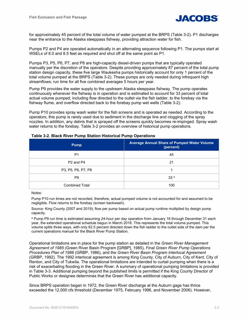
Fish Exclusion and Fish Passage
Document No. BI0512191046SEA 3-3
for approximately 45 percent of the total volume of water pumped at the BRPS (Table 3-2). P1 discharges near the entrance to the Alaska steeppass fishway, providing attraction water for fish.
Pumps P2 and P4 are operated automatically in an alternating sequence following P1. The pumps start at WSELs of 8.0 and 8.5 feet as required and shut off at the same point as P1.
Pumps P3, P5, P6, P7, and P8 are high-capacity diesel-driven pumps that are typically operated manually per the discretion of the operators. Despite providing approximately 87 percent of the total pump station design capacity, these five large Waukesha pumps historically account for only 1 percent of the total volume pumped at the BRPS (Table 3-2). These pumps are only needed during infrequent high streamflows; run time for all five combined averages 5 hours per year.
Pump P9 provides the water supply to the upstream Alaska steeppass fishway. The pump operates continuously whenever the fishway is in operation and is estimated to account for 33 percent of total actual volume pumped, including flow directed to the outlet via the fish ladder, to the forebay via the fishway flume, and overflow directed back to the forebay pump wet wells (Table 3-2).
Pump P10 provides spray wash water for the fish screens and is operated as needed. According to the operators, this pump is rarely used due to sediment in the discharge line and clogging of the spray nozzles. In addition, any debris that is sprayed off the screens quickly becomes re-impinged. Spray wash water returns to the forebay. Table 3-2 provides an overview of historical pump operations.
Table 3-2. Black River Pump Station Historical Pump Operations
Pump Average Annual Share of Pumped Water Volume (percent)
P1 45
P2 and P4 21
P3, P5, P6, P7, P8 1
P9 33 a
Combined Total 100
Notes: Pump P10 run times are not recorded, therefore, actual pumped volume is not accounted for and assumed to be negligible. Flow returns to the forebay (screen backwash). Source: King County (2007 and 2019); flow per pump based on actual pump runtime multiplied by design pump capacity. a Pump P9 run time is estimated assuming 24-hour per day operation from January 16 through December 31 each year, the extended operational schedule begun in March 2018. This represents the total volume pumped. This volume splits three ways, with only 62.5 percent directed down the fish ladder to the outlet side of the dam per the current operations manual for the Black River Pump Station.
Operational limitations are in place for the pump station as detailed in the Green River Management Agreement of 1985 (Green River Basin Program [GRBP], 1985), Final Green River Pump Operations Procedures Plan of 1986 (GRBP, 1986), and the Green River Basin Program Interlocal Agreement (GRBP, 1992). The 1992 interlocal agreement is among King County, City of Auburn, City of Kent, City of Renton, and City of Tukwila. The operational limitations are intended to curtail pumping when there is a risk of exacerbating flooding in the Green River. A summary of operational pumping limitations is provided in Table 3-3. Additional pumping beyond the published limits is permitted if the King County Director of Public Works or designee determines that the Green River has additional capacity.
Since BRPS operation began in 1972, the Green River discharge at the Auburn gage has thrice exceeded the 12,000 cfs threshold (December 1975, February 1996, and November 2006). However,
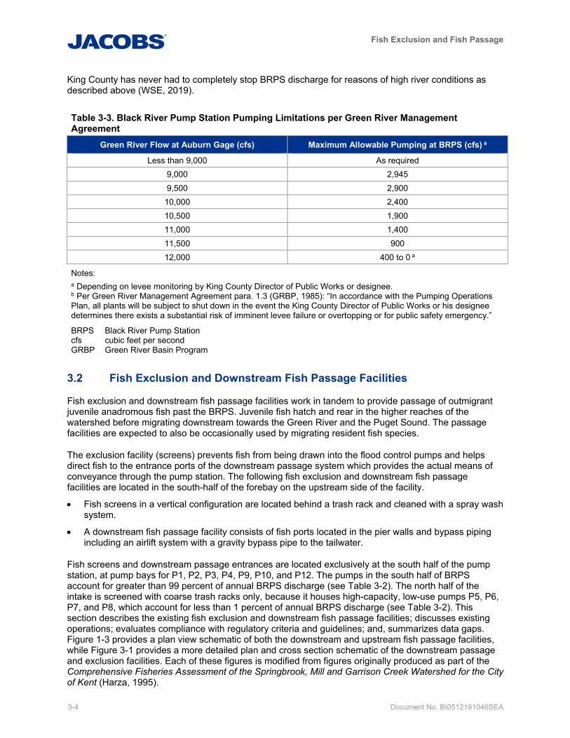
Fish Exclusion and Fish Passage
3-4 Document No. BI0512191046SEA
King County has never had to completely stop BRPS discharge for reasons of high river conditions as described above (WSE, 2019).
Table 3-3. Black River Pump Station Pumping Limitations per Green River Management Agreement
Green River Flow at Auburn Gage (cfs) Maximum Allowable Pumping at BRPS (cfs) a
Less than 9,000 As required 9,000 2,945 9,500 2,900
10,000 2,400 10,500 1,900 11,000 1,400 11,500 900 12,000 400 to 0 a
Notes: a Depending on levee monitoring by King County Director of Public Works or designee. b Per Green River Management Agreement para. 1.3 (GRBP, 1985): “In accordance with the Pumping Operations Plan, all plants will be subject to shut down in the event the King County Director of Public Works or his designee determines there exists a substantial risk of imminent levee failure or overtopping or for public safety emergency.”
BRPS Black River Pump Station cfs cubic feet per second GRBP Green River Basin Program
3.2 Fish Exclusion and Downstream Fish Passage Facilities
Fish exclusion and downstream fish passage facilities work in tandem to provide passage of outmigrant juvenile anadromous fish past the BRPS. Juvenile fish hatch and rear in the higher reaches of the watershed before migrating downstream towards the Green River and the Puget Sound. The passage facilities are expected to also be occasionally used by migrating resident fish species.
The exclusion facility (screens) prevents fish from being drawn into the flood control pumps and helps direct fish to the entrance ports of the downstream passage system which provides the actual means of conveyance through the pump station. The following fish exclusion and downstream fish passage facilities are located in the south-half of the forebay on the upstream side of the facility.
• Fish screens in a vertical configuration are located behind a trash rack and cleaned with a spray wash system.
• A downstream fish passage facility consists of fish ports located in the pier walls and bypass piping including an airlift system with a gravity bypass pipe to the tailwater.
Fish screens and downstream passage entrances are located exclusively at the south half of the pump station, at pump bays for P1, P2, P3, P4, P9, P10, and P12. The pumps in the south half of BRPS account for greater than 99 percent of annual BRPS discharge (see Table 3-2). The north half of the intake is screened with coarse trash racks only, because it houses high-capacity, low-use pumps P5, P6, P7, and P8, which account for less than 1 percent of annual BRPS discharge (see Table 3-2). This section describes the existing fish exclusion and downstream fish passage facilities; discusses existing operations; evaluates compliance with regulatory criteria and guidelines; and, summarizes data gaps. Figure 1-3 provides a plan view schematic of both the downstream and upstream fish passage facilities, while Figure 3-1 provides a more detailed plan and cross section schematic of the downstream passage and exclusion facilities. Each of these figures is modified from figures originally produced as part of the Comprehensive Fisheries Assessment of the Springbrook, Mill and Garrison Creek Watershed for the City of Kent (Harza, 1995).
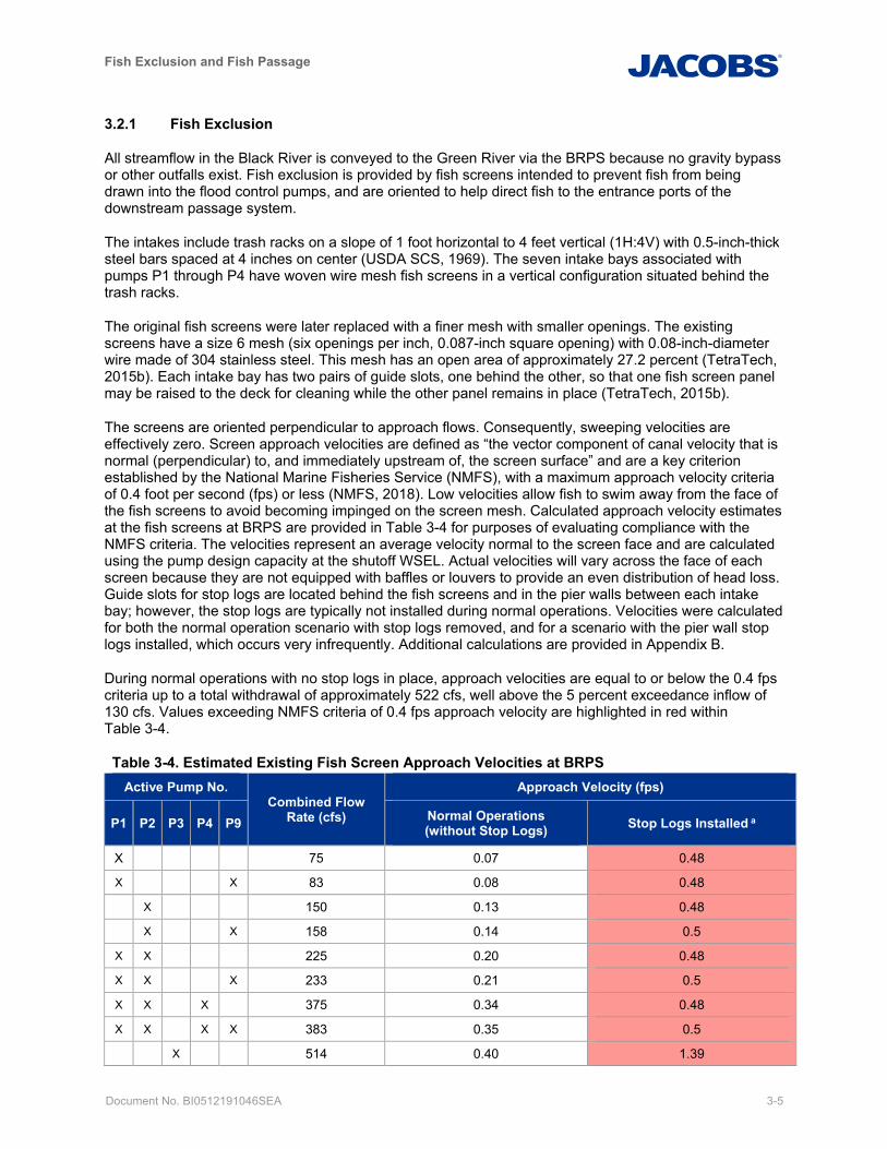
Fish Exclusion and Fish Passage
Document No. BI0512191046SEA 3-5
3.2.1 Fish Exclusion
All streamflow in the Black River is conveyed to the Green River via the BRPS because no gravity bypass or other outfalls exist. Fish exclusion is provided by fish screens intended to prevent fish from being drawn into the flood control pumps, and are oriented to help direct fish to the entrance ports of the downstream passage system.
The intakes include trash racks on a slope of 1 foot horizontal to 4 feet vertical (1H:4V) with 0.5-inch-thick steel bars spaced at 4 inches on center (USDA SCS, 1969). The seven intake bays associated with pumps P1 through P4 have woven wire mesh fish screens in a vertical configuration situated behind the trash racks.
The original fish screens were later replaced with a finer mesh with smaller openings. The existing screens have a size 6 mesh (six openings per inch, 0.087-inch square opening) with 0.08-inch-diameter wire made of 304 stainless steel. This mesh has an open area of approximately 27.2 percent (TetraTech, 2015b). Each intake bay has two pairs of guide slots, one behind the other, so that one fish screen panel may be raised to the deck for cleaning while the other panel remains in place (TetraTech, 2015b).
The screens are oriented perpendicular to approach flows. Consequently, sweeping velocities are effectively zero. Screen approach velocities are defined as “the vector component of canal velocity that is normal (perpendicular) to, and immediately upstream of, the screen surface” and are a key criterion established by the National Marine Fisheries Service (NMFS), with a maximum approach velocity criteria of 0.4 foot per second (fps) or less (NMFS, 2018). Low velocities allow fish to swim away from the face of the fish screens to avoid becoming impinged on the screen mesh. Calculated approach velocity estimates at the fish screens at BRPS are provided in Table 3-4 for purposes of evaluating compliance with the NMFS criteria. The velocities represent an average velocity normal to the screen face and are calculated using the pump design capacity at the shutoff WSEL. Actual velocities will vary across the face of each screen because they are not equipped with baffles or louvers to provide an even distribution of head loss. Guide slots for stop logs are located behind the fish screens and in the pier walls between each intake bay; however, the stop logs are typically not installed during normal operations. Velocities were calculated for both the normal operation scenario with stop logs removed, and for a scenario with the pier wall stop logs installed, which occurs very infrequently. Additional calculations are provided in Appendix B.
During normal operations with no stop logs in place, approach velocities are equal to or below the 0.4 fps criteria up to a total withdrawal of approximately 522 cfs, well above the 5 percent exceedance inflow of 130 cfs. Values exceeding NMFS criteria of 0.4 fps approach velocity are highlighted in red within Table 3-4.
Table 3-4. Estimated Existing Fish Screen Approach Velocities at BRPS Active Pump No.
Combined Flow Rate (cfs)
Approach Velocity (fps)
P1 P2 P3 P4 P9 Normal Operations (without Stop Logs) Stop Logs Installed a
X 75 0.07 0.48
X X 83 0.08 0.48 X 150 0.13 0.48
X X 158 0.14 0.5
X X 225 0.20 0.48
X X X 233 0.21 0.5
X X X 375 0.34 0.48
X X X X 383 0.35 0.5
X 514 0.40 1.39
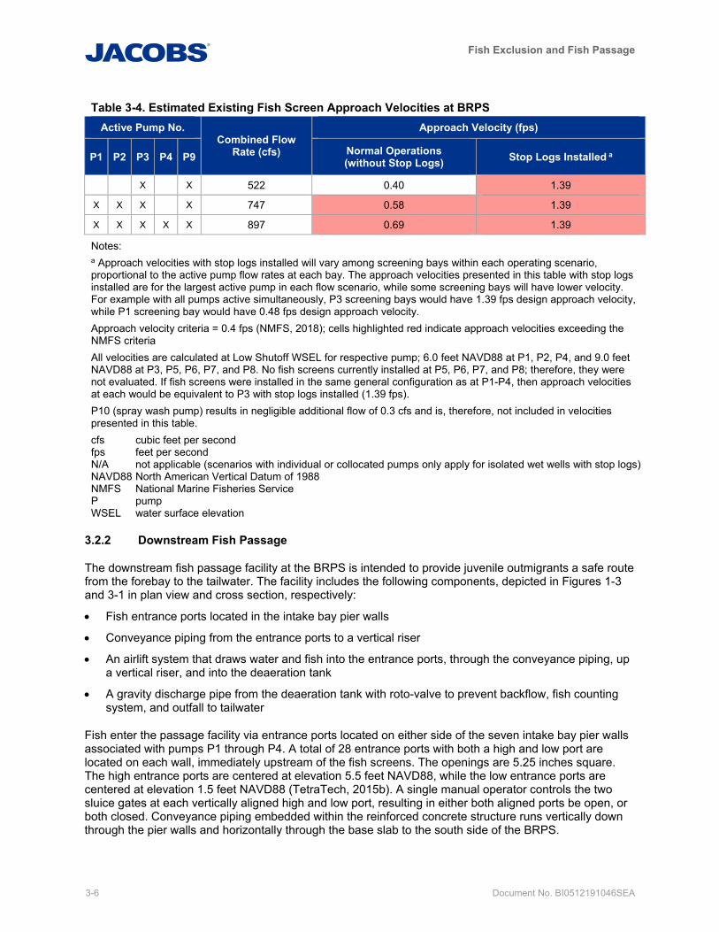
Fish Exclusion and Fish Passage
3-6 Document No. BI0512191046SEA
Table 3-4. Estimated Existing Fish Screen Approach Velocities at BRPS Active Pump No.
Combined Flow Rate (cfs)
Approach Velocity (fps)
P1 P2 P3 P4 P9 Normal Operations (without Stop Logs) Stop Logs Installed a
X X 522 0.40 1.39
X X X X 747 0.58 1.39
X X X X X 897 0.69 1.39
Notes: a Approach velocities with stop logs installed will vary among screening bays within each operating scenario, proportional to the active pump flow rates at each bay. The approach velocities presented in this table with stop logs installed are for the largest active pump in each flow scenario, while some screening bays will have lower velocity. For example with all pumps active simultaneously, P3 screening bays would have 1.39 fps design approach velocity, while P1 screening bay would have 0.48 fps design approach velocity. Approach velocity criteria = 0.4 fps (NMFS, 2018); cells highlighted red indicate approach velocities exceeding the NMFS criteria All velocities are calculated at Low Shutoff WSEL for respective pump; 6.0 feet NAVD88 at P1, P2, P4, and 9.0 feet NAVD88 at P3, P5, P6, P7, and P8. No fish screens currently installed at P5, P6, P7, and P8; therefore, they were not evaluated. If fish screens were installed in the same general configuration as at P1-P4, then approach velocities at each would be equivalent to P3 with stop logs installed (1.39 fps). P10 (spray wash pump) results in negligible additional flow of 0.3 cfs and is, therefore, not included in velocities presented in this table. cfs cubic feet per second fps feet per second N/A not applicable (scenarios with individual or collocated pumps only apply for isolated wet wells with stop logs) NAVD88 North American Vertical Datum of 1988 NMFS National Marine Fisheries Service P pump WSEL water surface elevation
3.2.2 Downstream Fish Passage
The downstream fish passage facility at the BRPS is intended to provide juvenile outmigrants a safe route from the forebay to the tailwater. The facility includes the following components, depicted in Figures 1-3 and 3-1 in plan view and cross section, respectively:
• Fish entrance ports located in the intake bay pier walls
• Conveyance piping from the entrance ports to a vertical riser
• An airlift system that draws water and fish into the entrance ports, through the conveyance piping, up a vertical riser, and into the deaeration tank
• A gravity discharge pipe from the deaeration tank with roto-valve to prevent backflow, fish counting system, and outfall to tailwater
Fish enter the passage facility via entrance ports located on either side of the seven intake bay pier walls associated with pumps P1 through P4. A total of 28 entrance ports with both a high and low port are located on each wall, immediately upstream of the fish screens. The openings are 5.25 inches square. The high entrance ports are centered at elevation 5.5 feet NAVD88, while the low entrance ports are centered at elevation 1.5 feet NAVD88 (TetraTech, 2015b). A single manual operator controls the two sluice gates at each vertically aligned high and low port, resulting in either both aligned ports be open, or both closed. Conveyance piping embedded within the reinforced concrete structure runs vertically down through the pier walls and horizontally through the base slab to the south side of the BRPS.
Fish Exclusion and Fish Passage
Document No. BI0512191046SEA 3-7
The airlift system utilizes a single compressor to feed pressurized air to two 30-inch diameter vertical fiberglass riser pipes, one dedicated to the high ports and one dedicated to the low ports. The pipes are approximately 52 feet in height from the sparge rings to the de-aeration tank. Water and fish flow by gravity from the de-aeration tank to the tailwater via an 18-inch diameter bypass pipe. An 18-inch roto-valve (SG1) is located immediately downstream of the deaeration tank and closes automatically whenever the downstream passage system is off. It prevents high downstream water levels from backflowing into the pump station through the downstream passage gravity bypass pipe.
An automatic fish counter is located in a vault near the bypass pipe outfall near the tailwater, downstream of valve SG1. The counter includes an array of four 2-inch-diameter polyvinyl chloride sensor tubes. The counter is a Smith Root Model SR-1601, believed to have been installed in 1983. The sensors are triggered by a change in conductance due to passing juvenile fish. It is understood that sufficiently large debris may also result in a positive fish count.
3.2.3 Current Operations
Beginning in March 2018, the period of operations for the downstream fish passage facility was expanded to approximately five and a half months, from January 16 through June 30. This schedule is nearly twice as long as the prior operating schedule (April through June) and is intended to better match the observed juvenile outmigration period, as discussed in Section 2.3 for Fish Biology (King County, 2018).
The BRPS is typically operated with the fish screens in place year-round. Per discussions with the BRPS operators, it is understood that the existing spray wash system is not effective because debris removed from the screens is rapidly re-impinged due to the lack of sweeping flows. The spray nozzles also clog frequently due to sediment and debris entrained by pump P10. The spray headers do not have drain/flush valves and the piping also appears to be corroded.
The airlift system has two sets of conduits and risers, one set for the upper ports and one set for the lower ports. The original design intent was to operate only one set of ports, conduits and risers at a time, depending upon the forebay pond elevation. Operation was to be controlled by a 3-inch air-actuated three-way flow control valve (FCV-8) and associated solenoid valve SV-8, located immediately downstream of compressor C2. The operational status of both valves is not clear, and as of 2015 were reported to be inoperable (TetraTech, 2015a). King County staff have anecdotally reported seeing active flow only in the riser pipe further to the south, associated with the low entrance ports, at the time this report was being prepared (June 2019). Future confirmation of the operability of these valves should be pursued, including identification of whether the system for the high ports, low ports, or both are operable.
The downstream fish counter is frequently inoperable, resulting in intermittent collection of downstream migration data. Larger fish can also become trapped in the vault if they are not able to pass through the 2-inch sensor tubes. On occasion, WTD staff have had to physically remove larger fish and place them in the tailwater.
3.2.4 Compliance with Regulatory Criteria and Guidelines
The existing fish exclusion and downstream fish passage facilities were evaluated with respect to current regulatory criteria and guidelines, including the August 16, 2018 Peer Review Draft of NOAA [National Oceanic and Atmospheric Association] Fisheries’ West Coast Region Anadromous Salmonid Passage Design Guidelines (NMFS, 2018). The Washington Administrative Code 220‐660‐200 (5) was also considered because the NMFS criteria focuses primarily on salmonids and may not adequately address other species including resident fish.
Table 3-5 summarizes key criteria for which the BRPS is found to be noncompliant for exclusion and downstream passage. A full list of NMFS criteria relevant to the fish passage and exclusion facilities at BRPS is provided in Appendix C, including summary evaluations of BRPS conditions and compliance status for each criteria.
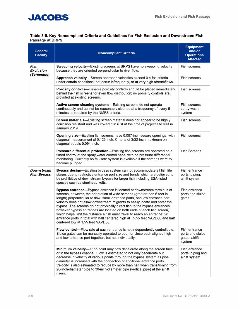
Fish Exclusion and Fish Passage
3-8 Document No. BI0512191046SEA
Table 3-5. Key Noncompliant Criteria and Guidelines for Fish Exclusion and Downstream Fish Passage at BRPS
General Facility Noncompliant Criteria
Equipment and/or
Operations Affected
Fish Exclusion (Screening)
Sweeping velocity—Existing screens at BRPS have no sweeping velocity because they are oriented perpendicular to river flow.
Fish screens
Approach velocity – Screen approach velocities exceed 0.4 fps criteria under certain conditions that occur infrequently, or at very high streamflows.
Fish screens
Porosity controls—Tunable porosity controls should be placed immediately behind the fish screens for even flow distribution; no porosity controls are provided at existing screens.
Fish screens
Active screen cleaning systems—Existing screens do not operate continuously and cannot be reasonably cleaned at a frequency of every 5 minutes as required by the NMFS criteria.
Fish screens, spray wash system
Screen materials—Existing screen material does not appear to be highly corrosion resistant and was covered in rust at the time of project site visit in January 2019.
Fish screens
Opening size—Existing fish screens have 0.087-inch square openings, with diagonal measurement of 0.123 inch. Criteria of 3/32-inch maximum on diagonal equals 0.094 inch.
Fish screens
Pressure differential protection—Existing fish screens are operated on a timed control at the spray water control panel with no pressure differential monitoring. Currently no fail-safe system is available if the screens were to become plugged.
Fish Screens
Downstream Fish Bypass
Bypass design—Existing bypass system cannot accommodate all fish life stages due to restrictive entrance port size and bends which are believed to be prohibitive of downstream bypass for larger fish including ESA-listed species such as steelhead kelts.
Fish entrance ports, piping, airlift system
Bypass entrance—Bypass entrance is located at downstream terminus of screens, however, the orientation of wide screens (greater than 6 feet in length) perpendicular to flow, small entrance ports, and low entrance port velocity does not allow downstream migrants to easily locate and enter the bypass. The screens do not physically direct fish to the bypass entrances, however bypass entrances are located on both ends of each fish screen, which helps limit the distance a fish must travel to reach an entrance; 28 entrance ports in total with half centered high at +5.55 feet NAVD88 and half centered low at 1.55 feet NAVD88.
Fish entrance ports and sluice gates
Flow control—Flow rate at each entrance is not independently controllable. Sluice gates can be manually operated to open or close each aligned high and low entrance port together, but not individually.
Fish entrance ports and sluice gates, airlift system
Minimum velocity—At no point may flow decelerate along the screen face or in the bypass channel. Flow is estimated to not only decelerate but decrease in velocity at various points through the bypass system as pipe diameter is increased with the connection of additional entrance ports. Velocity is also estimated to reduce by more than half when transitioning from 20-inch-diameter pipe to 30-inch-diameter pipe (vertical pipe) at the airlift risers.
Fish entrance ports, piping and airlift system
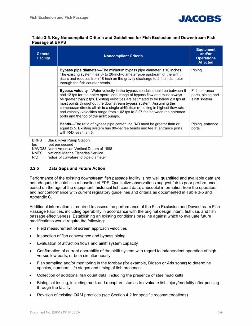
Fish Exclusion and Fish Passage
Document No. BI0512191046SEA 3-9
Table 3-5. Key Noncompliant Criteria and Guidelines for Fish Exclusion and Downstream Fish Passage at BRPS
General Facility Noncompliant Criteria
Equipment and/or
Operations Affected
Bypass pipe diameter—The minimum bypass pipe diameter is 10 inches. The existing system has 6- to 20-inch-diameter pipe upstream of the airlift risers and reduces from 18-inch on the gravity discharge to 2-inch diameter through the fish counter heads.
Piping
Bypass velocity—Water velocity in the bypass conduit should be between 6 and 12 fps for the entire operational range of bypass flow and must always be greater than 2 fps. Existing velocities are estimated to be below 2.0 fps at most points throughout the downstream bypass system. Assuming the compressor directs all air to a single airlift riser (resulting in highest flow rate and velocity) velocities range from 1.02 fps to 2.27 fps between the entrance ports and the top of the airlift pumps.
Fish entrance ports, piping and airlift system
Bends—The ratio of bypass pipe center line R/D must be greater than or equal to 5. Existing system has 90-degree bends and tee at entrance ports with R/D less than 5.
Piping, entrance ports
BRPS Black River Pump Station fps feet per second NAVD88 North American Vertical Datum of 1988 NMFS National Marine Fisheries Service R/D radius of curvature to pipe diameter
3.2.5 Data Gaps and Future Action
Performance of the existing downstream fish passage facility is not well quantified and available data are not adequate to establish a baseline of FPE. Qualitative observations suggest fair to poor performance based on the age of the equipment, historical fish count data, anecdotal information from the operators, and nonconformance with current regulatory guidelines and criteria as documented in Table 3-5 and Appendix C.
Additional information is required to assess the performance of the Fish Exclusion and Downstream Fish Passage Facilities, including operability in accordance with the original design intent, fish use, and fish passage effectiveness. Establishing an existing conditions baseline against which to evaluate future modifications would require the following:
• Field measurement of screen approach velocities
• Inspection of fish conveyance and bypass piping
• Evaluation of attraction flows and airlift system capacity
• Confirmation of current operability of the airlift system with regard to independent operation of high versus low ports, or both simultaneously
• Fish sampling and/or monitoring in the forebay (for example, Didson or Aris sonar) to determine species, numbers, life stages and timing of fish presence
• Collection of additional fish count data, including the presence of steelhead kelts
• Biological testing, including mark and recapture studies to evaluate fish injury/mortality after passing through the facility
• Revision of existing O&M practices (see Section 4.2 for specific recommendations)
Fish Exclusion and Fish Passage
3-10 Document No. BI0512191046SEA
• Consistent discharge data for Springbrook Creek at King County stream gage 03G
3.3 Upstream Fish Passage Facility
3.3.1 Upstream Fish Passage
The upstream fish passage facility at the BRPS includes the following components:
• Fishway located on the left bank (southern) abutment consisting of a fishway entrance, Alaska steeppass chute with a middle resting pool and a terminal upper resting pool
• False weir
• Gravity fish return to the forebay with fish counter
• False weir and fishway water supply system including pump P9 and associated piping
• Attraction flow water supply system including pump P1 and associated piping and diffuser
This section describes the existing upstream fish passage facility; discusses existing operations; evaluates compliance with regulatory criteria and guidelines; and summarizes data gaps. Figure 1-3 provides a plan view schematic of both the downstream and upstream fish passage facilities, while Figure 3-2 provides a more detailed plan and cross section schematic of the upstream passage facility. Each of these figures is modified from figures originally produced as part of the Comprehensive Fisheries Assessment of the Springbrook, Mill and Garrison Creek Watershed for the City of Kent (Harza, 1995).
Upstream fish passage at the BRPS is provided via a fishway consisting of a fishway entrance, two Alaska steeppass chutes (baffled aluminum chutes similar to a Denil fishway) with a reinforced concrete resting pool in between and a second resting pool at the upstream end. Each chute is approximately 25 feet long and is placed at a 28-degree slope. This is slightly steeper than the maximum slope of 27 degrees recommended by NMFS (NMFS, 2018), but within the typical range of slopes recommended by the Alaska Department of Fish and Game (ADFG, 1962). The total elevation gain is approximately 13 feet 10 inches from the entrance to the upper pool.
A false weir is located at the upper resting pool and directs water both into the upper pool and into a gravity fish return to the forebay. The fish return consists of 14-inch diameter steel pipe with a vinyl lining and a lower open flume section. A fish counter is located immediately downstream of the false weir and consists of a simple switch with a Lexan paddle that registers the passing of a fish and then returns to its original position.
Water for the fishway is provided via pump P9 with a design capacity of approximately 8 cfs. Approximately 5 cfs is directed into the upper pool, approximately 1 cfs is directed into the fish return, and approximately 2 cfs returns to the forebay as overflow (King County, 2011).
When operating, pump P1 provides additional attraction water. Pump P1 discharges to the open space beneath the Alaska steeppass chutes and combines with the fishway flow near the bottom entrance of the fishway. A “fish ladder rack” (Figure 3-1, or wall diffuser consisting of flat bars with 1-inch clear openings, prevents fish from entering the void beneath the Alaska steeppass chutes. The diffuser velocity exceeds NMFS criteria at low tailwater (see Appendix B); however, at other tailwater elevations this attraction water from pump P1 is released through additional submerged screening area, including the sloped wire mesh panels adjacent to the baffled chute, resulting in lower velocities.
3.3.2 Existing Operations and Conditions
Beginning in March 2018, the upstream fish passage facility operating schedule was expanded to approximately eleven and a half months, from January 16 through December 31. This schedule is nearly twice as long as the prior operating schedule (September through February) and is intended to better
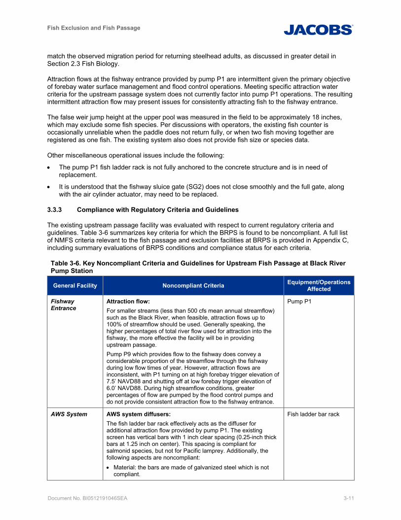
Fish Exclusion and Fish Passage
Document No. BI0512191046SEA 3-11
match the observed migration period for returning steelhead adults, as discussed in greater detail in Section 2.3 Fish Biology.
Attraction flows at the fishway entrance provided by pump P1 are intermittent given the primary objective of forebay water surface management and flood control operations. Meeting specific attraction water criteria for the upstream passage system does not currently factor into pump P1 operations. The resulting intermittent attraction flow may present issues for consistently attracting fish to the fishway entrance.
The false weir jump height at the upper pool was measured in the field to be approximately 18 inches, which may exclude some fish species. Per discussions with operators, the existing fish counter is occasionally unreliable when the paddle does not return fully, or when two fish moving together are registered as one fish. The existing system also does not provide fish size or species data.
Other miscellaneous operational issues include the following:
• The pump P1 fish ladder rack is not fully anchored to the concrete structure and is in need of replacement.
• It is understood that the fishway sluice gate (SG2) does not close smoothly and the full gate, along with the air cylinder actuator, may need to be replaced.
3.3.3 Compliance with Regulatory Criteria and Guidelines
The existing upstream passage facility was evaluated with respect to current regulatory criteria and guidelines. Table 3-6 summarizes key criteria for which the BRPS is found to be noncompliant. A full list of NMFS criteria relevant to the fish passage and exclusion facilities at BRPS is provided in Appendix C, including summary evaluations of BRPS conditions and compliance status for each criteria.
Table 3-6. Key Noncompliant Criteria and Guidelines for Upstream Fish Passage at Black River Pump Station
General Facility Noncompliant Criteria Equipment/Operations Affected
Fishway Entrance
Attraction flow: For smaller streams (less than 500 cfs mean annual streamflow) such as the Black River, when feasible, attraction flows up to 100% of streamflow should be used. Generally speaking, the higher percentages of total river flow used for attraction into the fishway, the more effective the facility will be in providing upstream passage. Pump P9 which provides flow to the fishway does convey a considerable proportion of the streamflow through the fishway during low flow times of year. However, attraction flows are inconsistent, with P1 turning on at high forebay trigger elevation of 7.5’ NAVD88 and shutting off at low forebay trigger elevation of 6.0’ NAVD88. During high streamflow conditions, greater percentages of flow are pumped by the flood control pumps and do not provide consistent attraction flow to the fishway entrance.
Pump P1
AWS System AWS system diffusers: The fish ladder bar rack effectively acts as the diffuser for additional attraction flow provided by pump P1. The existing screen has vertical bars with 1 inch clear spacing (0.25-inch thick bars at 1.25 inch on center). This spacing is compliant for salmonid species, but not for Pacific lamprey. Additionally, the following aspects are noncompliant: • Material: the bars are made of galvanized steel which is not
compliant.
Fish ladder bar rack
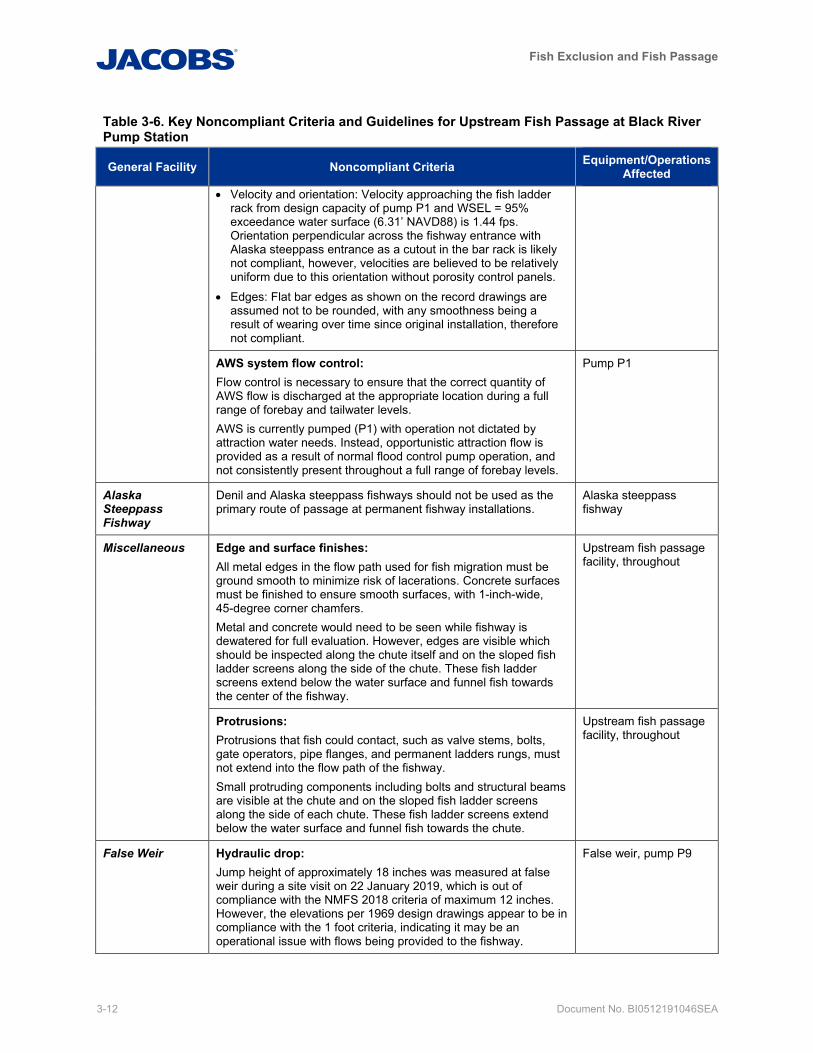
Fish Exclusion and Fish Passage
3-12 Document No. BI0512191046SEA
Table 3-6. Key Noncompliant Criteria and Guidelines for Upstream Fish Passage at Black River Pump Station
General Facility Noncompliant Criteria Equipment/Operations Affected
• Velocity and orientation: Velocity approaching the fish ladder rack from design capacity of pump P1 and WSEL = 95% exceedance water surface (6.31’ NAVD88) is 1.44 fps. Orientation perpendicular across the fishway entrance with Alaska steeppass entrance as a cutout in the bar rack is likely not compliant, however, velocities are believed to be relatively uniform due to this orientation without porosity control panels.
• Edges: Flat bar edges as shown on the record drawings are assumed not to be rounded, with any smoothness being a result of wearing over time since original installation, therefore not compliant.
AWS system flow control: Flow control is necessary to ensure that the correct quantity of AWS flow is discharged at the appropriate location during a full range of forebay and tailwater levels. AWS is currently pumped (P1) with operation not dictated by attraction water needs. Instead, opportunistic attraction flow is provided as a result of normal flood control pump operation, and not consistently present throughout a full range of forebay levels.
Pump P1
Alaska Steeppass Fishway
Denil and Alaska steeppass fishways should not be used as the primary route of passage at permanent fishway installations.
Alaska steeppass fishway
Miscellaneous Edge and surface finishes: All metal edges in the flow path used for fish migration must be ground smooth to minimize risk of lacerations. Concrete surfaces must be finished to ensure smooth surfaces, with 1-inch-wide, 45-degree corner chamfers. Metal and concrete would need to be seen while fishway is dewatered for full evaluation. However, edges are visible which should be inspected along the chute itself and on the sloped fish ladder screens along the side of the chute. These fish ladder screens extend below the water surface and funnel fish towards the center of the fishway.
Upstream fish passage facility, throughout
Protrusions: Protrusions that fish could contact, such as valve stems, bolts, gate operators, pipe flanges, and permanent ladders rungs, must not extend into the flow path of the fishway. Small protruding components including bolts and structural beams are visible at the chute and on the sloped fish ladder screens along the side of each chute. These fish ladder screens extend below the water surface and funnel fish towards the chute.
Upstream fish passage facility, throughout
False Weir Hydraulic drop: Jump height of approximately 18 inches was measured at false weir during a site visit on 22 January 2019, which is out of compliance with the NMFS 2018 criteria of maximum 12 inches. However, the elevations per 1969 design drawings appear to be in compliance with the 1 foot criteria, indicating it may be an operational issue with flows being provided to the fishway.
False weir, pump P9
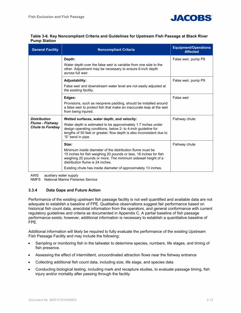
Fish Exclusion and Fish Passage
Document No. BI0512191046SEA 3-13
Table 3-6. Key Noncompliant Criteria and Guidelines for Upstream Fish Passage at Black River Pump Station
General Facility Noncompliant Criteria Equipment/Operations Affected
Depth: Water depth over the false weir is variable from one side to the other. Adjustment may be necessary to ensure 6-inch depth across full weir.
False weir, pump P9
Adjustability: False weir and downstream water level are not easily adjusted at the existing facility.
False weir, pump P9
Edges: Provisions, such as neoprene padding, should be installed around a false weir to protect fish that make an inaccurate leap at the weir from being injured.
False weir
Distribution Flume - Fishway Chute to Forebay
Wetted surfaces, water depth, and velocity: Water depth is estimated to be approximately 1.7 inches under design operating conditions, below 2- to 4-inch guideline for lengths of 50 feet or greater; flow depth is also inconsistent due to “S” bend in pipe.
Fishway chute
Size: Minimum inside diameter of the distribution flume must be 15 inches for fish weighing 20 pounds or less, 18 inches for fish weighing 20 pounds or more. The minimum sidewall height of a distribution flume is 24 inches. Existing chute has inside diameter of approximately 13 inches.
Fishway chute
AWS auxiliary water supply NMFS National Marine Fisheries Service
3.3.4 Data Gaps and Future Action
Performance of the existing upstream fish passage facility is not well quantified and available data are not adequate to establish a baseline of FPE. Qualitative observations suggest fair performance based on historical fish count data, anecdotal information from the operators, and general conformance with current regulatory guidelines and criteria as documented in Appendix C. A partial baseline of fish passage performance exists; however, additional information is necessary to establish a quantitative baseline of FPE.
Additional information will likely be required to fully evaluate the performance of the existing Upstream Fish Passage Facility and may include the following:
• Sampling or monitoring fish in the tailwater to determine species, numbers, life stages, and timing of fish presence.
• Assessing the effect of intermittent, uncoordinated attraction flows near the fishway entrance
• Collecting additional fish count data, including size, life stage, and species data
• Conducting biological testing, including mark and recapture studies, to evaluate passage timing, fish injury and/or mortality after passing through the facility

Fish Exclusion and Fish Passage
Document No. BI0512191046SEA 4-1
4. Fish Exclusion and Downstream Fish Passage Concepts Four potential concepts were developed at a preliminary level for improvement of fish exclusion and downstream fish passage at the BRPS:
• Concept D-1: Status Quo Repair of Existing Fish Exclusion and Downstream Passage Facility
• Concept D-2: Modifications to Existing Fish Exclusion and Downstream Fish Passage Facilities
• Concept D-3: Diagonal Screen in Forebay with Pumped Bypass
• Concept D-4/U-4: Baffled Channel with Operational Modifications
Preliminary concept development including descriptions and high-level evaluations is provided in this section. The objective is to identify concepts with the greatest potential for meeting project goals of improved fish passage and exclusion, maintenance of the ability to meet flood management objectives and to the extent possible, meeting tribal and stakeholder interests, and regulatory requirements.
Following a Fish Passage Workshop with King County staff on March 12, 2019, and subsequent conference call on March 21, 2019, three fish exclusion and downstream fish passage concepts were selected for more detailed development and evaluation, and generation of capital cost estimates (D-2, D-3, and D-4). Selection for detailed concept development was based on preliminary potential for meeting the project goals discussed above. Concepts deemed most likely to meet project goals were selected; however, all concepts, including D-1, remain as potential options for implementation pending stakeholder engagement and continued future design and evaluation.
Note that full evaluation and cost estimate for D-4/U-4, the baffled channel, is also presented as an upstream concept because it provides dual benefit for both upstream and downstream passage. Capital construction cost estimates for the “Status Quo” concept and concepts selected for detailed development are summarized in Section 7 while full estimates are provided in Appendix D.
4.1 Concept D-1: Status Quo Repair of Existing Fish Exclusion and Downstream Passage Facility
4.1.1 Preliminary Concept Development
This project does not have a “no action” concept, because King County is responsible for continued operation of the facility per the 1970 sponsorship agreement for federal design and construction. Concept D-1 assumes minimal action, consistent with that responsibility. Select facility components would be replaced to restore the fish exclusion and downstream passage facilities in accordance with the original design intent, along with minor revisions to existing O&M practices. However, no substantial modifications to the design of these systems would be contemplated, including attempting to comply with current regulatory agency established fish passage criteria. This represents a low capital cost concept, but would improve upon existing performance by restoring the original function of select equipment such as the compressor and airlift system.
This concept would restore function per the original design intent, but would not achieve the broader objective to avoid or minimize environmental impacts of the pump station. In addition, it does not meet current regulatory agency design guidelines and criteria (see Tables 4-3 and 5-3 for details). This concept would also not provide downstream passage for adult fish, including ESA-listed species such as steelhead, cutthroat trout repeat spawners (kelts) or adult coho and Chinook attempting to return downstream in search of suitable spawning habitat. Specific work elements included within this concept are identified alongside those for Concept D-2 in Table 4-1. Concepts D-3 and D-4/U-4 are not included in Table 4-1 because they consist of new systems with minimal overlap in project elements to these projects identified for repair or improvement of the existing system.
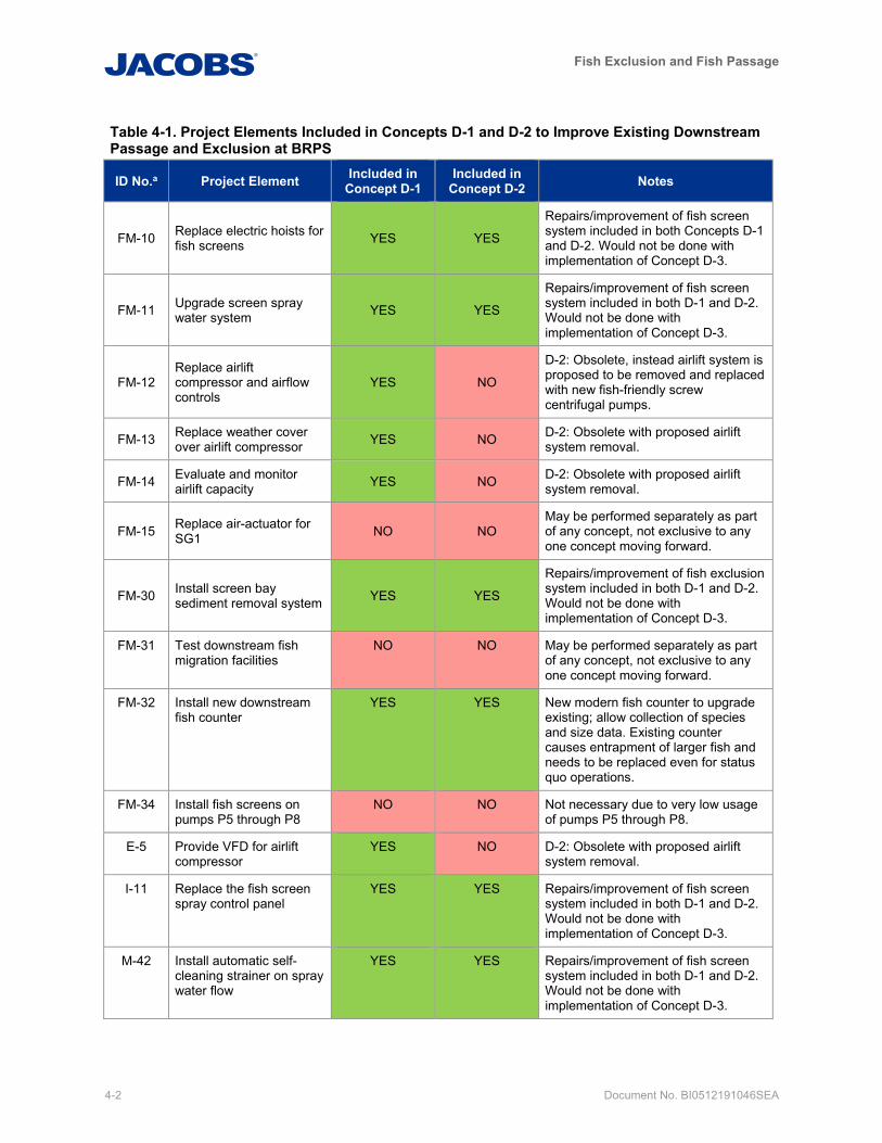
Fish Exclusion and Fish Passage
4-2 Document No. BI0512191046SEA
Table 4-1. Project Elements Included in Concepts D-1 and D-2 to Improve Existing Downstream Passage and Exclusion at BRPS
ID No.a Project Element Included in Concept D-1
Included in Concept D-2 Notes
FM-10 Replace electric hoists for fish screens YES YES
Repairs/improvement of fish screen system included in both Concepts D-1 and D-2. Would not be done with implementation of Concept D-3.
FM-11 Upgrade screen spray water system YES YES
Repairs/improvement of fish screen system included in both D-1 and D-2. Would not be done with implementation of Concept D-3.
FM-12 Replace airlift compressor and airflow controls
YES NO
D-2: Obsolete, instead airlift system is proposed to be removed and replaced with new fish-friendly screw centrifugal pumps.
FM-13 Replace weather cover over airlift compressor YES NO D-2: Obsolete with proposed airlift
system removal.
FM-14 Evaluate and monitor airlift capacity YES NO D-2: Obsolete with proposed airlift
system removal.
FM-15 Replace air-actuator for SG1 NO NO
May be performed separately as part of any concept, not exclusive to any one concept moving forward.
FM-30 Install screen bay sediment removal system YES YES
Repairs/improvement of fish exclusion system included in both D-1 and D-2. Would not be done with implementation of Concept D-3.
FM-31 Test downstream fish migration facilities
NO NO May be performed separately as part of any concept, not exclusive to any one concept moving forward.
FM-32 Install new downstream fish counter
YES YES New modern fish counter to upgrade existing; allow collection of species and size data. Existing counter causes entrapment of larger fish and needs to be replaced even for status quo operations.
FM-34 Install fish screens on pumps P5 through P8
NO NO Not necessary due to very low usage of pumps P5 through P8.
E-5 Provide VFD for airlift compressor
YES NO D-2: Obsolete with proposed airlift system removal.
I-11 Replace the fish screen spray control panel
YES YES Repairs/improvement of fish screen system included in both D-1 and D-2. Would not be done with implementation of Concept D-3.
M-42 Install automatic self-cleaning strainer on spray water flow
YES YES Repairs/improvement of fish screen system included in both D-1 and D-2. Would not be done with implementation of Concept D-3.
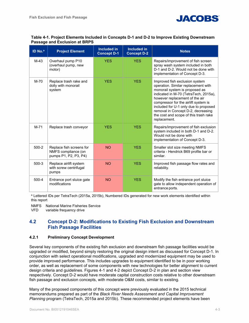
Fish Exclusion and Fish Passage
Document No. BI0512191046SEA 4-3
Table 4-1. Project Elements Included in Concepts D-1 and D-2 to Improve Existing Downstream Passage and Exclusion at BRPS
ID No.a Project Element Included in Concept D-1
Included in Concept D-2 Notes
M-43 Overhaul pump P10 (overhaul pump, new motor)
YES YES Repairs/improvement of fish screen spray wash system included in both D-1 and D-2. Would not be done with implementation of Concept D-3.
M-70 Replace trash rake and dolly with monorail system
YES YES Improved fish exclusion system operation. Similar replacement with monorail system is proposed as indicated in M-70 (TetraTech, 2015a), however replacement of the air compressor for the airlift system is included for U-1 only due to proposed removal in Concept D-2, decreasing the cost and scope of this trash rake replacement.
M-71 Replace trash conveyor YES YES Repairs/improvement of fish exclusion system included in both D-1 and D-2. Would not be done with implementation of Concept D-3.
500-2 Replace fish screens for NMFS compliance (on pumps P1, P2, P3, P4)
NO YES Smaller slot size meeting NMFS criteria - Hendrick B69 profile bar or similar.
500-3 Replace airlift system with screw centrifugal pumps
NO YES Improved fish passage flow rates and reliability.
500-4 Entrance port sluice gate modifications
NO YES Modify the fish entrance port sluice gate to allow independent operation of entrance ports.
a Lettered IDs per TetraTech (2015a, 2015b), Numbered IDs generated for new work elements identified within this report NMFS National Marine Fisheries Service VFD variable frequency drive
4.2 Concept D-2: Modifications to Existing Fish Exclusion and Downstream Fish Passage Facilities
4.2.1 Preliminary Concept Development
Several key components of the existing fish exclusion and downstream fish passage facilities would be upgraded or modified, beyond simply restoring the original design intent as discussed for Concept D-1. In conjunction with select operational modifications, upgraded and modernized equipment may be used to provide improved performance. This includes upgrades to equipment identified to be in poor working order, as well as replacement of some components with new technologies for better alignment to current design criteria and guidelines. Figures 4-1 and 4-2 depict Concept D-2 in plan and section view respectively. Concept D-2 would have moderate capital construction costs relative to other downstream fish passage and exclusion concepts, with moderate O&M costs, similar to existing.
Many of the proposed components of this concept were previously evaluated in the 2015 technical memorandums prepared as part of the Black River Needs Assessment and Capital Improvement Planning program (TetraTech, 2015a and 2015b). These recommended project elements have been
Fish Exclusion and Fish Passage
4-4 Document No. BI0512191046SEA
reevaluated now that a more detailed assessment of criteria compliance has been performed (see Section 3.2.4 and Appendix C), to determine which are appropriate for inclusion in current Concepts D-1 and D-2. A full list of the proposed project elements relevant to the fish exclusion and downstream passage systems identified in previous evaluations is provided in Table 4-1, indicating which are included in current Concepts D-1 and/or D-2, as well as notes to elaborate on reasoning for each as appropriate.
4.2.1.1 Modifications to Existing Fish Exclusion Facility
Fish exclusion facility modifications are assumed to focus on the high-use pumps including pumps P1, P2, and P4. The other large pumps operate so infrequently that they are well outside the typical 5 percent exceedance criteria identified by NMFS (passage and exclusion are not required during extreme high and extreme low flow conditions). Key components included in this concept relating to the fish exclusion facility include:
• 500-2: Replace fish screens for NMFS compliance (on pumps P1, P2, P3, P4):
– Replacement of fish screen panels with smaller slot size meeting NMFS criteria - Hendrick B69 profile bar or similar.
– Pressure differential monitoring system to enable monitoring of fish screen performance and identify blockages causing high head loss across the screens. This will enable the cleaning system (and operators if required) to more quickly respond to debris events and to minimize associated injury to fish.
• Replacement of fish screen hoists.
– The 2-ton manual chain hoist is very slow and cumbersome for the operations needed to remove the screens from their places for repairs. The screens must be lifted approximately 22 feet to be removed from the forebay, requiring an extended period of time with the manual hoist (TetraTech, 2015a).
• FM-11: Upgrades to the screen spray wash system to address the problem of re-entrainment of sediment and debris on screens after washing, including:
– I-11: replacement control panel. – M-42: automatic self-cleaning strainer.
• FM-30: Intake bay sediment removal system, including a submersible slurry pump and provisions for dewatering sediment. Sediment removal systems will improve reliability and operation of fish screen spray wash systems.
• M-70, M-71: Trash rack cleaning system replacement including a trash rake with a monorail system and a trash conveyor. Sediment removal systems will improve reliability and operation of fish screen spray wash systems and the downstream passage system which is susceptible to blockage from debris.
• Revisions and updates to existing O&M practices.
4.2.1.2 Modifications to Existing Downstream Fish Passage Facility
Key components of this concept relating to the downstream passage facility include the following elements:
• 500-3: Replace the existing airlift system with fish-friendly screw centrifugal pumps and removal/abandonment of the existing air system which is known to be in poor condition. Screw centrifugal pumps would help increase attraction flow and water velocities through the facility. However, these pumps are not large enough to pass adult steelhead, rainbow, or cutthroat trout (for which the existing inlet ports are also too small).
• 500-4: Modify the fish entrance port sluice gate to allow independent operation of entrance ports.
• FM-32: Install modern downstream fish counting system that would allow more accurate fish counts and identification of species.
Fish Exclusion and Fish Passage
Document No. BI0512191046SEA 4-5
• Revise and update O&M practices to accommodate operation of new equipment and modify standard operation of entrance port sluice gates for improved attraction with location adjacent to frequently operating pumps (P1 and P9) and to increase velocities through open ports.
• Video inspect and remotely clean conveyance piping as needed and identified by the inspection.
4.2.2 Detailed Concept Development
A detailed list of project elements that would be incorporated with Concept D-2 is provided herein. A scope of work with more detailed information for each item is provided within the basis of cost estimate in Appendix D.
• Modification of Existing Fish Exclusion System:
– Replace existing screens with stainless steel profile bar screen panels (see manufacturer data provided in Appendix E).
– Install pressure differential monitoring system. – Upgrade screen spray water system. – Install an automatic self-cleaning strainer on the spray water supply. – Install a screen bay sediment removal system, including:
Submersible slurry pump Sediment dewatering
– Replace the fish screen spray control panel. • Modification of Existing Downstream Passage Facility.
– Replace airlift system with screw centrifugal pumps (see manufacturer data provided in Appendix E), including:
Installation of new riser piping to existing dearation tank. Removal/abandonment of the existing airlift system and covered shed structure at existing air
compressor.
– Modify entrance port sluice gates to allow independent operation of gates that are currently installed with two gates on a single operator.
– Install modern fish counting system (see manufacturer data provided in Appendix E for VAKI’s pipeline counter).
– Upgrade trash rack cleaning system, including: Replacement of the trash rake and dolly with a monorail system. Replacement of the trash conveyor.
– Conduct video inspection and remote cleaning of existing fish bypass piping. Preliminary sizing of the screw centrifugal pumps for downstream bypass is estimated to be 3,000 gallons per minute (6.7 cfs) per pump. This flow rate results in velocities at the entrance ports of approximately 5 fps assuming operational modifications are made to only open half of the entrance ports (those closest to P1 which operated most frequently). A variable frequency drive (VFD) would be required to achieve the desired flow rate with the screw centrifugal pumps. Manufacturer data on preliminary pump selection are provided within Appendix E.
4.2.3 Data Gaps/Future Action Future evaluation should further explore pump specific operational limits for safe fish handling, including optimal pump rotation speed and flow rate, as well as maximum passable fish size.
Fish Exclusion and Fish Passage
4-6 Document No. BI0512191046SEA
4.3 Concept D-3: Diagonal Screen in Forebay with Pumped Bypass
A diagonal screen structure with bypass is proposed as Concept D-3. The term “diagonal screen” refers to the shape of the screen configuration in plan, which has flat vertical screen panels that cross the approach channel in a “diagonal” shape. The screen orientation promotes sweeping velocities parallel to the screen face to convey fish downstream towards the narrowing throat of the diagonal, while maintaining low approach velocities perpendicular to the screen face. Fish are better able to avoid impingement against the screen face when low approach velocities are substantially exceeded by sweeping velocities, consistent with regulatory criteria. Fish would enter the downstream bypass at the throat for transport past the BRPS to the tailwater and Green/Duwamish River.
4.3.1 Preliminary Concept Development
A diagonal screen facility as described in this section has the potential to provide good FPEs. The benefit is that the angled orientation of the diagonal screens and constriction towards the downstream end provide sweeping flows across the screens and an accelerating flow pattern, which guides fish towards the bypass. A pumped bypass, as opposed to a gravity bypass, would be required due to the unique operating conditions at BRPS with tailwater elevation frequently higher than the forebay water surface. Figures 4-3 through 4-6 depict Concept D-3 in plan and section views.
Key components of this concept include the following:
• Screens with trash rack at entrance, located in forebay • Mechanical trash rack cleaner • Mechanical brush screen cleaner • Porosity adjustment system behind screens to balance through and sweeping velocities • Overflow weir to capture downstream migrants at the end of the secondary screen • Screw centrifugal pumped bypass to tailwater • Modern fish counting system
Diagonal or vee screens are a commonly-used technology that are generally understood and accepted by fisheries agencies and stakeholders. They have the potential to provide a high level of fish passage performance relative to the other concepts considered, but also have high capital construction and O&M costs. Key considerations affecting the viability of this concept to be evaluated further include:
• Sizing and operation of the screening structure due to the high variation of BRPS inflows
• Effect on existing flood control pump operations
The configuration of the screens relative to pump P3 needs to be considered due to its proximity to the high-use pumps. The high-use pumps are expected to continue to require screens. However, pump P3 is located between the other high-use pumps (see Figure 4-3) and has only run for approximately 7 hours total in the past 10 years. Screening pump P3 would require a very large structure and need to accommodate regular low-flow conditions through much of the summer, which drop below approximately 10 cfs as discussed in Section 2.2. Further evaluation of screen hydraulics and the need to accommodate pump P3 will be considered in the detailed concept development below, as it could have significant effect on the feasibility of implementation Section 4.3.2.
Similar to Concept D-2, the intake bays at pumps P5 through P8 are assumed to remain unscreened aside from the existing coarse trash racks due to infrequent operation of these pumps, which provide less than 1.2 percent of total volume pumped at BRPS, and are well outside the typical operating limit of 5 percent exceedance streamflows for fish passage systems.
Substantial in-water work would be required in the forebay to construct diagonal screens at BRPS, though construction would likely be limited to the southern half of the forebay and BRPS.
Fish Exclusion and Fish Passage
Document No. BI0512191046SEA 4-7
The screw centrifugal pump proposed to convey fish through BRPS is similar to that identified for Concept D-2. These pumps may safely accommodate fish up to approximately 15 inches in length, but are not large enough to pass adult steelhead kelts for example (an ESA-listed species). If passage for large fish is required, alternative systems such as a fish lock or a fish elevator could be evaluated. Alternatively, sorting kelts out of the bypass immediately downstream of the control weir may be possible, before entering the screw centrifugal pump. Once sorted, the kelts could then be manually transported downstream to the tailwater.
Monitoring could be performed remotely to identify when adults are present and to respond accordingly, but it will likely require staff to respond on site more often than currently required for existing facility. The number of kelts or other adults requiring transport downstream is currently unknown.
4.3.2 Detailed Concept Development
The screen structure design and potential operational modif ications are refined herein for benefit of downstream passage and exclusion from high-use pumps. Key design considerations are evaluated, including determining the screen capacity and subsequent sizing, as well as impacts to existing flood control pump operations. Detailed discussion of the proposed configuration is provided for the screens and associated structure.
4.3.2.1 Operating Range and Impact to Existing Pump Operations
Fish passage facilities are required to have a minimum operating range from the 95 percent to the 5 percent exceedance streamflows per NMFS criteria (NMFS, 2018). However, fish screening is typically required over the full range of streamflows as noted in Section 2.2.1. NMFS has granted screening variances for other projects to operate in the range of 95 percent to 5 percent exceedance streamflows and such consideration seems reasonable at BRPS given the very infrequent operation of pumps P3, P5, P6, P7, and P8. This assumption would need to be explored further as part of the stakeholder engagement process.
Existing pump operations are such that the 5 percent exceedance inflow of 168 cfs is surpassed when pumps P1, P9 and either P2 or P4 are operating for a combined total of 233 cfs (approximately 1.1 percent exceedance). Pumps P2 and P4 alternate lead operation relative to each other; therefore, a screen structure accommodating existing pump operations may need to include both of these pumps, in addition to pump P3 that is located between pumps P2 and P4. As shown in Table 3-4, the combined design capacity of Pumps P1, P2, P3, P4, and P9 is 897 cfs (less than 1 percent exceedance), which would require a substantial structure requiring more than five times greater screen area than necessary for the 5-percent exceedance streamflow.
Modifications are proposed to the operations of pump P2 and P4, such that P2 would always lead operation of P4. This allows for a structure that encompasses pump bays for P1 and P2 (including P9), while excluding pump bays for P3 and P4 (including P10). This results in a screened flow of 233 cfs. The downstream bypass also would have a flow of approximately 5 cfs. The total design high-flow capacity of the diagonal screen facility is therefore assumed to be 238 cfs, which is equivalent to approximately the 1.1 percent exceedance.
The intake bays for pumps P3 and P4 currently have fish screens installed. Replacement of the existing fish screens at P3 and P4 consistent with that proposed in D-2 (Modifications to the Existing System) including profile bar having NMFS compliant slot sizing, upgraded spray wash system, and replacement of screen hoists is assumed. The proposed operational change to always have P4 follow after operation of P2 results in both P3 and P4 only operating with flows exceeding the 5 percent exceedance inflow. Therefore, potential optimization during detailed design and stakeholder engagement could consider removal of fish screens at P3 and P4.
Pump flow rates are a function of total dynamic head, which varies across the range of forebay and tailwater elevations. Pump flow rates identified herein are design capacities associated with the minimum total dynamic head operating point as marked on manufacturer pump curves. The screen structure will be sized
Fish Exclusion and Fish Passage
4-8 Document No. BI0512191046SEA
and configured to accommodate this condition while maintaining approach and sweeping velocities. Actual pumped flows at P1, P2, and P9 will be less than 233 cfs as the total dynamic head increases, though pump testing would be beneficial when considering total capacity in more detailed design to reflect the actual operation of these pumps which are key to the sizing the diagonal screen.
Diagonal screens operate most efficiently and are best able to meet NMFS criteria when operating within a narrow range of streamflows while providing a steady attraction flow. To accommodate the full range of streamflows, including the 95-percent exceedance streamflow of 6 cfs, recirculation must be provided within the forebay for consistent flow through the screens and, thus, avoiding over drawdown of the forebay. A recirculation design flow of 233 cfs is proposed, and two options for accommodating this requirement have been identified:
• Installation of valving and piping to return flow from pumps P1, and P2 to the BRPS forebay
• Dedicated recirculation pumps with variable flow capacity to provide the design screened flow rate in combination with the required operating flood control pumps
Valving and piping modifications on the discharge of P1 and P2 would introduce additional head loss, effectively reducing the capacity of the flood control pumps. This loss of capacity could be significant given the low design head of the pumps. Space constraints at the pump discharges also make installation of pump control valving and piping difficult and potentially infeasible. In order to avoid a reduction in flood control pump capacity and to avoid major modifications within the existing structure BRPS, dedicated recirculation pumps are, therefore, recommended and assumed.
During low streamflow periods, recirculation of upstream fish passage flows (pump P9) and downstream bypass flows may also be required. A new screened intake located in the tailwater and pumping is assumed for this purpose. Additional details are provided below.
4.3.2.2 Screen Sizing and Configuration
Screens are sized based on NMFS criteria for a maximum approach velocity of 0.4 fps or less, which is applicable to actively cleaned screens and an exposure time of 60 seconds or less, both criteria of which are assumed for the proposed screen structure. The screen structure would accommodate the 233 cfs flowrate above via primary and secondary screens with a safety factor of approximately 10 percent. Following are the two types of screening:
• Primary screening is located along the angled portion of the screen face (Figure 4-3). Approximately 90 percent of the total 233 cfs screened flow will pass through the primary screens, approximately 210 cfs. Approximately 583 square feet of screen is required.
• Secondary screening involves having the final 10 percent of the screened flow passing through the secondary screens (Figure 4-3)—approximately 23 cfs. Approximately 65 square feet of screen are required.
The screens are designed to remain submerged, with the top of screens set at elevation 5.5 feet NAVD88, which is 0.7 foot below the forebay 95 percent exceedance stage of 6.2 feet NAVD88 (Table 2-2). The bottom floor of the screening structure is assumed to be at elevation -4.5 feet NAVD88, which is equal to the upstream end of the existing concrete apron in the BRPS forebay. A screen height of 10 feet results in a length of 59 feet for primary screening. The bottom of secondary screening rises with the floor along the narrow throat of the screening structure to maintain an accelerating flow velocity and is sized accordingly to result in the desired total area. The secondary screens are made from the same material and same slot sizing as the primary screens, but are configured parallel to flow at the narrow throat of the diagonal screen structure, not oriented diagonally like the primary screens. Solid steel panels are installed above the screening panels so that all flow is directed through the screens or into the downstream bypass.
A vee screen structure (essentially two diagonal screens located on both sides of the bypass) was considered but rejected given the short length of the structure and the greater benefits associated with
Fish Exclusion and Fish Passage
Document No. BI0512191046SEA 4-9
the diagonal arrangement. The diagonal screen allows for a simple configuration with all flow passing through the screens in a uniform manner to the north side of the structure and into the existing pump intake bays. The screen brush cleaning system is simplified, the flow through each screen panel is easily adjusted with porosity controls, and recirculation pumping to the forebay can be more readily accommodated with the single diagonal screen concept.
4.3.2.3 Structure Configuration
The structure configuration includes the following assumptions:
• Reinforced concrete structure
– 24-inch concrete base slab matching the upstream invert of the existing sloping bed slab (elevation -4.5 feet NAVD88).
– 18-inch thick sidewalls Sidewall against south bank of forebay acting as a retaining wall and extending upstream to
create transition headwall for smooth approach for flow into the screen structure. Assumed to be formed against existing retaining wall which is to remain in place.
Top of wall elevation set to elevation 16.5 feet NAVD88, matching top of existing retaining wall along southern bank of forebay, with freeboard above FEMA 100-year flood level (10.0 feet NAVD88) (Table 2-2) and the maximum forebay WSEL on record from 2009-2019 (13.8 feet NAVD88).
• Steel grating used to create accessible top deck of structure at 16.5 feet NAVD88.
• Trash rack at structure entrance matching existing spacing (4-inch on center with 0.5-inch bar). This spacing can be adjusted during design as required to accommodate target species.
– Cleaning system with Atlas Polar-type rake and debris hopper • Bulkhead slots behind the trash racks would allow the structure to be sealed, dewatered, and cleaned
of deposited sediment and debris in the dry, and to maintain the screens and baffles.
• Structural considerations to allow dewatering:
– Reinforced concrete structure as opposed to steel sheet piling – Pile support system beneath the structure
18-inch diameter steel piles at 10 feet each way
Driven to elevation -51.5 feet NAVD88
4.3.2.4 Downstream Bypass and Control Weir
Downstream of the secondary screening, the narrow channel would continue to an adjustable control weir designed to provide a constant 5 cfs downstream bypass flow at all times and maintain consistent acceleration as water and fish move towards the downstream bypass. The height of the weir would be adjustable in accordance with the forebay WSEL, and would have a hinged ramp, which rises and falls with the weir crest to create a smooth approach condition. The weir would operate over the existing forebay water surface range of pump P2, which is approximately 2.5 feet. Controlling the forebay water surface to a tighter range may benefit screen operations, and could be facilitated with the use of VFD’s on the flood control pumps, or revise the P1 on/off elevation triggers to reduce the range of forebay/pond fluctuation.
A wet well located immediately downstream of the weir would contain a submersible fish-friendly screw centrifugal pump (see manufacturer data provided in Appendix E). The pump is necessary to transport fish up and over the BRPS structure, with the top of pipe discharge at elevation 25.0 feet NAVD88 to prevent backflow from the BRPS tailwater to the FEMA 100-year flood level (25.0 feet NAVD88) (Table 2-2). The pump would be sized with a design capacity of approximately 5 cfs and would be mounted on a guiderail for ease of maintenance. The potential for trapping larger fish between the control
Fish Exclusion and Fish Passage
4-10 Document No. BI0512191046SEA
weir and bypass pump exists. Monitoring of this location with manual transport as needed is assumed, requiring staff response on site with greater frequency than currently needed for the existing facility. More elaborate systems such as fish elevators could be employed if warranted by the anticipated number of kelts/adults. The quantity is currently unknown and is a data gap for future consideration during detailed design.
After rising with pumped flow to elevation 25.0 feet NAVD88 to avoid backflow from the 100-year tailwater flood level, the bypass pipe would convey fish and the 5 cfs bypass flow by gravity at an approximate 6 percent slope to the outfall in the tailwater. The outfall is assumed to be located at the same point and elevation as the existing downstream passage outfall, immediately downstream of the upstream passage entrance at elevation 14.0 feet NAVD88. This point will meet NMFS criteria for maximum outfall impact velocity at low water level, which requires the discharge to be less than approximately 10 feet above the low water surface. The downstream bypass pipe outfall would be submerged during high water levels due to the large tidal fluctuation of the BRPS tailwater, however the high point at 25.0 feet NAVD88 prevents backflow to the forebay. The downstream bypass piping is assumed to be 18-inch diameter, smooth-walled HDPE pipe, buried along the entire route. The route of the bypass pipe passes below the existing BRPS control building; however, it is assumed that this control building would be removed and replaced in a new location that minimizes conflicts prior to fish passage improvements. It is assumed that the downstream bypass piping would need to penetrate through the buried sheet pile wall. As such, costs associated with avoiding these conflicts are assumed to be minimal.
4.3.2.5 Pumped Flow Return from Tailwater to Forebay
The conveyance of water from the BRPS tailwater to the forebay is assumed to be required during periods of low streamflows to maintain sufficient water supply to both the upstream and downstream passage systems. This includes streamflows near the 95 percent exceedance streamflow of 6 cfs. The existing upstream passage system utilizes pump P9 with a design capacity of 8 cfs, approximately 5 cfs of which is directed down the Alaska steeppass to tailwater. The proposed downstream bypass is assumed to require an additional 5 cfs. Therefore, it is assumed that the pumped flow return from the tailwater to the forebay would be a minimum of approximately 10 cfs to fully offset both the upstream and downstream flow requirements. This will add resiliency to the facility and allow operation of both passage systems, regardless of streamflow.
Fish protection screens would be required for any withdrawals from the tailwater, and this facility is assumed to utilize a cylindrical wedge wire (tee) screen intake structure meeting NMFS criteria. Suction lines would lead to submersible pumps in cans, with discharge to the recirculation flow diffuser located in the forebay.
Additional evaluation would be required to locate and configure this facility; however, an allowance is included in the cost estimate. An alternative approach to managing low streamflows would be curtail or suspend fish passage operations intermittently during low flow periods. This approach was not assumed for the purposes of this evaluation to maximize operation of the downstream bypass; however, concerns with pumped tailwater supply do exist that may warrant preference of intermittent operation at low flow levels. Further evaluation of potential water quality impacts resulting from the introduction of additional Green River water to the forebay should be considered, including low DO, high temperature, and the potential for fish straying.
4.3.2.6 Dedicated Recirculation Pumping
The forebay screen size and configuration would be designed to accommodate a constant flow rate with minimal fluctuation. Recirculation pumping would be provided to maintain a constant design flow rate through the screening structure at all times, making up the difference between the design screen flow rate of 233 cfs, and the actual operating flow rates of P1, P2, and P9. A total of five Flygt submersible propeller pumps at approximately 50 cfs each are assumed behind the fish screens, with two VFD units allowing the recirculation rate to be adjusted as needed to hit the target design screen flow rate. Multiple low capacity pumps, as opposed to fewer pumps with higher capacity, are assumed in order to provide greater redundancy and distribute the recirculation flow.
Fish Exclusion and Fish Passage
Document No. BI0512191046SEA 4-11
Operational transitions between the use of flood control pumps and recirculation pumps would be complex given the need to maintain a constant flow rate of 233 cfs screened flow. It is assumed that VFD units would be provided for flood control pumps P1 and P2 to allow more gradual ramping at the start and stop of pump operations, and to facilitate the transition to/from the recirculation pumps. Because a VFD unit is already assumed to be added for P1 under Concept U-2, only the cost for a VFD unit at pump P2 is included in the cost estimate for D-3.
The recirculation flow would be discharged through a wall diffuser located in the north side wall of the screen structure (Figure 4-5). The diffuser opening would be sized to maintain a 1 fps maximum approach velocity at a total flow of 243 cfs (233 cfs recirculation flow plus 10 cfs pumped return from tailwater).
Future detailed design should consider the potential to reduce recirculation flows during low inflow periods, less than the design screened flow rate of 233 cfs, which could ultimately result in lower capital costs and energy savings. With this approach, the diagonal screen would be designed to meet NMFS criteria over a range of flows, with minor reductions in approach velocity and attraction flow during low inflow periods. Associated impacts to fish passage efficiency would need to be evaluated but are assumed to be minimal.
4.3.2.7 Conflicts and Considerations
Following are potential conflicts:
• Potential hydraulic conflicts with other alternatives (such as the baffled channel with modification to forebay operating WSEL) would require changes in recirculation flow pumping and other changes to flow patterns in the forebay that have not been fully evaluated and may not be reasonable to implement in combination.
• The pumped bypass is not volitional and would need a variance from NMFS. These pumps are not able to pass large fish including ESA-listed species such as steelhead kelts, which potentially could be trapped in the wet well below the adjustable weir.
• The existing upstream passage chute from the false weir to the forebay would need to be replaced and/or relocated.
• The control building would need to be relocated to avoid conflict with the proposed downstream bypass pipe.
4.3.2.8 Considerations for Future Evaluation and Optimization
Following are considerations for future evaluation and optimization:
• Computational fluid dynamic (CFD) modeling or similar may be required to accurately characterize and evaluate hydraulic conditions in the forebay, including recirculation, over the range of operations.
• A lower screen floor elevation could be considered to shorten the structure and to minimize costs.
• Decreasing width of the screen structure in the forebay could be considered to occupy fewer existing screening bays, down to a minimum of a single screen bay only (P1). This would affect hydraulic approach conditions for the existing flood control pumps, and would likely require CFD and/or physical hydraulic modeling to confirm suitability of the configuration.
• Reducing the height of the screen structure could be considered, including the wall height and/or top deck elevation (16.5 feet NAVD88), which are currently assumed with conservative freeboard above FEMA 100-year flood level (10.0 feet NAVD88) and the maximum forebay WSEL on record from 2009-2019 (13.8 feet NAVD88).
• Screen area could be provided to accommodate the flow from all the pumps as described herein (233 cfs) but operate at a lower screen flow with a lower recirculation rate (and recirculation capacity) for much of the time (say 168 cfs).
Fish Exclusion and Fish Passage
4-12 Document No. BI0512191046SEA
4.4 Concept D-4/U-4: Baffled Channel with Operational Modifications
4.4.1 Preliminary Concept Development
A baffled channel bypassing the pump station along the north side could be constructed to allow volitional fish passage in both the upstream and downstream direction. Flow through the channel would be controlled by the water surface differential between the forebay and tailwater on the Green River side of the BRPS. With the forebay WSEL higher than the tailwater, downstream flow could occur, with the channel and baffles designed to provide ideal hydraulic conditions to promote passage in both directions. A roller gate spanning the full channel at the midpoint would allow closure of the channel as needed to ensure flood control operations are not compromised. Figures 4-7 (plan), 4-8 (section), and 4-9 (west elevation) depict the proposed baffled channel.
Analysis of WSEL differentials are necessary to identify the frequency that gravity flow from the forebay to the tailwater towards the Green River would be expected to occur; a preliminary evaluation of the potential frequency of operation based on WSEL differential is provided in subsequent detailed development in Section 4.4.2. Operational modifications to normal forebay WSEL should also be evaluated with further consideration of upstream flooding impacts, particularly at the Oakesdale Avenue floodwall below I-405.
Due to the likelihood of periods throughout the year that the baffled channel system cannot reasonably operate due to WSEL conditions upstream and/or downstream, existing downstream fish passage facility (and possibly the existing upstream fish passage facility) is assumed would continue to be operated in conjunction with this concept. This would provide multiple fish passage routes and would limit outage periods to be no greater than that of the existing facility.
Concept D-4/U-4 is the only passage concept aside from trap and haul that could reasonably provide adult steelhead and trout passage in the downstream direction, and also allows for the greatest possibility for passage of weaker swimming species. Adult Chinook and steelhead would require 12-inch clear spaces between bars on the trash rack. Debris booms may also be required.
The capital construction cost is moderate, less than a vertical slot fishway, but more expensive than simple modifications to the existing system. This concept includes the following components:
• Baffled channel allowing both upstream and downstream passage
– Driven sheet piles to create a channel, with the ends closed during construction to form a temporary cofferdam
– Baffles that function in both directions – Trash racks at each end to exclude debris – Large roller gate in the middle for flood operations; designed to fail closed – Approximate 4-foot minimum water depth across the range of operations
• Implemented in conjunction with an increase in the normal forebay operating WSEL; normal flood operations maintained
4.4.2 Detailed Concept Development
A baffled channel around the north side of the BRPS is proposed as Concept D-4/U-4. Refinement of the baffled channel design and potential operational modifications are provided herein for dual benefit of upstream and downstream passage. A full list of project elements is provided, while a scope of work including greater detail for each item may be found within the basis of estimate provided in Appendix D.
4.4.2.1 Refinement of Baffled Chute Design
The channel would be approximately 200 feet in length and 8 feet wide, formed with sheet pile walls assumed to be driven down to bedrock. A level concrete slab would be poured with invert elevation at
Fish Exclusion and Fish Passage
Document No. BI0512191046SEA 4-13
approximately 1.5 feet NAVD88 to allow operation during low flow levels but maintain separation above the existing river bottom to limit sedimentation issues. Trash racks at each end of the channel with 12-inch spacing would be used to allow passage of adult Chinook and steelhead. A roller gate would be installed at the midpoint to allow closure as needed to ensure flood control operations are not impeded. Steel grating is assumed spanning the top of the channel to maintain site access from the north.
Operation at this conceptual level is designed for the 95 percent exceedance forebay minus tailwater WSEL differential of -6.13 feet. Preliminary baffle sizing with 3-foot openings is assumed in order to accommodate the maximum design WSEL differential. Adjustments of baffle sizing at the maximum design WSEL differential are used to target average head loss through each baffle set of approximately 0.5-foot, velocities between 2 to 4 fps, and a flow rate through the channel of approximately 100 cfs. Further analysis will be required to evaluate and refine these assumptions. Given the likelihood of periods throughout the year that the baffled channel system cannot reasonably operate due to WSEL conditions upstream and/or downstream, optimizing the system performance for more frequent WSEL differentials should be evaluated, with other fish passage methods providing passage during conditions approaching the 5% and 95% exceedance WSEL differential.
During times when flow is moving upstream through the baffled channel (towards the forebay of the BRPS) some recirculation of flow would occur, resulting in additional pumping. The size of the bypass and the selected forebay operating WSEL would impact the flow rate and frequency of recirculation pumping. Use of computational fluid dynamics modelling would be required as part of the preliminary design to evaluate and identify ideal velocities and hydraulics for fish passage and flood control pumping effects.
4.4.2.2 Refinement of Operational Modifications
Additional evaluation of hydrology and hydraulics relating to the baffled channel concept is identified in this section, including more detailed analysis of the frequency at which the system would be anticipated to be able to operate with flow traveling downstream towards the Green River on an annual average basis. This analysis and the potential operational modifications at the BRPS which could increase the frequency of downstream flow through the baffled channel are identified within this section. Operational implications to identified upstream locations with flooding concerns are discussed, though additional future data collection and evaluation would be required to fully define the operational modifications that could be pursued.
The percent exceedance of zero WSEL differential (forebay WSEL equals tailwater WSEL) is approximately 17.6 percent as shown in Exhibit 2-4. This indicates that under current pumping practices for management of the forebay, downstream flow towards the Green River could occur approximately 17.6 percent of the time on an annual average basis. Increasing the forebay operating WSEL could increase the frequency of gravity flow. This would require changing set operating points of the flood control pumps to turn on and shut off at higher water levels than present.
Modifications to increase the forebay WSEL by 1.75 feet (approximate WSEL elevation 8.5) would result in flow in the downstream direction approximately 50 percent of the time, given the 50 percent exceedance under current operation was found to be -1.75 feet (Table 2-2). Similarly, gravity flow towards the Green River through the baffled channel could be achieved 95 percent of the time on an annual average basis with an increase of 6.13 feet (approximate WSEL 12.9), given the current 95 percent exceedance WSEL differential of -6.13 feet (Table 2-2).
Operational modifications to raise the forebay WSEL may not realistically be possible to the extent needed for operation of a baffled channel between the full range of 5 percent and 95 percent design conditions, because upstream flood concerns and potential impacts to water quality including temperature and DO exist with higher forebay WSELs and increased storage. Existing upstream and downstream passage facilities presumably would continue to be operated in conjunction with the baffled channel, providing multiple passage routes and no periods without fish passage beyond that provided by existing operations.
Fish Exclusion and Fish Passage
4-14 Document No. BI0512191046SEA
4.4.2.3 Project Elements
A list of anticipated project elements that would be included with Concept D-4/U-4 follows; a full scope of work including greater detail for each item may be found within the basis of estimate provided in Appendix D:
• Baffled channel formed with sheet pile • Baffle sets forming approximately 14 pools • Roller gate at midpoint allowing closure of the channel • Trash rack at each end with 12-inch spacing for passage of adult Chinook and steelhead • Relocation of existing storage facilities on north side of the BRPS
4.4.3 Data Gaps/Future Action
Assessment of the temporal relationship between periods of WSEL differential allowing operation of the baffled channel with seasonal passage of target fish species. This will help quantify the percentage of time that the baffled channel would be expected to be operational and provide effective upstream and downstream passage opportunity, and how that changes with modifications to the normal forebay WSEL. Evaluation of forebay operating WSELs and the ability to increase WSELs while limiting upstream impacts.
4.5 Summary
Table 4-2 summarizes the advantages and disadvantages of the fish exclusion and downstream fish passage concepts. Table 4-3 documents the key noncompliant criteria previously established in Section 3.2.4 and notes whether each concept is anticipated to correct each condition.
Table 4-2. Summary of Fish Exclusion and Downstream Fish Passage Concepts at BRPS Concept Description Advantages Disadvantages
D-1. Status Quo Repairs
Make minor improvements to existing equipment with no change in intended design performance.
• Lowest capital cost. • Well-understood
operational requirements.
• Addresses very limited range of downstream fish passage concerns and operation issues.
• Does not meet regulatory requirements. Does not pass large fish including ESA-listed species such as steelhead kelts.
D-2. Modifications to existing fish exclusion and downstream fish passage facilities
Replace existing screens and install screw centrifugal pumps.
• Moderate capital and O&M cost.
• Uses existing infrastructure.
• Could be readily implemented.
• May not meet all resource agency criteria and guidelines (attraction velocity, 90-degree bends).
• Requires pumped attraction flows and fish bypass which is not preferable for regulatory compliance.
• Requires regulatory variance for pumps P5 through P8.
• Does not pass adult steelhead and trout due to existing entrance port and pipe sizing.
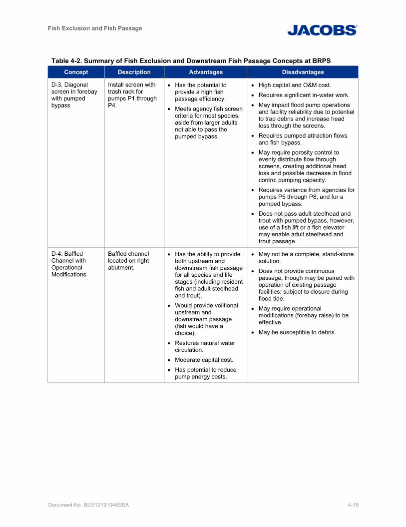
Fish Exclusion and Fish Passage
Document No. BI0512191046SEA 4-15
Table 4-2. Summary of Fish Exclusion and Downstream Fish Passage Concepts at BRPS Concept Description Advantages Disadvantages
D-3. Diagonal screen in forebay with pumped bypass
Install screen with trash rack for pumps P1 through P4.
• Has the potential to provide a high fish passage efficiency.
• Meets agency fish screen criteria for most species, aside from larger adults not able to pass the pumped bypass.
• High capital and O&M cost. • Requires significant in-water work. • May impact flood pump operations
and facility reliability due to potential to trap debris and increase head loss through the screens.
• Requires pumped attraction flows and fish bypass.
• May require porosity control to evenly distribute flow through screens, creating additional head loss and possible decrease in flood control pumping capacity.
• Requires variance from agencies for pumps P5 through P8, and for a pumped bypass.
• Does not pass adult steelhead and trout with pumped bypass, however, use of a fish lift or a fish elevator may enable adult steelhead and trout passage.
D-4: Baffled Channel with Operational Modifications
Baffled channel located on right abutment.
• Has the ability to provide both upstream and downstream fish passage for all species and life stages (including resident fish and adult steelhead and trout).
• Would provide volitional upstream and downstream passage (fish would have a choice).
• Restores natural water circulation.
• Moderate capital cost. • Has potential to reduce
pump energy costs.
• May not be a complete, stand-alone solution.
• Does not provide continuous passage, though may be paired with operation of existing passage facilities; subject to closure during flood tide.
• May require operational modifications (forebay raise) to be effective.
• May be susceptible to debris.
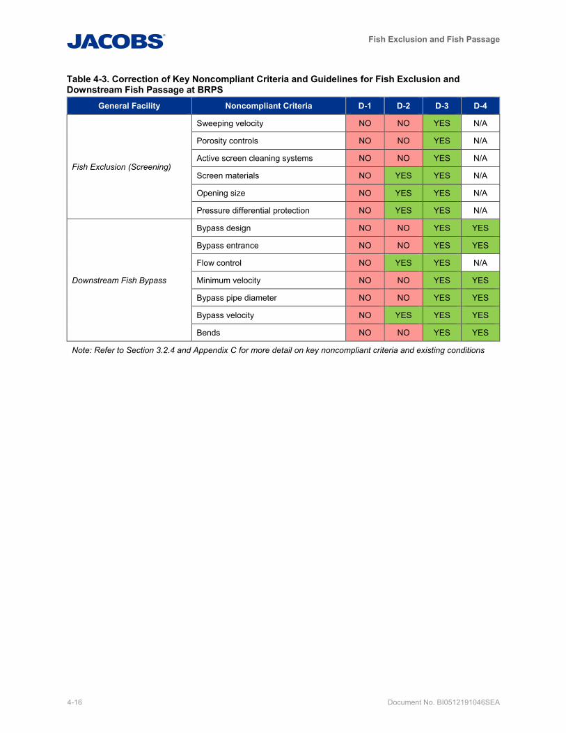
Fish Exclusion and Fish Passage
4-16 Document No. BI0512191046SEA
Table 4-3. Correction of Key Noncompliant Criteria and Guidelines for Fish Exclusion and Downstream Fish Passage at BRPS
General Facility Noncompliant Criteria D-1 D-2 D-3 D-4
Fish Exclusion (Screening)
Sweeping velocity NO NO YES N/A
Porosity controls NO NO YES N/A
Active screen cleaning systems NO NO YES N/A
Screen materials NO YES YES N/A
Opening size NO YES YES N/A
Pressure differential protection NO YES YES N/A
Downstream Fish Bypass
Bypass design NO NO YES YES
Bypass entrance NO NO YES YES
Flow control NO YES YES N/A
Minimum velocity NO NO YES YES
Bypass pipe diameter NO NO YES YES
Bypass velocity NO YES YES YES
Bends NO NO YES YES
Note: Refer to Section 3.2.4 and Appendix C for more detail on key noncompliant criteria and existing conditions
Fish Exclusion and Fish Passage
Document No. BI0512191046SEA 5-1
5. Upstream Fish Passage Concepts Four potential concepts were developed at a preliminary level for improvement of upstream fish passage at the BRPS:
• Concept U-1: Status Quo Repair of Existing Upstream Fish Passage Facility • Concept U-2: Modifications to Existing Upstream Fish Passage Facility • Concept U-3: Vertical Slot Fishway • Concept D-4/U-4: Baffled Channel with Operational Modifications (see description in Section 4.4 for
full evaluation)
Preliminary concept development including description and high-level evaluation is provided in this section. The objective is to identify concepts with the greatest potential for meeting project goals of improved upstream fish passage, maintenance of the ability to meet flood management objectives and, to the extent possible, meeting tribal and stakeholder interests and regulatory requirements.
Following a Fish Passage Workshop with King County staff on March 12, 2019, and subsequent conference call on March 21, 2019, two upstream fish passage concepts were selected for more detailed development and evaluation, and generation of capital cost estimates (U-2 and D-4/U-4). Selection for detailed concept development was based on preliminary potential for meeting the project goals discussed above. Concepts deemed most likely to meet project goals were selected; however, all concepts, including U-1 and U-3, remain as potential options for implementation pending stakeholder engagement and continued future design and evaluation.
Note that Concept D-4/U-4, the baffled channel, is also presented as a downstream concept because it provides dual benefit for both upstream and downstream passage.
Capital construction cost estimates for the “Status Quo” concept and concepts selected for detailed development are summarized in Section 7 while full estimates are provided in Appendix D.
5.1 Concept U-1: Status Quo Repair of Existing Upstream Fish Passage Facility
5.1.1 Preliminary Concept Development
This Concept U-1 assumes that select facility components would be replaced to restore the upstream passage system to original design conditions, and that some minor revisions to O&M practices could be implemented. However, no substantial changes to the design or upgrades in technologies would be pursued. This represents a low capital cost concept, with the potential to result in relatively small decreases in O&M costs due to restored function of some currently deficient systems.
This concept does not address the objective of improving fish passage as part of the broader objective to avoid or minimize environmental impacts of the pump station. In addition, it does not meet current regulatory agency design criteria and guidelines, or address concerns raised by stakeholders.
Specific work elements included within this concept are identified alongside those for Concept U-2 in Table 5-1 in the following section.
5.2 Concept U-2: Modifications to Existing Upstream Fish Passage Facility
5.2.1 Preliminary Concept Development
Several key components of the existing upstream fish passage system could be upgraded or modified, along with operational modifications, to improve operations and better align with current design criteria.
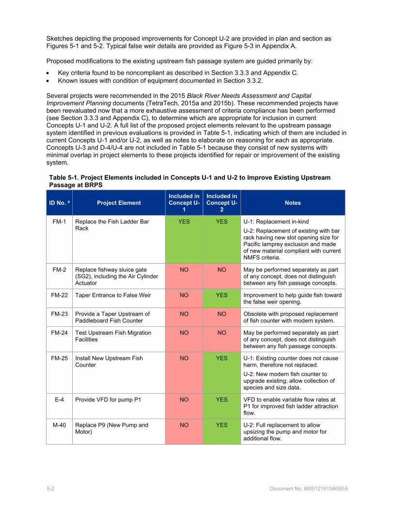
5-2 Document No. BI0512191046SEA
Sketches depicting the proposed improvements for Concept U-2 are provided in plan and section as Figures 5-1 and 5-2. Typical false weir details are provided as Figure 5-3 in Appendix A.
Proposed modifications to the existing upstream fish passage system are guided primarily by:
• Key criteria found to be noncompliant as described in Section 3.3.3 and Appendix C. • Known issues with condition of equipment documented in Section 3.3.2.
Several projects were recommended in the 2015 Black River Needs Assessment and Capital Improvement Planning documents (TetraTech, 2015a and 2015b). These recommended projects have been reevaluated now that a more exhaustive assessment of criteria compliance has been performed (see Section 3.3.3 and Appendix C), to determine which are appropriate for inclusion in current Concepts U-1 and U-2. A full list of the proposed project elements relevant to the upstream passage system identified in previous evaluations is provided in Table 5-1, indicating which of them are included in current Concepts U-1 and/or U-2, as well as notes to elaborate on reasoning for each as appropriate. Concepts U-3 and D-4/U-4 are not included in Table 5-1 because they consist of new systems with minimal overlap in project elements to these projects identified for repair or improvement of the existing system.
Table 5-1. Project Elements included in Concepts U-1 and U-2 to Improve Existing Upstream Passage at BRPS
ID No. a Project Element Included in Concept U-
1
Included in Concept U-
2 Notes
FM-1 Replace the Fish Ladder Bar Rack
YES YES U-1: Replacement in-kind U-2: Replacement of existing with bar rack having new slot opening size for Pacific lamprey exclusion and made of new material compliant with current NMFS criteria.
FM-2 Replace fishway sluice gate (SG2), including the Air Cylinder Actuator
NO NO May be performed separately as part of any concept, does not distinguish between any fish passage concepts.
FM-22 Taper Entrance to False Weir NO YES Improvement to help guide fish toward the false weir opening.
FM-23 Provide a Taper Upstream of Paddleboard Fish Counter
NO NO Obsolete with proposed replacement of fish counter with modern system.
FM-24 Test Upstream Fish Migration Facilities
NO NO May be performed separately as part of any concept, does not distinguish between any fish passage concepts.
FM-25 Install New Upstream Fish Counter
NO YES U-1: Existing counter does not cause harm, therefore not replaced. U-2: New modern fish counter to upgrade existing; allow collection of species and size data.
E-4 Provide VFD for pump P1 NO YES VFD to enable variable flow rates at P1 for improved fish ladder attraction flow.
M-40 Replace P9 (New Pump and Motor)
NO YES U-2: Full replacement to allow upsizing the pump and motor for additional flow.
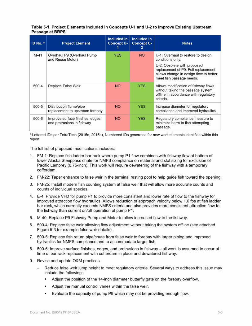
Document No. BI0512191046SEA 5-3
Table 5-1. Project Elements included in Concepts U-1 and U-2 to Improve Existing Upstream Passage at BRPS
ID No. a Project Element Included in Concept U-
1
Included in Concept U-
2 Notes
M-41 Overhaul P9 (Overhaul Pump and Reuse Motor)
YES NO U-1: Overhaul to restore to design conditions only. U-2: Obsolete with proposed replacement of P9. Full replacement allows change in design flow to better meet fish passage needs.
500-4 Replace False Weir NO YES Allows modification of fishway flows without taking the passage system offline in accordance with regulatory criteria.
500-5 Distribution flume/pipe replacement to upstream forebay
NO YES Increase diameter for regulatory compliance and improved hydraulics.
500-6 Improve surface finishes, edges, and protrusions in fishway
NO YES Regulatory compliance measure to minimize harm to fish attempting passage.
a Lettered IDs per TetraTech (2015a, 2015b), Numbered IDs generated for new work elements identified within this report
The full list of proposed modifications includes:
1. FM-1: Replace fish ladder bar rack where pump P1 flow combines with fishway flow at bottom of lower Alaska Steeppass chute for NMFS compliance on material and slot sizing for exclusion of Pacific Lamprey (0.75-inch). This work will require dewatering of the fishway with a temporary cofferdam.
2. FM-22: Taper entrance to false weir in the terminal resting pool to help guide fish toward the opening.
3. FM-25: Install modern fish counting system at false weir that will allow more accurate counts and counts of individual species.
4. E-4: Provide VFD for pump P1 to provide more consistent and lower rate of flow to the fishway for improved attraction flow hydraulics. Allows reduction of approach velocity below 1.0 fps at fish ladder bar rack, which currently exceeds NMFS criteria and also provides more consistent attraction flow to the fishway than current on/off operation of pump P1.
5. M-40: Replace P9 Fishway Pump and Motor to allow increased flow to the fishway.
6. 500-4: Replace false weir allowing flow adjustment without taking the system offline (see attached Figure 5-3 for example false weir details).
7. 500-5: Replace fish return pipe/chute from false weir to forebay with larger piping and improved hydraulics for NMFS compliance and to accommodate larger fish.
8. 500-6: Improve surface finishes, edges, and protrusions in fishway – all work is assumed to occur at time of bar rack replacement with cofferdam in place and dewatered fishway.
9. Revise and update O&M practices.
– Reduce false weir jump height to meet regulatory criteria. Several ways to address this issue may include the following: Adjust the position of the 14-inch diameter butterfly gate on the forebay overflow.
Adjust the manual control vanes within the false weir.
Evaluate the capacity of pump P9 which may not be providing enough flow.
5-4 Document No. BI0512191046SEA
Evaluate the size of the opening associated with fishway sluice gate (SG2) located in the upper pool.
Many attributes of the existing facility can be improved to provide better upstream fish passage; however, several noncompliant criteria would not be addressed unless more substantial retrofit improvements are undertaken. The primary NMFS criterion that would not be addressed through implementation of Concept U-2 is that Alaska steeppass fishways are not to be used for permanent fish passage operations. NMFS cites the tendency to collect debris and limited operating range, with large increases in passage time and decreases in fish entering the fishway with raised tailwater conditions backwatering the chute (NMFS, 2018). Continued use for permanent fish passage would require a variance from NMFS.
Capital construction costs and O&M costs of Concept U-2 are both low relative to other concepts; this concept would be the easiest and fastest to implement aside from no action.
The false weir jump height was measured in the field to be approximately 18 inches, which may exclude some fish species.
5.2.2 Detailed Concept Development
A detailed list of items that would be incorporated with Concept U-2 is provided herein. A scope of work with more detailed information for each project element is provided within the basis of estimate in Appendix D.
• Replace fish ladder bar rack diffuser with 0.75-inch spacing for Pacific lamprey exclusion.
• Taper entrance to false weir to guide fish towards opening.
• Install modern fish counting system (see Appendix E manufacturer data for VAKI Riverwatcher).
• Replace P9 Fishway Pump and Motor.
• Replace false weir allowing flow adjustment without taking the system offline (see attached Figure 5-3 for example false weir details).
– Padding to be added to the edges to prevent injury resulting from inaccurate leaps towards the sides of the false weir.
• Replace fish return pipe/chute.
– 18-inch polyvinyl chloride pipe and open chute as appropriate to replace existing 13-inch pipe and chute which are not compliant with NMFS sizing criteria. Adjust route to improve hydraulics and ensure sufficient water depth is maintained in pipe throughout length.
• Improve surface finishes, edges, and protrusions in fishway.
– Grind smooth metal edges in the flow path. – Concrete surface finish and corner chamfers. – Remove protrusions in flow path (for example, bolt, structural supports).
• Provide VFD for pump P1.
• Revise and update O&M practices in accordance with new equipment.
A VFD unit for pump P1 has been identified to allow turndown of flow. The ability to pump below the full capacity of P1 would provide better ability to match actual inflow to BRPS and reduce cycling of P1. This more steady and consistent attraction flow to the fish ladder is desirable for fish passage operations and would improve compliance with NMFS criteria for attraction flows. Additionally, as documented in hydraulic calculations for the fish ladder bar rack in Appendix B, existing approach velocities at the fish ladder bar rack exceed NMFS criteria at the full capacity of P1, with lower flow rates needed during low tailwater WSEL conditions for NMFS compliance.
Document No. BI0512191046SEA 5-5
5.3 Concept U-3: Vertical Slot Fishway with False Weir
5.3.1 Preliminary Concept Development
A vertical slot fishway could be constructed along the southern shoreline of the Black River, in approximately the same location as the existing fishway. Vertical slot fishways provide good fish passage, can be designed to meet agency fish criteria, and have good precedence in the region for providing effective passage. A vertical slot ladder can be designed to accommodate a wide range of species, including weaker-swimming fish, and is also good at managing variable heads and can accommodate high variability in the tailwater with an AWS system. A proposed vertical slot fishway is presented in plan view on Figure 5-4, with typical pool plan and section provided as Figure 5-5.
The fishway would utilize 18 pools, with typical pool sizes of 8-foot width by 10-foot length. The fishway would have an overall slope of 7.5 percent and 9-inch drops per pool. This reduced elevation drop per pool relative to typical 12-inch drops for stronger swimming salmonids would provide better passage for weaker swimming fish or Pacific lamprey, which are present. The existing fishway entrance location is proposed to be maintained, along with maintaining existing retaining wall 6A (per USDA SCS, 1969), which separates the fishway from the discharge of the flood control pumps. Upgrades similar to those presented in Concept U-2 for replacement of the false weir, fish counter, and fish chute to the forebay would be made. In addition, improvements to attraction flow hydraulics would be beneficial to pursue alongside the new vertical slot fishway.
The flow requirement of this fishway is approximately 30 cfs, which would require replacement of pump P9, the fishway pump, which currently has a capacity of 8 cfs. This raises concern for the viability of a vertical slot fishway given that total inflow to the pump station is estimated to be below 30 cfs for much of the year. As shown in Section 2.2, and Figures 2-1 and 2-2, the 95 percent exceedance inflow to BRPS is approximately 2.7 to 6.1 cfs throughout the entire year. The 5 percent exceedance inflow to BRPS is estimated to be below 30 cfs for roughly 5 months of the year, from April through mid-September, indicating that even during months which typically have high flow rates, the facility may not be able to operate consistently. This presents issues with typical requirements for operation within the range of 5 percent to 95 percent streamflow exceedance. Tailwater pumping with a new screened intake would likely be needed to provide adequate, consistent flow for the vertical slot fishway, adding considerable cost and complexity to this concept. This concept would have high capital construction costs and high O&M costs.
5.4 Concept D-4/U-4: Baffled Channel with Operational Modifications
A baffled channel bypassing the pump station along the north side could be constructed to allow volitional fish passage in both the upstream and downstream direction. For full evaluation of this concept, see Concept D-4/U-4, Section 4.4 under Downstream Fish Passage Concepts.
5.5 Summary
Table 5-2 summarizes the advantages and disadvantages of the upstream fish passage concepts. Table 5-3 documents the key noncompliant criteria previously established in Section 3.3.3 and notes whether each concept is anticipated to correct each condition.
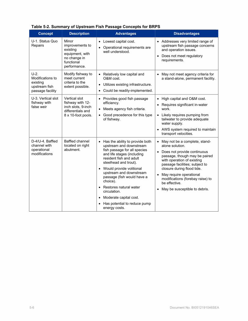
5-6 Document No. BI0512191046SEA
Table 5-2. Summary of Upstream Fish Passage Concepts for BRPS Concept Description Advantages Disadvantages
U-1. Status Quo Repairs
Minor improvements to existing equipment, with no change in functional performance.
• Lowest capital cost. • Operational requirements are
well understood.
• Addresses very limited range of upstream fish passage concerns and operation issues.
• Does not meet regulatory requirements.
U-2. Modifications to existing upstream fish passage facility
Modify fishway to meet current criteria to the extent possible.
• Relatively low capital and O&M cost.
• Utilizes existing infrastructure. • Could be readily-implemented.
• May not meet agency criteria for a stand-alone, permanent facility.
U-3. Vertical slot fishway with false weir
Vertical slot fishway with 12-inch slots, 9-inch differentials and 8 x 10-foot pools.
• Provides good fish passage efficiency.
• Meets agency fish criteria. • Good precedence for this type
of fishway.
• High capital and O&M cost. • Requires significant in-water
work. • Likely requires pumping from
tailwater to provide adequate water supply.
• AWS system required to maintain transport velocities.
D-4/U-4. Baffled channel with operational modifications
Baffled channel located on right abutment.
• Has the ability to provide both upstream and downstream fish passage for all species and life stages (including resident fish and adult steelhead and trout).
• Would provide volitional upstream and downstream passage (fish would have a choice).
• Restores natural water circulation.
• Moderate capital cost. • Has potential to reduce pump
energy costs.
• May not be a complete, stand-alone solution.
• Does not provide continuous passage, though may be paired with operation of existing passage facilities; subject to closure during flood tide.
• May require operational modifications (forebay raise) to be effective.
• May be susceptible to debris.
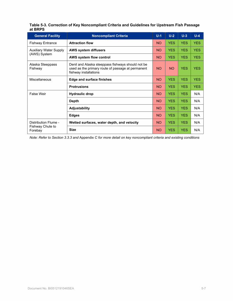
Document No. BI0512191046SEA 5-7
Table 5-3. Correction of Key Noncompliant Criteria and Guidelines for Upstream Fish Passage at BRPS
General Facility Noncompliant Criteria U-1 U-2 U-3 U-4
Fishway Entrance Attraction flow NO YES YES YES
Auxiliary Water Supply (AWS) System
AWS system diffusers NO YES YES YES
AWS system flow control NO YES YES YES
Alaska Steeppass Fishway
Denil and Alaska steeppass fishways should not be used as the primary route of passage at permanent fishway installations
NO NO YES YES
Miscellaneous Edge and surface finishes NO YES YES YES
Protrusions NO YES YES YES
False Weir Hydraulic drop NO YES YES N/A
Depth NO YES YES N/A
Adjustability NO YES YES N/A
Edges NO YES YES N/A
Distribution Flume - Fishway Chute to Forebay
Wetted surfaces, water depth, and velocity NO YES YES N/A
Size NO YES YES N/A
Note: Refer to Section 3.3.3 and Appendix C for more detail on key noncompliant criteria and existing conditions

Document No. BI0512191046SEA 6-1
6. Permitting and Construction Considerations 6.1 Permitting Considerations
King County will acquire all necessary permits per the regulations described in Section 1.3 and Appendix A. The applicable permits, regulatory triggers, and anticipated timelines for approvals upon application for them are listed in Table 6-1. Timelines may vary depending on project concepts selected and final project design. The County will comply with all applicable permit conditions, including use of a variety of best management practices (BMPs) during construction for water quality protection and other environmental protection needs. In-water work will occur within the standard in-water work window (typically July 1 – August 15, but subject to regulatory agency confirmation). Construction activities will minimize impacts to the environment by avoiding and minimizing impacts to critical areas, protecting water quality, and restoring temporary work areas.
King County completed a cultural resources analysis for the BRPS Sediment Removal Project in 2014. The area covered for that project likely encompasses all areas that would be included for fish passage improvements, and additional cultural resources review is not warranted. The nearest aquatic lands managed by the King County Department of Natural Resources and Parks are approximately 600 feet downstream of the pump station, so fish passage improvement activities are not likely to trigger an Aquatic Use Authorization.
Design of the fish passage improvements will be integrated with local salmonid recovery and habitat enhancement plans. Modifying the BRPS to improve fish passage was identified in the WRIA 9 Salmon Habitat Plan as a key salmon habitat need in the Lower Green River Watershed (Green/Duwamish and Central Puget Sound WRIA 9 Steering Committee 2005).
Great blue herons (Ardea herodias) have been documented nesting in the Black River Riparian Forest and Wetland (Suzanne Krom, Herons Forever, email to George Ritchotte on June 26, 2019). Construction has the potential to disturb any nesting birds, disrupting foraging or nesting behavior. King County will develop BMPs to minimize impacts to nesting herons if active nests are present during construction. BMPs may include timing restrictions to avoid disturbance during the nesting season, or limiting noise generated during construction.
6.2 Construction Considerations
Construction considerations will vary by concept but will probably include the following key items:
• Phasing and coordination of fish exclusion/passage modifications with other required BRPS upgrades (seismic retrofits and pump replacements).
• Scheduling of in-water work to avoid fish migration and periods of high streamflow.
• Minimizing excavation in areas that could potentially contain culturally-sensitive artifacts.
• Provision of a design that can be safely constructed and is safe to operate once the facility has been commissioned.
• Provision of features to facilitate post-construction hydraulic and biological testing, monitoring, and evaluation.
• Ensuring some BRPS pumping functionality during construction, either with existing pumps and/or temporary portable pumps
• Isolation, fish removal and de-watering of in-water work areas.
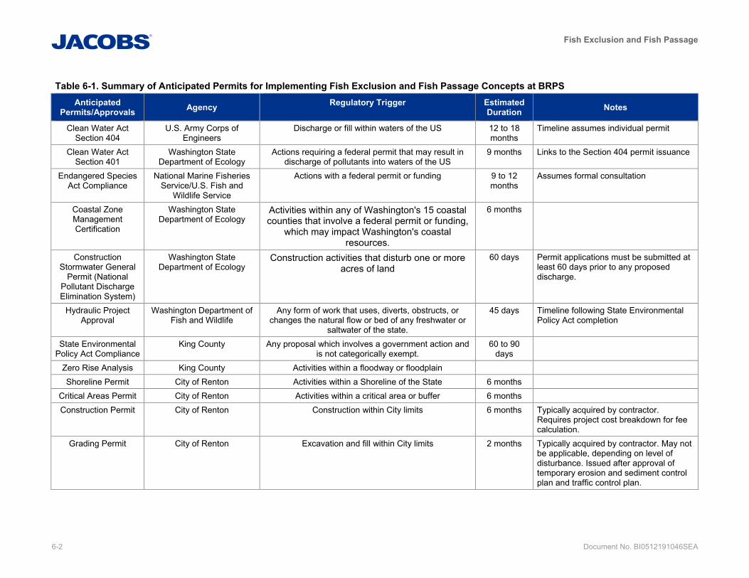
Fish Exclusion and Fish Passage
6-2 Document No. BI0512191046SEA
Table 6-1. Summary of Anticipated Permits for Implementing Fish Exclusion and Fish Passage Concepts at BRPS Anticipated
Permits/Approvals Agency Regulatory Trigger Estimated Duration Notes
Clean Water Act Section 404
U.S. Army Corps of Engineers
Discharge or fill within waters of the US 12 to 18 months
Timeline assumes individual permit
Clean Water Act Section 401
Washington State Department of Ecology
Actions requiring a federal permit that may result in discharge of pollutants into waters of the US
9 months Links to the Section 404 permit issuance
Endangered Species Act Compliance
National Marine Fisheries Service/U.S. Fish and
Wildlife Service
Actions with a federal permit or funding 9 to 12 months
Assumes formal consultation
Coastal Zone Management Certification
Washington State Department of Ecology
Activities within any of Washington's 15 coastal counties that involve a federal permit or funding,
which may impact Washington's coastal resources.
6 months
Construction Stormwater General
Permit (National Pollutant Discharge Elimination System)
Washington State Department of Ecology
Construction activities that disturb one or more acres of land
60 days Permit applications must be submitted at least 60 days prior to any proposed discharge.
Hydraulic Project Approval
Washington Department of Fish and Wildlife
Any form of work that uses, diverts, obstructs, or changes the natural flow or bed of any freshwater or
saltwater of the state.
45 days Timeline following State Environmental Policy Act completion
State Environmental Policy Act Compliance
King County Any proposal which involves a government action and is not categorically exempt.
60 to 90 days
Zero Rise Analysis King County Activities within a floodway or floodplain Shoreline Permit City of Renton Activities within a Shoreline of the State 6 months
Critical Areas Permit City of Renton Activities within a critical area or buffer 6 months Construction Permit City of Renton Construction within City limits 6 months Typically acquired by contractor.
Requires project cost breakdown for fee calculation.
Grading Permit City of Renton Excavation and fill within City limits 2 months Typically acquired by contractor. May not be applicable, depending on level of disturbance. Issued after approval of temporary erosion and sediment control plan and traffic control plan.
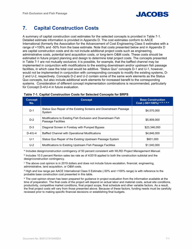
Fish Exclusion and Fish Passage
Document No. BI0512191046SEA 7-1
7. Capital Construction Costs A summary of capital construction cost estimates for the selected concepts is provided in Table 7-1. Detailed estimate information is provided in Appendix D. The cost estimates conform to AACE International (formerly the Association for the Advancement of Cost Engineering Class 5 estimates with a range of +100% and -50% from the base estimate. Note that costs presented below and in Appendix D are capital construction costs and do not include additional project costs such as engineering, administrative costs, potential land acquisition costs, or long-term O&M costs. These costs should be estimated in future project planning and design to determine total project costs. The concepts presented in Table 7-1 are not mutually exclusive; it is possible, for example, that the baffled channel may be implemented in conjunction with modifications to the existing downstream and/or upstream fish passage facilities, in which case the total cost would be additive. “Status Quo” concepts D-1 and U-1, however, would not be implemented in conjunction with corresponding concepts to modify the existing systems, D-2 and U-2, respectively. Concepts D-2 and U-2 contain some of the same work elements as the Status Quo concepts, but also include additional work elements for increased benefit to the corresponding systems. Consideration of different concept implementation combinations is recommended, particularly for Concept D-4/U-4 in future evaluation.
Table 7-1. Capital Construction Costs for Selected Concepts for BRPS Concept
No. Concept Base Construction
Cost (-50/+100%) a, b, c, d, e
D-1 Status Quo Repair of the Existing Screens and Downstream Passage System $4,570,000
D-2 Modifications to Existing Fish Exclusion and Downstream Fish Passage Facilities $5,909,000
D-3 Diagonal Screen in Forebay with Pumped Bypass $23,346,000
D-4/U-4 Baffled Channel with Operational Modifications $4,846,000
U-1 Status Quo Repair of the Existing Upstream Passage System $601,000
U-2 Modifications to Existing Upstream Fish Passage Facilities $1,540,000
a Includes design/construction contingency of 50 percent consistent with WLRD Project Management Manual. b Includes 10.0 percent Renton sales tax rate as of 4/2018 applied to both the construction subtotal and the design/construction contingency. c The above cost opinion is in 2019 dollars and does not include future escalation, financial, engineering, administrative, land acquisition, or O&M costs. d High and low range per AACE International Class 5 Estimate (-50% and +100% range) is with reference to the probable base construction cost presented in this table. e The cost opinion shown has been prepared for guidance in project evaluation from the information available at the time of preparation. The final costs of the project will depend on actual labor and material costs, actual site conditions, productivity, competitive market conditions, final project scope, final schedule and other variable factors. As a result, the final project costs will vary from those presented above. Because of these factors, funding needs must be carefully reviewed prior to making specific financial decisions or establishing final budgets.

Fish Exclusion and Fish Passage
Document No. BI0512191046SEA 8-1
8. Summary The existing fish passage systems were state-of-the-art facilities when installed but no longer meet current fish passage criteria or guidelines. Seven preliminary concepts were evaluated for improved fish exclusion and fish passage at BRPS. Following a workshop with King County staff in March 2019, the following four concepts were selected for further consideration:
• D-2 Modifications to Existing Fish Exclusion and Downstream Fish Passage Facilities • D-3 Diagonal Screen in Forebay with Pumped Bypass • U-2 Modifications to Existing Upstream Fish Passage Facility • D-4/U-4 Baffled Channel with Operational Modifications
Concepts D-2 and U-2 would modify the existing fish passage facilities, with moderate capital and O&M costs, enhance its performance. These modifications include replacing the airlift system with fish-friendly screw centrifugal pumps for D-2 and making changes to the steeppass attraction water system for U-2.
Concept D-3 could provide high FPEs, with high capital and O&M costs. This concept requires constructing a large in-water structure. Neither D-2 or D-3 would reasonably pass adult steelhead or cutthroat trout.
Concept D-4/U-4 could provide both upstream and downstream volitional passage with moderate capital and low O&M costs. An increase in the normal forebay operating WSEL would further enhance fish passage with an associated reduction in pump energy consumption. However, D-4/U-4 would only function a certain percentage of time, depending on the design maximum forebay WSEL; therefore, additional downstream passage via implementation of D-2 or D-3 and/or additional upstream passage via U-2 or U-3 may also be required.
8.1 Recommended Next Steps A variety of opportunities exist to enhance fish exclusion and fish passage at the BRPS. Obtaining the input of the Tribes and stakeholders, as well as addressing critical data gaps, will be key to the overall project success. Potential early actions can also be taken to enhance existing fish passage and facilitate implementation of the selected concepts. Following input from Tribes and stakeholders, some or all the concepts presented herein will be refined and further developed to guide the evaluation of alternatives. The comprehensive technical solution may consist of one or more of the proposed concepts and additional evaluation is required to confirm feasibility.
Any proposed fish passage solutions must be approved by the King County Flood Control District and includes adhering to the goals of the 2006 King County Flood Hazard Management Plan (King County, 2007). The tribes and external stakeholders must also be engaged to obtain their input. A collaborative approach will be beneficial and may facilitate identifying additional resources for addressing data gaps and/or obtaining required design data.
8.1.1 Address Critical Data Gaps
Critical data gaps include the following:
• Condition of the downstream fish passage facility conveyance piping is unknown and difficult to access.
• Understanding is limited about how various Black River streamflows and BRPS forebay WSELs affect upstream locations including Springbrook Creek at I-405.
• Fish count data to accurately characterize fish abundance, species, life stages and run timing for use in defining the baseline condition is lacking.
These data gaps can be addressed through the Early Action recommendations that follow.
Fish Exclusion and Fish Passage
8-2 Document No. BI0512191046SEA
8.1.2 Potential Early Actions
Potential early actions may include the following:
• Coordinating and collaborating with tribes and key stakeholders
• Minor equipment repairs and revisions to current O&M practices to enhance fish passage in the near-term, including replacement of the airlift system control valve and adjustment of the false weir water supply.
• Video inspection of the downstream fish passage facility conveyance piping.
• Field measurement and confirmation of the existing Springbrook Creek stream gage rating curve at Grady Way.
• Installation of a continuous stage recorder in Springbrook Creek at I-405.
• Installation of modern fish counting equipment (both downstream and upstream).
• Test existing passage systems for establishment of baseline passage efficiency and fish injury/mortality after passing through the systems (both upstream and downstream).
Obtaining input from the tribes and stakeholders, as well as addressing critical data gaps will be key to the overall success of the project. As such, a collaborative approach will be beneficial and may facilitate the identification of additional resources for addressing data gaps and/or obtaining required design data. The comprehensive technical solution may consist of one or more of the concepts identified herein, and additional evaluation would be required to confirm feasibility.
Fish Exclusion and Fish Passage
Document No. BI0512191046SEA 9-1
9. References Alaska Department of Fish and Game (ADFG). 1962. Informational Leaflet No. 12, Steeppass Fishway Development. http://www.sf.adfg.state.ak.us/fedaidpdfs/afrbIL.012.pdf. Prepared by G.L. Ziemer. Accessed March 11, 2019. Published April 27, 1962.
Bean, Tom. 2019a. “RE: BRPS Skype Meeting to review/discuss County comments on Draft Structural Performance TM.” Message to Wally Bennett and Nason McCullough. January 31. E-mail.
Bean, Tom. 2019b. “RE: BRPS PI History” Message to Hans Ehlert. March 29. E-mail.
Bean, Tom. 2019c. “RE: BRPS PI History” Message to Hans Ehlert. April 8. E-mail.
Burgner, R.L. 1991. Life history of sockeye salmon (Oncorhynchus nerka). Pages 1-118 in C. Groot and L. Margolis (editors) Pacific Salmon Life Histories. University of British Columbia Press, Vancouver, B.C.
Busby, P.J., T.C. Wainwright, G.J. Bryant, L.J. Lierheimer, R.S. Waples, F.W. Waknitz, and I.V. Lagomarsino. 1996. Status Review of West Coast Steelhead from Washington, Idaho, Oregon, and California. U.S. Department of Commerce, National Marine Fisheries Service. August 1996.
Carter, K. 2005. The Effects of Dissolved Oxygen on Steelhead Trout, Coho Salmon, and Chinook Salmon Biology and Function by Life Stage. California Regional Water Quality Control Board. <https://www.waterboards.ca.gov/northcoast/water_issues/programs/tmdls/shasta_river/060707/29appendixbetheeffectsofdissolvedoxygenonsteelheadtroutcohosalmonandchinooksalmonbiologyandfunction.pdf>
Cavender, T.M. 1978. Taxonomy and distribution of the bull trout, Salvelinus confluentus, from the American Northwest. California Fish and Game 64:139-174.
Ecology. 2002. Evaluating Criteria for the Protection of Aquatic Life in Washington’s Surface Water Quality Standards: Dissolved Oxygen. Draft discussion paper and literature summary. Washington State Department of Ecology, Olympia, Washington.
Federal Emergency Management Agency (FEMA). 2005. Flood Insurance Study, King County Washington and Incorporated Areas. Effective. Flood Insurance Study Number 53033CV001A. Revised 19 April 2005.
Federal Emergency Management Agency (FEMA). 2017. Flood Insurance Study, King County Washington and Incorporated Areas. Preliminary. Flood Insurance Study Number 53033CV001B. Eighth Revision, effective date to be determined. 15 September.
Fender, Daniel C. 1979. Preliminary Evaluation of the Black River Juvenile Fish Bypass System. Cooperative Study (WDFW, USFWS, Young Adult Conservation Corps). September.
Green River Basin Program (GRBP). 1985. Green River Management Agreement. Sponsors: King County, City of Auburn, City of Kent, City of Renton, City of Tukwila. July 18.
Green River Basin Program (GRBP). 1986. Final Green River Pump Operations Procedures Plan. Sponsors: King County, City of Auburn, City of Kent, City of Renton, City of Tukwila. May 13.
Green River Basin Program (GRBP). 1992. Green River Basin Program Interlocal Agreement. Sponsors: King County, City of Auburn, City of Kent, City of Renton, City of Tukwila. June 30.
Harza Engineering Company (Harza). 1995. Comprehensive Fisheries Assessment of the Springbrook, Mill and Garrison Creek Watershed for the City of Kent. Prepared for City of Kent, Environmental Engineering. June.
9-2 Document No. BI0512191046SEA
Heard, W.R. 1991. Life history of pink salmon (Oncorhynchus gorbuscha). Pages 119-230 in C. Groot and L. Margolis (editors) Pacific Salmon Life Histories. University of British Columbia Press, Vancouver, B.C.
Jacobs. 2019. Subtask 600.1 Capital Project Strategy Alternatives and Evaluation Criteria Technical Memorandum (Version 4). Prepared for King County Water and Land Resources Division by Jacobs Engineering Group Inc. December 20.
Jeanes, E.D., and P.J. Hilgert. 2001. Juvenile Salmonid Use of Lateral Stream Habitats Middle Green River, Washington. 2000 Data Report. Prepared for U.S. Army Corps of Engineers, Seattle District. July 19.
Kerwin, J. and T.S. Nelson. 2000. Habitat Limiting Factors and Reconnaissance Assessment Report, Green/Duwamish and Central Puget Sound Watersheds (WRIA 9 and Vashon Island). Washington Conservation Commission and the King County Department of Natural Resources and Parks. Available online at http://www.govlink.org/watersheds/9/reports/Recon.aspx.
King County. 2000a. Habitat Limiting Factors and Reconnaissance Assessment Report. Green/Duwamish and Central Puget Sound Watersheds (Water Resource Inventory Area 9 and Vashon Island). December, 2000. https://www.govlink.org/watersheds/9/reports/Recon.aspx. Accessed July 10, 2019.
King County. 2000b. Literature Review and Recommended Sampling Protocol for Bull Trout in King County. King County Department of Natural Resources and Parks, Seattle, Washington. May.
King County. 2007. 2006 King County Flood Hazard Management Plan. King County Department of Natural Resources and Parks, Water and Land Resources Division. Final Plan. January 2007. https://www.kingcounty.gov/depts/dnrp/wlr/sections-programs/river-floodplain-section/documents/flood-hazard-management-plan.aspx
King County. 2008. King County Environmental Lab Matrix Report #12983, Project 421195.
King County. 2010a. Black River Pump Station Sediment Dewatering Water & Sediment, collected on April 30, May 6, and June 4. King County Department of Natural Resources and Parks, Water and Land Resources Division, Environmental Laboratory.
King County. 2010b. Black River Pump Station Sediment Collection & Hanging Bag Test on April 29 (Memorandum by Erik Peters) and May 4. King County Department of Natural Resources and Parks, Water and Land Resources Division, River and Floodplain management Section, Seattle, WA.
King County. 2011. Black River Pumping Station Operations Manual 90% Draft. Department of Natural Resources and Parks, Wastewater Treatment Division. Dated December 2007, Change Package November.
King County. 2013. 2013 King County Flood Hazard Management Plan Update and Progress Report, An Amendment to the 2006 Flood Hazard Management Plan for the Community Rating System. King County Department of Natural Resources and Parks, Water and Land Resources Division. Final Plan. November 2013. https://www.kingcounty.gov/depts/dnrp/wlr/sections-programs/river-floodplain-section/documents/flood-hazard-management-plan-update.aspx
King County. 2015a. BRPS Summer Inflow Hydrology. Memorandum prepared by Tom Bean, Engineering Special Projects Lead, RFMS to Lorin Reinelt, Managing Engineer, RFMS. July 23.
King County. 2015b. BRPS Fish Passage Counts 2015. Scan of raw data collection sheets provided by King County.
King County. 2017. A synthesis of changes in our knowledge of Chinook salmon productivity and habitat uses in WRIA 9 (2004 – 2016). https://www.govlink.org/watersheds/9/pdf/technical-white-papers/WRIA9-salmonid-use-update-FINAL_11_6_2017.pdf. Accessed February 18, 2019.
Fish Exclusion and Fish Passage
Document No. BI0512191046SEA 9-3
King County. 2018. Recent and Ongoing Work at Black River Pump Station. Letter prepared by Tom Bean, P.E., King County Department of Natural Resources and Parks, Water and Land Resources Division, Seattle, WA. May 18.
King County. 2019. 03G - Springbrook Creek at Grady Way. Hydrologic Information Center, Data Download. https://green2.kingcounty.gov/hydrology/DataDownload.aspx?G_ID=598&Parameter=Stream Flow. Accessed July 9, 2019.
King County. 2020. King County Stream Monitoring Data for Springbrook Creek (Site #0317). Accessed February 7, 2020. <http://green2.kingcounty.gov/StreamsData/DataDownload.aspx?Locator=0317>
Lee, G.F., E. Bentley, and R. Amundson. 1975. Effects of marshes on water quality. Coupling of Land and Water Systems. A.D. Hasler, editor. Springer-Verlag, New York, New York.
Myers, J.M., J.J. Hard, E.J. Connor, R.A. Hayman, R.G. Kope, G. Lucchetti, A.R. Marshall, G.R. Pess, and B.E. Thompson. 2015. Identifying historical populations of steelhead within the Puget Sound distinct population segment. U.S. Department of Commerce, National Oceanic and Atmospheric Association, Technical Memorandum, NMFS-NWFSC-128.
Myers, J.M., R.G. Kope, G.J. Bryant, D. Teel, L.J. Lierheimer, T.C. Wainwright, W.S. Grant, F.W. Waknitz, K., Neely, S.T. Lindley, and R.S. Waples. 1998. Status review of Chinook salmon from Washington, Idaho, Oregon, and California. U.S. Department of Commerce, Technical Memorandum, NMFS-NWFSC-35, 443 p.
National Marine Fisheries Service (NMFS). 2011. Anadromous Salmonid Passage Facility Design. NMFS, Northwest Region, Portland, Oregon.
National Marine Fisheries Service (NMFS). 2012. Status of Endangered Species Act listings and critical habitat designations for West Coast salmon and steelhead. Accessed online July 8, 2014 at http://www.westcoast.fisheries.noaa.gov/publications/protected_species/salmon_steelhead/status_of_esa_salmon_listings_and_ch_designations_map.pdf.
National Marine Fisheries Service (NMFS). 2018. NOAA Technical Memorandum NMFS-NWFSC-1xx, NOAA Fisheries West Coast Region Anadromous Salmonid Passage Design Guidelines. Peer Review Draft August 16.
Northwest Hydraulic Consultants (NHC). 1991. East Side Green River Watershed Hydrologic Analysis. June.
Northwest Hydraulic Consultants (NHC). 1992. Black River Pump Station Performance Test Technical Memorandum. March.
Northwest Hydraulic Consultants (NHC). 1994. Black River Pump Station Performance Tests on Pump P3 and P8. December.
Northwest Hydraulic Consultants (NHC). 1996. East Side Green River Watershed Hydrologic Analysis. March.
Northwest Hydraulic Consultants (NHC). 1998a. East Side Green River Watershed Gage Data Review. January.
Northwest Hydraulic Consultants (NHC). 1998b. Updated Storage Event Simulations for Springbrook Creek. March.
Northwest Hydraulic Consultants (NHC). 2005. Hydrologic Analysis for Springbrook Creek FEMA Mapping Study. March.
9-4 Document No. BI0512191046SEA
Northwest Hydraulic Consultants (NHC). 2010. Floodplain Mapping Study for Lower Green River Mile 3.85 to State Highway 18 (RM 33.25). March.
Pickett, P.J. 1994. Black River Dry Season Dissolved Oxygen and Phosphorus Total Maximum Daily Load Study. Washington State Department of Ecology, Waterbody No. WA-23-1015, Publication No. 94-106.
Rieman, B.E. and J.D. McIntyre. 1993. Demographic and habitat requirements for conservation of bull trout. U.S. Forest Service, Intermountain Research Station, Boise, Idaho. General Technical Report INT-302.
Salo, E.O. 1991. Life history of chum salmon (Oncorhynchus keta). Pages 231-310 in C. Groot and L. Margolis (editors) Pacific Salmon Life Histories. University of British Columbia Press, Vancouver, B.C.
Sandercock, F.K. 1991. Life history of coho salmon (Oncorhynchus kisutch). Pages 396-445 in C. Groot and L. Margolis (editors) Pacific Salmon Life Histories. University of British Columbia Press, Vancouver, B.C.
Stoner, J.D. 1972. Determination of Mass Balance and Entrainment in the Stratified Duwamish River Estuary, King County, Washington. Geological Survey Water-Supply Paper 1873-F. https://pubs.usgs.gov/wsp/1873f/report.pdf. Accessed April 29, 2019.
TetraTech. 2015a. Black River Needs Assessment and Capital Improvement Planning: Task 2 – Needs Assessment Technical Memorandum. Prepared by Tetra Tech. January.
TetraTech. 2015b. Black River Needs Assessment and Capital Improvement Planning: Task 4 – Migration Facility Review Technical Memorandum. Prepared by Tetra Tech and Chinook Engineering. March.
United States Army Corps of Engineers (USACE). 2014. Upper Springbrook Creek: Year Two Biological Monitoring. U.S. Army Corps of Engineers, Seattle District. Seattle, Washington.
United States Department of Agriculture Soil Conservation Service (USDA SCS).1969. East Side Green River Watershed Discharge Structure. Record Drawings. Drawing Set No 7-E-21187.
United States Fish and Wildlife Service (USFWS). 2015. U.S. Fish and Wildlife Service. Coastal Recovery Unit Implementation Plan for Bull Trout (Salvelinus confluentus). Lacey Washington and Portland, Oregon. 160 pages.
United States Fish and Wildlife Service (USFWS). 2019. Coastal Cutthroat Trout. U.S. Fish & Wildlife, Washington Fish and Wildlife Office. https://www.fws.gov/wafwo/articles.cfm?id=149489586. Accessed May 1, 2019.
Washington State Department of Ecology (Ecology). 2019. Washington State Water Quality Assessment: 303(d)/305(b) List. Accessed 2 May 2019. https://apps.ecology.wa.gov/ApprovedWQA/ApprovedSearch.aspx
Washington State Department of Fish and Wildlife (WDFW). 2012. Green River Juvenile Salmonid Production Evaluation: 2011 Annual Report. Available online at http://wdfw.wa.gov/publications/01417/wdfw01417.pdf.
Washington State Department of Fish and Wildlife (WDFW). 2016. Fish Passage and Diversion Screening Inventory Database. February 9. http://apps.wdfw.wa.gov/fishpassagephotos/Reports/09.0004%20%20%200.20_Report.pdf
Washington State Department of Fish and Wildlife (WDFW). 2019a. SalmonScape https://apps.wdfw.wa.gov/salmonscape/map.html. Accessed May 9, 2019.
Washington State Department of Fish and Wildlife (WDFW). 2019b. Fish passage web app https://geodataservices.wdfw.wa.gov/hp/fishpassage/index.html. Accessed May 9, 2019.
Fish Exclusion and Fish Passage
Document No. BI0512191046SEA 9-5
Washington State Department of Transportation (WSDOT). 2005. Black River Pump Station Pump Station Evaluation. November.
Washington State Legislature. 2015. WAC 220-660-200 Fish passage improvement structures. https://apps.leg.wa.gov/wac/default.aspx?cite=220-660-200. Accessed March 4, 2019.
Water Resource Inventory Area 9 (WRIA 9) Steering Committee. 2005. Green/Duwamish and Central Puget Sound Watershed Water Resource Inventory Area 9 (WRIA 9) Steering Committee. August 2005. Salmon Habitat Plan – Making Our Watershed Fit for a King. Prepared for the WRIA 9 Forum. https://www.govlink.org/watersheds/9/plan-implementation/WRIA9Salmon%20HabitatPlanFull.pdf. 1998a.
Green/Duwamish and Central Puget Sound Watershed Water Resource Inventory Area 9 (WRIA 9) Steering Committee. 2005. Salmon Habitat Plan – Making Our Watershed Fit for a King. Prepared for the WRIA 9 Forum. August.
Watershed Science & Engineering (WSE). 2019. 3/19/2019 Black River Pump Station Check-In Meeting Notes. Meeting between Jacobs and WSE, personal communication from Larry Karpack. March 19.


Figures


Black River Basin
Auburn
DesMoines
FederalWay
SeaTac
Tukwila
Kent
Renton
StarLakeOutlet
MillCreekN
EAuburn
Drain
Bing
amon
Creek
MasseyCreek
BlackRiver
Midw
ay
Creek
MiddleFork
MillCreek
WestFork
SoosetteCreek
MiddleFork
GarrisonCreek
GarrisonCreek
GilliamCreek
Mill
Creek
Mullen
Slo
ugh
SoosetteCreek
Molasses
Creek
MeridianValleyCreek
Garrison
Creek
Benson
Fork
Garrison
Creek
CedarRiver
PantherCreek
BigSoosCreek
Sprin
gb
rookCreek
MillCreek
GreenRiver
SR 599
I-5
SR 518
I-405
SR 99
SR 167
I-5
I-405Exp
SR 167
\\SEAFPP01\PROJ\KINGCOUNTYDNR\D3164900BRPS\GIS\MAPS\WORKING\BRPS_FISH_PASSAGE.APRX SB058815 12/11/2019 5:54 PM
0 2,000 4,000
Feet
LEGEND
Study Area
Streams
Freeways
Stream Gages
BasinBoundaries* $
Figure 1-1. Vicinity MapBlack River Pump
Station Improvements
* "Basin boundaries derived from terraindata..." (King County GIS Open Data, 2006)
KC 03G - SpringbrookCreek at Grady Way
USGS 12113346Springbrook CreekUSGS 12113349
Mill Creek
Black RiverPump Station
Panther Lake
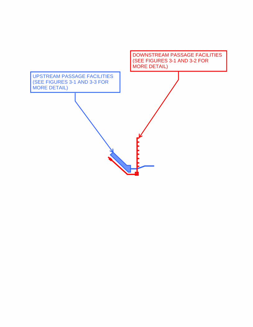
\\SEAFPP01\PROJ\KINGCOUNTYDNR\D3164900BRPS\GIS\MAPS\WORKING\BRPS_FISH_PASSAGE.APRX SB058815 7/10/2019 10:54 AM
0 50 100
Feet$Figure 1-2. Site Plan
Black River Pump StationImprovements
Monster Road
Black RiverForebayTailwater
&Flow
&Flow
DOWNSTREAM PASSAGE FACILITIES(SEE FIGURES 3-1 AND 3-2 FORMORE DETAIL)
UPSTREAM PASSAGE FACILITIES (SEE FIGURES 3-1 AND 3-3 FORMORE DETAIL)
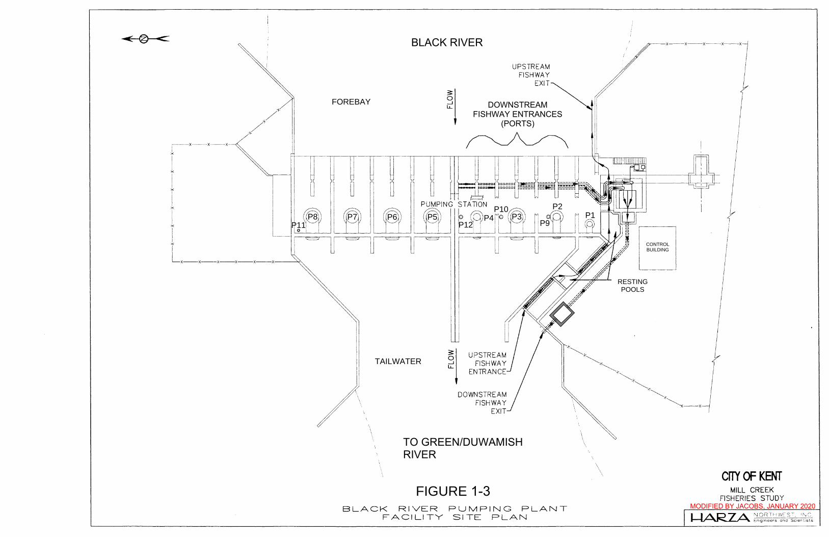
r--x--x--x
r i r i i X
LX--X--X--X--X--X'--~'
\
\ \
\ \
UPSTREAM FISHWAY
EXIT
DOWNSTREAM FISH PORTS
(ENTRANCE)
UPSTREAM FISHWAY
ENTRANCE
DOWNSTREAM FISHWAY
EXIT
Figure 6. BLACK RIVER PUMPING PLANT
FACILITY SITE PLAN
__,,.,.'--~_i..RESTING POOL
'
\
x--x--x--x--x
OPERATING BUILDING
CITY OF KENT MILL CREEK
FISHERIES STUDY
I I A 07 A NORTHWEST. INC. ~ Engineers and Scientists
FOREBAY
TAILWATER
FIGURE 1-3
P1P2
P9P3P4
P10P5P6P7P8
P12
CONTROLBUILDING
DOWNSTREAMFISHWAY ENTRANCES
(PORTS)
BLACK RIVER
TO GREEN/DUWAMISHRIVER
RESTINGPOOLS
MODIFIED BY JACOBS, JANUARY 2020
P11
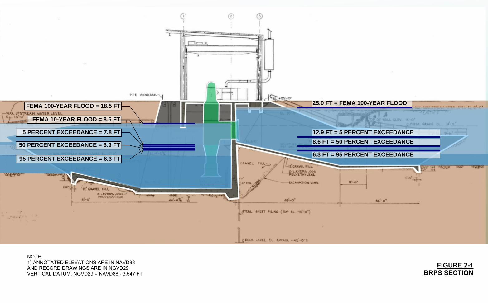
25.0 FT = FEMA 100-YEAR FLOOD
12.9 FT = 5 PERCENT EXCEEDANCE
8.6 FT = 50 PERCENT EXCEEDANCE
6.3 FT = 95 PERCENT EXCEEDANCE
FEMA 100-YEAR FLOOD = 18.5 FT
FEMA 10-YEAR FLOOD = 8.5 FT
FIGURE 2-1BRPS SECTION
NOTE:1) ANNOTATED ELEVATIONS ARE IN NAVD88AND RECORD DRAWINGS ARE IN NGVD29VERTICAL DATUM. NGVD29 = NAVD88 - 3.547 FT
5 PERCENT EXCEEDANCE = 7.8 FT
50 PERCENT EXCEEDANCE = 6.9 FT
95 PERCENT EXCEEDANCE = 6.3 FT
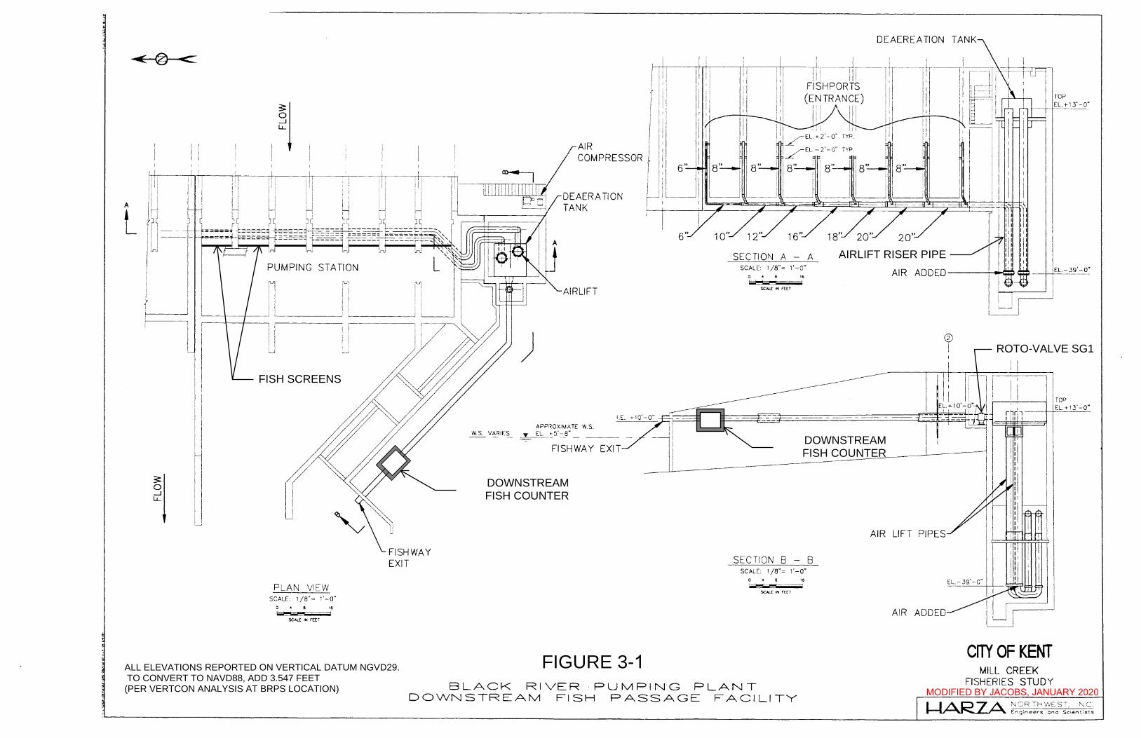
A
L
PLAN V!EW SCALE: 1/8"= 1'-0"
0 • • ~=-== SCALE tN FEE"f
FISHWAY EXIT
W.S. VARIES
"-._AIRLIFT
)
APPROX!MATE W.S. EL. +-5'-8" _y__ ____ ·-- -
FISHWAY
Figure 8.
SECTION A - A SCALE: 1 /8" = 1'-0"
0 4 8 ,. w~
SECTION 8 - 8 SCALE: 1 /8" = 1'-0"
0 4 8 16
...-- i----tw a SCAL.£ 'N FEET
BLACK RI\/ER PUMPING PLANT DOWNSTREAM FISH PASSAGE FACILITY
DEAEREATION
@ i
AIR LIFT PIPES
AIR ADDED
CITY OF KENT MILL CREEK
FISHERIES STUDY
I I A t=l '7 A 'JORThVVEST, ;~,iC_ ~ Ef7gir.eers and Scientists
FISH SCREENS
AIRLIFT RISER PIPE
ROTO-VALVE SG1
DOWNSTREAMFISH COUNTER
DOWNSTREAMFISH COUNTER
ALL ELEVATIONS REPORTED ON VERTICAL DATUM NGVD29. TO CONVERT TO NAVD88, ADD 3.547 FEET (PER VERTCON ANALYSIS AT BRPS LOCATION)
FIGURE 3-1MODIFIED BY JACOBS, JANUARY 2020
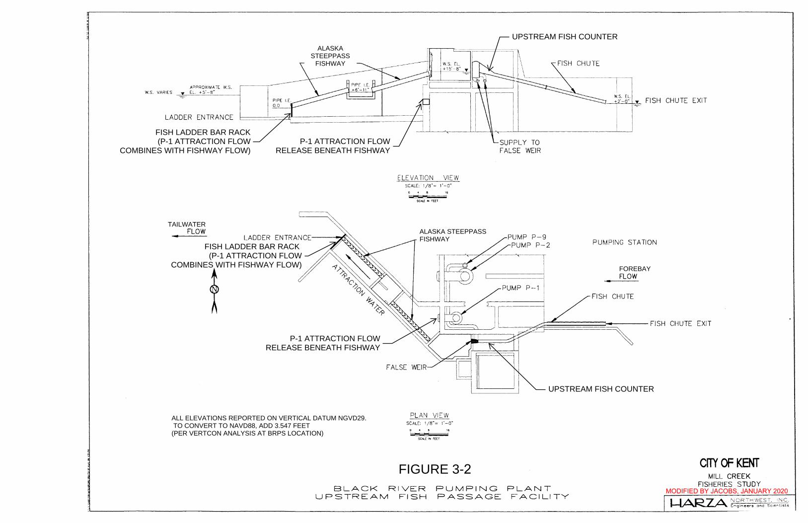
APPROXIMATE W.S. W.S. VARIES EL. +s·-s·
LADDER ENTRANCE
FLOW
ELEVATION VIEW SCALE: 1/8"= 1•-0•
D 4 8 16
SCAU .. FEET
DENIL LADDER
PLAN VIEW SCALE: 1/8"= 1•-0•
o • a 1&
SCALE IN FEET
Figure 7.
SUPPLY TO FALSE WEIR
BLACK RIVER PUMPING PLANT UPSTREAM FISH PASSAGE FACILITY
PUMPING STATION
FLOW
FISH CHUTE
CITY OF KENT MILL CREEK
FISHERIES STUDY
I-IARZA NORTHWEST, INC. Engineers and Scientists
FISH LADDER BAR RACK (P-1 ATTRACTION FLOW
COMBINES WITH FISHWAY FLOW)
FISH LADDER BAR RACK(P-1 ATTRACTION FLOW
COMBINES WITH FISHWAY FLOW)P-1 ATTRACTION FLOW
RELEASE BENEATH FISHWAY
P-1 ATTRACTION FLOWRELEASE BENEATH FISHWAY
UPSTREAM FISH COUNTER
ALL ELEVATIONS REPORTED ON VERTICAL DATUM NGVD29. TO CONVERT TO NAVD88, ADD 3.547 FEET (PER VERTCON ANALYSIS AT BRPS LOCATION)
ALASKA STEEPPASSFISHWAY
ALASKASTEEPPASS
FISHWAY
UPSTREAM FISH COUNTER
FOREBAY
TAILWATER
FIGURE 3-2MODIFIED BY JACOBS, JANUARY 2020
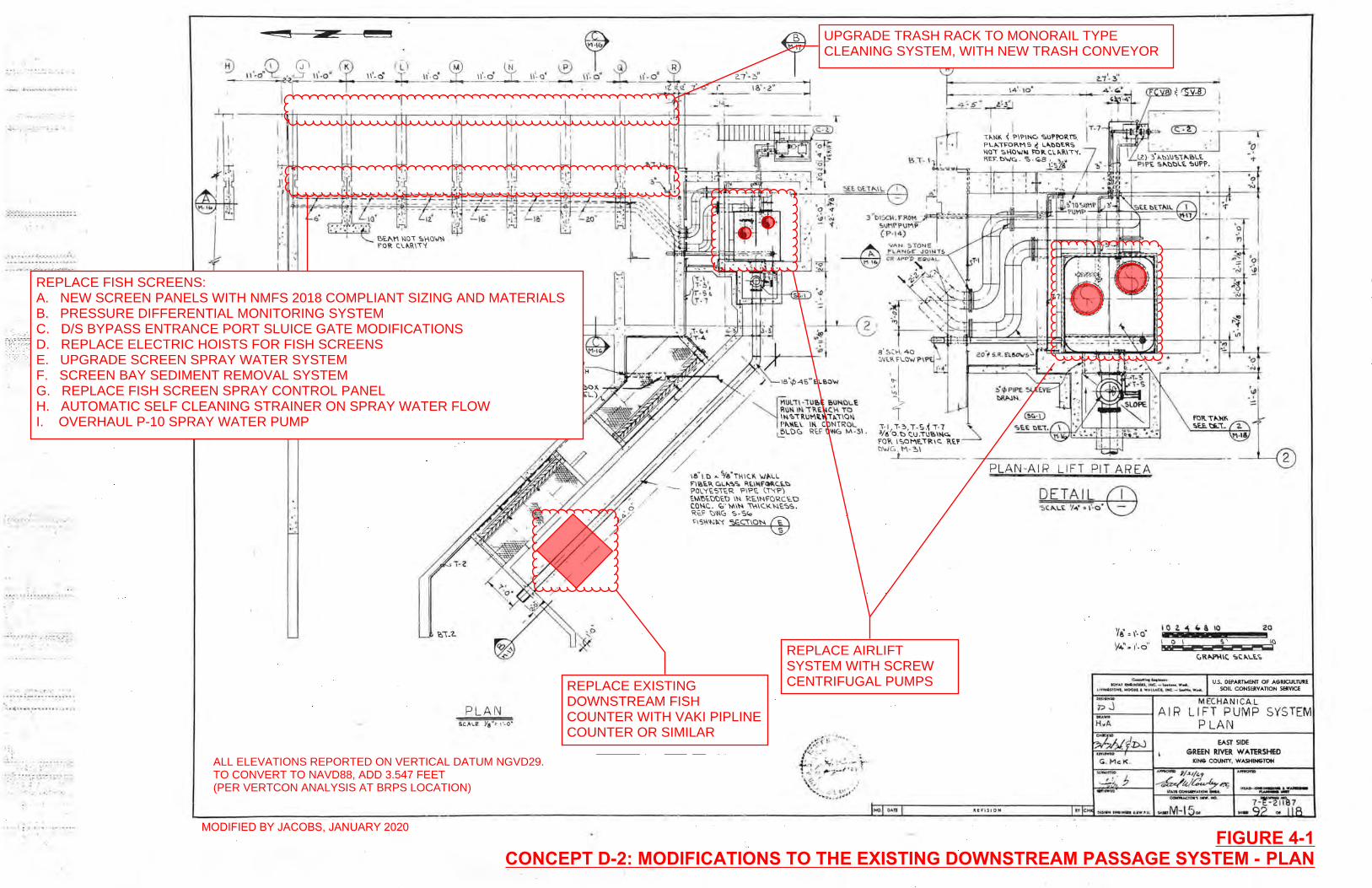
• ; ••• _, . , .'4
•• " •• • •• : ._.' _" ' ,0.",' .... .--.-- . .... -.. : ~ -- .. -
;l~~~~~;~:~~~~~Cc5~;·,~i:: " :-.... : . ..
.' . ::':''''-:'': ...... 1' .~ •
. . ~ :.: : . : ~ :' ~ : ~ "".: : : : ..... .....
_ .. ... -_ . . -'-: -'-:-:-'
',' ' ........ 1' • • • ...
P_' __ : .:-, 0 _ _ " ~..;, ..... :
.: ... "' .. .. .. ..... .. .... ... .. .
':-- .... :::' ....... : . .. ,
'.:~ : •••• = : .. :- ~_:- .. :.'4" '. : : :
., .; : ,' " .. ,
c:::::s
I !: I
4i J
11.
~. ,~ j ;~ i r I "
f .'
,
PLAN
~-----------------Z:ll. ~' __
3 "015(:\1. rPD~' 'o\lt'lI'PIlMP (P" 4)
8'S,\-\ 4Q ::'~I..\\ n.o'ol PI ?
~~I ",! -s. '1
.. I T·~ T·s .i T· 7 3/& '0. t:> 'c.u .T\JI!.I~<>. rOR IsoME..TRlc:. ~U D'oiG . M-~\
t
~s·~ i
I I ,,,,\>II<- { ?IPINC, SUPI'ORTS. PLI'.'I'Ol\M:' ~ l"l>l>EII.':. \>10, ':.1-10'010.1 1'01\. c.\. "-\\10'1 • RoEI'. b",c. . s· ~8 " ~J. '
..!.:1iS '0 . .:,
0 .' 1"1
~ \)1 .;5 '~ I ~~
0 i
' ", h
~ "1' . .j, . ',.,
-.!.
'0 . ,;,
!lou. t:i..i. 2-.UI
---------- 2 PLAN-AIR LIFT PIT AREA
fOR. T"'~\'. ~:~l
II.EV ISIO H
DETAIL
'Ie' = 1'-0'
y..;.'~ 1'·0"
~ ... - u.s. DEPARTMENT OF A6RlCULTUlE I'."",:::~=~~!r"'....; ... ~~*":::::::...-. SOIL CONSERVATION SERVICE
.. ... MEC ANICA L I-P_ J __ -I AIR LIFT PUMP SYSTEM H:A PLAN
EAST SIDE GREEN RIVER W A TERSH£D
KING CO\INIY, WASHINGTotI
REPLACE AIRLIFTSYSTEM WITH SCREWCENTRIFUGAL PUMPS
REPLACE FISH SCREENS:A. NEW SCREEN PANELS WITH NMFS 2018 COMPLIANT SIZING AND MATERIALSB. PRESSURE DIFFERENTIAL MONITORING SYSTEMC. D/S BYPASS ENTRANCE PORT SLUICE GATE MODIFICATIONSD. REPLACE ELECTRIC HOISTS FOR FISH SCREENSE. UPGRADE SCREEN SPRAY WATER SYSTEMF. SCREEN BAY SEDIMENT REMOVAL SYSTEMG. REPLACE FISH SCREEN SPRAY CONTROL PANELH. AUTOMATIC SELF CLEANING STRAINER ON SPRAY WATER FLOWI. OVERHAUL P-10 SPRAY WATER PUMP
REPLACE EXISTINGDOWNSTREAM FISHCOUNTER WITH VAKI PIPLINECOUNTER OR SIMILAR
UPGRADE TRASH RACK TO MONORAIL TYPECLEANING SYSTEM, WITH NEW TRASH CONVEYOR
FIGURE 4-1CONCEPT D-2: MODIFICATIONS TO THE EXISTING DOWNSTREAM PASSAGE SYSTEM - PLAN
ALL ELEVATIONS REPORTED ON VERTICAL DATUM NGVD29.TO CONVERT TO NAVD88, ADD 3.547 FEET(PER VERTCON ANALYSIS AT BRPS LOCATION)
MODIFIED BY JACOBS, JANUARY 2020
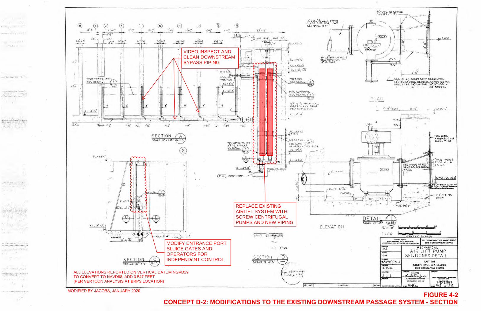
@ (u 1\' . o· f \\' -0'
- ---I- ,- ...:.---'--- -
(' 0' \" 0'
..... -................ ... . , .... ...... ..
I
I. I' . I .
;:1 ,
, . . . .- .... .. ... ~ -.... ... ... ...... .... .
~:::t,c"o·I ,' , I' lj,l .
. . . ~' 1,--_.,---;,1
s'
·?~9;! ~".i'!I~i··:~~~~;;~ ' .. . ' . .. :-:
. . . , (
SECTION
®
.... . ..
- --_.---..... --,_ .. .... . . ,
SECTION
I EL \ i ·o" r--::
I ,. I ' E.l 'a·o .' t=-=-= I , ,
\ • B
f.'
~2.0'
\ 8' I 0 .. y.!!o"W .... Ll FIBE.R C,LP-.-:'5 PIPE. FO\l. co.n SEE. D'NG _ M- \l
18-' I~S·!>I.l P 0\\ I'\.e. otl\.\. 'tOW-~c.~ -18" \ l'l \>\~f:.
. r-'I ' < I} ~";';'~:.\~<£) I · 'f\l P'Pl 5 ul' PO"iT!.
I· I , "'lot !)":T II. ffi t·, 1:'\ . ~ t '!.o"\ t) 'tz ,1-\\( K".;",\.\.
~ I
-t,III-+ ---r-- F\'C'<..I<GU,:'s Rt\I-\f PO\.'H.·,1ER I'll'£'
E.\.. \7' 4" -,---+
S"~~~J , 8lR ~\JPP. ,~. q 1'I<.\'\i;ER-:' • O'<lG. S-C.8
f..\. _ ~9 0 -----='
,n L A r I
'T'" , t
I
I r
~C? : '1\1 I
I
-- -.-- ! -l
~, -
. ' 1-1 ~_...::::'::.:' .:...:o=-'_' -~--I~
j.' ~"'-'O I ," , \ <o~\I,'T 'OOtl'< £.C.C.~~"'l.K --Z4 ' ,\<!o' .. 2.4· 01 Q.o R£.tl\JC.E.~, c.I.l\"'''' \2.SFl~.
1);1,\1.1. c i"-P a ""!'lCo. ,o~ IY4' ~TI,)1) 'lo ~ a" .. I'/~ '!>il,)l)",.
\'·9'(~U) ~~_ .-: l'~";-O' ..,. ~ ;;..
~~ .... ." i
c.1.._ 4~ °n-·--I--------1'11 l l
,\-- -~-:'--I-
~ '5UMPP\l\'1P
1 £L.~II'-~" I' ~ I :- i-- -:-"
1
ELEVATION
SEC:- "J ri SC.AL"- Y6' - 1'- 0"
\-\' = \~ 0" 1 0 \ 5
• ' If I ~ \ . 0
3·~ PIPE FOR DRAIN
"~
\Q lS b 1.0 o
IO'l'A' .... IM~ 11oIC._ ,........ w-. l m ... Jm",,, WOOII' WAI.I.JoCt" IIC.- '-""'- ..... -DJ MECHANICAL
AIR LIFT PUMP SEC TIONS& DETAIL
EAST SIDE GREEN RIVER WATERSHJ'D
KING COUNTY, WASHINGTON
~..., . ."
.. ., M-16 ..
.J
REPLACE EXISTINGAIRLIFT SYSTEM WITHSCREW CENTRIFUGALPUMPS AND NEW PIPING
MODIFY ENTRANCE PORTSLUICE GATES ANDOPERATORS FORINDEPENDeNT CONTROL
VIDEO INSPECT ANDCLEAN DOWNSTREAMBYPASS PIPING
FIGURE 4-2ALTERNATIVE D-2: MODIFICATIONS TO THE EXISTING DOWNSTREAM PASSAGE SYSTEM - SECTION
ALL ELEVATIONS REPORTED ON VERTICAL DATUM NGVD29.TO CONVERT TO NAVD88, ADD 3.547 FEET(PER VERTCON ANALYSIS AT BRPS LOCATION)
FIGURE 4-2CONCEPT D-2: MODIFICATIONS TO THE EXISTING DOWNSTREAM PASSAGE SYSTEM - SECTION
MODIFIED BY JACOBS, JANUARY 2020
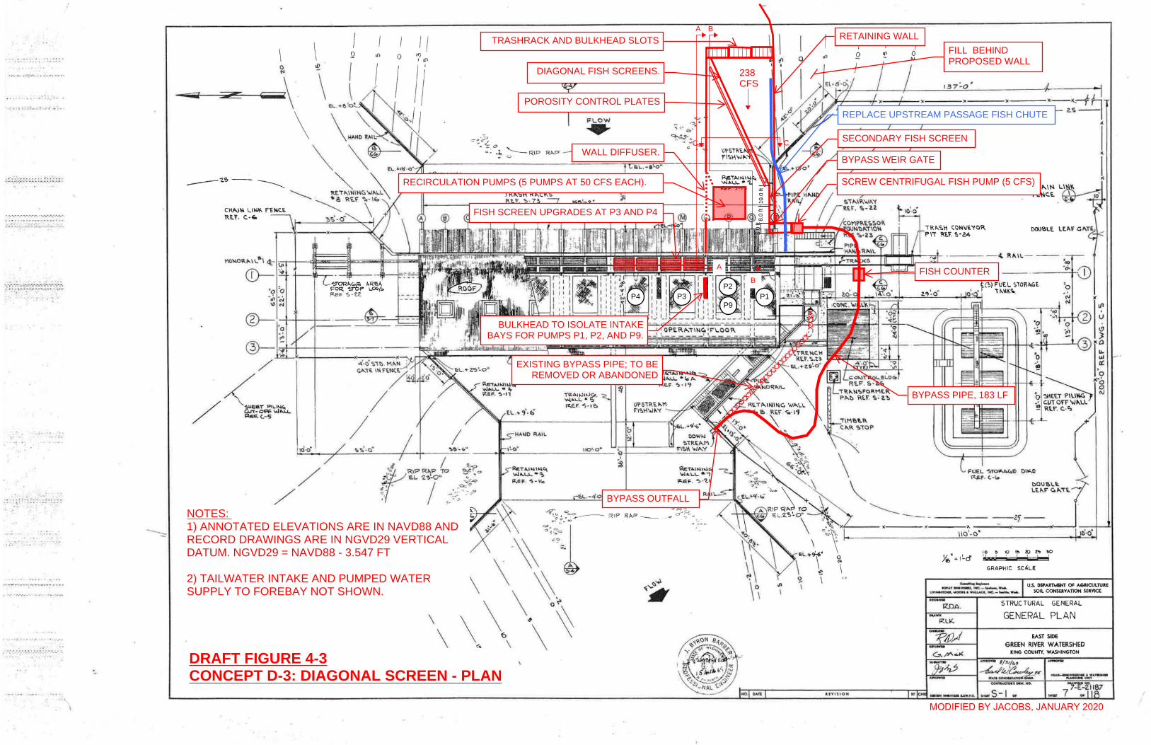
· .. .. .. .. ~ • • I •••••
',:.;-;:;-; :; ... :- ... : .. "":.
'J';"~_';'''~~;'-:_-: _~ .. :.-.~. ; • .• . :,~.~.: ' .. - ,!,-." ... ~ ,,-,"-..
{- .. ' .. .. ;.
.:
.''''- ...
\
\ I I o '( III 2
I 1/ ../ /
-+-+---I-- .-~~=
/ /
~/ /~
/ /
\ \ 11> (l'I , ,
r .". .
~ ~ ~?~ . ~~.
FLOW ..... ~ ~o
RIP R"P ___
'" \
o
a .. \
UVU~O"
Q
1<--~:-fh ----z.s-I
i .. I r.
C.HI'I.IN l.~ ---d FE,1-\c:.E. W ~
--2~--
x
10 ~ 10 I!:I «;) l~ "!to :.: ' , , I r-----:
GRAPH IC SCALE
~ ... '""-' u.s. DEPARTMENT Of AGRICULTURE SOIL CQNSERVATlON SEI!.VICE
1IO'f ... ,. ... l"' .... IfC.-~W .... uYlNoanOA wOOon .w~ lMC._....,.." ......
RnA.
-"" RLK.
STRUC TURAl GENERAL
GENERAL PLAN
EAST SIDE GREEN RIVER WATERSHED
KIN& COUNTY, WASHIH&TON
..... 5-1 .. ~~~-2jIB7
~.ur 7 Of
10.0
ft
FISH COUNTER
BYPASS OUTFALL
BYPASS PIPE, 183 LF
SCREW CENTRIFUGAL FISH PUMP (5 CFS)
POROSITY CONTROL PLATES
RETAINING WALL
DIAGONAL FISH SCREENS.
TRASHRACK AND BULKHEAD SLOTS
XXXXXXXXXXXXXXXXXXXXXXXX
XX
X
EXISTING BYPASS PIPE; TO BEREMOVED OR ABANDONED
DRAFT FIGURE 4-3CONCEPT D-3: DIAGONAL SCREEN - PLAN
RECIRCULATION PUMPS (5 PUMPS AT 50 CFS EACH).
WALL DIFFUSER.
FILL BEHINDPROPOSED WALL
A B
A
B
CC
8.0
ft5.
0 ft
BYPASS WEIR GATE
SECONDARY FISH SCREEN
NOTES: 1) ANNOTATED ELEVATIONS ARE IN NAVD88 ANDRECORD DRAWINGS ARE IN NGVD29 VERTICALDATUM. NGVD29 = NAVD88 - 3.547 FT
2) TAILWATER INTAKE AND PUMPED WATERSUPPLY TO FOREBAY NOT SHOWN.
MODIFIED BY JACOBS, JANUARY 2020
238CFS
REPLACE UPSTREAM PASSAGE FISH CHUTE
BULKHEAD TO ISOLATE INTAKEBAYS FOR PUMPS P1, P2, AND P9.
P1P2
P3P4P9
FISH SCREEN UPGRADES AT P3 AND P4
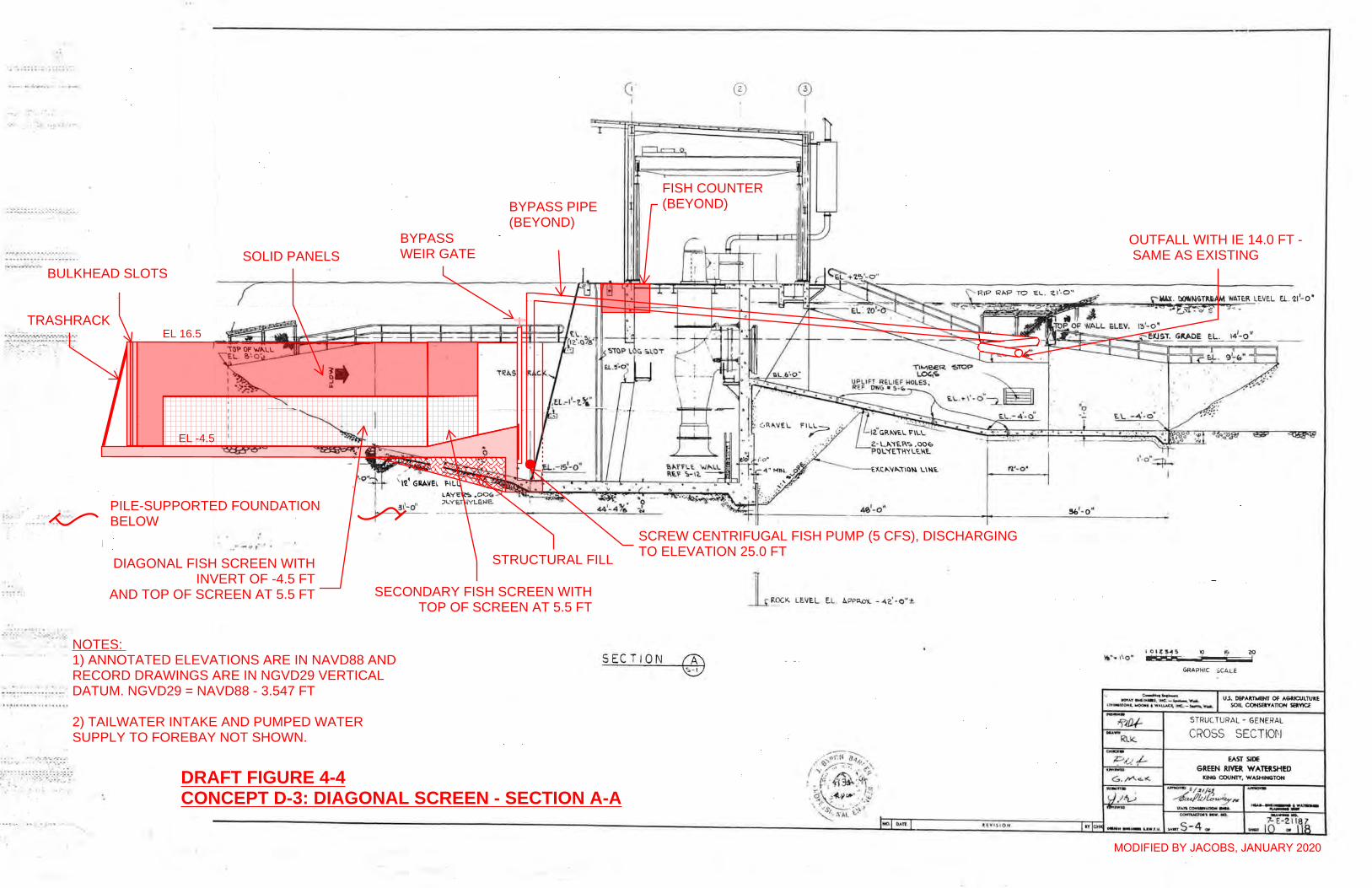
a .*, ••• ~ ..... _4 ... ___ • •
! _, .... ":.o- • •• -_~ ., • • U __ ~ ._.'r-...
· ..... -r.·_-.·. ·.~.-... ~·_";"'.7...;.-.· .· _." ....... , ........ ,.,."' ....... ...., .. /". =: . .: .. ..... ..
~~ . -- ... : .
.... .. --... -...... .. _.-. -'- .. . .. . ... .. : ... ........... .
--',' . . ........ . ?/ .. .... : :: ~::-;.: ~::::;~:=~:
. "
. .. .. ' .. ' ... ~
T l'I~'1.. Ur':.l'RE~M 'NII.l'E.R lE..'V'C.\' EL . \,~',O"
II. 'HATER LEVEL t L. OLD'
3\'-0"
. .
SECTION
® o I
4(1,'- 0"
n STER S~EET PILlI.IG (TOP El - \5 '-0 ')
1 ROCK LE.VEL EL l.PPI<..O'l. - 42.' -O"±
Sb' - O"
\10- ' "' 0·
t. l Vf $J.O H
I OIl! S ... S ., U
EL . '21'- 0'
zo =j
GRAPHIC SC.r.LE
STRUC TURAl - GENERAL
CROSS SECTIOr'l
EAST SIDE
GREEN RIVER WATBSHED K'N6 COUNTY. WASHlN6TON
", .. S-4 .. .....
PILE-SUPPORTED FOUNDATIONBELOW
BYPASSWEIR GATE
TRASHRACK
SOLID PANELS
DIAGONAL FISH SCREEN WITHINVERT OF -4.5 FT
AND TOP OF SCREEN AT 5.5 FT
BULKHEAD SLOTS
OUTFALL WITH IE 14.0 FT - SAME AS EXISTING
FISH COUNTER(BEYOND)
SCREW CENTRIFUGAL FISH PUMP (5 CFS), DISCHARGINGTO ELEVATION 25.0 FT
DRAFT FIGURE 4-4CONCEPT D-3: DIAGONAL SCREEN - SECTION A-A
SECONDARY FISH SCREEN WITHTOP OF SCREEN AT 5.5 FT
STRUCTURAL FILL
BYPASS PIPE(BEYOND)
MODIFIED BY JACOBS, JANUARY 2020
NOTES: 1) ANNOTATED ELEVATIONS ARE IN NAVD88 ANDRECORD DRAWINGS ARE IN NGVD29 VERTICALDATUM. NGVD29 = NAVD88 - 3.547 FT
2) TAILWATER INTAKE AND PUMPED WATERSUPPLY TO FOREBAY NOT SHOWN.
EL 16.5
EL -4.5
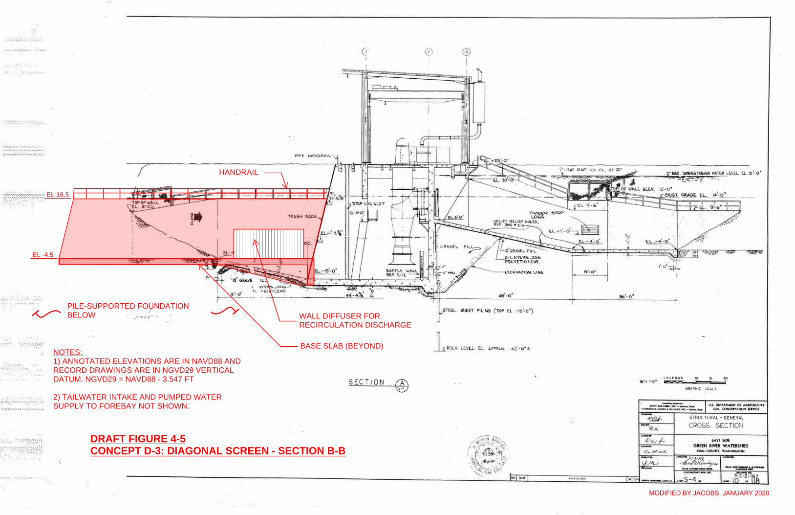
a .*, ••• ~ ..... _4 ... ___ • •
! _, .... ":.o- • •• -_~ ., • • U __ ~ ._.'r-...
· ..... -r.·_-.·. ·.~.-... ~·_";"'.7...;.-.· .· _." ....... , ........ ,.,."' ....... ...., .. /". =: . .: .. ..... ..
~~ . -- ... : .
.... .. --... -...... .. _.-. -'- .. . .. . ... .. : ... ........... .
--',' . . ........ . ?/ .. .... : :: ~::-;.: ~::::;~:=~:
. "
. .. .. ' .. ' ... ~
T l'I~'1.. Ur':.l'RE~M 'NII.l'E.R lE..'V'C.\' EL . \,~',O"
II. 'HATER LEVEL t L. OLD'
3\'-0"
. .
SECTION
® o I
4(1,'- 0"
n STER S~EET PILlI.IG (TOP El - \5 '-0 ')
1 ROCK LE.VEL EL l.PPI<..O'l. - 42.' -O"±
Sb' - O"
\10- ' "' 0·
t. l Vf $J.O H
I OIl! S ... S ., U
EL . '21'- 0'
zo =j
GRAPHIC SC.r.LE
STRUC TURAl - GENERAL
CROSS SECTIOr'l
EAST SIDE
GREEN RIVER WATBSHED K'N6 COUNTY. WASHlN6TON
", .. S-4 .. .....
PILE-SUPPORTED FOUNDATIONBELOW
DRAFT FIGURE 4-5CONCEPT D-3: DIAGONAL SCREEN - SECTION B-B
WALL DIFFUSER FORRECIRCULATION DISCHARGE
HANDRAIL
BASE SLAB (BEYOND)
MODIFIED BY JACOBS, JANUARY 2020
NOTES: 1) ANNOTATED ELEVATIONS ARE IN NAVD88 ANDRECORD DRAWINGS ARE IN NGVD29 VERTICALDATUM. NGVD29 = NAVD88 - 3.547 FT
2) TAILWATER INTAKE AND PUMPED WATERSUPPLY TO FOREBAY NOT SHOWN.
EL 16.5
EL -4.5
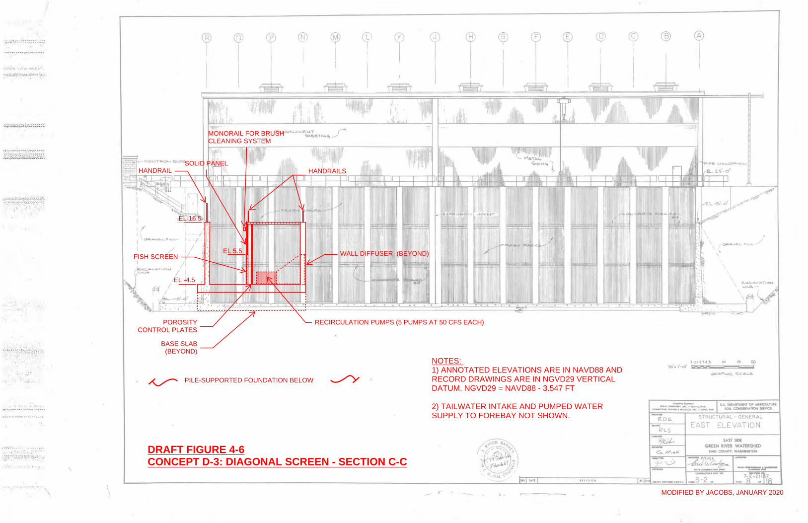
~ ..... ':-.r """: ~ ::'':;:. -:,:
--~·- .. t·,,· -- ,,-- ·
..... }.-. •• 0' '.'.; .. '
..... :.~::.r ~ ... '.-.-:"-.!-~ '. ~--. '
j"-..... --~~-.-.. -.- ...... ~-...... ;-:..;--~ • ...:~~ •• ' -'-.:--: .~'r:,:--....... ~ .. ;:,:';::-- ~~:-.~ :
;~. f - ":':~ .~!~~~~ .. :~.~; -:. -,'
" .....
, .... . .... ...... , .. . , ... ..
I
I I I
1
I I I' Il L _ __ /, I \~ .... ""-'- ,,... 1--/ - -
/ ~/
/ I
/ 1 / 1
I
@ ® ® ~ ~ I ! I I I ~ ~ I I @ ©
I I I
It- , I'
_ r r c _______
® ® I
\
, ~A.vE..L- FIL..L. /
, , \
\
aow ..... ..... : .. tIIIIU, t~ .... , 'fit.... u.s. OEPAln,e(f' OF- ANtCUt.rultE U-1_JlO"Iol00u .... AllAQ, ~_'--'........ SOIL COHSElVATION sava
STRUCTURAL-GENERAL
EAST ELEVATION
EAST SlOE GlIEN RIVER W" TEll.SI1ED
PILE-SUPPORTED FOUNDATION BELOW
POROSITYCONTROL PLATES
FISH SCREEN
SOLID PANELHANDRAIL HANDRAILS
MONORAIL FOR BRUSHCLEANING SYSTEM
EL -4.5
EL 16.5
EL 5.5 WALL DIFFUSER (BEYOND)
BASE SLAB(BEYOND)
DRAFT FIGURE 4-6CONCEPT D-3: DIAGONAL SCREEN - SECTION C-C
RECIRCULATION PUMPS (5 PUMPS AT 50 CFS EACH)
MODIFIED BY JACOBS, JANUARY 2020
NOTES: 1) ANNOTATED ELEVATIONS ARE IN NAVD88 ANDRECORD DRAWINGS ARE IN NGVD29 VERTICALDATUM. NGVD29 = NAVD88 - 3.547 FT
2) TAILWATER INTAKE AND PUMPED WATERSUPPLY TO FOREBAY NOT SHOWN.
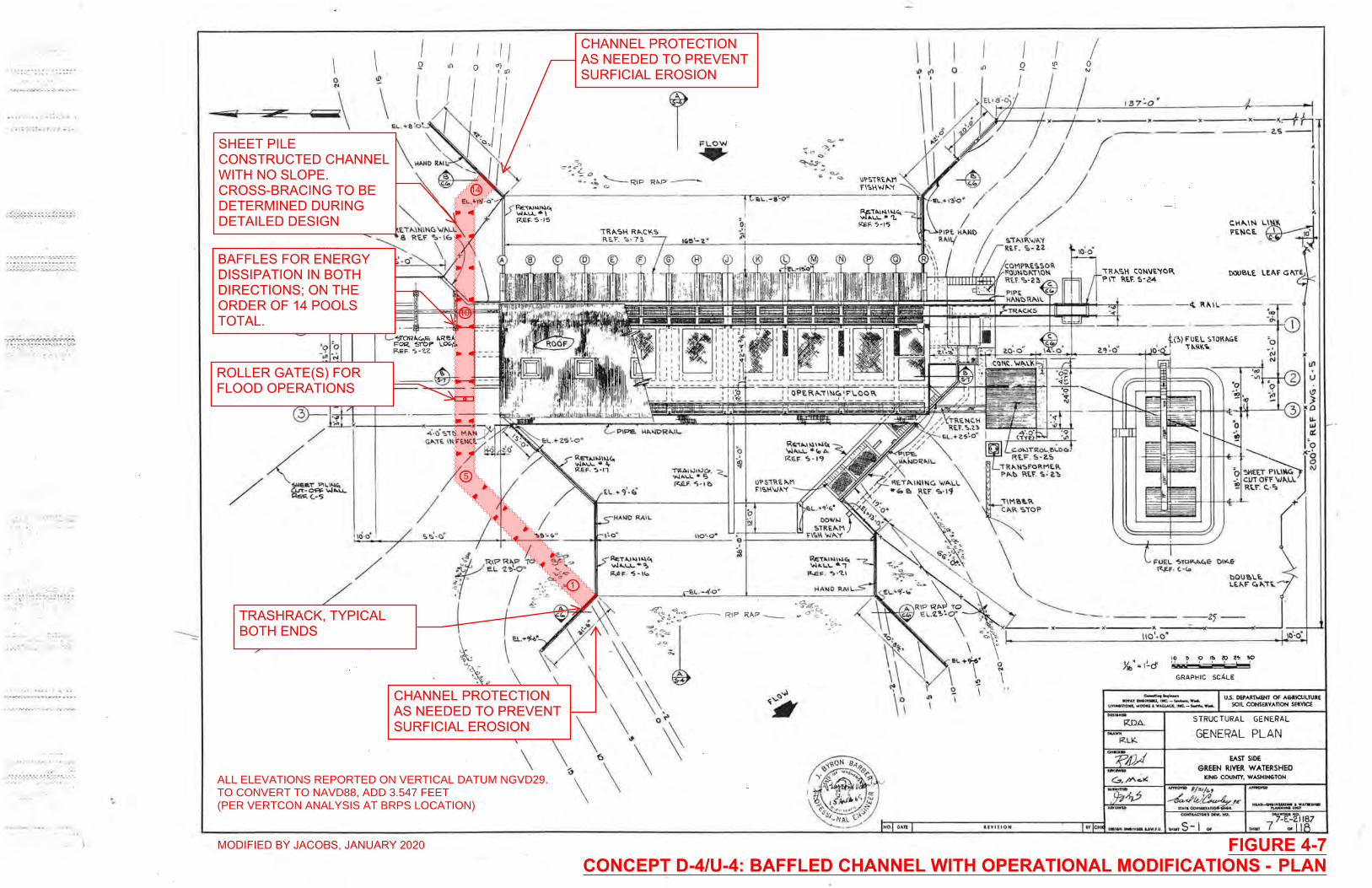
· .. .. .. .. ~ • • I •••••
',:.;-;:;-; :; ... :- ... : .. "":.
'J';"~_';'''~~;'-:_-: _~ .. :.-.~. ; • .• . :,~.~.: ' .. - ,!,-." ... ~ ,,-,"-..
{- .. ' .. .. ;.
.:
.''''- ...
\
\ I I o '( III 2
I 1/ ../ /
-+-+---I-- .-~~=
/ /
~/ /~
/ /
\ \ 11> (l'I , ,
r .". .
~ ~ ~?~ . ~~.
FLOW ..... ~ ~o
RIP R"P ___
'" \
o
a .. \
UVU~O"
Q
1<--~:-fh ----z.s-I
i .. I r.
C.HI'I.IN l.~ ---d FE,1-\c:.E. W ~
--2~--
x
10 ~ 10 I!:I «;) l~ "!to :.: ' , , I r-----:
GRAPH IC SCALE
~ ... '""-' u.s. DEPARTMENT Of AGRICULTURE SOIL CQNSERVATlON SEI!.VICE
1IO'f ... ,. ... l"' .... IfC.-~W .... uYlNoanOA wOOon .w~ lMC._....,.." ......
RnA.
-"" RLK.
STRUC TURAl GENERAL
GENERAL PLAN
EAST SIDE GREEN RIVER WATERSHED
KIN& COUNTY, WASHIH&TON
..... 5-1 .. ~~~-2jIB7
~.ur 7 Of
SHEET PILECONSTRUCTED CHANNELWITH NO SLOPE.CROSS-BRACING TO BEDETERMINED DURINGDETAILED DESIGN
ROLLER GATE(S) FORFLOOD OPERATIONS
TRASHRACK, TYPICALBOTH ENDS
BAFFLES FOR ENERGYDISSIPATION IN BOTHDIRECTIONS; ON THEORDER OF 14 POOLSTOTAL.
14
10
5
1
FIGURE 4-7CONCEPT D-4/U-4: BAFFLED CHANNEL WITH OPERATIONAL MODIFICATIONS - PLAN
ALL ELEVATIONS REPORTED ON VERTICAL DATUM NGVD29.TO CONVERT TO NAVD88, ADD 3.547 FEET(PER VERTCON ANALYSIS AT BRPS LOCATION)
CHANNEL PROTECTIONAS NEEDED TO PREVENTSURFICIAL EROSION
CHANNEL PROTECTIONAS NEEDED TO PREVENTSURFICIAL EROSION
MODIFIED BY JACOBS, JANUARY 2020
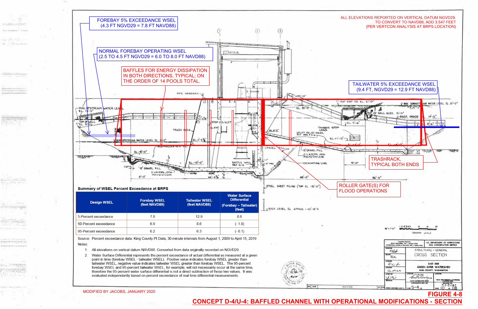
a .*, ••• ~ ..... _4 ... ___ • •
! _, .... ":.o- • •• -_~ ., • • U __ ~ ._.'r-...
· ..... -r.·_-.·. ·.~.-... ~·_";"'.7...;.-.· .· _." ....... , ........ ,.,."' ....... ...., .. /". =: . .: .. ..... ..
~~ . -- ... : .
.... .. --... -...... .. _.-. -'- .. . .. . ... .. : ... ........... .
--',' . . ........ . ?/ .. .... : :: ~::-;.: ~::::;~:=~:
. "
. .. .. ' .. ' ... ~
T l'I~'1.. Ur':.l'RE~M 'NII.l'E.R lE..'V'C.\' EL . \,~',O"
II. 'HATER LEVEL t L. OLD'
3\'-0"
. .
SECTION
® o I
4(1,'- 0"
n STER S~EET PILlI.IG (TOP El - \5 '-0 ')
1 ROCK LE.VEL EL l.PPI<..O'l. - 42.' -O"±
Sb' - O"
\10- ' "' 0·
t. l Vf $J.O H
I OIl! S ... S ., U
EL . '21'- 0'
zo =j
GRAPHIC SC.r.LE
STRUC TURAl - GENERAL
CROSS SECTIOr'l
EAST SIDE
GREEN RIVER WATBSHED K'N6 COUNTY. WASHlN6TON
", .. S-4 .. .....
ROLLER GATE(S) FORFLOOD OPERATIONS
BAFFLES FOR ENERGY DISSIPATIONIN BOTH DIRECTIONS, TYPICAL; ONTHE ORDER OF 14 POOLS TOTAL.
NORMAL FOREBAY OPERATING WSEL(2.5 TO 4.5 FT NGVD29 = 6.0 TO 8.0 FT NAVD88)
TRASHRACK,TYPICAL BOTH ENDS
TAILWATER 5% EXCEEDANCE WSEL(9.4 FT, NGVD29 = 12.9 FT NAVD88)
FIGURE 4-8CONCEPT D-4/U-4: BAFFLED CHANNEL WITH OPERATIONAL MODIFICATIONS - SECTION
FOREBAY 5% EXCEEDANCE WSEL(4.3 FT NGVD29 = 7.8 FT NAVD88)
ALL ELEVATIONS REPORTED ON VERTICAL DATUM NGVD29.TO CONVERT TO NAVD88, ADD 3.547 FEET
(PER VERTCON ANALYSIS AT BRPS LOCATION)
MODIFIED BY JACOBS, JANUARY 2020
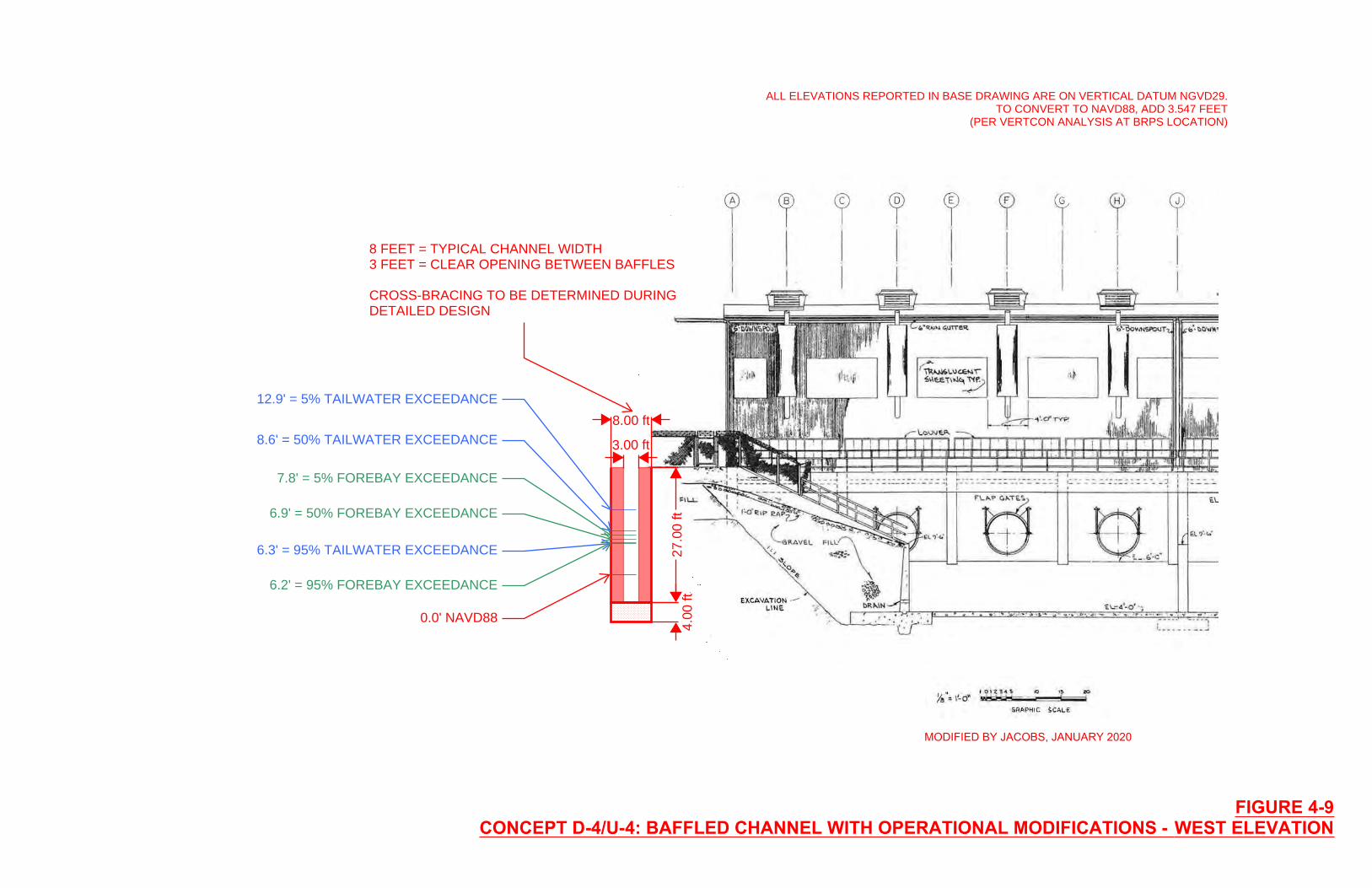
0.0' NAVD88
FIGURE 4-9CONCEPT D-4/U-4: BAFFLED CHANNEL WITH OPERATIONAL MODIFICATIONS - WEST ELEVATION
12.9' = 5% TAILWATER EXCEEDANCE
8.6' = 50% TAILWATER EXCEEDANCE
6.3' = 95% TAILWATER EXCEEDANCE
6.2' = 95% FOREBAY EXCEEDANCE
6.9' = 50% FOREBAY EXCEEDANCE
7.8' = 5% FOREBAY EXCEEDANCE
3.00 ft
8.00 ft
27.0
0 ft
4.00
ft
ALL ELEVATIONS REPORTED IN BASE DRAWING ARE ON VERTICAL DATUM NGVD29.TO CONVERT TO NAVD88, ADD 3.547 FEET
(PER VERTCON ANALYSIS AT BRPS LOCATION)
8 FEET = TYPICAL CHANNEL WIDTH3 FEET = CLEAR OPENING BETWEEN BAFFLES
CROSS-BRACING TO BE DETERMINED DURINGDETAILED DESIGN
MODIFIED BY JACOBS, JANUARY 2020
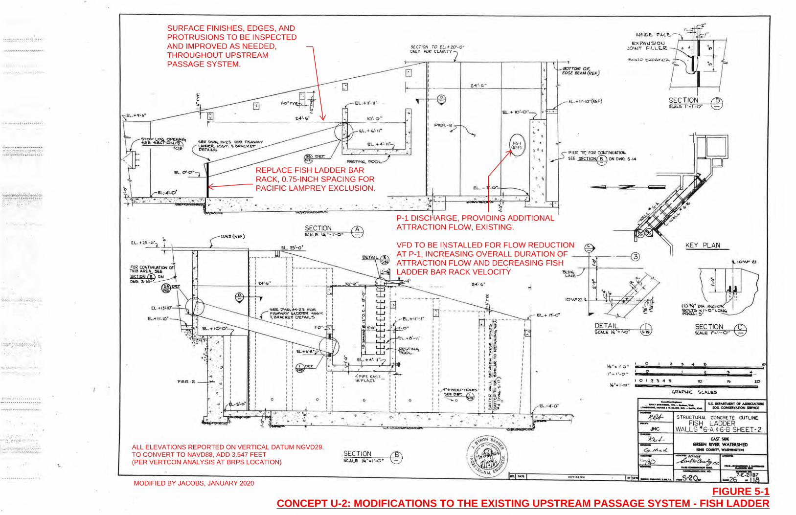
.... ' .
, •• -~·.·.-","""'''''P-'-' • • --'';- '
=::~:~~~ :'.: ~'.::: ~:~.'
•• , ... to .. .. ............. .... :,. -• • - .... ,p" --"to. .;--'\' ..
-to :.'.- .-t. •
. , ! .. 'I'~ . "'.J __ •
;.-:., '";, .... -::::--.. . "~.:-': .. •• ·.-""-.. · ,:01·. - ... -.. - .·_ ••
" .... :~.· ' t ~·' ' .:., . .... . '" ,
Q
" '. . ' ~ ,
CU~!I (REF)
FOR CDIITINUATION 01' I'-
,. .. . 0 ... ....
SECTION 5<.l.LE: I"""~I'-O"
r' l - - - -- r - ~ , I I 1
: : : ~ --------i-l : : I I , I
~
©
I:L. +~'- II" I ' • • ~
, ,
SECTION TO EL.+ZO'-O" ONLY F"O~ CLARITY
.. ,
, . l.I " . ' • •
. ... .
TN'" "REA :seE S1:CTfQ/I.I~ ON OWe. 5- -
l I I ,
hrlr-----___ f;-.;..I..!t:::! .. .::,. c.~'_' _ . .-i.J.. --'~'~~)2;:~~Fd!<:i:;lt;:~S,.:=-= I I I I
EL.+ \I~ 10"
PIER · R
I 1 I I I I
-!>U!. ~ M'-Z~ !=OR. r I'1'!oOlW," lj.Io,1:>01I!i'l ~v. t ~ I!>R-'C: E~ oeT .... 1L~
0
I ' f I
.
0
", .
f I 1 f , j
Q '
--- - or, 1 ' tj-- -I
e 0
' 9 <;' .
~ . > . '
SECTION ® SC."LE V~"-I'-O"
z.~ '-" ..
E:l.. . + 10'-0"
EL - !>'-O.-:..,. -1--__
I 1 , , I I I I
I I I , I I I ,
, \
eL.+ I'!I'-d'
EL. -4·-O"
E)<.Y'A\.lSlOI.J JOI\oJT f:ILLE..~
s::JrTOM OF EDGE BEAM (REf:)
PIER oR; FOR CONTINUATIOM
SEE SECTlON® ON OWG 5-14
a
.-@
DETAIL S,C.l.U: V&"= 1'-0"
!h 't ; l'-O ·t 0
1" -:. , t· O " · 0
I 0 1 'Z !It,.· .. II- O "
-....
-11'14110" IY
~ .01\
SECTION
'Z
S
KEY PLAN
SECTION SUlLE 1"=1'-0"
'!> .04 ~ \0
i ~ 4
'0 [I; to
5 TRUCTURAL CONCRE TE OUTLINE
FISH LADDER WALLS -6-A ~6-B SHEEL~ .
EAST SIDE 6REEN IUVEIl WATERSHm ... COUNTY. __ TON
-
REPLACE FISH LADDER BARRACK, 0.75-INCH SPACING FORPACIFIC LAMPREY EXCLUSION.
P-1 DISCHARGE, PROVIDING ADDITIONALATTRACTION FLOW, EXISTING.
VFD TO BE INSTALLED FOR FLOW REDUCTIONAT P-1, INCREASING OVERALL DURATION OFATTRACTION FLOW AND DECREASING FISHLADDER BAR RACK VELOCITY
SURFACE FINISHES, EDGES, ANDPROTRUSIONS TO BE INSPECTEDAND IMPROVED AS NEEDED,THROUGHOUT UPSTREAMPASSAGE SYSTEM.
FIGURE 5-1ALTERNATIVE U-2: MODIFICATIONS TO THE EXISTING UPSTREAM PASSAGE SYSTEM - FISH LADDER
ALL ELEVATIONS REPORTED ON VERTICAL DATUM NGVD29.TO CONVERT TO NAVD88, ADD 3.547 FEET(PER VERTCON ANALYSIS AT BRPS LOCATION)
FIGURE 5-1CONCEPT U-2: MODIFICATIONS TO THE EXISTING UPSTREAM PASSAGE SYSTEM - FISH LADDER
MODIFIED BY JACOBS, JANUARY 2020
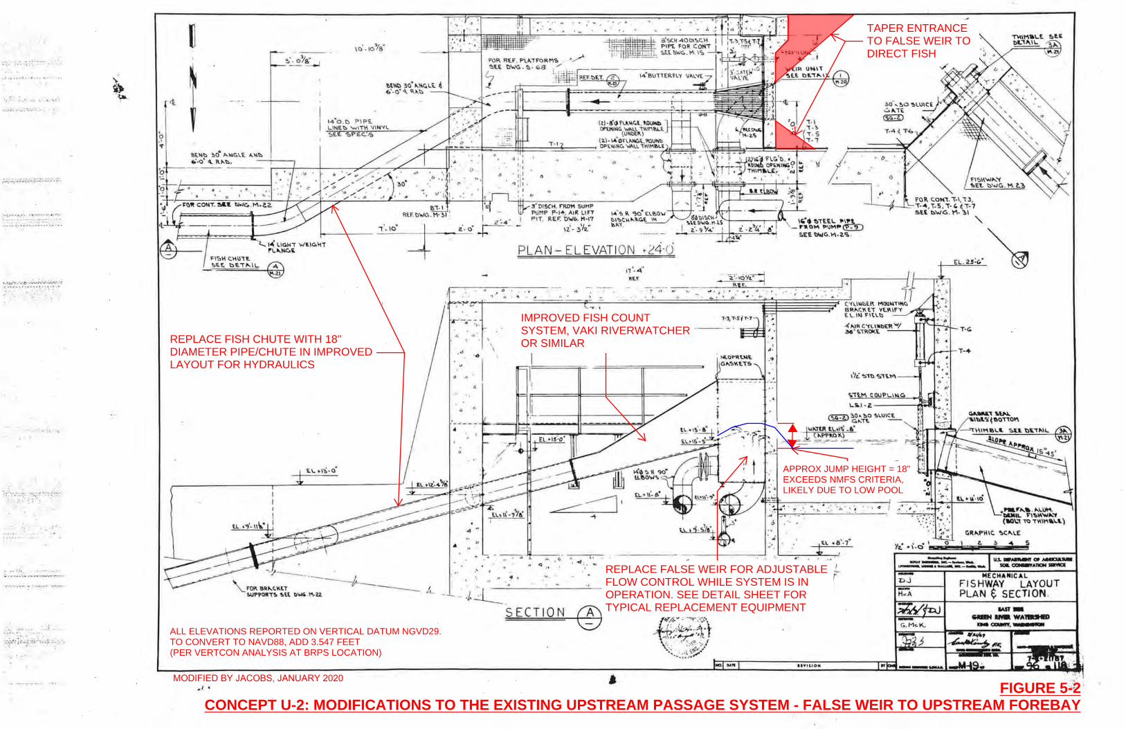
.: . , •• ~ .I •
, .,.~ ... .. ··C!"- .-:\iVU"' .... ":.:'~""-.""'" ' •• ... . • ~ . .. .. ' ''- ":"!" ', .. . .. ...
." ... . 't •• - """' ~"" - .. .: ....... .: .: . .... - .~:: .. : ..... : .. -_., -..
. :--
....... .. . . .
:-;:-:;- r.; ·.~-::d""',;~ •. !..·:, .. -... .. . ' .
. ... .. _ _ . ... _ .l •••
I!.\.w,\) :;00
",w,Gt.i, A.\l\) ~_04 ~ 1I."'t::.. - ----,i----,
... _._-- ------
,I •
FISH O~U\~ !;'EE. ~~"'''' \L
10'. 107'8 "
. " •• 10
V
"
-~ --+ '0
I • , I
:1, . 1, 1
,, :i; . I
"
" <:
3 'DI5CH. nwtI SUI1P PUMP P-I+, AIR LIFT Pli. REF. D\o{6, H'17
IZ" :,'/'2.."
. ' .
()
'"
, . PLAN - EL EVATIOI\J 1-24'0
o ,
, () .
I{ L'-, t> 0 ,
~~
,~~~~~_O~~' ~~-=======~==~==1E~~_= __ ~.~~. ~. ~==r=--=n=--==~~~~=-~'::====~====~O==' ===i~~~·~· ~· ~;'~~~~~·~· ~C~~I~~~R MDU~T\~~ l c. .,. . I SRI>.Cl\ E:i VE.~lf't'
t ~ . lt.I "'t~t::.
- --_ . .. --------~ .. -- .. ---- ",,' "'1\ C'1L'\lt>E~ "'I 36· ... "fP.OKE -----,
\
d \ T-'" ,.,
,\ I G
, .' '- I
•
"
I
Cf7='F-.-. -. -~-, --:--, -,. -:.-.'7' -:'''-' '''-'.-.- '-, - . -.-.-,,-1 .':' ~ .
GR,",P\oIIC. ~C""\.E
• Yl..· -i·a \ z. 5
\ . . ~. (J o --IQIII""-. ... - ....... ..... ....---. ....... ~-.-..... -.
.' u
'!' • .... . ,., ..
.'tl:. CHA CAL
FISHWAV LAYOUT PLAN ~ SECTION.
SECTION
APPROX JUMP HEIGHT = 18"EXCEEDS NMFS CRITERIA,LIKELY DUE TO LOW POOL
IMPROVED FISH COUNTSYSTEM, VAKI RIVERWATCHEROR SIMILAR
TAPER ENTRANCETO FALSE WEIR TODIRECT FISH
REPLACE FALSE WEIR FOR ADJUSTABLEFLOW CONTROL WHILE SYSTEM IS INOPERATION. SEE DETAIL SHEET FORTYPICAL REPLACEMENT EQUIPMENT
REPLACE FISH CHUTE WITH 18"DIAMETER PIPE/CHUTE IN IMPROVEDLAYOUT FOR HYDRAULICS
FIGURE 5-2CONCEPT U-2: MODIFICATIONS TO THE EXISTING UPSTREAM PASSAGE SYSTEM - FALSE WEIR TO UPSTREAM FOREBAY
ALL ELEVATIONS REPORTED ON VERTICAL DATUM NGVD29.TO CONVERT TO NAVD88, ADD 3.547 FEET(PER VERTCON ANALYSIS AT BRPS LOCATION)
MODIFIED BY JACOBS, JANUARY 2020
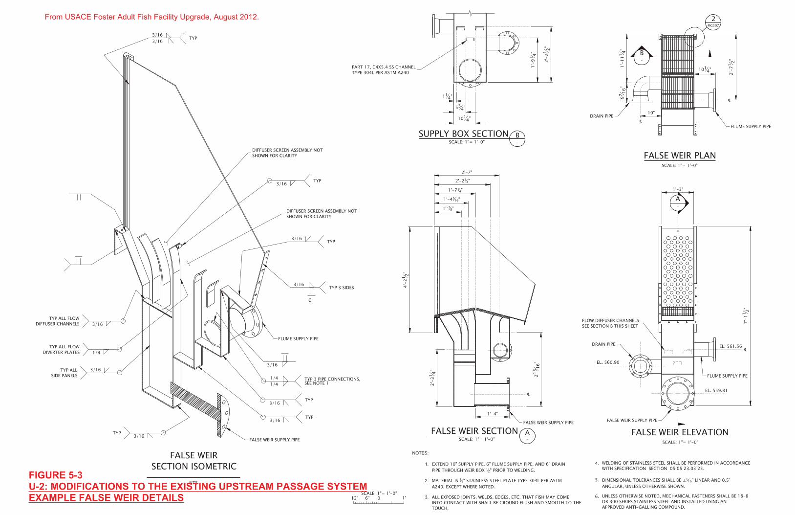
FIGURE 5-3U-2: MODIFICATIONS TO THE EXISTING UPSTREAM PASSAGE SYSTEMEXAMPLE FALSE WEIR DETAILS
From USACE Foster Adult Fish Facility Upgrade, August 2012.
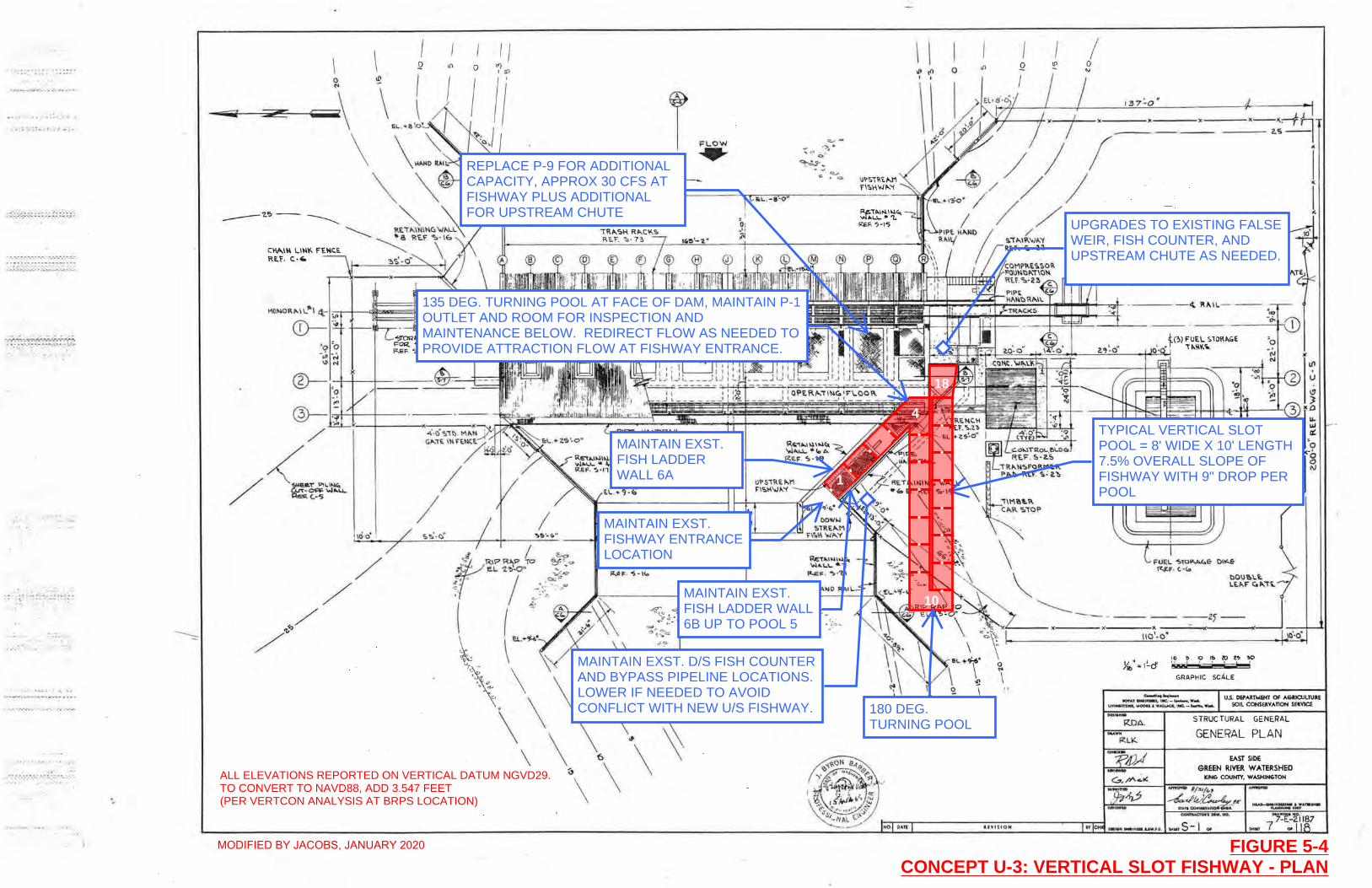
· .. .. .. .. ~ • • I •••••
',:.;-;:;-; :; ... :- ... : .. "":.
'J';"~_';'''~~;'-:_-: _~ .. :.-.~. ; • .• . :,~.~.: ' .. - ,!,-." ... ~ ,,-,"-..
{- .. ' .. .. ;.
.:
.''''- ...
\
\ I I o '( III 2
I 1/ ../ /
-+-+---I-- .-~~=
/ /
~/ /~
/ /
\ \ 11> (l'I , ,
r .". .
~ ~ ~?~ . ~~.
FLOW ..... ~ ~o
RIP R"P ___
'" \
o
a .. \
UVU~O"
Q
1<--~:-fh ----z.s-I
i .. I r.
C.HI'I.IN l.~ ---d FE,1-\c:.E. W ~
--2~--
x
10 ~ 10 I!:I «;) l~ "!to :.: ' , , I r-----:
GRAPH IC SCALE
~ ... '""-' u.s. DEPARTMENT Of AGRICULTURE SOIL CQNSERVATlON SEI!.VICE
1IO'f ... ,. ... l"' .... IfC.-~W .... uYlNoanOA wOOon .w~ lMC._....,.." ......
RnA.
-"" RLK.
STRUC TURAl GENERAL
GENERAL PLAN
EAST SIDE GREEN RIVER WATERSHED
KIN& COUNTY, WASHIH&TON
..... 5-1 .. ~~~-2jIB7
~.ur 7 Of
MAINTAIN EXST.FISHWAY ENTRANCELOCATION
MAINTAIN EXST.FISH LADDERWALL 6A
180 DEG.TURNING POOL
TYPICAL VERTICAL SLOTPOOL = 8' WIDE X 10' LENGTH7.5% OVERALL SLOPE OFFISHWAY WITH 9" DROP PERPOOL
MAINTAIN EXST. D/S FISH COUNTERAND BYPASS PIPELINE LOCATIONS.LOWER IF NEEDED TO AVOIDCONFLICT WITH NEW U/S FISHWAY.
REPLACE P-9 FOR ADDITIONALCAPACITY, APPROX 30 CFS ATFISHWAY PLUS ADDITIONALFOR UPSTREAM CHUTE
135 DEG. TURNING POOL AT FACE OF DAM, MAINTAIN P-1OUTLET AND ROOM FOR INSPECTION ANDMAINTENANCE BELOW. REDIRECT FLOW AS NEEDED TOPROVIDE ATTRACTION FLOW AT FISHWAY ENTRANCE.
4
10
18
MAINTAIN EXST.FISH LADDER WALL6B UP TO POOL 5
UPGRADES TO EXISTING FALSEWEIR, FISH COUNTER, ANDUPSTREAM CHUTE AS NEEDED.
1
FIGURE 5-4CONCEPT U-3: VERTICAL SLOT FISHWAY - PLAN
ALL ELEVATIONS REPORTED ON VERTICAL DATUM NGVD29.TO CONVERT TO NAVD88, ADD 3.547 FEET(PER VERTCON ANALYSIS AT BRPS LOCATION)
MODIFIED BY JACOBS, JANUARY 2020
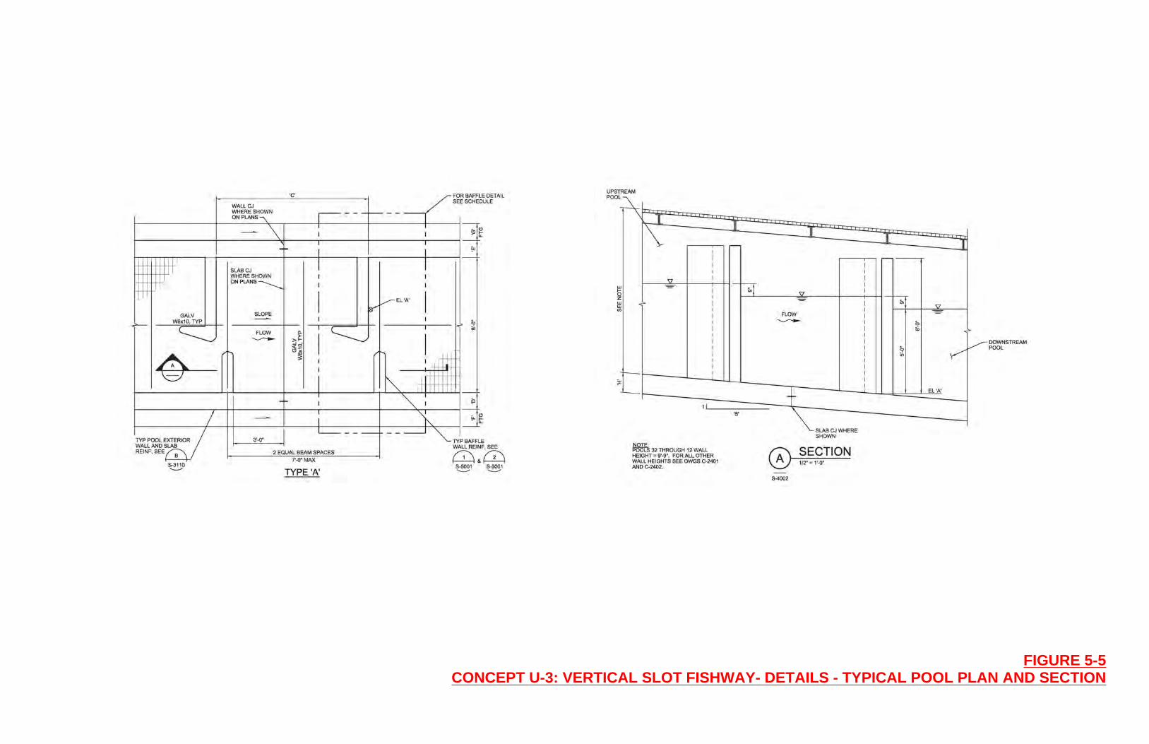
FIGURE 5-5CONCEPT U-3: VERTICAL SLOT FISHWAY- DETAILS - TYPICAL POOL PLAN AND SECTION
Appendix A Regulatory Background

Regulatory Background, Applicable Regulations and Permits
Regulatory Background – Applicable Regulations and Permits
1. NATIONAL1.1 Clean Water Act
The CWA is a national policy to restore and maintain the chemical, physical, and biological integrity of waters of the United States (U.S.); to enhance the quality of water resources; and to prevent, control, and abate water pollution. Sections 404 and 401of the CWA apply to the proposed project. Section 404 The Section 404 program is administered by the U.S. Army Corps of Engineers (USACE) with oversight from U.S. Environmental Protection Agency (EPA). Under Section 401 of the CWA, an activity that includes discharge into waters of the U.S. authorized by the Section 404 program must receive Water Quality Certification from the Washington State Department of Ecology (Ecology). Section 402 of the CWA is also administered by Ecology, and requires that project proponents that disturb one or more acres of land during construction and discharge runoff into a surface water of the United States obtain a Construction Stormwater General Permit under the National Pollutant Discharge Elimination System (NPDES).
1.2 Coastal Zone Management Act
The Coastal Zone Management Act (CZMA) provides for the management of the nation’s coastal resources. The act requires projects with a federal nexus (those that are performed by a federal agency, constructed on federal land, receive federal funding, or trigger a federal permit) are consistent with the Coastal Zone Management Program within the state where the project is located. The Washington State program is administered by the Ecology. The program prioritizes protecting and restoring coastal wetlands, preventing or reducing threats from coastal hazards, attaining increased opportunities for public access, partnering to manage the impacts of growth and development, and planning for the use of ocean resources. The BRPS project area is within the coastal zone.
1.3 Endangered Species Act
The Endangered Species Act (ESA) directs all Federal agencies to conserve endangered and threatened species. Under Section 7 of the ESA federal agencies must consult with the National Marine Fisheries Service (NMFS) and U.S. Fish and Wildlife Service (USFWS) when any action the agency carries out, funds, or authorizes (such as through a permit). Issuance of a CWA Section 404 permit triggers Section 7 consultation.
The NMFS has developed a recovery plan for Puget Sound Chinook salmon. Local governments within Water Resource Inventory Area (WRIA) 9, which includes the Black River, have developed a habitat plan to guide protection and restoration of Chinook salmon in support of the recovery plan (WRIA 9 Steering Committee 2005). The habitat plan identified improving fish passage at the BRPS as a key habitat need in the lower Green River subwatershed. Implementing the habitat plan is expected to improve habitat for other salmonid species as well as Puget Sound Chinook. The USFWS Bull Trout Coastal Recovery Unit Implementation Plan (USFWS 2015) does not list the BRPS as a threat factor.
Regulatory Background, Applicable Regulations and Permits
2. STATE2.1 Washington State Hydraulic Code A Hydraulic Project Approval (HPA) from the Washington Department of Fish and Wildlife (WDFW) is required for any project that will use, divert, obstruct, or change the natural flow or bed of any fresh or saltwater of the state (75.20 RCW). This approval applies to all construction or other work waterward and over the ordinary high water mark (OHWM), including dry channels, and may include work landward of the OHWM if activities directly impact fish life and habitat.
The WDFW has management and regulatory jurisdiction over the fish migration interests at the BRPS. The WDFW acknowledges that adult and juvenile anadromous fish reside in the Black River and its tributaries and is interested in maintaining and continuing to restore ESA-listed fish runs to the Black River (Fisher, L., personal communication, November 24, 2014; Lakey, K., personal communication, November 24, 2014). Although the pump station is not a designated fish passage barrier (WDFW, 2019b), the fishway may restrict upstream and downstream movement.
2.2 Shoreline Management Act The overall goal of the Washington State Shoreline Management Act (SMA) is "to prevent the inherent harm in an uncoordinated and piecemeal development of the state’s shorelines." The SMA directs each city and county with "shorelines of the state" to prepare and adopt a Shoreline Master Program. The Black River is identified as a Shoreline of Statewide Significance in the City of Renton. Activities within 200 feet of the Black River must comply with the Shoreline Master Program of the City of Renton (see Section 3).
2.3 Growth Management Act The Washington State Growth Management Act (GMA) requires local jurisdictions to develop a comprehensive plan to manage their population growth. Under the GMA, all cities and counties are directed to designate natural resource lands and identify steps to preserve them. In addition, all cities and counties in Washington are required to adopt critical areas regulations. The Black River and associated wetlands and their buffers are categorized as critical areas by the City of Renton (see Section 3).
2.4 Washington State Environmental Policy Act The State Environmental Policy Act (SEPA) review process helps state and local agencies in Washington identify and analyze possible environmental impacts that could result from governmental decisions. Under SEPA, one government agency is usually identified as the lead agency for the proposal and completes a SEPA environmental checklist. The lead agency identifies and evaluates potential adverse environmental impacts of a proposal and either issues a determination of non-significance, a mitigated determination of non-significance, or prepares an environmental impact statement (EIS). A mitigated determination of non-significance requires identifying adequate mitigation to offset project impacts but does not require an EIS. An EIS is required if potentially significant environmental impacts are identified that could occur due to the proposed action. King County will be the lead SEPA agency for any improvements undertaken at the BRPS.
3. LOCALThe project is located in King County and the City of Renton. King County code prohibits development from creating a measurable change in the water surface elevation for the 100-year flood event, or reducing the base flood storage volume of the floodplain (Section 21A.24.240 and 250). The BRPS is situated within the 100-year floodplain. Water surface elevation and flood storage analysis (“zero rise analysis”) determined and certified by a registered professional engineer using standard methods and practices.

Regulatory Background, Applicable Regulations and Permits
The City of Renton is responsible for implementing provisions of the SMA and GMA. Black River is identified within the City’s SMP as a regulated shoreline (Renton Municipal Code [RMC] 4-3-090B.2.c). The SMP requires that shoreline use and development result in no net loss of ecological functions such as fish and wildlife habitat, food chain support, and water temperature maintenance (RMC 4-3-090D.2.a.). King County will coordinate with the City of Renton to identify impacts to shorelines and other critical areas and mitigate impacts on those resources.
Construction may trigger local development permits and requirements, such as a construction permit and a clearing & grading permit.

Appendix B Hydraulic Calculations

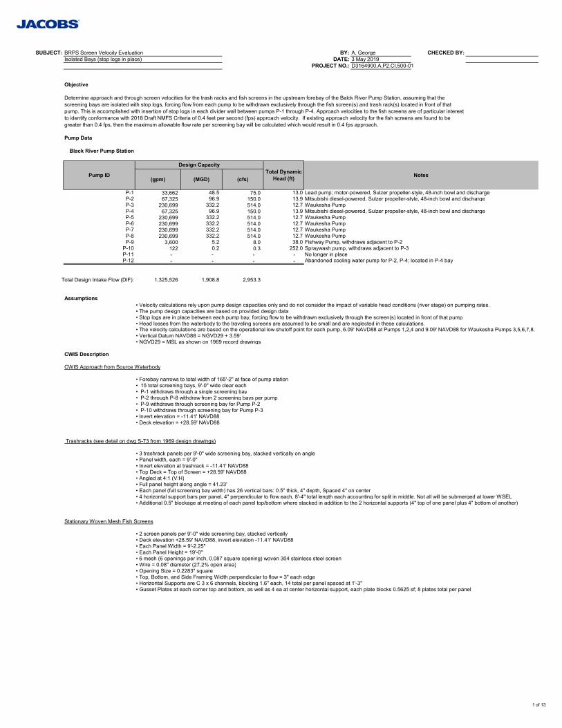
SUBJECT: BRPS Screen Velocity Evaluation BY: A. George CHECKED BY:Isolated Bays (stop logs in place) DATE: 3 May 2019
PROJECT NO.: D3164900.A.P2.CI.500-01
Objective
Pump Data
Black River Pump Station
(gpm) (MGD) (cfs)
P-1 33,662 48.5 75.0 13.0 Lead pump; motor-powered, Sulzer propeller-style, 48-inch bowl and dischargeP-2 67,325 96.9 150.0 13.9 Mitsubishi diesel-powered, Sulzer propeller-style, 48-inch bowl and dischargeP-3 230,699 332.2 514.0 12.7 Waukesha PumpP-4 67,325 96.9 150.0 13.9 Mitsubishi diesel-powered, Sulzer propeller-style, 48-inch bowl and dischargeP-5 230,699 332.2 514.0 12.7 Waukesha PumpP-6 230,699 332.2 514.0 12.7 Waukesha PumpP-7 230,699 332.2 514.0 12.7 Waukesha PumpP-8 230,699 332.2 514.0 12.7 Waukesha PumpP-9 3,600 5.2 8.0 38.0 Fishway Pump, withdraws adjacent to P-2
P-10 122 0.2 0.3 252.0 Spraywash pump, withdraws adjacent to P-3P-11 - - - - No longer in placeP-12 - - - - Abandoned cooling water pump for P-2, P-4; located in P-4 bay
Total Design Intake Flow (DIF): 1,325,526 1,908.8 2,953.3
Assumptions• Velocity calculations rely upon pump design capacities only and do not consider the impact of variable head conditions (river stage) on pumping rates.• The pump design capacities are based on provided design data• Stop logs are in place between each pump bay, forcing flow to be withdrawn exclusively through the screen(s) located in front of that pump• Head losses from the waterbody to the traveling screens are assumed to be small and are neglected in these calculations.• The velocity calculations are based on the operational low shutoff point for each pump, 6.09' NAVD88 at Pumps 1,2,4 and 9.09' NAVD88 for Waukesha Pumps 3,5,6,7,8.• Vertical Datum NAVD88 = NGVD29 + 3.59'• NGVD29 = MSL as shown on 1969 record drawings
CWIS Description
CWIS Approach from Source Waterbody
• Forebay narrows to total width of 165'-2" at face of pump station• 15 total screening bays, 9'-0" wide clear each• P-1 withdraws through a single screening bay• P-2 through P-8 withdraw from 2 screening bays per pump• P-9 withdraws through screening bay for Pump P-2• P-10 withdraws through screening bay for Pump P-3• Invert elevation = -11.41' NAVD88• Deck elevation = +28.59' NAVD88
Trashracks (see detail on dwg S-73 from 1969 design drawings)
• 3 trashrack panels per 9'-0" wide screening bay, stacked vertically on angle• Panel width, each = 9'-0"• Invert elevation at trashrack = -11.41' NAVD88• Top Deck = Top of Screen = +28.59' NAVD88• Angled at 4:1 (V:H)• Full panel height along angle = 41.23'• Each panel (full screening bay width) has 26 vertical bars: 0.5" thick, 4" depth, Spaced 4" on center• 4 horizontal support bars per panel, 4" perpendicular to flow each, 8'-4" total length each accounting for split in middle. Not all will be submerged at lower WSEL• Additional 0.5" blockage at meeting of each panel top/bottom where stacked in addition to the 2 horizontal supports (4" top of one panel plus 4" bottom of another)
Stationary Woven Mesh Fish Screens
• 2 screen panels per 9'-0" wide screening bay, stacked vertically• Deck elevation +28.59' NAVD88, invert elevation -11.41' NAVD88• Each Panel Width = 9'-2.25"• Each Panel Height = 19'-0"• 6 mesh (6 openings per inch, 0.087 square opening) woven 304 stainless steel screen• Wire = 0.08" diameter (27.2% open area)• Opening Size = 0.2283" square• Top, Bottom, and Side Framing Width perpendicular to flow = 3" each edge• Horizontal Supports are C 3 x 6 channels, blocking 1.6" each, 14 total per panel spaced at 1'-3" • Gusset Plates at each corner top and bottom, as well as 4 ea at center horizontal support, each plate blocks 0.5625 sf; 8 plates total per panel
Determine approach and through screen velocities for the trash racks and fish screens in the upstream forebay of the Balck River Pump Station, assuming that the screening bays are isolated with stop logs, forcing flow from each pump to be withdrawn exclusively through the fish screen(s) and trash rack(s) located in front of that pump. This is accomplished with insertion of stop logs in each divider wall between pumps P-1 through P-4. Approach velocities to the fish screens are of particular interest to identify conformance with 2018 Draft NMFS Criteria of 0.4 feet per second (fps) approach velocity. If existing approach velocity for the fish screens are found to be greater than 0.4 fps, then the maximum allowable flow rate per screening bay will be calculated which would result in 0.4 fps approach.
Pump ID
Design CapacityTotal Dynamic
Head (ft) Notes
1 of 13
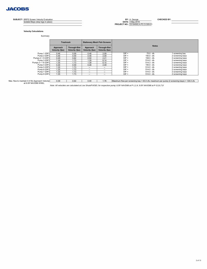
SUBJECT: BRPS Screen Velocity Evaluation BY: A. George CHECKED BY:Isolated Bays (stop logs in place) DATE: 3 May 2019
PROJECT NO.: D3164900.A.P2.CI.500-01
Velocity Calculations
Summary
Approach Velocity (fps)
Through-Slot Velocity (fps)
Approach Velocity (fps)
Through-Slot Velocity (fps)
Pump 1 (DIF) 0.46 0.59 0.48 2.09 DIF = 75.0 cfs 1 screening bayPump 2 (DIF) 0.46 0.59 0.48 2.09 DIF = 150.0 cfs 2 screening bays
Pumps 2 + 9 (DIF) 0.49 0.62 0.50 2.21 DIF = 158.0 cfs 2 screening baysPump 3 (DIF) 1.35 1.73 1.39 6.14 DIF = 514.0 cfs 2 screening bays
Pumps 3 + 10 (DIF) 1.35 1.73 1.39 6.15 DIF = 514.3 cfs 2 screening baysPump 4 (DIF) 0.46 0.59 0.48 2.09 DIF = 150.0 cfs 2 screening baysPump 5 (DIF) 1.35 1.73 -- -- DIF = 514.0 cfs 2 screening baysPump 6 (DIF) 1.35 1.73 -- -- DIF = 514.0 cfs 2 screening baysPump 7 (DIF) 1.35 1.73 -- -- DIF = 514.0 cfs 2 screening baysPump 8 (DIF) 1.35 1.73 -- -- DIF = 514.0 cfs 2 screening bays
Max. flow to maintain 0.4 ft/s Approach Velocity 0.39 0.50 0.40 1.76 Maximum flow per screening bay = 63.0 cfs; maximum per pump (2 screening bays) = 126.0 cfsat 6.09' NAVD88 WSEL
Note: All velocities are calculated at Low Shutoff WSEL for respective pump; 6.09' NAVD88 at P-1,2,4, 9.09' NAVD88 at P-3,5,6,7,8
Trashrack Stationary Mesh Fish Screens
Notes
2 of 13
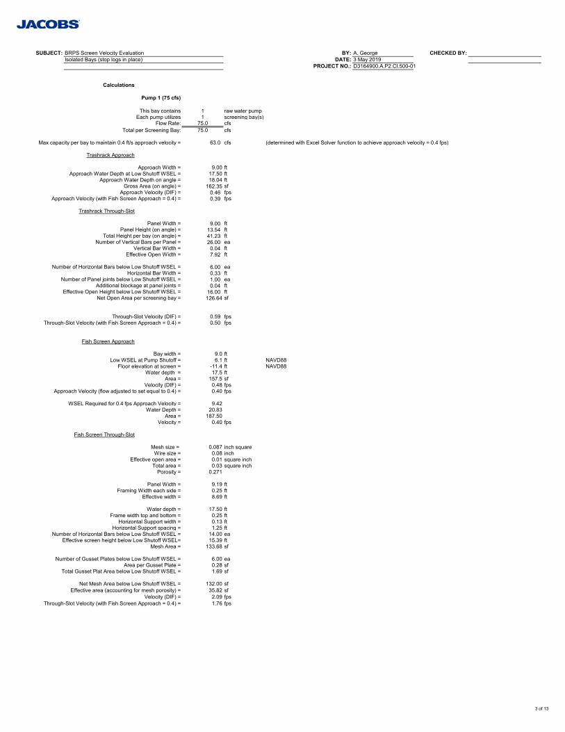
SUBJECT: BRPS Screen Velocity Evaluation BY: A. George CHECKED BY:Isolated Bays (stop logs in place) DATE: 3 May 2019
PROJECT NO.: D3164900.A.P2.CI.500-01
Calculations
Pump 1 (75 cfs)
This bay contains 1 raw water pumpEach pump utilizes 1 screening bay(s)
Flow Rate: 75.0 cfsTotal per Screening Bay: 75.0 cfs
Max capacity per bay to maintain 0.4 ft/s approach velocity = 63.0 cfs (determined with Excel Solver function to achieve approach velocity = 0.4 fps)
Trashrack Approach
Approach Width = 9.00 ftApproach Water Depth at Low Shutoff WSEL = 17.50 ft
Approach Water Depth on angle = 18.04 ftGross Area (on angle) = 162.35 sf
Approach Velocity (DIF) = 0.46 fpsApproach Velocity (with Fish Screen Approach = 0.4) = 0.39 fps
Trashrack Through-Slot
Panel Width = 9.00 ftPanel Height (on angle) = 13.54 ft
Total Height per bay (on angle) = 41.23 ftNumber of Vertical Bars per Panel = 26.00 ea
Vertical Bar Width = 0.04 ftEffective Open Width = 7.92 ft
Number of Horizontal Bars below Low Shutoff WSEL = 6.00 eaHorizontal Bar Width = 0.33 ft
Number of Panel joints below Low Shutoff WSEL = 1.00 eaAdditional blockage at panel joints = 0.04 ft
Effective Open Height below Low Shutoff WSEL = 16.00 ftNet Open Area per screening bay = 126.64 sf
Through-Slot Velocity (DIF) = 0.59 fpsThrough-Slot Velocity (with Fish Screen Approach = 0.4) = 0.50 fps
Fish Screen Approach
Bay width = 9.0 ftLow WSEL at Pump Shutoff = 6.1 ft NAVD88
Floor elevation at screen = -11.4 ft NAVD88Water depth = 17.5 ft
Area = 157.5 sfVelocity (DIF) = 0.48 fps
Approach Velocity (flow adjusted to set equal to 0.4) = 0.40 fps
WSEL Required for 0.4 fps Approach Velocity = 9.42Water Depth = 20.83
Area = 187.50Velocity = 0.40 fps
Fish Screen Through-Slot
Mesh size = 0.087 inch squareWire size = 0.08 inch
Effective open area = 0.01 square inchTotal area = 0.03 square inch
Porosity = 0.271
Panel Width = 9.19 ftFraming Width each side = 0.25 ft
Effective width = 8.69 ft
Water depth = 17.50 ftFrame width top and bottom = 0.25 ft
Horizontal Support width = 0.13 ftHorizontal Support spacing = 1.25 ft
Number of Horizontal Bars below Low Shutoff WSEL = 14.00 eaEffective screen height below Low Shutoff WSEL= 15.39 ft
Mesh Area = 133.68 sf
Number of Gusset Plates below Low Shutoff WSEL = 6.00 eaArea per Gusset Plate = 0.28 sf
Total Gusset Plat Area below Low Shutoff WSEL = 1.69 sf
Net Mesh Area below Low Shutoff WSEL = 132.00 sfEffective area (accounting for mesh porosity) = 35.82 sf
Velocity (DIF) = 2.09 fpsThrough-Slot Velocity (with Fish Screen Approach = 0.4) = 1.76 fps
3 of 13
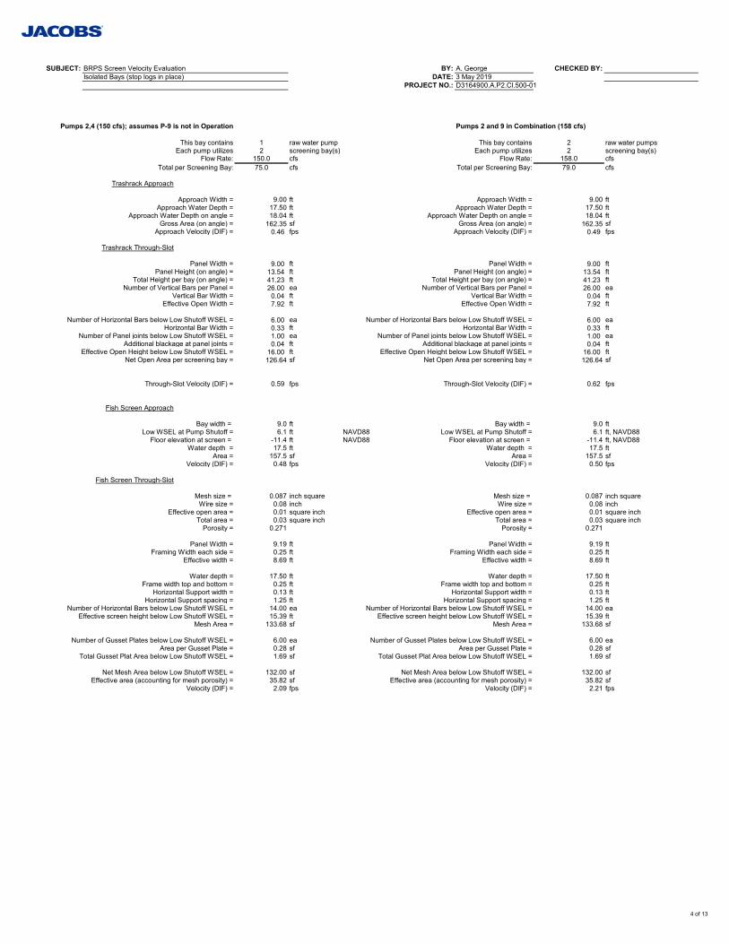
SUBJECT: BRPS Screen Velocity Evaluation BY: A. George CHECKED BY:Isolated Bays (stop logs in place) DATE: 3 May 2019
PROJECT NO.: D3164900.A.P2.CI.500-01
Pumps 2,4 (150 cfs); assumes P-9 is not in Operation Pumps 2 and 9 in Combination (158 cfs)
This bay contains 1 raw water pump This bay contains 2 raw water pumpsEach pump utilizes 2 screening bay(s) Each pump utilizes 2 screening bay(s)
Flow Rate: 150.0 cfs Flow Rate: 158.0 cfsTotal per Screening Bay: 75.0 cfs Total per Screening Bay: 79.0 cfs
Trashrack Approach
Approach Width = 9.00 ft Approach Width = 9.00 ftApproach Water Depth = 17.50 ft Approach Water Depth = 17.50 ft
Approach Water Depth on angle = 18.04 ft Approach Water Depth on angle = 18.04 ftGross Area (on angle) = 162.35 sf Gross Area (on angle) = 162.35 sf
Approach Velocity (DIF) = 0.46 fps Approach Velocity (DIF) = 0.49 fps
Trashrack Through-Slot
Panel Width = 9.00 ft Panel Width = 9.00 ftPanel Height (on angle) = 13.54 ft Panel Height (on angle) = 13.54 ft
Total Height per bay (on angle) = 41.23 ft Total Height per bay (on angle) = 41.23 ftNumber of Vertical Bars per Panel = 26.00 ea Number of Vertical Bars per Panel = 26.00 ea
Vertical Bar Width = 0.04 ft Vertical Bar Width = 0.04 ftEffective Open Width = 7.92 ft Effective Open Width = 7.92 ft
Number of Horizontal Bars below Low Shutoff WSEL = 6.00 ea Number of Horizontal Bars below Low Shutoff WSEL = 6.00 eaHorizontal Bar Width = 0.33 ft Horizontal Bar Width = 0.33 ft
Number of Panel joints below Low Shutoff WSEL = 1.00 ea Number of Panel joints below Low Shutoff WSEL = 1.00 eaAdditional blackage at panel joints = 0.04 ft Additional blackage at panel joints = 0.04 ft
Effective Open Height below Low Shutoff WSEL = 16.00 ft Effective Open Height below Low Shutoff WSEL = 16.00 ftNet Open Area per screening bay = 126.64 sf Net Open Area per screening bay = 126.64 sf
Through-Slot Velocity (DIF) = 0.59 fps Through-Slot Velocity (DIF) = 0.62 fps
Fish Screen Approach
Bay width = 9.0 ft Bay width = 9.0 ftLow WSEL at Pump Shutoff = 6.1 ft NAVD88 Low WSEL at Pump Shutoff = 6.1 ft, NAVD88
Floor elevation at screen = -11.4 ft NAVD88 Floor elevation at screen = -11.4 ft, NAVD88Water depth = 17.5 ft Water depth = 17.5 ft
Area = 157.5 sf Area = 157.5 sfVelocity (DIF) = 0.48 fps Velocity (DIF) = 0.50 fps
Fish Screen Through-Slot
Mesh size = 0.087 inch square Mesh size = 0.087 inch squareWire size = 0.08 inch Wire size = 0.08 inch
Effective open area = 0.01 square inch Effective open area = 0.01 square inchTotal area = 0.03 square inch Total area = 0.03 square inch
Porosity = 0.271 Porosity = 0.271
Panel Width = 9.19 ft Panel Width = 9.19 ftFraming Width each side = 0.25 ft Framing Width each side = 0.25 ft
Effective width = 8.69 ft Effective width = 8.69 ft
Water depth = 17.50 ft Water depth = 17.50 ftFrame width top and bottom = 0.25 ft Frame width top and bottom = 0.25 ft
Horizontal Support width = 0.13 ft Horizontal Support width = 0.13 ftHorizontal Support spacing = 1.25 ft Horizontal Support spacing = 1.25 ft
Number of Horizontal Bars below Low Shutoff WSEL = 14.00 ea Number of Horizontal Bars below Low Shutoff WSEL = 14.00 eaEffective screen height below Low Shutoff WSEL = 15.39 ft Effective screen height below Low Shutoff WSEL = 15.39 ft
Mesh Area = 133.68 sf Mesh Area = 133.68 sf
Number of Gusset Plates below Low Shutoff WSEL = 6.00 ea Number of Gusset Plates below Low Shutoff WSEL = 6.00 eaArea per Gusset Plate = 0.28 sf Area per Gusset Plate = 0.28 sf
Total Gusset Plat Area below Low Shutoff WSEL = 1.69 sf Total Gusset Plat Area below Low Shutoff WSEL = 1.69 sf
Net Mesh Area below Low Shutoff WSEL = 132.00 sf Net Mesh Area below Low Shutoff WSEL = 132.00 sfEffective area (accounting for mesh porosity) = 35.82 sf Effective area (accounting for mesh porosity) = 35.82 sf
Velocity (DIF) = 2.09 fps Velocity (DIF) = 2.21 fps
4 of 13
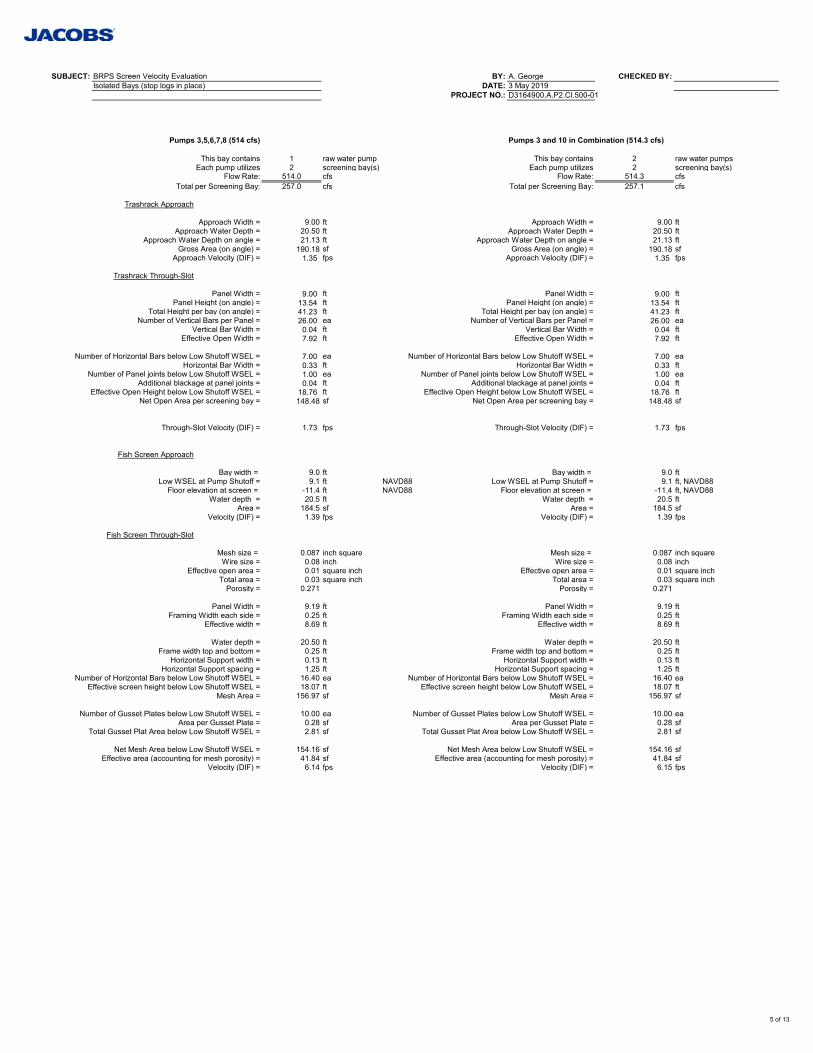
SUBJECT: BRPS Screen Velocity Evaluation BY: A. George CHECKED BY:Isolated Bays (stop logs in place) DATE: 3 May 2019
PROJECT NO.: D3164900.A.P2.CI.500-01
Pumps 3,5,6,7,8 (514 cfs) Pumps 3 and 10 in Combination (514.3 cfs)
This bay contains 1 raw water pump This bay contains 2 raw water pumpsEach pump utilizes 2 screening bay(s) Each pump utilizes 2 screening bay(s)
Flow Rate: 514.0 cfs Flow Rate: 514.3 cfsTotal per Screening Bay: 257.0 cfs Total per Screening Bay: 257.1 cfs
Trashrack Approach
Approach Width = 9.00 ft Approach Width = 9.00 ftApproach Water Depth = 20.50 ft Approach Water Depth = 20.50 ft
Approach Water Depth on angle = 21.13 ft Approach Water Depth on angle = 21.13 ftGross Area (on angle) = 190.18 sf Gross Area (on angle) = 190.18 sf
Approach Velocity (DIF) = 1.35 fps Approach Velocity (DIF) = 1.35 fps
Trashrack Through-Slot
Panel Width = 9.00 ft Panel Width = 9.00 ftPanel Height (on angle) = 13.54 ft Panel Height (on angle) = 13.54 ft
Total Height per bay (on angle) = 41.23 ft Total Height per bay (on angle) = 41.23 ftNumber of Vertical Bars per Panel = 26.00 ea Number of Vertical Bars per Panel = 26.00 ea
Vertical Bar Width = 0.04 ft Vertical Bar Width = 0.04 ftEffective Open Width = 7.92 ft Effective Open Width = 7.92 ft
Number of Horizontal Bars below Low Shutoff WSEL = 7.00 ea Number of Horizontal Bars below Low Shutoff WSEL = 7.00 eaHorizontal Bar Width = 0.33 ft Horizontal Bar Width = 0.33 ft
Number of Panel joints below Low Shutoff WSEL = 1.00 ea Number of Panel joints below Low Shutoff WSEL = 1.00 eaAdditional blackage at panel joints = 0.04 ft Additional blackage at panel joints = 0.04 ft
Effective Open Height below Low Shutoff WSEL = 18.76 ft Effective Open Height below Low Shutoff WSEL = 18.76 ftNet Open Area per screening bay = 148.48 sf Net Open Area per screening bay = 148.48 sf
Through-Slot Velocity (DIF) = 1.73 fps Through-Slot Velocity (DIF) = 1.73 fps
Fish Screen Approach
Bay width = 9.0 ft Bay width = 9.0 ftLow WSEL at Pump Shutoff = 9.1 ft NAVD88 Low WSEL at Pump Shutoff = 9.1 ft, NAVD88
Floor elevation at screen = -11.4 ft NAVD88 Floor elevation at screen = -11.4 ft, NAVD88Water depth = 20.5 ft Water depth = 20.5 ft
Area = 184.5 sf Area = 184.5 sfVelocity (DIF) = 1.39 fps Velocity (DIF) = 1.39 fps
Fish Screen Through-Slot
Mesh size = 0.087 inch square Mesh size = 0.087 inch squareWire size = 0.08 inch Wire size = 0.08 inch
Effective open area = 0.01 square inch Effective open area = 0.01 square inchTotal area = 0.03 square inch Total area = 0.03 square inch
Porosity = 0.271 Porosity = 0.271
Panel Width = 9.19 ft Panel Width = 9.19 ftFraming Width each side = 0.25 ft Framing Width each side = 0.25 ft
Effective width = 8.69 ft Effective width = 8.69 ft
Water depth = 20.50 ft Water depth = 20.50 ftFrame width top and bottom = 0.25 ft Frame width top and bottom = 0.25 ft
Horizontal Support width = 0.13 ft Horizontal Support width = 0.13 ftHorizontal Support spacing = 1.25 ft Horizontal Support spacing = 1.25 ft
Number of Horizontal Bars below Low Shutoff WSEL = 16.40 ea Number of Horizontal Bars below Low Shutoff WSEL = 16.40 eaEffective screen height below Low Shutoff WSEL = 18.07 ft Effective screen height below Low Shutoff WSEL = 18.07 ft
Mesh Area = 156.97 sf Mesh Area = 156.97 sf
Number of Gusset Plates below Low Shutoff WSEL = 10.00 ea Number of Gusset Plates below Low Shutoff WSEL = 10.00 eaArea per Gusset Plate = 0.28 sf Area per Gusset Plate = 0.28 sf
Total Gusset Plat Area below Low Shutoff WSEL = 2.81 sf Total Gusset Plat Area below Low Shutoff WSEL = 2.81 sf
Net Mesh Area below Low Shutoff WSEL = 154.16 sf Net Mesh Area below Low Shutoff WSEL = 154.16 sfEffective area (accounting for mesh porosity) = 41.84 sf Effective area (accounting for mesh porosity) = 41.84 sf
Velocity (DIF) = 6.14 fps Velocity (DIF) = 6.15 fps
5 of 13
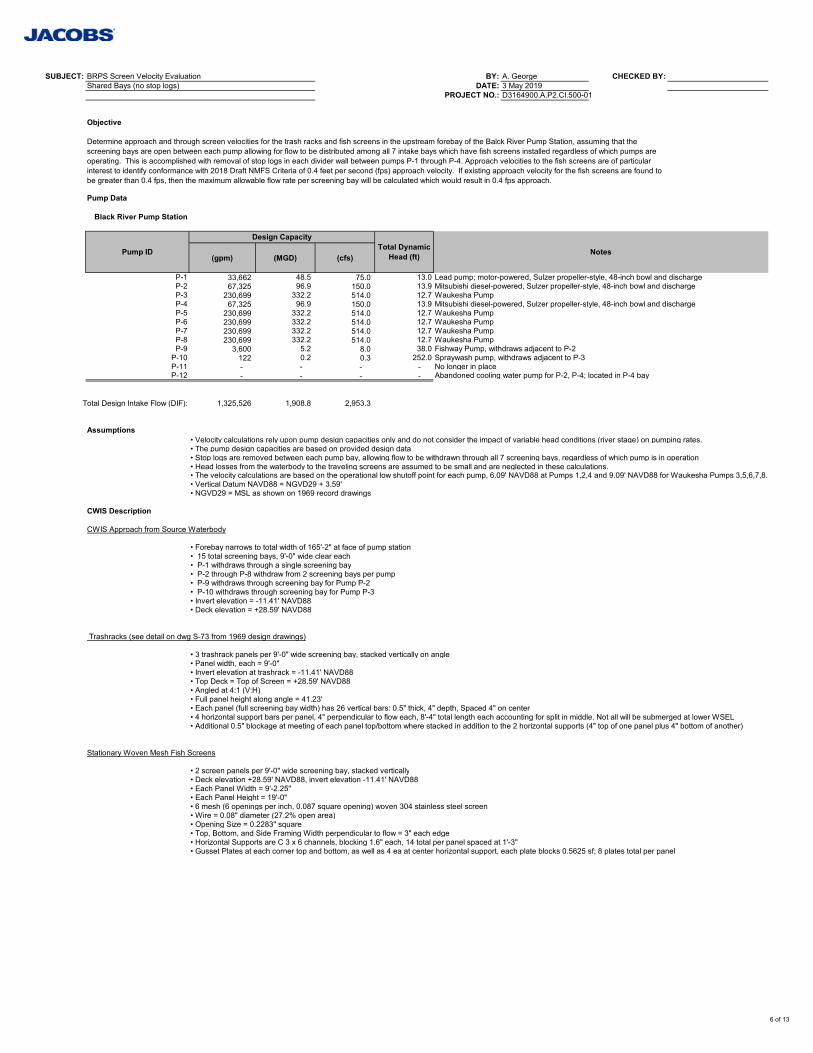
SUBJECT: BRPS Screen Velocity Evaluation BY: A. George CHECKED BY:Shared Bays (no stop logs) DATE: 3 May 2019
PROJECT NO.: D3164900.A.P2.CI.500-01
Objective
Pump Data
Black River Pump Station
(gpm) (MGD) (cfs)
P-1 33,662 48.5 75.0 13.0 Lead pump; motor-powered, Sulzer propeller-style, 48-inch bowl and dischargeP-2 67,325 96.9 150.0 13.9 Mitsubishi diesel-powered, Sulzer propeller-style, 48-inch bowl and dischargeP-3 230,699 332.2 514.0 12.7 Waukesha PumpP-4 67,325 96.9 150.0 13.9 Mitsubishi diesel-powered, Sulzer propeller-style, 48-inch bowl and dischargeP-5 230,699 332.2 514.0 12.7 Waukesha PumpP-6 230,699 332.2 514.0 12.7 Waukesha PumpP-7 230,699 332.2 514.0 12.7 Waukesha PumpP-8 230,699 332.2 514.0 12.7 Waukesha PumpP-9 3,600 5.2 8.0 38.0 Fishway Pump, withdraws adjacent to P-2
P-10 122 0.2 0.3 252.0 Spraywash pump, withdraws adjacent to P-3P-11 - - - - No longer in placeP-12 - - - - Abandoned cooling water pump for P-2, P-4; located in P-4 bay
Total Design Intake Flow (DIF): 1,325,526 1,908.8 2,953.3
Assumptions• Velocity calculations rely upon pump design capacities only and do not consider the impact of variable head conditions (river stage) on pumping rates.• The pump design capacities are based on provided design data• Stop logs are removed between each pump bay, allowing flow to be withdrawn through all 7 screening bays, regardless of which pump is in operation• Head losses from the waterbody to the traveling screens are assumed to be small and are neglected in these calculations.• The velocity calculations are based on the operational low shutoff point for each pump, 6.09' NAVD88 at Pumps 1,2,4 and 9.09' NAVD88 for Waukesha Pumps 3,5,6,7,8.• Vertical Datum NAVD88 = NGVD29 + 3.59'• NGVD29 = MSL as shown on 1969 record drawings
CWIS Description
CWIS Approach from Source Waterbody
• Forebay narrows to total width of 165'-2" at face of pump station• 15 total screening bays, 9'-0" wide clear each• P-1 withdraws through a single screening bay• P-2 through P-8 withdraw from 2 screening bays per pump• P-9 withdraws through screening bay for Pump P-2• P-10 withdraws through screening bay for Pump P-3• Invert elevation = -11.41' NAVD88• Deck elevation = +28.59' NAVD88
Trashracks (see detail on dwg S-73 from 1969 design drawings)
• 3 trashrack panels per 9'-0" wide screening bay, stacked vertically on angle• Panel width, each = 9'-0"• Invert elevation at trashrack = -11.41' NAVD88• Top Deck = Top of Screen = +28.59' NAVD88• Angled at 4:1 (V:H)• Full panel height along angle = 41.23'• Each panel (full screening bay width) has 26 vertical bars: 0.5" thick, 4" depth, Spaced 4" on center• 4 horizontal support bars per panel, 4" perpendicular to flow each, 8'-4" total length each accounting for split in middle. Not all will be submerged at lower WSEL• Additional 0.5" blockage at meeting of each panel top/bottom where stacked in addition to the 2 horizontal supports (4" top of one panel plus 4" bottom of another)
Stationary Woven Mesh Fish Screens
• 2 screen panels per 9'-0" wide screening bay, stacked vertically• Deck elevation +28.59' NAVD88, invert elevation -11.41' NAVD88• Each Panel Width = 9'-2.25"• Each Panel Height = 19'-0"• 6 mesh (6 openings per inch, 0.087 square opening) woven 304 stainless steel screen• Wire = 0.08" diameter (27.2% open area)• Opening Size = 0.2283" square• Top, Bottom, and Side Framing Width perpendicular to flow = 3" each edge• Horizontal Supports are C 3 x 6 channels, blocking 1.6" each, 14 total per panel spaced at 1'-3" • Gusset Plates at each corner top and bottom, as well as 4 ea at center horizontal support, each plate blocks 0.5625 sf; 8 plates total per panel
Determine approach and through screen velocities for the trash racks and fish screens in the upstream forebay of the Balck River Pump Station, assuming that the screening bays are open between each pump allowing for flow to be distributed among all 7 intake bays which have fish screens installed regardless of which pumps are operating. This is accomplished with removal of stop logs in each divider wall between pumps P-1 through P-4. Approach velocities to the fish screens are of particular interest to identify conformance with 2018 Draft NMFS Criteria of 0.4 feet per second (fps) approach velocity. If existing approach velocity for the fish screens are found to be greater than 0.4 fps, then the maximum allowable flow rate per screening bay will be calculated which would result in 0.4 fps approach.
Pump ID
Design CapacityTotal Dynamic
Head (ft) Notes
6 of 13
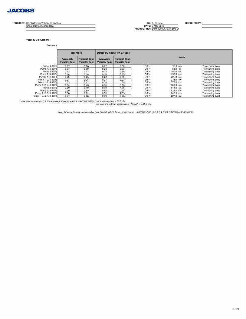
SUBJECT: BRPS Screen Velocity Evaluation BY: A. George CHECKED BY:Shared Bays (no stop logs) DATE: 3 May 2019
PROJECT NO.: D3164900.A.P2.CI.500-01
Velocity Calculations
Summary
Approach Velocity (fps)
Through-Slot Velocity (fps)
Approach Velocity (fps)
Through-Slot Velocity (fps)
Pump 1 (DIF) 0.07 0.08 0.07 0.30 DIF = 75.0 cfs 7 screening baysPump 1, 9 (DIF) 0.07 0.09 0.08 0.33 DIF = 83.0 cfs 7 screening bays
Pump 2 (DIF) 0.13 0.17 0.14 0.60 DIF = 150.0 cfs 7 screening baysPump 2, 9 (DIF) 0.14 0.18 0.14 0.63 DIF = 158.0 cfs 7 screening bays
Pumps 1, 2 (DIF) 0.20 0.25 0.20 0.90 DIF = 225.0 cfs 7 screening baysPump 1, 2, 9 (DIF) 0.21 0.26 0.21 0.93 DIF = 233.0 cfs 7 screening baysPump 1, 2, 4 (DIF) 0.33 0.42 0.34 1.50 DIF = 375.0 cfs 7 screening bays
Pump 1, 2, 4, 9 (DIF) 0.34 0.43 0.35 1.53 DIF = 383.0 cfs 7 screening baysPump 3 (DIF) 0.39 0.49 0.40 1.76 DIF = 514.0 cfs 7 screening bays
Pump 3, 9 (DIF) 0.39 0.50 0.40 1.78 DIF = 522.0 cfs 7 screening baysPump 1, 2, 3, 9 (DIF) 0.56 0.72 0.58 2.55 DIF = 747.0 cfs 7 screening bays
Pump 1, 2, 3, 4, 9 (DIF) 0.67 0.86 0.69 3.06 DIF = 897.0 cfs 7 screening bays
Max. flow to maintain 0.4 ft/s Approach Velocity at 6.09' NAVD88 WSEL: per screening bay = 63.0 cfs;per total shared fish screen area (7 bays) = 441.0 cfs
Note: All velocities are calculated at Low Shutoff WSEL for respective pump; 6.09' NAVD88 at P-1,2,4, 9.09' NAVD88 at P-3,5,6,7,8
Trashrack Stationary Mesh Fish Screens
Notes
7 of 13
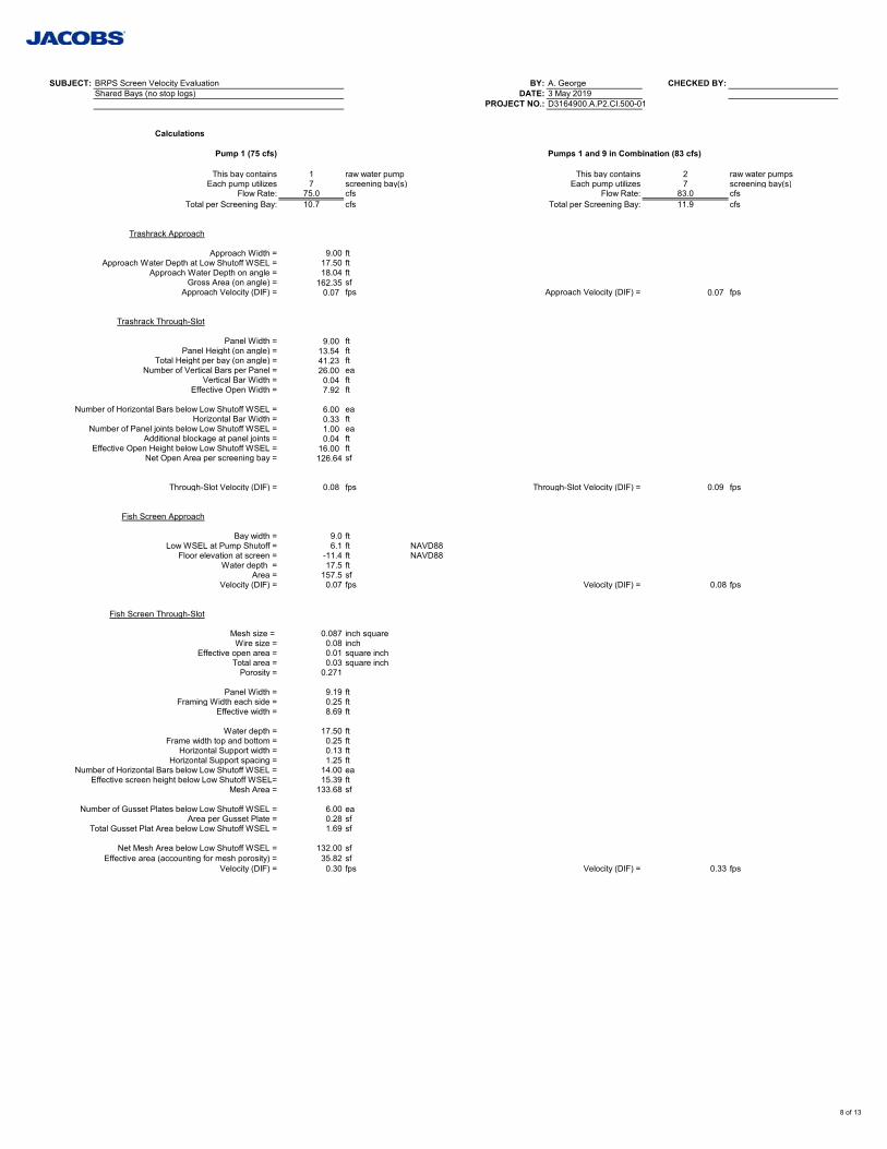
SUBJECT: BRPS Screen Velocity Evaluation BY: A. George CHECKED BY:Shared Bays (no stop logs) DATE: 3 May 2019
PROJECT NO.: D3164900.A.P2.CI.500-01
Calculations
Pump 1 (75 cfs) Pumps 1 and 9 in Combination (83 cfs)
This bay contains 1 raw water pump This bay contains 2 raw water pumpsEach pump utilizes 7 screening bay(s) Each pump utilizes 7 screening bay(s)
Flow Rate: 75.0 cfs Flow Rate: 83.0 cfsTotal per Screening Bay: 10.7 cfs Total per Screening Bay: 11.9 cfs
Trashrack Approach
Approach Width = 9.00 ftApproach Water Depth at Low Shutoff WSEL = 17.50 ft
Approach Water Depth on angle = 18.04 ftGross Area (on angle) = 162.35 sf
Approach Velocity (DIF) = 0.07 fps Approach Velocity (DIF) = 0.07 fps
Trashrack Through-Slot
Panel Width = 9.00 ftPanel Height (on angle) = 13.54 ft
Total Height per bay (on angle) = 41.23 ftNumber of Vertical Bars per Panel = 26.00 ea
Vertical Bar Width = 0.04 ftEffective Open Width = 7.92 ft
Number of Horizontal Bars below Low Shutoff WSEL = 6.00 eaHorizontal Bar Width = 0.33 ft
Number of Panel joints below Low Shutoff WSEL = 1.00 eaAdditional blockage at panel joints = 0.04 ft
Effective Open Height below Low Shutoff WSEL = 16.00 ftNet Open Area per screening bay = 126.64 sf
Through-Slot Velocity (DIF) = 0.08 fps Through-Slot Velocity (DIF) = 0.09 fps
Fish Screen Approach
Bay width = 9.0 ftLow WSEL at Pump Shutoff = 6.1 ft NAVD88
Floor elevation at screen = -11.4 ft NAVD88Water depth = 17.5 ft
Area = 157.5 sfVelocity (DIF) = 0.07 fps Velocity (DIF) = 0.08 fps
Fish Screen Through-Slot
Mesh size = 0.087 inch squareWire size = 0.08 inch
Effective open area = 0.01 square inchTotal area = 0.03 square inch
Porosity = 0.271
Panel Width = 9.19 ftFraming Width each side = 0.25 ft
Effective width = 8.69 ft
Water depth = 17.50 ftFrame width top and bottom = 0.25 ft
Horizontal Support width = 0.13 ftHorizontal Support spacing = 1.25 ft
Number of Horizontal Bars below Low Shutoff WSEL = 14.00 eaEffective screen height below Low Shutoff WSEL= 15.39 ft
Mesh Area = 133.68 sf
Number of Gusset Plates below Low Shutoff WSEL = 6.00 eaArea per Gusset Plate = 0.28 sf
Total Gusset Plat Area below Low Shutoff WSEL = 1.69 sf
Net Mesh Area below Low Shutoff WSEL = 132.00 sfEffective area (accounting for mesh porosity) = 35.82 sf
Velocity (DIF) = 0.30 fps Velocity (DIF) = 0.33 fps
8 of 13
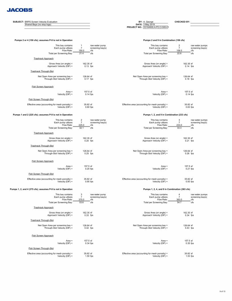
SUBJECT: BRPS Screen Velocity Evaluation BY: A. George CHECKED BY:Shared Bays (no stop logs) DATE: 3 May 2019
PROJECT NO.: D3164900.A.P2.CI.500-01
Pumps 2 or 4 (150 cfs); assumes P-9 is not in Operation Pumps 2 and 9 in Combination (158 cfs)
This bay contains 1 raw water pump This bay contains 2 raw water pumpsEach pump utilizes 7 screening bay(s) Each pump utilizes 7 screening bay(s)
Flow Rate: 150.0 cfs Flow Rate: 158.0 cfsTotal per Screening Bay: 21.4 cfs Total per Screening Bay: 22.6 cfs
Trashrack Approach
Gross Area (on angle) = 162.35 sf Gross Area (on angle) = 162.35 sfApproach Velocity (DIF) = 0.13 fps Approach Velocity (DIF) = 0.14 fps
Trashrack Through-Slot
Net Open Area per screening bay = 126.64 sf Net Open Area per screening bay = 126.64 sfThrough-Slot Velocity (DIF) = 0.17 fps Through-Slot Velocity (DIF) = 0.18 fps
Fish Screen Approach
Area = 157.5 sf Area = 157.5 sfVelocity (DIF) = 0.14 fps Velocity (DIF) = 0.14 fps
Fish Screen Through-Slot
Effective area (accounting for mesh porosity) = 35.82 sf Effective area (accounting for mesh porosity) = 35.82 sfVelocity (DIF) = 0.60 fps Velocity (DIF) = 0.63 fps
Pumps 1 and 2 (225 cfs); assumes P-9 is not in Operation Pumps 1, 2, and 9 in Combination (233 cfs)
This bay contains 2 raw water pump This bay contains 3 raw water pumpsEach pump utilizes 7 screening bay(s) Each pump utilizes 7 screening bay(s)
Flow Rate: 225.0 cfs Flow Rate: 233.0 cfsTotal per Screening Bay: 32.1 cfs Total per Screening Bay: 33.3 cfs
Trashrack Approach
Gross Area (on angle) = 162.35 sf Gross Area (on angle) = 162.35 sfApproach Velocity (DIF) = 0.20 fps Approach Velocity (DIF) = 0.21 fps
Trashrack Through-Slot
Net Open Area per screening bay = 126.64 sf Net Open Area per screening bay = 126.64 sfThrough-Slot Velocity (DIF) = 0.25 fps Through-Slot Velocity (DIF) = 0.26 fps
Fish Screen Approach
Area = 157.5 sf Area = 157.5 sfVelocity (DIF) = 0.20 fps Velocity (DIF) = 0.21 fps
Fish Screen Through-Slot
Effective area (accounting for mesh porosity) = 35.82 sf Effective area (accounting for mesh porosity) = 35.82 sfVelocity (DIF) = 0.90 fps Velocity (DIF) = 0.93 fps
Pumps 1, 2, and 4 (375 cfs); assumes P-9 is not in Operation Pumps 1, 2, 4, and 9 in Combination (383 cfs)
This bay contains 3 raw water pump This bay contains 4 raw water pumpsEach pump utilizes 7 screening bay(s) Each pump utilizes 7 screening bay(s)
Flow Rate: 375.0 cfs Flow Rate: 383.0 cfsTotal per Screening Bay: 53.6 cfs Total per Screening Bay: 54.7 cfs
Trashrack Approach
Gross Area (on angle) = 162.35 sf Gross Area (on angle) = 162.35 sfApproach Velocity (DIF) = 0.33 fps Approach Velocity (DIF) = 0.34 fps
Trashrack Through-Slot
Net Open Area per screening bay = 126.64 sf Net Open Area per screening bay = 126.64 sfThrough-Slot Velocity (DIF) = 0.42 fps Through-Slot Velocity (DIF) = 0.43 fps
Fish Screen Approach
Area = 157.5 sf Area = 157.5 sfVelocity (DIF) = 0.34 fps Velocity (DIF) = 0.35 fps
Fish Screen Through-Slot
Effective area (accounting for mesh porosity) = 35.82 sf Effective area (accounting for mesh porosity) = 35.82 sfVelocity (DIF) = 1.50 fps Velocity (DIF) = 1.53 fps
9 of 13
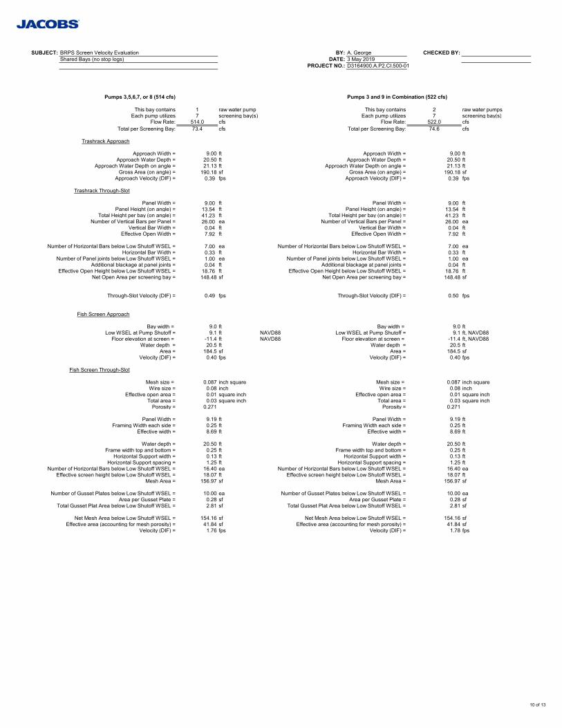
SUBJECT: BRPS Screen Velocity Evaluation BY: A. George CHECKED BY:Shared Bays (no stop logs) DATE: 3 May 2019
PROJECT NO.: D3164900.A.P2.CI.500-01
Pumps 3,5,6,7, or 8 (514 cfs) Pumps 3 and 9 in Combination (522 cfs)
This bay contains 1 raw water pump This bay contains 2 raw water pumpsEach pump utilizes 7 screening bay(s) Each pump utilizes 7 screening bay(s)
Flow Rate: 514.0 cfs Flow Rate: 522.0 cfsTotal per Screening Bay: 73.4 cfs Total per Screening Bay: 74.6 cfs
Trashrack Approach
Approach Width = 9.00 ft Approach Width = 9.00 ftApproach Water Depth = 20.50 ft Approach Water Depth = 20.50 ft
Approach Water Depth on angle = 21.13 ft Approach Water Depth on angle = 21.13 ftGross Area (on angle) = 190.18 sf Gross Area (on angle) = 190.18 sf
Approach Velocity (DIF) = 0.39 fps Approach Velocity (DIF) = 0.39 fps
Trashrack Through-Slot
Panel Width = 9.00 ft Panel Width = 9.00 ftPanel Height (on angle) = 13.54 ft Panel Height (on angle) = 13.54 ft
Total Height per bay (on angle) = 41.23 ft Total Height per bay (on angle) = 41.23 ftNumber of Vertical Bars per Panel = 26.00 ea Number of Vertical Bars per Panel = 26.00 ea
Vertical Bar Width = 0.04 ft Vertical Bar Width = 0.04 ftEffective Open Width = 7.92 ft Effective Open Width = 7.92 ft
Number of Horizontal Bars below Low Shutoff WSEL = 7.00 ea Number of Horizontal Bars below Low Shutoff WSEL = 7.00 eaHorizontal Bar Width = 0.33 ft Horizontal Bar Width = 0.33 ft
Number of Panel joints below Low Shutoff WSEL = 1.00 ea Number of Panel joints below Low Shutoff WSEL = 1.00 eaAdditional blackage at panel joints = 0.04 ft Additional blackage at panel joints = 0.04 ft
Effective Open Height below Low Shutoff WSEL = 18.76 ft Effective Open Height below Low Shutoff WSEL = 18.76 ftNet Open Area per screening bay = 148.48 sf Net Open Area per screening bay = 148.48 sf
Through-Slot Velocity (DIF) = 0.49 fps Through-Slot Velocity (DIF) = 0.50 fps
Fish Screen Approach
Bay width = 9.0 ft Bay width = 9.0 ftLow WSEL at Pump Shutoff = 9.1 ft NAVD88 Low WSEL at Pump Shutoff = 9.1 ft, NAVD88
Floor elevation at screen = -11.4 ft NAVD88 Floor elevation at screen = -11.4 ft, NAVD88Water depth = 20.5 ft Water depth = 20.5 ft
Area = 184.5 sf Area = 184.5 sfVelocity (DIF) = 0.40 fps Velocity (DIF) = 0.40 fps
Fish Screen Through-Slot
Mesh size = 0.087 inch square Mesh size = 0.087 inch squareWire size = 0.08 inch Wire size = 0.08 inch
Effective open area = 0.01 square inch Effective open area = 0.01 square inchTotal area = 0.03 square inch Total area = 0.03 square inch
Porosity = 0.271 Porosity = 0.271
Panel Width = 9.19 ft Panel Width = 9.19 ftFraming Width each side = 0.25 ft Framing Width each side = 0.25 ft
Effective width = 8.69 ft Effective width = 8.69 ft
Water depth = 20.50 ft Water depth = 20.50 ftFrame width top and bottom = 0.25 ft Frame width top and bottom = 0.25 ft
Horizontal Support width = 0.13 ft Horizontal Support width = 0.13 ftHorizontal Support spacing = 1.25 ft Horizontal Support spacing = 1.25 ft
Number of Horizontal Bars below Low Shutoff WSEL = 16.40 ea Number of Horizontal Bars below Low Shutoff WSEL = 16.40 eaEffective screen height below Low Shutoff WSEL = 18.07 ft Effective screen height below Low Shutoff WSEL = 18.07 ft
Mesh Area = 156.97 sf Mesh Area = 156.97 sf
Number of Gusset Plates below Low Shutoff WSEL = 10.00 ea Number of Gusset Plates below Low Shutoff WSEL = 10.00 eaArea per Gusset Plate = 0.28 sf Area per Gusset Plate = 0.28 sf
Total Gusset Plat Area below Low Shutoff WSEL = 2.81 sf Total Gusset Plat Area below Low Shutoff WSEL = 2.81 sf
Net Mesh Area below Low Shutoff WSEL = 154.16 sf Net Mesh Area below Low Shutoff WSEL = 154.16 sfEffective area (accounting for mesh porosity) = 41.84 sf Effective area (accounting for mesh porosity) = 41.84 sf
Velocity (DIF) = 1.76 fps Velocity (DIF) = 1.78 fps
10 of 13
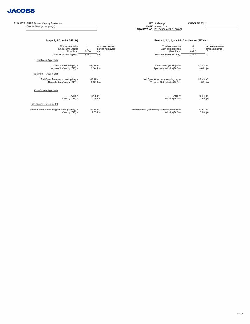
SUBJECT: BRPS Screen Velocity Evaluation BY: A. George CHECKED BY:Shared Bays (no stop logs) DATE: 3 May 2019
PROJECT NO.: D3164900.A.P2.CI.500-01
Pumps 1, 2, 3, and 9 (747 cfs) Pumps 1, 2, 3, 4, and 9 in Combination (897 cfs)
This bay contains 4 raw water pump This bay contains 5 raw water pumpsEach pump utilizes 7 screening bay(s) Each pump utilizes 7 screening bay(s)
Flow Rate: 747.0 cfs Flow Rate: 897.0 cfsTotal per Screening Bay: 106.7 cfs Total per Screening Bay: 128.1 cfs
Trashrack Approach
Gross Area (on angle) = 190.18 sf Gross Area (on angle) = 190.18 sfApproach Velocity (DIF) = 0.56 fps Approach Velocity (DIF) = 0.67 fps
Trashrack Through-Slot
Net Open Area per screening bay = 148.48 sf Net Open Area per screening bay = 148.48 sfThrough-Slot Velocity (DIF) = 0.72 fps Through-Slot Velocity (DIF) = 0.86 fps
Fish Screen Approach
Area = 184.5 sf Area = 184.5 sfVelocity (DIF) = 0.58 fps Velocity (DIF) = 0.69 fps
Fish Screen Through-Slot
Effective area (accounting for mesh porosity) = 41.84 sf Effective area (accounting for mesh porosity) = 41.84 sfVelocity (DIF) = 2.55 fps Velocity (DIF) = 3.06 fps
11 of 13
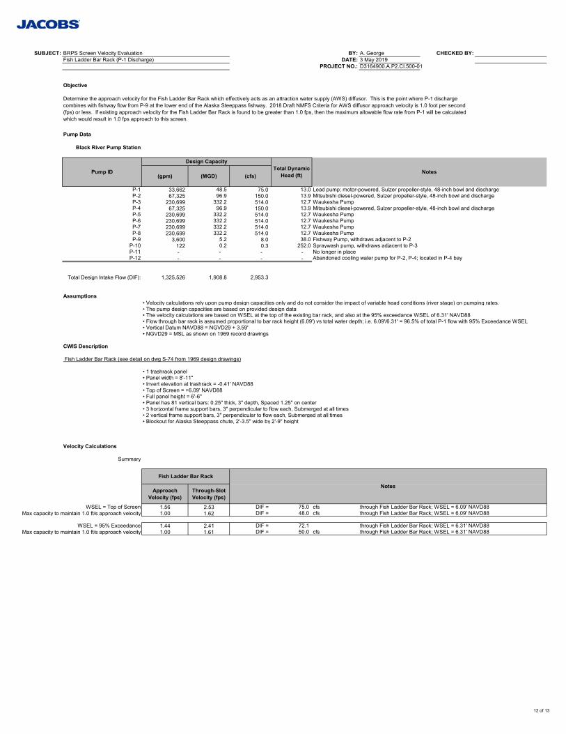
SUBJECT: BRPS Screen Velocity Evaluation BY: A. George CHECKED BY:Fish Ladder Bar Rack (P-1 Discharge) DATE: 3 May 2019
PROJECT NO.: D3164900.A.P2.CI.500-01
Objective
Pump Data
Black River Pump Station
(gpm) (MGD) (cfs)
P-1 33,662 48.5 75.0 13.0 Lead pump; motor-powered, Sulzer propeller-style, 48-inch bowl and dischargeP-2 67,325 96.9 150.0 13.9 Mitsubishi diesel-powered, Sulzer propeller-style, 48-inch bowl and dischargeP-3 230,699 332.2 514.0 12.7 Waukesha PumpP-4 67,325 96.9 150.0 13.9 Mitsubishi diesel-powered, Sulzer propeller-style, 48-inch bowl and dischargeP-5 230,699 332.2 514.0 12.7 Waukesha PumpP-6 230,699 332.2 514.0 12.7 Waukesha PumpP-7 230,699 332.2 514.0 12.7 Waukesha PumpP-8 230,699 332.2 514.0 12.7 Waukesha PumpP-9 3,600 5.2 8.0 38.0 Fishway Pump, withdraws adjacent to P-2
P-10 122 0.2 0.3 252.0 Spraywash pump, withdraws adjacent to P-3P-11 - - - - No longer in placeP-12 - - - - Abandoned cooling water pump for P-2, P-4; located in P-4 bay
Total Design Intake Flow (DIF): 1,325,526 1,908.8 2,953.3
Assumptions• Velocity calculations rely upon pump design capacities only and do not consider the impact of variable head conditions (river stage) on pumping rates.• The pump design capacities are based on provided design data• The velocity calculations are based on WSEL at the top of the existing bar rack, and also at the 95% exceedance WSEL of 6.31' NAVD88• Flow through bar rack is assumed proportional to bar rack height (6.09') vs total water depth; i.e. 6.09'/6.31' = 96.5% of total P-1 flow with 95% Exceedance WSEL• Vertical Datum NAVD88 = NGVD29 + 3.59'• NGVD29 = MSL as shown on 1969 record drawings
CWIS Description
Fish Ladder Bar Rack (see detail on dwg S-74 from 1969 design drawings)
• 1 trashrack panel• Panel width = 8'-11"• Invert elevation at trashrack = -0.41' NAVD88• Top of Screen = +6.09' NAVD88• Full panel height = 6'-6"• Panel has 81 vertical bars: 0.25" thick, 3" depth, Spaced 1.25" on center• 3 horizontal frame support bars, 3" perpendicular to flow each, Submerged at all times• 2 vertical frame support bars, 3" perpendicular to flow each, Submerged at all times• Blockout for Alaska Steeppass chute, 2'-3.5" wide by 2'-9" height
Velocity Calculations
Summary
Approach Velocity (fps)
Through-Slot Velocity (fps)
WSEL = Top of Screen 1.56 2.53 DIF = 75.0 cfs through Fish Ladder Bar Rack; WSEL = 6.09' NAVD88Max capacity to maintain 1.0 ft/s approach velocity 1.00 1.62 DIF = 48.0 cfs through Fish Ladder Bar Rack; WSEL = 6.09' NAVD88
WSEL = 95% Exceedance 1.44 2.41 DIF = 72.1 through Fish Ladder Bar Rack; WSEL = 6.31' NAVD88Max capacity to maintain 1.0 ft/s approach velocity 1.00 1.61 DIF = 50.0 cfs through Fish Ladder Bar Rack; WSEL = 6.31' NAVD88
Fish Ladder Bar Rack
Notes
Determine the approach velocity for the Fish Ladder Bar Rack which effectively acts as an attraction water supply (AWS) diffusor. This is the point where P-1 discharge combines with fishway flow from P-9 at the lower end of the Alaska Steeppass fishway. 2018 Draft NMFS Criteria for AWS diffusor approach velocity is 1.0 foot per second (fps) or less. If existing approach velocity for the Fish Ladder Bar Rack is found to be greater than 1.0 fps, then the maximum allowable flow rate from P-1 will be calculated which would result in 1.0 fps approach to this screen.
Pump ID
Design CapacityTotal Dynamic
Head (ft) Notes
12 of 13
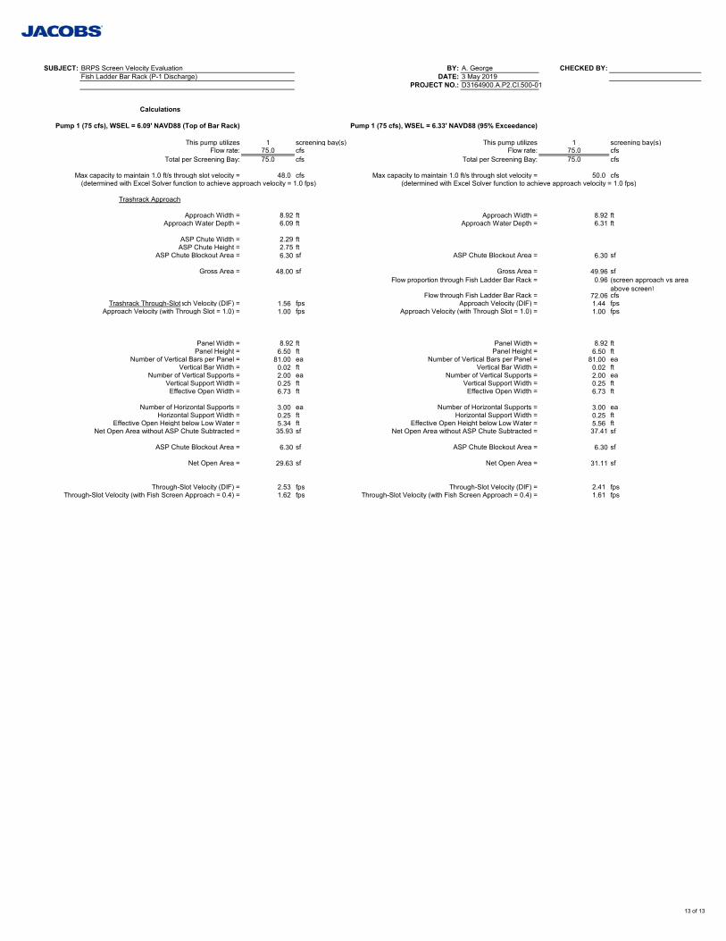
SUBJECT: BRPS Screen Velocity Evaluation BY: A. George CHECKED BY:Fish Ladder Bar Rack (P-1 Discharge) DATE: 3 May 2019
PROJECT NO.: D3164900.A.P2.CI.500-01
Calculations
Pump 1 (75 cfs), WSEL = 6.09' NAVD88 (Top of Bar Rack) Pump 1 (75 cfs), WSEL = 6.33' NAVD88 (95% Exceedance)
This pump utilizes 1 screening bay(s) This pump utilizes 1 screening bay(s)Flow rate: 75.0 cfs Flow rate: 75.0 cfs
Total per Screening Bay: 75.0 cfs Total per Screening Bay: 75.0 cfs
Max capacity to maintain 1.0 ft/s through slot velocity = 48.0 cfs Max capacity to maintain 1.0 ft/s through slot velocity = 50.0 cfs(determined with Excel Solver function to achieve approach velocity = 1.0 fps) (determined with Excel Solver function to achieve approach velocity = 1.0 fps)
Trashrack Approach
Approach Width = 8.92 ft Approach Width = 8.92 ftApproach Water Depth = 6.09 ft Approach Water Depth = 6.31 ft
ASP Chute Width = 2.29 ftASP Chute Height = 2.75 ft
ASP Chute Blockout Area = 6.30 sf ASP Chute Blockout Area = 6.30 sf
Gross Area = 48.00 sf Gross Area = 49.96 sfFlow proportion through Fish Ladder Bar Rack = 0.96 (screen approach vs area
above screen)Flow through Fish Ladder Bar Rack = 72.06 cfs
Trashrack Through-Slotach Velocity (DIF) = 1.56 fps Approach Velocity (DIF) = 1.44 fpsApproach Velocity (with Through Slot = 1.0) = 1.00 fps Approach Velocity (with Through Slot = 1.0) = 1.00 fps
Panel Width = 8.92 ft Panel Width = 8.92 ftPanel Height = 6.50 ft Panel Height = 6.50 ft
Number of Vertical Bars per Panel = 81.00 ea Number of Vertical Bars per Panel = 81.00 eaVertical Bar Width = 0.02 ft Vertical Bar Width = 0.02 ft
Number of Vertical Supports = 2.00 ea Number of Vertical Supports = 2.00 eaVertical Support Width = 0.25 ft Vertical Support Width = 0.25 ftEffective Open Width = 6.73 ft Effective Open Width = 6.73 ft
Number of Horizontal Supports = 3.00 ea Number of Horizontal Supports = 3.00 eaHorizontal Support Width = 0.25 ft Horizontal Support Width = 0.25 ft
Effective Open Height below Low Water = 5.34 ft Effective Open Height below Low Water = 5.56 ftNet Open Area without ASP Chute Subtracted = 35.93 sf Net Open Area without ASP Chute Subtracted = 37.41 sf
ASP Chute Blockout Area = 6.30 sf ASP Chute Blockout Area = 6.30 sf
Net Open Area = 29.63 sf Net Open Area = 31.11 sf
Through-Slot Velocity (DIF) = 2.53 fps Through-Slot Velocity (DIF) = 2.41 fpsThrough-Slot Velocity (with Fish Screen Approach = 0.4) = 1.62 fps Through-Slot Velocity (with Fish Screen Approach = 0.4) = 1.61 fps
13 of 13

Appendix C Compliance with Regulatory Criteria and
Guidelines

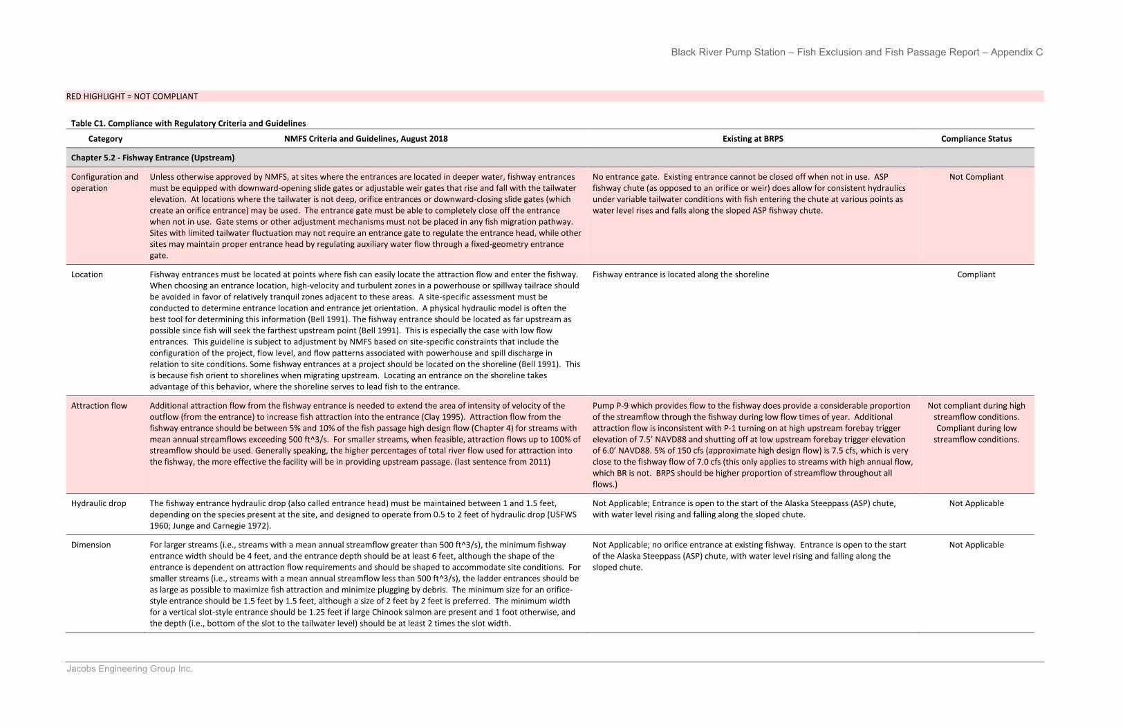
Black River Pump Station – Fish Exclusion and Fish Passage Report – Appendix C
Jacobs Engineering Group Inc.
RED HIGHLIGHT = NOT COMPLIANT
Table C1. Compliance with Regulatory Criteria and Guidelines
Category NMFS Criteria and Guidelines, August 2018 Existing at BRPS Compliance Status
Chapter 5.2 - Fishway Entrance (Upstream)
Configuration and operation
Unless otherwise approved by NMFS, at sites where the entrances are located in deeper water, fishway entrances must be equipped with downward-opening slide gates or adjustable weir gates that rise and fall with the tailwater elevation. At locations where the tailwater is not deep, orifice entrances or downward-closing slide gates (which create an orifice entrance) may be used. The entrance gate must be able to completely close off the entrance when not in use. Gate stems or other adjustment mechanisms must not be placed in any fish migration pathway. Sites with limited tailwater fluctuation may not require an entrance gate to regulate the entrance head, while other sites may maintain proper entrance head by regulating auxiliary water flow through a fixed-geometry entrance gate.
No entrance gate. Existing entrance cannot be closed off when not in use. ASP fishway chute (as opposed to an orifice or weir) does allow for consistent hydraulics under variable tailwater conditions with fish entering the chute at various points as water level rises and falls along the sloped ASP fishway chute.
Not Compliant
Location Fishway entrances must be located at points where fish can easily locate the attraction flow and enter the fishway. When choosing an entrance location, high-velocity and turbulent zones in a powerhouse or spillway tailrace should be avoided in favor of relatively tranquil zones adjacent to these areas. A site-specific assessment must be conducted to determine entrance location and entrance jet orientation. A physical hydraulic model is often the best tool for determining this information (Bell 1991). The fishway entrance should be located as far upstream as possible since fish will seek the farthest upstream point (Bell 1991). This is especially the case with low flow entrances. This guideline is subject to adjustment by NMFS based on site-specific constraints that include the configuration of the project, flow level, and flow patterns associated with powerhouse and spill discharge in relation to site conditions. Some fishway entrances at a project should be located on the shoreline (Bell 1991). This is because fish orient to shorelines when migrating upstream. Locating an entrance on the shoreline takes advantage of this behavior, where the shoreline serves to lead fish to the entrance.
Fishway entrance is located along the shoreline Compliant
Attraction flow Additional attraction flow from the fishway entrance is needed to extend the area of intensity of velocity of the outflow (from the entrance) to increase fish attraction into the entrance (Clay 1995). Attraction flow from the fishway entrance should be between 5% and 10% of the fish passage high design flow (Chapter 4) for streams with mean annual streamflows exceeding 500 ft^3/s. For smaller streams, when feasible, attraction flows up to 100% of streamflow should be used. Generally speaking, the higher percentages of total river flow used for attraction into the fishway, the more effective the facility will be in providing upstream passage. (last sentence from 2011)
Pump P-9 which provides flow to the fishway does provide a considerable proportion of the streamflow through the fishway during low flow times of year. Additional attraction flow is inconsistent with P-1 turning on at high upstream forebay trigger elevation of 7.5’ NAVD88 and shutting off at low upstream forebay trigger elevation of 6.0’ NAVD88. 5% of 150 cfs (approximate high design flow) is 7.5 cfs, which is very close to the fishway flow of 7.0 cfs (this only applies to streams with high annual flow, which BR is not. BRPS should be higher proportion of streamflow throughout all flows.)
Not compliant during high streamflow conditions. Compliant during low
streamflow conditions.
Hydraulic drop The fishway entrance hydraulic drop (also called entrance head) must be maintained between 1 and 1.5 feet, depending on the species present at the site, and designed to operate from 0.5 to 2 feet of hydraulic drop (USFWS 1960; Junge and Carnegie 1972).
Not Applicable; Entrance is open to the start of the Alaska Steeppass (ASP) chute, with water level rising and falling along the sloped chute.
Not Applicable
Dimension For larger streams (i.e., streams with a mean annual streamflow greater than 500 ft^3/s), the minimum fishway entrance width should be 4 feet, and the entrance depth should be at least 6 feet, although the shape of the entrance is dependent on attraction flow requirements and should be shaped to accommodate site conditions. For smaller streams (i.e., streams with a mean annual streamflow less than 500 ft^3/s), the ladder entrances should be as large as possible to maximize fish attraction and minimize plugging by debris. The minimum size for an orifice-style entrance should be 1.5 feet by 1.5 feet, although a size of 2 feet by 2 feet is preferred. The minimum width for a vertical slot-style entrance should be 1.25 feet if large Chinook salmon are present and 1 foot otherwise, and the depth (i.e., bottom of the slot to the tailwater level) should be at least 2 times the slot width.
Not Applicable; no orifice entrance at existing fishway. Entrance is open to the start of the Alaska Steeppass (ASP) chute, with water level rising and falling along the sloped chute.
Not Applicable
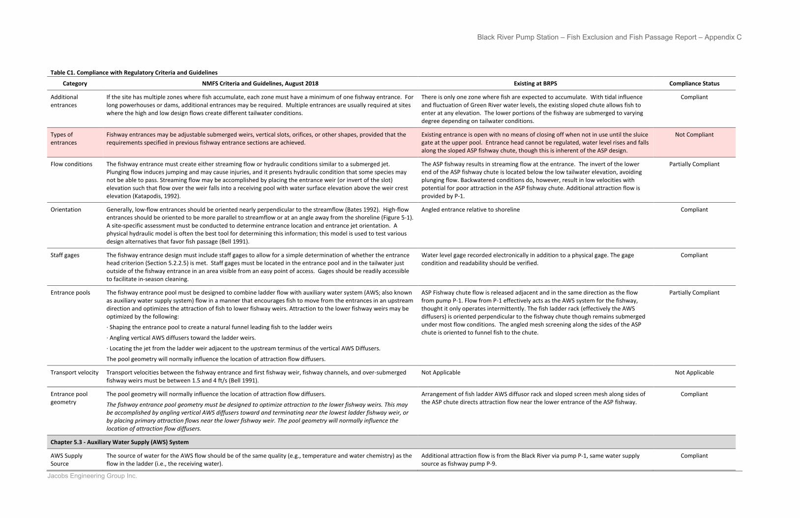
Black River Pump Station – Fish Exclusion and Fish Passage Report – Appendix C
Jacobs Engineering Group Inc.
Table C1. Compliance with Regulatory Criteria and Guidelines
Category NMFS Criteria and Guidelines, August 2018 Existing at BRPS Compliance Status
Additional entrances
If the site has multiple zones where fish accumulate, each zone must have a minimum of one fishway entrance. For long powerhouses or dams, additional entrances may be required. Multiple entrances are usually required at sites where the high and low design flows create different tailwater conditions.
There is only one zone where fish are expected to accumulate. With tidal influence and fluctuation of Green River water levels, the existing sloped chute allows fish to enter at any elevation. The lower portions of the fishway are submerged to varying degree depending on tailwater conditions.
Compliant
Types of entrances
Fishway entrances may be adjustable submerged weirs, vertical slots, orifices, or other shapes, provided that the requirements specified in previous fishway entrance sections are achieved.
Existing entrance is open with no means of closing off when not in use until the sluice gate at the upper pool. Entrance head cannot be regulated, water level rises and falls along the sloped ASP fishway chute, though this is inherent of the ASP design.
Not Compliant
Flow conditions The fishway entrance must create either streaming flow or hydraulic conditions similar to a submerged jet. Plunging flow induces jumping and may cause injuries, and it presents hydraulic condition that some species may not be able to pass. Streaming flow may be accomplished by placing the entrance weir (or invert of the slot) elevation such that flow over the weir falls into a receiving pool with water surface elevation above the weir crest elevation (Katapodis, 1992).
The ASP fishway results in streaming flow at the entrance. The invert of the lower end of the ASP fishway chute is located below the low tailwater elevation, avoiding plunging flow. Backwatered conditions do, however, result in low velocities with potential for poor attraction in the ASP fishway chute. Additional attraction flow is provided by P-1.
Partially Compliant
Orientation Generally, low-flow entrances should be oriented nearly perpendicular to the streamflow (Bates 1992). High-flow entrances should be oriented to be more parallel to streamflow or at an angle away from the shoreline (Figure 5-1). A site-specific assessment must be conducted to determine entrance location and entrance jet orientation. A physical hydraulic model is often the best tool for determining this information; this model is used to test various design alternatives that favor fish passage (Bell 1991).
Angled entrance relative to shoreline Compliant
Staff gages The fishway entrance design must include staff gages to allow for a simple determination of whether the entrance head criterion (Section 5.2.2.5) is met. Staff gages must be located in the entrance pool and in the tailwater just outside of the fishway entrance in an area visible from an easy point of access. Gages should be readily accessible to facilitate in-season cleaning.
Water level gage recorded electronically in addition to a physical gage. The gage condition and readability should be verified.
Compliant
Entrance pools The fishway entrance pool must be designed to combine ladder flow with auxiliary water system (AWS; also known as auxiliary water supply system) flow in a manner that encourages fish to move from the entrances in an upstream direction and optimizes the attraction of fish to lower fishway weirs. Attraction to the lower fishway weirs may be optimized by the following:
· Shaping the entrance pool to create a natural funnel leading fish to the ladder weirs
· Angling vertical AWS diffusers toward the ladder weirs.
· Locating the jet from the ladder weir adjacent to the upstream terminus of the vertical AWS Diffusers.
The pool geometry will normally influence the location of attraction flow diffusers.
ASP Fishway chute flow is released adjacent and in the same direction as the flow from pump P-1. Flow from P-1 effectively acts as the AWS system for the fishway, thought it only operates intermittently. The fish ladder rack (effectively the AWS diffusers) is oriented perpendicular to the fishway chute though remains submerged under most flow conditions. The angled mesh screening along the sides of the ASP chute is oriented to funnel fish to the chute.
Partially Compliant
Transport velocity Transport velocities between the fishway entrance and first fishway weir, fishway channels, and over-submerged fishway weirs must be between 1.5 and 4 ft/s (Bell 1991).
Not Applicable Not Applicable
Entrance pool geometry
The pool geometry will normally influence the location of attraction flow diffusers.
The fishway entrance pool geometry must be designed to optimize attraction to the lower fishway weirs. This may be accomplished by angling vertical AWS diffusers toward and terminating near the lowest ladder fishway weir, or by placing primary attraction flows near the lower fishway weir. The pool geometry will normally influence the location of attraction flow diffusers.
Arrangement of fish ladder AWS diffusor rack and sloped screen mesh along sides of the ASP chute directs attraction flow near the lower entrance of the ASP fishway.
Compliant
Chapter 5.3 - Auxiliary Water Supply (AWS) System
AWS Supply Source
The source of water for the AWS flow should be of the same quality (e.g., temperature and water chemistry) as the flow in the ladder (i.e., the receiving water).
Additional attraction flow is from the Black River via pump P-1, same water supply source as fishway pump P-9.
Compliant
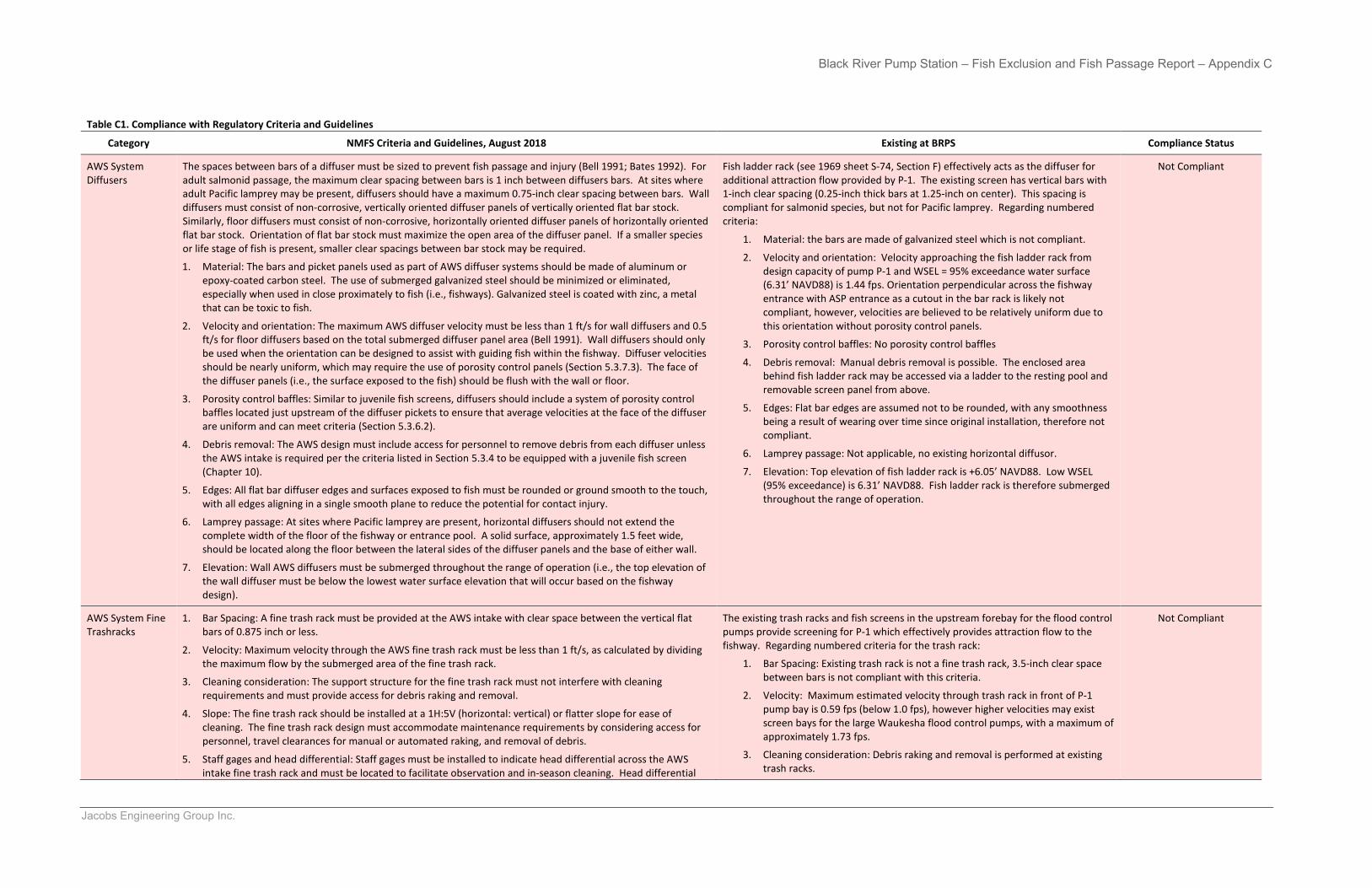
Black River Pump Station – Fish Exclusion and Fish Passage Report – Appendix C
Jacobs Engineering Group Inc.
Table C1. Compliance with Regulatory Criteria and Guidelines
Category NMFS Criteria and Guidelines, August 2018 Existing at BRPS Compliance Status
AWS System Diffusers
The spaces between bars of a diffuser must be sized to prevent fish passage and injury (Bell 1991; Bates 1992). For adult salmonid passage, the maximum clear spacing between bars is 1 inch between diffusers bars. At sites where adult Pacific lamprey may be present, diffusers should have a maximum 0.75-inch clear spacing between bars. Wall diffusers must consist of non-corrosive, vertically oriented diffuser panels of vertically oriented flat bar stock. Similarly, floor diffusers must consist of non-corrosive, horizontally oriented diffuser panels of horizontally oriented flat bar stock. Orientation of flat bar stock must maximize the open area of the diffuser panel. If a smaller species or life stage of fish is present, smaller clear spacings between bar stock may be required.
1. Material: The bars and picket panels used as part of AWS diffuser systems should be made of aluminum orepoxy-coated carbon steel. The use of submerged galvanized steel should be minimized or eliminated,especially when used in close proximately to fish (i.e., fishways). Galvanized steel is coated with zinc, a metalthat can be toxic to fish.
2. Velocity and orientation: The maximum AWS diffuser velocity must be less than 1 ft/s for wall diffusers and 0.5ft/s for floor diffusers based on the total submerged diffuser panel area (Bell 1991). Wall diffusers should onlybe used when the orientation can be designed to assist with guiding fish within the fishway. Diffuser velocitiesshould be nearly uniform, which may require the use of porosity control panels (Section 5.3.7.3). The face ofthe diffuser panels (i.e., the surface exposed to the fish) should be flush with the wall or floor.
3. Porosity control baffles: Similar to juvenile fish screens, diffusers should include a system of porosity controlbaffles located just upstream of the diffuser pickets to ensure that average velocities at the face of the diffuserare uniform and can meet criteria (Section 5.3.6.2).
4. Debris removal: The AWS design must include access for personnel to remove debris from each diffuser unlessthe AWS intake is required per the criteria listed in Section 5.3.4 to be equipped with a juvenile fish screen(Chapter 10).
5. Edges: All flat bar diffuser edges and surfaces exposed to fish must be rounded or ground smooth to the touch,with all edges aligning in a single smooth plane to reduce the potential for contact injury.
6. Lamprey passage: At sites where Pacific lamprey are present, horizontal diffusers should not extend thecomplete width of the floor of the fishway or entrance pool. A solid surface, approximately 1.5 feet wide,should be located along the floor between the lateral sides of the diffuser panels and the base of either wall.
7. Elevation: Wall AWS diffusers must be submerged throughout the range of operation (i.e., the top elevation ofthe wall diffuser must be below the lowest water surface elevation that will occur based on the fishwaydesign).
Fish ladder rack (see 1969 sheet S-74, Section F) effectively acts as the diffuser for additional attraction flow provided by P-1. The existing screen has vertical bars with 1-inch clear spacing (0.25-inch thick bars at 1.25-inch on center). This spacing iscompliant for salmonid species, but not for Pacific lamprey. Regarding numberedcriteria:
1. Material: the bars are made of galvanized steel which is not compliant.
2. Velocity and orientation: Velocity approaching the fish ladder rack fromdesign capacity of pump P-1 and WSEL = 95% exceedance water surface(6.31’ NAVD88) is 1.44 fps. Orientation perpendicular across the fishwayentrance with ASP entrance as a cutout in the bar rack is likely notcompliant, however, velocities are believed to be relatively uniform due tothis orientation without porosity control panels.
3. Porosity control baffles: No porosity control baffles
4. Debris removal: Manual debris removal is possible. The enclosed areabehind fish ladder rack may be accessed via a ladder to the resting pool andremovable screen panel from above.
5. Edges: Flat bar edges are assumed not to be rounded, with any smoothnessbeing a result of wearing over time since original installation, therefore notcompliant.
6. Lamprey passage: Not applicable, no existing horizontal diffusor.
7. Elevation: Top elevation of fish ladder rack is +6.05’ NAVD88. Low WSEL(95% exceedance) is 6.31’ NAVD88. Fish ladder rack is therefore submergedthroughout the range of operation.
Not Compliant
AWS System Fine Trashracks
1. Bar Spacing: A fine trash rack must be provided at the AWS intake with clear space between the vertical flatbars of 0.875 inch or less.
2. Velocity: Maximum velocity through the AWS fine trash rack must be less than 1 ft/s, as calculated by dividingthe maximum flow by the submerged area of the fine trash rack.
3. Cleaning consideration: The support structure for the fine trash rack must not interfere with cleaningrequirements and must provide access for debris raking and removal.
4. Slope: The fine trash rack should be installed at a 1H:5V (horizontal: vertical) or flatter slope for ease ofcleaning. The fine trash rack design must accommodate maintenance requirements by considering access forpersonnel, travel clearances for manual or automated raking, and removal of debris.
5. Staff gages and head differential: Staff gages must be installed to indicate head differential across the AWSintake fine trash rack and must be located to facilitate observation and in-season cleaning. Head differential
The existing trash racks and fish screens in the upstream forebay for the flood control pumps provide screening for P-1 which effectively provides attraction flow to the fishway. Regarding numbered criteria for the trash rack:
1. Bar Spacing: Existing trash rack is not a fine trash rack, 3.5-inch clear spacebetween bars is not compliant with this criteria.
2. Velocity: Maximum estimated velocity through trash rack in front of P-1pump bay is 0.59 fps (below 1.0 fps), however higher velocities may existscreen bays for the large Waukesha flood control pumps, with a maximum ofapproximately 1.73 fps.
3. Cleaning consideration: Debris raking and removal is performed at existingtrash racks.
Not Compliant
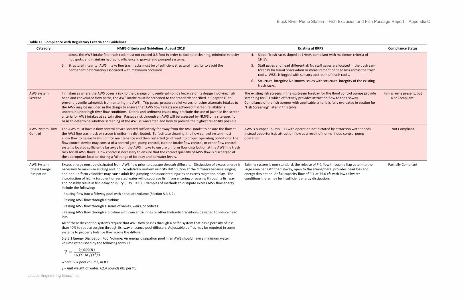
Black River Pump Station – Fish Exclusion and Fish Passage Report – Appendix C
Jacobs Engineering Group Inc.
Table C1. Compliance with Regulatory Criteria and Guidelines
Category NMFS Criteria and Guidelines, August 2018 Existing at BRPS Compliance Status
across the AWS intake fine trash rack must not exceed 0.3 foot in order to facilitate cleaning, minimize velocity hot spots, and maintain hydraulic efficiency in gravity and pumped systems.
6. Structural integrity: AWS intake fine trash racks must be of sufficient structural integrity to avoid thepermanent deformation associated with maximum occlusion.
4. Slope: Trash racks sloped at 1H:4V, compliant with maximum criteria of1H:5V.
5. Staff gages and head differential: No staff gages are located in the upstreamforebay for visual observation or measurement of head loss across the trashracks. WSEL is logged with sensors upstream of trash racks.
6. Structural integrity: No known issues with structural integrity of the existingtrash racks.
AWS System Screens
In instances where the AWS poses a risk to the passage of juvenile salmonids because of its design involving high head and convoluted flow paths, the AWS intake must be screened to the standards specified in Chapter 10 to prevent juvenile salmonids from entering the AWS. Trip gates, pressure relief valves, or other alternate intakes to the AWS may be included in the design to ensure that AWS flow targets are achieved if screen reliability is uncertain under high river flow conditions. Debris and sediment issues may preclude the use of juvenile fish screen criteria for AWS intakes at certain sites. Passage risk through an AWS will be assessed by NMFS on a site-specific basis to determine whether screening of the AWS is warranted and how to provide the highest reliability possible.
The existing fish screens in the upstream forebay for the flood control pumps provide screening for P-1 which effectively provides attraction flow to the fishway. Compliance of the fish screens with applicable criteria is fully evaluated in section for “Fish Screening” later in this table.
Fish screens present, but Not Compliant.
AWS System Flow Control
The AWS must have a flow control device located sufficiently far away from the AWS intake to ensure the flow at the AWS fine trash rack or screen is uniformly distributed. To facilitate cleaning, the flow control system must allow flow to be easily shut off for maintenance and then restarted (and reset) to proper operating conditions. The flow control device may consist of a control gate, pump control, turbine intake flow control, or other flow control systems located sufficiently far away from the AWS intake to ensure uniform flow distribution at the AWS fine trash rack for all AWS flows. Flow control is necessary to ensure that the correct quantity of AWS flow is discharged at the appropriate location during a full range of forebay and tailwater levels.
AWS is pumped (pump P-1) with operation not dictated by attraction water needs. Instead opportunistic attraction flow as a result of normal flood control pump operation.
Not Compliant
AWS System Excess Energy Dissipation
Excess energy must be dissipated from AWS flow prior to passage through diffusers. Dissipation of excess energy is necessary to minimize surging and induce relatively uniform velocity distribution at the diffusers because surging and non-uniform velocities may cause adult fish jumping and associated injuries or excess migration delay. The introduction of highly turbulent or aerated water will discourage fish from entering or passing through a fishway and possibly result in fish delay or injury (Clay 1995). Examples of methods to dissipate excess AWS flow energy include the following:
· Routing flow into a fishway pool with adequate volume (Section 5.3.6.2)
· Passing AWS flow through a turbine
· Passing AWS flow through a series of valves, weirs, or orifices
· Passing AWS flow through a pipeline with concentric rings or other hydraulic transitions designed to induce headloss
All of these dissipation systems require that AWS flow passes through a baffle system that has a porosity of less than 40% to reduce surging through fishway entrance pool diffusers. Adjustable baffles may be required in some systems to properly balance flow across the diffuser.
5.3.5.1 Energy Dissipation Pool Volume: An energy dissipation pool in an AWS should have a minimum water volume established by the following formula:
where: V = pool volume, in ft3
γ = unit weight of water, 62.4 pounds (lb) per ft3
Existing system is non-standard; the release of P-1 flow through a flap gate into the large area beneath the fishway, open to the atmosphere, provides head loss and energy dissipation. At full capacity flow of P-1 at 75.0 cfs with low tailwater conditions there may be insufficient energy dissipation.
Partially Compliant
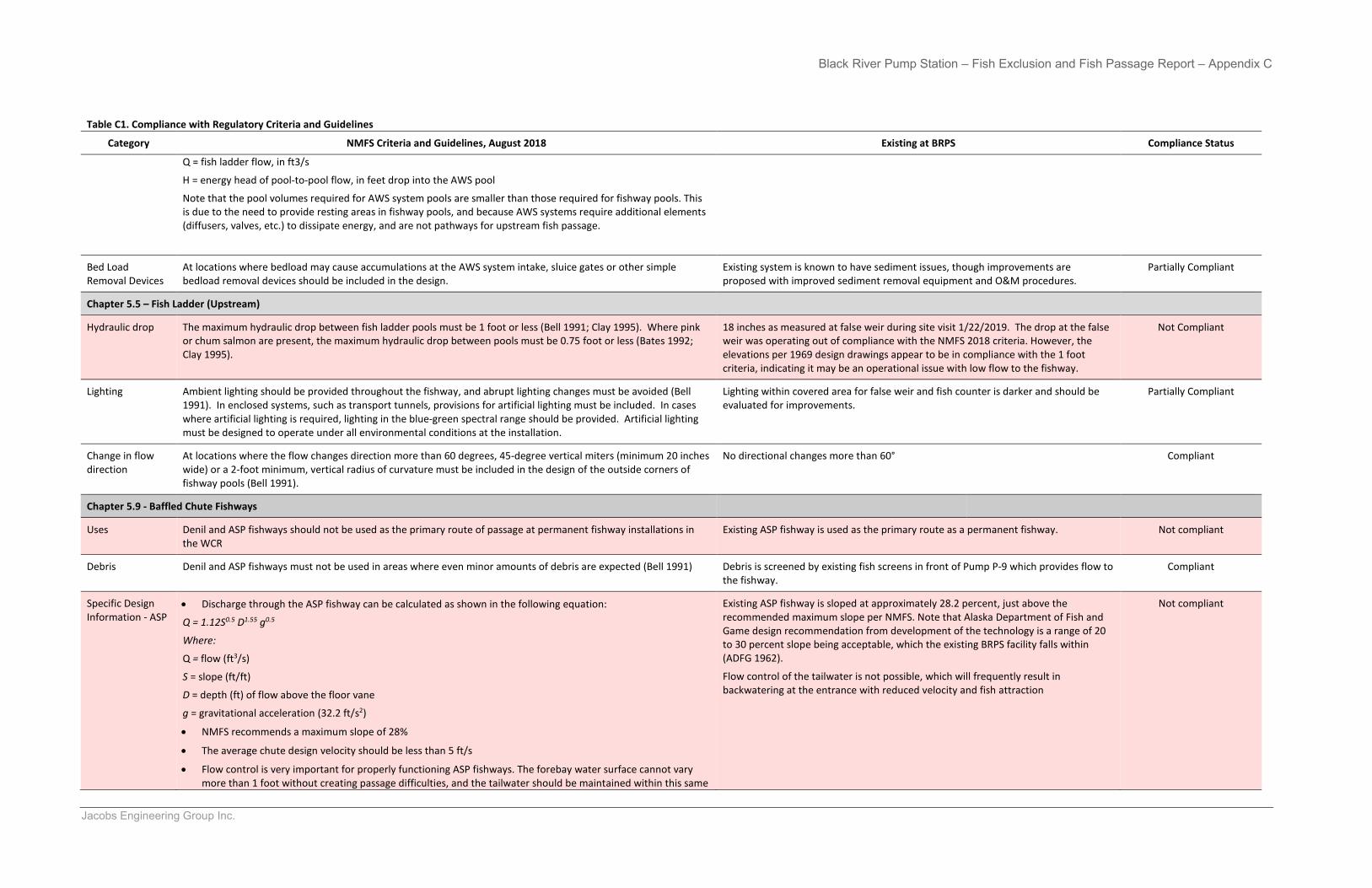
Black River Pump Station – Fish Exclusion and Fish Passage Report – Appendix C
Jacobs Engineering Group Inc.
Table C1. Compliance with Regulatory Criteria and Guidelines
Category NMFS Criteria and Guidelines, August 2018 Existing at BRPS Compliance Status
Q = fish ladder flow, in ft3/s
H = energy head of pool-to-pool flow, in feet drop into the AWS pool
Note that the pool volumes required for AWS system pools are smaller than those required for fishway pools. This is due to the need to provide resting areas in fishway pools, and because AWS systems require additional elements (diffusers, valves, etc.) to dissipate energy, and are not pathways for upstream fish passage.
Bed Load Removal Devices
At locations where bedload may cause accumulations at the AWS system intake, sluice gates or other simple bedload removal devices should be included in the design.
Existing system is known to have sediment issues, though improvements are proposed with improved sediment removal equipment and O&M procedures.
Partially Compliant
Chapter 5.5 – Fish Ladder (Upstream)
Hydraulic drop The maximum hydraulic drop between fish ladder pools must be 1 foot or less (Bell 1991; Clay 1995). Where pink or chum salmon are present, the maximum hydraulic drop between pools must be 0.75 foot or less (Bates 1992; Clay 1995).
18 inches as measured at false weir during site visit 1/22/2019. The drop at the false weir was operating out of compliance with the NMFS 2018 criteria. However, the elevations per 1969 design drawings appear to be in compliance with the 1 foot criteria, indicating it may be an operational issue with low flow to the fishway.
Not Compliant
Lighting Ambient lighting should be provided throughout the fishway, and abrupt lighting changes must be avoided (Bell 1991). In enclosed systems, such as transport tunnels, provisions for artificial lighting must be included. In cases where artificial lighting is required, lighting in the blue-green spectral range should be provided. Artificial lighting must be designed to operate under all environmental conditions at the installation.
Lighting within covered area for false weir and fish counter is darker and should be evaluated for improvements.
Partially Compliant
Change in flow direction
At locations where the flow changes direction more than 60 degrees, 45-degree vertical miters (minimum 20 inches wide) or a 2-foot minimum, vertical radius of curvature must be included in the design of the outside corners of fishway pools (Bell 1991).
No directional changes more than 60° Compliant
Chapter 5.9 - Baffled Chute Fishways
Uses Denil and ASP fishways should not be used as the primary route of passage at permanent fishway installations in the WCR
Existing ASP fishway is used as the primary route as a permanent fishway. Not compliant
Debris Denil and ASP fishways must not be used in areas where even minor amounts of debris are expected (Bell 1991) Debris is screened by existing fish screens in front of Pump P-9 which provides flow to the fishway.
Compliant
Specific Design Information - ASP
• Discharge through the ASP fishway can be calculated as shown in the following equation:
Q = 1.12S0.5 D1.55 g0.5
Where:
Q = flow (ft3/s)
S = slope (ft/ft)
D = depth (ft) of flow above the floor vane
g = gravitational acceleration (32.2 ft/s2)
• NMFS recommends a maximum slope of 28%
• The average chute design velocity should be less than 5 ft/s
• Flow control is very important for properly functioning ASP fishways. The forebay water surface cannot varymore than 1 foot without creating passage difficulties, and the tailwater should be maintained within this same
Existing ASP fishway is sloped at approximately 28.2 percent, just above the recommended maximum slope per NMFS. Note that Alaska Department of Fish and Game design recommendation from development of the technology is a range of 20 to 30 percent slope being acceptable, which the existing BRPS facility falls within (ADFG 1962).
Flow control of the tailwater is not possible, which will frequently result in backwatering at the entrance with reduced velocity and fish attraction
Not compliant
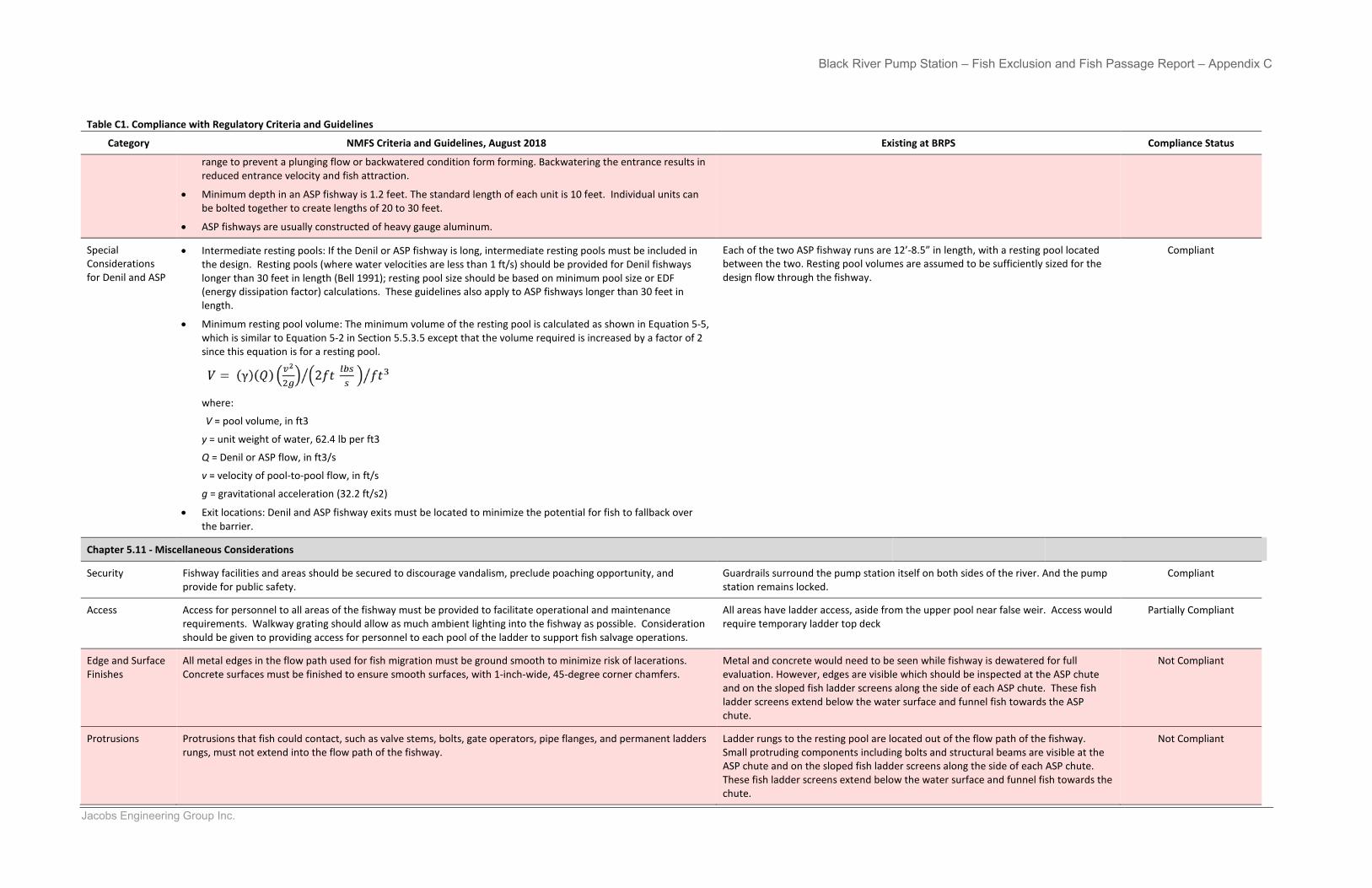
Black River Pump Station – Fish Exclusion and Fish Passage Report – Appendix C
Jacobs Engineering Group Inc.
Table C1. Compliance with Regulatory Criteria and Guidelines
Category NMFS Criteria and Guidelines, August 2018 Existing at BRPS Compliance Status
range to prevent a plunging flow or backwatered condition form forming. Backwatering the entrance results in reduced entrance velocity and fish attraction.
• Minimum depth in an ASP fishway is 1.2 feet. The standard length of each unit is 10 feet. Individual units canbe bolted together to create lengths of 20 to 30 feet.
• ASP fishways are usually constructed of heavy gauge aluminum.
Special Considerations for Denil and ASP
• Intermediate resting pools: If the Denil or ASP fishway is long, intermediate resting pools must be included inthe design. Resting pools (where water velocities are less than 1 ft/s) should be provided for Denil fishwayslonger than 30 feet in length (Bell 1991); resting pool size should be based on minimum pool size or EDF(energy dissipation factor) calculations. These guidelines also apply to ASP fishways longer than 30 feet inlength.
• Minimum resting pool volume: The minimum volume of the resting pool is calculated as shown in Equation 5-5,which is similar to Equation 5-2 in Section 5.5.3.5 except that the volume required is increased by a factor of 2since this equation is for a resting pool.
where:
V = pool volume, in ft3
y = unit weight of water, 62.4 lb per ft3
Q = Denil or ASP flow, in ft3/s
v = velocity of pool-to-pool flow, in ft/s
g = gravitational acceleration (32.2 ft/s2)
• Exit locations: Denil and ASP fishway exits must be located to minimize the potential for fish to fallback overthe barrier.
Each of the two ASP fishway runs are 12’-8.5” in length, with a resting pool located between the two. Resting pool volumes are assumed to be sufficiently sized for the design flow through the fishway.
Compliant
Chapter 5.11 - Miscellaneous Considerations
Security Fishway facilities and areas should be secured to discourage vandalism, preclude poaching opportunity, and provide for public safety.
Guardrails surround the pump station itself on both sides of the river. And the pump station remains locked.
Compliant
Access Access for personnel to all areas of the fishway must be provided to facilitate operational and maintenance requirements. Walkway grating should allow as much ambient lighting into the fishway as possible. Consideration should be given to providing access for personnel to each pool of the ladder to support fish salvage operations.
All areas have ladder access, aside from the upper pool near false weir. Access would require temporary ladder top deck
Partially Compliant
Edge and Surface Finishes
All metal edges in the flow path used for fish migration must be ground smooth to minimize risk of lacerations. Concrete surfaces must be finished to ensure smooth surfaces, with 1-inch-wide, 45-degree corner chamfers.
Metal and concrete would need to be seen while fishway is dewatered for full evaluation. However, edges are visible which should be inspected at the ASP chute and on the sloped fish ladder screens along the side of each ASP chute. These fish ladder screens extend below the water surface and funnel fish towards the ASP chute.
Not Compliant
Protrusions Protrusions that fish could contact, such as valve stems, bolts, gate operators, pipe flanges, and permanent ladders rungs, must not extend into the flow path of the fishway.
Ladder rungs to the resting pool are located out of the flow path of the fishway. Small protruding components including bolts and structural beams are visible at the ASP chute and on the sloped fish ladder screens along the side of each ASP chute. These fish ladder screens extend below the water surface and funnel fish towards the chute.
Not Compliant
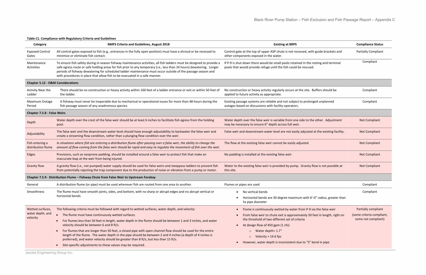
Black River Pump Station – Fish Exclusion and Fish Passage Report – Appendix C
Jacobs Engineering Group Inc.
Table C1. Compliance with Regulatory Criteria and Guidelines
Category NMFS Criteria and Guidelines, August 2018 Existing at BRPS Compliance Status
Exposed Control Gates
All control gates exposed to fish (e.g., entrances in the fully open position) must have a shroud or be recessed to minimize or eliminate fish contact.
Control gate at the top of upper ASP chute is not recessed, with guide brackets and other components exposed in the water.
Partially Compliant
Maintenance Activities
To ensure fish safety during in-season fishway maintenance activities, all fish ladders must be designed to provide a safe egress route or safe holding areas for fish prior to any temporary (i.e., less than 24 hours) dewatering. Longer periods of fishway dewatering for scheduled ladder maintenance must occur outside of the passage season and with procedures in place that allow fish to be evacuated in a safe manner.
If P-9 is shut down there would be small pools retained in the resting and terminal pools that would provide refuge until the fish could be rescued.
Compliant
Chapter 5.12 - O&M Considerations
Activity Near the Ladder
There should be no construction or heavy activity within 100 feet of a ladder entrance or exit or within 50 feet of the ladder.
No construction or heavy activity regularly occurs at the site. Buffers should be applied to future activity as appropriate.
Compliant
Maximum Outage Period
A fishway must never be inoperable due to mechanical or operational issues for more than 48 hours during the fish passage season of any anadromous species.
Existing passage systems are reliable and not subject to prolonged unplanned outages based on discussions with facility operators.
Compliant
Chapter 7.5.8 - False Weirs
Depth Water depth over the crest of the false weir should be at least 6 inches to facilitate fish egress from the holding pool.
Water depth over the false weir is variable from one side to the other. Adjustment may be necessary to ensure 6” depth across full weir.
Not Compliant
Adjustability The false weir and the downstream water level should have enough adjustability to backwater the false weir and create a streaming flow condition, rather than a plunging flow condition over the weir.
False weir and downstream water level are not easily adjusted at the existing facility. Not Compliant
Fish entering a distribution flume
In situations where fish are entering a distribution flume after passing over a false weir, the ability to change the amount of flow coming from the false weir should be rapid and easy to regulate the movement of fish over the weir.
The flow at the existing false weir cannot be easily adjusted Not Compliant
Edges Provisions, such as neoprene padding, should be installed around a false weir to protect fish that make an inaccurate leap at the weir from being injured.
No padding is installed at the existing false weir Not Compliant
Gravity flow A gravity flow (i.e., not pumped) water supply should be used for false weirs and steeppass ladders to prevent fish from potentially rejecting the trap component due to the production of noise or vibration from a pump or motor.
Water to the existing false weir is provided by pump. Gravity flow is not possible at this site.
Not Compliant
Chapter 7.5.9 - Distribution Flume – Fishway Chute from False Weir to Upstream Forebay
General A distribution flume (or pipe) must be used whenever fish are routed from one area to another. Flumes or pipes are used Compliant
Smoothness The flume must have smooth joints, sides, and bottom, with no sharp or abrupt edges and no abrupt vertical or horizontal bends.
• No vertical bends
• Horizontal bends are 30 degree maximum with 6’-0” radius, greater than5x pipe diameter
Compliant
Wetted surfaces, water depth, and velocity
The following criteria must be followed with regard to wetted surfaces, water depth, and velocity:
• The flume must have continuously wetted surfaces.
• For flumes less than 50 feet in length, water depth in the flume should be between 1 and 3 inches, and watervelocity should be between 6 and 8 ft/s.
• For flumes that are longer than 50 feet, a closed pipe with open channel flow should be used for the entirelength of the flume. The water depth in the pipe should be between 2 and 4 inches (a depth of 4 inches ispreferred), and water velocity should be greater than 8 ft/s, but less than 15 ft/s.
• Site-specific adjustments to these values may be required.
• Flume is continuously wetted by water from P-9 via the false weir
• From false weir to chute exit is approximately 50 feet in length, right onthe threshold of two different set of criteria
• At design flow of 450 gpm (1 cfs):
o Water depth= 1.7”
o Velocity = 14.6 fps
• However, water depth is inconsistent due to “S” bend in pipe
Partially compliant
(some criteria compliant, some not compliant)
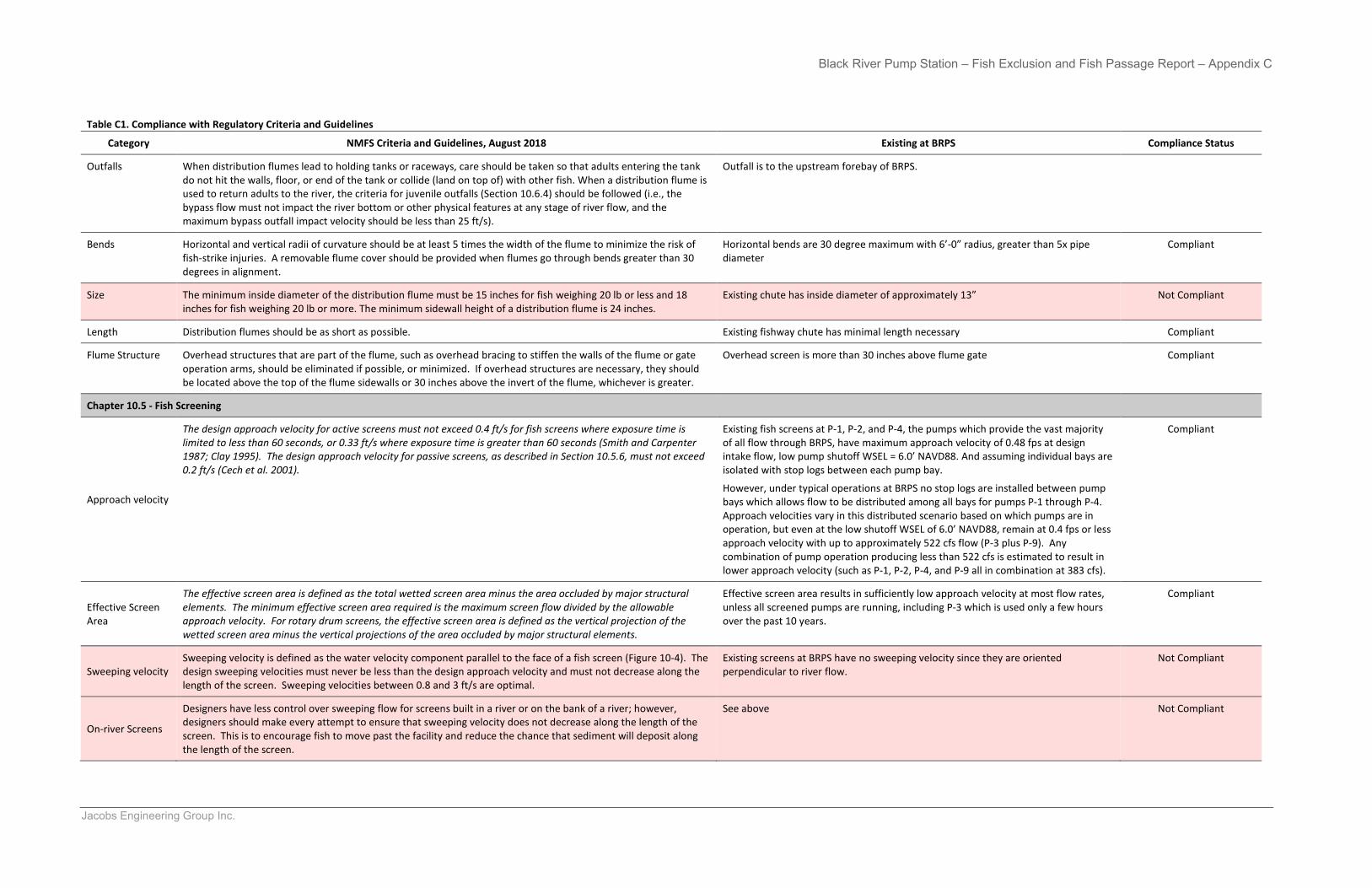
Black River Pump Station – Fish Exclusion and Fish Passage Report – Appendix C
Jacobs Engineering Group Inc.
Table C1. Compliance with Regulatory Criteria and Guidelines
Category NMFS Criteria and Guidelines, August 2018 Existing at BRPS Compliance Status
Outfalls When distribution flumes lead to holding tanks or raceways, care should be taken so that adults entering the tank do not hit the walls, floor, or end of the tank or collide (land on top of) with other fish. When a distribution flume is used to return adults to the river, the criteria for juvenile outfalls (Section 10.6.4) should be followed (i.e., the bypass flow must not impact the river bottom or other physical features at any stage of river flow, and the maximum bypass outfall impact velocity should be less than 25 ft/s).
Outfall is to the upstream forebay of BRPS.
Bends Horizontal and vertical radii of curvature should be at least 5 times the width of the flume to minimize the risk of fish-strike injuries. A removable flume cover should be provided when flumes go through bends greater than 30 degrees in alignment.
Horizontal bends are 30 degree maximum with 6’-0” radius, greater than 5x pipe diameter
Compliant
Size The minimum inside diameter of the distribution flume must be 15 inches for fish weighing 20 lb or less and 18 inches for fish weighing 20 lb or more. The minimum sidewall height of a distribution flume is 24 inches.
Existing chute has inside diameter of approximately 13” Not Compliant
Length Distribution flumes should be as short as possible. Existing fishway chute has minimal length necessary Compliant
Flume Structure Overhead structures that are part of the flume, such as overhead bracing to stiffen the walls of the flume or gate operation arms, should be eliminated if possible, or minimized. If overhead structures are necessary, they should be located above the top of the flume sidewalls or 30 inches above the invert of the flume, whichever is greater.
Overhead screen is more than 30 inches above flume gate Compliant
Chapter 10.5 - Fish Screening
Approach velocity
The design approach velocity for active screens must not exceed 0.4 ft/s for fish screens where exposure time is limited to less than 60 seconds, or 0.33 ft/s where exposure time is greater than 60 seconds (Smith and Carpenter 1987; Clay 1995). The design approach velocity for passive screens, as described in Section 10.5.6, must not exceed 0.2 ft/s (Cech et al. 2001).
Existing fish screens at P-1, P-2, and P-4, the pumps which provide the vast majority of all flow through BRPS, have maximum approach velocity of 0.48 fps at design intake flow, low pump shutoff WSEL = 6.0’ NAVD88. And assuming individual bays are isolated with stop logs between each pump bay.
However, under typical operations at BRPS no stop logs are installed between pump bays which allows flow to be distributed among all bays for pumps P-1 through P-4. Approach velocities vary in this distributed scenario based on which pumps are in operation, but even at the low shutoff WSEL of 6.0’ NAVD88, remain at 0.4 fps or less approach velocity with up to approximately 522 cfs flow (P-3 plus P-9). Any combination of pump operation producing less than 522 cfs is estimated to result in lower approach velocity (such as P-1, P-2, P-4, and P-9 all in combination at 383 cfs).
Compliant
Effective Screen Area
The effective screen area is defined as the total wetted screen area minus the area occluded by major structural elements. The minimum effective screen area required is the maximum screen flow divided by the allowable approach velocity. For rotary drum screens, the effective screen area is defined as the vertical projection of the wetted screen area minus the vertical projections of the area occluded by major structural elements.
Effective screen area results in sufficiently low approach velocity at most flow rates, unless all screened pumps are running, including P-3 which is used only a few hours over the past 10 years.
Compliant
Sweeping velocity Sweeping velocity is defined as the water velocity component parallel to the face of a fish screen (Figure 10-4). The design sweeping velocities must never be less than the design approach velocity and must not decrease along the length of the screen. Sweeping velocities between 0.8 and 3 ft/s are optimal.
Existing screens at BRPS have no sweeping velocity since they are oriented perpendicular to river flow.
Not Compliant
On-river Screens
Designers have less control over sweeping flow for screens built in a river or on the bank of a river; however, designers should make every attempt to ensure that sweeping velocity does not decrease along the length of the screen. This is to encourage fish to move past the facility and reduce the chance that sediment will deposit along the length of the screen.
See above Not Compliant
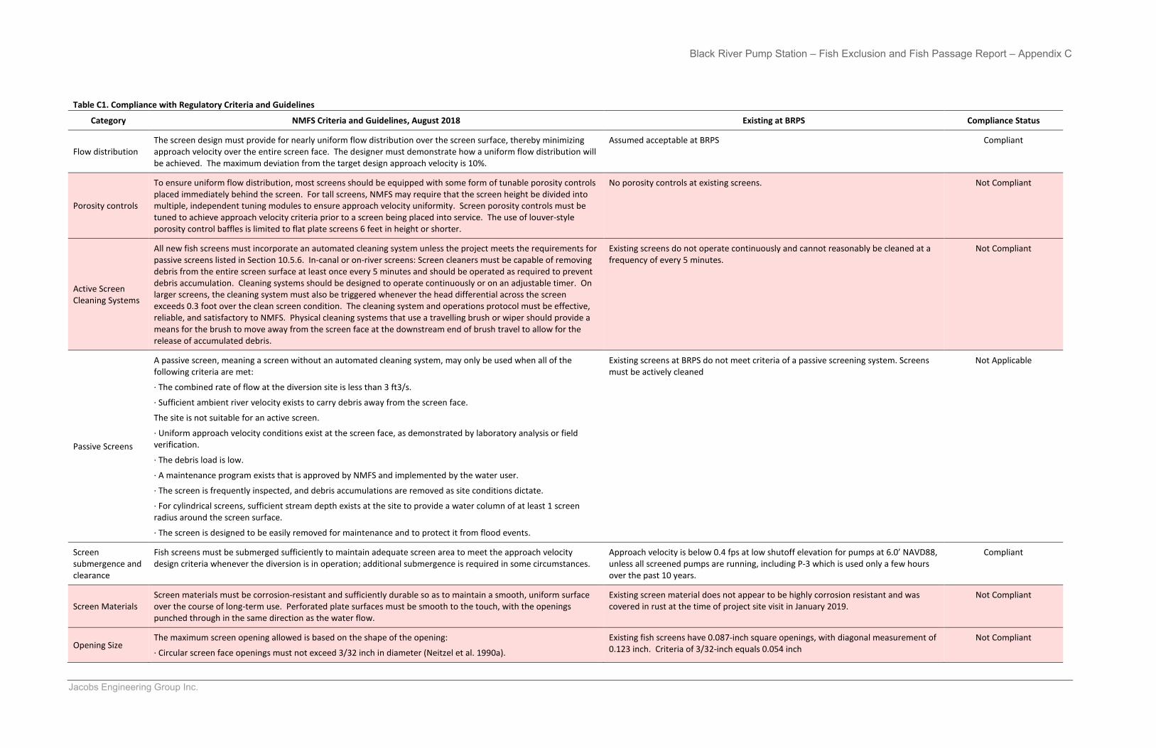
Black River Pump Station – Fish Exclusion and Fish Passage Report – Appendix C
Jacobs Engineering Group Inc.
Table C1. Compliance with Regulatory Criteria and Guidelines
Category NMFS Criteria and Guidelines, August 2018 Existing at BRPS Compliance Status
Flow distribution The screen design must provide for nearly uniform flow distribution over the screen surface, thereby minimizing approach velocity over the entire screen face. The designer must demonstrate how a uniform flow distribution will be achieved. The maximum deviation from the target design approach velocity is 10%.
Assumed acceptable at BRPS Compliant
Porosity controls
To ensure uniform flow distribution, most screens should be equipped with some form of tunable porosity controls placed immediately behind the screen. For tall screens, NMFS may require that the screen height be divided into multiple, independent tuning modules to ensure approach velocity uniformity. Screen porosity controls must be tuned to achieve approach velocity criteria prior to a screen being placed into service. The use of louver-style porosity control baffles is limited to flat plate screens 6 feet in height or shorter.
No porosity controls at existing screens. Not Compliant
Active Screen Cleaning Systems
All new fish screens must incorporate an automated cleaning system unless the project meets the requirements for passive screens listed in Section 10.5.6. In-canal or on-river screens: Screen cleaners must be capable of removing debris from the entire screen surface at least once every 5 minutes and should be operated as required to prevent debris accumulation. Cleaning systems should be designed to operate continuously or on an adjustable timer. On larger screens, the cleaning system must also be triggered whenever the head differential across the screen exceeds 0.3 foot over the clean screen condition. The cleaning system and operations protocol must be effective, reliable, and satisfactory to NMFS. Physical cleaning systems that use a travelling brush or wiper should provide a means for the brush to move away from the screen face at the downstream end of brush travel to allow for the release of accumulated debris.
Existing screens do not operate continuously and cannot reasonably be cleaned at a frequency of every 5 minutes.
Not Compliant
Passive Screens
A passive screen, meaning a screen without an automated cleaning system, may only be used when all of the following criteria are met:
· The combined rate of flow at the diversion site is less than 3 ft3/s.
· Sufficient ambient river velocity exists to carry debris away from the screen face.
The site is not suitable for an active screen.
· Uniform approach velocity conditions exist at the screen face, as demonstrated by laboratory analysis or fieldverification.
· The debris load is low.
· A maintenance program exists that is approved by NMFS and implemented by the water user.
· The screen is frequently inspected, and debris accumulations are removed as site conditions dictate.
· For cylindrical screens, sufficient stream depth exists at the site to provide a water column of at least 1 screenradius around the screen surface.
· The screen is designed to be easily removed for maintenance and to protect it from flood events.
Existing screens at BRPS do not meet criteria of a passive screening system. Screens must be actively cleaned
Not Applicable
Screen submergence and clearance
Fish screens must be submerged sufficiently to maintain adequate screen area to meet the approach velocity design criteria whenever the diversion is in operation; additional submergence is required in some circumstances.
Approach velocity is below 0.4 fps at low shutoff elevation for pumps at 6.0’ NAVD88, unless all screened pumps are running, including P-3 which is used only a few hours over the past 10 years.
Compliant
Screen Materials Screen materials must be corrosion-resistant and sufficiently durable so as to maintain a smooth, uniform surface over the course of long-term use. Perforated plate surfaces must be smooth to the touch, with the openings punched through in the same direction as the water flow.
Existing screen material does not appear to be highly corrosion resistant and was covered in rust at the time of project site visit in January 2019.
Not Compliant
Opening Size The maximum screen opening allowed is based on the shape of the opening:
· Circular screen face openings must not exceed 3/32 inch in diameter (Neitzel et al. 1990a).
Existing fish screens have 0.087-inch square openings, with diagonal measurement of 0.123 inch. Criteria of 3/32-inch equals 0.054 inch
Not Compliant
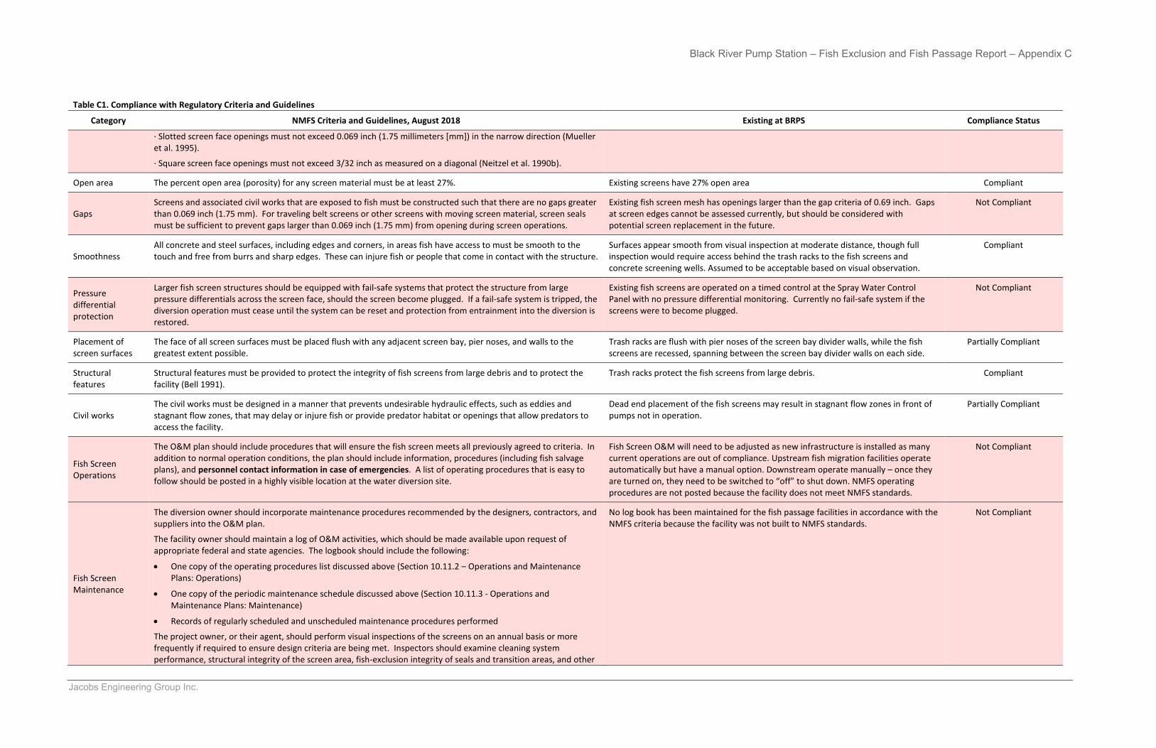
Black River Pump Station – Fish Exclusion and Fish Passage Report – Appendix C
Jacobs Engineering Group Inc.
Table C1. Compliance with Regulatory Criteria and Guidelines
Category NMFS Criteria and Guidelines, August 2018 Existing at BRPS Compliance Status
· Slotted screen face openings must not exceed 0.069 inch (1.75 millimeters [mm]) in the narrow direction (Muelleret al. 1995).
· Square screen face openings must not exceed 3/32 inch as measured on a diagonal (Neitzel et al. 1990b).
Open area The percent open area (porosity) for any screen material must be at least 27%. Existing screens have 27% open area Compliant
Gaps Screens and associated civil works that are exposed to fish must be constructed such that there are no gaps greater than 0.069 inch (1.75 mm). For traveling belt screens or other screens with moving screen material, screen seals must be sufficient to prevent gaps larger than 0.069 inch (1.75 mm) from opening during screen operations.
Existing fish screen mesh has openings larger than the gap criteria of 0.69 inch. Gaps at screen edges cannot be assessed currently, but should be considered with potential screen replacement in the future.
Not Compliant
Smoothness All concrete and steel surfaces, including edges and corners, in areas fish have access to must be smooth to the touch and free from burrs and sharp edges. These can injure fish or people that come in contact with the structure.
Surfaces appear smooth from visual inspection at moderate distance, though full inspection would require access behind the trash racks to the fish screens and concrete screening wells. Assumed to be acceptable based on visual observation.
Compliant
Pressure differential protection
Larger fish screen structures should be equipped with fail-safe systems that protect the structure from large pressure differentials across the screen face, should the screen become plugged. If a fail-safe system is tripped, the diversion operation must cease until the system can be reset and protection from entrainment into the diversion is restored.
Existing fish screens are operated on a timed control at the Spray Water Control Panel with no pressure differential monitoring. Currently no fail-safe system if the screens were to become plugged.
Not Compliant
Placement of screen surfaces
The face of all screen surfaces must be placed flush with any adjacent screen bay, pier noses, and walls to the greatest extent possible.
Trash racks are flush with pier noses of the screen bay divider walls, while the fish screens are recessed, spanning between the screen bay divider walls on each side.
Partially Compliant
Structural features
Structural features must be provided to protect the integrity of fish screens from large debris and to protect the facility (Bell 1991).
Trash racks protect the fish screens from large debris. Compliant
Civil works The civil works must be designed in a manner that prevents undesirable hydraulic effects, such as eddies and stagnant flow zones, that may delay or injure fish or provide predator habitat or openings that allow predators to access the facility.
Dead end placement of the fish screens may result in stagnant flow zones in front of pumps not in operation.
Partially Compliant
Fish Screen Operations
The O&M plan should include procedures that will ensure the fish screen meets all previously agreed to criteria. In addition to normal operation conditions, the plan should include information, procedures (including fish salvage plans), and personnel contact information in case of emergencies. A list of operating procedures that is easy to follow should be posted in a highly visible location at the water diversion site.
Fish Screen O&M will need to be adjusted as new infrastructure is installed as many current operations are out of compliance. Upstream fish migration facilities operate automatically but have a manual option. Downstream operate manually – once they are turned on, they need to be switched to “off” to shut down. NMFS operating procedures are not posted because the facility does not meet NMFS standards.
Not Compliant
Fish Screen Maintenance
The diversion owner should incorporate maintenance procedures recommended by the designers, contractors, and suppliers into the O&M plan.
The facility owner should maintain a log of O&M activities, which should be made available upon request of appropriate federal and state agencies. The logbook should include the following:
• One copy of the operating procedures list discussed above (Section 10.11.2 – Operations and MaintenancePlans: Operations)
• One copy of the periodic maintenance schedule discussed above (Section 10.11.3 - Operations andMaintenance Plans: Maintenance)
• Records of regularly scheduled and unscheduled maintenance procedures performed
The project owner, or their agent, should perform visual inspections of the screens on an annual basis or more frequently if required to ensure design criteria are being met. Inspectors should examine cleaning system performance, structural integrity of the screen area, fish-exclusion integrity of seals and transition areas, and other
No log book has been maintained for the fish passage facilities in accordance with the NMFS criteria because the facility was not built to NMFS standards.
Not Compliant
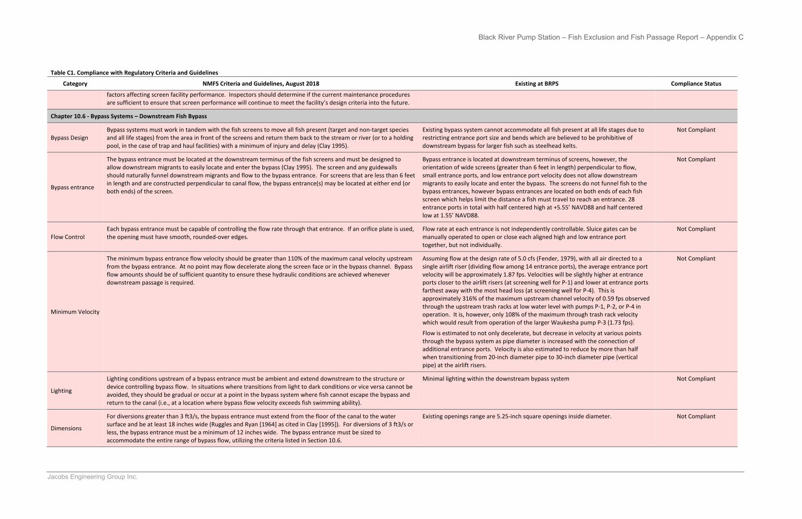
Black River Pump Station – Fish Exclusion and Fish Passage Report – Appendix C
Jacobs Engineering Group Inc.
Table C1. Compliance with Regulatory Criteria and Guidelines
Category NMFS Criteria and Guidelines, August 2018 Existing at BRPS Compliance Status
factors affecting screen facility performance. Inspectors should determine if the current maintenance procedures are sufficient to ensure that screen performance will continue to meet the facility’s design criteria into the future.
Chapter 10.6 - Bypass Systems – Downstream Fish Bypass
Bypass Design Bypass systems must work in tandem with the fish screens to move all fish present (target and non-target species and all life stages) from the area in front of the screens and return them back to the stream or river (or to a holding pool, in the case of trap and haul facilities) with a minimum of injury and delay (Clay 1995).
Existing bypass system cannot accommodate all fish present at all life stages due to restricting entrance port size and bends which are believed to be prohibitive of downstream bypass for larger fish such as steelhead kelts.
Not Compliant
Bypass entrance
The bypass entrance must be located at the downstream terminus of the fish screens and must be designed to allow downstream migrants to easily locate and enter the bypass (Clay 1995). The screen and any guidewalls should naturally funnel downstream migrants and flow to the bypass entrance. For screens that are less than 6 feet in length and are constructed perpendicular to canal flow, the bypass entrance(s) may be located at either end (or both ends) of the screen.
Bypass entrance is located at downstream terminus of screens, however, the orientation of wide screens (greater than 6 feet in length) perpendicular to flow, small entrance ports, and low entrance port velocity does not allow downstream migrants to easily locate and enter the bypass. The screens do not funnel fish to the bypass entrances, however bypass entrances are located on both ends of each fish screen which helps limit the distance a fish must travel to reach an entrance. 28 entrance ports in total with half centered high at +5.55’ NAVD88 and half centered low at 1.55’ NAVD88.
Not Compliant
Flow Control Each bypass entrance must be capable of controlling the flow rate through that entrance. If an orifice plate is used, the opening must have smooth, rounded-over edges.
Flow rate at each entrance is not independently controllable. Sluice gates can be manually operated to open or close each aligned high and low entrance port together, but not individually.
Not Compliant
Minimum Velocity
The minimum bypass entrance flow velocity should be greater than 110% of the maximum canal velocity upstream from the bypass entrance. At no point may flow decelerate along the screen face or in the bypass channel. Bypass flow amounts should be of sufficient quantity to ensure these hydraulic conditions are achieved whenever downstream passage is required.
Assuming flow at the design rate of 5.0 cfs (Fender, 1979), with all air directed to a single airlift riser (dividing flow among 14 entrance ports), the average entrance port velocity will be approximately 1.87 fps. Velocities will be slightly higher at entrance ports closer to the airlift risers (at screening well for P-1) and lower at entrance ports farthest away with the most head loss (at screening well for P-4). This is approximately 316% of the maximum upstream channel velocity of 0.59 fps observed through the upstream trash racks at low water level with pumps P-1, P-2, or P-4 in operation. It is, however, only 108% of the maximum through trash rack velocity which would result from operation of the larger Waukesha pump P-3 (1.73 fps).
Flow is estimated to not only decelerate, but decrease in velocity at various points through the bypass system as pipe diameter is increased with the connection of additional entrance ports. Velocity is also estimated to reduce by more than half when transitioning from 20-inch diameter pipe to 30-inch diameter pipe (vertical pipe) at the airlift risers.
Not Compliant
Lighting
Lighting conditions upstream of a bypass entrance must be ambient and extend downstream to the structure or device controlling bypass flow. In situations where transitions from light to dark conditions or vice versa cannot be avoided, they should be gradual or occur at a point in the bypass system where fish cannot escape the bypass and return to the canal (i.e., at a location where bypass flow velocity exceeds fish swimming ability).
Minimal lighting within the downstream bypass system Not Compliant
Dimensions
For diversions greater than 3 ft3/s, the bypass entrance must extend from the floor of the canal to the water surface and be at least 18 inches wide (Ruggles and Ryan [1964] as cited in Clay [1995]). For diversions of 3 ft3/s or less, the bypass entrance must be a minimum of 12 inches wide. The bypass entrance must be sized to accommodate the entire range of bypass flow, utilizing the criteria listed in Section 10.6.
Existing openings range are 5.25-inch square openings inside diameter. Not Compliant
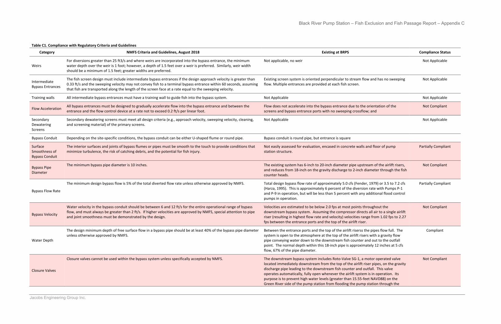
Black River Pump Station – Fish Exclusion and Fish Passage Report – Appendix C
Jacobs Engineering Group Inc.
Table C1. Compliance with Regulatory Criteria and Guidelines
Category NMFS Criteria and Guidelines, August 2018 Existing at BRPS Compliance Status
Weirs For diversions greater than 25 ft3/s and where weirs are incorporated into the bypass entrance, the minimum water depth over the weir is 1 foot; however, a depth of 1.5 feet over a weir is preferred. Similarly, weir width should be a minimum of 1.5 feet; greater widths are preferred.
Not applicable, no weir Not Applicable
Intermediate Bypass Entrances
The fish screen design must include intermediate bypass entrances if the design approach velocity is greater than 0.33 ft/s and the sweeping velocity may not convey fish to a terminal bypass entrance within 60 seconds, assuming that fish are transported along the length of the screen face at a rate equal to the sweeping velocity.
Existing screen system is oriented perpendicular to stream flow and has no sweeping flow. Multiple entrances are provided at each fish screen.
Not Applicable
Training walls All intermediate bypass entrances must have a training wall to guide fish into the bypass system. Not Applicable Not Applicable
Flow Acceleration All bypass entrances must be designed to gradually accelerate flow into the bypass entrance and between the entrance and the flow control device at a rate not to exceed 0.2 ft/s per linear foot.
Flow does not accelerate into the bypass entrance due to the orientation of the screens and bypass entrance ports with no sweeping crossflow; and
Not Compliant
Secondary Dewatering Screens
Secondary dewatering screens must meet all design criteria (e.g., approach velocity, sweeping velocity, cleaning, and screening material) of the primary screens.
Not Applicable Not Applicable
Bypass Conduit Depending on the site-specific conditions, the bypass conduit can be either U-shaped flume or round pipe. Bypass conduit is round pipe, but entrance is square
Surface Smoothness of Bypass Conduit
The interior surfaces and joints of bypass flumes or pipes must be smooth to the touch to provide conditions that minimize turbulence, the risk of catching debris, and the potential for fish injury.
Not easily assessed for evaluation, encased in concrete walls and floor of pump station structure.
Partially Compliant
Bypass Pipe Diameter
The minimum bypass pipe diameter is 10 inches. The existing system has 6-inch to 20-inch diameter pipe upstream of the airlift risers, and reduces from 18-inch on the gravity discharge to 2-inch diameter through the fish counter heads.
Not Compliant
Bypass Flow Rate
The minimum design bypass flow is 5% of the total diverted flow rate unless otherwise approved by NMFS. Total design bypass flow rate of approximately 5.0 cfs (Fender, 1979) or 3.5 to 7.2 cfs (Harza, 1995). This is approximately 6 percent of the diversion rate with Pumps P-1 and P-9 in operation, but will be less than 5 percent with any additional flood control pumps in operation.
Partially Compliant
Bypass Velocity
Water velocity in the bypass conduit should be between 6 and 12 ft/s for the entire operational range of bypass flow, and must always be greater than 2 ft/s. If higher velocities are approved by NMFS, special attention to pipe and joint smoothness must be demonstrated by the design.
Velocities are estimated to be below 2.0 fps at most points throughout the downstream bypass system. Assuming the compressor directs all air to a single airlift riser (resulting in highest flow rate and velocity) velocities range from 1.02 fps to 2.27 fps between the entrance ports and the top of the airlift riser.
Not Compliant
Water Depth
The design minimum depth of free surface flow in a bypass pipe should be at least 40% of the bypass pipe diameter unless otherwise approved by NMFS.
Between the entrance ports and the top of the airlift riserss the pipes flow full. The system is open to the atmosphere at the top of the airlift risers with a gravity flow pipe conveying water down to the downstream fish counter and out to the outfall point. The normal depth within this 18-inch pipe is approximately 12 inches at 5 cfs flow, 67% of the pipe diameter.
Compliant
Closure Valves
Closure valves cannot be used within the bypass system unless specifically accepted by NMFS. The downstream bypass system includes Roto-Valve SG-1, a motor operated valve located immediately downstream from the top of the airlift riser pipes, on the gravity discharge pipe leading to the downstream fish counter and outfall. This valve operates automatically, fully open whenever the airlift system is in operation. Its purpose is to prevent high water levels (greater than 15.55-feet NAVD88) on the Green River side of the pump station from flooding the pump station through the
Not Compliant
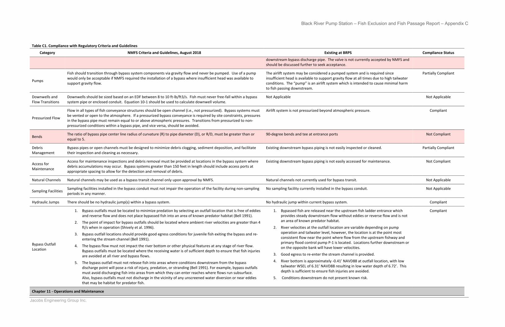
Black River Pump Station – Fish Exclusion and Fish Passage Report – Appendix C
Jacobs Engineering Group Inc.
Table C1. Compliance with Regulatory Criteria and Guidelines
Category NMFS Criteria and Guidelines, August 2018 Existing at BRPS Compliance Status
downstream bypass discharge pipe. The valve is not currently accepted by NMFS and should be discussed further to seek acceptance.
Pumps
Fish should transition through bypass system components via gravity flow and never be pumped. Use of a pump would only be acceptable if NMFS required the installation of a bypass where insufficient head was available to support gravity flow.
The airlift system may be considered a pumped system and is required since insufficient head is available to support gravity flow at all times due to high tailwater conditions. The “pump” is an airlift system which is intended to cause minimal harm to fish passing downstream.
Partially Compliant
Downwells and Flow Transitions
Downwells should be sized based on an EDF between 8 to 10 ft-lb/ft3/s. Fish must never free-fall within a bypass system pipe or enclosed conduit. Equation 10-1 should be used to calculate downwell volume.
Not Applicable Not Applicable
Pressurized Flow
Flow in all types of fish conveyance structures should be open channel (i.e., not pressurized). Bypass systems must be vented or open to the atmosphere. If a pressurized bypass conveyance is required by site constraints, pressures in the bypass pipe must remain equal to or above atmospheric pressures. Transitions from pressurized to non-pressurized conditions within a bypass pipe, and vice versa, should be avoided.
Airlift system is not pressurized beyond atmospheric pressure. Compliant
Bends The ratio of bypass pipe center line radius of curvature (R) to pipe diameter (D), or R/D, must be greater than or equal to 5.
90-degree bends and tee at entrance ports Not Compliant
Debris Management
Bypass pipes or open channels must be designed to minimize debris clogging, sediment deposition, and facilitate their inspection and cleaning as necessary.
Existing downstream bypass piping is not easily inspected or cleaned. Partially Compliant
Access for Maintenance
Access for maintenance inspections and debris removal must be provided at locations in the bypass system where debris accumulations may occur. Bypass systems greater than 150 feet in length should include access ports at appropriate spacing to allow for the detection and removal of debris.
Existing downstream bypass piping is not easily accessed for maintenance. Not Compliant
Natural Channels Natural channels may be used as a bypass transit channel only upon approval by NMFS. Natural channels not currently used for bypass transit. Not Applicable
Sampling Facilities Sampling facilities installed in the bypass conduit must not impair the operation of the facility during non-sampling periods in any manner.
No sampling facility currently installed in the bypass conduit. Not Applicable
Hydraulic Jumps There should be no hydraulic jump(s) within a bypass system. No hydraulic jump within current bypass system. Compliant
Bypass Outfall Location
1. Bypass outfalls must be located to minimize predation by selecting an outfall location that is free of eddiesand reverse flow and does not place bypassed fish into an area of known predator habitat (Bell 1991).
2. The point of impact for bypass outfalls should be located where ambient river velocities are greater than 4ft/s when in operation (Shively et al. 1996).
3. Bypass outfall locations should provide good egress conditions for juvenile fish exiting the bypass and re-entering the stream channel (Bell 1991).
4. The bypass flow must not impact the river bottom or other physical features at any stage of river flow.Bypass outfalls must be located where the receiving water is of sufficient depth to ensure that fish injuriesare avoided at all river and bypass flows.
5. The bypass outfall must not release fish into areas where conditions downstream from the bypassdischarge point will pose a risk of injury, predation, or stranding (Bell 1991). For example, bypass outfallsmust avoid discharging fish into areas from which they can enter reaches where flows run subsurface.Also, bypass outfalls must not discharge in the vicinity of any unscreened water diversion or near eddiesthat may be habitat for predator fish.
1. Bypassed fish are released near the upstream fish ladder entrance whichprovides steady downstream flow without eddies or reverse flow and is notan area of known predator habitat.
2. River velocities at the outfall location are variable depending on pumpoperation and tailwater level, however, the location is at the point mostconsistent flow near the point where flow from the upstream fishway andprimary flood control pump P-1 is located. Locations further downstream oron the opposite bank will have lower velocities.
3. Good egress to re-enter the stream channel is provided.
4. River bottom is approximately -0.41’ NAVD88 at outfall location, with lowtailwater WSEL of 6.31’ NAVD88 resulting in low water depth of 6.72’. Thisdepth is sufficient to ensure fish injuries are avoided.
5. Conditions downstream do not present known risk.
Compliant
Chapter 11 - Operations and Maintenance
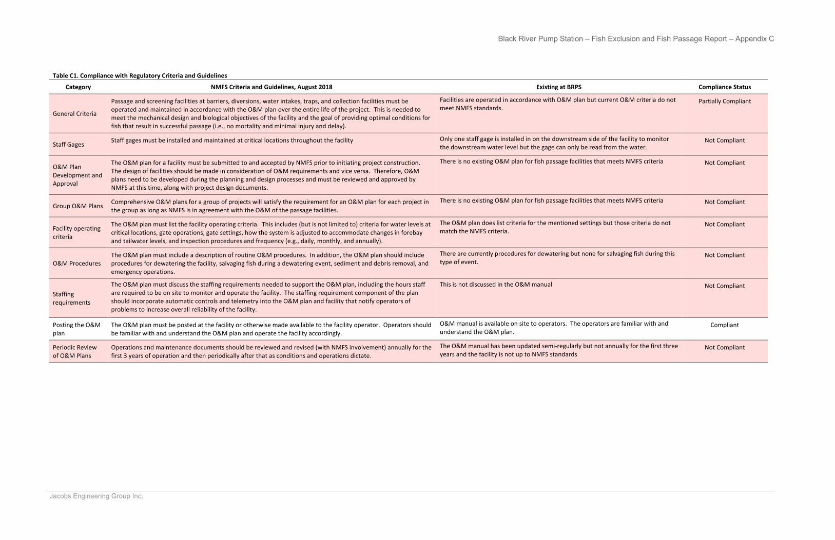
Black River Pump Station – Fish Exclusion and Fish Passage Report – Appendix C
Jacobs Engineering Group Inc.
Table C1. Compliance with Regulatory Criteria and Guidelines
Category NMFS Criteria and Guidelines, August 2018 Existing at BRPS Compliance Status
General Criteria
Passage and screening facilities at barriers, diversions, water intakes, traps, and collection facilities must be operated and maintained in accordance with the O&M plan over the entire life of the project. This is needed to meet the mechanical design and biological objectives of the facility and the goal of providing optimal conditions for fish that result in successful passage (i.e., no mortality and minimal injury and delay).
Facilities are operated in accordance with O&M plan but current O&M criteria do not meet NMFS standards.
Partially Compliant
Staff Gages Staff gages must be installed and maintained at critical locations throughout the facility Only one staff gage is installed in on the downstream side of the facility to monitor the downstream water level but the gage can only be read from the water.
Not Compliant
O&M Plan Development and Approval
The O&M plan for a facility must be submitted to and accepted by NMFS prior to initiating project construction. The design of facilities should be made in consideration of O&M requirements and vice versa. Therefore, O&M plans need to be developed during the planning and design processes and must be reviewed and approved by NMFS at this time, along with project design documents.
There is no existing O&M plan for fish passage facilities that meets NMFS criteria Not Compliant
Group O&M Plans Comprehensive O&M plans for a group of projects will satisfy the requirement for an O&M plan for each project in the group as long as NMFS is in agreement with the O&M of the passage facilities.
There is no existing O&M plan for fish passage facilities that meets NMFS criteria Not Compliant
Facility operating criteria
The O&M plan must list the facility operating criteria. This includes (but is not limited to) criteria for water levels at critical locations, gate operations, gate settings, how the system is adjusted to accommodate changes in forebay and tailwater levels, and inspection procedures and frequency (e.g., daily, monthly, and annually).
The O&M plan does list criteria for the mentioned settings but those criteria do not match the NMFS criteria.
Not Compliant
O&M Procedures The O&M plan must include a description of routine O&M procedures. In addition, the O&M plan should include procedures for dewatering the facility, salvaging fish during a dewatering event, sediment and debris removal, and emergency operations.
There are currently procedures for dewatering but none for salvaging fish during this type of event.
Not Compliant
Staffing requirements
The O&M plan must discuss the staffing requirements needed to support the O&M plan, including the hours staff are required to be on site to monitor and operate the facility. The staffing requirement component of the plan should incorporate automatic controls and telemetry into the O&M plan and facility that notify operators of problems to increase overall reliability of the facility.
This is not discussed in the O&M manual Not Compliant
Posting the O&M plan
The O&M plan must be posted at the facility or otherwise made available to the facility operator. Operators should be familiar with and understand the O&M plan and operate the facility accordingly.
O&M manual is available on site to operators. The operators are familiar with and understand the O&M plan.
Compliant
Periodic Review of O&M Plans
Operations and maintenance documents should be reviewed and revised (with NMFS involvement) annually for the first 3 years of operation and then periodically after that as conditions and operations dictate.
The O&M manual has been updated semi-regularly but not annually for the first three years and the facility is not up to NMFS standards
Not Compliant

Appendix D Construction Cost Estimates

Black River Pump Station Improvement Subtask 500.1 – Evaluation of Existing Fish Passage and Fish Exclusion Facilities and Alternatives
Basis of Estimate February 17, 2020
AACE International Class 5 Cost Estimate
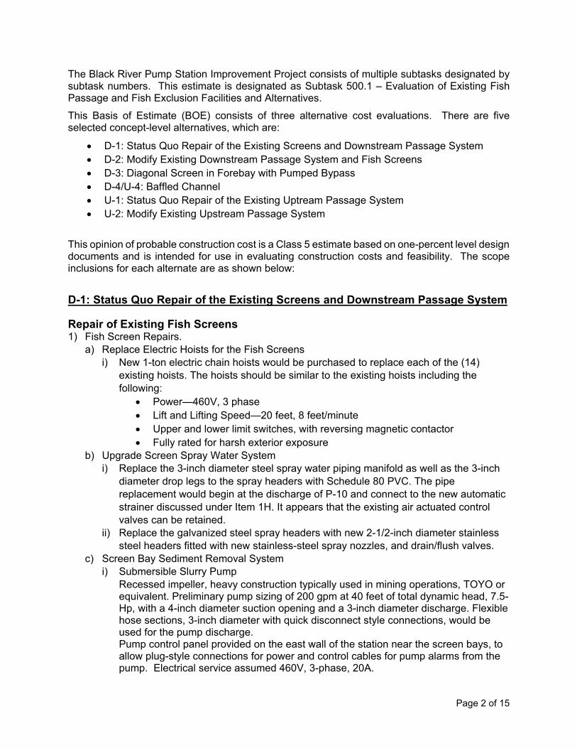
Page 2 of 15
The Black River Pump Station Improvement Project consists of multiple subtasks designated by subtask numbers. This estimate is designated as Subtask 500.1 – Evaluation of Existing Fish Passage and Fish Exclusion Facilities and Alternatives. This Basis of Estimate (BOE) consists of three alternative cost evaluations. There are five selected concept-level alternatives, which are:
• D-1: Status Quo Repair of the Existing Screens and Downstream Passage System • D-2: Modify Existing Downstream Passage System and Fish Screens • D-3: Diagonal Screen in Forebay with Pumped Bypass • D-4/U-4: Baffled Channel • U-1: Status Quo Repair of the Existing Uptream Passage System • U-2: Modify Existing Upstream Passage System
This opinion of probable construction cost is a Class 5 estimate based on one-percent level design documents and is intended for use in evaluating construction costs and feasibility. The scope inclusions for each alternate are as shown below:
D-1: Status Quo Repair of the Existing Screens and Downstream Passage System
Repair of Existing Fish Screens 1) Fish Screen Repairs.
a) Replace Electric Hoists for the Fish Screens i) New 1-ton electric chain hoists would be purchased to replace each of the (14)
existing hoists. The hoists should be similar to the existing hoists including the following:
• Power—460V, 3 phase • Lift and Lifting Speed—20 feet, 8 feet/minute • Upper and lower limit switches, with reversing magnetic contactor • Fully rated for harsh exterior exposure
b) Upgrade Screen Spray Water System i) Replace the 3-inch diameter steel spray water piping manifold as well as the 3-inch
diameter drop legs to the spray headers with Schedule 80 PVC. The pipe replacement would begin at the discharge of P-10 and connect to the new automatic strainer discussed under Item 1H. It appears that the existing air actuated control valves can be retained.
ii) Replace the galvanized steel spray headers with new 2-1/2-inch diameter stainless steel headers fitted with new stainless-steel spray nozzles, and drain/flush valves.
c) Screen Bay Sediment Removal System i) Submersible Slurry Pump
Recessed impeller, heavy construction typically used in mining operations, TOYO or equivalent. Preliminary pump sizing of 200 gpm at 40 feet of total dynamic head, 7.5-Hp, with a 4-inch diameter suction opening and a 3-inch diameter discharge. Flexible hose sections, 3-inch diameter with quick disconnect style connections, would be used for the pump discharge. Pump control panel provided on the east wall of the station near the screen bays, to allow plug-style connections for power and control cables for pump alarms from the pump. Electrical service assumed 460V, 3-phase, 20A.
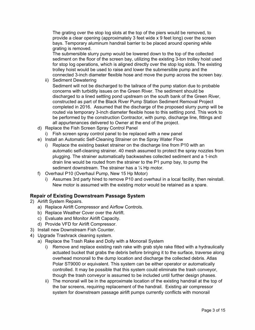
Page 3 of 15
The grating over the stop log slots at the top of the piers would be removed, to provide a clear opening (approximately 3 feet wide x 9 feet long) over the screen bays. Temporary aluminum handrail barrier to be placed around opening while grating is removed. The submersible slurry pump would be lowered down to the top of the collected sediment on the floor of the screen bay, utilizing the existing 3-ton trolley hoist used for stop log operations, which is aligned directly over the stop log slots. The existing trolley hoist would be used to raise and lower the submersible pump and the connected 3-inch diameter flexible hose and move the pump across the screen bay.
ii) Sediment Dewatering Sediment will not be discharged to the tailrace of the pump station due to probable concerns with turbidity issues on the Green River. The sediment should be discharged to a lined settling pond upstream on the south bank of the Green River, constructed as part of the Black River Pump Station Sediment Removal Project completed in 2016. Assumed that the discharge of the proposed slurry pump will be routed via temporary 3-inch diameter flexible hose to this settling pond. This work to be performed by the construction Contractor, with pump, discharge line, fittings and all appurtenances delivered to Owner at the end of the project.
d) Replace the Fish Screen Spray Control Panel i) Fish screen spray control panel to be replaced with a new panel
e) Install an Automatic Self-Cleaning Strainer on the Spray Water Flow i) Replace the existing basket strainer on the discharge line from P10 with an
automatic self-cleaning strainer. 40 mesh assumed to protect the spray nozzles from plugging. The strainer automatically backwashes collected sediment and a 1-inch drain line would be routed from the strainer to the P1 pump bay, to pump the sediment downstream. The strainer has a ¼ Hp motor.
f) Overhaul P10 (Overhaul Pump, New 15 Hp Motor) i) Assumes 3rd party hired to remove P10 and overhaul in a local facility, then reinstall.
New motor is assumed with the existing motor would be retained as a spare.
Repair of Existing Downstream Passage System 2) Airlift System Repairs.
a) Replace Airlift Compressor and Airflow Controls. b) Replace Weather Cover over the Airlift. c) Evaluate and Monitor Airlift Capacity. d) Provide VFD for Airlift Compressor.
3) Install new Downstream Fish Counter. 4) Upgrade Trashrack cleaning system.
a) Replace the Trash Rake and Dolly with a Monorail System i) Remove and replace existing rash rake with grab style rake fitted with a hydraulically
actuated bucket that grabs the debris before bringing it to the surface, traverse along overhead monorail to the dump location and discharge the collected debris. Atlas Polar ST9000 or equivalent. This system can be either operator or automatically controlled. It may be possible that this system could eliminate the trash conveyor, though the trash conveyor is assumed to be included until further design phases.
ii) The monorail will be in the approximate location of the existing handrail at the top of the bar screens, requiring replacement of the handrail. Existing air compressor system for downstream passage airlift pumps currently conflicts with monorail
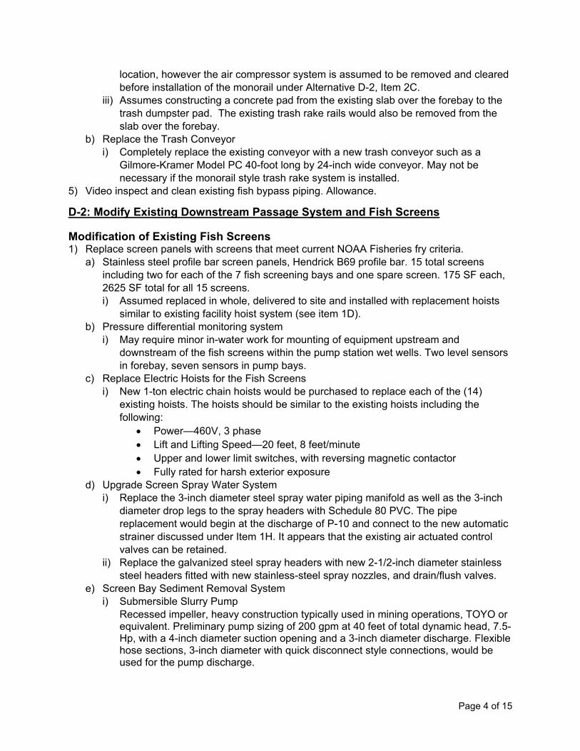
Page 4 of 15
location, however the air compressor system is assumed to be removed and cleared before installation of the monorail under Alternative D-2, Item 2C.
iii) Assumes constructing a concrete pad from the existing slab over the forebay to the trash dumpster pad. The existing trash rake rails would also be removed from the slab over the forebay.
b) Replace the Trash Conveyor i) Completely replace the existing conveyor with a new trash conveyor such as a
Gilmore-Kramer Model PC 40-foot long by 24-inch wide conveyor. May not be necessary if the monorail style trash rake system is installed.
5) Video inspect and clean existing fish bypass piping. Allowance.
D-2: Modify Existing Downstream Passage System and Fish Screens
Modification of Existing Fish Screens 1) Replace screen panels with screens that meet current NOAA Fisheries fry criteria.
a) Stainless steel profile bar screen panels, Hendrick B69 profile bar. 15 total screens including two for each of the 7 fish screening bays and one spare screen. 175 SF each, 2625 SF total for all 15 screens. i) Assumed replaced in whole, delivered to site and installed with replacement hoists
similar to existing facility hoist system (see item 1D). b) Pressure differential monitoring system
i) May require minor in-water work for mounting of equipment upstream and downstream of the fish screens within the pump station wet wells. Two level sensors in forebay, seven sensors in pump bays.
c) Replace Electric Hoists for the Fish Screens i) New 1-ton electric chain hoists would be purchased to replace each of the (14)
existing hoists. The hoists should be similar to the existing hoists including the following:
• Power—460V, 3 phase • Lift and Lifting Speed—20 feet, 8 feet/minute • Upper and lower limit switches, with reversing magnetic contactor • Fully rated for harsh exterior exposure
d) Upgrade Screen Spray Water System i) Replace the 3-inch diameter steel spray water piping manifold as well as the 3-inch
diameter drop legs to the spray headers with Schedule 80 PVC. The pipe replacement would begin at the discharge of P-10 and connect to the new automatic strainer discussed under Item 1H. It appears that the existing air actuated control valves can be retained.
ii) Replace the galvanized steel spray headers with new 2-1/2-inch diameter stainless steel headers fitted with new stainless-steel spray nozzles, and drain/flush valves.
e) Screen Bay Sediment Removal System i) Submersible Slurry Pump
Recessed impeller, heavy construction typically used in mining operations, TOYO or equivalent. Preliminary pump sizing of 200 gpm at 40 feet of total dynamic head, 7.5-Hp, with a 4-inch diameter suction opening and a 3-inch diameter discharge. Flexible hose sections, 3-inch diameter with quick disconnect style connections, would be used for the pump discharge.
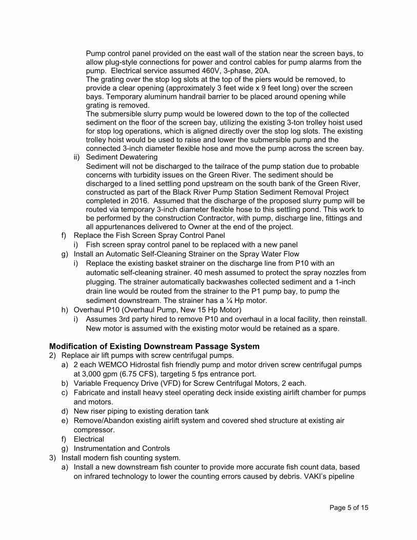
Page 5 of 15
Pump control panel provided on the east wall of the station near the screen bays, to allow plug-style connections for power and control cables for pump alarms from the pump. Electrical service assumed 460V, 3-phase, 20A. The grating over the stop log slots at the top of the piers would be removed, to provide a clear opening (approximately 3 feet wide x 9 feet long) over the screen bays. Temporary aluminum handrail barrier to be placed around opening while grating is removed. The submersible slurry pump would be lowered down to the top of the collected sediment on the floor of the screen bay, utilizing the existing 3-ton trolley hoist used for stop log operations, which is aligned directly over the stop log slots. The existing trolley hoist would be used to raise and lower the submersible pump and the connected 3-inch diameter flexible hose and move the pump across the screen bay.
ii) Sediment Dewatering Sediment will not be discharged to the tailrace of the pump station due to probable concerns with turbidity issues on the Green River. The sediment should be discharged to a lined settling pond upstream on the south bank of the Green River, constructed as part of the Black River Pump Station Sediment Removal Project completed in 2016. Assumed that the discharge of the proposed slurry pump will be routed via temporary 3-inch diameter flexible hose to this settling pond. This work to be performed by the construction Contractor, with pump, discharge line, fittings and all appurtenances delivered to Owner at the end of the project.
f) Replace the Fish Screen Spray Control Panel i) Fish screen spray control panel to be replaced with a new panel
g) Install an Automatic Self-Cleaning Strainer on the Spray Water Flow i) Replace the existing basket strainer on the discharge line from P10 with an
automatic self-cleaning strainer. 40 mesh assumed to protect the spray nozzles from plugging. The strainer automatically backwashes collected sediment and a 1-inch drain line would be routed from the strainer to the P1 pump bay, to pump the sediment downstream. The strainer has a ¼ Hp motor.
h) Overhaul P10 (Overhaul Pump, New 15 Hp Motor) i) Assumes 3rd party hired to remove P10 and overhaul in a local facility, then reinstall.
New motor is assumed with the existing motor would be retained as a spare.
Modification of Existing Downstream Passage System 2) Replace air lift pumps with screw centrifugal pumps.
a) 2 each WEMCO Hidrostal fish friendly pump and motor driven screw centrifugal pumps at 3,000 gpm (6.75 CFS), targeting 5 fps entrance port.
b) Variable Frequency Drive (VFD) for Screw Centrifugal Motors, 2 each. c) Fabricate and install heavy steel operating deck inside existing airlift chamber for pumps
and motors. d) New riser piping to existing deration tank e) Remove/Abandon existing airlift system and covered shed structure at existing air
compressor. f) Electrical g) Instrumentation and Controls
3) Install modern fish counting system. a) Install a new downstream fish counter to provide more accurate fish count data, based
on infrared technology to lower the counting errors caused by debris. VAKI’s pipeline
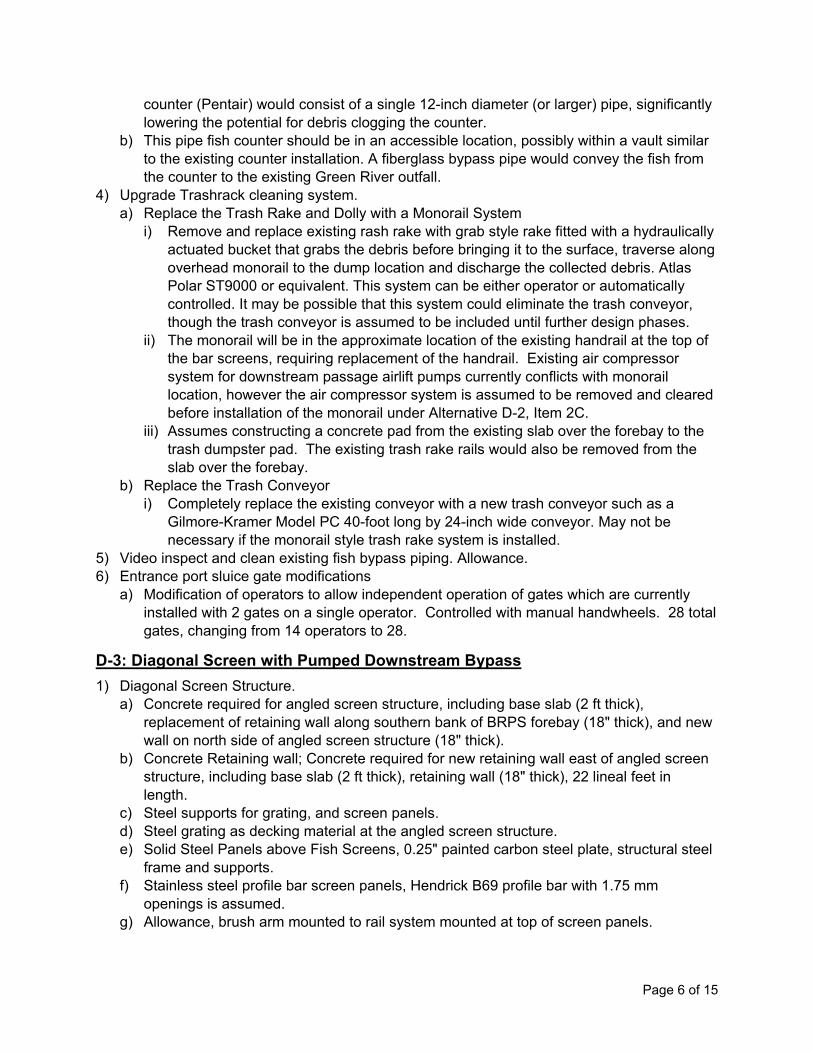
Page 6 of 15
counter (Pentair) would consist of a single 12-inch diameter (or larger) pipe, significantly lowering the potential for debris clogging the counter.
b) This pipe fish counter should be in an accessible location, possibly within a vault similar to the existing counter installation. A fiberglass bypass pipe would convey the fish from the counter to the existing Green River outfall.
4) Upgrade Trashrack cleaning system. a) Replace the Trash Rake and Dolly with a Monorail System
i) Remove and replace existing rash rake with grab style rake fitted with a hydraulically actuated bucket that grabs the debris before bringing it to the surface, traverse along overhead monorail to the dump location and discharge the collected debris. Atlas Polar ST9000 or equivalent. This system can be either operator or automatically controlled. It may be possible that this system could eliminate the trash conveyor, though the trash conveyor is assumed to be included until further design phases.
ii) The monorail will be in the approximate location of the existing handrail at the top of the bar screens, requiring replacement of the handrail. Existing air compressor system for downstream passage airlift pumps currently conflicts with monorail location, however the air compressor system is assumed to be removed and cleared before installation of the monorail under Alternative D-2, Item 2C.
iii) Assumes constructing a concrete pad from the existing slab over the forebay to the trash dumpster pad. The existing trash rake rails would also be removed from the slab over the forebay.
b) Replace the Trash Conveyor i) Completely replace the existing conveyor with a new trash conveyor such as a
Gilmore-Kramer Model PC 40-foot long by 24-inch wide conveyor. May not be necessary if the monorail style trash rake system is installed.
5) Video inspect and clean existing fish bypass piping. Allowance. 6) Entrance port sluice gate modifications
a) Modification of operators to allow independent operation of gates which are currently installed with 2 gates on a single operator. Controlled with manual handwheels. 28 total gates, changing from 14 operators to 28.
D-3: Diagonal Screen with Pumped Downstream Bypass 1) Diagonal Screen Structure.
a) Concrete required for angled screen structure, including base slab (2 ft thick), replacement of retaining wall along southern bank of BRPS forebay (18" thick), and new wall on north side of angled screen structure (18" thick).
b) Concrete Retaining wall; Concrete required for new retaining wall east of angled screen structure, including base slab (2 ft thick), retaining wall (18" thick), 22 lineal feet in length.
c) Steel supports for grating, and screen panels. d) Steel grating as decking material at the angled screen structure. e) Solid Steel Panels above Fish Screens, 0.25" painted carbon steel plate, structural steel
frame and supports. f) Stainless steel profile bar screen panels, Hendrick B69 profile bar with 1.75 mm
openings is assumed. g) Allowance, brush arm mounted to rail system mounted at top of screen panels.
Page 7 of 15
h) Monitoring equipment and controls to allow pressure differential monitoring on either side of the fish screens, in the fish pump box, and behind recirculation diffusers.
i) Perforated steel plates behind fish screens. j) Trash Rack panels at angled screen entrance. 3 panels assumed to span total width of
31 feet, 21-foot panel height on angle. k) Construction cost. M-70 and M-71 Per Task 2 and Task 4 TM (Tetra Tech 2015). Total
cost assumed as 75% of cost for full pump station trash rack cleaning system due to reduced length and number of panels for angled screen structure. i) M-70: Grab style rake with hydraulically actuated bucket, mounted on overhead
monorail system. Costing assumes reduced construction cost from 2015 Tetra Tech estimate due to exclusion of replacement of the air compressor system for the airlift pumps which are to be removed.
ii) M-71: Replace the existing conveyor with a new trash conveyor such as a Gilmore-Kramer Model PC 40-foot long by 24-inch wide conveyor.
l) Construction cost. M-70 and M-71 Per Task 2 and Task 4 TM (Tetra Tech 2015). Total cost assumed as 90% of cost for full pump station trash rack cleaning system due to reduced length and number of panels handled by separate system for angled screen structure. i) M-70: Grab style rake with hydraulically actuated bucket, mounted on overhead
monorail system. Costing assumes reduced construction cost from 2015 Tetra Tech estimate due to exclusion of replacement of the air compressor system for the airlift pumps which are to be removed.
ii) M-71: Replace the existing conveyor with a new trash conveyor such as a Gilmore-Kramer Model PC 40-foot long by 24-inch wide conveyor.
m) Bypass weir, variable height gate with adjustable ramp. n) Galvanized 1.5-inch dia. Pipe handrails. o) Galvanized chain link fence at retaining wall. p) Recirculation pumps (5 each). Flygt submersible pumps. Approx. 50 cfs design capacity
each. q) Two VFD units for recirculation pumps. r) Diffuser grating for recirculation pump discharge to the BRPS forebay. 10-foot height by
24.3 ft length. s) Remove for construction new retaining wall. t) Steel sheet piling for installation of retaining wall portion of new structure. u) Excavate for footings and structure pad. Over excavate 2 feet deep under structure
slab. v) Fill Material to regrade behind retaining wall along south bank of BRPS forebay(2,192
cy), below angled screen structure slab (183 cy), and perimeter of structure Slab and footings 32 cy).
w) Allowance. Assumes new transformer and service upgrades, MCCs. Lighting required at the structure.
x) Allowance for Controls. 2) Downstream Bypass
a) Motor driven screw centrifugal pump at 3,000 gpm (6.7 CFS). Includes pump, motor, and mounting accessories. Per manufacturer quote provided May 2019. $10,000 allowance assumed for guide rail materials and installation of submersible pump.
b) VFD unit for screw centrifugal pump motor. Per manufacturer quote provided July 2019.
Page 8 of 15
c) Downstream bypass piping from screw centrifugal pump to outfall. Buried. d) Includes removal of compressor, air piping, and downstream passage pipe from bottom
of dry well up to dearation tank. e) Allowance, including guiderail to raise submersible pump. f) Allowance for electrical connection to new pumps. g) Allowance for new pump controls.
3) Install New Downstream Fish Counter a) Construction cost. FM-32 Per Task 2 and Task 4 TM (Tetra Tech 2015)
4) Control Building a) Control building assumed at 500 SF
5) Replace Upstream Passage Fish Chute a) To replace existing 13" o.d. pipe from fish counter to the open fish chute, for improved
hydraulics. Welded Steel Pipe with epoxy liner, enlarge thru wall access. b) 10 GA steel with epoxy liner, open at top. To replace existing 13" fish chute to upstream
forebay. 6) Permanent Bulkheads
a) Permanent bulkheads to isolate pump bays for P1, P2, and P9 from the remainder of the pump station. Single opening to be blocked, bulkhead width of 10 feet, assumed minimum height of 30 feet.
7) Temporary Cofferdam a) Temporary cofferdam in BRPS forebay for construction of angled screen structure.
8) Remove/Abandon Existing Downstream Bypass Pipe and Fish Counter Vault a) Allowance Remove/abandon existing pipe and fish counter vault.
9) Remove Existing Trashracks and Fish Screens a) Allowance remove existing trashracks, fish screens, including piping and spraywash for
3 screening bays in front of P1 and P2. Modify to maintain use at all other screening bays.
10) Pile Supports a) Allowance, pile supports beneath angled screen structure are assumed to be 18-inch
diameter concrete filled steel pipe piles 10-feet each way, driven to elevation -55 equaling 49 lineal feet times 30 each equaling a total of 1,470 lineal feet of piling.
11) Pumped Water Supply from Tailwater to Forebay a) Allowance for pumped water supply needed to maintain bypass at low flow near 95%
exceedance inflow. Assumes tee screen with submersible pumps in wet well at tailwater and piping to discharge through recirculation pump diffuser in upstream forebay; 10 cfs capacity.
12) Replace P3 and P4 Fish Screens a) Stainless steel profile bar screen panels, Hendrick B69 profile bar. 9 total screens
including two for each of the 4 fish screening bays at P3 and P4 and one spare screen. 175 SF each. i) Assumed replaced in whole, delivered to site and installed with replacement hoists
similar to existing facility hoist system (see item 12C). b) Pressure differential monitoring system
i) May require minor in-water work for mounting of equipment upstream and downstream of the fish screens within the pump station wet wells. Two level sensors in forebay, four sensors in pump bays.
c) Replace Electric Hoists for the Fish Screens
Page 9 of 15
i) New 1-ton electric chain hoists would be purchased to replace each of the (8) existing hoists at P3 and P4. The hoists should be similar to the existing hoists including the following:
• Power—460V, 3 phase • Lift and Lifting Speed—20 feet, 8 feet/minute • Upper and lower limit switches, with reversing magnetic contactor • Fully rated for harsh exterior exposure
d) Upgrade Screen Spray Water System i) Replace the 3-inch diameter steel spray water piping manifold as well as the 3-inch
diameter drop legs to the spray headers with Schedule 80 PVC. The pipe replacement would begin at the discharge of P-10 and connect to the new automatic strainer discussed under Item 12G. It appears that the existing air actuated control valves can be retained.
ii) Replace the galvanized steel spray headers with new 2-1/2-inch diameter stainless steel headers fitted with new stainless-steel spray nozzles, and drain/flush valves.
e) Screen Bay Sediment Removal System i) Submersible Slurry Pump
Recessed impeller, heavy construction typically used in mining operations, TOYO or equivalent. Preliminary pump sizing of 200 gpm at 40 feet of total dynamic head, 7.5-Hp, with a 4-inch diameter suction opening and a 3-inch diameter discharge. Flexible hose sections, 3-inch diameter with quick disconnect style connections, would be used for the pump discharge. Pump control panel provided on the east wall of the station near the screen bays, to allow plug-style connections for power and control cables for pump alarms from the pump. Electrical service assumed 460V, 3-phase, 20A. The grating over the stop log slots at the top of the piers would be removed, to provide a clear opening (approximately 3 feet wide x 9 feet long) over the screen bays. Temporary aluminum handrail barrier to be placed around opening while grating is removed. The submersible slurry pump would be lowered down to the top of the collected sediment on the floor of the screen bay, utilizing the existing 3-ton trolley hoist used for stop log operations, which is aligned directly over the stop log slots. The existing trolley hoist would be used to raise and lower the submersible pump and the connected 3-inch diameter flexible hose and move the pump across the screen bay.
ii) Sediment Dewatering Sediment will not be discharged to the tailrace of the pump station due to probable concerns with turbidity issues on the Green River. The sediment should be discharged to a lined settling pond upstream on the south bank of the Green River, constructed as part of the Black River Pump Station Sediment Removal Project completed in 2016. Assumed that the discharge of the proposed slurry pump will be routed via temporary 3-inch diameter flexible hose to this settling pond. This work to be performed by the construction Contractor, with pump, discharge line, fittings and all appurtenances delivered to Owner at the end of the project.
f) Replace the Fish Screen Spray Control Panel i) Fish screen spray control panel to be replaced with a new panel
g) Install an Automatic Self-Cleaning Strainer on the Spray Water Flow i) Replace the existing basket strainer on the discharge line from P10 with an
automatic self-cleaning strainer. 40 mesh assumed to protect the spray nozzles from plugging. The strainer automatically backwashes collected sediment and a 1-inch
Page 10 of 15
drain line would be routed from the strainer to the P4 pump bay, to pump the sediment downstream. The strainer has a ¼ Hp motor.
h) Overhaul P10 (Overhaul Pump, New 15 Hp Motor) i) Assumes 3rd party hired to remove P10 and overhaul in a local facility, then reinstall.
New motor is assumed, changed to better accommodate lesser flow requirement for 4 screening bays, as opposed to existing 7 screening bays. Existing motor would be retained as a spare.
13) VFD for P2 a) VFD for P2, used to ramp start and stop of flood control pump with transition to and from
recirculation pumps for the angled screen structure. VFD for P1 is also assumed, though cost is included under Concept U-2 and therefore not accounted for under Concept D-3.
14) Log Boom a) A log boom is assumed to span the small embayment near the entrance to the diagonal
fish screen facility, similar system to existing log boom which spans the full channel in the BRPS forebay.
D-4/U-4: Baffled Channel 1) Steel Sheet Pile
a) Steel sheet pile will be used to form a bypass channel around the north side of the existing pump station. The channel totals approximately 200 feet in length and is 8 feet wide.
b) 390 LF of steel sheet pile c) 67 ft height from top elevation of +28.59' NAVD88 (matching existing BRPS top deck) to
rock level at approx. -38.41' NAVD88 d) The sheet pile will form a cofferdam for excavation and construction of the bypass
including pouring of the concrete slab invert, installation of baffle sets to form pools within the channel, and installation of two roller gates to allow closure of the bypass channel as needed and during extreme hydrologic conditions of high or low water levels on either the upstream or downstream side of the channel.
2) Baffle Sets a) Steel sheet pile and concrete will be used to form baffles, approximately 13 sets to
create a total of approximately 14 “pools”. 3) Roller Gate (2 each)
a) Roller Gate Equipment. Approximately 8 feet wide by 26 feet tall, each. b) Wire rope hoists. c) Instrumentation and Controls d) Electrical e) Access decking
4) Trashrack a) The bypass channel will have trashracks at both the upstream and downstream ends to
prevent debris from entering and becoming trapped in the channel. Each trashrack panel is fabricated from steel and will measure approximately 8 feet wide by 29 feet in height (invert = -0.41’, top of trashrack = 28.59’ NAVD88).
b) Trashrack cleaners (2 each) with electrical and I&C. 5) Concrete Slab
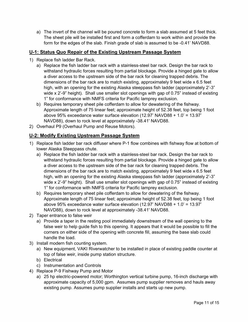
Page 11 of 15
a) The invert of the channel will be poured concrete to form a slab assumed at 5 feet thick. The sheet pile will be installed first and form a cofferdam to work within and provide the form for the edges of the slab. Finish grade of slab is assumed to be -0.41’ NAVD88.
U-1: Status Quo Repair of the Existing Upstream Passage System 1) Replace fish ladder Bar Rack.
a) Replace the fish ladder bar rack with a stainless-steel bar rack. Design the bar rack to withstand hydraulic forces resulting from partial blockage. Provide a hinged gate to allow a diver access to the upstream side of the bar rack for cleaning trapped debris. The dimensions of the bar rack are to match existing, approximately 9 feet wide x 6.5 feet high, with an opening for the existing Alaska steeppass fish ladder (approximately 2’-3” wide x 2’-9” height). Shall use smaller slot openings with gap of 0.75” instead of existing 1” for conformance with NMFS criteria for Pacific lamprey exclusion.
b) Requires temporary sheet pile cofferdam to allow for dewatering of the fishway. Approximate length of 75 linear feet; approximate height of 52.38 feet, top being 1 foot above 95% exceedance water surface elevation (12.97’ NAVD88 + 1.0’ = 13.97’ NAVD88), down to rock level at approximately -38.41' NAVD88.
2) Overhaul P9 (Overhaul Pump and Reuse Motors).
U-2: Modify Existing Upstream Passage System 1) Replace fish ladder bar rack diffuser where P-1 flow combines with fishway flow at bottom of
lower Alaska Steeppass chute. a) Replace the fish ladder bar rack with a stainless-steel bar rack. Design the bar rack to
withstand hydraulic forces resulting from partial blockage. Provide a hinged gate to allow a diver access to the upstream side of the bar rack for cleaning trapped debris. The dimensions of the bar rack are to match existing, approximately 9 feet wide x 6.5 feet high, with an opening for the existing Alaska steeppass fish ladder (approximately 2’-3” wide x 2’-9” height). Shall use smaller slot openings with gap of 0.75” instead of existing 1” for conformance with NMFS criteria for Pacific lamprey exclusion.
b) Requires temporary sheet pile cofferdam to allow for dewatering of the fishway. Approximate length of 75 linear feet; approximate height of 52.38 feet, top being 1 foot above 95% exceedance water surface elevation (12.97’ NAVD88 + 1.0’ = 13.97’ NAVD88), down to rock level at approximately -38.41' NAVD88.
2) Taper entrance to false weir a) Provide a taper in the resting pool immediately downstream of the wall opening to the
false weir to help guide fish to this opening. It appears that it would be possible to fill the corners on either side of the opening with concrete fill, assuming the base slab could handle the load.
3) Install modern fish counting system. a) New equipment, VAKI Riverwatcher to be installed in place of existing paddle counter at
top of false weir, inside pump station structure. b) Electrical c) Instrumentation and Controls
4) Replace P-9 Fishway Pump and Motor a) 25 hp electric-powered motor; Worthington vertical turbine pump, 16-inch discharge with
approximate capacity of 5,000 gpm. Assumes pump supplier removes and hauls away existing pump. Assumes pump supplier installs and starts up new pump.
Page 12 of 15
5) Replace false weir a) Steel fabrication allowing flow adjustment without taking the system offline. Padding to
be added to the edges to prevent injury resulting from inaccurate leaps towards the sides of the false weir. See attached drawing.
b) Electrical c) Instrumentation and Controls
6) Replace fish return pipe/chute. a) 18" PVC Pipe to replace existing 13” pipe and adjust route to improve hydraulics and
ensure sufficient water depth is maintained in pipe throughout length b) 18" Fish Chute to replace existing 13” chute
7) Improve Surface Finishes, Edges, and Protrusions in Fishway – all work is assumed to occur at time of bar rack replacement with cofferdam in place and dewatered fishway. Allowance. a) Grind smooth metal edges in the flow path b) Concrete surface finish and corner chamfers c) Remove protrusions in flow path (bolt, structural supports, etc.)
8) Provide VFD for P-1 a) VFD unit allowing turndown of P-1 flow to provide more steady attraction flow to fish
ladder and decrease approach velocities at the fish ladder bar rack for regulatory compliance.
All above items include aspects as required to install the required project designs. Further details can be found in each of the estimate section tabs provided the Attachment A. Where noted within cost estimate section tabs, individual line items are based upon existing cost estimates when available from January 2015 Black River Needs Assessment and Capital Improvement Planning Technical Memorandum for Task 2 (King County 2015a) and Task 4 (King County 2015b). All costs based on existing estimates are escalated to 2019 dollars. In accordance with County practice, the King County Estimating Guidelines dated April 29, 2004, the cost estimate has been prepared consistent with Association for the Advancement of Cost Engineering International (AACE) Recommended Practice RP18R-97 (Cost Estimate Classification System – As Applied in Engineering, Procurement, and Construction for the Process Industries) which is used for projects that are primarily heavy in the manufacturing and production of chemicals, petrochemicals, and hydrocarbon processing. Table 1 assesses the status of design development relative to AACE Publication 18R-97, which indicates the purpose as reducing the probability of a project cost overrun or underrun to less than 50%. Based on this assessment, the estimate is considered a Class 5 estimate under AACE recommended practices.
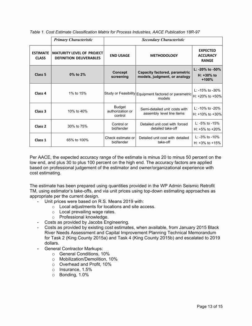
Page 13 of 15
Table 1. Cost Estimate Classification Matrix for Process Industries, AACE Publication 18R-97
Primary Characteristic Secondary Characteristic
ESTIMATE CLASS
MATURITY LEVEL OF PROJECT DEFINITION DELIVERABLES END USAGE METHODOLOGY
EXPECTED ACCURACY
RANGE
Class 5 0% to 2% Concept screening
Capacity factored, parametric models, judgment, or analogy
L: -20% to -50% H: +30% to
+100%
Class 4 1% to 15%
Study or Feasibility
Equipment factored or parametric
models
L: -15% to -30% H: +20% to +50%
Class 3 10% to 40% Budget
authorization or control
Semi-detailed unit costs with assembly level line items
L: -10% to -20% H: +10% to +30%
Class 2 30% to 75% Control or bid/tender
Detailed unit cost with forced detailed take-off
L: -5% to -15% H: +5% to +20%
Class 1 65% to 100% Check estimate or bid/tender
Detailed unit cost with detailed take-off
L: -3% to -10% H: +3% to +15%
Per AACE, the expected accuracy range of the estimate is minus 20 to minus 50 percent on the low end, and plus 30 to plus 100 percent on the high end. The accuracy factors are applied based on professional judgement of the estimator and owner/organizational experience with cost estimating. The estimate has been prepared using quantities provided in the WP Admin Seismic Retrofit TM, using estimator’s take-offs, and via unit prices using top-down estimating approaches as appropriate per the current design.
- Unit prices were based on R.S. Means 2019 with: o Local adjustments for locations and site access. o Local prevailing wage rates. o Professional knowledge.
- Costs as provided by Jacobs Engineering. - Costs as provided by existing cost estimates, when available, from January 2015 Black
River Needs Assessment and Capital Improvement Planning Technical Memorandum for Task 2 (King County 2015a) and Task 4 (King County 2015b) and escalated to 2019 dollars.
- General Contractor Markups: o General Conditions, 10% o Mobilization/Demolition, 10% o Overhead and Profit, 10% o Insurance, 1.5% o Bonding, 1.0%
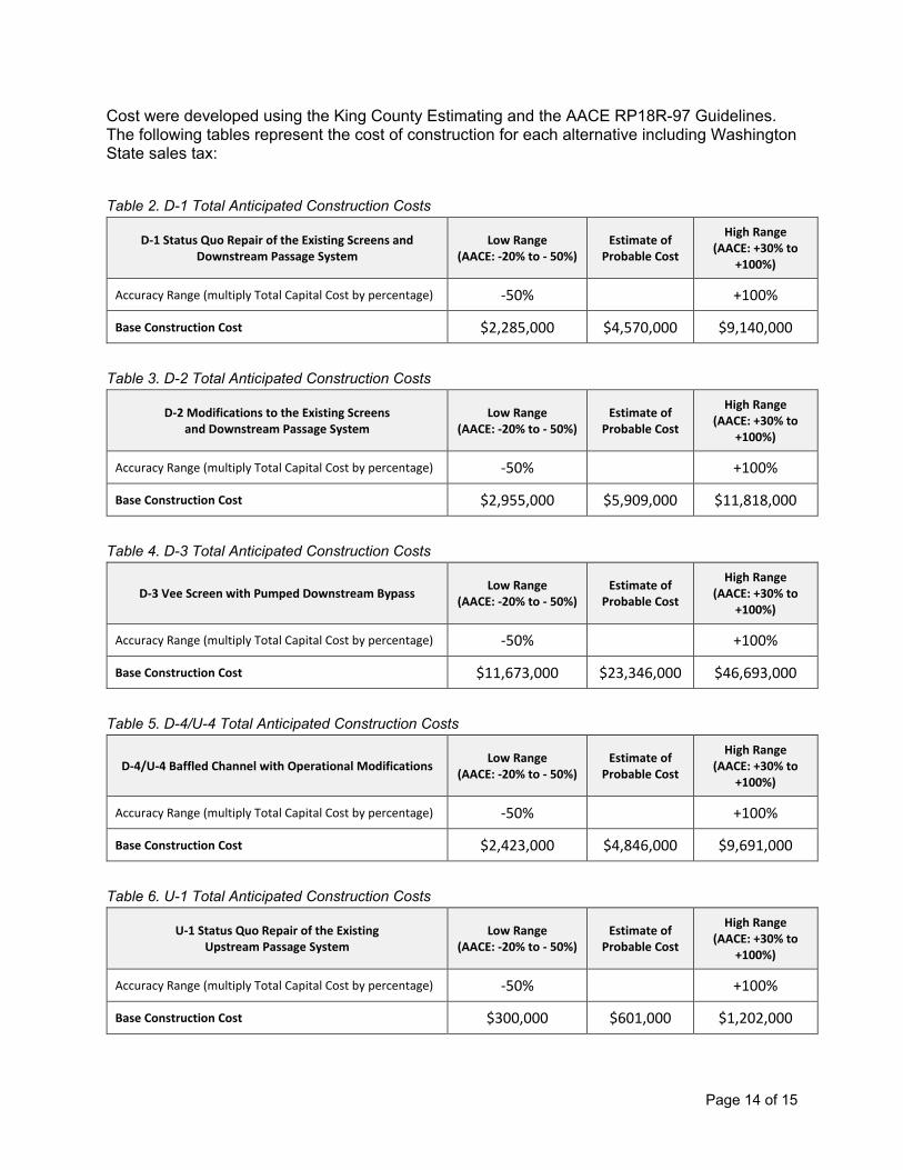
Page 14 of 15
Cost were developed using the King County Estimating and the AACE RP18R-97 Guidelines. The following tables represent the cost of construction for each alternative including Washington State sales tax:
Table 2. D-1 Total Anticipated Construction Costs
Table 3. D-2 Total Anticipated Construction Costs
Table 4. D-3 Total Anticipated Construction Costs
Table 5. D-4/U-4 Total Anticipated Construction Costs
Table 6. U-1 Total Anticipated Construction Costs
D-1 Status Quo Repair of the Existing Screens and Downstream Passage System
Low Range (AACE: -20% to - 50%)
Estimate of Probable Cost
High Range (AACE: +30% to
+100%)
Accuracy Range (multiply Total Capital Cost by percentage) -50% +100%
Base Construction Cost $2,285,000 $4,570,000 $9,140,000
D-2 Modifications to the Existing Screens and Downstream Passage System
Low Range (AACE: -20% to - 50%)
Estimate of Probable Cost
High Range (AACE: +30% to
+100%)
Accuracy Range (multiply Total Capital Cost by percentage) -50% +100%
Base Construction Cost $2,955,000 $5,909,000 $11,818,000
D-3 Vee Screen with Pumped Downstream Bypass Low Range (AACE: -20% to - 50%)
Estimate of Probable Cost
High Range (AACE: +30% to
+100%)
Accuracy Range (multiply Total Capital Cost by percentage) -50% +100%
Base Construction Cost $11,673,000 $23,346,000 $46,693,000
D-4/U-4 Baffled Channel with Operational Modifications Low Range (AACE: -20% to - 50%)
Estimate of Probable Cost
High Range (AACE: +30% to
+100%)
Accuracy Range (multiply Total Capital Cost by percentage) -50% +100%
Base Construction Cost $2,423,000 $4,846,000 $9,691,000
U-1 Status Quo Repair of the Existing Upstream Passage System
Low Range (AACE: -20% to - 50%)
Estimate of Probable Cost
High Range (AACE: +30% to
+100%)
Accuracy Range (multiply Total Capital Cost by percentage) -50% +100%
Base Construction Cost $300,000 $601,000 $1,202,000

Page 15 of 15
Table 7. U-2 Total Anticipated Construction Costs
Accuracy of the associated cost estimate is dependent upon the various underlying assumptions, inclusions, and exclusions described herein. Actual project costs may differ and can be significantly affected by factors such as changes in the external environment, the manner in which the project is executed and controlled, and other factors that may impact the estimate basis or otherwise affect the project. Estimate accuracy ranges are only assessments based upon the cost estimating methods and data employed in preparing the estimate and are not a guarantee of actual project costs. These estimates contain a Design/Construction Contingency which is not a standard contingency; rather, it accounts for the cost of known but undefined requirements necessary for a complete and workable project. It accounts for elements that are not explicitly shown in the one-percent design documents and will be further defined as the drawings and specifications progress towards 100-percent design. The design/construction contingency of 50 percent and is based on professional judgement, design maturity and the complexity of the project. It is calculated on the subtotal construction cost including contractor overhead and profit, less Street Use Permit, Construction Permits, and fees. The estimate includes the following assumptions:
1. It is assumed that there are no contaminated materials, soils or lead paint that would cause extra cost in handling and disposal.
2. Assumed execution strategy is a standard work week with limited overtime. 3. The project delivery method is assumed to be design, bid, and build with a general
contractor subcontracting wall and floor repair, painting, utility work while self-performing most of the remaining work.
4. Escalation forward to construction start has not been included. Attachment A: Opinion of Probable Cost.
U-2 Modifications to the Existing Upstream Passage System
Low Range (AACE: -20% to - 50%)
Estimate of Probable Cost
High Range (AACE: +30% to
+100%)
Accuracy Range (multiply Total Capital Cost by percentage) -50% +100%
Base Construction Cost $770,000 $1,540,000 $3,080,000

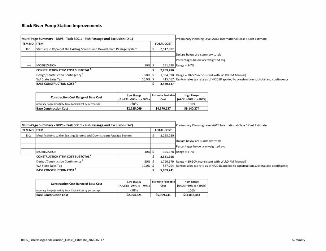
Black River Pump Station Improvements
Preliminary Planning Level AACE International Class 5 Cost EstimateITEM NO. ITEM TOTAL COST
D‐1 Status Quo Repair of the Existing Screens and Downstream Passage System 2,517,982$
Dollars below are summary totals
Percentages below are weighted avg
‐‐‐‐ MOBILIZATION 10% 251,798$ Range = 3‐7%CONSTRUCTION ITEM COST SUBTOTAL 1 2,769,780$ Design/Construction Contingency 2 50% 1,384,890$ Range = 30‐50% (consistent with WLRD PM Manual)WA State Sales Tax 10.0% 415,467$ Renton sales tax rate as of 4/2018 applied to construction subtotal and contingencyBASE CONSTRUCTION COST 3 4,570,137$
Construction Cost Range of Base Cost Low Range (AACE: -20% to - 50%)
Estimate Probable Cost
High Range (AACE: +30% to +100%)
Accuracy Range (multiply Total Capital Cost by percentage) -50% 100%Base Construction Cost $2,285,069 $4,570,137 $9,140,274
Preliminary Planning Level AACE International Class 5 Cost EstimateITEM NO. ITEM TOTAL COST
D‐2 Modifications to the Existing Screens and Downstream Passage System 3,255,780$
Dollars below are summary totals
Percentages below are weighted avg
‐‐‐‐ MOBILIZATION 10% 325,578$ Range = 3‐7%CONSTRUCTION ITEM COST SUBTOTAL 1 3,581,358$ Design/Construction Contingency 2 50% 1,790,679$ Range = 30‐50% (consistent with WLRD PM Manual)WA State Sales Tax 10.0% 537,204$ Renton sales tax rate as of 4/2018 applied to construction subtotal and contingencyBASE CONSTRUCTION COST 3 5,909,241$
Construction Cost Range of Base Cost Low Range (AACE: -20% to - 50%)
Estimate Probable Cost
High Range (AACE: +30% to +100%)
Accuracy Range (multiply Total Capital Cost by percentage) -50% 100%Base Construction Cost $2,954,621 $5,909,241 $11,818,483
Multi‐Page Summary ‐ BRPS ‐ Task 500.1 ‐ Fish Passage and Exclusion (D‐1)
Multi‐Page Summary ‐ BRPS ‐ Task 500.1 ‐ Fish Passage and Exclusion (D‐2)
BRPS_FishPassageAndExclusion_Class5_Estimate_2020‐02‐17 Summary
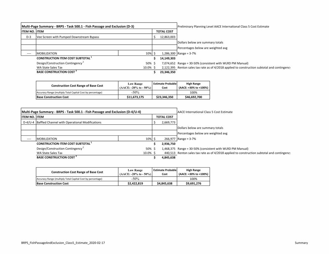
Preliminary Planning Level AACE International Class 5 Cost EstimateITEM NO. ITEM TOTAL COST
D‐3 Vee Screen with Pumped Downstream Bypass 12,863,003$
Dollars below are summary totals
Percentages below are weighted avg
‐‐‐‐ MOBILIZATION 10% 1,286,300$ Range = 3‐7%CONSTRUCTION ITEM COST SUBTOTAL 1 14,149,303$ Design/Construction Contingency 2 50% 7,074,652$ Range = 30‐50% (consistent with WLRD PM Manual)WA State Sales Tax 10.0% 2,122,395$ Renton sales tax rate as of 4/2018 applied to construction subtotal and contingencyBASE CONSTRUCTION COST 3 23,346,350$
Construction Cost Range of Base Cost Low Range (AACE: -20% to - 50%)
Estimate Probable Cost
High Range (AACE: +30% to +100%)
Accuracy Range (multiply Total Capital Cost by percentage) -50% 100%Base Construction Cost $11,673,175 $23,346,350 $46,692,700
AACE International Class 5 Cost EstimateITEM NO. ITEM TOTAL COST
D‐4/U‐4 Baffled Channel with Operational Modifications 2,669,773$
Dollars below are summary totals
Percentages below are weighted avg
‐‐‐‐ MOBILIZATION 10% 266,977$ Range = 3‐7%CONSTRUCTION ITEM COST SUBTOTAL 1 2,936,750$ Design/Construction Contingency 2 50% 1,468,375$ Range = 30‐50% (consistent with WLRD PM Manual)WA State Sales Tax 10.0% 440,513$ Renton sales tax rate as of 4/2018 applied to construction subtotal and contingencyBASE CONSTRUCTION COST 3 4,845,638$
Construction Cost Range of Base Cost Low Range (AACE: -20% to - 50%)
Estimate Probable Cost
High Range (AACE: +30% to +100%)
Accuracy Range (multiply Total Capital Cost by percentage) -50% 100%Base Construction Cost $2,422,819 $4,845,638 $9,691,276
Multi‐Page Summary ‐ BRPS ‐ Task 500.1 ‐ Fish Passage and Exclusion (D‐4/U‐4)
Multi‐Page Summary ‐ BRPS ‐ Task 500.1 ‐ Fish Passage and Exclusion (D‐3)
BRPS_FishPassageAndExclusion_Class5_Estimate_2020‐02‐17 Summary
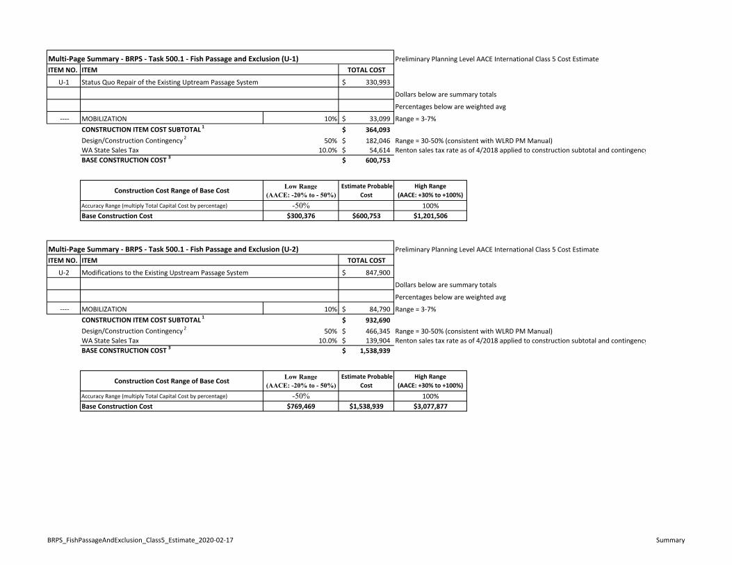
Preliminary Planning Level AACE International Class 5 Cost EstimateITEM NO. ITEM TOTAL COST
U‐1 Status Quo Repair of the Existing Uptream Passage System 330,993$
Dollars below are summary totals
Percentages below are weighted avg
‐‐‐‐ MOBILIZATION 10% 33,099$ Range = 3‐7%CONSTRUCTION ITEM COST SUBTOTAL 1 364,093$ Design/Construction Contingency 2 50% 182,046$ Range = 30‐50% (consistent with WLRD PM Manual)WA State Sales Tax 10.0% 54,614$ Renton sales tax rate as of 4/2018 applied to construction subtotal and contingencyBASE CONSTRUCTION COST 3 600,753$
Construction Cost Range of Base Cost Low Range (AACE: -20% to - 50%)
Estimate Probable Cost
High Range (AACE: +30% to +100%)
Accuracy Range (multiply Total Capital Cost by percentage) -50% 100%Base Construction Cost $300,376 $600,753 $1,201,506
Preliminary Planning Level AACE International Class 5 Cost EstimateITEM NO. ITEM TOTAL COST
U‐2 Modifications to the Existing Upstream Passage System 847,900$
Dollars below are summary totals
Percentages below are weighted avg
‐‐‐‐ MOBILIZATION 10% 84,790$ Range = 3‐7%CONSTRUCTION ITEM COST SUBTOTAL 1 932,690$ Design/Construction Contingency 2 50% 466,345$ Range = 30‐50% (consistent with WLRD PM Manual)WA State Sales Tax 10.0% 139,904$ Renton sales tax rate as of 4/2018 applied to construction subtotal and contingencyBASE CONSTRUCTION COST 3 1,538,939$
Construction Cost Range of Base Cost Low Range (AACE: -20% to - 50%)
Estimate Probable Cost
High Range (AACE: +30% to +100%)
Accuracy Range (multiply Total Capital Cost by percentage) -50% 100%Base Construction Cost $769,469 $1,538,939 $3,077,877
Multi‐Page Summary ‐ BRPS ‐ Task 500.1 ‐ Fish Passage and Exclusion (U‐1)
Multi‐Page Summary ‐ BRPS ‐ Task 500.1 ‐ Fish Passage and Exclusion (U‐2)
BRPS_FishPassageAndExclusion_Class5_Estimate_2020‐02‐17 Summary
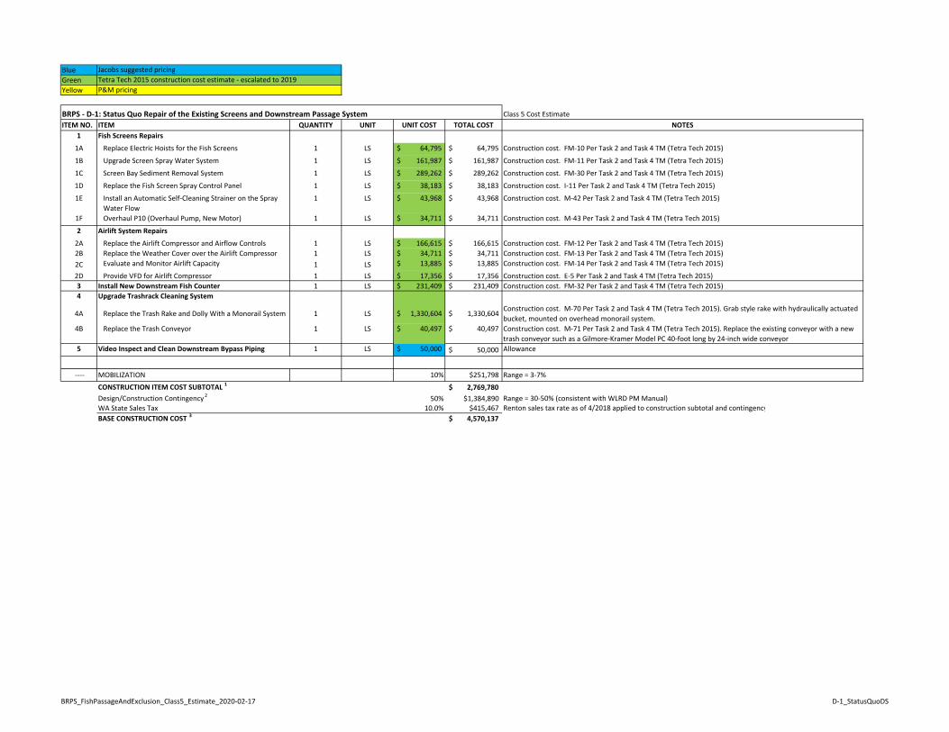
BlueGreenYellow
Class 5 Cost EstimateITEM NO. ITEM QUANTITY UNIT UNIT COST TOTAL COST NOTES
1 Fish Screens Repairs
1A Replace Electric Hoists for the Fish Screens 1 LS 64,795$ 64,795$ Construction cost. FM‐10 Per Task 2 and Task 4 TM (Tetra Tech 2015)
1B Upgrade Screen Spray Water System 1 LS 161,987$ 161,987$ Construction cost. FM‐11 Per Task 2 and Task 4 TM (Tetra Tech 2015)
1C Screen Bay Sediment Removal System 1 LS 289,262$ 289,262$ Construction cost. FM‐30 Per Task 2 and Task 4 TM (Tetra Tech 2015)
1D Replace the Fish Screen Spray Control Panel 1 LS 38,183$ 38,183$ Construction cost. I‐11 Per Task 2 and Task 4 TM (Tetra Tech 2015)
1E Install an Automatic Self‐Cleaning Strainer on the Spray Water Flow
1 LS 43,968$ 43,968$ Construction cost. M‐42 Per Task 2 and Task 4 TM (Tetra Tech 2015)
1F Overhaul P10 (Overhaul Pump, New Motor) 1 LS 34,711$ 34,711$ Construction cost. M‐43 Per Task 2 and Task 4 TM (Tetra Tech 2015)
2 Airlift System Repairs
2A Replace the Airlift Compressor and Airflow Controls 1 LS 166,615$ 166,615$ Construction cost. FM‐12 Per Task 2 and Task 4 TM (Tetra Tech 2015)2B Replace the Weather Cover over the Airlift Compressor 1 LS 34,711$ 34,711$ Construction cost. FM‐13 Per Task 2 and Task 4 TM (Tetra Tech 2015)2C Evaluate and Monitor Airlift Capacity 1 LS 13,885$ 13,885$ Construction cost. FM‐14 Per Task 2 and Task 4 TM (Tetra Tech 2015)
2D Provide VFD for Airlift Compressor 1 LS 17,356$ 17,356$ Construction cost. E‐5 Per Task 2 and Task 4 TM (Tetra Tech 2015)3 Install New Downstream Fish Counter 1 LS 231,409$ 231,409$ Construction cost. FM‐32 Per Task 2 and Task 4 TM (Tetra Tech 2015)4 Upgrade Trashrack Cleaning System
4A Replace the Trash Rake and Dolly With a Monorail System 1 LS 1,330,604$ 1,330,604$ Construction cost. M‐70 Per Task 2 and Task 4 TM (Tetra Tech 2015). Grab style rake with hydraulically actuated bucket, mounted on overhead monorail system.
4B Replace the Trash Conveyor 1 LS 40,497$ 40,497$ Construction cost. M‐71 Per Task 2 and Task 4 TM (Tetra Tech 2015). Replace the existing conveyor with a new trash conveyor such as a Gilmore‐Kramer Model PC 40‐foot long by 24‐inch wide conveyor
5 Video Inspect and Clean Downstream Bypass Piping 1 LS 50,000$ 50,000$ Allowance
‐‐‐‐ MOBILIZATION 10% $251,798 Range = 3‐7%
CONSTRUCTION ITEM COST SUBTOTAL 1 2,769,780$ Design/Construction Contingency 2 50% $1,384,890 Range = 30‐50% (consistent with WLRD PM Manual)WA State Sales Tax 10.0% $415,467 Renton sales tax rate as of 4/2018 applied to construction subtotal and contingencyBASE CONSTRUCTION COST 3 4,570,137$
Jacobs suggested pricingTetra Tech 2015 construction cost estimate ‐ escalated to 2019P&M pricing
BRPS ‐ D‐1: Status Quo Repair of the Existing Screens and Downstream Passage System
BRPS_FishPassageAndExclusion_Class5_Estimate_2020‐02‐17 D‐1_StatusQuoDS
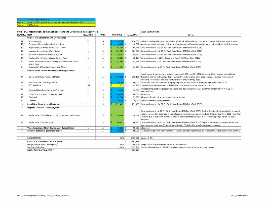
BlueGreenYellow
Class 5 Cost EstimateITEM NO. ITEM QUANTITY UNIT UNIT COST TOTAL COST NOTES
1 Replace Fish Screens for NMFS Compliance
1A Screen Panels 15 EA 30,000$ 450,000$ Stainless steel profile bar screen panels, Hendrick B69 profile bar. 15 total screens including one spare screen1B Pressure differential monitoring system 1 LS 40,000$ 40,000$ Monitoring equipment and controls to allow pressure differential monitoring on either side of the fish screens.
1C Replace Electric Hoists for the Fish Screens 1 LS 64,795$ 64,795$ Construction cost. FM‐10 Per Task 2 and Task 4 TM (Tetra Tech 2015)
1D Upgrade Screen Spray Water System 1 LS 161,987$ 161,987$ Construction cost. FM‐11 Per Task 2 and Task 4 TM (Tetra Tech 2015)
1E Screen Bay Sediment Removal System 1 LS 289,262$ 289,262$ Construction cost. FM‐30 Per Task 2 and Task 4 TM (Tetra Tech 2015)
1F Replace the Fish Screen Spray Control Panel 1 LS 38,183$ 38,183$ Construction cost. I‐11 Per Task 2 and Task 4 TM (Tetra Tech 2015)
1G Install an Automatic Self‐Cleaning Strainer on the Spray Water Flow
1 LS 43,968$ 43,968$ Construction cost. M‐42 Per Task 2 and Task 4 TM (Tetra Tech 2015)
1H Overhaul P10 (Overhaul Pump, New Motor) 1 LS 34,711$ 34,711$ Construction cost. M‐43 Per Task 2 and Task 4 TM (Tetra Tech 2015)
2 Replace Airlift System with Screw Centrifugal Pumps
2A Screw Centrifugal Pump and Motor 1 LS 230,125$ 230,125$ 2 each motor driven screw centrifugal pumps at 3,000 gpm (6.7 CFS) , targeting 5 fps entrance port velocity through 7 nearest entrance ports per pump (14 total entrance ports open). Includes pumps, motors, and mounting accessories. Per manufacturer quote provided May 2019.
2B VFD for Screw Centrifugal Motor 1 LS 40,000$ 40,000$ 2 each VFD units for screw centrifugal pump motors. Per manufacturer quote provided June 2019.2C 30" Steel Pipe 104 LF 435$ 45,240$ 2 upwelling pipes on discharge of Hidrostal pumps up to existing dearation tank
2DRemove/Abandon existing airlift system 1 LS 50,000$ 50,000$
Includes removal of compressor, air piping, and downstream passage pipe from bottom of dry well up to dearation tank
2E Construction of Pump Operating Deck 1 LS 100,000$ 100,000$ Allowance2F Electrical 1 LS 25,000$ 25,000$ Allowance for electrical connection to new pumps.
2G Controls 1 LS 10,000$ 10,000$ Allowance for new pump controls.
3 Install New Downstream Fish Counter 1 LS 231,409$ 231,409$ Construction cost. FM‐32 Per Task 2 and Task 4 TM (Tetra Tech 2015)
4 Upgrade Trashrack Cleaning System
4A Replace the Trash Rake and Dolly With a Monorail System 1 LS 1,230,604$ 1,230,604$
Construction cost. M‐70 Per Task 2 and Task 4 TM (Tetra Tech 2015). Grab style rake with hydraulically actuated bucket, mounted on overhead monorail system. Costing assumes reduced construction cost from 2015 Tetra Tech estimate due to exclusion of replacement of the air compressor system for the airlift pumps which are to be removed.
4B Replace the Trash Conveyor 1 LS 40,497$ 40,497$ Construction cost. M‐71 Per Task 2 and Task 4 TM (Tetra Tech 2015). Replace the existing conveyor with a new trash conveyor such as a Gilmore‐Kramer Model PC 40‐foot long by 24‐inch wide conveyor
5 Video Inspect and Clean Downstream Bypass Piping 1 LS 50,000$ 50,000$ Allowance6 Entrance port sluice gate modifications 1 LS 80,000$ 80,000$ Modifications to allow each individual entrance port to be controlled independently, and also allow flow control.
‐‐‐‐ MOBILIZATION 10% $325,578 Range = 3‐7%
CONSTRUCTION ITEM COST SUBTOTAL 1 3,581,358$ Design/Construction Contingency 2 50% $1,790,679 Range = 30‐50% (consistent with WLRD PM Manual)WA State Sales Tax 10.0% $537,204 Renton sales tax rate as of 4/2018 applied to construction subtotal and contingencyBASE CONSTRUCTION COST 3 5,909,241$
BRPS ‐ D‐2: Modifications to the Existing Screens and Downstream Passage System
Jacobs suggested pricingTetra Tech 2015 construction cost estimate ‐ escalated to 2019P&M pricing
BRPS_FishPassageAndExclusion_Class5_Estimate_2020‐02‐17 D‐2_ModifyExistDS
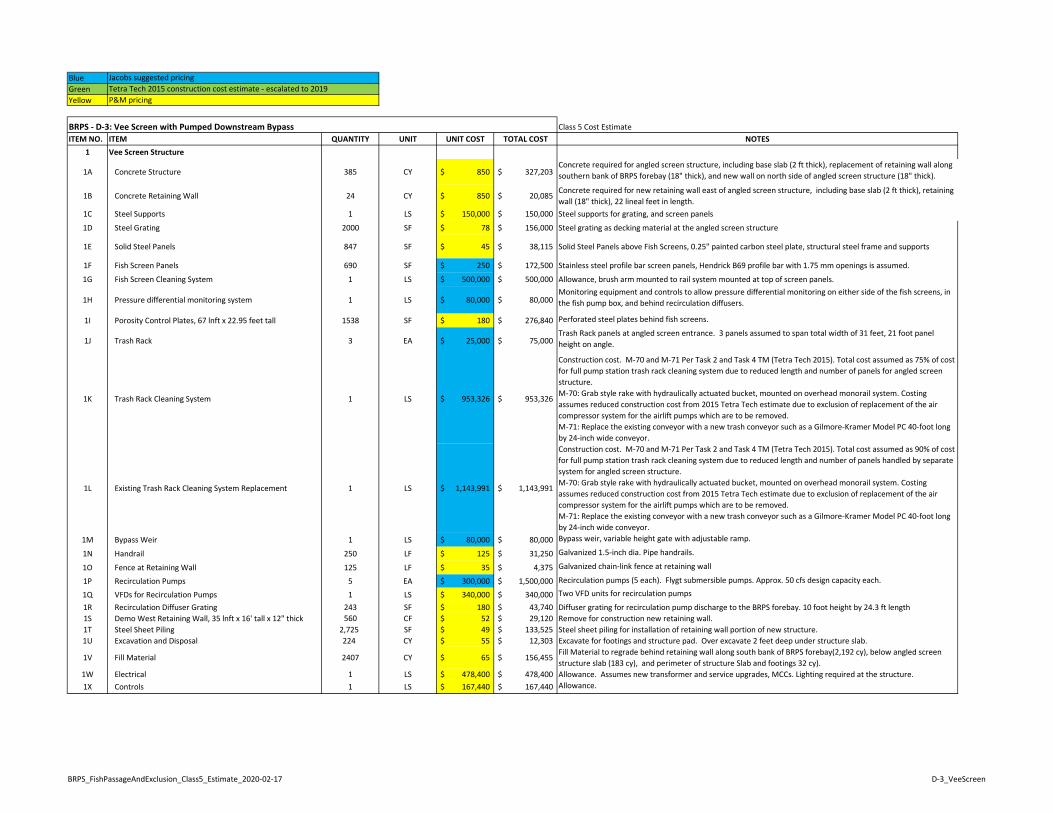
BlueGreenYellow
Class 5 Cost EstimateITEM NO. ITEM QUANTITY UNIT UNIT COST TOTAL COST NOTES
1 Vee Screen Structure
1A Concrete Structure 385 CY 850$ 327,203$ Concrete required for angled screen structure, including base slab (2 ft thick), replacement of retaining wall along southern bank of BRPS forebay (18" thick), and new wall on north side of angled screen structure (18" thick).
1B Concrete Retaining Wall 24 CY 850$ 20,085$ Concrete required for new retaining wall east of angled screen structure, including base slab (2 ft thick), retaining wall (18" thick), 22 lineal feet in length.
1C Steel Supports 1 LS 150,000$ 150,000$ Steel supports for grating, and screen panels
1D Steel Grating 2000 SF 78$ 156,000$ Steel grating as decking material at the angled screen structure
1E Solid Steel Panels 847 SF 45$ 38,115$ Solid Steel Panels above Fish Screens, 0.25" painted carbon steel plate, structural steel frame and supports
1F Fish Screen Panels 690 SF 250$ 172,500$ Stainless steel profile bar screen panels, Hendrick B69 profile bar with 1.75 mm openings is assumed.
1G Fish Screen Cleaning System 1 LS 500,000$ 500,000$ Allowance, brush arm mounted to rail system mounted at top of screen panels.
1H Pressure differential monitoring system 1 LS 80,000$ 80,000$ Monitoring equipment and controls to allow pressure differential monitoring on either side of the fish screens, in the fish pump box, and behind recirculation diffusers.
1I Porosity Control Plates, 67 lnft x 22.95 feet tall 1538 SF 180$ 276,840$ Perforated steel plates behind fish screens.
1J Trash Rack 3 EA 25,000$ 75,000$ Trash Rack panels at angled screen entrance. 3 panels assumed to span total width of 31 feet, 21 foot panel height on angle.
1K Trash Rack Cleaning System 1 LS 953,326$ 953,326$
Construction cost. M‐70 and M‐71 Per Task 2 and Task 4 TM (Tetra Tech 2015). Total cost assumed as 75% of cost for full pump station trash rack cleaning system due to reduced length and number of panels for angled screen structure.M‐70: Grab style rake with hydraulically actuated bucket, mounted on overhead monorail system. Costing assumes reduced construction cost from 2015 Tetra Tech estimate due to exclusion of replacement of the air compressor system for the airlift pumps which are to be removed.M‐71: Replace the existing conveyor with a new trash conveyor such as a Gilmore‐Kramer Model PC 40‐foot long by 24‐inch wide conveyor.
1L Existing Trash Rack Cleaning System Replacement 1 LS 1,143,991$ 1,143,991$
Construction cost. M‐70 and M‐71 Per Task 2 and Task 4 TM (Tetra Tech 2015). Total cost assumed as 90% of cost for full pump station trash rack cleaning system due to reduced length and number of panels handled by separate system for angled screen structure.M‐70: Grab style rake with hydraulically actuated bucket, mounted on overhead monorail system. Costing assumes reduced construction cost from 2015 Tetra Tech estimate due to exclusion of replacement of the air compressor system for the airlift pumps which are to be removed.M‐71: Replace the existing conveyor with a new trash conveyor such as a Gilmore‐Kramer Model PC 40‐foot long by 24‐inch wide conveyor.
1M Bypass Weir 1 LS 80,000$ 80,000$ Bypass weir, variable height gate with adjustable ramp.
1N Handrail 250 LF 125$ 31,250$ Galvanized 1.5‐inch dia. Pipe handrails.
1O Fence at Retaining Wall 125 LF 35$ 4,375$ Galvanized chain‐link fence at retaining wall
1P Recirculation Pumps 5 EA 300,000$ 1,500,000$ Recirculation pumps (5 each). Flygt submersible pumps. Approx. 50 cfs design capacity each.
1Q VFDs for Recirculation Pumps 1 LS 340,000$ 340,000$ Two VFD units for recirculation pumps
1R Recirculation Diffuser Grating 243 SF 180$ 43,740$ Diffuser grating for recirculation pump discharge to the BRPS forebay. 10 foot height by 24.3 ft length1S Demo West Retaining Wall, 35 lnft x 16' tall x 12" thick 560 CF 52$ 29,120$ Remove for construction new retaining wall.1T Steel Sheet Piling 2,725 SF 49$ 133,525$ Steel sheet piling for installation of retaining wall portion of new structure.1U Excavation and Disposal 224 CY 55$ 12,303$ Excavate for footings and structure pad. Over excavate 2 feet deep under structure slab.
1V Fill Material 2407 CY 65$ 156,455$ Fill Material to regrade behind retaining wall along south bank of BRPS forebay(2,192 cy), below angled screen structure slab (183 cy), and perimeter of structure Slab and footings 32 cy).
1W Electrical 1 LS 478,400$ 478,400$ Allowance. Assumes new transformer and service upgrades, MCCs. Lighting required at the structure.1X Controls 1 LS 167,440$ 167,440$ Allowance.
Jacobs suggested pricingTetra Tech 2015 construction cost estimate ‐ escalated to 2019P&M pricing
BRPS ‐ D‐3: Vee Screen with Pumped Downstream Bypass
BRPS_FishPassageAndExclusion_Class5_Estimate_2020‐02‐17 D‐3_VeeScreen
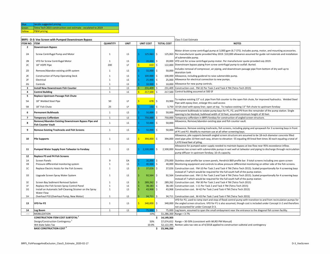
BlueGreenYellow
Class 5 Cost EstimateITEM NO. ITEM QUANTITY UNIT UNIT COST TOTAL COST NOTES
Jacobs suggested pricingTetra Tech 2015 construction cost estimate ‐ escalated to 2019P&M pricing
BRPS ‐ D‐3: Vee Screen with Pumped Downstream Bypass
2 Downstream Bypass
2A Screw Centrifugal Pump and Motor 1 LS 125,063$ 125,063$ Motor driven screw centrifugal pump at 3,000 gpm (6.7 CFS). Includes pump, motor, and mounting accessories. Per manufacturer quote provided May 2019. $10,000 allowance assumed for guide rail materials and installation of submersible pump.
2B VFD for Screw Centrifugal Motor 1 LS 20,000$ 20,000$ VFD unit for screw centrifugal pump motor. Per manufacturer quote provided July 2019.2C 18" HDPE Pipe 200 LF 610$ 122,000$ Downstream bypass piping from screw centrifugal pump to outfall. Buried.
2D Remove/Abandon existing airlift system 1 LS 50,000$ 50,000$ Includes removal of compressor, air piping, and downstream passage pipe from bottom of dry well up to dearation tank
2E Construction of Pump Operating Deck 1 LS 100,000$ 100,000$ Allowance, including guiderail to raise submersible pump.2F Electrical 1 LS 25,000$ 25,000$ Allowance for electrical connection to new pumps.
2G Controls 1 LS 10,000$ 10,000$ Allowance for new pump controls.
3 Install New Downstream Fish Counter 1 LS 231,409$ 231,409$ Construction cost. FM‐32 Per Task 2 and Task 4 TM (Tetra Tech 2015)4 Control Building 1 LS 217,500$ 217,500$ Control building assumed at 500 SF
5 Replace Upstream Passage Fish Chute
5A 18" Welded Steel Pipe 50 LF 678$ 33,900$ To replace existing 13" o.d. pipe from fish counter to the open fish chute, for improved hydraulics. Welded Steel Pipe with epoxy liner, enlarge thru wall access
5B 18" Fish Chute 25 LF 150$ 3,750$ 10 GA steel with epoxy liner, open at top. To replace existing 13" fish chute to upstream forebay
6 Permanent Bulkheads 1 LS 50,000$ 50,000$ Permanent bulkheads to isolate pump bays for P1, P2, and P9 from the remainder of the pump station. Single opening to be blocked, bulkhead width of 10 feet, assumed minimum height of 30 feet.
7 Temporary Cofferdam 1 LS 750,000$ 750,000$ Temporary cofferdam in BRPS forebay for construction of angled screen structure.
8Remove/Abandon Existing Downstream Bypass Pipe and Fish Counter Vault
1 LS 50,000$ 50,000$ Allowance, Remove/abandon existing pipe and fish counter vault.
9 Remove Existing Trashracks and Fish Screens 1 LS 50,000$ 50,000$ Allowance, Remove existing trashracks, fish screens, including piping and spraywash for 3 screening bays in front of P1 and P2. Modify to maintain use at all other screening bays.
10 Pile Supports 1 LS 394,000$ 394,000$ Allowance, pile supports beneath angled screen structure are assumed to be 18‐inch diameter concrete filled steel pipe piles 10‐feet each way, driven to elevation ‐55 equaling 49 lineal feet times 30 each equaling a total of 1,470 lineal feet of piling.
11 Pumped Water Supply from Tailwater to Forebay 1 LS 2,500,000$ 2,500,000$ Allowance for pumped water supply needed to maintain bypass at low flow near 95% exceedance inflow. Assumes tee screen with submersible pumps in wet well at tailwater and piping to discharge through recirculation pump diffuser in upstream forebay; 10 cfs capacity.
12 Replace P3 and P4 Fish Screens
1A Screen Panels 9 EA 30,000$ 270,000$ Stainless steel profile bar screen panels, Hendrick B69 profile bar. 9 total screens including one spare screen1B Pressure differential monitoring system 1 LS 40,000$ 40,000$ Monitoring equipment and controls to allow pressure differential monitoring on either side of the fish screens.
1C Replace Electric Hoists for the Fish Screens 1 LS 37,026$ 37,026$ Construction cost. FM‐10 Per Task 2 and Task 4 TM (Tetra Tech 2015). Scaled proportionally for 4 screening bays instead of 7 which would be required for the full south half of the pump station.
1D Upgrade Screen Spray Water System 1 LS 92,564$ 92,564$ Construction cost. FM‐11 Per Task 2 and Task 4 TM (Tetra Tech 2015). Scaled proportionally for 4 screening bays instead of 7 which would be required for the full south half of the pump station.
1E Screen Bay Sediment Removal System 1 LS 289,262$ 289,262$ Construction cost. FM‐30 Per Task 2 and Task 4 TM (Tetra Tech 2015)1F Replace the Fish Screen Spray Control Panel 1 LS 38,183$ 38,183$ Construction cost. I‐11 Per Task 2 and Task 4 TM (Tetra Tech 2015)1G Install an Automatic Self‐Cleaning Strainer on the Spray
Water Flow1 LS 43,968$ 43,968$ Construction cost. M‐42 Per Task 2 and Task 4 TM (Tetra Tech 2015)
1H Overhaul P10 (Overhaul Pump, New Motor) 1 LS 34,711$ 34,711$ Construction cost. M‐43 Per Task 2 and Task 4 TM (Tetra Tech 2015)
13 VFD for P2 1 LS 340,000$ 340,000$ VFD for P2, used to ramp start and stop of flood control pump with transition to and from recirculation pumps for the angled screen structure. VFD for P1 is also assumed, though cost is included under Concept U‐2 and therefore not accounted for under Concept D‐3.
14 Log Boom 1 LS 75,000$ 75,000$ Log boom, assumed to span the small embayment near the entrance to the diagonal fish screen facility. ‐‐‐‐ MOBILIZATION 10% $1,286,300 Range = 3‐7%
CONSTRUCTION ITEM COST SUBTOTAL 1 14,149,303$ Design/Construction Contingency 2 50% $7,074,652 Range = 30‐50% (consistent with WLRD PM Manual)WA State Sales Tax 10.0% $2,122,395 Renton sales tax rate as of 4/2018 applied to construction subtotal and contingencyBASE CONSTRUCTION COST 3 23,346,350$
BRPS_FishPassageAndExclusion_Class5_Estimate_2020‐02‐17 D‐3_VeeScreen
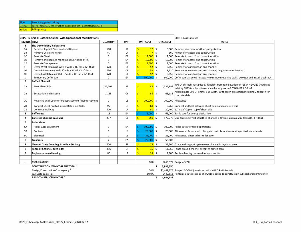
BlueGreenYellow
Class 5 Cost EstimateITEM NO. ITEM QUANTITY UNIT UNIT COST TOTAL COST NOTES
1 Site Demolition / Relocations1A Remove Asphalt Pavement and Dispose 500 SF 12$ 6,000$ Remove pavement north of pump station1B Remove Chain link Fence 80 LF 7$ 560$ Remove for access and construction1C Relocate Shed 1 EA 12,000$ 12,000$ Relocate to north from current location1D Remove and Replace Monorail at Northside of PS 1 EA 15,000$ 15,000$ Remove for access and construction1E Relocate Storage Area 1 EA 2,500$ 2,500$ Relocate to north from current location1F Demo West Retaining Wall, 8'wide x 16' tall x 12" thick 128 CF 52$ 6,656$ Remove for construction and channel1G Demo PS Retaining Wall, 8'wide x 20'tall x 12" thick 160 CF 52$ 8,320$ Remove for construction and channel, height includes footing1H Demo East Retaining Wall, 8'wide x 16' tall x 12" thick 128 CF 52$ 6,656$ Remove for construction and channel1I Temporary Cofferdam 2 EA 300,000$ 600,000$ Cofferdam assumed necessary to remove retaining walls, dewater and install trashrack2 Baffled Channel
2A Steel Sheet Pile 27,202 SF 49$ 1,332,898$ 406 LF of steel sheet pile; 67 ft height from top elevation of +25.0' NGVD29 (matching existing BRPS top deck) to rock level at approx. ‐42.0' NGVD29. 38 psf.
2B Excavation and Disposal 1,185 CY 55$ 65,185$ Approximate 200 LF length, 8 LF width, 20 ft depth excavation including 2 ft depth for concrete slab
2C Retaining Wall Counterfort Replacement / Reinforcement 1 LS 100,000$ 100,000$ Allowance
2D Connect Sheet Pile to Existing Retaining Walls 96 LF 60$ 5,760$ Connect and Seal between sheet piling and concrete wall2E Concrete Wall Cap 400 LF 51$ 20,400$ 12" x 12" Cap on top of sheet pile3 Baffle Sets 13 EA 5,000$ 65,000$ Baffle sets for energy dissipation
4 Concrete Channel Base Slab 237 CY 750$ 177,778$ Slab forming invert of baffled channel; 8 ft wide, approx. 200 ft length, 4 ft thick
5 Roller Gate
5A Roller Gate Equipment 1 EA 100,000$ 100,000$ Roller gates for flood operations
5B Controls 1 LS 25,000$ 25,000$ Allowance. Automated roller gate controls for closure at specified water levels
5C Electrical 1 LS 25,000$ 25,000$ Allowance. Electrical for roller gate.
6 Trashrack 2 EA 25,000$ 50,000$
7 Channel Grate Covering, 8' wide x 50' long 400 SF 78$ 31,200$ Grate and support system over channel in laydown area
8 Fence at Channel, both sides 316 LF 35$ 11,060$ Fence around channel except at grated area
8 Replace removed fencing 80 LF 35$ 2,800$ Replace fencing removed for construction
‐‐‐‐ MOBILIZATION 10% $266,977 Range = 3‐7%CONSTRUCTION ITEM COST SUBTOTAL 1 2,936,750$ Design/Construction Contingency 2 50% $1,468,375 Range = 30‐50% (consistent with WLRD PM Manual)WA State Sales Tax 10.0% $440,513 Renton sales tax rate as of 4/2018 applied to construction subtotal and contingencyBASE CONSTRUCTION COST 3 4,845,638$
Jacobs suggested pricingTetra Tech 2015 construction cost estimate ‐ escalated to 2019P&M pricing
BRPS ‐ D‐4/U‐4: Baffled Channel with Operational Modifications
BRPS_FishPassageAndExclusion_Class5_Estimate_2020‐02‐17 D‐4_U‐4_Baffled Channel
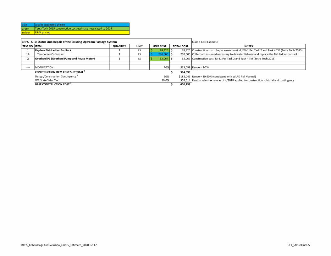
BlueGreenYellow
Class 5 Cost EstimateITEM NO. ITEM QUANTITY UNIT UNIT COST TOTAL COST NOTES
1 Replace Fish Ladder Bar Rack 1 LS 28,926$ 28,926$ Construction cost. Replacement in‐kind, FM‐1 Per Task 2 and Task 4 TM (Tetra Tech 2015)1A Temporary Cofferdam 1 LS 250,000$ 250,000$ Cofferdam assumed necessary to dewater fishway and replace the fish ladder bar rack.2 Overhaul P9 (Overhaul Pump and Reuse Motor) 1 LS 52,067$ 52,067$ Construction cost. M‐41 Per Task 2 and Task 4 TM (Tetra Tech 2015)
‐‐‐‐ MOBILIZATION 10% $33,099 Range = 3‐7%CONSTRUCTION ITEM COST SUBTOTAL 1 364,093$ Design/Construction Contingency 2 50% $182,046 Range = 30‐50% (consistent with WLRD PM Manual)WA State Sales Tax 10.0% $54,614 Renton sales tax rate as of 4/2018 applied to construction subtotal and contingencyBASE CONSTRUCTION COST 3 600,753$
Jacobs suggested pricingTetra Tech 2015 construction cost estimate ‐ escalated to 2019P&M pricing
BRPS ‐ U‐1: Status Quo Repair of the Existing Uptream Passage System
BRPS_FishPassageAndExclusion_Class5_Estimate_2020‐02‐17 U‐1_StatusQuoUS
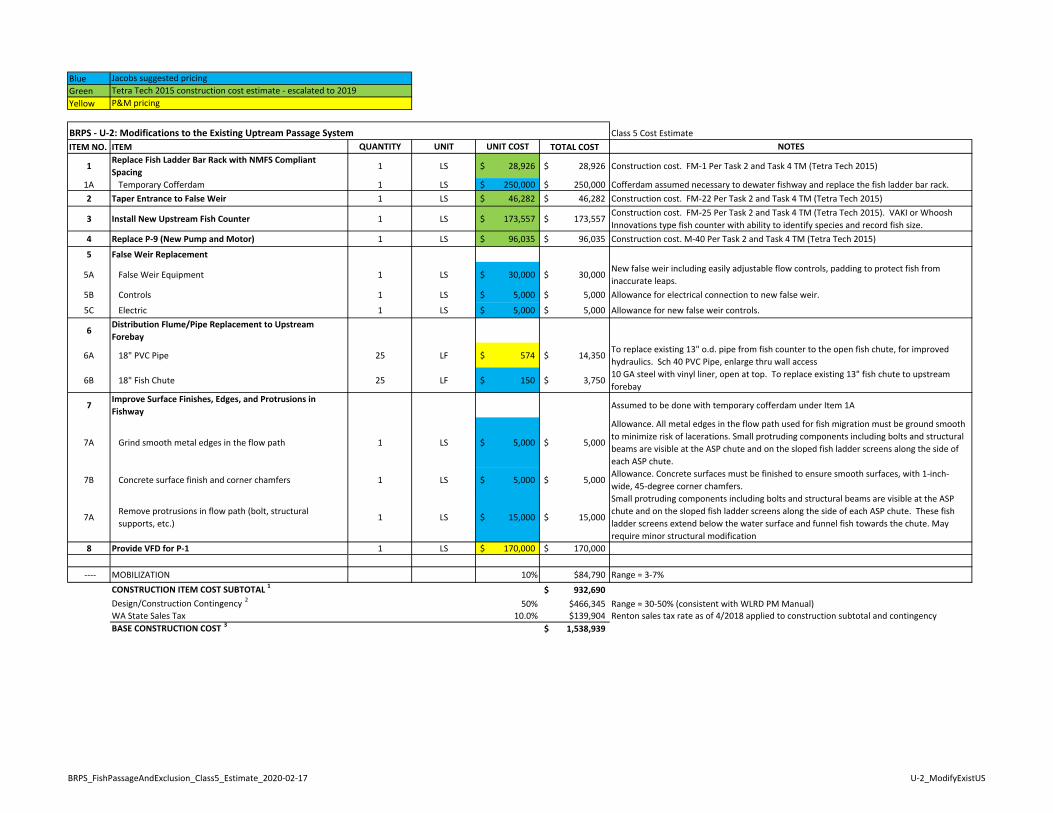
BlueGreenYellow
Class 5 Cost EstimateITEM NO. ITEM QUANTITY UNIT UNIT COST TOTAL COST NOTES
1Replace Fish Ladder Bar Rack with NMFS Compliant Spacing
1 LS 28,926$ 28,926$ Construction cost. FM‐1 Per Task 2 and Task 4 TM (Tetra Tech 2015)
1A Temporary Cofferdam 1 LS 250,000$ 250,000$ Cofferdam assumed necessary to dewater fishway and replace the fish ladder bar rack.2 Taper Entrance to False Weir 1 LS 46,282$ 46,282$ Construction cost. FM‐22 Per Task 2 and Task 4 TM (Tetra Tech 2015)
3 Install New Upstream Fish Counter 1 LS 173,557$ 173,557$ Construction cost. FM‐25 Per Task 2 and Task 4 TM (Tetra Tech 2015). VAKI or Whoosh Innovations type fish counter with ability to identify species and record fish size.
4 Replace P‐9 (New Pump and Motor) 1 LS 96,035$ 96,035$ Construction cost. M‐40 Per Task 2 and Task 4 TM (Tetra Tech 2015)
5 False Weir Replacement
5A False Weir Equipment 1 LS 30,000$ 30,000$ New false weir including easily adjustable flow controls, padding to protect fish from inaccurate leaps.
5B Controls 1 LS 5,000$ 5,000$ Allowance for electrical connection to new false weir.
5C Electric 1 LS 5,000$ 5,000$ Allowance for new false weir controls.
6Distribution Flume/Pipe Replacement to Upstream Forebay
6A 18" PVC Pipe 25 LF 574$ 14,350$ To replace existing 13" o.d. pipe from fish counter to the open fish chute, for improved hydraulics. Sch 40 PVC Pipe, enlarge thru wall access
6B 18" Fish Chute 25 LF 150$ 3,750$ 10 GA steel with vinyl liner, open at top. To replace existing 13" fish chute to upstream forebay
7Improve Surface Finishes, Edges, and Protrusions in Fishway
Assumed to be done with temporary cofferdam under Item 1A
7A Grind smooth metal edges in the flow path 1 LS 5,000$ 5,000$
Allowance. All metal edges in the flow path used for fish migration must be ground smooth to minimize risk of lacerations. Small protruding components including bolts and structural beams are visible at the ASP chute and on the sloped fish ladder screens along the side of each ASP chute.
7B Concrete surface finish and corner chamfers 1 LS 5,000$ 5,000$ Allowance. Concrete surfaces must be finished to ensure smooth surfaces, with 1‐inch‐wide, 45‐degree corner chamfers.
7ARemove protrusions in flow path (bolt, structural supports, etc.)
1 LS 15,000$ 15,000$
Small protruding components including bolts and structural beams are visible at the ASP chute and on the sloped fish ladder screens along the side of each ASP chute. These fish ladder screens extend below the water surface and funnel fish towards the chute. May require minor structural modification
8 Provide VFD for P‐1 1 LS 170,000$ 170,000$
‐‐‐‐ MOBILIZATION 10% $84,790 Range = 3‐7%CONSTRUCTION ITEM COST SUBTOTAL 1 932,690$ Design/Construction Contingency 2 50% $466,345 Range = 30‐50% (consistent with WLRD PM Manual)WA State Sales Tax 10.0% $139,904 Renton sales tax rate as of 4/2018 applied to construction subtotal and contingencyBASE CONSTRUCTION COST 3 1,538,939$
BRPS ‐ U‐2: Modifications to the Existing Uptream Passage System
Jacobs suggested pricingTetra Tech 2015 construction cost estimate ‐ escalated to 2019P&M pricing
BRPS_FishPassageAndExclusion_Class5_Estimate_2020‐02‐17 U‐2_ModifyExistUS
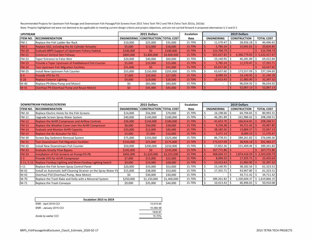
Recommended Projects for Upstream Fish Passage and Downstream Fish Passage/Fish Screens from 2015 Tetra Tech TM 2 and TM 4 (Tetra Tech 2015a, 2015b):Note: Projects highlighted red were not deemed to be applicable to meeting current design criteria and project objectives, and are not carried forward in proposed alternatives U‐2 and D‐2
UPSTREAM EscalationITEM NO. RECOMMENDATION ENGINEERING CONSTRUCTION TOTAL COST Rate ENGINEERING CONSTRUCTION TOTAL COSTFM‐1 Replace the Fish Ladder Bar Rack $10,000 $25,000 $35,000 15.70% 11,570.47$ 28,926.18$ 40,496.65$ FM‐2 Replace SG2, including the Air Cylinder Actuator $5,000 $13,000 $18,000 15.70% 5,785.24$ 15,041.61$ 20,826.85$ FM‐20 Evaluate BRPS Support of Upstream Fishery Habitat $100,000 $0 $100,000 15.70% 115,704.73$ ‐$ 115,704.73$ FM‐21 Construct Vertical Slot Fishway $800,000 $3,800,000 $4,600,000 15.70% 925,637.82$ 4,396,779.65$ 5,322,417.47$ FM‐22 Taper Entrance to False Weir $20,000 $40,000 $60,000 15.70% 23,140.95$ 46,281.89$ 69,422.84$ FM‐23 Provide a Taper Upstream of Paddleboard Fish Counter $5,000 $10,000 $15,000 15.70% 5,785.24$ 11,570.47$ 17,355.71$ FM‐24 Test Upstream Fish Migration Facilities $55,000 $0 $55,000 15.70% 63,637.60$ ‐$ 63,637.60$ FM‐25 Install New Upstream Fish Counter $55,000 $150,000 $205,000 15.70% 63,637.60$ 173,557.09$ 237,194.69$ E‐4 Provide VFD for P1 $7,000 $20,000 $27,000 15.70% 8,099.33$ 23,140.95$ 31,240.28$ E‐20 Replace Exterior Lighting $9,000 $19,000 $28,000 15.70% 10,413.43$ 21,983.90$ 32,397.32$ M‐40 Replace P9 (New Pump and Motor) $0 $83,000 $83,000 15.70% ‐$ 96,034.92$ 96,034.92$ M‐41 Overhaul P9 (Overhaul Pump and Reuse Motor) $0 $45,000 $45,000 15.70% ‐$ 52,067.13$ 52,067.13$
DOWNSTREAM PASSAGE/SCREENS EscalationITEM NO. RECOMMENDATION ENGINEERING CONSTRUCTION TOTAL COST Rate ENGINEERING CONSTRUCTION TOTAL COSTFM‐10 Replace Electric Hoists for the Fish Screens $14,000 $56,000 $70,000 15.70% 16,198.66$ 64,794.65$ 80,993.31$ FM‐11 Upgrade Screen Spray Water System $40,000 $140,000 $180,000 15.70% 46,281.89$ 161,986.62$ 208,268.51$ FM‐12 Replace the Airlift Compressor and Airflow Controls $36,000 $144,000 $180,000 15.70% 41,653.70$ 166,614.81$ 208,268.51$ FM‐13 Replace the Weather Cover over the Airlift Compressor $8,000 $30,000 $38,000 15.70% 9,256.38$ 34,711.42$ 43,967.80$ FM‐14 Evaluate and Monitor Airlift Capacity $33,000 $12,000 $45,000 15.70% 38,182.56$ 13,884.57$ 52,067.13$ FM‐15 Replace the Air‐Actuator for SG1 $3,000 $7,000 $10,000 15.70% 3,471.14$ 8,099.33$ 11,570.47$ FM‐30 Screen Bay Sediment Removal System $75,000 $250,000 $325,000 15.70% 86,778.55$ 289,261.82$ 376,040.36$ FM‐31 Test Downstream Fish Migration Facilities $150,000 $25,000 $175,000 15.70% 173,557.09$ 28,926.18$ 202,483.27$ FM‐32 Install New Downstream Fish Counter $50,000 $200,000 $250,000 15.70% 57,852.36$ 231,409.46$ 289,261.82$ FM‐33 Evaluate Gravity Flow Bypass $145,000 $0 $145,000 15.70% 167,771.86$ ‐$ 167,771.86$ FM‐34 Installation of Fish Screens on Pumps P5‐P8 $405,000 $1,620,000 $2,025,000 15.70% 468,604.15$ 1,874,416.59$ 2,343,020.73$ E‐5 Provide VFD for Airlift Compressor $7,000 $15,000 $22,000 15.70% 8,099.33$ 17,355.71$ 25,455.04$ E‐11, E‐12 Replace Forebay Lighting and Move Forebay Lighting Switch $9,000 $19,000 $28,000 15.70% 10,413.43$ 21,983.90$ 32,397.32$ I‐11 Replace the Fish Screen Spray Control Panel $20,000 $33,000 $53,000 15.70% 23,140.95$ 38,182.56$ 61,323.51$ M‐42 Install an Automatic Self‐Cleaning Strainer on the Spray Water Flo $15,000 $38,000 $53,000 15.70% 17,355.71$ 43,967.80$ 61,323.51$ M‐43 Overhaul P10 (Overhaul Pump, New Motor) $0 $30,000 $30,000 15.70% ‐$ 34,711.42$ 34,711.42$ M‐70 Replace the Trash Rake and Dolly with a Monorail System $250,000 $1,150,000 $1,400,000 15.70% 289,261.82$ 1,330,604.37$ 1,619,866.19$ M‐71 Replace the Trash Conveyor $9,000 $35,000 $44,000 15.70% 10,413.43$ 40,496.65$ 50,910.08$
ENR - April 2019 CCI 12,015.45ENR - January 2015 CCI 10,384.58
1630.87divide by earlier CCI 15.70%
2015 Dollars
2015 Dollars
2019 Dollars
2019 Dollars
Escalation 2015 to 2019
BRPS_FishPassageAndExclusion_Class5_Estimate_2020‐02‐17 2015 TETRA TECH PROJECTS


Appendix E Manufacturer Equipment Data

Weir Specialty Pumps
WEMCO® Screw-Flow Pump
Flow Control
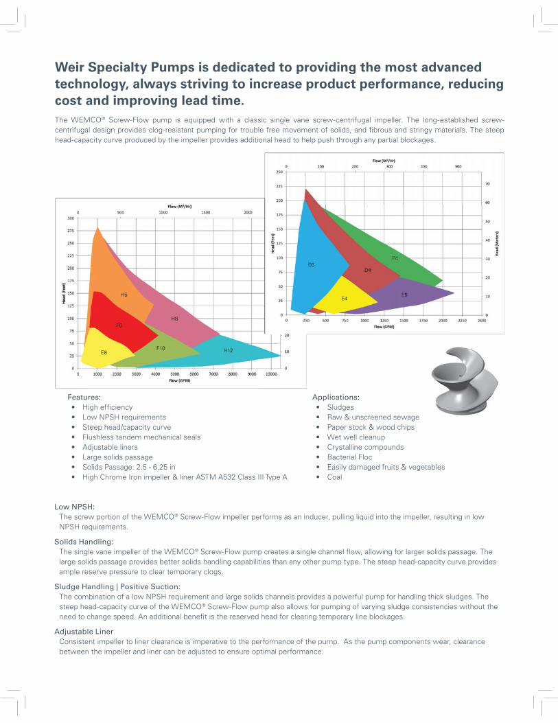
Weir Specialty Pumps is dedicated to providing the most advanced technology, always striving to increase product performance, reducing cost and improving lead time.
Low NPSH: The screw portion of the WEMCO® Screw-Flow impeller performs as an inducer, pulling liquid into the impeller, resulting in low NPSH requirements.
Solids Handling: The single vane impeller of the WEMCO® Screw-Flow pump creates a single channel flow, allowing for larger solids passage. The large solids passage provides better solids handling capabilities than any other pump type. The steep head-capacity curve provides ample reserve pressure to clear temporary clogs.
Sludge Handling | Positive Suction: The combination of a low NPSH requirement and large solids channels provides a powerful pump for handling thick sludges. The steep head-capacity curve of the WEMCO® Screw-Flow pump also allows for pumping of varying sludge consistencies without the need to change speed. An additional benefit is the reserved head for clearing temporary line blockages.
Adjustable Liner Consistent impeller to liner clearance is imperative to the performance of the pump. As the pump components wear, clearance between the impeller and liner can be adjusted to ensure optimal performance.
The WEMCO® Screw-Flow pump is equipped with a classic single vane screw-centrifugal impeller. The long-established screw-centrifugal design provides clog-resistant pumping for trouble free movement of solids, and fibrous and stringy materials. The steep head-capacity curve produced by the impeller provides additional head to help push through any partial blockages.
Features:• High efficiency• Low NPSH requirements• Steep head/capacity curve• Flushless tandem mechanical seals• Adjustable liners• Large solids passage• Solids Passage: 2.5 - 6.25 in• High Chrome Iron impeller & liner ASTM A532 Class III Type A
Applications:• Sludges• Raw & unscreened sewage• Paper stock & wood chips• Wet well cleanup• Crystalline compounds• Bacterial Floc• Easily damaged fruits & vegetables• Coal
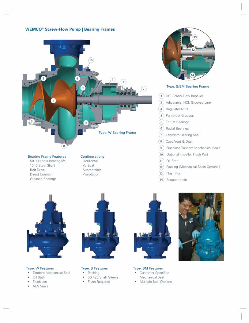
Type: S Features• Packing• SS 420 Shaft Sleeve• Flush Required
9 Flushless Tandem Mechanical Seals
Optional Impeller Flush Port
Oil Bath
10
11
12 Packing (Mechanical Seals Optional)
Flush Port
Scupper drain
13
14
WEMCO® Screw-Flow Pump | Bearing Frames
Type: S/SM Bearing Frame
Type: W Features• Tandem Mechanical Seal• Oil Bath• Flushless• AES Seals
12
14
13
Type: W Bearing Frame
Type: SM Features• Customer Specified
Mechanical Seal• Multiple Seal Options
Bearing Frame Features50,000 hour bearing life 1045 Steel Shaft Belt Drive Direct Connect Greased Bearings
ConfigurationsHorizontal Vertical Submersible Prerotation
1 HCI Screw-Flow Impeller
Adjustable, HCI, Grooved Liner
Regulator Nuts
Pump-out Grooves
Thrust Bearings
Radial Bearings
Labyrinth Bearing Seal
Case Vent & Drain
2
3
4
5
6
7
8
Type: W Bearing Frame
1
2
3
45
6
9
10
11
8
7
Copyright © 2016, 2015 Envirotech PumpSystems, Inc.. All rights reserved. WEIR and WEIR (logo) are trademarks and/or registered trademarks of Weir Engineering Services Ltd. WEMCO is a trademark of FLSmidth A/S used under license by companies forming part of The Weir Group PLC. BALDOR is not a trademark belonging to any company forming part of The Weir Group PLC.
WEMCO Screw-Flow Pump Brochure Version 4, Feb 2017
Flow Control
Weir Specialty Pumps 440 West 800 South Salt Lake City, UT 84101 USA
T 801 359 8731 www.global.weir
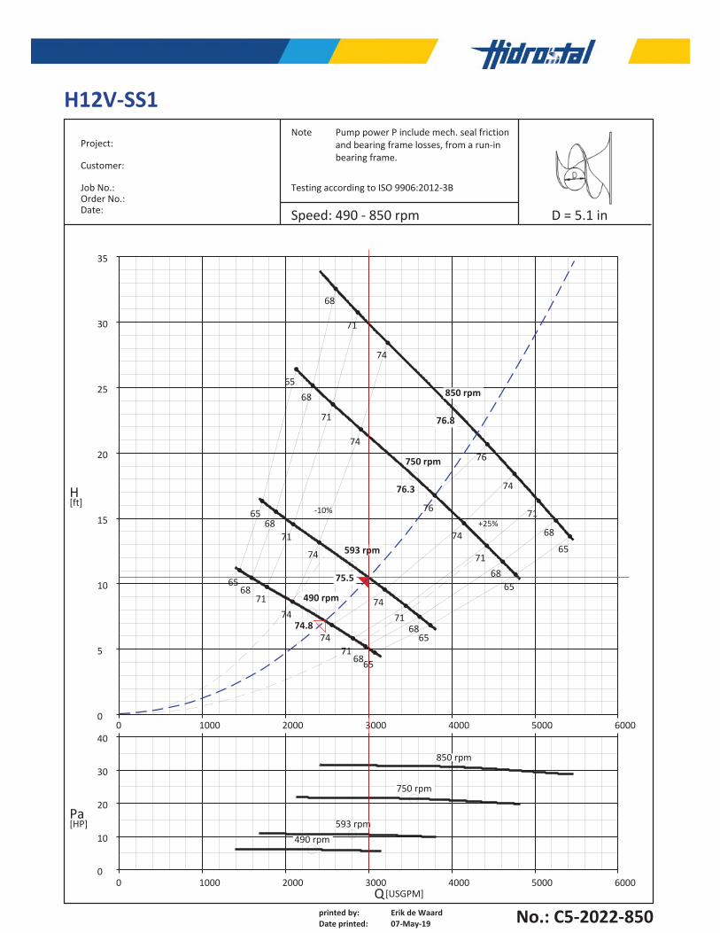
printed by: Erik de WaardDate printed: 07-May-19
Project:
Customer:
Job No.:Order No.:Date:
Note Pump power P include mech. seal frictionand bearing frame losses, from a run-inbearing frame.
Testing according to ISO 9906:2012-3B
H12V-SS1
Speed: 490 - 850 rpm D = 5.1 in
No.: C5-2022-850
0 1000 2000 3000 4000 5000 60000
5
10
15
20
25
30
35
H[ft]
0 1000 2000 3000 4000 5000 60000
10
20
30
40
Pa[HP]
Q[USGPM]
850 rpm
850 rpm
750 rpm
750 rpm
593 rpm
593 rpm
490 rpm
490 rpm
-10%+25%
65
65
65
65
65
65
65
74.8
68
68
68
68
68
68
68
68
75.5
71
71
71
71
71
71
71
71
76.3
74
74
74
74
74
74
74
74
76.8
76
76
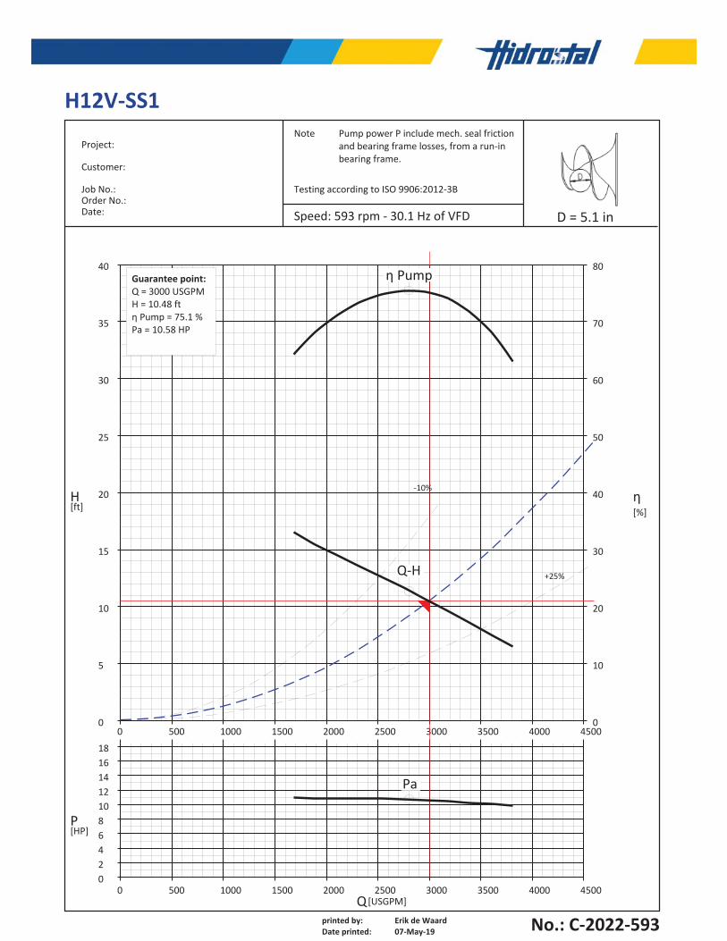
printed by: Erik de WaardDate printed: 07-May-19
Project:
Customer:
Job No.:Order No.:Date:
Note Pump power P include mech. seal frictionand bearing frame losses, from a run-inbearing frame.
Testing according to ISO 9906:2012-3B
H12V-SS1
Speed: 593 rpm - 30.1 Hz of VFD D = 5.1 in
No.: C-2022-593
0 500 1000 1500 2000 2500 3000 3500 4000 45000 0
5 10
10 20
15 30
20 40
25 50
30 60
35 70
40 80
H[ft]
0 500 1000 1500 2000 2500 3000 3500 4000 4500024681012141618
P[HP]
Q[USGPM]
η[%]
-10%
+25%Q-H
η Pump
Pa
Guarantee point:Q = 3000 USGPMH = 10.48 ftη Pump = 75.1 %Pa = 10.58 HP
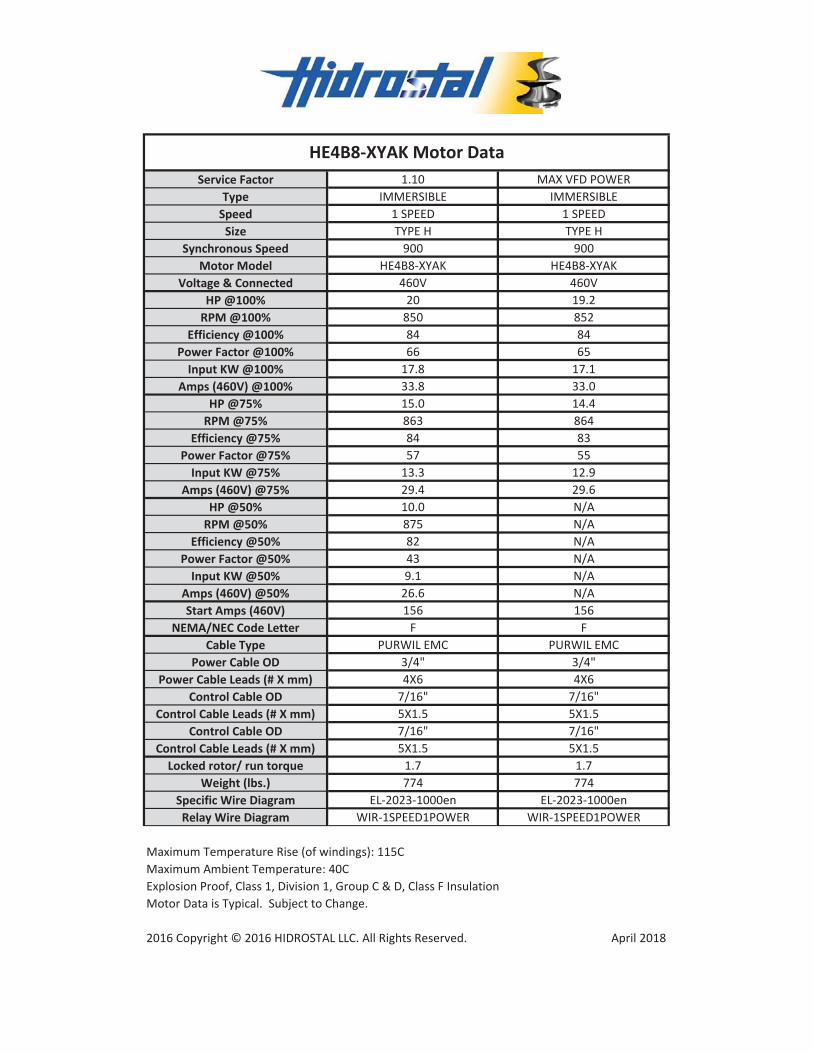
Service Factor 1.10 MAX VFD POWERType IMMERSIBLE IMMERSIBLE
Speed 1 SPEED 1 SPEEDSize TYPE H TYPE H
Synchronous Speed 900 900Motor Model HE4B8-XYAK HE4B8-XYAK
Voltage & Connected 460V 460VHP @100% 20 19.2
RPM @100% 850 852Efficiency @100% 84 84
Power Factor @100% 66 65Input KW @100% 17.8 17.1
Amps (460V) @100% 33.8 33.0HP @75% 15.0 14.4
RPM @75% 863 864Efficiency @75% 84 83
Power Factor @75% 57 55Input KW @75% 13.3 12.9
Amps (460V) @75% 29.4 29.6HP @50% 10.0 N/A
RPM @50% 875 N/AEfficiency @50% 82 N/A
Power Factor @50% 43 N/AInput KW @50% 9.1 N/A
Amps (460V) @50% 26.6 N/AStart Amps (460V) 156 156
NEMA/NEC Code Letter F FCable Type PURWIL EMC PURWIL EMC
Power Cable OD 3/4" 3/4"Power Cable Leads (# X mm) 4X6 4X6
Control Cable OD 7/16" 7/16"Control Cable Leads (# X mm) 5X1.5 5X1.5
Control Cable OD 7/16" 7/16"Control Cable Leads (# X mm) 5X1.5 5X1.5
Locked rotor/ run torque 1.7 1.7Weight (lbs.) 774 774
Specific Wire Diagram EL-2023-1000en EL-2023-1000enRelay Wire Diagram WIR-1SPEED1POWER WIR-1SPEED1POWER
Maximum Ambient Temperature: 40CExplosion Proof, Class 1, Division 1, Group C & D, Class F InsulationMotor Data is Typical. Subject to Change.
2016 Copyright © 2016 HIDROSTAL LLC. All Rights Reserved. April 2018
HE4B8-XYAK Motor Data
Maximum Temperature Rise (of windings): 115C
RELIABLE RIVER STOCK MANAGEMENT
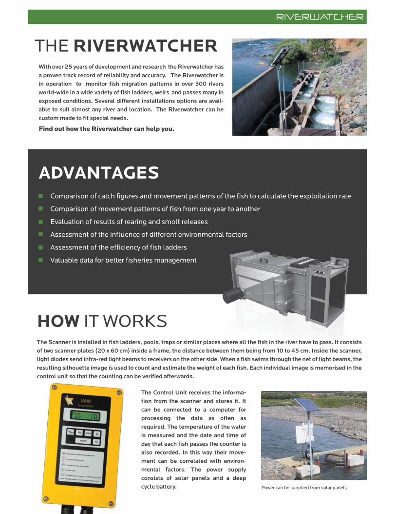
THE RIVERWATCHERWith over 25 years of development and research the Riverwatcher has
a proven track record of reliability and accuracy. The Riverwatcher is
in operation to monitor fish migration patterns in over 300 rivers
world-wide in a wide variety of fish ladders, weirs and passes many in
exposed conditions. Several different installations options are avail-
able to suit almost any river and location. The Riverwatcher can be
custom made to fit special needs.
Find out how the Riverwatcher can help you.
ADVANTAGES
Comparison of catch figures and movement patterns of the fish to calculate the exploitation rate
Comparison of movement patterns of fish from one year to another
Evaluation of results of rearing and smolt releases
Assessment of the influence of different environmental factors
Assessment of the efficiency of fish ladders
Valuable data for better fisheries management
HOW IT WORKSThe Scanner is installed in fish ladders, pools, traps or similar places where all the fish in the river have to pass. It consists
of two scanner plates (20 x 60 cm) inside a frame, the distance between them being from 10 to 45 cm. Inside the scanner,
light diodes send infra-red light beams to receivers on the other side. When a fish swims through the net of light beams, the
resulting silhouette image is used to count and estimate the weight of each fish. Each individual image is memorised in the
control unit so that the counting can be verified afterwards.
The Control Unit receives the informa-
tion from the scanner and stores it. It
can be connected to a computer for
processing the data as often as
required. The temperature of the water
is measured and the date and time of
day that each fish passes the counter is
also recorded. In this way their move-
ment can be correlated with environ-
mental factors. The power supply
consists of solar panels and a deep
cycle battery. Power can be supplied from solar panels
ent
milar places where all the fishhh ininn ttthe riviviveree have e e tototo pppasasass.s.s. IIItt t cococonsists
stance between them being from 1000 tttoo o 45 cm.m.m. Insiddde e e thththee e scanner,
e other side. When a fish swims through the net of light beams, the
the weight of each fish. Each individual image is memorised in the
ds
MULTIPLE SCANNERSIt is possible to connect several scanners together and monitor the
migration in rivers that do not have fish way or ladder. A PC with a
specially designed program is used to gather signals from all the
scanners that are connected and store the data. With a modem
connection it is possible to download the data at any time.
SPECIAL SOLUTIONS
THE SOFTWAREThe Riverwatcher software is used to
analyse and present the data from the
fish counter. It is possible to examine the
migration pattern of fish over a particular
period, by size groupings or for a particu-
lar time of the day. You can also examine
temperature records for a particular
period, and analyse silhouette images of
each fish to verify the counting.
It is possible to analyse silhouette images of each fish, and sort fish in different groups.
This chart shows the migration patterns over a selected period.
This chart shows the migration pattern over time, with the length and time of fish.
This chart shows the breakdown by size category. This chart shows the time of the day when the fish were recorded.
THE INSTALLATIONThe installation site should be selected to ensure that all
migrating fish will pass through the scanner with minimum of
changes to the river.
The most common sites are fish ladders, fish-passways, or
narrow sections of rivers. The circumstances can differ from
one installation site to another but in most cases a metal grid
(inscale) must be used to guide the fish through the scanner
without blocking the water flow. The bars on the grid must be
tight enough to prevent fish from passing through but allow
maximum water flow and minimise build up of debris.
REMOTE CONTROLThe Riverwatcher can be accessed remotly. This option makes it possible for users to control and check the status
of the counter as well as download data from the Riverwatcher directly to a PC without visiting the site.
This option is strongly recommended to maximise the efficiency and operation of the counter. Regular remote checks can
identify the status of power supply and build up of debris or damage to the scanner minimising counter downtime.
Increasing the frequency of downloads reduces download time, minimising any risk of problems in transferring data files.
www vaki is
CAMERA CONNECTIONThe Riverwatcher can be supplied with a digital camera system to record video or still images of fish passing through the
scanner. The scanner triggers the camera to capture between 1 and 5 digital photos or a short video clip of each fish. The
computer then automatically links the digital images to the other information contained in the database for that individual
fish such as size, passing hour, speed, silhouette image, temperature etc.
REMOTE LOCATIONSThe Riverwatcher with camera system can be used in remote locations with no mains
power. Both the scanner unit and digital camera are connected to a 12V computer. The
computer greatly increases the data that can be stored and analysed and can be
supplied by solar or battery power.
PHOTO TUNNELFor best images unaffected by sunlight or time of day, the photo tunnel is recom-
mended. The standard tunnel is 160 x 105 x 63 cm (L x W x H) and is fitted with the
underwater digital camera, lights and scanner unit. Standard opening between scann-
er plates is 40 cm. The tunnel ensures that the images are captured under controlled
and constant lighting conditions, as well as the optimum position and distance of the
fish to the camera.Lights and camera are installed in the photo tunnel
The camera, lights and scanner are connected to the PC through the connection box.A new Double Height Twin Scanner
FISH IDENTIFICATION
The digital photos can then be used with other data from the Riverwatcher to sort fish in groups accord-ing to species, sex and even in farmed or wild fish.
Real time videoLive video from the camera can be viewed in real time at any time on the Riverwatcher computer screen.
The videos and the digital photos can be used with
other data from the Riverwatcher to sort fish in
groups according to species, sex and even in farmed
or wild fish.
FIS
H I
DE
NT
IFIC
AT
ION
Live video from the camera can be viewed in real time
at any time on the Riverwatcher computer screen.
RE
AL
TIM
E V
IDE
O
, speed, s
A new Double Height Twin Scann
A k r a l i n d 4 | 2 0 1 K ó p a v o g u r | I c e l a n d | T e l . ( + 3 5 4 ) 5 9 5 3 0 0 0 | v a k i . c o m / r i v e r w a t c h e r . i s
MAIN FEATURES OF THE RIVERWATCHER1. The Riverwatcher counts fish with more than 98% accuracy.
2. The Riverwatcher measures the size of each fish with more than 95% accuracy.
3. Two silhouette images are linked to every fish and can be used for identification
and to verify the count.
4. The date and time of day that each fish passes the scanner is recorded.
5. The water temperature is measured at 3 hour intervals.
6. The 12V power requirement can be supplied from a solar panel kit in remote
locations or a mains transformer.
7. The counter can easily be adjusted for use in all fish ladders, dams,
traps and similar places.
8. The Riverwatcher database software is used to download and present all data
and images.
9. Remote control through telephone or internet.
10. Detailed identification of species, sex, etc. of individual fish from the
high quality digital images.
11. Several counters can be connected together to monitor rivers where
there are no fishways.
12. The Photo Tunnel option ensures optimal digital image and video quality.
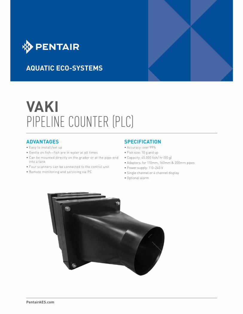
VAKI PIPELINE COUNTER (PLC)ADVANTAGES• Easy to install/set up
• Gentle on fish—fish are in water at all times
• Can be mounted directly on the grader or at the pipe-end
into a tank
• Four scanners can be connected to the control unit
• Remote monitoring and servicing via PC
SPECIFICATION• Accuracy: over 99%
• Fish size: 10 g and up
• Capacity: 45.000 fish/ hr (50 g)
• Adaptors: for 110mm, 160mm & 200mm pipes
• Power supply: 110–240 V
• Single channel or 4 channel display
• Optional alarm
PentairAES.com
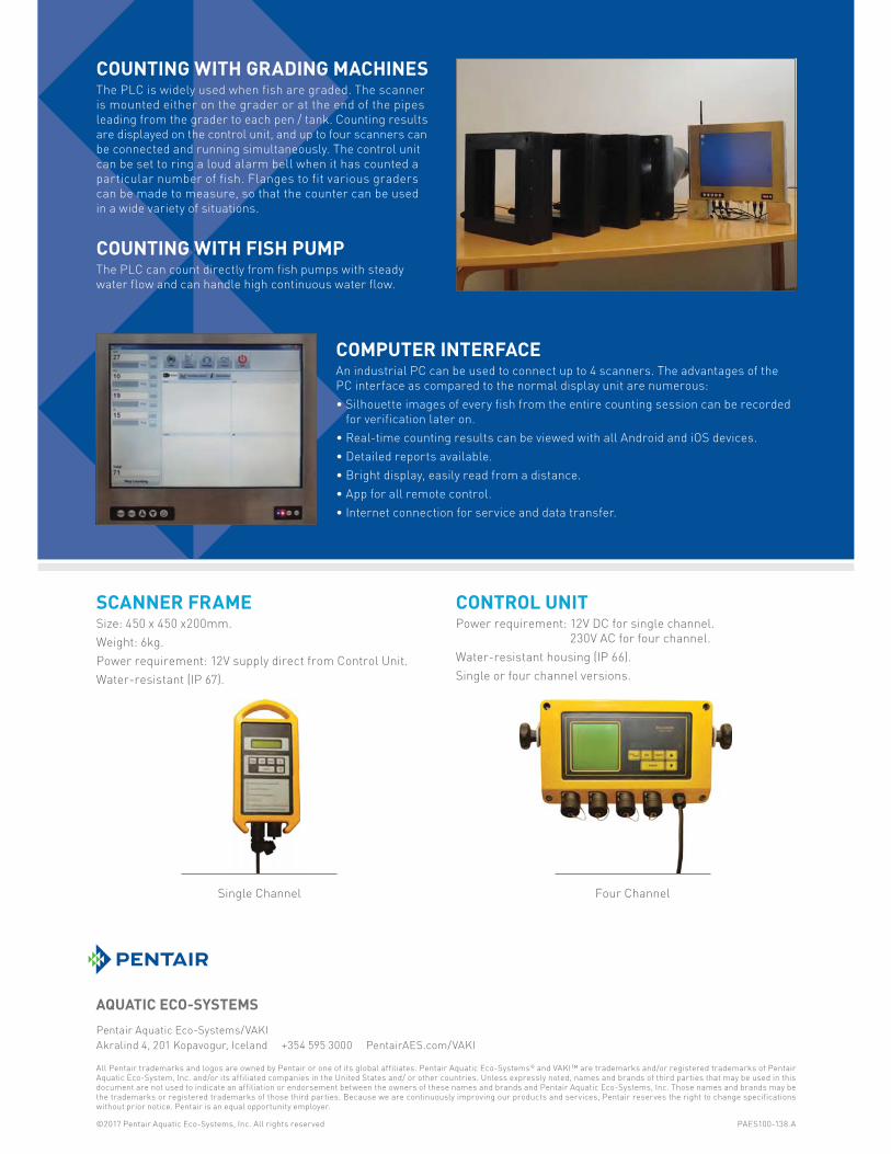
Pentair Aquatic Eco-Systems/VAKI
Akralind 4, 201 Kopavogur, Iceland +354 595 3000 PentairAES.com/VAKI
All Pentair trademarks and logos are owned by Pentair or one of its global affiliates. Pentair Aquatic Eco-Systems® and VAKI™ are trademarks and/or registered trademarks of Pentair Aquatic Eco-System, Inc. and/or its affiliated companies in the United States and/ or other countries. Unless expressly noted, names and brands of third parties that may be used in this document are not used to indicate an affiliation or endorsement between the owners of these names and brands and Pentair Aquatic Eco-Systems, Inc. Those names and brands may be the trademarks or registered trademarks of those third parties. Because we are continuously improving our products and services, Pentair reserves the right to change specifications without prior notice. Pentair is an equal opportunity employer.
©2017 Pentair Aquatic Eco-Systems, Inc. All rights reserved PAES100-138.A
COUNTING WITH GRADING MACHINESThe PLC is widely used when fish are graded. The scanner
is mounted either on the grader or at the end of the pipes
leading from the grader to each pen / tank. Counting results
are displayed on the control unit, and up to four scanners can
be connected and running simultaneously. The control unit
can be set to ring a loud alarm bell when it has counted a
particular number of fish. Flanges to fit various graders
can be made to measure, so that the counter can be used
in a wide variety of situations.
COUNTING WITH FISH PUMPThe PLC can count directly from fish pumps with steady
water flow and can handle high continuous water flow.
COMPUTER INTERFACEAn industrial PC can be used to connect up to 4 scanners. The advantages of the
PC interface as compared to the normal display unit are numerous:
• Silhouette images of every fish from the entire counting session can be recorded
for verification later on.
• Real-time counting results can be viewed with all Android and iOS devices.
• Detailed reports available.
• Bright display, easily read from a distance.
• App for all remote control.
• Internet connection for service and data transfer.
SCANNER FRAMESize: 450 x 450 x200mm.
Weight: 6kg.
Power requirement: 12V supply direct from Control Unit.
Water-resistant (IP 67).
CONTROL UNITPower requirement: 12V DC for single channel.
230V AC for four channel.
Water-resistant housing (IP 66).
Single or four channel versions.
Four ChannelSingle Channel

Cu ng Edge Metal Solu ons s Profile Bar* & Wedge Wire Screens
Fish Diversion Screens
www.hendrickscreen.com | [email protected] | 27070-00--68585-55-5138 |Owensboro, KYKY www hendrickscreen com | screen@hendrickcorp com | 27700 8686855 138 |Owensboro K515 KY*Profile Bar uses Hendrick’s proprietary interlocked screen construc on, providing superior strength.h.h.hh
Our fish diversion screens are used where fish protection is important to the environment. The screens are used in water systems to protect fish from hydroelectric turbines and pumps or migration into channels and canals. Hendrick’s screens comply with National Oceanic and Atmospheric Administration (NOAA) standards. Our products are environmentally friendly to fish and other aquatic life.
Reduces Fish and Aquatic Life Mortality and Stranding
316b Compliant—Identified as the Best Available Technology by the EPA
Keeps Turbines and Pumps Debris Free
Maintains Reliable Flow and Reduces Maintenance
BENEFITS
© 2017 by Hendrick Screen Company
Hendrick is your single source supplier for all your fish diversion screen needs. Our proprietary Profile Bar and Resistance-Welded designs lead to less debris and clogging for a smoother water flow. We have solutions for any situation you may encounter. Additionally we offer cleaning options to maximize flow efficiencies.
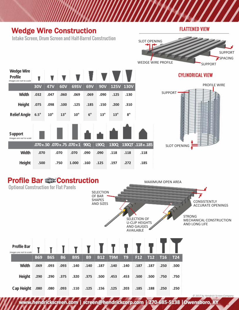
www.hendrickscreen.com | [email protected] | 270-685-5138 |Owensboro, KY
Wedge Wire
Profile
30V 47V 60V 69SV 69V 90V 125V 130V
Width .032 .047 .060 .069 .069 .090 .125 .130
Height .075 .098 .100 .125 .185 .150 .200 .310
Relief Angle 6.5° 10° 13° 10° 6° 13° 13° 8°
www.hendrickscreen.com | [email protected] | 27070-00--68585-55-5138 |Owensboro, KYKY
SUPPORT WEDGE WIRE PROFILE
SLOT OPENING
SUPPORT SPACING
Images are not to scale
Optional Construction for Flat Panels Profile Bar CConstruction
SELECTION OF U-CLIP HEIGHTS AND GAUGES AVAILABLE
MAXIMUM OPEN AREA
SELECTION OF BAR SHAPES AND SIZES CONSISTENTLY
ACCURATE OPENINGS
STRONG MECHANICAL CONSTRUCTION AND LONG LIFE
© 2017 by Hendrick Screen Company
Intake Screen, Drum Screen and Half-Barrel Construction Wedge Wire Construction FLATTENED VIEW
CYLINDRICAL VIEW
SUPPORT
SLOT OPENING
PROFILE WIRE
Profile Bar
B69 B6S B6 B9S B9 B12 T9M T9 F12 T12 T16 T24
Width .069 .093 .093 .140 .140 .187 .140 .140 .187 .187 .250 .500
Height .290 .290 .375 .320 .375 .500 .453 .453 .500 .500 .750 .750
Cap Height .080 .080 .093 .110 .125 .156 .125 .203 .185 .188 .250 .250
Images are not to scale
Images are not to scale Support
.070 x .50 .070 x .75 .070 x 1 90Q L90Q 130Q 130QT .118 x .185
Width .070 .070 .070 .090 .090 .118 .118 .118
Height .500 .750 1.000 .160 .125 .197 .272 .185
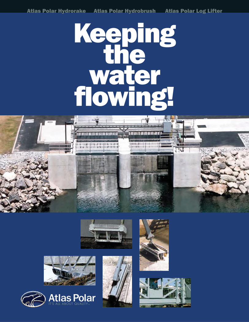
Keeping the
waterflowing!
Atlas Polar Hydrorake Atlas Polar Hydrobrush Atlas Polar Log Lifter
AtlasPolarIT’S ALL ABOUT QUALITY TM
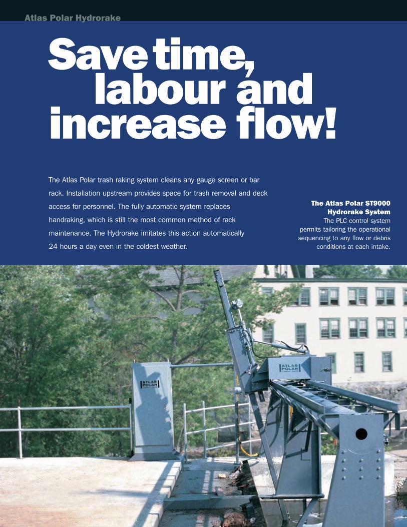
Savetime, labour and
increase flow!The Atlas Polar trash raking system cleans any gauge screen or bar
rack. Installation upstream provides space for trash removal and deck
access for personnel. The fully automatic system replaces
handraking, which is still the most common method of rack
maintenance. The Hydrorake imitates this action automatically
24 hours a day even in the coldest weather.
The Atlas Polar ST9000Hydrorake System
The PLC control system permits tailoring the operationalsequencing to any flow or debris
conditions at each intake.
Atlas Polar Hydrorake
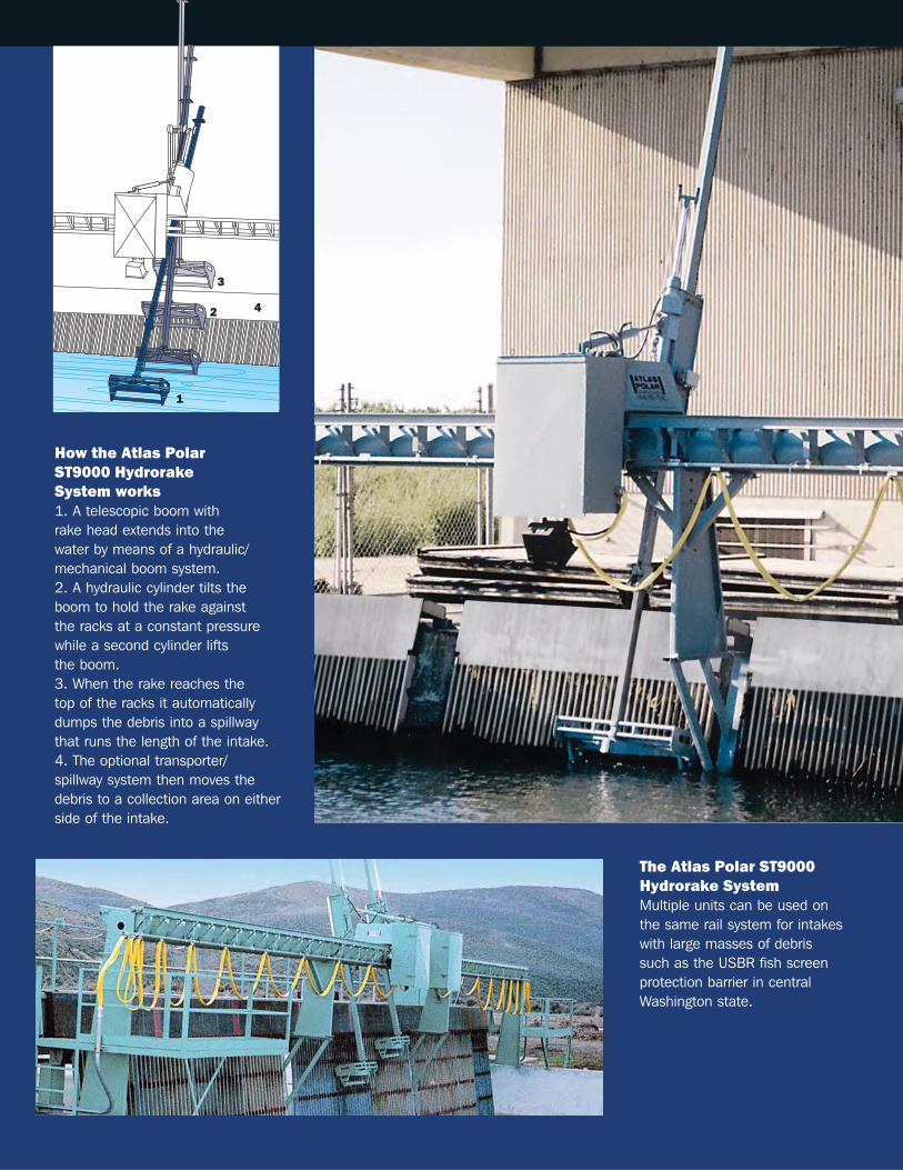
The Atlas Polar ST9000Hydrorake SystemMultiple units can be used on the same rail system for intakeswith large masses of debris such as the USBR fish screen protection barrier in centralWashington state.
How the Atlas Polar ST9000 Hydrorake System works1. A telescopic boom with rake head extends into the water by means of a hydraulic/mechanical boom system.2. A hydraulic cylinder tilts theboom to hold the rake against the racks at a constant pressurewhile a second cylinder lifts the boom.3. When the rake reaches the top of the racks it automaticallydumps the debris into a spillwaythat runs the length of the intake. 4. The optional transporter/spillway system then moves thedebris to a collection area on eitherside of the intake.
3
42
1
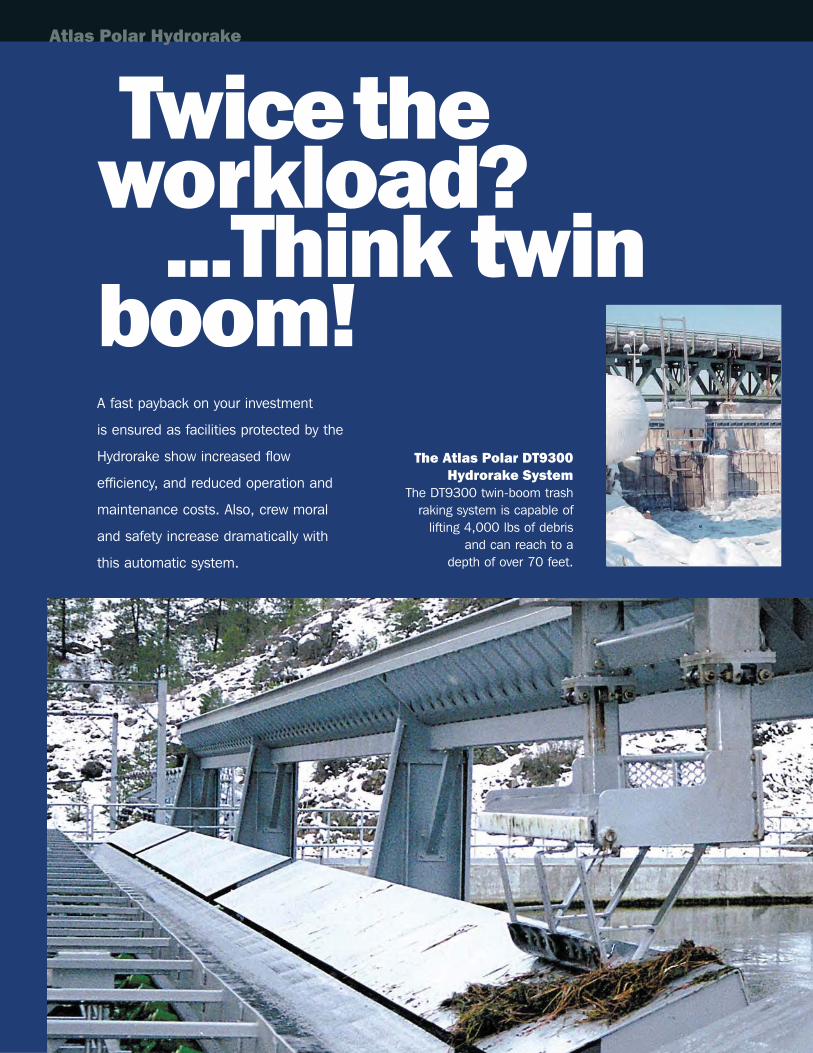
The Atlas Polar DT9300 Hydrorake System
The DT9300 twin-boom trash raking system is capable of
lifting 4,000 lbs of debris and can reach to a
depth of over 70 feet.
A fast payback on your investment
is ensured as facilities protected by the
Hydrorake show increased flow
efficiency, and reduced operation and
maintenance costs. Also, crew moral
and safety increase dramatically with
this automatic system.
Twicetheworkload?
...Think twinboom!
Atlas Polar Hydrorake
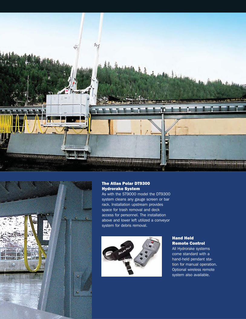
Hand Held Remote ControlAll Hydrorake systemscome standard with ahand-held pendant sta-tion for manual operation.Optional wireless remotesystem also available.
The Atlas Polar DT9300 Hydrorake SystemAs with the ST9000 model the DT9300 system cleans any gauge screen or barrack. Installation upstream provides space for trash removal and deck access for personnel. The installationabove and lower left utilized a conveyorsystem for debris removal.
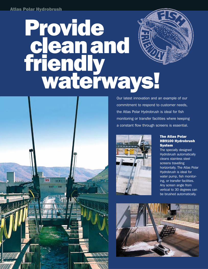
Providecleanandfriendly
waterways!
The Atlas Polar HB9100 HydrobrushSystemThe specially designedHydrobrush automaticallycleans stainless steelscreens travelling horizontally. The Atlas PolarHydrobrush is ideal for water pump, fish monitor-ing, or transfer facilities. Any screen angle from vertical to 30 degrees canbe brushed automatically.
Our latest innovation and an example of our
commitment to respond to customer needs,
the Atlas Polar Hydrobrush is ideal for fish
monitoring or transfer facilities where keeping
a constant flow through screens is essential.
Atlas Polar Hydrobrush
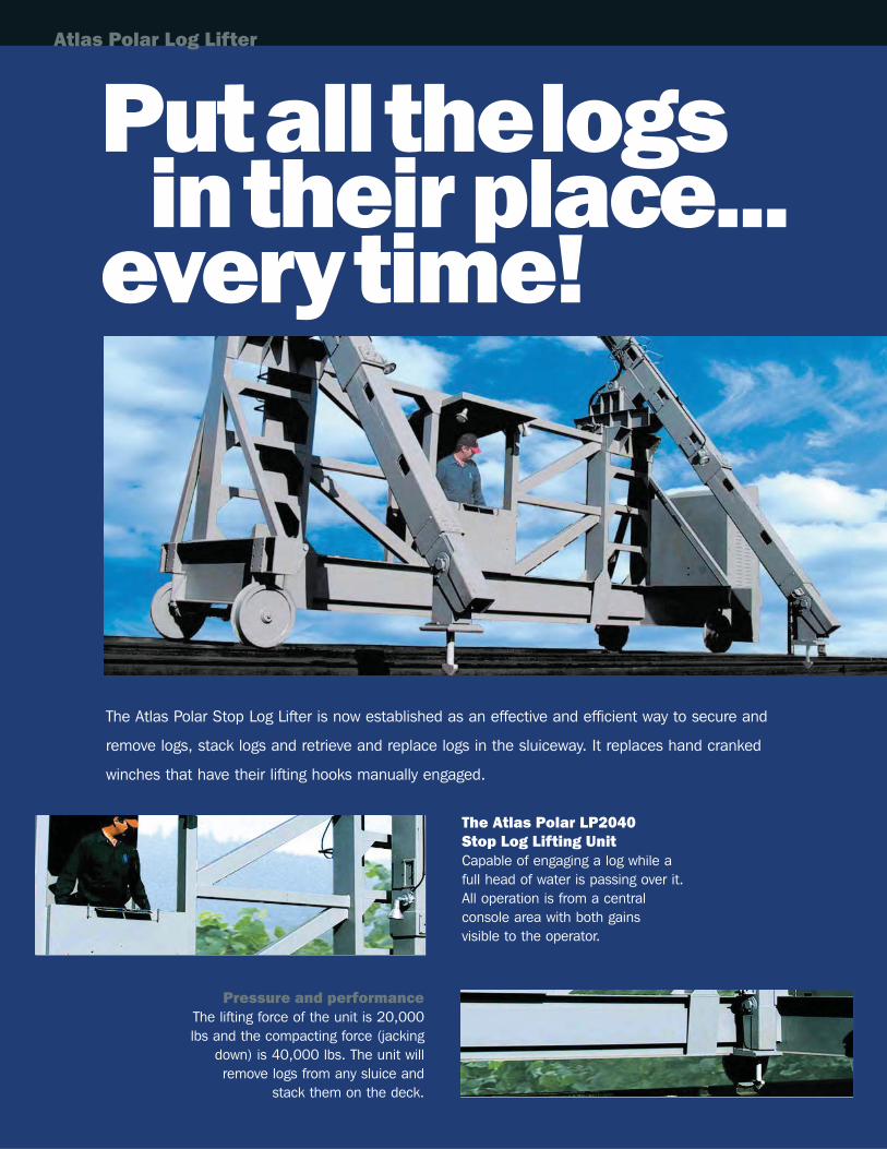
Putallthelogsintheir place...
everytime!
Pressure and performanceThe lifting force of the unit is 20,000lbs and the compacting force (jacking
down) is 40,000 lbs. The unit willremove logs from any sluice and
stack them on the deck.
The Atlas Polar LP2040Stop Log Lifting UnitCapable of engaging a log while a full head of water is passing over it. All operation is from a central console area with both gains visible to the operator.
The Atlas Polar Stop Log Lifter is now established as an effective and efficient way to secure and
remove logs, stack logs and retrieve and replace logs in the sluiceway. It replaces hand cranked
winches that have their lifting hooks manually engaged.
Atlas Polar Log Lifter
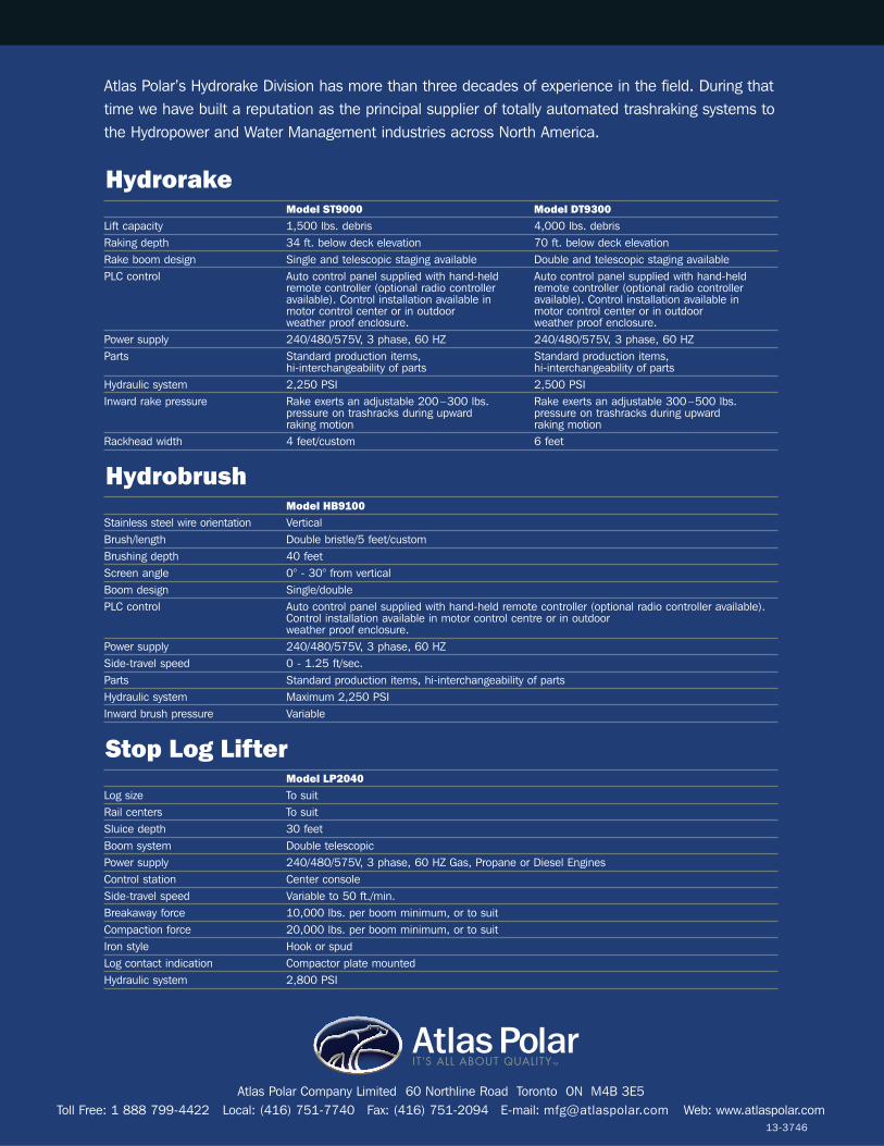
Atlas Polar Company Limited 60 Northline Road Toronto ON M4B 3E5Toll Free: 1 888 799-4422 Local: (416) 751-7740 Fax: (416) 751-2094 E-mail: [email protected] Web: www.atlaspolar.com
Hydrorake
Stop Log Lifter
Hydrobrush
Model ST9000 Model DT9300Lift capacity 1,500 lbs. debris 4,000 lbs. debrisRaking depth 34 ft. below deck elevation 70 ft. below deck elevationRake boom design Single and telescopic staging available Double and telescopic staging availablePLC control Auto control panel supplied with hand-held Auto control panel supplied with hand-held
remote controller (optional radio controller remote controller (optional radio controlleravailable). Control installation available in available). Control installation available in motor control center or in outdoor motor control center or in outdoor weather proof enclosure. weather proof enclosure.
Power supply 240/480/575V, 3 phase, 60 HZ 240/480/575V, 3 phase, 60 HZParts Standard production items, Standard production items,
hi-interchangeability of parts hi-interchangeability of partsHydraulic system 2,250 PSI 2,500 PSIInward rake pressure Rake exerts an adjustable 200–300 lbs. Rake exerts an adjustable 300–500 lbs.
pressure on trashracks during upward pressure on trashracks during upwardraking motion raking motion
Rackhead width 4 feet/custom 6 feet
Model HB9100 Stainless steel wire orientation VerticalBrush/length Double bristle/5 feet/customBrushing depth 40 feetScreen angle 0° - 30° from verticalBoom design Single/doublePLC control Auto control panel supplied with hand-held remote controller (optional radio controller available).
Control installation available in motor control centre or in outdoor weather proof enclosure.
Power supply 240/480/575V, 3 phase, 60 HZSide-travel speed 0 - 1.25 ft/sec.Parts Standard production items, hi-interchangeability of parts Hydraulic system Maximum 2,250 PSI Inward brush pressure Variable
Model LP2040 Log size To suitRail centers To suitSluice depth 30 feetBoom system Double telescopicPower supply 240/480/575V, 3 phase, 60 HZ Gas, Propane or Diesel EnginesControl station Center consoleSide-travel speed Variable to 50 ft./min.Breakaway force 10,000 lbs. per boom minimum, or to suitCompaction force 20,000 lbs. per boom minimum, or to suitIron style Hook or spudLog contact indication Compactor plate mountedHydraulic system 2,800 PSI
13-3746
Atlas Polar’s Hydrorake Division has more than three decades of experience in the field. During thattime we have built a reputation as the principal supplier of totally automated trashraking systems tothe Hydropower and Water Management industries across North America.
AtlasPolarIT’S ALL ABOUT QUALITY TM
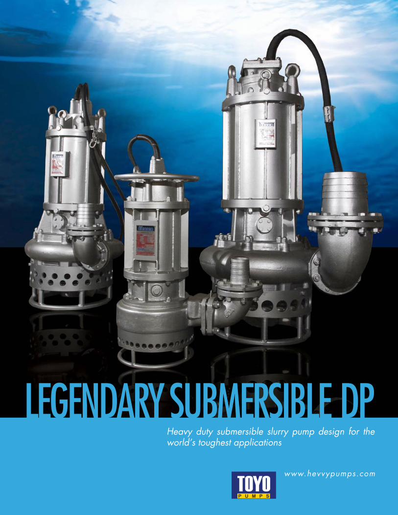
LEGENDARY SUBMERSIBLE DPHeavy duty submersible slurry pump design for the world’s toughest applications
www.hevvypumps.com
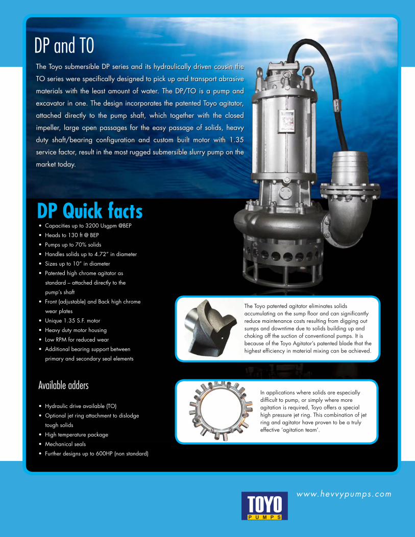
The Toyo submersible DP series and its hydraulically driven cousin the
TO series were specifically designed to pick up and transport abrasive
materials with the least amount of water. The DP/TO is a pump and
excavator in one. The design incorporates the patented Toyo agitator,
attached directly to the pump shaft, which together with the closed
impeller, large open passages for the easy passage of solids, heavy
duty shaft/bearing configuration and custom built motor with 1.35
service factor, result in the most rugged submersible slurry pump on the
market today.
www.hevvypumps.com
DP and T0
• Capacities up to 3200 Usgpm @BEP
• Heads to 130 ft @ BEP
• Pumps up to 70% solids
• Handles solids up to 4.72” in diameter
• Sizes up to 10” in diameter
• Patented high chrome agitator as
standard – attached directly to the
pump’s shaft
• Front (adjustable) and Back high chrome
wear plates
• Unique 1.35 S.F. motor
• Heavy duty motor housing
• Low RPM for reduced wear
• Additional bearing support between
primary and secondary seal elements
Available adders
• Hydraulic drive available (TO)
• Optional jet ring attachment to dislodge
tough solids
• High temperature package
• Mechanical seals
• Further designs up to 600HP (non standard)
DP Quick facts
The Toyo patented agitator eliminates solids accumulating on the sump floor and can significantly reduce maintenance costs resulting from digging out sumps and downtime due to solids building up and choking off the suction of conventional pumps. It is because of the Toyo Agitator’s patented blade that the highest efficiency in material mixing can be achieved.
In applications where solids are especially difficult to pump, or simply where more agitation is required, Toyo offers a special high pressure jet ring. This combination of jet ring and agitator have proven to be a truly effective ‘agitation team’.
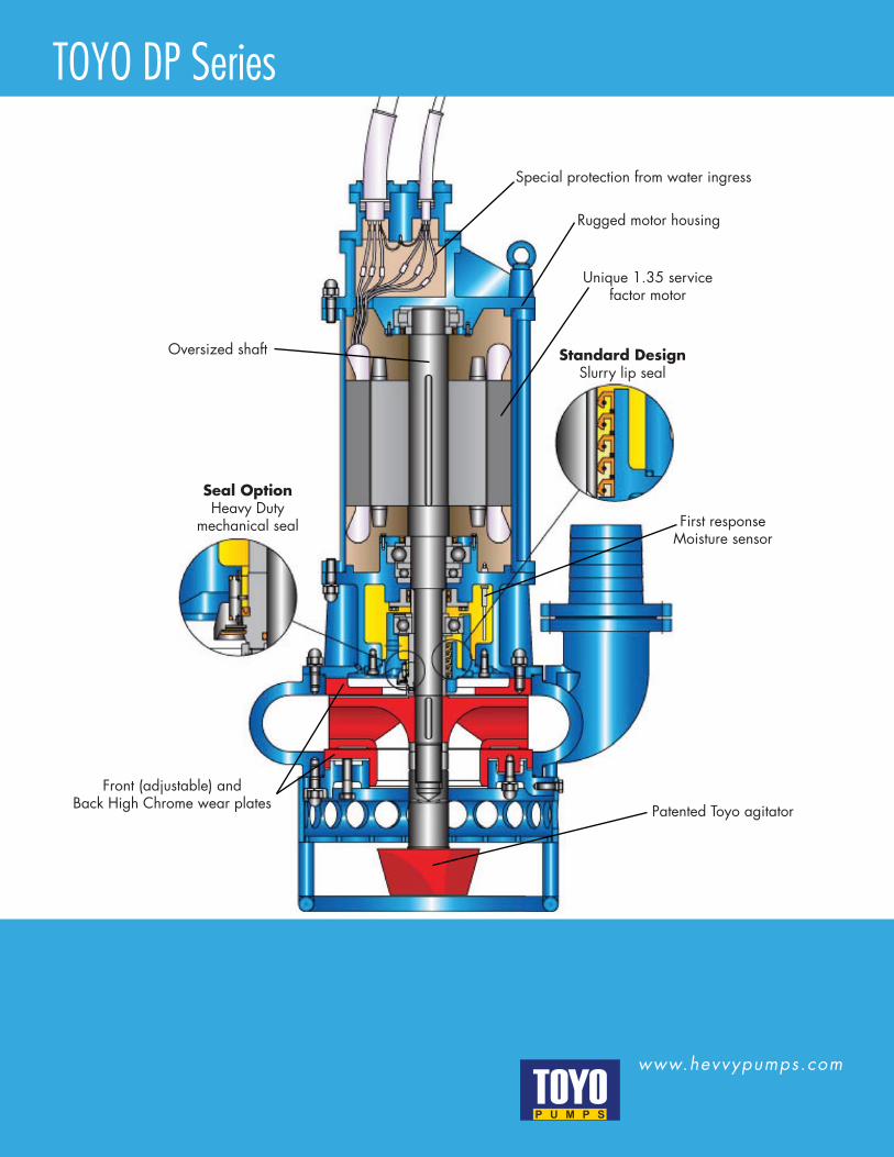
www.hevvypumps.com
TOYO DP Series
Oversized shaft
Seal OptionHeavy Duty
mechanical seal
Front (adjustable) and Back High Chrome wear plates Patented Toyo agitator
First responseMoisture sensor
Standard DesignSlurry lip seal
Unique 1.35 servicefactor motor
Rugged motor housing
Special protection from water ingress
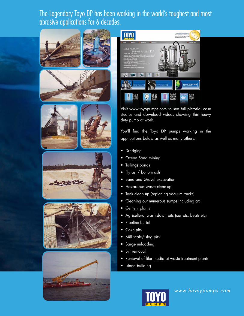
www.hevvypumps.com
The Legendary Toyo DP has been working in the world’s toughest and most abrasive applications for 6 decades.
Visit www.toyopumps.com to see full pictorial case studies and download videos showing this heavy duty pump at work.
You’ll find the Toyo DP pumps working in the
applications below as well as many others:
• Dredging
• Ocean Sand mining
• Tailings ponds
• Fly ash/ bottom ash
• Sand and Gravel excavation
• Hazardous waste clean-up
• Tank clean up (replacing vacuum trucks)
• Cleaning out numerous sumps including at:
• Cement plants
• Agricultural wash down pits (carrots, beats etc)
• Pipeline burial
• Coke pits
• Mill scale/ slag pits
• Barge unloading
• Silt removal
• Removal of filer media at waste treatment plants
• Island building
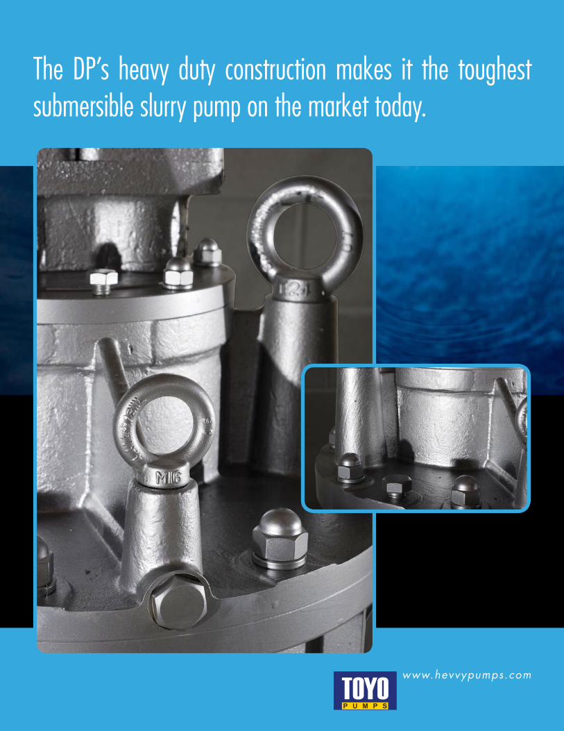
www.hevvypumps.com
The DP’s heavy duty construction makes it the toughest submersible slurry pump on the market today.
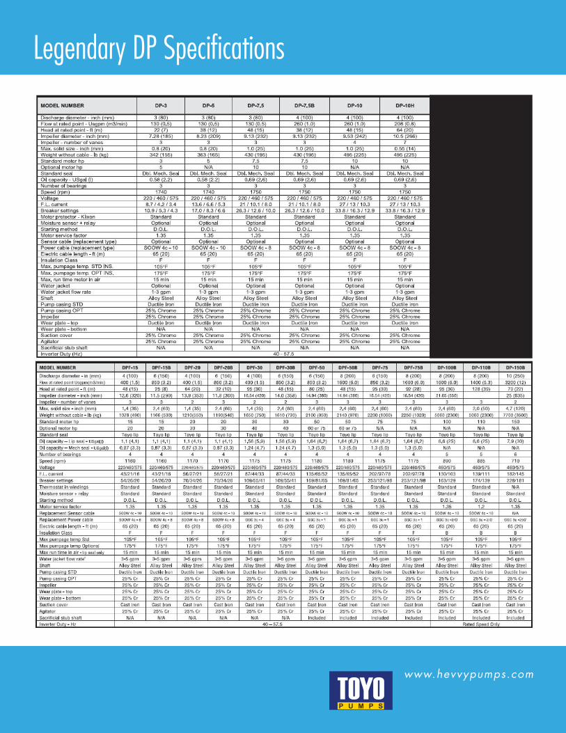
www.hevvypumps.com
Legendary DP Specifications
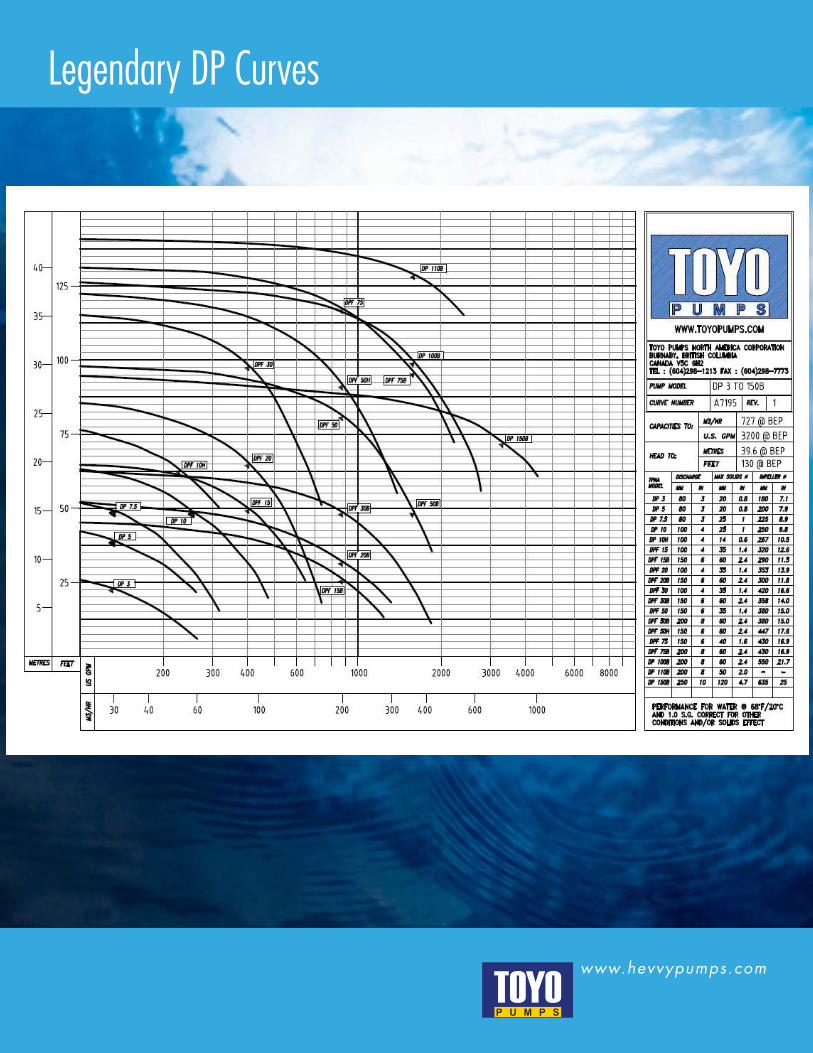
www.hevvypumps.com
Legendary DP Curves
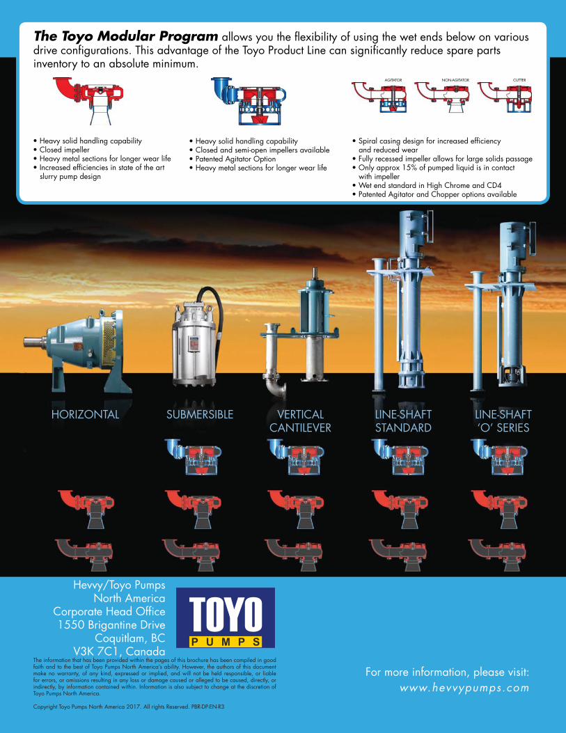
Hevvy/Toyo Pumps North America
Corporate Head Office1550 Brigantine Drive
Coquitlam, BCV3K 7C1, Canada
www.hevvypumps.comFor more information, please visit:
The information that has been provided within the pages of this brochure has been compiled in good faith and to the best of Toyo Pumps North America’s ability. However, the authors of this document make no warranty, of any kind, expressed or implied, and will not be held responsible, or liable for errors, or omissions resulting in any loss or damage caused or alleged to be caused, directly, or indirectly, by information contained within. Information is also subject to change at the discretion of Toyo Pumps North America. Copyright Toyo Pumps North America 2017. All rights Reserved. PBR-DP-EN-R3
HORIZONTAL SUBMERSIBLE VERTICALCANTILEVER
LINE-SHAFTSTANDARD
LINE-SHAFT‘O’ SERIES
• Heavy solid handling capability• Closed impeller• Heavy metal sections for longer wear life• Increased efficiencies in state of the art slurry pump design
• Heavy solid handling capability• Closed and semi-open impellers available• Patented Agitator Option• Heavy metal sections for longer wear life
• Spiral casing design for increased efficiency and reduced wear• Fully recessed impeller allows for large solids passage• Only approx 15% of pumped liquid is in contact with impeller• Wet end standard in High Chrome and CD4• Patented Agitator and Chopper options available
AGITATOR NON-AGITATOR CUTTER
The Toyo Modular Program allows you the flexibility of using the wet ends below on various drive configurations. This advantage of the Toyo Product Line can significantly reduce spare parts inventory to an absolute minimum.
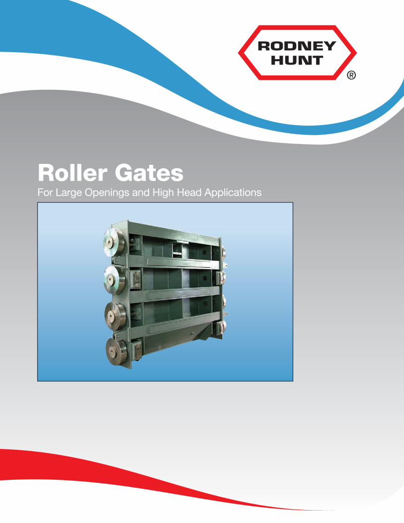
For Large Openings and High Head ApplicationsRoller Gates
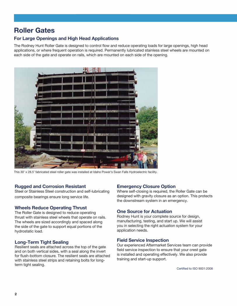
2
Roller Gates For Large Openings and High Head Applications
The Rodney Hunt Roller Gate is designed to control flow and reduce operating loads for large openings, high head applications, or where frequent operation is required. Permanently lubricated stainless steel wheels are mounted on each side of the gate and operate on rails, which are mounted on each side of the opening.
Rugged and Corrosion ResistantSteel or Stainless Steel construction and self-lubricating composite bearings ensure long service life.
Wheels Reduce Operating ThrustThe Roller Gate is designed to reduce operatingthrust with stainless steel wheels that operate on rails.The wheels are sized accordingly and spaced alongthe side of the gate to support equal portions of thehydrostatic load.
Long-Term Tight SealingResilient seals are attached across the top of the gateand on both vertical sides, with a seal along the invertfor flush-bottom closure. The resilient seals are attachedwith stainless steel strips and retaining bolts for long-term tight sealing.
Emergency Closure OptionWhere self-closing is required, the Roller Gate can bedesigned with gravity closure as an option. This protectsthe downstream system in an emergency.
One Source for ActuationRodney Hunt is your complete source for design,manufacturing, testing, and start up. We will assistyou in selecting the right actuation system for yourapplication needs.
Field Service InspectionOur experienced Aftermarket Services team can providefield service inspection to ensure that your crest gateis installed and operating effectively. We also providetraining and start-up support.
Certified to ISO 9001:2008
This 30’ x 28.5’ fabricated steel roller gate was installed at Idaho Power’s Swan Falls Hydroelectric facility.
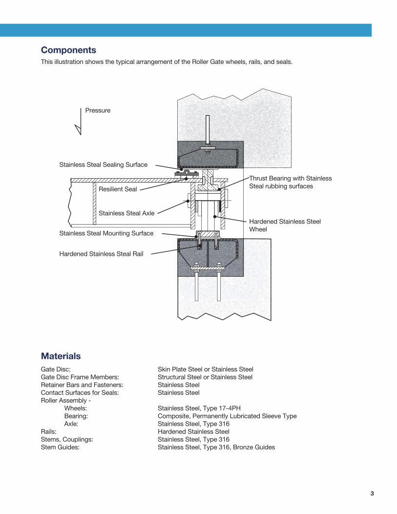
3
Components
This illustration shows the typical arrangement of the Roller Gate wheels, rails, and seals.
Stainless Steal Sealing Surface
Resilient Seal
Stainless Steal Axle
Stainless Steal Mounting Surface
Hardened Stainless Steal Rail
Thrust Bearing with Stainless Steal rubbing surfaces
Hardened Stainless Steel Wheel
Pressure
Materials
Gate Disc: Skin Plate Steel or Stainless SteelGate Disc Frame Members: Structural Steel or Stainless SteelRetainer Bars and Fasteners: Stainless SteelContact Surfaces for Seals: Stainless SteelRoller Assembly - Wheels: Stainless Steel, Type 17-4PH Bearing: Composite, Permanently Lubricated Sleeve Type Axle: Stainless Steel, Type 316Rails: Hardened Stainless SteelStems, Couplings: Stainless Steel, Type 316Stem Guides: Stainless Steel, Type 316, Bronze Guides
For more information about Rodney Hunt products or to contact a sales representative, visit the
Rodney Hunt website (www.rodneyhunt.com).
In the United States
Engineered Flow Control Products from Rodney Hunt
Engineered Flow Control Products
Gates
• Sluice Gates• Bonneted Gates• Channel Gates• Weir Gates• Crest Gates (including Bascule®
and Pelican® designs)• Tainter Gates
• Slide Gates• Roller Gates • Hinged Crest Gates• Bulkhead Gates• Velocity Control Gates• Stop Logs• Flap Gates
Actuation
Manual, electric, and hydraulic actuation systems are available.
For more information about Rodney Hunt products or to contact a sales representative, visit the Rodney Hunt website (www.rodneyhunt.com) or call 978-633-4362
RH-ROLLER-0917
Related Documents