Fire Rescue Robot Using IR Imaging Camera By Asad Hasnain (BEES/S11/0103) Muhammad Shahid (BEES/S11/0140) Osama Iftikhar (BEES/S11/0145) 2015 Faculty of Engineering Sciences and Technology Hamdard Institute of Engineering and Technology Hamdard University, Main Campus, Karachi, Pakistan

Welcome message from author
This document is posted to help you gain knowledge. Please leave a comment to let me know what you think about it! Share it to your friends and learn new things together.
Transcript
Fire Rescue Robot Using IR Imaging
Camera
By
Asad Hasnain (BEES/S11/0103)
Muhammad Shahid (BEES/S11/0140)
Osama Iftikhar (BEES/S11/0145)
2015
Faculty of Engineering Sciences and Technology
Hamdard Institute of Engineering and Technology
Hamdard University, Main Campus, Karachi, Pakistan

Fire Rescue Robot Using IR Imaging
Camera
By
Asad Hasnain (BEES/S11/0103)
Muhammad Shahid (BEES/S11/0140)
Osama Iftikhar (BEES/S11/0145)
Under the supervision of
Dr. Fahad Azim
2015
Faculty of Engineering Sciences and Technology
Hamdard Institute of Engineering and Technology
Hamdard University, Main Campus, Karachi, Pakistan
Fire Rescue Robot Using IR Imaging
Camera
By
Asad Hasnain (BEES/S11/0103)
Muhammad Shahid (BEES/S11/0140)
Osama Iftikhar (BEES/S11/0145)
A Project Presented to the
Faculty of Engineering Sciences and Technology
Hamdard Institute of Engineering and Technology
In partial fulfillment of the requirements
For the degree
Bachelors of Engineering In
Electronics
Faculty of Engineering Sciences and Technology
Hamdard Institute of Engineering and Technology
Hamdard University, Main Campus, Karachi, Pakistan
Faculty of Engineering Sciences and Technology
Hamdard Institute of Engineering & Technology
Hamdard University, Main Campus, Karachi, Pakistan
CERTIFICATE
This project “Fire Rescue Robot Using IR Imaging Camera” presented by Asad Hasnain,
Muhammad Shahid and Osama Iftikhar under the direction of their project advisor’s and
approved by the project examination committee, has been presented to and accepted by the
Hamdard Institute of Engineering Technology, in partial fulfillment of the requirements for
Bachelor of Engineering (Electronics).
____________________________
Dr. Fahad Azim
(Project Advisor)
____________________________
Engr. Dur-e-Jabeen
(Co-Supervisor)
____________________________
Dr. Rashid Husain
(Chairman Electrical Engineering Department)
____________________________
(Member)
____________________________
(Member)
___________________________
Dr. Fahad Azim
(Director, HIET)

i
ABSTRACT
As the technology sets its trends towards a new era, the research what were once called as an
effective preliminary systems i.e. smoke sensors now raise serious questions on their
effectiveness. The following report is based on building an effective solution which could very
well be used for early stages in fire rescue systems. The system uses controller and an Infrared
camera to capture images of fire. Using image processing techniques the system provides
effective algorithm which resolves the question that smoke sensors at times miss out in its fire
detection techniques, therefore becoming an obsolete and at the same time ineffective method for
discovering a true fire and not some fire from Cigar, Cigarettes and light matches etc. Using
stepper motor to pane the camera in motion, and cover all possible angles and if the system
detects a true fire, a small DC water pump is installed to extinguish that particular Flame at
preliminary stage, thereby saving countless lives and may be saving the loss of property.

ii
ACKNOWLEDGEMENT
All praises and thanks to Al-Mighty ”ALLAH”, the most merciful, the most gracious, the source
of knowledge and wisdom endowed to mankind, who conferred us with the power of mind and
capability to take this project to the exciting ocean of knowledge. All respects are for our most
beloved Holy Prophet “Hazrat MUHAMMAD (Peace Be Upon Him)”, whose personality will
always be source of guidance for humanity.
We are grateful to our parents who constantly supported us in this endeavor. We acknowledge
and wish to express our appreciation to our honorable teacher and supervisor, Dr. Fahad Azim
who gave us an opportunity to go with this project and fully cooperated under all circumstances.
We also thankful to the most co-operative and hard working Engr. Dur-e-Jabeen and Engr.
Junaid Ahmed Hashmani, their efforts and co-operation made our idea to turn into reality, we
would like to express our heartiest gratitude for their keen guidance. Last but not the least, we
would like to extend out gratefulness to our batch mates and friends who provided moral support
all the way and also assisted us in some project related issue.
iii
TABLE OF CONTENTS
ABSTRACT ......................................................................................................................... i
ACKNOWLEDGMENT..................................................................................................... ii
TABLE OF CONTENTS ................................................................................................... iii
LIST OF FIGURES .............................................................................................................v
LIST OF TABLES ............................................................................................................. vi
1. INTRODUCTION ...............................................................................................................1
1.1 Motivation ...............................................................................................................1
1.2 Problem Statement ...................................................................................................2
1.3 Organization of the Thesis .......................................................................................2
2. LITERATURE REVIEW ....................................................................................................4
2.1 Fire Triangle.............................................................................................................4
2.2 Types of Fire Protection...........................................................................................5
2.2.1 Active Fire Protection ..................................................................................5
2.2.2 Passive Fire Protection .................................................................................6
2.2.3 Smoke ..........................................................................................................7
2.3 Infrared .....................................................................................................................7
2.3.1 Overview of Infrared Waves ........................................................................7
2.4 Previous Researches.................................................................................................9
3. METHOD AND MATERIAL ...........................................................................................10
3.1 Testing and Training ..............................................................................................10
3.1.1 Training .....................................................................................................10
3.1.2 Testing .......................................................................................................10
3.2 Implementation of Algorithm ................................................................................11
4. SIMULATION AND RESULT ........................................................................................14
4.1 Code Simulation ....................................................................................................14
4.1.1 Reading Image ...........................................................................................14
4.1.2 Background Subtraction of Image .............................................................15
4.1.3 Threshold Level And Binary Image ..........................................................15
4.1.4 Crop Highest Blob of Image ......................................................................16
4.1.5 Index Color Image .....................................................................................15
4.1.6 Comparison ...............................................................................................17
4.2 Hardware Interfacing .............................................................................................18
4.3 Flow Chart .............................................................................................................19
4.4 Interpretation of Results ........................................................................................20
iv
5. CONCLUSION AND FUTURE WORK ..........................................................................21
5.1 Conclusion ............................................................................................................21
5.2 Recommendation for Future Work .......................................................................22
REFERENCES .................................................................................................................24
APPENDIX ........................................................................................................................26
A. RASPBERRY PI CONTROLLER ..................................................................26
B. PI NOIR IR CAMERA ....................................................................................28
C. RASPBERRY PI INTERFACING USING MATLAB® 2014 .......................31
D. STEPPER MOTOR AND DRIVING CIRCUIT .............................................43
v
LIST OF FIGURES
2.1 Fire Triangle.........................................................................................................................4
4.1(a) First IR Captured Image.....................................................................................................15
4.1(b) Second IR Captured Image ................................................................................................15
4.2 Binary Image Blob .............................................................................................................15
4.3 Highest Blob ......................................................................................................................16
4.4(a) Index Color ........................................................................................................................17
4.4(b) High Color .........................................................................................................................17
4.4(c) Low Color ..........................................................................................................................17
4.5 Hardware Interfacing .........................................................................................................18
4.6 Flow Chart .........................................................................................................................19
A.1 Raspberry Pi Front View ...................................................................................................26
A.2 Raspberry Pi Back View ....................................................................................................26
A.3 Raspberry Pi GPIO Ports ...................................................................................................26
A.4 Raspberry Pi Pin Configuration .........................................................................................26
B.1 Raspberry Pi NOIR Camera...............................................................................................28
B.2 Raspberry Pi Controller and Camera Connection ..............................................................30
B.3 Flex Cable ..........................................................................................................................30
D.1 Stepper Motor Driving Connections ..................................................................................43
D.2 Internal Structure of Stepper Motor ...................................................................................44
D.3 Stepper Motor Wiring ........................................................................................................44
D.4 ULN2003A Connection and Structure...............................................................................46
D.5 ULN2003A Logic ..............................................................................................................47
D.6 ULN2003A Pin Configuration ...........................................................................................47

vi
LIST OF TABLES
2.1 Electromagnetic Spectrum ...................................................................................................8
A.1 Raspberry Pi Model Configuration ....................................................................................27
1
CHAPTER 1
INTRODUCTION
The project was done to obtain a better understanding of Raspberry Pi Controllers and also the
concept of Image Processing. In addition also wanted to have proper knowledge of different
safety procedures adopted throughout the world and to provide a better and more effective
solution. The foremost purpose of this project is to implement our learning, regarding Raspberry
Pi Controllers and to learn electronics in the way of both programming as well its interfacing and
scientists all over the world have suggested that robots are a great source for preliminary or early
stage rescue, thus to fabricate a prototype model of an Automated Fire detection and
Extinguisher System.
Considering fire rescue because of the following reasons:
1) This robot could be applied to anywhere regardless of the size of the place
2) It becomes necessary when u don’t have enough force to fight a strong fire which
grows stronger because the preliminary rescue system was not present, when it was
needed at the most.
1.1 Motivation
Earth was created and given 4 major elements; fire, water, air and land. Among them Fire has
always been an element that is unprecedented, unaccounted and thus it sometimes is
uncontrollable. Under many cases it was observed that fire purge out in a horrific manner
because of the late arrivals of rescue teams. For example when fire broke out in a garment
factory about a year ago in Karachi Baldia town it was gutted completely with 270 casualties. At
there been this type of robot, the lost could have been largely reduced.
Over the years death rates by fire has increased tremendously. Fire consumes homes and
commercial premises quickly, indiscriminately taking lives and ruining property. No one should
have to be become a victim of fire, but the reality is that people do become victims every day.
Image processing was another motivation because to us not only it is necessary but also is quite
interesting and we wanted a project that would have the implication of image processing in it.
This project includes all three key points that a student and his supervisor wants when working
on FYP
1) Should be cost effective
2) Should have practical application
2
3) Comparative work that includes all aspects of undergrad learning
1.2 Problem Statement
The problem with having just detection is that although you know you have a fire (the fire alarm
sounders) there is no way to safely suppress the fire yourself and that’s if you are there. The Fire
service will put it out when called, but the smoke damage occurring before they arrive and the
water damage after can be quite significant. Fire suppression systems are used to reduce the level
of damage and down time by automatically suppressing the fire.
In a country such as ours, for preventing a building or a house from a fire incident we mostly use
three things for a preliminary rescue smoke detectors, roof showers and fire extinguishers.
Now a smoke detector is usually connected in such a manned that if it senses a smoke of any sort
it will activate the roof showers to shower the area.
A question arises that if this smoke is not made by fire but instead of a man lighting a cigar or
small lighter or a match stick being lit, then what?
For fire extinguishers the only question remains that they are not placed at each and every corner
of a building.
Due to these reasons more serious preventive measures are necessary. We have devised a
solution to the said problem. The robot will prevent fire from spreading fast, and it will also
extinguish it quickly.
1.2 Organization of Thesis
To make sure that whom so ever in the future picks this report to further implement this project
in a more effective manner we divided this report into five chapters for the ease of any particular
individual in layman terms. Each chapter covers different aspects i.e. of how this idea was
initially implemented, how we have made a difference, and how anybody else in the future
would or could make a positive difference in it.
Starting from First chapter which gives a brief overview of how we were motivated with the idea
of making a FYP that would not only cover the learning of entire bachelors, but if necessary it
would be a near to perfect solution for preliminary use.
As the idea starts to make sense so does the study of things required to put in the system, so
second chapter covers the study of materials that were required to cover all possible aspects
needed to make this system.
Third chapter comes with the methodology and results which by its name concludes that this
chapter would cover the explanation of how this task was performed and what aspects were
covered from the particular software needed to interface things in all in one manner.

3
Fourth chapter covers the results and simulation of project of how these images are said to be a
fire image and not something else.
Fifth chapter covers conclusive results of the images of true flame of fire that are formed by
applying particular algorithms and what drawbacks were found when applying these cases. Also
it tells us what future work could be done which could make it more impressive and effective at
best.

4
CHAPTER 2
LITERATURE REVIEW
Before start working on our designed fire rescue system, we had to study about fire and its
different protection techniques, which gave us sufficient knowledge so that we would be able to
select an appropriate camera and other hardware’s that are required to design a preliminary fire
rescue system.
2.1 Fire Triangle
The fire triangle or combustion triangle is a simple model for understanding the ingredients
necessary for most fires.
The triangle illustrates a fire requires three elements: heat, fuel, and an oxidizing agent (usually
oxygen). The fire is prevented or extinguished by removing any one of them. A fire naturally
occurs when the elements are combined in the right mixture.
Without sufficient heat, a fire cannot begin, and it cannot continue. Heat can be removed by the
application of a substance which reduces the amount of heat available to the fire reaction. This is
often water, which requires heat for phase change from water to steam. Introducing sufficient
quantities and types of powder or gas in the flame reduces the amount of heat available for the
fire reaction in the same manner. Turning off the electricity in an electrical fire removes the
ignition source.
Without fuel, a fire will stop. Fuel can be removed naturally, as
where the fire has consumed all the burnable fuel, or manually,
by mechanically or chemically removing the fuel from the fire.
The fire stops because a lower concentration of fuel vapor in the
flame leads to a decrease in energy release and a lower
temperature. Removing the fuel thereby decreases the heat [2].
Without sufficient oxygen, a fire cannot begin, and it cannot
continue. With a decreased oxygen concentration, the
combustion process slows. In most cases, there is plenty of air
left when the fire goes out so this is commonly not a major
factor.
Figure 2.1 Fire triangle
Source: Wikipedia

5
2.2 Types of Fire Protection
2.2.1 Active Fire Protection
Active fire protection systems need to respond effectively and appropriately to a fire. They
require activation through a combination of detectors or mechanical means and may consist of
fire alarms and notification systems, sprinklers, standpipes, water supplies, and smoke detectors
[2].
Detection systems such as alarms to enable immediate evacuation and notify fire
services.
Suppression systems such as sprinklers and extinguishers reduce damage to buildings and
contents.
These systems help reduce the growth of a fire, thereby increasing life safety and limiting
structural damage.
Categories of Active Fire Protection
Fire suppression
Fire can be controlled or extinguished, either manually (firefighting) or automatically. Manually
fighting a fire includes the use of a fire extinguisher or a standpipe system. Automatic fire
fighting means that it includes a fire sprinkler system, a gaseous clean agent, or a fire fighting
foam system. Automatic suppression systems would usually be found in large commercial
kitchens, hazardous chemical areas or other high-risk areas.
Sprinkler systems
Fire sprinkler systems are installed in all types of buildings, commercial and residential. They are
usually located at a ceiling level and are connected to a reliable water source, most commonly
city water. A typical sprinkler system operates when heat at the site of a fire causes a glass
component in the sprinkler head to break, thereby releasing the water from the sprinkler head.
Sprinkler systems help to reduce the growth of a fire, thereby increasing life safety and limiting
structural damage.
Fire detection
The fire is detected either by locating the smoke, flame or heat, and an alarm is sounded to
enable an emergency evacuation as well as to dispatch the local fire department. When a fire
detection system is activated, it can be programmed to carry out other actions. These include de-
energizing magnetic hold open devices on fire doors and opening servo-actuated vents in
stairways.

6
2.2.2 Passive Fire Protection
Passive Fire Protection attempts to contain fires or slow their spread, to the standard
expected by building codes. A PFP system is an integral part of the building layout and
construction materials, covering these key areas:
Fire-resistance rated walls.
Firewalls not only have a rating, they are also designed to sub-divide buildings such that
if collapse occurs on one side, this will not affect the other side.
Fire-resistant glass using multi-layer intumescing technology or wire mesh embedded
within the glass may be used in the fabrication of fire-resistance rated windows in walls
or fire doors.
Fire-resistance rated floors.
Occupancy separations. These barriers designated as occupancy separations are intended
to segregate parts of buildings.
Closures (fire dampers). Sometimes firestops are treated in building codes identical to
closures.
Grease ducts. (These refer to ducts that lead from commercial cooking equipment such as
ranges, deep fryers and double-decker and conveyor-equipped pizza ovens to grease duct
fans)
Spray fireproofing. This is an application of intumescing or endothermi cipaints, or
fibrous or cemented plasters to keep substrates such as structural steel, electrical or
mechanical services, valves, liquefied petroleum gas (LPG) vessels, vessel skirts,
bulkheads or decks below either 140 °C for electrical items or ca. 500 °C for structural
steel elements to maintain operability of the item to be protected.
Fire proof cladding. Materials for such cladding include perlite, vermiculite, calcium
silicate, gypsum, in tumescent epoxy, Dura steel (cellulose-fiber reinforced concrete and
punched sheet-metal bonded composite panels), and Micro Therm.
Enclosures. They are boxes or wraps made of fireproofing materials, including fire-
resistive wraps and tapes to protect special valves and other items deemed to require
protection against fire and heat.

7
2.2.3 Smoke
Smoke is a collection of airborne solid and liquid particulates and gases emitted when a material
undergoes combustion, together with the quantity of air that is entrained or otherwise mixed into
the mass. Smoke formation can be best explained where wood is burning.
There are four things that you find in any piece of wood:-
Water
Volatile organic compounds
Carbon
Ash
When you put a fresh piece of wood or paper on a fire, the smoke you see is due to the volatile
hydrocarbons evaporating from the wood or paper. They start vaporizing at a temperature of
about 300 degrees Fahrenheit (149 degrees Celsius). If the temperature gets high enough, these
compounds burst into flame. Once they start burning, there is no smoke because the
hydrocarbons are turned into carbon dioxide and water (both invisible) when they burn [2].
After studying about different natures of fire and its different sub categories along with the
smoke they create, we were able to select the nature of the camera i.e. an infrared camera which
could provide a cheap yet effective solution to our system.
2.3 Infrared
Infrared or more commonly called (IR) is a invisible radiant energy, electromagnetic radiation
with longer wavelengths than those of visible light which extends from the nominal range of the
visible spectrum at 700 nanometers which in frequency is equal to 430 THz to the range of 1 mm
which in frequency is equal to 300 GHz.
However people sometimes see infrared up to at least 1050 nanometers in experiments. It is
sometimes also considered that most of the thermal radiation emitted by objects near room
temperature is infrared.
2.3.1 Overview of Infrared Waves
Infrared radiation was discovered in 1800 by astronomer Sir William Herschel, who discovered a
type of invisible radiation in the spectrum beyond red light, by means of its effect upon a
thermometer. Slightly more than half of the total energy from the Sun was eventually found to
arrive on Earth in the form of infrared. The balance between absorbed and emitted infrared
radiation has a critical effect on Earth's climate.
8
Infrared energy is emitted or absorbed by molecules when they change their rotational-
vibration movements. Infrared energy elicits vibration modes in a molecule through a change in
the dipole moment, making it a useful frequency range for study of these energy states for
molecules of the proper symmetry. Infrared spectroscopy examines absorption and transmission
of photons in the infrared energy range.
Infrared radiation is used in industrial, scientific, and medical applications. Night-vision devices
using active near-infrared illumination allow people or animals to be observed without the
observer being detected. Infrared astronomy uses sensor-equipped telescopes to penetrate dusty
regions of space, such as molecular clouds; detect objects such as planets, and to view
highly red-shifted objects from the early days of the universe.[8] Infrared thermal-imaging
cameras are used to detect heat loss in insulated systems, to observe changing blood flow in the
skin, and to detect overheating of electrical apparatus.
Thermal-infrared imaging is used extensively for military and civilian purposes. Military
applications include target acquisition, surveillance, night vision, homing and tracking. Humans
at normal body temperature radiate chiefly at wavelengths around 10 μm (micrometers). Non-
military uses include thermal efficiency analysis, environmental monitoring, industrial facility
inspections, remote temperature sensing, short-ranged wireless communication, spectroscopy,
and weather forecasting.
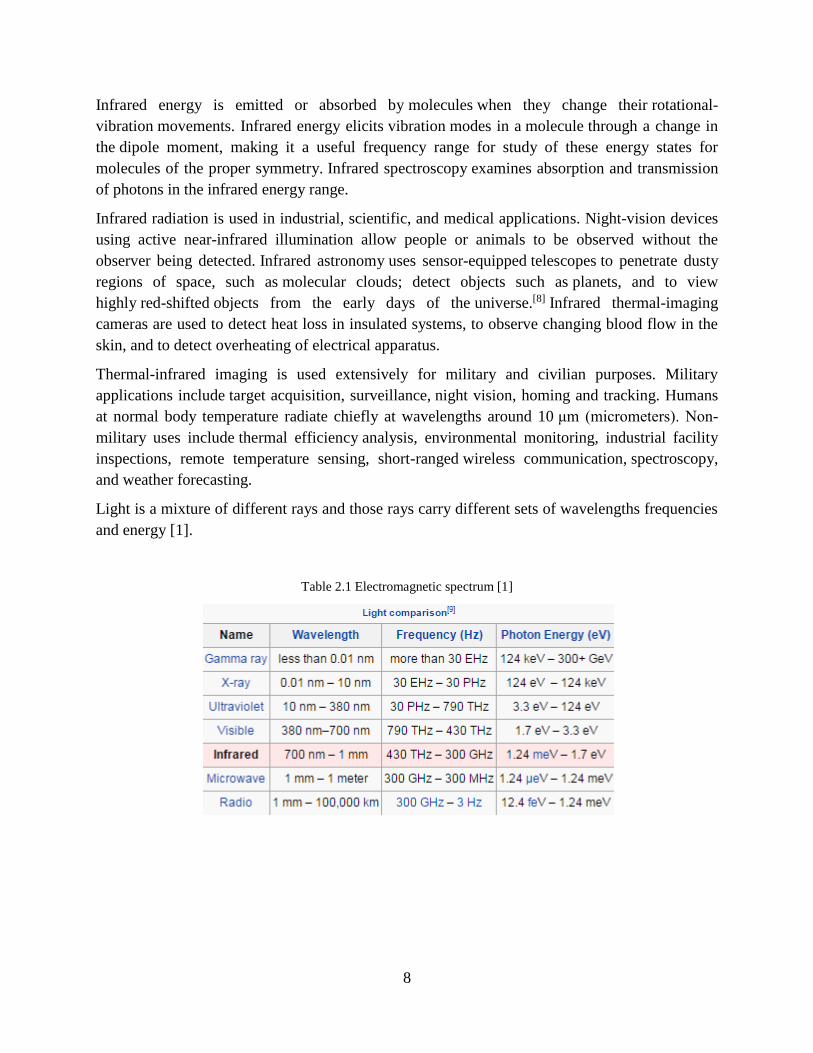
Light is a mixture of different rays and those rays carry different sets of wavelengths frequencies
and energy [1].
Table 2.1 Electromagnetic spectrum [1]
9
2.4 Previous Researches
Making of a project not only just requires a motivation, but also to perform a task such as this
one, a brief study of materials and their requirement is mandatory. The main objective of this
project in terms of literature was Image Processing and how it should be done by interfacing you
controller and camera to the said algorithm on MATLAB®, so all the method on how to
interface and how it will initiate and almost all the details and method for it are written at the end
in appendix title. Once the hardware interfacing was done, we again started to search over the
internet that how this technique could become more efficient and better. After a long and hard
search, a research paper with the title “Fire and Smoke Detection without Sensors Using Image
Processing based approach” was the closest one to give away the idea of how our task could be
done [14]. This paper model also used the idea to detect flame and smoke using a camera.
This paper clarifies the concepts that usually smoke sensors use and in their attempt sometimes
fail to perform in certain conditions. The technique used in this paper to convert image into
binary and finding its numerical values is done by breaking the picture into individual channels
and finding its histogram to find numerical value. By studying through MATLAB® help, a
simpler and effective command was found which also made the histogram technique
unnecessary. All the techniques used in this paper are based upon not only images captured but
also on the terms of live feed of fire i.e. video mode. This paper also provided the terminology
that we were quite unfamiliar with i.e. Blob which is the highly radiant part in any binary picture.
The idea of learning about comparison from one identity to the next is also necessary because
without it the background from the image which is the useless part would not b removed,
therefore again in the paper headline detection of colors, it gives away the comparison method to
perform from high values to the low values of picture in binary format.
Another research about flame detection “Optimized Flame Detection Using Image Processing
Based Technique” which is of an Indian author is very helpful in this project. This paper model
clearly shows the algorithm and technique used to detect the edges and to fill the lighter holes in
a Blob of a fire, author also briefly discussed the idea of motion detection and comparison of two
set of images, the main advantage of this idea is that, this technique of motion detection and
comparison can make the fire extinguishing system more efficient. By this technique system can
easily distinguish between a real flame image of fire and a static flame picture [5].
After the highly radiated part was done, the two checks that were necessary for our system to
specify from a fake fire to a real one i.e. height greater than width and correlation of these
pictures also was taken from the idea..

10
CHAPTER 3
METHOD AND MATERIAL
In this chapter we briefly discus the approach towards achieving the result, the algorithm and
technique we applied to detect the fire and to extinguish it, which was our target.
3.1 Testing and Training
The testing and training phases are necessary for any project which is for the preliminary or
prototype usage of any object.
3.1.1 Training
The training phase consists of two parts:
1. Pre processing
2. Data processing
Pre-Processing
In the pre-processing we take several images of different types of fire and feed it to memory of
raspberry pi (SD card) for the IR (Pi NOIR) camera to use. These images captured would be
certain types of fire like candle fire blob and flame, or a lighter etc, interface the raspberry
hardware via MATLAB® and load the captured image in MATLAB®, and through image
processing algorithm detect the fire presence.
Data-Processing
In the Data-processing phase our system will perform several mathematical techniques which is
done through MATLAB® which will give us the weight of the image which is most necessary in
this project because this weight means closeness of captured image to recognition of a certain
image of fire.
3.1.2 Testing
Testing phase is sub divided in three parts.
1. Input image
2. Data processing
3. Generate output

11
Input Image
In the input image the camera takes the unknown images at some particular instants and feed it to
SD card (memory) of the module.
Data Processing
In the data processing using the image processing algorithm checks the environmental changes
and our camera takes on the pictures and compares them with images fed in the memory. Until
they reach a certain decision based upon the comparison with the memory the motion of the
robot will continue as controller is developing no logic except to move the stepper motor, which
is using to pane the camera.
Generate Output
If the captured image readings are matched to the data base, the controller will developed the
logics that will stop the robot and start showering the fire place and until the readings are
satisfied the robot will not move. Once the fire is out the robot will again start moving.
3.2 Implementation of Algorithm
By dividing our code like a course breakup, or in this case the phases of testing and training we
were able to make effective use of our time for all possible conclusions. The writing of code is
never easy because each person designs and sees the possibilities of implementation differently,
and in order to apply the code we firstly needed the materials that were required on which we
could implement our code on, i.e. a controller. As discussed above of what task we needed to
achieve in the first chapter, we picked up the raspberry PI controller and along with it, it’s
camera as well.
Now these two things generally are the basic requirement for our first evaluation in which we
were told to capture an image through PI NOIR camera and using Image Processing we would
have to load this image [3]. The image definitely should be the one with fire in it and nature of
the fire was left on our own choosing.
In order to apply this method we first had to interface to the camera and raspberry to the
MATLAB® software. Since MATLAB® 2009 edition does not come with the additional library
files so we installed MATLAB® 2014 edition. The process of its installation is discussed in
detailed manner in the appendix C [10].
Once the controller and its camera was interfaced we had to only apply a single command to
connect the RASPI with MATLAB® which saved our time to connect the IP of RASPI to the IP
of our PC. Once the RASPI was ready we did a little bit of testing to check whether the RASPI is
functioning properly to the given logics i.e. its GPIO ports functioning properly.

12
With these testing’s we became more confident that now RASPI is ready to take any logic given
via MATLAB®, and so we applied the code required for the camera to take an image and load it
in its data.
The camera took a snapshot which was perfect as per our requirement. Since the image was
infrared in nature and with no flash on the camera, the image was showing only the radiant parts
which would become more understandable in the next chapter.
Once the image we disconnected the RASPI and its camera for safe keeping and decided to
make the code on MATLAB® and take the snapshot as a reference for the results.
Since all images taken form cameras are the mix up of three colors i.e. Red, Green, Blue so, the
first part of this code is to make this image colorless so that we would be able to check the nature
of each color separately [6].
After the image became colorless it showed the backgrounds as black while the radiant parts as
white, which means now it can only distinguish the pictures with two colors or two logics. Since
the background is not our requirement we subtracted the background from the image and were
left with radiant parts which we call blobs [4].
These blobs are the radiant parts for the camera and some of them are not fire. This is the part
where many smoke sensors fail because a smoke sensor cannot distinguish a smoke created from
a small cigar to a large fire, so by using crop selections we founded the binary values of small
blobs as well as the large ones.
These values helped us to distinguish between a large area of fire and vice versa. Obviously the
part where blobs are small possess very low binary values, therefore we applied the loops that if
the binary values are within the range of that area would be a fire, else it would a false alarm [5].
After countless hours of testing’s and checking from every conclusive angle that it should work
at least near to perfect we were amazed that the code was working perfectly so now we can
connect the raspberry PI to the code as well as its camera.
To check not only on laptop but also on the hardware, we connected a small LED to the GPIO
ports of raspberry that would glow only if all the loops are running properly which by the grace
of Almighty Allah was working perfectly.
To make this project more beautiful and push our limits as well as the limit of the controller, we
interfaced a stepper motor with it. This stepper motor would be used as a panning tool for the
camera so that it would not be in a fixated position but instead would move and cover all three
angles.

13
To drive the motor we used the ULN2003 to drive the motor [12], as discussed in the appendix D
which worked perfectly when it was interfaced to the motor via Raspberry PI. Using simple sum
and subtract logics we were able to move the motor from 0 to 90 and to 180.
The camera captures an image at each of the given angle and stops a delay when processing the
code for it. Once its done the fire if found present, the shower i.e. a DC water pump would turn
ON which would try to extinguish it and then move on when it is extinguished.
14
CHAPTER 4
SIMULATION AND RESULT
Here we explain the simulation and flow of our technique and method we used, i.e Image
Processing, stepper motor and DC water pump interfacing. And also discus our achieved result.
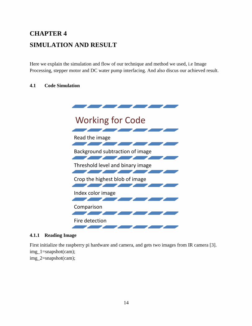
4.1 Code Simulation
4.1.1 Reading Image
First initialize the raspberry pi hardware and camera, and gets two images from IR camera [3].
img_1=snapshot(cam);
img_2=snapshot(cam);
Working for Code
Read the image
Background subtraction of image
Threshold level and binary image
Crop the highest blob of image
Index color image
Comparison
Fire detection
15
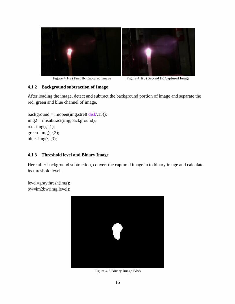
Figure 4.1(a) First IR Captured Image Figure 4.1(b) Second IR Captured Image
4.1.2 Background subtraction of Image
After loading the image, detect and subtract the background portion of image and separate the
red, green and blue channel of image.
background = imopen(img,strel('disk',15)); img2 = imsubtract(img,background);
red=img(:,:,1); green=img(:,:,2); blue=img(:,:,3);
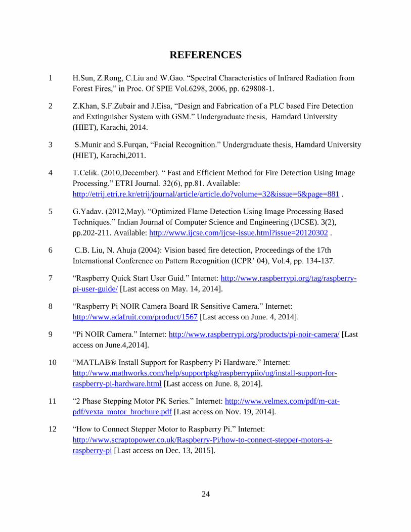
4.1.3 Threshold level and Binary Image
Here after background subtraction, convert the captured image in to binary image and calculate
its threshold level.
level=graythresh(img); bw=im2bw(img,level);
Figure 4.2 Binary Image Blob

16
4.1.4 Crop Highest Blob of Image
After converting the captured image in to binary, crop the highest white blob from the binary
image which is actually a highly radiant light part of the image, and neglect the other smaller
white parts of the binary image and also fill the holes in the major highest blob and that highest
cropped blob is the fire. We also set the condition the height of the flame should must be greater
than its width. Because we did our analysis on a candle, and candles flame is higher but not so
wider.
bwc= imfill(bw,'holes'); filledImage=bwmorph(bwc,'clean'); [max_area, idx] = max(measure_area); maxobj = false(size(max_area));
maxobj(cc.PixelIdxList{idx}) = true;
k=idx; x1 = measurements(k).BoundingBox(1); y1 = measurements(k).BoundingBox(2);
width = measurements(k).BoundingBox(3); height = measurements(k).BoundingBox(4); x2 = x1 + width; y2 = y1 + height;
FlameDetect=false; if height>width FlameDetect=true;
end
Figure 4.3 Highest Blob
4.1.5 Index Color Image
In further processing convert the image in to index color image and get the low and dark color
images of captured image.
[img_indexed, map]=rgb2ind(cropedImage,8);

17
figure,imshow(img_indexed,map)
cred=cropedImage(:,:,1);
cblue=cropedImage(:,:,2); cgreen=cropedImage(:,:,3); low_color=cred>210 &cblue>180 &cgreen>200 figure,imshow(low_color);
low_pixcount=size(low_color);
high_color=cred<10 &cblue>10 &cgreen<10
Figure 4.4(a) Index Color Figure 4.4(b) High Color Figure 4.4(c) Low color
4.1.6 Comparison
After all conditions we applied becomes true we set another condition to check the presence of
fire, and that is Comparison of two images, correlation command of image processing compare
the two images and check that the images are same or not.
When a candle is burning its flame never in static condition so images of two different interval of
the same candle flame will not be same, So if the images are not same that means it’s a fire and
in other case if the images of candle flame are same that means its not a fire it may be a picture
of fire in front of camera which is static.
ifFlameDetect==true
17orrelate = corr2(img,img_2): ifcorelate==1 disp(‘The images are same’)
‘means Fire not found’ else
disp(‘the images are not same’)
‘means Fire dete’

18
After detecting the fire as we discussed in chapter three, our next target is to extinguish the fire.
For that purpose the rotation of camera should be stop and water pump should start showering
water on fire.
To stop stepper motor from panning the camera, raspberry controller through its GPIO ports
gives low logic to stepper motor and to start water pump gives high logic.
4.2 Hardware Interfacing
When the fire detects MATLAB® send the low logic on GPIO ports to turn off the stepper motor
and sends high logic on GPIO port to turn on the DC water pump. While the fire extinguished
MATLAB® again sends the high logic to start the stepper motor and send low logic to turn off
the DC water pump.
And if fire not detects the MATLAB® continue sending the high logic on GPIO ports to rotate
the stepper motor to pan the camera and low logic on GPIO port to keep turn off the water pump.
Figure 4.5 Hardware Interfacing
Raspberry Pi
Controller
Driver Circuit
ULN2003A
Stepper
Motor
DC Water
Pump

19
4.3 Flow Chart
Figure 4.6 Flow Chart
Camera Pans
0° to 180°
Capture
Images
Convert into
Binary Image
Blobs Image of Fire
in Binary
Height >
Width
Image Create
Motion detects or
not
Water Pump
Starts
Fire
Detected
Taking Highest
Blob
Crop the Blob Area
Motion
Detection
No
No Yes Yes
No
Yes
Counting of
Objects
Calculate
Are of Blobs
Decide
Highest Blob

20
4.4 Interpretation of the Results
The first achieved result is that, the IR camera had successfully captured the set of images at
every 90 degree interval, and the image processing technique and algorithm we developed, find
and cropped the highly radiant part of fire if the fire is present in image, when the fire blob is
cropped our developed algorithm also successfully check the height and width of the blob and it
also work correctly in the last check which is the correlation of the two images of same instant,
when all the checks became true it successfully detect the presence of fire and also easily
distinguish between a static photo of fire or actual presence of fire.
The raspberry pi controller had successfully control the stepper motor rotation, it stop the motor
when fire detected and start it again when fire extinguished, raspberry also developed a high
logic for water pump in the presence of fire and water pump start showering water over fire
detected area and extinguished the fire.
Hence victoriously we achieved all the targets and results; we set for our fire rescue system.

21
CHAPTER 5
CONCLUSION AND FUTURE WORK
5.1 Conclusion
The objective of this task was to develop and implement a working prototype of a fire detection
and extinguishing system and test its performance under different conditions while using the
available local resources. By the grace of Allah, we were successful.
The main aim of undertaking any project is to learn something new and achieve something.
These achievements are not only related to technical aspects, but to behavioral and cultural
aspects as well.
When we first picked up this project we did not had much of the idea of image processing but we
had many goals in our mind that we wanted to achieve and most of all we wanted to achieve
something big, meaningful and yet useful. As we started to learn about how wide is the field of
image processing and how much it is useful to so many applications, it became quite clear
enough to us that yes it may not be an easy language to learn, but it is indeed a language which
was fun to learn.
As we get near towards to finishing our report, the conclusion to it is definitely positive. We all
wanted to learn a few parts from something new, instead we learnt more than our own
expectations.
With each result from testing of raspberry PI for the first time to the end of completing an entire
circuit and body of the project, the results worked out fine. The camera taking images of fire to
the applied algorithm doing its checkups to detect whether indeed it’s a fire flame or something
else was achieved.
Similarly the task to extinguish it using a water pump and also for the camera to cover all
possible areas was also achieved.
That being said this project is easily applicable to any small home to offices. If it’s a big room or
an office then place two of them rather than one. Not only because they are small but also they
are powerful so it’s not an issue that two being better than one cannot resolve.
We would like to conclude our achievements and lessons as follows:-

22
1) There was a very good practice of completing the task within the allotted time as this
prepares us for the practical life.
2) We learnt how to work as a team and how a team functions.
3) It boosted our self confidence both within ourselves and in our project mates.
4) It improved our imagination and designing abilities.
5) The project enabled us to gain technical knowledge of devices and components which
were previously unknown to us.
5.2 Recommendation for Future Work
Even though we were able to beat smoke sensors in some of its functionalities but like all good
things there were some limitations which could be considered as a future enhancement could
make it even more realistic if properly applied.
The most major limitation was that this system does not properly work in as highly radiated
lights as the sun. This defect is due to the sun being an emitter of many different types of rays. If
we were to apply this code in the opposite manner we would have been able to remove this
defect but that would also affect the entire system and it would start to give wrong assumptions.
Overall the project works fine, but future enhancements should be done on it, we personally
think that, the system should work on any area regardless of the conditions being bright or dark.
Although this issue would easily be resolved by using a thermal camera but as expensive and
rear as they are, these cameras are not so easy to configure so keeping all aspects as well as being
an open minded group is also mandatory.
One of the future enhancements that we have left for later was that we were only covering phases
in extinguishing the fire. It means that if fire is detected in either 0, 90 or 180 degrees, it will
open all the showers in that phase just like a series connection. To do this work more efficiently
one should try to locate the area where the fire is present and extinguish that particular area and
nothing else.
This requires that the image to be in 3Dphase rather than 2D, because a simple x axis and y axis
cannot determine the position of the fire due to the distance being taken in z axis. This work was
not part of our given task but it could however make the system more effective and impressive.
MATLAB® provides a powerful tool known as the “Distance Tool.”Although it takes analysis
of pixels in 3D pictures but its working is near to accurate and its working is quite simple. What
the distance tool does is that, it displays the Euclidean distance between the two endpoints of the

23
line in a label superimposed over the line. The tool specifies the distance in data units determined
by the X-Data and Y-Data properties, which is pixels, by default.
To do this task in MATLAB® a simple algorithm is required which is:
“imtool('picture.tif')”
By using this tool an image tool viewer would appear which will ask the starting and ending
points by highlighting the line. This will give away your distance in the said dialogue box [13].
This is all done by your pin point selection. If someone wants to enhance it,the said group should
try to first study about the Euclidean distance method and then if possible should try to make this
calculating of distance autonomous.
24
REFERENCES
1 H.Sun, Z.Rong, C.Liu and W.Gao. “Spectral Characteristics of Infrared Radiation from
Forest Fires,” in Proc. Of SPIE Vol.6298, 2006, pp. 629808-1.
2 Z.Khan, S.F.Zubair and J.Eisa, “Design and Fabrication of a PLC based Fire Detection
and Extinguisher System with GSM.” Undergraduate thesis, Hamdard University
(HIET), Karachi, 2014.
3 S.Munir and S.Furqan, “Facial Recognition.” Undergraduate thesis, Hamdard University
(HIET), Karachi,2011.
4 T.Celik. (2010,December). “ Fast and Efficient Method for Fire Detection Using Image
Processing.” ETRI Journal. 32(6), pp.81. Available:
http://etrij.etri.re.kr/etrij/journal/article/article.do?volume=32&issue=6&page=881 .
5 G.Yadav. (2012,May). “Optimized Flame Detection Using Image Processing Based
Techniques.” Indian Journal of Computer Science and Engineering (IJCSE). 3(2),
pp.202-211. Available: http://www.ijcse.com/ijcse-issue.html?issue=20120302 .
6 C.B. Liu, N. Ahuja (2004): Vision based fire detection, Proceedings of the 17th
International Conference on Pattern Recognition (ICPR’ 04), Vol.4, pp. 134-137.
7 “Raspberry Quick Start User Guid.” Internet: http://www.raspberrypi.org/tag/raspberry-
pi-user-guide/ [Last access on May. 14, 2014].
8 “Raspberry Pi NOIR Camera Board IR Sensitive Camera.” Internet:
http://www.adafruit.com/product/1567 [Last access on June. 4, 2014].
9 “Pi NOIR Camera.” Internet: http://www.raspberrypi.org/products/pi-noir-camera/ [Last
access on June.4,2014].
10 “MATLAB® Install Support for Raspberry Pi Hardware.” Internet:
http://www.mathworks.com/help/supportpkg/raspberrypiio/ug/install-support-for-
raspberry-pi-hardware.html [Last access on June. 8, 2014].
11 “2 Phase Stepping Motor PK Series.” Internet: http://www.velmex.com/pdf/m-cat-
pdf/vexta_motor_brochure.pdf [Last access on Nov. 19, 2014].
12 “How to Connect Stepper Motor to Raspberry Pi.” Internet:
http://www.scraptopower.co.uk/Raspberry-Pi/how-to-connect-stepper-motors-a-
raspberry-pi [Last access on Dec. 13, 2015].
25
13 “Measure Distance Between Pixels in Image Viewer.” Internet:
http://www.mathworks.com/help/images/measuring-the-distance-between-two-
pixels.html , [Last access on Feb. 22, 2015].
14 T.Celik, H.Ozkaramanh and H.Demirel (2007): “Fire and Smoke Detection Without
Sensors: Image Processing Based Approach,” proceeding of the 15th European Signal
Processing Conference (EUSIPCO 2007), pp. 1794 – 1798. Available:
http://www.eurasip.org/Proceedings/Eusipco/Eusipco2007/Papers/c5p-j09.pdf
15 “GPIO: Raspberry Pi Models.” Internet:
http://www.raspberrypi.org/documentation/usage/gpio/ [Last access on June 12, 2014].
16 “Stepper Motor.” Lalkishore Prasad, Internet:
http://www.slideshare.net/lalkishore1/stepper-motor-site [Last access on Oct 25, 2014]

26
APPENDIX
A -- Raspberry Pi Controller
The Raspberry Pi is a series of credit card sized single board computers developed in the UK by
the Raspberry Pi Foundation with the intention of promoting the teaching of basic computer
science in schools colleges and Universities.
The original Raspberry Pi and Raspberry Pi 2 are manufactured in several board configurations
through licensed manufacturing agreements with Newark element14 (Premier Farnell), RS
Components and Egoman. These companies sell the Raspberry Pi online. Egoman produces a
version for distribution solely in China and Taiwan, which can be distinguished from their other
models by their red coloring and lack of FCC/CE marks. The hardware is the same across all
manufacturers.
Figure A.1 Raspberry PI front view [7] Figure A.2 Raspberry PI back view [7]
One powerful feature of the Raspberry Pi is the row of GPIO (general purpose input/output) pins
along the edge of the board, next to the yellow video out socket [7].
These pins are a physical interface between the Pi and the outside world. At the simplest level,
you can think of them as switches that you can turn on or off (input) or that the Pi can turn on or
off (output). Seventeen of the 26 pins are GPIO pins; the others are power or ground pins.
Figure A.3 Raspberry Pi GPIO Ports [15] Figure A.4 Raspberry Pi Pin Configuration [15]

27
Overview of Different Raspberry Pi Models
The original Raspberry Pi is based on the Broadcom BCM2835 system on a chip (SOC), which
includes an ARM1176JZF-S 700 MHz processor, Video Core IV GPU, and was originally
shipped with 256 megabytes of RAM, later upgraded (Model B & Model B+) to 512 MB. The
system has Secure Digital (SD) or more commonly known as Micro SD (Model A+ and B+)
sockets for boot media and persistent storage.
In 2014, the Raspberry Pi Foundation launched the Compute Module, which packages a
BCM2835 with 512MB RAM and an EMMC FLASH chip into a module for use as a part of
embedded systems. The Foundation provides Debian and Arch Linux ARM distributions for
download. Tools are available for Python as the main programming language, with support for
BBC BASIC (via the RISC OS image or the Brandy Basic clone for Linux), C, C++, Java, Perl
and Ruby.
As of 2 February 2014, about 4.5 million boards had been sold. In early February 2015, the next-
generation Raspberry Pi, Raspberry Pi 2, was officially announced. The new computer board will
initially be available only in one configuration (Model B) and featured a quad-core Broadcom
BCM2836 (ARMv7-A) CPU with a Video Core IV dual-core GPU, 1GB of RAM with
remaining specifications being similar to those of the previous generation Model B+. Crucially,
the Raspberry Pi 2 will retain the same in order of price point of view.
Table A.1 Raspberry Pi Model Configuration [7]
The chart shown above gives a better idea about the development and proceedings of Raspberry
PI and its different sets of models [7].
28
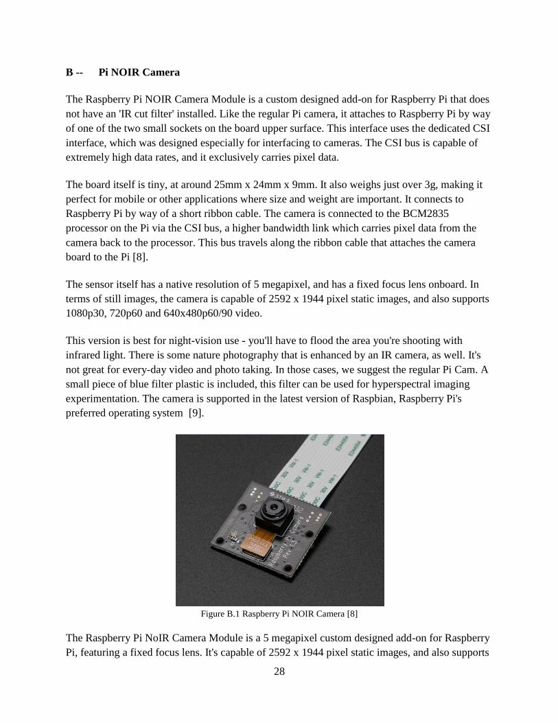
B -- Pi NOIR Camera
The Raspberry Pi NOIR Camera Module is a custom designed add-on for Raspberry Pi that does
not have an 'IR cut filter' installed. Like the regular Pi camera, it attaches to Raspberry Pi by way
of one of the two small sockets on the board upper surface. This interface uses the dedicated CSI
interface, which was designed especially for interfacing to cameras. The CSI bus is capable of
extremely high data rates, and it exclusively carries pixel data.
The board itself is tiny, at around 25mm x 24mm x 9mm. It also weighs just over 3g, making it
perfect for mobile or other applications where size and weight are important. It connects to
Raspberry Pi by way of a short ribbon cable. The camera is connected to the BCM2835
processor on the Pi via the CSI bus, a higher bandwidth link which carries pixel data from the
camera back to the processor. This bus travels along the ribbon cable that attaches the camera
board to the Pi [8].
The sensor itself has a native resolution of 5 megapixel, and has a fixed focus lens onboard. In
terms of still images, the camera is capable of 2592 x 1944 pixel static images, and also supports
1080p30, 720p60 and 640x480p60/90 video.
This version is best for night-vision use - you'll have to flood the area you're shooting with
infrared light. There is some nature photography that is enhanced by an IR camera, as well. It's
not great for every-day video and photo taking. In those cases, we suggest the regular Pi Cam. A
small piece of blue filter plastic is included, this filter can be used for hyperspectral imaging
experimentation. The camera is supported in the latest version of Raspbian, Raspberry Pi's
preferred operating system [9].
Figure B.1 Raspberry Pi NOIR Camera [8]
The Raspberry Pi NoIR Camera Module is a 5 megapixel custom designed add-on for Raspberry
Pi, featuring a fixed focus lens. It's capable of 2592 x 1944 pixel static images, and also supports

29
1080p30, 720p60 and 640x480p60/90 video. It attaches to Pi by way of one of the small sockets
on the board upper surface and uses the dedicated CSi interface, designed especially for
interfacing to cameras. The board itself is tiny, at around 25mm x 20mm x 9mm. It also weighs
just over 3g, making it perfect for mobile or other applications where size and weight are
important. It connects to Raspberry Pi by way of a short ribbon cable.
The sensor itself has a native resolution of 5 megapixel, and has a fixed focus lens on-board. In
terms of still images, the camera is capable of 2592 x 1944 pixel static images, and also supports
1080p30, 720p60 and 640x480p60/90 video.
Features
5 megapixel native resolution sensor-capable of 2592 x 1944 pixel static images
Supports 1080p30, 720p60 and 640x480p60/90 video
Camera is supported in the latest version of Raspbian, Raspberry Pi's preferred operating
system
Camera is capable of 2592 x 1944 pixel static images
No Infrared filter making it perfect for taking Infrared photographs or photographing
objects in low light (twilight) conditions
1.4 µm X 1.4 µm pixel with Omni BSI technology for high performance (high sensitivity,
low crosstalk, low noise)
Optical size of 1/4"
Connection of Pi NOIR Camera with Rasp Module
The flex cable inserts into the connector situated between the Ethernet and HDMI ports, with the
silver connectors facing the HDMI port. The flex cable connector should be opened by pulling
the tabs on the top of the connector upwards then towards the Ethernet port. The flex cable
should be inserted firmly into the connector, with care taken not to bend the flex at too acute an
angle. The top part of the connector should then be pushed towards the HDMI connector and
down, while the flex cable is held in place.
30
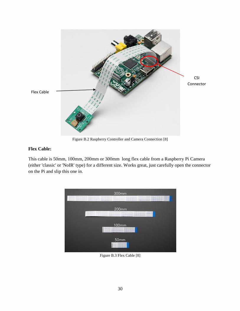
Figure B.2 Raspberry Controller and Camera Connection [8]
Flex Cable:
This cable is 50mm, 100mm, 200mm or 300mm long flex cable from a Raspberry Pi Camera
(either 'classic' or 'NoIR' type) for a different size. Works great, just carefully open the connector
on the Pi and slip this one in.
Figure B.3 Flex Cable [8]
CSI
Connector
Flex Cable

31
C -- Raspberry Pi Interfacing Using MATLAB® 2014
Raspberry Pi module and Pi NOIR camera can only be interface via MATLAB® version 2013
and 2014[10].
MATLAB® 2014
MATLAB® (“MATrix LABoratory”) is a tool for numerical computation and visualization. The
basic data element is a matrix, so if you need a program that manipulates array-based data it is
generally fast to write and run in MATLAB®. It is a high-performance language for technical
computing. It integrates computation, visualization, and programming in an easy-to-use
environment where problems and solutions are expressed in familiar mathematical notation.
Typical uses include: Math and computation.
MATLAB® 2014a Installation for Windows
1. To install MATLAB® 2014a, insert the MATLAB® flash drive, open the Windows
folder, and double click on setup. (On some 64 bit computers, you will need to go to the
BIN\WIN64 folder and run setup from there.)
2. In the MathWorks Installer window, select the radio button next to Use File Installation
Key and click Next.
3. In the License Agreement window, select the Yes radio button and then click Next

32
4. In the File Installation Key window, enter the file installation key found in the
MATLAB® 2014a key file PDF on the flash drive, and then click Next
5. In the folder selection window, click Next.
33
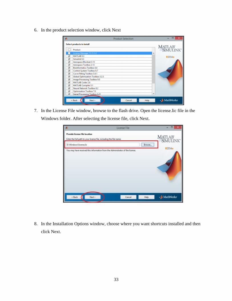
6. In the product selection window, click Next
7. In the License File window, browse to the flash drive. Open the license.lic file in the
Windows folder. After selecting the license file, click Next.
8. In the Installation Options window, choose where you want shortcuts installed and then
click Next.

34
9. In the Confirmation window, click Install
10. Now see the progress of the MATLAB® 2014a installation
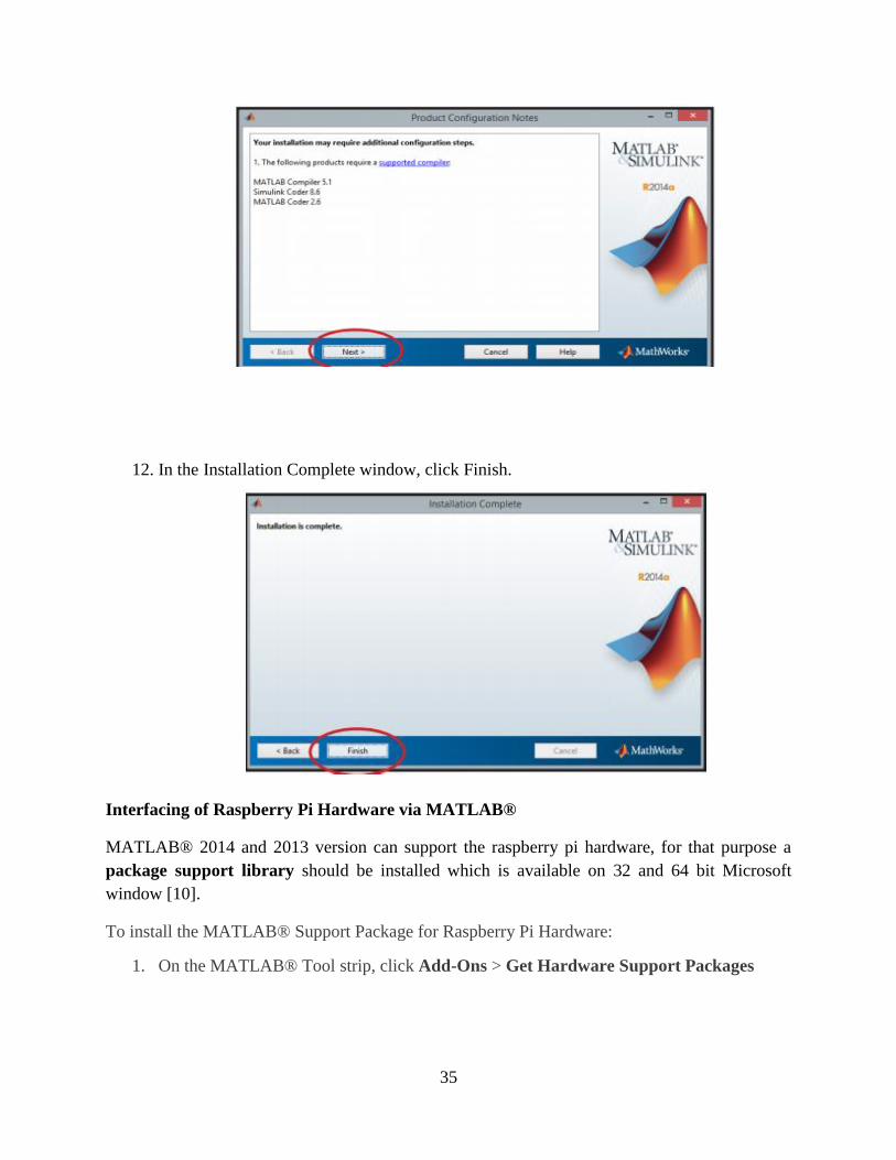
11. In the Product Configuration Notes window, click Next
35
12. In the Installation Complete window, click Finish.
Interfacing of Raspberry Pi Hardware via MATLAB®
MATLAB® 2014 and 2013 version can support the raspberry pi hardware, for that purpose a
package support library should be installed which is available on 32 and 64 bit Microsoft
window [10].
To install the MATLAB® Support Package for Raspberry Pi Hardware:
1. On the MATLAB® Tool strip, click Add-Ons > Get Hardware Support Packages
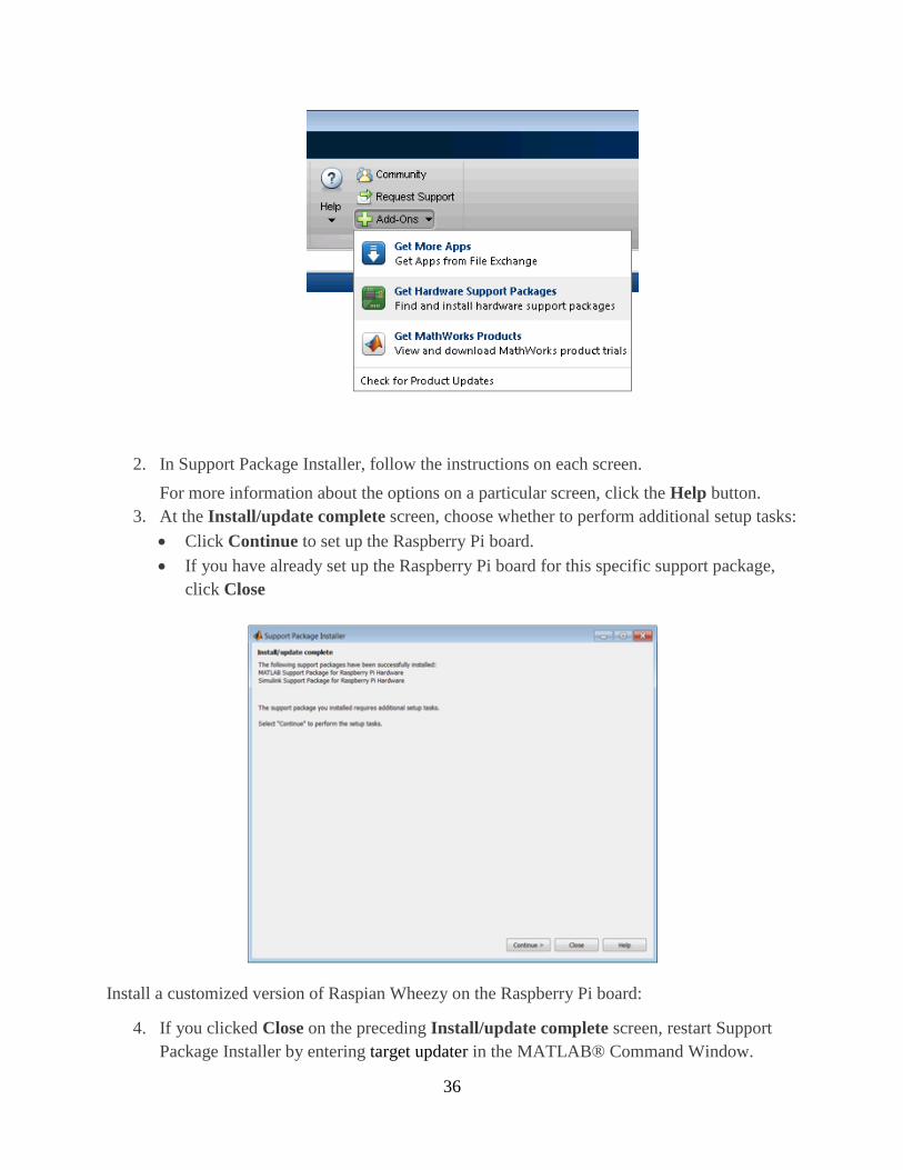
36
2. In Support Package Installer, follow the instructions on each screen.
For more information about the options on a particular screen, click the Help button.
3. At the Install/update complete screen, choose whether to perform additional setup tasks:
Click Continue to set up the Raspberry Pi board.
If you have already set up the Raspberry Pi board for this specific support package,
click Close
Install a customized version of Raspian Wheezy on the Raspberry Pi board:
4. If you clicked Close on the preceding Install/update complete screen, restart Support
Package Installer by entering target updater in the MATLAB® Command Window.

37
5. On the Set up support package screen, set Support package for to Raspberry Pi, and
click Next.
6. Select the board you are using, and click Next.
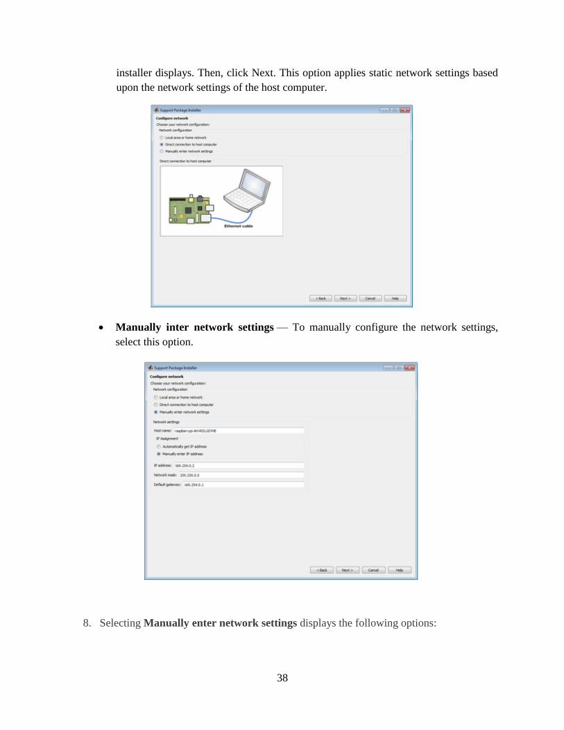
7. Choose your network configuration:
Local area or home network — Confirm that the Raspberry Pi hardware is
connected to your host computer using a local area network (LAN) or home network
similar to the ones that the installer displays. Then, click Next. This option applies
dynamic network settings provided by a DNS service on the network
Direct connection to host computer — Confirm that the Raspberry Pi hardware is
connected to your host computer using a direct connection similar to the one that the
38
installer displays. Then, click Next. This option applies static network settings based
upon the network settings of the host computer.
Manually inter network settings — To manually configure the network settings,
select this option.
8. Selecting Manually enter network settings displays the following options:
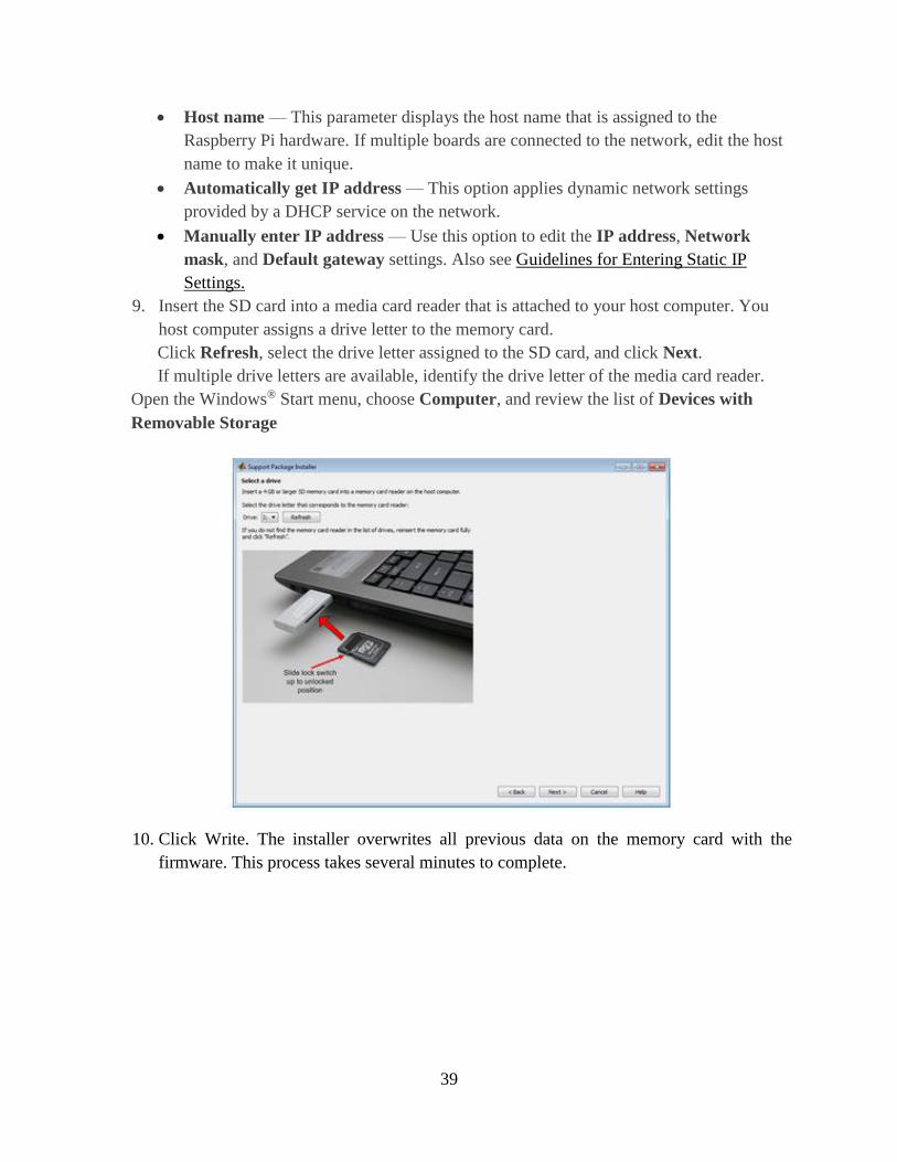
39
Host name — This parameter displays the host name that is assigned to the
Raspberry Pi hardware. If multiple boards are connected to the network, edit the host
name to make it unique.
Automatically get IP address — This option applies dynamic network settings
provided by a DHCP service on the network.
Manually enter IP address — Use this option to edit the IP address, Network
mask, and Default gateway settings. Also see Guidelines for Entering Static IP
Settings.
9. Insert the SD card into a media card reader that is attached to your host computer. You
host computer assigns a drive letter to the memory card.
Click Refresh, select the drive letter assigned to the SD card, and click Next.
If multiple drive letters are available, identify the drive letter of the media card reader.
Open the Windows® Start menu, choose Computer, and review the list of Devices with
Removable Storage
10. Click Write. The installer overwrites all previous data on the memory card with the
firmware. This process takes several minutes to complete.

40
11. Make the connections shown in the figure. When the PWR LED is solid red, and the
ACT or OK LED stops blinking, click Next
12. Keep a record of the IP address, host name, user name, and password. Then, click Test
Connection.
The installer uses SSH to create a test connection to the board using the host name, user
name, and password shown.
41
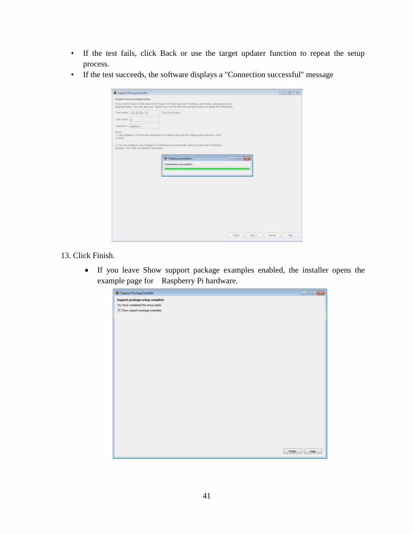
• If the test fails, click Back or use the target updater function to repeat the setup
process.
• If the test succeeds, the software displays a "Connection successful" message
13. Click Finish.
If you leave Show support package examples enabled, the installer opens the
example page for Raspberry Pi hardware.

42
14. For experience using MATLAB® software with Raspberry Pi hardware, complete the
examples.

43
D -- Stepper Motor and Driving Circuit
Stepper Motor
We used stepper motor to pane the camera from 0 to 180 degree (clock wise) and then 180 to 0
degree (anti clock wise), camera takes the images at each 0, 90 and 180 degree instant [11].
A stepper motor (or step motor) is a brushless DC electric motor that divides a full rotation into a
number of equal steps. The motor's position can then be commanded to move and hold at one of
these steps without any feedback sensor (an open-loop controller), as long as the motor is
carefully sized to the application.
Basic Winding Diagram:
Figure D.1 Stepper Motor Driving Connections
Source: Wikipedia

44
Figure D.2 Internal Structure of Stepper Motor [16]
Stepper Motor Wiring Color Code:
Figure D.3 Stepper Motor Wiring [11]
White lead is Common

45
Angle = 1.8 degree
200 steps per 360 degree rotation
0 – 90 degree = 50 steps
90 – 180 degree = 50 steps
180 – 270 degree = 50 steps
270 – 360 degree = 50 steps
We used only 100 steps of stepper motor from 0 to 180 degree and then used counter clock wise
rotation of motor from 180 to 0 degree to pane our camera.
Motor Power Ratings:
VEXTA Stepping Motor, Model PK268-01A-C18 [11].
Volts = 8.6 V
Amperes = 1 A
Phase = 2
Step Size = 1.8 degree
After the selection of an appropriate motor the technique to drive this motor also was difficult to
find because different techniques are used for driving of stepper motors like relays, transistors,
and controllers. Since we are using raspberry PI controller and it operates on 3.3v output
therefore it was a must need for us to find an appropriate IC to drive our motor.
ULN2003A (Driving IC)
We used ULN2003A IC which is consists of NPN Darlington transistor, for the motor driving
circuit.
The driver board contains a ULN2003A Darlington driver board. This little chip contains 7
Darlington transistors, these transistors allow the small current output from the Raspberry Pi to
control a bigger current (the stepper motor). The diodes in the IC are there to deal with the back
emf from the stepper motors coils. When the current is switched off to one of the coils, the
magnetic field around the coil collapses rapidly, this creates a high voltage spike across the coil
wire. This spike could damage the PI, so the diodes job is to dissipate this voltage safely [12].

46
Here is a circuit diagram that shows the driver board and the internal workings of the
ULN2003A IC.
Figure D.4 ULN2003A Connections and Structure [12]

47
Figure D.5 ULN2003A Logic Figure D.6 ULN2003A Pin Configuration
Source: Wikipedia Source: Wikipedia
A feasible water pump is also required in our project to achieve the final task which is to
extinguish the fire, we had briefly study about different water pumps and water thrower motors.
But the problem was that most of the pumps are AC pump, and we have the DC supply system
so we used a DC water pump.
PIN CONFIGURATION
Related Documents