FIRE DYNAMICS TOOLS An Educational Program to Improve the Level of Teaching Risk-Informed, Performance- based Fire Protection Engineering Assessment Methods 1

FIRE DYNAMICS TOOLS An Educational Program to Improve the Level of Teaching Risk-Informed, Performance- based Fire Protection Engineering Assessment Methods.
Dec 16, 2015
Welcome message from author
This document is posted to help you gain knowledge. Please leave a comment to let me know what you think about it! Share it to your friends and learn new things together.
Transcript
FIRE DYNAMICS TOOLS
An Educational Program to Improve the Level of Teaching Risk-Informed, Performance-
based Fire Protection Engineering Assessment Methods
1
RESOURCES PROVIDED
• All Participants will be given at the end of the course, a CD-ROM containing:– Handouts and visuals used in presentations– Reference materials, real-world example FHAs,
and the latest version of FDTs– “Fire Dynamics Tools (FDT s) Quantitative Fire
Hazard Analysis Methods for the U.S. Nuclear Regulatory Commission Fire Protection Inspection Program,” (NUREG-1805.1, June 2005).
– “Verification and Validation of Selected Fire Models for Nuclear Power Plant Applications,” (NUREG-1824/EPRI 1011999, May 2007)
2

INTRODUCTION
3

INTRODUCTION
• The U.S. Nuclear Regulatory Commission (NRC) has developed quantitative methods, known as the Fire Dynamics Tools (FDTs) to assist in performing Fire Hazard Analyses (FHAs) known as NUREG 1805.
• This methodology has been implemented in Exceltm spreadsheets
• The goal of this effort is to provide first-order calculations of potential postulated scenarios at nuclear power plants.
4

OBJECTIVES
• Provide basic calculation methodology for use in assessing potential fire hazards in NRC-licensed nuclear power plants (NPPs).
• The methodology uses simplified fire hazard analysis (FHA) techniques for credible fire scenarios.
• The FDTs spreadsheets are designed to incorporated empirical correlations and mathematical calculations based upon fire dynamics principles.
5
REGULATORY BACKGROUND
• “General Requirements” in Appendix R (10 CFR 50) states a fire protection program shall:–Prevent fires from starting–Rapidly detect, control, and extinguish
fires that do occur–Protect structures, systems, and
components
6

REGULATORY OBJECTIVES
• FHAs for Nuclear Power Plants should:– Consider the potential for transient fire
hazards– Determine the consequences of fire in any
location in the plant– Pay attention to safe reactor shutdown while
minimizing the chances for radioactive material releases
– Specify measures for fire detection, suppression, containment, and prevention.
7

COMMON NPP FIRE HAZARDS
• Combustible Solid Fuels– Cable insulation and pipe insulation– Building materials, combustible roof deck– Filtering, packing, and sealing materials– Low level radioactive wastes
• Combustible and Flammable Liquid Fuels– Lubricants, hydraulic oil, and control fuels
• Explosive and Flammable Gaseous Fuels– Hydrogen– Propane
8
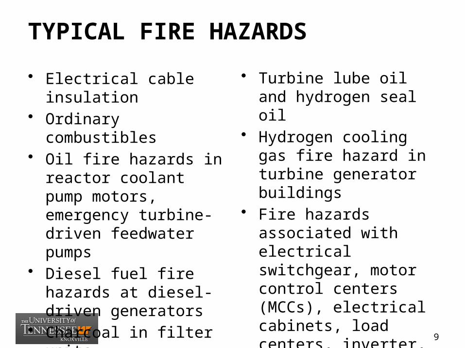
• Electrical cable insulation• Ordinary combustibles• Oil fire hazards in reactor
coolant pump motors, emergency turbine-driven feedwater pumps
• Diesel fuel fire hazards at diesel-driven generators
• Charcoal in filter units• Flammable off gases• Protective coatings
• Turbine lube oil and hydrogen seal oil
• Hydrogen cooling gas fire hazard in turbine generator buildings
• Fire hazards associated with electrical switchgear, motor control centers (MCCs), electrical cabinets, load centers, inverter, circuit boards, and transformers
TYPICAL FIRE HAZARDS
9

NPP FIRE SCENARIOS
(NUREG 1824)
10

NPP SCENARIOS (NUREG 1824)
• Switchgear Room• Cable Spreading
Room• Main Control
Room• Pump Room• Turbine Building• Multi-
Compartment Corridor
• Multi-Level Building
• Containment Building
• Battery Room• Computer or Relay
Room• Outdoors
11

SWITCHGEAR ROOM FIRE
12

CABLE SPREADING ROOM FIRE
13
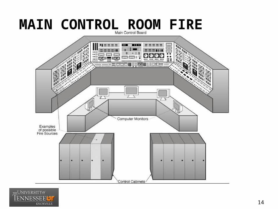
MAIN CONTROL ROOM FIRE
14
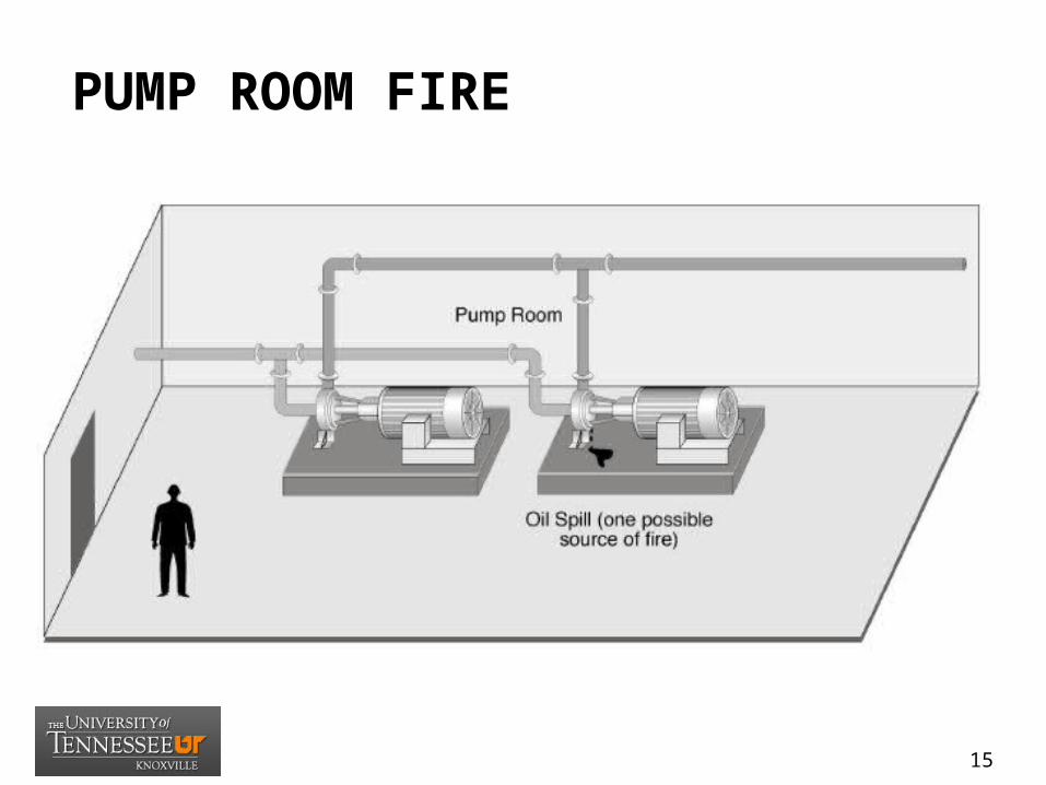
PUMP ROOM FIRE
15

TURBINE BUILDING ROOM FIRE
16

MULTI-COMP. CORRIDOR FIRE
17

MULTI-LEVEL BUILDING FIRE
18
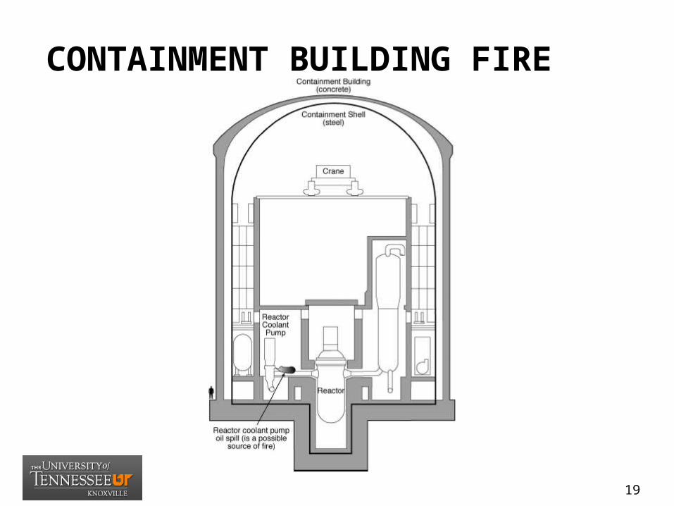
CONTAINMENT BUILDING FIRE
19
FHAS USING FIRE MODELS
20
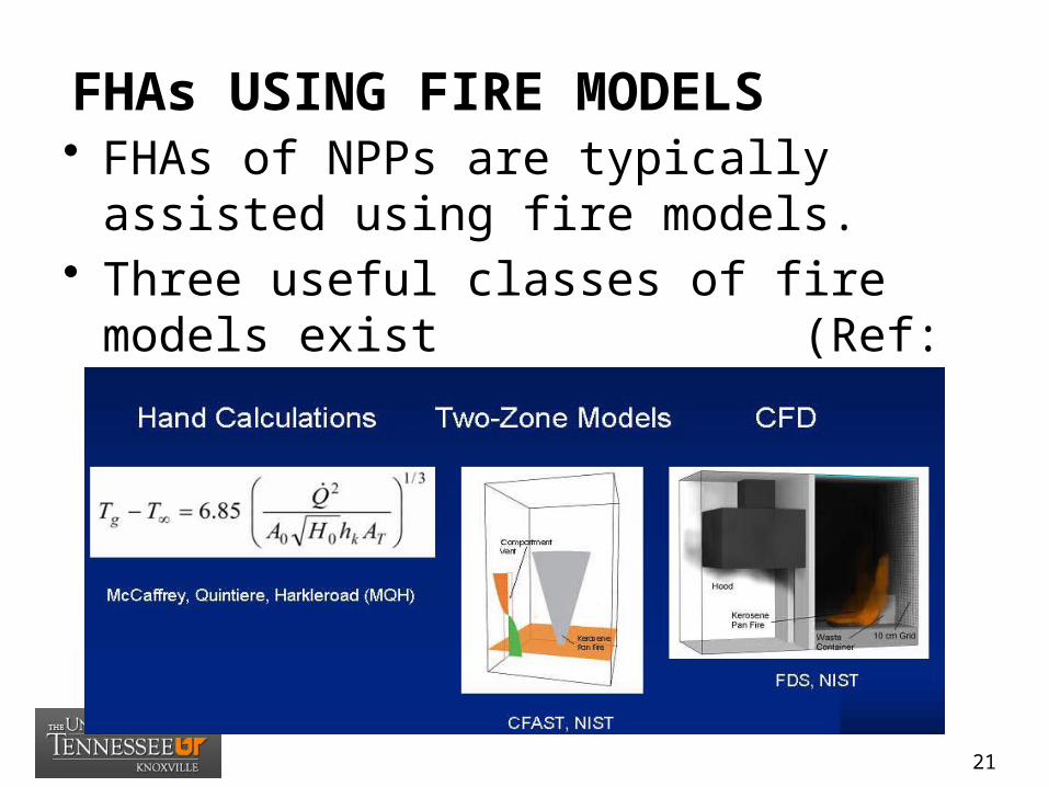
FHAs USING FIRE MODELS• FHAs of NPPs are typically assisted using
fire models.• Three useful classes of fire models exist
(Ref: NIST, RIC 2007):
21

FIRE MODELING OUTPUTS
22

FIRE MODELING PARAMETERS
• (1) Hot gas layer temperature: This temperature is particularly important in NPP fire scenarios because it can provide an indication of target damage away from the ignition source. Models predict the increase in environmental temperature attributable to the energy released by a fire in a volume.
23

FIRE MODELING PARAMETERS
• (2) Hot gas layer height: The height of the hot gas layer is also important in NPP fire scenarios because it indicates whether a given target is immersed in and affected by hot gas layer temperatures.
24
FIRE MODELING PARAMETERS
• (3) Ceiling jet temperature: The ceiling jet is the shallow layer of hot gases that spreads radially below the ceiling as the fire plume flow impinges on it. This layer of hot gases has a distinct temperature that is higher than the temperature associated with the hot gas layer. This attribute is important in NPP fire scenarios that subject targets to unobstructed ceiling jet gases.
25
FIRE MODELING PARAMETERS
• (4) Plume temperature: The fire plume is the buoyant flow rising above the ignition source, which carries the hot gases that ultimately accumulate in the upper part of a room to form the hot gas layer. The plume is characterized by a distinct temperature profile, which is expected to be higher than the ceiling jet and hot gas layer. This attribute is particularly important in NPP fires because of the numerous postulated scenarios that involve targets directly above a potential fire source.
26
FIRE MODELING PARAMETERS
• (5) Flame height: The height of the flame is important in those NPP fire scenarios where targets are located close to the ignition source. Some of these scenarios subject the target to flame temperatures because the distance between the target and the ignition source is less than the predicted flame height. A typical example would be cable trays above an electrical cabinet.
27

FIRE MODELING PARAMETERS
• (6) Radiated heat flux to targets: Radiation is an important mode of heat transfer in fire events. The modeling tools within the scope of this study address fire-induced thermal radiation (or radiated heat flux) with various levels of sophistication, from simply estimating flame radiation, to calculating radiation from different surfaces and gas layers in the computational domain.
28
FIRE MODELING PARAMETERS
• (7) Total heat flux to targets: In contrast to thermal radiation (or radiated heat flux), the total heat flux a target is subjected includes convective heat transfer. Convective heat transfer is a significant contributor to target heat-up in scenarios that involve targets in the hot gas layer, ceiling jet, or fire plume.
29

FIRE MODELING PARAMETERS
• (8) Total heat flux to walls: This attribute evaluates the incident heat flux to walls, floors, and ceilings, which includes the contributions of radiation and convection. Because the heat conducted through the walls, floors, and ceilings does not contribute to room heat up, it can be an important factor in the heat balance in control volume(s) in contact with the surfaces.
30

FIRE MODELING PARAMETERS
• (9) Wall temperature: This attribute was included as a separate attribute in this study to evaluate model capabilities to determine the temperature of walls, floors, and ceilings.
31

FIRE MODELING PARAMETERS
• (10) Target temperature: The calculation of target temperature is perhaps the most common objective of fire modeling analyses. The calculation of target temperature involves an analysis of localized heat transfer at the surface of the target after determining the fire induced conditions in the room.
32

FIRE MODELING PARAMETERS
• (11) Smoke concentration: The smoke concentration can be an important attribute in NPP fire scenarios that involve rooms where operators may need to perform actions during a fire. This attribute specifically refers to soot concentration, which affects how far a person can see through the smoke (visibility).
33

FIRE MODELING PARAMETERS
• (12) Oxygen concentration: This is an important attribute potentially influencing the outcome of fires in NPPs because of the compartmentalized nature of NPPs. Oxygen concentration has a direct influence on the burning behavior of a fire, especially if the concentration is relatively low.
34
FIRE MODELING PARAMETERS
• (13) Room pressure: Room pressure is a rarely used attribute in NPP fire modeling. It may be important when it contributes to smoke migration to adjacent compartments.
35

HAZARD METHODOLOGY
• Tier A – Material Properties–A1 – (08) Burning duration of
solids–A2 – (07) Heat Release Rate of
cable tray fires–A3 – (03) Burning characteristics
of liquid pool fires (HRR, burning duration, flame height)
36

HAZARD METHODOLOGY
• Tier B – Plume Development–B1 – (09) Center line temperature of a
fire plume–B2 – (04) Flame height calculations
(wall, line, corner)–B3 – (05) Estimate radiant heat flux to
target fuel–B4 – (06) Ignition temperature of a
target fuel
37

HAZARD METHODOLOGY
• Tier C – Compartment Factors– C1 – (02) Prediction of hot gas layer temperature– C2 – (10, 11, 12) Estimating detector/sprinkler
response times– C3 – (13) Predicting compartment flashover– C4 – (14, 15) Predicting pressure rise in closed
compartment, explosion pressure– C5 – (16) Predicting rate of hydrogen gas generation– C 6 – (17) Calculating fire resistance of structural
members
38

HAZARD METHODOLOGY
• Tier D – Tenability (Hazard Criteria)– D1 – (18) Estimating visibility through smoke– D2 – Heat release rate – D3 – Radiant heat exposure (2.5 kW/m2)– D4 – Layer temperature (100oC)– D5 – Layer smoke density (0.2/m)– D6 – Layer Carbon Monoxide (3,000 ppm)– D7 – Layer Oxygen (10 percent or less)
39

RECENT STUDIES
• “Comparison of Three Fire Models in the Simulation of Accidental Fires,”G. Rein, A. Bar-Ilan, and A.C. Fernandez-Pello, University of California at Berkeley; and N. Alvares, Fire Sciences Applications, San Carlos, California, 2004.
Study applied and compared the predictive capabilities of Analytical, CFAST Zone, and FDS Field Models to three accidental fires
Findings were these three models produced results in relatively good agreement, particularly in early stages of fire development
40
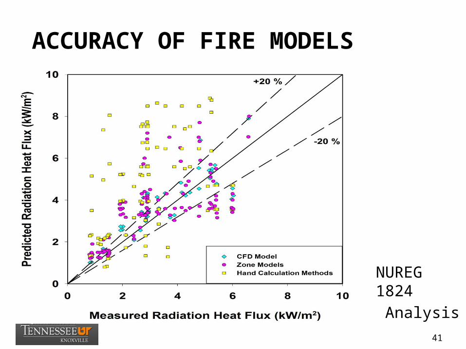
ACCURACY OF FIRE MODELS
• NUREG 1824
• Analysis
41

ACCURACY OF FIRE MODELS• NUREG 1824 Analysis
42

FIRE DYNAMICS TOOLS(TIER A)
43

HAZARD METHODOLOGY
• Tier A – Material Properties–A1 – (08) Burning duration of
solids–A2 – (07) Heat Release Rate of
cable tray fires–A3 – (03) Burning characteristics
of liquid pool fires (HRR, burning duration, flame height)
44
ESTIMATING BURNING DURATION OF SOLID COMBUSTIBLES
(NUREG 1805 -Chap 8)
08_Burning_Duration_Solid.xls
45

OBJECTIVES
• ESTIMATING BURNING DURATION OF SOLID COMBUSTIBLES
• Introduce factors that influence the fire duration of solid combustibles.
• Explain how to estimate fire durations for various solid combustibles.
• Approximate first order estimates of burning durations.
46

BURNING DURATION
• The burning duration is the time between ignition and the decay phase of a fire.
• The burning duration (fire) for a given compartment size and ventilation condition is driven by the fuel load.
• Given the mass of material being burned per second and the amount of material available to be consumed, it is possible to calculate a first order estimate for the total burning duration of a fuel.
47

BURNING DURATION• The burning duration of solid combustibles can
be estimated if the HRR and total energy contained in the fuel are known.
fuel csolid
fuel
m HEt
Q Q A
fuelA LW
48

ASSUMPTIONS/LIMITATIONS
• (1) Combustion is incomplete (leaving some residual fuel) and takes place entirely within the confines of the compartment.
• (2) Virtually all of the potential energy in the fuel is released in the involved compartment.
49

INPUT NEEDED
• (1) fuel type (material)• (2) mass of solid fuel • (3) exposed fuel surface area
50

PROBLEM SET
• Problem Statement (8.9-1)– A horizontal power cable fails as a result of
self-initiated fire and burn in a compartment. – Compute the burning duration of a cable tray
with an exposed surface area of 1 ft 2 filled with 10 lb of non-IEEE-383-qualified PE/PVC cables. The heat release per unit floor area of PE/PVC is 589 kW/m2, and the heat of combustion is 24,000 kJ/kg.
51

ESTIMATING THE FULL-SCALE HEAT RELEASE RATE OF A CABLE TRAY FIRE
(NUREG 1805 -Chap 7)
07_Cable_HRR_Calculations.xls
52

OBJECTIVES
• ESTIMATING THE FULL-SCALE HEAT RELEASE RATE OF A CABLE TRAY FIRE
• Describe the numerous functions that electrical cables perform in a nuclear power plant (NPP).
• Explain the factors that determine how a cable will behave in a fire.
• Describe the ways that fires can occur in cable tray installations and combustion reactions.
• Explain the processes that electrical failures can initiate in a cable tray.
53
CABLE TRAY FIRE HISTORY
• Fires in grouped electrical cable trays pose distinct fire hazards in power generating facilities.
• In the past, cable tray installations have caused fires that resulted in serious damage to NPPs.
• The 1975 fire at TVA’s Browns Ferry Nuclear Power Plant demonstrated the vulnerability of electric cables installed in an NPP when exposed to elevated temperatures as a result of a fire.
• In response, the NRC issued fire protection requirements in 10 CFR 50.48 and Appendix R to 10 CFR Part 50.
54
USE OF ELECTRICAL CABLES
• Power cables that supply electricity to motors, transformers, and heaters
• Lighting cables that supply electricity to normal lighting fixtures and fluorescent lighting ballasts
• Control cables that interconnect plant equipment to remote initiating devices (e.g., switches, relays, and contacts)
• Instrumentation cables that transmit low-voltage signals between devices (e.g., readout panels)
• Communication cables (telephone lines)• Heat tracing cables.
55
BEHAVIOR IN FIRES
• Electrical cables constitute a serious fire hazard for NPPs because the combustible polymeric insulation and jacket material are present in large quantities. This large fuel load can cause NPP fires to burn for extended periods
• The behavior of cables in a fire depends on: (1) their constituent materials and construction, (2) their location, and (3) installation geometry.
• Cable tray fires scenarios include (1) fire within a cable tray and (2) as exposure fire the subsequently ignites the cable tray.
56

CABLE TRAY HRR
• The peak full-scale HRR from a cable tray fire can be predicted according to the bench-scale HRR measurements.
0.45fs bs fQ Q A
57
ASSUMPTIONS/LIMITATIONS
• (1) This correlation is based on the data obtained from flaming fire of cable samples.
• (2) A complex cable tray configuration may be present in many NPPs. For very complex cable tray arrays, the above correlation would give a less accurate approximation for the HRR.
• (3) The equation should be used to calculate the HRR for any type of cable.
58

INPUT NEEDED
• (1) cable type (material)• (2) exposed cable tray burning area
59

PROBLEM SET
• Problem Statement (7.12-1)– A 32-gallon trash can exposure fire source is
located 2 m (6.5 ft) beneath a horizontal cable tray. It is assumed that the trash fire ignites an area of approximately 2 m2 (21 ft2) of the cable tray.
– The cables in the tray are IEEE-383 unqualified and made of PE/PVC insulation material.
– Compute the full-scale HRR of the PE/PVC cable insulation. The bench-scale HRR of PE/PVC is 589 kW/m2
60
BURNING CHARACTERISTICS OF LIQUID POOL FIRE, HEAT RELEASE RATE, BURNING DURATION, AND FLAME HEIGHT
(NUREG 1805 –Chap 3)
03_HRR_Flame_Height_Burning_Duration_Calculations.xls
61

OBJECTIVES
• PREDICTING BURNING CHARACTERISTICS OF LIQUID POOL FIRE, HEAT RELEASE RATE, BURNING DURATION, AND FLAME HEIGHT
• Identify the predominant flammable material in a nuclear power plant (NPP).
• Introduce the methods and factors that influence estimates of the heat release and burning rate of pool fires.
• Explain how to analyze the burning duration of object and pool fires.
62

POOL FIRE DYNAMICS FEATURES
,c effQ m H
, 1f
k Dc effQ m H A e
63

POOL FIRE BURNING DURATION
2
4b
Vt
D v
mv
64

FLAME HEIGHT CALCULATIONS• Heskestad
• Thomas
65
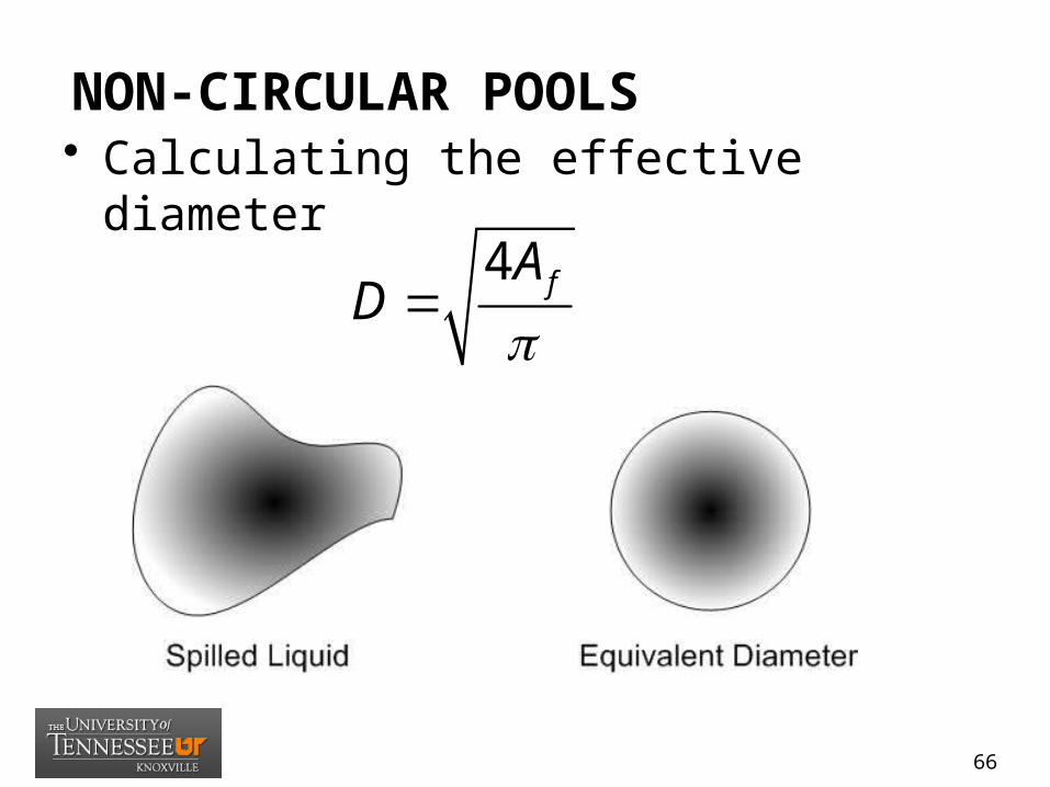
NON-CIRCULAR POOLS• Calculating the effective diameter
4 fAD
66

INPUT NEEDED• Steps to estimate the burning duration of a pool
fire:– (1) Determine the regression rate of the pool fire.– (2) Calculate the equivalent diameter of the pool fire.– (3) Calculate the burning duration of the pool fire.
• Input needed:– (1) fuel spill volume– (2) fuel spill area or dike area– (3) fuel type
67

INPUT NEEDED• Steps to estimate the flame height of a
pool fire:– (1) Determine the HRR of the pool fire.– (2) Calculate the equivalent diameter of the
pool fire.– (3) Determine the height of the pool fire flame.
• Input needed:– (1) fuel spill volume– (2) fuel spill area or dike area– (3) fuel type
68
ASSUMPTIONS/LIMITATIONS
• (1) The flame height correlation described in this chapter was developed for horizontal pool fire sources in the center or away from the center of the compartment.
• (2) The size of the fire (flame height) depends on the diameter of the fuel and the HRR attributable to the combustion.
• (3) This correlation method is developed for two-dimensional sources (primarily pool fires) assumes that the pool is circular or nearly circular.
• (4) There is no fire growth period. (the pool fire instantaneously reaches its maximum HRR.)
69
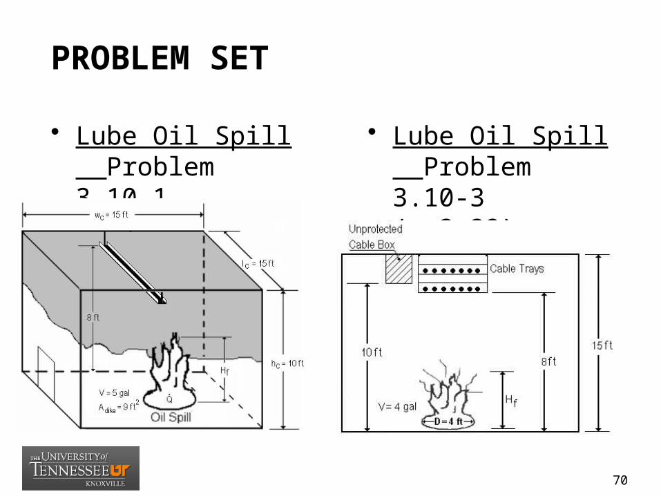
PROBLEM SET
• Lube Oil Spill Problem 3.10-1 (p. 3-22)
• Lube Oil Spill Problem 3.10-3 (p.3-32)
70

FIRE DYNAMICS TOOLS(TIER B)
71

HAZARD METHODOLOGY
• Tier B – Plume Development–B1 – (09) Center line temperature of a
fire plume–B2 – (04) Flame height calculations
(wall, line, corner)–B3 – (05) Estimate radiant heat flux to
target fuel–B4 – (06) Ignition temperature of a
target fuel
72
ESTIMATING THE CENTERLINE TEMPERATURE OF A BUOYANT FIRE PLUME
(NUREG 1805 -Chap 9)
09_Plume_Temperature_Calculations.xls
73

OBJECTIVES
• ESTIMATING THE CENTERLINE TEMPERATURE OF A BUOYANT FIRE PLUME
• Discuss various types of fire plumes.• Discuss the fire plume that is most common
encountered.• Identify the temperature and flow characteristics of the
fire plume.• Define relevant terms including fire plume, air
entrainment, plume temperature, ceiling jet, and virtual origin. 74

FIRE PLUMES• A fire plume is a buoyantly rising column of hot
combustion products, along with unburned fuel vapor and mixed with air.
• The turbulent column of hot gases rises because of buoyancy differences. This causes rapid mixing of the hot gases with the cooler surrounding air, which decreases its velocity, widens the column, and reduces its temperature.
• Temperature, velocity, and mass flow rates of the fire plume above the flame are critical to the many technical aspects of fire growth in a compartment.
75
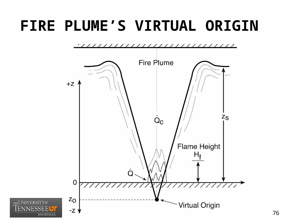
FIRE PLUME’S VIRTUAL ORIGIN
76

CENTERLINE TEMPERATURE
77

VIRTUAL ORIGIN
78
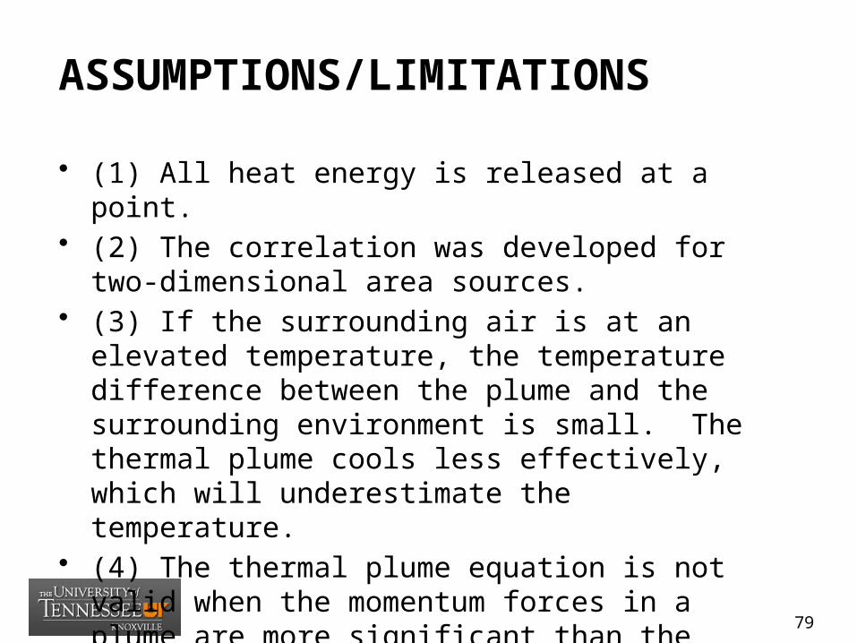
ASSUMPTIONS/LIMITATIONS
• (1) All heat energy is released at a point.• (2) The correlation was developed for two-dimensional
area sources.• (3) If the surrounding air is at an elevated temperature,
the temperature difference between the plume and the surrounding environment is small. The thermal plume cools less effectively, which will underestimate the temperature.
• (4) The thermal plume equation is not valid when the momentum forces in a plume are more significant than the buoyant forces, as in a jet fire.
79
INPUT NEEDED
• (1) heat release rate of the fire • (2) distance from the top of the fuel to the
ceiling• (3) surface area of the combustible fuel
80

PROBLEM SET
• Problem Statement (9.11-1)– A steel beam is located 25 ft above the floor.
Calculate the temperature of the beam exposed from a 34.5 ft lube oil pool 2 fire. Assume the HRR of the fire is 5,000 kW.
• Solution– (1) Calculate the diameter of the fire.– (2) Calculate the virtual origin of the fire.– (3) Calculate the convective HRR.– (4) Calculate the plume centerline temperature Tp(centerline).
81

ESTIMATING WALL FIRE FLAME HEIGHT, LINE FIRE FLAME HEIGHT AGAINST THE WALL, AND CORNER FIRE FLAME HEIGHT
(NUREG 1805 -Chap 4)
04_Flame_Height_Calculations.xls
82
OBJECTIVES
• ESTIMATING WALL FIRE FLAME HEIGHT, LINE FIRE FLAME HEIGHT AGAINST THE WALL, AND CORNER FIRE FLAME HEIGHT
• Identify the three regions of a diffusion flame.• Explain how corners and walls affect flames.• Define relevant terms, including persistent
flame region, intermittent flame region, flame height, and flame extension.
83
FIRE PLUME FLAME HEIGHTS
• If a fire is located close to a wall or a corner, the resulting restriction on free air entrainment will have a significant effect on fire growth and spread.
• The primary impact of walls and corners is to reduce the amount of entrained air available to the flame or plume.
• This lengthens flames and causes the temperature in a plume to be higher at a given elevation than it would be in the open.
84

FIRE PLUME FLAME HEIGHTS
• When a diffusion flame develops and is in contact with the wall, its structure can be subdivided into three regions: (1) persistent flame region, (2) intermittent flame region, and (3) buoyant plume region.
• As the plume rises to the ceiling, its direction changes from vertical (upward) to horizontal. Until the point where the flow changes direction, the plume is primarily driven by buoyancy.
• The resulting plume is driven by its residual momentum and becomes a jet, which is referred to as the “ceiling jet.”
85

FIRE PLUME FLAME HEIGHTS
86
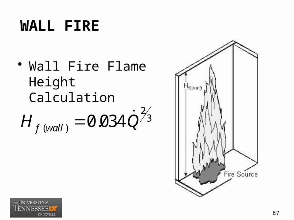
WALL FIRE
• Wall Fire Flame Height Calculation
23
( ) 0.034f wallH Q
87

LINE FIRE
• Line Fire Flame Height Calculation
23
( , ) 0.017f Wall LineH Q
88
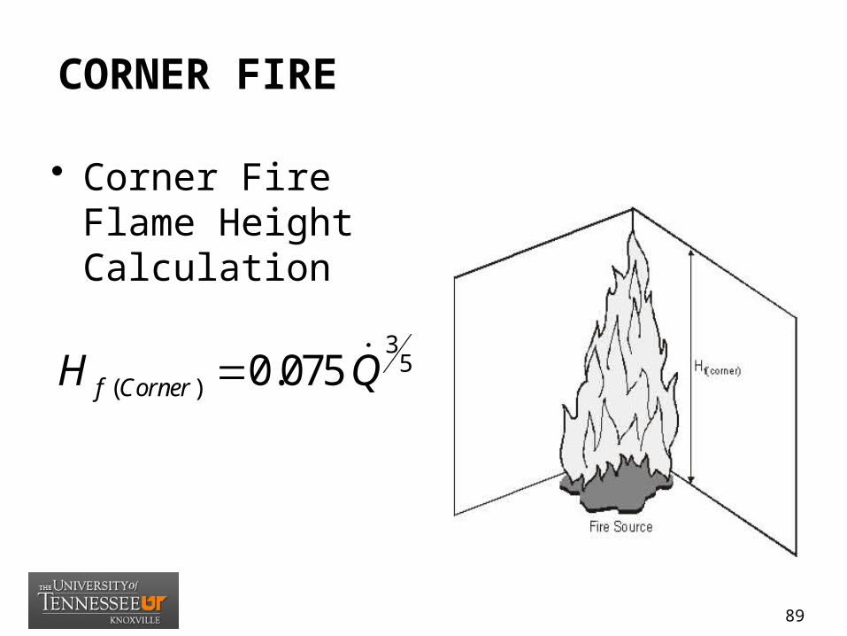
CORNER FIRE
• Corner Fire Flame Height Calculation
35
( ) 0.075f CornerH Q
89

ASSUMPTIONS/LIMITATIONS
• (1) This method includes correlations for flame height for liquid fire.
• (2) The size of the fire (flame height) depends on the length of the fire.
• (3) This correlation is developed for two-dimensional sources. The turbulent diffusion flames produced by fires burning at or near a wall configuration of a compartment affect the spread of the fire.
• (4) Air is entrained only from one side during the combustion process.
90
INPUT NEEDED
• (1) fuel type • (2) fuel spill volume • (3) fuel spill area
91
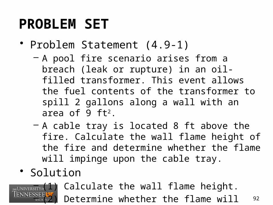
PROBLEM SET• Problem Statement (4.9-1)
– A pool fire scenario arises from a breach (leak or rupture) in an oil-filled transformer. This event allows the fuel contents of the transformer to spill 2 gallons along a wall with an area of 9 ft2.
– A cable tray is located 8 ft above the fire. Calculate the wall flame height of the fire and determine whether the flame will impinge upon the cable tray.
• Solution– (1) Calculate the wall flame height.– (2) Determine whether the flame will impinge upon the
cable tray.
92
ESTIMATING RADIANT HEAT FLUX FROM A FIRE TO A TARGET FUEL
(NUREG 1805 -Chap 5)
05.1_Heat_Flux_Calculations_Wind_Free.xls
93
OBJECTIVES
• ESTIMATING RADIANT HEAT FLUX FROM A FIRE TO A TARGET FUEL
• Introduce the three modes of heat transfer.• Explain how to calculate the heat flux from a
flame to a target outside the flame.• Discuss point source radiation models and
solid flame radiation models.
94

CRITICAL HEAT FLUX TO TARGET
• The incident heat flux (the rate of heat transfer per unit area) that is normal to the direction of heat flow is a total of heat transmitted by radiation, conduction, and convection required to raise the surface of a target to a critical temperature.
• Measured critical heat flux levels for representative cable samples typically range from 15 to 25 kW/m2. For screening purposes, it is appropriate to use value of 10 kW/m2 for IEEE-383 qualified cable and 5 kW/m2 for IEEE-383 unqualified cable.
95

CRITICAL HEAT FLUX TO TARGET
• Fire involving flammable and combustible liquids typically have higher heat release rates (for the same area of fuel involved) than ordinary combustibles fires.
• The flame from a liquid fire is typically taller, making it a better radiator.
• Hydrocarbon liquid fires are also quite luminous because of the quantity of soot in the flames, making them better emitters of thermal radiation. Thus, a flammable/combustible liquid fire feels more heat than an ordinary combustibles fire of comparable size.
96
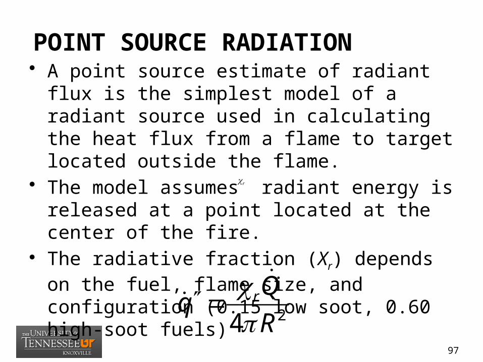
POINT SOURCE RADIATION• A point source estimate of radiant flux is the
simplest model of a radiant source used in calculating the heat flux from a flame to target located outside the flame.
• The model assumes radiant energy is released at a point located at the center of the fire.
• The radiative fraction (Xr) depends on the fuel, flame size, and configuration (0.15 low soot, 0.60 high-soot fuels)
24rQqR
r
97
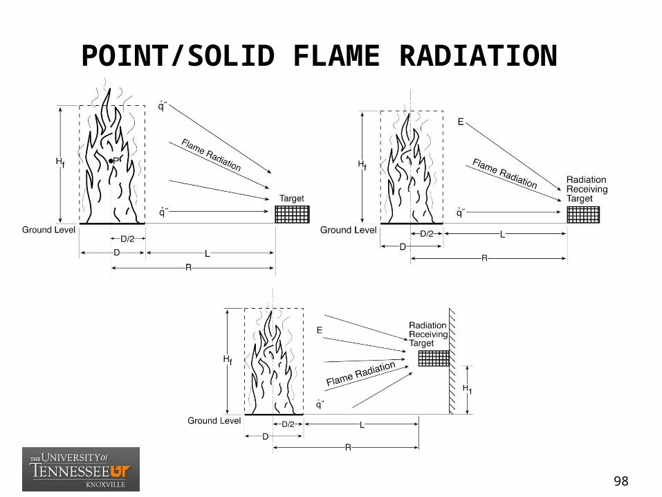
POINT/SOLID FLAME RADIATION
98
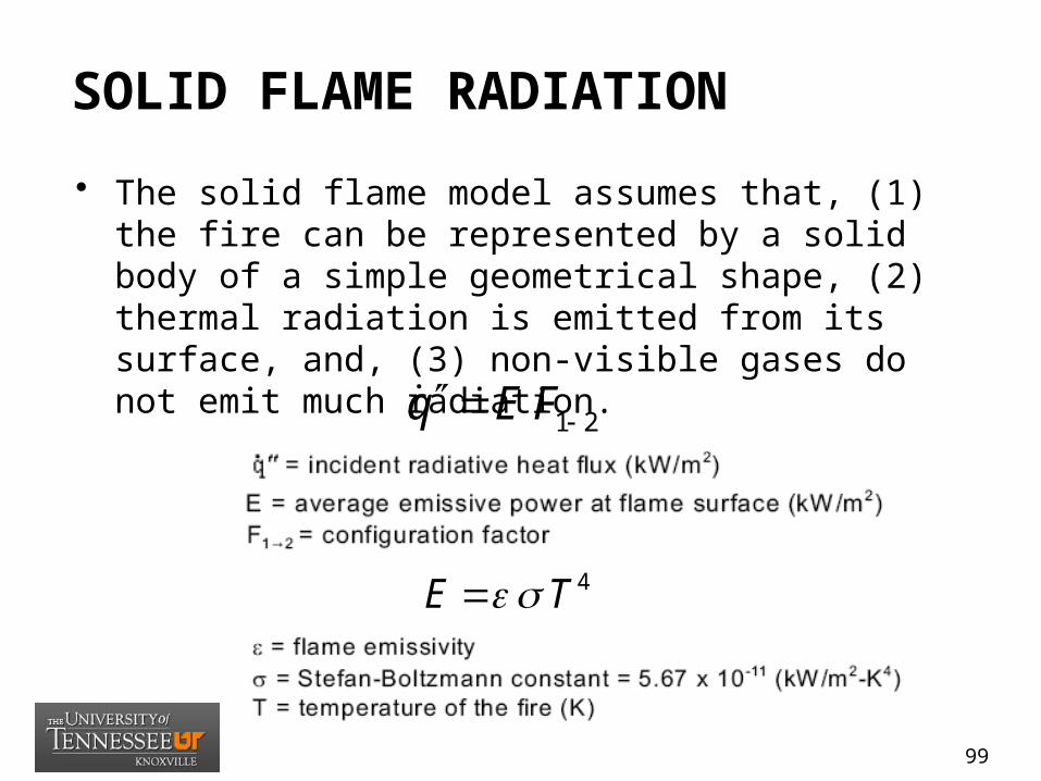
SOLID FLAME RADIATION
• The solid flame model assumes that, (1) the fire can be represented by a solid body of a simple geometrical shape, (2) thermal radiation is emitted from its surface, and, (3) non-visible gases do not emit much radiation.
1 2q E F
4E T
99

HYDROCARBON FIREBALL
• Variables impacting a fireball’s thermal radiation hazard: (1) the mass of fuel involved, (2) the fireball’s diameter, (3) duration, and (4) thermal emissive power.
• Radiation received by an object relatively distant from the fireball can be calculated by:
0.771
2
828 Fr
mq
R
100

HYDROCARBON FIREBALL• Distance from center of fireball to target
• Fireball flame height
• Fireball volumeF
FF
mV
101

ASSUMPTIONS/LIMITATIONS
• (1) The pool fires are circular or nearly circular.• (2) Except near the base of pool fires, radiation to the
surroundings can be approximated as being isotropic or emanating from a point source.
• (3) The point source model overestimates the intensity of thermal radiation at the observer’s (target) locations close to the fire.
• (4) A theoretical analysis of radiation from small pool fire by Modak (1977) indicated that the point source model is within 5-percent the correct incident heat flux when L/D >2.5.
102

ESTIMATING THERMAL RADIATION
• (1) Characterize the geometry of the pool fire• (2) Characterize the radiative properties of the fire
(emissive power).• (3) Calculate the radiant intensity at a given location. • (4) Determine the height of the pool fire.• (5) Calculate the view or configuration factor.• (6) Determine the effective emissive power of the
flame.• (7) Calculate the radiative heat flux to the target.
103

INPUT NEEDED
• (1) fuel type • (2) fuel spill area or curbed area• (3) distance between fire and target• (4) vertical distance of target from ground
level• (5) wind speed
104
PROBLEM SET
• Problem Statement (5.11-1)– A pool fire scenario arises from a breach (leak or
rupture) in a transformer where the fuel contents spills and spreads over the compartment floor. The compartment is large and has a high ceiling. A pool fire ensues with a spill area of 9.0 ft2 on the concrete floor.
– Calculate the flame radiant heat flux to a target (cabinet) at ground level with no wind using: a) point source radiation model and b) solid flame radiation model. The distance between the fire source and the target edge is assumed to be 10 ft.
105
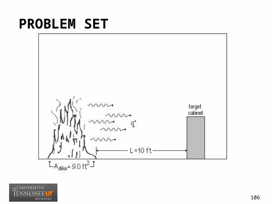
PROBLEM SET
106
ESTIMATING THE IGNITION TIME OF A TARGET FUEL EXPOSED TO A CONSTANT RADIATIVE HEAT FLUX
(NUREG 1805 -Chap 6)
06_Ignition_Time_Calculations.xls
107
OBJECTIVES
• ESTIMATING THE IGNITION TIME OF A TARGET FUEL EXPOSED TO A CONSTANT RADIATIVE HEAT FLUX
• Explain the importance of the location of the ignition source and fuels.
• Discuss how to calculate ignition time.• Define relevant terms, including ignition
temperature, flash point, piloted ignition, and non-piloted ignition.
108

IGNITION
• For ignition, the solid fuel must be heated sufficiently to vaporize and form a flammable pre-mixed system. An ignition source (spark or small flame) must also be present, for piloted ignition.
• A gas mixture must be heated sufficiently to cause auto-ignition.
• The critical surface temperature at which these ignitions occur is called the ignition temperature.
• Piloted ignition requires a much lower temperature than automatic (or spontaneous) ignition.
109
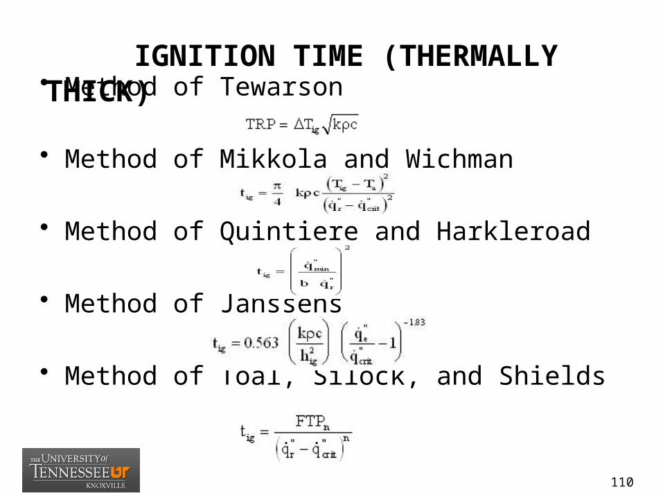
IGNITION TIME (THERMALLY THICK)• Method of Tewarson
• Method of Mikkola and Wichman
• Method of Quintiere and Harkleroad
• Method of Janssens
• Method of Toal, Silock, and Shields
110

ASSUMPTIONS/LIMITATIONS
• (1) For ignition to occur, a solid material must be heated sufficiently to vaporize and form a flammable mixture.
• (2) Ignition occurs when the surface reaches a critical temperature defined as the ignition temperature.
• (3) A heat source must be present to ignite the solid.• (4) The solid is assumed to be infinitely thick.• (5) The methods are all derived through the solid with
radiant heating on the surface.
111

INPUT NEEDED
• (1) Target fuel type (material)• (2) Exposed radiative heat flux to target
(kW/m2)
112
PROBLEM SET
• Problem Statement (6.11-1)– Calculate the ignition time for a PVC/PE
power cable, assuming that a 6.5-ft (2-m) diameter pool fire produces a 25-kW/m 2 heat flux.
113

FIRE DYNAMICS TOOLS(TIER C)
114
HAZARD METHODOLOGY
• Tier C – Compartment Factors– C1 – (02) Prediction of hot gas layer temperature– C2 – (10, 11, 12) Estimating detector/sprinkler
response times– C3 – (13) Predicting compartment flashover– C4 – (14, 15) Predicting pressure rise in closed
compartment, explosion pressure– C5 – (16) Predicting rate of hydrogen gas generation– C 6 – (17) Calculating fire resistance of structural
members
115
PREDICTING HOT GAS LAYER TEMPERATURE AND SMOKE LAYER HEIGHT IN A ROOM FIRE WITH NATURAL AND FORCED VENTILATION
(NUREG 1805 –Chap 2)
02.1_Temperature_NV.xls
02.1_Temperature_FV.xls116
OBJECTIVES
• PREDICTING HOT GAS LAYER TEMPERATURE AND SMOKE LAYER HEIGHT IN A ROOM FIRE WITH NATURAL AND FORCED VENTILATION
• Explain the different stages of a compartment fire• Identify and explain the types of forced and natural
ventilation systems• Describe how to calculate the hot gas layer
temperature and smoke layer height for a fire in a compartment with both natural and forced ventilation systems
117

COMPARTMENT FIRE STAGES
• CONDITIONS DEPEND ON:– Combustion– Enclosure Size– Enclosure
Construction– Enclosure
Ventilation
118

COMPARTMENT FIRE STAGES
119

MECHANICAL VENTILATION
120

GAS LAYER TEMPERATURE
• Natural Ventilation: Method of McCaffrey, Quintiere, and Harkleroad (MQH)
• Natural Ventilation: (Closed Compartment) Method of Beyler
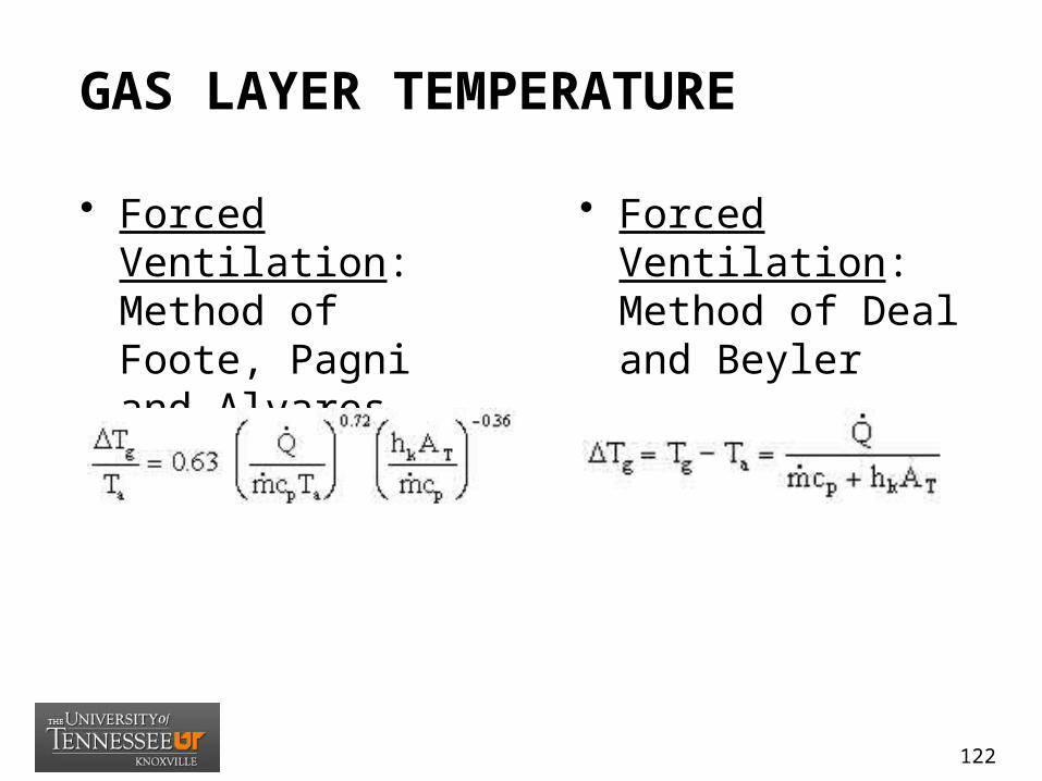
GAS LAYER TEMPERATURE
• Forced Ventilation: Method of Foote, Pagni and Alvares (FPA)
• Forced Ventilation: Method of Deal and Beyler
122
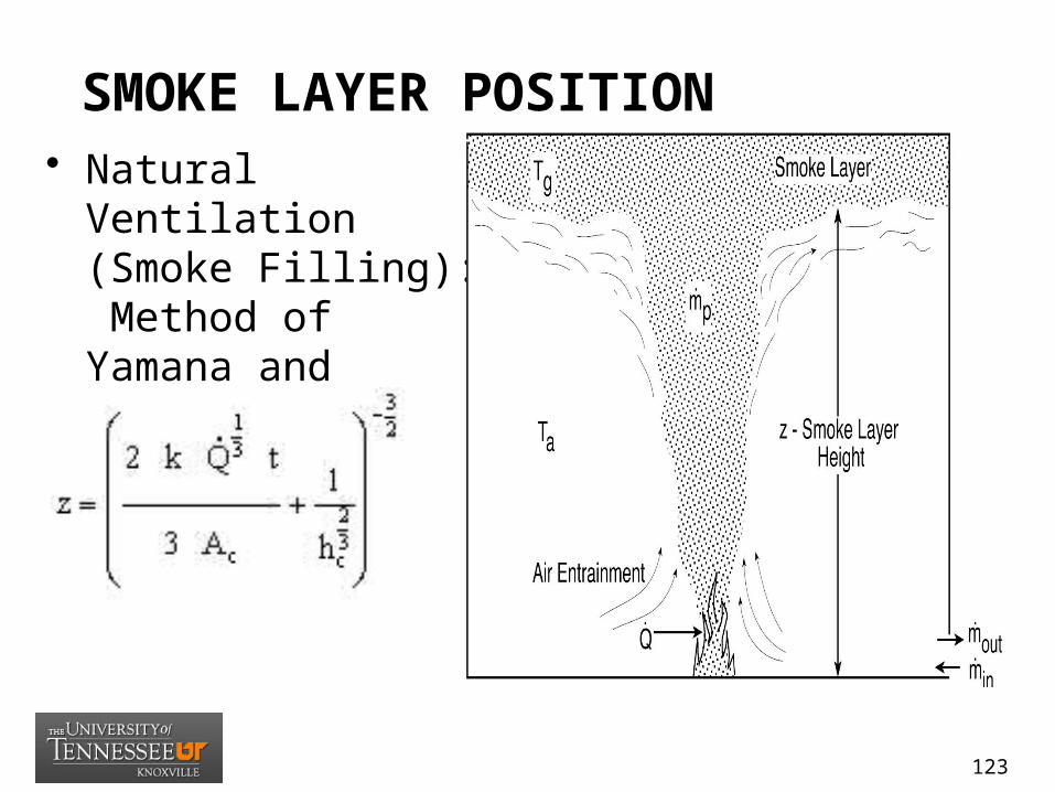
SMOKE LAYER POSITION• Natural Ventilation
(Smoke Filling): Method of Yamana and Tanaka
123
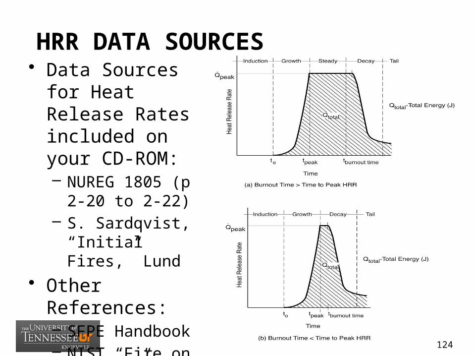
HRR DATA SOURCES• Data Sources for
Heat Release Rates included on your CD-ROM:– NUREG 1805 (p 2-
20 to 2-22)– S. Sardqvist,
“Initial Fires,” Lund
• Other References:– SFPE Handbook– NIST “Fire on the
Web” (fire.nist.gov)
124

ASSUMPTIONS/LIMITATIONSThe following assumptions and
limitations apply to all forced and natural convection situations:
• (1) These methods best apply to conventional-size compartments. They should be used with caution for large compartments.
• (2) These methods apply to both transient and steady-state fire growth.
• (3) The HRR must be known; it does not need to be constant, and can be allowed to change with time.
• (4) Compartment geometry assumes that a given space can be analyzed as a rectangular space with no beam pockets which affects the smoke filling rate within a space if the space has beam pockets.
• (5) These methods predict average temperatures and do not apply to cases in which predication of local temperature is desired
• (6) Caution should be exercised when the compartment overhead are highly congested with obstructions such as cable trays, conduits, ducts, etc.
• (7) A single heat transfer coefficient may be used for the entire inner surface of the compartment.
• (8) The heat flow to and through the compartment boundaries is unidimensional ( i.e., corners and edges are ignored, and the boundaries are assumed to be infinite slabs).
• (9) These methods assume that heat loss occurs as a result of mass flowing out through openings. These methods do not apply to situations in which significant time passes before hot gases begin leaving the compartment through openings.
125
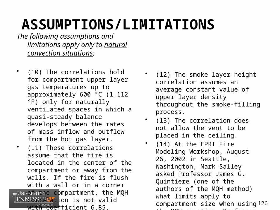
ASSUMPTIONS/LIMITATIONSThe following assumptions and
limitations apply only to natural convection situations:
• (10) The correlations hold for compartment upper layer gas temperatures up to approximately 600 °C (1,112 °F) only for naturally ventilated spaces in which a quasi-steady balance develops between the rates of mass inflow and outflow from the hot gas layer.
• (11) These correlations assume that the fire is located in the center of the compartment or away from the walls. If the fire is flush with a wall or in a corner of the compartment, the MQH correlation is not valid with coefficient 6.85.
• (12) The smoke layer height correlation assumes an average constant value of upper layer density throughout the smoke-filling process.
• (13) The correlation does not allow the vent to be placed in the ceiling.
• (14) At the EPRI Fire Modeling Workshop, August 26, 2002 in Seattle, Washington, Mark Salley asked Professor James G. Quintiere (one of the authors of the MQH method) what limits apply to compartment size when using the MQH equation. Professor Quintiere replied that the correlation will work for any size compartment since it is a dimensionless equation.
126
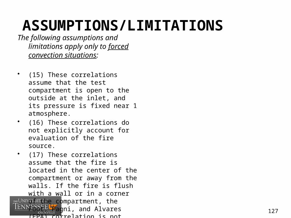
ASSUMPTIONS/LIMITATIONSThe following assumptions and
limitations apply only to forced convection situations:
• (15) These correlations assume that the test compartment is open to the outside at the inlet, and its pressure is fixed near 1 atmosphere.
• (16) These correlations do not explicitly account for evaluation of the fire source.
• (17) These correlations assume that the fire is located in the center of the compartment or away from the walls. If the fire is flush with a wall or in a corner of the compartment, the Foot, Pagni, and Alvares (FPA) correlation is not valid with coefficient 0.63.
127
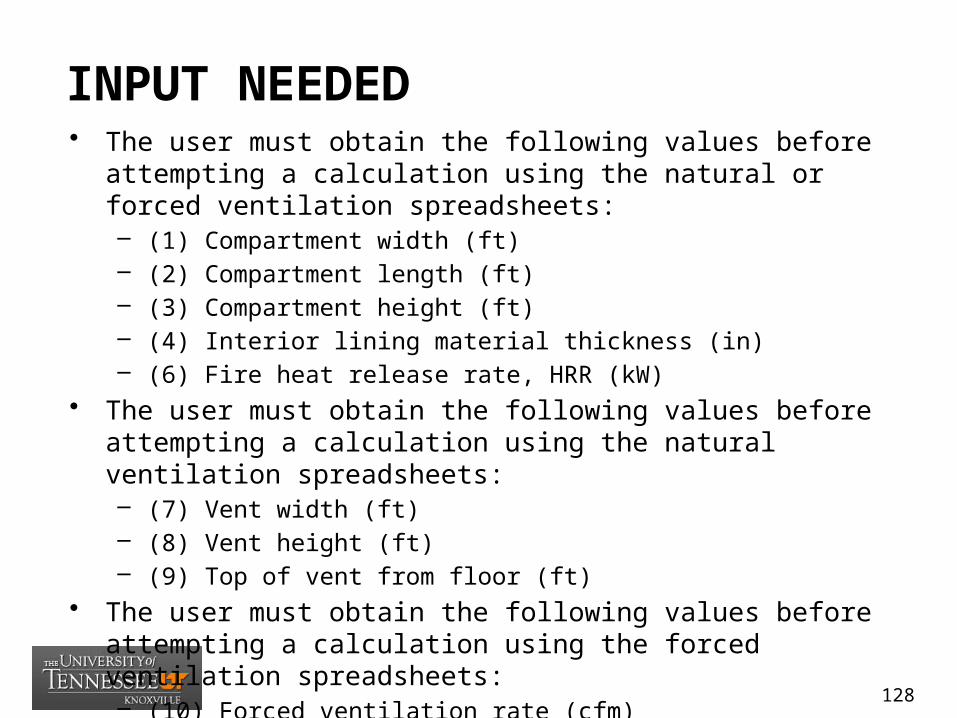
INPUT NEEDED• The user must obtain the following values before attempting a
calculation using the natural or forced ventilation spreadsheets:– (1) Compartment width (ft)– (2) Compartment length (ft)– (3) Compartment height (ft)– (4) Interior lining material thickness (in)– (6) Fire heat release rate, HRR (kW)
• The user must obtain the following values before attempting a calculation using the natural ventilation spreadsheets:– (7) Vent width (ft)– (8) Vent height (ft)– (9) Top of vent from floor (ft)
• The user must obtain the following values before attempting a calculation using the forced ventilation spreadsheets:– (10) Forced ventilation rate (cfm)
128
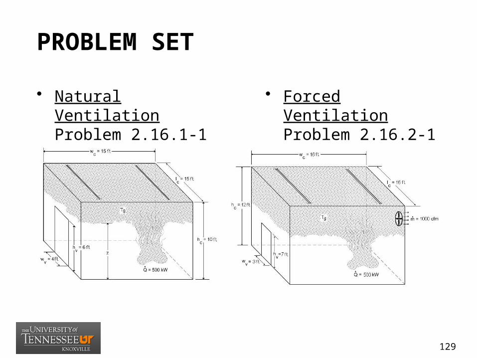
PROBLEM SET
• Natural Ventilation Problem 2.16.1-1 (p. 2-29)
• Forced Ventilation Problem 2.16.2-1 (p.2-55)
129
ESTIMATING SPRINKLER RESPONSE TIME
(NUREG 1805 -Chap 10)
10_Detector_Activation_Time.xls
130

OBJECTIVES
• ESTIMATING SPRINKLER RESPONSE TIME
• Explain the advantages and disadvantages of sprinklers.
• Identify the four basic types of sprinkler systems.
• Describe the purpose of sprinklers.• Explain how sprinklers function.
131
INTRODUCTION
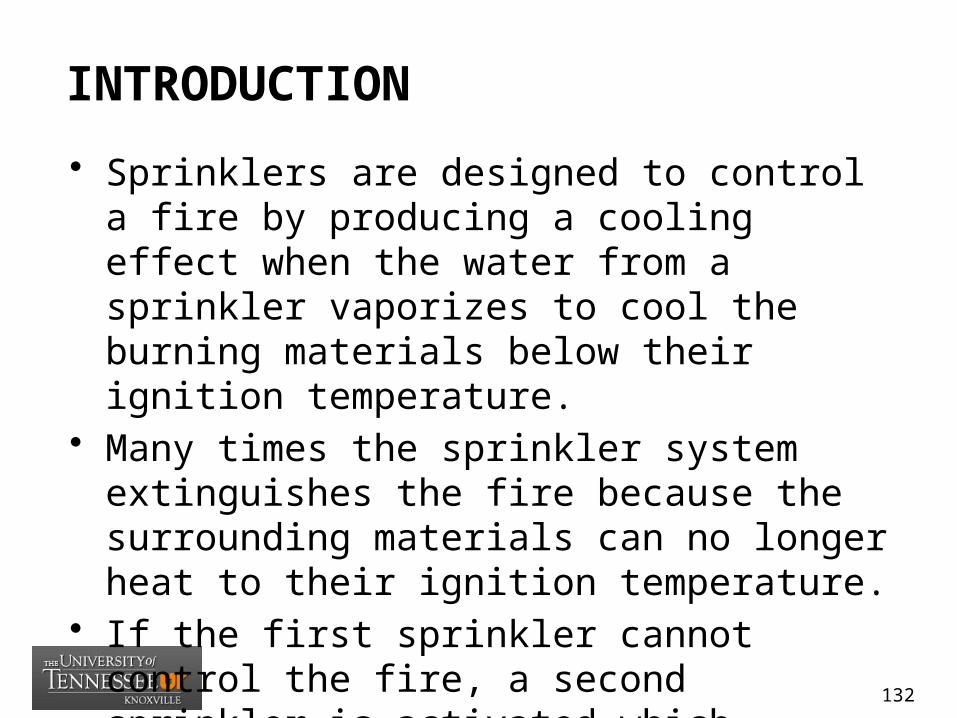
• Sprinklers are designed to control a fire by producing a cooling effect when the water from a sprinkler vaporizes to cool the burning materials below their ignition temperature.
• Many times the sprinkler system extinguishes the fire because the surrounding materials can no longer heat to their ignition temperature.
• If the first sprinkler cannot control the fire, a second sprinkler is activated which provides additional cooling. This process continues until the fire is controlled.
132
AUTOMATIC SPRINKLER SYSTEMS
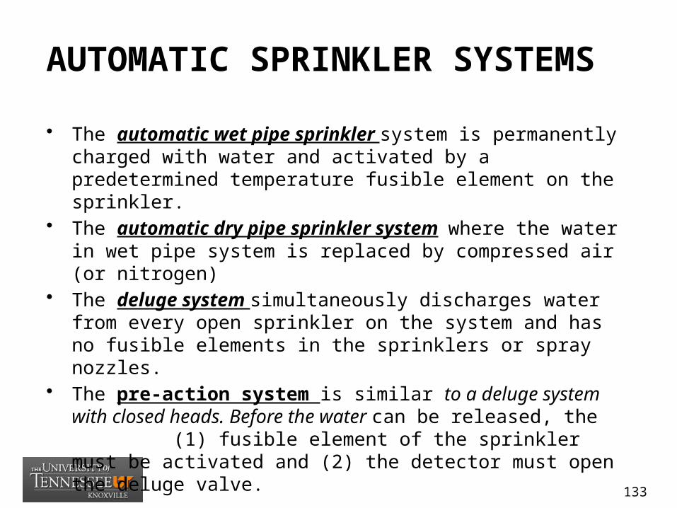
• The automatic wet pipe sprinkler system is permanently charged with water and activated by a predetermined temperature fusible element on the sprinkler.
• The automatic dry pipe sprinkler system where the water in wet pipe system is replaced by compressed air (or nitrogen)
• The deluge system simultaneously discharges water from every open sprinkler on the system and has no fusible elements in the sprinklers or spray nozzles.
• The pre-action system is similar to a deluge system with closed heads. Before the water can be released, the (1) fusible element of the sprinkler must be activated and (2) the detector must open the deluge valve.
133
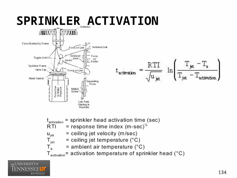
SPRINKLER ACTIVATION
134

ASSUMPTIONS/LIMITATIONS
• (1) The method assumes the ceiling is unconfined, unobstructed, smooth, flat, and horizontal.
• (2) The plume ceiling jet correlations of temperature and velocity assume that the fire source is located away from walls and corners.
• (3) The correlations for estimating the maximum ceiling jet temperature and velocity were developed for steady-state fires and plumes under unconfined ceilings
• (4) Plume ceiling jet correlations are valid for unconfined ceilings.• (5) Calculations determining time to operation only consider the
convective heating of sensing elements by the hot fire gases. • (6) This method does not apply to predict response time of sprinklers
installed on heat collectors1 far below the ceiling (in mid air).
135

INPUT NEEDED
• (1) heat release rate of the fire • (2) activation temperature of the sprinkler • (3) distance from top of fuel package to
the ceiling • (4) radial distance from the plume
centerline to the sprinkler • (5) ambient air temperature • (6) sprinkler type
136
PROBLEM SET
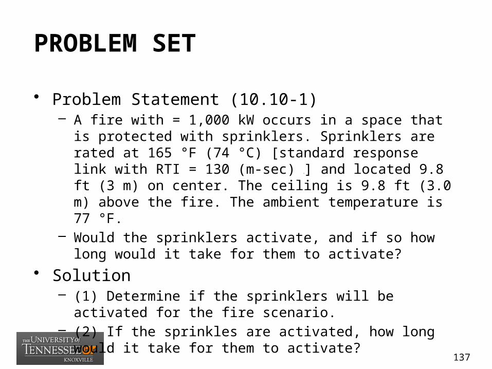
• Problem Statement (10.10-1)– A fire with = 1,000 kW occurs in a space that is protected with
sprinklers. Sprinklers are rated at 165 °F (74 °C) [standard response link with RTI = 130 (m-sec) ½] and located 9.8 ft (3 m) on center. The ceiling is 9.8 ft (3.0 m) above the fire. The ambient temperature is 77 °F.
– Would the sprinklers activate, and if so how long would it take for them to activate?
• Solution– (1) Determine if the sprinklers will be activated for the fire
scenario.– (2) If the sprinkles are activated, how long would it take for
them to activate?
137

ESTIMATING SMOKE DETECTOR RESPONSE TIME
(NUREG 1805 -Chap 11)
11_Detector_Activation_Time.xls
138

OBJECTIVES
• ESTIMATING SMOKE DETECTOR RESPONSE TIME
• Introduce the critical factors that influence smoke detector performance.
• Identify the various types of smoke detectors.• Describe how to estimate the response time of
a smoke detector.
139
SMOKE DETECTION
• Detection is critical to fire safety in NPPs since a potential fire hazard may jeopardize safe plant shutdown. Consequently, safety-related systems must be protected before redundant safety related systems become damaged by a fire.
• Two essential factors influencing the performance of smoke detectors are (1) the particle size of the smoke and (2) the fire-induced air velocities.
• Typically, a smoke detector will detect most fires more rapidly than a heat detector.
140
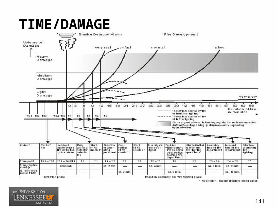
TIME/DAMAGE
141
SMOKE DETECTORS
• Types– Photoelectric light obscuration– Photoelectric light scattering– Projected beam detection– Air sampling detection
• Calculations Methods– Method of Albert– Method of Mowrer– Method of Milke
142

ASSUMPTIONS/LIMITATIONS
• (1) The fire is steady state.• (2) The forced ventilation system is off. As
ventilation is increased, detector response times increase.
• (3) Both flaming and non-flaming fire sources can be used.
• (4) Caution should be exercised with this method when the overhead area is highly obstructed.
• (5) The detectors are located at or very near to ceiling.
143
INPUT NEEDED
• (1) heat release rate of the fire • (2) ceiling height of the compartment • (3) radial distance from the centerline of
the plume
144

PROBLEM SET• Problem Statement (11.12-1)
– Estimate the response time of a smoke detector that is located 10 ft radially from the centerline of a 1,000-kW pool fire in a 13-ft-tall compartment.
• Solution– (1) Calculate the wall flame height.– (2) Determine whether the flame will impinge upon the
cable tray.
145

ESTIMATING HEAT DETECTOR RESPONSE TIME
(NUREG 1805 -Chap 12)
12_Detector_Activation_Time.xls
146
OBJECTIVES
• ESTIMATING HEAT DETECTOR RESPONSE TIME
• Explain where heat detectors are located.• Identify the various types of heat detectors
and how they work.• Describe how to calculate the activation time
of a heat detector.
147

OPERATING PRINCIPLES
• Heat detectors are one of the oldest forms of automatic fire detection devices, and they typically have the lowest false alarm rate of all automatic fire detection devices.
• Heat detectors are generally located on or near the ceiling, where they can respond to the convected thermal energy of a fire.
• They may be used in combination with smoke detectors, since smoke detectors usually activate before the flames and heat would are sufficient to alarm the heat detector.
148
TYPES OF DETECTORS
• Fixed-temperature• Fusible-element • Continuous Link• Bimetallic • Rate compensation• Rate-of-rise• Pneumatic heat detectors• Line-type detectors• Combination Heat detectors• Electronic spot-type thermal
149
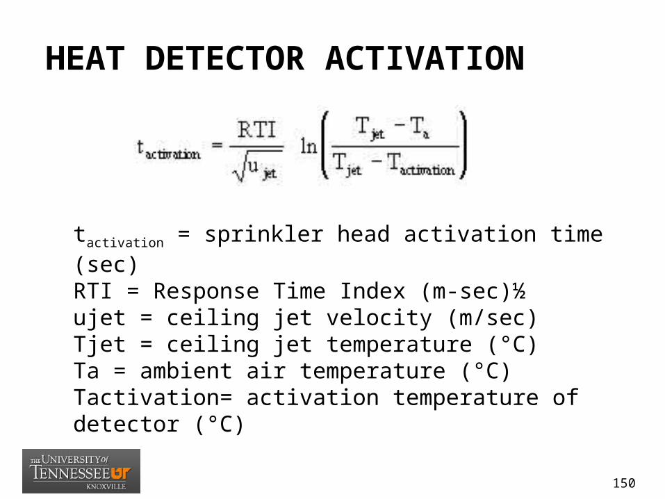
HEAT DETECTOR ACTIVATION
tactivation = sprinkler head activation time (sec)RTI = Response Time Index (m-sec)½ujet = ceiling jet velocity (m/sec)Tjet = ceiling jet temperature (°C)Ta = ambient air temperature (°C)Tactivation= activation temperature of detector (°C)
150
ASSUMPTIONS/LIMITATIONS• (1) Plume ceiling jet correlations of temperature and
velocity assume that the fire source is located away from walls and corners.
• (2) Correlations for estimating the maximum ceiling jet temperature and velocity were developed for steady-state fires and plumes under unconfined ceiling
• (3) The plume ceiling jet correlations are valid for unconfined flat ceilings.
• (4) The correlations for estimating the maximum ceiling jet temperature and velocity were developed for steady-state fires and plumes under unconfined ceiling.
• (5) The plume ceiling jet correlations are valid for unconfined ceilings.
151

INPUT NEEDED
• (1) heat release rate of the fire • (2) listed spacing of detectors • (3) activation temperature of detectors • (4) height to ceiling • (5) ambient room temperature
152

PROBLEM SET
• Problem Statement (4.9-1)– A 34.5-ft (3.20-m ) lube oil pool fire with = 5,750 kW
occurs in a space protected with fixed temperature heat detectors. Calculate the activation time for the fixed-temperature heat detectors, using 10-ft (3.05-m) spacing, in an area with a ceiling height of 10 ft (3.05 m).
– The detector activation temperature is 128 °F (53 °C), the radial distance to the detector is 4 ft (1.22 m), and the ambient temperature is 77 °F (25 °C).
153

PREDICTING COMPARTMENT FLASHOVER
(NUREG 1805 -Chap 13)
13_Compartment_Flashover_Calculations.xls
154

OBJECTIVES
• PREDICTING COMPARTMENT FLASHOVER
• Explain the incipient stage of a fire.• Characterize flashover and its stages.• Describe how to predict the HRR
required for flashover and post-flashover temperature in a compartment.
155
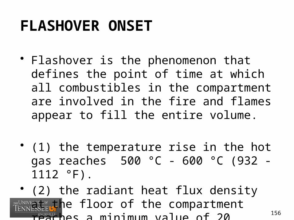
FLASHOVER ONSET
• Flashover is the phenomenon that defines the point of time at which all combustibles in the compartment are involved in the fire and flames appear to fill the entire volume.
• (1) the temperature rise in the hot gas reaches 500 °C - 600 °C (932 - 1112 °F).
• (2) the radiant heat flux density at the floor of the compartment reaches a minimum value of 20 kW/m2.
156
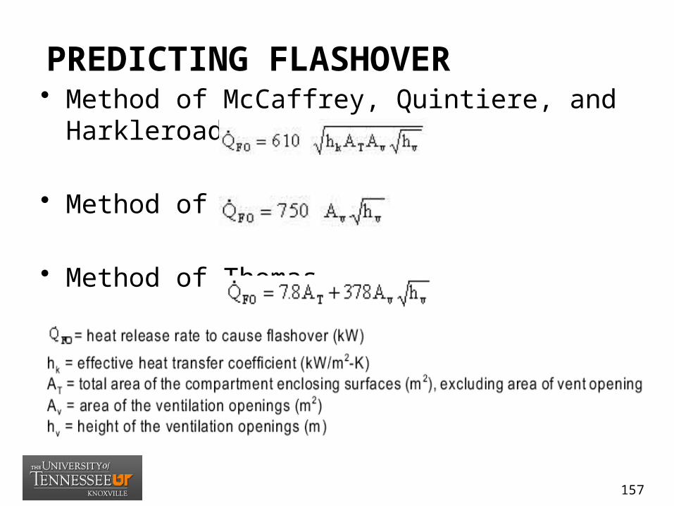
PREDICTING FLASHOVER• Method of McCaffrey, Quintiere, and Harkleroad
• Method of Babrauskas
• Method of Thomas
157
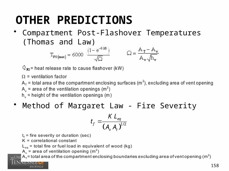
OTHER PREDICTIONS• Compartment Post-Flashover Temperatures (Thomas
and Law)
• Method of Margaret Law - Fire Severity
1/ 2eq
f
v t
K Lt
A A
158

ASSUMPTIONS/LIMITATIONS
• (1) The correlations were developed from a simplified mass and energy balance on a single compartment with ventilation openings.
• (2) The experimental data used to develop the correlation included compartments with thermally thick walls and fires of wood cribs. Typically, heat transfer through compartment surfaces is accounted for with a semi-infinite solid approximation.
• (3) The fire severity correlation is not appropriate for compartment that do not have openings for ventilation. While no precise minimum can be stated, it is suggested that this method not be used unless the size of the opening is at least 0.4 m2 (4 ft2).
159

INPUT NEEDED
• (1) compartment width • (2) compartment length • (3) compartment height • (4) vent width • (5) vent height
160
PROBLEM SET• Problem Statement (13.10-1)
– Consider a compartment 20 ft wide x 25 ft long x 12 ft high (wc x lc x hc), with an opening 3 ft wide
– and 8 ft high (wv x hv). The interior lining material of the compartment is 6 in. concrete. Calculate
– the HRR necessary for flashover and the post-flashover compartment temperature, TPFO.
161
ESTIMATING PRESSURE RISE ATTRIBUTABLE TO A FIRE IN A CLOSED COMPARTMENT
(NUREG 1805 -Chap 14)
14_Compartment_Over_Pressure_Calculations.xls
162

OBJECTIVES
• ESTIMATING PRESSURE RISE ATTRIBUTABLE TO A FIRE IN A CLOSED COMPARTMENT
• Discuss some systems of pressure measurement.
• Explain how to calculate pressure rise.• Define relevant terms, including pressure rise.
163
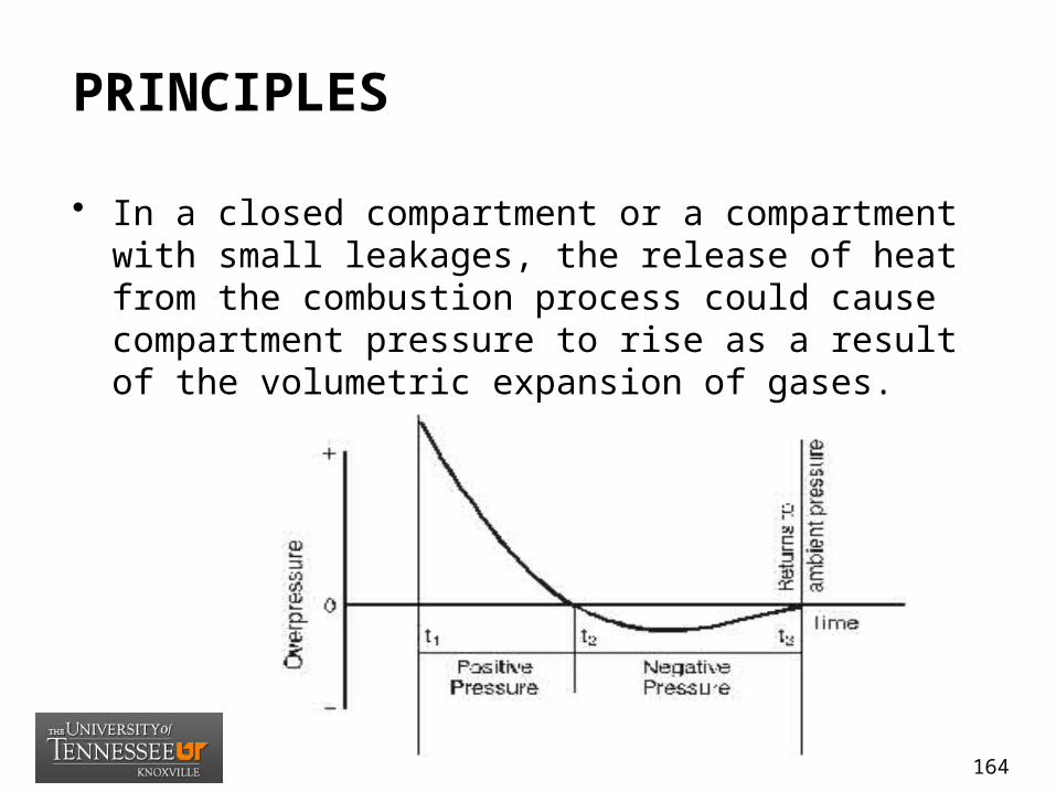
PRINCIPLES
• In a closed compartment or a compartment with small leakages, the release of heat from the combustion process could cause compartment pressure to rise as a result of the volumetric expansion of gases.
164

CALCULATIONS
• According to Karlsson and Quintiere (1999), the maximum pressure difference inside a compartment as a result of expansion of gases is given by the following expression:
165

ASSUMPTIONS/LIMITATIONS
• (1) The energy release rate is constant.• (2) The mass loss rate of the fuel is
neglected in the conversion of mass.• (3) The specific heat does not change
with temperature.• (4) The hydrostatic pressure difference
over the height of the compartment is ignored and assumed to be negligible compared to the dynamic pressure.
166
INPUT NEEDED
• (1) compartment width • (2) compartment length • (3) compartment height • (4) fire heat release rate • (5) time after ignition
167
PROBLEM SET
• Problem Statement (14-10.1)–A closed compartment in a facility
pump room has dimensions 10 ft wide x 12 ft long x 10 ft high. A fire starts with a constant HRR of = 100 kW. Estimate the pressure rise attributable to the expansion of gases after 10 seconds.
168
ESTIMATING THE PRESSURE INCREASE AND EXPLOSIVE ENERGY RELEASE ASSOCIATED WITH EXPLOSIONS
(NUREG 1805 -Chap 15)
15_Explosion_Calculations.xls
169
OBJECTIVES
• ESTIMATING THE PRESSURE INCREASE AND EXPLOSIVE ENERGY RELEASE ASSOCIATED WITH EXPLOSIONS
• Define the nature and implications of an explosion.• Explain the various causes, hazards, and effects of
explosions.• Explain how to calculate the energy released by an
explosion.• Explain how to calculate the pressure increase
attributable to an explosion.
170
CHARACTERISTICS
• A rapid release of high-pressure gases into the environment (Cruice, 1991).
• A sudden conversion of potential energy into kinetic energy in the form of rapidly expanding gases (NFPA 921).
• A physical reaction: high-pressure gas; confinement or restriction of the pressure; rapid production or release of pressure; and change or charge to the confining structure, container, or vessel caused by the pressure release. (NFPA 921).
• An exothermic chemical process that when occurring at constant volume, gives rise to a sudden and significant pressure rise (Vervalin, 1985).
171
EXPLOSION CONCEPTS
• Explosion Hazards• Explosive Range• Backdraft Explosions• Smoke Explosion• Unconfined/Confined Explosions• Attributable Damage• Estimating Explosive Energy Release• Blast Effects
172
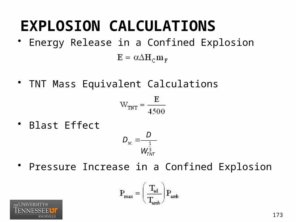
EXPLOSION CALCULATIONS• Energy Release in a Confined Explosion
• TNT Mass Equivalent Calculations
• Blast Effect
• Pressure Increase in a Confined Explosion
1
3
sc
TNT
DD
W
173
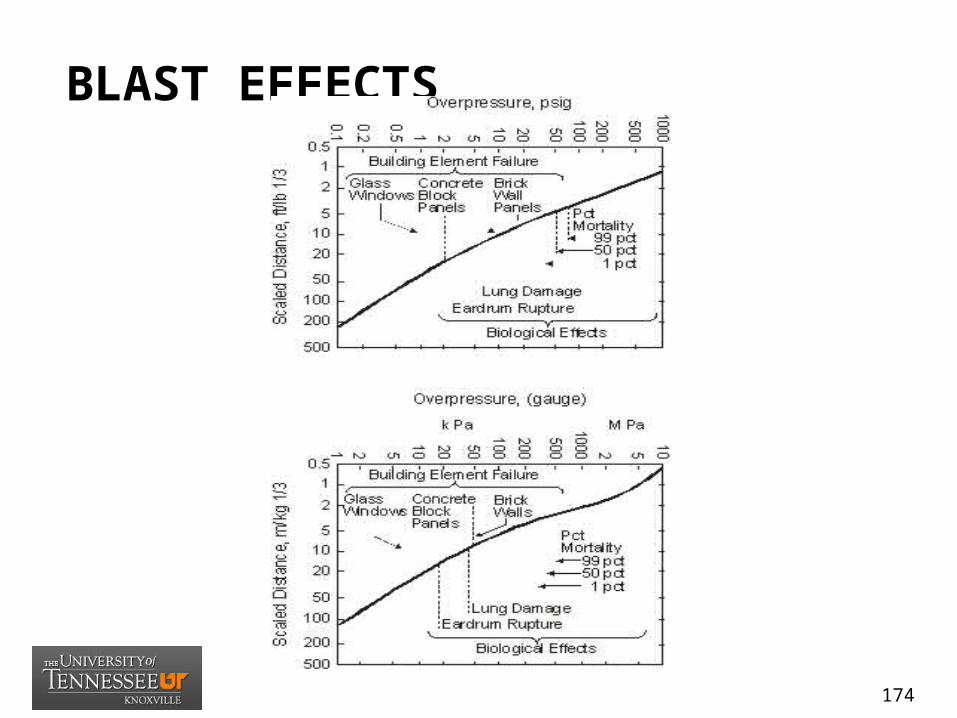
BLAST EFFECTS
174
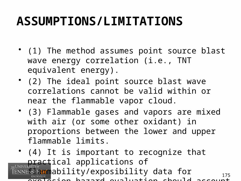
ASSUMPTIONS/LIMITATIONS
• (1) The method assumes point source blast wave energy correlation (i.e., TNT equivalent energy).
• (2) The ideal point source blast wave correlations cannot be valid within or near the flammable vapor cloud.
• (3) Flammable gases and vapors are mixed with air (or some other oxidant) in proportions between the lower and upper flammable limits.
• (4) It is important to recognize that practical applications of flammability/exposibility data for explosion hazard evaluation should account for nonuniform or stratified vapor-air mixtures.
175

INPUT NEEDED
• (1) fuel type (material)• (2) mass of flammable vapor • (3) ambient temperature • (4) ambient pressure
176

PROBLEM SET
• Problem Statement (15.18-1)• In an NPP, a liquid propane gas (LPG)-driven forklift is
used to un load materials from an upcoming outage. Mechanical failure could result in the release of LPG in the area. The maximum fuel capacity of the forklift is 10 gallons. Calculate pressure rise, energy released by expanding LPG, and equivalent TNT charge weight. Assume that the mass of the vapor released is 48 lb.
177
CALCULATING THE RATE OF HYDROGEN GAS GENERATION IN BATTERY ROOMS
(NUREG 1805 -Chap 16)
16_Battery_Room_Flammable_Gas_Conc.xls
178
OBJECTIVES
• CALCULATING THE RATE OF HYDROGEN GAS GENERATION IN BATTERY ROOMS
• Explain how hydrogen gas is generated in a battery room.• Describe the conditions under which hydrogen gas will ignite.• Describe possible ignition sources in a battery room.• Explain methods of controlling the combustion of hydrogen gas.• Describe how to estimate hydrogen gas generation rates.
179

OPERATING PRINCIPLES
• (1) Adequate ventilation is the most common form of fire prevention/protection in battery rooms.
• (2) The exhaust air outlets from the battery room shall be located separately
• (3) Codes require spill containment systems for battery installations that contain electrolyte.
• (4) NPP should maintain an ambient temperature of 23 to 26 °C (72 to 78 °F) in battery rooms.
• (5) To extinguish lead-acid battery fires, use CO2, fire protection foam, or dry chemical media.
180

CALCULATIONS• Rate of Hydrogen Generation
• Vapor Concentration Buildup Time
181
ASSUMPTIONS/LIMITATIONS• (1) Hydrogen gas is primarily generated in battery rooms
as a result of battery overcharge.• (2) The generation of hydrogen environment could occur
if the ventilation flow through the vapor space is completely stopped or other events allow hydrogen accumulation.
• (3) This method assumes that significant amounts of hydrogen gas are liberated only when the battery approaches full charge.
• (4) The calculations will produce a first order approximation.
• (5) The battery hydrogen generation equation is based on one specific vendor’s recommendations.
182

INPUT NEEDED
• (1) charge voltage (vpc)• (2) ampere Hours• (3) number of cells
183
PROBLEM SET
• Problem Statement (16.14-1)– Assume a 60-cell GT-41 (3,730 Ampere-
hour) battery near the end of its life, on equalize at 2.33 VPC at an electrolyte temperature of 92 °F (33 °C). Estimate the rate of hydrogen generation (in cubic feet per minute).
184
CALCULATING THE FIRE RESISTANCE OF STRUCTURAL STEEL MEMBERS
(NUREG 1805 -Chap 17)
17_FR_Beams_Columns_Substitution_Correlation.xls
185

OBJECTIVES
• CALCULATING THE FIRE RESISTANCE OF STRUCTURAL STEEL MEMBERS
• Describe the testing procedures for fire resistance protection of structural steel members.
• Describe the failure criteria for structural steel members.
• Explain how to calculate the fire resistance (failure time) of protected and unprotected structural steel members.
186
OPERATING PRINCIPLES
• Fire resistance denotes the ability of a building component to resist the thermal insult of a standard rest fire. ( e.g., 1 hour, 3 hours, etc.).
• The retention load-bearing capacities by structural members during a fire is very important.
• Buildings collapse when load-bearing members lose their load-bearing capacity.
• The temperature limits for structural steel members are based on ASTM E119. The maximum single point temperature in a steel beam, column, or girder is 649 °C (1,300 °F) and the allowable average temperature in these members is 530 °C (1,000 °F).
187
CALCULATION ENDURANCE
• Calculating Fire Resistance or Endurance• Equivalent fire resisance• Protection of steel columns• Beam substitution with spray-on materials• Unprotected/protected steel sections
188

ASSUMPTIONS/LIMITATIONS
• (1) The heat transfer analysis is one dimensional.• (2) Correlations are based on the analysis of data
resulting from performing the standard test numerous times, using curve-fitting techniques to establish the various correlations.
• (3) As the structural member heats up, its structural properties can change substantially.
• (4) Equation-specific limitations apply (see the various equations throughout this chapter).
189

INPUT NEEDED
• (1) dimensions of the steel member in question
• (2) thermal properties of the applied insulation
190

PROBLEM SET
• Problem Statement (17.14-1)– Calculate the thickness of spray-on fire
protection required to provide a 2-hour fire resistance for a W12 x 16 beam to be substituted for a W8 x 18 beam requiring 1.44 in. of protection for the same rating.
191

FIRE DYNAMICS TOOLS(TIER D)
192
HAZARD METHODOLOGY
• Tier D – Tenability (Hazard Criteria)– D1 – (18) Estimating visibility through smoke– D2 – Heat release rate – D3 – Radiant heat exposure (2.5 kW/m2)– D4 – Layer temperature (100oC)– D5 – Layer smoke density (0.2/m)– D6 – Layer Carbon Monoxide (3,000 ppm)– D7 – Layer Oxygen (10 percent or less)
193
Related Documents