Page 1 of 110 REV 04/09 CITY OF SPRINGFIELD, MISSOURI DIVISION OF PURCHASES INVITATION FOR BID #065-2012 SEALED BIDS MUST BE PHYSICALLY RECEIVED IN THE DIVISION OF PURCHASES PRIOR TO 3:00 P.M. ON THURSDAY, JANUARY 26, 2012. Bids will be opened by the buyer at the location listed above. • Bids shall be submitted on the forms provided and must be manually signed by the individual authorized to legally bind the company. • Bids shall be submitted with the IFB number clearly indicated on the outside of the mailing envelope. • Bids received after the opening date and time will be rejected. • The attached Terms and Conditions shall become part of any purchase order resulting from this bid. • FAXED/EMAILED BIDS WILL NOT BE ACCEPTED. You are invited to submit your bid to furnish the materials and/or services described herein. Please submit your prices/fees net of all discounts. DESCRIPTION FIRE APPARATUS - PUMPERS See attached General Conditions, Specifications, and Bid Form for detailed information. DELIVERY: F.O.B. DESTINATION The articles to be furnished hereunder shall be delivered all transportation charges paid by the bidder to destination. It is the intent of the City that this Invitation for Bid promotes competitive bidding. It shall be the Vendor’s responsibility to advise the Division of Purchases if any language, requirements, etc. any combination thereof, inadvertently restricts or limits the requirements stated in this Invitation for Bid to a single source. Such notification must be submitted in writing and must be received by the Division of Purchases not later than three (3) days prior to the bid opening date. Mike Bell, Buyer Date Issued: December 14, 2011 City of Springfield Buyer’s Email: [email protected] Division of Purchases Telephone Number: 417-864-1594 218 E. Central Fax Number: 417-864-1927 Springfield, MO 65802 Due Date: January 26, 2012 Pre-Bid Date: January 4, 2012

Welcome message from author
This document is posted to help you gain knowledge. Please leave a comment to let me know what you think about it! Share it to your friends and learn new things together.
Transcript
Page 1 of 110 REV 04/09
CITY OF SPRINGFIELD, MISSOURI DIVISION OF PURCHASES
INVITATION FOR BID #065-2012
SEALED BIDS MUST BE PHYSICALLY RECEIVED IN THE DIVISION OF PURCHASES PRIOR TO 3:00 P.M. ON THURSDAY, JANUARY 26, 2012. Bids will be opened by the buyer at the location listed above.
• Bids shall be submitted on the forms provided and must be manually signed by the individual authorized to legally bind the company.
• Bids shall be submitted with the IFB number clearly indicated on the outside of the mailing envelope. • Bids received after the opening date and time will be rejected. • The attached Terms and Conditions shall become part of any purchase order resulting from this bid. • FAXED/EMAILED BIDS WILL NOT BE ACCEPTED.
You are invited to submit your bid to furnish the materials and/or services described herein. Please submit your prices/fees net of all discounts.
DESCRIPTION
FIRE APPARATUS - PUMPERS
See attached General Conditions, Specifications, and Bid Form for detailed information.
DELIVERY: F.O.B. DESTINATION
The articles to be furnished hereunder shall be delivered all transportation charges paid by the bidder to destination.
It is the intent of the City that this Invitation for Bid promotes competitive bidding. It shall be the Vendor’s responsibility to advise the Division of Purchases if any language, requirements, etc. any combination thereof, inadvertently restricts or limits the requirements stated in this Invitation for Bid to a single source. Such notification must be submitted in writing and must be received by the Division of Purchases not later than three (3) days prior to the bid opening date.
Mike Bell, Buyer Date Issued: December 14, 2011 City of Springfield Buyer’s Email: [email protected] Division of Purchases Telephone Number: 417-864-1594 218 E. Central Fax Number: 417-864-1927 Springfield, MO 65802 Due Date: January 26, 2012
Pre-Bid Date: January 4, 2012
Page 2 of 110 REV 04/09
CITY OF SPRINGFIELD
INSTRUCTION TO BIDDERS 01. Opening Location The Bids will be opened at the City of Springfield, Division of Purchases, 218 E. Central, Springfield, MO 65802 in the presence of Purchasing officials at the due date and time indicated on the IFB. All bidders or their representatives are invited to attend the opening of the IFB. 02. IFB Delivery Requirements Any Bids received after the above stated time and date will not be considered. It shall be the sole responsibility of the bidder to have their Bid delivered to the Division of Purchases for receipt on or before the due date and time indicated. If a Bid is sent by U.S. Mail, the bidder shall be responsible for its timely delivery to the Division of Purchases office. Bids delayed by mail shall not be considered, shall not be opened, and shall be rejected. Arrangements may be made for their return at the bidder’s request and expense. Bids may be mailed to the Division of Purchases and accepted if the signed bid form and required information was mailed and received prior to the due date and time. Bids sent by email will not be accepted. 03. Sealed and Marked If sent by mail, one original signed Bid shall be submitted in one sealed package, clearly marked on the outside of the package with the Invitation for Bid number and addressed to:
City of Springfield Division of Purchases 218 E. Central Springfield, MO 65802
04. Legal Name and Signature Bids shall clearly indicate the legal name, address, and telephone number of the bidder (company, firm, corporation, partnership, or individual). Bids shall be manually signed above the printed name and title of signer on the Affidavit of Compliance page. The signer shall have the authority to bind the company to the submitted Bid. Failure to properly sign the Bid form shall invalidate same, and it shall not be considered for award. 05. Corrections No erasures are permitted. If a correction is necessary, draw a single line through the entered figure and enter the corrected figure above it. Corrections must be initialed by the person signing the Bid. 06. Clarification and Addenda Each bidder shall examine all Invitation for Bid documents and shall judge all matters relating to the adequacy and accuracy of such documents. Any inquiries or suggestions, concerning interpretation, clarification, or additional information pertaining to the Invitation for Bid shall be made through the Division of Purchases in writing or through email. The Division of Purchases shall not be responsible for oral interpretations given by any City employee, representative, or others. The issuance of written addenda is the official method whereby interpretation, clarification, or additional information can be given. It shall be the responsibility of each bidder, prior to submitting their Bid, to contact the Division of Purchases at phone number 417-864-1620, or to check the Purchasing website to determine if addenda were issued and to make such addenda a part of their Bid at: www.springfieldmo.gov/egov/finance/bid_center.html 07. IFB Expenses All expenses for making Bids to the City are to be borne by the bidder. 08. Irrevocable Offer Any Bid may be withdrawn up until the due date and time set for opening of the IFB. Any Bid not so withdrawn shall, upon opening, constitute an irrevocable offer for a minimum period of 90 days to sell to the City the goods or services set forth in the IFB, until one or more of the Bids have been duly accepted by the City. 09. Responsive and Responsible Bidder To be responsive, a bidder shall submit a Bid which conforms in all material respects to the requirements set forth in the Invitation for Bid. To be a responsible bidder, the bidder shall have the capability in all respects to perform fully the contract requirements, and the tenacity, perseverance, experience, integrity, reliability, capacity, facilities, equipment and credit which will ensure good faith performance. The lowest responsible bidder shall mean the bidder who makes the lowest Bid to sell goods or services of a quality which conforms closest to the quality of goods or services set forth in the specifications or otherwise required by the City and who is known to be fit and capable to perform the Bid as made. 10. Reserved Rights The City reserves the right to make such investigations as it deems necessary to make the determination of the bidder’s responsiveness and responsibility. Such information may include, but shall not be limited to: current financial statement, verification of availability of equipment and personnel, and past performance records. 11. The Right to Audit The bidder agrees to furnish supporting detail as may be required by the City to support charges or invoices, to make available for audit purposes all records covering charges pertinent to the purchase, and to make appropriate adjustments in the event discrepancies are found. The cost of any audit will be paid by the City. The City shall have the right to audit the bidder’s records pertaining to the work/product for a period of three (3) years after final payment. 12. Applicable Law All applicable laws and regulations of the State of Missouri and the City including the City Procurement Regulations and Procedures will apply to any resulting agreement, contract, or purchase order. Any involvement with the City Procurement shall be in accordance with the Procurement Regulations and Procedures. 13. Right to Protest Appeals and remedies are provided for in the City Procurement Regulations. Protestors shall seek resolution of their complaints initially with the City Purchasing Agent. Any protest shall state the basis upon which the solicitation or award is contested and shall be submitted within ten (10) calendar days after such aggrieved person knew or could have reasonably been expected to know of the facts giving rise thereto.

Page 3 of 110 REV 04/09
14. Ethical Standards With respect to this IFB, if any bidder violates or is a party to a violation of the general ethical standards of the City Procurement Code or the State of Missouri Statues, such bidder may be disqualified from furnishing the goods or services for which the Bid is submitted and shall be further disqualified from submitting any future Bids. A copy of the City’s General Ethical Standards is available at the Division of Purchases. 15. Collusion By offering a submission to this Invitation for Bid, the bidder certifies the bidder has not divulged, discussed, or compared the Bid with other bidders and has not colluded with any other bidder or parties to this IFB whatsoever. Also, the bidder certifies, and in the case of a joint Bid, each party thereto certifies as to their own organization, that in connection with this IFB: a. Any prices and/or cost data submitted have been arrived at independently, without consultation, communication, or agreement for the purpose
of restricting competition, as to any matter relating to such prices and/or cost data, with any other bidder or with any competitor. b. Any prices and/or cost data for this Bid have not knowingly been disclosed by the bidder and will not knowingly be disclosed by the bidder
prior to the scheduled opening directly or indirectly to any other bidder or to any competitor. c. No attempt has been made or will be made by the bidder to induce any other person or firm to submit or not to submit a Bid for the purpose of
restricting competition. d. The only person or persons interested in this Bid, principal or principals are named therein and that no person other than therein mentioned
has any interest in this Bid or in the contract to be entered into. e. No person or agency has been employed or retained to solicit or secure this contract upon an agreement or understanding for a commission,
percentage, brokerage, or contingent fee exempting bona fide employees or established commercial agencies maintained by the Purchaser for the purpose of doing business.
16. Contract Forms Any agreement, contract, or purchase order resulting from the acceptance of a Bid shall be on forms either supplied by or approved by the City. 17. Liability and Indemnity a. In no event shall the City be liable to the Contractor for special, indirect, or consequential damages, except those caused by the City’s gross
negligence or willful or wanton misconduct arising out of or in any way connected with a breach of this contract. The maximum liability of the City shall be limited to the amount of money to be paid or received by the City under this contract.
b. The Contractor shall defend, indemnify and save harmless the City, its elected or appointed officials, agents and employees from and against any and all liability, suits, damages, costs (including attorney fees), losses, outlays and expenses from claims in any manner caused by, or allegedly caused by, or arising out of, or connected with, this contract, or the work or any subcontract thereunder (the Contractor hereby assuming full responsibility for relations with subcontractors), including, but not limited to, claims for personal injuries, death, property damage, or for damages from the award of this contract to Contractor.
c. The Contractor shall indemnify and hold the City harmless from all wages or overtime compensation due any employees in rendering services pursuant to this agreement or any subcontract, including payment of reasonable attorneys’ fees and costs in the defense of any claim made under the Fair Labor Standards Act, the Missouri Prevailing Wage Law or any other federal or state law.
18. IFB Forms, Variances, Alternates Bids must be submitted on attached City IFB forms, although additional information may be attached. Bidders must indicate any variances from the City requested specifications and/or terms and conditions, on the IFB Affidavit of Compliance. Otherwise, bidders must fully comply with the City requested specifications and terms and conditions. Alternate Bids may or may not be considered at the sole discretion of the City Purchasing Agent. 19. Bid Form All blank spaces must be completed with the appropriate response. The bidder must state the price, written in ink, for what is proposed to complete each item of the project. Bidders shall insert the words “no bid” in the space provided for an item for which no Bid is made. The bidder shall submit an executed Bid form, affidavit of compliance with other requested documents. 20. Modifications or Withdrawal of Bid A modification for a Bid already received will be considered only if the modification is received prior to the time announced for opening of Bids. All modifications shall be made in writing, executed, and submitted on the same form and manner as the original Bid. Modifications submitted by telephone, fax, or email will not be considered. 21. No Bid If not submitting a Bid, respond by returning the “Statement of No Bid” no later than the stated Bid opening time and date, and explain the reason in the space provided. 22. Errors in Bids Bidders or their authorized representatives are expected to fully inform themselves as to the conditions, requirements, and specifications before submitting Bids; failure to do so will be at the bidder’s own risk. Neither law nor regulations make allowance for errors either of omission or commission on the part of bidders. In case of error of extension of prices in the Bid, the unit price shall govern. 23. Prices Bid Give both unit price and extended total. Price must be stated in units of quantity specified in the bidding specifications. In case of discrepancy in computing the amount of the Bid, the unit price of the Bid will govern. All prices shall be F.O.B. destination, freight prepaid (unless otherwise stated in special conditions). Each item must be bid separately and no attempt is to be made to tie any item or items in with any other item or items. If a bidder offers a discount on payment terms, the discount time will be computed from the date of satisfactory delivery at place of acceptance and receipt of correct invoice at the office specified. Payment terms shall be Net 30 if not otherwise specified. Pre-payment terms are not acceptable. 24. Discounts Any and all discounts except cash discounts for prompt payments must be incorporated as a reduction in the Bid price and not shown separately. The price as shown on the Bid shall be the price used in determining award(s). 25. Descriptive Information All equipment, materials, and articles incorporated in the product/work covered by this IFB are to be new and of suitable grade for the purpose intended. Brand or trade names referenced in specifications are for comparison purposes only. Bidders may submit Bids on items manufactured by other than the manufacturer specified when an “or equal” is stated. 26. Deviations to Specifications and Requirements When bidding on an “or equal,” Bids must be accompanied with all descriptive information necessary for an evaluation of the proposed material or
Page 4 of 110 REV 04/09
equipment such as the detailed drawings and specifications, certified operation and test data, and experience records. Failure of any bidder to furnish the data necessary to determine whether the product is equivalent, may be cause for rejection of the specific item(s) to which it pertains. All deviations from the specifications must be noted in detail by the bidder on the Affidavit of Compliance form, at the time of submittal of Bid. The absence of listed deviations at the time of submittal of the Bid will hold the bidder strictly accountable to the specifications as written. Any deviation from the specifications as written and accepted by the City may be grounds for rejection of the material and/or equipment when delivered. 27. Samples (if required) For certain types of procurements, samples may be required. If samples are required, it will be stated in the IFB. The following conditions and requirements apply to all samples submitted.
a. The samples submitted by bidders on items for which they have received an award may be retained by the City until the delivery of contracted items is completed and accepted. Bidders whose samples are retained may remove them after delivery is accepted.
b. Samples not retained must be removed as soon as possible after award has been made on the item or items for which the samples have been submitted. The City will not be responsible for such samples not removed by the bidder within 30 days after the award has been made. The City reserves the right to consume any or all samples for testing purposes.
c. Bidders shall make all arrangements for delivery of samples to place designated as well as the removal of samples. Cost of delivery and removal of samples shall be borne by the bidder.
d. All samples packages shall be marked “Sample for Division of Purchases” and each sample shall bear the name of the bidder, item number, Bid number, and shall be carefully tagged or marked in a substantial manner. Failure of the bidder to clearly identify samples as indicated may be considered sufficient reason for rejection of Bid.
28. Quality Guaranty If any product delivered does not meet applicable specifications or if the product will not produce the effect that the bidder represents to the City, the bidder shall pick up the product from the City at no expense. Also, the bidder shall refund to the City any money which has been paid for same. The bidder will be responsible for attorney fees in the event the bidder defaults and court action is required. 29. Quality Terms The City reserves the right to reject any or all materials if, in its judgment, the item reflects unsatisfactory workmanship, manufacturing, or shipping damages. 30. Tax-Exempt The City is exempt from sales taxes and Federal Excise Taxes: Missouri Tax ID Number 12493651. 31. Awards a. Unless otherwise stated in the Invitation for Bid, cash discounts for prompt payment of invoices will not be considered in the evaluation of
prices. However, such discounts are encouraged to motivate prompt payment. b. As the best interest of the City may require, the right is reserved to make awards by item, group of items, all or none, or a combination thereof;
to reject any and all Bids or waive any minor irregularity or technicality in Bids received. c. Awards will be made to the Bidder whose Bid (1) meets the specifications and all other requirements of the Invitation for Bid and (2) is the
lowest and best Bid, considering price, delivery, responsibility of the bidder, and all other relevant factors. 32. Authorized Product Representation The successful bidder(s) by virtue of submitting the name and specifications of a manufacturer’s product will be required to furnish the named manufacturer’s product. By virtue of submission of the stated documents, it will be presumed by the City that the bidder(s) is legally authorized to submit and the successful bidder(s) will be legally bound to perform according to the documents. 33. Regulations It shall be the responsibility of each bidder to assure compliance with OSHA, EPA, Federal, State of Missouri, and City rules, regulations, or other requirements, as each may apply. 34. Termination of Award Any failure of the bidder to satisfy the requirements of the City shall be reason for termination of the award. Any Bid may be rejected in whole or in part for good cause when in the best interest of the City. 35. Royalties and Patents The successful bidder(s) shall pay all royalties and license fees for equipment or processes in conjunction with the equipment being furnished. Bidder shall defend all suits or claims for infringement of any patent right and shall hold the City harmless from loss on account or cost and attorney’s fees incurred. 36. Equal Employment Opportunity Clause The City of Springfield, in accordance with the provision of Title VI of the Civil Rights Act of 1964 (78 Stat. 252) and the Regulations of the Department of Commerce (15 CFR, Part 8) issued pursuant to such Act, hereby notifies all bidders that affirmatively ensure that in any contract entered into pursuant to this advertisement that minority businesses will be afforded full opportunity to submit Bids in response to this advertisement and will not be discriminated against on the grounds of race, color, or national origin in consideration for award. 37. Bid Tabulation Bidders may request a copy of the bid tabulation of the Invitation for Bid. 38. Budgetary Constraints The City reserves the right to reduce or increase the quantity, retract any item from the Bid, or upon notification, terminate entire agreement without any obligations or penalty based upon availability of funds. 39. Additional Purchases by Other Public Agencies The bidder by submitting a Bid authorizes other public agencies to “Piggy-Back” or purchase equipment and services being proposed in this Invitation for Bid unless otherwise noted on the Affidavit of Compliance Form. 40. Order of Precedence Any and all Special/General Conditions and Specifications attached hereto, which varies from the instruction to bidders, shall take precedence. 41. Affidavit for Service Contracts The Bidder represents, in accordance with RSMO 285.530.2 that they have not employed, or subcontracted with, unauthorized aliens in connection with the scope of work to be done under the IFB and agrees to provide an affidavit to the City of Springfield affirming that they have not, and will not in connection with the IFB, knowingly employ, or subcontract with, any person who is an unauthorized alien. 42. Inspection and Acceptance No item(s) received by the City pursuant to this contract shall be deemed accepted until the City has had reasonable opportunity to inspect the item(s). Any item(s) which are discovered to be defective or which do not conform to any warranty of the Seller upon inspection may be returned at the seller’s expense for full credit or replacement. If at a later time, the defects were not ascertainable upon the initial inspection may also be returned at the Seller's expense for full credit or replacement. The City's return of defective items shall not exclude any other legal, equitable or contractual remedies the City may have.
Page 5 of 110
CITY OF SPRINGFIELD INVITATION FOR BID #065-2012
SECTION 1 GENERAL TERMS AND CONDITIONS
1. PRE-BID MEETING: A pre-bid conference will be held at 10:00 am, on Wednesday, January 4, 2012 at the Division of Purchases, 218 East Central, Springfield MO 65802. This is an opportunity for potential bidders to review and discuss equipment specifications. This meeting is not mandatory however; it is highly recommended that this opportunity be utilized.
1.1 COOPERATIVE PURCHASE: This is a cooperative procurement among the City of Springfield (MO) Fire Department (Lead agency), Nixa Fire Protection District, and Republic Fire Department. Each entity shall be responsible, individually, for any resulting purchase(s). Pricing shall remain in full force and effect for a minimum period of 180 days from date of award. The successful bidder shall allow other public agencies to use the purchase agreement resulting from this invitation for bid for the same period, unless the bidder expressly notes on the proposal form that prices are not available for tag-on. The condition of such use by other agencies shall be that any such agency must make and pursue contact, purchase order/contract, and all contractual remedies with the successful bidder. Such tag-ons shall be done so that the original purchasing agencies have no responsibility for performance by either the manufacturer or any other agency using the contract.
1.2 PAYMENT TERMS: The Bidder shall clearly state their prompt payment discount and/or net payment terms in
the space provided on the City’s Bid Form or Proposal page. If this section is not completed, the City will assume terms are Net 30 days from date of acceptance. No advance payments will be allowed.
1.3 EXCEPTIONS TO SPECIFICATIONS: The following cab, chassis, fire pump and body specifications shall be strictly adhered to. Exceptions will be allowed if they are equal to or superior to that specified and provided they are listed and fully explained on the Specification Response as an exception to the specifications. The individual jurisdiction(s) purchasing from the awarded bid reserves the right to make the determination of what is equal or superior to the item specified. Items, components, or systems may be presented as an “upgrade” to the specifications, and should not be included in the base bid. Upgrade items must be clearly identified as such. 1.4 BIDDING AN “EQUAL PRODUCT”: Bidders must include with their bid, specification sheets or information sufficient for thorough evaluation. Failure to do so may be cause for rejection as non-compliant. 1.5 BID BOND: A bid bond in the amount of five percent (5%) of the total bid price shall be submitted with the bid. The bond must be by an insurance company licensed to do business in the State of Missouri. Failure to comply with this section of the bid will cause immediate rejection of the bid. The bid shall remain good for a period of 180 calendar days after the date of award, and available for multi-jurisdictional cooperative purchasing unless expressly noted as an exception.

Page 6 of 110
1.6 PRODUCT LIABILITY INSURANCE: Each bidder shall supply proof of product liability and facility insurance equal to, or exceeding, $30,000,000.00. This shall be provided as part of the proposal (NO EXCEPTIONS). 1.7 PATENTS: The apparatus manufacturer will pay all royalties and license fees and will hold and save the purchasing entities, its officers, agents, servants, and employees harmless from liability of any nature and kind, including costs, and expenses for or on account of any patented or non-patented invention, process, article, or appliance manufactured or used on the performance of the contract including its use by the fire department. In this respect, the successful bidder will defend all suits or claims for infringement of any patent or license right. 1.8 PROPRIETARY PARTS: It is the intention of the Purchaser(s) for all bidder's to furnish the apparatus with major parts commonly used by heavy-duty truck manufacturers and open market vendors where as replacement parts are more readily available and at reduced cost. The use of proprietary parts such as, but not limited to, axles, suspensions, engines, transmissions, frontal air bags, electronic controls, seats, pumps, gauges, foam systems, etc., shall not be acceptable by the purchaser(s), NO EXCEPTIONS. 1. 9 MATERIAL AND WORKMANSHIP: All equipment furnished shall be guaranteed to be new and of current manufacture, to meet all requirements of these specifications. All workmanship shall be of high quality and accomplished in a professional manner so as to insure a functional apparatus with a pleasing, aesthetic appearance. 1.10 REQUIRED PROPOSAL BLUEPRINT: A scale drawing of the specific apparatus being proposed shall be submitted WITH THE BID. Drawings of similar units or demo units shall not be permitted. Bidders should be clear that this provision is requiring a SCALE drawing of the truck which is actually being bid. The drawing shall be done at the manufacturer's facility by the manufacturer's engineering department in order to guarantee the accuracy of the drawing. Failure to comply with this requirement shall be grounds for rejection of the bid (NO EXCEPTIONS). 1.11 APPROVAL DRAWING: A detailed drawing of the apparatus shall be provided to the purchaser for approval before construction begins. A copy of this drawing shall also be provided to the manufacturer's representative. Upon purchaser's approval, the finalized drawing shall become a part of the total contract. The drawing shall show, but is not limited to, such items as the chassis make and model, major components, location of lights, sirens, all compartment locations and dimensions, special suctions, discharges, etc. The drawing shall be a visual interpretation of the apparatus as it is to be supplied. 1.12 INSTRUCTION MANUALS, DRAWINGS, AND SCHEMATIC: In accordance with standard commercial practices, applicable to each vehicle (including body and special equipment) furnished under the contract, the following listed manuals and schematics, in the quantity specified, shall be provided at time of delivery of each vehicle. The contractor shall supply at time of delivery, two (2) copies of a complete operation and service manual covering the complete apparatus as delivered and accepted.

Page 7 of 110
The manual shall contain the following: Descriptions, specifications, and ratings of chassis and pump.
Wiring diagrams. Lubrication charts. Operating instructions for the chassis, any major components such as a pump and any auxiliary systems. Instructions regarding the frequency and procedures recommended for maintenance. Parts replacement information
1.13 "AS BUILT" WIRING SCHEMATICS: In accordance with standard commercial practices, the manufacturer shall supply two (2) copies of "AS BUILT" wiring schematics/diagrams for the entire vehicle at the time of delivery. 1.14 TESTING PRIOR TO DELIVERY: Prior to delivery, the apparatus shall be thoroughly tested at the manufacturers facility to 1500 gpm by a certified, independent third party testing organization in accordance with the appropriate requirements of the latest edition of NFPA, Standard for Automotive Fire Apparatus. A road test shall be conducted with the apparatus fully loaded and a continuous run of not less than ten miles. During that time, the apparatus shall show no loss of power nor shall it overheat. The transmission drive shaft or shafts and the axles shall run quietly and shall be free of abnormal vibration or noise. The apparatus shall meet NFPA 1901 acceleration and braking requirements. The apparatus, when fully loaded shall have not less than 25% nor more than 50% of the total vehicle weight on the front axle and not less than 50% nor more than 75% on the rear axle. 1.14.1 UNDERWRITERS LABORATORIES INC. (UL) EXAMINATION AND TEST PROPOSAL: If required by the specific chapters of NFPA-1901, the proposed unit shall be tested and certified by Underwriters Laboratories Inc. (UL) Underwriters Laboratories Inc. (UL) is recognized worldwide as a leading third party product safety certification organization for over 100 years. UL has served on National Fire Protection Association (NFPA) technical committees for over thirty years. 1.15 INDEPENDENT TESTING ORGANIZATION QUALIFICATIONS: UL is a nationally recognized testing laboratory recognized by OSHA. UL complies with the American Society for Testing and Materials (ASTM) Standard ASTM E543 "Determining the Qualifications for Nondestructive Testing UL has more than 40 years of automotive fire apparatus safety testing experience and 16 years of factory aerial device testing and Certification experience. UL has more than 100 years of experience developing and implementing product safety standards. UL does not represent, is not associated with, nor is in the manufacture or repair of automotive fire apparatus. All test work for fire pumps outlined in NFPA 1901, Edition shall be conducted. UL has included a list of all factory aerial device manufacturers for whom testing is currently being conducted on a regular basis. UL carries ten million dollars in excess liability insurance for bodily injury and properly damage combined.
UL provides the manufacturer a complete written examination and test report for each inspection performed at the manufacturer's facility. This report specifies the points of inspection and results of such examinations 1.16 PERSONNEL: The UL inspectors performing the test work on the units are certified to Level II in the required NDT methods, under the requirements outlined in ASNT document CP-189. The actual person(s) performing the inspection shall present for review proof of Level II Certification in the required NDT methods. Prior to submittal
Page 8 of 110
to the automotive fire apparatus manufacturer, the final Report shall be reviewed by the Supervisor of Fire Equipment Services and a Registered Professional Engineer. 1.17 INSPECTION TRIPS: Two (2) inspections will be made at the manufacturer’s facility with the manufacturer’s representative present. These inspections will be to check quality and specification compliance. The first inspection will be made pre-paint; the second will be made pre-delivery. The completed unit will not be shipped until authorized by the individual purchasing agency. All travel costs of the agency(s) conducting the inspections will be paid by the individual agency. 1.18 WARRANTIES: The bidder shall warrant the apparatus to be free from mechanical defects in workmanship for a minimum period of one year, or the Manufacturer’s Standard Warranty, if longer. The entire first year will be covered for parts and labor costs associated with repair. When possible, warranty work will be done where the apparatus is housed. The warranty period will begin upon delivery and acceptance by the agency. The following minimum warranties shall apply:
Bumper to Bumper: 1 Year Engine: 5 years, 100,000 miles Transmission: 5 years Axles: 2 Years Chassis Frame: Lifetime Pump: 5 years Water Tank: Lifetime (Non Prorated) Apparatus Body: Structural 10 years Apparatus Cab: Structural 10 years Apparatus Body: Corrosion Perforation 10 years Paint: 7 years
1.19 TABLE OF CONTENTS: As all manufacturers present their specifications in a different order, each manufacturer shall provide a table of contents for ease of bid comparison and to clearly locate all proposed items. 1.20 OPTIONAL EQUIPMENT: Some options will be in lieu of standard equipment, and in this case, pricing will be the difference between standard and the option. Others will be optional add on equipment and pricing will be for the addition of the option. If option affects delivery time, shorter or longer, bidder must notate in the option line explanation box on the Specification Compliance Response Form. The City of Springfield is offering, as an option, a trade-in vehicle, OPTIONAL ITEM 17, (Item #51 on the Bid Form Proposal). 1.21 EVALUATION CRITERIA: The award will be made to the lowest, most responsive and responsible bidder judged on the basis of price, fulfillment of specifications, delivery time, and references/past performance. The Optional trade-in Apparatus (Bid Form Proposal: Item #51.) offered by the City of Springfield will not be considered to determine lowest bidder.
Page 9 of 110
1.22 ACCEPTANCE: Upon deliver, the agency(s) shall have the right to inspect the apparatus to ascertain that all requirements of these specifications have been fully complied with and that the equipment is proper and complete in every respect and in acceptable working order. Agency(s) may elect to duplicate some or all of the testing requirements stated above. In the event that the apparatus fails to pass any on-site tests conducted by agency(s), manufacturer, at its own expense, shall make such repairs, adjustments or replacements necessary for the apparatus to pass testing requirements; and second tests shall be arranged within thirty (30) days following first test failure. The results of such subsequent tests shall be final and conclusive; and failure to meet agency(s) requirements shall be cause for rejection of the apparatus. Agency storage during testing and re-testing period shall not constitute acceptance of the apparatus. Furthermore, in the event of rejection by the agency(s) of any of the equipment or accessories furnished under this contract, manufacturer shall, at its own expense, make such repairs, adjustments or replacements necessary for the apparatus to conform to agency(s) requirements within thirty (30) days.
Page 10 of 110
CITY OF SPRINGFIELD INVITATION FOR BID #065-2012
SECTION 2 APPARATUS DESCRIPTION
2. GENERAL INFORMATION: It is the intent of these specifications to secure apparatus constructed to withstand the severe and continuous use encountered during emergency fire fighting services. The apparatus must be of the latest type, carefully designed and constructed with due consideration to the nature and distribution of the load to be sustained. These specifications detail the requirements for general design criteria of cab and chassis components, fire pump and related components, water tank, fire body, electrical components, painting, and equipment. In evaluating the bid proposals to determine which proposal is the most advantageous, these major items shall be considered. Apparatus and equipment must meet the specific requirements and intent of the requirements as specified herein. All items of these specifications shall conform to the character of the proposed apparatus and the purpose for which it is intended. Criteria as specified by the National Fire Protection Association Pamphlet No. 1901, latest edition, entitled "Suggested Specifications for Motor Fire Apparatus", as approved by the American Insurance Association and International Association of Fire Chiefs, are hereby adopted and made a part of these specifications the same as if they were written out in full, insofar as they apply and are not specifically modified in the following detailed specifications. Each bidder shall provide only that equipment as required in the following specifications. The fire apparatus and equipment to be furnished in meeting these specifications must be the products of an established, reputable fire apparatus and/or equipment manufacturer. Each bidder shall furnish satisfactory evidence of the manufacturer's ability to construct, supply service parts and technical assistance for the apparatus specified. Each bidder must state the location of the factory and location for post delivery service. The chassis shall be certified by the apparatus manufacturer as conforming to all applicable Federal Motor Vehicle Safety Standards in effect at the date of contract. This shall be attested to by the attachment of a FMVSS certification label on the vehicle by the contractor who shall be recognized as the responsible final manufacturer. 2.1 GENERAL CONSTRUCTION: The complete apparatus, assemblies, subassemblies, component parts, etc., shall be designed and constructed with the due consideration to the nature and distribution of the load to be sustained and to the general character of the service to which the apparatus is to be subject. All parts of the apparatus shall be designed with a factor of safety, which is equal to or greater than that which is considered standard and acceptable for this class of equipment in fire fighting service. All parts of the apparatus shall be strong enough to withstand general service under full load. The apparatus shall be so designed that the various parts are readily accessible for lubrication, inspection, adjustment and repair. Bidder's specifications must meet minimum requirements of N.F.P.A. Pamphlet #1901; Underwriters Laboratories, Inc.; and all State and Federal
Page 11 of 110
Department of Transportation vehicle regulations at time of sale of unit. The apparatus shall be designed and constructed, and the equipment so mounted, with due consideration to distribution of the load between front and rear axles that all specified equipment, including a full complement of specified ground ladders, full water tank, loose equipment, and firefighters shall be carried without overloading or injuring the apparatus. 2.1 GENERAL APPARATUS DESCRIPTION "PUMPER": The unit shall be designed to conform fully to the "Pumper Fire Apparatus" requirements as stated in the NFPA 1901 Standard (2009 Revision), which shall include the following required chapters as stated in this revision:
Chapter 1: Administration Chapter 2: Referenced Publications Chapter 3: Definitions Chapter 4: General Requirements Chapter 5: Pumper Fire Apparatus Chapter 12: Chassis and Vehicle Components Chapter 13: Low Voltage Electrical Systems and Warning Devices Chapter 14: Driving and Crew Areas Chapter 15: Body, Compartments and Equipment Mounting Chapter 16: Fire Pumps and Associated Equipment Chapter 18: Water Tanks
2.2 APPARATUS TYPE: The apparatus shall be a pumper vehicle designed for emergency service use which shall be equipped with a permanently mounted fire pump which has a minimum rated capacity of 750 gallons per minute (3000 L/min). The apparatus shall include a water tank and hose body whose primary purpose is to combat structural and associated fires. 2.3 VEHICLE TYPE: The chassis shall be manufactured for use as a straight truck type vehicle and designed for the installation of a permanently mounted apparatus behind the cab. The apparatus of the vehicle shall be supplied and installed by the apparatus manufacturer. 2.4 HEAVY DUTY CHASSIS: Bidders shall propose a custom built, heavy duty chassis designed to meet the needs of the fire service that will provide an extended in service life, including the cab, electrical system and drive train. (NO EXCEPTIONS) Severe duty chassis is preferred. 2.5 PRINCIPLE APPARATUS DIMENSIONS & G.V.W.R.: The bidder shall include the principle dimensions, front GAWR, rear GAWR, and total GVWR of the proposed apparatus. Additionally, the bidder shall provide a weight distribution of the fully loaded, completed vehicle; this shall include a filled water tank, specified hose load, miscellaneous equipment allowance in accordance with NFPA-1901 requirements, and an equivalent personnel load of 250 lbs. per seating position. 2.6 APPARATUS DIMENSIONS – MAXIMUM:
OVERALL LENGTH (max): 403” (33’-7”) OVERALL WIDTH (max): 100" OVERALL HEIGHT (max): 115" WHEELBASE (max): 202"

Page 12 of 110
The axle and total weight ratings of the completed apparatus shall not be less than the following minimum acceptable weight ratings: MINIMUM FRONT GAWR: 20,000 lbs. MINIMUM REAR GAWR: 24,000 lbs. MINIMUM TOTAL GVWR: 44,000 lbs.
2.7 ANGLE OF APPROACH: The angle of approach for the apparatus shall not be less than eight (8⁰) degrees as specified by the current edition of NFPA 1901. 2.8 ANGLE OF DEPARTURE: The angle of departure for the apparatus shall not be less than eight (8⁰) degrees as specified by the current edition of NFPA 1901. 2.9 MODEL YEAR: The chassis shall have a vehicle identification number that reflects a 2012 or newer model year. 2.10 COUNTRY OF SERVICE: The chassis shall be put in service in the country of United States of America (USA). The chassis will meet applicable U.S.A. federal motor vehicle safety standards per CFR Title 49 Chapter V Part 571 as clarified in the incomplete vehicle book per CFR Title 49 Chapter V Part 568 Section 4 which accompanies each chassis.
Page 13 of 110
CITY OF SPRINGFIELD
INVITATION FOR BID #065-2012 SECTION 3
CUSTOM CAB SPECIFICATION 3. CUSTOM CHASSIS - CAB STYLE: A flat roof style cab (with an optional 10” raised roof, dependent upon jurisdictional preference), will be decided upon at the time of award of contract. The cab shall be a custom, fully enclosed cab designed and built specifically for use as an emergency response vehicle by a company specializing in cab and chassis design for all emergency response applications. The cab shall be designed for heavy-duty service utilizing superior strength and capacity for the application of protecting the occupants of the vehicle. This style of cab shall offer up to eight (8) seating positions. The cab and chassis shall be hard wired, no exceptions. The cab shall incorporate a fully enclosed design with side wall roof supports, allowing for a spacious cab area with no partition between the front and rear sections of the cab. To provide a superior finish by reducing welds that fatigue cab metal; the roof, the rear wall and side wall panels shall be assembled using a combination of welds and proven industrial adhesives designed specifically for aluminum fabrication for construction. The cab shall be constructed using multiple aluminum extrusions in conjunction with aluminum plate, which shall provide proven strength and the truest, flattest body surfaces ensuring less expensive paint repairs if needed. All aluminum welding shall be completed to the American Welding Society and ANSI D1.2-96 requirements for structural welding of aluminum. All interior and exterior seams shall be sealed for optimum noise reduction and to provide the most favorable efficiency for heating and cooling retention. The cab shall be constructed of 5052-H32 corrosion resistant aluminum plate. The cab shall incorporate tongue and groove fitted 6061-T6 0.13 & 0.19 inch thick aluminum extrusions for extreme duty situations. A single formed, one (1) piece extrusion shall be used for the “A” pillar, adding strength and rigidity to the cab as well as additional roll-over protection. The cab side walls and lower roof skin shall be 0.13 inch thick; the rear wall and raised roof skins shall be 0.09 inch thick; the front cab structure shall be 0.19 inch thick. The exterior width of the cab shall be 100.00 inches wide maximum with a minimum interior width of 88.00 inches, and shall be designed to afford the maximum usable interior space and attention to ergonomics with hip and legroom while seated which exceeds industry standards. The crew cab floor shall be flat across the entire walking area for ease of movement inside the cab. The cab shall offer an interior height of approximately 57.50 inches from the floor to the headliner in the non- raised roof cab and a rear floor to headliner height of approximately 65.00 inches in the raised roof area, at a minimum.
Page 14 of 110
The cab shall offer an interior measurement at the floor level from the rear of the engine tunnel to the rear wall of the cab of 49.88 inches. All interior measurements shall include the area within the interior trimmed surfaces and not to any unfinished surface. 3.1 OPTIONAL 10” RAISED ROOF CAB: based upon jurisdictional preference: raised roof portion of the cab shall begin just behind the front doors and shall extend to the rear of the cab. The rear cab doors shall be extended up into the raised portion of the roof to allow for better egress. The structure integrity of the raised roof shall be the same if not greater than the portion over the front doors. The cab shall include a driver and officer area with two (2) cab doors large enough for personnel in full firefighting gear. The cab shall also include a crew area with up to two (2) cab doors of also large enough for personnel in full firefighting gear. 40” wide rear crew doors are preferred. The cab shall incorporate a progressive two (2) step configuration from the ground to the cab floor at each door opening. The progressive steps are vertically staggered and extend the full width of each step well allowing personnel in full firefighting gear to enter and exit the cab easily and safely. The interior of the cab will be sufficiently insulated to aid in climate control and to significantly decrease noise produced outside the cab (no exceptions). 3.1.1 OPTIONAL SEVERE DUTY INTERIOR FINISH WITH LINE-X COATING 3.2 CAB STRUCTURAL WARRANTY: The cab structure shall be warranted for a period of ten (10) years or one hundred thousand (100,000) miles which ever may occur first. Warranty conditions may apply and shall be listed in the detailed warranty document that shall be provided upon request. 3.3 CAB SAFETY SIGNS: The following safety signs shall be provided in the cab:
A label displaying the maximum number of personnel the vehicle is designed to carry shall be visible to the driver. “Occupants must be seated and belted when apparatus is in motion” signs shall be visible from each seat. “Do Not Move Apparatus When Light Is On” sign adjacent to the warning light indicating a hazard if the apparatus is moved (as described in subsequent section). A label displaying the height, length, and GVWR of the vehicle shall be visible to driver. This label shall indicate that the fire department must revise the dimension if vehicle height changes while vehicle is in service.
3.4 ENTRY: The first step for the driver and officer area shall measure a minimum of 8-1/2” inches deep X 30.00 inches wide. An intermediate step shall be provided between the lower step and the crew area floor. The height from the first step to the intermediate step and the intermediate step to the cab floor shall not exceed 11.00 inches. The first step for the crew area shall be a minimum of 8-1/2” inches deep X 21.50” inches wide. An intermediate step shall be provided between the lower step and the crew area floor. The height from the first step to the intermediate step and the intermediate step to the cab floor shall not exceed 12.50 inches. 3.5 CREW CAB SEATING & ACCESSORIES: This apparatus will contain a seating arrangement for four (4) personnel: Driver, Officer, and two (2) firefighter positions. Configuration of the rear seating shall be at the direction of the jurisdiction at the time of award of contract.
Page 15 of 110
3.6 CREW SEATING WITH SCBA STORAGE: The crew seats with SCBA storage shall be supplied with the chassis. 3.7 DRIVER'S SEAT: The driver's seat shall be a H. O. Bostrom Sierra EX 8, high back bucket ABTS seat. The seat shall have a tapered and padded seat cushion with lumbar support. The seat shall have an eight inch fore and aft adjustment, a 2 inch height adjustment, front of seat tilt, rear of seat tilt and a reclining seat back. All seat movements shall be electrically controlled from a control panel on the forward lower edge of the seat. The seat shall be equipped with a red integrated 3-point shoulder harness with lap belt and an automatic retractor built into the seat assembly. 3.8 OFFICER'S SEAT: The officer's seat shall be a H. O. Bostrom Tanker 450 ABTS series fixed base high back bucket seat. The seat shall have a tapered and padded seat cushion with lumbar support. The seat shall include a SCBA storage area with integral headrest. The seat shall be equipped with a red integrated 3-point shoulder harness with lap belt and an automatic retractor built into the seat assembly. The officer's seat shall include a H. O. BOSTROM Secure All™ SCBA Locking System. The bracket system shall be free of straps and clamps that may interfere with auxiliary equipment on SCBA units. The center guide fork shall keep the tank in-place for a safe and comfortable fit in seat cavity. Fire fighters shall simply push the SCBA unit against the pivot arm to engage the patented auto-locking system. Once the lock is engaged, the top clamp shall surround the top of the SCBA tank for a secure fit in all directions. The standard release handle shall be integrated into the seat cushion for quick and easy release and shall eliminate the need for straps or pull cords to interfere with other SCBA equipment. 3.9 CREW AREA SEATING: The crew seating shall be two (2) H. O. Bostrom Tanker 450 ABTS series fixed base high back bucket seat. The seat shall have a tapered and padded seat cushion with lumbar support. The seat shall include a SCBA storage area with integral headrest. The seat shall be equipped with a red integrated 3-point shoulder harness with lap belt and an automatic retractor built into the seat assembly. The crew seating shall include a H. O. BOSTROM Secure All™ SCBA Locking System. The bracket system shall be free of straps and clamps that may interfere with auxiliary equipment on SCBA units, and will be appropriate for the SCBA cylinders carried by the jurisdiction as specified at the time of award. The center guide fork shall keep the tank in-place for a safe and comfortable fit in seat cavity. Fire fighters shall simply push the SCBA unit against the pivot arm to engage the patented auto-locking system. Once the lock is engaged, the top clamp shall surround the top of the SCBA tank for a secure fit in all directions. 3.9.1 OPTION: Two additional folding crew seats shall be provided in a location determined by the jurisdiction. 3.10 SEAT UPHOLSTERY MATERIAL: The seats shall be upholstered with heavy duty gray tweed Durawear material as provided by Bostrom. 3.11 PADDED SCBA OPENING COVERS: Removable padded covers shall be provided for the SCBA seat openings.
Page 16 of 110
3.12 SEAT BELT CUSHION SENSORS AND BELT SENSORS: The apparatus shall be equipped with an IMMI seat belt warning system. The system shall consist of a Seat Belt module, dash mounted display and an audible alarm. Seat belt and seat cushion sensors shall be provided on the four (4) specified seating positions. 3.13 SEAT BELT WEAR PROTECTION: Stainless steel plates shall be provided in the wear areas where seat belts come into contact with other components or parts of the interior of the cab, such as the engine enclosure. 3.14 INTERIOR CABINET: There shall be one (1) full height storage cabinet installed in the rear crew seating area at a location specified by the jurisdiction at time of award of contact. The cabinet shall be constructed of smooth aluminum plate. The cabinet shall have approximate interior dimensions of 36" Wide x 18" Deep x Full Height. Three (3) vertically adjustable shelves shall be installed in the cabinet. The shelves shall be constructed of smooth aluminum plate. Each shelf shall have a 1" front bend for added strength. The shelves shall be mounted with extruded aluminum adjustable shelf track attached to the walls and secured with aluminum brackets to the tracks to allow for vertical height adjustment. The cabinet shall be equipped with a roll-up door constructed of anodized aluminum. The cabinet’s exterior finish shall match the interior finish of the chassis cab. The cabinet’s interior shall have a natural finish. LED Lighting shall be supplied inside of the cabinet to light the contents of each shelf. The cabinet shall also have a 110 volt outlet in the bottom of the cabinet connected to the shoreline power supply. A 12 volt power connection shall be supplied on each side of the cabinet for mounting of flashlights. 3.14.1 OPTION: ADVANCED OCCUPANT RESTRAINT SYSTEM: The cab shall be equipped with advanced occupant restraint systems. This system shall function in the event of a side roll over and shall be compatible with
occupants ranging from a 5th percentile female to 95th percentile male. This system consists of a roll sensor, seat and occupant pretensioners; buckle pretensioners and inflatable side airbags. This system shall be functionally active while the truck is in operation. A hybrid or pyrotechnic inflator shall inflate the side airbags. The bag should remain inflated to the extent of providing head cushioning for 10 seconds after inflation. Pretensioners should be compatible with either ABTS or body mounted seats and seat belts. Buckle pretensioners shall be used on static or power seats where there is no air suspension. The buckle pretensioners must be capable of stroking 125 mm. 3.15 DRIVER'S POSITION: If the Driver's position is equipped with a suspension seat, in addition to the 3-point seat belt, an occupant and seat pretension system and an inflatable side airbag shall be used. In the event a non-suspension seat is used in the Driver's position, a buckle-pretension device shall be used in conjunction with an inflatable side airbag. The seat and occupant pretension system should function and position the occupant prior to the side airbag deployment. 3.16 OFFICER'S POSITION: In addition to the 3-point seat belt, the Officer's position shall be equipped with a buckle pretension device and inflatable side airbag. 3.17 REAR CREW SEATING: In addition to the 3-point seat belt, the rear crew seats shall be equipped with a buckle
Page 17 of 110
pretension device and inflatable side airbag. 3.18 ROLL SENSOR: The apparatus shall meet the criteria defined in 4.13.1 for rollover stability as defined in the 2009 NFPA Standard for Automotive Fire Apparatus. Vehicle deployment angle shall never exceed 60 degrees. The system shall continue to function in the event of non-critical faults. System diagnostics are on the SAE J1587 bus. 3.19 VEHICLE DATA RECORDER: An IMMI Vehicle Data Recorder (VDR) system shall be provided. The system shall include an NFPA compliant "Black Box" with reporting software that shall be capable of data storage to coincide with the NFPA requirements. System software will be provided for maintenance or repair purposes. Required software will be provided at no additional expense. Data storage capabilities shall include interfaces with the following systems:
Display module (Master Optical Warning Device) Seat belt monitoring (seat occupied with seat belt) Surface or panel mount VDR, date & time stamp Max Vehicle speed (MPH) Vehicle acceleration / deceleration (MPH/Sec.) Engine Speed (RPM) ABS event Data password protected Data sampled once per second, in 48-hour loop Data sampled min by min for 100 engine hours Throttle position (% of Throttle) Data software Data interface for data download PC / Mac Compatible Hours Driven Data summary reports Last Minute Log Idle Time Track inputs from RollTek (If Equipped). 3.20 OPTION: Link₂ Vehicle Data Recorder/View₂ XP Product Specification: A vehicle data recorder (VDR) shall be provided. The Reach Engineering ‘Link₂ Vehicle Data Recorder’ module shall consist of a J1939 enabled hardware device connected into the chassis J1939 Controller Area Network (CAN) data bus. The Link₂ VDR module shall meet the minimum requirements of the NFPA 1901 Standard (2009 edition) for a Vehicle Data Recorder system.
Page 18 of 110
The system shall be capable of uploading stored VDR data locally to a computer and importing the data into a Link₂ data management software suite for reporting purposes. Data recorded and stored on the Link₂ VDR shall be downloaded to a computer via a USB port located on the Link₂ VDR module. The Link₂ VDR software suite shall be provided on a CD with the apparatus. For ease of access, the Link₂ VDR module shall be installed in an accessible location in the vehicle cab.
The Link₂ VDR shall typically be configured to record the following information: Vehicle Speed - MPH
Acceleration – MPH/sec
Deceleration – MPH/sec
Engine Speed - RPM
Engine Throttle Position - % of full throttle
ABS Event – On/Off Seat Occupied Status – Yes/No by seat position Seat Belt Status – Yes/No by seat position
Emergency Warning Status – On/Off Time – 24 hour
Date- Year/Month/Day
The Link₂ Vehicle Data Recorder shall connect to the Reach Engineering Seat Belt Monitor Module which
monitors all vehicle occupant seats. Seat belt status shall be displayed via the View₂ XP mini Seat Belt Status
Display. Each Link₂ VDR system shall include a View₂ XP display module visible to the driver or the officer showing the seatbelt buckle status of each seating position on the apparatus. This multi-color display shall visually indicate which seat position has compliant or non-compliant seatbelt buckle status with a numerical seat number indication. The View₂ XP display shall be capable of indicating vehicle speed and have a provision for flashing the vehicle speed at a programmed set point for use as an over-speed indication. An audible warning device will be provided to indicate non-compliant seatbelt buckle status. The audible warning device shall be capable of being heard at all seating positions.
3.21 DASH & CENTER CONSOLE: The dash shall be a custom fabricated, vinyl overlaid aluminum housing that creates an ergonomically designed interior that is user friendly and functional for the driver and officer. The instrument cluster shall be centered in front of the driver and all gauges shall be installed in a non-glare panel. All warning lights and indicators shall be located in either the gauge itself or in the warning light cluster located in the lower center portion of the dash. Each gauge shall be equipped with an international symbol that is easily recognizable, denoting the system being monitored. Instrumentation shall be backlit for easy identification. The transmission gear selector and spring brake control valve shall be located on the left side of the center dash assembly, toward the driver for easy access. 3.22 OPTION: DASH AND CENTER CONSOLE SEVERE DUTY FINISH.

Page 19 of 110
3.23 DRIVER’S DASHBOARD PANEL: The main instrument panel shall be centered in front of the driver and shall have a hinged bottom with two ¼ turn latches at the top. The driver dash panel shall be 1/8” aluminum with an anti- glare, pewter brushed surface. The driver's dashboard panel shall contain the instrument panel and an instrument warning light cluster. The lower portion of this panel can be used for the installation of up to five (5) guarded type rocker switches. Examples of the switches that shall be installed in this area are automatic chains, fan clutch over-ride, ATC mud- snow, inter-axle diff lock, electric fuel pump, all wheel drive, etc. The main instrument panel shall contain ten (10) primary gauges. An ignition and engine start switch shall be located on a panel to the right upper portion of the driver's side dash panel. Each gauge shall have a raised glass lens with a black matte finish trim ring and be backlit by integral white LED's. Each gauge shall also possess an integral red warning light with a pre-programmed warning point. Each gauge warning indicator shall be capable of activating an audible alarm inside the dashboard. The ten (10) primary gauges shall consist of:
Vehicle speedometer, (0-80 mph) Engine tachometer, (0-3000 rpm) Engine oil pressure, (0-100 psi); low oil warning (light and audible) Engine coolant temperature (100-280 °F); high engine temp warning (light and audible) Transmission oil temperature (100-350 °F); high transmission fluid temp warning (light and audible) Vehicle battery voltage (9-18 VDC); low voltage warning (light and audible) Front air system gauge (0-150 psi); low air pressure warning at 65 psi Rear air system gauge (0-150 psi); low oil pressure warning at 65 psi Fuel level (E - 1/2 - F); low fuel level warning Air cleaner restriction gauge (0-40), warning at 25".
Additional auxiliary control switches and instruments (if applicable) shall be located within the dash panel and overhead panel located near the driver's position:
Diesel Exhaust Fluid level (E-1/2-F); low fuel level warning @ 1/8 tank. Engine Compression Brake Controls. 3.23.1 OPTIONAL: CLASS ONE OFFICER’S SPEEDOMETER (near officer's seating position).
3.24 INDICATOR CLUSTER: The driver's dashboard panel shall contain the instrument warning light cluster and gauges. The display contains the system control unit that collects data from the vehicle data bus (J 1939), analog sensors, and switches throughout the vehicle. This data shall be presented using gauges, telltales and the display. 3.25 LOWER RIGHT AUXILIARY SWITCH PANEL: All auxiliary control panels shall be angled toward the driver or officer to facilitate ergonomics and ease of use. The driver’s lower right panel shall be capable of housing five (5) guarded type rocker switches. Examples of the switches that shall be installed in this area are automatic chains, fan clutch over-ride, ATC, inter-axle diff lock, electric fuel pump, all wheel drive, etc.
Page 20 of 110
3.26 PUMP SHIFT CONTROL: The pump shift control and pump engaged indicator light shall be mounted in the driver's lower left panel. This control shall be equipped with a mechanical type lock to prevent inadvertent activation or de-activation. The lever positions and indicator light shall be clearly marked. A manual pump-shift handle will be provided at the pump panel in the event of failure of the in cab system. 3.27 MOBILE TERMINAL AREA: There shall be a flat surface area in front of the officer for placement of a laptop computer. 3.28 LAPTOP COMPUTER SLIDE OUT TRAY: A slide out tray shall be installed for the officer to provide an area for laptop computer usage. In the closed position this area will be nest forward to allow access in and out of the vehicle. A power supply for mobile data shall be run to this location by the manufacturer. 3.29 MOBILE RADIO POWER: A 12-volt power supply will be provided near the center of the dash to power an 800 mHz mobile radio system and a VHF radio system. These must be dedicated circuits, no exceptions. 3.30 CENTER OVERHEAD PANEL: An overhead console with a removable pewter panel shall be provided on the cab roof between the driver and officer to permit installation of cab stereo, intercom systems, arrow stick controls, etc. The overhead console shall be approximately 27" wide x 4" high x 13" deep and shall be painted to match the interior of the cab. The overhead console shall not obstruct the driver's vision through the officer's side window. 3.31 CLIMATE CONTROL SYSTEM: System shall be a dual roof mounted SGM air conditioning system capable of cooling a heat soaked cab interior temperature of 100°F down to 73°F in 30 minutes with an outside ambient air temperature of 100°F and 50% humidity. Tread plate should be installed on the roof to facilitate durability and maintenance of the A/C unit. System shall utilize one (1) International Components Engineering #TM-31 HD compressor, mounted as close to level as practicable. The compressor shall have a serpentine Poly "V" drive belt system installed in accordance with the compressor and belt manufacturer's requirements. Air conditioning hoses and fittings shall be appropriately sized to the compressor and other specified air conditioning components. Minimum hose size, shall be #10 hose for discharge and #12 hose for suction. Steel hose end fittings shall be provided at the compressor. The air conditioner hose shall be the Aeroquip “Easy Clip” style hoses as recommended by Aeroquip. The A/C hoses shall utilize FC802 Aeroquip hose with re-usable JIC 37 degree fittings. One (1) condenser, rated at a minimum of 65,000 BTU with a minimum 2,500 CFM output shall be provided on the cab roof. Both the front and rear overhead units shall include the heating units. Two (2) evaporators, each rated at a minimum of 25,000 BTU, with a minimum blower output of 400 CFM through the louvers shall be provided. Both evaporator units shall be mounted on the cab roof, enclosed by aluminum panels painted white. The evaporator louvers and controls shall penetrate the cab roof into occupant compartments to the least extent practicable. Fourteen (14) 3" diameter adjustable louvers shall be furnished, six (6) in the front crew area and eight (8) in the rear crew area of the cab. The A/C drain lines shall be routed to the inside of the cab wheel well area. Draining condensation into the interior of the cab or onto the occupants, roof or windshield will not be acceptable under any conditions.

Page 21 of 110
The dual evaporator shall be roof mounted to allow service and maintenance without the need to remove interior components or upholstery. System shall be compatible with R134A refrigerant or the latest version of environmentally friendly refrigerant. The 12-volt system for the air conditioners shall have first priority to be load managed. System shall utilize clearly labeled automatic reset-type circuit breakers. The controls panel shall actuate the air-distribution system with air cylinders, which are to be separated from the brake system by an 85-90 psi pressure protection valve. The air conditioning system shall be configured to only operate when the vehicle's engine is running. The blowers, in both evaporators, shall be in operation whenever the air conditioning system is activated. If either the front or rear evaporator fan speed switches is in the "off" position, then the evaporator blower in the "off" position shall default to low speed. Heater-defroster shall have a three-speed electric fan with a minimum output of 350 CFM through the louvers. Six (6) 3" diameter adjustable defroster outlets shall be provided for directing warm air to the windshields. Heater-defroster unit controls shall be illuminated. Water lines from the engine to heater-defroster shall be 5/8" silicone heater hose with readily accessible flexible connections at each end. The water lines to the heater shall have brass shut-off valves mounted on the engine to isolate the heater-defroster unit. The heater hose installation shall not incorporate a copper tube manifold. The heater/defroster unit shall clear the windshield in half-the-time required by SAE Standards. A serviceable foam intake filter shall be installed on the rear of the evaporator. 3.32 ROOF MOUNT CONDENSER: A 12-volt roof top condenser shall be strategically positioned on the cab roof so as not to interfere with any emergency lighting systems. The condenser shall be designed with high performance, long life fan assemblies. The fan motors are to be equipped with sealed housings and shaft. The condenser and coil design shall include rifled tubing for maximum efficiency. Each coil shall be painted black. The condenser unit must include a receiver drier with a high and low pressure switch. The wire harness shall include necessary wiring for the clutch circuit as well as a separate power relay circuit. Mounting design shall enable easy servicing of all components and unit replacement if necessary. 3.33 CLIMATE CONTROL SWITCHES: The center dash console between the driver and officer shall contain all controls for the cab climate control system. The following controls shall be provided: mode selector switch, front fan speed switch, rear fan speed switch, air conditioning on/off switch, and temperature control dial. All controls shall be clearly labeled, adequately backlit, and installed in an easily removable panel.
Page 22 of 110
3.34 AUXILIARY FANS: Two auxiliary fans shall be provided to aid in defrosting of the apparatus windshield and the climate control of the cab. 3.35 CAB TILT SYSTEM: The entire cab shall be capable of tilting approximately 45-degrees to allow for easy maintenance of the engine and transmission. The electric-over-hydraulic lift system shall include an ignition interlock and red cab lock down indicator lamp on the tilt control which shall illuminate when holding the “Down” button to indicate safe road operation. It shall be necessary to activate the master battery switch and set the parking brake in order to tilt the cab. As a third precaution the ignition switch must be turned off to complete the cab tilt interlock safety circuit. Two (2) spring-loaded hydraulic hold down hooks located outboard of the frame shall be installed to hold the cab securely to the frame. Once the hold-down hooks are set in place, it shall take the application of pressure from the hydraulic cab tilt lift pump to release the hooks. Two (2) cab tilt cylinders shall be provided with velocity fuses in each cylinder port. The cab tilt pivots shall be 1.90 inch ball and be anchored to frame brackets with 1.25 inch diameter studs. A steel safety channel assembly shall be installed on the right side cab lift cylinder to prevent accidental cab lowering. The safety channel assembly shall fall over the lift cylinder when the cab is in the fully tilted position. A cable release system shall also be provided to retract the safety channel assembly from the lift cylinder to allow the lowering of the cab. Hydraulic pump shall have a manual override for backup in the event of electrical failure. 3.36 CAB TILT CONTROL RECEPTACLE: The cab tilt control cable shall include a receptacle which shall be temporarily located on the right hand chassis rail rear of the cab to provide a place to plug in the cab tilt remote control pendant. The tilt pump shall include 8.00 feet of cable with a six (6) pin Deutsch receptacle with a cap. The remote control pendant shall include 20.00 feet of cable with a mating Deutsch connector. The remote control pendant shall be shipped loose with the chassis. 3.37 CAB LIFT CONTROL LOCATION: The cab lift controls for tilting the cab shall be recess mounted in the forward wall inside the right front compartment. Proper operation and warning labels shall be installed adjacent to the controls. 3.38 CRASH TESTING CERTIFICATION: The cab shall have successfully achieved survival of the International crash test ECE-R29, Addendum 28, Revision 1 standards as indicated below. It shall also meet SAE J2420 COE Frontal Strength Evaluation Dynamic Loading Heavy Trucks and SAE J2422 Cab Roof Strength Quasi-Static Roof Load test requirements. As part of testing, the frontal area of the cab is struck by a 3,700 pound pendulum weight. The weight is brought back to a sixty degree angle and then the weight is released and allowed to swing forward, imparting some 32,600 lbs/ft of force to the cab front face.
Page 23 of 110
The cab shall be so constructed that after the test, there will be minimal intrusion of the cab structure into the passenger area. The doors shall remain usable for both entry and exit. Also, as part of the test the cab roof must withstand a static load bearing test. The cab shall withstand a weight of over 60,000 pounds without permanent damage or collapse. The above tests shall be witnessed by and attested to by an independent third party. The test results shall be recorded on/by cameras, high speed imagers, accelerometers and strain gauges. Documentation of the testing shall be provided upon request. To ensure the safety of the cab occupants and cab integrity, proof of third party testing shall be provided. The cab shall be certified for SAEJ2422 side impact, SAEJ2420 with ECER29 cab front impact, and ECER29 cab roof strength (NO EXCEPTIONS).

Page 24 of 110
CITY OF SPRINGFIELD INVITATION FOR BID #065-2012
SECTION 4 CHASSIS SPECIFICATIONS
4 CHASSIS: The chassis shall consist of double rails running parallel to each other with cross members forming a ladder style frame. The frame rails shall be formed in the shape of a "C" channel, with the outer rail measuring 10.25 inches high X 3.50 inches deep upper and lower flanges X 0.38 inches thick with an inner channel of 9.44 inches high X 3.13 inches deep and 0.38 inches thick. Each rail shall be constructed of 110,000 psi minimum yield high strength low alloy steel. Each double rail section shall be rated by a Resistance Bending Moment (RBM) minimum of 3,213,100 inch pounds and have a minimum section modulus of 29.21 cubic inches. The frame shall measure 35.00 inches in width. Proposals calculating the chassis strength using the “box method” shall not be considered (NO EXCEPTIONS). Proposals including heat treated rails shall not be considered. Heat treating frame rails produces rails that are not uniform in their mechanical properties throughout the length of the rail. Rails made of high strength, low alloy steel are already at the required yield strength prior to forming the rail. A minimum of seven (7) fully gusseted 0.25 inch thick cross members shall be installed. The inclusion of the body mounting, or bumper mounting shall not be considered as a cross member. The cross members shall be attached using zinc coated grade 8 fasteners. The head bolts shall be flanged type with distorted threads, held in place by flanged lock nuts. Each cross member shall be mounted to the frame rails utilizing a minimum of 0.25 inch thick gusset reinforcement plates at all corners balancing the area of force throughout the entire frame. Any proposals not including additional reinforcement for each cross member shall not be considered. All relief areas shall be cut in with a minimum 2.00 inch radius at intersection points with the edges ground to a smooth finish to prevent a stress concentration point. The frame and cross members shall carry a lifetime warranty to the original purchaser. A copy of the frame warranty shall be made available upon request. Proposals offering warranties for frames not including cross members shall not be considered. 4.1 CHASSIS ALIGNMENT: The chassis frame rails shall be measured to insure the length is correct and cross checked to make sure they run parallel and are square to each other. The front and rear axles shall be laser aligned. The front tires and wheels shall be aligned and toe-in set on the front tires by the chassis manufacturer. 4.2 CHASSIS WARRANTY: The frame and cross members shall carry a limited lifetime warranty to the original purchaser. The warranty shall include conditional items listed in the detailed warranty document which shall be provided upon request.
Page 25 of 110
4.3 BRAKE SYSTEM: A dual circuit, air operated braking system, meeting the design and performance requirements of FMVSS -121 and the operating test requirements of NFPA 1901 current edition shall be installed. It shall be direct air type with dual air treadle in the cab. The system shall be powered by an engine mounted, gear driven air compressor protected by a heated air dryer. The air system shall be plumbed with reinforced, air brake tubing/hose in conformance to SAE J 844-94, Type B and U.S.D.O.T. standards. The compressor discharge shall be plumbed with stainless steel braided hose lines with a Teflon lining. Eaton Synflex Eclipse Air Brake tubing shall be run along the inside frame rails and connected with Eaton Q-CAB 217 series fittings that meet or exceed all industry standards. All Synflex tubing shall be secured with non-conductive, corrosion resistant strapping mounted with standoff fasteners. Cord reinforced rubber hose lines with brass fittings shall be installed from the frame rails to axle mounted air connections. The air system shall provide a rapid air build-up feature and low-pressure protection valve with light and buzzer, designed to meet the requirements of NFPA 1901, current edition. A positive braking system shall be provided to prevent the apparatus from moving during pumping operations. The air brakes furnished must satisfy this requirement. 4.4 FRONT DISC BRAKES: Meritor EX-225 H, 17" disc brakes shall be provided for the front axle. The front brakes shall be full air actuated with automatic slack adjustment. 4.5 REAR BRAKES: Meritor EX-225 H, 17" disc brakes will be provided for the rear axle. The rear brakes will be full Air actuated with automatic slack adjustment. 4.6 ABS SYSTEM: An Anti-Skid Braking System (ABS) shall be provided to improve braking control and reduce stopping distance. This braking system shall be fitted to all of the axles. All electrical connections shall be environmentally sealed, water, weatherproof, and vibration resistant. The system shall constantly monitor wheel behavior during braking. Sensors on each wheel shall transmit wheel speed data to an electronic processor which shall sense approaching wheel lock causing instant brake pressure modulation up to 5 times per second in order to prevent wheel lockup. Each wheel shall be individually controlled. To improve service trouble shooting, provisions in the system for an optional diagnostic tester shall be provided. The system shall test itself each time the vehicle is started. A dash-mounted light shall go out once the vehicle has attained 4 mph after successful ABS start-up. To improve field performance; the system shall be equipped with a dual circuit design. The system circuits shall be configured in a diagonal pattern. Should a malfunction occur, the defective circuit shall revert to normal braking action. A warning light shall signal malfunction to the operator. The system shall consist of a wheel mounted toothed ring, sensor, sensor clip, electronic control unit and solenoid control valve. The sensor clip shall hold the sensor in close proximity to the toothed ring. An inductive sensor consisting of a permanent magnet with a round pole pin and coil shall produce an alternating current with a frequency proportional to wheel speed. The unit shall be sealed, corrosion resistant and protected from electromagnetic interference. The electronic control unit shall monitor the speed of each wheel. A deviation shall be corrected by cyclical brake application and release. If a malfunction occurs, the defective circuit shall signal the operator

Page 26 of 110
and the malfunctioning portion of the system shall shut down. The system shall be installed in a diagonal pattern for side-to-side control. The system shall insure that each wheel is braking to optimum efficiency up to 5 times a second. The system shall also control application of the auxiliary engine exhaust or drive line brakes to prevent wheel lock. This system shall have a three (3) year or 300,000 mile parts and labor warranty as provided by Meritor Wabco Vehicle Control Systems. 4.7 ELECTRONIC STABILITY CONTROL (ESC): An Electronic Stability Control (4 or 6 Channel) shall be provided as part of the Standard ABS system. The Electronic Stability Control system is capable of recognizing and assisting in both rollover and vehicle-under and over-steer situations through advanced monitoring of vehicle parameters and automatic and selective application of the chassis brakes. The Electronic Stability system uses lateral and yaw accelerometers, wheel speed sensors, ABS pressure modulator valves and an ECU to control the four corners of a vehicle. The controller monitors the vehicle response to turning and braking and adjusts or modulates the brake pressure at the wheel end to slow the vehicle in roll control, stabilize the vehicle when under or over steering, and modulate brake pressure when excessive wheel slip, or wheel lockup is detected. By these actions, the ESC system helps to maintain the vehicle’s lateral and roll stability at all times, and improves braking and steer ability during heavy brake applications and during braking on slippery surfaces. 4.8 AUTOMATIC TRACTION CONTROL (ATC): To further improve vehicle drive characteristics, the unit shall be fitted with automatic traction control (ATC). This system shall control drive wheel slip during acceleration from a resting point. An extra solenoid valve shall be added to the ABS system. The system shall control the engine and brakes to ensure efficient acceleration. The system shall be equipped with a dash-mounted light that shall come on when ATC is controlling drive wheel slip. The system shall also include an "off road traction" dash mounted switch that will allow the operator to momentarily allow for more wheel slip when the unit is in deep mud or snow. This system shall have a three (3) year or 300,000 mile parts and labor warranty as provided by Meritor Wabco Vehicle Control Systems. 4.9 BRAKE AIR RESERVOIRS: There shall be a minimum of three (3) air reservoirs installed in conformance with best automotive practices. An additional 1200 cu. in. air reservoir shall be provided for the accessory air outlet. Reservoir capacity total shall be a minimum of 5600 cubic inches. The air reservoirs shall be color coded to match the air lines for easy identification, ease of maintenance and troubleshooting. The reservoirs shall be painted the following colors:
Wet Tank: Black Primary Tank: Green Secondary Tank: Blue Auxiliary Tank(s): Yellow
Page 27 of 110
For ease of daily maintenance, each air system reservoir shall be equipped with pull cable type drains, which shall be extended to the edge of the body or running board. 4.10 REAR AIR TANK MOUNTING: If a combination of wheel base, air tank quantity, or other requirements necessitate the location of one or more air tanks to be mounted rear of the fuel tank, these tank(s) will be mounted perpendicular to frame. 4.11 AIR DRYER: A Bendix #AD-9 heated air dryer shall be furnished. An automatic moisture ejector on the primary, or wet tank, shall also be furnished. The air dryer shall be mounted in a location that is easy to service and without the removal equipment from the truck. 4.12 AIR LINES: The entire chassis of the air system shall be plumbed utilizing reinforced, Synflex air lines. All of the Airlines shall be color coded to correspond with an air system schematic and shall be adequately protected from heat and chafing. 4.13 AIR COMPRESSOR: Air compressor shall be a Wabco brand, minimum of 18.7 cubic feet per minute capacity. Air brake system shall be the quick build up type. The air compressor discharge line shall be stainless steel braid reinforced Teflon hose. A pressure protection valve shall be installed to prevent the use of air horns or other air operated devices should the air system pressure drop below 80 psi (552 kPa). The chassis air system shall meet NFPA 1901, latest edition for rapid air pressure build-up within sixty (60) seconds from a completely discharged air system. This system shall provide sufficient air pressure so that the apparatus has no brake drag and is able to stop under the intended operating conditions following the sixty (60) seconds build-up time. 4.14 BRAKE TREADLE VALVE: A Bendix dual brake treadle valve shall be mounted on the floor in front of the driver. The brake control shall be positioned to provide unobstructed access and comfort for the driver. 4.15 PARKING BRAKE: Parking brake shall be of the spring-actuated type, mounted on the rear axle brake chambers. The parking brake control shall be mounted on the cab center instrument panel, offset toward the driver. A red indicator light shall be provided in the driver dash panel that shall illuminate when the parking brake is applied. 4.16 AIR COMPRESSOR - BRAKE SYSTEM MAINTENANCE: A Gast, Model 5HCD-10-M550X, air compressor shall be provided to maintain the air pressure in the chassis air brake system while the vehicle is not in use. The compressor shall be driven by the 110-volt shoreline electrical system. A Square D Model #1-9013-GHG2J30 pressure switch shall sense when the system pressure drops and automatically start the compressor, which then shall run until pressure is restored. A Chicago Pneumatic water separator #CA 48360 coalescing filter shall be provided, and installed in the system. 4.17 CHASSIS DATA LABELS: The following information shall be on labels affixed to the vehicle in a location that is easy for the driver to access. Labels must be made of a durable and fade resistant material:

Page 28 of 110
FLUID DATA: Engine Oil (recommended weight and capacity) Engine Coolant (recommended type and capacity) Chassis Transmission Fluid (recommended type and capacity) Pump Transmission Lubrication Fluid (recommended type and capacity) Pump Primer Fluid (if applicable) (recommended type and capacity) Drive Axle(s) Lubrication Fluid (recommended type and capacity) Air Conditioning Refrigerant (recommended type and capacity) Air Conditioning Lubrication Oil Power Steering Fluid (recommended type and capacity) Cab Tilt Mechanism Fluid (recommended type and capacity) Transfer Case Fluid (if applicable) (recommended type and capacity) Equipment Rack Fluid (if applicable) Air Compressor System Lubricant Generator System Lubricant (if applicable) (recommended weight and capacity) Front Tire Cold Pressure Rear Tire Cold Pressure Aerial Hydraulic Fluid (if applicable) Maximum Tire Speed Rating
CHASSIS DATA:
Chassis Manufacturer Production Number Year Built Month Manufactured Vehicle Identification Number
MANUFACTURER’S WEIGHT CERTIFICATION: Gross Vehicle (or Combination) Weight Rating (GVWR or GCWR) Gross Axle Weight Rating, Front Gross Axle Weight Rating, Rear
4.18 FRONT AXLE: Front axle shall be a Meritor MFS-20-133 A-N, reversed Elliott "I" beam type and include low friction "Easy Steer" bushing technology for maximum steering ease and longer life. The power steering gear shall be a TRW model TAS 65 with an assist cylinder. The front axle shall be rated at 20,000 lbs. (Minimum) The chassis shall have a front axle cramp angle of 48 degrees to the left and 44 degrees to the right. 4.19 DUAL POWER STEERING: A dual power steering system shall be provided utilizing a Sheppard model #M110 main steering gear on the driver side of the chassis and a Sheppard model #M90 assist steering gear on the officer side of the chassis. The use of a power assist cylinder on the officer side of the chassis is NOT ACCEPTABLE. The system shall be designed utilizing an engine driven hydraulic pump, with a maximum operating pressure of 2000 PSI. Steering design shall permit a maximum of 5.6 turns from stop to stop. Steering system components shall be mounted in accordance with the steering gear manufacturer's instructions.

Page 29 of 110
4.20 STEERING WHEEL & COLUMN: The steering wheel shall be vinyl padded, minimum 18" diameter, with a center hub mounted horn button. There shall be a self-canceling, directional signal lever and a traffic hazard switch on the steering column. The high beam activator shall be controlled by pulling the directional signal lever toward the driver. The steering column shall have a separate lever control for tilting and telescoping capability. 4.21 FRONT SUSPENSION: Front suspension shall be progressive rate front leaf springs. The spring shall be permanently pinned at the front and have a shackle double pinned mounting at the rear. Suspensions allowing the spring to float freely at the ends without a permanent pin shall not be acceptable (No Exceptions). The front leaf springs shall have a minimum of 9 leaves, a minimum length of 51", and a minimum width of 3-1/2". The capacity at ground shall be 20,000 lbs., or exceed the capacity of the axle, unless specified to the contrary in this specification. All springs shall be of center bolt design. Cup center springs shall not be acceptable. All springs shall be positively restrained from rotating in brackets and shackles. 4.22 FRONT SHOCK ABSORBERS: The front suspension system shall be equipped with Koni, model # 90-194-3 SP 4, adjustable double acting hydraulic shock absorbers. Shock absorbers to have a minimum bore of 1.38" and an outside diameter of approximately 3-1/4". 4.23 REAR AXLE: Rear axle shall be a single, Meritor RS-26-185 with a capacity of 24,000 lbs. (Minimum). Axle shall be a single reduction axle with hypoid gearing and oil-lubricated wheel bearings. Oil seals shall be provided as standard equipment. 4.24 REAR AXLE TOP SPEED: The rear axle/s shall be geared for a vehicle top speed in accordance with NFPA sections 4.15.2 and 4.15.3. Units with GVWR over 26,000 pounds shall be limited to 68 mph. If the combined tank capacity is over 1250 gallons of foam and water or the GVWR is over 50,000 pounds, the vehicle top speed shall be limited to 60 mph or the fire service rating of the tires, whichever is lower. 4.25 REAR SUSPENSION: The rear suspension will be leaf type, variable rate with a 31,000 lb. rating. The main spring assembly will consist of 11 leaves with the main spring measuring 60.5" L x 3" W. There shall be a rubber block helper mounted above the leaf springs, rated at 4,500 lbs. Two (2) fully wrapped leaves will transmit driving and braking torque. The rating will be designed to match or exceed the rear axle. Designs allowing the main pack to float are not acceptable. 4.26 FRONT WHEELS & TIRES: The front wheels shall be Accuride hub piloted, 22.50 inch X 9.00 inch painted steel wheels. The hub piloted mounting system shall provide easy installation and shall include two-piece flange nuts. The front tires shall be Michelin 315/80R-22.5 20PR "L" tubeless radial XZA1 highway tread. 4.27 OPTION: POLISHED ALUMINUM WHEELS WITH ACCESSORIES (FRONT). 4.28 REAR WHEELS & TIRES: The rear wheels shall be Accuride hub piloted, heavy duty, 22.50 inch x 8.25 inch
Page 30 of 110
painted steel wheels. The hub piloted mounting system shall provide easy installation and shall include two- piece flange nuts. The rear tires shall be Michelin 12R-22.5 16PR "H" tubeless radial XZE regional tread. 4.29 OPTION: POLISHED ALUMINUM WHEELS WITH ACCESSORIES (REAR). 4.30 OPTION: MICHELIN 12R-22.5 16PR “H” TUBELESS RADIAL XDN 2. 4.31 WHEEL TRIM: The front wheels shall include stainless steel lug nut covers and stainless steel baby moons shipped loose with the chassis for installation by the apparatus builder. The baby moons shall have cutouts for oil seal viewing when applicable. The rear wheels shall include stainless steel lug nut covers and band mounted spring clip stainless steel high hats shipped loose with the chassis for installation by the apparatus builder. The lug nut covers, baby moons, and high hats shall be RealWheels® brand constructed of 304L grade, non- corrosive stainless steel with a mirror finish. Each wheel trim component shall meet D.O.T. certification. NOTE: Will not be required if Options 4.27 and 4.29 are chosen. 4.32 TIRE PRESSURE MONITORING DEVICES: Each tire shall be equipped with an air pressure indicator cap on the valve stem. Each cap shall have a visual indicator to show if the tire is correctly inflated. 4.33 TIRE CHAINS: Onspot brand six (6) strand automatic ice chains shall be installed on the rear axle of the chassis to provide instant traction while traveling on ice and snow at speeds below 35 mph. 4.34 TIRE CHAINS ACTIVATION: The tire chain system shall be activated by a locking switch on the dash to deter accidental activation. The light on the switch shall illuminate when the tire chains are engaged. The tire chains shall be interlocked with the transmission and shall engage only if the vehicle is traveling 30 MPH or less. After traveling over 30 MPH, the vehicle must be reduced to a speed below 5 MPH for the tire chains to be engaged or re-engaged. 4.35 FRONT BUMPER: A bright finish stainless steel front bumper shall be provided. The bumper shall be a wrapped design to match the contour of the front cab sheet. Bumper tray shall be designed to hold 150’ of 1 ¾ inch hose, or 50’ of 5 inch large diameter supply line. 4.36 OPTIONAL: FRONT BUMPER: The chassis shall be equipped with a severe duty front bumper constructed from structural steel channel. The bumper shall be primed and painted to match the cab color, or the lower cab color if an overlay is used. 4.37 FRONT BUMPER EXTENSION LENGTH: The front bumper shall be extended a maximum of 21.00 inches ahead of the cab regardless of option, and will be specified by the jurisdiction upon award of contract. 4.38 TOW HOOKS: Two (2) front painted tow hooks shall be fastened directly to the frame, below the front bumper. The tow hooks shall be fastened with grade 8 bolts and nuts.
Page 31 of 110
4.39 REAR TOWING PROVISIONS: There shall be two tow eyes furnished under the rear of the body and attached directly to each chassis frame rail. There shall be a reinforcement spreader bar connecting the two tow eyes. Tow eyes are to be constructed of 3/4" plate steel with a 3" I.D. hole, large enough for passing through a tow chain end hook. The tow plates shall be painted black. 4.40 FRONT MUD FLAPS: There will be no mud flaps on the front of the apparatus. 4.41 REAR MUD FLAPS: One (1) pair of black mud flaps shall be installed behind the rear wheels.
Page 32 of 110
CITY OF SPRINGFIELD INVITATION FOR BID #065-2012
SECTION 5 ENGINE SPECIFICATIONS
5. ENGINE: Engine shall be a Cummins, Model ISL, diesel, turbo-charged, per the following specifications: Shall Meet Federal Emissions Requirements 2010
Max. Horsepower: 370 HP @ 1900 RPM Governed Speed: 2100 RPM Peak Torque: 1250 lb. ft. @ 1400 RPM Cylinders: Six (6) Operating Cycles: Four (4) Bore & Stroke: 4.49 x 5.69 in. Displacement: 729 cu. in. Compression Ratio: 16.6:1 Governor Type: Limiting Speed Drive line Size: 1710 Series.
5.1 OPTION: CUMMINS ISL 400 HP MOTOR; and related engineering, will be bid as an option to allow for accommodation for multi-jurisdictional cooperative purchase. Engine oil filters shall be engine manufacturers branded or approved equal. Engine oil filters shall be accessible for ease of service and replacement. A fuel/water separator shall be provided. Engine shall be installed in accordance with engine manufacturer's instructions, and the chassis manufacturer shall be able to furnish proof of engine installation approval by the engine manufacturer. 5.2 ENGINE WARRANTY: The Cummins engine shall be warranted for a period of five (5) years or 100,000 miles, whichever occurs first. 5.3 COOLING/RADIATOR: The cooling system shall be designed for a maximum of fifteen (15) PSI operation. There shall be a sight glass in the radiator overflow tank to check the coolant level without removing the radiator cap. Extended life engine coolant shall provide anti-freeze protection to -30° F. The mixture shall be per the engine manufacture's specifications. A transmission, oil to liquid cooler shall be furnished. 5.4 RADIATOR SKID PLATE: The radiator installation shall include a heavy-duty radiator skid plate to protect the radiator from debris or obstructions under the chassis. The skid plate shall be designed so the angle of approach is not affected. 5.5 CHARGE AIR COOLER: The charge air cooler shall be constructed of aluminum with cast aluminum side tanks. The charge air cooler shall be mounted directly on top of the radiator. Rubber isolators shall be used at the mounting points to reduce transmission of vibrations.
Page 33 of 110
The piping between the charge air cooler and engine shall use heavy duty hoses with stainless steel bands. Bands are used to maintain the shape of the hose during changing turbo boost pressures. The hoses shall be attached with stainless steel constant torque hose clamps. 5.6 COOLING SYSTEM FAN: The engine cooling system shall incorporate a heavy duty fan, installed on the engine and include a shroud. The fan shall be equipped with an air operated clutch fan, which shall activate at a pre-determined temperature range. Re-circulation shields shall be installed to ensure that air which has passed through the radiator is not drawn through it again. Heavy duty rubber heater and coolant hoses shall be furnished for the heater and coolant system. All coolant hoses shall be equipped with constant torque type hose clamps. All integral hoses supplied with the engine shall be as supplied by the engine manufacturer. 5.7 LOW COOLANT INDICATOR LIGHT AND ALARM: A low engine coolant indicator light located in the dash instrument panel shall be provided. An audible alarm shall be provided to warn of the low coolant condition. 5.8 ENGINE BRAKE: A three (3) position Jacobs brand engine brake shall be provided. The control for the engine brake shall be located on the right side of the dash in a visible location while seated in the driver seat. 5.9 AIR CLEANER: An engine air cleaner shall be provided. Air cleaner shall include a dry type element. Air cleaner shall be installed in accordance with the engine manufacturer's recommendations. The air cleaner shall be located to the rear of the engine, with streamline air pipes and hump hose connections from the inlet to the air cleaner and from the air cleaner to the turbo. The air cleaner shall be easily accessible when the cab is tilted. Air cleaners mounted on the side or near the bottom of the cab shall not be acceptable (NO EXCEPTIONS). 5.10 SPARK ARRESTOR: A spark arrestor shall be installed in the chassis air intake system. This arrestor shall be mounted behind the intake grille to filter out airborne embers. The spark arrestor housing must be easily accessible when the cab is tilted. 5.11 ACCELERATOR CONTROL: A floor mount accelerator pedal shall be installed on the floor in front of the driver. The pedal shall be positioned for comfort with ample space for fire boots and adequate clearance from the brake pedal control. 5.12 TRANSMISSION: An Allison World Transmission, Model 3000 EVS electronically controlled, automatic transmission shall be provided. Transmission specifications shall be as follows:
Max. Gross Input Power: 450 HP Max. Gross Input Torque: 1250 lb. ft. Input Speed (Range): 2000- 2800 RPM Shift Calibrations: 5 Speed Direct Gear (Pumping): 4th (Lock-up) Direct Gear Ratio: 1.00:1
Page 34 of 110
Overdrive Ratio: 0.75:1.
Transmission installation shall be in accordance with the transmission manufacturer's specification. The transmission shall be readily and easily removable for repairs or replacement. An illuminated, touch-pad type shift control shall be mounted in the cab, convenient to the driver. Shift control shall be approved by the transmission manufacturer. 5.13 TRANSMISSION COOLING SYSTEM: The transmission shall include a water-to-oil cooler system located in the cooling loop between the radiator and the engine. The transmission cooling system shall meet all transmission manufacturer requirements. The transmission cooling system shall feature continuous flow of engine bypass water to maintain uninterrupted transmission cooling. The transmission operating temperature shall not exceed 210°F degrees at 100°F degrees outside ambient air temperature. 5.14 DRAIN PLUG: The transmission shall include an original equipment manufacturer installed oil drain plug. 5.15 TRANSMISSION WARRANTY: The Allison EVS series transmission shall be warranted for a period of five (5) years with unlimited mileage. Parts and labor shall be included in the warranty. 5.16 TRANSMISSION OIL LEVEL SENSOR: The transmission shall be equipped with the oil level sensor (OLS); this sensor shall allow the operator to obtain an indication of the fluid level from the shift selector. The sensor display shall provide the following checks, correct fluid level, low fluid level and high fluid level. 5.17 TRANSMISSION FLUID: TES-389 transmission fluid shall be utilized to fill the 3000 EVS transmission. 5.18 PARK TO NEUTRAL: The transmission, upon application of the parking brake, shall automatically shift into neutral. 5.19 DRIVE LINES: Drive lines shall be Dana (Spicer) 1710 heavy duty series or equal, with "glide coat" splines on all slip shafts. The chassis manufacturer shall utilize an electronic type balancing machine to statically and dynamically balance all drive shafts. The chassis manufacturer shall be able to provide proof of compliance with all drive shaft manufacturer's standards and specifications (No Exceptions). 5.20 DIESEL EXHAUST FLUID TANK: A five (5) gallon diesel exhaust fluid (DEF) tank shall be provided and installed. The tank shall be mounted in the area of the battery box and shall be accessible through a door in the crew area step well. The tank shall include an internal heater that will be fed by engine coolant directly from the engine block to ensure it is always kept at the proper temperature per EPA requirements. The tank shall include a temperature sensor to control the flow of the engine coolant from the heater valve to the DEF tank. A DEF fluid level senor shall be provided with the DEF tank and connected to the level gauge on the dashboard.
Page 35 of 110
5.21 EXHAUST SYSTEM: The exhaust system shall be installed in accordance with the engine manufacturer's requirements and meet all Environmental Protection Agency and State noise level requirements. Exhaust system components shall be securely mounted and easily removable. The diesel particulate filter/muffler shall be fabricated from stainless steel and of a size compatible with the engine exhaust discharge. Exhaust tubing shall be a minimum of 16 gauge stainless steel from the turbocharger on the engine to the inlet of the diesel particulate filter. Any flexible exhaust tubing shall be HDT stainless steel type. To minimize heat build-up, exhaust tubing within the engine compartment shall be wrapped with an insulating material. Exhaust shall be wrapped from the turbocharger to the entrance of the muffler. Material shall be held in place with worm gear type clamps. An exhaust diffuser shall be provided to reduce the temperature of the exhaust as it exits the tailpipe. The computer controlling the engine shall be programmed in such a manner that it shall not allow the engine to go into “regeneration” mode while the fire pump is engaged. Separate "regeneration" enable and prohibit switches shall be provided under the dash board on the driver's side. Each switch shall be provided with a spring loaded protective cover and shall be clearly marked as to function. 5.22 EXHAUST SYSTEM REDIRECTION: The chassis exhaust shall be modified and redirected to the right side of the apparatus and will exit ahead of the rear wheel. 5.23 EXHAUST HEAT SHIELD: A heat shield shall be installed under the body in the areas where the exhaust system is routed. 5.24 SELECTIVE CATALYTIC REDUCTION (SCR): The vehicle shall be equipped with SCR technology that uses a urea based diesel exhaust fluid (DEF) and a catalytic converter to significantly reduce oxides of nitrogen (NOx) emissions. The exhaust tailpipe extending from the SCR catalyst to the side of the vehicle shall be constructed from 16-gauge aluminized steel tubing. The exhaust discharge shall be on the officer side of the apparatus forward of the rear axle. 5.25 FUEL TANK: Fuel tank shall be a minimum of sixty-five (65) gallon capacity. It shall have a minimum fuel filler neck of 2" ID. A 1/2" minimum diameter drain plug shall be provided. The tank shall be fabricated from hot rolled, pickled and oiled steel. Provisions for an additional feed line and fuel level float shall be provided for apparatus manufacturer's use. The fuel tank shall be installed behind the rear wheels between the frame rails. The fuel tank shall be designed so it does not extend below the rear axle. The fuel filler neck shall be located on the driver’s side of the truck behind a access door marked diesel fuel only in a size 16 font. The fuel tank shall meet all FHWA 393.67 requirements including a fill capacity of 95% of tank volume. The fuel lines shall be ParaFlex HTFL fuel hose. The lines shall be carefully routed and secured along the inside of the frame rails.
Page 36 of 110
A fuel line shut-off valve shall be provided between the fuel tank and the primary fuel filter. The valve shall be labeled "Fuel Tank Shut-Off". No reserve feature shall be included in the tank. 5.26 FUEL TANK SERVICEABILTY PROVISIONS: The chassis fuel lines shall have additional length provided so the tank can be easily lowered and removed for service purposes. The additional 8 ft. of length shall be located above the fuel tank and shall be coiled and secured. The fuel line fittings shall be pointed towards the right side (curbside) of the chassis. Tank shall be positioned so the rear axle may be easily serviced. 5.27 FUEL FILTER/WATER SEPARATOR: The fuel system shall have a Fleetguard FS1003 fuel filter/water separator as a primary filter. The fuel filter shall have a drain valve. A secondary fuel filter shall be included as approved by the engine manufacturer. 5.28 FUEL LINES: The fuel system supply and return lines installed from the fuel tank to the engine shall be reinforced nylon tubing rated for diesel fuel. The fuel lines shall be brown in color and connected with brass fittings. 5.29 FUEL SHUTOFF VALVE: A fuel shutoff valve shall be installed in the fuel draw line at the primary fuel filter to allow the fuel filter to be changed without loss of fuel to the fuel pump. A second fuel shutoff valve shall be installed in the fuel draw line, near the fuel tank to allow maintenance to be performed with minimal loss of fuel. 5.30 FUEL COOLER: An aluminum cross flow air to fuel cooler shall be provided to lower fuel temperature allowing the vehicle to operate at higher ambient temperatures. The fuel cooler shall be located behind the rear axle.
Page 37 of 110
CITY OF SPRINGFIELD INVITATION FOR BID #065-2012
SECTION 6 CHASSIS ELECTRICAL SYSTEM SPECIFICATIONS
6. CHASSIS ELECTRICAL SYSTEM: All electrical wiring in the chassis shall be SXL cross link insulated type. Wiring is to be color coded and include function codes every three (3) inches on both sides. Wiring harnesses shall be routed in protective, heat resistant loom, securely and neatly installed. Two (2) power distribution centers shall be provided in central locations for greater accessibility. The power distribution centers shall contain automatic thermal self resetting breakers, power control relays, flashers, diode modules, daytime driving light module, and engine and transmission data links. All breakers and relays shall have a capacity substantially greater than the expected load on the related circuit, thus ensuring long component life. Power distribution centers shall be composed of a system of interlocking plastic modules for ease in custom construction. The power distribution centers are function oriented. The first is to control major truck function. The second shall control center to overhead switching and interior operations. Each module is single function coded and labeled to aid in troubleshooting. The centers also have accessory breakers and relays for future installations. All harnesses and power distribution centers shall be electrically tested prior to installation to ensure the highest system reliability. All external harness interfaces shall be of a triple seal type connection to ensure a proper connection. The cab/chassis and the chassis/body connection points shall be mounted in accessible locations. Complete chassis wiring schematics shall be supplied with the apparatus. Multiplex options for wiring will not be considered (NO EXCEPTIONS). 6.1 WIRING HARNESS DESCRIPTION: The wiring harness contained on the chassis shall be designed to utilize wires of stranded copper or copper alloy of a gauge rated to carry 125% of maximum current for which the circuit is protected without exceeding 10% voltage drop across the circuit. Wiring must be uniquely identified by color code or circuit function code, labeled at a minimum of every three (3) inches. The identification of the wiring shall be referenced on a wiring diagram. All wires conform to SAEJ1127 (Battery Cable), SAEJ1128 (Low Tension Primary Cable), SAEJ1560 (Low Tension Thin Wall Primary Cable). The covering of harnesses shall be moisture resistant loom with a minimum rating of 289 Degrees Fahrenheit and a flammability rating of VW-1 as defined in UL62. The covering of jacketed cable shall have a minimum rating of 289 degree Fahrenheit. All harnesses must be securely installed in areas protected against heat, liquid contaminants and damage. The harness connections and terminations shall use a method that provides a positive mechanical and electrical connection and are in accordance with the device manufacturers instructions. No connections within the harness may utilize wire nut, insulation displacement, or insulation piercing components.

Page 38 of 110
All circuits shall conform to SAEJ1292. All circuits must be provided with low voltage over current protective devices. These devices shall be readily accessible and protected against heat in excess of component rating, mechanical damage, and water spray. Star washers shall not used for ground connections. 6.2 DIRECT GROUNDING STRAPS: Direct grounding straps shall be mounted to the following areas; frame to cab, frame to body and frame to pump enclosure. All exposed electrical connections shall be coated with "Z-Guard 8000" to prevent corrosion. 6.3 EMI/RFI PROTECTION: The apparatus shall incorporate the latest designs in the electrical system with state of the art components to insure that radiated and conducted electromagnetic interference (EMI) and radio frequency interference (RFI) emissions are suppressed at the source. The apparatus proposed shall have the ability to operate in the environment typically found in fire ground operations with no adverse effects from EMI/RFI. EMI/RFI susceptibility is controlled by utilizing components that are fully protected and wiring that utilizes shielding and loop back grounds where required. The apparatus shall be bonded through wire braided ground straps. Relays and solenoids that are suspect to generating spurious electromagnetic radiation are diode protected to prevent transient voltage spikes. In order to fully prevent the radio frequency interference the purchaser may be requested to provide a listing of the type, power output, and frequencies of all radio and bio medical equipment that is proposed to be used on the apparatus. 6.4 12 VOLT ELECTRICAL SYSTEM TESTING: The apparatus low voltage electrical system shall be tested and certified by the apparatus manufacture. The certification shall be provided with the apparatus. All tests shall be performed with air temperature between 0°F and 100°F. The following three (3) tests shall be performed in order. Before each test, the batteries shall be fully charged. TEST #1-RESERVE CAPACITY TEST: The engine shall be started and kept running until the engine and engine compartment temperatures are stabilized at normal operating temperatures and the battery system is fully charged. The engine shall be shut off and the minimum continuous electrical load shall be activated for 10 minutes. All electrical loads shall be turned off prior to attempting to restart the engine. The battery system shall then be capable of restarting the engine. Failure to restart the engine shall be considered a test failure. TEST #2-ALTERNATOR PERFORMANCE TEST AT IDLE: The minimum continuous electrical load shall be activated with the engine running at idle speed. The engine temperature shall be stabilized at normal operating temperature. The battery system shall be tested to detect the presence of battery discharge current. The detection of battery discharge current shall be considered a test failure. TEST #3-ALTERNATOR PERFORMANCE TEST AT FULL LOAD: The total continuous electrical load shall be activated with the engine running up to the engine manufacturers governed speed. The test duration shall be a minimum of 2 hours. Activation of the load management system shall be permitted during this test. However, an alarm sounded due to excessive battery discharge, as detected by the system, or a system voltage of less than
Page 39 of 110
11.7 volts DC for a 12 volt system, for more than 120 seconds, shall be considered a test failure. 6.5 LOW VOLTAGE ALARM TEST: Following completion of the preceding tests, the engine shall be shut off. The total continuous electrical load shall be activated and shall continue to be applied until the excessive battery discharge alarm is activated. The battery voltage shall be measured at the battery terminals. With the load still applied, a reading of less than 11.7 volts shall be considered a test failure. The battery system shall then be able to restart the engine. At time of delivery, documentation shall be provided with the following information:
Documentation of the electrical system performance test A written load analysis of the following; Nameplate rating of the alternator Alternator rating at idle while meeting the minimum continuous electrical load Each component load comprising the minimum continuous electrical load. Additional loads that, when added to the minimum continuous load, determine the total connected load. Each individual intermittent load.
6.6 LOAD MANAGEMENT SYSTEM: A load management system shall be provided for performing electrical load management. The load manager shall have 16 programmable outputs to supply warning and load switching requirements. The load management system shall be capable of offering load sequencing, load shedding, fast idle control, low voltage warning, scene mode operation and response mode operation. Outputs 1 thru 12 shall be independently programmable to activate during the scene mode, the response mode or both. These outputs can also be programmed to activate with the ignition or master warning switch, or t sequence and shed along with the priority. Output 13 shall be designated to activate a fast idle system. Output 14 shall provide a low voltage warning for an isolated battery. Output 15 is a user configurable output and shall be programmable for activating between 10.5 and 15 volts. Output 16 shall provide a low voltage alarm that activates at the NFPA required 11.8 volts. The load management shall have a digital display to indicate system voltage in normal operation mode and also indicate the output configuration during programming mode. The load management shall also be protected against reverse polarity and shorted outputs, and be enclosed in a metal enclosure to enhance EMI/RFI protection. 6.7 DIAGNOSTICS: Diagnostic ports shall be accessible while standing on the ground and located inside the drivers side door left of the steering column. The diagnostic panel shall allow diagnostic tools such as computers to connect to various vehicle systems for improved troubleshooting providing a lower cost of ownership. Diagnostic switches shall allow engine and ABS systems to provide blink codes should a problem exist.
Page 40 of 110
The diagnostic system shall include the following:
Engine diagnostic port Transmission and ABS diagnostic port Roll sensor diagnostic port (if applicable)
Additional diagnostic locations under the officers side of the dash: Engine diagnostic switch (blink codes) ABS diagnostic switch (blink codes)
6.8 VOLTAGE MONITOR SYSTEM: A voltage monitoring system shall be provided to indicate the status of the battery system connected to the vehicle's electrical load. The system shall provide visual and audible warning when the system voltage is below or above optimum levels. The alarm shall activate if the system falls below 11.8 volts DC for more than two (2) minutes. 6.9 INDICATOR LIGHT AND ALARM PROVE-OUT SYSTEM: A system shall be provided which automatically tests Basic indicator lights and alarms located on the cab instrument panel. 6.10 SEQUENCER: A sequencer shall be provided that automatically activates and deactivates vehicle loads in a preset sequence thereby protecting the alternator from power surges. This sequencer operation shall allow a gradual increase or decrease in alternator output, rather than loading or dumping the entire 12 volt load to prolong the life of the alternator. Emergency light sequencing shall operate in conjunction with the emergency master light switch. When the emergency master switch is activated, the emergency lights shall be activated one by one at half second intervals. Sequenced emergency light switch indicators shall flash while waiting for activation. When the emergency master switch is deactivated, the sequencer shall deactivate the warning light loads in the reverse order. Rear of cab Air-Conditioning and Heat shall be load managed. 6.11 ELECTRICAL HARNESS REQUIREMENT: To ensure dependability, all 12-volt wiring harnesses installed by the apparatus manufacturer shall conform to the following specifications:
SAE J 1128 - Low tension primary cable SAE J 1292 - Automobile, truck, truck-tractor, trailer and motor coach wiring SAE J 163 - Low tension wiring and cable terminals and splice clips SAE J 2202 - Heavy duty wiring systems for on-highway trucks NFPA 1901 - Standard for automotive fire apparatus FMVSS 302 - Flammability of interior materials for passenger cars, multipurpose passenger vehicles, trucks and buses SAE J 1939 - Serial communications protocol SAE J 2030 - Heavy-duty electrical connector performance standard SAE J 2223 - Connections for on board vehicle electrical wiring harnesses NEC - National Electrical Code SAE J 561 - Electrical terminals - Eyelet and spade type

Page 41 of 110
SAE J 928 - Electrical terminals - Pin and receptacle type A.
For increased reliability and harness integrity, harnesses shall be routed throughout the cab and chassis in a manner which allows the harnessing to be laid into its mounting location. Routing of harnessing which requires pulling of wires through tubes shall not be allowed. Wiring shall be run in loom or conduit where exposed, and have grommets or other edge protection where wires pass through metal. Wire colors shall be integral to each wire insulator and run the entire length of each wire. Harnessing containing multiple wires and uses a single wire color for all wires shall not be allowed. Function and number codes shall be continuously imprinted on all wiring harness conductors at 3.00" intervals. All wiring installed between the cab and into doors shall be protected by a wire conduit to protect the wiring. Exterior exposed wire connectors shall be positive locking, and environmentally sealed to withstand elements such as temperature extremes, moisture and automotive fluids. Electrical wiring and equipment shall be installed utilizing the following guidelines:
All holes made in the roof shall be caulked with silicon (no exception). Large fender washers, liberally caulked, shall be used when fastening equipment to the underside of the cab roof. Any electrical component that is installed in an exposed area shall be mounted in a manner that shall not allow moisture to accumulate in it. Exposed area shall be defined as any location outside of the cab or body. For low cost of ownership, electrical components designed to be removed for maintenance shall be quickly accessible. For ease of use, a coil of wire shall be provided behind the appliance to allow them to be pulled away from the mounting area for inspection and service work. Corrosion preventative compound shall be applied to non-waterproof electrical connectors located outside of the cab or body. All non-waterproof connections shall re-quire this compound in the plug to prevent corrosion and for easy separation of the plug. Any lights containing non-waterproof sockets in a weather-exposed area shall have corrosion preventative compound added to the socket terminal area. All electrical terminals in exposed areas shall have protective coating applied completely over the metal portion of the terminal. Rubber coated metal clamps shall be used to support wire harnessing and battery cables routed along the Chassis frame rails. Heat shields shall be used to protect harnessing in areas where high temperatures exist. Harnessing passing near the engine exhaust shall be protected by a heat shield. Cab and crew cab harnessing shall not be routed through enclosed metal tubing. Dedicated wire routing channels shall be used to protect harnessing therefore improving the overall integrity of the vehicle electrical system. The design of the cab shall allow for easy routing of additional wiring and easy access to existing wiring. All standard wiring entering or exiting the cab shall be routed through sealed bulkhead connectors to protect against water intrusion into the cab.
6.12 BATTERY CABLE INSTALLATION: All 12-volt battery cables and battery cable harnessing installed by the apparatus manufacturer shall conform to the following requirements:

Page 42 of 110
SAE J 1127 - Battery Cable SAE J 561 - Electrical terminals, eyelets and spade type SAE J 562 - Nonmetallic loom SAE J 836 A - Automotive metallurgical joining SAE J 1292 - Automotive truck, truck-tractor, trailer and motor coach wiring NFPA 1901 - Standard for automotive fire apparatus. Battery cables and battery cable harnessing shall be installed utilizing the following guidelines: Splices shall not be allowed on battery cables or battery cable harnesses. For ease of identification and simplified use, battery cables shall be color coded. All positive battery cables shall be marked red in color. All negative battery cables shall be black in color. For ease of identification, all positive battery cable isolated studs throughout the cab and chassis shall be red in color. For increased reliability and reduced maintenance, all electrical buss bars located on the exterior of the apparatus shall be coated to prevent corrosion.
An operational test shall be conducted to ensure that any equipment that is permanently attached to the electrical system is properly connected and in working order. 6.13 ALTERNATOR: The alternator shall be Leece Neville Model 4890JB, 320 amp, serpentine belt driven unit. The installation shall include an integral self-diagnostic regulator and rectifier for compact installation. The alternator installation shall be designed to provide maximum output at engine idle speed to meet the minimum continuous electrical load of the apparatus as required. 6.14 BATTERY SYSTEM: Six (6) maintenance free batteries shall be provided. Each battery shall be rated at 925 CCA and shall have a reserve capacity of 180 minutes. Wiring for the batteries shall be 4/0 welding type dual path starting cables for SAEJ541. 6.15 BATTERY STORAGE: Batteries shall be securely mounted in fixed 3/16” stainless steel trays located on each side of the chassis frame. Complete access shall be provided when the cab is fully tilted. Batteries shall be mounted on non-corrosive matting material. 6.16 BATTERY DISCONNECT SWITCH: The chassis batteries shall be wired in parallel to a single 12 volt electrical system, controlled through a heavy duty, rotary type, master disconnect switch. The master disconnect switch shall be located within easy access of the driver upon entering or exiting the cab. 6.17 BATTERY JUMPER STUDS: A set of Cole Hersee battery jumper studs, model #46210-02 (red) and #46210-03 (black) shall be provided to allow the battery system to be jump started or charged from an external source. The studs shall be located on the back wall of the drivers step well. Each stud shall be equipped with both a rubber protector cap and a 2” square non-conductive plate to prevent accidental shorting.

Page 43 of 110
6.18 120 VOLT SHORELINE CONNECTION – KWIK-EJECT: One (1) Newmar Kwik-Eject 120V/20A, automatic, 120 volt, 20 amp shoreline disconnect shall be provided for the on board, 110 volt battery charging systems. The disconnect shall be equipped with a NEMA 5-20 P male receptacle, which shall automatically eject the shoreline when the vehicle starter is energized. A label shall be provided indicating voltage and amperage ratings. 6.19 SHORELINE POWER INLET PLATE: A shoreline power receptacle information plate shall be permanently affixed at or near the power inlet. The plate shall indicate the following:
Type of Line Voltage Current Rating in Amps Power Inlet Type (DC or AC).
The Newmar Kwik-Eject connection shall be equipped with a White weatherproof cover. The shoreline receptacle shall be located in an area specified by the jurisdiction at time of award of contract. 6.20 BATTERY INVERTER/CHARGER SYSTEM: The chassis shall be equipped with a fully automatic battery inverter/charger. The unit shall contain a 70 amp, fully automatic battery charger to re-charge and maintain the chassis batteries when the shoreline connection has been made. 6.21 EMERGENCY SWITCHES: A switch control console shall be provided in the overhead panel above the driver's position. This console shall separate the emergency / auxiliary electrical functions from the regular chassis functions. A minimum of ten (10) rocker type switches with integral indicator lights will be provided, in addition to the Load Manager indicator. Two (2) spare switches shall be provided. A master switch with integral red indicator light shall be provided, which shall allow pre-setting of emergency light switch and shall have a red integral indicator light. A primary emergency lighting switch shall be provided, next to the master switch. Then a total of seven (7) load manageable emergency switches shall be provided. The last remaining switch shall be a ground light switch. All switches, (other than the master switch), shall have switch function labeling and an amber integral indicator light. 6.22 LIGHTING - CAB INTERIOR: Four (4) combination red/white LED dome lights shall be furnished in the cab, two (2) in the forward section and two (2) in the rear section. Each dome light shall have an integral selector switch. Each dome light shall also activate when the respective, adjacent cab door is opened. One combination red/white LED dome light(s) shall be furnished in the rear crew section of the cab. Each additional dome light(s) shall have an integral selector switch. 6.23 CAB MAP LIGHT: An 18" goose neck map light shall be furnished and located on the right side of the cab dash. 6.24 "DO NOT MOVE APPARATUS" WARNING LIGHT WITH AUDIBLE ALARM: A red flashing warning light with an integral audible alarm, shall be functionally located in the cab to signal when an unsafe condition is present such as an open cab door or body compartment door, an extended ladder rack, a deployed stabilizer, an extended light tower or any other device which is opened, extended or deployed which may cause damage to the apparatus if it is moved.
Page 44 of 110
This light and audible alarm shall be activated through the parking brake switch to signal when the parking brake is released. This light shall be labeled "DO NOT MOVE TRUCK". 6.25 12 VOLT POWER PORT: Two (2) 12 volt power port accessory outlet(s) shall be installed in the cab of the truck for the fire departments accessory devices. The lighter(s) shall be located as directed in the cab for devices such as cellular phones.

Page 45 of 110
CITY OF SPRINGFIELD
INVITATION FOR BID #065-2012 SECTION 7
PUMP SYSTEM SPECIFICATIONS
7. WATEROUS S100C20-150 (1500 gpm) SINGLE STAGE PUMP: A Waterous model S100C20-150, single stage centrifugal pump shall be designed to mount on the chassis frame rails and shall be split-drive shaft driven. The pump casing shall be of high-tensile, close-grained ductile iron. Pump body shall be in a single impeller housing, for easy removal of impeller assembly including wear rings and bearings. Impeller: A matched bronze impeller specifically designed for the fire service will be provided. It shall be accurately balanced both mechanically and hydraulically, for vibration-free operation. Stainless steel heat- treated and precisely ground to size. It shall be supported by oil or grease lubricated ball bearings. Replaceable wear rings, bronze, reverse-flow, labyrinth-type shall be provided. Deep groove ball bearings shall be located outside the pump to give rugged support and proper alignment to the impeller shaft. The bearings shall be oil or grease lubricated. All bearings shall be completely separated from the water being pumped. Pump Transmission: The pump transmission shall be an all-aluminum “C20” model, with the housing constructed of high tensile aluminum and be of three (3) piece, horizontally split design. The transmission driveline shafts shall be made from alloy steel forging, hardened and ground to size. The drive and driven sprockets shall be made of steel and shall be carbonized and hardened and capable of operating at high speeds to provide smooth, quiet transfer of power. The shift engagement shall be accomplished by a free-riding collar and shall incorporate an internal locking mechanism to insure that the collar shall be maintained in ROAD or PUMP position. The drive chain shall be Morse HV involute form chain. The lubrication system shall be an impeller shaft driven oil pump to deliver oil to an integral spray header, to completely pressure lubricate the drive chain. Pump Mounting: Extra heavy duty pump mounting brackets shall be furnished. These shall be bolted to the frame rails in such a position to perfectly align the pump so that the angular velocity of the drive line joints shall be the same on each end of the drive shaft. This shall assure full capacity performance with a minimum of vibration. Mounting hardware shall utilize Grade 8 bolts. Pumps which are not mounted directly to the frame will not be considered. Under no circumstance shall the pump function as a frame cross member (NO EXCEPTIONS). The pump shall be bolted to steel angles in pump module, using grade 8 bolts. PUMP ASSEMBLY: The pump shall be of a size and design to mount on the chassis rails of commercial and custom truck chassis, and have the capacity of 1500 OR 2000 gallons per minute (U.S. GPM), NFPA-1901 rated performance, dependent upon jurisdictional preference. Drive Line: Hollow-tube drivelines and universals shall be properly matched to the engine and transmission output torque ratings.

Page 46 of 110
7.1 1500 GPM FIRE PUMP SPECIFICATIONS: The centrifugal type fire pump shall be a Waterous model S100C20-150 midship mounted with a rated capacity of 1500 GPM. The pump shall meet NFPA 1901 requirements. The pump shall be certified to meet the following deliveries: 1500 GPM @ 150 PSI 1500 GPM @ 165 PSI 1050 GPM @ 200 PSI 750 GPM @ 250 PSI 7.2 OPTIONAL: WATEROUS S100-C20-200 (2000 gpm), SINGLE STAGE PUMP: The pump shall be of a size and design to mount on the chassis rails of commercial and custom truck chassis, and have the capacity of 2000 gallons per minute (U.S. GPM), NFPA-1901 rated performance. The pump must deliver the percentage of rated capacity at the pressure listed below:
100% of rated capacity at 150 P.S.I. net pump pressure 100% of rated capacity at 165 P.S.I. net pump pressure 70% of rated capacity at 200 P.S.I. net pump pressure 50% of rated capacity at 250 P.S.I. net pump pressure.
7.3 FIRE PUMP MECHANICAL SHAFT SEAL: The Waterous fire pump shall be equipped with self-adjusting, maintenance free, 'mechanical shaft seal' which is designed to be functional in the unlikely event of a seal failure. 7.4 IMPELLER HUBS: The Waterous fire pump impeller shall be bronze, accurately balanced (mechanically and hydraulically), of mixed flow design with reverse flow labyrinth-type wear rings that resist water bypass and loss of efficiency due to wear. The impeller shall have flame plated hubs to assure maximum pump life and efficiency despite the presence of abrasive particles, such as fine sand, in the water being pumped. Wear rings shall be bronze, and shall be easily replaceable to restore original pump efficiency and eliminate the need for replacing the entire pump casing due to wear. 7.5 FIRE PUMP ANODE SYSTEM: The Waterous fire pump plumbing system shall be provided with an anode system to reduce corrosion within the piping. The anode system shall consist of replaceable zinc intake screens installed in the suction barrels and bolt-in or screw-in type replaceable anodes that are easily replaced. These items are designed to sacrifice the zinc element to galvanic corrosion. Without this protection, galvanic corrosion may damage the iron pump body and fittings. 7.6 ELECTRIC/PNEUMATIC PUMP SHIFT: The fire pump shift shall be air-operated incorporating an air cylinder with an electrically actuated pneumatic switch to shift from ROAD to PUMP and back. The fire pump shift control switch and valve shall be mounted in the cab. The fire pump shift system shall be equipped with a means to prevent unintentional movement of the control device from its set position. The system shall include a nameplate indicating the chassis transmission shift selector position to be used for pumping and located so that it can be easily read from the driver's position. The system shall include the applicable NFPA standard interlocks, pump shift and OK TO PUMP indicator lights in the cab and pump panel. The fire pump shift system shall be equipped with an interlock system to ensure that the pump drive system components are properly engaged in the pumping mode of operation so the pumping system can be safely operated from the pump operator's position.
Page 47 of 110
7.7 PRIMER – AUTOMATIC: An automatic fire pump priming system shall be provided and installed. The system shall be oil-less type and environmentally safe. Once engaged, the system shall be fully automatic and not require any action from the pump operator/engineer when pump draft is lost. This feature provides an additional safety margin by maintaining pump flow from the available water source automatically during drafting operations. When air is introduced during a drafting operation from conditions such as whirlpools or turbulence from porta-tank refill operations, the priming system shall automatically engage to remove the air and stabilize water flow and pump pressure. For additional safety, the entire system shall operate at less than 70dBA of ambient noise. The priming system shall engage automatically whenever the pump discharge falls below five (5) psi and shall remain engaged until a pump prime has been achieved. The priming system shall automatically disengage when a positive pump discharge pressure has been established. The electrical current draw from the chassis batteries shall not exceed four (4) amps at any given time of operation and allow for unlimited run time without causing an overheat condition for of any of the system components. A single engagement switch shall be provided on the pump control panel that will allow the operator to engage the automatic pump priming system. There shall be a light provided on the pump control panel to indicate when the system is engaged. The pump shall be capable of taking suction and discharging water with a lift of 10 feet in not more than 30 seconds with the pump dry, through 20 feet of suction hose of appropriate size. The priming system shall comply to applicable sections of NFPA standards. 7.8 PRESSURE GOVERNOR AND ENGINE-PUMP MONITORING: One (1) Fire Research InControl series TGA400 pressure governor and monitoring display kit shall be installed. The kit shall include a control module, intake pressure sensor, discharge pressure sensor, and cables. The control module case shall be waterproof and have dimensions not to exceed 5 1/2" high by 10 1/2" wide by 2" deep. The control knob shall be 2" in diameter with no mechanical stops, have a serrated grip, and a red idle push button in the center. It shall not extend more than 1 3/4" from the front of the control module. Inputs for monitored information shall be from a J1939 databus or independent sensors. Outputs for engine control shall be on the J1939 databus or engine specific wiring. The following continuous displays shall be provided:
Pump discharge; shown with four daylight bright LED digits more than 1/2" high Pump Intake; shown with four daylight bright LED digits more than 1/2" high Pressure / RPM setting; shown on a dot matrix message display Pressure and RPM operating mode LEDs Throttle ready LED Engine RPM; shown with four daylight bright LED digits more than 1/2" high Check engine and stop engine warning LEDs Oil pressure; shown on a dual color (green/red) LED bar graph display Engine coolant temperature; shown on a dual color (green/red) LED bar graph display Transmission Temperature: shown on a dual color (green/red) LED bar graph display Battery voltage; shown on a dual color (green/red) LED bar graph display.
The dot-matrix message display shall show diagnostic and warning messages as they occur. It shall show monitored apparatus information, stored data, and program options when selected by the operator. All LED intensity shall be automatically adjusted for day and night time operation. The program shall store the accumulated operating hours for the pump and engine to be displayed with the
Page 48 of 110
push of a button. It shall monitor inputs and support audible and visual warning alarms for the following conditions:
High Battery Voltage Low Battery Voltage (Engine Off) Low Battery Voltage (Engine Running) High Transmission Temperature Low Engine Oil Pressure High Engine Coolant Temperature Out of Water (visual alarm only) No Engine Response (visual alarm only).
The program features shall be accessed via push buttons and a control knob located on the front of the control panel. There shall be a USB port located at the rear of the control module to upload future firmware enhancements. Inputs to the control panel from the pump discharge and intake pressure sensors shall be electrical. The discharge pressure display shall show pressures from 0 to 600 psi. The intake pressure display shall show pressures from -30 in. Hg to 600 psi. The governor shall operate in two control modes, pressure and RPM. No discharge pressure or engine RPM variation shall occur when switching between modes. A throttle ready LED shall light when the interlock signal is recognized. The governor shall start in pressure mode and set the engine RPM to idle. In pressure mode the governor shall automatically regulate the discharge pressure at the level set by the operator. In RPM mode the governor shall maintain the engine RPM at the level set by the operator except in the event of a discharge pressure increase. The governor shall limit a discharge pressure increase in RPM mode to a maximum of 30 psi. Other safety features shall include recognition of no water conditions with an automatic programmed response and a push button to return the engine to idle. The pressure governor, monitoring and master pressure display shall be programmed to interface with a specific engine. 7.9 PUMP PLUMBING SYSTEM: The fire pump plumbing system shall be of rigid stainless steel pipe or flexible piping with stainless steel fittings. Mechanical grooved couplings shall be installed to permit flexing of the plumbing system and allow for quick removal of piping or valves for service. Flexible hose couplings shall be threaded stainless steel or mechanical grooved coupling connections. The fire pump and plumbing shall be hydrostatically tested in compliance to applicable sections of NFPA standards. The test results shall be included in the delivery documentation. 7.10 FIRE PUMP MASTER DRAIN: The fire pump plumbing system and fire pump shall be piped to a single push-pull type master pump drain assembly. 7.11 ADDITIONAL LOW POINT DRAINS: The plumbing system shall be equipped with additional low point manually operated drain valves to allow total draining of the fire pump plumbing system. These valves shall be accessible from the side of the vehicle and labeled.
Page 49 of 110
7.12 STAINLESS STEEL INTAKE MANIFOLD: The suction manifold assembly shall be fabricated with Schedule #10 type 304 stainless steel. All threaded fittings shall be a minimum of Schedule 10 stainless steel. The suction manifold assembly shall have radiused sweep elbows to minimize water turbulence into the suction volute. The suction manifold shall be welded and pressure tested prior to installation. The stainless steel manifold assembly shall be attached to the pump intake volute with a heavy-duty, flexible Victaulic coupling. The stainless steel manifold assembly shall have a ten (10) year warranty. 7.13 STAINLESS STEEL DISCHARGE MANIFOLD: The discharge manifold assembly shall be fabricated with Schedule #10 type 304 stainless steel. All threaded fittings shall be a minimum of Schedule 10 stainless steel. The discharge manifold assembly shall have radiused sweep elbows to minimize water turbulence into the discharge header. The manifold shall be welded and pressure tested prior to installation. The stainless steel manifold assembly shall be attached to the pump intake volute with a heavy-duty, flexible Victaulic coupling. The stainless steel manifold assembly shall have a ten (10) year warranty. 7.14 OPTIONAL PUMP MANIFOLDS: A custom made suction and discharge manifold shall be constructed from stainless steel weld pipe and/or tubing. The manifold shall be designed to provide maximum efficiency for the suction inlets and the discharges. The pump shall have the left and right side intake as described in previous specification sections. In addition a front suction located on the right corner of the bumper shall be included. The plumbing piping to the section intake shall be 5 inches in diameter. At the end of the section intake a 5 inch storz fitting with cap shall be included. The front section intake shall be controlled an electrically operated ball valve. The valve control shall be located on the pump panel and labeled front suction. Indicator lights shall be located next to the switch to show the valve positions (closed, ½, open). The front bumper shall be reconfigured from section 7.10.2. The 1 ¾ front bumper crosslay shall be reconfigured to hold 100 feet of fire department supplied 1-3/4" diameter double jacket hose and nozzle. In addition the front bumper shall have a compartment that will hold a 25 foot section of 5 inch diameter supply hose that is supplied by the fire department. The construction of interior of this compartment shall be the same as described in section 7.57. Both of the front bumper compartments shall have hinged doors over the top of the compartment with a latch to match the exterior finish. An additional 2 ½ discharge on the left side under 7.64 will be provided if this option is selected. 7.15 FIRE PUMP & PLUMBING SYSTEM PAINTING: The fire pump and plumbing system shall be painted by the fire apparatus manufacturer. The fire pump and the plumbing shall be painted metallic silver. 7.16 HOSE THREADS: The hose threads shall be National Standard Thread (NST) on all base threads on the apparatus intakes and discharges. 7.17 WATER TANK TO PUMP LINE: One (1) 4" water tank to fire pump line shall be provided with a full flow quarter turn ball Waterous valve, 3" piping, and with flex hose and stainless steel hose clamps. The tank to pump line shall be equipped with a check valve to prevent pressurization of the water tank.

Page 50 of 110
The line shall be flow tested during the fire pump testing and shall meet applicable requirements of NFPA standards. The specified intake valve shall be equipped with one (1) manually operated pull rod, with quarter turn locking feature. The handle shall be equipped with color coded engraved type name plate. 7.18 FIRE PUMP TO WATER TANK FILL LINE: One (1) 2" fire pump to water tank refill and pump bypass cooler line shall be provided. The valve shall be a full flow quarter turn ball valve with 2" piping and flex hose to tank. The valve control handle shall have a nameplate located near the valve control. The specified valve shall be an Akron 8000 Series two-inch (2") valve with a stainless ball. The specified intake valve shall be equipped with one (1) manually operated swing type manual control located adjacent the intake. The valve shall be equipped with a color coded engraved type name plate. 7.19 RIGHT and LEFT SIDE -- 6" UNGATED INTAKE: Two (2) 6" ungated suction intakes shall be installed, one on the right side pump and one on the left side panel, to supply the fire pump from an external water supply. The intake shall be provided with a removable screen. Two (2) 6" chrome plated caps shall be provided. The threads shall be NST and the cap shall be equipped with long handles. 7.20 OPTION: ONE ELECTRICALLY CONTROLLED BUTTERFLY VALVE LOCATED ON THE RIGHT SIDE OF THE APPARATUS. 7.21 5" STORZ ADAPTER: One (1) Kochek Model S54R56 or equal lightweight aluminum adapter shall be provided. Threads shall be: 5" Storz with lugs with manual locks x 6" swivel female NST. One (1) Kochek Model #CC507 or equal lightweight aluminum 5" Storz cap shall be provided. A chain or cable attachment shall be also supplied. 7.22 OPTIONAL: COMPRESSED AIR FOAM SYSTEM (CAFS): One (1) Waterous Eclipse 200 CFM compressed air foam system (CAFS) shall be installed to provide compressed air foam to specified CAFS discharges. The system shall be completely tested and certified by the apparatus manufacturer that the system meets all operating requirements of the foam system manufacturer and applicable sections of NFPA standards. The apparatus drive engine output, fire pump output, and air compressor output shall be designed to meet the criteria of CAFS performance required by the end user taking delivery of the apparatus. The apparatus manufacturer shall specify these requirements before the installation of the system components. It shall be capable of providing foam solution or compressed air foam from any of the specified CAFS discharge simultaneously. In addition, the consistency of the compressed air foam (expansion ratio) shall be individually adjustable to each discharge. 7.23 ELKHART INTELLIGENT CAF SELECTOR CONTROLLER: The crosslay #1 discharge valve shall be equipped with an Elkhart Model #UICS2 Intelligent CAF Selector electric valve control on the operator's panel with function plate. The control shall be equipped with ten (10) LED lights that show the range of the open/close position of the valve. The controller shall have a switch to operate the CAFS in three modes (dry CAF, medium CAF, and wet CAF or water only) as well as digital Pressure gauge. 7.24 WATEROUS AUTOFILL: The plumbing system shall be equipped with a Waterous AutoFill system, which is an automatically operating direct booster tank fill valve. A 2-1/2" full flow valve shall be plumbed to take the burden off the pump operator in keeping the booster tank full. The AutoFill valve shall automatically open

Page 51 of 110
when the booster tank level drops to ¾, and then closes itself when the tank is topped off full, when fed with an adequate incoming water supply source. The AutoFill valve shall have “manual” feature that allows the pump operator to manually operate the valve should conditions require. The water level gauge for the AutoFill shall be mounted inside the pump enclosure. 7.25 AIR COMPRESSOR: The air compressor shall be an oil-flooded, rotary screw type, sized to supply a minimum of 200 CFM of free air at minimum of 125# PSI. The air compressor shall be capable of maintaining prolonged pressures from 100 to 175# PSI. throughout its service life. The air compressor shall be encapsulated within its own sump/pressure vessel constructed and stamped (175# PSI. Working pressure) in accordance with ASME Boiler and Pressure Vessel Code Sec. VIII, Div. 1. The sump/pressure vessel shall have an oil level indicator, air pressure relief valve and threaded fill cap/plug. 7.26 PNEUMATIC MODULATING INLET VALVE: The air compressor shall be controlled by a pneumatic modulating inlet valve mounted on the air end inlet. This controller shall sense air pressure and control the air delivery of the air end while maintaining constant pressure. 7.27 AUTO SYNC BALANCING SYSTEM: An Auto Sync balancing system shall be provided to automatically maintain the air pressure within plus or minus 5% of the water pump pressure, throughout the pressure range. Auto Sync controls shall be installed on the pump operator's panel with the following modes:
AUTOMATIC - Air pressure matched to water pressure FIXED - Air pressure defaults to manual setting on compressor mounted control valve UNLOAD - Air pressure reduced to 40# PSI. For standby operations RUN - Air compressor in run operation. Air pressure determined by AUTO or FIXED setting
7.28 AIR DISTRIBUTION MANIFOLD: There shall be with an air distribution manifold. The air manifold shall provide the following:
1/2 electrically controlled solenoid valves - minimum of four 3/4 electrically controlled solenoid valve - quantity of one 3/4 auxiliary outlet - quantity of one
7.29 AIR COMPRESSOR DRIVE: The air compressor shall be driven by the fire pump split-shaft transmission utilizing a synchronous drive with a pneumatic activated hot shift clutch. The clutch shall be a shaft end mounted, high- speed clutch with HICO friction facings and shielded bearings. The compressor drive train shall include a means to adjust the tension of the synchronous drive. The air compressor drive system shall be designed to operate the air end at rated capacity when the fire pump is developing 130 to 140# PSI in a no flow state.
Page 52 of 110
7.30 AIR COMPRFESSOR OIL SYSTEM: The air compressor system shall feature a spin-on, full-flow oil filter unit and a thermostatic valve to control oil flow to the cooler.
Thermostatic Valve: The thermostat shall maintain the system oil temperature within 160⁰ to 225⁰F. Modular Air/Oil Separator Unit: A modular air/oil separator unit with spin-on element shall be provided with the sump tank. Replacement elements for the oil filter and separator shall be readily available. Oil Lines: All oil lines shall be routed in braided hose conforming to SAE 100R1 standards for hydraulic hose. Low Oil Level Alarm: A low oil level warning system shall be provided to warn the operator should the sump oil level fall below a predetermined level. Warning shall be a red LED and audible alarm; both located on the Auto Sync panel.
7.31 AIR COMPRESSOR COOLING SYSTEM: The air compressor shall be cooled by the apparatus fire pump, utilizing an all copper and brass shell and tube heat exchanger. Water shall flow through the heat exchanger whenever the fire pump is operating. An in-line strainer shall be provided on the water inlet side of the heat exchanger to prevent clogging. The strainer shall be removable for cleaning. The compressor cooling system shall be capable of maintaining recommended operating temperatures throughout its full operating range at ambient temperatures up to 115⁰F. 7.32 AIR CONTROLS AND INSTRUMENTS: The following shall be provided on the pump operator's panel, arranged in a logical and operator friendly manner:
Air compressor clutch engagement switch with ON indicator light Auto Sync compressor controls (Auto/Manual, Run/Unload) with engraved instruction plate Air compressor temperature gauge with warning light and audible alarm CAFS system air pressure gauge An ON/OFF air supply switch for each compressed air foam discharge (controls to be adjacent to and color coded with respective water valves)
7.33 PLUMBING:
Foam Concentrate Piping: All foam concentrate piping shall be stainless steel, brass or high-pressure wire braid reinforced hose with stainless steel or brass fittings
Foam Manifolds: All foam manifolds shall be constructed of heavy cast iron. The foam manifold shall be a fully integrated assembly with foam injector port, flow meter mount and a high-flow, low-loss, spring-assisted check valve to prevent back-flow of foam concentrate or foam solution into the pump.
Foam Discharges: All foam discharges shall be equipped with brass or stainless steel check valves on the water/solution plumbing to isolate the individual discharges and prevent back-flow of air or CAFS into the pump or neighboring discharges.
Compressed Air Discharges: All compressed air discharges shall be equipped with brass or stainless steel check valve at the air injection points to prevent back-flow of foam solution into the air lines.
7.34 MANUALS: Two (2) complete operation and maintenance manuals shall be provided with the completed apparatus. Manuals shall include instruction in the operation and maintenance of the overall compressed air foam system and each major component.

Page 53 of 110
7.35 ON-SITE TRAINING: Up to three (3) days training on the system shall be provided for Fire Department personnel. Training for diagnostics and repair will be provided for mechanic personnel employed by and specific to the jurisdictions listed, to include tuition, meals, lodging and all travel at trainer’s expense. 7.36 WATEROUS FOAM FILL SYSTEM - CLASS 'A': The Waterous FoamFill Foam Tank Refill System operating independently from the foam injection system, allows refilling of the foam tanks while the foam system is in operation. Consisting of a 12 or 24 volt electric motor driven concentrate pump that delivers a minimum flow of 10 GPM (37.8 L/min). The FoamFill Foam Tank Refill System can handle Class A foam concentrates, emulsifiers, gels and decontamination concentrates. 7.37 WATEROUS FOAM FILL SYSTEM - CLASS 'B': The Waterous FoamFill Foam Tank Refill System operating independently from the foam injection system, allows refilling of the foam tanks while the foam system is in operation. Consisting of a 12 or 24 volt electric motor driven concentrate pump that delivers a minimum flow of 10 GPM (37.8 L/min). The FoamFill Foam Tank Refill System can handle Class B foam concentrates, emulsifiers, gels and decontamination concentrates. 7.38 FOAM PRO FOAM SYSTEM: One (1) FoamPro part number S105-2001 electronic foam proportioning system shall be provided. The system shall be capable of using both Class A and most Class B foam concentrates. The foam proportioning operation shall be designed for direct measurement of water flows, and shall remain consistent within the specified flows and pressures. The system shall be capable of accurately delivering foam solution as required by applicable sections of the NFPA standards. The system shall be equipped with a digital electronic control display suitable for installation on the pump panel. There shall be a microprocessor incorporated within the electronic controls that shall receive input from the system's flowmeter, while also monitoring the foam concentrate pump output. The microprocessor shall compare the values to ensure that the desired amount of foam concentrate is injected onto the discharge side of the fire pump. Paddlewheel-type flowmeter(s) shall be installed in the discharges specified to be "foam capable". When the use of more than one (1) flowmeter is required, an electronic interface module will be provided to total these flows and send the flow total to the microprocessor in the computer control module. The digital computer control display shall enable the pump operator to perform the following control and operation functions for the foam proportioning system:
Provide push-button control of foam proportioning rates from 0.1% to 3%, in 0.1% increments Show current flow-per-minute of water Show total volume of water discharged during and after foam operations are completed Show total amount of foam concentrate consumed Simulate flow rates for manual operation Perform setup and diagnostic functions for the computer control microprocessor Flash a "low concentrate" warning when the foam concentrate tank (s) become low Flash a "no concentrate" warning and shut the foam concentrate pump off, preventing damage to the pump, should the foam tank(s) become empty
Page 54 of 110
A 12 volt electric motor driven positive displacement foam concentrate pump shall be provided and installed in an accessible location. The pump capacity range shall be 0.1 to 2.6 GPM (9.5L/min) at 150 PSI with a maximum operating pressure up to 400 PSI (27.6 BAR). The system shall draw a maximum of 40 amps at 12 volts. An electronic driver for the pump motor shall be mounted to the base of the pump and shall receive signals from the computer control display, and regulate the 1/2 horsepower (.40 Kw) electric motor directly coupled to the concentrate pump in a variable speed duty cycle to ensure that the correct proportion of concentrate, preset by the pump operator is injected into the water stream. A full flow check valve shall be provided to prevent foam contamination of the fire pump and water tank or water contamination of the foam tank. Components of the complete proportioning system as described above shall include:
Operator control and display Paddlewheel flowmeter(s) Pump and electric motor/motor driver Wiring harnesses Low level tank switch Foam injection check valve Main waterway check valve
The foam system shall be installed and calibrated to manufacturer's requirements. In addition the system shall be tested and certified by the apparatus manufacturer to meet applicable NFPA standards. The foam system design shall be tested and pass environmental testing in accordance to SAE standards. The system shall be third party tested to certify compliance with RFI/EMI emissions per MIL-STD-416E. An installation and operation manual shall be provided for the unit. The system shall have a one (1) year limited warranty by the foam system manufacturer. 7.39 CONTROL CONNECTION CABLE FOAM SYSTEM: The FoamPro 2001 Series foam system shall be provided with a twelve (12) foot control cable from the controller to the foam pump assembly. 7.40 PUMP PANEL CONTROL FOAM SYSTEM: The FoamPro 2001 Series foam system shall be provided with pump panel mounted control assembly. 7.41 INSTRUCTION AND RATING LABEL -- FOAM SYSTEM: A FoamPro part number 6032-0020 instruction and system rating label shall be provided. The label shall display information for a FoamPro 2001 Series foam system and shall meet applicable sections of the NFPA standards. 7.42 SCHEMATIC LABEL -- FOAM SYSTEM: A FoamPro foam system schematic label shall be installed on the pump panel near foam controls. The label shall be a diagram of the FoamPro 2001 foam system layout and shall meet applicable sections of the NFPA standards. 7.43 1" FOAM TANK CONTROL -- CLASS A: One (1) Class A foam tank shall be plumbed with 1" valve and corrosion resistant hose from the foam tank to the foam inlet of the foam system. The manually opened valve shall be provided behind the pump panel with a label.

Page 55 of 110
7.44 INTEGRAL CLASS A FOAM TANK -- 30 GALLON: One (1) thirty (30) gallon Class A foam tank shall be installed within the water tank. The non-corrosive foam tank shall meet applicable sections of NFPA standards. The foam concentrate tank shall be provided with sufficient wash partitions so that the maximum dimension perpendicular to the plane of any partition shall not exceed 36 inches. The swash partition(s) shall extend from wall to wall and cover at least 75 percent of the area of the plane of the partition. The foam concentrate tank shall be provided with a fill tower or expansion compartment having a minimum area of 12 square inches and having a volume of not less than 2 percent of the total tank volume. The fill tower opening shall be protected by a completely sealed air-tight cover. The cover shall be attached to the fill tower by mechanical means. The fill opening shall be designed to incorporate a 1/4 inch removable screen and shall be located so that foam concentrate from a five (5) gallon container can be dumped directly to the bottom of the tank to minimize aeration without the use of funnels or other special devices. The foam tank fill tower shall be equipped with a pressure/vacuum vent that enables the tank to compensate for changes in pressure or vacuum when filling or withdrawing foam concentrate from the tank. The pressure/vacuum vent shall not allow atmospheric air to enter the foam tank except during operation or to compensate for thermal fluctuations. The vent shall be protected to prevent foam concentrate from escaping or directly contacting the vent at any time. The vent shall be of sufficient size to prevent tank damage during filling or foam withdrawal. A color coded label or visible permanent marking that reads "FOAM TANK FILL" shall be placed at or near any foam concentrate tank fills opening. A label shall be placed at or near any foam concentrate tank fill opening that specifies the type of foam concentrate the system is designed to use. Any restrictions on the types of foam concentrate that can be used with the system shall also be stated, and a warning message that reads "WARNING: DO NOT MIX BRANDS AND TYPES OF FOAM." The foam concentrate tank outlet connection shall be designed and located to prevent aeration of the foam concentrate and shall allow withdrawal of 80 percent of the foam concentrate tank storage capacity under all operating conditions with the vehicle level. The foam tank(s) shall be fabricated by United Plastic Fabricating. 7.45 FOAM TANK DRAIN -- UNDER TANK: The foam tank shall have one (1) 1" gate valve drain provision installed. 7.46 FOAM TANK GAUGE: The apparatus shall be equipped with one (1) Class1 “Intelli-Tank” foam tank level gauge and shall be installed on the pump panel. The tank level gauge shall indicate the liquid level on an easy to read LED display and show increments of 1/8 of a tank. Each tank level gauge system shall include:
A pressure transducer mounted on the outside of the tank in an easily accessible area. Sealed foam tanks will require zero pressure vacuum vents. Super bright LED 4-light display with a visual indication at nine accurate levels.
Weather resistant connectors to connect to the digital display, to the pressure transducer and to the apparatus power.

Page 56 of 110
7.47 FOAM SYSTEM DISCHARGE: Three (3) 1-3/4" discharges and locations shall be either water or CAFS foam discharges. The CAFS air valve shall be a ½” diameter, manually controlled ball valve suitable for the application. 7.48 FOAM SYSTEM DISCHARGE: One (1) 2-1/2" discharges and locations shall be either water or CAFS foam discharges. The CAFS air valve shall be a ¾” diameter, manually controlled ball valve suitable for the application. 7.49 FIRE PUMP SPLIT SHAFT DRIVESHAFTS AND INSTALLATION: The mid-ship split shaft fire pump shall be installed and shall include installation of the fire pump, modification and/or fabrication of new drivelines and all pump- mounting brackets. The drive shaft(s) shall be spin balanced prior to final installation. 7.50 UNDERWRITERS LABORATORIES FIRE PUMP TEST: The pump shall undergo an Underwriters Laboratories Incorporated test per applicable sections of NFPA standards, prior to delivery of the completed apparatus. The UL acceptance certificate shall be furnished with the apparatus on delivery. 7.51 FIRE PUMP TEST LABEL: A fire pump performance and rating label shall be installed on the fire apparatus pump panel. The label shall denote levels of pump performance and testing completed at factory. These shall include GPM at net pump pressure, RPM at such level, and other pertinent data as required by applicable NFPA standards. In addition, the pressure control device, tank to pump flow tests, and other required testing shall be completed. In addition, the entire pump, suction and discharge passages shall be hydrostatically tested to a pressure as required by applicable NFPA standards. The pump shall be fully tested at the pump manufacturer's factory to the performance specifications as outlined by applicable NFPA standards. Pump shall be free from objectionable pulsation and vibration. If applicable, the fire pump shall be tested and rated as follows: 100% of rated capacity at 150 pounds net pressure. 70% of rated capacity at 200 pounds net pressure. 50% of rated capacity at 250 pounds net pressure. 100% or rated capacity at 165 pounds net pressure. 7.52 INTAKE RELIEF/DUMP VALVE: One (1) Elkhart Model 40, 2-1/2" intake relief/dump valve preset at 125 psi shall be permanently installed on the suction side of the fire pump. The valve shall have an adjustment range of 75 psi to 250 psi, and shall be designed to automatically self-restore to a non-relieving position when excessive pressure is no longer present. Discharge side of the intake relief valve shall be plumbed to the side the apparatus, away from the pump operator, and shall terminate with a 2-1/2" NST male thread. The outlet shall be marked with an engraved tag "Intake pressure relief outlet - Do Not Cap". 7.53 FIRE PUMP COOLING: The fire pump shall be equipped with 3/8" cooling line from the pump to the water tank. This re-circulation line shall be controlled by a pump panel control valve with nameplate label noting it as the "fire pump bypass cooler". There shall be a check valve installed in the pump cooler line to prevent tank water from back flowing into the pump when it is not in use.

Page 57 of 110
7.54 CHASSIS ENGINE HEAT EXCHANGER COOLING SYSTEM: The apparatus shall be equipped with a heat exchanger for supplementary chassis engine cooling during fire pump operations. A manually opened valve, mounted at the operator's panel, shall direct water from the fire pump to the heat exchanger that is mounted in the engine radiator cooling hose. The system shall provide cooling water from the fire pump to circulate around the engine radiator coolant without mixing or coming in direct contact with the engine coolant. The unit shall be installed by the chassis manufacturer and connected to the plumbing system by the fire apparatus manufacturer. A nameplate label shall be installed on the pump panel noting "engine cooling system" with "on-off" opening directions noted. 7.55 INTAKES AND DISCHARGES: A Class 1 automatic type 3/4" bleeder valve shall be installed on discharges larger than 1-1/2" in size. 7.56 LEFT SIDE - 2-1/2" GATED INTAKE: One (1) 2-1/2" gated suction intake shall be installed on left side pump panel to supply the fire pump from an external water supply. The control valve shall be a quarter turn ball valve and shall have 2-1/2" NST female thread of chrome plated brass. The intake shall be equipped with a ¾" drain and bleeder valve. A nameplate label and removable screen shall be installed. One (1) 2-1/2" chrome plated plug shall be provided. The threads shall be NST and the plug shall be equipped rocker lugs and chain or cable securement. The specified valve shall be an Akron 8000 Series two and one half-inch (2-1/2") valve with a stainless ball. The specified intake valve shall be equipped with one (1) manually operated swing type manual control located adjacent the intake. The valve shall be equipped with a color coded engraved type name plate. 7.57 FRONT BUMPER DISCHARGE: One (1) 1-3/4" front bumper crosslay installed at the bumper deck area. The discharge shall be supplied by a 2" quarter turn full flow ball valve at the pump panel. The discharge shall terminate with a swivel with 2" NPT female x 1-1/2" male NST hose threads. The swivel shall be mounted in the base of hose bed and plumbing shall not hang below the bumper level. The plumbing shall be flexible hose with abrasion resistant support mountings. Auxiliary low point drains shall be provided on the discharge line. The crosslay hose bed shall be constructed of smooth aluminum with a minimum capacity of 200 feet of fire department supplied 1-3/4" diameter double jacket hose and nozzle. The hosebed grating shall be equipped with drain holes. 7.58 FRONT BUMPER COMPARTMENT: One (1) recessed full width compartment constructed from smooth aluminum shall be installed in the front bumper extension. Water drain holes shall be drilled in the bottom. 7.59 BUMPER COMPARTMENT DOOR (OPTIONAL BASED UPON THE DESIGN OF THE BUMPER): The front bumper compartment shall be equipped with a raised aluminum treadplate door for the full width of the compartment. 7.60 CROSSLAY HINGED COVER: The crosslay hosebed shall be equipped with a single aluminum diamond plate hinged cover. The cover shall have rubber bumpers, latching devices, and lift up handle on each end of the cover. 7.61 CROSSLAY HOSEBEDS: Crosslay discharges shall be "LOW MOUNTED" above the lower pump panel. The body
Page 58 of 110
manufacturer shall denote in the specifications and proposal drawings. 7.62 1-1/2" CROSSLAY DISCHARGE: Two (2) pre-connect 1-3/4" hose crosslay shall be installed over pump enclosure, with quarter turn 2" diameter ball valve. The outlet shall be a 2" NPT female swivel x 1-1/2" male NST hose threads. The crosslay hose bed shall be constructed of extruded aluminum framework with smooth aluminum sides. The hosebed decking shall be constructed with slots integrated into the hosebed floor. The hose bed shall provide for a minimum capacity of 200 feet of 1-3/4" diameter double jacket hose with nozzle, for hose provided by the fire department. A 3/4" quarter turn bleeder valves shall be installed on gated intakes and discharges larger than 1-1/2" in size. The specified valve shall be an Akron 8000 Series two-inch (2") valve with a stainless ball. Two (2) manually operated pull rods, with quarter turn valve, with locking feature shall be provided on the specified discharges. The handles shall be equipped with color coded engraved type name plate. Two (2) 2-1/2" discharge pressure gauges (30"-0-400 PSI) shall be provided. The face of the gauge shall be a WHITE dial with black letters. The gauges will be located on the pump instrument panel. 7.63 CROSSLAY HOSE BED TRIM: The crosslay hosebed shall be equipped anodized aluminum angle overlays, one on each end of the hosebed. 7.64 LEFT SIDE PUMP PANEL - 2-1/2" DISCHARGE: One (1) 2-1/2" discharge shall be installed on the left side pump panel area and shall be controlled by a quarter turn ball valve. The discharge shall have 2-1/2" NST male hose threads. A color coded nameplate label shall be provided adjacent the control handle. A 3/4" quarter turn bleeder valves shall be installed on gated intakes and discharges larger than 1-1/2" in size. One (1) chrome plated elbow with rocker lugs shall be provided with 2-1/2" NST swivel female x 2-1/2" NST male hose threads. One (1) 2-1/2" NST rocker lug chrome plated vented cap and cable or chain securement shall be provided. The specified valve shall be an Akron 8000 Series two and one half-inch (2-1/2") valve with a stainless ball. One (1) manually operated pull rod, with quarter turn valve, with locking feature shall be provided on the specified discharge. The handle shall be equipped with color coded engraved type name plate. One (1) 2-1/2" discharge pressure gauges (30"-0-400 PSI) shall be provided. The face of the gauge shall be a WHITE dial with black letters. The gauges will be located on the pump instrument panel. 7.65 RIGHT SIDE PUMP PANEL - 2-1/2" DISCHARGE: Two (2) 2-1/2" discharge shall be installed on the right side pump panel area and shall be controlled by a quarter turn ball valve. The discharge shall have 2-1/2" NST male hose threads. A color coded nameplate label shall be provided adjacent the control handle. A 3/4" quarter turn bleeder valves shall be installed on gated intakes and discharges larger than 1-1/2" in size.

Page 59 of 110
Two (2) chrome plated elbow with rocker lugs shall be provided with 2-1/2" NST swivel female x 2-1/2" NST male hose threads. Two (2) 2-1/2" NST rocker lug chrome plated vented cap and cable or chain securement shall be provided. The specified valve shall be an Akron 8000 Series two and one half-inch (2-1/2") valve with a stainless ball. Two (2) manually operated pull rod, with quarter turn valve, with locking feature shall be provided on the specified discharge. The handle shall be equipped with color coded engraved type name plate. Two (2) 2-1/2" discharge pressure gauges (30"-0-400 PSI) shall be provided. The face of the gauge shall be a WHITE dial with black letters. The gauges will be located on the pump instrument panel. 7.66 RIGHT SIDE PUMP PANEL - 3" x 4" DISCHARGE: One (1) 4" discharge shall be installed on the right side pump panel area and shall be controlled by a full flow 3" slow-close quarter turn ball valve. The discharge shall have 4" NST male hose threads. A color coded nameplate label shall be provided adjacent the control handle. A 3/4" quarter turn bleeder valves shall be installed on gated intakes and discharges larger than 1-1/2" in size. One (1) lightweight aluminum elbow with 30 degree slant shall be provided. Threads shall be 5" Storz with lugs and manual locks x 4" female swivel NST with rocker lugs. One (1) 5" lightweight aluminum Storz cap with cable or chain securement shall be provided. The specified valve shall be an Akron 8000 Series three-inch (3") valve with a stainless ball. One (1) Akron hand wheel valve. One (1) 2-1/2" discharge pressure gauges (30"-0-400 PSI) shall be provided. The face of the gauge shall be a WHITE dial with black letters. The gauges will be located on the pump instrument panel. 7.67 REAR RIGHT SIDE - 2-1/2" DISCHARGE: One (1) 2-1/2" discharge shall be installed on the right side rear panel of the apparatus body and shall be controlled by a quarter turn ball valve on the pump panel. The discharge shall have 2-1/2" NPT x 2-1/2" NST male hose threads. The outlet shall be equipped with an engraved nameplate label shall be installed adjacent the valve control handle. A 3/4" quarter turn bleeder valves shall be installed on gated intakes and discharges larger than 1-1/2" in size. One (1) chrome plated elbow with rocker lugs shall be provided with 2-1/2" NST swivel female x 2-1/2" NST male hose threads. One (1) 2-1/2" NST rocker lug chrome plated vented cap and cable or chain securement shall be provided. The specified valve shall be an Akron 8000 Series two and one half-inch (2-1/2") valve with a stainless ball. One (1) manually operated pull rod at the pump panel, with quarter turn valve, with locking feature shall be provided on the specified discharge. The handle shall be equipped with color coded engraved type name plate. One (1) 2-1/2" discharge pressure gauges (30"-0-400 PSI) shall be provided. The face of the gauge shall be a WHITE dial with black letters. The gauges will be located on the pump instrument panel.

Page 60 of 110
7.68 OPTION: ADDITIONAL 2-1/2” DISCHARGE AT RIGHT REAR 7.69 3" MONITOR DISCHARGE: One (1) 3" discharge shall be piped to the area over the pump enclosure with 3" NPT male threads provided. The pipe shall be equipped with Victaulic couplings (if necessary) and shall be properly secured to prevent movement when a monitor or deck gun is attached. The quarter turn ball valve shall be controlled on pump panel. A color coded nameplate label shall be provided adjacent the valve control handle. A 3/4" quarter turn bleeder valves shall be installed. 7.70 OPTIONAL TELESCOPIC PIPING: The deluge riser piping shall include a 18.00" Task Force Model Extend-A-Gun extension. This extension shall be telescopic to allow the deluge gun to be raised 18.00" increasing the range of operation. A position sensor shall be provided on the telescopic piping that shall activate the "do not move vehicle" light inside the cab when the monitor is in the raised position. 7.71 MONITOR: One (1) Akron 3423 lift off style monitor and direct truck mount adapter shall be installed. The monitor shall be capable of 360-degree rotation, and be capable of flowing 1250 GPM when installed on the direct truck mount. The lift off monitor shall have heavy-duty dual lock pins when installed on the direct truck mount or the portable ground stand. The portable ground stand shall have two (2) 2-1/2" NST female swivel inlet connections. Each inlet connection shall have an automatic check valve. The portable ground stand shall have folding legs, a built in safety chain and spanner wrench.
7.71.1 OPTIONAL MONITOR: A Task Force Crossfire #XFT-NJ monitor shall be properly installed on the deluge riser. This monitor shall be unpainted. 7.72 MASTER STREAM NOZZLE: One (1) Akron #5160 Akromatic nozzle shall be provided. The nozzle manually adjustable with to accommodate the fluctuating flows of 250 to 1250 GPM. The stream pattern can easily be adjusted for an infinite pattern selection from straight stream to a wide full fog. The construction of the nozzle shall be lightweight aluminum with a 2-1/2" NH swivel base. 7.73 OPTIONAL NOZZLE: A Task Force Tips Master Stream 1250 M-R nozzle shall be provided. The deluge riser Extend-a-Gun shall have provisions for direct mounting a Task Force CrossFire monitor. 7.74 OPTION: ELECTRIC REWIND HOSE REEL: One (1) Hannay painted steel hose reel with leak proof ball bearing swing joint, adjustable friction brake, electric rewind shall be installed. The reel shall be plumbed with wire reinforced, high-pressure hose coupled. The reel shall be bolted to a mounting system for easy service or removal. The hose reel is to be mounted in the lower rear body compartment.

Page 61 of 110
A push button hose reel rewind switch shall be installed to control the electric rewind hose reel. The exact location shall be determined at construction. One (1) 1" discharge shall be provided and piped from the fire pump to the hose reel with flexible high pressure hose. The quarter turn ball valve shall be controlled on pump panel. A color coded engraved nameplate label shall be provided near the valve control handle. A 3/4" quarter turn bleeder valves shall be installed. The specified hose reel shall be piped to the normal pressure side of the fire pump. One (1) Akron 8000 Series one-inch (1") valve with a stainless ball shall be supplied. One (1) manually operated pull rod, with quarter turn valve, with locking feature shall be provided on the specified discharge. The handle shall be equipped with color coded engraved type name plate. One (1) 2-1/2" discharge pressure gauges (30"-0-400 PSI) shall be provided. The face of the gauge shall be a WHITE dial with black letters. The gauges will be located on the pump instrument panel. Three (3) 50' foot lengths of 1" water hose (150') with pin lug couplings and 800 PSI working pressure shall be provided and mounted on the specified hose reel. One (1) stainless steel roller assembly shall be provided on the rear hose reel. 7.75 HOSE REEL PAINTING: The hose reel(s) shall be painted silver grey. 7.76 SIDE MOUNT PUMP ENCLOSURE: The side mount pump enclosure shall be removable and supported from the chassis frame rails. This enclosure will allow independent flexing of the pump enclosure from the body and allow for quick removal. The support structure shall be constructed of extruded aluminum tubing and angle. All pump suction and discharge controls are to be mounted on the driver side pump operator's panel so as to permit operation of the pump from a central location. The fire pump, valves and controls shall be accessible for service and maintenance as required by applicable sections of NFPA standards. The "master" gauges shall be suitably enclosed and mounted on a full pump compartment width "hinged" gauge panel constructed of the same material as the pump operators control panel, allowing access to the backside of all gauges and gauge lines. The individual gauges shall be mounted in-line with the control handle or adjacent to the control handle. Panel is to include a stainless steel piano hinge, flush mounted chrome plated trigger latch, and stainless steel cable end stops. Electrical wiring and all gauge lines shall be properly tie wrapped to prevent kinking or cutting of the lines when the panel is opened. The following controls and equipment as specified in the specifications, shall be provided on the pump panel or within the pump enclosure:
Primer. Pump and plumbing area service lights. Pressure control device and throttle control. Fire pump and engine instruments. Pump intakes and discharge controls. Master intake and discharge gauges.

Page 62 of 110
Tank fill control. Tank suction control. Water tank level gauge. Pump panel lights. Air horn Button
Crosslay Installation: The area atop the pump enclosure shall be notched for the installation of a crosslay hose bed. The hosebed shall have smooth sides and a perforated floor to allow for drainage. Provisions shall be provided to secure hose and equipment per requirements of applicable NFPA standards. 7.77 LEFT SIDE RUNNING BOARD - SIDE MOUNT PANEL: The left side mount pump panel shall be equipped with side running board. The running board will extend along the width of the pump enclosure from the forward end of the body module to behind the chassis cab. The running board shall be constructed of aluminum tread plate, bolted in place with stainless steel fasteners. The step surfaces shall be in compliance to applicable sections of NFPA requirements. 7.78 OPTION: TRAY TO HOLD 50’ OF 5 INCH HOSE 7.79 RIGHT SIDE RUNNING BOARD - SIDE MOUNT PANEL: The right side mount pump panel shall be equipped with side running board. The running board will extend along the width of the pump enclosure from the forward end of the body module to behind the chassis cab. The running board shall be constructed of aluminum tread plate, bolted in place with stainless steel fasteners. The step surfaces shall be in compliance to applicable sections of NFPA requirements. 7.80 OPTION: TRAY TO HOLD 50’ OF FIVE INCH HOSE 7.81 GAUGE PANEL - LEFT SIDE UPPER: A gauge panel shall be provided on the upper left side of the side mount pump enclosure. The gauge panel shall be approximately 18" high and as wide as possible. The gauge panel shall be constructed of 14 gauge #304 brushed stainless steel and hinged. The gauge panel shall be held in the closed position with push button type latches. 7.82 PUMP ENCLOSURE ACCESS DOOR - RIGHT SIDE UPPER: A pump panel access door shall be provided on the upper right side of the side mount pump enclosure. The access door shall be approximately 18" high and as wide as possible. The door shall be constructed of 14 gauge #304 brushed stainless steel with push button type latches. 7.83 PUMP PANELS - SIDE MOUNT: The pump operator's panel, along with the lower left hand and right hand pump panels shall be constructed of 14 gauge #304 brushed stainless steel. 7.84 LEFT SIDE PUMP PANEL – BOLTED: The pump panel installed on the left hand side of the pump enclosure shall be fastened to the pump enclosure with 1/4" stainless steel bolts. 7.85 RIGHT SIDE PUMP PANEL -- BOLTED: The pump panel installed on the right hand side of the pump enclosure shall be fastened to the pump enclosure with 1/4" stainless steel bolts. 7.86 LABELS: Safety, information, data, and instruction labels for apparatus shall be provided and installed at the operator's instrument panel. The labels shall include rated capacities, pressure ratings, and engine speeds as determined by the certification tests. The no-load governed speed of the engine, as stated by the engine manufacturer, shall also be included.

Page 63 of 110
The labels shall be provided with all information and be attached to the apparatus prior to delivery.

Page 64 of 110
CITY OF SPRINGFIELD
INVITATION FOR BID #065-2012 SECTION 8
WATER TANK SPECIFICATION
8. COLOR CODED PUMP PANEL LABELING AND NAMEPLATES: Discharge and intake valve controls shall be color coded in compliance to guidelines of applicable sections of NFPA standards. All labels, instruction panels and warnings shall be installed on the pump panel for safe operation of the pumping equipment and controls using Innovative Controls labels and bezel assemblies. These bezel assemblies will be used to identify intake and discharge controls with color and verbiage. The label and bezel assemblies are designed and manufactured to withstand the specified apparatus service environment and shall be backed by a warranty equal to that of the exterior paint and finish. The specified assemblies feature a chrome-plated panel- mount bezel with durable UV resistant polycarbonate inserts. These UV resistant polycarbonate graphic inserts shall be sub-surface screen printed to eliminate the possibility of wear and protect the inks from fading. All insert labels shall be backed with 3M permanent adhesive (200MP), which meets UL969 and NFPA standards 8.1 MIDSHIP PUMP PANEL LIGHTS - LEFT SIDE: Three (3) LED lights with clear lenses shall be installed under an instrument panel light hood on the left side pump panel. The lights shall be controlled by a switch located on the operators instrument panel. 8.2 MIDSHIP PUMP PANEL LIGHTS - RIGHT SIDE: Two (2) LED with clear lenses shall be installed under an instrument panel light hood on the right side pump panel. The lights shall be controlled by a switch located on the operator's instrument panel. 8.3 TEST TAPS: Test taps for pump intake and pump pressure shall be provided on the pump instrument panel and be properly labeled. 8.4 WATER TANK GAUGE: One (1) tank indicator kit shall be installed on the pump panel. The kit shall include an electronic indicator module, a pressure sensor, and a 10' sensor cable. The indicator shall show the volume of water in the tank with easy to see super bright LEDs. The program features shall be accessed from the front of the indicator module. The program shall support self- diagnostics capabilities, self-calibration, and a datalink to connect remote indicators. Low water warnings shall include flashing LEDs at 1/4 tank, down chasing LEDs when the tank is almost empty, and an output for an audio alarm. The indicator shall receive an input signal from an electronic pressure sensor. The sensor shall be mounted from the outside of the water tank near the bottom. No probe shall place on the interior of the tank. Wiring shall be weather resistant and have automotive type plug-in connectors. 8.5 WATER TANK - 750 GALLON: The apparatus shall be equipped with a seven-hundred-fifty (750) gallon polypropylene water tank. The tank shall be equipped with a four-inch (4") overflow pipe.
Page 65 of 110
The apparatus shall be equipped with a polypropylene water tank. The tank body and end bulkheads shall be constructed of .5" thick, polypropylene, nitrogen-welded and tested inside and out. Tank construction shall conform to applicable NFPA standards. The tank shall carry a lifetime warranty. The transverse and longitudinal .375" thick swash partitions shall be interlocked and welded to each other as well as to the walls of the tank. The partitions shall be designed and equipped with vent holes to permit air and liquid movement between compartments. The .5" thick cover shall be recessed .375" from the top of the side walls. Hold down dowels shall extend through and be welded to both the covers and the transverse partitions, providing rigidity during fast fill operations. Drilled and tapped holes for lifting eyes shall be provided in the top area of the booster tank. The water fill tower shall be provided at front of the tank. The 0.5" thick polypropylene fill and overflow tower shall be equipped with a hinged lid and a removable polypropylene screen. The overflow tube shall be installed in fill tower and piped with schedule 40 PVC pipe through the tank. The water tank sump shall be located in the forward area of the tank. There will be a schedule 40 polypropylene tank suction pipe from the front of the tank to the tank sump. The tank drain and clean out shall be located in the bottom of the tank sump. The pump to tank refill connection shall be a sized to mate with tank fill discharge line. A deflector shield inside the tank will also be provided. The water tank manufacturer shall certify the capacity of the water tank prior to delivery of the apparatus. This capacity shall be recorded on the manufacturer's record of construction and the certification shall be provided to the purchaser when the apparatus is delivered. The apparatus shall be equipped with a water tank manufactured by United Plastic Fabricating. The tank shall be constructed and situated to allow for a “ Low Hosebed Design”. 8.6 OPTION: 1,000 GALLON WATER TANK IN LIEU OF 750 GALLON TANK: Purchaser will determine at time of award. 8.7 WATER TANK FILL TOWER: A fill tower measuring approximately 10” x 10” square shall be provided on the water tank. Tank suction shall be located in a sump assembly located below the bottom of the tank, properly baffled to prevent surging of water. A 3" cleanout plug shall be provided in the bottom of the tank sump.
Page 66 of 110
CITY OF SPRINGFIELD
INVITATION FOR BID #065-2012 SECTION 9
RESCUE STYLE BODY SPECIFICATIONS
9. HEAVY DUTY EXTRUDED ALUMINUM “RESCUE STYLE” BODY: To prevent possible interaction of dissimilar metals and to reduce the weight of the completed apparatus, the body and ALL STRUCTURAL SUPPORTS shall be constructed entirely of aluminum sheet and aluminum extrusions. Aluminum extrusions or sheet aluminum of smaller thicknesses or lesser grades to those specified herein are not acceptable. All extrusions utilized in the body superstructure, substructure and framing shall be 6061-T6 alloy aluminum. For strength and rigidity, all aluminum sheets utilized in the apparatus body, hose body and compartment sides shall be a minimum of 3/16" 5052-H32 alloy aluminum sheet. All extrusions shall be beveled at each joint and all seams shall be electrically seam welded using #5356 alloy aluminum wire. 9.1 EQUIPMENT PAYLOAD WEIGHT ALLOWANCE: In compliance with NFPA #1901 standards, the apparatus shall be engineered to provide a minimum allowance of 2000 pounds of fire department provided loose equipment. 9.2 FASTENERS: All fasteners use in the apparatus body shall be attached with Ny-Lok type fasteners. All aluminum and stainless steel components shall be attached using stainless steel fasteners. Zinc or cadmium plated fasteners are not acceptable for use with any aluminum or stainless steel components on the vehicle. Compartment door hinges, handrails and running boards shall be attached using a minimum of 1/4" diameter machine bolt fasteners. Fasteners used in nonstructural areas such as; door handles, trim moldings, gauge mounting, etc shall be 3/16" in diameter. 9.3 BODY SUPERSTRUCTURE CONSTRUCTION: All vertical and horizontal structural members of the outer apparatus body shall be constructed of no less than 4.00" by 12.00", 6061-T6 aluminum extrusions with a minimum .200" wall thickness fully welded together forming a unitized support system for the body and compartments. In order to provide a complete internal and integrated body super-structure, full height extruded structural members shall be provided at each corner of the apparatus and between each exterior equipment compartment. 9.4 EXTERIOR COMPARTMENT CONSTRUCTION: Compartment sides and walls shall be welded to the super- structure. Seams shall be sealed using an engineered grade polyurethane adhesive-sealant. The compartments shall be designed to provide protected raceways for vertically hinged door fastener retention elements. This requirement shall eliminate the possibility of door hinge hardware from being damaged by or damaging equipment stored in the compartments. The compartment door openings are to be full width of the compartment with no loss of space. The raceways shall be designed to allow door hardware removal by a single person with simple hand tools.
Page 67 of 110
Full height access panels fastened with stainless steel fasteners shall be provided to access all wiring routed through vertical super-structure extrusions. There shall be no exposed wiring allowed within the compartment interiors. Compartment flooring shall be constructed of a combination aluminum extrusion and aluminum treadplate welded in place to the extruded aluminum framework creating a double compartment floor for added strength. Due to the high usage and wear and tear caused by removal of equipment, only treadplate aluminum with a raised pattern will be acceptable for compartment flooring. Bolted or welded in smooth raw aluminum or painted aluminum does not meet the intent nor technical requirement of raised pattern treadplate. There shall be no floor welds visible from the interior of the equipment compartments. The tops of the side exterior compartments shall be constructed of NFPA #1901 Standards compliant non-slip polished aluminum treadplate fastened to the body with stainless steel fasteners. Compartment tops that are welded in place do not meet the serviceability intent of this requirement. 9.5 SHELVING TRACKS: The vertical extrusions forming the framework of the side exterior compartmentation shall be designed to incorporate FULLY RECESSED adjustable shelving standards. Shelving tracks shall run full height of ALL side exterior equipment compartment. The intent of this requirement is to allow full use of the available storage areas without the interference of shelving tracks extending into and reducing the interior widths of the compartments which will allow equipment to be stored within the full width of the compartment interiors. Shelving, when specified, shall have a width of no less than .50" of the overall compartment width. Adjustable shelving tracks welded or bolted onto interior walls of the compartments do not meet the intent of these specifications. 9.6 HOSE BODY CONSTRUCTION: To maintain strength and rigidity, the main hose body shall be completely framed with a minimum of 2.00" X 3.00" 6061-T6 alloy aluminum extrusions with a .281 nominal wall thickness. The hose body extrusions shall be welded to the super-structure framework, becoming an integral portion of a complete unitized support system. Sheet metal or sheet aluminum with double or triple formed breaks, does not meet the technical requirement of the specification in providing a complete hosebody framework and are not acceptable. Sides shall be constructed of aluminum sheet welded to the framework. There shall be no visible welds on the exterior of the hose bed side sheets. Low Hosebed Design is preferred. 9.7 HOSEBED WIDTH: The width of the pumper body hosebed shall be approximately 71". 9.8 ALUMINUM HOSEBED GRATING: The hose bed compartment deck shall be constructed entirely from maintenance-free, extruded aluminum slats. The slats shall have an anodized, radiused ribbed top surface. The slats shall be of widths approximately 3/4'' high x 6" wide, space 1/2" apart and shall be welded into a one- piece grid system to prevent the accumulation of water and allow ventilation to assist in drying hose. 9.9 HOSE BED STORAGE CAPACITY: The hose bed shall be designed to have a storage capacity for a minimum of 30 cubic feet of fire department supplied fire hose.
Page 68 of 110
The hose bed shall be designed to have storage capacity for twelve (12) 50-ft (600’) lengths of 2.5” Double Jacket fire hose. The hose bed shall be designed to have storage capacity for twelve (12) 100-ft (1200’) lengths of 5” LDH Single Jacket rubber fire. 9.10 ALUMINUM HOSEBED DIVIDER: Two (2) adjustable hosebed dividers constructed of .250" aluminum shall be installed on the apparatus. The divider shall be fully adjustable, mounted using extruded aluminum track at the rear and aluminum "C" channel tracks at the front of the divider for full side to side adjustment. Each hosebed divider installed on the apparatus shall be provided with a hand hole cut-out approximately 3" wide x 8" long. One (1) stationary hosebed partition shall be provided in the main hosebed, mounted left to right. The partition shall be fabricated of .190" smooth aluminum. Partition shall be bolted in place using stainless steel fasteners to allow for ease of removal or relocation. 9.11 VINYL HOSEBED COVER: The apparatus shall be equipped with a vinyl hosebed cover. The cover shall be secured utilizing a “cord and hook” style fastening system at the front and sides of the hosebed body. The color shall be black. 9.12 ELECTROLYSIS CORROSION CONTROL: The apparatus shall be assembled using ECK or electrolysis corrosion control, on all high corrosion potential areas, such as door latches, door hinges, trim plates, fenderettes, etc. This coating is a high zinc compound that shall act as a sacrificial barrier to prevent electrolysis and corrosion between dissimilar metals. This shall be in addition to any other barrier material that may be used. All 1/4" diameter and smaller screws and bolts shall be stainless steel with a powdered aluminum coating. This coating shall be bonded metallurgically to the stainless screws to prevent peeling and flaking. This coating is designed to reduce the potential for electrolysis and corrosion to occur where items are assembled and attached. Due to the expected life of the vehicle, proposals will only be acceptable from manufacturers that include these corrosion features. 9.13 ALUMINUM SUB-FRAME: The surface of the chassis frame rails shall be isolated from the apparatus substructure by an elastomeric isolator. The main body sub-frame shall be fully welded to the longitudinal chassis extrusions. Two (2) 6061-T6 aluminum longitudinal extrusions shall be provided, one (1) on each chassis frame rail running full length beneath the apparatus body. A minimum .50" extruded wall thickness shall be provided on the top flange of the chassis frame rail. Each extrusion shall be designed to cover the complete top flange and outside radius of the chassis frame rail extending down the outside web of the frame rail a minimum of 1.25" to prevent side to side shifting of the apparatus body. The main body sub-frame shall be constructed of not less than four (4) 4.00" by 2.50" tubular, 6061-T6 aluminum, "I" beams with a .375" vertical main body cross members. A minimum of four (4) cross members
Page 69 of 110
shall be provided two ahead of and two behind the rear axle forming the main body support cross members. The main cross tubes shall be routed through and fully welded to the vertical and horizontal extrusions forming the body super-structure. For added strength and rigidity, no less than six (6) intermediate body cross members shall be provided constructed of solid aluminum structural "I" beams 4.00" high by 3.00" wide with a minimum .29" flange thickness. If necessary, additional cross members shall be provided, to meet the minimum booster tank mounting requirements, as published by the manufacturer of the booster tank provided. The intermediate structural "I" beam cross members shall be interconnected and welded to the main body tubular cross members forming a fully welded support grid for the body super-structure compartments and booster tank. A minimum of six (6) U-bolts shall be provided to secure the body sub-structure to the chassis frame. The forward two (2) U-bolts shall be shock absorbing spring tension type to allow for flexing without placing stress on the apparatus body or chassis frame rails. 9.14 WHEEL WELL LINER: For ease of accessibility and maintenance, wheel well panels shall be double break formed polished aluminum treadplate that is fully gasketed and bolted in place with stainless fasteners. Wheel wells shall be of the removable design so as to provide replacement in the event of damage. There shall be no visible bolt heads, retention nuts or fasteners on the exterior surface of the panel. Wheelwell panel shall be isolated from the apparatus body utilizing .25" nylon spacer blocks. To fully protect the wheel well area from road debris and to aid in cleaning, a full depth (minimum of 24.00") radius wheel well liner constructed of exterior grade .25" black polyethylene sheet shall be provided. For ease of removal, the liner shall be held in place by a self-captive retention design. Due to possible corrosion and contamination by road debris in the wheel well area a minimal number of mechanical fasteners shall be used to secure the wheel well liner at the front and rear edges. 9.15 FENDERETTES: The rear wheel wells shall be radius cut for a streamlined appearance. A polished type 304 stainless steel radius fenderette shall be furnished at each rear wheel well opening, held in place with concealed stainless steel fasteners with nylon isolators to prevent contact of the fastener with the wheelwell housing panel. A black rubber gasket shall be installed between the stainless fenderette and the apparatus body sides. Silicone caulking does not meet the intent nor the technical requirement of a solid gasket material in this area and is not acceptable. 9.16 BODY WIDTH: The overall width of the pumper body shall not exceed 100". The overall width across the rub rails shall be 101". 9.17 COMPARTMENT DEPTH: All left side compartments shall have an interior useable depth of not less than 24" the full height of each compartment with the specified doors in the closed position in order to provide the maximum amount of storage area. All right side upper compartments shall have an interior usable depth of not less than 12" in the upper portion with the specified doors in the closed position. The right side lower portion of the forward and rear side compartments of the body are to be notched in and under the water tank to a useable depth of 26" with the specified doors in the closed position in order to provide the maximum amount of storage area. 9.18 ROLL-UP DOOR CONSTRUCTION: Exterior side equipment compartments so specified shall be equipped with

Page 70 of 110
roll-up shutter doors to be installed as specified herein. The door shall be located above and outside of the interior of the compartments thereby protecting the door in the raised position from possible damage by the shifting of equipment. The doors shall be painted the color specified for the apparatus body. The door roll mechanism shall also be protected from possible damage should equipment shift while the vehicle is in transit with the door in the closed position. When the door is raised, the location of the drum assembly shall not allow water drainage from the doors into any portion of the interior of the compartment, thereby preventing the accumulation of water, snow, or ice from damaging the equipment located therein. The roll-up door drum assembly shall be fully enclosed and protected from the elements. Provisions shall be made on each end and each side of the apparatus for moisture to self-drain from the raised doors to below the apparatus body using integral drainage ports. To provide access for repairs and adjustments without removing equipment from the compartments, the door roll assemblies shall be serviced from above the compartment. There shall be no need to remove any equipment nor to open the door to provide service to the same. Should a door be prohibited from being raised because of damage to or a defect in the roller assembly, service must be capable of being performed without the cutting, damaging or destroying of the door shutters to gain access. Access to the door mechanism shall be provided through the removable door roller assembly access panel that requires only the use of common hand tools to remove. Pendent plates supporting the door roll assembly shall be bolted in place, adjustable and capable of being removed with common hand tools. Pendent plates and supports that are welded in place do not meet the maintenance and service criteria of these specifications. In order to provide unlimited access to stored equipment and to help prevent damage to the tracks by removing equipment, the tracks shall not protrude into any portion of the door frame opening. The width of the door frame opening shall be the actual useable width available to store and remove equipment. No Exception. Door openings shall match the compartment sizes as specified. The roll up door(s) shall be fabricated from aluminum extrusions and be manufactured and assembled in the United States. The door slats shall be double-wall extrusions with dimensions of 1.366" high x .315" thick. The exterior surface shall be flat and the interior surface concave to deflect loose equipment to prevent the door from jamming. Each slat shall have interlocking end shoes to prevent the slat from moving side to side resulting in binding of the door. Each slat shall be separated by a co-extruded PVC and rubber inner seal to prevent metal to metal contact and minimize dirt and moisture from entering the compartment. The inner seal shall not be visible from the exterior to maintain a clean appearance of door. The slats shall have interlocking joints with a folding locking flange to provide security and prevent penetration by sharp objects. The track shall be a one (1) piece aluminum assembly that has an attaching flange and finishing flange incorporated into the design that facilitates installation and provides a finished look to the door without additional trim or caulking. A low profile side seal shall be utilized to maximize usable compartment space. A drip rail designed to prevent water from dripping into the compartment shall be provided. The drip rail shall have a built in replaceable non-contacting seal to eliminate scratching of the surface of the door. Bottom rail extrusion must have smooth back to prevent loose equipment from jamming the door and have “V”
Page 71 of 110
shaped double seal to prevent water and debris from entering the compartment. A two (2) inch wide finger pull shall be integrated into the bottom rail extrusion for easy one hand opening and closing. The door latch system shall be a full width one (1) piece lift bar that enables the user to operate with one hand. A magnetic door ajar system shall be integrated in the lift bar handle and the lift bar handle retainer block to signal an open door. The roll mechanism shall have a clip system that connects the curtain slats to the operator drum to allow for easy tension adjustment without tools. A four (4) inch diameter counterbalanced operator drum to shall be incorporated to assist in lifting the door. 9.19 SIDE BODY HEADER: All high side compartment tops shall be NFPA approved non-slip treadplate with the side body header area above the compartment doors finished with polished aluminum tread plate. The aluminum overlays on the compartmentation tops on each side of the body shall be extended out and downward a minimum of .50" over the compartment doors forming a drip rail. Corners shall be TIG welded. Lower or rear face compartments, if specified shall be provided with polished aluminum drip rails. 9.20 BODY LENGTH: The apparatus body shall be such length as to not exceed a total vehicle length of 403” (maximum) upon completion. (No Exceptions). 9.21 COMPARTMENT HEIGHT: The left side full height body compartments shall be 63" high and equipped with a 63" high clear door opening. The left side upper level compartment(s) shall be 32" high and equipped with a 32" high clear door opening. 9.22 LEFT FRONT COMPARTMENT: There shall be one (1) 44" wide full height compartment located ahead of the rear wheels. The compartment shall be equipped with a full height single painted roll up door. The compartment shall be equipped with the following: A removable louvered vent shall be provided in the compartment. Compartment shall be provided with one (1) fully recessed, rubber shock mounted, sealed and weather tight clear LED compartment light. The light shall be totally enclosed (not exposed to the environment) and side wall recess mounted within 12.00" of the compartment ceiling. The lights shall be a minimum of 4.00" diameter and use recessed wiring, and are to be equipped with wire plugs for ease of removable or replacement. The compartment light will be controlled by an automatic "On-Off" switch located on each compartment door. 9.23 ADJUSTABLE SHELF: Two (2) compartment shelves shall be provided and constructed of .190" smooth aluminum, and are to have formed upward breaks on front and rear for added strength. Shelve(s) shall be fully adjustable within the compartments. Lighter gauge shelf materials are not acceptable. Shelves shall extend full width of the compartments, within .50" of the overall width, and adjust up and down in the integral shelf tracks.

Page 72 of 110
9.24 COMPARTMENT DIVIDER: One (1) compartment divider constructed from 3/16" smooth aluminum material shall be installed. The divider shall be bolted in for ease of removal. 9.25 SLIDE OUT ALUMINUM TOOL BOARD: One (1) 400 lb. rated capacity fire apparatus slide out tool board(s) shall be provided. A single latch mechanism shall be provided to lock the tool board in the stored position and in the opened position. The handle shall be an inverted "U" shape for easy access with a gloved hand, painted yellow in color. 9.26 COMPARTMENT LIGHT: Compartment shall be provided with one (1) fully recessed, rubber shock mounted, sealed and weather tight clear LED compartment light. The light shall be totally enclosed (not exposed to the environment) and side wall recess mounted within 12.00" of the compartment ceiling. The lights shall be a minimum of 4.00" diameter and use recessed wiring, and are to be equipped with wire plugs for ease of removable or replacement. The compartment light will be controlled by an automatic "On-Off" switch located on each compartment door. 9.27 LEFT OVERWHEEL COMPARTMENT: There shall be one (1) 52" wide compartment above the rear wheels. The compartment shall be equipped with a single painted roll up door. The compartment shall be equipped with a removable louvered vent. 9.28 COMPARTMENT LIGHT: Compartment shall be provided with one (1) fully recessed, rubber shock mounted, sealed and weathertight clear LED compartment light. The light shall be totally enclosed (not exposed to the environment) and side wall recess mounted within 12.00" of the compartment ceiling. The lights shall be a minimum of 4.00" diameter and use recessed wiring, and are to be equipped with wire plugs for ease of removable or replacement. The compartment light will be controlled by an automatic "On-Off" switch located on each compartment door. 9.29 LEFT REAR COMPARTMENT: There shall be one (1) 44" wide full height compartment located behind the rear wheels. The compartment shall be equipped with a full height single painted roll up door. A removable louvered vent shall be provided in the compartment. 9.30 ADJUSTABLE SHELF: One (1) compartment shelf(ves) shall be provided and constructed of .190" smooth aluminum, and are to have formed upward breaks on front and rear for added strength. Shelve(s) shall be fully adjustable within the compartments. Lighter gauge shelf materials are not acceptable. Shelf shall extend full width of the compartments, within .50" of the overall width, and adjust up and down in the integral shelf tracks. 9.31 500# ROLLOUT TRAY: One (1) rollout equipment tray shall be installed in a standard depth compartment. The 500# rated tracks shall have roller bearings. The tray shall be constructed of .188" smooth aluminum plate, fabricated with four 3" sides. The unit shall roll fully out of the compartment, with a gas operator to hold tray in both the "in and out" positions.
Page 73 of 110
9.32 COMPARTMENT LIGHT: Compartment shall be provided with one (1) fully recessed, rubber shock mounted, sealed and weathertight clear LED compartment light. The light shall be totally enclosed (not exposed to the environment) and side wall recess mounted within 12.00" of the compartment ceiling. The lights shall be a minimum of 4.00" diameter and use recessed wiring, and are to be equipped with wire plugs for ease of removable or replacement. The compartment light will be controlled by an automatic "On-Off" switch located on each compartment door. 9.33 COMPARTMENT HEIGHT: The right side full height body compartments shall be 63" high and equipped with a 63" high clear door opening. The right side upper level compartment(s) shall be 32" high and equipped with a 32" high clear door opening. 9.34 RIGHT FRONT COMPARTMENT: There shall be one (1) 44" wide full height compartment located ahead of the rear wheels. The compartment shall be equipped with a full height single painted roll up door. 9.35 ADJUSTABLE SHELF: One (1) compartment shelf shall be provided and constructed of .190" smooth aluminum, and are to have formed upward breaks on front and rear for added strength. Shelve(s) shall be fully adjustable within the compartments. Lighter gauge shelf materials are not acceptable. Shelf shall extend full width of the compartments, within .50" of the overall width, and adjust up and down in the integral shelf tracks. 9.36 COMPARTMENT LIGHT: Compartment shall be provided with one (1) fully recessed, rubber shock mounted, sealed and weathertight clear LED compartment light. The light shall be totally enclosed (not exposed to the environment) and side wall recess mounted within 12.00" of the compartment ceiling. The lights shall be a minimum of 4.00" diameter and use recessed wiring, and are to be equipped with wire plugs for ease of removable or replacement. The compartment light will be controlled by an automatic "On-Off" switch located on each compartment door. 9.37 RIGHT OVERWHEEL COMPARTMENT: There shall be one (1) 52" wide compartment above the rear wheels. The compartment shall be equipped with a single painted roll up door. A removable louvered vent shall be provided in the compartment. 9.38 COMPARTMENT LIGHT: Compartment shall be provided with one (1) fully recessed, rubber shock mounted, sealed and weathertight clear LED compartment light. The light shall be totally enclosed (not exposed to the environment) and side wall recess mounted within 12.00" of the compartment ceiling. The lights shall be a minimum of 4.00" diameter and use recessed wiring, and are to be equipped with wire plugs for ease of removable or replacement. The compartment light will be controlled by an automatic "On-Off" switch located on each compartment door.
Page 74 of 110
9.39 RIGHT REAR COMPARTMENT: There shall be one (1) 44" wide full height compartment located behind the rear wheels. The compartment shall be equipped with a full height single painted roll up door. A removable louvered vent shall be provided in the compartment. 9.40 ADJUSTABLE SHELF: One (1) compartment shelf shall be provided and constructed of .190" smooth aluminum, and are to have formed upward breaks on front and rear for added strength. Shelf shall be fully adjustable within the compartments. Lighter gauge shelf materials are not acceptable. Shelf shall extend full width of the compartments, within .50" of the overall width, and adjust up and down in the integral shelf tracks. 9.41 OPTIONAL 500# ROLLOUT TRAY: One (1) rollout equipment tray shall be installed in a standard depth compartment. The 500# rated tracks shall have roller bearings. The tray shall be constructed of .188" smooth aluminum plate, fabricated with four 3" sides. The unit shall roll fully out of the compartment, with a gas operator to hold tray in both the "in and out" positions. 9.42 COMPARTMENT LIGHT: Compartment shall be provided with one (1) fully recessed, rubber shock mounted, sealed and weathertight clear LED compartment light. The light shall be totally enclosed (not exposed to the environment) and side wall recess mounted within 12.00" of the compartment ceiling. The lights shall be a minimum of 4.00" diameter and use recessed wiring, and are to be equipped with wire Plugs for ease of removable or replacement. The compartment light will be controlled by an automatic "On-Off" switch located on each compartment door. 9.43 REAR BODY CONFIGURATION: The rear of the apparatus body shall be of the flat back design. 9.44 REAR CENTER COMPARTMENT: There shall be one (1) low compartment located at the rear of the apparatus. The compartment shall be equipped with a low natural finish roll up door. The compartment shall be open to the rear side compartments, providing a transverse compartment at the rear of the truck. A removable louvered vent shall be provided in the compartment. 9.45 COMPARTMENT LIGHT: One (1) LED light fixture shall be installed in the compartment. The compartment light shall have a clear lens. The compartment light will be controlled by an automatic "On-Off" switch located on each compartment door. 9.46 OPTIONAL 500 lb roll out tray (if hose reel is not selected, and will be determined by the jurisdiction at the time of award). 9.47 REAR UPPER COMPARTMENT: There shall be no upper compartment located on the rear of the body. Aluminum tread plate overlays and panels shall be installed on the rear of the body in place of the rear upper compartment. The material shall be bolted in place and sealed to prevent any moisture entry between the overlay and the body structure. 9.48 REAR STEP - 18” BOLT-ON: An 18" deep step surface shall be provided at the rear of the apparatus body, bolted in place and easily removable for replacement or repair. The tailboard shall be constructed of .188" aluminum
Page 75 of 110
diamond plate or equal non-slip surface in compliance with NFPA #1901 standards. The maximum height of the step assembly shall be no more than 24" from the ground when the apparatus is in the loaded condition. A label shall be provided warning personnel that riding on the rear step while the apparatus is in motion is prohibited. 9.49 WHEEL WELL COMPARTMENTS: The apparatus body shall contain SCBA wheel well compartments to hold four spare SCBA cylinders. The cylinder storage compartment shall be constructed entirely of black polymer. The door assemblies shall be provided with a gasket between door and body side, bolted in-place and removable for repair or replacement. Compartment shall be provided with SCBA cylinder scuff protection. A brushed stainless steel door shall be provided. One (1) one-inch (1") wide loop of black webbing shall be installed in each SCBA compartment to prevent the bottle from sliding out of the compartment in case of door failure. The loop shall be mounted, centered in the compartment and shall hang within one-inch (1") of the compartment floor to allow the bottle to pass by the strap when the bottle is placed in the compartment. The strap shall loop over the valve. 9.50 FUEL FILL DOOR: A fuel fill access assembly shall be provided on the left side rear wheel well area. The assembly shall include a brushed stainless steel fuel fill enclosure door and a black polymer fuel assembly. A label indicating DIESEL FUEL ONLY shall be applied. 9.51 SLIDE OUT VERTICAL LADDER COMPARTMENT: The ground ladders shall slide into a compartment at the right rear of the apparatus beside, or through, the tank. The vertically mounted slide in assembly shall be an integral part of the body and accessible through a hinged door. 9.52 LADDER SOURCE: New fire service rated ground ladders shall be provided by the body builder. 9.53 ROOF LADDER: One (1) Duo Safety Model 775-A, 14 foot aluminum roof ladder with folding steel roof hooks on one end and steel spikes on the other end shall be provided on the apparatus. The ladder shall meet or exceed all latest NFPA Standards. 9.54 EXTENSION LADDER: One (1) Duo-Safety Model 900-A, 24 foot two (2) section aluminum extension ladder shall be provided on the apparatus. The ladder shall meet or exceed all the latest NFPA standards. 9.55 FOLDING ATTIC LADDER MOUNTING: A mounting in the ground ladder storage shall be provided for the specified folding attic ladder. 9.56 FOLDING ATTIC LADDER: New folding attic ladder shall be provided by the body builder. 9.57 FOLDING LADDER: One (1) Duo Safety Model 585-A, 10 foot folding aluminum ladder shall be provided on the apparatus. The ladder shall meet or exceed all the latest NFPA Standards. 9.58 PIKE POLE MOUNTING BRACKET: Two (2) tubes shall be provided for pike pole mounting. The tube shall have a 2-1/4" interior diameter and shall be mounted within the ladder compartment. 9.59 PIKE POLE: One (1) 6' pike pole with round handle shall be provided. The pike pole shall be of fiberglass construction. 9.60 PIKE POLE: One (1) 10' pike pole with round handle shall be provided. The pike pole shall be of fiberglass construction.

Page 76 of 110
9.61 FOLDING STEP - LEFT SIDE FRONT: Three (3) 8" square folding steps of chrome plated die cast aluminum shall be provided. The steps shall comply to NFPA #1901 non-slip standards and shall be installed on the left side front compartment face. 9.62 FOLDING STEP - RIGHT SIDE FRONT: An 8" square folding step of chrome plated die cast aluminum shall be provided. The step shall comply to NFPA #1901 non-slip standards and shall be installed on the right side front compartment face. 9.63 FRONT BODY PROTECTION PANELS: Aluminum tread plate overlays and panels shall be installed on the front of the body from the lower edge to the top of the compartment doors. The material shall be bolted in place and sealed to prevent any moisture entry between the overlay and the body structure. 9.64 REAR BODY PROTECTION PANELS: Smooth aluminum shall be installed on the rear of the body, to allow for the installation of a "Chevron" stripe on the rear. 9.65 FUEL TANK ACCESS PANEL: There shall be a removable panel in the rear compartment, used to gain access to the fuel tank and fuel gauge-sending unit. 9.66 FOLDING STEP - LEFT REAR: Four (4) 8" square folding steps of chrome plated die cast aluminum shall be provided. The steps shall comply to NFPA #1901 non-slip standards and shall be installed on the rear left side of the body. 9.67 FOLDING STEP - RIGHT REAR: An 8" square folding step of chrome plated die cast aluminum shall be provided. The step shall comply to NFPA #1901 non-slip standards and shall be installed on the rear right side of the body. 9.68 HANDRAIL - REAR STEP: Two (2) extruded aluminum non-slip handrails, approximately 60” in length, shall be provided and vertically mounted on the rear of the apparatus, one (1) on each side of the body. 9.69 HANDRAIL - BELOW HOSEBED: One (1) extruded aluminum non-slip handrail, approximately 60” in length, shall be provided and horizontally mounted below the hosebed on the rear of the apparatus. 9.70 EXTRUDED ALUMINUM RUB RAILS: Full body length polished aluminum rub rails shall be bolted in place on the lower right and left body sides. The side rub rails shall be a heavy extruded aluminum "C" channel. There shall also be a bolt on aluminum corner casting on each rear corner to blend the rear tail board assembly with the side rub rails. 9.71 OPTION: HARD SUCTION: Two 10 foot sections of Kochek model 2P601 (6 inch with long handles) will be mounted above the compartments next to the hose bed. 9.72 OPTION: HOSE TROUGHS: A compartment for storage of two (2) hard suction hose shall be provided below the water tank tee on the driver side. The compartment shall consist of two (2) troughs and a vertically hinged aluminum treadplate door at the rear. The door shall also include a D-handle latch. The troughs shall be constructed of stainless steel and stacked vertically.
Page 77 of 110
CITY OF SPRINGFIELD
INVITATION FOR BID #065-2012 SECTION 10
AUXILIARY POWER SPECIFICATIONS 10. AUXILIARY POWER UNIT (APU): A Terex (or equal) 7.9 KW, 120/240 volt, diesel driven generator shall be provided. The generator shall be controlled electronically by the Green Star IRT system. The APU engine shall be a Kubota D1105-E3B diesel powered. The engine must comply with Tier 4 emissions regulations. 10.1 ALTERNATOR: A 150-amp alternator shall be supplied with the APU. The alternator shall be tied to the chassis Batteries. 10.2 GENERATOR MOUNTING LOCATION: The generator shall be installed in the front section of the hosebed. 10.3 OPTION: IDLE REDUCTION TECHNOLOGY (IRT): Idle reduction technology should be bid as an option. If this option is chosen, APU specified will not be required. 10.4 AUXILIARY 12 VOLT AIR CONDITIONING: IRT system shall power an in cab climate control system. The system shall consist of a minimum 45,000 BTU air conditioning evaporator centrally located within the chassis crew area. The system is to have a 12.6 cu. in. minimum compressor, belt driven by the APU engine, to provide the compressed refrigerant to the system. The compressor will be plumbed to a heavy duty, dual fan air conditioning condenser mounted on the cab roof. The condensing unit shall have an aerodynamic shroud that is painted to match the color of the cab roof. There shall be an extended life filter receiver/dryer with a pressure relief valve installed to protect the system from contaminates, moisture, and high pressure. It is to have a sight glass for visual inspection and ease of service. The evaporator shall have an externally equalized expansion valve and be thermostatically protected to prevent freeze up. Dual high performance multi-speed blowers shall provide a minimum of 700 CFM air flow. Each blower is to be controlled separately. Adjustable diffusers with shutoff capability shall be utilized to direct the air flow through the cab. The air conditioning on/off switch, thermostat control, and blower switches shall be conveniently located in the chassis cab area. The air conditioning system shall use R134A Freon or other environmentally friendly refrigerant. 10.5 BATTERY CHARGER: A 40W 110 volt battery charger will be supplied with the apparatus that will have a three phase battery conditioning procedure. The charger shall be a 40-amp HD conditioning charger with digital dual battery meter.

Page 78 of 110
CITY OF SPRINGFIELD
INVITATION FOR BID #065-2012 SECTION 11
CAB PAINT SPECIFICATIONS 11. CAB PAINT EXTERIOR: The exterior custom cab, body and roll up doors shall be painted Paint Color PPG RED #70853, with an option of a two tone finish on the cab, painted PPG #2185 White over PPG#70853 RED with PPG#70853 RED on the body, and be finished through: 11.1 Manual Surface Preparation: All exposed metal surfaces on the custom cab and body shall be thoroughly cleaned and prepared for painting. Surfaces that shall not be painted include all chrome plated polished stainless steel, anodized aluminum and bright aluminum tread plate. Each imperfection on the exterior metal surface shall be removed or filled and then sanded smooth for a smooth appearance. All seams shall be sealed before painting. The cab shall be painted with PPG Industries paint. 11.2 Chemical cleaning and Treatment: The metal surfaces shall be properly cleaned using a high pressure and high temperature cleaning system. Surfaces are chemically cleaned to remove all dirt, oil, grease and metal oxides to ensure the subsequent coatings bond well. An ultra pure water final rinse shall be applied to all metal surfaces at the conclusion of the metal treatment process. 11.3 Primer/Surfacer Coats: A two (2) component urethane primer/surfacer shall be hand applied to the chemically treated metal surfaces to provide a strong corrosion protective base coat and to smooth out the surface. 11.4 Hand Sanding: The primer/surface coat shall be lightly sanded to an ultra smooth finish. 11.5 Sealer Primer Coat: A two (2) component sealer primer coat shall be applied over the sanded primer. 11.6 Topcoat Paint: Urethane base coat shall be applied to opacity for correct color matching. 11.7 Clearcoat: Two (2) coats of an automotive grade two (2) component urethane shall be applied. Roll-up doors shall not be clear coated and the standard roll-up door warranty shall apply. All removable items such as brackets, door hinges, trim, etc. shall be removed and painted separately to insure paint behind all mounted items. Body assemblies that cannot be finish painted after assembly shall be finish painted before assembly. All aluminum parts shall be bolted to the body using stainless steel fasteners. Zinc or Cadmium plated fasteners are not acceptable. All bright metal fittings, if unavailable in stainless steel shall be heavily chrome plated. Iron fittings shall be copper plated prior to chrome plating. Prior to reassembly and reinstallation of lights, handrails, door hardware and any miscellaneous items an isolation tape, gasket or dielectric material shall be used to prevent damage to the finish painted surfaces (no exceptions). A nylon washer shall be installed under each acorn nut or metal screw that is fastened directly to an exterior painted surface.
Page 79 of 110
11.8 TOUCH-UP PAINT: One (1) two (2) ounce bottle of touch-up paint shall be furnished with the completed truck at final delivery. 11.9 PAINT WARRANTY: The cab and chassis shall be covered by a limited manufacturer paint warranty which shall be in effect for ten (10) years from the first owner’s date of purchase or in service or the first 100,000 actual miles, whichever occurs first. 11.10 INTERIOR COMPARTMENT FINISH: The interiors of up to twelve (12) body compartments shall be left a natural finish. 11.11 UNDERCOATING: The entire underside of the single axle apparatus body is to be cleaned and properly prepared for application of a sprayed on automotive type undercoating for added corrosion resistance. Undercoating is to be a solvent based, rubberized coating, black in color. All data labels and tags must be covered or removed prior to application. 11.12 LETTERING: The lettering shall be applied in the color and style specified by the jurisdiction at the time of award. A quantity of sixty-five (65), four (4) inch letters/numbers and 25 letters/numbers up to twelve (12) inches tall are to be placed on the cab and on the body in a font and size as directed by the jurisdiction, to include lettering with a background color. 11.13 CAB AND BODY STRIPE: A straight Scotchlite reflective stripe, 4'' minimum in width, shall be applied horizontally around the cab and body in compliance with applicable NFPA 1901 standards. The purchaser shall specify the color and location of the stripe. 11.14 OPTION: A straight Scotchlite blue reflective stripe, 2” minimum in width, shall be applied horizontally around the cab and body in compliance with applicable NFPA 1901 standards and as directed by the jurisdiction. The stripe will be 1” below Item 11.13. 11.15 COLOR OF STRIPING MATERIAL: The color of the 3M brand striping material shall be specified by the jurisdiction at the time of award. 11.16 CHEVRON STRIPING: The entire rear portion of the body shall have 3M reflective red and fluorescent yellow/lime green striping installed. The chevron style striping shall be applied at a 45-degree upward angle pointing towards the center upper portion of the rear panel.
Page 80 of 110
CITY OF SPRINGFIELD INVITATION FOR BID #065-2012
SECTION 12 EMERGENCY VEHICLE LIGHTING AND WARNING EQUIPMENT SPECIFICATIONS
NOTE: SELECTION OF ITEM BID OR OPTIONAL ITEM SHALL BE MADE AT TIME OF AWARD
12. LIGHTBAR: One (1) Whelen Ultra Freedom Model #FN72QLED LED light bar shall be installed. The lightbar shall be 72" in length. The configuration and lens color shall be red / blue / red. The light bar shall be installed on the apparatus cab roof. 12.1 OPTION: One (1) 80” Code 3 Model: 2180NFPA2 Red/Blue lightbar shall be mounted on the cab roof. 12.2 UPPER REAR WARNING LIGHTS: One (1) pair of Whelen model #RB6T Rota-Beam warning lights shall be installed on the upper corners of the rear body. The unit shall have dual rotators with total dimensions of 7" high x 8" deep and shall have one red lens and one amber lens. 12.3 OPTION: Code 3, Model LDB24NFPA LED beacons shall be provided at the rear of the truck, located one (1) on each side. The color of the beacons shall be one red and one blue both with clear domes. 12.4 LOWER FRONT SIDE WARNING LIGHTS: One (1) pair of Whelen model #500 surface mounted red Super LED flashing warning lights shall be installed on the side of the apparatus. Lights shall include clear lenses. 12.5 OPTION: One (1) pair of Code 3, Model 468CXBZ-75 LED flashing warning lights with bezels shall be located on the sides of the apparatus. The location of the side front lights shall be one (1) each side on the bumper extension. The side front lights will be red. Lights shall include clear lenses. 12.6 LOWER MID-BODY WARNING LIGHTS: One (1) pair of Whelen model #600 red Super LED warning lights shall be installed , one each side of the apparatus, mid-body. Lights shall include clear lenses. The side middle lights shall be blue. There shall be chrome bezels supplied and installed on the warning lights. 12.7 OPTION: Code 3, Model 468CXBZ-75 LED flashing warning lights with bezels shall be installed on the crew cab to the rear of the doors. The lights shall be blue with clear lenses. 12.8 LOWER REAR SIDE WARNING LIGHTS: One (1) pair of Whelen model #500 surface mounted red Super LED flashing warning lights shall be installed, one each side of the apparatus body, towards the rear of the body. There shall be chrome bezels supplied and installed on the warning lights. Lights shall include clear lenses. 12.9 OPTION: Code 3, Model 468CXBZ-75 LED flashing warning lights with bezels shall be provided. The location of the side rear lights shall be rear fenders. The side rear lights will be red, and shall include clear lenses. 12.10 LOWER REAR WARNING LIGHTS: One (1) pair of Whelen model #600 blue Super LED flashing warning lights shall be installed, one each side on the lower rear of the apparatus body. Each light shall include a clear lens.
Page 81 of 110
12.11 OPTION: One (1) pair of Code 3 Model 468CXBZ-75 LED flashing warning lights shall be located at the rear of the apparatus, in the 65PKG2 housing with stop/turn/tail lights.
The rear lights shall both be blue. Each light shall include a clear lens. 12.12 WARNING LIGHT SYSTEM CERTIFICATION: The warning light system(s) specified above shall not exceed a combined total amperage draw of 45 AMPS with all lights activated in either the "Clearing Right of Way" or the "Blocking Right of Way" mode. The warning light system(s) shall be certified by the light system manufacturer(s), to meet all of the requirements in the current revision of the NFPA 1901 Fire Apparatus Standard as noted in the General Requirements section of these specifications. The NFPA required "Certificate of Compliance" shall be provided with the completed apparatus. 12.13 ALTERNATING FLASHING HEADLIGHT SYSTEM: An alternating flashing wig-wag system, wired to the apparatus headlights, shall be installed. The wig-wag system shall be individually switched at the master light console and wired through the load management system to be shut down when load management is required. The alternating flashing system shall be automatically disabled during the "Blocking Right of Way" mode. 12.14 ELECTRIC HORN: A single electric horn activated by the steering wheel horn button shall be furnished. A remote horn button shall be installed on the pump panel, and shall be labeled accordingly. 12.15 BACK-UP ALARM: A Code 3, model # D450C, 87dBA back-up alarm, shall be provided and installed at the rear of the apparatus under the tailboard. The back-up alarm shall activate automatically when the transmission is placed in reverse gear and the ignition is "on". 12.16 AIR HORNS: Two (2) chrome plated ‘Grover’ brand air horns shall be at the front of the vehicle. The air horns shall be mounted in full compliance with NFPA-1901. The supply lines shall be dual 1/4" lines with equal distance from each horn. The air horn(s) shall be controlled by a foot pedal on the floor at the drivers and the officers position, and the steering horn button for the driver, or remotely from pump panel as specified in 7.76. An air horn/ electric DOT horn selector switch shall be furnished on the dash for the drivers steering horn button. 12.17 ELECTRONIC SIREN: One (1) Code 3 Micro-Com 2 or Whelen V-Con electronic siren shall be provided featuring: electronic air horn, wail, yelp, hyper-yelp, hyper-lo, and hi-lo siren tones along with public address and radio rebroadcast. A hardwired microphone shall be provided for the public address feature. The electronic siren and speaker shall meet the NFPA required SAE certification to ensure compatibility between the siren and speaker. Two (2) chrome plated siren speakers shall be provided, recessed in the front bumper and wired to the electronic siren, and will match the brand of electric siren selected.
Page 82 of 110
12.18 FEDERAL Q2B MECHANICAL SIREN: One (1) Federal Model #Q2B mechanical siren shall be provided to provide audible warning. The Q2B siren shall be wired through the load management system to prevent excessive amperage draw. The siren shall be provided in addition to the required minimum NFPA audible warning requirements. The Q2-B siren shall be mounted on the extended front bumper. Two (2) Linemaster #632 floor mounted foot switches shall be provided, one (1) for the officer and one (1) for the driver. A siren brake button shall be provided near the driver's position. 12.19 OPTION: TRAFFIC DIRECTING LIGHT: There shall be one (1) Code 3 model NASL839, 40.50" long x 2.00" high x 2.87" deep, LED traffic directing light installed at the rear of the apparatus. A Code 3 control head shall be included with this installation. The auxiliary warning mode shall be activated with the control head only. This traffic directing light shall be recessed at the rear of the apparatus as high as practical. The traffic directing light controller shall be located within the switch panel on the engine tunnel. The controller shall be within easy reach of the driver.
Page 83 of 110
CITY OF SPRINGFIELD
INVITATION FOR BID #065-2012 SECTION 13
INTERCOM SYSTEM SPECIFICATIONS
13. INTERCOM SYSTEM: The vehicle shall be equipped with a Firecom 3010R intercom master station with wired headsets at four riding positions.
INTERCOM HEADSETS: One (1) Firecom UHW-10 hardwired headset shall be provided with the system.
Three (3) Firecom UHW-20 hardwired headsets shall be provided with the system.
13.1 OPTION: Sigtronics US-45S single radio interface with dual PTT in driver and officers seat locations and adapter cable for Motorola XPR-4550.
This system can operate with one (1) mobile radio. Connection of this system to the mobile radio in not included, unless specified. INTERCOM HEADSETS:
One (1) Sigtronics SE-8S headset shall be provided with the system. Three (3) Sigtronics SE-8 headsets shall be provided with the system.
Page 84 of 110
INVITATION FOR BID #065-2012
SECTION 14 LIGHTING SPECIFICATIONS
14. MARKER LIGHTS: LED marker lights shall be installed on the vehicle in conformance to the Department of Transportation requirements. 14.1 LICENSE PLATE BRACKET: One (1) Cast Products license plate bracket shall be provided at the rear bumper. The bracket shall have a polished finish and LED light. 14.2 TAIL LIGHTS: Two (2) Whelen LED tail/brake lights shall be provided. The rectangular 4"x6" light shall be red. 14.3 OPTION: see 14.8 below for optional combined unit. 14.4 TURN SIGNALS: Two (2) Whelen turn signals shall be provided. The rectangular LED light shall be 4" x 6" in dimension. 14.5 OPTION: Front turn signals shall be Code-3 Model 45TA arrow LED. Each light shall be provided with a chrome trim bezel. The turn signals shall be located below the headlights. In addition to the front facing directional, a Weldon, Model: 9186-8560-20, marker/turn indicator shall be provided on each side of the cab. 14.6 OPTION: LIGHTS, FRONT ZONE LOWER: Four (4) Code 3® Model 468X-75 LED flashing warning lights shall be located above the headlights, in the same common bezel as the directional lights. The driver's side front warning lights to be blue. The passenger's side front warning lights to be red. All lights shall include clear lenses. 14.7 TAIL, STOP/TURN, AND BACKUP LIGHTS: Two (2) Whelen Series 600 LED backup lights shall be installed on the rear of the apparatus body. The dimensions shall be 4" x 6" and the lens color shall be clear. 14.8 OPTION: The rear of the apparatus shall be equipped with Code 3® 65PKG2. This housing will also include the rear warning lights from section 12.11 above. 14.9 MID BODY GROUND LIGHTS: Two (2) LED ground lights shall be installed under the mid-body of the apparatus. One (1) light shall be located on the driver's side and one (1) light located on the officer's side of the apparatus. 14.10 REAR STEP GROUND LIGHTS: Two (2) LED ground lights shall be installed under rear step of the apparatus. The ground lights shall automatically activate when the parking brake is applied. 14.11 OPTION: Exterior truck ground lighting LED lights shall be mounted under the truck at each compartment door and across the rear of the truck.
Page 85 of 110
14.12 STEP LIGHT: Two (2) hooded step light(s) shall be installed. 14.13 REAR TAILBOARD LIGHTS: Two (2) LED step lights with clear lens shall be installed to illuminate the step surface(s) at rear of the apparatus body. The step/walkway light switch shall be installed and wired to the parking brake. 14.14 DECK LIGHTS – REAR: The deck lights shall be installed at the rear of the hose bed. One (1) Unity Model #AG spotlight and one (1) Unity Model #AG floodlight, with 50 watt bulbs shall be installed. The lights shall have an "on-off" switch. 14.15 PUMP ENCLOSURE LIGHTS: One (1) LED work light shall be provided in the pump enclosure. The control switch shall mounted on the light head. 14.16 OPTION: FRONT VISOR SCENE LIGHT: There shall be one (1) Whelen Pioneer PCP2, 12 volt LED combination spotlight and floodlight(s) provided on the front visor, centered. The light(s) shall flash in a warning mode when the emergency master switch is activated, the parking brake is released and with a separate switch powered from emergency master power, included on the switch panel. The lights shall be in a steady burning scene light mode with the following: A switch at the driver's side switch panel A switch at the pump operator's panel The scene light mode shall be the priority control. These light(s) may be load managed when the parking brake is set 14.17 OPTION: DRIVER SIDE SCENE LIGHT: There shall be one (1) Whelen Model PFP1, 12 volt LED floodlight(s) installed in semi-recessed housing(s) Model PBA103 located driver side crew cab. The light(s) selected above shall be controlled by the following: A switch at the driver's side switch panel A switch at the pump operator's panel These light(s) may be load managed when the parking brake is set 14.18 OPTION: PASSENGER SIDE SCENE LIGHT: There shall be one (1) Whelen Model PFP1, 12 volt LED floodlight(s) installed in semi-recessed housing(s) Model PBA103 located passenger side crew cab. The light(s) selected above shall be controlled by the following: A switch at the driver's side switch panel A switch at the pump operator's panel These light(s) may be load managed when the parking brake is set
Page 86 of 110
INVITATION FOR BID #065-2012 SECTION 15
MISCELANEOUS EQUIPMENT SPECIFICATIONS
15. WHEEL CHOCKS WITH MOUNTS: A pair of Zico Model SAC-44 Quic-Chok folding wheel chocks shall be provided and mounted under the apparatus body with model SQCH-44H horizontal mounting brackets. 15.1 HELMET SECUREMENT (if required under NFPA, OPTIONAL if not required): Four (4) Zico model UHH-1 helmet holder shall be supplied on the apparatus. The Zico holder safety stores your helmet. The model UHH-1 is compliant for use inside of the crew cab. Place the helmet hook on the red knob and pull the strap to lock the helmet in place. The holder fits any size helmet without any major adjustments. It is safely stored and always within quick access. Simply pull the strap down and remove the helmet. 15.2 ANTENNA INSTALLATION: Two (2) antenna mounting base(s) model #MATM with 17' of coaxial cable shall be provided and installed on the lower cab roof, behind the light bar. The attached antenna wire(s) shall be run to the right side cab dash area. These will facilitate the 800 MHz and VHF radios indicated previously. The jurisdiction is responsible to have the correct antenna whip installed once the apparatus is delivered, and will provide the appropriate base radio for their jurisdiction. 15.3 HAND LIGHTS: All NFPA required portable hand lights will be supplied and installed by the Customer before the apparatus is placed into service. Power should be easily accessible in the cab for ease of installation.
Page 87 of 110
INVITATION FOR BID #065-2012
SECTION 16 OPTIONAL ADDITION SPECIFICATIONS
NOTE: THE FOLLOWING SHALL BE BID AS OPTIONAL ADDITIONS TO THE APPARATUS SPECIFIED
16. 120/240 VOLT ELECTRICAL SYSTEM TESTING: All line voltage wiring and permanently connected devices and equipment shall be subjected to a dielectric voltage withstand test of 900 volts for one minute. The test shall be conducted between live parts and the neutral conductor and between live parts and the vehicle frame with any switches in the circuits closed. The test shall be conducted after all bodywork has been completed. The dielectric tester shall have a minimum 500 VA transformer with a sinusoidal output voltage that can be verified. Electrical polarity verification shall be made of all permanently wired equipment and receptacles to determine that connections have been properly made. 16.1 OPERATIONAL TESTING: The apparatus manufacturer shall perform the following operation test and shall certify that the power source and any devices that are attached to the line voltage electrical system are properly connected and in working order. The generator shall be started from a cold start condition and the line voltage electrical system shall be loaded to 100 percent of the nameplate voltage rating. The following items shall be monitored and documented every 15 minutes:
The cranking time until the generator starts and runs. The voltage, frequency, and amperes at continuous full rated load. The generator oil pressure, water temperature, transmission temperature, hydraulic temperature, and the
battery rate charge, as applicable. The ambient temperature and altitude.
The generator shall operate at 100 percent of its nameplate wattage for a minimum of two (2) hours. 16.2 OPTION: PTO DRIVEN HYDRAULIC GENERATOR: A Smart Power, model HR-10, 10 kW Heavy Rescue Series Hydraulic Generator shall be provided. A hot shift PTO shall be provided on the transmission for the Smart Power generator. The PTO shall be controlled from the cab. The control shall include a PTO engagement switch and a PTO engaged indicator light. The unit shall come equipped with: generator tray assembly (which includes the generator, hydraulic motor, cooler, fan, electronics package, 10 micron spin-on fluid filter and reservoir), axial piston hydraulic pump with pressure compensated control, and Command and Control Center (CCC) display with all required wiring harnesses.

Page 88 of 110
The CCC shall be an interactive operator control center, equipped with smart touch solid state buttons, with displays for voltage, frequency, amperage, hour meter, service reminders, operator warnings, system faults and diagnostics. Standard electronics package shall include smart start engagement to reduce mechanical stress, precise voltage and frequency control, cold start system, automatic load and temperature compensation, integrated diagnostics system, and other automated control features to protect system, vehicle and operator. The generator tray assembly shall be delivered with the cooler/fan assembly mounted such that the hot air is exhausted straight up, through an NFPA approved walking grate. The body of the generator tray assembly (including reservoir) shall be 32'' long x 13.5'' wide x 17'' high, weighing approximately 220 pounds. The hydraulic pump shall be driven by a chassis transmission mounted power take off (PTO). The wiring from the generator to the breaker box shall be type SO with suffix WA flexible cable. Ratings and Capacity*
Rating: 12000 watts peak - 10000 watts continuous Volts: 120/240 volts Phase: Single, 4 wire Frequency: 60 Hz Amperage: 83 amps @ 120 volts or 42 amps @ 240 volts Engine speed at engagement: Standard soft start feature allows for any speed engagement Operation range: 850 to 3240 RPM
*All ratings and capacities shall be derived utilizing current NFPA 1901 test parameters. The generator shall be tested in accordance with all current NFPA 1901 standards. 16.3 GENERATOR WARRANTY: The specified generator shall have a five (5) year or one thousand (1000) hour warranty as provided by the generator manufacturer. A copy of the generator warranty shall be provided at time of delivery. 16.4 GENERATOR LOCATION: The generator shall be mounted above the pump enclosure on the officer side. Locating the generator greater than 144" from the main breaker panel may require the installation of an additional power disconnecting means. 16.5 120/240 VOLT LOAD CENTER: The generator output line conductors shall be wired from the generator output connections to a Square D, model #QO112L125G breaker panel. The breaker panel shall be equipped with a properly sized main breaker using two (2) of the twelve (12) spaces which leaves a total of ten (10) available spaces. The generator output conductors shall be sized to 115% of the main breaker rating and shall be installed as indicated in the wiring section. Six (6) appropriately sized, 120 volt, circuit breakers shall be provided. Two (2) appropriately sized, 240 volt, circuit breaker shall be installed in place of two (2) standard 110 volt circuit breakers. The breaker panel shall be located on the rear wall of the driver side upper compartment.

Page 89 of 110
16.6 120/240 VOLT WIRING METHODS: Wiring/conduit shall not be attached to any chassis suspension components, water or fuel lines, air or air brake lines, fire pump piping, hydraulic lines, exhaust system components or low voltage wiring. All wiring shall be installed at a minimum of 12 inches away from any exhaust piping and a minimum of 6 inches from any fuel lines. All wiring shall be securely clamped within 6 inches of any junction box and at a minimum of every 24 inches of run. All supports shall be of nonmetallic material or corrosion protected metal. All supports shall not cut or abrade conduit or cable and shall be mechanically fastened to the vehicle. All power supply assembly conductors, including neutral and grounding conductors, shall have an equivalent amperage rating and shall be sized to carry not less than 115% of the main breaker rating. All Type SO or Type SEO cable not installed in a compartment shall be installed in wire loom. Where Type SO or Type SEO cable penetrates a metal surface, a rubber or plastic grommet or bushing shall be provided. The installation of all 120/240 wiring shall meet the current NFPA-1901 Standards (NO EXCEPTIONS). 16.7 120/240 VOLT WIRING IDENTIFICATION: All line voltage conductors located inside the main breaker panel box shall be individually and permanently identified. When pre-wiring for future power wiring installations, the non- terminated ends shall be labeled showing function and wire size. 16.8 120/240 VOLT GROUNDING: The neutral conductor of the power source shall be bonded to the vehicle fame only at the power source. The grounded current carrying conductor (neutral) shall be insulated from the equipment grounding conductors and from the equipment enclosures and other grounded parts. The neutral conductor shall be colored white or gray. In addition to the bonding required for the lower voltage return current, each body and driving/crew compartment enclosure shall be bonded to the vehicle frame by a copper conductor. The conductor shall have a minimum amperage rating of 115 percent of the name plate current rating of the power source specification label. 16.9 120/240 VOLT CIRCUIT BREAKER / RECEPTACLE INSTALLATION: The system shall be installed by highly qualified electrical technicians to assure the required level of safety and protection to the fire apparatus operators. When multiple circuit are required, the circuits shall be wired to the breaker panel in a staggered configuration to minimize electrical loads on each breaker or generator (leg) circuit. The wiring, electrical fixtures and components shall be to the highest industry quality standards available on the domestic market. The equipment shall be the type as designed for mobile type installations subject to vibration, moisture and severe continuous usage. 16.10 120/240 VOLT RECEPTACLE INSTALLATIONS: Any receptacle installed in a wet location must be a minimum of 24 inches above the ground and provided with an approved wet location cover. Wet receptacles may not be mounted at more than 45 degrees from vertical, nor can they be mounted in a face-up position.
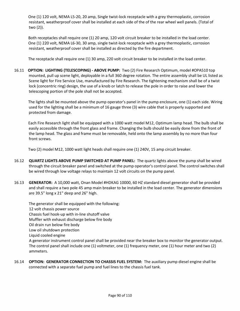
Page 90 of 110
One (1) 120 volt, NEMA L5-20, 20 amp, Single twist-lock receptacle with a grey thermoplastic, corrosion resistant, weatherproof cover shall be installed at each side of the of the rear wheel well panels. (Total of two (2)). Both receptacles shall require one (1) 20 amp, 120 volt circuit breaker to be installed in the load center. One (1) 220 volt, NEMA L6-30, 30 amp, single twist-lock receptacle with a grey thermoplastic, corrosion resistant, weatherproof cover shall be installed as directed by the fire department. The receptacle shall require one (1) 30 amp, 220 volt circuit breaker to be installed in the load center. 16.11 OPTION: LIGHTING (TELESCOPING) - ABOVE PUMP: Two (2) Fire Research Optimum, model #OPA510 top mounted, pull up scene light, deployable in a full 360 degree rotation. The entire assembly shall be UL listed as Scene light for Fire Service Use, manufactured by Fire Research. The tightening mechanism shall be of a twist lock (concentric ring) design, the use of a knob or latch to release the pole in order to raise and lower the telescoping portion of the pole shall not be accepted. The lights shall be mounted above the pump operator's panel in the pump enclosure, one (1) each side. Wiring used for the lighting shall be a minimum of 16 gauge three (3) wire cable that is properly supported and protected from damage. Each Fire Research light shall be equipped with a 1000 watt model M12, Optimum lamp head. The bulb shall be easily accessible through the front glass and frame. Changing the bulb should be easily done from the front of the lamp head. The glass and frame must be removable, held onto the lamp assembly by no more than four front screws. Two (2) model M12, 1000 watt light heads shall require one (1) 240V, 15 amp circuit breaker. 16.12 QUARTZ LIGHTS ABOVE PUMP SWITCHED AT PUMP PANEL: The quartz lights above the pump shall be wired through the circuit breaker panel and switched at the pump operator's control panel. The control switches shall be wired through low voltage relays to maintain 12 volt circuits on the pump panel. 16.13 GENERATOR: A 10,000 watt, Onan Model #HDKAG 10000, 60 HZ standard diesel generator shall be provided and shall require a two pole 45 amp main breaker to be installed in the load center. The generator dimensions are 39.5" long x 21" deep and 26" high. The generator shall be equipped with the following:
12 volt chassis power source Chassis fuel hook-up with in-line shutoff valve Muffler with exhaust discharge below fire body Oil drain run below fire body Low oil shutdown protection Liquid cooled engine A generator instrument control panel shall be provided near the breaker box to monitor the generator output. The control panel shall include one (1) voltmeter, one (1) frequency meter, one (1) hour meter and two (2) ammeters.
16.14 OPTION: GENERATOR CONNECTION TO CHASSIS FUEL SYSTEM: The auxiliary pump diesel engine shall be connected with a separate fuel pump and fuel lines to the chassis fuel tank.

Page 91 of 110
16.15 GENERATOR WARRANTY: The specified generator shall have a two (2) year or two thousand (2000) hour warranty as provided by the generator manufacturer. A copy of the generator warranty shall be provided at time of delivery. 16.16 GENERATOR LOCATION: The generator shall be mounted above the pump enclosure on the officer side. Locating the generator greater than 144" from the main breaker panel may require the installation of an additional power disconnecting means. 16.17 120/240 VOLT ELECTRICAL SYSTEM TESTING: All line voltage wiring and permanently connected devices and equipment shall be subjected to a dielectric voltage withstand test of 900 volts for one minute. The test shall be conducted between live parts and the neutral conductor and between live parts and the vehicle frame with any switches in the circuits closed. The test shall be conducted after all bodywork has been completed. The dielectric tester shall have a minimum 500 VA transformer with a sinusoidal output voltage that can be verified. Electrical polarity verification shall be made of all permanently wired equipment and receptacles to determine that connections have been properly made. 16.18 OPERATIONAL TESTING: The apparatus manufacturer shall perform the following operation test and shall certify that the power source and any devices that are attached to the line voltage electrical system are properly connected and in working order. The generator shall be started from a cold start condition and the line voltage electrical system shall be loaded to 100 percent of the nameplate voltage rating. The following items shall be monitored and documented every 15 minutes:
The cranking time until the generator starts and runs. The voltage, frequency, and amperes at continuous full rated load. The generator oil pressure, water temperature, transmission temperature, hydraulic temperature, and the battery rate charge, as applicable. The ambient temperature and altitude.
The generator shall operate at 100 percent of its nameplate wattage for a minimum of two (2) hours. 16.19 120/240 VOLT WIRING: The generator output conductors shall be 8 gauge and the output conductors shall be routed through non-metallic conduit 3/4" in diameter. 16.20 120/240 VOLT LOAD CENTER: The generator output line conductors shall be wired from the generator output connections to a Square D, model #QO112L125G breaker panel. The breaker panel shall be equipped with a properly sized main breaker using two (2) of the twelve (12) spaces which leaves a total of ten (10) available spaces. The generator output conductors shall be sized to 115% of the main breaker rating and shall be installed as indicated in the wiring section. Six (6) appropriately sized, 120 volt, circuit breakers shall be provided. Two (2) appropriately sized, 240 volt, circuit breakers shall be installed in place of four (4) standard 110 volt circuit breakers. The breaker panel shall be located on the rear wall of the driver side upper compartment.

Page 92 of 110
16.21 120/240 VOLT WIRING METHODS: Wiring/conduit shall not be attached to any chassis suspension components, water or fuel lines, air or air brake lines, fire pump piping, hydraulic lines, exhaust system components or low voltage wiring. All wiring shall be installed at a minimum of 12 inches away from any exhaust piping and a minimum of 6 inches from any fuel lines. All wiring shall be securely clamped within 6 inches of any junction box and at a minimum of every 24 inches of run. All supports shall be of nonmetallic material or corrosion protected metal. All supports shall not cut or abrade conduit or cable and shall be mechanically fastened to the vehicle. All power supply assembly conductors, including neutral and grounding conductors, shall have an equivalent amperage rating and shall be sized to carry not less than 115% of the main breaker rating. All Type SO or Type SEO cable not installed in a compartment shall be installed in wire loom. Where Type SO or Type SEO cable penetrates a metal surface, a rubber or plastic grommet or bushing shall be provided. The installation of all 120/240 wiring shall meet the current NFPA-1901 Standards (NO EXCEPTIONS). 16.22 120/240 VOLT WIRING IDENTIFICATION: All line voltage conductors located inside the main breaker panel box shall be individually and permanently identified. When pre-wiring for future power wiring installations, the non- terminated ends shall be labeled showing function and wire size. 16.23 120/240 VOLT GROUNDING: The neutral conductor of the power source shall be bonded to the vehicle fame only at the power source. The grounded current carrying conductor (neutral) shall be insulated from the equipment grounding conductors and from the equipment enclosures and other grounded parts. The neutral conductor shall be colored white or gray. In addition to the bonding required for the lower voltage return current, each body and driving/crew compartment enclosure shall be bonded to the vehicle frame by a copper conductor. The conductor shall have a minimum amperage rating of 115 percent of the name plate current rating of the power source specification label. 16.24 120/240 VOLT CIRCUIT BREAKER/RECEPTACLE INSTALLATION: The system shall be installed by highly qualified electrical technicians to assure the required level of safety and protection to the fire apparatus operators. When multiple circuit are required, the circuits shall be wired to the breaker panel in a staggered configuration to minimize electrical loads on each breaker or generator (leg) circuit. The wiring, electrical fixtures and components shall be to the highest industry quality standards available on the domestic market. The equipment shall be the type as designed for mobile type installations subject to vibration, moisture and severe continuous usage. 16.25 120/240 VOLT RECEPTACLE INSTALLATIONS: Any receptacle installed in a wet location must be a minimum of 24 inches above the ground and provided with an approved wet location cover. Wet receptacles may not be mounted at more than 45 degrees from vertical, nor can they be mounted in a face-up position. One (1) 120 volt, NEMA L5-20, 20 amp, Single twist-lock receptacle with a grey thermoplastic, corrosion resistant, weatherproof cover shall be installed at each side of the of the rear wheel well panels (Total of two (2)).
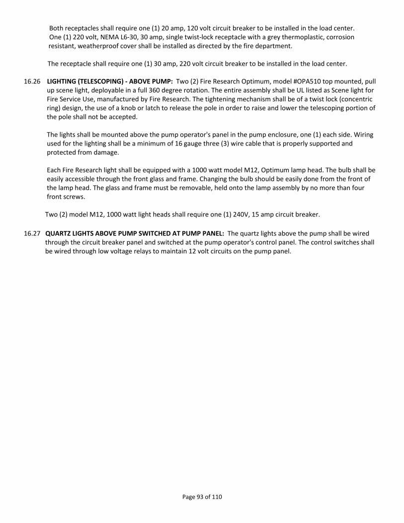
Page 93 of 110
Both receptacles shall require one (1) 20 amp, 120 volt circuit breaker to be installed in the load center. One (1) 220 volt, NEMA L6-30, 30 amp, single twist-lock receptacle with a grey thermoplastic, corrosion resistant, weatherproof cover shall be installed as directed by the fire department. The receptacle shall require one (1) 30 amp, 220 volt circuit breaker to be installed in the load center. 16.26 LIGHTING (TELESCOPING) - ABOVE PUMP: Two (2) Fire Research Optimum, model #OPA510 top mounted, pull up scene light, deployable in a full 360 degree rotation. The entire assembly shall be UL listed as Scene light for Fire Service Use, manufactured by Fire Research. The tightening mechanism shall be of a twist lock (concentric ring) design, the use of a knob or latch to release the pole in order to raise and lower the telescoping portion of the pole shall not be accepted. The lights shall be mounted above the pump operator's panel in the pump enclosure, one (1) each side. Wiring used for the lighting shall be a minimum of 16 gauge three (3) wire cable that is properly supported and protected from damage. Each Fire Research light shall be equipped with a 1000 watt model M12, Optimum lamp head. The bulb shall be easily accessible through the front glass and frame. Changing the bulb should be easily done from the front of the lamp head. The glass and frame must be removable, held onto the lamp assembly by no more than four front screws. Two (2) model M12, 1000 watt light heads shall require one (1) 240V, 15 amp circuit breaker. 16.27 QUARTZ LIGHTS ABOVE PUMP SWITCHED AT PUMP PANEL: The quartz lights above the pump shall be wired through the circuit breaker panel and switched at the pump operator's control panel. The control switches shall be wired through low voltage relays to maintain 12 volt circuits on the pump panel.

Page 94 of 110
INVITATION FOR BID #065-2012
SECTION 17 OPTIONAL TRADE-IN/PURCHASE
17. The City of Springfield is offering a 2003 Central States 85’ Aerial Platform with 2000 GPM Waterous Pump for optional Trade or Purchase. The Vehicle has 69,099 miles, and 344 hours. Apparatus is in good condition, and has been well maintained through an EVT certified mechanic. The Cab is configured for a six person crew, with power run for hand lights, thermal camera and mobile data terminal. All ground ladders and aerial ladder passed ladder testing in November 2010, and passed pump test in December 2010. Interior is clean and in good condition. Paint and roll up doors are in good condition and not in need of repair. Photos of the vehicle are available by going to www.springfieldmo.gov/purchasing and clicking on Bid Processing Center link. Apparatus will be available for viewing at pre-bid meeting.
Arrangements to inspect the vehicle or more information may be obtained by calling Assistant Chief Pennington at 417-864-1530. The vehicle is being Traded or Sold “as is, where is”, FOB Springfield, MO. This vehicle will not be taken into consideration to determine the IFB low bidder. It is simply being presented as an option to sell or trade vehicle.
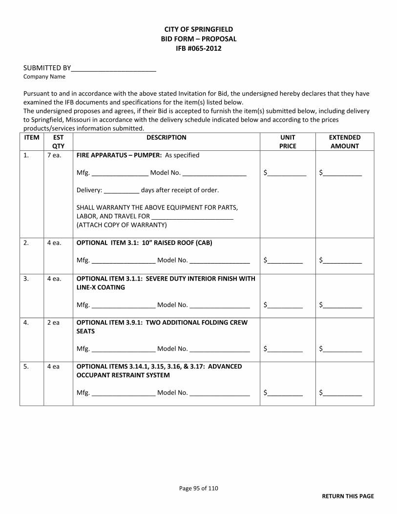
Page 95 of 110 RETURN THIS PAGE
CITY OF SPRINGFIELD BID FORM – PROPOSAL
IFB #065-2012
SUBMITTED BY______________________ Company Name Pursuant to and in accordance with the above stated Invitation for Bid, the undersigned hereby declares that they have examined the IFB documents and specifications for the item(s) listed below. The undersigned proposes and agrees, if their Bid is accepted to furnish the item(s) submitted below, including delivery to Springfield, Missouri in accordance with the delivery schedule indicated below and according to the prices products/services information submitted. ITEM EST
QTY DESCRIPTION UNIT
PRICE EXTENDED AMOUNT
1. 7 ea. FIRE APPARATUS – PUMPER: As specified Mfg. ________________ Model No. __________________ Delivery: __________ days after receipt of order. SHALL WARRANTY THE ABOVE EQUIPMENT FOR PARTS, LABOR, AND TRAVEL FOR _______________________ (ATTACH COPY OF WARRANTY)
$___________
$___________
2. 4 ea. OPTIONAL ITEM 3.1: 10” RAISED ROOF (CAB) Mfg. __________________ Model No. _________________
$__________
$___________
3. 4 ea. OPTIONAL ITEM 3.1.1: SEVERE DUTY INTERIOR FINISH WITH LINE-X COATING Mfg. __________________ Model No. _________________
$__________
$___________
4. 2 ea OPTIONAL ITEM 3.9.1: TWO ADDITIONAL FOLDING CREW SEATS Mfg. __________________ Model No. _________________
$__________
$___________
5. 4 ea OPTIONAL ITEMS 3.14.1, 3.15, 3.16, & 3.17: ADVANCED OCCUPANT RESTRAINT SYSTEM Mfg. __________________ Model No. _________________
$__________
$___________

Page 96 of 110 RETURN THIS PAGE
ITEM EST
QTY DESCRIPTION UNIT
PRICE EXTENDED AMOUNT
6. 1 ea. OPTIONAL ITEM 3.20: LINK ₂ VEHICLE DATA RECORDER/VIEW₂ XP Mfg. __________________ Model No. _________________
$__________
$___________
7. 4 ea. OPTIONAL ITEM 3.22: DASH AND CENTER CONSOLE SEVERE DUTY FINISH Mfg. __________________ Model No. _________________
$__________
$___________
8. 4 ea. OPTIONAL ITEM 3.23.1: CLASS ONE OFFICER’S SPEEDOMETER Mfg. __________________ Model No. _________________
$__________
$___________
9. 7 ea. OPTIONAL ITEM 4.27: POLISHED ALUMINUM WHEELS WITH ACCESSORIES (FRONT) Mfg. __________________ Model No. _________________
$__________
$___________
10. 7 ea. OPTIONAL ITEM 4.29: POLISHED ALUMINUM WHEELS WITH ACCESSORIES (REAR) Mfg. __________________ Model No. _________________
$__________
$___________
11. 1 ea. OPTIONAL ITEM 4.30: MICHELIN 12r-22.5 16PR “H” TUBLESS RADIAL XDN 2 Mfg. __________________ Model No. _________________
$__________
$___________
12. 4 ea OPTIONAL ITEM 4.36: FRONT BUMPER Mfg. __________________ Model No. _________________
$__________
$___________
13. 2 ea OPTIONAL ITEM 5.1: CUMMINS ISL 400 HP MOTOR Mfg. __________________ Model No. _________________
$__________
$___________
14. 2 ea. OPTIONAL ITEM 7.2: WATEROUS S100-2000 PUMP, SINGLE STAGE, 2000 G.P.M. Mfg. __________________ Model No. _________________
$__________
$___________
15. 2 ea. OPTIONAL ITEM 7.14: PUMP MANIFOLDS Mfg. __________________ Model No. _________________
$__________
$___________
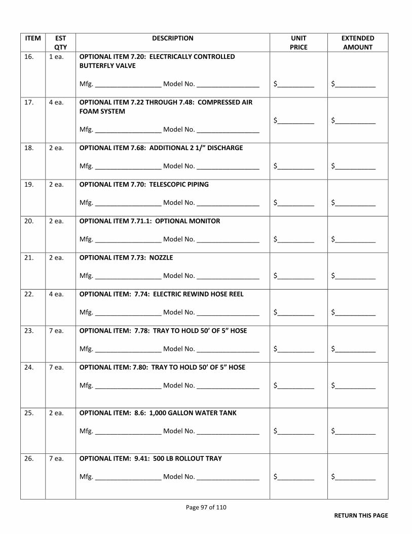
Page 97 of 110 RETURN THIS PAGE
ITEM EST
QTY DESCRIPTION UNIT
PRICE EXTENDED AMOUNT
16. 1 ea. OPTIONAL ITEM 7.20: ELECTRICALLY CONTROLLED BUTTERFLY VALVE Mfg. __________________ Model No. _________________
$__________
$___________
17. 4 ea. OPTIONAL ITEM 7.22 THROUGH 7.48: COMPRESSED AIR FOAM SYSTEM Mfg. __________________ Model No. _________________
$__________
$___________
18. 2 ea. OPTIONAL ITEM 7.68: ADDITIONAL 2 1/” DISCHARGE Mfg. __________________ Model No. _________________
$__________
$___________
19. 2 ea. OPTIONAL ITEM 7.70: TELESCOPIC PIPING Mfg. __________________ Model No. _________________
$__________
$___________
20. 2 ea.
OPTIONAL ITEM 7.71.1: OPTIONAL MONITOR Mfg. __________________ Model No. _________________
$__________
$___________
21. 2 ea. OPTIONAL ITEM 7.73: NOZZLE Mfg. __________________ Model No. _________________
$__________
$___________
22. 4 ea. OPTIONAL ITEM: 7.74: ELECTRIC REWIND HOSE REEL Mfg. __________________ Model No. _________________
$__________
$___________
23. 7 ea. OPTIONAL ITEM: 7.78: TRAY TO HOLD 50’ OF 5” HOSE Mfg. __________________ Model No. _________________
$__________
$___________
24. 7 ea. OPTIONAL ITEM: 7.80: TRAY TO HOLD 50’ OF 5” HOSE Mfg. __________________ Model No. _________________
$__________
$___________
25. 2 ea.
OPTIONAL ITEM: 8.6: 1,000 GALLON WATER TANK Mfg. __________________ Model No. _________________
$__________
$___________
26. 7 ea. OPTIONAL ITEM: 9.41: 500 LB ROLLOUT TRAY Mfg. __________________ Model No. _________________
$__________
$___________
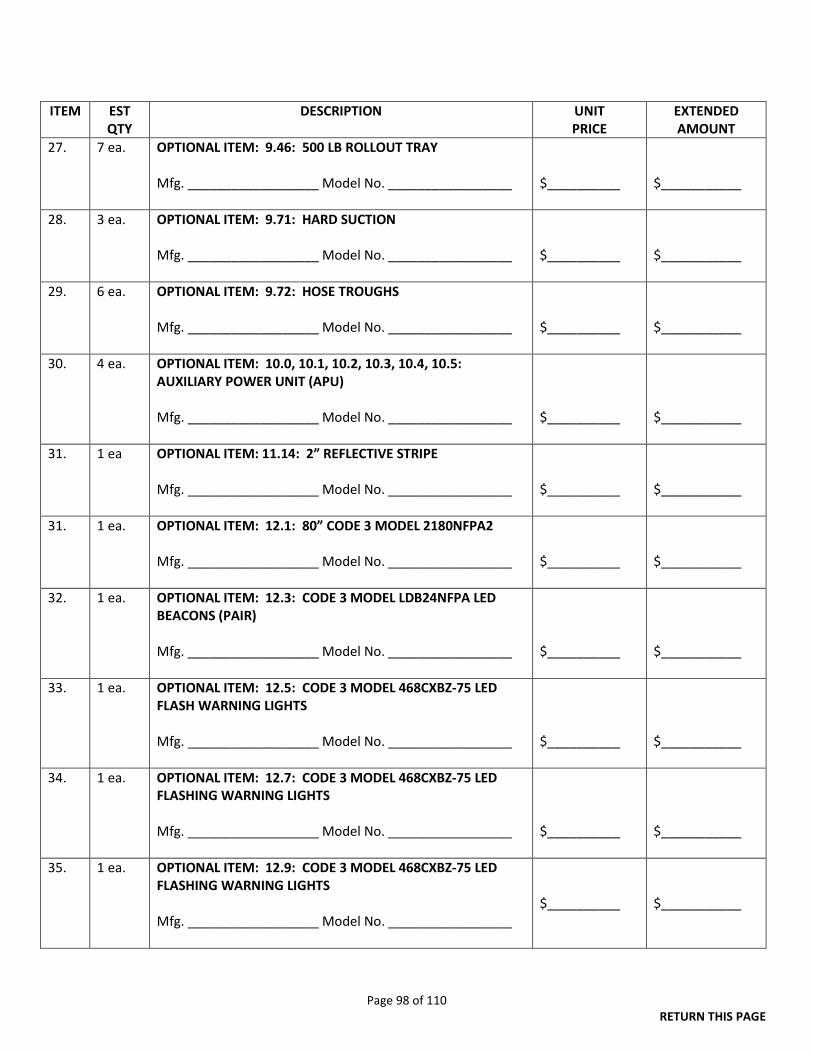
Page 98 of 110 RETURN THIS PAGE
ITEM EST QTY
DESCRIPTION UNIT PRICE
EXTENDED AMOUNT
27. 7 ea. OPTIONAL ITEM: 9.46: 500 LB ROLLOUT TRAY Mfg. __________________ Model No. _________________
$__________
$___________
28.
3 ea. OPTIONAL ITEM: 9.71: HARD SUCTION Mfg. __________________ Model No. _________________
$__________
$___________
29.
6 ea. OPTIONAL ITEM: 9.72: HOSE TROUGHS Mfg. __________________ Model No. _________________
$__________
$___________
30. 4 ea. OPTIONAL ITEM: 10.0, 10.1, 10.2, 10.3, 10.4, 10.5: AUXILIARY POWER UNIT (APU) Mfg. __________________ Model No. _________________
$__________
$___________
31. 1 ea OPTIONAL ITEM: 11.14: 2” REFLECTIVE STRIPE Mfg. __________________ Model No. _________________
$__________
$___________
31. 1 ea. OPTIONAL ITEM: 12.1: 80” CODE 3 MODEL 2180NFPA2 Mfg. __________________ Model No. _________________
$__________
$___________
32. 1 ea. OPTIONAL ITEM: 12.3: CODE 3 MODEL LDB24NFPA LED BEACONS (PAIR) Mfg. __________________ Model No. _________________
$__________
$___________
33. 1 ea. OPTIONAL ITEM: 12.5: CODE 3 MODEL 468CXBZ-75 LED FLASH WARNING LIGHTS Mfg. __________________ Model No. _________________
$__________
$___________
34. 1 ea. OPTIONAL ITEM: 12.7: CODE 3 MODEL 468CXBZ-75 LED FLASHING WARNING LIGHTS Mfg. __________________ Model No. _________________
$__________
$___________
35. 1 ea. OPTIONAL ITEM: 12.9: CODE 3 MODEL 468CXBZ-75 LED FLASHING WARNING LIGHTS Mfg. __________________ Model No. _________________
$__________
$___________
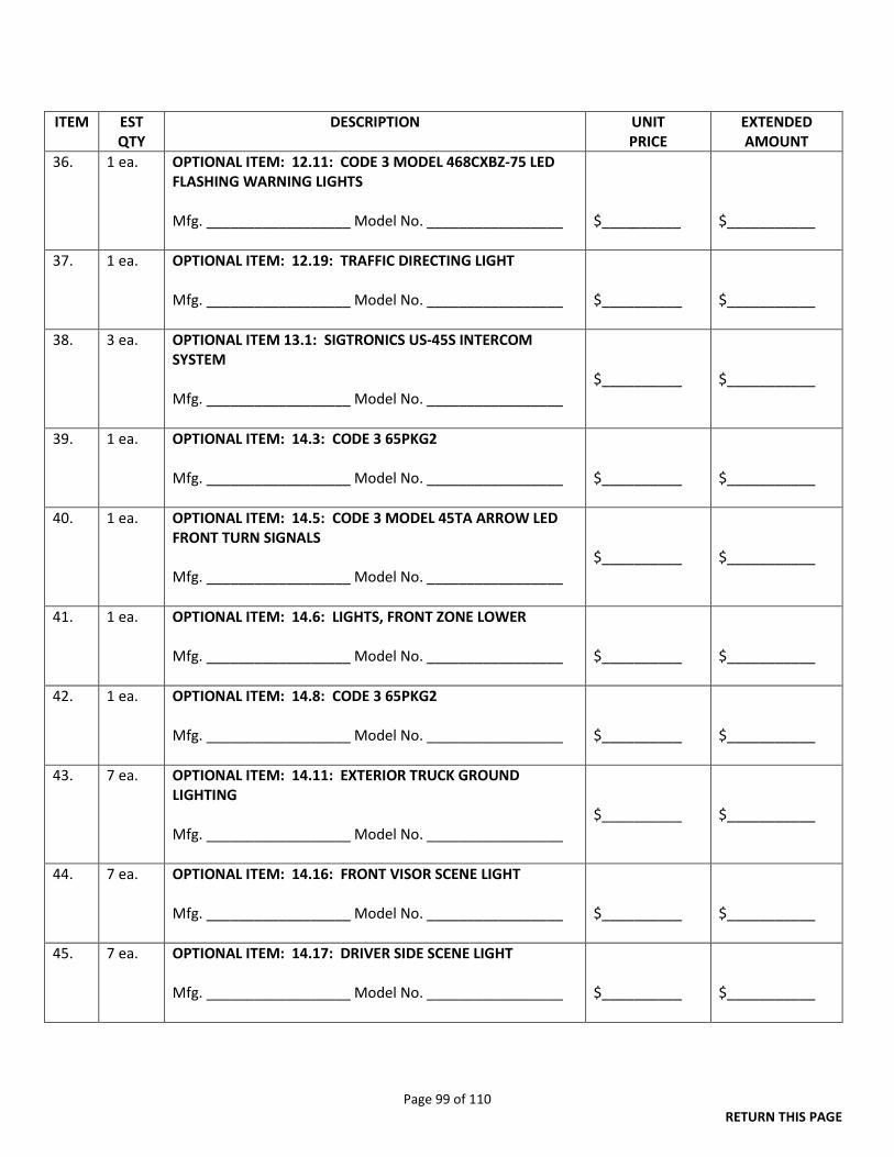
Page 99 of 110 RETURN THIS PAGE
ITEM EST QTY
DESCRIPTION UNIT PRICE
EXTENDED AMOUNT
36. 1 ea. OPTIONAL ITEM: 12.11: CODE 3 MODEL 468CXBZ-75 LED FLASHING WARNING LIGHTS Mfg. __________________ Model No. _________________
$__________
$___________
37. 1 ea. OPTIONAL ITEM: 12.19: TRAFFIC DIRECTING LIGHT Mfg. __________________ Model No. _________________
$__________
$___________
38. 3 ea. OPTIONAL ITEM 13.1: SIGTRONICS US-45S INTERCOM SYSTEM Mfg. __________________ Model No. _________________
$__________
$___________
39. 1 ea. OPTIONAL ITEM: 14.3: CODE 3 65PKG2 Mfg. __________________ Model No. _________________
$__________
$___________
40. 1 ea. OPTIONAL ITEM: 14.5: CODE 3 MODEL 45TA ARROW LED FRONT TURN SIGNALS Mfg. __________________ Model No. _________________
$__________
$___________
41. 1 ea. OPTIONAL ITEM: 14.6: LIGHTS, FRONT ZONE LOWER Mfg. __________________ Model No. _________________
$__________
$___________
42. 1 ea. OPTIONAL ITEM: 14.8: CODE 3 65PKG2 Mfg. __________________ Model No. _________________
$__________
$___________
43. 7 ea. OPTIONAL ITEM: 14.11: EXTERIOR TRUCK GROUND LIGHTING Mfg. __________________ Model No. _________________
$__________
$___________
44. 7 ea. OPTIONAL ITEM: 14.16: FRONT VISOR SCENE LIGHT Mfg. __________________ Model No. _________________
$__________
$___________
45. 7 ea. OPTIONAL ITEM: 14.17: DRIVER SIDE SCENE LIGHT Mfg. __________________ Model No. _________________
$__________
$___________

Page 100 of 110 RETURN THIS PAGE
ITEM EST QTY
DESCRIPTION UNIT PRICE
EXTENDED AMOUNT
46. 7 ea. OPTIONAL ITEM: 14.18: PASSENGER SIDE SCENE LIGHT Mfg. __________________ Model No. _________________
$__________
$___________
47. 2 ea. OPTIONAL ITEM: 16.2 PTO DRIVEN HYDRAULIC GENERATOR Mfg. __________________ Model No. _________________
$__________
$___________
48. 3 ea. OPTIONAL ITEM: 16.11: LIGHTING (TELESCOPING) ABOVE PUMP Mfg. __________________ Model No. _________________
$__________
$___________
49. 3 ea. OPTIONAL ITEM: 16.13: DIESEL ENGINE GENERATOR Mfg. __________________ Model No. _________________
$__________
$___________
50. 3 ea. OPTIONAL ITEM: 16.14: GENERATOR CONNECTION TO CHASSIS FUEL SYSTEM Mfg. __________________ Model No. _________________
$__________
$___________
51. 1 ea. OPTIONAL ITEM: 17: 2003 Central States 85’ Aerial Platform Trade or Purchase, FOB Springfield, MO TRADE AMOUNT OFFERED: PURCHASE AMOUNT OFFERED:
$___________ $___________
DELIVERY: F.O.B. DESTINATION
Prompt Payment Discount __________%_________Days, Net _____Days
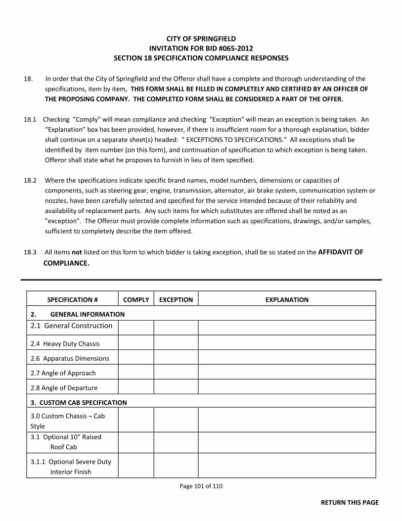
Page 101 of 110
RETURN THIS PAGE
CITY OF SPRINGFIELD INVITATION FOR BID #065-2012
SECTION 18 SPECIFICATION COMPLIANCE RESPONSES
18. In order that the City of Springfield and the Offeror shall have a complete and thorough understanding of the specifications, item by item, THIS FORM SHALL BE FILLED IN COMPLETELY AND CERTIFIED BY AN OFFICER OF THE PROPOSING COMPANY. THE COMPLETED FORM SHALL BE CONSIDERED A PART OF THE OFFER. 18.1 Checking "Comply" will mean compliance and checking "Exception" will mean an exception is being taken. An “Explanation” box has been provided, however, if there is insufficient room for a thorough explanation, bidder shall continue on a separate sheet(s) headed: " EXCEPTIONS TO SPECIFICATIONS." All exceptions shall be identified by item number (on this form), and continuation of specification to which exception is being taken. Offeror shall state what he proposes to furnish in lieu of item specified. 18.2 Where the specifications indicate specific brand names, model numbers, dimensions or capacities of components, such as steering gear, engine, transmission, alternator, air brake system, communication system or nozzles, have been carefully selected and specified for the service intended because of their reliability and availability of replacement parts. Any such items for which substitutes are offered shall be noted as an "exception". The Offeror must provide complete information such as specifications, drawings, and/or samples, sufficient to completely describe the item offered.
18.3 All items not listed on this form to which bidder is taking exception, shall be so stated on the AFFIDAVIT OF COMPLIANCE.
SPECIFICATION #
COMPLY
EXCEPTION
EXPLANATION
2. GENERAL INFORMATION
2.1 General Construction
2.4 Heavy Duty Chassis
2.6 Apparatus Dimensions
2.7 Angle of Approach
2.8 Angle of Departure
3. CUSTOM CAB SPECIFICATION 3.0 Custom Chassis – Cab Style
3.1 Optional 10” Raised Roof Cab
3.1.1 Optional Severe Duty
Interior Finish
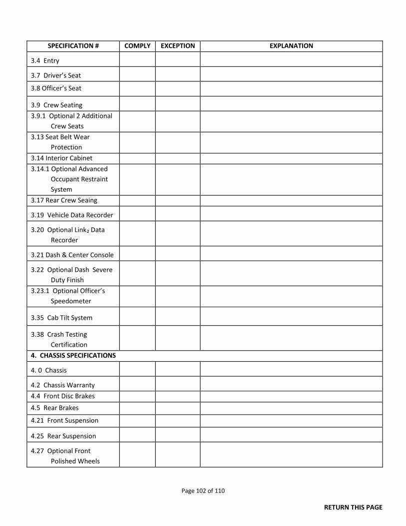
Page 102 of 110
RETURN THIS PAGE
SPECIFICATION # COMPLY EXCEPTION EXPLANATION 3.4 Entry
3.7 Driver’s Seat
3.8 Officer’s Seat
3.9 Crew Seating
3.9.1 Optional 2 Additional Crew Seats
3.13 Seat Belt Wear Protection
3.14 Interior Cabinet
3.14.1 Optional Advanced Occupant Restraint System
3.17 Rear Crew Seaing
3.19 Vehicle Data Recorder
3.20 Optional Link₂ Data
Recorder
3.21 Dash & Center Console
3.22 Optional Dash Severe
Duty Finish
3.23.1 Optional Officer’s Speedometer
3.35 Cab Tilt System
3.38 Crash Testing
Certification
4. CHASSIS SPECIFICATIONS 4. 0 Chassis
4.2 Chassis Warranty
4.4 Front Disc Brakes
4.5 Rear Brakes
4.21 Front Suspension 4.25 Rear Suspension
4.27 Optional Front
Polished Wheels
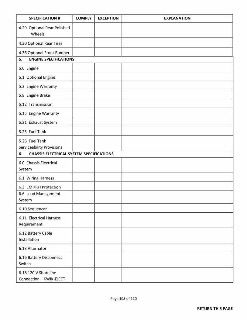
Page 103 of 110
RETURN THIS PAGE
SPECIFICATION # COMPLY EXCEPTION EXPLANATION 4.29 Optional Rear Polished
Wheels
4.30 Optional Rear Tires
4.36 Optional Front Bumper
5. ENGINE SPECIFICATIONS 5.0 Engine
5.1 Optional Engine
5.2 Engine Warranty
5.8 Engine Brake
5.12 Transmission
5.15 Engine Warranty
5.21 Exhaust System
5.25 Fuel Tank
5.26 Fuel Tank Serviceability Provisions
6. CHASSIS ELECTRICAL SYSTEM SPECIFICATIONS 6.0 Chassis Electrical System
6.1 Wiring Harness
6.3 EMI/RFI Protection
6.6 Load Management System
6.10 Sequencer
6.11 Electrical Harness Requirement
6.12 Battery Cable Installation
6.13 Alternator
6.16 Battery Disconnect Switch
6.18 120 V Shoreline Connection – KWIK-EJECT
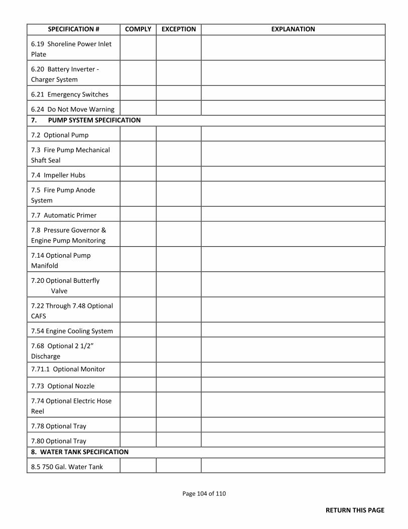
Page 104 of 110
RETURN THIS PAGE
SPECIFICATION # COMPLY EXCEPTION EXPLANATION 6.19 Shoreline Power Inlet Plate
6.20 Battery Inverter -Charger System
6.21 Emergency Switches
6.24 Do Not Move Warning
7. PUMP SYSTEM SPECIFICATION 7.2 Optional Pump
7.3 Fire Pump Mechanical Shaft Seal
7.4 Impeller Hubs
7.5 Fire Pump Anode System
7.7 Automatic Primer
7.8 Pressure Governor & Engine Pump Monitoring
7.14 Optional Pump Manifold
7.20 Optional Butterfly
Valve
7.22 Through 7.48 Optional CAFS
7.54 Engine Cooling System
7.68 Optional 2 1/2” Discharge
7.71.1 Optional Monitor
7.73 Optional Nozzle
7.74 Optional Electric Hose Reel
7.78 Optional Tray
7.80 Optional Tray
8. WATER TANK SPECIFICATION 8.5 750 Gal. Water Tank
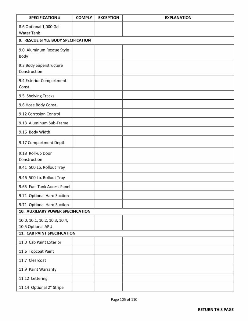
Page 105 of 110
RETURN THIS PAGE
SPECIFICATION # COMPLY EXCEPTION EXPLANATION 8.6 Optional 1,000 Gal. Water Tank
9. RESCUE STYLE BODY SPECIFICATION 9.0 Aluminum Rescue Style Body
9.3 Body Superstructure Construction
9.4 Exterior Compartment Const.
9.5 Shelving Tracks
9.6 Hose Body Const.
9.12 Corrosion Control
9.13 Aluminum Sub-Frame
9.16 Body Width
9.17 Compartment Depth
9.18 Roll-up Door Construction
9.41 500 Lb. Rollout Tray
9.46 500 Lb. Rollout Tray
9.65 Fuel Tank Access Panel
9.71 Optional Hard Suction
9.71 Optional Hard Suction
10. AUXILIARY POWER SPECIFICATION 10.0, 10.1, 10.2, 10.3, 10.4, 10.5 Optional APU
11. CAB PAINT SPECIFICATION 11.0 Cab Paint Exterior
11.6 Topcoat Paint
11.7 Clearcoat
11.9 Paint Warranty
11.12 Lettering
11.14 Optional 2” Stripe
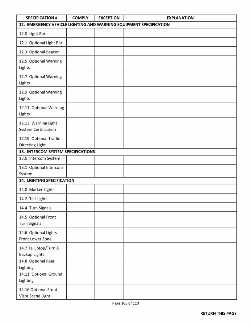
Page 106 of 110
RETURN THIS PAGE
SPECIFICATION # COMPLY EXCEPTION EXPLANATION
12. EMERGENCY VEHICLE LIGHTING AND WARNING EQUIPMENT SPECIFICATION 12.0 Light Bar
12.1 Optional Light Bar
12.3 Optional Beacon
12.5 Optional Warning Lights
12.7 Optional Warning Lights
12.9 Optional Warning Lights
12.11 Optional Warning Lights
12.12 Warning Light System Certification
12.19 Optional Traffic Directing Light
13. INTERCOM SYSTEM SPECIFICATIONS
13.0 Intercom System
13.1 Optional Intercom System
14. LIGHTING SPECIFICATION 14.0 Marker Lights
14.2 Tail Lights
14.4 Turn Signals
14.5 Optional Front Turn Signals
14.6 Optional Lights Front Lower Zone
14.7 Tail, Stop/Turn & Backup Lights
14.8 Optional Rear Lighting
14.11 Optional Ground Lighting
14.16 Optional Front Visor Scene Light
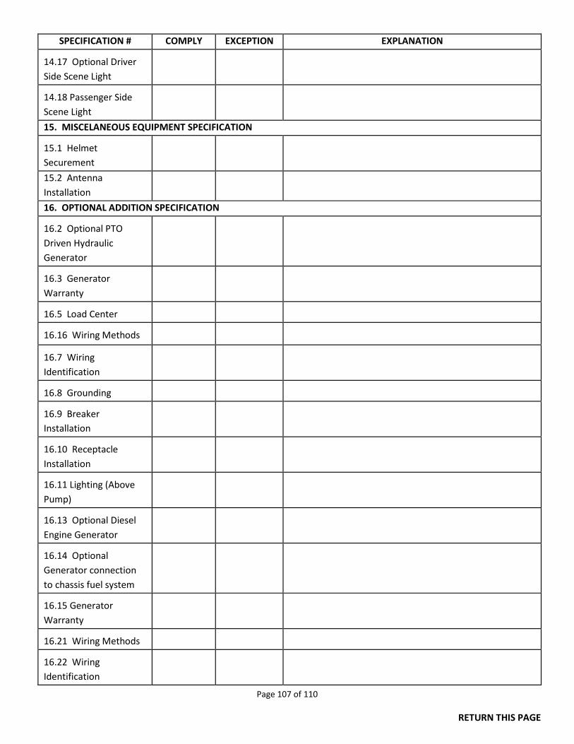
Page 107 of 110
RETURN THIS PAGE
SPECIFICATION # COMPLY EXCEPTION EXPLANATION 14.17 Optional Driver Side Scene Light
14.18 Passenger Side Scene Light
15. MISCELANEOUS EQUIPMENT SPECIFICATION 15.1 Helmet Securement
15.2 Antenna Installation
16. OPTIONAL ADDITION SPECIFICATION 16.2 Optional PTO Driven Hydraulic Generator
16.3 Generator Warranty
16.5 Load Center
16.16 Wiring Methods
16.7 Wiring Identification
16.8 Grounding
16.9 Breaker Installation
16.10 Receptacle Installation
16.11 Lighting (Above Pump)
16.13 Optional Diesel Engine Generator
16.14 Optional Generator connection to chassis fuel system
16.15 Generator Warranty
16.21 Wiring Methods
16.22 Wiring Identification
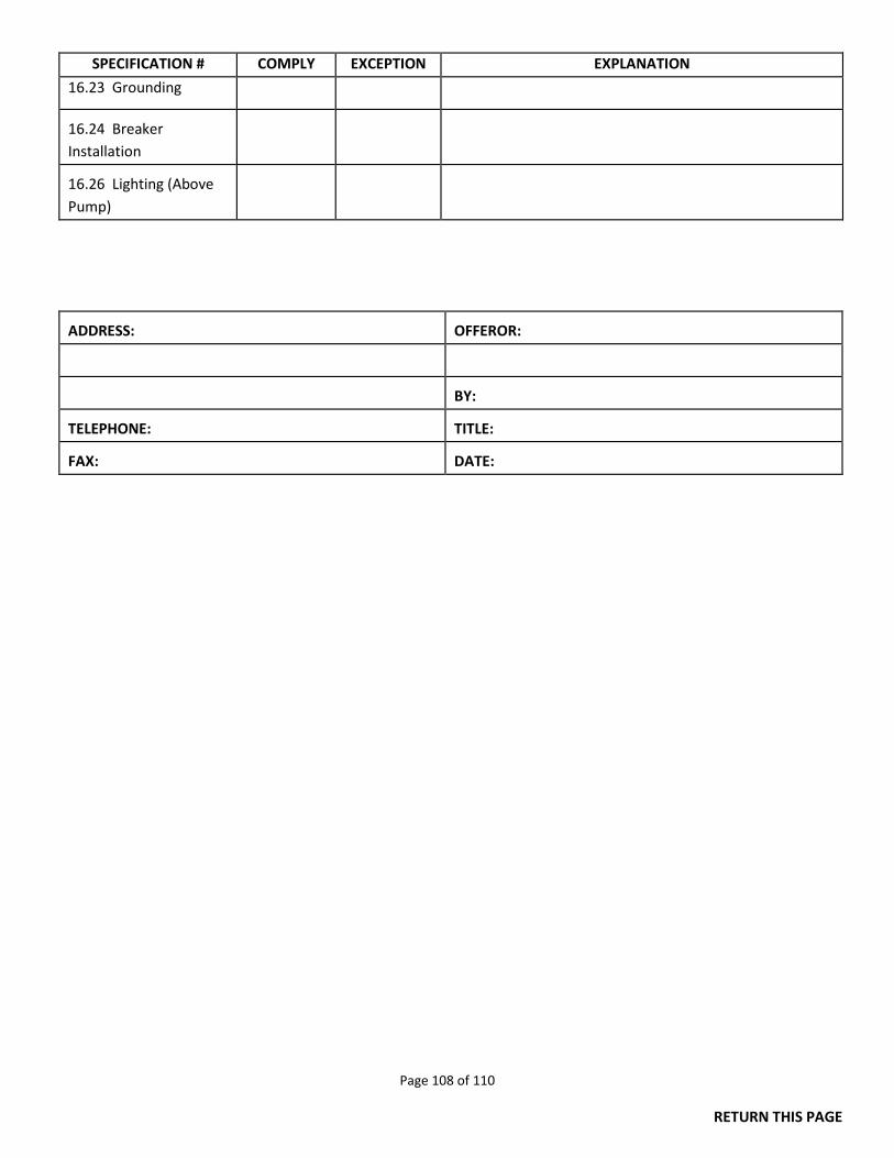
Page 108 of 110
RETURN THIS PAGE
SPECIFICATION # COMPLY EXCEPTION EXPLANATION
16.23 Grounding
16.24 Breaker Installation
16.26 Lighting (Above Pump)
ADDRESS:
OFFEROR:
BY:
TELEPHONE:
TITLE:
FAX:
DATE:
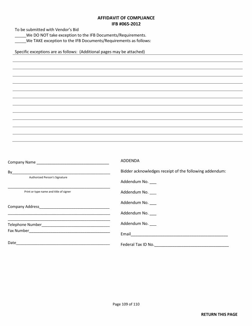
Page 109 of 110
RETURN THIS PAGE
AFFIDAVIT OF COMPLIANCE IFB #065-2012
To be submitted with Vendor’s Bid _____We DO NOT take exception to the IFB Documents/Requirements. _____We TAKE exception to the IFB Documents/Requirements as follows: Specific exceptions are as follows: (Additional pages may be attached)
Company Name __________________________________
By______________________________________________ Authorized Person’s Signature
________________________________________________ Print or type name and title of signer
Company Address_________________________________ ________________________________________________ ________________________________________________ Telephone Number________________________________ Fax Number______________________________________ Date____________________________________________
ADDENDA
Bidder acknowledges receipt of the following addendum:
Addendum No. ___
Addendum No. ___
Addendum No. ___
Addendum No. ___
Addendum No. ___
Email___________________________________________
Federal Tax ID No._________________________________
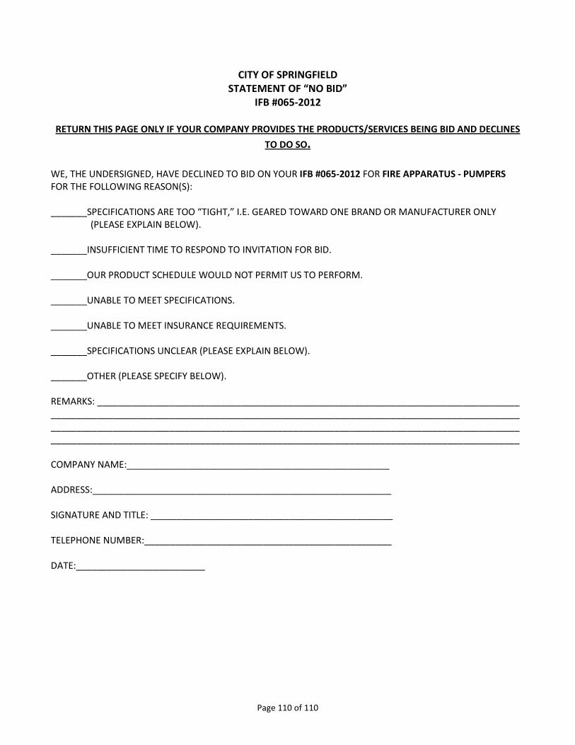
Page 110 of 110
CITY OF SPRINGFIELD STATEMENT OF “NO BID”
IFB #065-2012
RETURN THIS PAGE ONLY IF YOUR COMPANY PROVIDES THE PRODUCTS/SERVICES BEING BID AND DECLINES
TO DO SO.
WE, THE UNDERSIGNED, HAVE DECLINED TO BID ON YOUR IFB #065-2012 FOR FIRE APPARATUS - PUMPERS FOR THE FOLLOWING REASON(S): _______SPECIFICATIONS ARE TOO “TIGHT,” I.E. GEARED TOWARD ONE BRAND OR MANUFACTURER ONLY (PLEASE EXPLAIN BELOW). _______INSUFFICIENT TIME TO RESPOND TO INVITATION FOR BID. _______OUR PRODUCT SCHEDULE WOULD NOT PERMIT US TO PERFORM. _______UNABLE TO MEET SPECIFICATIONS. _______UNABLE TO MEET INSURANCE REQUIREMENTS. _______SPECIFICATIONS UNCLEAR (PLEASE EXPLAIN BELOW). _______OTHER (PLEASE SPECIFY BELOW). REMARKS: __________________________________________________________________________________ _________________________________________________________________________________________________________________________________________________________________________________________________________________________________________________________________________________ COMPANY NAME:___________________________________________________ ADDRESS:__________________________________________________________ SIGNATURE AND TITLE: _______________________________________________ TELEPHONE NUMBER:________________________________________________ DATE:_________________________
Related Documents