Report of the Committee on Technical Committee on Fire and Emergency Services Protective Clothing and Equipment Technical Correlating Committee (FAE-AAC) Richard M. Duff)', Chair Int'l Assn. of Fire Fighters, DC [L] Rep. Int'l Assn. of Fire Fighters Wayde B. Miller, Secretary Jacksonville Beach, FL [M] Lesfie Anderson, U.S. Forest SexMce, MT [E] Thomas G. Augherton, Safety Equipment Inst., VA [RT] Dennis W. Browner, Scott Aviation, NC [M] Rep. The Safety Equipment Assn. M Robert A. Freese, Globe Mfg. Co., NH [M] William L. Grilliot, Morning Pride Mfg. Co., OH [M] Rep. Fire and Emergency Mfrs.and Services Assn. Inc. Cheryl L. Harris, Dupont, VA [M] Virgil Hathaway, San Diego Fire Dept., CA [U] Rep. Southern Area Fire Equipment Research Jcames S. Johnson, Lawrence Livermore Nat'l Labs, CA [RT] y Long, Texas Commission on Fire Protection, TX [E] David G. Matthews, United Kingdom Fire Brigades" Assn., England [SE] Jim Minx, Oklahoma State Firefighters Assn., OK [C] Bob Montgomery, Celanese Corp., NC [M] Jeffrey O. Stull, Int'l Personnel Protection, Inc., TX [SE] Frank P. Taylor, Lion Apparel Inc., OH [M] Robert D. Tutterow,Jr., Charlotte Fire Dept., NC [U] Rep. Fire Indusuy Equipment Research Organization Bruce H. Varner, City of Carrollton Fire Dept., TX [U] Rep. Int'l Fire Service Training Assn. Harry Winer, U.S. Navy, MA [RT] Tricia Vogelpohl, Springfield, LLC, SC [M] Thomas L. Wollan, Underwriters Laboratories, Inc., NC [RT] Alternates Janice c. Bradley, Industrial Safety Equipment Assn., VA [M] (Alt. to D. W. Browner) Robert H. Chiostergi, Southern Mills Inc., GA [M] (Alt. to T. Vogelpohl) Nicholas J. Curtis:, Lion Apparel, Inc., OH [M] (Alt. to F. P. Taylor) Patricia A. Freem:m, Globe Mfg. Co., NH [M] (Alt. to 1L A. Freese) Patricia A. Gleason, Safety Equipment Inst., VA [RT] (Alt. to T. G. Augherton) William M. Lambert, Mine Safety Appliances Co., PA [M] (Alt. to W. B. Miller) Steven B. Lumry, Oklahoma City Fire Dept., OK [C] (Alt. to J. Minx) Daniel P. Ryan, Underwriters Laboratories Inc., NC [RT] (Alt. to T. L. Wollan) Nonvoting Don R. Forrest, United Firefighters of Los Angeles City, CA [L] Bryan C. Helrston, Oklahoma City Fire Dept., OK [L] Richard Mangan, USDA Forest Service, MT[RT] James S. Nee, A$~T Working Group, PA [U] 'Kirk H. Owen, Pl:mo Fire Dept., TX [U] Ray F. Reed, Dallas Fire Dept., TX [U] Committee Scope: This Committee shall have primary responsibility for documents on the design, performance, testing, and certification of protective clothing and p.rotective equipment manufactured for fire and emergency services organizations and personnel, to protect against exposures encountered during emergency incident operations. This Committee shall also have the primary responsibility for documents on the selection, care, and maintenance of such protective clothing and protective equipment by fire and emergency services organizations and personnel. Hazardous Materials Protective Clothing and Equipment (FAE-HAZ) Bryan C. Heirston, Chair Oklahoma City Fire Dept., OK [L] Rep. Int'l Assn. of Fire Fighters Patrlcia A. Gleason, Secretary Safety Equipment Inst., VA [RT] Donald Abbott, Command Emergency Response Training, IN [SE] William Alexander, Bata Shoe Co., MD [M] effrey B. Borkowski, Fire Dept. City New York, NY [U] err), Bore, Mine Safety Appliances, PA [M] wRa~lP e. Industrial Safety Equipment Assn. G. DeHate, Hillsborough County Fire Rescue, FL [E] Gerald J. Diskin, Kodak Fire Dept., NY[U] Catherine 1L Dodgen, Intertek Testing Semfices NA Inc., NY [RT] Jan Dunbar, Sacramento Fire Dept., CA [U] Rep. Int'l Assn. of Fire Chiefs Daniel Gohlke, W. L. Gore & Assoc., MD [M] William G. Hatch, Hatch, Health and Safety Training, CA [SE] Derek Jenkins, Ontario Hydro - Nanticoke, Canada [U] Glenn P. Jirka, University of Missouri Fire & Rescue Training Inst., MO [SE] John D. Langley, Kappler Safety Group, Inc., AL [M] JKames W. Marquardt, Underwriters Laboratories Inc., IL [RT] enneth A. Pever, Guardian Mfg. Co., OH [M] Jack IL Pryor, City of Piano Fire Dept., TX [U] Alar Ruutopold, Chemfah Corp., NH [M] Mel Seng, Norcross Safety Products, IL [MI Jeffrey O. Stull, Int'l Personnel Protection. Inc., "IX [SE] Richard W. Thomas, TRI/Environmental, Inc., TX [RT] Robert West, Texas Instruments, "IX [U] arnes P. Zeigler, E~ I. duPont de Nemours and Co., Inc., VA [M] ichael Ziskin, Field Safety Corp., CT [RT] Alternates Jon v. Brannan, Underwriters Laboratories Inc., IL [RT] (Alt. toJ. W. Marquardt) Prakash G.'Devasthali, Norcross Safety Products, IL [M] (Alt. to M. Seng) John J. Fanning, Fire Dept., City of New York, NY [U] (Alt. to J.B. Borkowski) Philip C. Mann, Kappler, AL [M] (Alt. toJ. D. Langley) Committee Scope: This Committee shall have primary responsibility for documents on protective clothing and protective equipment, except respiratory protective equipment, that provides hand, foot, torso, limb, and head protection for fire fighters and other emergency services responders during incidents that involve hazardous materials operations. These operations involve the activities of rescue; hazardous material confinement, containment, and mitigation; and property conservation where exposure to substances that present an unusual danger to responders are present or could occur due to toxicity, chemical reactivity, decomposition, corrosiveness, or similar reactions. Additionally, this committee shall have primary responsibility for documents on the selection, care, and maintenance of hazardous materials protective clothing and protective equipment by fire and emergency services organizations and personnel. Technical Committee on Special Operations Protective Clothing and Equipment (FAE-SCE) Don 1L Forrest, Chair United Firefighters of LA City, CA [L] Jeffrey o. Stull, Secretary Int'l Personnel Protection, Inc., TX [SE] Thomas G. Augherton, Safety Equipment InsL, VA [RT] Dean William Cox, Fairfax Fire & Rescue Dept., VA [U] Nicholas J. Curtis, Lion Apparel, Inc., OH [M] Steve Derynck, Underwriters Laboratories Inc., NC [RT] Hamid Ghorashi, E. I. DuPont de Nemonrs and Co., Inc., VA [M] 1025

Welcome message from author
This document is posted to help you gain knowledge. Please leave a comment to let me know what you think about it! Share it to your friends and learn new things together.
Transcript
Report o f the Committee on Technical Commit tee on
Fire and Emergency Services Protective Clothing and Equipment
Technical Correlating Committee (FAE-AAC)
Richard M. Duff)', Chair Int'l Assn. of Fire Fighters, DC [L]
Rep. Int'l Assn. of Fire Fighters
Wayde B. Miller, Secretary Jacksonville Beach, FL [M]
Lesfie Anderson, U.S. Forest SexMce, MT [E] Thomas G. Augherton, Safety Equipment Inst., VA [RT] Dennis W. Browner, Scott Aviation, NC [M]
Rep. The Safety Equipment Assn. M Robert A. Freese, Globe Mfg. Co., NH [M] William L. Grilliot, Morning Pride Mfg. Co., OH [M]
Rep. Fire and Emergency Mfrs.and Services Assn. Inc. Cheryl L. Harris, Dupont, VA [M] Virgil Hathaway, San Diego Fire Dept., CA [U]
Rep. Southern Area Fire Equipment Research Jcames S. Johnson, Lawrence Livermore Nat'l Labs, CA [RT]
y Long, Texas Commission on Fire Protection, TX [E] David G. Matthews, United Kingdom Fire Brigades" Assn.,
England [SE] Jim Minx, Oklahoma State Firefighters Assn., OK [C] Bob Montgomery, Celanese Corp., NC [M] Jeffrey O. Stull, Int'l Personnel Protection, Inc., TX [SE] Frank P. Taylor, Lion Apparel Inc., OH [M] Robert D. Tutterow,Jr., Charlotte Fire Dept., NC [U]
Rep. Fire Indusuy Equipment Research Organization Bruce H. Varner, City of Carrollton Fire Dept., TX [U]
Rep. Int'l Fire Service Training Assn. Harry Winer, U.S. Navy, MA [RT] Tricia Vogelpohl, Springfield, LLC, SC [M] Thomas L. Wollan, Underwriters Laboratories, Inc., NC [RT]
Alternates
Janice c. Bradley, Industrial Safety Equipment Assn., VA [M] (Alt. to D. W. Browner)
Robert H. Chiostergi, Southern Mills Inc., GA [M] (Alt. to T. Vogelpohl)
Nicholas J. Curtis:, Lion Apparel, Inc., OH [M] (Alt. to F. P. Taylor)
Patricia A. Freem:m, Globe Mfg. Co., NH [M] (Alt. to 1L A. Freese)
Patricia A. Gleason, Safety Equipment Inst., VA [RT] (Alt. to T. G. Augherton)
William M. Lambert, Mine Safety Appliances Co., PA [M] (Alt. to W. B. Miller)
Steven B. Lumry, Oklahoma City Fire Dept., OK [C] (Alt. to J. Minx)
Daniel P. Ryan, Underwriters Laboratories Inc., NC [RT] (Alt. to T. L. Wollan)
Nonvoting
Don R. Forrest, United Firefighters of Los Angeles City, CA [L] Bryan C. Helrston, Oklahoma City Fire Dept., OK [L] Richard Mangan, USDA Forest Service, MT[RT] James S. Nee, A$~T Working Group, PA [U] 'Kirk H. Owen, Pl:mo Fire Dept., TX [U] Ray F. Reed, Dallas Fire Dept., TX [U]
Committee Scope: This Committee shall have primary responsibility for documents on the design, performance, testing, and certification of protective clothing and p.rotective equipment manufactured for fire and emergency services organizations and personnel, to protect against exposures encountered during emergency incident operations. This Committee shall also have the primary responsibility for documents on the selection, care, and maintenance of such protective clothing and protective equipment by fire and emergency services organizations and personnel.
Hazardous Materials Protective Clothing and Equipment (FAE-HAZ)
Bryan C. Heirston, Chair Oklahoma City Fire Dept., OK [L]
Rep. Int'l Assn. of Fire Fighters
Patrlcia A. Gleason, Secretary Safety Equipment Inst., VA [RT]
Donald Abbott, Command Emergency Response Training, IN [SE] William Alexander, Bata Shoe Co., MD [M] effrey B. Borkowski, Fire Dept. City New York, NY [U] err), Bore, Mine Safety Appliances, PA [M] wRa~lP e. Industrial Safety Equipment Assn.
G. DeHate, Hillsborough County Fire Rescue, FL [E] Gerald J. Diskin, Kodak Fire Dept., NY[U] Catherine 1L Dodgen, Intertek Testing Semfices NA Inc., NY [RT] Jan Dunbar, Sacramento Fire Dept., CA [U]
Rep. Int'l Assn. of Fire Chiefs Daniel Gohlke, W. L. Gore & Assoc., MD [M] William G. Hatch, Hatch, Health and Safety Training, CA [SE] Derek Jenkins, Ontario Hydro - Nanticoke, Canada [U] Glenn P. Jirka, University of Missouri Fire & Rescue Training Inst.,
MO [SE] John D. Langley, Kappler Safety Group, Inc., AL [M] JKames W. Marquardt, Underwriters Laboratories Inc., IL [RT]
enneth A. Pever, Guardian Mfg. Co., OH [M] Jack IL Pryor, City of Piano Fire Dept., TX [U] Alar Ruutopold, Chemfah Corp., NH [M] Mel Seng, Norcross Safety Products, IL [MI Jeffrey O. Stull, Int'l Personnel Protection. Inc., "IX [SE] Richard W. Thomas, TRI/Environmental, Inc., TX [RT] Robert West, Texas Instruments, "IX [U] arnes P. Zeigler, E~ I. duPont de Nemours and Co., Inc., VA [M]
ichael Ziskin, Field Safety Corp., CT [RT]
Alternates
Jon v . Brannan, Underwriters Laboratories Inc., IL [RT] (Alt. toJ. W. Marquardt)
Prakash G.'Devasthali, Norcross Safety Products, IL [M] (Alt. to M. Seng)
John J. Fanning, Fire Dept., City of New York, NY [U] (Alt. to J .B. Borkowski)
Philip C. Mann, Kappler, AL [M] (Alt. toJ. D. Langley)
Committee Scope: This Committee shall have primary responsibility for documents on protective clothing and protective equipment, except respiratory protective equipment, that provides hand, foot, torso, limb, and head protection for fire fighters and other emergency services responders during incidents that involve hazardous materials operations. These operations involve the activities of rescue; hazardous material confinement, containment, and mitigation; and property conservation where exposure to substances that present an unusual danger to responders are present or could occur due to toxicity, chemical reactivity, decomposition, corrosiveness, or similar reactions.
Additionally, this committee shall have primary responsibility for documents on the selection, care, and maintenance of hazardous materials protective clothing and protective equipment by fire and emergency services organizations and personnel.
Technical Committee on
Special Operations Protective Clothing and Equipment (FAE-SCE)
Don 1L Forrest, Chair United Firefighters of LA City, CA [L]
Jeffrey o . Stull, Secretary Int'l Personnel Protection, Inc., TX [SE]
Thomas G. Augherton, Safety Equipment InsL, VA [RT] Dean William Cox, Fairfax Fire & Rescue Dept., VA [U] Nicholas J. Curtis, Lion Apparel, Inc., OH [M] Steve Derynck, Underwriters Laboratories Inc., NC [RT] Hamid Ghorashi, E. I. DuPont de Nemonrs and Co., Inc., VA [M]
1025
N F P A 1 9 9 4 m N o v e m b e r 2 0 0 0 R O P
Daniel Gohlke, W. L. Gore & Assoc., MD [M] Diane B. Hess, Celanese, NC [M] Steve Hudson, Pigeon Mountain Industries, Inc., GA [M] James R. Lawson, U.S. Nat'l Inst. of Standards and Technology,
MD [RT] Kevin S. Malley, New York City Fire Dept., NY [U] Michael L. Martin, Dayton Fire Dept. Headquarters, OH [C] H. Dean Paderlck, Spec Rescue Int'l, VA[SE] aCk Reali, City of Columbus Fire Division, OH [U] effrey G. Scott, Altamonte Springs Fire/Rescue Dept., FL [U] ell)' Wayne Sisson, City of La Mesa Fire Dept., CA [U]
Michael T. Stanhope, Southern Mills, Inc.,GA [M] Robert D. Steadman, Westinghouse SRS Fire Dept., SC [U] William F. Sullivan, Chelsea Fire Dept., MA[L]
Rep. Chelsea Fire fighters Assn. Michael L. Taylor, CMC Rescue, Inc., CA [M] Fred K. Walker, U.S. Air Force, FL [U] Harry Winer, U.S. Navy, MA [RT]
Alternates
Donald Aldridge, Lion Apparel Inc., OH [M] (Alt. to N.J. Curtis)
William R. Baer, Altamonte Springs Fire Dept., FL [U] (Alt. to J. G. Scott)
Loui Clem, Pigeon Mountain Industries, Inc., CO [M] (Alt. to S. Hudson)
Steven D. Corrado, Underwriters Laboratories Inc., NC [RT] (Alt. to S. Derynck)
Stephen J. King, New York City Fire Dept., NY [U] (Alt. to K. S. Malley)
Denise N. Statham, Southern Mills, Inc., GA [M] (Alt. to M. T. Stanhope)
Robert Vettori, U.S. Nat'l Inst. of Standards and Technology, MD [RT] (Alt. to J. Ro Lawson)
Committee Scope: This Committee shall have primary responsibility for documents on special operations protective clothing and protective equipment, except respiratory equipment, that provides hand, foot, torso, limb, head, and interface protection for fire fighters and other emergency services responders during incidents involving special operations functions including, but not limited to, structural collapse, trench rescue, confined space entry, urban search and rescue, high angle /mounta in rescue, vehicular extraction, swift water or flooding rescue, contaminated water diving, and air operations.
This committee shall also have primary responsibility for documents on station/work uniform garments that are not of themselves primary protective garments but can be combined with a primary protective garment to serve dual or multiple functions.
Additionally, tiffs committee shall have primary responsibility for documents on the selection, care, and maintenance of special operations protective clothing and equipment by fire and emergency services orgamzaUons and personnel.
Technical Committee on
Structural Fire Fighting Protective Clothing and Equipment (FAE-SFF)
Kirk H. Owen, Chair Piano Fire Dept., TX [U]
Rep. NFPA Fire Service Section
Patricla A. Freeman, Secretary Globe Manufacturing Co., NH [M]
Donald Aldridge, Lion Apparel Inc., OH [M] James M. Baker, Nat'l Safety Clean, Inc., PA JIM] Donald G. Beason, Lawrence Livermore Nat'l Lab, CA [RT] Donna P. Brehm, Virginia Beach Fire Dept., VA [U] Michael Carlin, La Mesa Fire Dept., CA [U] Ross Cochran, Securitex Inc., Canada [M] Dean William Cox, Fairfax Fire & Rescue Dept., VA [U] L. Charles Davis, Division of Fire and Emergency Services, KY [U] Catherine R. Dodgen, Intertek Testing Services NA Inc., NY [RT] Guy D. Eckert, Pro Warrington LLC, PA[M] Don R. Forrest, United Fireflghters of Los Angeles City, CA [L] Mary I. Gfilliot, Morning Pride Mfg. Co. Inc., OH [M] Cliff Haskell, IAFF Local 522, CA [L]
Rep. Int'l Assn. of Fire Fighters Larry Horn, City of Portland, OR [U] Stephen J. King, New York City Fire Dept., NY [U]
James IL Lawson, U.S. Nat'l Inst. of Standards and Technology, MD [RT]
~ i Long, Texas Commission on Fire Protection, TX [E] lliam T. McCutcheon, Jr., Cairns & Brother, Inc., NJ [M]
Kevin J. O'Connell, Louisville Division of Fire, KY [U] Tom Ragan, Shelby Specialty Gloves, TN [M] Kevin M. Roche, Phoenix Fire Dept., AZ [U]
Rep. Int'l Fire Service Training Assn. Mel Seng, Norcross Safety Products, IL [M] Dennis 1L Stout, E. D. Bullard Co., KY [M] ,~ffrey O. Stull, Int 'l Personnel Protection, Inc., TX [SE]
obert D. Tutterow,Jr. , Charlotte Fire Dept., NC [E] Rep. Int'l Assn. of Fire Chiefs
Woody Waiters, MN.State Fire/EMS/Safety/Center , MN [C] Rep. Nat'l Volunteer Fire Council
Harry Wiaer, U.S. Navy, MA [RT] Thomas L. Wollan, Underwriters Laboratories, Inc., NC [RT]
Alternates
Roger L. Barker, N. Carolina State University, NC [Ivl] (Air. to P. A. Freeman)
Prakash G. Devasthali, Norcross Safety Products, IL [M] (Alt. to M. Seng)
Kerry W. Gordon, Cairns & Brother, Inc., NJ [M] (/kit. to W. T. McCutcheon)
William L. Grilliot, Morning Pride Mfg. Co., OH [M] (Alt. to M. I. Grilliot)
James S. Johnson, Lawrence Livermore Nat'l Labs, CA [RT] (Alt. to D. G. Beason)
Kevin S. Malley, NewYork City Fire Dept., NY [U] (Alt. to S. J. King)
James w. Marquardt, Underwriters Laboratories Inc., IL [RT] (Alt. to T. L. Wollan)
Richard A. Oleson, E. D. Bullard Co., KY [M] (Alt. to D. K. Stout)
Kelly Wayne Sisson, City of La Mesa Fire Dept., CA I U] (Alt. to M. Carlin)
Charles C. Soros, Spencer Safety Products Co., WA [SE] (Air. to J. O. Stull)
Karen E. Strumlock, Intertek Testing Services, NY [RT] (Alt. to C. P,- Dodgen)
Frank P. Taylor, Lion Apparel Inc., OH [M] (Alt. to D. Aldridge)
Robert Vettori, U.S. Nat'l Inst. of Standards and Technology, MD [RT] (Alt. to J. R. Lawson)
Nonvoting
Glen E. Gardner, U.S. Occupational Safety & Health Admin., DC [El
Staff Liaison: Bruce W. Teele
Committee Scope: This Committee shall have primary responsibility for documents on protective clothing and protective equipment, except respiratory protective equipment, that provides hand, foot, torso, limb, head, and interface protection for fire fighters or other emergency services responders during incidents involving structural fire fighting operations. These operations include the activities of rescue, fire suppression, and property conservation in buildings, enclosed structures, vehicles, marine vessels, or like properties that are involved in a fire o, emcrgency situation.
Additionally, this committee shall have primary responsibility for documents on the selection, care, and maintenance of structural fire fighting protective clothing and protective equipment by fire and emergency services organizations and personnel.
These lists represent the membership at the time each Committee was balloted on the text of this edition. Since that time, chango_s in the membership may have occurred. A key to classifications is found at the front of this book.
The Committee on Fire and Emergency Services Protective Clothing and Equipment is presenting four Reports for adoption, as follows:
The Reports were prepared by the:
* Technical Correlating Committee on Fire and Emergency Services Protective Clothing and Equipment (FAE-AAC)
- 1026
N F P A 1994 - - N o v e m b e r 2 0 0 0 R O P
• Technical Committee on Hazardous Materials Protective Clothing and Equipment (FAE-HAZ)
• Technical Committee on Special Operations Protective Clothing and Equipment (FAE-SCE)
• Technical Committee on Structural Fire Fighting Protective Clothing and Equipment (FAE-SFF)
Report h The Technical Committee on Hazardous Materials Protective Clothing and Equipment proposes for adoption a new document. NFPA 1994, Standard on Protective Ensembles for Chemical or Biological Terrorism Incidents.
NFPA 1994 has been submitted to letter ballot of the Technical Committee on Hazardous Materials Protective Clothing a n d Equipment, which consists of 25 voting members; of whom 20 votedaffirmatively, 1 abstained (Mr. Gohlke), and 4 ballots were not returned (Abbott, Dod, gen, Ruttopold, and Thomas).
Mr. Gholke abstained stating: ""In keeping with the desire (see paragraph 1.2.1.1 and the
substantiation for creating this document) to provide fire and emergency services personnel protection from chemical and biological terrorism agents while responding to incidents and assessing, extricating, rescuing, triaging, anct treating victims, this document is incomplete a n d I abstain from issuingit for public comment.
It is obvious that many other kinds of garments will be used while doing these activities than those described by Classes 1 to 4 in this document. These classes are weighted heavily toward assessment and extrication activities at chemical incidents. They are incomplete, if not silent, on appropriate protection for rescue, treatment, triage and site control for chemical incidents and they are also confounded with biological incidents. Biological incidents are not even individually addressed even though featured in the title of the documenL
A lot of training is being conducted now which teaches that a first responder, without any of the specialized clothing currently covered in the proposed document, can perform significant amounts of rescue, triage and treatment. This proposed document, by not encompassing this concept, is incomplete and does a disservice to the personnel being so trained. Protective products for them should be defined with minimum performance reqmrements too.
I would suggest a more complete organization as follows: Category Chemical High - - no vapor, no liquid, similar to Class
1 Category Chemical Medium - - little vapor, no droplets, similar to
Class 2 Category Chemical Low - - some vapor, no droplets, similar to
Class 3 Category Biological High - - little vapor, no body fluids Category Biological Medium - - some vapor, no body fluids This organization more clearly separates and defines the threat,
covers a wider range of protective clothing and if combination exposures are thought possible and useful, then a garment carrying multiple category labels could be certified.
If the initial public review does not contemplate a wider landscape than at present, the ability to enlarge it in committee will not be possible. The benefit of the document will be limited, both in the short term and probably in the long term because the precedent and organization now set will be hard to change. It would be a shame not to take the time to think clearly and broadly at the outset"
NizPA 1994 has also been submitted to letter ballot of the Technical Correlating Committee on Fire and Emergency Services Protective Clothing and Equipment which consists o f 20 voting members; of whom 17 voted affirmatively, and 3 ballots were not returned (Harris, Hathaway, and Johnson).
Report Ih The Technical Committee on Special Operations Protective Clothing and Equipment proposes for adoption a new document NFPA 1951, Standard on Protective Ensemble for U r b a n Technical Rescue Incidents.
NFPA 1951 has been submitted to letter ballot of the Technical Committee on Special Operations Protective Clothing a n d Equipment, which consists of 23 voting members; of whom 18 votedaffirmatively, and 5 ballots were not returned (Reall, Sisson, Stanhope, Steadman, and Taylor).
The document when adopted will be redesignated NFPA 1951, Standard on Protective Ensemble for Technical Rescue Incidents.
NFPA 1951 has also been submitted to letter ballot of the Technical Correlating Committee on Fire a n d Emergency Services Protective Clothing and Equipment which consists of 20 voting members; of whom 18 voted affirmatively, and 2 ballot(s) were not returned (Hathway and Johnson).
Report HI: The Technical Committee on Special Operations Protective Clothing and Equipment proposes for adoption a complete revision to NFPA 1983, Standard on Ftre Service Life Safety Rope and System Components, 1995 edition. NFPA 1983-
£1 1995 is published in Volume 9 of the 199. National Fire Codes and in separate pamphlet form.
NFPA 1983 has been submitted to letter ballot of the Technical Committee on Special Operations Pretective Clothingand Equipment which consists of 23 voting members; of whom 18 votedaffirmatively, and 5 ballots were not returned (Reall, Sisson, Stanhope, Steadham and Taylor).
NFPA 1983 has also been submitted to h:tter ballot of the Technical Correlating Committee on Fire and Emergency Services . Protective Clothing and Equipment which consists o f 20 voting members; of whom 18 voted affirmatively; and 2 ballots were not returned (Hathaway and Johnson).
Report IV: The Technical Committee on Structural Fire Fighting Protective Clothing and Equipment proposes for adoption a new document NFPA 1851, Standard on Selection, Care, a n d M a i n t e n a n c e o f Structural Fire Fighting Protective E n s e m b l e s .
NFPA 1851 has been submitted to letter ballot of the Technical Committee on Structural Fire Fighting Protective Clothing and Equipment, which consists of 30 voting members; of whom 26 votedaf2firmatively, and 4 ballots were not returned (Beason, Haskell, Roche, and Seng).
NFPA 1851 has also been su[~mitted to letter ballot of the Technical Correlating Committee on Fire and Emergency Services Protective Clothing and Equipment, which consists of 20 voting members; of whom 18 voted affirmatively, and 2 ballots were not returned (Hathaway and Johnson).
1027
N F P A 1 9 9 4 - - N o v e m b e r 2 0 0 0 R O P
(Log #CP1) Committee: FAE- HAZ
1994- 1 - (Entire Document) : Accept TCC NOTE: NOTE 1 (1-1 Scope) . The TCC directs the TC to
reconsider the need for classes of ensembles . The TC needs to reduce the number of classes of ensembles and clearly substantiate the need for multiple classes if the TC chooses multiple classes.
N O T E 2 (1-1 Scope) . The TCC directs the TC to develop appendix material to explain to the users of the document the di f ferences in protection between the classes of ensembles .
NOTE 3 (1.1.5). The TCC directs the TC to revise 1.1.5 to reflect that this document will apply only to single use, disposable ensembles and ensemble e lements .
N O T E 4 (1.1.8). The TCC directs the TC to delete 1.1.8 as this document will provide the requirements for the primary protection from chemical and biological terrorism agents and should be conf ined to these ensembles and not be combined with other garments or ensembles that provide primary protection from different exposures at other incidents.
N O T E 5 (1.3). T h e TCC directs the TC to reconsider the use of the term "intrusion coefficient" and if the term "intrusion coefficient" is retained in this document , the TC is directed to develop a definition for the term. The TC is also directed to provide appendix material to adequately explain how "intrusion coeff icient" is calculated and applied.
NOTE 6 (4.1.4). The TCC directs the TC to substantiate how non-totally encapsulating ensembles can provide the vapor a n d / o r liquid protection and the intrusion coeff icients stated in 1.1. If these levels can not be met with non-totally encapsulated ensembles , then the TC is directed to revise 4 . 1 . 4 a n d all other affected text to require only totally encapsulated ensembles . SUBMITTER: Technical Commit tee on Hazardous Materials
NFPA 1994
Smndard on
Protective Ensembles for
Chemical or Biological Terrorism Incidents
2001 Edition
NOTICE: An asterisk (*) following the number or letter designating a paragraph indicates explanatory material on that paragraph in Appendix A.
Information on re ferenced publications can be found in Chapter 7 and Appendix A.
Chapter 1 Administration
1.1 Scope.
1.1.1 This s tandard shall specify the min imum requirements for the design, performance, testing, documentat ion, and certification of protective ensembles des igned to protect fire and emergency services personneIi:~om..:.......:....., chemical and biological terrorisru agents.
..::ii::""":'::~:~::.,.
1.1.1.l Tbeo:~.uire~:ents for Class 1 ensembles shall apply to vapor- p r ~ : c ~ - i ~ . n s e m b l e s and liquid-protective ensembles designe...d:~ prdi!~.!.:persqnnel at chemical or biological terrorism i n c i d ~ : . ~ r e a '~ i i~na l . u i s of the incident indicates that (1) the ide~]~"~9::c'iSncentr~'~.'~::-i~'t~ the vapor or liquid is unknown; (2) an ir,A}~usiQn coefficient ~ t e r than 50 is necessary to provide vapor
.... i i i ~ . e c t i ~ , , or (3) liq~i'id contact is expected and no direct skin :" cd~i~.~ii~'~!~e permit ted, as exposure of personnel at these levels
Protective Clothing and Equipment will 'g~2~}alt in the substantial possibility of immediate death, J RECOMMENDATION: Adopt a new documen t NFPA 1994, .::: ..... i m m e ~ . . s e ~ . i o u s injury or illness, or the ability to escape will be
S tandard on Protective Ensembles for Chemical or Biological ':~!!iii::::., severely i ~ f i i r e d . Terror ism Incidents. 'iii~::.::i:iii~:.--:..:.. ...:i':. ":-i ..... SUBSTANTIATION: This s tandard will establish min imum levels :~i!i iiiii-~i:]i~gi.-'.'--'-~he requirements for Class 2 ensembles shall apply to of protection for fire end emergency services personnel as.s.!~.., ed to ":i::: .:¢::"ense.~les that provide protect ion from vapors and liquids and are or invo red in chemical and biological terrorism incide~iii~ii::ii::!!~:: ::ii" designed to protec t personnel at chemical or biological terrorism involving dual-use industrial chemicals, chemical terr..~]sm ~ n t s , %...i~acidents where a risk analysis of the incident indicates that (1) an or biological terrorism agents. ...-...:.:~iiiiiii:.. .~?~ . . . . . . ..:: ii::i::::::::ii~ntrusion coefficient of 50 is necessary to provide sufficient vapor
This s tandard will address the design, performarf'~:e'~:~:~!...n..~-:!:""1:':'ii~:.:i~!!i ":~i::" protect ion for the in tended operation; (2) direct contact of liquid documenta t ion , and certification of protective engemblFi~:::::. ":*i_:'i~U designed to protect fire end emergency servi.~::"" ~pnneI:i:~'~oxn . . . . ~-.-.~---. .-:~..: . : . : . . ,, ~.:::.:.:.:.. ,:::. chemical and b~olog~cal terrorism agents...::y:" . . . . . ::::ii!ii~ii~i!~::.. ':::iiiiiiiiii:i:U
The standard establishes four levels of:~i~tecdve e~b le s j l i i : : i! .... Class 1, Class 2, Class 3, and Class 4 e . . ~ ~ l e s ; that c'i$'~d b'~" selected for protect ion of fire and emerge~{~...ervices l ~ o n n e l based on what the incident risk analysis ind i~ .$ . . i s ne..g."&ssary protect ion for the in tended operations. "%!iii!ii::....::!¢ ....
The goal of this docum en t is to reduce the safe~::~ks and health risks for fire and emergency services personnel r~ 'pond ing to chemical or biological terrorism incidents, or for fire and emergency services personnel exposed to victims or materials during assessment, extrication, rescue, triage, and t rea tment operations at or involving chemical or biological terrorism incidents. COMMITTEE ACTION: Accept.
droplets is probable; and (3) most victims are not ambulatory but still alive.
1.1.1.3 The requirements for Class 3 ensembles shall apply to ensembles that provide protect ion from vapors and liquids and are designed to protec t personnel at chemical or biological terrorism incidents where a risk analysis of the incident indicates that (1) an intrusion coefficient of 3 is necessary to provide sufficient vapor protect ion for the in tended operation; (2) direct contact of liquid droplets is possible; a n d (3) victims are impaired but ambulatory.
1.1.1.4 The requirements for Class 4 ensembles shall apply to ensembles that provide protect ion from vapors and liquids and are designed to protec t personnel at chemical or biological terrorism incidents where a risk analysis of the incident indicates that (1) an intrusion coefficient of 3 is sufficient to provide vapor protection for the in tended operation; and (2) direct contact of liquid droplets is unlikely.
1.1.2 This standard shall apply to tile design, manufacturing, and certification processes for n e w protective ensembles for chemical and biological terrorism incidents. This edit ion of NFPA 1994 shall not apply to any protective ensembles for chemical or biological terrorism incidents manufactured prior to the effective date of this standard.
1.1.3 This s tandard shall no t apply to any protective ensembles for chemical or biological terrorism incidents manufac tured in accordance with o ther specifications or standards of other organizations.
1.1.4 This s tandard shall not provide requi rements for respiratory protect ion for chemical or biological terrorism incidents. Appropria te respiratory protect ion for the specific chemical or biological exposure is a critical part of overall protect ion and shall be specified and provided by the authority having jurisdiction.
1028
N F P A 1 9 9 4 - - N o v e m b e r 2 0 0 0 R O P
I.L5* This standard shall no t provide requirements for reuse or multiple wearings of protective ensembles for chemical or biological terrorism incidents.
1.1.6" This s tandard shall n o t p r o v i d e requi rements for any fire f ighting applications, or hazardous material emergencies involving radiological, l iquefied gas, or cryogenic l iquid hazards; or against explosive atmospheres .
1.1.7 This standard shall no t apply to use requi rements for protective ensembles for chemical or biological terrorism incidents as these requi rements are specified in NFPA 1500, Standard on Fire Depa~¢ment Occupational Safety and Health Program.
1.1.8 Certification of protective ensembles for chemical or biological terrorism incidents to the requi rements of this s tandard shall not preclude certification to additional appropriate standards where the protective ensemble meets all the applicable requirements of each standard.
1.1.9 The requirements of this s tandard shall no t apply to accessories that might be a t tached to any ensemble or to any
wide areas (hundreds of sq km) traditionally used dur ing warfare or a rmed conflict to kill or incapacitate an enemy. (See also the definition for Biological Terrorism Agents.)
1.3.6 Bootie. Asock-like extension of the ~ r m e n t leg des igned to protect the wearer 's feet when worn in cor~unction with footwear or an outer boot.
1.3.7 Care. Procedures for cleaning, decontaminat ion, and storage of protective ensembles or ensemble elements.
1.3.8 Cert if icat ion/Cert if ied. A system whereby a certification organization determines that a manufacturer has demonst ra ted the ability to produce a product that complies with the requirements of this standard, authorizes the manufacturer to use a label on listed products that comply with the requirements of this standard, and establishes a follow-up program conducted by the certification organization as a check on the methods the manufacturer uses to de te rmine compliance with the requirements of this standard.
1.3.9 Certification Organization. An independent , third party organization established for product testing and evaluation and
e lement of an ensemble, unless specifically addressed herein, administers a label ing/ l is t ing/fol low-up program. The certification or~.i..z.atlon de termines compliance of a product by
1.1.10 Nothing here in shall restrict any jurisdict ion or evaluating a n ~ ~ ' : i ~ , the product in accordance with this manufacturer from exceeding these min imum requirements , standard,. ....... art'S::... :.the pi~oduct is found to be. com131iant, the .
organlzat.t¢~'i i'~.*..~tes such compliance by labehng and listang the 1.2 Purpose. p r ° d u ct'%i!': '::~i~::,
....:i:i:~:~:.-~ x:i~:. ".::~::':.1:~::'::~ 1.2.1" The purl~ose of this s tandard shall be to establish min imum 1 . 3 . . . : . ~ : : ' X ~ m i c a l / B ~ l Barrier Material. The layer or part of levels of p ro tecuon for fire and emergency services personnel ~ : % o m ~ o s i t e that is ~ "~nded to provide a barrier o f protect ion assigned to chemical and biological terrorism agents including . ~ t "~ .mical and":biological terrorism agents. dual-use industrial chemicals, chemical terrorism agents, or ':~ ""~:'.:~i~'?.:.~% biological terrorism agents. 1 . 3 . ~ ' ~ h e m i c a l or Biological Terror ism Incident Protective
..:,. E n s e m ~ ,¥u l tp le elements designed to provide min imum full . . . . ~:! .~.:..::.... "+:.:-:-:-:..-:+. . . . .
1.2.1.1 To achieve this Purpose this s tandard shall estabhsh ,:.:.:.:.:.:.:.:.:.... body I)r6 " ~ i ' o n a~mnst exposure to chemical and blolo~lcal • • • - - , , ~ . ~ . . . . . . . . . . . . . . > : Y . . - - ~ , : ~ - " ~ - -
minimum reqmrements for protectave ensembles for fire and ~':'.:c'~'~::"~'~!!?!:.~.grorzsm.--~gents occurnng during chemical or biological terrorism emergency services personnel responding to chemical or ".:.-'.~ . . . . ~ l o e s . The elements of the orotecUve ensemble are bmlogtcal . . . . . . terrorism incidents, or for fire and emergency .-.~:-.-.-~.-.-,s~---ces ':.~:-:~...,:.,..,.~.~:- g ~ t s , gloves, and footwear. Categorized. as Class 1 , Class 2 ,. personnel exposed to wcums or materials dur ing a s s e s s ~ - . . : : ~ Class $, or Class 4 ensembles. In this standard, also refer red to m extrication, rescue, triage, and t rea tment operations ~g-'~f in~ .~ ing :!i..".,..:..: . ~ abbreviated manne r as protective ensermgle(s) and ensemble(s). chemical or biological terror ism incidents. ~ i . ' . . . . . . ~!~.-.':::." .... ":k ~ S e e also the definitions for Class I Ensemble, Class 2 Ensemble, Class 3
"::" '::':~"-'.'~:..,::(J*:"~:~-~:-"~i"::" Ensemble, Class 4 Ensemble.) 1.2.1.2 This standard.shall establish four levels o f p r o t o n . -~,.-.-'~'-e ensembles that could be selected for p ro tec t . i .~ - -~J fe a r i ~ : . . . . 1.3.12 Chemical or Biological Terror ism Incident Protective emergency services personnel based on wh......~:"~he"l"~..nt ri~.:.:.":'~ Footwear. An e lement of the chemic.al or biological terrorism analysis indicates is necessary protection..:~r the i n t e ~ -!!~-"" incident protective ensemble des igned to provide nt in imum operations. . ~.'."..~t.... %~i ' : protect ion to the foot ankle, and lower leg. Footwear includes
"%ilia-::.. "iiii! " boots or outer boots in conjunct ion with booties. In this 1.2.2 Control led laboratory tests used to d e f f ~ n e co.~pliance standard, also referred to in an abbreviated manne r as protective with the per formance requirements of this s t an" : :~ . . . . ~ l no t be footwear and footwear. deemed as establishing per formance levels for a l l : !~a f ions to w h i c h p e r s o n n e l can be exposed. -.-~ff . 1.3.13 Chemical or Biological Terror ism Incident Protective
1.2.3 This s tandard is no t inte~aded to be utilized as a detai led manufactur ing or purchase specification, but shall be permi t ted to be referenced in purchase specifications as min imum requirements .
1.3 De f'mhions.
1.3.1" Accessories. Those items that are at tached to an ensemble or ensemble e lement that are no t necessary to mee t the requirements of this standard.
1.3.2" Approved. Acceptable to the authority having jurisdiction.
1.3.3" Authority Having Jurisdiction. The organization, office, or individual responsible for approving equipment , materials, an installation, or a procedure .
1.3.4 Biological Terror ism Agents. Biological warfare (BW) agents that are infectious (toxic) for humans and in tended for use dur ing warfare or a rmed conflict to kill or incapacitate an enemy; now seen as weapons of terrorism used to inflict lethal or incapacitating mass casualties, generally on a civilian populat ion, dur ing a terrorist attack. Can be liquid or particulate (dry) agents. (See also the definition for Biological Warfare (BW) Agents.)
1.3.5 Biological Warfare (BW) Agents. Liquid and particulate (dry) agents that can consist of a toxin with a short incubation per iod whose effectiveness is, in general, l imited to small targets (1 to 2 sq km); or a bacterial or viral organism with a longer incubat ion per iod whose effectiveness can arose casualties over
Garment(s) . An e lement of the chemical or biological terrorism incident protective ensemble des igned to provide min imum protect ion to the upper and lower torso, arms, and legs; excluding the head, hands, and feet. Garments include one-piece or multi- piece encapsulat ing suits or multi-piece non-encapsulat ing suits. In this standard, also referred to in an abbreviated manne r as protective garments and garments.
1.3.14 Chemical or Biological Terror ism Incident Protective Glove(s). An e lement of the chemical or biological terrorism inc ident protective ensemble des igned to provide min imum protect ion to the wearer 's hands and wrists. In this standard, also referred to in an abbreviated manne r 22 protective glove(s) and glove(s).
1.3.15 Chemical and Biological Terror ism Agents. The term used to refer to chemical terrorism agents, biological terrorism agents, and duabuse industrial chemicals. (Se~ a,~o the definitions for Biological Terrorism Agents, Chemical T~.'rrorism Agents, and Dual-Use Industrial Chemicals.)
1.$.16 Chemical Terror ism Agents. Chemical warfare (CW) agents and dual-use industrial chemic~ds in tended for use dur ing warfare or a rmed conflict to kill or in(~pacitate an enemy; now seen as weapons of terrorism used to inflict lethal or incapacitating mass casualties, generally on a civilian popu la ton , dur ing a terrorist attack. Can be liquid, solid, or gas agents, but most are liquid• (See also the definitions for Chemical Warfare Agents (CW) and Dual-Use Industrial Chemicals.)
1029
N F P A 1 9 9 4 ~ N o v e m b e r 2 0 0 0 R O P
1.3.17" Chemical Warfare (CW) Agents. Liquid, solid, and gas chemical agents (most are liquids) traditionally used during warfare or a rmed conflict to kill or incapacitate an enemy. (See also the definitions for Chemical Terrorism Agents and Dual-Use Industrial Chemicals.)
1.3.18 Class 1 Ensemble. A chemical or biological terrorism incident protective ensemble to protec t fire and emergency services personnel at chemical or biological terrorism incidents where the identity or concentrat ion of the vapor or liquid agent is unknown; or where an intrusion coefficient greater than 50 is necessary to provide vapor protection, or where liquid contact is expected and no direct skin contact can be permitted. Exposure of personnel at these levels will result in the substantial possibility of immediate death, immediate serious incapacitation, or the ability to escape will be severely impaired.
1.3.31" External Fittings. Any fitting externally located on, and part of, the ensemble which is not part of the garment material, visor material, gloves, footwear, seams, or closure assembly.
1.3.32 Fire and Emergency Services Personnel . Members of fire depar tments , o ther governmental agencies, or other organizations that have the public safety responsibilities and wh 9 would respond to terrorism incidents where a chemical terrorism agent(s)., biological terrorism agent(s) , or dual-use industrial chemical(s) has been or could be released.
1.3.33 Follow-Up Program. The sampling, inspections, tests, or other measures conducted by the certification organization on a periodic basis to de te rmine the cont inued compliance of products listed that are being p roduced by the manufacturer to the requirements of this standard.
1-.3.19 Class 2 Ensemble. A chemical or biological terrorism 1.3.34 Footwear. An abbreviated term for Chemical or Biological inc ident protective ensemble to protect fire and emergency services Terrorism Incident Protective Footwear element. (See definition of personnel at chemical or biological terrorism incidents where an Chemical or Biological Terrorism Incident Protective Footwear.) intrusion coefficient of 50 is necessary to provide sufficient vapor protect ion for the in tended operation, where direct contact of 1.3.35 Footwear Upper . That por t ion of the footwear above the liquid droplets is probable; and where most victims are not sole. ambulatory but still alive. ..::iii~::..
1.3.36 Gaxmen.t(~Y.:':':~:..abbreviated term for Chemical or 1.3.20 Class 3 Ensemble. A chemical or biological terrorism Biological T e ~ m Ir~cident Protective Garment(s) element. inc ident protective ensemble to protect fire and emergency services [See d e f i n i t i ~ i c a l or Biological Terrorism Incident Protective personnel at chemical or biological terrorism incidents where an Garment~s)~i!i: ~i~"::, ~ntrusion coefficient o f 3 is necessary to provide sufficient vapor .::.:i~i!~::.?i~i.-".-"::. "::""~!~!!::. protect ion for the in tended operation; where direct contact of 1 . 3 . ~ ' i ~ t Closu~::::i~'e ga rment c o m p o n e n t des igned and liquid droplets is possible; and where victims are impaired but c q . ~ u r ~ to allow the . .~a re r to enter (don) and exit (doff) the ambulatory. ~ . . . ~ ~ b ! o l o g i c a l ~;errorism inc ident protective ensemble.
1.3.21 Class 4 Ensemble. A chemical or biological terrorism 1.3.38:i!:: : :~ent Closure Assembly. The combinat ion of the incident protective ensemble to protect fire and emergency services .. garmen~::~.,.ut~¢::and the seam attaching the garment closure to the personnel at chemical or biological terrorism incidents where an :~::::i::!::!ii::..~arment,-~'~:aing any protective flap or cover. intrusion coefficient of 3 is necessary to provide sufficient vapor %::~::--.;.-..'.;~'~i!!! ............. i#" protect ion for the in tended operation, and where direct contact of "~::::i:. .L~'::~..::::::::!~ment Material, The principal protective clothing liquid droplets is unlikely. . ........ :%::!;..~ater~l:"used in the construction of chemical or biological
..::~i'i"-"~::i'i:'iii"- ":!i-:'."terro/~sm incident protective garments. 1.3.22 Compl iance/Compl iant . Product that meets or..:..C~:cee~i~ll ~i!i::-..-::::-, applicable requirements of this s tandard and is ce r t i~ - ; . . . . . ~!~ ....... ,. i~i~3.40 Glove(s). An abbreviated term for Chemical or Biological
-:i::" "%!i::::::~ ......... iii:;:::::::i:!i::i::~::i::~i::::...i'::i::: ::~:'I'errorism Incident Protective Glove(s) element. [See definition of 1.3.23 Component . Gloves or footwear used in the cons '~: :~.gn ":'::ii::i::i::::::i::i!::" Chemical or Biological Terrorism Incident Protective Glove(s).) of the protective ensemble.
1.3.24 Composite. Any layering of ensen~.~" or elerll~ii'.'.~ate~:~s" or c o m p o n e n t s as they appear in the fi ..r~. :-"~.-...~. ent con~~ct id f i .
1.3.25 Cryogenic Gas. A refrigerated liquid ~%ii~..ying ~i!~3oiling point be low-130°F (-90°C) at a tmospher ic pres'~,...s-:.!iii::"
1.3.26 Dual-Use Industrial Chemicals. Highly-tox~#:]ndustrial chemicals that have been identified as mass casualty threats that could be used as weapons of terrorism to inflict mass casualties, generally on a civilian population, during a terrorist attack. Can be liquid, solid, or gas agents. (See also the definitions for Chemical Terrorism Agents and Chemical Warfare (CW) Agents.)
1.3.27 Elements. The parts or items that comprise the chemical or biological terrorism incident protective ensemble. The protective ensemble e lements are garments, gloves, footwear, and respirators.
1.3.28 Encapsulating. A type of ensemble that provides liquid- tight p ro tecuon to the upper and lower torso, head, hands, and feet and completely covers the wearer and the wearer 's respirator. The encapsulat ing ensemble does no t provide vapor-right or gas- tight protection, (See also the definitions of Chemical or Biological Terrorism Incident Protective Ensemble" and Non-encapsulating.)
1.3.29 Non-Encapsulating. A type of ensemble that provides protect ion to the upper and lower torso, head, bands, and feet but does not cover the wearer 's respirator. The nonencapsula t ing ensemble does notprovide liquid-tight, vapor-tlght, or gas-tight protect ion. (See also the definitions of Chemical or Biological Terrorism Incident Protective Ensemble and Encapsulating.)
1.3.41 Labeled. Equipment or materials to which has been at tached a label, symbol, or other identifying mark of an organization that is acceptable to the authority having jurisdict ion and concerned with product evaluation, that maintains periodic inspection of product ion of labeled equ ipmen t or materials, and by whose labeling the manufacturer indicates compliance with appropriate standards or per formance in a specified manner .
1.3.42" Liquefied Gas. A gas that, under its charged pressure, is partially liquid at 70°F (21°C).
1.3.43" Listed. Equipment , materials, or services included in a list published by an organization that is acceptable to the authority having jurisdict ion and concerned with evaluation of products or services, that maintains periodic inspection of product ion of listed equ ipment or materials or periodic evaluation of services, and whose listing states that ei ther the equipment , material, or service meets appropriate designated standards or has been tested and found suitable for a specified purpose.
1.3.44 Maintenance. Procedures for inspection, repair, and removal f rom service of protective ensembles or ensemble elements.
1.3.45 Manufacturer. The entity that assumes the liability and provides the warranty for the compliant product .
1.3.46 Model. The collective term used to identify a group of individual protective ensembles or ensemble elements of the same basic design and componen t s f rom a single manufacturer , p roduced by the same manufactur ing and quality assurance procedures, and that are covered by the same certification.
1.3.30 Ensemble. An abbreviated term for Chemical or Biological Terror ism Incident Protective Ensemble. (See definition of Chemical or Biological Terrorism Incident Protective Ensemble.)
1.3.47 Outer Boot. A boot worn over footwear or bootie for file purposes of providing additional protect ion to the wearer and to meet the requirements of this standard.
1030
N F P A 1 9 9 4 ~ N o v e m b e r 2 0 0 0 R O P
1.3.48 Outer Garment. A secondary garment worn over a protective ensemble for the purposes of providing add i t i ona l protect ion to the wearer and to meet the requirements of this standard.
1.3.49 Outer Glove. A glove worn over another glove for the purposes of providing additional protect ion to the wearer and to mee t the requirements of this standard.
1.3.50 Particulates. Solid matter that is dispersed in air as a mixture. Particulates for the purpose of this s tandard does no t include aerosol, or suspended liquid droplets in air. Aerosols are considered liquids.
1.3.51 Percent Inward Leakage. The ratio of vapor concentrat ion inside the ensemble versus the vapor concent rauon outside the ensemble expressed as a percentage.
1.3.52 Product Label. A label or marking affixed to each e lement or the e lement package by the manufacturer . Such labels contain compliance statements, certification statements, general information, care, maintenance, or similar data. The product label is no t the certification organization's label, symbol, or
1.3.65 Visor Material. The t ransparent chemical-protective clothing material that allows the wearer to see outside the chemical or biological terrorism inc ident protective ensemble.
1.4 Units.
1.4.1 In this standard, values for measurement are followed by an equivalent in parentheses, but only the first stated value shall be regarded as the requirement . Equivalent values in parentheses Shall no t be considered as the requ i rement as these values might be approximate.
Chapter 2 Certification
2.1 General.
2.1.1" All protective ensembles that are labeled as being compliant with this s tandard shall mee t or exceed all applicable requirements specified in this s tandard and shall be certified. Manufacturers shall not claim compliance with a port ion(s) or segment(s) of the requirements of this s tandard and shall not use the name or identification of this standard, NFPA 1994, in any . s tatements about their respective products unless the product is
identifying mark; however, the certification organization's label, certified to this s ~ r d . symbol, or identifying mark can be at tached to or be part of the ..::i!'i'~:":::~:~%. -. p roduct label. (See also the definition of Labeled.) 2.1.2 All c e r ~ t i o n s~all be per formed by an approved
certificatio~!!~"r~:~.'.za, lion that meets at least the requirements 1.3.53 Protective Clothing Material. Any material or composite specified.ii~-:..~, cti6~::::~, and that is accredited f t r personal used in an ensemble or ensemble e lement for the purpose of protec~":.¢.,~.pme~i-$~:.acc.ordance with tMNSI Z34.1, American protect ing parts of the wearer 's body against chemical and N a t i ~ ? " ~ r d for ~ - " ~ a r t y Certification Programs for Products, biological terrorism agents, or against physical hazards. Pr~ses , ..:.~..nd Services...::iJ::"
1.3.54 Protective Ensembles. An abbreviated term for Chemical ~ l ~ i i i i ~ l ' ~ n t chemical or biological terrorism inc ident or Biological Terrorism Incident Protective Ensembles. (See p r o t e ~ , e n s e m b l e s and ensemble e lements shall be labeled and definition of Chemical or Biological Terrorism Incident Protective :~ listed, l ~ . ~ d i ~ o n , each compliant chem]ical or biological Ensembles.) , : '~--:: , , terrorism ~ n t protective ensemble and ensemble ~lement
::~::~:::i~ii~.~?~.,have ~ b d u c t label that meets the applicable requirements 1.3.55 Protective Footwear. An abbreviated term for Chemical or % ~ " ~ i - J ~ Section 3.1. Biological Terrorism Incident Protective Footwear. (Sa definition ":":I~..~Y "~::" of Chemical or Biological Terrorism Incident Protective Footwe~':.i:~:: ~i~:2.1.3:~" Gloves elements and footwear e lements that are provided,
.:.,...~"Y: "~'~i~ii "~'~:..@., or distr ibuted as part of a specific en.semble shall not be 1.3.56 Protective Garment(s). An abbreviated term .~.."¢.'.!~.hemi~ .... ~.,. i~6~luired to be separately labeled and listed but shall be: included or Biological Terror ism Incident Protective Garmen~(s~:~.:"ii!~e~.~:*;:::~ii~.::,:~.,~'.".::.'i.~*:~s a par t of the ensemble p roduc t label and listing. The definition of Chemical or Biological Terrorism Incident Protec'[f~i~ ":~i":" designation of which elements are certified as compliant with a Garment(s).1 ,::i..'.~i~-:.--, %i~i~i?::.. specific ensemble(s) shall be clearly indicated on the product
..#":" . . . . ~ i i i :~ ":~::~i; ¢:" labels of both the e lement and the ensemhle 1.3.57 Protective Glove(s). An abbreviate~{erm for ~ i c a l ~" Biological Terror ism Incident P r o t e c t i v ¢ ~ - . e ( s ) . [Se~::i~finiff:~n 2.1.3.2 Glove and footwear ensemble elements that are of Chemical or Biological Terrorism Incident P~;~'¢.~.i.ve Glove(~. ] manufactured as separate items and are not in tended to be
"%--%~ ...iiiY provided, sold, or distr ibuted as part of a complete ensemble shall 1.3.58 Radlologieal Agents. Radiation associate~iii~...~...:~]'ays, be certified as ensemble elements. alpha, beta, and gamma emissions from radioacti~i.~:iig~topes, or o ther materials in excess of normal background ra~{ation levels. 2.1.4 Where protective ensembles and elements are certified for
additional chemicals and mixtures, they shall also meet or exceed 1.3.59 Respirator. A device worn over the eyes, nose, and mouth all applicable requirements for the ensemble or ensemble e lement that provides respiratory protect ion for the wearer. Respirators for specified in this standard. chemical or biological terrorism incidents can include, but might no t be limited to self-contained breathing apparatus (SCBA), supplied air respirators (SAR), air purifying respirator's (APR), and powered air purifying respirators (PAPR).
1.3.60 Seam. Any pe rmanen t a t tachment of two or more protective clothing materials, excluding external fittings, gaskets, and garment closure assemblies; in a line fo rmed by jo in ing the separate material pieces.
1.3.61 Shall. Indicates a mandatory requirement .
1.3.62 Should. Indicates a r ecommenda t ion or that which is advised but no t required.
1.3.63 Standard. A document , the main text of which contains only mandatory provisions using the word "shall" to indicate requirements and which is in a form generally suitable for mandatory reference by ano the r s tandard or code or for adopt ion into law. Nonmandatory provisions are located in the appendix, and are no t to be considered a par t of the requirements of a standard.
1.3.64 Storage Life. The life expectancy of the protective ensemble f rom the d.ate of manufacture when it is only stored and inspected and has undergone proper care and maintenance in accordance with manufacturer ' s instructions, but not used, donned , doffed, or repaired.
2.2 Certification Program.
2.2.1" The certification organization shallt not be owned or controlled by manufacturers or vendors of the product being certified. The certification organization shall be primarily engaged in certification work and shall not have a monetary interest in the product ' s ultimate profitability.
2.2.2 The certification organization shall refuse to certify products to this s tandard that do no t comply with all requirements of this standard.
2.2.3* The contractual provisions between the certification organization and the manufacturer shall specify that certification is cont ingent on compliance with all applicable requirements of ttals standard. There shall be no conditional, temporary, or partial certifications. Manufacturers shall no t be authorized to use any label or reference to the certification organization un products that are no t manufac tured in compliance with all applicable requiremetats of this standard.
2.2.4* The certification laboratory shall have laboratory facilities and equ ipmen t for~conducting proper tests, a program for calibration of all instruments shall be in place and operating, and procedures shall be in use to ensure proper control of all testing. Good practice shall be followed regarding the use of laboratory manuals, form data sheets, d o c u m e n t e d calibration and
1031
N F P A 1 9 9 4 ~ N o v e m b e r 2 0 0 0 R O P
calibration routines, per formance verification, proficiency testing, and staff qualification and training programs.
2.2.5 The certification organization shall require the manufacturer to establish and maintain a program of product ion inspection and testing that at least meets the requirements of Section 2.4. The certification organization shall ensure that the audit assurance program provides cont inued product compliance with this standard.
2.2.6 The certification organization and the manufacturer shall evaluate any changes affecting the form, fit, or function of the certified product to de termine its continual certification of this standard.
2.2.7* The certification organization shall have a follow-up inspection program of the manufactur ing facilities of the certified product , with at least two random and unannounced visits per 12- month period. As par t of the follow-up inspection program, the certification organization shall select sample product at random f rom the manufacturer ' s p roduct ion line, f rom the manufacturer ' s in-house stock, or from the open market. The certification
2.3.5 Inspection by the certification organization shall include a review of all product labels to ensure that all required label at tachment, compliance statements, o ther statements, and other product information are at least as specified for the specific item in Section 3.1.
2.3.6 Inspection by the certification organization shall include a review of any graphic representat ions used on product labels, as permit ted by 3.1.1.7 to ensure that the graphics are consistent with the worded statements, readily unders tood, and clearly communicate the in tended message.
2.3.7 Inspection by the certification organization shall include a review of the user information required by Section 3.2 to ensure that the informat ion has been developed and is available.
2.3.8 Inspection by the certification organization for de termining compliance with the design requi rements specified in Chapter 4 shall be pe r fo rmed on whole or complete products.
2.3.9 Testing to de te rmine product compliance with the requirements specified in Chapter 5 shall be conducted by the
organization shall have a statistically validated process for certification organization in accordance with the testing de termining the critical inspections and tests to be conducted requirements of ~ p . : t e r 6. Testing shall be per formed on through this follow-up program to verify the cont inued compliance samples r e p r e s e . ~ 6 ~ f materials and componen t s used in the of the product or component , actual c o n s t r u ~ of ~ e protective ensembles or ensemble
elements...T...~:~~.~.lcation organization shall also be permit ted to 2.2.8 The certification organization shall have a program for use s a m p ! d ' i ~ a t e r i ' ~ m fTom a representative product. The investigating field reports alleging malperformance or failure of certifi . . .c4.~"~ganiz~ ~ shall no t allow test specimens that have listed products, beer~::~'~/~l~/ied and":~..~:~for one test me t hod to be
re.c:..~diti .eg)ed and tes t~ '~ 'or another test me thod unless 2.2.9* The certification organization shall require the . s . .~ca l l~ !~e rmi t t ed i#"the test method. manufacturer to have a product recall system as part of the : ':::::-~iiii::~A:i!i:i"%:. manufacturer ' s quality assurance program. 2 . 3 . 1 6 : % ~ certification org~/nization shall review the Technical
.. Data P a ~ . ¢ . t.~:determine compliance with the requirements of 2.2.10 The operat ing procedures of the certification organization 'ii'iii::#~::..5.ection 3.~-ii ~ ~iiii!::: shall provide a mechanism for the manufacturer to appeal :i~::i:"::~:~i!i::::::::i::ii::i~ii!!~:i . . . . . . . .:ii¢ .... decisions. The procedures shall include the presentat ion of ":~ii:. ~;t~[i::i::i~ change in the design, construction, or material of a information from both sides of a controversy to a designated...: ...... %-ii#"tmp[.j.~t p roduct shall necessitate new inspection and testing to appeals panel. .:ifi:;:i:iiii::::::::~: "i::ii verify~:compliance to all applicable requi rements of this s tandard
.... # . . . . . . ::::::.';."!i; ":~i!!~ the certification organization de termines can be affected by 2.2.11 The certification organization shall be in a p q ~ . a , to .u~ ....... ,:.. i::::~ch change. This recertification shall be conduc ted before legal means to protect the integrity of its name and I~b~..h....e.;U~i::.:.i~ii:::::|abeling the modif ied products as being compliant with dais name and label shall be registered and legally defended. ":":~ii.'.-.. "":::.@'-U standard.
. .::::.~:':~:~:.::.-::..-~.. "::~:~:.::i:i::.. 2.3 Inspection and Testing . . . . . ii ~i~ ................ :i:ii::::iiiii::i::::iiii:: '::ii::::iii::i~!~:::~;';: 2.3.12 The certification organization shall no t allow any
A-~::if. . . . . . :::::::::::::::::::::: .:i::iii;; . . . . modifications, pre t rea tment , condit ioning, or o ther sucb special 2.3.1 For both initial certification and r ~ c a t i o n of:~serr iSles processes of the product or any product c o m p o n e n t prior to the and ensemble elements, the certificatiori o r ~ t i o n sh~.t product ' s submission for evaluation and testing by the certification conduct both inspection and testing as specifi&l[.i-*.,n...this . ~ t i o n . organization. The certification organization shall accept, f rom the
":-%i:"::,.,.*'-:.:;::" manufacturer for evaluation and testing for certification, only 2.3.3.1 The certification organization shall e n s u r e ' ~ : " t h e product or product components that are the same in every respect manufacturer tests each ensemble and each ensem~'e e lement for
astight integrity as specified in Section 6.2, Gastight Integrity Test. ach ensemble and ensemble e lement shall show an ending
pressure of no t less than 80 mm (3 5 /32 in.) water gauge pressure.
2.3.1.2 The date of the test shall be pr inted on the product label.
2.3.2 All inspections, evaluations, condit ioning, and testing for certification or for recertification shall be conducted by the certification organization or a facility accredi ted by the certification organization for inspections, evaluations, conditioning{, and testing in accordance with all requirements per ta ining to tesUng laboratories in ISO Guide 25, General requirements for the competence of calibration and testing laboratories.
2.3.3 All inspections, evaluations, conditioning, or testing conducted by a product manufacturer shall not be used in the certification or recertification process unless the facility for inspections, evaluations, condit ioning, or testing has been accredited by the certification organization in accordance with all requirements per ta ining to testing laboratories in ISO Guide 25, General requirements for the competence of calibration and testing laboratories.
2.3.4 Sampling levels for testing and inspection shall be established by the certification organization and the manufacturer to assure a reasonable and acceptable reliability at a reasonable and acceptable conf idence level that products certified to this s tandard are compliant unless such samples levels are specified herein. This information shall be included in the manufacturer ' s technical data package.
to the actual final product or product component . The certification organization shall not allow the substitution, repair, or modification, other than as specifically permi t ted herein, of any product or any product componen t dur ing testing.
2.3.13" Unless otherwise no ted in this standard, any combination of materials or multi-piece e lement that is n e e d e d to mee t any of the per formance requi rements specified in Chapter 5 shall also be required to meet all the requi rements for that particular part of the ensemble or element.
2.3.14 The manufacturer shall maintain all design and performance inspection and test data from the certification organization used in the certification of the manufacturer ' s compliant product . The manufacturer shall provide such data, upon request, to the purchaser or authority having jurisdiction.
2.4 Recertification.
2.4.1 All ensemble models and all individual e lement models that are labeled as being compliant with this s tandard shall undergo recertification on an annual basis. This recertification shall include inspection and evaluation to all design requi rements and testing to all performance requirements as required by this s tandard on all manufacturer ' s models and componen t s as required by 2.4.3.
2.4.1.1 Any change that affects the ensemble or e lement performance under design or per formance requi rements of this s tandard shall constitute a different model.
1032
N F P A 1994 ~ N o v e m b e r 2000 R O P
2.4.1.2 For the purpose of this standard, models shall include • each unique pattern, style, or design of the individual element.
2.4.2 Samples of manufacturer 's models and components for recertification shall be acquired from the manufacturer or component supplier during random and unannounced visits as part of the follow-up program. For re certification, the certification organization shall acquire at least one complete ensemble sample outfitted with all manufacturer-provided external fittings. The certification organization shall also acquire a sufficient quantity of component samples to be tested for recertification as required by 2.4.3.
2.4.5 Ensembles and components shall be inspected, evaluated, and tested as follows.
2.4.3.1 One sample of each ensemble shall be inspected and evaluated to each of the design requirements specified in Chapter 4.
2.4.3.2 One sample of each ensemble shall be tested for overall performance as specified in Section 5.1 using the following sequence of tests:
2.5.5 The manufacturer shall, as part of the quality assurance program, maintain a calibration program of all instruments used to ensure proper control of testing. The calibration program shall be documented as to the date of calibration and performance verification.
2.5.6 The manufacturer shall maintain a system for identifying the appropriate inspection status of component materials, work in process, and finished goods.
2.5.7 The manufacturer shall establish and maintain a system for controllin~ nonconforming material, including procedures for the identificalaon, segregation, and disposition of rejected material. All nonconforming materials or products ,;hall be identified to prevent use, shipment, and intermingling with conforming materials or products.
2.5.8 The manufacturer's quality assurance program shall be audited by the third party certification orgamzation to determine that the program is sufficient to ensure continued product compliance with this standar d .
(a) The ensemble shall be tested for inward leakage as 2.5.9 The manufacturer's quality assurance program shall describe specified in Section 6.3, Overall Ensemble Inward Leakage Test, . how the quality as~li~.:ance method used to ensure that each item of and shall show no inward leakage greater than 2 percent, production co~/~.}i~. . th the requirements of Chapters 4 and of
(b) The ensemble shall then be tested for overall function and Chapter 5 o f . ~ i s . t a n d ~ d . integrity as specified in Section 6.4, Overall Suit Ensemble .::"~"~ "::~i!~i~'::- Function and Integrity Test. - 2.6 ISO ~ t r a ~ - . ~ o r Manufacturers.
(1) The ensemble shall allow no liquid penetration in ..::#:ii~:-i::...:i~:.... '::~i- . . . . . . subsequent liquid-lntegrity testing as specified in Section 6.2, 2.6.1 ~ : ~ l ; i n f a c t u r ' ~ provide and operate a quality Liquid-Tight IntegrityTest. a ~ . . ~ c ~ r o g r a m that ~:&ts the requirements of this Section and
(2) The ensemble shall allow the test subject to complete all . ~ i : : ~ c l u ~ . . a producf:'~ecall system as specified in 2.2.9. tasks. ' . . . . ::;.~:~i':. ~:~'::::'::%.~
(3) The ensemble shall accommodate head protection 2.6.2 ' : : ~ ,manufac tu re r shall be registered to ISO 9001, QuatiO devices meeting the requirements for Type 1 Class G helmets of ,, Systems "-':~'q~e.l~f~r Quality Assurance in D~Sgn, Development, ANSI Z89.1, Standard for Industrial Head Protection. "%i'?:..'::..i'.?.i::::.:.~.roduction"fi~allation, and Servicing. .
(4) The ensemble shall permit the test subject to see through %':::~:i~iiii.".-::~::~:~::.,. ..... ,4~::" the visor or respirator facepiece lense with a visual acuity of 20/35 ~:~.--- ~ : ' ~ S O registration requirements shall have an effective or better . . . . . . ":"i-:...::;~te o~: 'March 2003.
2.4.3.3 All suit material, visor,•glove, and footwear perf.~an~!~ ~iI~g,~A Until 1 Marcia 2003, or until the ,late: the manufacturer requirements shall be evaluated as specified in C h a p l e t . w i t h ..~.."i.e. .... :.:::. iii~comes ISO registered, whichever date occurs first, the following modifications: ~:" "~.."~'.'Z:~:.':-....., ~iii~.:~::.:. x "~!~.:"-':'haanufacturer shall comply with Section 2.5
~i~.?.:-g: :~ " ~ : • . . ~:~i~i::x ~..-::::.x - (a) Permeataon and penetrat ion resistance ~g...-. .-.~ecifii~i~ . Chapter 3 Labeling and Information
shall be performed against each of the f o l l o ~ ~ . . ~ . . l s : "~i:".::" (1) Distilled Sulfur Mustard (HD) g~!!~i "v",:.iiiiii~ ~ 3.1 Product Labeling Requirements. (2) Sarin (GB) ~-':'.-'.."..!:::. %::!!! ~ (3) Ammonia (NHs) (CAS 7664-4)~-7j:~.~ii~ ~iii 3.1.1 General.
(b) A total of two specimens shall be p e r r r ~ ' ~ for ~ i c a l ~ ; testing requirements, ff the testing is specified/~'~.t~"~h."rections . 3.1.1.1 Each protective ensemble shall.have a product label of a material, a total of two specimens per materiffl:':'~i'$;ection shall permanently and conspicuously attached to, embossed on, or be permitted for testing requirements. For gloves ,~ia:~"'vd footwear, printed on each separable garment element of the ensemble when the right- and left-hand components of a single pair shall be the ensemble is properly assembled with ~dl layers, components, considered as separate specimens under this requirement, and component parts in place.
2.4.4 The manufacturer shall maintain all design, inspection, performance, and test data from the certification organization produced during the recertification of manufacturers' models and components. The manufacturer shall provide such data, upon request, to the purchaser or to the authority having jurisdiction.
2.5 Manufacturer's Quality Assurance Program.
2.5.1 The manufacturer shall provide and maintain a quality assurance program that includes a documented inspection and product recall system. The manufacturer shall have an inspection system to substantiate conformance to this standard.
2.5.2 The manufacturer shall maintain written inspection and testing instructions. The instructions shall prescribe inspection and test of materials, work in process, and completed articles. Criteria for acceptance and rejection of materials, processes, and final product shall be part of the instructions.
2.5.$ The manufacturer shall maintain records of all pass/fail tests. Pass/fail records shall indicate the disposition of the failed material or product.
/
2.5.4 The manufacturer 's inspection system shall provide for procedures that assure the latest applicable drawings, specifications, and instructions are used for fabrication, inspection, and testing.
3.1.1.2 Each glove element shall have a product label permanently and conspicuously attached to, embossed on, or printed on the top outside of the gauntlet of each glove piece when the glove is properly assembled with all layers, components, and component parts in place. In place of the product label being affixed to the glove, the product label shall be permitted to be attached to, printed on, or inserted into each package containing one or more pairs of gloves.
3.1.1.3 Each footwear element shall have a product label permanently and conspicuously attached to, embossed on, or printed on the inside of each footwear piece when the footwear is properly assembled with all layers, components, and component parts in place• In place of the product label being affixed to the footwear, the product label shall be permitted to be attached to, printed on, or inserted into each package containing one or more pairs of footwear.
3.1.1.4 Multiple label pieces shall be permitted in order to carry all statements and information required to be on tile product label', however, all .label pieces comprising, g the entire product label shall be located adjacent to each other.
3.1.1.5 All worded portions of the required product label shall at least be in English.
1033
N F P A 1 9 9 4 - - N o v e m b e r 2 0 0 0 R O P
3.1.1.6 Symbols and other pictorial graphic representat ions shall be permit ted to he used to supp lement worded statements on the p roduc t label(s).
3.1.2.3 Each Glass 2 protective ensemble shall have at least the following additional s ta tement immediately following the compliance statement, specified in 3.1.2.1, on the product label.
3.1.1.7" The certification organization's label, symbol, or identifying mark shall be legibly pr in ted on the product label. All letters shall be at least 2.5 mm (3/32 in.) high.
3.1.1.8 The compliance and information statements specified in 3.1.2, 3.1.3, as applicable for the specific ensemble or ensemble element, shall be legibly pr inted on the product label. All letters shall be at least 2 mm (1/16 in.) high.
3.1.1.9 In addit ion to the compliance and information statements in 3.1.1.8, at least the following information shall also be pr inted legibly on the product label(s). All letters shall be at least 2 mm (1/16 in.) high.
(1) Manufacturer 's name, identification, or designation (2) Manufacturer 's address (3) Country of manufacture (4) Model, style, or serial number (5) Size (6) Garment, glove, footwear, ensemble material(s), as
applicable (7) Visor material(s) if provided (8) The glove e lement for the ensemble (9) The footwear e lement for the ensemble
3.1.1.10 Where detachable components including, but not limited to, outer garments, outer gloves, outer boots, or respirators where the respirator facepiece lense also is the visor of the ensemble; must be worn with an ensemble or ensemble e lement in order for
This Class 2 ensemble is designed for use at incidents where an intrusion coef f ic ient o f 50 is necessary to provide suff ic ient vapor protect ion for the intended operation, where direct contact o f l iquid droplets is probable; and where most victims are not ambulatory but still alive.
3.1.2.4 Each Class 3 protective ensemble shall have at least the following additional s ta tement immediately following the compliance statement, specified in 3.1.2.1, on the product label.
This Class 3 ensemble is designed for use at incidents where an intrusion coeff ic ient o f 3 is necessary to provide suff ic ient vapor protection for the intended operation; where direct contact o f l iquid droplets is possible; and where victims are impaired but ambulatory.
3.1.2.5 Each Class 4 protective ensemble shall have at least the following additional s ta tement immediately following compliance statement, specified in 3.1.2.1, on the product label.
..:: '::..,
This Class 4 ..~. ' ~ ' { ~ is designed for use at incidents where an intrusion c...~.'.'~.~..¢ient o f 3 is necessary to provide suff ic ient vapor prot~ci]~.'i:-£or the intended operation, and where direct contac:t "~?iqu~].':.':.~oplets is unlikely.
..::iii:i:i:!::-. "::::, ":::i:!:ii:i::.. 3.1.2,~!!i:%a:c~:.'~:rotectiv:~iii~:~nble shall have at least the following add:{~bna£.statement i m ~ d i a t e l y following the class statement, ~ f i e d ~::i~.1.2.2, 3.1:2.3, 3.1.2.4, or 3.1.2.5, on the product l a b ~]-~ii i i ::. 2 U'::::i:ii :.
"::iiiiiiiiii.:i:. the ensemble or e lement to be compliant with this standard, at ..::::::::::::.. least the following s ta tement and informat ion shall also be pr inted ....:.. The ~ . ' c . ~ . data package contains informat ion on chemical legibly on the product label of the ensemble or e lement that ::::i::!iEii::.: .... and b i o l , : h i agents for which this garment is certified. re~]uires additional component . All letters shall be at least 2.5 mm ::iii!:~:"::i::::i!ii~ii~.C:.-.~sult~t~e tecffnlcal data package and manufacturer ' s (3/32 in.) high. The appropriate term "ensemble" or "individual "::::::: . . . . i..'iii$;/i~i'ons before use. e lement" shall be inserted where indicated in the label text..T..he ::~!:...::--i . . . . . ~~-: DO NOT REMOVE THIS LABEL. detachable component ( s ) shall be listed, following this s ~ t , ::::{iiii:" :::" by type, identification, and how properly worn. ~::--'i" . . . . . . . ~iiiii: "~i~:.~..k,3 Glove and Footwear Elements Compl iance Statements.
. . : - - - : : . : . - : : . , "::::::::-"
TO BE COMPLIANT WITH NFPA 1994, THE F~:'~.~'. ' .: '~::i~i~::.~}i'4'3.l.3.1 Each glove e lement and footwear e lement shall have at ADDITIONAL COMPONENTS MUST BE WORN IN ============================= ""::~:i!!i:¢ii::" least the following compliance s ta tement on the product label.
The appropriate numeral for the class of the ensemble, "1", "2", "3", or "4"; and the appropriate term for the type of element, "glove" or "footwear", sball be inserted where indicated in the label texL
CONJUNCTION WITH THIS CHEMICAL..::~i::i.-.B...t...QLO~]~ . INCIDENT (insert the term "ENSEMBLE~:-6~; "I]~]~7~:-IDUP~::iii::ii:!~!# : ELEMENT" here) . :.i :::::. . . . . . . ::::ii::::::iiii?: .i::ii:,:::"
-:S::~::{ili::!~ .... "::::iiii ..... (The detachable component ( s ) shall be li:~{~::here. ) i!i::ii:
':-i-i::i:.-'..~ .... .?-- 3.1.1.11 Detachable components specified in 3.1'-~{i~i...0..::~.~:gll meet the label requirements specified in ASTM F 1301, S ' ~ d a r d Practice for Labeling Chemical Protective Clothing. 4:::"
3.1.2 Ensemble Compliance Statements.
THIS CLASS (insert "l", "2". "3". or "4" here) CHEMICAL AND BIOLOGICAL PROTECTIVE (insert "GLOVE" or "FOOTWEAR" he re ) MEETS THE REQUIREMENTS OF NFPA 1994, STANDARD ON PROTECTIVE ENSEMBLES FOR CdJEMICAL OR BIOLOGICAL TERRORISM INCJDENTS, 2001 EDITION; FOR THE ABOVE NOTED CLASS.
3.1.2.1 Each protective ensemble shall have at least the following compliance s ta tement on the product label. The appropriate numeral for the class of the ensemble, "1", "2", "3", or "4"; and the appropriate term for the type of ensemble, "encapsulating" or "non-encapsulating," shall be inserted where indicated in the label text.
THIS CLASS ( inser t "1", "2", "3", or "4" here) (insert "ENCAPSULATING" or "NON-ENCAPSULATING" here ) CHEMICAL AND BIOLOGICAL PROTECTIVE ENSEMBLE MEETS THE REQUIREMENTS OF NFPA 1994, STANDARD ON PROTECTIVE ENSEMBLES FOR CHEMICAL OR BIOLOGICAL TERRORISM INCIDENTS, 2001 EDITION; FOR THE ABOVE NOTED CLASS.
3.1.3.2 Each Class 1 glove and footwear e lement shall have at least the following additional s ta tement immediately following the compliance statement, specified in 3.1.3.1, on the product label.
This Class 1 (inser~ "glove" or "footwear" here) e lement is designed for use as part o f a total ensemble at incidents where the identity or concentration o f the vapor or liquid agent is unknown; or where an intrusion coef f ic ient greater than 50 is necessary to provide vapor protect ion, or where liquid contact is expected and no direct skin contact can be permit ted.
3.1.3.3 Each Class 2 glove and footwear e lement shall have at least the following additional s ta tement immediately following the compliance statement, specified in 3.1.3.1, on the product label.
3.1.2.2 Each Class 1 protective ensemble shall have at least the following additional s ta tement immediately following the compliance statement, specified in 3.1.2.1, on the product label.
This Class 1 ensemble is designed for use at incidents where the identity or concentration o f the vapor or liquid agent is unknown; or where an intrusion coeff ic ient greater than 50 is necessary to provide vapor protection, or where liquid contact is expected and no direct skin contact can be permitted.
This Class 2 (insert "~love" or "footwear" here) e lement is designed for use as part o f a total ensemble at incidents where an intrusion coef f ic ient o f 50 is necessary to provide sufficient vapor protection for the intended operation, where direct contact o f liquid droplets is probable; and where most victims are not ambulatory but still alive.
3.1.3.4 Each Class 3 glove and footwear e lement shall have at least the following additional s ta tement immediately following the compliance statement, specified in 3.1.3.1, on the product label.
1034
N F P A 1994 ~ N o v e m b e r 2000 R O P
This Class 3 ( insert "glove" or "footwear" heI'g) d e m e n t is des igned for use as pa r t o f a total ensemble at incidents where an intrusion coeff icient o f 3 is necessary to provide suf f ic ient vapor p r o t e c t i o n . . for t h o in tended operat ion; where direct contact o f l iqmd drople ts is possible; and where vict ims are impai red bu t ambulatory.
3.1.3.5 Each Class 4 glove a n d footwear e l ement shall have at least the following addi t ional s t a t emen t immedia te ly following compl iance s ta tement , specif ied in 3.1.3.1, on the p roduc t label.
This Class 4 ( insert "glove" or "footwear" he re ) e l ement is des igned for use as part o f a total en semb l e at incidents where an intrusion coeff ic ient o f 3 is necessary to provide su f f i c ien t vapor protect ion for the in tended opera t ion, and where direct contact of liquid drople ts is unlikely.
3.1.3.6 Each glove and footwear e l emen t shall have at least the following addi t ional s t a t emen t immedia te ly following the class s ta tement , specified in 5.1.3.2, 3.1.3.3, 3.1.3.4, or 5.1.3.5, on the p roduc t label. The appropr ia te t e rm for the type o f e lement , "glove" or "footwear", shall be inser ted where indicated in the label texL
(4) Decon tamina t ion p rocedure s for bo th chemical and biological cof i taminat ion
(g) Re t i r emen t a n d disposal criteria and considerat ion.
3.2.4 The manufac tu re r shall state the s torage life for each chemical or biological te r ror ism inc iden t ensemble or ensemble e lement .
3.3 Technical Data Package.
3.3.1" The manufac tu re r shall fu rn i sh a technical da ta package for the ensemble or ensemble e l emen t u p o n the reques t of the purchaser .
3.3.2* The technical da ta package shall conta in all d o c u m e n t a t i o n requi red by this s t andard a n d the data showing compl iance with this s tandard.
3.3.3 In the technical da ta package, the manu fac tu r e r shall describe the ensemble or ensemble e l emen t in te rms of manu fac tu r e r trade n a m e and model n u m b e r , manu fac tu r e r replaceable componen t s , available options, accessories, test ing devices, and sizes.
" .... i.".:!i!~.,.:~.
The technical da ta package conta ins in format ion on chemical 3.3.4* In the te:,e....~'i~]:~'~...data package, the m a n u f a c t u r e r shall and biological a~ents for which this ( insert "~love" or describe the . ~ l ~ b l e sfzes of the ensemble or ensemble e lement . . . . . . . . . . . ~;1,~o~: ~^~:e.^a r-^_ . ~, ,k~ ,~_~L_.__~ _ ~ _ . _ Descriptiorts".'~:f'~.:.:.~hall include the ~mge in he igh t and weieht f o o t ~ g a l l i n t e l l .~ I . C L U t l C U . ~g.~OKII~UIL I,[llg~ I L g g * [ l l l l l ~ l [ U d . l , i ~ . ~ ' ~ . ~.-'~:::.:.:. . . t
nacka~- nnd mnnnFaen]ro~'~ ;n~t~,~tlnng h~#" . . . . . for persons~.~kUng .~...b part icular s~ze for ga rmen t s or sizes "t, r s p e o f i c . ~ , p t e r 4":.'f..~..gloye and footwear e lements a n d shall
D O N O T REMOVE THIS LABEl . . ~.r~.:~ ::~..:..., . ,:.-:::~-~,_ .,.:.-:, , . , , . , pro ...v~e- mt t~anat lon to- .~tgg-:.'wearer as to w n e m e r mese stzes apply
r 9 l i f o , t,~" .... I~ to.~i-sorc~::.wearing SCB~"i~'I- o ther respirators, ha rd hats, . . . . . . . . . . . . . . . . . . . . ~ u n i ~ o n s devicd~, and o ther similar equ ipmen t .
" : ~ ' : : . : : ' : ! f f : x -::':i:'.':'--, ~ , , , 3.2.1 The manufac tu r e r shall provide user in format ion including, - ~ 2:::~:#': . . . . ~. . . . . . . . . .
3 3 ~ ~ en t Material ant/ t~om onent Oescrl Uons bu t no t l imited to warnings in format ion and ins t ruct ions with " " " -- '- '~ P ~ P • • . . , . o , . . , . "~.:=.:#'. .x .~. each individual protecuve c lothing ~tem or each ensemble . ~.~'>.-.: . . . . . . ~ , & . . . . . . . . . . .
"~.::'::'--g:.:,.~..:5.~.l Wl~f i f f specmc c l o m m g ~tems a n n e q u t p m e n t are requ~ren 3 ~ ~ T h e manufac tu re r shall a t t ac - ~ e e u" " ~ ~ r t l f y i ~ : " t h e ensemble or ensemble e e m e n t to this s tandard • z.z n m r q irect user ::.~., ~t:':~::::..:::....,,_ ,.~, . . . . . . . . . . . . . " . ' in format ion or nackao~n,~ con t a i n i n - the user in format ion to " -e ~,.,.'~ ~ : . ~ c t u r e r snan ust mese o o m l n g :ttems anct e q t n p m e n t m
, r ~,. ~, ~; tat ":"'" / ' :" te " da protective c lothing i tem or e l ement in such a m a n n e r tha t i .t.!~L~,,gt ! ~ . ~ i e t~@i~ical ta package. possible to use the clothin~ i tem or e l emen t wi thout b e i ~ a ~ i ~ ' - - - 5 ~ The m ufa lure " "" r . . . . . . . . . . of the availability ai r the in~'cwrnatlc~n x:.:::" ':-::i:!: 5:!:.O..~.~ .Z an c r snail p ovaoe, m m e tecnnlCal oa ta
• ~:.::.::%. .:~:" ....... >~... -.i.-.$mckage, the hst a n d descr lpuons of the follov~ng ensemble m a t e r i a l s a n d com onents , xf apphcab le 3.2.3 The m a n u f a c t u r e r shall provide at least the f o f i o ~ ."-.:.#::" ''"~:%:":~!~.:::::~ : , , , ~ P , ,
. . . . . . . ' :':',:'. ""::,':'::'::'-!-" ~1) t . ,arment m a t e n m m s t r u c u o n s and mforma taon w~th each l iquid soJ.ash.-.pr~ ~L~. " , . . . . . . . . . . • -':':':':':':':f<:::.,- ~:~:::¢:-':-. ~2~} V i s o r m a t e r l a l c lo thm t tem or ensemble : .:-~:~'~,,'.-~::.... -~:~::. <...::. .
g • ...-:j.~" ':*..:.:,-'."-!~!! ":~-~;.'.:. (3) Glove material and type of a t t a c h m e n t (a) Pre use information" .-::# "~;iii ~':: (4) Footwear material and type of a t t a c h m e n t ~.::'~:i::':.x
(1) Safety cons idera t ions ¢:-"::~.-'-~:.-::.. (5) Z ippe r / c losu re type and materials
(7) Exhaust valve types a n d material(s) (2) Limitat ions of use (3) E l emen t mark ing r e c o m m e n d a t i o n s ~ii~..estri.cfions (4) A s t a t emen t tha t mos t pe r fo rmance p r o ~ : ' o f the
chemical and biological e l emen t or ensemble c a n ~ : " b e t e s t e d by the user in the field r "~:
(5) Closure lubricants, if applicable (6) Visor ant i fog agents or p rocedure s (7) R e c o m m e n d e d u n d e r g a r m e n t s (8) Respira tor considera t ions for ensembles (9) Shelf life (10) Warranty in format ion
(b) Prepara t ion for use: (1) R e c o m m e n d e d s torage pract ices (2) S i z ing / ad ju s tmen t s .
(c) Inspect ion f requency a n d details. (d) Don /Dof f .
(1) D o n n i n g an doff ing p rocedures (2) Sizing a n d ad ju s t men t p rocedu re s (3) Ensemble interface issues (4) Respirator interface with ensemble
(e) Proper use consis tent with the following: (1) NFPA 1500, Standard on Fire Department Occupational
SafeOy Health Program (2) For users in the U.S.: 29 Cb'R1910.132, Personal Protective
Equipment (3) For users in o ther countries: nat ional or o the r
applicable personal protective e q u i p m e n t regula t ions
(f) Ma in tenance a n d cleaning. (1) Cleaning inst ruct ions a n d precau t ions with a s t a t emen t
advising users n o t to use c lothing or ensembles tha t are n o t thorough ly c leaned a n d dr ied
(2) Inspect ion details (3) M m n t e n a n c e criteria a n d repair methods , where
appl icable
(6) Material seam types and composi t ion
(8) External f i t t ing types and m2,terial(s) (9) External gasket types a n d material(s) (10) Oute r ga rment , glove, or footwear material(s) (11) Type of respirator(s) tes ted with the ensemble (12) Type or style of head pro tec t ion a c c o m m o d a t e d within
the suit
3.3.5.3 All descr ipt ions of mater ia l composi t ion shall specify ei ther the gener ic material n a m e s or t rade n a m e s if the composi t ion of the material is proprielxry.
3.3.5.4 Descript ions of respective sui t materials and c o m p o n e n t s shall inc lude the following informat ion , if applicable:
(a) Visor Material; the availability of p e r m a n e n t detachable covers a n d films.
(b) Gloves. (1) Type of l inings or surface t rea tments ; (2) Available glove sizes.
(c) Footwear. (1) Type of l inings or surface t rea tments ; (2) Type o f soles or special toe re inforcements ; (3) Available footwear sizes.
(d) G a r m e n t Closure. (1) The material(s) of cons t ruc t ion for the closure,
inc lud ing chain, slide, pull, and tape for zippers; (2) The location a n d l eng th of the comple ted closure .
assembly; (3) A descr ipt ion of any protective covers for flaps.
(e) O the r Cloth ing Items (e.g., ou te r garments ) ; type an d how used with ensemble .
3.3.5.5 The manufac tu r e r shall describe, iin the technical data acka~e, the type of seams or m e t h o d s o f a t t a chmen t for the llovafig g a r m e n t mater ia l a n d c o m p o n e n t combinat ions :
1 0 3 5
N F P A 1 9 9 4 ~ N o v e m b e r 2 0 0 0 R O P
(1) Garment material-garment material (2) Garment material-visor (3) Garment material-glove (4) Garment material-footwear (5) Garment material-garment closure (6) Outer cover-outer cover.
Chapter 4 Design Requirements
4.1 Protective Ensemble Requirements.
4.1.1 Ensembles shall have at least the applicable design requirements specified in this section where inspected by the certification organization as specified in Section 2.3.
4.1.2 Ensembles shall be designed to protect the wearer 's upper and lower torso, head, hands, and feet.
4.1.3 Ensembles elements shall include protective garments, protective gloves, and protective footwear.
4.1.4 Ensembles shall be permit ted to be designed as either encapsulating or non-encapsulating, and shall be so designated on the product label as specified in 3.1.2.1.
4.1.5 Ensembles shall be des igned to accommodate the respirators specified by the manufacturer for the specific ensemble.
4.1.6 Where a respirator 's full facepiece also serves as the visor chemical /biological barrier material of the ensemble, the respirator facepiece lense and facepiece material in which the lense is secured, that would also be exposed to the environment , shall meet the requirements of 5.1.2, and shall meet the requirements of 5.1.2.7, 5.2.2.7, 5.3.2.8, and 5.4.2.8 as applicable for the specific class ensemble.
4.4.3 The footwear heel breast shall no t be less than 13 mm (1/2 in.) nor more than 25 mm (1 in.). The heel breasting angle shall not be less than 90 degrees nor more than 135 degrees. The sides and rear of heel shall not be flared or tapered, and edges shall not be less than, or extend more than, 13 mm (1/2 in.) laterally from the upper at any point.
4.4.4 Footwear shall be available in all of the following sizes when measured in accordance with Footwear Industries of America, Shoe Size Conversionl Research Results and Recommendat ions:
Men's: 6 - 15 Women's: 5 - 10
4.4.5 Any metal parts of footwear shall not penetrate f rom the outside into the lining or insole at any poin~
4.4.6 No metal parts of footwear, including but not limited to nails or screws, shall be present or utilized in the construction or a t tachment of the sole with heel to the puncture-resistant device, insole, or upper.
4.4.7 Where booties are used as part of the ensemble, the manufacturer sh .a~...i-~..ecify types of outer footwear which provide the physical pe..ff..:.~'t~.c...e requirements for footwear which are specified in 5.,.~g!~.arou~h 5.3.3.
..::i:i:" "::i:i:i:~:!::.. 4.4.8 All h :~ware : : : :~ , external fittings shall be free of rough spots, ~ : ~ shar~::~es.::...that could tear primary mate,'ials.
4..5..iii::i!~c c ~ . o ry Require~'ts .
~;]~:::::~J~::~essories at tached to any e lement of the ensemble shall ~::"..m. terfere with the function of the e lement or with the
.:::::.:.:.. . functio/~";~ny.:i:pf the e lement ' s componen t parts. :iiiiii~:i:iii:i::.:..-. '::~?iiiiiii"::'
4.1.7 Where the respirator specified in 4.1.6 is an open-circuit self- ::::::::::::::::::::::::::::::::: Any z~cessories at tached to any e lement of the ensemble contained breathing apparatus (SCBA), that SCBA shall also be % "~]~: : i~. i~egrade the designed protect ion or performance of the certified as compliant with NFPA 1981, Standard on Open-Cir.quit -::.'i:...::~i~lemei~:below the requi rements of this standard. Self-Contained Breathing Apparatus, 1997 Edition. ..::ii#~i~iiiiiiili~iii~i
-':: .... ....... Chapter 5 Performance Requirements 4.2 Garment Element Requirements. .:~i::!i!i!':!;. ..i!i "::':. . . . . . . . . . "i'i'ii:#:"
-'-'-;::" "::!{i::i::i::ii ........ :::::::::::::::::::::::::::::::::: .i'i~::;::-:"5.1 Class 1 Ensemble Requirements . 4.2.1 Garments shall have at least the applicable design "::i-~'."-3~ ...... iii%~i-:: requirements specified in this section where in..$.p.'~..~.:..by tfi:~iiiiiii i . . . . . 5.1.1 General Requirements. certification organization as specified in Sectd~/i 2?g':ii::i::i::i::i::ii:i:. =============================
.... #.[ ••=%===?=?====== ili:: ::i!::" 5.1.1.1 Class 1 ensembles shall be tested as specified in Section 4.2.2 Garments shall be designed and c...oi~.~....~...ed to p r ~ t a ( least the wearer 's upper and lower torso, a r ~ i i ~ p d legs. :i!i::ii
"::iii~i!iiii:::.. ...:~i:: 4.2.3 Where garments incorporate booties, the"~.i.e.~ii~aall be designed as an extension of the garment leg and s[:i~i~over the entire foot and ankle. .~::"
4.2.4 Garments shall be offered in at least four unique and different sizes.
4.2.5 All hardware and external fittings shall be free of rough spots, burrs, or sharp edges that could tear primary materials.
4.3 Glove Element Requirements.
4.3.1 Gloves shall have at least the applicable design requirements specified in this section where inspected by the certification organization as specified in Section 2.3.
4.3.2 Gloves shall provide protect ion from the fingertips to at least 25 mm (1 in.) beyond the wrist crease.
4.3.3* In order to label or otherwise represent a glove that meets the recluirements of this standard, the manufacturer shall provide gloves m not less than five (5) separate and distinct sizes.
4.3.4 All hardware and external fittings shall be free of rough spots, burrs, or sharp edges that could tear primary materials.
4.4 Footwear Element Requirements.
4.4.1 Footwear shall have at least the applicable design requirements specified in dais section where inspected by the certification organization as specified in Section 2.3.
4.4.2 Footwear shall provide protect ion not be less than 200 mm (8 in.) in height when measured from the plane of sole bottom.
6.3, Overall Ensemble Inward Leakage Test and shall show no inward leakage greater than 0.02 percent when testing in accordance with Procedure A, Sulfur Hexafluoride Method, and shall have a protect ion factor of at least 1000 when tested in accordance with Procedure B, Man-In-Simulant Test Method.
5.1.1.2 Class 1 ensembles shall be tested for overall funct ion as specified in Section 6.4, Overall Suit Function and Integrity Test, and shall have the following performance:
ia) Class 1 ensembles shall have an ending pressure of at least 80 mm (3 5/32 in.) water gauge pressure.
(b) Class 1 ensembles shall allow the test subject to complete all tasks.
(c) Class 1 ensembles shall accommodate head protect ion devices meet ing the requirements for Type I, Class G helmets of ANSI Z89.1, Standard for Industrial Head Protection.
(d) Where Class 1 ensembles have hoods with visors, ensembles shall permit the test subject to see through the visor with a visual acuity of 20/35 or better.
(e) Where Class 1 ensembles use the respirator facepiece of the respirator, designated by the manufacturer for the ensemble as a face/visor chemical /biological barrier material, ensembles shall permit the test subject to see through the facepiece with a visual acuity of 20/35 or better.
5.1.1.3 Class 1 ensembles shall be tested for airflow capacity as specified in Section 6.5, Maximum Suit Ventilation Rate Test, and shall exhibit no t internal pressures greater than 38 mm (1 in.) water gauge pressure, and shall show an ending pressure o f at lest 80 mm (3 5/32) water gauge pressure after subsequent testing for gastight integrity as specified in Section 6.2, Gaslight Integrity Test.
1036
N F P A 1 9 9 4 ~ N o v e m b e r 2 0 0 0 R O P
5.1.1.4 Class 1 ensembles shall be tested for liquidtight integrity as specified in Section 6.6, Liquidtight Integrity Test, and shall no t allow an)' liquid penetrat ion.
5.1.1.5 Exhaust valves installed in Class 1 ensembles shall be tested for inward leakage as specified in Section 6.7, Exhaust Valve Inward Leakage Test, and shall no t exhibit a leakage rate exceeding 30 m l / m i n (1.83 in. ~ /min) .
5.1.1.6 Exhaust valves installed in Class 1 ensembles shall be tested for mount ing strength as specified in Section 6.8, Exhaust Valve Mount ing Strength Test, and shall no t have a failure force of less than 135 N (30 Ibf).
5.1.1.7 Class 1 ensembles, on which external fittings are installed that penetrate any primary materials, shall be tested for gastight integrity as specified in Section 6.2, Gasfight Integrity Test, and shall show an ending pressure of at lest 80 mm (3 5/32) water gauge.
5.1.1.8 External fittings installed in Class l ensembles shall be tested for pull-out s t rength as specified in Section 6.9, Fitting Pull
(b) For permeat ion testing of chemical warfare agents Sarin (GB) and VX, the average cumulative permeat ion in one hour shall no t exceed 1.25 g / c m ~.
(c) For permeat ion testing of liquid mad gaseous industrial chemicals, the shortest normalized breakthrough t ime shall be not be less than 60 minutes.
5.1.2.7.2 Class 1 garment visor materials, or those portions o f the respirator facepiece designated by the manufacturer for the Class 1 ensemble as a face/visor chemical /biological barrier materials, shall be tested for burs t ing s trength as specified in Section 6.11, Burst Strength Test, and shall have a bursting s trength of not less than 134N (30 lbO.
5.1.2.7.3 Class 1 garment visor materials, or those portions of the respirator facepiece designated by the manufacturer for the Class 1 ensemble as a face/visor chemical /biological barrier materials, shall be tested for puncture propagat ion tear resistance as
eCified in Sec t ion 6.12, Puncture Propagation Tear Resistance st, and shall have a punc ture propagat ion tear resistance of not
less than 49 N (11 lbf). Out Strength Test, and shall no t have a failure force of less than 1000 N (225 lbf). 5.1.2.7.4 Class 1 S e n t visor materials, or those portions of the
respirator f a c e p ~ U i ~ . ' g n a t e d by the manufacturer for the Class 1 5.1.2 Class 1 Garment Element Requirements. ensemble as .:~-~.¢./visd'r chemical /biological barrier materials,
shall be tes[ ~~:8~.~..jd tempera ture bend ing at -25°C (,-13°F) as 5.1.2.1 Class 1 garment materials and seams shall be tested for specified.i~i-.".'~!.~ectit~i:~,.--l,5, Cold Tempera ture Per formance Test permeat ion resistance after flexing and abrasion as specified in Two, ~ . : n o t U~. .o r . .~how evidence of visible damage. Section 6.10, Chemical Permeat ion Resistance Test, and shall mee t .:#::" ....... :::~!:. :" ":-%ii~i!:::?i::" the following performance criteria'. 5..,::~.:1~!~.5 -.-Class~:::.x 1 gar me~:..~t:':"%isor materi-d, s~ams,, or those p ordons
~ ' ~ , r e s i s t o r facepiifi:e designated by the manufacturer for the (a) For permeat ion testing of chemical warfare agents Lewisite ~ l a ~ % ~ : : ~ l e as a face/visor chemical /biological barrier
(L) and Distilled Mustard (HD), the average cumulative matei~$. .arr ts , shall be tested for seam strength as specified in permeat ion in one hour shall not exceed of 4.0 g / c m ~. : . . . . . . . Sect lon"6!~.S. .~ .m/closure Breaking Strength Test, and shall have
• • ~ . ~ b r e a k i n g : ~ g t h of no t less than 1.31 k N / m (15 lbf/2 in.). (b) For permeat ion testing of chemical warfare agents Satin ::i::.-:!~.""-",~!:.: ...... ~i!::"
(GB) and VX, the average cumulative permeat ion in one hour ~:~'-"- ~ i ~ 1 Glove Element Reouirements. shall not exceed 1.25 g / c m . . ...... ~::.,.::--::, :::::,
..,~-:'."~-->.. "~!:."5.1.3.:t' Class 1 glove materials and seams shall be tested for (c) For permeat ion testing of l iquid ,and gaseous in~strial%~ii " : ~ m e a t i o n resistance after repea ted flexing as specified in Section
• • • : 2 ~ ' : ¥ x : - : " • • • chemicals, the shortest normalized breakthrough t i m . ~ . ~ l be,g..o.L. ~. ~..-:~O, Chemical Permeat ion Resnstance Tes:t, and shall meet the be less than 60 minutes. "-~ ~ ,.4"-~"~::::~..,..~::'..'~:follovang performance criteria: ~,~-...-!!- :~...-:,:-
. • . . . . ~¢.:':'.~.'.'~..x " . . . . . . . . . 5.1.2.2 Class 1 garment materials shall be test~::'.:~.,~.rstinff.-.:.::::-.::.:~:'.~ . (a) For permeat ion testang of chemical warfare agents Le~vasxte s trength as specified in Section 6.11, Burst S~.~igt l~:~. . .~:and'~.- : : ' : (L) and D~stilled Mustard (HD), the average cumulative have a bursting s t rength of no t less than 2 ~ ' N (45 Ib~=~'-'#.'~, ~!~i~: permeat ion in one hour shall no t exceed of 4.0 g / c m ~. ~:..'..~:~::,., :~.<:::'~ .#:. .~::", :~:......'...." .....,., ~","~:~ .
5.1.2.3 Class 1 garment materials shall be t e ~ : . . f o r punc~..~ire (b) For permeat ion tesung of chemical warfare agents Sarm propagat ion tear resistance as specified in Sec{~. .# .12, ~ ' n c t u r e (GB) and VX, the average cumulative permeat ion in one hour Propagation Tear Resistance Test, and shall hav~ . . . "~ . .~hre shall not exceed 1.25 g / c m ~. propagat ion tear resistance of not less than 31 N (~.~f').
,:.- (c) For permeat ion testing of liquid and gaseous industrial 5.1.2.4 Class 1 garment materials shall be tested for cold weather performance as specified in Section 6.13, Cold Tempera ture Performance Test One, and shall have a bend ing m o m e n t of no t greater than 0.057 N.m (0.50 in.-lbf) at a angular deflection of 60 degrees and -25°C (-13°F).
5.1.2.5 Class 1 garment seams shall be tested for seam strength as specified in Section 6.14, Seam/Closure Breaking Strength Test, and shall have a breaking strength of no t less than 1.31 k N / m (15 Ibf/2 in.).
5.1.2.6 Class 1 garment closure assemblies shall be tested for closure strength as specified in Secdon 6.14, Seam/Closure Breaking Strength Test, and shall have a breaking strength of no t less than 1.31 k N / m (15 lbf /2 in.).
5 . 1 . 2 . 7 C l a s s 1 G a r m e n t V i s o r R e q u i r e m e n t s .
5.1.2.7.1 Class 1 garment visor materials and seams, or those pordons of the respirator facepiece designated by the manufacturer for the Class 1 ensemble as a face/visor chemical /biological barrier materials and seams, shall be tested for permeat ion resistance as specified i n S e c t i o n 6.10, Chemical Permeat ion Resistance Test, and shall mee t the following performance criteria:
(a) For permeat ion testing of chemical warfare agents Lewisite (L) and Distilled Mustard (HD), the average cumulative permeat ion in one hour shall not exceed o f 4.0 g / c m ~ .
chemicals, the shortest normalized break£hrough t ime shall be no t be less than 60 minutes.
5.1.3.2 Class 1 glove material and seams shall be tested for cut resistance as specified in Section 6.16, Cut Resistance Test, and shall have a cut distance resistance of no t more than 25 mm (1 in.) .
5.1.3.3 Class 1 glove materials shall be tested for puncture resistance as specified in Section 6.17, Puncture Resistance Test One, and shallh~tve a puncture resistmace of not less than 22 N (5 lbf).
5.1.3.4 Class 1 glove materials shall be tested for cold weather
~ erformance as specified in Section 6.15, Cold Tempera ture erformance Test One, and shall have a bend ing m o m e n t of 0.057
N'm (0.50 in.-lbf) at a angular deflection of 60 degrees and -25°C ( - lS°F) .
5.1.3.5 Class 1 gloves shall be tested for hand funct ion as specified in Section 6.18, Glove Hand Function Test, and shall have an average percen t increase over barehanded control less than 600 percent.
5 . 1 . 4 C l a s s 1 F o o t w e a r E l e m e n t R e q u i r e m e n t s .
5.1.4.1 Class 1 footwear upper material shall be tested for permeat ion resistance after repeated flexing as specified in Section 6.10, Chemical Permeat ion Resistance Test, and shall meet the following performance criteria:
1037
N F P A 1 9 9 4 ~ N o v e m b e r 2 0 0 0 R O P
(a) For permeat ion testing of chemical warfare agents Lewisite (L) and Distilled Mustard (HD), the average cumulative permeat ion in one hour shall no t exceed oi" 4.0 g / c m ~.
(b) For permeat ion testing of chemical warfare agents Sarin (GB) and VX, the average cumulative permeat ion in one hour shall no t exceed 1.25 g / c m ~.
(c) For permeat ion testing of liquid and gaseous industrial chemicals, the shortest normalized breakthrough time shall be no t be less than 60 minutes.
5.1.4.2 Class 1 footwear upper materials shall be tested for cut resistance as specified in Section 6.16, Cut Resistance Test, and shall have a cut distance resistance of not more than 25 mm (1 in.) .
5.1.4.3 Class 1 footwear upper materials shall be tested for puncture resistance as specified in Section 6.17, Puncture Resistance Test One, and shall have a puncture resistance of no t less than 45 N (10 lbf).
5.1.4.4 Class 1 Footwear soles and heels shall be tested for abrasion resistance as specified in Section 6.19, Abrasion Resistance Test, and have an abrasion-resistance rating of no t less
5.2.2 Class 2 Garment Element Requirements.
5.2.2.1 Class 2 garment materials and seams shall be tested for permeat ion resistance after flexing and abrasion as specified in Section 6.10, Chemical Permeat ion Resistance Test, and shall meet the following per formance criteria:
(a) For permeat ion testing of chemical warfare agents Lewisite (L) and Distilled Mustard (HD), the average cumulative permeat ion in one hour shall no t exceed of 4.0 g / c m L
(b) For permeat ion testing of chemical warfare agents Satin (GB) and VX, the average cumulative permeat ion in one hour shall not exceed 1.25 g / c m 2.
(c) For permeat ion testing of l iquid and gaseous industrial chemicals, the shortest normalized breakthrough time shall be no t be less than 60 minutes.
5.2.2.2 Class 2 garment materials shall be tested for bursting s trength as specified in Section 6.11, Burst Strength Test, and shall have a bursting strength of no t less than 156 N (35 lbf).
5.2.2.3 Class 2 gar..~.g.Ot materials shall be tested for puncture propagat ion t e a . r . . . i ~ ' ~ c e as specified in Section 6.12, Puncture
than 65. Propagation .T..~:..,Resis~nce Test, and shall have a puncture propagado~-~:a~:- '~.stance of no t less than 31 N (7 lbf).
5.1.4.5 Class 1 footwear soles and heels shall be tested for ~:~:~:~:i '::i:i~:~:::. puncture resistance as specified in Section 6.20, Puncture 5.2.2.4..::~'"~::i~ g ~ . : . m a ~ r i a l s shall be tested for cold weather Resistance Test Two, and have an abrasion-resistance rating of not p e r f o . . ~ ~ : & . ~ speciff~::-.i..a~::Section 6.13, Cold Tempera ture less than 65. Pev~i-ma~ce Test O n e , . ~ ' d shall have a bending m o m e n t of not
~ ' t . C g tla'~::_0.057 N.m:::(0.50 in.-lbf) at a angular deflection of 60 5.1.4.6 Class 1 footwear soles shall be tested for slip resistance as ~eg~:~ '~t : :~2.5 C (-13~F). specified in Section 6.21, Slip Resistance Test, and shall have a "::i::::::ii::i.::.-. static coefficient of 0.75 or greater. . ......... 5.2.2.5 " ~ 2:garment seams shall be tested for seam strength as
::i::::::::iii::.z..pecified i ' ~ i~ ' f i on 6.14, Seam/Closure Breaking Strength Test, 5.1.4.7 Class 1 footwear toes shall be tested for impact and %:::i:iii~::~::..s..hall h..~'~ a breaking strength of not less than 1.31 k N / m (15 compression resistance as specified in Section 6.22, Impact and ~i:. ~ - ~ . i j - ~ f : ' Compression Test, and shall have an impact resistance of n.o.$,l.ess ::~k...~:-:'::" iiiiiiY" than 10.07J (75 ft-lb) and a compression resistance of no..t...~i.~: %"5.2.2.6" Class 2 ga rment closure assemblies shall be tested for than 11,121 N (2500 lbf). .:iii .... ::::::::!: "--'.~i..¢...1.~. ure s trength as specified in Section 6.14, Seam/Closure
.... #i::i~: . . . . . . ii!i:i ............... i!::~i~aking Strength Test, and shall have a breaking strength of not 5.1.4.8 Where booties are used in the construction 6t"/~::~!~;::l~:i!::::::i::::iiii::.:.ili::ii ::~::iess than 1.31 k N / m (15 lbf /2 in.). ensemble, then the bootie shall mee t the chemical resist~. .~. . "::~::.¢~::" requi rement for footwear specified in 5.1.4.1 a...~....-':-'~..e.:i:§peci/~::~ . . . . . . outer footwear shall mee t the physical perfo . . .~~.nc~: : :~j remi~:~i ; ~:: for footwear which are specified in 5.1.4.2..J~:rough 5.l':.~ii~+ .:~ii "~ ....
.... iii:ii::i::i::i::ii .... ~::iiii-- ~: .... 5.2 Class 2 Ensemble Requirements. " ....... ":':::iiiii!ii!i-'..:::. :!ii~ i
5.2.1 General Requirements. "::ii::iiii!!i!ii::ii::iii~i~ii;;;i"..::::
5.2.1.1 Class 2 ensembles shall be tested as specifi~:"in Section 6.3, Overall Ensemble Inward Leakage Test and shall show no inward leakage greater than 2.0 percent when testing in accordance with Procedure A (Sulfur Hexafluoride Method) and a protect ion factor of at least 250 when tested in accordance with Procedure B (Man-In-Simulant Test Method) .
5.2.1.2 Class 2 Ensembles shall be tested for overall funct ion as specified in Section 6.4, Overall Suit Function and Integrity Test, and shall have the following performance:
(a) Class 2 ensembles shall have an allow no liquid penetrat ion in subsequent liquid-integrity testing as specified in Section 6.6, Liquld-Tight Integrity Test
(b) Class 2 ensembles shall allow the test subject to complete all tasks.
(c) Class 2 ensembles shall accommodate head protect ion devices meet ing the requirements for Type I, Class G helmets of ANSI Z89.1, Standard for Industrial Head Protection.
(d) Where Class 2 ensembles have hoods with visors, ensembles shall permit the test subject to see through the visor with a visual acuity of 20/35 or better.
(e) Where Class 2 ensembles use the respirator facepiece of the respirator, designated by the manufacturer for the Class 2 ensemble as a face/visor chemical /biological barrier material, ensembles shall permit the test subject to see through the facepiece with a visual acuity of 20/35 or better.
5.2.2.7 Class 2 Garment Visor Requirements.
5.2.2.7.1 Class 2 garment visor materials and seams, or those portions of the respirator facepiece designated by the manufacturer for the Class 2 ensemble as a face/visor chemical /biological barrier materials and seams, shall be ' t es ted for permeat ion resistance as specified in Section 6.10, Chemical Permeat ion Resistance Test, and shall meet the following performance criteria:
(a) For permeat ion testing of chemical warfare agents Lewisite (L) and Distilled Mustard (HD), the average cumulative permeat ion in one hour shall no t exceed of 4.0 g / c m ~.
(b) For permeat ion testing of chemical warfare agents Sarin (GB) and VX, the average cumulative permeat ion in one hour shall not exceed 1.25 g / c m ~.
(c) For permeat ion testing of liquid and gaseous industrial chemicals, the shortest normalized breakthrough time shall be no t be less than 60 minutes.
5.2.2.7.2 Class 2 garment visor materials, or those port ions of the respirator facepiece designated by the manufacturer for the Class 2 ensemble as a face/visor chemical /biological barrier materials, shall be tested for bursting s trength as specified in Section 6.11, Burst Strength Test, and shall have a bursting s trength of not less than 134N (30 lbf).
5.2.2.7.3 Class 2 garment visor materials, or those port ions of the respirator facepiece designated by the manufacturer for the Class 2 ensemble as a face/visor chemical /biological barrier materials, shall be tested for punc ture propagat ion tear resistance as specified in Section 6.12, Puncture Propagation Tear Resistance Test, and shall have a puncture propagat ion tear resistance of not less than 49 N (11 lbf).
5.2.2.7.4 Class 2 garment visor materials, or those port ions of the respirator faceplece designated by the manufacturer for the Class 2 ensemble as a face/visor chemical /biological barrier materials,
1038
N F P A 1994 ~ N o v e m b e r 2000 R O P
shall be tested for cold temperature bending at-25°C (-13°F) as in Section 6.15, Cold Temperature Performance Test
o, and shall not crack or show evidence of visible damage.
5.2.2.7.5 Class 2 garment visor material seams, or those portions of the respirator facepiece designated by the manufacturer for the Class 2 ensemble as a face/visor chemical/biological barrier material seams, shall be tested for seam strength as specified in Section 6.14, Seam/Closure Breaking Strength Test, and shall have a breaking strength of not less than 1.31 kN/m (15 lbf/2 in.).
5.2.$ Class 2 Glove Element Requirements.
5.2.3.1 Class 2 gloves shall be tested for liquid-tight integrity as specified in Section 6.24, Liquid-Tight Integrity Test Two, and shall show no leakage.
5.2.3.2 Class 2 glove material and seams shall be tested for permeation resistance after repeated flexing as specified in Section 6.10, Chemical Permeation Resistance Test, and shall meet the following performance criteria:
Resistance Test One, and shall have a puncture resistance of not less than 45 N (10 lbf).
5.2.4.5 Class 2 footwear soles and heels shall be tested for abrasion resistance as specified in Section 6.19, Abrasion Resistance Test, and have an abrasion-]:esistance ra t ingof not less than 65.
5.2.4.6 Class 2 footwear soles and heels shall be tested for puncture resistance as specified in Section 6.20, Puncture Resistance Test Two, and have an abrasion-resistance rating of not less than 65.
5.2.4.7 Class 2 footwear soles shall be tested for slip resistance as specified in Section 6.21, Slip Resistanc:e Test, and shall have a static coefficient of 0.75 or greater.
5.2.4.8 Class 2 footwear toes shall be tested for impact and compression resistance as specified in Section 6.22, Impact and Compression Test, and shall have an impact resistance of not less than 10.07J (75 ft-lb) and a compression resistance of not less than 11,121 N (2500 lbf).
(a) For permeation testing of chemical warfare agents Lewisite . (L) and Distilled Mustard (HD), the average cumulative 5.2.4.9 Where b o ~ are used in the construction of the
• • 2 ":: . : . : . :4". . . ' : : . . . . permeauon m one hour shall not exceed of 4.0 g /cm . ensemble, then :...~e ~....fie shall meet the chermcal resistance requirement ~ o t w e a r specified in 5.2.4.2 and the specified
(b) For permeation testing of chemical warfare agents Sarin outer foot~..g~'~ ~ : . m e e t the physical performance requirements (GB) and VX, the average cumulative permeation in one hour for f o o t w e ~ h i c [ $ ~ . . s p e c i f i e d in 5.2.4.3 through 5.2.4.8. shall not exceed 1.25 g /cm ~. . ~ ::~%:: "::~':-~i..:.:~ ........
5.3 .~"$':]gfi~emble l ~ e m e n t s . (c) For permeation testing of liquid and gaseous industrial .~:~ ..-:., .....'~'-=:"
chemicals, the shortest normalized breakthrough time shall be not ~ . i ? : : . . G e ~ l Class 3 l~hsemble Requirements. be less than 60 minutes. ' . . . . . ::iiii-ii-..~:~'.-.-:-
5.3.1~'iiiiii~s 3 ensembles shall be tested 2~s specified in Section 5.2.3.3 Class 2 glove materials shall be tested for cut resistance as .... 6.3, Ove~..'..~. tas.emble Inward Leakage Test and shall show no spe'cified in Section 6.16, Cut Resistance Test, and shall have a cut ":~:::'.'i:.~:':-::::.:j.nward l e ~ : : ~ r e a t e r than 33.3 percent when testing in distance resistance of not more than 25 mm (1 in.). ~ $ ~ . d a n c e ~ t h Procedure A (Sulfur Hexafluoride Method) and a
"~i: ~ " ~ ' t ' a c t o r of at least 15 when tested in accordance with 5.2.3.4 Class 2 glove materials shall be tested for puncture . . , . ~ ::i~:...::-:"~i'oce~.~e B (Man-In-Simulant Test Method). resistance as specified in Section 6.17, Puncture R e s i s t a n ~ ~.~" '*:" One, and shall have a puncture resistance of not less tl~..ji"22 I~i.-'~5 "~",-"iL~.~ 1.2 Class B ensembles shall be tested tor overall function as lbt). ,.:.-;-.'$.-'~ -'.:: .~. ,, . '.~eofied m Secuon 6 4, Overall Smt Funcaon and Integrity Test ~ : ' - ~ : : ' : . : : ~ . ~ . ~ ' - ' - ~ - ~ x . " , :+ . -~.-. " . '
• ~" ~i:':::'.::':'::, ~-:~*"-'::::-.;W~and shall have the following performance: 5.2.3.5 Class 2 glove materials shall be tested for cold w e ~ { ~ " : ~ : : performance as specified in Section 6.13, C o l d . . ~ a t u r ~ i i i . . - , , (a) Class 3 ensembles shall have an allow no liquid penetration ~erformance Test One, and shall have a ben~t$:ig m~. ' . .~t o f ~ : ~ . :''" m subsequent lnqmd-mtegnty testing as specified in Secuon 6.6, N'm (0.50 in.-lbf) at a angular deflection qf...~) d e g r e e g ~ -25.°.'.~ :~ Liquld-Tight Integrity Test ( -I g°F~ ~'~-:::~ ~:~?".:~ '::'" - _ _ _ ~ • . : : : . . ' . : : : : : : : : : : : : . . " :~: : : : :
"~iii!".:, ~ii~ (b) Class 3 ensembles shall allow the test subject to complete 5.2.3.6 Class 2 gloves shall be tested for hand"~S.f ion ~f~pecified all tasks. in Section 6.18, Glove Hand Function Test, a n d ' ~ . t .b.~e an average percent increase over barehanded control "|~::~,~han 450 (c) Class 3 ensembles shall accommodate head protection percent. ,~;"" devices meeting the requirements for Type I, Class G helmets of
5.2.4 Class 2 Footwear Element Requirements.
5.2.4.1 Class 2 footwear shall be tested for licpid-tight integrity as specified in Section 6.24, Liquid-Tight Integrnty Test Two, and shall show no leakage.
5.2.4.2 Class 2 footwear upper material shall be tested for permeation resistance after repeated flexing as specified in Section 6.10, Chemical Permeation Resistance Test, and shall meet the following performance criteria:
(a) For permeation testing of chemical warfare agents Lewisite (L) and Distilled Mustard (HD), the average cumulative permeation in onehour shall not exceed of 4.0 g /cm ~.
(b) For permeation testing of chemical warfare agents Sarin (GB) and VX, the average cumulative permeation in one hour shall not exceed 1.25 g / cm ~.
(c) For permeation testing of liquid and gaseous industrial chemicals, the shortest normalizedbreakthrough time shall be not be less than 60 minutes.
5.2.4.3 Class 2 footwear upper materials shall be tested for cut resistance as specified in Section 6.16, Cut Resistance Test, and shall have a cut distance resistance of not more than 25 mm (1 in.).
5.2.4.4 Class 2 footwear upper materials shall be tested for puncture resistance as specified in Section 6.17, Puncture
ANSI Z89.1, Standard for Industrial Head Protection.
(d) Where Class 3 ensembles have hoods with visors, ensembles shall permit the test subject to see through the visor with a visual acuity of 20/35 ~)r better.
(e) Where Class £ ensembles use the respirator facepiece of the respirator, designated by the manufacturer for the ensemble as a face/visor chemical/biological barrier material, ensembles shall permit the test subject to see through the facepiece with a visual acuity of 20/35 or better.
5.3.2 Class 3 Garment Element Requh-ements.
5.3.2.1 Class $ garment materials and searas shall be tested for
~ ermeation resistance after flexing and abrasion as specified in ection 6.10, Chemical Permeation Resist;race Test, and shall meet
the following performance criteria:
• (a) For permeation testing of chemical warfare agents Lewisite (L) and Distilled Mustard (HD), the average cumulative permeation in one hour shall not exceed of 4.0 g /cm ~.
(b) For permeation testing of chemical warfare agents Sarin (GB) and VX, the average cumulative permeation in one hour shall not exceed 1.25 g /cm ~.
(c) For permeation testing of liquid and gaseous industrial chemicals, the shortest normalized breakthrough time shall be not be less than 60 minutes.
1039
N F P A 1994 ~ N o v e m b e r 2000 R O P
5.3.2.2 Class 3 garment materials and seams shall be tested for resistance to liquid or blood borne pathogens as specified in Section 6.23, Viral Penetrat ion Resistance Test, and shall allow no penetra t ion of the Phi-X-174 bacter iophage for at [east one hour.
5.3.2.3 Class 3 ~arment materials shall be tested for bursting s t rength as specafied in Section 6.11, Burst Strength Test, and shall have a bursting s trength of no t less than 156 N (35 lbf).
5.3.2.4 Class 3 garment materials shall be tested for puncture
~ ropagation tear resistance as specified in Section 6.12, Puncture ropagation Tear Resistance Test, and shall have a punc ture
propagat ion tear resistance of not less than 31 N (7 lbf).
5.3.2.5 Class 3 garment materials shall be tested for cold weather performance as specified in Section 6.13, Cold Temperature Performance Test One, and shall have a bend ing m o m e n t of not greater than 0.057 N.m (0.50 in.-lbf) at a angular deflection of 60 degrees and -25 °C (-13°F).
5.3.2.6 Class 3 garment seams shall be tested for seam strength as specified in Section 6.14, Seam/Closure Breaking Strength Test, and shall have a breaking strength of not less than 1.31 k N / m (15 lbf /2 in.).
5.3.2.7 Class 3 garment closure assemblies shall be tested for closure strength as specified in Section 6.14, Seam/Closure Breaking Strength Test, and shall have a breaking strength of not less than 1.31 k N / m (15 lbf /2 in.).
5.3.2.8 Class 3 Garment Visor Requirements.
material seams, shall be tested for seam strength as specified in Section 6.14, Seam/Closure Breaking Strength Test, and shall have a breaking strength of not less than 1.31 k N / m (15 lbf /2 in.).
5.3.3 Class 3 Glove Element Requirements.
5.3.3.1 Class 3 gloves shall be tested for liquld-tight integrity as specified in Section 6.24, Liquid-Tight Integrity Test Two, and shall show no leakage.
5.3.3.2 Class 3 glove material and seams shall be tested for permeat ion resistance after repeated flexing as specified in Section 6.10, Chemical Permeat ion Resistance Test, and shall meet the following per formance criteria:
(a) For pe rmea t ion testing of chemical warfare agents Lewisite (L) and Distilled Mustard (HD), the average cumulative permeat ion in one hour shall not exceed of 4.0 g / c m ~.
(b) For permeat ion testing of chemical warfare agents Sarin (GB) and VX, the average cumulative permeat ion in one hour shall no t exceed 1.25 g / c m ~.
(c) For perme~.:o.:.a testing of liquid and gaseous industrial chemicals, the s h ~ $ ! . - o o r m a l i z e d breakthrough t ime shall be not be less than 6.~i-~iautes.
..::!ii: "':-iii-i!i::.. 5.3.3.3 ¢~1~i.3 gi~::::~aterials and seams shall be tested for resista~::i::.~::!'.~, uid ~iii~.t.o. od...borne pa thogens as specified in Secti~:"61]2~/~:.Viral P e 6 : ~ S n Resistance Test, and shall allow no p e . ~ a t i ~ of the Phi-X~'~:74 bacter iophage for at least one hour. ..:iiiii~iiiiii::.. "iiiiii!::.. .:i::"
5.3.2.8.1 Class 3 garment visor materials and seams, or those ~':(:~.~.::i'::.~:~'~ glove materials shall be tested for cut resistance as port ions of the respirator facepiece designated by the speciJ~:~::i'...u~.. Section 6.16, Cut Resistance Test, and shall have a cut manufacturer for the ensemble as a face/visor chemical/biological ..:.:,. distance'::t.-'~m...~ce of no t more than 25 mm (1 in.). barrier materials and seams, shall be tested for permeat ion ::-::'-::::'~?::~::::,:.. '::ii::i::ii!::!:!~::" resistance as specified in Section 6.10, Chemical Permeat ion "~iiiii:~:~"':-~ii~,::.$...,...5. C[~:"3 glove materials shall be tested for puncture Resistance Test, and shall mee t the following per formance criteria: ~i!i:. r . . ~ i : h s specified in Section 6.17, Puncture Resistance Test
.,,,,, :%::f.O'ne, ~i~t shall have a puncture resistance of not less than 22 N (5 (a) For permeat ion testing of chemical warfare a g e n t 4 . : : : ~ ~ ":.'~'!"lbf). .....
(L) and Distilled Mustard (HD), the average cumulativ.#.'i .... ~ii::-: ~!!::...::!:~ permeat ion in one hour shall no t exceed of 4.0 g/cm.~i::::iiii::. ...:ii?. ..... :::. :.-".:i~33.3.6 Class 3 glove materials shall be tested for cold weather
,~:i:::" "::i'i-?:i..-~::..::i~-;!'-"::-:!!!~®~::,~iiii~.~;'i~erformance as specified in Section 6.13, Cold Tempera ture (b) For permeat ion testing of chemical warfare a g e n t ~ : : ~ . ":::-i~.-~Y Performance Test One, and shall have a bend ing m o m e n t of 0.057
(GB) and VX, the average cumulative permea~::i..$.~:~..o.pe h8:~i..-:-:." . N m (0.50 in.-lbf) at a angular deflection of 60 degrees and -25°C shall not exceed 1.25 g / c m L ..::# .............. :::::::::::::::::::::::::: "%~::':i:S (-13°F).
..:-'-: . . . . %!~!'.-~. ~i!~=" (c) For permeat ion testing of l i q u i d . ~ i i ~ e o u s ind~:,Iriaf:":" 5.3.3.7 Class 3 gloves shall be tested for hand function as specified
chemicals the shortest normalized b r e a l ) , t h I : ' ~ time sh'~j be not in Section 6.18, Glove Hand Function Test, and shall have an be less than 60 minutes. ":::i@::~!::.. .#':" average percent increase over barehanded control less than 450
"::i~i~iii~i~::.. ..:-~:: percent. 5.3.2.8.2 Class 3 garment materials and seams, o r ' : : ~ : e portions of the respirator facepiece designated by the manuf~'&urer for the ensemble as a face/visor chemical /biological barrier materials and seams, shall be tested for resistance to liquid or blood borne
athogens as specified in Section 6.23, Viral Penetrat ion Resistance est, and shall allow no penetra t ion of the Phi-X-174
bacteriophage for at least one hour.
5.3.2.8.3 Class 3 garment visor materials, or those port ions of the respirator facepiece designated by the manufacturer for the Class 3 ensemble as a face/visor chemical /biological barrier materials, shall be tested for bursting s t rength as specified in Section 6.11, Burst Strength Test, and shall have a bursting s trength of not less than 134 N (30 lbf).
5.3.2.8.4 Class 3 garment visor materials, or those port ions of the respirator facepiece designated by the manufacturer for the Class 3 ensemble as a face/visor chemical /biological barrier materials, shall be tested for punc ture propagat ion tear resistance as SlPeeCified in Section 6.12, Puncture Propagation Tear Resistance
st, and shall have a puncture propagat ion tear resistance of not less than 49 N (11 lbf).
5.3.2.8.5 Class 3 garment visor materials, or those port ions of the respirator facepiece designated by the manufacturer for the Class 3 ensemble as a face/visor chemical /biological barrier materials, shall be tested for cold tempera ture bending at -25°C (-13°F) as specified in Section 6.15, Cold Tempera ture Performance Test Two, and shall no t crack or show evidence of visibl.e damage.
5.3.2.8.6 Class 3 ga rment visor material seams, or those portions of the respirator facepiece designated by the manufacturer for the Class 3 ensemble as a face/visor chemical /biological barrier
5.3.4 Class 3 Footwear Element Requirements.
5.3.4.1 Class 3 footwear shall be tested for liquid-tight integrity as specified in Section 6.24, Liquid-Tight Integrity Test Two, and shall show no leakage.
5.3.4.2 Class 3 footwear upper material shall be tested for permeat ion resistance after repea ted flexing as specified in Section 6.10, Chemical Permeat ion Resistance Test, and shall meet the following performance criteria:
(a) For permeat ion testing of chemical warfare agents Lewisite (L) and Distilled Mustard (HD), the average cumulative permeat ion in one hour shall no t exceed of 4.0 g / c m 2.
(b) For permeat ion testing of chemical warfare agents Sarin (GB) and VX, the average cumulative permeat ion in one hour shall no t exceed 1.25 g / c m ~.
(c) For permeat ion testing of liquid and gaseous industrial chemicals, the shortest normal ized breakthrough t ime shall be no t be less than 60 minutes.
5.3.4.3 Class 3 footwear upper material shall be tested for resistance to liquid or blood borne pa thogens as specified in Section 6.23, Viral Penetrat ion Resistance Test, and shall allow no penetrat ion of the Phi-X-174 bacter iophage for at least one hour.
5.3.4.4 Class 3 footwear upper materials shall be tested for cut resistance as specified in Section 6.16, Cut Resistance Test, and shall have a cut distance resistance of no t more than 25 mm (1 in.) .
1 0 4 0

N F P A 1994 - - N o v e m b e r 2 0 0 0 R O P
5.3.4.5 Class 3 footwear upper materials shall be tested for uncture resistance as specified in Section 6.17, Puncture esistance Test One, and shall have a puncture resistance of no t
less than 45 N (10 Ibf).
5.3.4.6 Class 5 footwear soles and heels shall be tested for abrasion resistance as specified in Section 6.19, Abrasion Resistance Test, and have an abrasion-resistance rating of no t less than 65.
5.3.4.7 Class 3 footwear soles and heels shall be tested for uncture resistance as specified in Section 6.20, Puncture esistance Test Two, and have an abrasion-resistance rating of not
less than 65.
5.3.4.8 Class $ footwear soles shall be tested for slip resistance as specified in Section 6.21, Slip Resistance Test, and shall have a static coefficient of 0.75 or greater.
5.3.4.9 Class 3 footwear toes shall be tested for impact and compression resistance as specified in Section 6.22, Impact and Compression Test, and shall have an impact resistance of no t less than 10.07J (75 ft-lb) and a compression resistance of not less
Section 6.25, Viral Penetrat ion Resistance Test, and shall allow no penetrat ion of the Phi-X-174 bacter iophage for at least one hour.
5.4.2.$ Class 4 garment materials shall be tested for bursting s trength as specified in Section 6.11, Burst Strength Test, and shall have a bursting strength of no t less than 156 N (55 Ibf).
5.4.2.4 Class 4 garment materials shall be tested for puncture
~ ropagation tear resistance as specified in Section 6.12, Puncture ropagation Tear Resistance Test, and shall have a puncture
propagation tear resistance of not less than 31 N (7 lbf).
5.4.2.5 Class 4 garment materials shall be tested for cold weather
~ erformance as specified in Section 6.15, Cold Tempera ture erformance Test One, and shall have a bending m o m e n t of not
greater than 0.057 N.m (0.50 in.-lbf) at a angular deflection of 60 degrees and -25°C (-13°F).
5.4.2.6 Class 4 garment seams shall be tested for seam stxength as specified in Section 6.14, Seam/Closure Breaking Strength Test, and shall have a breaking strength of no t less than 1.51 k N / m (15 lbf /9 in.).
than 11,121 N (2500 Ibf).
5.3.4.10 Where booties are used in the construction of the ensemble, then the bootie shall meet the chemical and biological resistance requirements for footwear specified in 5.$.4.2 and 5.$.4.$ and the specified outer footwear shall mee t the physical per formance requi rements for footwear which are specified in 5.3.4.4 through 5.3.4.9.
5.4 Class 4 Ensemble Requirements.
5.4.2.7 Class 4 ga~....~.e.xat closure assemblies shall be tested for closure s t r e n g ~ ~ e d in Section 6.14, Seam/Closure Breaking S t r e ~ . . T e s t , " a n d shall have a breaking strength of not less than 1.$..~71d~..,(15 lbf /2 in.).
'~iii::i::~ii "'~i!~'~::, 5 .4 .2 .8 .~ ' : .~ i~ G ~ $ : : ~ . $ : . o r Requirements.
5.4..,.~"~1 :.-...Class 4 garme~"~isor materials ~aad seams, or those ~ p s @~.~.e respirat~'r facepiece designated by the m ~ ; ~ - ~ o r the ensemble as a face/visor chemical /biological barrid~.i~terials and seams, shall be tested for permeat ion
5.4.1 General Requirements. ~::.. res is tan~i~: .s .pp.cified in Section 6.10, Chemical Permeat ion :~-.:-~:-:.:.R. e s i s t a n c e ' : ~ and shall mee t the following performance criteria:
5.4.1.1 Ensembles shall be tested as specified in Section 6.3 ~ , ~ : : ~ J::~ Overall Ensemble Inward Leakage Test and shall show no inward '% '~.~::i::i~,.~it"permeation testing of chemical warfare agents Lewisite leakage greater than 33.3 percent when testing in accordance.dy.ith "i~!: .:~.~L) a~: 'Dis t i l led Mustard (HD), the average cumulative Procedure A (Sulfur Hexafluoride Method) and a prote~..". . . : ' . : : ::ili~'permi~tion in one hour shall not exceed of 4.0 g / c m 2. factor of at least 15 when tested in accordance with Prq.g~lure"~.'~ "~:.-"..::~,...::~:.-. (Man-ln-Simulant Test Method) . . . . .~.:'..'.'~iii~... .,.-'iii~. ....... :~:.. ~-i~"(b) For permeat ion testing of chemical warfare agents Sarin
~::" %iiiiti.::.~/..~i'::~;::":::'%~i~::,~i~i~:'(GB) and VX, the average cumulative permeat ion in one hour 5.4.1.2 Ensembles shall be tested for overall function as ~ e d ":<~'Y" shall no t exceed 1.25 g / c m ~. in Section 6.4, Overall Suit Function and Integg~...~....~ a n d : ~ . l . have the following performance: --::i -~:':" . . . . ~ i : . ~ , '"~:,~iii( ~F:" (c) For permeat ion testing of liquid artd gaseous industrial
~.--#" "%.%~i'-'~. ~'.:'~":'::" chemicals, the shortest normalized breakthrough t ime shall be no t (a) Ensembles shall allow the test s ~ : : : : . . ~ , complei~:~::i~, l ~ k s . be less than 60 minutes.
"%'.:'~::~::. !i!i!::! (b) Ensembles shall accommodate head [?t~.g..tion ~ i c e s 5.4.2.8.2 Class 4 garment materials and seams, or those portions
meet ing the requi rements for Type I, Class G h~: |~ . . : .~ :ANSI of the respirator facepiece designated by the manufacturer for the Z89.1, Standard for Industrial Head Protection. "::':~i!i~i~:" ensemble as a face/visor chemical /biological barrier materials
4-:" and seams, shall be tested for resistance to liquid or blood borne (c) Where ensembles have hoods with visors, ensembles shall pathogens as specified in Section 6.23, Viral Penetrat ion Resistance
permit the test subject to see through the visor with a visual acuity Test, and shall allow no penet ra t ion of the Phi-X-174 of 20/$5 or better, bacteriophage for at least one hour.
(d) Where ensembles use the respirator facepiece of the respirator, designated by the manufacturer for the ensemble as a face/visor chemical /biological barrier material, ensembles shall permit the test subject to see th rough the facepiece with a visual acuity of 20/35 or better.
5.4.2 Class 4 Garment Element Requirements.
5.4.2.1 Class 4 garment materials and searr~ shall be tested for permeat ion resistance after flexing and' abrasion as specified in Section 6.10, Chemical Permeat ion Resistance Test, and shall mee t the following performance criteria:
(a) For permeat ion testing of ch.emical warfare agents Lewisite (L) and Distilled Mustard (HD), the average cumulative permeat ion in one hour shall no t exceed o fd .0 g / c m ~.
(b) For permeat ion testing of chemical warfare agents Sarin (GB) and VX, the average cumulative permeat ion in one hour shall not exceed 1.25 g / c m ~.
(c) For permeat ion testing of liquid and gaseous industrial chemicals, the shortest normalized breakthrough time shall be no t be less than 60 minutes.
5.4.2.2 Class 4 garment materials and seams shall be tested for resistance to liquid or b lood borne pathogens as specified in
5.4.2.8.3 Class 4 garment visor materials, or those port ions of the respirator facepiece designated by the manufacturer for the Class ,t ensemble as a face/visor chemical /biological barrier materials, shall be tested for bursting s trength as specified in Section 6.11, Burst Strength Test, and shall have a bursting s trength of not less than 134N (30 lbf).
5.4.2.8.4 Class 4 garment visor materials, or those portions of the respirator facepiece designated by the manufacturer for the Class .t ensemble as a face/visor chemical /biological barrier materials, shall be tested for punc ture propagat ion tear resistance as
eCified in Section 6.12, Puncture Propagation Tear Resistance st, and shall have a puncture propagat ion tear resistance of no t
less than 49 N (11 lbf).
5.4.2.8.5 Class 4 garment visor materials, or those port ions of the respirator facepiece designated by the manufacturer for the Class 4 ensemble as a face/visor chemical /biological barrier materials, shall be tested for cold tempera ture bend ing at -25°C (-13°F) as
eCified in Section 6.15, Cold Tempera ture Performance Test o, and shall no t crack or show evidence of visible damage.
5.4.2.8.6 Class 4 ga rment visor material seams, or those portions of the respirator facepiece designated by the manufacturer for the Class 4 ensemble as a face/visor chemical /biological barrier material seams, shall be tested for seanl s t rength as specified in
1041
N F P A 1 9 9 4 ~ N o v e m b e r 2 0 0 0 R O P
Section 6.14, S e a m / C l o s u r e Breaking Strength Test, and shall have a breaking s t rength of no t less than 1.31 k N / m (15 lbf /2 in.).
5.4.3 Class 4 Glove Element Requirements.
5.4.3.1 Class 4 gloves shall be tested for liquid-tight integrity as specified in Section 6.24, Liquld-Tight Integrity Test Two, and shall show no leakage.
5.4.3.2 Class 4 glove material and seams shall be tested for pe rmea t ion resistance after repeated flexing as specified in Section 6.10, Chemical Pe rmea t ion Resistance Test, and shall mee t the following pe r fo rmance criteria:
(a) For permeatiori test ing of chemical warfare agents Lewisite (L) and Distilled Mustard (HD), the average cumulat ive pe rmea t ion in one h o u r shall no t exceed of 4.0 g / c m ~.
(b) For pe rmea t ion testing of chemical warfare agents Sarin (GB) and VX, the average cumulat ive pe rmea t ion in One hou r shall no t exceed 1.25 g / c m L
(c) For pe rmea t ion test ing of liquid and gaseous industrial chemicals, the shor tes t normal ized b reak th rough t ime shall be no t be less than 60 minutes .
5.4.3.3 Class 4 glove materials and seams shall be tested for resistance to l iquid or b lood borne pa thogens as specified in Section 6.23, Viral Penet ra t ion Resistance Test, and shall allow no pene t ra t ion of the Phi-X-174 bacter iophage for at least one hour .
5.4.3.4 Class 4 glove materials shall be tested for cut resistance as specified in Section 6.16, Cut Resistance Test, and shall have a cut dis tance resistance of no t m o r e than 25 m m (1 in.).
5.4.4.5 Class 4 footwear uppe r materials shall be tested for unc tu re resistance as specified in Section 6.17, Punc ture esistance Test One, and shall have a punc tu r e resistance of not
less than 45 N (10 lb0.
5.4.4.6 Class 4 footwear soles and heels shall be tested for abrasion resistance as specified in Section 6.19, Abrasion Resistance Test, and have an abrasion-resistance rat ing of no t less than 65.
5.4.4.7 Class 4 footwear soles and heels shall be tested for punc tu re resistance as specif ied in Section 6.20, Punc ture Resistance Test Two, and have an abrasion-resis tance rat ing of not less d lan 65.
5.4.4.8 Class 4 footwear soles shall be tested for slip resistance as specified in Section 6.21, Slip Resistance Test, and shall have a static coefficient of 0.75 or greater.
5.4.4.9 Class 4 footwear toes shall be tested for impact and compress ion resistance as specified in Section 6.22, Impact and Compress ion Test, and shall have an impac t resistance of no t less than 10.07J (75 ft-lb) a n d a compress ion resistance of no t less than 11,121 N (25..0~..:.l.bf).
.+:.:+:.:.:.:.:.:.. ..:::::-" "-'-:.::::..
5.4.4.10 Wh~.g~ii.~.oties':"are used in the const ruct ion of the ensemble , ~'h"-~.'~!i:.bootie shall mee t the chemical and biological resistance, i % ~ u i r e ~ for footwear specified in 5.4.4.2 and 5.4.4.3..~::..tti~.. speci~:: .gut .e .r footwear shall mee t the physical perfq~'~.ii 'd:i~,:.(~quireni~i~'br footwear which are specif ied in 5.4,#:'4 thr.~ugh 5.4.4.9..i!~ ....
....... ::i::::iiiiiiii:i:i~ifi':i;i:!~':':~'~':-.~: -:::.. Chapter 6 Test Methods
............ 6.1 S a m ~ : P r e t o a r a t i o n Procedures . • :.i-i-i-i-i-: " 5.4.3.5 Class 4 glove materials shall be tested for punc tu re :~i!!!::~::!i!::iiii::::.:...
resistance as specif ied in Section 6.17, Punc ture Resistance Test %':'::i:iiii::i~..l.~L.l.:.:...App~tion. One, and shall have a punc tu re resistance of no t less than 22 N (5 ":ii::i:. =======:=:================================ .... l b0 . . ............ ::~!...::!i.:.B.'l.l.[.-:::::ii:The sample prepara t ion p rocedures conta ined in dais
.... :i#:i~ii'~ii::iiii-: ":~ii~"sectioii shall apply to each test m e t h o d in this chapter , as 5.4.3.6 Class 4 glove materials shall be tested for cold w..~'ther ::!::!::::::i: "~ii::~ .~...-cifically re fe renced itJ the sample prepara t ion sect ion of each pe r fo rmance as specified in Section 6.13, Cold T e m p . g ~ r e .#: .......... ..:::, :::::~t me thod . Per formance Test One, and shall have a bend i ng m~'~::~..f.:~,~::i!i::i!!~::.:.i:i::i~::; .... N m (0.50 in.-lbf) at a angula r deflect ion of 60 degrees an'i~::::~.5.°C ...... i:ii!i::i~i~::" 6.1.1.2 Only the specific sample prepara t ion p rocedure or (_13OF). - .............. ":a:i:i:i::.. p rocedures re fe renced in the sample prepara t ion sect ion of each
test m e t h o d shall be applied to tha t test me thod . .....-..';S ::::~:-2;-~-ii::-..'~:. :-~i::::~i:::i~ :-:~: 5.4.3.7 Class 4 gloves shall be tested for h ~ f u n c t i o n : ~ : ~ ! ~ p e c i ~ " in Section 6.18, Glove H a n d Funct ion T , ~ i i ~ . d shall h a ~ i ~ n ~':" average pe rcen t increase over ba rehand~d c ~ . l less t h e 450 percent . "::~i~i3!ii~:: . . . . ~!i::
5.4.4 Class 4 Footwear Element Requirements. '::~iiiiiiiiii::i;i ....
5.4.4.1 Class 4 footwear shall be tested for l iquid-tight integrity as specified in Section 6.24, Liquid-Tight Integrity Test Two, and shall show no leakage.
6.1.2 Room Temperature ConditioningProcedure for Garments , Gloves, Footwear, Garment Materials, Visor Materials, Glove Materials, Footwear Materials, Seams, and Closures. Spec imens shall be condi t ioned a t a t empera tu re of 21°C, +3°C (70°F, +-5°F) and a relative humid i ty of 65 percent , +_5 pe rcen t until equi l ibr ium is reached, as d e t e r m i n e d in accordance with Federal Test Method 191A, Section 4, or for at least 24 hours , whichever is shortest . Spec imens shall be tested within 5 minu te s after removal f rom condi t ioning.
5.4.4.2 Class 4 footwear uppe r material shall be tested for pe rmea t ion resistance after repea ted f lexing as specified in Section 6.10, Chemical Pe rmea t ion Resistance Test, and shall m e e t the following pe r fo rmance criteria:
6.1.3 Flexural Fatigue Procedure for Garment Materials. Specimens shall be subjected to flexural fatigue in accordance with ASTM F 392, Standard Test Method for Flex Durability of Flexible Barrier Materials, with the following modif icat ions:
(a) For pe rmea t ion test ing of chemical warfare agents Lewisite (L) a n d Distilled Mustard (HD), the average cumulat ive pe rmea t ion in one h o u r shall no t exceed of 4.0 g / c m ~.
(a) In lieu of Flexing Condi t ions A, B, C, D, or E, test spec imens shall have a flex per iod of 100 cycles at 45 cycles per minute . A cycle shall be full flex a n d twisting action.
(b) For pe rmea t ion testing of chemical warfare agents Sarin (GB) a n d VX, the average cumulat ive pe rmea t ion in one h o u r shall no t exceed 1.25 g / c m ~.
(c) For pe rmea t i on test ing of liquid and gaseous industrial chemicals, the shor tes t normal ized b reak th rough t ime shall be no t be less than 60 minutes .
(b) Anisotropic materials shall be tes ted in both mach in e and transverse directions.
6.1.4 Abrasion Procedure for Garment Materials. Spec imens shall be abraded in accordance with ASTM D 4157, Standard Test Method for Abrasion Resistance of Textile Fabrics (Oscillatory Cylinder Method) u n d e r the following condit ions:
5.4.4.3 Class 4 footwear uppe r material shall be tested for resistance to l iquid or b lood borne pa thogens as specified in Section 6.23, Viral Penet ra t ion Resistance Test, and shall allow no penet ra t ion of the Phi-X-174 bac ter iophage for at least one hour .
5.4.4.4 Class 4 footwear u p p e r materials shall be tested for cut resistance as specified in Section 6.16, Cut Resistance Test, and shall have a cut dis tance resistance of no t more than 25 m m (1 in . ) .
(a) A 2.3 kg (5 lb) tens ion weight shall be used.
(b) A 1.6 kg (3.5 lb) head weight shall be used.
(c) The wire screen of the test appara tus shall be used be used as the abradant .
(d) The spec imen shall be ab r aded for 100 con t inuous cycles.
1 0 4 2
N F P A 1994 ~ N o v e m b e r 2000 R O P
6.1.5 Flexural Fatigue Procedure for Gloves. Specimen gloves shall be subjected to one full cycle of testing for hand function as specified in Section 6.14 of this standard.
6.1.6 Flexural Fatigue Procedure for Footwear. Specimen footwear shall be subjected to 10,000 flexes in accordance with Footwear Industries of America Standard 1209, Who/e Shoe Flex.
6.1.7 Fatigue Procedure for Suit Closure Assemblies. Specimen suit closure assemblies shall be exercised a total of 50 openings and 50 closings.
6.2 Gasfight Integrity T e s t
6.2.1 Application.
6.2.1.1 This test m e thod shall apply to Class 1 ensembles, gloves, and footwear.
6.2.1.2 Modifications to this test me thod for testing ensembles shah be as specified in 6.2.7.
6.2.1.3 Modifications to this test me thod for tesfinggloves shall be as specified in 6.2.8.
6.2.1.4 Modificafi ons to this test me thod for testing footwear shall be as specified in 6.2.9.
6.2.2 Specimens.
6.2.2.1 A m i n i m u m of specimens shall be tested.
6.2.2.2 Where the ensemble consists o f multiple separate layers,
6.2.8.3 Repairs to gloves fairing this test shall not be permiRed.
6.2.9 Specific Requi rements f o r T e ~ n g F o o t w e a r .
6.2.9.1 A m i n i m u m of 3 footwear item!; shall be tested.
6.2.9.2 A test fixture shall be des igned which provides an gaslight seal between the footwear t op line and the fixture; the fixture shall have a valved p o r t t o allow air in t roduct ion and pressure . measurem ent.
6.2.9.3 Repairs to footwear failing this test shall n o t be permitted.
6.3 Overall Ensemble Inward Leakage Te~;ts.
6.3.1 Application.
6.3.1.1 This test shall apply to complete ensembles.
6.3.1.2 Both Procedure A, Sulfur Hexafluoride Test Method, and Procedure B, Man-In-Simulant Test Methe,d, shall be appl ied to each ensemble.
6.3.1.3 Where the~ . . semble utilizes the: respirator facepiece the ensemble visor, . ~ ? : : : g ~ e d in 4.1.6, this test me thod shall also apply to the ~ c ~ b l e [)orfions of the respirator.
.-:~: ::~:~-:i-:.:'.-i--:. 6.3.2 S pe~ens~ii i?~. . .
,::.ii~:'i~i~.':%.%: . ":~..::..~.:.. 6.3.2..,$i::"T]ff'~:.~ectmen ~ ' ~ e a complete ensemble vath gloves, fo~ear , : . :~nd shall also..:.~clude the respirator where applicable.
"~$'~i~:~mum~.::~:~ ~- of one specimen shall be tested. and outer layers are not cons idered gas-tight, then only the por t ion ~...:~::. o f the ensemble which is cons idered gas-tight shah be tested. ~ ...... 6.3.3 Pri$~ti..q=a.
':~:i:.'~-,.. ":~ii~!~:;" 6.2.3 Sam pie Preparat ion. ~ . ' . ~ . ' : ~ : . l Sa~.':~ies for condit ioning shall be complete ensembles.
6.2.3.1 Samples for condi t ion ingsha l l be comple te ensem....:b:..l::::e::.s:::k '%..::!.~:3.3('~.::ii!:"~'pecimens shall be condi t ioned as specified in 6.1.2.
6.2.3.2 Specimens shall be condi t ioned as specified in ~.~i'!2:.:%iiiiiiiii! :'~iii.~.~4 Apparatus for Procedure A.
6.2.4 Procedure. ~:~::":%ii~::...::ii~i~!~:~!~ii!iilii~i~::::..]!iii-'~"6.3.4.1 Sulfur hexafluoride, CAS No. 2551-62-4, with a min imum • ""~"~"-'." ...... ~!!!i::i!!::!!!!~:: purity of 99.8 percent , shall be used as the test agent.
6.2.4.1 Specimens shall be tested in accordan~-~ . . .~ . .T~ i~ : - : , .~ . 1052, Test Method for Pressure Testing of Vap.o~.~P'~'o~g'~!~.~ser~:~:., ;~,
6.2.4.2 The following pressures shall b e ~ : . d u r i n g t e n , g:. ::; .... • "~:"i~i~i'.:',-..- ~i~
(1) Pre-test expansion pressure o f 125 mm:: '~ i~ . ) w a ~ ~? gauge -:::;:~-~..-.:~ ~.:.-.:~,
(2) Tes tp re s su re o f 100 mm (4 in.) water gau~i ; : : "
6.2.5 R e p o r t The ending pressure shall be r epor ted for each speclm err
6.2.6 Interpretation.
6.2.6.1 If the end ing pressure is less than 80 m m ($.2 in.) , the spec imen fails the t e s t
6.2.6.2 Any one specimen failing the test constitutes failure o f the item.
6.2.7 Specific Requi rements for Test ing Ensembles.
6.2.7.1 At least one ensemble s l ~ l be tested.
6.2.7.2 f f the ensemble consists o f m u l f i ~ e s e p a r a t e l a y e r s , and outer layers are not cons idered gas-tight, 'then only the port ion o f the ensemble which is cons ide red gastight shall be tes ted.
6.2.7.3 Ensembles fa i l ingthe tes tshal l be permitted to be repaired. A repor t ind ica f ing the repairs made shall be provided by the manufacturer .
6.2.8 Specific Requi rements fo rTes t i ng Gloves.
6.2.8.1 A m i n i m u m of $ gloves shall he tested.
6.2.8.2 A test fixture shall be des igned which provides an gasfight seal between the glove c u f f a n d the fixture; the fixture shall have a waived po r t to allow air in t roduct ion and pressure measurement .
6.3.4.2 The test shall be conducted in a sealed test chamber with min imum volume of 28 m s (989 fts). The chamber shall be of sufficient dimension to permit free movement of the test subject when fully dressed in the ensemble. The chamber shall have a circulation fan or other means to ensure uni form concentrat ion of the test agent throughout the chamber during the test. The exact dimensions of the chamber shall be measured and used to calculate the total volume of the chamber in order to de termine the amount of sulfur hexafluoride gas to be added to achieve the required concentrat ion specified in 6.3.5.6.
6.3.4.3 Two calibrated portable pumps that are capable of maintaining a flow rate of 0.1 L /min , shall be provided.
6.3.4.3.1 One pump shall be placed in the test chamber, as close as possible to the center of the test chamber, such as a table or fixture.
6.$.4.3.2 The second pump shall be placed inside the ensemble by the test subject dur ing donning. The p u m p shall be secured on the test subject 's belt or other.device in such a manner that the pump does no t interfere with the ensemble or with the test subject 's free movement dur ing the test.
6.3.4.4 At least eight airtight sampling bags shall be used to collect air samples during the testing. Sampling bags shall have a capacity of 1.0 L.
6.3.4.4.1 Four gas-tight sampling bags shall be used to collect air samples inside the test chamber during the test. The sampling bags shall be placed with the second pump in the test chamber•
6.3.4.4.2 Four gas-tight sample bags shall be used to collect air samples inside the clothing ensemble during the test. The sampling bags shall be secured on the lest subject 's belt, other device, or in a pouch or pocket in such a manne r that the bags do not interfere with the ensemble or with the. free movement during the test.
1043
N F P A 1 9 9 4 - - N o v e m b e r 2 0 0 0 R O P
6.3.4.5 All test subjects shall have a medical doctor 's certificate that substant ia tes they are medically and physically suitable to per form these tests without dange r to themselves. T he medical certificate shall have been issued within 12 m o n t h s pr ior to the testing.
6.3.4.6 Test subjects shall be familiar with the use of chemical
~ rotect ion c lothing ensembles a n d with the selected respirator. he test subject shall select the appropr ia te size of the ensemble
f rom available sizes us ing the manufac tu re r ' s sizing chart.
6.3.4.7 The respirator specified by the manufac tu re r for use with the ensemble shall be used.
6.3.5 Procedure A, Sulfur Hexafluoride Test Method.
6.3.5.1 One portable sampl ing p u m p and at least four gas-tight sampl ing bags shall be placed inside the test chambe r as specif ied in 6.3.4.3.1 and 6.3.4.4.1.
6.3.5.2 The test subject shall secure the second portable sampl ing p u m p and at least four gas-tight sampl ing bags inside the ensemble as specified in 6.3.4.3.2 and 6.3.4.4.2, pr ior to completely d o n n i n g the respirator a n d the ensemble in accordance with the manu fac tu r e r ' s instruct ions.
6.3.5.3 After sealing the ensemble , the test subject shall enter the test chamber , a n d the test c h a m b e r shall be sealed.
6.3.5.4 At least one basel ine sample set shall be taken prior to the addi t ion of sulfur hexaf luor ide to the chamber . A baseline sample shall consist of one c h a m b e r air sample a n d one air sample taken
6.3.8.7.3 The second air sample shall be taken with the inlet port of the sampl ing probe placed near the exhaus t valves of the ensemble , where present .
6.3.5.7.4 The third ensemble air sample shall be taken with the inlet por t of t he sampl ing p robe placed nea r the ensemble closure assembly.
6.3.5.7.5 Each air test sample shall be collected at a flow rate of 0.1 L / ra in , _+0.005 L / m i n , for 8 minutes , -+30 seconds.
6.3.5.8 The test subject shall pe r fo rm one series of stationary exercised for each of the th ree air test sample sets. The stationary exercise shall be as specified in Procedure A of ASTM F 1154, Standard Practices for Qualitatively Evaluating the Comfort, Fit, Function, and Integrity of Chemical Protective Suit Ensembles, as modif ied by 6.3.5.10.
6.3.5.9 Immediate ly prior to beg inn ing each exercise series, the chambe r air sample for the inward leak detect ion test ing shall be init iated by the test subject who shall connec t a sampl ing bag to the p u m p , and tu rn on the p u m p . Once the chambe r air sample is started, the test subject shall initiate the ensemble air sample so as to conduc t both:i!ki; s ampl ing nearly s imultaneously.
::-i!:::::":::::~!!!!~k.. 6.3.5.9.1 To ~ u c t tfi'e ensemble air sample, the test subject shall pull l ~ ' - : ' ~ a n d s inside the ensemble , connec t the samplinb[ l ~ t o t ~ ! i ~ m p , a n d tu rn on the pump .
.... ~:!!!.':~:.. "'::i~i:. "---'.-::i::!::!::~ .... 6.3.5,~]~:::-~{!~:e end o ~ i ~ ] a a m b e r a n d ensemble air sampl ing pe~6:ds, .t~..... 9 sampl ing b . ~ shall be r emoved f rom the pumps , . ~ . . ' ~ , ari~ii'.$.Xo r e d. ' ....
within the ensemble . One sample of chambe r air shall be collected for each sample taken in the ensemble . 6.3.5.'I~i::i::~.he stationary exercise specified in Procedure A of ASTM
......... F 1154, "B~".~.. a.r.~ Practices for Qualitatively Evaluating the Comfort, Fit, 6.3.5.4.1 The c h a m b e r air sample shall be collected inside the test ::::::!::::::!i!!!!!i!~::::.:..ffunction, gi'~.~ii~ntegTity of Chemical Protective Suit Ensembles, shall be chamber , in a posit ion as near as possible to the center of the test "". ." .-? ' : -~9£med.!~th the following modificat ions. At the conclus ion of chamber , outs ide the ensemble . "iiii:" ~ : . ' . - ~ : : ~ q u a t " exercise specified in pa ragraph 8.8.2 o fA STM F
........... ":i::!!...::iii~:"154, ".[~ test subject shall r emain in a squat t ing posidon and 6.3.5.4.2 The ensemble air sampl ing shall be collected i ~ i : : ~ e ":ii::i::[exha(t~t as m u c h of the internal volume of the suit as possible by ensemble . The inlet por t of the sampl ing p u m p shall b~'::i)lace'0~!i: ":::i::i~l~cing the hands on top of the head, tucking the a rms in toward near the mid-torso of the test subject. ..:~iii.".:::. .::i:: . .. "::.-~:e body, and ga the r ing as m u c h of the excess ensemble material
-::"":-iiii':iiiiiii::....::ii-:.'.:ii:i:~:':i'-~iiii-ii!~::.:i~:ii :'~% the body as possible. T h e test subject shall t hen s tand quickly 6.3.5.4.3 Each air test sample shall be collected at a flow'~.~.:..o.f ""::..':~i'!i!i::" with a rms s t re tched overhead to create a possible negative pressure 0.1 L / ra in , +0.005 L / m i n , for 8 rain, -+30 s e c o ~ - - - : : : : . . ":::-~..-::-!i-::.. inside the suit. The test subject shall t hen r e sume the exercise
.... ~i ............. :::::::::::::::::::::: ============================= 6.3.5.5 The baseline c h a m b e r air sample ~ i l be init i 'a~., by t ~ ; .... test subject by connec t ing a sample bag L#::".~.'.'~:.pump an/~!!~rnifig on the p u m p . Once the chambe r air sampl 'g-~. . tar ted, ~ test subject shall initiate the baseline ensemble a i f ' : ~ l e s~.:::~is to conduc t both air sampl ings nearly simultaneousi~::::i!iii::.i:]..::;ii-:::.:::::
6.3.5.5.1 To conduc t the baseline ensemble air sat~'~le, the test subject shall pull h i s / h e r hands inside the ensemble , connec t the sampl ing bag to the p u m p , and tu rn on the pump .
6.3.5.5.2 At the end of the baseline chambe r and ensemble air sampl ing period, the sampl ing bags shall be removed f rom the p u m p , sealed and stored.
6.3.5.6 The test subject shall t h e n remain in the sealed test chambe r while sufficient sulfur hexaf luor ide is added to the test chambe r to achieve a concent ra t ion of 1000 ppm, +100 ppm, on a volume basis. T h e air inside the c h a m b e r shall be allowed to reach equi l ibr ium for a per iod of 3 minutes , +30 seconds prior to pe r fo rming the inward leakage testing.
6.3.5.7 The test subject shall collect at least three air test sample sets for inward leakage detec t ion testing. A sample set consist ing of one chambe r air sample and one ensemble air sample. O n e sample of chamber air shall be collected for each air sample taken within the ensemble .
6.3.5.7.1 The chambe r air samples shall be collected within the test chambe r as nea r as possible to the center of the test chamber , outside the ensemble .
6.3.5.7.2 The first ensemble air sample shall be taken with the inlet port of the sampl ing probe secured near the brea th ing zone of the test subject a r o u n d the front, outside of the respirator faceplece (if present ) .
protocol as specified in Procedure A o fASTM F 1154.
6.3.5.11 At the end of each exercise series, the test subject shall remove the chamber and ensemble air sampl ing bags, seal an d store the sampl ing bags, at tach a new sampl ing bags to each pump , initiate new chamber and ensemble air sampling, an d then begin the nex t exercise series.
6.3.5.12 At the conclusion of the three exercise series and collection of chambe r and ensemble air samples, the test subject shall turn off bo th sampl ing p u m p s and shall r ema in in the test chambe r for 5 minutes , +1 minute , while the c h a m b e r is evacuated. The test subject shall t hen exit the chambe r and doff the ensemble in an area away f rom the chamber .
6.3.5.13" All samples collected shall be analyzed us ing an appropr ia te analytical t e chn ique within 8 hour s of collection. The sensitivity of the analytical t e chn ique chosen shall provide for a m i n i m u m detec t ion limit of at least 0.1 p p m in order to de t e rmine compl iance with 5.1.2.
6.3.6 Procedure B, Man-in-Simulant Test Method. Test ing shall be conduc ted in accordance with U.S. Army Test a n d Evaluation C o m m a n d , TOP 10-2-022, Man-In-Sirnulant Test (MIST), Chemical Vapor Testing of Chemical~Biological Protective Suits.
6.3.7 Report.
6.3.7.1 For Procedure A, the pe rcen t inward leakage of sulfur hexaf luor ide into the ensemble shall be calculated and repor ted based on the measu red concent ra t ion inside the ensemble versus the measu red concent ra t ion in the test chanlber for each sampl ing location us ing the following equation:
1 0 4 4
N F P A 1 9 9 4 ~ N o v e m b e r 2 0 0 0 R O P
percent
inward leakage (concentration in the test chamber
6.3.7.2 For Procedure B, the average protection factor shall be reported.
6.'1.8 Interpretation.
6.'k8.1 For Procedure A, failure at any sampling location shall constitute failure of the test.
6.3.8.2 For Procedure B, the average protection factor shall be used to determine pass/fall performance.
6.4 Overall Ensemble Function and Integrity Test.
6.4.1 Application.
6.4.L1 This test method shall apply to complete ensembles with gloves and footwear.
6.4.1.2 Where the ensemble utilizes the respirator facepiece the
(concentration inside the ensemble - baseline inside ensemble) x 100
- b a s e l i n e in the tes t c h a m b e r )
6.4.4.2 Where hoods with visors or facepieces are provided, visual acuity testing within the suit shall be conducted using a standard 65.8 m (20 ft) eye chart with a normal ling.bring range of 100-150 ft- candles at the chart and with the test subject positions at a distance of 6.1 m (20 ft) from the chart.
6.4.4.3 Where hoods with visors or facepieces are provided, the test subject shall then read the standard eye chart through the lens of the respirator face piece (if present) and garment visor or facepiece to determine his or her visual acuity.
6.4.5 Report.
6.4.5.1 For Class 1 ensembles, the ending suit pressure shall be reported.
6.4.5.2 For Class 2 and Class $ ensembles, a diagram shall be prepared for each .W, zt that identified the locations of any liquid leakage as detec~:.~ ~!: . .~e liquid-absorptive garment.
. . : : . : . : ~ - ensemble visor, as specified in 4.1.6, this test method shall also ............ apply to the applicable portions of the respirator. 6.4.5.3 Thg::#B'~i~igf the test subject to satisfactorily complete all
exercises s~.].l be"~ ;~r ted . 6.4.2 Specimens. .~'!."!!:'::::-." %:.-. "~ii':i:,
6.4.5,:$iii:~'~.g'~: hoods"~-~$6.vided, the garment accommodation 6.4.2.1 The specimen shall be a complete ensemble with gloves, of 1 ~ p..rot'ecdon m e e ~ the dimensional requirements for Type footwear, and respirator if applicable. ~ ~ii..3h¢. Imets of A~S~" Z89.1, Standard for Industrial Head
P~6"~:~..n.~i~l be reported. 6.4.2.2 The test specimen shall include all outer wear and other '::?..:.z.~!!::.~" " items required for the ensemble to be compliant with this 6.4.5.5 " ~ r e .~oods with visors or facepieces are provided, the standard. '~i~':'~i.';.:i~:?.:x. visual a ~ . :.~.. ~4~e test subject in and out of the suit shall be _ " ~ r t e d . ,~.~':;" 0.4.2.3 A minimum of one specimen shall be evaluated. "-% ":~~i~::::.:.::,; ~"
~. : .x : : . 'V - - + : : . - : . : . $ : . e
~k .<~.~.6 ~ r p r e t a t i o n . 6.4.3 Sample Preparation. x~:~:, :~::~:" .:¢"
J"::"~'~i~ %6.~6.1 For Class 1 ensembles an ending suit pressure of less than 6.1.3.1 Samples for condmonmg shall be complete e~g~nbles.~: ., ~..~mm ($ 5/32 m.) shall constitute falling performance.
6.,[.3.2 Specimens shall be conditioned as specified in 6"~:~i~iii!::" "::i'~li!..":'ii~? 6.4.6.2 For Class 2 and Class 3 ensembles any evidence of liquid .~.,:-.',.-;-..-~:,, "::~..... .... on the liquid-absorptive garment shall constitute falling
6.4.4 Procedure. ~ d ~ ' " ~ ' ~ : performance. - A.".-":' *~'~!~::. ";:-"_:'-".":-" , • . - : : : : : : : : . . " . : : : : : . . : : : .% ~ : : :~ . . . . . . .
6.4.4.1 Ensemble overall function and i . ~ t y shall b~;:l~easared 6.4.6.3 The mabd~ty of the test subject to satasfactonly complete all in accordance with ASTM F 1154, Practt¢~.f~....uaflitativ~ exercises within 15 minutes shall constitute: failing performance. Evalu.a, ting the Comfort, Fit, Function, and I n t e ~ Chemi.)~l Protective Suit Ensembles, with the following para'~..~..~.....~...~:..~ ~, 6.4.6.4 Where hoods are provided, the non-accommodation of
":~ff .... head protection meeting the dimensional requirements of ANSI (a) Exercise Procedure A shall be used. Testinl#.'~f ensembles Z89.1, Type 1, Class G helmet, by the liquid splash-protective suit
immediately following testing as specified in Section 6.3, Overall shall constitute falling performance. Ensemble Inward Leakage Test, shall be permitted.
(b) Garments tested shall meet the sizing range of the test subject as determined in $.1.4. The !garment shall be donned in accordance with the manufacturer 's instructions.
(c) Testing shall be conducted at 25°C, +7°C (77~F, +10°F) and relative humidity of 50 percent, +20 percent.
(d) For Class 1 ensembles, gaslight integrity shall be measured as specified in Section 6.2. Gastight integrity shall only be measured after the exercise procedures are completed.
(e) For Class 2 and Class 3 ensembles, liquidtight integrity shall be measured as specified in Section 6.6. Liquid-tight integrity shall only be measuredaf ter the exercise procedures are completed.
(f) Where hoods are provided, a determination shall be made that the garment is designed to at least accommodate head protection meeting the dimensional requirements for Type 1, Class G helmets of ANSI Z89.1, Standard for Industrial Head Protection..
(g) Where hoods with visors or facepieces are provided, the test subject shall have a minimum visual acuity of 20/20 in each eye uncorrected or corrected with contact lenses as determined in a visual acuity test or doctor 's examination.
(h) Appropriate under clothing and a respirator shall be worn..
6.4.6.5 Where hoods with visors or facepieces are provided, the visual acuity of the test subject inside the suit shall be used for determining pass/fall.
6.5 M a x i m u m Suit Venti lat ion Rate Test.
6.5.1 Application. Tiffs test method shal lapply to (lass 1 ensembles.
6.5.2 Specimeng A minimum of one complete ensemble shall be evaluated. The test specimen shall include, all outer wear and other items required for the ensemble to be compliant with this standard.
6.5.3 Sample Preparation.
6.5.3.1 Samples for conditioning shall be complete ensembles.
6.5.3.2 Specimens shall be conditioned as specified in 6.1.2.
6.5.4 Apparatus.
6.5.4.1 A suit wall comec to r capable of accommodat ing the a t tachment of an ai dine hose from a pressurized air sou rce shall be installed in the back mid torso region of the ensemble to be tested as indicated in Figure 6.5.4.1. The connector and airline hose shall allow an air flow rate of 500 L/rain. The connector used in this testshall be permitted to be a standard airline connection that is used with airline respiratory equipment.
1045
N F P A 1 9 9 4 - - N o v e m b e r 2 0 0 0 R O P
Figure 6.5.4.1 (Not be ing shown at ROP stage)
6.5.4.2 A flow me te r capable o f measu r ing air flow rates of 0 to 1000 L/ ra in , +95 L / m i n , cal ibrated f o r a i r a n d the condi t ions of use, shall be used on t he airline hose .
6.5.4.3 A pressure gauge capable of measu t i ng pressures f rom 0 to 510 m m Hg, +-2.5 m m Hg (0 to 20 in., _+0.1 i r~ ) water gauge pressure shall be a t tached via a second suit wall connec to r at the very top o f the ensemble .
6.5.5 Procedure.
6.5.5.1 Fol lowing the a t t a chmen t of the two connec tors , the gas- figtit integrity of the suit shall be tested as spec i f ied in Sect ion 6. 2.
6.5.5.2 Dur ing the test, the pressure gauge specified in 6.5.4.2 shall be a t tached to one bulkhead connec tor ; the o ther bulkhead c o n n e c t o r shall be plugged. Dur ing the test, a soapy water so lu t ion shall be appfi ed a r o u n d the edges o f the connec to r s to assure that no leakage occurs t h rough t he instal led suit wall connectors . T h e r e m a i n i n g s t e p s o f this p r o c e d u r e shal l be comple t ed on ly i f the sam pie su i t shows an end i ng pressure o f 80 m m ( 3 i r t ) water gauge or h igher .
6.5.5.3 The suit shall be c o n n e c t e d to a pressurized air source capable o f providing 500 L / m i n bya t t ach ing an airline to the instal led mid-torso su i t wall connector .
6.5.5.4 B e g i n n i n g a t t ime zero, air shall be flowed into the suit at a rate o f 500 L / m i n .
6.5.5.5 After a per iod of five minu tes , t he pressure at the head c o n n e c t o r s h a l l b e measu red . A p re s su re of 38 m m ( 1 1 / 2 i n . ) water gauge or h igher shall consfi tute failing per formance .
6.5.5.6 The specialized fittings installed in the suit for this test shall be p lugged to prevent air leakage and the suit shall be ..........
Penetration Resistance of Protective Clothing or Protective Ensembles Using, a Shower Spray While on a Mannequin, us ing the following modif ica t ions:
(a) The surface tension of the water used in test ing shall be 35 dynes / cm, +5 d y n e s / c m .
(b) The m a n n e q u i n used in test ing shall have s t ra ight arms and legs, with one arm posi t ioned at the m a n n e q u i n ' s side an d the o ther arm bent at the elbow upward at a 45 degree angle.
6.6.5 Procedure.
6.6.5.1 Liquid-tight integrity testing of ga rments shall be conduc ted in accordance with ASTM F 1359, Test Method for Determining Liquid Penetration Resistance of Protective Clothing or Protective Ensembles Under a Shower Spray While on a Mannequin, with the following modificat ions:
(a) No provisions for ga rmen t s with a partial barrier layer shall be allowed.
(b) The m e t h o d used for m o u n t i n g of the m a n n e q u i n in the spray chambe r shall no t interfere with the water spray.
(c) The sui ted m a n n e q u i n shall be exposed to the liquid spray for a total of 20 minutes , 5 minutes in each of the four specified m a n n e q u i n or ien~9.p_s.
(d) At the eg.d:::8~:~...e, l iquid spray exposure period, excess liquid shall b...e..iii~.oved f rom the surface of the specimen.
. . : . : . : . , - . : . : . : . : . : + .
6.6.5.2 .T.h:~ii~peci"~::.shall be inspected within 10 minu te s of the end of:~!!!!i ' i~id sp/~: :~po.s .ure per iod for evidence of liquid p e n .e.....~ifi oti-!::::. " .... ::::::::::::::::::::: ....
. . . . . . . . . .
6 ~ I~i~lter gloves ....... ~hd outer boots are used as part of the ~ h s ~ . e . . ~ ! ~ i : i n t e r i o r of the outer gloves or outer boots shall be insped$~L.-..t..o de t e rmine if the collection of liquid has occurred.
"::~:~:~:~:i::-. . . -
"!~iiiiiii::i::i}~i::::.:..6..6.6 Rel~:~iiiii~- d iagram shall be p repared for each test that %::~::.~i:-J~lZe~tified tNi~ locations of any liquid leakage as detected on the
:~ili!!. ! : ~ ' r p t i v e garment .
sub jec ted to a s e c o n d overall gas-f ight in tegr i ty test as s p e e f ~ : : i ~ "xli{:'6.6.7 ::interpretation. Secfi on 6.2. ..::¢¢i .... %-!!} ":.:!::.....::i:~:.
.... j;::iiii::~! . . . . . . . . ii:.:...: ........ ?::..~i£~-;'6.7.1 Any evidence of liquid on the liquld-absorptive garment , as 6.5.6 R e p o r t ......... :::::::::::::::::::::::::::::::::::::::::::::::::::::::::::::::::::::::::::::::::::::: by visual, tactile, or absorben t toweling, shall
"::::::::::: "::::::'" const i tute failure of the specimen. 6.5.6.1 The m a x i m u m internal su i t pressure d.~.~.i~i:.~.e a i r : : i ~ . . . . " .... per iod shall be reported.
a t tached to the ensemble or if ou ter boots are worn in conjunc t ion . . : . : . : . . . . . . . . . . . . .
6.5.6.2 The ending sui t pressure for th<:~{N..h.t integrit ' :~.sts "g:: .... before and after the air flow p e r i o d shall bd' : i~o.rted. :i::i::ii
6 . 5 . 7 1 °
6.5.7.1 A maxim urn internal su i t pressure of 38 mrfi:"(1 1 / 2 in. ) Hg d u r i n g the air flow pe r i od shall const i tute falling pe r fo rmance .
6.6.7.2 If ou te r gloves are to be worn in con junc t ion with gloves
with g a r m e n t booties to m e e t foot protect ion requi rements , these i tems shall no t collect liquid.
6.7 ExhaustValve Inward Leakage Test.
6.7.1 Applicat ion. T I i s test m e t h o d s h a l l a p p l y to Class 1 ensemble exhaus t valves.
6.5.7.2 Fo l lowing the max i mt nn a i r f l ow test, an e n d i n g s u i t pressure o f l ess than 80 m m (3 in.) shall consti tute failing perfo rnl ance.
6.7.2 Specimens.
6.7.2.1 A mini m u m o f 10 s p e c i m e n s s hall be tested.
6.6 Liquid-Tight Integrity Tes t One.
6.6.1 Application. This test m e t h o d shall apply to Class 1, Class 2, and Class 3 ensembles .
6.7.2.2 Spec imens shall be individual ensemble exhaus t valves inc lud ing m o u n t i n g m e a n s .
6.7.3 Sam pie Prepara t ion .
6.6.2 Specimens. 6.7.3.1 Spec imens shall be cond i t ioned as specif ied in 6.1.2.
6.6.2.1 A m i n i m u m of three spec imens shall be tested. Specimens shall consist of the entire g a r m e n t or ensemble with all layers assembled tha t are requi red for the gar rnent to be compliant .
6.6.2.2 The size of the g a r m e n t or ensemble compris ing the spec imens shall be chosen to conform with the d imens ions of the m a n n e q u i n for p roper fit of the spec imen on the m a n n e q u i n in accordance with the manufac tu re r ' s sizing system. The size of the ga rmen t s compr is ing the spec imens shall be the same size of the m a n n e q u i n in te rms of ches t c i rcumference, ~vaist c i rcumference, and inseam height .
6.6.3 Preparat ion. Samples for condi t ion ing shall be comple te ga rmen t s or ensembles and shall be condi t ioned as specified in 6.1.2.
6.6.4 Apparatus . The appara tus a n d supplies for test ing shall be those specified in ASTM F 1359, Test Method for Determining Liquid
6.7.3.2 Samples for cond i t ion ing s hall be individual ensem 131 e exhaus t valves.
6.7.3.3 Spec imens shall be tested n o t more t h a n five min u t e s after - removal f r om condifiorfing.
6.7.4 Apparatus . The test fixture used to m e a s u r e exlxaust valve inward leakage shall have the fol lowing character is t ics:
(a) The fixture shal l allow m o u n t i n g o f an e.,d~aust valve inward leakage s u c h that an air- t ight seal is achieved between the valve body and the fixture.
(b) The f ixture shall p rovide for the appl ica t ion of suc t ion from a v a c u u m p u m p capable o f sus ta in ing a -25 m m H g water c o l u m n he igh t (1 in. water gauge v a c u u m ) .
(c) The fixture s h a l l i n c l u d e a pressure gauge or m a n o m e t e r capable o f m e a s u r i n g p res su res rang ing f rom -25 m m H g to 76
1 0 4 6
N F P A 1 9 9 4 ~ N o v e m b e r 2 0 0 0 R O P
mrn Hg, _+6.5 mm H g w a t e r co lumn height (-1 to 3 in., + l / 4 i n . water gauge).
(d) The ffLxture shall allow for the m e a s u r e m e n t of flow into the valve (valve exterior to valve interior s ides) with a flow-measuri ng device capable o f measuring flow rates from at least 0 m L / m i n to 100 m L /min , _-ld m L / m i n (0 in.S/rain to 6.1 in. S/min, ~-0.61 in. S/min) .
6.7.5 Procedure. The exhaustvalve shall be m o u n t e d in the test fixture and a suct ion of-25 m m Hg water c o l u m n height (1 in. water gauge vacuum) shall be applied to the side o f the valve represent ing the suit interior for 30 s while the flow rate into the valve is measured.
6.7.6 Report. The inward leakage flow rate shall be repor ted for each specimen and the average inward leakage of all specimens shall be calculated.
6.7.7 Interpretation. The average inward leakage shall be used to de te rmine pass/fail with this standard.
6.8 Exhaust Valve Mounting Strength Test.
(12 in . /min) under load condit ions and shall be uniform at all times.
6.8.5.4 The maximum force registered by the indicating device of the tensile testing machine shall be recorded for each determinat ion.
6.8.6 Report. The mount ing strength of each specimen shall be repor ted to the nearest 1 N (1 /4 lb force). The average mount ing strength shall be calculated and repor ted to the nearest 1 N (1 /4 lh force).
6.8.7 Interpretation. The average mount ing strength shall be used to de te rmine pass/fail performance.
6.9 Fitting Pull Out Strength Test.
6.9.1 Application. This test me thod shall apply to each type of external fitting moun ted in Class 1 ensembles.
6.9.2 Specimens. A min imum of three specimens shall be tested. A specimen shall consist of the entire external fitting assembly. The means of mount ing the external fitting assembly shall be
6.8.1 Application. This test me thod shall apply to exhaust valves moun ted in Class 1 ensembles.
6.8.2 Specimens. A min imum of three specimens shall be tested. A specimen shall consist of an exhaust valve moun ted into a piece of .garment material having a minimum d iame te r of 200 mm (8 in.). The means of mount ing the exhaust valve shall be representative of the construction practices used to fabricate the ensemble.
6.8.3 Sample Preparation.
representative of ~!::c.onstruction practices used to fabric the ensemble. ..::'!!:~""":'::i~!i::..
..::-ii~!~k "" 6.9.3 Sam ~ . ~ t i o n .
6.9.3.1~. ' : :~. .es f o r : : ~ i t i q l a i n g shall be exhaust valves and garr~...~/~"/fi~fi~t&ial s p e d ~ . ~ : " d e s c r i e d in 6.9.2.1.
~ & ~ . S ~ m e n s shali::"be condi t ioned as specified in 6.2.2.
6 . 9 . i : : i i ~ r a t u s .
6.8.$.1 Samples for condit ioning shall be exhaust valves and "!::!::i::i::i::iiii:i::::.:..6..9.4.1 A ~ i n e n mount ing ring shall be used for clamping the garment material specimens descried in 6.8.2.1. %':::~iiiii::~..~..men. ~.-.:-~ae mount ing r ing shall have an inner diameter of 150
~'~: ~ . : ' . - ' ~ . -~-)~ The mount ing r ing shall have a means for tightly 6.8.8.2 Specimens shall be condi t ioned as specified in 6.1.2 . . . . . . -%::~.~]kmi~::ilqe specimen along the circumference of the ring and
• : :;:::,.'#:~.~i::iiiiil:~, %:shall Fiold the specimen perpendicular to the motion of the 6.8.4 Apparatus. ::.-?.';::" :~.iiiii~ ":iiii~.~hing force. The mount ing ring shall be des igned such that a
.~-:." . . . . ,:?:i:~ .......... :.::.. i i i~ans is provided for affixing it to the fixed (bottom) arm of a 6.8.4.1 A specimen mount ing ring shall be used for~l~g.~.~:~:iii::::::i::ii!i:i::....~.~i~ ::'::~ensile testing machine. specimen. The mount ing ring shall have an inner d i a m e ~ . 250 ~::ii::iii::::::i::! i::" mm (6 in.). The mount ing ring shall have a m..$~!~9.g, tigffi
N F P A 1 9 9 4 ~ N o v e m b e r 2 0 0 0 R O P
6.9.5.4 The maximum force registered by the indicating device of the tensile testing machine shall be recorded for each determinat ion.
6.9.6 Report. The pull out s trength of each specimen shall be repor ted to the nearest 1 N (1 /4 Ibf). The average pull out s trength shall be calculated and repor ted to the nearest 1 N (1 /4 lbf).
6.9.7 Interpretat ion. The average pull out s trength shall be used to de termine pass/fail performance.
6.10 Chemical Permeat ion Resistance Test.
6.10.1 Application.
6.10.1.1 This m e thod shall apply to garment, visor, glove, and footwear materials.
6.10.1.2 Specific requirements for testing garment materials after flexing and abrasion shall be as specified it, 6.10.7.
6.10.1.3 Specific requirements for testing visor materials shall be as specified in 6.10.8. Where the ensemble utilizes the respirator facepiece the ensemble visor, as specified in 4.1.6, this test me thod shall also apply to the applicable port ions of the respirator.
6.10.1.4 Specific requirements for testing glove materials after flexing shall be as specified in 6.10.9.
6.10.1.5 Specific requirements for testing footwear materials after flexing and abrasion shall be as specified in 6.10.10.
6.10.1.6 Specific requirements for testing garment, visor, and glove
6.10.4.2 Liquid Industrial Chemicals. Specimens shall be tested for permeat ion resistance for 60 minutes against the liquid industrial chemicals listed below in accordance with ASTM F 739, Test Method for Resistance of Protective Clothing Materials to Permeation by Liquids or Gases under Conditions of Continuous Contact, using the following modifications:
(a) The following liquid industrial chemicals shall be tested: Dimethyl Sulfate (DMS, sulfuric acid dimethyl ester), 77-78-1 Hydrogen Cyanide (CAS; 74-90-8)(carbonyl chloride)
(h) For Class 1 elements, the challenge chemical shall be applied as a neat chemical on the specimen surface.
(c) For Class 2, Class 3, and Class 4 elements, the concentrat ion of the challenge chemical shall be at least 10 g / m ~ on the specimen surface. The test cell shall be configured to permit the application of chemical droplets onto the specimen surface.
(d) All tested shall be conducted at 27°C, -+2°C (81°F, +4°F).
6.10.4.5 Gaseous Industrial Chemicals. Specimens shall be tested for permeat ion resistance for 60 minutes against the gaseous industrial chemical listed below in accordance with ASTM F 739. Test Method for Resistance of Protective Clothing Materials to Permeation by Liqu.~y" Gases under Conditions of Continuous Contact, using the folio .w . . .~"~ i f i ca t ions ;
..::iii!i!i!!::-. (a) T h e . . . ~ ] ' [ ~ gaseous industrial chemicals shall be tested:
A m m o ~ , 766~i:1..-7 Ch!.o..~i.g~::~..Cl~; 7~9-5). . G . ~ B ~ t ; h I o r i d ~ - : % ~ 506-77-4)
..~N Fo~_.. Class 2, Clas{ii~] and Class 4 elements, the challenge ~ c a l "~centratiori:":'shall be at 100 percent (undiluted). .... ( e ~ i f . . . ~ : : ~ s 2, Class 3, and Class 4 elements, the challenge chem]:~{:concentration shall be at least 1000 ppm (v/v).
seams shall be as specified in 6.10.11. . ........ (d) ~iii~{..~..t.e.~t shall be conducted at 27°C, -+2°C (81°F, +4°F). ::i:!:!:i:!::::-:... :::::::::::::::::::::
6.10.1.7 Garment, visor, glove, and footwear materials shall be !iiiii!:iiiil;i::iiiii~{!t.,fl..5 R e p . ~ tested for permeat ion resistance against the chemical warfare
a s C O U S agents, industrial liquid chemicals, and industrial g ...... : ........ ":iii~k.::~;:~."lO.5"~i!::"For permeat ion testing of chemical warfare agents, the chemicals as specified in 6.10.4. ..::i¢:~:!:ii!~::~::iii. ":ii~i:"cumu~tive permeat ion in one hour shall be repor ted in _ g / c m ~
.:iU ":i:i::!i: ":iiii~9.~:.each specimen. The average cumulative permeat ion in one 6.10.2 Specimens. .:iiii:. ..ii!i:" :. ii:~iSur for all specimens shall be calculated and also reported. The
============================== ........ iii::~:~:iiii::iiii::iiii::::..."'::::::: :iS?report shall include the pass/fail results for each chemical tested 6.10.2.1 A min imum of three st)ecimens shall be tested a ' ~ . t ...... ::::::::::::::::::::::: and an identification of location where permeat ion occurs, if
..... iii "':':'ii::::iiiiiiiiiii::i::::il ..... "::ii::iiiili!iii::::ii::...::::;;-- d isce rn i bl e. each chemical. :;.:.. -.>>:.:.:.-::. -->:+:.:.:::,
6.10.2.2 For composite materials, only th.e.-ii~lemical ~ ~ t i o n . . : i i ii# layer shall be tested for chemical perm~::g.esistance."iiiiiiiii ....
"::i:i:i:i:i::-. ":::::: 6.10.2.3 The specimen shall be a complete e n a b l e wi~fi:gloves, footwear, and shall also include the respirator v ~ . a # # l i c a b l e .
"::.::'::.i?!:: 6.10.3 Preparation. Specimens shall be conditione~l" at least as specified in 6.1.2.
6.10.4 Procedures.
6.10.5.2 For permeat ion testing of liquid and gaseous industrial chemicals, the normalized breakthrough time shall be repor ted in minutes for each specimen.
6.10.6 Interpretation.
6.10.6.1 For permeat ion testing of chemical win'fare agents Lewisite (L) and Distilled Mustard (HD), a cumulative permeat ion in one hour in excess of 4.0 g / c m 2 shall constitute failure.
6.10.4.1 Chemical Warfare Agent Testing. Specimens shall be tested for permeat ion resistance for 60 minutes against the chemicals listed below in accordance with Method 2.2, Liquid Agent Contamina t ion /Vapor Penetrat ion of CRDG-SP-84010, Laboratory Methods for Evaluating Protective Clothing Systems Against Chemical Agents, using the following modifications;
(a) The following chemical warfare agents shall be tested:
Distilled Sulfur Mustard: HD; bis(2-chloroethyl)sulfide) 505- 60-2
Lewisite: (L; dichloro(2-chlorovinyl)arsine) 541-25-3 Satin: (GB; isopropyl methanef luorophosphona te ) 107-44-8 VX: (o-ethyl-S-2-
di isopropylaminoethylmethylphosphonothiola te) 50782-69-9
(b) For Class 1 elements, the concentrat ion density of challenge chemical shall be at least 100 g / m ~ on the exposed specimen surface.
(c) For Class 2, Class 3, and Class 4 elements, the concentra t ion density of challenge chemical shall be at least 10 g / m z on the exposed specimen surface.
(d) The test cell shall be configured with a closed top.
(e) All testing shall be conducted at 32°C, -+2°C (90°F, -+4°F).
6.10.6.2 For permeat ion testing of chemical warfare agents Sarin (GB) and VX, a cumulative permeat ion in one hour in excess of 1.25 g / c m ~ shall constitute failure.
6.10.6.3 For permeat ion testing of liquid and gaseous industrial chemicals, the shortest normalized breakthrough time shall be used to de termine pass/fail performance.
6.10.7 Specific Requirements for Testing Garment Materials After Flexing and Abrading.
6.10.7.1 Samples for condit ioning shall be 200 mm x 280 mm (8
in. x 11 in.) rectangles.
6.10.7.2 Samples shall first be condi t ioned by flexing as specified in 6.1.3. Following flexing, a new sample shall be cut from the center of the flexed sample that measures 45 m m x 230 mm (1 7 /8
in. × 9 in.).
6.10.7.3 The new samples shall then be condi t ioned by abrading as specified in 6.1.4. Following abrasion, only one specimen for Permeation resistance tesdng shall be taken from each sample subjected to abrasion. The Permeat ion test specimen shall be taken from the exact center of the abraded sample so that the
1048
N F P A 1994 ~ N o v e m b e r 2000 R O P
center of the Permeation test and the center of the abraded sample coincide.
6.10.8 Specific Requirements for Testing Visor or Facepiece Materials.
6.10.8.1 Samples for condit ioning shall be visor materials.
6.10.8.2 The specimen shall also include the respirator where applicable.
6.10.9 Specific Requirements for Testing Glove Materials After Flexing.
6.10.9.1 Samples for condit ioning shall be whole gloves.
6.10.9.2 Samples shall be condi t ioned as specified in 6.1.5.
6.10.10 Specific Requirements for Testing Footwear Materials After Flexing and Abrading.
6.10.10.1 This test shall apply to all types of footwear configurations. If the footwear incorporates a bootie constructed of garment material, the garment material flex fatigue resistance test shall be permit ted to be substituted for this test.
6.11.3.1 Specimens shall be condi t ioned as specified in 6.1.2.
6.11.3.2 Samples for condit ioning shall be at least 1 m (1 yd) square of material.
6.11.4 Procedure. Specimens shall be tested in accordance with Section 18.2, Tensile Testing Machine with Ring Clamp, in ASTM D 751, Test Methods for Coated Fabria~.
6.11.5 Report. The burst s trength of each specimen shall be repor ted to the nearest 1 N (0•23 lbf). The average burst s trength of all specimens shall be calculated and repor ted.
6.11.6 Interpretation. The average burst s trength shall be used to de termine pass/fall performance.
6.12 Puncture Propagation Tear Resistance Test.
6.12.1 Application.
6.12.1.1 This test shall apply to garment and visor materials. If the protective garment is constructed of several layers, then all layers, assembled in the order in which they appear in the garment , shall be tested as a c o ~ i t e .
6.10.10.2 Samples for condit ioning shall be whole footwear items.
6.10.10.3 Samples shall first be condi t ioned by flexing as specified in 6.1.6. Following flexing, new samples shall be taken in areas from the footwear upper where the greatest flexing occurred, usually at the footwear quarter or ~amp, measuring 45 mm x 230
mm (1 7 /8 in. x 9 in.).
6.12.1.2 W h e ~ i ~ e ensemble utilizes the respirator f:xcepiece the ensemble ~ ' i ' , "~ i~p . ecified in 4.1.6, this test me thod shall also apply to ttf~iiS.ppli~]e portions of the respirator.
6 . 1 2 . ~ ~ n s . %~C: ~iii~.,.1 ~!~'~inimum oi~:five specimens in tloth the ~arp direction, ~ a ~ " ~ r s e , and the filling direction, cross-machine or w a l e s ~ " ~ be tested.
6.10.10.4 The new samples shall then be condi t ioned by abrading :~-ii!~::.-:.:,6..12.2.2 ~-::~.~::material is non-anisotropic, then ten specimens as specified in 6•1.4. Following abrasion, only one specimen for "i!ii?'::~:~i~.l.l:...be tes..~:i~l. pet~Leation resistance testing shall be taken from each sample subjected to abrasion. The permeat ion test specimen shall .b...e.... iF:: :~;~:i2.~:;~::~rhe specimen shall also include the respirator where taken from the exact center of the abraded sample so tha.t,.-.t~ii~:.i!~. %:"appli~.ble. center of the permeat ion test and the center of the abr..a~.~d s ~ l e ":i:i::.....::i:;:. coincide. ....:~i~ . . . . . . ~?" ....... :::.. :L~'~:~[2.3 Sample Preparation.
~:~::""::!~::~::~:?:~ ....... ~i~'~:~:~:!~!::~::~i~:~::.: :~i~ <;;:: 6.10.11 Specific Requirements for Testing Garment or ~ " "%::iiiiii!i! !!'" 6.12.3.1 Specimens shall be condi t ioned as specified in 6.1.2. Seams. '":':':':':':" • " ":::::"
.... #!!;i:::::::::i:i~i~iiii!iiii!i".:'~::: "%iii!!i!!::.::!~;~;" 6.12.3.2 Samples for condit ioning shall be at least 1 m (1 yd) 6.10.11.1 Samples for condit ioning shall ..~..ii~00 mm"~:~- , /2 i~ii;:: lengths of p repared seam or cut from e . . t d ~ ! e s . '%iii ~:
'::~".:..:, "..-:..'!i! 6.10.11.2 Seam specimens shall be prepared ~÷~:. .seam:~mples that have a min imum of 75 mm (3 in.) of materi~.~!~.,~;ff~h side of the seam center. Permeat ion test specimens shall ~ii~iit such that the exact seam center divides the specimen in half,:iY"
6.10.11.3 Seam specimens shall be prepared represent ing or shall be taken from each different type of seam found in the ~,~. ment, including as a min imum the garment to garment material seams and the garment to visor material seams.
6.10.11.4 Seams specimens shall be taken from gloves f rom the gauntlet port ion of the glove when an external seam is used in the construction of the glove.
6.1 1 Burst Strength Test.
6.11.1 Application.
square of material•
6.12.4 Procedure. Specimens shall be tested in accordance with ASTM D 2582, Standard Test Method for Puncture Propagation Tear Resistance of Plastic Film and Thin Sheeting.
6.12.5 Report . The puncture propagat ion tear resistance of each specimen shall be repor ted to the nearest 0.05 kg (0.1 lb) of force. An average puncture propagat ion tear resistance shall be calculated for warp and filling directions.
6.12.6 Interpretation. Pass/fail performance shall be based on the average puncture propagat ion tear resislance in the warp and filling directions. Failure in any one direction constitutes failure for the material.
6.13 Cold Temperature Performance Test One.
6.13.1 Application. This test me thod shall apply to garment and glove materials.
6.11.1.1 This test shall apply to garment and visor materials. If the garment or visor is constructed of several separable layers, then all layers, assembled in the order in which they appear in the garment or visor, shall be tested as a composite.
6.1:1.1.2 Where the ensemble utilizes the respirator facepiece the ensemble visor, as specified in 4.1.6, this test me thod shall also apply to the applicable port ions of the respirator.
6.13.2 Specimens.
.6.13.2.1 A min imum of five specimens in each of the warp, machine or coarse direction, and the filling, cross-machine or wales direction, shall be tested.
6.13.2.2 ff the material is non-anisotropic, then ten specimens shall be tested.
6.11.2 Specimens. 6.13.3 Preparation.
6.1 [.2.1 A total of 10 specimens shall be tested. 6.13.3.1 Specimens shall be condi t ioned as specified in 6.1.2.
6.11.2.2 The specimen shall also include the respirator where applicable.
6.13.3.2 Samples for condit ioning shall be at least 1 in (1 yd) square of material.
6.11.3 Preparation.
1049
N F P A 1 9 9 4 ~ N o v e m b e r 2 0 0 0 R O P
6.13.4 Procedure . Spec imens shall be tested in accordance with ASTM D 747, Standard Test Method for Apparent Bending Modulus of Plastics by Means of a Cantilever Beam, with the following modif ica t ions:
(a) The test t empera tu re shall be -25°C (-13°F). (b) The bend ing m o m e n t shall be that applied with the
spec imen is ben t to a 60 degree angular deflect ion and shall be calculated in i nch -pounds as follows:
Bending m o m e n t = load scale reading x m o m e n t weight 100
Bend ing m o m e n t (N 'm) = Bending momen t , in-lb x 0.113
6.13.5 Report . Cold t empera tu re pe r fo rmance results shall be repor ted as the average for each material direction.
6.13.6 Interpretat ion. Failure of the material in any direction shall consti tute failing per formance .
6.14 S e a m / C l o s u r e Breaking Strength Test .
6.14.1 Application.
6.14.1.1 This test shall be applied to g a r m e n t seams and the g a r m e n t closure assembly used in the const ruct ion of the garment , inc luding a t least g a r m e n t a n d garment-visor seams, ff the g a r m e n t consists of mult iple separable layers, t hen the test shall be appl ied to the seams a n d closure assemblies of each separable layer.
6.14.1.2 Modifications to this test m e t h o d for testing seams shall
6.14.8 Specific P rocedures for Tes t ing Closure Assemblies .
6.14.8.1 Samples for condi t ion ing shall include 150 m m (6 in.) of material on ei ther side of the closure.
6.14.8.2 Spec imens shall be condi t ioned as specified in 6.1.7.
6.15 Cold Tempera tu r e Pe r fo rmance Tes t Two.
6.15.1 Application.
6.15.1.1 This test m e t h o d shall apply to visor materials.
6.15.1.2 Where the ensemble utilizes the respirator facepiece the ensemble visor, as specified in 4.1.6, this test m e t h o d shall also apply to the applicable por t ions of the respirator.
6.15.2 Specimens . A m i n i m u m of ten spec imens shall be tested.
6.15.3 Preparation.
6.1.5.3.1 Spec imens shall be condi t ioned as specified in 6.1.2.
6.15.3.2 Samples :[#)Kgonditioning shall be at least 1 m (1 yd) square of mat%...i..~{:?:':'::::ii::!!i~i ,
...-.-.-.-.-.-.-.-..
6.15.3.3 Tl~ii~16@~[.m..en silall also include the respirator where a p p I i c a b ! e~---!i! ....... @-iii ....
..::ii'ii:..::.. ":-'-:i!~.. "::i':?:?:?:?::;. 6.15 . t i i i i i ~ : a :~ r e. "::ii::!iii iiiiiii::i -:'::is
...:iii?:' .:::. ...i:i::" .~i']i~$.:l ~ . . c i m e n s sh&'i:l be tested in accordance with ASTM D 213ti:~::i::~iii~/:~.~/aod for Coated Fabrics- Low Temperature Bend Test.
" . : : : : : : : : : : : : .
be as specified in 6.13.7. . ....... 6.15.4.2"::i:~...~..o~ng this testing, spec imens shall be exam in ed for ::::i::ii::::iii~::...e.vidence 6~ .~ ihage . Damage shall include any breakage, cracks,
6.14.1.3 Modifications to this test m e t h o d for testing closure "!::iiii':":~:~::ii~.~9 r se.l~iration, bu t shall no t inc lude discolorat ion a long the assemblies shall be as specified in 6.13.8. ":::i:::: f~::::~...~S..
"iii: ..::i-! i:: . . . . . .!iiiii::" 6.14.1.4 Where the ensemble utilizes the respirator facepi..~ii~'9.." ':iiiiiii::6.15.~i-'Report. Observat ions of visible damage sball be repor ted ensemble visor, as specif ied in 4.1.6, this test method s.h~l als6--iii: ":ii}...I?..~..each spec imen.
apply to the applicable por t ions of the respirator..:iiiiii%iii::ii!!?.!::....::::iii:i?:i:iii:i:::?:i::i:ii::::..::!iii:: :!i:!~. 15.6 '":::: -" ~" Interpretation.
"- ' - : : : : : : : : : : : : : : : 6.14.2 Specimens. "::iii!i!iiii::.. - --:.: ....
- . : . : . : . : . : . : . . • ::i:iiiiiiiiiii!i:i:....., "-::::::::::::..
6.14.2.1 A m i n i m u m of five seam or closure~;~:sem:~ii~.ecim':~iiiiii ..... representat ive of the g a r m e n t shall be test~::~for each ~ ' ~ . and.:ii~'-';::"
closure assembly type 'iiiiiii 6.14.2.2 A straight seam shall be cut f rom t h e " ~ [ ~ a e d g ~ i n e n t or shall be permi t ted to be p repared by j o i n i n g twt"::~.c.~i~tf the g a r m e n t material . ":::: ::?:ill'i:"
6.14.2.3 The spec imen shall also include the respirator where appl icable .
6.14.3 Preparation.
6.14.3.1 Spec imens shall be condi t ioned as specified in 6.1.2.
6.14.3.2 Samples for condi t ion ing shall be 600 m m (23 1 /2 in.) l engths of seam.
6.14.4 Procedure . All seams and closure assemblies shall be tested in accordance with ASTM D 751, Methods for Testing Coated Fabrics.
6.14.5 Report .
6.14.5.1 The breaking ~trength for each seam or closure assembly spec imen shall be reported. The average breaking s t rength for each seam or closure assembly type shall also be reported.
6.14.5.2 The type of seams and closure assemblies tested shall be repor ted as to whe the r the spec imens were cut f rom the f in ished g a r m e n t or p repa red f rom fabric samples.
6.14.6 Interpretat ion. The average seam breaking s t rength for each seam type shall be used to de te rmine pass/fai l per formance .
6.14.7 Specific P rocedures for Testing Seams. Samples for condi t ion ing shall inc lude 150 m m (6 in.) of material on ei ther side of the seam.
6.15.6.1 Damage of any one spec imen shall const i tute failing per formance .
6.15.6.2 Rigid visors which do no t bend but show no evidence of damage , shall still be cons idered to pass the test.
6.16 Cut Resistance Test.
6.16.1 Application.
6.16.1.1 This test m e t h o d shall apply to glove and footwear uppe r materials.
6.16.1.2 Modifications to this test m e t h o d for test ing glove materials shall be as specified in 6.16.7.
6.16.1.3 Modifications to this test m e t h o d for testing footwear u p p e r materials shall be as specif ied in 6.16.8.
6.16.2 Specimens. A m i n i m u m of th ree spec imens , consist ing of all layers, shall be tested.
6.16.3 Preparation.
6.16.3,1 Samples for condi t ion ing shall be whole gloves.
6.16.3,2 Specimens shall be condi t ioned as specified in 6.1.2.
6.16.4 Procedure . Spec imens shall be evaluated in accordance with ASTM F 1790, Test Methods for Measuring Cut Resistance of Materials Used in Protective Clothing, with the spec imens tested at a specific load grams for the m e a s u r e m e n t of cut distance.
6.16.5 Report . The cut dis tance shall be repor ted to the nearest 1 m m ( 1 / 3 2 i n . ) for each sample specimen. The average cut dis tance in m m shall be repor ted for all spec imens tested. 6.16.6 Interpretat ion. The average cut force shall be used to de t e rmine pass/fai l pe r fo rmance .
6.16.7 Specific Requ i r emen t s for Testing Glove Materials.
1 0 5 0
N F P A 1 9 9 4 ~ N o v e m b e r 2 0 0 0 R O P
6.16.7.1 Specimens shall be taken f rom the back and palm of the glove and shall not include seams.
6.16.7.2 Class 1 glove specimens shall be tested at a load of 400 grams (1~ oz).
6.16.7.3 Class 2 glove specimens shall be tested at a load of 300 grams (10.5 oz).
6.16.7.4 Class 3 and 4 glove specimens shall be tested at a load of 200 grams (7 oz).
6.16.8 Specific Requirements for Testing Footwear Upper Materials.
6.16.8.1 Specimens shall be taken form the parts of the footwear upper which provide uniform thickness and shall not include seams.
6.16.8.2 Class 1 footwear upper specimens shall be tested at a load of 8,00 grams (28 oz).
6.16.8.3 Class 2 footwear upper specimens shall be tested at a load of 600 grams (21 oz).
6.16.8.4 Footwear upper specimens shall be tested at a load of 400 grams (14 oz).
6.17 Puncture Resistance Test One.
6.17.1 Application.
6.17.1.1 This test shall be applied to glove and footwear upper materials.
6.17.1.2 Modifications to this test method for testing glove materials shall be as specified in 6.17.7.
6.17.l.3 Modifications to this test method for testing footwe~:::::.:.. upper materials shall be as specified in 6.17.8. ~:::::::::-
6.18.2 Specimens.
6.18. 2.1 A mini m u m of three gloves pairs each for smal I and I arge sizes shall be used for testing.
6.18.2.2 Each glove pair shall be tested ~Ls a complete set of gloves in new, as distributed, condit ion.
6.18.2.3 Glove pair specimens shall not receive special softening weaunents prior to tests.
6.18.3 Sample Preparation.
6.18.3.1 Glove pair specimens shall be precondi t ioned as specified in 6.1.3.
6.18.5.2 Samples for condi t ioningshal l be whole glove pairs.
6.18.4 Apparatus. A pegboard apparatus shall be used which consists o f 25 stainless steel pins and a peg board. Each stainless steel p in shall have a diameter of 9.5 mm (0.375 in.) and length of 38.1 m m (1.5 in.) . T h e pegboard shall haw. ~ 25 holes with each hole having a diameter of (0.39 in.) and a depth of (0.5 in.). The holes shall be in ~;!~i~5 each hole shall have a ...... -~.- ........ pattern and separat ion of ~i.~m"(:]!!:in. ) f rom other holes.
x-:. ' . ' . : . : . : . : .:-. ' .
6.18.5 Pr ~ u ~iiiiiiii::.
6.18. 5,[iii::::~iNvail al~]~ize::~f gl oves s hall he evaluated with at leas~:ne s e ~ a t e test s ' ~ ' c t with the sam e pair ofgl oves.
..:.:.:.:.. .:.:.:.. ~ : . -
6:J~ik~ ~ ! ! ~ 9 i m u m of three different glove pairs s hall be eval ~ : . : " . . . . :::"
.... ~ ! ~ .... • :!:!::::-:-.. ......... 6.18.5.3 T.~i.t-.s..!.~ j ects shall be selected such that their hand "::@i!::::iiiiiii~ensi omii::~i~e a close as possible to those specified in
":i!!!. "":'~Nk~.aC.~"witb manufactur ing glove sizing guidelines.
::~i~18.Ni~::"Each test subject used to perform this testing shall .-::::" ":i:i:i:i:: -'i':. practice of the hand functions a m i n i m u m of 3 times before
..::!i::" ::i:i:: )i~d~idu cting actual testing. 6.17.2 Specimens. ..::!iii::::iiiiiii~ .... ..-:!ii::i:i:::i:! ........ :% ....:.i!i,"" c ,,r . . . . . . . . . . . . . ::~ .~":~iiii.:~::~# i:: ............. ii::::iiiiii~}i:~:!:iiii ':6.18.5.5 Before each test, the pegs s lnl l be placed on a nard, u. l , .Z.l ~peclmens snail consist ot eacn composite oI me'~...~. ".:: :::-" ., ~ ,. __ .~ - - . , . , , , _ ._ ~ . , ~ _ , , ~ . . . . . . . . . .-.-.~.:.:.....'. " s m o o m sunace a ~ a c e n t t o me pegDoaro, i ne pegs snail De pmrn slae ot me nngers, ana PaCK oI me glove -~ : : -m- actuat::..~.~t , , , • . , , • ~ - . - grove" conngurauon-- w~m" layers arranged in mtl~:"ro:i :::':''~':'::'p ~...iO rder'..:..,-:-:.. ..:~.:....:...:_:,:...,:-. rancm mq. scatterea . . . . in me working area m os t comtor tame to me • , . ' . . . . . ::::. , .~.:i::..':::::.~ . ":-?-;:" t es t subjec t O.e. the right side for nght -banded test subjects, left wne re mes,pec~,men com,pos~tes o.t i n e p t : . , prom SlO'~.~::...~.me~." side for left-handed test subj ects directly in front, etc. ). nngers, .ana oacK Ot me .grove are laenu ..l~r.)~.y one r e p ~ e n t a n v e compos te shall be reqmred to be tested. "::":"!ii~i?:::ii . . . . . iii!~i ~ 6.18.5.6 In starting the test, each pegshal l be picked up us inga
.................. pincer grasp near the center of the barrel of the peg, and shall be 6.17.2.2 A min imum of three specimens, consis'~]~.9[..::.~|] layers, measuring at least 150 m m (6 in.) square shall be ( ~ d . placed in pegboard beginning at the upper left corner, left-to-right
6.17.3 Preparation.
6.17'.3.1 Samples for conditioning shall be complete gloves or footwear upper sections.
6.17.3.2 Specimens shah be tested after conditioning as specified in 6 1.2.
6.17.4 Procedure. Specimens shall be tested in accordance with ASTM F 1342, Standard Test Method for Resistance of Protective ClotMng Materials to Puncture.
6.17,5 Report. The puncture force shall be reported for each specimen to the nearest 0.5 N (0.1 Ibf). The average puncture force in shall be reported for all specimens tested.
6.17.6 Interpretation. The average puncture force shall be used to determine pass/fail performance.
6.17.7 Specific Requirements for Testing Glove Materials. Specimens shall be taken f rom the back and palm of the glove and shall not include seams.
6.17.8 Specific Requirements for Testing Footwear Upper Materials. Specimens shall be taken form the parts of the footwear upper which provide uniform thickness and shall not include seams.
6.18 Glove H a n d Function Test.
and top-to-bottom.
6.18.5.7 The time to place all pegs in flat: pegboard shall be measured for each test subject and shall be known as the dexterity testt ime.
6.18.5.8 Each test subject shall pe r form the test following the steps 6.18.5.5 through 6.18.5.7 until the variance of the dexterity times of that person 's the last three repetitions does not exceed 8 percent. Variance shall be calculated by dividing the s tandard deviation by the average of the three repetitions, and multiplying byl00. The average o f the three repetitions shall be used as the baseline dexterity test time (DTTb) and shall be between 2w5 and 45 seconds. The test shall be corduc ted without the test subject 's knowl edge of the dexterity test time for each reped tlon.
6.18.5.9 Each test subject shall then perforrri the test with one Fair of gloves following the steps 6.18.5.5 through 6.18.5.7 with the pair of test gloves until the variance of the dexterity times of that person 's the fastest three repetit ions does no t exceed 8 percent. Variance shall be calculated as in 6.18.5.8. The average of the fastest three repetitions shall be used as the dexterity test time with gloves (DTT. ) . Each test shall be conducted, without the test subject s knowledge of the dexterity test 1~ me for each repetlt on.
6.18.5.10 The dexterity testt imes with gloves shall be compared with the baseline dexterity test time for each t e s t sub jec t The FoerCentage increase in barehanded conlrol shall be calculated as
llows:
6.18. 1 Application. This test shall apply to gloves.
1051
N F P A 1 9 9 4 - - N o v e m b e r 2 0 0 0 R O P
Percent increase in barehanded control - DTT g
D T T b
6.18.6 Report. The average percent increase in barehanded conwol shall be r epo r t ed for each tes tsubject . T h e average percent increase in b a r e h a n d e d control for all test subjects sl-nll be calculated.
6.18.7 Interpretation. The average percent increase in harehaslded con t ro l sha l l be used to de te rmine pass/fai l performance.
6.19 Abrasion Resistance Test.
6.19.1 Application. This test me thod shall apply to footwear soles.
6.19.2 Specimens. A min imum of three footwear soles shall be tested.
6.19.3 Preparation.
6.19.3.1 Samples for condit ioning shall be footwear soles.
6.19.3.2 Specimens shall be condi t ioned as specified in 6.1.2.
6.19.4 Procedure. Puncture resistance shall be performed in accordance with ASTM D 1630, Test Method for Rubber Property, Abrasion Resistance (NBS Abrader).
6.19.5 Report. The abrasion-resistance rating of each specimen shall be reported.
6.22 Impac t and Compress ion Resistance Tes t
6.22. 1 Application. This test me thod shall apply to the toe sect ion o f the footwear.
6.22.2 Specimens . A m i n i m u m of three footwear items shall be tes ted for both i mpac t and com pression.
6.22.3 Sam pie Preparat ion.
6.22.3.1 Samples for condl t ion ingshaU be comple te footwear toes.
6.22.3.2 Specimens shall be condi t ioned as specified in 6.1.2.
6.22.4 Procedure . Footwear specimens shall be tested in accordance with Section 1.4 of ANSI Zdl, Standard for Safety-Toe Foot we ar.
6.22.5 Report. qhe impact and compress ion forces for each spec imen shall be reported.
6.22. 6 Interpretat ion. O n e or more footwear specimens failing this test shall constitute failing per formance .
..:---i?:.:. 6.23 Viral Pene.~{:|'6:~ii~Resistance Test . .+ : . : . -.:.-
..::i:?!:!:?:.. 6.23.1 Appti~:a~i~::.
::i:::: ":ii i ! i-:!::.. < . : . : . : .
6.23. 1.14::~3Y:s::~*:st sla"~i::h~ppl ~ to Class 3 and Class 4 garmene;, gloves.i~i]"~:i~laStwear G ~ g ~ i s , and garment and glove seams.
6i~i;~2 ~ d i f i c a t i o n s ~: ' this test me thod for t e s f inggarment ma~:~: : i~ :{~-f l e x i . . . . . . . , ng and abrasi on shall be as specified i n 6.23.7.
"<'-:.~--~i::.. 6.19.6 Interpretation. One or more footwear specimens failing ..:.: .... 6.23.1.3"::~.'.~..d. ifi..:.~ations to this test me thod for testing visor of this test shall constitute failing performance. ::::i!i::i::i!!!!~::.:.~gcepi ece ~..t~i-ials shall be as specif ied in 6. 23.8.
::::::::::::::::::::::::::::::::::::::: . . . . . . . . . . . ~i .... 6.20 Puncture Resistance Test Two. :iii::i: ~!::i~{!?.~fodifi cations to this test me thod for testing gloves
6.20.1 Application. This test me thod shall apply to f oo t~ . . : ~ i ~e s . ::::iii:.#i~ate~}:~ after flexing shall be as specified in 6.23.9.
.... i . . . . . :iiiiii? 'iii~....,~.l.5 Modifications to this test me t hod for testing footwear 6.20.2 Specimens. A m i n i m u m of three footwearsoi~{~t~all b~.".~:. ........... :::.. i i i~ i£ te r ia l saf te r l lex ingandabras ionsha l l b e a s specified in 6.23.10.
tested . . . . . !i~i~{ ...... ii~i-':'/~{~!i:: 6.23.1.6 Modifications to this test m e t h o d for t e s t n g g a r m e n t and 6.20.3 Sample Preparat ion. .'.':':':':':': ..... "::i:i:i:i:i::.. glove seams shall b e a s specified in 6.23.11.
.... ~ ............. ii:##:~iii~.. "%#::C: 6.20.3.1 Samples for condi t ioning s hall b..ei~'otwear s'o!t~i~::..ectio..t~! ::'
..::?:"::i:!:i:!:i::.. "-'-'-'-" 6.20.3.2 Specimens shall be condit ioneci a s : ~ i . f i e d in ~i!.2.
'::iiiiiii~ii::.. .::i:: 6.20.4 Procedure. Puncture resisuance shall b e " ~ a w : ~ ' e d in accordance with Section 3 of CSA Z195 M-92, S t a n ~ ' i f o r Protective Footwear, Occupational Health and Safe~y. 4::"
6.20.5 Report. The force requ i red to punc ture the sole re in forcement device of each s p e o m e n shall be reported.
6.20.6 Interpretation. One or more footwear specimens failing this test shall constitute failing per formance .
6.21 Slip Resistance Test.
6.21.1 Application. This test me thod shall apply to footwear soles.
6.21.2 Specimens. A min imum of three complete footwear items shall be tested.
6.21.3 Preparation.
6.21.3.1 Samples for condit ioning shall be footwear.
6.21.3.2 Specimens shall be condi t ioned as specified in 6.1.2.
6.21.4 Procedure. Slip resistance shall be per formed in accordance with ASTM F 489, Standard Test Method for Static Coefficient of Friction of Shoe Sole and Heel Materials as Measured by the James Machine in a dry condition.
6.21.5 Report . The static coefficient of friction of each specimen shall be reported.
6.21.6 Interpretat ion. One or more footwear specimens failing this test shall constitute failing performance.
6.23.2 Specimens . A m i n i m u m of three specimens shall be tested. Specimens shall consist o f three 76 mm (3 in.) squares for each material type.
6.23.3 Sam ple Preparat ion. Specimens to be tested shall be cond i t i onedas specified in 6.1.2.
6.23.4 Procedure .
6.23.4.1 Biopenetrat ion resistance tes t ingshal l be conduc ted in accordance with ASTM F 1671, Standard Test Method for Resistance of Materials Used in Protective Clothing To Penetration by Blood-Borne Pathogens Using Phi-X174 Bacteriophage as a Test System.
6.23.4.2 The normal outer surface o f tile material shall be exposed tile liquid as or iented in the c lothing item.
6.23.5 Repor t The pass/fai l result for each spec imen shall be rep o rted.
6.23.6 Interpretat ion. O n e of more fail ures o f a n y s p e c i m e n against any liquid constitutes fail ure of the m ateri al.
6.23.7 Specific Requirements for Testing Garment Materials After Flexing and Abrading.
6.23.7.1 Samples for condit ioning shall be 200 m m × 280 mm (8
in. x 11 in.) rectangles.
6.23.7.2 Samples shall first be condi t ioned by flexing as specified in 6.1.3. Following flexing, a new sample shall be cut from the center of the flexed sample that measures 45 mm x 230 mm (1 7 /8
in. x 9 in.).
6.23.7.3 The new samples shall then be condi t ioned by abrading as specified in 6.1.4. Following abrasion, only one specimen for
1052
N F P A 1994 ~ N o v e m b e r 2000 R O P
Permeation resistance testing shall be taken from each sample subjected to abrasion, The Permeation test specimen shall be taken from the exact center of the abraded sample so that the center of the Permeation test and the center of the abraded sample coincide.
6.23.8 Specific Requirements for Testing Visor or Facepiece Materials.
6.23.8.1 Samples for conditioning shall be visor materials.
6.2!3.8.2 Where the ensemble utilizes the respirator facepiece the ensemble visor, as specified in 4.1.6, this test method shall also apply to the applicable portions of the respirator.
6.2'L8.3 The specimen shall also include the respirator where applicable.
6.2'|.9 Specific Requirements for Testing Glove Materials After Flexing.
6.2!3.9.1 Samples for conditioning shall be whole gloves.
6.23.9.2 Samples shall be conditioned as specified in 6.1.5.
6.2!3.10 Sl?ecific Requirements for Testing Footwear Materials After Flexing and Abrading.
6.23.10.1 This test shall apply to all types of footwear configurations, ff the footwear incorporates a bootie constructed of garment material, the garment material flex fatigue resistance test shall be permitted to be substituted for this test.
6.2!3.10.2 Samples for conditioning shall be whole footwear items.
6.24.2 Specimens. A minimum of ten specimens shall be tested.
~l ecimens shall consist of the entire glove or,footwear item with layers assembled that are required for the item to he compliant.
6.24.3 Preparation.
6.24,3.1 Samples for conditioning shall be whole gloves or footwear.
6.24.3.2 Specimens shall be conditioned as specified in 6.1.2.
6.24.4 Procedure. Liquid-right integrity testing of gloves and footwear shall he conducted in accordance with ASTM D 5151, Standard Test Method for Detection of Holes in Medical Gloves, with the following modifications:
(a) The surface tension of the water used in testing shall be 35 dynes/cm, :t:5 dynes/cm.
(h) The surfactant-treated water shall remain in the specimen for a period of 1 hr, +5/-0 rain.
(c) Observations for leakage shall be performed at the end of the test period.
(d) Blotting paper shall be permitted to be used for assisting in the determination.::.t.~.~t liquid leakage has occurred.
....:~-i~::-:-:-:-::~:~i~:." 6.24.5 Report~i~.bse~tions of water leakage shall be noted by specific are~!i~n"'~:..:test specimen•
6.24.6 .,~.'.~.~'.tgtatio~ii~y e..~dence of water leakage, as dete.r.~t/'~:.~)i~visual, ~ : , " or absorbent blotting, shall constitute fal..Mt% of.~.gl3, e specimen..:.'.i::~! ....
~ i ~ 2 ~ ] ~ v l c Requirements for Testing Gloves.
..::: .... 6.24.7.1":::-~:c!:.~ens shall be conditioned as specified in 6.1.5. 6.23.10.3 Samples shall first be conditioned by flexing as specified ::i~.::Si".-;~:.:., ".::~:::::~" in 6.1.6. Following flexing, new samples shall be taken in areas ::iiii~::::~i~::ii~.l. ~7..2 A~.~'fficient amount of suffactant-treated water shall be from the footwear upper where the greatest flexing occurred, '!ili.,. ~ ! ! ~ . : ~ e specimen so that the water is within 25 mm (1 in.) of usually at the footwear quarter or vamp measuring 45 nun ~-2,$- D :!ili-.::.~;ie ed...~:"of the glove opening.
mm (1 7/8 m. × 9 m.). ,:#:" ::ii~: :-:.-~.~.,~4.8 Specific Reqmrements for Testing Footwear.
6.2'3.10.4 The new samples shall then be c o n d i t i o n ~ ~ . : : - ~ : i ~ : l i ( ' % . 2 4 . 8 . 1 Specimens shall be conditioned as specified in 6.1.6. as specified in 6.1.4. Following abrasion, only one s p e c i e { o r " : ~ ' ~ permeation resistance testing shall be taken frg:..m..'-~ sam~'=,..::~ . 6.24.8.2 A sufficient amount of surfactant-ueated water shall be subjected to abrasion. The permeation t e s t # ~ ' ~ c i f f t ' ~ l b~.":~ii!,~$Y" added to the specimen so that the water is within 25 mm (1 in.) of taken from the exact center of the a b r a d e . ~ p l e so ~ i . t h e ,.~;'~: the edge of the footwear opening. center of the permeation test and the ce4~: ' :~ the a b r a ~ s ~ p l e coirlcide. ":*'~J~i~.~.- ~-':'~ Chapter 7 Referenced Publications • .~.~, ::~'-
o • • • " : : : ' i : : : : - ' : : ' - : " : " • • 6.2:..11 Soec~fic Reomrements for Testing Garm~tt~.o~.:~love 7.1 The following: documents or ooruons thereof are referenced Seams. ~..'~" w~thin this standard as mandatory requirements and shall be
" ~-": considered part of the requirements of this standard. The edition 6.2'L11.1 Samples for conditioning shall be 600 mm (23 1/2 in.) lengths of prepared seam or cut from ensembles.
6.23.11.2 Seam specimens shall be prepared from seam samples that have a minimum of 75 mm (3 in.) of material on each side of the seam center. Permeation test specimens shall be cut such that the exact seam center divides the specimen in haft.
6.23.11.3 Seam specimens shall beprepared representing or shall be taken from each different type of seam foundin the I~a:rment, including as a minimum the garment to garment material seams and the garment to visor material seams.
6.23.11.4 Seams specimens shall be taken from gloves from the gauntlet portion of the glove when an external seam is used in the construction of the glove.
indicated for each referenced mandatory document is the current edition as of the date of the NFPA issuance of this standard. Some of these mandatory documents might also be referenced in this standard for specific informational purposes and, therefore, are also listed in Appendix
7.1.1 NFPA Publication. National Fire Protection Association, 1 Batterymarch Park, P. O. Box 9101, Quincy, MA 02266-1101.
NFPA 1981, Standard on Open-Circuit Self-Contained Breathing Apparatus, 1997 Edition.
7.1.2 Other Publications.
7.1.2.1 ANSI Publication. American National Standards Institute, 1450 Broadway, New York, NY 10018.
6.24 Liquid-Tight Integrity Test Two.
6.24:.1 Application.
6.24.1.1 This test method shall apply to Class 2, Class 3, and Class 4 gloves and footwear.
6.24.1.2 Modifications to this test method for testing gloves shall be as specified in 6.24.7.
6.24.1.3 Modifications to this test method for testing footwear shall be as specified in 6.24.8.
ANSI Z34.1, American National Standard for Third Pa,rty Certification Programs for Products, Processes, and Services, 1993.
ANSI Z89.1, Standard for Industrial Head Protection., 1997.
7.1.2.2 ASTM Publications. American Society for Testing and Materials, 100 Bar Harbor Drive, West Conshohocken, PA 19428
ASTM D 747, Standard Test Method for Apparent Bending Modulus of Plastics by Means of a Cantilever Beam, 1999.
ASTM D 751, Standard Methods of Testing Coated Fabrics, 1998
1053
N F P A 1994 m N o v e m b e r 2000 R O P
ASTM D 1630, Standard Test Method for Rubber Property-Abrasion Resistance (NBS Abrader), 1994.
ASTM D 2136, Standard for Coated Fabrics-Low Temperature Bend Test, 1998.
ASTM D 2582, Standard Test Method for Puncture Propagation Tear Resistance of Plastic Film and Thin Sheeting, 1993.
ASTM D 4157, Standard Test Method for Abrasion Resistance of Textile Fabrics (Oscillatory Cylinder Method), 1992.
ASTM D 5151, Standard Test Method for Detection of Holes in Medical Gloves, 1999.
ASTM F 392, Standard Test Method for Flex Durabilit 3 of Flexible Barrier Materials, 1998.
ASTM F 489, Standard Test Method for Static Coefficient of Friction of Shoe Sole and Heel Material as Measured by the James Machin~ 1996.
ASTM F 739, Standard Test Method for Resistance of Protective Clothing Materials to Permeation by Liquids or Gases Under conditions of Continuous Contact, 1999.
ASTM F 1052, Standard Test Method for Pressure Testing Vapor- Protective Ensembles, 1997.
ASTM F 1154, Practices for Qualitatively Evaluating the Comfort, Fit, and Function of Chemical Protective Suit Ensembles, 1999.
ASTM F 1301, Standard Practice for Labeling Chemical Protective Clothing, 1999.
U.S. Army Test and Evaluation Command, Test Operat ions Procedure 10-2-022, Man-In-Simulant Test (MIST), Chemical Vapor Testing of Chemical/Biological Protective Suits, 10 April 1996 (Approved for Public Release; distribution unlimited)
Appendix A Explanatory Material
Appendix A is not a part of the requirements of this NFPA document but is included for informational purposes only. This appendix contains explanatory material, numbered to correspond with the applicable text paragraphs.
A.l . l .5 Users are caut ioned that exposure of ensembles to chemical or biological agents should require disposal, particularly if the effectiveness of decontaminat ion cannot be assessed.
.4.1.1.6 Organizations responsible for response to specialized hazardous materials, including radiological, cryogenics, or fire fighting applications, should use protective clothing and equipment specifically des igned for those activities.
A.1.2.1 The requirements of flais s tandard were developed taking into consideration the needs of personnel responding to incidents involving the in te~ .~aa l , criminal release of chemical or biological agen~-i:-~--..a.pplication can entail a variety of chemical, p h . ~ . . ~ biolbgical, and other hazards.
..::i-'T:" "::~ii!~!~!i::.. A.1.3.1 Ac:~sori'~::i::i-'.'~ccessories could include, but are not limitecl:~{i:.b"~nessesi!::ii~olir}g systems, and communicat ions d evi c.4~ ~'''~'::v'.ii:. " "%~ii:::iii::"
. . ~ i ~ A~"~....oved. Thdi:]Xlational Fire Protect ion Association does ~ot":~..~..r.:...~s~:i:itaspect, or certify any installations, procedures, equipi~.t..~ or materials; nor does it approve or evaluate testing
ASTM F 1342, Standard Test Method for Resistance of Protective ........ laborat6i~. : . Ia :de termining the acceptability of installations, Clothing Materials to Puncture, 1996. ::iiiiii..?:....p..rocedurdgi-~i~)ipment, or materials, the authority having
- ::::i!:ii[::':--iii::::~*~..d..ictio.q~!:may base acceptance on comphance with NFPA or ASTM F 1359, Standard Practice for Measuring the Liquid ":::iii:. ~ :~ . -~4~#opr ia te standards. In tile absence of such standards,
Permeation Resistance of Protective Clothing or Protective Enser~...:.~4" '-ii..:i~d a ~ o r i t y may require evidence of p roper installation, Under a Shower Spray While on a Mannequin, 1999 . . . . ::¢:ia:ii!i::!::!!i!!!:. %'proc~/i~lure or use. The authority having jurisdiction may also
..::iiii . . . . . . . . i::::::::::::i: i::::::il-.efer to the listings or labeling practices of an organization that is ASTM F 1790, Standard Test Methods for Measuring ~ii~esist~'~.¢.. . . . . . . !::.. iii~8:hcerned with product evaluations and is thus in a position to
of Materials Used in Protective Clothing, 1997. -::" "::'.::%i'i::....::;iiii:::::::-!:!i::{ii::::'~i~::.:.i[~.::::"determine compliance with appropria te standards for the current ":::i:i-:-- '::i:-iii:ii ::" product ion of listed items.
7.1.2.3 CSA Publication. Canadian S t a n d a r d s . ~ i o n S i i : : ~ . - . . Rexdale Boulevard, Toronto, Canada M9W I...R~3"~ ....... ~!::!i!iii!i!~iii;. "::!!::!!!!::!!.:!:~i.:i~" A.1.3.3 Authority Having Jurisdiction. The phrase "autlmrity having
CSA S t a n d a r d Z1975-M, Standard for ~ e Footweari:~"'{iii ":ii;;" Occupational Health and Safety, 1992. "::i:i:i:i:i::.. ":::::-'.
.... ~i::i::i::i::i~ . . . . . . ;ii} 7.1.2.4 FIA Publication. Footwear Industry of ~i. .ca~iii~700 Market Street, Philadelphia, PA 19104.
FIA 1209, Whole Shoe Flex.
7.1.2.5 GSA Publication. General Services Administration, Specifications Activity, Pr inted Materials Supply Division, Building 197, Naval Weapons Plant, Washington, DC 20407. U.S. Federal Test Method standards are also available from the U.S. Government Printing Office, Washington, DC 20402, or regional branches.
Federal Test Method Standard 191A, Textile Test Methods, 1978.
7.1.2.6 ISO Publications. ISO Central Secretariat, 1, Rue de Varembe, Case Postale 56, CH-1211 GENEVE 20, Switzerland.
ISO 9001, Quality Systems - Model for Qualit~ Assurance in Design, Development, Production, Installation, and Servidng, 1994.
7.1.2.7 U.S. Army Publication. U.S. Army Chemical/Biological Defense Command, Aberdeen Proving Ground, Maryland 21010.
CRDGSP-84010, Laboratory Methods for Evaluating Protective Clothing Systems Against Chemical Agents, June 1984.
7.1.2.8 U.S. Government Publications. U.S. Government Printing Office, Washington, DC 20402.
jurisdiction" is used in NFPA documents in a broad manner , sip.ce jurisdictions and approval agencies vary, as do their responsibilities. Where public safety is primary, the authority having jurisdiction may be a federal, state, local, or other regional depa r tmen t or individual such as a fire chief; fire marshal; chief of a fire prevention bureau, labor depar tment , or health depar tment ; building official; electrical inspector; or others having statutory authority. For insurance purposes, an insurance inspection depar tment , rating bureau, or other insurance company representative may be the authority having jurisdiction. In many circumstances, the property owner or his or her designated agent assumes the role of the authority having jurisdiction; at government installations, the commanding officer or departmental official may be the authority having jurisdiction.
A.1.3.17 Chemical Warfare (CW) Agent. Some common industrial chemicals have also been utilized in a rmed conflicts, such as chlorine and phosgene.
A.I.3 Cryogenic Liquid. Examples of cryogenic liquids include helium, nitrogen, and oxygen. This is not an inclusive list of cryogenic liquids.
A.1.3.31 External Fittings. Airline, cooling device, and communicat ions system connect ions or passthroughs and glove and footwear interface materials on the chemical or biological terrorism incident protective garments are examples of external fittings.
A.1.3.42 Liquefied Gas. Examples of liquified gases include ammonia, 1,2-butadiene, chlorine, ethylene oxide, hydrogen chloride, liquified pet roleum gas, and methyl chloride. This is not an inclusive list of liquified gases.
29 CFR 1910.132 (Title 29, Code of Federal Regulations, Part 1910.132), Personal Protective Equipment , 1994.
42 CFR 84 (Title 42, Code of Federal Regulations, Part 84), Respiratory Protective Devices, Tests for Permissibility, 1997
A.1.3.43 Listed. The means for identifying listed equ ipment may vary for each organization conce rned with product evaluation; some organizations do not recognize equipment as listed unless it is also labeled. The authority having jurisdict ion should utilize the system employed by the listing organization to identify a listed product.
1054
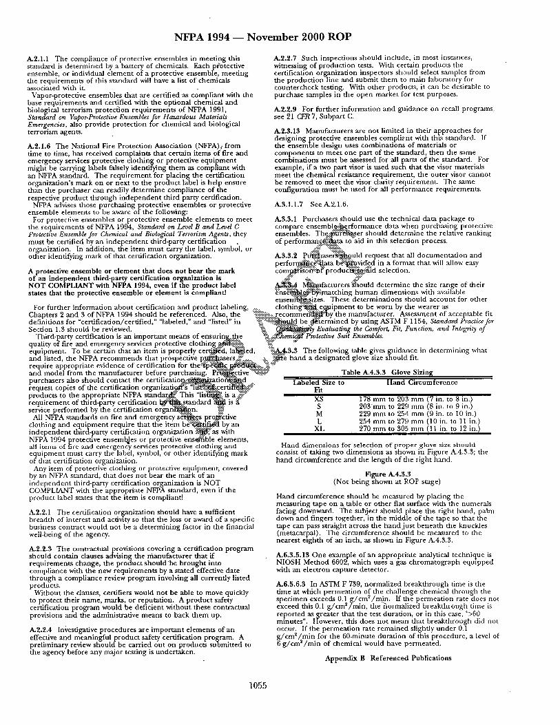
N F P A 1 9 9 4 - - N o v e m b e r 2 0 0 0 R O P
A,2.1.1 The compliance of protective ensembles in meet ing this standard is de te rmined by a battery of chemicals. Each p?otective ensemble, or individual e lement of a protective ensemble, meet ing the requirements of this s tandard will have a list of chemicals associated with it.
Vapor-protective ensembles that are certified.as compliant with the base requirements and certified with the optional chemical and biological terrorism protect ion requi rements of NFPA 1991, Standard on Vapor-Protective Ensembles for Hazardous Materials Emerg.encies, also provide protect ion for chemical and biological te~Tonsm agents.
A.2.1.6 The National Fire Protect ion Association (NFPA),. f rom time to time, has received complaints that certain items of fire and emergency services protective clothing or protective equipment might be carrying labels falsely identifying them as compliant with an NFPA standard. The requ i rement for placing the certification organization's mark on or next to the product label is help ensure than the purchaser can readily de te rmine compliance of the respective product th rough i ndependen t third party certification.
NFPA advises those purchasing protective ensembles or protective ensemble elements to be aware of the following:
For protective ensembles or protective ensemble e lements to meet
A.2.2.7 Such inspections should include, in most instances, witnessing of product ion tests. With certain products the certification organization inspectors should select samples from the product ion line and submit them to main laboratory for countercheck testing. With other producta, it can be desirable to purchase samples in the open market for test purposes.
A-2.2.9 For fur ther information and guidance on recall programs, see 21 C.FR 7, Subpart C.
A.2.3.13 Manufacturers are not limited in their approaches for designing protective ensembles compliant with this standard. If the ensemble design uses combinations of materials or components to mee t one part of the standard, then the same combinations must be assessed for all p a r e of the standard. For example, if a two part visor is used such that the visor materials meet the chemical resistance requirement , the outer visor cannot be removed to meet the visor clarity requirement . The same configuration must be used for all performance requirements .
A.3.1.1.7 See A.2.1.6.
A,3.3.1 Purchasers should use the techni~fl data package to the requirements of NFPA 1994, Standard on Level B and'Level C compare ensembl~.ii~...crformance data when purchasing protective Protective Ensemble for Chemical and Biological Terrorism Agents, they ensembles. T h e : ~ : ~ e r should determine the relative ranking must be certified by an i ndependen t third-party certification of performanf~.~::~ta to"aid in this selection process. organization. In addition, the item must carry the label, symbol, or ..::i::''::.::'!~.:!.:~i.::.. ...-.-.- . . . . . . .
other identifying mark of that certification organization. A.3.3.2 . . P . t J ~ a s ~ o u l d request that all documenta t ion and perfo .r.m....~'%.ata b~:~.yicr.c.d in a format that will allow easy
A protective ensemble or e lement that does not bear the mark com~:i'~6"~-;~f'produd~-,:4g~.-~]d selection. o f an independent third-party certification organization is NOT COMPLIANT with NFPA 1994, even if the product label ~ lqi'.i~.tlfacturers "~ould de te rmine the size range of their states that the protective ensemble or e lement is compliantl ~hs~ . .~ ' : :~ : : ima tch ing human dimension.,; with available
enser/i~'..:.,sizes. These determinat ions should account for other For fur ther information about certification and product labeling .......... c l o t h i n g : : ~ . . e . ~ i p m e n t to be worn by the wearer as
Chapters 2 and 3 of NFPA 1994 should be referenced. Also, the ::ii::::::::ii::::i::i~::::.:g.ecommefi:~¢-by the manufacturer. Assessment of acceptable fit definitions for "certification/certified," "labeled," and "listed" in %':'::':!i!!::::~.d be ..d~'~ermined by using ASTM 1;' 1154, Standard Practice for Section 1.3 should be reviewed. ":'ii~... ~ + ~ . " l y Evaluating the Comfort, Fit, Function, and Integrity of
Third-party certification is an impor tant means of ensuri.n._...~.the :'::.~:..::'~emik~t'Protective Suit Ensembles. quality of fire and emergency services protective clothing ~.¢i~iii~i!~i!::..'..~ equipment . To be certain that an item is properly c e ~ ' d , l a d l e d , '%.~...~.3.3 The following table gives guidance in de termining what and listed, the NFPA recommends that prospective p~ase r s - i~ -~ . . . . . . . ;:.. :::::~ hand a designated glove size should fit. require appropriate evidence of certification for the~:~:i)'~..g....~. ~'~i.:::::.:iiii?. ':~;; .... .
:r before purchasing. P ~ c t i v e "":~".':~i~f~::" Table A.4.3.3 Glove Sizing ,e ce r tiff catio n . : : ~ t i o ~ i f ~ d o r gan izati ~ ' ~ ;:l'~'~t :~!: .c e r ti~:~!i...'..~ :
k standar..~" This "lis~':~: is a :i]i! ;~::" :ation I . .~ :~ , s t anda rd " ~ is tion orgar/t~2n. %"i" emergency s ~ . . c . s p ro..~ective
e item b d : : ~ . ~ by an ganizat ion i ~ , " a s with
and model from the manufacturer before purchasing. purchasers also should contact the certlficatio request copies of the certification ot products to the appropria te NFPA requ i rement of third-party certification ' service pe r fo rmed by the certification or
All NFPA standards on fire and clothing and equipment require that the item b( i ndependen t third-party certification ol NFPA 1994 protective ensembles or protective e n s ~ b l e elements, all items of fire and emergency services protective clothing and equ ipment must carry the label, symbol, or o ther identifying mark of that certification organization.
Any item of protective clothing or protective equipment , covered by an NFPA standard, that does not bear the mark of an i ndependen t third-party certification organization is NOT COMPLIANT with the appropriate NFPA standard, even if the product label states that the item is compliant]
A.2.2.1 The certification of~anization should have a sufficient breadth of interest and aclawty so that the loss or award of a specific business contract would not be a de te rmin ing factor in the financial well-being of the agency.
A.2.2.3 The contractualprovis ions covering a certification program should contain clauses advising the rfianufacturer that if requirements change, the product should "be b rought into compliance with the new requirements by a stated effective date through a compliance review program involving all currently listed products.
Without the clauses, certifiers would no t be able to move quickly to protect their name, marks, or reputation. A produc t safety certification program would be deficient without these contractual provisions and the administrative means to back them up.
A,2.2.4 Investigative procedures are impor tant elements of an effective and meaningful product safety certification program. A preliminary review should be carried out on products submit ted to the agency before any major testing is undertaken.
Labeled Size to Hand Circumference Fit XS 178 mm to 20~'4 mm (7 in. to 8 in.) S 2 0 3 m m to 229 mm (8 in. to 9 in.) M 229 m m to 254 mm (9 in. to 10 in.) L 254 m m to 279 mm (10 in. to 11 in.)
XL 270 mm to 305 m m (11 in. to 12 in.)
Hand dimensions for selection of proper glove size should consist of taking two dimensions as shown in Figure A.4.3.3; the band circumference and the length of the right hand.
Figure A.4.3.3 (Not being shown at ROP stage)
Hand circumference should be measured by placing the measuring tape on a table or o ther fiat surface with the numerals facing downward. The subject should place the right hand, palm down and fingers together, in the middle of the tape so that the tape can pass straight across the band jus t beneath the knuckles (metacarpal). The circumference should be measured to the nearest eighth of an inch, as shown in Figure A.4.3.3.
A.6.3.5.13 One example of an appropriate analytical technique is NIOSH Method 6602, which uses a gas chromatograph equipped with an electron capture detector.
A.6.5.6.3 In ASTM F 739, normalized breakthrough time is the time at which permeat ion of the challenge chemical through the specimen exceeds 0.1 g / c m / m i n . ff the permeat ion rate does not exceed this 0.1 g / c m / n u n , the normahzed breakthrough nine ts repor ted as greater that the test duration, or in this case, ">60 minutes". However, this does no t mean that breakthrough did not occur. If the permeat ion rate remained slightly under 0.1 ~ / c m 2 / m i n for the 60-minute durat ion of this procedure , a level of
2 e g / c m / m i n of chemical would have p , rmea ted .
Appendix B Refe renced Publications
1055
N F P A 1951 ~ N o v e m b e r 2 0 0 0 R O P
NFPA 1951 (Log #23)
Commit tee : FAE~S CE 1951- 1 - (Entire Documen t ) : Reject SUBMITTER: Jeffrey o . Stull, Int ' l Personne l Protection, Inc. RECOMMENDATION: T h e fire service is in despera te need of this documen t . T h e Technica l Commi t t ee s h o u l d endeavor to comple te this d o c u m e n t du r i ng the nex t available cycle. SUBSTANTIATION: T he p roposed s tandard and its r equ i r emen t s are suppo r t ed by work conduc ted by the U.S. Fire Adminis t ra t ion, "Protective Clothing and E qu i pmen t Needs of Emergency Responders in Urban Search a n d Rescue Missions, "Report FA-136/September 1993. COMMITTEE ACTION: Reject. COMMITTEE STATEMENT: T he submi t te r was p resen t at the ROP mee t ing and asked the Commi t t ee no t to process the proposal .
(Log #24) Commit tee : FAE-SCE
1951- 2 - (Title): Accept SUBMITTER: Jeffrey o . Stull, Int ' l Personnel Protection, Inc_ RECOMMENDATION: C hange title to "Standard on Protective Ensemble for Technica l Rescue Incidents" SUBSTANTIATION: The p roposed tide is consistent with the p roposed NFPA 1670, "Standard on Opera t ions a n d Tra in ing for Technica l Rescue Incidents ." COMMITTEE ACTION: Accept.
(Log #2) Commit tee : FAE,S CE
1951- 3 - (1-1.3): Accept in Principle SUBMITTER: Dale Atkins, Rep. Amer ican Assn. of Avalanche Profess ionals RECOMMENDATION: Add the following text:
Title: Protective Ensemble for Urban Technical Rescue Opera t ions .
1-1.3 This s t andard shall no t apply to protective ensembles for wilderness ar~t moun ta in , swift water, contaminated . . . rescue operat ions . SUBSTANTIATION: Mounta in /wi lde rness rescue is a separate and distinct discipline. NFPA 1951 is written for the u rban rescuer, and thus shou ld be stated so in the title. Paragraph 1-1.3 recognizes o ther rescue specialties, so it shou ld include moun ta in /w i lde rne s s rescue. The 1951 s tandards are inappropr ia te for the wilderness setting. This was demons t r a t ed in two recen t avalanche incidents in Iceland. Modern fire d e p a r t m e n t ensembles were totally inappropr ia te for the weather condit ions. Only those equ ipped for the wilderness were able to func t ion a n d work in the env i ronment . COMMITTEE ACTION: Accept in Principle. COMMITTEE STATEMENT: See Commi t tee Action taken on Proposal 1951-10 (Log #25).
(Log #21) Commit tee : FAE,SCE
1951- 4 - (1-1.3): Reject SUBMITTER: Steve H u d s o n , Rep. Maine Assn. for Search and Rescue RECOMMENDATION: 1-1.3 This S tandard shall no t apply only to protective ensembles for use bv fire d e n a r t m e n t rescue pe rsonne l engaged in u rban search and rescue overat ions , except
noted on Section 1-1.4. ;;~ter, zlft;;'ater, con tamina ted water di;'in ~ or cave regcue o-crat ' ;ons. SUB~' I 'ANTIATION: ~ h e Protective Ensemble for Technical Rescue Opera t ions descr ibed in the d o c u m e n t is obviously des igned for use by those specifically involved in technical rescue opera t ions which may occur du r i ng a fire or haza rdous materials control opera t ion in an u rban area. Wilderness (i.e. non-u rban) search and rescue opera t ions require a widely varied array of c lo thing d e p e n d i n g on the weather, env i ronment , activity of the personnel , and location. Most of the specific hazards listed in Section 1-1.1 of the Scope of this documen t , such as chemical splash, chemical f lash fire, electrical, and thermal , do no t occur in a wilderness env i ronment , mad the need for c lothing to protec t a rescuer f rom these risks is basically non-existent . T he physical characteristics and limits to m o v e m e n t of c lothing des igned to
provide protec t ion f rom these hazards will increase the risk of physical injury or dea th for pe r sonne l in a wilderness env i ronment .
Requir ing c lothing of this type for a rescuer to protec t h im or he r f r o m s o m e of the hazards listed in Section 1-1.1 may endan g e r that pe r son when o ther hazards such as extremely ho t or cold weather are present . Opera t ions in a wilderness e n v i r o n m e n t m a n y t imes require chang ing c lothing at f r equen t intervals; the need to remove the o ther layers of this protective ensemble to get at insulat ing lower layers in a cold climate, for example , will only delay the rescuer in his tasks, and will also be nex t to impossible in m a n y rescue si tuations. No technical rescue opera t ion in which I have been involved in the past 15 years has r equ i red any th ing like the c lothing descr ibed in this s tandard, n o r h a s anyone I have known pe r fo rming or teaching wilderness technical rescue opera t ions ever sugges ted that any th ing like this would be of the slightest use.
This c lo thing may be eminent ly suitable to provide pro tec t ion for f irefighters involved in technical rescue operat ions as par t of their f i ref ight ing activities or hazardous materials control operat ions , but it would be totally unsui table , a n d dangerous , if it is requi red for use by technical rescuers who are no t normal ly at risk f rom these hazards. COMMITTEE ACTION: Reject. COMMITTEE STATEMENT: See Commi t t ee Action taken on Proposal 1951-10 (Log #25).
(Log #1) Commit tee : FAE-SCE
1951- 5 - (1-1.4 ( N e w ) ) : Accept in Principle SUBMITTER: Je r ryJ . Koenig, Falcon AFB Fire Dept. RECOMMENDATION: Add the following paragraph:
1-1.4 This s t andard shall no t apply to protective ensembles for Vehicle and Machinery Rescue or to Wilderness Search and Rescue
)l~erations. BSTANTIATION: T h o u g h appropr ia te for o ther types of
rescues, this ensemble is no t the p re fe r red g a r m e n t for these two tasks. NFPA 1670 (proposed) out l ines seven categories of rescue and NFPA 1951 shou ld address all of these same categories since the titles are so similar. COMMITTEE ACTION: Accept in Principle. COMMITTEE STATEMENT: See Commi t t ee Action taken on Proposal 1951-10 (Log #25).
(Log #7) Commit tee : FAE-,S CE
1951- 6 - (1-1.8 ( N e w ) ) : Accept in Principle SUBMITrER: Rick R. Schartel , West Lawn Fire Co . /Rep . West Lawn Fire Co. RECOMMENDATION: Add a new paragraph 1-1.8 to read as follows:
No th ing in this s tandard shall be c6ns t rued to indicate that fire service responders wear ing compl ian t s t ructural t u r n o u t gear may no t engage in technical rescue operat ions. SUBSTANTIATION: Standards of this sort imply tha t one mus t wear this ensemble to pe r fo rm technical rescues. Please r e m e m b e r that the fire service is a first r e sponde r to these incidents and will general ly have structural f i ref ight ing t u r n o u t gear only. Most regions and municipal i t ies do n o t have formal technical rescue teams ready to go at a m o m e n t ' s notice. Please also recall tha t the vast majority of t rapped living victims were SAFELY removed f rom the Mur rah Federal Bui lding in O k l a h o m a City by O k l a h o m a City firefighters in regular structural fire gear, well in advance of the arrival of formal technical rescue teams.
In having reviewed the s tandard , I conc lude that s tructural t u rnou t gear may be able to m e e t the r equ i r emen t s with minimal changes. However, mos t s t ructural gear in service today an d for the nex t few years will no t have been tested for dual certification and will theoretically no t be compliant . As such, the s tandard implies tha t it would no t be appropr ia te for use in technical rescue operat ions.
I am conce rned tha t a wel l- intent ioned d o c u m e n t such as this will be misappl ied by vendors , consul tants , trainers, and others to m e a n that one m u s t s t and idly by waiting for the tech rescue troops to arrive before engag ing in rescue operat ions--or , the fire service mus t equip all companies with this ensemble because anyone of t h e m may be faced with a collapse, h igh angle, or conf ined space situation. If this had been the case, imagine what the ou tcome in O k l a h o m a City would have been, or the l imb that Gary Mars would have gone out on to make the rescues.
1056
N F P A 1951 ~ N o v e m b e r 2 0 0 0 R O P
COMMITTEE ACTION: Accept in Principle. Add informat ion to s t andard in append i x as to read as follows: "A-l-2.1 Noth ing in this s tandard is i n t ended to imply tha t fire
service responders canno t engage in technical rescue incidents while wearing protective clothing and e q u i p m e n t tha t is certified as compl iant with NFPA 1971, S tandard on Protective Ensemble for Strucutral Fire Fighting." COMMITTEE STATEMENT: The Commi t t ee agrees with the submit ter , bu t since the proposal relates to use, the in ten t mus t be added to the append ix as advisory language as address ing use is beyond the scope of the Technical Commit tee .
a
" (Log #11) Commit tee : FAE-SCE
1951- 7 - (1-3 Recall ( N e w ) ) : Accept SUBMITTER: William L. Grilliot, M orn i ng Pride Mfg Co. R E C O M M E N D A T I O N : Add the tollowing definit ion:
Recall: A d o c u m e n t e d p rocedure which will demons t r a t e the maoufagmre r s ability to identify a snecific individual e l ement a m t / o r ~roun of e lements and to retrieve a snecific individual e l ement a n d / o r m- tun of e lements f rom the field. SUBSTANTIATION: There is a r e q u i r e m e n t for a Recall System and it needs to be def ined so that a third party can verify. COMMITTEE ACTION: Accept.
(Log #22) Commit tee : FAE-SCE
195,1- 8 - (1-3 Search Operat ions , Technica l Rescue Operat ions) : Accept in Principle SUBMITTER: Steve H u d s o n , Rep. Maine Assn. for Search and Rescue RECOMMENDATION: 1-3 Definit ions
Search Operat ions. Any activities involving the search for victims or body recovery in u rban or nonwi lderness land-based operat ions .
Technical Rescue Operat ions. The activities of victim search, rescue, body recovery, and site stabilization d u r i n g o p e r a t i o n s , inc luding bu t no t l imited to bu i ld ing / s t ruc tu ra l collapse, veh lc l e /pe r son extrication, conf ined space entry, and t r ench /cave - in rescue rope rezcue, ;;'Iderne-oa ~ d !and acarcb. ~v . . . . . . . . . Rope rgsgue and search onera t ions in a non -u rban or wilderness environrll¢lat u n d e r no rma l condit ions would no t be inc luded in this def ini t ion of Technica l Rescue Onerat ions . S U B S T A N T I A T I O N : To avoid confus ion conce rn i ng applicat ion of this s tandard , the defini t ion for Search Opera t ions shou ld clearly state tha t search activities are those taking place in an urban, or non-wilderness, env i ronment .
For the same reason, the defini t ion for Technica l Rescue Opera t ions shou ld specifically exclude rope rescue a n d land search opera t ions when they are no t taking place in an u rban env i ronment , A reference in the Append ix shou ld be inc luded expla in ing that this s tandard does no t apply to rope rescue and land-based search -operations outside of an u rban e n v i r o n m e n t unless the hazards listed in Section 1-1.1 are expected to be present . This would make it clear tha t the ensemble may be suitable for use du r ing rescue or search opera t ions which migh t take place du r ing wildlands f ight ing activities, for example. COMMITTEE ACTION: Accept in Principle. COMMITTEE STATEMENT: See Commi t tee Action taken on Proposal 1951-10 (Log #25).
(Log #13) Commit tee : FAE-SCE
1951- 9 - (1-3 Separate): Reject SUBMITTER: William L. Grilliot, M orn i ng Pride Mfg Co. R E C O M M E N D A T I O N : Add to the definitaon of Separate: Flaldng. S U B S T A N T I A T I O N : IqFPA 1971-ROP will add "Flaking" to the propert ies of the defini t ion of Separate. COMMITTEE ACTION: Reject. COMMITTEE STATEMENT: T h e commi t tee decided tha t an addit ional defini t ion was no t needed; the t e rm "flaking" no longer appears in NFPA 1971.
(Log #25) Commit tee : FAE-SCE
1951- 10 - (1-3 Technica l Rescue Operat ions) : Accept in Principle TCC NOTE: The TCC directs the TC to recons ider the
def in i t ions o f Urban Technical Rescue Inc idents and r emove the te rm "Urban" and be very specific to cons ider which technical rescue incidents apply and which do not. SUBMITTER: Jeffrey o . Stull, Int ' l Personnel Protect ion, Inc. R E C O M M E N D A T I O N : Change "Technical Rescue Operat ions" to "Technical Rescue Incidents" and provide the following revised definit ion: Complex rescue incidents requi r ing specially t ra ined
~ ersonnel a n d special e q u i p m e n t to comple te the mission. echnical rescue incidents inc lude the "activities of victim search,
rescue, body recovery, and site stabilization du r ing operat ions, inc luding bu t no t l imited to bu i ld ing / s t ruc tu ra l collapse, veh ic l e /pe r son extrication, conf ined space entry, t r ench /cave- in rescue, rope rescue, wilderness and land search operat ions. SUBSTANTIATION: The revised defini t ion captures the defini t ion for technical rescue incidents in NFPA 1670 .and provides addi t ional explanatory detail for those unfamil iar with the types of technical rescue incidents. COMMITTEE ACTION: Accept in Principle.
Add defini t ion for Technica l Rescue Incid.ents, def ined as: "1-3 Technical Rescue Incidents. Complex rescue incidents
requi r ing specially t ra ined pe r sonne l and special e q u i p m e n t to comple te the mission."
Add new defini t ion for Urban Technica l Rescue Incidents to react as follows:
"1-3 U r b a n Technica l Rescue Incidents . Those technical rescue incidents tha t involve the activities of victim search, rescue, body recovery, a n d site stabilization du r ing operat ions, inc luding bu t no~: l imited to bu i ld ing / s t ruc tu ra l collapse, veh ic l e /pe r son extrication, conf ined space entry, t r ench /cave- in rescue, rope rescue. Technica l rescue incidents in a n o n - u r b a n or wilderness e n v i r o n m e n t u n d e r normal condi t ions would no t be inc luded in this definit ion."
Also see changes to scope of documen t . COMMITTEE STATEMENT: The Commi t t ee agrees that the defini t ion shou ld be consis tent with NFPA 1670, S tandard on Opera t ions and Tra in ing for Technical Rescue Incidents; however, that areas are no t covered by the p roposed s t andard be inc luded in a new defini t ion that limits protective c lo th ing for urban, non- wilderness, non-water operat ions .
(Log #12) Commit tee : FAE-SCE
1951- 11 - (1-3 Veh ic le /Pe r son Extrication): Reject SUBMITTER: William L. Grilliot, Morn ing Pride Mfg Co. R E C O M M E N D A T I O N : Remove - ' ch ic !c /person ex~qea~on f rom the defini t ion of Technical Rescue Operat ions . S U B S T A N T I A T I O N : This def ini t ion is in conflict with NFPA 1971 scope, purpose, a n d defini t ion of a s tructural ga rmen t . COMMITTEE ACTION: Reject. COMMITTEE STATEMENT: The Commi t tee feels that protective ensemble is suitable for veh ic l e /pe r son ext~rication. No th ing prec ludes a d e p a r t m e n t f rom us ing a protective ensemble compl ian t with NFPA 1971, S tandard on Protective Ensemble for Structural Fire Fighting, for veh i c l e /pe r son extrication.
(Log #5) Commit tee : FAE-SCE
1951- 12 - (Chapter 2): Reject SUBMII~rER: Bruce R. Sawyer, Nor th S ton ing ton Fire R E C O M M E N D A T I O N : Delete existing a n d add: Certify to meet applicable ANSI, ASTM, AATCC, a n d Military Standards. S U B S T A N T I A T I O N : Certification of these i tems exists and your r e q u i r e m e n t will only inflate the cost of these i tems to the end u s e r COMMITTEE ACTION: Reject. COMMITTEE STATEMENT: Certification and manufac tu r e r quality assurance r equ i r emen t s are necessm'y to ensure compl iance of products with this s tandard .
1057
N F P A 1951 ~ N o v e m b e r 2 0 0 0 R O P
(Log #6) Commit tee : FAE-SCE
1951- 13 - (3-1.1.6, 3-2.1.6, 3-3.1.6, 3-4.1.6, 3-5.1.6, 3-6.1.6): Reject SUBMITTER: Bruce IL Sawyer, North Stonington Fire R E C O M M E N D A T I O N : S U B S T A N T I A T I O N : This label is a dupl icat ion of ANSI and o ther certifications a n d will only inflate the final cost. COMMITTEE ACTION: Reject. COMMITTEE STATEMENT: Specific p roduc t labeling is requi red to indicate to end users that i tems are compl iance with this s tandard. Requ i remen t s for user informat ion are needed to ensure that essential p roduc t informat ion is made available to the user.
(Log #17) Commit tee : FAE-SCE
1951- 18 - (4-1.17.1): Accept in Principle SUBMITTER: William L. Grilliot, Morn ing Pride Mfg Co. R E C O M M E N D A T I O N : Add r e q u i r e m e n t for individual m e n an d women pat tern ing. S U B S T A N T I A T I O N : Need to properly fit bo th m e n an d women. COMMITTEE ACTION: Accept in Principle.
Add new 4.1.1.7.5 to read as follows: "4.1.1.7.5 Garmen t s shall be cons t ruc ted in m e n ' s and wo m en ' s
pattern 's ." COMMITTEE STATEMENT: The commi t t ee agrees with the sribmitter bu t made the change by add ing a new 4.1.17.5.
(Log #20) Commit tee : FAE-S CE
1951- 14- (4-1.6): Accept SUBMITTER: William L. Grilliot, Morn ing Pride Mfg Co. R E C O M M E N D A T I O N : Remove the r e q u i r e m e n t for the uppe r torso g a r m e n t to be flat. SUBSTANTIATION: The mos t effective and efficient bo t tom h e m design for this type of a g a r m e n t is a tails type of cut. The tails have been specified and utilized by m a n y of the existing USAR Teams in operat ion today. Not only is this a design restrictive r e q u i r e m e n t bu t it is contra to rescuer safety, mobility, and comfort . COMMITTEE ACTION: Accept.
(Log #18) Commit tee: FAE-SCE
1951- 15 - (4-1.16): Reject SUBMITTER: William L. Grilliot, Morn ing Pride Mfg Co. R E C O M M E N D A T I O N : Make tr im an optional feature. S U B S T A N T I A T I O N : Some authori t ies having jur isdic t ion may not wish trim. For example , if dais type of g a r m e n t were to be used for search and recovery of collapsed bui ld ing dur ing wartime. COMMITTEE ACTION: Reject. COMMITTEE STATEMENT: T he commit tee believe tr im to be an impor t an t c o m p o n e n t of ga rmen t s since h igh visibility for both daytime and n igh t t ime was identif ied as a pr imary r equ i r emen t in the U.S. Fire Adminis t ra t ion s tudy for u rban search and rescue protective c lothing and equ ipmen t .
(Log #19) Commit tee : FAE-SCE
1951- 16 - (4-1.16): Reject SUBMITTER: William L. Gdlliot, Morn ing Pride Mfg Co, RECOMMENDATION: Make fluoresce of tr im an optional feature. S U B S T A N T I A T I O N : Some authori t ies having jur isdic t ion may not wish f luorescent trim. For example, K this type of g a r m e n t were to be used for search and recovery of collapsed bui ld ing du r ing wartime. COMMITTEE ACTION: Reject. COMMITTEE STATEMENT: See Commit tee Action taken on Proposal 1951-15 (Log #18).
(Log #14) Commit tee : FAE-SCE
1951- 17 - (4-1.17.1): Accept in Principle SUBMITTER: William L. Grilliot, Morn ing Pride Mfg Co. R E C O M M E N D A T I O N : Ga rmen t ches t inc rements shou ld be changed to 2" increments . S U B S T A N T I A T I O N : Chest inc rements of 2" are cus tomary within the industry. COMMITTEE ACTION: Accept in Principle.
Revise 4-1.17.1 to read as follows: "Upper torso g a r m e n t ches t c i rcumferences shall be provided in
c i rcumferences f rom 760 m m to 1270 m m (30 to 50 in.) in 50 m m (2 in.) inc rements of cut to order. COMMITTEE STATEMENT: T h e commit tee agrees with the submi t te r bu t changed language in 4-1.17.1 to reflect this change and increased the range to begin at 760 m m (30 in.) c i rcumferences .
(Log#15) Commit tee : FAE-SCE
1951- 19 - (4-1.17.3): Accept in Principle SUBMITTER: William L. Grilliot, Morn ing Pride Mfg Co. R E C O M M E N D A T I O N : G a r m e n t waist i nc remen t s shou ld be ehan~ed to 2" increments . S U B S T A N T I A T I O N : Waist inc rements of 2" are customary within the industry. COMMITTEE ACq'ION: Accept in Principle.
Revise 4-1.17.3 to read as follows: "Lower torso g a r m e n t waist c i rcumferences shall be provided in
c i rcumferences f rom 65 to 125 cm (26 to 50 in.) in 5.0 cm (2.0 in.) i nc remen t s or cu t to order. COMMITTEE STATEMENT: T h e commi t t ee agrees with the submi t te r bu t changed language in 4-1.17.1 to reflect dais change and increased the range to end at 1270 m m (50 in.) c i rcumferences .
(Log #16) Commit tee : FAE-SCE
1951- 20 - (4-1.17.3): Accept in Principle SUBMITTER: William L. Grilliot, Morn ing Pride Mfg Co. R E C O M M E N D A T I O N : Add r e q u i r e m e n t for individual m e n and women pat tern ing. S U B S T A N T I A T I O N : Need to properly fit bo th m e n and women. COMMITTEE ACTION: Accept in Principle. COMMITTEE STATEMENT: See Commi t t ee Action taken on Proposal 1951-18 (Log #17).
(Log #3) Commit tee : FAE-SCE
1951- 21 - (Chapter 5): Reject SUBMITTER: Bruce R. Sawyer, Nor th S tonington Fire R E C O M M E N D A T I O N : S U B S T A N T I A T I O N : Reference the applicable ANSI, ASTM, AATCC, OSHA, and Military Standards, dupl ica t ion is no t n eed ed and will inflate the final cost. COMMITTEE ACTION: Reject. COMMITTEE STATEMENT: Pe r fo rmance requ i rements already cite specific test m e t h o d s f rom s tandards organizat ions as a~i lable . O the r industry-accepted pe r fo rmance criteria for these i tems do
not: exist.
(Log #10) Commit tee : FAE-SCE
1951- 22 - (5-1.1.1): Reject TCC NOTE: The TCC directs the TC to recons ider the action on
1951-22 and the d o c u m e n t scope and include manda to ry carrier protect ion instead of as an opt ional choice. Protect ion f rom blood borne pa thogens appears to be a critical r equ i r emen t for garments , gloves, and footwear u sed dur ing rescue victim recovery, and body recovery. Also, the TC shou ld assure that the durability o f the barr ier is appropr ia te for mult iple uses o f the e lements and that the total heat loss value o f 450 w / m _ 2 is appropr ia te for ga rmen t s with carrier protect ion. SUBMITTER: William L. Grilliot, Morn ing Pride Mfg Co. R E C O M M E N D A T I O N : Lower the p a s s / f @ of the base g a r m e n t (no linings, usually one layer) to 450 w / m 2.
Add a ho t plate r e c ~ i r e m e n t for ga rmen t s with l inings and have a pass/fai l of 200 w / m z.
1 0 5 8
N F P A 1951 ~ N o v e m b e r 2000 R O P
SUBSTANTIATION: A 600 w/m2 garment requirement is too high. The protective hood is set at 450 w/m 2 (5-5.1.1 in this standard), and NFPA 1977 Wildlaaads single layer garment is also set. at 450 w/m 2. When barrier protection is desired (for water, chemical, and viral resistance) the hot plate pass/fall must be revised to 200 w/m2. COMMITTEE ACTION: Reject. COMMITTEE STATEMENT: The committee believes that comfort should be base requirement applied to all ensembles, with or without barrier protection, and that the requirement of" a minimum tolal heat loss of 450 W/m 2 accommodates both barrier and non- barrier applications.
(Log #26) Committee: FAE-SCE
1951- 23 - (5-1.2.1): Accept in Principle SUBMITTER: Jeffrey O. Stull, Int'l Personnel Protection, Inc. RECOMMENDATION: Change paragraph 5-1.2.1 to read:
"Specimens of garment composite shall be tested for liquid repellency as specified in Section 6-X, "Water Repellency," Test and shall have an index of repellency of 90 or greater:" SUBSTANTIATION: The requirement is incomplete as required. The proposed requirement uses testing in accordance with ISO
6530, a recognized test for establishing a water repellent claim. The actual performance criterion is based on the minimum liquid repellency deemed appropriate for chemical protective clothing EN 1513. COMMITTEE ACTION: Accept in Principle.
Revise 5-1.2.1 to read as follows: "5-2.1 Specimens of garment composite shall be tested for water
repellency as specified in Section 6-X, Water Repellency Test," and shall have a spray rating of 80 or greater." COMMITTEE STATEMENT: The Committee agrees with the need for a water repellency requirement, but recommends an alternative test, AATCC 22 (Water repellencIn. Spray test).
(Log #8) Committee: FAE-S CE
19:51- 24 - (5-1.2.3): Accept in Principle SUBMITTER: William L. Grilliot, Morning Pride Mfg Co. RECOMMENDATION: Viral should be tested on the barrier layer only for consistent results. SUBSTANTIATION: Testing a composite to viral lends itself to more false negatives. COMMITTEE ACTION: Accept in Principle.
I C, hange 6-18.42 to read as follows: "The exterior facing surface of the garment material layer
providing barrier performance shall be exposed to the liquid challenge. Any outer layer in the test sample shall not be tested." COMMITTEE STATEMENT: The committee agrees with the submitter, but the changes in the lest method are necessary to indicate which portion of the composite to test.
(Log #30) Committee: FAE-SCE
1951- 25 - (5-1.2.5 (New)): Reject SUBMITTER: Jeffrey O. Stull, Int'l Personnel Protection, Inc. RECOMMENDATION: Add new requirement to Section 5-1.2:
5-1.2 Specimens of garment composite, with barrier materials in place, shall be tested for total heat loss as specified in Section 6-6, "Total Heat LRss Test," and shall have a total heat Loss of not less than 300 w/m z. SUBSTANTIATION: It is import,'mt that garments when certified for the additional provisions of barrier protection, also minimize the: stress-related impact to the wearer. The proposed requirement ensures that a minimum level of "breathability" is achieved in the gas~ents to limit the potential for heat slress during long-term wearing of protective garments during technical rescue operations. COMMITTEE ACTION: Reject. COMMITrEE STATEMENT: See Committee Action taken on Prnposal 1951-22 (Log #10).
(Log #9) Committee: FAE-SCE
1951- 26- (5-1.3.3): Accept SUBMITTER: William L. Grilliot, Morning Pride Mfg Co. RECOMMENDATION: Drop requirement and test for Static Discharge. SUBSTANTIATION: Test is not needed. COMMITTEE ACTION: Accept.
(Log #23) Committee: FAE-SCE
1951- 27- (5-1.3.3): Reject SUBMITTER: Jeffrey O. Stull, Int'l Personnel Protection, Inc. RECOMMENDATION: Change paragraph 5-1.3.3 to read:
"Specimens of outer shell fabrics shall be individually tested for surface resistivity as specified in Section 6-11, "Surface Resistivity Test," and shall have a surface resistivity of less than 1 x 101/3 ohms per unit square of material." A separate proposal has been submitted to change the test method. SUBSTANTIATION: There is no universal agreement that the proposed test requirement is appropriate for textile-based products. The proposed requirement is based on an industry accepted test method and uses the same criteria for textiles as provided for in NFPA 99, Standard on Health Care Facilities. COMMITTEE ACTION: Reject. COMMITTEE STATEMENT: See Committee Action taken on Proposal 1951-26 (Log #9).
(Log #32) Committee: FAE-SCE
1951- 28 - (5-3.1.4): Accept in Principle SUBMITTER: Jeffrey O. Stull, Int'l Personnel Protection, Inc. RECOMMENDATION: Replace paragqaph 5-3.1.4 with the following performance criteria. Delete paragraph 5-3.1.5.
5-3.1.4 Glove specimens shall be tested for hand fimction as specified in Section 6-3.1, Glove Hand Function Tests, and shall meet the following requirements:
(a) The glove specimens shall have an average percent of barehand control not exceeding 140 percent for the Gross Dexterity Test A;
(b) The glove specimens shall have an average percent of barehand control not exceeding 140 percent for the Gross Dexterity Test B;
(c) the glove sp'ecimens shall permit a pin with an averaLge diameter of 5 mm (0.20 in.) to be picked up for the Fine Dexterity Test;
(d) The glove specimens shall permit pins with an average spacing of 5 mm (0.20 in.) to be deleted for the Tactility Test; and
(e) The glove specimens shall have an average percent of barehand control average of not less than 80 percent for the Grip Test. SUBSTANTIATION: The current test requirement does not effectively discriminate hand function performance of gloves and is of little value to the standard. The proposed testing methodology and criteria provide an industry-developed approach for more appropriately measuring hand function. The proposed criteria combines dexterity and grip hand function requirements. COMMITTEE ACTION:. Accept in Principle.
Revise 5-3.1.4 to read as follows: 5-3.1.4 Gloves shall be tested for hand function as specified in
Section 6-31, Glove Hand Function Test, and shall have an average: percent of barehanded control not exceeding 200 percent." COMMITTEE STATEMENT: The Committee modified the proposed changes to the requirement t6 make the requirement consistent with criteria and test method as used in other project standards (such as NFPA 1992).
(Log #4) Committee: FAE-SC E
1951- 29 - (Chapter 6): Reject SUBMITTER: Bruce R. Sawyer, North Stonington Fire RECOMMENDATION: None. SUBSTANTIATION: Reference the applicable ANSI, ASTM, AATCC, OSHA, and Military Standards, duplication is not needed and will inflate the final cost. COMMITTEE ACTION: Reject. COMMITTEE STATEMENT: See Committee Action taken on Proposal 1951-21 (Log #3).
1059
N F P A 1951 m N o v e m b e r 2 0 0 0 R O P
(Log #27) Commit tee : FAE-SCE
1951- 30 - (6-x (New) ) : Accept in Principle SUBMITTER: Jeffrey O. Stull, Int ' l Personnel Protection, Inc. R E C O M M E N D A T I O N : A new test m e t h o d 6-X to suppor t the r e q u i r e m e n t in pa ragraph 5-1.2.1:
6-X Water Repel lency Test. 6-X Application. 6-X.I.1 This test shall apply to ga rments outershells. 6-X.2 Specimens. 6-X.2.1 A m i n i m u m of three spec imens shall be tested.
Spec imens shall consist of three 180 m m (7 in.) squares for each material type.
6-X.3 Sample Preparat ion. 6-X.3.1 Specimens to be tested shall be condi t ioned as specified
in 6-1.3. 6-X.4 Procedure. 6-X4.1 Liquid pene t ra t ion resistance testing shall be conduc ted
in accordance with ISO 6530, Protective Clothing - Protection against liquid chemicals - De te rmina t ion of resistance of materials to pene t ra t ion by liquids, us ing distilled water.
6-X.4.2 The normal outer surface of the material shall be exposed to the liquid as or ien ted in the c lothing item.
6-X.5 Report. 6-X.5.1 The index of repel lency for each spec imen shah be
reported. 6->(.6 Interpretat ion. 6-17.6.1 The average index of repellency for the material shall be
used to de te rmine pass/fa i l pe r formance . Add to the list of re fe renced test methods : ISO 6530, Protective c lothing - Protect ion against liquid chemicals
- de te rmina t ion of resistance of materials to pene t ra t ion by liquids, 1990. S U B S T A N T I A T I O N : The draft s t andard indicates a r e q u i r e m e n t for water repel lency bu t no t provide a specific criterion or m a n n e r of testing. COMMITTEE ACTION: Accept in Principle.
Revise the test m e t h o d to read as follows: 6-X Water Repel lency Test. 6-X Application. 6-X.I.1 This test shall apply to g a r m e n t outer shells. 6-X.2 Specimens. 6-X.2.1 A m i n i m u m of th ree spec imens shall be tested.
Spec imens shall consist of three 180 m m (7 in.) squares of the outermost , separable layer of the g a r m e n t composi te or outer shell.
6-X.3 Sample Preparat ion. 6-X.3.1 Specimens to be tested shall be condi t ioned as specified
in 6-1.3. 6-X.4 Procedure. 6-)(.4.1 Liquid pene t ra t ion resistance testing shall be conduc ted
in accordance with AATCC 22, Water repellency: Spray test. 6-X.4.2 The normal outer surf~ace of the material shall be
exposed to the water as or iented in the c lothing item. 6-X.5 Report. 6-)(.5.1 The spray rat ing for each spec imen shall be reported. 6-X.6 Interpretat ion. 6-17.6.1 The lowest spray rat ing for the material shall be used to
de te rmine pass/fai l pe r formance . Add to the list of re fe renced test methods : AATCC 22, Water repelIency: Spray test, 1996.
COMMITTEE STATEMENT: The p roposed changes provide a more reproducible a n d indust ry accepted test me thod .
(Log #31 ) Commit tee : FAE-SCE
1951- 31 - (~6): Accept SUBMITTER: Jeffrey O. Stull, Int ' l Personnel Protection, I n c R E C O M M E N D A T I O N : Replace Section 6-6 with the following. Delete all a p p e n d i x references as well.
6-6 Total Heat Loss Test. 6-6.1 Application. 6-6.1.1 This test m e t h o d shall apply to the protective g a r m e n t and
h o o d composi tes . 6-6.2 Specimens. 6-6.2.1 Total hea t loss testing shall be conducted on at least three
specimens. Spec imens shall consist of all layers in the protective g a r m e n t or hood composi te a r n m g e d in the order and or ientat ion as worn.
6-6.3 Sample Preparation. 6-6.3.1 Specimens to be tested shall be conditioned as specified
in 6-1.2. 6-6.4 Procedure .
6-6.4.1 Evaluate spec imens in accordance with ASTM F 1868, Test Me thod for T h e r m a l and Evaporative Resistance of Clothing Materials Using a Sweating Hot Plate, Part C.
6-5.6 Report . 6-5.6.1 The average total hea t loss (Qt) of the sample shall be
d e t e r m i n e d mad repor ted. 6-6.6 Interpretat ion. 6-6.6.1 Pass or fail de te rmina t ion shall be based on the average
repor ted total hea t loss m e a s u r e m e n t of all spec imens tested. Add to list of r e fe renced test methods : ASTM F1868, Test Method for The rma l and Evaporative
Resistance of Clothing Materials Using a Sweating Hot Plate, 1998. S U B S T A N T I A T I O N : The p roposed revision of the test m e t h o d accounts for the recen t adopt ion of the test p rocedures by ASTM in Standard Test Me thod F 1868. COMMITTEE ACTION: Accept.
(Log #29) Commit tee : FAE-SCE
1951- 32- (6-11): Reject SUBMITTER: Jeffrey O. Stull, Int ' l Personne l Protection, Inc. R E C O M M E N D A T I O N : Replace Section 6-11 with the following test med~ od:
6-11 Surface Resistivity Test. 6-11.1 Application. 6-11.1.1 This test m e t h o d shall apply to g a r m e n t and ho o d
materials. 6-11.2 Specimens. 6-11.2.1 A m i n i m u m of five spec imens shall be cut f rom tile
material to be tested. 6-11.2.2 Only the exterior surface of g a r m e n t or hood material
composi tes shall be tested. 6-11.3 Sample Preparat ion. 6-11.3.1 Specimens shall be condi t ioned as specified in 6-1.2. 6-11.3.2 Samples for condi t ion ing shall be one me te r (1 yard)
square of the largest piece of textile that can be provided. 6-11.3.3 Prior to testing, spec imens shall be p recond i t ioned as
specified in 6-1.9. 6-11.4 Procedure. 6-11.4.1 Specimens shall be tested in accordance with AATCC 76,
Electrical Resistivity of Fabrics. 6-11.5 Report . 6-11.5.1 For each spec imen, the surface resistivity shall be
recorded . 6-11.6 in terpre ta t ion. 6-11.6.1 The average measu red voltage at five seconds for each
surface tested shall be used individually to de t e rmine pass/fail . Add to list of re ferenced test methods : AATCC 76, Electrical Resistivity of Fabrics, 1995.
SUBSTANTIATION: There is no universal a g r e e m e n t that the p roposed test r e q u i r e m e n t is appropr ia te for textile-based products. The p roposed r e q u i r e m e n t is based on an industry accepted test m e t h o d a n d uses the same criteria for textiles as provided for in NFP 99, S tandard on Heal th Care Facilities. COMMITTEE ACTION: Reject. COMMITTEE STATEMENT: See Commi t t ee Action taken on Proposal 1951- 26 (Log #9).
(Log #33) Commit tee : FAE-SCE
1951- 33 - (6-31, 6-32): Accept in Principle SUBMITTER: Jeffrey O. Stull, Int ' l Personnel Protect ion, Inc. R E C O M M E N D N F I O N : Replace Section 6-31 with the following test me thod . Delete Section 6-32.
6-31 Glove Hand Funct ion Tests. 6-31 Application. 6-31.1.1 This test shall apply to gloves. 6-31.2 Specimens. 6-31.2.1 A m i n i m u m of three gloves pairs each for each size
provided with the suit shall be used for testing. 6-31.2.2 Each glove pair shall be tested as a comple te set of gloves
in new, as dis t r ibuted condit ion. 6-31.2.3 Glove pair spec imens shall no t receive special sof ten ing
t rea tments pr ior to tests. 6-31.3 Sample Preparat ion. 6-31.3.1 Glove pair spec imens shall be p recond i t ioned as
specified in 6-1.2. 6-31.3.2 Samples for condi t ion ing shall be whole glove pairs. 6-31.4 Procedures.
1 0 6 0 i
N F P A 1951 ~ N o v e m b e r 2 0 0 0 R O P
6-31.4.1 Each available size of gloves shall be evaluated with at least one separate test subject with the same pair of gloves for each of the h a n d func t ions specified in 6-31.4.2, 6-31.4.3, 6-31.4.4, and 6- 31.4.5.
6-31.4.2 A m i n i m u m of five different g lovepa i r s shall be evaluated. W h e n less than 5 di f ferent sizes of gloves are available, different pairs of the same sized gloves shall be permi t ted to be tested by different test subjects to mee t the m i n i m u m five glove pair testing requi rement .
6-31.4.3 Test subjects shall be selected such tiaat their h a n d d imens ions are as close as possible to those specif ied in accordance with manu fac t u r i ng glove sizing guidelines.
6-31.4.4 Each test subject used to pe r fo rm this testing shall practice each of the h a n d func t ions a m i n i m u m of 3 t imes before conduc t ing actual testing.
6-31.4.5 Gross Dexteri ty Procedure A. 6-31.4.5.1 A kno t tying test appara tus shall be used which consists
of rec tangular blocks o f wood with two holes and a shoelace. The rectangular blocks shall have a nomina l size of 100 m m x 265 m m x 50 m m (4 in. x 10.5 in. x 2 in.). Each hole shall have a d iameter of 12.7 m m (0.5 in.). The two holes shall be separa ted by a dis tance of 100 m m (4.0 in.). A shoelace shall be s t rung t h r o u g h the holes. The shoelace shall be 1200 m m _+25 m m (47 in. _+1 in.) in length
and weigh 6.0, -+0.25 g (0.2 oz, -+ 0.001 oz). 6-31.4.5.2 Before each test, the shoelaces shall be un t i ed and
laying to the sides of the wood block. 6-31.4.5.3 The test subject shall be requi red to tie and unt ie the
shoelaces into a shoelace knot a total of ten times, the test shall begin with the first touch of the shoelaces by the test subject and the complet ion of untying the tenth knot.
6-31.4.5.4 The t ime to tie and unt ie all knots shall be measu red for each test subject and shall be known as the dexteri ty test t ime.
6-17.4.5.5 Each test subject shall pe r fo rm the test following the steps in 6-31.4.5.2 t h rough 6-31.4.5.4 until the dexterity test t imes of that person 's last three repeti t ions varies no more than 8 percent . The lowest dexterity test t ime of the last three repeti t ions shall be used as the baseline dexteri ty test t ime (DTTb). Each test shall be conduc ted wi thout the test subject 's knowledge of the dexterity test t ime for each test.
6-31.4.5.6 Each test subject shall t hen pe r fo rm the test following the steps in 6-31.4.5.2 t h rough 6-31.4.5.4 with the pair of test gloves. The measu red dexterity test t ime shall be used as the dexterity test
t ime with gloves (DTTg). the test shall be conduc ted wi thout the test subject 's knowledge of the dexteri ty test t ime for each test.
6-31.4.5.7 The dexteri ty test t imes with gloves shall be compa red with the baseline dexteri ty test t ime for each test subject. T h e pe rcen tage of b a r e h a n d control shall be calculated as follows:
Percen t of = ~ (100) b a r e h a n d control DTT~
6-31.4.6 Gross Dexteri ty Procedure B. 6-31.4.6.1 A peg board appara tus shall be used which consists of
25 stainless steel pins and a peg board. Each stainless steel pin shall have a d iameter of 9.5 m m (0.375 in.) a n d length of 38.1 m m (1.5 in.). The peg board shall have 25 holes with each hole having a d iameter of (0.39 in.) a n d a dep t h of (0.5 in.). The holes shall be in a 5 x 5 pat tern a n d each hole shall have a separat ion of 25 m m (1 in.) f r om o ther holes.
6-31.4.6.2 Before each test, the pegs shall be placed on a hard, s m o o t h surface adjacent to the pegboard (on the r ight side for r igh t -handed test subjects and on the left s lef t -handed test subjects) .
6-31.4.6.3 In start ing the test, each peg shall be grasped near its end and shall be placed in the peg board f rom left-to-right and to- to-bot tom.
6-31.4.6.4 The t ime to place all pegs in the pegboard shall be measu red ro each test subject and shall .be known as the dexteri ty test time.
6-31.4.6.5 Each test subject shall pe r fo rm the test following the steps in 6-31.4.6.2 t h r o u g h 6-31.4.6.4 until the dexteri ty test t ime of the last three repet i t ions shall be used as the baseline dexteri ty test t ime (DTrb) . T h e test shall be conduc t ed wi thout the test subject 's knowledge of the dexteri ty test t ime for reach test.
6-31.4.,6.7 T h e dexteri ty test t imes with gloves shall be compa red with the basel ine dexterity test t ime for each test subject. T h e percen tage of b a r e h a n d control shall be calculated as follows:
Percent of = DTT~ (100) b a r e h a n d control DTT b
6-31.4.7 Fine Dexteri ty Procedure.
6-31.4.7.1 Ten metal pins having diarneters of 11 m m (0.430 in.), 9.5 m m (0.370 in.), 8 m m (0.310 in.), 6.5 m m (0.260 in.), 5 m m (0.200 in.), 3.5 m m (0.138 in.), 2.5 m m (0.098 in.), 1.5 m m (0.058 in.), 0.5 m m (0.018 in.), and 0.2 m m (0.008 in.) which have a l eng th of 50 ram, +10 m m (2 in., +0.4 in.)
6-$1.4.7.2 With each of the metal pins laying on a'flat, sm o o th surface at a spac ing of 100 m m , +20 nun (4 in., "+0.8 in.), the test subject shall a t t empt to pick up each pin s tar t ing with the largest d iameter pin. The test subject shall be provided a period of 10 seconds to comple te picking up each pin a n d t hen shall hold the pin for a m i n i m u m of 10 seconds.
6-31.4.8 Tactility Procedure . 6-31.4.8.1 A two-point d iscr iminator test appara tus shall be used
which consists of sets of two pins, having a d iameter of 0.84 m m (0.033 in.) spaced apar t at dis tances of 2 ram (0.08 in.), 3 m m (0.12 in.), 4 m m (0.16 in.), 5 m m (0.20 in.), 6 m m (0.24 in.), 7 m m (0.28 in.) , a n d 8 m m (0.32 in.) A single (one) pin control shall also be included.
6-31.4.8.2 The test subject shall don the pair of gloves and place their glove hands in posit ion where they are h i d d e n f rom the test subject 's view. Hiding the gloves f rom view shall be accompl i shed by a part i t ion or o ther similar means .
6-31.4.8.3 A test adminis t ra tor us ing the two-point d iscr iminator test appara tus shall press the series o f two pin sets and the control against the test subject 's index f inger in a r a n d o m order. T h e test adminis t ra tor shall apply sufficient pressure of the two-point d iscr iminator test appara tus so that the pins cause indenta t ion of the glove materials without causing paint to the test subject.
6-31.4.8.3 The test adminis t ra tor shall indicate to test adminis t ra tor whe ther they can feel one or two pins.
6-31.4.9 Grip Procedure. 6-31.4.9.1 Grip test ing shall be evaluated with the use of 95 m m
(0.375 in.) d iameter , three-s t rand pres t re tched polyester rope a t tached to a calibrated force measu r ing device.
6-31.4.9.2 Each test subject shall make th ree successive a t tempts ' to pull as ha rd as possible on the type, us ing bo th hands and keeping both feet firmly planted on the g round . The average force measu red by the calibrated force m e a s u r i n g device shall be calculated a n d known as the basel ine weight pul l ing capacity (WPC~).
6-31.4.9.3 After a m i n i m u m rest per iod of 5 minutes , each test subject while wearing gloves shall make three successive a t tempts to pull as ha rd as possible on the rope, us ing both hands mad keeping both feet f irmly p lan ted on the g round . T h e average force m e a s u r e d by the calibrated force m e a s u r i n g device shall be calculated an known as the weight pul l ing capacity with gloves ( W P C 0 .
Percent of = WPC~ (100) ba r ehand control WPCb_
6-31.5 Report. 6-31.5.1 For Gross Dexterity Procedure A, the pe rcen t of
b a r e h a n d e d control shall be repor ted for each test subject. The average percen t of b a r e h a n d e d control for all test subjects shall be calculated.
6-31.5.2 For Gross Dexterity Procedure B, the pe rcen t of b a r e h a n d e d control shall be repor ted for each test subject. The average percen t of b a r e h a n d e d control for all test subjects shall be calculated.
6-31.5.3 For Fine Dexterity Procedure , the d iameter of the smallest p in that can be successfully picked up shall be repor ted for each test subject. The average d iamete r tha t can be successfully picked up by all test subjects shall be c;flculated.
6-31.5.4 For Tactility Procedure, the smallest spacing between the two pins tha t can be de tec ted shall be repor ted for each test subject. The average smallest spacing that can be detected for all test subjects shall be calculated.
6-31.5.5 For Grip Procedure , the pe rcen t of b a r e h a n d e d control shall be repor ted for each test subject. T h e average pe rcen t of b a r e h a n d e d control for all test subjects shall be calculated.
6-31.6 Interpretat ion. 6-31.6.1 For Gross Dexteri ty Procedure A~ the average percen t of
b a r e h a n d control shall be used to de t e rmine pass/fal l pe r formance .
6-31.6.2 For Gross Dexteri ty Procedure B, the average percen t of b a r e h a n d control shall be used to de t e rmine pass/fa i l pe r formance .
6-31.6.3 For Fine Dexteri ty Procedure , the average d iameter of the smallest p in tha t can be picked up shall be used to de te rmine pass / fa i l pe r fo rmance .
1061
N F P A 1951 - - N o v e m b e r 2 0 0 0 R O P
6-31.6.4 For Tactility Procedure, the average smallest pin spacing detected by test subject shall be used to determine pass/fall performance.
6-31.6.5 For Grip Procedure, the average percent of ba rehanded control shall be used to de te rmine pass/fail performance. SUBSTANTIATION: The current test requi rement does no t effectively discriminate hand funct ion performance of gloves and is of little value to the standard. The proposed testing methodology and criteria provide an industry-developed approach for more appropriately measuring hand function. The proposed method combined dexterity and grip hand funct ion evaluations. COMMITTEE ACTION: Accept in Principle.
Revise 6-31 to read as follows: 6-31 Glove Hand Function Tests. 6-31.1 Application. 6-31.1.1 This test shall apply to gloves. 6-31.2 Samples. 6-31.2.1 A min imum of three gloves pairs each for small and
large sizes shall be used for testing. 6-31.2.2 Each glove pair shall be tested as a complete set of gloves
in new, as distributed, condition. 6-31.2.3 Samples for condit ioning shall be whole glove pairs. 6-31.3 Specimen Preparation. 6-31.3.1 Glove pair specimens shall be precondi t ioned as
specified in 6-1.3. 6-31.3.2 Glove pair specimens shall not recieve special softening
treatments prior to tests. 6-31.4 Apparatus. 6-31.4.1 A pegboard apparatus shall be used which consists of 25
stainless steel ins and a peg board. Each stainless steel pin shall have a diameter of 9.5 mm (0.375 in.) and length of 31.1 mm (1.5
l in.). The pegboard shall have 25 holes with hole having a d iameter of (0.39 in.) and a dep th of (1 /2 in.). The holes shall be in a 5 x 5 pat tern and each hole shall have a separation of 25 mm (1 in.) f rom other holes.
6-31.5 Procedures. 6-31.5.1 Each available size of gloves shall be evaluated with at
least one separate test subject with the same pair of gloves. 6-31.5.2 A min imum of three different glove pairs shall be
evaluated. 6-31.5.3 Test subjects shall be selected such that their hand
dimensions are a close as possible to those specified in accordance with manufactur ing glove sizing guidelines.
6-31.5.4 Each test subject used to perform this testing shall practice of the hand functions a min imum of 3 times before conduct ing actual testing.
6-31.5.5 Before each test, the pegs shall be placed on a hard, smooth surface adjacent to the pegboard. The pegs shall be randomly scattered in the working area most comfortable to the test subject (i.e., the right side for r ight-handed test subjects, left side for left-handed test subjects, direcdy in front, etc.).
6-31.5.6 In starting the test, each peg shall be picked up using a pincer grasp near the center of the barrel of the peg, and shall be placed in pegboard beginning at the upper eft corner, left-to-right and top-to-bottom.
6-31.5.7 The time to place all pegs in the pegboard shall be measured for each test subject and shall be known as the dexterity test time.
6-31.5.8 Each test subject shall perform the test following the steps 6-31.5.5 through 6-31.5.7 until variance of the dexterity times of that test subject 's the last three repetit ions does not exceed 8 percent . Variance shall be calculated by dividing the standard deviation by the average of the three repetitions, and multiplying by 100. The average of the three repetitions shall be used as the baseline dexterity test time (DTTb) and shall be between 25 and 45 seconds. The test shall be conducted without the test subject 's knowledge of the dexterity test time for each repetition.
6-31.5.9 Each test subject shall then perform the test with one pair of gloves following the steps 6-31.5.5 through 6-31.5.7 with the pair of test gloves until the variance of the dexterity times of that person 's the fastest three repeti t ions does no t exceed 8 percent . Variance shall be calculated as in 6-31.5.8. The average of the fastest three repetit ions shall be used as the dexterity test t ime with gloves (DTTg). Each test shall be conducted without the test subject 's knowledge of the dexterity test t ime for each repetition.
6-31.5.10 The dexteri ty test times with gloves shall be compared with the baseline dexterity test t ime for each test subject. The percentage of ba rehand control shall be calculated as follows:
Percent of = D T T - (100) barehand control DTT~) 6-31.6 Report. 6-31.6.1 The average percent of barehanded control shall be
repor ted for each test subject. The average percent of barehanded control for all test subjects shall be calculated.
6-31.6 Interpretation. 6-31.6.1 The average percent of barehand control shall be used to
de te rmine pass/fail performance. COMMITTEE STATEMENT: The Commit tee modified the proposed test me thod to make the requi rement consistent with test me thod as used in o ther project standards.
(Log #CP1) Committee: FAE-SCE
1951- 34- (Entire Document) : Accept TCC NOTE: The TCC directs the TC to reconsider 1951-34
regarding the document s cope and including mandatory "flash f'tre" protection requirements instead of as an optional choice for all ensemble elements . The TCC bel ieves the "flash fire" criteria is important as it is the only measure of thermal protection. Also, the TC needs to address the product label text requirements in Section 3-1 to delete the optional requirement text. SUBMITTER: Technical Commit tee on Special Operat ions Protective Clothing and Equipment
I RECOMMENDATION: Adopt a new document , NFPA 1951, Standard on Protective Ensembles for Urban Technical Rescue Incidents. SUBSTANTIATION: This s tandard will establish min imum levels of protect ion for fire and emergency services personnel assigned to or involved in search, rescue, body recovery, and site stabilization operations at urban technical rescue incidents. Urban technical rescue incidents are complex rescue incidents requir ing specially t rained personnel and special equ ipment to complete the mission and involve the activities of victim search, rescue, extrication, body recovery, and site stabilization dur ing such operations as building or structural collapse, veh ic le /person extrication, conf ined space entry, t rench/cave- in rescue, and rope rescue.
Tile protective ensembles include protective garments, helmets, gloves, protective footwear, and eye and face protect ion devices designed to provide emergency response personnel limited protect ion from physical, environmental , thermal, electrical, chemical flash fire, chemical splash, and blood-borne hazards during urban technical rescue incidents.
The goal of this documen t would be to reduce the safety risks and potential health risks associated with exposure to the hazards of technical rescue incidents. COMMITTEE ACTION: Accept.
1062
N F P A 1951 ~ N o v e m b e r 2 0 0 0 R O P
NFPA 1951
Standard on
Protective Ensemble for Urban
Technical Rescue Incidents
2001 Edition
NOTICE: An asterisk (*) following the number o r l e t t e r designating a paragraph indicates explanatory material on that paragraph in Appendix A.
Information on referenced publications can be found in Chapter 7 and Appendix B.
Chapter 1 Administration
1A Scope.
• 1.1.1 This standard shall specify the min imum design, performance, testing, and certification requi rements for urban technical rescue protective ensembles and ensemble e lements that include protective garments, protective helmets, protective gloves, protective footwear, and eye and face protect ion devices designed to provide emergency response personnel limited protect ion from physical, environmental , thermal, electrical, chemical flash fire, chemical splash, and blood.-borne hazards during urban technical rescue incidents.
1.:1.2 This standard shall apply to the design, manufacturing, and certification of new protective ensembles or new individual elements of the protective ensemble.
I .L3 This s tandard shall not apply to protective ensembles for water, swiftwater, contaminated water diving or cave rescue
but are not limited to, utility belts, harnesses, back packs, tools, tool packs, radios, radio packs, suspender,;, lights, and heat sensing devices.
Approved.* Acceptable to the authority having jurisdiction.
Arch. The bot tom curve of the foot, f iom the heel to the ball.
Authority Having Jurisdiction.* The organization, office, or individual responsible for approving equipment , materials, an installation, or a procedure.
Basic Plane. A helmet term for the plane through the centers of the external ear openings and the lower edges of the eye sockets.
Biological Agents. Biological materials that are capable of causing an acute disease or long term damage to the h u m a n body.
Body Fluids. Fluids which are produced by the body including, but no t l imited to, blood, semen, mucus, feces, urine, vaginal secretions, breast milk, amniot ic fluid, cerebrospinal fluid, synovial fluid, and pericardlal fluid.
Body Recovery. An operat ion involving the retrieval of ei ther (1) the remains of a deceased victim or (2) property, but in no case a living person. ..:.
..-.:~:~:~:~::.. Brim. A par~:~':~:~Naell of the helmet extending a round the
entire circu~.. .e. .nce of the helmet.
Brim ..~...'.~:. A l ~ : ~ n t a l plane intersecting the point of the f ront o p e ~ e h e l ~ . ~ t . : . ~ e midsagittal plane.
~t~'ildi "..~... Structural ~ i i a p s e . The activity of rescue when a . : ~ i n ~ i ~ : : . . o t h e r stru:cture has collapsed.
Ca~!!~ocke ts . Pockets located on the protective garment operations. ....:.::::.. e x t e ri oV~'-i'~::.......4:.
~'...'-~:~::: ..... '::iiii::i::~i~::" 1.1.4* This s tandard shall not apply to protective ensembles for ":':.~'ii"::::~:~i::i::::::iiii::ii~tific~.%n/Certified. A system whereby a certification any fire fighting operations or hazardous materials emergencies. :iiii~:. . . : i i i ~ ~ : f i o n determines that a manufacturer has demonst ra ted the This s tandard shall not apply to protect ion f rom radiologist: : ':'iii:.:.-'iiU abilL.~"to produce a product that complies with the requirements agents, protect ion from all biological agents, or p r o t e c ~ "'iiiil of t~e standard, authorizes the manufacturer to use a label on all hazardous chemicals. :~?: ":{~!: '-!~::.::-]isted products that comply with the requirements of this s tandard
..::!~.'%ii~ . . . . . ..'.-!!!.".':.::.-: ....... -:i-:..i~::ii~i::knd establishes a follow-up program conducted by the certification 1.1.,5 Certification of the urban technical rescue l~~ot~#~:"*~::':6:-iiiiiiiiiii~:i::£ii!i! ...... organization as a check on the methods the manufacturer uses to ensemble, or individual elements of the protective e n s e ~ to "::::'::~:~:~::" de te rmine compliance with the requirements of this standard. the requi rements of this s tandard shall no t # I ~ N , . . . ¢ . e r t i i f f ~ n ~. to additional appropria te standards wherg.:~ffie p r d i ~ . e , e n ~ t [ ~ Certification Organization. An independent , third party or ensemble e lements mee t all the appli .~ble requi r"~ . )a ts o . f : : " organization that determines product compliance with the each standard, requi rements of this s tandard with a label ing/l ls t ing/fol low-up
1.1.6 The requirements of this s tandard s h a i ~ " ~ a p p ~ : ~ o accessories that might be at tached to any elemN~-'i~:if~e urban technical rescue protective ensemble unless spec'.~.:~lly addressed herein. ~::"
1.1.7 Nothing herein shall restrict any jurisdict ion or manufacturer from exceeding these min imum requirements .
1.'!* Purpose.
1.2.1" The purpose of dais s tandard shall be to establish min imum levels of protect ion for fire and emergency services personnel assigned to or involved in search, rescue, body recovery, and site stahilization operations at urban technical rescue incidents.
1.2.2" Control led laboratory tests used to de te rmine compliance with the per formance requirements of this s tandard shall no t be deemed as establishing per formance levels for all situations to which personnel may be exposed.
1.~'..3 This s tandard is not in tended to be utilized as a detailed manufacturing or purchase specification, but shall be permi t ted to be referenced in purchase specifications as min imum requirements .
1.3 Deffmitions.
Accessories. Those items that are at tached to a protective' ensemble e lement but designed in such a manne r to be removable f rom the protective ensemble e lement and that are not.necessary to mee t the requirements of dais standard. Such accessories include,
program.
Chin Strap. An adjustable strap, fitting under the chin, to help secure the he lmet to the head.
Coat. A protective garment; an e lement of the protective ensemble designed to provide min imum protect ion to upper torso and arms, excluding the hands and head.
Collar Lining. That part of collar fabric composite that is next to the skin when the collar is closed in the raised position.
Compl iance/Compl iant . Meeting or exceeding all applicable requirements of this standard.
Component . Any material, part, or subassembly used in the construction of the protective ensemble or any e lement of the protective ensemble that provides the required protection.
Composite. The layer or combination of layers of the protective ensemble or e lement of the protective ensemble that provides the required protect ion.
Confined Space Entry. The activity of rescue that takes place in a space which is large enough and so configured that an employee can bodily enter and perform assigaaed work, that has limited restricted means for entry or exit (for example, tanks, vessels, silos. storage bins, hoppers , vaults, and pits), and is not designed for cont inuous employee occupancy.
Coverall. A protective garment; an e lement of the protective ensemble configured as a single-piece garment and des igned to
1063
N F P A 1951 ~ N o v e m b e r 2 0 0 0 R O P
provide min imum protect ion to the torso, arms, and legs, excluding the h e a t , hands, and feet.
Crown. The por t ion of the helmet that covers the head above the reference plane.
Crown Straps. A he lmet term for the part of the suspension that passes over the head.
Dielectric Test Plane. A plane that runs from the intersection of the test line and mid-sagittal plalae in the front of the headform diagonally through the headform to the intersection of the reference plane and mid-sagittal plane in the rear of the headform.
Drip. To run or fall in drops or blobs.
Elements. The parts or items that comprise the protective ensemble. The protective ensemble are coats, trousers, coveralls, helmets, gloves, footwear, hoods, and ear protectors.
Energy Absorbing System. A material, suspension system, or combinat ion thereof incorporated into the design of the helmet to attenuate impact energy.
Ensemble. See Protective Ensemble.
Eye and Face Protection Device. An e lement of the protective ensemble in tended to protect the wearer 's eyes and face.
Faceshield. An eye and face protect ion device in tended to help protect a port ion of the wearer 's face in addit ion to the eyes.
Flame Resistance. The property of a material whereby the
Glove Liner. The innermos t componen t of the glove body composite that comes in contact with the wearer 's skin.
Gloves. An e lement of the protective ensemble designed to provide min imum protect ion to fingers, thumb, hand, and wrist.
Glove Wristlet. The circular, close-fitting part of the glove usually made of knit ted material, that extends beyond the open ing of the glove body. (See also Gauntlet and Wristlet).
Goggles. An eye and face protect ion device in tended to help protect a por t ion of the wearer 's face in addit ion to the eyes.
Hardware. Nonfabric componen t s of the technical rescue ensemble including, but not limited to those made of metal or plastic.
Headband. The port ion of the helmet suspension that encircles the head.
Headform. A device that simulates the configuration of the human head.
Helmet. An e lement of the protective ensemble des igned to provide min imum protect ion to the head.
Horizontal Cen..~'...'.~.lane. Any plane passing through the helmet whose interse.....~:6"/i"~t!a the he lmet surface is equidistant from the top of the ~.¢ ~ : . t . at all points.
..::!:-.::-r "::ii~i.".:!!i~::.. Insole...,.:..~ i n ~ " ~ ! ~ of the protective footwear upon which the
b o o t . ~ . . ~ that'~'.'.O/'..orms to the bot tom of the foot.
application of a f laming or nonf laming source of ignition and the . ~ i i e r f ~ Area. An .~....'~. of the body where the protective subsequent removal of the ignition source results in the ~.-:4~.en.~i?:::~.elmet, glt~,es, footwear, or eye/facewear meet. terminat ion of combustion. Flame resistance can be an inhe ren t "::-::-:;:.i~!.:.4:-" "::i:. proper ty of the material, or it can be impar ted by specific Int~:~..e.. Components . Elements of the protective ensemble that
are deg"'';::tQ- . rovide limited protect ion to interface areas treatment. :~i~i?~i~:! ........ ~-:]'-':'::::P " ::::::::::::::::::::::.~... "?i-i?'::
Flammable or Explosive Atmospheres . Atmospheres containing %+::::;~'iiiiiiiii~e!ed...4ii~quipment or materials to which has been a t tached a substances or gases at concentrat ions that will burn or explode if ::::::::i . . . . ..~!~:fJ@-i~bol, or o ther identifying mark of an organization that is ignited . . . . . . . . . :i!~.:!ii:: acc.e.~qSable to the authority having jurisdiction and concerned with
.... ¢~i~g'~%~ii!i: "% product evaluation, that maintains per iodic inspect ion of Flash Fire.* A fire that rapidly spreads through a ~ ' s e fue.I~ii ? "ii}::~:::~t~roduction of labeled equ ipment or materials, and by whose
such as a dust, gas, or the vapors of an ignitable li..c/.¢i{~-:....with~!:..tb....e %. i::::ii::'labeling the manufacturer indicates compliance with appropriate product ion of damaging pressure. '~ '~'i-iiiiii~::.::¢U'":-~~ili::i~iii.:..-:.:iiii'" standards or performance in a specified manner .
Fluorescence. A process by which radiant .fl.~i::~!~.xtain%::?:i'ii .......... Ladder Shank. Reinforcement to the shank area of footwear wavelengths is absorbed and reradiated n R ~ e r m ~ i . t { ~ oth~~-iiii::'-::" designed to provided additional suppor t to the instep when usually longer wavelengths. ...:.~.i.!.i.i ..... "%.iii: 4i-:: s tanding or a ladder rung.
Footwear, An e lement of the protective e ' ~ b l e d e s i ~ e d to Liquid-Borne Pathogen. An infectious microorganism conta ined provide min imum protect ion to the foot, anl~ii~..a,tid l~ff'er leg. within a body fluid or liquid.
Follow-Up Program. The sampling, i n s p e c t i o n s , ' ~ , or other Listed.* Equipment, materials, or services included in a list measures conducted by the certification organiz;~(ion on a periodic basis to de te rmine the cont inued compliance of labeled and listed products that are being p roduced by the manufacturer to the requirements of this standard.
Garment. The coat, trouser, or coverall e lements of the protective ensemble des igned to provide min imum protect ion to the upper and lower torso, arms, and legs, excluding the heat, hands, and fee l
Garment Closure. The garment componen t designed and configured to allow the wearer to enter (don) and exit (doff) the technical rescue garment.
Garment Closure Assembly. The combination of the garment closure and the seam attaching the garment closure to the garment , excluding any protective flap or cover.
Garment Material. The primary protective material(s) used in the construction of urban technical rescue garments.
Gauntlet. The circular, flared, or otherwise expanded part of the glove that extends beyond the opening of the glove body. (See also Glove Wristlet. )
Glove Body. The part of the glove that extends from the tip of the fingers to 25 (1 in.) beyond the wrist crease.
published by an organization that is acceptable to the authority having jurisdict ion and conce rned with evaluation of products or services, that maintains periodic inspect ion of product ion of listed equ ipment or materials or periodic evaluation of services, and whose listing states that ei ther the equipment , material, or service meets appropriate designated standards or has been tested and found suitable for a specified purpose.
Lower Torso. The area of the body below the waist including the legs but excluding the ankles and feet.
Major A Seams. See Seams.
Major B Seams. See Seams.
Manufacturer. The entity that assumes the liability and provides the warranty for the compliant product.
Melt. A response to heat by a material resulting in evidence of flowing or dripping.
Mid-Sagittal Plane. A he lmet term for the plane, perpendicular to the basic and coronal planes, that bisects the head symmetrically.
Minor Seams. See Seams.
Model. The collective term used to identify a group of individual elements of the same basic design and componen t s f rom a single
1064
N F P A 1951 ~ N o v e m b e r 2 0 0 0 R O P
manufacturer produced by the same manufactur ing and quality assurance procedures that are covered by the same certification.
O u t e r Shell. The outermost layers of the composite with the exception of trim, hardware, reinforcing material, and wristlet material.
Package. The wrapping or enclosure directly containing the emergency medical glove or face protect ion device.
Product. The compliant protective ensemble or the compliant elements of the protective ensemble.
P r o d u c t Label. A label or marking affixed to each compliant
~ arment, glove, or face protect ion device by the manufacturer . t, ch labels contain compliance statements, certification
statements, general information, care, maintenance, or similar data. The product label is no t the certification organization's label, symbol, or identifying mark; however, the certification organization's label, symbol, or identifying mark can be at tached to or be part of the product label. (See also Labeled.)
Protective Clothing. See Protective Ensemble.
Protective Coat. See Coat.
P r o t e c t i v e Coverall. See Coverall.
Protective Ensemble. Multiple elements of clothing and equipment designed to provide a degree of protect ion for emergency responders from the adverse exposures to the inheren t risks of technical rescue operations. The elements of the protective ensemble are coats, trousers, coveralls, helmets, gloves, footwear, hoods, and ear protectors.
Protective Footwear. See Footwear.
Seams, Major A. Outermost layer seam assemblies where rupture could reduce the protect ion of the garment by exposing the inner layers such as the moisture barrier, the thermal barrier, the wearer 's s ta t ion/work uniform, other clothing, or skin.
Seams, Major B. Moisture barrier or thermal barrier seam assemblies where rupture could reduce the protection of the garment by exposing the next layer of the garment, the wearer 's s ta t ion/work uniform, o ther clothing, or skin.
Seams, Minor. Seam assemblies that are not classified as Major A 6r Major B seams.
Search Operations. Any activities involving the search for victims or body recovery in land-based operations.
Separate. A material response evidenced by splitting or delaminating.
Shall. This term indicates a mandatory requi rement .
Shank. Reinforcement to the area of protective footwear designed to provide additional suppor t to the instep.
Shell. The outermost layer of the protective ensemble e lement composite. "(See %lso Outer ShelL)
..:~:.~::.. Should. I n d ~ / e s " ' ~ e c o m m e n d a t i o n or that which is advised but
no t r equ ir e:~iiii!i!! .... ..::~:y '.::~:!:~:~:~::.,
S h r o u d . ":~i~.acce:~joar t of the he lmet des igned to provide l imit~!!!~:~"~fion' :~e. . : . .g, ars. Provides no significant thermal pr ~t;6 cti o ~. . . . . ::~!!i~!~i!i.".:~::
.... ! ¢ ~ c i @ . The iteni'"::that undergoes testing. In some cases, the " s p ~ i ~ • ~ i . : - a l s o the sample.
Protective Garment. See Garment. . : : . . Susp~.a..~.:'-"A he lmet term for the energy at tenuating system "iiiiiiiliiii~i~,:.:.. made up"::~i.~e headband and crown strap.
Protective Glove. See Gloves. 'iiii?. ~ : : i i i i i ~ h d . A he lmet term for that par t of a headband, ei ther Protective Helmet. See Helmet. ........ %:.:i~! ::~ i n t e ~ or attached, that comes in contact with the wearer 's
Protective Trouser. See Trouser. ..:...:~i~ii-: % forehead. ,...4.:~:" 'iiii: ::::::-:: ....:¢~i-ii!~!::.. .:#.::.::..::.:.... <-:..i~i~ ::~ Technical Rescue Incidents. Complex rescue incidents requiring
P r o t e c t i v e Wristlet. See Wristlet. ~::" .~..~.....~...̀`̀.~..:.:..~..~.~.~.:.~i~.~iii~i~i~...~iiV̀~....~. specially t rained . . . . . personnel and special equ ipment to complete the. "~:~i~.::~. "~'::"::::::~ mission.
Puncture-Resistant Device. A r e in fo rceme~ i~ ' .~ .~o t to<~2~ . , ....::. protet~tive footwear located between the s..o.l~" with ~.~!-'...and t ~ . : # ::~ Textile Fabric. A planar sa-ucture.consisting of yarns or fibers. insole that is designed to provide p u n c t ~ , resistanc~i~ii~!:. ~::!i i::~
.:#::'::"~:::~:..::'~t..::.. %~ • Toecap. A re inforcement to the toe area of footwear designed to Radiologlcal Agents. Radiation a s soc i a t ed '~ . .X- r ays , ' ~ ]pha and protec t the toes f rom impact and compression. gamma emissions from radioactive isotopes, i ~ ! i ~ e r ..L~fiterial in excess of normal radiation background levels. ":~..~.f~'~ Top. A he lmet term for the intersection between t h e mid-sagitml
• ~:":~ plane and the Bitragion-Coronal Arc ex tended to m e netmet Reference Plane. A headform term for the plarfi~:'that is 60 mm, surface.
+1 mm, above and parallel to the basic plane.
Retention System. The complete assembly by which the he lmet is retained in posit ion on the head.
Retroreflection. The reflection of light in which the reflected rays are preferentially re turned in the direction close to the opposite of the direction of the incident rays, with this proper ty being m:dntained over wide variations of the direction of the incident rays.
Retroreflective.Marldngs. A material that reflects and returns a relatively high propor t ion of light in a direction close to the direction from which it came.
Safety Glasses. An eye and face protect ion device in tended to help protect the wearer 's eyes.
Sample. Protective ensemble elements taken from a manufacturer ' s current product ion lot. (See also Specimen.)
Seam. Any pe rmanen t a t tachment of two or more garment or glove materials, excluding external fittings, gaskets, and garment closure assemblies, in a line fo rmed by jo in ing the separate material pieces.
Top Line. The top edge of the protective footwear that includes the tongue, gusset, quarter, collar, and shaft.
Trench/Cave- in Rescue. The activity of rescue dur ing an the collapse or cave-in of a t rench. A t rench is deeper than it is wide.
Trim. Retroreflective and fluorescent malerial a t tached to the outermost surface of the protective ensemble e lement for visibility enhancement . Retroreflective materials enhance nightt ime visibility, and f luorescent materials enhance daytime visibility.
Trouser. A protective garment. An elemefit of the protective • ensemble that is des igned to provide min imum protection to the lower torso and legs, excluding the ankles and feet.
Upper . That part of the protective footwear, as shown in Figure 1.3, including, but no t limited to, the toe, vamp, quarter, shaft, collar, and throat; but not including the sole with heel, puncture- resistant device, and insole.
Uppe r Torso. The area of body above the waist and extending to the shoulder, including the arms and wrist.,~ but excluding the hands.
Urban Technical Rescue Ensemble. St:e definition of Protective Ensemble.
1065
N F P A 1 9 5 1 ~ N o v e m b e r 2 0 0 0 R O P
Urban Technical Rescue Eye and Face Protection Device. See definition of Eye and Face Protection Device.
Urban Technical Rescue Footwear. See definition of Footwear.
Urban Technical Rescue Garment. See definition of Garment.
Urban Technical Rescue Gloves. See definition of Gloves.
Urban Technical Rescue Helmet. See definition of Helmet.
Urban Technical Rescue Incidents. Those technical rescue incidents involving the activities of victim search, rescue, body recovery, and site stabilization during operations, including but not l imited to bui lding/s t ructural collapse, vehic le /person extrication, confined space entry, t rench/cave-in rescue, and rope rescue. Technical rescue incidents in a non-urban or wilderness envi ronment under normal conditions would not be included in this definition.
Vehicle/Person Extrication. The activity of removing a victim from a vehicle at the scene of an accident.
Wear Surface. A footwear term for the bot tom of the sole, including the heel.
Winter Liner. A garment term for an optional componen t layer designed to provide added insulation against cold.
Wristlet. An interface componen t e lement of the protective ensemble that is the circular, close fitting extension of the coat sleeve, usually made of knit ted material, designed to provide
2.2.2 The certification organization shall refuse to certify products to this s tandard that do no t comply with all applicable requirements of this standard.
2.2.3* The contractual provisions between the certification organization and the manufacturer shall specify that certification is cont ingent on compliance with all applicable requirements of this standard. There shall be no conditional, temporary, or partial certifications. Manufacturers shall not be authorized to use any label or reference to the certification organization on products that are no t manufactured in compliance with all applicable requirements of this standard.
2.2.4* The certification laboratory shall have laboratory facilities and equipment available for conduct ing proper tests, a program for calibration of all instruments shall be in place and operating, and procedures shall be in use to ensure proper control of all testing. Good practice shall be followed regarding the use of laboratory manuals, form data sheets, d o c u m e n t e d calibration and calibration routines, per formance verification, proficiency testing, and staff qualification and training programs.
2.2.5 The certification organization shall require the manufacturer to establish and maintain a program of product ion inspection and testing that at least meets the requirements of Section 2.4. The certification organization shall ensure that the audit assurance program provid...e.~:9...ntinued product compliance with this standard. ..::iiii;::" "'::::i'::,.
. . : : : : : : : ; : : : . . .:.-.-.:.:.:.:,:.:..
2.2.6 Th...e..ii~er~.t.ion organization and the manufacturer shall evaluate ~i~ k c h a i ~ . a f f e c t l n g the form, fit, or function of the certifi~!i~.iz~..duct tS~.er..rg,.ine its cont inued certification to this stas~ard. "::: . . . . . . ~ii::iiii'i-".-:" .... limited protect ion to the protective coat/glove interface area. (See
also Gauntlet, Glove Wristlet, and Interface Components.) ..::!~::~:." -:i~:: . . . . .~iii::" .::i¢~g:* ~ . . ce r t i f i ca t i~ 'n organization an shall have a follow-up
1.4" Units. In this standard, values for measurement are followed i n ~ ~ i i " i f f r o g r a m of the manufactur ing facilities of the certified by an equivalent in parentheses, but only the first stated value shall prod'~;..ii::.with at least 2 random and unannounced visits per 12- be regarded as the requirement . Equivalent values in parentheses :i~!:!:: ...... month"~.i:9.~-~. As par t of the follow-up inspection progrmn, the shall not be considered as the requi rement as these values might ::::::::::::::::::::::::::::::::::::::::::::::::::::::::::::: shall select sample product at random be approximate, iii~!:."':'::i:i'!ii--~" the ;~anufac tu re r ' s p roduct ion line, f rom the manufacturer ' s
::i;! . . . . :!!-~Pi-N~g"stock, or from the open market Sample product shall be Chapter 2 Certification ............... ::::ii!:.iii-::" insp.@:{ed and tested by the certification organization to verify the
...................... iiiii:, pro,]uct 's cont inued compliance. 2.1 Ge.eral . . . . . , / ............. . . . . . . . . . . . . . . . . . . . .
.... iiiiiii::iiiii.'.. . . . . iii::!:.; ............ -:ii.. i)iiii::ii~:2.2.8 The certification organization shall have a program for 2.1.1 All ensembles and ensemble elements that ~}-e"~ei~::~:ii~!):::::i::i::;i::::.:.i::i::i ...... investigating field reports alleging maiperformance or failure of being compliant with this s tandard shall meet or e x c e e d i ~ i .... '::::iiiiiiiii:: listed products. applicable requirements specified in this s .t,~...N~.~.::::::~..d sh~iT}::i::...~.. ~::::. certified. Manufacturers shall not claim c~'hpliari':6~i::~.i.th a ::::::::::::::::::::::::: ..... 2.2.9* T'he certification organization shall require the port ion(s) or segment(s) of the requirements of this":~da~..~i:~md manufacturer to have a product recall system as part of the shall not use the name or identificatio~"'g~::.'.'.~..js standa?i~i::~NFPA manufacturer ' s quality assurance program. 1951, in any statements about their respect]~::::~..roducts ~ l e s s the product is certified to this s tandard . . . . . ii::::iiiiiii:::ii::...::iiii¢::.
2.1.2 All certification shall be per formed by an a ~ o v e d certification organization that meets at least the f~'quirements specified in Section 2-2, and that is accredited for personal protective equ ipment in accordance with ANSI Z34.1, American National Standard for Third-Party Certification Program for Products, Processes, and Services.
2.2.10 The certification organization's operat ing procedures shall provide a mechanism for the manufacturer to appeal decisions. The procedures shall include the presentat ion of information from both sides of a controversy to a designated appeals panel.
2.2.11 The certification organization shall be in a position to use legal means to protect the integrity of its name and label. The nanle and label shall be registered and legally defended.
2.1.3 All compliant ensembles and ensemble elements shall be labeled and listed. All compliant ensembles and ensemble e lements shall also have a product label. The product label shall meet the applicable requirements in Section 3.1.
2.1.4" The certification organization's label, symbol, or identifying mark shah be at tached to the product label, be part of the product label, or immediately adjacent to the product label.
2.2 Certification Program.
2.2.1" The certification organization shall not be owned or control led by manufacturers or vendors of the product being certified. The certification organization shall be primarily engaged in certification work and shall not have a monetary intest in the product ' s ultimate profitability. The certification organization shall be accredited for personal protective equipment by the American National Standards Institute (ANSI) in accordance with ANSI Z34.1, American National Standard for Third-Party Certification Program for Products, Processes, and Services.
2.3 Inspection and Testing.
2.3.1 For both certificatoin and recertification of ensembles, ensemble elements, and components ; the certification organization shall conduct both inspection and testing as specified in this section.
2.3.2 All inspections, evaluations, condit ioning, and testing for certification or for recertification shall be conduct by the certification organization or a facility accredited by the certification organization for inspections, evaluations, condit ioning, and testing in accordance with all requirements per ta ining to testing laboratories in ISO Guide 25, General requirements for the competence of calibration and testing laboratories.
2.3.3 All inspections, evaluations, condit ioning, or testing conducted by a product manufacturer shall not be used in the certification or recertification process unless the facility for inspections, evaluations, condit ioning, or testing has been accredited by the certification organization in accordance with all requirements pertaining to testing laboratories in ISO Guide 25,
1066
NFPA 1951 - - N o v e m b e r 2000 ROP
General requirements for the competence of calibration and testing laboratories.
2.3.4 Sampling levels for testing and inspection shall be e,;tablished by the certification organization and the manufacturer to assure a reasonable and acceptable reliability at a reasonable m~d acceptable confidence level that products certified to this • standard are compliant unless such samples levels are specified herein. This information shall be provided to the purchaser upon request.
2.3.5 Inspection by the certification organization shall include a review of all product labels to ensure that all required label attachment, compliance statements, certification statements, and other product information are at least as specified for the specific element in Section 3.1.
2.3.6 Inspection by the certification orgarfization shall include a re.view of any graphic representations used on product labels, as permitted by'3.1.5 to ensure that the systems are consistent with the worded statements, readily understood, and clearly communicate the intended message.
2.3.7 Inspection by the certification organization shall include a review of the user information required by Section 3.2 to ensure that the information has been developed and is available.
2.3.8 Inspection by the certification organization for determining compliance with the design requirements specified in Chapter 4 shall be performed on whole or complete products.
a. When a test method incorporates testing both before and after laundering precondition specified in 6.1.2 and the test generates quantitative results, recertification testing shall be limited to the conditioning that yielded the worst case test result during the initial certification for the model or component.
b. When a test method incorporates testing both before and after laundering precondition specified in 6.1.2 and the test generates non-quantitative results (e.g., pass/fail for meh/crip), recerfifications shall be limited to a single conditioning procedure in any given year. Subsequent annual recertifications shall cycle through the remaining conditioning procedures to ensure that all required conditionings are included over time.
c. Where a test method requires the testing on three specimens, a minimum of one specimen .,;hall be tested for annual recertificaiton.
d. Where a test method requires the testing of five or more specimens, a minimum of two specimens shall be tested for annual recertificafion.
2.4.2 Samples of manufacturer models and components for recertification acquired from the manufacturer or component supplier during random and unannounced visits as part of the follow-up inspection program in accordance with 2.2.7, shall be permitted to be used toward annual recertification.
2.4.3 The manufa..cturer shall maintain all design and performance inspection and ~ a t a from the certification organization used in the recertificatt:~'~'~:~'manufacturer models and components. The manufaetur.~ii~ll provide such data, upon request, to the purchase~:~'r ~ '~or i ty having jurisdiction. "
• ::i!iii~: ':-~i'~::-. 2.3.9 Testing conducted by the certification organization in 2.5 ~ : ~ t u r e ~ ' ~ i i ~ a l i . ~ Assurance Program. accordance with the testing requirements of Chapter 6, for .....:..--:": . . . . % " .... :::!:!~!~!:::!:.:~::............ determining product compliance with the applicable requirements .~ .1 T~...e manufactu.r..~"shall provide and maintain a quality specified in Chapter 5 of this standard shall be performed on .:~!~.~.an~..rogram tl~:~.t includes a documented inspection and samples representative of materials and components used in the " p r ~ : : i : e ° ~ l l system. The manufacturer shall have an inspection actual construction of the ensemble or ensemble elements. The syst~i~:.substantiate conformance to this standard. - certification organization shall also be permitted to use sample %.. "::~%...~::~:. materials cut from a representative product. "~:.~:..::.:...2.5.2 T f i ' ~ n u f a c t u r e r shall maintain written inspection and
":ii~::"':'::i-~-~i~...~.n.g i.m/."~uctions. The instructions shall prescribe inspection 2.3.10 Any change in the design, construction, or material of a ":~iii.': .¢~ii~ii~::'0f materials, work in process, anti completed articles. compliant product shall necessitate new inspection and t ~ t o ::"~i?:" Crit.~a for acceptance and rejection of materials, processes, and verify compliance to all applicable requirements of t h i ~ d ':i~iil. final'product shall be part of the instructions. that the certification organization determines can be :.~ected ~.~ ":!~k:...:.::~... such change. This reeertification shall be conduct~i.~fore.:ii!:..':.::..: ....... .:~!:. iiiiiii-::2.5.3 The manufacturer shall maintain records of all pass/fail labeling the modified products as being complian'~:'~":~"':'::~..':.:~'~'i::..::~::ii':::" tests. Pass/fail records shall indicate the disposition o f the failed standard. %.:2i-:.-"~::.. ":::--*:-::" material or product
2.3.11 The certification organization shal~:i~:~t ai ' f~:-~y .... !!i::i::?:ili.:# !::~ 2.5.4 The manufacturer's inspection system shall provide for modifications, pretreatment, condi t ioni~i .or other ~ a sp¢~al processes of the product or any prod~:::~-'.:~ponent l ~ ; r to':'the product's submission for evaluation and t e ~ by the ~.~rtificafion or~mizatlon. The certificatoin o , g a n i z a t i o n : ~ not.gl"iiow test specimens that have been conditioned and tesi~{~.o~'ne method to be reconditioned and tested for another test ~ o d unless specifically pemited in the test method. The c e ~ c a t i o n organization shall accept, from the manufacturer for evaluation and testing for certification, only product or product components that are the same in every respect to the actual final product or product component. The certification organization shall not allow the substitution, repair, or modification, other than as specifically permitted herein, of any product or any product component during testing.
2.3.12 The manufacturer shall maintain all design and performance inspection and test data from the certification organization used in the certification of the manufacturer's compliant product. The manufacturer shall provide such data, upon request, to the purchaser or authority having jurisdiction.
2.,l Recertification.
2.4.1 All individual elements of the protective ensemble that are labeled as being compliant with this standard shall undergo re certification on an annual basis. This reeertificafion shall include the following:
(1) Inspection and evaluation to all design requirements as required by this standard on all manufacturer models and components.
(2) Testing to all performance requirements as required by this standard on all manufacturer models and components within the following protocol:
procedures that assure the latest applicable drawings, specifications, and instructions are used fl)r fabrication, inspection, and testing.
2.5.5 The manufacturer shall, as part of the quality assurance program, maintain a calibration program of all instruments used to ensure proper control of testing. The calibration program shall be documented as to the date of calibration and performance verification.
2.5.6 The manufacturer shall maintain a system for identifying the appropriate inspection status of component materials, work in process, and finished goods.
2.5.7 The manufacturer shall establish and maintain a system for controllin~ nonconforming material, including procedures for the identificataon, segregation, and disposititn of rejected material. All nonconforming materials or products shall be identified to prevent use, shipment, and intermingling with corfformlng materials or products.
2.5.8 The manufacturer's quality assurance program shall be audited by the third party certification organization to determine that the program is sufficient to ensure continued product compliance with this standard.
2.6* ISO Registration for Manufacttme~.
2.6.1 T h e manufacturer shall provide and operate a quality assurance program that meets the requirements of this Section and that includes a product recall system as specified in 2.2.9.
2.6.2 The manufacturer shall be registered to ISO 9001.
1 0 6 7
N F P A 1951 ~ N o v e m b e r 2 0 0 0 R O P
2.6.3 The ISO registrat ion r equ i r emen t s shall have an effective date of 1 March 2003.
2.6.4 Until 1 March 2003, or until the date the manufac tu re r becomes ISO registered, whichever date occurs first, the manu fac tu r e r shall comply with Section 2.5.
Chapter 3 Labeling and Information
3.1 Product Label Requirements.
3.1.1" Each e l emen t of the protective ensemble shall have a p roduc t label or labels p e r m a n e n d y a n d conspicuously located inside each e lement when the e l emen t is properly assembled with all layers and c o m p o n e n t s in place.
3.1.2 Multiple label pieces shall be pe rmi t t ed in order to carry all s ta tements and in format ion requi red to he on the p roduc t label. However, all label pieces compr i s ing the p roduc t label shall be located adjacent to each other.
3.1.3" The certification organizat ion 's label, symbol, or identifying mark shall be p e r m a n e n d y a t tached to the p roduc t label or shall be part of the p roduc t label. All letter shall be at least 2.5 m m (3 /32 in.) high. The label, symbol, or identifying mark shall be at least 6 m m (1 /4 in.) in he igh t and shall be paced in a consp i cuous location.
3.1.4 All worded por t ions of the requi red produc t label shall be pr inted at least in English.
3.1.5 Symbols and o ther pictorial g raphic representa t ions shall be permi t ted to be used to s u p p l e m e n t worded s ta tements on the p roduc t label(s). Such graphic representa t ions shall be consis tent clearly c o m m u n i c a t e the i n t ended message.
3.1.6 T h e following s t a t emen t shall be p r in ted legibly on the p roduc t label. The appropr ia te term for the e l emen t type - garment , he lmet , glove, footwear, eye / face protect ion - shall be inser ted in the compl iance s t a tement text where indicated. All letters shall be at least 2.5 m m (3 /32 in.) in height.
"THIS URBAN TECHNICAL RESCUE (insert appr~a t~ ! i i i i
3.1.9.1 Where the ga rmen t ' s outer shell and linings can be separa ted f rom each other, each separable layer shall have a supp lemen ta ry p roduc t label pe rmanen t l y a t tached.
3.1.9.2 Supp lemen ta ry p roduc t labels shall also mee t the r equ i rements of 3.1.4 and 3.1.5,
3.1.10 Specific Requ i remen t s for Eye and Face Protective Devices.
3.1.10.1 For eye and face protect ion devices only, the p roduc t label shall be permi t ted to be placed on the package. The package conta in ing the smallest n u m b e r of eye and face protective device e lements f rom which the user withdraws p roduc t for use shall have a package p roduc t label. The package p roduc t label shall be pe rmanen t ly and conspicuously located on the outside of the package or p r in ted on the package. The label shall no t be removed, obscured, or otherwise mut i la ted by the open ing of the package when the package is opened as in tended.
3.1.10.2 Where eye and face protective device has a package label, the certification organiza t ion ' s label, symbol, or identifying mark and at least the following s t a t emen t shall be legibly pr in ted as the p roduc t on each eye and face protective device. All letters arid n u m b e r s shall be at least 3.0 m m (1 /8 in.) high.
"MEETS NFPA ..t~'.l... (2001 ED.)" :::ii::i::: ......... :.::i!!~:.
3.2 User I ~ . f ' ~ a t i o n . ,-:#: '%~i?::.
3.2.1 .T.:...tf~{i~anu:~.rer shall provide user informat ion including, bu t .~.~-{~.~:t.ed to,'~.~.i....ngs, informat ion , and ins t ruct ions with e a~:"garf~i~'n t e I e na e/it~iii::i::iii#"
.::#~.~:.. T~@s!..~. anufactu'~:er shall at tach the requi red user inf~ii~i{i'd'i$,:-or packaging conta in ing the user informat ion, to the elen:i::~~ii..i..n such a m a n n e r tha t it is no t possible to use the e l ement
:i::iiii ......... withou't:i~}~...rk~iaware of the availability of the informat ion. • ii::ii!i!~i!!!~!i!i::::.:..... 'ii~!::~::ii,:" :i{iil.":::::iiii::iii?:!~{~$<...T...~."~:?equired user informat ion, or packaging conta in ing the
"::¢: . . . . . ::i~'~'~illi'~N~'{i'rmation, shall be a t tached to the e l emen t so that a :::'-~i:.i:ii-::" d e l i . ~ a t e act ion is necessary to remove it. The e lement
"i::iii:. mar~hfacmrer shall provide not ice tha t the user informat ion is to element term here) MEETS THE BASE (insert ap~opr ia t@i : . "iii::::iiiii}!~e removed ONLY by the end user. element term here) REQUIREMENTS OF NFPA~i::t.~*.t, .ii:::~iii:~ ...... ":::..iii .... . STANDa, RI~ ON PROTECTIVF. ENSEMBLE Fi~R ":i~::~:f:iiii::...::iii:: ........ :::::::::::::::::::::::::::::: " 3.2.4* The e lement m a n u t a c t u r e r shall provide at least the TECHNI-Ca~ RFNCUE OPEilA-TIONS 2001- ~I)ITI(~i::i:::.":,,L,~D ':::!*i:i: following instruct ions and in format ion with each e lement : , .... ::::........ ~i:?i... ANY ADDITIONAL REQUIREMENTS ~:::t'qO:~F,f BEE~t,/:..::i: •
.... ~¢~:: ...... ~iiiii::::i~:. '%i:¢: ADDITIONAL RE~UIREMENTS..::f{!Ii~:i :..YES :~;.,O -:i: BARRIER P R O T E C T I O N " '": iilllii .... !i:f:ii F O R LL T D F L A S H .... i <,: PROTECTION; THIS ENSEMBLE :i¢ i!:: PROVIDED LIMITED i! i P R O T E C T I O N IN THE EVENT OF FLASH FIRES T O ALLOW ESCAPE ONLY
DO N O T REMOVE THIS LABEL."
3.1.7 Where the ensemble or e l emen t provides one or more of the optional addi t ional protect ion, the YES or NO box shall be marked as appropr ia te for each of the three addit ional requ i rements .
3.1.8 The following informat ion shall also be pr in ted legibly on the p roduc t label. All letters shall be at least 1.6 m m (1 /16 in.) high:
(1) Manufac tu re r ' s name, identification, or designat ion (2) Manufac tu re r ' s address (3) Count ry of manufac tu re (4) Manufac tu re r ' s g a r m e n t identification n u m b e r or lot
n u m b e r or serial n u m b e r (5) Month and )'ear of manufac tu re (not coded) (6) Model name, number , or design (7) Size (8) G a r m e n t material(s) (9) Cleaning precaut ions
(1) Pre-use informat ion, inc lud ing the following: a. Safety considerat ions b. Limitat ions of use c. Marking r e c o m m e n d a t i o n s and restrict ions d. A s t a t emen t that mos t pe r fo rmance propert ies of the
e l emen t canno t be tested by the user in the field e. Warranty in format ion
(2) Prepara t ion for use, inc lud ing the following: a. S iz ing /ad jus tmen t b. R e c o m m e n d e d storage practices
(3) Inspect ion, inc lud ing the following: a. Inspect ion f requency and details
(4) Don /do f f , inc lud ing the following: a. D o n n i n g an doff ing p rocedures b. Sizing and ad jus tmen t p rocedures c. Interface issues
(5) Use, inc luding the following: a. Proper use consistent with NFPA 1500, Standard on Fire
Department Occupational Safety and Health Program and 29 CFR 1910.132
(6) Main tenance and c leaning inc luding the following: a. Cleaning inst ruct ions and precaut ions with a s t a tement
advising users no t to use garments tha t are no t thoroughly cleaned and dried
b. Inspect ion details c. Main tenance criteria and m e t h o d s of repair where
appli cable d. Decon tamina t ion p rocedures for both chemical and
hiological con t amina t i on (7) Re t i r emen t and disposal, inc lud ing the following:
a. Re t i r emen t a n d disposal criteria and considera t ion
3.1.9 Supp lemen ta ry Produc t Labels.
1 0 6 8
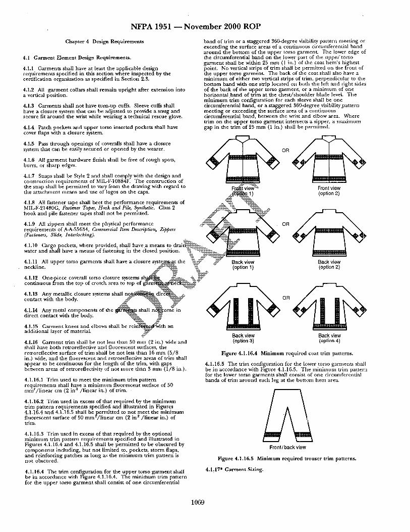
N F P A 1951 ~ N o v e m b e r 2 0 0 0 R O P
Chapter 4 Design Requirements
4.1 Garment Element Design Requ i rements .
4.1.1 Garments shall have at least the applicable design requ i rements specified in this sect ion where inspected-by the certification organizat ion as specif ied in Section 2.3.
4.1.2 All g a r m e n t collars shall r ema in up r i gh t after extension into a vertical posit ion.
4.1.3 Garments shall no t have tu rn -up cuffs. Sleeve cuffs shall have a closure system that can be adjus ted to provide a snug and secure fit a r o u n d the wrist while wear ing a technical rescue glove.
4.1.4 Patch pockets a n d uppe r torso inser ted pockets shall have cover flaps with a closure system.
4.1.5 Pass t h rough open ings of coveralls shall have a closure system that can be easily secured or o p e n e d by the wearer.
4.1.6 All g a r m e n t hardware finish shall be free of rough spots, burrs, or sharp edges.
band of tr im or a s taggered 360-degree visibility pa t te rn mee t ing or exceeding the surface areas of a con t inuous circumferent ia l band a r o u n d the bo t tom of the uppe r torso garment . The lower edge of the c i rcumferent ia l band on the lower par t of the u p p e f t o r s o g a r m e n t shall be within 25 m m (1 in.) of the coat h e m ' s h ighes t point. No vertical strips of tr im shall be permi t ted on the f ront of the uppe r torso garment . The back of the coat shall also have a m i n i m u m of ei ther two vertical strips of trim, perpendicu la r to fire bo t tom band with one strip located on both the left and r ight sides of the back of the uppe r torso garment , or a m i n i m u m of one horizontal band of t r im at the c h e s t / s h o u l d e r blade level. Th e m i n i m u m t r im conf igura t ion for each sleeve shall be one circumferent ia l band, or a s taggered 360-degree visibility.pattern mee t ing or exceeding the surface area of a con t inuous c i rcumferent ia l band, between the wrist asad elbow area. Where t r im on the uppe r torso g a r m e n t intersects a sipper, a m a x i m u m gap in the t r im of 25 m m (1 in.) shall be permit ted.
4.1.7 Snaps shall be Style 2 and shall comply with the design and construct ion requ i rements of MIL-F-10884F. T h e const ruct ion of
OR
the snap shall be permi t ted to vary f rom the drawing with regard to .~.-~:']"~'~'5.::'i:.~ Ft~.t w ~ "" Front view the attachment means and use of logos on the caps. : - ( ~ 1) (option 2)
.:~! "%".-:i~.".-::. 4.1.8 All fas tener tape shall beet the pe r fo rmance requ i rements of ~. "%-. ':%~ili~::., MIL-F-21480G, Fastener Tapes, Hook and Pile, Synthetic. Class 2 . - : ~ i i i ~ ....... hook a n d pile fas tener tapes shall no t be permit ted . . . : ~ ~ ' : ....
4.1.9 MI zippers shall mee t the physical pe r fo rmance . . : : i - ' ~ ~ ' ~ : ~ OR r equ i rements of A-A-55634, Commercial Item Description, zippers ...... ~ * ~ , , ~ N~
4..1.10 Cargo pockets, where provided, shall have .a m e a n s to dral~iiiii!::i!i~i::::~!~:~::::.:...~~;"" I water and shall have a means of fas tening in the closed position. '%~':::-:!iiiii::~:: [':" ]
4,.1.11 All uppe r torso ga rmen t s shall have a closure syste....m~...::.a.t the ::::iii.f i::~ ..#:!!::" Back view Back view neckline. ..::¢;~:~:'::':~i~!~i~!~:: '~!ii. "" (option 1 ) (option 2)
4.1.12 One-piece coverall torso closure systems s ~ ~...:..: ..... .:'.:. j!~iii~ .... con t inuous f rom the top of crotch area to top of ~..~laec~:':':"~.:"i~.~-.-::.#i ':';"
4.1.13 Any metall ic closure systems shall n .9 .~. - ' .$ . .~ , dir~i~::.~ ....::. contac t with the body. ~.4~::" ":~'~::.. ":~i~:::~.'~iY"
4.1.14 Any metal c o m p o n e n t s of the ~ t s shall n~i-~i:om~ in direct contact with the body. ,:::;::::":':'::%.. i~.:.-".:
4.1.15 G a r m e n t knees and elbows shall be rei___.~..:~.,_~...th~lE ~ an - - - - .#: addit ional layer of material.
4.1.16 Ga rmen t t r im shall be not less than 50 m m (2 in.) wide and shall have both retroreflective and f luorescent surfaces, the reu'oreflective surface of t r im shall be no t less t han 16 m m (5 /8 in.) wide, a n d the f luorescent a n d retroreflective areas of t r im shall appear to be con t inuous for the l eng th of the trim, with gaps between areas of retrorefiectivity of no t more t han 3 m m (1 / 8 in.).
4.1.16.1 Tr im used to m e e t the m i n i m u m tr im pa t te rn requ i rements shall have a m i n i m u m f luorescen t surface of 50 mm~/ l i nea r cm (2 in "2/ l inear in.) of trim. -
4.1.16.2 Tr im used in excess of tha t requi red by the m i n i m u m tr im pa t t e rn r equ i r emen t s specif ied and i l lustrated in Figures 4.1.16.4 a n d 4.1.16.5 shall be p e r m i t t e d to no t m e e t the m i n i m u m
2 f luorescent surface of 50 m m / l i n e a r cm (2 i n / l i n e a r in.) of trim.
4.1.16.3 Tr im used in excess of tha t requi red by the opt ional m i n i m u m tr im pa t te rn r equ i r emen t s specified a n d i l lustrated in Figures 4.1.16.4 a n d 4.1.16.5 shall be permi t ted to be obscured by c o m p o n e n t s including, bu t no t l imited to, pockets, s torm flaps, and re inforc ing patches as long zs the m i n i m u m t r im pa t te rn is no t obscured.
4.1.16.4 The t r im confi.~uration for the uppe r torso g a r m e n t shall be in accordance with Figure 4.1.16.4. T he m i n i m u m tr im pa t te rn for the uppe r torso g a r m e n t shall consist of one circumferent ial
Back view Back view (option 3) (option 4)
Figure 4.1.16.4 Min imum requi red coat trim patterns.
4.1.16.5 The t r im conf igurat ion for the lower torso ga rmen t s shall be in accordance with Figure 4.1.16.5. Tile m i n i m u m trim pat tern for the lower torso ga rmen t s shall consist of one c i rcumferendal bands of tr im a r o u n d each leg at the bo t tom h e m area.
Front/back view
Figure 4.1.16.5 Min imum requi red t rouser trim patterns.
4.1.17" Garment Sizing.
1 0 6 9
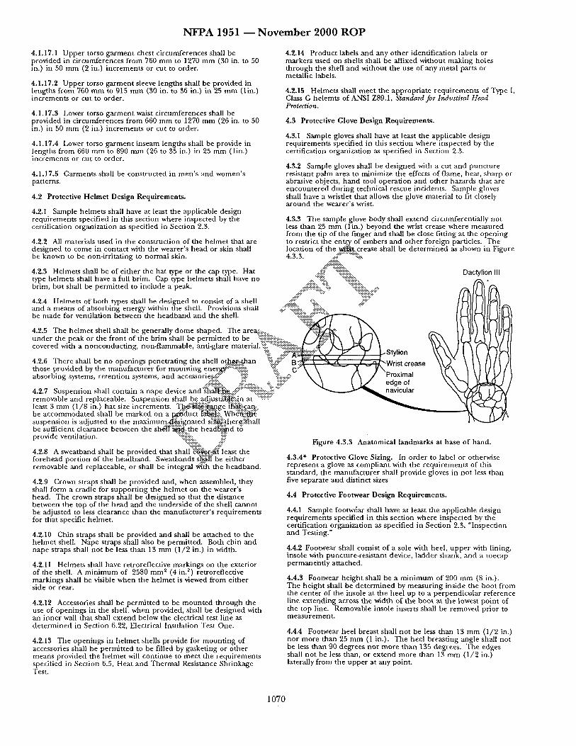
N F P A 1951 ~ N o v e m b e r 2 0 0 0 R O P
4.1.17.1 U p p e r torso g a r m e n t chest c i rcumferences shall be provided in c i rcumferences f rom 760 m m to 1270 m m (30 in. to 50 in.) in 50 m m (2 in.) i nc remen t s or cut to order.
4.1.17.2 U p p e r torso g a r m e n t sleeve lengths shall be provided in lengths f rom 760 m m to 915 m m (30 in. to 36 in.) in 25 m m (l in.) inc rements or cut to order.
4.1.17.3 Lower torso g a r m e n t waist c i rcumferences shall be provided in c i rcumferences f rom 660 m m to 1270 m m (26 in. to 50 in.) in 50 m m (2 in.) inc rements or cut to order.
4.1.17.4 Lower torso g a r m e n t inseam lengths shall be provide in lengths f rom 660 m m to 890 m m (26 to 35 in.) in 25 m m (l in.) inc rements or cut to order.
4.1.17.5 Garmen t s shall be cons t ruc ted in m e n ' s and women ' s patterns.
4.2 Protective He lme t Design Requi rements .
4.2.1 Sample he lmets shall have at least the applicable design requ i rements specif ied in this sect ion where inspected by the certification organizat ion as specified in Section 2.3.
4.2.2 All materials used in the const ruct ion of the he lme t that are des igned to come in contact with the wearer ' s head or skin shall be known to be non-irr i ta t ing to no rma l skin.
4.2.3 Helmets shall be of e i ther the ha t type or the cap type. Hat type he lmets shall have a full brim. Cap type he lmet s shall have no brim, bu t shall be pe rmi t t ed to include a peak.
4.2.4 Helmets of both types shall be des igned to consist of a shell
4.2.14 Product labels and any o ther identif icat ion labels or markers used on shells shall be affixed wi thout making holes t h rough the shell and without the use of any metal parts or metal l ic labels.
4.2.15 Helmets shall m e e t the appropr ia te r equ i r emen t s of Type [, Class G he lemts of ANSI Z89.1, Standard for Industiral Head Protection.
4.3 Protective Glove Design Requi rements .
4.3.1 Sample gloves shall have at least the applicable design requ i rements specified in this sect ion where inspected by the certification organizat ion as specified in Section 2.3.
4.3.2 Sample gloves shall be des igned with a cut and punc tu re resistant pa lm area to minimize the effects of f lame, heat, sha rp or abrasive objects, h a n d tool opera t ion and o ther hazards that are e n c o u n t e r e d du r ing technical rescue incidents. Sample gloves shall have a wristlet that allows the glove material to fit closely a r o u n d the wearer ' s wrist.
4.3.3 The sample glove body shall ex tend circumferential ly no t less t han 25 m m ( l in . ) beyond the wrist crease where measu red f rom the tip of the f inger a n d shall be close fitting at the open ing to restrict the en .tE¢ of embers and o ther fore ign particles. The locat ion of the ~ , c r e a s e shall be d e t e r m i n e d as shown in Figure 4.3.3. ..::!~;::: ........ :::-i'~:
. . : . : . : . : .
.... S :::i!::::iiii{iiiiii::::"-"::- Daetylion III ..... . . . .
.... ~::::::::ii ":ii::~ .... and a means of absorbing energy within the shell. Provisions shall .............................. ":'::':':':: . . . . . :-:-:':'- be made for venti lat ion between the h e a d b a n d and the shell. " ........ i i i : : i : : i : : i : : : : i ~ ~ I F
" ~ 1 . \ \ 4.2.5 The h e l m e t shell shall be general ly d o m e shaped. T he are~.::-:~ ....... 1 ~ ( / ,---,N ~ ~ ) u n d e r the peak or the f ron t of the br im shall be permi t ted to be ::.i.:i~iiiiii'P~ ....... l ) '~i:"~l '~ k Y ] \ \ k \ \ I C covered with a nonconduc t i ng , non- f lammable , anti-glare material.:~i!!£':'::::-:~i~---::::.:.l~..:.~::" /X,~ ~ ] I \ ~ I x \ I [
:::!:::!::':!:!:~::.. .:i:i::.:.::s:.:.... -:i:. ::i:i::" 4.2.7 Suspens ion shall contain a nape device and:~ha}~ii~:.:::.~;i!!::::""::-i::i::::iii!::i::::!;!i:i:ii!il; . . . . . . ~ ' - " - - " ~ ' ~ navicular ~ x ' - ( e d g e of removable and replaceable. Suspens ion shall b.e...adjustffl~ii:j.n at ............. " ~ ~'] least 3 m m (1 /8 in.) ha t size increments . T. l~."; i~: : i~ge ~!i..c.an:..::. be a c c o m m o d a t e d shall be marked on a p.....~~luct [~i~?.. W h ~ ! i ~ suspens ion is adjus ted to the maximura . :a .~ignated si~iither.¢~i~hall be sufficient clearance between the s h ~ } t ' : ~ : t h e h e a d ~ d t• provide ventilation. '::iii::iiii::i::iii .... iiiii:::
"::i~i~i~i~k.. ..iii;" 4.2.8 A sweatband shall be provided that shal l" :~er : :~" leas t the fo rehead port ion of the headband . Sweatbands s ~ f l be ei ther removable and replaceable, or shall be integral ~: th the headband .
4.2.9 Crown straps shall be provided and, when assembled, they shall form a cradle for suppor t ing the h e l m e t on the wearer 's head. The crown straps shall be des igned so that the dis tance between the top of the head and the unders ide of the shell canno t be adjusted to less clearance than the manufac tu re r ' s r equ i rements for that specific helmet .
4.2.10 Chin straps shall be provided and shall be a t tached to the he lme t shell. Nape straps shall also be permit ted. Both chin and nape straps shall no t be less t han 13 m m ( 1 / 2 in.) in width.
4.2.11 Helmets shall have retroreflective mark ings on the exterior of the shell. A m i n i m u m of 2580 m m ~ (4 in. z) retroreflective mark ings shall be visible when the he lme t is viewed f rom ei ther
s i d e or rear.
4.2.12 Accessories shall be permi t ted to be m o u n t e d t h rough the use of open ings in the shell, when provided, shall be des igned with an inne r wall that shall ex tend below the electrical test line as d e t e r m i n e d in Section 6.22, Electrical Insulat ion Test One.
4.2.13 The open ings in he l me t shells provide for m o u n t i n g of accessories shall be permi t ted to be filled by gasket ing or o ther means provided the h e l m e t will con t inue to mee t the r equ i rements specified in Section 6.5, Heat and The rma l Resistance Shr inkage Test.
Figure 4.3.3 Anatomical l andmarks at base o f hand.
4.3.4* Protective Glove Sizing. In order to label or otherwise r ep resen t a glove as compl ian t with the r equ i r emen t s of this s tandard, the manu fac tu r e r shall provide gloves in no t less than five separate and distinct sizes
4.4 Protective Footwear Design Requ i rements .
4.4.1 Sample footwdar shall have at least the applicable des ign requ i rements specified in this sect ion where inspected by file certification organizat ion as specified in Section 2.3, "Inspect ion and Test ing."
4.4.2 Footwear shall consist of a sole with heel, u p p e r with lining, insole with puncture- res is tant device, ladder shank, and a toecap pe rmaneh t ly a t tached.
4.4.3 Footwear he igh t shall be a m i n i m u m of 200 m m (8 in.). The he igh t shall be d e t e r m i n e d by m e a s u r i n g inside the boot f rom the center of the insole at the heel up to a pe rpend icu la r reference line ex tend ing across the width of the boo t at the lowest po in t of the top line. Removable insole inserts shall be removed prior to m e a s u r e m e n t .
4.4.4 Footwear heel breast shall no t be less than 13 m m (1 /2 in.) nor more than 25 m m (1 in.). The heel breas t ing angle shall no t be less than 90 degrees nor m o r e t h a n 1S5 degrees . The edges shall no t be less than, or ex tend more than 13 m m (1 /2 in.) laterally f rom tile uppe r at any point.
1 0 7 0
N F P A 1951 - - N o v e m b e r 2 0 0 0 R O P
4.4.5 The puncture-resistant device shall cover the maximum area of the insole.
4.4.6 Footwear shall have a toe cap not less than 50 mm (2 in.) fi:om the front edge of the footwear.
4.4.7 Metal parts shall no t penetra te from the outside into the lining or insole at any point, unless covered.
4.4.8 No metal parts, including but no t l imited to nails or screws, shall be present or utilized in the construction or a t tachment of the sole with heel to the puncture-resistant device, insole, or upper .
4,4.9 When used, there shall be a min imum of four metal stud hooks on each side of the eyebrow.
4,4.10 Eyelets, if used, shall be constructed of coated steel, solid brass, brass coated nickel or nickel.
4.4.11 Protective Footwear Sizing.
4..4.11.1 Footwear shall be available in all the following sizes:
Mens: 5-13, including half sizes, and a min imum of three widths
Womens: 5-10, including half sizes, and a min imum of three widths
4.4.11.2" Manufacturers shall be required to establish and provide, upon request, a size conversion char t for each model or style of protective footwear based on toe length, arch length, and foot width as measured on the Bannock Scientific Foot Measuring Device.
4.4.11.3 Full and half sizes, in each of the three required widths, shall be accomplished by individual and unique lasts to provide
5.1.1.6.1 Composite or outer textile fabric seams shall have a min imum of either 80 percent seam efficiency of fabric strength or 390 N (70 lbf), whichever is lower.
5.1.1.6.2 Separate liner seams shall have a min imum of either 80 percent seam efficiency of fabric s trength or 220 N (50 lbf), whichever is lower.
5.1.1.7 Textile fabrics, linings, collar linings, trim, letter, and other materials used in garment construction, including, but not limited to, padding, reinforcement , intert~tcing, binding, hanger loops, emblems, a n d p a t c h e s shall be individually tested for flame resistance as spec i f i ed in Section 6.4, Flame Resistance Test One, and shall have a char length of no t more than 100 m m (4 in.), an afterflame of no t more than 2.0 seconds, and shall no t melt or drip.
5.1.1.7.1 Labels shall meet the per formance requ i rement specified in 5.1.1.7 only where place on the exterior of the garment.
5.1.1.7.2 Zippers and seam-sealing materials shall mee t the performance requirements specified in 5.1.1.7 only where located on the exterior of the garment or located where they will directly contact the wearer 's body.
5.1.1.7.3 Elastic and hook and pile fasteners shall meet the performance re$~:e .ments specified in 5.1.1.7 only where located where they ~..R..:i!~i~r~:i~ly contact the wearer 's body.
.4~:-'i:.-':i:~:!::, 5.1.1.7.4 ~ : ~ i ~ | i i ~ c i m e n s such as hanger loops and emblems (patche.$y:!~at a/::~i~t large enough to meet the specimen size r e q u ~ @ ~ i ~ in 6.~-'.~.~:..s ..hgl. 1 be tested for resistance to flame as sp.e..~ed ~f Section O:~i.."..:Fl'ame Resistance Test One, and shall not .. . .~e a~i~terf lame of.:~:tre than 2.0 seconds, and shall not melt or
5.1.~:~i!ii~extile fabrics and linings utilized in garments shall be proper fit. ¢..~.... ..... individ'i~F:.....t.~ted for thermal shrinkage resistance as specified in
:~i~::::.:..Section ~;:~.~!i~qeat and Thermal Shrinkage Resistance Test, and 4.5 Eye and Face Protective Device Design Requirements. %":'::~:-::%~!!.:.no..t..-~aVfrink more than 10.0 percent in any direction.
-i~i-: ..::i:ii::":'::~:i~iii~i~?i~i?.:::" 4.5.1 Eye and face protective devices shall meet ANSI Z87,~:.:.: ..... ':~ii!:::.#~i::"5. l.~ii~"Textile fabrics, linings, hardware, and other materials used', requirements . ....:!?:i~:;::%::::i::::ii:: "~:".-:!~. in g~rment construction - including but no t l imited to padding
~.~ Ei'~ ~iiiii ~ ~%:::..-.x~einforcement, wristlets, collars, ga rment labels, hanger hooks, 4.5.2 Eye and face protective devices shall be p e ~ . ~ . t o bg~i!.".:.:::::.:... ~.i~. ~i..'.."~::'buttons, fasteners and closures, but excluding hook and pile at tached to the he lmet or be separate. ": ~%~i~-'.-,~-:':::~":':~:~i~i~!i!!::.]i ':::" fasteners and trim when not in direct contact with the skin - shall
......... '~iii~,. "::~:~i~i~i~:::" be individually tested for heat resistance in their original form as Chapter 5- Performance R e q ~ . '::"~::.:'i:":'?::. .-:-. specified in Secdon 6.5, Heat and Thermal Shrinkage Resistance
. . : : # :~ . ? :~ : : . . " ~ " " Ies t and shall no t melt dr ip separate or ignite. 5.1 Protective Garment Performance R ~ i r e m e n ~ . : .::iii ~!::"
:i"-'"~i::. ";-'i~ii~ ' 5.1.1.10 Sewing thread utilized in the construction of garments 5.1.1 Base Requirements . ~.~!:~ ~i.:.'ii.": shall be made of an inherent ly flame resistant fiber, shall be tested
" ~ Ai~ :~ for hea t resistance as specified in Section 6.14, "Thread Heat 5.1.1.1 Garment composites shall be tested f o r ' ~ . ~ a t loss as Resistance Test, and shall no t melt. specified in Section 6.6, Total Heat Loss Test, an~i~l:mll have a total heat loss of not less than or equal to 450 Wf-~la ~. 5.1.1.11 All metal hardware and hardware, that includes metal
5.1.1.2 Textile fabrics and linings used for garments shall be tested for tear resistance as specified in Section 6.7, Tear Resistance Test, and shall have a tear resistance of no t less than 25 N (5.0 lbf).
5.1.1.3 Outer shell fabric shall be tested for breaking strength as specified in Section 6.8, Breaking Strength Test, and shall have a breaking strength of no t less ' than 320 N (70 lbf).
5.1.1.4 Outer shell fabric shall be tested for abrasion resistance as specified in Section 6.9, Abrasion Resistance Test One, and shall have an ending breaking s t rength of no t less than 280 N (50 Ibf) and shall have a change in breaking strength no greater than 25 percent.
parts shall be tested for corrosion resistance as specified in Section 6.16, Corrosion Resistance Test. Metals inherent ly resistant to corrosion, including but no t l imited to stainless steel, brass, copper, aluminum, and zinc shall show no more than light surface-type corrosion or oxidation. Ferrous metals shall show no corrosion of the base metal.
5.1.1.12 Reflective trim used on garments shall be tested for retroreflectivity and fluorescence as specified in Section 6.15, Trim High Visibility Test, and shall have a total Coefficient of Retrorefiection (P~) of no t less than 100 c d / l u x / m ~ ( c d / f c / f t 2) and be designated as fluorescent.
5.1.2 Additional Optional Requirements for Barrier Protection.
5.1.1.5 Textile fabrics and linings shall be individually tested for ch:aning shrinkage resistance as specified in Section 6.10, Cleaning Shrinkage Resistance Test, and shall no t shrink more than 5.0 percent in any direction.
5.1.1.6 Seams shall be tested for seam strength as specified in Section 6.12, Seam Breaking Strength Test, and shall demonstrate a sewn seam strength equal to or greater than that stipulated for each seam type listed below.
5.1.2.1 Garment composite shall be tested for water repellency as specified in Section 6.15, Water Repellency Test, and shall have a spray rating of 80 or greater.
5.1.2.2 Garment composite shall be tested for liquid penetrat ion resistance as specified in Section 6.17, Liquid Penetrat ion Resistance Test, and shall show no chemical penetrat ion.
5.1.2.3 Garment composite shall be tested for biopenetrat ion resistance as specified in Section 6.18, Viral Penetrat ion Resistance Test, and shall show no viral penetrat ion.
1071
NFPA 1951 - - N o v e m b e r 2000 ROP
5.1.2.4 Garments shall be tested for liquid pene t ra t ion resistance as specified in Section 6.3, Overall Liquid Integrity Test One, and shall no t allow liquid penetra t ion.
5.1.3 Additional Optional Requirements for Limited Flash Fire Protection.
5.1.3.1 Garmen t composi te shall be tested for radiant protective
~ er formance as specif ied in Section 6.2, Radiant Reflective e r formance Test, and shall have an average rad iant protective
pe r fo rmance (RPP) of 8.0 or greater.
5.1.3.2 Garments shall be tested for overall flash fire exposure as " specified in Section 6.25, Overall Flash Fire Exposure Test, and
shall no t have more than 25 pe rcen t total body burn .
5.2 Protective Helmet Performance Requirements.
5.2.1 Base Requirements.
5.2.1.1 Helmets shall be tested for f lame resistance as specified in Section 6.19, Flame Resistance Test Two, and shall no t have afterf lame with a dura t ion greater than 5.0 seconds.
5.2.1.2 Any anti-glare material , when used, shall be tested for f lame resistance as specified in Section 6.19, Flame Resistance Test Two, and shall n o t have afterf lame with a dura t ion greater than 5.0 seconds .
5.2.1.3 Helmets shall be tested for hea t resistance as specified in Section 6.5, Heat and The rma l Shr inkage Resistance Iest, and shall no t have any deformat ion of the br im or peak exceed 25 pe rcen t of its length when measured f rom j unc t i on of the crown with the br im or peak.
5.2.1.4 Helmets shall be tested for top impact resistance as
5.2.1.9 Helmets shall be tested for re tent ion system and chin strap efficiency as specified in Section 6.24, Re ten t ion System Test, and shall no t show any failure.
5.2.1.10 Helmets with metal hardware and ha rdu~re that includes metal parts shall be tested for corrosion resistance as specified in Section 6.16, Corrosion Resistance Test. Metals inheren t ly resistant to corrosion, inc lud ing bu t n o t l imited to stainless steel, brass, copper , a l u m i n u m , and zinc shall show no more than light surface-type corrosion or oxidation. Ferrous metals shall show no corrosion of the base metal .
5.2.1.11 He lmet retroreflective markings shall be tested for retroreflectivity a n d f luorescence as specif ied in Section 6.15, Tr im High Visibility Test, and shall no t have a Coefficient or Retroreflectivity (R,) of less than 100 c d / l u x / m ~ ( c d / f c / f t z), an d shall be des ignated f luorescent .
5.2.2 Additional Optional Requirements for Limited Chemical Flash Fire Protection. Helmets shall be tested for overall flash fire exposure as specif ied in Section 6.25, Overall Flash Fire Exposure Test, and shall mee t the following requi rements :
(1) Show no ignit ion on any par t of the he lme t (2) Have no shell dis tor t ion of the front, back, and sides of
the shell ex tend more than 30 m m (1 13 /64 in.) below the original position of the .h.~~met
(3) Hav. .e!~o"~arat ion, mel t ing, or d r ipp ing of the re tent ion system, ene~-~....bsorption system, or neck sh roud
. . : . : ~ . . : . : . : . : . : . : . .
5.3 P r , t ' ~ v e ~ Pe r fo rmance Requi rements . . . : . . . . . . . . . . . . : , , . . . . . . . . . . . .
5.S ,~f : : : i i~4~ 'equi rem~ ~:,
.::¢i!N~}:.l..:l i~N.ve c o m p d l t e s shall be tested for resistance to cut as sp~.'.f.t..~:"i~i::i-Secdon 6.2, Cut Resistance Test, and shall no t have a
specified by Section 6.20, T op Impact Resistance Tes t (Force), cut c t ~ . c e resistance of more than 25 m m (1 in.). and shall no t t ransmi t an average force of more than 3783 N (850 :~i::.: .... ================================= lbf). No individual spec imen shall t r ansmi t a force of m o r e t h a n :::~-!}i}i}~:!.:.::i.:.5:3.i.2 (~.~.~ composi tes shall be tested for p u n c t u r e resistance as 4450 N (1000 lbf). ::~;i: "":'::::i~i~.fiec].:~i" Section 6.29, Punc tu re Resistance Test One, and shall
":!:::::: . . . . . . i ~ t u r e u n d e r an appl ied force of 45 N (10 lbf). ::ii!:. +i:i;::" .~:.::.'::" 5.2.1.5 Helmets shall be tested for resistance to impact as:.:.:.:.:.:.. • .......... ...
specif ied in Section 6.30, Impact Resistance Tes t ( a c c . e . . ~ ) , :!iiiil. 5.3.'][.3 Glove composi tes shall be tested for abrasion resistance as a n d shall have no spec ime n exceed the m a x i m u m a~ '~eradd~i : %:::i~pecified in Section 6.11, Abras ion Resistance Tes t Two, an d shall specified in Table 5.2.1.5. Any accelerat ion durati...o'/~::!~.gve ~ : ~ ":::i-...ii::::iii::"show no wear th rough . shall no t exceed 3 mil l iseconds accelerat ion dura~or/:i~...~:':I5~i'iiiiiii::i::::iii) ..... Gn shall no t exceed 6 mill iseconds. ::::::::::::::::::::::::: '::::iiii:i:i .... 5.3.1.4 Gloves shall be tested for h a n d func t ion as specified in
--i::::ili:: "::ii:: :~i:- Section 6.31, Glove H a n d Funct ion Test, and shall no t have an average pe rcen t of b a r e h a n d control exceeding 200 percent .
Table 5.2.1.5 .::!i!::! }::.::
Impact Maximum Location Acceleration*
Top 150 x Gn
Fron t 300 x Gn
.... ~i~i~}i~ .... i~i~i~ (m~c/sec)'%ii!iii~.mse~:~c)
(1471.5) .... !iiiii~4830) -:!i::"
(2943.0) (9660)
Sides 300 x Gn (2943.0) (9660)
Back 300 x Gn (2943.0) (9660)
* Gn denotes gravitational acceleration, which is def ined as 9.81 m / s 2 (32.~ f t /s~).
5.2.1.6 Helmets shall be tested for pene t ra t ion (physical) resistance as specified in Section 6.21, Physical Penet ra t ion Resistance Test, and shall no t have any pene t ra t ion pierce the he lme t shell by more tha t 9.5 m m (3 /8 in.).
5.2.1.7 Helmets shall be tested for electrical insulat ion as specified in Section 6.22, Electrical Insulat ion Tes t One, mad shall no t have electrical leakage cur ren t exceeding 3 mill iamperes.
5.2.1.8 Helmets shall be tested for suspens ion system separa t ion as specified in Section 6.23, Suspens ion System Retent ion Test, and shall no t have the m i n i m u m force requi red to separate any individual a t t a chmen t poin t of the suspens ion assembly f rom the he lme t shell be less than 2.3 kg (5 lbs).
5.3.1.5 Gloves shall be tested for. grip as specified in Section 6.32, Grip Test, and shall have a weight pul l ing capacity no t less than 80 percen t of the bare hand control values.
5.3.1.6 Gloves shall be tested for ease of d o n n i n g as specified in Section 6.33, Liner Retent ion Test, a n d shall no t have a final d o n n i n g t ime exceed the baseline d o n n i n g t ime plus 20.0 seconds.
5.3.1.7 Gloves shall be individually tested for f lame resistance as specified in Section 6.26, Flame Resistance Tes t Three , an d shall have an average char length of no t more than 100 m m (4 in.), an average afterf lame of no t more than 2.0 seconds, and shall no t mel t or drip.
5.3.1.8 Gloves shall be tested for hea t resistance as specified in Section 6.5, Heat and The rma l Shr inkage Resistance Test, and shall no t separate, melt , ignite or drip. The glove shall be measu red in both length and width and shall no t shr ink mo re than 10 pe rcen t in ei ther direction. T h e glove shall be measu red form the tip of the middle f inger to the bo t tom of tile glove body and the width shall be f rom side to side. If the glove is made with a wristlet of a different material, the wristlet shall be measu red separately.
5.3.1.9 Glove metal ha rdware and hardware that includes metal parts shall be tested for corrosion resis tance as specified in Section 6.16, Corrosion Resistance Test. Metals inheren t ly resis tant to corrosion, inc lud ing but no t l imited to stainless steel, brass, copper, a l u m i n u m , and zinc shall show no more than light surface-type corrosion or oxidat ion. Ferrous metals shall show no con-osion of the base metal .
1 0 7 2
N F P A 1951 ~ N o v e m b e r 2000 R O P
5.3.2 Additional Optional Requirements for Barrier Protection.
5.$.2.1 Glove composites shall be tested for liquid penetra t ion resistance as specified in Section 6.17, Liquid Penetra t ion Resistance Test, and shall show no chemical penetrat ion.
5.3.2.2 Glove composites shall be tested for biopenetrat ion resistance as specified in Section 6.18, Viral Penetrat ion Resistance Test, and shall show no viral penetrat ion.
5.3.2.3 Gloves shall be tested for overall water tight integrity as specified in Section 6.34, Overall Liquid Integrity Test Two, and shall show no water penetrat ion.
5.3.3 Additional Optional Requirements for Limited Flash Fire Protection.
5.3.3.1 Glove composites, excluding any optional, removable liners, shall be tested for radiant protective performance as specified in Section 6.2, Radiant Performance Performance Test, and shall not have an average radiant protective performance (RPP) of less than 7.0.
5.3.3.2 Gloves composites shall be tested for conductive heat resistance as specified in Section 6.27, Conductive Heat Resistance Test, and shall not have a second degree burn time of less than 7 seconds, and shall no t have the pain time be less than 4 seconds.
5.4 Protective Footwear Performance Requirements.
5.4.1 Base Requirements.
5.4.1.1 Footwear upper shall be tested for abrasion resistance as specified in Section 6.11, Abrasion Resistance Test Two, and shall
5.4.1.12 Metal parts used in sample footwear shall be tested for corrosion resistance as specified by Section 6.16, Corrosion Resistance Test. Metals inherently resistmat to corrosion, including but no t l imited to stainless steel, brass, copper, a luminum and zinc shall show no more than light surface type corrosion or oxidation. Ferrous metals shall show no corrosion of the base metals. Accessories shall remain functional.
5.4.1.13 Footwear shall be individually te,;ted for flame resistance as specified in Section 6.35, Flame Resistance Test Four, and shall not have a char length of more than 100 mm (4 in.), shall no t have an afterflame of more than 2.0 seconds, mad shall no t melt or drip.
5.4.1.14 Footwear shall be tested for heat resistance as specified in Section 6.5, Heat and Thermal Shrinkage Resistance Test, and shall not have any part of the footwear melt, o ther than laces, and shall have all accessories remain functional.
5.4.2 Additional Requirements for Barrier Protection.
5.4.2.1 Footwear shall be tested for liquid penetra t ion resistance as specified in Section 6.17, Liquid Penetrat ion Resistance Test, and shall show no chemical penetrat ion.
5.4.2.2 Footwear shall be tested for biopenetrat ion resistance as specified in SectiQn 6.18, Viral Penetrat ion Resistance Test, and shall s h o w n o ~ : y n e ~ t l o n .
..::'::.'-" "'-::~::~
5.4.2.3 F o a . ~ g . shall be tested for overall water tight integrity as spec i f i ed .~Sd :~ t i~ 6.44, Overall Integrity Test Two, and shall show n...9..':~er l~ :~ . . a t ion .
...-:-'iiiiiiii::.. ":'~k "::i~:.-".:::. :. 5...4..~i::':'~tional a e ~ ' e n t s for Limited Flash Fire Protection.
show no wear through. . . . . : g~ , 1 i ~ t w e a r upl~ier shall be tested for radiant protective " p ~ " { i : ' ~ as specified in Section 6.2, Radiant Reflective
5.4.1.2 Footwear upper shall be tested for cut resistance as P e r f ~ c e Test, and shall not have an average radiant protectiw." specified in Section 6.22, Cut Resistance Test, and shall have a cut;,:: ..... perfor~i¢~:-~-RPP ) of less than 8.0. distance resistance of not more than 25 mm (1 in.). ::i!iiii!::~ii::i::i::i!!!!:!:..: . . . . . #F"
':i!i:: ""'::::i:iiiii~..3..:....2 .~:i~twear upper shall be tested for conductive heat 5.4.1.3 Footwear upper shall be tested for puncture resistance as ":~i~i, ..:::-i~:i~:~:i~ as specified in Section 6.27, Conductive Heat Resistance specified in Section 6.29, Puncture Resistance Test One, ~ z h a l l ::~-: ~-i::~ Tes.g.--'!.-"~hd shall not have a second degree burn time of less than 7 not puncture under an applied force of 45 N (10 Ibf)...::#i:'-":":::%~ii.. %1. seconds, and shall no t have the pain time be less than 4 seconds.
..::ii::" :iiiiii:" ":~i.:'.-%..:.::~.~ 5.4.1.4 Footwear toes shall be tested for resistance...:¢~ii~pact:!~.:. ":i--. :iilii i::~::g-5 Eye and Face Protective Device Per formance Requirement - - compression as specified in Section 6.36, Impact ~:nd:::~:~:~::ii:i::::ii::ii ..... Additional Requirement for Limited Flash Fire Protection. Resistance Test, and shall have an impact requirg.ment ~:'::.:."~:1.7 J ":::*~:~:! .... (75 ft-lb), and shall have a compression r e q . . m . . ~ : : . o f 1 I : , ~ : N..:::. 5.5.1 Eye and face protective devices shall be tested for flame (2500 lbf) with a min imum clearance of 1.$::~m (1:~.~-:$.~..). "~--?ii'::" resistance as specified in Section 6.19, Flame Resistance Test Two,
• ":::::" and shall not show any visible afterflame 5.0 seconds after removal ..... "::~::~i~i~i~- . . . . . i~ .... 5A.1.5 Footwear ladder shanks shall ~ i ~ d for r e s i ' ~ c e "~o bending as specified in Section 6.37, L a d d ~ i ~ . a n k Ber~: Resistance Test, and shall not defect more tfi'~i!!.g.....mm.:.:..-"~]/4 in.).
--::::::::::::.. ::~,-
5..t.1.6 Footwear sole and heel shall be tested fo?~ : ra s ion resistance as specified in Section 6.38, Abrasion "l~:esistance Test Three, and shall not have an abrasion-resistance rating of less than 65 NBS Index.
5.4.1.7 Footwear sole and heel shall be tested fo rpene t r a t i on (ph}sical) resistance as specified in Section 6.39, Puncture Resistance Test Two, and shall no t have a puncture force of less than 1210 N (272 lbf).
5.4.1.8 Footwear outersole shall be tested for flex fatigue resistance as specified in Section 6.40, Flex Fatigue Resistance Test, and shall not exceed 350 percen t cut growth.
5.4.1.9 Footwear outersole shall be tested for slip resistance as specified in Section 6.41, Sllp Resistance Test, and shall not show a friction coefficient of less than 0.75 under dry condit ions and 0.50 under wet conditions.
5.4.1.10 Footwear shall be tested for electrical conduct ion as specified in Section 6.42, Electrical Insulation Test Two, and shall not have any electrical leakage shall exceed 3 milliamperes.
5.,t.. 1.11 -Eyelets and stud hooks shall be tested for de tachment strength as specified in Section 6.43, Eyelet and Stud Post At tachment Test, and shall have a min imum de tachmen t s trength of 300 N (66 lbf).
of the test flame.
5.5.2 Eye and face protective devices shall be tested for heat resistance as specified in Section 6.5, Heat and Thermal Shrinkage Resistance Test, and shall no t drip.
Chapter 6 Test Methods
6.1 Sample Preparat ion Procedures.
6.1.1 Application.
6.1.1.1 The sample preparat ion procedures contained in dais section shall apply to each test me thod in this chapter, as specifically referenced in the sample preparat ion section of each test method.
6.1.1.2 Only the specific sample preparat ion procedure or procedures referenced in the sample preparat ion section of each test me thod shall be applied to that test method.
6.1.2 Room Tempera ture Condit ioning Procedure for Garments, Helmets , Gloves, Footwear, and Eye and Face Protective Devices. Specimens shall be condi t ioned at a tempera ture of 21 °C, +3°C (70°F, +-5°F) and a relative humidity of 65 percent , +5 percent , for at least 24 hours. Specimens shall be tested within 5 minutes after removal f rom condit ioning.
6.1.3 Washing and Drying Procedure for Garments and Gloves. Specimens shall be subjected to 10 c~'cles of washing and drying in accordance with the procedure specified in Machine Cycle 1, Wash Temperature V, and Drying Procedure Ai, of AATCC 135, Dimensional changes in Automatic Home Laundering of Woven and
1073
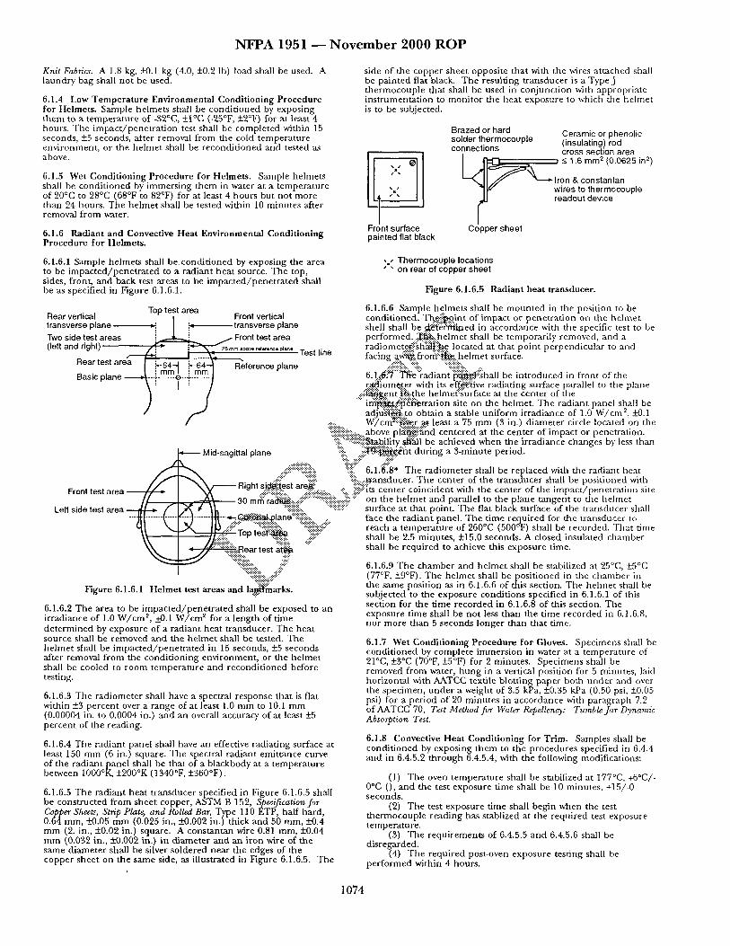
N F P A 1 9 5 1 ~ N o v e m b e r 2 0 0 0 R O P
Knit Fabrics. A 1.8 kg, _+0.1 kg (4.0, -+0.2 lb) load shall be used. A laundry bag shall no t be used.
6.1.4 Low T e m p e r a t u r e Environmenta l Condit ioning Procedure for Helmets . Sample he lmets shall be condi t ioned by exposing t h e m to a t empera tu re of -32°C, +-I°C (-25°F, +2°F) for a t least 4 hours . The i m p a c t / p e n e t r a t i o n test shall be comple ted within 15 seconds, -+5 seconds, after removal f rom the cold t empera tu re env i ronment , or the he lme t shall be recondi t ioned and tested as above.
6.1.5 Wet Condi t ioning Procedure for Helmets . Sample he lmets shall be condi t ioned by immers ing t hem in water at a t empera tu re of 20°C to 28°C (68°F to 82°F) for at least 4 hours but no t more than 24 hours . The he lme t shall be tested within 10 minu tes after removal f rom water.
6.1.6 Radiant and Convective Heat Environmental Condit ioning Procedure for Helmets .
6.1.6.1 Sample he lmets shall be. condi t ioned by exposing the area to be i m p a c t e d / p e n e t r a t e d to a rad ian t hea t source. The top, sides, front, and hack test areas to be i m p a c t e d / p e n e t r a t e d shall be as specif ied in Figure 6.1.6.1.
Rear vertical Top test area Front vertical transverse plane *i ] i " transverse plane Two side test areas ~ / Front test area (left and ri9ht ) ~ i~'-N-"5 a~mm .~o ~. . . . . p,,,..
Test line i I . . . . . . . . . Rear test area ~ ~64_ ~ i~64_. ~ R~eference plane
-:::-:. . .
side of the copper shee t opposite that with the wires a t tached shall be pa in ted fiat black. The result ing t r ansducer is a TypeJ t he rmocoup le that shall be used in conjunc t ion with appropr ia te ins t rumenta t ion to moni to r the hea t exposure to which the he lmet is to be subjected.
Front surface painted flat black
Brazed or hard Ceramic or phenolic solder thermocouple (insulating) rod connections cross section area
'XX. * -< 1.6 mm ~ (0.0625 in ~)
= Iron & constanlan wires to thermocouple readout device
Copper sheet
. . Thermocouple locations • " on rear of copper sheet
Figure 6.1.6.5 Radiant heat t ransducer .
6.1.6.6 Sample he lmets shall be m o u n t e d in the posit ion to be condi t ioned. T ~ i ~ . . . i n t of impact or pene t ra t ion on the h e l m e t shell shall be ~ i ~ t g ~ m e d in accordance with the specific test to be performed.. :~: . . . .helm'et shall be temporar i ly removed, and a rad omete~.::::sh~|~i!~e located at that p o n t p e r p e n d cu ar to and facing a~ : . f ro~! : :~e , he lme t surface.
.... ~!i::ii~!::.."%. '%i::i-::, . 6. t : .~! :~" '~e" : rad ian t"p~l~hal l be in t roduced Jr, f ront of the . r : ~ o m .~...er with its ef.£..~:dve radiat ing surface parallel to the plane
. : i i ! ~ e n t i ~ : t h e belmeffsurface at the center of the '" i n : i ~ . ~ g N ~ t r a t i o n site on the helmet . T h e rad iant panel shall be
adju'~t'~:..to obtain a stable un i fo rm irradiance of 1.0 W/cm ~, _+0.1 W/cm~i i : :~r al least a 75 m m (3 in.) d iamete r circle located on the
=========================== ....... above plff~ii~nd centered at the center of impact or penetra t ion. ":i-~":::~-~bilit-y ~ 1 1 be achieved when the i r radiance changes by less than
~ Mid-sagittal plane :~::ii..iiiii'~::::~:.¢. "-~t du r ing a 3-minute period.
.... iiiii::iiiiiiiiiiii!!!ii:::i:: ~ii!i: 6.1.'6:[8" The rad iometer shall be replaced with the radiant heat / ~ I ~ \ . . . . . . -~: . "~-: . "ii::::.:::..transducer. T h e center of the t r ansducer shall be pos i t ioned with
~ ~ 1 ~ , . ~ HJghl s l~~est are~: Font test area ...... :-. -'" -:. :::?:its center coincident with the center of the i m p a c t / ene t ra t ion site r ....:=:--::::::::.:::.. ======================= --::...:::::-- P 30 ram ra~--..-:-i:::''"::i;ii::iiiiiiii::::-:-)::if : on the he lmet and parallel to the plane t angen t to the heh n e t
@ /," ] ~ j¢ ~ ====@========= "::::iiiiiiill .... surface at that point. The flat black surface of the t ransducer shall Left side test area "~ [ -q , -~ " . - ] ( . l l \ I~',X ....... |[~ ~ ~ : : - - I ~ . " ~ i ~ : p l a n d : ....
t:lear test ar.@a
- ~ . . : ~ - ~ l a n e '*~!-i'-:......::.
.... '%iiiiiiiii,,iij! F ~ u r e 6.1.6.1 He lme t test areas and la.~haarks.
6.1.6.2 The area to be i m p a c t e d / p e n e t r a t e d shall be exposed to an irradiance of 1.0 W / c m ~, _+0.1 W / c m e for a l eng th of t ime de t e rmined by exposure of a radiant hea t t ransducer . The hea t source shall be r emoved a nd the he l me t shall be tested. The he lme t shall be i m p a c t e d / p e n e t r a t e d in 15 seconds, +5 seconds after removal f rom the condi t ion ing env i ronment , .or the he lme t shall be cooled to r oom t empera tu re and recondi t ioned before testing.
6.1.6.3 The rad iometer shall have a spectral response tha t is flat within +3 pe rcen t over a range of at least 1.0 m m to 10.1 m m (0.00004 in. to 0.0004 in.) and an overall accuracy of at least +_5 percen t of the reading.
6.1.6.4 The radiant panel shall have an effective radiat ing surface at least 150 m m (6 in.) square . The spectral rad ian t emi t tance curve of the rad iant panel shall be that of a blackbody at a t empera tu re between 1000°K, +200°K (1340°F, +360°F).
6.1.6.5 The rad iant hea t t r ansducer specif ied in Figure 6.1.6.5 shall be cons t ruc ted f rom shee t copper, ASTM B 152, Specification for Copper Sheets, Strip Plate, and Rolled Bar, Type 110 ETP, haf t hard, 0.64 mm, _-t-0.05 m m (0.025 in., --+0.002 in.) thick and 50 mm, +0.4 m m (2. in., +0.02 in.) square. A cons tan tan wire 0.81 mm, -+0.04 m m (0.032 in., _+0.002 in.) in d iameter a n d an i ron wire of the same d iamete r shall be silver soldered nea r the edges of the copper shee t on the same side, as i l lustrated in Figure 6.1.6.5. The
face the rad ian t panel . The t ime requ i red for the t ransducer to reach a t empera tu re of 260°C (500°F) shall be recorded. Th a t t ime shall be 2.5 minutes , -t-15.0 seconds. A closed insulated c h am b e r shall be requi red to achieve this exposure t ime.
6.1.6.9 The chambe r and he lme t shall be stabilized at 25°C, +_5°C (77°F, -+9°F). The he lme t shall be pos i t ioned in the cham b e r in the same posi t ion as in 6.1.6.6 of this section. The he lme t shall be subjected to the exposure condi t ions specified in 6.1.6.1 of this sect ion for the t ime recorded in 6.1.6.8 of this section. The exposure t ime shall be no t less than the t ime recorded in 6.1.6.8, no r more than 5 seconds longer than that time.
6.1.7 Wet Condi t ioning Procedure for Gloves. Spec imens shall be condi t ioned by comple te immers ion in water at a t empera tu re of 21°C, +3°C (70°F, +-5°F) for 2 minutes . Spec imens shall be removed f rom water, h u n g in a vertical posi t ion for 5 minutes , laid horizontal with AATCC textile blot t ing paper both u n d e r an d over the specimen, u n d e r a weight of 3.5 kPa, +0.35 kPa (0.50 psi, _+0.05 psi) for a period of 20 minu te s in accordance with paragraph 7.2 of AATCC 70, Test Method for Water Repellency: Tumble Jar Dynamic Absorption Test.
6.1.8 Convective Heat Condit ioning for Trim. Samples shall be condi t ioned by exposing t hem to the p rocedures specified in 6.4.4 and in 6.4.5.2 t h r o u g h 6.4.5.4, with the following modifications:
(1) The oven t empera tu re shall be stabilized at 177°C, +6°C/- 0°C 0 , and the test exposure t ime shall be 10 minutes , +15/-0 seconds .
(2) The test exposure t ime shall begin when the test t he rmocoup le read ing has stablized at the requi red test exposure tempera ture .
(3) The requ i rements of 6.4.5.5 and 6.4.5.6 shall be disregarded.
(4) The requi red post-oven exposure test ing shall be pe r fo rmed within 4 hours .
1 0 7 4
N F P A 1 9 5 1 ~ N o v e m b e r 2 0 0 0 R O P
6,2 Radiant Reflective P e r f o r m a n c e Test .
6.2.1 Application.
6.2.1.1 This test m e t h o d shall apply to protective g a r m e n t composites , glove composites, and footwear u p p e r materials.
6.2.1.2 Modifications to this test m e t h o d for test ing g a r m e n t composi tes shall be as specif ied in 6.2.8.
6.2.1.3 Modifications to this test m e t h o d for test ing glove composi tes shall be as specif ied in 6.2.9.
6.2.1.4 Mqdifications to this test m e t h o d for test ing footwear uppe r materials shall be as specif ied in 6.2.10.
6.2.2 Spec imens . The rma l protective pe r fo rmance test ing shall be conduc ted on three specimens . Spec imens shall measu re 75 m m x
250 mm, +_6 m m (3 in. x 10 in., +_1/4 in.) with the long d imens ion in the warp or w'ale direct ion and shall consist of all layers representat ive of the c lothing i tem to be tested.
.6.2.3 Sample Preparat ion. Specimens shall be tested after p recondi t ion ing as specified in 6.1.3 and t hen condi t ion ing as specified in 6.1.2.
6.2.4 Apparatus. The test appara tus specified in ASTM F 1939, Test Method for Radiant Protective Performance of Flame Resistant C,~thing Materials, shall be used al an exposure hea t flux of 21 k W / m ~ (0.5 ca l / cm %).
6.2.9.3 Tes t ing shall be pe r fo rmed as described in 6.2.2 t h ro u g h 6.2.7.
6.2.10 Spec i f i c R e q u i r e m e n t s f o r Tes t ing Footwear U p p e r Materials.
6.2.10.1 Spec imens shall consist of the footwear uppe r used in the actual footwear construct ion, with the layers a r r anged in proper order. Spec imens shall no t inc lude seams, where mult iple layers are involved. Spec imens shall no t be st i tched to hold individual layers together.
6.2.10.2 Samples for condi t ion ing shall inc lude footwear uppe r material which is a m i n i m u m of 75 turn × 250 ram, +6 m m (3 in. × 10 in., + 1 / 4 in.) with the long d i m e n s i o n in the warp or wale direction, consist ing o f the material used in the actual footwear construct ion, with the layers a r r anged in proper order and st i tched us ing the same th read used in the cons t ruc t ion of the footwear upper .
6.2.10.3 Tes t ing shall be pe r fo rmed as described in 6.2.2 t h ro u g h 6.2.7.
6.3 Overall Liquid Integrity Tes t One.
6.3.1 Applicatio.~)...This ............. test m e t h o d shall apply to complete .-.-.-.-.-.-.-.-.-.-. garments . ..::i!::i:: ....... ::%
. . .- .- . , . . .
6.3.2 S p e ~ ! ~ . .:!:!:!:!:. "::'-~:"'::.
6.3.2..~'iii-L~."::~nim~ii~.f. th ree spec imens shall be tested. Specimens s h a ! ~ . f : : b f the ~..¢.:i;~ait with all layers assembled tha t are
6.2.5 Procedure . Flame resistance test ing shall be pe r fo rmed in r ~ i l i r e d for the g a r m e n t to be compliant . accordance with ASTM F 1939, Test Method for Radiant Protective Ptrrformance of Flame Resistant Clothing Materials. ~ 2 ~ ' ~ size of the sui t compr is ing the spec imens shall be
. . . . c h o ~ i ' t o conform with the d imens ions of the m a n n e q u i n for .Z.D Keport. ..::::'~: • prope~i..~¢ of t~ae spec imen on the m a n n e q u i n in accordance with . . . . . . . . . . . . . . . . . . . . . . . :~i~!~!:!:::: ..... the m a t ~ ' l " e r ' s sizing system. The size of the suits compr is ing u.z.o. l l n e mcuvaoual test Kt't" ra t ing ot e a rn spec imen snail De =========================== -- • ::.'::::::." , , , , ., • ~. , • • r e - o r t e d The avera e RPP ratin shall be calculated a n d :-:i.?"::::i:i:i:i:i:i:i:.~e spec l~ . tns snan De m e same size ol m e m a n n e q u i n m te rms ot
P ," g g % ...... : : ! : : ~ { ~ m f e r e n c e , waist c i rcumference and in seam height . reporteo. %.....#": ":¢~-ii?::" '
~.~..~. -:.:-:. ~---: ~:-::.- 6 3 ~ Sample Preparat ion 6.9.6.2 Where a RPP rat ing is greater than 60, t hen t h e . : ~ i ~ n g :~i~. " ' "
shall be repor ted as >60. ~::~!!!!!:i i!iii i :. ~i~!!i.".-:!~.3.3.1 Spec imens shall be condi t ioned as specified in 6.1.2. . .-:~-+'%'.':i:~::.. 2~::~:~i~:~::::... ":.:'::..:~::"
6.9.7 Interpreta t ion "." ~:~:~:~::'.-.., ...<::." = =.==:: ==,========== = s=== '." " < ~ i .... i:ii::i::i::::::::ii:: 6.3.3.2 Samples for condi t ion ing shall be comple te suits.
6A'L7.1 Pass/fal l de te rmina t ions shall be s e ~ i ~ e d ~ i i . ' . ~ . e ..:::. average repor ted RPP rat ing of all specimg~L ":"'~:!::- ":":":"~::::
6.2.7.2 If an individual result f rom an.~;$'~i~.t varies n~:~e th~.n -+10 percen t f rom the average result, the r e ' ~ : . . f r o m th~ii~est set shall be discarded and another set of spec im~i i~a l l . :~ tested.
6.2.8 Specific Requ i remen t s for Tes t ing Garme~.~i~'omposites.
6.2.8.1 Spec imens shall consist of all layers used in the const ruct ion of the garment , exc luding any areas with special reiinforcements. Spec imens shall no t inc lude seams. Spec imens shall no t be s t i tched to ho ld individual layers together .
6.2.8.2 Samples for condi t ion ing shall be at least 1 m ~ (1 yd ~) of each material.
6.'!.8.3 Test ing shall be pe r fo rmed as descr ibed in 6.2.2 t h rough 6.',!.7.
6.2.9 Specific Requ i r emen t s for Tes t ing Glove Composi tes .
6.2.9.1 Spec imens shall consist of the composi te used in th/~ actual ~love construct ion, with the layers a r r anged in p roper order.
pec imens shall no t inc lude seams, where mul t ip le layers are involved. Spec imens shall no t be s t i tched to ho ld individual layers together.
6.2.9.2 Samples for condi t ion ing shall inc lude glove material which is a m i n i m u m of 75 m m x 250 mm, +6 m m (3 in. x 10 in., +1/4 in.) with the long d imens ion in the warp or wale direction, consist ing of the composi te used in the actual glove construct ion, with the layers a r r anged in proper order and st i tched us ing the same thread used in the construct ion of the glove.
6.3.4 Apparatus . The appara tus and suppl ies for test ing shall be those specified in ASTM F1359, Standard Practice for Determining Liquid-Tight Integrity of Chemical Protective Suits or Ensembles under Static Conditions, us ing the following modificat ious:
(a) The surface tens ion of the water used in test ing shall be 32 dynes / cm, 5:2 dynes / cm.
(b) The m a n n e q u i n used in test ing shall have s t ra ight a rms and legs, with the arms pos i t ioned at the m a n n e q u i n ' s side.
6.3.5 Procedure . Liquid-t ight integrity test ing of ga rmen t s shall be conduc ted in accordance with ASTM F 1359, Standard Practice for Determining Liquid-Tight Integrity of Chemical Protective Suits or Ensembles under Static Condiaons, with the following modifications:
(1) The m e t h o d used for m o u n t i n g of the m a n n e q u i n in the spray chamber shall no t interfere with the water spray.
(2) The sui ted m a n n e q u i n shall be exposed to the liquid spray for a total of 20 minutes , 5 minu te s in each of the four specif ied m a n n e q u i n orientat ions.
(3) At the end of the l iquid spray exposure period, excess liquid shall be removed f rom the surface of the specimen.
(4) The spec imen shall be inspec ted within 5 minu te s of the end of the liquid spray exposure per iod for evidence of liquid penet ra t ion .
6.3.6 Report . A d iagram shall be p repa red for each test tha t identif ied the locations of any liquid leakage as de tec ted on the l iquid-absorptive ga rmen t .
6.3.7 Inter~pretation. Any evidence of liquid inside the spec imen or on the hquid-absorpt ive ga rmen t , as d e t e r m i n e d by visual, tactile, or abso rben t toweling, shall const i tute failure of the spec imen.
1 0 7 5
NFPA 1951 - - N o v e m b e r 2000 R O P
6.4 Flame Resistance Test One.
6.4.1 Application.
6.4.1.1 This test m e t h o d shall apply to protective g a r m e n t textiles, hoods, and tr im materials.
6.4.1.2 Modifications to this test me t hod for t esdng woven textile materials shall be as specified in 6.2.8.
6.4..1.3 Modifications to this test me t hod for testing knit textile materials shall be as specified in 6.2.9.
6.4.1.4 Modifications to this test m e t h o d for test ing nonwoven texdle materials shall be as specified in 6.2.10.
6.4.1.5 Modifications to this test m e t h o d for t e sdng trim materials shall be as specified in 6.2.11.
6.4.1.6 Modifications to this test m e t h o d for test ing let tering which is t ransfer fi lm shall be as specified in 6.2.12.
6.4.1.7 Modificat ions to this test m e t h o d for test ing small spec imens not mee t ing the spec imen size r equ i rements of 6.2.2.1 shall be as specif ied in 6.2.13.
6.4.2 Samples.
6.4.2.1 Samples shall consist of a 75 m m × 305 m m (3-in. × 12-in.) rectangle with the long d imens ion parallel to ei ther the warp or filling; the wale or coarse; or m a c h i n e or cross mach ine ) direct ion of the material.
6.4.2.2 Each individual layer of mult i layer material systems or composi tes shall be separately tested.
6.4.3 Specimens Preparation.
6.4.3.1 Spec imens shall be tested both before and after being subjected to the p rocedure specified in 6.1.3.
6.4.8.2 Samples for condi t ion ing shall be at least 1 m (1 yd) square of each material.
6.4.8.3 Tes t ing shall be pe r fo rmed as descr ibed in paragraphs 6.4.2 t h rough 6.4.7 above.
6.4.9 Specific Requ i remen t s for Testing Knit Text i le Materials.
6.4.9.1 Five spec imens from each of the two directions shall be tested.
6.4.9.2 Samples for condi t ion ing shall inc lude material which is a m i n i m u m of 75 m m x 305 m m (g-in. x 12-in.).
6.4.9.3 Tes t ing shall be pe r fo rmed as descr ibed in paragraphs 6.4.2 t h rough 6.4.7 above.
6.4.10 Specific Requ i r emen t s for Testing Nonwoven Texti le Materials.
6.4.10.1 Five spec imens f rom each of the mach ine and cross mach ine direct ions shall be tested.
6.4.10.2 Samples for condi t ion ing shall be at least 1 m (1 yd) square of each material.
..::i::.. 6.4.10.3 Testi....n~!~fi~.t:! be pe r fo rmed as described in paragraphs 6.4.2 throug[~i'.~...4.7 at3bve.
6.4.11 S ~ i f i c : : i ~ u i r e m e n t s for Testing Trim Materials.
6.4...~-$i~¥ii::i~ tr im ~ s for f lammabil i ty test shall be at least 5~.:-:~fim::(2 in.) wide a/f~;!fio more than 75 m m (3 in.) wide. When
.... !~'~. r r~g . i a l s p e c i m ~ s are not wide e n o u g h to fit into the test " : : ' f ~ ~ r o w e r test f rame of sufficient width to accommoda te
t h e " : ~ a b l 6 trim width shall be constructed. The cu t ' edge of the .... tr im s : ~ e . o . , shall be or iented such that it is exposed directly to ::::i::i::i!i!:! ........ the bu r f i ~ : : ~ e. :::::::::::::::::::::::::::::::::: ........ ii.-.."ii:: ::::!}:. "":'::::i~.!~!~ii~..g.!:::igamples for condi t ioning shall include material s e w n
:-'.:.~:: ...:i;-':'bni'rii~i-':l-m (1-yd) square ballast material no closer than 50 m m (2 -'{ii! i,:" in.)-:~i~art in parallel strips, he ballast material shall be as 6.4.3.2 All spec imens to be tested shall be condi t ioned as~iii::i::iiiiii!::.
specified,n 612 S 6.4.4 Apparatus. The test appara tus specified in M~it~}t:..59O~i;.li!::::i::i!i!::.:.. ':ii~:.-!i! .... Flame Resistance of Cloth; Vertical, of Federal Test =========================================
-.:.>:.:+:.. 191A, Textile Test Methods, shall be used. ..:.::::::::::::::: . . . . . . . . . . . .... # ............. i:ii::i::::i::iiii~" .... "%::::::::ii::.....::ii~:"
6.4.5 Procedure . . . . . ¢':: . . . . . . . ~iiii::::ii::::. "'::i::i::i:::: i! ....
6.4.5.1 Flame resistance test ing shall ~'e i ~ : ~ r m e d in ~ c o r d a n c e with Me thod 5903.1, Flame Resistance of Clot]i?:::i~r.~tical, .(~'-4Federal Test Me thod Standard 191A, Textile Test Metti~:;i:i: ..::¢::'..:.:
6.4.5.2 Each spec imen shall be exami ned for evi~..i~nce of mel t ing or dr ipping.
6.4.6 Report.
6.4.6.1 After-flame t ime and char l eng th shall be repor ted for each specimen. The average after-flame t ime a n d char l eng th for each material shall be calculated and reported. The after-flame t ime shall be repor ted to the neares t 0.2 sec and the char l eng th to the neares t 3 m m (1 / 8 in.).
6.4.6.2 Observat ions of mel t ing or d r ipp ing for each spec imen shall be reported.
6.4.7 Interpretation.
6.4.7.1 Pass/fai l pe r fo rmance shall be based on any observed mel t ing or dr ipping, the average after-flame time, and average char length.
6.4.7.2 Failure in ei ther direction shall consti tute failure of the material .
6.4.8 Specific Requirements for Testing Woven Textile Materials.
6.4.8.1 Five spec imens f rom each of the warp and filling directions shall be tested. No two warp spec imens shall conta in the same warp yarns, and no two filling spec imens shall conta in the same filling yarns.
::i~!:..§pecified in ANSI /AATCC 135, Dimensional Changes in Automatic .. :i::::i::ii::i~/-/ome Laundering of Woven and Knit Fabrics. Specimens shall be
removed f rom the ballast material pr ior to testing.
6.4.11.3 Tes t ing shall be pe r fo rmed as descr ibed in paragraphs 6.4.2 t h rough 6.4.7 above.
6.4.12 Specific Requ i remen t s for Testing Lettering Which is Transfer Film.
6.4.12.1 Let ter ing which is t ransfer fi lm shall be appl ied to outer shell material mee t ing the r equ i r emen t s of this s tandard for testing as specified in 6.4.13.2.
6.4.12.2 Letter spec imens for f lammabil i ty test ing shall be at least 50 m m (2 in.) wide and no more than 75 m m (3 in.) in width. Samples shall be selected where le t ter ing is most dense .
6.4.12.3 Samples for condi t ion ing shall be outer shell material 1-m (1-yd) square .
6.4.12.4 Tes t ing shall be pe r fo rmed a.s descr ibed in paragraphs 6.4.2 t h rough 6.4.7 above, o ther than char length shall no t be measu red .
6.4.13 Specific Requ i remen t s for Tes t ing Small Materials.
6.4.13.1 Five spec imens a t tached to the textile layer as used in the protective ga rmen t s shall be tested. T h e spec imens shall be a t tached to the textile layer such that the bo t t om (exposure) edge of the i tem coincides with the bo t tom (exposure) edge of the textile suppor t layer.
6.4.13.2 Samples for condi t ion ing shall be 1 m (1 yd) square of the textile layer on which the small spec imens are at tached.
6.4.13.3 Tes t ing shall be pe r fo rmed as descr ibed in paragraphs 6.4.2 t h rough 6.4.7 above, o ther than char length shall no t be measured .
6.5 Heat and The rma l Shr inkage Resis tance Test.
1 0 7 6
N F P A 1 9 5 1 ~ N o v e m b e r 2 0 0 0 R O P
6.5.1 Application.
6..5.1.1 This test m e t h o d shall apply to protective g a r m e n t textiles ~uad hardware; trim; protective helmets , protective gloves, protective footwear, a n d eye a n d face protective devices.
6,5.1.2 Modifications to this test m e t h o d for test ing g a r m e n t textiles shall be as specified in 6.5.8.
6.5.1.3 Modifications to this test m e t h o d for o ther ga rment , trim, mad label materials shall be as specified in 6.5•9•
6.5.1.4 Modifications to this test m e t h o d for test ing hardware shall be as specified in 6•5.10.
6•5.1.5 Modifications to this test m e t h o d for test ing he lmet s shall be as specified in 6.5.11.
6.5•1.6 Modifications to this test m e t h o d for testing gloves shall be as specified in 6.5.12.
6.5.1.7 Modifications to this test m e t h o d for test ing footwear shall be as specified in 6.5.13.
6.5.1.8 Modifications to this test m e t h o d for test ing eye and face protective devices shall be as specified in 6.5.14.
6.5.2 Specimens.
6.5.2.1 Only hea t resistance test ing shall be conduc ted on a m i n i m u m of three spec imens for each hardware i tem, tr im material, label material, a n d o ther protective g a r m e n t materials no t listed in paragraph 6.5.2.2.
6.5.2.2 Both heat and thermal shr inkage resistance testing shall be conduc ted on a m i n i m u m of th ree spec imens for each g a r m e n t
6.5.5.3 The oven door shall no t r ema in open more t han 15 seconds. The air circulation shall be shu t off while the door is open and t u rned on when the door is closed. The total oven recovery t ime after door is closed shall no t exceed 30 seconds•
6.5.5.4 The spec imen, m o u n t e d as specified, shall be exposed in the test oven for 5 minutes , +0.15/-0 rain. The test exposure t ime shall begin when test t he rmocoup l e recovers to a t empera tu re of 260°C, +6/-0°C (500°F, +10/-0°F) .
6.5.5.5 Immedia te ly after the specified exposure , the spec imen shall be r emoved a n d e x a m i n e d for evidence of ignit ion, melt ing, dr ipping, or separat ion.
6.5.5.6 After the specified exposure, the spec imen shall also be measu red to de t e rmine pass/fai l . Knit fabric shall be pul led ~o original d imens ions a n d shall be allowed to relax for 1 rain prior to m e a s u r e m e n t to de t e rmine pass/fail .
6.5•6 Report .
6•5.6.1 Observat ions of ignition, mel t ing, dr ipping, or separa t ion shall be repor ted for each specimen•
6.5.6.2 The pe rcen t change in the width a n d l eng th d imens ions of each spec imen sh.~ll be calculated. Results shall be r epor t ed as the average o f ...~...iii~i..s.pecimens in each d imens ion .
.~....:!:.. . . . . . ...:.:~, 6.5.7 I n t e n t i o n .
6 . 5 . 7 . 1 . . ~ e v i ~ . of ignition, melt ing, dr ipping, or separat ion on a,~]~'~a~en s~t:~o~titute f~iling performance x:-'~" " :-~.~" :'-:.:'~:?-:'::-::~'::
~-~'7.2~.:" . ' ~e average ~ c e n t change in bo th d imens ions shall be .::~.:"~:.to i ~ . e r m i n e pass/fa l l pe r fo rmance . Failure in any one
d i ~ ; b ' ~ < ' ~ n s t i t u t e s failure for the ent ire sample. textile, a n d on whole gloves. Each separable layer of multi layer -.:.:.:.:.:.:.. material systems or composi tes shall be tested as an individual .:.-.~... 6.5.8 " ~ . 0 . . ¢ ~ R e q u i r e m e n t s for Tes t ing Ga rmen t Texti les.
. . . . . . ":(."*."'":~:"~1 g~%h spec imen shall be $80 m m × 380 m m +13 m m (15 in. o.5.~ ~ampte r repara t ion . ".h .::-'~:'."~.:.-'~:~:"
...... ':~,,~::"x 1 5 ~ , + 1 / 2 in.) a n d shall be cut f rom t.he fabric to be utilized in 6..5.$.1 Spec imens shall be tested bo th before and a f t e r , : ~ | ~ i ~ "~ii t h e ~ o n s t r u c t i o n of the c lothing item• • . . .~ .:+:.:. ,q.:~ ~. subjected to the p rocedure soecafied m 6•1.3. .~:" ":::::'. '-.'.,>.,~.,.~.
~ b ^ ~-'~..~!~ ~:~...:-'..~Y'6.5.8.2 Samples for condi t ion ing shall be :at least 1 m (1 yd) 6.5.$.2 Spec imens to be tested shall be condi t ioned ~ ~ ~ : ~ : square of each material. 6.12. :o:, :g$~, ::~:~*
. .~¥. . : . . : .~ ' ~.-.":-~.,. ~. 6.5.8.$ Tes t ing shall be oe r fo rmed as descr ibed in 6.5.2 t h rough 6.a.4 Apparatus . .<~b" ":'~$:~.~. ':g~q-::..~- 6 . 5 . 7 .
- - - "-'~" ~ .'4".'.%'. .~,x,.., x~x- x.:~. .~:" 47z:::::::.. -:~, ~:"
6.5.4.1 The test oven shall be a h o r i z ~ . w c i r c u l a ~ oven 6.5.9 Specific Requ i r emen t s for Tes t ing O the r Garmen t , Tr im, with m i n i m u m inter ior d imens ions such ~i. .~. . .e speci~'i~-ns may and Label Materials. be su spended and be at least 50 m m (2 in) fg~'....~-ay i 0~ r i o r oven surface or o ther test specimens. "~':.':'i:.~:~#" 6.5.9.1 Specimen length shall be 150 m m (6 in.), except for
~'J":" textiles utilized in the c lothing i tem in lengths less than 150 m m (6 6.5.4.2 The test oven shall have an airflow rate o ~ 8 m / m i n to 76 in.), where length shall be the same as utilized in the c lothing m / m i n (125 f t / m i n to 250 f t / m i n at the s t andard t empera tu re and item. Spec imen width shall be 150 m m (6 in.), except for textiles pressure of 21°C (70°17) at 1 a tmosphere , measu red at the center po in t of the oven.
6.5.4.3 A test t he rmocoup l e shall be pos i t ioned so that it is level with the horizontal center l ine of a m o u n t e d sample specimen• The the rmocoup le shall be ecjuidistant be tween the vertical centerl ine of a m o u n t e d spec imen placed in the middle of the oven and the oven wall where the air flow enter the test chamber . The the rmocoup le shall be an exposed bead, Type J or K, No. 30 AWG thermocouple . The test oven shall be hea t ed a n d the test the rmocoup le stabilized at 260°C, +6/ -0°C (500°F, +10/-0°F) for a period of no t less than 30 minutes .
6.fi;.5 Procedure .
6.5.5.1 Spec imen mark ing and m e a s u r e m e n t s shall be conduc ted in accordance with the p rocedure specif ied in AATCC 135, Dimensional Changes in Automatic Home Laundering of Woven and Knit Fabrics.
6.5.5.2 The spec imen shall be s u s p e n d e d by metal hooks at the top and centered in the oven so tha t the entire spec imen is no t less than 50 m m (2 in.) f rom any oven surface or o ther specimen, and air is parallel to the p lane o f the material.
utilized in the c lothing i tem in widths less than 150 m m (6 in.), where widths shall be the same as utilized in the c lothing item.
6.5.9.2 Samples for condi t ion ing shall inc lude material sewn onto a one yard square ballast material no closer t h a n 50 m m (2 in.) .~a~ t in parallel strips. T h e ballast mater ia l shall be as specified in
I /AATCC 1 $5, Dimensional Changes in Automatic Home Laundering of Woven and Knit Fabrics. Spec imens shall be removed f rom the ballast material pr ior to testing.
6 . 5 . 9 . 3 Test ing shall be p e r f o r m e d as descr ibed in 6.5.2 t h rough 6.5.7. The rma l shr inkage shall no t be measured .
6 . 5 . 1 0 S p e c i f i c R e q u i r e m e n t s f o r T e s t i n g H a r d w a r e .
6.5.10.1 A m i n i m u m of th ree comple te hardware i tems shall be tested.
6.5.10.2 Hardware shall no t be condi t ioned.
6.5.10.3 Observat ions of hardware condi t ion following hea t exposure shall be l imited to ignit ion.
6.5.10.4 Hardware shall be evaluated for f imctionali ty within 10 minu te s following removal f rom the oven.
1 0 7 7
NFPA 1951 - - N o v e m b e r 2000 R O P
6.5.10.5 Tes t ing shall be pe r fo rmed as described in 6.5.2 th rough 6.5.7. Therv0al shr inkage shall no t be measured .
6.5.11 Specific Tes t ing Requ i rements for Helmets .
6.5.11.1 He lme t spec imens shall include accessories.
6.5.11.2 Sample he lmets shall be m o u n t e d in accordance with dae he lme t pos i t ioning index on a n o n conductive headfo rm con fo rming to the d imens ions in Figure 6.5.11.2. The head fo rm with he lme t a t tached shall be placed in the center of the test oven with the center l ine of the f ront of the he lme t facing the air flow.
6.5.11.3 The m i n i m u m interior d imens ions shall be 610 m m x 610
m m x 610 m m (24 in. x 24 in. x 24 in.).
6.5.11.4 The test t he rmocoup le shall be posi t ioned so tha t it is level with the horizontal centerl ine of a m o u n t e d test helmet~ T h e t he rmocoup l e shall be equidis tant between the vertical center l ine of a m o u n t e d test he lme t placed in the middle of the oven and the oven wall where the air flow enters the test chamber .
6.5.11.5 Following removal f rom the oven, the he lme t shall be allowed to cool at r o o m tempera tu re for no t less t han two minutes . The shell distort ion shall t hen be measu red at the front , back, a n d sides, at e ight points radially separa ted by 45 degrees relative to their original position. The he l me t shall be examined to ascertain any effects of the hea t exposure.
6.5.11.6 Tes t ing shall be pe r fo rmed as descr ibed in 6.5.2 t h rough 6.5.7. The rma l shr inkage shall no t be measured .
6.5.12 Specific Requirements for Testing Gloves.
6.5.12.1 Specimens shall include comple te gloves with labels.
6.5.12.2 Condi t ion ing shall be pe r fo rmed as specified in 6.1.$.
6.5.12.3 Specimens shall include comple te gloves with labels.
6.5.13.6 The spec imen shall be placed in the center of the test oven with the center l ine of the front of the spec imen facing the air flow.
6.5.13.7 Following removal f rom the oven, the spec imen shall be allowed to cool at room tempera tu re for no t less t han two minutes .
6.5.13.8 Tes t ing shall be pe r fo rmed as descr ibed in 6.5.2 t h ro u g h 6.5.7. The rma l shr inkage shall no t be measured .
6.5.13.9 Each tested spec imen shall be recondi t ioned as specified in 6.1.3 and then shall be r eexamined inside ~ind outside for separa t ion and functionali ty.
6.5.14 Specific Testing Requirements for Eye and Face Protective Devices.
6.5.14.1 Eye and face protect ion devices spec imens shall include straps or headbands .
6.5.14.2 Sample goggles shall be m o u n t e d on a non conductive head fo rm con fo rming to the d imens ions in Figure 6.5.11.2. The head fo rm with goggles a t tached shall be placed in the center of the test oven with the centerl ine of the f ront of the he lme t facing the air flow.
....:!.:~::~:- 6.5.14.3 T h e . ~ inter ior d imens ions of the oven shall be 610 m m x ~ l ~ i ~ x 610 rmn (24 in. x 24 in. x 24 in.).
6.5.14e...44.::~ ~ t e s ~ : i ~ o c o u p l e shall he pos i t ioned so tha t it is levek~'h'~-*,fii~ horiz6~N$, -~n te r l ine of a m o u n t e d goggles. The ~}~rnqcou'ple shall b~:i[~'uidistant between the vertical center l ine
. : ~ . m d ~ t e d test goggles placed in the middle of the oven and the : : : : " o ' ~ ! i ~ i : ~ e r e the air flow enters the test chamber .
.... ii:?:~::i::i~:.. ' ' . . . . 6.5.1~:!~i))iig911~?~ng removal f rom the oven, the spec imen shall be ::::::::::::::::::::: ...... allowed"~:~::~l at room tempera tu re for no t less than two :~::i::i!:::iiii::i::::iii::ii~i;..m..i~nutes...i.-.-~e spec imen shall be examined to ,ascertain any effects ":ili: "::::~!~..l~.':fft exposure.
. . . . . . . .
6.5.12.4 The m i n i m u m interior d imens ions of the oven st~lt:..be 610 m m x 610 m m x 610 m m (24 in. x 24 in. x 24 in.)...::¢~i~i!i:::::i:ii::::::iiiiiiiii:: i :~iiiii{:f::" 6.5.'ti~:6 Tes t ing shall be pe r fo rmed as descr ibed in 6.5.2 th rougb
:ii::i: (~.5.7. The rma l shr inkage shall no t be measured . • :-:.~-#:"
6.5.12.5 The glove body shall be filled with dry ve~i~.e,.~i~::ii::i::::::::ii,:..':!::! .:#:" 6.6 Total Heat Loss Test. open ing of the glove shall be c lamped together , and th'i~2i!~'cime/~iiii::i::?::i::i::i! :: shall be suspended by the c lamp in the oven .s..~:i~..the e~l'.'.~.. .... 6.6.1 Application. This test m e t h o d shall apply to the protective glove is no t less than 50 m m (2 in.) f rom a.ef::3~~ce ~ r g a r m e n t composites . specimen, a n d airflow is parallel to the ~ e of t hC!~e r i a l .~ !#"
..::i:iii!i!!i!ii:: ..... . :i:?!:i:!:. ..... -:?" 6.6.2 Specimens . Total hea t loss test ing shall be conduc ted on at 6.5.12.6 The glove spec imen shall a l s o : " b e : i i ~ u r e d to:i~etermine least th ree specimens. Spec imens shall consist of all layers in the pass/fail . The length m e a s u r e m e n t of the g[:&'~ii§pecim~ shall be protective g a r m e n t composi te a r r anged in the order and f rom the tip of the middle finger to the end of::~::.gl.~.~ body on the pa lm side. The width m e a s u r e m e n t of the g}~f.~i::~pecimen shal be the width m e a s u r e m e n t on the palm sid.~::i~'5 m m (1 in.) below the base of the fingers.
6.5.12.7 The percent change in the width and length d imens ions of each spec imen shall be calculated. Results shall be repor ted as the average of all 3 spec imens in each d imens ion .
6.5.12.8 Tes t ing shall be pe r fo rmed as descr ibed in 6.5.2 t h rough 6.5.7•
6.5.13 Specific Testing Requirements for Footwear.
6.5.13.1 Samples for condi t ion ing shall be whole boots.
6.5.13.2 The footwear spec imen for testing shall be size 9.
6.5.13.3 Footwear spec imens shall include sole, heel, and upper . Footwear spec imens shall be filled with dry vermiculite. Any closures shall be fastened.
6.5.13.4 The test t he rmocoup le shall be posi t ioned so that it is level with the hor izontal centerl ine of a footwear test specimen. The the rmocoup le shall be equidis tant between the vertical center l ine of a footwear test spec imen placed in the middle of the oven and the oven wall where the air flow enters the test chamber .
6.5.13.5 The m i n i m u m inter ior d imens ions of the oven shall be 510 m m x 610 m m x 610 m m (24 in. x 24 in. x 24 in.).
or ientat ion as worn.
6.6.3 Sample Preparation.
6.6.3.1 Specimens to be tested shall be condi t ioned as specified in 6.1.2.
6.6.3.2 Samples for condi t ions shall be at least a 1-m (1 yd) square of each material.
6.6.4 Apparatus . The test appara tus shall be as specif ied in ASTM F 1868, Standard Test Method for Thermal and Evaporative Resistance of Clothing Mate'dals using a Sweating Hot Plate.
6.6.5 Procedure . Tes t ing shall be conduc t ed in accordance with ASTM F 1868, Standard Test Method for Thermal and Evaporative Resistance of Clothing Materials using a Sweating Hot Plate, using Part C.
6.6.6 Report.
6.6.6.1 The average intrinsic the rmal resistance (Rcf) of the sample shall be reported.
6.6.6.2 The average appa ren t intrinsic evaporative resistance (AR~f) of the sample shall be repor ted.
6.6.6.3 The average total hea t loss (Q,) of the sample shall be de t e rmined and reported.
1 0 7 8
NFPA 1951 - - N o v e m b e r 2000 ROP
6.6.7 Interpretat ion. Pass/fall de terminat ion shall be based on the average repor ted total heat loss measurement of all specimens tested.
6.7 Tear Resistance Test.
6.7.1 Application. This test shall apply to garment materials, ff the garment is constructed of several separable layers, then all layers including any supplemental liners, shall be-individually tested.
6.7.2 Specimens.
6.7.2.1 A minimum of five specimens in each of the warp, the machine or coarse direction, and filling, the cross-machine or wales direction, shall be tested.
6.7.2.2 ff the material is non-anisotropic, then ten specimens shall be tested.
6.7.3 Sample Preparation.
6.'7.3.1 Specimens shall be condi t ioned as specified in 6.1.2.
6.7.3.2 Samples for condit ioning shall be at least 1 m (1 yd) square of material.
6.7.4 Procedure. Specimens shall be tested in accordance with ASTM D 5733, Test Method for Tearing Strength of Nonwoven Fabrics by the Trapezoidal Procedure.
6.7.5 R e p o t .
6.7.5.1 The tear resistance of each specimen shall be repor ted to the nearest 0.2 N (0.1 lb) of force.
6.7.5.2 An average tear resistance shall be calculated for warp and
6.7.6 Interpretation.
6.7.6.1 Pass/fall per formance shall be based on the average tear resistance in the warp and filling directions.
6.7.6.2 Failure in any one direction constitutes failure for the material.
6.8 Breaking Strength Test.
6.8.1 .Application. This test shall apply to garment outer shell materials.
6.8.2 Specimens.
6.8.2.1 A min imum of five specimens in each of the warp (machine or coarse) and f i l ing (cross.machine or wales) directions shall be tested.
6.8.2.2 ff the material is non-anisotropic, then ten specimens shall be tested.
6.8.3 Sample Preparat ion.
6.8.3.1 Specimens shall be condi t ioned as specified in 6.1.2.
6.8.3.2 Sample~.:.~.~:,conditioning shall be at least 1 m (1 yd) square of ma.t ".~fflF":::~.s
~...-.-.-.. 6.8.4 P r ~ i i i ~ p e c i m e n s shall be tested in accordance with ASTM ~..D..':~34, ~ . . ~ r d Test Method for Bn~king Force and E l o n ~ : : ~ . T e x t i [ ~ i ~ .
6 ~ R~e..ort. y ~-)~:~. .:..--.-.:.. ~' 6~-~:..'.-!!~:~!i:breaking strength of each specimen shall be repor ted
to t f i ' ~ i i ~ e s t 0.2 N (0.1 lb) of force. fi II ing directions. :~ii~i~ ......... "::%ii~i~::.:is~¢:',.....:.:.::.:::.:
"!iiiiiiiii!iiiiii::::.:.... 6.8.5.2 An average breaking strength shall be calculated for warp %":'::::iiii::i::iiii~+...4.....2 ..:~:e second group of specimens shall first be subjected to and filling directions. ::i~i.. .,:.:-ii~:B"~"in accordance with ASTM D 3885, Standard Test Method for
..... ---:-:: .... ':'~#::" Abrq.~n Resistance of Textile Fabrics (Flying and Abrasion Method), 6.8.6 Interpretation. ..#-:!:"::'%i::::i::ii- ":iiii: und"~r the following conditions: ..::~::.. .:.~ ...-..--~::..~: 6.8.6.1 Pass/fall performance shall be based on t t ~ . ~ a g e g..'iiif,:~ ....... <ii:.. iliiii ::::ii .... (1) A 0.23 kg (0.5 lb) head weight shall be used. breaking strength in the warp and filling direction~: "%::::::::!!::,.#:"~"~"*~:!~i%!::#.:'.: .... (2) A 1.35 kg (3.0 lb) back weight shall be used.
" . ...... ':%iii.:.:~, ":'::~:~-i:i .... (3) The specimen shall be abraded for 500 cont inuous 6.8.6.2 Failure in any one direction constitu..t.~.*l...~.re for~i . - : , ,:.. cycles. material .~::~ ':::~:.:f.:~. "~'!.-'Y
• ,'.":.'~'iii~:: " : :~ : 2 "-':'i::" 6.9.4.3 After being abraded as specified in 6.9.4.2, the second 6.9 Abrasion Resistance Test One. .:¢::"~'::~!!!~i.".:i!:: ¢ ~ " group of specimen shall be tested in accordance with ASTM D
'::~$~'~,.. .:.:.: 5035, Standard Test Method for Breaking Force and Elongation of 6.9.1 Application. This test shall apply to ..... t ou.[.~f shell ~ . . .~.~" Textile Fabrics (Strip Method). materials. ~ , , ~
. ~ 6.9.4.4 The percentage change in the breaking s t rength shall be 6.9.2 Specimens.
6.9,.2.1 A min imum of two groups of five specimens in each of the warp (machine or coarse) and filling (cross-machine or wales) directions shall be tested.
6.9.2.2 If the material is non-anisotropic, then two groups of ten specimens shall he tested.
6.9.3 Sample Preparation.
6.9.3.1 Specimens shall be condi t ioned as specified in 6.1.3.
6.9.3.2 Samples for condi t ioning shall be at least 1 m (1 yd) square of material.
6.9.4 Procedure.
6.9.4.1 One group of specimens shall be tested in accordance with ASTM D 5035, Standard Test Method for Breaking Force and Elongation of Textile Fabrics (Strip Method).
calculated as followed:
6.9.5 Report.
6.9.5.1 The breaking strength of each specimen shall be reported to the nearest 0.2 N (0.1 Ib) of force. An average breaking strength after abrasion shall be calculated for warp and filling directions.
6.9.5.2 The percentage change in the breaking strength shall be repor ted for each specimen. An average percentage change in breaking strength shall be calculated and repor ted for warp and filing directions.
6.9.6 Interpretation.
6.9.6.1 Pass/fall performance shall be based on the average breakin~g strength after abrasion in the warp and filling directions. Failure m any one direction constitutes failure for the material.
Pct of original breaking strength = Breaking strength after abrasion
Breaking strength before abrasion x 1 0 0
1079
N F P A 1951 ~ N o v e m b e r 2 0 0 0 R O P f 6.9.6.2 Pass/fail pe r fo rmance shall also be based on the average percentage change in breaking s t rength in the warp and filing directions. Failure in any one direct ion const i tutes failure for the material .
6.10 Cleaning Shrinkage Resistance Test.
6.10.1 Application.
6.10.1.1 This test m e t h o d shall apply to g a r m e n t textiles and hood materials .
6.10.1.2 Modifications to this test m e t h o d for woven material shall be as specified in 6.10.7.
6.10.1.3 Modifications to this test m e t h o d for knit and stretch woven materials shall be as specified in 6.10.8.
6.10.2 Specimens . Cleaning shr inkage resistance testing shall be conduc ted on three spec imens of each material, and each material shall be tested separately.
6.10.3 Sample Preparation. Specimens to be tested shall be condi t ioned as specified in 6.1.2 of this Standard.
6.10.4 Procedure .
6.10.4.1 Spec imens shall be tested us ing Machine Cycle 1, Wash T e m p e r a t u r e V, a n d Drying Procedure Ai, of ANSI /AATCC 135, Dimensional changes in Automatic Home Laundering of Woven and Knit Fabrics.
6.10.4.2 A 1.8 +-0.1 kg (4.0 +-0.2 lb) load shall be used. A l a u n d r y
6.11 Abrasion Resistance Test Two.
6.1 I.I Application.
6.11.1.1 This test shall apply to glove palm composi tes and footwear uppe r materials.
6.11.1.2 Modificat ions to this test m e t h o d for test ing glove composi te shall b'e as specif ied in 6.11.7.
6.11.1.8 Modificat ions to this test m e t h o d for test ing footwear uppe r materials shall be as specified in 6.11.8.
6.11.2 Specimens . A m i n i m u m of five spec imens shall be tested.
6.11.3 Sample Preparat ion. Spec imens shall be condi t ioned as specified in 6.1.2.
6.11.4 Procedure . Spec imens shall be tested in accordance with ASTM D 3884, Standard Test Method for Abrasion Resistance of Textile Fabrics (Rotary Platform, Double-Head Method) us ing a Calibvase H-18 wheel us ing a total of 2500 cycles. At the end of each abrasion exposure, the spec imen shall be examined for wear- through of the ou te rmos t separahle layer.
6.11.5 Report . The wear- through de te rmina t ion shall be repor ted for each specin}e.di...~...sted.
..::!:: . . . . .:::.~:~
6.11.6 I n t e . . ~ t l o n . Any spec imen showing wear- through shall constitute::f~ilfi:~i::~f this test.
"::'i'iii!: "::iiiiii."iii.-.:. 6.11.:~::::ii::~.~jreme'aRii~r...T.esting Glove Composites.
bag shall no t be used. ...fi..{~).7.1!!!!::..Specimens s...h..'~l" be taken f rom the pa lm area of the gloves ,.:-!"-"~':~ h al~;~.o t i nc lude ' seams .
6.10.4.3 Spec imen mark ing and m e a s u r e m e n t s shall be conduc ted " %i::{ii::-::¢:::":::iii :- in accordance with the p rocedure specif ied in AATCC 135, 6.1 i?~{~::!i:.Samples for conditioning shall be full gloves.
-.:.:.:.:.:.:....:,:.- KnitDimensi°nalFabrics. Changes in Automatic Home Laundering of Woven and :iiiii!!ii!i::i:::i::i!!i::::.:..," 6.11.8 l~ :~ i : r emen t s for Tes t ing Footwear U p p e r Materials.
::::-. "=========================. .-::i::"
6.10.4.4 Knit fabric specimens, ins tead of be ing res tored to :!!il...~N:!'{::~.'l':'!::'gp ecimens shall be taken f rom the footwear uppe r away paragraph 7.4.2 of ANSI /AATCC 135, shall be pul led to .t!.~..e.~.. :i::ii...::iii:: and..$1afall no t inc lude seams. original d imens ions and shall be allowed to relax for 1 .g'it~i:-'~or to measu remen t . .... :...--i!: . . . . {i::i::i...., ':i::i:::::..::.::.~.l 1.8.2 Samples for condi t ion ing shall be complete footwear
:.: j:::::::::::::::::: .:~ii!! ............. % iii::i::ii::'] t e ms. 6.10.5 Report . The percen t change in the width ~ d ' ~ : ~ .~.:-:"::~':':%?:i!::ii~::::ili::i} ...... d imens ions of each spec imen shall be calculated. Resu~i-~hall be :q:':':'?:" 6.12 Seam Breaking Strength Test , repor ted as the average of all 3 spec imens i...a..i;!~!i~mens]::@~!i ......... i:-
6.10.6 Interpretat ion. The average p e r . ~ g , change i~! i~th .::ii:: i .... d imens ions shall be used to determin4i : :~i :~fai r p e r f o ' ~ a n c & Failure in any one d imens ion consti tutes f ~ e for the::i.~iatire
s a m p l e . . . . . iiiiii::ii:.i:::ii::,.::#ii i . : : : : : : : ....
6.10.7 Specific Requ i rements for Tes t ing Woven ' :~ 'x t i le Materials.
6.10.7.1 Each spec imen shall be 380 x 380 mm. +13 mm. (15 x 15 in., +-1/2 in) and shall be cut f rom the fabric to be utilized in the const ruct ion of the c lothing item.
6.10.7.2 Samples for condi t ion ing shall be at least 1 yard square of each material.
6.10.7.3 Tes t ing shall be pe r fo rmed as described in 6.10.2 t h rough 6.10.6.
6.10.8 Specific Requirements for Test ing Knit and Stretch Woven Texti le Materials.
6.10.8.1 Each spec imen shall be 380 x 380 m m , +-13 mm. (15 x 15 in., + 1 / 2 in) a n d shall be cut f rom the fabric to be utilized in the cons t ruc t ion of the c lothing item.
6.10.8.2 Samples for condi t ion ing shall include material which is at least 50 m m (2 in.) larger than necessary for the d imens iona l change m e a s u r e m e n t in each of the two requi red spec imen d imens ions .
6.10.8.3 Tes t ing shall be pe r fo rmed as descr ibed in 6.10.2 th rough 6.10.6.
6.12.1 Application. This test m e t h o d shall apply to seam assemblies for ga rmen t s and hoods.
6.12.2 Specimens.
6.12.2.1 A m i n i m u m of five seam spec imens representat ive of the g a r m e n t shall be tested for each seam type.
6.12.2.2 A straight seam may be cut f rom the f inished g a r m e n t or may be prepared by j o in ing two pieces of the g a r m e n t fabric as specified in 8.2.1.2 o fASTM D 1683a, Standard Test Method for Failure in Sewn &~ms of Woven Fabrics, for woven fabrics or 7.2.2 of ASTM D 3940, Standard Test Method for Bursting Strength (Load) and Elongation of Sewn Seams of Knit or Woven Stretch Textile Fabrics, for knit or s t retch woven fabrics, us ing the same thread, seam type, and stitch type as used in the f inished garment .
6.12.3 Sample Preparation.
6.12.3.1 Specimens shall be condi t ioned as specified in 6.1.2.
6.12.3.2 Samples for condi t ion ing shall be full c lothing i tems or 305 m m (12.in.) or grea ter lengths of seam with at least 150 m m (6 in.) of material on ei ther side of the seam centerl ine.
6.12.4 Procedure.
6.12.4.1 All woven seam assemblies shall be tested in accordance with ASTM D 1683a, Standard Test Method for Failure in Sewn Seams of Woven Fabric. The test mach ine shall be opera ted at a rate of 12 n . / m i n (304.8 m m / m i n ) .
6.12.4.2 All knit seam assemblies shall be tested in accordance with ASTM D 3940, Standard Test Method for Bursting Strength (Load) and Elongation of Seams of Knit and Stretch Woven Textiles,
1 0 8 0
NFPA 1951 - -November 2000 ROP
6.12.5 Report.
6.12.5.1 The seam breaking strength for each seam specimen shall be reported. The average seam breaking strength for each seam type shall also be reported.
6.12.5.2 The type of seams tested shall be repor ted as to whether the specimens were cut from the finished garment or p repared from fabric samples.
6.112.6 Interpretation. The average seam breaking strength for each seam type shall be used to de termine pass/fail performance.
6.13 Water Repellency Test.
6.1.3.1 Application. This test shall apply to garment outer shell materials.
6.13:2 Specimens. A min imum of three specimens sfiall be tested. Specimens shall consist of three 180 mm (7 in.) squares of the outermost, separable layer of the garment composite.
6.1.3.3 Sample Preparation. Specimens to be tested shall be condi t ioned as specified in 6.1.3.
6.1.3.4 Procedure.
6.13.4.1 Liquid penetrat ion resistance testing shall be conducted in accordance with AATCC 22, Water repelleney: Spray test.
6.1.3.4.2 The normal outer surface of the material shall be exposed to the water as oriented in the clothing item.
6.13,5 Report. The spray rating for each specimen shall be reported.
6.13.6 Interpretation. The lowest spray radng for the material shall be used to de termine pass/fail performance.
retroreflective surface areas are combined to form a trim, the complete f inished product consisting of the retroreflective and non-retroreflective port ions shall be used to form the composite test specimen.
6.15.3 Sample Preparation.
6.15.3.1 Specimens shall be condi t ioned za specified in 6.1.2.
6.15.3.2 Samples for condit ioning shall include 305 mm (12 in.) long sections of trim.
6.15.4 Procedures.
6.15.4.1 Measurement o f Coefficient o f Retrorefiectivity.
6.15.4.1.1 The Coefficient of Retroreflccdon (R~) shall be measured in accordance with ASTM E 809, Standard Test 54ethodf~r Measuring Photometric Characteristics of Retroreflectors, using the following modifications:"
(1) Test distance = 15.2 m (50 ft). (2) Observation angle = 0.2 degree. (3) Entrance angle = -4.0 degree (4) The receiver shall be provided with an enuance aperture
of 25 mm (1 in.) . ~ percent , in diameter which is equivalent to 0.1 degree angular ~ . . ~ r e .
(5) The. . : .~l t"ff~ture of the source shall be circular mad 25 mm (1 in.),.:.~::~.ercent, in d iameter which corresponds to 0.1 degree ~ l a ~ t u r e .
(6...). ""~"..e..tror~tor reference angle = 90 degrees. ~::i '~::I~um r ~ " ~ h a U be placed as specified by the trim
maidS'achieVer. ":%ili~!i, ":.'~::" ..::!!::" .:::.. .:!~!.:.':"
,:~i~.~.~t.l~iii~.-:The Coeffi:~ient of Retroreflection ( R ) shall be " ca l~l~:~" '~y the following equation: ~ = I~ / AT; where: P~ is
the ~ : ~ c i e n t of luminous intensity measured as specified in :-%:.:~.. 6.15.4.1::-:".~'~i!~#....~1 where ,% represents only the retroreflective surface :~--'iii--i':i::.:.:-. are of th~i~i~n test specimen 's surface area. ,% shall be calculated
6.14 Thread Heat Resistance Test. :'ii-i.":::::-%iii~i~..q..b.t~ng the non-retroreflecfive surface area from the test ::i~i:. .~ i i~ ' i~"-~ ' s total surface area. ::i:!..::iii::" i:!:i::" 6.14.1 Application. This test me thod applies to each type...of. . . . . . . . . . . . . . . . . ......
thread used in the construction of protective g a r m e n t s . . ~ : ~ i : ~ d s . :i::::::il 6.1ff:4.2 Evaluation of Fluorescence.
6.14.2 Specimens. A total of three different d e t e r . . . ~ O o n s . ~ . t . : ~ .:ii. 2#!:6.15.4.2.1 Trim fluorescence shall be de te rmined by examining be made. ':: ':":.::.-:-?.~i::::../:-":::'::-~-ii"?:"-::.:.~i::i:: the material under a black light at a distance of 305 m m ( 12 in.)
%!!:~...::, -,-:::.-::::::
6.14.3 Sample Preparation. ....:#i:~-:-::'~i!!~.-:i~:~::.............. .... '::ii::ii!i!i!!!-.'.:i::...:._:.-..!:.,....... ~ : . : . - . . : . : . : . : . : . : . : . . . . : . : . : . : . : . : . : . -
6.14.3.1 Specimens shall be condit ion ei. .~, specifie~!!::~?:...6..1.~i!i !~i ....
6.14.3.2 Samples for condit ioning shail b ~ { N : m m (6 N ) or greater lengths of thread. "::~::iii~-::.. A~::"
6.14.4 Procedure. Specimens shall be tested to ~ p e r a t u r e of 50(l°F (260°C) in accordance with Method 1534,":"~elting Point of Synthetic Fibers, of Federal Test Method Standard 191A, Text i le Test Methods.
6.14.5 Report. The pass/fail results for each specimen tested shall be reported.
6.14.6 Interpretat ion. One or more thread specimens failing this test shall constitute failing performance for the thread type.
6.1.5 Trim High Visibility Test.
6.15.1 Application.
6.15.1.1 This test me thod shall apply to trim materials used on protective garments and helmets.
6.15.1.2 Trim materials shall be tested for each procedure specified in 6.15.4.
6.15.2 Specimens.
6.15.2.1 A min imum of three trim test specimens shall be tested.
6.15.2.2 Except as specified in the test procedures referenced in 6.15.4.2 and 6.15.4.3, each trim test specimen shall consist of a 305 × 305 mm (12 x 12 in.) composite made up of multiple strips of the f inished trim product. Where retroreflective and non-
for a period of 30 seconds.
6.15.4.2.2 Specimens which exhibit f luorescence shall be designated as fluorescent. Specimens which do no t exhibit f luorescence shall be designated as non-fluorescent.
6.15.4.3 Rainfall Test.
6.15.4.3.1 Specimens of trim shall be tested for retroreflectivity when wet as specified in Annex A of EN 471, High Visibility Warning Clothing, at a rate of 109 m m / h r (4.3 in . /hr ) .
6.15.4.3.2 The Coefficient of Retroreflectivity shall be measured as specified in 6.15.4.1 while the rainfall test is in progress.
6.15.4.3.3 The fluorescence shall be ev=duated as specified in 6.15.4.2.
6.I5.4.4 Convective Heat Exposure Test.
6.15.4.4.1 Specimens of trim shall be tested for retroreflectJvity after convective heat exposure as specified in 6.1.8.
6.15.4.4.2 The Coefficient of Retroreflectivity shall be measured as specified in 6.15.4.1.
6.15.4.3.3 The fluorescence shall be evaluated as specified in 6.15.4.2.
6.15.4.5 Laundering Test.
6.15.4.5.1 Specimens o'f trim shall be tested for retroreflectivity after convective heat exposure as specified in 6.1.3.
6.15.4.5.2 The Coefficient of Retroreflectivity shall be measured as specified in 6.15.4.1.
t
1081
NFPA 1951 - - N o v e m b e r 2000 ROP
6.15.4.5.3 The fluorescence shall be evaluated as specified in 6.15.4.2.
6.15.5 Report,
6.15.5.1 The Coefficient of Retroreflection (R~) shall be repor ted for each specimen. The average Coefficient of Retroreflection (R~) of all specimens shall be calculated and reported separately for each of the test procedures specified in 6.15.4.1 and 6.15.4.3.
6.15.5.2 The number of f luorescent and non-fluorescent specimens shall be repor ted separately for each of the test procedures specified in 6.15.4.2, 6.15.4.3, 6.14.4.4, and 6.14.4.5.
6.15.6 Interpretation.
6.15.6.1 For trim retroreflectivity, pass/fail performance shall be de te rmined using the average Coefficient of Retroreflection (R,) of each group of specimens tested for the procedures in 6.15.4.1, 6.14.4.3, 6.14.4.4, and 6.14.4.5.
6.15.6.2 For trim fluorescence, any non f luorescent specimens in any test procedure shall constitute failing performance.
6.16 Corrosion Resistance Test.
6.16.1 Application.
6.16.1.1 This test me thod shall apply to hardware items on garments, helmets, gloves, and footwear.
6.16.1.2 Modifications to this test me thod for testing garment and glove hardware shall be as specified in 6.16.8.
6.16.1.3 Modifications to this test me thod for testing helmet hardware shall be as specified it, 6.16.9.
6.16.1.4 Modifications to this test me thod for testing footwear hardware shall be as specified in 6.16.10.
6.17.1.2 Modifications to this test me thod for testing garment materials shall be as specified in 6.17.8.
6.17.1.3 Modifications to this test me thod for testing gloves materials shall be as specified in 6.17.9.
6.17.1.4 Modifications to this test me thod for testing footwear materials shall be as specified in 6.17.10.
6.17.2 Specimens. A min imum of three specimens shall be tested. Specimens shall consist of three 75 mm (3 in.) squares for each material type.
6.17.3 Sample Preparation. Specimens to be tested shall be condi t ioned as specified in 6.1.3.
6.17.4 Procedure.
6.17.4.1 Liquid penetrat ion resistance testing shall be conducted in accordance with ASTM F 903, Standard Test Method for Resistance of Protective Clothing Materials to Penetration by Liquids, using exposure procedure C.
6.17.4.2 Each of the following liquids shall be tested separating against each sample specimen:
(1) Aque.9..~!~.!lm Forming Foam (AFFF), 3 pe rcen t concentrate .-.-:i":" ""'::i!::.
(2) B ~ : a c i d (37 percen t w/w sulfuric acid) (3) .:..~.':i~e-Y~tant hydraulic fluid, phosphate ester base (4.). : : : ~ r r o ~ i i .~s. oline fuel C as def ined in ASTM D 471,
S tan~ i i~ . .~ Metli~i~r ~bber PropertyEffect of Liquids, a 50/50 pe.Ni~nt ,)i3Nme of T ~ t ~ i ' e and Iso-octane ..::(:::::-" (~r~-::..Swimming ~ ' 1 chlorinat ing chemical containing at least
::!ii~i::~rc~::.free chlori:he (saturated solution)
" + : - : + x .
::+: . . . . 6.17.4:~++~{).e:+~aormal outer surface of the material shall be exposed +:iiiii!::iiiiiiiiiiiiii~:..t.? the lici':~i~;::as oriented in the clothing item.
6.16.2 Specimens. A total of 5 different items of each hardware "+i+ili-.'":':[::ii.~'~:m+-!+Report,: ::ii:'i::+i+i++'i+:"+:"+:+:' ~#++ The pass/fail result for each specimen shall be type shall be t e s t e d . . . . . . . . . . . . . . . . . ..... ':i}i...:-i+ i::." repo~ed .
..::~;.:':':::i:i!iiiiiiii::. "i:i:. " 6.16.3 Sample Preparation. Specimens shall be con.~i~'oned:i~ ::~i~:.::~.17.6 Interpretat ion. One of more failures of any specimen specified in 6.1.2. ..::ji!iiiii::::ii . . . . . . !~iii:.:::::i:i ........ ".~!:.+ .iiiiiiii::'against any l iquid constitutes failure of the material.
6.16.4 Procedure. ':~;~-~i::i~" . . . . :-~i~ ~!:: 6.17.7 Specific Requirements for Testing Garment Materials. "'::i:i:i:!:i::.. ..::::~!~ii~::i::~::i::i::i::iiii~::-... "::i:i:i:i:i:: . . . . . Specimens shall consist of the barrier layer which is in tended to
6.16.4.1 Specimens shall be tested in acc.o.$'~ance":~i-'.'.P~T~i::~iiii#; .... prevent the penetrat ion of liquids. 117, Standard Method of Salt Spray (Fog) .~ng . Salt s : ~ s ha.!f]be 5 percent saline solution, a n d t e s t e x p ~ ! ~ a l l be fd~}~0 hi. 6.17.8 Specific Requirements for Testing Glove Materials. Three
specimens each shall be taken from sample gloves at the palm, 6.16.4.2 Immediately following the test expo:~.- : :and ~r]or to examination, specimens shall be rinsed under ~ i i ~ h n n i n g tap water and dr ied with compressed air. "::ii::ii ii:'~"
6.16.4.3 Specimens shall then be examined visually with the unaided eye to de te rmine pass/fail.
6.16.4.4 The functionality of each specimen shall be evaluated.
6.16.5 Report, The presence of corrosion and the functionality of each specimen shall be reported.
6.16.6 Interpretation. One or more hardware specimens failing this test shal lconst i tute failing performance for the hardware type.
6.16.7 Specific Requirements for Testing Garment and Glove Hardware. Samples for condit ioning shall be whole hardware items.
6.16.8 Specific Requirements for Testing Helmets. Samples for condi t ioning shall be whole hehnets with accessories.
6.16.9 Specific Requirements for Testing Footwear. Samples for condi t ioning shall be whole footwear.
6.17 Liquid Penetration Resistance Test.
6.17.1 Application.
6.17.1.1 This test shall apply to garments, gloves, and footwear materials.
back, and seam areas. Only that port ion of the glove in tended to prevent the penetrat ion of liquids shall be tested.
6.17.9 Specific Requirements for Testing Footwear Materials. Three specimens shall be taken f rom the footwear upper and any upper seam areas. Only that port ion of the footwear item in tended to prevent the penet ra t ion of liquids shall be tested.
6.18 Viral Penetrat ion Resistance Test.
6.18.1 Application.
6.18.l.1 This test shall apply to garments, gloves, and footwear materials.
6.18.1.2 Modifications to this test method for testing garment materials shall be as specified in 6.18.8.
6.18.1.3 Modifications to this test me thod for testing gloves materials shall be as specified in 6.18.9.
6.18.1.4 Modifications to this test me thod for testing footwear materials shall be as specified in 6.18.10.
6.18.2 Specimens. A min imum of three specimens shall be tested. Specimens shall consist of three 75 mm (3 in.) squares for each material type.
6.18.3 Sample Preparation. Specimens to be tested shall be condi t ioned ffs specified in 6.1.3.
1082
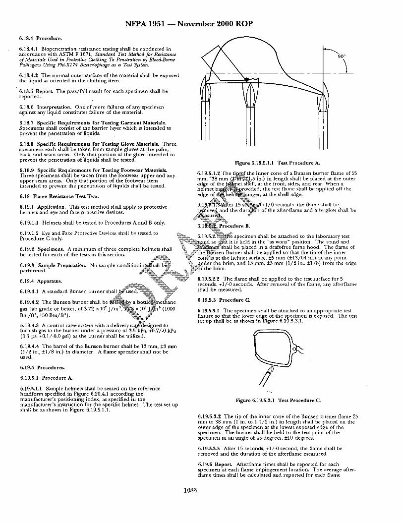
N F P A 1951 ~ N o v e m b e r 2 0 0 0 R O P
6.18.4 Procedure.
6.118.4.1 Biopenetrat ion resistance testing shall be conducted in accordance with ASTM F 1671, Standard Test Method for Resistance of Materials Used in Protective Clothing To Penetration by Blood-Borne Pathogens Using Phi-X174 Bacteriophage as a Test System.
6.18.4.2 The normal outer surface of the material shall be exposed the liquid as oriented in the clothing item.
• 6.18.5 Report. The pass/fail result for each specimen shall be reported.
6.18.6 Inte.rpretation. One of more failures of any specimen against any hquid constitutes failure of the material.
6.18.7 Specific Requirements for Testing Garment Materials. Specimens shall consist of the barrier layer which is in t ended to prevent the penetrat ion of liquids.
6.18.8 Specific Requirements for Testing Glove Materials. Three specimens each shall be taken from sample gloves at the palm, back, and seam areas. Only that por t ion of the glove in tended to prevent the penetrat ion of liquids shall be tested.
6.18.9 Specific Requirements for Testing Footwear Materials. Three specimens shall be taken from the footwear upper and any upper seam areas. Only that port ion of the footwear ~tem in tended to prevent the penetrat ion of liquids shall be tested.
6.19 Flame Resistance Test Two.
6.19.1 Application. This test method shall apply to protective helmets and eye and face protective devices.
6.19.1.1 Helmets shall be tested to Procedures A and B only.
6.19.1.2 Eye and Face Protective Devices shall be tested to
. - - - . . . . 90 °
Figure 6.19.5.1.1 Test l ' rocedure A.
6.19.5.1.2 The ti~..,~.£ the inner cone of a Bunsen burner flame of 25 mm, "38 m m (.~!-::~'i:i~-:.-~:~:j.5 in.) in length :;hall be placed at the outer edge of the ~ e t s~'~ll, at the front, sides, and rear. When a helmet h .a~.~:-~i-frovided, the test flame shall be applied off the edge o f ~ he l ~ ! .~ . ange r at the shell edge.
.... ~!~:: ~'i~:: ::~ ::ii::iii~:: 6.1~.'-~i.]:~:~'~er 15 s ~ + l / O seconds, the flame shall be r.~'ove.~, and the d u r a ~ h of the after-flame and afterglow shall be
.... ~ . ~ u r ~ . ..-...!i .... ~:: -%~i~:: ~:::::i~::
6.1 ff.i~i'.~::. Proc edu re B. "- : : : : : : : : : : : : . .
:!ii::i::::ii'~i:- ..... 6.19.5.2"~]iiiiii~f~!e specimen shall be at tached to the laboratory test Procedure C only. :iifi~:f:::i::::::::::~!,~tand so ~ t it is held in the "as worn" position. The stand and 6.19.2 Specimens. A minimum of three complete helmets shall :~i::i. " ' i i : : ~ : " s h a l l be placed in a draft-free fume hood. The flame of be tested for each of the tests in this section. '~i!: : : # : : " t h e ~ s e n Burner shall be applied so' that the tip of the inner
...::':.:i'i::.:':-::"i:-i::."-.-, :ii::i:i:" con'~:'is at the he lmet surface, +_5 mm (+13/'64 in.) at any point conditionin_.~l~~, ' b~iiii: :i:::::: under the brim and 13 mm, _+3 mm (1/2 in., _+1/8) from the edge 6.19.3 Sample Preparation. No s:unple .~..:r, ,uJ u . . . . . . . . . . . . . . ~'f '
performed. ..:::..& ~i~" . . . . . :i~i~ii::~i" the brim.
6.19.4 Apparatus. ':::'~~i~i~- "::i-;:!ii.:.7 -'-'.:~ 6.19.5.2.2 The flame shall be applied to the test surface for 5
6.19.4.1 A standard Bunsen burner shall ..~i::used.::'~i~iiiiii::!~::. iiiiiiiiiii ..... • - . - . - . - . - . - , . . : . : . .
6.19.4.2 The Bunsen burner shall be ~ ieJ~ i~y a bot t l~ i !me~ 'ane gas, lab grade or better, of 3.72 x 10' J / m S ~ : : x 10 s . [ ~ ' (1000 Btu/f t 3, +_50 Btu/ft3). "":::"":::: . . . . . . -~..*:.-:~
6.19.4.3 A control valve system with a delivery rat.~"::~esigned to furnish gas to the burner under a pressure of 3.5"kPa, +0.7/-0 kPa (0.5 psi +0.1/-0.0 psi) at the burner shall be utilized.
6.19.4.4 The barrel of the Bunsen burner shall be 13 mm, +3 m m (1/'2 in., +1/8 in.) in diameter. A flame spreader shall no t be used.
6.19.5 Procedures.
6.19.5.1 Procedure A.
6.19.5.1.1 Sample helmets shall be seated on the reference headform specified in Figure 6.20.4.1 according the manufacturer 's posit ioning index, as specified in the mmaufacturer's instruction for the specific helmet. The test set up shall be as shown in Figure 6.19.5.1.1.
seconds, +1/-0 seconds. After removal of the flame, any afterflame shall be measured.
6.19.5.3 Procedure C.
6.19.5.3.1 The specimen shall be at tached to an appropria te test fixture so that the lower edge of the specimen is exposed. The test set up shall be as shown in Figure 6.19.5.3.1.
/2": Figure 6.19.5.3.1 Test Procedure (1.
6.19.5.8.2 The tip of the inner cone of the Bunsen burner flame 25 mm to 38 mm (1 in. to 1 1/2 in.) in length shall he placed on the outer edge of the specimen at the lowest exposed edge of the specimen. The burner shall be held to the test point of the specimen in an angle of 45 degrees, +10 degrees.
6.19.5.3.3 After 15 seconds, +1/-0 second, the flame shall be removed and the durat ion of the afterflame measured.
6.19.6 Report. Afterflame times shall be repor ted for each specimen at each flame impingement location. Tbe average after- flame times shall be calculated and repor ted for each flame
1083
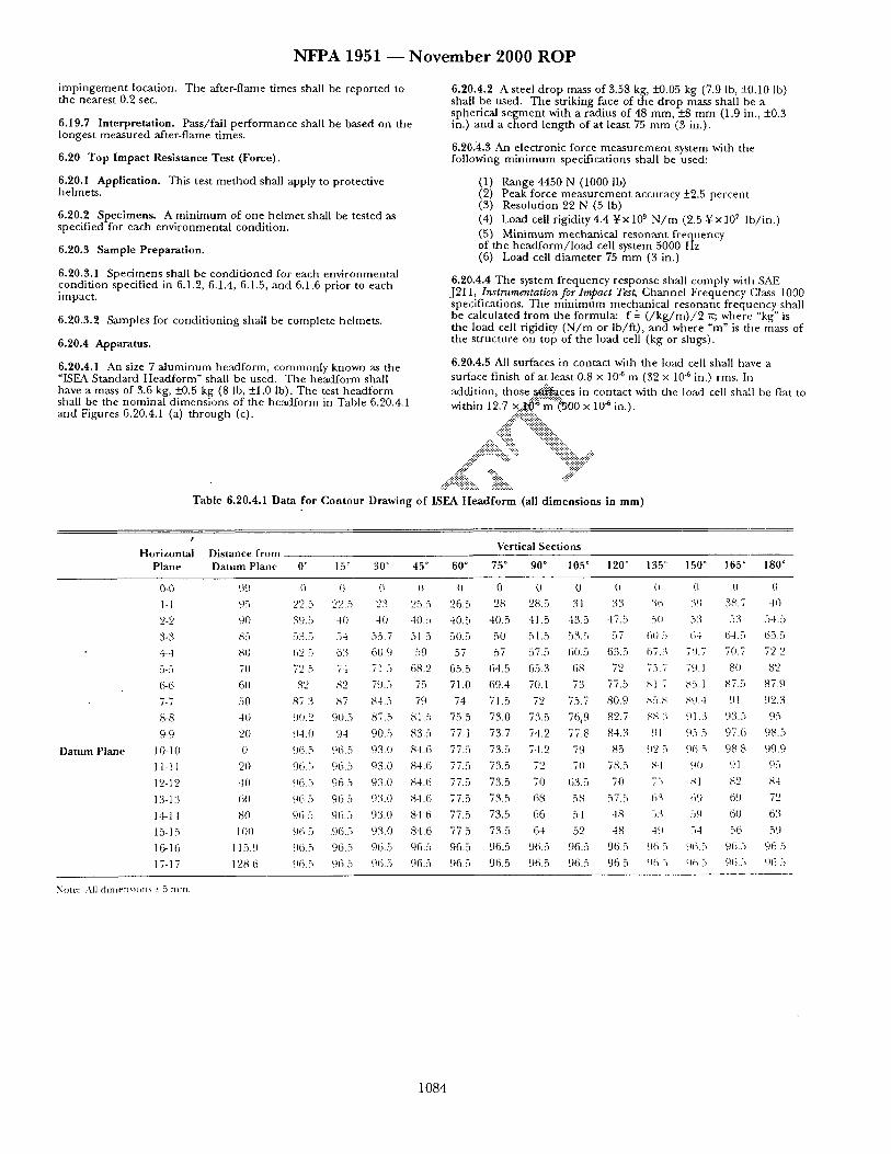
N F P A 1951 - - N o v e m b e r 2 0 0 0 R O P
impingement location. The after-flame times shall be reported to the nearest 0.2 sec.
6.19.7 Interpretation. Pass/fail performance shall be based on the longest measured after-flame times.
6.20 Top Impact Resistance Test (Force).
6.20.1 Application. This test method shall apply to protective helmets.
6.20.2 Specimens. A minimum of one helmet shall be tested as specified for each environmental condition.
6.20.3 Sample Preparation.
6.20.3.1 Specimens shall be conditioned for each environmental condition specified in 6.1.2, 6.1.4, 6.1.5, and 6.1.6 prior to each impact.
6.20.3.2 Samples for conditioning shall be complete helmets.
6.20.4 Apparatus.
6.20.4.1 An size 7 a luminum headform, commonly known as the "ISEA Standard Headform" shall be used. The headform shall have a mass of 3.6 kg, _+0.5 kg (8 lb, +1.0 Ib). The test headform shall be the nominal dimensions of the head.form in Table 6.20.4.1 and Figures 6.20.4.1 (a) through (c).
6.20.4.2 A steel drop mass of 3.58 kg, _+0.05 kg (7.9 lb, _+0.10 Ib) shall be used. The striking face of the drop mass shall be a spherical segment with a radius of 48 ram, +8 m m (1.9 in., +0.3 in.) and a chord length of at least 75 m m (3 in.).
6.20.3,.3 An electronic force measurement system with the following min imum specifications shall be used:
(1) Range 4450 N (1000 lb) (2) Peak force measurement accuracy -+2.5 percent (3) Resolution 22 N (5 lb) (4) Load cell rigidity 4.4 Yx 109 N / m (2.5 Yxl07 lb/ in.) (5) Minimum mechanical resonant frequency of the headform/ load cell system 5000 Hz (6) Load cell diameter 75 m m (3 in.)
6.20.4.4 The system frequency response shall comply with SAE J211, Instrumentation for Impact Test, Channel Frequency Class 1000 specifications. The min imum mechanical resonant frequency shall be calculated from the formula: f 2- ( / k g / m ) / 2 re; where "kg" is the load cell rigidity ( N / m or lb/f t) , and where "m" is the mass of the structure on top of the load cell (kg or slugs).
6.20.4.5 All surfaces in contact with the load cell shall have a surface finish of at least 0.8 x 10 "6 m (32 x 10 ~ in.) rms. In addition, t h o s e . . ~ c e s in contact with the load cell shall be flat to within 12.7 x..::~.~. =s m"~.~O0 x 10 ~ in.).
.... ~.-';::::~i::i::ii::i~ ....
.... ji!iiii,, %iii5,, .... .....#-iiii!::" "'::::"
,.::::::::::.. ::::::..
~:i!~::':%iii~::.. :i!~i~!~i~! ....
Table 6.20.4.1 Data for Contour Drawing of ISEA Headform.(al l dimensions in m m )
I
Horizontal Plane
Distance from Vertical Sections
Datum Plane 0 ~ 15 ° 30 ° 45 ° 60 ° 75 ° 90 ° 105 ° 120 ° 135 ~ 150 ° 165 ° 180 °
Datum Plane
0-0 99 () {~ 0 ~ 0 0 0 0 0 (~ O 0 0 l-I 95 ,)o . . . . . . . . 5 ")') =) 23 25.5 26.5 28 28.5 31 33 % 39 38.7 40
2-2 90 39.5 40 -t0 40.5 40.5 40.5 41.5 43.5 47.5 5u 53 53 -)4.5
3-3 85 53.5 54 55.7 51 5 50.5 50 51.5 53.5 57 60 5 6.t 64.5 65.5
4-4 81) 6'_) 5 63 6o.9 59 57 57 57.5 (30 .5 63.5 67.3 7u.7 70.7 7'2 '2
5-5 70 72 5 74 71 5 68.2 65.5 64.5 65.3 68 72 75.7 79.1 80 82
6-6 60 82 ,q2 79..) 75 71.0 69.4 70.1 73 77.5 ~,1 7 b5.l 87.5 87.9
7-7 50 87 3 87 84.5 79 74 71.5 72 75.7 80.9 ,~ 5.,~ sg.-t 91 92.3
8-8 4O ~.m.2 90.5 87.5 81.5 75.5 73.0 73.5 76~9 82.7 ,~8 3 91.3 93.5 95
9-9 20 94.0 94 90.5 83.5 77.1 73.7 74.2 77.8 84.3 91 95 5 97.6 98.5
10-10 0 96.5 96.5 93.0 84.6 77.5 73.5 7-t.2 79 85 ~ 2 5 96 5 98 8 c)9.9
11-11 20 96.5 96.5 93.0 84.6 77.5 73.5 72 7t) 78.5 8-t 90 91 95
12-12 -t0 96.5 96.5 93.0 84.6 77.5 73.5 70 63.5 70 75 ,ql 82 84
13-13 60 96 5 96.5 93.0 8-t.6 77.5 73.5 68 58 57.5 63 69 69 72
14-14 80 96 5 96.5 93.0 84 6 77.5 73.5 66 54 48 53 59 60 63
15-15 lO0 96 5 .96.5 93.0 84.6 77.5 73.5 6.t 52 48 49 54 56 59
16-16 115.9 96.5 96.5 96.5 96.5 96.5 96.5 96.5 96.5 96.5 .% 5 96.-, 96.5 96 5
17-17 128 6 96.:, 96.5 96.5 96.5 96.5 96.5 96.5 96.5 96.5 9~ 5 96 5 96.5 96 5
NOUn: .-\]] dlnlCllql()l}S *- ~ nlln.
1 0 8 4
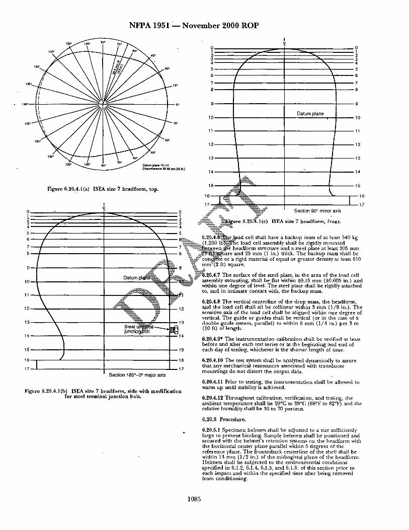
N F P A 1951 2__. N o v e m b e r 2000 R O P
120"
13'S° 45* ?
" 4
1~ 3o' Is" 6 5
1e6" 7
8
18o~ 0* 9
10 lC:6 ° 15"
11
150 • 30 ~ 12
135 ° 45* 13
Cimun~etenoe 65.88 orn (22 in.) 14
Figure 6.20.4.1(a) ISEA size 7 headform, top.
I
4 ~ 3
Datum
1¢
Steel t( junctiol
15
Section 180 °- 0 ° major axis
Figure 6.20.4.1(b) ISEA size 7 headform, side with modificat ion for steel terminal junct ion bolt.
Datum plane
15 -:¢-:-: i "'¢¢¢, I
-,.%, ..::~;~s::::::%~<;-:~> i~ "~:" Section 90 ° minor axis .... !..-..'!!#" "~. . ,g, "
I I
0 1 2 3 4 5
6
7
8
9
10
11
12
13
14
15
t 6
17
!igi:..:: . . . . 6.20.4.~"~e...J~gad cell shall have a backup mass of at least 540 kg "~iiiiiiNiiii! .......... (1,200 IB%~Vfie load cell assembly shall be rigidly moun ted :-.?:i:i"::*iiii::i::ii::::~.een...~:~ headform structure and a stee~ plate at least 305 mm -~ii..:~:: . , , i ~ i ~ ' ~ : ~ a r e and 25 mm (1 in.) thick. "File backup mass shall be
' " c o n c ~ t e or a rigid material of equal or greater density at least 610 ~"~!::~ mrr~:'i2 ft) square.
~..% ~!!~.20.4.7 The surface of the steel plate, in the area of the load cell ~..5........~. z- assembly mount ing, shall be flat within i-0.15 mm (5.'0.005 in.) and
~ i t within one degree of level. The steel plate shall be rigidly at tached • to, and in intimate contact with, the backup mass.
6.20.4.8 The vertical centerl ine of the drop mass, the headform, and the load cell shall all be collinear within 3 m m (1/8 in.). The sensitive axis of the load cell shall be al igned within one degree of vertical. The guide or guides shall be vertical (or in the case of a double guide system, parallel) to within 6 mm (1/4 in.) per 3 m (10 ft) o f length.
6.20.4.9* The inst rumentat ion calibration shall be verified a t least before and after each test series or at the beginning and end of each day of testing, whichever is the shorter length of time.
6.20.4.10 The test system shall be analyzed dynamically to assure that any mechanical resonances associated with t ransducer mount ings do no t distort the output data.
6.20.4.11 Prior to testing, the ins t rumentat ion shall be allowed to warm up until stability is achieved.
6.20.4.12 Throughou t calibration, verification, and testing, the ambient tempera ture shall be 20°C to 28°C (68°F to 82°F) and the relative humidity shall be 30 to 70 percent .
6.20.5 Procedure.
6.20.5.1 Specimen helmets shall be adjusted to a size sufficiently large to prevent binding. Sample helmets shall be posit ioned and secured with the he lmet ' s re tent ion systems on the headform with the horizontal center plane parallel within 5 degrees of the reference plane. The fronttoback centerl ine of the shell shall be within 13 mm (1/2 in.) of the midsagittal plane of the headform. Helmets shall be subjected to the environmental cortdifions specified in 6.1.2, 6.1.4, 6.1.5, and 6.1.6, of this section prior to each impact and within the specified time after being removed f rom conditioning.
1085
N F P A 1951 ~ N o v e m b e r 2 0 0 0 R O P
6.20.5.2 The impactor shall be d ropped f rom a he igh t tha t yields an impact velocity within two pe rcen t of 5.47 m / s e c (17.9 f t / sec) . A means of verifying the impact velocity to within 2 pe rcen t for each impac t shall be incorpora ted .
6.20.5.3 The verification tests shall demons t ra te an accuracy of 2.5 percen t or .better in the measu red force.
6.20.6 Report.
6.20.6.1 The peak force and impact velocity shall be recorded for each test.
6.20.6.2 The results of each system verification shall be made part of the test results for the he lmets being tested.
6.20.7 Criteria.
6.20.7.1 D i sengagemen t of, deformat ion of, or damage to the he lme t shell or c o m p o n e n t parts shall no t of itself consti tute failure.
6.20.7.2 Pass/fall pe r fo rmance shall be de t e rmi ned for each specimen. One or more he l me t spec imens failing this test shall const i tute failing per formance .
6.20.7.3 T h e verification tests shall demons t ra te an accuracy of 2.5 percen t or better in the measu red force.
6.21 Physical Penetration Resistance Test.
6.21.1 Application. This test m e t h o d shall apply to protective helmets .
6.21.2 Specimens . A m i n i m u m of one he lmet shall be tested for each env i ronmenta l condi t ion.
and 6.1.6 shall be conduc ted in such a m a n n e r that at least one pene t ra t ion test shall be pe r fo rmed in each of the test areas def ined in Figure 6.1.6.1. The spec imen shall be envi ronmenta l ly condi t ioned prior to each pene t ra t ion test. A m i n i m u m of two pene t ra t ion test blows shall be appl ied at d i f ferent test areas on each spec imen .
6.21.6 Report . The pass/fa i l result for each spec imen shall be reported.
6.21.7 Criteria. O n e or m o r e spec imens failing this test shall const i tute failing per formance .
6.22 Electrical Insulation Test One.
6.22.1 Application. This test m e t h o d shall apply to helmets.
6.22.2 Specimens . A m i n i m u m of three he lmets shall be tested for each test.
6.22.3 Sample Preparation.
6.22.3.1 Specimens shall be condi t ioned as specified in 6.1.2.
6.22.3.2 Samples for condi t ioning shall be comple te helmets .
6.22.4 Ap p arat ~:.~i!!~::. ..::ii?:" ""'::!~:::,
6.22.4.1 Thf.~::~owing e q u i p m e n t shall be provided for the test
one: "~i~" "::~!i!iiiiii!i~" ....
..:~::~::::::i!~::::'.~urce%~i~ I ~ a l te rnat ing cur ren t variable f rom 0 to 2,200" voli~::~rue rms %:i::i::i~#:" .:.:i!i!- (2~:.Wiring and ~;i:'}ninals for appl icat ion of voltage to the
4"~ii~l: inli::~ vessel ..... .... iiii.i.~:::"~-~oltmeter to measu re the appl ied voltage within 2
p e r ce~::::!i .... 6.21.3 Sample Preparation. :iii:i::.:.~ (4)~i::::i"~., ~..itliampmeter to measu re the leakage cur ren t to
:iiii!!!i!~:::..-.. within 2 ~ ' e n t 6.21.3.1 Spec imens shall be condi t ioned for each env i ronmenta l ::i~i):'::::i~ii-'~-:-:.:..(.5)..:~!:"~'vessel, conta in ing tap water, of suff icient size to condi t ion specified in 6.1.2, 6.1.4, 6.1.5, and 6.1.6 prior to each ::::i: . : i i ~ ' ~ e an inverted he lme t to the dielectric test plane
":::iii:ii# .... .:ii~) A f rame for su spend ing the test spec imen in water physical penet ra t ion . -'::iiiiiiii~i~!~iiii"i:: ":::i .:.::. "
6.21.3.2 Samples for condi t ion ing shall be complete..-~imets%i i: %:!~:.0.22.4.2 The following e q u i p m e n t shall be provided for the test
6.21.4 Apparatus . ..-#i:::i:iii::i!?:::!i ........ f:::iii!ii::::::i::iiii::.:..-:i:.:..:.~i~::"two: ":~!:.:: . . . . . . :~i-:~i~i:
- , : : ! ; : : : : : : : : . . " , ' - : : : : : : : : >
6.21.4.1 The ISO SizeJ head fo rm shall conf..~::i~ii...~...e n o : ~ l ...... d imens ions in Figure 6.20.4.1. Above the .~ic llne":':~i~hall h ~ ; ~ i ~ electrically conductive surface that is e l ~ i c a l l y con~ . ' . t ed t~i::~/he contact indicator. .:!i!:: "'::ii::i::i::i::ii: "!!::~::!::ii "
• . . . . . . . . . .
6.21.4.2 The perietration striker shall have a ~ . . o f 1 .~,~+0.02/- 0.00 kg (2.2 lb +0.01/-0.00 lb.). The poin t of t i : i : ~ - ~ r shall be a cone with an included angle of 60 degrees +0.5 d ~ : ~ e , a he igh t of 38 m m (1. 1 /2 in.), and a tip radius of 0.5 mm, _'Lg).l m m (0.020 in. , +0.004 in.). The hardness of the striking tip shall be Rockwell Scale C60, m i n i m u m . The pene t ra t ion striker shall be electrically connec ted to the contact indicator.
6.21.4.3 The contact indicator shall indicate when electrical compac t has been made between the pene t ra t ion striker and the conductive surface of the test headfo rm. The contact indicator shall have a response t ime of less than 0.5 millisecond.
6.21.4.4 The test shall be conduc ted at an ambien t t empera tu re of 20°C to 28°C (68°F to 82°F), and the relative humidi ty shall be 30 pe rcen t to 70 percent .
6.21.5 Procedure .
6.21.5.1 The env i ronmenta l ly condi t ioned he l me t shall be placed on the rigidly m o u n t e d test head fo rm and secured by the he lme t re tent ion system or by o ther means that will no t interfere with the test. The spec imen shall be posi t ioned so that the penet ra t ion striker shall impact pe rpend icu la r to the he lme t anywhere above the test line. The impac t site shall be at least 75 m m (3 in.) f rom the center of a previous penet ra t ion or impact site.
6.21.5.2 The drop he igh t of the pene t ra t ion striker shall be adjusted so that the velocity at impact is at 7.0 m / see , -+0.1 m / s e e (23 f t /sec, _+0.5 f t / sec) . A total of two pene t ra t ion tests for each of the four env i ronmenta l condi t ions specified in 6.1.2, 6.1.4, 6.1.5,
(1) A source of 60 Hz a l te rnat ing cur rent variable f rom 0 to 2,200 volts t rue R.M.S.
(2) Wiring and terminals for appl icat ion of voltage across the crown of the test spec imen
(3) A vol tmeter to measure the appl ied voltage within 2 percen t
(4) A mi l l i ampmete r to measure the leakage cur ren t to within 2 percen t
(5) A vessel, conta in ing fresh tap water, of sufficient size to submerge an inverted he lme t shell
(6) An a l u m i n u m size 7 ISEA head fo rm modi f ied in accordance within a l u m i n u m ISEA size 7 head fo rm modif ied in accordance with Table 6.20.4.1 and Figures 6.20.4.1 (a) Oarough (c)
6.22.5 Procedures .
6.22.5.1 Procedure A.
6.22.5.1.1 Where helmets have a vertical ad jus tmen t to the suspens ion system, the vertical ad jus tmen t shall be set to raise the h e l m e t to the h ighes t position, with m a x i m u m crown clearance between the heacfform and the inside of the h e l m e t crown, prior to establishing tile he lme t posi t ioning index. The he lme t shall be placed on the head fo rm specified in Figure 6.5.12.3 and posi t ioned according to the he lme t posi t ioning index for this test. After p roper pos i t ioning in accordance with the h e l m e t posi t ioning index, the dielectric test p lane specified in Figure 6.22.5.1.2 shall be de te rmined .
6.22.5.1.2 The he lme t shall be inver ted and posi t ioned in accordance with the inverted he lme t pos i t ion ing index while mainta in all vertical ad jus tments set at thei r h ighes t position. The inverted he lme t shall be filled with tap water equal to the dielectric test plane as shown in Figure 6.22.5.1.2. The h e l m e t shall t hen be submerged to the same level as the water on the inside of the helmet .
1 0 8 6
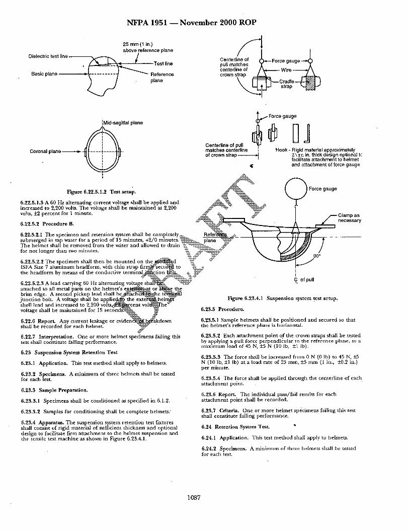
Dielectric test line
Basic plane
N F P A 1951 ~ N o v e m b e r 2000 R O P
25 mm (1 in.) above reference plane
~ Test line
"* Reference plane
/ Centerline of ).~-- Force gauge - ~ !;e~l~n ~ilitch ec7 ~ - ' ~ Wire - Z ~
s ~ --I " ~ , , ~ C r a d l e ~ strap
'~ Mid-sagittal plane
Centerline of pull Coronal plane • • matches ¢anterline of crown strap
I I
Figure 6.22.5.1.2 Test setup.
~ t~ ~j~c e gauge
, Hook - Rigid material approximately • ] Z\zn in thick design optional t~:
facilitate attachment to helmet ~. and attachment of force gauge
.~:~ ":$.-'i:i:'::, .,,.~:'- "-.'$~?::, .4[:: • ~;.:~: "~:.~&:-%. x:..~:::~. '~.~. "::::::::::::.
-- ../.~-::..
6.'!2.5.1.3 A 60 Hz alternating current voltage shall be applied and increased to 2,200 volts. The voltage shall be mainta ined at 2,200 volts, +2 percent for 1 minute. ~i~ ":~.>.:
6.22.5.2 Procedure B. ~ ' ~ " ~ -, 1 6.22.5.2.1 The specimen and retent ion system shall be completely..: .... Refer~ submerged in tap water for a per iod of 15 minutes, +2/0 minutes. '!!liiiiiiii~:i ....... p - ~ e The he lmet shall be removed from the water and allowed to drain ":iii:i"::::i:ii::i::i::i~::~iii. ": ...... i~.':" for not longer than two minutes. -~ ======================== ":':::"
6.22.5.2.2 The specimen shall then be mounted on the . ~ . d ~!ii!i ~ .:i .... ISEA Size 7 a luminum headform, with chin strap f i r m . ~ e c u ' ~ to ~i::iii:~....::i: the headform by means of the conductive termin~.:.$~..tion j . ~ : : .... .:ii!.. :iiiiiii::i i ....
6.22.5.2.3 A lead carrying 60 Hz alternating voltage s h ~ ~ ....... "'::~:.~:..J~: at tached to all metal parts on the he lmet ' s e.x.~$-.::..a.t or $ ~ . ~ tl~.e brim edge. A second pickup lead shall be..#~cti~:~-~$.'~!i:..~e t ~ . ~ ' ~ junc t ion bolt. A voltage shill be applie.~i ~ the e x t e ~ : h e l m . ~ : " shell lead and increased to 2,200 v o l t s ~ : ~ . : ~ c e n t vol~:~i~he "<" voltage shall be maintained for 15 s e c t n d g ~ i ~. $~
6.22.6 Report. Anycur r en t l eakage or e v i d e n ' ~ i ~ : ~ k d o w n shall be recorded for each helmet. ]~'>"
6.22.7 Interpretat ion. One or more he lmet specimens failing this test shall constitute failing performance.
6.23 Suspension System Retention Test 6.23.1 Application. This test me thod shall apply to helmets.
6.23.2 Specimens. A min imum of three helmets shall be tested for each test.
6.23.3 Sample Preparation. 6.23.3.1 Specimens shall be condi t ioned as specified in 6.1.2.
6.23.3.2 Samples for condit ioning shall be complete helmets.-
6.23.4 Apparatus. The suspension system retent ion test fixtures shall consist of rigid material of sufficient thickness and optional design to facilitate f irm a t tachment to the he lmet suspension and the tensile test machine as shown in Figure 6.23.4.1.
~'/Force gauge j - -
/---Clamp as necessary
I I
J
~_ of pull
Figure 6.23.4.1 Suspension system test setup.
6.23.5 Procedure. 6.23.5.1 Sample helmets shall be posi t ioned and secured so that the helmet ' s reference plane is horizontal.
6.23.5.2 Each a t tachment po in t of the crown straps shall be tested by applying a pull force perpendicular to tile reference plane, to a maximum load of 45 N, +5 N (10 lb, +t lb).
6.23.5.3 The force shall be increased from 0 N (0 lb) to 45 N, +_5 N (10 lb, +1 lb) at a load rate of 25 ram, +5 mm (1 in., _+0.2 in.) per minute.
6.23.5.4 The force shall be applied through the centerl ine of each a t tachment point.
6.23.6 Report. The individual pass/fail results for each a t tachment point shall be recorded.
6.23.7 Criteria. One or more he lmet specimens failing this test shall constitute falling performance.
6.24 Retention System Test. 6.24.1 Application. This test me thod shall apply to helmets.
6.24.2 Specimens. A min imum of three helmets shall be tested for each test.
1087
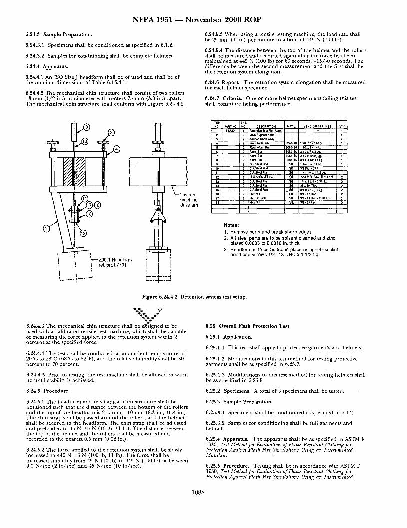
N F P A 1951 m N o v e m b e r 2 0 0 0 R O P
6.24.3 Sample Preparat ion.
6.24.3.1 Spec imens shall be condi t ioned as specified in 6.1.2.
6.24.3.2 Samples for condi t ion ing shall be comple te helmets .
6.24.4 Apparatus.
6.24.4.1 An ISO SizeJ h e a d f o r m shall be of used and shall be of the nomina l d imens ions of Table 6.16.4.1.
6.24.4.2 The mechanica l chin s t ruc ture shall consist of two rollers 13 m m (1 /2 in.) in d iamete r with centers 75 m m (3.0 in.) apart. The mechanica l chin s t ructure shall conform with Figure 6.24.4.2.
6.24.5.3 W h e n us ing a tensile test ing machine , the load rate shall be 25 m m (1 in.) per m inu t e to a limit of 445 N (100 ]b).
6.24.5.4 The dis tance between the top of the he lme t and the rollers shall be m e a s u r e d a n d recorded aga in after the force has been ma in ta ined at 445 N (100 lb) for 60 seconds, +15/-0 seconds. Th e dif ference between the second m e a s u r e m e n t and the first shall be the re ten t ion system elongat ion.
6.24.6 Report . The re ten t ion system elongat ion shall be measu red for each h e l m e t spec imen.
6.24.7 Criteria. O n e or more he lme t spec imens failing this test shall const i tute failing pe r fo rmance .
' I I I -'lns on' machine drive arm
/'- /' zgo.l.ead,orm i , I ref. prt. L7791
I _._i L-_:G::j I
ITEM $HT. NO. PART NO, NO. DESCRIPTION MAT'L. VEND. OR STR SIZE QTY.
1 L8539 1 Rtlonlbn T ~ F~. Ass,/. - - ~ 1
2 2 u~ r,~p~ A~t, - - 1 3 2 V,m~,,~ Kr<,b Ar.R. -- -- 2 4 2 Rect. AbJ~. ~ r SOGI-'~6 1 1/2X 3 x "~.L~. I 5 2 RecI.AkJm.B~ 6061-T6 1 1 /2x3x14L~. 1 6 2 Ak~. B~" 6C6 I -T6 2 X 2 X 7 l/2L~. 1 7 2 Alum. Bat 6C~I.T6 2X2X 1296 L~. 1 8 2 Alum. Fkll 606t-T6 3/4x 41/2 x 5 L~. l
90 2 O.F. Steel Rod Sfl. 1 1/4 Dia.X 4 L 9 . 1 2 CJ z. Sl*el Rod Sll. 3/8 Dia. x 22 L~. 1
11 2 CJ:.Sleel Fla SI]. : 1 x 1 1/4x ! 1/2L~. 1 12 2 HoEow Sleel Tube Stl. : .500 dO..384 LD.x 1 1/2 2 13 2 C ~:. Sleol Flat SII 1/4x3 l f 4x 3 3/4L 9 . 2 14 2 C.F. Sleel Flat SII. 39 X 3/4 "r}~ < . 2 15 2 C J:. Sleel Rod SII. 3/4 e x 101/2 L~. 2 16 2 Hox Nul S~I, 3/4 - 10 UtlC. 2
t7 I l'h,x Hd. Boll SII. 3~ - 24 Urd.x 2 1/2 L~. 3 18 1 Hex NuI Stl. 3/8 - 24 Urd. 3
Notes : 1. Remove burrs and break sharp edges. 2. All steel parts are to be solvent cleaned and zinc
plated 0.0003 to 0.0010 in. thick. 3. Headform is to be bolted in place us ing-3-socket
head cap screws 1/2-13 UNC x 1 1/2 Lg.
F'~gure 6.24.4.2 Retent ion system test setup.
6.24.4.3 The mechanica l chin s t ructure shall be d ~ i g n e d to be used with a cal ibrated tensile test machine , which shall be capable of measu r ing the force appl ied to the re tent ion system within 2 pe rcen t at the specif ied force.
6.24.4.4 The test shall be conduc ted at an ambien t t empera tu re of 20°C to 28°C (68°C to 82°F), and the relative humidi ty shall be 30 pe rcen t to 70 percent .
6.25 Overall H a s h Protect ion Tes t
6.25.1 Application.
6.25.1.1 This test shall apply to protective ga rmen t s and helmets.
6.25.1.2 Modifications to this test m e t h o d for test ing protective gamaents shall be as specified in 6.25.7.
6.24.4.5 Prior to testing, the test mach ine shall be allowed to warm up unti l stability is achieved.
6.25.1.3 Modifications to this test m e t h o d for test ing he lmets shall be as specified in 6.25.8
6.24.5 Procedure . 6.25.2 Specimens . A total of 3 spec imens shall be tested.
6.24.5.1 T h e h e a d f o r m and mechanica l chin s t ructure shall be posi t ioned such that the dis tance between the bo t tom of the rollers and the top of the head fo rm is 210 mm, +10 m m (8.3 in., _+0.4 in.). The chin strap shall be paxsed a r o u n d the rollers, and the he lme t shall be secured to the headform. The chin strap shall be adjusted and pre loaded to 45 N, +_5 N (10 lb, +1 lb). T h e dis tance between the top of the he lme t and the rollers shall be measu red and recorded to the neares t 0.5 m m (0.02 in.).
6.24.5.2 The force appl ied to the re ten t ion system shall be slowly increased to 445 N, +5 N (100 lb, +1 lb). The force shall be increased smooth ly f rom 45 N (10 lb) to 445 N (100 lb) at between 9.0 N / s e c (2 lb /sec) and 45 N / s e c (10 lb / sec) .
6.25.3 Sample Preparat ion.
6.25.3.1 Specimens shall be condi t ioned as specified in 6.1.2.
6.25.3.2 Samples for condi t ion ing shall be full ga rmen t s an d helmets .
6.25.4 Apparatus. T h e appara tus shall be as specif ied in ASTM F 1930, Test Method for Evaluation of Flame Resistant Clothing for Protection Against Flash Fire Simulations Using an Instrurnented Manikin.
6.25.5 Procedure . Tes t ing shall be in accordance with ASTM F 1930, Test Method for Evaluation of Flame Resistant Clothing for Protection Against Flash Fire Simulations Using an Instrumented
1 0 8 8
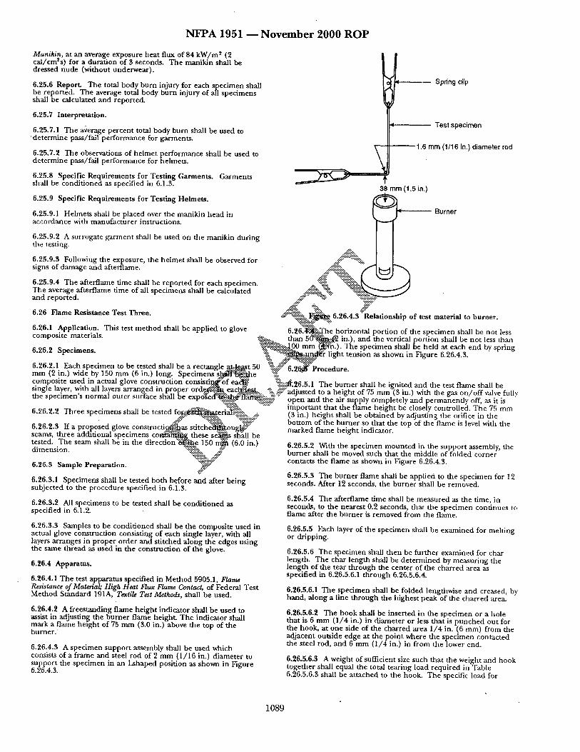
N F P A 1 9 5 1 - - N o v e m b e r 2 0 0 0 R O P
Manikin, at an average exposure heat flux of 84 k W / m ~ (2 cal/cm~s) for a durat ion of 3 seconds. The manikin shall be dressed nude (without underwear) .
6.25.6 Report. The total body burn injury for each specimen shall be reported. The average total body burn injury of all specimens shall be calculated and reported.
6.25.7 Interpretation.
6.25.7.1 The average percent total body burn shall be used to ' de te rmine pass/fail per formance for garments.
6.25.7.2 The observations of helmet performance shall be used to de te rmine pass/fall per formance for helmets.
6.25.8 Specific Requirements for Testing Garments. Garments shall be condi t ioned as specified in 6.1.3.
\
t -- Spring clip
~- -- Test specimen
1.6 mm (1/16 in.) diameter rod
38 mm (1.5 in.) O 6.,,5.9 Specific Requirements for Testing Helmets.
6.25.9.1 Helmets shall be placed over the manikin head in - - Burner accordance with manufacturer instructions.
6.25.9.2 A surrogate garment shall be used on the manikin during the testing.
O 6.,,5.9.3 Following the exposure, the he lmet shall be observed for signs,, of damage and afterflame, j~ i l -':':'!!i~i~:.
6.,,5.9.4 The afferflame time shall be repor ted for each specimen. The average afterflame time of all specimens shall be calculated and reported. : : : : :~ • ..-.::::::::::::.-
. ~i~il % . . . . ~:i~:: 6.26 Flame Remstance Test Three. ~ : . . : . ' . ' ~ i ~ . . 6.26.4.3 "Relationship of test material to burner .
6~6A o:,App~Hcauon. This test me thod shall be apphed to glove 6.26~)i. . :The .horizontal port ion of the specimen shall be not less . . . . . . v' . . . . . . . . . . . . . . . . . :.:~..:...:.~ than 5 ( Y : ' ~ . ~ in.), and the vertical por t ion shall be no t less than . . . . . . ~-:'..'~.~i.-..,~..00 m m ~ ! ~ . ) . The specimen shall be he ld at each end by spring o.zo.z ~pecmaens. ::~:.i, " ' : " " : ~ ! ~ # ~ light tension as shown in Figure 6.26.4.3.
'T.~ .::..t. :~'' ,'~.~.:~$::~ 6.26.2.1 Each specimen to be tested shall he a rectangle . ~ : : ~ t 50 ~'i!!!:J.'::" 6 2 ~ $ ' P r o c e d u r e mm (2 in.) wide by 150 m m (6 in.) long. Specimens s l - ~ $ : ~ h e % " "
~,u~,~ ,,~v~. ~,u, , t , . , t vc~ a H m ~ u ,u ~o~er orct ..F~m-eact~..:..t( c°~m~'P°~ ' t euse~ln lac t^u '~-g~°veC-°enSt r -u~n~°ns]s -~ :° te~ ; " " :~6~:'26"5"1 The burner shall be ignited and the test flame shall be . ,8 .r , y t~ ; v , , p ~..e.:~, . ~$~::..- %,~-:: adjusted to a height of 75 mm (3 in.) with t h e g a s o n / o f f w a l v e f u l l v me s p e c i m e n s normal outer surlace snail De e x p o s e d ~ i ~ ~ tlart~ii!i::~i~: open and the air supply completely and pe rmanendy off, asfit is . . . . . . . . . . . . . . . . . . . .:..-.:.-~.,:.. . . . . fi:.~!~!::::.. """ impor tant that the flame height be closely controlled. The 75 mm o.z,o.z.z J n r e e specimens snau oe testect Io~:.~:.~i~,terlaY'-:!.:ii.::. .. 3 in hei ht shall be obtained b ad'ustin the o ifi ~ ~ ,t.~ . . . . . . . . . . . . . . . . . .................. ( .) g y . r . . . . . . . . . . . . . . . . . . -:::"k::* .. ,"~.'i-'~, fi~.:.:~'::" bot tom of the burner so that the top of the flame is level with the o.zo.z.3 i t a proposeo glove constructa~!!.O.as stttcne6"tg~.ougJai::" marked flame heit~ht indicator seams, three addit ional specimens c o ~ " ~ g these s ~ s s[a'all be ° ' tested. The seam shall he in the d i r e c d o n ' ~ . . e 150 ~ (6 0 in ) . . . . . . . . . . . . . . . . . . . . . . . . . . . . u zo a z wire me specimen mounteo lrt m e suppor t assemoly me dimension. ":%:ili~ L .-.:~?" burner shall be moved such that the middle of folded co rne r ' . . . . . . . . . "::~-~F" contacts the flame as shown in Figure 6.26.4.~. o.zo.~ ~ample r reparauon . ~.~.'-~-"
6.26.5.3 The burner flame shall be applied to the specimen for 12 6.26.3.1 Specimens shall be tested both before and after being subjected to the procedure specified in 6.1.3.
6.26.3.2 All specimens to be tested shall be condi t ioned as specified in 6.1.2.
6.26.3.3 Samples to be condi t ioned shall be the composite used in actual glove construction consisting of each single layer, with all layers arranges in p roper order and st i tched along the edges using the same thread as used in the construction of the glove.
6.26.4 Apparatus.
6.26.4.1 The test apparatus specified in Method 5905.1, F/ame Resistance of Material; High Heat Flux Flame Contact, of Federal Test Method Standard 191A, Textile Test Methods, shall be used.
6.26.4.2 A freestanding flame he ight indicator shall be used to asskst in adjusting the burner flame height. The indicator shall mark a flame height of 75 mm (3.0 in.) above the top of the bu rne r .
6.26.4.3 A specimen suppor t assembly shall be used which consists of a frame and steel rod of 2 m m (1/16 in.) d iameter to suppor t the specimen in an Lshaped position as shown in Figure 6.26.4.3.
seconds. After 12 seconds, the burner shall be removed.
6.26.5.4 The afterflame time shall be measured as the time, in seconds, to the nearest 0.2 seconds, that the spec imen continues to flame after the burner is removed from the flame.
6.26.5.5 Each layer of the specimen shall be examined for melting or dripping.
6.26.5.6 The specimen shall then be fur ther examined for char length. The char length shall be deternf ined by measuring the length of the tear th rough the center of the charred area as specified in 6.26.5.6.1 th rough 6.26.5.6.4.
6.26.5.6.1 The specimen shall be folded lengthwise and creased, by hand, along a line through the highest peak of the charred area.
6.26.5.6.2 The hook shall be inserted in the specimen or a hole that is 6 mm (1 /4 in.) in d iameter or less that is punched out for the hook, at one side of the charred area 1,/4 in. (6 ram) from the adjacent outside edge at the po in t where the specimen contacted the steel rod, and 6 mm (1/4 in.) in f rom the lower end.
6.26.5.6.3 A weight of sufficient size such that the weight and hook together shall equal the total tearing load required in Table 6.26.5.6.3 shall be at tached to the hook. Tile specific load for
1089
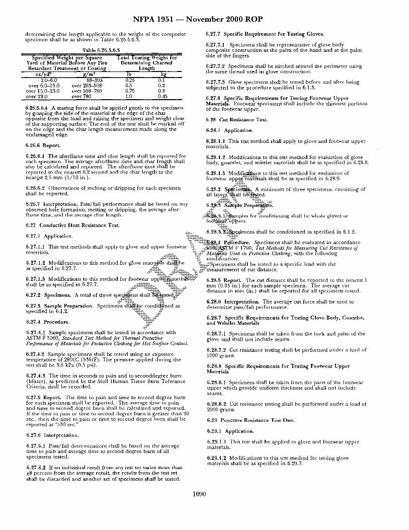
N F P A 1 9 5 1 ~ N o v e m b e r 2 0 0 0 R O P
determining char length applicable to the weight of the composite specimen shall be as shown in Table 6.26.5.6.3.
Table 6.26.5.6.3 Specified Weight per Square Total Tearing Weight for
Yard of Material Before Any Fire Determining Charred Retardant Treatment or Coating Length
oz/) 'd ~ gr/mZ Ib kg 2.0-6.0 68-203 0.25 0.1
over 6.0-15.0 over 203-508 0.5 0.2 over 15.0-23.0 over 508-780 0.75 0.3 over 23.0 over 780 1.0 0.45
6.26.5.6.4 A tearing force shall be applied gently to the specimen by grasping the side of the material at the edge of the char opposite from the load and raising the specimen and weight clear of the suppor t ing surface. The end of the tear shall be marked off on the edge and the char length measurement made along the undamaged edge.
6.26.6 Report.
6.26.6.1 The afterflame time and char length shall be repor ted for each specimen. The average afterflame time and char length shall also be calculated and reported. The afterflame time shall be reported to the nearest 0.2 second and the char length to the neargst 2.5 mm (1/10 in.).
6.26.6.2 Observations of melting or dr ipping for each specimen shall be reported.
6.26.7 Interpretation. Pass/fall performance shall be based on any observed hole formation, melting or dripping, the average after- flame time, and the average char length.
6.27 Conductive Heat Resistance Test.
6.27.7 Specific Requirement for Testing Gloves.
6.27.7.1 Specimens shall be representative of glove body composite construction at the palm of the hand and at the pahn side of the fingers.
6.27.7.2 Specimens shall be sti tched around the per imeter using the same thread used in glove construction.
6.27.7.3 Glove specimens shall be tested before and after being subjected to the procedure specified in 6.1.$.
6.27.8 Specific Requirements for Testing Footwear Upper Materials. Footwear specimens shall include the thinnest portions of the footwear upper.
6.28 Cut Resistance Test.
6.28.1 Application.
6.28.1.1 This test me thod shall apply to glove and footwear upper materials.
6.28.1.2 Modifications to this test me thod for evaluation of glove body, guantlet, and wristlet materials shall be as specified in 6.28.8.
6.28.1.3 Modi f i~a~ns to this test me thod for evaluation of footwear upp..:~;!:~:i'~ff{:~t.ials shall be as specified in 6.28.9.
..::: ? ::iii~.'.'-,:-::.. 6.28.2 S ~ i d i ' ~ . . A min imum of three specimens, consisting of all laye..r..~i:~..h..all b~::!~ted.
..::i:!:!:i:i::.. ' ::i:i.. '::i:!:i:i:i::.. . 6..2..~:"S:~i~ pie P rep '~ i~ :n ' .
::~!~i@i~,3-lli{::i~mP les for'::conditioniug shall be whole gloves or fo ~ 5 ( ~ f " / i ~ e rs.
"::i:i:i:i:!::.. :i::ili; ......... 6.28.3:$i-{~:~...dmens shall be condi t ioned as specified in 6.1.2.
6.27.1 Application. "?i''i::::{::iiii ::.'~:,9,8A Pr:.:~:~edure. Specimens shall be evaluated in accordance 6.27.1.I This test methods shall apply to glove and upper footwear iiii::i . . . . iii~ii:t~/~::::~M F 1790, Test Methods for Measuring Cut Resistance of m a t e r i a l s . . ~ : : . : . : . : . : , ii'::-ili!:: Mat~Ms Used in Protective Clothing, with the following
.... i¢!i:::::i:i!::i!i!::i!i:: :!::iill m o d ifi catio n: 6.27.1.2 Modifications to dais me thod for glove mater.-~ls shS:ffiibe "iiii:..---::-:Specimens shall be tested to a specific load with the as specified in 6.27.7. :-iiiiiiii" . . . . . :~iiii!!:: ............ ":ii.. iiiiiiiii::ii:measurement of cut distance.
6.27.1.3 Modifications to this me thod for foo..~....e....~., uplS"i£~.:i:~ateria~!i!i!i!i!::" 6.28.5 Report. The cut distance shall be repor ted to the nearest 1 shall be as specified in 6.27.7. mm (0.05 in.) for each sample specimen. The average cut
.... #~ ............. ::::::::::::::::::::::::: .... ~:?-iiiiiib.:::~!~: 6.27.2 Specimens. A total of three spe.9.'.~ns shall":~!ii~$stec(~}' .... distance in mm (in.) shall be repor ted for all specimens tested.
6.27.8 Sample Preparation. Specimens s'~ii.b..e cond i{~ned as specified in 6.1.2. "::ii~i~i~i~: . . . . iii::
6.27.4 Procedure. "":ii::::ii.::i#:::i.jiii~ii?: .',i#::"
6.27.4.1 Sample specimens shall be tested in accordance with ASTM F 1060, Standard Test Method for The~nal Protective Performance of Materials for Protective Clothing f~r Hot Surface Contac~
6.27.4.2 Sample specimens shall be tested using an exposure tempera ture of 280(C (536(F). The pressure applied during the test shall be 3.5 kPa (0.5 psi).
6.27.4.3 The time in seconds to pain and to seconddegree burn (blister), as predic ted by the Stoll Human Tissue Burn Tolerance Criteria, shall be recorded.
6.27.5 Report. The time to pain and time to second degree burn for each specimen shall be reported. The average time to pain and t ime to second degree burn shall be calculated and reported. If the time to pain or time to second degree burn is greater than 30 see., then the time to pain or time to second degree burn shall be repor ted as ">30 see."
6.27.6 Interpretation.
6.27.6.1 Pass/fail determinat ions shall be based on the average time to pain and average time to second degree burn of all specimens tested.
6.27.6.2 If an individual result f rom any test set varies more than +8 percent from the average result, the results from the test set shall be discarded and another set of specimens shall be tested.
6.28.6 Interpretation. The average cut force shall be used to de termine pass/fall performance.
6.28.7 Specific Requirements for Testing Glove Body, Guantlet, and Wristlet Materials
6.28.7.1 Specimens shall be taken from the back and palm of the glove and shall no t include seams.
6.28.7.2 Cut resistance testing shall be per formed under a load of 1000 grams.
6.28.8 Specific Requirements for Testing Footwear Upper Materials
6.28.8.1 Specimens shall be taken f rom the parts of the footwear upper which provide uniform thickness and shall not include seams.
6.28.8.2 Cut resistance testing shall be per formed under a load of 2000 grams.
6.29 Puncture Resistance Test One.
6.29.1 Application.
6.29.1.1 This test shall be applied to glove and footwear upper materials.
6.29.1.2 Modifications to this test me thod for testing glove materials shall be as specified in 6.29.7.
1090
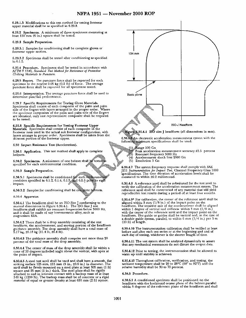
N F P A 1951 - - N o v e m b e r 2000 R O P
6.29.1.3 Modifications to this test me thod for testing footwear upper material shall be as specified in 6.29.8.
6.29.2 Specimens. A min imum of three specimens measuring at least 150 mm (6 in.) square shall be tested.
6.29.3 Sample Preparation.
6.29.3.1 Samples for condit ioning shall be complete gloves or footwear upper section.
6.29.3.2 Specimens shall be tested after condit ioning as specified in 6.1.2.
6.29.4 Procedure. Specimens shall be tested in accordance with ASTM F 1342, Standard Test Method for Resistance of Protective CLgthing Materials to Puncture.
6.29.5 Report. The puncture force shall be repor ted for each specimen to the nearest 0.05 kg (0.1 lb) of force. The average puncture force shall be repor ted for all specimens tested.
6.29.6 Interpretation. The average puncture force shall be used to de termine pass/fail performance.
1.!m l
Basic pC 6.29.7 Specific Requirements for Testing Glove Materials. Specimefis shall consist of each composite of the palm and paalm side of the fingers with layers arranged in the proper order. Where the specimen composites of the palm and palm side of the fingers are identical, only one representative composite shall be required to be tested.
6 ...'~9 8 Specific .Re q uirements for. Testintg Footwear. Upper Materials. Specimens shall consist of each composite o t t h e footwear i tem used in the actual suit footwear configuration, with layers arrange in proper order• Specimens shall be taken f rom the
. . . . 6 ~ !~:lo~:Oa:c~:JahtSoa!~m°~ia~ii!l~m~riesn~'t~ m t h ~ : e
th innes t por t ion of the footwear upper. • --:-:- followi':~-~li~imum specifications shall be used:
. . " : : : : : : : : : : : k ~ . . . . - ~ . . . : . : . : . : . ~ .
6.30 Impact Resmtance Test (Acceleratmn). "::::~!!i!!i!i!ii!~::::.:... "?.'!!!iii::" :ii~..'., ":'::!:-:?~::~::ii~::~:'::::,,..(1 ) ~ : ~nge 500 Gn
6.30.1 Application. This test me thod shall apply to complete % ~:.:i::~...~.': Peak acceleration measurement accuracy -1-2.5 percen t helmets . . . . . . . . . . ":~-":~":" •::~) Resonant frequency 5000 Hz
. .~ i : . ' . . ' : "% "'(4) Accelerometer shock limi 2000 Gn 6.30 2 Specimens. A min imum of one he lmet shall ~:"tested~::::~ "%.:::.,.~: (5) Resolution 5 Gn
. . . . ~ . ~ . . : . . : + : ~ , : . : . : . : . .~"
specified for each environmental condmon . ..::i-'-:.:i:i:i:i::.. .-'.:-:'.:.:::::-:,.. ":::...::~*~" • ",;;.~'::':'::,,:--y~ "::---9~:::.-:::~-.:~ 6.30.4.7 The system frequency response shall comply w~th SAE
6.30.3 Samole Preoaration. . ~;g~ii~:, ":::":":"":'~::~ J211 Instrumentation for Impact Test, Channel Frequency Class 1000 " ....:::-:':ii~i~-~i .... ":'%'~i? . . . . . . specifications. The u'me durat ion of acceleration levels shall be
6.g0.3.1 Specimens shall be condi t ioned . f . ~ ' e a c ~ . o n m ~ ' ~ ¢:: measured to within +0.2 millisecond. . . . . . . .-~:. . ÷ : . : . : . - . : . . : • : . .
condiuon specafied m 6.1.2, 6.1.4, 6.1.5.:~:.d 6.1.6 prr~ii~o e~¢ti impact. -:Y~"::.:~i~i::.. " ..... 6.30.4.8 A reference anvil shall be substituted for the test anvil to t-"..-'-"~
'<iii::i::~::ii::.. *iz" verify the calibration of the acceleration measurement system. The 6.30.3.2 Samples for condit ioning shall he ~ t e ~"me t s . reference anvil shall be constructed of any material that will yield
reproducible test results during a per iod of at least four months. 6.30.4 Apparatus. ~?::,
6.30.4.1 The headform shall be an ISO SizeJ conforming to the mzLnual dimensions in Figure 6.30.4.1. The ISO SizeJ test headform shall exhibit no resonant frequencies below 3000 Hz, and it shall be made of any lowresonance alloy, such as m2gnesium K1A.
6.30.4.2 There shall be a drop assembly consisting of the test he:~:lform, the accelerometer, and moving por t ion of the headform guidance assembly. The drop assembly shall have a total mass of 5.17 kg, _+0.18 kg (11.4 lb, !-0.4 lb).
6.30.4.3 The guidance assembly shall comprise no t more than 20 percen t of the total mass of the drop assembly.
6.30.4.4 The center of mass of the d rop assembly shall lie within a cone of 10 degrees included angle about the vertical, with apex at the point of impact.
6.30.4.5 A steel test anvil shall be used and shall have a smooth, flat striking surface 125 mm, +15 m m (5 in., _+0.6 in.) in diameter. The anvil shall be firmly m oun ted on a steel plate at least 505 m m (1 It) square and 25 m m (1 in.) thick. The steel plate shall be rigidly at tached to and in intimate contact with a backup mass of at least 540 kg (1200 lb). The backup mass shall be of concrete or a rigid material of equal or greater density at least 610 mm (2 ft) square.
6.30.4.9* For calibration, the center of the reference anvil shall be aligned within 3 mm (1/8 in.) of the impact point on the headform. The sensitive axis of the accelerometer shall be aligned within 1 degree of vertical and collinear within 3 mm (1/8 in.) with the center of the reference anvil and the impact point on the headform. The guide or guides shall be vertical and, in the case of a double guide system, parallel, to within 6 mm (1 /4 in.) per 3 m (10 ft) of length.
6.30.4.10 The inst rumentat ion calibration shall be verified at least before and after each test series or at the beginning and end of each day of testing, whichever is the shorter length of time.
6.30.4.11 The test system shall be analyzed dynamically to assure that any mechanical resonances do no t distort the output data.
6.30.4.12 Prior to testing, the ins t rumentat ion shall be allowed to warm up until stability is achieved.
6.30.4.13 Throughout calibration, verification, and testing, t he ambient temperature shall be 20 to 28°C (68 ° to 82°F) and the relative humidity shall be 30 to 70 percent .
6.30.5 Procedure.
6.30.5.1 A condi t ioned specimen shall be posi t ioned on the headform with the horizontal center plane of the he lmet parallel within 5 degrees of the reference plane of the headform and shall
1091

N F P A 1 9 5 1 ~ N o v e m b e r 2 0 0 0 R O P
be secured to the drop assembly by its re tent ion system so as to mainta in this posit ion du r i ng the test. No part of the he l me t shell shall be cut away to a c c o m m o d a t e the test system, a n d no par t of the test system shall contact the he lme t shell e i ther as m o u n t e d or du r ing an impact test.
6.30.5.2 The drop assembly with a he l me t a t tached shall be d ropped f rom a he igh t tha t yields an impact velocity within 2 percen t of 6.0 m / s e c (19.7 f t / sec) . A means of verifying the impact velocity within 2 pe rcen t for each impact shall be incorpora ted in the test system. The accelerat ion t ime dura t ion values, peak acceleration, a n d impac t velocity shall be recorded for each test. Each he lme t shall be envi ronmenta l ly condi t ioned pr ior to each impact and shall be impac ted in each of the five impac t areas specified in Figure 6.1.6.1.
6.30.5.3 T h e impact areas shall be as specified in Figure 6•1•6.1. The top, front, rear, and side areas of the he lme t shall be tested•
6.30.5.4 The top impact area shall consist of a 30 m m (12 in.) radius measu red f rom a po in t located on the head.form at the j u n c t i o n of the coronal plane and mid-sagittal plane•
6.30.5.5 The f ront impac t test area shall consist of an area def ined as ex tending forward on the head fo rm f rom the f ront vertical transverse plane to the test line.
6.30.5.6 The rear impact test area shall consist of an area def ined as ex tend ing backward on the head fo rm f rom the rear vertical transverse plane ex tend ing down to the test line.
6.30.5.7 The side test areas shall consist of the areas between the top test area and test line ex tend ing f rom the rear vertical transverse plane and the f ron t vertical transverse plane.
6.30.5.8 Each condi t ioned spec imen in a series shall be impac ted
38 m m (1 1 /2 in.). The pegboard shall have 25 holes with each hole having a d iamete r of (0.39 in.) and a dep th of (1 /2 in.). Th e holes shall be in a 5 x 5 pa t te rn a n d each hole shall have a separa t ion of 25 m m (1 in.) f rom o ther holes•
6.31.5 Procedures .
6.31.5.1 Each available size of gloves shall be evaluated ~ith at least one separate test subject with the same pair of gloves.
6.31.5.2 A m i n i m u m of three different glove pairs shall be evaluated.
6.31.5.3 Test subjects shall be selected such that their ha n d d imens ions are a close as possible to those specified in accordance with manu fac tu r i ng glove sizing guidelines.
6.31.5.4 Each test subject used to pe r fo rm this test ing shall practice of the h a n d funct ions a m i n i m u m of 3 t imes before conduc t ing actual testing.
6.31.5.5 Before each test, the pegs shall b e p l a c e d on a hard, s m o o t h surface adjacent to the pegboard . The pegs shall be r andomly scat tered in the working area most comfortable to the test subject (i.e., the r ight side for r igh t -handed test subjects, left side for left-hand....~0. " test subjects, directly in front , etc.).
. . . . . . . . . . . . . . . . . . . . . . . . . . . . . . . . . .
. : . : . . . . . . . . . : . : . : . .
6.31.5.6 In ~ i t i n g i]}e test, each peg shall be picked up using a p incer gr .~...:IU~::.the center of the barrel of the peg, and shall be placed i r ~ : : ~ g b d ~ : . b e g i n n i n g at the uppe r left corner, left-to-right and t~ " t,d~otto~ii-"iiiiii!:: -
6..~."f.5..7:, The t ime to ~.~'i~e all pegs in the pegboard shall be .... ~ u r ~ : . . g o r each te~Vsubject and shall be known as the dexterity
....... t ~lte.-~:~:~i ..... . . . . < . . . . >
on the top rear, f ront a n d side test areas of the he lmets as def ined ~ ,;::~::::~i . . . . . . . . . . . . . . . . . . wi - . ~ ;~ . . . . . . ' . . . . . . t).9 . :~i:i:~act~ test suoject m a n pe r to rm m e test tono ng m e steps in Plgure o.1 0 1 /~t least one impact snail occur in earn area. .:::.:-.. -:::.'-:.:::....:.::. . . . . . . -~::.~iiiii:i ....... _^ _ . ,~:~- ,~., , t . _~ _ ~ _ ^ , . , . ~ .~______ ____.~ o ~ ^ _ ~ ^ ~ . 6 " 3 1 . 5 . 5 ~ " ~ g h 6.31.5.7 un? ! variance of the dexterity Umes of that
6.30.5.9 The center of the test anvil shall be no lower than 65 m m :::::i:"::::i:!ii":::!ii::~:rs°" ~:uJ~ ;'~'t uu '~c "cvcu'uut~2u" 'uYa"U'teeX3~'u°V'~'~Y"'t" n :.~*a ~g.¢ snaal t)e caicumtect t ) y m v l m n g m stanctarct cte~aauo (2 1 /2 in ) above the test line "!i~i " : : ; ' ~ - - ' " by
• " .... "{!i, ....{iii::'the"~Fage of the three repititions, and mult iplying by 100. The 6 30 5 "~ T " v "ficati " sts 's . . . . em " e ..:::,~:.i:i!i*:.: ~ ~^ '~i!~i!:" aver~ge of the three renit i t ions shall be used as the baseline
e r c e n i t ; r ~tteerixn theOmn et~urSc~a~icca~le~ai~%~r2t an a . . c~ ~..:ii~.I Xu .% dexteri ty test t ime (D~I; 0 and shall be between 2w5 and 45 P ~ ~ • ..::ii::i::il :iii::i:.. . . . . . . . . . !iiiiiii:j~:~conds. The test shall be conduc ted wi thout the test subject 's
-:f:::i:ii::iii::i.:.: ........ ii;i:i:--':i:ii!i~i~::.:.. ":ii:..:~i::" knowledge of the dexterity test t ime for each repeti t ion. 6.30.6 Report . '%iiiiiii~" . . . . . . . %iiii::? :::::ii,
6.30.6.1 The results of each system verifica~Ni::~!~::.b.e m:~i~..ar...t.. of the test results for the he lmets being test#it. ===:===================== "::i~::~iiii::iiiiii::"
6.30.6.2 The m a x i m u m acceleration, ~ ? ~ . n of a c c e i : ~ t i o n : above 200 Gn, and dura t ion of a c c e l e r a t i o f f ~ v e 150 ~ shall be recorded for each test. .... ~i::::ii~iii:i::iii::::!i::....::#!!#"..:::::
6.30.7 Interpreta t ion. Pass/fail pe r fo rmance sha.~::~:e de t e rmined for each specimen. O n e or more he l me t s p e c i ~ ' n s failing this test shall const i tute failing per formance .
6.31 Glove Hand Function Test.
6.31.1 Application. This test shall apply to gloves.
6.31.2 Specimens.
6.31.2.1 A m i n i m u m of three gloves pairs each for small and large sizes shall be used for testing•
6.31.2.2 Each glove pair shall be tested as a complete set of gloves in new, as distr ibuted, condi t ion .
6.31.2.3 Glove pair spec imens shall no t receive special sof ten ing t rea tments prior to tests.
6.31.3 Sample Preparation.
6.31.3.1 Glove pair spec imens shall be p recond i t ioned as specified in 6.1.3.
6.31.3.2 Samples for condi t ion ing shall be whole glove pairs.
6.31.4 Apparatus . A pegboard appara tus shall be used which consists of 25 stainless steel pins and a peg board. Each stainless steel pin shall have a d iamete r of 9.5 m m (0.375 in.) and length of
6.31.5.9 Each test subject shall t hen pe r fo rm the test with one pair of gloves following the steps 6.31.5.5 t h r o u g h 6.31.5.7 with the pair of test" gloves until tt~e variance of the dexteri ty t imes of that pe rson ' s the fastest th ree repet i t ions does no t exceed 8 percent . Variance shall be calculated as in 6.31.5.8. T h e average of the fastest th ree repitit ions shall be used as the dexteri ty test t ime with gloves (DTT, ) . Each test shall be conduc ted without the test subject 's knoMedge of the dexteri ty test t ime for each repeti t ion.
6.31.5.10 The dexterity test t imes with gloves shall be compared with the baseline dexterity test t ime for each test subject. The percen tage of b a r e h a n d control shall be calculated as follows:
DVr Percent of barehanded control - (100)
D T T b
6.31.6 Report . The average percen t of b a r e h a n d e d control shall be repor ted for each test subject. The average percen t of ba r eh an d ed control for all test subjects shall be calculated.
6.31.7 Interpretat ion. The average percen t of ba r ehand control shall be used to de te rmine pass/fai l pe r fo rmance .
6.32 Grip Test.
6.32.1 Application. This test m e t h o d shall apply to protective gloves.
6.32.2 Specimens.
6.32.2.1 A m i n i m u m of three gloves pairs each for size small and large shall be used for testing.
6.32.2.2 Each glove pair shall be tested as a comple te set of gloves in new, as distr ibuted, condi t ion .
1 0 9 2
N F P A 1951 ~ N o v e m b e r 2000 R O P
6.'~2.2.3 Glove pair specimens shall not receive special softening treatments prior to tests.
6.'~2.2.4 Glove pair specimens shall be tested for each material and construction combination.
6.32.3 Sample Preparation.
6.32.3.1 Glove pair specimens shall be p recondi t ioned as specified in 6.1.3.
6.32.3.2 Glove pair specimens shall be tested after being condi t ioned for dry condit ions as specified in 6.1.2.
6.32.3.3 Glove pair specimens shall be tested after being condi t ioned for wet condit ions as specified in 6.1.7.
6.'12.3.4 Samples for condit ioning shall be whole gloves.
6.32.4 Apparatus. Grip testing shall be evaluated with the use of a 9.5 mm (3/8 in.) diameter, 3 strand pres t re tched polyester rope at tached to a calibrated force measuring device.
6.32.5 Procedure.
6.33.4.1 Test subjects shall be selected such that their hand dimensions are a close as possible to the middle of the range for hand length and hand circumference ~-s specified in the tables for small and large gloves in 4-3.5.3.
6.33.4.2 The time to don one glove of the glove pair specimen shall be de te rmined by measuring the time it takes for the test subject to don the single glove on three consecutive trials without altering the sample glove linings between donnings.
6.33.4.3 Each donn ing trial shall start with the glove laying in front of the test subject and shall end when the test subject's fingers are seated in the glove sample.
6.33.4.4 The baseline donn ing time shall be the average of the first three donn ing times as de te rmined in 6.33.4.2. The baseline donn ing time shall no t exceed 10 seconds. The doffing time between donn ing shall not exceed 10 seconds.
6.33.4.5 Glove pair specimens shall then be condi t ioned as specified in 6.1.3.
6.33.4.6 The final donn ing time shall be the average of the times for the first three donnings after remowal from the final drying cycle as specified in 6.33.4.4. No preparat ion of the gloves shall be
6.32.5.1 Test subjects shall be se lec tedsuch that their hand done. dimensions are a close as possible to the midd l e of the range for ..~:.-.:.k-.. b a n d length and hand circumference as specified in the tables for 6.33.5 Report~¢~:~i:~final donn ing time and the baseline donn ing small and large gloves in 4-3.5.3. time shall ..l~'~..:9rted to the nearest 0.1 sec. for each trial. The
average f . t ~ ~::::~yerage baseline donn ing times shall be 6.32.5.2 Each test subject shall make three successive at tempts to calcula.~.-'.:-~"~ad r~.~.t.ed. lift as much weight using the halyard as possible; using both hands ...-:~.ii~i~.-.,":% "%11i~::.. ..:, and keeping both feet firmly planted on the ground. The aver.age 6 . ~ ; " . i ~ ' ~ r l a r e t a t i o d : ~ / f a l l determinat ions shall be made weight hoisted over the three trials shall be the ba rehanded weight . ~ n g ~ : . ave rage fin~i;gnd average basehne d o n m n g umes. lift capability. .: i!:':':~ iiiiiii':: . . . . !!!!!!~!~::.. "
'" 6.$~ii~..~'~1 Liquid Integrity Test Two. 6.32.5.3 Drycondit ioned sample gloves shall be tested on a dry "::-::.ii!~i-: rope and then on a wet rope ::'::::.~. 6.34.1 ": ' :~l i~ation. This test me thod shall apply to protective
"~i~iii::::i::~i.:i.:--.-::.:... gloves. "%~::ii~ .... 6.3.2.5.4 Wetcondi t ioned sample gloves shall be tested on a dry :!"::::.~'::~:-~:':~::..-. ,-:i#:" rope and then on a wet rope. "iii!_ ~ _ ~ i - ~ p e c l m e n s . A min imum of three gloves pairs each for size
.......... "%~.':~:: smal~!~ndlarge shall be used for testing. 6.$2.5.5 Each test subject shall be tested with a m i n i m ~ e e :iiii:: "+" pairs of gloves. Test subjects shall a t tempt one trial ~ eac~!~air ¢-::ii::.::.0.34.3 Sample Preparation. of gloves for a min imum of six grip tests for each . s ~ i ~ : , c o n d . ~ , ~., ~iiii ~i::" with at least three grip tests with small sized g l o v e s " h n ~ ' ~ ~ '~" 6.34.3.1 Specimens shall be tested after being subjected to the test with large sized gloves. '::~.:~:~zx ':'::!:i~":~ procedure specified in Section 6.1.3.
6.32.5.6 Weight pulling capacity with glov.~-':~hall ~ i ' ~ : " : " ~ p a r ' ~ l ~ 6.34.3.2 Specimens to be tested shall be condi t ioned as specified ba rehanded weight lift capability. T h e ~ . ~ e n t a g e o ~ h t d ::~ in 6.1.2. pulling capacity with gloves to b a r e h a ~ i ~ ' ~ i ~ i g h t lift ~ a b i l i t y shall be calculated as follows: ~:'"~i~. 'i~:.~: 6.34.4 Apparatus.
":~k- . . . . . #"
Percent of barehanded control = "%i~¢ .... .:.#':~
Weight pulling capacity (with gloves) X 100
Barehanded weight lift capability
6.32.6 Report. The percen t of ba rehand control shall be repor ted for each glove pair specimen, condition, and test subjected tested.
6.3~.7 Interpretation. One or more glove pair specimens failing this test shall constitute failing performance.
6.33 Liner Retention Test.
6.33.1 Application. This test shall apply to protective gloves.
6.33.2 Specimens. A min imum of three gloves pairs each for size small and large shall be used for testing.
6.33.3 Sample Preparation.
6.33.3.1 Specimens to be tested shall be condi t ioned as specified in 6.1.3.
6.33.3.2 Samples for condit ioning shall be whole gloves.
6.33.4 Procedure .
6.34.4.1" A water markable glove shall cover all areas of the tester 's hand. The water markable glove shall be constructed of a fabric which is easily water marked to de te rmine leakage.
6.34.4.2 Water used for integrity testing shall be t reated with a non foaming surfactant to lower its surface tension to less than 34 dynes /cm, +5 dynes/cm.
6.34.5 Procedure.
6.34.5.1 Test subjects shall be selected such that their hand dimensions are a close as possible to the middle of the range for hand length and hand circumference as specified in the tables provide for small and large gloves in 4-3.5.'k
6.34.5.2 The test subject shall don the glove specimen over the water markable glove.
6.34.5.3 The test subject shall immerse the glove specimen to within 25 mm (1 in.) of the top of the body of the glove specimen for 5 minutes in 20°C, +_3°C (68°F, +5°F) water. The test subject shall flex the glove specimen in a fist c lenching mot ion every 10 seconds.
6.34.5.4 The g lovespec imen shall be removed from the testing person 's hand and the inner glove shall be inspected for water marks.
6.34.6 Report. The appearance of water marks on the inner glove after testing any of the three gloves shall be reported.
1093
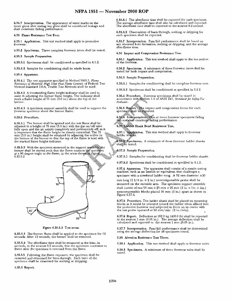
N F P A 1951 - - N o v e m b e r 2 0 0 0 R O P
6.34.7 Interpretation. The appearance of water marks on the inner glove after testing any glove shall be considered leakage and shall constitute failing performance.
6.35 Flame Resistance Test Four.
6.35.1 Application. This test method shall apply to protective footwear.
6.35.2 Specimens. Three complete footwear items shall be tested.
6.35.3 Sample Preparation.
6,35.3.1 Specimens shall be condi t ioned as specified in 6.1.2.
6.35.3.2 Samples for condit ioning shall be whole boots.
6.35.4 Apparatus.
6.35.4.1 The test apparatus specified in Method 5905.1, Flame Resistance of Material; High Heat Flux Flame Contact, of Federal Test Method Standard 191A, Textile Test Methods shall be used.
6.35.4.2 A freestanding flame height indicator shall be used to assist ila adjusting the burner flame height. The indicator shall mark a flame height of 75 mm (3.0 in.) above the top of the burner.
6.35.6.1 The afterflame time shall be repor ted for each specimen. The average afterflame time shall also be calculated and reported. The afterflame time shall be repor ted to the nearest 0.2 second.
6.35.6.2 Observations of burn through, melt ing or dr ipping for each specimen shall be reported.
6.35.7 Interpretat ion. Pass/fail performance shall be based on any obse rvedho le formation, melt ing or dripping, and the average after-flame time.
6.$6 Impact and Compression Resistance Test.
6.36.1 Application. This test me t hod shall apply to the toe section of the footwear.
6.36.2 Specimens. A min imum of three footwear items shall be tested for both impact and compression.
6.36.3 Sample Preparation.
6.36.3.1 Samples for condit ioning shall be complete footwear toes.
6.36.3.2 Specimens shall be condi t ioned as specified in 6.1.2.
6.36.4 Procedure. Footwear specimens shall be tested in accordance witt) : :~.t ion 1.4 of ANSI Z41, Standard for Safety-Toe
# i U % ..:.-.-.:.:.:.:.:.:..
6.35.4.3 A specimen suppor t assembly shall be used to support the 6.36.5 R~.~r~::ii::::i~.~e impact and compression forces for each footwear specimen above the burne r flame, specimet:i:::'-~qall B:~p. .or ted.
======================= % ::i:~ii:'.. . . . . . . . 6.35.5 Procedure. 6..$...~'~g""in%r~retatio'~iiii~:e or more footwear specimens failing
. ~ tes~::i~.hal[ constitug.@::['ailing performance. 6.35.5.1 The burner shall be ignited and the test flame shall be ..::~!~:::::~: ..:'ii!i!i!!::. "" adjusted to a he ight of 75 m m (3.0 in.) with the gas o n / o f f valve " 6.~-~-~-~i~i- Shank Bend Resistance Test. fully open mad the air supply completely and permanent ly off, as it "::!!iii:...:!~!i::.. is important that the flame height be closely controlled. The 75 :~:i ....... 6.37.1"::~h'gzation. This test me thod shall apply to footwear mm (3.0 in.) height shall be obtained by adjusting the orifice in :!iiii::iiiii:~i~ii:i-::.:..ladder sh'~t~s. the bot tom of the burner so that the top of the flame is level with :'ii!~':~":~:!i;i::i:#:~ii:i:::: . . . . . . ::i~ i::" the marked flame height indicator. ':::'-:i!: ::iii~:]~i!~!~pecimens. A min imum of three footwear ladder shanks
................ :~::.:::!.:.:'!ii::" shal~i!~e tested. 6.35.5.2 With the specimen moun ted in the support a s s 4 ~ i ~ . t h e :-ill ..... burner shall be moved such that the flame contacts ~..~:"speci~.~n "%:::i~.37.3 Sample Preparation. at a 90 degree angle to the flame, in the areas s b o ~ : : ~ : .Figur#.i:::~ ..... -:ii.. :~!iiii .... 6.35.5.2 ....... ~::i::i::i::ii::....::i! i .............. !:ii::i::i::i::ii::::.:.iiiii "~" 6.37.3.1 Samples for condit ioning shall be footwear ladder shanks.
" : ~ . . ":'.::~-~U 6373 Specimens shall be conditioned as specified in 6 1 2
: : : " : : l i . : ~ i i i i i i : . iiiii!!- .:i ::::ii .... 6.37.4 Apparatus. The apparatus shall consist of a tensile testing .:iii::""%i~i~:: "iiiii::iii " machine, such as an Instron or equivalent, that challenges a
"%i~ii~.::.. ~ specimen with a simulated ladder rung. A 32 mm diameter ×50
" ~ "::~i"""ii~iiiiii::::ii::- ~ 0 " mm long (1 1 /4 in. x 2 in.) noncompress ib le probe shall be 9 0 " "::::::ii:: - moun t ed on the movable arm. The specimen suppor t assembly
":!!:" shall consist of two 50 mm x 25 mm × 25 mm (2 in. × lin. × l in.)
Figure 6.35.5.2 Test areas.
6,35.5.3 The burner flame shall be applied to the specimen for 12 seconds. After 12 seconds, the burner shall be removed.
6.35.5.4 The afterflame time shall be measured as the time, in seconds, to the nearest 0.2 seconds, that the specimen continues to flame after the specimen is removed from the flame.
6.35.5.5 Following the flame exposure, the specimen shall be removed and examined for burn-through. Each layer of the specimen shall be examined for melting or dripping.
noncompress ible blocks placed 50 mm (2 in.) apart as shown in Figure 6.37.4.
6.37.5 Procedure. The ladder shank shall be placed on mount ing blocks as it would be or iented toward the ladder when affixed into the protective footwear and subjected to force on its center with the test probe operated at 50 ram/ ra in (2 in . /min) .
¢
6.37.6 Report. Deflection at 182.0 kg (400.0 lb) shall be reported to the nearest 1 mm (0.05 in.). The average deflection shall be calculated and repor ted to the nearest 1 mm (0.05 in.).
6.37.7 Interpretation. Pass/fall per formance shall be de te rmined using the average deflection for all specimens tested.
6.38 Abrasion Resistance Test Three.
6.38.1 Application. This test me thod shall apply to footwear soles.
6.38.2 Specimens. A min imum of three footwear soles shall be tested.
6,35.6 Report.
1094
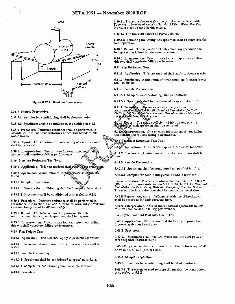
N F P A 1 9 5 1 ~ N o v e m b e r 2 0 0 0 R O P
Force
Shank sample
l~ 5 .08 cm (2 i n . ) r - i 5 .08 cm ~ ' ' 12 i..)
(1 in.)
t 2.54 cm C I i n')
6.40.4.1 Protective footwear shall be tested in accordance with Footwear Industr ies of Amer ica S tandard 1209, Who/e Shoe Flex. No water shall be used in this testing.
6.40.4.2 The test shall consist of 100,000 flexes.
6.40.4.3 Following the testing, the spec imen shall be examined for sole separat ion.
6.40.5 Report . The separa t ion of soles f rom any spec imen shall be repor ted as failure for the tested specimen.
6.40.6 Interpreta t ion. O n e or m o r e footwear spec imens failing this test shall const i tute failing pe r fo rmance .
6.41 Slip Resis tance Test .
6.41.1 Application. This test m e t h o d shall apply to footwear soles.
6.41.2 Spec imens . A m i n i m u m of three comple te footwear i tems shall be tested.
6.41.3 Sample Preparat ion.
6.41.3.1 Samples for condi t ioning shall be footwear.
oi, ,~ 6 41 3 2 S p e c i m ~ s h a l l be cond i t ioned as specified in 6 1 2 F i t - r e 6 . 3 7 . 4 S h a n k b e n d t e s t s e t u r . • • • ~# . . . . . . . . " " "
6.41.4 P r o ~ . Slip resis tance sh i l l be pe r fo rmed in g aa a ~ o ~ t o v . . . . . ~ , a cco rdan .~ 'w i~ '~ .~TM F 489, Standard Test Method for Static . . . . . . . . . v . . . . . v . . . . . . . . Coeffici..e@.~'~ F r i c ~ ' . C f Shoe Sole and Heel Materials as Measured by
3 . . . . a w t h e ' ) ~ h i n e , "~i¥~.~-:¢1 ..r~.:.... c o n d i tio n 6 . 3 8 . . 1 Samples for cond~tuomng sh II be foot ear soles. ..:.:.-~" ":::',:.v :'":"-.:,-.:.:.:.:.:.:.:.-":'" ...,:, • ..:.y....~::.. . . .
6.38.3.2 Spec imens shall be condi t ioned as specified in 6.1.2. ~ i ! , . 5 . . R ~ o r t . The s ~ c coe f f ioen t of f r icuon u n d e r a dry ' .-.-:.::-'t"O~UuO~.".~.t eacn s p e o m e n snm~ oe repor tea .
• . " " " ~ : ! : : . : i - " . ' : : . . . . : : ~ : : ~ " " : : : : . ~ x - -
6 . 3 8 . 4 Procedure . Punc ture resmtance shall be pe r fo rmed m ~ . ~::i-~i.:.:~ " ^ . . . . . . accordance with F,~ntwear Industr ies nf Amori ra RtanHard ~01 n.41.lr.~ii-i.t.~terpretation, o n e or m o r e tootwear spec tmens t a m n g NBS Abrasion. . . . . . . . . . . . . . . . . . . . ~:'~:~..:: ..... this t e ~ - - ~ o n s t i t u t e falling p e r f o r m a n c e .
": :.k",~ ?..":: ~:!::'-:" - s:::>; . 6.3.8.5 Report . The abrasion-resis tance rat ing of each spec imen .% .....'.:::i~...:&El~r,cal Insn la tmn Tes t Two. shall be repor ted . "% ,~'U ".'.:~:~:~w . . . . . . . .
..:.....~:!:!.....:~$:.~.. "i:~..~.~::" 6.4~.i:" Application. 1 la~s test snail apply to protectave tootwear.
6.38.6 In ternre ta t ion . O n e or m o r e footwear s p e c i m ~ ' % : ~ i ~ ":iiik . . . . . thi,' test sha ] [cons t i tu te failing pe r fo rmance :~ ~ ~'.:~:~..~.42.2 Specimens . A m i n i m u m of three footwear ~tems snan t~e
"' " ~i~i.'~::. .:..':~!.".:..~:~ ..... "-'~. ~:::tested. • " "~.~'.-':'-~..~-': ........ ::~.x~:.-'~: "
6.39 Punc ture Resis tance Tes t Two. "~.::-~-::s- "-::::-'..:..::::::~: ........... • ~.:;~:. "x::-':-'.':" 6.42.3 Sample Preparat ion.
6 39 1 Application Th~s test m e t h o d s h a l t ~ i I ~ { . ~ o t w e ~ . , . , ~ . o ~ d as s eof ied m 6 1 . . . ,.~. :- ~ c ~:.9.:.:a.~ • 6.42.3.1 Spec imens shall be condi t ione p " ' • .2.
6.3'9.2 Spec imens . A m i n i m u m of th~..o...:.otwear s ~ h a l k ~ e 6.42.3.2 Samples for condi t ion ing shall be whole footwear. test ed.
6.39.3 Sample Prepara t ion. "::ii::ii::::ii:i::'. 2i::? • "::~..%~.~.,:..~t~ :~ "%~y,
6.39.3.1 Samples for condi t ion ing shall be foot~:~i" sole sections.
6.39.3.2 Spec imens shall be condi t ioned as specified in 6.1.2.
6.39.4 Procedure . Punc ture resistance shall be pe r fo rmed in accordance with Section 3 of C~SA Z195 M-92, Standard for Protective Footwear, Occupational Health and Safety.
6.39.5 Report . The force requi red to punc t u r e the sole re i t f forcement device of each spec imen shall be repor ted.
6.39.6 Interpre ta t ion. One or more footwear spec imens failing this test shall const i tute falling per formance .
6.40 Flex Fatigue Test .
6.41).1 Application. This test shall apply to protective footwear.
6.40.2 Specimens . A m i n i m u m of three footwear i tems shall be tested.
6.40.3 Sample Preparat ion.
6.40.3.1 Spec imens shall be condi t ioned as specified in 6.1.2.
6.40.3.2 Samples for condi t ion ing shall be whole footwear.
6.40.4 Procedure .
6.42.4 Procedure . Protective footwear shall be tested to 14,000 V (RMS) in accordance with Section 5.1.1 o f A S T M F 1116, Standard Test Method for Determining Dielectric Strength of Overshoe Footwear. The electrode inside the boot shall be conductive metal shot.
6.42.5 Report . Any cu r ren t leakage or evidence of breakdown shall be recorded for each footwear item.
6.42.6 Interpre ta t ion. O n e or m o r e footwear spec imens failing this test shall const i tute failing per formance .
6.43 Eyelet and Stud Pos t At tachment Test .
6.43.1 Application. This test m e t h o d shall apply to protective footwear eyelets and s tud posts.
6.43.2 Specimens .
6.43.2.1 Spec imens shall total two eyelets and two s tud posts on th ree separate footwear items.
6.43.2.2 Specimens shall be removed f rom the footwear and shall be 25 m m x 50 m m (1in. x 2 in.).
6.43.3 Sample Preparat ion.
6.43.3.1 s amp le s for condi t ion ing sha l l 'be whole footwear.
6.43.3.2 The eyelets or s tud pos t spec imens shall be condi t ioned as specified in 6.1.2.
1 0 9 5
N F P A 1951 ~ N o v e m b e r 2 0 0 0 R O P
6.43.4 Apparatus. A tensile testing machine shall be used with a traverse rate of 50 m m / m i n (2 in . /min) . Clamps measuring 25 mm × 38 mm (1 in. x 1.5 in.) shall have gripping surfaces that are parallel, flat, and capable of preventing slippage of the specimen during the test.
6.43.5 Procedure. The stud post or eyelet puller shall be inserted or attached to the upper position of the tensile machine. The traverse rate shall be set a 50 m m / m i n (2 in . /min) . The test eyelet or stud post shall be attached using the appropriate puller fixture. The eyelet stay shall be clamped, but clamping the metal port ion of the eyelets or stud hook in the lower clamps shall not be permitted. The distance between the clamps and stud hooks or eyelets shall be 1.6 m m to 3.2 m m (0.063 in. to 0.125 in.). The test shall then be started.
6.43.6 Report. The force will reach a peak, decline slightly, and then increase to complete failure; however, the value at which the force first declines shall be recorded and reported as the initial failure point, as this is the separation point of the material a round the eyelet or stud post. The average force shall be calculated and reported.
6.43.7 Interpretation. The average force shall be used to determine pass/fail.
6.44 Overall Liquid Integrity Test Three.
6.44.1 Application. This test shall apply to protective footwear.
6.44.2 Specimens. A min imum of three footwear items shall be tested.
6.44.3 Sample P r e p a r a t i o n .
NFPA 1500, Standard on Fire Department Occupational Safety and Health Program, 1998 Edition.
7.1.2 Other P u b l i c a t i o n s .
7.1.2.1 AATCC P u b l i c a t i o n . American Association of Text le Chemists and Colorists, P. O. Box 12215, Research Triangle Park, NC 27709.
AATCC 22, Water repellency: Spray test, 1996.
AATCC 70, Test Method for Water R.~ellency: Tumble Jar Dynamic Absorption Test, 1988.
7.1.2.2 ANSI Publications. American National Standards Institute, 1450 Broadway, New York, NY 10018.
ANSI Z41, Standard for Safety-Toe Footwear, 1991.
ANSI/AATCC 135, Dimensional Changes in Automatic Home Laundering of Woven and Knit Fabrics, 1989.
7.1.2.3 ASTM Publications. American Society for Testing and Materials, 100 Barr Harbor Drive, West Conshohocken, PA 19428- 2959.
ASTM B 117, ~ a r d Method of Salt Spray (Fog) Testing, 1985. ..::?:: . . . . ......~:::~
ASTM B ~..~.~i'..~..ecification for Copper Sheets, Strip Plate, and Rolled Bar, 1986.::~i::f" "::ii::iiii!::ii::.
A,S~ii"..~.ii~l, S ~ d T....~t Method for Rubber Property- Effect of
.#':':-':~i~.TM..'::~.:.~.6831 , Stan:"dard Test Method for Failure in Sewn Seams of wa~a~,'~., 1990. 6.44.3.1 Specimens shall be condit ioned as specified in 6.1.2.
6 ,t,t ~ 9 R~,,,~l,~ for ~,~,a;a,n;n,~ sh~tt, h , ,~h,~l~ ¢, , , t ,~,~ ::i!:-:::.:.~ ASTI~'."'~!~...88g, Standard Test Method for Abrasion Resistance of . . . . . . . . . . . . v . . . . . . . . . . . . . . . t, . . . . . . . . . . . . . . . . . . . . . . . . . . . . . . . . . . . . . . . "-...:.: ....~:::.'-:-:-:-:-:-.-.:':':~ .: - 1. extt te/~o~t~'s":~.:..... . . . . . . . . . . . . . (/wta ry r latformT , u~o uote~'~Head Met hod'), 199 ~z
6 44 4 Procedure • " " ":i::ii~:. ..iJi~i::i!i:~!~ 3885, Standard Test Method for Abrasion Resistance of Tex~ 'Fabncs (Flexing and Abraswn Method, 1992 6.44.4.1 Protective footwear shall be tested in a c c o r d a n c . g ~ . , . %'::" --:~
Footwear Industries of America Standard 1209, W h o / e ~ e ~ ! : "~i!-, . . . . . . . . . . . . . . . . . . . . . . . . . . . . . . . . . . Th~ I~,,~I ~¢ ~ t ~ r ~h~ll h~ ~ 1 ~ t h ~ q ~ m i l ;~.~-~ ~ ~ : '::-~:'.~::-~ am t) o~,~u, ~anaara I es~ zvletnoa ]or ~urstmg o~reng~n (£,oaa) . . . . . . . . . . . . . ~.,~... o:: . . . . . . . . e . . . . . . . m,.. ~ . . t~-~ .o , . . ~ ....... t: ."::~ii"::"and Elongation of Seams of Knit and Stretch Woven Textiles 1983 rawest point or me mroat. "-'-"::" "::;~ii::~::ii.:.:::....::¢:;:::::::::i:.::i::iiiiii:b.:..~!~U'~:"
6 44 4 - The test shall consis "100 000 " ":::".~i::i~i::ii:.. "::::~iiiiii!::" ASTM D 5034, Standard Test Method for Breaking Force and • z t o l , t t e x ~-~. . .] . . : . . . "-:~-'.:::.~.~:- . . . +':'~*:":~i'/'-:.:: "".-~i:i:.-]i-'.:, +:. Elongatmn of Textile Fabrics (Grab Method), 1995. ...~::" " -'.:~ ...-':- ~ .:.:.:.',. ~. ".:.~:~!.~.~ ~.~:::i:."
6.44.4.3 After flexing the specimen sha~:...::~ olaced"~':'.-:.'~kcon~:~r . . . . . . . . . . . . . . . . . . . . . . . . . . "" -1 ws " " e ' " ..~-:."--. t .., ~::::~k ,.-:-:-- ~ ttvI u Du~, .~tanaara Iest ivlemoa jor z~rea~tmg ~orce ana that aa o ~ts ~mm rsmn m tap water, : ~ t warn a a3~ . . i~anc t~a . . . .
• • -:-:- . . . . . -,..:. .-::- Elon atwn o Textde Fabrws (Strt Method), 1995. surfactant which achieves a surface t e r / s m r ~ : ~ 4 d y n e s ~ , ~ g f P dynes/cm, to a height of not less than 25 rn'~"~i~.~.~.n.) f r ~ the ~¢.r~t r~ ~'7~t ,~.., ,.¢.,t..a r~. "P---;n- Stren ~ . r ~t . . . . . . . . . Fat.~-.',~ lowest point of the throat. The paper towehng::~u~.e~t m FIA ~ ~'h. T..l.~,~,,,.;d.l P¢..ad, , - ~ 1QOr~ 1209 shall be placed inside the footwear specimei~ii~'~h that the • ~-~ . . . . . . r . . . . . . . . . . . . . . . . . . toweling intimately contacts all areas inside the t ~ t w e a r specimen ASTM E 809 Standard Test Method for Measuring Photometric to a height of not less than 25 m m (1in.) f rom the lowest point of the throat.
6.44.4.4 After 2.0 hr, +10 rain, the paper toweling shall be removed and examined for evidence liquid leakage.
6.44.5 Report. The appearance of water leakage on the removed paper towelling shall be reported as failure for the tested specimen.
6.44.6 Interpretation. One or more footwear specimens failing this test shall constitute failing performance.
C h a p t e r 7 R e f e r e n c e d P u b l i c a t i o n s
7.1 The following documents or portions thereof are referenced within this standard as mandatory requirements and shall be considered par t of the requirements of this standard. The edition indicated for each referenced mandatory document is the current edition as of the date of the NFPA issuance of this standard. Some of these mandatory documents might also be referenced in this standard for specific informational purposes and, therefore, are also listed in Appendix B.
7.1.1 NFPA Publications. National Fire Protection Association, 1 Batterymarch Park, P. O. Box 9101, Quincy, MA 02269-9101.
Characteristics of Retroreflectors, 1994.
ASTM F 489, Standard Test Method for Static Coefficient of Friction of Shoe Sole and Heel Materials as Measured by the James Machine, 1997.
ASTM F 903, Standard Test Method for Resistance of Protective Clothing Materials to Penetration by Liquids, 1995.
ASTM F 1060, Standard Test Method for Thermal Protective Performance of Materials for Protective Clothing for Hot Surface Contact,1987.
ASTM F 1116, Standard Test Method for Determining Dielectric Strength of Overshoe Footwear, 1988.
ASTM F 1342, Standard Test Method for Resistance of Protective Clothing Materials to Puncture, 1991
ASTM F 1359, Standard Practice for Determining Liquid-Tight Integrity of Chemical Protective Suits or Ensembles under Static Conditions, 1996
ASTM F 1671, Standard Test Method for Resistance of Materials Used in Protective Clothing To Penetration by Blood-Borne Pathogens Using Phi-X174 Bacteriophage as a Test System, 1995.
1096
N F P A 1951 - - N o v e m b e r 2000 R O P
ASTM F 1790, Test Methods for Measuring Cut Resistance of Materials Used in Protective Clothing, 1997.
(3) NFPA 1977, Standard on Protective Clothing and Equipment for Wildland Fire Fighting
ASTM F 1868, Standard Test Method for Thermal and Evaporative Resistance of Clothing Materials using a Sweating Hot Plate, 1998.
~KSTM F 1930, Test Method for Evaluation of Flame Resistant Clothing for Protection Against Flash Fire Simulations Using an Instrumented Manikin, 1998.
7.1.2.4 CSA Publication. Canadian Standards Association, 178 Rexdale Boulevard, Toronto M9W 1Rg, Canada.
C..SA Z195 M-92, Standard for Protective Footwear, Occupational Health and Safety, 1984.
7 . 1 . 2 . 5 E N P u b l i c a t i o n .
EN 471, High Wtsibili~ Warning Clothing, 1994.
7.1.2.6 FIA Publications. Footwear Industries of America, 1420 K Street, NW, Suite 600, Washington, DC 20005.
FIA Standard 301, NBS Abrasion.
Organizations responsible for hazardous chemical emergencies should use protective clothing and equipment specifically designed for those activities. Applicable standards include the following:
(1) NFPA 1991, Standard on Vapor-Protective Suits for Hazardous Chemical Emergencies
(2) NFPA 1992, Standard on Liquid Splash-Protective Suits for Hazardous Chemical Emergencies
(8) NFPA 199~, Standard on Support Function Protective Clothing for Hazardous Chemical Operations
Organizations responsible for emergency medical operations should use protective clothing and equipment specifically designed for those activities. The applicable standard is NFPA 1999, Standard on Protective Clothing for Emergency Medical Operations.
A.I.2 This standard is not designed to be utilized as a4imrchase specification. It is prepared, as far as practical, with regard to required performance, avoiding restriction of design wherever
OSSible. Purchasers should specify departmental requirements r such items as color, markings, closures, pockets, and trim
patterns. Tests specified in this standard should not be deemed as I,IA Standard 1209, Whole Shoe Flex. " defining or establishing performance levels for protection from alll
technical r e s c u ~ r o n m e n t s . . . . . . . ...;~..-'~. ~. 7.1.2.7 GSA Publicauons. General Servtces Admmtstrauon, - ,.~!~ .-::, Specifications Activity, Printed Materials Supply Division, Building A.1.2.1, T h ~ . . ~ o r i t y having jurisdiction should perform a risk 1~J7, Naval WeaponsPlan, Washington, DC 20407. assessmer~f!~o ~ i f y the hazards present and to determine the
SUttabl.~.....t~:~.g_ p r ~ . . v . e ensemble specified by thin standard. For Federal Test Method Standard 191A, Textile Test Methods, July 20, each.~':~ctawta" ~'~i~.sc.t.i.bed as technical rescue incidents, the
1978 a u . ~ r i t 3 / t ? a v i n g j u r i ~ ' ~ n should determine if the protection ~vid~....:.by complia~....~-'50rban Technical Rescue Protective
:Federal Specification FED-V-F-106E Fasteners, Interlockin& Slide ~-'-'"~mb.'~.b~..:~i...~neeting ~ l s standard is commensurate with the level of June 23, 1987. '" p r ~ : i ~ ' ~ e e d e d as deemed by the hazards present. For
e x a ~ , . i n an automobile extrication the decision for using Military Standard MII_~STD-105D, Sampling Procedures and Tables....:.:.....:: ...... T e c h m ~ u e Protective Ensembles versus Structural Fire
for Inspection by Attributes, April 16, 1983 :~:.~:.~.,;. Fighting ~..-~i$ecfive Ensembles may be dependent on the level of % ~ ' : ~ s k i.~-'~he incident.
7.1.2.8 ISO Publications. International Standards Organization 1 ~!i~. ,:.-"~ i'~ ~"~$~'#": reue de Varembe, Case Postale 56, CH-1211, Geneve 20, ..o.,-~.~ .... :~...<~":'A.l.~i-~ The testing requirements in Chapter 6 of this standard are. Switzerland. ~ $ : % not ' in tended to establish the limitations of the working .~:~ ~..-.-'.~ % . . . . .
~.,'."~t '*¢ '.~:~...:.~av~ronment for techmcal rescue but are intended to establish ISO 9001, QualiO Systems - Model for Quali 0 assu~..~.'~jn D~@.....:: ":~, W":'material performance.
Development, Production, and Servicing,1995. ~" "%~ii~?.:.~ -y ........ %..:'75.:'?::~}':":" ..'x 0 • . " ~ \ ":':::::::~'~ Users sh uld be advised that if unusual conditions prevail, or if
][SO Guide 25, General requirements for the ~ . o f c ~ t i o ~ . there are signs of abuse or mutilation of the protective ensemble arm testing laboratories. ~:#:" ""'~]-']'~..".'~ " ~ ' Y " or any element or component thereof, or if modifications or
..::::." "~.-%':2.-. :~ - -~" . . ~:~.".:.. ~.~. 4 ~ ; " replacements are made or accessories are added w~thout
7.1.2.9 SAE Publication. Society o f A ~ 5 ~ f i v e Eng in '~s , 400 authorization of the protective ensemble element manufacturer, Commonwealth Drive, Warrendale, PA 150~i~. ' ~i~: the margin of protection might be reduced.
e • " ; ~ & - . 4 ~" • • - • oAEJ211, lnstrumentatwn for Impact T e s g ":~,~" Users should be advised that the protecuve properues in new • ..~'~ technical rescue protective ensemble elements, as required by this
7.1.2.10 U.S. Naval Publications. Naval Publica~ons and Forms standard, can diminish as the product is worn and ages. Center, 5801 Tabor Avenue, Philadelphia, PA 19120
MIL-F-21840G, Fastener Tapes, Hook and Pile, Synthetic, December 16, 1987.
MIL-F-10884F, Fa4tener, Snap, November 30, 1984.
Appendix A Explanatory Material
.Appendix A is not a part of the requirements of this NFPA document but :s included for informational purposes onl 3. This appendix contains explanatory material, numbered to correspond with the applicable text paragraphs..
A.I.1.4 Nothin[g in this standard is intended to imply that fire service responcters cannot engage in urban technical rescue incidents while wearing protective clothing and equipment meeting NFPA 1971.
Organizations responsible for fi/~e fighting applications should use protective clothing and equipment specifically designed for those activities. Applicable standards include the following:
(1) NFPA 1971, Standard on Protective Ensemble for Structural Fire Fighting
(2) NFPA 1976, Standard on Protective Clothlng for Proximity Fire Fighting
A.I.3 Approved. The National Fire Protection Association does not approve, inspect, or certify any installations, procedures, lae~buipment, or materials; nor does it approve or evaluate testing
oratories. In determining the acceptability of installations, procedures, equipment, or materials, the authority having jurisdiction may base acceptance on compliance with NFPA or other appropriate standards. In the absence of such standards, said authority may require evidence of proper installation, procedure, or use. The authority having jurisdiction may also refer to the listings or labeling practices of an organization that is concerned with product evaluations and is thus in a position to determine compliance with appropriate standards for the current production of listed items.
A.1.3 Authority Having Jurisdiction. The phrase "authority havintg jurisdiction" is used in NFPA documents in a broad manner, since jurisdictions and approval agencies vary, as do their responsibilities. Where public safety is primary, the authority having jurisdiction may be a federal, state, local, or other regional depar tment or individual such as a fire chief; fire marshal; chief of a fire prevention bureau, labor department, or health department; building official; electrical inspector; or others having statutory authority. For insurance purposes, an insurance inspection department, rating bureau, or other insurance company representative may be the authority having jurisdiction. In many circumstances, the property owner or his or her designated agent
1097
N F P A 1951 ~ N o v e m b e r 2 0 0 0 R O P
assumes the role of the author i ty having jurisdict ion; at g o v e r n m e n t installations, the c o m m a n d i n g officer or depar tmen ta l official may be the author i ty having jurisdict ion.
A. 1.3 Flash Fire. Flashover is a p h e n o m e n a which requires hea t and genera tes t empera tu res in the range of 1200 to 1500°F. A flash fire requires an ignit ion source and a chemical or dus t a tmosphe re which contains a concent ra t ion of the subs tance above the lower explosive limit of the chemical . Flash fires genera te hea t f rom 1000 to 1900°F. A structural fire f lashover as a rule is conf ined to a des ignated area with walls as a boundary. A flash fire depends on the size of the gas or vapor cloud and when ignited, the f lame f ront expands outward in the form of a fireball. T he resul t ing effect of the fireball 's energy with respect to rad ian t hea t significantly enlarges the hazard areas a r o u n d the gas released.
A.I.3 Listed. The m e a n s for identifying listed e q u i p m e n t may vary for each organizat ion conce rned with p roduc t evaluation; some organizat ions do no t recognize e q u i p m e n t as listed unless it is also labeled. The author i ty hav ing jur isdic t ion shou ld utilize the system employed by the listing organizat ion to identify a listed product .
A.1.4 Melxic uni ts are used t h r o u g h o u t Chapters 5 and 6 with English equivalents provided in parentheses .
A.2.1.4 The National Fire Protect ion Associat ion (NFPA), f rom time to t ime, has received complaints that certain i tems of fire and emergency services protective c lothing or protective e q u i p m e n t migh t be carrying labels falsely identifying t hem as compl iant with an NFPA standard. The r e q u i r e m e n t for placing the certification organizat ion 's ma rk on or nex t to the p roduc t label is he lp ensure than the purchase r can readily de te rmine compl iance of the respective p roduc t t h r o u g h i n d e p e n d e n t third party certification.
A.2.2.I T h e certification organizat ion shou ld have suff icient breadth of interest and activity so tha t the loss or award of a specific business contract would no t be a de t e rmi n i ng factor in the financial well being of the agency. :ili~:~:~:::: .....
A.3.1.3 See A.2.1.4
A.3.2.4 A s t a t emen t shou ld be inc luded in the user informat ion specifying that, u p o n the purchaser ' s request , the m a n u f a c t u r e r is to furn ish all d o c u m e n t a t i o n requi red by this s tandard and the test data showing compl iance with this s tandard . A s t a t emen t also should be inc luded in the user in format ion specifying that, u p o n the purchaser ' s request, the m a n u f a c t u r e r is to furn ish a comple te specification of all materials a n d c o m p o n e n t s compr is ing each certified helmet .
A.4.1.17 The selection of protective clothing size related directly to the g a r m e n t ' s ability to func t ion properly. In occupat ions , such as fire and rescue services, p roper fit and func t ion related directly to the individual 's ability to pe r fo rm jobs that are often hazardous. Issues of p rope r fit are directly associated with the risk of injury. Protective c lothing that restricts m o v e m e n t or exposes the skin to hazardous env i ronmen t s will resul t in lost efficiency a n d may p romote injury and illness, respectively. Proper sizing is a factor in the ability of a person to pe r fo rm tasks that of ten involve life or dea th situations. Protective c lothing mus t fit well to func t ion properly when addit ional safety e q m p m e n t or o ther ga rmen t s are worn. In addit ion, the selection of protective g a r m e n t size has a direct impact on ma in ta in ing appropr ia te pro tec t ion in areas where the protective g a r m e n t has an interface with safety e q u i p m e n t or o ther protective garments . ASTM F 1731, Standard Practice for Bod~.:..~..'.~...surements and Sizing of Fire and Rescue Services Uniforms and O..~K~"~ermal Hazard Protective Clothing, may be found use~li~.h....e.n select ing protective c lo th ing for technical o p e r a t i o ~ " ~ , F 1731 primari ly addresses processes for sizing station..£~/~..k u n i t ' ~ s r e fe renced in NFPA 1975, Standard on Stati.o..:~9..'t.'.~i:.Unifo~ii-..b..o..N...ever, the t echn iques descr ibed in the s @ a r d 'gqll be usef~Iii~i::lhe selection of protective clothing a~]ress~d in this stan~:i:d.
.-::i:i:i:i:i:k "i:i:i::-. ":::"
..... A)~!~:!¢!~:~:.purchaser shou ld consider the following sizing p e r f ~ c e r e c o m m e n d a t i o n s and evaluation methods :
.... ~---~::.....::~, ":iiiii:iii!iii-iii:i:.-: ..... (a) Gl~.~i::Fit/Performance Requ i rements .
A.2.2 3 The contractual provisions covering a certification program~i-.":::i:-i~?-::-..... .::ii:: shou ld conta in clauses advising the manu fac t u r e r that if "i~?::: ,£~iiii;:::i:ii::i~i::ii~;:"Glove fit is def ined in te rms of f inger length finger r equ i rements change the p roduc t shou ld be b r o u g h t into..:.:.:.:.:... ::ii::i...::~i !i:: c i r c6~ te rence , glove c i rcumference , and crotch offset. compl iance with the new requ i rements by a stated e f f e . c . . ~ : : i ~ :iiiiil" " .... t h rough a compl iance review program involving all c . ~ e n t l y l ~ t e d :::::::::::::,::::: (2) The t h u m b and index f inger of the h a n d shou ld reach products , x:-!":'~i~i::~iii..: . . . . . iiii~i?.~i~!:!::-..-... %...~::~':::"the ends of the t h u m b and index f inger of the glove.
"" -"iii!:'ii!!::...::!!~::"" " "::::'i-ii'i'.::~:::::i!i" "" Without the clauses, certifiers would no t be ab..1...e..to mo~i::.".gt..uickly ::::iiii:i:i .... (3) The middle and r ing f ingers of the glove can be
to protect their name, marks, or reputation..-~ii'~.~.tO:.ct safaris:. .. permi t ted to ex tend beyond the f inger of the h a n d no more than certification p rog ram would be deficient . . ~ { o u t " ~ : : . c o n ~ l 0.4 in. orovisions a n d the administrat ive mean~.~(~, back t h e ~ ) . .:-'i .... - ":#::':'::ii::ii::i::)::ii! .... ":!i::~il " (4) The little f inger of the glove can be permit ted to extend A.2.2.4 Investigative p rocedures are i m p o f ~ i : : e l e m e n ~ i g f an beyond the little f inger of the h a n d no more than 13 m m (1 /2 in.). effective and mean ingfu l p roduc t safety ce r t i f i~ i .on pr.-.b~ram. A prel iminary review shou ld be carried out on pr~/~¢.~i::submitted to (5) T h e f inger crotches of the glove can be offset f rom the t-he agency before any major testing is unde~en~i~i!:: ' f inger crotches o f the h a n d no m o r e - t h a n 13 m m (1 /2 in.)
.:...
A.2.2.7 Such inspect ions shou ld include, in mos t instances, wimess ing of p roduc t ion tests. With certain products the certification organizat ion inspectors shou l d select samples f rom the p roduc t ion line and submi t t h e m to ma i n laboratory for coun te rcheck testing. With o ther products, it may be desirable to purchase samples in the open marke t for test purposes .
A.2.2.9 For fu r ther informat ion and guidance on recall programs, see Title 21, Code of Federal Regulations, Part 7, Subpar t C (21 CFR 7, Subpar t C).
A.2.6 ISO 9000 def ines quality terms and concepts. It gives an overview of the con ten t and use of the entire ISO 9000 series. A useful cross-reference to the series ' quality system e lements is f ound in A n n e x A of ISO 9000. ISO 9001 is used when the quality system to be assessed covers several stages of one f i rm's processes. It prescribes quality system requ i rements for design, deve lopment , product ion , installation mad servicing.
A.3.1.1 Purchasers migh t wish to include a r equ i r emen t in the purchase specifications for an addit ional label that includes certain informat ion such as the date of manufac ture , manufac tu re r ' s name, and g a r m e n t identif ication n u m b e r to be located in a pro tec ted location on the g a r m e n t in order to reduce the chance of label degradat ion and as a backup source of informat ion to aid in g a r m e n t t racking or du r ing an investigation.
(6) The glove shou ld no t be permi t ted to constrict the f ingers of the h a n d in c i rcumference.
(7) Excess c i rcumference of the glove over the f ingers an d h a n d can be permi t ted bu t shou ld no t exceed 0.4 in. for any finger, or 1.5 in. for the h a n d as a whole.
(b) Glove Fit Test Method .
(1) The subject 's h a n d shou ld be measu red for han d c i rcumference and h a n d length to de t e rmine the correct size of test glove. The me thods descr ibed in 4-3.5.1.1 a n d 4-3.5.1.3, respectively, shou ld be used.
(2) Samples shou ld be condi t ioned to be new, after ten washes (see 6.1.2.1), and after hea t resistance test ing (see Section 6.6).
(3) The subjects shou ld don the test gloves as they would their own gloves.
(4) The subject should de te rmine if the t h u m b and index f inger are at the ends of the t h u m b and index finger of the glove. The tips of the t h u m b and index f inger shou ld b felt f rom the outside to verify the subject ' s answer.
1098
N F P A 1951 ~ N o v e m b e r 2 0 0 0 R O P
(5) An inside diameter caliper should be used to measure the excess of glove finger over test subject finger for the middle, ring, and little fingers.
(6) The subject should determine if the glove constricts either the fingers or the hand in terms of circumference. Each finger, and the sides of the gloved hand should be felt to verify the subject's answer.
(7) An inside diameter caliper should be used to measure may excess circumference in each finger and in the hand. When recording the values, it should be noted that the measured excess should be doubled to convert the flat dimension into a circumferential dimension (to account for the fact that there are two thicknesses of the glove material).
(8) The subject's hand dimensions, glove size, and all test results should be recorded.
A.4.4.11.2 The Bannock Scientific Foot Measuring Device can be obtained from the Brannock Device Compa/ay, 509 East Fayette Street, Syracuse, NY 13202; 315475-9862.
A.6.1.6.8 A radiant heat exposure condition for helmets is specified. Under controlledcomtitions, a radiant heat load of 1 V~/cm is applied until a temperature of 260 C (500 F) is reached on a transducer. This temperature alone does not simulate actual field conditions but is a test devised to put extreme heat loads on helmets in an accurate and reproducible manner by testing laboratories. However, the radiant heat load of 1 W/cm ~ was selected as an average value based on studies of fire conditions that relate to field use.
A.6.20.4.9 Calibration Procedures. The following multiple-step
A.6.28.4.6 A practical, easy to use technique for achieving this control utilizes a reference material with known cut resistance. For example, the vinyl tapes manufactured by the 3M Company, c,r their equivalents, as shown in Table A~6.28.4.6, can be used:
Table A.6.28.4.6 Tape Identification, Minimum Weight for Cut
No. 470 White vinyl tape 10 lb (4.5 kg) No. 472 Bl~ck vinyl tape 12 lb (5.4 k~:)
A.6.30.4.9 Calibration Procedures. ' The following multi-step calibration shall be used:
Procedure 1: Medium and System Calibration. This 'calibration step should be carried out using a guided-fall system with an accelerometer mounted in the drop assembly and a load cell mounted under the reference anvil. The load cell should be mounted in compliance with the requirements of 6.30.4.3 through 6.30.4.8. The drop assembly should be ch'opped onto the reference anvil from a height that yields a peak acceleration of 400 Gn +20 Gn and accelerations above 200 Gn of at least 1 millisecond duration. A means of verifying the impact velocity within 2 percent should be utilized. The measured peak performance should equal (within 2 percent) the measuredpeak acceleration (in g's) time the weight of the drop assembly. This accuracy should ~ . repeatable through at least five impacts.
.#....-~.,...::. Procedure.~.~.'.Elect~:tnics Verification. When in use, electronic
verficatiort.:..~i*:~.i~:.normally used instrumentation scales should be under.tak..~ at l:~k::weekly. This should be accomplished by follo~..~...oced~i~!~.eco.mmended by the manufacturer of the i n s ~ * ~ ' ~ . ~ on. ::iiiiiiiiii.:..-:::~..c~.~:"
~ . 3 4 . ~ , . . An exampl~:"of an inner glove fabric is a lightweight, procedure is recommended: ~ " ~ d ~ : : ~ (e.g., 2.2 ox/yd. 92 × 88), medium- or dark-colored,
Procedure 1: Medium and System Calibration. This calibration 1 0 0 - ~ ' ~ n t polyester fabric without surface treaunent. step should be carried out with an accelerometer mounted in the .:::~,.. ~,.,-,.,:.:, ~::~ impactor. The accelerometer should be mounted with its s ens i t i v~ - . -~ .... "%11i~"::' Appendix B Referenced Publications axis within 5 degrees of vertical. ~ : " ~ . . . . . ~::"
% ~ i ~ i ~ f o l l o w i n g documents or portions thereof are referenced A calibrating medium should be mounted over the 1oac[...¢.$~1,~ as ~i~-:.# "::" wi~: : ' th is standard for informational purposes only and are thus
specified in Section 6.20. The centers of the load c e l l , ~ " ~ , % not':~onsidered part of the requirements of this standard unless impactor, and accelerometer should be colinear w i ~ ' 3 m ~ ":¢~..:.',a$~lso listed in Chapter 7. The edition indicated here for each (0.125 in.), _T.I.R. The impactor should be d r o p ~ m a~.'~j~.t ~.. #~":"reference is the current edition as of the date of the NFPA issuance that yields a peak force of 9000 N, +500 N (2000 lb~ + " $ ~ . ~ . ' ~ y ? ' ~ " ~ " " of this standard. means of verifying the impact velocity within 2 ~...e.rcent s ~ d be ":":"-"-::-"::':'" utilized. The measured peak force should ~ ~ i n 2 ~ . 2 . " ~.. B.I.1 NFPA Publications. National Fire Protection Association, 1 percent) the measured peak acceleration :f~ g's) "fJ~:. the ~ . ~ . ~ Batterymarch Park, P.O. Box 9101, Quincy, MA 02269-9101. of the impactor. This accuracy should ~:":-icepeatable"~:~...ougl~.i~t least five impacts. " : ~ : . ":'~iii " NFPA 1971, Standard on Protective Ensemble for Structural Fire
Procedure 2: System Calibration Only. A ' ~ ~ . . a t i .~.%aedium that has been tested in accordance with Proced"~..~iii-~:.-.:~'bove can be used without an accelerometer or guided mass. ~ force value obtained when testing in accordance with Procee$fire 1 should be recorded and provided with the calibrating medium. The calibrating medium should be mounted over the load ceil. The centers of the load cell, medium, impactor, and accelerometer should be collinear within 3 mm (0.125 in.), T.I.R. The impactor should be dropped onto the medium, and the peak force measured by the load cell should be recorded. The peak force should be within 2.5 percent of that recorded while testing in accordance with Procedure 1. The calibrating medium should be retested in accordance with Procedure 1 at not more than ,t-month intervals.
Procedure 3: Electronics Calibration. When in use, electronic calibration of the normally used instrumentation scales should be undertaken at least every 6 months. This should be accomplished by following the procedures recommended by the manufacturer of the instrumentation.
, Fighting, 1997 edition.
NFPA 1976, Standard on Protective Clothing for Proxirni~y Fire Fighting, 1992 edition.
NFPA 1977, Standard on Protective Clothing and Equipment for Wildland Fire Fighting, 1993 edition.
NFPA 1991, Standard on Vapor-Protective Suits for Hazardous Chemical Emergencies, 1994 edition.
NFPA 1992, Standard on Liquid Splash Protective Suits for Hazardous Chemical Emergencies, 1994 edition.
NFPA 1993, Standard on Support Function Garments for Hazardous Chemical Operations, 1994 ediuon.
NFPA 1999, Standard on Protective Clothing for Emergency Medical Operations, 1997 edition.
1099
N F P A 1983 - - N o v e m b e r 2 0 0 0 R O P
NFPA 1983 (Log #4)
Commit tee: FAE-S CE 1983- 1 - (Entire Document ) : Accept in Principle SUBMITI'ER: J i m Kovach, Fairview Park, OH, Fire Dep t . /Rep . Fairview Park, OH, Fire Dept. RECOMMENDATION: I would like to see the commit tee address an ambigui ty that is f ound t h r o u g h o u t the s tandard in regards to life safety rope. Within the s tandard there are references to one person rope, two person rope, one person load, two person load, m a x i m u m working load, genera l use, and personal use. I believe the fire service would be bet ter served if the NFPA were to rate ropes according to their m a x i m u m safe working load ra ther than calling ropes o n e p e r s o n or two pe r son ropes. S U B S T A N T I A T I O N : O n April 7, 1997 I called Mr. Bruce Teele of the NFPA regard ing the use of 1 / 2 inch NFPA approved rope. My ques t ion was "Is it a two person rope or can I follow the 600 lb m a x i m u m working load limit?"
As an example, if a 250 lb fire f ighter who weighs 300 lbs with fire gear rescues ano the r fire f ighter who weighs 300 lbs with fire gear on a 1 /2 inch NFPA approved rope, that is a 600 lb m a x i m u m working load on a two person rope and is acceptable.
Wha t if a 250 lb fire f ighter who weighs 300 lbs with fire gear rescues a m o t h e r who weighs 150 Ibs and he r daugh te r who weighs 100 Ibs. It's 3 people on a 2 person rope whose total weight is below the m a x i m u m working load of the rope. Is dais acceptable?
Wha t if we lower a fire f ighter who weighs 225 lbs with fire gear on a one person NFPA approved rope a n d h e rescues a victim who weighs 75 Ibs. Tha t ' s 2 people on a 1 person rope with a m a x i m u m load rat ing of 300 Ibs. Is dfis acceptable?
Would it make any difference if the rope was 3 / 8 inch or 7 /16 inch? COMMITTEE ACTION: Accept in Principle. COMMITTEE STATEMENT: See Repor t on Proposals draft for new te rms of "Light use" and "'General use".
(Log #2) Commit tee : FAE-SCE
1983- 2 - (5-5.4.3 a n d 5-5.4.4 ( N e w ) ) : Accept in Principle SUBMITTER: Loui Clem, PMI-Petzle Distr ibution, Inc. RECOMMENDATION: 1. Add new 5-5.4.3 and 5-5.4.4 to read as follows:
5-5.4.3 Personal escape descen t devices shall withstand a m i n i m u m test load of at least 1200 lbf wi thout p e r m a n e n t damage to the device or to the rope.
5-5.4.4 Personal escape descen t devices shall withstand a m i n i m u m test load of at least 2000 lbf wi thout failure. SUBSTANTIATION: Personal escape c o m p o n e n t test ing per the above proposal shou ld have its' own pe r fo rmance requ i rement . The figure selected for the " p e r m a n e n t damage" is the same as that for a "personal descender" . The figure selected for "failure" is slightly lower to be consis tent with the breaking s t rength of the ro e.
~(~TE: Wheneve r a rope is used in a system there is a sl ight decrease in s t rength due to bends and the effects of o ther componen t s . This is the reason for safety factors. For instance, the personal descender breaking s t rength r equ i r emen t is 3000 lbf. This piece of e q u i p m e n t may be used on a 4500 lbf rope. Since the
ersonal escape rope has a breaking s t rength r e q u i r e m e n t of 3000 f, the pe r fo rmance of the descender in conjunct ion with the rope
can be a s s u m e d to be somewhat less than t h a t COMMITTEE ACTION: Accept in Principle. COMMITTEE STATEMENT: See Report on Proposals text in 5.5.3 for "escape descen t control" devices. T he 3000 lbf breaking s t rength selected to be consis tent with o ther light use e q u i p m e n t such as personal escape rope.
(Log #1) Commit tee: FAE~S CE
1983- 3 - (Figure 6-3.1.2 Note) : Accept SUBMITTER: Loui Clem, PMI-Petzle Distribution, Inc.
I RECOMMENDATION: Revise no te to Figure 6-3.1.2 to read as follows:
"Note: Waist Ci rcumference at X-X is 750 mm." SUBSTANTIATION: The informat ion regard ing the torso states that "the d imens ions are those of a d u m m y developed by the UIAA for test ing harnesses" . The UIAA has two approved torso 's with differ ing shapes a n d dimensions. . The. d iagram clearly specifies tha t the torso selected ~s the one with a clearly def ined body shape; however, per the actual UIAA specification, the body-shaped torso shou ld have an X-X d ime ns i on of 750 mm. T he o ther torso, which
is of ten used specifically in a head-up conf igurat ion, has a ra ther u n d e f i n e d body shape and the 850 m m dimens ion . Clearly, there was an error in t ransferr ing the da ta when the d iagram was copied f rom the UIAA specification. COMMITTEE ACTION: Accept .
(Log #3) Commit tee : FAE-SCE
1983- 4 - (6-5.3.6 ( N e w ) ) : Accept in Principle SUBMITTER: Loui Clem, PMI-Petzle Distr ibution, Inc. RECOMMENDATION: Add new 6-5.3.6 to read as follows:
6-5.3.6 Personal escape descen t devices shall be tested in m a n n e r of funct ion, a t tached to a personal escape rope as def ined in Section 5-2. SUBSTANTIATION: While the new allowance for a personal escape rope was an excel lent i m p r o v e m e n t for the 1983-95 documen t , the test m e t h o d was no t clearly t h o u g h t out. The re is no separate test m e t h o d for devices used for personal escape - therefore, by defanlt , test labs categorize such descenders alongside personal use descenders . This is p rob lemat ic when it comes to testing. The test m e t h o d for a personal use descender states tha t it shou ld be tested "in m a n n e r of f u n c d o n . . . o n a life safety rope" (6-5.3.3). Life safety rope (5-1) is classified separately f rom the personal escape rope c o m p o n e n t (5-2). Life safety rope may come in a one- or two-person conf igura t ion a n d m u s t have a c i rcumference measu r ing between 1.125 and 2.25 inches. Personal escape rope, however, as a one- t ime-use c o m p o n e n t , mus t have a c i rcumference between .90 and 1.5 inches. Consequent ly , a personal escape descender des igned for a smal ler c i rcumference personal escape rope will no t fit onto a larger def ined "Life Safety Rope". Therefore, it c anno t be testedl COMMITTEE ACTION: Accept in Principle. COMMITTEE STATEMENT: See new text in 6.5.3.4 of the Report on Proposal" draft.
(Log #5) Commit tee : FAE-SCE
1983- 5 - (A-3-2.2): Reject SUBMITTER: J im Kovach, Fairview Park, OH, Fire Dep t . /Rep . Fairview Park, OH, Fire Dept. RECOMMENDATION: Add new p a r a g r a p h as follows:
A-3-2.2 Personal escape ropes may be reused for t ra in ing only if at least all of the following condi t ions are met:
(a) Rope has no t been visually darnaged. (b) Rope has no t been exposed to heat, direct f lame
i m p i n g e m e n t , or abrasion. (c) R o p e has no t been exposed to liquids, solids, gases, mists, or
vapors of any chemical or o ther material that can deter iorate rope. (d) Rope passes inspect ion when inspec ted by a qualif ied person
following the manu fac tu r e r ' s inspect ion p rocedures both before and after each use. SUBSTANTIATION: I agree with the NFPA commi t tee that anyt ime a personal escape rope is u sed for self rescue it shou ld be destroyed, but I also believe personal escape ropes can be reused in t ra in ing u n d e r control led condit ions. In the fire service we do no t place any new e q u i p m e n t or tools into service until our pe r sonne l have been properly t ra ined in its use. The same shou ld hold t rue for personal escape ropes. Tra in ing is the key to the proper , safe usage of personal escape ropes. As an example: If a fire d e p a r t m e n t wants to train 10 fire f ighters and they want each fire f ighter to practice serf rescue 3 t imes so tha t each fire f ighter can j u d g e the proper a m o u n t of control necessary for a safe descent , tha t could require 30 pieces of personal escape rope. Imagine larger depa r tmen t s a t t empt ing to train h u n d r e d s of fire fighters. Imagine d e p a r t m e n t s tha t desire to train more than once a year. That ' s a lot of rope.
I u n d e r s t a n d the NFPA is no t conce rned with cost factors. Thei r c o m m i t m e n t is to safety mad I c o m m e n d tha t line of thinking. But I also realize tha t the cost of the t ra in ing may be prohibit ive for many depa r tmen t s or may cause d e p a r t m e n t s to provide only l imited t ra ining or worse yet, no t ra in ing at all. Limited t ra ining could m e a n only selected fire f ighters or selected companies being t ra ined and no t t ra in ing everyone. Limited t ra ining could m e a n fewer self rescue a t tempts per fire f ighter du r ing t ra in ing which may expose the fire f ighter to self rescue but no t teach t hem how to control the t echn ique or give t h e m e n o u g h conf idence to us__&the t ra ining when necessary. Limited t ra in ing could m e a n less f r equen t refresher training. For those fire fighters who a ren ' t
1 1 0 0
N F P A 1 9 8 3 - - N o v e m b e r 2 0 0 0 R O P
comfor table on rope or who d o n ' t t rain on rope regularly, re f resher t ra in ing will be vital to main ta in thei r new skills.
In defense of reus ing personal escape ropes du r i ng t ra in ing I offer the following: Dur ing 1995 (April-November) the Fairview Park Fire D e p a r t m e n t began expe r imen t ing with self rescue techniques . T h i s was before the rope manufac tu re r s had received UL approval for thei r personal escape ropes. We used PMI 8 m m accessory cord which is n o t des igned to be used as rappel line. But it d id give us a s tar t ing po in t as to the p roposed d iameter of the personal escape ropes. W e did 44 rappels or bail outs on the same piece of PMI 8 m m accessory cord wi thout any problems. We also did 49 rappels or bail outs on a piece of Sterling 8 m m accessory cord, which again is no t des igned to be used as rappel
• line a n d again wi thout a n y p r o b l e m s . A n d we did 22 rappels or bail outs on a piece of 5 / 1 6 i n c h PMI rope wi thout any problems. I have also t augh t a n u m b e r of self rescue classes outside of the Fairview Park Fire D e p a r t m e n t and we have d o n e over 200 rappels or bail outs on 2 p i e c e s of PMI 8 m m UL approved personal escape ropes. We have done in excess of 300 rappels or bail outs on small d iameter line and there has never been a personal escape rope failure.
Tra in ing for self rescue us ing small d iamete r line is new to the fire service and the t ra in ing shou ld be t h o r o u g h a n d complete. It siaould no t be restricted by potential budgetary constraints caused by an NFPA s tandard which is really des igned to pro tec t fire
fi~or~ese~h*°~ reasons I believe the s tandard shou ld allow reus ing personal escape ropes for training.
Background informat ion: In the self rescue classes we t e a c h (c.alled bail ou t classes), we always use a belay line. It is a secondary u n l o a d e d NFPA approved rope used as a backup in case of personal escape rope failure o r loss of control by the fire fighter. To reiterate, we have never bad a personal escape rope failure in
the $00 plus rappels or ball outs we have observed. While we endorse the use of a belay line, we also realize the re are
o ther m e a n s of pro tec t ing fire f ighters du r i ng trainirig a n d believe tha t decis ion shou ld be left up to the t ra in ing insti tution. COMMITTEE ACTION: Reject. C O M M I T T E E STATEMENT: This is a p roduc t d o c u m e n t and it is n o t appropr ia te for this d o c u m e n t . Such use criteria shou ld be addressed in NFPA 1500.
(Log #CP1) Commit tee : FAE-S CE
1983- 6 - (Entire Documen t ) : Accept SUBMITEER: Technica l C ommi t t e e on Special Opera t ions Protective Clothing and E q u i p m e n t
I R E C O M M E N D A T I O N : Adop t a comple te revision of NFPA 1983, S tandard on Fire Service Life Safety Ropes and System C o m p o n e n t s . S U B S T A N T I A T I O N : T h e Technica l Commi t t ee has comple ted a comple te revision to NFPA 1983, the 1995 edition. The principal changes are summar ized here.
Units of Measure: To make NFPA d o c u m e n t s more useable in o ther countries, SI units will be the control l ing un i t and non- metr ic English units, where inc luded, will be advisory (for reference only) and will no t be the manda to ry requ i rement . For example , the 9,000 lbf breaking s t reng th cacabiner will become a 40 kN r carabiner. Ropes will be labeled to the nea res t 0.5 m m in d iameter a n d neares t whole kN for m i n i m u m breaking s t rength.
Ropes: The 1995ed i t i on rel ied on Federal Tes t Me thod Standard 191A for tensile s t rength, e longat ion, a n d d iamete r test methods . T h a t test m e t h o d is no longer cons idered current . The new Cordage Insti tute s t andard CI 1801, Low Stretch and Static Kernmant le Life Safety Rope, 1998 is now re fe renced for d iameter , e longat ion, and tensile s t rength test methods .
Besides chang ing the m e t h o d for e longat ion m e a s u r e m e n t , the . m i n i m u m elongat ion of all new life safety rope was c h a n g e d to no t be less t han 1 pe rcen t e longat ion at 10 pe rcen t o f breaking strength.
Throwline: The scope o f the d o c u m e n t was modi f ied to inc lude water rescue throwlines tha t are defined, as "A floating, one-person rope tha t is i n t ended to be th rown to a pe r son du r i ng water rescues or as a te ther for rescuers en te r ing the water." T he m i n i m u m breaking s t rength for new throwline shall no t be less t han 13 kN (2923 lbf) and it will be requi red to float.
]Harness: Belt type ha rness classifications were modified. The combina t ion of a l adde r / e scape belt as one i tem has been el iminated. Users wishing to have a dual ra ted belt tha t is both a l ~ d e r belt and an escape belt will n e e d to have i t pa s s the entire test for bo th type belts. L a d d e r belt te thers or the device tha t
connects the wearer to a ladder will be requ i red to be pe rmanen t ly affixed to the ladder belt a n d n o t be grea ter t han 450 m m (17 3/,4 in.) in length.
All harnesses, o ther t han ladder belts, will still be tested to both static s t rength test and dynamic drop test. T h e dynamic test has been made less sever a n d n o t as m a n y repet i t ions of the drop test per harness will be required. The new drop test is m o r e in line with existing ANSI drop test for fall pro tec t ion harnesses .
Loads: Several people have been conce rned with issues of 1 and 2 person load classifications and the confus ion tha t this te rminology can cause. (If you have a rescuer a t t empt ing to rescue two small chi ldren f rom a b u r n i n g building, does the rescuer have to wait for a n o t h e r rope because the rescuer a n d two small ch i ldren are a th ree person load?) Also, the s imple concep t o f one and two person static loads doesn ' t work well with the n e e d to be able to eng inee r more complex rope rescue r igging appl icat ions than tradit ional roof based rescues by rappel l ing down to a patient. New defini t ion a n d classifications have been p roposed to replace the old concept o f one pe rson a n d two person loads.
Design Load. The load for which a given piece of e q u i p m e n t or m a n u f a c t u r e d system was eng inee red u n d e r no rma l static condi t ions .
Light-Use Load. A des ignat ion of system c o m p o n e n t s or manu fac tu r ed systems des igned for Ligh.t-Use loads, a n d for Escape, and is compl ian t with this s tandard .
GeneraI Use Load. A des ignat ion of system c o m p o n e n t s or m a n u f a c t u r e d systems des igned for General-Use loads, for Light- Use Loads, a n d for Escape, and is compl ian t with this s tandard.
Auxiliary e q u i p m e n t will also be marked with a "G" for genera l use, an "L" for l ight use, or an "E" for escape use.
Descent Control System Componen t s . Ila the 1995 edition, Personal Escape Ropes were added• It became evident that the test me thods a n d r equ i r emen t s for General Use a n d Light Use descenders d idn t of ten work with descenders des igned for smaller d iameter "escape ropes," so t h e TC is p ropos ing a new type of descender , an Escap.e Descen t Control Device" tha t will be def ined as, "An auxiliary e q m p m e n t system component ; , a friction or mechanica l device utilized with escape rope to control descent ."
Descent control auxiliary e q u i p m e n t devices (descenders) compl ian t with the p roposed 2001 edit ion will be tested for efficiency a n d will have the efficiency ratio on the p roduc t label. The efficiency test measu res the descende r ' s braking ability in relation to the control h a n d force input . The test was kept s imple with the in ten t to provide prospective buyers with data to compare p roduc t pe r fo rmance .
Descenders are p roposed to be tested on a rope to the following criteria in the m a n n e r of func t ion specified in the s tandard.
"Escape" descen t control devices will be requ i red to withstand a m i n i m u m test load of at least 5 kN (1124 Ibf) wi thout p e r m a n e n t damage or visible de format ion to the genera l shape of the device or damage .to the rope, and will have a m i n i m u m breaking s t rength of at least 13 kN (2922 lbf).
".L!ght-use" descen t control devices will be requ i red to withstand a m l m m u m test load of at least 5 kN (1124 Ibf) wi thout p e r m a n e n t damage or visible deformat ion , and will have a m i n i m u m breaking s t rength of at least 13 kN (2923 lb0 .
"General use" descen t control device.,; will be requi red to wi ths tand a m i n i m u m test load of at least 5 kN (1124 lbf) wi thout p e r m a n e n t damage or visible de fo rma t ion to the genera l shape of the device or damage to the rope, and will have a m i n i m u m breaking s t rength at least 22 kN (4946 lbf).
Pulleys: A m e t h o d for providing users with comparat ive product. evaluat ion in format ion on pulley eff idencies and s t rengths has been inc luded in the new p roposed edidon.
Pulleys des igna ted for Light-use or General-use will be s t rength tested.
"Light-use" pulleys will be r equ i red to wi ths tand a m i n i m u m test load of a t least 5 kN (1124 lbf) wi thout p e r m a n e n t damage an d have a m i n i m u m breaking s t reng th of a t least 22 kN (4946 lb.).
"Genera l -use pulleys will be requ i red to withstand a m i n i m u m test load of at l eas t 22 kN (4946 lbf) wi thout p e r m a n e n t dama g e an d have a m i n i m u m breaking s t rength of at least 36 kN (8093 lbf).
Pulley efficiency will be tested for bo th light-use a n d general-use des igna ted p u l l e ~ and the in format ion will be provided on the p r o d u c t label. Pulleys tha t inc lude a becket at the b o t t o m of the pulley will have the becket tested by applying a load longitudinal ly between the carabiner hole and the becket.
"Light-use" pulley beckets will have a m i n i m u m breaking s t rength of at least 16.5 kN (3709 lbf), a n d "General-use" pulley beckets will have a m i n i m u m breaking s t rength o f at least 27 kN (6070 lbf).
1101
N F P A 1 9 8 3 ~ N o v e m b e r 2 0 0 0 R O P
Portable Anchors . New requ i r emen t s were a d d e d to the s tandard portable anchors . Portable anchors are def ined as a device des igned to suppo r t h u m a n loads. Examples include, bu t are no t l imited to, davits, A-frames, tripods, quadpods , a n d cantilever devices.
Auxiliary Equipment : Auxiliary e q u i p m e n t will he des ignated by the manufac tu re r for its i n t ended use and design load as ei ther Escape, Light-use, or General-use. The des ignat ion of "Escape" will apply to auxiliary e q u i p m e n t in t ended for the sole use of the rescuer for personal escape or self- r e s c u e . The des ignat ion of "Light-use" will apply to auxiliary e q u i p m e n t in t ended for a des ign load of 1330 N ( 3 0 0 lbI0, and will be requi red to withstand a m i n i m u m test load of at least 5 kN (1124 lbf) wi thout p e r m a n e n t damage to the device or visible de format ion to the genera l shape of the device or o ther associated equ ipmen t . "Light-use" auxiliary e q u i p m e n t wilt have a minimum breaking s t rength of at least 22 kN (4946 lbf).
The de s ignauon of genera l use will apply to auxiliary e q u i p m e n t in t ended for des ign loads of 2670 N (600 lbf), a n d will be required to withstand a m i n i m u m test load of at least 22 kN (4946 lbf) wi thout p e r m a n e n t damage to the device or visible de fo rmat ion to the genera l shape of the device or o ther associated equ ipment . "General use" auxiliary e q u i p m e n t will have a m i n i m u m breaking s t rength of at least 56 kN (8093 lbf).
Quality Assurance: A r e q u i r e m e n t for p roduc t manufac tu re r s to be registered as compl ian t with ISO 9001 is be ing added to all d o c u m e n t s in the Project on Fire and Emergency Services Protective Cloth ing and Equipment . This will be a new r e q u i r e m e n t for the 2001 edi t ion of NFPA 1983. T he re is a 2 year phase-in per iod f rom the NFPA effective date for the 2001 edit ion that will resul t in an effective date of 1 March 2003 for ISO registration.
Also being added to all d o c u m e n t s in the Project on Fire and Emergency Services Protective Clothing and E q u i p m e n t is the r e q u i r e m e n t that the th i rd par t certification organizat ion will annual ly recertify the compl ian t product .
P roduc t Warn ing Labels: The s tandard will no t have mand.a..~9ry or sugges ted wording for any warning labels on compliant ,~-i i i : : .
1-1.3 This edi t ion of NFPA 1983 shall no t apply to any fire service life safety rope and system c o m p o n e n t s m a n u f a c t u r e d to previous editions of this s tandard.
1-1.4" This s tandard shall no t apply to rope or e q u i p m e n t for opera t ions where pe r sonne l are requ i red to work above anchor points or in opera t ions where the fall factor m i g h t exceed 0.25.
1-1.5 This s t andard shall no t apply to use r equ i rements for fire service life safety rope a n d system c o m p o n e n t s as these requ i rements are specified in NFPA 1500, Standard on Fire Department Occupational Safety and Health Program.
1-1.6 The r equ i r emen t s of this s t anda rd shall no t apply to accessories tha t m igh t be a t tached to any ensemble or to any e l emen t of an ensemble , unless specifically addressed herein.
1-1.7 No th ing he re in shall be cons t rued as i n t ended to restrict any jur isdic t ion or m a n u f a c t u r e r f r om exceed ing these minimum requ i rements .
1-2 Purpose . ..:~::,.
1-2.1" T h e pu rp . .~ i i . . . ~ , is s t andard shall be to establish minimum levels of p e r f o . ~ n c e fi~Zid a reasonable degree of safety for new life safety rope ..~.."i~':~:.system c o m p o n e n t s used to suppor t fire service personnel, . :(~ otlJ~ii.~mergency services personnel , and civilians du r ing r.~c{~}: fire f i ~ g , and o ther emergency operat ions, or d u r i ~ " ~ : ~ e v ol u ~: i~ig:"
I.:~.i~k.~on:~9.11ed labora~ ' ry tests used to de t e rmine compl iance ~ t f l ~ ! i ~ . . ~ ' . ~ m a n c e r equ i r emen t s of this s t anda rd shall no t be deem'~::::~, establ ishing pe r fo rmance for all s i tuat ions to which this
.:::.:... equ ipm'~ i~ ig . .~ . t be exposed. ~.:'~'.-~::.:.... ".::~:~:~:~:!:~::-"
:~iii!":'-~i'i::~ii~.;~. This s ~ d a r d is no t i n t ended to serve as a detai led !i~: " ~ ' ~ i n g or purchase specmcation, but shall be permitted to
% ..:~:$ r e f ~ h c e d in purchase specifications as minimum ~:i::ii:.:~r'e q u i ~ m e n ts.
products . Warn ing labels are strictly up to each manufa~hrer"~.~: ..:.:.. ,~. decide if they are n e e d e d and what language is apprg..~te.. . i!iii:: . . . . . . . . ":iii~" Defini t ions.
The Technical Commi t t ee also did editorial updati~/ig'::~!~--~dle..:~:~::::::iii::ii:i::.... '!::!i: "i ~i .... modif icat ion to make the d o c u m e n t as user fr iendly as ~ 3 ~ ! e .... :::::::::::::::::::::::: Adjust ing Device. An auxiliary e q u i p m e n t system componen t ; a and to main ta in the style of d o c u m e n t s in th i s . . :~ .g . : . . . "::'~i'::::::.:.. connec tor device tha t allows ad jus tmen t to be made to a piece of
C O M M I T T E E A C T I O N : Accept. ..==iiiii ~!¢ ..... "==iiiiiiiiiiii!i!=:
NFPA1983 .... iiiiii!iiiiiiiii! ........ iii::'
S tandard .... iiii~iiiiiiiiii .... o n .:~i::"
Fire Service Life Safety Rope and
System Components
2001 Edition
NOTICE: An asterisk (*) following the n u m b e r or letter des ignat ing a pa rag raph indicates explanatory material on tha t pa rag raph in Append ix A.
In format ion on re fe renced publ icat ions can be f o u n d in. Chapter 7 and Append ix B.
Chapter 1 Administration
1-1 Scope.
1-1.1 This s t anda rd shall specify m i n i m u m design, per formance , testing, and certification requ i rements for new life safety rope and new system c o m p o n e n t s inc lud ing escape rope, water rescue throwlines, life safety harness , belts, a n d auxiliary e q u i p m e n t used for rescue and t ra in ing by the fire service or similar emergency service organizations.
1-1.2 This s t andard shall no t apply to utility rope. This s tandard shall no t apply to rope and e q m p m e n t used for special rescue opera t ions inc luding bu t no t l imited to: m o u n t a i n rescue, cave rescue, lead c l imbing operat ions , or where specific rescue s i tuat ions dictate o ther pe r fo rmance requi rements . This s tandard shall no t apply to industrial fall s i tuations or recreational uses.
equ ipmen t .
Approved.* Acceptable to the author i ty having jur isdict ion.
Ascent Device. An auxiliary e q u i p m e n t system componen t ; a friction or mechan ica l device util ized to allow ascending a fixed line.
Author i ty Having Jur isdic t ion.* The organizat ion, office, or individual responsible for approving equ ipmen t , an installation, or a procedure .
Auxil iary Equipment. System components tha t are load-bearing accessories des igned to be util ized with life safety rope a n d harness including, bu t no t l imited to, a scend ing devices, carabiners, descen t control devices, rope grab devices, a n d snap-links.
Belt. A system componen t ; material conf igured as a device tha t fastens a r o u n d the waist only a n d des igna ted as a ladder belt or a l adde r / e scape belt.
Ladder Belt. A belt tha t is certified as compl ian t with the applicable r equ i r emen t s of this s t andard and is i n t ended for use as a pos i t ioning device for a person on a ladder.
Ladder~Escape Belt. A belt tha t is certified as compl ian t with the applicable r equ i r emen t s of this s t andard for bo th a ladder belt and an escape belt, a n d tha t is i n t ended for use bo th as a posi t ioning device for a pe r son on a ladder as well as for use only by the wearer as an emergency self-rescue device.
Block Creel Construction. Rope cons t ruc ted without knots or lices in the yarns, ply yarns, s t rands or braids, or rope. avoidable knots migh t be p resen t in individual fibers as received
f rom the fiber producer .
Buckle. A load-bearing connec to r tha t is an integral par t of an auxiliary e q u i p m e n t system c o m p o n e n t and used to connec t two pieces of webbing.
1 1 0 2
N F P A 1 9 8 3 - - N o v e m b e r 2 0 0 0 R O P
Carablner. An auxiliary equipment system component ; an oval or D-shaped metal, load-bearing connector with a self-closing gate used to j o in o ther components of a rope system.
Cert i f lcat ion/Cert i f led. A system whereby a certification or ..~..aaization determines that a manufacturer has demonst ra ted the al:,flity to produce a product that ~omplies with the requirements of this standard, authorizes the manufacturer to use a label on listed products that comply with the requi rements of this standard, and establishes a follow-up program conducted by the certification organization as a check on the methods the manufacturer uses to de te rmine compliance with the requirements of this standard.
C, ertiflcation Organization. An independent , third-party organization that determines product compliance with the requi rements of this s tandard with a label ing/l is t ing/fol low-up program.
Compliant. Meeting or exceeding all applicable requirements of this standard.
Continuous Filament Fiber. Fiber of indefinite or unmeasurable
Ladder Belt. See Belt.
Ladder /Escape Belt. See Belt.
Life Safety Harness. A system component ; an a r rangement of materials secured about the body used to suppor t a person during: fire service rescue.
Life Safety Rope. See Rope.
Light-Use. A designation of system componen t s or manufactured systems des igned for Light-Use loads and Escape, and is compliant with this standard.
Line. Rope when in use.
Listed.* Equipment or materials included in a list publ ished by an organization acceptable to the authority having jurisdict ion and concerned with product evaluation that maintains periodic inspection of product ion of listed equ ipmen t or materials and whose listing states either that the equ ipment or material meets appropriate standards or has been tested and found suitable for
length, use in a spec i f i ed . . . .~ner . . . . . . . . . . ~.~::~" -'.-~.~.~ . . .
Corrosion. A condiUon exhlblung any signs of de tenorauon , L o a d - B e a n n g . . . ~ u e c t t r • An aumhary e q m p m e n t system . . . . ~:'~'':*:" " " o ents mcl.uding pitt ing or loss of metal, c o m p o n e n t ~ # ' d ' ~ used to jo in o ther system cutup n
including, ~ t ndi~:;]~ted to, carabiners, rings, rapid links, and Descent Control Device. An auxiliary equ ipmen t system snap-li..n...:.~..x':~.~: "';.'.'~.:..-,...,.:
component ; a friction or mechanical device utilized with rope to ~- '- :- .%-'~ "~'.'?.".-'!!~:(~" control descent. Escape Descent Control Device - An auxiliary M~fac. .g.ured System. ~/;~assembled system, sold as a unit by the equ ipmen t system component ; a friction or mechanical device . ~ a c t ~ r and teste~'as a complete assembly. uuhzed with escape rope to control descent. - ----~-:i:~.,.'~.~'".%
- - M a n / i ~ r e t : . The entity that assumes the liability and provides Design Load• The load for which a given piece of equ ipment or ... the war/:~:.fol~:.the compliant product.
manufac tured system was eng ineered for under normal statac ~ . . , ~ . -.-.-~.,.~.-.-- conditions. %".%%~...~...ufact~/~s Lot. An identifiable series of products that can be
~'.'!. ~ ~ or a subset of a product ion lot; used by the • (Rope). length :t straight" " th rough $-'~ " " :::: " " ' " " Dmmeter The of line the ..c .~....ter ~ . . . . . : ~ u r e r for quality control or ldenuficataon purposes.
of the rope as calculated in 5-1.5, 5-1.6 and 5-2.3 of this s . t ~ g % ~ , ~ - / ""~ig ~ ~£ M...clt. A resoonse to heat by a material resulting in evidence of
. . x . . ~ ~:::.'." ~'." ..,,-:- . - . . -
Escape Immedmte self-resuce of a stogie fire or e m ~ c y ~iv" ~x. , ~ w m g or dripping. . " . • . . . . ~ - . x . x -'.:.: .:.::.-
}ii~l~:alb.S?g~ee~i°o~r i ! ~ i S e i s t t s n ) e i y ! ! e ~ p g c ~ m p ° g n e n n C ~ ~ ! ~ s ~ ~ r ' en i smLmdaBrr$~lki~gSotr:nfrgtohm(~Sm)" Tanh~erseuSUlt?fSeUlbo?~nngg
' " . . : : : ~ : : ?:'~ii~ ":t" . tested using the formulas in 0-1.1.2 e d 6-2.1.2. Escape Rope. See Rope. ....~!~" "-:~,3~:~:::s::'%, .~i: "::'>"
- " ~.:'~.,:::. ~.,..'i::i::i~ 6." Portable Anchor. A manufactured device des igned to support Elongatmn. The increase m length, express~gi'..~., a perce~g of the human loads. Examples may include bu t are not hm~ted to: davats,
original gauge length that occurs in a s a m p l e ' ~ . e . w r o ~ ' w h e n A-frame, tripods, quadpods, and cantilever devices. tested as specified herein. ' ~i-".-'-:, .-.-'..:#'~
" :~ i :~::~ Product Label. A label afftxed to the product by the manufacturer Fall Factor•* A measure of fall severity calculated ~ 'cl ividing the containing general information, care, maintenance, or similar data.
distance fallen by the length of rope used to arrest the fall. See This product label is no t a certification organizations' label, illustration in Appendix A.
FoUow-Up Program. The sampling; inspections, tests, or o ther measures conducted by the certification organization on a periodic basis to de te rmine the cont inued compliance of labeled and listed products that are being p roduced by the manufacturer to the requi rements of this standard.
General Use. A designation of system componen t s or manufactured systems des igned for General-Use Loads, Light-Use Loads, and Escape, and is compliant with this standard.
Hardware. A type of auxiliary equ ipment that includes, but is no t l imited to, ascent devices, carabiners, descent control devices, pulleys, rings, and snap-links.
Harness. See Life Safety Harness.
Impact Load. Sudden application of a.force, which causes kinetic energy and m o m e n t u m to be converted into other forms of energy. For the purposes of this document , fall factors greater than 0.25 generate unacceptable impact loads.
Labeled. Equipment or materials to which has been at tached a label, symbol, or other identifying mark of an organization that is acceptable to the authority having jurisdict ion and concerned with product evaluation that maintains periodic inspect ion of product ion of labeled equ ipmen t or materials and by whose labeling the manufacturer indicates compliance with appropriate standards or performance in a specified manner .
symbol, or identifying mark; however, the certification organizations ' label, symbol, or identifying mark can be at tached to it or be par t of it.
Product ion Lot. An identifiable series of products manufac tured with identical design specifications and identical materials, and p roduced without any alterations to technique or procedure .
P r o o f Load• The application of force to a material as a nondestructive test to verify the per formance of that material. The appl ied p roof load is usually well above the allowable service load, but low enough so as no t to damage the p roduc t being tested.
RIn~. An auxiliary equ ipment system component ; an ungated load- bearing connector .
Rope. A compact but flexible, torsionally balanced, cont inuous structure of fibers p roduced f rom strands that are twisted; plaited, or braided together , and that serve primarily to suppor t a load or transmit a force f rom the point of origin to the point of applicat ion.
Life Safety Rope. Rope dedicated solely for the purpose of suppor t ing people during rescue, fire fighting, other emergency operations, or dur ing training evolutions.
Esca,pRop.e • A system component ; a single-purpose,, one-time use, emergency self:escape (self-rescue) roF, e; no t classified as a hfe safety rope.
Rope Grab Device. An auxiliary equ ipmen t system component ; a device used to grasp a life safety rope for the purpose of support ing loads; can be used in ascending a fuced line.
1103
N F P A 1983 ~ N o v e m b e r 2 0 0 0 R O P
Sample. A specified num ber of life safety ropes or a specified number of system components taken from a manufacturer ' s current product ion lot.
Self-Destructive Action. Interaction of materials in a manner that leads to deterioration.
Shall. Indicates a mandatory requlrement~
Should. Indicates a r ecommenda t ion or that which is advised but not required.
Snap-Link. An auxiliary equ ipment system component ; a self- closing, gated, load-bearing connector .
Software. A type of auxiliary equipment that includes, but is not l imited to, anchor straps, pick-off straps, and rigging slings.
Standard Deviation. A parameter that indicates the way in which a probability function is centered a round its mean. In this standard, s tandard deviation is calculated using the formulas in 6-1.1.2, 6-
system components as compliant with the 1995 edit ion of NFPA 1983 on or after 1 September 2001.
2-1.7 The certification organization shall require manufacturers to remove all certification labels and product labels indicating compliance with the 1995 edit ion of NFPA 1983, or earlier editions of NFPA 1983, from all items of fire service life safety rope and system components , that are under the control of the manufacturer on 1 September 2001. The certification organization shall verify this action is taken.
2-2 Certification Program.
2-2.1" The certification organization shall not be owned or controlled by manufacturers or vendors of the product being certified. The certification organization shall be primarily engaged in certification work and shall not have a monetary interest in the product ' s ultimate profitability.
2-2.2 The certification organization shall refuse to certify pr.oducts to this s tandard that do not comply with all requirements of this standard.
2.1.2. and 6-5.3.16. .-.'~ .... 2-2.3* The c o n ~ . : : : p r o v i s i o n s between the certification
System Components. Life safety rope, life safety harness, belts, and organization ~ i i : t h e m~nufacturer shall specify that certification is auxiliary equipment devices. (See respective definitions herein.) cont ingent . ~ " ~ 6 ~ l i a n c e with all applicable requirements of this
standard.. " ~ e r e ~ti~!:..be no conditional, temporary, or partial Test Lanyard. Static Kernmantie rope used to connect the test cer t i f i~n~i : : i i i : .Man~. .urers shall not be authorized to use any
mass to anchorage in dynamic drop tests, label ~ f ~ 6 i f c e to ~.'...:~..Iffification organization on products that are..:-~:St .r~an. ufactured id~E~mpliance with all applicable
Throwline. A floating, one-person rope that is in tended to be ~ -~ . . k . . . em~ of this sta~idard. . thrown to a person during water rescues or as a te ther for rescuers " ":~ '":%~i!::.~'~:::::::-:-::-:. enter ing the water. 2 - 2 . 4 " : : ~ e certification laboratory shall have laboratory facilities
..... and eqt i~ent . : . .gor conduct ing p roper tests, a program for Virgin Fiber. Fiber that is new and previously unused. ~i~!~!!!~!!::::.:..galibratioff:~!:~ll instruments shall be in place and operating, and . %!'::::?"-i~..e.dures..:-$tlall be in use to ensure proper control of all testing. waist. For the purpose of this documen t "waist" refers to the area ~ii.:. ~i~r . . . .~. .~fce shall be followed regarding the use of laboratory
above the hips and below the xiphoid process. ..._ % ..::~'and~i:"form data sheets, documen ted calibration and calibration .... jiii::!::i~i::i::::i::!!:" %:~routiri~s, per formance verification, proficiency testing, and staff
Webbing. Woven material in the form of a long strip; : ~ he":~i} :~ii::~...q..u.....alification and training programs. flat or tubular weave. ..:.":::'i~.:.: . . . . . "-::"~'- . . . . . . . . "::-'."~i-:: '~i ....
-:ii-:::ii::~-}.::, x::..:-~;:--~iiii::i--%.['!!i!~iii~-2.5 The certification organization shall require the manufacturer 1-4 Units. In this standard, values for measurement are f ' d~ |~ed b~:~;~!iii::i::::ii; :" to establish and maintain a p rogram of product ion inspection and an equivalent in parentheses, but only the first.~..~.....t.~:::..~, lue "~.l!.:.be. testing that at least meets the requirements of Section 2-4. The regarded as the requirement . Equivalent valu....4~':'i'/i"~i~.'~ese£::~.~.~::" certification organization shall ensure that the audit assurance not be considered as the requirement , as ~ ~ e v a l u e s " ~ t be.#::" program provides cont inued produc t compliance with this approximate . .:i-i~i:i%ii::::ii::.. "ii::i::i::i::: " ..... standard.
Chapter 2 Certification%iiii~i:: . . . .
2-1 General. .:i;:y:ii:::
2-1.1 All individual items of fire service life safety rope and system components that are labeled as being compliant with this s tandard shall meet or exceed all applicable requirements specified in this s tandard and shall be certified. Manufacturers shall not claim compliance with a port ion(s) or segment(s) of the requirements of this s tandard and shall not use the name or identification of this standard, NFPA 1983, in any statements about their respective products unless the product is certified to this standard.
2-1.2 All certification shall be pe r fo rmed by a certification organization that meets at least the requirements specified in Section 2-2, and that is accredited for personal protective equ ipmen t in accordance with ANSI Z34.1, American National Standard for Third-Party Certification Programs for Products, Processes, and Services.
2-1.3 All individual items of fire service life safety rope and system components shall be labeled and listed. All individual items of fire service life safety rope and system components shall also have a product label. The product label shall meet the requirements specified in Section 3-1.
2-1.4 The certification organization's label, symbol, or identifying mark shall be attached to the product label or shall be par t of the p roduc t label.
2-1.5 The certification organization shall not certify any items of fire service life safety rope and system components to the 1995 edition of NFPA 1983 on or after 1 September 2001.
2-1.6 The certification organization shall not permit any manufacturer to label any items of fire service life safety rope and
2-2.6 The certification organization and the manufacturer shall evaluate any changes affecting the form, fit, or function of the certified product to de termine its continual certification of this standard.
* a 2-2.7 The certification organization sh I1 have a follow-up inspection program of the manufactur ing facilities of the certified product, with at least two random and u n a n n o u n c e d visits per 12- mon th period. As part of the follow-up inspection program, the certification organization shall select sample product at random from the manufacturer ' s p roduct ion line, f rom the manufacturer ' s in-house stock, or from the open market. The certification organization shall have a statistically validated process for de termining the critical inspections and tests to be conducted through this follow-up program to verify the cont inued compliance of the product or component .
2-2.8 The certification organization shall have a program for investigating field reports alleging malperformance or failure of listed products.
2-2.9" The certification organization shall require the manufacturer to have a product recall system as par t of the manufacturer 's quality assurance program.
2-2.10 The operat ing procedures of the certification organization shall provide a mechanism for the manufacturer to appeal decisions. The procedures shall include the presentat ion of information from both sides of a controversy to a designated appeals panel.
2-2.11 The certification organization shall be in a position to use legal means to protect the integrity of its name and label. The name and label shall be registered and legally defended.
2-3 Inspection and Testing.
1104
N F P A 1 9 8 3 - - N o v e m b e r 2 0 0 0 R O P
2-.'4.1 For both initial certification and recertification of fire service life safety rope and system components, the certification organization shall conduct both inspection and testing as specified in this section.
2~L2 All inspections, evaluations, conditioning, and testing for certification or for recertification shall be conducted by the certification organization or a facility accredited by the certification
. organization for inspections, evaluations, conditioning, and testing in accordance with all requirements pertaining to testing laboratories in ISO Guide 25, General requirements for the competence of calibration and testing laboratories.
2-3.5 All inspections, evaluations, conditioning, or testing conducted by a product manufacturer shall not be used in the certification or recertification process unless the facility for inspections, evaluations, conditioning, or testing has been accredited by the certification organization in accordance with all requirements pertaining to testing laboratories in ISO Guide 25, General requirements for the competence of calibration and testing laboratories.
compliant product. The manufacturer shall provide such data, upon request, to the purchaser or authority having jurisdiction.
2-4 R e c e r t i f i c a t i o n .
2-4.1 All fire service life safety rope and system component models that are labeled as being compliant with this standard shall undergo recertification on an annual basis. This recertification shall include inspection and evaluation to all design requirements and testing to all perfi~rmance requirements as required by this standard on all manufacturer 's models and components as required by 2-4.3.
2-4.1.1 Any change that affects the life safety rope or system component performance under design or performance requirements of this standard shall constitute a different model.
2-4.1.2 For the purpose of this standard, models shall include each unique pattern, style, or design of life safety rope or system component .
2-4.2 Samples of manufacturer 's models and components for 2-3.4 Sampling levels for testing and inspection shall be established recertification sha.~i~.~..e acquired from the manufacturer or by the certification organization and the manufacturer to assure a component sup ..~.''L~:'~l.~ng random and unannounced visits as reasonable and acc ptable rehabflity at a reasonable and part of the fol~.'.~....Up pftgram. For receruficatlon, the cernficat~on acceptable confidence level that products certified to this standard o r g a n i z a t i o ~ - - ; ' ~ q u i r e at least one complete life safety rope or are compliant unless such samples levels are specified herein, system c o ~ n e ~ ! ~ p l e . The certification organization shall
• also a ~ e " "%..sufflc'~.quantity of component samples to be 2-.'-1.5 Inspection by the certification organization shall include a tes te~: : ' f t r"~.~f icat i t~ . . t . ' :~quired by 2-4.3. review of all product labels to ensure that all required label ,...:~:" ~..~ ~!':-":.ff:'" attachment, compliance statements, other statements, and other ~ i ! ~ O n ~ p l e of e ~ h life safety rope and system component product information are at least as specified for the specific item in ~tlaaltE~-~.~.".:,~'~',~.ted and evaluated to each of the design Section 3-1. r e q u i i ~ t s ~pecified in the applicable sections of Chapter 4.
. t~..,.~..... . . . . . . . . . . . . % - . . ' : : : : ~ . " . : :~ : : : : : : - : : . . . - : - : : . : . " .
2-3..6 Inspecnon by.the certificataon orgamzataon shall include a :~.;...:~..:::.:..2-4.40ne~..'~ble of each life safety rope and system component rewew of any graphic representataons used on product labels, as ".':'~':"-~:~i!~i~.l.l...be tes.g~ for overall performance as ,;pecified in the permitted by 3-1.1.7, to ensure that the graphics are consistent with '.iii " ~ . - ' . " 6 " e c t i o n s of Chapter 5. the worded statements, readily understood, and clearly ':iiii:: .-::':."'*" ....... -:."~Y:" communicate the intended message. - ~.-. ' i :~i?., "ii~(¢2-4.5 4~he manufacturer shall maintain all design, inspection ~,~...-~ :~:~..:-..:-::,.:. .,.:::: . ,
,~" %".-:':'~:'." "-:'::-:.o....e~formance, and test: data from the certification organization . . . . . . . ~ : : ~ :~ .* ~ : ~ : : . - : ~ . . . ,
2-3.7 Inspection by the certificataon orgamzataon sh .a~:~,g.dude.~ .... .:::. !:.~roduced dunng the recertificataon of manufacturers models and review of the user information required by Section $~'~"~#~$~:.~!..".'?&.:..i'!i!.~'~omponents- The manufacturer shall provide such data, upon that the information has been developed and is available~$11 ~ ":'~i~'.'i~? request, to the purchaser or to the authority having jurisdiction.
~.~:.-::.. %~i-~ . . . . "
2-3.8 Inspection by the certification o r g a n i ~ / i ' ~ r m i ~ # i ~ 2-5 Manufacturer 's Quality Assurance Program. compliance with the design requirements ~ c i f i e d i n ' : ~ t e r ~.~:7:'::'" shall be performed on whole or c o m p l ¢ ~ d u c t s . "%~:~. ~:: 2-5.1 The manufacturer shall provide and maintain a quality
'-'~:::.,. "~:,'- assurance program that includes a documented inspection and 2-.'-1.9 Testing to determine product compl ian~i~ , t h th~ii -~" product recall system. The manufacturer .shall have an inspection requirements specified in Chapter 5 shall be coff~.%t,e#:~y the system to substantiate conformance to this standard. certification organization in accordance with the t ~ " ~ requirements of Chapter 6. Testing shall be p e r f o ~ e d on samples 2-5.2 The manufacturer shall maintain written inspection and representative of materials and components used in the actual testin~ instructions. The instructions shall prescribe inspection and construction of fire service life safety rope and system components, test otmaterials, work in process, and completed articles. Criteria The certification organization shall also be permitted to use for acceptance and rqjection of materials, processes, and final
sample materials cut from a representative product. The product shall be part of the instructions. certification organization shall not allow test specimens that have been conditioned and tested for one test method to be 2-5.3 The manufacturer shall maintain records of all pass/fail reconditioned and tested for another test method unless tests. Pass/fail records shall indicate the disposition of the failed specifically permitted in the test method, material or product.
' 2"4.10 Any change in the design, construction, or material of a compliant product shah iaecessitate new inspection and testing to verify compliance to all applicable requirements of this standard that the certification organization determines can be affected by such change. This recertification shall be conducted before labeling the modified products as being compliant with this standard.
2-3.11 The certification organization shall not allow any modifications, pretreatment, conditioning, or other such special processes of the product or any product component prior to the product's submission for evaluation and testing by the certification organization. The certification organization shall accept, from the manufacturer for evaluation and testing for certification, only product or product components that are the same in every respect to the actual final product or product component. The certification orgamzation Shall not allow the substitution, repair, or modification, other than as specifically permitted herein, of any product or any product component during testing.
2-3.12 The manufacturer shall maintain all design and performance inspection and test data from the certification organization used in the certification of the manufacturer 's
2-5.4 The manufacturer's inspection system shall provide for procedures that assure the latest applicable drawings, . specifications, and instructior/s are used for fabrication, inspection, and testing.
2-5.5 The manufacturer shall, as part of the quality assurance program, maintain a calibration program of all instruments used ro ensure proper control of testing. The calibration program shall be documented as to the date of calibration and performance verification.
2-5.6 The manufacturer shall maintain a system for identifying the appropriate inspection status of component materials, work in process, and finished goods.
2-5.7 The manufacturer shall establish and maintain a system for controllinl~ nonconforming material, including procedures for the identificanon, segregation, and disposition of rejected material. All nonconforming materials or products shall be identified to prevent use, shipment, and intermingling with conforming materials or products.
1105
N F P A 1983 ~ N o v e m b e r 2000 R O P
2-5.8 The manufacturer 's quality assurance program shall be audited by the third party certification organization to de termine that the program is sufficient to ensure cont inued product compliance with this standard.
2-5.9 The manufacturer ' s quality assurance program shall describe how the quality assurance me thod used to ensure that each item of product ion complies with the requirements of Chapters 4 and of Chapter 5 of this standard. ,
2-6 ISO Registration for Manufacturers.
2-6.1 The manufacturer shall provide and operate a quality assurance program that meets the requirements of this section and that includes a product recall system as specified in 2-2.9.
2-6.2 The manufacturer shall be registered to ISO 9001, Quality Systems - - Model for Quality Assurance in Design, Development, Production, Installation, and Servicing.
2-6.3 The ISO registration requirements shall have an effective date of 1 March 2003.
2-6.4 Until 1 March 2003, or until the date the manufacturer becomes ISO registered, whichever date occurs first, the manufacturer shall comply with Section 2-5.
Chapter 3 Labeling and Information
3-1 Product Lilbeling Requirements.
3-1.1" General.
TO BE COMPLIANT WITH NFPA 1983, THE FOLLOWING ADDITIONAL COMPONENTS MUST BE USED IN CONJUNCTION WITH THIS (insert the term for the type of rope or o ther ~ t e m c o m p o n e n t h e r e , :
(The detachable component ( s ) shall be listed here.)
3-1.1.9 Where rope and auxiliary equ ipment are integral and non- separable pieces of a manufactured system and that system is certified as compliant with this standard, such integral and non- separable componen t s shall not be required to be individually labeled. Harnesses and belts used in manufactured systems shall be required to be individually labeled.
3-1.2" Life Safety Rope Compliance and Information Statements.
3-1.2.1" Each life safety rope shall have the following compliance s ta tement on the product label.
THIS ROPE MEETS THE LIFE SAFETY ROPE REQUIREMENTS OF NFPA 1983, STANDARD ON FIRE SERVICE LIFE SAFETY ROPE AND SYSTEM COMPONENTS, 2001 EDITION. CLASS: A~!~::.. -USE ROPE
x:i~i::-:-:';';'::i:ii::.:.. 3-1.2.2 In a d . ~ . ~ , to ~ 'e compliance s ta tement specified in 3-1.2.1, at l.¢.~t ~::~p.llowing informat ion shall be provided on the p roduc t la~.L "N~i--i-: x
M.[.-.~"i~i~::::~ ~ i i ' ~ R E N G T H: kN ...D.ZA_M ~-~. ER: __ .-".::'.::'::" mm.
. : : f ~ ¢ o~i~ber(s) ':~
3-1.2.3::ii::~]fi~:.~addition to the product label specified in 3-1.1 and 3-1.1.1 Each each fire service life safety rope and system - ..... 3-1.2.1, ~:~::lif~..safety rope shall be marked for its full length by c o m p o n e n t shall have a product label. The product label shall be "~!!!::::i::::ii::~.osertion 6"~-:.:~:bntinuous identification tape. At least the following permanent ly and conspicuously a t tached to, embossed on, or : : : : i i ( " : : : i ~ e n t a/4/:a information shall be legibly pr inted on the tape not pr inted on each item when the item is properly assembled with all ~: l i~~ i i~ :~ :nce every meter (39 in )" componen t s in place. Load-bearing software auxiliary equ ipment :~-...:~i::" "~:!:!:~: . . . . "" shall be permi t ted to have the product label or labels se~i:ii::i::ii::iii~!k :ii!::::i ..... MEETS REQUIREMENTS FOR LIFE SAFETY ROPE OF NFPA stapled riveted or otherwise permanent ly affixed. .:iU "":-"~-iii! -.:::i:. -..1983 9001 EDITION
~:.....@. . . . . S~!~ ...... 4::. "~!~-i:: Cert']fication organization's label, symbol, or identifying mark 3-1.1.2 Multiple label pieces shall be permit ted in o~:.c~..~:~::~i~::.: . . -~ ::: Name of manufacturer statements and information required to be on the produ'~-it~bel; ::i::::::::::i; Year and quarter of manufacture (not coded) however, all label pieces comprising the e n t i r e . ~ . c t l a b ~ i ~ a l l be located adjacent to each other . . . . . i - ~ : : ! ! .... "%~-ii:::::i¢:'
. 4 . . . . . . . . ~i::i::i::i::i::i~.. "::?:iii~ .... 3-1.1.3 All worded portions of the requi.~g~ii~oduct lab-~i~hall:"'i~'t least be in English.
.... ~i:::iiiii?:~ ~ . . . . . . i::i~ ~ 3-1.1.4 Symbols and other pictorial graphic r e p i ~ . ~ n s shall be permit ted to be used to supp lement worded s t ~ / ~ n t s on the product label(s).
3-1.1.5 The certification organization's label, symbol, or identifying mark shall be legibly pr inted on the product label. All letters shall be at least 2.5 mm (3/32 in.) high.
3-1.1.6 The compliance and informat ion statements specified in 3-1.2, 3-1.3, 3-1.4, 3-1.5, 3-1.6, and 3-1.7, as applicable for the specific life safety rope or system component , shall be legibly pr in ted on the p roduc t label. All letters shall be at least 1.6 mm (1/16 in.) high.
3-1.1.7 In addit ion to the compliance and information statements in 3-1.1.8, at least the following information shall also be pr in ted legibly on the product label(s). All letters shall be at least 1.6 mm (1/16 in.) high.
(a) Manufacturer 's name, identification, or designation (b) Manufacturer 's address (c) Country of manufacture (d) Manufacturer 's product identification (e) Model, style, lot, or serial number .
3-1.1.8 Where detachable components must be used with a life safety rope or system componen t in order for the life safety rope or system c o m p o n e n t to be compliant with this standard, at least the following s ta tement and information shall also be pr in ted legibly on the p roduc t label of the life safety rope or system componen t that requires addit ional component . All letters shall be at least 2.5 mm (3/32 in.) high. The appropria te term for the rope or system c o m p o n e n t shall be inserted where indicated in the label text. The detachable component ( s ) shall be listed, following this statement, by type, identification, and how properly used.
3-1.2.4 The class designation of the life safety rope required to be stated on the product label shall be as de te rmined by the certification organization in accordance with Section 5-1.
3-1.2.5 The min imum breaking strength of the life safety rope required to be stated on the product label shall be as de te rmined by the certification organization in accordance with 5-1.1 or 5-1.2, as applicable.
3-1.2.6 The diameter of the life safety rope required to be stated on the product label shall be as de te rmined by the certification organization in accordance with 5-1.5.
3-1.2.7 Any llfe safety rope that is designed to include components with electrical carrying capabilities shall also mee t labeling requi rements of Class I, Division 1, hazardous locations specified in ANSI /UL 913, Standard for Intrinsically Safe Apparatus and Associated Apparatus for Use in Class I, II, and III, Division 1, Hazardous (Classified) Locations.
3-1.3 Escape Rope Compliance and Information Statements.
3-1.3.1 Each escape rope shall have the following compliance s ta tement on the p roduc t label.
THIS ROPE MEETS THE ESCAPE ROPE REQUIREMENTS OF NFPA 1983, STANDARD ON FIRE SERVICE LIFE SAFETY ROPE AND SYSTEM COMPONENTS, 2001 EDITION.
3-1.3.2 In addit ion to the compliance s ta tement specified in 3- 1.3.1, at least the following information shall be provided on the p roduc t label.
MINIMUM BREAKING STRENGTH: kN DIAMETER: mm Type of fiber(s)
1 1 0 6
N F P A 1983 - - N o v e m b e r 2000 R O P
3-1.3.3 In addit ion to the product label specified in 3-1.1 and 3-1.3.1, each escape rope shall be marked for its full length by insertion of a cont inuous identification tape. At least the following s ta tement and information shall be legibly pr in ted on the tape no t less than once every meter (39 in.):
MEETS REQUIREMENTS FOR ESCAPE ROPE OF NFPA 1983, 2001 EDITION Certification organization's label, symbol, or identifying mark Name of manufacturer Year and quarter of manufacture
3-1.3.4 The min imum breaking strength of the escape rope required to be stated on the product label shall be as de te rmined by the certification organization !n accordance with 5-2.1.
3-1.3.5 The diameter of the escape rope requi red to be stated on the product label shall be as de te rmined by the certification organization in accordance with 5-2.3.
3-1.4 Life Safety Harness Compliance and In format ion Statements.
3-1.4.1 Each life safety harness shall have at least the following compliance s ta tement on the product label.
THIS LIFE SAFETY HARNESS MEETS THE HARNESS REQUIREMENTS OF NFPA 1983, STANDARD ON FIRE SERVICE LIFE SAFETY ROPE AND SYSTEM COMPONENTS, 2001 EDITION; C L A S S
3-1.6.2 In addit ion to the compliance s ta tement specified in 3- 1.6.1, at least the following informat ion shall be provided on the p roduc t label.
Minimum rated breaking strength pret~aced by the letters MBS.
3-1.6.3 In addit ion to the compliance s ta tement specified in 3-1.6.1, auxiliary equ ipment shall also be stamped, engraved, or otherwise permanent ly marked with a "G" for general use, an "L" for light use or an "E" for escape use as designated in accordance with Section 5-5 and Section 5-6 as applicable.
3-1.6.4 In addit ion to the compliance s ta tement specified in 3-1.6.1, descent control auxiliary equ ipmen t shall include the following additional informat ion on the product label.
EFFICIENCY
3-1.6.5 In addit ion tO the compliance s ta tement specified in 3-1.6.1, portable anchor auxiliary equ ipment devices shall include the following addit ional informat ion on the product label.
MINIMUM B ~ N G STRENGTH AND RATING ARE D E T E R M I N E D f f ~ : ~ H E CONFIGURATION OF LOWEST STRENGT~I..'.:~R ~ U F A C T U R E R ' S INSTRUCTIONS.
:p'*'~!i}!~:. 3-1.6.6 In ~ i f io :~ i~ . : , t he compliance s ta tement specified in 3- 1.6.1, p.~t..¢~ii~.hall ~/t~-.'.i.oclude the following information on the p r o d ~:"1"~'~i~£::" ~:~#.:~:!,4.*'
~ - " .t~ L~- I~ EF I C I E N G'~" RAT I N G .% 3-1.4.2 In addit ion to the compliance s ta tement specified in ~:" "":~i!i:'.:'~::, A~!-~!:-":i~-:!!::, 3-1.4.1, at least the following information shall be provided on the 3 -1 .7" : :~owl]ne Compliance and Informat ion Statements . product label. • "%111!i!!.?,... ::::.
":i::?:ii!::!::ii!i::::.:...3-1.7.1 E ~ . ~ o w l i n e shall have the following compliance (a) For Class I and II harness: %:~:i!i!::!::::~.ment ..~"~i.he product label. Fits waist size' _ _ ':~ii~- ""~!:::::::#-"
(b) For one-pie~-~-e CTas~s III harness: ........ % ....:ff'TFI'.~.'j~,OPE MEETS THE THROWLINE REQUIREMENTS OF Fits waist size .+!-¢~i~i~i:: ":~.::.:" NF~A 1983, STANDARD ON FIRE SERVICE LIFE SAFETY Fits height ~ ,:.,.';'~:" ":'%iiii ";:ii:.:, ..ROPE AND SYSTEM COMPONENTS, 2001 EDITION. or ~ . . . . . i!~.'."::. . . . . . . ~ii?:~ii i:'~:" Fits chest size ~ ! ~ . : : ~:.~!...'...~::.~."-~: ~i~ 1.7.2 In addit ion to the compliance s ta tement specified in Fits height ~ ":~..;..'~ "::ig:.:.~i~": 3-1.7.1, at least the following informat ion shall be provided on the
(c) For multiple-piece Class III harness: ~..:.'~!+., "::i:~{~::{ii:.. p roduc t label. • . .~.-'../:.:~g: :.%.'..~:?~:?~..x ~@::. .s:- Fits waist stze :.'.'.~" ".'-::::::'.::::?.:.. -~.::::::::::.'::::-"
Fits height ~ ~i~:" ":="~.~., ~Y~ MINIMUM BRFAKJNG STRENGTH: _ _ kN or ~!i~:: . "~.:~i~: "~:" DIAMETER= _ _ mm Fits chest size ":" "%~!..:'~::. %."" - Type of fiber(s) Fits height _ _ ~{~:..:-..:,:'..-~.. ~{~i~-" This is one part o f a multiple-piece harnes~!-"~ . . ~ t be used 3-1.7.3 In addit ion to the product label :specified in 3-1.1 and in conjunction with componen t par t n u m b e r " ~ ::: in order 3-1.7.1, each throwline shall be marked for its full length by to fully meet the criteria o f Class III harness.x.~:;: insertion of a cont inuous identification tape. At least the following
s ta tement and informat ion shall be legibly pr in ted on the tape not 3-1.4.3 The class designation of the life safety harness required to less than once every meter (39 in.): be stated on the product label(s) shall be as de te rmined by the certification organization in accordance with 4-3.1. Meets requirements for Throwline of NFPA 1983
3-1.5 Belt Compl iance and In format ion Statements . Year and quarter of manufacture
'M.5.1 Each belt shall have the following compliance s ta tement on the product label.
THIS BELT MEETS THE BELT REQUIREMENTS OF NFPA 1983, STANDARD ON FIRE SERVICE LIFE SAFETY ROPE AND SYSTEM COMPONENTS, 2001 EDITION; TYPE _ _
3-1.5.2 In addit ion to the compliance s ta tement specified in 3-1.5.1, at least the following information shall be provided on the product label.
Fits waist s ize
3-1.5.3 The type designation of belt required to be stated on the product label(s) shall be as de te rmined by the certification organization in accordance with 4-4.1.
3-1.7.4 The min imum breaking strength of the throwline required to be stated on the product label shall be as de te rmined by the certification organization in accordance with 5-7.1.
3-1.7.5 The diameter of the throwline required to be stated on tShe product label shall be as de t e rmined by the certification organization in accordance with 5-7.2.
3-2 User Information.
3-2.1" Life Safety R o p e User Informat ion .
3-2.1.1 The manufacturer of life safety rope that is certified as being compliant with this s tandard shall furnish the purchaser with at least use criteria, inspect ion procedures, main tenance procedures, and re t i rement criteria for the product.
3-1.6 Auxiliary Equipment Compliance and Informat ion Statements .
3-1.6.1 Each item of auxiliary equipment shall have the fo l lowing compliance s ta tement on the product label.
MEETS NFPA 1983 (2001 ED.)
3-2.1.2 The manufacturer shall provide information for the user to consider pr ior to reusing life safety rope.., including that the rope be considered for reuse only if at least all of the following conditions are met:
(a) Rope has no t been visually damaged. (b) Rope has no t been exposed to heat, direct flame
impingement , or abrasion.
1107
N F P A 1983 ~ N o v e m b e r 2 0 0 0 R O P
(c) Rope has no t been subjected to any impact load. (d) Rope has not been exposed to liquids, solids, gases, mists,
or vapors of any chemical or o ther material that can deteriorate rope.
(e) Rope passes inspect ion when inspected by a qua l i f i edperson following the manufacturer ' s inspect ion procedures both before and after each use.The manufacturer shall provide information for the user regarding no t using the life safety rope and removing the rope from service if the rope does not meet all of the above conditions, if the rope does no t pass inspection, or if there is any doubt about the safety or serviceability of the rope.
3-2.1.3" The manufacturer shall provide information for the user regarding at least the following issues:
(a) Inspecting the rope periodically according to the manufacturer ' s inspection procedure.
(b) Removing the rope from service and destroying it if the rope does no t pass inspection or if there is any doubt about the safety or serviceability of the rope.
(c) Protect ing the rope from abrasion. (d) Not exposing the rope to flame or high temperature and
carrying the rope where it will be protected as the rope could melt or burn and fail if exposed to flame or high temperature.
32.3 Life Safety Harness User Information.
3-2.3.1 The manufacturer of life safety harness that is certified as being compliant with this s tandard shall furnish the purchaser with at least use criteria, inspection procedures, main tenance procedures, and re t i rement criteria for the product .
3-2.3.2 The manufacturer shall provide information for the user regarding at least the following issues:
(a) Inspectin~ the harness periodically according to the manufacturer ' s inspect ion procedure.
(b) Removing the harness f rom service and destroying it if the harness does no t p, ass inspection or if there is any doubt about the safety or serviceability of the harness.
(c) Not exposing the harness to flame or high tempera ture and carrying the harness where it will be protec ted as the harness could melt or burn and fall if exposed to flame or high temperature.
(d) Repairing the harness only in accordance with the manufacturer ' s instructions.
(e) Keeping the user ins t ruct ions / informat ion after it is separated from the harness and retaining it in a pe rmanen t record; copying the user i..t~..'Nuctions/information and keeping the copy with the harness,.::iii:::::::::::iii!::....
(e) Keeping the product label and user ins t ruct ions/ informat ion after they are removed/separa ted from the rope and retaining them in the pe rmanen t rope record; copying the product label and user ins t ruct ions/ informat ion and keeping the copies with the rope.
(f) Referring to the user ins t ruct ions/ informat ion before and after each use.
(g) Cautioning that, if the ins t ruct ions/ informat ion are not followed, the user could be seriously injured or could die.
(O Referrin~.ii~ the '~ser ins t ruct ions / informat ion before and after each u~:.''::iii~:,
(g) C a u r i ~ i n g ~ if the ins t ruct ions/ informat ion are not followe.~::i::~..h~, set ¢~'.d.. be seriously injured or could die.
3-2:.~i"~ T.~e manufacture]~ii~'J~all provide informat ion for the user ~ d i / ~ . . ~ a l informaffbn regarding life safety harness can be f'6u'~!~'.~...~8~.~a NFPA 1500, Standard on Fire Department Occuf~".~...al Safety and Health Program, and NFPA 1983, Standard on Fire Serv"('~i~fe...$...afety Pu:Cpe and System Components. 3-2.1.4 The manufacturer shall provide informat ion for the user
that additional information regarding life safety rope can be found "'~iii~-:'::--.-:,. --:::::::: ..... at least in NFPA 1500, Standard on Fire Department Occupational ".-~:.-":-~5i(~$,4 The..!~i~i'anufacturer of life safety harness that is certified as Safety and Health Program, and NFPA 1985, Standard on Fire Service ":~::ii: ] ~ i ~ l i a n t with this s tandard shall furnish the purchaser with Life Safety Rope and System Components. ":i::i~...~:"sarr/~.'..~"of suggested records to be mainta ined by the purchaser
..::!:!:-":i::::#i~i!~:. i:#'or u s t ~ o f hfe safety harness, and a hst of items that the records 3-2.1.5 The manufacturer of life safety rope that is c e r t i ~ " a s ~ . h g %.n..9.$d to contain. compliant with this s tandard shall furnish the purch~-. . . .with a.~.:'~ ...... .:::.. ~ii .... sample of suggested records to be mainta ined by thei:z~.h.as...e~i:~i~iii!~ii!:.....,.'~iU~::3-2.4 Belt User Information. user of life safety rope, and a list of i tems that the record~::i~cl to "::i:ii::i!iii::!~":" contmn. '::S#ii:i:;*i:ii::i::::?:ii:i:!::::"!!~!!!::::iiiii ii::::ii:. .... i:i:i:i:~ .... 3-2.4.1 The manufacturer of belts that are certified as being
" ~ i - : " 3-2.2* Escape Rope User Information. ~::.;:.y "%::ii ....
.... ¢~i~i~::i::!!::, "%i'-': 4-" 3-2.2.1" The manufacturer of escape rope " ~ i i ~ cerfifie~i~s being compliant with this s tandard shall furnish the "~iilhzhaser ,~ th at least use criteria, inspection procedures, m a i n t ~ : ~ e . . : ~ o c e d u r e s , and re t i rement criteria for the product. "%!::i::::! ~::"
3-2.2.2 The manufacturer shall provide information for the user regarding at least the following issues:
(a) Using the rope only with a life safety harness, or escape belt. (b) Inspecting the rope periodically according to the
manufacturer ' s inspection procedure. (c) Removing the rope f rom service and destroying it if the rope
does no t pass inspection or if there is any doubt about the safety or serviceability of the rope.
(d) Protect ing the rope f rom abrasion. (e) Not exposing the rope to flame or high tempera ture and
carrying the rope where it will be protected as the rope could melt or burn and fail if exposed to flame or high temperature.
(f) Keeping the product label mad user ins t ruct ions/ informat ion after they are r emoved / separa ted f rom the rope for future reference.
(g) Referring to the user ins t ruct ions/ informat ion before and after each use.
(h) Cautioning that, if the ins t ruct lons/ informat ion are not followed, the user could be seriously injured or could die.
3-2.2.3 The manufacturer shall provide information for the user that additional information regarding escape rope can be found at least in NFPA 1500, Standard on Fire Department Occupational Safety and Health Program, and NFPA 1983, Standard on Fire Service Life Safety Rope and System Components.
3-2.2.4 The manufacturer of escape rope that is certified as being compliant with this s tandard shall furnish the purchaser with a sample of suggested records to be mainta ined by the purchaser or user of escape rope, and a list of items that the records need to contain.
compliant with this s tandard shall furnish the purchaser with at least use criteria, inspection procedures, main tenance procedures, and re t i rement criteria for the product.
3-2.4.2 The manufacturer shall provide information for the user regarding at least the following issues:
(a) Inspecting the belt periodically according to the manufacturer ' s inspection procedure.
(b) Removing the belt from service and destroying it if the belt does not pass inspection or if there is any doubt about the safety or serviceability of the belt.
(c) Not exposing the bel t to flame or h igh temperature and carrying the belt where it will be protec ted as the belt could melt or burn and fail if exposed to flame or high temperature .
(d) Repairing the belt only in accordance with the manufacturer ' s instructions.
(e) Keeping the user ins t ruct ions / informat ion after it is separated from the belt and retaining it in a pe rmanen t record; copying the user ins t ruct ions / informat ion and keeping the copy with the belt.
(f) Referring to the user ins t ruct ions / informat ion before and after each use.
(g) Cautioning that, if the ins t rnc t ions / in formadon are not followed, the user could be seriously injured or could die.
3-2.4.3 The manufacturer shall provide information for the user that additional informat ion regarding belts can be found at least in NFPA 1500, Standard on Fire Department Occupational Safety and Health Program, and NFPA 1983, Standard on Fire Service Life Safety Rope and System Components.
3-2.4.4 The manufacturer of belts that are certified as being compliant with this s tandard shall furnish the purchaser with a sample of suggested records to be mainta ined by the purchaser or user of belts, and a llst of items that the records need to contain.
3-2.5 Auxiliary Equipment User Information.
1108
N F P A 1983 - - N o v e m b e r 2000 R O P
3-2.5.1 The manufacturer of auxiliary equipment that is certified as being compliant with this standard shall furnish the purchaser with at least use criteria, inspection procedures, maintenance procedures, and retirement criteria for the product.
3-2.5.2 The manufacturer shall .provide information for the user regarding at least the following issues:
(a) Inspecting the auxiliary equipment periodically according to the manufacturer's inspection procedure•
(b) Removing the auxiliary equipment from service if the equipment does not pass inspection or if there is any doubt about the safety or serviceability of the equipment.
(c) Maintaining the auxiliary equipment in accordance with the manufacturer's instructions when metal componen~ are subjected to corrosion or deterioration.
(d) Returning auxiliary equipment to the manufacturer or to a qualified inspection person/center if the equipment is dropped or impact loaded•
(e) Not exposing the software auxiliary equipment to flame or high temperature and carrying the equipment where it will be protected as it could melt or burn and fail if exposed to flame or high temperature.
(f) Repairing the auxiliary equipment only in accordance with the manufacturer's instructions.
(g) Keeping the user instructions/information after it is separated from the auxiliary equipment and retaining it in a permanent record; copying the user instructions/information and keepingthe copy with the equipment.
(h) Referring to the user mstrnctions/information before and after each use.
(i) Cautioning that, if the instructions/information are not followed, the user could be seriously injured or could die.
3-2.5.3 The manufacturer shall provide information for the user that additional information regarding auxiliary equipment can be found at least in NFPA 1500, Standard on Fire Department Occupational Safe~ and Health Program, and NFPA 1985, S t a ~ r d on Fire Service Life Safety Rope and System Components. ~ %
3-2.5.4 The manufacturer of auxiliary equipment that.~i!.~ertifie~?.~.. being compliant with this standard shall furmsh t h e ~ g u ~ ~ a sample of suggested records to be maintained by the ~ e r " or user of the auxiliary equipment, and a list o ~ a t d~'..:il~::.- records need to contain. ~'"::'" '"~"" ~'!$*:" -'-"
. . . . . ~......%.:~.. • . . . : : $ : . x •
3-2.5.5* In addmon to the r e q m r e m e n t ~ . ~ , fliary e , q ~ r a e i ¢ the manufacturer of portable anchors sffall ¢ ~ d e in !~r~ation'for the user that indicates the minimum breaki, ;g~,.gtl~.; at..!.~ae":* highest level of adjustment or at the maximum l ~ . - ~ t ¢~ion for which the device is designed to support human ~ 1 ~ Fhis information shall be provided for each attachment.~ nt, if they differ, to which human loads may be attached.
3-2.6 Manufactured Systems.
3-2,.6.1. The manufacturer of manufactured systems certified as being compliant with this standard shall furnish the purchaser with a sample of suggested records to be maintained by the purchaser or user of the auxiliary equipment.
3-$.6.2 The suggested records shall include a list of items that the records need to contain.
Chapter 4 Design and Construction Requirements
4-1 Life Safety Rope.
4-1.1" Life safety rope shall be constructed of virgin fiber.
4-1.2 Life safety rope shall be of block creel construction; primary load-bearing elements shall be constructed of continuous filament fiber.
4-1.$ Life safety rope that is designed to include components with electric current carrying capabilities shall meet the requirements for Class I, Division 1, hazardous locations of ANSI/UL 913, Standard for Int~inslcally Safe Apparatus and Associated Apparatus for Use in Class I, lI, and III, Division I, Hazardous (Classified) Locations.
4-2 Escape Rope System Component.
4-2.1" Escape rope shall be constructed of virgin fiber.
4-2.2 Escape rope shall be of block creel construction; primary load-bearing elements shall be constructed of continuous filament fiber.
4-3 Life Safety Harness System Component.
4-3.1 Life safety harness shall be designed and designated in accordance with one of the following classes.
4-3.1.1 Harness that fastens around waist and around thighs or under buttocks and designed/to be used for emergency escape with a design load of 133 daN (300 lbf) shall be designated as Class I life safety harness.
4-3.1.2 Harness that fastens around waist and around thighs or under buttocks and designed for rescue with a design load of 267 dan (600 lbf) shall be designated as Class II life safety harness.
4-3.1.3 Harness that fastens arou/ad waist, around thighs, or under buttocks, and over shoulders, and designed for rescue with a design load of 267 daN (600 l b o shall be designated as Class IIl life safety harness. Class III life safety harness shall be permitted to consist of one or r ~ e parts.
~.~.~." " ~ . x 4-$.2* Life saf..$..@:':~arne~ shall be permitted to be adjustable within a r a n g e o f ~ ¢ d e d in a range of sizes, or custom-fitted for
iaterials used in the construction of life from virgin, synthetic, continuous
4-$.4*x~.~ebbing endsshall be secured by heat sealing or by a n o t h e l : ~ o ~ t h a t prevents unraveling.
i~.~- * All ~ a d utilized in the construction of life safety harness ~ ~ p a t i b l e with the webbing used and shall allow for east: ~ : ~ o n by the unaided eye with 20/20 vision, or vision "corre~ed to 20/20, at a nominal distance of 30 cm (12 in.). All
.~hing breaks or ends shall be backtacked not less than 13 mm in3.
4-3.6 Life safety harness shall have at least one load bearing attachment point located at the front waist or sternal location of the harness.
4-4 Belt System Component.
4-4.1 Belts shall be designed and designated in accordance with one of the following types.
4-4.1.1 A belt that fastens only around the waist and is intended for use as a positioning device for a person on a ladder shall be designated as a /adder belt.
4-4.1.2 A belt that fastens only around the waist and is intended for use as a positioning device for a person on a ladder and also intended for use only by the wearer as :m emergency self-rescue device shall be designated as a ladd~/e~cape belt.
4-4.2* All belts shall be permitted to be adjustable within a range of sizes, provided in a range of sizes, or custom-fitted for individuals.
4-4.3* Load-bearing textile materials used 'in the construction of all belts shall be made from virgin, synthetic, continuous filament fiber.
4-4.4* All belts shall have webbing ends secured by heat sealing or by another method that prevents unraveling.
44.5* All thread utilized in the construction of all belts shall be compatible with the webbing used and shaU allow for ease of inspection by the unaided eye with 20/20 ,vision, or vision corrected to 20/20, at a nominal distance of 30 cm (12 in.). All stitching breaks or ends shall be backtacked not less than 13 mm ( /~ in.).
44.6 The ladder belt tether or device that connects the wearer to ~t ladder shall be permanently affixed to the ladder belt and shall not be greater than 45 cm (17.7 in.) in length. This requirement applies only to Ladder Belts as defined in 4-4.1.1.
4-5 Auxiliary Equipment System Component.
1109
N F P A 1983 ~ N o v e m b e r 2 0 0 0 R O P
4-5.1 Auxiliary equ ipment shall not be designed or constructed in a manne r that allows self-destructive action.
4-5.2 Auxiliary equipment shall be designated by the manufacturer for its in tended use and design load as e i th t r Escape, Light-use or General-use.
4-5.2.1 q~he designation of escape shall apply to auxiliary equ ipment in tended for the sole use of the rescuer for personal escape or self-rescue.
4-5.2.2* The designation of light use shall apply to auxiliary equipment in tended for a design load of 133 daN (300 lbf).
4-5.2.3* The designation of general use shall apply to auxiliary equ ipment in tended for design loads of 267 daN (600 lbf).
4-5.3 Load-bearing hardware auxiliary equipment shall be constructed of forged, machined, s tamped, extruded, or cast metal. Castings shall mee t Class I, Grade A requi rements of MIL-STD 2175A, Castings, Classification and Inspection of.
4-5.4 Where a buckle is an integral part of an auxiliary equipment system component , the buckles shall have a corner radius of not less than 6.4 mm (0.25 in.).
4-5.5 Where a buckle is an integral part of an auxiliary equipment system component , the buckle manufacturer shall provide written evidence that all load-bearing buckles have been proof-loaded to at least 11 kN (2473 lbf).
5-1.3" The min imum elongation of all new life safety rope shall not be less than 1 percent at 10 percent of breaking strength when tested as specified in 6-1.1.
5-1.4" All life safety rope shall be tested as specified in 6-1.1, for not more than 10 percent at 10 percent of breaking strength.
5-1.5 Light-use life safety rope shall have a d iameter 9.5 mm (3/8 in.) or greater and less than 13 mm (1/2 in.) when tested in accordance with section 9.1 of CI 1801 Low Stretch Kernmantle Life Safety Rope.
5-1.6 General-Use life safety rope shall have a d iameter 12, mm (1/2 in.) or greater and not more than 16 mm (5/8 in.) when tested in accordance with section 9.1 of CI 1801 Low Stretch Kernmantle Life Safety Rope.
5-1.7" For the purpose of report ing, the calculated diameter of all new life safety rope shall be rounded to the nearest 0.5 ram. (~/64 in.)
5-1.8" Fiber utilized for all life safety rope shall not have a melting point of less than ~..~...°C (400°F) when tested in accordance with ASTM E 794, S~..~'?i~;~ii~T.est Method for Melting and Crystallization Temperatures "i~herma~:'Analysis ~ ::.~::::::::.:
...::::. , - . : : : : : : : : : : :
5-1.9 M1 d ~ life::~.t.y rope shall have colorfastness to washing of at least. . :~:::~, co lo / : : i~nge .when tested in accordance with ANSI./...~T.~.C:'Test M ~ ; ~ / 6 , Opt ion A or E, for a 10-hour ex ~ : u r e.,.. fi'::"
..::i:i:i:!!!::.. "i::i:::. .~::" 4-5.6* Snap-link and carabiner gates shall be self-closing and of a ~i~$~!ii~::::~.duct label(s) and the marking tape specified in locking design. Sectio:~i~. shall be legible to the una ided eye with 20/20 vision, or
vision c ~ t e d . . t o 20/20, at a nominal distance of 30 cm (12 in.), 4-5.7 Webbing used to construct auxiliary equ ipment software shall %~i.:':'~:::..both befo"~i~"~"after the rope, with the identification tape inserted be constructed of virgin, synthetic, continuous f i lament fiber. %:::::!!~!~::~...wi.'th tl~...~i::~roduct label(s) at tached, has been subjected to
-i~!~ ~ ! : ~ : ~ t least Class 2 color change when tested in accordance 4-5.8 All webbing ends used to construct auxiliary equipmen.t. ..... "i~'-....:~ith ~ / A A T C C Test Method 16, Opt ion A or E, for a 10-hour software shall be secured by heat sealing or by ano ther me$1~::ih'aat ".~.-:.-::~:%xpos~i're. prevents unraveling. --::Y'" ':~.:]-~: -:-":
.... !~iiiiii!iii:iii: . . . . iiiiii. :. .............. ! ~ * Escape Rope System Component. 4-5.9* All thread utilized to construct auxiliary equi~ii~o..f.~::::::::::ii::.:...i!!!# .... shall be compatible with webbing used and shall allow f ~ - ~ g of '::i:i~ii::::iii."..:? 5-2.1 Escape rope with min imum breaking strength, as specified in inspection by the una ided eye with 20/20 vislo..~.~-..~.jon ~ . . ¢ . t e d . 6-2.1, shall no t be less than 1B kN (2925 lbf) when tested. to 20/20, at a nominal distance of 30 cm (1.2.:~.:i~':3:" ~::i~.chin~i::::giii.::.-¢::" breaks or ends shall be backtacked no t le~:~...".~an 13 cr~!::::~:::¥~ in.).'..:..:::f::" 5-2.2 Elongation of all new escape rope as specified in 6-2.1 shall
..#i~:'::i!~::.-:--::, ":i::::ii::::ii: "::::" be less than 1 percent and no t more than 10 percent at 10 percent 4-5.10 Rope grab devices shall be design~.te~i!~ii.~.eing d e s i r e d for of breaking strength. use as componen t parts of personal ascent system.s, or as ~ a b b i n g devices for use in rescue systems. "::i~::::::ii::iii:::i::::::.-::.:-:i:'_.:::::: 5-2.3 Escape rope shall have a d iameter of 7.5 mm (0.295 in.)or
greater and less than 9.5 mm (3/8 in.) when tested in accordance 4-6 Tahrowline. .:-~ii ::::~i:: with Cordage Institute Standard CI 1801-98 Low Stretch Kernmantle
Life Safety Rope section 9.1. (Diameter) . 4-6.1 Throwline shall be constructed of virgin fiber.
5-2.4* For the purpose of reporting, the calculated diameter of all 4-6.2 Throwline shall be of block creel construction; load bearing new escape rope shall be rounded to the nearest 0.5 mm. (~/64 elements shall be constructed of cont inuous fi lament fiber, in.) .
4-7 Accessory Requirements.
4-7.1 Any accessories attached to any life safety rope or system c o m p o n e n t shall not interfere with the function of the life safety rope or sys t em 'componen t or with the function of any componen t parts.
4-7.2 Any accessories attached to any life safety rope or system componen t shall no t degrade the designed performance of the life safety rope or system c o m p o n e n t below the requirements of this standard.
Chapter 5 Performance Requirements
5-2.5* Fiber utilized for all escape rope shall not have a melting point of less than 204°C (400°F)when tested in accordance with ASTM E 794, Standard Test Method for Melting and Crystallization Temperatures by Thermal Analysis.
5-2.6 The product label(s) and the marking tape specified in Section 3-2 shall be legible to the unaided eye with 20/20 vision, or vision corrected to 20/20, at a nominal distance of 30 cm (12 in.), both before and after the rope, with the identification tape inserted and with the product label(s) at tached, has been subjected to washing of at least Class 2 color change when tested in accordance with ANSI/AATCC Test Method 16, Opt ion A or E, for a 10-hour exposure.
5-1" Life Safety Rope. 5-3 Life Safety Harness System Component.
5-1.1 Light use life safety rope shall be tested for breaking strength as specified in 6-1.1, Breaking and Elongation Testing and shall have a min imum breaking strength of no t less than 20 kN (4496 lbf).
5-1.2 General use life safety rope shall be tested for breaking strength as specified in 6-1.1, Breaking and Elongation Testing and shall have a min imum breaking strength of not less than 40 kN (8992 lbf).
5-3.1 Samples of each design and model of finished life safety harness shall meet the applicable requirements of this chapter.
5-3.2 Sample Class I life safety harness shall be tested as specified in 6-3.2. Sample harness shall not release f rom the test torso, the harness buckles and adjusting devices shall not slip more than 10 mm (0.4 in.), and the harness shall show no visible signs of damage that would affect its function.
1110
N F P A 1983 ~ N o v e m b e r 2000 R O P
5-3.3 Sample Class II life safety harness shall be ~ tested as specified in 6-3.2; and 6-3.4. Sample harness shall no t release f rom the test torso, the harness buckles and adjusting devices shall no t slip more than 10 mm (0.4 in.), and the harness shall show no visible signs of damage that would affect its function.
5-3.4 Sample Class III life safety harness shall be tested as specified in 6-3.2; 6-3.3; and 6-3.4. Sample harness shall no t release from the test: torso, the harr~ess buckles and adjusting devices shall no t slip more than 10 m m (0•4 in.), and the harness shall show no visible signs of damage that would affect its function.
5-3.4.1 For sample Class III life safety harness that include shoulder a t tachment points, such shoulder a t t achmen tpo in t s shall be tested only during the Static Test - - Upr ight as specified in 6-3.2. The " shoulder a t tachment points shall no t release f rom the test torso anti shall show no visible signs of damage that would affect their function.
5-3.5* All f iber and thread used in the construction of all life safety harness shall no t have a melt ing point of less than 204°C (400°F) when tested in accordance with ASTM E 794, Standard Test Method for Melting and Crystallization Temperatures by Thermal Analysis•
5-3.6 All dyed life safety harness shall have colorfastness to washing of at least Class 2 color change when tested in accordance with ANSI/AATCC Test Method 16, Opt ion A or E, for a 10-hour exposure.
5-3..7 The product label(s) specified in Section g-3 shall remain in place, shall be legible to the una ided eye with 20/20 vision, or vision corrected to 20/20, at a nominal distance of 30 cm (12 in.),
at a nominal distance of 30 cm (12 in.), bo th before and after the belt, with the product label(s) at tached, has been subjected to washing of at least Class 2 color change when tested in accordance with ANSI/AATCC Test Method 16, Opt ion A or E, for a 10-hour exposure.
5-4.8 Product label(s) specified in Section 3-4 shall be tested as specified in 6-7.7. Product labels shall no t melt, ignite, or separate and shall be legible to the una ided eye ~vith 20/20 vision, or vision corrected to 20/20, at a nominal distance of $0 cm (12 in•)•
5-5 Auxiliary Equipment System Components .
5-5.1 Carablners and Snap-Link System Components.
5-5.1.1 Carahiners and snap-link auxiliary shall be tensile tested in the manne r of funct ion as specified 6-5. l.
5-5.1.2 Carabiners and snap-links with a major axis min imum breaking strength, with the gate closed, of at least 27 kN (6069 lbf) shall be designated as light use.
5-5.1.3 Light-use ~ b i n e r s and snap-links shall have major axis min imum b r e ~ : ~ g t h , with the gate open, of at least 7 kN (15741bf). ~:. ~ i : "
..::-: • • ~..::~:.:::.,........ 5-5.1.4 Li~ . -use~:"~.b iners and snap-links shall have a minor axis minim~.::. .b.f~king ~ g t h .of at least 7 kN (1574 Ibf).
5-5::.f~g C@ua. biners and ~ - l i n k s with a m:Oor axis min imum ~ @ ~ . n g ~.e.ngth, with'-'~e gate closed, of at least 40 kN (8992 lbf) ~ a | $ ~ ~ t e d as general us~
.:.:.:~ and shall no t be torn or otherwise damaged when tested for label permanency as specified in 6-3.5. .... 5 - 5 . 1 . 6 " : : ~ r ~ u s e carabiners and snap-links shall have major axis
• ";#..'~?.-~::,,.. m i n i m u ~ n g strengths, with the gate open, of at least 11 kN 5-3.8 The product label(s) specified in Section 3-3 shall be legible %~:'::~',"~ii~.~,~.3.. lbf)....~" to the unaided eye with 20/20 vision, or vision corrected to 20/20, "% " ~ ' ~ - . - ~ " at a nominal distance of 30 cm (12 in.), both before and after the ~.i]".-~ .,~'~i.l~ff~$~eneral-use carabiners and snap-links shall have a minor harness, with the p roduc t label(s) at tached, has been s u b j ~ . . t o %":"axis n~a imum breaking strength of at least 11 kN (2473 lbf). washing of at least Class 2 color change when tested i n . ~ e "%. ~ wlth ANSI/AATCC Test Method 16, Optaon A or E, f~..'::~ 10-ho~ , ~.2 Ascending and Rope Grab Dewce System Component.
~ : ~ . - ~ - . . : : : : -~ - :~ :~ . ' . - :~ ~.:,, ¢~... exposure• ~" ~:.-'.-'.~.~::. ~ - . . ~ * : "
~ ' ~ ¢ ~ . " " : 5-5.2.1 Ascending device auxiliary equ ipment shall be strength • - . : : ~ : : ~ : . - . . . . .
5-3 9 Product labels used on hfe safety harness~g.e . -gO .'..'..'..::.'..::. tested m the manne r of function as specified m 6-5 2, and shall components shall be tested as specified in ~...~.'::~rV'~:~ labe~i~i].'..'-.:i:~: ~" withstand a min imum test load of at least 5 kN (1124 lbf) without shall no t melt, ignite, or separate and shal.k-'~:e legible i~!i~i ~.e ~ j ~ - " pe rmanen t damage to the device or danlage to the rope• unaided eye with 20/20 vision, or v i s i o n , ~ . ~ t e d to 20~ ~., a t '~ nominal distance of 30 cm (12 in.). "~ "~:i~j~...-.., ~ 5-5.2.2 Rope grab device auxiliary equ ipment designated by the
~'.-'.:~, .~ i! ~' manufacturer for general use shall be s t rength tested in the manner 5-4 Belt System Component . "%~ii~-::. ~": of function as specified in 6-5•2, and shall withstand a min imum
":~'~" test load of at least 11 kN (2473 lbf) without pe rmanen t damage to 5-4.1 Samples of each design and model of finishe .~l.J~elts shall meet the device or damage to the rope. the: applicable requirements of this chapter.
5-4.2 Sample ladder belts shall be tested as specified in 6-4.2 and 6- 4.3. Sample ladder belts shall no t release f rom the test torso, the belt buckles and adjusting devices shall not slip more than 10 m m (0.4 in.), and the belt shall show no visible signs of damage that would affect its function•
5-4.3 Sample ladder /escape belts shall be tested as specified in 6- 4.2 and 6-4.3. Sample l adder /escape belts shall no t release f rom the test torso, the bel t buckles and adjusting devices shall no t slip more than 10 mm (0.4 in.), and the belt shall show no visible signs of damage that would affect its function•
5-4.4* All fiber and thread used in the construction of all belts shall no t have a melt ing point of less than 204°C (400°F) when tested in accordance with ASTM E 794, Standard Test Mahod for Melting and C~staUization Temperatures by Thermal Analysis.
5-4.5 All dyed belts shall have colorfastness to washing of at least Class 2 color change when tested in accordance with ANSI/AATCC Test Method 16, Opt ion A or E, for a 10-hour exposure.
5-4.6 The product label(s) specified in Section 3-4 shall remain in place, shall be legible to the una ided eye with 20/20 vision, or vision corrected to 20/20, at a nominal distance of 30 cm (12 in.), and shall no t be torn or otherwise damaged when tested for label permanency as specified in 6-4.4.
5-4.7 The product label(s) specified in Section 3-4 shall be legible to the unarded eye with 20/20 vision, orvis ion corrected to 20/20,
5-5.3 Descent Control System Components
5-5.3.1 Descent control device auxiliary equ ipmen t shall be s trength tested in the manne r of funct ion as specified in 6-5.3.
5-5.$.2 Escape 'descent control devices shall withstand a min imum test load of at least 5 kN (1124 Ibf) without pe rmanen t damage 9 r visible deformation to the general shape of the device or damage to the rope when tested in the manne r of funct ion in accordance with. 6-5.3.
5-5.3.3 Escape descent control devices shall withstand a min imum test load of at least 9 kN (2025 ibf) without failure when tested in accordance with 6-5.3.
5-5.3.4 The holding force for escape descent control devices, on the con t rohhand end of the rope shall be measured without slippage when a 136 kg (300 lb) load is appl ied when tested in accordance with 6-5.3.
5-5.3.5 Light-use descent control devices shall withstand a min imum test load of at least 5 kN (1124 lbf) without pe rmanen t damage or visible deformat ion to the general shape of the device or damage to the rope when tested in accordance with 6-5.3.
5-5.3.6 Light-use descent control devices shall withstand a min imum test load of at least 13 kN (2923 lbf) without failure when tested in accordance with 6-5.3.
5-5.3.7 The holding force for light-use descent control devices, on the control-hand end of the rope shall be measured without
1111
N F P A 1 9 8 3 ~ N o v e m b e r 2 0 0 0 R O P
slippage when a 136 kg (300 lb) load is applied when tested in accordance with 6-5.3.
5-5.3.8 General-use descent control devices shall withstand a min imum test load of at least 5 kN (1124 lbf) without pe rmanen t damage or visible deformation to the general shape of the device or damage to the rope when tested in accordance with 6-5.3.
5-5.3.9 General-use descent control devices shall withstand a min imum test load of at least 22 kN (4946 lbf) without failure when tested in accordance with 6-5.3.
5-5.3.10 The holding force for general-use descent control devices, on the control-hand end of the rope shall be measured without slippage when a 267 kg (600 lb) load is applied when tested in accordance with 6-5.3.
5-5.4 Portable Anchor System Components.
5-5.4.1 Portable anchor devices shall be strength tested in the manne r of function as specified in 6-5.4.
5-5.4.2 Light-use portable anchor devices shall withstand a min imum load of at least 5 kN (1124 lbt) without pe rmanen t damage or visible deformat ion to the general shape of the device.
the device or visible deformat ion to the general shape of the device or other associated equipment .
5-5.6.3 Light-use auxiliary equ ipment shall have a minimum tensile s t rength of at least 22 kN (4946 lbt) without failure.
5-5.6.4 General-use auxiliary equ ipment shall have a min imum tensile s trength of at least 22 kN (4946 lbf) without pe rmanen t damage to the device or visible deformation to the general shape of the device or other associated equipment .
5-5.6.5 General-use auxiliary equ ipment shall have a min imum tensile s trength of at least 36 kN (8093 lb) without failure.
5-5.7 All auxiliary equ ipment metal hardware and hardware that includes metal parts shall be tested for corrosion resistance as specified in 6-7.5. Metals inherent ly resistant to corrosion including, but not l imited to, stainless steel, brass, copper, a luminum, and zinc shall show no more than light surmce-type corrosion or oxidation. Ferrous metals shall show no corrosion of the base metal. All hardware shall remain functional as specified in the manufacturer ' s operat ing instructions.
. . : :~:: . .
5-5.8* All fiber ~ g ~ a d utilized in the construction of all auxilias-y equi~".".~nt sot'~ware shall not have a melt ing point of less than 204°C..(..40"O~i:.when tested in accordance with ASTM E 794,
5-5.4.3 Light-use portable anchor devices shall withstand a Standard T'~:: M e b i ~ o r Melting and Crystallization Temperatures by minimum load of at least 22 kN (4946 lbf) without failure. T h e r m a ~ i s . ""-~iii::!::: . . . .
• " : : : : + " " " " " : : i : : : ' - " ~ " :::::::::::::::::::::::::
5-5.4.4 General-use portable anchor devices shall withstand a 5-5,~:.¢~I ~ye~l auxiliary ~ : ~ p m e n t shall have colorfasmess to min imum load of at least 13 kN (2923 lbf) without pe rmanen t w ~ g o:~i..a...t least Clas~!:~ color change when tested in accordance damage to the device or visible deformation to the general shape of N i f f i ~ J , ~ T C C Test Method 16, Opt ion A or E, for a 10 hour the device, ex p os:~'~i ! .... ""
5-5.4.5 General-use portable anchor devices shall withstand a "ii!i!i~i::::...5-5.10 T ~ u c t label(s) specified in Section 3-5 shall remain in min imum load of at least 36 kN (8093 lbf) without failure. -'ii;-'::::i'i{{i~.e., shall....:.~ legible to the una ided eye with 20/20 vision, or
":':i~}- ~ : : : : ~ r f i ~ ' c t e d to 20/20, at a nominal distance of 30 cm (12 in.), ::::{~:..s~id S ~ l : ' n o t be torn or otherwise damaged when tested for label 5-5.5 Pulley System Components . ..::i:iii!iiii!i!!i!!i!:: %:."perm~ency as specified in 6-7.6.
5-5.5.1 Pulleys designated by the manufacturer for light-~ie:"or%::::::::::: . . . . . . . . . , , . , , ,
general-use shall be tensile tested as specified in 6-5.5...*.'!{iii~i:. ..iii::!i . . . . . . . " i ~ l l The product label(s) specified in Section 3-5 shall be legible • :U"%iii::iii::." ..::?'.."!#::-:?iiiiiiii?!::.:...'!i(? -:~o the unaided eye with 20/20 vision, or vision corrected to 20/20,
5-5.5.2 Light-use pulleys shall have a min imum tensile s t i 8 ~ t h of ":*iiiiiiii::i::ii::" at a nominal distance of 30 cm (12 in.), both before and after the at least 5 kN (1124 lb) without pe rmanen t da~Nii~,.,~..:ljae d ~ . . o r damage to the rope. .:-..'i:'.': ...... :~!~ii::iii::, "¢'"iiii::::~:::ii :':?"
.-.-:~ . . . . ":-i~i~i~i~--. !-i~i~ .... 5-5.5.3 Light-use pulleys shall have a m i . ~ . i ~ tensile s ~ g t h - l o f at least 22 kN (4946 lb) without failure. " '::~i!i!!!ili .... ':i:i:i:
• '::-:.-'~'~ . . . . . . i}:" 5-5 .5 .4 G e n e r a l - u s e p u l l e y s sha l l h a v e a m i n i m u : ~ i } . ~ . s i t ~ : : s t r e n g t h of at least 22 kN (4946 lb) without pe rmanen t damg~f{o the device or damage to the rope. .:.i:: ~
5-5.5.5 General-use pulleys shall have a min imum tensile s t rength of at least 36 kN (8093 Ib) without failure.
5-5.5.6 Pulley efficiency shall be tested in the manner specified in 6-5.5 for both light-use and general-use designated pulleys. The manufacturer shall supply this information to the consumer as specified in 3-5.6.
5-5.5.7 Pulleys that include a becket at the bottom of the pulley shall have the becket tested by applying a load longitudinally between the carabiner hole and the becket.
5-5.5.8 The becket on pulleys designated as light-use shall have a min imum tensile s trength o f at least 16.5 kN (3709 lb) without failure.
5-5.5.9 The becket on pulleys designated as general-use by the manufacturer shall have a min imum tensile s trength of at least 27 kN (6070 lb) without failure.
5-5.6 Other Auxiliary Equipment , Systems and System Components.
auxiliary equipment , with the product label(s) attached, has been subjected to the washing test specified in 5-5.13.
5-6 Manufactured Systems.
5-6.1 Manufactured systems designated by the manufacturer for light or general use shall be strength tested in the manner of function.
5-6.2 Where a manufactured system contains a life safety harness sub-component , it shall be individually tested, labeled and certified to mee t the appropriate requirements specified in Section 5-3 in addit ion to the manufactured system requirements of 5-6.3 through 5-6.6 as applicable.
.6-6.3 Light-use manufactured systems shall have a min imum tensile s t rength of at least 5 kN (1124 lbf) without pe rmanen t damage to the system or its c o m p o n e n t parts or visible deformat ion to the general shape of the system or components .
5-6.4 Light-use manufactured systems shall have a min imum tensile s t rength of at least 22 kN (4946 lbf) without failure.
5-6.5 General-use manufac tured systems shall have a min imum tensile s t rength of at least 22 kN (4946 lbt) without pe rmanen t distortion to the system or its c o m p o n e n t parts or visible deformation to the general shape of the system or components .
5-6.6 General-use manufac tured systems shall have a min imum tensile s t rength of at least 36 kN (8093 lb) without failure.
5-7 Throwline.
5-5.6.1 All o ther auxiliary equipment designated by the manufacturer for light-use and general use that is no t specifically addressed in this section shall be strength tested in the manner of function.
5-5.6.2 Light-use auxiliary equipment shall have a minimum tensile s trength of at least 5 kN (1124 lbf) without pe rmanen t damage to
5-7.1 The min imum breaking strength for new throwline shall not be less than 13 kN (2923 lbf) when tested as specified in 6-6.1.
5-7.2 The diameter of all new throwline shall be de te rmined using the test me thod for diameter as specified in The Cordage Institute Standard CI-1801-98, Low Stretch and Static Kermnantle Life Safety Rope.
1 1 1 2
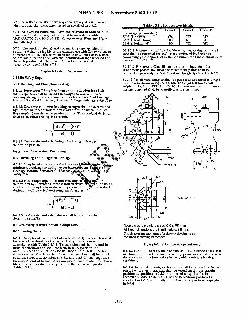
N F P A 1 9 8 3 ~ N o v e m b e r 2 0 0 0 R O P
5-7.3 New throwline shall have a specific gravity of less than one when dry and shall float when tested as specified in 6-6.2.
5-7.4 All dyed throwline shall have colorfastness to washing of at least Class 2 color change when tested in accordance with ANSI/AATCC Test Method 125, Colorfastness to Water and Light" Alternate Exposure.
5-7.5 The product label(s) and the marking tape specified in Section 3-6 shall be legible to the una ided eye with 20/20 vision, or corrected to 20/20, at a nominal distance of 30 cm (12 in.), bo th before and after the rope, with the identification tape inserted and the with product label(s) at tached, has been subjected to the washing test specified in 5-7.4.
Chapter 6 Testing Requirements
6-1 Life Safety Rope. i
6-1.1 Breaking and Elongation Testing.
6-1.1.1 Samples shall be taken f rom each product ion lot of life safety rope and shall be tested for, elongation and min imum
Table 6-3.1.1 Harness Test Matrix
Test (paragraph number )
6-3.2 (Uptight) 6-3.3 (Head Down) 6-3.4 (Horizontal)
Class I
YES NO NO
Class lI ,
YES NO YES
Class III
YES YES YES
6-3.1.1.1 If there are multiple load-bearing connect ing points, all tests shall be repeated for each combinat ion of load-bearing connect ing points specified in the manufacturer ' s instructions or ~,~ specified in 6-3.1.1.2.
6-3.1.1.2 For sample Class III harness that include shoulder a t tachment points, the shoulder a t t achment points shall be required to pass only the Static Test - - Upr ight specified in 6-3.2.
6-3.1.2 For all tests, samples shall be put on and secured to a rigid test torso as shown in Figure 6-3.1.2. The rigid test torso shall weigh 136 kg +1 kg (300 lb. +2.2 lb). The test torso with the sample harness at tached shall be identified as the test mass.
breaking strength in accordance with sections 8 and 9 of Cordage Institute Standard CI 1801-98 Low Stretch Kernmantle Life Safety Rope.
6-1.1.2 New rope min imum breaking s t rength shall be de te rmined by subtracting three standard deviations f rom the mean result of five samples fxom the same product ion lot. The s tandard deviation shall be calculated using the formula:
6-1.1.3 Test results and calculations shall be examined to de te~n ine pass/fall. ~ ! . . . . . .
• ~'3 :°" ""~~~ ~'.i: 6-2 Escape Rope System Component . .,,~ii~" ~:i~': %.':~#:"
~::~.;':':$..:-'-~:'~.:.. ...-/~:.:-~i..'.':'.-!~::,. ":~?, ~V ~" x : ! : : ~ : : . . . : : : : ~ - " ====================== ,
6-2.1 Breaking and Elongation Testing. -:~..::g.:.:.-,'-- -:~...-:.:. . .. "~::~.~ ~ " : ~ . . x : . ~ . : : : : : : : : : .%,
6-2.1.1 Samples of escape rope shall be t e s t e d . . . - ¢ ~ t a o n " ~ . . ~.,,...~. min imum breaking s t rength in acco rdance . ,~ t ions ~ _ 9 o f X ~ "~':" Cordage Institute S tandard CI 1801-98 L~.':::.~retch K e r d ~ t l e L ~ Sat'et~ RoOe ~"?.%~.. ".'.'~ -., - __• . -::!$~:?.!..--:.. ~.:-:.
• , . ":6:~ :~:::- " ~
6-21.2 New escape rope ~ . ,mum break,rig s t r ~ s ~ be dete rmined by subtracting three st :mdard d e v i a t i ~ ' ~ n the mean result of five samples f rom the same product ion l o ~ h e standard deviation shall be calculated using the formula: "::"
6-2.1.$ Test results and calculations shall be examined to de te rmine pass/fail.
6-$ Life Safety Harness System Component.
6~. 1 Testing Setup.
6-3.1.1 Samples of each model o f each life safety harness class shall be selected randomly and tested to the appropria te tests in accordance with Table 6-3.1.1. Test samples shall be new and in unused condit ion and shall conform in all respects to the manufacturer ' s specifications for the model to be tested• At least three samples of each model of each harness class shall be tested to all the static tests specified in 6-3.2 and 6-3.3 for the respective harness. A total of at least three samples of each model and class of life safety harness shall be requi red for the test series specified in Table 6-3.1.1.
° , !% , o •
~. " ~ii~;;-. ° _._ <:#"
x %%. ' ~#" \ ,_ 2,0 _ , j , _ ÷ ,o,,- i I o
~ ~ ~~/,.0 ''{~ E:~:::~:~i~" "X,~' ~ Lower L60ring I ~ I. 380 d
223
,~160 ~, I L5 0
..-15
Section X-X
48--~
Notes: Waist circumference at X-X is 750 ram. All l inear dimensions are in millimeters, + 5 mrn. The dimensions are those of a dummy developed by the UIAA for testing harnesses
Figure 6-3.1.2 Outline o f the test torso.
6-3.1.3 For all stadc tests, the test mass shall be at tached to the test machine at the load-beating connect ing point, in accordance with the manufacturer ' s instruction for use, with a suitable locking carabiner.
6-3.1.4 For all static tests, each sample shall be secured to the test torso, i.e., the test mass, and shall be tested first in the upright posit ion as specified in 6-3.2, then tested as applicable, in accordance with Table 6-3.1.1, in the head::down position as specified in 6-3.3, and finally in the horizontal pos idon as specified in 6-3.4.
1113
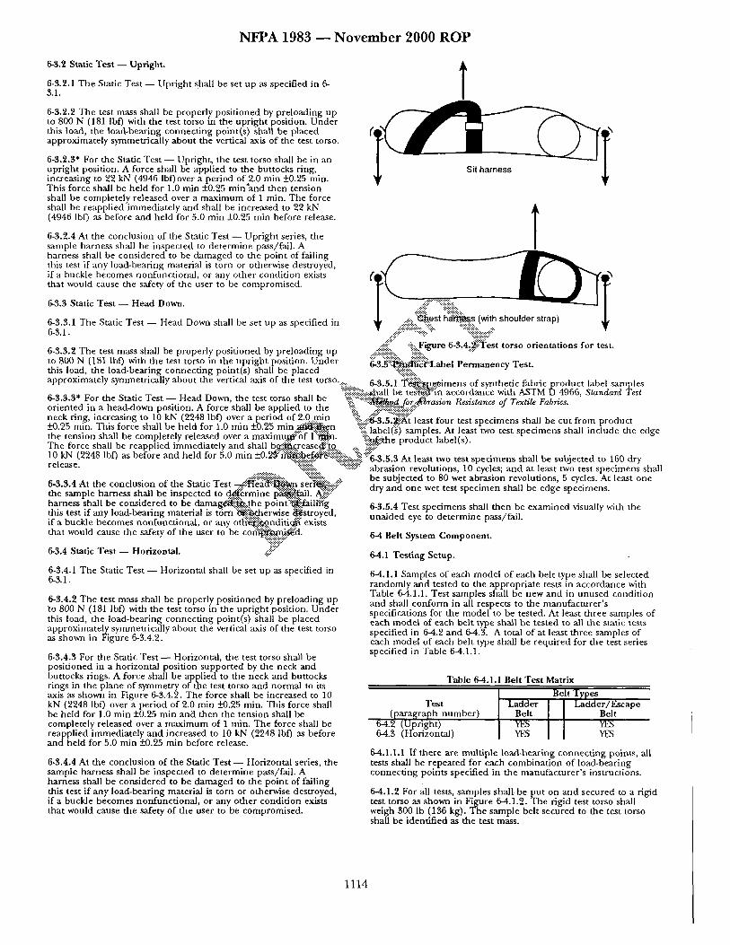
N F P A 1983 ~ N o v e m b e r 2 0 0 0 R O P
6-3.2 Static Test - - Upright.
6-3.2.1 The Static Test - - Upright shall be set up as specified in 6- 3.1.
6-3.2.2 The test mass shall be properly positioned by preloading up to 800 N (181 lbf) with the test torso in the upright position• Under this load, the load-bearing connecting point(s) shall be placed approximately symmetrically about the vertical axis of the test torso.
6-3.2.3* For the Static Test - - Upright, the test torso shall be in an upright position. A force shall be applied to the buttocks ring, increasing to 22 kN (4946 lbf)over a period of 2.0 min -+0.25 min. This force shall be held for 1.0 rain -+0.25 min~and then tension shall be completely released over a maximum of 1 min. The force shall be reapplied immediately and shall be increased to 22 kN (4946 lbf) as before and held for 5.0 rain -+0.25 min before release.
6-3.2.4 At the conclusion of the Static Test - - Upright series, the sample harness shall be inspected to determine pass/fail. A harness shall be considered to be damaged to the point of failing this test if any load-bearing material is torn or otherwise destroyed, if a buckle becomes nonfunctional, or any other condition exists that would cause the safety of the user to be compromised.
6-3.3 Static Test - - Head Down.
6-3.3.1 The Static Test - - Head Down shall be set up as specified in 6-3.1.
6-3.3.2 The test mass shall be properly positioned by preloading up to 800 N (181 lbf) with the test torso in the upright position. Under
t
T I ' I C e s (wit should strap) Lsio 4,Lto..i e.,.t,o°sfort t.
======================= i:i:i:i:x ~3.~:'-~N':c:~'itabel Permanency T e s t .
this load, the load-bearing connecting point(s) shall be placed "%i?:i::ii! .... approxamately symmemcally about the verucal ax~s of the test torso . . . . • .~ ...... 6-3.5.1 "Y/~i~.~.ff..e-imens of synthetic fabric p roduc t label samples . . . . , . . . . . . . . . . . . . . . :-'~"~:i::~laall be teg'~.@:'in accordance with ASTM D 4966, S t a n d a r d Test o-a.~.a f o r me ~tatlc l e s t - - Heaa Down, me test torso Sn~l De ========================== - - 2:iff ~ - ~ • - ~ ~ -.-- ~ - - . . . . __ ~ . :::~, " ' : t~ .~Z jor.:2~io'foAlo'rl, l~esls~ag"lc.g oJ 1 ex~it.$1"attics• oriented m a head-down posmon. A Iorce shall be applied to the ::~:: ::::::::::::::::::::::::::::::::: neckrin.g, increasing to 10 ,kN,(2748 l b 0 o v e r a, p eriod .of 2: .%~n ':}!L::ii~.~!f~::t'least four test specimens shall be cut from product -x-u.za mln. ln lS ioree snml De nel(1 Ior l .u mln xu.za rain 2~tt~-.~.e.n ".:-- •-:: - - . . . . . . . . . . . . :-.-.-.-, .-::.....:.:~ ::::.. label(s) samoles. At least two test s o e o m e n s shall include the edge me tension snaa ne completely . . . . releasea over a maxlmu.~'ot,::, l ~ . . . " "::::-:!..~.me- proau" [ct la'oett"s')• - The force shall be reapphed immediately and shall b~i:~.crease@:'tQ ::, ~:.i:i:i::" l0 kiN (2248 bf) as before and held for 5 0 min +0 2~::"~{~i:bef~i~iii!i-"."~-"."-'. ":- %..-'!i::" . . . . . . . . . . . t . . . . :me~o o~'all r.~ ~ub;e,,~a *o 160 dr-' • - " .. ~: . . . . . . . "':.-:i:Y.-:'..~::.:-.-:~:: 6 - 3 . 5 . 3 A t 1 . . . . . . . . . . v . . . . . . . . . . . . ,, . . . . . r release ":::::::; "-:-:::::::.-" • - - - • - . . . . . . . . . . • ...... abrasion revolutions, 10 cycles; and at least two test specimens shall
...... :::i,~.:: ...... ~ i i i i ~ i k , 6-3.3.4 .At the conclusion of the Static Test ~ ! . : '~~ i !~ . .~ . . s e ~ : the sample harness shall b e inspected to d~i~rmine p~...gail. A~" .... harness shall be considered to be d a m a g ~ - : : t h e point ' :~fail[h'g this test if any load-beating material is t~ ' rn" :~ i~erwise ~s t royed , if a buckle becomes nonfunctional, or any o ~ : ~ n d i t i ~ exists that would cause the safety of the user to be c o ~ . ~ ' d .
63.4 Static Test - - Horizontal. ...~ii~i! ....
6-3.4.1 The Stadc Test - - Horizontal shall be set up as specified in 6-3.1.
6-3.4.2 The test mass shall be properly positioned by preloading up to 800 N (181 lbf) with the test torso in the upright position. Under this load, the load-bearing connecting point(s) shall be placed approximately symmetrically about the vertical axis of the test torso as shown in Figure 6-3.4.2.
6-3.4.3 For the Static Test - - Horizontal, the test torso shall be positioned in a horizontal position supported by the neck and buttocks rings. A force shall be applied to the neck and buttocks rings in the plane of symmetry of the test torso and normal to its axis as shown in Figure 6-3.4.2. The force shall be increased to 10 kN (2248 lbf) over a period of 2.0 rain _-t-0.25 min. This force shall be held for 1.0 min -+0.25 min and then the tension shall be completely released over a max imum of I rain. The force shall be reapplied immediately and increased to 10 kN (2248 lbf) as before a n d h e l d for 5.0 rain -+0.25 min before release.
6-3.4.4 At the conclusion of the Static Test - - Horizontal series, the sample harness shall be inspected to determine pass/fall. A harness shall be considered to be damaged to the point of failing this test if any load-bearing material is torn or otherwise destroyed, if a buckle becomes nonfunctional , or any other condition exists that would cause the safety of the user to be compromised.
be subjected to 80 wet abrasion revolutions, 5 cycles. At least one dry and one wet test specimen shall be edge specimens•
6-3.5.4 Test specimens shall then be examined visually with the unaided eye to determine pass/fail.
6 - 4 B e l t S y s t e m C o m p o n e n t .
6-4.1 Testing Setup.
6-4.1.1 Samples of each model of each belt type shall be selected randomly and tested to the appropriate tests in accordance with Table 6-4.1.1. Test samples shall be new and in unused condition and shall conform in all respects to the manufacturer ' s specifications for the model to be tested• At least three samples of each model of each belt type shall be tested to all the static tests specified in 6-4.2 and 6-4.3. A total of at least three samples of each model of each belt type shall be required for the test series specified in Table 6-4.1.1.
T a b l e 6 - 4 . 1 . 1 B e l t T e s t Matrix
T e s t ~ ~ e s number ) Ladder [ I Ladder /Escape
6-4.3 (Horizontal) YES I [ YES
6-4.1.1.1 If there are multiple load-bearing connecting points, all tests shall be repeated for each combination of load-bearing connecting points specified in the manufacturer ' s instructions.
6-4.1.2 For all tests, samples shall, be Eut on and secured to a rigid test torso as shown in Figure 6-4.1.2. The rigld test torso shall weigh 300 lb (136 kg). The sample belt secured to the test torso shall be identified as the test mass.
1114
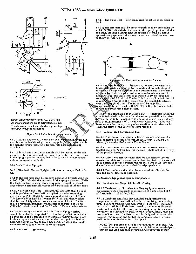
N F P A 1983 ~ N o v e m b e r 2 0 0 0 R O P
_ ~ 60 ~ 483 • 6-4.$.1 The Static T e s t - Horizontal shall be set up as specified in 64.1.
. I ~ I 6-4.$.2 The test mass shall be properly posi t ioned by preloading up tn to 800 N (181 lbf) with the test torso in the upr ight position. Under
' ~ - - ' - this load, the load-bearing connect ing point(s) shall he placed . . . . . approximately symmetrically about the vertical axis of the test torso
/~200 ~ as shown in Figure 6-4.3.2.
X \ I X / / o ~ \ , _ 280 , t
I _ o Section X-X
--'.-'...--.).:...:.. over a m ~ . ~ . ~ of 1 re.in. The force shall he reapplied ~ . ~!~:.-::i..g2gn. edlate!'~iN~id increased to 10 kN (2248 lbf) as before and held
I I ' I L ~ n • %":'::":~i'~4~,mit!~.'-~0.25 min before release. ~ ~!i!'. .-..:~-'~ .~ ~ : . : : ' ~ •
48---~ l~ l~n ~ L 1 5 ,...::.:..'...'...::.:, % ~ t . $ . ~ t the conclusion of the Static T e s t - Horizontal series, the "-- .d~::':'::::'%~i~i~i ::-ii-sampl'e belts shall be inspected to de te rmine ~p.~,.s/fail. A belt shall
Notes" Waist circumference at X-X is 750 mm ~!!" ].:..:~!? "~.i!~'.':tonsidered to be damaged to the point of ]ailing dais test if any . . . . . " . . . . . . . . . + - " :::'-":':"-".::.-.'-':".'-'-::. ~:::.'::<, "% ~'-]tad-bearing material is torn or otherwise destroyed if a buckle All l inear olmens~ons are In mi l l imeters o m m -:-.:: ":::::~:-:::::. ~:.:::':-::.-::. ::i:: ~:-
. . . . . ~:~$~$:.~::~ ":::-:~$~::':~:::::.:::':" becomes n o n f u n c u o n a l , o r any o t h e r c o n d l u o n exists t ha t w o u l d The d mens ons are those of a d u m m y deve loped by "~:i::. "~'::~:':~::':": cause the safew of the user to be comoromised the UIAA for testln 9 harnesses .... ..,:#iii':~:.., ": ~:....~. ..::., -- " "
.#:: . . . . . ~'.-.::, " : ~ " 6-4.4 Product Label Permanency Test. Figure 6-4.1.2 Outline of t ~ , s t torso. %i::ii!. At -::~
";Y '~""-"-':-"!i!i.'.-!~::.. %ii " 6-4.4.1 Test specimens of synthetic fabric product label samples 6-4.1.3 For all static tests, the test mass shall ~ i ~ - t a c h e d t.'~!;the test shall be tested in accordance with ASTM D 4966, Standard Test machine at the load-bearing connect ing point,'~i~:-:"-~gcor~ce with Method. for Abrasion Resistance of Textile Fabrics. the manufacturer ' s instruction for use, wath a s u i ~ J ~ c k i n g carabiner. ~'::~
6-4,1.4 For all static tests, each sample shall be secured to the test torso, i.e., the test mass, and each sample shall be tested twice, first in the upright position as specified in 6-4.2, t h e n in the horizontal position as specified in 6-4.3.
64.2 Static Test - - Upright.
6-4.4.2 At least four test specimens shall be cut f rom product label(s) samples. At least two test specimens shall include the edge of the product label(s).
6-4.4.3 At least two test specimens shall be subjected to 160 dry abrasion revolutions, 10 cycles; and at least two test specimens shall be subjected to 80 wet abrasion revolutions, 5 cycles. At least one dry and one wet test specimen shall be edge specimens.
6-4.2.1 The Static Test - - Upr ight shall be set up as specified in 6- 4.1.
6-4.4.4 Test specimens shall then be examined visually with the una ided eye to de termine pass/fail.
6-4.2.2 The test mass shall be properly posi t ioned by preloading up to 800 N (181 lbf) with the test torso m the upr ight position. U n d e r this load, the load-bearing connect ing point(s) shall be placed approximately symmetrically about the vertical axis o f the test torso.
6-4.2.3* For the Static Test - - Upright, the test torso shall be in an upright position. A force shall be applied to the buttocks ring, increasing to 13 kN (2923 lbf) over a per iod 6f 2.0 min i~0.25 min. This force shall be he ld for 1.0 min +0.25 min and then tension shall be completely released over a maximum of I rain. The force shall be reapplied immediately and shall be increased to 13 kN (2923 lbf) as before and he ld for 5.0 min +0.25 rain before release.
6-4.2.4 At the conclusion of the Static Test - - Upr ight series, sample belts shall be inspected to de te rmine pass/fail. A belt shall be considered to be damaged to the point of failing this test if any loa~]-bearing material is torn or otherwise destroyed, if a buckle becomes nonfunct ional , or any other condi t ion exists that would cause the safety of the user to be compromised.
64.3 Static T e s t - Horizontal.
6-5 Auxiliary Equipment System Components.
6-5.1 Carabiner and Snap-Link Tensile Testing.
6-5.1.1 Carabiner and Snap-link Auxiliary equ ipment system componen t tensile tests shall he conducted at a rate of pull of 3 +0.5 c m / m i n ( 1.18 +.2 in . /min) .
6-5.1.2 Carabiner and Snap-link Auxiliary equ ipmen t system componen t tensile tests shall be 'conducted utilizing non-rotat ing pins. Test pins .must be AISI SAE Type 01 Tool Steel (commonly purchased as 01 Drill Rod) hea t t reated to a min imum Rockwell hardness, C scale 60. The mean surface roughness, Ra, must not exceed 0.8 microns and the peak to valley height, Rmax, must not exceed 6.3 microns. The fixture must be designed to prevent the test pins from rotating and so that the carabiner is free to locate i tself on the test pins when force is applied.
NOTE: Test pin cross section is no t required to be round. Any cross-section necessary to prevent test pin failure or any design to prevent test pin rotation is acceptable, as long as the contact
1115
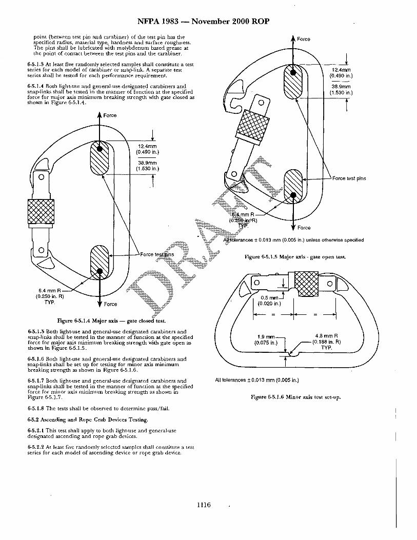
N F P A 1983 ~ N o v e m b e r 2 0 0 0 R O P
point (between test pin and carabiner) of the test pin has the SlPhecified radius, material type, hardness and surface roughness.
e pins shall be lubricated with molybdenum based grease at the point of contact between the test pins and the carabiner.
6-5.1.3 At least five randomly selected samples shall constitute a test series for each model of carabiner or snap-link. A separate test series shall be tested for each performance requirement .
6-5.1.4 Both light-use and general-use.designated carabiners and snap-links shall be tested in the manne r of function at the specified force for major axis min imum breaking strength with gate closed as shown in Figure 6-5.1.4.
12.4mm (0.490 in.)
I 38.9mm (1.530 in.)
l
\ 12.4mrn
(0.490 in.)
38.9mm (1.530 in.)
\ _ ~ Force test pins
\ / %ii!::!::!!~! ........
%'::-i~ii::i::i e % ~":.!-::i~iiii!i~i~i~!~i:!::.:.:.::C
........ " "~-:...::#-::: "#,:~lorancos _ 0.013 mm (0.005 in.) unless otherwise specified
Force tes(tii~ns :.::::::::i! ~::~¢:" . . .... -.':.':i~:~.:: . . . . . . . ~" ................ -:'.--.:...::.-:i~i::: Figure 6-5.1.5 Major axis - gate open test.
, ...... ii~iii::i::i:?:i::i::i!!!:~ ...... "%::::~!i~ ... . . . t~
¢::i~i£i:." ' %
Figure 6-5.1.4 Major axis - - gate closed" test.
6-5.1.5 Both light-use and general-use designated carabiners and I I . . . . . . . ~ snap-links shall be tested in the manne r of function at the specified [ I 1.9 m m - - - - I ,~,o m.m ~ , ] I force for major axis min imum breaking strength with gate open as ~ ~ (0.075 in.) I / (U.l~.=n. ~) ] /
6-5.1.6 Both light-use and general-use designated carabiners and ~ ~ snap-links shall be set up for testing for minor axis min imum breaking strength as shown in Figure 6-5.1.6.
6-5.1.7 Both light-use and general-use designated carabiners and snap-links shall be tested in the manne r of function at the specified force for minor axis min imum breaking strength as shown in Figure 6-5.1.7.
6-5.1.8 The tests shall be observed to de termine pass/fail.
6-5.2 Ascending and Rope Grab Devices Testing.
6-5.2.1 This test shall apply to both light-use and general-use designated ascending and rope grab devices.
6-5.2.2 At least five randomly selected samples shall constitute a test series for each model of ascending device or rope grab device.
All tolerances + 0.013 mm (0.005 in.)
Figure 6-5.1.6 Minor axis test set-up.
1116
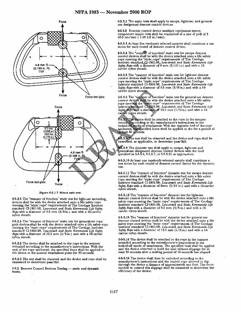
N F P A 1983 - - N o v e m b e r 2000 R O P
Force
r
Force Force test pins
Force
1
9.3 mm .(0.365 in.)
19.6 mm (0.770 in.)
4.8 mm R
Force test pins • Force
Figure 6-5.1.7 Minor axis test.
6-5.2.3 The "manner of function" static test for light-use ascending. devices shall be with the device attached onto a life safety rope meeting the "static rope" requirements of The Cordage Institute standard CI-1801-98, Low-stretch and Static Kernmantle Life Safety Rope with a diameter of 9.5 mm (3/8-in.) and with a 16-carrier nylon sheath.
6.5.2.4 The "manner of function" static test for general-use rope ' grab devices.shall be with the device attached onto a life safety rope meeting the "static rope" requirements of The Cordage Institute standard CI-1801-98, l_xm~stretch dnd Static Kcrnmantle Life Safety Rope with a diameter of 12.5 mm (1/2-in.) and with a 16-carrier nylon sheath.
6.5,2.5 The device shall be attached to the rope in the manner intended according to the manufacturer's instructions. With the end of the rope anchored, the specified force shall be applied to the device at the normal attachment point for 30 seconds.
6-5.2.6 The test shall be observed and the device and rope shall be examined to determine pass/fall.
6-5,3 Descent Control Devices Tes t ing- - s ta t i c and dynamic loads.
6-5.3.1 The static tests shall apply to escape, light-use, and general-' use designated descent control devices.
6-5.3.2 Descent control device auxiliary equipment system component tensile tests shall be conducted :at a rate of pull of 3 i-0.5 cm/min ( 1.18 +--2 in./min).
6-5.3.3 At least five randomly selected samples shall constitute a test series for each model of descent control device.
6-5.3.4 The : 'rnann~ of function" static test for escape descent control devices shall be with the device attached onto a life safety rope meeting the "static rope" requirements of The Cordage Institute standard~C~I-1801~98~ Low-stretch and Static Kernmantle Life Safety Ropewiih a diameter of 8 mm (5/16 ia.) and with a 16- carrier nylon sheath.
6-5.$.5 The "manner of function" static test for light-use descent control devices shall be with the device attached onto a life safety rope meeting the "static rope" requirements of The Cordage Institute standard C1-1801-98, Low-stretch and Static Kernmantle Life Safety Rope with a diameter of 9.5 mm ($/8-iin.) and with a 16- carrier nylon s h e ~ . .
: : : : . ' : - - - - ~ : : ~ > .
6.5.3.6 The " ~ e r o~:~unction" static test for general-use descent con~wol d e v i . . ~ " : ~ be with the device attached onto a life safety rope meeti~..~ t h e : : ~ c rope" requirements of The Cordage Institul~i~[..~a..rd ~:+.."~1-98, Low-stretch and Static Kernmantle Life Safe~.¢~::"~ 'a diaffi :~:: .~ 12.5 mm (1/2-in.) and with a 16- ~ r ny:lon sheath. ~-~ .........
I~ "~!~'~+':~" ~ , - v ~ _i._ ~" shall '~#" :o~-~gr '~ t~ce be attached to the rope in the manner in ten~.~cco ' rd ing to the manufacturer's imtructions in the l o c k e d - ~ d ~ o f attachment. With the opposite end of the rope m c h o r e d , : ~ i e c i f i e d force shall be applied to the for a period of
50 ~ b n d s .
l~" test shall be observed and the device and rope shall be .'d, as applicable, to determine pass/fail.
~*.3.9 The dynamic test slaall apply to escape, light-use and metal-use designated descent control devices with the load ~ecified in 5-5.3.4, 5-5.$.7, or 5-5.3.10 as appropriate.
6-5.3.10 At least one randomly selected sample shall constitute a test series for each model of descent control device for the dynamic test.
6.5.3.11 The "manner of function" dynamic test for escape descent control devices shall be with the device attached onto a life safety rope meeting the "static rope" requiremenu of The Cordage Institute standard CI-1801-98, Low-strach and Static Kernmantle Life Safety Rope with a diameter of 8ram (5/16 in.) and with a 16-carrier nylon sheath.
6.5.3.12 The "manner of function" dynamic test for light-use descent control devices shall be with the device attached onto a life safety rope meeting the "static rope" requirements of The. Cordage Institute standard CI-1801-98, Low-stretch a~d Static Kernmantle Life Safety Rope with a diameter of 9.5 mm (3/8-in.) and with a 16- carrier nylon sheath.
6-5.3.13 The "manner of function" dynamic test for general-use descent control devices shall be with the de'rice attached onto a life safety rope meeting the "static rope" requirements of The Cordage Institute standard CI-1801-98, Low-stretch a~d Static Kernmantle Life Safety Rope with a diameter of 12.5 mm (1/2-in.) and with a 16- carrier nylon sheath.
6-5-$.14 The device shall be attached to the rope in the manner intended accordin~ to the manufacturer's instructions in the locked-off mode or attachment. The specified load shall be applied and the device observed to hold the load without slippage for at least 30 seconds after a settling period of 10 seconds has elapsed.
6-5-3.15 The device shall then be unlocked according to the manufacturer's instructions and the loaded rope allowed to slip through the device a distance of approximately one foot. The force needed to control this slippage shall be me~Lsured to determine the efficiency of the device.
1117
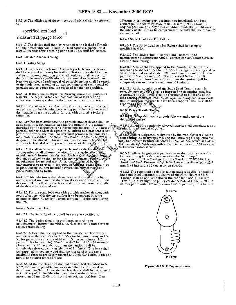
N F P A 1983 ~ N o v e m b e r 2 0 0 0 R O P
6-5.3.16 The efficiency of descen t control devices shall be expressed a s :
specified test load :1
measured slippage force
6-5-3.17 The device shall then be r e tu rned to the locked-off m o d e and the device observed to ho ld the load without sl ippage for at least 30 seconds after a set t l ing per iod of 10 seconds has elapsed.
6-5.4 Portable Anchor Test ing.
6-5.4.1 Testing Setup.
6-5.4.1.1 Samples of each mode l of each portable ancho r device shall be selected r andomly for testing. Test samples shall be new and in an u n u s e d condi t ion a n d shall conform in all respects to the manufac tu re r ' s specifications for the mode l to be tested. At least two samples of each mode l of portable ancho r shall be tested to the stadc tests. A total of at least two samples of each mode l of portable ancho r device shall be requi red for the test specified.
6-5.4.1.2 If the re are mul t ip le load-bearing connec t ion points , all tests shall be repea ted for each combina t ion of load-bearing connec t ing points specified in the manufac tu re r ' s instructions.
6-5.4.1.3 For all static tests, the device shall be a t tached to the test mach ine at the load-bear ing connec t ing point, in accordance with the manu fac tu r e r ' s instruct ions for use, with a suitable locking carabiner.
ad jus tmen t or moving part becomes non-funct ional , any base contact po in t de~4ates by more than 150 m m (5.9 in.) f rom its original position, or if any o ther condi t ion exists that would cause the safety of the user to be compromised . Results shall be repor ted as pass or fail.
6-5.4.3 Static Load Tes t For Failure.
6-5.4.3.1 The Static Load test For Failure shall be set up as specified in 6-5.4.
6-5.4.3.2 The device shou ld be pos i t ioned accord ing t8 manufac tu re r ' s ins t ruct ions with all surface contac t points securely seated before testing.
6-5.4.3.3 A force shall be appl ied to the portable anchor device, increas ing to the load specified in 5-5.7.2 for light-use testing and 5- 5.8.2 for genera l use at a rate of 30 m m _+5 m m per minu te (1.2 in. per rain x'-0.2 in. per minu te ) . T h e force shall be he ld for B0 seconds plus or m inus 1 second, and t h e n the t ens ion shall be completely re leased over a m a x i m u m of I minu te .
6-5.4.3.4 At the co.~...e-.I.usion of the Stadc Load Test, the sample portable a n c h o r . . ~ , s . h a l l be inspec ted to de te rmine pass/fail . A portable an.c.~.r devi~: shall he cons idered to fail if any of the load-bearin~i-~'~.~J~9.rs fracture, collapse, or if any condi t ion exists tha t would.::~use ~...:~Jser to have been d ropped . Results shall be r e p o r t e ~ i ~ f ' ~ o r ' ~ ! : : . .
6 -5......~. 'ii::P u .B:..ey"T e n sil e T~:g.
~"-'5"!~i?.'-T.l~i~ii~:st shall apply to both light-use and general-use d e s i ~ : : . p u h eys.
6-5.4.1.4" For both static tests, the portable ancho r device shall be posi t ioned on a fiat, unf in i shed concrete surface in the m a n n e r 9iiiii::ii!~ ...... 6-5 5 2 At -~* ' - :~ve r andomly selected samples shall consti tute a test descr ibed by the manufac tu re r ' s ins t ruct ions for use. In the case oi :~i::::!:!.-'.-~!~es for e ~ mode l of hul ler portable a n c h o r devices des igned to be affixed to a base tha t is no t "~iii. '":':%i::::-::i::i::ii:i!:i::.:.:.::!ii! . . . . . . " part of the device the manu t ac t u r e r mus t provide a test base that ':~: :" ":':~":::" d " n te i h b" *~'~ m a n "'c . . . . . . . . r.~,~ ~.~ , :-:- :.~5.5..:-~-ulleys es g a d as 1 ~ t-use y . . . . . . . . . . . . . . . . . . . . mos t closely resembles the structural e l emen t to which th .ec.:~.:r,,e. is :ii::i!::'tested:;iusing life safety rope me'et ing the "static rope" r eau i r emen t s des igned to be affixed. This test base mus t be complet~::~'ta[6l~..".:. :iiii:.of..The Cordage Insti tute S tandard CI-1801-98, Low Stretch and Static and may be bolted down to prevent m o v e m e n t durin.g..~e, test..:ii?:i:.i . . . . . . . . . . ":.ii~nrnantle Life Safety Rope with a d iamete r of 9.5 m m (3 /8 in.) and
• :?:::'"::~:.."&::......-ii'.":'::-:~:'..':'-,.. ":i~:~.-:~ 1 6-carrier nylon sheath. 6-5.4.1.5 For all static tests, the portable ancho r device s ~ i i ~ "':~.:':':
6-5.5.4 Pulleys des igna ted as general-use by the manufac tu re r shall be tested us ing life safety rope mee t ing the "static rope" r equ i rements of The Cordage Inst i tute S tandard C1-1801-98, Low Stretch and Static Kernmantle Life Safety Rope with a d iamete r of 12.5 m m (1 /2 in.) and a 16-carrier nylon shea- th.
accompanied by all adjuncts required for use a~,..:~:~bed'~i~.~.e manufacturer's instructions for use. Devices..~1"l:':~ii.~,. boli~,::.:.::i!~:" tied off, or affixed to the test base in any w.....~::'ianless r ~ . . e d b ) ; ' !~ manufac tu re r for no rma l use. All adjun.~::::~..C..sigued by"'.~.~ .:~i .... m a n u f a c t u r e r to be used in c o n j u n c t i o n " : ~ i ~ device ~ b u l d be in place du r ing the test inc luding ropes, chai'~::i~.ebbin~::i.~ope grabs, bolts, a n d so forth. ":-'i~':-'~::. ..:~!~::
6-5.4.1.6" Manufacl~urers shall des ignate the device .~%i ther l ight use or genera l use based on the weakest extension'::~or which it was designed. This will allow the tests to show the m i n i m u m s t rength of the device for its ra ted use.
6-5.4.1.7 For the static load test with portable anchor devices, each po in t of contact with the test surface is to be marked in some m a n n e r to allow the ability to assess m o v e m e n t of the base du r ing the test.
6-5.4.2 Static Load Test .
6-5.4.2.1 The Static Load Test shall be set up as specified in
6-5.4.2.2 The device shou ld be posi t ioned according to manufac tu re r ' s ins t ruct ions with all surface contact points securely seated before testing.
6-5.4.2.3 A force shall be applied to the portable a n c h o r device, increas ing to the load specified in 5-5.7 for light-use test ing and 5- 5.8 for general use at a rate of 30 m m +5 m m per minu te (1.2 in. per min -+0.2 in. per rain). The force shall be held for 30 seconds plus or minus 1.0 seconds, and then the tens ion shall be completely released over a m a x i m u m of 1 minute . The force shall be reappl ied immedia te ly and shall be increased to the same m a x i m u m force as previously exer ted and held for 1 m i nu t e plus or m i n u s 15 seconds before i'elease.
6-5.4.2.4 At the conclus ion of the Static Load Test descr ibed in 6- 5.4.2, the sample portable ancho r device shall be inspected to de t e rmine pass/fai l . A portable ancho r device shall be cons idered to fail if any of the load-bear ing m e m b e r s remain deflected by more than 25 m m (0.98 in.) f rom their original position, If an
6-5.5.5 The rope shall be tied in a loop us ing a double f i sherman ' s knot and looped a r o u n d the sheave as shown in Figure 6-5.5.5. Tens ion shall be appl ied between the rope loop and a 12.5 m m (1 /2 in.) p in t h rough the pulley carabiner hole at a rate of 30 m m +_5 m m per m inu t e (1.2 in. pe r rain +0.2 in. per rain) until failure.
Force
Figure 6-5.5.5 Pulley tensile test.
1118
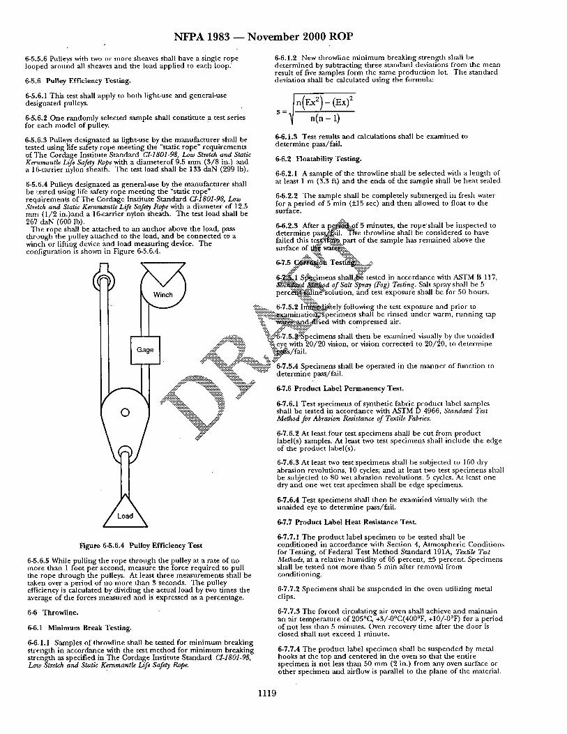
N F P A 1983 ~ N o v e m b e r 2 0 0 0 R O P
6-5.5.6 Pulleys with two or more sheaves shall have a single rope looped a round all sheaves and the load applied to each loop.
6-5.6 Pulley Efficiency Testing.
6-5.6.1 This test shall apply to both light-use and general-use designated pulleys.
6-5.6.2 One randomly selected sample shall constitute a test series for each model of pulley.
6-5.6.3 Pulleys designated as light-use by the manufacturer shall be tested using life safety rope meet ing the "static rope" requirements of The Cordage Institute Standard CI-1801-98, Low Stretch and Static Ker.nmantIe Life Safety Rope with a d iameterof 9.5 m m (3/8 in.) and a 16-carrier nylon sheath. The test load shall be 133 daN (299 Ib).
6-5.6.4 Pulleys designated as general-use by the manufacturer shall be r.ested using life safety rope meet ing the "static rope" requirements of The Cordage Institute Standard CI-1801-98, Low Stretch and Static Kernmantle Life Safety Rope with a d iameter of 12.5 mrn (1 /2 in . )and a 16-carrier nylon sheath. The test load shall be 267 daN (600 lb).
The rope shall be at tached to an anchor above the load, pass through the pulley at tached to the load, and be connected to a winch or lifting device and load measuring device. The configuration is shown in Figure 6-5.6.4.
O
Figure 6-5.6.4 Pulley Efficiency Test
..... ~i~i."..~. ":':~:.ii ""g ....:.>:.......:.:~ ,:,':." ,::!:'~.-:::,
6-5.6.5 While pulling the rope th rough the pulley at a rate of no more than 1 foot per second, measure the force required to pull the rope through the pulleys. At least three measurements shall be taken over a per iod of no more than 3 seconds. The pulley efficiency is calculated by dividing the actual load by two times the average of the forces measured and is expressed as a percentage.
6-6 Throwline.
6-6.1 Minimum Break Testing.
6-6,.1.1 Samples of throwline shall be tested for min imum breaking s t rength in accordance with the test me thod for min imum breaking strength as specified in The Cordage Institute Standard CI-1801-98, Low Stretch and Static K~famantle Life Safety Rope.
6-6.1.2 New throwline minimum breaking strength shall be de te rmined by subtracting three s tandard deviations from the mean result of five samples .form the same product ion lot. The standard deviation shall be calculated using the formula:
6-6.1.3 Test results and calculations shall be examined to de te rmine pass/faiL
6-6.2 FloatabUity Testing.
6-6.2.1 A sample of the throwline shall be selected with a length of at least 1 m (3.3 ft) and the ends of the sarnple shall be hea t sealed.
6-6.2.2 The sample shall be completely submerged in fresh water for a per iod of 5 min (+15 sec) and then allowed to float to the surface.
6-6.2.3 After a p~ . . : .p . . f 5 minutes, the ropesha l l be inspected to de termine p a r b o i l . T N e throwline shall be considered to have failed this t ~ . part of the sample has remained above the surface of ~ " ~ i ~ i : : ,
6-7.5 ~ a T est~!ii~i~::::~_-;':.
6-~K1 S~.c.imens shall.~.~ tested in accord~mce with ASTM B 117, a ~ . . d ~ o d of Salt Spray (Fog) Testing. Salt spray shall be 5 p e r c ~ " i " : ' s o l u t i o n , and test exposure shall be for 50 hours.
:!:.::-:................. 6-7.5.2 I ~ t e l y following the test exposure and pr ior to "%ii::i::::::iiii::-i~..g~..minado~iigpecimens shall be rinsed under warm, runn ing tap ":i!!!:: " ' : ~ i i ~ , ~ . ~ i e d with compressed air.
..... ::.-.'i::::.:.. ':~iii'-:."~-7.5.~i~'pecimens shall then be examined visually by the unaided .-:~:'::::":~".'i ':!ii-: eye with 20/20 vision, or vision corrected to 20/20, to de termine
.-:-'::ii~" :.i~i i!: " : ~ g / f a i l . .~::""-::!~t..:~ .::~.'.::.'.::.;.'i~i-..~.~. -...:~.-.-.::~ . . . "~":':.:'~i~i~:.:"U ":!i.i~ii~-.iiii~i:: 6-7.5.4 Speomens shall be opera ted m the manne r ot funcuon to
":":":':" "':':':"~ de termine pass/fail.
6-7.6 Product Label Permanency Test.
6-7.6.1 Test specimens of synthetic f ab r i cp roduc t label samples shall be tested in accordance with ASTM D 4966, Standard Test Method for Abrasion Resistance of Textile Fabrics.
6-7.6.2 At least four test specimens shall be cut f rom product label(s) samples. At least two test specimens shall include the edge of the product label(s).
6-7.6.3 At least two test specimens shall be subjected to 160 dry abrasion revolutions, 10 cycles; and at least two test specimens shall be subjected to 80 wet abrasion revolutions, 5 cycles. At least one dry and one wet test specimen shall be edge specimens.
6-7.6.4 Test specimens shall then be examirled visually with the una ided eye to de te rmine pass/fail.
6-7.7 Product Label Heat Resistance Test.
6-7.7.1 The product label specimen to be tested shall be condi t ioned in accordance with Section 4, Atmospher ic Condition:; for Testing, of Federal Test Method Standard 191A, Textile Test Methods, at a relative humidity of 65 percent , +_.5 percent. Specimens shall be tested no t more than 5 rain after removal f rom conditioning.
6-7.7.2 Specimens shall be suspended in the oven utilizing metal clips.
6-7.7.3 The forced circulating air oven shall achieve and maintain an air tempera ture of 205°C, +3/-0°C(400°F, +10/-0°F) for a period of not less than 5 minutes. Oven recovery time after the door is closed shall not exceed 1 minute.
6-7.7.4 The product label specimen shall be suspended by metal hooks at the top and centered in the oven so that the entire specimen is no t less than 50 mm (2 in.) f rom any oven surface or other specimen and airflow is parallel to the plane of the material.
1119
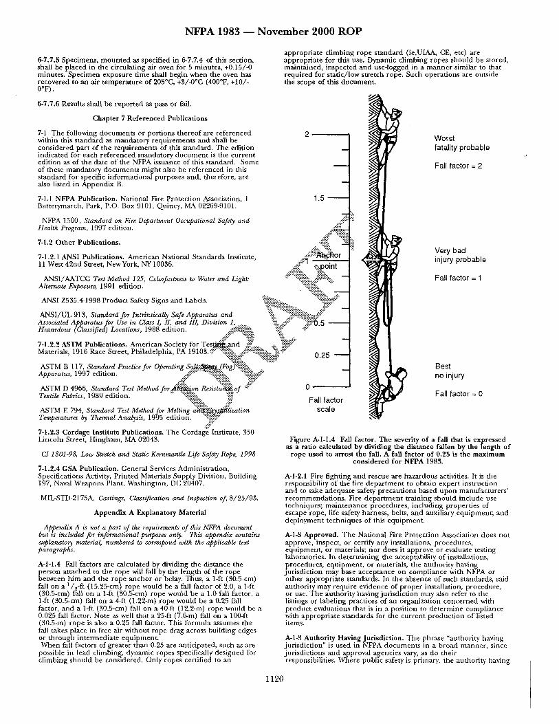
N F P A 1983 - - N o v e m b e r 2 0 0 0 R O P
6-7.7.5 Specimens, m oun ted as specified in 6-7.7.4 of this section, shall be placed in the circulating air oven for 5 minutes, +0.15/-0 minutes. Specimen exposure t ime shall begin when the oven has recovered to an air tempera ture of 205°G, +3/-0°C (400°F, +10/- 0°F).
6-7.7.6 Results shall be repor ted as pass or fail.
Chapter 7 Referenced Publications
7-1 The following documents or port ions the reof are referenced 2 within this s tandard as mandatory requirements and shall be considered part of the requirements of this standard. The edit ion indicated for each referenced mandatory document is the current edition as of the date of the NFPA issuance of this standard. Some of these mandatory documents might also be referenced in this s tandard for specific informational purposes and, therefore, are also listed in Appendix B.
7-1.1 NFPA Publication. National Fire Protect ion Association, 1 1.5 Batterymarch, Park, P.O. Box 9101, Quincy, MA 02269-9101.
NFPA 1500, Standard on Fire Department Occupational Safety and .:.-:';::-'- Health Program, 1997 edition. ..:?:!!!!!i!: .....
7-1.2 Other Publications. ., ":~ii:"":?-:~"::: :--:~
7-1.2.1 ANSI Publications. American National Standards Institute, ..::!!~i::::~or 11 West 42nd Street, NewYork, NY10036. ...::#:ii~:~.!. "" ii::~l ,:ii:~:.p. .oint
ANSI/AATCC Test Method 125, Colorfastness to Water and Light: Alternate Exposure, 1991 edition.
ANSI Z535.4-1998 Product Safety Signs and Labels. "~:Y~:i: ....... ~iiii!!i~!::!!ii!::!i!~!~:~ ........ ili::i~i~:: _
ANSI/UL 913, Standard for Intrinsically Safe Apparatus and :'~iii. "":'::~i~!Ji~i~:k~:f ::" Associated Apparatus for Use in Class I, II, and III, Division 1 ........ ":-::i:...::iii! . . . . . . i~iiii':~).5 - Hazardous (Classified)Locations, 1988 edition. ....J!i~i~i..-'..-'~... "iiii::." -:i ....
7-1.2.2 ASTM Publications. American Society for T e s ~ i : . a n d ~ - ..... 4:.. ~":~!::" Materials, 1916 Race Street, Philadelphia, PA 19105..:U-::::?.."?:.~!:-).~::..,.:.:i~:-%:::...,:."::i?~. -'-~ 0 P5
A S T M B 117, Standard Praoti.for Opiating Saa.:~.~.(Fog:'fii~i~ii~: " ......... Apparatus, 1997 edition. ..::i:;::'-"-'-" "::::::~:~:~i~::.. ":::i!ii~!!i~::.:.::~i::" --
~::...~i~ ~ .... %ii~!~i:~, "!iiiiY ASTM D 4966, Standard Test Method f o r . ~ v . n Resista'~of -:U 0 Textile Fabn'cs, 1989 edition. '" "::~ii!::~iiiii .... ':::i::i::! Fall factor
ASTM E 794, Standard Test Method for Melting a ~ ! i ~ l i z a t i o n sca l e Temperatures by Thermal Analysis, 1995 edition. ""'?~-"::"
.f::. 7-1.2.3 Cordage Institute Publications. The Cordage Institute, 350 Lincoln Street, Hingham, MA 0204?,.
CI 180108, Low Stretch and Static Kernrnantle Life Safety Rope, 1998
7-1.2.4 GSA Publication. General Services Administration, Specifications Activity, Printed Materials Supply Division, Building 197, Naval Weapons Plant, Washington, DC 20407.
M IL-STD-2175A, Ca.~tings, Classification and Inspection of, 8/25/93.
Appendix A Explanatory Material
Appendix A is not a part of the requirements of this NFPA document but w included for informational purposes only. This appendix contains explanatory material, numbered to correspond with the applicable text paragraphs.
A-l-l .4 Fall "factors are calculated by dividing the distance the person attached to the rope will fall by the length of the rope between him and the rope anchor or belay. Thus, a 1-ft (30.5-cm) fall on a a/~-ft (15.25-cm) rope would be a fall factor of 2.0, a 1-ft (~,0.5-cm) fall on a 1-ft (50.5-cm) rope would be a 1.0 fall factor, a 1-ft (30.5-cm) fall on a 4-ft (1.22-m) rope would be a 0.25 fall factor, and a 1-ft (30.5-cm) fall on a 40-ft (12.2-m) rope would be a 0.025 fall factor. Note as well that a 25-ft (7.6-m) fall on a 100-ft (30.5-m) rope is also a 0.25 fall factor. This formula assumes the fall takes place in free air without rope drag across building edges or through intermediate equipment . When fall factors of greater than 0.25 are anticipated, such as are
possible in lead climbing, dynamic ropes specifically designed for climbing should be considered. Only ropes certified to an
appropriate climbing rope s tandard (ie,UIAA, CE, etc) are appropriate for this use. Dynamic cl imbing ropes should be stored, maintained, inspected and useqogged in a manne r similar to that required for static/ low stretch rope. Such operat ions are outside the scope of this document .
Worst fatal i ty probable
Fall factor = 2
Very bad injury probable
Fall factor = 1
Best no injury
Fall factor = 0
Figure A-l-I.4 Fall factor. The severity of a fall that is expressed as a ratio calculated by dividing the distance fallen by the length of
rope used to arrest the fall. A fall factor o f 0.25 is the maximum considered for NFPA 1983.
A-I-2.1 Fire fighting and rescue are hazardous activities. It is the responsibility of the fire depa r tmen t to obtain exper t instruction and to take adequate safety precautions based upon manufacturers ' recommendat ions . Fire depa r tmen t t raining should include use techniques; main tenance procedures, including propert ies of escape rope, life safety harness, belts, and auxiliary equipment; and deployment techniques of this equipment .
A-I-3 Approved. The National Fire Protect ion Association does not approve, inspect, or certify any installations, procedures, equipment , or materials; nor does it approve or evaluate testing laboratories. In de te rmin ing the acceptability of installations, procedures, equipment , or materials, the authority having jurisdict ion may base acceptance on compliance with NFPA or other appropria te standards. In file absence of such standards, said authority may require evidence of p roper installation, procedure, or use. The authority having jurisdiction may also refer to the listings or labeling practices of an organization concerned with product evaluations that is in a position to de termine compliance with appropriate standards for the current product ion of listed items.
A-l-3 Authority Having Jurisdiction. The phrase "authority having jurisdict ion" is used in NFPA documents in a broad manner , since jurisdictions and approval agencies vary, as do their responsibilities. Where public safety is primary, the authority having
1120
N F P A 1 9 8 3 ~ N o v e m b e r 2 0 0 0 R O P
jurisdiction may be a federal, state, local, or o ther regional depar tment or individual such as a fire chief; fire marshal; chief of a fire prevention bureau, labor depar tment , or health depar tment ; building official; electrical inspector;, or others having statutory authority. For insurance purposes, an insurance inspection depar tment , rating bureau, or other insurance company representative may be the authority having jurisdiction. In many circumstances, the property owner or his or her designated agent assumes the role of the authority having jurisdiction; at government installations, the command ing officer or depar tmenta l official may he the authority having jurisdiction.
A-l-3 Fall Factor. See A-l-l.4.
A-I-3 Listed. The means for identifying listed equipment may vary for each organization concerned with product evaluation, some of which do not recognize equ ipmen t as listed unless it is also labeled. The authority having jurisdict ion should utilize the system employed by the listing organization to identify a listed product.
Ao2-2.1 The certification organization should have sufficient breadth of interest and activity so that the loss or award of a
should provide a history of each rope, and should call for regular inspection and replacement as necessary. Any rope that fails to pass inspection or has been impact loaded should be destroyed immediately.
It is highly r e c o m m e n d e d that depar tments establish an inspection program and shelf life criteria for their ropes based on the conditions and environments encounte red in their respective operations. It is highly r e c o m m e n d e d that training ropes and rescue ropes be
separate ropes. The destruction of rope means that it should be removed from
service and al tered in such a manner that it. could no t mistakenly be used as a life safety rope. This could include disposal or removal of label and cutting into short length to be used for utility purposes.
A-3-2.1 Information useful to the purchaser that applies to a particular rope could be added to the tape.
A-3-2.2 When escape rope is purchased, the purchaser or the authority having jurisdict ion should ensure that a product label with the information as specified in 3-2.2 is at tached and remains
specific business contract would no t be a de te rmin ing factor in the with the rope unti.l:.~..].aced in service. This label should be retained financial well-being of the agency, ei ther in the a u ~ . a . : . y o p e records or with the user of the rope
for reference. ~2-:.-..:.. """ . - . "4 " : ' ; ; ' ~ : : ; : : ~ -. . . A-2-2.3 The contractual provisions covering certification programs • Escape r o p . ~ : a s : ~ p d e d only for emergency self-rescue sttuatwns and
should contain clauses advising the manufacturer that, if cannot be . ~ . d ft~.: : :~er rope rescue situations. Escape rope is requirements change, the product should be brought into designe~.9...~":'~.ne us~:'.-'~y an.d must be destroyed after any use. compliance with the new requirements by a stated effective date E s c a ~ / 5 ~ " l ~ intend~-.t..@..'::be carried by a fire fighter, or other th rough a compliance review program involving all currendy listed em:...g...~enf, ff. services personnel , so that it will be available in products. Without the clauses, certifiers would no t be able to move ~ . c i p ~ d situata~on~;'¢:"~rom which self-rescue using the rope is quickly to protect their name, marks, or reputation. A product h~ae":~.~.~.,...~'~i~. Therefore, the escape rope should be carefully safety certification program would be deficient without these stored[::~"~, periodically inspected by a qualified person to ensure contractual provisions and the administrative means to back them .,. status a/~.ii~nd~.'..fion of the rope. During inspecuon, if there is any
~:. . . . : . : . . . . . : . . . . . . . . . ~ . ~ . . . .
up.. '~:!:!:~:y..::.:.... doubt as t ~ suttabdtty of the escape rope for use It should be "-'.:'::':.':~:~ii~::'::'::'.'~oyed i.~m:':"':" ediately and replaced.
A-2-2.4 Investigative procedures are impor tant elements of an % " ~ # ~ s may be reused for training only if at least all of the effective and meaningful product safety certification program.:....A ~iiii:...:~]lo~;~ conditions are met: preliminary review should be carried out on products s u b ~ : : t o . "?i" ":":" the agency before any major testing is undertaken. .:-"::: '":-..-"~-i :ii?:-::.......~a) Rope has not been visually damaged.
~ i .... dS~'.". . . . . :. ~.::.'~:.-"::'(b) Rope has not been exposed to heat, direct flame A-2-2.7 Such inspections should include, in most i n ~ . ~.:.:.i:...:."~.':.~']mpingement, or abrasion. wit2aessing of product ion tests. With certain products, the~:-~%~.'. " " ~ i : : (c) Rope has not been exposed to liquids, solids, gases, mists, certification organization inspectors should se.l~$~t~p.les F / ; ~ . t h e or vapors of any chemical or o ther material that can deter iorate product ion line and submit them to the m a i ~ : t i ~ S i 3 ~ . . f o r " : ~ - " " rope. countercheck testing. With other products~...-~"might b'~"'ii~rabl~-~~ (d) Rope passes inspections when inspected by a qualified purchase samples in the open market f~j.:i~.~urposes.~::'-:::::; ~v: person following the manufac ture r ' s inspect ion procedures both
• " : " ~ ":iiii~ before and after each use. A-S.LI Xnformation could be added to the t a f ; % ~ t apples to a oarticular rope, such as date of manufacture or "~ '~oe~a~ent A-3-2.2.1 The term "destroy" for the eseape rope componen t means i 'nformation useful to the purchaser. ~ i ~ ~ " that it should be removed f rom service and destroyed by cutting
~!~::~ into less than 1-ft (30.5-cm) pieces, burning, or otherwise ruining A-3-1.2 When life safety rope is purchased, the authority having jurisdict ion should assure that the product label(s) with the information as specified in 3-1.2.1 and 3-1.2.2 is at tached and remains with the rope until placed in service. When the product label is removed from the rope, the label should be re ta ined in the authority 's pe rmanen t rope records.
It is very impor tant that the information on the product label(s) . and the informat ion required in 3-8.1 to be supplied by the manufacturer reach the persons who will actually be using the rope. It is useless for the supply personnel or equ ipment officer to remove the product label a n d o t h e r pe r t inen t information and simply retain them in the rope record file. The persons who potentially will be using the rope need to be provided with all the information that might be available. Copies of the product label(s) and other per t inent informat ion should be mainta ined with the rope wherever the rope is in-service awaiting use so that the potential users can consult the information.
Where life safety or escape rope is purchased in long lengths, and then cut by the end user agency to make several life safety ropes or escape ropes, the product label(s) should be pho tocop ied or otherwise reproduced and at tached to each life safety rope when it is sent into service. The end user person or persons (in a fire depa r tmen t it probably would be a f i r e company) should keep the copy of the product label(s) and any other per t inen t information for reference and have the product label and other information reaJtily available so that they can be reviewed by all potential users whenever necessary.
Ropes can be damaged in use by high stresses, impact loading situations, abrasion, kinking, heat, and exposure to chemicals and o ther products.
Ropes should be inspected by a qualified person before and after every operat ion and carefully s tored between each use. Records
the rope to prevent reuse.
A-3-2.5.5 Many portable anchor auxiliary equipment devices (such as tripods) have several height or length adjustments they can be set up at. The streng.tla, rating of such devices may be different at each setting. As a mtmmum, the lowest s t rength set-up configuration of the device, as r e c o m m e n d e d by the mannfacturer in the user instructions, should be tested and labeled on each device.
A-3-3.1.4 For calculating the "fit height", it will be assumed the wearer has a 40-in. (101.6-cm) chest.
A-3-6.2" Throwiines that are provided to the potential user in water rescue throwbags should include p roper instructions of use for the throwbag in accordance with ASTM F1730-96 Guide for Throwing a Water Rescue Throwbag.
A-3-8.1 To avoid possible damage, and possible reduct ion and loss of s t rength of the life safety rope or harness, the manufacturer should be contacted prior to disinfecting or cleaning by a method no t prescr ibed in the maln tehance procedures and re t i rement criteria. Generic inspection information for some types of life safety ropes can be found in: ASTM F1740-96, Guide for Inspection of Nylon, Polyester and/or Nylon~Polyester Blend Kernrm~ntle Rope.
A-3-8.1.3 When life safety rope is purchased, the authority having urisdiction should assure that the product label(s) with the nformat ion as specified in 3-1.2.1 and 3-1.2.2 is a t tached and
remains with the rope until placed in service. When the product
1121
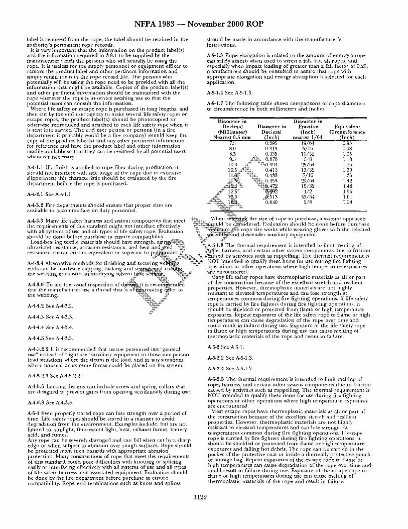
N F P A 1 9 8 3 ~ N o v e m b e r 2 0 0 0 R O P
label is removed from the rope, the label should be retained in the authority's pe rmanen t rope records.
It is very impor tant that the information on the product label(s) and the information required in 3-8.1 to be supplied by the
.manufacturer reach the persons who will actually be using the rope. It is useless for the supply personnel or equipment officer to remove the product label and other pert inent information and simply retain them in the rope record file. The persons who potentially will be using the rope need to be provided with all the information that might be available. Copies of the product label(s) and other pert inent information should be maintained with the rope wherever the rope is in-service awaiting use so that the potential users can consult the information.
Where life safety or escape rope is purchased in long lengths, and then cut by the end user agency to make several life safety ropes or escape ropes, the product label(s) should be photocopied or otherwise reproduced and attached to each life safety rope when it is sent into service. The end user person or persons (in a fire depar tment it probably would be a fire company) should keep the copy of the product label(s) and any other pert inent information for reference and have the product label and other information readily available so that they can be reviewed by all potential users whenever necessary.
A-4-1.1 If a finish is applied to rope fiber dur ing production, it should not interfere with safe usage of the rope due to excessive slipperiness; this characteristic should be evaluated by the fire depar tment before the rope is purchased.
A-4-2.1 See A-4-1.1.
A4-3.2 Fire departments should ensure that proper sizes are available to accommodate on-duty personnel.
should be made in accordance with the manufacturer ' s instructions.
A-5-1.3 Rope elongation is related to the amoun t of energy a rope can safely absorb when used to arrest a fail. For all ropes, and especially when impact loading of greater than a fall factor of 0.25, manufacturers should be consulted to assure that rope with appropriate elongation and energy absorption is selected for each application.
A-,~-l.4 See A-5-1.3.
A-5-1.7 The following table shows comparisons of rope diameters to circumference in both millimeters and inches.
Diameter in Diameter in Dec imal Diameter in Fraction Equivalent
(Millimeter) Dec imal (Inch) Circumference Nearest 0.5 mm (Inch) nearest 1 /64 (Inch)
7.5 0.295 19/64 0.93 8.0 0.313 5/16 0.98 8.5 0.335 11/32 1.05 9.5 .... ii::::iii~ii::::ii::.. 0.376 3/8 1.18 10.0 ..::~i:: ........ ::::iii0.394 25/6,1 1.24 10.5 ..::;#:::i::i::i~ ..... 0.413 13/32 1.30 ll,~i i .... . i~iiii::iii~i .... 0.433 7,/16 1.36 1..1 ~$.:i::!: '::iiiiii:i::.. 0.453 29/64 1.42
.... #:i::~ i:{}:. :i:"i::i::i::iit?, 47.2 15/32 1.48 .... iii:: 12.5 .... ' : :~N2 1/2 1.55
.: {:: :.:. I:.3,0 ..:~15 ] 3 3 3 / 6 4 1.61 =: ¢:=:===================::=. 1 ~ . "b.630 5/8 1.98
":~::iii:::d:! ............. ~: -.-.-....:... "-::::::::::::..
"i!!i::i!i!::::.:.. Xaelaen s ~ g i : ~ the size of rope to purchase, a systems approach A-4-3.3 Many life safety harness and system components that meet . . . . . : . . . . . . . . c ,~,: . . . . . . "~ '~ ~:-~'* n ̂ ~ : ~ e effe~'Zv ̂~" iiiii:iiiiiiiiiiiii!:N~,ould be c2~'~idered Evaluation should be done before purchase
t b c LZ, q U I I I ~ J I I ~ L I ~ IO1 1,1113 3 txJ -~ . IL[~LIU I I L I ~ . L I L t~ l t I I t l L U I L t b t , ,U e l y ':21:. =========================== +:." . . . . . . . . . ith a d - s c ~ a" - > "fe s -~ t e Evalua"- "::::- "t~:::P, NS.ure ~ e rope s~ze works wlalle weanng gloves vatn the selected W 11 S [em O~ use ana .1. e s O [ u k k [ e ro uon '- . . . . . -< . . . . . . . . . . . . . ys yp y p . .:.: .................. : . . . . . .
should be done before purchase to ensure compatibility. .. .:{!!....::.....~tet~k'and descender auxlhary equipment. Load-bearing textile materials should have strength, agin~'-'-'iii::i::i::iii::iiii::: :i::i!i::::" -:i!::" . . . . . . . . . . . . .
• • - • • -- ~ - - ~ --~-~, "::?---:- :?:.A-.%1.8 The thermal r eqmrement IS mtenaea to nmlt ine|tlng ot ultravlotet resistance aDra.slon resistance, ann neat ana.4aola --:::::::. -::::, ..:, . . . res stance charac ter l s t ' c s enuivalent or suoerior m oa l~mides "::::: ":::~10e harness and certa n other system components due to fr ctmn
.r.::i::" "::i:i:i:i:iz~"z-:. ..::~:i:::i:~:i:?i-'i::..-. "%..i:igaused by actlvatles such as rappelllng. The thermal r eqmremen t ts A-4-3.4 Alternative methods for finishing and securing ~ g ......... ii::::{{ii!ii!iii::i::::i::::i" NOT intended to qualify these items for use during fire fighting
operations or other operations where high temperature exposures ends can be hardware capping, tucking and se~ ' i~ .~ . . d c o ~ . the webbing ends with an air-drying solvent . ~ ' ~ ' ~ ' ~ : . . "::ii~i?-!i::"
..::i::" "-.':::::::-:s: ~i-":'~: " A4-3.5 To aid the visual inspection of t .~.'-'~,:.jt is r e c o ' ~ e n d { : a that the manufacturer use a thread that is o~'-i~trasting ~ l o r to the webbing. "::~:i:i:i:!::.. .ii::i?
A-44.2 See A-4-3.2. ':::::---- :::::::-"
.:ii:~::" A--4--4.3 See A-4-3.3.
A-4-4.4 See A4-3.4.
A-4-4.5 See AM-3.5.
A-4-5.2.2 It is recommended that rescue personnel use "general use" instead of "light-use" auxiliary equipment in those one-person load situations where the victim is the load, and in any situations where unusual or extreme forces could he placed on the system.
A-4-5.2.3 See A-4-5.2.2.
A-4-5.6 Locking designs can include screw and spring collars that are designed to prevent gates f rom opening accidentally during use.
A-4-5.9 See A4.3.5.
A-g-1 Even properly stored rope can lose strength over a period of time. Life safety ropes should be stored in a manner to avoid degradation from the environment. Examples include, but are not limited to, sunlight, fluorescent light, heat, exhaust fumes, battery acid, and fumes. Any rope can be severely damaged and can fail when cut by a sharp edge or when subject to abrasion over rough surfaces. Rope should be protected from such hazards with appropriate abrasion protection. Many constructions of rope that meet the requirements of this standard could pose difficulties with knotting or splicing easily or interfacing effectively with all systems of use and all types of life safety harness and associated equipment. Evaluation should be done by the fire depar tment before purchase to ensure compatibility. Rope end terminations such as knots and splices
are encountered. Many life safety ropes have thermoplastic materials as all or part
of the construction because of the excellent stretch and resilient properties. However, thermoplastic materials are not highly resistant to elevated temperatures and can lose strength at temperatures common during fire fighting operations. If life safety rope is carried by fire fighters during fire fighting operations, it should be shielded or protected from flame or bigb temperature exposures. Repeat exposures of the life safety rope to flame or high temperatures can cause degradation of the rope over time and could result in failure during use. Exposure of the life safety rope to flame or high temperatures during use can cause melting of thermoplastic materials of the rope and result in failure.
A-5-2 See A-5-1.
A-5-2.2 See A-5-1.3.
A-5-2.4 See A-5-1.7.
A-5-2.5 The thermal requi rement is intended to limit melting of rope, harness, and certain other system components due to friction caused by activities such as rappelling. The thermal requirement is NOT intended to qualify these items for use during fire fighting operations or other operations where high temperature exposures are encountered.
Most escape ropes have thermoplastic materials as all or part of the construction because of the excellent stretch and resilient properties. However, thermoplastic materials are not higtfly resistant to elevated temperatures and can lose strength at temperatures common during fire f ighdng operations. If escape rope is carried by fire fighters during fire fighting operations, it should be shielded or protected fi-om flame or high temperature exposures and falling hot debris. The rope can be carried in the pocket of the protective coat or inside a thermally protective pouch or storage bag. Repeat exposures of the escape rope to flame or high temperatures can cause degradation of the rope over time and could result in failure during use. Exposure of the escape rope to flame or high temperatures during use can cause melting of thermoplastic materials of the rope and result in failure.
1122
N F P A 1983 ~ N o v e m b e r 2 0 0 0 R O P
A-5-B.5 The thermal requ i rement is in t ended to limit melting of rope, harness, and certain o ther system components due to friction caused by activities such as rappelling. The thermal requ i rement is NOT in tended to qualify these ~terfis for use during fire fighting operations or o ther operations where high tempera ture exposures are encountered.
Many life safety harness have thermoplast ic materials as all or part of the construction because of the excellent s trength and resilient properties. However, thermoplast ic materials are no t highly resistant to elevated temperatures and can lose strength at temperatures common during fire fighting operations. If life safety harness is carried or used by fire fighters dur ing fire f ighdng operations, it should be shielded or protec ted from flame or high tempera ture exposures, Repeat exposures of the life safety rope to flan~e or high temperatures can cause degradat ion of the harness over time and could result in failure during use. Exposure of the life safety harness to flame or high temperatures during use can cause melting of thermoplastic materials of the harness and result in failure.
Many auxiliary equ ipmen t software items have thermoplast ic materials as all or par t of the construction because of the excellent s t rength and resilient properties. However, daermoplasdc materials are no t highly resistant toe leva ted temperatures and can lose s trength at temperatures common during fire fighting operations. If auxiliary equipment software items are carried by fire fighters during fire fighting operations, they should be shielded or protected from flame or high tempera ture exposures. Repeat exposures of the auxiliary equ ipment software to flame or high temperatures can cause degradat ion of the item(s) over time and could result in failure dur ing use. Exposure of the auxiliary equipment software to flame or high temperatures during use can cause melting of thermoplast ic materials of the item(s) and result in failure.
A-6-3.2.3 The g600-1bf (16.01-kN) test value selected for this static test, which employs a rigid test torso, equates to having a dynamic force exerted on the body greatly exceeding that which is considered reasonable to survive.
A-5-4.4 The thermal requ i rement is in tended to limit melting of A-6-3.3.3 The force selected for this test is less than that selected for rope, harness, and certain other system components due to friction the previous test because, in realistic fire g round operations, a fire caused by activities such as rappelllng. The thermal requi rement is f ighter falling head£~.st will impact the harness with less force in the NOT in tended to qualify these items for use during fire fighting head down posi~: i :~ . .c .p be inverted and arrested, producing the operations or other operations where high temperature exposures maximum f o r ~ the ~ipright position. are encountered. .-::i::" ':"~:~:i:':~.:
Many belts have thermoplastic materials as all or part of the A-6-4.2.3 ~.-':-'l~ser~..e. is used in this test than in the rescue construction because of the excellent s t rength and resilient " harness..:~.~.t":~., e to ~ ~ e r s o n a l protective application of belts. The properties. However, thermoplastic materials are no t highly indi .c~~":~t."~'brce ot':~i-~i~:(2923 lbf) is compliant with the resistant to elevated temperatures and can lose s trength at req~lt':'ern.¢nts for escape"~pe .
e r C n . . . . . . . . . . "~" t emp atures ommo durmg fire f ighting operations. If belts are ~??..::, :i~::.. ,:: can'ied or used by fire fighters during fire fighting operations, they ~- '~. . , .~J: :~O)" example, portable anchors designed to be at tached should be shielded" or pro tec ted f rom flame or h igh temperature to. fla~i~l~.rirr~s of vessel openings would recluire~ a test base to exposures. Repeat exposures, o f belts to .flame or h igh temperatures. ¢,,:.... simulate "~.~.~:...:::,flan..+v.ged portal to which the de ace is design ed to be can cause degradat ion of the belt over t ime and could result in "!~'?.~.'.'..-~.-:.:.!!::::.:...affixed. ~?'?-'::i~i~.";:" failure during use.. Exposure of the belt to. flame or h igh . ~-:'~--'-~:-...~ ~.~::~:-:..,.:~:.:.~,~,. ...,,.-~?-'::~ . . temperatures dur ing use can cause melt ing of thermoplast ic -'~.-..!: ~ ' ~ o r all static tests, the portable anchor devace shall be materials of the belt and result in failure. ,. .... ' % , : : ~ n f i g ~ d at its weakest extension des igned for use in accordance
. ~ t i ' : : %-":'~with tl~e manufacturer ' s instructions for use. In most cases, the A-5-5.8 The thermal requ i rement is in tended to limit ~ a g ~:.~ ':ii'..'..,~.~table anchor device will be weakest at its greatest (or highest) rope, harness, and certain other system componen t s ~ . t o fri.~.,~o~ ,:.. ".-"~ension. caused by activities such as rappelling. The thermal-lC~"~.~m~:"-~i~:~.,. "~:: : NOT in tended to qualify these items for use dur ing fire ~ l l ~ . g '::i~i~iiiiiii~i:: Appendix B Refe renced Publications operations or o ther operations where high t e ~ j c e e x l S ~ e s are encountered . ~ . ~ "~:."~::.::" -':::': .-::::" "~.".k.:-:-:. %:::::?.":-~-!::" .,...:~,,- ~...-'~ :,%*
.<-:<<.. "::::-':: :'-" A':-
%~,, #-
1 1 2 3
N F P A 1851 - - N o v e m b e r 2 0 0 0 R O P
NFPA 1851 (Log #39)
Commit tee : FAE-S FF 1851- 1 - (Entire Documen t ) : Accept in Principle SUBMITTER: GeorgeJ . Paul , Assn. of Fire Districts, NY R E C O M M E N D A T I O N : None given. S U B S T A N T I A T I O N : We have reviewed and find the proposals conta ined in the draft d o c u m e n t for the Main tenance of Structural Fire Fight ing Protective Ensemble Elements would impose a heavy a n d b u r d e n s o m e obligation on the fire service, whe ther it be volunteer or paid.
Therefore , our Associat ion goes on record as express ing concern relative to the imposi t ion of this s t andard a n d / o r r equ i rements without greater dialogue within the fire service regarding these requ i rements .
We agree tha t the p roposed s tandard is overly resuictive and is in need of a serious reality check. COMMITTEE ACTION: Accept in Principle. COMMITTEE STATEMENT: Al though the submi t te r did no t provide any specific sugges t ions for changes to the r equ i r emen t s found in the initial draft s tandard, the commit tee a t t empted to address the submit te rs concerns by revising several sections a n d / o r r equ i r emen t s of the p roposed s tandard.
(Log #40) Commit tee : FAE-SFF
1851- 2 - (Title): Reject SUBMITTER: Fred Windisch , Ponde rosa Vol. Fire Dept., T X / R e p . Ponde rosa Vol. Fire Dept. , TX R E C O M M E N D A T I O N : T h e p r o p o s e d n a m e is to be a STANDARD. I r e c o m m e n d this d o c u m e n t to be a RECOMMENDATION versus a s tandard . The Fire and Emergency Manufac ture rs and Service Association, Inc. (FEMSA) Official User Informat ion Guide tho rough ly explains mos t or all of the issues listed in the p roposed s tandard. 1851 could r e c o m m e n d tha t organizat ions follow the manufac tu re r s r e c o m m e n d a t i o n s a n d those of the FEMSA booklet.
The re are far too many SHALL's in the p roposed version a n d I will address several o ther issues in o ther submissions.
I do sugges t a t ho rough review of the FEMSA booklet and reques t a t ho rough analysis of, IS THIS PROPOSED STANDARD REALLY NEEDED SINCE THE MAJORITY OF T HE ISSUES ARE COVERED IN THE FEMSA BOOKLET. T he addi t ional s t anda rd will cause fu r the r f inancial and bureaucra t ic systems be created for those organizat ions tha t adop t the p roposed s tandard , as well as create fu r the r liabilities for those depa r tmen t s who do no t follow the p roposed s tandard to the verbatim.
The p roposed s tandard is unrealist ic in its def ini t ions of soiled equ ipmen t . I will cover that in a n o t h e r submission. S U B S T A N T I A T I O N : See the above since this is a general submis s ion . COMMITTEE ACTION: Reject. COMMITTEE STATEMENT: The Commi t t ee felt tha t the p roposed d o c u m e n t shou ld be a Standard, no t a r e c o m m e n d e d practice. These r equ i r emen t s are necessary to ensure that a PPE is
~ roperly inspected and ma in t a ined t h r o u g h o u t its useful life for ealth and safety considerat ions and t o p r o t e c t and organizat ion 's
inves tment in PPE, a n d therefore s h o u l d b e mandatory . In addit ion, the Commi t t ee did no t feel that the user informat ion provided by manufac tu re r s addressed all of the issues in the p roposed s tandard . T h e Commi t t ee did, however, a t t empt to address several of the submit ters concerns by revising several sections a n d / o r r equ i r em en t s of the p roposed s tandard.
(Log #35) Commit tee : FAE-S FF
1851- 3 - (1 -1 .3 ) : Reject SUBMITTER: Stanford E. Davis, PA Power & Light Co. R E C O M M E N D A T I O N : Add to end of Section 1-1.3, "....or NFPA 600, Industrial Fire Brigades." S U B S T A N T I A T I O N : NFPA 600 needs to be included in this s t a t emen t to exclude Industr ial Fire Brigade programs. COMMITTEE ACTION: Reject. COMMITTEE STATEMENT: This S tandard applies to s tructural fire f ight ing protective c l o t h i n g a n d e q u i p m e n t the Commit tee felt that Industrial Fire Brigades who use structural fire f ight ing protective c lo th ing a n d e q u i p m e n t should no t be excluded.
(Log #47) Commit tee : FAE~SFF
1851- 4 - (1-1.8 ( N e w ) ) : Accept in Principle SUBMITTER: William L. Grilliot, Morn ing Pride Mfg Co. R E C O M M E N D A T I O N : Add the following new section:
"ff any por t ion of this s t andard differs f rom the manufac to rs r e c o m m e n d e d procedures , the m a n u f a c t u r e r ' s p rocedures shall be followed." S U B S T A N T I A T I O N : This s t andard shou ld never override the m a n u f a c t u r e r ' s "users in format ion" provided. - COMMITTEE ACTION: Accept in Principle. COMMITTEE STATEMENT: The Commi t t ee agreed with the submi t te r bu t revised the submi t te r ' s sugges ted text to be consis tent with other r equ i rements in Chapte r 2 of the Standard. (See Section 2-4.2)
(Log #10) Commit tee : FAE-SFF
1851- 5 - (1-3 Soi l ing/Soi led) : Accept in Principle SUBMITTER: J o h n E. Reiter, Nuclear Service Organizat ion R E C O M M E N D A T I O N : Add text as follows:
Substantial acc~rrlulation of dir t a n d / o r perspira t ion that is no t cons idered a hazardous mater ia l or biological agent , but which could degrade the pe r fo rmance of the protective e lement . S U B S T A N T I A T I O N : The cur ren t def ini t ion in the proposed s tandard is too vague. A user of this s t anda rd could mis in te rpre t the in ten t of the defini t ion of soi l ing/soi led. COMMITTEE ACTION: Accept in Principle. COMMITTEE STATEMENT: The Commi t t ee agreed with the submi t te r ' s concern bu t revised the submi t te r ' s sugges ted defini t ion to be consis tent with the r equ i r emen t s for cleaning, which were also revised. (See new defini t ion and Section 4-1.2)
(Log #34) Commit tee : FAE~;FF
1851- 6 - (1-3 Soi l ing/Soi led) : Reject SUBMITTER: Stanford E. Davis, PA Power & Light Co. R E C O M M E N D A T I O N : Soil ing/Soiled. Dirt tha t is no t considered. . . S U B S T A N T I A T I O N : I am no t aware of any technical basis for s tat ing that persp i ra t ion will degrade the pe r fo rmance of the protective e lement . COMMITTEE ACTION: Reject. COMMITTEE STATEMENT: Al though t the defini t ion of so i l ing/soi led was revised, the Commi t t ee did no t agree with the submi t te r ' s substant iat ion. Manufac tu re r ' s have d o c u m e n t e d m an y instances of p roduc t degra t ion due specifically to perspirat ion.
[lLIso see Commi t t ee Action on Proposal 1851-5 (Log #10)]
(Log #41) Commit tee : FAE~S FF
1851- 7 - (1-3 Soi l ing/Soi led) : Accept in Principle SUBMITTER~ F r e d W i n d i s c h , Ponde rosa Vol. Fire Dept., T X / R e p . Ponde rosa Vol. Fire Dept. , TX R E C O M M E N D A T I O N : Revise text as follows:
Soil ing/Soiled. Con taminan t s tha t are no t cons idered a haza rdous material or biological agent , bu t which could degrade the pe r fo rmance of the protective e lement . Examples are, earth, no rma l perspirat ion, non -haza rdous substances , etc. etc. etc. (give more examples) . S U B S T A N T I A T I O N : The defini t ion needs more explanat ion. COMMITTEE ACTION: Accept in Principle. COMMITTEE STATEMENT: See Commi t t ee Action taken on Proposal 1851-5 (Log #10).
(Log #60) Commit tee : FAE~S FF
1851- 8 - (1-3 Wear Test ( N e w ) ) : Accept SUBMITTER: Jeffrey O. Stull, Int ' l Personnel Protect ion, Inc. R E C O M M E N D A T I O N : Add the following new definition:
'%Year Test. A control led evaluation of one or more protective ensembles or e lements involving selected organizat ion m em b er s wear ing each ensemble or e l e m e n t in actual or s imula ted fire f ight ing activity with the objective of providing quantitative ratings a n d subjective c o m m e n t s f rom part ic ipat ing organizat ion m e m b e r s . " S U B S T A N T I A T I O N : A defini t ion is n e e d e d to describe the wear test indicated in Paragraph 2-1.6. COMMITTEE ACTION: Accept .
1124
N F P A 1851 ~ N o v e m b e r 2 0 0 0 R O P
(Log #48) Committee: FAE-SFF
1851- 9 - (1-3 Winter Liner (New)): Accept SUBMITYER: William L. Grilliot, Morning Pride Mfg Co. RE, COMMENDATION: Add the following new definition:
"Winter Liner. A garment term for an optional component layer designed to provide added insulation against cold."
And, address winter liners where appropriate in the standard. SUBSTANTIATION: Care and maintenance of winter liners needs to be addressed. COMMITTEE ACTION: Accept.
(Log #42) Committee: FAE-SFF
1851- 10- (2-1): Reject SUBMITTER: Fred Windisch, Ponderosa Vol. Fire Dept., TX/Rep. Ponderosa Vol. Fire Dept., TX RECOMMENDATION: Remove the word SHALL and replace with RECOMMENDED, or IF THE AHJ REQUIRES... SUBSTANTIATION: Paragraphs 2-1.1 through 2-1.5, the use of SHALL overwhelms any organization that does not have the resources to perform risk assessments, tile standards listed including OSHA for review, comparative products and verification of interfaces. A wear test may only include ONE individual and ONE set of PPE due to limited resources. COMMITTEE ACTION: Reject. COMMITTEE STATEMENT: The requirements in the standard are. mandatory. Therefore, the use of the word "shall" is appropriate. The Committee believes the requirements in 2-1.1 through 2-1.5 (now 3-1.2 through 3-1.6) are the minimum requirements necessary for the selection of structural fire fighting protective clothing and equipment that best suits the needs of the organization.
(Log #55) Comnfittee: FAE-S FF
1851- 14- (2-1.5(c)): Accept SUBMITTER: Jeffrey O. Stull, Int'l Personnel Protection, Inc. RECOMMENDATION: Add the following to Paragraph 2-1.5(c):
"The product evaluation form shall include a rating system for those characteristics of the element or ensemble considered important to the organization for allowing a quantitative evaluation of each ensemble. Product evaluation forms which include narrative answers only shall be avoided." SUBSTANTIATION: It is important that the product evaluation form allow the organization to quantitatively evaluate test subject responses. The provision of rating systems for important characteristics assists in a successful wear trial. COMMrlTEE ACTION: Accept.
(Log #4q) Committee: FAE-SFF
1851- 15 -'(2-1.6(g) (New)) : Accept in Principle SUBMITTER: William L. Grilliot, Morning Pride Mfg Co. RECOMMENDATION: Add the following new section:
(g) The organization shall compare a pre-production sample from the apparent winning submitter against the purchase specifications before awarding the bid. SUBSTANTIATION: This is an important step in a responsible bidding process. COMMITTEE ACTION: Accept in Principle. COMMITTEE STATEMENT: The Committee agreed with the submitter but felt there were situations where the inspection of a pre-production sample would not be necessary such as a small order or reorder. The submitters proposed text was added to the appendix. [See A-3-1.7(f)]
(Log #53) Committee: FAE-SFF
Y. 18aI- II - (2-I.X (New)): Accept in Principle SUBMITTER: Jeffrey O. Stull, Int'l Personnel Protection, Inc. RECOMMENDATION: Add new para~aph to Section 2-1:
"2-1.X The organization shall review reformation from prospective manufacturers which demonstrates the compliance of considered ensembles or elements to the reguirements of NFPA 1971. This review shall include compliance reformation for all components used in the construction of the element or ensemble." SUBSTANTIATION: Organizations must ensure that all considered elements or ensembles meet the respective requirements of NFPA 1971. COMMITTEE ACTION: Accept in Principle. COMMITTEE STATEMENT: The committee agreed but modified the submitter's text. (See 3-1.3 and A-3-1.3)
(Log #36) Committee: FAE-SFF
1851- 12- (2-1.2): Accept SUBMITYER: Stanford E. Davis, PA Power & Light Co. RECOMMENDATION: Change to, "....NFPA 1500, NFPA 600, and any.i_" SUBSTANTIATION: Industrial Fire Brigades need to be included here. COMMITTEE ACTION: Accept.
(Log #54) Committee: FAE-SFF
1851- 13 - (2-1.5(b)): Accept in Principle SUBMrrTER: Jeffrey O. Stull, Int'l Personnel Protection, Inc. RECOMMENDATION: Add the following to Paragraph 2-1.5(b):
"Different participants shall not be used for evaluating different sets, of ensembles. All field evaluations shall be conducted using the same participants, who use/evaluate the same sets of ensembles." SUBSTANTIATION: Field studies which fail to use the same set of test subjects for all ensembles to be evaluated cannot provide a fair comparison of each ensemble. COMMITTEE ACTION: Accept in Principle. COMMrrTEE STATEMENT: The Committee agreed but deleted the first sentence as it was felt that it was not necessary to meet the intent of the requirement.
(Log #43.) Committee: FAE-S FF
1851- 16 - (Chapter 3): Accept in Principle SUBMITTER: Fred Windisch, Ponderosa Vol. Fire Dept., TX/Rep. Ponderosa Vol. Fire Dept., TX RECOMMENDATION: This is a condensed version addressing certain paragraphs but should be repeated for all sections concerning bunker gear, hoods, ~loves, boots, etc. Generally speaking, the proposed standard is too strict to be realistic for most organizations to follow.
3-1.1.1 Garments shall be cleaned WHENEVER DETERMINED TO BE SUFFICIENTLY SOILED AS DETERMINED BY THE AHJ.
3-1.1.3 Garments SHOULD be cleaned following an incident where they have been SUFFICIENTLY SOILED AS DETERMINED BY THE AHJ...
3-1.1.5 A revised definition of SOILED should be provided to giw. • more depth to this statement.
$-1.1.7 Organizations SHOULD provide a means for... 3-1.1.17 DELETE THE ENTIRE PARAGRAPH OR MINIMIZE
TO INCLUDE ONLY THE ID, DATE OF MANUFACTURE, AND DATE OF ISSUE.
3-1.3.7 WHAT IS A VENTILATED STORAGE BAG? DO WE HAVE TO INVENT AND BUY ALL NEW ONES?!
3-2.1.1 Hoods shall be cleaned AS DETERMINED BY THE AHJ. 3-2.1.17 DELETE THE ENTIRE PARAGRAPH. 3-3.1.18 DELETE THE ENTIRE PARAGILAPH OR MINIMIZE
TO INCLUDE ID, DATE OF MANUFACTURE, AND DATE OF ISSUE.
3-4.1.15 Gloves MUST NOT BE DRIED IN HEAT GREATER THAN 140 DEGREES F (OR SOMETHING!!!)
SEVERAL AREAS STATE CANNOT STORE PPE WITH PERSONAL BELONGINGS OR INSIDE PASSENGER COMPARTMENTS. GIVE MORE DEFINITION. HOW MANY PPM, WHAT IF THE GEAR HAS BEEN DECONTAMINATED. THESE SECTIONS ARE ENTIRELY TOO ,STRICT.
3-4.1.16 THIS STATEMENT CONFLICTS WITH 3-4.1.15. SUBSTANTIATION: Certain issues listed above remove responsibility and management oversight for the AHJ. The proposed standard is entirely too strict and allows for no common sense approaches to taking care of very expensive protective clothing.
I suggest that EACH section be combined with one another to reduce the size of the document. This is not fun reading to read and reread the same paragraphs for each part of the ensemble. A complete rewrite is in order to make the document more user friendly and encourage the reader to read the whole thing.
Soiled needs a better definition. Maybe even a story or two to support the definition.
1125
N F P A 1851 - - N o v e m b e r 2 0 0 0 R O P
T h e record keep ing suggested for soiled gear is a n igh tmare of bureaucra t ic nonsense . It s imply adds no value to the organization, the individual. However, it does add a huge liability factor if this detai led record keeping is no t in place. Let 's look at value for our work, no t j u s t make work.
This d o c u m e n t needs to have a cost a n d risk analysis p e r f o r m e d pr ior to adopt ion. The d o c u m e n t assumes the a m o u n t of soil ing a n d / o r con tamina t ion wi thout giving data, statistical suppor t , or e n o u g h defini t ion to allow the AHJ to make an educa ted decision when to clean PPE. This places a h u g e liability on an organizat ion even if one molecule of so i l / con t amina t i on is there. This d o c u m e n t is in serious need of a reality check.
Venti la ted s torage bags: I suppose I will have to immedia te ly go ou t and f ind some a n d buy 80 new ones. This is ridiculous. How about drying the gear first, t hen it is ok to pu t in a storage bag?
Please allow my m o t h e r to sew the edge of one f inger or the wristlet of a $50 pair of gloves versus throw them away!!!
Overall, t he p roposed s tandard MUST allow for some c o m m o n sense m a n a g e m e n t to make a value based decision to wash and repair this very expensive and impor tan t piece of fire f ight ing equ ipmen t . COMMITTEE ACTION: Accept in Principle. COMMITTEE STATEMENT: See text in Report on Proposals at the end of this report.
(Log #50) Commit tee : FAE-S FF
1851- 17 - (3 Note ( N e w ) ) : Accept in Principle SUBMITTER: William L. Grilliot, Morn ing Pride Mfg Co. RECOMMENDATION: Add the following note between "Chapter 3" and "3-1."
"ff any section of Chapter 3 differs f rom the manufac tu re r ' s r e c o m m e n d e d procedures , the manu fac t u r e r ' s p rocedures shall be followed." S U B S T A N T I A T I O N : This s t andard should never override the manu fac tu r e r ' s "user in format ion" provided. COMMITTEE ACTION: Accept in Principle. COMMITTEE STATEMENT: See Commi t tee Action taken on Proposal 1851-4 (Log #47).
(Log #38) Commit tee : FAE-SFF
1851- 18 - (3-1.1): Accept in Principle SUBMITTER: J o h n Soecler, Miami-Dade Fire Rescue Dept., FL/Rep . Miami-Dade Fire Rescue Dept., FL RECOMMENDATION: None given. S U B S T A N T I A T I O N : T he following are areas of concern in regards to the ga rmen t s ' care a n d cleaning:
3-1.1.1 G a r m e n t shall be cleaned at a m i n i m u m of every six mon ths .
Wha t criteria was used to establish this t ime frame? Does a driver 's gear need to be cleaned that often? Does new gear that has not been issued after six m o n t h s need to be taken off the shel f and washed every six months?
3-1.1.2 Garments shall be c leaned following an inc iden t where they have been soiled, init iat ing the c leaning procedure at the inc iden t scene.
Accord ing to 4-1.1.2 "the end user (myself) is responsible for inspect ion of the garment . " In 4-1.1.12 the s tandard tells me what to look for bu t does no t spell out to what ex ten t the soil ing or con tamina t ion mus t be to warrant taking the g a r m e n t out of service. Therefore , if my gear is con tamina ted or soiled the first t ime worn, and I feel it is no t tha t soiled or contamina ted , can I wait six m o n t h s to wash it?
3-1.1.5 a n d 3-1.2.6 The public shall no t be exposed at any t ime to soiled g a r m e n t used by emergency response personnel .
Wha t do we do if we run back to back to back calls in our g a r m e n t and have contact with the public?
3-1.1.5 Organizat ions shall provide a m e a n s for having PPE cleaned.
If a mach ine is provided at the station, can we use it to wash everybody's g a r m e n t risking cross contamina t ion , or do we need to provide a separate m a c h i n e for each fire fighter?
3-1.1.17 The following records shall be kept for each g a r m e n t cleaned. Inspect ion shall be done after the c leaning is complete.
NOTE: See p roposed 1851 for specific record informat ion required.
The record keep ing requi red in this sect ion will become cost prohibitive and s torage space consuming . It appears it is only there for the purpose of placing b lame on a third party if the g a r m e n t is no t washed in a timely manne r .
In 3-1.1.2 it states that an inspect ion will be conduc ted after every use. So, do I inspect the g a r m e n t first, or do I wash it first t hen
inspect it? I realize this is no t the point, bu t if you manda t e this, it needs to be clarified.
The sections identif ied above can be appl ied to the like sections for the o ther parts of the ensemble: helmets , gloves, hoods, boots.
In summary , I have only t ouched on a few of the glar ing problems with this s tandard . The re is no doub t tha t deaa~ PPE is of the u tmos t impor tance . It he lps ensure the fire f ighter tha t h e / s h e has the best protec t ion possible. Yet, this s t andard gives no clear defini t ion of "clean" and when c leaning is to be conducted . This s t andard should only be a guide to the care and c leaning of the ensemble , no t as a regula t ion or manda te . COMMITTEE ACTION: Accept in Principle. COMMITTEE STATEMENT: 3-1.1.5 and 3-1.2.6 - See Proposal 1851-24 (Log #8).
3-1.1.7 - See Proposal 1851-28 (Log #14). 3-1.1.1 and 5-1.1.2 -See Proposal 1851-20 (Log #11). 4-1.1.2 - See new 4-1.2. Also, See Proposal 1851-1 (Log #39).
(Log #9) Commit tee : FAE-S FF
1851- 19 - (3-1.1.1): Reject" -~ SUBMITTER: Rick R. Schartel , PA Power and Light, Inc . /Rep . PA Power and Light, Inc. RECOMMENDATION: Delete Paragraph 3-1.1.1 SUBSTANTIATION: Requir ing the c leaning of all ga rmen t s every 6 m o n t h s wi thout regard to use levels or degree of soil ing is excessive. T u r n o u t gear used by slow companies , particularly in the vo lun teer or industr ial sectors, do no t rout inely see the bui ldup of soiling and con tamina t ion exper i enced in larger, busier depar tments . Taking t u r n o u t gear out of service for a cleaning, if no t necessary, reduces the organizat ion 's effectiveness by l imiting the n u m b e r of pe r sonne l available for response by e l iminat ing their ability to dress appropriately. T h e alternative of providing each m e m b e r with two sets of t u r n o u t gear is also expensive an d impractical. It places an arbitrary f inancial b u r d e n on small communi t i e s a n d industr ial concerns which canno t provide for the quality of facility requ i red to properly clean gear in confo rmance with this s tandard. COMMITTEE ACTION: Reject. COMMITTEE STATEMENT: Al though the r e q u i r e m e n t for c leaning was no t deleted, it was revised in an a t t emp t to address the submi t te r ' s concern. (See 4-12 a n d 5-3.1) The r e q u i r e m e n t was no t de le ted because the Commi t t ee believes tha t soiled protective ensemble e lements pose a hea l th risk to the wearer and may provide reduced levels of protective per formance .
(Log #11) Commit tee : FAE-S FF
1851- 20 - (3-1.1.1): Accept in Principle SUBMITTER: J o h n E. Reiter, Nuclear Service Organizat ion RECOMMENDATION: Revise text as follows:
Garments shall be c leaned at a minimz:m of ever /~ ix me, n ~ z as needed to remove heavy soiline. S U B S T A N T I A T I O N : A proscriptive c lean ing schedule provides little value. The r e q u i r e m e n t to clean ga rmen t s at a m i n i m u m of every six m o n t h s does no t take into accoun t the ga rmen t ' s purpose and use pat terns. At some large industr ial facilities, ga rmen t s are provided a n d strategically placed t h r o u g h o u t the site for fire br igade use. The gear is inf requent ly used and may be s tored in a m a n n e r or location which prohibi ts it f rom becoming soiled, and is typically inspec ted a n d can be c leaned as necessary. COMMITTEE ACTION: Accept in Principle. COMMITTEE STATEMENT: T h e r equ i r emen t s for c leaning were revised in an a t t empt to address the submi t te r ' s concern. (See 4- 1.2 and 5-3.1)
(Log #37) Commit tee : FAE-SFF
1851- 21 - (3-1.1.1): Reject SUBMITTER: Stanford E. Davis, PA Power & Light Co. RECOMMENDATION: Delete this section. S U B S T A N T I A T I O N : There is no technical basis for requi r ing ga rmen t s to be c leaned every six months . This will impose a s ignif icant bu rden on Industr ial Fire Brigades and Volunteer Fire Depar tmen t s which may have ga rmen t s that have no t been used within that t ime frame. COMMITTEE ACTION: Reject.
1 1 2 6
N F P A 1851 ~ N o v e m b e r 2 0 0 0 R O P
COMMITTEE STATEMENT: See Committee Action on Proposal 1851-19 (Log #9).
(Log #33) Committee: FAE-SFF
1851- 22 - (3.1.1.2): Accept SUBMITTER: Stanford E. Davis, PA Power & Light Co.
[ I~]COMMENDATION: Change "decontamination" to ~contamlnatlon." SUBSTANTIATION: Contamination appears to be the more correct terminology for an inspection. COMMITTEE ACTION: Accept.
(Log #12) Committee: FAE-SFF
1851- 23 - (3-1.1.3): Accept in Principle SUBMITTER: John E. Reiter, Nuclear Service Organization RECOMMENDATION: Revise text as follows:
Garments shall be cleaned following an incident where they have been heavily soiled, initiating the cleaning procedure at the incident scene. SUBSTANTIATION: In the literal compliance environment that some large industrial facilities and fire departments are currently operating, one could misinterpret this requirement. The current wording m the proposed standard could suggest that gear which has been simply perspired in, or has a minor accumulation of products of combustion, would require cleaning. COMMITTEE ACTION: Accept in Principle. COMMITTEE STATEMENT: The Committee agreed with the submitter's concern and revised the definition of soiled and the requirements for cleaning. [Also see 1851-5 (Log #10)]
(Log #8) Committee: FAE-SFF
1851- 24 - (3-1.1.5): Accept in Principle SUBMrlq'ER: Rick R. Schartel, PA Power and Light, Inc./Rep. PA Power and Light, Inc. RECOMMENDATION: Revise 3-1.1.5 to read as follows:
F.xposure to soiled garments by the public shall be kept to a minimum. SUBSTANTIATION: Literal translation of this paragraph as currently written indicates that a company returning to quarers from a working fire must be placed out of service until they can have their garments cleaned. "Contact with the public" occurs at fire alarm investigations, odor investigations, EMS runs, rescue calls and a wide variety of events which could occur between the soiling (meaning d i r to r merely perspiration) of a garment and the opportunity to clean it. The current language gives absolutely no leeway in this regard and is therefore clearly impractical, especially for busy companies. COMMITTEE ACTION: Accept in Principle. COMMITTEE STATEMENT: The Committee agreed with the submitter but revised the submitter's suggested text to be consistent with other requirements in Chapter 2 o f the Standard. (See Section 2-5.1)
(Log #13) Committee: FAE-SFF
1851- 25 - (3-1.1.5): Accept in Principle SUBMITrER: John E. Reiter, Nuclear Service Organization RECOMMENDATION: Revise text as follows:
The public shall not be exposed at a=zy ~dr...z to heavily soiled
~ arments used by emergency response personnel. UBSTANTIATION: In my opinion, lightly soiled gear does not
present a public safety hazard. Without.the insertion of the word "heavily," one could interpret this requirement to require cleaning
• of gear which has been simply perspired in or has a minor accumulation of products of combustion. Remove "at any time" because it does not provide additional guidance - only words. COMMITTEE ACTION: Accept in Principle. COMMITTEE STATEMENT: See Committee Action on Proposal 1851-24 (Log #8).
(Log #32) Committee: FAE~S l:-'F
1851- 26 - (3-1.1.5): Accept in Principle SUBMITTER: Stanford E. Davis, PA Power & Light Co. RECOMMENDATION: Add to the end of the sentence, "...after an incident." SUBSTANTIATION: As written, this section would not allow an emergency responder to render aid once they have soiled their garments as part of their response. COMMITrEE ACTION: Accept in Principle. COMMITTEE STATEMENT: See Committee Action on Proposal 1851-24 (Log #8).
(Log #51) Committee: FAE-,S I"F
1851- 27 - (3-1.1.12): Accept in Principle SUBMITTER: William L. Grilliot, Mornin~g Pride Mfg Co. RECOMMENDATION: Revise text to read:
Where hand washing is performed or required, 130 degrees F. may cause a burn. SUBSTANTIATION: Water temperature should be reduced to a temperature which will not cause a burn when hand washing. COMMITTEE ACTION: Accept in Principle. COMMITTEE STATEMENT: See Section 5-5.5(c) and A-5-5.5(c)
(Log #14) Committee: FAE-SFF
1851- 28- (3-1.1.17): Reject SUBMITTER: John E. Reiter, Nuclear SeiMce Organization RECOMMENDATION: Revise text as follows:
The fMl~.;;~.:g records shall be kept for each garment cleaned. Inspection shall be done after the cleaning is complete.
Move items (a) through (m) into appendix. SUBSTANTIATION: The level of record keeping required in Section 3-1.1.17 is excessive. Individual owners/users of gear should determine their level of record keeping. Items listed in (a) through (m) are advisory in nature and may be appropriate as appendix material. COMMITTEE ACTION: Reject. COMMITTEE STATEMENT: The Committee eliminated several, but not all, of the record keeping requirements. The remaining requirements, which were previously found in the Chapter on Care. and the Chapter on Maintenance, were consolidated into one section on record keeping and placed in Chapter 2, Program. (See Section 2-3) These requirements are nece,~ary to ensure that PPE is properly inspected and maintained throughout its useful life. In addition to health and safety considerations, appropriate records protect the organization's investment in PPE. Good record keeping is essential for maintenance and replacement programs, as well as the ongoing evaluation of PPE.
(Log #56) Committee: FAE-S f,'F
1851- 29 - (3-1.2.19 (New)): Reject TCC NOTE: The TCC directs the TC to reconsider the action
taken on 1851-29 and the issues raised in the proposal. The TC needs to consider developing advisory information for the document's appendix to assist the organlz.atlon in evaluating the effectiveness of a contract cleaner's decontamination process. SUBMITTER: Jeffrey o . Stull, Int'l Personnel Protecuon, Inc. RECOMMENDATION: Add the following new paragraph:
"3-1.2.19 Each organization shall develop procedures for evaluating the levels of contamination in protective garments using analytical procedures which identify and quantify contaminants. These analytical procedures shall be used 1:o determine when contamination is present and the effectiveness of decontamination, when performed."
(Similar paragraphs should appear in Sections 3-4, 3-5.) SUBSTANTIATION: Decontamination is only effective when it can be established that the decontamination process removes contaminants. Organizations must have a plan in place to determine when excessive contaminants are present and for checking the effectiveness of decontamination. COMMITTEE ACTION: Reject. COMMITTEE STATEMENT: Although the Committee understands the submitters reasoning for his proposed requirement, the Committee felt that verification of decontamination as suggested would not be a practical requirement to impose on departments at this time. In addition, there were concerns that this level of evaluation could require the destruction of the protective element to perform the evaluation.
1127
N F P A 1851 m N o v e m b e r 2 0 0 0 R O P
(Log #38a) Committee: FAE-S FF
1851- 30 - (3-1.3): Accept in Principle SUBMITTER: J o h n Soecler, Miami-Date Fire Rescue Dept., FL/Rep. Miami-Dade Fire Rescue Dept., FL RECOMMENDATION: None given. SUBSTANTIATION: The following are areas of concern in regards to the garments ' care and cleaning:
3-1.3.1 Garments shall no t be stored in direct or indirect sunlight.
Is this at all times? Do we need to provide completely dark storage in both the station and on the apparatus?
3-1.3.6 Soiled garments shall no t be stored with personal belongings, inside living quarters, or within the passenger compar tment of vehicles.
Does this apply to apparatus? If so, do we have to provide an externally ventilated compar tment in the cab?
The sections identified above can be applied to the like sections for the o ther parts of the ensemble: helmets, gloves, hoods, boots.
In summary, I have only touched on a few of the glaring problems with this standard. There is no doubt that clean PPE is of the utmost importance. It helps ensure the fire fighter that h e / s h e has the best protect ion possible. Yet, this s tandard gives no clear definition of " c l e a n - a n d when cleaning is to be conducted. This s tandard should only be a guide to the care and cleaning of the ensemble, not as a regulation or mandate. COMMITTEE ACTION: Accept in Principle. COMMITTEE STATEMENT: Several changes were made to the proposed standard (See ROP, new Chapter 7, Storage).
See Committee Action taken on Proposal 1851-1 (Log #39).
(Log #15) Committee: FAE-S FF
1851- 31 - (3-2.1.1): Accept in Principle SUBMrrTERa J o h n E. Reiter, Nuclear Service Organization RECOMMENDATION: Revise text as follows:
Hoods shall be cleaned at a rain!mum ~f c;'c D" z.x moc.th~ as needed to remove h e a w soilinE. SUBSTANTIATION: A proscriptive cleaning schedule provides little value. The requ i rement to clean garments at a min imum of every six months does not take into account the garment ' s purpose and use patterns. At some large industrial facilities, garments are provided and strategically placed throughout the site for fire brigade use. The gear is infrequently used and may be stored in a manne r or location which prohibits it from becoming soiled, and is typically inspected and can be cleaned as necessary. COMMITTEE ACTION: Accept in Principle. COMMITTEE STATEMENT: See Committee Action taken on Proposal 1851-20 (Log #11).
(Log #16) Committee: FAE-S FF
1851- 32 - (3-2.1.3): Accept in Principle SUBMITTER: J o h n E. Reiter, Nuclear Service Organization RECOMMENDATION: Revise text as follows:
Hoods shall be cleaned following an incident where they have been heavily soiled, initiating the cleaning procedure at the incident scene. SUBSTANTIATION: In the literal compliance environment that some large industrial facilities and fire depar tments are currently operating, one could misinterpret this requirement . The current wording in the p roposed standard could suggest that gear which has been simply perspi red in, or has a minor accumulation of products of combustion, would require cleaning. COMMITTEE ACTION; Accept in Principle. COMMITTEE STATEMENT: See Committee Action taken on Proposal 1851-5 (Log #10) and 1851-23 (Log #12).
(Log #17) Committee: FAE-SFF
1851- 33 - (3-2.1.5): Accept in Principle SUBMITTER: J o h n E. Reiter, Nuclear Service Organization RECOMMENDATION: Revise text as follows:
The public shall not be exposed at any "dine to heavily soiled hoods used by emergency response personnel . SUBSTANTIATION" In my opinion, lightly soiled gear does not present a public safety hazard. Without the insertion of the word "heavily," one could in terpret this requi rement to require cleaning of gear which has been simply perspired in or has a minor
accumulat ion of products of combustion. Remove "at any time" because it does no t provide additional guidance - only words. COMMITTEE ACTION: Accept in Principle. COMMITTEE STATEMENT: See Commit tee Action taken on Proposal 1851-24 (Log #8).
(Log #18) Committee: FAE-S FF
1851- 34- (3-2.1.17): Reject SUBMITTER: J o h n E. Reiter, Nuclear Service Organization RECOMMENDATION: Revise text as follows:
The f~!!~':dng records shall be kept for each hood cleaned. Inspection shall be done after the cleaning is complete.
Move items (a) through (m) into appendix. SUBSTANTIATION: The level of record keeping required in Section 3-1.1.17 is excessive. Individual owners /users of gear should de te rmine their level of record keeping. Items listed in (a) through (m) are advisory in nature and may be appropriate as appendix material. COMMITTEE ACTION: Reject. COMMITTEE STATEMENT: See Commit tee Action taken on Proposal 1851-28 (Log #14).
(Log #19) Committee: FAE-S FF
1851- 35 - (3-3.1.2): Accept in Principle SUBMITTER: John E. Reiter, Nuclear Service Organization RECOMMENDATION: Revise text as follows:
Helmets shall be cleaned following an incident where they have been heavily soiled, initiating the cleaning procedure at the incident scene. SUBSTANTIATION: In the literal compliance envi ronment that some large industrial facilities and fire depar tments are currently operating, one could misinterpret this requirement . The current wording in the p roposed standard could suggest that gear which has been simply perspired in, or has a minor accumulation of products of combustion, would require cleaning. COMMITTEE ACTION: Accept in Principle. COMMITTEE STATEMENT: See Commit tee Action taken on Proposal 1851-5 (Log #10) and 1851-23 (Log #12).
(Log #20) Committee: FAE-SFF
1851- 36 - (3-3.1.4): Accept in Principle SUBMITTER: J o h n E. Reiter, Nuclear Service Organization RECOMMENDATION: Revise text as follows:
The public shall no t be exposed at mzy *,Jmc to heavily soiled helmets used by emergency response personnel . SUBSTANTIATION: In my opinion, lightly soiled gear does not present a public safety hazard. Without the insertion of the word "heavily," one could in terpret this r equ i rement to require cleaning of gear which has been simply perspired in or has a minor accumulation of products of combustion. Remove "at any time" because it does not provide addit ional guidance - only words. COMMITTEE ACTION: Accept in Principle. COMMITTEE STATEMENT: See Commit tee Action taken on Proposal 1851-24 (Log #8).
(Log #21) Committee: FAE-SFF
1851- 37- (3-3.1.18): Reject SUBMITTER: J o h n E. Reiter, Nuclear Service Organization RECOMMENDATION: Revise text as follows:
-v~.o . . . . . . . . . . . . . . ¢ ~ " ^ ' " : ~ records shall be kept for each h o o d cleaned. Inspection shall be done after the cleaning is complete.
Move items (a) th rough (m) into appendix. SUBSTANTIATION: The level of record keeping required in Section 3-1.1.17 is excessive. Individual owners /users of gear should de te rmine their level of record keeping. Items listed in (a) th rough (m) are advisory in nature and may be appropriate as appendix material. COMMITTEE ACTION: Reject. COMMITTEE STATEMENT: See Commit tee Action taken on Proposal 1851-28 (Log #14).
1128
N F P A 1851 - - N o v e m b e r 2000 R O P
(Log #22) Committee: FAE-SFF
1851- 38 - (3-4.1.1): Accept in Principle SUBMIZ"rER: John E. Reiter, Nuclear Service Organization RECOMMENDATION: Revise text as follows:
Gloves shall be cleaned ~ a minimum c.f =vc D" ~-- monttm as needed to remove heavy soiling. SUBSTANTIATION: A proscriptive cleaning schedule provides litde value. The requirement to clean gloves at a minimum of every six months does not take into account the gloves purpose and use patterns. At some large industrial facilities, gloves are provided and strategically placed throughout the site for fire brigade use. The gloves are infrecjuendy used and may be stored in a manner or location which prohibits them from becoming soiled, and are typically inspected and can be cleaned as necessary. COMMITTEE ACTION: Accept in Principle. COMMITTEE STATEMENT: See Committee Action taken on Proposal 1851-20 (Log #11).
(Log #23) Committee: FAE-SFF
1851- 39 - (3-4.1.3): Accept in Principle SUBMITTER: John E. Reiter, Nuclear Service Organization RECOMMENDATION: Revise text as follows:
Gloves shall be cleaned following an incident where they have been heavily soiled, initiating the cleaning procedure at the incident scene. SUBSTANTIATION: In the literal compliance environment that some large industrial facilities and fire departments are currendy operating, one could misinterpret this requirement. The current wording m the proposed standard could suggest that gloves which have been simply perspired in, or have a minor accumulation of products of combustion, would require cleaning. COMMITTEE ACTION: Accept in Principle. COMMITTEE STATEMENT: See Committee Action taken on Proposals 1851-5 (Log #10) and 1851-23 (Log #12).
(Log #24) Committee: FAE-SFF
18!51- 40 - (3-4.1.5): Accept in Principle SUBMITTER: John E. Reiter, Nuclear Service Organization P.~',COMMENDATION: Revise text as follows:
"I]ae public shall not be exposed at .~-z~.. time to heavily soiled
~ loves used by emergency response personnel. UBSTANTIATION: In my opinion, lightly soiled gloves do not
present a public safety hazard. Without the insertion of the word "heavily," one could interpret this requirement to require cleaning of gloves which have been simply perspired in or have a minor accumulation of products of combustion. Remove "at any time" because it does notprovide additional guidance - only words. COMMITTEE ACTION: Accept in Principle. COMMITTEE STATEMENT: See Committee Action taken on Proposal 1851-24 (Log #8).
(Log #25) Committee: FAE-SFF
1851- 41 - (3-4.1.18): Reject SUBM1TTER: John E. Reiter, Nuclear Service Organization RECOMMENDATION: Revise text as follows:
zf.~c f~!l.;;~ng records shall be kept for each glove cleaned. Inspection shall be done after the cleaning is complete.
Move items (a) through (m) into appendix. SUBSTANTIATION: The level of record keeping required in Section 3-1.1.17 is excessive. Individual owners/users of gloves should determine their level of record keeping. Items listed in (a) through (m) are advisory in nature and may be appropriate as
materi '. TrEE ACTION: Reject.
COMMITTEE STATEMENT: See Committee Action taken on Proposal 1851- 28 (Log #14).
(Log #26) Committee: FAE-SFF
1851- 42 - (3-5.1.2): Accept in Principle SUBMITrER: John E. Reiter, Nuclear Service Organization RECOMMENDATION: Revise text as follows:
Footwear shall be cleaned following an incident where they have been heavily soiled, initiating the cleaning procedure at the incident scene.
SUBSTANTIATION: In the literal compliance environment that some large industrial facilities and fire departments are currently operating{, one could misinterpret this requirement. The current wording m the proposed stmadard could suggest that footwear which has been simply perspired in, or has a minor accumulation of products of combusuon, would require cleaning. COMMITTEE ACTION: Accept in Principle. COMMITTEE STATEMENT: See Committee Action taken on Proposals 1851-5 (Log #10) and 1851-23 (Log #12).
(Log #27) Committee: " FAE-SFF
1851- 43 - (3-5.1.4): Accept in Principle - SUBMITTER: John E. Reiter, Nuclear Service Organization RECOMMENDATION: Revise text as follows:
The public shall not be exposed at any-t/me to heavily soiled footwear used by emergency response personnel. SUBSTANTIATION: In my opinion, lightly soiled footwear does not present a p, ublic safety hazard. Without the insertion of the word "heavily,' one could interpret this requirement to require cleaning of footwear which has been simply perspired in or has a minor accumulation of products of combustion. Remove "at any time" because it does not provide additional guidance - only words. COMMITTEE ACTION: Accept in Principle. COMMITTEE STATEMENT: See Committee Action taken on Proposal 1851-24 (Log #8).
(Log #28) Committee: FAE-St,'F
1851- 44- (3-5.1.24): Reject SUBMITTER: John E. Reiter, Nuclear Service Organization RECOMMENDATION: Revise text as follows:
-m,~ e^t~^,.,:~ records shall bd kept for each piece of footwear cleaned. Inspection shall be done after the cleaning is complete.
Move items (a) through (m) into appendix. SUBSTANTIATION: The level of record keeping required in Section 3-1.1.17 is excessiv.e. Individual o~aaers/users of gear should determine their level of record keeping. Items listed in (a) through (m) are advisory in nature and may be appropriate as appendix material. COMMITTEE ACTION: Reject. COMMITTEE STATEMENT: See Committee Action taken on Proposal 1851-28 (Log #14).
(Log #5,'!) Committee: FAE-S ~Y
1851- 45 - (4 Note (New)): Accept in Principle SUBMITrER: William L. Grilliot, Morning Pride Mfg Co. RECOMMENDATION: Add the following note between "Chapter 4" and "4-1."
"ff any section of Chapter 4 differs from the manufacturer's recommended procedures, the manufacturer's procedures shall be. followed." SUBSTANTIATION: This standard shouht never override the manufacturer's "user information" provided. COMMITTEE ACTION: Accept in Principle. COMMITTEE STATEMENT: The Commi~:tee agreed with the submitter but revised the suggested text to be consistent ~ t h the requirements in Chapter 2, Program of the standard. (see 2-4.2)
(Log #31) Committee: FAE-SFF
1851- 46 - (4-1): Reject TCC NOTE: The TCC directs the TC to reconsider their "reject"
action on 1851-46. The issue o f mois ture barriers is critical to the protection for fire fighters. Recently, then. ~ have been field reports and barrier manufacturer confirmauon of apparent premature failure of moisture barriers. Moisture barriers need to be evaluated periodical ly to ensure satisfactory performance while the garments remmn m service. The TC needs to address these issues at this time while the d o cu men t is under development. SUBMITTER: CyLong, Texas Comm. on Fire Protection RECOMMENDATION: Add the following paragraph:
Fireflghter structural protective clothing in use must be cleaned and inspected by the manufacturer or a qualified repair center once every 12 to 24 months. Moisture barrier and moisture barrier seams must be tested for water penetration in accordance with NFPA 1971, Standard on Protective EnsemMe for Structural Fire Fighting, Sections 6-27.7.3 and 6-27.8.3.
1129
N F P A 1851 - - N o v e m b e r 2 0 0 0 R O P
SUBSTANTIATION: It has come to my at tent ion that the water pene t ra t ion test has shown some mois ture barrier seams a n d / o r mois ture barriers no longer m e e t original specifications and allow water to penetra te . The mois ture barrier seam leakage could no t have been discovered without testing. COMMITTEE ACTION: Reject. COMMITTEE STATEMENT: Al though the Commi t t ee unde r s t ands the submit te rs r eason ing for his p roposed requi rements , the Commi t t ee felt they would impose too heavy a b u r d e n on mos t deparmaents at this t ime. Even t h o u g h the p roposed s tandard requires organizat ions to follow the m a n u f a c t u r e r ' s r e c o m m e n d a t i o n s and to consul t the manu fac tu r e r in certain situations, the S tandard is i n t ended to he lp organizat ions care for their protective clothing and e q u i p m e n t i tems "in-house" as m u c h as possible. In addit ion, there is no t h i ng in the proposed Standard that would prevent an organization f rom i mp l emen t ing p rog ram such as the one p roposed by the submitter .
COMMITTEE STATEMENT: The Commi t tee agreed with the concept. Placed r e q u i r e m e n t to inspect for reflectivity in s tandard [see 4-3.2.(a)(8)] and placed "how to" in format ion in Appendix . [see A-4-3.2)a) (8)]
(Log #7) Commit tee : FAE-SFF
1851- 51 - (4-1.2.14): Reject SUBMITTER: James Baker, Nat'l Safety Clean RECOMMENDATION: Delete the words "or altered" f rom 4- 1.2.14. SUBSTANTIATION: Manufac tu re r s COMMITTEE ACTION: Reject. COMMITTEE STATEMENT: The wording of the r equ i r em en t is consis tent with the wording used t h r o u g h o u t the repair chapter and the Commi t t ee believes it is appropr ia te .
(Log #29) Commit tee : FAE-S FF
1851- 47 - (4-1.1.2): Accept in Principle SUBMITTER: J o h n E. Reiter, Nuclear Service Organizat ion RECOMMENDATION: Revise text as follows:
The end user shall inspect ga rments for damage, heavy soiling, or con tamina t ion after each use. SUBSTANTIATION: Lightly soiled gear is no t a hazard to the public, end user, or serviceability of gear. COMMITTEE ACTION: Accept in Principle. COMMITTEE STATEMENT: T he proposed s tandard still requires end users to inspect their protective ensemble e lements after each us for soiling. However, a new item was added that requires the organizat ion to de t e rmine when an e l e m e n t is soiled to the e x m t tha t c leaning is necessary. [Also see Proposals 1851-5 (Log #10) and 1851-20 (Log #11)].
(Log #4) Commit tee : FAE,S FF
1851- 48 - (4-1.1.9): Accept in Principle SUBMITTER: James Baker, Nat'l Safety Clean RECOMMENDATION: Add the following sentence:
If a label n rob lem occurs organizat ion shall contact the manufac tu re r . SUBSTANTIATION: Sta tement does not advise how organizat ion is to proceed shou ld a p rob lem occur. COMMITTEE ACTION: Accept in Principle. COMMITTEE STATEMENT: T he Commi t tee agreed with the submit ter , but moved to append ix to be consistent with revisions made to the s tandard.
(Log #3) Commit tee : FAE4FF
1851 -49 - (4-1.1.12(b)(1)): Accept SUBMITTER: James Baker, Nat'l Safety Clean RECOMMENDATION: Delete (1) Delaminat ion of seam seal materials. SUBSTANTIATION: Inspect ion of seam seals requires separa t ing the mois ture barrier and thermal liner. COMMITTEE ACTION: Accept.
(Log #57) Commit tee : FAE-SFF
1851- 50 - (4-1.1(x) ( N e w ) ) : Accept in Principle SUBMITTER: Jeffrey O. Stull, Int ' l Personnel Protection, Inc. RECOMMENDATION: Add the following new paragraph:
4-1.1.X The retroreflective port ions of t r im shall be inspected by have a test subject wear the garments and sh in ing a f lashlight at the c lothing u n d e r da rkened condi t ions to de te rmine the intensity of the reflected light. Test garnaents shall be compared with new ga rmen t s for de t e rmin ing the intensity of reflected light. Garments which show relatively low intensity shall have the tr im port ions of the g a r m e n t replaced. SUBSTANTIATION: A simple test should be provided to allow field evaluation of tr im per formance . COMMITTEE ACTION: Accept in Principle.
(Log #2) Commit tee : FAE-SFF
1851- 52 - (4-1.2.18): Accept in Principle SUBMITTER: James Baker, Nat'l Safety Clean RECOMMENDATION: Revise text as follows:
If replacing tr im necessitates sewing into a major A seam, tr im rep lacemen t shall only be done by the manu fac tu r e r or by a repair facility dcz igned des ignated by the manufac ture r . SUBSTANTIATION: Makes s t a t emen t consis tent with rest of the s tandard. COMMITTEE ACTION: Accept in Principle. COMMITTEE STATEMENT: See Commi t t ee Action taken on Proposal 1851-61 (Log #1).
(Log #59) Commit tee : FAE-S FF
185I- 53 - (4-1.3.3 (New), 4-2.3.3 (New), 4-3.3.3 (New), and 4-4.3.3 ( N e w ) ) : Accept in Principle
TCC NOTE: The TCC directs the TC to revisit 1951-53 to determine whether the issue of removing ensembles or elements from service should be addressed in a separate section, using the appendix material in A.2.7.2 as part of the procedure, in order to better specify these actions for such special circumstances. SUBMITTER: Jeffrey O. Stull, Int ' l Personnel Protect ion, Inc. RECOMMENDATION: Add the following pa ragraph to each of the sections. The respective pa ragraph should be changed to reflect the individual e lement: he lmet , gloves, footwear.
4-1.3.3 Each organizat ion shall develop p rocedures for the hand l ing and custody of ga rmen t s when ret ired due to injury or fatality of the wearer. These p rocedures shall include:
(a) Immedia te removal of the g a r m e n t and all other parts of the ensemble f rom service a n d custody at a location where control led access to the g a r m e n t and o ther parts of the ensemble can be mainta ined. The g a r m e n t and o ther parts of the ensemble shall also be tagged and placed in a bag or box to prevent an}" damage to these items.
(b) Implemen ta t ion of strict chain-of-custody procedures for the hand l ing of the ga rmen t s and o ther parts of the ensembles .
(c) Review of the g a r m e n t and o ther parts of the ensemble by qualified organizat ion personnel or outside exper ts for de t e rmin ing the condi t ion of the clothing.
(d) A specific per iod for re ta in ing custody of the g a r m e n t or o ther parts of the ensemble . SUBSTANTIATION: Each organizat ion m u s t exercise proper hand l ing of ga rments and o ther i tems which are ret ired or removed f rom service due to injury or fatalities. Many i tems are of ten lost du r ing ensu ing investigations. COMMITTEE ACTION: Accept in Principle. COMMITTEE STATEMENT: The Commi t tee agreed with the concept. Put r e q u i r e m e n t in new 2-7.2. Put "how to" list in Appendix . (see A-2-7.2)
(Log #58) Comn3ittee: FAE-S FF
1851- 54 - (4-3.1(x) ( N e w ) ) : Accept in Principle SUBMITTER: Jeffrey o . Stull, Int ' l Personnel Protection, Inc. RECOMMENDATION: Add the following new paragraph:
4-3.1.X The water-fight integrity of the gloves shall be inspected by having a test subject wear the gloves and immerse the gloves into water up to the ~Tist crease of the gloves. The test subject shall wear light-weight, cot ton gloves pr ior to d o n n i n g the gloves to be inspected. The test subject shall repeatedly flex his or he r hands
1 1 3 0
N F P A 1851 - - N o v e m b e r 2 0 0 0 R O P
for a period of 30 seconds and then remove their hands from the water. The test subject shall then remove the gloves and examine the cotton gloves for signs of water marks. Gloves showing evidence of water leakage shall be removed from service. SUBSTANTIATION: A simple test should be provided to allow field evaluation of glove moisture barrier integrity. COMMITTEE ACTION: Accept in Principle. COMMITTEE STATEMENT: The Committee agreed with the concept but did not want to make the test something that organizations would have to perform on every pair of gloves. The - test method was placed in the appendix.
(Log #44) Committee: FAE-SFF
1851- 55 - (4-3.2.1): Accept in Principle SUBMITTER: Fred Windisch, Ponderosa Vol. Fire Dept., TX/Rep. Ponderosa Vol. Fire Dept., TX RECOMMENDATION: Revise text to read:
Organizations may repair gloves. SUBSTANTIATION: The current statement of shall not is overly restrictive. COMMITTEE ACTION: Accept in Principle. COMMITTEE STATEMENT: The Committee agreed with the submitter's concept, but revised text to be consistent with the other requirements in the repair chapter.
(Log #45) Committee: FAE-SFF
1851- 56 - (4-3.3.1): Accept in Principle S1JBMITrER: Fred Windisch, Ponderosa Vol. Fire Dept., TX/Rep. Ponderosa Vol. Fire Dept., "IX RECOMMENDATION: Revise text to read:
Gloves with any of the following characteristics that cannot be remedied shall be retired: SUBSTANTIATION: Give the AHJ some responsibility to make a value based decision. Bodily fluids can be decontaminated with soap and water. COMMITTEE ACTION: Accept in Principle. COMMITTEE STATEMENT: The Committee agreed with the submitter's concern. The requirements for retirement were revised and consolidated into a new 2-6.1.
(Log #6) Committee: FAE~;FF
1851- 59 - (A-3-1.3.2): Accept in Principle. SUBMrrTER: James Baker, Nat'l Safety Clean RECOMMENDATION: Add the following sentence:
Lon~ term storage is defined as lon~erthan six months. SUBSTANTIATION: The term "long term storage" must be defined. Users should be given a specific starting point rather than leave the term open to interpretation. COMMITTEE ACTION: Reject. COMMITTEE STATEMENT: "Long Term" was removed from the requirement. The Committee felt that elements should be clean and dry propr to either short or long term storage.
(Log #5) Committee: FAE-S FF
1851- 60 - (A-3-1.3.4): Accept in Principle SUBMITTER: James Baker, Nat'l Safety Clean RECOMMENDATION: Add the following sentence:
Extreme temneratures shall be defined as below 32°F and above 120°F. SUBSTANTIATION: The term "extreme temperatures" must be defined for the user and not left open for interpretation. COMMITTEE ACTION: Accept in Principle. COMMITTEE STATEMENT: The Committee agreed with the concept proposed by the submitter, but revised the temperature parameter to be consistent with performance requirements found in NFPA 1971. (See 7-5 and A-7-5)
(Log #1) Committee: FAE-S FF
1851- 61 - (A-4-1.2.19): Accept in Principle SUBMITTER: James Baker, Nat'l Safety Clean RECOMMENDATION: Revise text as follows:
"...or at repair facilities de=igncd designated by the original manufacturer? SUBSTANTIATION: Makes statement consistent with rest of the standard. COMMITTEE ACTION: Accept in Principle. COMMITTEE STATEMENT: The Committee used the term "recognized" instead of "designated".
(Log #46) Committee: FAE-SFF
1851- 57 - (4-4.3.1): Accept in Principle SI.JBMrI~ER: Fred Windlsch, Ponderosa Vol. Fire Dept., TX/Rep. Ponderosa Vol. Fire Dept., TX RECOMMENDATION: 4-4.3.1: The characterics listed do not allow for AHJ value based decisions for retirement. The wording needs to be modified to allow more explanation to allow for slight cuts in the outer leather outside of the toe cap to be acceptable. SUBSTANTIATION: See above. COMMrrTEE ACTION: Accept in Principle. COMMITTEE STATEMENT: See Committee Action taken on Proposal 1851-56 (Log #45).
(Log #30) Committee: FAE-SFF
1851- 58 - (A-3-1.1.5): Accept in Principle SUBMITTER: John E. Reiter, Nuclear Service Organization RECOMMENDATION: Revise text as follows:
The public should not be exposed =t an 7 fir...c to heavily soiled and /o r contaminated protective equipment used by emergency response personnel... SUBSTANTIATION: In my opinion, lightly soiled gear does not ~resent a public safety hazard. Without the insertion of the word heavily," one could interpret this requirement to require cleaning
of gear which has been simply perspired in or has a minor accumulation of products of combustion. Remove "at any time" because it does not provide additional guidance - only words. COMMITrEE ACTION: Accept in Principle. COMMITYEE STATEMENT: Although the Committee revised the requirement in the Standard, (See 2-5.1) the Committee felt that the information provided in the appendix item was appropriate.
(Log #CP1) Committee: FAE-SFF
1851- 62 - (Entire Document): Accept SUBMITrER: Technical Committee on Structural Fire Fighting Protective Clothing and Equipment RECOMMENDATION: Adopt a new document, NFPA 1851, Standard on Selection, Care, and Maintenance of Structural Fire Fighting Protective Ensembles. SUBSTANTIATION: The Committee was assigned the responsibility of addressing selection, care, and maintenance issues for structural fire fighting PPE. The Technical Committee developed a new document oriented to the users of such PPE and their respective organizations to address these issues.
The contents of this proposed document cover the requirements for the selection, care, and maintenance of protective ensembles and ensemble elements for structural fire fighting that are certified as compliant with NFPA 1971, Standard on Protective Ensembles for Structural Fire Fighting. The intent of this new document is for organizations, who use NFPA 1971 compliant protective ensemble~ to protect their personnel who engage in structural fire fighting operations, to establish a program for the selection, care, and maintenance of these structural fwe fighting protective ensembles and ensemble elements. The goal of this program would be to reduce the safety risks and potential health risks assodated with poorly maintained, contaminated, or damaged ensembles and ensemble elements. COMMITTEE: ACTION: Accept.
1131
N F P A 1 8 5 1 - - N o v e m b e r 2 0 0 0 R O P
N F P A 1851
Standard on
S e l e c t i o n , Care , and M a i n t e n a n c e of
Structural Fire F ight ing P r o t e c t i v e E n s e m b l e s
2001 Edit ion
N O T I C E : An as te r i sk (*) f o l l o w i n g the n u m b e r or l e t t e r d e s i g n a t i n g a p a r a g r a p h i nd i ca t e s t h a t e x p l a n a t o r y m a t e r i a l on the p a r a g r a p h can be f o u n d in A p p e n d i x A.
I n f o r m a t i o n on r e f e r e n c e d p u b l i c a t i o n s can be f o u n d in C h a p t e r 8 a n d A p p e n d i x B.
C h a p t e r 1 A d m i n i s t r a t i o n
1.1 S c o p e .
1.I.I Th i s s t a n d a r d shal l spec i fy the m i n i m u m se lec t ion , care, a n d m a i n t e n a n c e r e q u i r e m e n t s for s t ruc tu ra l f i re f i g h t i n g p ro t ec t ive e n s e m b l e s , a n d t h e i n d i v i d u a l e n s e m b l e e l e m e n t s t h a t i n c l u d e coats, t rouse r s , coveral ls , h e l m e t s , gloves, foo twear , a n d i n t e r f ace c o m p o n e n t s t h a t a re c o m p l i a n t wi th NFPA 1971, Standard on Protective Ensemble for Structural Fire Fighting.
1.1.2 This s t a n d a r d shal l a lso a p p l y to s t ruc tu ra l f i re f i g h t i n g p ro t ec t ive c l o t h i n g a n d e q u i p m e n t m a n u f a c t u r e d to p rev ious ed i t i ons of NFPA 1971, Standard on Protective Clothing for Structural
backpacks , tools , t oo l packs , rad ios , r a d i o packs , s u s p e n d e r s , l ights , a n d h e a t s e n s i n g devices.
1.3.2 A d v a n c e d Clean ing . See d e f i n i t i o n of C l e a n i n g .
1.3.3 B io log i ca l Agen t s . B io log ica l m a t e r i a l s t h a t c o u l d be c a p a b l e of c a u s i n g a d i sease or l o n g - t e r m d a m a g e to t he h u m a n body .
1.3.4 B o d y Flu ids . F lu ids p r o d u c e d by the b o d y i n c l u d i n g , b u t n o t l i m i t e d to, b lood , s e m e n , mucus , Ieces , u r i ne , vag ina l sec re t ions , b r e a s t mi lk , a m n i o t i c f luids, c e r e b r o s p i n a l f luid, synovial f luid, a n d p e r i c a r d i a l f luid.
1.3.5 C a r c i n o g e n / C a r c i n o g e n i c . A c a n c e r - c a u s i n g s u b s t a n c e wh ich is i d e n t i f i e d in o n e of several p u b l i s h e d lists, i n c l u d i n g , bu t n o t l i m i t e d to N I O S H P o c k e t Gu ide , Sax H a z a r d o u s Chemica l s , a n d A C G I H TLVs a n d B i o l o g i c a l Ind ices•
1.3.6 Care . P r o c e d u r e s for c l e a n i n g , d e c o n t a m i n a t i o n , a n d s to rage of p ro t ec t i ve c l o t h i n g a n d e q u i p m e n t .
1.3.7 Ce r t i f l ca t io . ~ . . ~ f i e d , A sys tem w h e r e b y a ce r t i f i ca t ion o r g a n i z a t i o n deLe . '~ ines" :~a t a m a n u f a c t u r e r has d e m o n s t r a t e d the ab i l i ty to prod~.~;g:-:.~iii!.roduct t h a t c o m p l i e s wi th the r e q u i r e m e n t s of a spec i f ic . :~n~. ' .~$ .~ . , a u t h o r i z e s t he m a n u f a c t u r e r to use a labe l on !j~.d!'::~..rodu~::-$b.at c o m p l y wi th the r e q u i r e m e n t s of t ha t s t andag . :~ :~ : : ' ~ '~ es tabl ' i :~ . : .#! :~ol low-up p r o g r a m c o n d u c t e d by the ~ f i c a . t i o n o r g a n i z a t . ~ ' a s a c h e c k on the m e t h o d s the m a t ~ c t u ~ t e . . u s e s to d e t { ~ m i n e c o m p l i a n c e wi th the r e q u i r e m e n t s o~::~4~ii~(s~. Fire Fightinff, N F P A 1972, Standard on Helmets for Structural Fire
Fighting,, NFPA 1973, Standard on Gloves for Structural Fire Fighting; .... ::::::::::::::::::::: a n d NFPA 1974, Standard on Protective Footwear for Structural Fire 1.3.8 Ch~::~::ii:The . fo rmat ion of a b r i t t l e r e s i due w h e n m a t e r i a l is
:{iii::::i::~!~:i::.~xposed to " ~ : ~ 1 energy. Fighting. :.~iU:-:~iii??~%.:.. . . . . ~,:-
1 " 3 . . . . . . . . t a 1 . . . . . '-iii. ~ '~ i : : ! : : i~ . e~ng . T h e ac t o f r e m o v i n g soi ls a n d c o n t a m i n a t e s f r o m .1. l n t s s t a n c t a m snai l no pp y to o m e r o r g a n i z a t i o n a l .::. ,.::-.-"--::.:.z:.--..- , _ , _ , _ , , • . -:::: .¢~. ' e m u t ~ " a n a e l e m e n t s by a phys ica l cnemlcaa or comnlne{1
p r o g r a m s s u c h as s t ruc tu ra l f i re f i g h t i n g p r o t e c n v e ensemblez....:.:.:.. ":::i:":'~ocess":::"" . . . . . . . ani is " i v i - - " ' . . . . • ~ - - ~ . . . . . . . ::::::::-. :::-~ ~-" In t i l ls .~tanoarct, cle n g a o.eo_ i n t o m r e e ca t egor i e s t r a in ing , a p p r o p n a t e use o~ s t ruc tu ra l n r e n g n u n g protecU ..~. :.'"-'-:::ii:i:i:::i. ":'"~?Outa'ne a d v a n ce'a an(/" specl"alized e n s e m b l e s for o p e r a t i o n s , a n d i n f e c t i o n cont ro l ; as thes.e.: i~6"rogr~ "*i::::.::!::" . . . . a re u n d e r the j u r i s d i c t i o n of o t h e r NFPA s t anda rds . .:iiiii:. !i!:..:.:.:.:.. --?: ~a~ :~, . . . . . . . . . . . . . . . . .
::;::" ::~:i:i:i:i:: . . . . ::i::::-:-::::ii:i::i::ii!i:i::.:...{iiir.:~.,. ~ t~manmg, Aavancect . ~ n e m o r o u g n c m a n m g or e n s e m o m s . . . . . . . . . . . . . . . '::ii:::ii:::::i!:i::Y '::i:i:i:i:i*!::::or e l e m e n t s by w a s h i n g wi th c l e a n i n g agen t s . A d v a n c e d c l e a n i n g 1 ~ l n l S stanelar( l snai l n o t a 1 to res l ra to ro tec t lve x "":':":"
. . - - p p y p ry .p... ...... .::::::. u sua l ly r e q u i r e s e l e m e n t s to be t e m p o r a r i l y t a k e n o u t o f serv ice e q u i p m e n t or n e r s o n m a l e r t sa te tv sys tems ===================== ':::i:::::i:. ,. . . , , , , . . , . . . .
. . . . . ..:.j:: . . . . . . ::::::?::::::::::::::::::::: "::~{{i~::::::i~i#" ~xam.pms m c m a e nanct wash ing , m a c m n e w a s n m g , ant1 c o n t r a c t
1.1.5 Tiffs s t a n d a r d sha l l n o t a p p l y to p r o l : ~ v e e n s e m ~ i i i . o r j:::" c l ean ing . p ro t ec t ive c l o t h i n g t h a t a re c o m p l i a n t w i t l $ ; ~ P a 1976 S ~ i ~ a r d ' o n . . . . . . . . . . . . . . . . . . . . .
. ~ _ _ _ _ ~ ~ . . ~. _ . . . ;::~-~., .,L,,, ,¢.~:' , , t .~ .~ .a t~leanlng, l~ounne , l n e n g n t c l e a n i n g or e n s e m n l e s or rrotectwe Lnsemotes jor rromrntty rtre r tgntmg; I ' ~ r .~ 1~11, ~.ganaara le . . . . . us r . . . . . " " • ~ - . . , _ • ~ , , , . ,-- ,'-~::.-:: ~ . , • :::.: e m e n t s p e r t o r m e c t Dy m e enct e w l t n o u t t a k i n g the e l e m e n t s on rrotectzve ~ w t n m g ana r, qutpment jor wt ta tana *'~r~i::etent~..~g,, . . . . . . . . . . . . . . . . . . ~ , ~ - - . ~ , o. , , . , - - . • ~ - - , "~::::::::ve .:-:::" , ' o u t o i service, e .xamples lnclucle n r u s n l n g OLt ctry Oeorls r l n s m g l~lrrA l~'a~l, oranaara on v apor-rrorectlve r, nsernotes jof:.ii...~.......~raous Materials Emergencies;, NFPA 1992, Standard on Liquid.:i'..~lash- off deb r i s wi th a wa te r hose , a n d s p o t c l ean ing . Protective Ensembles and Protective Clothing for HazardNzs Materials Emergencies; a n d NFPA 1999, Standard on Protective Clothing for Emergency Medical Operations.
1.1.6 T h e r e q u i r e m e n t s of th is s t a n d a r d sha l l n o t a p p l y to accessor ies t h a t m i g h t be a t t a c h e d to a n y e l e m e n t of the s t ruc tu ra l f i re f i g h t i n g p ro t ec t i ve e n s e m b l e un le s s spec i f ica l ly a d d r e s s e d he re in .
1.1.7 N o t h i n g h e r e i n shal l r e s t r i c t any j u r i s d i c t i o n f r o m e x c e e d i n g these m i n i m u m r e q u i r e m e n t s .
1.2 P u r p o s e .
1.2.1 T h e p u r p o s e of this s t a n d a r d shal l be es tabl i sh a p r o g r a m for s t ruc tu r a l f i re f i g h t i n g p ro t ec t ive e n s e m b l e s a n d e n s e m b l e e l e m e n t s to r e d u c e the safety r isks a n d p o t e n t i a l h e a l t h risks a s soc i a t ed with p o o r l y m a i n t a i n e d , c o n t a m i n a t e d , or d a m a g e d s t ruc tu ra l f i re f i g h t i n g p ro t ec t ive e n s e m b l e s a n d e n s e m b l e e l e m e n t s .
1.2.2 Th i s s t a n d a r d sha l l a lso es tab l i sh a bas ic c r i t e r i a for eva lua t ing , se lec t ing , a n d p u r c h a s i n g p e r s o n a l p ro t ec t ive c l o t h i n g a n d e q u i p m e n t .
1.3 De f in i t i ons .
1.3.1 Accesso r i e s . T h o s e i t ems t h a t a re a t t a c h e d to an e n s e m b l e or e n s e m b l e e l e m e n t b u t d e s i g n e d in s u c h a m a n n e r to be r e m o v a b l e f r o m the e n s e m b l e or the e l e m e n t a n d t h a t a re n o t n e c e s s a r y to m e e t the r e q u i r e m e n t s of the s t anda rd . Such accessor ies i n c l u d e , b u t a re n o t l i m i t e d to, u t i l i ty belts, ha rnesses ,
1.3.9.3 Clean ing , S p e c i a l i z e d . C l e a n i n g to r e m o v e h a z a r d o u s m a t e r i a l s or b i o l o g i c a l agen ts . Th i s level of c l e a n i n g involves spec i f i c p r o c e d u r e s a n d s p e c i a l i z e d c l e a n i n g a g e n t s a n d processes .
1.3.10 Coat . A p ro t ec t ive g a r m e n t ; an e l e m e n t of the p ro t ec t ive e n s e m b l e d e s i g n e d to p r o v i d e m i n i m u m p r o t e c t i o n to u p p e r torso a n d a rms , e x c l u d i n g t he h a n d s a n d head .
1.3.11 C o n t a m i n a t i o n / C o n t a m i n a t e d . T h e p roce s s by which e n s e m b l e s a n d e n s e m b l e e l e m e n t s a re e x p o s e d to h a z a r d o u s m a t e r i a l s o r b io log i ca l agen t s .
1.3.12 C o n t r a c t C lean ing . C l e a n i n g c o n d u c t e d by a faci l i ty ou t s i de the o r g a n i z a t i o n t h a t spec ia l izes in c l e a n i n g p ro t ec t i ve c lo th ing .
1.3.13 Covera l l . A p ro t ec t ive g a r m e n t ; a n e l e m e n t of the p ro t ec t ive e n s e m b l e c o n f i g u r e d as a s l ng l e -p i ece g a r m e n t a n d d e s i g n e d to p rov ide m i n i m u m p r o t e c t i o n to the torso , a rms , a n d legs, e x c l u d i n g the head , hands , a n d feet.
1.3.14 Craze . T h e a p p e a r a n c e of f ine cracks in su r face of h e h n e t she l l o r o t h e r s m o o t h sur face of an e l e m e n t .
1.3.15 C r o s s C o n t a m i n a t i o n . T h e t r ans fe r o f c o n t a m i n a t i o n f r o m o n e i t e m to a n o t h e r or to t he e n v i r o n m e n t .
1.3.16 Crown . T h e p o r t i o n of t he h e l m e t t h a t covers the h e a d above t he r e f e r e n c e p l ane .
1.3.17 C r o w n St raps . A h e l m e t t e r m for the p a r t of t he s u s p e n s i o n t h a t passes over the h e a d .
1 1 3 2
N F P A 1851 1 N o v e m b e r 2 0 0 0 R O P
1.3.18 Decontaminat ion. The act of removing contaminates from ensembles and ensemble e lements by a physical, chemical, or combined process. (Also see definitions for Cleaning and Specialized Cleaning.)
1.3.19 Disinfectant. An agent that destroys, neutralizes, or inhibits the growth of harmful biological agents.
1.3.20 Ear Covers. An integral part of the helmet designed to provide limited protect ion for the ears. Provides no significant thermal protection.
1.3.21 Elasticity. The ability of an ensemble or element, when repeatedly stretched, to re turn to its original form as applied to wristlets and hoods.
1.3.22 Elements. The parts or items that comprise the protective ensemble. The protectave ensemble e lements are coats, trousers, coveralls, helmets, gloves, footwear, and interface components .
1.3.23 Embrit t lement. The harden ing of a textile material that makes the ensemble or e lement or a textile material susceptible to easy fracture.
1.3.24 Emergency Medical Operat ions. The delivery of emergency medical care and transportat ion pr ior to arrival at a hospital or other health care facility.
13.25 Energy Absorbing System. A material, suspension system, or combination thereof incorpora ted into the design of the helmet to attenuate impact energy.
1.3.37 Goggles. A he lmet componen t in tended to help protect the wearer 's eyes and a por t ion of the wearer 's face, not in tended as primary eye protection.
1.3[58 Hardware. Nonfabric components of the structural fire fighting protective ensemble including, but not limited to, those made of metal or plastic.
1.3.39 Hazardous Chemicals. Any solid, liquid, gas, or mixture the reof that can potentially cause harm to the human body through respiration, ingestion, skin absorption, injection, or contact.
1.3.40 Hazardous Materials Emergencies. Incidents involving the release or potential release of hazardous chemicals into the envi ronment that can cause loss of life, personnel injury, or damage to property and the environment .
1.3.41 Helmet . An e lement of the protective ensemble designed to provide min imum protect ion to the head.
1.3.42 Hood . The ~ r f a c e c o m p o n e n t e lement of the protective ensemble d e s i g n e @ ~ . o . v i d e limited protect ion to the c o a t / h e l m e t / ~ : : f a c e ~ i ~ e c e interface area.
~ " ":*:.~-":~i~.-., . . 1.3.43 I n t ~ . ~ i ~ b l h t y of a ensemble or e lement to remain intact a n ~ . . . . d e c d ~ i ~ e d mi n i mum performance.
....:.~...-: .%-'~ , ".::~':~':y- 1.3..4~.-;.-'~-"::Inte.g.face Area. Ai~.~!igtea of the body where the protecuve g ~ . t s , ~ m e t , gloves~:$ootwear, or SCBA facepiece mee t (i.e., th~ i~Yi~~.~ i~ :ga t /he lmet /SCBA facepiece area, protective c o a t / p ~ $ ~ f i v e ' t r o u s e r area, the protective coat/glove area, and
1"k26 Ensemble. Multiple e lements of clothing and equipment the p r o t e ~ . t r o . u s e r / f o o t w e a r area). desil~ned to provide a de~ree of protect ion for fire fi~hters from "~:.::-::::::-:--- " ~ : " adve~rse exposures to t he~nhe ren t risks of structural fi°re fighting ":-~i':~~i~.~..~.. L i n e r ~ t e m . The combinat ion of the moisture barrier operations and certain other emergency operations. The elements "~.: a / : i ~ ; " b a r r i e r as used in a garment . of the protective ensemble are coats trousers coveralls; helmets, ~-ii.-: .-:-.:::i! ~ . . . . . -::.!::/ gloves, footwear, and interface components . . ~ - . - : . ::'~i!~!3.46 ~a in t enance . Procedures for inspection, repair, and
.~f'~' ""::~ "~t i~gment of protective clothing and e q u i p m e n t . 1"k27 Faceshieid. A helmet componen t in tended to ~ : p ro te~ i .... :ii~? "~ a port ion of the wearer 's face in addit ion to the eyes, ~i:~.e..n~iiii~i~:?..~ "(ii.t:.i:~.47 Major A Seams. Outermost layer seam assemblies where as primary eye protection. ~-~;i.::-.::: . . . . . ::~ii~Yrupture could reduce the protect ion of the garment by exposing
.,.:*.-':~:*.~:-:, ":::~i-:'.:-".::., " ...... the inner layers such as the moisture barrier, the thermal barrier, 1.; .28 Field-test. The non-laboratory evaluaq.~"oi'~t~.emb}~ii!~i~::::: U the wearer s s ta tmn/work uniform, other clothing, or skin. or e lement to de te rmine its performance relative to ord~t ion ' : i i i i i i :: expectations or to compare products in m~::::::~, related t6"':~eir 4"" 1.3.48 Major B Seams. Moisture harrier or thermal barrier seam in~:ended use. " "::~i~!::{~.::. "~ii assemblies where rupture could reduce the protect ion of the
: "::~iii~::.. j~? garment by exposing the next layer of the garment, the wearer 's 1.3.29 Fit. The quality, state or manner in w h i c h ' ~ l . e ~ and s ta t ion/work uniform, o ther clothing, or skin. closeness of clothing, when worn, relates to the hu~:"..~"ody.
s# / 1.3.49 Manufacturer . The entity that assumes the liability and 1~$.30 Flame Reslstance/Resistant . The property of"a material provides the warranty for the compliant product- whereby the application of a f laming or nonf laming source of ig~fition and the subsequent removal of the ignition source results in the termination of combustion. Flame resistance can be an inheren t property of the material, or it can be impar ted by specific treatment.
1.3.31 Footwear. An e lement of the protective ensemble designed to provide min imum protect ion to the foot, ankle, and lower leg.
12~.32 Funct ional /Funct ional i ty . The ability of an ensemble or e lement or componen t to continue to be utilized for its in tended purpose.
1.3.$3 Garment(s) . The coat, trouser, or coverall e lements of the protective ensemble des igned to provide min imum protect ion to the upper and lower torso, arms, and legs, excluding the head, hands, and feet.
1.3.34 Gauntlet. The circular, flared, or otherwise expanded part of the glove that extends beyond the open ing of the glove body.
12k35 Gloves. An e lement of the protective ensemble des igned to provide min imum protect ion to the fingers, thumb, hand, and wrist.
1.3.36 Glove Wristlet. The circular, close-fitting part of the glove, usually made. of knit ted material, that extends beyond the opening of the glove body.
1.3.50 Melt. A response to hea t by a mate:dal resulting in evidence. of flowing or dripping.
1.3.51 Minor Seams. Seam assemblies that are no t classified as Major A or Major B seams.
1.3.52 Moisture Barrier. The por t ion of the composite ciesigned to prevent the transfer of liquids.
1.3.53 Organization. The entity that provides the direct managemen t and supervision for the emergency incident response personnel . Examples of such entities include, but are not limited to, fire depar tments , police departmefits , rescue squads, emergency medical service providers, and hazardous materials response teams.
1.3.54 Outer Shell. The outermost layer of the composite with the exception of trim, hardware, reinforcing material and wristlet material .
1.3.55 Protective Clothing. See 'defini t ion of Protective Ensemble.
1.3.56 Protective Coat. See definition of Coat,
1.3.57 Protective Coverall. See definition of Coverall.
1.3.58 Protective Ensemble. Multiple elements of clothing and equipment designed to provide a degree of protect ion for fire fighters f rom adverse exposures to the inhe ren t risks of structural fire f ighting operat ions and certain other emergency operations.
1133
N F P A 1 8 5 1 ~ N o v e m b e r 2 0 0 0 R O P
The elements of the protective ensemble are coats, trousers, coveralls, helmets, gloves, footwear, and interface components .
1.3.59 Protective Footwear. See definition of Footwear.
1.3.60 Protective Garment. See definition of Garment(s) .
1.3.61 Protective Glove. See definition of Glove.
1.3.62 Protective Helmet. See definit ion of Helmet.
12,.63 Protective Hood. See definit ion of Hood.
1.3.64 Protective Trouser. See definition of Trouser.
1.3.65 Reinforcement . An additional layer placed in or on an element.
1.3.66 Ret irement . The process of removing an e lement from service.
1.3.67 Routine Cleaning. See definition of Cleaning.
1.3.68 Seams. See definition of Major A Seams, Major B Seams, and Minor Seams.
1.3.69 Selection. The process of de termining what protective clothing and equipment is necessary for protect ion of fire and emergency service responders from an anticipated, specific hazard, or o ther activity, the p rocurement of the appropriate protective clothing and equipment , and the choice of the proper protective clothing and equipment for a specific hazard or activity at an emergency scene.
1.3.70 Separate. A material response evidenced by splitting or delaminaung.
1.3.71 Service Life. The per iod for which a ensemble or e : ! ~ , is useful before ret irement.
body fluids is difficult or impossible, all body fluids shall be considered potentially infectious materials.
1.3.84 Utility Sink. A separate sink used for cleaning ensembles and ensemble elements.
1.3.85 Wear Test. A control led evaluation of one or more protective ensembles or elements involving selected organization members wearing each ensemble or e lement in actual or simulated fire f ighting activity with the objective of providing quantitative ratings and subjective comments f rom participating members .
1.3.86 Winter Liner. A garment term for an optional componen t layer des igned to provide added insulation against cold.
1.3.87 Wristlet. An interface componen t e lement of the protective ensemble that is the circular, close-fitting extension of the coat sleeve, usually made of knit ted material, designed to provide limited protect ion to the protective coat/glove interface area. (See also Gauntlet, Glove Wristlet, and Interface Components . )
. , : : : : : . .
1.4 Units. In t h i s . . : ~ a . r d , values for measurement are followed by an equivalen.t.:~..pare/i~eses, but only the first stated value shall be regarded .~...ii~d~/~::~uirement. Equivalent values in parentheses shall no t b e . @ s i d ' ~ . . a s the requirement , as these values might be app r oxiTi'm~. "%~::::::ii ....
"::i:i:i:!:!::....::i:. .... ¢ ii>~:::%: ..... ~ : t e r 2 P r o m m
.... ~::::g:. % .... . . . - . - . - . - . - . - . - . - . . . . . . . . . . ~ .
2::~" ~ # ~ i ~ ~: - . - . . . - . - . - . . .
2.1.1" 3~'~{ii~ga..n..jzation shall develop, implement , and apply a ::ii{i~!::!i!i~::.Rrogram fo f f :~ 'ge lec t ion , care, and maintenance of structural fire %::::i:ii~i..~.g prot..e.'~ve ensembles and ensemble elements used by the ":i{.:. m ' ~ : : o f : : : ~ e organization in the performance of their assigned -iii: f.~;~ ti'g:~i'::
.:.:.:: . . . . . ~iii~ '.~..1..~ This program shall have the goal of providing structural fire ..!!i!i!ii!~-. .:iii~ ?. . . . . . . . f.~;~ing protective ensembles and ensemble e lements that is
1.3.72 Shall. Indicates a mandatory requirement . :ii#"::~!::i!!!~::!!:: . . . . !ii~i:i:~i~iii::~::iiii::.:... :::ii:~table and appropria te for the in tended use; maintaining such .... ii::::::::::::::::ii:!i! i . . . . . . . . %::::::iiii#protective ensembles and ensemble e lements in a safe, useable
1.3.73 Shank. Reinforcement to the area of prot.~.~.~...~..foot~!!::.. " ....... condit ion to provide the in tended protect ion to the user removing designed to provide additional support to the i~=====~==================== =============:.=:===:= from use such protective ensembles and ensemble elements that
.... # . . . . . . . . :::::::::::::::::::::::::: "::::i::i::ii::" could cause or contr ibute to user injury, illness, or death because 12,.74 Should. Indicates a r e c o m m e n d a ~ : : i ~ that whi'~ii.is :ii! .... of its condition; and recondit ioning, repairing or retiring such
":': "::::::::::::'. "i:i:i:i. advised but not required. -.::iii!ii!i!i!:::i i .... ~ili!:
1.3.75 Soi led/Soi l ing. The accumulat ion of m a ~ , . ~ t are not considered hazardous materials or biological ag~.~"~'but which could degrade the performance of the e n s e m ~ : or element.
1.3.76 Specialized Cleaning. See definition of Cleaning.
1.3.77 Stress Areas. Those areas of the garment that are subjected to more wear, including but not l imited to, crotches, knees, elbows, and shoulders.
1.3.78 Suspension. A he lmet term for the energy at tenuating system made up of the headband and crown strap.
1.3.79 Tensile Strength. The force at which a fabric will break when pulled in one dimension.
1.3.80 Thermal Barrier. The port ion of protective ensemble or e lement composite that is designed to provide thermal protection.
1.3.81 Trim. Retroreflective and fluorescent material at tached to the outermost surface of the protective ensemble or e lement for visibility enhancement . Retroreflective materials enhance nightt ime visibility, and f luorescent materials improve daytime visibility.
1.3.82 Trouser. A protective garment. An e lement of the protective ensemble that is des igned to provide minimum protect ion to the lower torso and legs, excluding the ankles and feet.
1.3.83 Universal Precautions. An approach to infection control in which human blood and certain human body fluids are t reated as if kn-own to be infectious for HIV, HBV, and other b loodborne pathogens. U n d e r circumstances in which differentiation between
protective ensembles and ensemble elements.
2.12, Where this program for the selection, care, and maintenance of structural fire f ighting protective ensembles and ensemble e lements is part of an organization's overall program on protective clothing and protective equipment , the por t ion of the organization's overall program that affects structural fire f ighting protective ensembles and ensemble e lements shall be in accordance with Section 2.2.
2.2 Program Part for Structural Fire Fighting Protective Ensembles and Ensemble Elements
2.2.1 The organization shall develop written s tandard operating procedures (SOP) that shall identify and define the various parts of the program and the various roles and responsibilities of the organization and of the members.
2.2.2 The part of the program that applies to structural fire fighting protective ensembles and ensemble e lements shall include at least selection, inspection, cleaning and decontaminat ion, repair, and storage.
2.2.2.1 The parts of the program that address the selection of structural fire fighting protective ensembles and ensemble elements shall at least incorporate the requi rements specified in Chapter 3.
2.2.2.2* The parts of the program that address the inspection of structural fire fighting protective ensembles and ensemble elements shall at least incorporate the requi rements specified in Chapter 4.
2.2.2.3 The parts of the program that address the cleaning and decontaminat ion of structural fire fighting protective ensembles and ensemble e lements shall at least incorporate the requirements specified in Chapter 5.
1134
N F P A 1851 ~ N o v e m b e r 2 0 0 0 R O P
2..2.2.4 The parts of the program that address the repairing of structural fire fighting protective ensembles and ensemble elements shall at least incorporate the requirements specified in Chapter 6.
2.2.2.5* The parts of the program that address the storage of structural fire fighting protective ensembles and ensemble elements shall at least incorporate the requirements specified in Chapter 7.
2.3 Records.
2.3.1 The organization shall compile and maintain records on their structural fire fighting protective ensembles or ensemble elements.
2.3.2 At least the following records shall be kept for each ensemble element:
(1) Person to whom element is issued (2) Date of issue (3) Manufacturer
be performed. The risk assessment shall include, but not be limited to, the expected hazards that can be encountered by structural fire fighters based on the type c,f duties performed, frequency of use, the or~r!ization's experiences, and the organization's geographtc location and climactic conditions.
3.1.2" The organization shall review NFPA 1971, NFPA 1500, NFPA 600, and any applicable State or Federal OSHA standards relating to structural fire fighting ensembles and ensemble elements.
3.1.3" The organization shall ensure that elements under consideration are certified as being compliant with NFPA 1971 by a third-party certification organization.
$.1.4" The organization shall compile and evaluate information on the comparative strengths and weaknesses of the elements under consideration.
3.1.5" The organization shall verify that the ensembles and ensemble elements under consideration interface properly with other personal protg.C..~ve items already in service.
.... ~!~.-'.?.'~i~%.. (4) Manufacturer's model name, number, or design 3.1.6" Where a . . : ~ r tes~:':is conducted, at least the following (5) Manufacturer's identification number, lot number, or criteria shall ~:: '~J~:,for designing a systematic evaluation
serial number procedure: .:~..:."i~ "~.-..~ii!!::~::...~ (6) Month and year of manufacture ..::~---:.':%. '%iiiiii~:: (7). Date(s) and findings of inspection(s) by organization (a) . ~ - ~ : i ] c i p a n ~ : ~ ( ~ . - . ' ~ e selected based on a cross section (8) Date(s) cleaned or decontaminated by organization of p.c...~bnr~l, wi l l ingness '~ar t i c ipa te , objectivity and level of (9) Reason for cleaning or decontaminating op.~nar~k.c t iv i ty . ~-~ (10) Who performed cleaning or decontamination :~':" .~;~it.~:..4~:'.:i~::. (11) Date(s) of repair(s) (b) ~ c i p ~ i n t s shall wear test each different product model (19) Who performed repair(s) .. being e v ~ d f..r.om each manufacturer for a particular ensemble (13) Brief description of any repair(s) ::::::::::::::.-"i:i:!::::..¢.lement. P ' ~ 3 " a n t s shall be fitted for each prodnct model being (14) Person authorizing element for serviceability :~l::i:~:~i~ted frg~:"each manufacturer. Evaluations shall be
% co~.~$~.::.ti:~)ng the same participants, who use/evaluate each 2..4 Manufacturers' Instructions. ..-:::~.'~.::~.':~.:% ::~i!i..~:~m'~!~::"
2.4.1 When issuing new structural fire fighting ensembles~%"~":%~'i'~ ~ii::. ~...g.)* A product evaluation form shall be developed for each ensemble elements, the organization shall provide u s e ~ t h the~::.-."." .. 6 . ~ e n t . The form shall include a rating system for those
~ - ' ~ : ~ -¢:"-.N . . . "~:~,¢- .~x. ~ : - : " ' ~ • • -
instrucuons prowded by the manufacturer on the c a r e ~ . ~ , ' . . ~ n ~ . > : : , . -.,:.eYtiaracterlstlcs considered important to the orgamzauon that will maintenance of their protective ensembles or elements, i f i i ~ i S g .... ~.'.:!:'facilitate a quantitative evaluation. Evaluation forms that provide any warnings provided by the manufacturer. ....:....~ !~:.......::,. ':::."~. ., "" only narrative responses shall be avoided.
, . . ,,.~" . • :::;~i.~,..~.~i~:: .:~-~i:: ~ . . . . . . 2.4.2 Where the manufacturer s mstructaon.s.~gardin ~ ~i~.v.are, ~#::" (d)* The organtzataon shall sohctt periodic reports from use, and maintenance of their protective ~ : . ~ . b l e s aad ~'~.".'.~en~" participants in the field test. differ from the requirements in this s t a n ~ r d ~ . m a aufac"~er's irtstructions shall be followed. :~.-"~.~. ~ : (e) The organization shall conclude the evaluation process and
""'-"~'~ :.. .. '7 analyze the results 2.5 P r o t e c t i n g t h e P u b h c f r o m .Con .t~amatlon..TFi~ ~i~rgan~zataon shall develop written SOPs that minimize the pubhc'., ;~'~sk of $.1.7 Where the organization develops purchase specifications a : exposure to soiled or contaminated structural fire fig'l tting least the following criteria shall be included: protective ensembles and ensemble elements.
2.6 Retirement.
2.6.1" Structural fire fighting ensembles and ensemble elements that are worn, damaged, or contaminated to the extent that it is not possible or cost effective to repair or decontaminate them, shall be retired.
2.6.2 Structural fire fighting ensembles and ensemble elements that were not in compliance with the edition of the respective NFPA standard, that was current when the element(s) were manufactured, shall be retired.
2.7 Disposal.
2.7.1 Retired structural fire fighting ensembles and ensemble elements shall be destroyed or disposed of in a manner assuring that they will not be used in any fire fighting or other emergency activities including training.
2.7.2 The organization shall develop procedures for the handling arid custody of ensembles and ensemble elements retired due to the serious injury or fatality of the wearer.
C h a p t e r 3 S e l e c t i o n
3 . 1 " S e l e c t i o n a n d P u r c h a s e .
3.1.1" Prior to starting the procurement process of structural fire fighting ensembles and ensemble elements, a risk assessment shall
(a) Purchase specifications shall require that the element(s) u) be purchased shall be compliant with NFPA 1971.
(b) Purchase specifications shall indicate the organization's selection of choice for the following required NFPA 1971 element components:
(1) Garment outer shell material; fabric, weight, color.
(2) Garment thermal liner material.
(3) Garment moisture barrier material; base fabric, film.
(4) Garment trim; cbnfiguration, material, color.
(5) Garment closure system.
(6) Garment wristlets; material, design.
(7) Hood; material, face opening design.
(8) Gloves; body material, wristlet or gauntlet, wristlet material.
(9) Helmet; material, color, retention system, trim configuration, trim color, ear cover material, ear cover dimension, eye protection.
(10) Boots; material, design.
1135
N F P A 1851 - - N o v e m b e r 2 0 0 0 R O P
(c)* Where the organization selects criteria that exceeds the min imum requirements of NFPA 1971, such criteria shall be stipulated in the purchase specifications.
(d)* Purchase specifications shall require that manufacturer bids include substantiation of certification for each e lement and model stated in the bid.
(e)* Where applicable, the purchase specifications shall define the process for de te rmin ing proper fit,
(f)* The organization shall compare each bid submittal against purchase specifications.
3.1.8 Upon receipt, organizations shall inspect purchased protective ensemble element(s) to insure they meet their
~ ecifications and that they were not damaged during shipment. rganizations shall also verify quantity and sizes of the protective
ensemble e lement(s) received.
3.1.9 Organizations shall examine information supplied with the products such as instructions, warranties, and technical data.
3.1.10 Procedures shall be established for re turning unsatisfactory products, if the organization's specifications are not met.
Chapter 4 Inspection
4.1 General.
4.1.1 Any elements contaminated by hazardous materials or biological agents shall be decontamina ted before any additional inspection is initiated.
4.1.2" The organization shall establish guidelines for their
b. Thermal damage to the shell such as bubbling, soft spots, warping, or discoloration
(4) Physical damage to the ear flaps, such as the following: a. Rips, tears, and cuts b. Thermal damage such as charring, burn holes, or
melting (5) Damaged or missing componen t s of the suspension and
re tent ion s~stems (6)* Damaged or missing components of the
faceshie ld/goggle system, including discoloration and scratches to the faceshield/goggle lens limiting visibility
(7) Damaged or missing reflective trim (d) Gloves shall be inspected for the following:
(1) Soiling (2) Contaminat ion from hazardous materials or biological
agents (3) Physical damage, such as the following:
a. Rips, tears, and cuts b. Thermal damage such as char and burn holes c. Inverted liner
(4) Shrinkage (5) Loss of el .a~...~ity/flexibility
(e) Footwear s...lg~tl*t.J.~ inspected for the following: (1) S oil i n g.-iiii::i::i .... " ..... (2) Co . r l : . ~ i ~ j . o n f rom hazardous materials or biological
a~ents .:iii::i::i::i '::i~::~::~::~ .... - (S) . . :~g.~i~ d a ' ~ , such as the following:
..~i::::'~'t~i~m.>it ear s a.'~i!~....~ctu res ...-:!.".-:i::'i~..Thermal dama~:: '~uch as char, burn holes, and melting
..::i!iiii-i}-?::g. ~ o s e d / d e f ~ e d steel toe, steel midsole, and shank • :i::"" " ~ : : ~ . f water resistance
(5yiii!~osui'e system c o m p o n e n t damage and functionality "::::':!:i:?::..
"~i::!:::::':.-~:..::.t • 3 Adva ~}: t .~ '~ 'p e c t i o n.
members to follow in de te rmin ing when an e lement is soiled to ~ i { - - : 4 : ~ i i ~ : . ~ n c e d inspect ion of all personal ensembles and the extent that cleaning is necessary. "-.'i~..¢~:em'13~.~i!ii~lements shall be conducted, at a minimum of every 6
.~-.":',-N:i-!i::- ~::::~onths:#oy a member(s) of the organization who has received 4.1.3 The organization shall de termine appropria te actio~-:-ilo l~:~i~i~i ~ o j n g in the inspection of structural fire fighting protective taken if an e lement is found to be in need of cleanlng,:::~-iii: " ,iii!'2. ..... --!::. ~ i n g and equipment .
decontaminat ion, or repair . . . . . :'!!~i!!!~i~! y ....... . . . . ::'%~.'::.'i:4.3.1.1* The findings of the advanced inspection shall be 4.1.3.1 At a minimum, any necessary cleaning o.r....:~...~...tamf~.~ documen ted on an inspect ion form. shall be done in accordance with the r e q u i r e m . ¢ l ~ i N ' ~ . e d iff~:~!!~i:..:::: Chapter 5. .:::iii- . . . . . . . :':':::~':.i~i:: '~i~-
4.1.3.2 At a minimum, any necessary r e p ~ r s ' : ~ be mad~::i~n accordance with the requirements specified in ~ : t e r 6...:iii::i:"
4.2 Routine Inspection. ".-:::::::::: .:.:+.. ..i;i}i::
4.2.1 Each individual member shall conduct a rouune inspection of their personal ensemble or ensemble elements after each use.
4.2.2 The rout ine inspection shall include, as a minimum, the following:
(a) Coats and trousers shall be inspected for the following: . (1) Soiling (2) Contaminat ion from hazardous materials or biological
agents (3) Physical damage, such as the following:
a. Rips, tears, and cuts b. Damaged/miss ing hardware and closure systems c. Thermal damage such as charring, burn holes, or
melting (4) Damaged or missing reflective trim
(b) Hoods shall be inspected for the following: (1) Soiling (2) Contaminat ion f rom hazardous materials or biological
agents (3) Physical damage, such as the following:
a. Rips, tears, and cuts b. Thermal damage such as charring, burn holes, or
melting (4) Loss of face open ing elasticity
(c) Helmets shall be inspected for the following: (1) Soiling (2) Contaminat ion f rom hazardous materials or biological
agents (3) Physical damage to the shell, such as the following:
a. Cracks, dents, abrasions
4.3.2 The advanced inspect ion shall include, as a min imum the following.
(a)* Coats and trousers shall be inspected for the following: (1) Soiling (2) Contaminat ion f rom hazardous materials or biological
agents (3)* Physical damage to all layers, such as the following:
a. Rips, tears, and cuts b. Damaged/miss ing hardware c. Thermal damage such as charring, burn holes, melting,
or discoloration of any layer (4) Evaluation of system fit and coa t / t rouser overlap (5) Loss of seam integrity; broken or missing stitches (6)* Material integrity; UV or chemical degradation, loss of
liner material, shifting of liner material (7) Wristlets: loss of elasticity, stretching, runs, cuts, burn
holes (8)* Reflective trim integrity, a t tachment to garment,
reflectivity, damage (9)* Label integrity, legibility (10) Hook and loop functionality (11) Liner a t tachment systems (12) Closure system functionality
(b) Hoods shall be inspected for the following: (1) Soiling (2) Contaminat ion f rom hazardous materials or biological
agents (3) Physical damage, such as the following:
a. Rips, tears, and cuts b. Thermal damage such as charring, burn holes, or
melting (4) Shrinkage (5) Loss of material elasticity; s tretching out of shape (6) Loss of seam integrity;, b roken or missing stitches (7) Loss of face open ing elasticity
(c) Helmets shall be inspected for the following: (1) Soiling
1136
N F P A 1851 ~ N o v e m b e r 2000 R O P
(2) Con tamina t ion f rom haza rdous mater ia ls or biological agents
(3) Physical damage to the shell, such as the following: a. Cracks, dents , abrasions b. The rma l damage to the shell such as bubbling, soft
spots, warping, or d iscolorat ion (4) Physical damage to the ear flaps
a. Rips, tears, and cuts b. The rma l damage such as charr ing, bu rn hQles, or
mel t ing (5) D a m a g e d or miss ing c o m p o n e n t s of the suspens ion a n d
re tent ion systems (6) Suspens ion and re ten t ion systems functional i ty (7) D a m a g e d or miss ing componen t s of the
f acesh ie ld /gogg le system, inc lud ing discolorat ion or scra tches to the facesh ie ld /goggle lens l imit ing visibility
(8) Facesh ie ld /goggle system funct ional i ty (9) Damage to the impact cap (10) Damaged or missing reflective t r im
5.2.2 The end user shall be responsible for the rout ine c leaning of their personal ensemble or ensemble e lements .
5.2.3 The following process shall be used: (1)* W h e n possible, initiate clemfing at the inc iden t scene. (2) Brush off any dry debris. (3) Gently rinse off debris with a water hose. (4) If necessary, scrub gently with a soft bristle b rush an d
rinse off again. (5) If necessary, spot clean utilizing a utility sink. (6) Inspect for s6il ing and contamina t ion , and repea t
process if necessary.
5.2.4 Should rou t ine cleaning fail to r ende r the e lement(s) sufficiently clean for service, the e lement (s ) shall receive advanced cleaning.
5.3 Advanced Cleaning.
(d) Gloves shall be inspected for the following: 5.3.1" Every six months , at a m i n i m u m , e lements that have been (1) Sotlmg • ' . . issued used, and are soiled shall receive advanced cleaning. (2) C o n t a m i n a t m n f rom hazardous mater ia ls or biological ' ....:i~iii~i::.. '
a g e n ~ o , . . . . . . . . . . . . " 5.3.2* A member..:.(J~%'~i".t~e organizat ion who has received t ra ining t~) rnysma~ a a m a g e sucn as tlae touovnn ~. . ' g: in the cleanine:~i.~Oactural fire fiuhtin~ protective c lothine and '
a. traps tears anti cuts • ~"::g-:::-':. • ~ - • ~ , , , ~,, . . . . . . e q m p m e n t s ~ l 15~.~Z.~..ponslble for pe r fo rming or managang O. lnern ' l a l oamage sucn as cnar a n a t u r n hOleS - - -- • ":.----- "-:::::~. . . . . anvancect c l e ' ~ n g . ..:::.--.::::.-::.. c. lnver tea nne r ....':~:'.::'.:::, ~:~:-;:: "::i:~:~:!:i:x
4 d. Loss. of seam integrity;,, b roken or miss ing sti tches 5.3.3 . : , ~ . ~ ; ~ n ~ v ~ i ' ~ ] ~ a l l :s be used. ! . ! S h n n k a g e . . . . . . i.~"]) Bk":nsh off any d~:clebris. t~) t, oss o t n e m n l 1 W ": ..... C'::':" win ::utili . . . . . . . . . . . . . . . . ~:.'4:::::~:.$'~.. ~ folio ~ ty sink c leaning p rocedure s or
• 3oL Loss ot e l ~ u c 1 7 a n a snape m wnsue t s . m ' ~ . c l a l : ~ ] ~ h g procedures , or utilize a qualified cont rac t re) foo twear snail De m s p e c t e a t o r m e louowlng: I a n e r "::::£':":':~"
I . . . c e . ":~:t.:.:.-':-~:. !~! So,hng . . . . . . . . . . . . . . (3) I ~ c t d f o r soil ing a n d contamina t ion , and repea t t z ) u o n t a m m a u o n t r o m naza raous m a t e n m s or biological ~.-' .:~.ggcess if n ~ r v .
agents " ~ " -':':~:-:~.:,, 2:~::" - - ($) Physical damage , such ~Ls the following:. ~i': ~ " : : " * i ~ a t ~ z ' ; d C lean in -
a. Cuts, tears, punctures , cracking, or spli t t ing -~i~...'..:if" ~ : : " g" b. Thermal,dar~nage such as char, b u r n .holes, or ~ : : . ' . ~4 .1" g l e m e n t s tha t are con tamina t ed with haza rdous materials or c. r . ~ x p o s e a / a e t o r m e a . . s teel toe,.steet, m m s o m , an~.'.,.*.-~...~. . . ,:~-:. ~toJ:o~ical~,.~.~ ~; a~ents~ shall receive s-ecializedp cleanin~; as necessa-~y to d. Loss o f seam integrity; delanunataon, b roke~m~ss~rg .g . -'- r ~ ' o v e the sneciflc contaminant t s~
' S .:.,.!~:q:;~::'.-.':~::. .:$'.:~.::::-'::::.-., ~:-'?: ::...'~'" r ~ ~" st t tche -~, *',,~:-,~ ~***:-:-:,,:-.-,,. ~:-'..:~ • "::?:i~.:::'.:.,.,...:::: " :::::::- :~:~::.::.::-'.:- (4) Loss of water reststance . . . . . . . . . ":::~'.'~. " :~: : '5 .4 .2 E lements that are con t amina t ed with haza rdous materials or ta) u o s u r e system c o m p o n e n t a a m a g e an.q:..~ onaarty..¢:~. " " e " ' tg~ r: . . . . ; . . . . . . ,a . . . . . : . ' : ' 4 : ~ ° ::~.'.-:a:..-, .~.'.. bmlogacal agents shall be r emoved f rom s ,rvtce unti l they can ~,~,,~ %"~,~.':~ ~ " : ~ , , , . ~,-'i~'~ ' * ~ ! ? . ":*~!::.-"-':'.!!!:."~-"" receive specialized c leaning as necessary to remove the specific t ~1 ~ o n a m o n oi n n m g , sucn as m e to~.owmg: x~ii.:::.,~: :. .'.:#s ~ c o n t a m i n a n t ( s )
a. Tears .,:iii'i~.':".~.:~::.. ":';i-".-"~.-"~-": *":" " "" • "~-~" "~-~. ::'a':i
b. Excess!ye wear , ""~.~j~. :~ 5.4.3 A member ( s ) of the organizat ion who has received t ra ining c. ~e a rauon t rom outer la er -':::::::::-- :::~" P Y ".':::::::::::.. x:::. i n the c leaning of structural fire f ight ing protective clothing and
x-:.:.:.:-.~. .-:@" Decontamind .~ i - : : , e q u i p m e n t shall be responsible for p e r f o r m i n g or m a n a g i n g Chapter 5 Cleaning and specialized cleaning.
5.1 General.
5.1.1" Organizat ions shall provide a means for having e lements c leaned and decontamina ted .
5.1.2 Cleaning and decon tamina t ion shall comply with the r equ i rements of Section 5-4 of NFPA 1581, S tandard on Fire D e p a r t m e n t In fec t ion Program. Cleaning and decon tamina t ion p rocedures shall also comply with Federal, State, a n d Local regulat ions.
5.1.2.1 Wash water f rom washing mach ines or utility sinks shall be h a n d l e d pe r Federal, State, and Local regulat ions.
5.1.$ Soiled or con tamina t ed e l emen t s shall no t be b rough t into the home , washed in h o m e laundries , or washed in public laundr ies unless the publ ic l aundry has a ded ica ted business to hand le fire f ight ing protective clothing:
5.4.4 Elements known or suspec ted to be con tamina t ed with hazardous materials or biological agents shall be isolated an d bagged at the inc ident scene in accordance with Federal, State, and Local regulat ions.
5.4.5 Universal precaut ions shall be obse~wed when hand l i n g e lements known or suspec ted to be con tamina ted with hazardous materials or biological agents.
5.4.5.1 Protective gloves shall be worn when hand l ing con tamina ted e lements .
5.4.5.2 Direct skin con tac twi th con tamina ted e l emen t s shall be avoided.
5.4.5.3 Exposed skin shall be washed as soon as possible to remove con taminan t s and to prevent spread ing to o ther body par.~s or personnel .
5.4.6 For e lements tha t have been conta ra ina ted with body fluids. the following process shall be used:
(1) Clean following utility sink c leaning p rocedures or m a c h i n e c leaning p rocedures or utilize a qualif ied contract cleaner.
(2) Inspec t for contamina t ion , and repea t process if necessary.
5.4.7* For e lements tha t m igh t have been con tamina ted with a hazardous mater ia l or biological agent , t he c o n t a m i n a n t shall be identif ied if possible.
5.1.4" Commercia l dry d e n n i n g shall no t be used as a m e a n s of c leaning or decon t amina t i ng ensembles a n d ensemble e lements .
5.1.5" W h e n contract c leaning or decon tamina t ion is used, the contract c leaner shall demons t ra te , to the organizat ion 's satisfaction, p rocedures for c leaning a n d decon tamina t ion tha t do no t compromise the pe r fo rmance of ensembles a n d ensemble elements .
5.2 Rout ine Cleaning.
5.2.1" After each use any e lements tha t are soiled shall receive rou t ine cleaning.
1 1 3 7
N F P A 1851 - - N o v e m b e r 2 0 0 0 R O P
5.4.7.1 When the contaminant has been identified, the organization shall consult the manufacturer for an appropriate decontaminat ion agent and process.
5.4.7.2 In the absence of detailed manufacturer 's instructions, the following process shall be used:
(1) Utilize a qualified contract cleaner. (2) Inspect for contamination, and repeat process if
necessary.
5.4.7.2.1 Contaminated elements shall be shipped in accordance with Federal, State, and Local regulations.
5.5 Cleaning and Decontaminat ion Procedures.
5.5.1 Organizations shall consult with the manufacturer of the ensemble or ensemble e lements for instructions on cleaning procedures. In the absence of manufacturers ' instructions, the cleaning procedures provided in this section shall be used. The requirements of Section 5-4 of NFPA 1581, Standard on Fire Department Infection Program, shall apply.
5.5.2 Organizations shall consult with the e lement manufacturer for instructions on which detergents or cleaning solutions to use.
5.6 Drying Procedures .
5.6.1" Organizations shall consult with the e lement manufacturer for instructions on drying. In the absence of manufacturers ' instructions, one of the drying procedures provided in this section shall be used.
5.6.2* The following procedures shall be used for air<lr)ing: (1)* Place elements in an area with good ventilation. (2)* Do not dry in direct sunlight.
5.6.3* The following procedures shall be used for machine drying: (1) Do no t overload the machine. (2) Fasten all closures, including pocket closures, hook and
loop, snaps, zippers, hooks and dees, etc. (3) Turn garments inside out and place in a mesh laundry
bag. (4)* If the dryer has a no-beat option, use it. (5)* If beat must be used, basket tempera ture shall not
exceed 140°F. (6)* If heat is used, remove garments before they are
completely dry. ..::i:i::.. ..::!~iii:i:i~iiii---::.
5.7 Additional .~:cedu÷:ds for Helmets. .... ~iU:::::iiiiiii::-::..
5.5.2.1" Chlorine bleach or chlorinated solvents shall not be used 5.7.1 He lme~i ' sha lY-~ be machine cleaned or dried. to clean or decontaminate garments. .+.:%. "~::i::i:. '::'::-'i'i'i?::-.
5.7.2 ~ ! ~ : : ~ e l l s , h ' ~ s crown straps, ear covers, and 5.5.2.2 Cleaning and decontaminat ion solutions shall not be suspe:~]on:,sys'ierns shall l~.~ii.":i~'leaned in a utility sink using mild greater than pH 10.5. d ~ t ~ : . w a t e r . -:"::"
5.5.3 Heavy scrubbing or high velocity power washers, shall not be 5.7.3 "i~..:~@an~facturer shall be consulted if s t ronger cleaning used. ...... agents ar e : : ~ u ir ..e..d.
.::-:-::-:-::::.>. ~::-:-:~:':~.:::-::.-" 5.5.4 Ensembles and ensemble e lements shall be cleaned and '~i!~'~':iii::::~i$~..:..No s o l ~ ' t s shall he used to clean or decontaminate d e c o n t a m i n a t e d separately from non-protective items. '% i C a ~ : . . 6 ~ goggles. The manufacturer shall be consulted when
":!::L~//i;e f f i : .~ugh cleaning is necessary. 5.5.4.1 Ensembles and ensemble e lements shall only be c l ~ i ~ : . " %; .... ¢:" and decontamina ted with like elements, including but nQ~.-::fii'nit~::i!i ".~,..8 ..:.Additional Procedures for Gloves. Gloves shall not be to, hoods with hoods, gloves with gloves, and boots wit,l'~.-:.:'it~.oots. #.::' ...... ~ i ~ h i n e dried with h e a l
5.5.4.2* Where the shells and liners of protective garment~-@~.~:."!! '~ . . . . . . . . iiii~i.':-':i:5.9 Additional Procedures for Footwear. e lements are separable, those items shall only b e . ~ d ar/i~::!i::~!! .... """ decon tamina t edwi th like items, including b u t : : ~ ~ , t o , ":%ili::!-::::~!i~ ~ 5.9.1 Footwear shall no t be machine cleaned or dried. shells with shells and liners with liners• .~-'.:~V : ~ : : "~.':'~ ....
~-':.% ""~: <'::" 5.9.2 Footwear shall be cleaned in a utility sink using mild . .:::~.• -.:.:::.:~.. . . ~ g . . $ .
5.5.5* The follovang procedures shall be u s e ~ . . ~ . uuhty S l ~ detergent , water, and a soft b n s d e brush. • cleaning. "':':~-::::. ;!!?
(1) Do no t overload the sink. ":~i!~i::.. ,:#" 5.9.3 The manufacturer shall be consulted if s t ronger cleaning (2)* If necessary, pre-treat heavily soiled or s ~ : a r e a s , agents are required.
(7) (8)
stick. (9)
sink. (lO)
rinsed. (11) (12) (1~)
(3)* Fill the sink using 100°F to l lO°F w a t e r . . - F (4) Add cleaning solution or detergent. (5)* Wear protective gloves and eye/face splash protection. (6) Scrub gently using a soft bristle brush. Use extra care
with moisture barrier assemblies. Drain the water from the sink. Refill the sink; agitate gently using gloved hand or stir
Gently wring out garments and drain the water from the
Repeat steps (7) and (8) until ga rment is thoroughly
Dry the elements. Inspect and rewash if necessary. Rinse out the sink.
5.5.6* The following procedures shall be used for machine cleaning:
(1)* Do not overload the machine. (2)* If necessary, pre-treat heavily soiled or spot ted areas. (3) Fasten all closures, including pocket closures, hook and
loop, snaps, zippers, hooks and dees, etc. (4) Turn garment inside out and place in mesh laundry hag. (5) Set and start the machine cycle; use 120°F to 125°F water. (6) Add detergent . (7)* Run one complete cycle, rinsing at least twice. (8) Dry the elements. (9) Inspect and rewash if necessary. (10)* If the machine is also used to wash items other than protective ensemble elements, rinse out the machine by runn ing it while empty through a complete cycle with 120°F to 125°F water and detergent .
5.9.4* Footwear shall be air dr ied in a well-ventilated area, away from direct sunlight•
Chapter 6 Repair
6.1 Garment Repair.
6.1.1 Garments shall be thoroughly cleaned before any repair work is undertaken.
6.1.2 All repairs and alterations to garments shall be done in the same manne r and using the same materials as the manufacturer; including but not l imited to fabric, th read type, stitch construction, hardware, and hardware backing.
8.13 Since there are different methods of construction, the clothing manufacturer shall be contacted if the organization is unsure of whether a field repair can be accomplished without adversely affecting the integrity of the g a r m e n t
6.1.4 Major repairs to the outer shell shall only be accomplished by the manufacturer or by a manufacturer recognized repair facility consistent with the manufacturer ' s instructions and methods.
6.1.5" All repairs to the moisture barrier shall only be per formed by the manufacturer or by a manufacturer ' s recognized repair facility consistent with the manufac turer ' s instructions a n d methods . The organization shall contact the original manufacturer if unsure as to whether an area to be repaired contains a moisture barrier.
1138
N F P A 1851 - - N o v e m b e r 2 0 0 0 R O P
6.1.6" Minor field repairs to the rmal l iners shall be permi t ted providing the re is no s t i tching t h r o u g h the mois ture barrier. The types of field repairs permi t ted are: pa tch ing of m i n o r tears, char marks a n d embe r b u m s , repair of skipped, b roken and missin~ stitches, a n d r ep l acemen t of miss ing hardware. -All repmrs a n n al terat ions to thermal l iners inc lud ing mi no r field repairs, shall be pe r fo rmed in the same m a n n e r and us ing the same materials as the manufac ture r , inc lud ing bu t no t l imited to fabric, th read type, stitch construct ion, hardware a n d hardware backing.
6.1.7 Repairs shall be comple ted on all c o m p o n e n t s and on all layers of the composi te which have been damaged , tha t h a v e ~ e e n affected by the repair, or . that are affected by alteration.
6.1.8 Th read used for repair or al teration shall be the same as the original th read used in construct ion, inc luding size and type.
6.1.9 Repairs and al terat ions shall be pe r fo rmed us ing seaming m e t h o d s consis tent with the manu fac t u r e r ' s instructions. Seaming m e t h o d s shall include but no t be l imited to: s eam type, sti tches per inch, and m a n n e r of construct ion.
6.1.10 Major A seams are critical to the integrity of the g a r m e n t mad rest i tching of more than 1 con t inuous inch of a major A seam shall require consul t ing the manufac ture r , or shall be pe r fo rmed by the manufac tu re r or by a manu fac t u r e r recognized repair facility it:a a m a n n e r consis tent with the manufac tu re r ' s instructions.
6.1.11 Major B seams in the mois ture barrier shall be repai red or al tered only by the manufac tu re r or by a manu fac t u r e r recognized repair facility and shall no t be repai red in the field.
6.1.19" Rep l acemen t zippers shall be installed in a m a n n e r consis tent with the g a r m e n t manu fac tu r e r ' s m e t h o d of construct ion, a n d r ep l acemen t zippers shall be obta ined f rom the manufac tu r e r or the manufac tu re r ' s recognized source. If u n su re of the complexi ty of the repair, the manu thc tu re r shall be consul ted .
6.1.20" Rep lacemen t hook a n d loop fastener tape shall be installed in a m a n n e r consis tent with the g a r m e n t manu fa c tu r e r ' s m e t h o d of construct ion, and r ep l acemen t hook and loop shall be obta ined f rom i.he g a r m e n t manu fac tu r e r or the manufac tu re r ' s recognized source, ff unsu re of the complexity of the repair, the manu fac tu r e r shall be consul ted.
6.1.21" Rep l acemen t r e in fo rcemen t materials shall be installed i~ a m a n n e r consis tent with the g a r m e n t manufac tu re r ' s m e t h o d of construct ion, a n d r ep l acemen t r e in fo rcemen t mater ia l shall be obta ined f rom the g a r m e n t manu fac tu r e r or the manufac tu re r ' s recognized source, ff unsu re of the complexi ty of the repair, the manu fac tu r e r shall be consul ted.
6.1.22 Replacement..:...~. "stlets shall be inst~dled in a m a n n e r consis tent with t h e : : ~ n t manu fac tu r e r ' s m e t h o d of construct ion, a~ i~eplac~: tnen t wristlets shall be obta ined f rom the g a r m e n t man.~. : fffE~r or the manufac tu re r ' s recognized source, ff unsu re of t l ~ . i i ~oml~ . .~ of the repair, the manu fac tu r e r shall be c o n s u I t e d~!ii!!::.. "~ii~-: "::~!~!~!~!!::..
..:---~:::::i:ii!i!::.. ?ii:. "::~:?:!!~h::.....:~':- 6.2 l~~$me.t l~:~palr. "% is:'"
6.~:il'::::iiiii:~-":..~all--::: : ' ~ be thoroughly c leaned before any repair work is u n d e ' ~ n . "
6.1.12 Repairs to major B seams in the thermal l iner tha t do no t %i::i::::~i . . . . . al!fect any mois ture barr ier mater ia l shall be permit ted . Rest i tching :'~::,6._:2.2" All ~ " t o he lmet s shall be clone in the same m a n n e r of more than 1 con t inuous inch of major B seams shall require :.~ii--:ii~i:.O..~ing tb..e."igame materials as the manufac tu re r . consul t ing the manufac ture r , or shall be p e r f o r m e d by the manufac tu re r or by a manu fac t u r e r recognized repair facility in a "~iiii..~2"~ " ~ e r ep l acemen t of a h e l m e t c o m p o n e n t is pe r fo rmed m a n n e r consis tent with the manufac tu re r ' s instructions. ~.::'~i~ii::i'i'-:~. ":~!!~e r e p ~ c e m e n t componen t ( s ) shall be ob ta ined f rom the he lme t
..-'-'-'¢~::" "::!~i!i!!!i "~.ag..~facturer or the m a n u f a c t u r e r ' s recognized source. 6.1.13 All minor seams, o ther than mois tu re barr ier s e ~ shall.]:ii~ i" ... :--::::~ be repai red or al tered in a m a n n e r consis tent with th~ii!~:~::~iiii::i:. :~-~i~:...':ii:'!.:::.:. ":~'.-'~2.4 If there is indicat ion of a crack, dent , abrasion, bubbl ing, manufac tu re r ' s instructions. ":%i!~i::iiiiiii[ "~":"~tiii~i'soft spot, discolorat ion or warping in the he lme t shell the he lmet
shall be r e tu rned to the manu fac tu r e r for de te rmina t ion of 6. I. 14 Minor seams in the mois ture barrier sh~.~ed::6:~.iiiiiii::.:.:i.i:.~.:-:-. - !:".:!:ii.:'.-: al tered only by the m a n u f a c t u r e r or by a m a~..~:~acturer ~ n i z e ~ : : : : ~! .... repair facility and shall no t be repaired in..:~::ig..eld. '-:i::i::::i::ii: ~-i:-"
6.1.15" All repaired stress areas shall be reinfo~ii:.j . .n a ~ n e r consis tent with the manufac tu re r ' s instruct ions. "::iiii'i!ii3: . . . . . :~;:"
6.1.16 Repairs of m ino r tears, char marks, ember b ~ s , and abraded areas shall be l imited to those where the d ~ a g e d area can be covered by a m a x i m u m of a 50 square inch patch. The f inished edge of the patch shall ex tend at least 1 inch in all directions beyond the d a m a g e d area. T he patch shall have no raw edges to prevent fraying. W h e n repair ing tears, holes, or abrasions the damaged areas shall be m e n d e d to prevent fu r ther damage pr/or to applying the patch.
6.1.17 Rep lacemen t t r im shall be instal led in a m a n n e r consis tent with the g a r m e n t manu fac t u r e r ' s m e t h o d of construct ion, and r ep l acemen t t r im shall be obta ined f rom the g a r m e n t m a n u f a c t u r e r or the manufac tu re r ' s recognized source. Tr im be ing replaced shall be complete ly r emoved so that no new tr im is sewn over older trim. No repair or al teration shall resul t in a reduct ion of the total a m o u n t of t r im on the garment . I r a repair or al terat ion necessitates rep lac ing trim, an equal a m o u n t of t r im shall be installed, ff replacing t r im necessi tates sewing into a major A seam, t r im r ep l acemen t shall only fie done by the manufac tu re r or by a repair facility recognized by the manufac ture r . If unsu re of the complexi ty of the repair, the manu fac tu r e r shall be consul ted.
6.1.18" Rep lacemen t hardware shall be installed in a m a n n e r consis tent with the g a r m e n t manufac tu re r ' s m e t h o d of construct ion, and r ep l acemen t hardware shall be obta ined f rom the g a r m e n t m a n u f a c t u r e r or the manufac tu re r ' s recognized source. W h e n replacing hardware, the r e in fo rcemen t backing material shall e i ther be reinstalled, or if no longer serviceable, the backing material shall be replaced. If u n s u r e of the complexity of the repair, the manu fac tu r e r shalVbe consulted.
serviceability. Major repairs to the h e h n e t shell shall only be accompl ished by the manu fac tu r e r or by a m a n u f a c t u r e r recognized repair facility consis tent with the manufac tu re r ' s ins t ruct ions and methods .
6.2.5 The he lme t manufac tu re r shall be contacted if the organization is unsu re of the complexi ty of the repair, or whether a field repair can be accompl i shed without adversely affecting the integrity of the helmet .
6.2.6 Small surface cracks a n d abras ions shall be repai red us ing the manufac tu re r s r e c o m m e n d e d methods .
6.2.7 Small scratches on the he lme t shell shall be permi t ted to be r emoved by us ing mildly abrasive c o m p o u n d s r e c o m m e n d e d by the manufac ture r .
6.2.8 He lme t facesh ie ld /goggle c o m p o n e n t s that become cracked or badly sc ra tched shall be replaced.
6.3 Glove Repair. All repairs to gloves shall be done in the same m a n n e r and us ing the same materials as the manufac ture r .
6.4 Footwear Repair.
6.4.1 Footwear shall be thorough ly c leaned before any repair work is under taken .
6.4.2 All repairs to rubbe r boots, o the r t han replacing tile drop-in insoles provided by the manufac tu re r , shall be pe r fo rmed by the boot manufac tu re r .
6.4.3 All repairs to leather boots, o the r t han the r ep l acemen t of boot laces, resoles a n d zipper assemblies, shall be pe r fo rm ed by the manu fac tu r e r or a repair service recognized by the manufac ture r . All r ep l acemen t boot laces, zippers, and insoles shall be provided by the boot m a n u f a c t u r e r or the manufacturer ' , ; recognized source.
1139
N F P A 1851 - - N o v e m b e r 2 0 0 0 R O P
Chapter 7 Storage
7.1 Requ i rements for all Ensembles and Ensemble Elements .
7.1.1" Ensembles and ensemble e lements shall no t be stored in direct sunlight .
7.1.2" Ensembles and e lements shall be clean and dry before storage.
7.1.3 Ensemble and ensemble e l emen t storage areas shall be clean, dry, and well ventilated.
7.1.4 Ensemble and ensemble e lements shall no t be stored in air t ight containers .
7.1.5" Ensembles and ensemble e lements shall no t be s tored at t empera tu res below-40°F or above 180°F.
7.1.6" Ensembles and ensemble e lements shall no t be s tored or . t r anspor ted in c o m p a r t m e n t s or t runks with sharp objects, tools, or o ther equ ipment . Where ensembles or ensemble e lements mus t be t ranspor ted or s tored in these envi ronments , the ensemble and e lement(s ) shall be placed in a protective case or bag to prevent damage .
7.1.7" Soiled ensembles and ensemble e lements shall no t be s tored or t r anspor ted inside living quarters, with personal belongings, or within the passenger c o m p a r t m e n t of personal vehicles. Where ensembles or ensemble e lements mus t be t ranspor ted or s tored in these envi ronments , the ensembles and e lement(s ) shall be placed in a protective case or bag to prevent c ross -con tamina t ion .
7.1.8" Ensembles and ensemble e lements shall no t be s tored in contact with hydraul ic fluids, solvents, hydrocarbons , hydrocarbon vapors, or o ther con taminants .
.::~:¢:~:~:~::~::~::~::~::.
hea l th risks. Improper storage can result in damage to the ensemble or e l emen t a n d can compromise the fire f ighter ' s safety. Certain condi t ions can result in a de ter iora t ion of pe r fo rmance of the ensemble or e lement , or create potential hea l th hazards.
A.2.5 The public shou ld no t be exposed at any time, except du r ing emergency opera t ions such as rescue, to soiled or con tamina ted protective e q u i p m e n t used by emergency response personnel . Extra caut ion shou ld be practiced to avoid expos ing chi ldren to soiled protective e q u i p m e n t since they are usually more in teres ted in actually touch ing and hand l i ng the e q u i p m e n t than are adults. Chi ldren are also less likely to wash off any dirt or soot tha t they migh t have picked up f rom hand l i ng the ensemble or e lements . U n d e r no c i rcumstances shou ld soiled or con tamina ted personal protective e q u i p m e n t be b rough t into the home , washed in h o m e laundries , or washed in "public" laimdries unless the public laundry has a dedica ted business to handle fire f ight ing protective clothing.
A.2.6.1 Re t i r emen t criteria are based on a n u m b e r of factors, inc luding bu t no t l imited to: the overall condi t ion of the i tem, exposures to produ.c.....~...:.gf combus t ion , haza rdous materials, and o ther contaminan.t~i:;:::P.-t~.gs, ical d a m a g e f rom use or improper c leaning are oth...e.'~i::~actor~'that can affect when an i tem should be retired. The ~ ' i~ .~ i~rv ice life of ensembles and ensemble e lements wil~/::i~ry f f ~ d i n g u p o n the a m o u n t of their use and the care t h e y .;:.i~,¢.~i~. :ii::::::::ii::::ii ....
.... :.~iii:i-:::::~:%y~:- %iiii~::.:.::¢: O r g ~ a t i g . . l a s s h o u l d d e t ~ i n e if it will it be more appropr ia te fo . r .4~m td:}:~ve ensemb~i~s and ensemble e lements repaired, d ~ o ~ . i . . ~ ~ or replaced? O n e genera l guidel ine is if the cost of repa'fiZ':Z~.~:.ytec'ontamlnation is greater than 50 percen t of flae
.. replacem'~}~icost:...gf the ensembles and ensemble elements , ':~i~:::.-.replacemeni!~i~.g/tild be considered. Organiza t ions shou ld use a :~i!i::!:':~{!~.~..er(s) ~ has received t ra in ing in the inspect ion of ":i}:; s f i ~ ! i : ~ r : ~ f ight ing protective ensembles , who unde r s t ands the
' -{i! . . l~itati~"of each ensemble and e l emen t a n d recognizes the signs :i~i~" f a i l u ~ to help t h e m make these decisions.
...i:ii::" "::~iiiii '-:::: . . . . Chapter 8 Refe renced Publicat ions .iii::i i:::f .. ~.~"~.2 The organizat ion 's p rocedures shou ld include at least the
.:ii:~;::::i;i::i i i::i . . . . iiiiii~i:;ii::::::~::i ii:-... '!ii:: ~11 owi n g: 8.1 The following d o c u m e n t s or port ions thereof are refe?:~.~:~ ...... ~i::iii::iii!i::ii :-::i: (a) Provisions for the immedia te removal of all e lements of the within this s t anda rd as manda to ry requ i rements ...~..~'~..a..tt be:!!%::)i::. " ........ ensemble f rom service and custody at a locat ion where control led cons idered par t of the requ i rements of this sta...~.~l~/'?~l:?:!~::.editi'~!::i!:::::-i:i::" access to the e lement ( s ) can be main ta ined . The e lement(s ) indicated for each re fe renced manda to ry do.:.~.'ment is/F/.~::i::i~urret).~i::i i .... shou ld be tagged and stored in a m a n n e r to prevent fur ther edit ion as of the date of the NFPA issuanc.e¢~i::$bis standa'~::: Sortie damage . of these manda to ry d o c u m e n t s m i gh t a l s6 : :be" :~£enced ilJ::i::Olis s t andard for specific informat ional purposes an '~: :~erefor .~:are
. also listed in Append ix B. :-~-.-ii::, ...ii; .... iii~i~iiiiii~:
8.1.1 NFPA Publications. National Fire Protect ion ~ o c i a t i o n , 1 Bat terymarch Park, P.O. Box 9101, Quincy, MA 0226i~9101.
NFPA 1500, Standard on Fire Department Occupational Safety and Health Program, 1997 edition.
NFPA 1581, Standard on Fire Department Infection Control Program, 1995 edition.
NFPA 1971, Standard on Protective Ensemble for Structural Fire Fighting, 2000 edition.
Appendix A Explanatory Material
(b) Imp lemen ta t i on of strict chain-of-custody p rocedures for the hand l i ng of the ensemble or e lement (s ) .
(c) Review of the ensemble or e lement (s ) by qualif ied m e m b e r s of the organizat ion or outside experts to de te rmine the condi t ion of the ensemble or e lement (s ) .
(d) A specific per iod for re ta in ing custody of the ensemble or ~ lement ( s ) .
A.3.1 The organizat ion shou ld consider establ ishing a commi t tee to oversee the process of selecting ensembles or ensemble elements . This commi t t ee shou ld consist of in teres ted individuals r epresen t ing a cross sect ion of the organizat ion (i.e., f rom both labor and m a n a g e m e n t who collectively have several years of exper ience in fire f ight ing activities). T h e role of the commit tee shou ld be to set and def ine goals a n d r equ i r emen t s and identify areas of responsibil i ty for each member , plus provide r e c o m m e n d a t i o n s to the au thor i ty mak ing the final decisions.
Appendix A is not a part of the requirements of this NFPA document but is included for informational purposes only. This appendix contains explanatory material, numbered to correspond with the applicable text paragraphs.
A.2.1.1 NFPA 1500, Standard on Fire Department Occupational Safety and Health Program, and NFPA 1581, Standard on Fire Department Infection Control Program, also provides r equ i r emen t s a n d in format ion on c leaning and decon tamina t ion .
Copies of specifications on the organizat ion 's cu r ren t ensembles and ensemble e lements shou ld be dis t r ibuted to the commit tee as a po in t of reference. T h e commi t t ee shou ld consider if there are possible areas for i m p r o v e m e n t to the exist ing specifications. Examples of i m p r o v e m e n t criteria over existing specifications include hea t stress, weight, design, style, interface with o ther componen t s , durability, comfort , flexibility, safety, pe r fo rmance , price, cus tomer service, delivery, compl iance, reliability and warranty.
A.2.2.2.2 Protective ensembles and ensemble . e l emen t s are impor tan t tools tha t enable fire f ighters to per form their jobs in a safe and effective manner . Organizat ions need to recognize that these i tems do not have an indefini te life span and tha t regular inspect ions are a necessary par t of any protective e q u i p m e n t p rogram.
A.2.2.2.5 Proper s torage of ensembles and ensemble e lements will ex tend their life, main ta in their per formance , and reduce potential
A.3.1.1 The safety officer is the togical individual to per form this funct ion as it is h i s / h e r role in the organizat ion. The safety officer shou ld also consider nat ional t rends when pe r fo rming dais task. NFPA 1500, Standard on Fire Department Occupational Safety and Health Program, substant ia te OSHA's regula t ions in Sections:
(a) 2.3, Mandatory evaluation of Safety a n d Heal th programs. (b) 2.4.1.1, Manda t ing compl iance to state and federal laws. (c) 2.5.2, Safety officer responsibil i t ies related to protective
ensemble e lements , which is also def ined in NFPA 1521.
1 1 4 0
N F P A 1851 ~ N o v e m b e r 2 0 0 0 R O P
(d) 5.1, Requirements for ensembles and ensemble elements.
A.3.1.2 These requirements for the structural fire f ighting ensemble are min imum requirements that should be supplemented with any additional requirements de te rmined by the organization procuring the ensemble elements as a result of their specific work-load requirements , anticipated hazards, smiting levels and f i reground tactics. Organizations should also solicit and exchange information with o ther organizations as a fur ther informational resource. Fire service user groups such as SAFER, NAFER, CAFER and FIERO are also avenues to aid in this process.
(addresses and te leohone numbers of r e fe renced groups will he provided here~
A.3.1.3 Additional information on third-party certification requirements and programs can be f o u n d i n NFPA 1971. Documenta t ion of compliance should be available f rom the manufacturer or the certification organization. Organizations
(a) Garments.
(1) Any styling issues (2) Any specific range of mot ion requirements (5) Any sleeve retraction requirements (4) Any garment rise with overhead reach requirements (5) Any winter l iner requirements (6) Any additional re inforcement needs (recognizing
multiple layering can modify protective performance in several areas, especially breathability)
(7) Any specific additional thread requirements (8) Any specific additional requirements for stitch
characteristics (9) Any customized sizing requirements (10) Any a t tachment requirements for liners and outer shells (11) Any specific requirements for p lacement and materials
of tr im (and reflective lettering, if desired) (12) Any specific material choices (15) Any requirements for weight reduct ion (14) Any specific details of required suspender construction
or s u s p e n d e r / g a r m e n t interface should review this information carefully to ensure that the both the elements under consideration, and the third-party certification . . (1.5) An_}, r e q u ~ e n t s for spot or localized enhanced
• • " " • i n s u l a r t v e pertorm~e~::.-'-- o~ Ramzauon that certified the elements, comply with the . . . . . . . :.:,. ..--::::.. , . . . . . . . . . requirements in NFPA 1971 - - r io) #my r...g.~.trements mr nero mtercnangeabmty or
"q " rep lacement ~ . . ~ r c e m e n t pieces A.3.1.4 Products that are compliant with NFPA 1971 offer different (17) . A ~ i . r e q i ~ i ~ e n t s for enhanced flexibility at movement
. . . . . sensiuve ~.'..-'!-: ":*':i*~::. materials and construction with different nronertaes, x,-.-:.-:~ "::::, . ".'.::.'.::::.'., ~ . . . . . . " " (~ : : s 'A~. . : . l '~qul re~- -~ t~r notalcataon systems to mchcate
A.3.1.5 The organization should consider the interface of items line.r4~tlSseq:.~e . ~i~!":" _ . such as helmets with hoods and SCBA ~loves marl h,~,~a~ ~qth ~.~'~:..9.) ~ y . requirements tor MB substrate or thermal fill coats trousers with boots etc "" ~' . . . . . . . . . . a ~ . ~ ' . ' . : . . $ 1 1 o w field inspect ion
' ' " ( 2 0 5 ~ y "~equirements for lumbar suppor t systems A.3.1.6 Organizations should contact manufacturers or vendors ,..-.. ( 2 1 ) " : ~ c...~.tomlzanon requiremenl~
• • '~'-':'~-:,- (22) A~ "'t~ss ort /accountabi l i ty sy~:tem requi rements about wear test programs. Many wall provide sample nroducts for ~...~:.-'.:.':.:. . . . . . . ~ i P . . . . . . . . . . . t P ~ " ~:":":'~.?-{~:-:.'::-:.I,Z~) A~. '~'speclanzect or aOdltaonal pocKeUng requirements . . . . . ~i~k " " ~ . ~ : ~ Y flashlight clips requi red A.$. 1.6(c) An evaluation work sheet can aid organizations in .......... ~%~..(~.~.~" ! ~ ? ~ y PASS. interfaceffeatures required determinin~ how well a snedf ic i tem meets the needs of ~ i ~ . ~ . ~." tz'yl may requirements to t personal escape or rescue teatures depar tment . The evaluation form should include gene ..r~..~" ":.';-.:-:~ ~:. ,::..(27) Any requirements fo sizing adjus tment nerformance criteria a snecific leno~h of t ime fo~ ,h~ (',:~-.~s~ #'-..- .v ~::" (28) Any requirements tor tempera ture sensing features mad evaluation c d t e n a addressin~r e~se of m o v e m ~ ; ~ ~ ' ~ : " : ~ " - ' ~ . ~:~ "f::, (29) Any requirements for interface area compatabilities work, etc. Size and fit issues are impor tan t and should be ::~:.#~'.(-:, -.':--..::..'-~.is- . . _.
1 (O) Helmets addressed since they re ate to comparative e v a l ~ i ~ . ~ . : . e n s e < ~ s ~ and ensemble elements. An example of a t y ~ . . ~ ' e ~ fo~i!::i~i~:" , . . . . . . . . . . . . . . ::::" ",',.:+" ":::':" ~1) &lay styling requirements ~s provaaea oelow, s..~i.,.':,. "--'~:?~?.., ,:,:." . . .
• ~'.'~-'.:-~g.~:-. ':::::~: • ":~ (2) Any customtzauon requi rements • ~ %.-~.~:, -(...-:.~, . .
($) Any facesh~eld/goggles requirements .(.gvaluation forms for each elevaent will be n ~ d h e r e ) ' . " ~ i ~ . . . . . . . . . . . - " "~.:':~$~ ..~.~" t'~) may ret~ecuve marrang reqmrements
• ~"-"¢"~. ~::" (5) Any customized sizing re u i rements A.$. l .6(d) At least three evaluauon reports s h o u l d " ~ g ~ p l e t e d ; . . . . . . . . . . q • • .fi.'.'.~.:'~'k ~ tol #my specmc materlm ChOiCes at the end of the first week at the m~dpolnt, and at ~ . e n d . . . . .
' ~.t* (7) Any specific r eqmrement s for era-flaps (design, matemals, %.3.1.7 Specifications translate the organization's needs into and dimensions and a t tachment to shell specifics) performance or design requirements that can be met by manufacturers of protective equipment . Specifications should clearly address every aspect of the Depar tment ' s needs and erpectat ions in regard to both the performance and the delivery of the ensembles or ensemble elements. Organizations should , specify delivery time requirements , and if appropriate , penalty assessments for no t meet ing delivery dates. Warehousing requirements , if desired, should also be established in the p rocu remen t specification.
Organizations should, however, be careful no t to write specifications that are redundant , contradictory or that cannot be met by manufacturers of ensembles or ensemble elements. For example, be sure the TPP specified can be achieved with the materials specified. A pre-bid meet ing with participation of potential bidders or manufacturers is useful in eliminating inconsistencies or explaining requirements , which can be unclear in the specifications•
Organizations should continuously review and d o c u m e n t how their specifications and ensembles and ensemble e lements mee t their needs and applicable standards. There are many ways to improve the quantity and quality of information received f rom prospective bidders. Additionally, increased purchasing power potential can be gained by forming collective buys with other organizations for possible volume discounts.
A.3.1.7(c) An organization should consider their needs for per formance or features in excess of the min imum requirements nf NFPA 1971, such as the following:
(8) Any specific requi rements for suspension construction (9) Any requirements for weight reduct ion
(c) Gloves.
(1) Any specific material choices (2) Any overall styling requirements (3) Any details o f cuff styling (wrisdet or gaundet)
(d) Boots.
(1) Any specific material choices (2) Any overall styling requirements ($) Any interface with trouser requirements
(e) Hoods.
(1') Any specific material choices (2) Any styling requi rements (3) Any coverage requi rements
(f) All elements.
(1) Any additional certification requi rements (i.e., Project FIRES, State OSHA, Fed OSHA)
(2) Any requirements for interface'with existing elements of the protective ensemble
(3) Any warranty requirements (4) Any requirements for cleaning and repair support (5) Any requirements for manufacturer or dealer references
1141
N F P A 1851 - - N o v e m b e r 2000 R O P
A.3.1.7(d) D e p e n d i n g on the i tems be ing purchased and the size of the order, organizat ions should consider requi r ing p roduc t representat ives to provide samples with their proposals. Manufac ture rs shou ld also be requi red to provide comple te user ins t ruct ions a n d warranty in format ion with each bid. Organizat ions shou ld review the past record of each manufac tu r e r conce rn ing length of t ime for delivery, repair tu rn a r o u n d t imes and similar "cus tomer service" issues.
A.3.1.7(e) Organizat ions can obtain assistance in g a r m e n t sizing from ASTM F 1731-96. Helmets are adjustable and fit a wide range of sizes. If a he lme t is no t adjusted correctly, it migh t no t stay on the users head du r ing active periods of wear. In addi t ion to the sizing and dep th adjus tments , m a n y models are also available with quick adjusters to a ccomm oda t e varying condi t ions for p roper fitting. (i.e., with or wi thout SCBA facepiece).
A.3.1.7(f) Organizat ions shou ld consider compar ing a pre- p roduc t ion sample f rom the appa ren t winning submi t te r against the purchase specifications before awarding the bid.
A.4.1.2 It is no t the in ten t of this S tandard to require the c leaning of ensembles and ensemble e lements if those e lements are no t dirty. Organizat ions shou ld establish guidel ines for j u d g i n g the ex ten t of soil lng that requires c leaning based on their needs and exper ience. In applying this j u d g e m e n t organizat ions should , however, also take into considerat ion the impor tance of keeping ensembles a n d ensemble e lements clean. Soiled e lements can pose a heal th risk to the wearer and can provide reduced levels of protective per formance .
degradat ion, ultraviolet (UV) damage , and chemical con tamina t ion .
A.4.3.2(a)(8) Tr im can appear to be u n d a m a g e d to the h u m a n eye when it has actually lost m u c h of the ability to reflect. To check for con t inued retroreflective propert ies , p e r f o r m a s imple f lashlight test. Hold a bright, focused f lashlight at eye level, e i ther nex t to the temple or on the bridge of the nose. Stand approximate ly 40 feet fi-om the tr im sample; aim the l ight beam at the sample. Compare the br igh tness of the reflected l ight coming back to a sample of new trim. If the reflected l ight is substantially less than that seen on the new trim, the t r im shou ld be replaced.
A.4.3.2(a)(9) I f a label p rob lem is identified, the organizat ion should contact the manufac tu re r of the ensemble or e lement .
A.4.3.2(d)(3) The watert ight integrity of gloves can be evaluated by conduc t ing the following test. Have a test subject wear the gloves and immerse t h e m into water up to the wrist crease of the gloves. The test subject shou ld wear l ightweight cotton gloves u n d e r the gloves being inspected. The test subject shou ld repeatedly flex his or he r hands for a p.~..:j.od of 30 seconds and t hen remove their hands f rom the wa~!i!!~.ig, en remove the test gloves and examine the cot ton glov~ii~'.or sigfig of watermarks. Gloves showing signs of leakage shou!:~i~:~i~2~ov - ed f rom service.
":.:~:'::i ":::iiiiii~!~!::.. A.5.1.1 . .T . . .~ : . .~orm~:9. . f ma in ta in ing the cleanliness of ensem~"5:Ni~.. : . 'Nasembt~:: : : : :~nts shou ld n o t be underes t imated . Soile.g~i::br c.Rntaminated e ~ ' m b l e s and ensemble e lements are a h ~ - : : t o t~: . . f ighters sirbi~'i~ soils and con tamina tes can be f l N n ~ . e ~ # " . 6 ~ , or carcinogenic . Additionally, soiled or contan~i~N~:d ensembles a n d ensemble e lements can have reduced AA.2.2(c)(6) Ensure tha t sides a n d edges of bo th faceshields and
goggles are ma in t a ined to preserve per ipheral vision. . protective:ii~..tff, o .rg)..ance. Clean e lements offer the emergency ::}}iii..-"..'i!i!~::g.esponder ~"~.'~::[orotection and can add to the life of the
A.4.3.1 For any inspect ion p rogram to be effective, ensembles and %: : : i~ i '~ .n t s . E~l~mbles and ensemble e lements should , therefore, ensemble e lements shou ld be evaluated by t ra ined individuals. "% b~!~.d. . . :~- .~henever they have become soiled. The individuals evaluat ing the ensembles and ensemble e lemeqts ::iii!.-...--:f . . . . . . . i:.::::::::! ~:" shou ld u n d e r s t a n d the l imitat ions of each e l emen t and r e c ~ N ~ i : : . 'i::::::ii::'In n o d a l everyday use, personal protective e q u i p m e n t becomes the signs of faUure . Utilizing t ra ined individuals will p r o ~ '":!:: ::::::::i "~..'rt~. by absorb ing sweat f rom the wearer and soils, soot, etc., f rom consistency on whe the r an i tem shou ld be repai red or r : ~ e d . .i~i? ... t '~i : imtside env i ronment . Cleaning of ensembles and ensemble T h e organizat ion should de te rmine the level Of traini~::::'%ii!~!::." --ii~i~}f:!;::::.[:':-:i.e-'l'bments removes these substances. Ensembles and ensemble appropr ia te for their organization. Resources for training'~i~i~ : . . . . . . iii}ii::i::iii::i!:'elements can also become c o n t a m i n a t e d with o the r substances, should be considered, as a m i n i m u m , are the ma...n..~.~jarer~}::::i::~ "" principally hazma t chemicals, part iculates, and biological agents. the e lements in use, the FEMSA User Guide, ..N~K"t:~}::ii::.. ":::::::::::}::::::::::::::::: The removal of these substances is mos t often referred to as professional cleaning a n d repair facilities, an f f f i r e servi:~-~-:, " ? - : " decon tamina t ion . In s t ructural fire f ighting, bo th genera l c leaning organizat ions such as SAFER, NAFER, ~ : : . a n d F I E I ~ i. 4 .... and decon tamina t ion of ensembles and ensemble e lements migh t
........ ii::iiiii}-::. ":~;~!i!~ be needed . A.4.3.1.1 The inspect ion g rad ing scale p r o v i d e ? t ~ l g w is ..d..~signed to assist fire d e p a r t m e n t personne l in identifying ~'~i-go....cta'"inenting the condi t ion of ensembles and ensemble elements."::ii}~!i~Iescribes the overall condi t ion of the e q u i p m e n t and an a s t e ~ " i s used to note that a specific c o m p o n e n t can require repair even t hough the general condi t ion is acceptable. Grade Defini t ions are as follows:
(a) New or as-new condition. Newly pu rchased i tems that are in like new condit ion.
(b) Good condition. I tems in good serviceable condition; migh t show wear bu t r ep l acemen t or repair is no t necessary.
(c) Maintenance needed. T he item is in need of repair. T he organizat ion will de t e rmine if the i tem is to be repaired or retired, Main tenance details shall be descr ibed in the "Comments" section of the inspect ion form.
(d) Immediate replacement. T he i tem is unsafe and shou ld be removed f rom service.
( inspect ion fo rms for each e lement will be provided here)
A.4.3.2(a) W h e n ga rmen t s have an optional winter liner, the winter l iner shou ld be inspected du r i ng each advanced inspection.
A.4.3.2(a)(3) All charred, burned , or discolored areas shall be thoroughly checked for s t rength and integrity by aggressively flexing the material and a t t empt ing to push a f inger or t h u m b th rough the fabric. Any loss of s t rength or weakening of the materials to the degree where the material can be torn with manua l pressure is a sign of d e t e d o r a t o n and the g a r m e n t shall be removed f rom service.
A.4.3.2(a)(6) Material discolorat ion can indicate many types of possible damage , inc luding bu t no t l imited to: dye loss, hea t
Health risks of soiled or contaminated ensembles and ensemble elements. Soiled or con t amina t ed ensembles and ensemble e lements can expose fire fighters to toxins and carc inogens that en ter the body t h rough ingestion, inhalat ion, oi" absorpt ion. Repea ted small exposures to some con taminan t s can add up over t ime and cause heal th problems.
Al though great emphas is is placed on safety to avoid injury or inhalat ion hazards while working on the fire g round , many of the toxins which lead to hea l th risks are be ing carried away f rom the fire scene on personal protective e q u i p m e n t used by the fire fighter.
Toxins that a fire f ighter will come into contact with are f o u n d in soot, t rapped within the fibers of soiled ensembles and ensemble e lements or absorbed into the materials themselves. Contact with the soiled ensembles and ensemble e lements increases the risk of the toxic con taminan t s be ing in t roduced into the body.
Clo th ing con tamina ted with blood or o ther body fluids presents a potential risk of a commun icab l e disease be ing t ransmit ted to the person coming into contact with the con t amina t ed clothiz~g system.
Reduced p~forrnance hazards of contaminated ensendyles and ensemble elements. W h e n c lo th ing or e q u i p m e n t becomes laden with particles a n d chemicals, o ther p rob lems are faced in addi t ion to being exposed to toxins, such as the following:
(a) Soiled ensembles and ensemble e lements typically reflects less rad ian t heat. After mater ia ls are sa tura ted with hydrocarbons , they will t end to absorb ra ther than reflect the radiant hea t f rom the su r round ing fire.
1 1 4 2
N F P A 1851 - - N o v e m b e r 2 0 0 0 R O P
(b) Ensembles and ensemble elements heavily contaminated with hydrocarbons are more likely to conduc t electricity, increasing the danger when enter ing a building or vehicle where wiring can still be live.
(c) Clothing materials impregnated with oil, grease, and hydrocarbon deposits f rom soot and smoke can ignite and cause severe b u m s and injuries, even if the materials are normally flame resistant.
Even though the number of specialized hazardous materials response teams is growing, individual fire fighters can still encounte r various chemicals in their normal fire f ighting activities. Exposures to oils, gasolines, and lubricants can occur a round fire station vehicles. During responses, exposures to liquids ranging f rom pesticides to acids to chemical solvents can occur, knowingly or unknowingly. These contaminants, in addit ion to being hazardous, can also degrade protective clothing material. For example:
(1) Clothing fabrics can become weakened and tear more
(1) Does the contract cleaner have the capability to restore or reapply the water repellency of the ensembles and ensemble elements?
For ensembles and ensemble elements that are to be decontamina ted by contract cleaning, refer to the following questions to assist in de te rmin ing if the contract cleaner is knowledgeable enough to provide adequate service and not cause damage to the ensembles and ensemble elements.
(a) Can the ensembles or ensemble elements be effectively decontaminated?
(b) What testing or evaluation method(s) will be used to assure that the decontaminated ensemble or e lement is truly decontamina ted and safe to wear?
(c) Does the professional cleaner have references for decontaminat ing ensembles and ensemble elements?
(d) Does the decontaminat ing company have liability insurance
ensembles and ensemble elements . . . . :..:::::-:.-.:~.. ..:..-..-.:.:.:. ..:~,.-::.-:- ~ : - . : ~ ... ~:~::~:.-~::~ ....:::. .::~-.~- .:-~.~?..::~ .~:-:.-
(a) Does the contract cleaner have r e f e r ~ e e s for c l ~ g i:..::-..:i~: :: ensembles and ensemble elements? .~.~i-i~.?:.~-:~ ' ~ i ~::"
• ":-"--° ~ i ~ : : . -~;-.:.:..:.~ (b) Does the contract cleaner have l i a b i l i t y ' ~ K a n c e t~c l ean
protective clothing (i.e., for the repair or r e p l a c e ~ o~ff" ensembles and ensemble elements damaged in l a u f i ~ i ~ a s h water contaminants , etc.)? . ~.#"
to prevent cross contaminat ion between may and all products laundered in the facility?
(c) Do the contract cleaner 's personnel take reasonable precautions for preventing personal exposures while handl ing ensembles and ensemble elements?
(d) Is the contract cleaner familiar with the requirements of NFPA 1971 and NFPA 1581, as well as national and local regulations?
(e) Does the contract cleaner use an adequate tracking, tagging, or recording system?
(f) What type of process does the contract c leaner use? Are Material Safety Data Sheets (MSDS) available? If the process is proprietary, is it approved by the ga rmen t and componen t manufacturers?
(g) Does the contract cleaner take appropriate steps to prevent cross contaminat ion between any and all products l aundered in the facility? . .
(h) Does the contract cleaner comply with applicable local, state, and federal wastewater discharge regulations and standards?
(i) Does the contract cleaner provide delivery and pick-up services of the soll and contaminated garments?
(j) How does the contract cleaner demonstra te the effectiveness of the cleaning process?
(k) What is the turn-around time provided by the contract cleaner?
(j) Does the contract cleaner comply ~fith applicable national or local wastewater discharge regulations and standards?
(k) Does the contract cleaner provide delivery mad pick-up services of the soil and contaminated garments?
(1) How does the contract cleaner demonstra te the effectiveness of the d e a n i n g process?
(m) Does the contract cleaner have the capability to restore or reapply the water repellency of the ensembles and ensemble elements?
A.5.2.1 Routine cleaning is a light cleaning of ensembles and ensemble elements pe r fo rmed by the end user without taking the e lements out of service. Routine cleaning can be accomplished by brushing off dry debris, rinsing off debris with a water hose, and spot cleaning.
A.5.2.B(a) Routine cleaning immediately ~ffter the termination of an incident c~an remove substantial amounts of surface contaminants before they have a chance to "set in." This can also help to limit the transfer of contaminates to apparatus and stations.
A.5.3.I Advanced Cleaning is a tho rough cleaning of ensembles and ensemble e lements accomplished by washing them with cleaning agents. Advanced cleaning usually requires elements to be temporarily taken out of service. Advmaced cleaning can be accompl ished by h a n d washing in a utility sink, machine washing, or contract cleaning.
A.5.3.2 The organization should de te rmine the level of training appropriate for their organization. Resources for training that should be considered, as a minimum, are the manufacturer(s) of the elements in use, the FEMSA User Guide, NFPA 1500, professional cleaning and repair facilities, and fire service organizations such as SAFER, NAFER, CAFER, and FIERO.
1143
N F P A 1851 ~ N o v e m b e r 2 0 0 0 R O P
A.5.4.1 Specialized Cleaning can involve specific p rocedures and specialized c leaning agents and processes as necessary to remove hazardous mater ia ls or biological agents.
A,5.4.7 Organizat ions shou ld consul t the local hazardous materials team or hea l th d e p a r t m e n t and seek their assistance in de t e rmin ing what the contaminate(s ) is and if the con tamina t ion is a true hazardous materials situation. Shou ld it be d e t e r m i n e d tha t the con tamina t ion is n o t a hazardous material, advanced c leaning shou ld be per formed.
A.5.5.2.1 Chlor ine will damage the fibers of the protective fabrics used in ensemble e lements .
A.5.5.4.2 It is highly r e c o m m e n d e d that g a r m e n t liner systems be removed (if possible) a n d c leaned separately to avoid con tamina t ion with the debris f ound in the shell. Removing the l iner will resul t in better c leaning since the mois ture barrier limits the flow of water t h r o u g h the outer shell fabric. Separat ing the l iner f rom the outer shell will also reduce drying time.
A.5.5.5 Utility sink c leaning is an appropr ia te m e t h o d for c leaning ensemble e lements such as helmets , footwear, and gloves. Utility sink cleaning can also be used for g a r m e n t e lements i tems such as coats, t rousers, coveralls, and hoods.
A.5.5.5(2) Soak ga rmen t s per the de te rgen t manufac tu re r ' s instructions. Remove the ga rmen t s and dra in the soak water.
A.5.5.5(3) When us ing utility sinks, it is expected that the
A.5.5.6(10) W h e n possible, organizat ions shou ld provide a washing mach ine(s ) for the sole purpose of c leaning protective clothing.
A,5.6.1 The decision of how to dry ensembles and ensemble e lements after c leaning shou ld be m a d e with two factors in mind: t ime constraints and the affect of the drying m e t h o d on the ensembles and ensemble e lements .
A.5.6.2 Air-drying is the mos t appropr ia te m e t h o d for drying ensembles a n d ensemble e lements . It causes no mechanica l damage mad little or no shr inkage. The mos t efficient m e t h o d of air-drying involves forced air ventilation. This m e t h o d of drying can be achieved by simply us ing fans that re-circulate air inside a r oom where ensembles a n d ensemble e lements are drying. The basic drying r o o m shou ld inc lude floor drains, a m e t h o d to exchange the air to the outside env i ronment , a n d drying racks for h a n g i n g ensembles and ensemble e lements to provide m a x i m u m air exposure. Overall drying t ime will be d e p e n d e n t on the efficiency of the drying room and the a m b i e n t condit ions. Heat ing of the room or the inlet air at t empera tu res up to 100°F c~m fur ther improve the efficien.:~::.gf the drying process. Drying ensembles and ensemble e le#~i i . ' .m, amb ien t air, as opposed to drying rooms, takes a ~ i d e r a l ~ i l e length of t ime d e p e n d i n g on the amb ien t e n v i . ~ l condit ions.
-:i:i:i:i:i '::~ili!'~i:i::.. A.5.6.2(l~::~i~i::use o:~::~ks providing m a x i m u m air exposure of the e n ~ . ~ $ ~ : . . ~ d ens~][c..:!.~'lements will decrease the overall dryi!~i~m%.th'at is n e c e s s ~ : "
c lean ing /ag i ta t ion will be accompl i shed by hand . Therefore , ho t A~ '~ '~ . . ) . .~ : . .~ . su re to direct sun l igh t will cause degradat ion of water t empera tu res shou ld be set so as no t to cause burns to the fibers iB i i~ tec / ive ga rmen t s resul t ing in fabric s t rength loss. skin.
:ii?:::i::iii~::..~.. 5.6.3 Ma:~'~!':~Irying of ensembles and ensemble e lements is A.5.5.5(5) Appropr ia te precaut ions shou ld be taken to provide 'ii::::::i::::ii~i~$~.~. ly noOn, c o m m e n d e d . Dryers can reach very h igh basket- protec t ion f rom possible exposure to con taminan t s du r ing the ':i:.::::. t ~ ' ~ . . r . : ~ " du r ing opera t ion, potentially d a m a g i n g ensemble c leaning process. ... ::i::i!: ~..~,e~%~':']Vlachine drying also includes mechan ica l act ion which
.~:j~ii~ii::~:".":. "!i~n cat~g'~ damage to ensembles and ensemble e lements . A.5.5.6 Machine c leaning is an appropr ia te m e t h o d for ~)nir;~.i-::iii ":i:::::: ....... ensemble e lements such as coats, t rousers, coveralls, a~i::~oods.--i" ..... ~-"$i:~J.3(4) No-heat is the prefer red m e t h o d of m a c h i n e drying as it (In some cases, gloves can be m a c h i n e cleaned.) It i~;;~iii~gst~.:iiii~!:i:iiii::!ii::i~i~::::.,.":::::iit;ffectively accompl ishes forced air ventilation. effective means of loosening and removing dirt, soot, a n d ~ . . . . "::iiiiiii::::::i::::::i !:" debris. The re are two basic types of au tomat ic ~ . O . g . m a c ~ : A.5.6.3(5) Excessive t empera tu res can cause damage to ensembles These are top loading (typical h o m e laundry ~ : ~ I - i i ~ : : i ~ n d f/~::i i : : : and ensemble e lements , excessive g a r m e n t shr inkage, a n d loading washer /ext rac tors . Out l ined b e l o w : . ~ some d ~ : : ~ .ii::i::!~ ~ . . . . potentially cause p r ema tu re failure and re t i r ement of protective advantages and disadvantages of each t y p e : ~ : : ~ c h i n e . ::ii::::::::i::::i : : : " equ ipmen t .
..:----::: .. .----:
Top Load Washers. Top load mach ines are simfi~ii.t..o the t ~ e used A.5.6.3(6) Tempera tu r e s can rise as the ga rmen t s in the basket dry in most homes . They use a center post agitator t f : { ~ s .k.:.~.ter out. t h rough the fibers of garments . They are des igned g~.::i~'fi.n mult iple ga rmen t s of m i n i m u m bulk. As a result of.gl~/'~: center post agitation, it is general ly accepted tha t top load machines are more d a m a g i n g to ensembles and ensemble e lements than f ront load machines . Top load, agitat ing machines , have the potential to reduce the longevity of ga rmen t s due to mechanica l damage. If top load mach ines are used, stainless steel wash tubs are r e c o m m e n d e d to protect against rust ing and chipping, and the associated wear on garments .
Front Load Washers. Front load washers have a door on the f ront of the mach ine th rough which ga rmen t s are loaded. They clean by lifting ga rmen t s out of the water and gently d ropp ing t h e m back into the water. These uni ts provide better mechanica l act ion because of the size and type of rotation, as well as the degree of extraction. They have various capacities and are des igned to hand le heavy loads of bulky items, and also to save water a n d energy. For these reasons, it is general ly accepted that f ront load mach ines are more appropr ia te for protective clothing.
A.5.5.6(1) For example, no more than one set of ga rmen t s in a top load mach ine a n d follow manufac t u r e r ' s instruct ions for f ron t load machines . Proper load size is essential to effective cleaning.
A.5.5.6(2) Soak the ga rmen t s per the de te rgen t manufac tu re r ' s instructions. Remove the g a r m e n t and dra in the soak water. If necessary, sc rub gent ly us ing a soft bristle brush. NOTE: Extra care should be taken with l iner assembles.
A.5.5.6(7) If m a c h i n e does no t automatically have a second rinse, run an addit ional comple te cycle wi thout detergent .
A.5.9.4 On leather footwear, a leather cond i t ioner can be used in accordance with the footwear manu fac tu r e r ' s instruct ions.
A.6.1.5 Moisture barr ier mater ia ls are f o u n d in collars, collar closure systems, arid can also be found in o the r assemblies, inc luding bu t no t l imited to, s tormflaps and sleevewells.
A.6.1.6 While some loss of qui l t ing threads on thermal liners is the normal result of wear, excessively large areas where quilt s t i tching is broken or miss ing can indicate the need to replace the liner.
A.6.1.15 Stress areas are general ly cons idered to be at the c o m e r s of pockets and flaps, the base of the fly, the top and bo t tom of the s torm flap, or any place where the s t i tching begins or ends.
A.6.1.18 Al though some hardware can be replaced in the field, it shou ld be no ted t/rat this field appl icat ion migh t no t be as p e r m a n e n t or as s t rong as when the hardware is replaced at the factory, or at repair facilities recognized by the original manufac tu re r .
A.6.1.19 D e p e n d i n g u p o n the m e t h o d of construct ion, b roken zippers can be replaced in the field, providing this can be accompl i shed wi thout caus ing a b reach to any mois ture barrier material and without affecting the g a r m e n t integrity.
A.6.1.20 D e p e n d i n g u p o n the m e t h o d of construct ion, hook and loop can be replaced in the field, providing this can be accompl i shed wi thout caus ing a breach to any mois ture barrier material and without affecting the g a r m e n t integrity.
1 1 4 4

N F P A 1851 - - N o v e m b e r 2 0 0 0 R O P
A.6.1.21 Reinforcing materials include, but no t l imited to, suede leather, and outer shell fabrics.
-4.6.2.2 Manufacturers literature supplied with the helmet should be consulted for disassembly instructions. If the manufacturer ' s instructions cannot be located, contact the manufacturer for a new set o f inspec t ion /main tenance instructions. Accessories to su-uctural fire fighting helmets should include only those items, which are provided by, or r e c o m m e n d e d by, the manufacturer . Since after-market accessories affect the weight and balance of the helmet, they should not be utilized unless they have the approval of the manufacturer . Never at tempt to drill out pre-existing holes to accommodate after-market accessories.
A.7.1.1 Storage in direct sunlight will cause degradat ion of fibers in protective garments resulting in fabric s t rength loss, and will also cause accelerated aging of o ther equipment . UV light degradation, especially from sunlight, is the pr ime cause of "unknown" personal protective equ ipmen t failures.
Appendix B Referenced Publications
B.1 The following documents or portions the reof are referenced within this s tandard for informational purposes only and are thus no t considered part of the requirements of this s tandard unless also listed in Chapter 8. The edit ion indicated here for each reference is the current edit ion as of the date of the NFPA issuance of this standard.
B.I.1 NFPA P u b l i c a t i o n s . National Fire Protect ion Association, 1 Batterymarch Park, P.O. Box 9101, Quincy, MA 02269-9101.
NFPA 1500, Standard on Fire Departrnmtt Occupational Safety and Health Program, 1997 edition.
NFPA 1521, Standard for Fire Department Safety Offlwer, 1997 edition.
NFPA 1581, Standard on Fire Department Infection Control Program, 2000 edition.
A.7.1.2 Storage of wet or moist ensembles and ensemble elements will p romote the growth of mildew and bacteria, which can lead to
NFPA 1971, Standard on Protective Ens~bL; for Structural Fire
skin irritation, rashes, or more serious medical conditions. Mildew and bacteria growth can also affect the s trength of some materials.
A.7.1.5 Storage in extreme temperatures for ex tended periods can accelerate the deter iorat ion of ensembles and ensemble elements. -40°F is a cold performance parmneter used in NFPA 1971. 180°F is a temperature that could cause some adhesives to lose their integrity.
Fighting, 2000 editio~i.. " ..::~:--::-:.-------.:.
B.1.2 ASTM P~at lo~:]" :" American Society Testing and Materials, 100 Barr Har.~..V.....e., West Conshohocken, PA 19,t28-2959.
ASTM F...4~.3~'.. "-:::.:.:.? ~,.-.:-::.
B . l.~::#~th.¢J" Publ icat ion '~f i i .... ...<'.~'.."~::.. 'i'~'~, 4~::"
~ i i ~ ' ~ . i~. A.7.1.6 Storage in abrasive environments or in contact with sharp objects can cause mechanical damage. Avoid contact with tools, :'~ii':.:"~::~$':::,... "~i'i'i~i:ii::" and other equipment when storing elements in compar tments or %~.::..~:~:::: . . . . #::~ trunks. Where ensembles and ensemble elements are t ransported % "%iiii~ii~i~i-~-..$:....:!3:': or' s tored in these environments, the use of a protective bag is ':-"..-::.-!~....:.-'.il." . . . . . . :::.i::i::i i::" r e q u i r e d . . . . . . . ..'.~i~i~i~ .... '~iiii;~: 4 ....
j " " % i i ~ % ..... A.7.1.7 Soiled ensembles and ensemble elements c a n ~ e n t a .iii::? . . . . . . . . "~i!!::i:# ~ .... heal th risk to individuals who come into contact with.&~f~].:..~n, d;~.'-::".-~!:i~iiiii~i~::;:.. ". "%.:"~::" need to be segragated f rom other protective clothing, u n i ~ i ~:" ":~..:::~:" clothing, personal clothing, or other materials ~ . : . - ~ e in~6%~::, contact wath lmmans. To prevent the spread ~ ~ : : . "%iiii~i~..:.....(':" infections through cross-contamination soilcff elemen/~/~i~ not':..,'.'~i.".::"
• • • ' . -'2:':':-- ~,:~.'.'~:~:: ~:.':." be cleaned wath o ther items of clothing o.r::..~i.~:..... ~. .dry ,:.:...:..'.~:~:~:~: • -%-.:~% ::::::::
A.7.1.8 Storage in contact with hydraulic fluid~i~.l~ents, f f hydrocarbons, hydrocarbon vapors, or o ther c o n ~ a . . ~ . . ~ : c a n cause material degradation, transfer toxins to i n d i w ' d ' ~ and reduce self-extinguishing proper t ies of ensembles and"ensemble elements.
1145
Related Documents