Fire Alarm Control Panels FPD-7024 Family en Installation and operation guide

Welcome message from author
This document is posted to help you gain knowledge. Please leave a comment to let me know what you think about it! Share it to your friends and learn new things together.
Transcript

Fire Alarm Control PanelsFPD-7024 Family
en Installation and operation guide


Fire Alarm Control Panels Table of contents | en 3
Bosch Security Systems, Inc. Installation and operation guide 2016.12 | 7.0 | F.01U.008.458
Table of contents1 Notices 61.1 Open Source Software Information 61.1.1 License texts 71.2 FCC Compliance Notice 141.3 FCC Phone Connection to Users 141.4 Industry Canada Notice 151.5 NFPA Standard 72 151.6 Trademarks 162 Fire Safety 172.1 Having and practicing an escape plan 173 Overview 183.1 System overview 183.2 Components 193.2.1 On-board conventional points 193.2.2 Off-board addressable points 193.2.3 Enclosure Housing 203.2.4 Remote LCD Keypads 203.2.5 Remote LED Annunciators 203.2.6 D7032 - use with the D7030X 203.2.7 Communicator 223.2.8 Users 233.2.9 Lightning protection 233.2.10 Battery backup calculation 233.2.11 Required batteries for existing load 263.2.12 Compatible devices 274 Installation 304.1 UL Listed systems installation guide 304.1.1 FPD‑7024 UL Listings 304.1.2 Installation considerations 304.1.3 UL requirements 304.2 Installing the enclosure 314.3 Installing the FACP 334.4 Installing optional equipment 334.5 Installing detection devices 345 Connection 365.1 FACP terminal connection 365.2 Option bus wiring requirements 435.3 Power supply connection 446 System operation 466.1 Modes of Operation 466.1.1 Normal 466.1.2 Off-normal Displays 466.1.3 Acknowledge 466.1.4 Alarm 466.1.5 Supervisory 466.1.6 Trouble 476.1.7 Fire Silence/Reset 476.2 Basic System Use 48

4 en | Table of contents Fire Alarm Control Panels
2016.12 | 7.0 | F.01U.008.458 Installation and operation guide Bosch Security Systems, Inc.
6.2.1 Function keys 486.2.2 Selecting menu items 486.2.3 After Main Menu item selected 486.2.4 Returning to an earlier screen 486.2.5 Entering data 486.2.6 Drill 486.2.7 Disable 486.2.8 History 496.2.9 Remote Programming 506.3 Keypads 506.3.1 Built-in keypad 506.3.2 FMR-7033 keypad 516.3.3 FMR-7036 Annunciator Keypad 526.4 Testing 526.4.1 Walk test 526.4.2 Communicator test 536.4.3 Battery/NAC circuits test 536.4.4 Activate outputs test 536.4.5 Input level test 536.4.6 MUX test 546.4.7 Sensitivity test 546.5 Point/Zone Mapping 556.6 Personal Identification Numbers (PINs) 566.7 Communicator Operation 577 Programming overview 597.1 Programming features 597.2 Point programming 607.3 Alpha programming 617.4 Format programming 637.5 Program menu tree 657.6 Shortcuts 667.7 Remote programming 678 Control panel programming 698.1 PROG TIME 698.1.1 Program time 698.1.2 Automatic test 708.1.3 Daylight saving time 708.2 SECURITY 718.2.1 Personal Identification Numbers (PINs) 718.2.2 Authority 728.3 PROG SYSTEM 728.3.1 Program timers 738.3.2 AC line synch 748.3.3 Option bus 758.3.4 PIN required 768.3.5 NAC silence mode 778.3.6 Remote programming 778.4 PROG INPUTS 778.4.1 Point number 78

Fire Alarm Control Panels Table of contents | en 5
Bosch Security Systems, Inc. Installation and operation guide 2016.12 | 7.0 | F.01U.008.458
8.4.2 Point function 818.5 PROG OUTPUTS 848.5.1 Programming NACs 848.5.2 Programming relays 868.6 PROG ACCOUNTS 888.6.1 Phone Numbers/IP Addresses 888.6.2 Phone Control 948.6.3 Report Steering 958.6.4 Ring Count 968.6.5 Communication Tries 978.6.6 Machine Bypass 978.6.7 ALT. COMM 978.7 PROG FORMATS 988.7.1 4/2 Zone Report 988.7.2 4/2 Report Codes 998.7.3 BFSK Report Codes 1008.8 HISTORY DEFAULTS 1008.8.1 Clear History 1018.8.2 Default EE 1018.8.3 Alternate 4/2 Codes 1018.9 Program MUX 1018.9.1 MUX Edit 1028.9.2 MUX Bus Type 1028.9.3 AUTO PROGRAM 1038.9.4 Removing MUX Devices 1069 Specifications 10810 Appendices 11010.1 Appendix A: Display Abbreviations 11010.2 Appendix B: Panel Displays 11110.3 Appendix C: Communicator Reporting Summary 11210.4 Appendix D: Programming Defaults List 12110.5 Appendix E: Phone Monitor Troubleshooting 12910.5.1 COMM FLT/DATA LOST 12910.5.2 Trouble Phone 130

6 en | Notices Fire Alarm Control Panels
2016.12 | 7.0 | F.01U.008.458 Installation and operation guide Bosch Security Systems, Inc.
1 Notices1.1 Open Source Software Information
Notice!For general information regarding open source software in Bosch Security Systems pleasevisit http://www.boschsecurity.com/oss
This product may contain the following open source components:OpenSSH license:- bsd-snprintf.c from OpenSSH 6.6p1 (single file from OpenSSH 6.6p1)
Fire Alarm Control Panels Notices | en 7
Bosch Security Systems, Inc. Installation and operation guide 2016.12 | 7.0 | F.01U.008.458
1.1.1 License texts

8 en | Notices Fire Alarm Control Panels
2016.12 | 7.0 | F.01U.008.458 Installation and operation guide Bosch Security Systems, Inc.

Fire Alarm Control Panels Notices | en 9
Bosch Security Systems, Inc. Installation and operation guide 2016.12 | 7.0 | F.01U.008.458
10 en | Notices Fire Alarm Control Panels
2016.12 | 7.0 | F.01U.008.458 Installation and operation guide Bosch Security Systems, Inc.

Fire Alarm Control Panels Notices | en 11
Bosch Security Systems, Inc. Installation and operation guide 2016.12 | 7.0 | F.01U.008.458

12 en | Notices Fire Alarm Control Panels
2016.12 | 7.0 | F.01U.008.458 Installation and operation guide Bosch Security Systems, Inc.

Fire Alarm Control Panels Notices | en 13
Bosch Security Systems, Inc. Installation and operation guide 2016.12 | 7.0 | F.01U.008.458
14 en | Notices Fire Alarm Control Panels
2016.12 | 7.0 | F.01U.008.458 Installation and operation guide Bosch Security Systems, Inc.
1.2 FCC Compliance NoticeThis equipment was tested and found to comply with the limits for a Class A digital device,pursuant to Part 15 of the FCC Rules. These limits are designed to provide reasonableprotection against harmful interference in a residential installation. This equipment generates,uses, and can radiate radio frequency energy. When it is not installed and used in accordancewith the instructions, it might cause harmful interference to radio communications. There isno guarantee that interference will not occur in a particular installation. If this equipment doescause harmful interference to radio or television reception (that can be determined by turningthe equipment off and on), then the user is encouraged to try to correct the interference byone or more of the following measures:– Re-orient or relocate the receiving antenna.– Increase the separation between the equipment and the receiver.– Connect the equipment into an outlet on a circuit different from that to which the
receiver is connected.– Consult the dealer or an experienced radio or TV technician for help.
1.3 FCC Phone Connection to UsersThis control panel complies with Part 68 of the FCC rules.On the inside of the enclosure is a label that contains, among other information, the ringerequivalence number (REN) for this equipment. You must, upon request, provide thisinformation to your local telephone company.

Fire Alarm Control Panels Notices | en 15
Bosch Security Systems, Inc. Installation and operation guide 2016.12 | 7.0 | F.01U.008.458
The REN is useful to determine the quantity of devices that can be connected to yourtelephone line and still have all of those devices ring when your telephone number is called. Inmost, but not all areas, the sum of the RENs of all devices connected to one line should notexceed five. To ascertain the number of devices that you can connect to your line, contactyour local telephone company to determine the maximum REN for your local calling area.This equipment can not be used on coin service provided by the telephone company. Do notconnect this control panel to party lines. If this equipment causes harm to the telephonenetwork, then the telephone company might discontinue your service temporarily. Thetelephone company will notify you in advance if possible. But, when advance notice isn’tpractical, you will be notified as soon as possible.You will be informed of your right to file a complaint with the FCC. The telephone companymight make changes in its facilities, equipment, operations, or procedures that could affectthe proper functioning of your equipment. If they do, then you will be notified in advance togive you an opportunity to maintain uninterrupted telephone service.You should contact the manufacturer for information on obtaining service or repairs f youexperience trouble with this equipment.The telephone company might ask that you disconnect this equipment from the network untilthe problem is corrected or until you are sure that the equipment is not malfunctioning. Themanufacturer, not the user, must make the repairs to this equipment. To guard againstaccidental disconnection, there is ample room to mount the telco jack inside of the controlpanel cabinet.The operation of this control panel might also be affected if events such as accidents or actsof God cause an interruption in telephone service.
1.4 Industry Canada NoticeThe Industry Canada label identifies certified equipment. This certification means that theequipment meets certain telecommunications network protective, operational, and safetyrequirements. Industry Canada does not guarantee the equipment will operate to the user’ssatisfaction.Before installing this equipment, users should ensure that it is permissible to be connected tothe facilities of the local telecommunications company. The equipment must also be installedusing an acceptable method of connection. The customer should be aware that compliancewith the above conditions might not prevent degradation of service in some situations.Repairs to certified equipment should be made by an authorized Canadian maintenancefacility designated by the supplier. Any repairs or alterations made by the user to thisequipment, or equipment malfunctions, might give the telecommunications company cause torequest the user to disconnect the equipment.Users should ensure for their own protection that the electrical ground connections of thepower utility, telephone lines, and internal metallic water pipe system, if present, areconnected together. Users should not attempt to make such connections themselves, butshould contact the appropriate electric inspection authority or electrician.
1.5 NFPA Standard 72NFPA 72 (the national fire alarm code for the United States) is one of the standardsreferenced in this Installation and Operation Manual. Current editions of this standard areavailable at a nominal cost from: The National Fire Protection Association, Batterymarch Park,Quincy, MA 02269.

16 en | Notices Fire Alarm Control Panels
2016.12 | 7.0 | F.01U.008.458 Installation and operation guide Bosch Security Systems, Inc.
Older editions of the standard identified circuit types by Class and Style. The newer editionsuse Class only. The following table identifies the relationship between the older and newerdesignations.
New Designation Old Designations
IDC NAC SLC Supplementary
Class B Class B, Style BClass B, Style C
Class B, Style Y Class B, Style 4
Class A Class A, Style DClass A, Style E
Class A, Style Z Class A, Style 6
Class X Class A, Style 7
Class E Non‑supervised
Tab. 1.1: NFPA 72 circuit designations
1.6 TrademarksAll hardware and software product names used in this document are likely to be registeredtrademarks and must be treated accordingly.

Fire Alarm Control Panels Fire Safety | en 17
Bosch Security Systems, Inc. Installation and operation guide 2016.12 | 7.0 | F.01U.008.458
2 Fire SafetyDanger!No fire detection device or system is 100% foolproof.
This fire alarm system can provide early warning of a developing fire. Such a system, however,does not ensure protection against property damage or loss of life resulting from a fire. Anyfire alarm system can fail to warn for any number of reasons (such as smoke not reaching adetector that is behind a closed door).
Notice!This system must be regularly tested (when installed, when modified, and at least annuallythereafter) to ensure continued performance.
When considering detectors for residential applications, refer to NFPA Standard 72, TheNational Fire Alarm Code. This standard is available at a nominal cost from: The National FireProtection Association, Batterymarch Park, Quincy, MA 02269.
2.1 Having and practicing an escape planA fire warning can be wasted unless the personnel planned in advance for a rapid and safe exitfrom the building.Draw a floor plan of the entire building showing two exits from each sleeping area and twofrom the building. Since stairwells and hallways can be blocked during a fire, provide exitsfrom sleeping area windows. Make copies of the plan and practice it with all personnel.Arrange a meeting place outside and away from the building. Once out of the building, alloccupants should immediately go to the pre-selected location to be accounted for.Provide a barricade between personnel and fire, smoke, and toxic gases (such as closing allsleeping area doors before retiring).Instruct children on opening their bedroom windows and exiting safely from the building. Ifexiting is not possible, then teach them to stay at the open window and shout for help until itarrives.If a fire alarm occurs after retiring, then wake the children by shouting to them from behindyour closed door. Tell them to keep their bedroom doors closed.If the top of your bedroom door is uncomfortably hot, thendo not open it. There is most likelyfire, intolerable heat, or smoke on the other side. Shout to all family members to keep theirbedroom doors closed and to exit the building by alternate routes.If the top of the door is not uncomfortably hot, then brace the bottom of the door with yourfoot and the top with one hand, then open the door about one inch. Be prepared to slam thedoor shut if there is any pressure against the door or if any hot air rushes in.If there is no evidence of excessive heat or pressure, then leave the room and close the doorbehind you. Shout appropriate instructions to all family members and immediately leave thebuilding by the planned routes. If heavy smoke is present, then drop to your hands and kneesand crawl to remain below the smoke level.

18 en | Overview Fire Alarm Control Panels
2016.12 | 7.0 | F.01U.008.458 Installation and operation guide Bosch Security Systems, Inc.
3 Overview3.1 System overview
The FPD‑7024 Fire Alarm Control Panel is a fully integrated hard-wire fire alarm system. Itsupports four initiating device circuits (IDCs) which can be expanded to eight by adding anFPC‑7034. An additional 247 addressable points can be added using a D7039 or FPE-7039Multiplex Expansion Module. The control panel has a built-in LCD keypad. Up to fouradditional keypads can be used to provide user interface with the system and programmingaccess for the installer. The FPD‑7024 also includes the following features:– Built-in dual-line communicator– Multilanguage built-in with display text in English, Spanish, or Portuguese and symbols on
keypads– Menu driven keypad programming– Freely programmable alphanumeric/alphabetical display– 99 event history buffer– 16 user codes– UL Listed, CSFM, MEA ApprovedWhen the Multiplex Expansion Module is installed, these additional features are available:– 247 additional addressable input points (255 total points)– 499 Non-volatile event history buffer– 100 user codesFor the location of the major items on the FPD‑7024 Control Board, see the following figure:
Figure 3.1: FPD-7024 control board
1 TELCO terminal blocks 2 Relay terminal blocks
3 Ground terminal 4 Smoke power terminal block
5 FPC-7034 point expander connectorpins
6 Zone input terminal blocks
7 Option bus terminal block 8 Keypad
9 MUX expansion module connector pins 10 LCD display
11 Fuse (15 A) 12 Battery terminal block

Fire Alarm Control Panels Overview | en 19
Bosch Security Systems, Inc. Installation and operation guide 2016.12 | 7.0 | F.01U.008.458
13 LEDs 14 NAC terminal blocks
15 Auxiliary power terminal block 16 Transformer secondary terminal block
3.2 Components
3.2.1 On-board conventional pointsAll on-board points and points implemented with the FPC-7034 work with two- or four-wiredetectors. The on-board conventional points have an optional alarm verification feature.
Number of two-wire circuits Four circuits, expandable to eight using anFPC‑7034 Expander
Type of Circuit Class B and Class A (as needed)
EOL Resistor 2.21 kΩ (P/N: 25899 or F01U034504), ULlisted
Supervisory Existing 8 mA to 20 mA
Required Existing for Alarm 25 mA
Maximum Short Circuit Existing 46 mA
Maximum Line Resistance 150 Ω
Circuit Voltage Range 20.4 VDC to 28.2 VDC
Maximum Detectors per Point 20 detectors (two-wire)
Total Detector Standby Existing 3 mA maximum
Response Time1 Either fast (500 ms) or programmable (from1 second to 89 seconds)
Dirty Detector Monitoring Implements Bosch Security Systems, Inc.Chamber Check and GE Interlogix, Inc.CleanMe protocol to monitor conventionalloops for dirty detectors.
1 See Loop response in Point function, page 81
Tab. 3.2: Two-wire circuits
All on-board points, and points activated with the FPC‑7034 Four Point Expander, arecontinuously monitored for detectors signaling a dirty condition using the Bosch SecuritySystems, Inc. Chamber Check and GE Interlogix, Inc. CleanMe protocols. To prevent nuisancereports, dirty trouble (both annunciated and restored) on panel can have a response lag.
3.2.2 Off-board addressable points
Notice!Off‑board addressable points are only available when a Multiplex Expansion Module isinstalled on the FACP.
The Multiplex Expansion Module adds:– Two Class B or one Class A Signaling Line Circuit (SLC)
20 en | Overview Fire Alarm Control Panels
2016.12 | 7.0 | F.01U.008.458 Installation and operation guide Bosch Security Systems, Inc.
– Each point is individually supervised for proper connection to the common bus (whenover 30 points are troubled, the 30 troubles are shown and the balance of the troubles isindicated by a “MORE, SEE HISTORY” message).
– Response time can be set to fast, or programmed from 1 to 89 seconds.– Input points on the SLCs are implemented with a D7042 Eight Input Remote Module.
3.2.3 Enclosure HousingThe standard enclosure is 18 ga., cold-rolled steel, and measures 20.75 in. x 15 in. x 4.25 in.(52.7 cm x 38.1 cm x 10.8 cm). A keyed lock is included, and the LEDs and LCD display arevisible through the door.
3.2.4 Remote LCD KeypadsMaximum number of keypads: Four FMR‑7033 LCD Fire Keypads.For wiring requirements, see Option bus wiring requirements, page 43.
3.2.5 Remote LED AnnunciatorsMaximum number of annunciators: Eight D7030 eight-zone LED Annunciators.For wiring requirements, see Option bus wiring requirements, page 43.
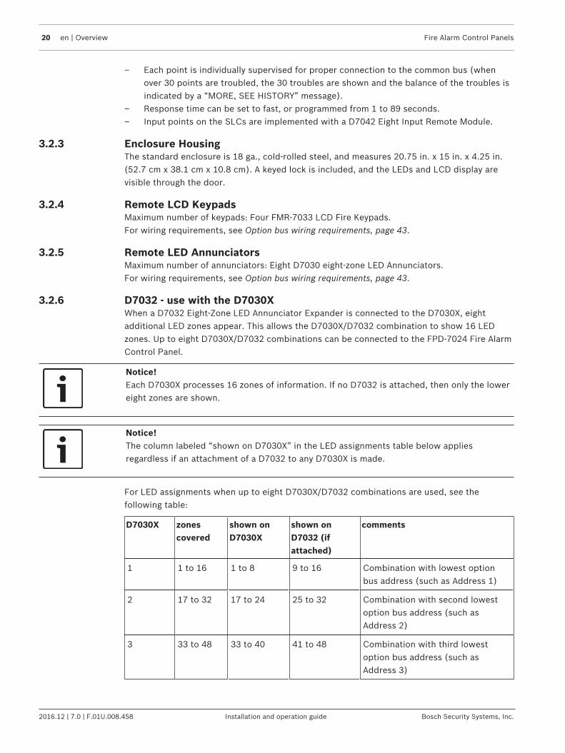
3.2.6 D7032 - use with the D7030XWhen a D7032 Eight-Zone LED Annunciator Expander is connected to the D7030X, eightadditional LED zones appear. This allows the D7030X/D7032 combination to show 16 LEDzones. Up to eight D7030X/D7032 combinations can be connected to the FPD‑7024 Fire AlarmControl Panel.
Notice!Each D7030X processes 16 zones of information. If no D7032 is attached, then only the lowereight zones are shown.
Notice!The column labeled “shown on D7030X” in the LED assignments table below appliesregardless if an attachment of a D7032 to any D7030X is made.
For LED assignments when up to eight D7030X/D7032 combinations are used, see thefollowing table:
D7030X zonescovered
shown onD7030X
shown onD7032 (ifattached)
comments
1 1 to 16 1 to 8 9 to 16 Combination with lowest optionbus address (such as Address 1)
2 17 to 32 17 to 24 25 to 32 Combination with second lowestoption bus address (such asAddress 2)
3 33 to 48 33 to 40 41 to 48 Combination with third lowestoption bus address (such asAddress 3)

Fire Alarm Control Panels Overview | en 21
Bosch Security Systems, Inc. Installation and operation guide 2016.12 | 7.0 | F.01U.008.458
D7030X zonescovered
shown onD7030X
shown onD7032 (ifattached)
comments
4 49 to 64 49 to 56 57 to 64 Combination with fourth lowestoption bus address (such asAddress 4)
5 1 to 16 1 to 8 9 to 16 Fifth combination repeats firstcombination
6 17 to 32 17 to 24 25 to 32 Sixth combination repeats secondcombination
7 33 to 48 33 to 40 41 to 48 Seventh combination repeats thirdcombination
8 49 to 64 49 to 56 57 to 64 Eighth combination repeats fourthcombination
Tab. 3.3: LED assignments for LED Annunciators
For the LED display for Zones 49 to 64, see the following table.
LED Zone Description
1 49 User defined
2 50 User defined
3 51 (reserved)
4 52 General fire alarm monitor waterflow (non-silencable)
5 53 General fire alarm monitor (silencable)
6 54 (reserved)
7 55 General Supervisory (silencable)
8 56 General Waterflow (silencable)
9 57 (reserved)
10 58 General supervisory alarm (non-silencable)
11 59 (reserved)
12 60 (reserved)
13 61 General waterflow alarm (non-silencable)
14 62 (reserved)
15 63 General Alarm, Supervisory, and Waterflow (non-silencable): activewhile any alarm is present; remains active even while system issilenced
16 64 (reserved)
Tab. 3.4: LED display for Zones 49 to 64

22 en | Overview Fire Alarm Control Panels
2016.12 | 7.0 | F.01U.008.458 Installation and operation guide Bosch Security Systems, Inc.
3.2.7 CommunicatorThe communicator can report to two phone numbers or IP addresses with full single, double,and back-up reporting. It communicates in SIA, Modem IIIa2, Contact ID, BFSK, and 3/1 and4/2 formats (available communication formats depend on phone or IP connection).
Notice!The communicator must be enabled and configured to operate. The communicator and phoneline monitors are disabled in the default factory configuration.
Phone Line and Phone Number/IP Selection: To ensure the delivery of critical reports, the firepanel has two phone lines and two phone numbers or IP addresses that can be used forreporting. Reports can be directed to one or both of two phone numbers or IP addressesusing the Report Steering feature in the control panel programming. Note that AccountNumber 1 is used with Phone Number/IP 1, and Account Number 2 is used with PhoneNumber/IP 2. Except for test reports, the control panel automatically selects the phone line orIP address to use. If the report is not successful after two attempts on Line 1, then the controlpanel automatically switches and uses Phone Line 2. One exception is when test reports(manual or automatic) are sent. Test reports are sent every 4 hours to 28 days. Each time atest report is sent, the control panel alternates phone lines. If the user sends two manual testreports, then both phone lines can be tested. The first report uses one line, and the seconduses the other line. During normal operation, the automatic test uses both lines each time.Because the control panel automatically selects which line to use, both phone lines must usethe same dialing sequences for sending reports. For example, a line that requires a 9 to bedialed for an outside line cannot be paired with a line that does not require a 9.For more information on report steering, see Report Steering, page 95.
Notice!PBX lines and ground start lines do not comply with NFPA requirements for digitalcommunication.
While the control panel is idle, the FACP monitors the primary and alternate telephone lines bymonitoring the line for trouble. The FACP monitors each line every 12 seconds. When a troublestill exists after three samples (36 seconds), the FACP sends a trouble report and activatesthe yellow trouble LED and trouble relay.
Danger!When the central station receives the automatic test report only every other day, thisindicates that one phone line at the protected premises is inoperative.Check that Report Steering is set for PHONE/IP 1 ONLY or PHONE/IP 2 ONLY. If not, correctthis immediately because other critical reports can be delayed when the communicator istrying to send the test signal through the inoperative phone line (once each 48 hours).
Supplemental Reporting: While two independent phone lines are required for UL864 CentralStation service, the FACP can be configured with one phone line if the control panel is usedonly for supplemental reporting on a local, remote station or auxiliary system.To install the control panel with only one phone line, connect a jumper from T1 to T2 and ajumper from R1 to R2. These jumper connections are shown in the following figure:

Fire Alarm Control Panels Overview | en 23
Bosch Security Systems, Inc. Installation and operation guide 2016.12 | 7.0 | F.01U.008.458
Figure 3.2: Supplemental Reporting
1 Jumper from R1 to R2 3 House phone
2 Jumper from T1 to T2 4 TELCO line
3.2.8 UsersThe system allows up to 16 individual users or up to 100 users when the Multiplex ExpansionModule is installed. A personal identification number (PIN, the four-digit code entered at thekeypads) and an authority level to determine which functions can be performed can beassigned to each user.For PINs, see Personal Identification Numbers (PINs), page 56.
3.2.9 Lightning protection
Notice!This system is intended for installation entirely within one building.
Metal-oxide varistors (MOVs) and spark gaps provide protection from lightning surges andstatic discharges
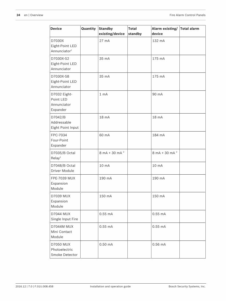
3.2.10 Battery backup calculationWhen a power failure occurs, your control panel has back‑up batteries that continue to powerthe system for the calculated battery backup time. The control panel automatically rechargesthe battery when power is restored. To calculate the standby battery capacity required byNFPA, see the two following tables:
Device Quantity Standbyexisting/device
Totalstandby
Alarm existing/device
Total alarm
FPD‑7024Control Panel
1 220 mA 220 mA 380 mA 380 mA
FMR‑7033Keypad1
80 mA 100 mA
FMR‑7036AnnunciatorKeypad
80 mA 100 mA
24 en | Overview Fire Alarm Control Panels
2016.12 | 7.0 | F.01U.008.458 Installation and operation guide Bosch Security Systems, Inc.
Device Quantity Standbyexisting/device
Totalstandby
Alarm existing/device
Total alarm
D7030XEight‑Point LEDAnnunciator1
27 mA 132 mA
D7030X‑S2Eight‑Point LEDAnnunciator
35 mA 175 mA
D7030X‑S8Eight-Point LEDAnnunciator
35 mA 175 mA
D7032 Eight‑Point LEDAnnunciatorExpander
1 mA 90 mA
D7042/BAddressableEight Point Input
18 mA 18 mA
FPC‑7034Four‑PointExpander
60 mA 184 mA
D7035/B OctalRelay1
8 mA + 30 mA 2 8 mA + 30 mA 2
D7048/B OctalDriver Module
10 mA 10 mA
FPE-7039 MUXExpansionModule
190 mA 190 mA
D7039 MUXExpansionModule
150 mA 150 mA
D7044 MUXSingle Input Fire
0.55 mA 0.55 mA
D7044M MUXMini ContactModule
0.55 mA 0.55 mA
D7050 MUXPhotoelectricSmoke Detector
0.50 mA 0.56 mA

Fire Alarm Control Panels Overview | en 25
Bosch Security Systems, Inc. Installation and operation guide 2016.12 | 7.0 | F.01U.008.458
Device Quantity Standbyexisting/device
Totalstandby
Alarm existing/device
Total alarm
D7050TH MUXPhotoelectricSmoke/HeatDetector
0.50 mA 0.56 mA
D7052 MUX DualInput Fire
0.55 mA 0.55 mA
D7053 MUX I/ OModule Fire
0.70 mA 0.70 mA
FMM-7045/-DMUX PullStations
0.55 mA 0.55 mA
Smoke Detectors
Bells, Horns, andso on
Other Sensors
Other
Grand TotalStandby Existing
Grand TotalAlarm Existing
1 The 24 VDC existing requirements for the D7030X, FMR-7033 and D7035 are shown at 75%of the 12 VDC level shown on the specification sheets for these models. The FACP regulates24 VDC power from the battery to 12 VDC for these accessories.2 Add 30 mA for each relay activated
Tab. 3.5: Standby battery capacity calculations
The units shown in the following table are Amp hours (Ah), and the calculations include a 20%derating factor.
Grand Total Standby Existing (in amps) CS
Total Hours of Standby Required(usually 24 or 60):
HS
Total Standby Capacity (multiply CS x HS) TS= CS x HS
Grand Total Alarm Existing (in amps) CA
Total Hours of Alarm Time Required(usually 0.083 o 0.25):
HA
Total Standby Capacity (multiply CA x HA) TA= CA x HA
Total Capacity Required (add TA + TS): TC = TA + TS
26 en | Overview Fire Alarm Control Panels
2016.12 | 7.0 | F.01U.008.458 Installation and operation guide Bosch Security Systems, Inc.
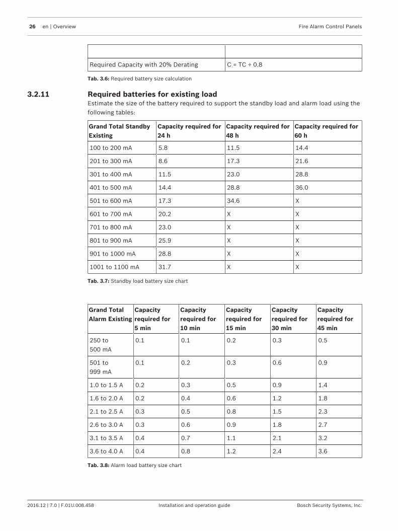
Required Capacity with 20% Derating C = TC ÷ 0.8
Tab. 3.6: Required battery size calculation
3.2.11 Required batteries for existing loadEstimate the size of the battery required to support the standby load and alarm load using thefollowing tables:
Grand Total StandbyExisting
Capacity required for24 h
Capacity required for48 h
Capacity required for60 h
100 to 200 mA 5.8 11.5 14.4
201 to 300 mA 8.6 17.3 21.6
301 to 400 mA 11.5 23.0 28.8
401 to 500 mA 14.4 28.8 36.0
501 to 600 mA 17.3 34.6 X
601 to 700 mA 20.2 X X
701 to 800 mA 23.0 X X
801 to 900 mA 25.9 X X
901 to 1000 mA 28.8 X X
1001 to 1100 mA 31.7 X X
Tab. 3.7: Standby load battery size chart
Grand TotalAlarm Existing
Capacityrequired for5 min
Capacityrequired for10 min
Capacityrequired for15 min
Capacityrequired for30 min
Capacityrequired for45 min
250 to500 mA
0.1 0.1 0.2 0.3 0.5
501 to999 mA
0.1 0.2 0.3 0.6 0.9
1.0 to 1.5 A 0.2 0.3 0.5 0.9 1.4
1.6 to 2.0 A 0.2 0.4 0.6 1.2 1.8
2.1 to 2.5 A 0.3 0.5 0.8 1.5 2.3
2.6 to 3.0 A 0.3 0.6 0.9 1.8 2.7
3.1 to 3.5 A 0.4 0.7 1.1 2.1 3.2
3.6 to 4.0 A 0.4 0.8 1.2 2.4 3.6
Tab. 3.8: Alarm load battery size chart

Fire Alarm Control Panels Overview | en 27
Bosch Security Systems, Inc. Installation and operation guide 2016.12 | 7.0 | F.01U.008.458
3.2.12 Compatible devices
Device Function
B420, B426, or DX4020 module Manages secure, two‑way IP communications over Ethernetnetworks.
B450 with B440, B441, B442, orB443 module or ITS‑DX4020‑Gmodule
Enables two-way IP or dialed communications over acommercial GPRS/GSM network. Typical applications areevent reporting to a central monitoring station and remoteaccess to Bosch control panels. May require an appropriateSIM card and data plan.
D7030 Eight Point LEDAnnunciator
Identifies the location of a fire alarm for up to eight zonesallowed per system.
D7030X Eight Point LEDAnnunciator
Identifies the location of a fire alarm for up to eight zonesallowed per system.
D7030X‑S2 Eight Point LEDAnnunciator
An eight zone LED annunciator, of which two zones arereserved for supervisory functions. It has Power andTrouble LEDs plus eight zone LEDs that can be labeledindividually.
D7030X‑S8 Eight Point LEDAnnunciator
An eight-zone LED annunciator, of which all eight zones arereserved for supervisory functions. It has Power andTrouble LEDs plus eight-zone LEDs that can be labeledindividually.
D7032 Eight Point LEDAnnunciator Expander
Attaches to a D7030X and identifies the location of a firealarm for eight additional zones.
D7035/B Octal Relay Module Provides eight Form C relay outputs for addition to thesystem. The outputs are programmable and can beactivated by system events. Each output operatesindependently of the other seven outputs for completeflexibility. The D7035 connects to the option bus; up totwo are allowed per system. The D7035B comes installedon a mounting skirt.For required enclosure modification, see also the D7035Installation Guide.
D7042/B Eight‑Input RemoteModule
Provides eight Class B input points. Connect up to 10modules to MUX Bus A, and 10 on MUX Bus B. The D7042is powered by 12 VDC supplied by the option bus powerterminals, in addition to the two‑wire data connection. TheD7042 cannot be used on a MUX bus for Class Aconfiguration and operation.
D7044 MUX Single InputModule
Connects a normally‑open contact device to the multiplexbus of the FPD‑7024 with a supervised local loop anddraws operating power from the FPD‑7024.
28 en | Overview Fire Alarm Control Panels
2016.12 | 7.0 | F.01U.008.458 Installation and operation guide Bosch Security Systems, Inc.
Device Function
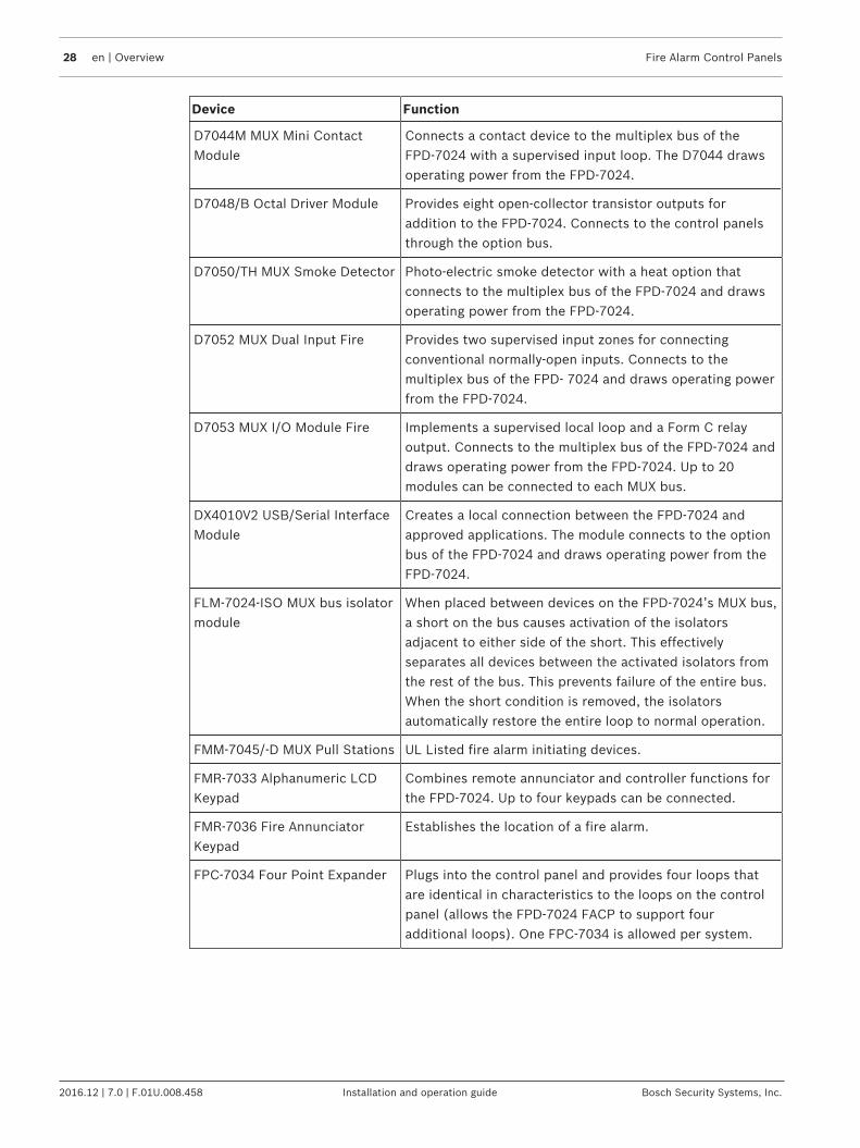
D7044M MUX Mini ContactModule
Connects a contact device to the multiplex bus of theFPD‑7024 with a supervised input loop. The D7044 drawsoperating power from the FPD‑7024.
D7048/B Octal Driver Module Provides eight open‑collector transistor outputs foraddition to the FPD‑7024. Connects to the control panelsthrough the option bus.
D7050/TH MUX Smoke Detector Photo‑electric smoke detector with a heat option thatconnects to the multiplex bus of the FPD‑7024 and drawsoperating power from the FPD‑7024.
D7052 MUX Dual Input Fire Provides two supervised input zones for connectingconventional normally-open inputs. Connects to themultiplex bus of the FPD‑ 7024 and draws operating powerfrom the FPD‑7024.
D7053 MUX I/O Module Fire Implements a supervised local loop and a Form C relayoutput. Connects to the multiplex bus of the FPD‑7024 anddraws operating power from the FPD‑7024. Up to 20modules can be connected to each MUX bus.
DX4010V2 USB/Serial InterfaceModule
Creates a local connection between the FPD‑7024 andapproved applications. The module connects to the optionbus of the FPD‑7024 and draws operating power from theFPD‑7024.
FLM-7024-ISO MUX bus isolatormodule
When placed between devices on the FPD-7024’s MUX bus,a short on the bus causes activation of the isolatorsadjacent to either side of the short. This effectivelyseparates all devices between the activated isolators fromthe rest of the bus. This prevents failure of the entire bus.When the short condition is removed, the isolatorsautomatically restore the entire loop to normal operation.
FMM-7045/-D MUX Pull Stations UL Listed fire alarm initiating devices.
FMR‑7033 Alphanumeric LCDKeypad
Combines remote annunciator and controller functions forthe FPD‑7024. Up to four keypads can be connected.
FMR‑7036 Fire AnnunciatorKeypad
Establishes the location of a fire alarm.
FPC‑7034 Four Point Expander Plugs into the control panel and provides four loops thatare identical in characteristics to the loops on the controlpanel (allows the FPD‑7024 FACP to support fouradditional loops). One FPC‑7034 is allowed per system.

Fire Alarm Control Panels Overview | en 29
Bosch Security Systems, Inc. Installation and operation guide 2016.12 | 7.0 | F.01U.008.458
Device Function
FPE-7039 or D7039 MultiplexExpansion Module
Provides either 2 two-wire Class B multiplex buses or 1four‑wire Class A multiplex bus. In Class A mode, up to 120addressable points can be added. In Class B Mode, up to247 addressable points can be added. The moduleconnects directly to the control panel. One is allowed persystem.
FPP‑RNAC‑8A‑4C Remote NACPower Supply
Connects to the option bus of the FPD‑7024 and adds fourNFPA 72 Class B Notification Appliance Circuits supervisedby the control panel. Up to four are allowed per system.
Tab. 3.9: Compatible devices
Install D7042 modules only at addresses:
9 17 25 33 41 49 57 65
73 81 89 97 105 113 121 129
137 145 153 161 169 177 185 193
201 209 217 225 233 241
Do not install D7052 and D7053 modules at these addresses:
16 24 32 40 48 56 64 72
80 88 96 104 112 120 128 136
144 152 160 168 176 184 192 200
208 216 224 232 240 248 255
Install B420, B426, B450/B440/B441/B442/B443 modules, DX4020, or ITS‑DX4020‑Gmodules only at addresses:
1341 2501
1 An IP connection to RPS can only be created using an IP module at address 250; IPmodules at both addresses 134 and 250 can be used for reporting.
Tab. 3.10: Address restrictions for modules

30 en | Installation Fire Alarm Control Panels
2016.12 | 7.0 | F.01U.008.458 Installation and operation guide Bosch Security Systems, Inc.
4 Installation4.1 UL Listed systems installation guide
4.1.1 FPD‑7024 UL ListingsThe FPD‑7024 is UL Listed for the following:– Commercial Fire Alarm (UL Standard UL864)
– Type Service: Auxiliary, Local, Central Station, and Remote Station– Type Initiating: Automatic, Manual, Sprinkler Supervisory, and Waterflow
Install the control panel according to NFPA 72 for Commercial Fire installations.
4.1.2 Installation considerationsFailure to install and program the control panel according to the requirements in this sectionvoids the listing mark of Underwriters Laboratories.– The standby battery capacity is 7 Ah to 40 Ah at 24 VDC.– The total nominal existing must not exceed 1.25 A in standby or 4 A when in alarm.– The control panel must be mounted indoors and within the protected area.– Grounding must be according to article 250 of the NEC (NFPA 70).– Points must be connected to UL Listed, compatible devices.– The ground wire provided with the enclosure must be connected between the door and
the enclosure using the supplied nuts.– Select Phone Monitoring if the digital alarm communicator transmitter (DACT) feature is
used.
4.1.3 UL requirements
Notice!The system must be tested after installation and after any re-programming, includingprogramming performed by downloading.
When used in UL Listed installations, the control panel must conform to certain programmingrequirements. For acceptable programming selections for Listed applications that meet therequirements of the currently released edition of UL864, see Programming features, page 59.
Commercial Fire Alarm Systems
Notice!This section applies to both Central Station and Local Fire Systems.
Required Accessories– At least one Bosch Security Systems, Inc. Model F220‑P Smoke Detector with an F220
Family Base; or another UL Listed compatible smoke detector.– At least one Horn Strobe or Bell (provides 85 dB for UL985 and NFPA 72 requirements;
other UL Listed compatible devices listed for regulated 24 V can be used) is required forthis application and must be installed inside the protected area.
– Four-wire detectors must be used with UL Listed power supervision devices. Acompatible UL Listed four-wire detector is the Bosch Security Systems, Inc. F220‑P in anF220‑B6 Family Base. Compatible UL Listed relays are the Bosch Security Systems, Inc.D275 and PAM-4.

Fire Alarm Control Panels Installation | en 31
Bosch Security Systems, Inc. Installation and operation guide 2016.12 | 7.0 | F.01U.008.458
– All points must be used with the resistor provided.Report Programming– Program non-supervisory and supervisory reports for those points used.– Program trouble reports.– Set AC Failure Report Delay for a delay of 1 hour to 3 hours.– Set automatic test report frequency to occur at least every 24 hours (pre-NFPA72‑2013;
NFPA72‑2013 requires 6 hrs max).Timer Programming– Program Auto Silence Time for not less than five minutes, or to “0” to disable auto-silence
operation.Point Programming– For fire points: open = trouble, latching.Alarm Output Programming– Program notification appliance circuits to activate from the appropriate input points.Communications Programming– When used for Central Station Service, select a communication format compatible with
the central station. Enable monitoring of both phone lines.
UL Listed Accessory DevicesD132B Multi-use Reversing Relay ModuleThe D132B is a multi-purpose, fully configurable, smoke power-reversing module for activatingdetectors with local annunciation. The D132B operates both two-wire and four-wire circuitsand also works with Class A or Class B initiating circuits. An alarm latch connection isprovided to allow an initiating loop to be held in alarm after the detector loop power isreversed to activate any sounders. The D132B does not affect compatibility between the FACPand detectors, or the FACP and Notification Appliance Circuits (NACs).For detailed installation instructions for the D132B module, see the D132B Installation Guide.D185 Reverse Polarity ModuleThe D185 Reverse Polarity Module is a UL Listed module that connects the control panel witheither a single set or a pair of leased telephone company (TELCO) lines in NFPA 72 remotestation applications. It relays system alarm status information from the control panel to amonitoring station. The D185 operates with either 12 VDC or 24 VDC supply. All circuits arepower limited and have a current between 2.5 mA and 15 mA with nominal current of 10 mA.For typical wiring of the D185 module, see the D185 Installation Instructions.
4.2 Installing the enclosureTo install the enclosure, follow these instructions:1. Using the enclosure as a template, mark the top mounting holes on the mounting surface.2. Start the mounting screws (not supplied) for these two holes.3. Slide the enclosure onto these screws so that the screws rest on the thinner section of
the holes.4. Tighten the screws.5. Install and tighten the remaining two screws in the bottom mounting holes.6. Knock out the desired wire entrances on the enclosure.
For mounting hole locations, see the following figure:

32 en | Installation Fire Alarm Control Panels
2016.12 | 7.0 | F.01U.008.458 Installation and operation guide Bosch Security Systems, Inc.
Figure 4.1: Enclosure installation
1 Control panel location 2 Mounting holes
3 Retainer holes for standoffs 4 Retainer holes for support posts
5 Transformer 6 Stud
7 Ground wire
!
Warning!The FPD‑7024‑LT needs an external power supply for operation!The power supply must meet the following characteristics:INPUT: 240 VAC; 50 HZ; 0.6 A; Class BOUTPUT: 26.0 VAC; 5.5 AUse of a power supply not having the same electrical characteristics may cause shock andserious injuries to persons or objects. Do not connect a power supply with characteristicsdifferent from those specified, since the equipment will be damaged.
Notice!When using the knockouts located at the bottom of the enclosure, install batteries in aseparate enclosure.

Fire Alarm Control Panels Installation | en 33
Bosch Security Systems, Inc. Installation and operation guide 2016.12 | 7.0 | F.01U.008.458
4.3 Installing the FACP
Danger!The control circuit board is static sensitive.To avoid damage to sensitive components, touch ground before handling the control board.This discharges any static electricity in your body. For example, run the ground wire to theenclosure before handling the control circuit board. Continue touching the enclosure whileinstalling the control board.
!
Warning!Before the circuit board is installed, connect the supplied ground wires between the door andthe enclosure and from the transformer to the enclosure using the supplied nuts. Bothgrounds connect to the stud in the enclosure to the left of the circuit board.
For installation illustrations, see the , page 31 and the , page 33.1. Insert the three support posts in the enclosure’s retainer holes.2. Press the 1/8 in. nylon standoffs (P/N: F01U034705) into the retainer holes.3. Slide the top of the control panel onto the retainer tabs (the slots under the top of the
frame). When the control panel is in the retainer tabs, it rests on the posts.4. Secure the bottom of the circuit board by inserting and tightening the screws at the two
bottom corners through the support posts and the retainer holes.For installing standoffs and support posts, see the following figure:
Figure 4.2: Standoff and support post installation
1 1/8 in. nylon standoff 4 Corner of circuit board
2 Retainer holes 5 Support post
3 Support post assembly 6 Retainer hole in enclosure
4.4 Installing optional equipmentTwo expansion options connect directly to the control panel, and are automatically detectedand supervised when the control panel is powered:– FPC-7034 Four Point Expander– FPE-7039 or D7039 Multiplex Expansion ModuleWhen the control panel is powered after installing one of these options, the control paneldisplays one of the following windows:

34 en | Installation Fire Alarm Control Panels
2016.12 | 7.0 | F.01U.008.458 Installation and operation guide Bosch Security Systems, Inc.
4Z EXP DETECTED
PRESS BACK KEY
MUX DETECTED
PRESS BACK KEY
Press the key to confirm the installation of the device and automatically set it up forsupervision.If the key is not pressed during the power-up time-out period, the control panel resumesoperation using the last confirmed status of the affected expander and displays an installationerror condition.
!
Warning!Expansion devices such as point expanders and multiplex expanders are disabled if they areremoved from the control panel configuration after installation. You cannot disablesupervision of these devices when they are installed.
For additional information, see the installation instructions for the specific expanders.
Notice!EEPROM fault at first installationWhen the Multiplex Expansion Module is first installed, the system displays an EEPROM fault.Execute the default procedure to synchronize the EEPROM on the expansion module to theEEPROM in the control panel. Remove power to the control panel, then reapply power and re-install option bus devices after the default procedure.
Notice!Loss of programmingReplacing a Multiplex Expansion Module causes the loss of programming of expansion pointsand PINs. Reprogram all multiplex point and PINs if you replace the module.
When the Multiplex Expansion Module is first installed, or anytime the control panel ispowered with a module that has no points programmed, the system automatically starts themultiplex auto-programming process:
AUTO PROGRAM?
_______:YES(1) NO(0)
Pressing the key starts auto-programming and pressing allows the control panel tocontinue normal startup. The menu automatically closes with NO selected if no key is pressedafter several minutes.For detailed instructions on the auto-programming mode, see AUTO PROGRAM, page 103.
4.5 Installing detection devicesGeneral considerations

Fire Alarm Control Panels Installation | en 35
Bosch Security Systems, Inc. Installation and operation guide 2016.12 | 7.0 | F.01U.008.458
Proper location of detection devices is one of the most critical factors in a fire alarm system.Smoke detectors should not be installed in dead air spaces or close to ventilating or airconditioning outlets because smoke can be circulated away from the detector. Locations nearair inlets are favored.Avoid areas subject to normal smoke concentrations such as kitchens, garages, or nearfireplaces.Do not install smoke detectors where normal area temperatures are above +100°F (+38°C) orbelow +32°F (0°C).Avoid areas of high humidity and dust concentrations.For exact mounting information, refer to the instructions provided with the smoke detectors.Family residencesMost fire deaths occur in the home, especially during sleeping hours. The minimum level ofprotection requires smoke detectors to be installed outside of each separate sleeping areaand on each additional story of the dwelling.
Notice!For added early warning protection, install detectors in all separate areas including thebasement, bedrooms, dining room, utility room, furnace room, and hallways.
For residential smoke detector locations, see the chapter in NFPA 72 on Single- andMultiple‑Station Alarms and Household Fire Alarm Systems.

36 en | Connection Fire Alarm Control Panels
2016.12 | 7.0 | F.01U.008.458 Installation and operation guide Bosch Security Systems, Inc.
5 Connection5.1 FACP terminal connection
Danger!Incorrect connections can result in damage to the unit and personal injury.
!
Warning!Before servicing this equipment, remove all power including that from the transformer,battery and phone lines.
Notice!Shared cable is not recommended for option bus, telephone or NAC wiring.
Notice!All wiring except battery terminal and primary AC power is power-limited. Primary AC andbattery wires must be separated from other wires by at least ¼ in. (64 mm) and tied toprevent movement.
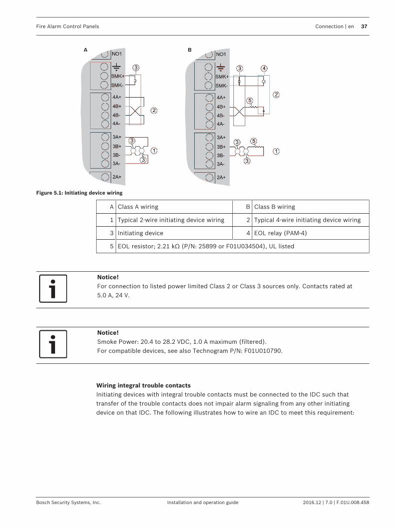
Input Points 1-4:Points (supervised) are intended for connection of normally-open/normally-closed contacts.They may also be used for compatible two-wire smoke detectors. All EOL resistors are2.21 kΩ, P/N: 25899 or F01U034504 Bosch, UL listed. Initiating devices are Class B or Class A.Two‑wire Compatibility Identifier "A".
Fire Alarm Control Panels Connection | en 37
Bosch Security Systems, Inc. Installation and operation guide 2016.12 | 7.0 | F.01U.008.458
Figure 5.1: Initiating device wiring
A Class A wiring B Class B wiring
1 Typical 2‑wire initiating device wiring 2 Typical 4‑wire initiating device wiring
3 Initiating device 4 EOL relay (PAM-4)
5 EOL resistor; 2.21 kΩ (P/N: 25899 or F01U034504), UL listed
Notice!For connection to listed power limited Class 2 or Class 3 sources only. Contacts rated at5.0 A, 24 V.
Notice!Smoke Power: 20.4 to 28.2 VDC, 1.0 A maximum (filtered).For compatible devices, see also Technogram P/N: F01U010790.
Wiring integral trouble contactsInitiating devices with integral trouble contacts must be connected to the IDC such thattransfer of the trouble contacts does not impair alarm signaling from any other initiatingdevice on that IDC. The following illustrates how to wire an IDC to meet this requirement:
38 en | Connection Fire Alarm Control Panels
2016.12 | 7.0 | F.01U.008.458 Installation and operation guide Bosch Security Systems, Inc.
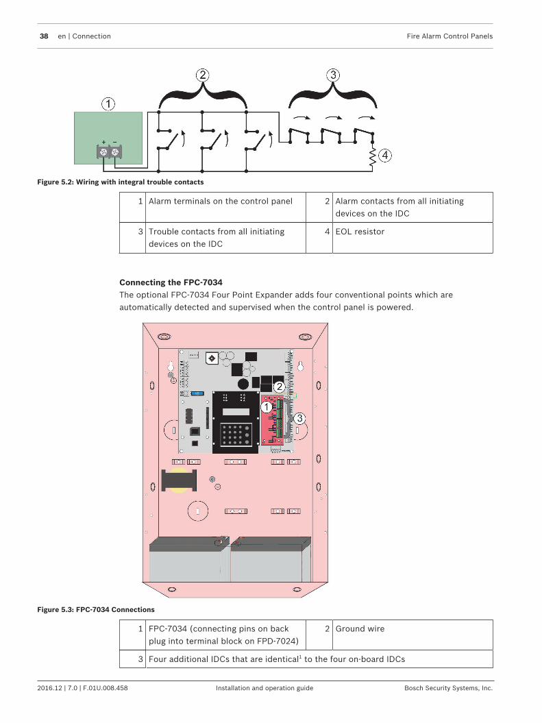
Figure 5.2: Wiring with integral trouble contacts
1 Alarm terminals on the control panel 2 Alarm contacts from all initiatingdevices on the IDC
3 Trouble contacts from all initiatingdevices on the IDC
4 EOL resistor
Connecting the FPC-7034The optional FPC-7034 Four Point Expander adds four conventional points which areautomatically detected and supervised when the control panel is powered.
Figure 5.3: FPC-7034 Connections
1 FPC-7034 (connecting pins on backplug into terminal block on FPD‑7024)
2 Ground wire
3 Four additional IDCs that are identical1 to the four on‑board IDCs

Fire Alarm Control Panels Connection | en 39
Bosch Security Systems, Inc. Installation and operation guide 2016.12 | 7.0 | F.01U.008.458
1 The IDCs provided by the FPC-7034 cannot be programmed for Alarm Verification.
On-board relays:The main control panel includes three Form “C” relays (Relay 1, Relay 2, and Relay 3). Therelay contacts are rated at 5 A, 28 VDC. No over existing limiting is performed on the contactsof these relays. The default selection for the relays is to indicate general alarm and generalsystem trouble and supervisory. By using point or zone mapping, they can be programmed toactivate in a wide variety of conditions.
Notice!When a local relay is programmed for trouble, it is energized in the normal state. This causesthe common and normally open terminals to be shorted when not in the trouble condition.
Figure 5.4: On-board relays
Phone line connections:
Figure 5.5: Telephone lines 1 and 2
40 en | Connection Fire Alarm Control Panels
2016.12 | 7.0 | F.01U.008.458 Installation and operation guide Bosch Security Systems, Inc.
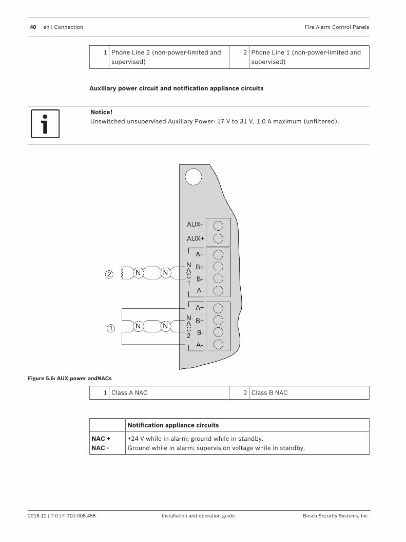
1 Phone Line 2 (non-power-limited andsupervised)
2 Phone Line 1 (non-power-limited andsupervised)
Auxiliary power circuit and notification appliance circuits
Notice!Unswitched unsupervised Auxiliary Power: 17 V to 31 V, 1.0 A maximum (unfiltered).
Figure 5.6: AUX power andNACs
1 Class A NAC 2 Class B NAC
Notification appliance circuits
NAC +NAC -
+24 V while in alarm; ground while in standby.Ground while in alarm; supervision voltage while in standby.

Fire Alarm Control Panels Connection | en 41
Bosch Security Systems, Inc. Installation and operation guide 2016.12 | 7.0 | F.01U.008.458
Battery Connections and fuse
Figure 5.7: Battery connections and fuse
1 Battery 1 (12 Vdc in series with battery2)
2 Battery 2 (12 Vdc in series with battery1)
Danger!Explosion and burn hazard!Do not short terminals!
Batteries:
BAT -BAT +
Requires two 12 V batteries in series, for a combined voltage of 24 V.Charge current = 1.7 A, maximum
MUX bus connectionsThe optional FPE-7039 Multiplex (MUX) Expansion module connects directly to the FACP foreither two Class B MUX buses or one Class A MUX bus that allow up to 247 remote pointswhich are automatically detected and supervised when the control panel is powered.For more information regarding Class A and Class B wiring instructions, see also the MultiplexExpansion Module’s Installation Guide. For mounting locations inside the FPD‑7024’senclosure and wiring possibilities for the Multiplex Expansion Module and its I/O module, seethe following figure:

42 en | Connection Fire Alarm Control Panels
2016.12 | 7.0 | F.01U.008.458 Installation and operation guide Bosch Security Systems, Inc.
Figure 5.8: MUX_bus_connections
1 Connection between FPE‑7039 and I/Omodule
2 Connection between FPE‑7039 andFPD‑7024 ground
3 FPE-7039 board 4 I/O module
5 Connection between I/O module andFPD‑7024 ground terminal
6 Mounting standoffs for I/O module
7 I/O module (upper module showsClass A wiring); bottom module showsClass B wiring with D7042 and withEOL relay)
8 Connection between I/O module andFPE‑7039 (see also callout 1)
9 Connection between I/O module andFPD‑7024 ground terminal (see alsocallout 5)
10 MUX Class A (addresses 9 to 128)
11 Power connection to FPP‑RNAC‑8A‑4C 12 D7042 Eight Point Input module
13 Connection (MUX+) between I/Omodule and D7042
14 EOL relay
Fire Alarm Control Panels Connection | en 43
Bosch Security Systems, Inc. Installation and operation guide 2016.12 | 7.0 | F.01U.008.458
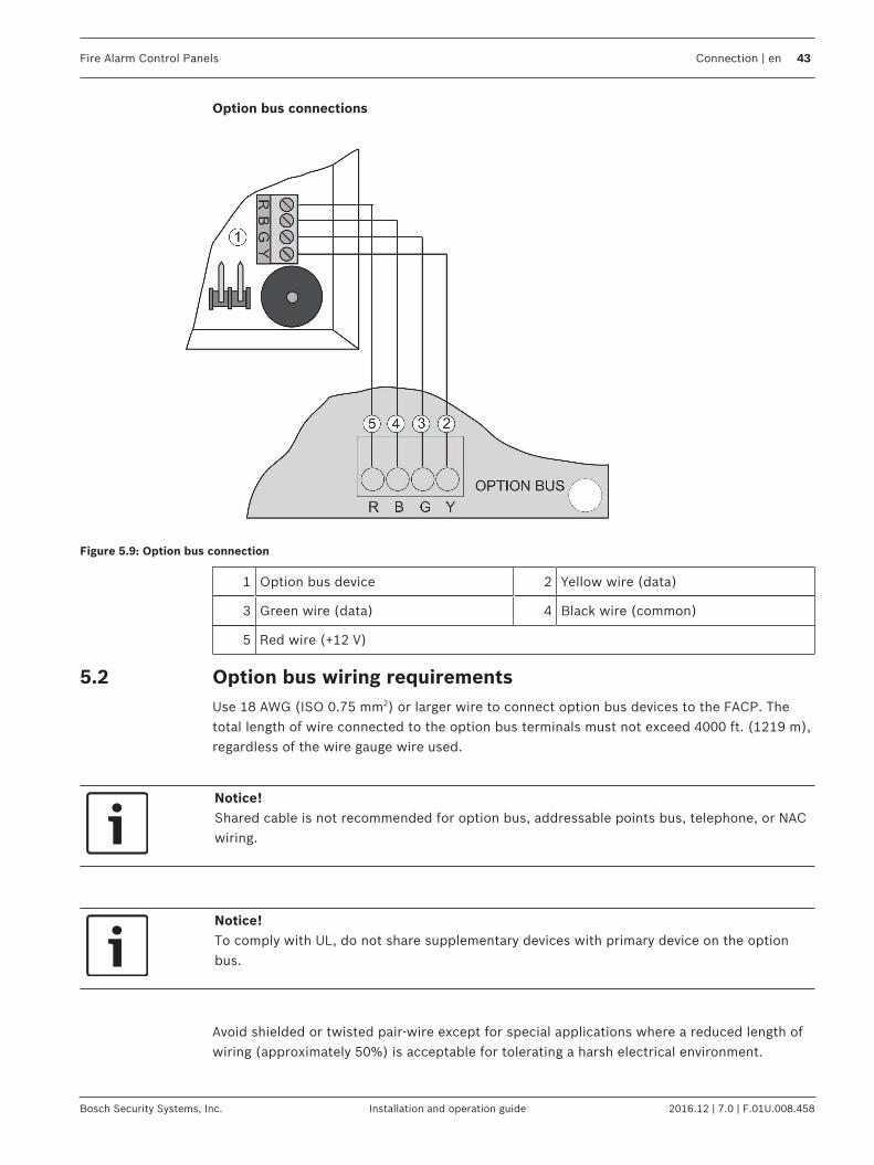
Option bus connections
Figure 5.9: Option bus connection
1 Option bus device 2 Yellow wire (data)
3 Green wire (data) 4 Black wire (common)
5 Red wire (+12 V)
5.2 Option bus wiring requirementsUse 18 AWG (ISO 0.75 mm2) or larger wire to connect option bus devices to the FACP. Thetotal length of wire connected to the option bus terminals must not exceed 4000 ft. (1219 m),regardless of the wire gauge wire used.
Notice!Shared cable is not recommended for option bus, addressable points bus, telephone, or NACwiring.
Notice!To comply with UL, do not share supplementary devices with primary device on the optionbus.
Avoid shielded or twisted pair-wire except for special applications where a reduced length ofwiring (approximately 50%) is acceptable for tolerating a harsh electrical environment.
44 en | Connection Fire Alarm Control Panels
2016.12 | 7.0 | F.01U.008.458 Installation and operation guide Bosch Security Systems, Inc.
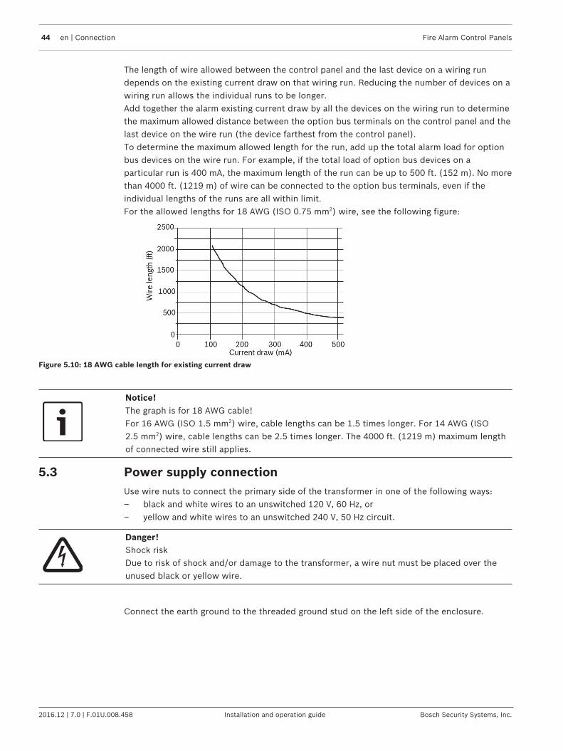
The length of wire allowed between the control panel and the last device on a wiring rundepends on the existing current draw on that wiring run. Reducing the number of devices on awiring run allows the individual runs to be longer.Add together the alarm existing current draw by all the devices on the wiring run to determinethe maximum allowed distance between the option bus terminals on the control panel and thelast device on the wire run (the device farthest from the control panel).To determine the maximum allowed length for the run, add up the total alarm load for optionbus devices on the wire run. For example, if the total load of option bus devices on aparticular run is 400 mA, the maximum length of the run can be up to 500 ft. (152 m). No morethan 4000 ft. (1219 m) of wire can be connected to the option bus terminals, even if theindividual lengths of the runs are all within limit.For the allowed lengths for 18 AWG (ISO 0.75 mm2) wire, see the following figure:
Figure 5.10: 18 AWG cable length for existing current draw
Notice!The graph is for 18 AWG cable!For 16 AWG (ISO 1.5 mm2) wire, cable lengths can be 1.5 times longer. For 14 AWG (ISO2.5 mm2) wire, cable lengths can be 2.5 times longer. The 4000 ft. (1219 m) maximum lengthof connected wire still applies.
5.3 Power supply connectionUse wire nuts to connect the primary side of the transformer in one of the following ways:– black and white wires to an unswitched 120 V, 60 Hz, or– yellow and white wires to an unswitched 240 V, 50 Hz circuit.
Danger!Shock riskDue to risk of shock and/or damage to the transformer, a wire nut must be placed over theunused black or yellow wire.
Connect the earth ground to the threaded ground stud on the left side of the enclosure.

Fire Alarm Control Panels Connection | en 45
Bosch Security Systems, Inc. Installation and operation guide 2016.12 | 7.0 | F.01U.008.458
AUX-
AUX+
A+
B+
B-
A-
NAC
1
2
NAC
BAT-
24V
BAT+
A+
B+
B-
A-
2A+
2B+
2B-
2A-
1A+
1B+
1B-
1A-
4A+
4B+
4B-
4A-
3A+
3B+
3B-
3A-
B G Y
OPTION BUS
NC3
COM3
NO3
T1
NC2
COM2
NO2
NC1
COM1
NO1
SMK+
SMK-
HT1
HR1
R1
T2
HT2
HR2
R2
R
2
1
3
4
15
Figure 5.11: Transformer wiring
1 Supply wires (hot, neutral, andground)
2 Secondary wire held in place by wireties
3 Grounding post (connect to groundwire)
4 Primary wiringyellow: unswitched 240 V, 50 Hz, black: unswitched 120 V, 60 Hz, andwhite: common Use a wire nut on unconnected blackor yellow wire.
Danger!Electrical shock hazardThe unused yellow or black primary wire must have a wire nut on its end to prevent contactwith the bare wire.

46 en | System operation Fire Alarm Control Panels
2016.12 | 7.0 | F.01U.008.458 Installation and operation guide Bosch Security Systems, Inc.
6 System operation6.1 Modes of Operation
There are four modes of system operation for the FPD‑7024: normal, alarm, supervisory, andtrouble. Alarm, supervisory, and trouble are off‑normal conditions.
6.1.1 NormalWhen the system operates normally, it shows SYSTEM NORMAL on the top line of the display,the Power LED lights steadily, and no other LEDs are lit. The bottom line indicates the existingdate MM/DD/YY and time HH:MM. If the system is programmed to require a PIN, then thesecond line of the LCD screen shows ENTER PIN.
6.1.2 Off-normal DisplaysControl panel alarms and problems are indicated on the top line of the display. Contact yourinstalling company if problems persist.For the alarm/problem messages, see the following table:
Off-Normal Display Description
XXX/XXX FIR: XXXXX One or more fire or waterflow points are in alarm.
XXX/XXX SUP: XXXXX One or more supervisory conditions exist.
XXX/XXX TRB: XXXXX A trouble condition exists (AC power failure, phone linetrouble, and so on).
Tab. 6.11: Off-normal displays
6.1.3 AcknowledgeWhen the control panel is off-normal, the control panel’s piezo (buzzer) can be silencedwithout silencing the NACs or resetting the control panel. Press the [ACK] button on the localor remote keypad to silence only the piezo.
6.1.4 AlarmWhen an alarm occurs, the top line shows the number of alarms and the point that is in alarm.The bottom line alternates between the instructions and the programmed description for theaffected point. When you back out of the detail view and go to the group view by pushing the
key, the top line of the display shows ALARM (XXX), where XXX indicates the number ofalarms. This display overrides any other system display. The built-in sounder turns on with asteady tone, and outputs programmed to activate with the existing alarm condition(s)activate.When the control panel is not scanning the inputs, as during smoke power reset, or on-siteprogramming, the trouble LED flashes to indicate this condition.
6.1.5 SupervisoryWhen a Supervisory condition occurs, the top line shows the number of supervisories and thepoint that is in the supervisory condition. The bottom line alternates between the instructionsand the programmed description for the affected point. When you back out of the detail viewand go to the group view by pushing the key, the top line of the display shows supervisory(XXX), where XXX indicates the number of supervisory conditions. The bottom line indicatesmore instructions. The built‑in sounder beeps. Outputs programmed to activate with theexisting condition(s) then activate.
Fire Alarm Control Panels System operation | en 47
Bosch Security Systems, Inc. Installation and operation guide 2016.12 | 7.0 | F.01U.008.458
6.1.6 TroubleWhen a trouble condition occurs (such as cut wiring for a point or AC power fails), thesounder beeps every 10 seconds. The Trouble LED lights and the LCD shows the troublecondition. When you back out of the detailed screen when the key is pressed the group isentered and shows TROUBLE (XXX). The system can diagnose and show a variety of troubleconditions, including those affecting the input points, NAC circuits, power, battery, systemgrounding, and internal operations of the fire control panel. Notify your installing companyimmediately if the system trouble message appears.Press the key to silence the system trouble beep.
6.1.7 Fire Silence/Reset
Danger!Fire Alarm!During a fire alarm, exit from the premises immediately. Do not enter the premises unlessaccompanied by the appropriate emergency services' personnel, or until they have given theOK to enter.
When it is determined that there is no fire, then you can silence the horns or bells to allowmore investigation of the devices that initiated the alarm, or you can reset the system toreturn it to normal operation.
Notice!Before resetting fire alarmsBefore using the key, determine which smoke detector initiated the alarm so that themonitoring company can check that the system is operating correctly. When the control panelis being used as an addressable control panel, use the key to determine which address is inalarm.
When the system is configured to allow alarm silencing, the key turns off the horns or bells,but does not reset the alarm status and does not return the activated input to normal service.Detectors that were activated stay in alarm and can be checked (usually by observing an LEDon the device) to see which detector caused the alarm. When the detectors causing the alarmare identified, reset the system to return it to normal service.The key clears the system alarm status, and briefly turns off power to the detectors to resetthem. This command is required after any fire alarm affecting a point programmed for latchingoperation (which is the normal configuration). This operation is also required to reset Class Amultiplex (SLC) wiring fault troubles.The software automatically supervises the system software for proper operation. If the systemfails, then a CPU FAULT message appears, and the nature of the failure can be optionallyrecorded in the history buffer. To enable history buffer recording for CPU faults, programOutput Zone D of onboard Relay 2 to Zone 51 (unused). The history buffer message, ifenabled, shows CPUFLTxxx, where xxx is an error code. If the display shows CPU FAULT, thencontact Bosch Security Systems, Inc. Technical Support and report the history buffer codealong with a description of the operations that caused the fault. Unusual conditions duringprogramming and debugging operations can result in a CPUFLT message in the history buffer.If this occurs when the control panel is in service, then report it to Technical Service.

48 en | System operation Fire Alarm Control Panels
2016.12 | 7.0 | F.01U.008.458 Installation and operation guide Bosch Security Systems, Inc.
6.2 Basic System Use
6.2.1 Function keysA keypad that does not require a PIN number shows (under normal conditions) SYSTEMNORMAL on the top line, and existing date and time on the bottom line. On a keypad thatdoes require a PIN number, enter the PIN number first. This enables the function keys.
6.2.2 Selecting menu itemsDepending on the level in the system (menu, sub-menu, sub-sub-menu), you can select an itemthree different ways:1. TEST, HISTORY, DISABLE and DRILL each have an exclusive key on the keypad in the
main menu. To select one of these menu items, press the corresponding key. Forexample, to select TEST, press the key.
2. The and keys are not exclusive, but are shared with other characters. To select oneof these items, press the corresponding key. For example, the key is also 0.
3. The key corresponding to a sub-menu item might appear in the second line preceding adash. Press the corresponding key to select that item. For example, press to selectPROG TIMES.
While a menu is active, you do not need to wait for the desired menu item to appear beforemaking your selection. You can select any item on the existing menu rotation at any time.
6.2.3 After Main Menu item selectedWhen a main menu item is selected, the keypad might prompt you to enter your PIN. If so,enter the number (factory default is 9876) and press the key (or press the key labeled withthe desired command directly). The display automatically retrieves the sub-menu display.
6.2.4 Returning to an earlier screenTo return to a previous screen at any time, press the key. To return to the SYSTEM NORMALdisplay, press the key repeatedly until you reach SYSTEM NORMAL. When you reachSYSTEM NORMAL, you cannot go any farther.
6.2.5 Entering dataWhen a sub-menu item asks you to enter data, enter the data and press the key. If dataalready exists at a particular location, you can either accept that data or enter new data. Whenyou press the key to enter the data, the display returns you to the previous sub-menudisplay.
6.2.6 DrillThe key activates all NACs and no relays. It creates a history log entry and, as an option, canbe reported to the central station.
6.2.7 DisableUse the key to disable input points, outputs, or the dialer. When any device is disabled, thesystem shows this condition on the LCD and on the system trouble LED. The Disable All Inputsoperation takes several seconds to perform, during which time the system display remainsfixed.

Fire Alarm Control Panels System operation | en 49
Bosch Security Systems, Inc. Installation and operation guide 2016.12 | 7.0 | F.01U.008.458
6.2.8 History
Notice!If a system without a Multiplex Expansion Module loses all power (AC and standby battery),then all history events are cleared.
The HISTORY option is a chronological list of system events that occurred. Press the key toselect HISTORY from the Main Menu (SYSTEM NORMAL display).On an FACP with a Multiplex Expansion Module, up to 499 History events are supported.On an FACP without a Multiplex Expansion Module, up to 99 History events are supported.After you press the key, the most recent system event appears on the top line of the LCDwith the time and date below it.Example: (Assume you pressed the key at the Main Menu):While the first event shows, the bottom line toggles every four seconds between the time anddate that the event occurred.To return to a previous screen in the history buffer, press .To scroll to the next event record,press .For abbreviations used in history events, see the following table:
Abbreviation Meaning Abbreviation Meaning
ALRM Alarm OFFNORM Off Normal at Test
ARST Alarm Restore PH1 Phone Line 1
AUTOTST Auto Test PH2 Phone Line 2
BATT:LOW Battery Low RSTR Restore
BAT:RSTR Battery Restore S Supervisory
CPUFLT Internal Error SMK:FLT Smoke Power Fault
DRILL:BEG Drill Begin SYSRESET System Reset
DRILL:OVR Drill Over SYSRST System Restore
DRST Dirty Restore SYSTRB System Trouble
DRTY Dirty SYS:WDOG Automatic CPU Reset(Watchdog)
DSBL Disable TRBL Trouble
EE2 EEPROM TRST Trouble Restore
ENBL Enable TST:BEG Test Begin
F Fire TST:OVR Test Over
MANULTST Manual Test W Waterflow
Tab. 6.12: History event abbreviations
For additional history log ID information, see the Modem IIIa2 reporting table.

50 en | System operation Fire Alarm Control Panels
2016.12 | 7.0 | F.01U.008.458 Installation and operation guide Bosch Security Systems, Inc.
6.2.9 Remote ProgrammingCall for remote programmingPhone Numbers 1 and 3 must be programmed, along with Account Code 1. The control panelcalls Phone Number 3 and attempts to connect to RPS. This function requires an access codewith programming authority (Level 1).
Notice!While programming is underway, the TROUBLE LED is on.
Answer for remote programmingThe control panel immediately seizes the phone line to answer a remote programming call.While programming is underway, the Trouble LED is on. This also allows direct connection toRPS. This function requires an access code with programming authority (Level 1).
Notice!UL requirementThe “answer for remote programming” function is not permitted by the current releasededition of UL864.
6.3 Keypads
6.3.1 Built-in keypadThe keypad built into the control/communicator is an alphanumeric LCD keypad. It has a two-line by 16-character display to provide information on various control panel functions. Usually,the first line shows the off-normal condition, while the second line describes specific detailsthat might be relevant to the existing system status. A built-in sounder annunciates keystrokeentries and acts as a warning device.
Figure 6.1: Built-in keypad

Fire Alarm Control Panels System operation | en 51
Bosch Security Systems, Inc. Installation and operation guide 2016.12 | 7.0 | F.01U.008.458
1 Green Power LED: is on when the ACpower is present, and flashes whenthe unit is operating from batterypower.
2 Yellow Trouble LED: lights when thesystem is faulted. The Trouble LEDflashes while programming mode isactive and whenever inputs are notactive, such as during smoke powerreset or alarm verification.
3 Red Alarm LED: lights when the systemis in an alarm condition and has notbeen reset.
4 Yellow Silenced LED: lights when theuser manually silences an event that isprogrammed as silencable; turns offwhen the condition that was silencedis corrected.
5 Yellow Supervisory LED: lightswhenever the system is in asupervisory condition.
6 Yellow GND Fault LED: lights wheneverthe system detects a ground faultcondition.
7 Drill key: used to activate the NACsmanually. It creates a history log entryand, as an option, reports to thecentral station.
8 Acknowledge key: to silence localkeypad sounders and to step throughthe groups of off-normal conditions.
9 Disable key: used to disable orre‑enable inputs, NACs or relays(outputs), and the dialer
10 Silence key: mutes the bell or sirensfor an alarm condition, if the system isso configured.
11 Test key: used to select one of sevenspecial test modes.1
12 Reset key: briefly (programmable from1 to 16 seconds) turns off power tothe detectors to reset them and clearsany off- normal conditions.
13 History key: to view system events. 14 Enter key: to accept data when in theprogramming mode.
15 0/Prog key: for selecting theprogramming mode.
16 Back key: used during programming toexit from menus or to exit from theprogramming mode entirely.
1 For test modes, see Testing, page 52.
For abbreviations on the keypad and control panel, see Appendix B: Panel Displays, page 111.
6.3.2 FMR-7033 keypadThe FMR-7033 Keypad is an alphanumeric LCD keypad. Up to four of these keypads can bemounted apart from the main control panel to provide additional locations for system statusand control. The LCD display and keys operate identically to those of the built-in keypad onthe control panel.

52 en | System operation Fire Alarm Control Panels
2016.12 | 7.0 | F.01U.008.458 Installation and operation guide Bosch Security Systems, Inc.
Figure 6.2: FMR-7033 keypad
1 LEDs 2 Keypad Display
3 Keys
6.3.3 FMR-7036 Annunciator KeypadThe FMR‑7036 is a four‑wire LCD annunciator keypad used with the FPD‑7024 to establish thelocation of a fire alarm. The two‑line, 16‑character display is capable of showing all messagesnormally displayed on the control panel. All alarm and status messages are included. Fouron‑board LEDs provide easy reading of the annunciator's status from a distance. There areSilence and Reset buttons for controlling annunciator and control panel operation. A built‑inkeyswitch offers extra security by locking the annunciator to prevent unwanted soundersilencing or control panel resetting.
Figure 6.3: FMR-7036 Annunciator Keypad
6.4 Testing
6.4.1 Walk testThe Walk Test allows a technician to initate each point manually to ensure that detectorsconnected to a point initiate a response at the control panel. While in this mode, the LCDshows the system test status and the sounder beeps every 10 seconds indicating trouble. NACoutputs activate during this test as points are alarmed and restored based on the followingsettings:– NAC CONFIRM: 5 second activation– SILENT: outputs do not activate
Fire Alarm Control Panels System operation | en 53
Bosch Security Systems, Inc. Installation and operation guide 2016.12 | 7.0 | F.01U.008.458
As each point is activated, the outputs activate once (if selected) and power is reset. As eachpoint is activated, alarms and restorals are logged in the control panel’s history log. When thepoint returns to standby, the outputs activate twice. The control panel attempts to resetpoints ten times to restore them. Points remaining alarmed when exiting from the walk testmode cause an immediate alarm.
6.4.2 Communicator testThe communicator sends a test report or reports according to the report steeringprogramming. While communication is in progress, the Power LED flashes. When thecommunication succeeds, a long keypad beep sounds, the Power LED returns to normal, andthe display returns to normal.
Notice!This test is available only if your system sends alarms and system information to a monitoringservice, and was programmed by the security installing company to permit communicatortests.
!
Warning!Reset upon termination of testTerminating the communicator test function (with the key) resets the communicator anddiscards all unsent reports. When an off-normal condition occurs during a Communicator test,the test automatically resets, clearing all reports, so the off-normal conditions are sentnormally.
6.4.3 Battery/NAC circuits test
Notice!Fully charged batteriesThe batteries must be fully charged before running this test to determine if they need to bereplaced. To ensure the batteries are fully charged before beginning this test, make sure thesystem has been in normal operating mode for 48 hours.
In this test mode, the system operates the local NAC circuits to measure short‑time dischargeof the battteries. The test results (PASS [batteries are okay] or FAIL [batteries need to bereplaced]) are shown at the end of the test, and are not reported to the central station. At theend of the test, you can press the key to back out of the TEST mode, press the key toreturn the display to standby mode, or allow the system to time out (return to standby mode)after three minutes.
6.4.4 Activate outputs testThis test turns a selected output on and off manually.
6.4.5 Input level testThis test shows the status of a selected on‑board point. The loop existing through the point isshown. Normal loops show 11 mA to 15 mA. Loops in alarm show over 25 mA, and loops introuble show less than 6 mA.

54 en | System operation Fire Alarm Control Panels
2016.12 | 7.0 | F.01U.008.458 Installation and operation guide Bosch Security Systems, Inc.
6.4.6 MUX testThis test allows activation of the special test mode for addressable (multiplex) devices. Thisapplies only if the optional Multiplex Expansion Module is installed. When this test mode isselected, the system asks which bus to test, 1 or 2. There is only one bus, but on the I/O card,1 corresponds to the terminals labelled A and 2 corresponds to the terminals labelled B.Select 1 to test points 9 to 128 and select 2 to test points 129 to 255. The system presents 5options:1. List Devices: Shows the point numbers of all devices on the selected bus. Some devices
(such as a dual point module) can use two or more points2. List Holes: Lists locations on the bus that have no assigned device. This can help to find
programming errors or identify an available address for a new device.3. Show Extras: The system scans the bus to identify devices that are present on the bus,
but are not programmed into the system. Scanning the bus takes about 90 sec. andrestoring the bus after scanning also takes about 90 sec. The system cannot identifydevices above Address 128 on Bus 1, or below Address 129 on Bus 2. If you know that adevice is connected to the system but cannot find it, ensure that it is connected to thecorrect bus: 9 to 128 for Bus 1, 129 to 255 for Bus 2.
4. Show Missing: Lists devices programmed into the system but not present on the bus arelisted. Unless a device was programmed into the system (such as using MUX EDIT), it isnot considered missing.
5. Show Status: After you select a device and press the key, this test shows detailedstatus information for the selected device. Eight conditions (not all status conditionsapply to or are supported by all devices) are shown. See the display shown below (whichupdates automatically every five seconds). For this option, you can view the status of anyMUX device regardless of which bus you selected to test when test mode was entered.
‑XxLxRxDxMxTxFxAx
The x is either 0 or 1 depending on whether the condition is false or true (0=false and 1=true).The letters indicate the condition.– X: Reserved for future use.– L: Commanded relay state ‑ this is how the output relay should be set.– R: Actual relay state ‑ this is how the output relay is actually set.– D: Detector dirty ‑ the detector is excessively sensitive.– M: Missing device ‑ the device cannot be found on the loop. Unless a device was
programmed into the system (such as using MUX EDIT), it is not considered missing.– T: Tamper ‑ the detector’s case was opened.– F: Loop fault ‑ the loop from a contact input device is open, or the device is faulted.– A: Loop alarm ‑ the point is in alarm.Pressing the ends the display for any of these modes.Examples: X0L0R0D0M0T0F0A0 (relay off, not dirty, not missing, no tamper, no fault and noalarm).
6.4.7 Sensitivity testTests the MUX smoke detectors to determine if they are within their normal range ofsensitivity. Press the key, then .
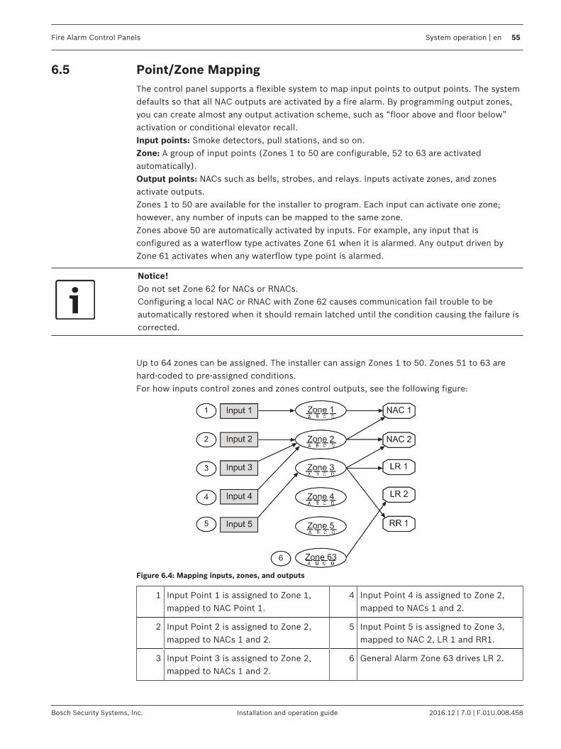
Fire Alarm Control Panels System operation | en 55
Bosch Security Systems, Inc. Installation and operation guide 2016.12 | 7.0 | F.01U.008.458
6.5 Point/Zone MappingThe control panel supports a flexible system to map input points to output points. The systemdefaults so that all NAC outputs are activated by a fire alarm. By programming output zones,you can create almost any output activation scheme, such as “floor above and floor below”activation or conditional elevator recall.Input points: Smoke detectors, pull stations, and so on.Zone: A group of input points (Zones 1 to 50 are configurable, 52 to 63 are activatedautomatically).Output points: NACs such as bells, strobes, and relays. Inputs activate zones, and zonesactivate outputs.Zones 1 to 50 are available for the installer to program. Each input can activate one zone;however, any number of inputs can be mapped to the same zone.Zones above 50 are automatically activated by inputs. For example, any input that isconfigured as a waterflow type activates Zone 61 when it is alarmed. Any output driven byZone 61 activates when any waterflow type point is alarmed.
Notice!Do not set Zone 62 for NACs or RNACs.Configuring a local NAC or RNAC with Zone 62 causes communication fail trouble to beautomatically restored when it should remain latched until the condition causing the failure iscorrected.
Up to 64 zones can be assigned. The installer can assign Zones 1 to 50. Zones 51 to 63 arehard-coded to pre-assigned conditions.For how inputs control zones and zones control outputs, see the following figure:
Figure 6.4: Mapping inputs, zones, and outputs
1 Input Point 1 is assigned to Zone 1,mapped to NAC Point 1.
4 Input Point 4 is assigned to Zone 2,mapped to NACs 1 and 2.
2 Input Point 2 is assigned to Zone 2,mapped to NACs 1 and 2.
5 Input Point 5 is assigned to Zone 3,mapped to NAC 2, LR 1 and RR1.
3 Input Point 3 is assigned to Zone 2,mapped to NACs 1 and 2.
6 General Alarm Zone 63 drives LR 2.

56 en | System operation Fire Alarm Control Panels
2016.12 | 7.0 | F.01U.008.458 Installation and operation guide Bosch Security Systems, Inc.
For pre-assigned zone assignments, see the following table:
Zone Condition
51 Reserved for future use.
52 General Fire Alarm (non-silenceable); same as Zone 53, but remains active evenwhile system is silenced.
53 General Fire Alarm (silenceable); active when a fire alarm condition is present;does not activate for waterflow.
54 (reserved)
55 General Supervisory (silenceable)
56 General Waterflow (silenceable)
57 Communication Trouble; active when the dialer fails to communicate; remainsactive until communication through the digital communicator is restored.
58 General Supervisory Alarm (non-silenceable); active when any supervisory alarmcondition is present.
59 Alarm Verification; active while alarm verification is in progress. This starts with thefirst detection of an alarm to be verified and clears in 1 to 16 seconds according tothe configuration of reset time or when the system is reset.
60 Active when AC power fails.
61 General Waterflow (Non-silenceable); active when any waterflow alarm is present.
62 General Trouble. Active while any system trouble is present, not active in test andprogramming modes.
63 General Alarm, Supervisory, and Waterflow (non-silenceable); active while anyalarm is present; remains active even while system is silenced.
64 (reserved)
Tab. 6.13: Pre-assigned zones
6.6 Personal Identification Numbers (PINs)The personal identification number (PIN) is the four digit code users enter at the keypad togain access to the system. A PIN can be assigned to each User Number. The User Numberidentifies each person using the system. There are 16 possible User Numbers (00 to 15). Usercodes 00 to 99 are available with the installation of an FPE-7039 or D7039 Multiple ExpansionModule. The Authority Level assigned to each User Number determines which functions eachuser can perform.Your system can have up to 100 different PINs, each four digits long. There is one PIN for eachUser Number. Attempting to assign the same PIN to multiple User Numbers results in thethree-beep error tone, and the change is not made.User Number 00 is designated as a Programmer’s Code. It can be used to silence alarms,reset, disable, and program the unit.

Fire Alarm Control Panels System operation | en 57
Bosch Security Systems, Inc. Installation and operation guide 2016.12 | 7.0 | F.01U.008.458
User Number 00 is shipped from the factory with the sequence of 9876. Change this code toone of your personal preference. It is automatically assigned the highest authority. Neverprogram PINs with common sequences such as 1111, 1234, or 2468 because they are easilyviolated.Authority levels are assigned to PINs to determine which functions each user can perform.For a description of the four authority levels, see the following table:
PIN authority level Allowed operations
Maximum (1) All control panel operations; including programming and disable
Medium (2) System test modes, fire drill, reset, silence, view history
Minimum (3) Silence, view history
None (0) Allows no action
Tab. 6.14: PIN authority levels
6.7 Communicator OperationThe FACP contains an integrated communicator that can be optionally enabled to send reportsto a monitoring station. When enabled, operation of the communicator is fully automatic.
Notice!You must enable and configure the communicator before it works. The communicator andphone line monitors are disabled in the default factory configuration.
Notice!To disable a phone number or IP address, set the FORMAT to 0=disable. To completelydisable the communicator, set FORMAT to 0=disable for both phone numbers/IP addresses,and set MONITOR to 0=NO for both phone lines.
Notice!Do not install this control panel on a phone line that might be required for other emergencyuse.
When events occur, the communicator sends them to the monitoring station in priority orderaccording to NFPA requirements. Fire and waterflow alarms are sent first, followed bysupervisory alarms and trouble reports and then all other reports. Priority reporting can senda Restoral report after several alarm reports in a situation where a point sends multiplealarms, implying that a point is restored when it has returned to alarm. The followingsequence, (alarm, restore, alarm) is sent as (alarm, alarm, restore) when priority sorting isapplied.
!
Warning!Event sorting can hide unrestored pointsPriority sorting on events sent to a monitoring station can cause the message sequence toimply that a point is restored when it is not.

58 en | System operation Fire Alarm Control Panels
2016.12 | 7.0 | F.01U.008.458 Installation and operation guide Bosch Security Systems, Inc.
The communicator can store 32 events while waiting for the monitoring station to accept theevents. If more than 32 reportable events occur before the monitoring station accepts events,then some event information is lost and a COMM FAIL trouble report is sent to the centralstation.The FACP’s communicator is equipped with a line‑seizure relay to prevent interference withoutgoing event reports. In a system where the fire communicator shares the phone line withother equipment on the premises, the phone line might be unavailable to the other equipmentfor up to 15 minutes. Other equipment can be installed on the same phone lines as the firecontrol panel as long as it is not installed between the fire panel and the phone lines.

Fire Alarm Control Panels Programming overview | en 59
Bosch Security Systems, Inc. Installation and operation guide 2016.12 | 7.0 | F.01U.008.458
7 Programming overviewDanger!Untested systems!After any programming change, and especially after remote programming changes, completelycheck the operation of the control panel. Hazards to life and property can result if the systemis not tested to detect possible improper programming.
!
Warning!Improper system operation!When programming the system, enter only valid types of information within the rangesspecified in the programming table. Incorrect programming results in improper systemoperation. When using built-in programming, invalid input values might not be rejected inevery case. Ensure that you enter only the intended values while programming to preventimproper system operation.
7.1 Programming featuresFor programming requirements for the current released edition of UL864, see the followingtable:
Program feature oroption
Permitted in UL864(Yes/No)
Possible settings Settings permitted inUL864
Auto Test Frequency Yes 4 HOURS6 HOURS24 HOURS7 DAYS28 DAYS
4 HOURS6 HOURS
AC Fail Delay Yes Wait for DCWait Delay Time0‑24 HRS
Wait Delay Time1‑3 HRS
Phone Line Monitorfor Each Line
Yes NoYes
Yes
Remote Programming(offsite)
Yes PHONE/IP #1PHONE/IP #2COMPTER PH/ID
Phone #1Phone #2
Response Time Yes Fast (.5 sec) Programmed
1 sec
NAC Config Yes SteadyPulsingCalifornia MarchTemporalWheelockGentexSystem Sensor
TemporalWheelockGentexSystem Sensor
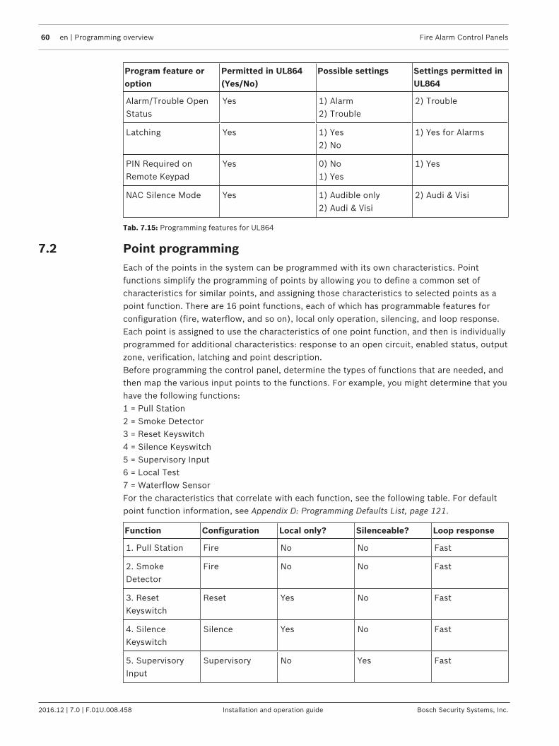
60 en | Programming overview Fire Alarm Control Panels
2016.12 | 7.0 | F.01U.008.458 Installation and operation guide Bosch Security Systems, Inc.
Program feature oroption
Permitted in UL864(Yes/No)
Possible settings Settings permitted inUL864
Alarm/Trouble OpenStatus
Yes 1) Alarm2) Trouble
2) Trouble
Latching Yes 1) Yes2) No
1) Yes for Alarms
PIN Required onRemote Keypad
Yes 0) No1) Yes
1) Yes
NAC Silence Mode Yes 1) Audible only2) Audi & Visi
2) Audi & Visi
Tab. 7.15: Programming features for UL864
7.2 Point programmingEach of the points in the system can be programmed with its own characteristics. Pointfunctions simplify the programming of points by allowing you to define a common set ofcharacteristics for similar points, and assigning those characteristics to selected points as apoint function. There are 16 point functions, each of which has programmable features forconfiguration (fire, waterflow, and so on), local only operation, silencing, and loop response.Each point is assigned to use the characteristics of one point function, and then is individuallyprogrammed for additional characteristics: response to an open circuit, enabled status, outputzone, verification, latching and point description.Before programming the control panel, determine the types of functions that are needed, andthen map the various input points to the functions. For example, you might determine that youhave the following functions:1 = Pull Station2 = Smoke Detector3 = Reset Keyswitch4 = Silence Keyswitch5 = Supervisory Input6 = Local Test7 = Waterflow SensorFor the characteristics that correlate with each function, see the following table. For defaultpoint function information, see Appendix D: Programming Defaults List, page 121.
Function Configuration Local only? Silenceable? Loop response
1. Pull Station Fire No No Fast
2. SmokeDetector
Fire No No Fast
3. ResetKeyswitch
Reset Yes No Fast
4. SilenceKeyswitch
Silence Yes No Fast
5. SupervisoryInput
Supervisory No Yes Fast

Fire Alarm Control Panels Programming overview | en 61
Bosch Security Systems, Inc. Installation and operation guide 2016.12 | 7.0 | F.01U.008.458
Function Configuration Local only? Silenceable? Loop response
6. Local Test Fire Yes Yes Fast
7. WaterflowSensor
Waterflow No No Programmed
Tab. 7.16: Point function characteristics
7.3 Alpha programmingWhen programming the point descriptions, the numeric keys are used to enter alphanumericinformation similar to the way telephone keys are used to process information over the phonelines each key represents four or more letters or symbols. For alphanumeric pointprogramming, see the following table:
Notice!A different character is entered each time a numeric key is pressed. For example, pressing repeatedly enters A, B, C, 2, A, B, and so on.
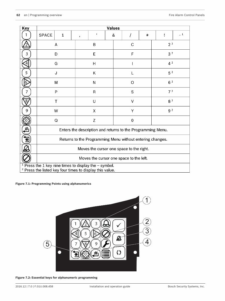
62 en | Programming overview Fire Alarm Control Panels
2016.12 | 7.0 | F.01U.008.458 Installation and operation guide Bosch Security Systems, Inc.
Figure 7.1: Programming Points using alphanumerics
Figure 7.2: Essential keys for alphanumeric programming

Fire Alarm Control Panels Programming overview | en 63
Bosch Security Systems, Inc. Installation and operation guide 2016.12 | 7.0 | F.01U.008.458
1 Number keys (including 0): used toenter alphanumeric values.
2 (Disable) key: moves the cursor onespace to the left
3 (Silence) key: moves the cursor onespace to the right.
4 (Enter) key: used to accept data whenin programming mode.
5 (Back) key: used to exit alpha programming, or exit the programming mode entirely.
7.4 Format programming4/2The 4/2 format supports only a four‑digit account number. The control panel sends the loworder four digits that are programmed (program: 0000001234; panel sends: 1234). When 4/2format is used, reports generated by points consist of an event type (first digit) and a pointnumber (second digit). Digits can be programmed for the following events: fire alarm, firerestoral, waterflow alarm, supervisory alarm, point trouble, trouble restore, point disable,disable restoral, and monitor alarm. The same event type (first digit) is sent for any point. Thepoint number is the second digit. Each point can be programmed to a different digit.7- PROG FORMATS, 1- 4/2 POINT RPT.Additionally, 18 system events can each be programmed with a unique two-digit code. Eventsthat can be programmed this way include, for example: System Silence, Fire Drill,Phone 1 Trouble, and Phone 2 Restoral.7- PROG FORMATS, 2- 4/2 RPT CODS.The 4/2 (and 3/1) format cannot report full point data for each point. Points 1 to 10 haveunique reporting codes. The codes repeat every ten points. For example, Point 31 has thesame point report as Points 11 and 21.
BFSKSimilar to the programming of system events for 4/2 formats, five system events can beprogrammed for two unique digits each when the BFSK format is used. This programming isdone under:7- PROG FORMATS, 3- BFSK RPT CODS.The BFSK format supports only a three-digit account number. The control panel sends the 7th
to 9th digits that are programmed (for example, 1234567890, account number sent is 789).The BFSK format requires that an A (hex character) be entered at the control panel to causethe receiver to display 0. The BFSK format can report only eight points, so Points 8 to 255 areall reported as point “8”.
3/1The 3/1 reporting codes are determined by the programming of the 4/2 codes. Send onlyDigit 1 (left digit of the two-digit code) and the 7th to 9th digits of the account number (forexample, 1234567890, account number sent is 789).
SIAThe SIA format supports low order six-digit account numbers. For SIA format, if 1-4 digits areentered it will ignore the leading zeros and the panel will send 4 digits, if 5 or 6 digits areentered it will send this number of digits to the central station. The SIA reports are fixed, anddo not require programming.
Contact IDThe Contact ID format supports a ten‑digit account number. if 1-4 digits are enter the leadingzeros are ignored and the panel will send 4 digits, when the account number is 5-10 digits thepanel will send 10 digits to the central station. The Contact ID reports are fixed and do notrequire programming.

64 en | Programming overview Fire Alarm Control Panels
2016.12 | 7.0 | F.01U.008.458 Installation and operation guide Bosch Security Systems, Inc.
Modem IIIa2
The format supports a 10‑digit account number. if 1-4 digits are enter the leading zeros areignored and the panel will send 4 digits, when the account number is 5-10 digits the panel willsend 10 digits to the central station. The reports are fixed and do not require programming.
Notice!When Anti-replay is enabled in IP reporting, the receiver account number uses low order 8digits of the panel account number as NNC (network naming convention).

Fire Alarm Control Panels Programming overview | en 65
Bosch Security Systems, Inc. Installation and operation guide 2016.12 | 7.0 | F.01U.008.458
7.5 Program menu tree
Figure 7.3: Program Menu - page 1
For factory defaults, see Appendix D.

66 en | Programming overview Fire Alarm Control Panels
2016.12 | 7.0 | F.01U.008.458 Installation and operation guide Bosch Security Systems, Inc.
Figure 7.4: Program Menu - page 2
For factory defaults, see Appendix D.
See also– Appendix D: Programming Defaults List, page 121
7.6 ShortcutsYou can use shortcuts to reduce repetition and provide speedy instructions for programmingthe control panel.The first level in the system is the Main Menu. For all system programming, is yourMain Menu choice. Therefore, the first number in the shortcut is “0”.

Fire Alarm Control Panels Programming overview | en 67
Bosch Security Systems, Inc. Installation and operation guide 2016.12 | 7.0 | F.01U.008.458
The second level in your system provides eight options: PROG TIME, SECURITY,PROG SYSTEM, PROG INPUTS, PROG OUTPUTS, PROG ACCOUNTS, PROG FORMATS, andHISTORY DEFAULTS. When a Multiplex Expansion Module is installed, a ninth option appears:PROGRAM MUX. The second number in the shortcut enters the Level 2 option and allowsaccess to Level 3.Level 3 provides the third set of options that branch from Level 2. The third number in theshortcut represents the option chosen in Level 3.For an example of the shortcut to TEST FREQNCY and TEST TIME, see the following figure. Thesample of the Program Menu Tree shows that to get to TEST TIME and TEST FREQNCY, youmust go to PROG/0 in Level 1, PROG TIME in Level 2, and AUTO TEST in Level 3. The shortcutis simply a list of the keys you press to get to the fourth level option. Once you enter theshortcut, follow the procedural description that appears on the screen of the specific functionyou are programming.
Shortcut = 012
LEVEL 1(Main Menu)
LEVEL 2 LEVEL 3 LEVEL 4
PROG/0
1- PROG TIME
1- SYSTEM
2- AUTO TEST
1- TEST TIME
2- TEST FREQNCY
5
1
2
3
4 6 87
Figure 7.5: Example of a programming shortcut
1 Use "0" to select PROG from the MainMenu which scrolls at the SystemNormal display.
2 Use "1" to select PROG TIME fromSub-Level 2.
3 Use "2" to select AUTO TEST from Sub-Level 3. Follow the proceduraldescription that appears on thescreen.
4 First number in shortcut
5 Password 6 Second number in shortcut
7 Third number in shortcut 8 Fourth number in shortcut
7.7 Remote programmingWhen using a modem for remote programming, the system operates during remoteprogramming so that new alarms end the remote programming session and report normally.Using the keypads to perform other functions during remote programming (such as disables)can cause remote programming to disconnect or other unexpected operations. Avoiddownloading programming changes that cause alarms, because the session disconnects assoon as the alarm occurs, before the session completes. To indicate that the system is in aspecial operating mode with user input inhibited (but alarm monitoring continuing), the

68 en | Programming overview Fire Alarm Control Panels
2016.12 | 7.0 | F.01U.008.458 Installation and operation guide Bosch Security Systems, Inc.
system indicates SYSTEM TROUB, RMT PRG ACTIVE during remote programming. Sounders donot activate during this mode, but other outputs programmed for Zone 62, general systemtrouble, do activate.Trouble conditions that occur during a remote programming session are not annunciated atthe control panel until the remote programming session ends. These conditions are availablein the remote programmer diagnostic displays during the session. Alarm conditions terminateremote programming and are shown immediately.
Notice!After using RPS for remote programming, cycle power to the panel to bring the system tonormal.
When remote programming is disabled, you can still connect to the control panel fordiagnostics and view the existing programming (except PIN numbers). To actually changeprogramming, enable remote programming.To enable remote programming, refer to the following programming items:– 0-3-7 Remote programming, page 77– 0-6-1 Phone Numbers/IP Addresses, page 88– 0-6-2 Phone Control, page 94– 0-6-4 Ring Count, page 96– 0-6-6 Machine Bypass, page 97An access code with maximum authority (1) is needed to begin remote programming from thepanel.

Fire Alarm Control Panels Control panel programming | en 69
Bosch Security Systems, Inc. Installation and operation guide 2016.12 | 7.0 | F.01U.008.458
8 Control panel programmingWhen you logon to the control panel, the following screen appears prompting you to choosethe display language:
LANGUAGE1-ENGLISH2-ESPANOL3- PORTGUES
If you want English or if you have previously selected a language different than English, thenyou can let the screen time out and it will set the display for the default (English) or leave itset to the language chosen previously.Main Menu:SYSTEM NORMALSELECT: PROG/0SELECT: ENTER/#SELECT: TESTSELECT: HISTORYSELECT: DISABLESELECT: DRILLProgramming Menu:PROG/01-PROG TIME2-SECURITY3-PROG SYSTEM4-PROG INPUTS5-PROG OUTPUTS6-PROG ACC’NTS7-PROG FORMATS8-HISTORY DEFLTS9-PROGRAM MUX
8.1 PROG TIMEPROG TIME1-SYSTEM2-AUTO TEST3-DAYLIGHT SAV
8.1.1 Program time
Shortcut: 0-PROG, 1-PROG TIME, 1-SYSTEM
The following window appears:
ENTER DATEMMDDYY: _______
Enter the date followed by the key. The following window appears:
ENTER TIMEHHMM: _______
Enter the time followed by the key.

70 en | Control panel programming Fire Alarm Control Panels
2016.12 | 7.0 | F.01U.008.458 Installation and operation guide Bosch Security Systems, Inc.
8.1.2 Automatic testTest Time
Shortcut: 0-PROG, 1-PROG TIME, 2-AUTO TEST
Use this feature to program the time of day at which automatic tests occur. This feature uses a24‑hour clock (for example, 11:00 p.m. = 2300).The following window appears:
AUTOMATIC TEST1-TEST TIME2-TEST FREQNCY
Press to select Test Time. The following window appears:
AUTO TEST TIMEHHMM: _______
Enter the time followed by the key.
Test Frequency
Shortcut: 0-PROG, 1-PROG TIME, 2-AUTO TEST
This feature allows you to program how often the automatic test reports are sent. The firsttest is sent when the programmed test time matches the system time. Subsequent reports aresent according to the selected interval.The following window appears:
AUTOMATIC TEST1-TEST TIME2-TEST FREQNCY
Press to select Test Frequency.The following window appears:
AUTO FRQNCY ( )1-4 HOURS2-6 HOURS3-24 HOURS4-7 DAYS*5-28 DAYS*
* For acceptable programming selections for Listed applications that meet the requirementsof the currently released edition of UL864, see Programming features, page 59.Press the number key that corresponds to your selection. The existing setting is displayed inparentheses on the first line. After you have programmed the test frequency, the previouswindow appears.
8.1.3 Daylight saving time
Shortcut: 0-PROG, 1-PROG TIME, 3-DAYLIGHT SAV
This feature enables automatic adjustment of system time for Daylight Saving Time. The datesfor the adjustment are pre-programmed in the system.The following window appears:

Fire Alarm Control Panels Control panel programming | en 71
Bosch Security Systems, Inc. Installation and operation guide 2016.12 | 7.0 | F.01U.008.458
DAYLIGHT1-DISABLE2-ENABLE
Press to select DISABLE or to select ENABLE. After you have programmed this feature,the previous window appears.
8.2 SECURITYSECURITY1-PINS2-AUTHORITY
8.2.1 Personal Identification Numbers (PINs)Programmer PIN
Shortcut: 0-PROG, 2-SECURITY, 1-PINS
The Programmer PIN is the code used by the installer to configure and operate the panel.Factory default code is 9876 and may be changed at any time.
Notice!Do not set Programmer PIN to 0000.The Programmer PIN can be set from 0001 to 9999. Setting the Programmer PIN to 0000 willprevent future login for programming.
The following window appears:
PROGRAM PINS1-PROGRAMR PIN2-USER PINS
Press for Programmer PIN. The following window appears:
USER 0ENTER PIN:_______
Enter the PIN and press the key. After you have programmed the Programmer PIN, theprevious window appears.
Program User PINs
Shortcut: 0-PROG, 2-SECURITY, 1-PINS
Up to 15 additional user codes (or up to 99 additional users when a Multiplex ExpansionModule is installed) can be programmed to protect the system from unauthorized operationand allow a record to be kept of actions by individual system users.The following window appears:
PROGRAM PINS1 - PROGRAMR PIN2 - USER PINS
Press for user PINs. The following window appears:
OTHER PINSUSER (01-15)
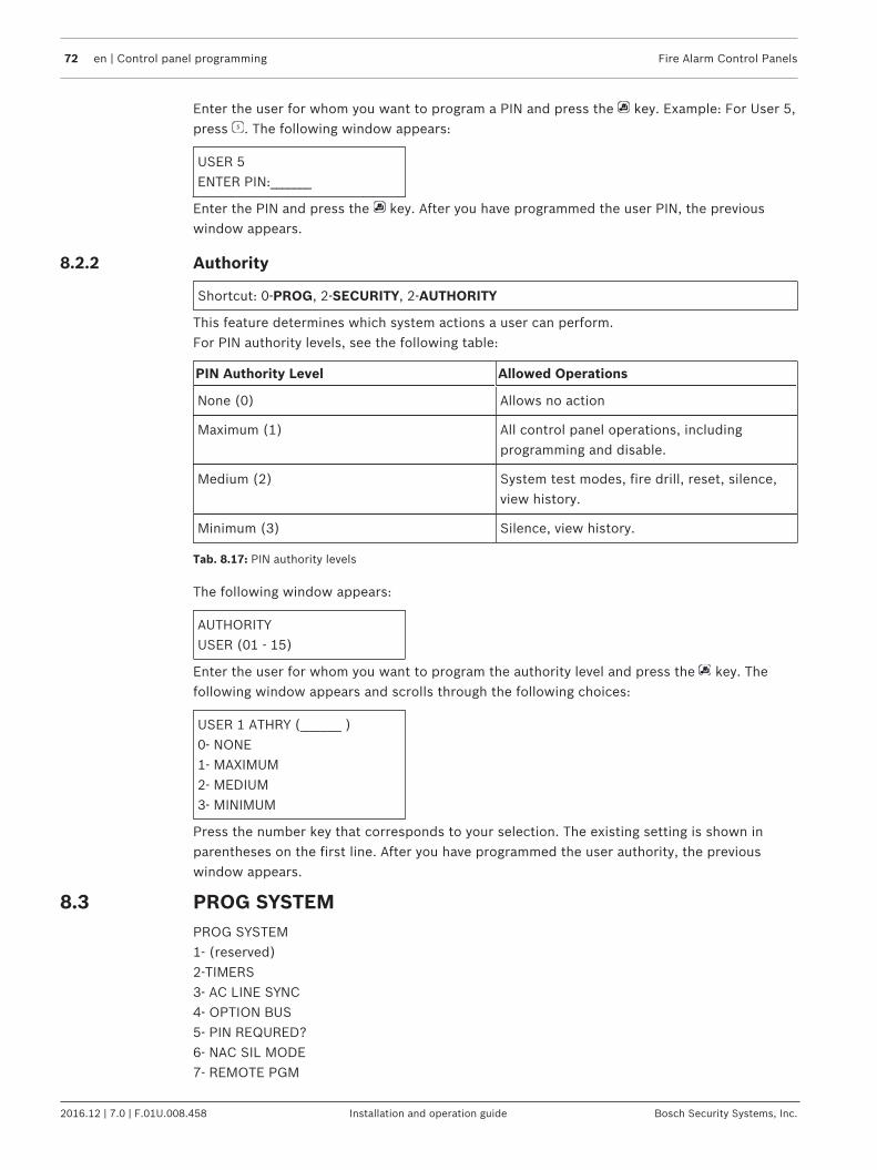
72 en | Control panel programming Fire Alarm Control Panels
2016.12 | 7.0 | F.01U.008.458 Installation and operation guide Bosch Security Systems, Inc.
Enter the user for whom you want to program a PIN and press the key. Example: For User 5,press . The following window appears:
USER 5ENTER PIN:_______
Enter the PIN and press the key. After you have programmed the user PIN, the previouswindow appears.
8.2.2 Authority
Shortcut: 0-PROG, 2-SECURITY, 2-AUTHORITY
This feature determines which system actions a user can perform.For PIN authority levels, see the following table:
PIN Authority Level Allowed Operations
None (0) Allows no action
Maximum (1) All control panel operations, includingprogramming and disable.
Medium (2) System test modes, fire drill, reset, silence,view history.
Minimum (3) Silence, view history.
Tab. 8.17: PIN authority levels
The following window appears:
AUTHORITYUSER (01 - 15)
Enter the user for whom you want to program the authority level and press the key. Thefollowing window appears and scrolls through the following choices:
USER 1 ATHRY (_______ )0- NONE1- MAXIMUM2- MEDIUM3- MINIMUM
Press the number key that corresponds to your selection. The existing setting is shown inparentheses on the first line. After you have programmed the user authority, the previouswindow appears.
8.3 PROG SYSTEMPROG SYSTEM1‑ (reserved)2‑TIMERS3‑ AC LINE SYNC4‑ OPTION BUS5‑ PIN REQURED?6‑ NAC SIL MODE7‑ REMOTE PGM

Fire Alarm Control Panels Control panel programming | en 73
Bosch Security Systems, Inc. Installation and operation guide 2016.12 | 7.0 | F.01U.008.458
8.3.1 Program timers
Shortcut: 0-PROG, 3-PROG SYSTEM, 2-TIMERS
The following window appears:
TIMERS1 - SMOKE RESET2 - AC FAIL DLY3 - AUTO SILENCE4 - (reserved)5 - DISPLAY RATE
Smoke reset
Shortcut: 0-PROG, 3-PROG SYSTEM, 2-TIMERS
This feature determines how long the smoke detector power (SMK) is off after reset. Noalarms are registered by the system for 5 sec after power is returned.The display scrolls through the TIMERS options. Press for Smoke Reset. The followingwindow appears:
SMOKE RESET (__ )(1-16 SECS):_______
Enter the time and press the key. The existing setting is shown in parentheses on the firstline. After you have programmed the smoke reset, the previous window appears.
AC fail delay
Shortcut: 0-PROG, 3-PROG SYSTEM, 2-TIMERS
This feature sets the number of hours the control panel waits after an AC failure beforesending an AC Failure report. A setting of DC causes the system to send a report when 25% ofthe battery capacity is used.The display scrolls through the TIMERS options. Press for AC FAIL DELAY. The followingwindow appears:
AC FAIL DELAY1 - WAIT FOR DC2 - ENTER TIME
The wait for DC function causes the AC fail report to be sent when the battery is 25%depleted, based on the measured voltage of the battery. If you want to WAIT FOR DC (25percent of capacity), then press the key. The existing setting is displayed in parentheses onthe first line, either “DC”, or the number of hours selected. After you program the AC FailDelay, the previous window appears.To ENTER TIME press . The following window appears:
AC FAIL DLY (___)(00-24 HRS):_______*
* For acceptable programming selections for Listed applications that meet the requirementsof the currently released edition of UL864, see Programming features, page 59.Enter the time and press . The existing setting is shown in parentheses on the first line. Afteryou program the AC Fail Delay, the previous window appears.

74 en | Control panel programming Fire Alarm Control Panels
2016.12 | 7.0 | F.01U.008.458 Installation and operation guide Bosch Security Systems, Inc.
Notice!When Wait For DC is the existing selection, the Enter Time menu displays DC as the time inhours.
Auto silence
Shortcut: 0-PROG, 3-PROG SYSTEM, 2-TIMERS
This feature silences the sounding of an alarm condition on selected NACs after a certainamount of time. When you use Auto Silence, pressing disables the feature and the only wayto turn off an alarm is to manually silence it. Entering between 5 min and 99 min means thatthe alarm sounds for that much time before automatically silencing.
Notice!If the condition that caused an alarm is not corrected after an alarm is silenced (automaticallyor manually), then the alarm sounds again within 24 hours. The system must eventually bereset after silencing to allow the alarmed zones to restore and detect new alarms.
The display scrolls through the TIMERS options. Press for AUTO SILENCE. The followingwindow appears:
AUTO SILENCE (___)(0, 5-99 MIN):_______*
Enter desired length of time (or press to disable) and press the key. The existing settingis shown in parentheses on the first line. After you program the auto silence, the previouswindow appears.
Display rate
Shortcut: 0-PROG, 3-PROG SYSTEM, 2-TIMERS
Set the speed at which menus are displayed on the LCD (in units of 0.25 sec).The display scrolls through the TIMERS options. Press for DISPLAY RATE. The followingwindow appears:
DSPLY RATE (___).25 X (1-16):_______*
Enter desired value and press . The existing setting is shown in parentheses on the first line.After you program the display rate, the previous window appears.
8.3.2 AC line synch
Shortcut: 0-PROG, 3-PROG SYSTEM, 3-AC LINE SYNC
When AC power is available, the control panel uses the line frequency to stabilize the real-time clock. This setting must match the frequency of the local AC power (60 Hz in the US).The following window appears:
AC LINE SYN (__)1 - 50 Hz2 - 60 Hz

Fire Alarm Control Panels Control panel programming | en 75
Bosch Security Systems, Inc. Installation and operation guide 2016.12 | 7.0 | F.01U.008.458
Press the number key that corresponds to your selection and press . The existing setting isshown in parentheses on the first line. After you program AC Line Synch, the previous windowappears.
Notice!AC line synch setting reprogrammedIn order to keep the real‑time clock operating correctly, cycle power to the panel to restorethe system to normal after reprogramming the AC line synch setting.
8.3.3 Option busUpdate bus
Shortcut: 0-PROG, 3-PROG SYSTEM, 4-OPTION BUS
When devices are added or removed from the option bus, this feature queries the option busand updates the list of connected devices. This enables the new devices and removessupervision for devices no longer present.
!
Warning!Inoperable, unsupervised devices!Be sure the count of devices displayed when this operation completes matches the number ofdevices installed on the bus. Devices not detected during the update bus operation will notoperate and will not be supervised.
Notice!These menu items are allowed only at the local keypad.
The following window appears:
OPTION BUS (M/M)1 - UPDATE BUS2 - SETUP KEYPDS
Press to program the system to update the bus. After you program Update Bus, thefollowing window appears:
UPDATE COMPLETETOT BUS DEVS: X
Then the previous window appears.
Setup keypads
Shortcut: 0-PROG, 3-PROG SYSTEM, 4-OPTION BUS
This feature tells the system how many keypads to supervise. It automatically performs anupdate bus operation as it completes.
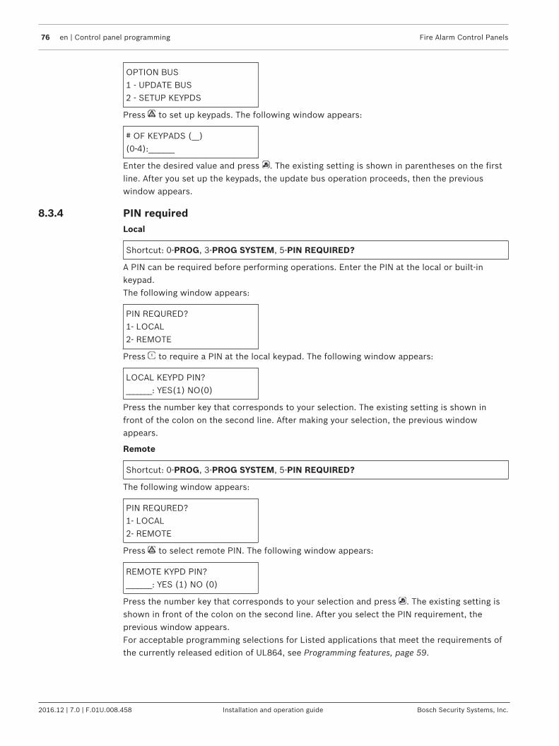
76 en | Control panel programming Fire Alarm Control Panels
2016.12 | 7.0 | F.01U.008.458 Installation and operation guide Bosch Security Systems, Inc.
OPTION BUS1 - UPDATE BUS2 - SETUP KEYPDS
Press to set up keypads. The following window appears:
# OF KEYPADS (__)(0-4):_______
Enter the desired value and press . The existing setting is shown in parentheses on the firstline. After you set up the keypads, the update bus operation proceeds, then the previouswindow appears.
8.3.4 PIN requiredLocal
Shortcut: 0-PROG, 3-PROG SYSTEM, 5-PIN REQUIRED?
A PIN can be required before performing operations. Enter the PIN at the local or built-inkeypad.The following window appears:
PIN REQURED?1- LOCAL2- REMOTE
Press to require a PIN at the local keypad. The following window appears:
LOCAL KEYPD PIN?_______: YES(1) NO(0)
Press the number key that corresponds to your selection. The existing setting is shown infront of the colon on the second line. After making your selection, the previous windowappears.
Remote
Shortcut: 0-PROG, 3-PROG SYSTEM, 5-PIN REQUIRED?
The following window appears:
PIN REQURED?1- LOCAL2- REMOTE
Press to select remote PIN. The following window appears:
REMOTE KYPD PIN?_______: YES (1) NO (0)
Press the number key that corresponds to your selection and press . The existing setting isshown in front of the colon on the second line. After you select the PIN requirement, theprevious window appears.For acceptable programming selections for Listed applications that meet the requirements ofthe currently released edition of UL864, see Programming features, page 59.

Fire Alarm Control Panels Control panel programming | en 77
Bosch Security Systems, Inc. Installation and operation guide 2016.12 | 7.0 | F.01U.008.458
Notice!A PIN can be required before operations can be performed using the remote keypads on theoption bus. If the remote keypads are not otherwise secured, then this option must be set toYES to comply with NFPA and Local requirements.
8.3.5 NAC silence mode
Shortcut: 0-PROG, 3-PROG SYSTEM, 6-NAC SIL MODE
NAC silence mode allows notification devices to be silenced from the control panel. Anyoutput configured as silenceable is silenced upon silence operation. You can define audibleonly or audible and visible by this option. When silenced, a relay is completely turned off.The following window appears:
1-AUDIBLE ONLY2-AUDI & VISI
Press to configure the audible output to be silenceable leaving the visible output to display.Press to configure both the audible and visible outputs to be silenceable.
8.3.6 Remote programming
Shortcut: 0-PROG, 3-PROG SYSTEM, 7-REMOTE PGM
Remote Programming Software (RPS) allows connection to the panel from a remote site toreconfigure any of the programmable options. When remote programming is disabled, you canstill connect to the control panel for diagnostics and to view the existing program. PINnumbers are suppressed while remote programming is disabled.
REMOTE PGM0- DISABLE1- ENABLE
Press to select DISABLE or to select ENABLE, and the previous window appears.
Danger!After any programming change, and especially after remote program changes, completelycheck operation of the control units. Hazards to life and property can result if the system isnot tested for incorrect programming.
8.4 PROG INPUTSPROG INPUTS1- POINT NUMBER2- POINT FUNCT3- (reserved)
Notice!Point functions allow quick programming of similarly functioning points (for example, pullstations, smoke detectors) with common settings.

78 en | Control panel programming Fire Alarm Control Panels
2016.12 | 7.0 | F.01U.008.458 Installation and operation guide Bosch Security Systems, Inc.
For more information on point functions, see Point function, page 81.
8.4.1 Point number
Shortcut: 0‑PROG, 4‑PROG INPUTS, 1‑POINT NUMBER
The following window appears:
POINT NUMBER (1‑255):_____
Enter the point number you wish to program and press . Once you have entered the pointnumber, the display scrolls through the following PROG INPUT options:
PROG POINT0‑ FUNCTION1‑ ALARM/TROUBL2‑ OUTPUT ZONE3‑ VERIFICATION4‑ LATCHING5‑ DESCRIPTION<DRILL>‑NEXT PNT<HIST>‑PREV PNT
Press the number key that corresponds to your selection.Pressing retrieves the next point. For instance, if you are programming Point 2 and youpress , then you retrieve the setting for Point 3.Pressing retrieves the previous point. For instance, if you are programming Point 2 and youpress , then you return to the setting for Point 1.
Assigning point functions
Shortcut: 0‑PROG, 4‑PROG INPUTS, 1‑POINT NUMBER
This feature assigns each point to one point function. A point function is a set ofcharacteristics that you can assign to selected points. There are 16 point functions to choosefrom.For more information about point functions, see Point function, page 81. For the limitationswhen assigning points to point functions that were programmed with a response time otherthan Fast, see Loop response in Point function, page 81.Enter the point number you wish to program and press . The display scrolls through thePROG INPUT options.Press to select FUNCTION. The following window appears:
POINT FUNC (___)(01 ‑ 16):_______
Enter the function number you wish to assign to the point and press . The existing setting isshown in parentheses on the first line. After you assign a point function, the previous windowappears.
Alarm/Trouble status
Shortcut: 0‑PROG, 4‑PROG INPUTS, 1‑POINT NUMBER
This feature allows you to program the system response to an open loop condition. A shortedloop always causes an alarm condition.

Fire Alarm Control Panels Control panel programming | en 79
Bosch Security Systems, Inc. Installation and operation guide 2016.12 | 7.0 | F.01U.008.458
For acceptable programming selections for Listed applications that meet the requirements ofthe currently released edition of UL864, see Programming features, page 59.ALARM: A point in an open circuit state causes an alarm.TROUBLE: If a point is in an open circuit state, then the system responds with a troublecondition. Enter the point number you wish to program and press . The display scrollsthrough the PROG INPUT options.Press to select ALARM/TROUBLE. The following window appears:
OPEN STATUS (__)1‑ ALARM2‑ TROUBLE
Press to select ALARM on open loop and ALARM on shorted loop or to select TROUBLEon open loop and ALARM on shorted loop. The previous window appears. The existing settingis shown in parentheses on the first line.
Output zones
Shortcut: 0‑PROG, 4‑PROG INPUTS, 1‑POINT NUMBER
Enter the point number you wish to program and press . The display scrolls through thePROG INPUT options.Press to select OUTPUT ZONE. The following window appears:
OUTPUT ZONE ZZZ(01 ‑ 50):_______
Press the number key that corresponds to your selection. ZZZ indicates the point beingprogrammed. The existing setting is shown on the second line. After you set up the outputzone, the previous window appears.
Verification
Shortcut: 0‑PROG, 4‑PROG INPUTS, 1‑POINT NUMBER
If an input point is configured as “Alarm verification” and goes into an active state, then thepanel does not immediately annunciate the alarm, activate associated outputs or send asignal. Instead, it resets the input point/addressable smoke detector and waits for a secondalarm before annunciating the event.The total delay introduced by this feature is equal to the smoke power reset time plus fiveseconds.Alarm verification is applicable only to 2‑wire smoke detectors or addressable smokesconfigured for fire. The alarm verification option is not applicable to other point types such asWaterflow and supervisory point types.– The alarm verification feature can be used with four loops of 2-wire smoke detectors or
addressable smokes configured for fire or one loop (on‑board point) of 4‑wire smokedetectors powered through the onboard smoke power (SMK PWR). For an illustration oftypical device wiring, see FACP terminal connection, page 36.
– The alarm verification option is arranged on a per point basis.– After the alarm verification period starts, any alarm from anywhere in the system that
occurs during the alarm verification cycle immediately results in an alarm indication.– The alarm verification timer is system wide; thus, only one timer applies for the whole
system.

80 en | Control panel programming Fire Alarm Control Panels
2016.12 | 7.0 | F.01U.008.458 Installation and operation guide Bosch Security Systems, Inc.
– The alarm verification timer is user programmable, ranging from 6 to 21 seconds for theRETARD-RESET-RESTART period, plus 60 seconds for the CONFIRMATION period. Thedefault is 11 seconds.
– A reset command is sent to reset the input point on SLCs for alarm verification.– The global alarm verification zone 59 is activated during the A ‑ B verification period.
Notice!CSFM installations require the alarm verification Retard-Reset-Restart (A‑C) time to be amaximum of 30 seconds. This time is not programmable and is always less than 30 seconds
Notice!Alarm Verification is configurable for the four onboard points and Addressable smokedetectors only.
Enter the point number you wish to verify and press . The display scrolls through the PROGINPUT options.Press to select VERIFICATION. The following window appears:
ALARM VERIF (ZZZ)_______: YES(1) NO(0)
ZZZ indicates the point being programmed. The existing setting is shown on the second line.Press either to verify or to not verify. The previous window appears.
Latching
Shortcut: 0‑PROG, 4‑PROG INPUTS, 1‑POINT NUMBER
If a zone is non-latching, then the system resets the alarm status automatically (but does notreset smoke power) when the input restores to the standby condition. Otherwise, the systemmust be manually reset.For acceptable programming selections for Listed applications that meet the requirements ofthe currently released edition of UL864, see Programming features, page 59.Enter the point number you wish to program and press . The display scrolls through thePROG INPUT options.Press to select LATCHING. The following window appears:

Fire Alarm Control Panels Control panel programming | en 81
Bosch Security Systems, Inc. Installation and operation guide 2016.12 | 7.0 | F.01U.008.458
LATCHING? ZZZ:YES(1)NO(0)
ZZZ indicates the point being programmed. The existing setting is shown on the second line.Press the number key that corresponds to your selection. Select YES for alarm.The previous window appears.
Point description
Shortcut: 0‑PROG, 4‑PROG INPUTS, 1‑POINT NUMBER
For this feature, use the numeric keys to enter alphanumeric information to identify each input(such as initiating circuit). The system allows one 16‑character description per input. Enter thepoint number you wish to program and press . The display scrolls through the PROG INPUToptions.Press to select DESCRIPTION. The following window appears:
PNT DSCRPTN ZZZ:
Enter the description using the numeric, and keys, then press to save the description.
8.4.2 Point function
Shortcut: 0-PROG, 4-PROG INPUTS, 2-POINT FUNCTION
There are 16 point functions, each of which has programmable features for: configuration(fire, waterflow, and so on), local only operation, silencing, and loop response.
Notice!At default, points 9 to 255 are programmed as Function 10 which is set as Fire. Function 11 isset as Supervisory. Function 04 is set as Waterflow 16 second.
The following window appears:
POINT FUNC (__)(01 - 16):_______
Enter the function number you wish to program and press . The following window appears:
PROG FUNCT0- CONFIGURE1- LOCAL ONLY2- (reserved)3- SILENCABLE4- LOOP RESPONS5- (reserved)<DRILL>-NXT FCT<HIST>-PREV FCT
Enter the function you wish to program.
Configure
Shortcut: 0-PROG, 4-PROG INPUTS, 2-POINT FUNCTION

82 en | Control panel programming Fire Alarm Control Panels
2016.12 | 7.0 | F.01U.008.458 Installation and operation guide Bosch Security Systems, Inc.
– Fire: When activated, the point displays FIRE ALARM on control panel and keypads,activates selected output devices, and sends a Fire Alarm report (if programmed). Firepoints are defaulted to a latch when first configured.
– Waterflow: When activated, the point displays xxx/xxx WTF on control panel andkeypads, activates selected output devices, and sends a Waterflow Alarm event (ifprogrammed). Waterflow points are defaulted to a non-verify characteristic when firstconfigured.
– Supervisory: When activated, the point displays xxx/xxx SUP on control panel andkeypads, and sends a Supervisory Alarm event (if programmed). Supervisory points aredefaulted to a non-verify characteristic when first configured.
– Reset: When activated, the point initiates a control panel-reset operation to clear alarmsand reset smoke detectors. Only points 1 to 8 can be configured as reset points.
– Silence: When activated, the point initiates a control panel silence operation to turn offsounders if the control panel is configured to allow silencing. Only points 1 to 8 can beconfigured as silence points.
– AC Fault: When activated, the control panel indicates AC FAIL TROUBLE and theTROUBLE LED turns on. The panel then waits for the AC Delay Timer to expire beforesending an AC Fail report and activating zone 60 (AC fail).
Enter the point number you wish to program and press . The display scrolls through thePROG FUNCTION options.Press ] to select CONFIGURE. The following window appears:
ACTVTN TYPE ( )1- FIRE2- WATERFLOW3- SUPERVISORY4- (reserved)5- RESET6- SILENCE7- AC FAULT
Press the number key that corresponds to your selection. (The existing setting is shown inparentheses on the first line.) The previous window appears.
Local only
Shortcut: 0-PROG, 4-PROG INPUTS, 2-POINT FUNCTION
Enabling this feature provides the input point for local annunciation only with nocommunicator report except Reset and Silence functions. Enter the point number you wish toprogram and press . The display scrolls through the PROG FUNCTION options.Press to select LOCAL ONLY. The following window appears:
LOCAL ONLY_______: YES (1)NO(0)
Press either to enable or to disable. The previous window appears.
Silencing
Shortcut: 0-PROG, 4-PROG INPUTS, 2-POINT FUNCTION
This feature determines if an output zone (1 to 50) follows the Silence key (relays reset, NACssilence).

Fire Alarm Control Panels Control panel programming | en 83
Bosch Security Systems, Inc. Installation and operation guide 2016.12 | 7.0 | F.01U.008.458
Enter the point number you wish to program and press . The display scrolls through thePROG FUNCTION options.Press to select SILENCEABLE. The following window appears:
SILENCABLE? (FF)_______: YES (1)NO(0)
Press for relays to reset and NACs to silence when the Silence key is pressed, or press for relays to remain latched until reset and NACs to continue sounding when the Silencebutton is pressed.
Notice!When an output is assigned to more than one zone, the programming of the zone that triggersthe output controls the output. When more than one zone triggers the output, if one of thezones is programmed as non-silencing, then the output will be non-silencing.
The previous window appears. FF indicates the function being programmed.
Loop response
Shortcut: 0-PROG, 4-PROG INPUTS, 2-POINT FUNCTION
This feature allows you to configure points to activate with standard response time (setting 1)or one system-wide programmed response time (setting 2).Enter the point number you wish to program and press . The display scrolls through thePROG FUNCTION options.Press to select LOOP RESPONSE. The following window appears:
RESPNS TIME (___)1- FAST (.5 sec)2- PRGRMMD*
* For acceptable programming selections for Listed applications that meet the requirementsof the currently released edition of UL864, see Programming features, page 59.Press the number key that corresponds to your selection (the existing setting is displayed inparentheses on the first line). The previous window appears.When you select a programmed response time, the system asks you to enter a response timefrom 1 sec to 89 sec that applies to all functions. All functions share a single programmableresponse time setting. If this time is set for multiple functions, then the last time set is used.
Notice!Up to 20 points can be assigned to point functions that were programmed with a responsetime other than Fast. If more than 20 points are assigned to functions programmed with aresponse time other than Fast, then an error message appears: PRGRMMD POINTS EXCEEDMAX. Switching a point function from Fast to Programmed can cause this error, depending onhow many points reference the point function.
<DRILL> NEXT FCT: Pressing retrieves the next function. For instance, if you areprogramming Point Function 2 and you press , then you retrieve the setting for PointFunction 3.<HIST> PREV FCT: Pressing returns you to the previous function. For instance, if you areprogramming Point Function 2 and you press , then you return to the setting for PointFunction 1.
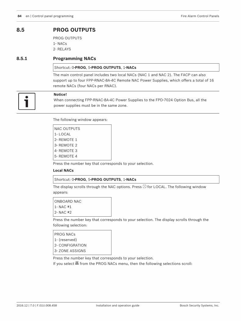
84 en | Control panel programming Fire Alarm Control Panels
2016.12 | 7.0 | F.01U.008.458 Installation and operation guide Bosch Security Systems, Inc.
8.5 PROG OUTPUTSPROG OUTPUTS1- NACs2- RELAYS
8.5.1 Programming NACs
Shortcut: 0‑PROG, 5‑PROG OUTPUTS, 1‑NACs
The main control panel includes two local NACs (NAC 1 and NAC 2). The FACP can alsosupport up to four FPP‑RNAC‑8A‑4C Remote NAC Power Supplies, which offers a total of 16remote NACs (four NACs per RNAC).
Notice!When connecting FPP-RNAC-8A-4C Power Supplies to the FPD-7024 Option Bus, all thepower supplies must be in the same zone.
The following window appears:
NAC OUTPUTS1‑ LOCAL2‑ REMOTE 13‑ REMOTE 24‑ REMOTE 35‑ REMOTE 4
Press the number key that corresponds to your selection.
Local NACs
Shortcut: 0‑PROG, 5‑PROG OUTPUTS, 1‑NACs
The display scrolls through the NAC options. Press for LOCAL. The following windowappears:
ONBOARD NAC1‑ NAC #12‑ NAC #2
Press the number key that corresponds to your selection. The display scrolls through thefollowing selection:
PROG NACs1‑ (reserved)2‑ CONFIGRATION3‑ ZONE ASSIGNS
Press the number key that corresponds to your selection.If you select from the PROG NACs menu, then the following selections scroll:
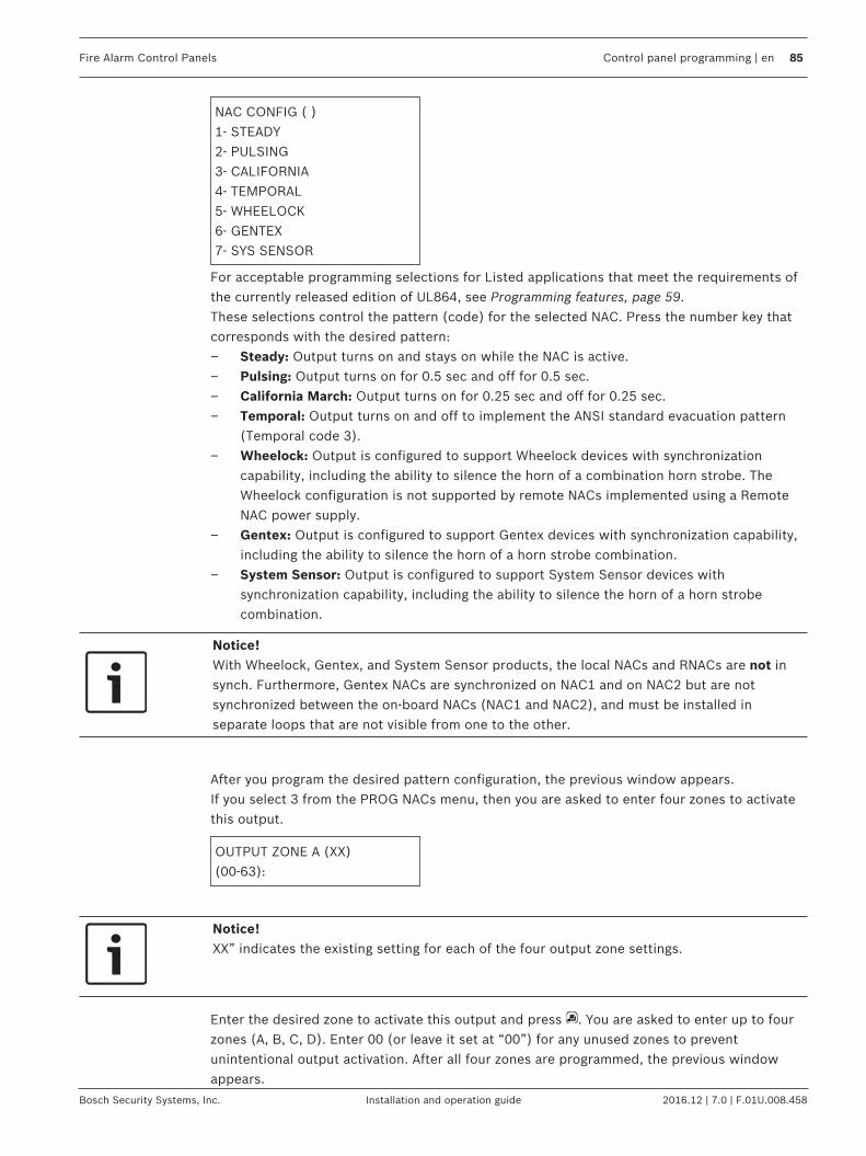
Fire Alarm Control Panels Control panel programming | en 85
Bosch Security Systems, Inc. Installation and operation guide 2016.12 | 7.0 | F.01U.008.458
NAC CONFIG ( )1‑ STEADY2‑ PULSING3‑ CALIFORNIA4‑ TEMPORAL5‑ WHEELOCK6‑ GENTEX7‑ SYS SENSOR
For acceptable programming selections for Listed applications that meet the requirements ofthe currently released edition of UL864, see Programming features, page 59.These selections control the pattern (code) for the selected NAC. Press the number key thatcorresponds with the desired pattern:– Steady: Output turns on and stays on while the NAC is active.– Pulsing: Output turns on for 0.5 sec and off for 0.5 sec.– California March: Output turns on for 0.25 sec and off for 0.25 sec.– Temporal: Output turns on and off to implement the ANSI standard evacuation pattern
(Temporal code 3).– Wheelock: Output is configured to support Wheelock devices with synchronization
capability, including the ability to silence the horn of a combination horn strobe. TheWheelock configuration is not supported by remote NACs implemented using a RemoteNAC power supply.
– Gentex: Output is configured to support Gentex devices with synchronization capability,including the ability to silence the horn of a horn strobe combination.
– System Sensor: Output is configured to support System Sensor devices withsynchronization capability, including the ability to silence the horn of a horn strobecombination.
Notice!With Wheelock, Gentex, and System Sensor products, the local NACs and RNACs are not insynch. Furthermore, Gentex NACs are synchronized on NAC1 and on NAC2 but are notsynchronized between the on‑board NACs (NAC1 and NAC2), and must be installed inseparate loops that are not visible from one to the other.
After you program the desired pattern configuration, the previous window appears.If you select 3 from the PROG NACs menu, then you are asked to enter four zones to activatethis output.
OUTPUT ZONE A (XX)(00‑63):
Notice!XX” indicates the existing setting for each of the four output zone settings.
Enter the desired zone to activate this output and press . You are asked to enter up to fourzones (A, B, C, D). Enter 00 (or leave it set at “00”) for any unused zones to preventunintentional output activation. After all four zones are programmed, the previous windowappears.

86 en | Control panel programming Fire Alarm Control Panels
2016.12 | 7.0 | F.01U.008.458 Installation and operation guide Bosch Security Systems, Inc.
For a list of pre-assigned zones, see the Pre-assigned zones table in Point/Zone Mapping, page55.
Remote NACs
Shortcut: 0‑PROG, 5‑PROG OUTPUTS, 1‑NACs
Notice!SynchronizationWhen using System Sensor NACs, the four NACs available on a specific RNAC aresynchronized, but the NACs on one RNAC are not synchronized with the NACs on the otherRNACs. The RNAC loops should be installed so that the NACs connected to each RNAC arenot visible to or from the NACs connected to the other RNACs,
Use only with the FPP‑RNAC‑8A‑4C. The display scrolls through the NAC options. Press forREMOTE 1, for REMOTE 2, for REMOTE 3, or for REMOTE 4. One of the followingwindows appears:
REM EXP NAC #11‑ NAC #12‑ NAC #23‑ NAC #34‑ NAC #4
or
REM EXP NAC #21‑ NAC #12‑ NAC #23‑ NAC #34‑ NAC #44
or
REM EXP NAC #31‑ NAC #12‑ NAC #23‑ NAC #34‑ NAC #4
or
REM EXP NAC #41‑ NAC #12‑ NAC #23‑ NAC #34‑ NAC #4
Press the number key that corresponds with the NAC you want to program. The display scrollsthrough the following selections:
PROG NACs1‑ (reserved)2‑ CONFIGRATION3‑ ZONE ASSIGNS
The options for remote NACs are the same as for local NACs.Output Configuration:Steady: Programmed to turn on steadily for a fire alarm.Pulsing: Programmed to pulse for a fire alarm at 0.5 sec on and 0.5 sec off.California March: Output turns on for 0.25 sec and off for 0.25 sec.Temporal: Programmed to pulse for a fire alarm in Temporal 3.Zone Assignment: Assign each output up to four zones. ZONE A, B, C, or D (00 = disabled) (1to 63).Press the number key that corresponds to your selection. After you program the local NACs,the previous window appears.
8.5.2 Programming relays
Shortcut: 0-PROG, 5-PROG OUTPUTS, 2-RELAYS
The main control panel includes three on-board relays (Relay 1, Relay 2, and Relay 3). TheFACP can also support up to two D7035 Octal Relay Modules (Remote Relay 1 and RemoteRelay 2), that offer a total of 16 remote relays (eight relays per module).The following windowappears:

Fire Alarm Control Panels Control panel programming | en 87
Bosch Security Systems, Inc. Installation and operation guide 2016.12 | 7.0 | F.01U.008.458
RELAY OUTPUTS1- LOCAL2- REMOTE 13- REMOTE 24- MULTIPLEX
Press the number key that corresponds to your selection.
Notice!The option for multiplex relay programming is visible only when a Multiplex Expansion Moduleis installed.
Local Relays
Shortcut: 0-PROG, 5-PROG OUTPUTS, 2-RELAYS
The display scrolls through the Relay options.Press for LOCAL. The following window appears:
ONBOARD RELAY(1-3):
Enter the number corresponding to the relay to be programmed and press . The display asksyou to enter four zones to activate this output:
OUTPUT ZONE A:_______(00 - 63):_______
Enter the first zone (00 to 63) you want to assign to this output and press . A similar displayfor Zones B, C and D will appear to allow up to four zones to be assigned to this output. Whenall four zones are assigned, the previous window appears.For pre-assigned zones, see the Pre-assigned zones table in Point/Zone Mapping, page 55.An output point cannot be assigned to more than four zones. Each output does not need to beassigned to four zones. Each zone can have any number of outputs assigned to it.
Remote relays
Shortcut: 0-PROG, 5-PROG OUTPUTS, 2-RELAYS
The display scrolls through the Relay options. Press for REMOTE 1 or for REMOTE 2. Thefollowing window appears:
REMOTE RELAY @ x(1 - 8):
Notice!The @ x shows the address of the relay module in the system. The lower number address isRelay 1; the higher one is Relay 2.When you address a MUX Module, you assign an address. Ifyou have a dual point, then it would have two consecutive addresses.
Enter the relay you wish to assign and press . The display shows:
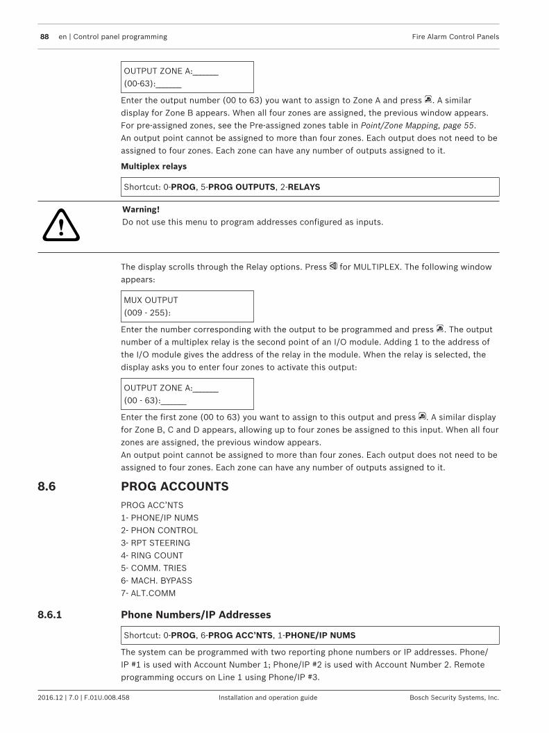
88 en | Control panel programming Fire Alarm Control Panels
2016.12 | 7.0 | F.01U.008.458 Installation and operation guide Bosch Security Systems, Inc.
OUTPUT ZONE A:_______(00-63):_______
Enter the output number (00 to 63) you want to assign to Zone A and press . A similardisplay for Zone B appears. When all four zones are assigned, the previous window appears.For pre-assigned zones, see the Pre-assigned zones table in Point/Zone Mapping, page 55.An output point cannot be assigned to more than four zones. Each output does not need to beassigned to four zones. Each zone can have any number of outputs assigned to it.
Multiplex relays
Shortcut: 0-PROG, 5-PROG OUTPUTS, 2-RELAYS
!
Warning!Do not use this menu to program addresses configured as inputs.
The display scrolls through the Relay options. Press for MULTIPLEX. The following windowappears:
MUX OUTPUT(009 - 255):
Enter the number corresponding with the output to be programmed and press . The outputnumber of a multiplex relay is the second point of an I/O module. Adding 1 to the address ofthe I/O module gives the address of the relay in the module. When the relay is selected, thedisplay asks you to enter four zones to activate this output:
OUTPUT ZONE A:_______(00 - 63):_______
Enter the first zone (00 to 63) you want to assign to this output and press . A similar displayfor Zone B, C and D appears, allowing up to four zones be assigned to this input. When all fourzones are assigned, the previous window appears.An output point cannot be assigned to more than four zones. Each output does not need to beassigned to four zones. Each zone can have any number of outputs assigned to it.
8.6 PROG ACCOUNTSPROG ACC’NTS1- PHONE/IP NUMS2- PHON CONTROL3- RPT STEERING4- RING COUNT5- COMM. TRIES6- MACH. BYPASS7- ALT.COMM
8.6.1 Phone Numbers/IP Addresses
Shortcut: 0-PROG, 6-PROG ACC’NTS, 1-PHONE/IP NUMS
The system can be programmed with two reporting phone numbers or IP addresses. Phone/IP #1 is used with Account Number 1; Phone/IP #2 is used with Account Number 2. Remoteprogramming occurs on Line 1 using Phone/IP #3.

Fire Alarm Control Panels Control panel programming | en 89
Bosch Security Systems, Inc. Installation and operation guide 2016.12 | 7.0 | F.01U.008.458
– PHONE/IP #1: Phone Number 1 or IP address 1– PHONE/IP #2: Phone Number 2 or IP address 2– COMPTR PHONE/IP: Sets the Phone Number or IP Address to call for remote
programming.For acceptable programming selections for Listed applications that meet the requirements ofthe currently released edition of UL864, see Programming features, page 59.The following window appears:
PHONE/IP NUMBER1- PHONE /IP #12- PHONE /IP #23- COMPTR PH/IP
Press the number key that corresponds with the phone number you wish to configure(example is Phone #1). The following window appears:
PHONE/IP NUMBER #11- NUMBER2- PORT NUMBER3- FORMAT4- ACCT NUMS5- TONE6- IP MOD PRIRY
Press the number key that corresponds with your selection. Refer to the next four sub-sections (Number, Format, Account Numbers and Tone) for explanations of the phone numberoptions.
Number/IP addressThe display scrolls through the Phone /IP Number options. Press for NUMBER. Thefollowing window appears:
PH/IP NO1: >??????????????????????
Press . Press to add the wait for dial tone, and then enter the phone number and press. The previous menu appears. You can include several other special control characters in the
phone number by pressing followed by a digit.For a list of control characters, see the following table:
Press See Action
* Touch Tone “*”
# Touch Tone “#”
/ Three-second delay
> Wait for dial tone
Tab. 8.18: Phone number control characters
Several keys assist when you enter phone or IP numbers. For these keys, see the followingtable:
Press Action
Advance to next position

90 en | Control panel programming Fire Alarm Control Panels
2016.12 | 7.0 | F.01U.008.458 Installation and operation guide Bosch Security Systems, Inc.
Press Action
Go back one position
Clear position
Tab. 8.19: Phone number assistance keys
Notice!For a phone number, you must enter 1 as a prefix before the special character >. Except forunusual situations, all phone numbers should have the wait for dial tone character as thesecond digit. This ensures that reports are delivered as quickly as possible, even if anincoming phone call must be disconnected. For example, you would program 1>18002890096for the phone number 1 800-289-0096.If the wait for dial tone is not specified, then the control panel waits 3 seconds after goingoff-hook and then dials whether or not the dial tone is present.
To enter a central station IP address in either phone number 1 or 2 in the control panel,replace all three phone numbers with an IP address. To distinguish an IP address from aphone number, enter 0 as the first digit, followed by the 12 digit IP address.
Notice!The IP address must be 12 digits long. For example, if the IP address is 172.30.1.101, thenthe address is programmed as 0172030001101.
Figure 8.1: IP address and bit locations
For timing configurations, see the following table:
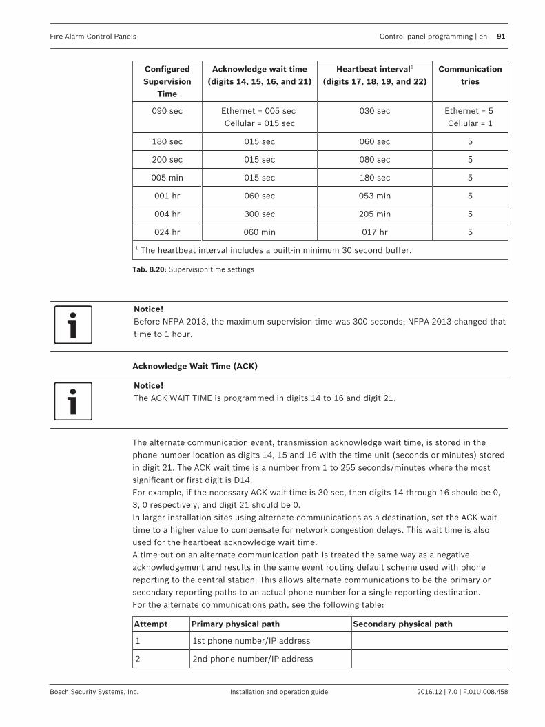
Fire Alarm Control Panels Control panel programming | en 91
Bosch Security Systems, Inc. Installation and operation guide 2016.12 | 7.0 | F.01U.008.458
ConfiguredSupervision
Time
Acknowledge wait time(digits 14, 15, 16, and 21)
Heartbeat interval1
(digits 17, 18, 19, and 22)Communication
tries
090 sec Ethernet = 005 sec Cellular = 015 sec
030 sec Ethernet = 5 Cellular = 1
180 sec 015 sec 060 sec 5
200 sec 015 sec 080 sec 5
005 min 015 sec 180 sec 5
001 hr 060 sec 053 min 5
004 hr 300 sec 205 min 5
024 hr 060 min 017 hr 5
1 The heartbeat interval includes a built‑in minimum 30 second buffer.
Tab. 8.20: Supervision time settings
Notice!Before NFPA 2013, the maximum supervision time was 300 seconds; NFPA 2013 changed thattime to 1 hour.
Acknowledge Wait Time (ACK)
Notice!The ACK WAIT TIME is programmed in digits 14 to 16 and digit 21.
The alternate communication event, transmission acknowledge wait time, is stored in thephone number location as digits 14, 15 and 16 with the time unit (seconds or minutes) storedin digit 21. The ACK wait time is a number from 1 to 255 seconds/minutes where the mostsignificant or first digit is D14.For example, if the necessary ACK wait time is 30 sec, then digits 14 through 16 should be 0,3, 0 respectively, and digit 21 should be 0.In larger installation sites using alternate communications as a destination, set the ACK waittime to a higher value to compensate for network congestion delays. This wait time is alsoused for the heartbeat acknowledge wait time.A time-out on an alternate communication path is treated the same way as a negativeacknowledgement and results in the same event routing default scheme used with phonereporting to the central station. This allows alternate communications to be the primary orsecondary reporting paths to an actual phone number for a single reporting destination.For the alternate communications path, see the following table:
Attempt Primary physical path Secondary physical path
1 1st phone number/IP address
2 2nd phone number/IP address

92 en | Control panel programming Fire Alarm Control Panels
2016.12 | 7.0 | F.01U.008.458 Installation and operation guide Bosch Security Systems, Inc.
Attempt Primary physical path Secondary physical path
3 1st phone number/IP address
4 2nd phone number/IP address
5 2nd phone number/IP address
6 1st phone number/IP address
7 1st phone number/IP address
8 2nd phone number/IP address
9 2nd phone number/IP address
10 1st phone number/IP address
Tab. 8.21: Reporting paths
Heartbeat Interval (HB)
Notice!The Heartbeat Interval, also known as Polling Time, is programmed in digits 17 to 19 and digit22.
This interval is a value between 001 and 255 that indicates the number of seconds/minutes/hours between heartbeat events sent from the control panel. The heartbeat event is sent onlywhen the communication path is idle for at least the programmed heartbeat interval period oftime. The value is stored in phone number digits 17 through 19 with 17 being the mostsignificant or first digit. Digit 22 identifies the unit of time (seconds, minutes, or hours). Avalue of zero in these locations disables the heartbeat feature. These digits are always zero inthe remote programmer phone number.The heartbeat feature is an acknowledged test event sent to the central station receiver over anetwork connection. This event does not appear at the central station, and it is not logged inthe control panel as an actual event. The heartbeat event is used as a periodic test of thevirtual circuit between the control panel and the networked receiver. The event format alwaysremains the same regardless of the communication protocol formats available in the controlpanel.
Anti-replay
Notice!Anti‑replay is programmed in digit 20 and has a default=1.
Digit 20 of the phone number enables the Anti-Replay Feature for central stationcommunications. A zero in this location disables this feature. This digit is always zero in theremote programmer phone number.The purpose of Anti-Replay is to prevent malicious or accidental repetition of event packets tothe central station network receiver. A communication packet can be recorded on a networkand replayed in its entirety as if it came from the control panel. If for some reason the packetsbecome out of sequence, then the communication path generates a communications failureevent and must be manually resynchronized.
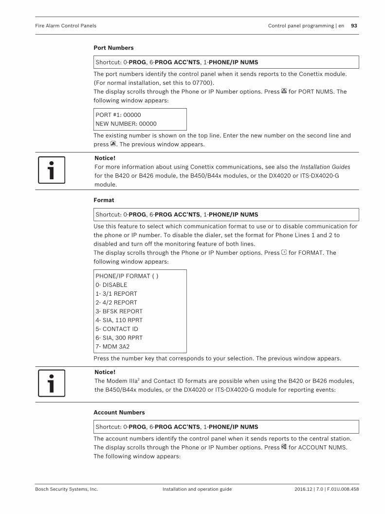
Fire Alarm Control Panels Control panel programming | en 93
Bosch Security Systems, Inc. Installation and operation guide 2016.12 | 7.0 | F.01U.008.458
Port Numbers
Shortcut: 0-PROG, 6-PROG ACC’NTS, 1-PHONE/IP NUMS
The port numbers identify the control panel when it sends reports to the Conettix module.(For normal installation, set this to 07700).The display scrolls through the Phone or IP Number options. Press for PORT NUMS. Thefollowing window appears:
PORT #1: 00000NEW NUMBER: 00000
The existing number is shown on the top line. Enter the new number on the second line andpress . The previous window appears.
Notice!For more information about using Conettix communications, see also the Installation Guidesfor the B420 or B426 module, the B450/B44x modules, or the DX4020 or ITS‑DX4020‑Gmodule.
Format
Shortcut: 0-PROG, 6-PROG ACC’NTS, 1-PHONE/IP NUMS
Use this feature to select which communication format to use or to disable communication forthe phone or IP number. To disable the dialer, set the format for Phone Lines 1 and 2 todisabled and turn off the monitoring feature of both lines.The display scrolls through the Phone or IP Number options. Press for FORMAT. Thefollowing window appears:
PHONE/IP FORMAT ( )0- DISABLE1- 3/1 REPORT2- 4/2 REPORT3- BFSK REPORT4- SIA, 110 RPRT5- CONTACT ID6- SIA, 300 RPRT7- MDM 3A2
Press the number key that corresponds to your selection. The previous window appears.
Notice!The Modem IIIa2 and Contact ID formats are possible when using the B420 or B426 modules,the B450/B44x modules, or the DX4020 or ITS‑DX4020‑G module for reporting events:
Account Numbers
Shortcut: 0-PROG, 6-PROG ACC’NTS, 1-PHONE/IP NUMS
The account numbers identify the control panel when it sends reports to the central station.The display scrolls through the Phone or IP Number options. Press for ACCOUNT NUMS.The following window appears:

94 en | Control panel programming Fire Alarm Control Panels
2016.12 | 7.0 | F.01U.008.458 Installation and operation guide Bosch Security Systems, Inc.
ACCT 1: 0000000000NEW : 0000000000
The existing number is shown on the top line. Enter the new number on the second line andpress . The previous window appears. Enter hexadecimal digits A through F by pressing followed by for A, for B, for C, for D, for E and for F.If the account number contains fewer than 10 digits, then the system auto loads leading zeros(for example, 1234 becomes 0000001234).
Notice! followed by (A) is only valid in Modem IIIa2; the other formats will send 0 to the central
station receiver.
Tone
Shortcut: 0-PROG, 6-PROG ACC’NTS, 1-PHONE/IP NUMS
The FREQ (_) programming items (refer to window below) modify the reporting format when3/1 or 4/2 reporting is selected for the format. Select three parameters with one setting: datatone frequency, acknowledge tone frequency, and data rate. The frequency that the controlpanel uses to send data pulses can be set for 1900 Hz (19D) or 1800 Hz (18D). The frequencyof the acknowledge tone from the receiver to which control panel responds can be set to 1400Hz (14A) or 2300 Hz (23A). The rate at which the data pulses are sent can be set to 10, 20, or40 pulses per second (10PS, 20PS or 40PS).The display scrolls through the Phone/IP Number options (refer to 52). Press for TONE. Thefollowing window appears:
FREQ (__)1- 19D, 14A, 10PS2- 18D, 23A, 10PS3- 19D, 14A, 20PS4- 18D, 23A, 20PS5- 19D, 14A, 40PS6- 18D, 23A, 40PS
Press the number key that corresponds to your selection. The previous window appears.
IP MOD PRIRYThis configuration (refer to window below) is always available no matter how many IP modulesare connected. If there is only one IP module connected, then the configuration will beignored in the logical process for reporting and only one IP module will be used for reporting.The IP module at address 250 will always be the default.
IP MOD PRIRY (1)1- 250 AS PRIM2- 134 AS PRIM
8.6.2 Phone Control
Shortcut: 0-PROG, 6-PROG ACC’NTS, 2-PHONE CONTROL
In addition to features associated with each phone and IP number, each phone line hasassociated features.

Fire Alarm Control Panels Control panel programming | en 95
Bosch Security Systems, Inc. Installation and operation guide 2016.12 | 7.0 | F.01U.008.458
PHONE CONTROL (1)1- LINE #12- LINE #2
Press the number key that corresponds with your selection. Line 1 and Line 2 have the sameoptions. The following window appears:
PHONE CONTROL #11- MONITOR LINE2- DIALING TYPE
For explanations of the phone control options, see the following sections for Monitor Line andDialing Type.
Monitor Line
Shortcut: 0-PROG, 6-PROG ACC’NTS, 2-PHONE CONTROL
The phone line monitor feature, that supervises the connection of the phone line to thecontrol panel, can be disabled for each phone line. When an IP address is entered for thePhone/ IP number, set the monitor to No. If this is not programmed to No, then a trouble isgenerated. Choose Line 1 or Line 2 (see the window above). The display scrolls through thePhone Control options. Press for MONITOR LINE. The following window appears:
MONITOR LINE #1_______: YES (1) NO (0)
For acceptable programming selections for Listed applications that meet the requirements ofthe currently released edition of UL864, see Programming features, page 59.Press for YES or for NO. The previous window appears.
Dialing Type
Shortcut: 0-PROG, 6-PROG ACC’NTS, 2-PHONE CONTROL
This feature determines the format the control panel uses for dialing on each phone line. TheTONE/PULSE setting first tries tone dialing. If that fails, it switches to pulse dialing. If an IPaddress is entered in for the Phone/IP number, then the control panel ignores this setting.Choose Line 1 or Line 2 (see the window below). The display scrolls through the PhoneControl options. Press for DIALING TYPE. The following window appears:
PHONE CONTRO (__)1- PULSE ONLY2- TONE/PULSE3- TONE ONLY
Press the number key that corresponds to your selection. The previous window appears.
8.6.3 Report Steering
Shortcut: 0-PROG, 6-PROG ACC’NTS, 3-RPT STEERING
Different classes of reports can be directed to different phone numbers. Non-supervisoryalarms include fire alarms and waterflow alarms. Supervisory alarms come from pointsconfigured as a supervisory type. Non-supervisory restorals include fire and waterflowrestorals. Supervisory restorals come only from points configured as a supervisory type.

96 en | Control panel programming Fire Alarm Control Panels
2016.12 | 7.0 | F.01U.008.458 Installation and operation guide Bosch Security Systems, Inc.
Trouble reports include all point and system troubles and restorals. Tests include Auto Tests,Manual Tests and Off-normal at Test Reports. The control panel allows the special reportsSilence, Reset, and Drill to be individually directed.
Notice!If any reports are directed to Phone/IP Number 2 (including the default, PHONE 2 BACKUP),then a phone number and account number must be programmed for Phone/IP Number 2. Thecontrol panel indicates a COMM FAULT if it sends a report (using Phone Number 1parameters) which references unprogrammed Phone/IP Number 2 parameters.
The display scrolls through the following items:
REPORT STEERING1- NONSUP ALRM2- SUPVSY ALRM3- NONSUP RSTR4- SUPVSY RSTR5- TROUBLE6- TESTS7- SILENCE8- RESET9- FIRE DRILL
Press the number key that corresponds to your selection. Selecting, for example,NONSUP ALRM produces the following window:
NONSUP ALRM (__)1- PH/IP 1 ONLY2- PH/IP 2 ONLY3- PH/IP 1 & 24- PH/IP 2 BKUP5- NO REPORT
PHONE/IP#1 ONLY: Panel sends the report to Phone/IP #1 receiver using the primary physicalpath (Disable monitor line 2 when PSTN used).PHONE/IP#2 ONLY: Panel sends the report to phone/IP #2 receiver using the primary physicalpath (Disable monitor line 2 when PSTN used).PHONE/IP#2 BACKUP: The panel sends the report to Phone/IP #1 receiver using the primaryphysical path. if report fails, then the panel sends the report to Phone/IP #2 receiver using theprimary physical path. if this report also fails, then the panel sends the report to Phone/IP #1receiver using the secondary physical path. if this report fails, then the panel sends the reportto Phone/IP #2 receiver using the secondary physical path.PHONE/IP#1 AND 2: The panel sends the report to Phone/IP #1 receiver using the primaryphysical path and also to Phone/IP #2 receiver using the primary physical path. if thesereports fail, then the panel sends the reports to Phone/IP #1 receiver using the secondaryphysical path and also to Phone/IP #2 receiver using the secondary physical path.NO REPORT: No report sent.Press the number key that corresponds with your selection. The previous window appears.
8.6.4 Ring Count
Shortcut: 0-PROG, 6-PROG ACC’NTS, 4-RING COUNT

Fire Alarm Control Panels Control panel programming | en 97
Bosch Security Systems, Inc. Installation and operation guide 2016.12 | 7.0 | F.01U.008.458
Notice!Set to 0 the number of phone rings before the control panel seizes the line to attempt remoteprogramming. The number of phone rings before the panel seizes the line to attempt remoteprogramming must remain at 0 for UL864 local, auxiliary, or remote station installations. If anIP address is entered for the Phone/IP number, then the panel will ignore this setting. Whenthe ring count is set to 0, remote programming must be answered on site. Once answered,the panel will prompt for a password.
The following window appears:
RING COUNT(01-15, 00=DIS) _______
Enter the information and press . The previous window appears. An entry of disablesring detection.For acceptable programming selections for Listed applications that meet the requirements ofthe currently released edition of UL864, see Programming features, page 59.
8.6.5 Communication Tries
Shortcut: 0-PROG, 6-PROG ACC’NTS, 5-COMM. TRIES
The system default is to try ten times to communicate an event. Bosch recommends settingthis to five tries. This parameter determines after which attempt the system indicates a failurecondition. (After reporting a failure, the system continues to communicate until it reaches tentimes). Do not select 1 or a failure is indicated whenever a report is sent.The following window appears:
COMM. TRIES (__)(01-10): _______
Enter the information and press . The previous window appears.
8.6.6 Machine Bypass
Shortcut: 0-PROG, 6-PROG ACC’NTS, 6-MACH BYPASS
The downloading computer must redial the control panel if an answering machine answeredthe phone before the control panel. When this option is selected, if the control panel detectsthe phone line ringing within one minute of when the last ringing cycle stopped, then itanswers on the first ring and seizes the phone line. If an IP address is entered in for thePhone/IP number, then the control panel ignores this setting.The following window appears:
MACHINE BYPASS_______: YES (1) NO (0)
Enter the information and press . The previous window appears.
8.6.7 ALT. COMM
Shortcut: 0‑PROG, 6‑PROG ACC’NTS, 7‑ALTER COMM
This prompt is used with the B420 or B426 modules, the B450/B44x modules, the DX4010V2module, and the DX4020 or ITS-DX4020-G module.When using the DX4010V2, select 1-serial; for all others, select 0-network. The followingwindow appears:
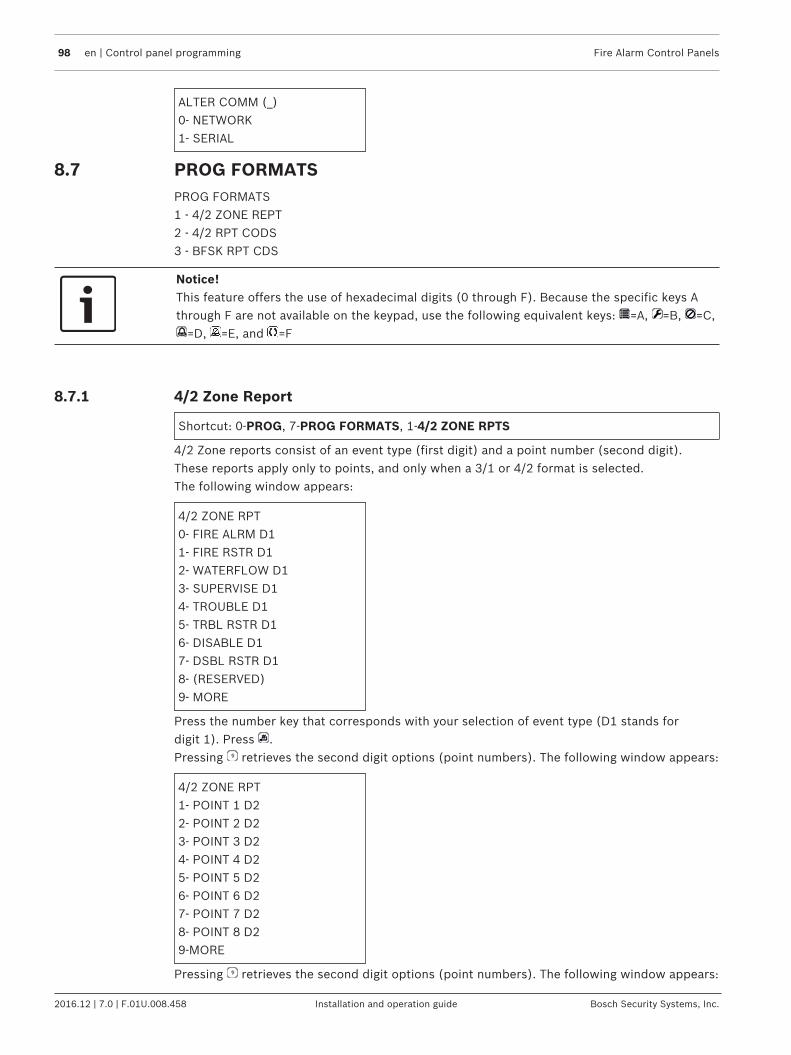
98 en | Control panel programming Fire Alarm Control Panels
2016.12 | 7.0 | F.01U.008.458 Installation and operation guide Bosch Security Systems, Inc.
ALTER COMM (_)0‑ NETWORK1‑ SERIAL
8.7 PROG FORMATSPROG FORMATS1 - 4/2 ZONE REPT2 - 4/2 RPT CODS3 - BFSK RPT CDS
Notice!This feature offers the use of hexadecimal digits (0 through F). Because the specific keys Athrough F are not available on the keypad, use the following equivalent keys: =A, =B, =C,
=D, =E, and =F
8.7.1 4/2 Zone Report
Shortcut: 0-PROG, 7-PROG FORMATS, 1-4/2 ZONE RPTS
4/2 Zone reports consist of an event type (first digit) and a point number (second digit).These reports apply only to points, and only when a 3/1 or 4/2 format is selected.The following window appears:
4/2 ZONE RPT0- FIRE ALRM D11- FIRE RSTR D12- WATERFLOW D13- SUPERVISE D14- TROUBLE D15- TRBL RSTR D16- DISABLE D17- DSBL RSTR D18- (RESERVED)9- MORE
Press the number key that corresponds with your selection of event type (D1 stands fordigit 1). Press .Pressing retrieves the second digit options (point numbers). The following window appears:
4/2 ZONE RPT1- POINT 1 D22- POINT 2 D23- POINT 3 D24- POINT 4 D25- POINT 5 D26- POINT 6 D27- POINT 7 D28- POINT 8 D29-MORE
Pressing retrieves the second digit options (point numbers). The following window appears:

Fire Alarm Control Panels Control panel programming | en 99
Bosch Security Systems, Inc. Installation and operation guide 2016.12 | 7.0 | F.01U.008.458
4/2 ZONE RPT1- POINT 9 D22- POINT 10 D23- RETURN TO D1
Press the number key that corresponds to your selection. A window based on your previousselection allowing entry of hex digits appears:
FIRE ALARM D1 ( )0 THRU 9<HISTORY>:A<TEST>:B<DISABLE>:C<DRILL>:D<SILENCE>:E<RESET>:F
Enter the digit that corresponds to the selected condition by pressing a number key or one ofthe special keys if a hex character is needed. Press and the previous display appears.
8.7.2 4/2 Report Codes
Shortcut: 0-PROG, 7-PROG FORMATS, 1-4/2 RPT CODS
4/2 Report Codes apply to system conditions but only when 3/1 or 4/2 format is selected. Twodigits can be programmed to be sent for each condition. The conditions that can beprogrammed are:System in test, system in test restore: sent for walk test operationsSilence: sent when the silence key is pressedFire drill, fire drill restore: sent for fire drill operationsOpen reset report: sent when the reset key is pressedLow battery, low battery restore, AC failure, AC failure restore: sent for power problemsTest report: sent for manual or automatic communicator testsOff normal at test: sent if the panel is off-normal at the automatic test timePhone trouble, restore: sent for phone line problemsSystem trouble, restore: sent for general system problemsThe following window displays:
4/2 RPT CODS0- SYSTM IN TST1- SYS TEST RST2- SILENCE3- FIRE DRILL4- FIRE DRL RST5- OPEN RST RPT6- LOW BATTERY7- LOW BATT RST8- AC FAILURE9- MORE
Pressing allows programming additional reports:

100 en | Control panel programming Fire Alarm Control Panels
2016.12 | 7.0 | F.01U.008.458 Installation and operation guide Bosch Security Systems, Inc.
4/2 RPT CODS0- AC FAIL RST1- TEST REPORT2- OFF NORM TEST3- PHONE 1 TRBL4- PN 1 TRB RST5- PHONE 2 TRBL6- PN 2 TRB RST7- SYSTEM TROUB8- SYS TRB RST
Pressing returns you to the previous group of reporting codes.Press the number key that corresponds to your code selection. A window based on yourprevious selection allowing entry of two hex digits appears:
SYSTM IN TST ( )0 THRU 9<HISTORY>: A<TEST>: B<DISABLE>: C<DRILL>: D<SILENCE>: E<RESET>: F
Enter digits that correspond to the selected condition by pressing a number key, or one of thespecial keys if a hex character is needed. Press and the previous display appears.
8.7.3 BFSK Report Codes
Shortcut: 0-PROG, 7-PROG FORMATS, 1-BFSK RPT CODS
When BFSK reporting is used, most reporting codes are fixed and do not need programming.There are five reports that the control panel can send that are not standard BFSK codes:Off normal at test: Sent if the panel is off-normal at the automatic test time.Open reset report: Sent when the reset key is pressed.Silence: Sent when the silence key is pressed.Fire drill, fire drill restore: Sent for fire drill operations.The following window displays:
BFSK RPT CDS1- OFF NRM TEST2- OPEN/RESET3- SILENCE4- FIRE DRILL5- FR DRIL RSTR
Press the number key that corresponds to your report code selection. A window allowingentry of two hex digits appears.
8.8 HISTORY DEFAULTS
Shortcut: 0-PROG, 8-HSTRY DEFLTS
The following window appears:
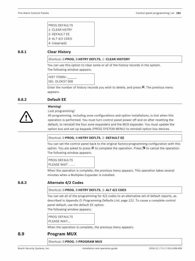
Fire Alarm Control Panels Control panel programming | en 101
Bosch Security Systems, Inc. Installation and operation guide 2016.12 | 7.0 | F.01U.008.458
PROG DEFAULTS1- CLEAR HSTRY2- DEFAULT EE3- ALT 4/2 CDES4- (reserved)
8.8.1 Clear History
Shortcut: 0-PROG, 8-HSTRY DEFLTS, 1- CLEAR HISTORY
You can use this option to clear some or all of the history records in the system.The following window appears:
HIST ITEMS= _______DEL OLDEST 000
Enter the number of history records you wish to delete, and press . The previous menuappears.
8.8.2 Default EE
!
Warning!Lost programming!All programming, including zone configurations and option installations, is lost when thisoperation is performed. You must turn control panel power off and on after resetting thedefault, to reinstall the four zone expanders and the MUX expander. You must update theoption bus and set up keypads (PROG SYSTEM MENU) to reinstall option bus devices.
Shortcut: 0-PROG, 8-HSTRY DEFLTS, 2- DEFAULT EE
You can set the control panel back to the original factory-programming configuration with thisoption. You are asked to press to complete the operation. Press to cancel the operation.The following window appears:
PROG DEFAULTSPLEASE WAIT . . . .
When the operation is complete, the previous menu appears. This operation takes severalminutes when a Multiplex Expander is installed.
8.8.3 Alternate 4/2 Codes
Shortcut: 0-PROG, 8-HSTRY DEFLTS, 3- ALT 4/2 CDES
You can set all of the programming for 4/2 codes to an alternative set of default reports, asdescribed in Appendix D: Programming Defaults List, page 121. To cause a complete controlpanel default, use the default EE option.The following window appears:
PROG DEFAULTSPLEASE WAIT...
When the operation is complete, the previous menu appears.
8.9 Program MUX
Shortcut: 0-PROG, 9-PROGRAM MUX

102 en | Control panel programming Fire Alarm Control Panels
2016.12 | 7.0 | F.01U.008.458 Installation and operation guide Bosch Security Systems, Inc.
!
Warning!1. Unprogrammed devices on the bus will not operate or be supervised2. This menu is accessible only when a Multiplex Expansion Module is installed.3. Do not install more than one device programmed to the same address on the bus. Doing socan inhibit alarm reporting from both devices.
The following window appears:
PROGRAM MUX1- MUX EDIT2- (reserved)3- MUX BUS TYPE4- AUTO PROGRAM
8.9.1 MUX Edit
Shortcut: 0-PROG, 9-PROGRAM MUX, 1- MUX EDIT
To add MUX devices to the system, use the MUX Edit option. Each device must have a uniqueaddress programmed using the address switches.The following window appears:
DEVICE TYPE ( )0- NO DEVICE2- SINGLE INPUT3- I/O MODULE4- MUX SMOKE5- (reserved)6- DUAL INPUT7- OCTAL INPUT
Notice!Single input devices include the D7044/M, D7045, FMM-7045, FMM-7045-D, and D7052(Class A). The I/O module is the D7053. The MUX smoke detectors are the D D7050,D7050TH, and D343. The dual input module is the D7052 (Class B). The Octal input module isthe D7042.
Press the number that corresponds with the device you are adding or press if you areremoving a device. When the device type is selected, the following window appears:
POINT NUMBER(009 - 255) 009
Enter the address of the point being added, and press . The device type window appearsagain allowing additional devices to be added. Eight points are added at once when the D7042is added to the control panel.
8.9.2 MUX Bus Type
Shortcut: 0-PROG, 9-PROGRAM MUX, 3- BUS TYPE
This option configures the system for two independent Class B buses allowing addresses upto 255.

Fire Alarm Control Panels Control panel programming | en 103
Bosch Security Systems, Inc. Installation and operation guide 2016.12 | 7.0 | F.01U.008.458
Notice!Class A operation is not supported by the D7042 Eight Input Module; do not select Class Aoperation.
The following window appears:
MUX BUS TYPE ( )1- CLASS A2- CLASS B
Press to select Class B operation if the setting was changed from the default setting.For wiring details for a Class B configuration, see also the D7042/D7042B Multiplex Eight InputRemote Modules Installation Instructions. For more information regarding Class A and Class Bwiring instructions, see also the MUX expansion module’s Installation Guide.
8.9.3 AUTO PROGRAM
Shortcut: 0‑PROG, 9‑PROGRAM MUX, 4‑AUTO PROGRAM
This option provides a convenient way for the installer to configure the FACP to operate withthe existing devices on the multiplex buses by scanning the buses for missing or newmultiplex devices.The following display appears:
AUTO PROGRAM?_______:YES(1) NO(0)
Press to continue with auto programming or to cancel. When you press , the FACPchecks for existing programming errors in which devices are programmed incorrectly in thespace required for a lower-addressed multi-point device (such as a dual point module). If apoint is found to be programmed under another device, then the following error messageappears for five seconds, and the auto programming process aborts:
ADDRESS ERROR 1AT ADDRESS xxx
If no errors are found, then the FACP starts a scanning process that takes approximately oneminute to complete, while showing the following display:
AUTO PROGRAMSCANNINGPLEASE WAIT...
When the scanning is completed, the FACP checks for missing devices. Missing devices areaddresses with no devices on the multiplex buses, but are programmed into the FACP’ssite‑specific memory area. If missing devices are detected, then the FACP shows the followingmenu (where xxx is the address of the first point of the missing device):
MISSING PT @ xxx0‑ DELETE POINT1‑ KEEP POINT2‑ DEL REMAIN3‑ KEEP REMAIN

104 en | Control panel programming Fire Alarm Control Panels
2016.12 | 7.0 | F.01U.008.458 Installation and operation guide Bosch Security Systems, Inc.
DELETE POINT: When selected, the missing point and any addresses it implemented (up toeight for an octal input module) are permanently deleted from the site specific memory area. Ifthe deleted device is an I/O module, then the output zones that were programmed for therelay are reset to 0. If additional devices are found to be missing, then the above display isrepeated for each missing device.KEEP POINT: When selected, the FACP retains the programming for the existing point andcontinues scanning for additional missing points.DEL REMAIN: When selected, the following prompt # KEY TO CONFIRM appears at theFPD‑7024. If the key is pressed, then all the missing points are deleted from thesite‑specific memory area and the auto program process continues with the devices foundmenu. If any other key is pressed, then the existing point is kept and the control panelcontinues scanning for additional missing devices.KEEP REMAIN: When selected, no additional points are deleted and the auto program processcontinues with the Devices Found menu. Points individually deleted with the Delete Pointcommand before selecting the Keep Remain command stay deleted when Keep Remain isselected.
!
Warning!Missing points!Use the DEL REMAINING feature with caution. Any devices missing from the multiplex busesduring the DEL REMAINING operation, even momentarily, are permanently deleted. Thesepoints do not operate, and do not generate trouble conditions even if they are returned to thebus.
When the delete point operation is finished, the FACP shows for five seconds the total numberof points that were deleted from the control panel (xxx indicates the number of points thatwere removed from the control panel’s site‑specific configuration).
AUTO PROGRAMxxx PNTS DELETED
Confirm that only the expected number of points was removed from the system. Points thatare removed from the control panel’s site‑specific configuration do not operate and are notsupervised even if they are returned to the bus.When the point delete process completes, the auto programming process automaticallychecks for new devices on the buses. New devices are found when a device is present on oneof the multiplex buses, but its address is not programmed into the control panel’s site-specificmemory. If new devices are detected, then the FACP shows the following menu (where xxx isthe address of the first new device found):
NEW DEVICE @ xxx2‑ SINGLE INPUT3‑ I/O MODULE4‑ MUX SMOKE5‑ (reserved)6‑ DUAL INPUT7‑ OCTAL INPUT0‑ NO DEVICE

Fire Alarm Control Panels Control panel programming | en 105
Bosch Security Systems, Inc. Installation and operation guide 2016.12 | 7.0 | F.01U.008.458
Use this menu to define the device type. Press the number key that corresponds with thedevice type installed at the address. If a detected device should not be installed and should beleft inactive, then press to bypass the new device.
!
Warning!Device malfunction!Ensure that the correct device type is selected for each point. Incorrectly specified devicetypes can cause multiplex devices to malfunction or fail to operate.
All inputs are configured to use Point Function 10 as they are added. Points added during autoprogramming are configured for the following operation:– Point Function 10 (Fire Alarm, Fast Response, Non-silenceable, Not Local-only)– Open Status = Trouble– Output Zone 9– Alarm Verify = NO– Latching = YESThe programming of input points can be changed when auto programming completes usingthe input-programming menu.When I/O modules are added during auto programming, the relay (second point) is configuredto activate on any alarm, non-silenceable (Zone 63). This can be changed when autoprogramming completes by using the output-programming menu.The FACP performs some basic error checks when new devices are added. The followingerrors can be shown during the process of adding a device:
ADDRESS ERROR #AT ADDRESS xxx
In the previous message, # is replaced by a code number and xxx is replaced by the affectedaddress that indicates the type of error.For code numbers and corresponding error message descriptions, see the following table:
Code Error Description
1 New point is under an existingpoint
The new point is in the space required for anexisting multi-address device. This is checkedwhen auto programming first starts.
2 Point overlaps existing point There are already devices configured at one ofthe addresses required for the new multi-pointdevice.
3 Point is at an illegal address The addresses at which multi-address devicescan be installed are restricted.
4 Too many multiplex relays Only 20 input output devices can be supportedon a given bus.
Tab. 8.22: Auto programming error messages
For details on installation restrictions, see also the specific device’s installation instructionsWhen the point adding operation completes, the FACP shows for five seconds the totalnumber of points that were added to the control panel. Confirm that the number of devicesadded matches the expected number.
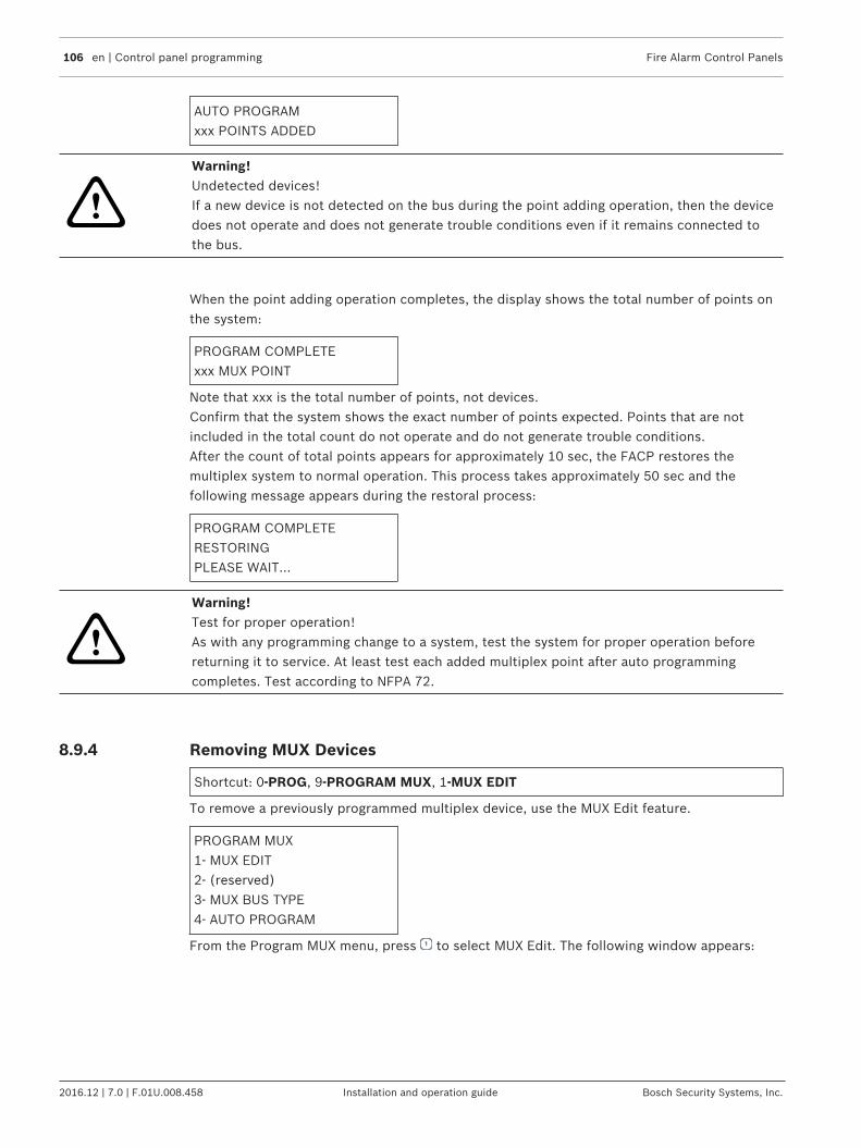
106 en | Control panel programming Fire Alarm Control Panels
2016.12 | 7.0 | F.01U.008.458 Installation and operation guide Bosch Security Systems, Inc.
AUTO PROGRAMxxx POINTS ADDED
!
Warning!Undetected devices!If a new device is not detected on the bus during the point adding operation, then the devicedoes not operate and does not generate trouble conditions even if it remains connected tothe bus.
When the point adding operation completes, the display shows the total number of points onthe system:
PROGRAM COMPLETExxx MUX POINT
Note that xxx is the total number of points, not devices.Confirm that the system shows the exact number of points expected. Points that are notincluded in the total count do not operate and do not generate trouble conditions.After the count of total points appears for approximately 10 sec, the FACP restores themultiplex system to normal operation. This process takes approximately 50 sec and thefollowing message appears during the restoral process:
PROGRAM COMPLETERESTORINGPLEASE WAIT...
!
Warning!Test for proper operation!As with any programming change to a system, test the system for proper operation beforereturning it to service. At least test each added multiplex point after auto programmingcompletes. Test according to NFPA 72.
8.9.4 Removing MUX Devices
Shortcut: 0‑PROG, 9‑PROGRAM MUX, 1‑MUX EDIT
To remove a previously programmed multiplex device, use the MUX Edit feature.
PROGRAM MUX1‑ MUX EDIT2‑ (reserved)3‑ MUX BUS TYPE4‑ AUTO PROGRAM
From the Program MUX menu, press to select MUX Edit. The following window appears:
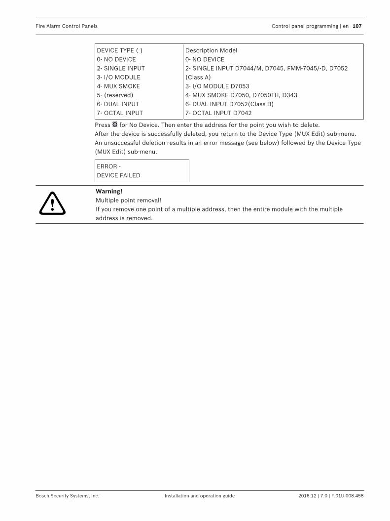
Fire Alarm Control Panels Control panel programming | en 107
Bosch Security Systems, Inc. Installation and operation guide 2016.12 | 7.0 | F.01U.008.458
DEVICE TYPE ( )0‑ NO DEVICE2‑ SINGLE INPUT3‑ I/O MODULE4‑ MUX SMOKE5‑ (reserved)6‑ DUAL INPUT7‑ OCTAL INPUT
Description Model0‑ NO DEVICE2‑ SINGLE INPUT D7044/M, D7045, FMM-7045/-D, D7052(Class A)3‑ I/O MODULE D70534‑ MUX SMOKE D7050, D7050TH, D3436‑ DUAL INPUT D7052(Class B)7‑ OCTAL INPUT D7042
Press for No Device. Then enter the address for the point you wish to delete.After the device is successfully deleted, you return to the Device Type (MUX Edit) sub-menu.An unsuccessful deletion results in an error message (see below) followed by the Device Type(MUX Edit) sub-menu.
ERROR ‑DEVICE FAILED
!
Warning!Multiple point removal!If you remove one point of a multiple address, then the entire module with the multipleaddress is removed.

108 en | Specifications Fire Alarm Control Panels
2016.12 | 7.0 | F.01U.008.458 Installation and operation guide Bosch Security Systems, Inc.
9 SpecificationsNotice!When a local relay is programmed for general trouble (Zone 62), Position A will energize therelay in the normal state. Positions B, C, and D must be configured as Zone 0 (notprogrammed). This causes the common and normally‑open terminals to be shorted when notin the trouble condition.
Electrical
Line impedance for ground fault detection(Option Bus, conventional input, NAC,secondary power circuit, MUX Bus, AUXpower, SMK power):
10 kΩ or less
Power (Input): 120 V 60 Hz 1.4 A or 230/240 V 50 Hz, 0.7 A
Power (Auxiliary): 17 to 31 VRMS, unfiltered, 1.0 A
Power (Smoke)1: 20.4 to 28.2 VDC nominal, filtered, 1.0 A.
Power (Option Bus): 12 VDC nominal, 500 mA
Power (Notification Appliance Circuit[NAC])2:
Each NAC has 24 FWR nominal, unfilteredpower with up to 2.5 A capacity (but limitedby panel’s overall 4.0 A capacity)
Power (Optional Standby Batteries): Two 12 V (in series), 7 Ah to 40 Ah
NACs Line Impedance (voltage loss) 1.5 V
Recommended Manufacturers:3 Power Sonic: PS-1270, PS-12170, PS-12180YUASA: NP7-12, NPG18-12
1 For compatible smoke detection devices, see also the FPD‑7024 Smoke DetectorCompatibility List.2 For compatible NAC devices, see also the FPD‑7024 NAC Compatibility List3 If other manufacturers or battery types are used, ensure that the battery or batteries canhandle an initial charge current of at least 1.7 A.
Environmental
Temperature (operating and storage): +32°F to +120°F (0°C to +49°C)
Notification Appliance Circuits (NACs)
Wiring: Class B or Class A
Notification patterns: Configurable for steady, pulsing, California March, Temporal(ANSI) code 3, synchronized Wheelock, synchronized Gentex, andsynchronized System Sensor.
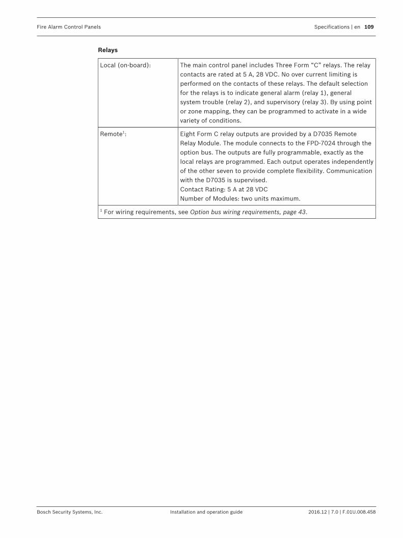
Fire Alarm Control Panels Specifications | en 109
Bosch Security Systems, Inc. Installation and operation guide 2016.12 | 7.0 | F.01U.008.458
Relays
Local (on-board): The main control panel includes Three Form “C” relays. The relaycontacts are rated at 5 A, 28 VDC. No over current limiting isperformed on the contacts of these relays. The default selectionfor the relays is to indicate general alarm (relay 1), generalsystem trouble (relay 2), and supervisory (relay 3). By using pointor zone mapping, they can be programmed to activate in a widevariety of conditions.
Remote1: Eight Form C relay outputs are provided by a D7035 RemoteRelay Module. The module connects to the FPD‑7024 through theoption bus. The outputs are fully programmable, exactly as thelocal relays are programmed. Each output operates independentlyof the other seven to provide complete flexibility. Communicationwith the D7035 is supervised.Contact Rating: 5 A at 28 VDCNumber of Modules: two units maximum.
1 For wiring requirements, see Option bus wiring requirements, page 43.

110 en | Appendices Fire Alarm Control Panels
2016.12 | 7.0 | F.01U.008.458 Installation and operation guide Bosch Security Systems, Inc.
10 Appendices10.1 Appendix A: Display Abbreviations
Abbreviation Definition Abbreviation Definition
3/1 3/1 reporting format IP Internet Protocol address
4/2 4/2 reporting format KPAD, KYPAD, KYPD Keypad
@ Device address on OptionBus
LRelay Local Relay
ACTVTN Activation LOC Local
A, ALRM Alarm MACH Answering Machine
ALT Alternate M, MONI, MON Monitor
ANN, ANUN Annunciator NAC Notification ApplianceCircuit
BAT, BATT, BATTRY Battery NMBR, NUM Number
BX Box (e.g. city box) NONSUP Non-Supervisory
CATE Catastrophe NORM, NRM Normal
CDES, CODS, CDS Codes OUT Output
CMPTR Computer OVRC Overcurrent
COMM Communicator PAS Positive Alarm Sequence
CONFIG Configure PHN, PHON Phone
DESCRIPTION Description PROG, PRGMNG Programming
DIG Digit PRGMMD Programmed
DLY Delay PT, PNT Point
DRL, DRIL Drill PWR Power
D, DBL, DISABL Disable REM, REMOT Remote
DSPLY Display RESPNS Response
DTY Dirty RLY Relay
EE EEPROM RPRT, RPT Report
ERelay Expander Relay RST Restore
EXP Expander SIL Silence
FAIL Failure SMK Smoke
F, FIR, FR Fire S, SUPERVISORY, SUP,SUPRVSRY, SUPV, SPV,SUPVSY
Supervisory
FLT Fault SHRT Short
FRQNCY, FREQ,FREQUENCY
Frequency SYS, SYSTM System

Fire Alarm Control Panels Appendices | en 111
Bosch Security Systems, Inc. Installation and operation guide 2016.12 | 7.0 | F.01U.008.458
Abbreviation Definition Abbreviation Definition
FUNC Function T, TRBL, TRB, TROUB Trouble
GRND Ground TST Test
HI High VER Version
HSTRY History W, WFLW, WTF Waterflow
INIT Initialize ZN, ZON Zone
Table 10.23: Abbreviations on control panel display
10.2 Appendix B: Panel DisplaysThe meanings of control panel messages are given in the following table:
Panel Display Message Panel Display Message Definition (v1.06.01)
DBL PTXXX Point is disabled from the keypad.
DTY PTXXX A smoke detector with the Chamber Check feature indicates a dirtychamber.
INST.FLT 4Z EXP There is a missing FPD-7034 Four Zone Expander Board, or theexpander appeared unexpectedly since the last time the systemwas powered.
INST.FLT MX EXP There is a missing MUX Expander Module, or the expanderappeared unexpectedly since the last time the system waspowered.
MUX X WIRE FAIL A wiring short on Bus A or Bus B in Class B mode occurred. Checkthe wiring for shorts.
MUX CPU FAILURE A CPU failure on the MUX Expander board occurred. Ensure thatthe Multiplex Expander module is correctly installed on the headerpins. If the message persists, then call for service immediately.
MUX WIRING FAULT A failure on the MUX wiring in Class A mode occurred. Check thewiring for opens. If an isolator is installed on the MUX bus, checkfor an activated condition.
REPROGRAM SYSTEM An EEPROM failure occurred. Call for service immediately.
TRB PTXXX Trouble condition for specific points on the system. Refer to thesecond line of display for more information. Check control panelwiring and field wiring for shorts or opens. Also check pointprogramming to ensure the control panel knows what points belongon the system.
TRB SYS General trouble message. Refer to second line of the display formore information.
TRBL OPEN NAC X A Local NAC circuit is open. Check the field wiring and the EOLresistor.
TRBL OUTX RNACX An FPP‑RNAC‑8A‑4C Remote NAC circuit is open. Check the fieldwiring and the EOL resistor.
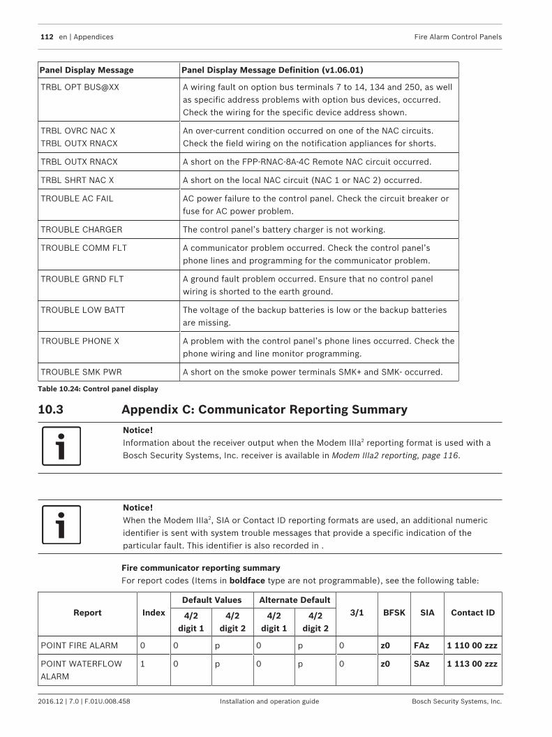
112 en | Appendices Fire Alarm Control Panels
2016.12 | 7.0 | F.01U.008.458 Installation and operation guide Bosch Security Systems, Inc.
Panel Display Message Panel Display Message Definition (v1.06.01)
TRBL OPT BUS@XX A wiring fault on option bus terminals 7 to 14, 134 and 250, as wellas specific address problems with option bus devices, occurred.Check the wiring for the specific device address shown.
TRBL OVRC NAC X TRBL OUTX RNACX
An over-current condition occurred on one of the NAC circuits.Check the field wiring on the notification appliances for shorts.
TRBL OUTX RNACX A short on the FPP‑RNAC‑8A‑4C Remote NAC circuit occurred.
TRBL SHRT NAC X A short on the local NAC circuit (NAC 1 or NAC 2) occurred.
TROUBLE AC FAIL AC power failure to the control panel. Check the circuit breaker orfuse for AC power problem.
TROUBLE CHARGER The control panel’s battery charger is not working.
TROUBLE COMM FLT A communicator problem occurred. Check the control panel’sphone lines and programming for the communicator problem.
TROUBLE GRND FLT A ground fault problem occurred. Ensure that no control panelwiring is shorted to the earth ground.
TROUBLE LOW BATT The voltage of the backup batteries is low or the backup batteriesare missing.
TROUBLE PHONE X A problem with the control panel’s phone lines occurred. Check thephone wiring and line monitor programming.
TROUBLE SMK PWR A short on the smoke power terminals SMK+ and SMK- occurred.
Table 10.24: Control panel display
10.3 Appendix C: Communicator Reporting Summary
Notice!Information about the receiver output when the Modem IIIa2 reporting format is used with aBosch Security Systems, Inc. receiver is available in Modem IIIa2 reporting, page 116.
Notice!When the Modem IIIa2, SIA or Contact ID reporting formats are used, an additional numericidentifier is sent with system trouble messages that provide a specific indication of theparticular fault. This identifier is also recorded in .
Fire communicator reporting summaryFor report codes (Items in boldface type are not programmable), see the following table:
Report IndexDefault Values Alternate Default
3/1 BFSK SIA Contact ID4/2digit 1
4/2digit 2
4/2digit 1
4/2digit 2
POINT FIRE ALARM 0 0 p 0 p 0 z0 FAz 1 110 00 zzz
POINT WATERFLOWALARM
1 0 p 0 p 0 z0 SAz 1 113 00 zzz
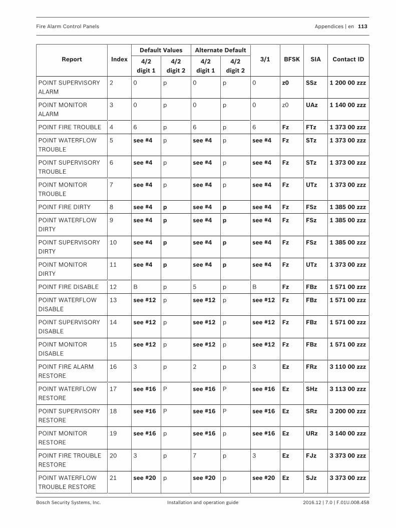
Fire Alarm Control Panels Appendices | en 113
Bosch Security Systems, Inc. Installation and operation guide 2016.12 | 7.0 | F.01U.008.458
Report IndexDefault Values Alternate Default
3/1 BFSK SIA Contact ID4/2digit 1
4/2digit 2
4/2digit 1
4/2digit 2
POINT SUPERVISORYALARM
2 0 p 0 p 0 z0 SSz 1 200 00 zzz
POINT MONITORALARM
3 0 p 0 p 0 z0 UAz 1 140 00 zzz
POINT FIRE TROUBLE 4 6 p 6 p 6 Fz FTz 1 373 00 zzz
POINT WATERFLOWTROUBLE
5 see #4 p see #4 p see #4 Fz STz 1 373 00 zzz
POINT SUPERVISORYTROUBLE
6 see #4 p see #4 p see #4 Fz STz 1 373 00 zzz
POINT MONITORTROUBLE
7 see #4 p see #4 p see #4 Fz UTz 1 373 00 zzz
POINT FIRE DIRTY 8 see #4 p see #4 p see #4 Fz FSz 1 385 00 zzz
POINT WATERFLOWDIRTY
9 see #4 p see #4 p see #4 Fz FSz 1 385 00 zzz
POINT SUPERVISORYDIRTY
10 see #4 p see #4 p see #4 Fz FSz 1 385 00 zzz
POINT MONITORDIRTY
11 see #4 p see #4 p see #4 Fz UTz 1 373 00 zzz
POINT FIRE DISABLE 12 B p 5 p B Fz FBz 1 571 00 zzz
POINT WATERFLOWDISABLE
13 see #12 p see #12 p see #12 Fz FBz 1 571 00 zzz
POINT SUPERVISORYDISABLE
14 see #12 p see #12 p see #12 Fz FBz 1 571 00 zzz
POINT MONITORDISABLE
15 see #12 p see #12 p see #12 Fz FBz 1 571 00 zzz
POINT FIRE ALARMRESTORE
16 3 p 2 p 3 Ez FRz 3 110 00 zzz
POINT WATERFLOWRESTORE
17 see #16 P see #16 P see #16 Ez SHz 3 113 00 zzz
POINT SUPERVISORYRESTORE
18 see #16 P see #16 P see #16 Ez SRz 3 200 00 zzz
POINT MONITORRESTORE
19 see #16 p see #16 p see #16 Ez URz 3 140 00 zzz
POINT FIRE TROUBLERESTORE
20 3 p 7 p 3 Ez FJz 3 373 00 zzz
POINT WATERFLOWTROUBLE RESTORE
21 see #20 p see #20 p see #20 Ez SJz 3 373 00 zzz

114 en | Appendices Fire Alarm Control Panels
2016.12 | 7.0 | F.01U.008.458 Installation and operation guide Bosch Security Systems, Inc.
Report IndexDefault Values Alternate Default
3/1 BFSK SIA Contact ID4/2digit 1
4/2digit 2
4/2digit 1
4/2digit 2
POINT SUPERVISORYTROUBLE RESTORE
22 see #20 p see #20 p see #20 Ez SJz 3 373 00 zzz
POINT MONITORTROUBLE RESTORE
23 see #20 p see #20 p see #20 Ez UJz 3 373 00 zzz
POINT FIRE DIRTYRESTORE
24 see #20 p see #20 p see #20 Ez FJz 3 385 00 zzz
POINT WATERFLOWDIRTY RESTORE
25 see #20 p see #20 p see #20 Ez FJz 3 385 00 zzz
POINT SUPERVISORYDIRTY RESTORE
26 see #20 p see #20 p see #20 Ez FJz 3 385 00 zzz
POINT MONITORDIRTY RESTORE
27 see #20 p see #20 p see #20 Ez UJz 3 373 00 zzz
POINT FIRE DISABLERESTORE
28 3 p 2 p 3 Ez FHz 3 571 00 zzz
POINT WATERFLOWDISABLE RESTORE
29 see #28 p see #28 p see #28 Ez FHz 3 571 00 zzz
POINT SUPERVISORYDISABLE RESTORE
30 see #28 p see #28 p see #28 Ez FHz 3 571 00 zzz
POINT MONITORDISABLE RESTORE
31 see #28 p see #28 p see #28 Ez FHz 3 571 00 zzz
SYSTEM IN TEST 40 F 1 3 3 F FD TS0 1 607 00000
SYSTEM IN TESTRESTORE
41 E 1 3 7 E ED TE0 3 607 00000
SILENCE 42 9 F 9 F 9 FD KB000 1 400 00uuu
FIRE DRILL 43 F 2 3 3 F FD FI0 1 607 00000
FIRE DRILL RESTORE 44 E 2 3 7 E ED FK0 3 607 00000
SYSTEM RESET 45 9 F 9 F 9 FD OR 1 305 00uuu
LOW BATTERY 46 F 9 6 9 F F9 YT0 1 302 00000
LOW BATTERYRESTORE
47 E 9 7 9 E E9 YR0 3 302 00000

Fire Alarm Control Panels Appendices | en 115
Bosch Security Systems, Inc. Installation and operation guide 2016.12 | 7.0 | F.01U.008.458
Report IndexDefault Values Alternate Default
3/1 BFSK SIA Contact ID4/2digit 1
4/2digit 2
4/2digit 1
4/2digit 2
AC FAIL 48 F D 6 0 F FD AT0 1 301 00000
AC FAIL RESTORE 49 E D 7 0 E ED AR0 3 301 00000
AUTO TEST 50 E E 3 0 E EE RP0 1 602 00000
OFF NORMAL AT TEST 51 F D 3 3 F FD YX0 1 608 00000
PHONE 1 TROUBLE 52 F B 3 1 F FB LT1 1 351 00000
PHONE 1 RESTORE 53 E B 3 5 E EB LR1 3 351 00000
PHONE 2 TROUBLE 54 F C 3 2 F FC LT2 1 352 00000
PHONE 2 RESTORE 55 E C 3 6 E EC LR2 3 352 00000
SYSTEM TROUBLE 56 F D 3 3 F FD ET 1 300 00 ccc
SYSTEM TROUBLERESTORE
57 E D 3 7 E ED ER 3 300 00 ccc
MANUAL TEST 58 see #50 see #50 see #50 see #50 see #50 EE RX0 1 601 00000
COMM. FAULT 59 see #56 see #56 see #56 see #56 see #56 FD RT0 1 354 00000
EEPROM FAILURE 60 see #56 see #56 see #56 see #56 see #56 FD UT18 1 307 00018
EEPROM RESTORAL 61 see #57 see #57 see #57 see #57 see #57 ED UJ18 3 307 00018
SMOKE POWER FAULT 62 see #56 see #56 see #56 see #56 see #56 FD YP0 1 320 00000
SMOKE POWERRESTORE
63 see #57 see #57 see #57 see #57 see #57 ED YQ0 3 320 00000
REMOTEPROGRAMMING FAIL
66 F D F D F FD RU0 1 413 00000
REMOTEPROGRAMMINGSUCCESS
67 E D E D E ED RS0 1 412 00000

116 en | Appendices Fire Alarm Control Panels
2016.12 | 7.0 | F.01U.008.458 Installation and operation guide Bosch Security Systems, Inc.
Report IndexDefault Values Alternate Default
3/1 BFSK SIA Contact ID4/2digit 1
4/2digit 2
4/2digit 1
4/2digit 2
Notes:c: system trouble condition codep: programmable digit for each zone u: user ID digitz: zone digit
Modem IIIa2 reporting
Notice!The Modem IIIa2 reports are fixed and do not require programming.
Report Index Receiver output
POINT FIRE ALARM 0 dd/dd tt:tt ql ACCT aaaa FIRE ALARM+++ ACCT aaaa AREA=1 POINT=zzz
POINT WATERFLOW ALARM 1 dd/dd tt:tt ql ACCT aaaa FIRE ALARM+++ ACCT aaaa AREA=1 POINT=zzz
POINT SUPERVISORY ALARM 2 dd/dd tt:tt ql ACCT aaaa FIRE SUPRVISION+++ ACCT aaaa AREA=1 POINT=zzz
POINT MONITOR ALARM 3 dd/dd tt:tt ql ACCT aaaa FIRE ALARM+++ ACCT aaaa AREA=1 POINT=zzz
POINT FIRE TROUBLE 4 dd/dd tt:tt ql ACCT aaaa FIRE TROUBLE+++ ACCT aaaa AREA=1 POINT=zzz
POINT WATERFLOW TROUBLE 5 dd/dd tt:tt ql ACCT aaaa FIRE TROUBLE+++ ACCT aaaa AREA=1 POINT=zzz
POINT SUPERVISORY TROUBLE 6 dd/dd tt:tt ql ACCT aaaa FIRE TROUBLE+++ ACCT aaaa AREA=1 POINT=zzz
POINT MONITOR TROUBLE 7 dd/dd tt:tt ql ACCT aaaa FIRE TROUBLE+++ ACCT aaaa AREA=0 POINT=zzz
POINT FIRE DIRTY 8 dd/dd tt:tt ql ACCT aaaa ANALOG SERVICE+++ ACCT aaaa AREA=0 POINT=zzz
POINT WATERFLOW DIRTY 9 dd/dd tt:tt ql ACCT aaaa ANALOG SERVICE+++ ACCT aaaa AREA=1 POINT=zzz
POINT SUPERVISORY DIRTY 10 dd/dd tt:tt ql ACCT aaaa ANALOG SERVICE+++ ACCT aaaa AREA=1 POINT=zzz
POINT MONITOR DIRTY 11 dd/dd tt:tt ql ACCT aaaa FIRE TROUBLE+++ ACCT aaaa AREA=1 POINT=zzz
POINT FIRE DISABLE 12 dd/dd tt:tt ql ACCT aaaa COMMANDBYPASS+++ ACCT aaaa AREA=1 ID=uuu POINT=zzz

Fire Alarm Control Panels Appendices | en 117
Bosch Security Systems, Inc. Installation and operation guide 2016.12 | 7.0 | F.01U.008.458
Report Index Receiver output
POINT WATERFLOW DISABLE 13 dd/dd tt:tt ql ACCT aaaa COMMANDBYPASS+++ ACCT aaaa AREA=1 ID=uuu POINT=zzz
POINT SUPERVISORY DISABLE 14 dd/dd tt:tt ql ACCT aaaa COMMANDBYPASS+++ ACCT aaaa AREA=1 ID=uuu POINT=zzz
POINT MONITOR DISABLE 15 dd/dd tt:tt ql ACCT aaaa COMMANDBYPASS+++ ACCT aaaa AREA=1 ID=uuu POINT=zzz
POINT FIRE ALARM RESTORE 16 dd/dd tt:tt ql ACCT aaaa FIRE ALM RESTOR+++ ACCT aaaa AREA=1 POINT=zzz
POINT WATERFLOW RESTORE 17 dd/dd tt:tt ql ACCT aaaa FIRE ALM RESTOR+++ ACCT aaaa AREA=1 POINT=zzz
POINT SUPERVISORY RESTORE 18 dd/dd tt:tt ql ACCT aaaa FIRE ALM RESTOR+++ ACCT aaaa AREA=1 POINT=zzz
POINT MONITOR RESTORE 19 dd/dd tt:tt ql ACCT aaaa FIRE ALM RESTOR+++ ACCT aaaa AREA=1 POINT=zzz
POINT FIRE TROUBLE RESTORE 20 dd/dd tt:tt ql ACCT aaaa FIRE TBL RESTOR+++ ACCT aaaa AREA=1 POINT=zzz
POINT WATERFLOW TROUBLERESTORE
21 dd/dd tt:tt ql ACCT aaaa FIRE TBL RESTOR+++ ACCT aaaa AREA=1 POINT=zzz
POINT SUPERVISORY TROUBLERESTORE
22 dd/dd tt:tt ql ACCT aaaa FIRE TBL RESTOR+++ ACCT aaaa AREA=1 POINT=zzz
POINT MONITOR TROUBLE RESTORE 23 dd/dd tt:tt ql ACCT aaaa FIRE TBL RESTOR+++ ACCT aaaa AREA=1 POINT=zzz
POINT FIRE DIRTY RESTORE 24 dd/dd tt:tt ql ACCT aaaa ANALOG RESTORE+++ ACCT aaaa AREA=1 POINT=zzz
POINT WATERFLOW DIRTY RESTORE 25 dd/dd tt:tt ql ACCT aaaa ANALOG RESTORE+++ ACCT aaaa AREA=1 POINT=zzz
POINT SUPERVISO Y DIRTY RESTORE 26 dd/dd tt:tt ql ACCT aaaa ANALOG RESTORE+++ ACCT aaaa AREA=1 POINT=zzz
POINT MONITOR DIRTY RESTORE 27 dd/dd tt:tt ql ACCT aaaa FIRE TBL RESTOR+++ ACCT aaaa AREA=1 POINT=zzz
POINT FIRE DISABLE RESTORE 28 dd/dd tt:tt ql ACCT aaaa FIRE TBL RESTOR+++ ACCT aaaa AREA=1 POINT=zzz
POINT WATERFLOW DISABLERESTORE
29 dd/dd tt:tt ql ACCT aaaa FIRE TBL RESTOR+++ ACCT aaaa AREA=1 POINT=zzz
POINT SUPERVISORY DISABLERESTORE
30 dd/dd tt:tt ql ACCT aaaa FIRE TBL RESTOR+++ ACCT aaaa AREA=1 POINT=zzz

118 en | Appendices Fire Alarm Control Panels
2016.12 | 7.0 | F.01U.008.458 Installation and operation guide Bosch Security Systems, Inc.
Report Index Receiver output
POINT MONITOR DISABLE RESTORE 31 dd/dd tt:tt ql ACCT aaaa FIRE TBL RESTOR+++ ACCT aaaa AREA=1 POINT=zzz
SYSTEM IN TEST 40 dd/dd tt:tt ql ACCT aaaa WALK TEST START+++ ACCT aaaa AREA=1 ID=uuu
SYSTEM IN TEST RESTORE 41 dd/dd tt:tt ql ACCT aaaa WALK TEST END+++ ACCT aaaa AREA=1 ID=uuu
SILENCE 42 dd/dd tt:tt ql ACCT aaaa SENSOR RESET+++ ACCT aaaa AREA=0 ID=uuu RELAY#=001
FIRE DRILL 43 dd/dd tt:tt ql ACCT aaaa FIRE WALK START+++ ACCT aaaa AREA=1 ID=uuu
FIRE DRILL RESTORE 44 dd/dd tt:tt ql ACCT aaaa FIRE WALK END+++ ACCT aaaa AREA=1 ID=uuu
SYSTEM RESET 45 dd/dd tt:tt ql ACCT aaaa SENSOR RESET+++ ACCT aaaa AREA=1 ID=uuu RELAY#=002
LOW BATTERY 46 dd/dd tt:tt ql ACCT aaaa BATTERY LOW
LOW BATTERY RESTORE 47 dd/dd tt:tt ql ACCT aaaa BATTERYRESTORE
AC FAIL 48 dd/dd tt:tt ql ACCT aaaa AC FAILURE
AC FAIL RESTORE 49 dd/dd tt:tt ql ACCT aaaa AC RESTORAL
AUTO TEST 50 dd/dd tt:tt ql ACCT aaaa TEST REPORT
OFF NORMAL AT TEST 51 dd/dd tt:tt ql ACCT aaaa TEST-OFFNORMAL
PHONE 1 TROUBLE 52 dd/dd tt:tt ql ACCT aaaa PHONE LINE FAIL+++ ACCT aaaa PHONE LINE=1
PHONE 1 RESTORE 53 dd/dd tt:tt ql ACCT aaaa PHONE RESTORAL+++ ACCT aaaa PHONE LINE=1
PHONE 2 TROUBLE 54 dd/dd tt:tt ql ACCT aaaa PHONE LINE FAIL+++ ACCT aaaa PHONE LINE=2
PHONE 2 RESTORE 55 dd/dd tt:tt ql ACCT aaaa PHONE RESTORAL+++ ACCT aaaa PHONE LINE=2
SYSTEM TROUBLE 56 dd/dd tt:tt ql ACCT aaaa EQUIPMENT FAIL+++ ACCT aaaa SDI=001 COND=ccc
SYSTEM TROUBLE RESTORE 57 dd/dd tt:tt ql ACCT aaaa EQUIP RESTORAL+++ ACCT aaaa SDI=001 COND=ccc
MANUAL TEST 58 dd/dd tt:tt ql ACCT aaaa TEST REPORT
COMM. FAULT 59 dd/dd tt:tt ql ACCT aaaa COMM FAIL+++ ACCT aaaa PH#=1

Fire Alarm Control Panels Appendices | en 119
Bosch Security Systems, Inc. Installation and operation guide 2016.12 | 7.0 | F.01U.008.458
Report Index Receiver output
EEPROM FAILURE 60 dd/dd tt:tt ql ACCT aaaa EQUIPMENT FAIL+++ ACCT aaaa SDI=001 COND=18
EEPROM RESTORAL 61 dd/dd tt:tt ql ACCT aaaa EQUIP RESTORAL+++ ACCT aaaa SDI=001 COND=18
SMOKE POWER FAULT 62 dd/dd tt:tt ql ACCT aaaa EQUIPMENT FAIL+++ ACCT aaaa SDI=001 COND=4
SMOKE POWER RESTORE 63 dd/dd tt:tt ql ACCT aaaa EQUIP RESTORAL+++ ACCT aaaa SDI=001 COND=4
REMOTE PROGRAMMING FAIL 66 dd/dd tt:tt ql ACCT aaaa RAM ACCESS FAIL
REMOTE PROGRAMMING SUCCESS 67 dd/dd tt:tt ql ACCT aaaa RAM ACCESS OK
Notes: dd/dd tt:tt: date and time aaaa: 10‑digit account number ccc: numeric identifier uuu: user ID zzz: point
History logThe following table provides event numbers and their condition as they appear in the historylog.
Condition Systemevent
Condition Systemevent
Option bus device at address 1 failed 2 Class A wiring failure on MUX bus 53
Option bus device at address 2 failed 3 “MORE, SEE HISTORY” 54
Option bus device at address 3 failed 4 “MORE, SEE HISTORY” 55
Option bus device at address 4 failed 5 MUX module processor failure 56
Option bus device at address 5 failed 6 Remote NAC module 1, output 1 wiringfault
57
Option bus device at address 6 failed 7 Remote NAC module 1, output 2 wiringfault
58
Option bus device at address 7 failed 8 Remote NAC module 1, output 3 wiringfault
59
Option bus device at address 8 failed 9 Remote NAC module 1, output 4 wiringfault
60
Option bus device at address 9 failed 10 MUX bus A (9-128) hardware failure 61
Option bus device at address 10 failed 11 MUX bus B (129-255) hardware failure 62
Option bus device at address 11 failed 12 NAC 1 disabled by user 63
Option bus device at address 12 failed 13 NAC 2 disabled by user 64

120 en | Appendices Fire Alarm Control Panels
2016.12 | 7.0 | F.01U.008.458 Installation and operation guide Bosch Security Systems, Inc.
Condition Systemevent
Condition Systemevent
Option bus device at address 13 failed 14 Remote NAC module 2, output 1 wiringfault
65
Option bus device at address 14 failed 15 Remote NAC module 2, output 2 wiringfault
66
Option bus device at address 134 failed 16 Remote NAC module 2, output 3 wiringfault
67
Option bus device at address 250 failed 17 Remote NAC module 2, output 4 wiringfault
68
Communication fault (Restoral datalost)
18 Remote NAC module 3, output 1 wiringfault
69
EEPROM failure 19 Remote NAC module 3, output 2 wiringfault
70
Battery charger failure 20 Remote NAC module 3, output 3 wiringfault
71
Ground fault- wiring short 21 Remote NAC module 3, output 4 wiringfault
72
NAC 1 open wiring 22 Remote NAC module 4, output 1 wiringfault
73
NAC 2 open wiring 23 Remote NAC module 4, output 2 wiringfault
74
Remote NAC module 1 AC failure 24 Remote NAC module 4, output 3 wiringfault
75
Remote NAC module 2 AC failure 25 Remote NAC module 4, output 4 wiringfault
76
Remote NAC module 3 AC failure 26 Remote NAC module 1, output 1disabled by user
77
Remote NAC module 4 AC failure 27 Remote NAC module 1, output 2disabled by user
78
NAC 1 shorted wiring 28 Remote NAC module 1, output 3disabled by user
79
NAC 2 shorted wiring 29 Remote NAC module 1, output 4disabled by user
80
Remote NAC module 1 ground fault-short
30 Remote NAC module 2, output 1disabled by user
81
Remote NAC module 2 ground fault-short
31 Remote NAC module 2, output 2disabled by user
82
Remote NAC module 3 ground fault-short
32 Remote NAC module 2, output 3disabled by user
83
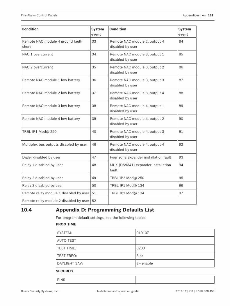
Fire Alarm Control Panels Appendices | en 121
Bosch Security Systems, Inc. Installation and operation guide 2016.12 | 7.0 | F.01U.008.458
Condition Systemevent
Condition Systemevent
Remote NAC module 4 ground fault-short
33 Remote NAC module 2, output 4disabled by user
84
NAC 1 overcurrent 34 Remote NAC module 3, output 1disabled by user
85
NAC 2 overcurrent 35 Remote NAC module 3, output 2disabled by user
86
Remote NAC module 1 low battery 36 Remote NAC module 3, output 3disabled by user
87
Remote NAC module 2 low battery 37 Remote NAC module 3, output 4disabled by user
88
Remote NAC module 3 low battery 38 Remote NAC module 4, output 1disabled by user
89
Remote NAC module 4 low battery 39 Remote NAC module 4, output 2disabled by user
90
TRBL IP1 Mod@ 250 40 Remote NAC module 4, output 3disabled by user
91
Multiplex bus outputs disabled by user 46 Remote NAC module 4, output 4disabled by user
92
Dialer disabled by user 47 Four zone expander installation fault 93
Relay 1 disabled by user 48 MUX (DS9341) expander installationfault
94
Relay 2 disabled by user 49 TRBL IP2 Mod@ 250 95
Relay 3 disabled by user 50 TRBL IP1 Mod@ 134 96
Remote relay module 1 disabled by user 51 TRBL IP2 Mod@ 134 97
Remote relay module 2 disabled by user 52
10.4 Appendix D: Programming Defaults ListFor program default settings, see the following tables:
PROG TIME
SYSTEM: 010107
AUTO TEST
TEST TIME: 0200
TEST FREQ: 6 hr
DAYLIGHT SAV: 2‑- enable
SECURITY
PINS

122 en | Appendices Fire Alarm Control Panels
2016.12 | 7.0 | F.01U.008.458 Installation and operation guide Bosch Security Systems, Inc.
PROGRAMMER: 9876
USERS: User 1 = 1234
User 2 = 0000
AUTHORITY
USER 1: 2
OTHERS: 0
PROG SYSTEM
TIMERS
SMOKE RESET: 6 sec
AC FAIL DELAY: 6 hr
AUTO SILENCE: 0 min
DISPLAY RATE: 4x.25 = 1 sec
AC LINE SYNCH 2 (60 Hz)
OPTION BUS
UPDATE BUS: Queries option buses and updates list ofconnected devices.
SETUP KEYPAD: 0
PIN REQUIRED:
LOCAL: 0‑- No
REMOTE: 1‑- Yes
NAC SIL MODE 1‑- Audible only
REMOTE PGM 0‑- disable
PROG INPUTS
POINT NUMBER (1‑4/5‑8/9‑255)
FUNCTION Point Function 1 = 1
Point Function 2 = 2
Point Function 3 = 3
Point Function 4 = 4
Point Function 5 = 5
Point Function 6 = 6
Point Function 7 = 7
Point Function 8 = 8
Point Function 9 - 255 = 10
ALARM/TROUBLE: Trouble On Open

Fire Alarm Control Panels Appendices | en 123
Bosch Security Systems, Inc. Installation and operation guide 2016.12 | 7.0 | F.01U.008.458
OUTPUT ZONE Point Zone 1 = 1
Point Zone 2 = 2
Point Zone 3 = 3
Point Zone 4 = 4
Point Zone 5 = 5
Point Zone 6 = 6
Point Zone 7 = 7
Point Zone 8 = 8
Point Zone 9 - 19 = 9
Point Zone 20 - 39 = 10
Point Zone 40 - 59 = 11 etc.
VERIFICATION: No
LATCHING: Yes
POINT FUNCTION (1-16)
1‑3, 5‑10, 12‑16 4 11
CONFIGURE fire water supv
LOCAL ONLY no no no
SILENCEABLE no no no
LOOP REPSONSE fast 16s fast
PROG OUTPUTS
NACs
NAC #1:
CONFIGURATION: Steady
ZONE ASSIGNS:
Zone A: 53
Zone B: 61
Zone C: 0
Zone D: 0
NAC #2:
CONFIGURATION: Steady
ZONE ASSIGNS:
Zone A: 53
Zone B: 61
Zone C: 0
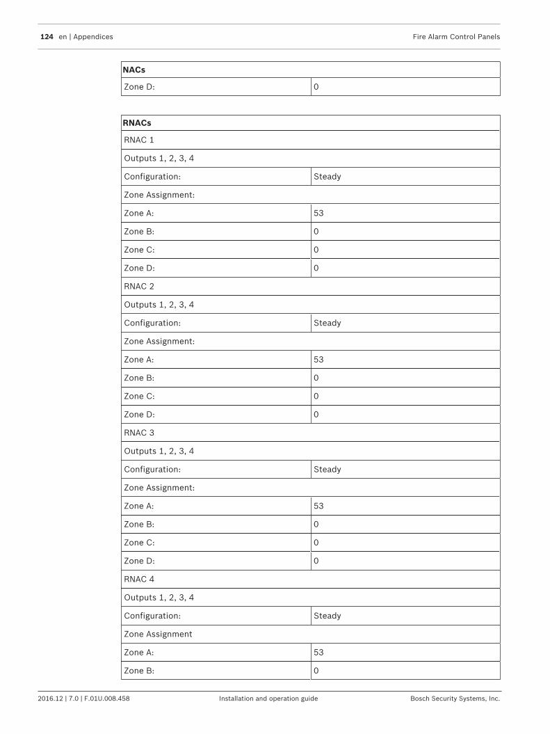
124 en | Appendices Fire Alarm Control Panels
2016.12 | 7.0 | F.01U.008.458 Installation and operation guide Bosch Security Systems, Inc.
NACs
Zone D: 0
RNACs
RNAC 1
Outputs 1, 2, 3, 4
Configuration: Steady
Zone Assignment:
Zone A: 53
Zone B: 0
Zone C: 0
Zone D: 0
RNAC 2
Outputs 1, 2, 3, 4
Configuration: Steady
Zone Assignment:
Zone A: 53
Zone B: 0
Zone C: 0
Zone D: 0
RNAC 3
Outputs 1, 2, 3, 4
Configuration: Steady
Zone Assignment:
Zone A: 53
Zone B: 0
Zone C: 0
Zone D: 0
RNAC 4
Outputs 1, 2, 3, 4
Configuration: Steady
Zone Assignment
Zone A: 53
Zone B: 0
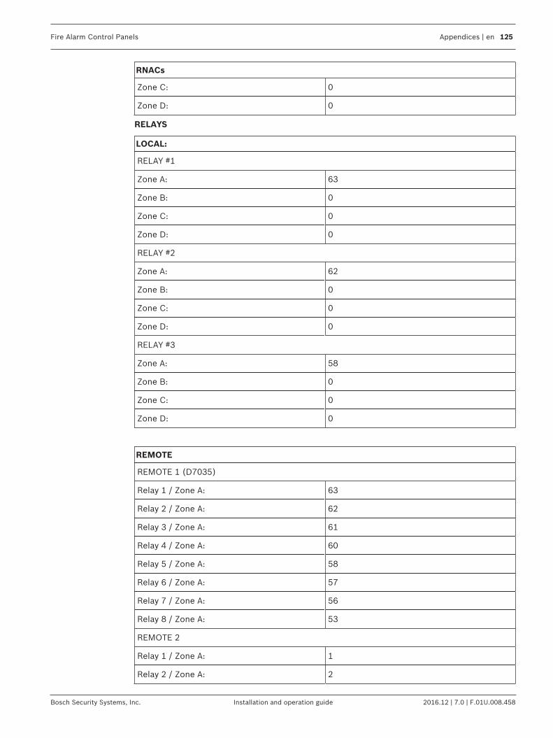
Fire Alarm Control Panels Appendices | en 125
Bosch Security Systems, Inc. Installation and operation guide 2016.12 | 7.0 | F.01U.008.458
RNACs
Zone C: 0
Zone D: 0
RELAYS
LOCAL:
RELAY #1
Zone A: 63
Zone B: 0
Zone C: 0
Zone D: 0
RELAY #2
Zone A: 62
Zone B: 0
Zone C: 0
Zone D: 0
RELAY #3
Zone A: 58
Zone B: 0
Zone C: 0
Zone D: 0
REMOTE
REMOTE 1 (D7035)
Relay 1 / Zone A: 63
Relay 2 / Zone A: 62
Relay 3 / Zone A: 61
Relay 4 / Zone A: 60
Relay 5 / Zone A: 58
Relay 6 / Zone A: 57
Relay 7 / Zone A: 56
Relay 8 / Zone A: 53
REMOTE 2
Relay 1 / Zone A: 1
Relay 2 / Zone A: 2

126 en | Appendices Fire Alarm Control Panels
2016.12 | 7.0 | F.01U.008.458 Installation and operation guide Bosch Security Systems, Inc.
REMOTE
Relay 3 / Zone A: 3
Relay 4 / Zone A: 4
Relay 5 / Zone A: 5
Relay 6 / Zone A: 6
Relay 7 / Zone A: 7
Relay 8 / Zone A: 8
PROG ACCOUNTS
PHONE NUMBERS
PHONE 1, 2
NUMBER/IP: > (wait for dialtone)
FORMAT: 0‑- Disable
ACCT NUMS: 0000000000
TONE: 1‑ 19D, 14A, 10PS
IP MOD PRIRY 1‑ @250 AS PRIM
PHONE CONTROL 1- PULSE ONLY
LINE 1, 2
MONITOR: No
DIALING TYPE: Pulse Only
REPORT STEERING
ALL SUB-MENU ITEMS: Phone 2 Back-up
RING COUNT: 00
COMM TRIES: 10
MACH BYPASS: No
ALTER COMM 0
PROG FORMATS
4/2 ZONE REPORT
0‑ FIRE ALRM D1: 0
1‑ FIRE RSTR D1: 3
2‑ WATERFLOW D1: 0
3‑ SUPERVISE D1: 0
4‑ TROUBLE D1: 6
5‑ TRBL RSTR D1: 3
6‑ DISABLE D1: B

Fire Alarm Control Panels Appendices | en 127
Bosch Security Systems, Inc. Installation and operation guide 2016.12 | 7.0 | F.01U.008.458
4/2 ZONE REPORT
7‑ DSBL RSTR D1: 3
8‑ (reserved)
9‑ MORE
1‑ POINT 1 D2: 1
2‑ POINT 2 D2: 2
3‑ POINT 3 D2: 3
4‑ POINT 4 D2: 4
5‑ POINT 5 D2: 5
6‑ POINT 6 D2: 6
7‑ POINT 7 D2: 7
8‑ POINT 8 D2: 8
1‑ POINT 9 D2: 9
2‑ POINT 10 D2: 0
ALT 4/2 CODES
SYSTM IN TST: F1
SYS TEST RST: E1
SILENCE: 9F
FIRE DRILL: F2
FIRE DRL RST: E2
OPEN RST RPT: 9F
LOW BATTERY: F9
LOW BATT RST: E9
AC FAILURE: FA
9‑ MORE
ALT 4/2 CODES
AC FAIL RST: EA
TEST REPORT: EE
OFF NORM TST: FD
PHONE 1 TRBL: FB
PN 1 TRB RST: EB
PHONE 2 TRBL FC
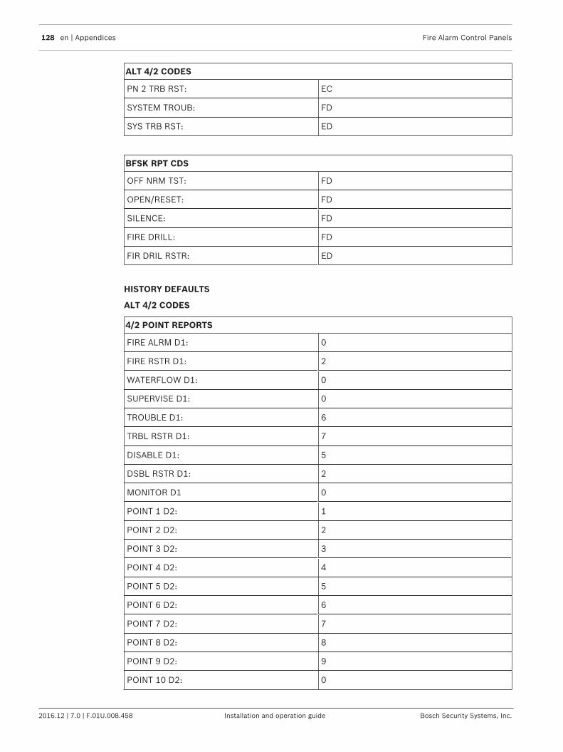
128 en | Appendices Fire Alarm Control Panels
2016.12 | 7.0 | F.01U.008.458 Installation and operation guide Bosch Security Systems, Inc.
ALT 4/2 CODES
PN 2 TRB RST: EC
SYSTEM TROUB: FD
SYS TRB RST: ED
BFSK RPT CDS
OFF NRM TST: FD
OPEN/RESET: FD
SILENCE: FD
FIRE DRILL: FD
FIR DRIL RSTR: ED
HISTORY DEFAULTS
ALT 4/2 CODES
4/2 POINT REPORTS
FIRE ALRM D1: 0
FIRE RSTR D1: 2
WATERFLOW D1: 0
SUPERVISE D1: 0
TROUBLE D1: 6
TRBL RSTR D1: 7
DISABLE D1: 5
DSBL RSTR D1: 2
MONITOR D1 0
POINT 1 D2: 1
POINT 2 D2: 2
POINT 3 D2: 3
POINT 4 D2: 4
POINT 5 D2: 5
POINT 6 D2: 6
POINT 7 D2: 7
POINT 8 D2: 8
POINT 9 D2: 9
POINT 10 D2: 0

Fire Alarm Control Panels Appendices | en 129
Bosch Security Systems, Inc. Installation and operation guide 2016.12 | 7.0 | F.01U.008.458
4/2 RPT CODS
SYSTM IN TST: 33
SYS TEST RST: 37
SILENCE: 9F
FIRE DRILL: 33
FIRE DRL RST: 37
OPEN RST RPT: 9F
LOW BATTERY: 69
LOW BATT RST: 79
AC FAILURE: 60
AC FAIL RST: 70
TEST REPORT: 30
OFF NORM TST: 33
PHONE 1 TRBL: 31
PN 1 TRB RST: 35
PHONE 2 TRBL 32
PN 2 TRB RST: 36
SYSTEM TROUB: 33
SYS TRB RST: 37
Multiplex
MUX BUS TYPE: 2 CLASS B
10.5 Appendix E: Phone Monitor Troubleshooting
10.5.1 COMM FLT/DATA LOSTA common cause of this fault condition is failing to program Phone/IP 2 or Account Number 2.While some reports are directed to Phone/IP 2, backup reports are still made to Phone/IP 1.This message warns the installer that Phone/IP 2 is not available if it is needed.Other communications problems that can cause this condition include:1. Events occurring faster than the dialer can send them, which overflows the 32 event
buffer,2. Programming errors such as missing phone numbers or account codes, over 100 Trouble
reports in 24 hours, or3. Other problems contacting a receiver.Check dialing type, format selection, phone numbers, account codes, phone line condition andtone programming.For more information, see Communicator Operation, page 57.
130 en | Appendices Fire Alarm Control Panels
2016.12 | 7.0 | F.01U.008.458 Installation and operation guide Bosch Security Systems, Inc.
10.5.2 Trouble PhoneSome troubleshooting tips for phone monitor problems when using two phone lines are listedbelow:
!
Warning!High voltage!The voltage present during ringing for an incoming call can be over 100 VAC.
1. Use a voltmeter to measure the voltage present across each phone line (Tip to Ring)while the phone line is on‑hook. This standby telco battery voltage is typically in the rangeof 30 VDC to 50 VDC, but any voltage above 5 VDC is accepted by the control panel. Thepolarity of the voltage does not matter.
2. Check for other devices that might use the phone line, such as fax machines, credit cardverifiers or PBX systems. If the devices cannot be removed, then ensure that they arewired so that the control panel’s line‑seizure relay disconnects them when needed.Measure the line voltage while these devices are in use. Ensure that it stays above 5 Vwhen off‑hook.
3. Check for intermittent faults in the phone line. Make a test call and confirm that the lineis free of distortion and noise. Temporarily swap Lines 1 and 2 on the control panel andcheck if the problem indication moves to the control panel’s other phone line channel. Ifso, then the phone line is causing the problem rather than the line monitor.
4. Confirm that the fault message is phone fault and not com fault. Com fault is oftencaused by failing to program a phone number or account number for Phone Number 2while routing reports to Line 1, Backup Line 2. If only one phone number is available forreporting, then set report direction for all events to phone 1 only. Com fault can alsohappen if one of the phone lines has telco battery voltage, but does not complete a call.Make test calls to the receiver(s) on both phone lines, listening for the receiver ACK tone.
5. Ensure that two phone lines are available. The Auto-test report is sent on a differentphone line each time it is sent. If only one phone line is connected to the control panel,then a Com fault is generated on every other test call.

Bosch Security Systems, Inc.130 Perinton ParkwayFairport, NY 14450USAwww.boschsecurity.com© Bosch Security Systems, Inc., 2016
Bosch Sicherheitssysteme GmbHRobert-Bosch-Ring 585630 GrasbrunnGermany
Related Documents