Finite State Machine By : Ali Mustafa

Welcome message from author
This document is posted to help you gain knowledge. Please leave a comment to let me know what you think about it! Share it to your friends and learn new things together.
Transcript

Finite State Machine
By : Ali Mustafa

So Far
• We have covered the memory elements issue and we are ready to implement the sequential circuits.
• We need to know how to Deal(analyze) with a sequential circuit?

How could you describe circuit?
• Truth table• Logic function between input and output
F = A+B => if A= 1 and B= 0 F= 1if A =0 and B=0 F=0
(not depends on the pervious value of F)
How could you describe a sequential circuit?
• The sequential circuit output is now function in the inputs and past outputs
• So, we need a tool to help us describe the behavior of the circuit.

Finite State Machine (FSM)
• Finite State Machine is a tool to model the desired behavior of a sequential system.
• The designer has to develop a finite state model of the system behavior and then designs a circuit that implements this model.
• A FSM consists of several states. Inputs into the machine are combined with the current state of the machine to determine the new state or next state of the machine.
• Depending on the state of the machine, outputs are generated based on either the state or the state and inputs of the machine.

How to describe FSM?
1. State equation ( transition equation )
– input variables, present states, next states equation
2. State table
– input variables, present states ,next states, truth table
3. State diagram
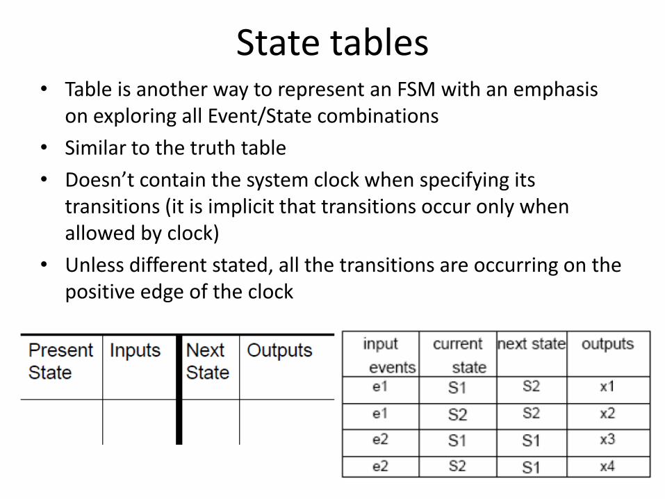
State tables• Table is another way to represent an FSM with an emphasis
on exploring all Event/State combinations
• Similar to the truth table
• Doesn’t contain the system clock when specifying its transitions (it is implicit that transitions occur only when allowed by clock)
• Unless different stated, all the transitions are occurring on the positive edge of the clock
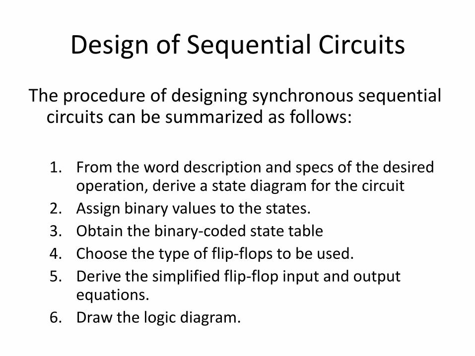
Design of Sequential Circuits
The procedure of designing synchronous sequential circuits can be summarized as follows:
1. From the word description and specs of the desired operation, derive a state diagram for the circuit
2. Assign binary values to the states.
3. Obtain the binary-coded state table
4. Choose the type of flip-flops to be used.
5. Derive the simplified flip-flop input and output equations.
6. Draw the logic diagram.

State Transition Diagrams• Used to visually represent any Finite State Machine
• Emphasis is on identifying states and possible transitions
Circles represent States
Arrows represent Transitions

Example
• Using T-type FFs, design a 3-bits binary counter that can count in binary from 0 to 7 with step 1

1-Derive the state diagram
• As we need a 3 binary bits to represent the numbers from 0 to 7so we need 1 T-FF to generate 1binary bit
• We need 3 T-FF to implement this design
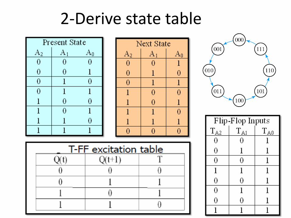
2-Derive state table
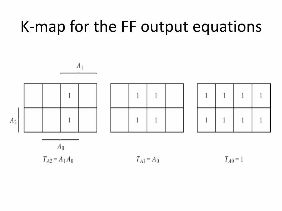
K-map for the FF output equations

Draw Circuit logic diagram
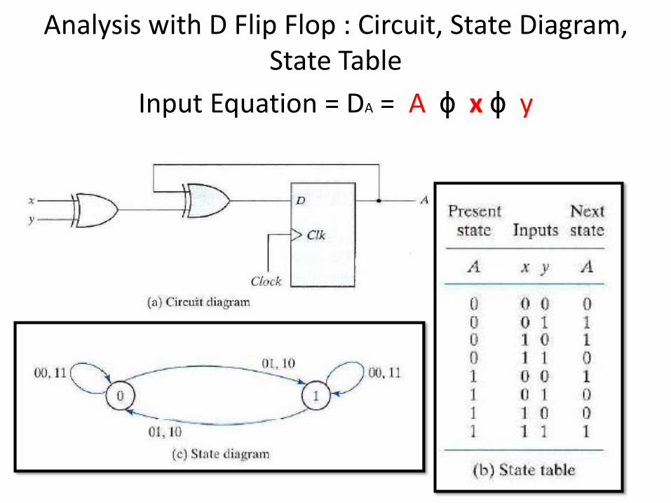
Analysis with D Flip Flop : Circuit, State Diagram, State Table
Input Equation = DA = A ɸ x ɸ y

Example 1: Circuit, State Diagram, State Table
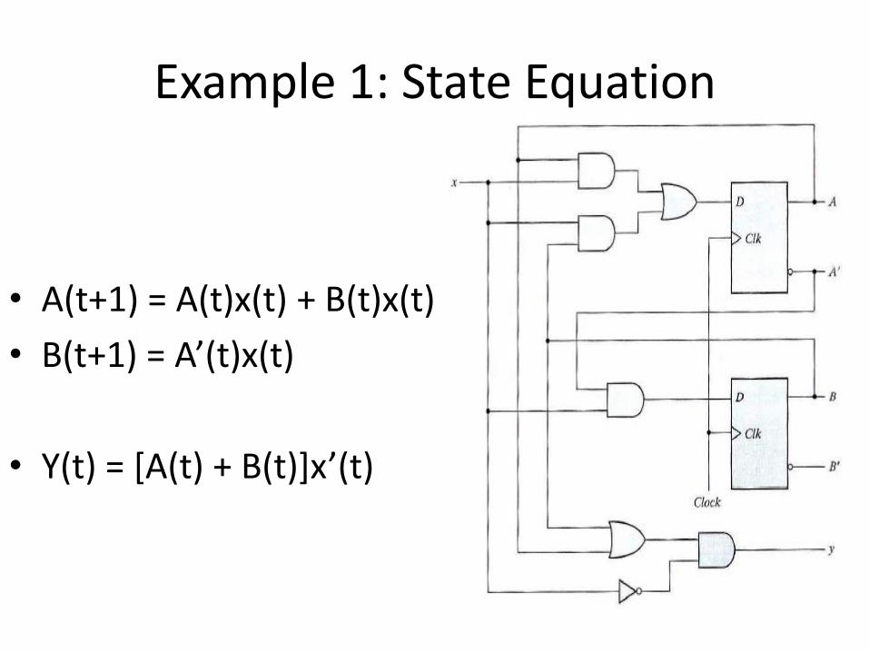
Example 1: State Equation
• A(t+1) = A(t)x(t) + B(t)x(t)
• B(t+1) = A’(t)x(t)
• Y(t) = *A(t) + B(t)+x’(t)

Example 2: Analysis with T Flip Flop
Characteristic equation of T is
Q(t+1) = T ɸ Q = T’Q + TQ’
Output Equation will be
TA = BX
TB = X
Y = ABNOTE : ɸ is exclusive
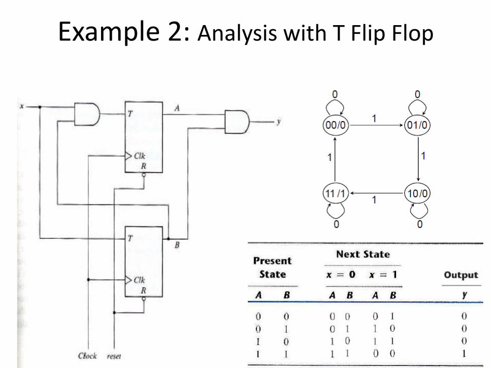
Example 2: Analysis with T Flip Flop

Types of State Machines
• Mealy Model for FSM
– Characterized by – Outputs are a function of both inputs and current state
Next
State
Logic
Output
Logic
State
Memory
(F/F)
CLOCK
Inputs Excitation
Current
StateOutputs

Types of State Machines
• Moore Model for FSM
– Characterized by – Outputs are a function current state only
Next
State
Logic
Output
Logic
State
Memory
(F/F)
CLOCK
Inputs Excitation
Current
StateOutputs

Problem : Already Discussed• Analyze the following sequential circuit• How to analyze any sequential circuit• You need to know :
– State equation – State diagram– State table

Solution: 1-Determine State equation
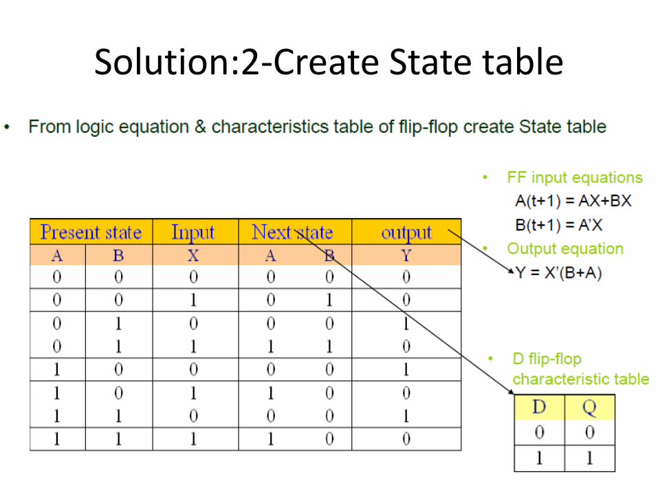
Solution:2-Create State table
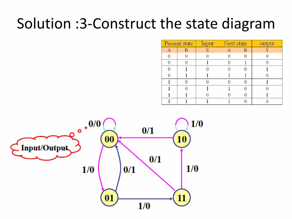
Solution :3-Construct the state diagram

Self Study
1. Analysis of JK Flip Flop
2. Detail study of Mealy & Moore Models
Related Documents


![EEE 241 - ELEKTRONIK ANALOG 1 - core.ac.uk · PDF file1. (a) [EEE 241] Transistor Q dalam penguat pemancar sepunya dalam Rajah 1(a) mempunyai voltan "Early" VA = 100 V dan parameter-parameter](https://static.cupdf.com/doc/110x72/5a7081767f8b9aa7538c144a/eee-241-elektronik-analog-1-coreacuk-nbsppdf-file1-a-eee.jpg)