Procedia Engineering 53 (2013) 624 – 631 1877-7058 © 2013 The Authors. Published by Elsevier Ltd. Selection and peer-review under responsibility of the Research Management & Innovation Centre, Universiti Malaysia Perlis doi:10.1016/j.proeng.2013.02.080 Malaysian Technical Universities Conference on Engineering & Technology 2012, MUCET 2012 Finite Element Model of Machining with High Pressure Coolant for Ti- 6Al-4V alloy A B. Mohd Hadzley*, R. Izamshah, A. Siti Sarah and M. Nurul Fatin Department of Manufacturing Process, Faculty of Manufacturing Engineering Universiti Teknikal Malaysia Melaka, Hang Tuah Jaya 76100 Durian Tunggal, Melaka, Malaysia Abstract This study present a series of finite element models for high-pressure jet-assisted machining of Ti-6Al-4V alloy. The application of Fluid- Structure Interaction (FSI) together with the Johnson-Cook plasticity model, Cockcroft-Latham chip separation criteria and EOS polynomial were implemented to study the effect of coolant pressure on chip formation, cutting force and cutting temperature. The resulting motion of fluid at the tool-chip interface, chip breakage, cutting force as well as temperature generation at the tool-chip interfaceis then interpreted, analyzed and compared to their real experimental results. The models simulate interactions between the fluid and solid structure, where continuous chip formation was observed when simulation in conventional coolant supply while chip breakage was clearly evident as high-pressure coolant was introduced. Increasing coolant pressure significantly reduce the friction at the tool-chip interface, which significantly reduced the cutting force and cutting temperature. Keywords: High-pressure coolant, machining, finite element method (FEM) 1. Introduction Advanced materialsuch as Ti-6Al-4V titanium alloy hasbeen increasingly used for high performance application for oil and gas, aerospace andmedical industries etc. However, machining such alloy presents a great challenge due to the high temperature generation at the tool-chip interface,which lead to rapid tool wear within a short time. Therefore, cutting performance of Ti-6Al-4V alloy can be improved enormously by controlling the tool-chip and tool-workpiece interfacial temperature rise and frictional effects through the use of a coolant [1]. The use of a high-pressure coolant supply during machining is one of the many ways to dissipate extensive heat generation in the cutting zone [2]. Machining with high pressure coolant supply enables the coolant flow to traverse the machined surface faster, significantly increasing heat transfer of the coolant, penetrating deep into the cutting area and achieving high chip breakability through increased chip curl [3]. This consequently reduces the tool-chip contact area, minimises friction at the tool-chip interface, removes more heat from the cutting region and consequently improves tool performance during machining. It has been reported that the use of high-pressure coolant is capable of increasing productivity when compared to the conventional methods ofcoolant delivery [2]. Reduction of temperature in the cutting zone, lower cutting forces, lower vibration levels, better surface integrity and closer tolerances of the machined components are other major benefits reported by these studies. * Corresponding author. E-mail address: [email protected] Available online at www.sciencedirect.com © 2013 The Authors. Published by Elsevier Ltd. Selection and peer-review under responsibility of the Research Management & Innovation Centre, Universiti Malaysia Perlis

Welcome message from author
This document is posted to help you gain knowledge. Please leave a comment to let me know what you think about it! Share it to your friends and learn new things together.
Transcript
Procedia Engineering 53 ( 2013 ) 624 – 631
1877-7058 © 2013 The Authors. Published by Elsevier Ltd.Selection and peer-review under responsibility of the Research Management & Innovation Centre, Universiti Malaysia Perlisdoi: 10.1016/j.proeng.2013.02.080
Malaysian Technical Universities Conference on Engineering & Technology 2012, MUCET 2012
Finite Element Model of Machining with High Pressure Coolant for Ti-6Al-4V alloy
A B. Mohd Hadzley*, R. Izamshah, A. Siti Sarah and M. Nurul Fatin Department of Manufacturing Process, Faculty of Manufacturing Engineering
Universiti Teknikal Malaysia Melaka, Hang Tuah Jaya 76100 Durian Tunggal, Melaka, Malaysia
Abstract
This study present a series of finite element models for high-pressure jet-assisted machining of Ti-6Al-4V alloy. The application of Fluid-Structure Interaction (FSI) together with the Johnson-Cook plasticity model, Cockcroft-Latham chip separation criteria and EOS polynomial were implemented to study the effect of coolant pressure on chip formation, cutting force and cutting temperature. The resulting motion of fluid at the tool-chip interface, chip breakage, cutting force as well as temperature generation at the tool-chip interfaceis then interpreted, analyzed and compared to their real experimental results. The models simulate interactions between the fluid and solid structure, where continuous chip formation was observed when simulation in conventional coolant supply while chip breakage was clearly evident as high-pressure coolant was introduced. Increasing coolant pressure significantly reduce the friction at the tool-chip interface, which significantly reduced the cutting force and cutting temperature.
© 2013 The Authors. Published by Elsevier Ltd. Selection and/or peer-review under responsibility of the Research Management & Innovation Centre, Universiti Malaysia Perlis. Keywords: High-pressure coolant, machining, finite element method (FEM)
1. Introduction
Advanced materialsuch as Ti-6Al-4V titanium alloy hasbeen increasingly used for high performance application for oil and gas, aerospace andmedical industries etc. However, machining such alloy presents a great challenge due to the high temperature generation at the tool-chip interface,which lead to rapid tool wear within a short time. Therefore, cutting performance of Ti-6Al-4V alloy can be improved enormously by controlling the tool-chip and tool-workpiece interfacial temperature rise and frictional effects through the use of a coolant [1].
The use of a high-pressure coolant supply during machining is one of the many ways to dissipate extensive heat generation in the cutting zone [2]. Machining with high pressure coolant supply enables the coolant flow to traverse the machined surface faster, significantly increasing heat transfer of the coolant, penetrating deep into the cutting area and achieving high chip breakability through increased chip curl [3]. This consequently reduces the tool-chip contact area, minimises friction at the tool-chip interface, removes more heat from the cutting region and consequently improves tool performance during machining. It has been reported that the use of high-pressure coolant is capable of increasing productivity when compared to the conventional methods ofcoolant delivery [2]. Reduction of temperature in the cutting zone, lower cutting forces, lower vibration levels, better surface integrity and closer tolerances of the machined components are other major benefits reported by these studies.
* Corresponding author. E-mail address: [email protected]
Available online at www.sciencedirect.com
© 2013 The Authors. Published by Elsevier Ltd.Selection and peer-review under responsibility of the Research Management & Innovation Centre, Universiti Malaysia Perlis
625 A. B. Mohd Hadzley et al. / Procedia Engineering 53 ( 2013 ) 624 – 631
Since the machining with high-pressure coolant requires a large amount of coolant, the coolant usually splashes around the tool-chip contact and creates a mist in the cutting area. This situation hinders visibility, thereby restricting the ability to monitor the conditions during machining.Therefore, the experimental trials of machining with high pressure coolant normally do not provide a complete picture of the whole machining process, particularly with respect to the cutting mechanisms [4]. Alternatively, finite element method (FEM) can be used to determine some of the items that difficult to be obtained from experimental trials such as stress, strain and temperature distributions. In machining, FEM can be used to represent the machining process by modelling the cutting tool and workpiece material into discrete elements interconnected at discrete node points [1]. The application of FEM is beneficial to gain a better understanding of chip formation mechanism, stress and strain distribution, effect of cutting parameters, analysis of heat generation and observation of contact conditions. Model FEM allows detailed visualization of the microscale cutting action in the machining zone, which will enable the machining conditions to be monitored, improve the process control and predict the final output properties [1,4]. However, the studies regarding the development ofFEM models to represent the machining with high pressure coolant are still limited.
In this study, a new FEM model is proposed to simulate machining in conventional and high pressure coolant supply. The effect of the coolant in relation to chip formation, cutting forces and thermal generation will be modelled using FEM and coupled with FSI algorithm. The effect of the coolant pressure onchip formation, cutting force and temperature generation during the machining of Ti-6Al-4V alloy has been analysed, compared and visualized in detail. The model enable further understanding of the effect of coolants in the machining zone, such as chip breakage, cutting force and temperature generation.
2. Methodology
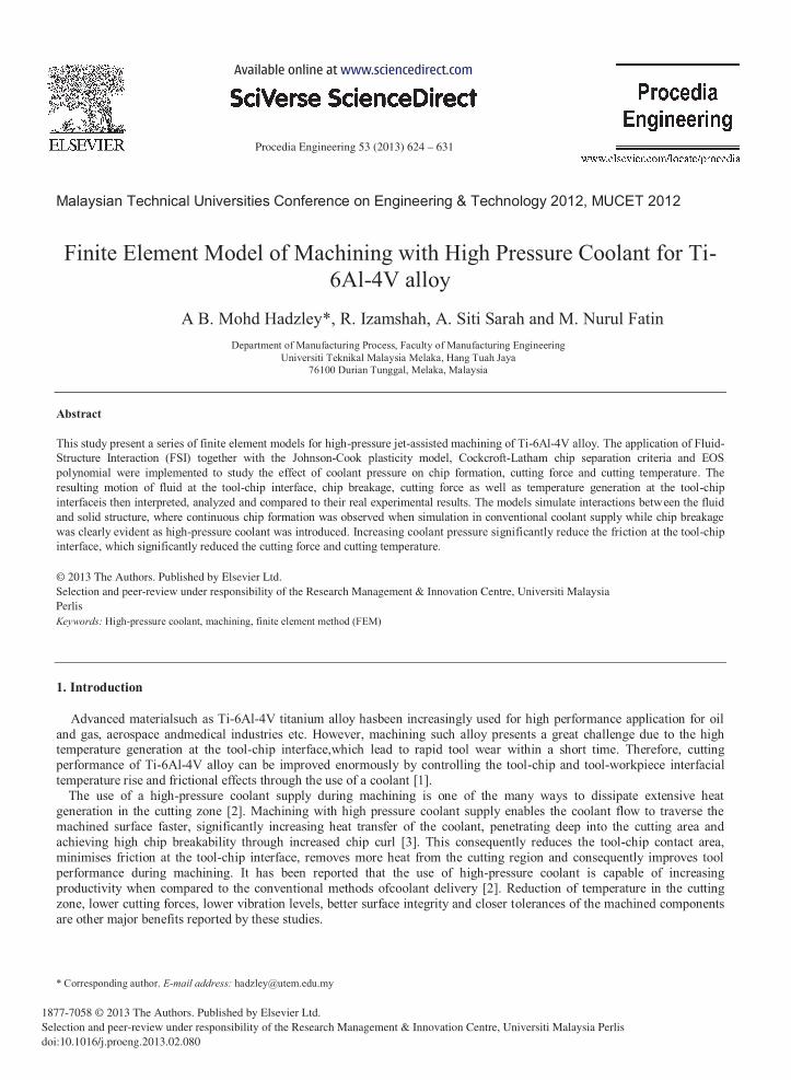
Figure 1a shows the image of machining with high pressure coolant. From Figure 1a, it can be observed that three structures were involved in modelling machining with a high pressure coolant. These include the workpiece and the cutting tool for solid structures and the coolant for the fluid structure (Figure 1b). The workpiece dimensions were simplified with a 5 mm length and 0.25 mm height. The resulting mesh was built from 4,000 elements and 6,605 nodes. The cutting tool was simplified with 0.44 mm length and 1.7 mm height and meshed with 200 elements and 328 nodes. The rake angle of the cutting tool was set at 6o. For simplication, the fluid in this model was assumed to flow from the nozzle, which was set at 0.5 mm diameter. The fluid source was placed about 2 mm from the tool tip and the air-mesh was constructed between the workpiece, cutting tool and the fluid source. The fluid model was built using 446 elements and 820 nodes. Boundary conditions were applied on the bottom and right side nodes of the workpiece and the tool was constrained against vertical displacement and rotation. A cutting speed of 110 m/min was chosen and the coolant pressures were varied at 7 MPa, 11 MPa, 15 MPa and 20.3 MPa.
(a) (b)
Fig.1. (a) Machining with high pressure coolant (b) FEM model for the cutting process with conventional coolant and high pressure coolant delivery.
The constitutive model proposed by Johnson and Cook (Equation 1) was utilized to describe the properties of Ti-6Al-
4V alloy while an effective plastic strain failure criterion based on Cockcroft and Latham (Equation 2) was taken as the failure measure to facilitate chip separation. All simulation data were taken from Lee and Lin [5], as shown in Table 1.
Fluid Structure
Workpiece Material
Cutting Tool Coolant
Flow/ Pressure
Cutting Speed
Coolant Flow/ Pressure Cutting Tool
626 A. B. Mohd Hadzley et al. / Procedia Engineering 53 ( 2013 ) 624 – 631
omelt
o
o TToTTmTToTlnCCBBAAA 111111111111n
o''n
(1)
Table 1material properties for ti-6al-4v alloy [5]
(2)
For the cutting fluid, the Polynomial equation of state (EOS) is used to calculate the internal characteristics of the fluid structure, which is expressed by:
321 32 CCCCP o CCCC (3)
WhereCo-C3 are polynomial coefficients and μ is the ratio density of the fluid structure at the current ( ) and initial ( o)conditions. The polynomial coefficient Co-C3can be found in the study from Mabroukiet al.ll [6]. The velocity of fluid, Vduring high-pressure flow can be expressed by the formula
212 /stagnation )/Ps(V o.)( (4)
Where o is initial density and Pstagnationis the coolant pressure of the steady flow.
3. Result and Discussions
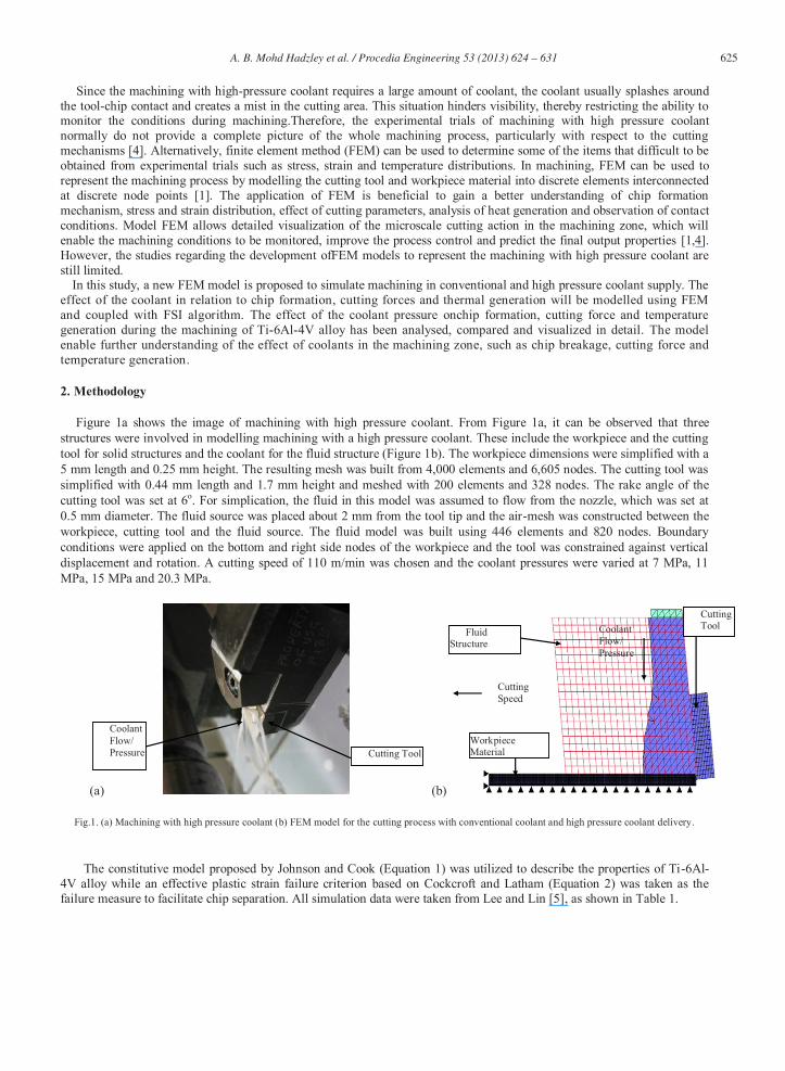
The simulations of a chip formation of machining Ti-6Al-4V alloy under dry condition is shown in Figures 2a. It can be seen that the simulation presented segmented chip formation with the deformation of the chip being found to beinhomogeneous with periodic variation in thickness. Figure 2b shows the comparison of chip formation between obtained from simulation and machining experiment of Ti-6Al-4V. The chips obtained from the experiment was mounted into theepoxy resin before polished using different type of sand paper and polish lubricant. The chip morphology and microstructure were then observed and measured by a Scanning Electron Microscope. It can be seen that the shape and pitch of the serrated chip segments in these figures show a good resemblance to those observed in actual cutting processes by experiment .
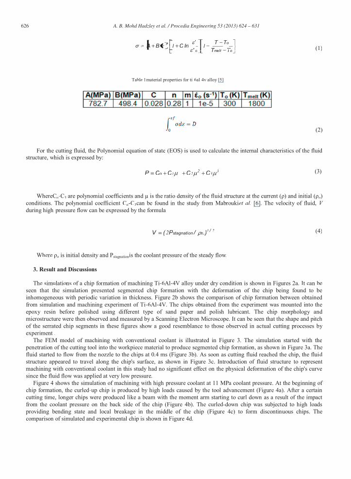
The FEM model of machining with conventional coolant is illustrated in Figure 3. The simulation started with the penetration of the cutting tool into the workpiece material to produce segmented chip formation, as shown in Figure 3a. The fluid started to flow from the nozzle to the chips at 0.4 ms (Figure 3b). As soon as cutting fluid reached the chip, the fluid structure appeared to travel along the chip's surface, as shown in Figure 3c. Introduction of fluid structure to represent machining with conventional coolant in this study had no significant effect on the physical deformation of the chip's curvesince the fluid flow was applied at very low pressure.
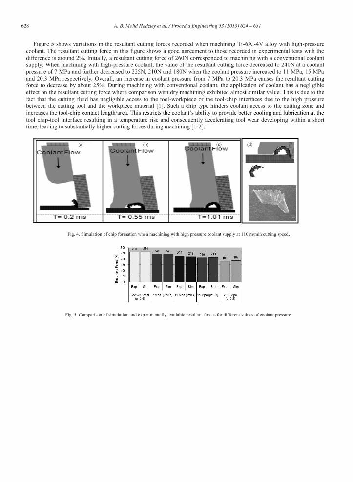
Figure 4 shows the simulation of machining with high-pressure coolant at 11 MPa coolant pressure. At the beginning of chip formation, the curled-up chip is produced by high loads caused by the tool advancement (Figure 4a). After a certaincutting time, longer chips were produced like a beam with the moment arm starting to curl down as a result of the impact from the coolant pressure on the back side of the chip (Figure 4b). The curled-down chip was subjected to high loads providing bending state and local breakage in the middle of the chip (Figure 4c) to form discontinuous chips. Thecomparison of simulated and experimental chip is shown in Figure 4d.
627 A. B. Mohd Hadzley et al. / Procedia Engineering 53 ( 2013 ) 624 – 631
Fig. 2. (a) Chip morphology during simulation (b) Segmented chips obtained from the simulations and machining trials [1].
Fig. 3. Simulation of chip formation when machining with conventional coolant flow at 110 m/min cutting speed.
(a)
(b)
Simulation Experiment
(a) (b) (c)
628 A. B. Mohd Hadzley et al. / Procedia Engineering 53 ( 2013 ) 624 – 631
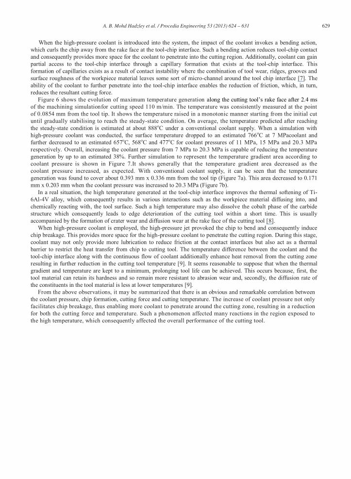
Figure 5 shows variations in the resultant cutting forces recorded when machining Ti-6Al-4V alloy with high-pressure
coolant. The resultant cutting force in this figure shows a good agreement to those recorded in experimental tests with the difference is around 2%. Initially, a resultant cutting force of 260N corresponded to machining with a conventional coolant supply. When machining with high-pressure coolant, the value of the resultant cutting force decreased to 240N at a coolant pressure of 7 MPa and further decreased to 225N, 210N and 180N when the coolant pressure increased to 11 MPa, 15 MPa and 20.3 MPa respectively. Overall, an increase in coolant pressure from 7 MPa to 20.3 MPa causes the resultant cutting force to decrease by about 25%. During machining with conventional coolant, the application of coolant has a negligible effect on the resultant cutting force where comparison with dry machining exhibited almost similar value. This is due to the fact that the cutting fluid has negligible access to the tool-workpiece or the tool-chip interfaces due to the high pressure between the cutting tool and the workpiece material [1]. Such a chip type hinders coolant access to the cutting zone and increases the tool-tool chip-tool interface resulting in a temperature rise and consequently accelerating tool wear developing within a short time, leading to substantially higher cutting forces during machining [1-2].
Fig. 4. Simulation of chip formation when machining with high pressure coolant supply at 110 m/min cutting speed.
Fig. 5. Comparison of simulation and experimentally available resultant forces for different values of coolant pressure.
(d) (a) (b) (c)
629 A. B. Mohd Hadzley et al. / Procedia Engineering 53 ( 2013 ) 624 – 631
When the high-pressure coolant is introduced into the system, the impact of the coolant invokes a bending action,
which curls the chip away from the rake face at the tool-chip interface. Such a bending action reduces tool-chip contact and consequently provides more space for the coolant to penetrate into the cutting region. Additionally, coolant can gain partial access to the tool-chip interface through a capillary formation that exists at the tool-chip interface. This formation of capillaries exists as a result of contact instability where the combination of tool wear, ridges, grooves and surface roughness of the workpiece material leaves some sort of micro-channel around the tool chip interface [7]. The ability of the coolant to further penetrate into the tool-chip interface enables the reduction of friction, which, in turn, reduces the resultant cutting force.
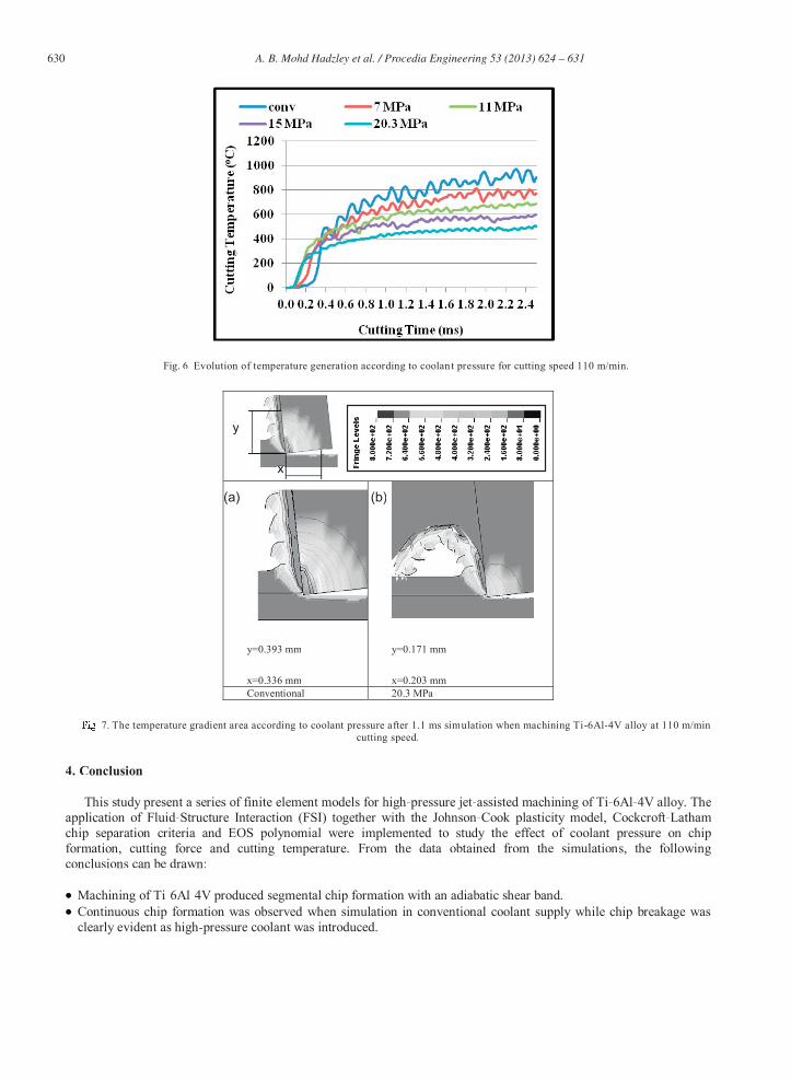
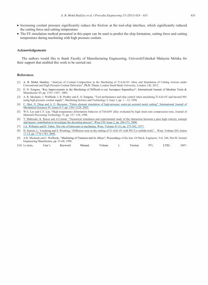
Figure 6 shows the evolution of maximum temperature generation of the machining simulationfor cutting speed 110 m/min. The temperature was consistently measured at the point of 0.0854 mm from the tool tip. It shows the temperature raised in a monotonic manner starting from the initial cut until gradually stabilising to reach the steady-state condition. On average, the temperature predicted after reaching the steady-state condition is estimated at about 888oC under a conventional coolant supply. When a simulation with high-pressure coolant was conducted, the surface temperature dropped to an estimated 766oC at 7 MPacoolant and further decreased to an estimated 657oC, 568oC and 477oC for coolant pressures of 11 MPa, 15 MPa and 20.3 MPa respectively. Overall, increasing the coolant pressure from 7 MPa to 20.3 MPa is capable of reducing the temperature generation by up to an estimated 38%. Further simulation to represent the temperature gradient area according to coolant pressure is shown in Figure 7.It shows generally that the temperature gradient area decreased as the coolant pressure increased, as expected. With conventional coolant supply, it can be seen that the temperature generation was found to cover about 0.393 mm x 0.336 mm from the tool tip (Figure 7a). This area decreased to 0.171 mm x 0.203 mm when the coolant pressure was increased to 20.3 MPa (Figure 7b).
In a real situation, the high temperature generated at the tool-chip interface improves the thermal softening of Ti-6Al-4V alloy, which consequently results in various interactions such as the workpiece material diffusing into, and chemically reacting with, the tool surface. Such a high temperature may also dissolve the cobalt phase of the carbide structure which consequently leads to edge deterioration of the cutting tool within a short time. This is usually accompanied by the formation of crater wear and diffusion wear at the rake face of the cutting tool [8].
When high-pressure coolant is employed, the high-pressure jet provoked the chip to bend and consequently induce chip breakage. This provides more space for the high-pressure coolant to penetrate the cutting region. During this stage, coolant may not only provide more lubrication to reduce friction at the contact interfaces but also act as a thermal barrier to restrict the heat transfer from chip to cutting tool. The temperature difference between the coolant and the tool-chip interface along with the continuous flow of coolant additionally enhance heat removal from the cutting zone resulting in further reduction in the cutting tool temperature [9]. It seems reasonable to suppose that when the thermal gradient and temperature are kept to a minimum, prolonging tool life can be achieved. This occurs because, first, the tool material can retain its hardness and so remain more resistant to abrasion wear and, secondly, the diffusion rate of the constituents in the tool material is less at lower temperatures [9].
From the above observations, it may be summarized that there is an obvious and remarkable correlation between the coolant pressure, chip formation, cutting force and cutting temperature. The increase of coolant pressure not only facilitates chip breakage, thus enabling more coolant to penetrate around the cutting zone, resulting in a reduction for both the cutting force and temperature. Such a phenomenon affected many reactions in the region exposed to the high temperature, which consequently affected the overall performance of the cutting tool.
630 A. B. Mohd Hadzley et al. / Procedia Engineering 53 ( 2013 ) 624 – 631
Fig. 6. Evolution of temperature generation according to coolant pressure for cutting speed 110 m/min.
y=0.393 mm
x=0.336 mm
y=0.171 mm
x=0.203 mmConventional 20.3 MPa
7. The temperature gradient area according to coolant pressure after 1.1 ms simulation when machining Ti-6Al-4V alloy at 110 m/min cutting speed.
4. Conclusion
This study present a series of finite element models for high-pressure jet-assisted machining of Ti-6Al-4V alloy. Theapplication of Fluid-Structure Interaction (FSI) together with the Johnson-Cook plasticity model, Cockcroft-Latham chip separation criteria and EOS polynomial were implemented to study the effect of coolant pressure on chipformation, cutting force and cutting temperature. From the data obtained from the simulations, the followingconclusions can be drawn:
Machining of Ti-6Al-4V produced segmental chip formation with an adiabatic shear band.Continuous chip formation was observed when simulation in conventional coolant supply while chip breakage wasclearly evident as high-pressure coolant was introduced.
y
xxx
(b)(a)
631 A. B. Mohd Hadzley et al. / Procedia Engineering 53 ( 2013 ) 624 – 631
Increasing coolant pressure significantly reduce the friction at the tool-chip interface, which significantly reduced the cutting force and cutting temperature.
The FE simulation method presented in this paper can be used to predict the chip formation, cutting force and cutting temperature during machining with high pressure coolant.
Acknowledgements
The authors would like to thank Faculty of Manufacturing Engineering, UniversitiTeknikal Malaysia Melaka for their support that enabled this work to be carried out.
References
[1] Analysis of Coolant Composition in the Machining of Ti-6Al-4V Alloy and Simulation of Cutting Actions under Conventional and High Pressure Coolant Deliveries London South Bank University, London, UK, 2012.
[2] -to-Manufacture 45, pp. 1353 1367, 2005.
[3] A. R. Machado, J. Wallbank, I. R. Pashby and E. O. Tool performance and chip control when machining Ti-6Al-4V and Inconel 901 using high pressure coolant supply , Machining Science and Technology 2, Issue 1, pp. 1 12, 1998.
[4] C. Shet, X. Deng and A. E. Bayoumi Finite element simulation of high-pressure water-jet assisted metal cutting , International Journal of Mechanical Sciences 45, Issues 6-7, pp. 1201-1228, 2003.
[5] W.S. Lee and C.F. High-temperature deformation behavior of Ti6Al4V alloy evaluated by high strain-rate compression tests, Journal of Materials Processing Technology 75, pp. 127 136, 1998.
[6] T. Mabrouki, K. Raissi and A.Cornier, Numerical simulation and experimental study of the interaction between a pure high-velocity waterjet and targets: contribution to investigate the decoating process , Wear 239, Issue 2, pp. 260-273, 2000.
[7] J.A. Williams and D. Tabor, The role of lubricants in machining, Wear, Volume 43 (3), pp. 275-292, 1977. [8] D. Jianxin, L. Yousheng and S. Wenlong, Diffusion wear in dry cutting of Ti 6Al 4V with WC/Co carbide tools Wear, Volume 265, Issues
11-12, pp. 1776-1783, 2008. [9] A.R. Machado and J. Wallbank gs of the Inst. Of Mech. Engineers, Vol. 204, Part B: Journal
Engineering Manufacture, pp. 53-60, 1990. [10] Ls-dyna, , 2007.
Related Documents