Medical Engineering & Physics 36 (2014) 1322–1330 Contents lists available at ScienceDirect Medical Engineering & Physics jo ur nal home p ag e: www.elsevier.com/locate/medengphy Technical note Finite element analysis of three commonly used external fixation devices for treating Type III pilon fractures Muhammad Hanif Ramlee a , Mohammed Rafiq Abdul Kadir a,∗ , Malliga Raman Murali b , Tunku Kamarul b a Medical Devices and Technology Group (MEDITEG), Faculty of Biosciences and Medical Engineering, Universiti Teknologi Malaysia, 81310 Johor Bahru, Johor, Malaysia b Tissue Engineering Group (TEG), National Orthopaedic Centre of Excellence in Research and Learning (NOCERAL), Department of Orthopaedic Surgery, Faculty ofMedicine, University of Malaya, 50603 Lembah Pantai, Kuala Lumpur, Malaysia a r t i c l e i n f o Article history: Received 28 October 2013 Received in revised form 19 May 2014 Accepted 24 May 2014 Keywords: Finite element External fixator Pilon fractures Stability Biomechanics Micromovement a b s t r a c t Pilon fractures are commonly caused by high energy trauma and can result in long-term immobilization of patients. The use of an external fixator i.e. the (1) Delta, (2) Mitkovic or (3) Unilateral frame for treating type III pilon fractures is generally recommended by many experts owing to the stability provided by these constructs. This allows this type of fracture to heal quickly whilst permitting early mobilization. However, the stability of one fixator over the other has not been previously demonstrated. This study was conducted to determine the biomechanical stability of these external fixators in type III pilon fractures using finite element modelling. Three-dimensional models of the tibia, fibula, talus, calcaneus, navicu- lar, cuboid, three cuneiforms and five metatarsal bones were reconstructed from previously obtained CT datasets. Bones were assigned with isotropic material properties, while the cartilage was assigned as hyperelastic springs with Mooney–Rivlin properties. Axial loads of 350 N and 70 N were applied at the tibia to simulate the stance and the swing phase of a gait cycle. To prevent rigid body motion, the calca- neus and metatarsals were fixed distally in all degrees of freedom. The results indicate that the model with the Delta frame produced the lowest relative micromovement (0.03 mm) compared to the Mitkovic (0.05 mm) and Unilateral (0.42 mm) fixators during the stance phase. The highest stress concentrations were found at the pin of the Unilateral external fixator (509.2 MPa) compared to the Mitkovic (286.0 MPa) and the Delta (266.7 MPa) frames. In conclusion, the Delta external fixator was found to be the most stable external fixator for treating type III pilon fractures. © 2014 IPEM. Published by Elsevier Ltd. All rights reserved. 1. Introduction A pilon fracture is a general description of a comminuted frac- ture at the distal tibia involving the ankle joint that occurs as the result of high-energy vertical axial loading. This can occur as the result of a fall from a substantial height, road traffic accidents, industrial mishaps or sporting injuries, especially those involving contact sports [1–6]. These fractures are uncommon and represent up to 7–10% of tibia fractures and less than 1% of all lower extrem- ity fractures [4,7]. The mechanism of injury varies from simple rotational fractures to high energy axial compression injuries com- plicated by shearing, rotation and bending forces [4,8,9]. In 1969, ∗ Corresponding author. Tel.: +6 07 5535961; fax: +6 07 5536222. E-mail addresses: [email protected] (M.H. Ramlee), rafi[email protected] (M.R. Abdul Kadir), [email protected] (M.R. Murali), [email protected] (T. Kamarul). Ruedi and Allgower [10–16] classified the pilon fractures into three types: type I is an intra-articular fracture of the distal tibia with or without minimal displacement; type II is a displaced intra-articular fracture with or without minimal comminution; and type III has sig- nificant comminution and impaction of the intra-articular surface with displacement. Treatment of pilon fractures is targeted to reduce the frac- ture, align the ankle position, provide fast soft tissue healing, be minimally invasive, allow the recreation of the joint surfaces and provide early ankle function [17–19]. Type I and type II frac- tures can be almost effortlessly restored using internal fixation, and the results are promising without any major complications [4,17,20,21]. However, the treatment of a type III fracture is still controversial since it involves an intra-articular fracture with dis- placement, significant comminution and is associated with high rate of complications [1,22]. Immediate treatment is reported to produce complications such as infection, loss of reduction, non- union, malunion and deformity [23–26]. A systemic step-wise http://dx.doi.org/10.1016/j.medengphy.2014.05.015 1350-4533/© 2014 IPEM. Published by Elsevier Ltd. All rights reserved.

Welcome message from author
This document is posted to help you gain knowledge. Please leave a comment to let me know what you think about it! Share it to your friends and learn new things together.
Transcript
T
Fd
MMa
Jb
F
a
ARRA
KFEPSBM
1
trricuirp
r(
h1
Medical Engineering & Physics 36 (2014) 1322–1330
Contents lists available at ScienceDirect
Medical Engineering & Physics
jo ur nal home p ag e: www.elsev ier .com/ locate /medengphy
echnical note
inite element analysis of three commonly used external fixationevices for treating Type III pilon fractures
uhammad Hanif Ramleea, Mohammed Rafiq Abdul Kadira,∗,alliga Raman Muralib, Tunku Kamarulb
Medical Devices and Technology Group (MEDITEG), Faculty of Biosciences and Medical Engineering, Universiti Teknologi Malaysia, 81310 Johor Bahru,ohor, MalaysiaTissue Engineering Group (TEG), National Orthopaedic Centre of Excellence in Research and Learning (NOCERAL), Department of Orthopaedic Surgery,aculty ofMedicine, University of Malaya, 50603 Lembah Pantai, Kuala Lumpur, Malaysia
r t i c l e i n f o
rticle history:eceived 28 October 2013eceived in revised form 19 May 2014ccepted 24 May 2014
eywords:inite elementxternal fixatorilon fracturestabilityiomechanicsicromovement
a b s t r a c t
Pilon fractures are commonly caused by high energy trauma and can result in long-term immobilizationof patients. The use of an external fixator i.e. the (1) Delta, (2) Mitkovic or (3) Unilateral frame for treatingtype III pilon fractures is generally recommended by many experts owing to the stability provided bythese constructs. This allows this type of fracture to heal quickly whilst permitting early mobilization.However, the stability of one fixator over the other has not been previously demonstrated. This study wasconducted to determine the biomechanical stability of these external fixators in type III pilon fracturesusing finite element modelling. Three-dimensional models of the tibia, fibula, talus, calcaneus, navicu-lar, cuboid, three cuneiforms and five metatarsal bones were reconstructed from previously obtainedCT datasets. Bones were assigned with isotropic material properties, while the cartilage was assigned ashyperelastic springs with Mooney–Rivlin properties. Axial loads of 350 N and 70 N were applied at thetibia to simulate the stance and the swing phase of a gait cycle. To prevent rigid body motion, the calca-neus and metatarsals were fixed distally in all degrees of freedom. The results indicate that the model
with the Delta frame produced the lowest relative micromovement (0.03 mm) compared to the Mitkovic(0.05 mm) and Unilateral (0.42 mm) fixators during the stance phase. The highest stress concentrationswere found at the pin of the Unilateral external fixator (509.2 MPa) compared to the Mitkovic (286.0 MPa)and the Delta (266.7 MPa) frames. In conclusion, the Delta external fixator was found to be the most stableexternal fixator for treating type III pilon fractures.. Introduction
A pilon fracture is a general description of a comminuted frac-ure at the distal tibia involving the ankle joint that occurs as theesult of high-energy vertical axial loading. This can occur as theesult of a fall from a substantial height, road traffic accidents,ndustrial mishaps or sporting injuries, especially those involvingontact sports [1–6]. These fractures are uncommon and representp to 7–10% of tibia fractures and less than 1% of all lower extrem-
ty fractures [4,7]. The mechanism of injury varies from simpleotational fractures to high energy axial compression injuries com-licated by shearing, rotation and bending forces [4,8,9]. In 1969,
∗ Corresponding author. Tel.: +6 07 5535961; fax: +6 07 5536222.E-mail addresses: [email protected] (M.H. Ramlee),
[email protected] (M.R. Abdul Kadir), [email protected]. Murali), [email protected] (T. Kamarul).
ttp://dx.doi.org/10.1016/j.medengphy.2014.05.015350-4533/© 2014 IPEM. Published by Elsevier Ltd. All rights reserved.
© 2014 IPEM. Published by Elsevier Ltd. All rights reserved.
Ruedi and Allgower [10–16] classified the pilon fractures into threetypes: type I is an intra-articular fracture of the distal tibia with orwithout minimal displacement; type II is a displaced intra-articularfracture with or without minimal comminution; and type III has sig-nificant comminution and impaction of the intra-articular surfacewith displacement.
Treatment of pilon fractures is targeted to reduce the frac-ture, align the ankle position, provide fast soft tissue healing,be minimally invasive, allow the recreation of the joint surfacesand provide early ankle function [17–19]. Type I and type II frac-tures can be almost effortlessly restored using internal fixation,and the results are promising without any major complications[4,17,20,21]. However, the treatment of a type III fracture is stillcontroversial since it involves an intra-articular fracture with dis-
placement, significant comminution and is associated with highrate of complications [1,22]. Immediate treatment is reported toproduce complications such as infection, loss of reduction, non-union, malunion and deformity [23–26]. A systemic step-wise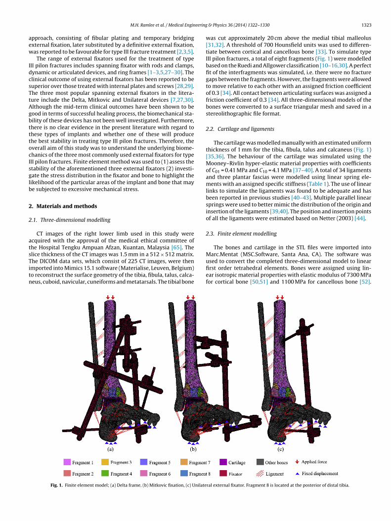
eering
aew
IdcsTtAgbtttocIsglb
2
2
atsTitn
M.H. Ramlee et al. / Medical Engin
pproach, consisting of fibular plating and temporary bridgingxternal fixation, later substituted by a definitive external fixation,as reported to be favourable for type III fracture treatment [2,3,5].
The range of external fixators used for the treatment of typeII pilon fractures includes spanning fixator with rods and clamps,ynamic or articulated devices, and ring frames [1–3,5,27–30]. Thelinical outcome of using external fixators has been reported to beuperior over those treated with internal plates and screws [28,29].he three most popular spanning external fixators in the litera-ure include the Delta, Mitkovic and Unilateral devices [7,27,30].lthough the mid-term clinical outcomes have been shown to beood in terms of successful healing process, the biomechanical sta-ility of these devices has not been well investigated. Furthermore,here is no clear evidence in the present literature with regard tohese types of implants and whether one of these will producehe best stability in treating type III pilon fractures. Therefore, theverall aim of this study was to understand the underlying biome-hanics of the three most commonly used external fixators for typeII pilon fractures. Finite element method was used to (1) assess thetability of the aforementioned three external fixators (2) investi-ate the stress distribution in the fixator and bone to highlight theikelihood of the particular areas of the implant and bone that maye subjected to excessive mechanical stress.
. Materials and methods
.1. Three-dimensional modelling
CT images of the right lower limb used in this study werecquired with the approval of the medical ethical committee ofhe Hospital Tengku Ampuan Afzan, Kuantan, Malaysia [65]. Thelice thickness of the CT images was 1.5 mm in a 512 × 512 matrix.
he DICOM data sets, which consist of 225 CT images, were thenmported into Mimics 15.1 software (Materialise, Leuven, Belgium)o reconstruct the surface geometry of the tibia, fibula, talus, calca-eus, cuboid, navicular, cuneiforms and metatarsals. The tibial boneFig. 1. Finite element model; (a) Delta frame, (b) Mitkovic fixation, (c) Unilate
& Physics 36 (2014) 1322–1330 1323
was cut approximately 20 cm above the medial tibial malleolus[31,32]. A threshold of 700 Hounsfield units was used to differen-tiate between cortical and cancellous bone [33]. To simulate typeIII pilon fractures, a total of eight fragments (Fig. 1) were modelledbased on the Ruedi and Allgower classification [10–16,30]. A perfectfit of the interfragments was simulated, i.e. there were no fracturegaps between the fragments. However, the fragments were allowedto move relative to each other with an assigned friction coefficientof 0.3 [34]. All contact between articulating surfaces was assigned afriction coefficient of 0.3 [34]. All three-dimensional models of thebones were converted to a surface triangular mesh and saved in astereolithographic file format.
2.2. Cartilage and ligaments
The cartilage was modelled manually with an estimated uniformthickness of 1 mm for the tibia, fibula, talus and calcaneus (Fig. 1)[35,36]. The behaviour of the cartilage was simulated using theMooney–Rivlin hyper-elastic material properties with coefficientsof C01 = 0.41 MPa and C10 = 4.1 MPa [37–40]. A total of 34 ligamentsand three plantar fascias were modelled using linear spring ele-ments with an assigned specific stiffness (Table 1). The use of linearlinks to simulate the ligaments was found to be adequate and hasbeen reported in previous studies [40–43]. Multiple parallel linearsprings were used to better mimic the distribution of the origin andinsertion of the ligaments [39,40]. The position and insertion pointsof all the ligaments were estimated based on Netter (2003) [44].
2.3. Finite element modelling
The bones and cartilage in the STL files were imported intoMarc.Mentat (MSC.Software, Santa Ana, CA). The software was
used to convert the completed three-dimensional model to linearfirst order tetrahedral elements. Bones were assigned using lin-ear isotropic material properties with elastic modulus of 7300 MPafor cortical bone [50,51] and 1100 MPa for cancellous bone [52].ral external fixator. Fragment 8 is located at the posterior of distal tibia.
1324 M.H. Ramlee et al. / Medical Engineering
Table 1Stiffness of ligaments.
Ligaments representedin the models
Stiffness (N/mm) References
Interosseous membrane (4 ligaments) 400 [45]Anterior tibiofibular (distal) 78 [46]Posterior tibiofibular (distal) 101 [47]Anterior talofibular 90 [46]Posterior talofibular 70 [48]Calcaneofibular 70 [48]Anterior tibiotalar 70 [46]Posterior tibiotalar 80 [46]Tibiocalcaneal 122 [46]Tibionavicular 40 [46]Interosseous talocalcaneal 70 [45,48]Lateral talocalcaneal 70 [48]Medial talocalcaneal 70 [48]Posterior talocalcaneal 70 [48]Dorsal talonavicular (2 ligaments) 70 [46]Calcaneonavicular (dorsal & plantar) 70 [46,48]Calcaeocuboid (dorsal & short plantar) 70 [46,48]Cuboideonavicular (dorsal & plantar) 70 [45,46]Cuneonavicular (dorsal & plantar) 70 aIntercuneiform (dorsal & plantar) 70 aTarsometatarsal (dorsal & plantar) 70 aMetatarsal (dorsal & plantar) 70 aMedial plantar fascia 200 [49]Central plantar fascia 230 [49]Lateral plantar fascia 180 [49]
a
PletDwDdtob3napmfnaa5egn
2
iavtwbtsf
Long plantar 70 [45]
: assumed from neighboring ligaments.
oisson’s ratio for both cortical and cancellous bones was simu-ated with value of 0.3 [50,51] and 0.26 [52], respectively. Threexternal fixator frames, i.e. the Delta, Mitkovic and Unilateral sys-ems, were designed using three-dimensional (3D) Computer Aidedesign (CAD) software (Solidworks 2012, Dassault Systemes Solid-orks Corp., USA) with 5 mm pins and 11 mm rods. To simulate theelta and Mitkovic fixators, two pins were positioned at the tibialiaphysis, one pin at the body of the calcaneus and another pin athe first metatarsal (Fig. 1) [27,30]. For the Unilateral frame, onlyne pin was positioned at the tibial diaphysis and another pin at theody of calcaneus (Fig. 1) [7]. All the fixators were meshed using-Matic 7.1 (Materialise, Belgium) and were assigned with tita-ium material properties with a Young’s modulus of 110,000 MPand Poisson’s ratio of 0.3 [53,54]. Mesh convergence analyses wereerformed and resulted in a variation in mesh size throughout theodel. The smallest mesh of size 1 was used for the pin-bone inter-
ace, whereas a larger mesh size of 3 was used for the bone. The totalumber of elements and nodes for the Delta fixator was 675,000nd 157,000, respectively; for the Mitkovic fixator, this was 588,000nd 140,000, respectively, and for the Unilateral frame, this was10,000 and 112,000, respectively. Contact condition between thexternal fixators and bone was set as an explicit contact with a tan-ential friction coefficient of 0.4 [52,55,56]. Radial pre-stress wasot modelled at the interface between the bone and the fixators.
.4. Boundary conditions
In order to simulate human walking conditions, two physiolog-cal loads were applied in this study: (1) the swing phase [57–59]nd (2) the stance phase [60,61] of a gait cycle, where the forcealue was determined from the adjacent muscles such as the gas-rocnemius and soleus. For the swing phase, 10% of the body weightas recorded on these particular muscles [57–59]. We assumed a
ody weight of 70 kg in our study; therefore, 70 N was applied tohe tibia in the axial direction to simulate the swing phase. For thetance phase, 50% (350 N) of the body weight was applied onto theoot, as has been reported by Cheung et al. and Simkin [60,61]. The
& Physics 36 (2014) 1322–1330
use of axial weight loading has become popular since this techniqueis a way of testing bone quality and bone healing process [62]. Inorder to prevent rigid body movements during the analysis, the dis-tal surfaces of the calcaneus and all metatarsal bones were fixed inall directions (Fig. 1). The relative micromovement of all simulatedmodels were measured between the proximal and distal fragmentsat the lateral side.
3. Results
3.1. Stress distribution
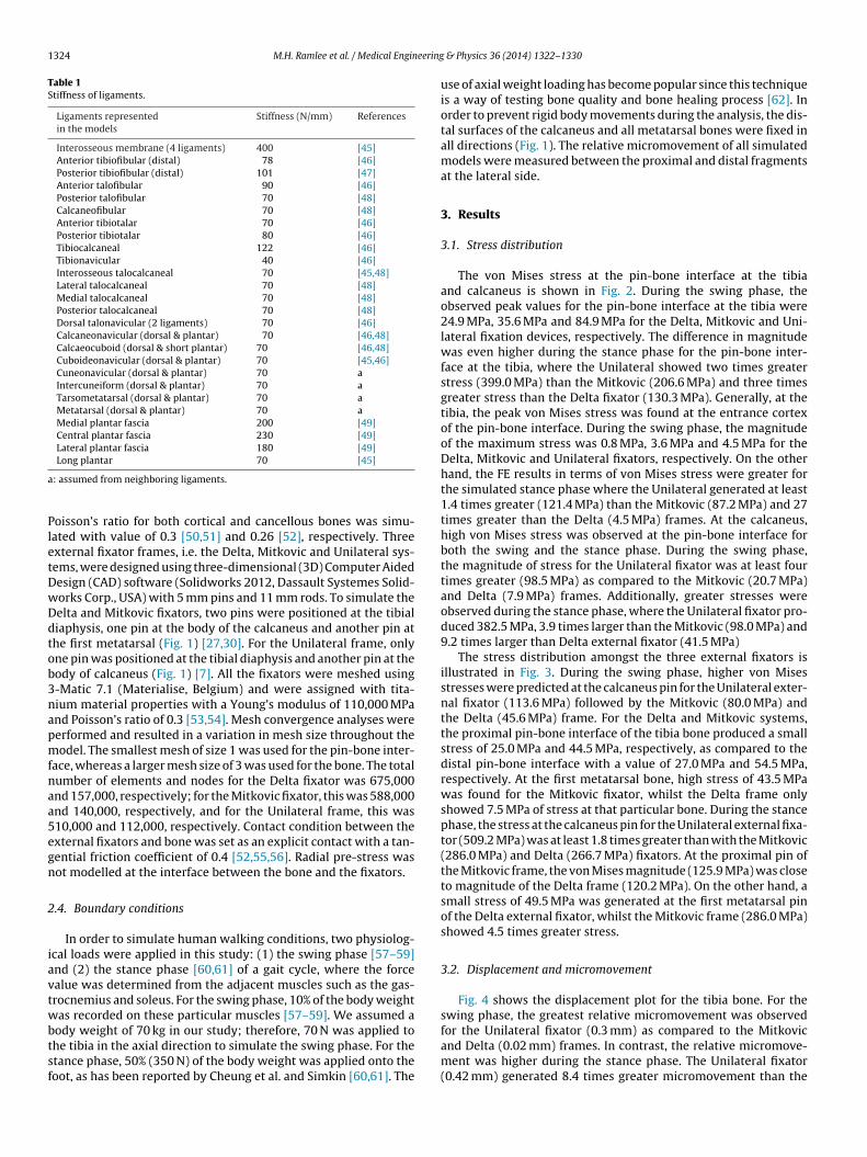
The von Mises stress at the pin-bone interface at the tibiaand calcaneus is shown in Fig. 2. During the swing phase, theobserved peak values for the pin-bone interface at the tibia were24.9 MPa, 35.6 MPa and 84.9 MPa for the Delta, Mitkovic and Uni-lateral fixation devices, respectively. The difference in magnitudewas even higher during the stance phase for the pin-bone inter-face at the tibia, where the Unilateral showed two times greaterstress (399.0 MPa) than the Mitkovic (206.6 MPa) and three timesgreater stress than the Delta fixator (130.3 MPa). Generally, at thetibia, the peak von Mises stress was found at the entrance cortexof the pin-bone interface. During the swing phase, the magnitudeof the maximum stress was 0.8 MPa, 3.6 MPa and 4.5 MPa for theDelta, Mitkovic and Unilateral fixators, respectively. On the otherhand, the FE results in terms of von Mises stress were greater forthe simulated stance phase where the Unilateral generated at least1.4 times greater (121.4 MPa) than the Mitkovic (87.2 MPa) and 27times greater than the Delta (4.5 MPa) frames. At the calcaneus,high von Mises stress was observed at the pin-bone interface forboth the swing and the stance phase. During the swing phase,the magnitude of stress for the Unilateral fixator was at least fourtimes greater (98.5 MPa) as compared to the Mitkovic (20.7 MPa)and Delta (7.9 MPa) frames. Additionally, greater stresses wereobserved during the stance phase, where the Unilateral fixator pro-duced 382.5 MPa, 3.9 times larger than the Mitkovic (98.0 MPa) and9.2 times larger than Delta external fixator (41.5 MPa)
The stress distribution amongst the three external fixators isillustrated in Fig. 3. During the swing phase, higher von Misesstresses were predicted at the calcaneus pin for the Unilateral exter-nal fixator (113.6 MPa) followed by the Mitkovic (80.0 MPa) andthe Delta (45.6 MPa) frame. For the Delta and Mitkovic systems,the proximal pin-bone interface of the tibia bone produced a smallstress of 25.0 MPa and 44.5 MPa, respectively, as compared to thedistal pin-bone interface with a value of 27.0 MPa and 54.5 MPa,respectively. At the first metatarsal bone, high stress of 43.5 MPawas found for the Mitkovic fixator, whilst the Delta frame onlyshowed 7.5 MPa of stress at that particular bone. During the stancephase, the stress at the calcaneus pin for the Unilateral external fixa-tor (509.2 MPa) was at least 1.8 times greater than with the Mitkovic(286.0 MPa) and Delta (266.7 MPa) fixators. At the proximal pin ofthe Mitkovic frame, the von Mises magnitude (125.9 MPa) was closeto magnitude of the Delta frame (120.2 MPa). On the other hand, asmall stress of 49.5 MPa was generated at the first metatarsal pinof the Delta external fixator, whilst the Mitkovic frame (286.0 MPa)showed 4.5 times greater stress.
3.2. Displacement and micromovement
Fig. 4 shows the displacement plot for the tibia bone. For theswing phase, the greatest relative micromovement was observed
for the Unilateral fixator (0.3 mm) as compared to the Mitkovicand Delta (0.02 mm) frames. In contrast, the relative micromove-ment was higher during the stance phase. The Unilateral fixator(0.42 mm) generated 8.4 times greater micromovement than the
M.H. Ramlee et al. / Medical Engineering & Physics 36 (2014) 1322–1330 1325
s for (
MD
ssfipsttes
Fig. 2. The von Mises stress distribution for the tibia and calcaneus bone
itkovic (0.05 mm) and 14 times greater micromovement than theelta (0.03 mm) external fixators.
The contour plot for the displacement of external fixators ishown in Fig. 5. When simulating the swing phase, it was demon-trated that the maximum displacement produced by the Unilateralxator (8.7 mm) was at least three times greater than the dis-lacement produced by the Mitkovic (3.0 mm) and Delta (0.8 mm)ystems. During the stance phase, the Unilateral fixator generated
he highest magnitude of displacement (34.8 mm). The Delta sys-em was the most stable fixation system among the three constructsxamined with a maximum displacement of 3.8 mm. The Mitkovicystem showed a maximum displacement value of 13.4 mm.a) Delta frame, (b) Mitkovic fixation and (c) Unilateral external fixation.
4. Discussion
The use of an external fixator for treating type III pilon frac-tures is a well-accepted surgical option. This system not only allowsminimally invasive surgery of the soft tissue to be performed, butalso maintains the ankle alignment whilst allowing early anklemobilization [17–19]. The results of using an external fixator suchas the Delta, Mitkovic or Unilateral frame have been shown to
produce favourable clinical outcomes as compared to internal fixa-tors [17–19,23–26]. Stable fixation and early anatomic reductionof all fractures and dislocations can minimize long-term mor-bidity and hasten soft tissue healing [63,64]. The biomechanical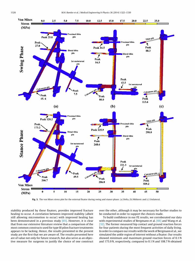
1326 M.H. Ramlee et al. / Medical Engineering & Physics 36 (2014) 1322–1330
g swin
shsbtmasat
Fig. 3. The von Mises stress plot for the external fixator durin
tability produced by these fixators, provides improved fractureealing to occur. A correlation between improved stability (albeittill allowing micromotion to occur) with improved healing haseen demonstrated in a previous study [65]. However, it is clearhat from our extensive literature review that a comparison of the
ost common constructs used for type III pilon fracture treatments
ppears to be lacking. Hence, the results presented in the presenttudy are the first that we are aware of. The results presented herere of value not only for future research, but also serve as an objec-ive measure for surgeons to justify the choice of one constructg and stance phase. (a) Delta, (b) Mitkovic and (c) Unilateral.
over the other, although it may be necessary for further studies tobe conducted in order to support the choices made.
To build confidence in our FE results, we corroborated our datawith experimental studies of Bergmann et al. [66] and Wang et al.[32]. The former measured hip contact and ground reaction forcesfor four patients during the most frequent activities of daily living.
In order to compare our results with the work of Bergmann et al., wesimulated the ankle region of interest without a fixator. Our resultsshowed minimum and maximum ground reaction forces of 0.1 Nand 175.9 N, respectively, compared to 0.1 N and 108.7 N obtained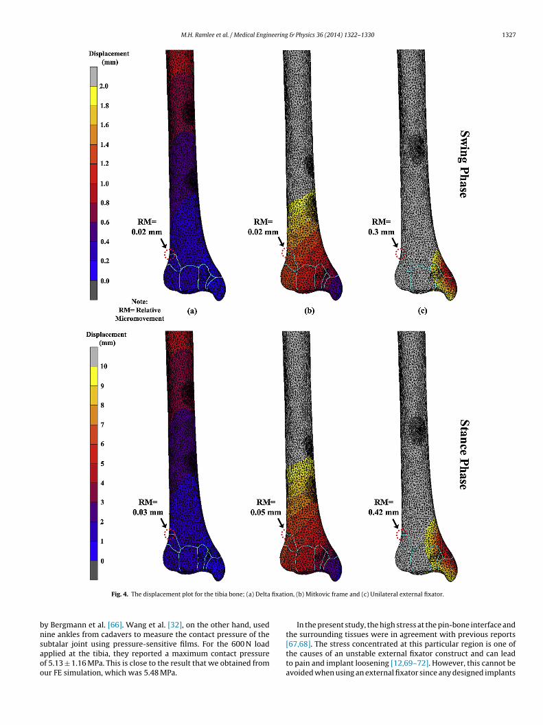
M.H. Ramlee et al. / Medical Engineering & Physics 36 (2014) 1322–1330 1327
fixati
bnsaoo
Fig. 4. The displacement plot for the tibia bone; (a) Delta
y Bergmann et al. [66]. Wang et al. [32], on the other hand, usedine ankles from cadavers to measure the contact pressure of the
ubtalar joint using pressure-sensitive films. For the 600 N loadpplied at the tibia, they reported a maximum contact pressuref 5.13 ± 1.16 MPa. This is close to the result that we obtained fromur FE simulation, which was 5.48 MPa.on, (b) Mitkovic frame and (c) Unilateral external fixator.
In the present study, the high stress at the pin-bone interface andthe surrounding tissues were in agreement with previous reports
[67,68]. The stress concentrated at this particular region is one ofthe causes of an unstable external fixator construct and can leadto pain and implant loosening [12,69–72]. However, this cannot beavoided when using an external fixator since any designed implants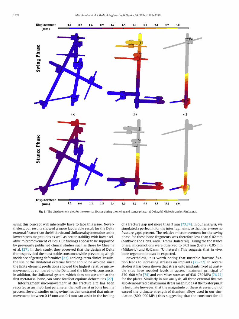
1328 M.H. Ramlee et al. / Medical Engineering & Physics 36 (2014) 1322–1330
e swi
utelabefittmIfi
rpm
Fig. 5. The displacement plot for the external fixator during th
sing this concept will inherently have to face this issue. Never-heless, our results showed a more favourable result for the Deltaxternal fixator than the Mitkovic and Unilateral systems due to theower stress magnitudes as well as better stability with lower rel-tive micromovement values. Our findings appear to be supportedy previously published clinical studies such as those by Cheemat al. [27]. In their study, they observed that the design of Deltarames provided the most stable construct, while preventing a highncidence of getting deformities [27]. For long-term clinical results,he use of the Unilateral external fixator should be avoided sincehe finite element predictions showed the highest relative micro-
ovement as compared to the Delta and the Mitkovic constructs.n addition, the Unilateral system, which does not use a pin at therst metatarsal bone, can cause forefoot equinus deformities [27].
Interfragment micromovement at the fracture site has beeneported as an important parameter that will assist in bone healingrocess. Several studies using ovine has demonstrated that micro-ovement between 0.15 mm and 0.4 mm can assist in the healing
ng and stance phase. (a) Delta, (b) Mitkovic and (c) Unilateral.
of a fracture gap not more than 3 mm [73,74]. In our analysis, wesimulated a perfect fit for the interfragments, so that there were nofracture gaps present. The relative micromovement for the swingphase for these bone fragments was therefore less than 0.02 mm(Mitkovic and Delta) and 0.3 mm (Unilateral). During the the stancephase, micromotions were observed to 0.03 mm (Delta), 0.05 mm(Mitkovic) and 0.42 mm (Unilateral). This suggests that in vivo,bone regeneration can be expected.
Nevertheless, it is worth noting that unstable fracture fixa-tion leads to increasing stresses on implants [75–77]. In severalstudies it has been shown that stress onto implants fixed at unsta-ble sites have recoded levels in access maximum principal of370–600 MPa [75] and von Mises stresses of 436–750 MPa [76,77]for the plates. Similarly in our analysis, all three external fixators
also demonstrated maximum stress magnitudes at the fixator pin. Itis fortunate however, that the magnitude of these stresses did notexceed the ultimate strength of titanium alloys used in our sim-ulation (800–900 MPa) thus suggesting that the construct for all
eering
fio
aproproifcamsp
eshwtptimcsblmomclot(ddewoooy[
5
fsOivc
E
wn
[[
[[
[
[
[
[
[
[
[
[
[
[
[
[
[
M.H. Ramlee et al. / Medical Engin
xations appears to provide adequate stability with minimal riskf implant failure [78].
In treating type III pilon fractures, initial considerations suchs pin placement and the type of external fixator must be maderoperly before the surgery can be conducted. Previous clinicaleports have mentioned that misplacing the pins or improper usef these devices can lead to a high incidence of complications, within infection and loosening in up to 50% of cases and malunionates of up to 45% [24,26,79]. In the simulations conducted here, wenly attempted to show the comparison of ankle external fixatorn terms of the biomechanical properties. Although the Unilateralrame showed larger displacements and relative micromovementsompared to the other two constructs, stability could be betterchieved by placing the proximal pin closer to the fractured seg-ents. The literature on pin placement is fairly limited, thus further
tudy is necessary to assess the biomechanical effects of differentin orientations.
As with any study, there are limitations that need to be consid-red so as to not to overstate the findings. In the present study,everal assumptions and simplifications were made which mayave resulted in alterations to the predicted data. These limitations,hich are inherently particular to computer modelling involving
he reconstruction of complex joints such as the ankle, will beresent and are unfortunately unavoidable. First, it should be notedhat the model was simplified using isotropic material propertiesn this simulation, thus excluding all other important factors that
ay influence the prediction of fracture stability. Although moreomplex modelling would yield more realistic outcomes, omittinguch details appears to be an acceptable practice as demonstratedy many previous studies [39,40,50,51]. Further simplifications of
igaments and plantar fascias modelling using linear links againay have diverted the results from demonstrating true, real life
utcomes. The elements used to simulate the ligaments were notodified, and therefore were allowed to resist both tension and
ompression. Though this may not mimic the actual behaviour ofigaments, the simplified properties of a spring have been used bythers with acceptable accuracy [40–43]. The insertion points ofhe ligaments were estimated based on a reference book by Netter2003) [44] and confirmed by an orthopaedic specialist. This wasone as there are no published reports regarding the geometricaletails of all 37 ligaments modelled in our study. Considering thexistence of subject-specific variation in ligament insertion points,e believe that these estimations were valid. The determination
f the region of interest for the analysis is another limitation ofur study. Due to constraints in computing resources, we modellednly the distal half of the tibia and fibula. Nevertheless the FE anal-sis still valid as similar region of interest has been used by others31,32].
. Conclusion
The results of finite element predictions suggest that the Deltarame provides better stability and generates lower constructtresses as compared to Mitkovic and Unilateral external fixators.ur data therefore suggest that Delta fixators are superior for treat-
ng this type of fracture. However, further studies are required toalidate the outcome of these simulated studies, such as those ofadaveric or clinical studies.
thical approval
Access to the CT images of the right lower limb used in this studyas granted by Dr. Zainun Bt. A. Rahman, Head of Department Diag-ostic Imaging and Dr. Ghazali Ismail, Chairman of Clinical Research
[
& Physics 36 (2014) 1322–1330 1329
Centre, Hospital Tengku Ampuan Afzan, 25100 Kuantan, PahangDarul Makmur, Malaysia.
Acknowledgement
The work has been carried out using the research grants receivedfrom eScienceFund, Ministry of Science, Technology and InnovationMalaysia, FRGS Ministry of Education Malaysia, and UTM ResearchUniversity Grants. More than one of the authors of this paper wassupported under University of Malaya HIR-MOHE research grant.
Conflict of interest
None declared.
References
[1] Kapukaya A, Subasi M, Arslan H, Tuzuner T. Non-reducible, open tibial plafondfractures treated with a circular external fixator (is the current classificationsufficient for identifying fractures in this area). Injury 2005;36:1480–7.
[2] Piper KJ, Won HY, Ellis AM. Hybrid external fixation in complex tibial plateauand plafond fractures: an Australian audit of outcomes. Injury 2005;36.
[3] Marsh JL, Nepola JV, Wuest TK, Osteen D, Cox K, Oppenheim W. Unilateralexternal fixation until healing with the dynamic axial fixator for severe opentibial fractures. J Orthop Trauma 1991;5:341–8.
[4] Bonar SK, Marsh JL. Tibial plafond fractures: changing principles of treatment.J Am Acad Orthop Surg 1994;2:297–305.
[5] Kapukaya A, Subasi M, Arslan H. Management of comminuted closed tibial pla-fond fractures using circular external fixators. Acta Orthop Belg 2005;71:582–9.
[6] Mittal R, Matthews SJ, Zavras DT, Giannoudis PV. Management of ipsilat-eral pilon and calcaneal fractures: a report of 2 cases. J Foot Ankle Surg2004;43:123–30.
[7] Prayson MJ, Moon BS. Stabilization of the fractured tibial plafond. Oper TechOrthop 1999;9:216–28.
[8] Borrelli JJ, Ellis E. Pilon fractures: assessment and treatment. Orthop Clin N Am2002;33:231–45.
[9] Spinosa FA. Chapter 19—classification of fractures and dislocations. Foot AnkleRadiol 2003:415–51.
10] Bartolozzi P, Lavini F. Fractures of the tibia pilon. Milan: Springer; 2004.11] Anwar R, Tuson KWR, Khan SA. Classification and diagnosis in orthopaedic
trauma. New York: Cambridge University Press; 2008.12] Hopton BP, Harris NJ. Fractures of the foot and ankle. Surgery 2010;28:502–7.13] Ruedi T, Matter P, Allgower M. Intra-articular fractures of the distal tibial end.
Hel Chir Acta 1968;35:556–82.14] Ruedi T. The treatment of displaced metaphyseal fractures with screws and
wiring systems. Orthopedics 1989;12:55–9.15] Ruedi T, Allgower M. The operative treatment of intra-articular fractures of the
lower end of the tibia. Clin Orthop Relat Res 1979;138:105–10.16] Ruedi T. Fractures of the lower end of the tibia into the ankle joint: results 9
years after opne reduction and internal fixation. Injury 1973;5:130–4.17] Liporace FA, Yoon RS. An adjunct to percutaneous plate insertion to obtain
optimal sagittal plane alignment in the treatment of pilon fractures. J Foot AnkleSurg 2012;51:275–7.
18] Dudko S, Kusz D, Wojciechowski P, Stoltny T. Operative treatment of anklesfractures using internal osteosynthesis by a minimal surgical approach. Foot2004;14:185–91.
19] Mauffrey C, Vasario G, Battiston B, Lewis C, Beazley J, Seligson D. Tibial pilonfractures: a review of incidence, diagnosis, treatment, and complications. ActaOrthop Belg 2011;77:432–40.
20] Pellegrini M, Cuchacovich N, Lagos L, Henriquez H, Carcuro G, Bastias C.Minimally-invasive alternatives in the treatment of distal articular tibial frac-tures. Fur Sprunggelenk 2012;10:37–45.
21] Wall OR, Pinder R, Faraj AA. Ender’s nail fixation of tibial pilon fractures—a safe,minimally invasive approach for high risk patients in a small district generalhospital. Inj Extra 2007;38:8.
22] Etter C, Ganz R. Long-term results of tibial plafond fractures treated with openreduction and internal fixation. Arch Orthop Trauma Surg 1991;110:277–83.
23] Picanz J. Poor results mark ORIF of tibial plafond fractures. Orthop Today1990;10:1–2.
24] Teeny S, Wiss DA, Hathaway R, Sarmiento A. Tibial plafond fractures:errors, complications, and pitfalls in operative treatment. Orthop Trans1990;14:265–71.
25] Rammelt S, Marti RK, Raaymakers ELFB, Grass R, Zwipp H. Joint preservingreconstruction of malunited pilon fractures. Fur Sprunggelenk 2012;10:62–72.
26] Sirkin M, Sanders R, DiPasquale T, Herscovici D. A staged protocol for soft tissue
management in the treatment of complex pilon fractures. J Orthop Trauma1999;13:78–84.27] Cheema GS, Arora S, Sabat D, Singla J, Goel N, Maini L. The results of two-stagedoperative management of pilon fractures—a review of 25 cases. J Clin OrthopTrauma 2011;2:104–8.
1 eering
[
[
[
[
[
[
[
[
[
[
[
[
[
[
[
[
[
[
[
[
[
[
[
[
[
[
[
[
[
[
[
[
[
[
[
[
[
[
[
[
[
[
[
[
[
[
[
[
[
[
330 M.H. Ramlee et al. / Medical Engin
28] Barbieri R, Schenk R, Koval K, Aurori K, Aurori B. Hybrid external fixation in thetreatment of tibial plafond fractures. Clin Orthop Relat Res 1996;332:16–22.
29] Bone L, Stegemann P, McNamara K, Seibel R. External fixation of severely com-minuted and open tibial pilon fractures. Clin Orthop Relat Res 1993;292:101–7.
30] Mitkovic MB, Bumbasirevic MZ, Lesic A, Golubovic Z. Dynamic external fixa-tion of comminuted intra-articular fractures of the distal tibia (type C pilonfractures). Acta Orthop Belg 2002;68:508–14.
31] Cheung JT-M, Zhang M, An KN. Effect of Achilles tendon loading on plantarfascia tension in the standing foot. Clin Biomech 2006;21:194–203.
32] Wang CL, Cheng CK, Chen CW, Lu CM, Hang YS, Liu TK. Contact areas andpressure distributions in the subtalar joint. J Biomech 1994;28:269–79.
33] Yosibash Z, Trabelsi N, Milgrom C. Realiable simulations of the human proxi-mal femur by high-order finite element analysis validated by the experimentalobservations. J Biomech 2007;40:3688–99.
34] Chen WP, Tai CL, Shih CH, Hsieh PH, Leou MC, Lee MS. Selection of fixationdevices in proximal femur rotational osteotomy: clinical complications andfinite element analysis. Clin Biomech 2004;19:255–62.
35] Millington SA, Grabner M, Wozelka R, Anderson DD, Hurwitz SR, Crandall JR.Quantification of ankle articular cartilage topography and thickness using ahigh resolution stereophotography system. Osteoarthr Cartil 2007;15:205–11.
36] Akiyamat K, Sakai T, Sugimoto N, Yoshikawa H, Sugamoto K. Three-dimensionaldistribution of articular cartilage thickness in the elderly talus and cal-caneus analyzing the subchondral bone plate density. Osteoarthr Cartil2012;20:296–304.
37] Brown CP, Nguyen TC, Moody HR, Crawford RW, Oloyede A. Assess-ment of common hyperelastic constitutive equations for describing normaland osteoarthritis articular cartilage. Proc Inst Mech Eng H: J Eng Med2009;223:643–52.
38] Li Z, Kim J-E, Davidson JS, Etheridge BS, Alonso JE, Eberhardt AW. Biomechanicalresponse of the pubic symphysis in lateral pelvic impacts: a finite elementstudy. J Biomech 2007;40:2758–66.
39] Gislason MK, Stansfield B, Nash DH. Finite element model creation and stabilityconsiderations of complex biological articulation: the human wrist joint. MedEng Phys 2010;32:523–31.
40] Bajuri MN, Abdul Kadir Mohammed Rafiq, Murali Malliga Raman, Kamarul T.Mechanical and functional assessment of the wrist affected by rheumatoidarhtritis: a finite element analysis. Med Eng Phys 2012;34:1294–302.
41] Ezquerro F, Jimenez S, Perez A, Prado M, de Diego G, Simon A. The influenceof wire positioning upon the initial stability of scaphoid fractures fixed usingKirschner wires: a finite element study. Med Eng Phys 2007;29:652–60.
42] Tao K, Wang D, Wang C, Wang X, Liu A, Nester CJ, et al. An in vivo exper-imental validation of a computational model of human foot. J Bionic Eng2009;6:387–97.
43] Yu J, Cheung JT-M, Fan Y, Zhang Y, Leung AKL, Zhang M. Development of afinite element model of female foot for high-heeled shoe design. Clin Biomech2008;23. S31-S8.
44] Netter FH. Atlas of human anatomy. 3rd ed New York City, USA: ICON LearningSystem; 2003.
45] Pfaeffle HJ, Tomaino MM, Grewal R, Xu J, Boardman ND, Woo SL, et al. Tensileproperties of the interosseous membrane of the human forearm. J Orthop Res1996;14:842–5.
46] Siegler S, Block J, Schneck CD. The mechanical characteristics of the collateralligaments of the human ankle joint. Foot Ankle 1988;8:234–42.
47] Beumar A, van Hemert WL, Swierstra BA, Jasper LE, Belkoff SM. A biomechanicalevaluation of the tibiofibular and tibiotalar ligaments of the ankle. Foot AnkleInt 2003;24:426–9.
48] Liacouras PC, Wayne JS. Computational modeling to predict mechanical func-tion of joints: application to the lower leg simulation of two cadaver studies. JBiomech Eng 2007;129:811–7.
49] Iaquinto JM, Wayne JS. Computational model of the lower leg and foot/anklecomplex: application to arch stability. J Biomech Eng 2010:2010.
50] Nakamura S, Crowninshield RD, Cooper RR. An analysis of soft tissue loading inthe foot—a preliminary report. Bull Prosthet Res 1981;18:27–34.
51] Qiu TX, Teo EC, Yan YB, Lei W. Finite element modeling of a 3D coupled foot-bootmodel. Med Eng Phys 2011;33:1228–33.
52] Kim H-J, Kim S-H, Chang S-H. Bio-mechanical analysis of a fractures tibia withcomposite bone plates according to the diaphyseal oblique fracture angle. Com-pos B: Eng 2011;42:666–74.
53] Fan Y, Xiu K, Duan H, Zhang M. Biomechanical and histological evaluation of theapplication of biodegradable poly-l-lactic cushion to the plate internal fixationfor bone fracture healing. Clin Biomech 2008;23:S7–16.
54] Benli S, Aksoy S, Havitcioglu H, Kucuk M. Evaluation of bone plate with low-stiffness material in terms of stress distribution. J Biomech 2008;14:3229–35.
[
[
& Physics 36 (2014) 1322–1330
55] Cordey J, Borgeaud M, Perren SM. Force transfer between the plate and thebone: relative importance of the bending stiffness of the screws and the frictionbetween plate and bone. Injury 2000;31:21–8.
56] Tajdari M, Javadi M. A new experimental procedure of evaluating thefriction coefficient in elastic and plastic region. J Mater Process Technol2006;1–3:247–50.
57] Heintz S, Gutierrez-Farewik EM. Static optimization of muscle forces dur-ing gait in comparison to EMG-to-force processing approcach. Gait Posture2007;26:279–88.
58] Anderson FC, Pandy MG. Static and dynamic optimization solutions for gait arepractically equivalent. J Biomech 2001;34:153–61.
59] Kim S-H, Chang S-H, Son D-S. Finite element analysis of the effect of bendingstiffness and contact condition of composite bone plates with simple rectan-gular cross-section on the bio-mechanical behaviour of fractures long bones.Compos Part B 2011;42:1731–8.
60] Cheung JT-M, Zhang M, Leung AKL, Fan YB. Three-dimensional finite elementanalysis of the foot during standing—a material sensitivity study. J Biomech2005;38:1045–54.
61] Simkin A. Structural analysis of the human foot in standing posture. Tel Aviv:Tel Aviv University; 1982.
62] Aarnes GA, Steen H, Kristiansen LP, Festo E, Ludvigsen P. Optimum load-ing mode for axial stiffness testing in limb lengthening. J Orthop Res2006;24:348–54.
63] Chandran P, Puttaswamaiah R, Dhillon MS, Gill SS. Management of complexopen fracture injuries of the midfoot with external fixation. J Foot Ankle Surg2006;45:308–15.
64] Zgonis T, Roukis TS, Polyzois V, Wukich DK. Surgical management of the unsta-ble diabetic Charcot deformity using the Taylor spatial frame. Oper Tech Orthop2006;16:10–7.
65] Izaham RMAR, Kadir MRA, Rashid AHA, Hossain MG, Kamarul T. Finite ele-ment analysis of Puddu and Tomofix plate fixation for open wedge high tibialosteotomy. Injury 2012;43:898–902.
66] Bergmann G, Deuretzbacher G, Heller M, Graichen F, Rohlmann A, Straus J,et al. Hip contact forces and gait patterns from routine activities. J Biomech2001;34:859–71.
67] Donaldson FE, Pankaj P, Simpson AHRW. Bone properties affect loosen-ing of half-pin external fixators at the pin-bone interface. Injury 2012;43:1764–70.
68] Brianza S, Brighenti V, Lansdowne JL, Schwieger K, Boure L. Finite element anal-ysis of a novel pin-sleeve system for external fixation of distal limb fracturesin horses. Vet J 2011;190:260–7.
69] Gardner TN, Mishra S. The biomechanical environment of a bone fractureand its influence upon the morphology of healing. Med Eng Phys 2003;25:455–64.
70] Nash RA, Nunamaker DM, Boston R. Evaluation of a tapere-sleeve transcorticalpin to reduce stress at the bone-pin interface in metacarpal bones obtainedfrom horses. Am J Vet Res 2001;62:955–60.
71] Richardson DW, Nunamaker DM, Sigafoos RD. Use of an external skeletal fixa-tion device and bone graft for arthrodesis of the metacarpophalangeal joint inhorses. J Am Vet Med Assoc 1987;191:316–21.
72] Williams TM, Nepola JV, DeCoster TA, Hurwitz SR, Dirschl DR, Marsh JL.Factors affecting outcome in tibial plafond fractures. Clin Orthop Relat Res2004;423:93–8.
73] Claes LE, Wilke HJ, Augat P, Rubenacker S, Margevicius KJ. Effect of dynamiza-tion on gap healing of diaphyseal fractures under external fixation. ClinBiomech 1995;10:227–34.
74] Goodship AE, Kenwright J. The influence of induced micromovement uponhealing of experimental tibial fractures. J Bone Jt Surg 1985;67B:650–5.
75] Chen G, Schmutz B, Wullschleger M, Pearcy MJ, Schuetz MA. Computationalinvestigations of mechanical failures of internal plate fixation. Proc Inst MechEng H: J Eng Med 2010;224:119–26.
76] Ebrahimi H, Rabinovich M, Vuleta V, Zalcman D, Shah S, Dubov A, et al.Biomechanical properties of an intact, injured, repaired, and healed femur:an experimental and computational study. J Mech Behav Biomed Mater2012;16:121–35.
77] Moazen M, Mak JH, Etchels LW, Jin Z, Wilcox RK, Jones AC, et al. The effect offracture stability on the performance of locking plate fixation in periprostheticfemoral fractures. J Arthroplast 2013;28:1589–95.
78] Gorsse S, Miracle DB. Mechanical properties of Ti–6Al–4V/TiB compos-ites with randomly oriented and aligned TiB reinforcement. Acta Mater2003;51:2427–42.
79] Redfern DJ, Syed SU, Davies SJM. Fractures of the distal tibia: minimally invasiveplate osteosynthesis. Injury 2004;35:615–20.
Related Documents


![The mid-term results of treatment for tibial pilon fractures · 7-10% of all tibia fractures are pilon fractures.[1-3] The usual mechanism of injury is axial loading of the limb through](https://static.cupdf.com/doc/110x72/6018c5987d71101a3a4e4d4b/the-mid-term-results-of-treatment-for-tibial-pilon-fractures-7-10-of-all-tibia.jpg)


