10.1098/rspa.2003.1264 Finite-element analysis of the effect of material properties and fibre shape on stresses in an elastic fibre embedded in an elastic matrix in a fibre-composite material By K. L. Goh 1 †, R. M. Aspden 2 , K. J. Mathias 1 and D. W. L. Hukins 1 ‡ 1 Department of Bio-Medical Physics and Bio-Engineering, 2 Department of Orthopaedic Surgery, University of Aberdeen, Foresterhill, Aberdeen AB25 2ZD, UK ([email protected]) Received 4 September 2001; revised 6 November 2002; accepted 8 October 2003; published online 11 May 2004 The finite-element method was used to calculate the axial stress in an elastic fibre embedded in an elastic matrix to model a fibre-composite material. Axisymmet- ric models were created for cylindrical, ellipsoidal, paraboloidal and conical fibres embedded in a matrix and characterized by a fibre axial ratio, q. The effects of vary- ing q, from 200 to 1000, and the ratio of the Young moduli of the fibre and the matrix, E f /E m , from 50 to 10 4 , were investigated. For a cylindrical fibre, the axial stress distribution along the fibre axis was similar for all values of q and E f /E m ; it was greatest at the centre, decreased steadily over most of the fibre length and fell rapidly to zero near the fibre end. For fixed q, the magnitude of this stress increased with increasing E f /E m , whereas for fixed E f /E m the variation with q was small. There was good qualitative agreement between these data and previous analytical models. The axial stress in the conical fibre was a minimum at the fibre centre and rose gradually to a maximum close to the fibre end. This was most pronounced for small values of q and at large values of E f /E m . Stress distributions for the paraboloid and ellipsoid lay between those for the cylinder and the cone. For small values of E f /E m , both the magnitudes and the axial distributions of axial stress were almost indistinguishable for all shapes of fibre and all values of q studied. Keywords: composite materials; fibre composites; finite-element analysis; fibre shape 1. Introduction Fibre composites consist of fibres embedded in and reinforcing a matrix material. Commercially, fibre composites of high strength and toughness can be produced † Present address: Cardiff Institute of Tissue Engineering and Repair, Department of Optometry and Vision Sciences, Cardiff University, CF10 3XQ, UK. ‡ Present address: School of Engineering, Mechanical Engineering, University of Birmingham, Edg- baston, Birmingham B15 2TT, UK. Proc. R. Soc. Lond. A (2004) 460, 2339–2352 2339 c 2004 The Royal Society

Welcome message from author
This document is posted to help you gain knowledge. Please leave a comment to let me know what you think about it! Share it to your friends and learn new things together.
Transcript
10.1098/rspa.2003.1264
Finite-element analysis of the effect of materialproperties and fibre shape on stresses inan elastic fibre embedded in an elasticmatrix in a fibre-composite material
By K. L. Goh1†, R. M. Aspden
2, K. J. Mathias
1
and D. W. L. Hukins1‡
1Department of Bio-Medical Physics and Bio-Engineering,2Department of Orthopaedic Surgery, University of Aberdeen, Foresterhill,
Aberdeen AB25 2ZD, UK ([email protected])
Received 4 September 2001; revised 6 November 2002; accepted 8 October 2003;published online 11 May 2004
The finite-element method was used to calculate the axial stress in an elastic fibreembedded in an elastic matrix to model a fibre-composite material. Axisymmet-ric models were created for cylindrical, ellipsoidal, paraboloidal and conical fibresembedded in a matrix and characterized by a fibre axial ratio, q. The effects of vary-ing q, from 200 to 1000, and the ratio of the Young moduli of the fibre and thematrix, Ef/Em, from 50 to 104, were investigated. For a cylindrical fibre, the axialstress distribution along the fibre axis was similar for all values of q and Ef/Em; itwas greatest at the centre, decreased steadily over most of the fibre length and fellrapidly to zero near the fibre end. For fixed q, the magnitude of this stress increasedwith increasing Ef/Em, whereas for fixed Ef/Em the variation with q was small.There was good qualitative agreement between these data and previous analyticalmodels. The axial stress in the conical fibre was a minimum at the fibre centre androse gradually to a maximum close to the fibre end. This was most pronounced forsmall values of q and at large values of Ef/Em. Stress distributions for the paraboloidand ellipsoid lay between those for the cylinder and the cone. For small values ofEf/Em, both the magnitudes and the axial distributions of axial stress were almostindistinguishable for all shapes of fibre and all values of q studied.
Keywords: composite materials; fibre composites;finite-element analysis; fibre shape
1. Introduction
Fibre composites consist of fibres embedded in and reinforcing a matrix material.Commercially, fibre composites of high strength and toughness can be produced
† Present address: Cardiff Institute of Tissue Engineering and Repair, Department of Optometry andVision Sciences, Cardiff University, CF10 3XQ, UK.
‡ Present address: School of Engineering, Mechanical Engineering, University of Birmingham, Edg-baston, Birmingham B15 2TT, UK.
Proc. R. Soc. Lond. A (2004) 460, 2339–23522339
c© 2004 The Royal Society
2340 K. L. Goh and others
by reinforcing materials using fibres of high tensile stiffness and strength (Kelly &Macmillan 1986). In animal tissues, the same principles are exploited where collagenfibrils provide reinforcement (Hukins 1982). Recently, it has been noticed that colla-gen fibrils have ‘pointed’ or ‘parabolic’ ends (Holmes et al . 1992; Trotter & Purslow1992; Trotter et al . 1994; DeVente et al . 1997).
This paper presents the results of a finite-element (FE) analysis of the effect offibre and matrix properties on the stresses in an elastic fibre, which need not be auniform cylinder, embedded in an elastic matrix. In such a fibre-composite system,the fibre is bonded to the matrix. Deformation of the matrix generates an interfacialshear stress, τ . This stress has been shown not to be constant in analytical models(Cox 1952; Dow 1963; Rosen 1965; Lawrence 1972; Nairn 1997) and FE analyses(Carrara & McGarry 1968) for a cylindrical fibre embedded in an elastic material.In response to τ , stresses are generated in the fibre. The result is that both the fibreand matrix elongate elastically. This process is referred to as elastic load transfer(Kelly & Macmillan 1986) and corresponds to the behaviour of the matrix at theinitial stage of loading before the matrix yields. The fibre axial ratio, q, the ratioof the Young modulus of the fibre to that of the matrix, Ef/Em, and Poisson’sratios of the fibre, νf, and the matrix, νm, have to be considered in the analysis ofelastic load transfer (Aspden 1994). To our knowledge, no previous analysis of elasticload transfer (Raisanen & Herrmann 1999; Carrara & McGarry 1968; Nairn 1997)has considered the effect of varying these parameters or investigated the influence offibre shape, although an early FE analysis did consider cylindrical fibres with conicalor elliptical ends (Carrara & McGarry 1968). When the matrix yields, it debondsfrom the fibre and flows plastically, while the fibre elongates elastically, and so thisprocess is known as plastic load transfer (Kelly & Macmillan 1986). In this case,the magnitude of τ is constant along the length of a fibre (Kelly & Tyson 1965)and analysis is simpler than for the elastic case, because only the debonded fibre isconsidered, while q merely acts as a scaling factor (Aspden 1994; Goh et al . 1999).
Fibre shape is rarely considered in studies of fibre–matrix interactions. Althoughthe analysis reported here was prompted by the observations on animal tissuesdescribed above (Holmes et al . 1992; Trotter et al . 1994; DeVente et al . 1997), itis intended to provide more general information on how shape affects the ability ofa fibre to reinforce an elastic matrix; previous analytical (Goh et al . 1999) and FEanalyses (Goh et al . 2000) have been concerned with the effect of fibre shape whenthe surrounding matrix is plastic. Studies of elastic load transfer by photoelasticity(Schuster & Scala 1964) and FE analysis (Carrara & McGarry 1968) demonstratedstress concentrations in the matrix surrounding the cylindrical fibre end and thatthese were reduced at a tapered fibre end. However, these conclusions were not com-plete; it is equally important to examine stresses in the fibre, because stresses in thefibre and matrix are different, owing to the different elastic moduli. Eshelby (1957)analysed the stresses in an ellipsoidal inclusion, which includes the case of an ellip-soidal reinforcing fibre, in a matrix. In § 4, we compare his analytical results withthose obtained from our FE model. Several subsequent publications have extendedEshelby’s work, including that of Tandon & Weng (1986), who considered an assem-bly of oriented ellipsoidal particles in a matrix. In this paper, we report the effect offibre shape, for a cylinder, an ellipsoid, a paraboloid and a cone, on the axial stressesin a fibre. We also consider the effect of variation in q, Ef/Em and, for completeness,νf and νm.
Proc. R. Soc. Lond. A (2004)
Fibre and matrix properties in composite materials 2341
2. Methods
(a) Introduction
A model of a cylindrical fibre in a coaxial cylindrical matrix was developed first toestablish the dimensions of the matrix and the optimum FE meshes to be used in allmodels. The aim was to ensure convergence of the calculated axial stress in the fibreto consistent values for the range of material properties investigated. This was doneby selecting values for Ef/Em and q towards the extremes of realistic values, thoughsome limitations were placed on these values by the modelling process. So, for eachfibre shape, four models were solved representing the four combinations of materialproperties and axial ratios. The effects of different Poisson’s ratios were assessed sep-arately. The matrix radius and length were increased in turn until selected stressesconverged to a steady value (see § 2 f). Radial dimensions were checked after thelength was determined to ensure that changing the length had not affected the radiusrequired for convergence. At each stage of developing the model, the FE mesh wasoptimized. The matrix dimensions and meshing were first determined for the cylin-drical fibre. The other fibre shapes were then modelled using the same dimensionsand mesh, with small modifications around the fibre ends to accommodate the differ-ent shapes (see § 2 b). Once suitable models had been developed for the four extremevalues of q and Ef/Em, these parameters were varied systematically over their rangesto produce the results. The following sections will describe the development of themodels in more detail, including fibre shape and dimensions, the material propertiesused, the boundary conditions imposed and the meshing and solving process. Allthese stages were performed using commercially available FE software (Ansys v. 5.4(educational), Ansys Inc., Houston, PA, USA) which limits the number of nodes to32 000.
(b) Model descriptions
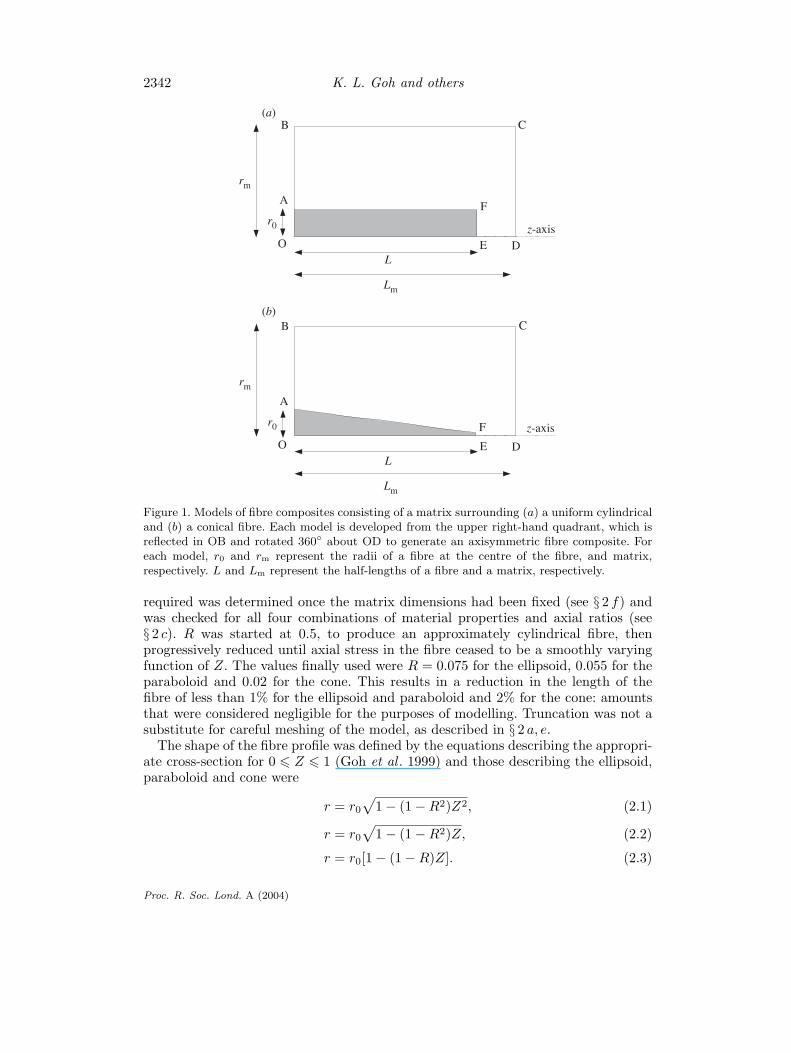
Models were constructed for a composite comprising a single fibre with one of fourdifferent shapes embedded in a cylindrical matrix. The shapes studied were right-cylindrical, ellipsoidal, paraboloidal and conical. Figure 1 shows upper right-handquadrants of plane sections through two of these: a uniform cylinder and a cone.The ellipsoid and paraboloid are intermediate between these (Goh et al . 1999). Acylindrical polar coordinate system (r, φ, z) was defined to have its origin at thefibre–matrix centre, O, where z lies along the fibre–matrix axis, and r and φ areradial distance and azimuthal angle, respectively. The axial ratio of the fibre wasdefined by q = L/r0, where r0 is the radius of the fibre at the origin and L is thehalf-length of the fibre (Aspden 1994). The fibre was surrounded by matrix such thatthe composite had a radius, rm, and a half-length, Lm. The complete, fibre–matrixmodel could be generated by reflecting about OB and rotating about OD. In order tocompare results obtained for different fibres, distances along the fibre were expressedas fractional coordinates, Z = z/L.
To solve the models with free ends, it was found that the fibres had to be truncatedbecause of badly shaped elements which appeared at the ends of pure tapers anddifficulties in getting the stresses to vary smoothly. The fibre half-length was thendefined as extending to the truncated end where the radius is rc. This was definedas a fraction of r0, so that R = rc/r0 (Goh et al . 1999). The extent of truncation
Proc. R. Soc. Lond. A (2004)
2342 K. L. Goh and others
rm
B
A
O
r0
C
F
EL
Lm
Dz-axis
C
F
rm
B
A
O
r0
EL
Lm
D
z-axis
(a)
(b)
Figure 1. Models of fibre composites consisting of a matrix surrounding (a) a uniform cylindricaland (b) a conical fibre. Each model is developed from the upper right-hand quadrant, which isreflected in OB and rotated 360◦ about OD to generate an axisymmetric fibre composite. Foreach model, r0 and rm represent the radii of a fibre at the centre of the fibre, and matrix,respectively. L and Lm represent the half-lengths of a fibre and a matrix, respectively.
required was determined once the matrix dimensions had been fixed (see § 2 f) andwas checked for all four combinations of material properties and axial ratios (see§ 2 c). R was started at 0.5, to produce an approximately cylindrical fibre, thenprogressively reduced until axial stress in the fibre ceased to be a smoothly varyingfunction of Z. The values finally used were R = 0.075 for the ellipsoid, 0.055 for theparaboloid and 0.02 for the cone. This results in a reduction in the length of thefibre of less than 1% for the ellipsoid and paraboloid and 2% for the cone: amountsthat were considered negligible for the purposes of modelling. Truncation was not asubstitute for careful meshing of the model, as described in § 2 a, e.
The shape of the fibre profile was defined by the equations describing the appropri-ate cross-section for 0 � Z � 1 (Goh et al . 1999) and those describing the ellipsoid,paraboloid and cone were
r = r0√
1 − (1 − R2)Z2, (2.1)
r = r0√
1 − (1 − R2)Z, (2.2)
r = r0[1 − (1 − R)Z]. (2.3)
Proc. R. Soc. Lond. A (2004)
Fibre and matrix properties in composite materials 2343
These equations were used to generate coordinates from which axisymmetric com-puter models were created.
(c) Fibre and matrix properties
Fibres were modelled having axial ratios, q, of 200 and 1000. These values wereachieved by fixing the fibre half-length, L, at unit length and calculating the corre-sponding fibre radius from r0 = L/q. In this FE model, the units used are imma-terial, as long as they are consistent. The results were scaled by the original lengthor applied stress, as appropriate, so making them effectively dimensionless. Largervalues of q proved very difficult to mesh because of limits on the number of nodesand the allowed slenderness of the elements. Fibres with q less than 200 were notmodelled because of difficulties obtaining convergence of the axial stress to a smoothdistribution at the fibre end (see § 2 f).
The literature suggests that the collagen fibrils, which prompted this investigation,have q values (as defined in § 2 b and not as in the original papers) of a few hundred(DeVente et al . 1997) to a few thousand (Trotter & Koob 1989). We were not able toincrease q to beyond about 1000 because the restricted number of nodes, imposed bythe software (see § 2 a), made it impossible to describe the fibre width by a reasonablenumber of elements. Nevertheless, the results presented here are able to demonstratehow the axial stress in a fibre depends on q, for the range of shapes investigated, asdescribed in § 5.
The materials used for the fibre and matrix were assumed to be homogeneous,isotropic and linearly elastic. The assumption of homogeneity assumes that fibres,and volumes of matrix, are large compared with molecular dimensions. This assump-tion is reasonable for animal tissues in which collagen fibrils typically have radii ofthe order of 30 nm (see, for example, Hickey & Hukins 1981) and for other fibre-reinforced composite materials. The assumption that fibres are isotropic is less easyto justify. Collagen fibrils in animal tissues are cross-linked assemblies of oriented rod-like molecules (Hukins et al . 1995) and are, therefore, expected to have anisotropicproperties. However, the information is inadequate for modelling their anisotropyand, in any case, such a specific model would not be well suited to answering thegeneral question of the effect of shape on the axial stress in any fibre surrounded byan elastic matrix. Collagen fibrils and many of the fibrous materials used to reinforcesynthetic composite materials are not linearly elastic. However, their behaviour willapproximate to linear elasticity over a sufficiently small strain range and a simplelinearly elastic material then provides insights into how shape affects axial strain ina fibre (see also § 3 c).
Fibre stresses were found to be independent of the absolute values of the moduli,but their distribution depended on the ratio of fibre to matrix moduli, Ef/Em. Emwas, therefore, chosen to be 1 MPa and the ratio Ef/Em was assigned values of 50 and104 to represent extremes of realistic values. Collagen fibrils in animal tissues have Efvalues of ca. 109–1010 Pa (Cusack & Miller 1979; Ashby et al . 1995) which are muchlarger than the Em values, which are expected to be ca. 104–105 Pa (Hooley & Cohen1979; Leahy & Hukins 2001). Thus an Ef/Em ratio of ca. 104 is sufficiently high to berelevant to the reinforcement of animal tissues by collagen, but the true value couldsometimes be as high as 106. Values for Ef/Em of greater than 104 resulted in largervalues being required for rm (see § 2 f) and limits on the number of nodes availablethen made modelling unreliable.
Proc. R. Soc. Lond. A (2004)
2344 K. L. Goh and others
B
A
O E
F
F’ C
F’’
z-axis
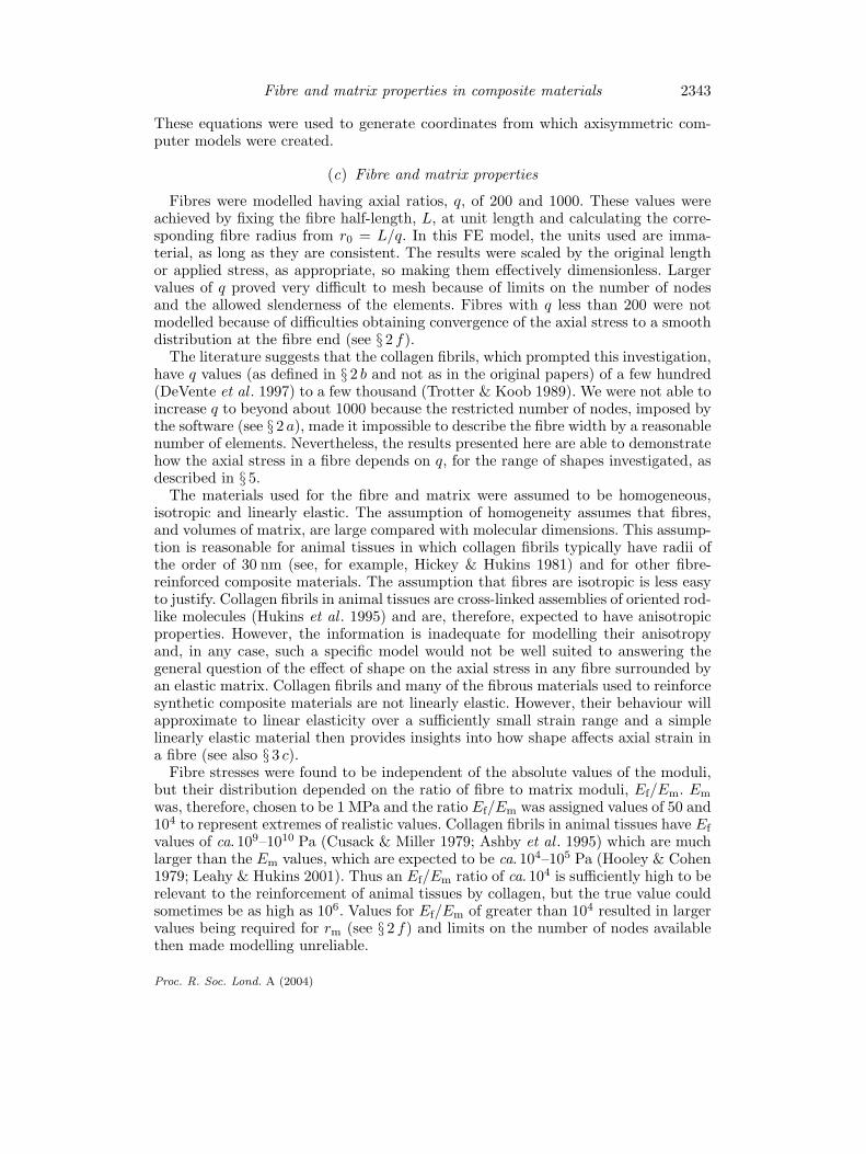
Figure 2. Schematic of an FE model of the cylindrical fibre composite. The model was dividedinto four regions and was meshed using eight-node quadrilateral elements. The four regions wereOAFE, ABF′F, EFF′′D and FF′CF′′. Similar methods were implemented for the ellipsoidal,paraboloidal and conical fibre composites. In practice, OB is 750 times OA and OD is twice OE.Also, there are many more elements in the final model than are shown here.
Preliminary studies found the effect of Poisson’s ratios of both fibre and matrix onthe stresses in the fibre to be negligible, as expected. For this reason, Poisson’s ratiosfor the fibre and matrix materials were assigned values of 0.3 and 0.49, respectively,which are typical of metallic and elastomeric materials, respectively.
(d) Boundary conditions
To ensure that the model had the symmetry described in § 2 b, the nodes lying alongOB, in figure 1, were constrained to prevent any displacement in the z-direction. Theradius of the matrix was made sufficiently large to simulate an infinite matrix (see§ 2 f) and the outer surface of the matrix was left free.
A uniform force of 1 N was applied across the end face of the matrix, describedby CD in figure 1. Dividing by the area of the circular end of the matrix resultedin an applied stress of σc. Because of the linear elastic properties assigned to thematerials, this force can be scaled to any required value. Thus the assumption oflinear elasticity (see § 2 c) has the advantage of providing results which apply for arange of σc values (see § 3 b). There was no bonding between the end of the fibre andthe matrix, so that no axial stress was transmitted to the fibre and the axial stressin the fibre must fall to zero at the fibre end (Kelly & Macmillan 1986).
(e) Meshing
Quadrilateral elements with mid-side nodes were used and cylindrical symmetrywas invoked to generate a three-dimensional model as described in § 2 b. Each modelwas divided into four regions for the purposes of meshing (figure 2). The mesh ineach region was graded to produce a greater density near the fibre, which is theregion of interest. The random design generation method within the software wasused to obtain optimized meshes. The mesh in the fibre was optimized for eachdifferent q value, for each fibre shape, and when determining the amount of truncationrequired. The meshes in the matrix ABF′F and EFF′′D were optimized each timethe matrix radius or length was varied. The numbers of elements in the final modelsof all four fibre-shapes were 292 in the fibre and 5076 in the matrix. Figure 3 showsthe mesh around the tip of a truncated (see § 2 b) conical fibre.
Proc. R. Soc. Lond. A (2004)
Fibre and matrix properties in composite materials 2345
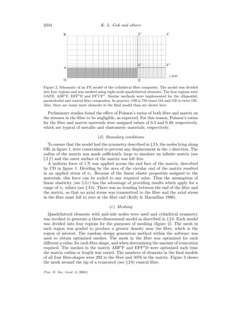
Figure 3. Mesh around the tip of a truncated conical fibre in an FE model. This figure shows thetruncated tip of a fibre with q = 200 and the surrounding matrix elements. The matrix elementsto the right of the fibre tip are shown in the bottom right-hand corner. The fibre axis forms thelower margin of the figure and the columns of four elements above it belong to the tapered fibre.In order for the fibre shape to be appreciated, and for a reasonable number of elements to beseen, the scale along the fibre axis direction is one-tenth of that in the radial direction, i.e. thefibre appears much shorter and fatter than it really is.
(f ) Matrix dimensions
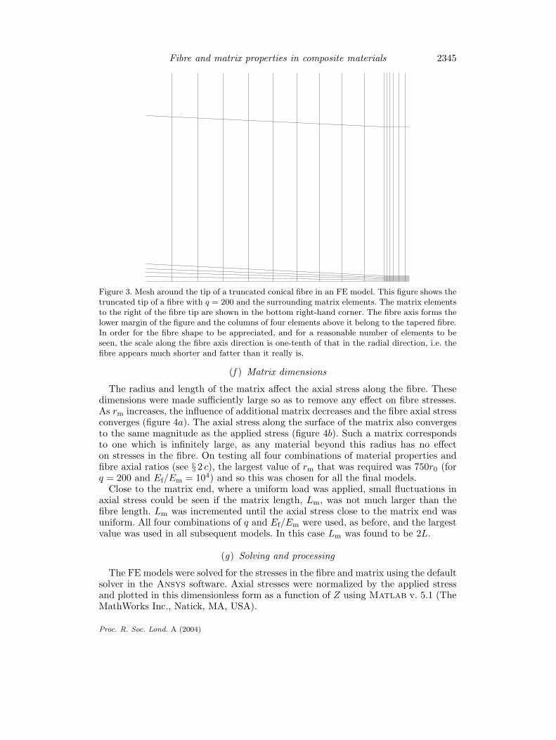
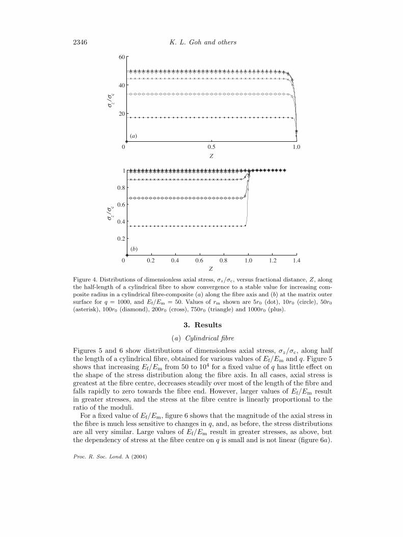
The radius and length of the matrix affect the axial stress along the fibre. Thesedimensions were made sufficiently large so as to remove any effect on fibre stresses.As rm increases, the influence of additional matrix decreases and the fibre axial stressconverges (figure 4a). The axial stress along the surface of the matrix also convergesto the same magnitude as the applied stress (figure 4b). Such a matrix correspondsto one which is infinitely large, as any material beyond this radius has no effecton stresses in the fibre. On testing all four combinations of material properties andfibre axial ratios (see § 2 c), the largest value of rm that was required was 750r0 (forq = 200 and Ef/Em = 104) and so this was chosen for all the final models.
Close to the matrix end, where a uniform load was applied, small fluctuations inaxial stress could be seen if the matrix length, Lm, was not much larger than thefibre length. Lm was incremented until the axial stress close to the matrix end wasuniform. All four combinations of q and Ef/Em were used, as before, and the largestvalue was used in all subsequent models. In this case Lm was found to be 2L.
(g) Solving and processing
The FE models were solved for the stresses in the fibre and matrix using the defaultsolver in the Ansys software. Axial stresses were normalized by the applied stressand plotted in this dimensionless form as a function of Z using Matlab v. 5.1 (TheMathWorks Inc., Natick, MA, USA).
Proc. R. Soc. Lond. A (2004)
2346 K. L. Goh and others
0 0.5 1.0
20
40
60
σ z / σ c
Z
0 0.2 0.4 0.6 0.8 1.0 1.2 1.4
0.2
0.4
0.6
0.8
1
Z
σ z / σ c
(a)
(b)
Figure 4. Distributions of dimensionless axial stress, σz/σc, versus fractional distance, Z, alongthe half-length of a cylindrical fibre to show convergence to a stable value for increasing com-posite radius in a cylindrical fibre-composite (a) along the fibre axis and (b) at the matrix outersurface for q = 1000, and Ef/Em = 50. Values of rm shown are 5r0 (dot), 10r0 (circle), 50r0
(asterisk), 100r0 (diamond), 200r0 (cross), 750r0 (triangle) and 1000r0 (plus).
3. Results
(a) Cylindrical fibre
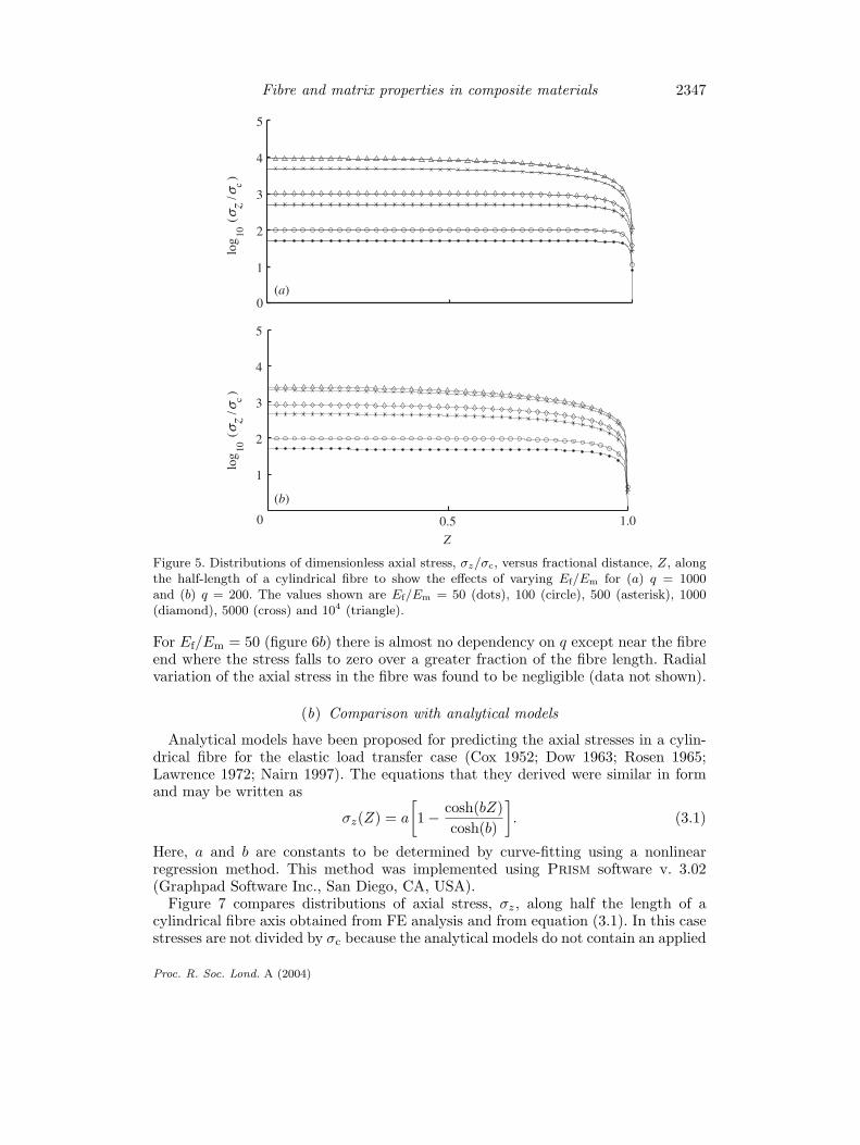
Figures 5 and 6 show distributions of dimensionless axial stress, σz/σc, along halfthe length of a cylindrical fibre, obtained for various values of Ef/Em and q. Figure 5shows that increasing Ef/Em from 50 to 104 for a fixed value of q has little effect onthe shape of the stress distribution along the fibre axis. In all cases, axial stress isgreatest at the fibre centre, decreases steadily over most of the length of the fibre andfalls rapidly to zero towards the fibre end. However, larger values of Ef/Em resultin greater stresses, and the stress at the fibre centre is linearly proportional to theratio of the moduli.
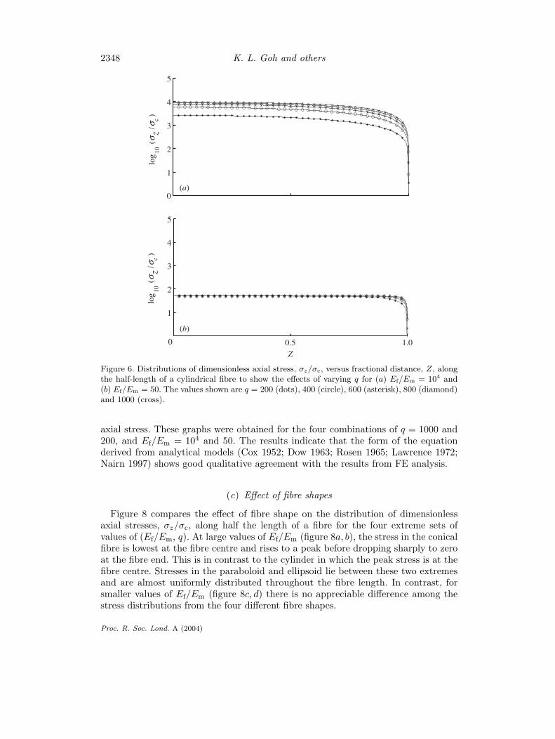
For a fixed value of Ef/Em, figure 6 shows that the magnitude of the axial stress inthe fibre is much less sensitive to changes in q, and, as before, the stress distributionsare all very similar. Large values of Ef/Em result in greater stresses, as above, butthe dependency of stress at the fibre centre on q is small and is not linear (figure 6a).
Proc. R. Soc. Lond. A (2004)
Fibre and matrix properties in composite materials 2347
0
1
2
3
4
5
log
10 (
σ z / σ c
)
0 0.5
1
2
3
4
5
Z
log
10 (
σ z / σ c
)
1.0
(a)
(b)
Figure 5. Distributions of dimensionless axial stress, σz/σc, versus fractional distance, Z, alongthe half-length of a cylindrical fibre to show the effects of varying Ef/Em for (a) q = 1000and (b) q = 200. The values shown are Ef/Em = 50 (dots), 100 (circle), 500 (asterisk), 1000(diamond), 5000 (cross) and 104 (triangle).
For Ef/Em = 50 (figure 6b) there is almost no dependency on q except near the fibreend where the stress falls to zero over a greater fraction of the fibre length. Radialvariation of the axial stress in the fibre was found to be negligible (data not shown).
(b) Comparison with analytical models
Analytical models have been proposed for predicting the axial stresses in a cylin-drical fibre for the elastic load transfer case (Cox 1952; Dow 1963; Rosen 1965;Lawrence 1972; Nairn 1997). The equations that they derived were similar in formand may be written as
σz(Z) = a
[1 − cosh(bZ)
cosh(b)
]. (3.1)
Here, a and b are constants to be determined by curve-fitting using a nonlinearregression method. This method was implemented using Prism software v. 3.02(Graphpad Software Inc., San Diego, CA, USA).
Figure 7 compares distributions of axial stress, σz, along half the length of acylindrical fibre axis obtained from FE analysis and from equation (3.1). In this casestresses are not divided by σc because the analytical models do not contain an applied
Proc. R. Soc. Lond. A (2004)
2348 K. L. Goh and others
0
1
2
3
4
5
log
10 (
σ z / σ c
)
(a)
0.50
1
2
3
4
5
Z
log
10 (
σ z / σ c
)
(b)
1.0
Figure 6. Distributions of dimensionless axial stress, σz/σc, versus fractional distance, Z, alongthe half-length of a cylindrical fibre to show the effects of varying q for (a) Ef/Em = 104 and(b) Ef/Em = 50. The values shown are q = 200 (dots), 400 (circle), 600 (asterisk), 800 (diamond)and 1000 (cross).
axial stress. These graphs were obtained for the four combinations of q = 1000 and200, and Ef/Em = 104 and 50. The results indicate that the form of the equationderived from analytical models (Cox 1952; Dow 1963; Rosen 1965; Lawrence 1972;Nairn 1997) shows good qualitative agreement with the results from FE analysis.
(c) Effect of fibre shapes
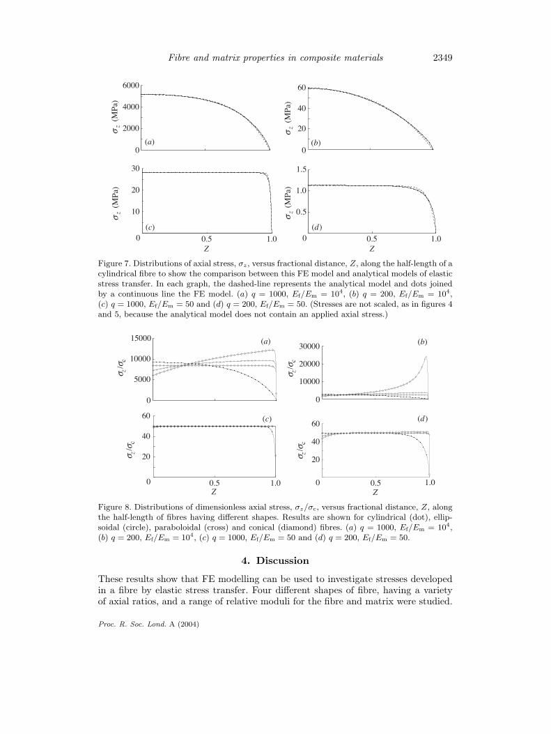
Figure 8 compares the effect of fibre shape on the distribution of dimensionlessaxial stresses, σz/σc, along half the length of a fibre for the four extreme sets ofvalues of (Ef/Em, q). At large values of Ef/Em (figure 8a, b), the stress in the conicalfibre is lowest at the fibre centre and rises to a peak before dropping sharply to zeroat the fibre end. This is in contrast to the cylinder in which the peak stress is at thefibre centre. Stresses in the paraboloid and ellipsoid lie between these two extremesand are almost uniformly distributed throughout the fibre length. In contrast, forsmaller values of Ef/Em (figure 8c, d) there is no appreciable difference among thestress distributions from the four different fibre shapes.
Proc. R. Soc. Lond. A (2004)
Fibre and matrix properties in composite materials 2349
2000
4000
6000
σz
(MPa
)
(a)0
20
40
60
0
σz
(MPa
)
(b)
0.5 1.00
10
20
30
Z
σz
(MPa
)
0.5 1.00
0.5
1.0
1.5
Z
σz
(MPa
)
(c) (d)
Figure 7. Distributions of axial stress, σz, versus fractional distance, Z, along the half-length of acylindrical fibre to show the comparison between this FE model and analytical models of elasticstress transfer. In each graph, the dashed-line represents the analytical model and dots joinedby a continuous line the FE model. (a) q = 1000, Ef/Em = 104, (b) q = 200, Ef/Em = 104,(c) q = 1000, Ef/Em = 50 and (d) q = 200, Ef/Em = 50. (Stresses are not scaled, as in figures 4and 5, because the analytical model does not contain an applied axial stress.)
0
5000
10000
15000
σ z / σ
c
0
10000
20000
30000
σ z / σ
c
(a) (b)
0.5 1.00
20
40
60
Z
(c)
0.5 1.00
20
40
60
Z
σ z / σ
c
σ z / σ
c
(d)
Figure 8. Distributions of dimensionless axial stress, σz/σc, versus fractional distance, Z, alongthe half-length of fibres having different shapes. Results are shown for cylindrical (dot), ellip-soidal (circle), paraboloidal (cross) and conical (diamond) fibres. (a) q = 1000, Ef/Em = 104,(b) q = 200, Ef/Em = 104, (c) q = 1000, Ef/Em = 50 and (d) q = 200, Ef/Em = 50.
4. Discussion
These results show that FE modelling can be used to investigate stresses developedin a fibre by elastic stress transfer. Four different shapes of fibre, having a varietyof axial ratios, and a range of relative moduli for the fibre and matrix were studied.
Proc. R. Soc. Lond. A (2004)
2350 K. L. Goh and others
Comparison of the results for a cylindrical fibre with those obtained from analyticalmodels showed good agreement in the shape of the axial stress distribution. Thisindicates that these models are consistent and supports the extension to differentshapes and material properties using FE modelling.
The results for an ellipsoidal fibre are in good agreement with the theoreticalpredictions of Eshelby (1957). He predicted that the strain within an ellipsoidalinclusion surrounded by an infinite homogeneous isotropic medium would be uniform.Figure 7 shows an effectively uniform distribution of axial strain in an ellipsoid forthe range of q and Ef/Em values investigated. This result adds further credibility tothe FE analysis.
The extent to which a model based on a single fibre surrounded by matrix can beapplied to a real composite material, in which there are many such fibres, may not beclear. Galiotis et al . (1984) were able to demonstrate experimentally that the axialdistribution of tensile stress in a single fibre reinforcing a matrix was similar to thatpredicted theoretically by Cox (1952). Furthermore, Carrara & McGarry (1968) wereable to compare the results of an FE analysis with the predictions of Cox’s modelby neglecting neighbouring fibres. It is often supposed that the function H in Cox’smodel allows for interactions between fibres (Cox 1952; Kelly & Macmillan 1986).However, Cox’s H function can be derived without the need to invoke interactionsbetween fibres (Goh 2001). Tandon & Weng (1986) showed that the axial tensilestress in ellipsoidal particles, surrounded by matrix, decreased as their packing frac-tion increased. However, it is clear that the simple model presented here enables theaxial stress distribution in fibres of different shape to be compared when they aresubjected to an interfacial shear stress, τ , generated by elastic deformation of thematrix.
For elastic stress transfer, the magnitudes of the axial stresses in the fibre aresensitive to the ratio of the moduli of the fibre and the matrix, Ef/Em, irrespectiveof the shape of the fibre. At large values of Ef/Em, axial stress in the cylindrical fibreis greatest at the centre of the fibre. In contrast, axial stress in a conical fibre is lowerthan for the equivalent cylinder at the fibre centre and is concentrated towards thefibre end. Stress distributions in the ellipsoidal and paraboloidal fibres lie betweenthese two extremes and are generally more uniformly distributed throughout thefibre, though they are all of approximately the same magnitude. For fibres that arenot much stiffer than the matrix (Ef/Em ≈ 50), the tapered fibres behave in similarways and there is little to distinguish them. However, the cylindrical fibres have aregion near the fibre end which is not maximally stressed and they are, therefore,not being used to their fullest extent to provide reinforcing.
The fibre axial ratio, q, has a smaller effect than the relative moduli on the mag-nitude of the stress. A fivefold increase in q results in a threefold increase in axialstress for high values of Ef/Em or no change for small Ef/Em. Changing q appearsto have little effect on the stress distributions in the cylindrical, the paraboloidaland ellipsoidal fibres; the tapered fibres have an almost uniform distribution of axialstress, whereas the stress in the cylinder reduces over the length of the fibre. In con-trast, for large Ef/Em, reducing q has an effect of concentrating stress towards theend of the fibre, increasing it by up to an order of magnitude over the stress at thefibre centre for q = 200. This could increase the risk of fibre fracture.
If the matrix around the fibre becomes loaded beyond its yield stress, and stresstransfer becomes plastic rather than elastic, then we have previously shown that the
Proc. R. Soc. Lond. A (2004)
Fibre and matrix properties in composite materials 2351
distribution of axial stress in the fibre takes a different form (Goh et al . 1999, 2000).For the cylindrical fibre it is greatest at the fibre centre and falls linearly to zeroat the fibre end, whereas for the conical fibre it is constant over the length of thefibre. Again the paraboloidal and ellipsoidal fibre stress distributions are intermediateto these. Change to plastic deformation of the matrix around a cylindrical fibrewould then result in a stress concentration appearing at the fibre centre, whichcould fracture the fibre. Similar failure of a composite containing a paraboloidal orellipsoidal fibre would not alter the stress distribution so dramatically and, therefore,has less potential to cause fibre failure. Together these studies suggest there could beconsiderable advantages to having tapered fibres in an elastic–matrix/elastic–fibre-composite material.
We thank Dr Judith Meakin (for help and advice on the figures), the University of Aberdeen(for an award of a university postgraduate studentship to K.L.G.) and the Medical ResearchCouncil (for an award of a Senior Fellowship to R.M.A.).
References
Ashby, M. F., Gibson, L. J., Wegst, U. & Olive, R. 1995 The mechanical properties of naturalmaterials. I. Material property charts. Proc. R. Soc. Lond. A450, 123–140.
Aspden, R. M. 1994 Fibre stress and strain in fibre-reinforced composites. J. Mater. Sci. 29,1310–1318.
Carrara, A. S. & McGarry, F. J. 1968 Matrix and interface stresses in a discontinuous fibrecomposite model. J. Compos. Mater. 2, 222–241.
Cox, H. L. 1952 The elasticity and strength of paper and other fibrous materials. Br. J. Appl.Phys. 3, 72–79.
Cusack, S. & Miller, A. 1979 Determination of the elastic constants of collagen by Brillouin lightscattering. J. Mol. Biol. 135, 39–51.
DeVente, J. E., Lester, G. E., Trotter, J. A. & Dahners, L. E. 1997 Isolation of intact collagenfibrils from healing ligament. J. Electron Microsc. 46, 353–356.
Dow, N. F. 1963 Study of stresses near a discontinuity in a filament-reinforced composite mate-rial. Report no. R63SD61, Barrington, IL: General Electric.
Eshelby, J. D. 1957 The determination of the elastic field of an ellipsoidal inclusion and relatedproblems. Proc. R. Soc. Lond. A241, 376–396.
Galiotis, C., Young, R. J., Yeung, P. H. J. & Batchelder, D. N. 1984 The study of modelpolydiacetylene/epoxy composites. I. The axial strain in the fibre. J. Mater. Sci. 19, 3640–3648.
Goh, K. L. 2001 Fibre reinforcement in fibre composite materials: effect of fibre shape. PhDthesis, University of Aberdeen, UK.
Goh, K. L., Aspden, R. M., Mathias, K. J. & Hukins, D. W. L. 1999 Effect of fibre shape onthe stresses within fibres in fibre-reinforced composite materials. Proc. R. Soc. Lond. A455,3351–3361.
Goh, K. L., Mathias, K. J., Aspden, R. M. & Hukins, D. W. L. 2000 Finite element analysisof the effect of fibre shape on stresses in an elastic fibre surrounded by a plastic matrix. J.Mater. Sci. 35, 2493–2497.
Hickey, D. S. & Hukins, D. W. L. 1981 Collagen fibril diameters and elastic fibres in humanfetal intervertebral disc. J. Anat. 133, 351–357.
Holmes, D. F., Chapman, J. A., Prockop, D. J. & Kadler, K. E. 1992 Growing tips of type I col-lagen fibrils formed in vitro are near-paraboloidal in shape, implying a reciprocal relationshipbetween accretion and diameter. Proc. Natl Acad. Sci. USA 89, 9855–9859.
Proc. R. Soc. Lond. A (2004)
2352 K. L. Goh and others
Hooley, C. J. & Cohen, R. E. 1979 A model for the creep behaviour of tendon. Int. J. Biol.Macromol. 1, 123–132.
Hukins, D. W. L. 1982 Biomechanical properties of collagen. In Collagen in health and disease(ed. J. B. Weiss & M. I. V. Jayson), pp. 49–72. Edinburgh: Churchill Livingston.
Hukins, D. W. L., Weston, S. A., Humphries, M. J. & Freemont, A. J. 1995 Extracellular matrix.In Cellular organelles and the extracellular matrix (ed. E. E. Bittar & N. Bittar). Principlesof medical biology, vol. 3, pp. 181–232. Greenwich, CT: JAI Press.
Kelly, A. & Macmillan, N. H. 1986 Strong solids, 3rd edn, pp. 240–325. Oxford University Press.Kelly, A. & Tyson, W. R. 1965 Tensile properties of fibre-reinforced metals: copper/tungsten
and copper/molybdenum. J. Mech. Phys. Solids 13, 329–350.Lawrence, P. 1972 Some theoretical considerations of fibre pull-out from an elastic matrix. J.
Mater. Sci. 7, 1–6.Leahy, J. C. & Hukins, D. W. L. 2001 Viscoelastic properties of the nucleus pulposus of the
intervertebral disc in compression. J. Mater. Sci. Mater. Med. 12, 689–692.Nairn, J. A. 1997 On the use of shear-lag methods for analysis of stress transfer in unidirectional
composites. Mech. Mater. 26, 63–80.Raisanen, V. I. & Herrmann, H. J. 1999 Stress transfer in dilute short-fibre reinforced composites.
J. Mater. Sci. 34, 897–904.Rosen, B. W. 1965 Fibre composite materials, p. 37. Metals Park, OH: American Society for
Metals.Schuster, D. M. & Scala, E. 1964 The mechanical interaction of sapphire whiskers with a bire-
fringent matrix. Trans. AIME 230, 1635–1640.Tandon, G. P. & Weng, G. J. 1986 Stress distributions in and around spheroidal inclusions and
voids at finite concentrations. J. Appl. Mech. 53, 511–518.Trotter, J. A. & Koob, T. J. 1989 Collagen and proteoglycan in a sea urchin ligament with
mutable mechanical properties. Cell Tissue Res. 258, 527–539.Trotter, J. A. & Purslow, P. P. 1992 Functional morphology of the endomysium in series fibered
muscles. J. Morphol. 212, 109–122.Trotter, J. A., Thurmond, F. A. & Koob, T. J. 1994 Molecular structure and functional mor-
phology of echinoderm collagen fibrils. Cell Tissue Res. 275, 451–458.
Proc. R. Soc. Lond. A (2004)
Related Documents