1 FINITE ELEMENT ANALYSIS OF PLASTICITY-INDUCED FATIGUE CRACK CLOSURE WITH SINGULAR ELEMENT R. Rahgozar, Assistant Professor, Department of Civil Engineering, Kerman University, Kerman, Iran H.Saffari , Assistant Professor, Department of Civil Engineering, Kerman University, Kerman, Iran and R.Tabatabaei, PhD Student, [email protected] Department of Civil Engineering, Islamic Azad University of Kerman, Iran Abstract In this paper, a new methodology is presented to calculate crack opening values in planar geometries using the crack surface nodal force distribution under minimum loading as determined from finite element analyses (FEM). Finite element analyses are frequently used to model growing fatigue cracks and the associated plasticity-induced crack closure. Two-dimensional, elastic-perfectly plastic finite element analyses of middle-crack tension (MT) geometry were conducted to study fatigue crack closure and to calculate the crack opening values under plane-strain and plane-stress conditions. Mesh refinement studies were performed on geometry with various element types. Next, effect of a highly refined mesh on crack opening values was noted and significantly lower crack opening values than those reported in literature were found. The calculated crack opening values are compared with values obtained using finite element analysis and more conventional crack opening assessment methodologies. It is shown that the new method is independent of loading increment, integration method and crack opening assessment location. The compared opening values is exposed in good agreement with strip-yield models. Keywords: Fatigue, Crack closure, Plasticity, Strip-yield models, FEM. 1. Introduction It has been estimated more than fifty percent of all mechanical failures are due to fatigue, and the majority of these failures are unexpected. There are currently many approaches to fatigue design. If an engineering structure, which can be any load bearing component of a complex assembly, is subjected to repeated or cyclic loading, the structure is inherently accumulating fatigue damage. Wolf Elber quantified and confirmed the importance of a new fatigue crack growth phenomena, crack closure [1]. Based on experimental results using thin sheets of an aluminum alloy, Elber argued that a reduction in the crack tip driving force occurred as a result of residual tensile deformation left in the wake of a growing crack. The residual tensile deformation caused the crack surfaces to close impulsively before minimum load was reached.

Welcome message from author
This document is posted to help you gain knowledge. Please leave a comment to let me know what you think about it! Share it to your friends and learn new things together.
Transcript
1
FINITE ELEMENT ANALYSIS OF PLASTICITY-INDUCED FATIGUE CRACK CLOSURE WITH SINGULAR ELEMENT
R. Rahgozar, Assistant Professor,
Department of Civil Engineering, Kerman University, Kerman, Iran H.Saffari , Assistant Professor,
Department of Civil Engineering, Kerman University, Kerman, Iran and
R.Tabatabaei, PhD Student, [email protected] Department of Civil Engineering, Islamic Azad University of Kerman, Iran
Abstract In this paper, a new methodology is presented to calculate crack opening values in planar geometries using the crack surface nodal force distribution under minimum loading as determined from finite element analyses (FEM). Finite element analyses are frequently used to model growing fatigue cracks and the associated plasticity-induced crack closure. Two-dimensional, elastic-perfectly plastic finite element analyses of middle-crack tension (MT) geometry were conducted to study fatigue crack closure and to calculate the crack opening values under plane-strain and plane-stress conditions. Mesh refinement studies were performed on geometry with various element types. Next, effect of a highly refined mesh on crack opening values was noted and significantly lower crack opening values than those reported in literature were found. The calculated crack opening values are compared with values obtained using finite element analysis and more conventional crack opening assessment methodologies. It is shown that the new method is independent of loading increment, integration method and crack opening assessment location. The compared opening values is exposed in good agreement with strip-yield models. Keywords: Fatigue, Crack closure, Plasticity, Strip-yield models, FEM.
1. Introduction It has been estimated more than fifty percent of all mechanical failures are due to
fatigue, and the majority of these failures are unexpected. There are currently many approaches to fatigue design. If an engineering structure, which can be any load bearing component of a complex assembly, is subjected to repeated or cyclic loading, the structure is inherently accumulating fatigue damage. Wolf Elber quantified and confirmed the importance of a new fatigue crack growth phenomena, crack closure [1]. Based on experimental results using thin sheets of an aluminum alloy, Elber argued that a reduction in the crack tip driving force occurred as a result of residual tensile deformation left in the wake of a growing crack. The residual tensile deformation caused the crack surfaces to close impulsively before minimum load was reached.
2
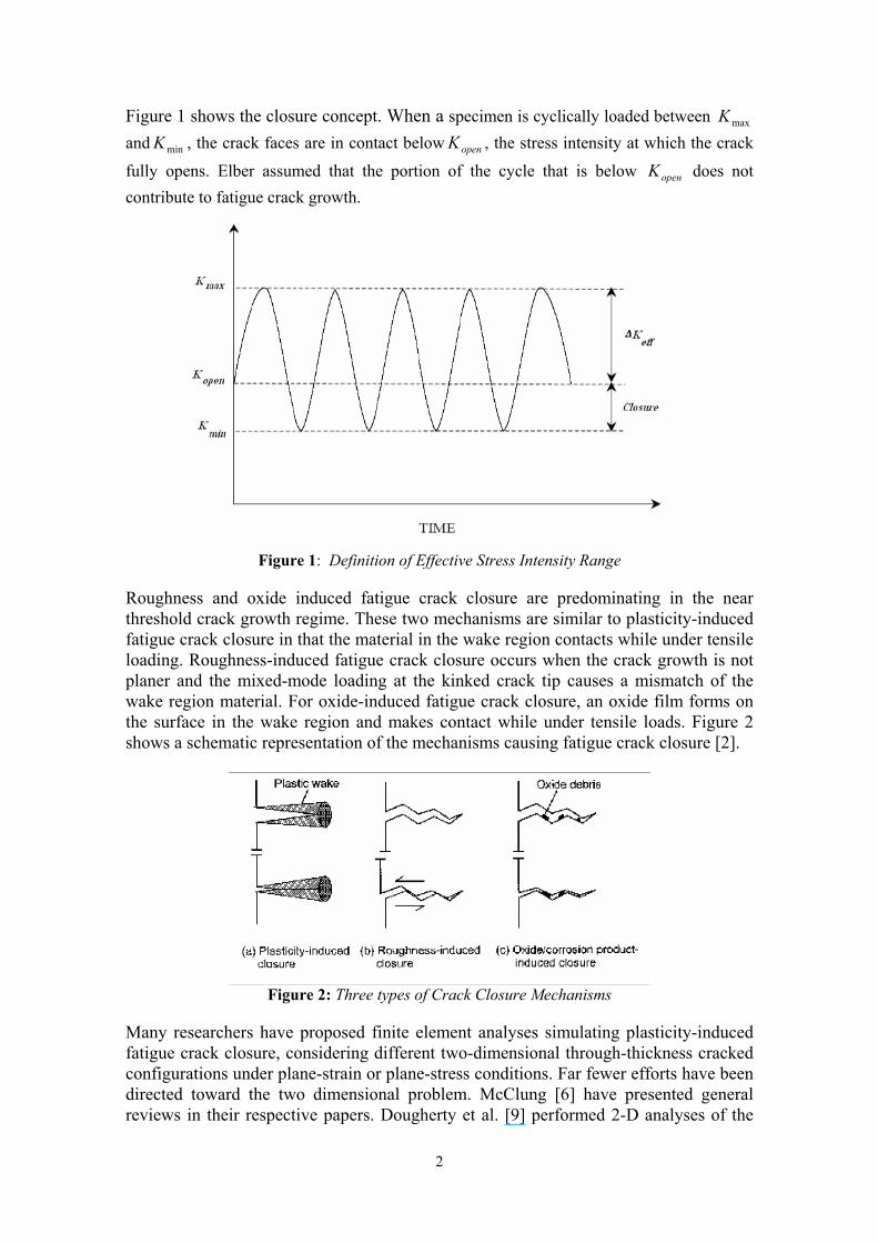
Figure 1 shows the closure concept. When a specimen is cyclically loaded between maxKand minK , the crack faces are in contact below openK , the stress intensity at which the crack
fully opens. Elber assumed that the portion of the cycle that is below openK does not contribute to fatigue crack growth.
Figure 1: Definition of Effective Stress Intensity Range
Roughness and oxide induced fatigue crack closure are predominating in the near threshold crack growth regime. These two mechanisms are similar to plasticity-induced fatigue crack closure in that the material in the wake region contacts while under tensile loading. Roughness-induced fatigue crack closure occurs when the crack growth is not planer and the mixed-mode loading at the kinked crack tip causes a mismatch of the wake region material. For oxide-induced fatigue crack closure, an oxide film forms on the surface in the wake region and makes contact while under tensile loads. Figure 2 shows a schematic representation of the mechanisms causing fatigue crack closure [2].
Figure 2: Three types of Crack Closure Mechanisms
Many researchers have proposed finite element analyses simulating plasticity-induced fatigue crack closure, considering different two-dimensional through-thickness cracked configurations under plane-strain or plane-stress conditions. Far fewer efforts have been directed toward the two dimensional problem. McClung [6] have presented general reviews in their respective papers. Dougherty et al. [9] performed 2-D analyses of the
3
compact tension CT and MT geometries under plane-strain, and demonstrated a good comparison between predicted closure levels and experimental results. Their finite element meshes were composed of four-noded and eight-noded quadrilateral elements. Ashbaugh et al. [10] performed a study similar to that conducted by Blom and Holm [11], focusing on finite element analysis of plasticity-induced crack closure in the CT specimen under plane-strain conditions. In their analyses four noded quadrilateral elements were used, and their results indica ted that closure does occur in plane-strain. Again, their results are also suspect due to a lack of mesh refinement and potential plane-strain locking. A 2-D plane-stress and plane-strain model of the CT specimen was constructed with constant strain triangular (CST) elements. Under plane-strain conditions closure was observed, and the plane-strain closure levels were smaller than those for plane-stress. Their results are also questionable due to a relatively coarse mesh and the use of element type which is prone to plane-strain locking [12]. Solanki et al. proposed, a detailed and comprehensive review considering the finite element analysis of plasticity- induced fatigue crack closure for both two- and three-dimensional geometries [4]. The two-dimensional plane stress strip yield model used is essentially physically similar to that suggested by Newman [8]. In strip yield model, Displacement discontinuity boundary elements are employed to model the crack opening and to represent are employed to model the crack opening and to represent tensile yield in the strip yield zone ahead of the crack. In any case, some of fatigue design methods are simple and inexpensive; others are extremely complex and expensive. If initially an expensive complete fatigue design procedure is implemented, this may lead to lower cost in the long run by reducing failure. In this paper, a 2-D finite element model for the fatigue crack closure is presented. Prominence is focused on the difficulties in modeling with high opinion to mesh modification level, crack opening assessment location and crack shape progress techniques. 2. Two dimensional finite element mesh modification
Finite element analysis of plasticity-induced fatigue crack closure is theoretically simple. A mesh is created with an initial crack, and the mesh is loaded by slightly applied tractions. For constant amplitude loading, the loading is cycled between a maximum applied stress maxS and a minimum applied stress minS .During the cyclic loading the crack is advanced in some mode, leading to the development of a plastic wake behind the crack tip. This modeling concept is simple; however, there are several results from which must be addressed during the fatigue crack growth simulation.
2.1. Crack organization All over this paper, references are made to specific regions around the crack front.
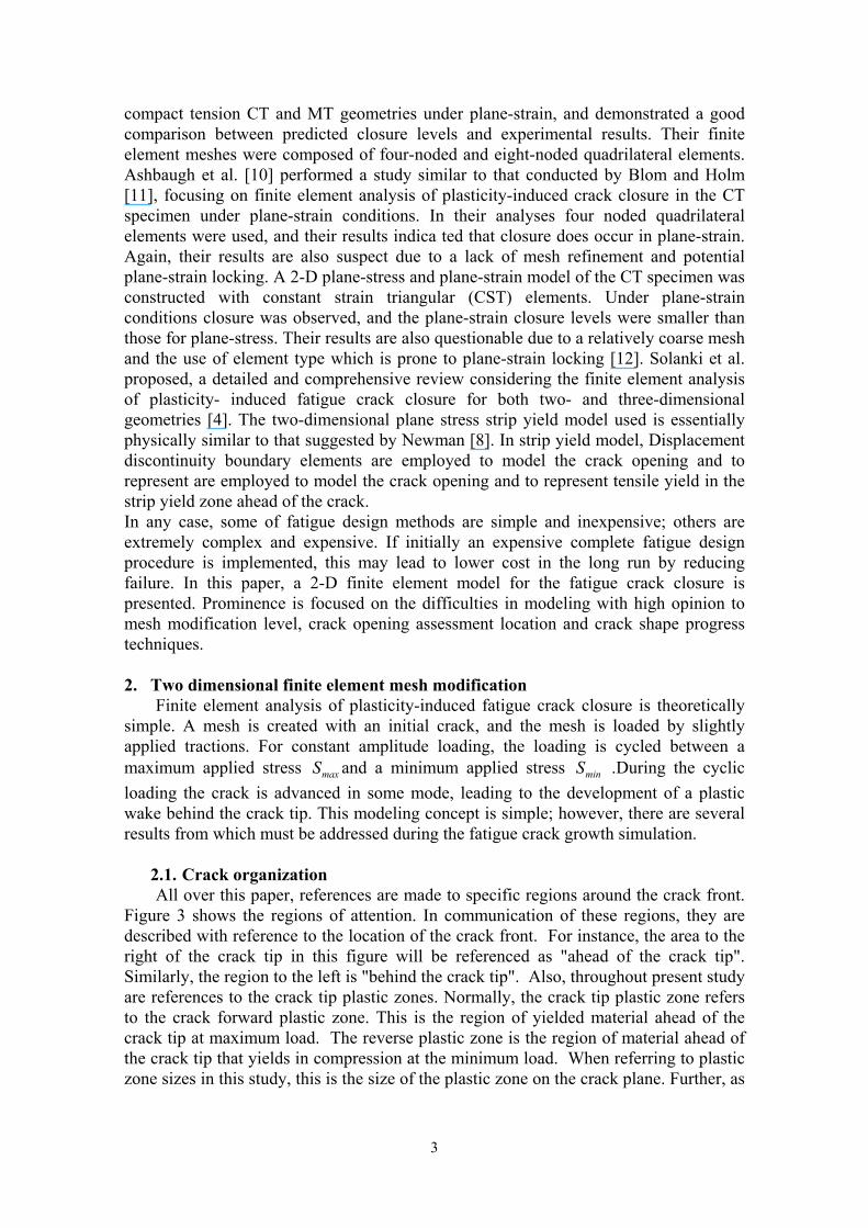
Figure 3 shows the regions of attention. In communication of these regions, they are described with reference to the location of the crack front. For instance, the area to the right of the crack tip in this figure will be referenced as "ahead of the crack tip". Similarly, the region to the left is "behind the crack tip". Also, throughout present study are references to the crack tip plastic zones. Normally, the crack tip plastic zone refers to the crack forward plastic zone. This is the region of yielded material ahead of the crack tip at maximum load. The reverse plastic zone is the region of material ahead of the crack tip that yields in compression at the minimum load. When referring to plastic zone sizes in this study, this is the size of the plastic zone on the crack plane. Further, as
4
the crack progresses through the initial plastic zone, yielded material with residual stresses is left behind the crack tip; this region is referred to as the plastic wake.
Figure 3: Plastic Deformation in the region of a growing crack
2.2. Element Type Early two-dimensional analyses were performed with constant strain triangle
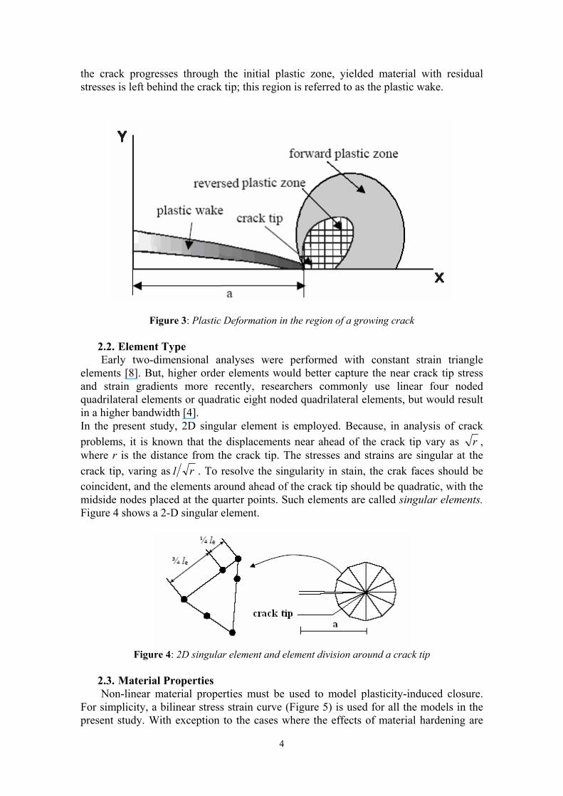
elements [8]. But, higher order elements would better capture the near crack tip stress and strain gradients more recently, researchers commonly use linear four noded quadrilateral elements or quadratic eight noded quadrilateral elements, but would result in a higher bandwidth [4]. In the present study, 2D singular element is employed. Because, in analysis of crack problems, it is known that the displacements near ahead of the crack tip vary as r ,where r is the distance from the crack tip. The stresses and strains are singular at the crack tip, varing as r1 . To resolve the singularity in stain, the crak faces should be coincident, and the elements around ahead of the crack tip should be quadratic, with the midside nodes placed at the quarter points. Such elements are called singular elements. Figure 4 shows a 2-D singular element.
Figure 4: 2D singular element and element division around a crack tip
2.3. Material Properties Non-linear material properties must be used to model plasticity-induced closure.
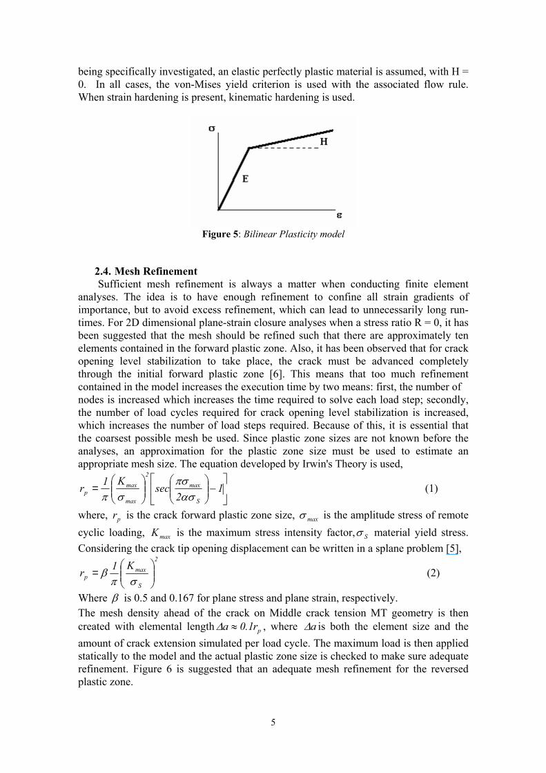
For simplicity, a bilinear stress strain curve (Figure 5) is used for all the models in the present study. With exception to the cases where the effects of material hardening are
5
being specifically investigated, an elastic perfectly plastic material is assumed, with H = 0. In all cases, the von-Mises yield criterion is used with the associated flow rule. When strain hardening is present, kinematic hardening is used.
Figure 5: Bilinear Plasticity model
2.4. Mesh Refinement Sufficient mesh refinement is always a matter when conducting finite element
analyses. The idea is to have enough refinement to confine all strain gradients of importance, but to avoid excess refinement, which can lead to unnecessarily long run-times. For 2D dimensional plane-strain closure analyses when a stress ratio R = 0, it has been suggested that the mesh should be refined such that there are approximately ten elements contained in the forward plastic zone. Also, it has been observed that for crack opening level stabilization to take place, the crack must be advanced completely through the initial forward plastic zone [6]. This means that too much refinement contained in the model increases the execution time by two means: first, the number of nodes is increased which increases the time required to solve each load step; secondly, the number of load cycles required for crack opening level stabilization is increased, which increases the number of load steps required. Because of this, it is essential that the coarsest possible mesh be used. Since plastic zone sizes are not known before the analyses, an approximation for the plastic zone size must be used to estimate an appropriate mesh size. The equation developed by Irwin's Theory is used,
−
= 1
2sec
K1rS
max2
max
maxp ασ
πσσπ
(1)
where, pr is the crack forward plastic zone size, maxσ is the amplitude stress of remote cyclic loading, maxK is the maximum stress intensity factor, Sσ material yield stress. Considering the crack tip opening displacement can be written in a splane problem [5],
2
S
maxp
K1r
=
σπβ (2)
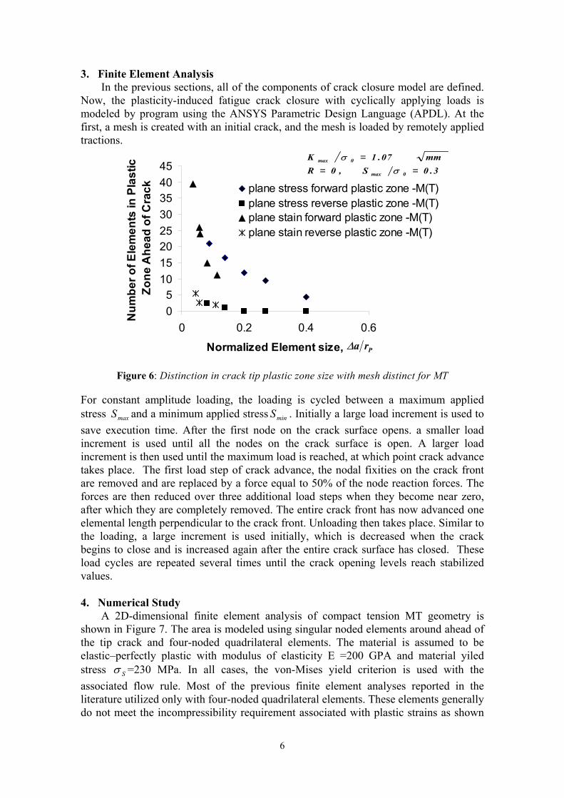
Where β is 0.5 and 0.167 for plane stress and plane strain, respectively. The mesh density ahead of the crack on Middle crack tension MT geometry is then created with elemental length pr1.0a ≈∆ , where a∆ is both the element size and the amount of crack extension simulated per load cycle. The maximum load is then applied statically to the model and the actual plastic zone size is checked to make sure adequate refinement. Figure 6 is suggested that an adequate mesh refinement for the reversed plastic zone.
6
3. Finite Element Analysis In the previous sections, all of the components of crack closure model are defined.
Now, the plasticity-induced fatigue crack closure with cyclically applying loads is modeled by program using the ANSYS Parametric Design Language (APDL). At the first, a mesh is created with an initial crack, and the mesh is loaded by remotely applied tractions.
05
1015202530354045
0 0.2 0.4 0.6
Normalized Element size,
Num
bero
fEle
men
tsin
Plas
ticZo
neA
head
ofC
rack plane stress forward plastic zone -M(T)
plane stress reverse plastic zone -M(T)plane stain forward plastic zone -M(T)plane stain reverse plastic zone -M(T)
Pra∆
3.0S,0Rmm07.1K
0max
0max
===
σσ
Figure 6: Distinction in crack tip plastic zone size with mesh distinct for MT
For constant amplitude loading, the loading is cycled between a maximum applied stress maxS and a minimum applied stress minS . Initially a large load increment is used to save execution time. After the first node on the crack surface opens. a smaller load increment is used until all the nodes on the crack surface is open. A larger load increment is then used until the maximum load is reached, at which point crack advance takes place. The first load step of crack advance, the nodal fixities on the crack front are removed and are replaced by a force equal to 50% of the node reaction forces. The forces are then reduced over three additional load steps when they become near zero, after which they are completely removed. The entire crack front has now advanced one elemental length perpendicular to the crack front. Unloading then takes place. Similar to the loading, a large increment is used initially, which is decreased when the crack begins to close and is increased again after the entire crack surface has closed. These load cycles are repeated several times until the crack opening levels reach stabilized values. 4. Numerical Study
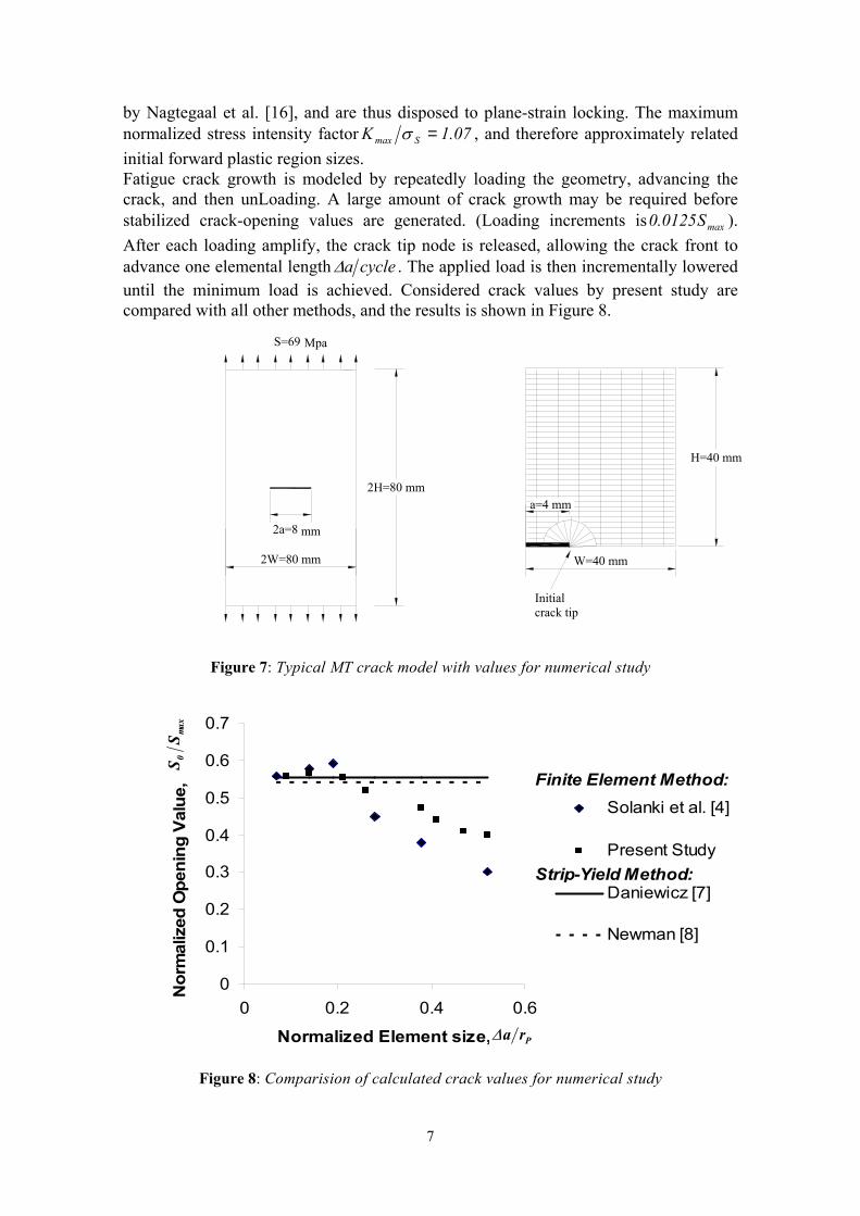
A 2D-dimensional finite element analysis of compact tension MT geometry is shown in Figure 7. The area is modeled using singular noded elements around ahead of the tip crack and four-noded quadrilateral elements. The material is assumed to be elastic–perfectly plastic with modulus of elasticity E =200 GPA and material yiled stress Sσ =230 MPa. In all cases, the von-Mises yield criterion is used with the associated flow rule. Most of the previous finite element analyses reported in the literature utilized only with four-noded quadrilateral elements. These elements generally do not meet the incompressibility requirement associated with plastic strains as shown
7
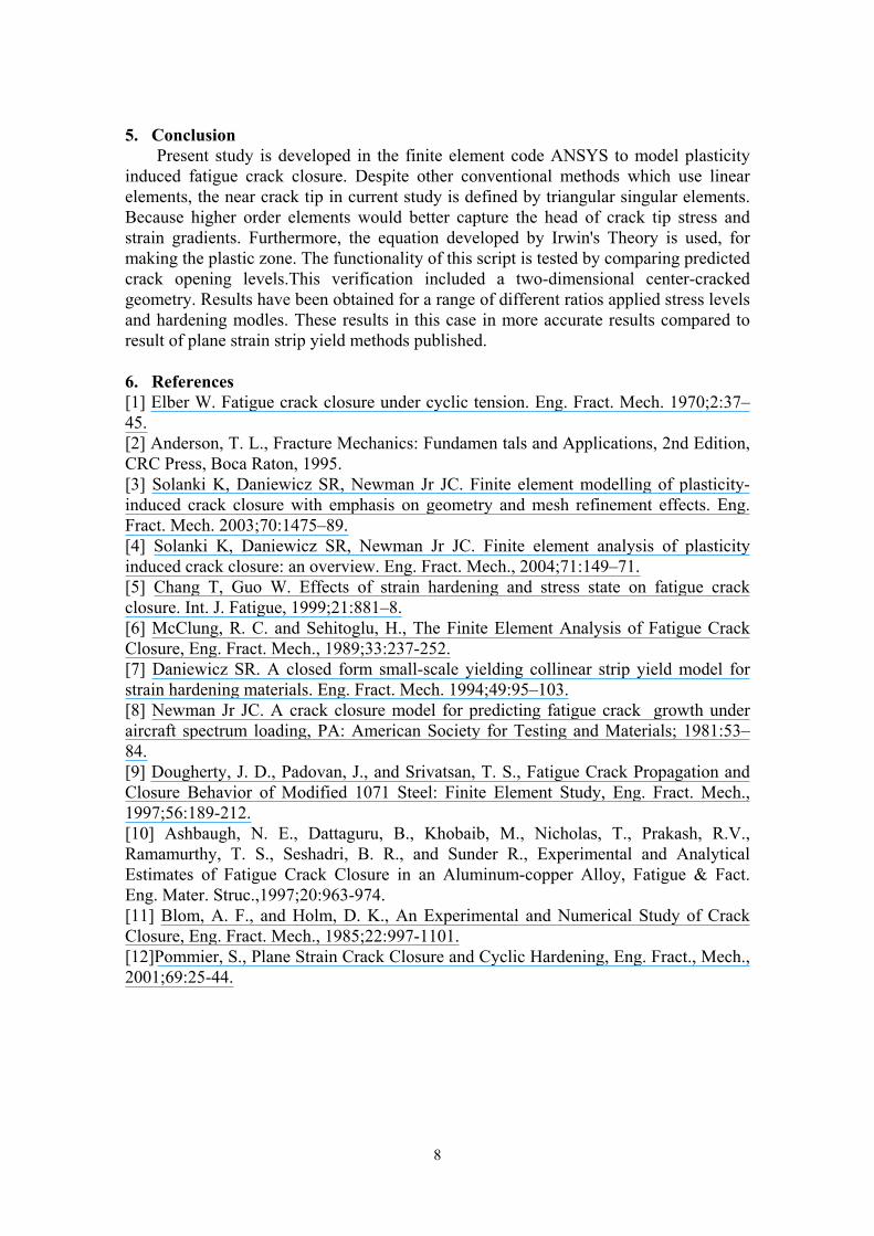
by Nagtegaal et al. [16], and are thus disposed to plane-strain locking. The maximum normalized stress intensity factor 07.1K Smax =σ , and therefore approximately related initial forward plastic region sizes. Fatigue crack growth is modeled by repeatedly loading the geometry, advancing the crack, and then unLoading. A large amount of crack growth may be required before stabilized crack-opening values are generated. (Loading increments is maxS0125.0 ). After each loading amplify, the crack tip node is released, allowing the crack front to advance one elemental length cyclea∆ . The applied load is then incrementally lowered until the minimum load is achieved. Considered crack values by present study are compared with all other methods, and the results is shown in Figure 8.
Initial crack tip
a=4 mm
W=40 mm
H=40 mm
2W=80 mm
mm
2H=80 mm
2a=8
MpaS=69
Figure 7: Typical MT crack model with values for numerical study
0
0.1
0.2
0.3
0.4
0.5
0.6
0.7
0 0.2 0.4 0.6
Normalized Element size,
Nor
mal
ized
Ope
ning
Valu
e,
Solanki et al. [4]
Present Study
Daniewicz [7]
Newman [8]
Pra∆
max
0S
S
Finite Element Method:
Strip-Yield Method:
Figure 8: Comparision of calculated crack values for numerical study
8
5. Conclusion Present study is developed in the finite element code ANSYS to model plasticity
induced fatigue crack closure. Despite other conventional methods which use linear elements, the near crack tip in current study is defined by triangular singular elements. Because higher order elements would better capture the head of crack tip stress and strain gradients. Furthermore, the equation developed by Irwin's Theory is used, for making the plastic zone. The functionality of this script is tested by comparing predicted crack opening levels.This verification included a two-dimensional center-cracked geometry. Results have been obtained for a range of different ratios applied stress levels and hardening modles. These results in this case in more accurate results compared to result of plane strain strip yield methods published.
6. References [1] Elber W. Fatigue crack closure under cyclic tension. Eng. Fract. Mech. 1970;2:37–45. [2] Anderson, T. L., Fracture Mechanics: Fundamen tals and Applications, 2nd Edition, CRC Press, Boca Raton, 1995. [3] Solanki K, Daniewicz SR, Newman Jr JC. Finite element modelling of plasticity-induced crack closure with emphasis on geometry and mesh refinement effects. Eng. Fract. Mech. 2003;70:1475–89. [4] Solanki K, Daniewicz SR, Newman Jr JC. Finite element analysis of plasticity induced crack closure: an overview. Eng. Fract. Mech., 2004;71:149–71. [5] Chang T, Guo W. Effects of strain hardening and stress state on fatigue crack closure. Int. J. Fatigue, 1999;21:881–8. [6] McClung, R. C. and Sehitoglu, H., The Finite Element Analysis of Fatigue Crack Closure, Eng. Fract. Mech., 1989;33:237-252. [7] Daniewicz SR. A closed form small-scale yielding collinear strip yield model for strain hardening materials. Eng. Fract. Mech. 1994;49:95–103. [8] Newman Jr JC. A crack closure model for predicting fatigue crack growth under aircraft spectrum loading, PA: American Society for Testing and Materials; 1981:53–84. [9] Dougherty, J. D., Padovan, J., and Srivatsan, T. S., Fatigue Crack Propagation and Closure Behavior of Modified 1071 Steel: Finite Element Study, Eng. Fract. Mech., 1997;56:189-212. [10] Ashbaugh, N. E., Dattaguru, B., Khobaib, M., Nicholas, T., Prakash, R.V., Ramamurthy, T. S., Seshadri, B. R., and Sunder R., Experimental and Analytical Estimates of Fatigue Crack Closure in an Aluminum-copper Alloy, Fatigue & Fact. Eng. Mater. Struc.,1997;20:963-974. [11] Blom, A. F., and Holm, D. K., An Experimental and Numerical Study of Crack Closure, Eng. Fract. Mech., 1985;22:997-1101. [12]Pommier, S., Plane Strain Crack Closure and Cyclic Hardening, Eng. Fract., Mech., 2001;69:25-44.
Related Documents