JGW-T1301996-v1 19 Nov 2013 Finite Element Analysis of Heat Links And Optimization Study Takanori Sekiguchi Department of Physics, University of Tokyo

Welcome message from author
This document is posted to help you gain knowledge. Please leave a comment to let me know what you think about it! Share it to your friends and learn new things together.
Transcript

JGW-T1301996-v1 19 Nov 2013
Finite Element Analysis of Heat Links
And Optimization Study
Takanori Sekiguchi
Department of Physics, University of Tokyo

1. Introduction
1.1. Purpose and Scope
This document sets out finite element analysis of heat links to estimate their mechanical
transfer functions. Optimization of heat links geometry is performed.
1.2. Applicable Documents
“Finite elemental analysis of heat links for LCGT ”, Y. Aso, JGW-G1000108-v4
“Finite element analysis of heat links using COMSOL Multiphysics”, T. Sekiguchi,
JGW-T1301987-v2
1.3. Version History
19/11/2013, v1, initial release by T. Sekiguchi
2. General Description
2.1. About this study
Mechanics about heat links with several shapes is investigated. The purpose of this study is
mainly the optimization of heat link geometry between the cooling bars and the suspension,
but the study is also applicable for the heat links in between the suspension masses.
2.2. Calculation method
COMSOL multiphysics (ver. 4.2) is used for the finite element simulation. Details are
written in T1301987.
2.3. Geometry
Fig.1: Dimensioning of the suspension in the inner radiation shield
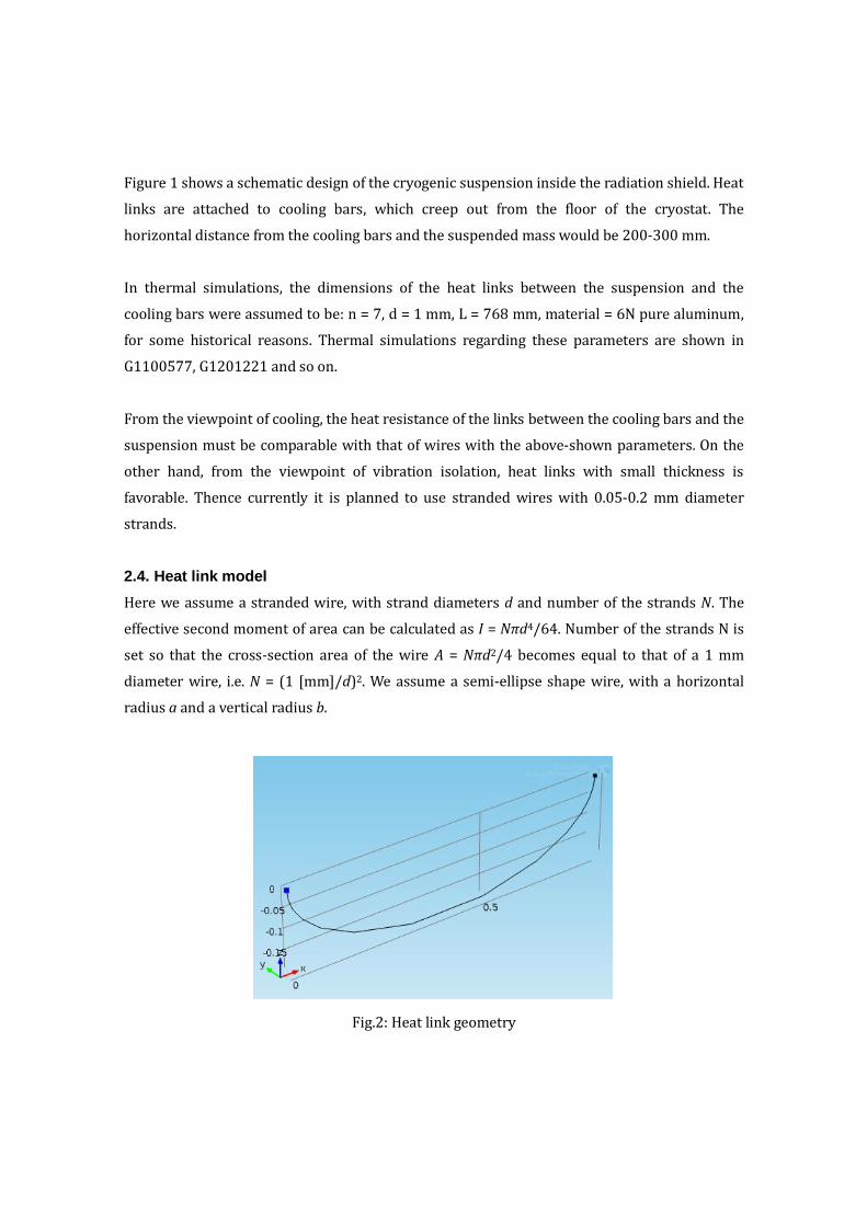
Figure 1 shows a schematic design of the cryogenic suspension inside the radiation shield. Heat
links are attached to cooling bars, which creep out from the floor of the cryostat. The
horizontal distance from the cooling bars and the suspended mass would be 200-300 mm.
In thermal simulations, the dimensions of the heat links between the suspension and the
cooling bars were assumed to be: n = 7, d = 1 mm, L = 768 mm, material = 6N pure aluminum,
for some historical reasons. Thermal simulations regarding these parameters are shown in
G1100577, G1201221 and so on.
From the viewpoint of cooling, the heat resistance of the links between the cooling bars and the
suspension must be comparable with that of wires with the above-shown parameters. On the
other hand, from the viewpoint of vibration isolation, heat links with small thickness is
favorable. Thence currently it is planned to use stranded wires with 0.05-0.2 mm diameter
strands.
2.4. Heat link model
Here we assume a stranded wire, with strand diameters d and number of the strands N. The
effective second moment of area can be calculated as I = Nπd4/64. Number of the strands N is
set so that the cross-section area of the wire A = Nπd2/4 becomes equal to that of a 1 mm
diameter wire, i.e. N = (1 [mm]/d)2. We assume a semi-ellipse shape wire, with a horizontal
radius a and a vertical radius b.
Fig.2: Heat link geometry

3. Simulation Results
3.1. Original design
Here we assume an aluminum wire with parameters shown in Table 1 and 2.
Description Value
d Strand diameter 1 [mm]
N Number of strands 1
a Horizontal radius 400 [mm]
b Vertical radius 200 [mm]
Table 1: Parameters of the original design wire
Description Value
E Young’s modulus 70 [GPa]
ν Poisson ratio 0.33
ρ Volume density 2.7 [g/cm3]
φ Loss angle 1E-2
Table 2: Material properties of pure aluminum
Figure 3 shows calculated transfer functions of the wire, when it is attached to a free mass of
50 kg. Figure 4 shows frequency dependence of effective spring ‘constants’ of the wire. The
orientations of X, Y, Z axes are shown in Figure 2.

Fig.3: Original wire transfer function (d=1mm, a=400mm, b=200mm)
Fig.4: Original wire stiffness coefficient (d=1mm, a=400mm, b=200mm)

The stiffness of the wire is larger in the longitudinal horizontal axis (X-axis) than in other axes.
From the viewpoint of vibration isolation, the heat link longitudinal axis should be set in a
perpendicular direction from the beam axis of the interferometer.
3.2. Strand Diameter
Transfer functions of the wire with various strand diameters are shown in Figure 5, 6 and 7. In
order to conserve the thermal resistance of the wire, the number of strands is set as N = (1
[mm]/d)2
Fig.5: Transfer function of the wire in X-axis with various diameters (a=400mm, b=200mm)
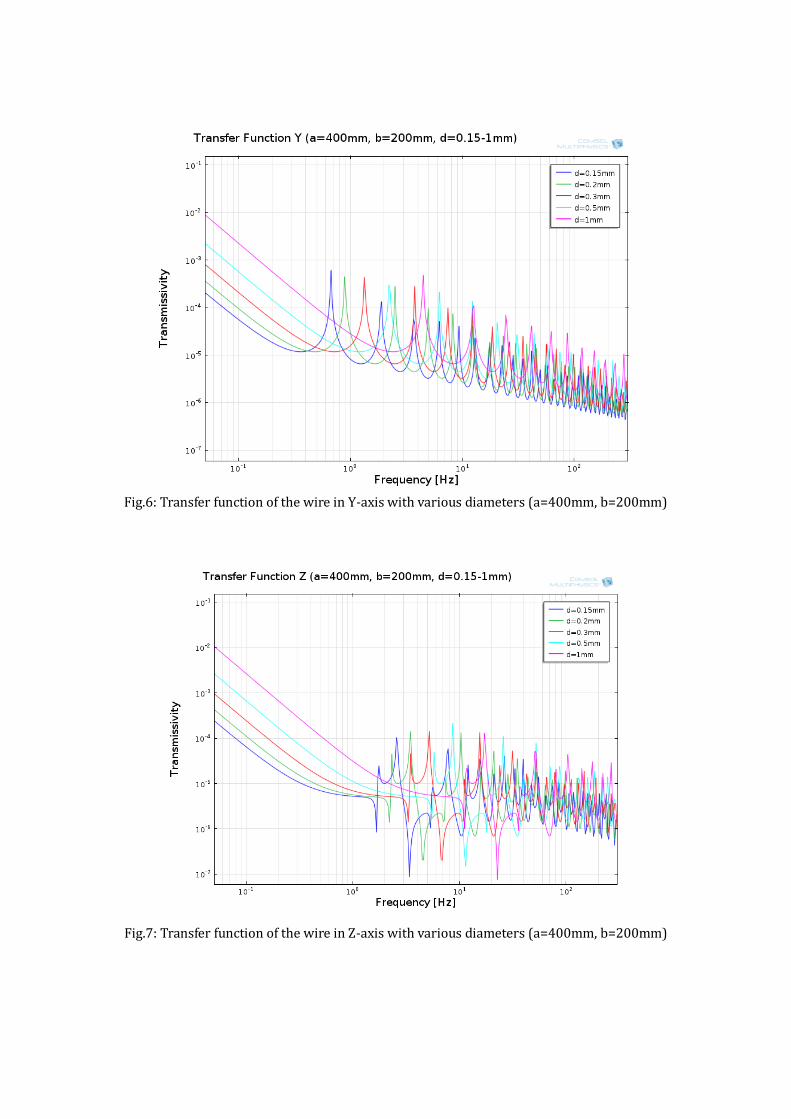
Fig.6: Transfer function of the wire in Y-axis with various diameters (a=400mm, b=200mm)
Fig.7: Transfer function of the wire in Z-axis with various diameters (a=400mm, b=200mm)

The smaller the strand diameter becomes:
The lower the first resonant frequency becomes.
The more number of resonant peaks appear.
The softer the wire become in DC (low frequency region).
The lower the resonant peak height and the plateau region become at high frequencies.
Smaller diameter wire benefits in the overall vibration isolation performance. On the other
hand, if one uses smaller diameter wire, it would be more probable that the resonances of the
cooling bars and the heat links meet.
3.3. Wire horizontal length
Transfer functions of the wire with various horizontal radii are shown in Figure 8, 9 and 10.
Fig.8: Transfer function of the wire in X-axis with various a (d=0.15mm, b=200mm)

Fig.9: Transfer function of the wire in Y-axis with various a (d=0.15mm, b=200mm)
Fig.10: Transfer function of the wire in Z-axis with various a (d=0.15mm, b=200mm)

The smaller the horizontal radius becomes:
The higher the resonant frequencies become.
The stiffer the wire becomes at DC in Y and Z axes.
The stiffer the wire becomes also in the X-axis, but not critically.
In terms of vibration isolation performance in the observation band (>10 Hz), shorter wire
benefits more because of fewer mechanical resonances. However, the increase of DC stiffness
would be non-negligible for too short fibers.
3.4. Wire vertical length
Transfer functions of the wire with various vertical radii are shown in Figure 11, 12 and 13.
Fig.11: Transfer function of the wire in X-axis with various b (d=0.15mm, a=250mm)

Fig.12: Transfer function of the wire in Y-axis with various b (d=0.15mm, a=250mm)
Fig.13: Transfer function of the wire in Z-axis with various b (d=0.15mm, a=250mm)

The smaller the vertical radius becomes:
The higher the resonant frequencies become.
The stiffer the wire becomes at DC in the X axis.
The stiffer the wire becomes also in the Y and Z axes, but not critically.
3.5. Different Shape Wire
To be investigated.
4. Discussion
A wire with thinner strands seems to be better in terms of vibration isolation. Strands
should be as thin as possible in the range where the size effect is negligible.
Vertical size of the wire loop affects DC stiffness in the longitudinal axis, while horizontal
size affects in the transversal and vertical axes. Shorter wires have larger DC stiffness,
while the isolation level in the observation band (>10 Hz) is not so different from that of
longer wires.
Related Documents