Fingerprint Watermarking using SVD and DWT Based Steganography to Enhance Security By Mandy Douglas Sept 15, 2015 Supervisors Karen Bailey and Dr Mark Leeney

Welcome message from author
This document is posted to help you gain knowledge. Please leave a comment to let me know what you think about it! Share it to your friends and learn new things together.
Transcript
Fingerprint Watermarking using SVD and DWT Based
Steganography to Enhance Security
By Mandy Douglas
Sept 15, 2015
Supervisors
Karen Bailey and Dr Mark Leeney

Acknowledgements
I wish to acknowledge the assistance of my academic supervisors Karen Bailey and Dr Mark
Leeney and of Letterkenny Institute of Technology for providing a bursary to allow me to
complete this MSc Thesis.
Abstract
Identification of persons by way of biometric features has evolved significantly over the
years. During this time, biometric recognition has received much attention due to its need
for security. Amongst the many existing biometrics, fingerprints are considered to be one
of the most practical ones. Techniques such as watermarking and steganography have
been used in attempt to improve security of biometric data.
Watermarking is the process of embedding information into a carrier file for the protection
of ownership/copyright of music, video or image files, whilst steganography is the art of
hiding information.
This paper presents, a hybrid steganographic watermarking algorithm based on Discrete
Wavelet Transform (DWT) and Singular Value Decomposition (SVD) transforms in order to
enhance the security of digital fingerprint images. A facial watermark is embedded into
fingerprint image using a method of singular value replacement. First, the DWT is used to
decompose the fingerprint image from the spatial domain to the frequency domain and then
the facial watermark is embedded in singular values (SV’s) obtained by application of SVD.
In addition, the original fingerprint image is not required to extract the watermark.
Experimental results provided demonstrate the methods robustness to image degradation and
common signal processing attacks, such as histogram and filtering, noise addition, JPEG and
JPEG2000 compression with various levels of quality.

i
CONTENTS
1. INTRODUCTION................................................................................................................1
1.1 Overview ..........................................................................................................................1
1.2 THESIS ORGANISATION ..............................................................................................2
2. BIOMETRIC SYSTEMS & BIOMETRIC SECURITY .................................................4
2.1 Introduction ......................................................................................................................4
2.2 Introduction to Biometric Systems...................................................................................4
2.3 Biometric Techniques ......................................................................................................7
2.3.1 Face............................................................................................................................7
2.3.2 Fingerprints................................................................................................................8
2.3.3 Retina.........................................................................................................................8
2.3.4 Iris ..............................................................................................................................9
2.3.5 Voice recognition 10
2.3.6 Signature recognition...............................................................................................10
2.3.7 Hand geometry ........................................................................................................11
2.4. Fingerprint as a Biometric Trait ....................................................................................12
2.5. Fingerprint Patterns .......................................................................................................12
2.6 Minutia Points ................................................................................................................13
2.7 Minutiae Extraction Process ..........................................................................................14
2.7.1 Image Enhancement ................................................................................................14
2.7.2 Binarization .............................................................................................................14
2.7.3 Thinning (Skeletonization) ......................................................................................14
2.7.4 Minutia Extraction...................................................................................................15
2.7.5 Fingerprint Matching...............................................................................................16
2.8 Multibiometric Systems .................................................................................................17
2.9 Security Issues in Biometric Systems ............................................................................18
2.10 Conclusion....................................................................................................................18
ii
3. STEGANOGRAPHY.........................................................................................................20
3.1 Introduction ....................................................................................................................20
3.2 Overview of Steganography...........................................................................................20
3.3 Ancient Steganography ..................................................................................................20
3.4 Evaluation of different techniques .................................................................................21
3.5 Related Work..................................................................................................................22
3.6 Digital Image Steganography.........................................................................................22
3.7 Image definition .............................................................................................................23
3.8 Image Compression........................................................................................................23
3.8.1 Lossy Compression..................................................................................................24
3.8.2 Lossless Compression..............................................................................................24
3.9 Conclusion......................................................................................................................24
4. DATA HIDING IN DIGITAL IMAGES .........................................................................25
4.1 Introduction ....................................................................................................................25
4.2 Steganography Embedding Techniques .........................................................................25
4.3 Spatial Domain Techniques ...........................................................................................26
4.3.1 Least Significant Bit ................................................................................................26
4.4 LSB and Palette based images .......................................................................................27
4.5 LSB Related Work .........................................................................................................28
4.6 Transform Domain Techniques......................................................................................28
4.7 JPEG compression..........................................................................................................29
4.8 Discrete Cosine Transform.............................................................................................29
4.9 JPEG Steganography......................................................................................................31
4.10 Discrete Wavelet Transform ........................................................................................32
4.11 Hiding Biometric Data .................................................................................................34
4.12 Hybrid Techniques .......................................................................................................35
4.12.1 Singular Value Decomposition 35
4.12.1.1 SVD Example 36
4.123.1.2 Properties of SVD 37
4.12.1.3 Data hiding schemes based on SVD 38
4.13 Conclusion....................................................................................................................41
iii
5 STEGANALYSIS................................................................................................................43
5.1 Introduction ....................................................................................................................43
5.2 Targeted Attacks ............................................................................................................44
5.2.1 Visual Attacks..........................................................................................................44
5.2.2 Structural Attacks ....................................................................................................45
5.2.3 Statistical Attacks ....................................................................................................46
5.2.3.1 Chi-squared (x2) Test/Pairs of Values (POV) 47
5.2.3.2 The Extended Chi-Squared Attack .......................................................................48
5.2.3.3 Regular Singular (RS) Steganalysis .....................................................................48
5.3 Blind Steganalysis ..........................................................................................................49
5.3.1 JPEG Calibration .....................................................................................................50
5.3.1.1 Calibration Methodology......................................................................................50
5.3.1.2 Blockiness.............................................................................................................51
5.4 Conclusion......................................................................................................................52
iv
6. IMPLEMENTATION .......................................................................................................55
6.1 Introduction ....................................................................................................................55
6.2 The Proposed Algorithm ................................................................................................56
6.3 Methodology ..................................................................................................................58
6.4 Fingerprint Image Processing.........................................................................................58
6.4.1 Algorithm Level Design ..........................................................................................58
6.4.2 Image Pre-Processing ..............................................................................................59
6.4.2.1 Image Acquisition 59
6.4.2.2 Image Enhancement 59
6.4.23 Image Binarization 59
6.4.3 Minutia Extraction Process......................................................................................60
6.4.3.1 Thinning 60
6.4.3.2 Minutiae Marking 61
6.4.4 Post-Processing Stage..............................................................................................62
6.4.4.1 Removal of False Minutiae 62
6.4.4.2 Image Segmentation 63
6.4.4.3 ROI Extraction 63
6.5 Securing fingerprints biometrics ....................................................................................65
6.5.1 Steps of the algorithm..............................................................................................65
6.5.2 Embedding Phase ....................................................................................................66
6.5.3 Extraction Phase ......................................................................................................67
6.6 Image Attacks.................................................................................................................67
6.7 Image Quality Measures.................................................................................................68
6.8 Steganalysis....................................................................................................................71

v
7. RESULTS AND ANALYSIS ............................................................................................72
7.1 Introduction ....................................................................................................................72
7.2 Image Database ..............................................................................................................72
7.3 Minutia Extraction..........................................................................................................74
7.4 Image Quality Analysis..................................................................................................75
7.5 Robustness Analysis.......................................................................................................76
7.5.1 JPEG Compression Attack ......................................................................................77
7.5.2 JPEG 2000 Compression Attack .............................................................................79
7.5.3 Noise Attack ............................................................................................................81
7.5.4 Rotation Attacks ......................................................................................................84
7.5.5 Cropping Attack ......................................................................................................85
7.5.6 Median Filter Attacks ..............................................................................................87
7.5.7 Resizing Attacks ......................................................................................................88
7.5.8 Histogram and Filter Attacks...................................................................................89
7.6 Detection of Steganalysis ...............................................................................................91
7.7 Minutiae Analysis ..........................................................................................................93
7.8 Conclusion......................................................................................................................96
8. CONCLUSION – FUTURE WORK................................................................................97
8.1 Overall Conclusion.........................................................................................................97
8.2 Recommendations and Future Work..............................................................................98
REFERENCES.....................................................................................................................100
APPENDIX A.......................................................................................................................113
APPENDIX B .......................................................................................................................143
vi
Figure 1 – The Enrolment Process of a Biometric System (Biometrics Research Group)........5
Figure 2: The process of Verification and Identification (Biometrics Research Group)...........6
Figure 3: Facial Recognition......................................................................................................7
Figure 4: Fingerprint Recognition .............................................................................................8
Figure 5(a): Retina Recognition Figure 5(b): The Retina ...................................................9
Figure 6a: The Iris Figure 6b: Iris Recognition...........................................................9
Figure 7: Voice recognition .....................................................................................................10
Figure 8: Signature recognition ...............................................................................................11
Figure 9: Hand geometry recognition ......................................................................................11
Figure 10: Basic Patterns of Fingerprint (Cant, 2009).............................................................13
Figure 11: Minutiae points in fingerprint (Cant, 2009). ..........................................................13
Figure 12: A fingerprint with its corresponding binary image and ridge skeleton (Eriksson,
2001). .......................................................................................................................................15
Figure 13: Fingerprint Changes (fingerprint thesis desktop)...................................................16
Figure 14: Matching minutiae points in two fingerprints (Cant, 2009). ..................................17
Figure 15: Pixel Values vs DCT coefficients (Bateman, 2008)...............................................29
Figure 16: Quantisation Procedure (Bateman, 2008). .............................................................30
Figure 17: The Zigzag grouping process (Bateman, 2008). ....................................................31
Figure 18: The horizontal procedure based on the first row (Chen, & Lin, 2006). .................33
Figure 20: (a) Original image (b) After 2-D Haar DWT is applied (Chen, & Lin, 2006). ......34
Figure 21: The SVD operation SVD (A) = U S VT (Bandyopadhyay et al., 2010).................36
Figure 22 (a): Original Lena image Figure 22 (b): Salt & Pepper image .....................38
Figure 23: EzStego embedding technique (Westfeld & Pfitzmann, 1999)..............................45
Figure 24: The calibration procedure (Bateman, 2008)...........................................................50
Figure 25: Formula for calculating image blockiness..............................................................51
Figure 26: Graphical representation of the blockiness algorithm (Bateman, 2008). ...............52
Figure 27: Feature extraction process steps. ............................................................................59
Figure 28: A fingerprint image before and after Binarization. ................................................60
Figure 29: Before and after thinning........................................................................................61
Figure 30: Indication of minutia points ...................................................................................62
Figure 31: Euclidean distance equation. ..................................................................................62
Figure 32: fingerprint before (a) and after (b) removal of false minutiae. ..............................63
Figure 33: Region of Interest. ..................................................................................................64
Figure 34: Fingerprint image after Region of Interest is applied.............................................64
vii
Figure 35: Graphical User Interface (GUI) for fingerprint processing....................................65
Figure 36: Embedding (a) and Extraction (b) Algorithm. .......................................................66
Figure 37: Fingerprint images and watermark face image. .....................................................73
Figure 38: MATLAB GUI comparing the original “fingerprint” image and “fingerprint”
image after the proposed hybrid steganographic technique is executed..................................75
Figure 38: MATLAB GUI for fingerprint minutia extraction ...............................................113
Figure 39: MATLAB GUI for SVD-DWT hybrid watermarking scheme ............................120
viii
Table 1: Methods of Identification ............................................................................................6
Table 2: Singular values of two images...................................................................................38
Table 3: Singular values of HH frequency band of different..................................................57
Table 5: Minutiae extracted from five fingerprint images before embedding.........................74
Table 6: PSNR and SSIM results for images all containing the watermark............................76
Table 7: Data survival after of the embedded watermark after JPEG compression is applied at
various quality levels. ..............................................................................................................79
Table 8: Data survival of watermark after JPEG 2000 compression was applied using various
quality factors...........................................................................................................................81
Table 9: Data survival results of the embedded watermark after noise addition.....................83
Table 10: Data survival results of the embedded watermark after rotation. ............................85
Table 11: Data survival results of the embedded watermark after cropping attacks ...............86
Table 12: Data survival results of embedded watermark after median filter attacks...............87
Table 13: Data survival results of embedded watermark after resizing attacks. .....................89
Table 14: Data survival results of embedded watermark after filter attacks ...........................91
Table 15: StegSpy detection results for original and stego images. ........................................93
Table 16: Minutia extraction results for pre and post data embedding....................................94
Table 17: Fingerprint one minutiae survival results after attacks............................................95
Table 18: NCC values and data survival of the embedded watermark after JPEG compression
is applied at various quality levels. ........................................................................................143
Table 19: NCC values and data survival of the embedded watermark after JPEG2000
compression is applied at various quality levels....................................................................143
Table 20: NCC value and data survival of the embedded watermark after noise addition ...144
Table 21: NCC value and data survival of the embedded watermark after rotation attacks .144
Table 22: NCC value and data survival results of the embedded watermark after cropping
attacks ....................................................................................................................................145
Table 23: NCC value and data survival results of embedded watermark after median filter
attacks ....................................................................................................................................145
Table 24: NCC value and data survival results of embedded watermark after resizing attacks.
................................................................................................................................................145
Table 25: NCC value and data survival results of embedded watermark after filter attacks.146
Table 26: NCC value and data survival results of the embedded watermark after cropping
attacks ....................................................................................................................................146
Table 27: Fingerprint two minutiae survival results after attacks..........................................147

ix
Table 28: Fingerprint three minutiae survival results after attacks........................................147
Table 29: Fingerprint four minutiae survival results after attacks.........................................148
Table 30: Fingerprint five minutiae survival results after attacks .........................................148
1
1. INTRODUCTION
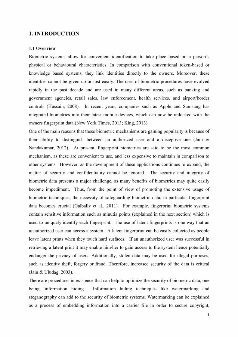
1.1 Overview
Biometric systems allow for convenient identification to take place based on a person’s
physical or behavioural characteristics. In comparison with conventional token-based or
knowledge based systems, they link identities directly to the owners. Moreover, these
identities cannot be given up or lost easily. The uses of biometric procedures have evolved
rapidly in the past decade and are used in many different areas, such as banking and
government agencies, retail sales, law enforcement, health services, and airport/border
controls (Hussain, 2008). In recent years, companies such as Apple and Samsung has
integrated biometrics into their latest mobile devices, which can now be unlocked with the
owners fingerprint data (New York Times, 2013; King, 2013).
One of the main reasons that these biometric mechanisms are gaining popularity is because of
their ability to distinguish between an authorized user and a deceptive one (Jain &
Nandakumar, 2012). At present, fingerprint biometrics are said to be the most common
mechanism, as these are convenient to use, and less expensive to maintain in comparison to
other systems. However, as the development of these applications continues to expand, the
matter of security and confidentiality cannot be ignored. The security and integrity of
biometric data presents a major challenge, as many benefits of biometrics may quite easily
become impediment. Thus, from the point of view of promoting the extensive usage of
biometric techniques, the necessity of safeguarding biometric data, in particular fingerprint
data becomes crucial (Galbally et al., 2011). For example, fingerprint biometric systems
contain sensitive information such as minutia points (explained in the next section) which is
used to uniquely identify each fingerprint. The use of latent fingerprints is one way that an
unauthorized user can access a system. A latent fingerprint can be easily collected as people
leave latent prints when they touch hard surfaces. If an unauthorized user was successful in
retrieving a latent print it may enable him/her to gain access to the system hence potentially
endanger the privacy of users. Additionally, stolen data may be used for illegal purposes,
such as identity theft, forgery or fraud. Therefore, increased security of the data is critical
(Jain & Uludag, 2003).
There are procedures in existence that can help to optimize the security of biometric data, one
being, information hiding. Information hiding techniques like watermarking and
steganography can add to the security of biometric systems. Watermarking can be explained
as a process of embedding information into a carrier file in order to secure copyright,
2
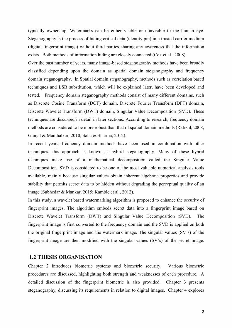
typically ownership. Watermarks can be either visible or nonvisible to the human eye.
Steganography is the process of hiding critical data (identity pin) in a trusted carrier medium
(digital fingerprint image) without third parties sharing any awareness that the information
exists. Both methods of information hiding are closely connected (Cox et al., 2008).
Over the past number of years, many image-based steganography methods have been broadly
classified depending upon the domain as spatial domain steganography and frequency
domain steganography. In Spatial domain steganography, methods such as correlation based
techniques and LSB substitution, which will be explained later, have been developed and
tested. Frequency domain steganography methods consist of many different domains, such
as Discrete Cosine Transform (DCT) domain, Discrete Fourier Transform (DFT) domain,
Discrete Wavelet Transform (DWT) domain, Singular Value Decomposition (SVD). These
techniques are discussed in detail in later sections. According to research, frequency domain
methods are considered to be more robust than that of spatial domain methods (Rafizul, 2008;
Gunjal & Manthalkar, 2010; Saha & Sharma, 2012).
In recent years, frequency domain methods have been used in combination with other
techniques, this approach is known as hybrid steganography. Many of these hybrid
techniques make use of a mathematical decomposition called the Singular Value
Decomposition. SVD is considered to be one of the most valuable numerical analysis tools
available, mainly because singular values obtain inherent algebraic properties and provide
stability that permits secret data to be hidden without degrading the perceptual quality of an
image (Subhedar & Mankar, 2015; Kamble et al., 2012).
In this study, a wavelet based watermarking algorithm is proposed to enhance the security of
fingerprint images. The algorithm embeds secret data into a fingerprint image based on
Discrete Wavelet Transform (DWT) and Singular Value Decomposition (SVD). The
fingerprint image is first converted to the frequency domain and the SVD is applied on both
the original fingerprint image and the watermark image. The singular values (SV’s) of the
fingerprint image are then modified with the singular values (SV’s) of the secret image.
1.2 THESIS ORGANISATION
Chapter 2 introduces biometric systems and biometric security. Various biometric
procedures are discussed, highlighting both strength and weaknesses of each procedure. A
detailed discussion of the fingerprint biometric is also provided. Chapter 3 presents
steganography, discussing its requirements in relation to digital images. Chapter 4 explores

3
the main data embedding techniques used in the area of digital watermarking and
steganography. A comparison of these embedding techniques is also provided, including
advantages and disadvantages. Chapter 5 discusses the detection of hidden data by method of
Steganalysis, and discusses and evaluates some of the detection techniques used to break a
steganography algorithm. Chapter 6 presents the methodology and procedures used to design
a robust and secure fingerprint recognition system. Chapter 7 provides and analysis all
experimental test results. Lastly, Chapter 8 draws conclusions and discusses suggestions for
future improvements.
4
2. BIOMETRIC SYSTEMS & BIOMETRIC SECURITY
2.1 Introduction
This section will provide an overview of biometric systems and explore the main biometric
techniques in use. The advantages and drawbacks of biometric data usage will also be
discussed.
2.2 Introduction to Biometric Systems
Biometric systems are basically pattern recognition systems that function by obtaining unique
personal and biological characteristics from a human being for verification purposes. They
use physical qualities such as face recognition, hand geometry, fingerprints, iris sequences,
and personal attributes such as voice recognition, keystroke and handwriting patterns.
The use of biometric recognition includes various privacy perks. For instance, biometrics can
exclude the need to be mindful of numerous passwords and pin numbers hence there is no
need to remember them. Biometrics can also be used to restrain unauthorised users from
gaining access to mobile devices, computers, government buildings, bank machines, places of
work. Moreover, the same biometric data can be used consistently, for everything.
Biometric data can be divided into two categories: physiological features, which include
DNA, face, hand geometry, fingerprints, iris and retina, behavioural features, which include
signature, gait and voice. A person’s behavioural features may change during the course of
their life, for that reason regular sampling is necessary. In comparison, physiological
biometric data requires much less sampling. (Jain et al., 2005)
Biometric systems can operate in two modes, identification mode or verification mode. Prior
to the system being set up, firstly a database of reference data has to be created. The database
is used to store all the biometric templates, this process is known as the enrolment process
(Zaheera et al., 2011).
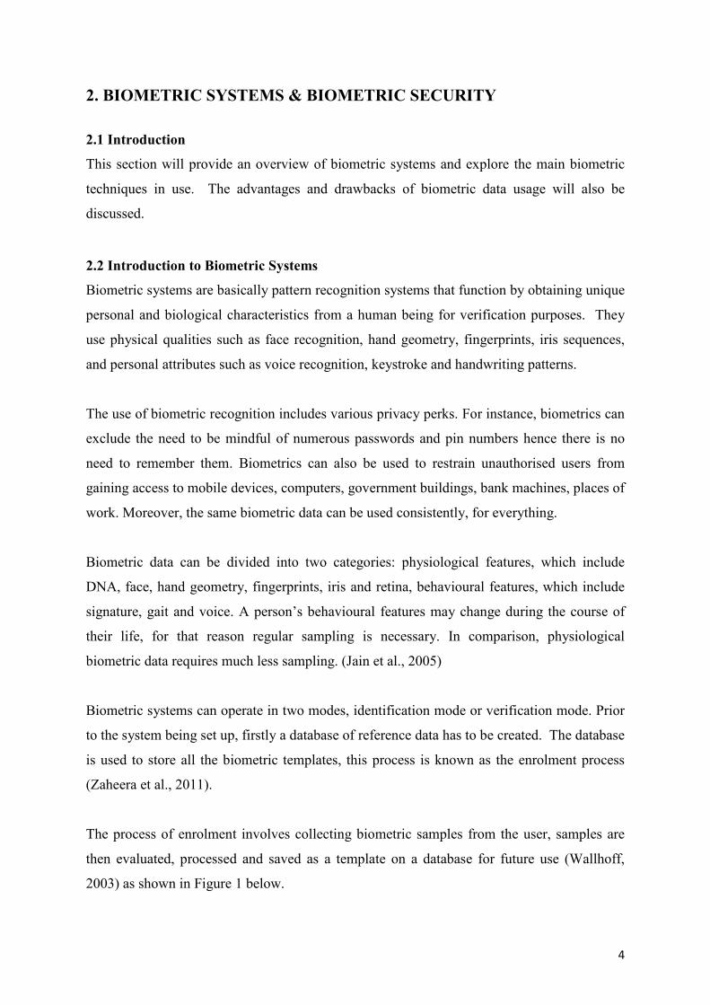
The process of enrolment involves collecting biometric samples from the user, samples are
then evaluated, processed and saved as a template on a database for future use (Wallhoff,
2003) as shown in Figure 1 below.
5
Figure 1 – The Enrolment Process of a Biometric System (Biometrics Research Group,
2013)
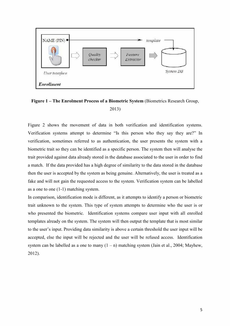
Figure 2 shows the movement of data in both verification and identification systems.
Verification systems attempt to determine “Is this person who they say they are?” In
verification, sometimes referred to as authentication, the user presents the system with a
biometric trait so they can be identified as a specific person. The system then will analyse the
trait provided against data already stored in the database associated to the user in order to find
a match. If the data provided has a high degree of similarity to the data stored in the database
then the user is accepted by the system as being genuine. Alternatively, the user is treated as a
fake and will not gain the requested access to the system. Verification system can be labelled
as a one to one (1-1) matching system.
In comparison, identification mode is different, as it attempts to identify a person or biometric
trait unknown to the system. This type of system attempts to determine who the user is or
who presented the biometric. Identification systems compare user input with all enrolled
templates already on the system. The system will then output the template that is most similar
to the user’s input. Providing data similarity is above a certain threshold the user input will be
accepted, else the input will be rejected and the user will be refused access. Identification
system can be labelled as a one to many (1 – n) matching system (Jain et al., 2004; Mayhew,
2012).
6
Figure 2: The process of Verification and Identification (Biometrics Research Group,
2013).
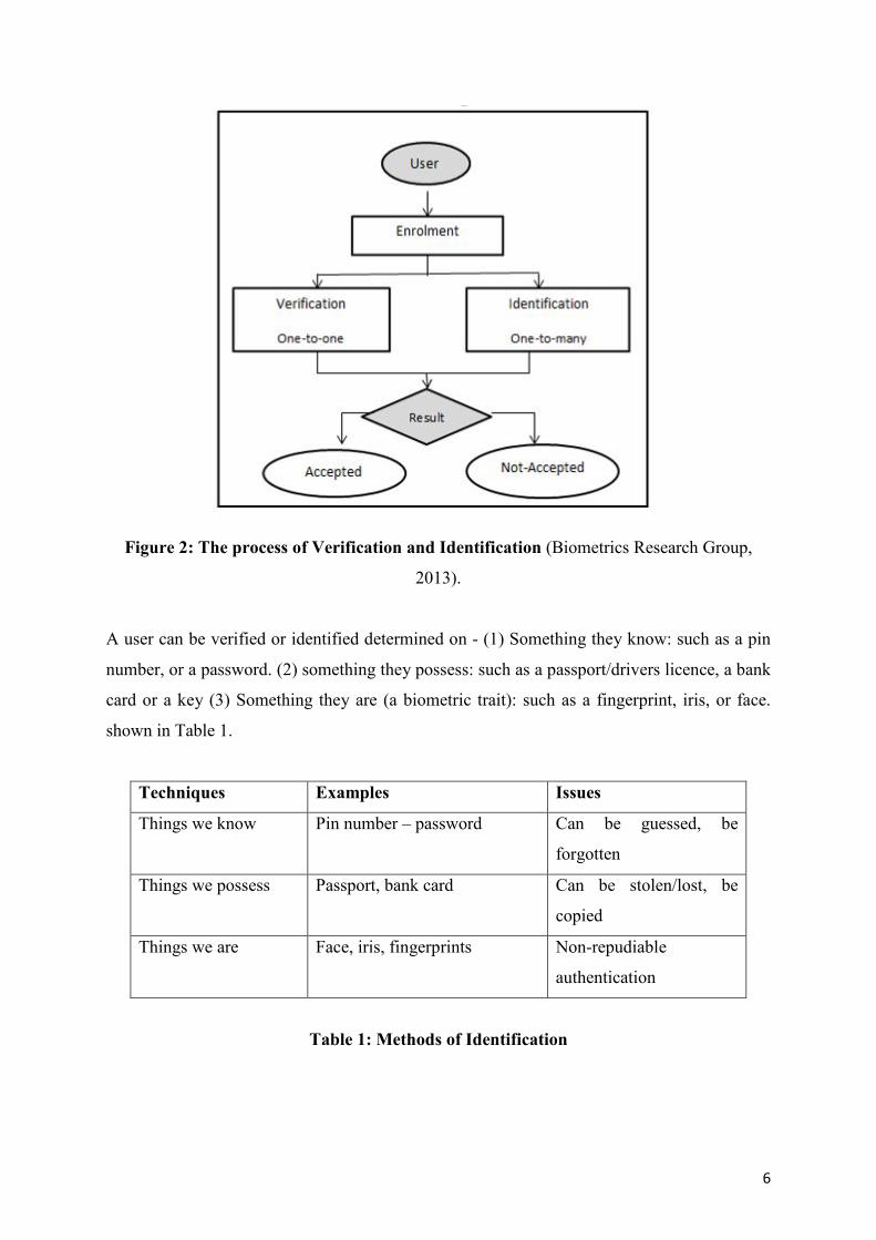
A user can be verified or identified determined on - (1) Something they know: such as a pin
number, or a password. (2) something they possess: such as a passport/drivers licence, a bank
card or a key (3) Something they are (a biometric trait): such as a fingerprint, iris, or face.
shown in Table 1.
Techniques Examples Issues
Things we know Pin number – password Can be guessed, be
forgotten
Things we possess Passport, bank card Can be stolen/lost, be
copied
Things we are Face, iris, fingerprints Non-repudiable
authentication
Table 1: Methods of Identification
7
Using things we know and own are two simple approaches that are widely used for
verification and identification purposes. To use something we know just requires us to have a
good memory, but quite often, things we know can simply be guessed. Something we have
may be snatched and can easily be copied and used at a later date. People’s biometric traits
are the one thing that does not need to be memorised and because these biometric traits are
determined by using body parts they cannot be easily stolen, lost or duplicated (Jain et al.,
2004).
2.3 Biometric Techniques
There are various biometric techniques that can be used for verification or identification
purposes. These characteristics can be separated into two techniques, physical and
behavioural. Physiological biometric traits include face, iris, and fingerprint, hand geometry,
retina and palm print. Behavioural techniques include signature, voice, gait and keystroke
(Jain et al., 2006). Over the years, some of the above mentioned biometric traits such as,
fingerprint and face, together with data hiding techniques (discussed in section 4), have been
investigated in order to enhance security of biometric data (Cheddad et al., 2008; Lavanya et
al., 2012; Malkhasyan, 2013).
2.3.1 Face
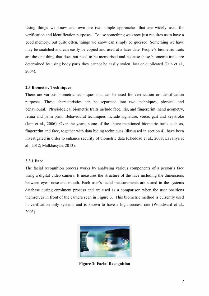
The facial recognition process works by analysing various components of a person’s face
using a digital video camera. It measures the structure of the face including the dimensions
between eyes, nose and mouth. Each user’s facial measurements are stored in the systems
database during enrolment process and are used as a comparison when the user positions
themselves in front of the camera seen in Figure 3. This biometric method is currently used
in verification only systems and is known to have a high success rate (Woodward et al.,
2003).
Figure 3: Facial Recognition
8
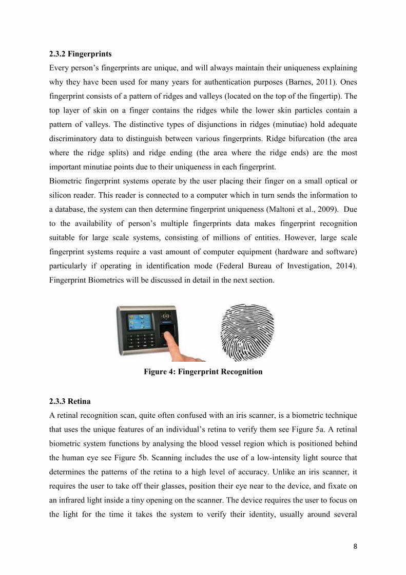
2.3.2 Fingerprints
Every person’s fingerprints are unique, and will always maintain their uniqueness explaining
why they have been used for many years for authentication purposes (Barnes, 2011). Ones
fingerprint consists of a pattern of ridges and valleys (located on the top of the fingertip). The
top layer of skin on a finger contains the ridges while the lower skin particles contain a
pattern of valleys. The distinctive types of disjunctions in ridges (minutiae) hold adequate
discriminatory data to distinguish between various fingerprints. Ridge bifurcation (the area
where the ridge splits) and ridge ending (the area where the ridge ends) are the most
important minutiae points due to their uniqueness in each fingerprint.
Biometric fingerprint systems operate by the user placing their finger on a small optical or
silicon reader. This reader is connected to a computer which in turn sends the information to
a database, the system can then determine fingerprint uniqueness (Maltoni et al., 2009). Due
to the availability of person’s multiple fingerprints data makes fingerprint recognition
suitable for large scale systems, consisting of millions of entities. However, large scale
fingerprint systems require a vast amount of computer equipment (hardware and software)
particularly if operating in identification mode (Federal Bureau of Investigation, 2014).
Fingerprint Biometrics will be discussed in detail in the next section.
Figure 4: Fingerprint Recognition
2.3.3 Retina
A retinal recognition scan, quite often confused with an iris scanner, is a biometric technique
that uses the unique features of an individual’s retina to verify them see Figure 5a. A retinal
biometric system functions by analysing the blood vessel region which is positioned behind
the human eye see Figure 5b. Scanning includes the use of a low-intensity light source that
determines the patterns of the retina to a high level of accuracy. Unlike an iris scanner, it
requires the user to take off their glasses, position their eye near to the device, and fixate on
an infrared light inside a tiny opening on the scanner. The device requires the user to focus on
the light for the time it takes the system to verify their identity, usually around several
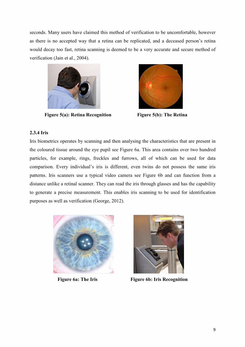
9
seconds. Many users have claimed this method of verification to be uncomfortable, however
as there is no accepted way that a retina can be replicated, and a deceased person’s retina
would decay too fast, retina scanning is deemed to be a very accurate and secure method of
verification (Jain et al., 2004).
Figure 5(a): Retina Recognition Figure 5(b): The Retina
2.3.4 Iris
Iris biometrics operates by scanning and then analysing the characteristics that are present in
the coloured tissue around the eye pupil see Figure 6a. This area contains over two hundred
particles, for example, rings, freckles and furrows, all of which can be used for data
comparison. Every individual’s iris is different, even twins do not possess the same iris
patterns. Iris scanners use a typical video camera see Figure 6b and can function from a
distance unlike a retinal scanner. They can read the iris through glasses and has the capability
to generate a precise measurement. This enables iris scanning to be used for identification
purposes as well as verification (George, 2012).
Figure 6a: The Iris Figure 6b: Iris Recognition
10
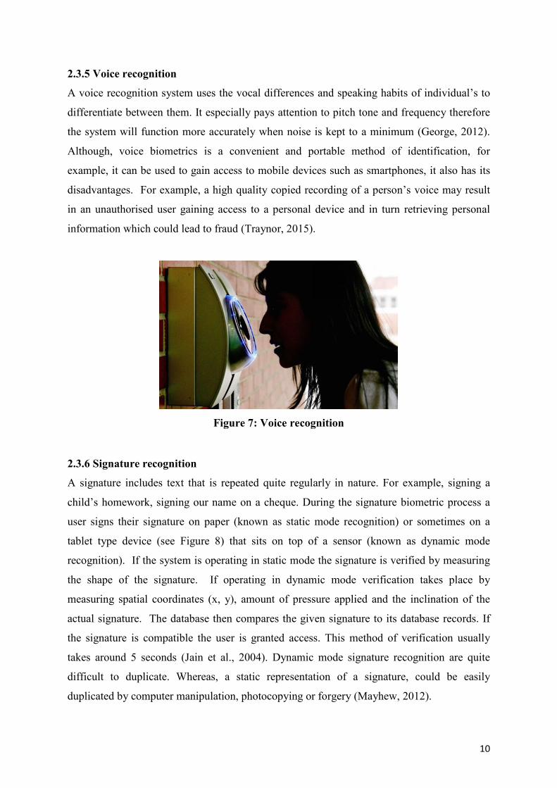
2.3.5 Voice recognition
A voice recognition system uses the vocal differences and speaking habits of individual’s to
differentiate between them. It especially pays attention to pitch tone and frequency therefore
the system will function more accurately when noise is kept to a minimum (George, 2012).
Although, voice biometrics is a convenient and portable method of identification, for
example, it can be used to gain access to mobile devices such as smartphones, it also has its
disadvantages. For example, a high quality copied recording of a person’s voice may result
in an unauthorised user gaining access to a personal device and in turn retrieving personal
information which could lead to fraud (Traynor, 2015).
Figure 7: Voice recognition
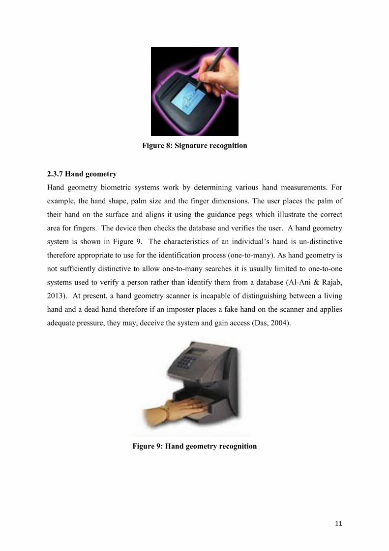
2.3.6 Signature recognition
A signature includes text that is repeated quite regularly in nature. For example, signing a
child’s homework, signing our name on a cheque. During the signature biometric process a
user signs their signature on paper (known as static mode recognition) or sometimes on a
tablet type device (see Figure 8) that sits on top of a sensor (known as dynamic mode
recognition). If the system is operating in static mode the signature is verified by measuring
the shape of the signature. If operating in dynamic mode verification takes place by
measuring spatial coordinates (x, y), amount of pressure applied and the inclination of the
actual signature. The database then compares the given signature to its database records. If
the signature is compatible the user is granted access. This method of verification usually
takes around 5 seconds (Jain et al., 2004). Dynamic mode signature recognition are quite
difficult to duplicate. Whereas, a static representation of a signature, could be easily
duplicated by computer manipulation, photocopying or forgery (Mayhew, 2012).
11
Figure 8: Signature recognition
2.3.7 Hand geometry
Hand geometry biometric systems work by determining various hand measurements. For
example, the hand shape, palm size and the finger dimensions. The user places the palm of
their hand on the surface and aligns it using the guidance pegs which illustrate the correct
area for fingers. The device then checks the database and verifies the user. A hand geometry
system is shown in Figure 9. The characteristics of an individual’s hand is un-distinctive
therefore appropriate to use for the identification process (one-to-many). As hand geometry is
not sufficiently distinctive to allow one-to-many searches it is usually limited to one-to-one
systems used to verify a person rather than identify them from a database (Al-Ani & Rajab,
2013). At present, a hand geometry scanner is incapable of distinguishing between a living
hand and a dead hand therefore if an imposter places a fake hand on the scanner and applies
adequate pressure, they may, deceive the system and gain access (Das, 2004).
Figure 9: Hand geometry recognition
12
2.4. Fingerprint as a Biometric Trait
Research carried out has indicated that fingerprints have been used as a method of
identification, dating back as far as 6000 BC, by the ancient Assyrians and Chinese (Barnes,
2011). During these times, many clay potters used the pattern of their fingerprint to mark
their work. Bricklayers in ancient Jericho also used this method by imprinting their
thumbprints on the bricks they used to build houses. Although fingerprint individuality was
acknowledged, there is no existing proof to state that this method was used extensively within
any of the mentioned societies (O’Gorman, 1998).
During the mid-1800’s experimental studies discovered two critical features of fingerprints
that are still valid today, (1) no two fingerprints are the same, (2) they will not change
through the course of a person’s lifetime (Barnes, 2011). Soon after these findings,
organizations such as Scotland Yard were using fingerprints for criminal identification
purposes. Digitization of fingerprints began in the early 1960’s, since then automated
fingerprint recognition has been used in widely. The late 1990’s has seen the introduction of
inexpensive hardware devices (fingerprint capturing devices), and fast and reliable matching
algorithms.
Among the many biometric techniques discussed above, the fingerprint biometric is one of
the most popular ones, due to its high accuracy rate, ease of use and standardization.
Furthermore, It is inexpensive, fast and easy to setup. In order for fingerprint scanning to
work efficiently it generally requires the comparison of various fingerprint features. These
features consist of patterns that are combined unique features of ridges, and minutia points,
found within a fingerprint pattern (Hong et al., 1997).
2.5. Fingerprint Patterns
A fingerprint consists of three basic patterns of ridges, the arch, loop and whorl as shown in
Figure 10. An arch can be explained as the pattern where ridges begin from one side of the
finger, ascent in the centre which develops an arc, and then exits the finger from the opposite
side (see Figure 10 a). A loop can be explained as the pattern where ridges begin at one side
of a finger to create a curve, and are inclined to exit in the same way they entered (same side
- see Figure 10 b).

13
Figure 10: Basic Patterns of Fingerprint (Cant, 2009)
As seen above in Figure 10(c), in the whorl pattern, ridges are structured in a circular position
around a central spot on the finger. In general, researchers have discovered that relatives
frequently share similar fingerprint patterns, which has led to the concept that fingerprint
patterns are genetic (Cant, 2009).
2.6 Minutia Points
The major minutia points in a fingerprint consist of: ridge ending, bifurcation, and short ridge
as shown in Figure 11.
(a) Ridges Ending (b) Ridges Bifurcation (c) Short Ridge
Figure 11: Minutiae points in fingerprint (Cant, 2009).
Figure 11 illustrates the point where the ridge stops, which is called the ridge ending. The
point where a single ridge splits in two is known as a bifurcation point. (See Figure 11 b).
Short ridges, also referred to as dots are the shorter ridges which are somewhat shorter in
length than the typical ridge length (see Figure 11 c). As each fingerprint is different, both
14
minutiae points and patterns are considered a critical aspect in fingerprint biometrics, so the
system can analyse data efficiently (Hong et al., 1997).
2.7 Minutiae Extraction Process
There are two primary procedures used to extract minutia data, binary extraction and direct
grayscale extraction. This binary approach has been intensively studied and is also the
backbone of many current fingerprint recognition systems and will also be used within this
work. Therefore, a binary minutiae extraction method will be discussed in detail. This
technique can be broken down into 4 steps, (1) Image enhancement (2) Binarization (3)
Thinning and (4) Feature Extraction (Bhowmik et al., 2012).
2.7.1 Image Enhancement
Many fingerprint images are obtained using various types of scanners, for example, optical
sensor, capacitive sensor or thermal sensor. Quite often, the image quality can be poor; this
can be for numerous reasons. For example, a user can be uncooperative and make it difficult
to retrieve a correct sample (law enforcement), or the user may have dry/oily hands
(Eriksson, 2001). Therefore the purpose of fingerprint enhancement is to process the
obtained fingerprint image in order to upgrade its quality thus make the identification process
easier and more accurate (Awasthi & Tiwari, 2012).
2.7.2 Binarization
During the binarization step the grayscale fingerprint image is converted into a black and
white binary image. This procedure is carried out by correlating every pixel value to a
threshold value (0.5). If the value of the pixel is lower than the threshold value then the pixel
value is assigned black otherwise it is assigned white. The threshold value mentioned here is
the default threshold for the MATLAB’s ‘im2bw’ function which will be used for the
purpose of binarization in this project. However, it is important to note that other thresholding
methods can also be used such as, Otsu’s method (Sung Liao et al., 2001). After the image is
binarized, a process known as thinning is then performed.
2.7.3 Thinning (Skeletonization)
Thinning sometimes referred to as skeletonization of the image will reduce the thickness of
all ridge lines to one pixel width. It should be noted that this process is quite important as it
15
allows for minutiae to be extracted more efficiently and will not change its location
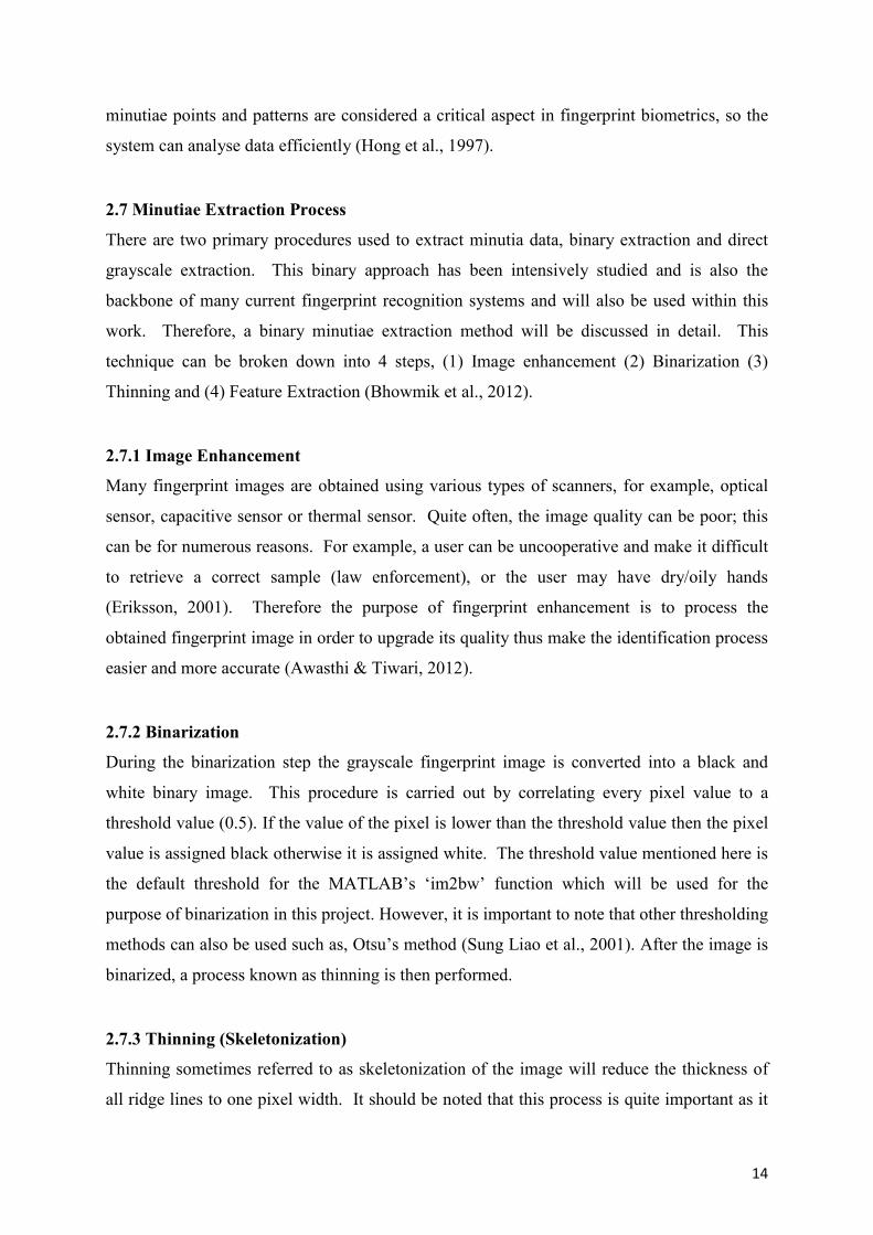
(Kocharyan & Sarukhanyan, 2001). More on thinning algorithms can be found here (Golabi
et al., 2012; Lam et al., 1992). A sample fingerprint with its corresponding thinned skeleton
image is shown in Figure 12.
Figure 12: A fingerprint with its corresponding binary image and ridge skeleton
(Eriksson, 2001).
2.7.4 Minutia Extraction
Only a few matching algorithms operate on grayscale fingerprint images directly, therefore
an intermediate fingerprint likeness must be derived, this is done during a feature extraction
process An outline as to how this procedure works is given below.
A capture device is used to take a distinctive image of the users fingerprint. Distinctive
software is then used to examine the fingerprint image and decides if the image truly is a
fingerprint, by checking the pattern type (left loop, right arch), measuring ridge line qualities,
and lastly extracting minutia. Minutiae specify where a significant change has occurred in
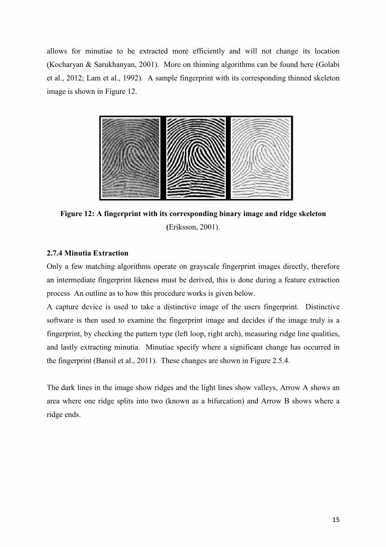
the fingerprint (Bansil et al., 2011). These changes are shown in Figure 2.5.4.
The dark lines in the image show ridges and the light lines show valleys, Arrow A shows an
area where one ridge splits into two (known as a bifurcation) and Arrow B shows where a
ridge ends.
16
Figure 13: Fingerprint Changes
When these fingerprint features are located, the extraction software establishes a notable
direction of the change (using Arrow B as an example, the notable direction begins at the end
of the ridge and progresses in a descending direction). Simply put, the resultant minutia is a
group of all reasonable bifurcations and ridge endings, their location, and their specific
direction.
2.7.5 Fingerprint Matching
Fingerprint matching algorithms work by comparing two given fingerprints and outputs
either a percentage of similarity (usually a score between 0 and 1) or a binary decision (match
or no match). Only a minority of matching algorithms function directly on grayscale
fingerprint images; nearly all of them require that an intermediate fingerprint image be
obtained via a feature extraction process (Maltoni et al., 2009).
A large amount of fingerprint matching techniques can be divided into two families:
correlation based and minutiae based. Correlation based matching operates by superimposing
two fingerprint images and computes the correlation between corresponding pixels for
various alignments (different displacements and rotations). Minutiae-based techniques,
which seem to be the most popular approach, extract minutiae from the two fingerprints and
essentially match the alignment between the database template and the minutiae presented by
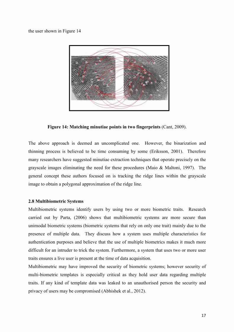
17
the user shown in Figure 14
Figure 14: Matching minutiae points in two fingerprints (Cant, 2009).
The above approach is deemed an uncomplicated one. However, the binarization and
thinning process is believed to be time consuming by some (Eriksson, 2001). Therefore
many researchers have suggested minutiae extraction techniques that operate precisely on the
grayscale images eliminating the need for these procedures (Maio & Maltoni, 1997). The
general concept these authors focused on is tracking the ridge lines within the grayscale
image to obtain a polygonal approximation of the ridge line.
2.8 Multibiometric Systems
Multibiometric systems identify users by using two or more biometric traits. Research
carried out by Parta, (2006) shows that multibiometric systems are more secure than
unimodal biometric systems (biometric systems that rely on only one trait) mainly due to the
presence of multiple data. They discuss how a system uses multiple characteristics for
authentication purposes and believe that the use of multiple biometrics makes it much more
difficult for an intruder to trick the system. Furthermore, a system that uses two or more user
traits ensures a live user is present at the time of data acquisition.
Multibiometric may have improved the security of biometric systems; however security of
multi-biometric templates is especially critical as they hold user data regarding multiple
traits. If any kind of template data was leaked to an unauthorised person the security and
privacy of users may be compromised (Abhishek et al., 2012).
18
2.9 Security Issues in Biometric Systems
Even though a biometric system can better accommodate users and boost security, they are
also vulnerable to numerous types of threats as outlined below: (Uludag & Jain, 2004).
Circumvention: An imposter may gain entry to the system and browse private data such as
medical reports belonging to a genuinely enrolled user. Besides violating user privacy, the
intruder can also alter any sensitive information that they have accessed.
Repudiation: A genuine user may abuse their authentication rights by entering the system,
and maintain that an imposter had done so. For example, a bank employee may alter a
customer’s bank account details and insist that an imposter could have done this by deceiving
the system and stealing the biometric data.
Covert Acquisition: An unauthorised user can secretly obtain a user’s raw biometric
information to gain entry to the system. For example, an intruder may collect an authorised
person’s latent fingerprint from a specific item, and in time use the fingerprint to create a
physical or digital representation of the finger, which in many cases can lead to identity
fraud.
Collusion: A biometric user who has access to a wide range of system privileges such as, a
system administrator, may intentionally alter system parameters to enable an intruder to
attack the system, allowing the intruder to view, change or even steal the biometric data that
is stored on the system.
Denial of Service (DoS): An attacker may overload system resources so that genuine users
wishing to enter will be denied any service. For instance, a server that deals with access
applications can be submerged with an extensive amount of fake requests, thus overloading
its data processing resources which would prevent legitimate requests from being processed.
2.10 Conclusion
In this section the functionalities of biometric systems were discussed. Various biometric
techniques along with their strengths and weaknesses were examined. Fingerprint biometrics
was discussed in detail and various feature extraction methods were explored. The
19
weaknesses of biometric systems in regards to security and privacy were also highlighted.
Research shows that even though the use of biometrics can boost user accessibility, they are
also susceptible to numerous types of attacks as discussed in section 2.6. So, in order to
enhance the security of these systems, primarily fingerprints, the field of digital
steganography will be explored and tested.
20
3. STEGANOGRAPHY
3.1 Introduction
In order to gain a basic understanding of the steganography techniques that will be discussed
later on in this project, it is important to first build up a basic understanding of the topic area.
Firstly, a brief overview of steganography is given and the necessary background knowledge
is discussed. Secondly, the main fundamentals relating to steganography and steganographic
algorithm requirements will be explored. Digital images and image compression will be
explained. To grasp the concept of the steganography embedding techniques that will be
discussed in the next chapter, it is first important to gain an understanding of how digital
images are constructed.
3.2 Overview of Steganography
Steganography can be described as the art and science of covert communications which
involves the process of hiding information inside other information. Unlike cryptography,
steganography messages do not draw attention to themselves, as data is hidden in such a way
as to make it undetectable to the human eye. Requirements of a good stenographic algorithm
will be discussed below.
The word steganography is derived from the Greek words “stegos” meaning “cover” and
“grafia” meaning “writing”, defining it as “covered writing”. This practice and idea of hiding
information can be traced back as far as 440 BC and has been used in many forms over the
years (Barve et al., 2011).
3.3 Ancient Steganography
According to Greek historian Herodotus, Histaiacus, a Greek tyrant, used a form of
steganography to communicate with his son-in-law Aristagoras. Histaiacus shaved the head
of a trusted slave and tattooed a secret message on to his scalp. Once the slave’s hair grew
back he was sent to Aristagoras with the hidden message (Cheddad et al., 2008).
Another form of steganography occurred in World War 2 when the Germans developed the
microdot technique. This method allowed for a lot of information, mostly photographs, to be
condensed to the size of a typed period. Information was then hidden in one of the periods on
the paper (a full stop) and distributed over an unprotected channel. The FBI detective, J.
21
Edgar Hoover described the use of microdots as “the enemy’s masterpiece of espionage”.
(Cummins et al., 2004)
Although steganography has been in existence for many years, its current formation can be
explained using the Prisoners’ problem proposed by Simmons (Morkel et al., 2005) where
two inmates wish to secretly exchange information to come up with an escape plan.
All communication between the two inmates has to pass through a warden. If the warden
suspects any type of covert communication has taken place, both inmates will be sent to
solitary confinement. All correspondence between the inmates can be checked by the warden,
the warden can be either passive or active. If the warden takes a passive approach he\she will
attempt to detect if the communication contains any secret information. If covert
communication is discovered the warden will make note of it and inform an outside party,
information will be allowed to pass through without obstruction. However, if an active
warden suspects any hidden information, he/she will attempt to modify the communication
by removing or altering the hidden data.
3.4 Evaluation of different techniques
For a steganographic algorithm to be successful it must adhere to the following requirements:
(Morkel et al., 2005)
Invisibility: first and foremost, a steganographic technique needs to be invisible,
considering the aim of steganography is to fend off unwanted attention to the
transmission of hidden information. If the human eye suspects that information is
hidden then this goal is defeated. Moreover, the concealed data may be compromised.
Payload capacity – Dissimilar to the watermarking method of information hiding
where only a small amount of copyright data needs to be embedded, steganography
aims at covert communication, thus requires adequate embedding space.
Robustness against statistical attacks – Statistical steganalysis is the technique used to
discover if hidden information exists. A steganalyst will examine image data by
carrying out various statistical tests. Many steganographic algorithms leave a
‘signature’ when embedding information that can be easily detected through statistical
analysis. (Steganalysis will be discussed in more detail in section 5)
Robustness against image manipulation – During the course of the communication
process an image can be subjected to changes by an active warden in an effort to
22
expel secret information. Prior to the image reaching its destination it can be
manipulated by using techniques such as rotating or cropping. Depending on how the
information is embedded, these manipulations may sabotage or ruin any hidden data.
A Steganography algorithm is more preferable if it is potent against malicious or
unforeseen adjustments to the image.
Independent of file format – As there are an abundance of various image file formats
being used on the web, it may attract unwanted suspicion that an individual type of
file format is repeatedly communicated amongst two parties. However, if a
stenographic algorithm is powerful it should possess the ability to embed data in all
types of file formats. This requirement also sorts out the issue of not always being
able to acquire a suited image at the correct moment in time, that is, the correct format
to use as a cover image.
Unsuspicious files – This requirement contains all features of a stenographic
algorithm that may consist of images that are not commonly used and can lead to
suspicion. For example, file size that are abnormal may attract suspicion, thus result in
further examination of the image by a warden.
An essential condition of a steganographic system is that the image being used (stego-image)
for steganography purposes must be as close as possible to the original image, as not to raise
suspicion or attract any unwanted attention to the stego image. Image embedding capacity
and data invisibility are two primary requirements that have been extensively researched in
different steganography techniques over the years (Johnson & Jajodia, 1998).
3.5 Related Work
In 1999 (Johnson et al. 1999) presented a thorough survey on ‘Information Hiding’.
Steganographic methods in use today have progressed a lot since then. In 2006 (Bailey et al.
2006) produced a paper which examined various spatial domain techniques using the least
significant bit approach, applied to the GIF image format. Goel and colleagues presented a
more recent study on image steganography techniques, published in 2013 (Goel et al., 2013).
3.6 Digital Image Steganography
Due to the expansion of the World Wide Web there has been a noticeable increase in the use
of digital images. The large quantity of redundant bits that exist within a digital image
23
representation, makes images more preferable for embedding steganographic data. An
abundance of diverse image file formats exist within the digital image domain. For each of
these different image formats, various steganographic techniques exist (Morkel et al., 2005).
Prior to exploring these techniques, it is necessary to gain an understanding of digital images.
3.7 Image definition
A PC presents images as an assortment of binary digits, comprising distinctive light
intensities, in the various image sections (Morkel et al., 2005). This digit representation
constructs a grid. The various locations on the grid are known as pixels. Generally, most
digital images on the web are made up of a rectangular graph consisting of images pixels,
(bits) where each pixel’s colour is contained. These pixels are presented on the grid
horizontally, row by row.
The bit depth, which also can be explained as the total number of bits in a colour scheme,
relate to the total amount of bits used for individual pixels. In Greyscale or Monochrome
images, each pixel uses 8 bits and is capable of displaying 256 various colours or shades of
grey.
Digital images that are coloured normally contain 24-bit files and use the RGB colour model.
The bit depth of modern colour schemes is 8; this means that 8 bits are needed to represent
the colour of each pixel. All colour variations for pixels of a 24-bit image derive from three
colours: red, green and blue, and all colours are represented by 8 bits. Therefore, in one pixel,
there can be 256 specific amounts of red, green and blue, producing more than 16-million
colours. In addition, the more colours displayed, the larger the image file will be (Koeling,
2004).
3.8 Image Compression
To transmit an image over the internet successfully it must be an appropriate size. In some
cases, (minimum storage, system performance) larger images may not be appropriate, smaller
images may be preferred. In certain circumstances, mathematical formulas can be used to
decrease the size of the image by condensing the image data, consequently reducing the
image size. This technique is known as compression, which can be either lossy or lossless.
Both approaches compress the image to save on storage, but are implemented quite
differently (Bateman, 2008).
24
3.8.1 Lossy Compression
The lossy compression technique decreases the file size by eliminating redundant bits of data
from the original image. It eliminates areas of the image that are not visible to the human eye;
as a result some data may be lost. Although the compressed image bears a close resemblance
to the original image, the compressed image is not an exact duplicate, mainly due to data
elimination. An example of an image format that uses lossy compression is JPEG (Joint
Photographic Experts Group). The JPEG file format will be discussed in detail in the next
section (Kumar, 2011).
3.8.2 Lossless Compression
In contrast, lossless compression does not discard any data from the original image. After
compression, all original data is restored. This technique would generally be used for spread
sheets or text files where loss of data would cause problems. The down-side of this technique
is the larger image size. Image formats such as Bitmap, PNG and GIF use lossless file
compression (Chapman, 2010).
3.9 Conclusion
Unlike other information hiding techniques, the main goal of steganography is to ensure that
any hidden data is invisible to the human eye. As discussed above, there are many
requirements that a steganographic algorithm must satisfy to ensure the secrecy of hidden
information. The use of digital images and image compression plays a significant part in
choosing which steganographic algorithm to use. For example, lossy compression methods
(relating to JPEG images) provide smaller image file sizes, but it intensifies the probability of
the hidden information being altered or lost based on the fact that some redundant data is
always eliminated. Lossless compression (relating to GIF, PNG images) allows for an image
to be compressed without any loss of data, allowing the original image to be maintained. As
a result of the lossless approach the image will be larger in size. Lossless image formats may
not be suitable for hiding biometric data, as biometric systems also require a fast response
time as well as strong security measures (Shanthini & Swamynathan, 2012). Many
steganographic algorithms have been developed for both of the above compression
techniques and will be explained in detail in the next section.
25
4. DATA HIDING IN DIGITAL IMAGES
4.1 Introduction
The following section will present an overview of the most relevant steganographic
embedding methods in digital images. Two of the most popular digital image formats relating
to internet usage are Joint Photographic Experts Group (JPEG) and Portable Network
Graphics (PNG). Other image formats are also used, such as Graphics Interchange Format
(GIF), but to a lesser degree. Most of the steganographic techniques created were constructed
to manipulate the design of the image formats mentioned (Chedded et al., 2010).
4.2 Steganography Embedding Techniques
Embedding information using steganography can be carried out by inserting the following
line of code into a Microsoft command window:
C:\> Copy Cover.jpg /b + Message.txt /b Stego.jpg
The above code appends the hidden information found in the text file ‘Message.txt’ inside the
JPEG image file ‘Cover.jpg’ and constructs the stego-image ‘Stego.jpg’. The concept behind
this is to exploit the recognition of EOF (End of file), that is, the information is loaded and
added after the EOF tag. When observation of the Stego.jpg occurs using any image editing
tool, the latter simply exhibits the image disregarding anything that follows the EOF tag.
However, if opened in Notepad, the hidden data will be unveiled. The embedded data does
not decrease the quality of the image. Image histograms or visual perception will identify any
disparity between the two images as the secret data is hidden after the EOF tag. Although this
technique is easy to implement, many steganography programs distributed on the internet
make use of it (Camouflage, JpegX). Unfortunately, this simple procedure would not
withstand any type of altering to the Stego-image nor would it endure steganalysis attacks
(Praveen, 2011).
Another straightforward method is to affix secret data to the Extended File Information of the
image, this is a common approach taken by the manufacturers of digital cameras to store
metadata info in the image header file, and the cameras make and model. However, this
technique is just as unreliable as the preceding approach as it is very simple to overwrite such
information (Chedded, 2009).
26
In recent years, data hiding, using the LSB embedding method within the spatial domain
(pixel level) of images was a very popular technique. This was mainly due to its potentially
sizable capacity and its simplicity. More recent studies investigated the frequency domain
(Gunjal & Manthalkar, 2010; Shejul & Kulkarni, 2010; Barve et al., 2011).
Steganography methods can generally be restricted to three specific types:
Spatial Domain Techniques
Frequency Domain Techniques
Hybrid Techniques
The next sections will explore these domain procedures and evaluate their significance to
successfully producing the steganographic requirements, which were previously discussed in
section 3.
4.3 Spatial Domain Techniques
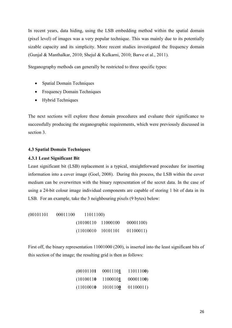
4.3.1 Least Significant Bit
Least significant bit (LSB) replacement is a typical, straightforward procedure for inserting
information into a cover image (Goel, 2008). During this process, the LSB within the cover
medium can be overwritten with the binary representation of the secret data. In the case of
using a 24-bit colour image individual components are capable of storing 1 bit of data in its
LSB. For an example, take the 3 neighbouring pixels (9 bytes) below:
(00101101 00011100 11011100)
(10100110 11000100 00001100)
(11010010 10101101 01100011)
First off, the binary representation 11001000 (200), is inserted into the least significant bits of
this section of the image; the resulting grid is then as follows:
(00101101 00011101 11011100)
(10100110 11000101 00001100)
(11010010 10101100 01100011)
27
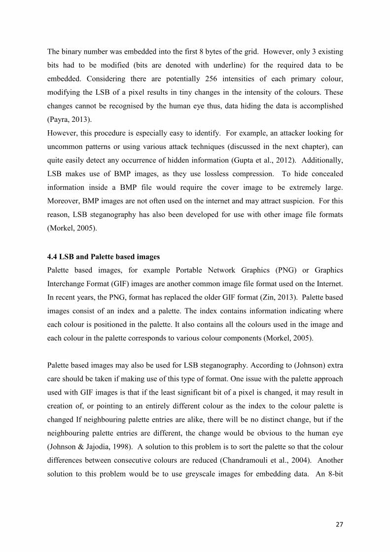
The binary number was embedded into the first 8 bytes of the grid. However, only 3 existing
bits had to be modified (bits are denoted with underline) for the required data to be
embedded. Considering there are potentially 256 intensities of each primary colour,
modifying the LSB of a pixel results in tiny changes in the intensity of the colours. These
changes cannot be recognised by the human eye thus, data hiding the data is accomplished
(Payra, 2013).
However, this procedure is especially easy to identify. For example, an attacker looking for
uncommon patterns or using various attack techniques (discussed in the next chapter), can
quite easily detect any occurrence of hidden information (Gupta et al., 2012). Additionally,
LSB makes use of BMP images, as they use lossless compression. To hide concealed
information inside a BMP file would require the cover image to be extremely large.
Moreover, BMP images are not often used on the internet and may attract suspicion. For this
reason, LSB steganography has also been developed for use with other image file formats
(Morkel, 2005).
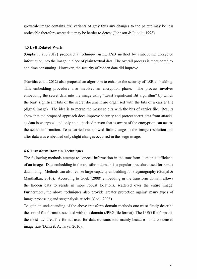
4.4 LSB and Palette based images
Palette based images, for example Portable Network Graphics (PNG) or Graphics
Interchange Format (GIF) images are another common image file format used on the Internet.
In recent years, the PNG, format has replaced the older GIF format (Zin, 2013). Palette based
images consist of an index and a palette. The index contains information indicating where
each colour is positioned in the palette. It also contains all the colours used in the image and
each colour in the palette corresponds to various colour components (Morkel, 2005).
Palette based images may also be used for LSB steganography. According to (Johnson) extra
care should be taken if making use of this type of format. One issue with the palette approach
used with GIF images is that if the least significant bit of a pixel is changed, it may result in
creation of, or pointing to an entirely different colour as the index to the colour palette is
changed If neighbouring palette entries are alike, there will be no distinct change, but if the
neighbouring palette entries are different, the change would be obvious to the human eye
(Johnson & Jajodia, 1998). A solution to this problem is to sort the palette so that the colour
differences between consecutive colours are reduced (Chandramouli et al., 2004). Another
solution to this problem would be to use greyscale images for embedding data. An 8-bit
28
greyscale image contains 256 variants of grey thus any changes to the palette may be less
noticeable therefore secret data may be harder to detect (Johnson & Jajodia, 1998).
4.5 LSB Related Work
(Gupta et al., 2012) proposed a technique using LSB method by embedding encrypted
information into the image in place of plain textual data. The overall process is more complex
and time consuming. However, the security of hidden data did improve.
(Kavitha et al., 2012) also proposed an algorithm to enhance the security of LSB embedding.
This embedding procedure also involves an encryption phase. The process involves
embedding the secret data into the image using “Least Significant Bit algorithm” by which
the least significant bits of the secret document are organised with the bits of a carrier file
(digital image). The idea is to merge the message bits with the bits of carrier file. Results
show that the proposed approach does improve security and protect secret data from attacks,
as data is encrypted and only an authorised person that is aware of the encryption can access
the secret information. Tests carried out showed little change to the image resolution and
after data was embedded only slight changes occurred in the stego image.
4.6 Transform Domain Techniques
The following methods attempt to conceal information in the transform domain coefficients
of an image. Data embedding in the transform domain is a popular procedure used for robust
data hiding. Methods can also realize large-capacity embedding for steganography (Gunjal &
Manthalkar, 2010). According to Goel, (2008) embedding in the transform domain allows
the hidden data to reside in more robust locations, scattered over the entire image.
Furthermore, the above techniques also provide greater protection against many types of
image processing and steganalysis attacks (Goel, 2008).
To gain an understanding of the above transform domain methods one must firstly describe
the sort of file format associated with this domain (JPEG file format). The JPEG file format is
the most favoured file format used for data transmission, mainly because of its condensed
image size (Danti & Acharya, 2010).
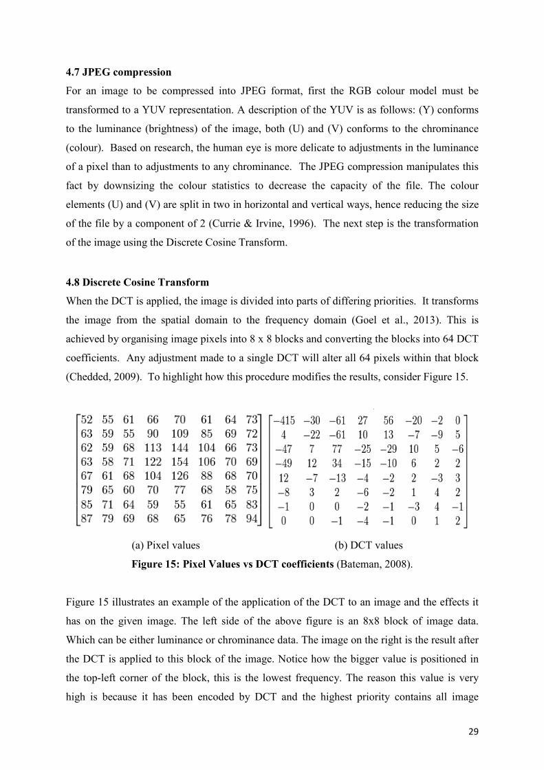
29
4.7 JPEG compression
For an image to be compressed into JPEG format, first the RGB colour model must be
transformed to a YUV representation. A description of the YUV is as follows: (Y) conforms
to the luminance (brightness) of the image, both (U) and (V) conforms to the chrominance
(colour). Based on research, the human eye is more delicate to adjustments in the luminance
of a pixel than to adjustments to any chrominance. The JPEG compression manipulates this
fact by downsizing the colour statistics to decrease the capacity of the file. The colour
elements (U) and (V) are split in two in horizontal and vertical ways, hence reducing the size
of the file by a component of 2 (Currie & Irvine, 1996). The next step is the transformation
of the image using the Discrete Cosine Transform.
4.8 Discrete Cosine Transform
When the DCT is applied, the image is divided into parts of differing priorities. It transforms
the image from the spatial domain to the frequency domain (Goel et al., 2013). This is
achieved by organising image pixels into 8 x 8 blocks and converting the blocks into 64 DCT
coefficients. Any adjustment made to a single DCT will alter all 64 pixels within that block
(Chedded, 2009). To highlight how this procedure modifies the results, consider Figure 15.
(a) Pixel values (b) DCT values
Figure 15: Pixel Values vs DCT coefficients (Bateman, 2008).
Figure 15 illustrates an example of the application of the DCT to an image and the effects it
has on the given image. The left side of the above figure is an 8x8 block of image data.
Which can be either luminance or chrominance data. The image on the right is the result after
the DCT is applied to this block of the image. Notice how the bigger value is positioned in
the top-left corner of the block, this is the lowest frequency. The reason this value is very
high is because it has been encoded by DCT and the highest priority contains all image

30
energy. Note how all values nearer to the bottom right hand corner are closer to zero, this is
because these values contain less energy. These values are classed as the high frequencies; it
is these frequencies that will be discarded during the next process (Bateman, 2008).
When the image has been transformed quantization is the next stage of the process. During
this stage the human eye again is exploited. As discussed earlier the human eye can be
sensitive to certain areas of an image. For example, our eyes are relatively good at
recognising tiny changes in luminance (brightness) over a relatively large area, however, not
so great at recognising various strengths in high frequency brightness. This allows the
strength of higher frequencies to be reduced, without modifying the presentation of the image
(Morkel e al., 2005). For example, consider an image with a dense collection of trees, in
which you have an all-around view. Smaller trees that you do not notice may exist beneath
the larger trees in the image. If you cannot see these trees, your view will not be affected if
the small trees are there or not. Quantization can be viewed as exactly the same principle.
JPEG carries out this process by separating all the values in a block by a quantization
coefficient. The outcome is rounded to integer values (Bateman, 2008).
Figure 16: Quantisation Procedure (Bateman, 2008).
The quantised coefficients of the DCT shown above in figure 16 are typically normal. There
are only a slight amount of individual values where the numbers are larger than zero ( most
will always be zeros). It is also common practice that all non-zero numbers reside towards the
upper left, and zeros to the lower-right corner. Due to the fore mentioned, another process
must be applied to group similar frequencies together; this process is called zigzagging. The
purpose of this procedure is to group all low frequencies together using a zigzag motion. As
stated above, after quantization there will only be a minimal amount of values that hold
values (low frequencies) other than zeros (high frequencies), the zig-zag process works by re
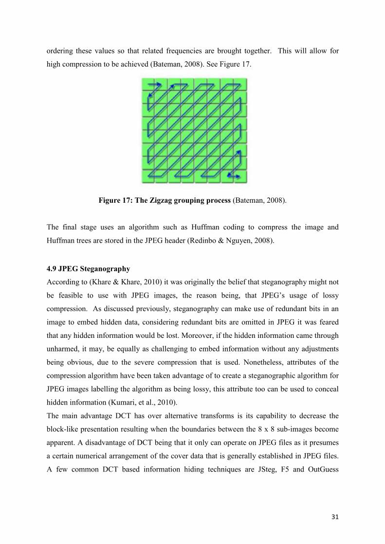
31
ordering these values so that related frequencies are brought together. This will allow for
high compression to be achieved (Bateman, 2008). See Figure 17.
Figure 17: The Zigzag grouping process (Bateman, 2008).
The final stage uses an algorithm such as Huffman coding to compress the image and
Huffman trees are stored in the JPEG header (Redinbo & Nguyen, 2008).
4.9 JPEG Steganography
According to (Khare & Khare, 2010) it was originally the belief that steganography might not
be feasible to use with JPEG images, the reason being, that JPEG’s usage of lossy
compression. As discussed previously, steganography can make use of redundant bits in an
image to embed hidden data, considering redundant bits are omitted in JPEG it was feared
that any hidden information would be lost. Moreover, if the hidden information came through
unharmed, it may, be equally as challenging to embed information without any adjustments
being obvious, due to the severe compression that is used. Nonetheless, attributes of the
compression algorithm have been taken advantage of to create a steganographic algorithm for
JPEG images labelling the algorithm as being lossy, this attribute too can be used to conceal
hidden information (Kumari, et al., 2010).
The main advantage DCT has over alternative transforms is its capability to decrease the
block-like presentation resulting when the boundaries between the 8 x 8 sub-images become
apparent. A disadvantage of DCT being that it only can operate on JPEG files as it presumes
a certain numerical arrangement of the cover data that is generally established in JPEG files.
A few common DCT based information hiding techniques are JSteg, F5 and OutGuess
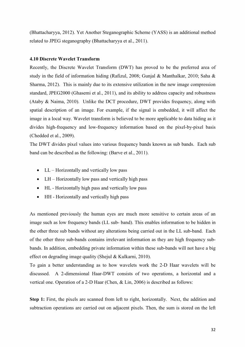
32
(Bhattacharyya, 2012). Yet Another Steganographic Scheme (YASS) is an additional method
related to JPEG steganography (Bhattacharyya et al., 2011).
4.10 Discrete Wavelet Transform
Recently, the Discrete Wavelet Transform (DWT) has proved to be the preferred area of
study in the field of information hiding (Rafizul, 2008; Gunjal & Manthalkar, 2010; Saha &
Sharma, 2012). This is mainly due to its extensive utilization in the new image compression
standard, JPEG2000 (Ghasemi et al., 2011), and its ability to address capacity and robustness
(Ataby & Naima, 2010). Unlike the DCT procedure, DWT provides frequency, along with
spatial description of an image. For example, if the signal is embedded, it will affect the
image in a local way. Wavelet transform is believed to be more applicable to data hiding as it
divides high-frequency and low-frequency information based on the pixel-by-pixel basis
(Chedded et al., 2009).
The DWT divides pixel values into various frequency bands known as sub bands. Each sub
band can be described as the following: (Barve et al., 2011).
LL – Horizontally and vertically low pass
LH – Horizontally low pass and vertically high pass
HL - Horizontally high pass and vertically low pass
HH - Horizontally and vertically high pass
As mentioned previously the human eyes are much more sensitive to certain areas of an
image such as low frequency bands (LL sub- band). This enables information to be hidden in
the other three sub bands without any alterations being carried out in the LL sub-band. Each
of the other three sub-bands contains irrelevant information as they are high frequency sub-
bands. In addition, embedding private information within these sub-bands will not have a big
effect on degrading image quality (Shejul & Kulkarni, 2010).
To gain a better understanding as to how wavelets work the 2-D Haar wavelets will be
discussed. A 2-dimensional Haar-DWT consists of two operations, a horizontal and a
vertical one. Operation of a 2-D Haar (Chen, & Lin, 2006) is described as follows:
Step 1: First, the pixels are scanned from left to right, horizontally. Next, the addition and
subtraction operations are carried out on adjacent pixels. Then, the sum is stored on the left
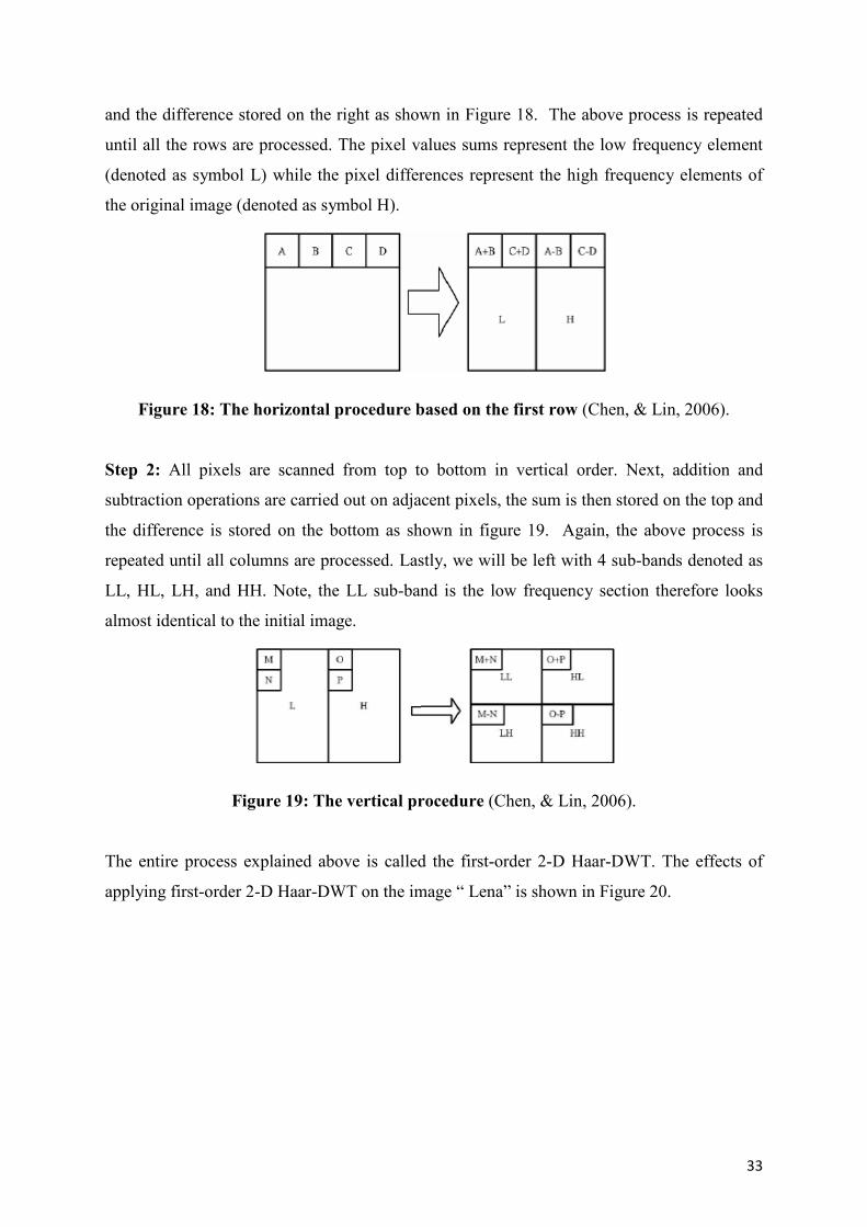
33
and the difference stored on the right as shown in Figure 18. The above process is repeated
until all the rows are processed. The pixel values sums represent the low frequency element
(denoted as symbol L) while the pixel differences represent the high frequency elements of
the original image (denoted as symbol H).
Figure 18: The horizontal procedure based on the first row (Chen, & Lin, 2006).
Step 2: All pixels are scanned from top to bottom in vertical order. Next, addition and
subtraction operations are carried out on adjacent pixels, the sum is then stored on the top and
the difference is stored on the bottom as shown in figure 19. Again, the above process is
repeated until all columns are processed. Lastly, we will be left with 4 sub-bands denoted as
LL, HL, LH, and HH. Note, the LL sub-band is the low frequency section therefore looks
almost identical to the initial image.
Figure 19: The vertical procedure (Chen, & Lin, 2006).
The entire process explained above is called the first-order 2-D Haar-DWT. The effects of
applying first-order 2-D Haar-DWT on the image “ Lena” is shown in Figure 20.

34
Figure 20: (a) Original image (b) After 2-D Haar DWT is applied (Chen, & Lin, 2006).
In comparison to DCT, recent studies have shown that wavelets are considered as being less
resource intensive and cause less distortion to an image hence why the DWT method is
becoming a more popular. Moreover, as DWT is broken down into sub-bands, it gives higher
flexibility in terms of scalability (Elysium, 2007).
4.11 Hiding Biometric Data
Shejul & Kulkarni, (2010) propose a steganography method based on biometrics. The
biometric feature used to implement steganography is the skin tone region of images. The
technique suggested involves embedded data in skin region of images. Prior to embedding,
the skin tone detection is carried out using HSV (Hue, Saturation and Value) colour space.
Additionally, data embedding is implemented using frequency domain approach - DWT
(Discrete Wavelet Transform). Secret data is embedded in one of the high frequency sub-
bands of DWT by tracing skin pixels in that sub-band. Their analysis shows that by adopting
an adaptive technique, in the sense that, skin tone objects are traced in image by cropping
various image regions to embed that data, enhanced security is achievable.
A skin tone detection steganography algorithm is proposed by (Chedded et al., 2009), which
demonstrates robustness to attacks, while keeping the secret data invisible, by embedding in
skin regions of an image. This technique is very appropriate for hiding biometric data,
especially where templates contain a lot of skin attributes (facial or fingerprints).
(Lavanya et al., 2012) introduced a new high capacity Steganography method relating to
biometrics. A skin tone detection algorithm is again proposed. Skin tone regions are
detected by HSV (Hue, Saturation and Value) colour space and data is embedding in one of
the high frequency sub-bands using the DWT transform domain. The embedding process is
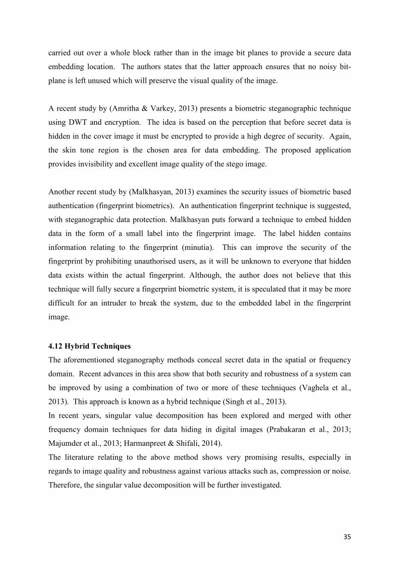
35
carried out over a whole block rather than in the image bit planes to provide a secure data
embedding location. The authors states that the latter approach ensures that no noisy bit-
plane is left unused which will preserve the visual quality of the image.
A recent study by (Amritha & Varkey, 2013) presents a biometric steganographic technique
using DWT and encryption. The idea is based on the perception that before secret data is
hidden in the cover image it must be encrypted to provide a high degree of security. Again,
the skin tone region is the chosen area for data embedding. The proposed application
provides invisibility and excellent image quality of the stego image.
Another recent study by (Malkhasyan, 2013) examines the security issues of biometric based
authentication (fingerprint biometrics). An authentication fingerprint technique is suggested,
with steganographic data protection. Malkhasyan puts forward a technique to embed hidden
data in the form of a small label into the fingerprint image. The label hidden contains
information relating to the fingerprint (minutia). This can improve the security of the
fingerprint by prohibiting unauthorised users, as it will be unknown to everyone that hidden
data exists within the actual fingerprint. Although, the author does not believe that this
technique will fully secure a fingerprint biometric system, it is speculated that it may be more
difficult for an intruder to break the system, due to the embedded label in the fingerprint
image.
4.12 Hybrid Techniques
The aforementioned steganography methods conceal secret data in the spatial or frequency
domain. Recent advances in this area show that both security and robustness of a system can
be improved by using a combination of two or more of these techniques (Vaghela et al.,
2013). This approach is known as a hybrid technique (Singh et al., 2013).
In recent years, singular value decomposition has been explored and merged with other
frequency domain techniques for data hiding in digital images (Prabakaran et al., 2013;
Majumder et al., 2013; Harmanpreet & Shifali, 2014).
The literature relating to the above method shows very promising results, especially in
regards to image quality and robustness against various attacks such as, compression or noise.
Therefore, the singular value decomposition will be further investigated.
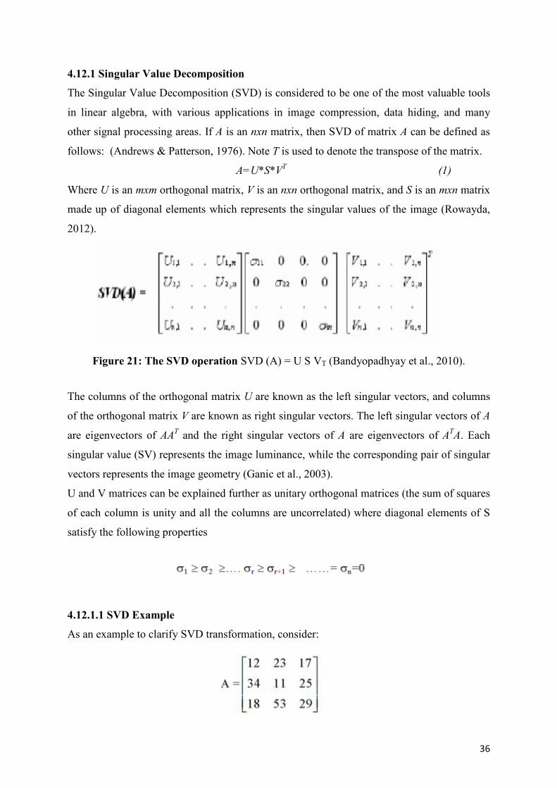
36
4.12.1 Singular Value Decomposition
The Singular Value Decomposition (SVD) is considered to be one of the most valuable tools
in linear algebra, with various applications in image compression, data hiding, and many
other signal processing areas. If A is an nxn matrix, then SVD of matrix A can be defined as
follows: (Andrews & Patterson, 1976). Note T is used to denote the transpose of the matrix.
A=U*S*VT (1)
Where U is an mxm orthogonal matrix, V is an nxn orthogonal matrix, and S is an mxn matrix
made up of diagonal elements which represents the singular values of the image (Rowayda,
2012).
Figure 21: The SVD operation SVD (A) = U S VT (Bandyopadhyay et al., 2010).
The columns of the orthogonal matrix U are known as the left singular vectors, and columns
of the orthogonal matrix V are known as right singular vectors. The left singular vectors of A
are eigenvectors of AAT and the right singular vectors of A are eigenvectors of ATA. Each
singular value (SV) represents the image luminance, while the corresponding pair of singular
vectors represents the image geometry (Ganic et al., 2003).
U and V matrices can be explained further as unitary orthogonal matrices (the sum of squares
of each column is unity and all the columns are uncorrelated) where diagonal elements of S
satisfy the following properties
4.12.1.1 SVD Example
As an example to clarify SVD transformation, consider:
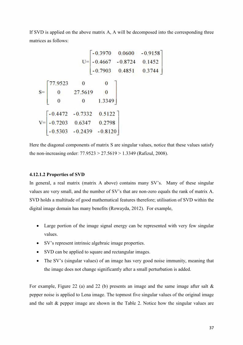
37
If SVD is applied on the above matrix A, A will be decomposed into the corresponding three
matrices as follows:
Here the diagonal components of matrix S are singular values, notice that these values satisfy
the non-increasing order: 77.9523 > 27.5619 > 1.3349 (Rafizul, 2008).
4.12.1.2 Properties of SVD
In general, a real matrix (matrix A above) contains many SV’s. Many of these singular
values are very small, and the number of SV’s that are non-zero equals the rank of matrix A.
SVD holds a multitude of good mathematical features therefore; utilisation of SVD within the
digital image domain has many benefits (Rowayda, 2012). For example,
Large portion of the image signal energy can be represented with very few singular
values.
SV’s represent intrinsic algebraic image properties.
SVD can be applied to square and rectangular images.
The SV’s (singular values) of an image has very good noise immunity, meaning that
the image does not change significantly after a small perturbation is added.
For example, Figure 22 (a) and 22 (b) presents an image and the same image after salt &
pepper noise is applied to Lena image. The topmost five singular values of the original image
and the salt & pepper image are shown in the Table 2. Notice how the singular values are
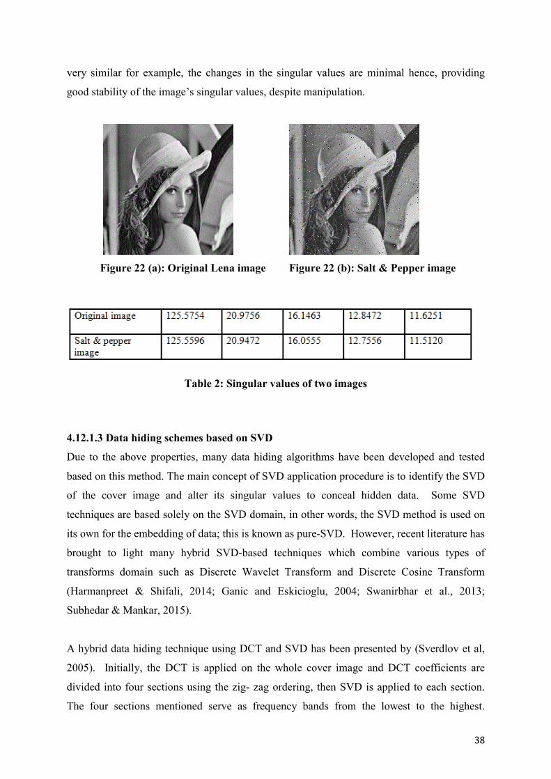
38
very similar for example, the changes in the singular values are minimal hence, providing
good stability of the image’s singular values, despite manipulation.
Figure 22 (a): Original Lena image Figure 22 (b): Salt & Pepper image
Table 2: Singular values of two images
4.12.1.3 Data hiding schemes based on SVD
Due to the above properties, many data hiding algorithms have been developed and tested
based on this method. The main concept of SVD application procedure is to identify the SVD
of the cover image and alter its singular values to conceal hidden data. Some SVD
techniques are based solely on the SVD domain, in other words, the SVD method is used on
its own for the embedding of data; this is known as pure-SVD. However, recent literature has
brought to light many hybrid SVD-based techniques which combine various types of
transforms domain such as Discrete Wavelet Transform and Discrete Cosine Transform
(Harmanpreet & Shifali, 2014; Ganic and Eskicioglu, 2004; Swanirbhar et al., 2013;
Subhedar & Mankar, 2015).
A hybrid data hiding technique using DCT and SVD has been presented by (Sverdlov et al,
2005). Initially, the DCT is applied on the whole cover image and DCT coefficients are
divided into four sections using the zig- zag ordering, then SVD is applied to each section.
The four sections mentioned serve as frequency bands from the lowest to the highest.
39
Singular values of the secret image are then used to alter the singular values of each section
of the cover image. The approach used in this paper comprises of the cover image being
broken down into four parts (blocks) therefore the size of the secret image is equal to quarter
size of the cover image. It has been mentioned that concealing information in the lower
frequencies bands of the image can aid to robustness against some attacks whereas altering
the higher frequencies provide robustness against a different group of attacks, such as noise
addition or filtering. The authors have carried out tests based on the robustness of this
technique against attacks which include JPEG and JPEG 2000 compression, Gaussian noise
and blur, histogram equalization, cropping and image rotation. Results showed that the
algorithm was robust to most attacks. However, the rotation test proved to be unsatisfactory
due to loss of embedded data.
Ganic and Eskicioglu (2004) proposed an SVD-DWT based algorithm, quite akin to the
above mentioned technique presented by (Sverdlov et al., 2005). They break down the cover
image into four sub-bands using DWT and SVD is applied to each of the image sub- bands.
Then, SVD is applied on the secret image and the singular values of the cover image are
altered with the singular values of the secret image. Subsequently, four sets of DWT
coefficients are obtained and the DWT inverse is applied which includes the modified
coefficients, producing a stego image. The stego image was tested for robustness against
various image processing attacks including Gaussian noise, JPEG and JPEG 2000
compression, cropping and histogram equalization. Image quality measure was also tested by
comparison of secret data extraction and the original secret data. These test showed no
severity to image quality based on the above embedding technique.
A more recent study by Subhedar & Mankar, (2015) also proposes a technique based on
Discrete Wavelet Transform (DWT) and SVD. They embed their secret data using the
singular values of the secret image into the cover image based on the modification of the
wavelets HH sub-band coefficients. This method also showed very promising results, in
relation to many image attacks. Furthermore, after comparison of the stego image against the
original cover image, results also look encouraging.
The above studies confirm that some SVD hybrid methods have been developed and tested in
the area of biometrics, mainly for securing biometric data. However, at the time of this
research, very few pieces of literature were found. The present studies in this area seem to
40
focus solely on iris biometric. However, one study proposed a method to improve the
authenticity of fingerprint biometrics (Bandyopadhyay et al., 2010). This is discussed below.
Swanirbhar et al. (2013) proposes an algorithm in order to enhance the security of biometric
data (iris template) using DWT-SVD domain. The authors highlight that the integration of
the SVD and DWT together produces a more robust and imperceptible strategy for data
hiding. They first apply single level DWT to the host image to obtain the set of four sub-
band coefficients. This is followed up by application of SVD operation on the high-
frequency sub-bands such as, the HH or HL bands. Then, a binary representation of the
biometric iris template is hidden by modifying the singular values of the high-frequency
bands. The inverse of SVD is applied which include the modified SV’s. Lastly, the DWT
inverse is applied to produce a stego image. The outcome of tests carried out was very
encouraging. Image quality tests showed, barely any image distortion after embedding had
taken place. Moreover, the method proved to be robust whist analysed against an abundance
of popular attacks.
Harmanpreet & Shifali, (2014) have presented a data hiding technique using a combination
of three frequency domains, SVD, DWT and DCT (Discrete Cosine Transform). The
projected technique is based on the detection of facial and iris biometric detection, to secure
for authenticity and ownership of data. As in prior methods, the wavelet coefficients of the
cover image are utilised to embed the secret data; the HH-sub-band is selected for data
embedding. Following the DWT decomposition of the cover image, DCT is then applied to
the HH band. Subsequently, the SVD application is applied and the singular values of both
cover and secret image are retrieved, and added together to produce the modified singular
values. Lastly, the inverse DCT transform is applied followed by the inverse DWT. The use
of this algorithm for data hiding has proven to be highly imperceptible. Furthermore, it
shows robustness against all sorts of attacks, and also possesses very high data hiding
capacity. In addition, this technique holds all the requisites required of a model data hiding
system such as fidelity, robustness and high capacity.
In a study by (Bandyopadhyay et al., 2010), a robust data hiding algorithm is proposed for the
safeguarding of fingerprint images. Again, SVD transform technique is used for embedding
secret data. This approach differs from the above techniques as it uses solely the singular
value decomposition without any input from DWT or DCT. A fingerprint is used as a cover

41
image and a facial image used for embedding purposes. The cover image is divided in to 8x8
blocks and the SVD is computed for each block. The diagonal elements of each block, which
is the singular values, are then modified with the
bit pattern of the secret image content by remainder of the singular values S (1,1) divided by
the set value of the image quality ‘Q’ factor. The inverse of SVD is then applied to produce
the new image containing the secret data. The authors mention that various attacks are
initiated on the fingerprint images to verify its robustness. However, only the outcome of one
particular attack (rotation attack) was discussed in the paper. The authors highlight that
resistance to rotation is an important factor for fingerprint images yet give no explanation as
to why this claim was made. Furthermore, no material was included to verify this statement.
4.13 Conclusion
This section explored current studies in the area of steganography, deployed in spatial domain
and transform domains of digital images. In general, a frequency domain approach seems
much more attractive than that of a spatial domain, as transform methods (DCT), (DWT)
make modifications in the high frequency coefficients rather than directly manipulating the
image pixels. Embedding data into the frequency domain causes less distortion to the image,
and seems to be a lot more resilient to attacks such as compression, hence why these methods
are preferred. In most cases, it is hard to recognise secret data is present, but on the other
hand the payload of the hidden information must be small (in comparison to spatial
embedding) due to the risk of image distortion, thus a higher possible detection risk.
Studies conducted into the field of steganography in biometrics indicate that a frequency
domain approach for hiding biometric data is a more preferable approach. The use of low
frequency bands often cause the image to become distorted, thus increasing the visibility of
hidden data. On the other hand, embedding in the high frequencies also has its downfalls, as
attacks such as compression and filtering mainly affect these frequencies. It is likely that
embedding data in high frequencies will lead to data disruption, or complete loss of data. A
good compromise may be to embed information in mid frequency bands, this may improve,
or even solve the above mentioned problems. Even though some negative points, such as
small capacity for hiding, have been highlighted in regards to the DWT domain, it still
presents a promising outcome and surpasses the DCT domain particularly in surviving
compression (Wayner, 2002; Rakhi Singh, 2013).
42
In recent years, many hybrid algorithms have been proposed. These techniques are more
robust against various image attacks as they utilise the properties of more than one domain.
Many of these recent approaches are developed by computing the SVD of a cover image and
then modify its singular values to conceal secret data. As the singular values do not change
much when small modifications are made, image distortion has been reported as minimal
after embedding has taken place, hence less chance of detecting that hidden data is present.
Studies show that there are many types of algorithms for data hiding, some of which were
discussed above. It is clear that each method has its own advantages and limitations no one
method is 100% robust. For example, each technique proved resilient to some type of attacks
but showed weakness towards other attack types.
It is noticed that more advantages exist in systems using wavelet transforms, such as DWT
along with SVD. Many encouraging results have been recorded based on these two domains.
43
5 STEGANALYSIS
5.1 Introduction
The process of steganalysis can be explained as the art and science of detecting hidden
information that occurs through the practice of steganography (Hashemi, et al., 2011).
Steganalysis is an extremely challenging discipline, as its dependant on vulnerable
steganography techniques (Patil et al., 2012). According to (Fridrich et al., 2002), "the ability
to detect secret messages in images is related to the message length". The fore mentioned
declaration is established on the sense that if a tiny amount of information is embedded in a
sizable carrier file, it will result in a limited percentage of manipulations, thus it will be much
more difficult to identify the existence of a concealed communication. There exists two
primary classifications of steganography, targeted, and blind (Pevny & Fridrich, 2006). This
chapter will focus on how the latter can be used to combat the steganographic algorithms
discussed in the previous chapter. The strengths and weaknesses of these strategies will also
be discussed.
Patil et al., (2012) believe that the success of any steganalysis algorithm is dependent on the
amount of information the steganalysist has to begin with. Moreover, to successfully attack a
steganographic algorithm, a steganalysist must be knowledgeable of the procedures and
techniques of many steganography tools (Reddy & Kumar, 2007).
Classification of attacks based on information available to the attacker as discussed by
(Reddy & Kumar, 2007), are outlined below:
Stego only attack: In a stego-only attack, only the stego object is available for investigation,
the steganalysist does not have any additional information. Realistically, the only way a
steganalysist could attack is by trying all common attacks on current steganographic
algorithms
Known cover attack: In this sequence of events, both the cover object and the stego object are
available. As both mediums are available to the steganalyst they can look for variations
between the two mediums and therefore can attempt to identify what type of steganographic
algorithm was used.
Known message attack: In this scenario, the steganalyst is aware of the hidden information,
and they can study the stego image for similar future attacks. Sometimes, knowing the
44
message and studying of the stego image help the steganalyst to attack related systems.
However, even by knowing the above information, this may still prove to be a difficult task
and may even be treated the same as the stego-only attack as the original image is not
available for consideration.
Chosen stego attack: In this case, both the steganographic algorithm and stego medium
(image) are known to the steganalyst. This type of attack may involve the steganalyst
attempting to produce stego objects from cover objects in order to pair the seized stego
medium. Theoretically, trying to create brand-new stego mediums to pair the seized one
seems right, yet in practice it is extremely difficult to achieve, considering both the stego
medium and the embedded information is not known
The above classification of steganalytic attacks is rarely used, as the primary objective of
steganalysis is to detect the existence, or the absence of concealed information. Most of the
current steganalysis attacks were created by the awareness of the algorithm used, just as
Kerckhoffs’ principle suggests (Schaathun, 2012), in order to acquire a methodology by
constructing stego images with known covers, and thus measure their statistics. As discussed
previously, the main goal of steganalysis is to initially detect the existence of hidden
information. A more useful list of attacks that are primarily used are the following.
5.2 Targeted Attacks
Targeted steganalysis works when a technique planned for detecting a particular
steganographic process has been created (Patil et al., 2012). For instance, embedding within
pixel values leaves behind specific pattern types which can be investigated for with
suspicious files. Assuming the steganalyst is confident that secret communications have
taken place, and is also aware of an available process as to how the hidden information might
me embedded, then it should take only minimum effort to identify whether or not the file
consists of this kind of steganography or not. The next few sub sections introduces a few
fundamental steganalytical strategies relating to targeted steganalysis, and includes visual,
structural, and statistical attacks.
5.2.1 Visual Attacks.
According to (Patil et al., 2012) visual attacks are considered as the simplest form of
steganalysis. Just as the name implies, a visual attack is generally associated with
investigation of the stego object with the human eye in the hope that any occurrence of
disparity is noticeable. An important rule of steganography is to ensure quality degradation of
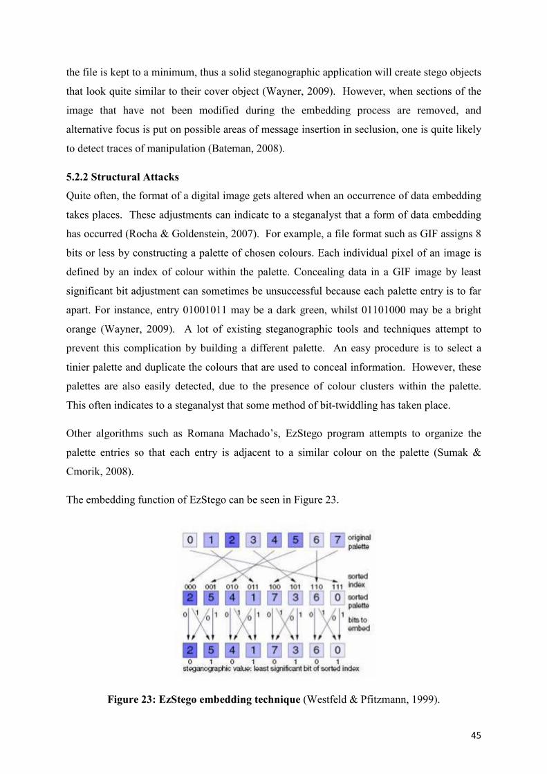
45
the file is kept to a minimum, thus a solid steganographic application will create stego objects
that look quite similar to their cover object (Wayner, 2009). However, when sections of the
image that have not been modified during the embedding process are removed, and
alternative focus is put on possible areas of message insertion in seclusion, one is quite likely
to detect traces of manipulation (Bateman, 2008).
5.2.2 Structural Attacks
Quite often, the format of a digital image gets altered when an occurrence of data embedding
takes places. These adjustments can indicate to a steganalyst that a form of data embedding
has occurred (Rocha & Goldenstein, 2007). For example, a file format such as GIF assigns 8
bits or less by constructing a palette of chosen colours. Each individual pixel of an image is
defined by an index of colour within the palette. Concealing data in a GIF image by least
significant bit adjustment can sometimes be unsuccessful because each palette entry is to far
apart. For instance, entry 01001011 may be a dark green, whilst 01101000 may be a bright
orange (Wayner, 2009). A lot of existing steganographic tools and techniques attempt to
prevent this complication by building a different palette. An easy procedure is to select a
tinier palette and duplicate the colours that are used to conceal information. However, these
palettes are also easily detected, due to the presence of colour clusters within the palette.
This often indicates to a steganalyst that some method of bit-twiddling has taken place.
Other algorithms such as Romana Machado’s, EzStego program attempts to organize the
palette entries so that each entry is adjacent to a similar colour on the palette (Sumak &
Cmorik, 2008).
The embedding function of EzStego can be seen in Figure 23.
Figure 23: EzStego embedding technique (Westfeld & Pfitzmann, 1999).
46
Following the hiding process the palette needs to be unsorted to its initial state. If a
steganalyst views the palette they will see no signs that any steganography procedure has
taken place. As it stands now the information isn’t stored in the least significant bits of pixels.
When the recipient receives the image an identical ordering process as above in Figure 16
must be carried out so the hidden data can be extracted by applying the new ordered indexes
of the palette. The least significant bits instantly encodes the data. Nevertheless, if a
steganalyst is aware of the sorting algorithm then they also will be able to access hidden bits
(Westfeld & Pfitzmann, 1999). In addition, even with the above disadvantage taken into
account, structural attacks are agreeably of greater importance to steganalysts as opposed to
visual attacks, as they can be tested against a broader range of embedding methods (Patil et
al., 2012).
5.2.3 Statistical Attacks
In mathematics, the subject of statistics makes it viable to detect if any phenomenon takes
place at random within a data set. Commonly, a hypothesis would be created that apparently
describes why the phenomenon happens, and statistical techniques can then be used to
confirm this hypothesis to be either true or false. If we consider the data format for a stego
object, we can start to view how statistics can be beneficial for the purpose of steganalysis,
and determine whether or not an image includes secret information (Chhikara & Singh,
2013).
A stego object can be divided into two data sets, image data, and message data.
The image data relates to the facts concerning the physical image that can be seen, and
usually refers to pixel values. In addition, the message data refers to the facts in relation to
the secret message, and if coded, it is usually more randomly constructed than image data. It
can agreeably be derived that the message data is more random than image data, and this is
where statistical attacks normally work. Although there is significantly less message data
than image data, the tiny proportion of changeability generated by the message data is
adequate enough to allow a steganalyst to invoke an attack (Bateman, 2008).
There are many techniques recognised for determining the existence of secret data by means
of statistical procedures, all directed at recognising traces of embedding for particular stego
schemes. In the next section, some common statistical attacks will be discussed. The reasons
as to why these attacks are so effective will also be presented.
47
5.2.3.1 Chi-squared (x2) Test / Pairs of Values (POV)
The Chi-squared Test, often referred to as the x2 Test, is one of the most popular and
straightforward statistical attacks in existence today. It was initially, recorded in
steganalytical terms by (Westfeld & Pfitzmann, 1999). The test allows for comparison of the
statistical properties (pairs of values) of a suspicious image with the theoretically anticipated
statistical properties of its carrier correspondent such that it is achievable to figure out the
possibility that a suspicious image is indeed a stego object (El-Sayed et al., 2012). For
example, if we think of LSB substitution, at the time of the embedding procedure, fixed sets,
of Pairs of Values (PoV): the number of 1s and the number of 0s show up (Guillermito,
2004). For instance, a pixel which has an initial value of 2 would evolve into 3 if the bit to be
embedded was a 1. If the bit to be embedded was a 0, the pixel would stay at 2. It was this
logic, that (Westfeld & Pfitzmann, 1999) used whilst developing the chi-squared attack that
can be used on steganographic methods, in situations where a fixed set of PoVs are flipped
into one another to embed hidden data bits. As mentioned above, this technique is established
by the statistical examination of PoVs that change at the time of data embedding. When the
amount of pixels for which LSB has been changed increases, both POVs frequencies tend to
become the same, such that if an image contains 50 pixels which have a value 2 and 100
pixels that include a value 3. After, LSB embedding of the whole LSB plane the likely
frequencies of 2 and 3 will be 75 and 75 respectively. It should be noted, that the latter is
when the whole LSB plane is altered (Lussan, 2007).
With application of the x2 test it is not imperative for a steganalyst to have access to the
cover object in order to test if data hiding has taken place, explaining why it is one of the
more favourable approaches. Only in exceptional circumstance will a steganalyst have access
to the original cover object, so the primary aim of the x2 test is to be effective in establishing
a technique for precisely calculating the likely statistical attributes of the initial cover object,
without literally accessing it. To achieve this successfully, normally depends upon a
profound understanding of numerous embedding techniques. For this reason, the test is
classified as a targeted procedure. If a steganalyst is knowledgeable of a potential
steganographic embedding scenario, then they are capable of analysing the significance of
embedding such that they finally determine a series of features that can be examined to
decide the possibility that a suspicious image is in fact a stego image (Bateman, 2008).
Although, the above technique is popular in the detection of sequential style embedding it
does not work accurately on random type embedding. Several steganographic algorithms
48
have been created such that they randomise the embedding approach (particular algorithms
include OutGuess 0.1, OutGuess 0.2, F3, F4, F5.).
5.2.3.2 The Extended Chi-Squared Attack
As mentioned above, it is not possible for the x2 test to provide accurate results based on
random style embedding. For example, the Chi-squared test uses an increased sample size
and always starts at the beginning of an image. Due to this, changes will only be detected in
the histogram if the image is distorted continuously, from start to finish thus areas of the
image that are not distorted can give negative results. Whereas, the extended Chi-squared
uses a constant sample size and slides the position of the samples over the entire image range,
resulting in more accurate results (Provos, 2001). Over the years, various efforts have been
invented to generalise the concept such that it can still function. (Bateman, 2008).The most
renowned work in this area is the work carried out by (Provos and Honeyman, 2002). As
mentioned above, the procedure they used adapted the basic x2 test by using a fixed sample
size but moving the location where the samples are taken (Westfeld, 2003). This technique is
in variation to the basic x2 test that raises the sample size and applies the test at a fixed area.
It is clear that the extended approach does make it possible to detect the occurrence of
randomly scattered data, yet according to (Wayner, 2009) differentiating between embedded
data and regular image data can be difficult. (Bateman, 2008) explains that this is mainly due
to the p-value calculation (probability that an image is a stego image) being obsolete. The p-
value plot tends to rise and fall irregularly between 5% and 95%. For this reason, (Bateman,
2008) believes that the extended chi-squared test is not proficient in the estimation the hidden
message length.
5.2.3.3 Regular Singular (RS) Steganalysis
Another highly regarded technique for detection of LSB embedding in colour and grey-scale
images was introduced by (Fridrich et al., 2001). Fridrich and colleagues discuss how
statistical measures on LSBs for detecting the level of embedding, alone is inaccurate. They
explain that this is mainly due to the lack of unrecognisable structure of the bit plane in a
stegoed image. RS Steganalysis can manipulate this feature. (Fridrich et al., 2001) method
works by analysing embedding capacity for lossless data insertion in LSBs. Randomising
LSBs minimises this capacity. To inspect an image, the authors establish two groups of fixed
shape. These groups are known as Regular (R) and Singular(S) groups of pixels and are
49
based on particular attributes. For example, whether or not the pixel noise within the group
(calculated using the mean absolute value of the differences between adjacent pixels) is
increased or decreased after flipping the LSBs of a fixed set of pixels within each group (Ker,
2004). Subsequently, corresponding frequencies of both groups are then used to attempt to
foresee the embedding degree, in the image retrieved from the initial image with flipped
LSBs, and the image retrieved by randomising the LSBs of the initial image.
5.3 Blind Steganalysis
In contrast to targeted steganalysis, blind steganalysis detection techniques are considerably
challenging (Patil et al., 2012). However, these methods are modern and more powerful than
targeted procedures for attacking a stego file since the method does not depend on knowing
any specific embedding procedures (Kumar, 2011). Based on this method of detection a
steganalyst has no reason to think that any form of secret communications has transpired.
Based on these circumstances, a series of algorithms are generally created to enable suspected
files to be examined for indications of manipulations. If the algorithms indicate any evidence
that tampering has occurred, then it is quite possible that the speculated file contains
steganography (Patil et al., 2012).
Memon et al., (2001) introduced early blind steganalysis techniques based on Image Quality
Measures (IQM) were the system could easily identify images based on the possibility that
they hold communicative information such as a message or a watermark.
Farid, (2002) also introduced a technique in accordance with extracted features based on the
higher order statistics (mean, variance, skewness, and kurtosis) of the wavelet (transform) of
the suspected file. Farid concluded by stating that robust high-order statistical consistencies
exist within the mentioned domain for natural images, and that these consistencies are
modified when data is embedded.
Fridrich et al., (2002) contributed a more straightforward technique for blind steganalysis that
was based on self-calibration. The next few sections will discuss this procedure and explain
how the process makes it possible to produce an estimate of the cover image using only a
suspected image file. When a steganalyst uses an estimate of the cover file it allows them to
carry out more generalised attacks than prior attacks discussed in the previous sections
(targeted attacks) and accurately determine any possibility that the suspect image contain
message data.
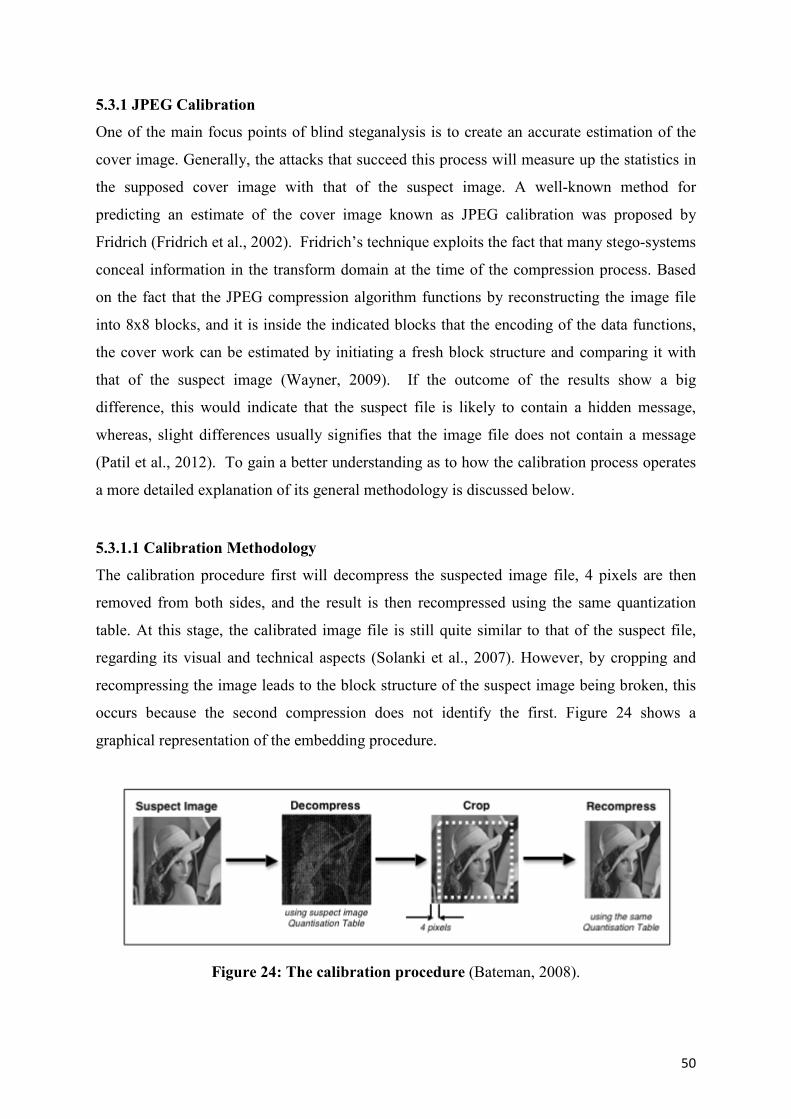
50
5.3.1 JPEG Calibration
One of the main focus points of blind steganalysis is to create an accurate estimation of the
cover image. Generally, the attacks that succeed this process will measure up the statistics in
the supposed cover image with that of the suspect image. A well-known method for
predicting an estimate of the cover image known as JPEG calibration was proposed by
Fridrich (Fridrich et al., 2002). Fridrich’s technique exploits the fact that many stego-systems
conceal information in the transform domain at the time of the compression process. Based
on the fact that the JPEG compression algorithm functions by reconstructing the image file
into 8x8 blocks, and it is inside the indicated blocks that the encoding of the data functions,
the cover work can be estimated by initiating a fresh block structure and comparing it with
that of the suspect image (Wayner, 2009). If the outcome of the results show a big
difference, this would indicate that the suspect file is likely to contain a hidden message,
whereas, slight differences usually signifies that the image file does not contain a message
(Patil et al., 2012). To gain a better understanding as to how the calibration process operates
a more detailed explanation of its general methodology is discussed below.
5.3.1.1 Calibration Methodology
The calibration procedure first will decompress the suspected image file, 4 pixels are then
removed from both sides, and the result is then recompressed using the same quantization
table. At this stage, the calibrated image file is still quite similar to that of the suspect file,
regarding its visual and technical aspects (Solanki et al., 2007). However, by cropping and
recompressing the image leads to the block structure of the suspect image being broken, this
occurs because the second compression does not identify the first. Figure 24 shows a
graphical representation of the embedding procedure.
Figure 24: The calibration procedure (Bateman, 2008).
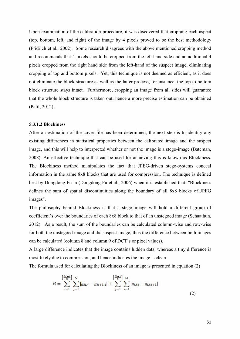
51
Upon examination of the calibration procedure, it was discovered that cropping each aspect
(top, bottom, left, and right) of the image by 4 pixels proved to be the best methodology
(Fridrich et al., 2002). Some research disagrees with the above mentioned cropping method
and recommends that 4 pixels should be cropped from the left hand side and an additional 4
pixels cropped from the right hand side from the left-hand of the suspect image, eliminating
cropping of top and bottom pixels. Yet, this technique is not deemed as efficient, as it does
not eliminate the block structure as well as the latter process, for instance, the top to bottom
block structure stays intact. Furthermore, cropping an image from all sides will guarantee
that the whole block structure is taken out; hence a more precise estimation can be obtained
(Patil, 2012).
5.3.1.2 Blockiness
After an estimation of the cover file has been determined, the next step is to identity any
existing differences in statistical properties between the calibrated image and the suspect
image, and this will help to interpreted whether or not the image is a stego-image (Bateman,
2008). An effective technique that can be used for achieving this is known as Blockiness.
The Blockiness method manipulates the fact that JPEG-driven stego-systems conceal
information in the same 8x8 blocks that are used for compression. The technique is defined
best by Dongdong Fu in (Dongdong Fu et al., 2006) when it is established that: "Blockiness
defines the sum of spatial discontinuities along the boundary of all 8x8 blocks of JPEG
images".
The philosophy behind Blockiness is that a stego image will hold a different group of
coefficient’s over the boundaries of each 8x8 block to that of an unstegoed image (Schaathun,
2012). As a result, the sum of the boundaries can be calculated column-wise and row-wise
for both the unstegoed image and the suspect image, thus the difference between both images
can be calculated (column 8 and column 9 of DCT’s or pixel values).
A large difference indicates that the image contains hidden data, whereas a tiny difference is
most likely due to compression, and hence indicates the image is clean.
The formula used for calculating the Blockiness of an image is presented in equation (2)
(2)
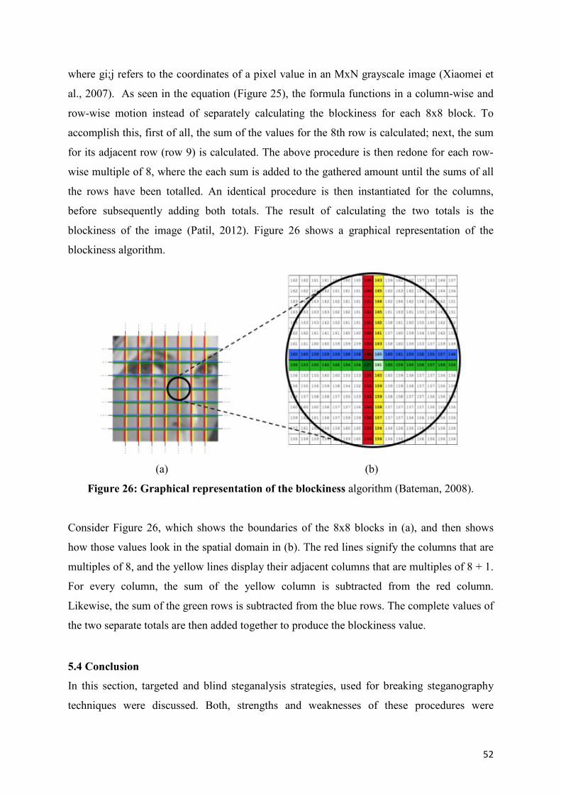
52
where gi;j refers to the coordinates of a pixel value in an MxN grayscale image (Xiaomei et
al., 2007). As seen in the equation (Figure 25), the formula functions in a column-wise and
row-wise motion instead of separately calculating the blockiness for each 8x8 block. To
accomplish this, first of all, the sum of the values for the 8th row is calculated; next, the sum
for its adjacent row (row 9) is calculated. The above procedure is then redone for each row-
wise multiple of 8, where the each sum is added to the gathered amount until the sums of all
the rows have been totalled. An identical procedure is then instantiated for the columns,
before subsequently adding both totals. The result of calculating the two totals is the
blockiness of the image (Patil, 2012). Figure 26 shows a graphical representation of the
blockiness algorithm.
(a) (b)
Figure 26: Graphical representation of the blockiness algorithm (Bateman, 2008).
Consider Figure 26, which shows the boundaries of the 8x8 blocks in (a), and then shows
how those values look in the spatial domain in (b). The red lines signify the columns that are
multiples of 8, and the yellow lines display their adjacent columns that are multiples of 8 + 1.
For every column, the sum of the yellow column is subtracted from the red column.
Likewise, the sum of the green rows is subtracted from the blue rows. The complete values of
the two separate totals are then added together to produce the blockiness value.
5.4 Conclusion
In this section, targeted and blind steganalysis strategies, used for breaking steganography
techniques were discussed. Both, strengths and weaknesses of these procedures were
53
examined in relation to how simple the artefacts of message embedding can be detected by
way of steganalysis.
The first attack reviewed was visual attacks. It is clear that the key aspect of a productive
visual attack is to accurately establish what parts of the image can be disregarded (redundant
data), and which parts need to be examined (test data), in order to verify the theory that a
suspected file has a message or watermark. However, if a steganalyst makes an incorrect
judgement regarding both data types, a rise in false-negatives may occur, this is an issue that
a steganalyst needs to avoid (Patil et al., 2012). As a result, it is extremely likely that every
modification of attainable redundant and test data sets is likely to be investigated so that the
steganalyst is in a powerful position to make an informed judgement. For this reason, visual
attacks can be tedious and time consuming. For example, the production of test images for
various potential techniques of embedding would take up a lot of time. Moreover, after test
images are produced they require perceptual inspection. If a steganalyst aspires to exhaust
every type of embedding scenario, then thousands of images would need to be viewed to
determine whether or not one suspect image is a stego image (Sumak & Cmorik, 2008).
(Patil et al., 2012) believe that methodologies used for visual attacks are inefficient, and is
generally why alternative steganalytical procedures are preferable.
Structural Attacks were also reviewed and are considered to be the more favourable approach
taken by steganalyst. A Structural Attack can detect changes that may occur in an image due
to data embedding, for example, changes to the palette colours/palette size or increasing or
decreasing of the image size. If a steganalyst suspects any of the above mentioned changes,
the suspected file will then be investigated further. Structural attacks can be evaluated based
on a wide-range of embedding techniques. Furthermore, they more difficult from a
steganographic perspective as there are likely to be a greater number of existing stego-
systems where structural attacks can be practiced with success, however, more recent systems
are inclined to be too secure and robust for this attack to be successful (Bateman, 2008).
The last type of targeted attack discussed was statistical attacks. These attacks are preferred
over visual or structural attacks, mainly because they can be automated. Considering this
technique is capable of making an automatic analysis of the image, pressure of determining if
an image is a stego image or not is taken away from the steganalyst because the analysis is
done by the computer. Furthermore, automated findings will reduce the chance of misleading
conclusions because of less human interpretation, unlike visual attacks. In addition,
statistical attacks do not need to have an in depth knowledge of what the cover image should
54
look like whereas, structural attacks requires the cover image to check for adjustments in
image structure (palette colours) for testing (Patil et al., 2012). However, for these attacks to
work efficiently, a steganalyst must have a deep understanding of various embedding
methods and have awareness as to how the stego image may have been created (referred to as
a known stego-attack). If the above information is not available, then they will require access
to the original image (referred to as a known-cover attack) so that differences in the original
and the suspected stego can be examined.
In contrast to targeted steganalysis, blind steganalysis works based on the assumption that
zero knowledge exists regarding the cover image, or the algorithm used to embed the hidden
information. These attacks judge the likelihood of image tampering merely on the data
contained in the suspected image. It is clear from research that blind attacks are more realistic
in a real world scenario as a steganalyst is seldom knowledgeable about an image.
The JPEG calibration and blockiness method shows that it is unnecessary for the cover image
to be obtained for the attack to be successful. (Fridrich et al., 2002) noted a positive outcome
with a 94% success rate. It also was successful at obtaining potential embedding strategies.
Finally, as with all the steganalytical techniques explained in this thesis, the chance of
success is greatly reduced when the message load is close to zero. Obviously, if only few
changes are needed when the message data is hidden, fewer changes occur in the carrier file.
The reason for this is that a by embedding smaller message, only a few changes will occur in
the cover image, hence the stego image will look identical, or almost identical to the original
image, even with hidden data embedded. Both JPEG calibration and blockiness are no
different, as they too depend on message capacity, to produce a precise outcome. In addition,
many trade-offs exist between the discussed techniques. For example, a stego-system that is
easy to implement (LSB embedding), can also be easily attacked, whilst a more complex
stego system (DCT, DWT), cannot be violated quite as easily. More complex stego-systems
are inclined to be harder to break as they conceal the hidden data in a more complicated way
than the simpler systems.
55
6. IMPLEMENTATION
6.1 Introduction
This chapter presents procedures used to develop a secure fingerprint recognition system.
The objective behind this technique is to hide a facial image (secret image) within a
fingerprint image (cover image) in order to make fingerprint biometrics more secure. First, a
short background of the proposed system is given and then the detailed project is described.
In many of the studies reviewed, it has been observed that data hiding algorithms are based
on either substitution or quantisation procedure, and pixel bits or coefficients are manipulated
in order to conceal data. Research shows that many frequency domain algorithms exceed that
of the spatial domain. However, spatial domain techniques do possess some advantages over
frequency domains, for instance, its large capacity to hide data. Nonetheless, the negative
points of embedding in the spatial domain, such as its poor robustness to attacks, outweigh
the positive ones. Even though, the majority of methods mentioned in the literature review
suggest that frequency domain methods are deemed a more appropriate method,
disadvantages also exist. In frequency domain embedding the capacity for hiding data is
much less than that of the spatial domain. For instance, using DWT as an example, and a
bitmap image size 512x512, which is decomposed at first level (LL, LH, HL, HH), the
maximum message or watermark size would be 256x256. Moreover if decomposed further
(LL1, LH1, HL1, HH1), the maximum message or watermark size would be 128x128.
Furthermore, depending on how and where the data is hidden, applying compression on the
image may cause the hidden message or watermark to be badly distorted or unreadable.
When an image is compressed most of the energy stored in the high frequency sub-bands are
removed, so if a message or watermark is hidden in these sub bands it may be lost. Lusson,
(2011), originally proposed a method to exploit the wavelet domain by hiding information
(watermark image) in the sub-band coefficients of the mid frequency band of an image to
produce a stego image. Image quality tests carried out showed positive results. However,
after testing the algorithms robustness against jpeg compression, results proved very
disappointing. Lusson reported that after applying various levels of compression to the
image, the hidden data extracted was badly distorted and hence unreadable. Lusson used a
method of LSB replacement to conceal data in a high frequency sub-band. As mentioned
above, hiding data within a high frequency band may cause data loss after compression.
Moreover, Lusson used an LSB embedding approach (replacing 0 with 1). Based on research
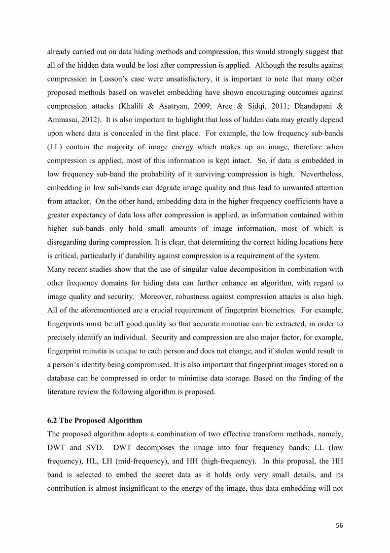
56
already carried out on data hiding methods and compression, this would strongly suggest that
all of the hidden data would be lost after compression is applied. Although the results against
compression in Lusson’s case were unsatisfactory, it is important to note that many other
proposed methods based on wavelet embedding have shown encouraging outcomes against
compression attacks (Khalili & Asatryan, 2009; Aree & Sidqi, 2011; Dhandapani &
Ammasai, 2012). It is also important to highlight that loss of hidden data may greatly depend
upon where data is concealed in the first place. For example, the low frequency sub-bands
(LL) contain the majority of image energy which makes up an image, therefore when
compression is applied; most of this information is kept intact. So, if data is embedded in
low frequency sub-band the probability of it surviving compression is high. Nevertheless,
embedding in low sub-bands can degrade image quality and thus lead to unwanted attention
from attacker. On the other hand, embedding data in the higher frequency coefficients have a
greater expectancy of data loss after compression is applied, as information contained within
higher sub-bands only hold small amounts of image information, most of which is
disregarding during compression. It is clear, that determining the correct hiding locations here
is critical, particularly if durability against compression is a requirement of the system.
Many recent studies show that the use of singular value decomposition in combination with
other frequency domains for hiding data can further enhance an algorithm, with regard to
image quality and security. Moreover, robustness against compression attacks is also high.
All of the aforementioned are a crucial requirement of fingerprint biometrics. For example,
fingerprints must be off good quality so that accurate minutiae can be extracted, in order to
precisely identify an individual. Security and compression are also major factor, for example,
fingerprint minutia is unique to each person and does not change, and if stolen would result in
a person’s identity being compromised. It is also important that fingerprint images stored on a
database can be compressed in order to minimise data storage. Based on the finding of the
literature review the following algorithm is proposed.
6.2 The Proposed Algorithm
The proposed algorithm adopts a combination of two effective transform methods, namely,
DWT and SVD. DWT decomposes the image into four frequency bands: LL (low
frequency), HL, LH (mid-frequency), and HH (high-frequency). In this proposal, the HH
band is selected to embed the secret data as it holds only very small details, and its
contribution is almost insignificant to the energy of the image, thus data embedding will not
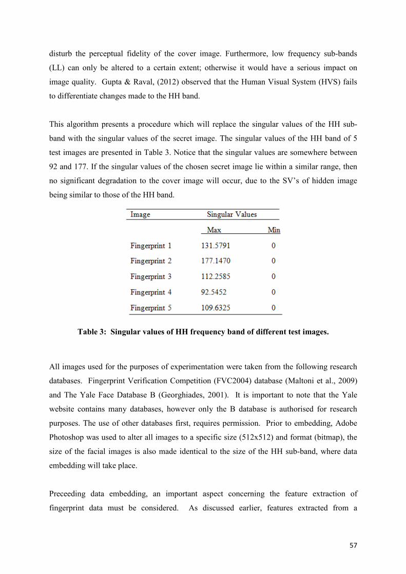
57
disturb the perceptual fidelity of the cover image. Furthermore, low frequency sub-bands
(LL) can only be altered to a certain extent; otherwise it would have a serious impact on
image quality. Gupta & Raval, (2012) observed that the Human Visual System (HVS) fails
to differentiate changes made to the HH band.
This algorithm presents a procedure which will replace the singular values of the HH sub-
band with the singular values of the secret image. The singular values of the HH band of 5
test images are presented in Table 3. Notice that the singular values are somewhere between
92 and 177. If the singular values of the chosen secret image lie within a similar range, then
no significant degradation to the cover image will occur, due to the SV’s of hidden image
being similar to those of the HH band.
Table 3: Singular values of HH frequency band of different test images.
All images used for the purposes of experimentation were taken from the following research
databases. Fingerprint Verification Competition (FVC2004) database (Maltoni et al., 2009)
and The Yale Face Database B (Georghiades, 2001). It is important to note that the Yale
website contains many databases, however only the B database is authorised for research
purposes. The use of other databases first, requires permission. Prior to embedding, Adobe
Photoshop was used to alter all images to a specific size (512x512) and format (bitmap), the
size of the facial images is also made identical to the size of the HH sub-band, where data
embedding will take place.
Preceeding data embedding, an important aspect concerning the feature extraction of
fingerprint data must be considered. As discussed earlier, features extracted from a
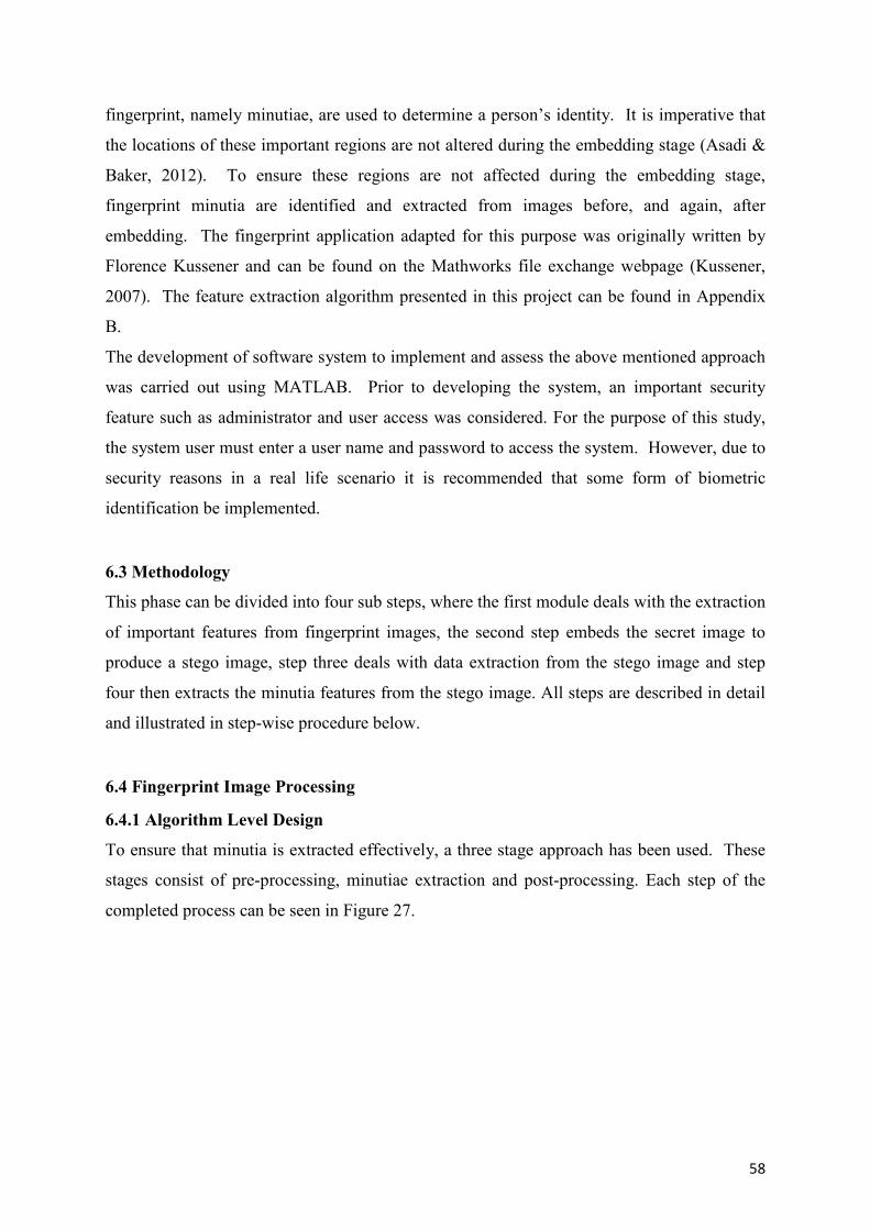
58
fingerprint, namely minutiae, are used to determine a person’s identity. It is imperative that
the locations of these important regions are not altered during the embedding stage (Asadi &
Baker, 2012). To ensure these regions are not affected during the embedding stage,
fingerprint minutia are identified and extracted from images before, and again, after
embedding. The fingerprint application adapted for this purpose was originally written by
Florence Kussener and can be found on the Mathworks file exchange webpage (Kussener,
2007). The feature extraction algorithm presented in this project can be found in Appendix
B.
The development of software system to implement and assess the above mentioned approach
was carried out using MATLAB. Prior to developing the system, an important security
feature such as administrator and user access was considered. For the purpose of this study,
the system user must enter a user name and password to access the system. However, due to
security reasons in a real life scenario it is recommended that some form of biometric
identification be implemented.
6.3 Methodology
This phase can be divided into four sub steps, where the first module deals with the extraction
of important features from fingerprint images, the second step embeds the secret image to
produce a stego image, step three deals with data extraction from the stego image and step
four then extracts the minutia features from the stego image. All steps are described in detail
and illustrated in step-wise procedure below.
6.4 Fingerprint Image Processing
6.4.1 Algorithm Level Design
To ensure that minutia is extracted effectively, a three stage approach has been used. These
stages consist of pre-processing, minutiae extraction and post-processing. Each step of the
completed process can be seen in Figure 27.

59
Figure 27: Feature extraction process steps.
6.4.2 Image Pre-Processing
6.4.2.1 Image Acquisition
During the fingerprint acquisition stage a digital fingerprint is acquired from a user via a
sensor/scanner (optical scanner). For this project, fingerprints from the FVC database
(Maltoni et al., 2009) were used therefore, no acquisition step is implemented.
6.4.2.2 Image Enhancement
As discussed in the literature review, occasionally, fingerprints obtained from a user can be of
poor quality. This sometimes will occur because of the different scanners used to acquire the
print. For a system to give an accurate reading, all fingerprints images must be of good
quality. Thus, prints need to be enhanced accordingly to ensure the system is precise in the
reading and matching the data. Many algorithms and image processing techniques can be
used for this purpose (Thirani, 2013). However, this phase is not implemented here, as the
fingerprints used are already of good quality.
6.4.2.3 Image Binarization
Image Binarization is applied to the fingerprint image. This process transforms the 8-bit
fingerprint image to 1-bit image. In general, an object pixel is given a value of “1” whereas a
background pixel is given a value of “0.” Subsequently, a binary image is generated by
shading pixels, either black or white (black for 0, white for 1). Here, a locally adaptive
binarization method is performed using Matlab “im2bw” function.
60
binarizedImage = im2bw (inputImage);
The approach used here divides the image into (16x16) blocks and calculates the mean
intensity value for each block. Then, each pixel value is changed to “1” if its intensity value
is greater than the mean intensity value of the current block, to which the pixel belongs to.
Figure 28 shows fingerprint image before and after Binarization.
Figure 28: A fingerprint image before and after Binarization.
6.4.3 Minutia Extraction Process
6.4.3.1 Thinning
After the fingerprint image is converted to binary form, a thinning algorithm is applied to
reduce the ridge thickness to one pixel wide. In order to preserve fingerprint minutia, it is
important that the thinning operation be performed without any modification being made to
the original ridge. For this purpose, MATLAB’s built in morphological thinning function
“bwmorph" is used. The “bwmorph” operation is based on the following two principles,
ridge end points are not removed and connected ridges are preserved. The function is applied
as below.
bwmorph(binaryImage,'thin',inf);
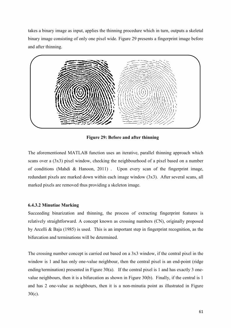
61
takes a binary image as input, applies the thinning procedure which in turn, outputs a skeletal
binary image consisting of only one pixel wide. Figure 29 presents a fingerprint image before
and after thinning.
Figure 29: Before and after thinning
The aforementioned MATLAB function uses an iterative, parallel thinning approach which
scans over a (3x3) pixel window, checking the neighbourhood of a pixel based on a number
of conditions (Mahdi & Hanoon, 2011) . Upon every scan of the fingerprint image,
redundant pixels are marked down within each image window (3x3). After several scans, all
marked pixels are removed thus providing a skeleton image.
6.4.3.2 Minutiae Marking
Succeeding binarization and thinning, the process of extracting fingerprint features is
relatively straightforward. A concept known as crossing numbers (CN), originally proposed
by Arcelli & Baja (1985) is used. This is an important step in fingerprint recognition, as the
bifurcation and terminations will be determined.
The crossing number concept is carried out based on a 3x3 window, if the central pixel in the
window is 1 and has only one-value neighbour, then the central pixel is an end-point (ridge
ending/termination) presented in Figure 30(a). If the central pixel is 1 and has exactly 3 one-
value neighbours, then it is a bifurcation as shown in Figure 30(b). Finally, if the central is 1
and has 2 one-value as neighbours, then it is a non-minutia point as illustrated in Figure
30(c).
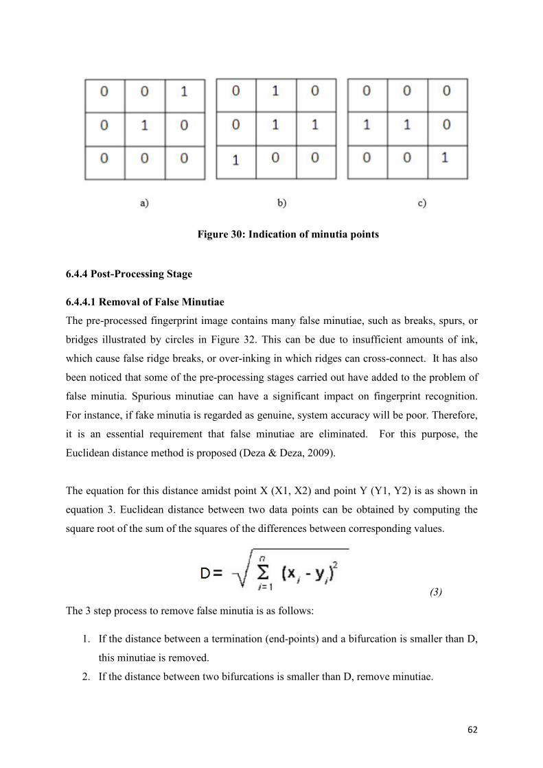
62
Figure 30: Indication of minutia points
6.4.4 Post-Processing Stage
6.4.4.1 Removal of False Minutiae
The pre-processed fingerprint image contains many false minutiae, such as breaks, spurs, or
bridges illustrated by circles in Figure 32. This can be due to insufficient amounts of ink,
which cause false ridge breaks, or over-inking in which ridges can cross-connect. It has also
been noticed that some of the pre-processing stages carried out have added to the problem of
false minutia. Spurious minutiae can have a significant impact on fingerprint recognition.
For instance, if fake minutia is regarded as genuine, system accuracy will be poor. Therefore,
it is an essential requirement that false minutiae are eliminated. For this purpose, the
Euclidean distance method is proposed (Deza & Deza, 2009).
The equation for this distance amidst point X (X1, X2) and point Y (Y1, Y2) is as shown in
equation 3. Euclidean distance between two data points can be obtained by computing the
square root of the sum of the squares of the differences between corresponding values.
(3)
The 3 step process to remove false minutia is as follows:
1. If the distance between a termination (end-points) and a bifurcation is smaller than D,
this minutiae is removed.
2. If the distance between two bifurcations is smaller than D, remove minutiae.
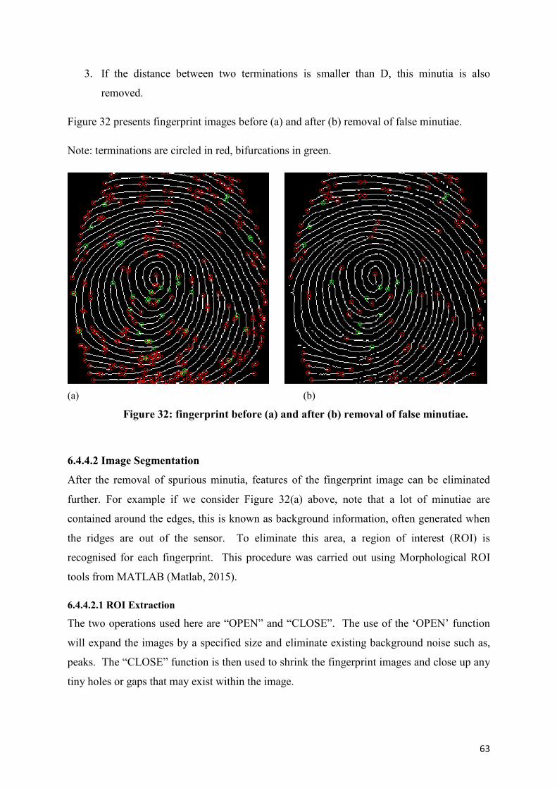
63
3. If the distance between two terminations is smaller than D, this minutia is also
removed.
Figure 32 presents fingerprint images before (a) and after (b) removal of false minutiae.
Note: terminations are circled in red, bifurcations in green.
(a) (b)
Figure 32: fingerprint before (a) and after (b) removal of false minutiae.
6.4.4.2 Image Segmentation
After the removal of spurious minutia, features of the fingerprint image can be eliminated
further. For example if we consider Figure 32(a) above, note that a lot of minutiae are
contained around the edges, this is known as background information, often generated when
the ridges are out of the sensor. To eliminate this area, a region of interest (ROI) is
recognised for each fingerprint. This procedure was carried out using Morphological ROI
tools from MATLAB (Matlab, 2015).
6.4.4.2.1 ROI Extraction
The two operations used here are “OPEN” and “CLOSE”. The use of the ‘OPEN’ function
will expand the images by a specified size and eliminate existing background noise such as,
peaks. The “CLOSE” function is then used to shrink the fingerprint images and close up any
tiny holes or gaps that may exist within the image.
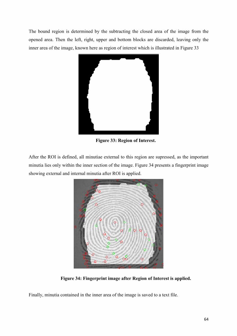
64
The bound region is determined by the subtracting the closed area of the image from the
opened area. Then the left, right, upper and bottom blocks are discarded, leaving only the
inner area of the image, known here as region of interest which is illustrated in Figure 33
Figure 33: Region of Interest.
After the ROI is defined, all minutiae external to this region are supressed, as the important
minutia lies only within the inner section of the image. Figure 34 presents a fingerprint image
showing external and internal minutia after ROI is applied.
Figure 34: Fingerprint image after Region of Interest is applied.
Finally, minutia contained in the inner area of the image is saved to a text file.
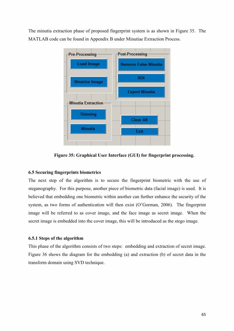
65
The minutia extraction phase of proposed fingerprint system is as shown in Figure 35. The
MATLAB code can be found in Appendix B under Minutiae Extraction Process.
Figure 35: Graphical User Interface (GUI) for fingerprint processing.
6.5 Securing fingerprints biometrics
The next step of the algorithm is to secure the fingerprint biometric with the use of
steganography. For this purpose, another piece of biometric data (facial image) is used. It is
believed that embedding one biometric within another can further enhance the security of the
system, as two forms of authentication will then exist (O’Gorman, 2006). The fingerprint
image will be referred to as cover image, and the face image as secret image. When the
secret image is embedded into the cover image, this will be introduced as the stego image.
6.5.1 Steps of the algorithm
This phase of the algorithm consists of two steps: embedding and extraction of secret image.
Figure 36 shows the diagram for the embedding (a) and extraction (b) of secret data in the
transform domain using SVD technique.
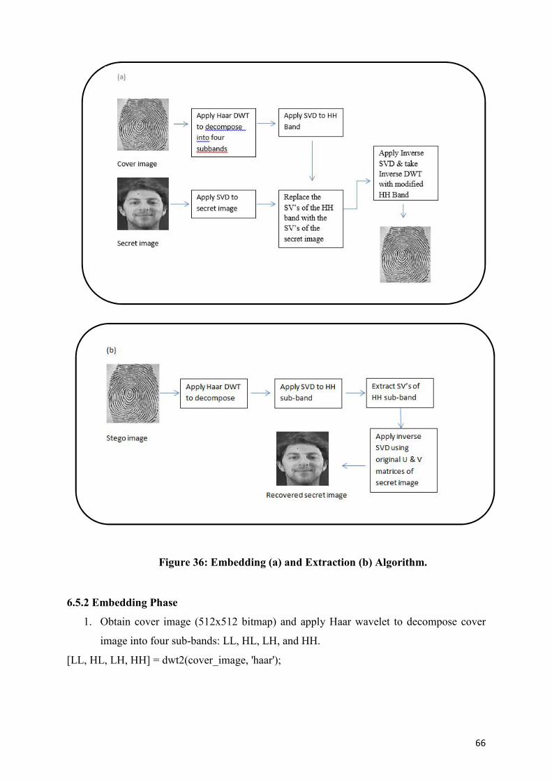
66
Figure 36: Embedding (a) and Extraction (b) Algorithm.
6.5.2 Embedding Phase
1. Obtain cover image (512x512 bitmap) and apply Haar wavelet to decompose cover
image into four sub-bands: LL, HL, LH, and HH.
[LL, HL, LH, HH] = dwt2(cover_image, 'haar');
67
2. Apply SVD to HH band. Where Uh is an mxm orthogonal matrix, Vh is an nxn
orthogonal matrix, and Sh is an mxn matrix made up of diagonal elements which
represents the singular values of the image
HH = Uh * Sh * VhT.
3. Obtain secret image and apply SVD to it
SecretImg = Us * Ss * VsT .
4. Replace the singular values of the HH band with the singular values of the secret image.
5. Apply inverse of SVD to obtain the modified HH band.
HH_mod = Uh * Ss * VhT.
6. Apply inverse of DWT to generate the stego cover image.
6.5.3 Extraction Phase
1. Decompose the stego image into four sub-bands: LL, HL, LH, and HH using Haar wavelet.
2. Apply SVD to HH band
HH = Uh * Sh * VhT.
3. Extract the singular values from HH band
4. Construct image using singular values from the stego image and orthogonal matrices
U s and Vs obtained using SVD of secret image.
After the above phases, the secret image was extracted and clearly recognisable. Modifying
only the singular values of an image allows for the data to be extracted without the need for
the original cover image. This has many benefits in regards to security and image
management such as, the original image does not need to be stored.
6.6 Image Attacks
In order to prove the robustness of the data embedding technique proposed, a series of attacks
have been carried out on the stego fingerprint images. Many of these attacks (noise addition,
rotation, compression, filtering) are explained in more detail in chapter 7, and have been
automated using MATLAB (see code in Appendix B). The proposed scheme has also been
tested against JPEG/JPEG 2000 compression attacks. All attacks implemented within this
study are relative to the proposed system. For example, both removal attacks such as
compression, and geometric attacks such as, resizing or cropping have been applied to all
fingerprint images. As mentioned earlier, it is quite important that a fingerprint image can be
68
compressed in order to save space on a system database so, tests are carried out using various
levels of JPEG and JPEG2000 compression. Another important requirement of the proposed
system, or any watermarking/steganographic system is that the hidden data is extractable and
recognisable after attacks are applied. Applied attacks such as cropping, rotation or noise
addition may also remove or distort hidden data and make it unrecognisable therefore all of
the above mentioned attacks are implemented and tested.
6.7 Image Quality Measures
In most cases, it is a challenging task to objectively detect differences between two images.
One person may not recognise any differences whereas another may observe slight image
disparity. For this reason, mathematical functions have been established to rationalise these
slight changes. A lot of studies compare two images using PSNR (peak signal to noise ratio)
based on the MSE (mean-squared error). The PSNR is normally expressed in decibels, which
is a logarithmic scale (National Instruments Community, 2013) and outputs a high value if
only, slight differences occur between the original cover image and the stego image. If a
value is above 38db, the human eye can not recognise any deterioration in image quality
(Zhiwei et al., 2007). The PSNR is calculated like so in equation (4):
(4)
where Cmax represents the highest pixel value present in the image (maximum of 255).
For a cover image whose width and height are M and N, MSE is defined
As follows in equation (5):
(5)
where x and y are image co-ordinates, S is the generated stego image and C is the original
cover image.
More recent studies carried out by (Lukac & Plataniotis, 2006) highlight that the PSNR is not
adequately correlated with the human perception as PSNR is a component average. If data is
specifically embedded within the image edges or textured areas, PSNR is then an inefficient
method to compute the quality of an image. (Wang et al., 2004) proves this statement using
images that have been altered, one image is badly distorted whereas another image shows no
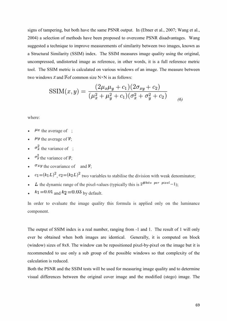
69
signs of tampering, but both have the same PSNR output. In (Ebner et al., 2007; Wang et al.,
2004) a selection of methods have been proposed to overcome PSNR disadvantages. Wang
suggested a technique to improve measurements of similarity between two images, known as
a Structural Similarity (SSIM) index. The SSIM measures image quality using the original,
uncompressed, undistorted image as reference, in other words, it is a full reference metric
tool. The SSIM metric is calculated on various windows of an image. The measure between
two windows and of common size N×N is as follows:
(6)
where:
the average of ;
the average of ;
the variance of ;
the variance of ;
the covariance of and ;
, two variables to stabilise the division with weak denominator;
the dynamic range of the pixel-values (typically this is );
and by default.
In order to evaluate the image quality this formula is applied only on the luminance
component.
The output of SSIM index is a real number, ranging from -1 and 1. The result of 1 will only
ever be obtained when both images are identical. Generally, it is computed on block
(window) sizes of 8x8. The window can be repositioned pixel-by-pixel on the image but it is
recommended to use only a sub group of the possible windows so that complexity of the
calculation is reduced.
Both the PSNR and the SSIM tests will be used for measuring image quality and to determine
visual differences between the original cover image and the modified (stego) image. The
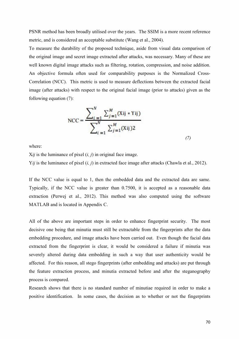
70
PSNR method has been broadly utilised over the years. The SSIM is a more recent reference
metric, and is considered an acceptable substitute (Wang et al., 2004).
To measure the durability of the proposed technique, aside from visual data comparison of
the original image and secret image extracted after attacks, was necessary. Many of these are
well known digital image attacks such as filtering, rotation, compression, and noise addition.
An objective formula often used for comparability purposes is the Normalized Cross-
Correlation (NCC). This metric is used to measure deflections between the extracted facial
image (after attacks) with respect to the original facial image (prior to attacks) given as the
following equation (7):
(7)
where:
Xij is the luminance of pixel (i, j) in original face image.
Yij is the luminance of pixel (i, j) in extracted face image after attacks (Chawla et al., 2012).
If the NCC value is equal to 1, then the embedded data and the extracted data are same.
Typically, if the NCC value is greater than 0.7500, it is accepted as a reasonable data
extraction (Perwej et al., 2012). This method was also computed using the software
MATLAB and is located in Appendix C.
All of the above are important steps in order to enhance fingerprint security. The most
decisive one being that minutia must still be extractable from the fingerprints after the data
embedding procedure, and image attacks have been carried out. Even though the facial data
extracted from the fingerprint is clear, it would be considered a failure if minutia was
severely altered during data embedding in such a way that user authenticity would be
affected. For this reason, all stego fingerprints (after embedding and attacks) are put through
the feature extraction process, and minutia extracted before and after the steganography
process is compared.
Research shows that there is no standard number of minutiae required in order to make a
positive identification. In some cases, the decision as to whether or not the fingerprints
71
match is left solely to the examiner. However, each individual department may hold their
own set of requirements in order to establish a positive identification (Lofland, 2009).
Ireland follows what is known as an 8-point rule, meaning that 8 minutia points are required
for a valid identification. Many European countries require no less than 12 points of
similarity (Girard, 2013), with Australia requirement also being 12. The UK and Italy require
16, while Brazil and Argentina require not less than 30 (Dallas, 2014). In the United States,
standards vary, the U.S seem to depend more on the opinion of a fingerprint expert to
establish a valid match, regardless of the amount of matching minutiae (Tipton & Krause,
2007). Nonetheless, it is obvious that the more minutiae points exist, the more accurate the
identification process will be.
6.8 Steganalysis
To conclude this investigation, a steganalysis tool, StegDetect is used to evaluate if the
proposed steganography algorithm is perceptible. This tool is used widely in research
relating to steganography as they can identify a broad selection of data hiding methods such
as jsteg, jphide (unix and windows), invisible secrets, outguess 01.3b, F5 (header analysis),
appendX and camouflage The most recent version of StegDetect is 0.6 which was issued in
September 2004. The following chapter presents test results and findings.
72
7. RESULTS AND ANALYSIS
7.1 Introduction
This chapter, presents the results and analysis of all experiments completed. Experiments
were carried out on MATLAB using a Windows 7 computer equipped with an Intel Core i5-
3230M 2 GHz (Gigahertz) CPU (Central Processing Unit) and 8 GB of RAM (Gigabytes of
Random Access Memory).
The strengths and weaknesses of the proposed technique were investigated with regards to
invisibility, robustness against various image processing attacks and possible detection using
Steganalysis tools. Although, five test images were used for test purposes (Results can be
seen in Appendix C), this chapter will only discuss, and display detailed results based on one
fingerprint image (fingerprint one). However, the results from the additional four fingerprint
images will occasionally be referred to, and compared with the results of fingerprint one.
7.2 Image Database
To allow for a fair comparison regarding results, it is important that any steganographic
software is tested on many different images. “The same set of sample images should always
be used.”(Petitcolas, 1997-2015). In some cases, collecting data for the evaluation process
can be quite difficult and time consuming. Therefore, organisers of the FVC (Fingerprint
Verification Competition) have created a multi-database for research purposes, which
includes four disjoint fingerprint databases (DB1, DB2, DB3, and DB4). Images from each
of these database were collected using various sensor technologies therefore differ in quality.
Images from DB2 were captured by use of an optical sensor, and are used here for test
purposes. The reasons this decision was made are as follows:
Images in DB2 database are of good quality hence no image enhancement process is
required.
This database has been used widely to test fingerprint systems (Xu et al., 2009;
Cappelli et al., 2011; Kayaoglu et al., 2013).
A similar set of images had to be used, so that a fair comparison of strengths and
weaknesses of the presented technique can be determined.
Five test images were used, each of size 512x512 pixels. They will be referred to as
fingerprint one, two, three, four and five as illustrated in Figure 30. A facial image from the
Yale Face Database B (Georghiades, 2001) will be embedded within each fingerprint image.
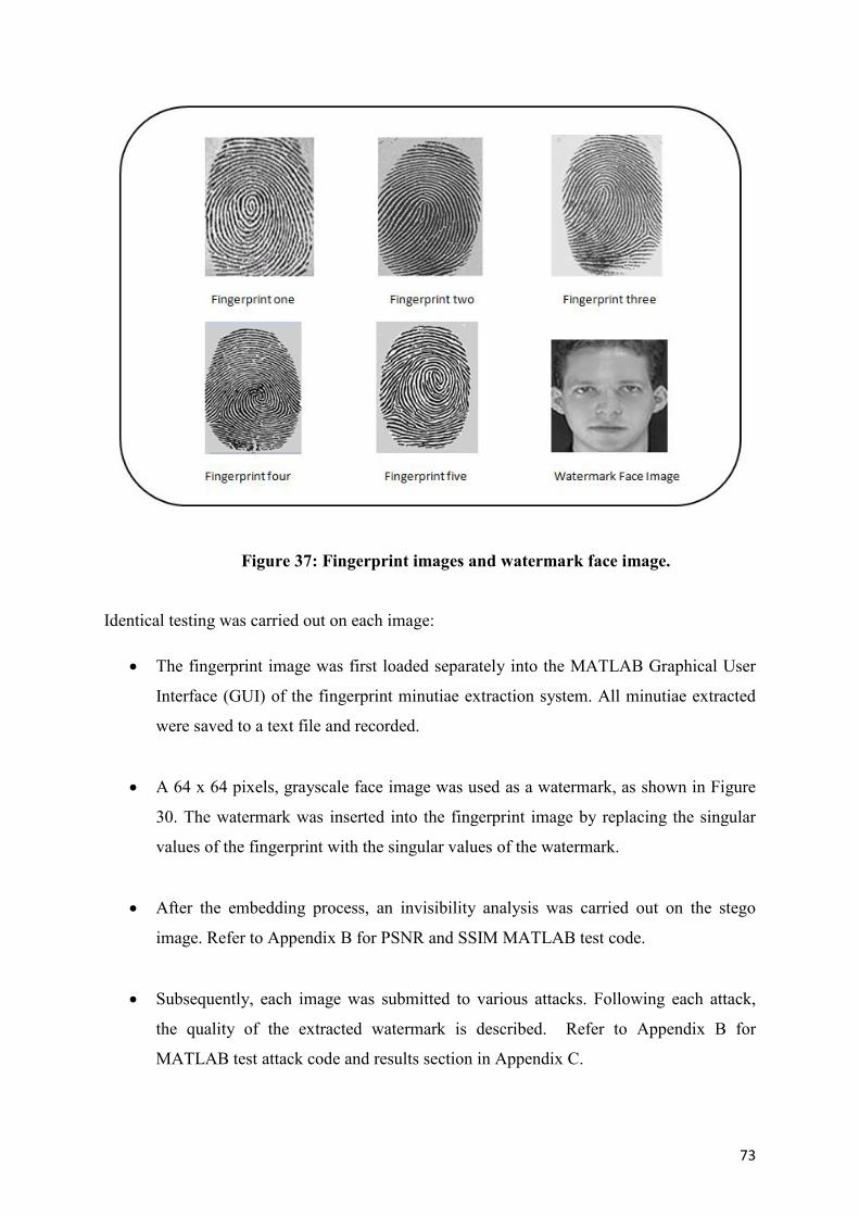
73
Figure 37: Fingerprint images and watermark face image.
Identical testing was carried out on each image:
The fingerprint image was first loaded separately into the MATLAB Graphical User
Interface (GUI) of the fingerprint minutiae extraction system. All minutiae extracted
were saved to a text file and recorded.
A 64 x 64 pixels, grayscale face image was used as a watermark, as shown in Figure
30. The watermark was inserted into the fingerprint image by replacing the singular
values of the fingerprint with the singular values of the watermark.
After the embedding process, an invisibility analysis was carried out on the stego
image. Refer to Appendix B for PSNR and SSIM MATLAB test code.
Subsequently, each image was submitted to various attacks. Following each attack,
the quality of the extracted watermark is described. Refer to Appendix B for
MATLAB test attack code and results section in Appendix C.
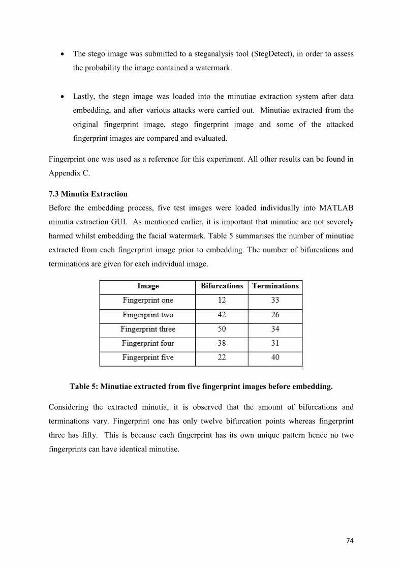
74
The stego image was submitted to a steganalysis tool (StegDetect), in order to assess
the probability the image contained a watermark.
Lastly, the stego image was loaded into the minutiae extraction system after data
embedding, and after various attacks were carried out. Minutiae extracted from the
original fingerprint image, stego fingerprint image and some of the attacked
fingerprint images are compared and evaluated.
Fingerprint one was used as a reference for this experiment. All other results can be found in
Appendix C.
7.3 Minutia Extraction
Before the embedding process, five test images were loaded individually into MATLAB
minutia extraction GUI. As mentioned earlier, it is important that minutiae are not severely
harmed whilst embedding the facial watermark. Table 5 summarises the number of minutiae
extracted from each fingerprint image prior to embedding. The number of bifurcations and
terminations are given for each individual image.
Table 5: Minutiae extracted from five fingerprint images before embedding.
Considering the extracted minutia, it is observed that the amount of bifurcations and
terminations vary. Fingerprint one has only twelve bifurcation points whereas fingerprint
three has fifty. This is because each fingerprint has its own unique pattern hence no two
fingerprints can have identical minutiae.
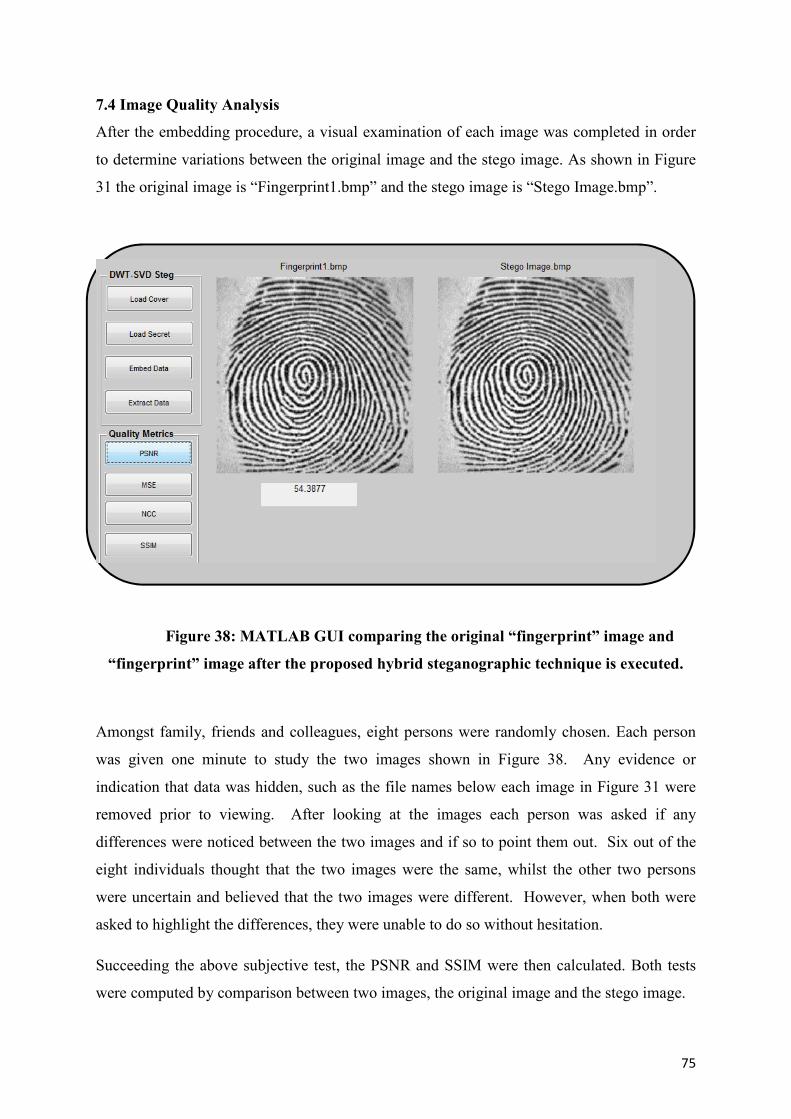
75
7.4 Image Quality Analysis
After the embedding procedure, a visual examination of each image was completed in order
to determine variations between the original image and the stego image. As shown in Figure
31 the original image is “Fingerprint1.bmp” and the stego image is “Stego Image.bmp”.
Figure 38: MATLAB GUI comparing the original “fingerprint” image and
“fingerprint” image after the proposed hybrid steganographic technique is executed.
Amongst family, friends and colleagues, eight persons were randomly chosen. Each person
was given one minute to study the two images shown in Figure 38. Any evidence or
indication that data was hidden, such as the file names below each image in Figure 31 were
removed prior to viewing. After looking at the images each person was asked if any
differences were noticed between the two images and if so to point them out. Six out of the
eight individuals thought that the two images were the same, whilst the other two persons
were uncertain and believed that the two images were different. However, when both were
asked to highlight the differences, they were unable to do so without hesitation.
Succeeding the above subjective test, the PSNR and SSIM were then calculated. Both tests
were computed by comparison between two images, the original image and the stego image.
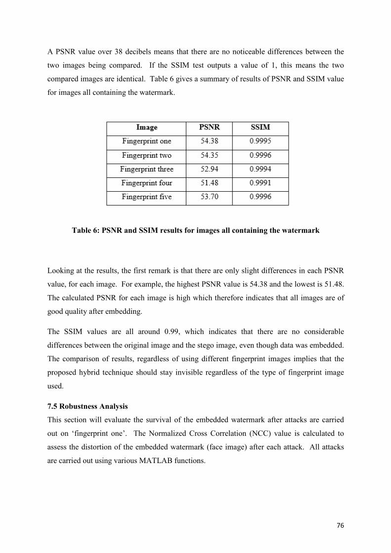
76
A PSNR value over 38 decibels means that there are no noticeable differences between the
two images being compared. If the SSIM test outputs a value of 1, this means the two
compared images are identical. Table 6 gives a summary of results of PSNR and SSIM value
for images all containing the watermark.
Table 6: PSNR and SSIM results for images all containing the watermark
Looking at the results, the first remark is that there are only slight differences in each PSNR
value, for each image. For example, the highest PSNR value is 54.38 and the lowest is 51.48.
The calculated PSNR for each image is high which therefore indicates that all images are of
good quality after embedding.
The SSIM values are all around 0.99, which indicates that there are no considerable
differences between the original image and the stego image, even though data was embedded.
The comparison of results, regardless of using different fingerprint images implies that the
proposed hybrid technique should stay invisible regardless of the type of fingerprint image
used.
7.5 Robustness Analysis
This section will evaluate the survival of the embedded watermark after attacks are carried
out on ‘fingerprint one’. The Normalized Cross Correlation (NCC) value is calculated to
assess the distortion of the embedded watermark (face image) after each attack. All attacks
are carried out using various MATLAB functions.
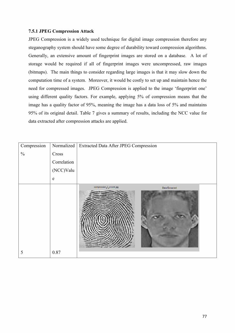
77
7.5.1 JPEG Compression Attack
JPEG Compression is a widely used technique for digital image compression therefore any
steganography system should have some degree of durability toward compression algorithms.
Generally, an extensive amount of fingerprint images are stored on a database. A lot of
storage would be required if all of fingerprint images were uncompressed, raw images
(bitmaps). The main things to consider regarding large images is that it may slow down the
computation time of a system. Moreover, it would be costly to set up and maintain hence the
need for compressed images. JPEG Compression is applied to the image ‘fingerprint one’
using different quality factors. For example, applying 5% of compression means that the
image has a quality factor of 95%, meaning the image has a data loss of 5% and maintains
95% of its original detail. Table 7 gives a summary of results, including the NCC value for
data extracted after compression attacks are applied.
Compression
%
Normalized
Cross
Correlation
(NCC)Valu
e
Extracted Data After JPEG Compression
5 0.87
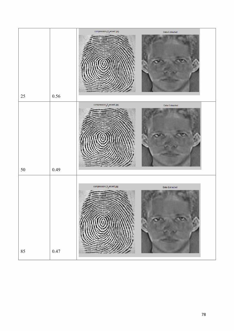
78
25 0.56
50 0.49
85 0.47
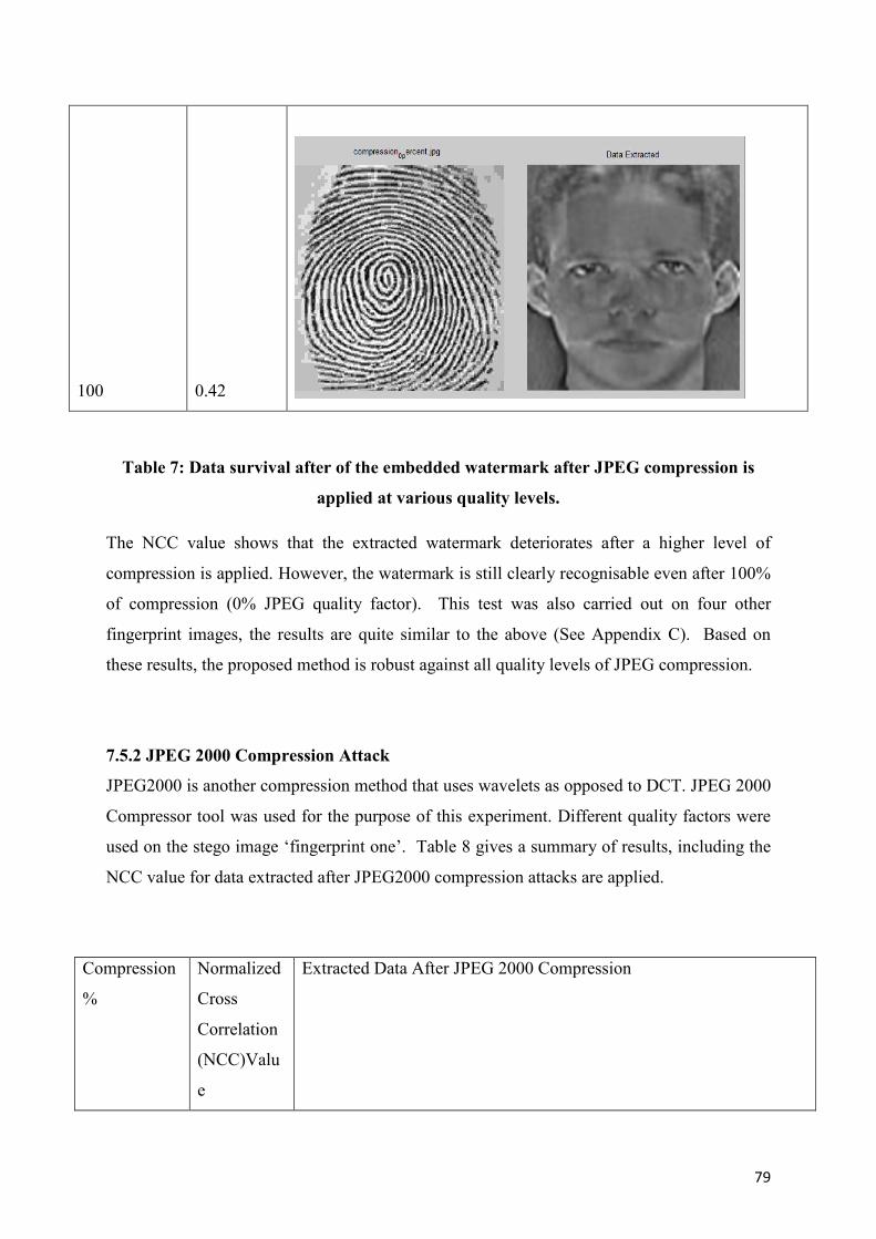
79
100 0.42
Table 7: Data survival after of the embedded watermark after JPEG compression is
applied at various quality levels.
The NCC value shows that the extracted watermark deteriorates after a higher level of
compression is applied. However, the watermark is still clearly recognisable even after 100%
of compression (0% JPEG quality factor). This test was also carried out on four other
fingerprint images, the results are quite similar to the above (See Appendix C). Based on
these results, the proposed method is robust against all quality levels of JPEG compression.
7.5.2 JPEG 2000 Compression Attack
JPEG2000 is another compression method that uses wavelets as opposed to DCT. JPEG 2000
Compressor tool was used for the purpose of this experiment. Different quality factors were
used on the stego image ‘fingerprint one’. Table 8 gives a summary of results, including the
NCC value for data extracted after JPEG2000 compression attacks are applied.
Compression
%
Normalized
Cross
Correlation
(NCC)Valu
e
Extracted Data After JPEG 2000 Compression
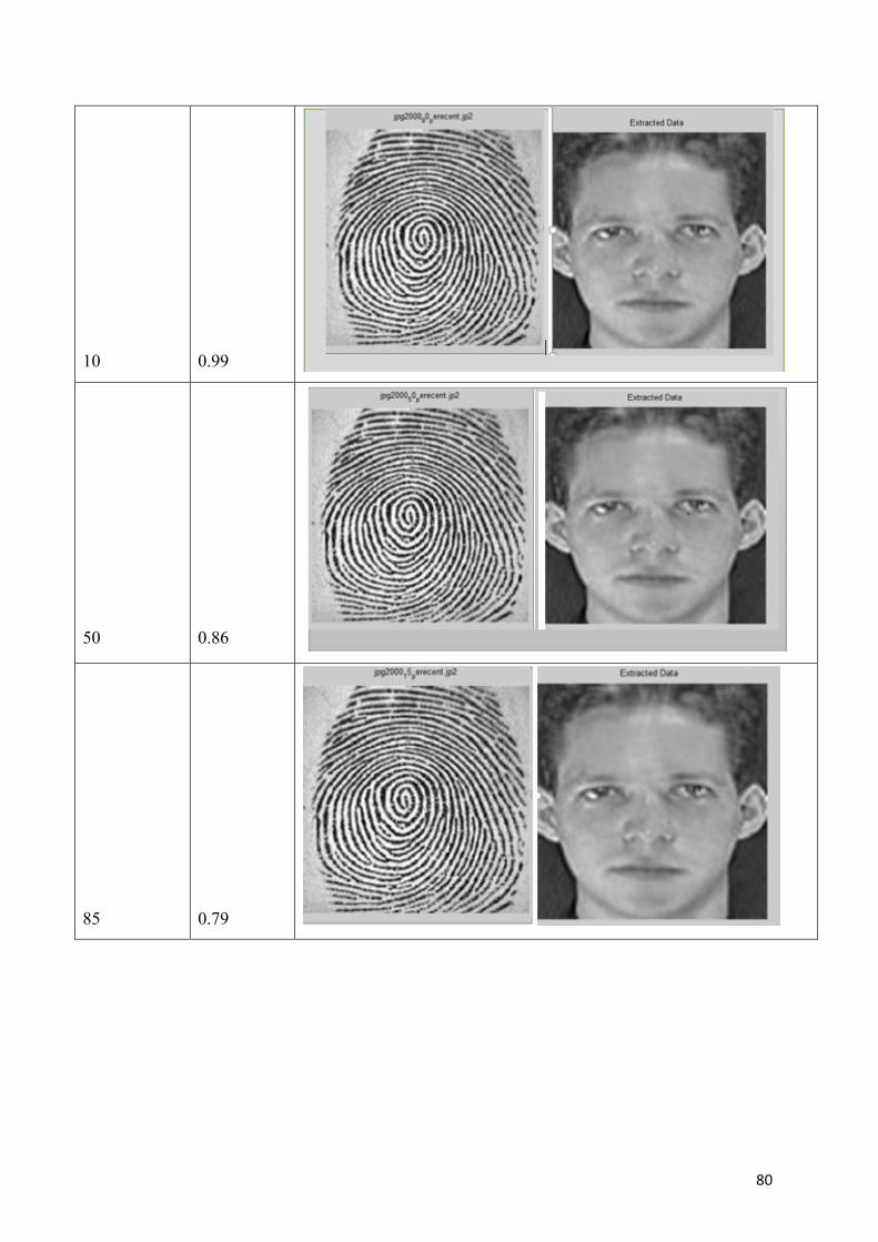
80
10 0.99
50 0.86
85 0.79
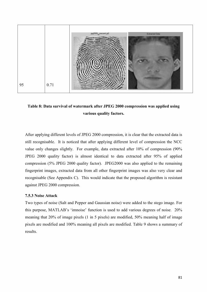
81
95 0.71
Table 8: Data survival of watermark after JPEG 2000 compression was applied using
various quality factors.
After applying different levels of JPEG 2000 compression, it is clear that the extracted data is
still recognisable. It is noticed that after applying different level of compression the NCC
value only changes slightly. For example, data extracted after 10% of compression (90%
JPEG 2000 quality factor) is almost identical to data extracted after 95% of applied
compression (5% JPEG 2000 quality factor). JPEG2000 was also applied to the remaining
fingerprint images, extracted data from all other fingerprint images was also very clear and
recognisable (See Appendix C). This would indicate that the proposed algorithm is resistant
against JPEG 2000 compression.
7.5.3 Noise Attack
Two types of noise (Salt and Pepper and Gaussian noise) were added to the stego image. For
this purpose, MATLAB’s ‘imnoise’ function is used to add various degrees of noise. 20%
meaning that 20% of image pixels (1 in 5 pixels) are modified, 50% meaning half of image
pixels are modified and 100% meaning all pixels are modified. Table 9 shows a summary of
results.
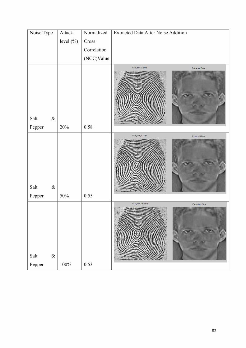
82
Noise Type Attack
level (%)
Normalized
Cross
Correlation
(NCC)Value
Extracted Data After Noise Addition
Salt &
Pepper 20% 0.58
Salt &
Pepper 50% 0.55
Salt &
Pepper 100% 0.53
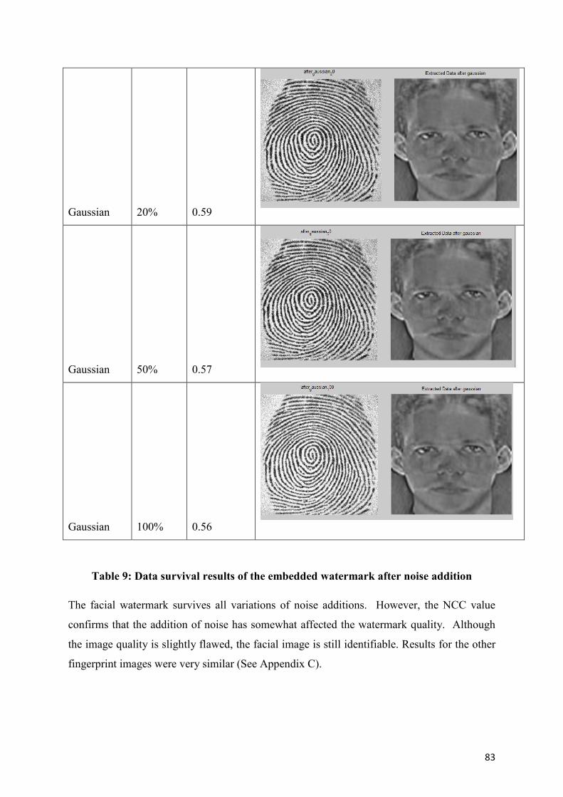
83
Gaussian 20% 0.59
Gaussian 50% 0.57
Gaussian 100% 0.56
Table 9: Data survival results of the embedded watermark after noise addition
The facial watermark survives all variations of noise additions. However, the NCC value
confirms that the addition of noise has somewhat affected the watermark quality. Although
the image quality is slightly flawed, the facial image is still identifiable. Results for the other
fingerprint images were very similar (See Appendix C).
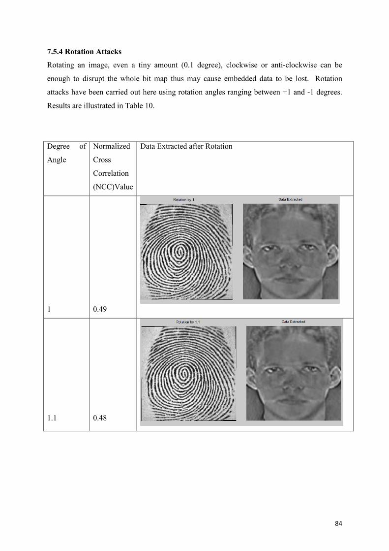
84
7.5.4 Rotation Attacks
Rotating an image, even a tiny amount (0.1 degree), clockwise or anti-clockwise can be
enough to disrupt the whole bit map thus may cause embedded data to be lost. Rotation
attacks have been carried out here using rotation angles ranging between +1 and -1 degrees.
Results are illustrated in Table 10.
Degree of
Angle
Normalized
Cross
Correlation
(NCC)Value
Data Extracted after Rotation
1 0.49
1.1 0.48
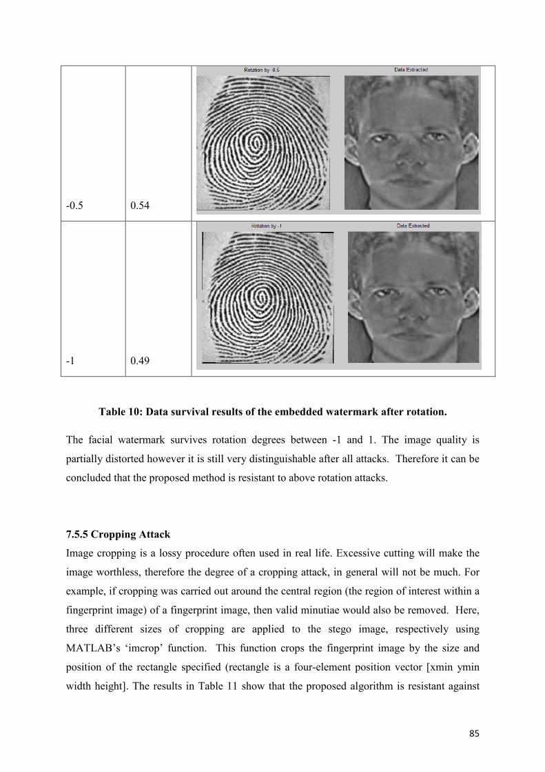
85
-0.5 0.54
-1 0.49
Table 10: Data survival results of the embedded watermark after rotation.
The facial watermark survives rotation degrees between -1 and 1. The image quality is
partially distorted however it is still very distinguishable after all attacks. Therefore it can be
concluded that the proposed method is resistant to above rotation attacks.
7.5.5 Cropping Attack
Image cropping is a lossy procedure often used in real life. Excessive cutting will make the
image worthless, therefore the degree of a cropping attack, in general will not be much. For
example, if cropping was carried out around the central region (the region of interest within a
fingerprint image) of a fingerprint image, then valid minutiae would also be removed. Here,
three different sizes of cropping are applied to the stego image, respectively using
MATLAB’s ‘imcrop’ function. This function crops the fingerprint image by the size and
position of the rectangle specified (rectangle is a four-element position vector [xmin ymin
width height]. The results in Table 11 show that the proposed algorithm is resistant against
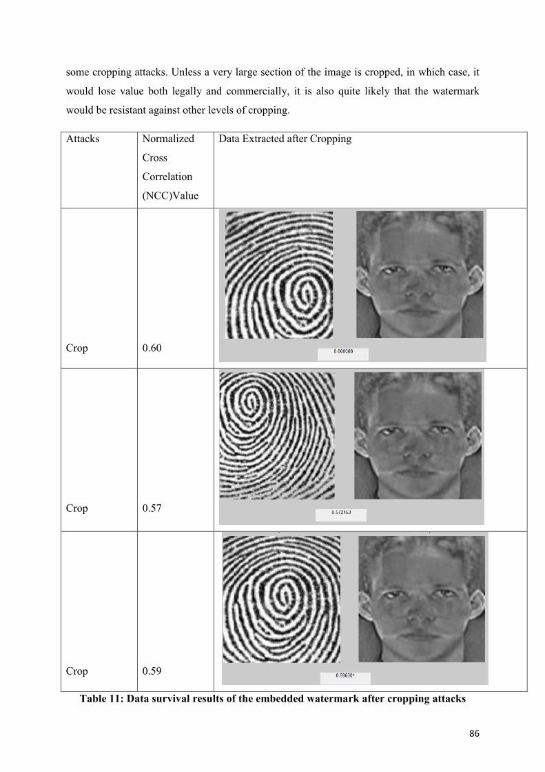
86
some cropping attacks. Unless a very large section of the image is cropped, in which case, it
would lose value both legally and commercially, it is also quite likely that the watermark
would be resistant against other levels of cropping.
Attacks Normalized
Cross
Correlation
(NCC)Value
Data Extracted after Cropping
Crop 0.60
Crop 0.57
Crop 0.59
Table 11: Data survival results of the embedded watermark after cropping attacks
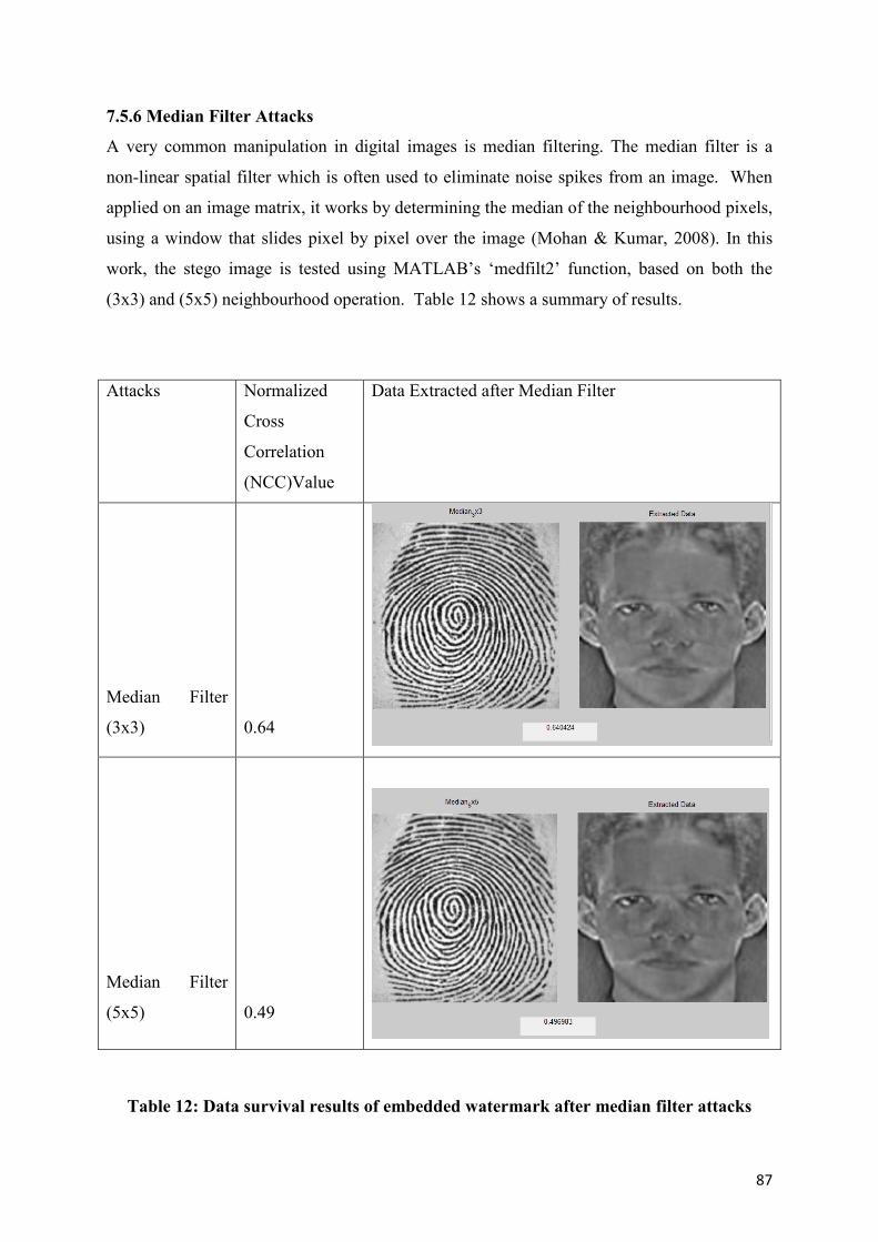
87
7.5.6 Median Filter Attacks
A very common manipulation in digital images is median filtering. The median filter is a
non-linear spatial filter which is often used to eliminate noise spikes from an image. When
applied on an image matrix, it works by determining the median of the neighbourhood pixels,
using a window that slides pixel by pixel over the image (Mohan & Kumar, 2008). In this
work, the stego image is tested using MATLAB’s ‘medfilt2’ function, based on both the
(3x3) and (5x5) neighbourhood operation. Table 12 shows a summary of results.
Attacks Normalized
Cross
Correlation
(NCC)Value
Data Extracted after Median Filter
Median Filter
(3x3) 0.64
Median Filter
(5x5) 0.49
Table 12: Data survival results of embedded watermark after median filter attacks
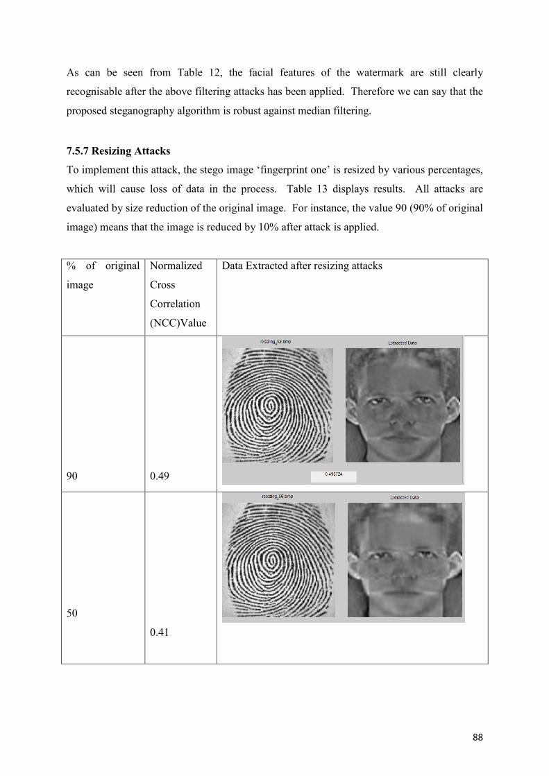
88
As can be seen from Table 12, the facial features of the watermark are still clearly
recognisable after the above filtering attacks has been applied. Therefore we can say that the
proposed steganography algorithm is robust against median filtering.
7.5.7 Resizing Attacks
To implement this attack, the stego image ‘fingerprint one’ is resized by various percentages,
which will cause loss of data in the process. Table 13 displays results. All attacks are
evaluated by size reduction of the original image. For instance, the value 90 (90% of original
image) means that the image is reduced by 10% after attack is applied.
% of original
image
Normalized
Cross
Correlation
(NCC)Value
Data Extracted after resizing attacks
90 0.49
50
0.41
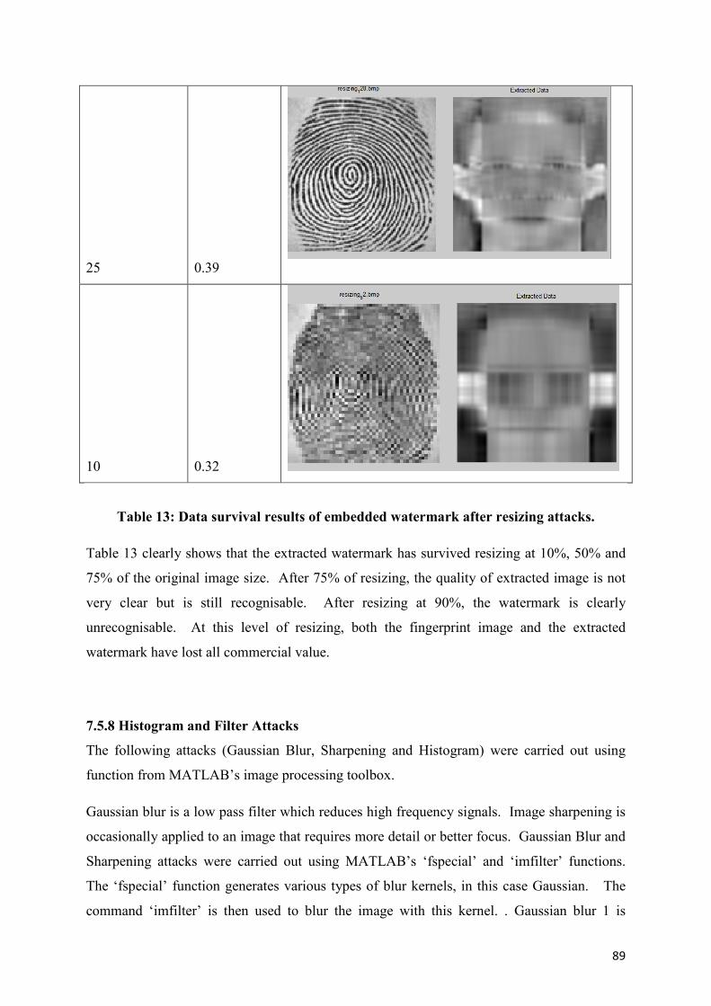
89
25 0.39
10 0.32
Table 13: Data survival results of embedded watermark after resizing attacks.
Table 13 clearly shows that the extracted watermark has survived resizing at 10%, 50% and
75% of the original image size. After 75% of resizing, the quality of extracted image is not
very clear but is still recognisable. After resizing at 90%, the watermark is clearly
unrecognisable. At this level of resizing, both the fingerprint image and the extracted
watermark have lost all commercial value.
7.5.8 Histogram and Filter Attacks
The following attacks (Gaussian Blur, Sharpening and Histogram) were carried out using
function from MATLAB’s image processing toolbox.
Gaussian blur is a low pass filter which reduces high frequency signals. Image sharpening is
occasionally applied to an image that requires more detail or better focus. Gaussian Blur and
Sharpening attacks were carried out using MATLAB’s ‘fspecial’ and ‘imfilter’ functions.
The ‘fspecial’ function generates various types of blur kernels, in this case Gaussian. The
command ‘imfilter’ is then used to blur the image with this kernel. . Gaussian blur 1 is
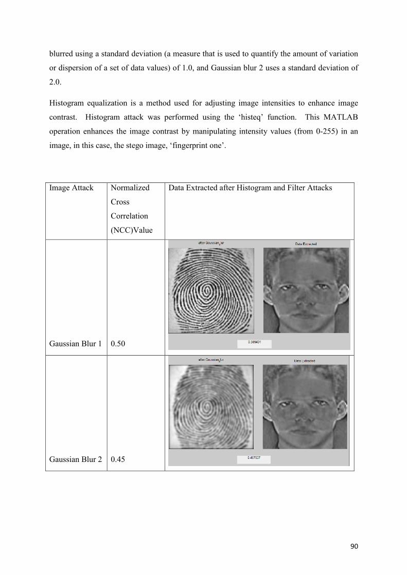
90
blurred using a standard deviation (a measure that is used to quantify the amount of variation
or dispersion of a set of data values) of 1.0, and Gaussian blur 2 uses a standard deviation of
2.0.
Histogram equalization is a method used for adjusting image intensities to enhance image
contrast. Histogram attack was performed using the ‘histeq’ function. This MATLAB
operation enhances the image contrast by manipulating intensity values (from 0-255) in an
image, in this case, the stego image, ‘fingerprint one’.
Image Attack Normalized
Cross
Correlation
(NCC)Value
Data Extracted after Histogram and Filter Attacks
Gaussian Blur 1 0.50
Gaussian Blur 2 0.45
Related Documents


![A Reliable SVD-DWT Based Watermarking Scheme with ... · demonstrated its high robustness against image distortion. Chih-Chin et al. [6] proposed a hybrid image watermarking scheme](https://static.cupdf.com/doc/110x72/6045af843eb55e586b23bcb9/a-reliable-svd-dwt-based-watermarking-scheme-with-demonstrated-its-high-robustness.jpg)


![Blind Image Watermark Detection Algorithm based on Discrete Shearlet Transform Using ... · develop the DWT-based watermarking methods. In [16] SVD was applied to the watermark and](https://static.cupdf.com/doc/110x72/5ecd5f6fca840f610776737e/blind-image-watermark-detection-algorithm-based-on-discrete-shearlet-transform-using.jpg)