FINAL YEAR PROJECT SYNOPSIS SUBMIT TED BY- UMESH CHANDRA YADAV (0715340106) LO V VERMA (2815340002) PRIYANKA YADAV (2715340003) VIDIT TOMAR (0715340108) SATYA PRAKASH (0715340092) SANDEEP BHASKAR (0715340089) 11/20/2010

Welcome message from author
This document is posted to help you gain knowledge. Please leave a comment to let me know what you think about it! Share it to your friends and learn new things together.
Transcript

FINAL YEAR PROJECT SYNOPSIS
SUBMITTED BY-
UMESH CHANDRA YADAV (0715340106)
LOV VERMA (2815340002)
PRIYANKA YADAV (2715340003)
VIDIT TOMAR (0715340108)
SATYA PRAKASH (0715340092)
SANDEEP BHASKAR (0715340089)
11/20/2010
[Type the author name]
qwertyuiopasdfghjklzxcvbnmqwertyuiopasdfghjFFIklzxcvbnmqwertyuiopas

COUNTINOUS VARIABLE TRANSMISSION SYSTEM
which can change sleeplessly through an infinite number of effective gear ratios between maximum and minimum values. This contrasts with other mechanical transmissions that only allow a few different distinct gear ratios to be selected. The flexibility of a CVT allows the driving shaft to maintain a constant angular velocity over a range of output velocities. This can provide better fuel economy than other transmissions by A continuously variable transmission (CVT) is a transmission enabling the engine to run at its most efficient revolutions per minute (RPM) for a range of vehicle speeds

COMPONENT USED
1. 4- Special design pulley (design on cnc mechine)
2. Gear motor
3. Bearing (608, 6201 and 6801)
4. Bearing stand
5. Cycle foot gear and chain drive
6. Iron design power shaft
7. Bike timing gear and chain drive
8. Threading nut and bolt
9. Wheels
10. Iron and wooden body fram
11. Rubber pully

. PULLY

BIKE TIMING CHAIN
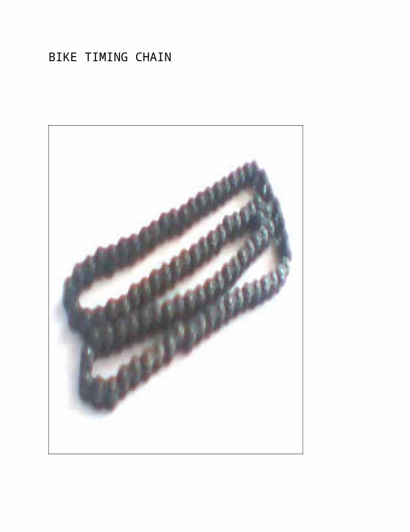
BIKE TIMING CHAIN
ABOUT OUR PROJECTAs per our model we divide our project in two sections:
1. Section-A DRIVE PULLEY (ENGINE)
2. Section-B WHEEL SHAFT PULLEY
Our design and working of model is discribe below steps:

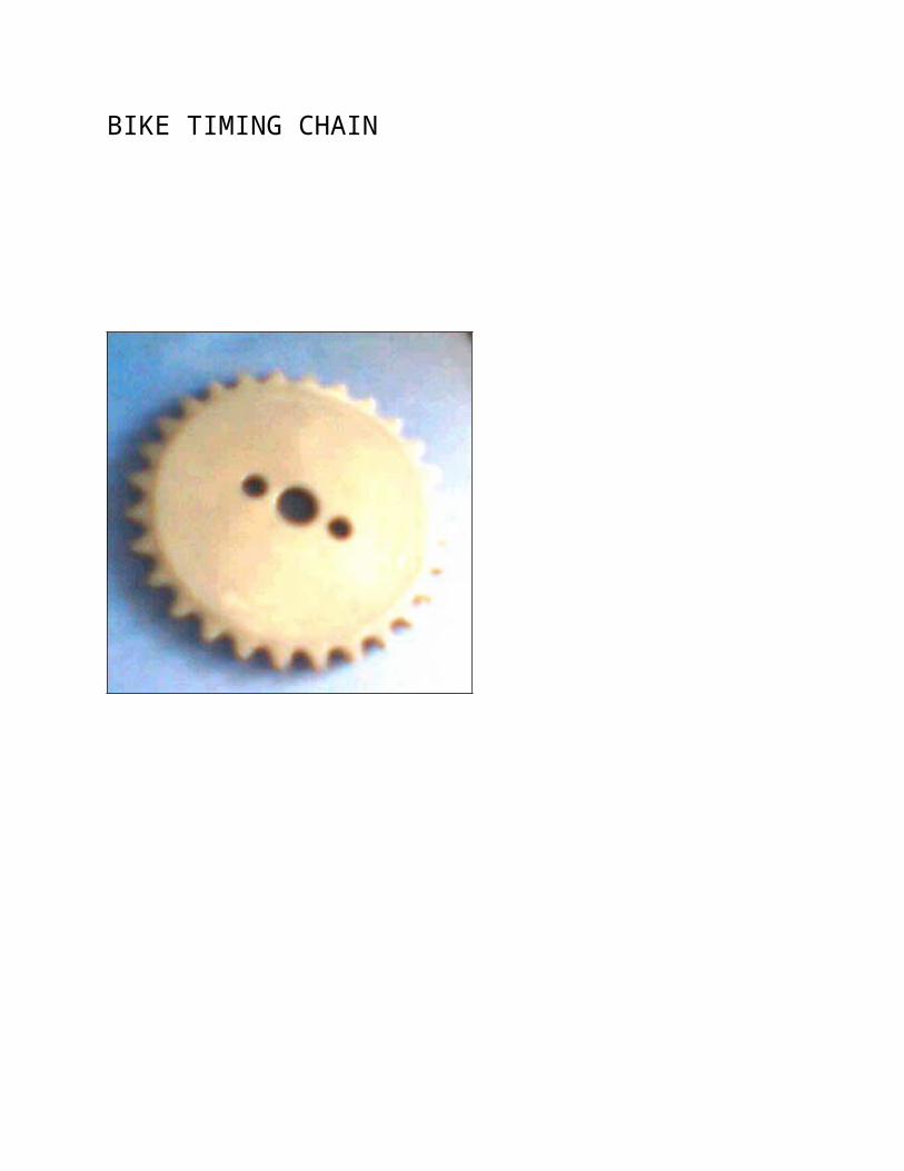
Power transmittion to wheel shaftAs the above diagram opposite rotation turn transmit to the
section-B rotate red pulley with the help of thread and nut
system as shown below. In this section our pink pully is fixed
with wheel shaft.

WORKING PRINCIPLE OF C.V.T.As per the below diagram of section-1 our liver drive the power
variable power transmittion which is fixed on main power
transmittion shaft. We insert on pink pulley with bearing no.
6201 in power transmittion shaft rode and we lock that pulley
with simple lock washer for smooth driving.
Now, we insert second pulley in to power transmittion rode.
This pulley is attached with model body frame with help of
bearing for smooth drive. We transmit rotation power from the
motor (as engine) to the pulley with the help of gear and chain
drive as shown below.
Next to motor drive section pulley we thread and nut system. In
which we reduce and increase pulley space by turnning of liver
shaft.

We insert one rubber pulley in between two sections to show
complet working.


ADVANTAGE
The main advantage of CVTs ís that they allow an engine to run at its ideal RPM regardless of the speed of the vehicle. For low speed special purpose vehicles the RPM is usually set to achieve peak efficiency. This maximizes fuel economy and reduces emissions. Alternatively the CVT can be setup to maximise performance and maintain the engine RPM at the level of peak power rather than efficiency. Automotive CVT's generally attempt to balance both of these functions by shooting for efficency when the driver is only applying light to moderate amounts of accelerator ie. Under cruise conditions, and power when the accelerator is being applied more generously.
DISADVANTAGE
CVT torque-handling capability is limited by the strength of their transmission medium (usually a belt or chain), and by their ability to withstand friction wear between torque source and transmission medium (in friction-driven CVTs). CVTs in production prior to 2005 are predominantly belt- or chain-driven and therefore typically limited to low-powered cars and other light-duty applications. Units using advanced lubricants, however, have been proven to support a range of torques in production vehicles, including that used for buses, heavy trucks, and earth-moving equipment.
Some CVTs in production vehicles have seen premature failures.
Some CVTs transmit torque in only one direction, rendering them useless for regenerative or engine-assisted vehicle braking; all
Related Documents