FAMU-FSU COLLEGE OF ENGINEERING Final Report – Palm Harvester Project A report submitted to Dr. Okenwa Okoli Industrial & Manufacturing Engineering Department Advisors: Dr. Chuy, Dr. Edrington, Dr. Frank, Dr. Gupta, Dr. Okoli, and Dr. Shih Authors: Thomas Baker, Christopher Chiros, Maurice Derius, Shaneatha Gates, Talya Levin, and Amber Smith 4/10/2015

Welcome message from author
This document is posted to help you gain knowledge. Please leave a comment to let me know what you think about it! Share it to your friends and learn new things together.
Transcript

FAMU-FSU COLLEGE OF ENGINEERING
Final Report – Palm Harvester Project
A report submitted to Dr. Okenwa Okoli Industrial & Manufacturing Engineering Department
Advisors: Dr. Chuy, Dr. Edrington, Dr. Frank, Dr. Gupta, Dr. Okoli, and Dr. Shih Authors: Thomas Baker, Christopher Chiros, Maurice Derius, Shaneatha Gates, Talya Levin,
and Amber Smith 4/10/2015

i
Table of Contents List of Figures ................................................................................................................................ iv
List of Tables ................................................................................................................................. vi
List of Equations ............................................................................................................................ vi
Abstract ......................................................................................................................................... vii
1. Introduction ............................................................................................................................. 1
2. Project Charter ........................................................................................................................ 2
2.1 Overview .......................................................................................................................... 2
2.1.1 Background and History ........................................................................................... 3
2.1.2 Objectives and Expected Benefits ............................................................................ 3
2.1.3 Business Case............................................................................................................ 4
2.1.4 Team Members/ Major Stakeholders ........................................................................ 5
2.2 Approach .......................................................................................................................... 6
2.2.1 Scope ......................................................................................................................... 6
2.2.2 Assumptions & Constraints ...................................................................................... 7
2.2.3 Deliverables .............................................................................................................. 8
2.2.4 Milestones ................................................................................................................. 8
2.3 Budget / Bill of Materials ............................................................................................... 10
3. Defining Customer & Technical Requirements .................................................................... 13
4. Measuring the Baseline Performance ................................................................................... 16
5. Identifying the Root Causes .................................................................................................. 19
5.1 Telescoping Poles ........................................................................................................... 19
5.2 Wheels ............................................................................................................................ 20
5.3 Pulley System ................................................................................................................. 22
5.4 Alignment Block ............................................................................................................ 24
5.5 Assembly ........................................................................................................................ 25
5.5.1 Stress Analysis ........................................................................................................ 27
5.5.2 Deflection Analysis ................................................................................................. 29
5.6 Motor .............................................................................................................................. 30
6. Improving the Current Process ............................................................................................. 31
6.1 Electrical Components ................................................................................................... 31

ii
6.1.1 Camera .................................................................................................................... 31
6.1.2 Motor, Battery, and Cutting Mechanism ................................................................ 32
6.2 Mechanical Components ................................................................................................ 32
6.2.1 Wheels..................................................................................................................... 32
6.2.2 Buffer Strips ............................................................................................................ 33
6.2.3 Lowering the Center of Gravity .............................................................................. 34
7. Controlling Process Improvement ........................................................................................ 35
7.1 Testing the Mechanism .................................................................................................. 35
7.1.1 Pulley System.......................................................................................................... 35
7.1.2 Cutting Mechanism ................................................................................................. 37
7.1.3 Camera Mechanism ................................................................................................ 39
7.1.4 Maneuverability ...................................................................................................... 40
7.2 Time Analysis ................................................................................................................ 43
7.3 Safety Precautions .......................................................................................................... 44
7.4 Customer’s Needs .......................................................................................................... 45
8. Project Completion ............................................................................................................... 46
8.1 Cutting Mechanism ........................................................................................................ 47
8.2 Battery Capacity ............................................................................................................. 47
8.3 Camera Mechanism ........................................................................................................ 48
9. Business Analysis ................................................................................................................. 48
9.1 Economic Analysis ......................................................................................................... 48
9.2 Environmental Impact .................................................................................................... 50
9.3 Ethical Considerations .................................................................................................... 50
9.4 Health and Safety ........................................................................................................... 50
9.4.1 NIOSH Analysis ..................................................................................................... 51
9.4.2 RULA Analysis ....................................................................................................... 53
9.5 Social and Political Considerations ................................................................................ 55
9.6 Sustainability .................................................................................................................. 55
10. Summary/Conclusion ......................................................................................................... 55
11. References .......................................................................................................................... 57
Appendix A ................................................................................................................................... 59

iii
Appendix B ................................................................................................................................... 60
Appendix C ................................................................................................................................... 61
Appendix D ................................................................................................................................... 62
Appendix E ................................................................................................................................... 63
Appendix F.................................................................................................................................... 64
Appendix G ................................................................................................................................... 65

iv
List of Figures Figure 1. (a) Worker climbing tree (b) Worker cutting palm fruit elongated sickle blade [2,3] ... 2
Figure 2. (a) Previous year's pole (b) Design concept for this year’s pole ..................................... 4
Figure 3. Gantt chart ....................................................................................................................... 9
Figure 4. Pie of chart of budget usage .......................................................................................... 11
Figure 5. House of quality ............................................................................................................ 13
Figure 6. Steps to assemble and disassemble cart ......................................................................... 16
Figure 7. Forces acting on the telescoping pole ............................................................................ 18
Figure 8. Previous year's deflated wheels .................................................................................... 20
Figure 9. Zoomed in view of the deflated wheels from the previous year's mechanism .............. 21
Figure 10. Wheels ordered for the current mechanism [4] .......................................................... 22
Figure 11. (a) Schematic of the internal pulley system (b) Schematic of the external pulley system ................................................................................................................................... 23
Figure 12. Alignment block assembly for the previous year's mechanism [5] ............................ 25
Figure 13. A schematic of the assembly of the new mechanism as of the analyze phase ............ 26
Figure 14. Stress analysis, in MPa, of assembled mechanism ...................................................... 28
Figure 15. Deflection analysis, in mm, of assembled mechanism ................................................ 30
Figure 16. Motor selected for the mechanism [8] ......................................................................... 31
Figure 17. Comparison of last year's wheel to the current wheels................................................ 32
Figure 18. The wheels being tested on different terrain (concrete, asphalt, and grass/dirt) ......... 33
Figure 19. Recessed buffer strip ................................................................................................... 34
Figure 20. Process of lowering the center of gravity .................................................................... 35
Figure 21. Motor and largest pole mounted on the cart ................................................................ 35
Figure 22. Wiring of the motor controller, battery, and motor ..................................................... 36
Figure 23. Pulley system being tested at different heights ........................................................... 37
Figure 24. Wiring of the cutting mechanism ................................................................................ 38

v
Figure 25. Cutting mechanism aligned on tree branch ................................................................. 39
Figure 26. Camera mechanism from previous year [9] ................................................................ 40
Figure 27. Free body diagram of assembled mechanism .............................................................. 41
Figure 28. Assembled cart being pushed for testing purposes ...................................................... 43
Figure 29. Specification of the motor [11] .................................................................................... 48
Figure 30. NIOSH Table II.40 used to determine if the pushing forces are within range [14] .... 52
Figure 31. Image of a table showing the score associated with level of MSD risk [15] .............. 53
Figure 32. RULA assessment worksheet of the prototype [15] .................................................... 54

vi
List of Tables Table 1. Threat and Opportunity Matrix ......................................................................................... 5
Table 2. Oil palm trees statistical data [2] ...................................................................................... 7
Table 3. Purchased items with the budget .................................................................................... 10
Table 4. Bill of materials .............................................................................................................. 12
Table 5. Customer requirements and importance ......................................................................... 14
Table 6. Assembling and disassembling times ............................................................................. 17
Table 7. Known free body diagram variables ............................................................................... 42
Table 8. Time analysis .................................................................................................................. 44
List of Equations Equation 1 ..................................................................................................................................... 19
Equation 2 ..................................................................................................................................... 19
Equation 3 ..................................................................................................................................... 42
Equation 4 ..................................................................................................................................... 47

vii
Abstract The palm harvester senior design project is dedicated to create an effective, efficient, and
economical solution to harvest palm fruits. For several years the methodologies used to harvest
palm fruits have proven to be quite dangerous. This has caused a great need for more efficient
methods to collect the palm fruit and maximize palm oil production. For the completion of this
project, the team followed the six-sigma methodology known as DMAIC (Define, Measure,
Analyze, Improve, and Control). After completing the Control Phase, a few tests and
calculations still needed to be done before the conclusion of the project. Testing of the line speed
yielded 11.25ft/min. Battery capacity calculations determined an operation time of 3.9 hours,
which yields approximately 22.3tons of palm oil to be harvested on one fully battery charge.

1
1. Introduction Oil palms are oil-producing trees that grow in numerous countries including: Malaysia,
Indonesia, and Colombia. After processing, the palm fruit becomes a natural source of vegetable
oil used for cooking, lipstick, ice cream, and soaps. These trees can grow up to 12m, or 39ft, on
plantations; accordingly, a palm harvester that can extend 35ft will reach a vast majority of oil
palms on the plantation. The current harvesting methods are dangerous and inefficient making
the opportunity to enter this market very promising. That being said, there is a need for a safe
and efficient solution for harvesting the palm fruit. Along with the need for a safe and efficient
device, the project sponsor desires a completely well-designed device that harvests the fruit of
the palm oil tree. During the Define and Measure phases the client requests were first identified
and prioritized using a house of quality. In addition, a website was made to record progress on
the project along Gantt charts to keep the project on track. During the Measure and Analyze
Phase, the procurement process began. Throughout these phases the group also took a closer
look at the design and performance of the device. The improvements were a tedious process but
all in line with the goals of safety and efficiency. The Control Phase consisted of assembling and
testing the palm harvester mechanism. Testing included timing of the raising and lowering of the
telescoping pole as well as testing of the cutting mechanism on a tree branch. This report
includes all previous documentation of the project as well as final calculations of battery capacity
and updates on the project since the Control Phase.

2
2. Project Charter
2.1 Overview Palm oil is used in everyday products such as soaps, washing powders, margarine, and
cereal [2]. Palm oil is derived from the trees native to West Africa [2]. The current palm fruit
harvesting method is performed in a dangerous manner where workers either climb the trees
with sickle blades or they use an elongated pole with a sickle blade attached to the end in
order to remove the fruit. Both of these methods are extremely dangerous because the palm
fruit bunch could strike the workers on the ground and cause injury or the worker could
injure themselves by climbing a tree with a blade in hand as seen in Figure 1(a) (left). Figure
1(b) (right) shows a plantation worker on the ground removing the palm fruit bunches from
the tree [2,3].
(a) (b)
Figure 1. (a) Worker climbing tree (b) Worker cutting palm fruit elongated sickle blade [2,3]
The goal of this project is to create a mechanism that will both replace these dangerous
methods and improve the previous senior design mechanism. The previous senior design
mechanism consisted of an unstable telescoping pole mounted a non-maneuverable cart. To
improve last year’s mechanism, the stability of the pole must be maximized along with the
mobility and portability so the worker can move from tree to tree with ease. For this
mechanism to be implemented in oil palm plantations, it must be affordable, effective, and

3
safer than current methods. Performing these improvements will minimize the risk of injury
to the workers.
2.1.1 Background and History Oil palm trees originated in the tropical region of West Africa [1]. Between the 14th
and 17th century, these oil palm plants were taken to the Americas and then to the Far
East. Indonesia, Malaysia, Thailand, Nigeria, and Colombia are the top five producing
nations of palm oil today. Oil palms are grown as a plantation crop in countries with high
rainfall exhibiting tropical climates within 10 degrees of the equator [1]. There are small-
scale oil palm farms which cover up to 10 hectares, medium scale farms which cover 10
to 500 hectares, and large-scale farms which cover 500 hectares or more [1]. The oil palm
trees can grow up to forty feet and grow palm fruits in bunches that could weigh up to 55
lbs [1].
2.1.2 Objectives and Expected Benefits The team has decided that it would be most beneficial to improve the mobility of the
mechanism, incorporate automation, change the material and shape of the telescoping
poles, and modify the pulley system. The wheels of the existing mechanism will be
replaced with more durable ones in order to suit the rough terrain of a plantation. A motor
will be added to the cart, resulting in an automated telescoping pole. Figures 2(a) & 2(b)
shows the previous (left) and new (right) ideas for the telescoping pole. The previous
pole was made of circular PVC pipes that lacked ductility and rotated within each other,
whereas the new design consists of square aluminum pipes that will not rotate within
each other and increase ductility allowing for deformation to be visible before failure.

4
(a) (b)
Figure 2. (a) Previous year's pole (b) Design concept for this year’s pole
2.1.3 Business Case Indonesia and Malaysia are the main exporters of palm oil and by 2020 the palm oil
market is projected to grow more than 65% [2]. Palm oil plantations require an average of
five workers per hectare whereas competing oil crops only require one worker for every
200 hectares [2]. Indonesia has 3.7 million people engaged in the palm oil industry while
Malaysia has 590,000 people [2]. This shows that palm fruit impacts a large amount of
people, with a way to safely and efficiently harvest the fruit the industry would benefit
greatly.
This project exists due to the fact that palm oil is profitable and high yielding. The
versatility of the palm oil, its long shelf life, its low cost, and its nutritional benefits
compared to other leading oils give it an edge over the other oils. Figure 3 shows the high
consumption of palm oil. In 2011, India consumed 7 million tons of palm oil, 14% of all
of the global palm oil consumption [2]. This shows that there is a very strong opportunity
for palm oil in the market.
A Threat & Opportunity Matrix was developed to further explain the short term and
long term threats and opportunities associated with this project as seen in Table 1.

5
Table 1. Threat and Opportunity Matrix
Threats Opportunity
Short Term
Laborers will continue to sustain injuries using current harvesting methods
Less workers will be injured
Opportunity for sponsor to patent design
Long Term
Oil palm industry will not grow
Harvesting efficiency will not increase in order keep up with rising demands
Abundance of palm oil due to automation of process
Device will become a necessity for palm plantations
If the palm fruit harvester is not completed, then the oil palm industry will not grow
along with the rising demand of palm oil. In order to keep up with this demand, new
technology must be implemented in order to fix the adherent issues associated with the
harvesting of palm fruit. The current harvesting methods put workers in unsafe working
conditions such as climbing tall oil palm trees with saw blades as well the risk of falling
from the tree. The addition of the palm fruit harvester into the oil palm industry will limit
the amount of injuries by preventing the workers from climbing the oil palm trees. If this
product is entered into the palm oil market, then less injuries will occur to the workers,
allowing the plantation to keep up with the international demand of products derived
from palm oil. Opportunity for patenting the product will be a future option, allowing the
mechanism to be mass produced by sponsor for oil palm plantations to use in the
everyday harvesting process. Long term opportunities include this device becoming a
necessary item for every palm plantation and an abundance of palm oil due to automating
the process and eliminating fatigue in the worker.
2.1.4 Team Members/ Major Stakeholders Dr. Okoli is the key stakeholder and sponsor for this project. He is the chair of the
Industrial and Manufacturing Engineering Department. Dr. Frank is one of the advisors
but also serves as the instructor of the Electrical and Computer Engineering senior design
class. Dr. Shih and Dr. Gupta are the instructors of the Mechanical Engineering senior

6
design class. Dr. Edrington serves as the Electrical Engineering advisor while Dr. Chuy
serves as the Mechanical Engineering advisor. Dr. Edrington and Dr. Chuy have guided
the team in the process of selecting a motor and installing the electrical system, while Dr.
Shih and Dr. Gupta have served as a guide to the redesign of the telescoping poles.
Margaret Scheiner and Emily Hammel serve as the Industrial and Manufacturing
Engineering teaching assistants who help the project run smoother by answering all the
team’s questions.
Given that Talya Levin would like to focus on materials research post-graduate and
has had additional coursework in material science based classes, she has been tasked to
the material selection process. Thomas Baker is the mechanical lead and is in charge of
designing the new pulley system. Thomas takes a hands on approach to his work and
finds improvements in the current system easily making him the ideal candidate for this
position. Christopher Chiros has had an internship at Caterpillar working within an
engineering team in charge of providing technical documentation to move forward with
engineering projects. Given his credentials, Chris is the industrial lead and technical
writer. Shaneatha Gates is the electrical lead and in charge of automation; given her
coursework within the Electrical Engineering department she has the knowledge and
resources to accomplish this task. Amber Smith is the financial advisor and web designer;
having been an application developer for JP Morgan and the National Science Foundation
she has the expertise to design a functional website. Maurice Derius is the
parliamentarian and Six Sigma leader; having a Green Belt in Six Sigma gives Maurice
the credentials to ensure the project is aligned within the requirements of Six Sigma and
overall DMAIC process.
2.2 Approach
2.2.1 Scope Improvements to the previous mechanism include: replacing the circular cross-section
polyvinyl chloride (PVC) telescoping pole with square cross-section aluminum,
incorporating an efficient easy-to-use and non-tangling pulley system, adding automation
to the telescoping pole so that it may ascend and descend to and from the bunches of
fruit, and replacing the wheels with all-terrain, never flat tires.

7
2.2.2 Assumptions & Constraints In order to complete this project, a variety of assumptions have been made. Since the
mechanism is unable to be tested in Malaysia, the country that it will be used in, the team
must assume environmental and working conditions found on the web are accurate. In
addition to this, there are no oil palm trees in Tallahassee, Florida so the parameters of
the average height, weight of the fruit bunches, and other key factors were found in dated
statistical data as shown in Table 2. It is also assumed that the workers operate on an 8
hour work day and one to two workers are needed to operate the mechanism. During the
harvesting process the mechanism will operate on horizontal ground in order to maintain
proper stability. It is assumed that by successfully cutting the branch of a tree at the
average height of an oil palm tree, the mechanism is successful.
Table 2. Oil palm trees statistical data [2]
The main constraints are the height the telescoping pole can reach and the size of the
overall mechanism. The height of the entire mechanism extended is based upon the
average height of an oil palm tree. Due to this, the height of the mechanism cannot be
less than the average height of an oil palm tree as it would not be able to reach all the
fruit bunches on the tree. In addition to this, the overall height of the mechanism should
not be much greater than the average height of an oil palm tree as the mechanism will
Characteristics Values
Palm Fruit Weight 40 – 55 lbs
Number of Fruits per Bunch Up to 200 fruits
Growing Temperatures 77 – 82° F
Plantation Planting Density 143 Palms per Hectare
Begins to Produce 3 – 4 years
Average Maximum Growth Height 40 ft
Diameter 0.75 – 2.5 ft
Amount of Sunlight 4-5 hours/day
Amount of Rainfall Year-round

8
decrease in stability with a larger deflection and will be harder to store. The size of the
overall mechanism is crucial, as it needs to be stored and have the ability to move
between trees.
2.2.3 Deliverables Upon the conclusion of this project, the sponsor will be presented with the following: o Functioning Palm Harvester
o Operation Manual
o End-of-Phase Report
o Technical Poster
2.2.4 Milestones During each phase of the palm harvester project, several milestones must be
completed to stay on track and in order to successfully complete the goal of improving
the palm harvester mechanism. The milestones for each phase are as follows:
Define Phase:
o Visit Prototype: Assemble and compile data from previous year’s harvester.
o Gather Requirements: Speak with sponsor on expectations and goals.
o HPMI Safety Meeting: Certify team members to access the HPMI building.
o Finalize New Design: Determine the most feasible design that best suits
expectations and product improvements.
Measure Phase:
o Build Scaled Prototype: Assemble a functioning prototype for sponsor.
o Incorporate Automation: Determine the most efficient method for automation of
the mechanism.
Analyze Phase:
o Order Parts and Materials: Submit all product and material orders to the Industrial
and Manufacturing Engineering office.
o Plan Labor Assembly: Prepare plan of action to assemble actual palm harvester.
Improve Phase:

9
o Assemble Mechanism: Physically assemble the final palm harvester mechanism.
o Meet with Electrical & Mechanical Advisors: To assess any issues that have
arose.
Control Phase:
o Finalize Building: Finish building the remainder of the mechanism.
o Meet with Project Sponsor: To determine if the project is still within the proper scope.
o Test Mechanism: Operate and observe final mechanism.
The Gantt chart is shown in Figure 3, below.
Figure 3. Gantt chart
This portion of the Gantt chart reflects the Control Phase until the completion of the final
presentation. During this time the Palm Harvester was behind in finalizing the assembly
of the mechanism however able to operate the mechanism at least twice before the final
paper and presentation. After the operation of the mechanism the conclusion of the

10
project will consist of prepare the poster, website, and final report and presentation for
the team’s sponsors, stakeholders, and peers.
2.3 Budget / Bill of Materials Table 3 shows all the items, along with their description and company that have been
purchased with the allotted $2,500 budget.
Table 3. Purchased items with the budget
Item Company Description Cost Wheels Grainger (4) Never Flat Wheel,
10-1/4 in, 350lb $213.12
Motor Lowes Trakker 1-HP 2,000-lb Universal Winch
$104.26
Aluminum Pole Discount Steel 6063 AL TUBE 5 X 5 X ¼ X 120”
$225.60
Aluminum Pole Discount Steel 6063 AL TUBE 4 X 4 X 1/8 X 120”
$85.77
Aluminum Pole Discount Steel 6063 AL TUBE 3 X 3 X 1/8 X 120”
$61.21
Aluminum Pole Discount Steel 6063 AL TUBE 3 X 3 X 1/8 X 120”
$41.66
Shipping Discount Steel - $225.00 Battery O’Reilly Auto
Parts 12 V Super Start Marine- Deep Cycle
$94.99
Total : $1,051.61
The wheels purchased are called the “Never Flat Wheel” which are made of solid
polyurethane, meaning if ever punctured, the wheels will not deflate. Each wheel has a 10-
1/4 in diameter which fits perfectly in the brackets mounted on the legs of the cart. It should
be noted that the wheels can each carry a maximum load of 350 lbs. All four wheels
combined can carry a load of 1,400 lbs, which is significantly more than the weight of the
entire system (253.92 lbs). The motor purchased was a Trakker Universal Winch which was
connected to the first segment of the pulley system allowing the telescoping process to occur
at the push of a button. Each of the four aluminum 6063 telescoping poles are listed
individually in the table in order show that they each have different cross-sectional
dimensions and costs. Since the poles had to be shipped from Minnesota, a shipping cost was
added, as shown on Table. Lastly, the battery purchased was the Super Start Marine-Deep
Cycle which is typically used for large scale purposes, such as travel trailers, thus providing

11
enough amperes to power the motor. Overall $1,051.61 was used of the total $2,500 budget.
The pie chart in Figure 4 shows the percentage of each component with respect to the overall
budget.
Figure 4. Pie of chart of budget usage
From Figure 4 it can be seen that 58% of the total budget still remains. Since all the parts
have been purchased, the remainder of the money will not be used. It is important to note that
the aluminum poles (including the shipping) take up more than a quarter of the budget, this is
due to the fact they each are 10ft long and require a large amount of material to produce.
Another factor is that since they had to be shipped to HPMI they incurred a large shipping
cost of $225.00. The motor, battery, and wheels combined take up 16% of the budget, which
is not very significant compared to that of the aluminum poles. It is important to note that
many of the old parts have been reused such as the cart, pulleys, pulley cables, cutting
mechanism, lazy susan, and camera thus saving the project a lot of money.
Table 4 shows the bill of materials for the mechanism, which includes all the parts reused
from the previous year’s mechanism.

12
Table 4. Bill of materials
Component Description Quantity Cart
Pneumatic Caster Fits 10.25” diameter wheels 2 Pneumatic Swivel Caster Fits 10.25” diameter wheels 2
Perforated Tube 1 ½”x1 ½”x6’ 1 Perforated Tube 1 ¾”x1 ¾”x6’ 1
Edsal Service Cart Steel, 24”x36”x32” 1 Square Tube Aluminum, 1”x1”,6’, 1/8”
thick 1
Corner Bracket Zinc-Plated Steel, 3” 16 Motorized Winch Tracker, 2000lb, 1-Hp 1
Battery Super Start Marine 1 Telescoping Pole
Pole Pulley 2” OD 3 Wire Rope 1/8”x100’ 1 Oval Sleeve - 50 pack Stop Sleeve - 50 pack
Angle Bracket 2” steel 4 SS Bolt 10-24x1” 50 pack Washer #10 50 pack
Nut 10-24 50 pack HDPE Rod ¼”x1” 24 HDPE Rod 1”x1”x4’ 1
Aluminum Tube AL-6063 5”x5”x1/4”x10’ 1 Aluminum Tube AL-6063 4”x4”x1/8”x10’ 1 Aluminum Tube AL-6063 3”x3”x1/8”x10’ 1 Aluminum Tube AL-6063 2”x2”x1/8”x10’ 1
Cutting Mechanism Aluminum Tube AL-6061 1”x1”x1/8”x6’ 1
Locking Shoulder Screw 10-24, 1 ¼” long 1 Turntable Galvanized, 6.06”x6.06” 1 Pole Saw Black and Decker 1 AL Plate ¼”x12”x1’ 2 AL Bar AL 6061, 2”x2”x1’ 1
Pole Pulley 2” OD 4 Corner Bracket Zinc-Plated Steel, 3” 6 Corner Bracket Zinc-Plated Steel, 4” 4
Camera Pyle PLCM7200 1

13
3. Defining Customer & Technical Requirements In order to address the customer requirements, a House of Quality (HOQ), shown in Figure 5,
was created.
Figure 5. House of quality
The HOQ is divided into two main categories: The “Whats” and the “Hows”. The “Whats”
section lists the customer requirements or what the customer wants from the product. The
“Hows” depicts the functional requirements; these requirements are the processes that will be
used to meet the customer requirements. The most important customer requirements are listed in
the following Table 5. After brainstorming with the team, a scale from 1 to 10 was created in

14
order rank the customer requirements, with 10 being the most important and 1 the least
important.
Table 5. Customer requirements and importance
Customer requirements Weight/Importance
Automated 10.0
Power efficient 10.0
Light-weight/ Portable 9.0
Durable 9.0
Easy to use 9.0
Cost effective 8.0
Fast 8.0
Environmentally friendly 8.0
Safe 7.0
Water proof 6.0
Automation and power efficiency are ranked the highest since the customer wants the final
product to be both automated and power efficient. Waterproof is the lowest ranked customer
requirement as is it not crucial in the operation of the mechanism.
The team brainstormed several quality characteristics: weight of materials, quality of
materials, speed of pole extension, battery capacity/durability, size of cart, size of wheels, and
complexity of design. The weight of materials is very important for the implementation of the
new design. Using heavy materials will require greater force and power to push the cart and
could cause musculoskeletal disorders to user. In other words, it will not be ergonomically safe
to select heavy materials as it will cause injuries to the user. The type of the material needed for
this design needs to accommodate climate changes as the final product will be used in humid and
hot climates. The size of the cart is another important factor in this design because it will be

15
implemented in oil palm plantations where there is an average of 143 palm trees per hectare with
an average distance of nine feet between the trees [2]. The cart should be compact because it will
be difficult to transport and store if it is not compact. The wheels need to be sturdy enough to
allow for stability and maneuverability of the cart. When the initial push force is applied, the
contact between the tires and ground will experience a frictional force. The final product is going
to be designed for owners of oil palm plantations in Malaysia, therefore it must be easy to use
and have low maintenance cost as this is not a wealthy country. The speed of the pole extension
of the final mechanism needs to be quicker when compared to the current harvesting methods.
Furthermore, the goal of this team is to come up with a product that will be more efficient than a
human climbing an oil palm tree.
The weight/importance, located at the bottom of the House of Quality matrix, determines the
most critical customer requirements. The relative weights on the left of the HOQ were obtained
by dividing each customer’s rating index by the total of all the indices, which totaled 84. For
example, waterproof has a customer rating index of 6.0, dividing 6.0 by 84 will give 7.1%. This
calculation is performed for each of the other relative weights. The weights/importance at the
bottom of the HOQ were calculated by adding all the products resulting from multiplying the
relative weight by the index number assigned to the relationship between the functional
requirements and the customer requirements. For example, there is a moderate relationship
between environmentally friendly and the weight of the materials. A moderate relationship has
an index value of 3 and environmentally friendly has a relative weight of 9.5, so multiplying 3
and 9.5 will give a portion of the technical weight. This calculation is performed for each
relationship in the matrix and the products for a specific column are added together. Battery
capacity/durability has the highest weight, and is therefore very important to take that into
account when designing the final product. Example formulas and calculations used in the HOQ
are provided in Appendix A.
The roof of the HOQ identifies the correlations that exist between each functional
requirement. For example, there is a positive correlation between the weight of the materials and
the speed of the pole extension, because the lighter the pole, the easier it will be able to extend.
The box below the roof indicates the objective of functional requirements, it can either minimize,
maximize, or hit the target. The HOQ helped to pinpoint the improvements that need to be made.

16
Rather than having a broad focus, the HOQ allowed the criteria to be narrowed down to the most
important factors. The most important quality characteristics were the weight of the material, the
quality of the material used and the speed of pole extension. These quality characteristics need to
be considered in the design and manufacturing of the final product.
4. Measuring the Baseline Performance In the measure phase, the team compared the proposed improvements against the previous
year’s device. This test proved that the key areas of improvement were essential to having a
more effective and efficient mechanism that will be one step closer to improving working
conditions on oil palm plantations. The measurements taken included the time of assembly and
disassembly as well as the stress experienced by the telescoping pole.
When the project began, the team agreed that an improvement to the process of assembling
and disassembling of the cart was necessary. The excessive time consumed putting the palm
harvester together is something that is not viable out on the job site. To show improvement
between the old design and the new, the time of assembly was recorded and broken down in a
series of steps. The steps are outlined in Figure 6 and the times are recorded in Table 6. It was
concluded that automation will drastically cut this assembly time, as well as make the process
smoother and safer.
Figure 6. Steps to assemble and disassemble cart
DisassemblingCart

17
Table 6. Assembling and disassembling times
Steps Assembling Time (min)
Disassembling Time (min)
Assembly Time Interval (s)
Disassembly Time Interval (s)
1 0:00-0:39 0:00-0:40 39 40
2 0:39-1:15 0:40-1:12 36 32
3 1:15-2:15 1:12-1:22 60 70
4 2:15-2:25 1:22-1:50 20 28
5 2:25-3:10 1:50-2:05 45 15
6 3:10-3:50 2:05-2:20 40 15
The telescoping pole will be changed from circular cross-sectional to square-cross
sectional. The material of the pole is being changed from PVC/steel to Aluminum 6063. Having
a square cross-section will not allow the poles to rotate within each other. During the Measure
Phase, it was decided that the pulley system would be located within the poles however this idea
was changed in the Analyze Phase to an external pulley system. A stress analysis for each
telescoping pole was performed using PTC Creo Parametric, resulting in a Von Mises Stress
diagram for each. In order to do an equivalent comparison, the same forces were applied to the
two poles. These forces along with a legend are shown in the schematic in Figure 7. The PVC
pole had stress values that ranged from 3.2 x 10⁻⁴ MPa to 113.76 MPa while the aluminum cross
section’s stress ranged from 4.8 x 10⁻⁴ MPa to 28.45 MPa, therefore making the aluminum cross
sections a better option.

18
Figure 7. Forces acting on the telescoping pole
Overall, the Measure Phase allowed the team to determine the necessary adjustments that
need to be made to the palm harvester. It was determined that the wheels will be upgraded to
increase mobility. This will allow the mechanism to effectively traverse the oil palm plantation’s
terrain. The telescoping pole will be moved to the lower section of the cart in order to lower the
center of gravity of the cart and improve the telescoping process. The team will add a motor to
make the process completely automated, decreasing the setup time. Square cross-sectioned
aluminum 6063 will be used in replacement of the circular cross section PVC and steel in order
to increase the ductility of the telescoping pole.

19
5. Identifying the Root Causes
5.1 Telescoping Poles As previously stated, the telescoping poles have been changed from circular Polyvinyl
Chloride (PVC) poles to square aluminum poles (Aluminum 6063) in order to attain ductility.
Using a ductile material allows the user to physically see the material fail. For example, if the
aluminum poles reach the end of their life, they will begin to neck, which will cause a visible
deterioration. This allows the user to see that failure is occurring and take safety precautions.
Materials such as PVC do not possess this quality and will break without any warning
because of the material’s brittle nature. After analysis the team decided to order four 3.05m
(10ft) tall poles with cross sectional dimensions of 0.15m x 0.15m, 0.13m x 0.13m, 0.10m x
0.10m, 0.08m x 0.08m (6”x6”, 5”x5”, 4”x4”, and 3”x3”) which in total weighed 58.5 kg (129
pounds). These cross-sectional dimensions were chosen because they were similar in size to
the previously used PCV poles and many parts can be reused to reassemble the pulley
system, saving time and money. Before ordering the poles, a final analysis was completed to
make sure the poles were exactly what was needed with respect to the motor, stress on the
cart, weight, and budget. The key factor in this analysis was weight. This final analysis
showed that if the weight of the poles could be reduced then the stress due to the poles on the
cart would decrease as well. First the equation for stress (Equation 1) was analyzed, where σ
is the amount of stress, F is the amount of force applied, and A is the area perpendicular to
the force.
(1)
It can be seen from this equation that by applying less force, in this case due to the weight,
the amount of stress applied to that area will decrease. Another aspect considered, was the
amount of torque required to power the motor, shown in Equation 2, where τ is the torque, F
is the force applied, and d is the perpendicular distance the force is applied from the axis of
rotation.
(2)

20
By reducing the amount of force, required to power the motor to lift the top three
telescoping poles and the cutting mechanism, the amount of torque needed would also
decrease. Reducing the weight of the poles causes less stress on the cart, especially on the
bottom shelf where the poles will be resting, and requires less torque from the motor.
Another benefit of reducing the weight of the poles, was a decrease in cost of material. In
order to decrease the weight of the poles, less material is needed, thus the cross sectional area
of the poles needed to be reduced. By reducing each cross-sectional (square) pole dimension
by 0.03 m (1”x1”), the total weight of the four poles would go from 58.5 kg (129 pounds) to
48.1 kg (106 pounds), which is a 10.4 kg (23 pound) decrease, and similar to the weight of
the previous PVC and steel poles. Since the poles didn’t come in fractional sizes, the team
decided that reducing the square shape by 0.03 m (1”x1”) was enough because if the shape
was reduced by more, then the inside of the smallest pole would be too small to fit the pulley
cable and wiring (camera and cutting mechanism). The decrease in weight and dimension of
the poles allowed for smaller stress concentrations as well as, enhancing portability, and
decreasing overall cost.
5.2 Wheels The previous year’s palm fruit harvester utilized 0.25 m (10”) pneumatic swivel castor
wheels, shown in Figure 8.
Figure 8. Previous year's deflated wheels

21
These particular wheels are said to be self-inflating, however the current condition of the
wheels are flat making the palm harvester very difficult to maneuver on asphalt let alone on
the soft soil found at an oil palm plantation. There was a major need to replace these wheels
with wheels that can also withstand the weight but not deflate at any time. A zoomed in view
of the condition of the current wheels is shown in Figure 9.
Figure 9. Zoomed in view of the deflated wheels from the previous year's mechanism
The wheels that were chosen are 0.26 m (10.25”) “never flat wheels”, capable of a 158.8 kg
(350 pounds) load for each wheel, easily supporting the weight of the entire mechanism. To
avoid replacing the entire swivel castor assembly on the current cart, a wheel that had the
same axle diameter of 0.02 m (5/8”), was chosen, for easy replacement. Although the
diameter of the new wheels is a quarter of an inch larger than the previous ones, there is still
enough space between the axle and the top bracket of the cart leg, to accommodate this. The
wheels chosen are made of solid polyurethane, allowing the cart to be easily maneuvered
without having to worry about tire deflation. The new tires, shown in Figure 10, arrived on
February 3, 2015[4]. The new tires have been installed on the mechanism and tested on
multiple terrain (i.e. concrete, grass, dirt, and unleveled ground) and was able to easily
maneuver across each setting.

22
Figure 10. Wheels ordered for the current mechanism [4]
5.3 Pulley System The pulley system has undergone a series of improvements throughout the course of this
project. The initial idea was an internal pulley system, where all of the pulleys and cabling
were attached to the inside faces of the telescoping pole segments. A schematic of the
internal pulley system can be found in Figure 11 (a). The main reasons for building an
internal pulley system was to minimize the risk of tangling and to protect the pulley system
from weather conditions. There was one key factor that was not thought of during the initial
design phase and that was maintenance. Imagine a laborer in the middle of an oil palm
plantation, unable to harvest because of a pulley failure or cable mishap. The laborer would
not be able to fix the issue if it were located on the inside of the telescoping pole without
bringing it back to the main facilities for repair. This would be costly for the plantation as
well as unproductive. With an external pulley system, the malfunction would be clearly
visible and possibly able to be repaired while on the job site. Overall, it was decided that an
external pulley system would be used in the future design.

23
(a) (b)
Figure 11. (a) Schematic of the internal pulley system (b) Schematic of the external pulley system
The schematic in Figure 11 (b), on the right, is the design for the external pulley system.
Each cable is threaded through three telescoping pole segments. The lower most pulley
system begins at the motor and travels upwards, parallel to the first pole, and wraps around a
pulley mounted at the top of the pole. From the pulley, the cable travels in between the first
and second pole segments and finally attaches to the bottom of the second segment. This
entire process is repeated for the other two pulley systems with the exception that the
beginning of the pulley segments attach to the telescoping pole segment located above it
instead of the motorized winch. As the motorized winch pulls the steel cabling, it lifts all of
the telescoping segments simultaneously, reducing the amount of lift time and the amount of
battery power used.

24
Note that the depicted pulley layout is for visual representation only as there are a few
modifications that will be made during the fabrication process. It can be seen from the figure
that the cabling in between telescoping pole segments are at a significant angle, which would
cause a moment or torque to be place on the telescoping pole. This will not be an issue for
the actual telescoping pole because the empty space between the pole segments range from a
quarter-inch to three-eighths-inch. This amount of space for the cable to travel in the
horizontal direction will not equate to a significant torque, as can be seen from Equation 2.
Another deviation from the external pulley schematic is that all of the pulleys will not be on
the same side of the square cross-sectioned aluminum tubing. In order to distribute the forces
placed on the pole segments evenly, each individual pulley will be mounted on its own
separate face of the telescoping pole. Less friction will be encountered between the buffer
striping and the telescoping pole segments because all of the tension forces in the cabling
will not be on the same side. Having the pulleys mounted to different sides of the poles will
also allow for the pole to be compressed down further. If all of the pulleys were mounted on
the same side then the pole would only be able to compress as far as when the pulleys are
stacked on top of each other. When the pulleys are on separate sides, the pole will compress
until each individual pulley comes into contact with the prior telescoping pole segment,
making for a lower initial height of the telescoping pole.
5.4 Alignment Block The previous palm harvester team made use of an alignment block mounted to the top
shelf of the cart in order to aid in the stability and alignment of the telescoping pole. The
circular cross-sectioned telescoping pole would fit into the pivot ring and the alignment block
would become inserted into the bottom of the outermost telescoping pole segment as seen in
Figure 12.

25
Figure 12. Alignment block assembly for the previous year's mechanism [5]
Without the use of this alignment block, the bottom of the telescoping pole is not locked
into place, allowing the bottom to pivot about its axis of rotation. This situation would be
extremely dangerous for the operators of this device. Since the telescoping pole is being
moved down to the lower shelf of the cart, the pivot point would be the top shelf.
The original idea for locking the telescoping pole in place was to mount an alignment
sleeve that fit over the outside of the first telescoping pole segment to the bottom shelf of the
cart. Due to time and budget constraints, this idea was not used, yet a simpler plan was
constructed in its place. By reusing the old alignment block, cuts can be made in order to fit
the current telescoping pole segment. The alignment block will be mounted to the bottom
shelf and perform in the same manner as it was originally intended.
5.5 Assembly A model of the entire assembly (cart and pole) was created, as shown in Figure 13. This
diagram depicts how the mechanism will be assembled and also provides workers with the
most accurate location of stress on the device in order to ensure sensitivity during assembly.

26
Figure 13. A schematic of the assembly of the new mechanism as of the analyze phase
Figure 13 is made up of many important parts, which are labeled with a zoomed view for
a better understanding. The steel cross-bar created by the previous year’s team, shown below
the bottom level of the cart, serves a very important purpose. The purpose is to provide more
support for the weights being applied to the cart, in order to prevent the cart from buckling.
The cart would manage without the cross-bar but would not have as long of life because
eventually the stress would cause plastic (permanent) deformation. Another part is the buffer
strips, which were originally attached to the outside (each side) of each of the top three poles,

27
but have been moved to the inside face of each segment in order to be hidden during the
telescoping process. These Teflon buffer strips allow the poles to smoothly (minimal friction)
extend out of each pole and also eliminate the unwanted gap between each pole. The
alignment sleeve is another part of the mechanism, keeping the pole in place on the bottom
shelf. As mentioned before, instead of the alignment sleeve, an alignment block will be used
for the same purpose. The last crucial component is the wheels, which were replaced with
polyurethane no flat wheels in order to prevent the wheels from deflating. The electric winch
and battery are not depicted in Figure 13 due to the fact that final placement of these
components was still in question. Weight distribution was a key factor in the placement of
the battery because of its significant weight therefore motor placement was dependent upon
placement of the battery.
5.5.1 Stress Analysis Once the assembly was completed, it was time to put it to the test to determine
whether it could withstand the wind and load forces placed on it. Figure 14 shows the
Von Mises stress diagram in MPa of the entire assembly, consisting of the forces shown
on the poles in Figure 7 as well as the force the poles exert on the cart. The calculations
for the forces applied to the cart are shown in Appendix B.

28
Figure 14. Stress analysis, in MPa, of assembled mechanism
Figure 14 shows that the maximum stress distribution occurs on the bottom shelf of
the cart where the crossbar is located and where the telescoping pole as well as the motor
and its components rest. Starting from the bottom of the assembly, the brackets that hold
the wheels feel the weight of the crossbar, which is why there is some blue distribution,
indicating minimal stress. The connection between the crossbar and the wheels brackets

29
shows a wider variety of stress distribution with green being intermediate stress and red
being maximum stress. This maximum stress the cross-bar feels from the cart is due to
the weight placed on the end of each bar. As the bars reach the corners of the bottom
shelf, a stress is shown due to the weight the cross-bars feel from the cart. Due to the fact
that the cart and cross-bar are in compression, because of the weight of the poles and the
ground applying an equal but opposite force on the wheels, the bottom shelf of the cart
shows a stress distribution that mimics the shape of the cross-bar. This stress distribution
can be considered moderate. Another aspect of the stress diagram that is crucial to
understand is the telescoping pole. One thing that should be noted is that due to the wind
forces, the telescoping pole experiences a minimal amount of stress on the side of the
pole that is perpendicular to the force. Lastly, the buffer strips on each of the top three
poles cause a minor stress on the poles because they are being pushed onto the poles by
the previous poles for a tight fit. Overall the most crucial stress locations are at the
connection point of the wheel brackets and the cross bar. The maximum stress felt here is
between 9 and 11 MPa which is approximately twice the amount of water pressure
coming out of a spray nozzle at a regular car wash [6]. Although this does not cause
major concern, this part of the cart will still need to be monitored regularly, as a safety
precaution.
5.5.2 Deflection Analysis The deflection analysis was the last analysis done on the assembly, which is shown in
Figure 15.

30
Figure 15. Deflection analysis, in mm, of assembled mechanism
In Figure 15, measured in millimeters, the maximum deflection of 11.3 mm is shown
at the top of the telescoping pole. This maximum deflection occurs due to the lack of
stability at the top of the mechanism. More specifically, since there is nothing holding the
top of the pole in the upright position, it becomes somewhat flimsy. Since the value of the
maximum deflection is about twice the size of an ant, it does not pose any concern, as it
is minute compared to the overall height of the poles [7].
5.6 Motor To reduce the man power and time to harvest the palm fruit, the team has chosen to
automate the telescoping mechanism. This will also make the mechanism more marketable
than having to manually crank the telescoping pole 40 feet. The mechanical engineers on the
team collaborated to calculate the force and torque that the motor would need to supply to the
poles. Based on the torque and power ratings, the electrical engineer will have enough
criteria to select a probable motor. The calculations for force and torque can be seen in
Appendix C.
After reviewing these calculations with a technical advisor, a motor was selected. The
team decided to go with a winch and motor set by Trakker that has 1 horsepower (HP) [8].
This specific set seen in, Figure 15 is capable of pulling up to 907.2 kg (2000 pounds) and

31
will have no problem lifting the telescoping poles. Some commercial benefits to this motor
are that it is within the allotted motor budget. This choice includes a handheld switch
allowing the user to control the motor from a distance. A technical benefit of this motor is the
pole rise time of 3 minutes; this addresses the goal of the machines competitiveness with
present harvesting techniques. Other technical benefits are circuit breaker protection and low
power consumption. These are all aids that will minimize production cost, increase safety
and efficiency. A picture of the Trakker motor is seen in Figure 16. As a result of the ratings,
the motor should perform well during test and should be able to lift and lower the poles
together in less than 3 minutes.
Figure 16. Motor selected for the mechanism [8]
6. Improving the Current Process
6.1 Electrical Components
6.1.1 Camera
The electrical components are essential to the project. These modules consist of: the
camera, monitor, motor, and battery. As for the camera/monitor, they are being reused
from last years’ design. To assemble and power the camera/monitor there are wires and
an eight volt battery to accompany it. Basic testing of the camera was done; including
connecting positive and negative terminals to achieve power. Upon completion of this

32
test it was concluded that the wires were damaged. This prompted the electrical engineer
to rewire the connection through wire threading and masking with electrical tape. The
remaining task was to connect the red (positive) and black (ground) wires to the proper
components to power the camera and monitor. To receive video input the engineer
simply connected the V1 (video-1) cables together, similar to the connections of a DVD
player, however with these connections there was still no progress.
6.1.2 Motor, Battery, and Cutting Mechanism
The remaining electrical components are the battery and winch motor. As of Friday,
February 27, 2015 the office notified the team that the components had just been
ordered. Testing began upon the arrival of these components. The cutting mechanism
was also reused from last year’s design. It was accompanied by an 18V battery that
provided the necessary power for operation.
6.2 Mechanical Components
6.2.1 Wheels
The Never Flat Wheels, made of polyurethane, arrived on February 3rd, 2015. The old,
Pneumatic Swivel Caster wheels were replaced with the new wheels, which made the cart
easier and safer to maneuver. Figure 17 shows the old wheels compared to the new ones.
Figure 17. Comparison of last year's wheel to the current wheels

33
After installing the new wheels, the cart was easier to push, as the wheels were no
longer deflated and cracked. The cart was pushed throughout HPMI on concrete, then on
asphalt on the roadway, and on the grass/dirt in front of HPMI. This is shown in Figure
18 below.
Figure 18. The wheels being tested on different terrain (concrete, asphalt, and grass/dirt)
When turning the cart, the old wheels would get stuck and the operator would need to
kick the wheels in order for them to realign, whereas with the new wheels this is not an
issue.
6.2.2 Buffer Strips
Last year’s project used high density polyethylene (HDPE) stripping in order to
prevent the circular cross-sectioned PVC from rotating within each other. This material
was reused in order to stabilize and minimize friction within the aluminum telescoping
poles. Since there is a quarter-inch gap between the first and second segments on all
sides, there needed to be something filling this gap, in order for the intersections between
the poles to be stable. This is where the buffer stripping came into play. The material was
cut in short quarter-inch thick strips and mounted to the inside face of the first segment.
This process was repeated for the remaining segments.

34
Cutting the buffer strips to the exact width of the gaps resulted in unwanted friction in
the telescoping pole. This occurrence forces the winch work harder than it needs to, thus
draining the battery quicker. In order to alleviate some of this friction, a small layer of the
buffer stripping was sanded off allowing for an easier overall telescoping process.
In order to mount the buffer stripping to the inside face of the segments, the nuts were
recessed into the HDPE stripping and the bolts were cut to the exact length. The recessed
nuts within the buffer stripping can be seen in Figure 19. Performing this process
prevented metal on metal contact and allowed the telescoping poles to only come into
contact with the HDPE stripping.
Figure 19. Recessed buffer strip
6.2.3 Lowering the Center of Gravity
Lowering the center of gravity of the poles allowed for increased stability. The
circular alignment block on the top shelf of the cart was removed, allowing a 5x5
segment to be mapped out in its place. Using a jigsaw, the square was removed from the
top level of the cart. The sequence of events to lower the center of gravity is shown in
Figure 20 below.

35
Figure 20. Process of lowering the center of gravity
In order to fit the poles into the square cut out, the edges of the square were sanded to
allow extra room for the poles to slide in smoothly.
7. Controlling Process Improvement
7.1 Testing the Mechanism
7.1.1 Pulley System In order to test the pulley system, the poles and motor had to be mounted to the cart.
First, the motor was mounted to the bracing of the top shelf of the cart. Then the largest
pole was mounted on the cart making sure that the pole fit over the alignment block. This
is shown in Figure 21.
Figure 21. Motor and largest pole mounted on the cart
Alignment Block
Motor

36
Once the first pole was mounted to the cart, the pulley system was assembled. Figure
11 shows how the pulley system was assembled. After the entire pulley system was
connected, the battery (located on the bottom shelf) was connected to the motor using the
red and black cables extending from the motor controller. A better understanding of this
is shown in Figure 22 where Chris is holding the controlling buttons.
Figure 22. Wiring of the motor controller, battery, and motor
Using the control buttons, the pulley system was tested by pressing the up button and
making sure that each pole extended successively. In order to prove that the pulley
system was successful, the pulley system was tested at different heights, making sure the
poles extended as expected. Once the control button was released, the telescoping pole
height should remain consistent. Figure 23 shows the pulley system being tested at
different heights.

37
Figure 23. Pulley system being tested at different heights
It was concluded that the pulley system was very successful, as the poles extended
with no issues. More specifically, the cables were able to withstand the tensile forces due
to the weight of the poles, the pulleys stayed in place and did not show any form of
yielding, and most importantly the poles stayed aligned and no visible form of deflection
was present.
7.1.2 Cutting Mechanism Once the pulley system was tested and proven successful, the telescoping pole was
fully compressed in order to assemble the cutting mechanism. A better understanding of
the cutting mechanism assembly is shown in Figure 24.

38
Figure 24. Wiring of the cutting mechanism
After the cutting mechanism was wired and successfully powered on, the mechanism was
tested on a tree limb. The cutting mechanism was tested by cutting a tree branch instead
of a bunch of palm fruit, as a palm fruit bunch is not readily available. In order to align
the cutting mechanism on the desired branch, the preexisting pulley system attached to
the lazy susan and cutting mechanism, implemented by the previous year’s team, was
used. This pulley system used to align the cutting mechanism will be operated at ground
level by the worker. The cutting mechanism being aligned on a branch using the pulley
system is shown in Figure 25.

39
Figure 25. Cutting mechanism aligned on tree branch
While testing the cutting mechanism on a branch, the cutting saw became lodged in
the branch requiring the user to wiggle the cables in order to free the saw. Once the saw
was freed, the cutting mechanism was realigned on the branch but wasn’t able to cut the
remainder of the branch off, as the battery on the saw was depleted. Ideally, the cutting
mechanism would align itself with the cutting surface and cut through the surface within
seconds, without the need to readjust and worry about the battery running low.
7.1.3 Camera Mechanism The camera mechanism, implemented by the previous year’s team, is shown in Figure
26.

40
Figure 26. Camera mechanism from previous year [9]
During the improve phase, the camera mechanism was tested to ensure that it turned
on and displayed an image on the screen. Although the camera turned on when powered
by the battery, the screen displayed “No Signal”. The connection between the screen and
camera was broken, which did not allow the screen show an image. Unfortunately the
camera was unable to be fixed and due to time constraints and the long ordering process,
a new camera was not able to be purchased. Efforts will be made to find a replacement
camera before then end of this project.
7.1.4 Maneuverability Before testing the maneuverability of the entire mechanism, a theoretical analysis was
completed on the assembly to determine the amount of force required to push the fully
assembled cart. Figure 27 shows a free body diagram of the mechanism with all the
forces labeled.

41
Figure 27. Free body diagram of assembled mechanism
In the above free body diagram, W corresponds to the weight forces and F
corresponds to the forces applied to the mechanism. Fexternal is the amount of force
required to push the cart by the user and this force is at an angle of θ which was found
using averaged statistics with regards to the height of Malaysian males and their arm
length. The calculations for this angle are shown in Appendix D. Fwind is the wind force
applied to the telescoping pole in the opposite direction of the cart motion, in order to
receive a maximum external force needed to push the cart. The value for the wind force
was calculated in Appendix E based on the average wind speed found on a Malaysian
government meteorology website. Ffriction is the frictional force the wheels feel due to
contact with the ground, which is shown in equation where µs is the coefficient of static
friction and Fnormal is the opposing force the ground applies to the wheels.
Fwin
d

42
Ffriction = µs x Fnormal (3)
In order to find the amount of force required by the user to push the cart, the forces
were summed in the x and y directions. The known variables were replaced with their
actual values shown in Table 7.
Table 7. Known free body diagram variables
Variable Description Value Wbattery weight of the battery 59.5 lbf
Wcart weight of the cart 65 lbf
Wcutting weight of the cutting mechanism
21.3 lbf
Wmotor weight of the motor 13.2 lbf
Wwheels weight of the wheels 18 lbf µs coefficient of static
friction 0.35
Fwind wind force 0.85 lbf
θ angle of the external force
41.4°
Once the known variables were replaced with their corresponding values, the only
unknown variables left were Fexternal and Fnormal. Since there are two equations, x direction
and y direction, and two unknowns, the unknown values were able to be solved for. The
method to calculate these values are shown in Appendix F. The normal and external
forces were calculated for two cases, with and without the wind force applied. The force
required by the user to push the cart, with the wind opposing it, is 246.6 lbf and without
any wind force is 237 lbf. There is only a 9.6 lbf difference which means the wind force
does not have a significant effect on the maneuverability of the cart. After doing some
research, it was found that the external force required to push the cart is similar to that of
a human bite. Since this amount of force is hard to visualize, a physical test was
completed on dirt/grass terrain, as shown in Figure 28.

43
Figure 28. Assembled cart being pushed for testing purposes
Although the values for the external force seemed high based on their magnitude, it
was concluded after testing that the amount of force needed to push the cart felt like
pushing a sofa across a room.
7.2 Time Analysis A time analysis of the assembly and disassembly procedure for the previous year’s palm
harvester mechanism was completed during the Measure Phase. The steps and breakdown of
the time involved in these procedures can be seen in detail in Figures 6 and Table 6. The
setup time includes the time taken to mount the pole to the cart as well as raise the pole to the
maximum achievable height. In total, the setup time for the old mechanism was 3:10, with an
additional 40s being the time spent cranking the winch in order to raise the pole to 25ft. The
total disassembly time was 1:40. Since the new telescoping pole mechanism is mounted onto
the cart during transportation, the setup and disassembly time is completely eliminated. In
order to compare the rise time of both the old and new mechanisms, the new mechanism was
raised to the maximum height achieved by last year’s mechanism, which was about 25ft. The
rise time of the new telescoping pole to a height of 25ft took a total of 16 s, which is over
half the total rise time of the old mechanism. The total lowering time of the new telescoping

44
pole was 12s, compared that of the old mechanism with a time of 40s. Overall, the time from
the completely lowered position to a height of 25ft was cut by more than 50% by automating
the telescoping pole. The total time saved by automating the raising and lowering of the
telescoping pole to and from 25ft was calculated to be 5:42. Not only was there a drastic
increase in saved time, but the amount of effort required to complete these processes was
condensed down to the push of a button. A table comparing the times of assembly,
disassembly, and rise/lower times of the old and new telescoping poles can be seen in Table
8.
Table 8. Time analysis
Process Old Mechanism
(min:sec) New Mechanism
(min:sec) Time Difference
(min:sec) Assembly 3:10 0:00 -3:10
Disassembly 1:40 0:00 -1:40 Rise to 25ft 0:40 0:16 -0:24
Lower from 25ft 0:40 0:12 -0:28 Total Saved Time 5:42
7.3 Safety Precautions While using the palm fruit harvester a few safety precautions are needed in order to operate
the mechanism:
1. A hard hat and safety glasses must be worn by all operators when in the vicinity of the
palm fruit harvester
2. The harvester will only be operated on level ground
3. The mechanism will not be operated in harsh weather conditions
4. Do not move the cart without the telescoping pole being in the fully lowered position
5. Before the harvesting process beings the telescoping legs must be fully extended in order
to prevent tipping
6. At least two operators will be present during the harvesting process. One operator will
control the raising and lowering of the pole as well as the cutting of the oil palm fruit
bunch. The other operator will act as a spotter to ensure the mechanism and operator are
working in safe operating conditions.

45
Failure to abide by these safety precautions could result in serious injury or even death.
The operator should follow the following steps to properly use the palm fruit harvester:
1. Visually inspect the palm fruit harvester for any defects in the telescoping poles,
pulley system, cart, and wiring. If any defects found, then do not operate until issue is
fixed.
2. Maneuver the cart to five feet from the base of the oil palm tree.
3. Extend telescoping legs outward.
4. Connect electric winch controller to battery.
5. Extend the telescoping pole upwards by pressing the appropriately labeled button on
the controller.
6. Allow pole to extend to desired height. Height can be measured using reflective
stickers on outside face of second pole segment. Note: Initial height of harvester is
13ft.
7. Once desired height is reached, release extension button on controller to allow the
electric winch to maintain the telescoping pole height.
8. The electric saw is powered using the grey push button. Once electric saw is turned
on, the movement on the saw can be maneuvered using the provided strings.
9. Once the harvesting process is completed, turn off saw by releasing grey push button.
10. Lower the telescoping pole to fully contracted position using the retract button on
electric winch controller.
11. Return legs to normal position.
Move cart to next tree in order to being process again, starting with step 1
7.4 Customer’s Needs The main customer of the palm fruit harvester will be oil palm plantation owners. In
order for the palm fruit harvester to be commercially viable, a few expectations are
considered:
o Cutting mechanism reaches the desired height with minimal time and effort.
o Rise and fall times of the telescoping pole are comparable to that of a worker using
current harvesting methods.

46
o The telescoping pole sustains minimal deflection while at maximum height.
o Stability of the mechanism allows for safe working conditions.
o Mechanism is environmentally safe.
When an oil palm plantation owner is in the market to purchase the palm harvester, the
comparison to the current method of harvesting will be made. If the palm harvester does not
improve upon the harvesting process, then the plantation owner will not purchase the
product. The telescoping pole must be able to achieve maximum height in less time than the
laborer climbing the tree by hand. It is extremely unlikely that a worker climbing an oil palm
tree can ascend the tree to 25ft in less than 16s, as the data shows in Figure 8. Hypothetically
speaking, even if a worker was able to climb the tree in an amount of time comparable with
that of the palm harvester, then the amount of effort used in climbing the tree will not be able
to be sustained for multiple trees at a time. This amount of effort expelled by the worker is
much greater than that of holding a button for 16s.
An oil palm plantation owner will also consider the safety of the workers when
purchasing the palm fruit harvester. Since there is minimal deflection at maximum height, the
stability of the palm harvester is desirable when compared to the risk of falling from the tree
while a worker is at that same height. The stability of the mechanism is only increased when
the telescoping legs are extended to their full length. The risk of severe injury is extremely
likely when the worker is harvesting atop the oil palm tree.
The palm harvester is environmentally friendly in that there are no exhaust gases expelled
from the mechanism. Rechargeable batteries are used in order to protect the environment in
which the plantation owner gains profit. The customer will desire a mechanism that is not
only efficient at harvesting oil palm fruits, but also increases the safety of the workers.
8. Project Completion Upon the completion of the control phase, there were still a few tests that had to be done.
These tests included testing the cutting mechanism on a full battery, testing the car battery’s
capabilities based on the mechanisms purpose, and obtain a camera to test with the preexisting
monitor.

47
8.1 Cutting Mechanism While testing the cutting mechanism in the control phase the pole saw became lodged in
the tree branch, due to a low battery. The team planned to test the cutting mechanism with a
fully charged battery, however since permission was not able to be obtained, the continuation
of the testing could not take place. From the initial testing and the previous year’s results, it
is believed that the cutting mechanism would successfully cut a tree branch on a fully
charged saw battery.
8.2 Battery Capacity In order to determine the overall telescoping runtime, battery specifications were used.
Every battery is tested in order to determine what is called the amp-hour rating. This is the
time that it takes the battery to be depleted of all charge at a certain amperage. For deep cycle
batteries, like the one used on the palm harvester, standard testing occurs over a time period
of 20 hours. An amp-hour rating of 105Ahr was given to the battery used for the palm
harvester [10]. In order to determine discharge time the Equation 4 was used.
(4)
Before calculating the discharge time the continuous current being applied to the electric
winch must be known. A test was completed on the palm harvester in order to determine the
line speed, that is, how fast the electric winch pulls in the pulley cabling. In order to measure
the line speed, one foot worth of cabling was measured and then timed as the electric winch
raised the telescoping pole. The final line speed was determined to be 11.25 seconds. Using
the motor specifications provided by the manufacturer, as can be seen in Figure 29, a linear
interpolation was completed in order to find the amount of amps drawn from the battery
based on the measured line speed [11].

48
Figure 29. Specification of the motor [11]
Using a line speed of 11.25ft/min, the amperage was found to be 26.6A. Using Equation
3 a discharge time of 3.9 hours was calculated. All calculations for line speed, battery
amperage, and battery life can be found in Appendix G. Since the battery is only used for
powering the electric winch that drives the telescoping pole up and down, the discharge time
will only be affected when the electric winch is in use.
8.3 Camera Mechanism From the time of the of the control phase completion, measures have been taken to
procure a replacement camera. Since time did not allow for the ordering process of a new
camera to take place, efforts were made in order to find a similar camera that is compatible
with the current monitor. After conversing with colleagues, it was found that a similar
camera was used on a previous project at HPMI. Efforts were made to contact Jerry Horne
and Dr. Dickens at HPMI, but no avail. It has been determined that a camera will not be used
on this year’s pam harvester, however future implementation is advised.
9. Business Analysis
9.1 Economic Analysis The aluminum poles used in the telescoping pole consisted of 26% of the overall budget.
This was an integral component of the mechanism as it allowed the cutting mechanism to
reach the proper height. The poles required a large amount of material, increasing the cost
and cost of shipping. In order to achieve the telescoping process, a motor was needed to drive

49
the pulley system. According to required torque calculations, the motor was selected in order
to not only provide this amount of torque, but also more torque in order to overcome any
extraneous frictional forces. A battery is needed to power the motor. This battery must be
able to provide the necessary current and voltage to operate the motor as well as continue
operation throughout the workday. Due to poor conditions of previous wheels, new wheels
needed to be purchased. The inherent risk of puncture is highly likely during transportation,
therefore solid polyurethane tires were purchased. Self-inflating tires were used on the
previous model of the palm harvester causing them to deflate over time; solid polyurethane
tires were used in order to prevent this issue.
The total cost to manufacture the palm harvester would be approximately $1,500. A total
of $1,051 was used in order to build the current mechanism, not including the parts that were
reused from the previous palm harvester. The costs of the main reused components such as:
the cutting mechanism, utility cart, and steel reinforcement bring the cost up to about $1,400
and will the inclusion of extraneous parts the total manufacturing cost would be about
$1,500.
Regular maintenance costs would be the replacement of the buffer stripping as they are
the component of the palm harvester that incurs the largest amount of friction. This buffer
stripping material is cheap and simple to replace. Other components, such as the pulleys and
cabling, will need to be replaced when signs of wear and tear are visible. These components
are cheap and can be bought in bulk and stored until needed. The batteries that power the
electric winch and electric saw will need to be replaced when the end of the battery life cycle
has been reached. Overall, the maintenance cost of the palm fruit harvester is minimal
because these components are readily available at low costs.
Using the total discharge time of 3.9 hours, calculations can be made to determine how
many oil palm trees can be harvested before battery depletion. Before performing these
calculations a few assumptions must be made: the battery is only powering the electric
winch, full extension of the pole is needed for every palm tree, and raising/lowering times
remain consistent from tree to tree. Raising and lowering the telescoping pole to the
maximum height of 35ft and back down to the initial height elapses a total time of 39.2s
(0.0109hr). Each tree will require battery usage for 39.2s and when compared to 3.9hrs of

50
total battery time, a total of 361 trees can be harvested before depletion of the battery. Since
the average oil palm plantation density is 143 palms per hectare, a total of about 6 acres
worth of oil palm plantation land can be harvested from one battery cycle [12]. It is averaged
that each oil palm tree grows 5 palm fruit bunches weighing in at 55lbs that contain about
3,000 individual palm fruits [12]. Knowing that each palm fruit contains 45% palm oil and
that the density of palm oil is 7.386lb/gal, 6.059 gallons or 22.3tons of palm oil can be
harvested from one fully battery life. All calculations for the yield of palm oil based on
battery capacity can be found in Appendix G [13].
9.2 Environmental Impact The palm fruit harvester is designed to harvest palm fruit in sub-tropical areas. One of the
sponsor’s main requirements was the overall safety of the oil palm. With this in mind, the
final product should not damage the tree or the soil. It is important that the final product is
sustainable, energy efficient and friendly to the areas it being used. Since the prototype will
be mainly operated outdoors and the materials that it is made of are heavy, it is suggested to
place a piece of plywood in the harvesting area in order to protect the soil surrounding the oil
palm tree. The prototype will be battery powered which is cleaner, cheaper and quieter than a
generator. The use of a generator will expel poisonous exhaust gases into the atmosphere.
The users will properly dispose or recycle the batteries when they reach the end of their life
cycle. The materials used to build the prototype are not corrosive and will not destroy any
living organisms that they may come in contact with.
9.3 Ethical Considerations This product is designed exclusively for agriculture use. The product will have a sharp
cutter, mechanical pulley system, and a relatively heavy cart. Any use represents a potential
risk to the worker. The product should be used for exclusively harvesting purposes and the
user should have proper training and knowledge of the device.
9.4 Health and Safety Scientific evidence shows that effective ergonomic interventions can lower the physical
demands of Manual Material Handling (MMH) work tasks, thereby lowering the incidence
and severity of the musculoskeletal injuries they can cause. MMH tasks may expose workers
to physical risk factors. If these tasks are performed repeatedly or for a long period of time,

51
they can cause fatigue and injury. Injury may include damages to muscles, tendons,
ligaments, nerves and blood vessels. These types of injuries are known as musculoskeletal
disorders. With this in mind, the team has designed a product that is a safer alternative to
harvest palm fruits.
When designing the prototype, some ergonomic factors were taken into consideration, such
as awkward postures (e.g. bending, twisting), repetitive motions (e.g., frequent carrying,
lifting and pushing). By limiting the stress on the body, the occurrence of repetitive strain
injuries can be prevented which could ultimately lead to long term disability.
In order to accurately assess the prototype, two ergonomic tools were used. The first one is
called the National Institute of Occupational Safety and Health (NIOSH) Manual Material
Handling, the other one is the Rapid Upper Lamb Assessment (RULA).
9.4.1 NIOSH Analysis The team used the Psychophysical table, Figure 29, from the NIOSH Manual Material
Handling to determine if the palm plantation worker’s tasks are within the recommended
guidelines. Figure 29 is used for two-hand push data. This table presents the maximum
forces that can be exerted by 75% of the female population based on task characteristics;
the first column of the table has the height notations, it can be at shoulder level, elbow
level and knee level. For this prototype, the elbow level is used because the handles of the
cart are at this level. The second column has the push distance in feet, in other words the
distance from one point to another or the distance between the palm trees is about 30 feet
(9 meters). An interpolation between 25 and 50 feet at the elbow level might be
necessary. The third column gives the frequency of how often the worker has to perform
the task during the day. It is assumed that the worker will perform the task for an entire
workday of 8 hours. The two values given are the forces with the first number being the
maximum initial acceptable push force that can be exerted. The number in parentheses is
the sustained push force that can be acceptably maintained across the distance/duration of
the push. It was found that the prototype requires initial and sustained forces of 237 lbs.,
which is greater than all the listed values in Figure 30 at the elbow level. This is due to
the fact the materials used to build the cart and the poles are very heavy for one worker to
push from one tree to another.

52
Figure 30. NIOSH Table II.40 used to determine if the pushing forces are within range [14]

53
9.4.2 RULA Analysis The Rapid Upper Limb Assessment (RULA) tool is utilized to evaluate the exposure
of the users to ergonomic risk factors associated with upper extremity Musculoskeletal
Disorders (MSDs). This tool considers biomechanical and postural load requirements of
job tasks/demands on the neck, trunk and upper extremities. Using the RULA worksheet,
as seen in Figure 32, a score will be assigned for each of the following body regions:
upper arm, lower arm, wrist, neck, trunk, and legs. After the data for each region is
collected and scored, tables on the form are then used to compile the risk factor variables,
generating a single score that represents the level of MSD risk as outlined in Figure 31.
Figure 31. Image of a table showing the score associated with level of MSD risk [15]
In step 1, for arm and wrist analysis, a score of +3 was used for the upper arm
position (45-90 degree). For step 2, a +2 was given for the lower arm position (< 60
degrees). The step 3 wrist score was +1 for wrist flexion and the wrist score was also +1.
These values were then input in Table A. The intersection between upper arm score and
wrist twist score rows will give the score for the arm and wrist analysis, which results in a
final score of 3. Muscle and force scores were added to the final arm and wrist analysis
score. The same procedure was done for neck, trunk and leg analysis. The final RULA
score for the prototype is 7, which indicates high risk and calls for engineering and/or
work method changes to reduce or eliminate MSD risk as outlined in the above chart.
Although the prototype is not fully ergonomic, the team thinks that it is more
important that it is fully functional. For this reason, the team is going to build the
prototype for ease of manufacture regardless of its ergonomic risks. Future considerations

54
for total weight of mechanism should be implemented into future designs.
Figure 32. RULA assessment worksheet of the prototype [15]

55
9.5 Social and Political Considerations Palm oil is a cash crop that provides a huge source of employment in third world
countries such as Malaysia and Indonesia. The industry allows for small landholders to
participate in a huge industry which helps small communities grow and prosper. The business
improves local infrastructure allowing for these rural areas to have access to schools,
hospitals, and many other necessary institutes. It allows for people who would not normally
have an opportunity to grow economically, achieve social levels they never would imagine to
reach. Introducing a safer, affordable, and more efficient method of harvesting palm fruits
will only help these countries advance and flourish. Introducing a mechanism such as this
could in the long run hinder smaller organizations that can’t afford such an advanced
mechanism. The project goal is to make the process as affordable as possible and help the
industry grow as a whole.
9.6 Sustainability The improvements mentioned in the Controlling Process Improvement section were done
to enhance the current mechanism. A development that would further improve this
mechanism would be a self-catching system, in which the fruit would fall into. This system
would prevent the fruit from falling to the ground thus preventing injury to worker and the
produce. To ensure Palm Harvester mechanism will successfully operate for the next five to
twenty years general maintenance will need to be done. On a monthly basis, nuts, bolts,
screws, pulleys, wheels, motor, and battery need to be checked and replaced as needed.
10. Summary/Conclusion The palm oil industry is growing quickly, therefore new technologies must be implemented
in order to keep up with the demand. The team was tasked with analyzing and improving upon a
palm fruit harvester that was designed and built by the 2014 senior design team. Ideas were taken
to the drawing board and analyzed, improvements were made in order to increase the efficiency
of the palm fruit harvester. The define phase allowed the team to plan an early list of
improvements to be made for the cart. The measure phase pushed the team to pinpoint the exact
areas that will be improved using data gathered from force and assembly simulation. In the
analyze phase, all the planning was finalized and the required parts were ordered. During the
improvement phase, the team was able to assemble the telescoping pole and modify the cart

56
using the parts from the previous year’s mechanism. The poles were replaced and the pulleys
were attached to the new poles. The center of gravity of the mechanism was lowered, increasing
cart stability. For the control phase, verification of the design was conducted, consisting of
testing and analyzing. In the final phase of the project, the battery capacity was calculated to be
3.9hours of battery usage, resulting in harvesting of 22.3tons of oil palm. Testing of the cutting
mechanism could not continue due to proper permissions not being granted. From procurement
to patience, the team learned a great deal throughout the course of this senior design project.

57
11. References [1] "Forest Conversion News No. 33 - April 2012." WWF -. Web. 2 Apr. 2015. <http://wwf.panda.org/?204206/forest-conversion-news-no-33---april-2012>.
[2] Poku, Kwasi. Small-Scale Palm Oil Processing in Africa. Ghana: Food and Agriculture Organization of the United Nations, 2002.
[3] "Bon Appetit." Congo Pages. Web. 2 Apr. 2015. <http://www.congo-pages.org/livingbdd.htm>.
[4] "Pneumatic and Solid Rubber Wheels." Casters. Web. 2 Apr. 2015. <http://www.grainger.com/category/material-handling-casters-and-wheels-pneumatic-and-solid-rubber-wheels/ecatalog/N-irw/Ntt-casters and wheels?nls=0&sst=subset&suggestConfigId=6&ts_optout=true#nav=/category/pneumatic-and-solid-rubber-wheels/casters-and-wheels/material-handling/ecatalog/N-irwZ1z0bc40Z1z0860k/Ntt-casters+and+wheels?nls=0&sst=subset&suggestConfigId=6&ts_optout=true>.
[5] "Measure Phase." Web. 2 Apr. 2015. <http://www.eng.fsu.edu/me/senior_design/2014/team25/sddocssite/MeasurePhaseReport.pdf>.
[6] Web. 2 Apr. 2015. <http://people.alfred.edu/>.
[7] "Order of Magnitude." Order of Magnitude. Web. 2 Apr. 2015. <http://www2.pvc.maricopa.edu/tutor/chem/chem151/metric/magnitude.html>.
[8] "Trakker 1-HP 2,000-lb Universal Winch." Shop Trakker 1-HP 2,000-lb Universal Winch at Lowes.com. Web. 2 Apr. 2015. <http://www.lowes.com/pd_632857-50881-KT2000_0__?productId=50332867>.
[9] Device, Palm Pruning. Improve Phase Deliverable (n.d.): n. pag. Web.
[10] "Super Start Marine - Deep Cycle Battery." Super Start Marine 31DCM. Web. 10 Apr. 2015. <http://www.oreillyauto.com/site/c/detail/SSB2/31DCM/N0056.oap?ck=Search_deep cycle battery_-1_-1&keyword=deep cycle battery>.
[11] "Keeper Corporation KT2000 Trakker 1-horsepower Electric Winch - 2,000-Pound Capacity." Amazon.com: : Automotive. Web. 10 Apr. 2015. <http://www.amazon.com/Keeper-Corporation-KT2000-1-horsepower-Electric/dp/B0017M8HPA>.
[12] "THE PLANTATION." The Oil Palm. Web. 10 Apr. 2015. <http://www.fao.org/docrep/006/t0309e/T0309E03.htm>.
[13] "Palm Oil Properties." CHEMPRO. Web. 9 Apr. 2015. <http://www.chempro.in/palmoilproperties.htm>.

58
[14]Centers for Disease Control and Prevention. Centers for Disease Control and Prevention, 12 Mar. 2015. Web. 03 Apr. 2015. <http://www.cdc.gov/niosh/>.
[15] "RULA - Rapid Upper Limb Assessment." RULA - Rapid Upper Limb Assessment. N.p., n.d. Web. 03 Apr. 2015. <http://www.rula.co.uk/>.

59
Appendix A House of Quality Calculations

60
Appendix B Original Drag Force Calculations

61
Appendix C Motor Torque Requirements

62
Appendix D Calculation of Angle of Applied Force to Initiate Movement of Cart

63
Appendix E Final Drag Force Calculations

64
Appendix F Sum of Forces to Determine Applied Force to Initiate Movement of Cart

65
Appendix G Calculation of Line Speed, Battery Capacity, and Yield of Palm Oil
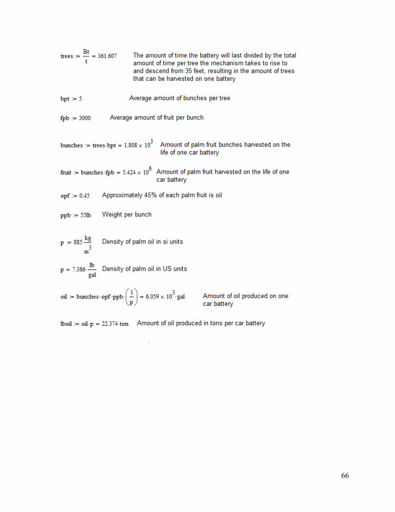
66
Related Documents