1 CHAPTER 1 1. INTRODUCTION OF THE COMPANY 1.1. INTRODUCTION Magline Switchboards Pvt Ltd is the leading manufacturer of low voltage power distribution panels, sub distribution panels, cable management systems and server rack systems for industrial and domestic applications in Sri Lanka. They have their own designing and manufacturing capability in house which gives them the flexibility in providing their customers, a complete solution as per their requirements. Their products are manufactured according to international standards. Magline started its operation in year 1987 and it has expanded beyond the borders serving the customers in Asia and Pacific. They have a good track record of being business for over 27 years and have a competent workforce of over 100. Today Magline Switchboards Pvt Ltd, is one of the leading electrical engineering companies that relies on local engineering expertise, successfully compete against international competitors with a large corporate clientele built up over the years by the professional service and quality. Figure 01.

Welcome message from author
This document is posted to help you gain knowledge. Please leave a comment to let me know what you think about it! Share it to your friends and learn new things together.
Transcript

1
CHAPTER 1
1. INTRODUCTION OF THE COMPANY
1.1. INTRODUCTION
Magline Switchboards Pvt Ltd is the leading manufacturer of low voltage power distribution panels, sub
distribution panels, cable management systems and server rack systems for industrial and domestic applications in
Sri Lanka. They have their own designing and manufacturing capability in house which gives them the flexibility in
providing their customers, a complete solution as per their requirements. Their products are manufactured
according to international standards.
Magline started its operation in year 1987 and it has expanded beyond the borders serving the
customers in Asia and Pacific.
They have a good track record of being business for over 27 years and have a competent workforce of
over 100. Today Magline Switchboards Pvt Ltd, is one of the leading electrical engineering companies that relies on
local engineering expertise, successfully compete against international competitors with a large corporate clientele
built up over the years by the professional service and quality.
Figure 01.

2
They Design and Manufacture,
Main switch boards.
Distribution panels.
Motor control panels.
Auto transfer panels.
Power factor correction capacitor banks.
Cable management systems.
They Fabricate,
Free standing panels.
Wall mounted enclosures.
19” Rack systems.
Feeder Pillars.
Cable ladders.
Cable trunking.
Perforated cable trays - Hot dip
Galvanized / Powder coated
Figure 02.

3
VISION - Our vision is to deliver power safely and reliably.
MISSION - To provide products, services and solutions of the highest quality and more value to our
customers that earns their respect and loyalty.
VALUES - Responsible, Excellent and Innovative – Have been the basis for Magline’s success for over
27 years.
1.2. STANDARDS AND PROTECTION
The protection of enclosures against ingress of dirt or against the ingress of water is defined in IEC529
(BSEN60529:1991). Conversely, an enclosure which protects equipment against ingress of particles will also protect
a person from potential hazards within that enclosure, and this degree of protection is also defined as a standard.
The degrees of protection are most commonly expressed as "IP" followed by two numbers, e.g. IP65, where
the numbers define the degree of protection. The first digit (Foreign Bodies Protection) shows the extent to which the
equipment is protected against particles, or to which persons are protected from enclosed hazards. The second digit
(Water Protection) indicates the extent of protection against water. The wording in the table is not exactly as used in
the standards document, but the dimensions are accurate.
The first digit in the rating is the protection against contact and foreign bodies. The second digit in the rating
is the water protection factor. The third digit in the impact protection factor It is normally displayed in the format
below
A two-digit number established by the International Electro Technical Commission is used to provide an
Ingress Protection rating to a piece of electronic equipment or to an enclosure for electronic equipment. The
protection class after EN60529 is indicated by short symbols that consist of the two code letters IP and a code
numeral for the amount of the protection. IP XX (e.g. – IP 54)
The two digits represent different forms of environmental influence:
• The first digit represents protection against ingress of solid objects.
• The second digit represents protection against ingress of liquids.

4
The larger value of each digit, the greater the protection. As an example, a product rated IP54 would be
better protected against environmental factors than another similar product rated as IP42. IP rating tables are as
below.
IP First number - Protection against solid objects
1st numeral Definition Description
0 Non-protected -
1 Protected against solid foreign objects
with diameter of 50mm & grater.
The object probe, sphere 50mm diameter, shall not
fully penetrate.
2 Protected against solid foreign objects
with diameter of 12.5mm & grater.
The object probe, sphere 12.5mm diameter, shall
not fully penetrate. The jointed test finger shall have
adequate clearance from hazardous parts.
3 Protected against solid foreign objects
with diameter of 2.5mm & grater.
The object probe, of 2.5mm diameter, shall not
penetrate at all.
4 Protected against solid foreign objects
with diameter of 2.5mm & grater.
The object probe, of 1.0mm diameter, shall not
penetrate at all.
5 Dust protected Ingress of dust is not totally prevented, but dust
shall not penetrate in a quantity to interfere with
satisfactory operation of the apparatus or to impair
safety.
6 Dust-tight No ingress of dust (at a partial vacuum of 20 mbar
inside the enclosure.

5
IP Second Number – Protection against liquid
2nd
numeral
Definition Description
0 Non protected -
1 Protected against vertically falling
water drops.
Vertically falling drops shall have no harmful effects.
2 Protected against vertically falling
water drops when the enclosure tied
Vertically falling drops shall have no harmful effects when
3 Protected against spraying water.
vertical no harmful effects.
4 Protected against splashing water. Water splashed against the enclosure from any direction
shall have no harmful effects.
5 Protected against water jets. Water projected in jets against the enclosure from any
direction shall have no harmful effects.
6 Protected against powerful water jets. Water projected in jets against the enclosure from any
direction shall have no harmful effects.
7 Protected against the effects of
temporally immersion in water.
Ingress of water in quantities casing harmful effects shall
not be possible when the enclosure is temporally immersed
in water under standardized conditions of pressure and
time.
8 Protected against the effects of
continuous immersion in water.
Ingress of water in quantities casing harmful effects shall
not be possible when the enclosure is continuously
immersed in water under conditions which shall be agreed
between the manufacturer & the user but which are more
severe than for numeral 7.

6
According to above two charts it can be seen that there must be some ways to increase the protection of a
panel Board. They are,
Equal thickness of powder coating according to the standards - Insulate enclosure to prevent hazards up to
some level in case of a fault condition.
Doors for panel boards with properly assembled & earthed.
Cover plates which are tailor made for the panel – provides additional protection after door is opened.
Insulation of the Bus bars & Perspex sheets – provides additional protection after Cover plates are removed.
Panel earthing – to ground in case of fault current.
Using glands in cable entries.
Generally Magline Switchboards manufacture up to IP 54 enclosures.
Form of separation in LV Switchboard
Form of separation refers to the internal segregation provided.
As per IEC 61439-1 “Separation of the various element of an Assembly; busbars, functional units, terminals, can be
claimed providing one or more of the following criteria are met.
In most installations, no particular partitioning is needed, electrical switchboard of the form 1 type is acceptable.
However this is no longer true without a front plate or other equivalent mean. The user shall not
access to living parts.
Following forms 2, 3 and 4 introduce additional partitioning within the switchboard.
Form 2: partitioning of busbars
Form 3a and 3b:
- functional units separated from each other and separated from the busbars
- connecting terminals separated from busbars

7
Form 4a and 4b:
- Functional units separated from each other and separated from the busbars
- connecting terminals separated from each other and separated from busbars.
Maintenance people should not be in a dangerous situation, e.g. parts not under maintenance should not
create dangerous situation in parts under maintenance.
Maintenance in one part should not create a dangerous situation in another part e.g. a screw or a tool falls
in another part.
Danger in one part should not expand to other parts e.g. an arc in one part should not influence other parts.

8
1.3. ORGANIZATIONAL STRUCTURE
Organizational structure is so made that the information, commands and decisions travel from top to bottom
rapidly which is a huge advantage in running such a large organization. On the other hand management has rapid
access to information from the flow that will make the decision making fast.
Figure 03.

9
CHAPTER 2
2. TRANING EXPERIENCE
2.1. WELDING
2.1.1. MANUAL METAL ARC WELDING
Arc welding is the fusion of two pieces of metal by an electric arc between the pieces being joined the work pieces
and an electrode that is guided along the joint between the pieces. The electrode is either a rod that simply carries
current between the tip and the work, or a rod or wire that melts and supplies filler metal to the joint.
The basic arc welding circuit is an alternating current (AC) or direct current (DC) power source connected by a “work”
cable to the work piece and by a “hot” cable to an electrode. When the electrode is positioned close to the work
piece, an arc is created across the gap between the metal and the hot cable electrode. An ionized column of gas
develops to complete the circuit.
Figure 04
2.1.1.1. Electrode Selection
When we select an electrode the only consideration of selecting an electrode of similar composition to the parent
metal. However, for some metals there is a choice of several electrodes. Often, one electrode will be more suitable

10
for general applications due to its all- round qualities. For example, the normal welder will carry out most fabrication
using mild steel and for this material has a choice of various standard electrodes, each of which will have qualities
suited to particular tasks.
2.1.1.2. Electrode Sizes
The size of the electrode generally depends on the thickness of the section being welded, and the thicker the section
the larger the electrode required. This means that, if 2.0 mm sheet is being welded, 2.5 mm diameter electrode is the
recommended size. The following table gives the maximum size of electrodes that may be used for various
thicknesses of section.
Recommended Electrode Sizes,
Plate thickness Electrode size
1.5 – 2.0 mm 2.5 mm
2.0 – 5.0 mm 3.2 mm
5.0 – 8.0 mm 4.0 mm
≥ 8.0 mm 5.0 mm
2.1.1.3. Welding Current
Correct current selection for a particular job is an important factor in arc welding. With the current set too low,
difficulty is experienced in striking and maintaining a stable arc. The electrode tends to stick to the work, penetration
is poor and beads with a distinct rounded profile will be deposited. Excessive current is caused by overheating of the
electrode. It will cause undercut and burning through of the material. Normal current for a particular job may be
considered as the maximum, which can be used without burning through the work, over-heating the electrode.

11
2.1.2. GAS METAL ARC WELDING
GMAW is an arc welding process which incorporates the automatic feeding of a continuous, consumable electrode
that is shielded by an externally supplied gas. Since the equipment provides for automatic self-regulation of the
electrical characteristics of the arc and deposition rate, the only manual controls required by the welder for
semiautomatic operation are gun positioning, guidance, and travel speed. The arc length and the current level are
automatically maintained.
Figure 05.
2.1.2.1. Equipment
The GMAW process can be used either semi automatically or automatically. The basic equipment for any GMAW
installation consists of the following:
A welding gun
A wire feed motor and associated gears or drive rolls
A welding control
A welding power source
A regulated supply of shielding gas
A supply of electrode
Interconnecting cables and hoses

12
2.1.2.2. Welding gun
The welding gun is used to introduce the electrode and shielding gas into the weld zone and to transmit electrical power to the
electrode.
Figure 06.
The contact tip, usually made of copper or a copper alloy, is used to transmit welding power to the electrode and to direct the
electrode towards the work. The contact tip is connected electrically to the welding power source by the power cable. The inner
surface of the contact tip is very important since the electrode must feed easily through this tip and also make good electrical
contact. The literature typically supplied with every gun will list the correct size contact tip for each electrode size and material.
The contact tip must be held firmly by the collet nut (or holding device) and must be centered in the shielding gas nozzle.
The nozzle directs an even-flowing column of shielding gas into the welding zone. This even flow is extremely important in
providing adequate protection of the molten weld metal from atmospheric contamination. Different size nozzles are available and
should be chosen according to the application. For an example larger nozzles for high current work where the weld puddle is
large, and smaller nozzles for low current and short circuiting welding.

13
2.1.2.3. Shielding Gas Regulator
A system is required to provide constant shielding gas pressure and flow rate during welding. The regulator reduces
the source gas pressure to a constant working pressure regardless of variations at the source.
The shielding gas source can be a high pressure cylinder, a liquid-filled cylinder, or a bulk liquid system. Gas
mixtures are available in a single cylinder. Mixing devices are used for obtaining the correct proportions when two or
more gas or liquid sources are used. The size and type of the gas storage source are usually determined by
economic considerations based on the usage rate in cubic feet (cubic meters) per month.
2.1.2.4. Power Source
The welding power source delivers electrical power to the electrode and work piece to produce the arc. For the vast
majority of GMAW applications, direct current with positive polarity is used; therefore, the positive lead must go to the
gun and the negative to the work piece. The transformer-rectifier type is usually preferred for in-shop fabrication
where a source of electrical power is available.
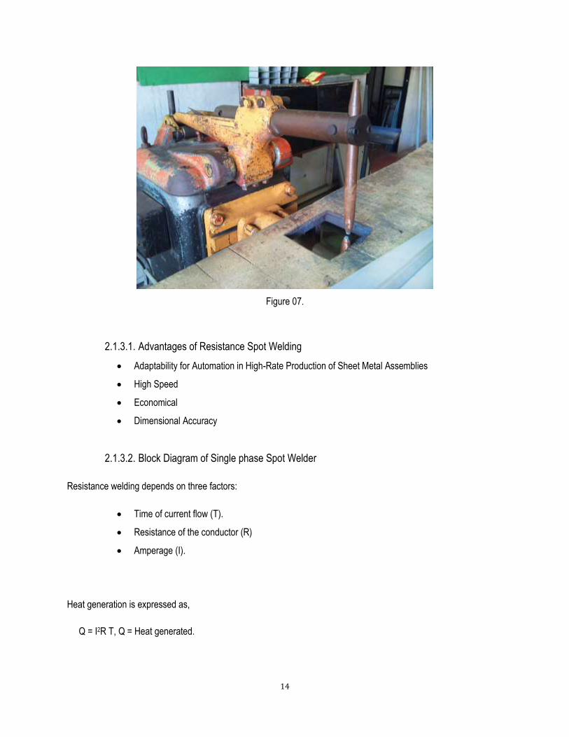
2.1.3. SPOT WELDING
Spot welding is a resistance welding method used to join two to three overlapping metal sheets, studs, projections,
electrical wiring hangers, some heat exchanger fins, and some tubing. Usually power sources and welding equipment
are sized, to the specific thickness and material being welded together. The thickness is limited by the output of the
welding power source and thus the equipment range due to the current required for each application. Care is taken to
eliminate, contaminates between the faying surfaces. Usually, two copper electrodes are simultaneously used to
clamp the metal sheets together and to pass current through the sheets. When the current is passed through the
electrodes to the sheets, heat is generated due to the higher electrical resistance where the surfaces contact each
other. As the electrical resistance of the material causes heat build-up in the work between the copper electrodes, the
rising temperature causes a rising resistance, and results in a molten pool contained most of the time between the
electrodes.
14
Figure 07.
2.1.3.1. Advantages of Resistance Spot Welding
Adaptability for Automation in High-Rate Production of Sheet Metal Assemblies
High Speed
Economical
Dimensional Accuracy
2.1.3.2. Block Diagram of Single phase Spot Welder
Resistance welding depends on three factors:
Time of current flow (T).
Resistance of the conductor (R)
Amperage (I).
Heat generation is expressed as,
Q = I2R T, Q = Heat generated.

15
Figure 08.
2.1.4. OXY ACETYLENE WELDING.
In Magline they used Oxy acetylene welding for weld enclosures after bending process and widely used in the
manufacturing process of 19” wall mounting racks and free standing racks.
Figure 09.
Here they used gas welding because very thin sheets (up to 2mm) are damaged when welding by using arc welding.
Because, there, it is impossible to control the heat in the arc welding process. In gas welding process, it is used two
gases Oxygen and Acetylene. Used acetylene pressure is about 0.5 to 1.0 bar and Oxygen pressure is about 2.0 to
2.5 bar.

16
There are three types of Oxy acetylene flames, usually termed, Neutral, Carburizing (excess of acetylene) and
Oxidizing (excess of oxygen). The types of flames produced depend upon the ratio of Oxygen to Acetylene in the gas
mixture which leaves the torch tip.
2.2. POWDER COATING
2.2.1. INTRODUCTION
There are two principal technologies that are the back bone of the coating industry,
Liquid coating technology (wet).
Powder coating technology (dry)
Powder coating generally produces a coating twice as thick as standard paint. The real advantage is its flexibility and
ability to bend and yield with the material it is applied to. This makes it ideal in the transportation industry where the
products are subject to a lot of vibration and twisting as they move down the road.
There are many advantages that make the choice of applying thermosetting powder coating so attractive to the
coating company.
Powder is immediately ready for use.
Less powder wastage during the application process.
More durable than paints.
Powder recovery for reuse.
Superior cured-film properties.
Lower capital investment costs.
Several disadvantages of powder coating over paints,
Can have less leveling than paint (more orange peel).
Curing is typically more energy intensive than paint drying due to higher temperature requirement.

17
2.2.2. POWDER COATING PROCESS FOR METAL PARTS.
In the powder coating process Phosphating is a very important point that must be considered. It improves the
corrosion protection and the adhesion. In here it is used about 50ml for 100 liters of water. After cleaning and rinsing
the metal sheets deliver to the phosphate solution. The chemical that used in Magline to prepare phosphate solution
is Aqua-PHOS. After Phospating is allows to drying and send to the powder coating booth by the use of conveyer.
Here they user Corona type powder coating system to powder coating process. The powder coating thickness is
used 80 – 120 microns as a standard. After powder coating the coated parts are delivered to the oven to achieve the
curing process. The curing conditions are for the temperature of 1900 C and 10 minutes curing time in the oven.
Cleaning Rinsing Phosphating
Drying Powder Coating Curing

18
Figure 10.
2.2.3. OVEN TEST REPORT
Following graph illustrated for checking purpose of temperature behavior against relevant time intervals.
Figure 11.

19
2.3. MACHINE OPERATION
2.3.1. MILLING OPERATION
In Magline machine shop we have only vertical milling machines. Here, I have mentioned only a single operation of
milling. First, must be considered on how to setup a job to the milling machine. There are vertical milling machine in
the following figure.
Before setting up a job, we clean the work piece, table, and the taper in the spindle and cutter shank to free from
chips or burrs. We would not select a milling cutter of larger diameter than is necessary. It should be checked that it
is in good running order and properly lubricated and that it moves freely only necessary movements. Then it should
be considered about the rotating direction of the spindle. In conventional milling we feed the work piece in the
direction opposite the rotation of milling cutter. We must not change of feed or speed while in operation. It must be
clamped work piece properly to avoid unnecessary vibrations and movements. For reliable running tools should be
used a proper cutting oil and in every job it should be set as close to the milling machine spindle as circumstances
will permit.
2.3.1.1. Keyway cutting on a round shaft.
First, it should be align the work piece to the milling cutter. The shaft should be supported in the vise mounted
between centers. The cutter must be set properly to the spindle.
The shaft should be positioned to the side of the cutter is tangential to the circumference of the shaft. This is done by
moving the shaft transversely to a point that permits the work piece to touch the cutter side teeth.

20
Figure 12.
At this point, gradually dial on the cross feed and touch the point as shown above. After finding the correct point the
table is lowered and moved the table transversely a distance equal to the radius of the shaft plus half of width of the
cutter.
Figure 13.

21
Milling cutter is located over the position in which the keyway to be cut. The work piece should be moved up
gradually in to the cutter until obtained the desired key depth.
2.3.2. LATHE OPERATION
The lathe is a machine tool used principally for shaping of metal (and sometimes wood or other materials) by causing
the work piece to be held and rotated by the lathe while a tool bit is advanced into the work causing the cutting
action. The basic lathe that was designed to cut cylindrical metal stock has been developed further to produce screw
threads, tapered work, knurled surfaces and crankshafts. The typical lathe provides a variety of rotating speeds and a
means to manually and automatically move the cutting tool into the work piece.
2.3.2.1. THREAD CUTTING ON LATHE.
After the work piece is machined to the major diameter of the desired thread, the thread cutting tool is set to the work
piece using the center gauge as following figure.
Figure 14.
To align the tool bit to work piece, first, ensure that the point of the tool bit is set at the center height of the lathe.
Then place the center gauge between the point of tool bit and the work piece. After secure the tool bit on position,
advance the tool bit until the point just make contact with the work piece. After that, zero the cross side dial and then
feed the dial gradually.
In the thread cutting process, it takes several passes to cut the thread to full depth. We use the power feed forward/
neutral/ reverse lever to engage the lead screw drive.

22
Figure 15.
To cut the threads, first, move the carriage to the beginning of the cut. For the first pass, it should be about 0.001mm
and for additional passes, it should be 0.005mm to 0.010mm. The lathe should be run at the lower speed to develop
sufficient torque to make the cut. When the threading dial reaches on appropriate mark, the half nut is engaged. It
must be done at right on the mark and if half nut will engage between each marks will damage the thread. When the
tool reaches the end of the thread, the half nut should be disengaged. After cutting the thread, the thread gauge can
be used to check the accuracy of the thread.
Figure 16.

23
2.3.3. CNC TURRET PUNCH OPERATION
With the turret punch press the work sheet is positioning according to the machining dimensions for an intended
product. Press working, optimal operation mode selection, die and punch choosing are automatically done following
the CNC commands.
G- Code (Address for preparatory commands)
G commands often tell the control, what kind of motion is wanted (rapid positioning, linear feed, circular feed, fixed
cycle) or what offset value to use.
M- Code
Miscellaneous functions are done by M-codes. They control machine auxiliary options like coolant and spindle
directions.
X dimensions are considered positive to the right of the origin and negative to the left. Y dimensions are considered
positive to the up from the origin and negative down from the origin.
Figure 17.

24
2.3.3.1. A SIMPLE CODE FOR PUNCHING.
G 90 Absolute coordinates
G 91 Increment coordinates
TXX Tool selection
IXX Offset XX value on X direction.
JXX Offset XX value on Y direction.
PXX I offset repeat XX times.
KXX J offset repeat XX times.
VXX and UXX Sub programs.
CNC PROGRAM.
V01
G90 X10 Y1210 T06
G78 I20 J-20 P04 K02
U01
G98 X00 Y00 I850 J-450 P01 K01
G74 U01 Q01
G90 G70
M30

25
Figure 18.
2.4. SHEET METAL FORMING MACHINES
2.4.1. CNC TURRET PUNCH PRESS
Figure 19.

26
A CNC turret punch press machine bases on the principle of nibbling, features a unified structure into which a die
turret and punch turret mounted with various punch dies, and punch respectively and a work sheet positioning
mechanism are combined together. Turret punch presses are brought into run, in combination with a CNC unit.
With this punch press, work sheet positioning according to the machining dimensions for an intended product, press
working, optimal operation mode selection, die and punch choosing are automatically done, following the CNC
commands. Therefore the CNC turret press can undertake sequentially punching different holes in a work sheet with
each die and punch indexed automatically at one fixed punching position while relocating the sheet in each cycle of
punching. Work sheet positioning and turret drive are optionally, controlled numerically, allowing the press to
automatically punch to a complicated profile with easy.
2.4.2. SHEARING MACHINE
Figure 20.
Shearing is a simple process whereby a sheet of metal is cut into smaller pieces by two knives which are positioned
at an angle relative to each other. The lower knife is firmly attached into a pocket in the stationary table, while the
upper blade is fixed to the moving ram assembly. The two blades are separated only by a distance measured in
thousandths of an inch at the point of cut.
Hold down clamps attached to the forward fixed ram, must depress just prior to the moving ram knife making contact
with the material being sheared. This avoids the material from squirming or moving while the shearing process takes
place.

27
2.4.2.1. Rake angle and Shearing.
The rake angle of a shear is the slope of the upper knife from the left to the right. Shears will either have a fixed rake
angle or an adjustable rake, whereby the operator will set the angle for the appropriate gauge of metal that is being
sheared.
The load required to shear material depends on the thickness and the rake of the upper blade. As metal thickness
increases, shear load increases very rapidly.
High rake angles increase:
Twist and bow on the cut-off piece of material
Stroke length requirements thus decreasing cycles per/minute.
Wastage of material that has been twisted beyond recovery or unnecessary time to re-straighten.
2.4.2.2. Blade Clearance
Blade clearance is the distance between the upper and lower blade of the shear as they pass each other during the
shearing process. For optimum shearing quality, the clearance between the upper and lower blades should be set at
approximately 7% of the material thickness.
2.4.3. HYDRAULIC PRESS BRAKE
Figure 21.

28
2.4.3.1. Pump
A motor driven, variable volume, hydraulic piston pump provides the flow and pressure for advancing, retracting and
loading the power cylinders. This pump is equipped with a “load sensing” control that precisely matches pump flow
and pressure to load demands. This precise match provides maximum system efficiency.
2.4.3.2. Ram Stroke
Hydraulic pressure from the pump forces the cylinder pistons down or up to move the ram. The stroke length is
adjustable. The maximum standard stroke length is shown in the preceding Specifications chart.
2.4.3.3. Press Brake Tooling
A hydraulic press brake is a very versatile bending machine. It is capable of exerting high forces between its bed and
ram. These forces are applied and directed into the material to be formed by the use of tooling (dies).
The type and shape of the dies are the principle factors in establishing the shape of the part to be formed. There are
many different types and shapes of press brake dies. Some have a very special and unique shape. However, most
dies are members of a family of tooling called Vee
Air bend dies Bottoming dies
Figure 22.

29
2.5. ELECTRICAL PANEL BOARDS
2.5.1. ATS - Auto Transfer Switch
A transfer switch is an electrical switch that switches a load between two sources. Some transfer switches are
manual, in that an operator affects the transfer by throwing a switch, while others are automatic and switch when they
sense one of the sources has lost or gained power.
An Automatic Transfer Switch (ATS) is often installed where a backup generator is located, so that the generator may
provide temporary electrical power if the utility source fails.
In small application which have 32A – 400A rated, we normally used contactor type ATS unit, because that
type of ATS’s are easy to install and it has low cost than MCCB type ATS.
The MCCB type ATS are used between 400A to 1600A. in here MCCB’s are manually operated by using a
motor. The MCCB which above 800A, has inbuilt motorized system
Above 1600A ATS panel, ACB’s are normally recommended.

30

31
2.5.2. CAPACITOR BANK
Capacitor bank is used to reduce the cosØ. Normally, there are several method to reduce the cosØ.
1. Using synchronous motor
2. Install the capacitor bank
Benefits of using capacitor bank,
1. current reduction
2. increase the energy using efficiency
3. increase the electricity supply quality
4. increase the national grid capacity
5. increase the electrical machine durable
The internal connection of three phase capacitor
Figure 24.

32
2.5.2.1. THE APPLICATION OF CAPACITOR BANK
Figure 25.
Before install the capacitor bank we should take the load profile where capacitor bank should be installed. Specially,
the minimum load should be considered, because to determine the step of capacitor bank. Following figure shows
the component arrangement of capacitor bank
Figure 26.

33

34
CHAPTER 3
3. PROJECTS
3.1. RE-INSTALLATION FACTORY COMPRESSOR ROOM
3.1.1. MECHANICAL CONSIDERATION
The factory compressor room has many problems and issues currently and we started a project a project to reduce
those issues. When we analyze about the issues, we observed that there is no proper way to exit heat dissipated
from the compressors.
Because of that, the temperature of the compressor room increases significantly. That affects to the motor insulations
of the compressors and insulations tend to weak. We got to know that the few electric motors were replaced during
last year. We assume that had happened due to the excess temperature increase in the room. To reduce the
temperature in the compressor room we proposed to re-arrange the all for compressors and install an exhaust fan.
Before re-installation we got measurements of the compressor room including all four compressors and modeled it in
SolidWorks. The following figure shows the current situation of the factory compressor room.
Figure 28.

35
For the re-installation of compressors the mechanical arrangement and the piping system is a very
important factor that we had to consider more. There for, the model of the mechanical arrangement was
very important to get an idea about the spacing and to analyze and get to know about the real situation
after installation. This arrangement was very convenient, because the heat dissipated by compressor
heads was travelled to the outside in the one direction. It was a force feed system by supporting the pulley
fans of the each compressor. The installation of exhaust fan helps to carry out the heat outside. The
temperature in the room was at about 400 C and it was a big fault and it can be reduced by help of this new
system. The following figure shows the new model of the compressor room that creates in SolidWorks.
Figure 29.
After installation, another issue was which need of a water draining valve to drain the collected in the air lines.
Because the compressors are subjected to lots of repairing and they are very old ones there are some faults of
compressors. It was collected considerable amount of water because the unit works for all 24 hours of the day.
Therefore it is a need of a water draining valve to reduce lots of issues in air lines. But because of the higher cost of
the valves in the market they requested to design a water draining valve also.
When the compressors works for some time, it is collected some water in the pressure bar. If it works for a day
without draining water a big problem occurs, because here are a lot of machines operate with the help of compressed

36
air. There are a lots of air tools in the assembly section which drives by compressed air, and also powder coating
section is the very important section which is totally depend on the compressed air.
Because of that, it is necessary to fix a water draining system to the pressure bar. They gave me a shunt coil which is
used to the MCCBs and it is easy to operate by supplying 230V power. The rod of the shunt coil has about a 5mm
stroke and the spool of the valve is connected through the link to actuate the valve. The following figure shows the
shunt coil which used to design the valve.
Figure 30.
It had used a simple lever mechanism to operate the spool of the draining valve. The valve consists with mainly two
parts which are assembled by a thread, Except that two parts the spool operates in between two part as shown in the
below figure. When considering about the return of the valve, it takes return due to its weight and the pressure
applied on the spool.
The water draining valve operate at about ten seconds to drain the collected water and it returns to the closed
position just after the power disconnected by the twenty four hour timer.

37
Figure 31.
3.1.2. ELECTRICAL CONSIDERATION
In the re-installation process the next step was to reduce electrical issues of the compressor unit. First we observed
that all the motors start at once and it will affect to the maximum demand reading of the electricity bill. Because there
are more issues we decided to design a new control system.
First, because of missing the name plates of all four motors we had to measure the currents drawn from each phase
of the motors by using clip-on meter.
By considering currents drawn at starting and running conditions, we calculated the power of all four motors
individually. Those kW values send to purchase the contactors and overload relays which suitable for each motor.
The result of current drawn by each motor,
COMP. 01 COMP. 02 COMP. 03 COMP. 04
Starting Current (A) 66 25 66 33
Running Current (A) 13.04 6.09 15.8 7.9
kW Values 7.50 3.50 9.10 4.54

38
When we design the control circuit for the compressor unit we had to consider about the requirements of the factory.
Because of that we had to add more options for the better and flexible design. There are some options below that
considered for the control panel designing process.
Starting sequence.
There should be a starting sequence of compressors. If the all four motors started at once, the demand of the factory
increases significantly. If the maximum KVA value increases the factory have to pay more for the CEB. Therefore,
setting a starting sequence is very important to reduce the cost of electricity bill.
Auto/Manual Option
We include Auto/Manual option for each compressor to use when it necessary. We used the pressure switch of
pressure bar for the auto option. It senses the pressure of the pressure of the pressure bar and it is common for all
four compressors. When the pressure increase more than the set value, it switched off the all four compressors.
In manual option we have used individual pressure switches of each compressor and it is depend on the individual
set values. When we switch to the manual option the compressors work until it increases the se value.
Draining Switch
When the compressor works some water is stored in the FRL unit and we used a solenoid valve to drain the excess
water in the unit. We used a twenty four hour timer for draining and it set to activate the solenoid valve at each and
every working hour. It takes the control via another timer because the twenty four hour timer has only fifteen minutes
sensitivity. The second timer set to the five seconds operation time for draining water.
Air relief valve
We have included star-delta starting for two compressors. At star condition, it is unable to run with a load for the
compressors, because of that reason at starting the air relief valve operates and reduce the pressure stored by
relieving air for only three seconds. After shifting to the delta connection, the motor can be run with a load.
To satisfy above all requirements, we designed a new electrical panel and a control circuit for the flexible running of
the compressor unit.
The control wiring diagram
Notation: PS – Pressure switch of the pressure bar CPS- Compressor pressure switch (1,2,3,4)
KS- Star contactor KD- Delta contactor KM- Main contactor T- Timer
OL – Overload relay KP – Pressure switch contactor (Pressure bar)

39
40
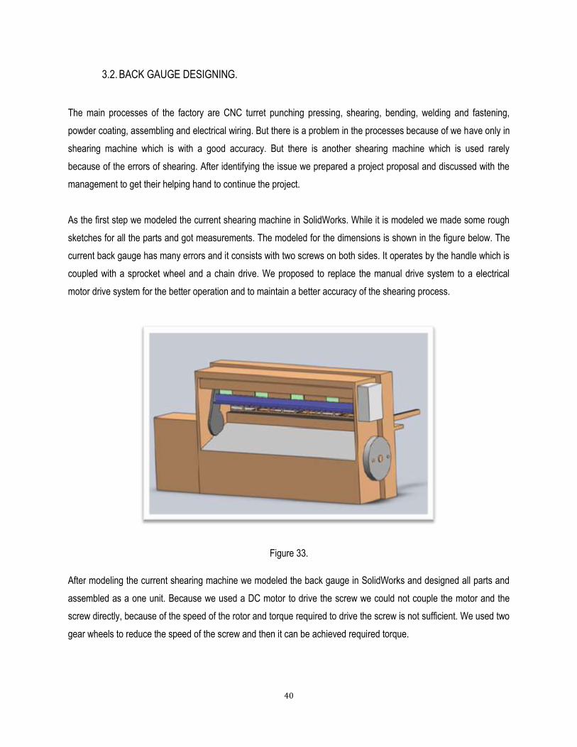
3.2. BACK GAUGE DESIGNING.
The main processes of the factory are CNC turret punching pressing, shearing, bending, welding and fastening,
powder coating, assembling and electrical wiring. But there is a problem in the processes because of we have only in
shearing machine which is with a good accuracy. But there is another shearing machine which is used rarely
because of the errors of shearing. After identifying the issue we prepared a project proposal and discussed with the
management to get their helping hand to continue the project.
As the first step we modeled the current shearing machine in SolidWorks. While it is modeled we made some rough
sketches for all the parts and got measurements. The modeled for the dimensions is shown in the figure below. The
current back gauge has many errors and it consists with two screws on both sides. It operates by the handle which is
coupled with a sprocket wheel and a chain drive. We proposed to replace the manual drive system to a electrical
motor drive system for the better operation and to maintain a better accuracy of the shearing process.
Figure 33.
After modeling the current shearing machine we modeled the back gauge in SolidWorks and designed all parts and
assembled as a one unit. Because we used a DC motor to drive the screw we could not couple the motor and the
screw directly, because of the speed of the rotor and torque required to drive the screw is not sufficient. We used two
gear wheels to reduce the speed of the screw and then it can be achieved required torque.

41
We used two guiding shafts with linear bearings for better working by reducing friction losses in contacts too. Mainly
we considered about the mounting the back gauge to the shearing machine by making alignments properly. We used
existing holes and mounting brackets to reduce weaken by making new holes and slots.
We made a few calculations for the critical parts by considering stresses and bending moments that can be built up in
the system.
Figure 34.
Price Estimation for Back gauge.
After designing the back gauge we prepared a bill of materials and price estimation for the designed back gauge for
the shearing machine.
With the help of our purchasing executives we got the prices for most of the parts and the production costs for each
and every item in the BOM we prepared.

42
Component Material cost (Rs:) Production cost (Rs:)
Screw(ɸ35-P5-L875) with Nut 20,100
Screw(ɸ6-L100)x4 120
Screw( ɸ6-L200)x2 120
Gear wheel(T15-P4) 9,600
Gear wheel(T45-P4)
Side bars( ɸ30-L830) x 2 4,840
Wiper motor(12V) 2,000
Open Linear Bearing(SK 71-230) x 2 7,840
Single row angular contact ball bearing(6004) x 2 7,500
L angle(24 x 24 x 3 x 1800) 3,900
L angle(40 x 40 x 3 x 900)x2 3,780
Bolts( ɸ4x12)x4 40
Bolts( ɸ6x25)x24 504
Bolts( ɸ6x55)x4 140
Bolts( ɸ6x35)x4 100
Bolts( ɸ10x55)x12 1,622
M4 Nuts x4 26
M6 Nuts x34 220
M10 Nuts x12 360
M4 washers x8 52
M6 washers x80 517
M10 washers x24 405
Sheet Plate(10 x50 x 410)x4 4,212
Sheet Plate(10 x 70 x 1960) 6,210
Sheet Plate(5x20x1920) x 2 3,182
Sheet Plate(5x75x2000) 3,300
Sheet Plate(5x20x2000) 1,600
Sheet Plate(5x70x2000) 3,300
Sheet Metal(2x900x2000) 10,400
Cast Iron Metal Blocks(50x60x100)x6 13,780
Cast Iron Metal Blocks(20x20x50)x4 1300
Cast Iron Metal Blocks(70x100x100)x3 21,600

43
Cast Iron Metal Blocks(20x70x1000)x4 7,400
Cast Iron Metal Blocks(40x40x60)x2 6,630
Total Cost 1,17,000 29,600

44
CHAPTER 4
4. CONCLUTION
Magline Switchboards factory is a good place to be trained as a mechanical trainee because we can do many
projects to improve their production and to improve their efficiency. I think I was very lucky to work in here with the
limited chances that we have as a mechanical engineering students.
They used very simple and old methods to their production for an example hand punching machines, manual press
brakes. Because of that case they had to maintain more labors and they have to pay more for the production. In my
training periods now I have started few projects leads to improve their production and minimize the production errors
of their products.
I believe that this is a good opportunity to obtain new designs and serve them the best solutions for their production
within my scope. I hope that they will give their helping hand to me to continue this.
Related Documents


