FINAL REPORT: CONCEPTUAL DESIGN OF A 10-MEGAWATT ELECTRON BEAM IRRADIATION FACILITY FOR BIO-SOLID WASTE TREATMENT Fermi National Accelerator Laboratory Kirk and Pine Street / P.O. Box 500 / Batavia, IL 60510 Managed by Fermi Research Alliance, LLC for the U.S. Department of Energy Office of Science DOE / Office of Science Program Office: High Energy Physics December 12, 2018 Fermi National Accelerator Laboratory Metropolitan Water Reclamation District of Chicago FERMILAB-FN-1063-DI

Welcome message from author
This document is posted to help you gain knowledge. Please leave a comment to let me know what you think about it! Share it to your friends and learn new things together.
Transcript
FINAL REPORT: CONCEPTUAL DESIGN OF A 10-MEGAWATT ELECTRON BEAM IRRADIATION FACILITY FOR BIO-SOLID WASTE TREATMENT
Fermi National Accelerator Laboratory Kirk and Pine Street / P.O. Box 500 / Batavia, IL 60510
Managed by Fermi Research Alliance, LLC for the U.S. Department of Energy Office of Science DOE / Office of Science Program Office: High Energy Physics
December 12, 2018
Fermi National Accelerator Laboratory
Metropolitan Water Reclamation District of Chicago
FERMILAB-FN-1063-DI
Fermi National Accelerator Laboratory 2
Table of Contents
INTRODUCTION 3
EB TREATMENT REQUIREMENTS 3 BACKGROUND 3 NEED AND APPROACH 4
CONCEPTUAL DESIGN FOR THE 10 MW COMPACT SRF ACCELERATOR 4
THE 1 MW CRYOMODULE DESIGN FOR A 10 MW ACCELERATOR 5 INJECTOR 6 RF GUN 7 ELECTROMAGNETIC DESIGN OF GUN RESONATOR 9 INJECTOR CAVITY 9 BEAM DYNAMICS STUDY IN RF GUN 11 MAIN ACCELERATING SECTION 13
SPECIFICATION OF BEAMLINE ELEMENTS 14
SOLENOIDAL FOCUSING MAGNET 14 ACCELERATING SUPERCONDUCTING RADIO FREQUENCY CAVITY: 15 RF POWER SOURCE FOR THE ACCELERATING CAVITY 18 SWEEPING MAGNET DESIGN 19 DIFFERENTIAL PUMPING INSERT (DPI) 19 BEAMDYNAMICS SIMULATION STUDIES 19 BEAM DELIVERY SYSTEM 22 CHOICE OF WINDOW MATERIAL 23 IMPLICATION OF MATERIAL THICKNESS 24
COST ANALYSIS 26
CONSTRUCTION COST 26 OPERATION COST 28
ADDITIONAL R&D AND TECHNOLOGY DEVELOPMENT NEEDED FOR COMPACT SRF ACCELERATOR: 29
MULTI-WATT CRYOCOOLER DEVELOPMENT AND DEMONSTRATION 29 MULTI-CELL NB3SN COATED CAVITIES 29 RF POWER SOURCE 30 HIGH CURRENT SRF INJECTOR DESIGN 30
SUMMARY AND CONCLUSION 30
REFERENCES 32
APPENDIX 34
Fermi National Accelerator Laboratory 3
CONCEPTUAL DESIGN OF A 10-MEGAWATT ELECTRON BEAM IRRADIATION FACILITY
FOR BIO-SOLID WASTE TREATMENT
J. C. T. Thangaraj, A. Saini, V. Yakovlev, I. Gonin, N. Solyak, R. Dhuley, T. Kroc,
M. Geelhoed, I. Tropin, N. Mokhov, T. Khabiboullline
Fermi National Accelerator Laboratory
Introduction
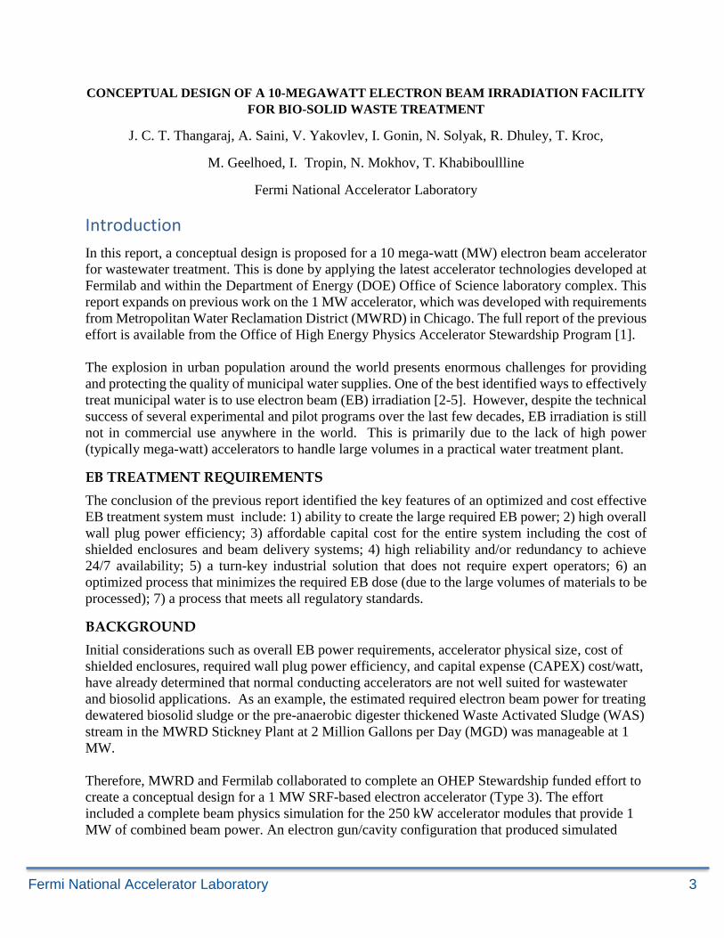
In this report, a conceptual design is proposed for a 10 mega-watt (MW) electron beam accelerator
for wastewater treatment. This is done by applying the latest accelerator technologies developed at
Fermilab and within the Department of Energy (DOE) Office of Science laboratory complex. This
report expands on previous work on the 1 MW accelerator, which was developed with requirements
from Metropolitan Water Reclamation District (MWRD) in Chicago. The full report of the previous
effort is available from the Office of High Energy Physics Accelerator Stewardship Program [1].
The explosion in urban population around the world presents enormous challenges for providing
and protecting the quality of municipal water supplies. One of the best identified ways to effectively
treat municipal water is to use electron beam (EB) irradiation [2-5]. However, despite the technical
success of several experimental and pilot programs over the last few decades, EB irradiation is still
not in commercial use anywhere in the world. This is primarily due to the lack of high power
(typically mega-watt) accelerators to handle large volumes in a practical water treatment plant.
EB TREATMENT REQUIREMENTS
The conclusion of the previous report identified the key features of an optimized and cost effective
EB treatment system must include: 1) ability to create the large required EB power; 2) high overall
wall plug power efficiency; 3) affordable capital cost for the entire system including the cost of
shielded enclosures and beam delivery systems; 4) high reliability and/or redundancy to achieve
24/7 availability; 5) a turn-key industrial solution that does not require expert operators; 6) an
optimized process that minimizes the required EB dose (due to the large volumes of materials to be
processed); 7) a process that meets all regulatory standards.
BACKGROUND
Initial considerations such as overall EB power requirements, accelerator physical size, cost of
shielded enclosures, required wall plug power efficiency, and capital expense (CAPEX) cost/watt,
have already determined that normal conducting accelerators are not well suited for wastewater
and biosolid applications. As an example, the estimated required electron beam power for treating
dewatered biosolid sludge or the pre-anaerobic digester thickened Waste Activated Sludge (WAS)
stream in the MWRD Stickney Plant at 2 Million Gallons per Day (MGD) was manageable at 1
MW.
Therefore, MWRD and Fermilab collaborated to complete an OHEP Stewardship funded effort to
create a conceptual design for a 1 MW SRF-based electron accelerator (Type 3). The effort
included a complete beam physics simulation for the 250 kW accelerator modules that provide 1
MW of combined beam power. An electron gun/cavity configuration that produced simulated
Fermi National Accelerator Laboratory 4
losses of zero was arrived at such that, when statistical errors are included, the loss level is < 10-6
of the beam [1].
NEED AND APPROACH
While the 1 MW beam power is sufficient for bio-solid treatment at 1 MGD, an important area of
interest for MWRD is improving the ability to remove water from WAS before thickening where
the flow rate is higher. In this case, the flows are larger at 8-13 Million Gallons per Day (MGD).
Therefore, if a 10 kGy dose is required to improve dewatering, this leads to an EB power
requirement for MWRD to be 4-6 MW assuming all the beam is effectively utilized. This means
treatment of this waste stream is only addressable with a 10 MW scale accelerator. Motivated by
encouraging simulation results for a 250 kW SRF module, the conceptual design of a 10 MW
combined beam power system based on 1 MW modules was developed.
The increase in beam power in each module was accomplished by increasing the average beam
current in each accelerator module by a factor of four from our previous concept. Although much
of the previous work was applicable, such high gun currents and electron beam powers needed
additional simulation effort that employed higher statistics to understand loss distributions at the
level of 10-6 or lower. In these studies, the limits of achievable beam power for such SRF accelerator
modules was explored. Other challenges at these high beam powers were RF couplers, RF power
sources, beam delivery, and shielding. Of particular note are the challenges associated with
windows that separate the clean vacuum of the cavity from the harsh environment of the industrial
waste streams at issue. As in previous work, the accelerator design will focus on the concept and
feasibility of a very high power industrial Superconducting Radio-Frequency (SRF) electron beam
accelerator that leverages recent transformational SRF technology improvements to achieve both
reliability and cost targets via a modular approach and an innovative low-cost Radio-Frequency (RF)
power source.
Conceptual design for the 10 MW compact SRF accelerator
The conceptual design for a 10 MW electron beam irradiation facility is based on ten identical units
of 1 MW linac modules. Each module is designed to deliver a 100mA, 10 MeV CW electron beam
based on SRF technology, which is the most cost-effective way to build and operate MW beam
facilities. SRF technology enables high accelerating fields with minimum power dissipation and
high-duty factor beam operation.
However, achieving superconducting temperatures requires a significant investment in a cryogenic
system, which is a cumbersome and large system. This is where Fermilab’s novel conduction
cooling technique allows one to reach superconducting temperatures without using complex
cryogenic systems [6]. This is done with a combination of advanced SRF coatings and compact,
industrially available cryo-coolers to maintain the cryogenic temperature for reliable operation of
the SRF cavity. This patented technology was recently demonstrated at the IARC facility.
Conduction cooling technology achieves superconducting temperatures without requiring a
cryogenic system which is cumbersome and complex.
For the objective of this report, the limited cryogenic capacity of cryo-coolers (2 W) places stringent
tolerances on power dissipation in the SRF cavity. Consequently, it puts a strict limitation on the
beam loss in SRF section. Therefore, the goal is to develop a baseline configuration with a minimal
Fermi National Accelerator Laboratory 5
uncontrolled beam loss in the linac optics design. Because of the identical nature of each module,
only the 1 MW machine will be discussed in most parts of the report.
To be specific, the conceptual design of a 1 MW beam power module that has a 4 ½ cell, 650-
MHz, elliptical Nb cavity, coated inside with Nb3Sn, and powered by an RF source with ~80%
efficiency and a target cost of $4/W is to be focused on. Elliptical SRF cavities at 650 MHz are a
natural choice for this application since this is a frequency already chosen for Office of Science
applications that represents a good balance between physical size; cavity cost; large apertures
leading to low beam losses; and low expected cryogenic load during CW operation. Each
independent module will deliver ~10 MeV electrons in Continuous Wave (CW) operation. This
report addresses key design aspects of the basic module to validate or improve the initial vision
and determine the performance requirements of emerging technology.
The team began by modifying the physics calculations and simulations to understand how higher
current beam (100 mA average, > 1 A peak) can be generated at the cathode, accelerated away
from the space-charge regime and transported through the linac to 10 MeV with a total power of 1
MW all the while maintaining the beam losses at or below 10-6. This does not include particle
losses that happen outside the SRF cryomodule that does not contribute to the heat budget such as
scrapers. As mentioned above, IARC’s previous work indicated that a 650 MHz cavity coated
with Nb3Sn cavities operating at 4 K CW, with ~10 MeV/m gradient can accelerate 25 mA
electron beams corresponding to 250 kW output power per module with insignificant loss. Finally,
a preliminary estimate for the Type 4 target capital and operating costs for the first article and in
production will be discussed.
IARC focused on design solutions for high current cathodes, very high-power couplers, low cost
RF, and careful beam transport with an overarching goal to minimize beam loss – a stringent
requirement in an SRF accelerator for MW power levels. An acceptable target is a loss of < 2 x
10-6 of the beam on cold cavity surfaces corresponding to 2.0 W at 4 K. The team estimated that
an optimized, magnetically shielded 650 MHz Nb3Sn coated 4 ½ cell cavity can achieve dynamic
RF losses ~ 2.5 W at 4 K based on measurements of similar 1.3 GHz cavities [6]. The goal is a
1MW module cooled by several high capacity, high reliability commercial cryocoolers without
the use of Liquid Helium. The MTF for current cryocoolers is between 40000-70000 hours
making them ideal for industrial use. This approach permits use of a simple cryostat and a
completely sealed helium system—both are key items for simple turn-key industrial operation.
In summary, IARC envisioned a novel SRF-based, 10-MeV, 10-MW, industrial electron
accelerator that consists of ten modules each containing a 4 ½ cell, 650-MHz, elliptical Nb cavity,
coated inside with Nb3Sn, and powered by an RF source with 80% efficiency. Each independent
module will deliver 1 MW of 10 MeV electrons in Continuous Wave (CW) operation. This
modular approach is attractive to MWRD because it can provide a straight-forward path to scaling
to higher powers and can provide operational reliability via redundant modules.
THE 1 MW CRYOMODULE DESIGN FOR A 10 MW ACCELERATOR
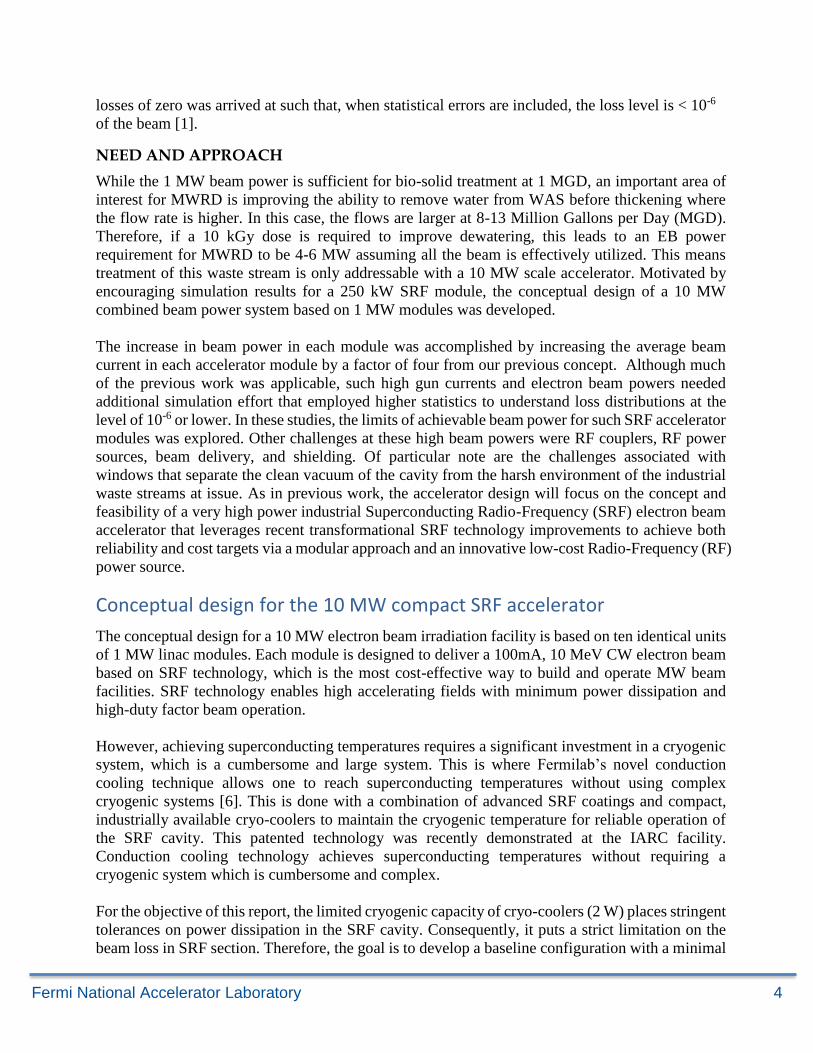
Figure 1 is a schematic of the baseline 1 MW linac module. It is composed of three main sections
which are modularly connected:
Fermi National Accelerator Laboratory 6
• Injector
• Main Accelerating Section
• Beam Delivery System
Each of these sections is treated with inputs from the previous section and iteratively designed. As
an example, the optics design of the main accelerating section was made using an input beam
distribution generated from the RF gun while the RF gun design was made to deliver a high-quality
beam with an optimal energy that ensured a maximum capture through the accelerating section. The
final design of the linac is the result of several iterations accounting for different aspects of the
design considerations. A detailed description of each section layout follows.
Figure 1 Schematic layout of a 1 MW linac module for the MWRD facility. Ten identical modules will be used to deliver 10 MW beam.
INJECTOR
In recent years, SRF injection schemes [9] have been widely used in new proposals and ongoing
projects throughout the world. An SRF injector typically includes a photocathode placed inside an
SRF accelerating cavity. Because particles are emitted inside the accelerating cavity, they are
quickly captured and accelerated; therefore, a high-quality beam is delivered at the output.
However, this scheme also poses severe technical challenges; for example, particles that are not
captured contribute to additional power dissipation in the cavity. In addition, as the cathode operates
in the normal conducting state, it acts as a heat source while the SRF cavity serves as a sink. Thus,
black body radiation coming from the cathode is deposited on the cavity. The heat load of the cavity
is limited due to the cooling efficiency of the cryo-coolers. Therefore, an external beam injection
scheme was selected for the following reasons:
• High current emission from the cathode increases the possibility of evaporation of the
cathode material. In the case of internal injection, this material may deposit to the cavity
surface and degrade its quality-factor. External injection reduces the likelihood of material
deposition on the surface of the cavity.
• A large cathode could be built for an external injection scheme that reduces the surface
Fermi National Accelerator Laboratory 7
current density. A lower surface current density not only improves the longevity of a
cathode but also reduces material evaporation from the surface of the cathode.
• Only a small fraction of lateral heat radiation from the cathode reaches the SRF cavity in
the external injection scheme.
• The fraction of the beam not captured gets lost in the normal conducting section. This
reduces the thermal load on the superconducting section.
• An external injection usually requires only a modest vacuum.
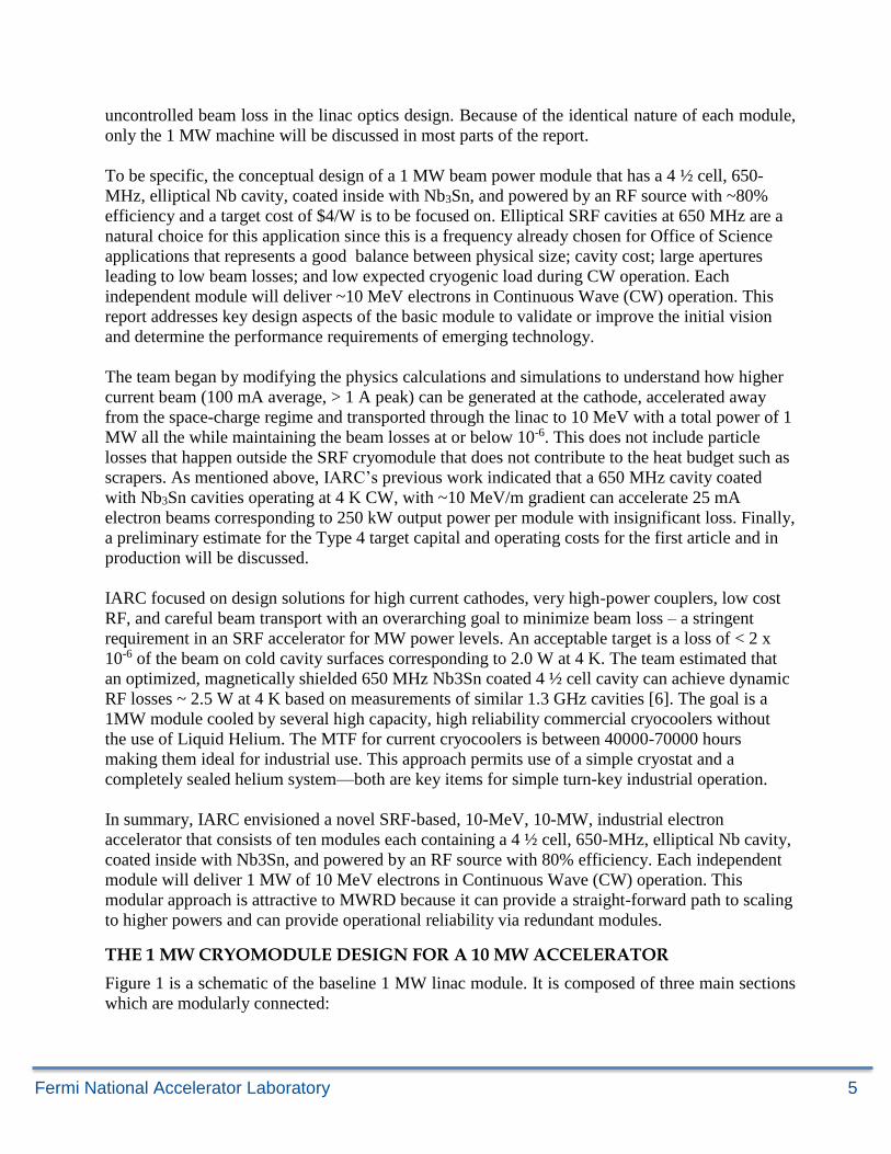
The proposed external injection scheme for the MWRD facility includes a thermionic cathode-based
RF gun and an injector cavity that provides a pre-acceleration to the beam before it enters the
superconducting section. Figure 2 is a schematic of the injector layout. The RF gun resonator is
installed at base of the cathode-grid assembly. A grid is used to gate the electron emission. A single
cell injector cavity is placed just downstream of the gun-grid assembly. The injector section must
deliver a high-quality beam to the SRF section. Thus, the gun design facilitates operation not only
at the fundamental frequency of 650 MHz but at the second harmonic if needed to obtain a short
bunch length.
Figure 2 Schematic of the injection scheme that includes a RF gun and an injector cavity.
To match the injection energy at the entrance of the main accelerating section, special design
considerations of the RF gun and injection cavity were considered to accelerate non-relativistic low
energy electrons. In addition, operating parameters such as DC voltage, RF voltage, phase interval
of gun were also optimized to deliver a well-focused beam. A detailed discussion of the RF gun and
injection cavity designs are presented in following sections.
RF GUN
Operational experience gained through several ongoing projects [7-10] showed that RF guns based
on thermionic cathodes, are cost effective, simple and reliable. They can be operated in various
regimes with minimal backward bombardment of the electrons and can deliver a high-quality beam
with low energy and phase spread among particles. In addition, they are ideal for applications that
require high average beam current and long lifetime. These features make the thermionic-cathode
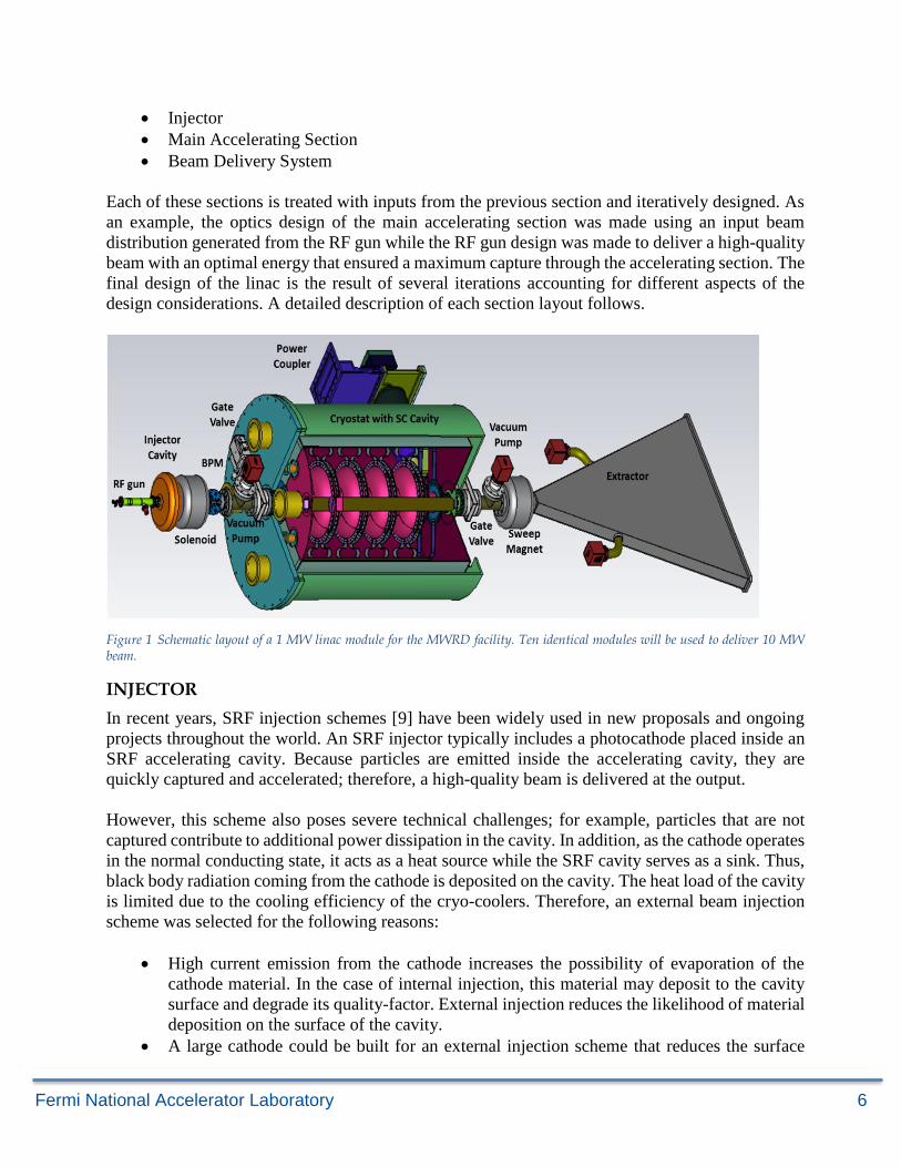
RF gun a preferred choice for the project. Figure 3 shows the proposed layout of the RF gun for the
Fermi National Accelerator Laboratory 8
MWRD linac.
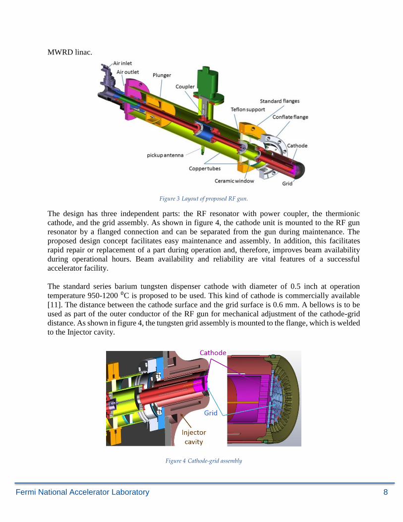
Figure 3 Layout of proposed RF gun.
The design has three independent parts: the RF resonator with power coupler, the thermionic
cathode, and the grid assembly. As shown in figure 4, the cathode unit is mounted to the RF gun
resonator by a flanged connection and can be separated from the gun during maintenance. The
proposed design concept facilitates easy maintenance and assembly. In addition, this facilitates
rapid repair or replacement of a part during operation and, therefore, improves beam availability
during operational hours. Beam availability and reliability are vital features of a successful
accelerator facility.
The standard series barium tungsten dispenser cathode with diameter of 0.5 inch at operation
temperature 950-1200 ⁰C is proposed to be used. This kind of cathode is commercially available
[11]. The distance between the cathode surface and the grid surface is 0.6 mm. A bellows is to be
used as part of the outer conductor of the RF gun for mechanical adjustment of the cathode-grid
distance. As shown in figure 4, the tungsten grid assembly is mounted to the flange, which is welded
to the Injector cavity.
Figure 4 Cathode-grid assembly
Fermi National Accelerator Laboratory 9
ELECTROMAGNETIC DESIGN OF GUN RESONATOR
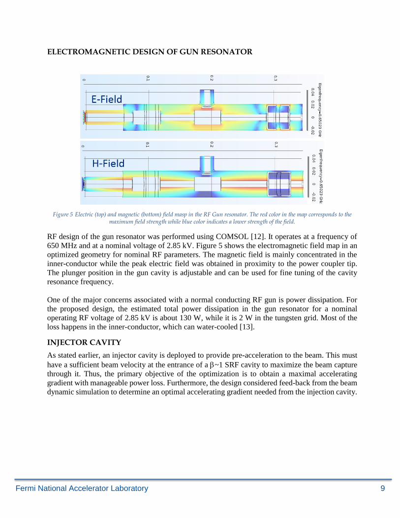
Figure 5 Electric (top) and magnetic (bottom) field masp in the RF Gun resonator. The red color in the map corresponds to the maximum field strength while blue color indicates a lower strength of the field.
RF design of the gun resonator was performed using COMSOL [12]. It operates at a frequency of
650 MHz and at a nominal voltage of 2.85 kV. Figure 5 shows the electromagnetic field map in an
optimized geometry for nominal RF parameters. The magnetic field is mainly concentrated in the
inner-conductor while the peak electric field was obtained in proximity to the power coupler tip.
The plunger position in the gun cavity is adjustable and can be used for fine tuning of the cavity
resonance frequency.
One of the major concerns associated with a normal conducting RF gun is power dissipation. For
the proposed design, the estimated total power dissipation in the gun resonator for a nominal
operating RF voltage of 2.85 kV is about 130 W, while it is 2 W in the tungsten grid. Most of the
loss happens in the inner-conductor, which can water-cooled [13].
INJECTOR CAVITY
As stated earlier, an injector cavity is deployed to provide pre-acceleration to the beam. This must
have a sufficient beam velocity at the entrance of a ~1 SRF cavity to maximize the beam capture
through it. Thus, the primary objective of the optimization is to obtain a maximal accelerating
gradient with manageable power loss. Furthermore, the design considered feed-back from the beam
dynamic simulation to determine an optimal accelerating gradient needed from the injection cavity.
Fermi National Accelerator Laboratory 10
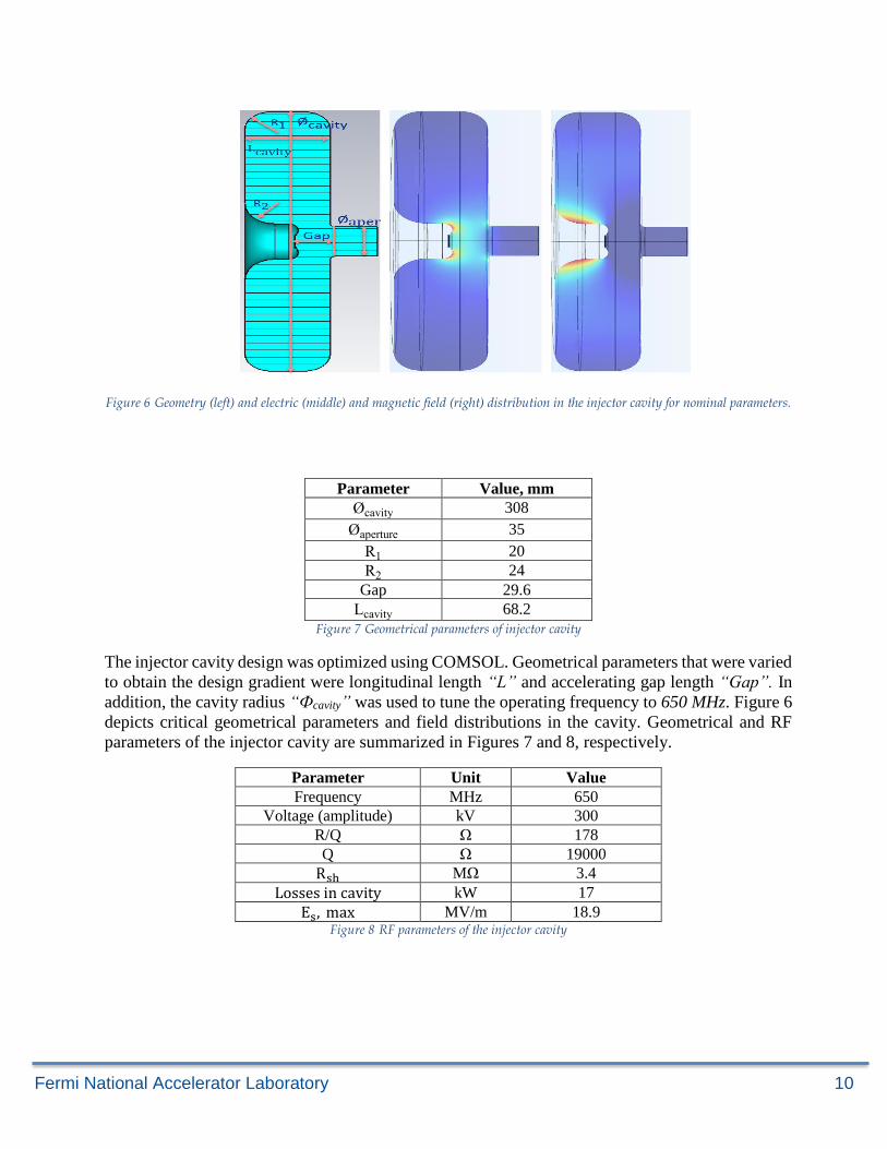
Figure 6 Geometry (left) and electric (middle) and magnetic field (right) distribution in the injector cavity for nominal parameters.
Parameter Value, mm
Øcavity 308
Øaperture 35
R1 20
R2 24
Gap 29.6
Lcavity 68.2
Figure 7 Geometrical parameters of injector cavity
The injector cavity design was optimized using COMSOL. Geometrical parameters that were varied
to obtain the design gradient were longitudinal length “L” and accelerating gap length “Gap”. In
addition, the cavity radius “Фcavity” was used to tune the operating frequency to 650 MHz. Figure 6
depicts critical geometrical parameters and field distributions in the cavity. Geometrical and RF
parameters of the injector cavity are summarized in Figures 7 and 8, respectively.
Parameter Unit Value
Frequency MHz 650
Voltage (amplitude) kV 300
R/Q Ω 178
Q Ω 19000
Rsh MΩ 3.4
Losses in cavity kW 17
Es, max MV/m 18.9 Figure 8 RF parameters of the injector cavity
Fermi National Accelerator Laboratory 11
BEAM DYNAMICS STUDY IN RF GUN
A beam dynamics study of the injector section was performed using SMASON [14]. Modeling was
performed by simulating the cathode, grid, and injector cavity altogether. An RF voltage with an
operating frequency of 650 MHz and a DC voltage were applied to the cathode to generate a
designed beam current of 100 mA. Thus, voltage at the cathode U at a time t is expressed as:
U(t) = Ud + Ua cos(ωt + φ) (1)
where Ud is the constant DC voltage, Ua is the amplitude of the RF voltage, ω is the angular
operating frequency, and φ is the phase shift between the bias RF voltage and RF fields in the
injection cavity. RF voltage (URF ) in the injector cavity was modelled in SMASON using the
following expression:
URF(t) = U0 cos(ωt) (2)
where U0 is the static field. This field approximation performs well in regimes where the cathode
size is much smaller than the operating wavelength of the cavity.
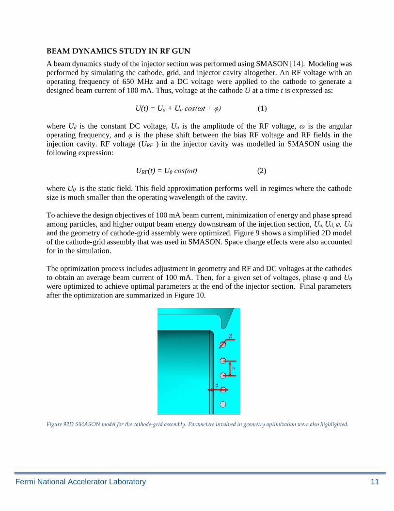
To achieve the design objectives of 100 mA beam current, minimization of energy and phase spread
among particles, and higher output beam energy downstream of the injection section, Ua, Ud, φ, U0
and the geometry of cathode-grid assembly were optimized. Figure 9 shows a simplified 2D model
of the cathode-grid assembly that was used in SMASON. Space charge effects were also accounted
for in the simulation.
The optimization process includes adjustment in geometry and RF and DC voltages at the cathodes
to obtain an average beam current of 100 mA. Then, for a given set of voltages, phase φ and U0
were optimized to achieve optimal parameters at the end of the injector section. Final parameters
after the optimization are summarized in Figure 10.
Figure 92D SMASON model for the cathode-grid assembly. Parameters involved in geometry optimization were also highlighted.
Fermi National Accelerator Laboratory 12
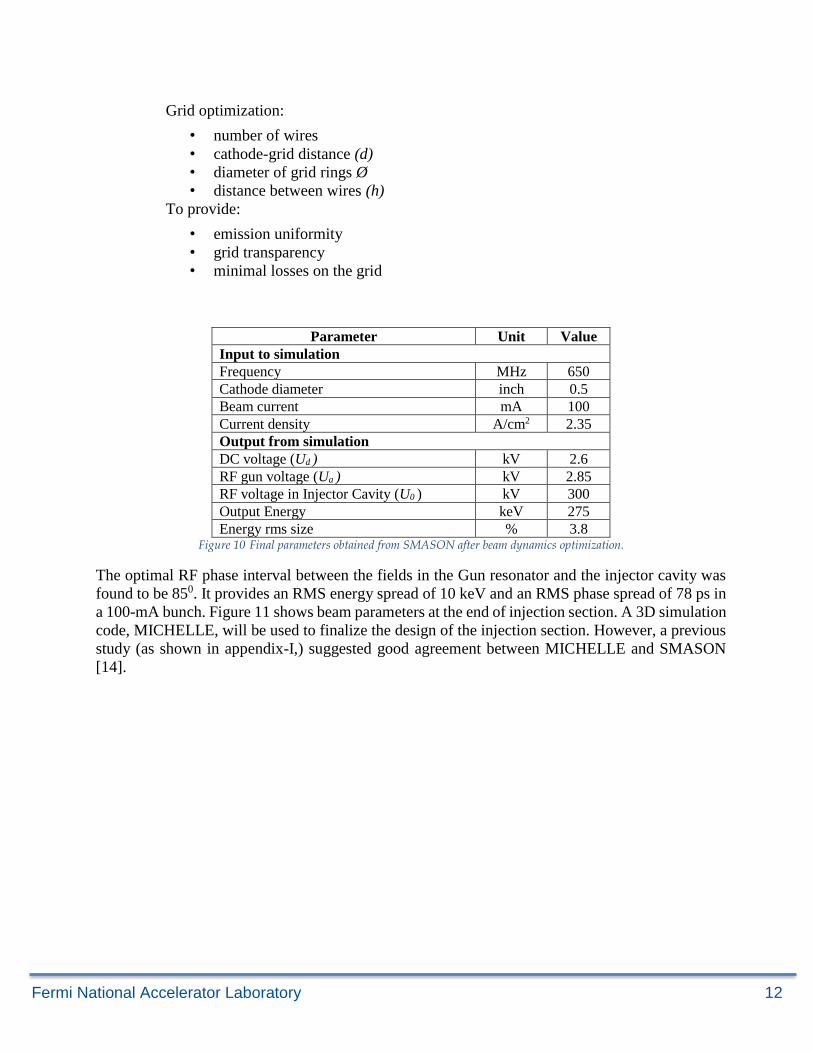
Parameter Unit Value
Input to simulation
Frequency MHz 650
Cathode diameter inch 0.5
Beam current mA 100
Current density A/cm2 2.35
Output from simulation
DC voltage (Ud ) kV 2.6
RF gun voltage (Ua ) kV 2.85
RF voltage in Injector Cavity (U0 ) kV 300
Output Energy keV 275
Energy rms size % 3.8 Figure 10 Final parameters obtained from SMASON after beam dynamics optimization.
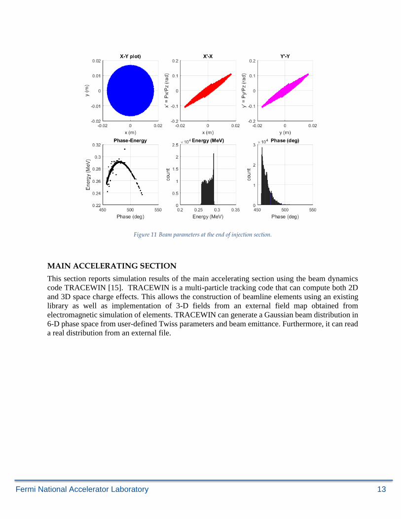
The optimal RF phase interval between the fields in the Gun resonator and the injector cavity was
found to be 850. It provides an RMS energy spread of 10 keV and an RMS phase spread of 78 ps in
a 100-mA bunch. Figure 11 shows beam parameters at the end of injection section. A 3D simulation
code, MICHELLE, will be used to finalize the design of the injection section. However, a previous
study (as shown in appendix-I,) suggested good agreement between MICHELLE and SMASON
[14].
Grid optimization:
• number of wires
• cathode-grid distance (d)
• diameter of grid rings Ø
• distance between wires (h)
To provide:
• emission uniformity
• grid transparency
• minimal losses on the grid
Fermi National Accelerator Laboratory 13
Figure 11 Beam parameters at the end of injection section.
MAIN ACCELERATING SECTION
This section reports simulation results of the main accelerating section using the beam dynamics
code TRACEWIN [15]. TRACEWIN is a multi-particle tracking code that can compute both 2D
and 3D space charge effects. This allows the construction of beamline elements using an existing
library as well as implementation of 3-D fields from an external field map obtained from
electromagnetic simulation of elements. TRACEWIN can generate a Gaussian beam distribution in
6-D phase space from user-defined Twiss parameters and beam emittance. Furthermore, it can read
a real distribution from an external file.
Fermi National Accelerator Laboratory 14
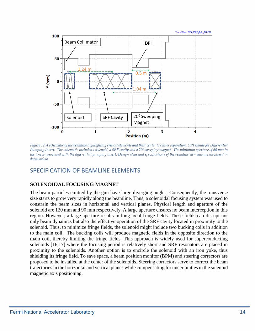
Figure 12 A schematic of the beamline highlighting critical elements and their center to center separation. DPI stands for Differential Pumping Insert. The schematic includes a solenoid, a SRF cavity and a 200 sweeping magnet. The minimum aperture of 60 mm in the line is associated with the differential pumping insert. Design ideas and specifications of the beamline elements are discussed in detail below.
SPECIFICATION OF BEAMLINE ELEMENTS
SOLENOIDAL FOCUSING MAGNET
The beam particles emitted by the gun have large diverging angles. Consequently, the transverse
size starts to grow very rapidly along the beamline. Thus, a solenoidal focusing system was used to
constrain the beam sizes in horizontal and vertical planes. Physical length and aperture of the
solenoid are 120 mm and 90 mm respectively. A large aperture ensures no beam interception in this
region. However, a large aperture results in long axial fringe fields. These fields can disrupt not
only beam dynamics but also the effective operation of the SRF cavity located in proximity to the
solenoid. Thus, to minimize fringe fields, the solenoid might include two bucking coils in addition
to the main coil. The bucking coils will produce magnetic fields in the opposite direction to the
main coil, thereby limiting the fringe fields. This approach is widely used for superconducting
solenoids [16,17] where the focusing period is relatively short and SRF resonators are placed in
proximity to the solenoids. Another option is to encircle the solenoid with an iron yoke, thus
shielding its fringe field. To save space, a beam position monitor (BPM) and steering correctors are
proposed to be installed at the center of the solenoids. Steering correctors serve to correct the beam
trajectories in the horizontal and vertical planes while compensating for uncertainties in the solenoid
magnetic axis positioning.
Fermi National Accelerator Laboratory 15
Steering correctors were designed to deliver a maximum kick () of 10 mrad. This kick is sufficient
to shift the beam by 10 mm from the axis of the cavity. Thus, the design specification for the
maximum integral field (BL) in the corrector (using equation 3 where B is beam rigidity) is: 0.2
mT-m.
𝜃 =𝐵𝐿
𝐵𝜌 (3)
ACCELERATING SUPERCONDUCTING RADIO FREQUENCY CAVITY:
A 650, MHz, g =1, elliptical shaped SRF cavity was designed to accelerate the beam from an initial
beam energy of 275 keV to 10 MeV. The choice of an operating frequency of the cavity is made
with considerations of both practical and fundamental aspects which are summarized below:
Maximization of Accelerating field: To develop a compact and cost-effective accelerator, an
unprecedented “conduction cooling” technique will be used to cool down the cavity to the operating
temperature of 4K. The availability of the refrigeration puts a stringent limit on the surface power
dissipation (𝑃𝐷) in the cavity which is estimated using following expression:
𝑃𝐷 =1
2𝑅𝑠 ∫ 𝐻2(𝑠)𝑑𝑠
𝑠; (4)
where 𝑅𝑠 is the surface resistance, S is the surface area of the cavity and H is the magnetic field
amplitude. The BCS surface resistance is proportional to the square of the frequency while the
surface area of the cavity is inversely proportional to the square of the frequency. In this regime,
two cavities operating at different frequencies but at same field amplitude will have same power
dissipation. However, energy gain in a cavity is
𝐸𝑔𝑎𝑖𝑛 = 𝑞 ∫ 𝐸𝑧(𝑧)𝑒𝑖(𝜔𝑡−𝑘𝑧)𝑑𝑧𝐿
0 ; (5)
where 𝐸𝑧 is the longitudinal electric field along the cavity and L is the length of the cavity and given
as
𝐿 =1
2𝑁𝑐𝑒𝑙𝑙𝛽𝑔𝜆; (6)
where g is the relative particle velocity, 𝜆 is the operating RF wavelength in free space and 𝑁𝑐𝑒𝑙𝑙
is the number of cells in a cavity. Equations (5) and (6) show that lowering the operating frequency
results in a longer cavity and therefore higher energy gain. To achieve the same energy gain in a
shorter (higher operating frequency) cavity, the field amplitude will have to increase. This, in turn,
will also increase power dissipation in quadrature. As stated earlier, use of cryo-coolers puts
stringent tolerances on the power dissipation. Thus, one prefers 650 MHz frequency to 1.3 GHz.
Fermi National Accelerator Laboratory 16
Large Transverse Acceptance: The transverse dimension of a TM mode operating accelerating
cavity is inversely proportional to the operating frequency. A lower frequency results in a large
aperture, which reduces the likelihood of the beam loss on the cold surface.
Low Power Dissipation due to Higher Order Modes (HOMs): As stated earlier, a low operating
frequency implies a large transverse aperture and, therefore, higher frequency modes easily
propagate out of the cavity. This in turn, reduces the possibility of mode trapping and hence
minimizes the power dissipation in the cavity. In addition, HOMs were coupled with the power
coupler, which further reduces power dissipation at the cold surface. The design exhibits a regular
and sparse beam spectrum that further reduces the likelihood of a HOM resonance excitation.
Large longitudinal acceptance: A beam is injected into the accelerating structure with well-defined
phase with respect to sinusoidal time varying accelerating field. This phase must be maintained to
achieve a continuous acceleration along the cavity. Because the beam is an ensemble of a large
number of particles with a finite energy and time spread, particles with large energy and time spread
with respect to the reference particle will slip on the field and will ultimately be lost inside the
cavity. A lower operating frequency implies a large RF separatrix and ensures maximum capture of
particles. A lower operating cavity frequency is preferable for the beam with a longer longitudinal
length.
Practical Aspects: A cavity with low operating frequency is large in dimension; therefore, its
handling becomes difficult and expensive. Thus, the selection of the operating frequency of the
cavity is a compromise between operational requirements and practical factors. For this project,
IARC chose 650 MHz frequency, which is a natural choice for this application since it is a frequency
already chosen for the Office of Science PIP-II project and extensive development work has already
taken place. This, in turn, allows one to leverage the same ancillary components (wherever they
apply), such as tuners, RF components etc., reducing R&D cost.
After making the choice of the geometrical beta and the operating frequency, the shape of the cavity
was optimized to achieve maximum acceleration and minimum power dissipation. The cavity will
operate in pi -mode and is composed of 4.7 cells. Length of the regular cell is calculated using:
𝐿 =1
2𝛽𝑔𝜆; (7)
The particle velocity at the entrance of the cavity is for a cavity designed at𝛽𝑔This
implies that particles take longer to cover the first regular cell and therefore might be out of phase,
while decelerated particles, especially at low energy, could get trapped and oscillate back and forth
in the cavity until they experience the correct RF phase. In the worst case, this process may lead to
a beam loss on the cold surface of the cavity. To fix this problem, the first cell of the cavity is made
only 0.7 times the regular cell length. In the first cell, electrons receive sufficient acceleration to
become relativistic and therefore no phase slippage occurs in rest of the cavity. This arrangement
ensures maximum beam capture and efficient acceleration. The choice of the first cell length was
made after several beam-dynamics simulations; it was observed that this length was optimal for this
Fermi National Accelerator Laboratory 17
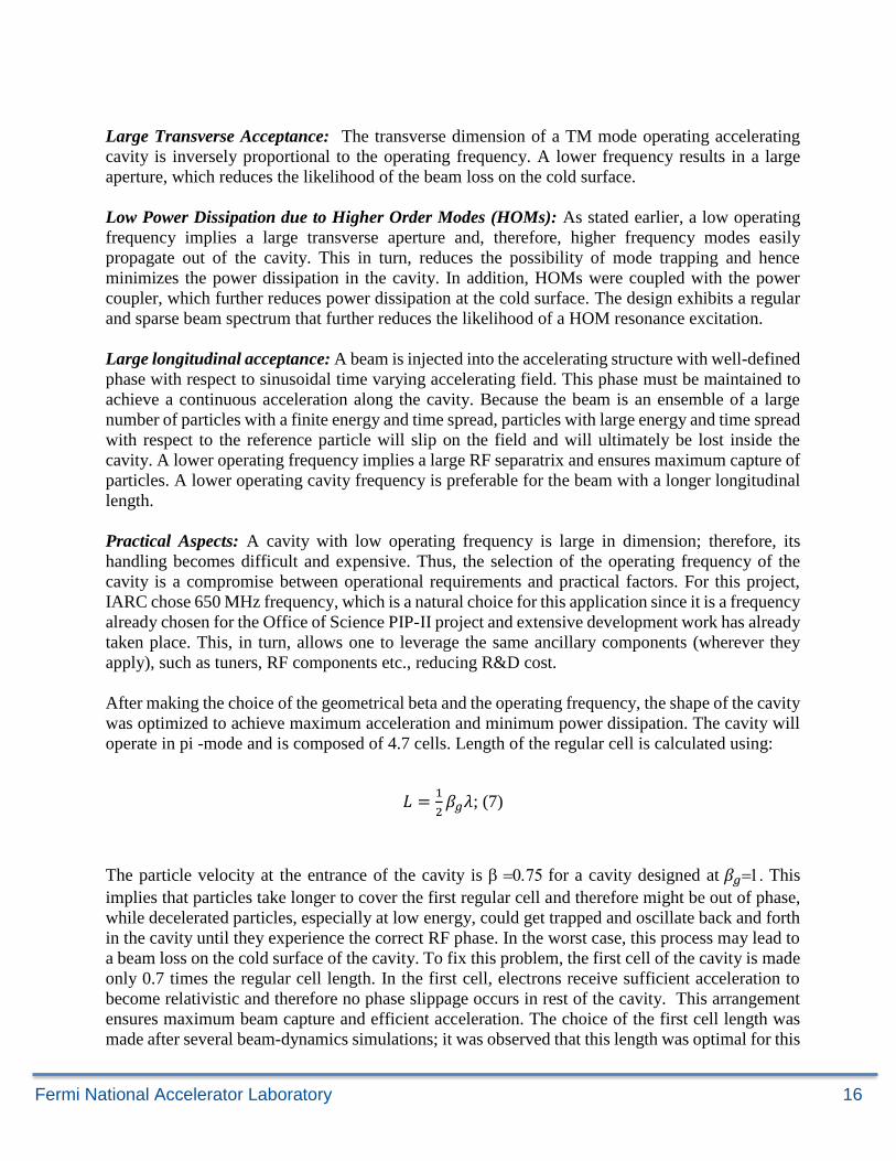
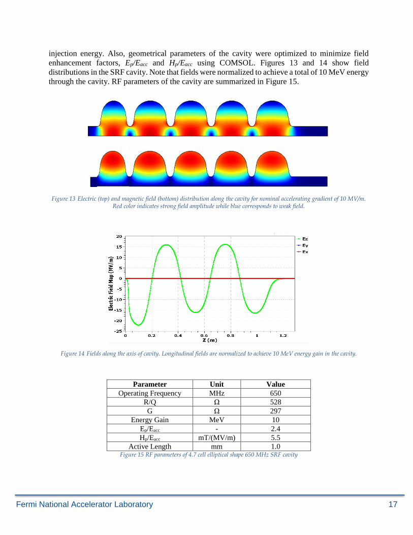
injection energy. Also, geometrical parameters of the cavity were optimized to minimize field
enhancement factors, Ep/Eacc and Hp/Eacc using COMSOL. Figures 13 and 14 show field
distributions in the SRF cavity. Note that fields were normalized to achieve a total of 10 MeV energy
through the cavity. RF parameters of the cavity are summarized in Figure 15.
Figure 13 Electric (top) and magnetic field (bottom) distribution along the cavity for nominal accelerating gradient of 10 MV/m. Red color indicates strong field amplitude while blue corresponds to weak field.
Figure 14 Fields along the axis of cavity. Longitudinal fields are normalized to achieve 10 MeV energy gain in the cavity.
Parameter Unit Value
Operating Frequency MHz 650
R/Q Ω 528
G Ω 297
Energy Gain MeV 10
Ep/Eacc - 2.4
Hp/Eacc mT/(MV/m) 5.5
Active Length mm 1.0 Figure 15 RF parameters of 4.7 cell elliptical shape 650 MHz SRF cavity
Fermi National Accelerator Laboratory 18
RF POWER SOURCE FOR THE ACCELERATING CAVITY
Since losses in the superconducting acceleration structure are very small, a total of 1 MW of RF
input power is required for beam acceleration. A small additional amount (e.g. 10%) of the RF
power will be required for control and regulation. A magnetron-based RF source operating in
injection-locked mode is envisioned to provide operational power of ~1MW in the CW regime for
a 650 MHz superconducting cavity. The phase-locking is done by a reflected wave having an
amplitude of 40 % of the incident wave. As discussed elsewhere [18], recent study suggests
operating in an injection-locked mode offers a higher efficiency (typically in range of > 80%) compared to klystrons and IOTs, which offer 65% efficiency and solid-state RF sources, which are
50% efficient at 650 MHz. Regarding lifetime, the magnetron lasts between 2000 and 4000 hours
while IOTs and klystrons can last up to 50000 hrs [19-21]. However, use of the magnetron simplifies
the overall design by avoiding large RF-circulators and thus is simpler to operate.
Note that, Qext ~ U/(R/Q*Ibeam) for a beam current of 100mA, energy gain of 10 MeV and, R/Q ~500
is about 2×10⁵, which results in a bandwidth of the cavity equal to ~3.25 kHz. This implies that
the bandwidth of the cavity is much higher than the microphonics that typically lay in range of a
few tens of Hertz. The bandwidth of a magnetron is much higher than the cavity bandwidth; this, in
turn, eliminates the need for fine tuning the cavity. Furthermore, precise amplitude and phase
control of the RF are not mandatory, as there is not a requirement for precise control of the
accelerator output energy. It is likely that beam loss control in sweeping magnets may be what sets
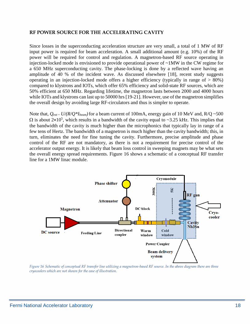
the overall energy spread requirements. Figure 16 shows a schematic of a conceptual RF transfer
line for a 1MW linac module.
Figure 16 Schematic of conceptual RF transfer line utilizing a magnetron-based RF source. In the above diagram there are three cryocoolers which are not shown for the ease of illustration.
Fermi National Accelerator Laboratory 19
SWEEPING MAGNET DESIGN
A sweeping magnet is placed downstream of the SRF cavity to facilitate the beam scan in the
horizontal direction. It is designed to provide a maximum deflection of 200 to a 10 MeV electron
beam. The magnet length is 325 mm and it provides a maximum integral field of 4.16 mT-m. The
aperture of the magnet is 100 mm. The choice of the aperture is made to avoid any potential beam
loss across the magnet. The beam width in the vertical direction is sufficiently large and, therefore,
beam scanning is not required in this direction.
DIFFERENTIAL PUMPING INSERT (DPI)
The reliable, high performance of the SRF cavity demands a low dust environment to avoid any
surface contamination. This, in turn, requires an ultra-high vacuum (UHV) in the SRF section.
However, the room temperature section just downstream of the SRF cavity is to be a high vacuum
(HV) environment with a characteristic pressure in the ~10-8 Torr range. This is driven mainly from
a large flux of scattered/reflected particles. To avoid the flux of gas condensing on the cold surface
of the SRF cavity, a separation of HV and UHV regions was accomplished in the beamline using
the Differential Pumping Insert (DPI) section. This is a low-conductance 0.5m region with an
aperture of 60 mm. The volume at the middle of the DPI is pumped by a 100 1/s ion pump. The DPI
is electrically isolated such that any beam loss at the aperture restriction may be measured.
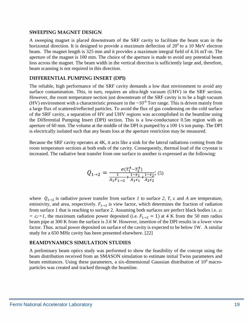
Because the SRF cavity operates at 4K, it acts like a sink for the lateral radiations coming from the
room temperature sections at both ends of the cavity. Consequently, thermal load of the cryostat is
increased. The radiative heat transfer from one surface to another is expressed as the following:
𝑄1→2 =𝜎(𝑇1
4−𝑇24)
1
𝐴1𝐹1→2 +
1−𝜖1 𝐴1𝜖1
+1−𝜖2𝐴2𝜖2
; (5)
where 𝑄1→2 is radiative power transfer from surface 1 to surface 2, T, and A are temperature,
emissivity, and area, respectively. 𝐹1→2 is view factor, which determines the fraction of radiation
from surface 1 that is reaching to surface 2. Assuming both surfaces are perfect black bodies i.e.
= =1, the maximum radiation power deposited (i.e. 𝐹1→2 = 1) at 4 K from the 50 mm radius
beam pipe at 300 K from the surface is 3.6 W. However, insertion of the DPI results in a lower view
factor. Thus. actual power deposited on surface of the cavity is expected to be below 1W. A similar
study for a 650 MHz cavity has been presented elsewhere. [22]
BEAMDYNAMICS SIMULATION STUDIES
A preliminary beam optics study was performed to show the feasibility of the concept using the
beam distribution received from an SMASON simulation to estimate initial Twiss parameters and
beam emittances. Using these parameters, a six-dimensional Gaussian distribution of 106 macro-
particles was created and tracked through the beamline.
Fermi National Accelerator Laboratory 20
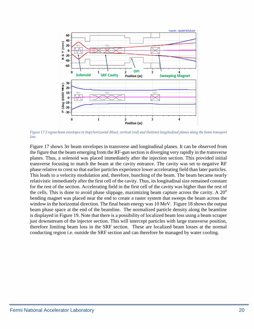
Figure 17 3 sigma beam envelopes in (top) horizontal (blue), vertical (red) and (bottom) longitudinal planes along the beam transport line.
Figure 17 shows 3 beam envelopes in transverse and longitudinal planes. It can be observed from
the figure that the beam emerging from the RF-gun section is diverging very rapidly in the transverse
planes. Thus, a solenoid was placed immediately after the injection section. This provided initial
transverse focusing to match the beam at the cavity entrance. The cavity was set to negative RF
phase relative to crest so that earlier particles experience lower accelerating field than later particles.
This leads to a velocity modulation and, therefore, bunching of the beam. The beam became nearly
relativistic immediately after the first cell of the cavity. Thus, its longitudinal size remained constant
for the rest of the section. Accelerating field in the first cell of the cavity was higher than the rest of
the cells. This is done to avoid phase slippage, maximizing beam capture across the cavity. A 200
bending magnet was placed near the end to create a raster system that sweeps the beam across the
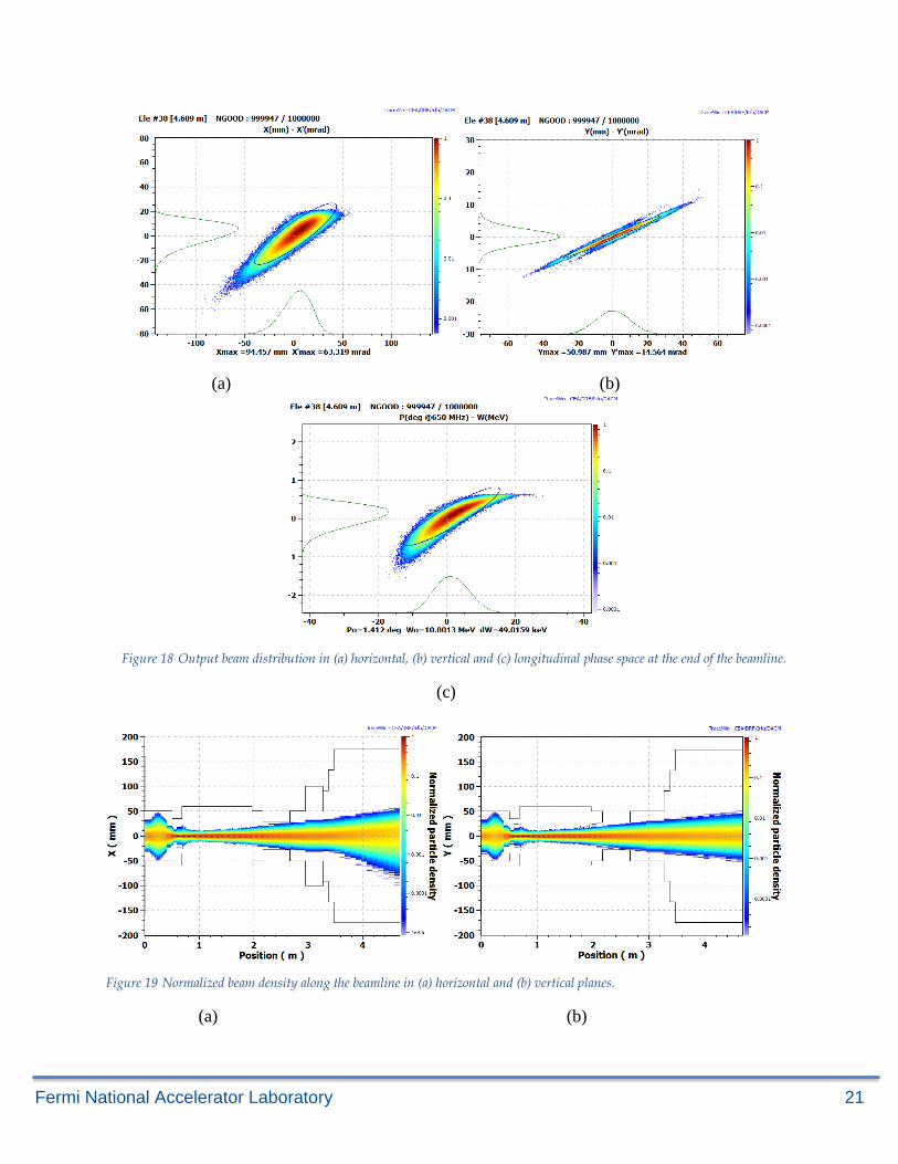
window in the horizontal direction. The final beam energy was 10 MeV. Figure 18 shows the output
beam phase space at the end of the beamline. The normalized particle density along the beamline
is displayed in Figure 19. Note that there is a possibility of localized beam loss using a beam scraper
just downstream of the injector section. This will intercept particles with large transverse position,
therefore limiting beam loss in the SRF section. These are localized beam losses at the normal
conducting region i.e. outside the SRF section and can therefore be managed by water cooling.
Fermi National Accelerator Laboratory 21
(a) (b)
Figure 18 Output beam distribution in (a) horizontal, (b) vertical and (c) longitudinal phase space at the end of the beamline.
(c)
Figure 19 Normalized beam density along the beamline in (a) horizontal and (b) vertical planes.
(a) (b)
Fermi National Accelerator Laboratory 22
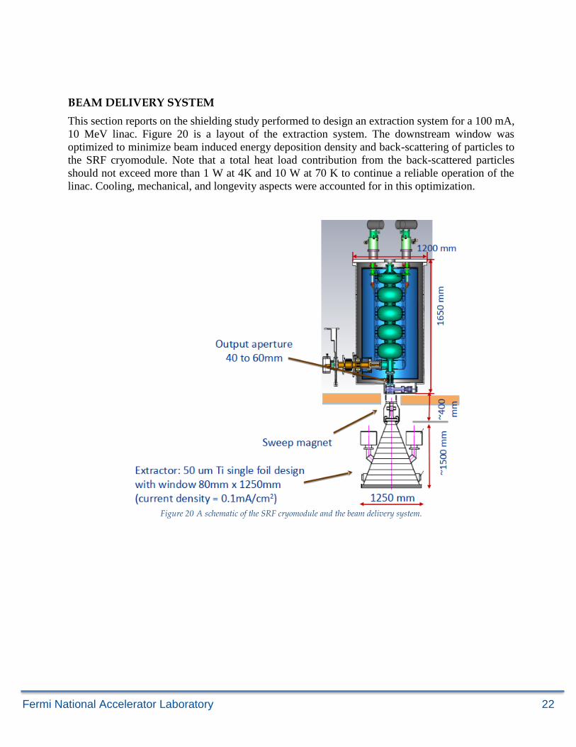
BEAM DELIVERY SYSTEM
This section reports on the shielding study performed to design an extraction system for a 100 mA,
10 MeV linac. Figure 20 is a layout of the extraction system. The downstream window was
optimized to minimize beam induced energy deposition density and back-scattering of particles to
the SRF cryomodule. Note that a total heat load contribution from the back-scattered particles
should not exceed more than 1 W at 4K and 10 W at 70 K to continue a reliable operation of the
linac. Cooling, mechanical, and longevity aspects were accounted for in this optimization.
Figure 20 A schematic of the SRF cryomodule and the beam delivery system.
Fermi National Accelerator Laboratory 23
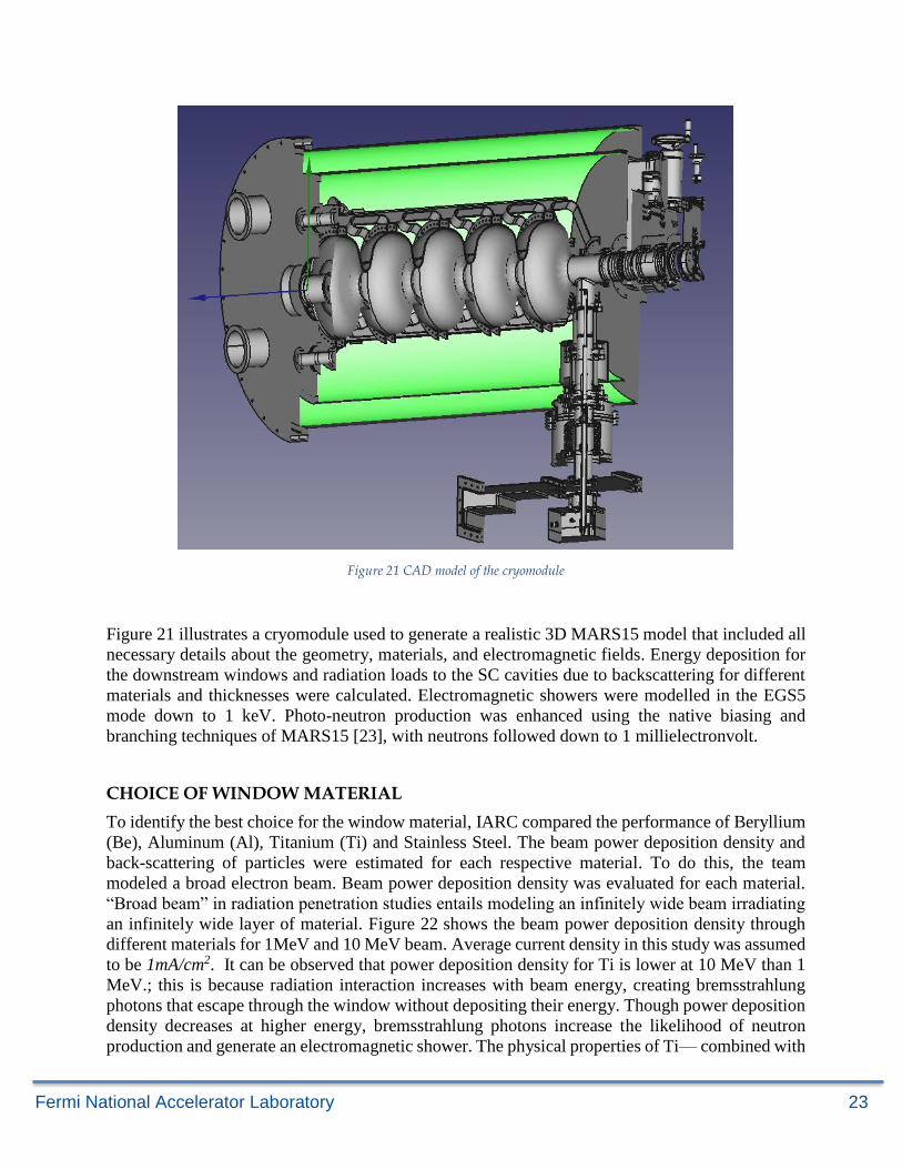
Figure 21 CAD model of the cryomodule
Figure 21 illustrates a cryomodule used to generate a realistic 3D MARS15 model that included all
necessary details about the geometry, materials, and electromagnetic fields. Energy deposition for
the downstream windows and radiation loads to the SC cavities due to backscattering for different
materials and thicknesses were calculated. Electromagnetic showers were modelled in the EGS5
mode down to 1 keV. Photo-neutron production was enhanced using the native biasing and
branching techniques of MARS15 [23], with neutrons followed down to 1 millielectronvolt.
CHOICE OF WINDOW MATERIAL
To identify the best choice for the window material, IARC compared the performance of Beryllium
(Be), Aluminum (Al), Titanium (Ti) and Stainless Steel. The beam power deposition density and
back-scattering of particles were estimated for each respective material. To do this, the team
modeled a broad electron beam. Beam power deposition density was evaluated for each material.
“Broad beam” in radiation penetration studies entails modeling an infinitely wide beam irradiating
an infinitely wide layer of material. Figure 22 shows the beam power deposition density through
different materials for 1MeV and 10 MeV beam. Average current density in this study was assumed
to be 1mA/cm2. It can be observed that power deposition density for Ti is lower at 10 MeV than 1
MeV.; this is because radiation interaction increases with beam energy, creating bremsstrahlung
photons that escape through the window without depositing their energy. Though power deposition
density decreases at higher energy, bremsstrahlung photons increase the likelihood of neutron
production and generate an electromagnetic shower. The physical properties of Ti— combined with
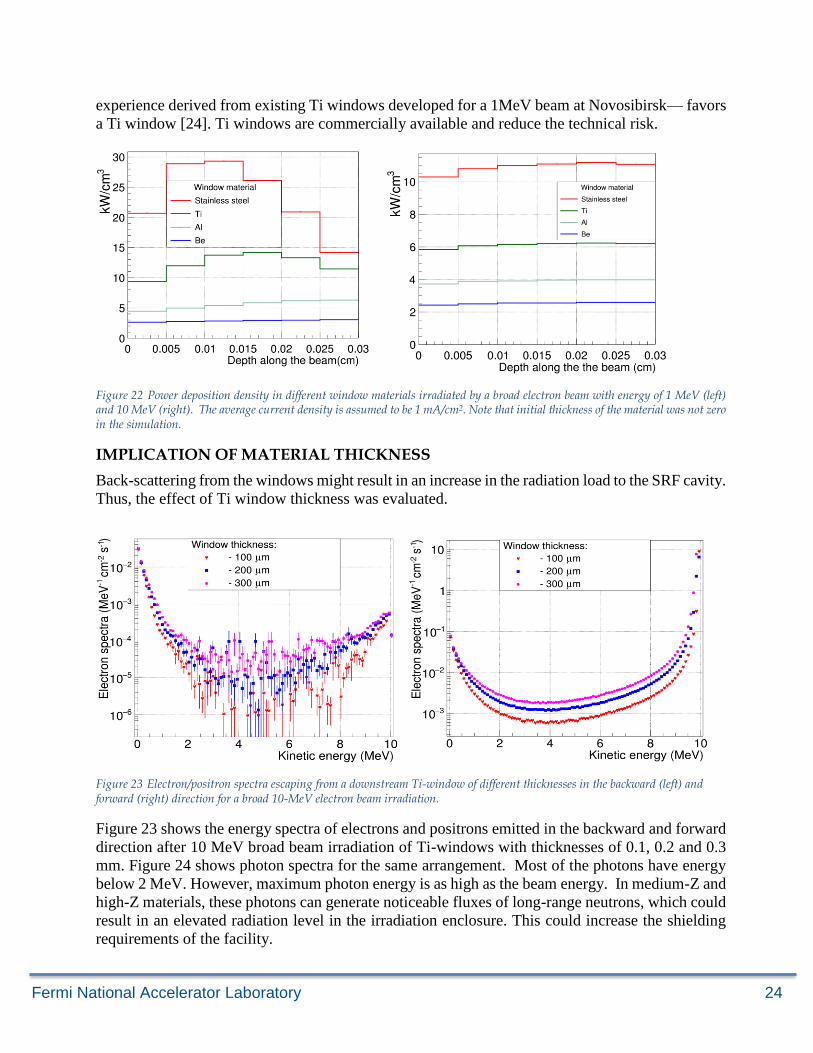
Fermi National Accelerator Laboratory 24
experience derived from existing Ti windows developed for a 1MeV beam at Novosibirsk— favors
a Ti window [24]. Ti windows are commercially available and reduce the technical risk.
Figure 22 Power deposition density in different window materials irradiated by a broad electron beam with energy of 1 MeV (left) and 10 MeV (right). The average current density is assumed to be 1 mA/cm2. Note that initial thickness of the material was not zero in the simulation.
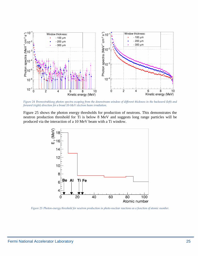
IMPLICATION OF MATERIAL THICKNESS
Back-scattering from the windows might result in an increase in the radiation load to the SRF cavity.
Thus, the effect of Ti window thickness was evaluated.
Figure 23 Electron/positron spectra escaping from a downstream Ti-window of different thicknesses in the backward (left) and forward (right) direction for a broad 10-MeV electron beam irradiation.
Figure 23 shows the energy spectra of electrons and positrons emitted in the backward and forward
direction after 10 MeV broad beam irradiation of Ti-windows with thicknesses of 0.1, 0.2 and 0.3
mm. Figure 24 shows photon spectra for the same arrangement. Most of the photons have energy
below 2 MeV. However, maximum photon energy is as high as the beam energy. In medium-Z and
high-Z materials, these photons can generate noticeable fluxes of long-range neutrons, which could
result in an elevated radiation level in the irradiation enclosure. This could increase the shielding
requirements of the facility.
Fermi National Accelerator Laboratory 25
Figure 24 Bremsstrahlung photon spectra escaping from the downstream window of different thickness in the backward (left) and forward (right) direction for a broad 10-MeV electron beam irradiation.
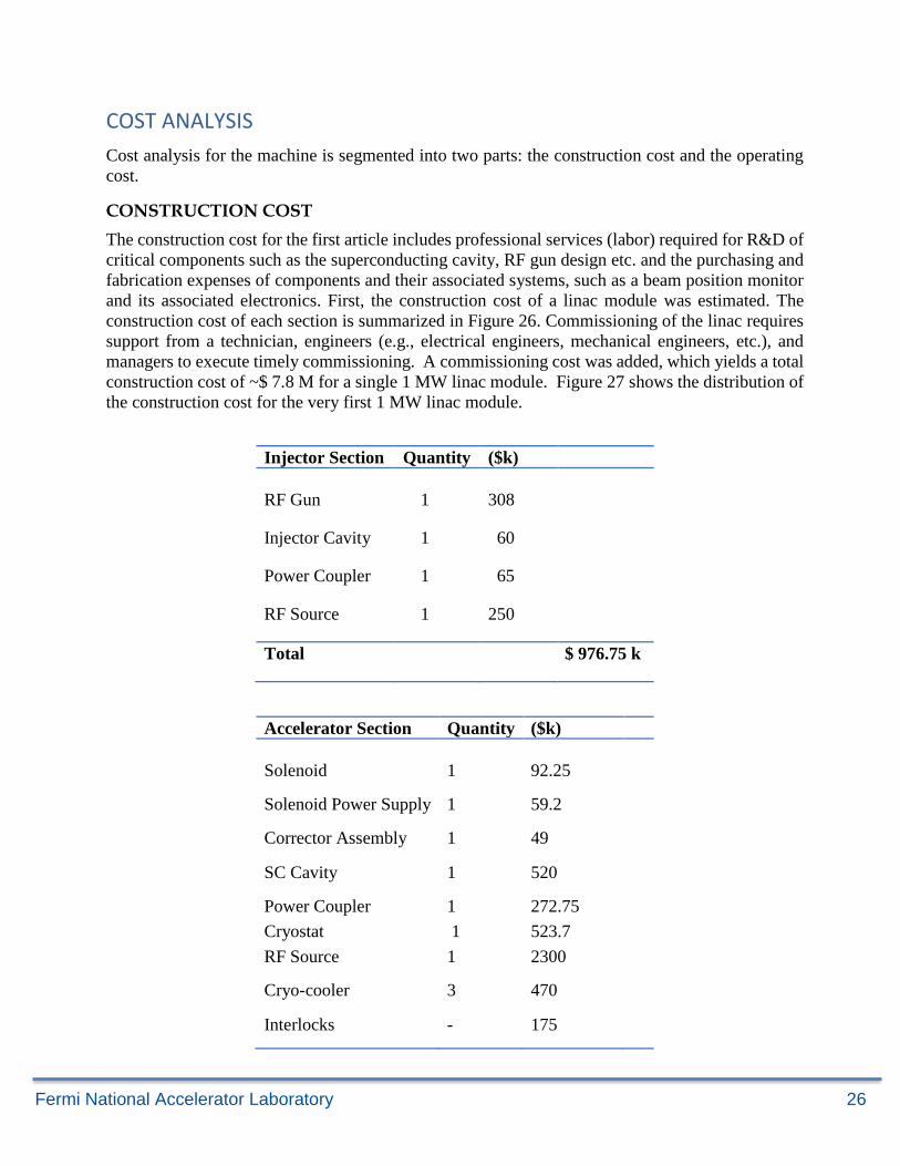
Figure 25 shows the photon energy thresholds for production of neutrons. This demonstrates the
neutron production threshold for Ti is below 8 MeV and suggests long range particles will be
produced via the interaction of a 10 MeV beam with a Ti window.
Figure 25 Photon-energy threshold for neutron production in photo-nuclear reactions as a function of atomic number.
Fermi National Accelerator Laboratory 26
COST ANALYSIS
Cost analysis for the machine is segmented into two parts: the construction cost and the operating
cost.
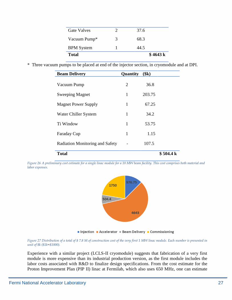
CONSTRUCTION COST
The construction cost for the first article includes professional services (labor) required for R&D of
critical components such as the superconducting cavity, RF gun design etc. and the purchasing and
fabrication expenses of components and their associated systems, such as a beam position monitor
and its associated electronics. First, the construction cost of a linac module was estimated. The
construction cost of each section is summarized in Figure 26. Commissioning of the linac requires
support from a technician, engineers (e.g., electrical engineers, mechanical engineers, etc.), and
managers to execute timely commissioning. A commissioning cost was added, which yields a total
construction cost of ~$ 7.8 M for a single 1 MW linac module. Figure 27 shows the distribution of
the construction cost for the very first 1 MW linac module.
Injector Section Quantity ($k)
RF Gun 1 308
Injector Cavity 1 60
Power Coupler 1 65
RF Source 1 250
Total $ 976.75 k
Accelerator Section Quantity ($k)
Solenoid 1 92.25
Solenoid Power Supply 1 59.2
Corrector Assembly 1 49
SC Cavity 1 520
Power Coupler 1 272.75
Cryostat 1 523.7
RF Source 1 2300
Cryo-cooler 3 470
Interlocks - 175
Fermi National Accelerator Laboratory 27
Gate Valves 2 37.6
Vacuum Pump* 3 68.3
BPM System 1 44.5
Total $ 4643 k
* Three vacuum pumps to be placed at end of the injector section, in cryomodule and at DPI.
Beam Delivery Quantity ($k)
Vacuum Pump 2 36.8
Sweeping Magnet 1 203.75
Magnet Power Supply 1 67.25
Water Chiller System 1 34.2
Ti Window 1 53.75
Faraday Cup 1 1.15
Radiation Monitoring and Safety - 107.5
Total $ 504.4 k
Figure 26 A preliminary cost estimate for a single linac module for a 10 MW beam facility. This cost comprises both material and labor expenses.
Figure 27 Distribution of a total of $ 7.8 M of construction cost of the very first 1 MW linac module. Each number is presented in unit of $k ($1k=$1000).
Experience with a similar project (LCLS-II cryomodule) suggests that fabrication of a very first
module is more expensive than its industrial production version, as the first module includes the
labor costs associated with R&D to finalize design specifications. From the cost estimate for the
Proton Improvement Plan (PIP II) linac at Fermilab, which also uses 650 MHz, one can estimate
Fermi National Accelerator Laboratory 28
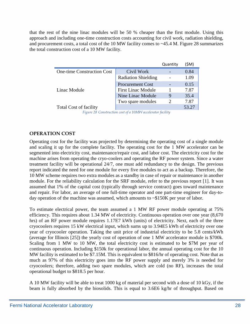
that the rest of the nine linac modules will be 50 % cheaper than the first module. Using this
approach and including one-time construction costs accounting for civil work, radiation shielding,
and procurement costs, a total cost of the 10 MW facility comes to ~45.4 M. Figure 28 summarizes
the total construction cost of a 10 MW facility.
Quantity ($M)
One-time Construction Cost Civil Work - 0.84
Radiation Shielding - 1.09
Procurement Cost - 0.15
Linac Module First Linac Module 1 7.87
Nine Linac Module 9 35.4
Two spare modules 2 7.87
Total Cost of facility 53.27 Figure 28 Construction cost of a 10MW accelerator facility
OPERATION COST
Operating cost for the facility was projected by determining the operating cost of a single module
and scaling it up for the complete facility. The operating cost for the 1 MW accelerator can be
segmented into electricity cost, maintenance/repair cost, and labor cost. The electricity cost for the
machine arises from operating the cryo-coolers and operating the RF power system. Since a water
treatment facility will be operational 24/7, one must add redundancy to the design. The previous
report indicated the need for one module for every five modules to act as a backup. Therefore, the
10 MW scheme requires two extra modules as a standby in case of repair or maintenance in another
module. For the reliability calculation for the SRF module, refer to the previous report [1]. It was
assumed that 1% of the capital cost (typically through service contract) goes toward maintenance
and repair. For labor, an average of one full-time operator and one part-time engineer for day-to-
day operation of the machine was assumed, which amounts to ~$150K per year of labor.
To estimate electrical power, the team assumed a 1 MW RF power module operating at 75%
efficiency. This requires about 1.34 MW of electricity. Continuous operation over one year (8,670
hrs) of an RF power module requires 1.17E7 kWh (units) of electricity. Next, each of the three
cryocoolers requires 15 kW electrical input, which sums up to 3.94E5 kWh of electricity over one
year of cryocooler operation. Taking the unit price of industrial electricity to be 5.8 cents/kWh
(average for Illinois [25]) the yearly cost of operation of one 1 MW accelerator module is $700k.
Scaling from 1 MW to 10 MW, the total electricity cost is estimated to be $7M per year of
continuous operation. Including $150k for operational labor, the annual operating cost for the 10
MW facility is estimated to be $7.15M. This is equivalent to $816/hr of operating cost. Note that as
much as 97% of this electricity goes into the RF power supply and merely 3% is needed for
cryocoolers; therefore, adding two spare modules, which are cold (no RF), increases the total
operational budget to $818.5 per hour.
A 10 MW facility will be able to treat 1000 kg of material per second with a dose of 10 kGy, if the
beam is fully absorbed by the biosolids. This is equal to 3.6E6 kg/hr of throughput. Based on
Fermi National Accelerator Laboratory 29
$818.5hr treating 3.6E6 kg/hr of throughput, the cost of biosolid treatment is 0.023 cents/kg.
Additional R&D and Technology Development Needed for Compact SRF
Accelerator:
To transition lab developed breakthroughs in SRF into a viable MW class industrial accelerator,
several key technologies require further development. In what follows, it is assumed the goal is an
SRF based module capable of producing ~ 1 MW or more CW beam for use in either fixed or mobile
applications. The enabling R&D topics are:
MULTI-WATT CRYOCOOLER DEVELOPMENT AND DEMONSTRATION
Conduction cooling of SRF cavities is a Fermilab proprietary technology (US Patent 9,642,239
B2) that, when combined with commercial cryocoolers, enables SRF cavity operation without
liquid cryogens. This novel and proprietary configuration (US Patent 10,070,509 B2) results in
dramatic reductions in complexity, size, weight, and cost. However, existing cryocoolers cannot
go beyond 2.5 W at 4K. There is a significant need for higher capacity cryocoolers to reliably
support a heat budget of ~10 W at 4 K. As of this report, it is known that a 3W cryocooler could
be available commercially in 2019.
Status: In 2018, Fermilab demonstrated this technology at 650 MHz with a gradient of 1-2 MV/m
using a XX W1W cryocooler. This was developed as a part of the Laboratory Directed Research
and Development Program. An increase in gradient will require a larger cryo-cooler capacity.
Need: Further R&D of conduction cooling and multi-W cryocoolers can provide a huge benefit
by simplifying the cryo-design, lowering costs, and advancing the design toward commercial
viability. R&D is needed to develop cavities optimized for conduction cooling, develop cavity and
coupler heat removal systems optimized for conduction, and to fund first purchases from vendors
willing to develop 4K cryocoolers with higher capacities (~ 10 W).
MULTI-CELL Nb3Sn COATED CAVITIES
An optimized, magnetically shielded, high Q0, 650 MHz Nb3Sn coated 4 ½ cell cavity can achieve
dynamic RF losses ~2.5 W at 4.5K when operated CW. This is a factor of 20 better than can be
currently achieved with a pure Niobium (Nb) cavity when operated at 4.5 K. It is Nb3Sn technology
that enables one to envision a simple industrial SRF accelerator cooled with commercial cryocoolers
and without liquid Helium. Development of Nb3Sn coated cavities is a high priority.
Status: Single cell 1.3 GHz Nb cavities coated with Nb3Sn have been demonstrated and have
achieved quality factor (Q) ~ 2 x10¹⁰ at 4K. Most recently, Fermilab demonstrated 650 MHz coated
single cell cavities.
Need: Development of a reproducible cavity coating process that can be transferred to industry
requires research on the Nb3Sn coating properties and defects, development of coating infrastructure
including high temperature vacuum ovens, and funds for sufficient cavity throughput such that a
Fermi National Accelerator Laboratory 30
robust process can be developed in a timely way. A program to coat multi-cell 650 MHz Nb3Sn
cavities is needed. After achieving success in the lab with high Q0 650 MHz Nb3Sn “multi-cell”
prototype cavities, the cavity treatment must be further developed into a robust industrial process
and transferred to industrial cavity manufacturers.
RF POWER SOURCE
Broad adoption of this accelerator for wastewater treatment requires an affordable, high-efficiency
(> 80%), high-power RF power source. However, continuous Wave (CW) RF power sources with
50% wall plug power efficiencies are commercially available at ~ $ 10/watt. These would be
suitable for testing the first article accelerator. Fermilab has developed a patent-pending magnetron-
based RF system capable of fast slew rates and precise control of the power and phase while
dramatically reducing the cost per watt of continuous-wave RF power systems (US Patent
Application 2017/0280549A1).
Magnetrons were developed pre-World War II for radar applications. However, even today they
remain the most efficient source for the generation of RF power in the hundreds of MHz to a few
GHz frequency range. Industrial RF heating systems employ 100 kW, CW, 915 MHz magnetrons
and achieve high reliability at < $1 per watt of output RF power. Driving an SRF-cavity based
accelerator will require more complex controls and better spectral purity of the RF output.
Need: The first step is to engage an existing RF tube manufacturer to scale existing 915 MHz or 1.3
GHz magnetron designs to 650 MHz and build the first article high-power (>150kW) CW
magnetron. The next step is for a vendor to integrate one or more of these tubes into an efficient
high power (~ 300 kW) commercial CW RF power source. Development of this 650 MHz RF source
is a long-lead item that is currently not funded from any source
HIGH CURRENT SRF INJECTOR DESIGN
Injecting a high current electron beam with minimal particle loss into an accelerator is challenging.
The simulation shows external injection is superior to integrated gun design at high-power levels [>
few MW], where dynamic losses could adversely affect accelerator operation.
Need: A high power 650 MHz SRF injector design and experimental facility is the next logical
step. Such a facility could be used to optimize the gun design for the proposed accelerator. It can
also serve as a long-term test bed for SRF compatible cathode development. A 2nd harmonic RF
system on the gun could lead to very high beam transmission and low beam power losses to cold
cavity surfaces.
Summary and conclusion
This report presents a conceptual design for a 10 MW accelerator system for a wastewater treatment
facility such as the MWRD plant. This facility included ten identical linac modules and two spares;
each module, when active, will deliver 1 MW beam power. All active modules will operate
simultaneously to deliver a combined 10 MW of beam power. A baseline configuration of a 1 MW
linac module was developed to deliver a 100 mA, 10 MeV electron beam in the CW regime. Optimal
Fermi National Accelerator Laboratory 31
choices of nominal operating parameters of the beamline elements were made using beam dynamics
simulations. A preliminary electromagnetic design of critical elements such as the RF gun, injector
cavity, and SRF cavity were also performed. To achieve a reliable operation of the linac, it is
essential to limit total power deposition (static and dynamic losses) to below 1 W and 10 W at 4K
and 70 K. This was achieved by reducing beam loss on the cold surface.
As detailed in the cost section, it appears that the conduction cooling scheme using cryocoolers will
become costly and complex beyond the 10 W per module heat budget requirement when compared
to a 4K plant, which can offer much higher cooling capacity for a 10 MW accelerator that will need
several 10’s of Watts. Therefore, for a 10 MW facility— even if the losses are significantly
controlled to less than 10-6— the losses are dominated by RF compared to beam loss at these power
levels and it is simpler to take advantage of the economies of scale of a liquid Helium plant.
However, the work also indicates that if external injection is used, a single 1 MW SRF module
based on conduction cooling is preferable to separate 250 kW modules, thus dramatically decreasing
the footprint of the overall system.
A detailed study was performed using MARS15 to optimize the window material. It was observed
that beam power deposition density for a Titanium window was smaller for 10 MeV beam
irradiation compared to 1 MeV beam for the same current density. Titanium windows have already
been demonstrated for use with 1 MeV beam; thus, Titanium was selected for the window material.
The construction and operational costs of the facility were projected. Cumulative experience with
building such projects suggested that the construction of a first article 1 MW linac module would
be expensive compared to its industrial production version. Based on prior experience from the PIP-
II linac, the building cost of a 10 MW accelerator facility was estimated to be $ 53.27 M including
spare modules for high availability. Note that a liquid He cryosystem would be better than a
conduction cooled configuration when the losses are more than 10 W per module. Further
developments in high-Q SRF cavity R&D at modest gradients can substantially modify the cost of
a facility.
Fermi National Accelerator Laboratory 32
REFERENCES
1. Link to the CRADA protected document is available from the DOE Accelerator Stewardship
Program Manager. Title of the proposal is: “CONCEPTUAL DESIGN OF AN ELECTRON
ACCELERATOR FOR BIO-SOLID WASTE TREATMENT”.
2. IAEA, Working Material – Prospects and Challenges in Application of Radiation for Treating
Exhaust Gasses, pg 9, Vienna, Austria, (2011)
3. IAEA, “Emerging Applications of Radiation Processing,” IAEA-TECDOC-1386, Vienna,
Austria, (2004)
4. IAEA, “Radiation Treatment of Gaseous and Liquid Effluents for Containment Removal,”
Proceedings of a technical meeting, Sofia, Bulgaria, (2004)
5. DOE Report “Workshop on Energy and Environmental Applications of Accelerators” (2015)
6. R. Kephart et. al., Proceedings of IPAC2017, Copenhagen (2017)
7. A. Arnold and J. Teichert, Overview on superconducting photoinjectors, Phys. Rev. ST Accel.
Beams 14, 24801 (2011).
8. J. Madey, G. Ramian, and T. Smith, A fast pulsed electron gun system, IEEE Trans. Nucl. Sci.
27, 999 (1980).
9. D. Oepts, A. van der Meer, and P. van Amersfoort, The free-electron-laser user facility FELIX,
Infrared Phys. Technol. 36, 297 (1995).
10. V. Bolotin et al., Status of the Novosibirsk terahertz FEL, Nucl. Instrum. Methods Phys. Res.,
Sect. A 543, 81(2005).
11. http://www.cathode.com/
12. https://www.comsol.com/
13. V.N. Volkov et. al, “CW 100 kev Electron RF Injector For 40 mA Average Beam Current”
14. Code SUPERSAM for calculation of electron guns with high beam area convergence -
Myakishev, D.G. et al. Int.J.Mod.Phys.Proc.Suppl. A2B (1993) 915-917
15. http://irfu.cea.fr/en/Phocea/Page/index.php?id=780
16. P.N. Ostroumov, K.W. Shepard, S.H. Kim, E.S. Lessner, R. Laxdal, R. Wheatley, “A New
Generation of Superconducting Solenoids for Heavy-Ion Linac Application”,
LINAC2003,Gyeongiu.
17. G. Davis, et al, “Designing Focusing Solenoids for Superconducting RF accelerators”, IEEE
Transactions on Applied Superconductivity, vol. 17, no. 2, pp. 1221 – 1224, June 2007.
18. “Resonant interaction of the electron beam with a synchronous wave in controlled magnetrons
for high-current superconducting accelerators” Phys. Rev. Accel. Beams 21, 062001, 14 June
2018
19. https://www.cpii.com/docs/datasheets/264/ECONCO%20%20100L%20Magnetron-
new%20photo.pdf
20. http://www.capp.iit.edu/workshops/epem/Transparencies/Guidee.pdf
Fermi National Accelerator Laboratory 33
21. M. Boyle et al., "L3 L6200 Multibeam IOT for the European Spallation Source," in IEEE Transactions on Electron Devices, vol. 65, no. 6, pp. 2096-2100, June 2018.
22. A. Saini, V. Labedev, N. Solyak and V. Yakovlev, “Estimation of Cryogenic Heat Loads in
Cryomodule due to Thermal Radiation,” in form of proceedings of IPAC2015, held in
Richmond, USA from May 3 08 2015.
23. N.V. Mokhov, “MARS Code System User’s Guide”, Fermilab-FN-628 (1995)
24. J.I. Golubenko, N.K. Kuksanov, P.I. Nemytov, “Powerful electron accelerator ELV-12 for
ecological applications: power supply and control”. Budker Institute of Nuclear Physics.
25. https://www.electricitylocal.com/states/illinois/chicago/
Fermi National Accelerator Laboratory 34
Appendix
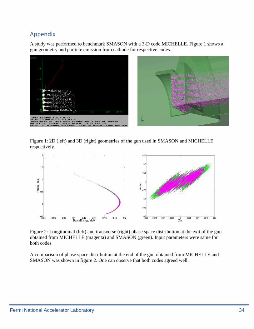
A study was performed to benchmark SMASON with a 3-D code MICHELLE. Figure 1 shows a
gun geometry and particle emission from cathode for respective codes.
Figure 1: 2D (left) and 3D (right) geometries of the gun used in SMASON and MICHELLE
respectively.
Figure 2: Longitudinal (left) and transverse (right) phase space distribution at the exit of the gun
obtained from MICHELLE (magenta) and SMASON (green). Input parameters were same for
both codes
A comparison of phase space distribution at the end of the gun obtained from MICHELLE and
SMASON was shown in figure 2. One can observe that both codes agreed well.
Related Documents