GSM RF Planning Project Supervisor: Mr.Qazi Zeeshan Group Members: Abdul- Raheem

Final Presentation
Dec 08, 2015
hjgkyd
Welcome message from author
This document is posted to help you gain knowledge. Please leave a comment to let me know what you think about it! Share it to your friends and learn new things together.
Transcript

GSM RF Planning
Project Supervisor:
Mr.Qazi Zeeshan
Group Members:
Abdul-Raheem
Nargis Sultana

Cellular Communication
Communication between mobile subscribers..
It removes the fixed wiring
Mobile subscriber is able to move around, perhaps
can travel in a vehicle or on foot & still make &
receive call.

The Cell…..
The hexagonal-shaped communication cells are artificial & are generated to simplify the planning & design of a cellular network.
BTS

Fitting of the cellular structure
A

Cellular structure
Base Station
Base Station
Base Station
Base StationBase Station
Base Station
Each cell is served by a base station.

Coverage & Capacity

Cell Size
Large Cells
35 Km
Small Cells
Near about 1 KM
Urban Areas

GSM
one or more RF carriers in each cell. An RF carrier is a pair of radio frequencies
One used in upward direction by MS - Uplink Other used in downward direction by BTS - Downlink The transmit and receive frequencies are separated by a
gap of 45 MHz in GSM of 75 MHz in DCS. There are 124 carries in GSM Band. With each
carrier carrying 8 timeslots, only 124 x 8 = 992 calls can be made!
Frequency Reuse is the solution

Uplink-Downlink
Downlink = 935 to 960 MHz
Uplink = 890 to 915 MHz
BTS Tx MS Rx
BTS Rx MS Tx
dl
ul

Frequency Reuse Pattern
Three types of frequency reuse patterns
7 Cell reuse pattern
4 cell reuse pattern
3 cell reuse pattern

Cell Dia = R
FREQUENCY RE - USE
Frequency Re-use
7 cell cluster
1
2
3
45
6
7D D/R = (3N)1/2
where N is Cluster size

Principal Of Sectorization
Omni Directional Cells 120 degree Sectors 60 Degree sectors
Each Sector in a Site has its own allocation of Radio Carriers.
Advantage By frequent reuse of frequency more capacity can be
achieved.

a1a2
a3a3
a4a6
a5
Cell Sectorisation
OMNI CELL
1 ANTENNA
b1
b2
b3
120O CELLS
3 ANTENNAS
60O CELLS
6 ANTENNAS

3 Site Reuse Pattern
c2
c1
c3
a1
a2
a3
b1
b2
b3
c1c2
c3Cell Re-use

Continued…3 cluster site
3/9 cell cluster 4 cluster site 4/12 cell cluster

Base Station 2
Base Station 3
Base Station 1
Handovers
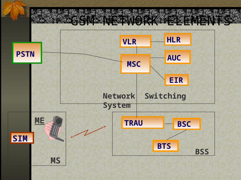
GSM NETWORK ELEMENTS
PSTNMSC
HLR
AUC
VLR
EIR
TRAU BSC
BTS
Network Switching System
BSS
SIM
ME
MS

GSM Network Components Mobile Station consists of two parts-
Mobile Equipment (ME)
Subscriber Identity Module (SIM)
ME
Hardware e.g. Telephone, Fax Machine,
Computer.
SIM
Smart Card which plugs into the ME.

Mobile Equipment (ME)
A handset

SIM
Subscriber Interface Identity Module
--------------
--------------
Small SIM
Full Size SIM Card
--------------
--------------

SIM stores…
IMSI (International Mobile
Subscriber Identity)Permanently stored on SIM card
15 digit Decimal
MCC (3) MNC (2) MSIN (10)
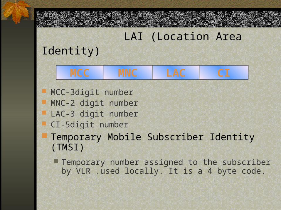
LAI (Location Area Identity)
MCC-3digit number MNC-2 digit number LAC-3 digit number CI-5digit number Temporary Mobile Subscriber Identity (TMSI)
Temporary number assigned to the subscriber by VLR .used locally. It is a 4 byte code.
LACMCC MNC CI

SIM continued…
MSISDN (Mobile subscriber ISDN) 10 digit number to which a subscriber is being called.
PIN (Personal Identification Number) Four digit PIN An internal security to Protect the SIM from illegal use. Card blocks itself after three wrong entries
PUK (Personal Unblocking Key) 8 digit code to unblock the SIM Card
Ki (Authentication Key), A3 & A8 Algorithms

Base Station System (BSS) BSS (Base Station System)
BSC (Base Site Controller) BTS (Base Transceiver Station) XCDR (Transcoder)
Network Switching System (NSS)
XCDR
BSC
BTS

Base Station System (BSS)
BSCControls upto 40 BTSConveys information to/from BTSControls handovers between BTSs
under itself BTS
1 - 6 carriers in a BTS7 - 48 simultaneous calls per BTS

Network Switching System(NSS)
NSS (Network Switching System)
MSC (Mobile Switching Centre)
HLR (Home Location Register)
VLR (Visitor Location Register)
EIR (Equipment Identity Register)
AUC (Authentication Centre)

o The OMC has access to the (G)MSC, BSC.o Handles error messages being reported from the Networko Controls the traffic load of the BSC, and the BTS.
Operation & Maintenance Centre

GSM Interfaces Um MS - BTS
Abis BTS - BSC
A BSC - MSC
B MSC - VLR
C MSC - HLR
D VLR - HLR
E MSC - MSC
F MSC - EIR
G VLR - VLR
H HLR - AUC

TDMA F
RAME n
+10 7
3
0
5
01
2
0 7
3
0
5
01
2
4.61
5 m
S
TDMA F
RAME n
T D M
A
TDMA & FDMA
F D M A200KHz
Uplink - MS Tx890MHz to 915MHz
Downlink - BTS Tx935MHz to 960MHz

LOGICAL CHANNELS
0 1 2 3 4 5 6 7
3
57 encrypted
57 encrypted
26 training
1S
1S
3T
8.25GP
3T
577S
577S x 8 = 4.615mS
TDMA Frame
Normal Burst
26 Frame Multi-frame

BURST

Five Types of Burst
Normal BurstTraffic & Control Channels
Frequency Correction Burst
FCCH
Synchronization Burst
SCH
Dummy Burst
BCCH Carrier
Access Burst
RACH

GSM Logical Channels
TCH and Control Channels

Frames & Multiframes
Traffic Channel occupy a 26-frame multiframe
(120 ms)
Control Channel occupy a 51-frame multiframe
(235 ms).

Channels On Air InterfaceBCCH
BCCH, FCCH, SCH
CCCH RACH, PCH, AGCH, DCCH

Channels On Air Interface
DCCH SDCCH
FACCH & SACCH

Call Scenarios Mobile to Mobile
Intra-city Inter-city
Mobile to Land Intra-city Inter-city
Land to Mobile Intra-city Inter-city

MULTI-PATH PROPAGATION

FREQUENCY HOPPING
F0
F2
F3
F4
FN
F1
T I M E
FR
EQ
UE
NC
Y

RF Planning Aspects
Coverage
Total sites used are 8.
S333,s22,and s332 site configuration is used.
3/9 Multiplexing mode used. i-e 3x3 frequency reuse.

The radio channel configuration model
Number of TRXs
in a cell Number of control
channels Number of voice channels
Capacity ? Erlang?
2% congestion rate
Capacity ? Erlang?
5% congestion rate
1 1? BCCH+SDCCH? 7 2.94 3.74 2 1BCCH+1SDCCH 14 8.2 9.73 3 1BCCH+1SDCCH 22 14.9 17.1 4 1BCCH+1SDCCH 30 22 24.8 5 1BCCH+2SDCCH 37 28 31.6 6 1BCCH+2SDCCH 45 35.5 39.6 7 1BCCH+2SDCCH 53 43 47.53

3x3 frequency re-use:

continued…
• Capacity:
Number of potential users = 12,000
Average BHCA = 2minutes
mean holding time per call = 45seconds
erlang per subscriber = (45*2)/3600 = 0.25erlang
Design capacity of a network :
10,000*0.025 = 250erlang

Frequency Planning softwares
Softwares used are:
ASSETT PLANET GAIA

FINAL PROJECT
GSM RF PLANNING

Project specifications
5MHz Frequency band used is:
uplink 1780-1785
downlink 1875-1880
Total RF carriers = 25 120degree antenna used

Coverage forecast table
B T S ID B T S N a m e C o n fig u ra t io n T O W N P R O V IN C E L O N L A T G N D H T A z im u t h H e ig h tA B D 0 0 1 S a rb a n C h o w k S 3 3 3 A b b o t t a b a d N W F P 7 3 . 2 2 0 2 3 4 . 1 4 8 2 1 2 3 7 1 4 0 3 5A B D 0 0 2 S u p p ly B a z a r S 3 3 2 A b b o t t a b a d N W F P 7 3 . 2 2 5 3 4 . 1 7 0 9 1 2 0 0 6 0 3 5A B D 0 0 3 S h im la P a h a r i S 3 3 3 A b b o t t a b a d N W F P 7 3 . 2 0 0 8 3 4 . 1 4 8 2 1 3 4 9 1 2 0 3 5A B D 0 0 4 N a w a n S h e h r S 3 3 3 A b b o t t a b a d N W F P 7 3 . 2 6 5 3 3 4 . 1 6 3 4 1 2 3 7 1 8 0 3 5A B D 0 0 5 K a k u l S 3 3 2 A b b o t t a b a d N W F P 7 3 . 2 4 7 9 3 4 . 1 8 2 6 1 2 2 3 9 0 3 5A B D 0 0 6 S I S t a t e S 3 3 3 A b b o t t a b a d N W F P 7 3 . 2 3 4 8 3 4 . 2 0 0 1 1 2 0 0 1 8 0 3 5A B D 0 0 7 S h a h ra h -e -R a is h a m S 2 2 A b b o t t a b a d N W F P 7 3 . 1 7 7 2 3 4 . 1 2 7 1 3 9 7 8 0 3 5A B D 0 0 8 C h in a r R o a d S 3 3 2 A b b o t t a b a d N W F P 7 3 . 2 3 6 5 3 4 . 1 5 9 4 1 2 0 0 1 8 0 3 5

mapped data


Coverage


Mean received power


Path Loss


END OF PRESENTATION
QUESTIONS???
Related Documents