GOVERNMENT OF INDIA MINISTRY OF RAILWAYS MINUTES OF XXXIX MAINTENANCE STUDY GROUP (ELECTRIC LOCO) MEETING HELD AT NAGPUR, CENTRAL RAILWAY ON 14 th & 15 th OCTOBER’ 2019 RESEARCH DESIGNS AND STANDARDS ORGANISATION MANAK NAGAR, LUCKNOW – 226 011

Welcome message from author
This document is posted to help you gain knowledge. Please leave a comment to let me know what you think about it! Share it to your friends and learn new things together.
Transcript
GOVERNMENT OF INDIA
MINISTRY OF RAILWAYS
MINUTES
OF
XXXIX MAINTENANCE STUDY GROUP
(ELECTRIC LOCO)
MEETING
HELD AT
NAGPUR, CENTRAL RAILWAY
ON
14th & 15th OCTOBER’ 2019
RESEARCH DESIGNS AND STANDARDS ORGANISATION
MANAK NAGAR, LUCKNOW – 226 011
Page 2 of 147
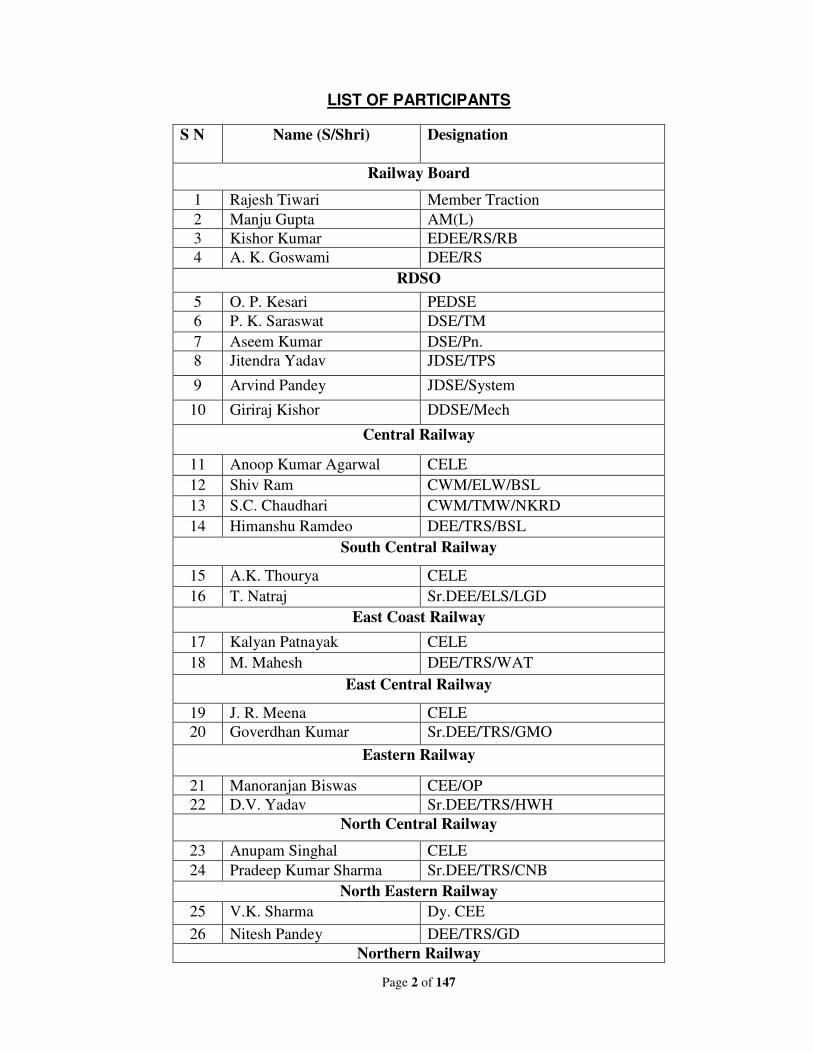
LIST OF PARTICIPANTS
S N Name (S/Shri) Designation
Railway Board
1 Rajesh Tiwari Member Traction
2 Manju Gupta AM(L)
3 Kishor Kumar EDEE/RS/RB
4 A. K. Goswami DEE/RS
RDSO
5 O. P. Kesari PEDSE
6 P. K. Saraswat DSE/TM
7 Aseem Kumar DSE/Pn.
8 Jitendra Yadav JDSE/TPS
9 Arvind Pandey JDSE/System
10 Giriraj Kishor DDSE/Mech
Central Railway
11 Anoop Kumar Agarwal CELE
12 Shiv Ram CWM/ELW/BSL
13 S.C. Chaudhari CWM/TMW/NKRD
14 Himanshu Ramdeo DEE/TRS/BSL
South Central Railway
15 A.K. Thourya CELE
16 T. Natraj Sr.DEE/ELS/LGD
East Coast Railway
17 Kalyan Patnayak CELE
18 M. Mahesh DEE/TRS/WAT
East Central Railway
19 J. R. Meena CELE
20 Goverdhan Kumar Sr.DEE/TRS/GMO
Eastern Railway
21 Manoranjan Biswas CEE/OP
22 D.V. Yadav Sr.DEE/TRS/HWH
North Central Railway
23 Anupam Singhal CELE
24 Pradeep Kumar Sharma Sr.DEE/TRS/CNB
North Eastern Railway
25 V.K. Sharma Dy. CEE
26 Nitesh Pandey DEE/TRS/GD
Northern Railway
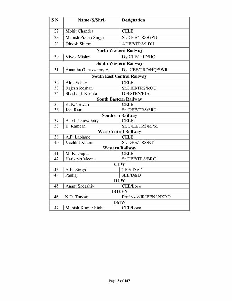
Page 3 of 147
S N Name (S/Shri) Designation
27 Mohit Chandra CELE
28 Manish Pratap Singh Sr.DEE/ TRS/GZB
29 Dinesh Sharma ADEE/TRS/LDH
North Western Railway
30 Vivek Mishra Dy.CEE/TRD/HQ
South Western Railway
31 Anantha Guruswamy A Dy. CEE/TRD/HQ/SWR
South East Central Railway
32 Alok Sahay CELE
33 Rajesh Roshan Sr.DEE/TRS/ROU
34 Shashank Koshta DEE/TRS/BIA
South Eastern Railway
35 R. K. Tewari CELE
36 Jeet Ram Sr. DEE/TRS/SRC
Southern Railway
37 A. M. Chowdhary CELE
38 B. Ramesh Sr. DEE/TRS/RPM
West Central Railway
39 A.P. Labhane CELE
40 Vachhit Khare Sr. DEE/TRS/ET
Western Railway
41 M. K. Gupta CELE
42 Harikesh Meena Sr.DEE/TRS/BRC
CLW
43 A.K. Singh CEE/ D&D
44 Pankaj SEE/D&D
DLW
45 Anant Sadashiv CEE/Loco
IRIEEN
46 N.D. Turkar, Professor/IRIEEN/ NKRD
DMW
47 Manish Kumar Sinha CEE/Loco
Page 4 of 147
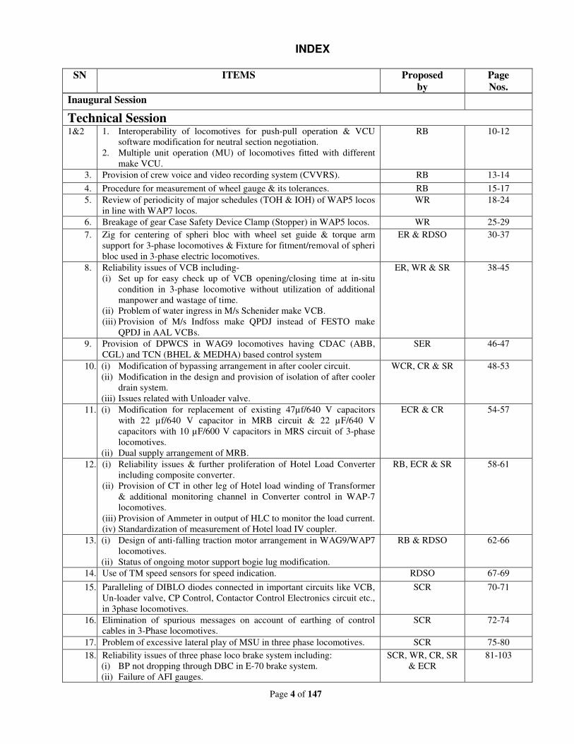
INDEX
SN ITEMS Proposed
by
Page
Nos.
Inaugural Session
Technical Session
1&2 1. Interoperability of locomotives for push-pull operation & VCU
software modification for neutral section negotiation.
2. Multiple unit operation (MU) of locomotives fitted with different
make VCU.
RB 10-12
3. Provision of crew voice and video recording system (CVVRS). RB 13-14
4. Procedure for measurement of wheel gauge & its tolerances. RB 15-17
5. Review of periodicity of major schedules (TOH & IOH) of WAP5 locos
in line with WAP7 locos.
WR 18-24
6. Breakage of gear Case Safety Device Clamp (Stopper) in WAP5 locos. WR 25-29
7. Zig for centering of spheri bloc with wheel set guide & torque arm
support for 3-phase locomotives & Fixture for fitment/removal of spheri
bloc used in 3-phase electric locomotives.
ER & RDSO 30-37
8. Reliability issues of VCB including-
(i) Set up for easy check up of VCB opening/closing time at in-situ
condition in 3-phase locomotive without utilization of additional
manpower and wastage of time.
(ii) Problem of water ingress in M/s Schenider make VCB.
(iii) Provision of M/s Indfoss make QPDJ instead of FESTO make
QPDJ in AAL VCBs.
ER, WR & SR 38-45
9. Provision of DPWCS in WAG9 locomotives having CDAC (ABB,
CGL) and TCN (BHEL & MEDHA) based control system
SER 46-47
10. (i) Modification of bypassing arrangement in after cooler circuit.
(ii) Modification in the design and provision of isolation of after cooler
drain system.
(iii) Issues related with Unloader valve.
WCR, CR & SR 48-53
11. (i) Modification for replacement of existing 47µf/640 V capacitors
with 22 µf/640 V capacitor in MRB circuit & 22 µF/640 V
capacitors with 10 µF/600 V capacitors in MRS circuit of 3-phase
locomotives.
(ii) Dual supply arrangement of MRB.
ECR & CR 54-57
12. (i) Reliability issues & further proliferation of Hotel Load Converter
including composite converter.
(ii) Provision of CT in other leg of Hotel load winding of Transformer
& additional monitoring channel in Converter control in WAP-7
locomotives.
(iii) Provision of Ammeter in output of HLC to monitor the load current.
(iv) Standardization of measurement of Hotel load IV coupler.
RB, ECR & SR 58-61
13. (i) Design of anti-falling traction motor arrangement in WAG9/WAP7
locomotives.
(ii) Status of ongoing motor support bogie lug modification.
RB & RDSO
62-66
14. Use of TM speed sensors for speed indication. RDSO 67-69
15. Paralleling of DIBLO diodes connected in important circuits like VCB,
Un-loader valve, CP Control, Contactor Control Electronics circuit etc.,
in 3phase locomotives.
SCR 70-71
16. Elimination of spurious messages on account of earthing of control
cables in 3-Phase locomotives.
SCR 72-74
17. Problem of excessive lateral play of MSU in three phase locomotives. SCR 75-80
18. Reliability issues of three phase loco brake system including:
(i) BP not dropping through DBC in E-70 brake system.
(ii) Failure of AFI gauges.
SCR, WR, CR, SR
& ECR
81-103
Page 5 of 147
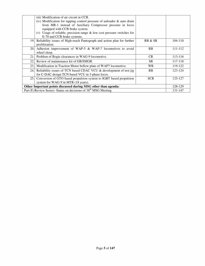
(iii) Modification of air circuit in CCB.
(iv) Modification for tapping control pressure of unloader & auto drain
from MR-1 instead of Auxiliary Compressor pressure in locos
equipped with CCB brake system.
(v) Usage of reliable, precision range & low cost pressure switches for
E-70 and CCB brake systems.
19. Reliability issues of High-reach Pantograph and action plan for further
proliferation.
RB & SR 104-110
20. Adhesion improvement of WAP-5 & WAP-7 locomotives to avoid
wheel sleep.
RB 111-112
21. Problem of Bogie clearances in WAG-9 locomotive. CR 113-116
22. Review of maintenance kit of GR/SMGR. SR 117-118
23. Modification in Traction Motor bellow plate of WAP7 locomotive. WR 119-122
24. Reliability issues of TCN based CDAC VCU & development of test jig
for C-DAC design TCN based VCU in 3-phase locos.
RB 123-124
25. Conversion of GTO based propulsion system to IGBT based propulsion
system for WAG-9 in MTR (18 years).
SCR 125-127
Other Important points discussed during MSG other than agenda: 128-129
Part II (Review Items)- Status on decisions of 38th
MSG Meeting 131-147
Page 6 of 147
Inaugural Session
DRM/NGP address:
Nagpur division is grateful to Railway Board for choosing the Electric Loco Shed/Ajni for the venue
of 39th
MSG. We welcome all the delegates for the meeting. We have taken all the efforts to take
care of comfortable stay of participants for the meeting. If any shortcomings are noticed, please let
us know for further improvement & excuse for the same.
I am hopeful that present meeting will be very useful & give suitable direction for reliability
improvement of electric locomotives.
PCEE/CR address:
We got full co-operation for organizing the 39th MSG from Nagpur Division. I have been associated
with Electric Loco Shed/Ajni from the beginning when this shed was homing only conventional
electric locomotives. Since then, this has been a very long journey for Electric Loco Shed/Ajni. Now
it is fully developed with all the infrastructural facilities for maintenance of state of art 3-phase
electric locomotives. Ajni shed has contributed by giving innovative ideas for reliability
improvement of electric locomotives which has been noted by RDSO in issuing the technical
instructions.
Central Railway is grateful to Railway Board for choosing Electric Loco Shed/Ajni as a venue for
MSG meeting. I hope that deliberations shall be very useful & fruitful.
PEDSE address:
At the outset, I on behalf of RDSO extend a hearty welcome to all the delegates of 39th MSG
meeting at Nagpur. RDSO is grateful and thankful to PCEE/CR, DRM/NGP and their team of
officers and staff for having accepted the responsibility of organizing 39th MSG meeting in Electric
Loco Shed, Ajni and making an excellent arrangement for all the delegates. I also belong to Central
Railway right from the beginning of the career. I clearly remember the development of Electric Loco
Shed, Ajni. While working in Central Railway, we have noted a number of times the innovative
ideas and suggestions came from Electric Loco Shed, Ajni, which were followed later by other sheds
on Indian Railways. Since the production of electric locomotives has increased, there is lot of
responsibility on electrical engineers, particularly involved in maintenance and operations of electric
locomotives. During the quality audit done by RDSO from time to time, it has been noted that in
some of the cases maintenance practices have been diluted or not being followed in proper way
resulting into reliability issues. Therefore it is essential to ensure compliance of SMIs, TCs and MSs
issued by RDSO.
The first MSG meeting was held in 1968 in Electric Loco Shed, Tatanagar. At that time, electrical
department was having only 500 locomotives and electrified route kilometer of 3000. From that
position, we have travelled a long way. At present, we have under our control more than 5000 locos
and majority of traffic on electric traction. Therefore, reliability of locomotives has gained a lot of
significance. The MSG meetings have contributed a lot towards reliability. Several new ideas and
modifications have been originated in the past as a takeaway of the deliberations in MSG meetings.
Page 7 of 147
The present need is to ensure compliance of maintenance practices as well as thorough investigation
of the failures with an intention to find out the root cause of failures. Just reporting the failures may
not serve the purpose. In the past, Electric Loco Sheds have carried out wonderful investigation
since they were able to observe the failures closely. Correct failure investigation gives the input for
improvement in maintenance practices, improvement in design of equipment, change in material,
workmanship and condition monitoring.
Recently, we had a detailed discussion on reliability issues of traction converters in a meeting held
under the guidance of Member Traction on 28.09.2019 and number of issues have been flagged in
the meeting on which CLW and RDSO are working. In this MSG meeting, total 26 items have been
approved by Railway Board including one item of “Centre of Excellence”, for which CLW & SER
will carry out a separate presentation. For remaining items, RDSO note is available in the booklet
circulated to all the members. RDSO will try its best to address all the issues within three months, as
directed by Railway Board.
Deliberations of 39th MSG are going to be very useful under the guidance of Member Traction,
Addl. Member (Electrical) and Railway Board officials. RDSO is thankful to Railway Board and
Central Railway for facilitating the conduction of 39th MSG meeting.
EDEE/RS Address:
Failures of most of the critical equipments have increased. The cases of failures are more in newly
commissioned locomotives, which indicates that proper care is needed while carrying out assembly
work of locomotives in Production Units. At the same time, maintenance sheds should also ensure
compliance of all Maintenance Instructions without fail. In this regard, the up-gradation of skill and
knowledge of artisan staff who are carrying out the maintenance is very important. All the matters
referred by Railways to RDSO for this MSG Meeting should be addressed within three months’
time.
AM/Electrical address:
MSG Meeting should be held regularly to address the maintenance issues timely. Commissioning
time of new locomotives is very high. Production Units and Zonal Railways have to ensure that
locomotives are commissioned immediately after receipt of loco in the shed. Zonal Railways are
requested to give equal attention to locomotives failing in the territory of foreign Railways. South
Eastern Railway has taken good initiative for making “Centre of Excellence” at Bondamunda, which
is still under developing stage. Due to large scale electrification, the training of crew has become
very important. All the Production Units are requested to adopt uniform policy for vendor approval
to ensure proper quality & transparency in decision making.
MTR address:
Consequent upon 100% electrification, number of challenges are before electrical engineers. The
cost of diesel traction is high. Therefore, wherever electric traction is available, trains should be run
with the electric locos. This will reduce the fuel as well as maintenance cost. Electric Loco Sheds
should share the good works done by them with other sheds so that benefits could be multiplied. If
problem is tackled with collective efforts, solutions could be found out early. Electric Loco Sheds
should own the locomotives of foreign Railways also and give same attention as they give to their

Page 8 of 147
homing locos. Shed and workshop officers should spend more time on shop floor to give proper
direction for day-to-day maintenance. All the staff in the organization have equal importance and
only the roles are different. RDSO, Production Units and Zonal Railways should work together as
team to achieve the overall objectives of Indian Railways. The present target of loco production is
725 but it is likely to increase in time to come. The reliability of newly commissioned locomotives
is a cause of concern. DLW team should also be associated in inspection and quality control.
Maintenance instructions issued from time to time should be followed strictly and all concerned staff
should be trained accordingly. All the modifications and proposed improvements should be
implemented after carrying out proper tests and field trials.
Page 9 of 147
PART-I
New agenda items proposed for discussion with brief
descriptions
Page 10 of 147
Technical Session
New Item
Item no. : 1 & 2
Subject : 1. Interoperability of Locomotive for push-pull
operation & VCU software modification for
neutral section negotiation.
2. Multiple Unit Operation (MU) of locomotive
fitted with different make VCU.
Proposed by : Railway Board
File no. : EL/4.2.17
RDSO’s note:
Item no. 1: Interoperability of Locomotive for push-pull operation & VCU software
modification for neutral section negotiation:
Interfacing Control Document has been sent to OEMs and CLW. Comments are likely to be
received by Oct end from OEMs. Based on the same CLW will advice to OEM to incorporate the
modification in protocol for communication to various manufacturers.
During this process VCU software modification for neutral section negotiation shall also be
done by OEM.
REF: MOM of meeting held at Railway Board on 22-07-2019 and issued vide letter no. EL/4.2.17
dated 29-07-2019.
Item no. 2: Multiple Unit Operation (MU) of locomotive fitted with different make VCU:
MU of Medha and BHEL make propulsion have been already been tested. However later on
it was split. During reliability meeting held at RDSO on 28/9/2019 it was decided to make multi of
Medha and BHEL make propulsion in South Central Railway in 05 Loco sets. During the meeting
held on 28/09-2019, it was also decided to home same type of VCU fitted locomotives.
Since multi formation carried out in loco shed only it was decided in meeting on 28/09/2019
that effort should be made to make multi in same type of VCU for smooth loco operation.
Deliberations:
A meeting was held in RDSO on 10.06.2019 with a view to make all the locomotives inter-
operable for multi as well as push-pull operation. In this meeting, a draft ICD was finalized in
Page 11 of 147
consultation with all the OEMs of propulsion system. This draft ICD includes the communication
protocol. In general, OEMs are in agreement with proposed draft ICD. However, CLW is carrying
out minor modification in this draft ICD to take into account all the logics for operation as per
MICAS. Once all the communication protocol is made uniform, it would be possible for various
makes of TCN VCU to communicate with each other.
At present, following types of VCUs are in 3-phase locomotives:
i) M/s ABB & M/s CG Power – using C-DAC VCU
ii) M/s BT – using their own TCN compliant VCU
iii) M/s BHEL - using C-DAC VCU as well as TCN compliant VCU
iv) M/s Medha – using their own TCN compliant VCU
In addition to above, in MICAS VCU are also working in locomotives turned out at CLW.
At present, inter-operability is needed among all above makes of VCUs.
M/s Medha and M/s BHEL make VCUs were tested for multiple operation in ECoR as well
as Electric Loco Shed, LGD. However, it was informed that these multis were later on broken. SER
pointed out that in their territory, BHEL and Medha could not work in multi operation. It was
directed that multi formation among various makes of VCUs should be made preferably in SER or
Electric Loco Shed, Gomoh, where multi-operation is in use in sufficient numbers. EDEE/RS
pointed out that while finalizing the ICD, CLW should advise OEMs to upload the modified
software in one of the Zonal Railways, preferably SER. Thereafter, multi operation should be tested.
On successful tests and trial, the draft ICD should be finalized to avoid any problem later on within a
month time.
CLW also stated that the present draft ICD will take care of inter-operability among various
makes of TCN VCU only. This does not cover locomotives working with MICAS VCU software.
As far as neutral section modification is concerned, the software has been tested by M/s BT
and M/s BHEL. MICAS VCU software already modified by CLW and working satisfactorily.
Therefore, remaining two other VCUs, i.e. Medha and C-DAC, should also be tested with modified
rakes for neutral section operation in push-pull mode.
CLW will convene a meeting for draft ICD finalization at the earliest with all concerned
propulsion manufacturers. ICD will be finalized by CLW by Nov. 2019.On finalization of ICD,
propulsion manufacturers will implement this in new supply and will be jointly tested by
CLW/RDSO. After validation of ICD, software patch will be reloaded by Zonal Railways in existing
locomotives. Software modification for Neutral Section negotiation will be carried out
simultaneously with above modification.
Recommendations:
1. ICD modification may be carried out in few locomotives by the firms directly in Zonal
railways (preferably in SER). The performance may be evaluated and modification required
in ICD may be done simultaneously. After successful validation in Zonal Railways, it should
be implemented in new and existing locomotives.
Page 12 of 147
2. Trials for neutral section modification for C-DAC and Medha make should also be done for
modified rakes in the Railways, where such modification for coach wiring has been
completed.
Railway Board’s decision:
May be accepted. Target date for compliance is 31.03.2020.
Page 13 of 147
New Item
Item no. : 3
Subject : Provision of crew voice and video recording system
(CVVRS).
Proposed by : Railway Board
File no. : EL/0.1.3/Driver
RDSO’s note:
i) CVVRS is provided to ensure effective and temper proof video and voice recording of
locomotive cab and track view for post event analysis.
ii) In compliance of RB directives, Electrical Directorate/RDSO has issued spec for CVVRS
bearing no. RDSO/2015/EL/SPEC/0118, Rev. ‘0’ on 17.09.2015.
iii) MP Dte./RDSO has also issued spec for CVVRS in the name of LCVRS.
iv) As per RB directive vide their letter no 2009/Elect.(TRS)/441/6 Pt. dated 17.11.2015,
“CLW to provide CVVRS in newly built locomotives without field trials, however in
phase-I only passenger locos to be cut-in. To be reviewed after one year.”
v) Further, Railway Board vide letter no. 2009/Elect.(TRS)/440/4 dated 10.11.2017 CLW
has to provide CVVRS initially in 20 locomotives and to monitor the performance to
decide the action plan for provision on regular basis.
vi) As per RB letter no. 2009/Elect. (TRS)/441/6 Pt. dated 09/08/2019, RDSO is in the
process of revising the previously issued specification.
vii) In the revised specification, the additional requirement of CVVRS for diesel locomotives
besides other improvements have been included to have common specification for
CVVRS for electric/diesel locomotive.
viii) A meeting was held with OEMs and stake holders in RDSO on 13.09.2019. After this,
final draft of revised specification has been uploaded on RDSO website on 30.09.2019
for 15 days and will be finalized/issued afterwards.
Deliberations:
Group was informed that draft specification is available on RDSO website and if somebody
wants to give any suggestions than same may be sent to RDSO so that same can be incorporated.
PEDSE stated that whenever the CVVRS is provided, 1st unit shall be offered to RDSO for its
prototype testing to validate the system whether it is in order or not. The system will be verified after
it is fitted in the locomotive & performance of system i.e. quality of recording (video & voice) will
be verified in running state of loco.
LCD screen for camera’s monitoring give more comfortable and user friendly result to know
camera’s health and connectivity. Without display monitoring screen we cannot get connectivity and
camera’s health report easily. Zonal Railways stated that this requirement is not required as it will
distract the attention of LP/ALP.
Page 14 of 147
Recommendations:
1. The Zonal Railways may give suggestions on final Draft Specification of CVVRS, which is
available on RDSO website.
2. There will be 4 cameras per cab of electric locomotive.
3. Whenever ZRs/PUs places order, the first unit shall be type tested & the test shall be done
by providing the CVVRS in locomotive & observing its performance in running
locomotive. The recording quality shall be checked & if found in order than only prototype
clearance should be given otherwise firm shall be asked to improved upon that.
(Note: At the time of sending the draft MOM, the specification no. RDSO
/2015/EL/SPEC/0118, (Rev.‘0’) issued on dated 24.10.2019 and uploaded on RDSO
website by taking into account all the comments received from ZRs/PUs and MP
Directorate of RDSO.)
Railway Board’s decision:
May be accepted. RDSO should associate in prototype clearance. RDSO to ensure
compliance of requirements as stipulated in specification for clear and audible recording of voice
with appropriate noise reduction.
Item no. : 4
Subject : Procedure for measurement of wheel gauge and its
tolerances.
Proposed by : Railway Board
File no. : EL/3.2.108/Wheel
RDSO’s Note:
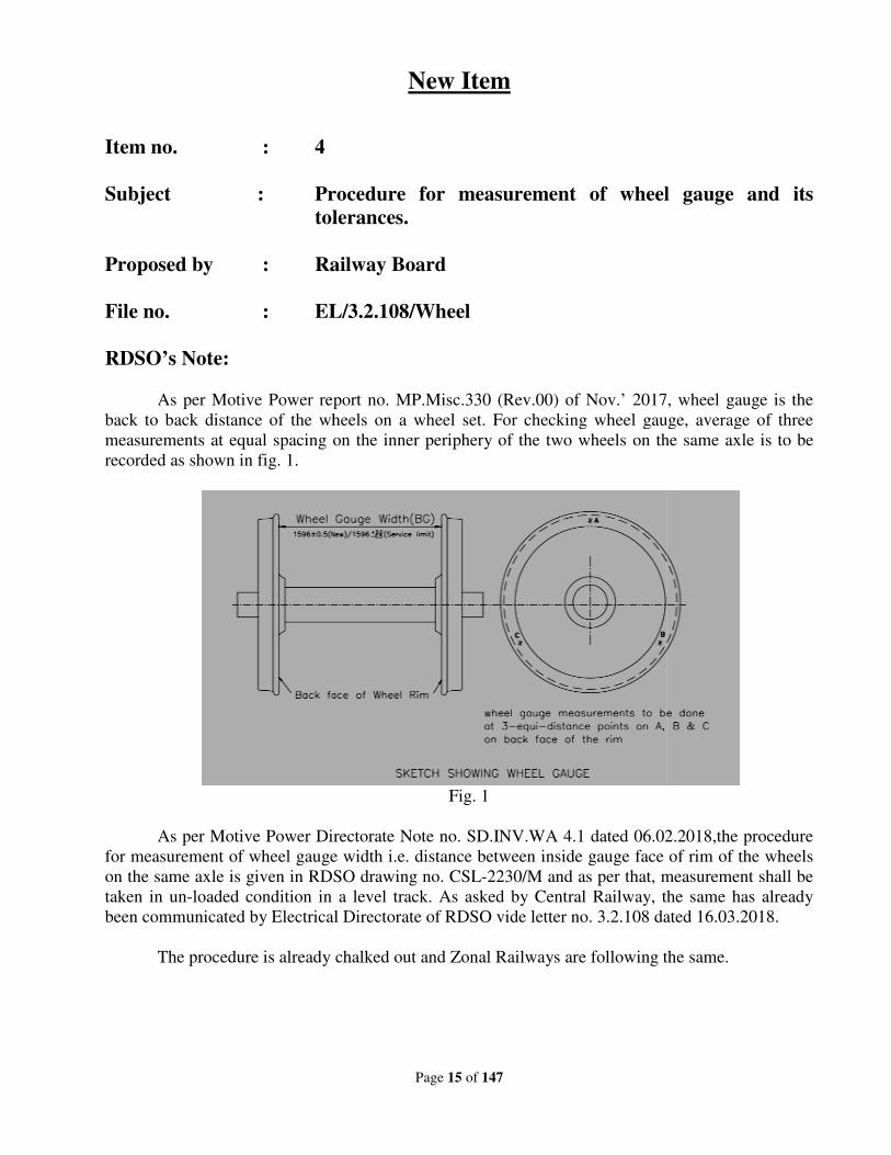
As per Motive Power report no. MP.Misc.330 (Rev.00)
back to back distance of the wheels on a wheel set. For checking wheel gauge, average of three
measurements at equal spacing on the inner periphery of the two wheels on the same axle is to be
recorded as shown in fig. 1.
As per Motive Power Directorate Note n
for measurement of wheel gauge width i.e. distance between inside gauge face of rim of the wheels
on the same axle is given in RDSO drawing
taken in un-loaded condition in a level track. As asked by Central Railway, the same has already
been communicated by Electrical D
The procedure is already chalk
Page 15 of 147
New Item
Procedure for measurement of wheel gauge and its
tolerances.
Railway Board
EL/3.2.108/Wheel
As per Motive Power report no. MP.Misc.330 (Rev.00) of Nov.’ 2017, wheel gauge is the
back to back distance of the wheels on a wheel set. For checking wheel gauge, average of three
measurements at equal spacing on the inner periphery of the two wheels on the same axle is to be
Fig. 1
Motive Power Directorate Note no. SD.INV.WA 4.1 dated 06.02.2018,the procedure
for measurement of wheel gauge width i.e. distance between inside gauge face of rim of the wheels
on the same axle is given in RDSO drawing no. CSL-2230/M and as per that, measurement shall be
loaded condition in a level track. As asked by Central Railway, the same has already
been communicated by Electrical Directorate of RDSO vide letter no. 3.2.108 dated 16.03.2018.
The procedure is already chalked out and Zonal Railways are following the same.
Procedure for measurement of wheel gauge and its
of Nov.’ 2017, wheel gauge is the
back to back distance of the wheels on a wheel set. For checking wheel gauge, average of three
measurements at equal spacing on the inner periphery of the two wheels on the same axle is to be
o. SD.INV.WA 4.1 dated 06.02.2018,the procedure
for measurement of wheel gauge width i.e. distance between inside gauge face of rim of the wheels
, measurement shall be
loaded condition in a level track. As asked by Central Railway, the same has already
o. 3.2.108 dated 16.03.2018.
ed out and Zonal Railways are following the same.
Page 16 of 147
Deliberations:
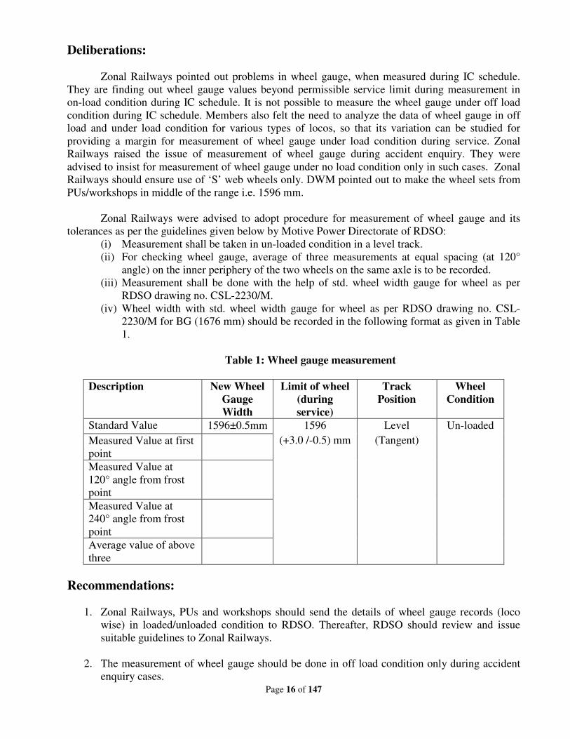
Zonal Railways pointed out problems in wheel gauge, when measured during IC schedule.
They are finding out wheel gauge values beyond permissible service limit during measurement in
on-load condition during IC schedule. It is not possible to measure the wheel gauge under off load
condition during IC schedule. Members also felt the need to analyze the data of wheel gauge in off
load and under load condition for various types of locos, so that its variation can be studied for
providing a margin for measurement of wheel gauge under load condition during service. Zonal
Railways raised the issue of measurement of wheel gauge during accident enquiry. They were
advised to insist for measurement of wheel gauge under no load condition only in such cases. Zonal
Railways should ensure use of ‘S’ web wheels only. DWM pointed out to make the wheel sets from
PUs/workshops in middle of the range i.e. 1596 mm.
Zonal Railways were advised to adopt procedure for measurement of wheel gauge and its
tolerances as per the guidelines given below by Motive Power Directorate of RDSO:
(i) Measurement shall be taken in un-loaded condition in a level track.
(ii) For checking wheel gauge, average of three measurements at equal spacing (at 120°
angle) on the inner periphery of the two wheels on the same axle is to be recorded.
(iii) Measurement shall be done with the help of std. wheel width gauge for wheel as per
RDSO drawing no. CSL-2230/M.
(iv) Wheel width with std. wheel width gauge for wheel as per RDSO drawing no. CSL-
2230/M for BG (1676 mm) should be recorded in the following format as given in Table
1.
Table 1: Wheel gauge measurement
Description New Wheel
Gauge
Width
Limit of wheel
(during
service)
Track
Position
Wheel
Condition
Standard Value 1596±0.5mm 1596
(+3.0 /-0.5) mm
Level
(Tangent)
Un-loaded
Measured Value at first
point
Measured Value at
120° angle from frost
point
Measured Value at
240° angle from frost
point
Average value of above
three
Recommendations:
1. Zonal Railways, PUs and workshops should send the details of wheel gauge records (loco
wise) in loaded/unloaded condition to RDSO. Thereafter, RDSO should review and issue
suitable guidelines to Zonal Railways.
2. The measurement of wheel gauge should be done in off load condition only during accident
enquiry cases.

Page 17 of 147
Railway Board’s decision:
May be accepted. RDSO to issue standard format for uniform data and procedure must be
finalized within one month of issue of the MOM.
Page 18 of 147
New Item
Item no. : 5
Subject : Review of periodicity of major schedules (TOH & IOH)
of WAP5 locomotives in line with WAP7 locomotives.
Proposed by : WR
File no. : EL/3.1.35/16
Note of proposing Railway:
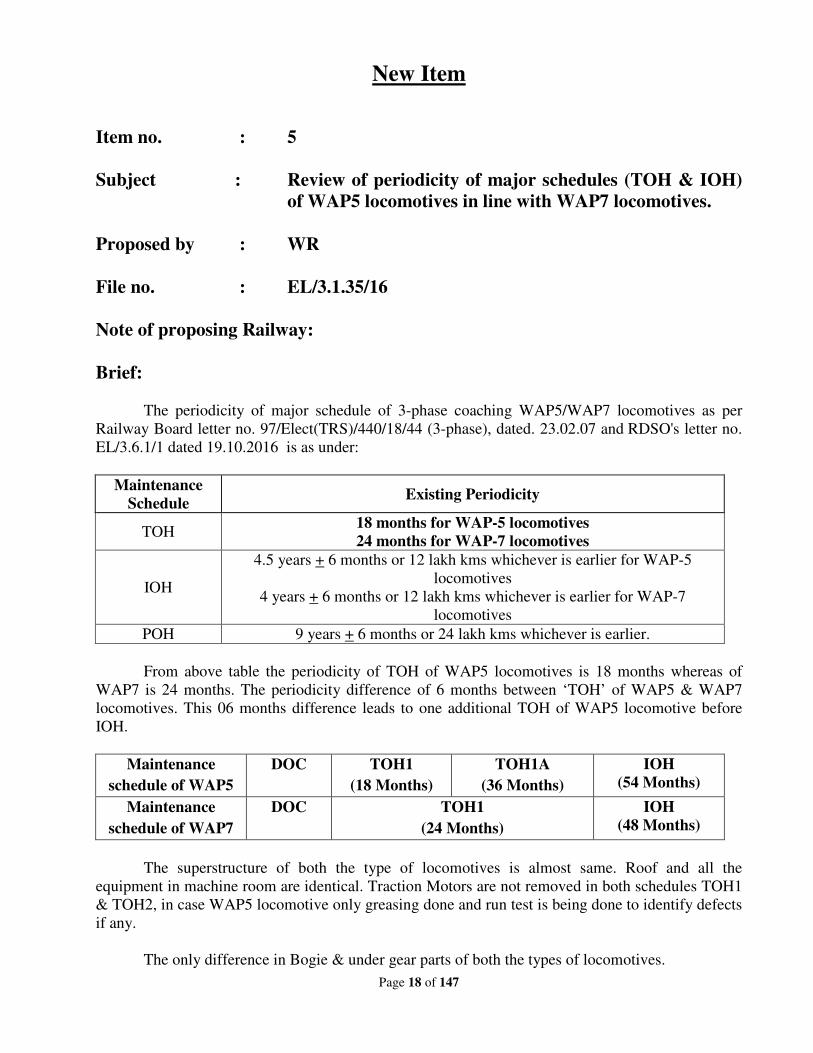
Brief:
The periodicity of major schedule of 3-phase coaching WAP5/WAP7 locomotives as per
Railway Board letter no. 97/Elect(TRS)/440/18/44 (3-phase), dated. 23.02.07 and RDSO's letter no.
EL/3.6.1/1 dated 19.10.2016 is as under:
Maintenance
Schedule Existing Periodicity
TOH 18 months for WAP-5 locomotives
24 months for WAP-7 locomotives
IOH
4.5 years + 6 months or 12 lakh kms whichever is earlier for WAP-5
locomotives
4 years + 6 months or 12 lakh kms whichever is earlier for WAP-7
locomotives
POH 9 years + 6 months or 24 lakh kms whichever is earlier.
From above table the periodicity of TOH of WAP5 locomotives is 18 months whereas of
WAP7 is 24 months. The periodicity difference of 6 months between ‘TOH’ of WAP5 & WAP7
locomotives. This 06 months difference leads to one additional TOH of WAP5 locomotive before
IOH.
Maintenance
schedule of WAP5
DOC TOH1
(18 Months)
TOH1A
(36 Months)
IOH
(54 Months)
Maintenance
schedule of WAP7
DOC TOH1
(24 Months)
IOH
(48 Months)
The superstructure of both the type of locomotives is almost same. Roof and all the
equipment in machine room are identical. Traction Motors are not removed in both schedules TOH1
& TOH2, in case WAP5 locomotive only greasing done and run test is being done to identify defects
if any.
The only difference in Bogie & under gear parts of both the types of locomotives.
Page 19 of 147
In addition, the warranty period of costly must change items like spheri bloc, membrane,
Brake pad etc. is 24 months from date of commission and 30 months form date of supply whichever
is earlier. However currently in WAP5 locomotives these items are being replaced within warranty
period i.e. in 18 months only.
The equipments are replaced in every major schedule i.e. 18 months. Explanation is given
below:
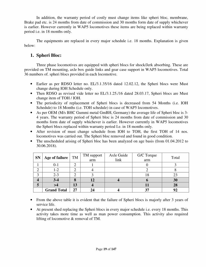
1. Spheri Bloc:
Three phase locomotives are equipped with spheri blocs for shock/Jerk absorbing. These are
provided on TM mounting, axle box guide links and gear case support in WAP5 locomotives. Total
36 numbers of. spheri blocs provided in each locomotive.
• Earlier as per RDSO letter no. EL/3.1.35/16 dated 12.02.12, the Spheri blocs were Must
change during IOH Schedule only.
• Then RDSO as revised vide letter no EL/3.1.25./16 dated 28.03.17, Spheri blocs are Must
change item of TOH / IOH.
• The periodicity of replacement of Spheri blocs is decreased from 54 Months (i.e. IOH
Schedule) to 18 Months (i.e. TOH schedule) in case of WAP5 locomotives.
• As per OEM (M/s BHC Gummi metal GmBH, Germany) the average life of Spheri bloc is 3-
4 years. The warranty period of Spheri bloc is 24 months from date of commission and 30
months form date of supply whichever is earlier. However currently in WAP5 locomotives
the Spheri blocs replaced within warranty period I.e. in 18 months only.
• After revision of must change schedule from IOH to TOH, the first TOH of 14 nos.
locomotives was carried out. The Spheri bloc removed and found in good condition.
• The unscheduled arising of Spheri bloc has been analyzed on age basis (from 01.04.2012 to
30.06.2018).
SN Age of failure TM TM support
arm
Axle Guide
link
G/C Torque
arm Total
1 0-1 2 1 0 3
2 1-2 2 4 2 8
3 2-3 2 3 18 23
4 3-4 8 12 4 6 30
5 >4 13 4 11 28
Grand Total 27 24 4 37 92
• From the above table it is evident that the failure of Spheri blocs is majorly after 3 years of
service life.
• At present shed replacing the Spheri blocs in every major schedule i.e. every 18 months. This
activity takes more time as well as man power consumption. This activity also required
lifting of locomotive & removal of TM.
Page 20 of 147
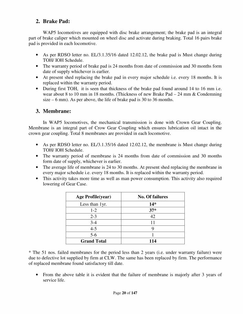
2. Brake Pad:
WAP5 locomotives are equipped with disc brake arrangement; the brake pad is an integral
part of brake caliper which mounted on wheel disc and activate during braking. Total 16 pairs brake
pad is provided in each locomotive.
• As per RDSO letter no. EL/3.1.35/16 dated 12.02.12, the brake pad is Must change during
TOH/ IOH Schedule.
• The warranty period of brake pad is 24 months from date of commission and 30 months form
date of supply whichever is earlier.
• At present shed replacing the brake pad in every major schedule i.e. every 18 months. It is
replaced within the warranty period.
• During first TOH, it is seen that thickness of the brake pad found around 14 to 16 mm i.e.
wear about 8 to 10 mm in 18 months. (Thickness of new Brake Pad – 24 mm & Condemning
size – 6 mm). As per above, the life of brake pad is 30 to 36 months.
3. Membrane:
In WAP5 locomotives, the mechanical transmission is done with Crown Gear Coupling.
Membrane is an integral part of Crow Gear Coupling which ensures lubrication oil intact in the
crown gear coupling. Total 8 membranes are provided in each locomotive.
• As per RDSO letter no. EL/3.1.35/16 dated 12.02.12, the membrane is Must change during
TOH/ IOH Schedule.
• The warranty period of membrane is 24 months from date of commission and 30 months
form date of supply, whichever is earlier.
• The average life of membrane is 24 to 30 months. At present shed replacing the membrane in
every major schedule i.e. every 18 months. It is replaced within the warranty period.
• This activity takes more time as well as man power consumption. This activity also required
lowering of Gear Case.
Age Profile(year) No. Of failures
Less than 1yr. 14*
1-2 37*
2-3 42
3-4 11
4-5 9
5-6 1
Grand Total 114
* The 51 nos. failed membranes for the period less than 2 years (i.e. under warranty failure) were
due to defective lot supplied by firm at CLW. The same has been replaced by firm. The performance
of replaced membrane found satisfactory till date.
• From the above table it is evident that the failure of membrane is majorly after 3 years of
service life.
Page 21 of 147
• At present shed replacing the membrane in every major schedule i.e. every 18 months. This
activity takes more time as well as man power consumption. This activity also requires
lowering of gear case.
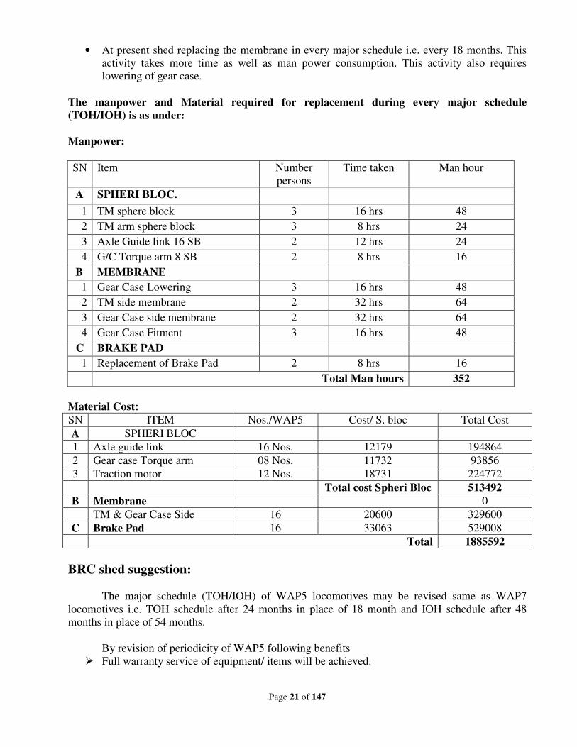
The manpower and Material required for replacement during every major schedule
(TOH/IOH) is as under:
Manpower:
SN Item Number
persons
Time taken Man hour
A SPHERI BLOC.
1 TM sphere block 3 16 hrs 48
2 TM arm sphere block 3 8 hrs 24
3 Axle Guide link 16 SB 2 12 hrs 24
4 G/C Torque arm 8 SB 2 8 hrs 16
B MEMBRANE
1 Gear Case Lowering 3 16 hrs 48
2 TM side membrane 2 32 hrs 64
3 Gear Case side membrane 2 32 hrs 64
4 Gear Case Fitment 3 16 hrs 48
C BRAKE PAD
1 Replacement of Brake Pad 2 8 hrs 16
Total Man hours 352
Material Cost:
SN ITEM Nos./WAP5 Cost/ S. bloc Total Cost
A SPHERI BLOC
1 Axle guide link 16 Nos. 12179 194864
2 Gear case Torque arm 08 Nos. 11732 93856
3 Traction motor 12 Nos. 18731 224772
Total cost Spheri Bloc 513492
B Membrane 0
TM & Gear Case Side 16 20600 329600
C Brake Pad 16 33063 529008
Total 1885592
BRC shed suggestion:
The major schedule (TOH/IOH) of WAP5 locomotives may be revised same as WAP7
locomotives i.e. TOH schedule after 24 months in place of 18 month and IOH schedule after 48
months in place of 54 months.
By revision of periodicity of WAP5 following benefits
Full warranty service of equipment/ items will be achieved.
Page 22 of 147
Saving of material cost of must change items of one whole TOH. As by revision of
periodicity of Major schedule, one TOH will be skipped before IOH.
Existing schedule
of WAP5
DOC TOH1
(18 Months)
TOH2
(36 Months)
IOH
(54 Months)
Proposed schedule
of WAP5
DOC TOH1
(24 Months)
Skipped IOH
(48 Months)
Saving of manpower.
Availability of more locomotives on line for passenger services.
BRC shed has also given the failure details.
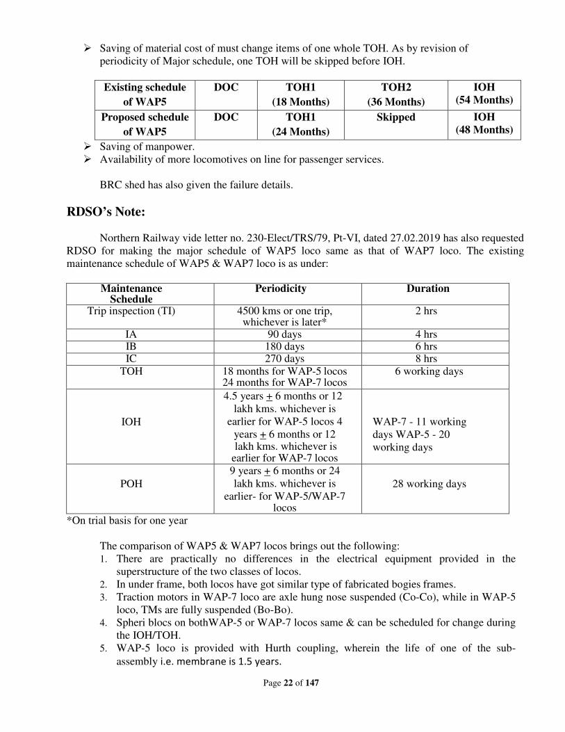
RDSO’s Note:
Northern Railway vide letter no. 230-Elect/TRS/79, Pt-VI, dated 27.02.2019 has also requested
RDSO for making the major schedule of WAP5 loco same as that of WAP7 loco. The existing
maintenance schedule of WAP5 & WAP7 loco is as under:
Maintenance
Schedule Periodicity Duration
Trip inspection (TI) 4500 kms or one trip, whichever is later*
2 hrs
IA 90 days 4 hrs IB 180 days 6 hrs IC 270 days 8 hrs
TOH 18 months for WAP-5 locos 24 months for WAP-7 locos
6 working days
IOH
4.5 years + 6 months or 12
lakh kms. whichever is
earlier for WAP-5 locos 4
years + 6 months or 12 lakh kms. whichever is
earlier for WAP-7 locos
WAP-7 - 11 working
days WAP-5 - 20
working days
POH
9 years + 6 months or 24
lakh kms. whichever is
earlier- for WAP-5/WAP-7 locos
28 working days
*On trial basis for one year
The comparison of WAP5 & WAP7 locos brings out the following:
1. There are practically no differences in the electrical equipment provided in the
superstructure of the two classes of locos.
2. In under frame, both locos have got similar type of fabricated bogies frames.
3. Traction motors in WAP-7 loco are axle hung nose suspended (Co-Co), while in WAP-5
loco, TMs are fully suspended (Bo-Bo).
4. Spheri blocs on bothWAP-5 or WAP-7 locos same & can be scheduled for change during
the IOH/TOH.
5. WAP-5 loco is provided with Hurth coupling, wherein the life of one of the sub-
assembly i.e. membrane is 1.5 years.
Page 23 of 147
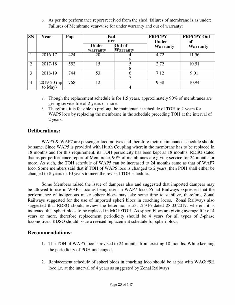
6. As per the performance report received from the shed, failures of membrane is as under:
Failures of Membrane year-wise for under warranty and out of warranty:
SN Year Pop Fail
ure FRPCPY
Under Warranty
FRPCPY Out of Warranty Under
warranty Out of Warranty
1 2016-17 424 20 49
4.72 11.56
2 2017-18 552 15 58
2.72 10.51
3 2018-19 744 53 67
7.12 9.01
4 2019-20 (up to May)
768 12 14
9.38 10.94
7. Though the replacement schedule is for 1.5 years, approximately 90% of membranes are
giving service life of 2 years or more.
8. Therefore, it is feasible to prolong the maintenance schedule of TOH to 2 years for
WAP5 loco by replacing the membrane in the schedule preceding TOH at the interval of
2 years.
Deliberations:
WAP5 & WAP7 are passenger locomotives and therefore their maintenance schedule should
be same. Since WAP5 is provided with Hurth Coupling wherein the membrane has to be replaced in
18 months and for this requirement, its TOH periodicity has been kept as 18 months. RDSO stated
that as per performance report of Membrane, 90% of membranes are giving service for 24 months or
more. As such, the TOH schedule of WAP5 can be increased to 24 months same as that of WAP7
loco. Some members said that if TOH of WAP5 loco is changed to 2 years, then POH shall either be
changed to 8 years or 10 years to meet the revised TOH schedule.
Some Members raised the issue of dampers also and suggested that imported dampers may
be allowed to use in WAP5 loco as being used in WAP7 loco. Zonal Railways expressed that the
performance of indigenous make sphere blocs may take some time to stabilize, therefore, Zonal
Railways suggested for the use of imported spheri blocs in coaching locos. Zonal Railways also
suggested that RDSO should review the letter no. EL/3.1.25/16 dated 28.03.2017, wherein it is
indicated that spheri blocs to be replaced in MOH/TOH. As spheri blocs are giving average life of 4
years or more, therefore replacement periodicity should be 4 years for all types of 3-phase
locomotives. RDSO should issue a revised replacement schedule for spheri blocs.
Recommendations:
1. The TOH of WAP5 loco is revised to 24 months from existing 18 months. While keeping
the periodicity of POH unchanged.
2. Replacement schedule of spheri blocs in coaching loco should be at par with WAG9/9H
loco i.e. at the interval of 4 years as suggested by Zonal Railways.
Page 24 of 147
3. The failures of the spheri blocs /dampers of indigenous sources may take some time to
stabilize since being developed for the first time in India. Therefore, for time being in
coaching locos, only imported spheri blocs/dampers should be used as requested by all
Zonal Railways.
Railway Board’s decision:
• May be accepted.
• RDSO to collect regular feedback from Zonal Railways for technical evaluation and
further action as required.
Page 25 of 147
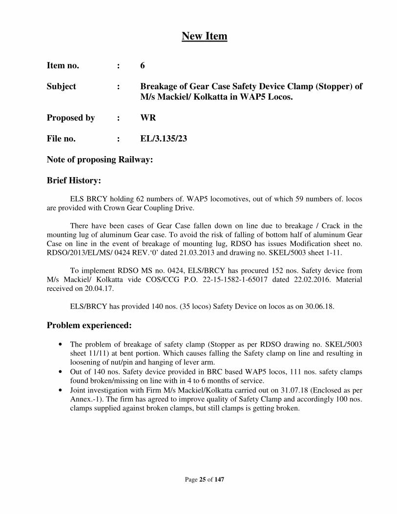
New Item
Item no. : 6
Subject : Breakage of Gear Case Safety Device Clamp (Stopper) of
M/s Mackiel/ Kolkatta in WAP5 Locos.
Proposed by : WR
File no. : EL/3.135/23
Note of proposing Railway:
Brief History:
ELS BRCY holding 62 numbers of. WAP5 locomotives, out of which 59 numbers of. locos
are provided with Crown Gear Coupling Drive.
There have been cases of Gear Case fallen down on line due to breakage / Crack in the
mounting lug of aluminum Gear case. To avoid the risk of falling of bottom half of aluminum Gear
Case on line in the event of breakage of mounting lug, RDSO has issues Modification sheet no.
RDSO/2013/EL/MS/ 0424 REV.‘0’ dated 21.03.2013 and drawing no. SKEL/5003 sheet 1-11.
To implement RDSO MS no. 0424, ELS/BRCY has procured 152 nos. Safety device from
M/s Mackiel/ Kolkatta vide COS/CCG P.O. 22-15-1582-1-65017 dated 22.02.2016. Material
received on 20.04.17.
ELS/BRCY has provided 140 nos. (35 locos) Safety Device on locos as on 30.06.18.
Problem experienced:
• The problem of breakage of safety clamp (Stopper as per RDSO drawing no. SKEL/5003
sheet 11/11) at bent portion. Which causes falling the Safety clamp on line and resulting in
loosening of nut/pin and hanging of lever arm.
• Out of 140 nos. Safety device provided in BRC based WAP5 locos, 111 nos. safety clamps
found broken/missing on line with in 4 to 6 months of service.
• Joint investigation with Firm M/s Mackiel/Kolkatta carried out on 31.07.18 (Enclosed as per
Annex.-1). The firm has agreed to improve quality of Safety Clamp and accordingly 100 nos.
clamps supplied against broken clamps, but still clamps is getting broken.
Page 26 of 147
RDSO to issue necessary guidelines to avoid breakage of Safety Clamp.
Page 27 of 147
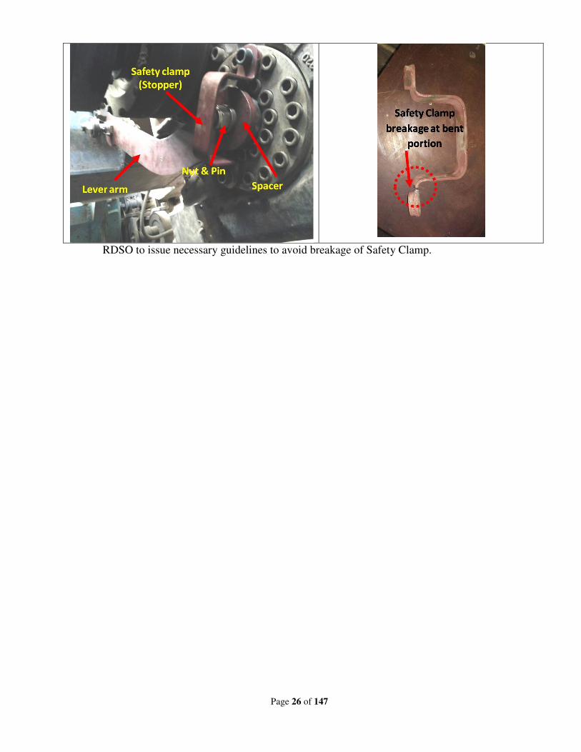
Annexure – 1
RDSO’s Note:
Meeting was held on 20.12.2018 with t
corrective measures to stops cracks in safety devise stopper. Vide letter no. MCPL/RDSO/SEDE
HC/19-20 dated 31.08.2019, M/s Mackeil has informed that they have modified stopper drawing no.
SKEL-5003 Alt.0 (Sheet 11/11). Modifications done by M/s Mackeil, Kolkata have been examined by
RDSO and found in order. Firm has already supplied 10 nos. of stopper as per modified drawing to
ELS/BRCY for the purpose of fitment and trial. The trial is under way. RDSO (Electr
has been revised with proposed modifications as RDSO drawing
(Rev.1). Based on feedback, stopper as per modified drawing may be regularized.
Page 28 of 147
Meeting was held on 20.12.2018 with the firm at RDSO and firm was advised to make
corrective measures to stops cracks in safety devise stopper. Vide letter no. MCPL/RDSO/SEDE
20 dated 31.08.2019, M/s Mackeil has informed that they have modified stopper drawing no.
11/11). Modifications done by M/s Mackeil, Kolkata have been examined by
RDSO and found in order. Firm has already supplied 10 nos. of stopper as per modified drawing to
ELS/BRCY for the purpose of fitment and trial. The trial is under way. RDSO (Electr
has been revised with proposed modifications as RDSO drawing no. SKEL-5003(Alt.0) Sheet 11/11
(Rev.1). Based on feedback, stopper as per modified drawing may be regularized.
Annexure– 2
he firm at RDSO and firm was advised to make
corrective measures to stops cracks in safety devise stopper. Vide letter no. MCPL/RDSO/SEDE-
20 dated 31.08.2019, M/s Mackeil has informed that they have modified stopper drawing no.
11/11). Modifications done by M/s Mackeil, Kolkata have been examined by
RDSO and found in order. Firm has already supplied 10 nos. of stopper as per modified drawing to
ELS/BRCY for the purpose of fitment and trial. The trial is under way. RDSO (Electrical Directorate)
5003(Alt.0) Sheet 11/11
(Rev.1). Based on feedback, stopper as per modified drawing may be regularized.
Page 29 of 147
Deliberations:
Western Railway informed that after modification in safety device (i.e. increasing thickness of
plate to 8 mm and reducing the thickness of washer), no case of breakage of safety device has been
notices in modified version. This modification appears to be useful. NR pointed out for the provision of
a split pin. Moreover, the performance of direct drive provided in 20 WAP5 locos was also discussed
.Zonal Railways were requested to monitor the performance of direct drive in WAP5 locos. CLW has
placed an order for 20 more numbers of direct drives for WAP5. Out of this, order for 08 loco set direct
drives is on M/s IGW. Zonal Railways may give their performance report, so that decision for this type
of drive for regular cut-in can be taken.
All Zonal Railways agreed to adopt modified gear case safety device clamp (stopper) as per
RDSO’s drawing no. SKEL/5003 (Alt. 0), (Rev.1).
Recommendations:
1. ZRs should provide modified Gear Case Safety Device Clamp (Stopper) as per RDSO’s
drawing no. SKEL/5003 (Alt.0), (Rev.1). RDSO may issue suitable technical instruction for
this.
2. Zonal Railways should give performance feedback for direct drive provided in WAP5 locos.
Railway Board’s decision:
May be accepted.
Page 30 of 147
New Item
Item no. : 7
Subject : Zig for centering of spheri bloc with wheel set guide &
torque arm support for 3-phase locomotives & Fixture for
fitment/removal of spheri bloc used in 3-phase Electric
Locomotives
Proposed by : ER & RDSO
File no. : EL/3.1.35/12
Note of proposing Railway:
Problem:
The wheel set guide, which is bolted to the axle box housing and to the bogie frame, provides a
longitudinal guide for the axle box housing. The wheel set guide is fitted with spheri blocs at each end,
which provide positive longitudinal guidance while allowing negligible resistance to lateral movement.
Spheri bloc fitted in the wheel set guide allows the axle lateral movement without undue restrictions.
To minimize undue restriction centering of spheri bloc with wheel set guide is needed which may
reduce axle box running warm cases as well as high metal content in grease of axle boxes.
Torque support of Traction motor is suspended in between motor support and holder for TM
suspension. If spheri bloc is mounted perfectly by centering with torque support, no uneven load will
transmitted to motor support and holder which will provide reliability of motor support and holder and
will reduce the damaging tendency of rubber portions of spheri blocs and will increase self life.
Solution:
To reduce axle box running warm cases, high metal content in grease of axle boxes and for
arresting pre mature failures of spheri blocks, centering of spheri bloc with wheel set guide is required.
In this connection, Electric loco Shed, Howrah developed two Zigs, one for centering of spheri bloc
with wheel set guide and another for centering of spheri bloc with torque arm support of Traction motor
to meet up the requirement.
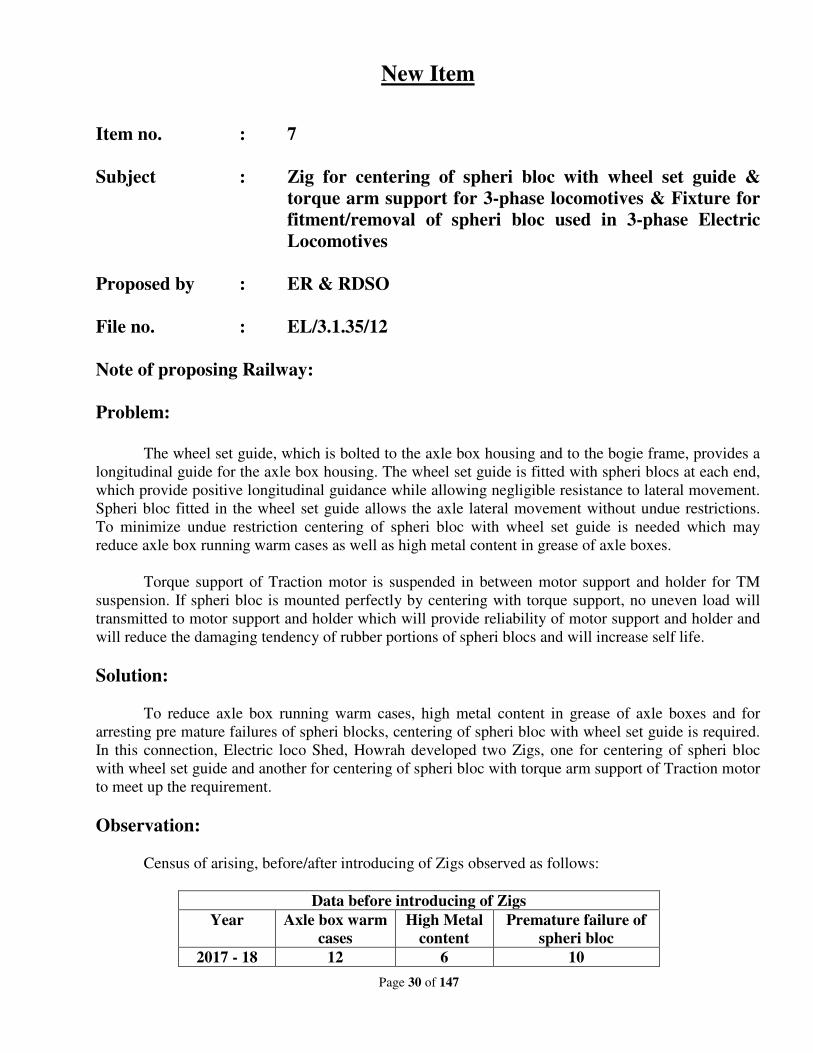
Observation:
Census of arising, before/after introducing of Zigs observed as follows:
Data before introducing of Zigs
Year Axle box warm
cases
High Metal
content
Premature failure of
spheri bloc
2017 - 18 12 6 10
Page 31 of 147
Data after introducing of Zigs till date
Year Loco no. Date Axle box warm
cases
High Metal
content
Premature failure of
spheri bloc
2018 – 19
30372 17.04.18 0 0 0
30323 17.05.18 0 0 0
30457 04.06.18 0 0 0
30458 10.07.18 0 0 0
30369 13.07.18 0 0 0
30468 28.07.18 0 0 0
30370 18.08.18 0 0 0
30455 19.09.18 0 0 0
30371 11.10.18 0 0 0
30469 28.10.18 0 0 0
30487 14.11.18 0 0 0
30322 20.01.19 0 0 0
30295 22.01.19 0 0 0
30506 26.02.19 0 0 0
30478 15.04.19 0 0 0
30205 26.04.19 0 0 0
30504 07.05.19 0 0 0
30529 30.05.19 0 0 0
30508 26.06.19 0 0 0
30328 13.07.19 0 0 0
30503 24.07.19 0 0 0
30490 30.07.19 0 0 0
30524 08.08.19 0 0 0
30525 20.08.19 0 0 0
30454 31.08.19 0 0 0
Description of Zigs:
S N Description Photograph
1 Zig for centering of spheri
bloc is being used (in top or
bottom position) for
inserting spheri bloc in
torque support of Traction
Motor.
Spheri bloc Torque support Zig provided at bottom
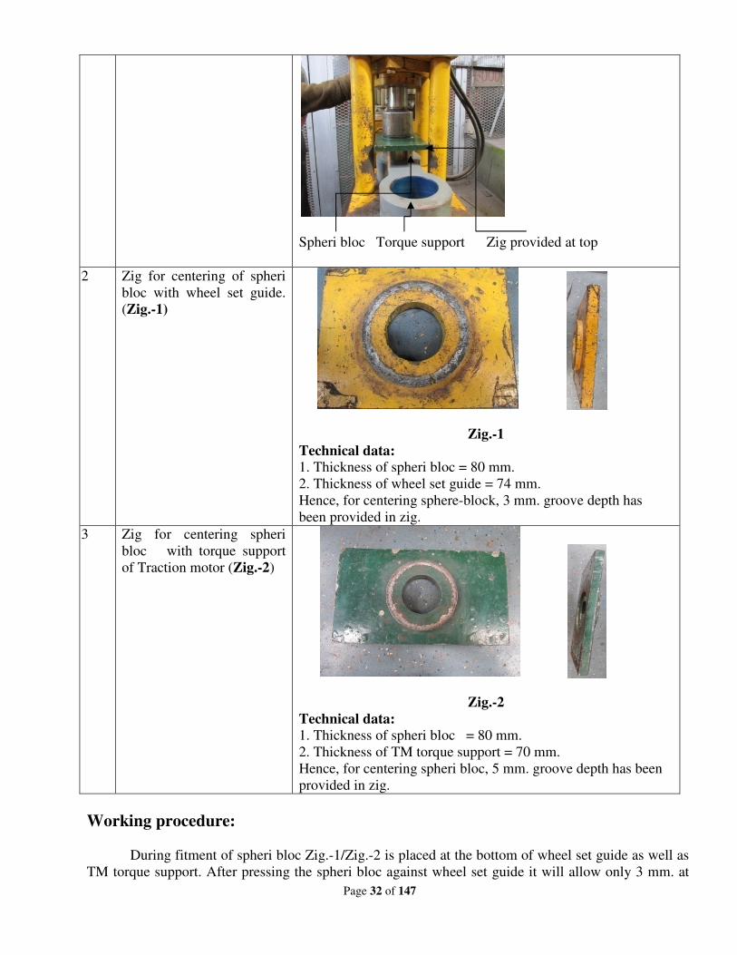
Page 32 of 147
Spheri bloc Torque support Zig provided at top
2 Zig for centering of spheri
bloc with wheel set guide.
(Zig.-1)
Zig.-1
Technical data:
1. Thickness of spheri bloc = 80 mm.
2. Thickness of wheel set guide = 74 mm.
Hence, for centering sphere-block, 3 mm. groove depth has
been provided in zig.
3 Zig for centering spheri
bloc with torque support
of Traction motor (Zig.-2)
Zig.-2
Technical data:
1. Thickness of spheri bloc = 80 mm.
2. Thickness of TM torque support = 70 mm.
Hence, for centering spheri bloc, 5 mm. groove depth has been
provided in zig.
Working procedure:
During fitment of spheri bloc Zig.-1/Zig.-2 is placed at the bottom of wheel set guide as well as
TM torque support. After pressing the spheri bloc against wheel set guide it will allow only 3 mm. at
Page 33 of 147
both side of the same for proper centering and 5 mm. for the TM torque support at both side for proper
centering accordingly.
Materials required:
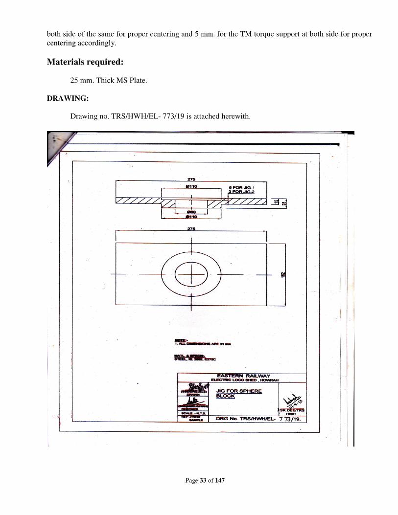
25 mm. Thick MS Plate.
DRAWING:
Drawing no. TRS/HWH/EL- 773/19 is attached herewith.
Page 34 of 147
RDSO’s Note:
Problem:
Generally most of the Zonal Railways are fitted spheri bloc in torque arm, axle guide link,
Traction motor support arm, gear case used in three phase Electric Locomotives manually by press
machine without any zig/fixture due to which there is possibility of poor alignment of spheri bloc to
the component. This may cause failure of spheri bloc.
Zonal Railways had also expressed that the design of Zig/fixture is required to achieve better
alignment of spheri bloc to the components on fitment.
Solution:
During meeting held at RDSO on 21.08.2019 on reliability issues of spheri bloc, it was
pointed out that ELS/TKD has already developed fixture for fitment/removal of spheri blocs. RDSO
has visited ELS/TKD to study the design details of the same. During visit a demonstration of
fitment/removal of spheri bloc on torque arm & axle guide link was observed and working of fixture
has been found satisfactory. This fixture works automatically by a power pack of 70ton.
However this is only for fitment/removal of sphere ibloc for torque arm, axle guide link
used in WAP7/WAG9 electric locomotives.
RDSO is in process to study on feasibility of modification in this fixture for following
purpose also:
i) Fitment/removal of spheri bloc of axle guide link, Traction motor support arm and gear case
fitted in WAP5 locomotive.
ii) Feasibility of providing arrangement to measure axial wear of spheri bloc on same fixture.
Working of Zig/Fixture:
From the study carried out at ELS/TKD following observations were made on
fitment/removal of spheri bloc on fixture.
1. Fixture with power pack (oil circulating pump) of 70t and accessories of fixture are shown in
Fig-1, 2 & 3.
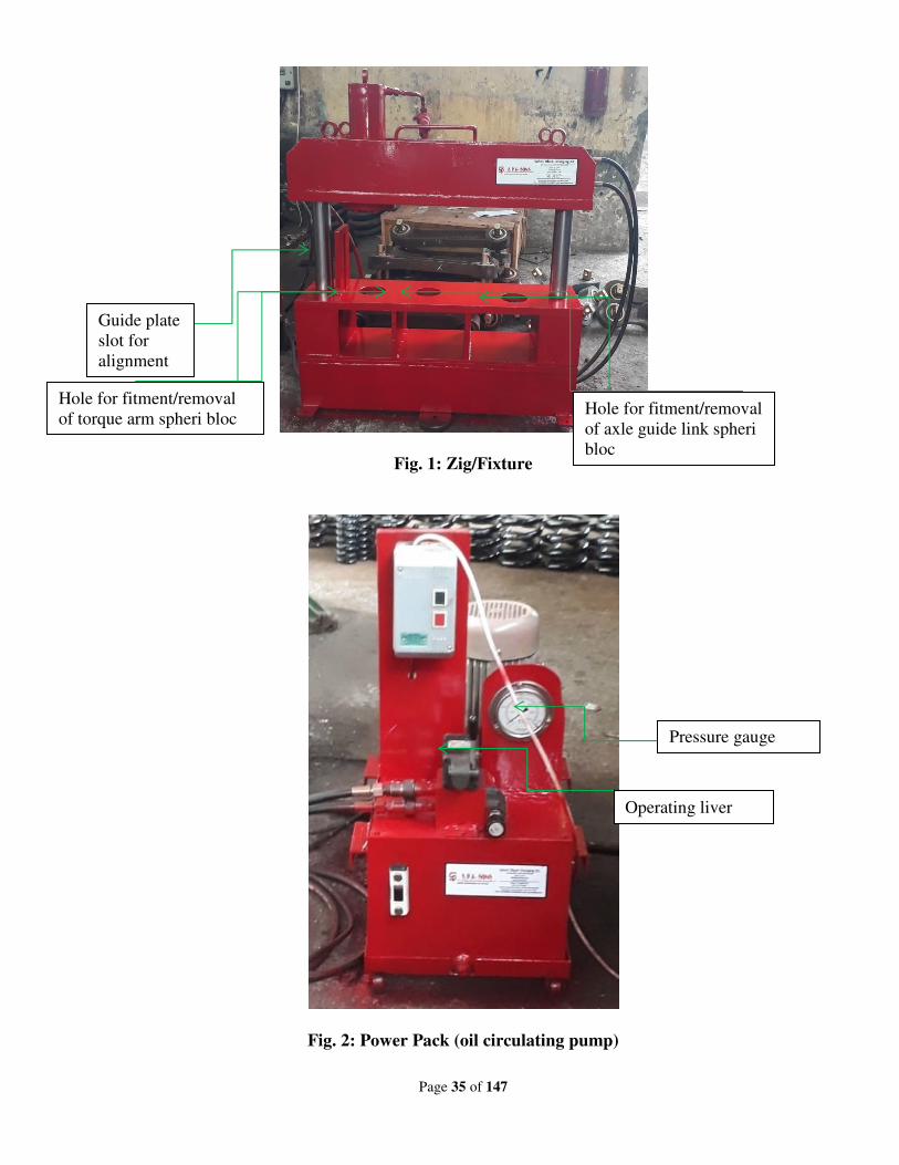
Page 35 of 147
Fig. 1: Zig/Fixture
Fig. 2: Power Pack (oil circulating pump)
Hole for fitment/removal
of torque arm spheri bloc Hole for fitment/removal
of axle guide link spheri
bloc
Guide plate
slot for
alignment
Operating liver
Pressure gauge
Page 36 of 147
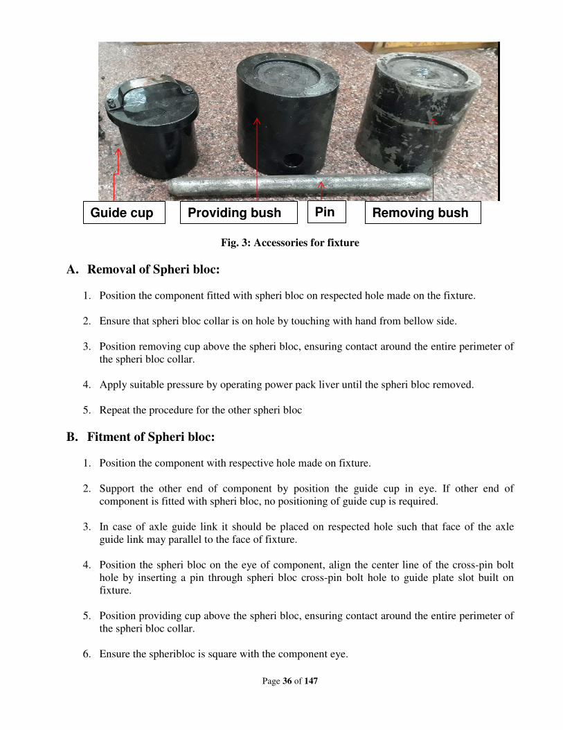
Fig. 3: Accessories for fixture
A. Removal of Spheri bloc:
1. Position the component fitted with spheri bloc on respected hole made on the fixture.
2. Ensure that spheri bloc collar is on hole by touching with hand from bellow side.
3. Position removing cup above the spheri bloc, ensuring contact around the entire perimeter of
the spheri bloc collar.
4. Apply suitable pressure by operating power pack liver until the spheri bloc removed.
5. Repeat the procedure for the other spheri bloc
B. Fitment of Spheri bloc:
1. Position the component with respective hole made on fixture.
2. Support the other end of component by position the guide cup in eye. If other end of
component is fitted with spheri bloc, no positioning of guide cup is required.
3. In case of axle guide link it should be placed on respected hole such that face of the axle
guide link may parallel to the face of fixture.
4. Position the spheri bloc on the eye of component, align the center line of the cross-pin bolt
hole by inserting a pin through spheri bloc cross-pin bolt hole to guide plate slot built on
fixture.
5. Position providing cup above the spheri bloc, ensuring contact around the entire perimeter of
the spheri bloc collar.
6. Ensure the spheribloc is square with the component eye.
Guide cup Pin Providing bush Removing bush
Page 37 of 147
7. Insert pin through hole made in providing cup to guide plate
8. Apply suitable pressure on providing cup by operating power pack lever to press the spheri
bloc into the eye.
9. Repeat the procedure for the other spheri bloc.
C. Precautions:
During fitment/removal process on fixture following precaution should be ensured
1. Remove any burrs or scratches from the spheri bloc collar and the eyes as necessary.
2. Apply a thin film of machine oil, or other suitable lubricant, to the spheri bloc collar.
3. If there is no movement in spheri bloc after applying initial pressure, please check position of
spheri bloc on hole.
Deliberations:
Jig (top & bottom) for centering of spheri blocs with wheel set guide & torque arm support
proposed by ER and Fixture for spheri blocs for fitment/removal were discussed. RDSO shall
develop design drawings for fitment/removal of spheri blocs for TM torque arm, axle guide link used
in WAP7/WAG9 power pack of 70 tonne (it should work automatically) after examining/studying
the Jig/Fixture setup available with ELS/TKD.
RDSO shall also develop separate design drawings for fitment/removal of spheri blocs for
axle guide link, traction motor support arm & gear case fitted arm in WAP5 with using common
power pack of 70 tonne.
Recommendations:
RDSO will finalize the design and drawing of jig/ fixture for removal/fitment of spheri blocs
for WAP7/WAG9/WAP5 & issue guidelines to Zonal Railways for implementation in Electric
Locomotive Sheds/shops/PUs.
Railway Board’s decision:
May be accepted. RDSO to issue guidelines within two months from issue of MOM.
Page 38 of 147
New Item
Item no. : 8
Subject : Reliability issues of VCB including:
(i) Set up for easy checking up of VCB opening/closing
time at in-situ condition in 3-phase locomotive
without utilization of additional manpower &
wastage of time.
(ii) Problem of water ingress in M/s Schneider make
VCB.
(iii) Provision of M/s Indfoss make QPDJ instead of
FESTO make QPDJ in AAL VCB’s.
Proposed by : ER, WR & SR
File no. : EL/3.2.61
Note of proposing Railways:
(i) Notes of Eastern Railway:
Problem:
In 3-phase locomotives, frequent message of ‘VCB stuck in ON/OFF position’ appears in DDS.
This message also leads trouble of ‘Main power OFF’. The message generates either due to slow
opening/closing time of VCB or due to other reasons. Whenever, this message generates, checking up
of closing/opening time of VCB with operation analyzer is required. In this situation VCB is to be
stripped out from locomotive for analysis which is involved with additional manpower and excess time
of about 16 man-hours along with crane operation.
Solution:
To get rid of this trouble, Electric loco Shed, Howrah developed a set up through timer by
which opening/closing time of VCB can be checked easily in-situ position (without removing VCB
from locomotive). The total operation may be completed in fifteen minutes only without involvement
of any additional manpower.
Page 39 of 147
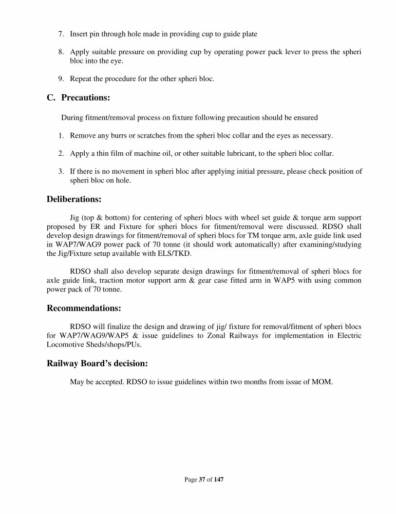
Details of set up:
Working procedure:
To achieve opening/closing time of VCB, 110 VDC supply is to be taken from loco battery and
coupler to be connected with VCB male G-mota connector. After connecting, by operating pick
up/drop out switch, corresponding closing/opening time of VCB is displayed on timer display screen.
The Rest button starts every operation initially counting from zero.
Materials required:
1 no. Timer unit.
Schematic block diagram of VCB opening/closing set up
Block Diagram of VCB closing opening timer circuit
Page 40 of 147
(ii) Notes of Western Railway:
Problem:
The failure rate of M/s Schenider make VCB is very high, total 27 nos. till 30.06.018. The
failure occurs due to ingress of water, which is a type defect of M/s Schenider make VCB. Due to water
ingress, heavy rusting is found on shunt assembly, piston assembly, actuator rod, Aux. Switch
operating rod and relay valve assembly. Therefore, these parts required to be replaced in these VCBs.
04 nos. failed VCBs are kept in shed waiting for attention from firm.
Joint inspection has been done many times regarding this problem but M/s Schneider could not
rectify the problem. 02 nos. of VCB failed within 18 months after attending by firm for the same
reason. Although, BRC shed has completed RDSO SMI no. RDSO/2014/EL/SMI/0281 (Rev-‘0’) dated
27.06.14 regarding use of loctite 518 in place of RTV1080 to seal upper and lower insulator & RDSO
SMI no. RDSO/2015/EL/SMI/0285 (Rev-‘0’) dated 23.09.15 regarding use of RTV 1080 sealant in M/s
Schneider make 22 CB VCB in conventional & 3-phase, problem hasn’t been resolved.
During the joint inspection with firm on dated 05.01.18, following observations were noticed.
• 03 nos. VCB checked and variation in Groove Depth & Flange Step noticed. Old VCB (before
2014) Groove Depth and Flange Step higher side compare to new one (after 2014).
• As per measurement it is concluded that the compression in ‘O’ Ring in the range of 01 mm is
quite low enough to permit moisture ingress inside the VCB.
Page 41 of 147
• BRC shed suggested the firm that depth of the Groove of lower flange will be reduced from 05
mm to 04 mm for increasing the compression between upper and lower flange of VCB.
• BRC shed has suggested to firm that if size of O ring between upper and bottom flange will be
increased then compression will be increased between upper and lower flange which will
decrease the failure of VCB due to water ingress.
Action Plan:
On the basis of ELS BRCY suggestion, firm was agreed to increase the compression & reduce
the size of groove from 05 mm to 04 mm and on dated 05.07.18. Firm has also stated that 03 sample
made with modified groove dimension were tested with water spray and result found satisfactory.
Modified VCBs will supply to ELS BRCY for performance review. (Joint note enclosed at Annex.-C)
The ELS BRCY has given the details of the failure of Schneider/ AREVA make VCB.
(iii) Notes of Southern Railway:
Problem: M/s AAL make VCBs are provided with M/s FESTO make QPDJ with a cut in pressure of
3.6 kg/cm2 and cut out pressure of 3.3kg/cm
2. FESTO QPDJs are prone to pressure setting variations
and malfunctioning. (Failure details are enclosed.) Also only AAL is using this kind of QPDJ. M/s
BTIL and M/s Schneider are using Indfoss QPDJ. Cost of 01no FESTO make QPDJ is around
Rs.25,000/-compared to Indfoss make QPDJ cost of Rs.3000/-
In this context it is economical and reliable to replace FESTO make QPDJ with Indfoss make
QPDJ in AAL VCBs. ELS/ED had already modified 1 no. M/s AAL VCB SL. no. VCBA 1410092 on
03.03.18 and has been provided in locomotive no. 28026 locomotive in 27.03.18 and is found to be
working satisfactorily, since then.
Suggestion:
M/s AAL may be advised to provide Indfoss QPDJ in AAL make VCBs. It will be economical
due to less cost, reliable due to trouble free operation of Indfoss QPDJ and also railways will have
better chance of interchangeability with other makes of VCBs.
Page 42 of 147
RDSO’s Note:
(i) On ER Proposal:
• At present, the closing & opening time of VCB is measured through CRO wherein the probe is
connected at shafting head and gives the actual opening & closing time of VCB.
• Through proposed scheme, the closing & opening time will include the time for activation of EP
valve also and will not be possible to measure the actual opening & closing time of VCB. With
measured opening/closing time with proposed arrangement, it will be difficult to locate the
problem area i.e. whether the problem is inside VST (spring) or in outside (EP valve) VST.
(ii) On WR Proposal:
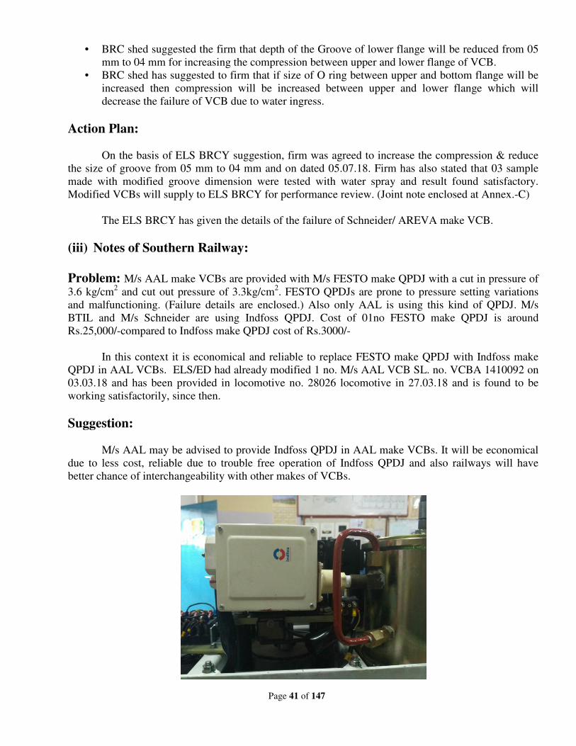
Problem: Water ingress in M/s Schenider make VCB:
• The ingress of water in VCB is due to leakage from joints and presence of moisture in
inlet air causing rusting .
• Water ingress & in-turn rusting was reported by railways earlier also. Based on
suggestion from firm and railways, SMI No 285 for re-application of RTV sealant type
1080 was issued. Zonal Railways have reported that with application of RTV water
ingress and rusting continues.
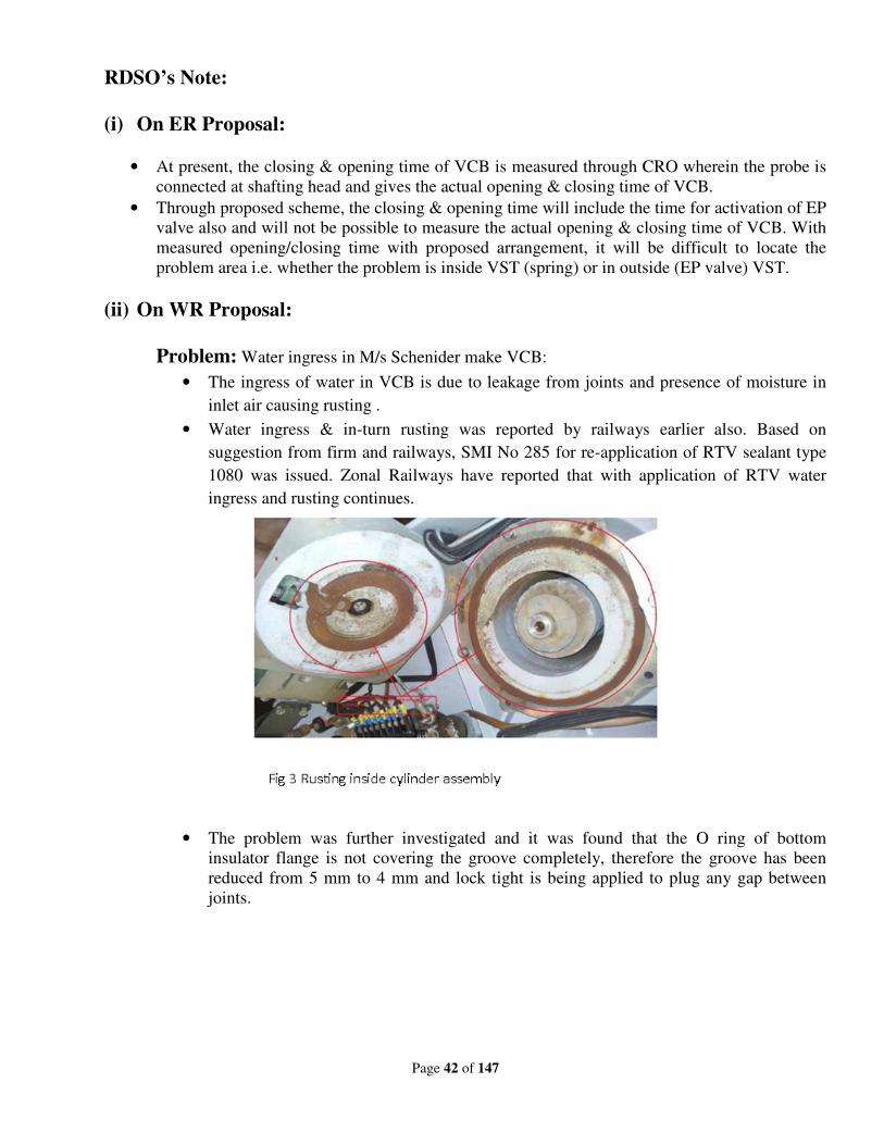
• The problem was further investigated and it was found that the O ring of bottom
insulator flange is not covering the groove completely, therefore the groove has been
reduced from 5 mm to 4 mm and lock tight is being applied to plug any gap between
joints.
Page 43 of 147
• With this modification, the firm has conducted water jet test and water ingress was not
observed. Further to prevent rusting material of some parts have been changed to
stainless steel and rest have been power coated. This modification already has been cut
in.
• However since the exhaust of EP valve opens in the VCB chamber, if the inlet air is not
dry, moisture in air can get deposited and result in rusting. The firm was told to find a
solution to this.
• Locomotive shed should maintain air-dryer of the locomotive in good condition to
supply moisture free air to VCB. For this special maintenance instruction (SMI) No 305
have been issued.
• Kanpur shed has made 9 holes of 8 mm diameter in the bottom cover plate of the VCB
just below the exhaust port to give a vent to moisture. This has given good dividend and
they have not observed rusting so far.
• Based on positive feedback, Zonal Railways and the Firm are being advised to
implement the provision of suitable holes on the bottom plate of VCB.
(iii) On SR Proposal:
After conducting consistency prototype testing M/s AAL make VCB with Indfos make pressure
switch during Nov’16, clearance was accorded to M/s AAL for manufacturing & supply of VCB with
Indfoss make pressure switch. At present, M/s AAL is supplying VCB with Indfoss make pressure
switches.
Page 44 of 147
Deliberations:
(i) ECR explained the arrangement for measuring the closing & opening time of VCB in-situ
position. The opening & closing time includes the opening & closing time of magnet
valves also. One of the Railways said that the problem of opening /closing time only
appears in M/s Schneider make VCBs & that has started after changing of pressure
setting from 6 kg to 6.5 kg.
(ii) RDSO had done the quality audit for VCB & report has been sent to all Zonal Railways.
The report is also available on RDSO website. The report includes the action plan to be
followed by Railways to improve the reliability of VCBs of all make. If after
implementation of various action plan, the performance of M/s Schneider make VCB is
not improving then only option is to downgrade the firm. RDSO has already
implemented all the suggestions as proposed by WR & VCBs are cut-in accordingly &
firm is supplying the new VCBs with all improvements as suggested.CLW shall insist the
firm to carry out modification.
(iii) SCR has done some modifications in VCBs i.e. shifting of QPDJ after buffer/timing
chamber, paralleling of self & feedback interlock, magnet valve with Rotex make &
provision of quick RTV etc & these modifications have given good results. Members
suggested that air-dryer shall be re-introduced & CLW shall start providing it. Even after
deleting this from specification, firm is supplying it.CLW will again make the provision
of air-dryer in the VCB specification & its fitment shall be ensured by CLW.
(iv) SER stated that they have revised their description to delete the Festo make pressure
switch from their procurement. However, ECR informed that they do not have any
problem with Festo make pressure switches.]
(v) VCB suppliers are already providing air-dryer along with VCB as a part of kit .In
conventional loco, it was being provided. However, it is not being provided in 3-phase
locos. Since , there are problems of moisture in VCB , Zonal Railways pointed out to
provide air dryer in 3-phase locos also as being done in VCBs of conventional electric
locos.
Recommendations:
1. SCR will send the details of modifications to RDSO/CLW and all these modifications
will be implemented in few other sheds and based on the performance feedback, same
will be implemented on regular basis or otherwise.
2. Action plan has already been issued for various make of VCBs vide Quality Audit report
no. RDSO/2016/EL/TAR/009 Rev. ‘0’ issued in July’2016. Same shall be perused &
there are certain work to be carried out by shed & certain work by firm.
3. CLW is advised to provide air dryer as firm is providing along with supply and NR has
very good experience with air dryer as failures due to moisture & others are not reported.
Page 45 of 147
For this purpose, conventional loco VCB specification to be adopted where there is
provision of air-dryer for VCB of 3-phase locomotives.
4. FESTO make pressure switch shall be deleted from AOH kit.
Railway Board’s decision:
• May be accepted. RDSO to examine why recommendations of audit reports are not
implemented so far by firms & Zonal Railways under advice to this office.
• RDSO to ensure implementation of recommendations of audit report at the earliest.
Page 46 of 147
New Item
Item no. : 9
Subject : Provision of DPWCS in WAG-9 locomotives having CDAC
(ABB, CGL) and TCN (BHEL & MEDHA) based control
systems.
Proposed by : SER
File no. : EL/3.1.3/DPWCS
Note of proposing Railway:
South Eastern Railway is running 29 pairs of WAG-9 locomotives with DPWCS arrangement
(M/s ARC - 24 pairs & M/s LWT - 5 pairs) over various graded sections of South Eastern Railway.
Further proliferation of DPWCS has stopped as other WAG-9 locomotives are provided with either
CDAC or TCN based control systems. CLW & RDSO should develop scheme for provision of
DPWCS in these locomotives also.
RDSO’s Note:
• Meetings held with OEMs of propulsion system at CLW for development of standard
software for all types of control system (CDAC, BT & Medha).
• The details of standard Interface signals & application logic in-form of Interface Control
Document (ICD) has been furnished to OEMs of Propulsion system by CLW. The OEMs of
Propulsion systems are in process of modifying their software accordingly so that DPWCS of
any make can be integrated with either make of VCU.
• According to decision taken during last ESC, RDSO has issued the specification for
Interoperable DPWCS meant for 3-phase & conventional electric locomotives. Production
Units can place developmental orders on existing firms as per this specification, so that
prototype testing of DPWCS with different type of propulsion system can be done.
Deliberations:
SER said that there is no problem in providing DPWCS in MICAS based 3-phase
locomotive. But, in new locomotives having TCN or CDAC based VCU, DPWCS cannot be fitted.
RDSO after detailed deliberations with OEMs for a year has issued the specification for
interoperable DPWCS and as per this specification, M/s ARC & M/s Lotus has developed their
DPWCS and their testing has been done by RDSO. As per this specification, different make of
DPWCS can communicate with each other in same train formation. The interfacing of DPWCS with
different make of VCUs is not in the scope of specification. To achieve interoperability, indigenous
make Radio from M/s Bharat Electronics Limited (BEL) has been developed. SER said that both the
issues i.e. interoperability among different make of DPWCS and working with different make of
VCUs is yet to be resolved.
Page 47 of 147
The issue involves interoperability at two levels i.e. (i) Interoperability among various make
of VCUs with different make of DPWCS & (ii) Interoperability among various make of DPWCS
which will be achieved if radio equipment & communication protocol is identical for DPWCS.
Therefore, interoperability has to be dealt at two levels.
Till interfacing of DPWCS with different make of VCU is done, CLW shall not provide
DPWCS in new locomotives.CLW said that they have provided the standard Interface Control
Document (ICD) to OEMs of VCU for changing their software accordingly & expected to be
completed by end of Dec’2019.The modified VCU software shall be proved in existing loco fitted
with DPWCS preferably in SER before accepting any supply with new orders. CLW shall convene a
meeting with OEMs of VCUs and ask them to change their VCU software as per ICD.
Recommendations:
1. CLW should proliferate TCN based VCU having compatibility of DPWCS.
2. To achieve interoperability among different make of DPWCS, BEL make OR similar radio
shall be used.
Railway Board’s decision:
May be accepted. The supply of present tender shall only be accepted after clearance of
prototype duly resolving both the issues. RDSO may associate in prototype clearance.
Page 48 of 147
New Item
Item no. : 10
Subject : (i) Modification of bypassing arrangement in After Cooler
circuit.
(ii) Modification in the design of after cooler drain system.
(iii) Issues related with Unloader valve.
Proposed by : WCR, CR & SR
File no. : EL/3.2.19 (G) & EL/3.2.19/3-phase
Note of proposing Railway:
10(i):
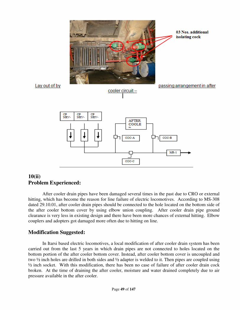
Problem Experienced:
It is seen that there is no arrangement of bypassing the after cooler during failure of after
cooler due to CRO or leakage. This is causing failure of loco on line.
Suggestion:
• To avoid the loco failure on line due to failure of after cooler, an arrangement has been made to
bypass the after cooler by providing 03 nos. of additional isolating cock in the loco no. 27119
during TOH on date 08/02/16.
• By this modification, line failure of locos can be avoided after CRO or leakage from after
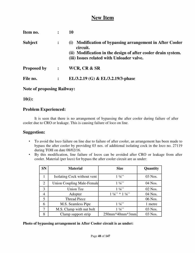
cooler. Material (per loco) for bypass the after cooler circuit are as under:
SN Material Size Quantity
1 Isolating Cock without vent 1 ¼’’ 03 Nos.
2 Union Coupling Male-Female 1 ¼’’ 04 Nos.
3 Union Tee 1 ¼’’ 02 Nos.
4 Adopter 1 ¼’’ * 1 ¼’’ 04 Nos.
5 Thread Piece 06 Nos.
6 M.S. Seamless Pipe 1 ¼’’ 1 metre
7 M.S. Clamp with nut bolt 1 ¼’’ 03 Nos.
8 Clamp support strip 250mm*40mm*3mm 03 Nos.
Photo of bypassing arrangement in After Cooler circuit is as under:
Page 49 of 147
10(ii)
Problem Experienced:
After cooler drain pipes have been damaged several times in the past due to CRO or external
hitting, which has become the reason for line failure of electric locomotives. According to MS-308
dated 29.10.01, after cooler drain pipes should be connected to the hole located on the bottom side of
the after cooler bottom cover by using elbow union coupling. After cooler drain pipe ground
clearance is very less in existing design and there have been more chances of external hitting. Elbow
couplers and adopters got damaged more often due to hitting on line.
Modification Suggested:
In Itarsi based electric locomotives, a local modification of after cooler drain system has been
carried out from the last 5 years in which drain pipes are not connected to holes located on the
bottom portion of the after cooler bottom cover. Instead, after cooler bottom cover is uncoupled and
two ½ inch holes are drilled in both sides and ½ adapter is welded to it. Then pipes are coupled using
½ inch socket. With this modification, there has been no case of failure of after cooler drain cock
broken. At the time of draining the after cooler, moisture and water drained completely due to air
pressure available in the after cooler.
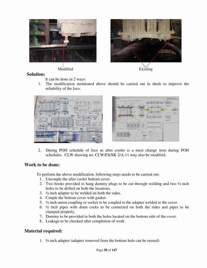
Page 50 of 147
Modified Existing
Solution: It can be done in 2 ways:
1. The modification mentioned above should be carried out in sheds to improve the
reliability of the loco.
2. During POH schedule of loco as after cooler is a must change item during POH
schedules. CLW drawing no. CLW/ES/SK-2/A-11 may also be modified.
Work to be done:
To perform the above modification, following steps needs to be carried out:
1. Uncouple the after cooler bottom cover.
2. Two hooks provided to hang dummy plugs to be cut through welding and two ½ inch
holes to be drilled on both the locations.
3. ½ inch adapter to be welded on both the sides.
4. Couple the bottom cover with gasket.
5. ½ inch union coupling or socket to be coupled to the adapter welded to the cover.
6. ½ inch pipes with drain cocks to be connected on both the sides and pipes to be
clamped properly.
7. Dummy to be provided in both the holes located on the bottom side of the cover.
8. Leakage to be checked after completion of work.
Material required:
1. ½ inch adapter (adapter removed from the bottom hole can be reused)
Page 51 of 147
2. ½ inch pipeline one meter approx(removed pipe can be reused)
3. ½ inch socket or ½ inch union coupling 2nos (new)
4. ½ inch dummy 2 nos. (new)
5. ½ inch drain cocks 2 nos. (new)
Material Render Surplus:
1. ½ inch adapter -2 nos. (reuse)
2. ½ inch elbow-2 nos. (spare)
3. ½ inch pipe- 2 meter approx.
4. ½ inch drain cocks- 2 nos. (reuse)
Applications:
All Conventional Electric locomotives.
Special Note:
After the alteration mentioned above, modified after coolers will be provided to all the shed
and shops of Indian Railways which will reduce the cases of line failures caused due to damage of
after cooler drain pipes. Hence it will ultimately contribute to improve the reliability of electric
locomotives.
10(iii):
Problem:
As per RDSO Modification no.0412, the unloader valve isolating cocks are being provided by
CLW during manufacturing. It is find very difficult to isolate the cock in case of any failure in mid-
section especially CP-1 unloader valve isolating cock which is not accessible.
Solution:
The same is to be relocated in a convenient location for easy maintenance.
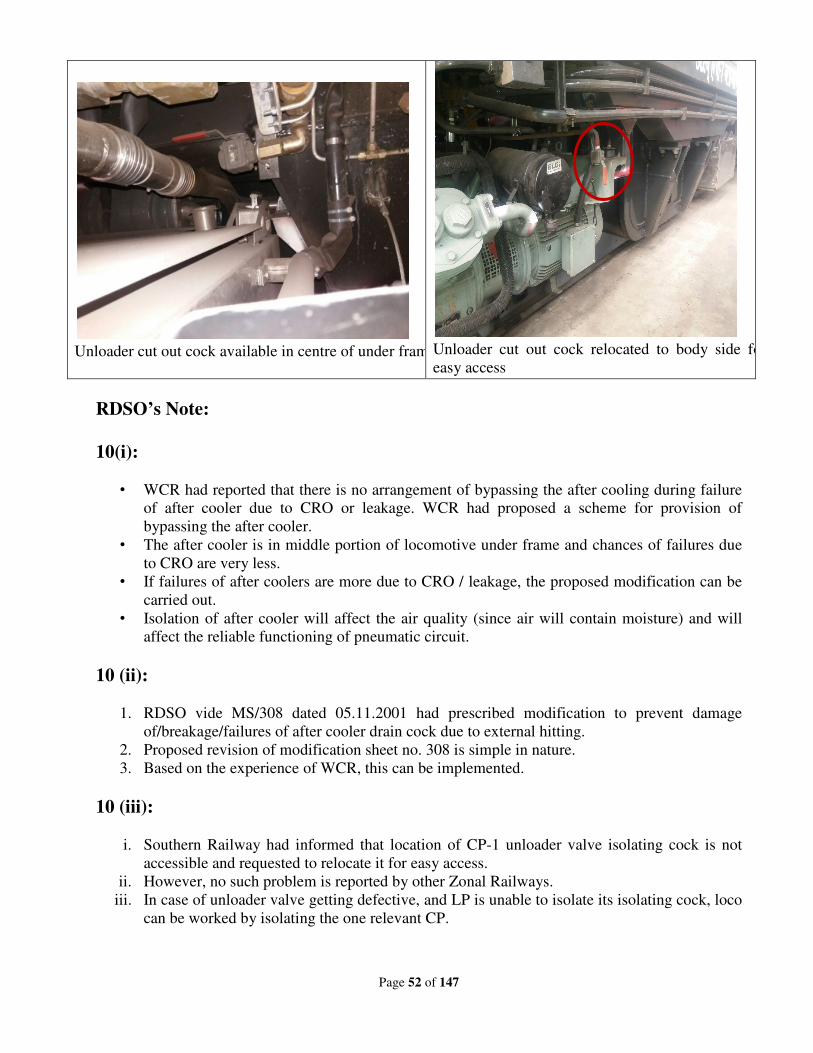
Page 52 of 147
Unloader cut out cock available in centre of under frame
Unloader cut out cock relocated to body side for
easy access
RDSO’s Note:
10(i):
• WCR had reported that there is no arrangement of bypassing the after cooling during failure
of after cooler due to CRO or leakage. WCR had proposed a scheme for provision of
bypassing the after cooler.
• The after cooler is in middle portion of locomotive under frame and chances of failures due
to CRO are very less.
• If failures of after coolers are more due to CRO / leakage, the proposed modification can be
carried out.
• Isolation of after cooler will affect the air quality (since air will contain moisture) and will
affect the reliable functioning of pneumatic circuit.
10 (ii):
1. RDSO vide MS/308 dated 05.11.2001 had prescribed modification to prevent damage
of/breakage/failures of after cooler drain cock due to external hitting.
2. Proposed revision of modification sheet no. 308 is simple in nature.
3. Based on the experience of WCR, this can be implemented.
10 (iii):
i. Southern Railway had informed that location of CP-1 unloader valve isolating cock is not
accessible and requested to relocate it for easy access.
ii. However, no such problem is reported by other Zonal Railways.
iii. In case of unloader valve getting defective, and LP is unable to isolate its isolating cock, loco
can be worked by isolating the one relevant CP.
Page 53 of 147
iv. Zonal Railway may implement this modification on trial basis in few locomotives and
provide feedback to RDSO. If feedback found satisfactory, the Modification sheet no.
RDSO/2012/MS/EL/ 0412, Rev ‘0’ dated 22.08.12 may be reviewed.
Deliberations:
1. The matter was discussed in detail. Zonal Railways expressed that there is no need to change
in after cooler circuit.
2. RDSO vide MS/308 dated 05.11.2001 had prescribed modification to prevent damage
of/breakage/failures of after cooler drain cock due to external hitting. WCR proposed
revision of modification sheet no. 308 to improve it further. However, most of the railways
reported that they have implemented MS/308 in all locos and the arrangement is working
well. Problem of external hitting of the drain cock is very rare and as such no further
modification is required.SER stated that MS 308 is sufficient. Protection guard is included in
MS.
3. Southern Railway informed that location of CP-1 unloader valve isolating cock is not
accessible and requested to relocate it for easy access. During the discussion this problem
was also reported by other Zonal Railways also and they were of the opinion that this
proposal of SR may be accepted.
Recommendations:
1. The proposal of bypassing the after cooler is not acceptable.
2. The proposal of revision in MS-308 is also not desirable.
3. Zonal Railways may implement modification of shifting the existing isolating cock for
unloader valve for CP-1.RDSO will issue the addendum to Modification sheet no.
RDSO/2012/MS/EL/ 0412, Rev ‘0’ dated 22.08.12.
Railway Board’s decision:
May be accepted.
Page 54 of 147
New Item
Item no. : 11
Subject : (i) Modification for replacement of existing 47µf/640 V
capacitors with 22 µf/640 V capacitor in MRB circuit
& 22 µF/640 V capacitors with 10 µF/600 V
capacitors in MRS circuit of 3-phase locomotives.
(ii) Dual supply arrangement of MRB.
Proposed by : ECR & CR
File no. :
Note of proposing Railways:
(i) Notes of East Central Railway:
ELS/GMO has noticed six nos. of failures of MRBs (CGL-01 & Ranjan-05) & 17 nos. of
failures of MR Scavenge Blowers (CGL-11 & Ranjan-06) during the period-2018-19 & 2019-20 (Up
to Aug’19) of M/s CGL & Ranjan makes. These failures have taken place mainly due to high
terminal voltage in the stator windings. To overcome this problem, ELS/GMO has carried out a
modification with the replacement of existing 47µF/640 V capacitors with 22µF/640 V capacitors in
MRB start circuit & 22µF/640 V capacitors with 10µF/600 V capacitors in MRS circuit. After
replacement of these capacitors, the terminal voltage of MRBs & MRSs get reduced from 560 volt to
470 volt at the time of starting without significantly reducing the flow of air delivery. Also, if the
contactor with timer (54.2/1) fails to open after 10 seconds, it will not damage the winding due to
high voltage during run. The subject modification has been implemented in 13 Locos in MRB circuit
& 42 locos in MRS circuit & no failure of any MRB or MRS on account of its burning has been
noticed by the Shed so far. The photographs of burnt MRB & MRS of M/s CGL/Ranjan make &
schematic circuit diagram of existing & modified circuit is given below:
Photographs of burnt MRB/MRS of WAG-9 Locomotive:
Page 55 of 147
(ii) Notes of Central Railway:
At present MRBs in 3-phase locomotive work on split phase supply arrangement. This supply
is not balanced. The MRB voltages & currents measured in locomotive 32117 on 16.05.2018 are as
below:
MRB
Supply voltage (V) 409 V 394 V 417 V
Current (A) 5.7 Amp 4.7 Amp 2.5 Amp
Due to unbalanced supply there is overheating of windings of two phases of MRB. For last
03 years nos. of MRBs taken out from service due to overheating are as below:
Year 2015-16 2016-17 2017-18
No. of MRB taken out from service 09 01 09
The split phase supply arrangement for MRBs is to ensure MRB working during cooling
mode. Initially ELS/AQ has modified supply arrangements for MRB-2 from split phase to Auxiliary
converter no. 2. This arrangement is in service in 13 locomotives having CGL make Auxiliary
converter for more than 02 years. This arrangement is working satisfactorily & no failure of MRB-2
is reported in modified arrangement. However in this arrangement MRB-2 is not working in cooling
mode.
ELS/AQ has again modified MRB supply arrangements so that during cooling mode MRB
works on split supply arrangement and during driving mode MRB works on Auxiliary Converter-2
supply.
This dual supply arrangement is implemented in locomotive no. 32117 (MRB-2) from
12.05.2018 & is working satisfactorily till date. The proposed supply arrangement for MRB will
reduce MRB failures due to balanced supply during driving mode.
RDSO’s Note:
(i) On ECR Proposal:
• As per CLW specification No. CLW/ES/3/0020 (for MRB) & CLW/ES/3/0022(for MRS),
the specified rating of capacitors is as under:
For MRB: starting 69µF/900V AC, running 22µF/900V AC
For MSR: Starting & running both -22µF/900V AC
• The rating of capacitor has been considered in line with characteristics supply available from
Auxiliary Converter through transformer & besides influence on voltage wave form due to
interferences by converter.
• Based on the detailed performance report from ECR decision on the changed value of
capacitance may be taken.
(ii) On CR proposal:
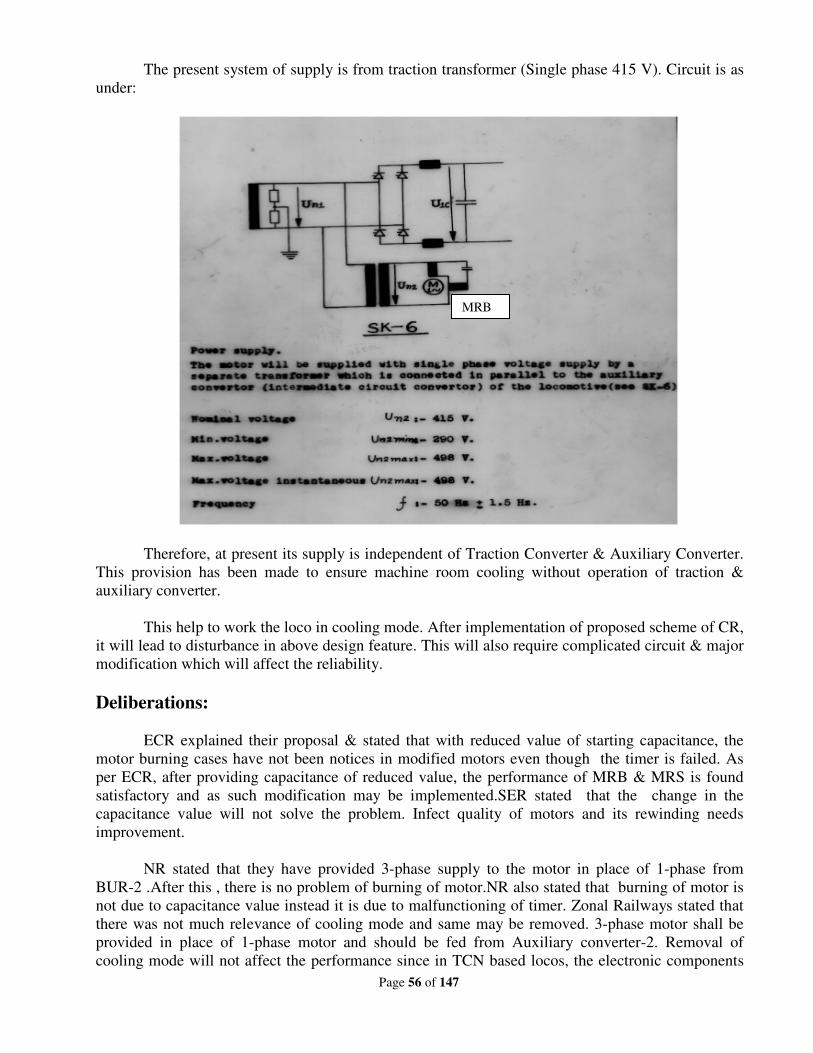
Page 56 of 147
The present system of supply is from traction transformer (Single phase 415 V). Circuit is as
under:
Therefore, at present its supply is independent of Traction Converter & Auxiliary Converter.
This provision has been made to ensure machine room cooling without operation of traction &
auxiliary converter.
This help to work the loco in cooling mode. After implementation of proposed scheme of CR,
it will lead to disturbance in above design feature. This will also require complicated circuit & major
modification which will affect the reliability.
Deliberations:
ECR explained their proposal & stated that with reduced value of starting capacitance, the
motor burning cases have not been notices in modified motors even though the timer is failed. As
per ECR, after providing capacitance of reduced value, the performance of MRB & MRS is found
satisfactory and as such modification may be implemented.SER stated that the change in the
capacitance value will not solve the problem. Infect quality of motors and its rewinding needs
improvement.
NR stated that they have provided 3-phase supply to the motor in place of 1-phase from
BUR-2 .After this , there is no problem of burning of motor.NR also stated that burning of motor is
not due to capacitance value instead it is due to malfunctioning of timer. Zonal Railways stated that
there was not much relevance of cooling mode and same may be removed. 3-phase motor shall be
provided in place of 1-phase motor and should be fed from Auxiliary converter-2. Removal of
cooling mode will not affect the performance since in TCN based locos, the electronic components
MRB
Page 57 of 147
are less and temperature rise is also less due to IGBT. The instruction should be issued for removal
of cooling mode. Zonal Railways stated that scavenger motors should be wound with corona wire
which will improve its performance and CLW will make necessary provisions in the specification for
this purpose. Change in capacitance value & modification in control circuit is not required.
Recommendations:
(i) The cooling mode shall be eliminated.
(ii) 3-phase motors rewound with corona wire shall be used for MRB & MRS and it will
be fed from BUR-2.
(iii) This will be implemented in new as well in existing locomotives.
Railway Board’s decision:
May be accepted.
Page 58 of 147
New Item
Item no. : 12
Subject : (i) Reliability issues & further proliferation of Hotel
Load Converter including composite converter.
(ii) Provision of CT in other leg of Hotel load winding of
Transformer & additional monitoring channel in
Converter control in WAP-7 locomotives.
(iii) Provision of Ammeter in output of HLC to monitor
the load current.
(iv) Standardization of measurement of Hotel Load IV
Coupler.
Proposed by : Railway Board, ECR & SR
File no. : EL/11.5.5/6 (Part)
Note of proposing Railways:
12(ii) & (iii):
i) In locomotives equipped with Hotel Load Converters (HLC), input current of HLC-1 is
monitored by Traction Converter-1 & that of HLC-2 by Traction Converter-2 while any one
or both HLC can be made operational through one traction converter. In case of isolation of
Traction Bogie-1, Loco is running with traction bogie 2 but there is no provision for
monitoring of input current of HLC-1 by traction bogie 2. Similarly, in case of isolation of
Traction Bogie-2, there is no provision for monitoring of input current of HLC-2 from
traction bogie 1. In such condition, it is unsafe to run the concerned Hotel Load converter.
To overcome this problem, it is proposed to provide additional CT for each HLC to facilitate
monitoring of input current of each HLCs by both the Traction Converters.
ii) At present there is no facility for monitoring the load current through IVC of coaches in the
locos equipped with Hotel load converters.
To overcome this problem, it is proposed to provide 02 (two) Ammeters in each cab for
HLC-1 & 2 to facilitate monitoring of load current of coaches.
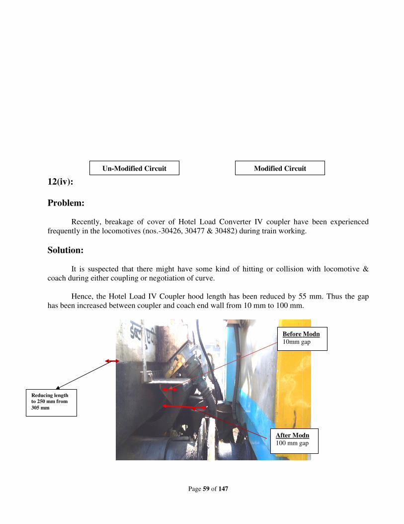
12(iv):
Problem:
Recently, breakage of cover of Hotel Load Converter IV coupler have been experienced
frequently in the locomotives (no
Solution:
It is suspected that there might have some kind of hitting or collision with locomotive
coach during either coupling or negotiation of curve.
Hence, the Hotel Load IV Coup
has been increased between coupler and coach end wall from 10
Un-Modified Circuit
Reducing length
to 250 mm from
305 mm
Page 59 of 147
Recently, breakage of cover of Hotel Load Converter IV coupler have been experienced
os.-30426, 30477 & 30482) during train working.
It is suspected that there might have some kind of hitting or collision with locomotive
during either coupling or negotiation of curve.
Hence, the Hotel Load IV Coupler hood length has been reduced by 55
has been increased between coupler and coach end wall from 10 mm to 100 mm.
Modified Circuit Modified Circuit
Before Modn
10mm gap
After Modn
100 mm gap
Recently, breakage of cover of Hotel Load Converter IV coupler have been experienced
30426, 30477 & 30482) during train working.
It is suspected that there might have some kind of hitting or collision with locomotive &
ler hood length has been reduced by 55 mm. Thus the gap
mm.
Modified Circuit
Before Modn
10mm gap
After Modn
100 mm gap
Page 60 of 147
RDSO’s Note:
12 (i):
Reliability issues reported from Railways from time to time is resolved. At present, there is
no such major reliability issues with hotel load converter including composite converter reported
from user Railways.
Regular cut-in of 2x500 kVA hotel load converter is being carried out in WAP7 locos being
turned out from PUs.
The present status on development of Composite Converter which to be fitted in WAP5 locos
is as under:
SN Firm
(Order)
Supply status Remarks
1. M/s ABB
(10 sets)
4 sets (3 in WAP5, 1 in
WAP7)
Prototype unit supplied Feb
2018, Commissioned in
loco 30140 in May 2018
Three more units supplied
and commissioned.
Six sets under
commissioning at CLW.
2. M/s BHEL
(5 sets)
Prototype unit supplied in
May 2019
Under Commissioning at
CLW.
3. M/s CGL
(5 sets)
-- Firm is developing the item
Preliminary Design
Document submitted.
In the meeting, CLW was advised to accelerate the development of Composite Converter so
that all WAP5 locomotives being turned out from CLW must be fitted with Composite Converter
having hotel load converter.
12 (ii):
Input hotel load current is monitored by traction converter. There may be three fallowing
scenarios:
1. Normal operation without isolation of any traction converter.
2. Electrical isolation of Traction converter. In this case control electronics of traction
converter remains live and keeps monitoring the hotel load converter current.
3. Manual isolation of traction converter.
In scenarios 1 & 2 above HLC current is under monitoring by traction converter. Only
scenario 3 needs attention. However, HLC have their own input over current protection, which work
irrespective of traction converter. Thus, it is felt that the suggested modifications are not required.
However, the Railways may share their experience.
Page 61 of 147
12 (iii):
Output current of hotel load converter is monitored by hotel load converter itself. Also, there
is provision of output over current monitoring. As such, provision of additional CT in the output of
HLC is not felt necessary. However, the Railways may share their experience.
12 (iv):
Present Hotel load couplers are as per the design compatible with Power car. This is in use
for a long time without problem. IT is already standardize and no change is recommended in present
Hotel load coupler. Staff needs training for its proper connections to the power car. WR is already
having enough experience, thus other Railways may follow the practice of WR. However, the
Railways may share their experience.
Deliberations:
1. At present 6 Sets of composite converters are under commissioning at CLW. NR shared their
experiences with Composite converter provided in 3 WAP-5 and in 1 WAP-7 locomotive.
Initially there was problem of Motor Protection Circuit Breaker(MPCB) tripping in coaches
hauled by WAP-5 locomotive. M/s ABB studied problem and rectified it by changing the
capacitors. WR requested to nominate M/s ABB make newly fitted composite converter
locos to ELS/BRC.NR requested to nominate 2 new locomotives to them also.
2. It was deliberated that over current and earth fault protection already exists in HLC for
overload and earth fault. Therefore, this modification is not desirable. Moreover, it will
complicate the circuit and reliability problems may arise. Moreover, provision of
measurement of hotel load current is already present.
3. SR reported breakage of HLC couplers .Zonal Railways has already started doing desired
modification as suggested by SR. CLW has already issued modified drawing and it is also in
regular cut-in.
Recommendations:
1. CLW was advised to accelerate the development of composite converter, so that all WAP-5
locomotives are turned out from CLW fitted with composite converter.
2. Provision of additional CT and Ammeter to monitor the hotel load current is not desirable.
3. Loco sheds/shops should modify Hotel load converter coupler cover as per CLW drawing no
CCD-HL-P73-085 dated 26/09/17.
Railway Board’s decision:
May be accepted.
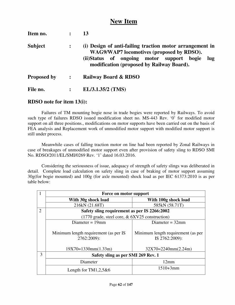
Page 62 of 147
New Item
Item no. : 13
Subject : (i) Design of anti-failing traction motor arrangement in
WAG9/WAP7 locomotives (proposed by RDSO).
(ii)Status of ongoing motor support bogie lug
modification (proposed by Railway Board).
Proposed by : Railway Board & RDSO
File no. : EL/3.1.35/2 (TMS)
RDSO note for item 13(i):
Failures of TM mounting bogie nose in trade bogies were reported by Railways. To avoid
such type of failures RDSO issued modification sheet no. MS-443 Rev. ‘0’ for modified motor
support on all three positions., modifications on motor supports have been carried out on the basis of
FEA analysis and Replacement work of unmodified motor support with modified motor support is
still under process.
Meanwhile cases of falling traction motor on line had been reported by Zonal Railways in
case of breakages of unmodified motor support even after provision of safety sling to RDSO SMI
No. RDSO/2011/EL/SMI/0269 Rev. ‘1’ dated 16.03.2016.
Considering the seriousness of issue, adequacy of strength of safety slings was deliberated in
detail. Complete load calculation on safety sling in case of braking of motor support assuming
30g(for bogie mounted) and 100g (for axle mounted) shock load as per IEC 61373:2010 is as per
table below:
1 Force on motor support
With 30g shock load With 100g shock load
216kN (21.68T) 585kN (58.71T)
2 Safety sling requirement as per IS 2266:2002
(1770 grade, steel core, & 6XV25 construction)
Diameter = 19mm
Minimum length requirement (as per IS
2762:2009):
19X70=1330mm(1.33m)
Diameter = 32mm
Minimum length requirement (as per
IS 2762:2009):
32X70=2240mm(2.24m)
3 Safety sling as per SMI 269 Rev. 1
Diameter 12mm
Length for TM1,2,5&6 1510+3mm
Page 63 of 147
Length for TM3 & 4 1810+3mm
From the above, it is noted that provision of 32mm dia sling is not feasible since it will
require a length of minimum 2.24m where requirement is only for 1810mm (max.), However, 19mm
sling is feasible but it will only cater the requirement of 30g shock load which is prescribed for bogie
mounted equipment as per IEC. As such a heavy cross-section of safety slings are impractical and
will not serve the purpose.
Proposed arrangement:
1. An alternative solution as design of anti-failing traction motor arrangement was discussed
during the meeting cum workshop held at ELS/GZB on 25.07.2019.
2. For finalization of the proposed design and its feasibility of proper fitment the sample
developed by the firms i.e. M/s Ashika Commercial Pvt. Ltd, Kishangarh, Rajasthanand
M/s Anup Malleables Ltd., Dhanbad, a demonstration was held in ELS/CNB on
03.09.2019 in presence of officer/staff of ELS/CNB by RDSO. During this demonstration
fitment arrangement was found satisfactory with minor dimensional/correction as
discussed on shop floor at ELS/CNB.
3. It was decided to provide anti – falling traction motor arrangement in one loco by firms as
under:
(i) M/s Ashika Commercial Pvt. Ltd, Kishangarh, Rajasthan at ELS/AQ
(ii) M/s Anup Malleables Ltd., Dhanbad at ELS/TATA
During such fitment RDSO representative will be present as this is a prototype being done
for first time.
4. Based on satisfactory fitment and trial decision for its regular adoption shall be taken in
consultation with Railway Board/CLW.
5. As decided by RDSO vide RDSO letter no. EL/3.1.35/2 (TMS) dated 04.09.2019, M/s
Ashika Commercial (P) Ltd., Kishangarh, Rajasthan make samples of anti-falling traction
motor arrangement have been fitted successfully in loco no. 31388 WAG9H at location
TM no. 3 of bogie no. TG-308B & TM No. 4 of bogie no. TPP-70B only as shown in Fig.
1 & 2.
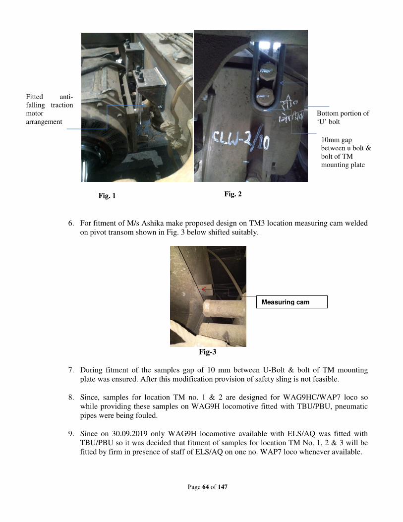
Page 64 of 147
6. For fitment of M/s Ashika make proposed design on TM3 location measuring cam welded
on pivot transom shown in Fig. 3 below shifted suitably.
Fig-3
7. During fitment of the samples gap of 10 mm between U-Bolt & bolt of TM mounting
plate was ensured. After this modification provision of safety sling is not feasible.
8. Since, samples for location TM no. 1 & 2 are designed for WAG9HC/WAP7 loco so
while providing these samples on WAG9H locomotive fitted with TBU/PBU, pneumatic
pipes were being fouled.
9. Since on 30.09.2019 only WAG9H locomotive available with ELS/AQ was fitted with
TBU/PBU so it was decided that fitment of samples for location TM No. 1, 2 & 3 will be
fitted by firm in presence of staff of ELS/AQ on one no. WAP7 loco whenever available.
Fitted anti-
falling traction
motor
arrangement
Bottom portion of
‘U’ bolt
Fig. 1 Fig. 2
Measuring cam
10mm gap
between u bolt &
bolt of TM
mounting plate
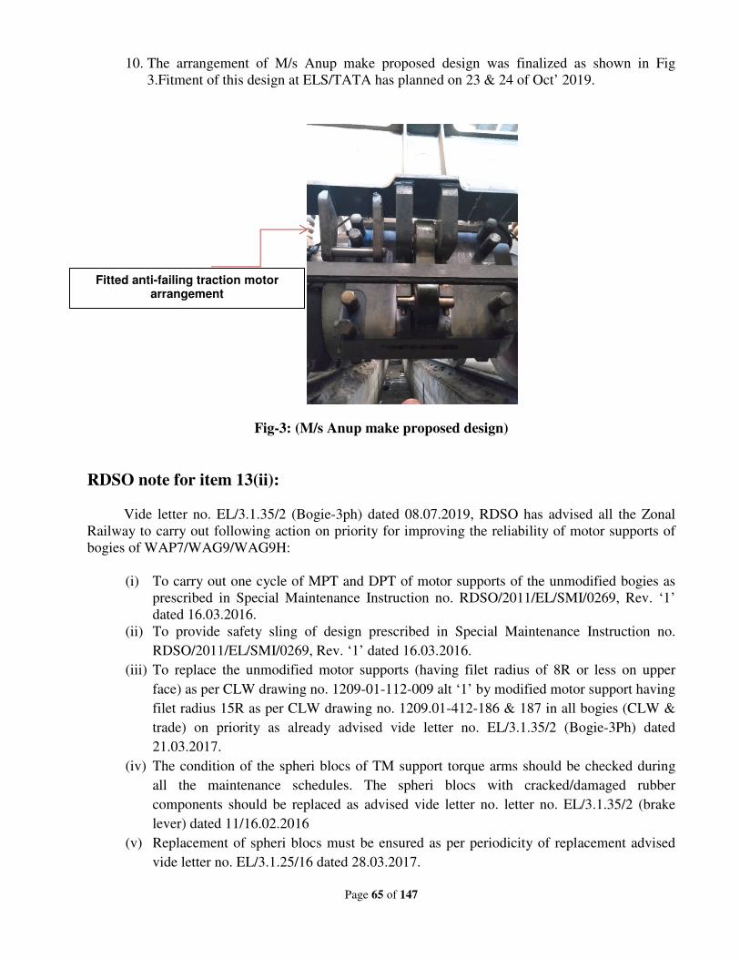
Page 65 of 147
10. The arrangement of M/s Anup make proposed design was finalized as shown in Fig
3.Fitment of this design at ELS/TATA has planned on 23 & 24 of Oct’ 2019.
Fig-3: (M/s Anup make proposed design)
RDSO note for item 13(ii):
Vide letter no. EL/3.1.35/2 (Bogie-3ph) dated 08.07.2019, RDSO has advised all the Zonal
Railway to carry out following action on priority for improving the reliability of motor supports of
bogies of WAP7/WAG9/WAG9H:
(i) To carry out one cycle of MPT and DPT of motor supports of the unmodified bogies as
prescribed in Special Maintenance Instruction no. RDSO/2011/EL/SMI/0269, Rev. ‘1’
dated 16.03.2016.
(ii) To provide safety sling of design prescribed in Special Maintenance Instruction no.
RDSO/2011/EL/SMI/0269, Rev. ‘1’ dated 16.03.2016.
(iii) To replace the unmodified motor supports (having filet radius of 8R or less on upper
face) as per CLW drawing no. 1209-01-112-009 alt ‘1’ by modified motor support having
filet radius 15R as per CLW drawing no. 1209.01-412-186 & 187 in all bogies (CLW &
trade) on priority as already advised vide letter no. EL/3.1.35/2 (Bogie-3Ph) dated
21.03.2017.
(iv) The condition of the spheri blocs of TM support torque arms should be checked during
all the maintenance schedules. The spheri blocs with cracked/damaged rubber
components should be replaced as advised vide letter no. letter no. EL/3.1.35/2 (brake
lever) dated 11/16.02.2016
(v) Replacement of spheri blocs must be ensured as per periodicity of replacement advised
vide letter no. EL/3.1.25/16 dated 28.03.2017.
Fitted anti-failing traction motor arrangement
Page 66 of 147
(vi) To follow all other prescribed instructions related to improving reliability of motor
supports.
Deliberations:
Design of anti-failing traction motor arrangements in WAP7/WAG9HC locomotives proposed
by RDSO have been discussed.
• ‘U’ bolt type anti-failing arrangement of TM in WAP7 bogie was provided under
overhauling on 10.10.2019 in ELS/AQ.
• Above arrangement shown at shop floor on 15.10.2019 by the participants.
• It was pointed that strengthen of modified lug should also be checked for its adequacy
before proliferation.
• All instruction issued by RDSO till dated shall be followed. Replacement of modified lugs
should be done on priority.
Recommendations:
In principle, anti-falling arrangement provided in the bogie of WAG9/WAP7 is in order.
Adequate trial should be done for its satisfactory working before its proliferation.
Railway Board’s decision:
May be accepted. RDSO to carry out Quality audit of M/s Anup.
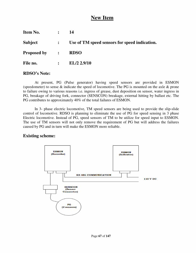
Page 67 of 147
New Item
Item No. : 14
Subject : Use of TM speed sensors for speed indication.
Proposed by : RDSO
File no. : EL/2 2.9/10
RDSO’s Note:
At present, PG (Pulse generator) having speed sensors are provided in ESMON
(speedometer) to sense & indicate the speed of locomotive. The PG is mounted on the axle & prone
to failure owing to various reasons i.e. ingress of grease, dust deposition on sensor, water ingress in
PG, breakage of driving fork, connector (SENSCON) breakage, external hitting by ballast etc. The
PG contributes to approximately 40% of the total failures of ESMON.
In 3- phase electric locomotive, TM speed sensors are being used to provide the slip-slide
control of locomotive. RDSO is planning to eliminate the use of PG for speed sensing in 3 phase
Electric locomotive. Instead of PG, speed sensors of TM to be utilize for speed input to ESMON.
The use of TM sensors will not only remove the requirement of PG but will address the failures
caused by PG and in turn will make the ESMON more reliable.
Existing scheme:
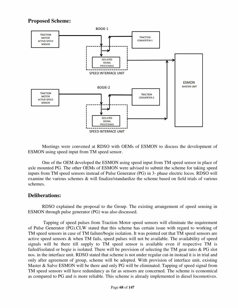
Page 68 of 147
Proposed Scheme:
Meetings were convened at RDSO with OEMs of ESMON to discuss the development of
ESMON using speed input from TM speed sensor.
One of the OEM developed the ESMON using speed input from TM speed sensor in place of
axle mounted PG. The other OEMs of ESMON were advised to submit the scheme for taking speed
inputs from TM speed sensors instead of Pulse Generator (PG) in 3- phase electric locos. RDSO will
examine the various schemes & will finalize/standardize the scheme based on field trials of various
schemes.
Deliberations:
RDSO explained the proposal to the Group. The existing arrangement of speed sensing in
ESMON through pulse generator (PG) was also discussed.
Tapping of speed pulses from Traction Motor speed sensors will eliminate the requirement
of Pulse Generator (PG).CLW stated that this scheme has certain issue with regard to working of
TM speed sensors in case of TM failure/bogie isolation. It was pointed out that TM speed sensors are
active speed sensors & when TM fails, speed pulses will not be available. The availability of speed
signals will be there till supply to TM speed sensor is available even if respective TM is
failed/isolated or bogie is isolated. There will be provision of selecting the TM gear ratio & PG slot
nos. in the interface unit. RDSO stated that scheme is not under regular cut-in instead it is in trial and
only after agreement of group, scheme will be adopted. With provision of interface unit, existing
Master & Salve ESMON will be there and only PG will be eliminated. Tapping of speed signal from
TM speed sensors will have redundancy as far as sensors are concerned. The scheme is economical
as compared to PG and is more reliable. This scheme is already implemented in diesel locomotives.
Page 69 of 147
RDSO should work out the cost & scheme may be tried. If scheme is found in order, then will be
adopted on regular basis.
Recommendations:
Proposed scheme shall be tried in 50 locomotives i.e. 10 numbers each in 5 sheds and based
upon performance feedback further action with regard to adoption of scheme will be taken
accordingly. In this regard, developmental tender may be done by PUs as per the Functional
Requirement Specification (FRS) to be issued by RDSO.
Railway Board’s decision:
May be accepted. Proposed scheme shall be tried in coaching locos. In addition to
performance cost comparison may also be carried out before further proliferation.
Page 70 of 147
New Item
Item No. : 15
Subject : Paralleling of DIBLO diodes connected in important
circuits like VCB, Un-loader Valve, CP Control, Contactor
Control Electronics circuit etc., in 3- phase locomotives.
Proposed by : SCR
File no. : EL/11.5.5/1
Note of proposing Railway:
Problem & Proposal:
To avoid on line failures of 3phase locos due to carbonization because of slackness in
between male pins & female sockets in blocking diode sets, Diblo-5 & Diblo-8 provided in SB
panels.
Five nos. of DIBLO -5 & one no. of DIBLO -8 Blocking diode sets having male pins are
mounted in each SB Panel on a base provided with female socket. DIBLO -5 & 8 blocking diode
sets consist of packs of five diodes and eight diodes respectively. Clips to hold these blocking diode
sets are very flimsy. DIBLO -5 & DIBLO -8 sets are connected in circuits of Pantograph, VCB, Un-
loader, Head Light, CP Control, Control Electronics Contactor and signal lamp circuit etc., A hylam
sheet is to be clamped on all the six diode boxes in each SB Panel to avoid the vibrations as shown
in photograph-1 as per the modification Sheet No. RDSO/2017/EL/MS/0467, Rev.0 dated 07.12.17.
However, this modification had helped in bringing down cases but not solved permanently the main
issue of slackness of the diode male/female contacts. In view of practical problems in carrying out
hard wiring to eliminate the existing plug-in type arrangement of blocking diodes, instructions were
given to clean and check the contacts for proper size in every IOH.
After completion of the modification suggested by RDSO in all locos of SCR, no. of on line
failures of these blocking diodes were reported. On investigation, it was found that the main cause of
failures was carbonization because of looseness in between male pins & female sockets mostly in
Diblo-5 blocking diode sets.
Further, male pin of blocking diode set of one make does not match exactly with the wired
base on the panel of other make.
Carbonization in between male Pins & female Contact Sockets causes transient /intermittent
failures of the locomotives.
To avoid such failures, it is proposed for paralleling of Diblo-5 diodes connected in
important circuits like VCB, Un-loader valve, CP Control, Contactor Control Electronics circuit.
Page 71 of 147
Trials & Observations:
This modification was first carried out in loco no.31149 WAG-9/LGD on 31.08.17 during MOH
and so far completed in 151 locomotives (WAP7-47, WAG9-104). So far no abnormality in DIBLO
diodes of these locomotives is noticed.
Modification works to be carried out:
In spite of securing by clamping sheet as per the modification sheet, it was noticed that
contacts are becoming loose due to wear and tear leading to failure. To overcome this, it is proposed
to parallel the diodes connected in the important circuits. Accordingly nineteen (19) circuits were
identified for paralleling.
Out of which, in six circuits, paralleling of diodes can be done by simply shorting at the input
side of the diode. In other thirteen (13) circuits, paralleling is to be done with the spare diodes.
Following are the spare diodes available in the diode boxes.
RDSO’s Note:
RDSO has already issued draft modification sheet and invited comments from Zonal
Railways. On receipt of remark this will be finalized by Oct-2019.
Deliberations:
Zonal Railways expressed concern about quality of Diode pins. Cases of bad or loose
contacts are being notices during service due to poor quality of male-female connector & pins. It is
noted that male-female connection are not proper. Zonal Railways expressed the need to specify the
connectors properly. CLW should check the specification. Moreover, quality audit for inspection &
testing of connectors should be done jointly by CLW and RDSO within a month time. Paralleling
may just enhance the life of circuit but not prevent diode failure as such. Quality audit of supplier
firm should be done by RDSO and CLW jointly. BRC shed has carried out this modification in
different manner and is also reliable. ZRs pointed out that some of makes connectors are better
.However, re-designing of DIBLO diode connectors by providing Gimota make. Wago connectors
should also be studied to eliminate the problem all together. RDSO/CLW should review the design
and suggest changes if necessary.
Recommendations:
1. Suggestion given by SCR may be implemented by Zonal Railways to prevent the failures.
2. CLW and RDSO should review the present scheme and carry out quality audit of the firm by
associating SCR.
3. CLW/RDSO to review the design and explore the possibility of using Wago connectors.
Railway Board’s decision:
May be accepted.
Page 72 of 147
New Item
Item No. : 16
Subject : Elimination of spurious messages on account of earthling
of control cables in 3-phase locomotives.
Proposed by : SCR
File no. : EL/3.135/2 (Elect)
Note of proposing Railway:
There are many cases of intermittent failures of three phase locomotives on account of earth
fault and later being concluded as checked found normal.
For example,
1) In locos equipped with E-70 brake system, any earth fault on cables 2111A & 2111B
causes “Brake Electronics Fail”. Out of two cables 2111A & 2111B if one cable gets feed
due to energisation of the respective cab and the second cable gets feed due to earth fault
in the second cable connected circuit leads to “Brake Electronics Fail” message.
2) Recently, 10 nos. of M/s AAL make couplers and 03 nos. SCB make couplers have
flashed in three phase locos of ELS/LGD leading to on line loco failures. In most of the
cases, tracking took place between pins and coupler body leading to earth fault.
At present the locomotive battery earth fault detection circuit has two centre point earthed R-
R resistors and this causes a potential of 48 V on any cable after touching to ground.
This is leading to spurious signal high read by the card.
Now by changing the resistors to 2R-R or R-R/2 instead of R-R, the rise of potential in the
event of earth fault can be reduced to 35V which is not considered as signal high by the card and
spurious failures on account of earth fault can be avoided.
This modification has been carried out on trial basis as follows:
1) 2R+R scheme modification implemented in Six WAP7 locos.
2) R+R/2 scheme modification implemented in Four WAG9 locos.
Performance of both the schemes are under observation.
Modification scheme:
Schematic diagram enclosed.
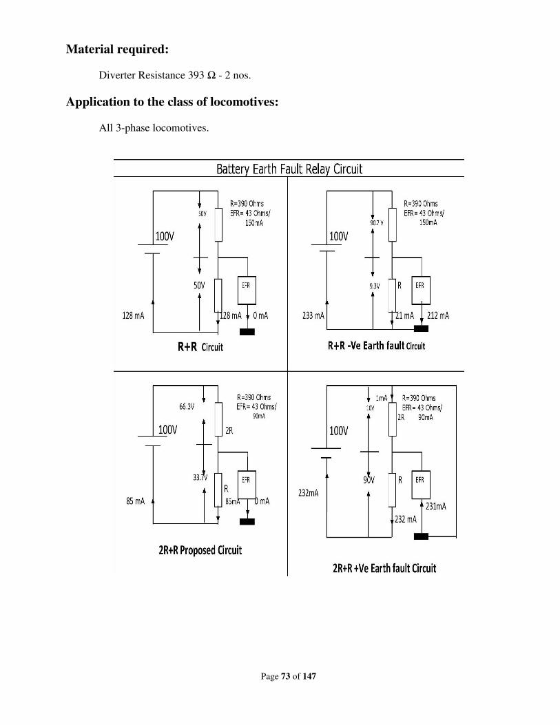
Page 73 of 147
Material required:
Diverter Resistance 393 Ω - 2 nos.
Application to the class of locomotives:
All 3-phase locomotives.
Page 74 of 147
RDSO’s Note:
There are different ratios of potential divider used to detect the earthing in the electric circuit.
The proposed combination will also be one of the ways to improve the earth fault detection
mechanism. Modification appears to be useful.
Deliberations:
Earthing of control cable leads wrong operation of reed relay of electronic cards. This
generates various types of spurious messages due to leakage current at nearly 48 volts from floating
ground of midpoint of potential divider used of earth fault circuit. Modification may be done by
changing R-R potential divider circuit to 2R-R or R-R/2 potential divider circuit.
Recommendations:
Modification of R-R/2 potential divider circuit may be implemented in 10 freight
locomotives by each shed having WAG-9 locomotives. RDSO will issue detailed scheme for this
circuit modification. Sheds to give feedback within a month after implementation, so that final MS
may be issued.
Quality of M/s AAL make coupler is not upto mark. RDSO may take appropriate action to
improve the quality.
Railway Board’s decision:
May be accepted.
Page 75 of 147
New Item
Item No. : 17
Subject : Problem of excessive lateral play of MSU in three phase
locomotives.
Proposed by : SCR
File no. : El/1.3.10/3
Note of proposing Railway:
A large number of MSU NDE bearing seizure cases and breakages of supporting ring fixing
socket head bolts in 3 phase locos were reported at ELS/LGD during 2015-16 and 2016-17.
Subsequently, RDSO carried out technical audit on maintenance practices of MSU at ELS/LGD,
CLW & ELW/BSL and recommended corrective measures in March, 2016.
A team of Senior Supervisors of ELS/LGD was deputed to RYP Shops of SCR and studied
the various problems associated with MSU maintenance during overhauling, with respect to OEM
Manual and found the design/manufacturing factors leading to DE& NDE side bearing failures.
Summary of observations is appended below.
Driving End side:
Causes of breakage of supporting ring fixing bolts at driving end of MSU are:
a. Lack of adequate counter balancing of lateral thrust, since inadequate gap (‘C’ clearance)
between supporting ring and suspension tube due to improper machine/component
tolerances during manufacturing.
b. The inner labyrinth in the MSU has width less than the width of the step provided on the
labyrinth seat in the MSU housing which does not provide adequate counter balancing of
axial forces (lateral thrust).
c. Supporting rings are getting bent on tightening the supporting ring bolts during
assembling of MSUs due to inadequate thickness of support ring.
d. Usage of non standard bolts.
e. Throwing of Oil on to the Face of the Wheel in the DE side due to the breakage of the bolt
provided to hold the outer labyrinth on DE side to prevent the leakage of oil.
NDE Side:
Following are the reasons of NDE bearing seizure.
a. Lack of lateral thrust in the NDE end bearing fitment leading to rotation of labyrinth. b. Grease is not coming through outlet since no matching of grease outlet path in the inner
Page 76 of 147
labyrinth caused due to shearing off of guide pin. This leads to rotation of labyrinth in the MSU housing. This is due to lack of lateral thrust as well as interference in the housing.
c. Excessive lateral play after 3 to 4 years of service is due to present bearing arrangement does not adequately accommodate lateral thrust.
Further, to avoid the online failures of MSU in 3 phase locos, practice of measuring lateral
play of MSU was initiated since November-15 during major schedules and special repairs, as a
preventive measure. Wheel sets having lateral play of MSU more than 1.0 mm are being withdrawn
from service and being sent to shops for MSU overhauling. There are no clear guidelines in the
schedule maintenance instructions of 3 phase locos issued by RDSO vide Letter no. EL/3.1.35/16,
dated 07.02.12, where as in conventional locos lateral clearance of MSU is being checked as per
RDSO SMI/217 dated 24.02.2000 during major schedules. ELS/LGD is permitting Lateral clearance
up to 1.0 mm where as the specified limit in SMI (No, 217) is 0.05 to 0.25 mm.
As per the reports submitted by ELS/LGD & CLW, RDSO issued modification sheet MS-
456 to ensure adequate lateral thrust on driving end of MSU by ensuring proper ‘C’ clearance.
However, the problem of excessive lateral play and non availability of grease sample at NDE MSU
bearing for checking the metal content are still not addressed by the modification sheet No. 456.
In three phase locomotives, cylindrical roller bearings of the NJ with HJ angle ring was
adopted for MSU unlike tapper roller bearing arrangement in WAP4, WAG7 and WAP5
locomotives. The increase in lateral play is attributed to the phenomenon of roller, thrust collar and
NDE inner racer wear observed in three phase locomotive MSU bearings. Details of number of
wheel sets sent for MSU overhauling due to excessive lateral play since 2015- 16 to 2019-20 till
August are furnished below.
S
N
Type of
loco 2015-16 2016-17 2017-18 2018-19
2019-20
(Till Aug-19)
1. WAP7 19 Nos. 53 Nos. 40 Nos. 47 Nos. 32 Nos.
2. WAG9 27 Nos. 31 Nos. 35 Nos. 33 Nos. 11 Nos.
Total 46 Nos. 84 Nos. 85 Nos. 80 Nos. 43 Nos.
The increase in arising of MSU overhauling is attributed to excessive lateral play being
observed during major schedules and as a result, three phase locomotives are getting detained for
want of wheel sets.
From the study of bearing fitment arrangement, it is understood that lateral clearance is the
gap between track width of NDE bearing minus width of thrust collar and NDE roller width.
Basically it is the gap available on both sides of roller to move axially/laterally. The NDE bearing in
the MSU is a locating type bearing and it is designed to take the axial load. From the theoretical
values obtained from M/s FAG for various components, the range of lateral play and the
arrangement of lateral play is given in the annexure-I. As per the tolerances specified for various
components, the range of axial play is 0.147 to 0.215mm (Detailed sketch given in Annexure-I
and as shown in the sketch W1+W2 is the lateral play) and service limit as per OEM is 0.25 to
0.48 mm (Copy of OEM manual enclosed).
On dismantling a wheel set found with excessive lateral play, rubbing marks are noticed on
the rollers of bearing and the width of collar of NDE racer and thrust collar getting worn out during
service. As the wear will increase the gap, the lateral play is increasing in the course of service. This
problem is not noticed on the rollers of DE bearing as it is not of locating type and racers are not
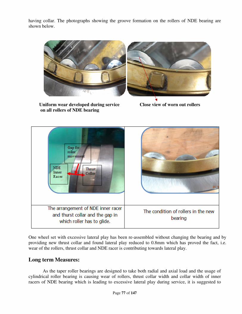
having collar. The photographs showing the groove formation on the rollers of NDE bearing are
shown below.
Uniform wear developed during service Close view of worn out rollers
on all rollers of NDE bearing
One wheel set with excessive lateral play has been re
providing new thrust collar and found lateral play reduced to 0.8mm which has proved the fact, i.e.
wear of the rollers, thrust collar and NDE racer is contributing towards lateral play.
Long term Measures:
As the taper roller bearings are designed to t
cylindrical roller bearing is causing wear of rollers, thrust collar width and collar width of inner
racers of NDE bearing which is leading to excessive lateral play during service, it is suggested to
Page 77 of 147
having collar. The photographs showing the groove formation on the rollers of NDE bearing are
Uniform wear developed during service Close view of worn out rollers
on all rollers of NDE bearing
One wheel set with excessive lateral play has been re-assembled without changing the bearing and by
providing new thrust collar and found lateral play reduced to 0.8mm which has proved the fact, i.e.
wear of the rollers, thrust collar and NDE racer is contributing towards lateral play.
As the taper roller bearings are designed to take both radial and axial load and the usage of
cylindrical roller bearing is causing wear of rollers, thrust collar width and collar width of inner
racers of NDE bearing which is leading to excessive lateral play during service, it is suggested to
having collar. The photographs showing the groove formation on the rollers of NDE bearing are
Uniform wear developed during service Close view of worn out rollers
assembled without changing the bearing and by
providing new thrust collar and found lateral play reduced to 0.8mm which has proved the fact, i.e.
wear of the rollers, thrust collar and NDE racer is contributing towards lateral play.
ake both radial and axial load and the usage of
cylindrical roller bearing is causing wear of rollers, thrust collar width and collar width of inner
racers of NDE bearing which is leading to excessive lateral play during service, it is suggested to
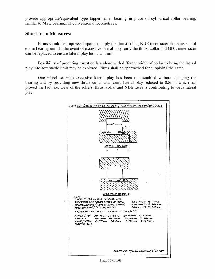
provide appropriate/equivalent type tapper roller bearing in place of cylindrical roller bearing,
similar to MSU bearings of conventional locomotives.
Short term Measures:
Firms should be impressed upon to supply the thrust collar, NDE inner racer alone instead
entire bearing unit. In the event of excessive lateral play, only the thrust collar and NDE inner racer
can be replaced to ensure lateral play less than 1mm.
Possibility of procuring thrust collars alone with different width of collar to bring the lat
play into acceptable limit may be explored. Firms shall be approached for supplying the same.
One wheel set with excessive lateral play has been re
bearing and by providing new thrust collar and found lateral play reduc
proved the fact, i.e. wear of the rollers, thrust collar and NDE racer is contributing towards lateral
play.
Page 78 of 147
appropriate/equivalent type tapper roller bearing in place of cylindrical roller bearing,
similar to MSU bearings of conventional locomotives.
Firms should be impressed upon to supply the thrust collar, NDE inner racer alone instead
entire bearing unit. In the event of excessive lateral play, only the thrust collar and NDE inner racer
can be replaced to ensure lateral play less than 1mm.
Possibility of procuring thrust collars alone with different width of collar to bring the lat
play into acceptable limit may be explored. Firms shall be approached for supplying the same.
One wheel set with excessive lateral play has been re-assembled without changing the
bearing and by providing new thrust collar and found lateral play reduced to 0.8mm which has
proved the fact, i.e. wear of the rollers, thrust collar and NDE racer is contributing towards lateral
appropriate/equivalent type tapper roller bearing in place of cylindrical roller bearing,
Firms should be impressed upon to supply the thrust collar, NDE inner racer alone instead of
entire bearing unit. In the event of excessive lateral play, only the thrust collar and NDE inner racer
Possibility of procuring thrust collars alone with different width of collar to bring the lateral
play into acceptable limit may be explored. Firms shall be approached for supplying the same.
assembled without changing the
ed to 0.8mm which has
proved the fact, i.e. wear of the rollers, thrust collar and NDE racer is contributing towards lateral
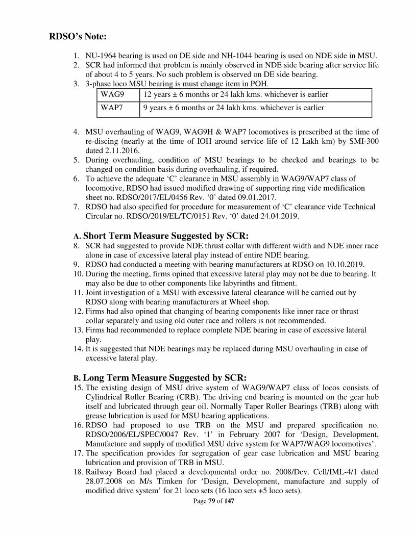
Page 79 of 147
RDSO’s Note:
1. NU-1964 bearing is used on DE side and NH-1044 bearing is used on NDE side in MSU.
2. SCR had informed that problem is mainly observed in NDE side bearing after service life
of about 4 to 5 years. No such problem is observed on DE side bearing.
3. 3-phase loco MSU bearing is must change item in POH.
WAG9 12 years ± 6 months or 24 lakh kms. whichever is earlier
WAP7 9 years ± 6 months or 24 lakh kms. whichever is earlier
4. MSU overhauling of WAG9, WAG9H & WAP7 locomotives is prescribed at the time of
re-discing (nearly at the time of IOH around service life of 12 Lakh km) by SMI-300
dated 2.11.2016.
5. During overhauling, condition of MSU bearings to be checked and bearings to be
changed on condition basis during overhauling, if required.
6. To achieve the adequate ‘C’ clearance in MSU assembly in WAG9/WAP7 class of
locomotive, RDSO had issued modified drawing of supporting ring vide modification
sheet no. RDSO/2017/EL/0456 Rev. ‘0’ dated 09.01.2017.
7. RDSO had also specified for procedure for measurement of ‘C’ clearance vide Technical
Circular no. RDSO/2019/EL/TC/0151 Rev. ‘0’ dated 24.04.2019.
A. Short Term Measure Suggested by SCR:
8. SCR had suggested to provide NDE thrust collar with different width and NDE inner race
alone in case of excessive lateral play instead of entire NDE bearing.
9. RDSO had conducted a meeting with bearing manufacturers at RDSO on 10.10.2019.
10. During the meeting, firms opined that excessive lateral play may not be due to bearing. It
may also be due to other components like labyrinths and fitment.
11. Joint investigation of a MSU with excessive lateral clearance will be carried out by
RDSO along with bearing manufacturers at Wheel shop.
12. Firms had also opined that changing of bearing components like inner race or thrust
collar separately and using old outer race and rollers is not recommended.
13. Firms had recommended to replace complete NDE bearing in case of excessive lateral
play.
14. It is suggested that NDE bearings may be replaced during MSU overhauling in case of
excessive lateral play.
B. Long Term Measure Suggested by SCR: 15. The existing design of MSU drive system of WAG9/WAP7 class of locos consists of
Cylindrical Roller Bearing (CRB). The driving end bearing is mounted on the gear hub
itself and lubricated through gear oil. Normally Taper Roller Bearings (TRB) along with
grease lubrication is used for MSU bearing applications.
16. RDSO had proposed to use TRB on the MSU and prepared specification no.
RDSO/2006/EL/SPEC/0047 Rev. ‘1’ in February 2007 for ‘Design, Development,
Manufacture and supply of modified MSU drive system for WAP7/WAG9 locomotives’.
17. The specification provides for segregation of gear case lubrication and MSU bearing
lubrication and provision of TRB in MSU.
18. Railway Board had placed a developmental order no. 2008/Dev. Cell/IML-4/1 dated
28.07.2008 on M/s Timken for ‘Design, Development, manufacture and supply of
modified drive system’ for 21 loco sets (16 loco sets +5 loco sets).
Page 80 of 147
19. As per PO, firm was to supply prototype unit (1 loco set) of MSU drive system within 3
months. Field trial of 6 months was prescribed.
20. Drawings & QAP of modified MSU for WAG9/WAP7 locomotives had been
provisionally approved vide RDSO letter no. EL/1.3.10/3 dated 24.07.2009.
21. M/s Timken supplied 6 number of modified MSU. One MSU with gear of KPC had been
fitted in one loco 31488/KYN (one wheel set) and dispatched for service on 5.03.2014.
22. However, remaining 5 number of modified MSU could not be assembled by M/s Timken
at CLW till now. Target of 31.12.2019 given to M/s Timken for completing the assembly
during the meeting on 10.10.2019.
23. Railway Board had also placed developmental Order no. 2008/Dev. Cell/IML-4/2, dated
08.09.2008 on M/s SKF for 18 loco sets (14 loco sets +4 loco sets) of modified MSU
drive system.
24. As per PO, firm has to supply prototype unit (1 loco set) of MSU drive system within 3
months. Field trial of 6 months was prescribed.
25. Drawings for manufacturing & supply of MSU assembly and components of modified
suspension Unit drive system for WAG9/WAP7 had been provisionally approved vide
RDSO’s letter no. EL/1.3.10/3 dated 09.03.2011.
26. M/s SKF had not yet supplied any material to CLW. During the meeting at RDSO held
on 10.10.2019, M/s SKF was advised to expedite.
Deliberations:
1. Western Railway informed that no such cases of excessive lateral play observed by them.
2. South Eastern Railway informed that in 20 -25 percent cases, bearing is replaced during
IOH of MSU. South Eastern Railway is requested to provide details of such cases and
analyze them for Goods/Passenger service application.
3. South Central Railway was requested to identify one wheel set with excessive lateral play
and offer it for joint investigation by RDSO and bearing manufacturers at wheel shop.
4. RDSO will also carry out audits of wheel set assembly procedure at ELW/BSL and
CLW.
5. Complete NDE bearing needs to be replaced if required, instead of replacement of NDE
thrust collar with different width and NDE inner race alone as suggested by SCR.
Recommendations:
1. Technical investigation of wheel set with excessive lateral play will be carried out by
RDSO jointly with SCR and bearing manufacturers at Wheel Shop. Quality audit of
wheel shop (ELW/BSL) will also be carried out by RDSO for MSU assembly procedure.
2. Complete NDE bearing should be replaced on condition basis, whenever required.
3. CLW to expedite the fitment and trials of Modified MSU Drive System supplied by M/s
Timken.
Railway Board’s decision:
• May be accepted.
• Quality audit of wheel shop of CLW will also be carried out by RDSO for MSU
assembly procedure.
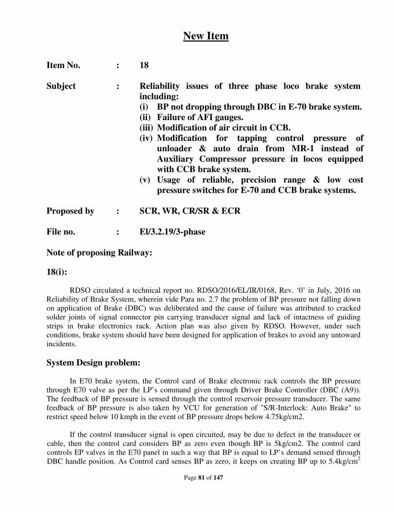
Page 81 of 147
New Item
Item No. : 18
Subject : Reliability issues of three phase loco brake system
including:
(i) BP not dropping through DBC in E-70 brake system.
(ii) Failure of AFI gauges.
(iii) Modification of air circuit in CCB.
(iv) Modification for tapping control pressure of
unloader & auto drain from MR-1 instead of
Auxiliary Compressor pressure in locos equipped
with CCB brake system.
(v) Usage of reliable, precision range & low cost
pressure switches for E-70 and CCB brake systems.
Proposed by : SCR, WR, CR/SR & ECR
File no. : El/3.2.19/3-phase
Note of proposing Railway:
18(i):
RDSO circulated a technical report no. RDSO/2016/EL/IR/0168, Rev. ‘0’ in July, 2016 on
Reliability of Brake System, wherein vide Para no. 2.7 the problem of BP pressure not falling down
on application of Brake (DBC) was deliberated and the cause of failure was attributed to cracked
solder joints of signal connector pin carrying transducer signal and lack of intactness of guiding
strips in brake electronics rack. Action plan was also given by RDSO. However, under such
conditions, brake system should have been designed for application of brakes to avoid any untoward
incidents.
System Design problem:
In E70 brake system, the Control card of Brake electronic rack controls the BP pressure
through E70 valve as per the LP’s command given through Driver Brake Controller (DBC (A9)).
The feedback of BP pressure is sensed through the control reservoir pressure transducer. The same
feedback of BP pressure is also taken by VCU for generation of "S/R-Interlock: Auto Brake" to
restrict speed below 10 kmph in the event of BP pressure drops below 4.75kg/cm2.
If the control transducer signal is open circuited, may be due to defect in the transducer or
cable, then the control card considers BP as zero even though BP is 5kg/cm2. The control card
controls EP valves in the E70 panel in such a way that BP is equal to LP’s demand sensed through
DBC handle position. As Control card senses BP as zero, it keeps on creating BP up to 5.4kg/cm2
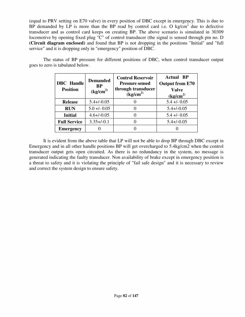
Page 82 of 147
(equal to PRV setting on E70 valve) in every position of DBC except in emergency. This is due to
BP demanded by LP is more than the BP read by control card i.e. O kg/cm2 due to defective
transducer and as control card keeps on creating BP. The above scenario is simulated in 30309
locomotive by opening fixed plug "C" of control transducer (the signal is sensed through pin no. D
(Circuit diagram enclosed) and found that BP is not dropping in the positions "Initial" and "full
service" and it is dropping only in "emergency" position of DBC.
The status of BP pressure for different positions of DBC, when control transducer output
goes to zero is tabulated below.
DBC Handle
Position
Demanded
BP
(kg/cm2)
Control Reservoir
Pressure sensed
through transducer
(kg/cm2)
Actual BP
Output from E70
Valve
(kg/cm2)
Release 5.4+/-0.05 0 5.4 +/- 0.05
RUN 5.0 +/- 0.05 0 5.4+/-0.05
Initial 4.6+/-0.05 0 5.4 +/- 0.05
Full Service 3.35+/-0.1 0 5.4+/-0.05
Emergency 0 0 0
It is evident from the above table that LP will not be able to drop BP through DBC except in
Emergency and in all other handle positions BP will get overcharged to 5.4kg/cm2 when the control
transducer output gets open circuited. As there is no redundancy in the system, no message is
generated indicating the faulty transducer. Non availability of brake except in emergency position is
a threat to safety and it is violating the principle of "fail safe design" and it is necessary to review
and correct the system design to ensure safety.
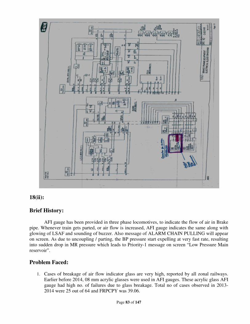
18(ii):
Brief History:
AFI gauge has been provided in three phase locomotives, to indicate the flow of air in Brake
pipe. Whenever train gets parted, or air flow is increased, AFI gauge indicates
glowing of LSAF and sounding of buzzer. Also message of ALARM CHAIN PULLING will appear
on screen. As due to uncoupling / parting, the BP pressure start expelling at very fast rate, resulting
into sudden drop in MR pressure which leads
reservoir”.
Problem Faced:
1. Cases of breakage of air flow indicator glass are very high, reported by all zonal railways.
Earlier before 2014, 08 mm acrylic glasses were used in AFI gauges. These acrylic
gauge had high no. of failures due to glass breakage. Total no of cases observed in 2013
2014 were 25 out of 64 and FRPCPY was 39.06.
Page 83 of 147
AFI gauge has been provided in three phase locomotives, to indicate the flow of air in Brake
pipe. Whenever train gets parted, or air flow is increased, AFI gauge indicates
glowing of LSAF and sounding of buzzer. Also message of ALARM CHAIN PULLING will appear
on screen. As due to uncoupling / parting, the BP pressure start expelling at very fast rate, resulting
into sudden drop in MR pressure which leads to Priority-1 message on screen “Low Pressure Main
Cases of breakage of air flow indicator glass are very high, reported by all zonal railways.
Earlier before 2014, 08 mm acrylic glasses were used in AFI gauges. These acrylic
gauge had high no. of failures due to glass breakage. Total no of cases observed in 2013
2014 were 25 out of 64 and FRPCPY was 39.06.
AFI gauge has been provided in three phase locomotives, to indicate the flow of air in Brake
pipe. Whenever train gets parted, or air flow is increased, AFI gauge indicates the same along with
glowing of LSAF and sounding of buzzer. Also message of ALARM CHAIN PULLING will appear
on screen. As due to uncoupling / parting, the BP pressure start expelling at very fast rate, resulting
1 message on screen “Low Pressure Main
Cases of breakage of air flow indicator glass are very high, reported by all zonal railways.
Earlier before 2014, 08 mm acrylic glasses were used in AFI gauges. These acrylic glass AFI
gauge had high no. of failures due to glass breakage. Total no of cases observed in 2013-
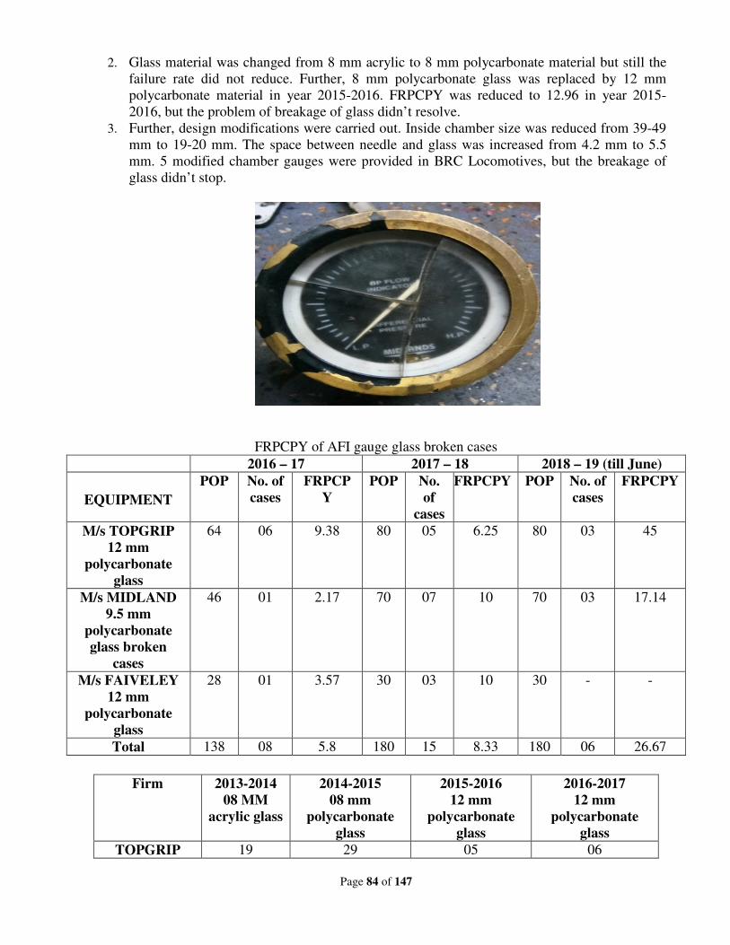
Page 84 of 147
2. Glass material was changed from 8 mm acrylic to 8 mm polycarbonate material but still the
failure rate did not reduce. Further, 8 mm polycarbonate glass was replaced by 12 mm
polycarbonate material in year 2015-2016. FRPCPY was reduced to 12.96 in year 2015-
2016, but the problem of breakage of glass didn’t resolve.
3. Further, design modifications were carried out. Inside chamber size was reduced from 39-49
mm to 19-20 mm. The space between needle and glass was increased from 4.2 mm to 5.5
mm. 5 modified chamber gauges were provided in BRC Locomotives, but the breakage of
glass didn’t stop.
FRPCPY of AFI gauge glass broken cases
2016 – 17 2017 – 18 2018 – 19 (till June)
EQUIPMENT
POP No. of
cases
FRPCP
Y
POP No.
of
cases
FRPCPY POP No. of
cases
FRPCPY
M/s TOPGRIP
12 mm
polycarbonate
glass
64 06 9.38 80 05 6.25 80 03 45
M/s MIDLAND
9.5 mm
polycarbonate
glass broken
cases
46 01 2.17 70 07 10 70 03 17.14
M/s FAIVELEY
12 mm
polycarbonate
glass
28 01 3.57 30 03 10 30 - -
Total 138 08 5.8 180 15 8.33 180 06 26.67
Firm 2013-2014
08 MM
acrylic glass
2014-2015
08 mm
polycarbonate
glass
2015-2016
12 mm
polycarbonate
glass
2016-2017
12 mm
polycarbonate
glass
TOPGRIP 19 29 05 06
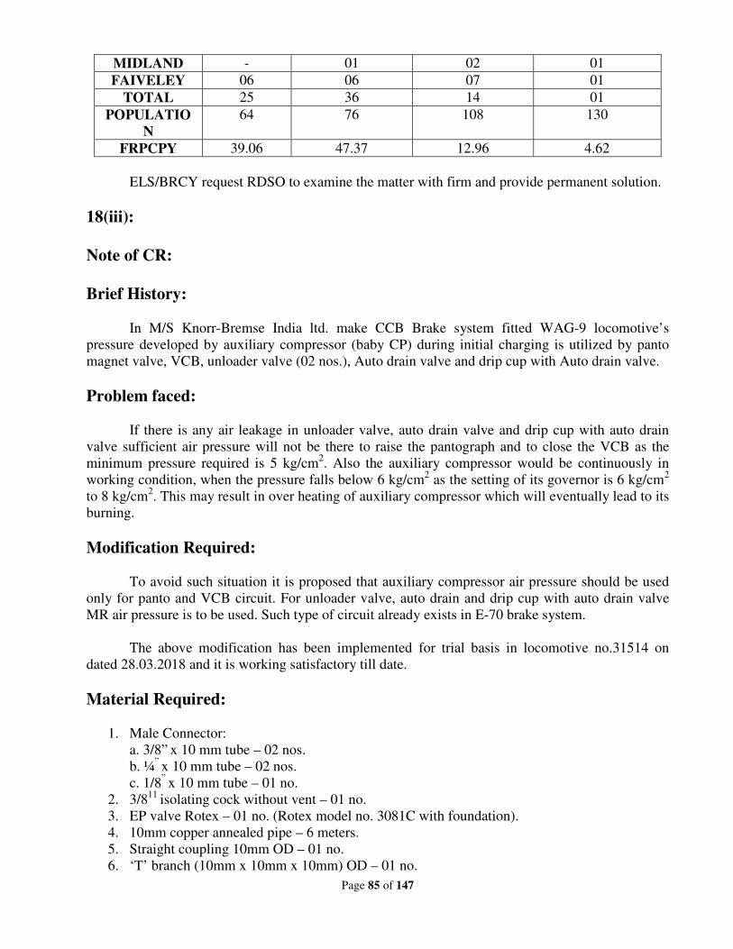
Page 85 of 147
MIDLAND - 01 02 01
FAIVELEY 06 06 07 01
TOTAL 25 36 14 01
POPULATIO
N
64 76 108 130
FRPCPY 39.06 47.37 12.96 4.62
ELS/BRCY request RDSO to examine the matter with firm and provide permanent solution.
18(iii):
Note of CR:
Brief History:
In M/S Knorr-Bremse India ltd. make CCB Brake system fitted WAG-9 locomotive’s
pressure developed by auxiliary compressor (baby CP) during initial charging is utilized by panto
magnet valve, VCB, unloader valve (02 nos.), Auto drain valve and drip cup with Auto drain valve.
Problem faced:
If there is any air leakage in unloader valve, auto drain valve and drip cup with auto drain
valve sufficient air pressure will not be there to raise the pantograph and to close the VCB as the
minimum pressure required is 5 kg/cm2. Also the auxiliary compressor would be continuously in
working condition, when the pressure falls below 6 kg/cm2 as the setting of its governor is 6 kg/cm
2
to 8 kg/cm2. This may result in over heating of auxiliary compressor which will eventually lead to its
burning.
Modification Required:
To avoid such situation it is proposed that auxiliary compressor air pressure should be used
only for panto and VCB circuit. For unloader valve, auto drain and drip cup with auto drain valve
MR air pressure is to be used. Such type of circuit already exists in E-70 brake system.
The above modification has been implemented for trial basis in locomotive no.31514 on
dated 28.03.2018 and it is working satisfactory till date.
Material Required:
1. Male Connector:
a. 3/8” x 10 mm tube – 02 nos.
b. ¼” x 10 mm tube – 02 nos.
c. 1/8” x 10 mm tube – 01 no.
2. 3/811
isolating cock without vent – 01 no.
3. EP valve Rotex – 01 no. (Rotex model no. 3081C with foundation).
4. 10mm copper annealed pipe – 6 meters.
5. Straight coupling 10mm OD – 01 no.
6. ‘T’ branch (10mm x 10mm x 10mm) OD – 01 no.
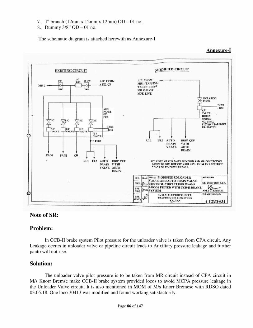
Page 86 of 147
7. T’ branch (12mm x 12mm x 12mm) OD – 01 no.
8. Dummy 3/8” OD – 01 no.
The schematic diagram is attached herewith as Annexure-I.
Annexure-I
Note of SR:
Problem:
In CCB-II brake system Pilot pressure for the unloader valve is taken from CPA circuit. Any
Leakage occurs in unloader valve or pipeline circuit leads to Auxiliary pressure leakage and further
panto will not rise.
Solution:
The unloader valve pilot pressure is to be taken from MR circuit instead of CPA circuit in
M/s Knorr Bremse make CCB-II brake system provided locos to avoid MCPA pressure leakage in
the Unloader Valve circuit. It is also mentioned in MOM of M/s Knorr Bremese with RDSO dated
03.05.18. One loco 30413 was modified and found working satisfactorily.
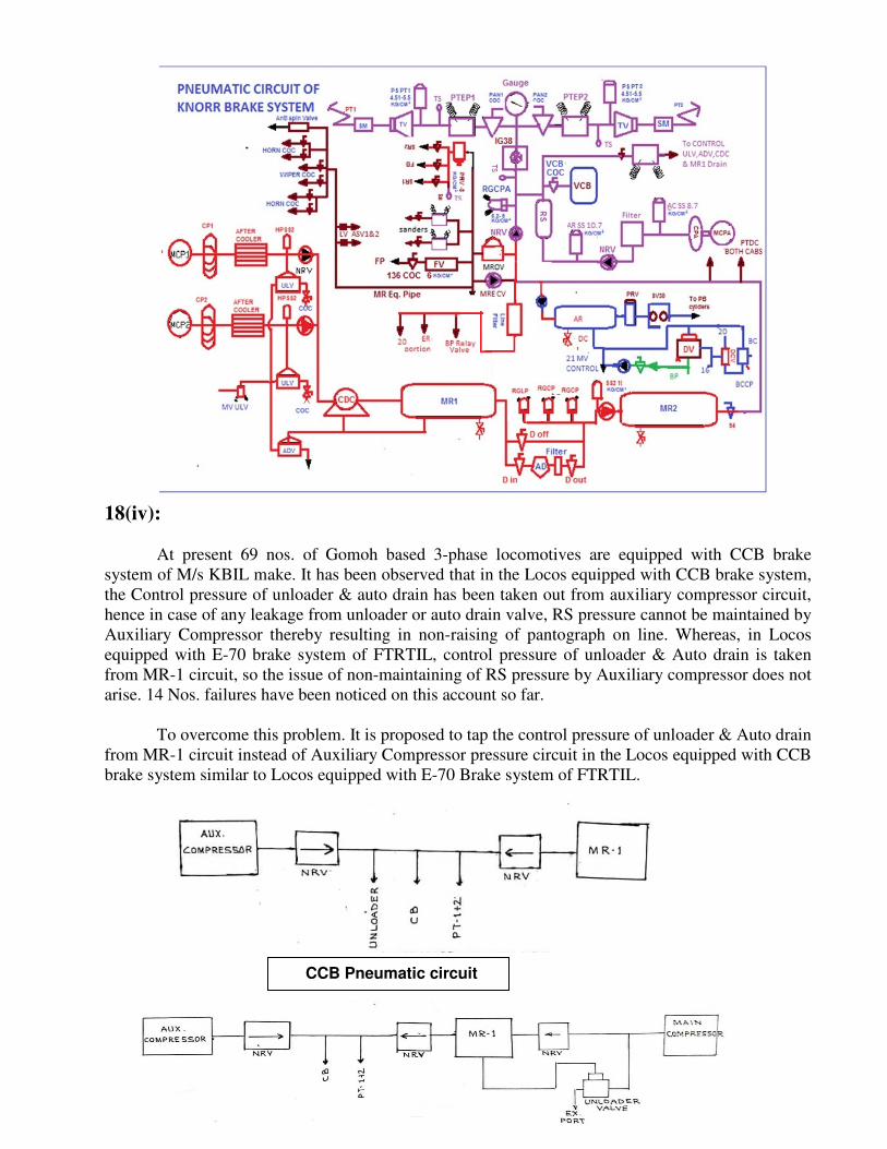
Page 87 of 147
18(iv):
At present 69 nos. of Gomoh based 3-phase locomotives are equipped with CCB brake
system of M/s KBIL make. It has been observed that in the Locos equipped with CCB brake system,
the Control pressure of unloader & auto drain has been taken out from auxiliary compressor circuit,
hence in case of any leakage from unloader or auto drain valve, RS pressure cannot be maintained by
Auxiliary Compressor thereby resulting in non-raising of pantograph on line. Whereas, in Locos
equipped with E-70 brake system of FTRTIL, control pressure of unloader & Auto drain is taken
from MR-1 circuit, so the issue of non-maintaining of RS pressure by Auxiliary compressor does not
arise. 14 Nos. failures have been noticed on this account so far.
To overcome this problem. It is proposed to tap the control pressure of unloader & Auto drain
from MR-1 circuit instead of Auxiliary Compressor pressure circuit in the Locos equipped with CCB
brake system similar to Locos equipped with E-70 Brake system of FTRTIL.
CCB Pneumatic circuit
Page 88 of 147
18(v):
1. In E70 and CCB brake systems, 14 Nos. of pressure switches are used for various
applications. Pressure switches of Square D or Eaton make are used in E-70 brake system,
whereas only Eaton make pressure switches are used in KBIL make CCB brake system.
These pressure switches are failing frequently, mainly due to pressure setting disturbance.
Apart from the high failure rate, there are costlier as compared to Indfos/Danfoss make
pressure switches which are used in conventional locomotives, since long. Reliability of
Indfos/ Danfoss make switch is also better than SQUARE-D /EATON make switches.
2. Pressure switch provided in Brake cylinder circuit of E70 brake system is set for cut in at
0.65 Kg/Cm2 and cut out at 0.2 Kg/Cm
2. FTIL is using SQUARE-D make pressure switch
for this application with operating range of 0.1 to 5 bar and minimum differential pressure of
0.2 bar. With low operating range and low differential pressure setting, erratic behaviour of
the pressure switch is noticed. Hence, a precision range pressure switch is required for this
purpose.
Observations:
Eaton make pressure switches provided in locomotives with CCB 2.0 brake system are
failing frequently mainly due to setting disturbance. Failure details of these pressure switches for the
last three years are enclosed in the Annexure-I. EATON make pressure switches are available in E-
70 brake system also in recently received new locos. However, M/s KBIL is providing their part
number on EATON pressure switches, whereas M/s FTIL is not providing their own part number.
Details of model Nos., makes, operating ranges and actual usage & settings of different pressure
switches provided in CCB2.0 and E-70 Brake systems are given in the enclosed Annexure-II.
E-70 brake system:
In old locos, three models (GAWM4, GAWM5 & GAWM6) of Square-D make pressure
switches were used for eleven different applications. However, in the recently received new locos,
only one type/ model pressure switch of Eaton make for all eleven different applications used i.e.
only MCS-11 type pressure switch (Eaton Part no.60947-5-1) with maximum operating pressure of
11 Kg/cm2 and minimum differential pressure of 0.3kg/cm
2.
CCB 2.0 brake system:
Eaton pressure switches with KBIL part nos., and four types i.e. 1135829, 1135830, 18469,
192268 were used for eleven different circuits. Though M/s KBIL has given four different numbers
but shed is not able to identify original Eaton numbers.
From the above, it may be noted that precision range pressure switches are not used for
different applications by both the firms. This is the main reason for pressure switch setting
disturbances.
Further, pressure switch is not a must change item even in POH schedule. There is no
specified periodicity for replacement and is being replaced only on condition basis. As there is no
Page 89 of 147
periodical replacement, the failure rate of pressure switches would further increase after certain
service (not defined) period which could affect reliability of loco.
Trials:
To overcome the above problems, SCR has replaced the existing failure prone, high cost and
wide range Square D make (Type: GAWM-4) pressure switches with better working and proven
Pressure switch of Indfos make (Type: RT-112X) initially in 15 locomotives for brake cylinder
circuit on trial basis. After noticing satisfactory working, 57 more (G9-22; P7-35) locomotives were
provided with Indfos make pressure switch in brake cylinder circuit since Feb 2016. No abnormality
has been noticed in these locos for the last three years.
Further five Nos. wall mounted pressure switches were replaced with equivalent Indfos make
in two locos i.e. 31175 on 10.02.17 and 31176 on 08.03.17. For the last two and half years, these
pressure switches have been working satisfactorily.
In view of poor reliability and high cost of Square-D/EATON make pressure switches, SCR
identified Indfos/Danfoss, a reputed make precision range pressure switches available in the market.
Equivalent Indfos/Danfoss make pressure switches suitable for different applications of 3 phase
locomotives are mentioned in the Annexure-II.
Accordingly all 14 Nos. of Square D make pressure switches (Five pressure switches are of
wall mounted and nine pressure switches are of panel mounted) were replaced with equivalent
Indfos make pressure switches in loco no. 31250/LGD during Apr’17. So far no failures of Indfos
make pressure switch is noticed in this loco. Photographs depicting provision of Indfos make
pressure switches in place of Square D make pressure switches along with accessories (modified
base plate, adopters, and clamps with bolt & nuts) required for modifications are enclosed in the
Annexure.
In all the above locos pressure switches are working satisfactorily.
Cost savings:
Saving of about Rs.4,23,900/- per loco could be achieved. Cost comparison statement is
enclosed as Annexure-IV.
In view of poor reliability and high costs of Square-D / EATON make pressure switches, it is
recommended to adopt reliable, precision range and cost effective pressure switches in three phase
locos.
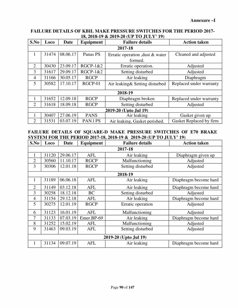
Page 90 of 147
Annexure –I
FAILURE DETAILS OF KBIL MAKE PRESSURE SWITCHES FOR THE PERIOD 2017-
18, 2018-19 & 2019-20 (UP TO JULY’ 19)
S.No Loco
No
Date Equipment Failure details Action taken
2017-18
1 31474 08.06.17 Panas PS Erratic operation ,dust & water
formed.
Cleaned and adjusted
2 30430 23.09.17 RGCP-1&2 Erratic operation. Adjusted
3 31617 29.09.17 RGCP-1&2 Setting disturbed Adjusted
4 31166 30.05.17 RGCP Air leaking Diaphragm
5 30582 17.10.17 RGCP-01 Air leaking& Setting disturbed Replaced under warranty
2018-19
1 31652 12.09.18 RGCP Diaphragm broken Replaced under warranty
2 31618 18.09.18 RGCP Setting disturbed Adjusted
2019-20 (Upto Jul 19) 1 30407 27.06.19 PANS Air leaking Gasket given up
2 31531 03.07.19 PAN.l PS Air leaking, Gasket perished. Gasket Replaced by firm
FAILURE DETAILS OF SQUARE-D MAKE PRESSURE SWITCHES OF E70 BRAKE
SYSTEM FOR THE PERIOD 2017-18, 2018-19 & 2019-20 (UP TO JULY’ 19)
S.No Loco
No
Date Equipment Failure details Action taken
2017-18
1 31120 29.06.17 AFL Air leaking Diaphragm given up
2 30560 11.10.17 RGCP Malfunctioning Adjusted
3 30306 12.01.18 RGCP Setting disturbed Adjusted
2018-19
1 31189 06.06.18 AFL Air leaking Diaphragm become hard
2 31149 03.12.18 AFL Air leaking Diaphragm become hard
3 30258 18.12.18 BC Setting disturbed Adjusted
4 31154 29.12.18 AFL Air leaking Diaphragm become hard
5 30275 12.01.19 RGCP Erratic operation Adjusted
6 31123 16.01.19 AFL Malfunctioning Adjusted
7 31133 07.03.19 Emer.BP-69 Air leaking Diaphragm become hard
8 31252 15.02.19 AFL Malfunctioning Adjusted
9 31463 09.03.19 AFL Setting disturbed Adjusted
2019-20 (Upto Jul 19)
1 31134 09.07.19 AFL Air leaking Diaphragm become hard
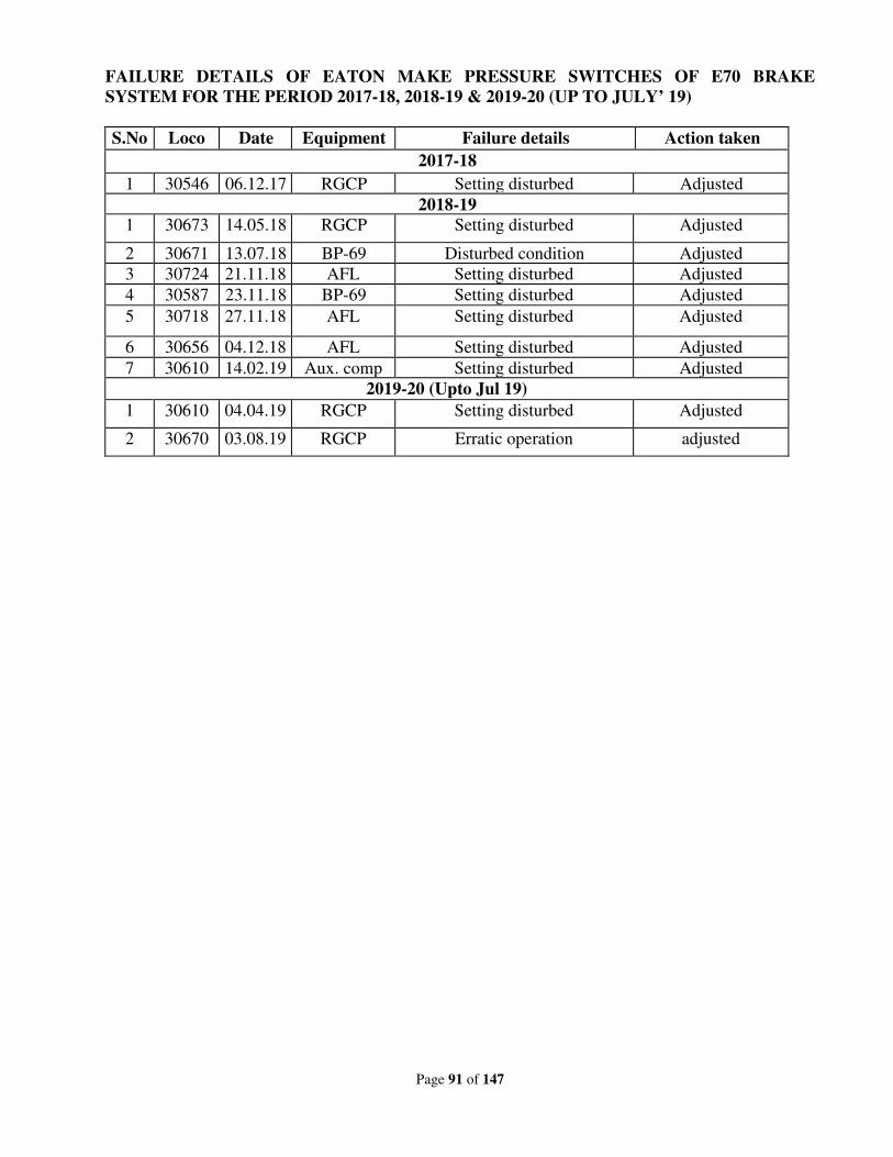
Page 91 of 147
FAILURE DETAILS OF EATON MAKE PRESSURE SWITCHES OF E70 BRAKE
SYSTEM FOR THE PERIOD 2017-18, 2018-19 & 2019-20 (UP TO JULY’ 19)
S.No Loco
No
Date Equipment Failure details Action taken
2017-18
1 30546 06.12.17 RGCP Setting disturbed Adjusted
2018-19
1 30673 14.05.18 RGCP Setting disturbed Adjusted
2 30671 13.07.18 BP-69 Disturbed condition Adjusted
3 30724 21.11.18 AFL Setting disturbed Adjusted
4 30587 23.11.18 BP-69 Setting disturbed Adjusted
5 30718 27.11.18 AFL Setting disturbed Adjusted
6 30656 04.12.18 AFL Setting disturbed Adjusted
7 30610 14.02.19 Aux. comp Setting disturbed Adjusted
2019-20 (Upto Jul 19)
1 30610 04.04.19 RGCP Setting disturbed Adjusted
2 30670 03.08.19 RGCP Erratic operation adjusted
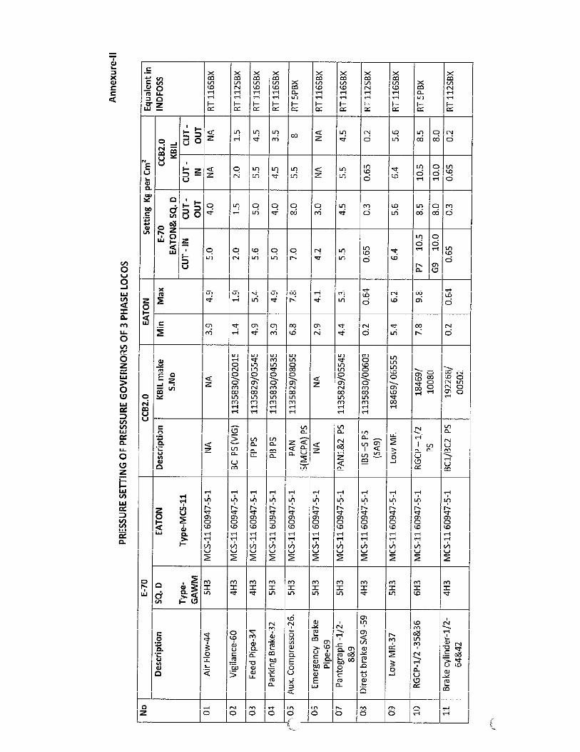
Page 92 of 147
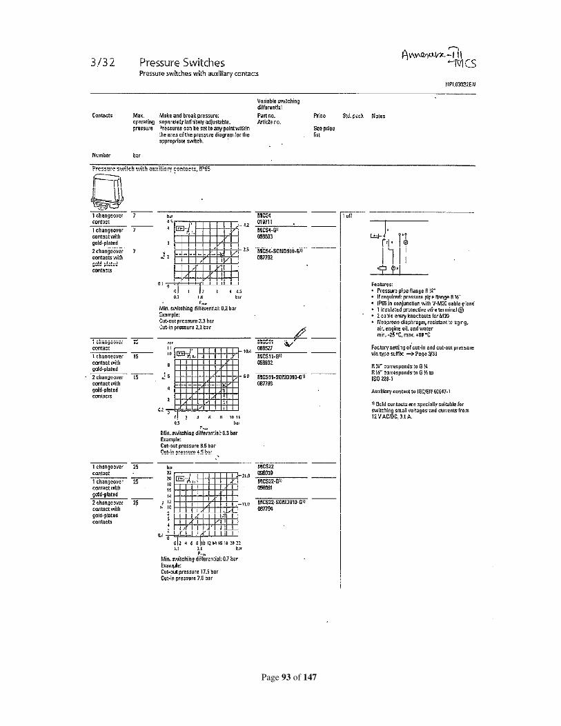
Page 93 of 147
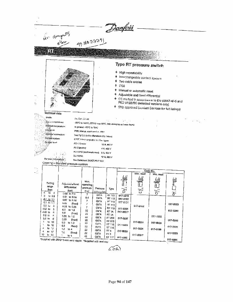
Page 94 of 147
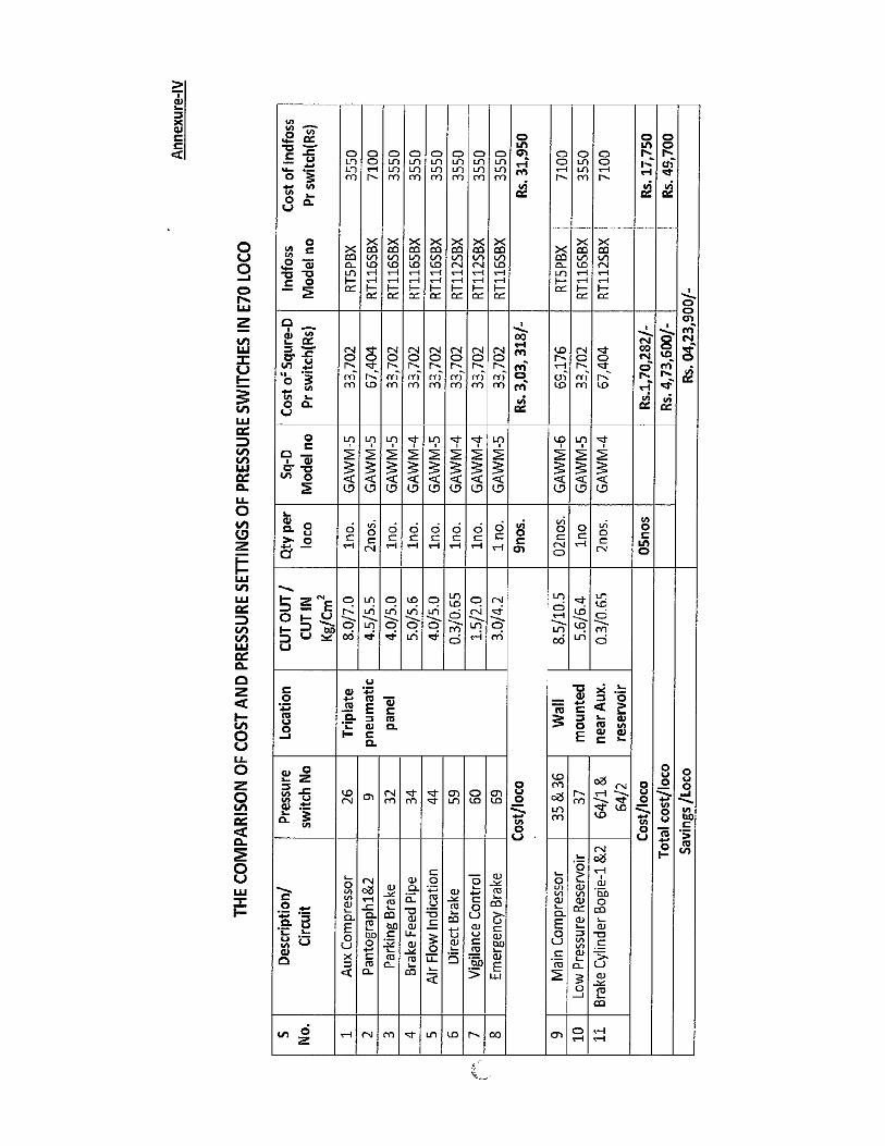
Page 95 of 147
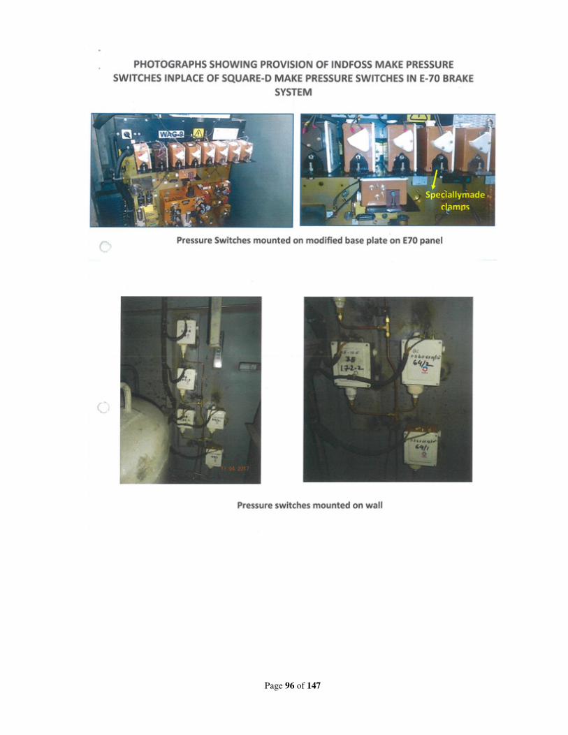
Page 96 of 147
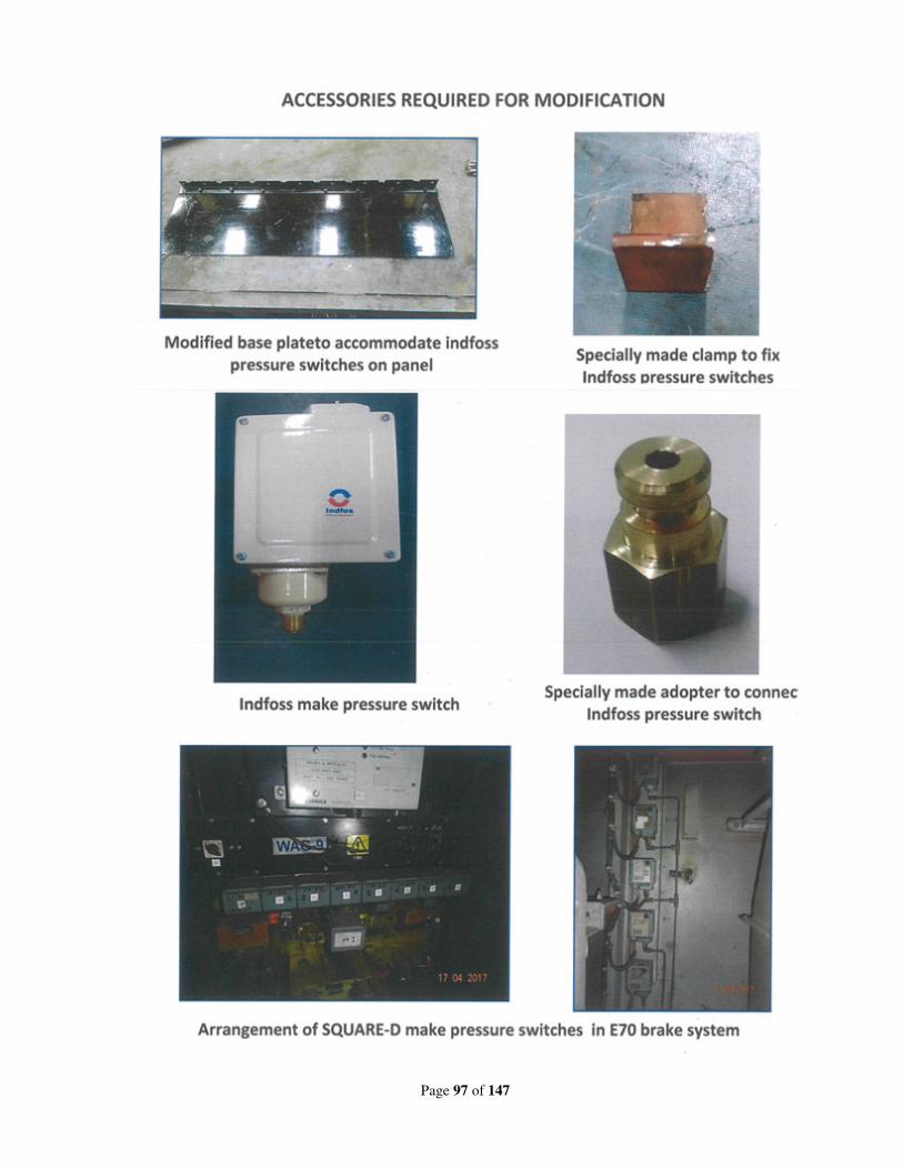
Page 97 of 147
Page 98 of 147
RDSO’s Note:
18(i):
• A meeting was held at RDSO on 03.05.2018 with Zonal Railways and representatives of M/s
FTRTIL & M/s KBIL to discuss the issue. MOM was issued vide letter no. EL/3.2.19/3-
Phase dated 08.05.2018.
• M/s FTRTIL investigated the matter and reported various reasons of failure related to bad
workmanship during manufacturing of electronics cards like wiring/soldering, loose
connection, breakage of strands of a wire.
• M/s FTRTIL had carried out one round of field check of all E-70 brake panels electronic
cards for any loose connection, breakage of strands in wires, setting of card in rack etc. in SE
Railway based locomotives.
• M/s FTRTIL developed “System Operated Automatic Emergency Brake” (SOAEB) for E70
system to address this issue as a fail- safe measure. In case when BP is not dropped by A9 in
service zone, then penalty brake will be activated through SOAEB.
• Presently, 3 units of SOAEB are working in one loco each in ELS/ TATA, RPM & AQ
(31658/TATA from 23.03.18, 30366/RPM from 31.03.18 & 31368/AQ from 29.06.18) for
field trial.
• Firm has developed a new sub vendor M/s Avalon, Chennai for electronic cards and procured
10sets. Six sets of electronic cards are put in service at ELS/GZB for field trial.
Improvements in devices used with new sources are as below:
Component Grade of device
IC MIL grade
Resistors Automotive grade with temperature rating increased
from125 O
C to 155 OC
Diodes Temperature rating increasedfrom 125 O
C to 150 O
C
Zener Diodes Temperature rating increased from 125 O
C to 200 O
C
Capacitors Electrolytic, film and ceramic with temperature rating
increasing from 85 O
C to 125 O
C
Relays, Connectors As existing
• To overcome the problem of burning of resistances R62 and RL5 firm has included the
following new developments of the control card:
Trace width will be increased to handle higher current.
Copper thickness of PCB will be increased near to two times
Power rating of R62 will be increased from 6.5W to 8 W
Power rating of R63 will be increased from 2.5W to 5 W.
Based on performance of brake electronic cards supplied by new source M/s Avalon further
decision shall be taken for cut in for new supplies of brake system as well as replacement of
existing cards.
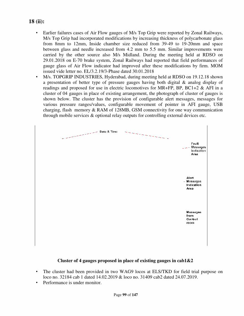
18 (ii):
• Earlier failures cases of Air Flo
M/s Top Grip had incorporated modifications by increasing thickness of polycarbonate glass
from 8mm to 12mm, Inside chamber size reduced from 39
between glass and needle incr
carried by the other source also M/s Midland. During the meeting held at RDSO on
29.01.2018 on E-70 brake system, Zonal Railways had reported that field performances of
gauge glass of Air Flow indicato
issued vide letter no. EL/3.2.19/3
• M/s. TOPGRIP INDUSTRIES, Hyderabad, during meeting held at RDSO on 19.12.18 shown
a presentation of better type of pressure gauges having both
readings and proposed for use in electric locomotives for MR+FP, BP, BC1+2 & AFI in a
cluster of 04 gauges in place of existing arrangement, the photograph of cluster of gauges is
shown below. The cluster has the provision of co
various pressure ranges/values, configurable movement of pointer in AFI gauge, USB
charging, flash memory & RAM of 128MB, GSM connectivity for one way communication
through mobile services & optional relay outputs f
Cluster of 4 gauges proposed in place of existing gauges in cab1&2
• The cluster had been provided in two WAG9 locos at ELS/TKD for field trial purpose on
loco no. 32184 cab 1 dated 14.02.2019 & loco no. 31409 cab2 da
• Performance is under monitor.
Page 99 of 147
Earlier failures cases of Air Flow gauges of M/s Top Grip were reported by Zonal Railways,
M/s Top Grip had incorporated modifications by increasing thickness of polycarbonate glass
from 8mm to 12mm, Inside chamber size reduced from 39-49 to 19
between glass and needle increased from 4.2 mm to 5.5 mm. Similar improvements were
carried by the other source also M/s Midland. During the meeting held at RDSO on
70 brake system, Zonal Railways had reported that field performances of
gauge glass of Air Flow indicator had improved after these modifications by firm. MOM
issued vide letter no. EL/3.2.19/3-Phase dated 30.01.2018
M/s. TOPGRIP INDUSTRIES, Hyderabad, during meeting held at RDSO on 19.12.18 shown
a presentation of better type of pressure gauges having both digital & analog display of
readings and proposed for use in electric locomotives for MR+FP, BP, BC1+2 & AFI in a
cluster of 04 gauges in place of existing arrangement, the photograph of cluster of gauges is
shown below. The cluster has the provision of configurable alert messages, messages for
various pressure ranges/values, configurable movement of pointer in AFI gauge, USB
charging, flash memory & RAM of 128MB, GSM connectivity for one way communication
through mobile services & optional relay outputs for controlling external devices etc.
Cluster of 4 gauges proposed in place of existing gauges in cab1&2
The cluster had been provided in two WAG9 locos at ELS/TKD for field trial purpose on
loco no. 32184 cab 1 dated 14.02.2019 & loco no. 31409 cab2 dated 24.07.2019.
Performance is under monitor.
w gauges of M/s Top Grip were reported by Zonal Railways,
M/s Top Grip had incorporated modifications by increasing thickness of polycarbonate glass
49 to 19-20mm and space
eased from 4.2 mm to 5.5 mm. Similar improvements were
carried by the other source also M/s Midland. During the meeting held at RDSO on
70 brake system, Zonal Railways had reported that field performances of
r had improved after these modifications by firm. MOM
M/s. TOPGRIP INDUSTRIES, Hyderabad, during meeting held at RDSO on 19.12.18 shown
digital & analog display of
readings and proposed for use in electric locomotives for MR+FP, BP, BC1+2 & AFI in a
cluster of 04 gauges in place of existing arrangement, the photograph of cluster of gauges is
nfigurable alert messages, messages for
various pressure ranges/values, configurable movement of pointer in AFI gauge, USB
charging, flash memory & RAM of 128MB, GSM connectivity for one way communication
or controlling external devices etc.
Cluster of 4 gauges proposed in place of existing gauges in cab1&2
The cluster had been provided in two WAG9 locos at ELS/TKD for field trial purpose on
ted 24.07.2019.
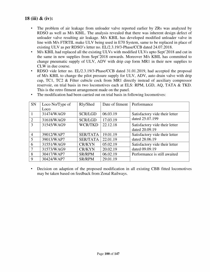
Page 100 of 147
18 (iii) & (iv):
• The problem of air leakage from unloader valve reported earlier by ZRs was analyzed by
RDSO as well as M/s KBIL. The analysis revealed that there was inherent design defect of
unloader valve resulting air leakage. M/s KBIL has developed modified unloader valve in
line with M/s FTRTIL make ULV being used in E70 System, same to be replaced in place of
existing ULV as per RDSO’s letter no. EL/2.3.19/3-Phase/CCB dated 24.07.2018.
• M/s KBIL had replaced all the existing ULVs with modified ULVs upto Sept’2018 and cut in
the same in new supplies from Sept’2018 onwards. Moreover M/s KBIL has committed to
change pneumatic supply of ULV, ADV with drip cup form MR1 in their new supplies to
CLW in due course.
• RDSO vide letter no. EL/2.3.19/3-Phase/CCB dated 31.01.2019, had accepted the proposal
of M/s KBIL to change the pilot pressure supply for ULV, ADV, auto drain valve with drip
cup, TC1, TC2 & Filter cubicle cock from MR1 directly instead of auxiliary compressor
reservoir, on trial basis in two locomotives each at ELS: RPM, LGD, AQ, TATA & TKD.
This is the retro fitment arrangement made on the panel.
• The modification had been carried out on trial basis in following locomotives:
SN Loco No/Type of
Loco
Rly/Shed Date of fitment Performance
1 31474/WAG9 SCR/LGD 06.03.19 Satisfactory vide their letter
dated 25.07.199 2 31618/WAG9 SCR/LGD 17.03.19
3 31545/WAG9 WCR/TKD 22.12.18 Satisfactory vide their letter
dated 20.09.19
4 39012/WAP7 SER/TATA 19.01.19 Satisfactory vide their letter
dated 28.06.19 5 39013/WAP7 SER/TATA 22.01.19
6 31551/WAG9 CR/KYN 05.02.19 Satisfactory vide their letter
dated 09.09.19 7 31573/WAG9 CR/KYN 20.02.19
8 30417/WAP7 SR/RPM 06.02.19 Performance is still awaited
9 30424/WAP7 SR/RPM 29.01.19
• Decision on adaption of the proposed modification in all existing CBB fitted locomotives
may be taken based on feedback from Zonal Railways.
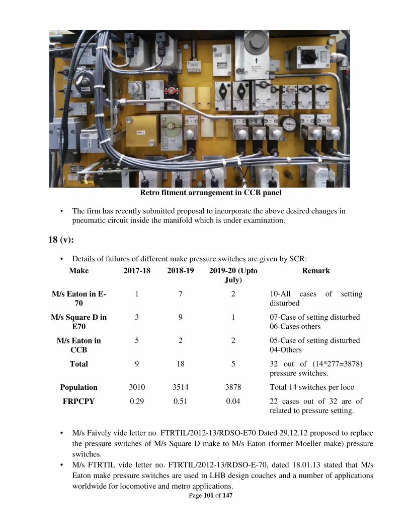
Page 101 of 147
Retro fitment arrangement in CCB panel
• The firm has recently submitted proposal to incorporate the above desired changes in
pneumatic circuit inside the manifold which is under examination.
18 (v):
• Details of failures of different make pressure switches are given by SCR:
Make 2017-18 2018-19 2019-20 (Upto
July)
Remark
M/s Eaton in E-
70
1 7 2 10-All cases of setting
disturbed
M/s Square D in
E70
3 9 1 07-Case of setting disturbed
06-Cases others
M/s Eaton in
CCB
5 2 2 05-Case of setting disturbed
04-Others
Total 9 18 5 32 out of (14*277=3878)
pressure switches.
Population 3010 3514 3878 Total 14 switches per loco
FRPCPY 0.29 0.51 0.04 22 cases out of 32 are of
related to pressure setting.
• M/s Faively vide letter no. FTRTIL/2012-13/RDSO-E70 Dated 29.12.12 proposed to replace
the pressure switches of M/s Square D make to M/s Eaton (former Moeller make) pressure
switches.
• M/s FTRTIL vide letter no. FTRTIL/2012-13/RDSO-E-70, dated 18.01.13 stated that M/s
Eaton make pressure switches are used in LHB design coaches and a number of applications
worldwide for locomotive and metro applications.
Page 102 of 147
• FRPCPY of pressure switches is less than 0.5 %.
• RDSO discussed the issues in various reliability meetings and studied the matter, it was
noted that setting of pressure switches were not done properly.
• SMI no. RDSO/2019/EL/SMI/0327, Rev ‘0’ dated 11.02.19 describing the procedure for
setting of pressure switches at various required pressure values as well as lock the set values
of all the applications for pressure switches being used in E-70 & CCB brake systems.
Deliberations:
1. The problem of BP not dropping through DBC in E-70 brake system was discussed. This
happens mainly due to failure of control card in brake electronics. M/s FTRTIL developed
“System Operated Automatic Emergency Brake” (SOAEB) for E70 system to address this issue
as a fail- safe measure. In case when BP is not dropped by A9 in service zone, then penalty
brake will be activated through SOAEB. Zonal Railways expressed regarding focus on
reliability of cards rather than adding more equipment, which will lead to increase in cost and
reliability issues. Regarding electronic cards failure, ZRs reported that most of the failures of
electronic cards were in locos commissioned after 2014. After 2014 M/s Triphase is the vendor
of M/s FTRTIL who is manufacturing these cards. The firm has now developed new source for
electronic cards i.e. M/s Avalon and they have provided till now electronic racks in 6 locos at
ELS/GZB for trials.
2. WR reported problem of failures of AFI Gauges even after modifications in BRC based 3-phase
locomotives, though the FRPCPY has reduced. NR and SCR informed that they are taking
polycarbonate glass from M/s Yogya/ Mathura and they do not have problem of breakage of
glass of AFI gauge. New type of cluster of gauges provided by M/s Topgrip in two locos of
ELS/TKD was appreciated by Zonal railways. Its performance has been reported satisfactory by
TKD shed where it is working for more than 6 months time. OEMs of Brake System should
consider it for using this new type of gauges for improving the reliability in their new supply.
3. Modification in air circuit of CCB as developed by M/s KBIL as a retro fitment solution was
reported to be successful by Zonal Railways. This modification was carried in 9 locos and are
working fine since installation wherein the pilot pressure supply for ULV, ADV, auto drain
valve with drip cup, TC1, TC2 & Filter cubicle cock was changed from auxiliary compressor
reservoir to MR1 directly.
4. Usage of reliable, precision range & low cost pressure switches for E-70 and CCB brake
systems was discussed in the group. SCR has proposed low cost Danfoss/Indfoss make pressure
switches. During the discussion ZRs reported that performance of Square D make pressure
switch is better than the existing Eaton make.
Recommendations:
1. Officials from DLW, RDSO, ELS/ LGD and ELS/RPM will conduct a quality audit of the new
source for electronic cards developed by M/s Faively for brake system. If the performance of
cards from new source is found satisfactory, then the firm will have to replace the control cards
having manufacturing defect.
Page 103 of 147
2. Zonal Railways/PUs should provide polycarbonate glass of good quality, which should be
replaced during IOH schedule. CLW/RDSO are requested to advise approved vendors to use
polycarbonate glass for AFI gauges as well as LCD gauges on trial basis for new locos to
improve the reliability of the gauges.
3. Modification in air circuit of CCB as proposed by KBIL and working satisfactory in 9 locos
should be carried out on regular basis.
4. RDSO should review the performance of various make of pressure switches by collecting
failures data from Zonal Railways.
Railway Board’s decision:
May be accepted.
Page 104 of 147
New Item
Item no. : 19
Subject : Reliability issues of High-reach Pantograph and action
plan for further proliferation.
Proposed by : Railway Board & SR
File no. : EL/2.2.1/High Reach
Note of proposing Railway:
Problem:
CLW/CRJ has made centralized procurement of High reach pantograph type WBL 85HR out of
which, 10 nos. of high reach pantographs had been supplied to ELS/ED by M/s SCHUNK metal &
carbon India (P) Ltd./Bangalore. These 10 numbers of pantographs have been commissioned in
ELS/ED based locomotives from May 2015.
A. Failures:
Since the time of commissioning, many numbers of failures have been noticed in these
pantographs. The failure details are given below. Locomotive wise details are enclosed.
Year Ave. population Failures FRPCPY
2015-16 08 04 50%
2016-17 07 02 28.5%
2017-18 06 Nil 00
2018-19 (up to
June)
06 03 200%
B. Less life of carbon strip:
The life of carbon strip for conventional type pantographs in WAG-7 locomotive is 12 months,
whereas the life of carbon strip for high reach pantograph in WAG-7 locomotive is 10 months.
C. Cost of carbon strip:
• Cost of carbon strip for conventional type pantograph: Rs. 7000/- approx.
• Cost of carbon strip for high reach pantograph : Rs. 35,000/- approx.
D. Cost of pantograph:
Cost of conventional type pantograph : Rs. 73,000/- approx. (Low speed)
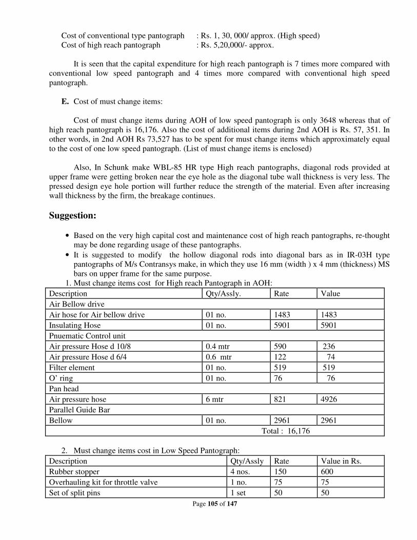
Page 105 of 147
Cost of conventional type pantograph : Rs. 1, 30, 000/ approx. (High speed)
Cost of high reach pantograph : Rs. 5,20,000/- approx.
It is seen that the capital expenditure for high reach pantograph is 7 times more compared with
conventional low speed pantograph and 4 times more compared with conventional high speed
pantograph.
E. Cost of must change items:
Cost of must change items during AOH of low speed pantograph is only 3648 whereas that of
high reach pantograph is 16,176. Also the cost of additional items during 2nd AOH is Rs. 57, 351. In
other words, in 2nd AOH Rs 73,527 has to be spent for must change items which approximately equal
to the cost of one low speed pantograph. (List of must change items is enclosed)
Also, In Schunk make WBL-85 HR type High reach pantographs, diagonal rods provided at
upper frame were getting broken near the eye hole as the diagonal tube wall thickness is very less. The
pressed design eye hole portion will further reduce the strength of the material. Even after increasing
wall thickness by the firm, the breakage continues.
Suggestion:
• Based on the very high capital cost and maintenance cost of high reach pantographs, re-thought
may be done regarding usage of these pantographs.
• It is suggested to modify the hollow diagonal rods into diagonal bars as in IR-03H type
pantographs of M/s Contransys make, in which they use 16 mm (width ) x 4 mm (thickness) MS
bars on upper frame for the same purpose.
1. Must change items cost for High reach Pantograph in AOH:
Description Qty/Assly. Rate Value
Air Bellow drive
Air hose for Air bellow drive 01 no. 1483 1483
Insulating Hose 01 no. 5901 5901
Pnuematic Control unit
Air pressure Hose d 10/8 0.4 mtr 590 236
Air pressure Hose d 6/4 0.6 mtr 122 74
Filter element 01 no. 519 519
O’ ring 01 no. 76 76
Pan head
Air pressure hose 6 mtr 821 4926
Parallel Guide Bar
Bellow 01 no. 2961 2961
Total : 16,176
2. Must change items cost in Low Speed Pantograph:
Description Qty/Assly Rate Value in Rs.
Rubber stopper 4 nos. 150 600
Overhauling kit for throttle valve 1 no. 75 75
Set of split pins 1 set 50 50
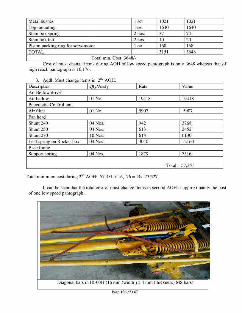
Metal bushes
Top mounting
Stem box spring
Stem box felt
Piston packing ring for servomotor
TOTAL
Cost of must change items during AOH of low speed pantograph is only 3648 whereas that of
high reach pantograph is 16,176.
3. Addl. Must change items in 2
Description Qty/Assly
Air Bellow drive
Air bellow 01 No.
Pnuematic Control unit
Air filter 01 No.
Pan head
Shunt 240 04 Nos.
Shunt 250 04 Nos.
Shunt 270 10 Nos.
Leaf spring on Rocker box 04 Nos.
Base frame
Support spring 04 Nos.
Total minimum cost during 2nd
AOH: 57,351 + 16,176 = Rs. 73,527
It can be seen that the total cost of must change items in second AOH is approximately the cost
of one low speed pantograph.
Diagonal bars in IR
Page 106 of 147
1 set 1021
1 set 1640
2 nos. 37
2 nos. 10
Piston packing ring for servomotor 1 no. 168
3151
Total min. Cost: 3648/-
ost of must change items during AOH of low speed pantograph is only 3648 whereas that of
high reach pantograph is 16,176.
Addl. Must change items in 2nd
AOH:
Qty/Assly Rate
01 No. 19418
01 No. 5907
04 Nos. 942
04 Nos. 613
10 Nos. 613
04 Nos. 3040
04 Nos. 1879
Total: 57,351
AOH: 57,351 + 16,176 = Rs. 73,527
It can be seen that the total cost of must change items in second AOH is approximately the cost
Diagonal bars in IR-03H (16 mm (width ) x 4 mm (thickness) MS bars)
1021
1640
74
20
168
3648
ost of must change items during AOH of low speed pantograph is only 3648 whereas that of
Value
19418
5907
3768
2452
6130
12160
7516
l: 57,351
It can be seen that the total cost of must change items in second AOH is approximately the cost
03H (16 mm (width ) x 4 mm (thickness) MS bars)
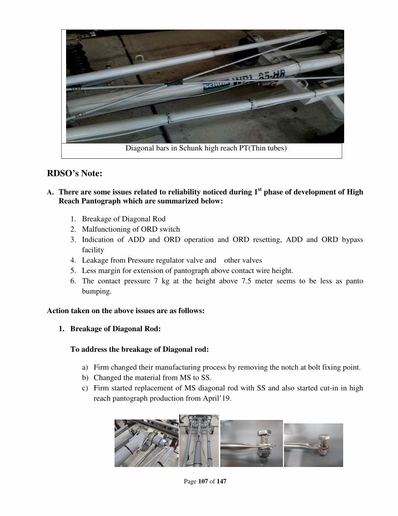
Diagonal bars in Schunk high reach PT(Thin tubes)
RDSO’s Note:
A. There are some issues related to reliability noticed during 1
Reach Pantograph which are summarized below:
1. Breakage of Diagonal Rod
2. Malfunctioning of ORD switch
3. Indication of ADD and ORD operation and ORD resetting,
facility
4. Leakage from Pressure regulator valve and other valves
5. Less margin for extension of
6. The contact pressure 7 kg at the height above 7.5 meter seems to be less as panto
bumping.
Action taken on the above issues are as follows:
1. Breakage of Diagonal Rod:
To address the breakage of Diagonal rod:
a) Firm changed their manufacturing process by removing the notch at bolt fixing point.
b) Changed the material from MS to SS.
c) Firm started replacement of MS diagonal rod with SS and also started cut
reach pantograph production from April’19.
Page 107 of 147
Diagonal bars in Schunk high reach PT(Thin tubes)
There are some issues related to reliability noticed during 1st phase of development of High
which are summarized below:
Breakage of Diagonal Rod
Malfunctioning of ORD switch
Indication of ADD and ORD operation and ORD resetting, ADD and ORD bypass
Leakage from Pressure regulator valve and other valves
Less margin for extension of pantograph above contact wire height.
The contact pressure 7 kg at the height above 7.5 meter seems to be less as panto
Action taken on the above issues are as follows:
Breakage of Diagonal Rod:
To address the breakage of Diagonal rod:
anged their manufacturing process by removing the notch at bolt fixing point.
Changed the material from MS to SS.
Firm started replacement of MS diagonal rod with SS and also started cut
reach pantograph production from April’19.
phase of development of High
ADD and ORD bypass
The contact pressure 7 kg at the height above 7.5 meter seems to be less as panto
anged their manufacturing process by removing the notch at bolt fixing point.
Firm started replacement of MS diagonal rod with SS and also started cut-in in high
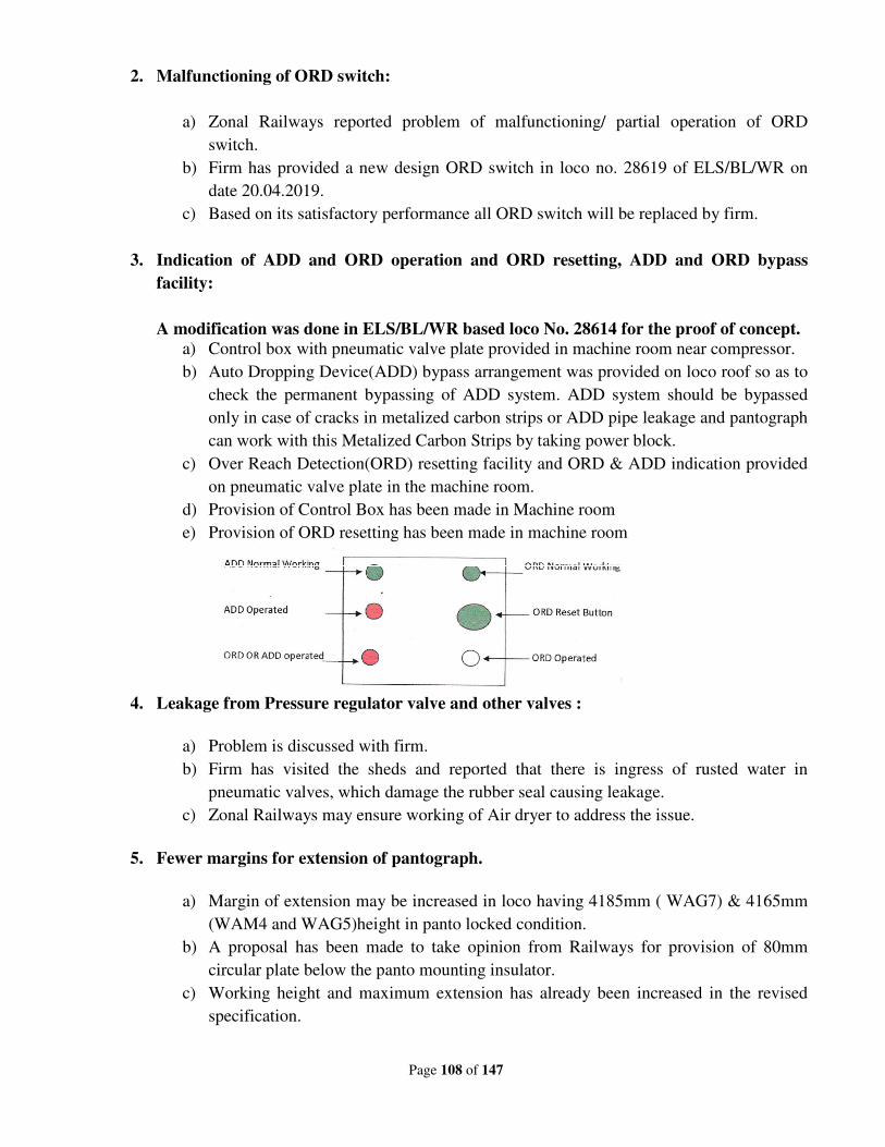
Page 108 of 147
2. Malfunctioning of ORD switch:
a) Zonal Railways reported problem of malfunctioning/ partial operation of ORD
switch.
b) Firm has provided a new design ORD switch in loco no. 28619 of ELS/BL/WR on
date 20.04.2019.
c) Based on its satisfactory performance all ORD switch will be replaced by firm.
3. Indication of ADD and ORD operation and ORD resetting, ADD and ORD bypass
facility:
A modification was done in ELS/BL/WR based loco No. 28614 for the proof of concept.
a) Control box with pneumatic valve plate provided in machine room near compressor.
b) Auto Dropping Device(ADD) bypass arrangement was provided on loco roof so as to
check the permanent bypassing of ADD system. ADD system should be bypassed
only in case of cracks in metalized carbon strips or ADD pipe leakage and pantograph
can work with this Metalized Carbon Strips by taking power block.
c) Over Reach Detection(ORD) resetting facility and ORD & ADD indication provided
on pneumatic valve plate in the machine room.
d) Provision of Control Box has been made in Machine room
e) Provision of ORD resetting has been made in machine room
4. Leakage from Pressure regulator valve and other valves :
a) Problem is discussed with firm.
b) Firm has visited the sheds and reported that there is ingress of rusted water in
pneumatic valves, which damage the rubber seal causing leakage.
c) Zonal Railways may ensure working of Air dryer to address the issue.
5. Fewer margins for extension of pantograph.
a) Margin of extension may be increased in loco having 4185mm ( WAG7) & 4165mm
(WAM4 and WAG5)height in panto locked condition.
b) A proposal has been made to take opinion from Railways for provision of 80mm
circular plate below the panto mounting insulator.
c) Working height and maximum extension has already been increased in the revised
specification.
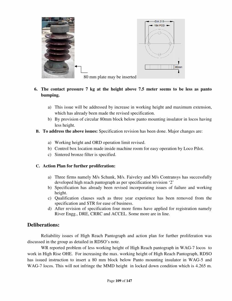
80 mm
6. The contact pressure 7 kg at the height above 7.5 meter seems to be less as panto
bumping.
a) This issue will be addressed by increase in working height and maximum extension,
which has already been made the revised specification.
b) By provision of circular 80mm block below panto mounting insulator in locos having
less height.
B. To address the above issues:
a) Working height and ORD operation limit revised.
b) Control box location made i
c) Sintered bronze filter is specified.
C. Action Plan for further proliferation:
a) Three firms namely M/s Schunk, M/s. Faiveley and M/s Contransys has successfully
developed high reach pantograph as per speci
b) Specification has already been revised incorporating issues of failure and working
height.
c) Qualification clauses such as three year experience has been removed from the
specification and STR for ease of business.
d) After revision of s
River Engg., DRE, CRRC and ACCEL. Some more are in line.
Deliberations:
Reliability issues of High Reach Pantograph and action plan for further proliferation was
discussed in the group as detailed in RDSO’s note.
WR reported problem of less working height of High Reach pantograph in WAG
work in High Rise OHE. For increasing the max. working height of High Reach Pantograph, RDSO
has issued instruction to insert a 80 mm block
WAG-7 locos. This will not infringe the MMD height in locked down condition which is 4.265 m.
Page 109 of 147
80 mm plate may be inserted
The contact pressure 7 kg at the height above 7.5 meter seems to be less as panto
This issue will be addressed by increase in working height and maximum extension,
which has already been made the revised specification.
provision of circular 80mm block below panto mounting insulator in locos having
To address the above issues: Specification revision has been done. Major changes are:
Working height and ORD operation limit revised.
Control box location made inside machine room for easy operation by Loco Pilot.
Sintered bronze filter is specified.
Action Plan for further proliferation:
Three firms namely M/s Schunk, M/s. Faiveley and M/s Contransys has successfully
developed high reach pantograph as per specification revision ‘2’
Specification has already been revised incorporating issues of failure and working
Qualification clauses such as three year experience has been removed from the
specification and STR for ease of business.
After revision of specification four more firms have applied for registration namely
River Engg., DRE, CRRC and ACCEL. Some more are in line.
Reliability issues of High Reach Pantograph and action plan for further proliferation was
as detailed in RDSO’s note.
WR reported problem of less working height of High Reach pantograph in WAG
work in High Rise OHE. For increasing the max. working height of High Reach Pantograph, RDSO
has issued instruction to insert a 80 mm block below Panto mounting insulator in WAG
7 locos. This will not infringe the MMD height in locked down condition which is 4.265 m.
The contact pressure 7 kg at the height above 7.5 meter seems to be less as panto
This issue will be addressed by increase in working height and maximum extension,
provision of circular 80mm block below panto mounting insulator in locos having
Specification revision has been done. Major changes are:
nside machine room for easy operation by Loco Pilot.
Three firms namely M/s Schunk, M/s. Faiveley and M/s Contransys has successfully
fication revision ‘2’
Specification has already been revised incorporating issues of failure and working
Qualification clauses such as three year experience has been removed from the
pecification four more firms have applied for registration namely
Reliability issues of High Reach Pantograph and action plan for further proliferation was
WR reported problem of less working height of High Reach pantograph in WAG-7 locos to
work in High Rise OHE. For increasing the max. working height of High Reach Pantograph, RDSO
below Panto mounting insulator in WAG-5 and
7 locos. This will not infringe the MMD height in locked down condition which is 4.265 m.
Page 110 of 147
This will resolve the working height issue. However, RDSO has revised specification where max.
working height has been increased from 3.4m in Rev ‘2’ to 3.6 m in Rev ‘3’.
Development of High Reach Pantograph as per Rev ‘3’ may take from 6-9 months.
Therefore, RDSO has issued an amendment in their vendor directory that mentions that ZRs/PUs
may continue with procurement of Rev ‘2’ High reach pantograph.
ELS/GMO/ECR reported problem of chipping off of carbon strip of one unit High reach
pantograph supplied by M/s FTRTIL, though there was no abnormality in mechanism of
pantograph.. NR reported that one High reach pantograph of M/s FTRTIL is installed in ELS/LDH
based loco which is working normal since July. ECR and NR are requested to send performance
report.
Distribution of High reach pantographs by CLW to ZRs was discussed. It was suggested that
more pantographs may be supplied to ELS/GZB, LDH, BRC, BL and TKD to take care movement
of trains in High rise OHE coming in WR, NWR and NR region. ZRs can use the released
conventional pantographs as spares and their procurement may be stooped.
SER raised the issue related to Maintenance of High reach pantograph. Maintenance
schedules and TOH/IOH/POH kits for high reach pantograph WBL 85HR are to be finalized by
RDSO based on the experience of railways. Though, it is believed that this pantograph will have less
maintenance as compare to conventional pantograph.
Metallized carbon strip of High reach pantograph is having ADD feature where in a copper
tube is inserted inside the strips. Due to this feature, the carbon strips need to be replaced earlier as
compare to carbon strip of conventional locos. However there is need to develop more sources for
carbon strip with ADD feature. Also, DMW/Patiala has to try to develop the same in their Carbon
shop where carbon brushes for Traction motors are made.
Recommendations:
(i) For increasing the working height of high reach pantograph in conventional locos having
less height, RDSO letter EL/2.2.1/High Reach dated 11.10.2019 is to be followed where
in 80 mm block is inserted below the mounting insulator to raise the lock down height.
(ii) Maintenance schedules for high reach pantograph are to be finalized by RDSO based on
the experience of Zonal Railways.
(iii) As lot of spare pantograph may be released after installation of high reach pantographs.
Instructions already exist vide Railway Board letter no. 2005/Elect(TRS)440/10 Pt dated
04.09.2015.Therefore, procurement of conventional loco pantograph may be regulated
suitably by Zonal Railways
(iv) DMW/Patiala should try to develop metalized carbon strip with ADD feature in their
Carbon shop.
Railway Board’s decision:
May be accepted.
Page 111 of 147
New Item
Item no. : 20
Subject : Adhesion improvement of WAP-5 & WAP-7 locomotive
to avoid wheel slip.
Proposed by : Railway Board
File no. : EL/11.5.5/4
Note of proposing Railway:
RDSO Note:
The three phase locomotive is having slip-slide control with software. Various propulsion
manufacturers have already been intimated about improvement in adhesion. CLW and RDSO are
already processing the same.
Matter was also discussed during 63rd
ESC wherein on the request of PCEE/ECoR, it was
decided to go in for Doppler radar system for slip-slide control in 05 Locomotives on trial basis. For
this CLW was advised to process for developmental order.
Deliberations:
This point was also raised during last ESC meeting as a out of agenda item that in rainy
season when track is in wet condition than WAP5 & WAP7 locos are experiencing excessive wheel
slip resulting in stalling of passenger trains. Problem comes in graded section & also when track is in
wet condition. The question is how to improve the adhesion. Now TCN compliant VCUs of different
make are being used in loco. We should interact with OEMs to fine tune the software for slip –slide
control. Another idea mooted in last ESC recently by ZRs that why not use Doppler radar for slip
slide control which is working is diesel locomotives. The tractive-effort requirement in diesel locos
is less as compared to electric locos & their adhesive weight is more. So they are not experiencing
much problem of slipping. It is due to better slip slide control or else is not known. Doppler radar
system measures ground speed & wheel speed and compares for deciding the tractive-effort strategy.
CLW has provided Doppler radar system in locomotives.RSP for 150nos.was sanctioned in past and
accordingly Doppler radar system for slip slide control were provided in ELS/LGD- 27 nos.,
ELS/AQ- 35 nos., ELS/BIA- 35 nos., ELS/TATA- 10 nos. and ELS/GMO- 35 nos. based
locomotives. In GTO based drive system, adhesion was less due to bogie control feature. Now, due
to axle control, adhesion has already improved. There is new issue of wheel slip in IGBT locos. ZRs
should furnish the details of slip-slide cases with type of loco & make of propulsion system in the
period July’19 to Sep’19. On the basis of details received from Railways, RDSO should discuss the
same with OEMs of propulsion system. Railways should report the failures on RDSO’s on line
failure portal.
Page 112 of 147
Recommendations:
1. There is a problem of adhesion particularly in coaching locos. IGBT converters with
individual axle control, the TCN based VCU suppliers may be adopting different strategies
for slip-slide control. ZRs should furnish the wheel slip cases indicating the make of
propulsion system.
2. RDSO will convene a meeting with CLW, ZRs and OEMs for discussion on strategy for
improving the slip-slide control in locos having IGBT converters and chalk out the action
plan for software or any other modification as per the need.
Railway Board’s decision:
May be accepted.
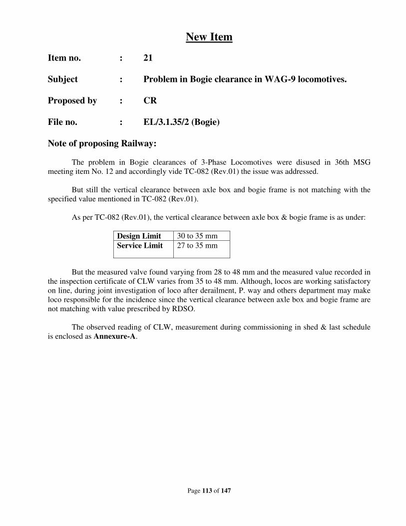
Page 113 of 147
New Item
Item no. : 21
Subject : Problem in Bogie clearance in WAG-9 locomotives.
Proposed by : CR
File no. : EL/3.1.35/2 (Bogie)
Note of proposing Railway:
The problem in Bogie clearances of 3-Phase Locomotives were disused in 36th MSG
meeting item No. 12 and accordingly vide TC-082 (Rev.01) the issue was addressed.
But still the vertical clearance between axle box and bogie frame is not matching with the
specified value mentioned in TC-082 (Rev.01).
As per TC-082 (Rev.01), the vertical clearance between axle box & bogie frame is as under:
Design Limit 30 to 35 mm
Service Limit 27 to 35 mm
But the measured valve found varying from 28 to 48 mm and the measured value recorded in
the inspection certificate of CLW varies from 35 to 48 mm. Although, locos are working satisfactory
on line, during joint investigation of loco after derailment, P. way and others department may make
loco responsible for the incidence since the vertical clearance between axle box and bogie frame are
not matching with value prescribed by RDSO.
The observed reading of CLW, measurement during commissioning in shed & last schedule
is enclosed as Annexure-A.
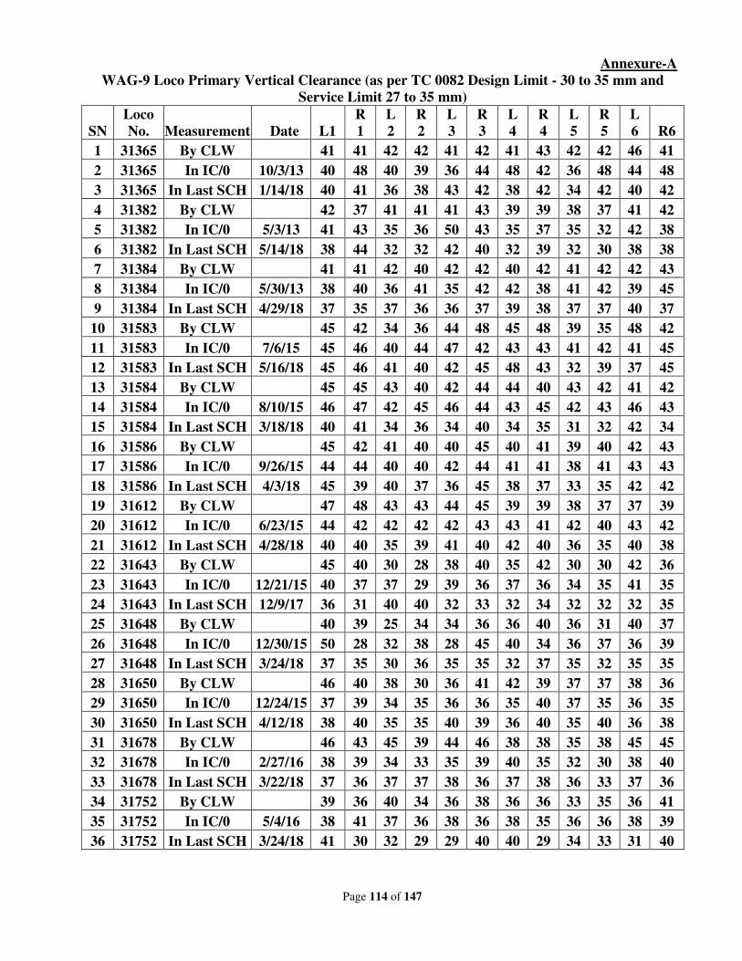
Page 114 of 147
Annexure-A
WAG-9 Loco Primary Vertical Clearance (as per TC 0082 Design Limit - 30 to 35 mm and
Service Limit 27 to 35 mm)
SN
Loco
No. Measurement Date L1
R
1
L
2
R
2
L
3
R
3
L
4
R
4
L
5
R
5
L
6 R6
1 31365 By CLW 41 41 42 42 41 42 41 43 42 42 46 41
2 31365 In IC/0 10/3/13 40 48 40 39 36 44 48 42 36 48 44 48
3 31365 In Last SCH 1/14/18 40 41 36 38 43 42 38 42 34 42 40 42
4 31382 By CLW 42 37 41 41 41 43 39 39 38 37 41 42
5 31382 In IC/0 5/3/13 41 43 35 36 50 43 35 37 35 32 42 38
6 31382 In Last SCH 5/14/18 38 44 32 32 42 40 32 39 32 30 38 38
7 31384 By CLW 41 41 42 40 42 42 40 42 41 42 42 43
8 31384 In IC/0 5/30/13 38 40 36 41 35 42 42 38 41 42 39 45
9 31384 In Last SCH 4/29/18 37 35 37 36 36 37 39 38 37 37 40 37
10 31583 By CLW 45 42 34 36 44 48 45 48 39 35 48 42
11 31583 In IC/0 7/6/15 45 46 40 44 47 42 43 43 41 42 41 45
12 31583 In Last SCH 5/16/18 45 46 41 40 42 45 48 43 32 39 37 45
13 31584 By CLW 45 45 43 40 42 44 44 40 43 42 41 42
14 31584 In IC/0 8/10/15 46 47 42 45 46 44 43 45 42 43 46 43
15 31584 In Last SCH 3/18/18 40 41 34 36 34 40 34 35 31 32 42 34
16 31586 By CLW 45 42 41 40 40 45 40 41 39 40 42 43
17 31586 In IC/0 9/26/15 44 44 40 40 42 44 41 41 38 41 43 43
18 31586 In Last SCH 4/3/18 45 39 40 37 36 45 38 37 33 35 42 42
19 31612 By CLW 47 48 43 43 44 45 39 39 38 37 37 39
20 31612 In IC/0 6/23/15 44 42 42 42 42 43 43 41 42 40 43 42
21 31612 In Last SCH 4/28/18 40 40 35 39 41 40 42 40 36 35 40 38
22 31643 By CLW 45 40 30 28 38 40 35 42 30 30 42 36
23 31643 In IC/0 12/21/15 40 37 37 29 39 36 37 36 34 35 41 35
24 31643 In Last SCH 12/9/17 36 31 40 40 32 33 32 34 32 32 32 35
25 31648 By CLW 40 39 25 34 34 36 36 40 36 31 40 37
26 31648 In IC/0 12/30/15 50 28 32 38 28 45 40 34 36 37 36 39
27 31648 In Last SCH 3/24/18 37 35 30 36 35 35 32 37 35 32 35 35
28 31650 By CLW 46 40 38 30 36 41 42 39 37 37 38 36
29 31650 In IC/0 12/24/15 37 39 34 35 36 36 35 40 37 35 36 35
30 31650 In Last SCH 4/12/18 38 40 35 35 40 39 36 40 35 40 36 38
31 31678 By CLW 46 43 45 39 44 46 38 38 35 38 45 45
32 31678 In IC/0 2/27/16 38 39 34 33 35 39 40 35 32 30 38 40
33 31678 In Last SCH 3/22/18 37 36 37 37 38 36 37 38 36 33 37 36
34 31752 By CLW 39 36 40 34 36 38 36 36 33 35 36 41
35 31752 In IC/0 5/4/16 38 41 37 36 38 36 38 35 36 36 38 39
36 31752 In Last SCH 3/24/18 41 30 32 29 29 40 40 29 34 33 31 40

Page 115 of 147
RDSO’s Note:
This issue was discussed at the 36th
MSG meeting, wherein CLW and RDSO were asked to
study the problem. Based on the MSG recommendation, CLW and RDSO has jointly studied the
problem of abnormal clearance including audit of the manufacturing process at CLW, clearance
specified in ABB drawing no. IB011-00192 and in maintenance and repair manual (Vol. D1) of
WAG9. Also, clarification sought from OEM of the locomotives including study of clearances on
more than 100 locomotives were analyzed.
Based upon the study and analysis and clarification given by the OEM design/service limit of
the bogie clearance has been recommended in RDSO Technical circular no. ELRS/TC/0082 (Rev-1).
The same should be followed.
Deliberations:
RDSO stated that the vertical clearances was reduced in past to address the problem reported
by ELS/AQ. It was done when ELS/AQ was using indigenous spring & was getting compressed
completely and was not even able to maintain the minimum clearance. After reduction in vertical
clearance, ELS/AQ again reported that they are getting vertical clearance more than the stipulated
values advised by RDSO. so again , it was changed to present value. The issue was jointly
investigated by RDSO & CLW in consultation with OEMs. OEMs stated that clearances can’t be
reduced instead the bogie & shell assembly be checked which may be causing the problem. RDSO
stated that locomotives are being manufactured for last 25 years and why this problem has arisen
now. As per OEMs recommendations, the present values of clearances have been stipulated.
Railways were of different opinion regarding type of locos in which this problem is coming i.e. SCR
said that this problem is coming in coaching locos only where as ELS/AQ said that this is coming in
WAG9/9H also. Since problem is coming in both types of loco, weight is not a factor for problem.
RDSO should study the problem jointly with PUs & identify the area i.e. bogie/spring leading to
excess vertical clearance.SER stated that in past when spring height was less, liners were used to
maintain the height of spring. Later on, spring quality was improved but liners were not removed
from drawing and CLW continued the provision of liners. After study by RDSO & CLW, the liners
were removed & problem was addressed to some extent. Still one liner of 3mm is provided. Height
of spring with 3 mm liner is more than 45mm.CLW should ensure the measurement of clearances on
level track. Axle load measurement facility should be created by Pus. Instead of reducing the
clearances, RDSO jointly with CLW & DLW should study the problem and take action.
Zonal Railways were requested to send the details of clearances position wise. Moreover
stiffness of spring and its free height should also be checked in cases, where clearances were found
more. Provision of extra sim should not be made.
Recommendations:
1. CLW in association with RDSO and DLW will study the whole assembly process of
bogie and measurement of clearances to find out the solution to maintain in the
clearances. Thereafter, action will be taken whether limit is to be revised.
2. Zonal Railways/CLW should send the details of cases of excess clearance position
wise/loco wise along with the details of spring property in the bogies, in where excess
clearance were found.

Page 116 of 147
3. Facility to be created by Production units for measurement of axle load on priority.
Railway Board’s decision:
May be accepted.
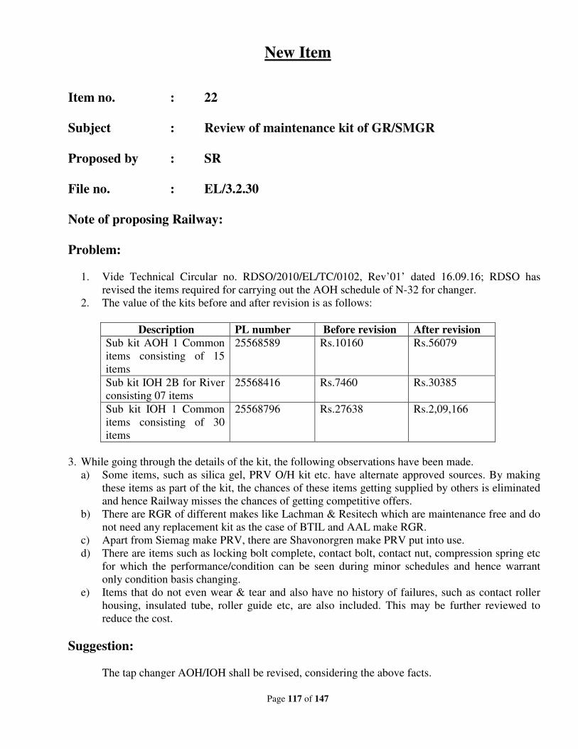
Page 117 of 147
New Item
Item no. : 22
Subject : Review of maintenance kit of GR/SMGR
Proposed by : SR
File no. : EL/3.2.30
Note of proposing Railway:
Problem:
1. Vide Technical Circular no. RDSO/2010/EL/TC/0102, Rev’01’ dated 16.09.16; RDSO has
revised the items required for carrying out the AOH schedule of N-32 for changer.
2. The value of the kits before and after revision is as follows:
Description PL number Before revision After revision
Sub kit AOH 1 Common
items consisting of 15
items
25568589 Rs.10160 Rs.56079
Sub kit IOH 2B for River
consisting 07 items
25568416 Rs.7460 Rs.30385
Sub kit IOH 1 Common
items consisting of 30
items
25568796 Rs.27638 Rs.2,09,166
3. While going through the details of the kit, the following observations have been made.
a) Some items, such as silica gel, PRV O/H kit etc. have alternate approved sources. By making
these items as part of the kit, the chances of these items getting supplied by others is eliminated
and hence Railway misses the chances of getting competitive offers.
b) There are RGR of different makes like Lachman & Resitech which are maintenance free and do
not need any replacement kit as the case of BTIL and AAL make RGR.
c) Apart from Siemag make PRV, there are Shavonorgren make PRV put into use.
d) There are items such as locking bolt complete, contact bolt, contact nut, compression spring etc
for which the performance/condition can be seen during minor schedules and hence warrant
only condition basis changing.
e) Items that do not even wear & tear and also have no history of failures, such as contact roller
housing, insulated tube, roller guide etc, are also included. This may be further reviewed to
reduce the cost.
Suggestion:
The tap changer AOH/IOH shall be revised, considering the above facts.
Page 118 of 147
RDSO’s Note:
Railway Board vide letter no. 2002/Elect.(TRS)/441/4 Pt. I dated 04.07.2016 has nominated a
committee comprising ED/EM, RDSO (Convener), CWM/WR/Dahod and CELE/CR to look into all
the aspects of reliability pertaining to tap changer & SMGR for Conventional Electric Locomotives.
Accordingly, QA Directorate of RDSO issued the SMGR kit requirement in form of Technical Circular
no. RDSO/2010/EL/TC/0102 Rev.1 dated 16.9.2016. Railways should adhere to the said TC in
maintaining the SMGR.
As per Para 3.1 & 3.3 of TC, Zonal Railways may replace the items as per their need and may
also include other items as per their experience and need.
Since, the production of conventional locos have stopped. GR/SMGR are being maintained by
Zonal Railways for a long time. As per their experience, ZRs may add/delete the items as already
provided in TC.
Deliberations:
RDSO should get the feedback from Railways and kit shall be reviewed in light of provisions in
the kit issued prior to 2016.SCR had formed a committee of DEEs to review the kit and have suggested
what has to be kept in the kit. Other Railways shall also form a committee as done by SCR and shall
review the kit. RDSO stated that Railways may add/delete items as per their need & experience.SER
said that firms are not quoting for kit. Zonal Railways shall review the kit within one month and furnish
the details to RDSO who in turn will revise the kit accordingly. If RDSO does not receive the details
from any of the Railways, then RDSO will revise the kit based upon suggestions from SCR & SR.
Recommendations:
Zonal Railways will review the kit within a week time or 10 days and will give feedback to
RDSO that what are the items they want in various kits of GR/SMGR. RDSO will review it and will
hold a one to one meeting also with Railways and will revise the kit accordingly.
Railway Board’s decision:
May be accepted.
Page 119 of 147
New Item
Item no. : 23
Subject : Modification in Traction Motor bellow plate of WAP7
loco.
Proposed by : WR
File no. : El/3.2.172
Note of proposing Railway:
Brief:
ELS/BRCY has a holding of 28 nos. WAP 7 locos. There had been cases on line where in the
bellow plate on the traction motor was completely uprooted from TM, this would result in less
cooling of the traction motor. There had been 10 cases of this failure online and in shed.
Problem Faced:
In WAP7 locos, the T.M. Bellow Plate used to be fixed on T.M. with 8 bolts of size 10 x 20
mm (SS Bolts) Grade A2-70. But issues of loosening of these bolts were frequently arising in these
WAP7 locos.
The possible reasons for arising of the issues are as follows:
1. This loosening of bolts was mainly because of the fact that the threads of these bolts were not
adequate enough to hold on to the bellow plates.
2. Also another reason of this loosening could be the fact that the TM bellow plate is not
welded to the magnet frame unlike in WAP5 locos. Due to this reason the threads of the bolts
and the mechanical bonding between the TM magnet frame and Bellow plate is disrupted by
the vibrations the loco endures.
Action Plan of BRC shed:
To eliminate occurrence of these issues the following modifications have been implemented by
ELS BRC shed:
1. The dimensions of the bolts i.e. the length of the bolt was changed. Initially the bolts of size
10X20 mm were being used by CLW. But now ELS BRC shed is using the bolts of size 10X30
mm so that the length of thread is considerable enough to hold on to the TM bellow plate.
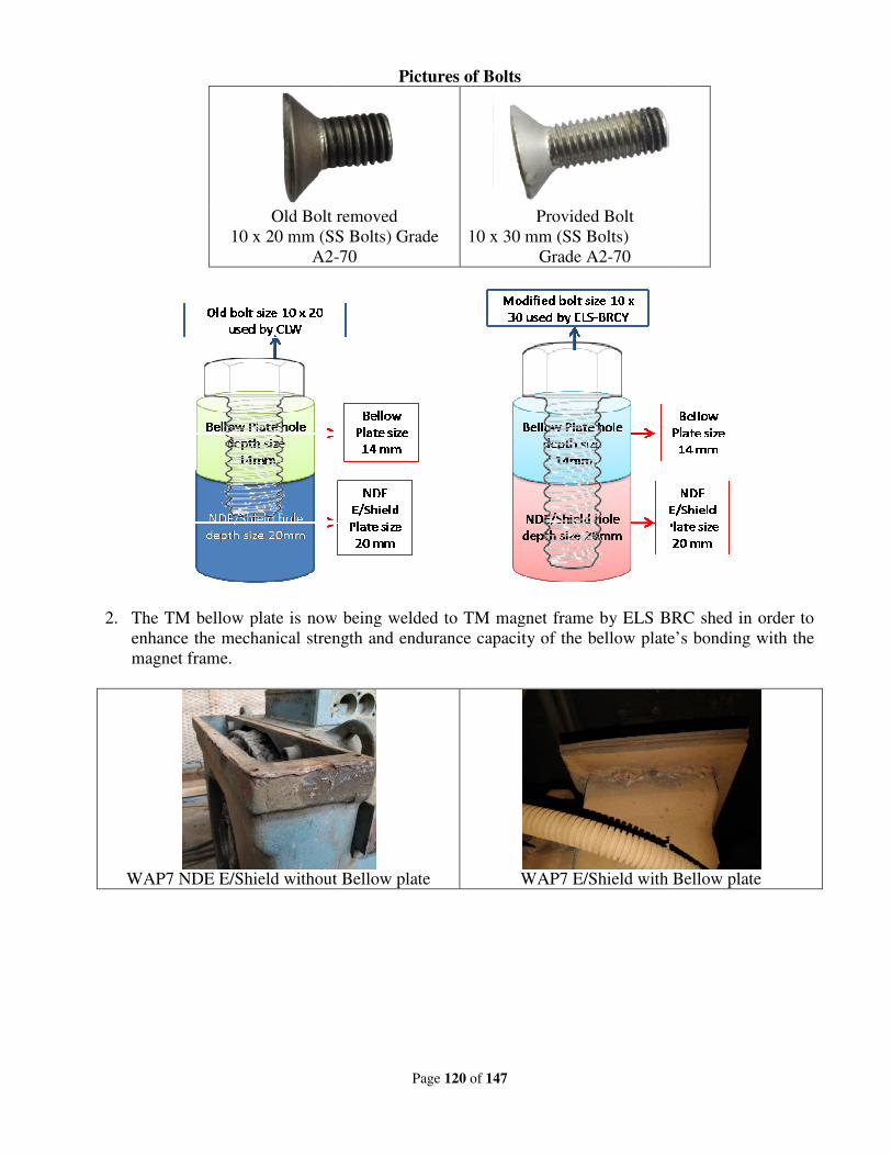
Old Bolt removed
10 x 20 mm (SS Bolts) Grade
A2-
2. The TM bellow plate is now being welded to TM magnet frame by ELS BRC shed in order to
enhance the mechanical strength and endurance capacity of the bello
magnet frame.
WAP7 NDE E/Shield without Bellow plate
Page 120 of 147
Pictures of Bolts
Bolt removed Provided Bolt
10 x 20 mm (SS Bolts) Grade
-70
10 x 30 mm (SS Bolts)
Grade A2-70
The TM bellow plate is now being welded to TM magnet frame by ELS BRC shed in order to
enhance the mechanical strength and endurance capacity of the bellow plate’s bonding with the
WAP7 NDE E/Shield without Bellow plate WAP7 E/Shield with Bellow plate
The TM bellow plate is now being welded to TM magnet frame by ELS BRC shed in order to
w plate’s bonding with the
WAP7 E/Shield with Bellow plate
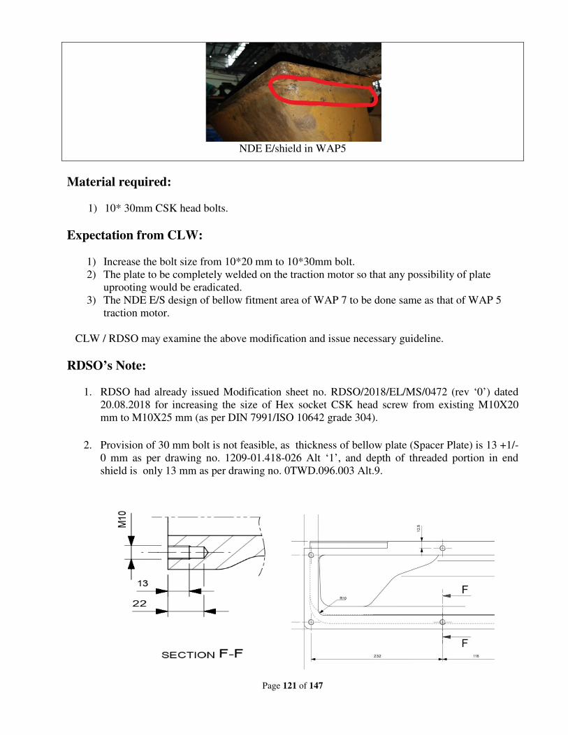
Page 121 of 147
NDE E/shield in WAP5
Material required:
1) 10* 30mm CSK head bolts.
Expectation from CLW:
1) Increase the bolt size from 10*20 mm to 10*30mm bolt.
2) The plate to be completely welded on the traction motor so that any possibility of plate
uprooting would be eradicated.
3) The NDE E/S design of bellow fitment area of WAP 7 to be done same as that of WAP 5
traction motor.
CLW / RDSO may examine the above modification and issue necessary guideline.
RDSO’s Note:
1. RDSO had already issued Modification sheet no. RDSO/2018/EL/MS/0472 (rev ‘0’) dated
20.08.2018 for increasing the size of Hex socket CSK head screw from existing M10X20
mm to M10X25 mm (as per DIN 7991/ISO 10642 grade 304).
2. Provision of 30 mm bolt is not feasible, as thickness of bellow plate (Spacer Plate) is 13 +1/-
0 mm as per drawing no. 1209-01.418-026 Alt ‘1’, and depth of threaded portion in end
shield is only 13 mm as per drawing no. 0TWD.096.003 Alt.9.
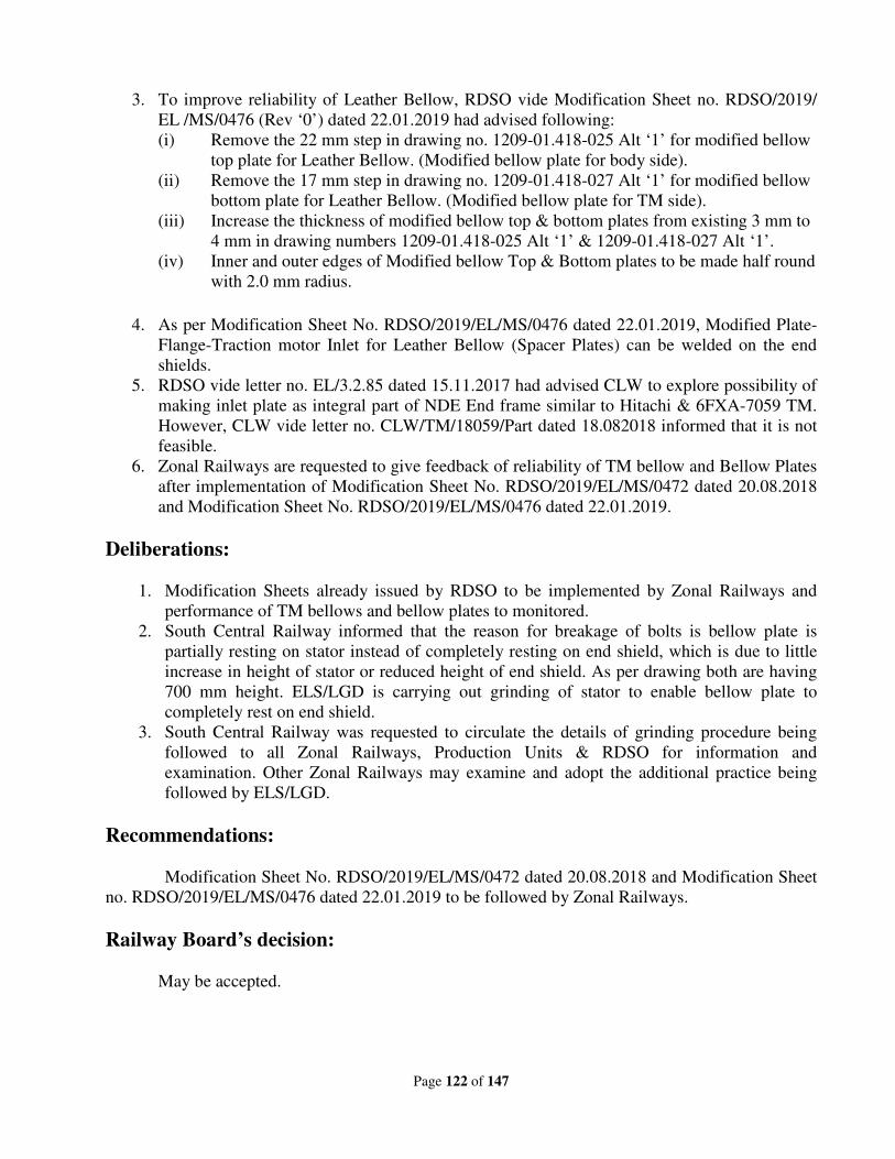
Page 122 of 147
3. To improve reliability of Leather Bellow, RDSO vide Modification Sheet no. RDSO/2019/
EL /MS/0476 (Rev ‘0’) dated 22.01.2019 had advised following:
(i) Remove the 22 mm step in drawing no. 1209-01.418-025 Alt ‘1’ for modified bellow
top plate for Leather Bellow. (Modified bellow plate for body side).
(ii) Remove the 17 mm step in drawing no. 1209-01.418-027 Alt ‘1’ for modified bellow
bottom plate for Leather Bellow. (Modified bellow plate for TM side).
(iii) Increase the thickness of modified bellow top & bottom plates from existing 3 mm to
4 mm in drawing numbers 1209-01.418-025 Alt ‘1’ & 1209-01.418-027 Alt ‘1’.
(iv) Inner and outer edges of Modified bellow Top & Bottom plates to be made half round
with 2.0 mm radius.
4. As per Modification Sheet No. RDSO/2019/EL/MS/0476 dated 22.01.2019, Modified Plate-
Flange-Traction motor Inlet for Leather Bellow (Spacer Plates) can be welded on the end
shields.
5. RDSO vide letter no. EL/3.2.85 dated 15.11.2017 had advised CLW to explore possibility of
making inlet plate as integral part of NDE End frame similar to Hitachi & 6FXA-7059 TM.
However, CLW vide letter no. CLW/TM/18059/Part dated 18.082018 informed that it is not
feasible.
6. Zonal Railways are requested to give feedback of reliability of TM bellow and Bellow Plates
after implementation of Modification Sheet No. RDSO/2019/EL/MS/0472 dated 20.08.2018
and Modification Sheet No. RDSO/2019/EL/MS/0476 dated 22.01.2019.
Deliberations:
1. Modification Sheets already issued by RDSO to be implemented by Zonal Railways and
performance of TM bellows and bellow plates to monitored.
2. South Central Railway informed that the reason for breakage of bolts is bellow plate is
partially resting on stator instead of completely resting on end shield, which is due to little
increase in height of stator or reduced height of end shield. As per drawing both are having
700 mm height. ELS/LGD is carrying out grinding of stator to enable bellow plate to
completely rest on end shield.
3. South Central Railway was requested to circulate the details of grinding procedure being
followed to all Zonal Railways, Production Units & RDSO for information and
examination. Other Zonal Railways may examine and adopt the additional practice being
followed by ELS/LGD.
Recommendations:
Modification Sheet No. RDSO/2019/EL/MS/0472 dated 20.08.2018 and Modification Sheet
no. RDSO/2019/EL/MS/0476 dated 22.01.2019 to be followed by Zonal Railways.
Railway Board’s decision:
May be accepted.
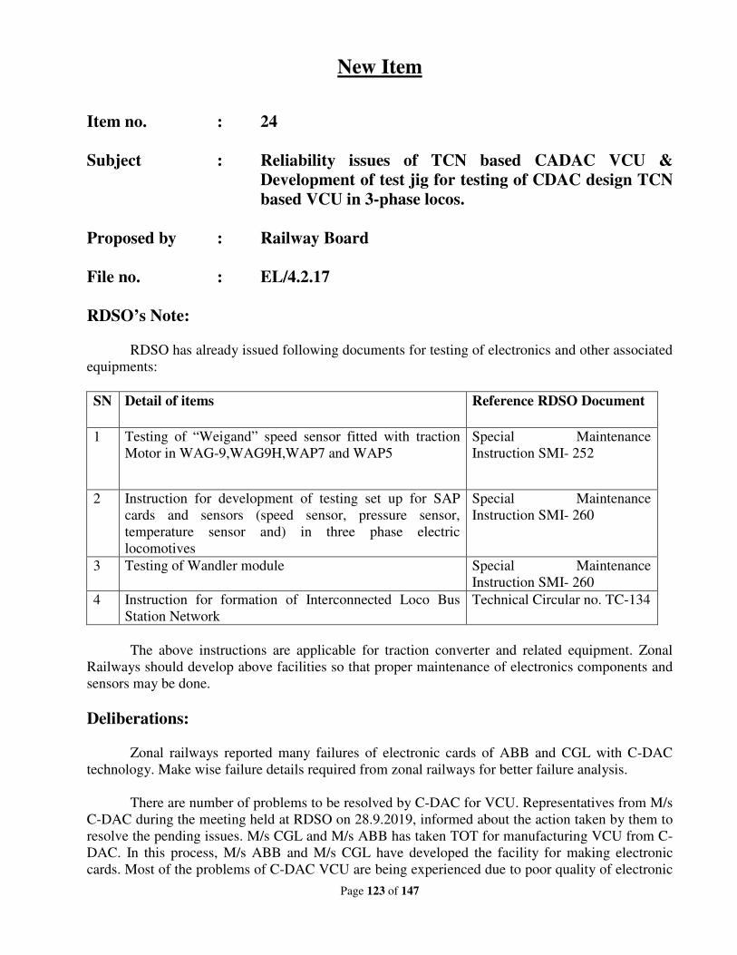
Page 123 of 147
New Item
Item no. : 24
Subject : Reliability issues of TCN based CADAC VCU &
Development of test jig for testing of CDAC design TCN
based VCU in 3-phase locos.
Proposed by : Railway Board
File no. : EL/4.2.17
RDSO’s Note:
RDSO has already issued following documents for testing of electronics and other associated
equipments:
SN Detail of items Reference RDSO Document
1 Testing of “Weigand” speed sensor fitted with traction
Motor in WAG-9,WAG9H,WAP7 and WAP5
Special Maintenance
Instruction SMI- 252
2 Instruction for development of testing set up for SAP
cards and sensors (speed sensor, pressure sensor,
temperature sensor and) in three phase electric
locomotives
Special Maintenance
Instruction SMI- 260
3 Testing of Wandler module Special Maintenance
Instruction SMI- 260
4 Instruction for formation of Interconnected Loco Bus
Station Network
Technical Circular no. TC-134
The above instructions are applicable for traction converter and related equipment. Zonal
Railways should develop above facilities so that proper maintenance of electronics components and
sensors may be done.
Deliberations:
Zonal railways reported many failures of electronic cards of ABB and CGL with C-DAC
technology. Make wise failure details required from zonal railways for better failure analysis.
There are number of problems to be resolved by C-DAC for VCU. Representatives from M/s
C-DAC during the meeting held at RDSO on 28.9.2019, informed about the action taken by them to
resolve the pending issues. M/s CGL and M/s ABB has taken TOT for manufacturing VCU from C-
DAC. In this process, M/s ABB and M/s CGL have developed the facility for making electronic
cards. Most of the problems of C-DAC VCU are being experienced due to poor quality of electronic
Page 124 of 147
cards. It is also noted that the original VCU cards supplied by M/s C-DAC gave much better
performance when it was fitted in ELS/TKD locos initially. Therefore, there is a need for quality
audit of electronic cards being supplied for VCU by M/s ABB & M/s CGL.
Zonal Railways pointed out for having reasonable number of laptops to be supplied along
with supply of Traction Converters/Auxiliary Converters. A yardstick of one laptop on a supply of
25 converters was considered.
Test Zig for testing of C-DAC design TCN based VCU developed by TKD shed was
discussed. Zonal Railways requested to include test zig developed by propulsion manufactures for
different make VCU in their purchase order.
Recommendations:
1. Quality audit of electronic cards based on C-DAC technology of ABB and CGL make to be
carried out by CLW/RDSO and SCR in their manufacturing premises.
2. Test Zig of various types to be procured by CLW from manufactures during procurement of
propulsion system and to be distributed to Zonal Railways.
Railway Board’s decision:
May be accepted.
Page 125 of 147
New Item
Item no. : 25
Subject : Conversion of GTO based propulsion system to IGBT
based propulsion system for WAG-9 in MTR.
Proposed by : SCR
File no. : EL/3.1.35/17
Note of proposing Railway:
Railways took a policy decision that with effect from January 2016, only 3-Phase Electric
Locomotives should be manufactured by the Production Units. With the advent of IGBTs, which
have superior operating performance, better reliability, maintainability and efficiency vis-a-vis
GTOs, need was felt for considering retro-fitment of IGBT based traction converters and auxiliary
converters on locos equipped with GTO based traction converters and auxiliary converters, at the
end of the codal life of the GTO based products. Dwindling OEM support for the GTO based
technology was another factor which is making this switchover to IGBT inevitable. With this
mandate, a committee was constituted by Railway Board vide letter No. 2009/Elect(TRS)/720/1 Pt
2 dated 02.09.14 for submitting a report on “Mid-Term rehabilitation of 3-Phase Electric
Locomotives”. Based on the recommendations of this committee, Railway Board vide letter No.
2009/Elect(TRS)/720/1 Pt. 2 dt. 18.11.2015, approved for Up-gradation of GTO based 3-Phase locos
to IGBT based converters, after completion of 18 years codal life of converter by Electric loco
workshops and sheds.
RDSO vide letter no. EL/3.6.1/1 dated 19.10.16, specified the periodicity of POH schedule
for WAP-5/WAP-7 as 9 Years± 6 months and for WAG-9/9H as 12 Years± 6 months. This means
that the Up-gradation work would be done during 2nd POH schedule for WAP-5/WAP-7
locomotives (18 years) & during 2nd IOH schedule after 1st POH for WAG-9/9H type Locomotives
as recommended and approved by Railway Board.
Carrying out this major work of Up-gradation of GTO based WAG-9 locos to IGBT based locos by
locosheds in 2nd
IOH schedule after 1st POH would have following implications:
a) Responsibility of Procurement, Provision and Commissioning of IGBT based propulsion
system during Mid-Term rehabilitation for up-gradation of GTO based WAG 9 locos,
solely lies with maintenance sheds, since there is no nominated POH shop for carrying out
this work in 3-Phase locomotives. For Conventional electric locomotives Mid-Term
Rehabilitation is done by DHD workshops after 18 years.
b) The funds required for procurement of above equipment cannot be allocated from existing
funds and the same requires to be procured either under Revenue Head or DRF head or
RSP which further delays the process.
c) The time involved and the manpower and material resources required for carrying out this
work would undoubtedly have an adverse impact on shed outage.
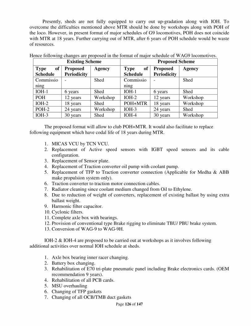
Page 126 of 147
Presently, sheds are not fully equipped to carry out up-gradation along with IOH. To
overcome the difficulties mentioned above MTR should be done by workshops along with POH of
the loco. However, in present format of major schedules of G9 locomotives, POH does not coincide
with MTR at 18 years. Further carrying out of MTR, after 6 years of POH schedule would be waste
of resources.
Hence following changes are proposed in the format of major schedule of WAG9 locomotives.
Existing Scheme Proposed Scheme
Type of
Schedule
Proposed
Periodicity
Agency Type of
Schedule
Proposed
Periodicity
Agency
Commissio
ning
- Shed Commissio
ning
- Shed
IOH-1 6 years Shed IOH-1 6 years Shed
POH 12 years Workshop IOH-2 12 years Workshop
IOH-2 18 years Shed POH+MTR 18 years Workshop
POH-2 24 years Workshop IOH-3 24 years Shed
IOH-3 30 years Shed IOH-4 30 years Workshop
The proposed format will allow to club POH+MTR. It would also facilitate to replace
following equipment which have codal life of 18 years during MTR.
1. MICAS VCU by TCN VCU.
2. Replacement of Active speed sensors with IGBT speed sensors and its cable
configuration.
3. Replacement of Sensor plate.
4. Replacement of Traction converter oil pump with coolant pump.
5. Replacement of TFP to Traction converter connection (Applicable for Medha & ABB
make propulsion system only).
6. Traction converter to traction motor connection cables.
7. Radiator cleaning since coolant medium changed from Oil to Ethylene.
8. Due to reduction of weight of converters, replacement of existing ballast by using extra
ballast weight.
9. Harmonic filter capacitor.
10. Cyclonic filters.
11. Complete axle box with bearings.
12. Provision of conventional type Brake rigging to eliminate TBU/ PBU brake system.
13. Conversion of WAG-9 to WAG-9H.
IOH-2 & IOH-4 are proposed to be carried out at workshops as it involves following
additional activities over normal IOH schedule at sheds.
1. Axle box bearing inner racer changing.
2. Battery box changing.
3. Rehabilitation of E70 tri-plate pneumatic panel including Brake electronics cards. (OEM
recommendation 9 years).
4. Rehabilitation of all PCB cards.
5. MSU overhauling
6. Changing of TFP gaskets
7. Changing of all OCB/TMB duct gaskets
Page 127 of 147
8. Replacement of fiber body above CBC
RDSO’s Note:
Railway Board vide letter no. 2009/Elect(TRS)/720/1 Pt.2 dated 18-11-2015, decided to
change the locomotives fitted with GTO based propulsion system into IGBT based propulsion
system during Mid-term rehabilitation. In this concern Modification Sheet no.
RDSO/2018/EL/MS/0473 had been issued by RDSO vide letter no. EL 3.1.35/17 dated 17-09-2018.
Deliberations:
ELS/AQ has already carried out conversion work successfully in the shed. Other Zonal
Railways have expressed that they have also done it. Various Zonal Railways are doing conversion
of GTO based propulsion system to IGBT based system in IOH-2.SCR wanted to carry out MTR in
18 years by replacing auxiliary machines.
There should not be any POH for WAG-9 locomotive. It was pointed out that there are no
such guidelines for MTR. Since cable with e-beam and stainless steel piping are already provided in
3-phase locomotives, there is no need for rehabilitation. There was some justification for MTR of
conventional locos since replacement of steel pipe and cable was required along with other work like
Arno to SIV conversion. No such work is needed for 3-phase loco.
Zonal Railways expressed that conversion work can be done in shed only as per the need.
There is no need for MTR of 3-phase loco. All must change items should be replaced in POH.
Recommendations:
1. No change is required in existing major maintenance schedule of WAG- 9/9H/HC locos.
2. Zonal Railways should follow Modification Sheet no. RDSO/2018/EL/MS/0473 issued by
RDSO for conversion of GTO to IGBT converters.
Railway Board’s decision:
May be accepted.
Page 128 of 147
Other important issues:
1. Back up brake (PTDC) is available in CCB and M/s FTRTIL has also developed similar type of
back up brake system. However, due to SR interlock, speed upto 10 kmph can only be achieved
during failure of brake system with back up brake. It was decided in the group that speed
restriction should be increased to 25 kmph for which CLW has to carry out necessary software
modification in VCU in consultation with OEMs.
Railway Board’s decision:
May be accepted.
2. Zonal Railways reported problem in maintenance of terminal box in CCB because of its location.
Very less space is available for staff to work between CCB panel and TM duct. This terminal
box may be shifted to top side. RDSO has to discuss with firm to sort out the issue.
Railway Board’s decision:
May be accepted.
3. CEE(Loco)/DLW made a presentation on energy saving scheme in 3-phase electric locomotives
wherein it was explained that how the energy can be saved by switching off the TMB 1&2 and
OCB 1 & 2 while loco is in idle mode. This is already been done in conventional electric
locomotives. As per the logic of scheme, whenever the throttle is on zero and speed of loco is
also zero and transformer & converter oil is less than 600C than the software will switch off the
said auxiliaries after 2 minutes (configurable) and in-turn huge amount of energy can be saved.
The said is being tested in SER. After feedback, necessary modification may be made in loco
software by CLW.
Railway Board’s decision:
May be accepted.
4. Development of source for conventional brake items.
Recommendations of MSG:
As CLW is vendor controlling authority. CLW should develop the adequate sources for
conventional brake items.
Railway Board’s decision:
Conventional locos are going to be in service upto 30 years. Adequate sources may be developed
for conventional brake items by CLW.
5. AAL connectors failures.
(i) To conduct Quality Audit of connectors jointly by CLW & RDSO.
(ii) During the process, its specification should also be reviewed for necessary inclusion of
additional tests/inspection for improving the reliability.
(iii) CLW, being the vendor controlling authority was also requested to develop more/additional
sources.
Railway Board’s decision:
May be accepted.
6. OCU blower failures.
The quality audit of sheds/firms shall be undertaken by RDSO/CLW along with detailed failure
analysis and workmanship issues with the firm.
Railway Board’s decision:
May be accepted.
Page 129 of 147
7. Performance of Scheme 1 & scheme 2 for rotors of 3-phase traction motors.
Reliability level of both the schemes is more or less at same level and satisfactory. the sheds
were advised to ensure the compliance of modification sheet no. RDSO/2015/EL/MS/0438,
(Rev. 0) for scheme 2 rotors.
Railway Board’s decision:
May be accepted.
Page 130 of 147
Part-II
Review of Implementation of decisions of last (38th) MSG
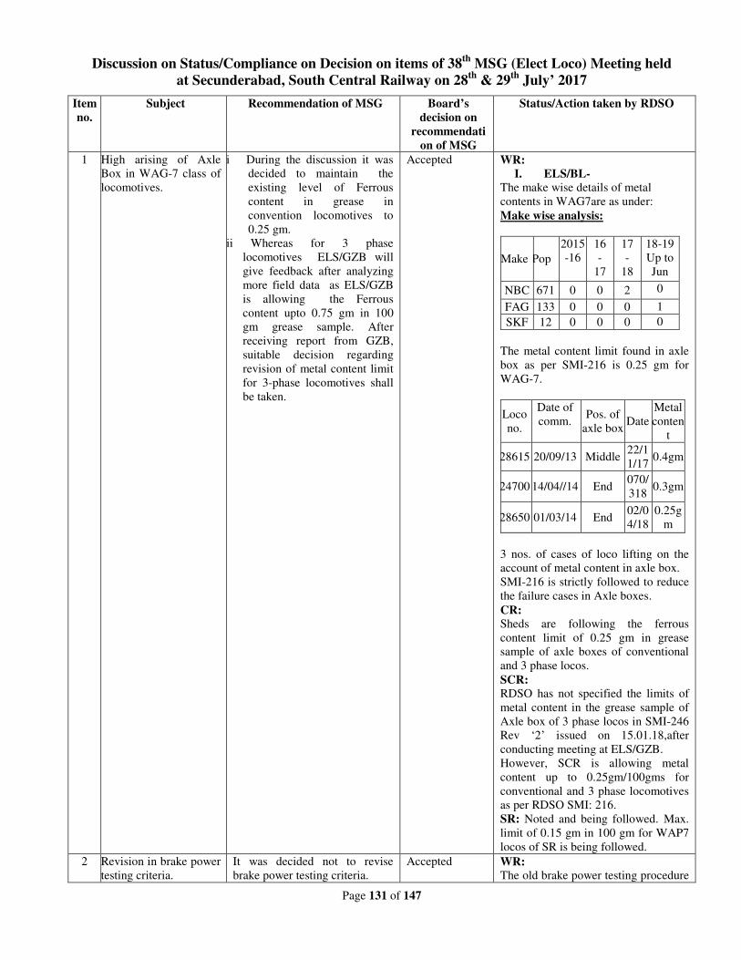
Page 131 of 147
Discussion on Status/Compliance on Decision on items of 38th
MSG (Elect Loco) Meeting held
at Secunderabad, South Central Railway on 28th
& 29th
July’ 2017
Item
no.
Subject Recommendation of MSG Board’s
decision on
recommendati
on of MSG
Status/Action taken by RDSO
1 High arising of Axle
Box in WAG-7 class of
locomotives.
i During the discussion it was
decided to maintain the
existing level of Ferrous
content in grease in
convention locomotives to
0.25 gm.
ii Whereas for 3 phase
locomotives ELS/GZB will
give feedback after analyzing
more field data as ELS/GZB
is allowing the Ferrous
content upto 0.75 gm in 100
gm grease sample. After
receiving report from GZB,
suitable decision regarding
revision of metal content limit
for 3-phase locomotives shall
be taken.
Accepted WR:
I. ELS/BL-
The make wise details of metal
contents in WAG7are as under:
Make wise analysis:
Make Pop
2015
-16
16
-
17
17
-
18
18-19
Up to
Jun
NBC 671 0 0 2 0
FAG 133 0 0 0 1
SKF 12 0 0 0 0
The metal content limit found in axle
box as per SMI-216 is 0.25 gm for
WAG-7.
Loco
no.
Date of
comm. Pos. of
axle box Date
Metal
conten
t
28615 20/09/13 Middle 22/1
1/17 0.4gm
24700 14/04//14 End 070/
318 0.3gm
28650 01/03/14 End 02/0
4/18
0.25g
m
3 nos. of cases of loco lifting on the
account of metal content in axle box.
SMI-216 is strictly followed to reduce
the failure cases in Axle boxes.
CR:
Sheds are following the ferrous
content limit of 0.25 gm in grease
sample of axle boxes of conventional
and 3 phase locos.
SCR:
RDSO has not specified the limits of
metal content in the grease sample of
Axle box of 3 phase locos in SMI-246
Rev ‘2’ issued on 15.01.18,after
conducting meeting at ELS/GZB.
However, SCR is allowing metal
content up to 0.25gm/100gms for
conventional and 3 phase locomotives
as per RDSO SMI: 216.
SR: Noted and being followed. Max.
limit of 0.15 gm in 100 gm for WAP7
locos of SR is being followed.
2 Revision in brake power
testing criteria.
It was decided not to revise
brake power testing criteria.
Accepted WR:
The old brake power testing procedure
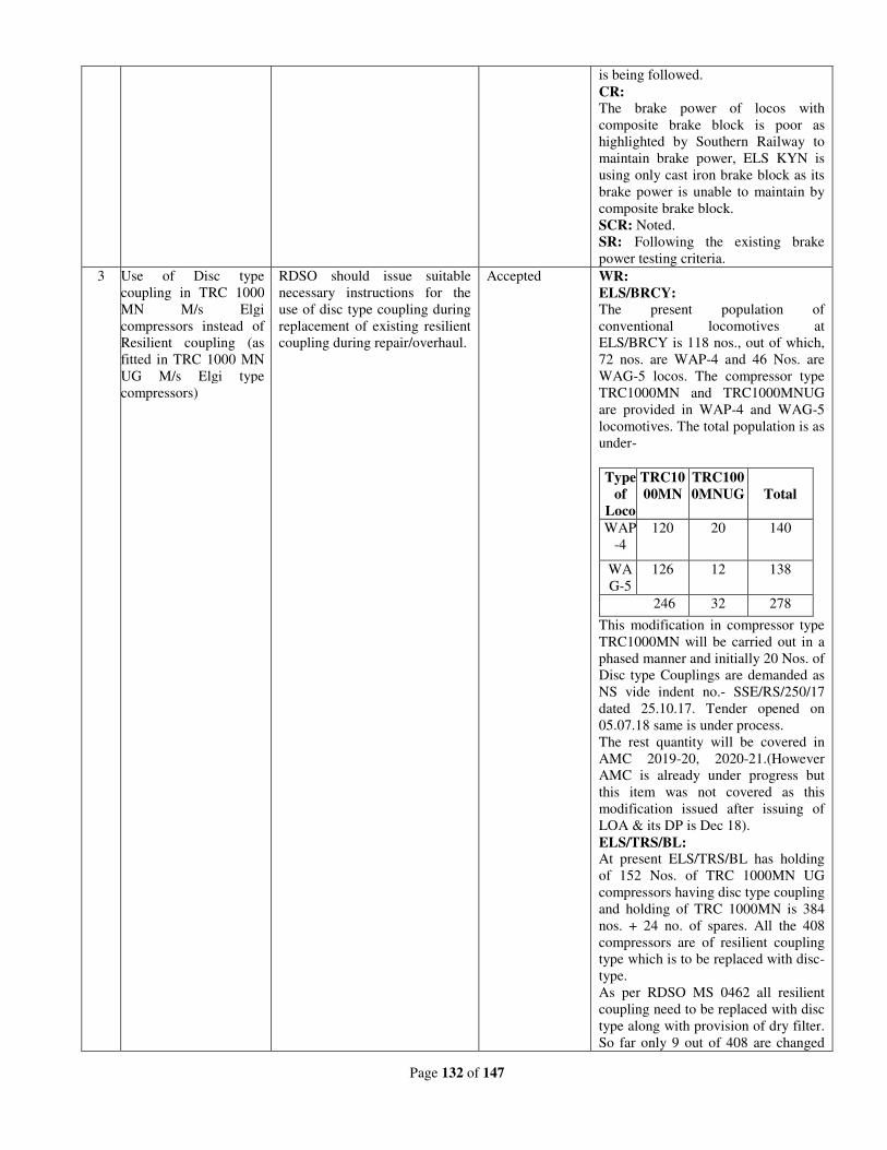
Page 132 of 147
is being followed.
CR:
The brake power of locos with
composite brake block is poor as
highlighted by Southern Railway to
maintain brake power, ELS KYN is
using only cast iron brake block as its
brake power is unable to maintain by
composite brake block.
SCR: Noted.
SR: Following the existing brake
power testing criteria.
3 Use of Disc type
coupling in TRC 1000
MN M/s Elgi
compressors instead of
Resilient coupling (as
fitted in TRC 1000 MN
UG M/s Elgi type
compressors)
RDSO should issue suitable
necessary instructions for the
use of disc type coupling during
replacement of existing resilient
coupling during repair/overhaul.
Accepted WR:
ELS/BRCY:
The present population of
conventional locomotives at
ELS/BRCY is 118 nos., out of which,
72 nos. are WAP-4 and 46 Nos. are
WAG-5 locos. The compressor type
TRC1000MN and TRC1000MNUG
are provided in WAP-4 and WAG-5
locomotives. The total population is as
under-
Type
of
Loco
TRC10
00MN
TRC100
0MNUG
Total
WAP
-4
120 20 140
WA
G-5
126 12 138
246 32 278
This modification in compressor type
TRC1000MN will be carried out in a
phased manner and initially 20 Nos. of
Disc type Couplings are demanded as
NS vide indent no.- SSE/RS/250/17
dated 25.10.17. Tender opened on
05.07.18 same is under process.
The rest quantity will be covered in
AMC 2019-20, 2020-21.(However
AMC is already under progress but
this item was not covered as this
modification issued after issuing of
LOA & its DP is Dec 18).
ELS/TRS/BL: At present ELS/TRS/BL has holding
of 152 Nos. of TRC 1000MN UG
compressors having disc type coupling
and holding of TRC 1000MN is 384
nos. + 24 no. of spares. All the 408
compressors are of resilient coupling
type which is to be replaced with disc-
type.
As per RDSO MS 0462 all resilient
coupling need to be replaced with disc
type along with provision of dry filter.
So far only 9 out of 408 are changed
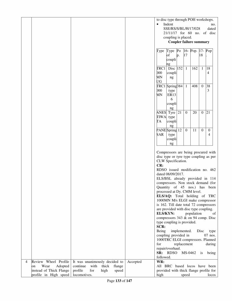
Page 133 of 147
to disc type through POH workshops.
• Indent no.
SSE/RS/S/BL/H/17/028 dated
21/11/17 for 60 no. of disc
coupling is placed.
Coupler failure summary
Type Type
of
coupli
ng
Po
p.
16-
17
Pop. 17-
18
Pop
.
TRC1
000
MN
UG
Disc
coupli
ng
152 1 162 1 18
4
TRC1
000
MN
Spring
type
ER13
6
coupli
ng
384 1 408 0 38
3
ANES
TIWA
TA
Tyre
type
coupli
ng
21 0 20 0 21
PANE
SAR
Spring
type
coupli
ng
12 0 11 0 0
4
Compressors are being procured with
disc type or tyre type coupling as per
CLW Specification.
CR:
RDSO issued modification no. 462
dated 08/09/2017.
ELS/BSL already provided in 114
compressors. Non stock demand (for
Quantity of 45 nos.) has been
processed at Dy. CMM level.
ELS/AQ: Total holding of TRC
1000MN M/s ELGI make compressor
is 162. Till date total 72 compressors
are provided with disc type coupling.
ELS/KYN: population of
compressors 343 & on 94 comp. Disc
type coupling is provided.
SCR:
Being implemented. Disc type
coupling provided in 07 nos.
1000TRC ELGI compressors. Planned
for replacement during
repair/overhaul.
SR: RDSO MS-0462 is being
followed.
4 Review Wheel Profile
on Wear Adopted
instead of Thick Flange
profile in High speed
It was unanimously decided to
continue with thick flange
profile for high speed
locomotives.
Accepted WR:
All BRC based locos have been
provided with thick flange profile for
high speed locos
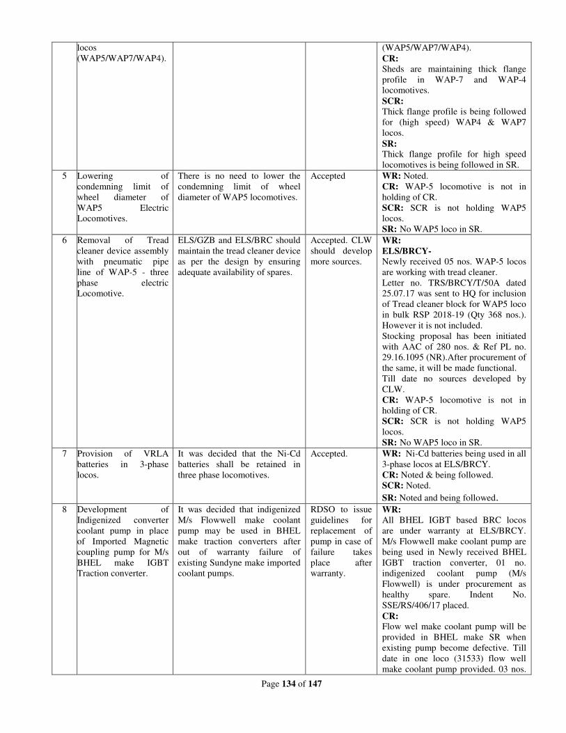
Page 134 of 147
locos
(WAP5/WAP7/WAP4).
(WAP5/WAP7/WAP4).
CR:
Sheds are maintaining thick flange
profile in WAP-7 and WAP-4
locomotives.
SCR:
Thick flange profile is being followed
for (high speed) WAP4 & WAP7
locos.
SR: Thick flange profile for high speed
locomotives is being followed in SR.
5 Lowering of
condemning limit of
wheel diameter of
WAP5 Electric
Locomotives.
There is no need to lower the
condemning limit of wheel
diameter of WAP5 locomotives.
Accepted WR: Noted.
CR: WAP-5 locomotive is not in
holding of CR.
SCR: SCR is not holding WAP5
locos.
SR: No WAP5 loco in SR.
6 Removal of Tread
cleaner device assembly
with pneumatic pipe
line of WAP-5 - three
phase electric
Locomotive.
ELS/GZB and ELS/BRC should
maintain the tread cleaner device
as per the design by ensuring
adequate availability of spares.
Accepted. CLW
should develop
more sources.
WR:
ELS/BRCY-
Newly received 05 nos. WAP-5 locos
are working with tread cleaner.
Letter no. TRS/BRCY/T/50A dated
25.07.17 was sent to HQ for inclusion
of Tread cleaner block for WAP5 loco
in bulk RSP 2018-19 (Qty 368 nos.).
However it is not included.
Stocking proposal has been initiated
with AAC of 280 nos. & Ref PL no.
29.16.1095 (NR).After procurement of
the same, it will be made functional.
Till date no sources developed by
CLW.
CR: WAP-5 locomotive is not in
holding of CR.
SCR: SCR is not holding WAP5
locos.
SR: No WAP5 loco in SR.
7 Provision of VRLA
batteries in 3-phase
locos.
It was decided that the Ni-Cd
batteries shall be retained in
three phase locomotives.
Accepted. WR: Ni-Cd batteries being used in all
3-phase locos at ELS/BRCY.
CR: Noted & being followed.
SCR: Noted.
SR: Noted and being followed. 8 Development of
Indigenized converter
coolant pump in place
of Imported Magnetic
coupling pump for M/s
BHEL make IGBT
Traction converter.
It was decided that indigenized
M/s Flowwell make coolant
pump may be used in BHEL
make traction converters after
out of warranty failure of
existing Sundyne make imported
coolant pumps.
RDSO to issue
guidelines for
replacement of
pump in case of
failure takes
place after
warranty.
WR:
All BHEL IGBT based BRC locos
are under warranty at ELS/BRCY.
M/s Flowwell make coolant pump are
being used in Newly received BHEL
IGBT traction converter, 01 no.
indigenized coolant pump (M/s
Flowwell) is under procurement as
healthy spare. Indent No.
SSE/RS/406/17 placed.
CR: Flow wel make coolant pump will be
provided in BHEL make SR when
existing pump become defective. Till
date in one loco (31533) flow well
make coolant pump provided. 03 nos.
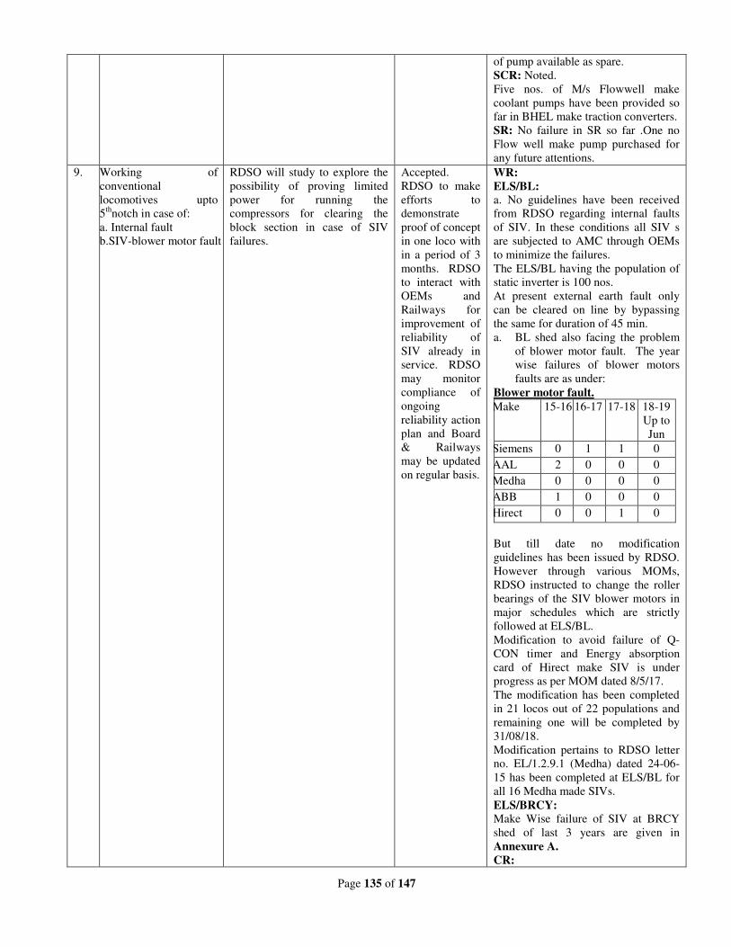
Page 135 of 147
of pump available as spare.
SCR: Noted.
Five nos. of M/s Flowwell make
coolant pumps have been provided so
far in BHEL make traction converters.
SR: No failure in SR so far .One no
Flow well make pump purchased for
any future attentions.
9. Working of
conventional
locomotives upto
5th
notch in case of:
a. Internal fault
b.SIV-blower motor fault
RDSO will study to explore the
possibility of proving limited
power for running the
compressors for clearing the
block section in case of SIV
failures.
Accepted.
RDSO to make
efforts to
demonstrate
proof of concept
in one loco with
in a period of 3
months. RDSO
to interact with
OEMs and
Railways for
improvement of
reliability of
SIV already in
service. RDSO
may monitor
compliance of
ongoing
reliability action
plan and Board
& Railways
may be updated
on regular basis.
WR:
ELS/BL:
a. No guidelines have been received
from RDSO regarding internal faults
of SIV. In these conditions all SIV s
are subjected to AMC through OEMs
to minimize the failures.
The ELS/BL having the population of
static inverter is 100 nos.
At present external earth fault only
can be cleared on line by bypassing
the same for duration of 45 min.
a. BL shed also facing the problem
of blower motor fault. The year
wise failures of blower motors
faults are as under:
Blower motor fault.
Make 15-16 16-17 17-18 18-19
Up to
Jun
Siemens 0 1 1 0
AAL 2 0 0 0
Medha 0 0 0 0
ABB 1 0 0 0
Hirect 0 0 1 0
But till date no modification
guidelines has been issued by RDSO.
However through various MOMs,
RDSO instructed to change the roller
bearings of the SIV blower motors in
major schedules which are strictly
followed at ELS/BL.
Modification to avoid failure of Q-
CON timer and Energy absorption
card of Hirect make SIV is under
progress as per MOM dated 8/5/17.
The modification has been completed
in 21 locos out of 22 populations and
remaining one will be completed by
31/08/18.
Modification pertains to RDSO letter
no. EL/1.2.9.1 (Medha) dated 24-06-
15 has been completed at ELS/BL for
all 16 Medha made SIVs.
ELS/BRCY:
Make Wise failure of SIV at BRCY
shed of last 3 years are given in
Annexure A.
CR:
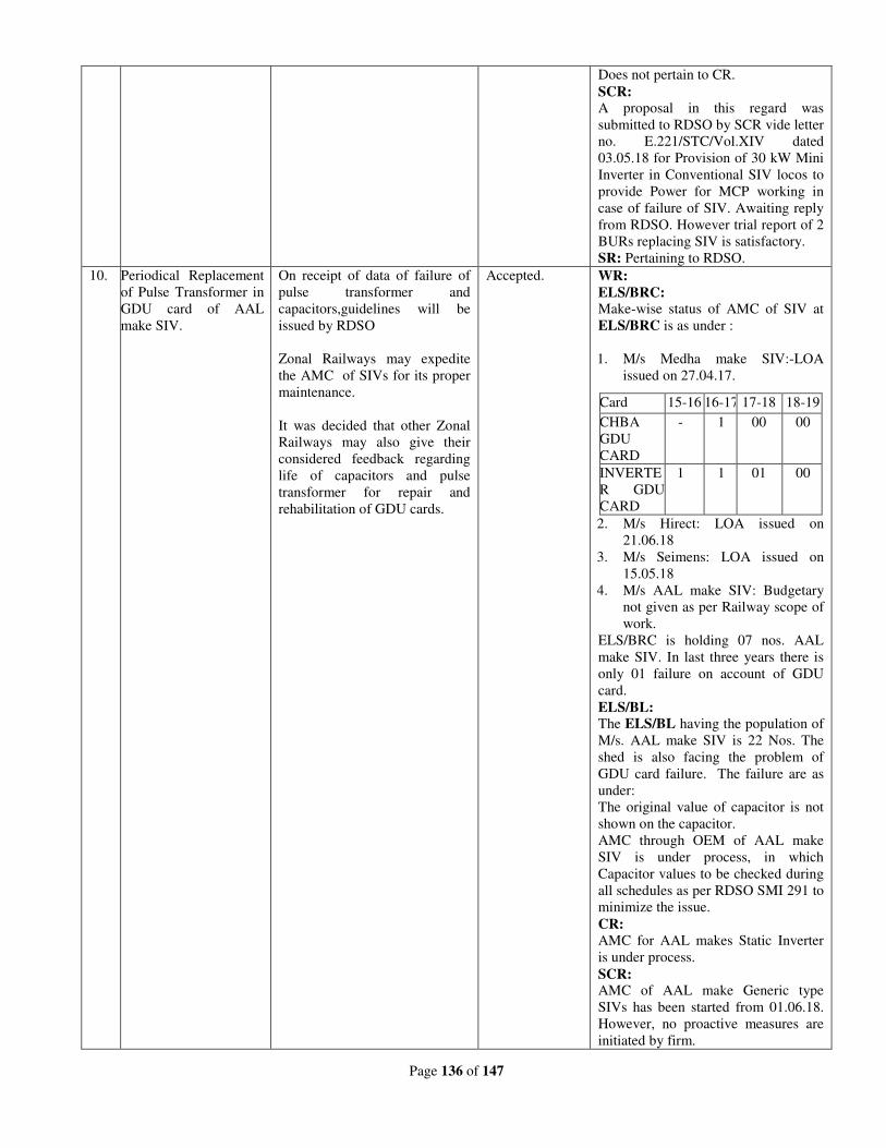
Page 136 of 147
Does not pertain to CR.
SCR:
A proposal in this regard was
submitted to RDSO by SCR vide letter
no. E.221/STC/Vol.XIV dated
03.05.18 for Provision of 30 kW Mini
Inverter in Conventional SIV locos to
provide Power for MCP working in
case of failure of SIV. Awaiting reply
from RDSO. However trial report of 2
BURs replacing SIV is satisfactory.
SR: Pertaining to RDSO.
10. Periodical Replacement
of Pulse Transformer in
GDU card of AAL
make SIV.
On receipt of data of failure of
pulse transformer and
capacitors,guidelines will be
issued by RDSO
Zonal Railways may expedite
the AMC of SIVs for its proper
maintenance.
It was decided that other Zonal
Railways may also give their
considered feedback regarding
life of capacitors and pulse
transformer for repair and
rehabilitation of GDU cards.
Accepted. WR:
ELS/BRC:
Make-wise status of AMC of SIV at
ELS/BRC is as under :
1. M/s Medha make SIV:-LOA
issued on 27.04.17.
2. M/s Hirect: LOA issued on
21.06.18
3. M/s Seimens: LOA issued on
15.05.18
4. M/s AAL make SIV: Budgetary
not given as per Railway scope of
work.
ELS/BRC is holding 07 nos. AAL
make SIV. In last three years there is
only 01 failure on account of GDU
card.
ELS/BL:
The ELS/BL having the population of
M/s. AAL make SIV is 22 Nos. The
shed is also facing the problem of
GDU card failure. The failure are as
under:
The original value of capacitor is not
shown on the capacitor.
AMC through OEM of AAL make
SIV is under process, in which
Capacitor values to be checked during
all schedules as per RDSO SMI 291 to
minimize the issue.
CR:
AMC for AAL makes Static Inverter
is under process.
SCR: AMC of AAL make Generic type
SIVs has been started from 01.06.18.
However, no proactive measures are
initiated by firm.
Card 15-16 16-17 17-18 18-19
CHBA
GDU
CARD
- 1 00 00
INVERTE
R GDU
CARD
1 1 01 00
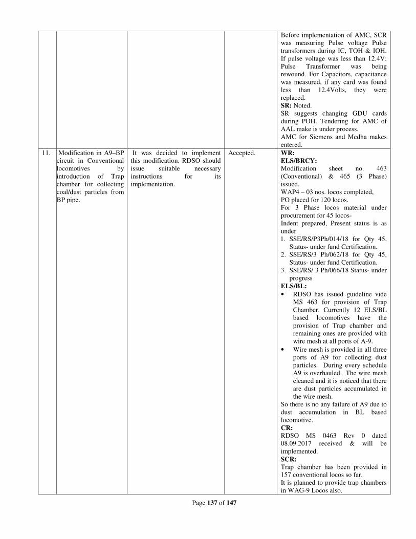
Page 137 of 147
Before implementation of AMC, SCR
was measuring Pulse voltage Pulse
transformers during IC, TOH & IOH.
If pulse voltage was less than 12.4V;
Pulse Transformer was being
rewound. For Capacitors, capacitance
was measured, if any card was found
less than 12.4Volts, they were
replaced.
SR: Noted.
SR suggests changing GDU cards
during POH. Tendering for AMC of
AAL make is under process.
AMC for Siemens and Medha makes
entered.
11. Modification in A9–BP
circuit in Conventional
locomotives by
introduction of Trap
chamber for collecting
coal/dust particles from
BP pipe.
It was decided to implement
this modification. RDSO should
issue suitable necessary
instructions for its
implementation.
Accepted. WR:
ELS/BRCY:
Modification sheet no. 463
(Conventional) & 465 (3 Phase)
issued.
WAP4 – 03 nos. locos completed,
PO placed for 120 locos.
For 3 Phase locos material under
procurement for 45 locos-
Indent prepared, Present status is as
under
1. SSE/RS/P3Ph/014/18 for Qty 45,
Status- under fund Certification.
2. SSE/RS/3 Ph/062/18 for Qty 45,
Status- under fund Certification.
3. SSE/RS/ 3 Ph/066/18 Status- under
progress
ELS/BL:
• RDSO has issued guideline vide
MS 463 for provision of Trap
Chamber. Currently 12 ELS/BL
based locomotives have the
provision of Trap chamber and
remaining ones are provided with
wire mesh at all ports of A-9.
• Wire mesh is provided in all three
ports of A9 for collecting dust
particles. During every schedule
A9 is overhauled. The wire mesh
cleaned and it is noticed that there
are dust particles accumulated in
the wire mesh.
So there is no any failure of A9 due to
dust accumulation in BL based
locomotive.
CR:
RDSO MS 0463 Rev 0 dated
08.09.2017 received & will be
implemented.
SCR:
Trap chamber has been provided in
157 conventional locos so far.
It is planned to provide trap chambers
in WAG-9 Locos also.
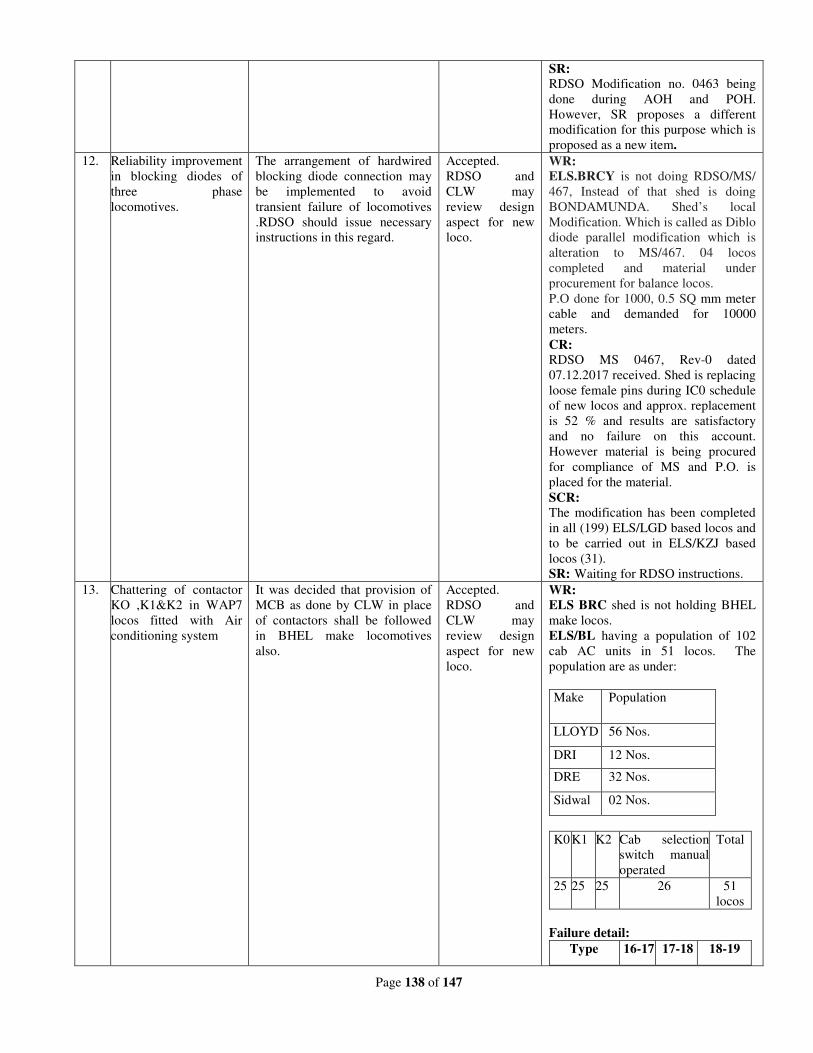
Page 138 of 147
SR:
RDSO Modification no. 0463 being
done during AOH and POH.
However, SR proposes a different
modification for this purpose which is
proposed as a new item.
12. Reliability improvement
in blocking diodes of
three phase
locomotives.
The arrangement of hardwired
blocking diode connection may
be implemented to avoid
transient failure of locomotives
.RDSO should issue necessary
instructions in this regard.
Accepted.
RDSO and
CLW may
review design
aspect for new
loco.
WR:
ELS.BRCY is not doing RDSO/MS/
467, Instead of that shed is doing
BONDAMUNDA. Shed’s local
Modification. Which is called as Diblo
diode parallel modification which is
alteration to MS/467. 04 locos
completed and material under
procurement for balance locos.
P.O done for 1000, 0.5 SQ mm meter
cable and demanded for 10000
meters.
CR:
RDSO MS 0467, Rev-0 dated
07.12.2017 received. Shed is replacing
loose female pins during IC0 schedule
of new locos and approx. replacement
is 52 % and results are satisfactory
and no failure on this account.
However material is being procured
for compliance of MS and P.O. is
placed for the material.
SCR:
The modification has been completed
in all (199) ELS/LGD based locos and
to be carried out in ELS/KZJ based
locos (31).
SR: Waiting for RDSO instructions.
13. Chattering of contactor
KO ,K1&K2 in WAP7
locos fitted with Air
conditioning system
It was decided that provision of
MCB as done by CLW in place
of contactors shall be followed
in BHEL make locomotives
also.
Accepted.
RDSO and
CLW may
review design
aspect for new
loco.
WR:
ELS BRC shed is not holding BHEL
make locos.
ELS/BL having a population of 102
cab AC units in 51 locos. The
population are as under:
Make Population
LLOYD 56 Nos.
DRI 12 Nos.
DRE 32 Nos.
Sidwal 02 Nos.
K0 K1 K2 Cab selection
switch manual
operated
Total
25 25 25 26 51
locos
Failure detail:
Type 16-17 17-18 18-19
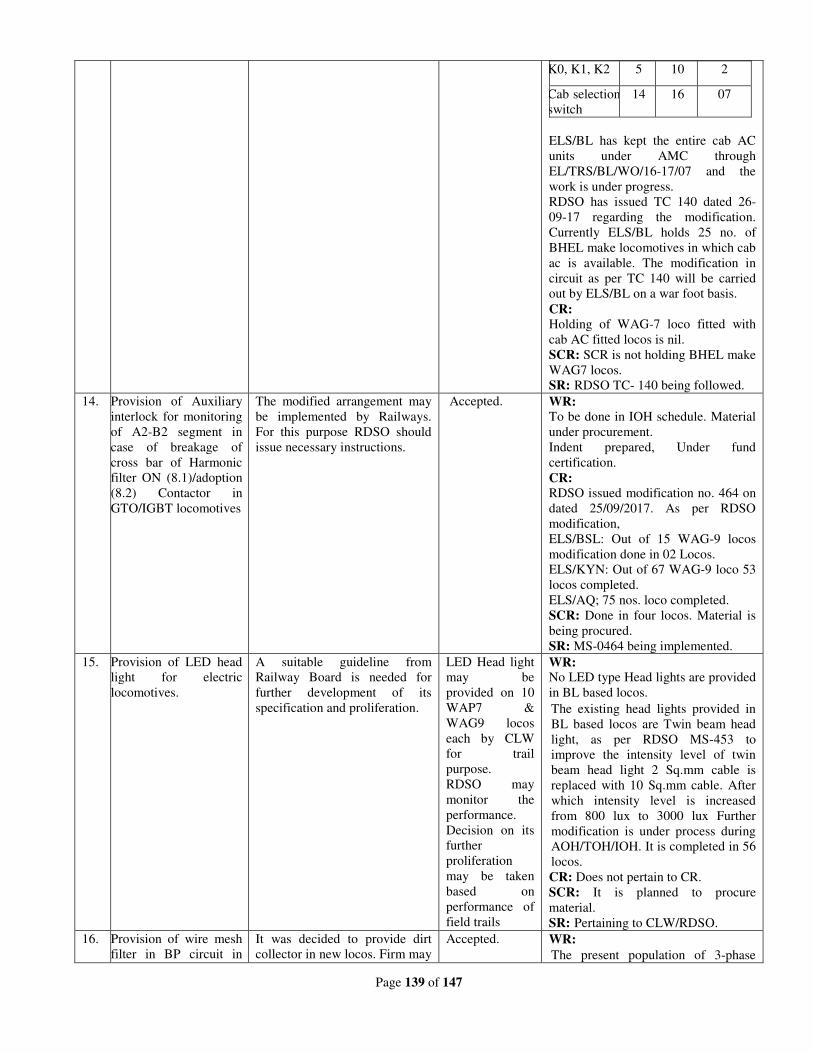
Page 139 of 147
K0, K1, K2 5 10 2
Cab selection
switch
14 16 07
ELS/BL has kept the entire cab AC
units under AMC through
EL/TRS/BL/WO/16-17/07 and the
work is under progress.
RDSO has issued TC 140 dated 26-
09-17 regarding the modification.
Currently ELS/BL holds 25 no. of
BHEL make locomotives in which cab
ac is available. The modification in
circuit as per TC 140 will be carried
out by ELS/BL on a war foot basis.
CR:
Holding of WAG-7 loco fitted with
cab AC fitted locos is nil.
SCR: SCR is not holding BHEL make
WAG7 locos.
SR: RDSO TC- 140 being followed.
14. Provision of Auxiliary
interlock for monitoring
of A2-B2 segment in
case of breakage of
cross bar of Harmonic
filter ON (8.1)/adoption
(8.2) Contactor in
GTO/IGBT locomotives
The modified arrangement may
be implemented by Railways.
For this purpose RDSO should
issue necessary instructions.
Accepted. WR:
To be done in IOH schedule. Material
under procurement.
Indent prepared, Under fund
certification.
CR:
RDSO issued modification no. 464 on
dated 25/09/2017. As per RDSO
modification,
ELS/BSL: Out of 15 WAG-9 locos
modification done in 02 Locos.
ELS/KYN: Out of 67 WAG-9 loco 53
locos completed.
ELS/AQ; 75 nos. loco completed.
SCR: Done in four locos. Material is
being procured.
SR: MS-0464 being implemented.
15. Provision of LED head
light for electric
locomotives.
A suitable guideline from
Railway Board is needed for
further development of its
specification and proliferation.
LED Head light
may be
provided on 10
WAP7 &
WAG9 locos
each by CLW
for trail
purpose.
RDSO may
monitor the
performance.
Decision on its
further
proliferation
may be taken
based on
performance of
field trails
WR: No LED type Head lights are provided
in BL based locos.
The existing head lights provided in
BL based locos are Twin beam head
light, as per RDSO MS-453 to
improve the intensity level of twin
beam head light 2 Sq.mm cable is
replaced with 10 Sq.mm cable. After
which intensity level is increased
from 800 lux to 3000 lux Further
modification is under process during
AOH/TOH/IOH. It is completed in 56
locos.
CR: Does not pertain to CR.
SCR: It is planned to procure
material.
SR: Pertaining to CLW/RDSO.
16. Provision of wire mesh
filter in BP circuit in
It was decided to provide dirt
collector in new locos. Firm may
Accepted. WR:
The present population of 3-phase
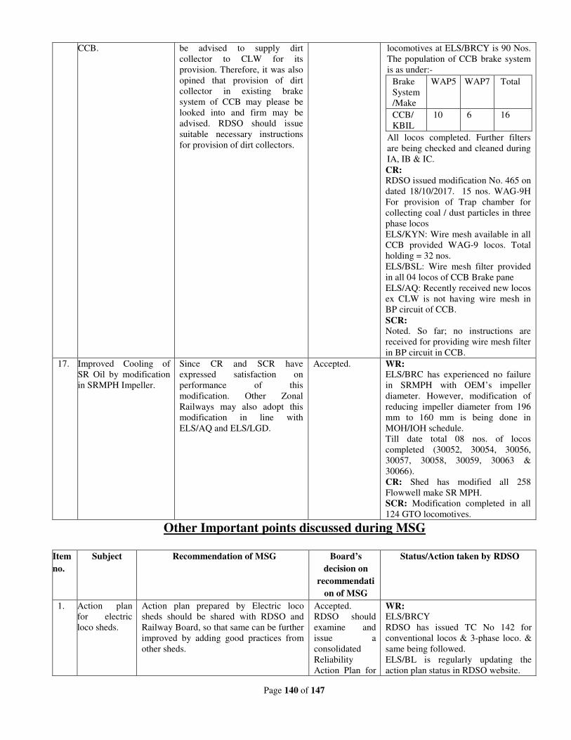
Page 140 of 147
CCB. be advised to supply dirt
collector to CLW for its
provision. Therefore, it was also
opined that provision of dirt
collector in existing brake
system of CCB may please be
looked into and firm may be
advised. RDSO should issue
suitable necessary instructions
for provision of dirt collectors.
locomotives at ELS/BRCY is 90 Nos.
The population of CCB brake system
is as under:-
Brake
System
/Make
WAP5 WAP7 Total
CCB/
KBIL
10 6 16
All locos completed. Further filters
are being checked and cleaned during
IA, IB & IC.
CR: RDSO issued modification No. 465 on
dated 18/10/2017. 15 nos. WAG-9H
For provision of Trap chamber for
collecting coal / dust particles in three
phase locos
ELS/KYN: Wire mesh available in all
CCB provided WAG-9 locos. Total
holding = 32 nos.
ELS/BSL: Wire mesh filter provided
in all 04 locos of CCB Brake pane
ELS/AQ: Recently received new locos
ex CLW is not having wire mesh in
BP circuit of CCB.
SCR:
Noted. So far; no instructions are
received for providing wire mesh filter
in BP circuit in CCB.
17. Improved Cooling of
SR Oil by modification
in SRMPH Impeller.
Since CR and SCR have
expressed satisfaction on
performance of this
modification. Other Zonal
Railways may also adopt this
modification in line with
ELS/AQ and ELS/LGD.
Accepted. WR: ELS/BRC has experienced no failure
in SRMPH with OEM’s impeller
diameter. However, modification of
reducing impeller diameter from 196
mm to 160 mm is being done in
MOH/IOH schedule.
Till date total 08 nos. of locos
completed (30052, 30054, 30056,
30057, 30058, 30059, 30063 &
30066).
CR: Shed has modified all 258
Flowwell make SR MPH.
SCR: Modification completed in all
124 GTO locomotives.
Other Important points discussed during MSG
Item
no.
Subject Recommendation of MSG Board’s
decision on
recommendati
on of MSG
Status/Action taken by RDSO
1. Action plan
for electric
loco sheds.
Action plan prepared by Electric loco
sheds should be shared with RDSO and
Railway Board, so that same can be further
improved by adding good practices from
other sheds.
Accepted.
RDSO should
examine and
issue a
consolidated
Reliability
Action Plan for
WR: ELS/BRCY
RDSO has issued TC No 142 for
conventional locos & 3-phase loco. &
same being followed.
ELS/BL is regularly updating the
action plan status in RDSO website.
Page 141 of 147
all Zonal
Railways for
conventional
and 3-phase
locomotives.
SCR: TC 142 issued by RDSO is
being followed.
SR:
Reliability Action Plan being followed
in all SR sheds as per RDSO TC-142.
2. Three bridge
design of M/s
Stesalit make
RSI.
Three bridge design rectifier (RSI block)
of M/s Stesalit is not reliable. This is to be
converted into four bridge design as per
RDSO letter no. EL/3.2.185 dated
31/5/2012. Zonal Railways pointed out
that M/s Stesalit is not responding and still
appearing in CLW’s vendor list. CLW was
advised to review the approval status of
M/s Stasalit. On conversion work from
three bridge design to four bridge design
may be opened to other OEMs of this item
for early action.
Accepted. WR: There are no locos at BRC & BL
shed with M/s Stesalit make RSI.
SCR:
Loco no. 28253/BZA & 28073/KZJ
equipped with Stesalit make 3P block
are in working condition.
SR: Being followed
SR has 2 WAG7 locos and 3 WAP4
locos fitted with 3 bridge design of
M/s Stesalit make RSI and all will be
converted to 4 bridges.
3. Pneumatic
pipe
connection to
harmonic
filter.
Pneumatic pipe connection to harmonic
filter is to be standardized. Zonal Railways
are adopting following actions-
(i) Double ferrule fitting with check nut.
(ii) Copper pipe with fittings.
RDSO will study and issue necessary
guidelines.
Accepted.
RDSO may
issue necessary
guidelines
within a month.
WR: ELS/BRCY has provided copper
pipe with fittings for pneumatic pipe
connection to harmonic filter. This is
being provided during IC0 schedule.
Not being done in locos having double
ferrule fitting with check nut.
SCR:
RDSO has issued SMI no: 313
(Rev’0’), dated 30.08.17 for provision
of 10mm nylon pipe and double
ferrule fittings with check nut.
However SCR is providing 6 mm
Teflon pipe with 6mm SMC & Legris
make push fittings (double ferrule) in
view of better performance.
SR: RDSO SMI 0313 being followed.
4. Water jet
testing of
electric loco.
NCR pointed out rain water testing of loco.
RDSO should issue standard arrangement
for testing purpose in consultation with
Zonal Railways.
Accepted. WR: SMI 315 issued by RDSO. 02
water testing plants are available at
ELS/BRCY. It has 30 showers which
are sufficient for testing water leakage
in locos.
At ELS/BL - Water testing plant for
MU is proposed in law book under
plan head 42. Proposal is uploaded in
IREPSM on 19/01/18. File lying with
CME/WR tray since 29/01/2018.
Existing water testing plant is only for
single loco in which showers are
provided.
SCR: Water jet testing facility is
available and all locos are being
checked.
SR: RDSO SMI-315 being
implemented.
5. Failures of
transition
coupling.
Transition coupling failures of M/s
Ramakrishna make are taking place. Zonal
Railways should give details of failures to
RDSO for needful action.
Accepted. WR: The total population of M/s
Ramkrishna make transition coupling
at ELS/BRC is 324 & 157 at ELS/BL
till date no failure is noticed in this
make.
SCR:
SCR vide letter no. E.221/Bogie-3
phase/Vol.V dated 02.01.18 furnished
Page 142 of 147
the performance to RDSO.
There have been no failures of M/s
Ramakrishna make transition screw
couplings in SCR, except one case
which was due to mal-operation of
TXR staff.
SR: No failures in SR. The total
population of M/s Ramakrishna make
in SR is 588 nos.
6. Fixture of
gear case.
SER has developed a fixture for correctly
locating the bosh of gear case. This will
help in reduced stress and better reliability.
RDSO should study and issue necessary
guidelines.
Accepted. WR:
RDSO issued TC 146 Dated 02.05.18
ELS/BRC has already developed a
gauge for checking proper alignment
of gear case top and bottom. However,
As per TC, it will be studied &
accordingly procurement action will
be taken.
As per TC 146 Rev.0, Demand for jig
placed on date 11/05/18 at ELS/BL
PO placed on 03/07/18 for M/s Dhruvi
Mechanical Works, Valsad. Material
will be supplied by July end to
ELS/BL.
SCR: Jig would be made as per the
Technical circular.
SR: SR developed Jig in 2004 for gear
case and using for boss locating.
7. Fire ball in
H.T.
compartment.
Feasibility of providing fire ball in H.T.
compartment should be studied by RDSO
as has been done in NCR for adopting it, if
found useful.
Accepted. WR: Noted.
At present fire extinguishers are used
in Locos and all fire prevention
measures are strictly followed.
SCR: Noted. No guidelines from
RDSO so far.
SR: Pertaining to RDSO.
8. Boroscope
camera.
Boroscope camera is useful in visual
inspection of those areas of loco, which are
not accessible. This should be examined
and RDSO to issue guidelines.
Accepted. WR: RDSO TC 144 dated 27.03.18 issued.
At ELS/BRCY One no available &
One more will be procured as per
specification of TC. At ELS/BL it Will
be procured by as per RDSO TC 144
dated 27/03/18 after consulting with
other loco sheds.
SCR:
Two nos. of Bore scope Camera are
procured and being utilized at
ELS/BZA.
SR: TC 144 being implemented.
9. Dew point
depression
measurement.
Dew point depression is being measured by
recording wet bulb and dry bulb
temperature by SER. This avoids
procurement of use of separate dew point
meter. This practice should be studied and
RDSO to issue the guidelines.
Accepted. WR: RDSO has issued guidelines
vided TC no. 139. It Being done
during AOH/IOH of air-dryer at
ELS/BRCY. Dew point meter is
already provided at ELS/BL on air
dryer test bench so there is no need for
separate measurement.
SCR: Dew point depression is being
measured by Dry-bulb temperature
and wet-bulb temperature, same as
S.E. Railway.
SR: TC 139 being implemented.
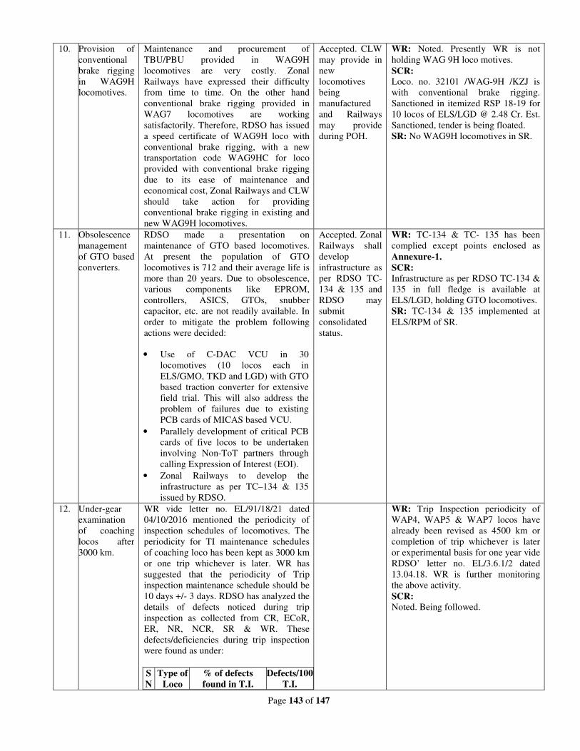
Page 143 of 147
10. Provision of
conventional
brake rigging
in WAG9H
locomotives.
Maintenance and procurement of
TBU/PBU provided in WAG9H
locomotives are very costly. Zonal
Railways have expressed their difficulty
from time to time. On the other hand
conventional brake rigging provided in
WAG7 locomotives are working
satisfactorily. Therefore, RDSO has issued
a speed certificate of WAG9H loco with
conventional brake rigging, with a new
transportation code WAG9HC for loco
provided with conventional brake rigging
due to its ease of maintenance and
economical cost, Zonal Railways and CLW
should take action for providing
conventional brake rigging in existing and
new WAG9H locomotives.
Accepted. CLW
may provide in
new
locomotives
being
manufactured
and Railways
may provide
during POH.
WR: Noted. Presently WR is not
holding WAG 9H loco motives.
SCR:
Loco. no. 32101 /WAG-9H /KZJ is
with conventional brake rigging.
Sanctioned in itemized RSP 18-19 for
10 locos of ELS/LGD @ 2.48 Cr. Est.
Sanctioned, tender is being floated.
SR: No WAG9H locomotives in SR.
11. Obsolescence
management
of GTO based
converters.
RDSO made a presentation on
maintenance of GTO based locomotives.
At present the population of GTO
locomotives is 712 and their average life is
more than 20 years. Due to obsolescence,
various components like EPROM,
controllers, ASICS, GTOs, snubber
capacitor, etc. are not readily available. In
order to mitigate the problem following
actions were decided:
• Use of C-DAC VCU in 30
locomotives (10 locos each in
ELS/GMO, TKD and LGD) with GTO
based traction converter for extensive
field trial. This will also address the
problem of failures due to existing
PCB cards of MICAS based VCU.
• Parallely development of critical PCB
cards of five locos to be undertaken
involving Non-ToT partners through
calling Expression of Interest (EOI).
• Zonal Railways to develop the
infrastructure as per TC–134 & 135
issued by RDSO.
Accepted. Zonal
Railways shall
develop
infrastructure as
per RDSO TC-
134 & 135 and
RDSO may
submit
consolidated
status.
WR: TC-134 & TC- 135 has been
complied except points enclosed as
Annexure-1.
SCR:
Infrastructure as per RDSO TC-134 &
135 in full fledge is available at
ELS/LGD, holding GTO locomotives.
SR: TC-134 & 135 implemented at
ELS/RPM of SR.
12. Under-gear
examination
of coaching
locos after
3000 km.
WR vide letter no. EL/91/18/21 dated
04/10/2016 mentioned the periodicity of
inspection schedules of locomotives. The
periodicity for TI maintenance schedules
of coaching loco has been kept as 3000 km
or one trip whichever is later. WR has
suggested that the periodicity of Trip
inspection maintenance schedule should be
10 days +/- 3 days. RDSO has analyzed the
details of defects noticed during trip
inspection as collected from CR, ECoR,
ER, NR, NCR, SR & WR. These
defects/deficiencies during trip inspection
were found as under:
S
N
Type of
Loco
% of defects
found in T.I.
Defects/100
T.I.
WR: Trip Inspection periodicity of
WAP4, WAP5 & WAP7 locos have
already been revised as 4500 km or
completion of trip whichever is later
or experimental basis for one year vide
RDSO’ letter no. EL/3.6.1/2 dated
13.04.18. WR is further monitoring
the above activity.
SCR:
Noted. Being followed.
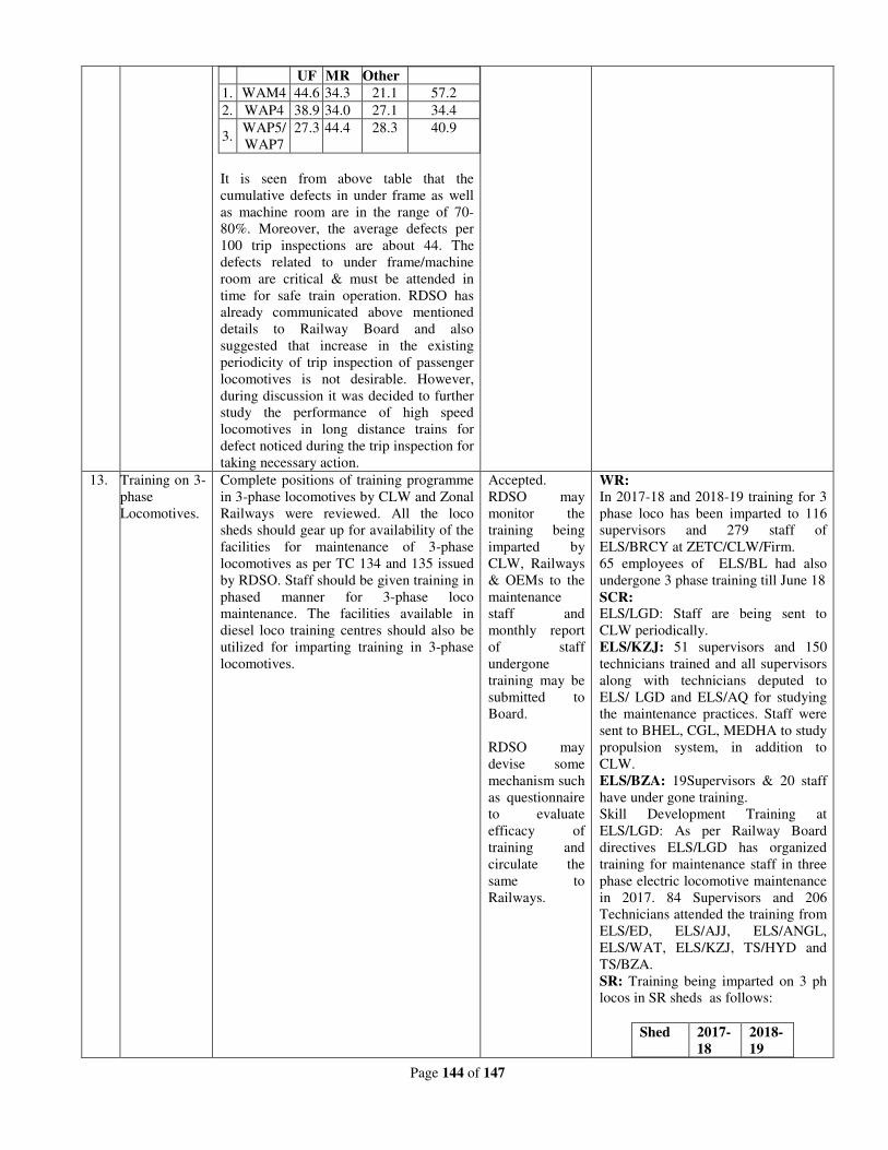
Page 144 of 147
It is seen from above table that the
cumulative defects in under frame as well
as machine room are in the range of 70-
80%. Moreover, the average defects per
100 trip inspections are about 44. The
defects related to under frame/machine
room are critical & must be attended in
time for safe train operation. RDSO has
already communicated above mentioned
details to Railway Board and also
suggested that increase in the existing
periodicity of trip inspection of passenger
locomotives is not desirable. However,
during discussion it was decided to further
study the performance of high speed
locomotives in long distance trains for
defect noticed during the trip inspection for
taking necessary action.
UF MR Other
1. WAM4 44.6 34.3 21.1 57.2
2. WAP4 38.9 34.0 27.1 34.4
3. WAP5/
WAP7
27.3 44.4 28.3 40.9
13. Training on 3-
phase
Locomotives.
Complete positions of training programme
in 3-phase locomotives by CLW and Zonal
Railways were reviewed. All the loco
sheds should gear up for availability of the
facilities for maintenance of 3-phase
locomotives as per TC 134 and 135 issued
by RDSO. Staff should be given training in
phased manner for 3-phase loco
maintenance. The facilities available in
diesel loco training centres should also be
utilized for imparting training in 3-phase
locomotives.
Accepted.
RDSO may
monitor the
training being
imparted by
CLW, Railways
& OEMs to the
maintenance
staff and
monthly report
of staff
undergone
training may be
submitted to
Board.
RDSO may
devise some
mechanism such
as questionnaire
to evaluate
efficacy of
training and
circulate the
same to
Railways.
WR:
In 2017-18 and 2018-19 training for 3
phase loco has been imparted to 116
supervisors and 279 staff of
ELS/BRCY at ZETC/CLW/Firm.
65 employees of ELS/BL had also
undergone 3 phase training till June 18
SCR: ELS/LGD: Staff are being sent to
CLW periodically.
ELS/KZJ: 51 supervisors and 150
technicians trained and all supervisors
along with technicians deputed to
ELS/ LGD and ELS/AQ for studying
the maintenance practices. Staff were
sent to BHEL, CGL, MEDHA to study
propulsion system, in addition to
CLW.
ELS/BZA: 19Supervisors & 20 staff
have under gone training.
Skill Development Training at
ELS/LGD: As per Railway Board
directives ELS/LGD has organized
training for maintenance staff in three
phase electric locomotive maintenance
in 2017. 84 Supervisors and 206
Technicians attended the training from
ELS/ED, ELS/AJJ, ELS/ANGL,
ELS/WAT, ELS/KZJ, TS/HYD and
TS/BZA.
SR: Training being imparted on 3 ph
locos in SR sheds as follows:
Shed 2017-
18
2018-
19
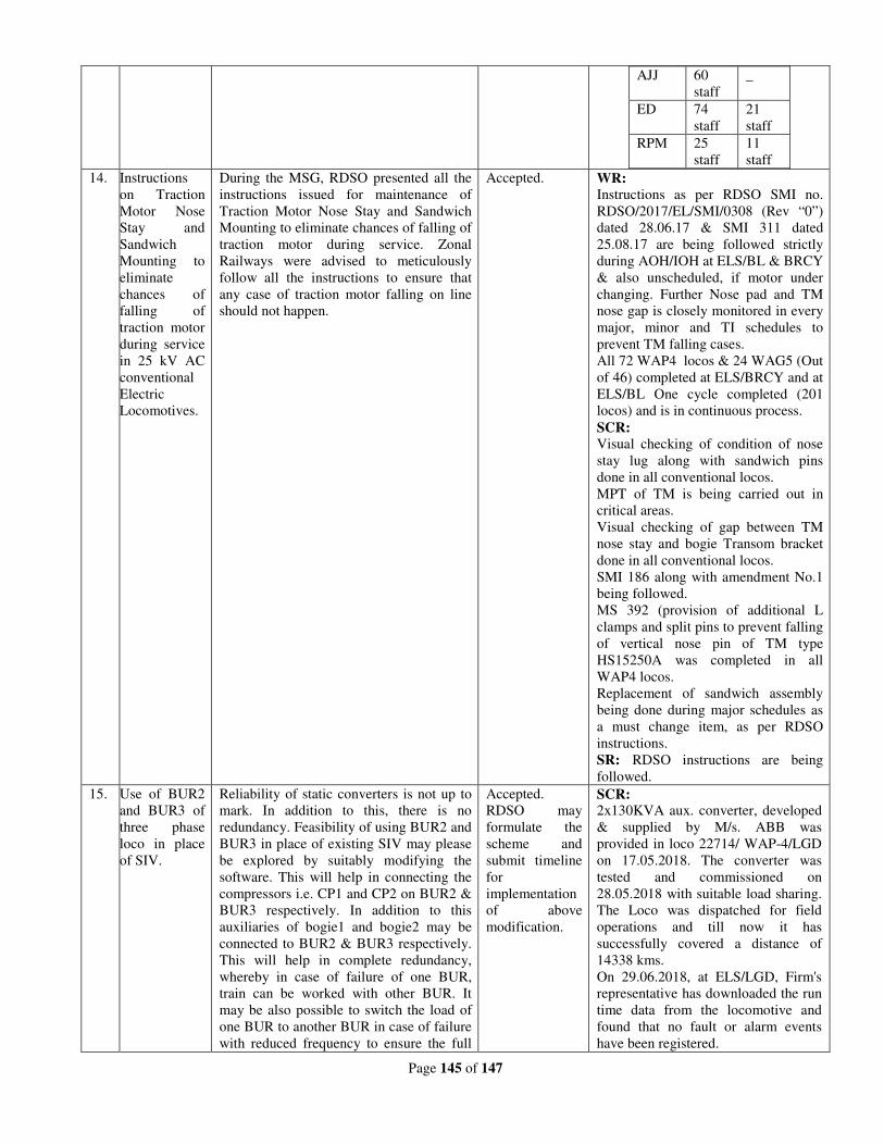
Page 145 of 147
AJJ 60
staff
_
ED 74
staff
21
staff
RPM 25
staff
11
staff
14. Instructions
on Traction
Motor Nose
Stay and
Sandwich
Mounting to
eliminate
chances of
falling of
traction motor
during service
in 25 kV AC
conventional
Electric
Locomotives.
During the MSG, RDSO presented all the
instructions issued for maintenance of
Traction Motor Nose Stay and Sandwich
Mounting to eliminate chances of falling of
traction motor during service. Zonal
Railways were advised to meticulously
follow all the instructions to ensure that
any case of traction motor falling on line
should not happen.
Accepted.
WR:
Instructions as per RDSO SMI no.
RDSO/2017/EL/SMI/0308 (Rev “0”)
dated 28.06.17 & SMI 311 dated
25.08.17 are being followed strictly
during AOH/IOH at ELS/BL & BRCY
& also unscheduled, if motor under
changing. Further Nose pad and TM
nose gap is closely monitored in every
major, minor and TI schedules to
prevent TM falling cases.
All 72 WAP4 locos & 24 WAG5 (Out
of 46) completed at ELS/BRCY and at
ELS/BL One cycle completed (201
locos) and is in continuous process.
SCR:
Visual checking of condition of nose
stay lug along with sandwich pins
done in all conventional locos.
MPT of TM is being carried out in
critical areas.
Visual checking of gap between TM
nose stay and bogie Transom bracket
done in all conventional locos.
SMI 186 along with amendment No.1
being followed.
MS 392 (provision of additional L
clamps and split pins to prevent falling
of vertical nose pin of TM type
HS15250A was completed in all
WAP4 locos.
Replacement of sandwich assembly
being done during major schedules as
a must change item, as per RDSO
instructions.
SR: RDSO instructions are being
followed.
15. Use of BUR2
and BUR3 of
three phase
loco in place
of SIV.
Reliability of static converters is not up to
mark. In addition to this, there is no
redundancy. Feasibility of using BUR2 and
BUR3 in place of existing SIV may please
be explored by suitably modifying the
software. This will help in connecting the
compressors i.e. CP1 and CP2 on BUR2 &
BUR3 respectively. In addition to this
auxiliaries of bogie1 and bogie2 may be
connected to BUR2 & BUR3 respectively.
This will help in complete redundancy,
whereby in case of failure of one BUR,
train can be worked with other BUR. It
may be also possible to switch the load of
one BUR to another BUR in case of failure
with reduced frequency to ensure the full
Accepted.
RDSO may
formulate the
scheme and
submit timeline
for
implementation
of above
modification.
SCR: 2x130KVA aux. converter, developed
& supplied by M/s. ABB was
provided in loco 22714/ WAP-4/LGD
on 17.05.2018. The converter was
tested and commissioned on
28.05.2018 with suitable load sharing.
The Loco was dispatched for field
operations and till now it has
successfully covered a distance of
14338 kms.
On 29.06.2018, at ELS/LGD, Firm's
representative has downloaded the run
time data from the locomotive and
found that no fault or alarm events
have been registered.
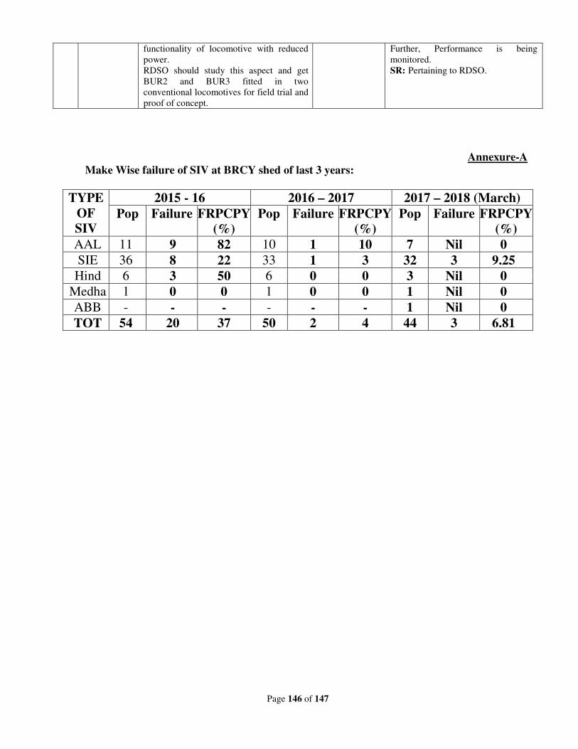
Page 146 of 147
functionality of locomotive with reduced
power.
RDSO should study this aspect and get
BUR2 and BUR3 fitted in two
conventional locomotives for field trial and
proof of concept.
Further, Performance is being
monitored.
SR: Pertaining to RDSO.
Annexure-A
Make Wise failure of SIV at BRCY shed of last 3 years:
TYPE
OF
SIV
2015 - 16 2016 – 2017 2017 – 2018 (March)
Pop Failure FRPCPY
(%)
Pop Failure FRPCPY
(%)
Pop Failure FRPCPY
(%)
AAL 11 9 82 10 1 10 7 Nil 0
SIE 36 8 22 33 1 3 32 3 9.25
Hind 6 3 50 6 0 0 3 Nil 0
Medha 1 0 0 1 0 0 1 Nil 0
ABB - - - - - - 1 Nil 0
TOT 54 20 37 50 2 4 44 3 6.81
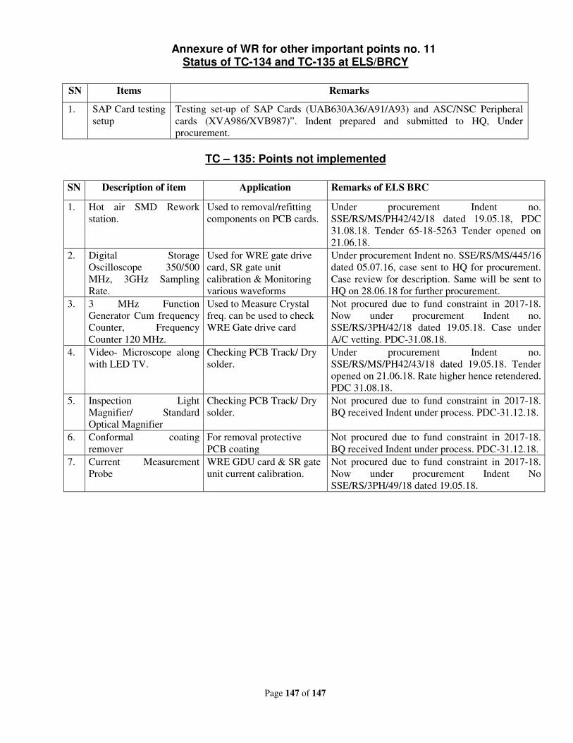
Page 147 of 147
Annexure of WR for other important points no. 11 Status of TC-134 and TC-135 at ELS/BRCY
SN Items Remarks
1. SAP Card testing
setup
Testing set-up of SAP Cards (UAB630A36/A91/A93) and ASC/NSC Peripheral
cards (XVA986/XVB987)”. Indent prepared and submitted to HQ, Under
procurement.
TC – 135: Points not implemented
SN Description of item Application Remarks of ELS BRC
1. Hot air SMD Rework
station.
Used to removal/refitting
components on PCB cards.
Under procurement Indent no.
SSE/RS/MS/PH42/42/18 dated 19.05.18, PDC
31.08.18. Tender 65-18-5263 Tender opened on
21.06.18.
2. Digital Storage
Oscilloscope 350/500
MHz, 3GHz Sampling
Rate.
Used for WRE gate drive
card, SR gate unit
calibration & Monitoring
various waveforms
Under procurement Indent no. SSE/RS/MS/445/16
dated 05.07.16, case sent to HQ for procurement.
Case review for description. Same will be sent to
HQ on 28.06.18 for further procurement.
3. 3 MHz Function
Generator Cum frequency
Counter, Frequency
Counter 120 MHz.
Used to Measure Crystal
freq. can be used to check
WRE Gate drive card
Not procured due to fund constraint in 2017-18.
Now under procurement Indent no.
SSE/RS/3PH/42/18 dated 19.05.18. Case under
A/C vetting. PDC-31.08.18.
4. Video- Microscope along
with LED TV.
Checking PCB Track/ Dry
solder.
Under procurement Indent no.
SSE/RS/MS/PH42/43/18 dated 19.05.18. Tender
opened on 21.06.18. Rate higher hence retendered.
PDC 31.08.18.
5. Inspection Light
Magnifier/ Standard
Optical Magnifier
Checking PCB Track/ Dry
solder.
Not procured due to fund constraint in 2017-18.
BQ received Indent under process. PDC-31.12.18.
6. Conformal coating
remover
For removal protective
PCB coating
Not procured due to fund constraint in 2017-18.
BQ received Indent under process. PDC-31.12.18.
7. Current Measurement
Probe
WRE GDU card & SR gate
unit current calibration.
Not procured due to fund constraint in 2017-18.
Now under procurement Indent No
SSE/RS/3PH/49/18 dated 19.05.18.
Related Documents