FINAL FREQUENCY ADJUSTMENT OF QUARTZ OSCILLATOR-PLATES Cr-rrrono FRoxooL,* Research Diaision, Reeaes Sound Laboratories, I{ew York, I{. Y' CoNrnNrs Page Abstract 416 Introduction. 416 Finishing by the Abrasion Method.. . . 416 Ageing Phenomena in Abrasive-Lapped Plates... 421 Finishing by the Etch Method. 423 Finishing by the X-Ray Irradiation Technique. 427 Frequency Adjustment of Metal-Plated Crystals.. . ' 430 Agsrn.q.ct The art of finishing machine lapped quartz oscillator-plates to final frequency and ac- tivity specifications is discussed. Two general methods have been practiced: the abrasive lapping technique, now abandoned because of undesirable ageing phenomena caused in the plate, and the etching-tci-frequency method. The x ray irradiation technique has a special field of application in making highly precise frequency adjustments and in salvaging over- frequency plates. The cause and cure of frequency and activity ageing in quartz plates is discussed, and methods of adjusting the frequency of metal plated wire-suspension type plates are described. INrnooucrroN The machine lapping of AT and BT quartz oscillator-plates is usually stopped somewhat over the final desired thickness. The final finishing operation as ordinarily applied involves a process of lapping or etching the individual crystals by hand, with intermittent electronic measure- ment of the accompanying change in frequency' until the final desired frequency is reached. Control over the thickness of the crystal cannot be had at this stage by mechanical measurement since the dimensions in- volved are of the order of millionths of an inch. At the end of the finish- ing operation the crystal is cleanedand assembled in its permanent hold- er. The unit is now tested over a specifiedrange of temperature, say from - 55oto +90o C., to seeif the frequency and activity remain within pre- scribed tolerance values, and then passesthrough various mechanical tests and inspections before it is submitted to Government inspectors for final acceptance. FrNrsrrtNc BY THE AnnasroN Mprrroo In this method the crystals are first lapped by machine until they are within roughly 0.04 to O.4/s of the final desiredfrequency. The plates are * Department of Mineralogy, Harvard University, Cambridge, Mass. (on leave). 4t6

Welcome message from author
This document is posted to help you gain knowledge. Please leave a comment to let me know what you think about it! Share it to your friends and learn new things together.
Transcript

FINAL FREQUENCY ADJUSTMENT OF
QUARTZ OSCILLATOR-PLATES
Cr-rrrono FRoxooL,*Research Diaision, Reeaes Sound Laboratories, I{ew York, I{. Y'
CoNrnNrsPage
Abstract 416
Introduction. 416
Finishing by the Abrasion Method.. . . 416
Ageing Phenomena in Abrasive-Lapped Plates... 421
Finishing by the Etch Method. 423
Finishing by the X-Ray Irradiation Technique. 427
Frequency Adjustment of Metal-Plated Crystals.. . ' 430
Agsrn.q.ct
The art of finishing machine lapped quartz oscillator-plates to final frequency and ac-
tivity specifications is discussed. Two general methods have been practiced: the abrasive
lapping technique, now abandoned because of undesirable ageing phenomena caused in the
plate, and the etching-tci-frequency method. The x ray irradiation technique has a special
field of application in making highly precise frequency adjustments and in salvaging over-
frequency plates. The cause and cure of frequency and activity ageing in quartz plates is
discussed, and methods of adjusting the frequency of metal plated wire-suspension type
plates are described.
INrnooucrroN
The machine lapping of AT and BT quartz oscillator-plates is usually
stopped somewhat over the final desired thickness. The final finishing
operation as ordinarily applied involves a process of lapping or etching
the individual crystals by hand, with intermittent electronic measure-
ment of the accompanying change in frequency' until the final desired
frequency is reached. Control over the thickness of the crystal cannot be
had at this stage by mechanical measurement since the dimensions in-
volved are of the order of millionths of an inch. At the end of the finish-
ing operation the crystal is cleaned and assembled in its permanent hold-
er. The unit is now tested over a specified range of temperature, say from- 55o to +90o C., to see if the frequency and activity remain within pre-
scribed tolerance values, and then passes through various mechanical
tests and inspections before it is submitted to Government inspectors for
final acceptance.
FrNrsrrtNc BY THE AnnasroN Mprrroo
In this method the crystals are first lapped by machine until they are
within roughly 0.04 to O.4/s of the final desired frequency. The plates are
* Department of Mineralogy, Harvard University, Cambridge, Mass. (on leave).
4t6

FINAL FREQUENCY ADJUSTMENT 417
Frc' 1' Final abrasive finishing position, showing glass lap (herd in a pie dish) withcrystal.and abrasive, comparison osciilator with sta"ndard crysiar, polariscope (reft) fordetermining x and z' directions, sink with soap sorution and tooth brush for cleaning, airgun for drying, and lead dish of etching sorution with prastic hording tongs for acid wash.
418 CLIFFORD FRONDEL
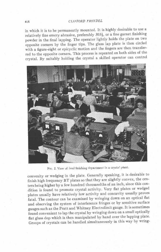
Frc. 2. View of final finishing departrnent in a crystal plant'

FTNAL FREQU ENCT/ ADJ USTM ENT
ing or cementing down on a large optical flat. Needless to say, the flat-ness of the glass lapping plate itself must be carefully maintained.
In the finishing process attention must also be paid to the so-calredactivity of the crystal. The activity is primarily a function of the edgedimensions of the plate in a given electric circuit and holder, but also isinfluenced by the.contour, the fineness of abrasive finish, creanliness, thepresence of cracks and chips on the edges, twinning, inclusions and otherfactors. rn so-called predimensioned AT and BT prates the edge dimen-sions are deliberately preselected so as to give minimum coupling betweenthe fundamental high frequency shear mode vibration and high harmon-ics of the Y flexural mode. Such crystals have inherent high activity andare relatively free from spurious frequencies and from activity dips overa range of temperature. Accurate control of dimensions, usually to 0.001inch in low frequency crystals, and of cutting angle, with both the ZZIand XX' angles held to at least * 15 minutes of arc, is essential. rt isgeneral practice, however, especially in the higher frequencies, to cut allcrystals during manufacture to some abritrary set of dimensions. This isdone because the ideal dimensions for 6 particular frequency usually arenot known or conveniently determined, and because the dimensional andangular control involved is not easily achieved on a mass productionbasis. when arbitrarily dimensioned crystals are hand finished it is oftennecessary to bevel or grind down the edges of the plate in order to bringup activity. This changes the edge dimensions to a more favorable ratio.lThe edging operation is variously done by lapping with abrasive on glass,or on a carborundum stone, fine emery paper, crocus cloth or a diamondwheel. Rotating hollow cylinders lined with diamond impregnated bake-lite also are useful. Grinding the X edge of the plate is advantageoussince this dimension more directly controls the interfering flexural mode.unless the edge dimensioning of the plates preliminary to finishing iscarefully done, a slight beveling and rounding of the sides and corners ofthe plate is desirable in order to remove roughness and chips. Roughedges and sharp corners are objectionable because of the danger of smallparticles of. quartz becoming dislodged and wedging between the plateand electrodes.
After the plate has been brought to specif.cations it is scrubbed witha toothbrush and soap, thoroughly rinsed and dried, rechecked for fre-quency and activity and then mounted permanently in its holder. Theholder and electrodes must also be clean. Drying shourd be done with a
r remperature test rejects in randomly dimensioned plates usually run between 15 and40 per cent. The rejected crystals are disassembled and run through the finishing operationagain, where the edge dimensions are changed to a more favorable ratio. Temperaiure testreject rates in predimensioned crystals ordinarily are only a few per cent.
419
420 CLIFFORD FRONDEL
jet of clean dry compressed air. Rubbing with a towel is objectionable
because the surface of the plate becomes loaded with cellulose and the
plate frequency is decreased thereby. Towelled plates when baked at ca.
500' C. gain exactly the same amount of frequency lost by the towelling
operation, presumably due to burning ofi of the organic matter. Slight
upward or downward changes in frequency can be efiected by changing
to electrodes with a higher or lower air gap, respectively, and a further
downward change in frequency can be efiected by the r-ray method de-
scribed beyond. Plates can be given a crude partial temperature test
during the finishing operation by heating them during measurement
over an alcohol burner or electric stove or by cooling with a piece of dry
ice. Activity dips recognized in this way can be removed by edge grind-
ing, the changes in the plate dimension moving the dip to higher tem-
peratures until it goes beyond the upper temperature limit.
Various mechanical lapping contrivances have been devised to speed
up the initial stages of the finishing operation. The Sipp-Eastwood or
Seco lap comprises two rotating Iapping discs with a thin perforated
workholder containing a single quartz plate. The workholder, ordinarily
made of vinylite plastic or zinc, is held in position by a metal post and
has a rotatory motion imparted by the lapping discs' The Empire EIec-
tronics co. lap is a small scale version of the drill press type of mechani-
cal lap. These laps are described in an accompanying paper.2
Electrod,es and Springs. Most of the high frequency crystals currently
in mass production, notably the CR-1 andFT-243, are clamped between
stainless steel electrodes about 0.050 to 0.060 inches thick. The corners
of the electrodes are raised somewhat, giving an air gap which usually
ranges between 0.0004 and 0.0008 inches. Maximum activity is obtained
in the lower gaps and the plate will ultimately refuse to oscillate as the
air gap is increased. Both the lands and the air gap areas must be flat
and parallel to at least within 0.0001 inches. This is necessary in order
that the crystal withstand drop and vibration tests and to avoid certain
undesirable modes of vibration which result in activity and frequency
failures in the temperature testing. The electrodes are held in place by a
spring exerting a force of about 5 to 8 pounds. Excessive spring pressure
may damp out undesirable subsidiary modes of vibration but tends to
reduce activity, while low spring pressure may result in failure in the drop
and vibration tests.Care should be taken in low frequency AT clamped plates to avoid
particular air gap dimensions. Acoustic waves generated by the oscillator-
plate are reflected back from the electrode and at certain gaps resonance
2 Parrish, w.: Machine Lapping of Quartz oscillator-Plates, Am. Mi,neraL this issue.
FIN A L FREQUENCY ADJ USTMEN T
will occur resulting in damping and diminished activity of the crystal.The air gap dimensions to be avoided are given by
t : Fo2f
where I is the air gap in inches, u the velocity of acoustic waves in air atroom temperature and pressure (: 1083 It/sec.), f the plate frequency incycles per second, and p:1,2,3. . . . The ef fect is of l i t t le or no conse-quence in high frequency BT plates.
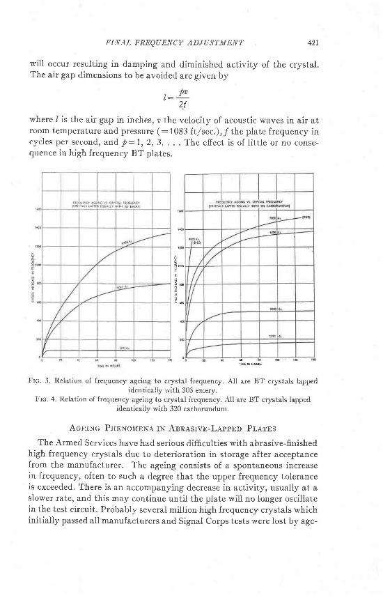
Frc. 3. Relation of frequency ageing to crystal frequency. All are BT crystals iappedidentically with 303 emery.
Frc. 4. Relation of frequency ageing to crystal frequency. All are BT crystals lappedidenticaily with 320 carborundum.
Acnrxc PnrxolrBwe IN ABRASTvE-LappBo Pr,erBs
The Armed Services have had serious difficulties with abrasive-finishedhigh frequency crystals due to deterioration in storage after acceptancefrom the manufacturer. The ageing consists of a spontaneous increasein frequency, often to such a degree that the upper frequency toleranceis exceeded. There is an accompanying decrease in activity, usually at aslower rate, and this may continue until the plate wiII no longer oscillatein the test circuit. Probably several million high frequency crystals whichinitially passed all manufacturers and Signal Corps tests were lost by age-
A l l
r
: m o

A a a CLIFFORD FRONDEL
ing before the cause and cure of the effect were found. Most of these
crystals have since been salvaged. The principal features of quaftz ageing
are as follows:1. In a series of plates of difierent frequencies that have been lapped identically with
abrasive the amount of frequency ageing increases with increasing plate frequency.
(Figs. 3 and 4.)2. In a series of plates of the same frequency the frequency efiect is more marked the
coarser the abrasive used (Fig. 5).
" ;.. '
"",:,
" ''*' 'n *'"'
Frc. 5. Relation of frequency ageing to abrasive size. 8062 Kc BT crystals lapped 50 Kc
by hand with abrasive of the type indicated.
Frc. 6. 8062 Kc crystals lapped 50 Kc with 320 carborundum and then etched varying
amounts. The frequency ageing decreases with increased depth of etching up to a limit of
roughly 0.5 micron of quartz.
3. In a group of plates lapped identically with abrasive the frequency ageing is both
accelerated and accentuated if the plates are kept wet. The reverse is true if the
plates are kept dry over a powerful desiccant. Immersion in various organic liquids
has little efiect on the ageing and no correlation is found with the dielectric constants
or other properties of the liquids.
4. Abrasivelappedplatesallowedtoageoveralengthyperiodarefoundonexaminationto have a loose dust-like deposit of quartz ovei their surface. Fur-iller, the plate may
be covered by a thin adherent film of silica that can be scraped up by a pointed me'
dium. This film may be thick enough to visibly reduce the air gap between clamped
electrodes; when the piate is rubbed with a towel the air gap increases, and the fre-
quency may increase as much as several kilocycles over the original value. The film
consists of hydrated (?) silica together with remnants of finger grease, abrasive, and
soap or other agents used in cleaning.
II i lE N rcUiS
FINAL FREQUENCY ADJUSTMENT
5. Activity ageing is more marked and more rapid the coarser the abrasive finish andthe higher the plate frequency. Generally speaking, the decrease in activity with timein crystals lapped with 303 emery or finer abrasive is measurable but does not com-monly exceed tolerances in frequencies below about 6500 Kc The deterioration be-comes more serious with increasing frequency and the great majority of abrasivefinished, unetched, crystals over about 7500 to 8000 Kc either drop below activitytolerance or go dead entirely with time. rn a series of BTcrystalsfinishedwith320carborundum it was found that in frequencies from 3400 to 5000 Kc many of thecrystals still osciliated, with diminished activity, after standing five months, butthat over about 6000 Kc all crystals soon went dead. rn a series of 9825 Kc crystals,those finished 50 Kc with 18 garnet were still weakly active after five months whilethose finished with 600 or 320 carborundum went dead after periods of a few hoursup to a few weeks.
The principal cause of ageing is believed to be a deterioration of thesurface of the quartz oscillator-plate itself . Due to the abrasive action inIapping the surface of the plate becomes strained and cracked on asubmicroscopic scale. This thin surface skin of misaligned quartz tendsto spall off or recrystallize with time, aided apparently by adsorbed andcapillary water, and the increase in frequency reflects the decrease ineffective thickness of the plate. Direct evidence of the damaged surfaceIayer has been obtained by r-ray, electron difiraction, and electron micro-scope studies; this work, done by others, wil l be published and need notbe described here.3 Other effects which may also contribute to undesir-able frequency and activity changes with time are fatigue and corrosionof the springs and other metal parts of the holder, absorption of moisture,and deterioration of the phenolic material composing the body of theholder itself. These result in loading of the crystal by water or organicmaterial and in decreased spring pressure.
It is found that ageing effects can be eliminated if the oscillator-plateis etched in a solvent as the last step in manufacture, thus removing thestrained and misaligned material and exposing solid bedrock. Data il-Iustrating the decrease in frequency ageing accompanying various depthof etching are shown in Fig. 6. This discovery led the Signal Corps tospecify that all high frequency crystals must be etched instead of abrasivelapped to frequency. The minimum etch specifies one micron of qtartzand contains a safety factor of roughly 2 to 3.
FrNrsnrnc By rHE Ercrr MBrnou
In the etching-to-frequency technique, the machine lapping is stoppedwhen the crystals are a little more than one micron above final thickness.The crystals are now etched in bulk, in a single continuous operation, toremove one micron ol quartz-the minimum Signal Corps requirement.
3 See also Bottom, V., Ageing of Quartz Crystal Units, Camp Coles Signal Labs.,Crystal Branch, Eng. Memo, No. 4, 13 pp., June 29,lgW.
423
CLIFFORD FRONDEL
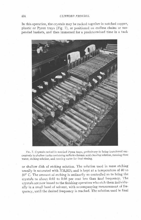
In this operation, the crystals may be racked together in notched copper'plastic or Pyrex trays (Fig. 7), or positioned on endless chains or sus-
pended baskets, and then immersed for a predetermined time in a tank
Frc. 7. Crystals racked in notched Pyrex trays, preliminary to being transferred suc-
cessively to shallow tanks containing sulfuric-chromic acid cleaning solution, running rinse
water, etching solution, and running water for final rinsing.
or shallow dish of etching soiution. The solution used in mass etching
usually is saturated with NHaHFz and is kept at a temperature of 40 to
50' C. The amount of etching is ordinarily so controlled as to bring the
crystals to about 0.02 to 0.08 per cent Iess than final frequency' The
crystals are now issued to the finishing operators who etch them individu-
ally in a small bowl of solvent, with accompanying measurement of fre-
quency, until the desired frequency is reached. The solution used in final
IIINAL F'Ii|::,OULNCY ADJUSTMENI' 425
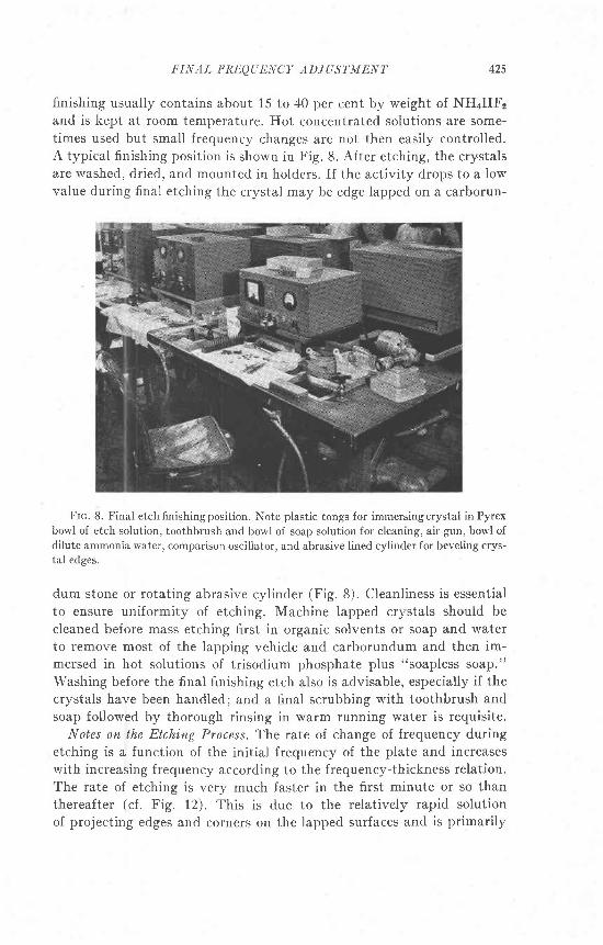
finishing usually contains about 15 lo 40 per cent by weight of NHTHFzand is kept at room temperature. Hot concentrated solutions are some-times used but small frequency changes are not then easily controlled.A typical finishing position is shown in Fig. 8. After etching, the crystalsare washed, dried, and mounted in holders. If the activity drops to a lowvalue during final etching the crystal may be edge lapped on a carborun-
Frc. 8. Final etch finishing position. Note plastic tongs for immersing crystai in Pyrexborvl of etch solution, toothbrush and bor'l of soap solution for cleaning, air gun, bowl ofdilute ammonia water, comparison oscillator, and abrasive lined cylinder for beveling crys-tal edges.
dum stone or rotating abrasive cylinder (Fig.8). Cleanliness is essentialto ensure uniformity of etching. Machine lapped crystals should becleaned before mass etching first in organic solvents or soap and waterto remove most of the lapping vehicle and carborundum and then im-mersed in hot solutions of trisodium phosphate plus "soapless soap."Washing before the finai finishing etch also is advisable, especially if thecrystals have been handled; and a final scrubbing with toothbrush andsoap followed by thorough rinsing in warm running water is requisite.
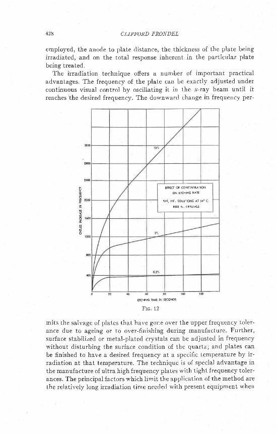
Notes on the Etching Process. The rate of change of frequency duringetching is a function of the initial frequency of the plate and increaseswith increasing frequency according to the frequency-thickness relation.The rate of etching is very much faster in the first minute or so thanthereafter (cf. Fig. 12). This is due to the relatively rapid solutionof projecting edges and corners on the lapped surfaces and is primarily

426 CLIFFORD F'RONDEL
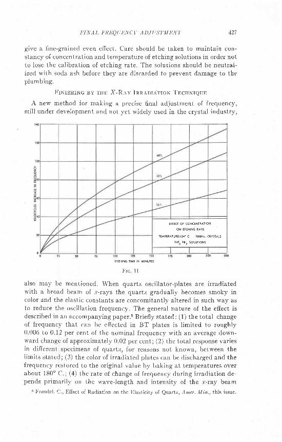
an unloading effect. The effect is especially marked in dilute solutions.In crystals of the same frequency the rate of etching is faster the coarserthe abrasive finish on the crystal (Fig.9). The rate of etching also in-creases with increasing temperature of the etching solution (Fig. 10), andwith increasing concentration (Figs. 11 and 12). Agitating the solutionspeeds the action. Crystals from which 5 to 10 microns or so of quartzhave been etched, depending on the kind of abrasive finish, become trans-parent with a glazed appearance. Prolonged etching commonly results
Frc. 9 Frc. 10
in decrease of activity due partly to relatively deep etch pits, enlarge-ment of surface flaws, and change of contour. Difierent oscil lator-cutschange frequency at different rates during etching because of the vec-toriality of solution rates in quartz and in part, because of the differencesin modes of vibration.
Hydrofluoric acid formerly was used as the etching medium but thisdangerous compound was later replaced by ammonium bifluoride and byproprietary compoundsa based on ammonium bifluoride but containingadditional ingredients to improve the quality of the work. General speak-ing, hydrofluoric acid gives a coarse deeply pitted efiect while the am-monium and alkali bifluorides, especially when containing fluoborates,
1 "Safe-T-Etch" and "Frequency-Etch," sold by the Hudson American Corp., 25 West
43rd Street, New York, N. Y.
EICHING IIMC IN HOUR5
IIINAI, I,'RI'OLiENCY ADJUSTTIDNT 127
give a fine-grained even effect. Care should be taken to maintain con-stancy of concentration and temperature of etching solutions in order notto lose the calibration of etching rate. The solutions should be neutral-ized with soda ash before they are discarded to prevent damage to theplumbing.
FrNrsnrxe By rHE X-Rev Inn,qnrarroN TncuNrqun
A new method for making a precise final adjustment of frequency,sti l l under development and not yet widely used in the crystal industry,
ETCHING IIME IN MINUT€S
Frc . 11
also may be mentioned. When cluartz oscil lator-piates are irradiatedwith a broad beam of r-rays the quartz gradually becomes smoky incolor and the elastic constants are concomitantiy altered in such way asto reduce the oscil lation frequency. The general nature of the efiect isdescribed in an accompanying paper.s Briefly stated: (1) the total changeof frequency that can be efiected in BT plates is l imited to roughly0.006 to 0.12 per cent of the nominal frequency with an average down-ward change of approximately 0.02 per cent; (2) the total response variesin different specimens oI quartz, for reasons not known, between thelimits stated; (3) the color of irradiated plates can be discharged and thefrequency restored to the original value by baking at temperatures overabout 180" C.; (a) the rate of change of frequency during irradiation de-pends primarily on the wave-length and intensity of the r-ray beam
6 Frondel. r-)., ElIect of Radiation on the Iilasticity of Quartz, Amer. Min., this issue.
EFFK OF CONCENTRATION
ON ETCHING RAIE
IEMPERATURE=?a 'C 7@0K< CRYSTALS
NH4 HF2 SOLUTIONS
428 CLIFFORD FRONDEL
employed, the anode to plate distance, the thickness of the plate beingirradiated, and on the total response inherent in the particular platebeing treated.
The irradiation technique offers a number of important practicaladvantages. The frequency of the plate can be exactly adjusted undercontinuous visual control by oscillating it in the r-ray beam until itreaches'the desired frequency. The downward change in frequency per-
Frc. 12
mits the salvage of plates that have gone over the upper frequency toler-ance due to ageing or to over-finishing during manufacture. Further,surface stabilized or metal-plated crystals can be adjusted in frequencywithout disturbing the surface condition of the quartzl and plates canbe finished to have a desired frequency at a specific temperature by ir-radiation at that temperature. The technique is of special advantage inthe manufacture of ultra high frequency plates with tight frequency toler-ances. The principal factors which limit the application of the method arethe relatively long irradiation time needed with present equipment when
z
c
z
EFFECT OF CONCENTRATION
ON EICHING R^TE
NHr Hf r SOLUTTONS aT 24 'C
8m Kc CRYSTALS

FINAL FREQUENCY ADJUSTMENT 429
Iarge frequency changes are desired, and the high initial cost of installingsufficient equipment to handle a large volume of work. Generally speak-ing, the crystals have to be finished by conventional methods to withinroughly 0.02 per cent of nominal frequency before irradiation since thetotal frequency change that can be effected is of this order.
Commercial r-ray equipment for irradiating oscillator-plates has beenmarketed by the North American Philips X-Ray Corporation. A photo-
Frc. 13. Philips *-ray irradiation units used to adjust the frequency of finished
quartz oscillator-plates
graph of three Philips irradiation units used on the production line at oneof the quartz plants of Reeves Sound Laboratories in New York City isshown in Fig. 13. The equipment comprises a broad focus copper anodetube designed to operate continuously at 25 ma and 60 KV. The water-cooled tube is housed in a casting to which are attached two insulatedjigs opposite the windows of the tube. The jigs consist of a rotatable
shielded disc containing six variously sized electrode positions into whichoscillator-plates may be inserted and in turn rotated into the c-ray beam(Fig. 1a). The outer electrode facing the window is pierced with a largehole to permit the beam to strike the central area of the crystal. The jig
is so constructed that the plate can be oscillated during irradiation and

CI,IF'FORD F'RONDI|L
the frequency change followed visually on a meter. The average rate ofdownward change of frequency in this equipment in high frequency BTplates'averages between 20 and 40 cycies a minute. Crystals mounted bywire suspension in bakelite or other holders relatively transparent tor-rays can be oscil lated and irradiated to frequency directly throughthe holder.
Frc. 14. Close-up vieu'of jig used to hold and oscillate crystals during irradiation.
Fnnquulcv AoyusrunNr oF vfETAL Pr,arno Cnvsrer,s
A number of types of crystals are plated on the surface u'ith a thinfilm of metal, usually gold, silver or aluminum. In crystals whose fre-quency is determined by edge dimensions, as in the GT, CT, DT cutsand X-cut bars, the frequency is relatively insensitive to the amount ofmetal deposited and to the thickness dimension of the quartz plate itself.Minor frequency adjustments of such crystals are effected by edgegrinding, leaving the metall ized surface untouched. These crystals or-dinarily are mounted by clamping electrodes to or soldering wires to thenodal points. In plated AT and BT shear mode crystals, however, the

FINAL FR]JQUENCV ADJUST-MENT +31
frequency decreases with the amount of metal deposited and unless the
plating operation itself is very carefully calibrated minor frequency ad-justments are necessary. These are effected by operating on the metal
plated surface itself . Shear mode plated crystals are preferably mounted
by wire suspension, the wires being soldered to opposite and opposing
edges or corners of the plate.In the manufacture of plated AT and BT crystals, the plate is lapped
and etched a number of kilocycles over the final desired frequency and
then metal is superdeposited by cathode sputtering, evaporation, chem-
ical deposition or ceramic processes unti l the frequency is brought back
close to the desired value. If a further downward change is then required,
a metal such as nickel can be electroplated upon the base coat or minor
adjustments can be effected by x-ray irradiation. If an upward adjust-ment is desired the metal f i lm can be carefully abraded with a rubber
ink eraser or the fi lm can be partly etched off with a solvent. Metal also
can be deplated electrochemically. These adjustments can be made after
the crystal has been soldered to its supporting wires. Efforts to remove
large amounts of metal often result in a loosening of the fi lm and if a
large upward frequency is desired it is best to dissolve off all the metal
and start over. Methods recently have been devised in which the plate
can be oscil lated and measured during the metal plating operation and
brought directly to frequency. It is desirable to bake plated crystals at
ca. 550o C. to bring about an increased particle size in the fi lm and en-
hance its strength and adherence.
Related Documents


