Final Exam Review Professor Deepa Kundur University of Toronto Professor Deepa Kundur (University of Toronto) Final Exam Review 1 / 67 Final Exam Review Reference: Sections: 2.1, 2.2, 2.3, 2.4, 2.5, 2.6, 2.7 3.1, 3.2, 3.3, 3.4, 3.5, 3.6 4.1, 4.2, 4.3, 4.4, 4.6, 4.7, 4.8 5.1, 5.2, 5.3, 5.4, 5.5 6.1, 6.2, 6.3, 6.4, 6.5, 6.6 7.1, 7.2, 7.3, 7.4, 7.5, 7.6, 7.7, 7.8 10.1, 10.2 of S. Haykin and M. Moher, Introduction to Analog & Digital Communications, 2nd ed., John Wiley & Sons, Inc., 2007. ISBN-13 978-0-471-43222-7. Professor Deepa Kundur (University of Toronto) Final Exam Review 2 / 67 Chapter 3: Amplitude Modulation Professor Deepa Kundur (University of Toronto) Final Exam Review 3 / 67 Amplitude Modulation I In modulation need two things: 1. a modulated signal: carrier signal: c (t ) 2. a modulating signal: message signal: m(t ) I carrier: I c (t )= A c cos(2πf c t ); phase φ c = 0 is assumed. I message: I m(t ) (information-bearing signal) I assume bandwidth/max freq of m(t ) is W Professor Deepa Kundur (University of Toronto) Final Exam Review 4 / 67

Welcome message from author
This document is posted to help you gain knowledge. Please leave a comment to let me know what you think about it! Share it to your friends and learn new things together.
Transcript

Final Exam Review
Professor Deepa Kundur
University of Toronto
Professor Deepa Kundur (University of Toronto) Final Exam Review 1 / 67
Final Exam Review
Reference:
Sections:2.1, 2.2, 2.3, 2.4, 2.5, 2.6, 2.73.1, 3.2, 3.3, 3.4, 3.5, 3.64.1, 4.2, 4.3, 4.4, 4.6, 4.7, 4.85.1, 5.2, 5.3, 5.4, 5.56.1, 6.2, 6.3, 6.4, 6.5, 6.67.1, 7.2, 7.3, 7.4, 7.5, 7.6, 7.7, 7.810.1, 10.2 of
S. Haykin and M. Moher, Introduction to Analog & Digital Communications, 2nded., John Wiley & Sons, Inc., 2007. ISBN-13 978-0-471-43222-7.
Professor Deepa Kundur (University of Toronto) Final Exam Review 2 / 67
Chapter 3: Amplitude Modulation
Professor Deepa Kundur (University of Toronto) Final Exam Review 3 / 67
Amplitude Modulation
I In modulation need two things:
1. a modulated signal: carrier signal: c(t)2. a modulating signal: message signal: m(t)
I carrier:I c(t) = Ac cos(2πfct); phase φc = 0 is assumed.
I message:I m(t) (information-bearing signal)I assume bandwidth/max freq of m(t) is W
Professor Deepa Kundur (University of Toronto) Final Exam Review 4 / 67

Amplitude Modulation
Three types studied:
1. Amplitude Modulation (AM)(yes, it has the same name as the class of modulation techniques)
2. Double Sideband-Suppressed Carrier (DSB-SC)
3. Single Sideband (SSB)
Professor Deepa Kundur (University of Toronto) Final Exam Review 5 / 67
Amplitude Modulation TechniquesAM:
sAM(t) = Ac [1 + kam(t)] cos(2πfct)
SAM(f ) =Ac
2[δ(f − fc) + δ(f + fc)] +
kaAc
2[M(f − fc) + M(f + fc)]
f
S (f )
f
S (f )
f
S (f )
f
S (f )
2W 2W
2W 2W
W W
W W
AM
USSB
LSSB
DSB
I highest power
I BT = 2W
I lowest complexity
Professor Deepa Kundur (University of Toronto) Final Exam Review 6 / 67
Amplitude Modulation TechniquesAM: For:
1. 1 + kam(t) > 0 (envelope is always positive); and
2. fc �W (message moves slowly compared to carrier)
m(t) can be recovered with an envelope detector.
AMwave
Output+
-+
-
Professor Deepa Kundur (University of Toronto) Final Exam Review 7 / 67
Amplitude Modulation TechniquesDSB-SC:
sDSB(t) = Ac cos(2πfct)m(t)
SDSB(f ) =Ac
2[M(f − fc) + M(f + fc)] f
S (f )
f
S (f )
f
S (f )
f
S (f )
2W 2W
2W 2W
W W
W W
AM
USSB
LSSB
DSB
I lower power
I BT = 2W
I higher complexity
Professor Deepa Kundur (University of Toronto) Final Exam Review 8 / 67

Amplitude Modulation Techniques
DSB-SC:
I An envelope detector will not be able to recover m(t); it willinstead recover |m(t)|.
I Coherent demodulation is required.
ProductModulator
Low-pass�lter
Local Oscillaor
DemodulatedSignal
v (t)0s(t)
Professor Deepa Kundur (University of Toronto) Final Exam Review 9 / 67
Amplitude Modulation TechniquesSSB:
sUSSB(t) =Ac
2m(t) cos(2πfct)− Ac
2m̂(t) sin(2πfct)
SUSSB(f ) =
{Ac
2 [M(f − fc) + M(f + fc)] |f | ≥ fc0 |f | < fc
sLSSB(t) =Ac
2m(t) cos(2πfct) +
Ac
2m̂(t) sin(2πfct)
SLSSB(f ) =
{0 |f | > fcAc
2 [M(f − fc) + M(f + fc)] |f | ≤ fc
H(f ) = -j sgn(f )M(f ) M(f )
f
H(f )j
-j
h(t) = 1/( t)m(t) m(t)
Professor Deepa Kundur (University of Toronto) Final Exam Review 10 / 67
Amplitude Modulation TechniquesSSB:
upper SSB
lower SSB
f
S (f )
f
S (f )
f
S (f )
f
S (f )
2W 2W
2W 2W
W W
W W
AM
USSB
LSSB
DSB
I lowest power
I BT = W
I highest complexity
Professor Deepa Kundur (University of Toronto) Final Exam Review 11 / 67
Amplitude Modulation Techniques
SSB:
I Coherent demodulation works here as well.
ProductModulator
Low-pass�lter
Local Oscillaor
DemodulatedSignal
v (t)0s(t)
Professor Deepa Kundur (University of Toronto) Final Exam Review 12 / 67

Costas Receiver
-90 degreePhase Shifter
Voltage-controlledOscillator
ProductModulator
Low-passFilter
PhaseDiscriminator
ProductModulator
Low-pass�lter
DSB-SC wave
DemodulatedSignal
Coherent Demodulation
Circuit for Phase Locking
v (t)0local oscillator output
Professor Deepa Kundur (University of Toronto) Final Exam Review 13 / 67
Costas Receiver
-90 degreePhase Shifter
Voltage-controlledOscillator
ProductModulator
Low-passFilter
PhaseDiscriminator
ProductModulator
Low-pass�lter
DSB-SC wave
DemodulatedSignal
Q-Channel (quadrature-phase coherent detector)
I-Channel (in-phase coherent detector)
v (t)I
v (t)Q
Professor Deepa Kundur (University of Toronto) Final Exam Review 14 / 67
Quadrature Amplitude Modulation
-90 degreePhase Shifter
ProductModulator
ProductModulator
MultiplexedSignal
Messagesignal
Messagesignal
s(t) = Acm1(t) cos(2πfct) + Acm2(t) sin(2πfct)
Professor Deepa Kundur (University of Toronto) Final Exam Review 15 / 67
Quadrature Amplitude Modulation
s(t) = Acm1(t) cos(2πfct) + Acm2(t) sin(2πfct)
ProductModulator
Low-passFilter
ProductModulator
Low-pass�lter
MultiplexedSignal
-90 degreePhase Shifter
Professor Deepa Kundur (University of Toronto) Final Exam Review 16 / 67
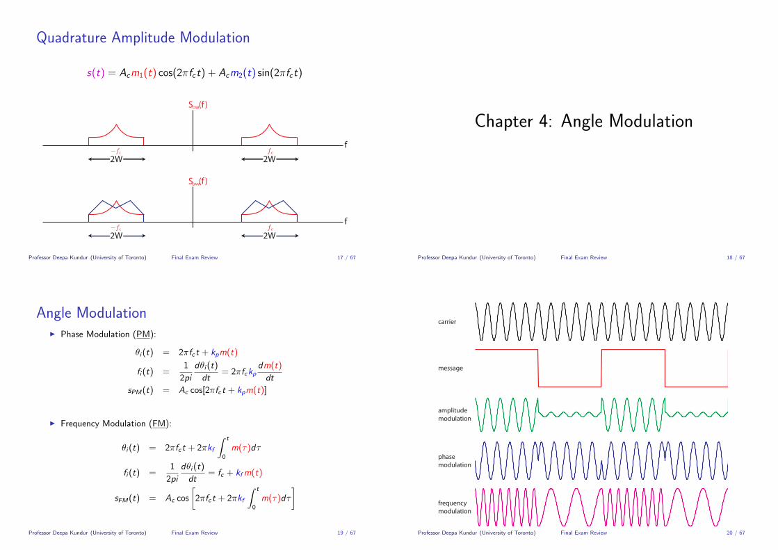
Quadrature Amplitude Modulation
s(t) = Acm1(t) cos(2πfct) + Acm2(t) sin(2πfct)
upper SSB
lower SSB
f
S (f )DSB
f
S (f )
f
S (f )
f
S (f )
2W 2W
2W 2W
W W
W W
USSB
LSSB
QAM
Professor Deepa Kundur (University of Toronto) Final Exam Review 17 / 67
Chapter 4: Angle Modulation
Professor Deepa Kundur (University of Toronto) Final Exam Review 18 / 67
Angle ModulationI Phase Modulation (PM):
θi (t) = 2πfct + kpm(t)
fi (t) =1
2pi
dθi (t)
dt= 2πfckp
dm(t)
dt
sPM(t) = Ac cos[2πfct + kpm(t)]
I Frequency Modulation (FM):
θi (t) = 2πfct + 2πkf
∫ t
0
m(τ)dτ
fi (t) =1
2pi
dθi (t)
dt= fc + kfm(t)
sFM(t) = Ac cos
[2πfct + 2πkf
∫ t
0
m(τ)dτ
]
Professor Deepa Kundur (University of Toronto) Final Exam Review 19 / 67
carrier
message
amplitudemodulation
phasemodulation
frequencymodulation
Professor Deepa Kundur (University of Toronto) Final Exam Review 20 / 67

Angle Modulation
PM and FM:
Integrator PhaseModulator
m(t) s (t)FM
Di�erentiator FrequencyModulator
m(t) s (t)PM
Professor Deepa Kundur (University of Toronto) Final Exam Review 21 / 67
Properties of Angle Modulation
1. Constancy of transmitted power
2. Nonlinearity of angle modulation
3. Irregularity of zero-crossings
4. Difficulty in visualizing message
5. Bandwidth versus noise trade-off
Professor Deepa Kundur (University of Toronto) Final Exam Review 22 / 67
Narrowband FM
I Suppose m(t) = Amcos(2πfmt).
fi (t) = fc + kf Amcos(2πfmt) = fc + ∆f cos(2πfmt)
∆f = kf Am ≡ frequency deviation
θi (t) = 2π
∫ t
0
fi (τ)dτ
= 2πfct +∆f
fmsin(2πfmt) = 2πfct + βsin(2πfmt)
β =∆f
fmsFM(t) = Ac cos [2πfct + βsin(2πfmt)]
For narrow band FM, β � 1.
Professor Deepa Kundur (University of Toronto) Final Exam Review 23 / 67
Narrowband FM
Modulation:
sFM(t) ≈ Ac cos(2πfct)︸ ︷︷ ︸carrier
−β Ac sin(2πfct)︸ ︷︷ ︸−90oshift of carrier
sin(2πfmt)︸ ︷︷ ︸2πfmAm
∫ t0 m(τ)dτ︸ ︷︷ ︸
DSB-SC signal
Modulatingwave
IntegratorNarrow-band
FM waveProduct
Modulator
-90 degreePhase Shifter carrier
+-
Professor Deepa Kundur (University of Toronto) Final Exam Review 24 / 67

Carson’s Rule
A significant component of the FM signal is within the followingbandwidth:
BT ≈ 2∆f + 2fm = 2∆f
(1 +
1
β
)
I For β � 1, BT ≈ 2∆f = 2kfAm
I For β � 1, BT ≈ 2∆f 1β
= 2∆f∆f /fm
= 2fm
Professor Deepa Kundur (University of Toronto) Final Exam Review 25 / 67
Generation of FM Waves: Armstrong Modulator
Narrow bandModulator
FrequencyMultiplier
m(t) s(t) s’(t)Integrator
CrystalControlledOscillator
frequency isvery stable
Narrowband FM modulator
widebandFM wave
Professor Deepa Kundur (University of Toronto) Final Exam Review 26 / 67
Demodulation of FM Waves
Ideal EnvelopeDetector
ddt
I Frequency Discriminator: uses positive and negative slopecircuits in place of a differentiator, which is hard to implementacross a wide bandwidth
I Phase Lock Loop: tracks the angle of the in-coming FM wavewhich allows tracking of the embedded message
Professor Deepa Kundur (University of Toronto) Final Exam Review 27 / 67
Chapter 5: Pulse Modulation
Professor Deepa Kundur (University of Toronto) Final Exam Review 28 / 67

Pulse Modulation
I the variation of a regularly spaced constant amplitude pulsestream to superimpose information contained in a message signal
tTTs
A
I Three types:
1. pulse amplitude modulation (PAM)2. pulse duration modulation (PDM)3. pulse position modulation (PPM)
Professor Deepa Kundur (University of Toronto) Final Exam Review 29 / 67
Pulse Amplitude Modulation (PAM)
tTTs
At
TTs
t
m(t)m(0)m(-T )s
m(T )s
m(2T ) s
t
m(t)
s(t)
T
Ts
m(0)m(-T )sm(T )s
m(2T ) s
tT
Ts
t
m(t)m(0)m(-T )s
m(T )s
m(2T ) s
t
m(t)
s(t)
T
Ts
m(0)m(-T )sm(T )s
m(2T ) s
Professor Deepa Kundur (University of Toronto) Final Exam Review 30 / 67
Pulse Duration Modulation (PDM)
tT
Ts
t
m(t)m(0)m(-T )s
m(T )s
m(2T ) s
t
m(t) s(t)m(0)m(-T )s
m(T )s
m(2T ) s
PDM
Professor Deepa Kundur (University of Toronto) Final Exam Review 31 / 67
tT
Ts
t
m(t)m(0)m(-T )s
m(T )s
m(2T ) s
t
m(t) s(t)m(0)m(-T )s
m(T )s
m(2T ) s
PDM
m(t) s(t)
PPM
Professor Deepa Kundur (University of Toronto) Final Exam Review 32 / 67

Summary of Pulse ModulationLet g(t) be the pulse shape.
I PAM:
sPAM(t) =∞∑
n=−∞kam(nTs)g(t − nTS)
where ka is an amplitude sensitivity factor; ka > 0.
I PDM:
sPDM(t) =∞∑
n=−∞g
(t − nTs
kdm(nTs) + Md
)where kd is a duration sensitivity factor; kd |m(t)|max < Md .
I PPM:
sPPM(t) =∞∑
n=−∞g(t − nTs − kpm(nTs))
where kp is a position sensitivity factor; kp |m(t)|max < (Ts/2).
Professor Deepa Kundur (University of Toronto) Final Exam Review 33 / 67
Pulse-Code Modulation
I Most basic form of digital pulse modulation
PCM Data Sequence
ChannelOutput
Transmitter ReceiverTranmissionPathSO
URC
E
DES
TIN
ATIO
N
Professor Deepa Kundur (University of Toronto) Final Exam Review 34 / 67
PCM Transmitter
PCM Data Sequence
Anti-aliasedCts-timeSignal
Discrete-timeSignal
Digitalsignal
Continuous-timeMessageSignal
Source Sampler Quantizer EncoderLow-passFilter { {
Anti-aliasingFilter
Sampling aboveNyquist with
Narrow RectangularPAM Pulses
Maps Numbersto Bit Sequences
{ {Using a
Non-uniformQuantizer
Professor Deepa Kundur (University of Toronto) Final Exam Review 35 / 67
PCM Transmitter: Sampler
PCM Data Sequence
Anti-aliasedCts-timeSignal
Discrete-timeSignal
Digitalsignal
Continuous-timeMessageSignal
Source Sampler Quantizer EncoderLow-passFilter { {
Anti-aliasingFilter
Sampling aboveNyquist with
Narrow RectangularPAM Pulses
Maps Numbersto Bit Sequences
{ {
Using aNon-uniform
Quantizer
ts(t)
T
Ts
m(0)m(-T )sm(T )s
m(2T ) sm(t)
t
m(0)m(-T )sm(T )s
m(2T ) s
Professor Deepa Kundur (University of Toronto) Final Exam Review 36 / 67

PCM Transmitter: Non-Uniform Quantizer
PCM Data Sequence
Anti-aliasedCts-timeSignal
Discrete-timeSignal
Digitalsignal
Continuous-timeMessageSignal
Source Sampler Quantizer EncoderLow-passFilter { {
Anti-aliasingFilter
Sampling aboveNyquist with
Narrow RectangularPAM Pulses
Maps Numbersto Bit Sequences
{ {
Using aNon-uniform
Quantizer
AmplitudeCompressor
v
m2 3-2-3 -
23
-2
-3
-
UniformQuantizer
-1 10-2-3 2 3n
1
v[n] m[n]
0 0.25 0.5 0.75 1.0
0.25
0.5
0.75
1.0
Normalized input |m|
Nor
mal
ized
out
put |
v| large mu
Professor Deepa Kundur (University of Toronto) Final Exam Review 37 / 67
PCM Transmitter: Encoder
PCM Data Sequence
Anti-aliasedCts-timeSignal
Discrete-timeSignal
Digitalsignal
Continuous-timeMessageSignal
Source Sampler Quantizer EncoderLow-passFilter { {
Anti-aliasingFilter
Sampling aboveNyquist with
Narrow RectangularPAM Pulses
Maps Numbersto Bit Sequences
{ {
Using aNon-uniform
Quantizer
Quantization-Level Index Binary Codeword (R = 3)
0 0001 0012 0103 0114 1005 1016 1107 111
Professor Deepa Kundur (University of Toronto) Final Exam Review 38 / 67
Encoder: Example
Professor Deepa Kundur (University of Toronto) Final Exam Review 39 / 67
PCM: Transmission Path
PCM Data Sequence
ChannelOutput
Transmitter ReceiverTranmissionPathSO
URC
E
DES
TIN
ATIO
N
ChannelOutput
TranmissionLine
RegenerativeRepeater
TranmissionLine
RegenerativeRepeater
TranmissionLine
...PCM Data Shaped for Transmission
Decision-making
DeviceAmpli�er-Equalizer
TimingCircuit
DistortedPCMWave
RegeneratedPCMWave
Professor Deepa Kundur (University of Toronto) Final Exam Review 40 / 67
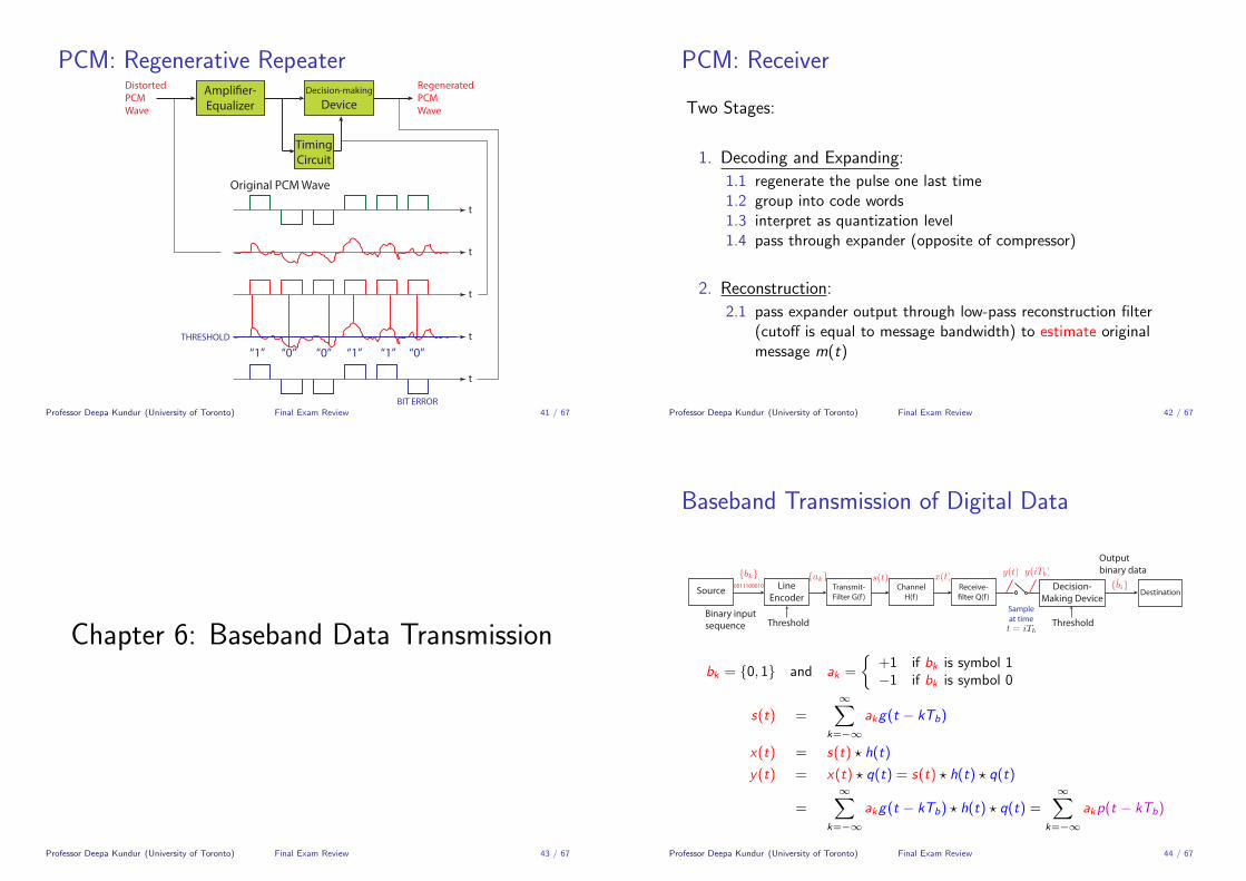
PCM: Regenerative RepeaterDecision-making
DeviceAmpli�er-Equalizer
TimingCircuit
DistortedPCMWave
RegeneratedPCMWave
t
t
t
t
t
THRESHOLD
BIT ERROR
“0” “0” “0”“1” “1” “1”
Original PCM Wave
Professor Deepa Kundur (University of Toronto) Final Exam Review 41 / 67
PCM: Receiver
Two Stages:
1. Decoding and Expanding:
1.1 regenerate the pulse one last time1.2 group into code words1.3 interpret as quantization level1.4 pass through expander (opposite of compressor)
2. Reconstruction:
2.1 pass expander output through low-pass reconstruction filter(cutoff is equal to message bandwidth) to estimate originalmessage m(t)
Professor Deepa Kundur (University of Toronto) Final Exam Review 42 / 67
Chapter 6: Baseband Data Transmission
Professor Deepa Kundur (University of Toronto) Final Exam Review 43 / 67
Baseband Transmission of Digital Data
ThresholdBinary input sequence
LineEncoder
0011100010Source
Threshold
Decision-Making Device
Sampleat time
DestinationTransmit-Filter G(f )
ChannelH(f )
Receive-�lter Q(f )
Outputbinary data
Threshold
Decision-Making Device
Sampleat time
Pulse Spectrum P(f )
bk = {0, 1} and ak =
{+1 if bk is symbol 1−1 if bk is symbol 0
s(t) =∞∑
k=−∞
akg(t − kTb)
x(t) = s(t) ? h(t)
y(t) = x(t) ? q(t) = s(t) ? h(t) ? q(t)
=∞∑
k=−∞
akg(t − kTb) ? h(t) ? q(t) =∞∑
k=−∞
akp(t − kTb)
Professor Deepa Kundur (University of Toronto) Final Exam Review 44 / 67
Baseband Transmission of Digital Data
ThresholdBinary input sequence
LineEncoder
0011100010Source
Threshold
Decision-Making Device
Sampleat time
DestinationTransmit-Filter G(f )
ChannelH(f )
Receive-�lter Q(f )
Outputbinary data
Threshold
Decision-Making Device
Sampleat time
Pulse Spectrum P(f )
∴ y(t) =∞∑
k=−∞
akp(t − kTb)
where p(t) = g(t) ∗ h(t) ∗ q(t)
P(f ) = G (f ) · H(f ) · Q(f ).
Professor Deepa Kundur (University of Toronto) Final Exam Review 45 / 67
Baseband Transmission of Digital Data
Threshold
Decision-Making Device
Sampleat time
Transmit-Filter G(f )
ChannelH(f )
Receive-�lter Q(f )
ThresholdBinary input sequence
LineEncoder
0011100010Source Destination
Outputbinary data
Threshold
Decision-Making Device
Sampleat time
Pulse Spectrum P(f )
P(f ) = G(f )H(f )Q(f )
Professor Deepa Kundur (University of Toronto) Final Exam Review 46 / 67
Baseband Transmission of Digital Data
Threshold
Decision-Making Device
Sampleat time
Pulse Spectrum P(f )
P(f ) = G(f )H(f )Q(f )
yi = y(iTb) and pi = p(iTb)
yi =√Eai︸ ︷︷ ︸
signal to detect
+∞∑
k=−∞,k 6=i
akpi−k︸ ︷︷ ︸intersymbol interference
for i ∈ Z
To avoid intersymbol interference (ISI), we need pi = 0 for i 6= 0.
Professor Deepa Kundur (University of Toronto) Final Exam Review 47 / 67
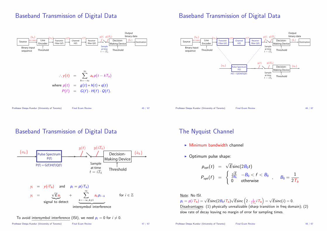
The Nyquist Channel
I Minimum bandwidth channel
I Optimum pulse shape:
popt(t) =√E sinc(2B0t)
Popt(f ) =
{ √E
2B0−B0 < f < B0
0 otherwise, B0 =
1
2Tb
Note: No ISI.
pi = p(iTb) =√E sinc(2B0iTb)
√E sinc
(2 · 1
2TbiTb
)=√E sinc(i) = 0.
Disadvantages: (1) physically unrealizable (sharp transition in freq domain); (2)
slow rate of decay leaving no margin of error for sampling times.
Professor Deepa Kundur (University of Toronto) Final Exam Review 48 / 67

Raised-Cosine Pulse Spectrum
I has a more graceful transition in the frequency domain
I more practical pulse shape:
p(t) =√E sinc(2B0t)
(cos(2παB0t)
1− 16α2B02t2
)
P(f ) =
√E
2B00 ≤ |f | < f1
√E
4B0
{1 + cos
[π(|f |−f1)(B0−f1)
]}f1 < f < 2B0 − f1
0 2B0 − f1 ≤ |f |
α = 1− f1B0
BT = B0(1 + α) where B0 =1
2Tband fv = αB0
Note: No ISI. ∵ pi = 0.Professor Deepa Kundur (University of Toronto) Final Exam Review 49 / 67
Raised-Cosine Pulse Spectrum
f (kHz)
A= sqrt(E)/2B
A/2
0
0B0-B 02B0-2B0B /2 0B /2 0B /2 0B /2
Raised-Cosine
NyquistPulse
Professor Deepa Kundur (University of Toronto) Final Exam Review 50 / 67
The Eye Pattern
Slope dictates sensitivityto timing error
Best samplingtime
Distortion at sampling time
NO
ISE
MA
RGIN
Time interval over which waveis best sampled.
ZERO-CROSSINGDISTORTION
Professor Deepa Kundur (University of Toronto) Final Exam Review 51 / 67
Chapter 7: Digital Band-Pass ModulationTechniques
Professor Deepa Kundur (University of Toronto) Final Exam Review 52 / 67

Binary Modulation Schemes
c(t) = Ac cos(2πfct + φc)
I Binary amplitude-shift keying (BASK): carrier amplitude is keyed between
two possible values (typically√Eb and 0 to represent 1 and 0, respectively);
carrier phase and frequency are held constant.
I Binary phase-shift keying (BPSK):carrier phase is keyed between twopossible values (typically 0 and π to represent 1 and 0, respectively); carrieramplitude and frequency are held constant.
I Binary frequency-shift keying (BFSK): carrier frequency is keyed betweentwo possible values (typically f1 and f2 to represent 1 and 0, respectively);carrier amplitude and phase are held constant.
Professor Deepa Kundur (University of Toronto) Final Exam Review 53 / 67
Preliminaries
c(t) = Ac cos(2πfct + φc)
I Tb represents the bit duration
I Eb represents the energy of the transmitted signal per bit
I In digital communications the carrier amplitude is normalized to have unitenergy in one bit duration; thus we set
Ac =
√2
Tb
I The carrier frequency fc = kTb
for k ∈ Z to ensure an integer number ofcarrier cycles in a bit duration.
Professor Deepa Kundur (University of Toronto) Final Exam Review 54 / 67
Carrier for Digital Communications
Therefore
c(t) =
√2
Tbcos(2πfct + φc).
For k = 4
0t
Professor Deepa Kundur (University of Toronto) Final Exam Review 55 / 67
Binary Amplitude-Shift Keying (BASK)
Let φc = 0 and the carrier frequency is fc .
b(t) =
{ √Eb for binary symbol 1
0 for binary symbol 0
c(t) =
√2
Tbcos(2πfct + φc) =
√2
Tbcos(2πfct)
s(t) = b(t) · c(t)
=
{ √2Eb
Tbcos(2πfct) for symbol 1
0 for symbol 0
Professor Deepa Kundur (University of Toronto) Final Exam Review 56 / 67

BASK Transmitter and Receiver
Transmitter
BASKTransmittedSignal
LevelEncoding
ProductModulator
carrier
EnvelopeDetector
Low-passFilterBASK
wave
Output+
-
Threshold
Decision-Making Device
Binary inputsequence
t0011100010
Sampleat time
Receiver
EnvelopeDetector
Low-passFilterBASK
wave
Output+
-
Threshold
Decision-Making Device
BASKTransmittedSignal
LevelEncoding
ProductModulator
carrier
Binary inputsequence
t0011100010
Sampleat time
Professor Deepa Kundur (University of Toronto) Final Exam Review 57 / 67
Binary Phase-Shift Keying (BPSK)
si(t) =
√
2Eb
Tbcos(2πfct) for symbol 1 (i = 1)√
2Eb
Tbcos(2πfct + π) for symbol 0 (i = 2)
=
√
2Eb
Tbcos(2πfct) for symbol 1 (i = 1)
−√
2Eb
Tbcos(2πfct) for symbol 0 (i = 2)
Professor Deepa Kundur (University of Toronto) Final Exam Review 58 / 67
BPSK Transmitter and Receiver
Transmitter
Low-passFilter
Threshold
Decision-Making Device
Sampleat time
BPSKTransmittedSignal
Binary inputsequence
LevelEncoding
ProductModulator
carrier
ProductModulator
local carrierfrom PLL
(Non-return-to zero)
t0011100010
Receiver
Low-passFilter
Threshold
Decision-Making Device
Sampleat time
BPSKTransmittedSignal
Binary inputsequence
LevelEncoding
ProductModulator
carrier
ProductModulator
local carrierfrom PLL
(Non-return-to zero)
t0011100010
Professor Deepa Kundur (University of Toronto) Final Exam Review 59 / 67
Binary Frequency-Shift Keying (BFSK)
Let φc = 0, |f1 − f2| = 1Tb
and fi = kiTb
(integer number of cycles in a
bit duration).
si(t) =
√
2Eb
Tbcos(2πf1t) for symbol 1 (i = 1)√
2Eb
Tbcos(2πf2t) for symbol 0 (i = 2)
0t
0 1 0 1 1 0 0 0
4 cycles 4 cycles 4 cycles 4 cycles 4 cycles5 cycles 5 cycles 5 cycles
Professor Deepa Kundur (University of Toronto) Final Exam Review 60 / 67

BFSK Transmitter and Receiver
Transmitter
BFSKTransmittedSignal
Binary inputsequence 0011100010
controlsswitchposition
localoscillator
localoscillator
Receiver
EnvelopeDetector
EnvelopeDetector
Band-pass�lter, f1
Comparator
Band-pass�lter, f2
v1
v2
{ 1 if v1 > v20 if v2 > v1
Professor Deepa Kundur (University of Toronto) Final Exam Review 61 / 67
Summary
BASK s1(t) =√
2Eb
Tbcos(2πfct) for symbol 1
s2(t) = 0 for symbol 0
BPSK s1(t) =√
2Eb
Tbcos(2πfct + 0) for symbol 1
s2(t) =√
2Eb
Tbcos(2πfct + π) for symbol 0
BFSK s1(t) =√
2Eb
Tbcos(2πf1t) for symbol 1
s2(t) =√
2Eb
Tbcos(2πf2t) for symbol 0
Professor Deepa Kundur (University of Toronto) Final Exam Review 62 / 67
Summary: Phasor Diagrams
BASK
BPSK
BFSK
symbol1
symbol1
symbol1
symbol0
symbol0
symbol0
Professor Deepa Kundur (University of Toronto) Final Exam Review 63 / 67
Summary: Phasor Diagrams
BASK
BPSK (antipodal)
BFSK (orthogonal)
symbol1
symbol1
symbol1
symbol0
symbol0
symbol0
Professor Deepa Kundur (University of Toronto) Final Exam Review 64 / 67

M-ary Digital Modulation SchemesFor M = 2m and T = mTb,
I M-ary Phase-Shift Keying
si (t) =
√2E
Tcos
(2πfc +
2π
Mi
)i = 0, 1, . . . ,M − 1, 0 ≤ t ≤ T .
I M-ary Quadrature Amplitude Modulation
si (t) =
√2E0
Tai cos(2πfct)−
√2E0
Tbi sin(2πfct)
i = 0, 1, . . . ,M − 1, 0 ≤ t ≤ T .
I M-ary Frequency-Shift Keying
si (t) =
√2E
Tcos( πT
(n + i)t)
i = 0, 1, . . . ,M − 1, 0 ≤ t ≤ T .
Professor Deepa Kundur (University of Toronto) Final Exam Review 65 / 67
Signal Constellations
M-PSK M-QAM M-FSK
1. For a given basis set: φ1, φ2, . . . , φn. Compute correlation of si (t) witheach of the bases members.
2. Graph the result in signal space.
Professor Deepa Kundur (University of Toronto) Final Exam Review 66 / 67
Important Identities
cos(A + B) = cos(A) cos(B)− sin(A) sin(B)
cos(A) cos(B) =1
2cos(A + B) +
1
2cos(A− B)
cos(A) sin(B) =1
2sin(A + B)− 1
2sin(A− B)
cos(A) = sin(A +
π
2
)cos(A + π) = − cos(A)
cos(A) = cos(−A) sin(A) = − sin(−A)
cos2(A) =1
2+
1
2cos(2A)
cos2(A) + sin2(A) = 1
cos(A) ≈ 1 for |A| � 1
sin(A) ≈ A for |A| � 1
�Professor Deepa Kundur (University of Toronto) Final Exam Review 67 / 67
Related Documents