ROADS AND MARITIME SERVICES NSW PROSPECT HIGHWAY UPGRADE FINAL DRAINAGE INVESTIGATION REPORT

Welcome message from author
This document is posted to help you gain knowledge. Please leave a comment to let me know what you think about it! Share it to your friends and learn new things together.
Transcript

ROADS AND MARITIME SERVICES NSW PROSPECT HIGHWAY UPGRADE
FINAL DRAINAGE INVESTIGATION REPORT

MR644 - Prospect Highway Upgrade between Reservoir Road and St Martins Crescent—Final Drainage Investigation Report Hyder Consulting Pty Ltd-ABN 76 104 485 289 f:\aa005690\f-reports\b - drainage\fb0001-aa005690-aar-06- final drainage investigation report.docx
Hyder Consulting Pty Ltd
ABN 76 104 485 289 Level 5, 141 Walker Street Locked Bag 6503 North Sydney NSW 2060 Australia Tel: +61 2 8907 9000 Fax: +61 2 8907 9001 www.hyderconsulting.com
ROADS AND MARITIME SERVICES
MR644 - PROSPECT HIGHWAY UPGRADE BETWEEN RESERVOIR ROAD AND ST MARTINS CRESCENT Final Drainage Investigation Report
Author Luiz Segundo
Checker Jeff Dane/ San Ng
Approver Luiz Segundo
Report No FB0001-AA005690-AAR-06- Final Drainage Investigation Report
Date March 2014
This report has been prepared for Roads and Maritime Services in accordance with the terms and conditions of appointment for MR644 - Prospect Highway Upgrade between Reservoir Road and St Martins Crescent dated 4 April 2013. Hyder Consulting Pty Ltd (ABN 76 104 485 289) cannot accept any responsibility for any use of or reliance on the contents of this report by any third party.


MR644 - Prospect Highway Upgrade between Reservoir Road and St Martins Crescent—Final Drainage Investigation Report
Page i
Hyder Consulting Pty Ltd-ABN 76 104 485 289 f:\aa005690\f-reports\b - drainage\fb0001-aa005690-aar-06- final drainage investigation report.docx
CONTENTS
1 Introduction ................................................................................................................................. 1 1.1 Proposal Overview................................................................................................................................ 1
1.2 Scope of Works .................................................................................................................................... 1
1.3 Available Information ............................................................................................................................ 1
2 Hydrology Investigation ............................................................................................................... 3 2.1 Existing Cross Drainage ....................................................................................................................... 3
2.2 Catchment Description ......................................................................................................................... 4
2.3 Existing Hydrology .............................................................................................................................. 12
3 Proposed Drainage System ...................................................................................................... 17 3.1 General ............................................................................................................................................... 17
3.2 Drainage Design Criteria .................................................................................................................... 17
3.3 Aquaplaning Checks ........................................................................................................................... 19
3.4 Proposed Cross Drainage .................................................................................................................. 20
3.5 New Pavement Drainage Systems Strategy ...................................................................................... 21
3.6 Impact of the Proposed Upgrade on Existing Drainage Patterns ...................................................... 21
3.7 Recommeded Drainage Strategy ....................................................................................................... 28
4 Erosion and Sediment Control .................................................................................................. 33 4.1 Key Elements of Proposed Strategy .................................................................................................. 33
5 ConstructAbility ......................................................................................................................... 36
6 Outstanding Issues ................................................................................................................... 37
7 Summary .................................................................................................................................. 37
8 Glossary ................................................................................................................................... 38
APPENDICES
Appendix A Figures
Appendix B Concept Drainage Layout and Longitudinal Sections
Appendix C Sketch of Proposed Pedestrian Underpass (MC10 CH 1980) – SK90

Page ii MR644 - Prospect Highway Upgrade between Reservoir Road and St Martins Crescent - Final Drainage Investigation
Report Hyder Consulting Pty Ltd-ABN 76 104 485 289 f:\aa005690\f-reports\b - drainage\fb0001-aa005690-aar-06- final drainage investigation report.docx
MR644 - Prospect Highway Upgrade between Reservoir Road and St Martins Crescent—Final Drainage Investigation Report
Page 1
Hyder Consulting Pty Ltd-ABN 76 104 485 289 f:\aa005690\f-reports\b - drainage\fb0001-aa005690-aar-06- final drainage investigation report.docx
1 INTRODUCTION NSW Roads and Maritime Services (Roads and Maritime) have engaged Hyder Consulting to undertake the drainage investigation in relation to the works associated with the upgrade of the Prospect Highway between Reservoir Road and St Martins Crescent. This report details the findings of the drainage investigation, concept drainage strategy and erosion sediment control requirements for the proposal.
As part of the same commissioning, Hyder Consulting have been engaged to undertake the utility investigation for the proposal. This drainage design report should be read in conjunction with the utility investigation report (FA0001-AA005690-AAR-05-Utilities Investigation & Strategy Report). The concept drainage design presented in this report was developed considering the utility investigation.
1.1 PROPOSAL OVERVIEW The proposal includes the upgrading of Prospect Highway from Reservoir Road, Prospect to St Martins Crescent, Blacktown and is located within the Blacktown City Council (Council) local government area. It also includes:
The improvement of all intersections.
Replacement of the roundabouts at the southern section of the proposal.
Construction of a two way access ramp from Great Western Highway.
New shared path on the western side of the highway to connect the existing shared path between M4 Western Motorway and Harrod Street.
Replacement of the existing pedestrian underpass at approximately CH 1980.
Figure 1 in Appendix A shows the locality plan and presents the extent of the works and key features of the proposal area.
1.2 SCOPE OF WORKS The scope of works covered in this report includes:
Undertake a hydrology and hydraulic (drainage) investigation of the proposal area and areas in the vicinity of the proposal potentially affected by the proposed works.
Undertake the pavement drainage investigation and concept design based on the proposed road design including the proposal of measures to eliminate and or reduce potential impact of the proposed works.
Determine the erosion and sediment control requirements for the construction stage.
Provide a ‘Drainage Investigation and Design’ report incorporating the items above.
1.3 AVAILABLE INFORMATION The following information was made available and reviewed for the preparation of the drainage investigation and the development of the concept drainage design:

Page 2 MR644 - Prospect Highway Upgrade between Reservoir Road and St Martins Crescent - Final Drainage Investigation
Report Hyder Consulting Pty Ltd-ABN 76 104 485 289 f:\aa005690\f-reports\b - drainage\fb0001-aa005690-aar-06- final drainage investigation report.docx
Roads and Maritime detailed ground survey along the existing road corridor for the extent of the proposal.
Roads and Maritime 3d utility survey model. This model also included various utilities in 2d format.
Roads and Maritime road design models.
Roads and Maritime pedestrian underpass bridge design.
Roads and Maritime preliminary construction staging plans.
Cadastral information.
Aerial imagery information for the proposal locality supplied by Roads and Maritime.
Drainage design drawings of the existing drainage systems constructed as part of the M4 Western Motorway and Great Western Highway.
Blacktown City Council drainage system layout information in the vicinity of the proposal.
Blacktown City Council plans of the stormwater detention basins located adjacent to the road at about chainage 2100.
Two (2) metre contours CAD file for the locality.

MR644 - Prospect Highway Upgrade between Reservoir Road and St Martins Crescent—Final Drainage Investigation Report
Page 3
Hyder Consulting Pty Ltd-ABN 76 104 485 289 f:\aa005690\f-reports\b - drainage\fb0001-aa005690-aar-06- final drainage investigation report.docx
2 HYDROLOGY INVESTIGATION The Prospect Highway road corridor runs in close proximity to the catchment boundary of Greystanes Creek and Blacktown Creek. Greystanes Creek Catchment is generally located to the east of the proposal corridor and Blacktown Creek the west. The proposal does not cross major waterways and therefore is not impacted by regional (major) flooding. The Girraween Creek and Blacktown Creek are in close proximity but outside the scope of the proposal. Girraween Creek is located south of proposal limit and Blacktown Creek is located west of the Two-way Link Road and north of the proposal limit. Flooding information of Girraween Creek and Blacktown Creek was not available for the current investigation. However, the proposal is not expected to impact or be impacted by major flooding from the waterways.
It s important to note that the proposal is not within the Prospect Reservoir catchment, and runoff from the existing Prospect Highway does not discharge to Prospect Reservoir.
Runoff generated within the road corridor catchments discharge to four (4) cross drainage structures and to Council’s drainage lines located along the route. Along the section of the proposal located to the north of the Great Western Highway (GWH), some road runoff escapes the road corridor through the several side streets. The following sections of this report discuss the existing drainage patterns in more detail.
The location of the existing cross drainage structures, drainage lines and other key drainage features along the proposed proposal corridor is shown on Figures 2-1 to 2-5 contained in Appendix A.
2.1 EXISTING CROSS DRAINAGE Four (4) cross drainage structures were identified along the corridor. The details of these structures are provided in Table 2-1.
Table 2-1 Existing Cross Drainage Structures
Catchment Design Road
Chainage
(Approx)
Size/Type
(mm)
Upstream
Invert Level
(m AHD)
Downstream
Invert Level
(m AHD)
Adjacent
Road Level
(m AHD)
Greystanes Creek
MC10 - 460 1350 RCP1 65.32 63.86 72.41
Blacktown Creek
MX01 - 110 750 RCP1 74.55 72.25 76.33
MC10 - 2034 900 RCP1 64.75 63.14 70.11
MC10 - 3100 450 RCP1 59.94 59.54 61.06
1 RCP – Stands for reinforced concrete pipe.
It is important to note that there are two stormwater detention basins located at both upstream (eastern side of the road) and downstream (western side) of cross drainage structure at CH 2034. The discharge through this cross drainage culvert is inlet controlled by a complex inlet structure.

Page 4 MR644 - Prospect Highway Upgrade between Reservoir Road and St Martins Crescent - Final Drainage Investigation
Report Hyder Consulting Pty Ltd-ABN 76 104 485 289 f:\aa005690\f-reports\b - drainage\fb0001-aa005690-aar-06- final drainage investigation report.docx
A pedestrian underpass is located approximately 55 metres south of the cross drainage culvert and would serve as emergency flow path for basin on the eastern side of the road corridor in storm larger than 100 year ARI.
2.2 CATCHMENT DESCRIPTION A brief description of the catchments and their existing drainage patterns are provided below in Table 2-2. Refer to Figures 2-1 to 2-5 for catchment location and details on the existing drainage systems.
Table 2-2 Catchment Description Summary
Catchment
ID
Catchment
System
Description
C1 Greystanes Creek
Runoff from approximately 180 m of roadway (the section of Prospect Highway also called Reconciliation Road is captured and conveyed by a piped drainage system located to the south of Reservoir Road Intersection.
Discharges from the catchment external on the western side of the road are collected by an existing catch drain that runs along the road and connects to inlet pits located along the drain. The inlet pits are linked to the road piped drainage system. The piped system discharges to Girraween Creek at approximately CH 0.
C2 Greystanes Creek
Runoff from the intersection of Prospect Highway and Reservoir and approximately 50 metres of roadway flows overland within the southern gutter of Reservoir Road. Runoff conveyed by the gutter discharges to the low point located near the southern end of Reservoir Road.
C3 Greystanes Creek
The catchment is approximately 13.9 ha in area and comprises of mostly undeveloped land and a number dwellings. The survey and contour information available indicate that the catchment extends to Watch House Road on the western end, Reservoir Road on the southern end, the M4 Western Motorway westbound entry ramp on the northern end and Prospect Highway on the eastern side.
Runoff from this catchment discharges the inlet of the cross drainage culvert at approximately CH 460 comprised of a 1350 RCP which across Prospect Highway. Runoff from small portion of land located between the M4 Western Motorway westbound entry ramp and the M4 Western Motorway discharges flows across the westbound entry ramp via a 375 RCP to open channels that run towards the cross drainage structure at approximately CH 460.
The cross drainage culvert at MC10 – 460 has sufficient capacity to convey the 100 year average recurrence interval (ARI) flows.
C4 Greystanes Creek
This catchment is comprised of approximately 140 m of Prospect Highway roadway and part of the road embankment and batter located on the eastern side of the Prospect Highway. Runoff from this catchment joins the flows from catchment C3 in the vicinity of the cross drainage structure outlet at approximately CH 460.

MR644 - Prospect Highway Upgrade between Reservoir Road and St Martins Crescent—Final Drainage Investigation Report
Page 5
Hyder Consulting Pty Ltd-ABN 76 104 485 289 f:\aa005690\f-reports\b - drainage\fb0001-aa005690-aar-06- final drainage investigation report.docx
Catchment
ID
Catchment
System
Description
C5 Greystanes Creek
Runoff from the M4 Western Motorway westbound exit ramp discharges to a number of small sedimentation basins located on the southern side of the M4 westbound exit ramp. The catchment is comprised of approximately 50 m of roadway.
C6 Greystanes Creek
This catchment is approximately 5.9 ha in area and comprises of a large portion of the M4 Western Motorway/ Prospect Highway interchange. The interchange and the M4 Western Motorway is served by a number of drainage systems comprised of cross drainage structures, pavement drainage systems and catch drains/ open channels. These systems ultimately discharge to the M4 water quality basin located between the M4 Western Motorway and the westbound exit ramp.
The drainage systems located to the north of the M4 combine their runoff with runoff from approximately 500 m of the M4 Western Motorway eastbound carriageway at the inlet of the existing 825 RCP cross drainage culvert. The cross culvert which conveys runoff to the existing M4 basin on the southern side of the motorway.
C7 Blacktown Creek
Catchment C7 is comprised of approximately 70m of M4 eastbound exit ramp roadway. Flows from this catchment are conveyed within a SA gutter in the vicinity of the Prospect Highway. The gutter connects to an open channel that runs along the ramp towards Blacktown Creek.
C8 Blacktown Creek
C8 is comprised of an undeveloped land between the GWH and the M4 Western Motorway eastbound exit ramp. The catchment includes the section of Prospect Highway roadway between the roundabout located to the north of the M4 and to the south of the bridge over the GWH. Runoff from the roadway is captured and conveyed by a piped drainage system which discharges to an open channel at approximately CH 1120. The runoff from this catchment travels to the inlet of a 750 RCP cross drainage culvert located across the GWH.
C9 Greystanes Creek
Runoff from approximately 110 m of roadway including runoff generated within the bridge over GWH is captured by the minor piped drainage system located at the southern end of the bridge. Runoff is discharged to a catch drain located at the top of the GWH cutting on the south eastern side of the bridge. Based on as built plans for the GWH, runoff from this catchment is then discharged across the GWH in northerly direction via a 600 RCP cross drainage structure.
C10 Greystanes Creek
Runoff from C10 escapes the Prospect Highway roadway via the GWH eastbound entry ramp.

Page 6 MR644 - Prospect Highway Upgrade between Reservoir Road and St Martins Crescent - Final Drainage Investigation
Report Hyder Consulting Pty Ltd-ABN 76 104 485 289 f:\aa005690\f-reports\b - drainage\fb0001-aa005690-aar-06- final drainage investigation report.docx
Catchment
ID
Catchment
System
Description
C11 Blacktown Creek
Runoff from approximately 120 m of the GWH eastbound exit ramp is captured by a minor piped system and discharged to an open channel on the northern side of the ramp. Runoff from this catchment joins the runoff of C8 at the outlet of the existing GWH 750 RCP cross pipe. The GWH cross pipe discharges to the inlet of the 750 RCP which forms part of the Council’s piped drainage system. The Council’s 750 RCP runs through the properties located on the northern side of the GWH eastbound exit ramp.
The drainage easement adjacent to the inlet of the 750 RCP (Council’s piped drainage system) is expected to carry catchment runoff which bypasses the underground drainage system at this location. It is believed that the area would provide some flood storage before runoff starts escaping through the back (timber) fences of the properties located near the low point. However, the flood storage available is limited as the timber fences located at the rear of the properties would allow runoff to escape through and collapse depending on the water depth building up behind them.
Hydraulic analysis indicates that the GWH cross pipe has sufficient capacity to convey the 100 year ARI storm flows.
C12 Blacktown Creek
This catchment is comprised of approximately 700 m length of the GWH and includes part of the GWH eastbound exit ramp. Runoff from this catchment is captured by the highway piped drainage system and discharges to Blacktown Creek located approximately 530m to the west of the Prospect Highway bridge.
C13 Greystanes Creek
Runoff from approximately 170 of roadway is captured by a number breaks in the SF type gutter and conveyed via chutes to a 375 RCP which forms part of the Council’s piped drainage system.
Bypass flows from this catchment contributes to catchment C15.
C14 Blacktown Creek
C14 is comprised a grassed area located adjacent to the existing Prospect Highway roadway. Runoff from this catchment discharges to inlet of Council’s piped drainage system on the western side of the road at approximately CH 1450.
Bypass flows from this catchment contributes to catchment C15.
C15 Greystanes Creek
A piped drainage system captures and conveys runoff from an approximately 160 m roadway within C15. The piped system also capture and conveys runoff from the grassed area located on the western side of the roadway and discharges to the Council’s piped drainage system on the eastern side of the road
Bypass flows from this catchment contributes to catchments C16 and C17.
MR644 - Prospect Highway Upgrade between Reservoir Road and St Martins Crescent—Final Drainage Investigation Report
Page 7
Hyder Consulting Pty Ltd-ABN 76 104 485 289 f:\aa005690\f-reports\b - drainage\fb0001-aa005690-aar-06- final drainage investigation report.docx
Catchment
ID
Catchment
System
Description
C16 Blacktown Creek
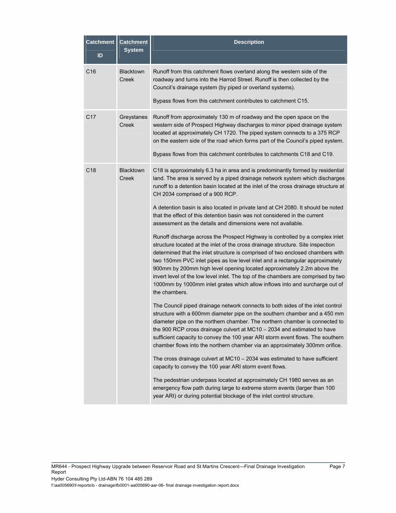
Runoff from this catchment flows overland along the western side of the roadway and turns into the Harrod Street. Runoff is then collected by the Council’s drainage system (by piped or overland systems).
Bypass flows from this catchment contributes to catchment C15.
C17 Greystanes Creek
Runoff from approximately 130 m of roadway and the open space on the western side of Prospect Highway discharges to minor piped drainage system located at approximately CH 1720. The piped system connects to a 375 RCP on the eastern side of the road which forms part of the Council’s piped system.
Bypass flows from this catchment contributes to catchments C18 and C19.
C18 Blacktown Creek
C18 is approximately 6.3 ha in area and is predominantly formed by residential land. The area is served by a piped drainage network system which discharges runoff to a detention basin located at the inlet of the cross drainage structure at CH 2034 comprised of a 900 RCP.
A detention basin is also located in private land at CH 2080. It should be noted that the effect of this detention basin was not considered in the current assessment as the details and dimensions were not available.
Runoff discharge across the Prospect Highway is controlled by a complex inlet structure located at the inlet of the cross drainage structure. Site inspection determined that the inlet structure is comprised of two enclosed chambers with two 150mm PVC inlet pipes as low level inlet and a rectangular approximately 900mm by 200mm high level opening located approximately 2.2m above the invert level of the low level inlet. The top of the chambers are comprised by two 1000mm by 1000mm inlet grates which allow inflows into and surcharge out of the chambers.
The Council piped drainage network connects to both sides of the inlet control structure with a 600mm diameter pipe on the southern chamber and a 450 mm diameter pipe on the northern chamber. The northern chamber is connected to the 900 RCP cross drainage culvert at MC10 – 2034 and estimated to have sufficient capacity to convey the 100 year ARI storm event flows. The southern chamber flows into the northern chamber via an approximately 300mm orifice.
The cross drainage culvert at MC10 – 2034 was estimated to have sufficient capacity to convey the 100 year ARI storm event flows.
The pedestrian underpass located at approximately CH 1980 serves as an emergency flow path during large to extreme storm events (larger than 100 year ARI) or during potential blockage of the inlet control structure.

Page 8 MR644 - Prospect Highway Upgrade between Reservoir Road and St Martins Crescent - Final Drainage Investigation
Report Hyder Consulting Pty Ltd-ABN 76 104 485 289 f:\aa005690\f-reports\b - drainage\fb0001-aa005690-aar-06- final drainage investigation report.docx
Catchment
ID
Catchment
System
Description
C19 Blacktown Creek
C19 is approximately 6.2 ha in area is comprised predominantly of residential land. Approximately 300 m roadway and open space located adjacent to the road also form this catchment. Runoff from this catchment joins runoff from C18 (900 RCP cross drainage culvert) at the detention basin located within this vicinity.
The basin is formed by a levee on that runs along the back of the properties on the western side of the basin. Flows discharge from the basin via a 375 mm diameter pipe and Lorne Street cul de sac located on the north western end of the basin forms the basin spillway.
C20 Blacktown Creek
Catchment C20 is approximately 3.5 ha in area and formed by roadways, open space and residences. Runoff from this catchment is captured and conveyed by a minor piped drainage system that connects to the Eltham Street pipe drainage network via a drainage easement located at approximately CH 2290 on the western side of the Prospect Highway.
Runoff generated on the eastern side of the Prospect Highway and on Prospect Highway flows to the localised low point located in vicinity of the intersection of these two roads. Runoff is captured by the piped drainage system in this vicinity and conveyed across to the Eltham Street pipe drainage network.
On the western side, runoff flows along the gutter where it is captured by a number of SA1 type inlet pits and is piped to the to the Eltham Street pipe drainage network.
Runoff bypassing the existing piped drainage system flows to catchments C21 and C22.
C21 Blacktown Creek
C21 is formed by roadway catchment and the open space land at the south western corner of Lancelot Street. Runoff generated within this catchment flows overland to the west of Prospect Highway into Lancelot Street.

MR644 - Prospect Highway Upgrade between Reservoir Road and St Martins Crescent—Final Drainage Investigation Report
Page 9
Hyder Consulting Pty Ltd-ABN 76 104 485 289 f:\aa005690\f-reports\b - drainage\fb0001-aa005690-aar-06- final drainage investigation report.docx
Catchment
ID
Catchment
System
Description
C22 Greystanes Creek/ Blacktown Creek
C22 is approximately 1.8 ha in area and comprised of 330m roadway and residential land. Runoff from the residential land to the east of Prospect Highway and from the eastern side of Prospect Highway roadway flows along the eastern gutter towards the existing low point at approximately CH 2600. On the western side of the road, runoff flows within the SO type gutter to the low point at approximately CH 2600. It is important to note that flows bypassing the piped drainage system in catchment C20 join runoff from catchment C22.
Runoff is collected by the minor piped drainage system located in the vicinity of the low point at approximately CH 2600 and discharged east into a 450 RCP which connects into the existing Council’s pipe drainage network. It is noted that the existing 450 RCP is located within the residential land adjacent the roadway and overland flow paths is blocked by dwellings.
Flows surcharging the pipe system on the eastern side of the road are believed to impact on the residences on the eastern side of the Prospect Highway towards Greystanes Creek catchment system. This is evidenced by the number of inlet pits located within the driveway of No. 223/223A Prospect Highway property which is located immediately opposite the road low point.
On the western side of the road, the low point is located immediately opposite No. 224 Prospect Highway property. Flows exceeding the capacity of the existing drainage system are believed to escape the roadway through this property and Shelley Public School located immediately to the north and discharge to the Blacktown Creek catchment system.
C23 Greystanes Creek
Runoff from approximately 120 m of roadway runs along the road verge. Runoff then escapes the proposal corridor via Vesuvius Street where it is collected by the Council’s drainage network.
C24 Blacktown Creek
Runoff from approximately 190 m of roadway runs along the gutter on the western side of the road. Runoff then escapes the proposal corridor via Keyworth Drive where it is collected by the Council’s drainage network.
Page 10 MR644 - Prospect Highway Upgrade between Reservoir Road and St Martins Crescent - Final Drainage Investigation
Report Hyder Consulting Pty Ltd-ABN 76 104 485 289 f:\aa005690\f-reports\b - drainage\fb0001-aa005690-aar-06- final drainage investigation report.docx
Catchment
ID
Catchment
System
Description
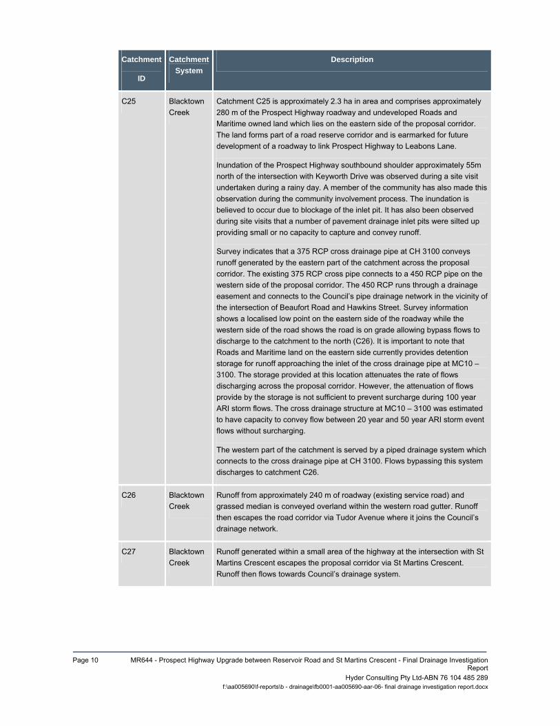
C25 Blacktown Creek
Catchment C25 is approximately 2.3 ha in area and comprises approximately 280 m of the Prospect Highway roadway and undeveloped Roads and Maritime owned land which lies on the eastern side of the proposal corridor. The land forms part of a road reserve corridor and is earmarked for future development of a roadway to link Prospect Highway to Leabons Lane.
Inundation of the Prospect Highway southbound shoulder approximately 55m north of the intersection with Keyworth Drive was observed during a site visit undertaken during a rainy day. A member of the community has also made this observation during the community involvement process. The inundation is believed to occur due to blockage of the inlet pit. It has also been observed during site visits that a number of pavement drainage inlet pits were silted up providing small or no capacity to capture and convey runoff.
Survey indicates that a 375 RCP cross drainage pipe at CH 3100 conveys runoff generated by the eastern part of the catchment across the proposal corridor. The existing 375 RCP cross pipe connects to a 450 RCP pipe on the western side of the proposal corridor. The 450 RCP runs through a drainage easement and connects to the Council’s pipe drainage network in the vicinity of the intersection of Beaufort Road and Hawkins Street. Survey information shows a localised low point on the eastern side of the roadway while the western side of the road shows the road is on grade allowing bypass flows to discharge to the catchment to the north (C26). It is important to note that Roads and Maritime land on the eastern side currently provides detention storage for runoff approaching the inlet of the cross drainage pipe at MC10 – 3100. The storage provided at this location attenuates the rate of flows discharging across the proposal corridor. However, the attenuation of flows provide by the storage is not sufficient to prevent surcharge during 100 year ARI storm flows. The cross drainage structure at MC10 – 3100 was estimated to have capacity to convey flow between 20 year and 50 year ARI storm event flows without surcharging.
The western part of the catchment is served by a piped drainage system which connects to the cross drainage pipe at CH 3100. Flows bypassing this system discharges to catchment C26.
C26 Blacktown Creek
Runoff from approximately 240 m of roadway (existing service road) and grassed median is conveyed overland within the western road gutter. Runoff then escapes the road corridor via Tudor Avenue where it joins the Council’s drainage network.
C27 Blacktown Creek
Runoff generated within a small area of the highway at the intersection with St Martins Crescent escapes the proposal corridor via St Martins Crescent. Runoff then flows towards Council’s drainage system.
MR644 - Prospect Highway Upgrade between Reservoir Road and St Martins Crescent—Final Drainage Investigation Report
Page 11
Hyder Consulting Pty Ltd-ABN 76 104 485 289 f:\aa005690\f-reports\b - drainage\fb0001-aa005690-aar-06- final drainage investigation report.docx
Catchment
ID
Catchment
System
Description
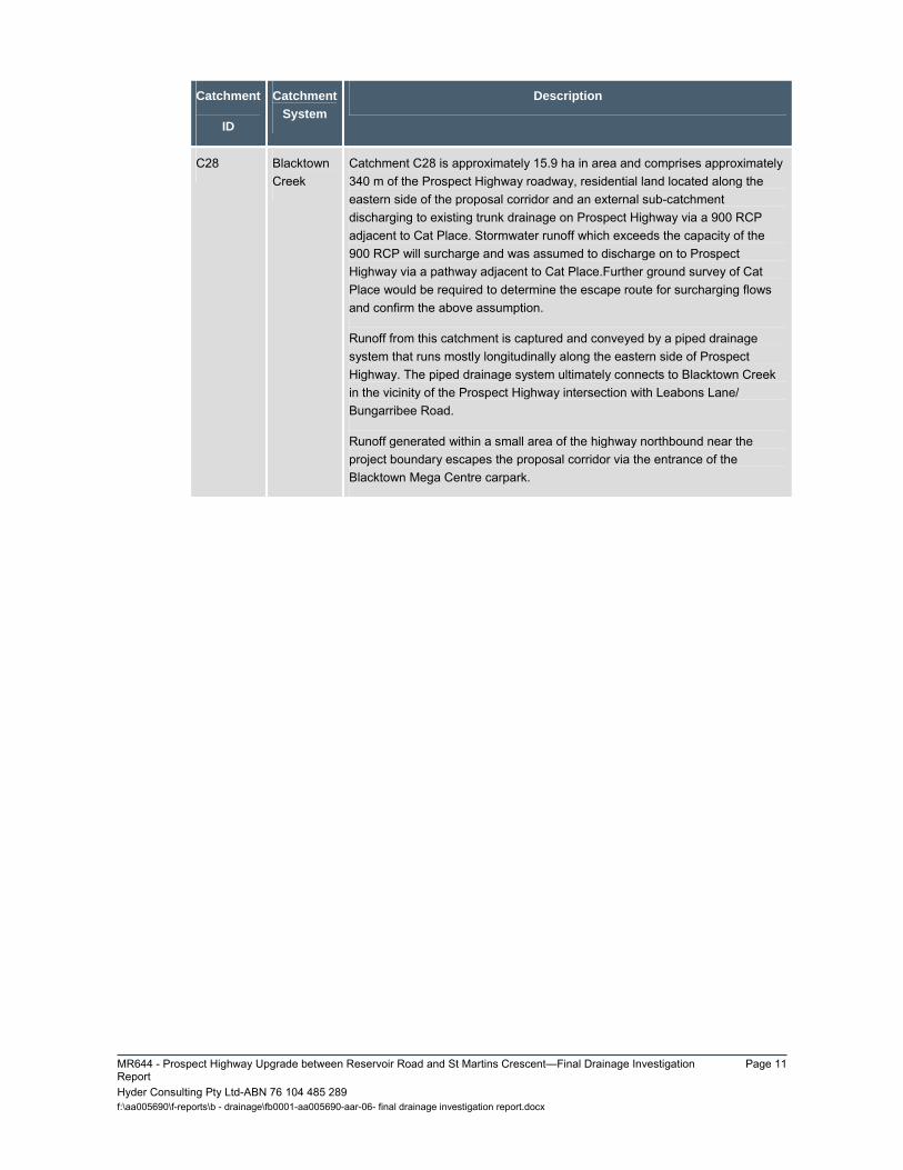
C28 Blacktown Creek
Catchment C28 is approximately 15.9 ha in area and comprises approximately 340 m of the Prospect Highway roadway, residential land located along the eastern side of the proposal corridor and an external sub-catchment discharging to existing trunk drainage on Prospect Highway via a 900 RCP adjacent to Cat Place. Stormwater runoff which exceeds the capacity of the 900 RCP will surcharge and was assumed to discharge on to Prospect Highway via a pathway adjacent to Cat Place.Further ground survey of Cat Place would be required to determine the escape route for surcharging flows and confirm the above assumption.
Runoff from this catchment is captured and conveyed by a piped drainage system that runs mostly longitudinally along the eastern side of Prospect Highway. The piped drainage system ultimately connects to Blacktown Creek in the vicinity of the Prospect Highway intersection with Leabons Lane/ Bungarribee Road.
Runoff generated within a small area of the highway northbound near the project boundary escapes the proposal corridor via the entrance of the Blacktown Mega Centre carpark.

Page 12 MR644 - Prospect Highway Upgrade between Reservoir Road and St Martins Crescent - Final Drainage Investigation
Report Hyder Consulting Pty Ltd-ABN 76 104 485 289 f:\aa005690\f-reports\b - drainage\fb0001-aa005690-aar-06- final drainage investigation report.docx
2.3 EXISTING HYDROLOGY
2.3.1 MODELLING The DRAINS software was used to determine the existing hydrologic regime of the receiving drainage systems affected by the proposal. This assists the assessment of the potential impact the proposal will have on the existing drainage systems.
DRAINS software is suitable for performing analysis for urban drainage systems. It is a simulation program which converts rainfall patterns to runoff and routes flows through pit and pipe network systems, culverts, basins and open channels.
The initial losses of 1 mm for paved and 5 mm for grassed areas were adopted in the DRAINS model. An antecedent moisture condition of 3 was adopted. Rainfall intensities for design storms ranging between 2 and 100 year average recurrence interval (ARI) were derived using the raw rain data obtained from the Bureau of Meteorology (BoM) website for 33.80S (latitude) and 150.92E (longitude).
The catchments shown on Figures 2.1 to 2.5 were divided into a number of sub-catchments and their characteristics were entered into the models including area, paved fractions, flow path lengths, gradients and time of concentration. A catchment summary is included in Table 2-3 below.
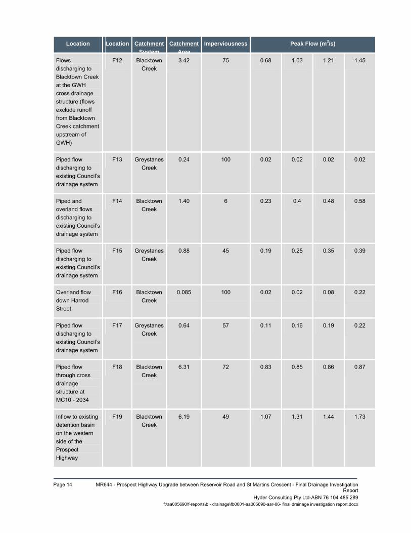
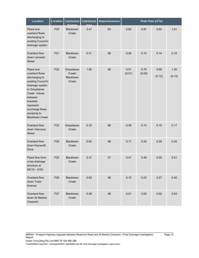
2.3.2 MODEL RESULTS (PRE-UPGRADE) The DRAINS models were simulated for design storm events ranging between 2 and 100 year ARI. The estimated peak runoff rates at the key locations indicated on Figures 2.1 to 2.5 are presented in Table 2-3. Table 2-3 below also summarises the catchments characteristics.
It should be noted that the peak flow location ID number corresponds with its respective catchment ID number. For example, F1 relates to the peak flows generated within catchment C1 at the catchment outlet, F2 for peak flows at outlet of C2 and so on.
Table 2-3 Pre-upgrade Peak Flows
Location Location
ID
Catchment
System
Catchment
Area
(ha)
Imperviousness
(%)
Peak Flow (m3/s)
2 year
ARI
10 year
ARI
20 year
ARI
100 year
ARI
Combined overland and pipe flows at southern end of the proposal limit
F1 Greystanes Creek
1.26 67 0.25 0.39 0.46 0.55
Overland flow along Reservoir Road (east of Prospect Hwy)
F2 Greystanes Creek
0.16 75 0.03 0.05 0.06 0.07

MR644 - Prospect Highway Upgrade between Reservoir Road and St Martins Crescent—Final Drainage Investigation Report
Page 13
Hyder Consulting Pty Ltd-ABN 76 104 485 289 f:\aa005690\f-reports\b - drainage\fb0001-aa005690-aar-06- final drainage investigation report.docx
Location Location Catchment
System
Catchment
Area
Imperviousness Peak Flow (m3/s)
Peak flow at the inlet of cross drainage structure at MC10 - 460
F3 Greystanes Creek
13.7 22 1.69 3.12 3.68 4.69
Flows discharging to the outlet of cross drainage structure at MC10 - 460
F4 Greystanes Creek
0.76 33 1.87 3.33 3.92 5.04
Outlet of piped drainage system combining flows from M4 water quality basin and pavement drainage systems at this location
F5 Greystanes Creek
0.43 69 0.10 0.27 0.43 0.92
Inflows to M4 water quality basin
F6 Greystanes Creek
6.17 53 0.71 1.12 1.32 1.66
Overland flow down the M4 eastbound exit ramp
F7 Blacktown Creek
0.21 50 0.04 0.06 0.08 0.09
Inlet flow at cross drainage structure at GWH MX01 - 110
F8 Blacktown Creek
3.85 17 0.44 0.82 0.96 1.25
Outlet of piped drainage system discharging to catch drain at top of GWH cutting
F9 Greystanes Creek
0.15 70 0.10 0.14 0.17 0.21
Overland flow down the GWH eastbound entry ramp
F10 Greystanes Creek
0.1 100 0.01 0.02 0.02 0.03
Inlet of existing 825 RCP
F11 Blacktown Creek
1.07 24 0.61 1.09 1.27 1.65
Page 14 MR644 - Prospect Highway Upgrade between Reservoir Road and St Martins Crescent - Final Drainage Investigation
Report Hyder Consulting Pty Ltd-ABN 76 104 48 f:\aa005690\f-reports\b - drainage\fb0001-aa005690-aar-06- final drainage investigation repo
5 289rt.docx
Location Location Catchment
System
Catchment
Area
Imperviousness Peak Flow (m3/s)
Flows discharging to Blacktown Creek at the GWH cross drainage structure (flows exclude runoff from Blacktown Creek catchment upstream of GWH)
F12 Blacktown Creek
3.42 75 0.68 1.03 1.21 1.45
Piped flow discharging to existing Council’s drainage system
F13 Greystanes Creek
0.24 100 0.02 0.02 0.02 0.02
Piped and overland flows discharging to existing Council’s drainage system
F14 Blacktown Creek
1.40 6 0.23 0.4 0.48 0.58
Piped flow discharging to existing Council’s drainage system
F15 Greystanes Creek
0.88 45 0.19 0.25 0.35 0.39
Overland flow down Harrod Street
F16 Blacktown Creek
0.085 100 0.02 0.02 0.08 0.22
Piped flow discharging to existing Council’s drainage system
F17 Greystanes Creek
0.64 57 0.11 0.16 0.19 0.22
Piped flow through cross drainage structure at MC10 - 2034
F18 Blacktown Creek
6.31 72 0.83 0.85 0.86 0.87
Inflow to existing detention basin on the western side of the Prospect Highway
F19 Blacktown Creek
6.19 49 1.07 1.31 1.44 1.73
MR644 - Prospect Highway Upgrade between Reservoir Road and St Martins Crescent—Final Drainage Investigation Report
Page 15
Hyder Consulting Pty Ltd-ABN 76 104 485 289 f:\aa005690\f-reports\b - drainage\fb0001-aa005690-aar-06- final drainage investigation report.docx
Location Location Catchment
System
Catchment
Area
Imperviousness Peak Flow (m3/s)
Piped and overland flows discharging to existing Council’s drainage system
F20 Blacktown Creek
3.47 64 0.62 0.87 0.92 1.01
Overland flow down Lancelot Street
F21 Blacktown Creek
0.31 68 0.08 0.12 0.14 0.16
Piped and overland flows discharging to existing Council’s drainage system to Greystanes Creek. Values between brackets represent surcharge flows escaping to Blacktown Creek
F22 Greystanes Creek/
Blacktown Creek
1.82 82 0.51 (0.01)
0.75 (0.09)
0.99
(0.12)
1.30
(0.14)
Overland flow down Vesuvius Street
F23 Greystanes Creek
0.33 86 0.09 0.13 0.15 0.17
Overland flow down Keyworth Drive
F24 Blacktown Creek
0.62 86 0.17 0.24 0.29 0.34
Piped flow from cross drainage structure at MC10 - 3100
F25 Blacktown Creek
2.31 57 0.41 0.49 0.50
0.51
Overland flow down Tudor Avenue
F26 Blacktown Creek
0.62 90 0.15 0.23 0.27 0.40
Overland flow down St Martins Crescent
F27 Blacktown Creek
0.28 90 0.01 0.02 0.02 0.03

Page 16 MR644 - Prospect Highway Upgrade between Reservoir Road and St Martins Crescent - Final Drainage Investigation
Report Hyder Consulting Pty Ltd-ABN 76 104 485 289 f:\aa005690\f-reports\b - drainage\fb0001-aa005690-aar-06- final drainage investigation report.docx
Location Location Catchment
System
Catchment
Area
Imperviousness Peak Flow (m3/s)
Piped and overland flows discharging to Blacktown Creek. Values in brackets represent surcharge flows escaping to Blacktown Mega Centre.
F28 Blacktown Creek
16.2 71 3.01
(0.02)
4.46
(0.03)
5.27
(0.04)
6.24
(0.05)
MR644 - Prospect Highway Upgrade between Reservoir Road and St Martins Crescent—Final Drainage Investigation Report
Page 17
Hyder Consulting Pty Ltd-ABN 76 104 485 289 f:\aa005690\f-reports\b - drainage\fb0001-aa005690-aar-06- final drainage investigation report.docx
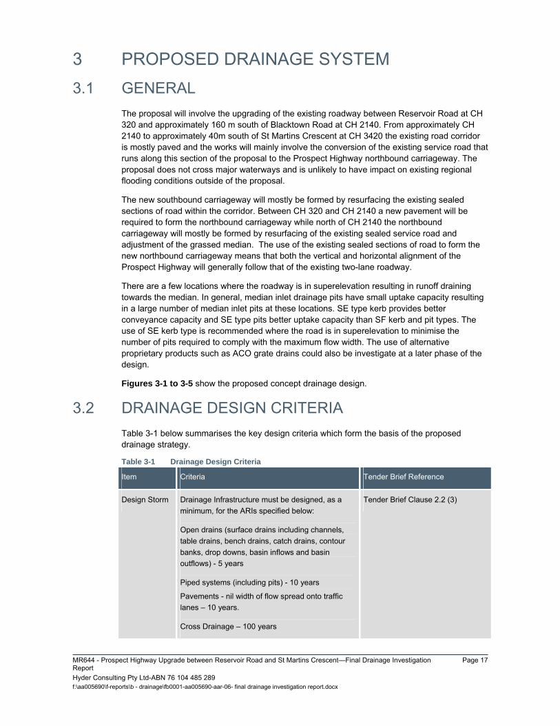
3 PROPOSED DRAINAGE SYSTEM 3.1 GENERAL
The proposal will involve the upgrading of the existing roadway between Reservoir Road at CH 320 and approximately 160 m south of Blacktown Road at CH 2140. From approximately CH 2140 to approximately 40m south of St Martins Crescent at CH 3420 the existing road corridor is mostly paved and the works will mainly involve the conversion of the existing service road that runs along this section of the proposal to the Prospect Highway northbound carriageway. The proposal does not cross major waterways and is unlikely to have impact on existing regional flooding conditions outside of the proposal.
The new southbound carriageway will mostly be formed by resurfacing the existing sealed sections of road within the corridor. Between CH 320 and CH 2140 a new pavement will be required to form the northbound carriageway while north of CH 2140 the northbound carriageway will mostly be formed by resurfacing of the existing sealed service road and adjustment of the grassed median. The use of the existing sealed sections of road to form the new northbound carriageway means that both the vertical and horizontal alignment of the Prospect Highway will generally follow that of the existing two-lane roadway.
There are a few locations where the roadway is in superelevation resulting in runoff draining towards the median. In general, median inlet drainage pits have small uptake capacity resulting in a large number of median inlet pits at these locations. SE type kerb provides better conveyance capacity and SE type pits better uptake capacity than SF kerb and pit types. The use of SE kerb type is recommended where the road is in superelevation to minimise the number of pits required to comply with the maximum flow width. The use of alternative proprietary products such as ACO grate drains could also be investigate at a later phase of the design.
Figures 3-1 to 3-5 show the proposed concept drainage design.
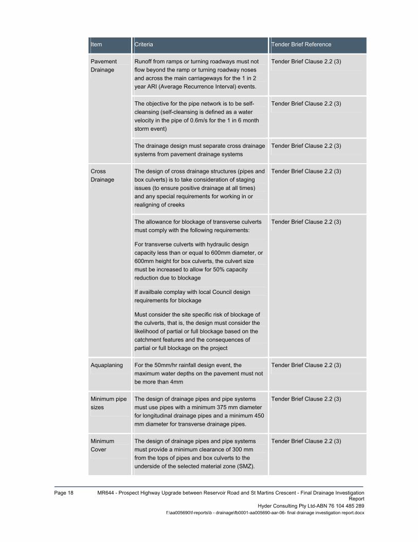
3.2 DRAINAGE DESIGN CRITERIA Table 3-1 below summarises the key design criteria which form the basis of the proposed drainage strategy.
Table 3-1 Drainage Design Criteria
Item Criteria Tender Brief Reference
Design Storm Drainage Infrastructure must be designed, as a minimum, for the ARIs specified below:
Open drains (surface drains including channels, table drains, bench drains, catch drains, contour banks, drop downs, basin inflows and basin outflows) - 5 years
Piped systems (including pits) - 10 years
Pavements - nil width of flow spread onto traffic lanes – 10 years.
Cross Drainage – 100 years
Tender Brief Clause 2.2 (3)
Page 18 MR644 - Prospect Highway Upgrade between Reservoir Road and St Martins Crescent - Final Drainage Investigation
Report
Item Criteria Tender Brief Reference
Pavement Drainage
Runoff from ramps or turning roadways must not flow beyond the ramp or turning roadway noses and across the main carriageways for the 1 in 2 year ARI (Average Recurrence Interval) events.
Tender Brief Clause 2.2 (3)
The objective for the pipe network is to be self-cleansing (self-cleansing is defined as a water velocity in the pipe of 0.6m/s for the 1 in 6 month storm event)
Tender Brief Clause 2.2 (3)
The drainage design must separate cross drainage systems from pavement drainage systems
Tender Brief Clause 2.2 (3)
Cross Drainage
The design of cross drainage structures (pipes and box culverts) is to take consideration of staging issues (to ensure positive drainage at all times) and any special requirements for working in or realigning of creeks
Tender Brief Clause 2.2 (3)
The allowance for blockage of transverse culverts must comply with the following requirements:
For transverse culverts with hydraulic design capacity less than or equal to 600mm diameter, or 600mm height for box culverts, the culvert size must be increased to allow for 50% capacity reduction due to blockage
If availbale complay with local Council design requirements for blockage
Must consider the site specific risk of blockage of the culverts, that is, the design must consider the likelihood of partial or full blockage based on the catchment features and the consequences of partial or full blockage on the project
Tender Brief Clause 2.2 (3)
Aquaplaning For the 50mm/hr rainfall design event, the maximum water depths on the pavement must not be more than 4mm
Tender Brief Clause 2.2 (3)
Minimum pipe sizes
The design of drainage pipes and pipe systems must use pipes with a minimum 375 mm diameter for longitudinal drainage pipes and a minimum 450 mm diameter for transverse drainage pipes.
Tender Brief Clause 2.2 (3)
Minimum Cover
The design of drainage pipes and pipe systems must provide a minimum clearance of 300 mm from the tops of pipes and box culverts to the underside of the selected material zone (SMZ).
Tender Brief Clause 2.2 (3)
Hyder Consulting Pty Ltd-ABN 76 104 485 289 f:\aa005690\f-reports\b - drainage\fb0001-aa005690-aar-06- final drainage investigation report.docx

MR644 - Prospect Highway Upgrade between Reservoir Road and St Martins Crescent—Final Drainage Investigation Report
Page 19
Hyder Consulting Pty Ltd-ABN 76 104 485 289 f:\aa005690\f-reports\b - drainage\fb0001-aa005690-aar-06- final drainage investigation report.docx
3.3 AQUAPLANING CHECKS Aquaplaning checks were carried out in locations where the designed longitudinal gradients are low, areas of changing road crossfall (super transitions) and at intersection.
A standard rainfall intensity of 50mm/hr was used for the calculations as specified by the Roads and Maritime. In accordance with the assessment criteria, a location is considered to be safe if the water depth on the pavement was calculated to be less than 4mm. The calculations are summarised in the table below. Table 3-2 Aquaplaning Checks Results
Location Lane Length
m
Slope
S
m/m
Intensity
I
mm/hr
Flow Depth
d
mm
Check if
> 4mm
260 NB 39.6 0.044 50 2.0 OK
600 NB 43.1 0.039 50 2.3 OK
960 M4 Western Motorway Eastbound
Exit Ramp 29.0 0.013 50 3.2 OK
1060 NB 15.0 0.006 50 3.3 OK
1240 GWH Exit Ramp Eastbound (E ) 55.2 0.032 50 3.6 OK
1250 GWH Exit Ramp Eastbound
(W) 82.0 0.019 50 3.6 OK
1540 SB Stoddart Road Intersection 24.9 0.044 50 1.6 OK
1940 SB 32 0.014 50 3.3 OK
2200 SB 38.4 0.012 50 3.8 OK
2640 NB 35.7 0.028 50 2.4 OK
2760 NB 42.4 0.031 50 2.6 OK
2800 SB Vesuvius Street Intersection 24.8 0.044 50 1.6 OK
2860 NB Keyworth Drive Intersection 28.7 0.064 50 1.4 OK
2970 SB 33.2 0.009 50 4.0 OK
3320 SB 49.8 0.053 50 2.1 OK

Page 20 MR644 - Prospect Highway Upgrade between Reservoir Road and St Martins Crescent - Final Drainage Investigation
Report Hyder Consulting Pty Ltd-ABN 76 104 485 289 f:\aa005690\f-reports\b - drainage\fb0001-aa005690-aar-06- final drainage investigation report.docx
The results above indicate that the water depth does not exceed the maximum allowed depth at any location.
3.4 PROPOSED CROSS DRAINAGE Four (4) cross drainage structures were identified along the corridor. Details of the existing structures are summarised in Table 2-1.
Blockage of cross drainage structures has been considered in the concept drainage design in compliance with the project brief requirements (refer to Section 3.2). The four cross drainage structures identified are located in catchments mainly comprised of residential or parkland areas. The potential of culverts to be blocked by large debris is deemed to be low.
It is proposed to extend and upgrade two of the identified cross drainage structures to provide the proposal with 100 Year ARI flood immunity. The remaining two existing culverts have adequate capacity and will be retained.
The details of the proposed changes to cross drainage structures are provided in Table 3-3.
Table 3-3 Proposed Cross Drainage Structures
Catchment
Design
Road
Chainage
(Approx)
Size/Type
(mm)
Upstream
Invert Level
(m AHD)
Downstream
Invert Level
(m AHD)
Adjacent
Road Level
(m AHD)
Proposed
Treatment
Greystanes Creek
MC10 - 460 1350 RCP1 65.32 63.86 72.41 No Change
Blacktown Creek
MX01 - 110 750 RCP1 74.55 69.57 79.52 Extension of existing culverts
MC10 - 2034 900 RCP1 64.75 63.14 70.11 No Change
MC10 - 3100 675 RCP1 59.28 59.12 61.48 Demolish and replace existing 450 RCP with new 675 RCP
1 RCP – Stands for reinforced concrete pipe.
A hydraulic assessment was undertaken to compare headwater levels upstream of the identified cross drainage structures under post upgrade conditions and existing conditions. Figures 5-1 to 5-4 included in Appendix A show flood extents upstream of the cross drainage structures in 100 Year ARI storm events.
Roads and Maritime propose to modify the existing pedestrian underpass located approximately at CH 1980 from a box culvert to a bridge. A sketch of the proposed bridge is included in Appendix C of this report. The current hydrology and hydraulic assessment indicates that the detention basin and the outlet cross drainage culvert at CH 2034 have 100 year ARI capacity and the pedestrian underpass will only operate as emergency flood route during large to extreme event (larger than 100 year ARI). Hence the modification of the pedestrian underpass is unlikely to change the flow regime in the vicinity during storm events up to 100 year ARI. Risk of flooding during construction of the bridge is also deemed to be very low.
MR644 - Prospect Highway Upgrade between Reservoir Road and St Martins Crescent—Final Drainage Investigation Report
Page 21
Hyder Consulting Pty Ltd-ABN 76 104 485 289 f:\aa005690\f-reports\b - drainage\fb0001-aa005690-aar-06- final drainage investigation report.docx
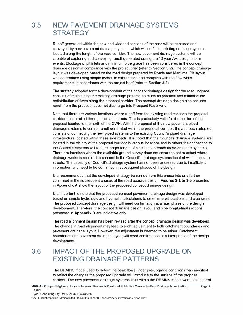
3.5 NEW PAVEMENT DRAINAGE SYSTEMS STRATEGY Runoff generated within the new and widened sections of the road will be captured and conveyed by new pavement drainage systems which will outfall to existing drainage systems located along the length of the road corridor. The new pavement drainage systems will be capable of capturing and conveying runoff generated during the 10 year ARI design storm events. Blockage of pit inlets and minimum pipe grade has been considered in the concept drainage design in compliance with the project brief (refer to Section 3.2). The concept drainage layout was developed based on the road design prepared by Roads and Maritime. Pit layout was determined using simple hydraulic calculations and complies with the flow width requirements in accordance with the project brief (refer to Section 3.2).
The strategy adopted for the development of the concept drainage design for the road upgrade consists of maintaining the existing drainage patterns as much as practical and minimise the redistribution of flows along the proposal corridor. The concept drainage design also ensures runoff from the proposal does not discharge into Prospect Reservoir.
Note that there are various locations where runoff from the existing road escapes the proposal corridor uncontrolled through the side streets. This is particularly valid for the section of the proposal located to the north of the GWH. With the proposal of the new pavement piped drainage systems to control runoff generated within the proposal corridor, the approach adopted consists of connecting the new piped systems to the existing Council’s piped drainage infrastructure located within these side roads. It is noted that the Council’s drainage systems are located in the vicinity of the proposal corridor in various locations and in others the connection to the Council’s systems will require longer length of pipe lines to reach these drainage systems. There are locations where the available ground survey does not cover the entire extent where drainage works is required to connect to the Council’s drainage systems located within the side streets. The capacity of Council’s drainage system has not been assessed due to insufficient information and need to be confirmed in subsequent phases of the design.
It is recommended that the developed strategy be carried from this phase into and further confirmed in the subsequent phases of the road upgrade design. Figures 3-1 to 3-5 presented in Appendix A show the layout of the proposed concept drainage design.
It is important to note that the proposed concept pavement drainage design was developed based on simple hydrologic and hydraulic calculations to determine pit locations and pipe sizes. The proposed concept drainage design will need confirmation at a later phase of the design development. Therefore, the concept drainage design layout and pipe longitudinal sections presented in Appendix B are indicative only.
The road alignment design has been revised after the concept drainage design was developed. The change in road alignment may lead to slight adjustment to both catchment boundaries and pavement drainage layout. However, the adjustment is deemed to be minor. Catchment boundaries and pavement drainage layout will need confirmation at a later phase of the design development.
3.6 IMPACT OF THE PROPOSED UPGRADE ON EXISTING DRAINAGE PATTERNS The DRAINS model used to determine peak flows under pre-upgrade conditions was modified to reflect the changes the proposed upgrade will introduce to the surface of the proposal corridor. The new pavement drainage systems links within the DRAINS model were also altered

Page 22 MR644 - Prospect Highway Upgrade between Reservoir Road and St Martins Crescent - Final Drainage Investigation
Report Hyder Consulting Pty Ltd-ABN 76 104 485 289 f:\aa005690\f-reports\b - drainage\fb0001-aa005690-aar-06- final drainage investigation report.docx
to reflect changes that will occur in drainage patterns as a result of the installation of new cross and pavement drainage systems along the length of the road upgrade.
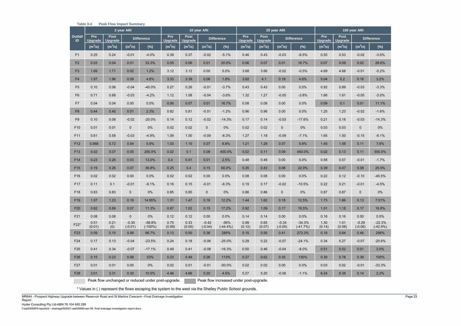
The proposed concept drainage design presented on Figures 3-1 to 3-5 forms the basis for the assessment of the potential impact of the road upgrade on the existing drainage patterns.
Table 3-4 in the next page provides an overview of the impacts the proposed road upgrade will have on the existing peak flows at the outfall locations. The table shows the comparison of peak flows under pre-upgrade and post-upgrade conditions at the outfall locations and highlights the locations where peak flows are expected to increase. Refer to the Figures 2-1 to 2-5 and Figures 3-1 to 3-5 in Appendix A for outfall locations.
MR644 - Prospect Highway Upgrade between Reservoir Road and St Martins Crescent—Final Drainage Investigation Report
Page 23
Hyder Consulting Pty Ltd-ABN 76 104 485 289 f:\aa005690\f-reports\b - drainage\fb0001-aa005690-aar-06- final drainage investigation report.docx
Table 3-4 Peak Flow Impact Summary
Outfall ID
2 year ARI 10 year ARI 20 year ARI 100 year ARI
Pre Upgrade
Post Upgrade
Difference Pre
Upgrade Post
Upgrade Difference
Pre Upgrade
Post Upgrade
Difference Pre
Upgrade Post
Upgrade Difference
(m3/s) (m3/s) (m3/s) (%) (m3/s) (m3/s) (m3/s) (%) (m3/s) (m3/s) (m3/s) (%) (m3/s) (m3/s) (m3/s) (%)
F1 0.25 0.24 -0.01 -4.0% 0.39 0.37 -0.02 -5.1% 0.46 0.43 -0.03 -6.5% 0.55 0.53 -0.02 -3.6%
F2 0.03 0.04 0.01 33.3% 0.05 0.06 0.01 20.0% 0.06 0.07 0.01 16.7% 0.07 0.09 0.02 28.6%
F3 1.69 1.71 0.02 1.2% 3.12 3.12 0.00 0.0% 3.68 3.66 -0.02 -0.5% 4.69 4.68 -0.01 -0.2%
F4 1.87 1.96 0.09 4.8% 3.33 3.39 0.06 1.8% 3.92 4.1 0.18 4.6% 5.04 5.2 0.16 3.2%
F5 0.10 0.06 -0.04 -40.0% 0.27 0.26 -0.01 -3.7% 0.43 0.43 0.00 0.0% 0.92 0.89 -0.03 -3.3%
F6 0.71 0.68 -0.03 -4.2% 1.12 1.08 -0.04 -3.6% 1.32 1.27 -0.05 -3.8% 1.66 1.61 -0.05 -3.0%
F7 0.04 0.04 0.00 0.0% 0.06 0.07 0.01 16.7% 0.08 0.08 0.00 0.0% 0.09 0.1 0.01 11.1%
F8 0.44 0.45 0.01 2.3% 0.82 0.81 -0.01 -1.2% 0.96 0.96 0.00 0.0% 1.25 1.23 -0.02 -1.6%
F9 0.10 0.08 -0.02 -20.0% 0.14 0.12 -0.02 -14.3% 0.17 0.14 -0.03 -17.6% 0.21 0.18 -0.03 -14.3%
F10 0.01 0.01 0 0% 0.02 0.02 0 0% 0.02 0.02 0 0% 0.03 0.03 0 0%
F11 0.61 0.58 -0.03 -4.9% 1.09 1.00 -0.09 -8.3% 1.27 1.18 -0.09 -7.1% 1.65 1.50 -0.15 -9.1%
F12 0.568 0.72 0.04 5.9% 1.03 1.10 0.07 6.8% 1.21 1.28 0.07 5.8% 1.45 1.56 0.11 7.6%
F13 0.02 0.07 0.05 250.0% 0.02 0.1 0.08 400.0% 0.02 0.11 0.09 450.0% 0.02 0.13 0.11 550.0%
F14 0.23 0.26 0.03 13.0% 0.4 0.41 0.01 2.5% 0.48 0.48 0.00 0.0% 0.58 0.57 -0.01 -1.7%
F15 0.19 0.26 0.07 36.8% 0.25 0.4 0.15 60.0% 0.35 0.43 0.08 22.9% 0.39 0.47 0.08 20.5%
F16 0.02 0.02 0.00 0.0% 0.02 0.02 0.00 0.0% 0.08 0.08 0.00 0.0% 0.22 0.12 -0.10 -45.5%
F17 0.11 0.1 -0.01 -9.1% 0.16 0.15 -0.01 -6.3% 0.19 0.17 -0.02 -10.5% 0.22 0.21 -0.01 -4.5%
F18 0.83 0.83 0 0% 0.85 0.85 0 0% 0.86 0.86 0 0% 0.87 0.87 0 0%
F19 1.07 1.23 0.16 14.95% 1.31 1.47 0.16 12.2% 1.44 1.62 0.18 12.5% 1.73 1.86 0.13 7.51%
F20 0.62 0.69 0.07 11.3% 0.87 1.02 0.15 17.2% 0.92 1.09 0.17 18.5% 1.01 1.18 0.17 16.8%
F21 0.08 0.08 0 0% 0.12 0.12 0.00 0.0% 0.14 0.14 0.00 0.0% 0.16 0.16 0.00 0.0%
F22* 0.51 (0.01)
0.21 (0)
-0.30 (-0.01)
-58.8% (-100%)
0.75 (0.09)
0.33 (0.05)
-0.42 (-0.04)
-56% (-44.4%)
0.99 (0.12)
0.65 (0.07)
-0.34 (-0.05)
-34.3% (-41.7%)
1.30 (0.14)
1.01 (0.08)
-0.29 (-0.06)
-22.3% (-42.9%)
F23 0.09 0.15 0.06 66.7% 0.13 0.50 0.36 285% 0.15 0.56 0.41 273.3% 0.18 0.64 0.46 256%
F24 0.17 0.13 -0.04 -23.5% 0.24 0.18 -0.06 -25.0% 0.29 0.22 -0.07 -24.1% 0.34 0.27 -0.07 -20.6%
F25 0.41 0.34 -0.07 -17.1% 0.49 0.41 -0.08 -16.3% 0.50 0.46 -0.04 -8.0% 0.51 0.52 0.01 2.0%
F26 0.15 0.23 0.08 53% 0.23 0.49 0.26 113% 0.27 0.62 0.35 130% 0.39 0.78 0.39 100%
F27 0.01 0.01 0.00 0% 0.02 0.01 -0.01 -50.0% 0.02 0.02 0.00 0.0% 0.03 0.02 -0.01 -33.3%
F28 3.01 3.31 0.30 10.0% 4.46 4.66 0.20 4.5% 5.27 5.20 -0.06 -1.1% 6.24 6.38 0.14 2.2%
Peak flow unchanged or reduced under post-upgrade. Peak flow increased under post-upgrade.
* Values in ( ) represent the flows escaping the system to the west via the Shelley Public School grounds.

Page 24 MR644 - Prospect Highway Upgrade between Reservoir Road and St Martins Crescent - Final Drainage Investigation
Report Hyder Consulting Pty Ltd-ABN 76 104 485 289
f:\aa005690\f-reports\b - drainage\fb0001-aa005690-aar-06- final drainage investigation report.docx
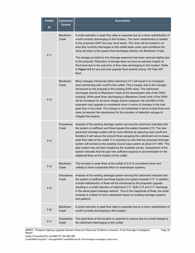
A brief discussion on the expected changes and impacts on the existing drainage patterns are provided Table 3-5 below.
Table 3-5 Discussion on Impacts of the Proposal
Outfall
ID
Catchment
System
Description
F1
Greystanes Creek
The outflows at this location would be expected to reduce slightly as a result of the works associated with the proposed upgrade. The changes to Reservoir Road intersection and the proposed drainage system for this road will result in better control of runoff reducing bypass flows currently entering Reconciliation Road.
F2
Greystanes Creek
A minor increase in peak flow rate is expected due to small changes to the catchment size at the intersection of Prospect Highway and Reservoir Road. The increase is minor and is unlikely to cause adverse impact on the downstream drainage patterns.
F3
Greystanes Creek
The flows arriving at the inlet of the cross drainage structure at MC10 – 460 are expected to remain similar to the existing peak flows. The minor changes to this catchment do not have substantial impact on peak flows.
F4
Greystanes Creek
A minor increase in peak flows are expected at the outlet of cross drainage structure at MC10 – 460 due to the increase of roadway catchment discharging runoff to this location. The increase is unlikely to have substantial effect on the downstream drainage patterns.
F5 Greystanes Creek
The peak flows from C5 are expected to have a small reduction in peak flow rates due to a minor redistribution of runoff.
F6 Greystanes Creek
The peak flows from C6 are expected to have a small reduction in peak flow rates due to a minor redistribution of runoff.
F7 Blacktown Creek
A minor change to this catchment will result in negligible changes to peak runoff at the outfall.
F8
Blacktown Creek
The peak flow rates for catchment C8 are expected to remain largely the same as changes associated with the proposed upgrade will have insignificant impact on the peak flows.
F9
Greystanes Creek
The peak flow rates for catchment C9 are expected to reduce as flows bypassing the existing drainage system serving catchment C8 enter this catchment under pre-upgrade conditions. It is noted that an existing F type barrier prevents runoff from C8 from flowing to the west and re-direct the runoff to C9. The new pavement drainage system will control runoff within catchment C8 and will reduce the bypass flows arriving at the outfall of C9.
F10 Greystanes Creek
Peak flow rates are expected to remain as per pre-upgrade conditions.
MR644 - Prospect Highway Upgrade between Reservoir Road and St Martins Crescent—Final Drainage Investigation Report
Page 25
Hyder Consulting Pty Ltd-ABN 76 104 485 289 f:\aa005690\f-reports\b - drainage\fb0001-aa005690-aar-06- final drainage investigation report.docx
Outfall
ID
Catchment
System
Description
F11
Blacktown Creek
A small reduction in peak flow rates is expected due to a minor redistribution of runoff currently discharging to this location. The minor redistribution is related to the proposed GWH two-way ramp works. The ramp will be located in an area that currently discharges to this outfall while under post-conditions the ramp will drain to the system that discharges directly into Blacktown Creek.
The storage provided by the drainage easement has been reduced slightly due to the proposal. Reduction of storage does not have an adverse impact on flood level due to the reduction of flow rates discharging to this location. Refer to Figure 5-2 for pre and post upgrade flood extents during 100 Year ARI flood.
F12
Blacktown Creek
Minor changes introduced within catchment C11 will result in an increased area contributing with runoff to this outfall. This is largely due to the changes introduced by the proposal to the existing GWH ramp. This catchment discharges directly to Blacktown Creek at the downstream side of the GWH crossing. While peak flows discharging to Blacktown Creek north of the GWH will be increased for all storm design storms analysed, the net effect of the proposed road upgrade is considered minor in terms of changes to the total peak flow in the creek. The change is not substantial in terms of total flows and does not warrant the requirement for the provision of detention storage to mitigate the impacts.
F13
Greystanes Creek
Analysis of the existing drainage system serving this catchment indicates that the system is inefficient and flows bypass the system towards C15. The new pavement drainage system will be more efficient at capturing road runoff and therefore it will reduce the amount flows escaping this catchment and increase peak flow rates at the outfall. It is important to note that the proposed drainage system will connect to the existing Council pipe system at about CH 1450. This pipe system has not been located by the available survey. Assessment of the system indicates that the pipe has sufficient capacity to accommodate for the additional flows at the location of the outfall.
F14 Blacktown Creek
The increase in peak flows at the outfall of C14 is considered minor and unlikely to have substantial effect on downstream systems.
F15
Greystanes Creek
Analysis of the existing drainage system serving this catchment indicates that the system is inefficient and flows bypass the system towards C17. In addition, a small redistribution of flows will be introduced by the proposed upgrade resulting in a small reduction of catchment C17. Both C15 and C17 discharge to the same piped drainage network. Due to the magnitude of flows, the small increase is unlikely to have substantial impact on existing drainage systems and patterns.
F16 Blacktown Creek
A small reduction in peak flow rates is expected due to a minor redistribution of runoff currently discharging to this location.
F17 Greystanes Creek
The peak flows at this location is expected to reduce due to a small change to the catchment discharging to this outfall.

Page 26 MR644 - Prospect Highway Upgrade between Reservoir Road and St Martins Crescent - Final Drainage Investigation
Report Hyder Consulting Pty Ltd-ABN 76 104 485 289 f:\aa005690\f-reports\b - drainage\fb0001-aa005690-aar-06- final drainage investigation report.docx
Outfall
ID
Catchment
System
Description
F18
Blacktown Creek
This catchment discharges to a Council detention storage area. The proposed drainage system will not introduce peak flow changes entering this storage area. No substantial changes are expected for this location.
It is important to note that the proposal does not impact on the existing detention storage basin. Modification of the existing pedestrian underpass within this area will not change flow regime during storm up to 100 year ARI.
F19
Blacktown Creek
A small increase in peak flows is expected at this location largely due to the increase in paved surface within the catchment. The proposed drainage system will discharge to a Council detention storage area located at about CH 2040. Given the sensitivity of this location and potential impacts of additional flows discharging to the detention storage, it is recommended additional storage is provided to mitigate the potential impacts. A preliminary estimate indicates that 300 m3 is required storage to accommodate for the increase in peak flows. The additional storage can be easily accommodated within the existing detention storage area. A preliminary sketch of the earthworks and extent of the works is provided in Appendix B. It should be noted that the preliminary design of the earthworks assumed a 4H:1V batters for easy maintenance (i.e. mowing) of the area.
F20
Blacktown Creek
Analysis of the existing drainage systems within C20 indicates that flows bypass the drainage system within this catchment towards C22. The proposed drainage system will be more efficient at capturing runoff and will reduce bypass flows resulting in increase of peak flows at the outlet of this catchment.
F21 Blacktown Creek
Peak flows will remain largely the same under post-upgrade conditions.
F22
Greystanes Creek/ Blacktown Creek
The total peak flows discharging from this catchment is expected to substantially reduce. The outfall is located within a low point and existing piped drainage system does not have sufficient capacity to convey the design flows for most design storm events (refer discussion in Section 2.2). A surcharge system is proposed by concept drainage design to re-direct surcharge flows through Vesuvius Street. The surcharge system will be comprised of a two chamber drainage pit located at the low point. The low flows will discharge to the existing pipe system located at the low point while excess flows will surcharge into the second chamber connected to a drainage pipe that will run along Prospect Highway and connect to the Vesuvius Street drainage system. This arrangement will reduce nuisance flooding at the property located opposite the low point (No. 223/223A Prospect Highway).
MR644 - Prospect Highway Upgrade between Reservoir Road and St Martins Crescent—Final Drainage Investigation Report
Page 27
Hyder Consulting Pty Ltd-ABN 76 104 485 289 f:\aa005690\f-reports\b - drainage\fb0001-aa005690-aar-06- final drainage investigation report.docx
Outfall
ID
Catchment
System
Description
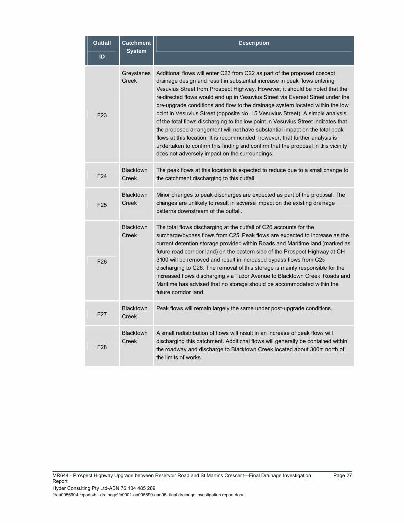
F23
Greystanes Creek
Additional flows will enter C23 from C22 as part of the proposed concept drainage design and result in substantial increase in peak flows entering Vesuvius Street from Prospect Highway. However, it should be noted that the re-directed flows would end up in Vesuvius Street via Everest Street under the pre-upgrade conditions and flow to the drainage system located within the low point in Vesuvius Street (opposite No. 15 Vesuvius Street). A simple analysis of the total flows discharging to the low point in Vesuvius Street indicates that the proposed arrangement will not have substantial impact on the total peak flows at this location. It is recommended, however, that further analysis is undertaken to confirm this finding and confirm that the proposal in this vicinity does not adversely impact on the surroundings.
F24 Blacktown Creek
The peak flows at this location is expected to reduce due to a small change to the catchment discharging to this outfall.
F25
Blacktown Creek
Minor changes to peak discharges are expected as part of the proposal. The changes are unlikely to result in adverse impact on the existing drainage patterns downstream of the outfall.
F26
Blacktown Creek
The total flows discharging at the outfall of C26 accounts for the surcharge/bypass flows from C25. Peak flows are expected to increase as the current detention storage provided within Roads and Maritime land (marked as future road corridor land) on the eastern side of the Prospect Highway at CH 3100 will be removed and result in increased bypass flows from C25 discharging to C26. The removal of this storage is mainly responsible for the increased flows discharging via Tudor Avenue to Blacktown Creek. Roads and Maritime has advised that no storage should be accommodated within the future corridor land.
F27 Blacktown Creek
Peak flows will remain largely the same under post-upgrade conditions.
F28
Blacktown Creek
A small redistribution of flows will result in an increase of peak flows will discharging this catchment. Additional flows will generally be contained within the roadway and discharge to Blacktown Creek located about 300m north of the limits of works.

Page 28 MR644 - Prospect Highway Upgrade between Reservoir Road and St Martins Crescent - Final Drainage Investigation
Report Hyder Consulting Pty Ltd-ABN 76 104 485 289 f:\aa005690\f-reports\b - drainage\fb0001-aa005690-aar-06- final drainage investigation report.docx
3.7 RECOMMEDED DRAINAGE STRATEGY The recommended drainage strategy discussed below is based on the concept drainage design presented in Figures 3-1 to 3-5. This section should be read in conjunction with these figures.
The recommendations provided below were developed based on available and current information. They are deemed correct for this stage of the design. However, it is important to note that the recommendations should be confirmed in the subsequent phases of the design as more information becomes available and the design of the proposal changes and progresses.
Catchment C1
Construct new pavement drainage lines along western kerbline of Reconciliation Road and connect to the existing pavement drainage system.
Demolish and remove a short section of existing piped drainage system serving median of Reconciliation Road in the vicinity of the intersection with Reservoir Road and replace with new pavement drainage line to suit the proposed works.
Construct new catch drain along the western edge of Reconciliation Road proposed works to replace existing catch drain running through this section which will be impacted by proposal.
Catchment C2
No drainage works is proposed within this catchment other than adjusts to kerbline to connect to existing kerbline and drainage channels in Reservoir Road (East) and Thornley Road.
Catchment C3
Construct new pavement drainage system along northern kerbline of Reservoir Road and western kerbline of Prospect Highway between CH 330 and CH 420 and between CH 460 and CH670. Connect new pavement drainage system to inlet of the existing 1350 mm diameter cross drainage culvert at CH 460.
Construct new pavement drainage system along western kerbline of Prospect Highway between CH 700 and CH 810. An open drain is proposed along the back of the shared path to intercept and convey flows from cutting and to avoid an excessive number inlet pits along the kerbline. It will also prevent runoff from flowing across shared path. It is recommended that shared path is graded to the proposed open drain.
Connect existing catch drain to new pavement drainage system at about CH 810.
Demolish and remove existing 375 mm diameter pipe across M4 Western Motorway westbound entry ramp replace with a new 450 mm diameter pipe.
Catchment C4
Construct new pavement drainage system along eastern kerbline of Prospect Highway between CH 360 and CH 620. New pavement drainage system is to discharge to eastern side of Prospect Highway in the vicinity of the outlet of existing 1350mm diameter cross drainage culvert at CH 460.
Retain existing pavement drainage system located eastern kerbline of Prospect Highway between CH 620 and CH 720.
MR644 - Prospect Highway Upgrade between Reservoir Road and St Martins Crescent—Final Drainage Investigation Report
Page 29
Hyder Consulting Pty Ltd-ABN 76 104 485 289 f:\aa005690\f-reports\b - drainage\fb0001-aa005690-aar-06- final drainage investigation report.docx
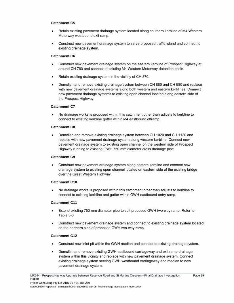
Catchment C5
Retain existing pavement drainage system located along southern kerbline of M4 Western Motorway westbound exit ramp.
Construct new pavement drainage system to serve proposed traffic island and connect to existing drainage system.
Catchment C6
Construct new pavement drainage system on the eastern kerbline of Prospect Highway at around CH 760 and connect to existing M4 Western Motorway detention basin.
Retain existing drainage system in the vicinity of CH 870.
Demolish and remove existing drainage system between CH 880 and CH 980 and replace with new pavement drainage systems along both western and eastern kerblines. Connect new pavement drainage systems to existing open channel located along eastern side of the Prospect Highway.
Catchment C7
No drainage works is proposed within this catchment other than adjusts to kerbline to connect to existing kerbline gutter within M4 eastbound offramp.
Catchment C8
Demolish and remove existing drainage system between CH 1020 and CH 1120 and replace with new pavement drainage system along western kerbline. Connect new pavement drainage system to existing open channel on the western side of Prospect Highway running to existing GWH 750 mm diameter cross drainage pipe.
Catchment C9
Construct new pavement drainage system along eastern kerbline and connect new drainage system to existing open channel located on eastern side of the existing bridge over the Great Western Highway.
Catchment C10
No drainage works is proposed within this catchment other than adjusts to kerbline to connect to existing kerbline and gutter within GWH eastbound entry ramp.
Catchment C11
Extend existing 750 mm diameter pipe to suit proposed GWH two-way ramp. Refer to Table 3-3
Construct new pavement drainage system and connect to existing drainage system located on the northern side of proposed GWH two-way ramp.
Catchment C12
Construct new inlet pit within the GWH median and connect to existing drainage system.
Demolish and remove existing GWH eastbound carriageway and exit ramp drainage system within this vicinity and replace with new pavement drainage system. Connect existing drainage system serving GWH westbound carriageway and median to new pavement drainage system.

Page 30 MR644 - Prospect Highway Upgrade between Reservoir Road and St Martins Crescent - Final Drainage Investigation
Report Hyder Consulting Pty Ltd-ABN 76 104 485 289 f:\aa005690\f-reports\b - drainage\fb0001-aa005690-aar-06- final drainage investigation report.docx
Connect new pavement drainage system to a new open drain to run along the northern side of the GWH towards Blacktown Creek.
Catchment C13
Construct pavement drainage system along eastern kerbline of Prospect Highway and connect to existing piped drainage system located at around CH 1450.
Catchment C14
Construct a new open drain along western edge of proposed works. Discharge is to be collected by new drainage system (median pits and 375mm diameter pipe and connect to existing piped drainage system.
Construct pavement drainage systems along western kerbline of Prospect Highway and connect to new open drain.
Catchment C15
Construct new pavement drainage systems along both western and eastern kerblines of Prospect Highway between CH 1460 and CH 1660.
Connect new pavement drainage systems to existing piped drainage system located on eastern side of Prospect Highway at around CH 1620.
Catchment C16
No drainage works is proposed within this catchment other than adjusts to kerbline to connect to existing kerbline within Harrod Street.
Catchment C17
Demolish and remove existing piped drainage system and replace with new pavement drainage systems along both western and eastern kerblines of Prospect Highway between CH 1680 and CH 1720.
Construct new catch drain along the western edge of the roadway between CH 1700 and 1790 and connect to new pavement drainage system.
Catchment C18
Retain the existing detention basin on the eastern side of Prospect Highway. Blacktown City Council has advised that the parcel of land adjacent to the basin is used as a privately operated on-site detention basin. No additional information is available to confirm its availability or performance as an overflow basin
Modification of earthworks to detention basin on the western side of Prospect Highway to provide additional stormwater storage of approximately 300 m3.
Retain existing cross drainage and piped drainage systems within this catchment.
Construct new pavement drainage system along eastern kerbline of Prospect Highway between CH 1740 and CH 1960 and connect to existing underground drainage system located to the north of existing pedestrian underpass at CH 1980. The connection pass the existing pedestrian underpass is to avoid potential surcharge to flow into the underpass.
Catchment C19

MR644 - Prospect Highway Upgrade between Reservoir Road and St Martins Crescent—Final Drainage Investigation Report
Page 31
Hyder Consulting Pty Ltd-ABN 76 104 485 289 f:\aa005690\f-reports\b - drainage\fb0001-aa005690-aar-06- final drainage investigation report.docx
Construct a new open drain along western edge of roadway between CH 1990 and CH 2100 and connect to existing Council detention basin in this vicinity.
Construct new pavement drainage systems along eastern and median kerblines of Prospect Highway between CH 1720 and CH 2110 and connect to new open drain.
Construct new earthworks within existing detention basin to provide an additional storage of around 300 m3 to accommodate additional runoff discharging to this basin.
Catchment C20
Retain existing piped drainage system located within the vicinity of CH 2300 Prospect Highway.
Construct a new pavement drainage system along western, median and eastern kerblines of Prospect Highway and connect to existing piped drainage system at around CH 2280.
Catchment C21
No drainage works is proposed within this catchment.
Catchment C22
Demolish and remove existing piped drainage system and replace with new pavement drainage systems along both western and eastern kerblines of Prospect Highway between CH 2500 and CH 2600.
Construct a new surcharge pit system at low point at around CH 2600 to convey surcharge flows in excess of the 10 year ARI design storm event to catchment C23. Connect surcharge pit system to new pavement drainage system to serve C23.
Catchment C23
Construct new pavement drainage systems along both eastern and median kerblines of Prospect Highway between CH 2600 and CH 2800.
Connect new pavement drainage system to existing drainage system at Vesuvius Street near intersection with Everest Street.
Undertake further assessment accounting for existing Council’s piped drainage network located within residential catchment discharging to low point in Vesuvius Street to confirm the effects of the proposal on the existing drainage patterns within this vicinity.
Catchment C24
Construct new pavement drainage systems along western kerbline of Prospect Highway between CH 2780 and CH 2860.
Connect new pavement drainage system to existing drainage system at Keyworth Drive near intersection with Beaufort Road.
Catchment C25
Replace existing cross drainage system at CH 3100 with a new 675 mm diameter pipe and connect to existing drainage system on the western side of Prospect Highway. Refer to Table 3-3
Replace existing piped drainage system and replace with new pavement drainage systems along eastern, western and median kerblines of Prospect Highway between CH 2840 and CH 3140.
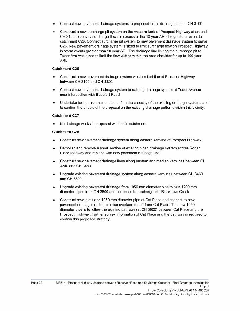
Page 32 MR644 - Prospect Highway Upgrade between Reservoir Road and St Martins Crescent - Final Drainage Investigation
Report Hyder Consulting Pty Ltd-ABN 76 104 485 289 f:\aa005690\f-reports\b - drainage\fb0001-aa005690-aar-06- final drainage investigation report.docx
Connect new pavement drainage systems to proposed cross drainage pipe at CH 3100.
Construct a new surcharge pit system on the western kerb of Prospect Highway at around CH 3100 to convey surcharge flows in excess of the 10 year ARI design storm event to catchment C26. Connect surcharge pit system to new pavement drainage system to serve C26. New pavement drainage system is sized to limit surcharge flow on Prospect Highway in storm events greater than 10 year ARI. The drainage line linking the surcharge pit to Tudor Ave was sized to limit the flow widths within the road shoulder for up to 100 year ARI.
Catchment C26
Construct a new pavement drainage system western kerbline of Prospect Highway between CH 3100 and CH 3320.
Connect new pavement drainage system to existing drainage system at Tudor Avenue near intersection with Beaufort Road.
Undertake further assessment to confirm the capacity of the existing drainage systems and to confirm the effects of the proposal on the existing drainage patterns within this vicinity.
Catchment C27
No drainage works is proposed within this catchment.
Catchment C28
Construct new pavement drainage system along eastern kerbline of Prospect Highway.
Demolish and remove a short section of existing piped drainage system across Roger Place roadway and replace with new pavement drainage line.
Construct new pavement drainage lines along eastern and median kerblines between CH 3240 and CH 3460.
Upgrade existing pavement drainage system along eastern kerblines between CH 3460 and CH 3600.
Upgrade existing pavement drainage from 1050 mm diameter pipe to twin 1200 mm diameter pipes from CH 3600 and continues to discharge into Blacktown Creek
Construct new inlets and 1050 mm diameter pipe at Cat Place and connect to new pavement drainage line to minimise overland runoff from Cat Place. The new 1050 diameter pipe is to follow the existing pathway (at CH 3600) between Cat Place and the Prospect Highway. Further survey information of Cat Place and the pathway is required to confirm this proposed strategy.
MR644 - Prospect Highway Upgrade between Reservoir Road and St Martins Crescent—Final Drainage Investigation Report
Page 33
Hyder Consulting Pty Ltd-ABN 76 104 485 289 f:\aa005690\f-reports\b - drainage\fb0001-aa005690-aar-06- final drainage investigation report.docx
4 EROSION AND SEDIMENT CONTROL Water quality in downstream drainage lines and watercourses is expected to be impacted upon during the construction phase of this proposed upgrade. To mitigate these impacts, a strategy was developed involving appropriate measures.
A layout of the recommended erosion and sediment control strategy is provided in Figures 4-1 to 4-5.
The likelihood for erosion and sediment mobilisation during construction has been considered at various locations within the construction corridor throughout the section of upgrade. This erosion and the associated potential for sediment to be transported to downstream watercourses have been addressed in the development of this strategy.
It is recommended that this proposed strategy be used in the preparation of the Soil and Water Management Plan required as part of the final design. However it is important to note that the final requirements for erosion and sediment control during the construction process will be affected by the final design of the upgrade works and involves consideration of proposed construction methods and staging practices which are yet to be finalised.
This strategy has been developed based on design guidelines set out in the Soils and Construction – Managing Urban Stormwater, Volume 1 (Landcom, 2004) , also known as the ‘Blue Book’.
In the development of the erosion and sediment control strategy, it has been assumed that local erosion and control measures during construction will be sufficient for the sections of the upgrade where the existing road corridor is mostly paved and the works will mainly involve the conversion of the existing roadway to form the southbound carriageway and where the conversion of the existing service roads north of Lancelot Street will form the northbound carriageway.
4.1 KEY ELEMENTS OF PROPOSED STRATEGY Effective erosion and sediment control primarily aims to minimise erosion and then capture and remove sediment from disturbed areas where erosion is unavoidable.
In addition to sediment capture measures presented as part of this proposed strategy, erosion control methods need to be incorporated into the development of the Soil and Water Management Plan.
Local erosion and sediment control measures
In assessing the appropriate measures to be taken at various locations along the upgrade, the Blue Book was consulted and the Revised Universal Soil Loss Equation (RUSLE) was applied in determining whether or not sediment retention basins were required. In locations where soil loss calculated using the RUSLE was over 150 m3/yr, sediment retention basins were required by the Blue Book.
A proposed construction staging plan was prepared by Roads and Maritime and was used to determine the extent of the disturbed catchments and identify the potential locations for sediment retention basins.
The table below shows the parameters that remained constant in the application of the RUSLE for each catchment in the upgrade.
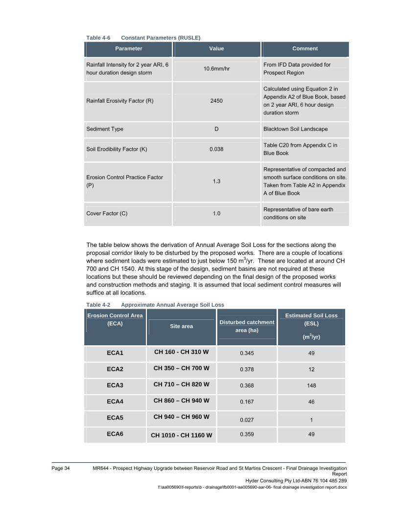
Page 34 MR644 - Prospect Highway Upgrade between Reservoir Road and St Martins Crescent - Final Drainage Investigation
Report Hyder Consulting Pty Ltd-ABN 76 104 485 289 f:\aa005690\f-reports\b - drainage\fb0001-aa005690-aar-06- final drainage investigation report.docx
Table 4-6 Constant Parameters (RUSLE)
Parameter Value Comment
Rainfall Intensity for 2 year ARI, 6 hour duration design storm
10.6mm/hr From IFD Data provided for Prospect Region
Rainfall Erosivity Factor (R) 2450
Calculated using Equation 2 in Appendix A2 of Blue Book, based on 2 year ARI, 6 hour design duration storm
Sediment Type D Blacktown Soil Landscape
Soil Erodibility Factor (K) 0.038 Table C20 from Appendix C in Blue Book
Erosion Control Practice Factor (P)
1.3
Representative of compacted and smooth surface conditions on site. Taken from Table A2 in Appendix A of Blue Book
Cover Factor (C) 1.0 Representative of bare earth conditions on site
The table below shows the derivation of Annual Average Soil Loss for the sections along the proposal corridor likely to be disturbed by the proposed works. There are a couple of locations where sediment loads were estimated to just below 150 m3/yr. These are located at around CH 700 and CH 1540. At this stage of the design, sediment basins are not required at these locations but these should be reviewed depending on the final design of the proposed works and construction methods and staging. It is assumed that local sediment control measures will suffice at all locations.
Table 4-2 Approximate Annual Average Soil Loss
Erosion Control Area
(ECA) Site area Disturbed catchment
area (ha)
Estimated Soil Loss
(ESL)
(m3/yr)
ECA1 CH 160 - CH 310 W 0.345 49
ECA2 CH 350 – CH 700 W 0.378 12
ECA3 CH 710 – CH 820 W 0.368 148
ECA4 CH 860 – CH 940 W 0.167 46
ECA5 CH 940 – CH 960 W 0.027 1
ECA6 CH 1010 - CH 1160 W 0.359 49

MR644 - Prospect Highway Upgrade between Reservoir Road and St Martins Crescent—Final Drainage Investigation Report
Page 35
Hyder Consulting Pty Ltd-ABN 76 104 485 289 f:\aa005690\f-reports\b - drainage\fb0001-aa005690-aar-06- final drainage investigation report.docx
Erosion Control Area
(ECA) Site area Disturbed catchment
area (ha)
Estimated Soil Loss
(ESL)
(m3/yr)
ECA7 CH 1190 (GWH median – 1)
0.151 3
ECA8 CH 1190 (GWH median – 2)
0.303 8
ECA9 CH 1220 – CH 1260 W 0.054 9
ECA10 CH 1230 (GWH ramp - 1)
0.218 58
ECA11 CH1230 (GWH ramp - 2)
0.328 29
ECA12 CH 1230 (GWH ramp - 3)
0.408 63
ECA13 CH 1230 – CH 1580 W 0.613 146
ECA14 CH 1580 – CH 1660 W 0.152 3
ECA15 CH 1690 – CH 1715 W 0.025 1
ECA16 CH 1715 – CH 1810 W 0.127 7
ECA17 CH 1810 – CH 1970 W 0.288 40
ECA18 CH 1970 – CH 2030 W 0.096 21
ECA19 CH 2030 - CH2300 0.359 101
Page 36 MR644 - Prospect Highway Upgrade between Reservoir Road and St Martins Crescent - Final Drainage Investigation
Report Hyder Consulting Pty Ltd-ABN 76 104 485 289 f:\aa005690\f-reports\b - drainage\fb0001-aa005690-aar-06- final drainage investigation report.docx
5 CONSTRUCTABILITY Key constructability issues identified during development of the concept drainage design include the following:
Construction of new pavement drainage on existing road corridor. Design needs to take consideration of minimising interference to existing traffic flow on Prospect Highway and providing construction staging to construct the new pavement drainage as safe as possible for all concerned.
Construction of new pavement drainage near existing utilities corridor. Utilities survey is incomplete and elevations of certain utilities are missing. Check for clashes between new pavement drainage and existing utilities have been undertaken using available information only. Further survey information is required for levels of existing utilities. The design needs to take considerations of avoiding clashes with utilities and consider the proposed relocation of the utilities.
Trenching for the construction of stormwater drainage lines in the vicinity of the telegraph poles will need to consider the support of the poles.
Upgrade of pavement drainage near the intersection of Prospect Highway and Bungarribee Road. This includes construction of twin 1200mm diameter pipes within limited space to avoid clash with utilities. The design needs to take consideration of minimising relocation of utilities and avoiding clashes with utilities. The relocation of the existing underground electrical cables cannot be avoided and will need to be undertaken to make space/ avoid clash with the proposed twin 1200 mm diameter pipes.
Further to the above, Roads and Maritime has undertaken a constructability workshop in August 2013. The details of the workshop were documented in the Constructability Review Report prepared by Roads and Maritime.

MR644 - Prospect Highway Upgrade between Reservoir Road and St Martins Crescent—Final Drainage Investigation Report
Page 37
Hyder Consulting Pty Ltd-ABN 76 104 485 289 f:\aa005690\f-reports\b - drainage\fb0001-aa005690-aar-06- final drainage investigation report.docx
6 OUTSTANDING ISSUES Results of additional survey of utilities which have insufficient 3d information to confirm
pavement drainage systems are not clashing with utilities
Further information on Council’s drainage system to undertake hydraulic capacity assessment. This is required where proposed drainage work is required to connect to the Council drainage system.
Further survey information of Cat Place and adjacent pathway to confirm proposed drainage strategy in this area.
7 SUMMARY A drainage investigation was undertaken to determine the existing drainage patterns within the proposal’s corridor and to determine the impacts the upgrade of the Prospect Highway will have on these drainage patterns. The pre-upgrade peak flows were estimated at locations where runoff outfalls along the road corridor. The estimated pre-upgrade peak flows also provided a basis for comparison with the peak discharges from the road corridor under post-upgrade conditions. Figures 2-1 to 2-5 show the pre-upgrade catchment plan used for the assessment of existing conditions peak flows.
The proposed concept drainage design presented on Figures 3-1 to 3-5 forms the basis for the assessment to determine peak flows under post-upgrade conditions. The post-upgrade peak flows were compared with the pre-upgrade flows to identify the locations where the proposed upgrade will impact on the existing drainage patterns. The table under Section 3.4 of this report presents the results of this analysis. The assessment determined that the proposal will introduce changes to the existing drainage patterns at numerous locations. Measures are proposed for locations where the changes were considered significant to minimise the effect of the proposal on the drainage patterns. The proposed strategy and findings of current assessment will need to be confirmed as the design of the upgrade progresses in the next phases.
The concept drainage design proposes to connect the new pavement drainage systems to Council’s drainage systems located within the side roads. The capacity of these systems will need to be confirmed at a later phase of the proposal.

Page 38 MR644 - Prospect Highway Upgrade between Reservoir Road and St Martins Crescent - Final Drainage Investigation
Report Hyder Consulting Pty Ltd-ABN 76 104 485 289 f:\aa005690\f-reports\b - drainage\fb0001-aa005690-aar-06- final drainage investigation report.docx
8 GLOSSARY Annual Average Soil Loss The average amount of soil lost in a location per year. Antecedent Moisture Condition The word antecedent simply means ‘preceding’ and so the AMC refers to the relative wetness or dryness of a drainage basin before a rainfall event or other leading to water flow through the area. Aquaplaning Aquaplaning by the tyres of a vehicle occurs when a layer of water builds between the wheels of the vehicle and the road surface which leads to a loss of traction and of control. Traction is still diminished even without aquaplaning in wet conditions. Australian Height Datum (AHD) A common national surface level datum approximately corresponding to mean sea level. Average Recurrence Interval (ARI) The long-term average number of years between the occurrence of a flood as big as, or larger than, the selected event. For example, floods with a discharge as great as, or greater than, the 20 year ARI flood event will occur on average once every 20 years. Cadastre, cadastral base Information in map or digital form showing the extent and usage of land, including streets, lot boundaries, water courses etc. Batter A slope, as of the outer face of a wall, that recedes from bottom to top. Basin A storage site (such as a small reservoir) that delays the flow of water downstream Cadastral information A map or survey showing or recording property boundaries, subdivision lines, buildings, and related details. Catchment The area draining to a site. It always relates to a particular location and may include the catchments of tributary streams as well as the main stream. Cross drainage A cross drainage work is a structure carrying the discharge from one stream across another that intercepts it Cross fall The transverse sloping of a roadway toward the shoulder or gutter on either side Cross pipe A pipe that provides a convergence or cross over between two other pipes. Culvert A culvert is a structure that allows water to flow under a road, railroad, trail, or similar obstruction.

MR644 - Prospect Highway Upgrade between Reservoir Road and St Martins Crescent—Final Drainage Investigation Report
Page 39
Hyder Consulting Pty Ltd-ABN 76 104 485 289 f:\aa005690\f-reports\b - drainage\fb0001-aa005690-aar-06- final drainage investigation report.docx
Design storm/flood A significant event to be considered in the design process; various works within the floodplain may have different design events. e.g. some roads may be designed to be overtopped in the 1 in 1 year ARI. Discharge The rate of flow of water measured in terms of volume over time. It is to be distinguished from the speed or velocity of flow, which is a measure of how fast the water is moving rather than how much is moving. Drainage easement A drainage easement is a legal addition to a property deed that allows a certain party to access part of a property for drainage Embankment In transportation, a raised bank to carry a road, railway, or canal across a low-lying or wet area Hydraulics The term given to the study of water flow in a river, channel or pipe, in particular, the evaluation of flow parameters such as stage and velocity. Hydrology The term given to the study of the rainfall and runoff process as it relates to the derivation of hydrographs for given floods. Inflow Something, such as a liquid or gas, that flows in Inundation From inundate, To cover with water, especially flloodwaters. Invert The bottom of the inside of a pipe. Low point The point of lowest elevation above AHD On grade At ground level. Supported directly on the ground. Mathematical/computer models The mathematical representation of the physical processes involved in runoff and stream flow. These models are often run on computers due to the complexity of the mathematical relationships. In this report, the models referred to are mainly involved with rainfall, runoff, pipe and overland stream flow. Peak discharge The maximum discharge occurring during a storm/flood event. RCP Reinforced Concrete Pipe RCBC Reinforced Concrete Box Culvert
Page 40 MR644 - Prospect Highway Upgrade between Reservoir Road and St Martins Crescent - Final Drainage Investigation
Report Hyder Consulting Pty Ltd-ABN 76 104 485 289 f:\aa005690\f-reports\b - drainage\fb0001-aa005690-aar-06- final drainage investigation report.docx
Runoff The amount of rainfall that actually ends up as stream or pipe flow, also known as rainfall excess. RSG Pits Raised Steel Grate Pit. Refer To RMS Model Drawing MD.R11.B37.A.2 SA1 Pits Gully Pit Type SA. Refer to RMS Model Drawing MD.R11.B02.A.1 SA2 Pits Gully Pit Type SA. Refer to RMS Model Drawing MD.R11.B02.A.1 SE Pits Gully Pit Type SE. Refer to RMS Model Drawing MD.R11.B06.A.1 SO Pits Gully Pit Type SO1 and SO2. Refer to RMS Model Drawing MD.R11.B21.A.1 and MD.R11.B22.A.1 Sediment mobilisation The movement of loose soils and sediments Spillway A spillway is a structure used to provide the controlled release of flows from a dam or levee into a downstream area Super elevation Super elevation is tilting the roadway to help offset centripetal forces developed as the vehicle goes around a curve. Surcharge An additional or excessive burden; an overload. Topography
A surface which defines the ground level of a chosen area.
Verge A narrow strip of grass or plants located between the carriageway curb and the boundary

APPENDIX A
FIGURES

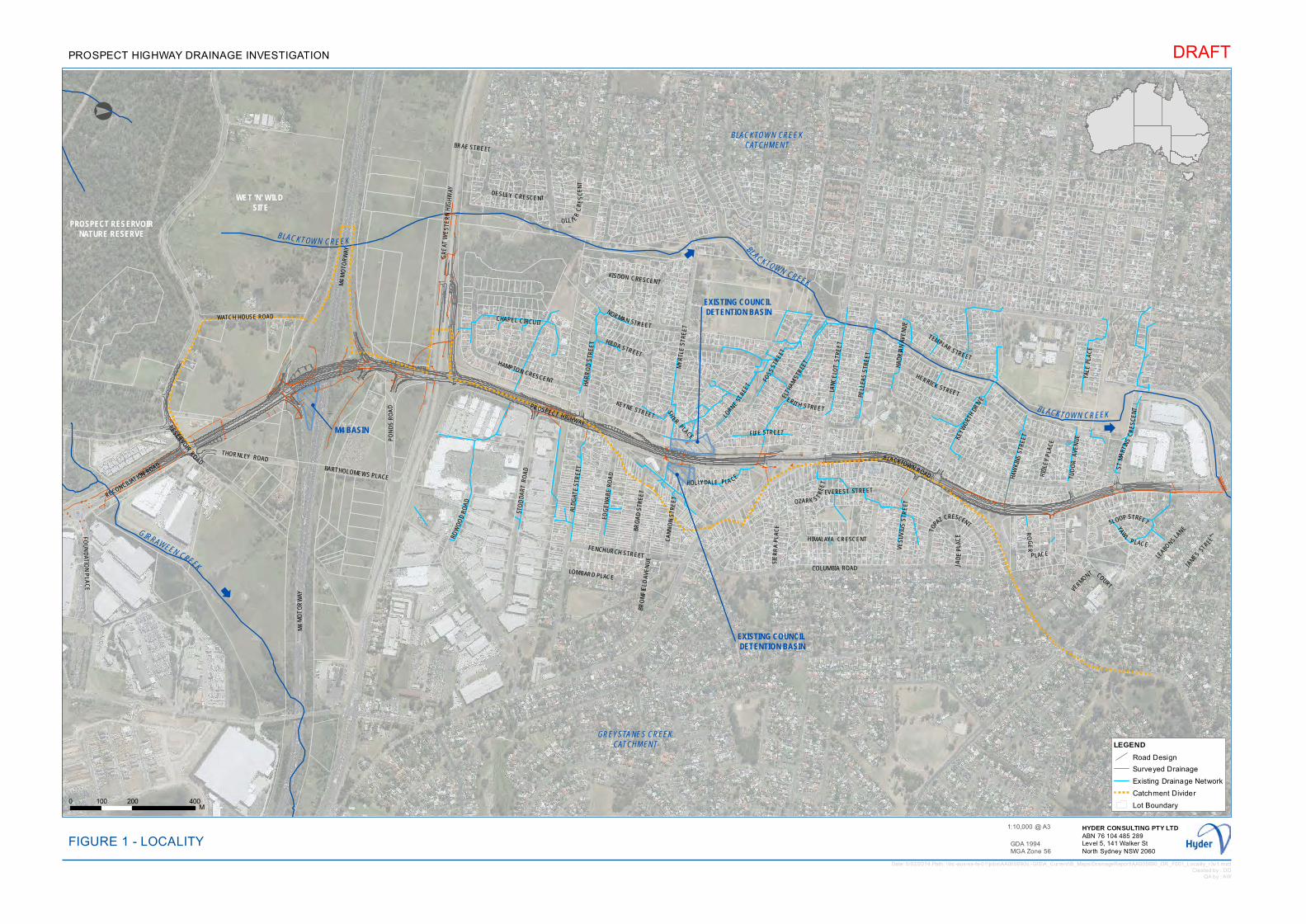
WET 'N' WILD SITE
BLACKTOWN CREEKCATCHMENT
GREYSTANES CREEKCATCHMENT
PROSPECT RESERVOIRNATURE RESERVE
!
M4 BASIN
!
EXISTING COUNCIL DETENTION BASIN
!
EXISTING COUNCIL DETENTION BASIN
M4
MO
TO
RW
AY
GIRRAWEEN CREEK
BLACKTOWN CREEK BLACKTOWN CREEK
BLACKTOWN CREEK
LAN
CE
LOT
STR
EE
T
LEABO
NSLA
NE
PO
ND
SR
OA
D
BLACKTOWN ROAD
PROSPECT HIGHWAY
KEYNE STREET
ROW
OO
DR
OA
D
GR
EAT
WE
STE
RN
HIG
HW
AY
M4
MO
TOR
WAY
SHER
PLACE
PELL
EAS
STR
EE
T
BRO
MF
IELD
AVE
NU
E
NORMAN STREET
ELTH
AM S
TREE
T
ALD
GAT
E S
TRE
ET
MY
RTL
E S
TRE
ET
FENCHURCH STREET
RECONCILIATION ROAD
HOLLYDALE PLA CE
COLUMBIA ROAD JAD
EP
LAC
E
RIDL
EY P
LACE
BRAE STREET
LORNE
STRE
ET
FIFE STREET
TEMPLAR STREET
HA
RR
OD
STR
EE
T
EVEREST STREET
SLOOP STREET
YAW
LPLACE
VES
UV
IUS
STR
EET
HIMALAYA CRESCENT
VERMONT COURT
FOSS
STR
EET
ST
MA
RTI N
SC
RE
SC
EN
T
ERIT H STREET
HAW
KINS
STR
EET
CA
NN
ON
STR
EE
T
LOMBARD PLACE
YALE
PLA
CE
BARTHOLOMEWS PLACE
OLL I ER
CR
ES
CE
NT
BRO
AD
STR
EE
T
HERRICK STREET
WATCH HOUSE ROAD
THORNLEY ROAD
FOU
ND
ATION
PLA
CE
EDG
EW
AR
E R
OA
D
STO
DD
AR
T R
OA
D
KEYW
ORT
HDR
IVE
OZARK S TR
EET
HA
DR
IAN
AV
EN
UE
HAMPTON CRESCENT
RESERVOIRROAD
TUD
OR
A
VEN
UE
CHAPEL CIRCUIT
SIE
RR
A P
LAC
E
KISDON CRESCENT
DESLEY CRESCE NT
HILDA STREET
TOPA
Z CRESCENT
RO
GE
R
P LACE
JAM
ESST
REET
°
LEGENDRoad DesignSurveyed DrainageExisting Drainage NetworkCatchment DividerLot Boundary
Date: 5/02/2014 Path: \\hc-aus-ns-fs-01\jobs\AA005690\L-GIS\A_Current\B_Maps\DrainageReport\AA005690_DR_F001_Locality_r3v1.mxdCreated by : DD
QA by : AW
DRAFT
GDA 1994MGA Zone 56
0 200 400100M
FIGURE 1 - LOCALITYHYDER CONSULTING PTY LTDABN 76 104 485 289Level 5, 141 Walker StNorth Sydney NSW 2060
1:10,000 @ A3
PROSPECT HIGHWAY DRAINAGE INVESTIGATION
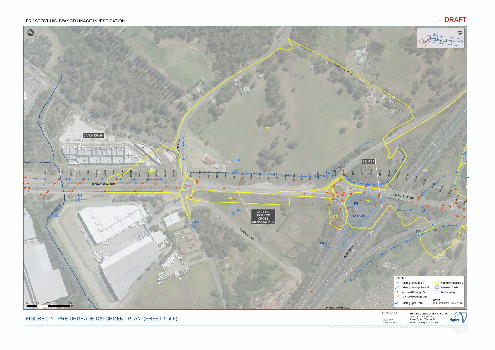
GG
GG
G
G
G G G
GG
G
G G
GG
GGGGGGGGGGGGG
GGG
GGG
GG
G
G
G
G
G
GGGGGGG
G G G G
G
G
G
G
G
G
G
G
G
G
!!
!
!!
!
!
!
!
!
!
!!!
!
!!!! !
!
!
!
! !
!
!
!
!
!
!
!
!
!
!
!
!
!
!
!!
!
!!
!
!
!
!
!
!
!!!
!
!!!! !
!
!
!
! !
!
!
!
!
!
!
!
!
!
!
!
!
!
!
!
!!
!
!!
!
!
!
!
!
!
!!!
!
!
!!!! !
!
!
!
!
!
!
!
!
!!
!
!
!
!
!
!
!
!
!
!
!
!
!
!
!
!
!
!
!
!
!
!
!
!
!
!
!
!
!
!
!
!!
!!!
!
!
!
!
!
!
!
!
!
!
!!
!
!! !
!
0.000
20.000
40.000
60.000
80.000
100.000
120.000
140.000
160.000
180.000
200.000
220.000
240.000
260.000
280.000
300.000
320.000
340.000
360.000
380.000
400.000
420.000
440.000
460.000
480.000
500.000
520.000
540.000
560.000
580.000
600.000
620.000
640.000
660.000
680.000
700.000
720.000
740.000
760.000
780.000
800.000
820.000
840.000
860.000
880.000
900.000
920.000
940.000 960.000 980.000
C1
C2C4
C3
C5
C6
C6F1
F2
F3
F4
F5
F6
F7!
EASTING1350 RCP
CROSSDRAINAGE PIPE
!
CATCH DRAIN
!
750 RCP
GIRRAW
EEN CREEK
BARTHOLOMEWS PLACE
PROSPECT HIGHWAY
RE
SER
VO
IRR
OAD
PON
DS
RO
AD
WATCH HOUSE ROAD
THORNLEY ROAD
RECONCILIATION ROAD
M4 M
OTORW
AY
M4 BASIN
24
5
31
°
LEGEND! Existing Drainage Pit
Existing Drainage Network
! Surveyed Drainage Pit
Surveyed Drainage Line
GExisting Open Drain
Catchment Boundary
Detention Basin
Lot Boundary
Date: 5/02/2014 Path: \\hc-aus-ns-fs-01\jobs\AA005690\L-GIS\A_Current\B_Maps\DrainageReport\AA005690_DR_F002_ExistingDrainage_r3v1.mxdCreated by : DD
QA by : AW
DRAFT
GDA 1994MGA Zone 56
0 50 10025m
FIGURE 2-1 - PRE-UPGRADE CATCHMENT PLANHYDER CONSULTING PTY LTDABN 76 104 485 289Level 5, 141 Walker StNorth Sydney NSW 2060
1:2,750 @ A3
PROSPECT HIGHWAY DRAINAGE INVESTIGATION
°
(SHEET 1 of 5)
NOTESRCP - Reinforced Concrete Pipe
!
!
!
!
!
!
!
!
!!
!
!
!
!
!
!!
!
!!
!
!
!!
!
!
!
!
!
!
!
!
!
!
!
!
!!!
!! !
!
!
!
!
!
!
!
!
!
!
!
!
!
!!
!
!
!!
!
!
!
!
!!
!
!
!
!
!
!
!!
!
!
!!
!
!
!
!
!
!!
!
!
!
!!!
!
!
!
!
!
!
!
!
!
!
!!
!
!
!
!!!
!
!
!
!!
!
!
!
!!!
!! !
!
!
!
!
!
!
!
!
!
!
!!
!
!!
!
!
!!
!
!
!!!
!!
!
!!
!
!
!
!
!
!
!
!
!!!
!
!
!
!
!
!!
!
!!
!
!
!
!
!
!
!
!
!
!
!
!
!
!
!
!!!
!
!
!
!!
!!
!
!!
!
!
!
!
!
!
! !
!
!
!
!
!
!!!
!
!
!
!
!
!
!
!
!
!
!
!
!!! !!
!
!
!
!
!
!
! !
!! !
!
!
!
!!
!
!
!
!
!
! !
!
!
!!
!
!
!
!
!
!
!
!
!
!
!
!
!
!
!
!
!
!
!
!
!
!
!
!!
!
!
!
!
!
!!!
!!!!
!!!!!
!
!!
!
!
!!
!
!
!
!
!! !
!!
!
!
!
!!!
!
!!!
!
!
!!
!
!!
!
!
!
!
!
!
!
!
!
!
!
!
!
!
!
!
!
!
!
!
!!!
!
!
!
!
!
!!
!!!
!!
!
!!
!
! !
!
!
!
!
!
!!
!
!!
!
!
!
!
!!
!!!
!
!
!
!
!
!
!!
!
!
!
! !
!
!
!
!!
!
!
!! !!
!
!
!
!
!
!
!! !
!
!!
!
!
!!
!
!
!!
!
!
!
!
!
!
!
!
!!
!
!!
!
!! !
!
!!
!!
!!
!
!
!
!
! !
!
!
!
!
!
!
!
!
!
!!!
!!
!
!
!
!
!
!
!!
!
!
!
!!
!
!
!
!
!
!
!
!!
!
!
! !
!!
!
!
!
!
!
!
!
!
!
!
!
!
!
!
!
!!
!!
!
!
!
!
!
!
!!
!
!!!
!
!
!
!
!!!!!
!
!
!
!
! !
!!
!
!
!
!
!
!!
!
!
!! !
!!
! !! !
!
!
!
!!
!
!
!
!
!
!
!
!
!
!
!!
!
!
!
!
!
!
!
!
!!
!
!!
!
!!
!
!
!! !!
!
!!!! !
!!
!
!
!
!
!!
!
!
!
!
!!
! !
!
!
!
!!
!
!
!!!
!
!
!!
!
!!
!!
!!!
!
!!!
!
!
!
!
!
!!
!!
!
!
!
! !!
!
!
!
!
!!
!
!
!
!
!
!
!
!
!
!
!!!
!
!
!
!!
!
!
!
!!
!
!
!
!
!
!
!
!
!
!
!
!
!
!
!
!
!
!
!
!
!
!
!
!
!
!
!
!!
!
!
!!!
!
!
!
!
!
!
!
!
!
!!
!
!
!
!
!!
!
!
!
!
!
!
!
!!
!
!
!!
!
!
!
!
!
!!
!
!
!
!
!
!
!
!
!
!
!
!
!
!
!
!
!
!
!!
!
!
!!
!
!
!
!
!
!
!
!
!
!
!
!
!
!
!
!
!
!
!!
!
!
!
!
!
! !
! !
!
!!
!
!
!
!
!
!
!
!
!
!
!!!!!
!
!
!
!
!
!
!!
!
!
!
!
!
!
!
!
!!
!
!
!
!
!
!
!
!
!
!
!
!
!
!
!
!
GG
G
G
G
G
G
GG
G
G
G
G
!! !
!
!
!
!!
!!
!
!
!
!
!!
!!
!
!
!
!
!
!
!
!
!
!
!
!
!
!
!! !
!
!
!
!!
!!
!
!
!
!
!!
!!
!
!
!
!
!
!
!
!
!
!
!
!
!
!
!! !
!
!
!
!
!!
!!
!
!
!!
!!
!!
! !
!
!
!
!!
!
!
!
!
!
!!
!
!
!
!
!
!!
!
!
!
!
!
!
!
!
1000.000 1020.000 1040.000 1060.000 1080.000 1100.000 1120.000 1140.000 1160.000 1180.000 1200.000 1220.000
!
EXISTING750 RCPCROSS
DRAINAGE PIPE
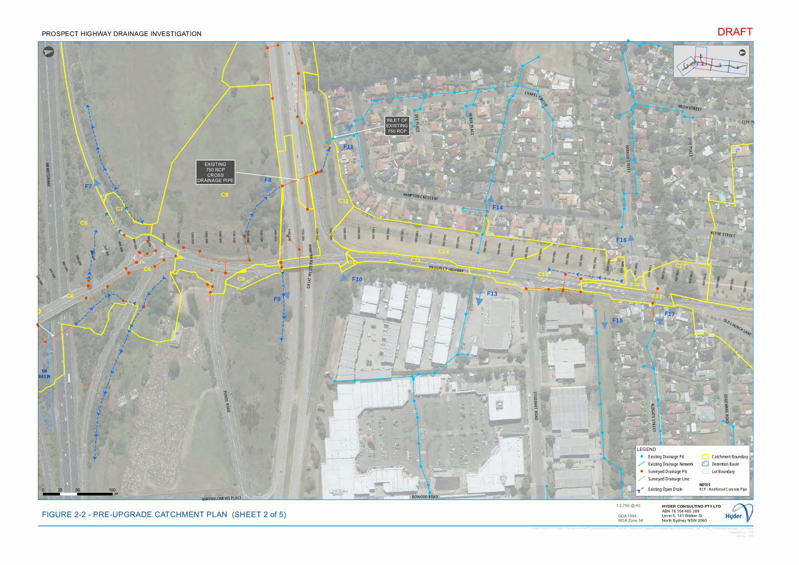
!
!!
!!
!
!
!!
!
!
!
!
!
!!
!!
!
!
!
!!!
!
!
!
!
!
! !
!
!
!
!
!
!
!!!!
!!!
!!
!
!
!!
!!
!!
!
!
!!
!
!
!
!
!!
!
!
!
!
!
!
!!
!!
!
!!!
!
!!
!
!
!!
!
!
!
!
!!
!!
! !
!
!!!
!!
!
!
!
!
!! !
!
! !
!!
!
!
!!
!!
!
!!
!
!
!
!
!
!
!
!
!
!!
!!
!
!
!
!
!!
!
!
!
!
!
!
!!
!
!
!
!!
!
!
!
!!
!!
!!
!
!!
!!!
!!
!
!
!
! !
G
G
G
GG
GG
G
G
GG
GG
G
G
G
G
GG
G
G
G
G
G
G
GG
G
G
G
G
G
G
GG
GGGG
GG
!
!
!
!!
!
!
!
!
!
!
!!
!
!!
!
!
!
!
!
!
!
!
!
!!
!
!
!
!
!!
!
!
!
!
!
!
!!
!
!!
!
!
!
!
!
!
!
!
!
!!
!
!
!
!
!
!
!
!!
!
!
!
!
!
!
!
!!
!
!
!!!
!
!
!
!
!
!
! !
!
!
!
!
!
!
!
!
!
!!
!
!
!
!
!
!
!
!
!
!
! !! !
!
!!!
!
!
!
820.000
840.000
860.000
880.000
900.000
920.000
940.000
960.000
980.000
1000.000
1020.000
1040.000
1060.000
1080.000
1100.0
00
1120.0
00
1140.0
00
1160.0
00
1180.0
00
1200.000
1220.000
1240.000
1260.000
1280.000
1300.000
1320.000
1340.000
1360.000
1380.000
1400.000
1420.000
1440.000
1460.000
1480.000
1500.000
1520.000
1540.000
1560.000
1580.000
1600.000
1620.000
1640.000
1660.000
1680.000
1700.000
1720.000
1740.000
1760.000
1780.000
1800.000
1820.000
1840.000
C8C7
C9
C11
C10
C14
C15C16
C17C6C13
C6
C6 C17
F7F8
F9
F11
F10
F14
F15
F16
F17
F13
!
EXISTING750 RCPCROSS
DRAINAGE PIPE
!
!
INLET OFEXISTING750 RCP
HILDA STREET
PROSPECT HIGHWAY
HAMPTON CRESCENT
GR
EAT
WE
ST E
RN
HIG
HW
AY
OLD CHURCH LANE
DE
E P
LAC
E
BARTHOLOMEWS PLACE
CHAPEL CIRCUIT
HE
BER
PLAC
E
KEYNE STREET
L YTE
PLA
CE
NORMAN STREET
EDG
EW
AR
E R
OA
D
M4 M
OTO
RW
AY
PON
DS ROAD
HA
RR
OD
STR
EE
T
ALDG
ATE
STR
EET
STOD
DA
RT R
OA
D
CLEY PL
ROWOOD ROAD
M4BASIN
1 4
5
32
°
LEGEND! Existing Drainage Pit
Existing Drainage Network
! Surveyed Drainage Pit
Surveyed Drainage Line
GExisting Open Drain
Catchment Boundary
Detention Basin
Lot Boundary
DRAFT
GDA 1994MGA Zone 56
0 50 10025m
FIGURE 2-2 - PRE-UPGRADE CATCHMENT PLANHYDER CONSULTING PTY LTDABN 76 104 485 289Level 5, 141 Walker StNorth Sydney NSW 2060
1:2,750 @ A3
PROSPECT HIGHWAY DRAINAGE INVESTIGATION
°
(SHEET 2 of 5)
NOTESRCP - Reinforced Concrete Pipe
Date: 5/02/2014 Path: \\hc-aus-ns-fs-01\jobs\AA005690\L-GIS\A_Current\B_Maps\DrainageReport\AA005690_DR_F002_ExistingDrainage_r3v1.mxdCreated by : DD
QA by : AW
!!
!
!
!!
!
!
!
!
!!
!
!
!
!!
!
!
!
!
!
!
!
!!
!!
!!
!!
!!
!
!
!
!!!
!
!
! !
!!
!!
!!
!!
!
!
!
!
!!
! !!
!
!
!
!!!
!
!!
!
!!
!
! !
!!!
!
!
!!
!
!
!
!
!
!!!!
!!! !
! !
!
!
!!
!!
!!
!!!
!
!
!
!
!!!
!
!
!
!!
!!
!
!
!
!
!
!!
!
!
!
!!
!! !! !
!
!!
!
!!!
!
!
!
!
!
!
!
!
!
!!
!
!
!!!
!
!
!
!
!
!
!!!
!
!
!
!
!!
!
!
!
!
!
!
!
!
!
!!
!!!
!
!
!
!
!
!!
!
!
!
!
!
!
!
!
!
!
!
!
!
!
!
!
!!
!
!
!!
!
!
!!
!
!!
!!
!
!!
!!!
!!!
!!
!
!
!
!
!
!
!
!
!
!
!
!!
!
!
!
!!
!
!!
!!
!!
!!
!
!
!!
!
!
!
!
!
!
!
!
!!
!!
!!!
!
!!
! !
! !! !!!!
!!!!!
!
!
!
!
!
!
!
!
!
!!
!!!
!!
!!! !! !
!!
!!
!!
!!
!!!
!!
!
!
!
!
!
!
!
!
!!
!
!
!
!
!
!!
!!
!!
!!
! !
!
!
!
!!!
!!
!!
! !
!
!
! !
!
!
!
!!
!!
!
!
!!
!
!!
!
!!
!
!!
!
!
!
!!!
!
!
!
!
!
!
!!
!
!
!
!
!
!
!
!
!
!!
!
!
!!
!
!
!!!
!
!!
!
!
!!
!
!
!! !
!!
! !!
!
!
! ! !!
!!
!
!
!!
! !
!
!
!
!
!
!
!
!!
!
!
!
!
!
!!!
!
!
!
!
!
!
!
!
!
!
!
!
!
!!!
!
!!
!!
!!
!
!
!
!!!
!!
!!!
!!
!
!!
!
!
!
!
!
!
!
!
!!
!
!
!
!
!!
!
!
!
!!
!
!
!
!
!
!
!!!!!
!
!
!
!!
!!
!! ! !
!
!
!!
!
! !
!
!
!
!
!
!
!
!
!!
!!
!
!
!
!
! !
!!
!
!!
!!
!
!!
!
! !
!
!
!! !
!
!
!
!! !
!
!!
!
!
!!!!
!
!
!!
!
!!
!
!!
! !
!
!
!!
!
!
!!
!!! !
!
!!
!
!
!
!!
!!
!
!
!
!
!
!
!
!!
!
!
!
!
!
!! !! !
!!!!
!
!!!!
!
!!
!
!!
!
!
!
!
!
!
!!
!
!!
!
!
!
!
!!
!
!!
G
G
G
G
G
G
G
G
GG
G
GG
G
G
G
G
G
G
G
G
GG
G
!
!
!!
!!
!!
!
!
!
!
!
!
!
!
!!
!!
!!
!
!
!
!
!
!
!!!!
!
!!
!
! !
!
!
!
!
!
!!
!
!!
!
! !
!!
!
!
!
!
!
!
!
!
!
!
!
!
!
!
!
!
!
!
!
660.000
680.000
700.000
720.000740.000
760.000
780.000
800.000
1860.000
1880.000
1900.000
1920.000
1940.000
1960.000
1980.000
2000.000
2020.000
!
PEDESTRIAN UNDERPASS
750 RCP
!
EXISTING900 RCPCROSS
DRAINAGE PIPE
ACE
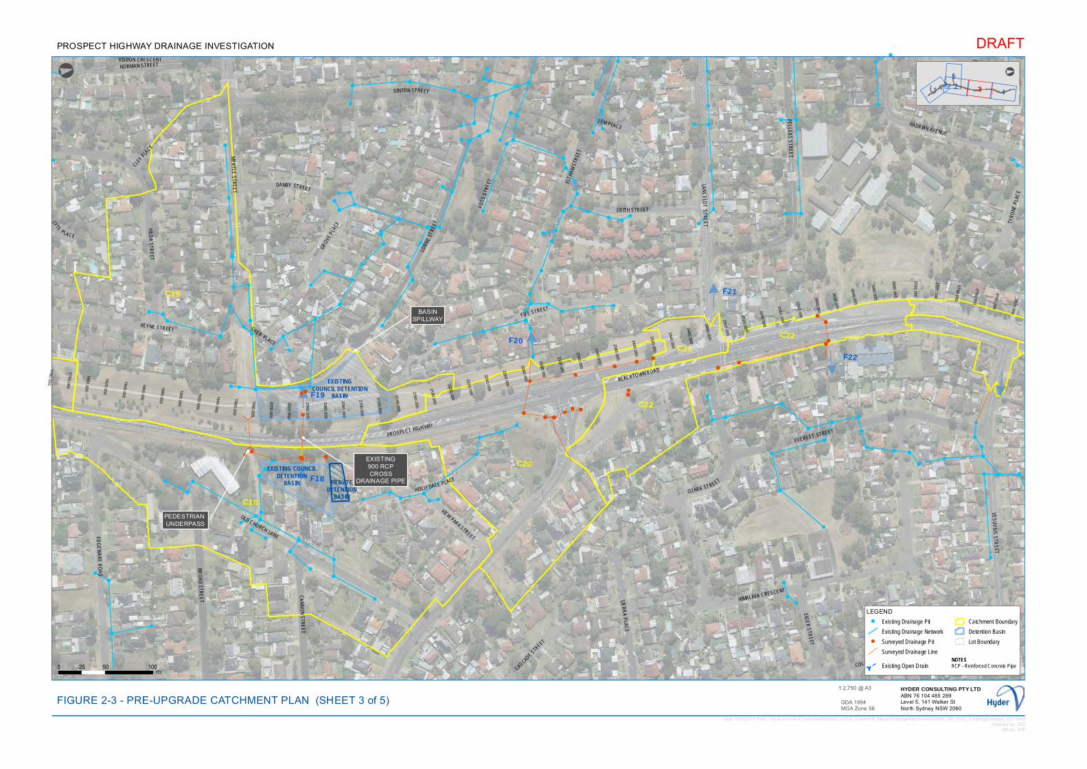
!
!
!!
!! !! !
!
!!
!
!!!
!
!
!
! !
!
!
!
!
!!
!
!
!!!
!
!
!
!
!
!
!!!
!
!
!!
!
!!
!
!!
!
!!
!!!
!
!! !
!!!
!
!
!
!
!
!
!!
! !
!
!
! !
!
!
!
!!
!!
!
!
!!
!
!!
!
!!
!
!!
!
!
!
!!!
!
!
!
!
!
!
!!
!
!
!
!
!
!
!
!
!
!!
!
!
!!
!
!
!!!
!
!
!
!
!
!
!
!
!
!
!!!
!
!
!
!
!
!
!
!
!
!
!
!
!
!!!
!
!!
!!
!!
!
!
!
!!!
!!
!!!
!!
!
!!
!
!
!
!
!
!
!
!
!!
!
!
!
!
!!
!
!
!
!!
!
!
!
!
!
!
!!!!!
!
!
!
!!
!!
!! ! !
!
!
!!
!
! !
!
!
!
!
!
!
!
!
!!
!!
!
!
!
!
! !
!!
!
!!
!!
!
!!
!
! !
!
!
!! !
!
!
!
!! !
!
!!
!
!
!!!!!
!
!!
!
!!
!
!!
! !
!
!
!!
!
!
!!
!!!
!
!
!!
!
!
!
!!
!!
!
!
!
!
!
!
!!!
!
!
!
!
!
!!!
!
!
!
!
!
!
!
!
!!
!
!
!
!
!
!
!
!
!
!
!
!!
!
!
!
!
!
!
!
!
!
!!
!!
!!
!
!
!
!!!!
!
!!!
!
!!!
!
!
!
!!
!
!
1760.000
1780.000
1800.000
1820.000
1840.000
1860.000
1880.000
1900.000
1920.000
1940.000
1960.000
1980.000
2000.000
2020.000
2040.000
2060.000
2080.000
2100.000
2120.000
2140.000
2160.000
2180.000
2200.000
2220.000
2240.000
2260.000
2280.000
2300.000
2320.000
2340.000
2360.000
2380.000
2400.000
2420.000
2440.000
2460.000
2480.000
2500.000
2520.000
2540.000
2560.000
2580.000
2600.000
2620.000
2640.000
2660.000
2680.000
2700.000
2720.000
2740.000
2760.000
2780.000
2800.000
C18
C19
C20
C21C22
C22F19
F18
F20
F21
F22
!
PEDESTRIAN UNDERPASS
!
EXISTING900 RCPCROSS
DRAINAGE PIPE
!
BASINSPILLWAY
KISDON CRESCENT
MY
RTLE
STR
EE
T
BLACKTOWN ROAD
KEYNE STREET SHER PLACE
COLUMBIA ROAD
CLEY P
LACE
LYTEPLACE
JEM PLACE
LAN
CE
LOT S
TRE
ET
OLD CHURCH LANE
DINTON STREET
HOLLYDALE PLACE
SIER
RA P
LAC
E
LORN
EST
REE
T
HERRICK STREET
CASCADE
STREET
FOSS
STR
EET
TYRO
NE P
LAC
E
HILD
A STR
EET
NORMAN STREET
EIGER STR
EET
FIFE STREET
VIEW PARK STREET
EVEREST STREET
DANBY STREET
CA
NN
ON
STR
EE
T
ERITH STREET
BRO
AD
STR
EE
T
HADRIAN AVENUE
PROSPECT HIGHWAY
EDG
EW
AR
E R
OA
D
OZARK STREET
GROVE
PLA
CE
ELTH
AM S
TREE
T
VES
UV
IUS
STR
EET
HIMALAYA CRESCENT
PELLEA
S S
TRE
ET
EXISTING COUNCILDETENTION
BASIN
EXISTINGCOUNCIL DETENTION
BASIN
PRIVATEDETENTION
BASIN
1 4
52 3
°
LEGEND! Existing Drainage Pit
Existing Drainage Network
! Surveyed Drainage Pit
Surveyed Drainage Line
GExisting Open Drain
Catchment Boundary
Detention Basin
Lot Boundary
Date: 5/02/2014 Path: \\hc-aus-ns-fs-01\jobs\AA005690\L-GIS\A_Current\B_Maps\DrainageReport\AA005690_DR_F002_ExistingDrainage_r3v1.mxdCreated by : DD
QA by : AW
DRAFT
GDA 1994MGA Zone 56
0 50 10025m
FIGURE 2-3 - PRE-UPGRADE CATCHMENT PLANHYDER CONSULTING PTY LTDABN 76 104 485 289Level 5, 141 Walker StNorth Sydney NSW 2060
1:2,750 @ A3
PROSPECT HIGHWAY DRAINAGE INVESTIGATION
°
(SHEET 3 of 5)
NOTESRCP - Reinforced Concrete Pipe
!!
!
!
!!
!
!
!
!
!!
!
!
!
!!
!
!
!
!
!
!
!
!!
!!
!!
!!
!!
!
!
!
!!!
!
!
! !
!!
!!
!!
!!
!
!
!
!
!!
! !!
!
!
!
!!!
!
!!
!
!!
!
! !
!!!
!
!
!!
!
!
!
!
!
!!!
!
!!! !
! !
!
!
!!
!!
!!
!!!
!
!
!
!
!!!
!
!
!
!!
!!
!
!
!
!
!
!!
!
!
!
!!
!
!
!
!
!
!
!
!
!
!!
!!!
!
!
!
!
!
!!
!
!
!
!
!
!
!
!
!
!
!
!
!
!
!
!
!!
!
!
!!
!
!
!!
!
!!
!!
!
!!
!!!
!!!
!!
!
!
!
!
!
!
!
!
!
!
!
!!
!
!
!
!
!
!
!!
!
!
!!
!
!
!
!
!
!
!
!! !! !!!!
!!!!!
!
!
!
!
!
!
!
!
!
!!
!!!
!!
!!! !! !
!!
!!
!!
!!
!!!
!
!!
!
!
!
!
!
!!
!!
!!
!!
! !
!
!
!
!!!
!!
!
!!
!
!
!!
!
!
!
!
!
!
! !!
!
!
!
! !!
!!
!
!
!!
!
!!
!
!
!
!
!!
!!
!
!
!!
!
!
!
!
!
!
!!
!!
!
!
!
!
!!
!
!
!
!
!
! !
!
!
!
!
!
!
!!!
!!
!!
!!
!!
!!
!
!
!
!
!!
!
!
!!
!
!
!
!
!! !! !
!!
!!
!!
!!
!!!
!
!!
!
!!!
!!
!
!
!!
!
!
!
!
!!
!!
! !
!
!!!
!!
!
!
!
!
!! !
!
! !
!!
!
!
!!
!!
!
!!
!
!!
!
!
!
!
!
!
!!
!!
!
!
!
!
!!
!
!
!
!
!
!
!!
!
!
!
!!
!
!
!
!!
!!
!!
!
!!
!!!
!
!
!!
!
!
!!
!!
!
!
!
!
!
!
!
!
! !
!!
!
!!
!
!
!
!
!!
!
!!
GG
G
!
!
!
!
!
!
!!
!
!!
!!!
!
!
!
!
1580.000
1600.000
1620.000
1640.000
1660.000
1680.000
1700.000
1720.000
1740.000
2820.000
2840.000
2860.000
2880.000
2900.000
2920.000
2940.000
2960.000
C17
C17
F17
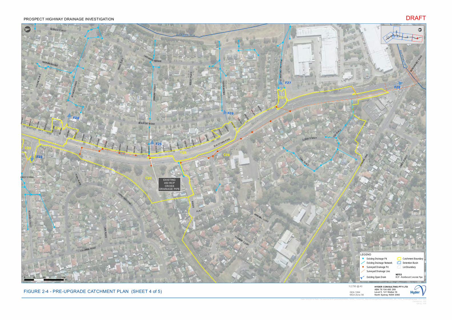
!!
!
!
!
!
!
!
!
!!
!
!
!
!!
!
!
!
!
!
!
!
!!
!!
!!
!!
!!
!
!
!
!!!
!
!
! !
!
!
!
!!!
!
!
!
!!
!!
!
!
!
!
!
!!
!
!
!
!!
!! !! !
!!
!
!!!
!
!
! !
!
!
!
!
!!!
!
!
!
!
!
!
!!
!
!!
!!
!
!!
!!!
!!!
!!
!
!
!
!
!
!
!
!
!
!
!
!!
!
!
!
!!
!
!!
!!
!
!
!
!
!
!
!
!
!
!!
!
!
!
!
!
!
!
!
!
!
!!
!
!
!
!!
!
!
!
! !
!
!
!
!
!
!!!
!
!
!!
! !
2760.000
2780.000
2800.000
2820.000
2840.000
2860.000
2880.000
2900.000
2920.000
2940.000
2960.000
2980.000
3000.000
3020.000
3040.000
3060.000
3080.000
3100.000
3120.000
3140.000
3160.000
3180.000
3200.000
3220.000
3240.000
3260.000
3280.000
3300.000
3320.000
3340.000
3360.000
3380.000
3400.000
3420.000
C23
C24
C25
C26 C28
C27
F23
F24
F25
F26
F28F27
!
EXISTING450 RCPCROSS
DRAINAGE PIPE
BLAC KTOWN CREEK
BLACKTOWN CREEK
KEYW
ORT
H D
RIVE
LEAB
ONS LA
NE
CAVENDISH AVENUE
BEAUFORT ROAD
BLACKTOWN ROAD
COLUMBIA ROAD
PEARL PLACE
BUNG
ARRIB
EE R
OAD
WINDMILL CLOSE
CATPL
ACE
HADRIAN AVENUE
JADE
PLAC
E
RID
LEY
PLA
CE
TYRO
NE P
LAC
E
YAWL
PLACE
VERMONT CO URT
HAW
KIN
S S
TRE
ET
HERRICK STREET
TUD
OR
AVE
NU
E
SLOOP STREET
VES
UV
IUS
STR
EET
DRAK
E PL
ACE
TOPAZ CRESCENT
STM
AR
TIN
SC
RE
SC
EN
T
RO
GE
R
PLACE
JAM
ES S
TREE
T
EREST STREET
1
5
32 4
°
LEGEND! Existing Drainage Pit
Existing Drainage Network
! Surveyed Drainage Pit
Surveyed Drainage Line
GExisting Open Drain
Catchment Boundary
Detention Basin
Lot Boundary
Date: 5/02/2014 Path: \\hc-aus-ns-fs-01\jobs\AA005690\L-GIS\A_Current\B_Maps\DrainageReport\AA005690_DR_F002_ExistingDrainage_r3v1.mxdCreated by : DD
QA by : AW
DRAFT
GDA 1994MGA Zone 56
0 50 10025m
FIGURE 2-4 - PRE-UPGRADE CATCHMENT PLANHYDER CONSULTING PTY LTDABN 76 104 485 289Level 5, 141 Walker StNorth Sydney NSW 2060
1:2,750 @ A3
PROSPECT HIGHWAY DRAINAGE INVESTIGATION
°
(SHEET 4 of 5)
NOTESRCP - Reinforced Concrete Pipe
!
!!
!!
!!
!!
!
!
!
!
!!
! !!
!
!
!
!!!
!
!!
!
!!
!
! !
!!!
!
!
!!
!
!
!
!
!
!!!
!
!!! !
! !
!
!
!!
!!
!!
!!!
!
!
!
!
!
!
!
!
!
!
!!
!
!
!!!
!
!
!
!
!
!
!!!
!
!
!
!
!!
!
!
!
!
!
!
!
!!
!!!
!
!
!
!
!
!
!
!
!
!
!!
!
!
!!
!
!!
!!
!!
!
!
!!
!
!
!
!
!
!
!
!!
!!!
!
!!
! !
! !! !!!!
!!!!!
!
!
!
!
!
!
!
!
!
!!
!!!
!!
!!! !! !
!!
!!
!!
!!
!!!
!!
!
!
!
!
!
!
!
!
!!
!
!
!
!
!
!!
!!
!!
!!
! !
!
!
!
!!!
!!
!!
! !
!
!
! !
!
!
!
!!
!!
!
!
!!
!
!!
!
!!
!
!!
!
!
!
!!!
!
!
!
!
!
!
!!
!
!
!
!
!
!
!
!
!
!!
!
!
!!
!
!
!!!
!
!!
!
!
!!
!
!
!! !
!!
! !!
!
!
! ! !!
!!
!
!
!!
! !
!
!
!
!
!
!
!
!!
!
!
!
!
!
!!!
!
!
!
!
!
!
!
!
!
!
!
!
!
!!!
!
!!
!!
!!
!
!
!
!!!
!!
!!!
!!
!
!!
!
!
!
!
!
!
!
!
!!
!
!
!
!
!!
!
!
!
!!
!
!
!
!
!
!
!!!!!
!
!
!
!!
!!
!! ! !
!
!
!!
!
! !
!
!
!
!
!
!
!
!
!!
!!
!
!
!
!
! !
!!
!
!!
!!
!
!!
!
! !
!
!
!! !
!
!
!
!! !
!
!!
!
!
!!!!
!
!
!!
!
!!
!
!!
! !
!
!
!!
!
!
!!
!!! !
!
!!
!
!
!
!!
!!
!
!!
!!
!
!
!!
!
!
!
!
!
!
!!
!!
!
!
!
!
!!
!
!
!
!
!
! !
!
!
!
!
!
!
!
!
!!!!
!
!
!!!
!
!
!
!
!
!!!
!
!!
!!
!!
!!
!!
!
!
!
!
!!
!
!
!!
!!
!
!
!
!! !! !
!!
!!
!!
!!
!!!
!
!!
!
!!!
!!
!
!
!!
!
!
!
!
!!
!!
! !
!
!!!
!!
!
!
!
!
!! !
!
! !
!!
!
!
!!
!!
!
!!
!
!!
!
!
!
!
!
!
!!
!!
!
!
!
!
!!
!
!
!
!
!
!
!!
!
!
!
!!
!
!
!
!!
!!
!!
!
!!
!!!
!
!
!!
!
!
!!
!!
!
!
!
!
!
!
!
!
! !
!!
!
!!
!
!
!
!
!!
!
!!
!
!
!
!
!
!!!
!!
2580.000
2600.000
2620.000
2640.000
2660.000
2680.000
2700.000
2720.000
2740.000
F22
EV

!
!
!
!!
!!
!
!
!
!
!!
!
!
!
!
!
!
!
!
!
!
!
!
!
!
!
!
!
!
! !
!
!
!
!! !
!
!!
!
!
!
!
!
!
!
!
!
!!
!
!
!
!
!
!
!!
!
!
!
!
!
!
!!
!
!
G
G
G
GG
G G
G
G
G
G
G
G
G
G
G
G
G
G
G
G
!
!
!
!
!
!
!
!
!
!!
!!!
!
!
!
!
!
!
!
!
!
!
!
!
!!
!
!
!
!
!
!
!
!
!
!
!!
!!!
!
!
!
!
!
!
!
!
!
!
!
!
!!
!
!
!
!
!
!
!
!
!
!
!
!
!
!!
!
!!
!!!
!
!
!
!
!
!
!
!
!
!
!
!
! !
!
!
!!
!
!
!! !
!
!!
!
!
!!
!
!!
!
!
!
960.000
980.000
1000.000
1020.000
1040.000
1060.000
1080.000
1100.000
1120.000
1140.000
1160.000
1180.000
1200.000
1220.000
1240.000
1260.000
1280.000
1300.000
1320.000
1340.000
1360.000
1380.000
1400.000
1420.000
1440.000
1460.000
1480.000
1500.000
1520.000
1540.000
1560.000
1580.000
1600.000
1620.000
1640.000
660.000
C8
C7
C9
C12C11
C10
C14
C6
C13
C15
F8
F9
F11
F12
F10
F14
!
EXISTING750 RCPCROSS
DRAINAGE PIPE
!
INLET OFEXISTING750 RCP
B LAC
KTOW
NCRE
E K
OLLIER CRESCENT
PONDS ROAD
PRO
SPEC
T HI
GH
WAY
GREAT WESTERN HIGHWAY
HAM
PTO
N C
RESC
ENT
NORMAN STREET
STODDART ROAD
DEE PLACE
CHAP ELCI
RCUI
T
BRAE
STR
EET
HEBER PLACE
DES
LEY CRESCENT
ORDE PLACE
M4 MOTORWAY 1 4325
°
LEGEND! Existing Drainage Pit
Existing Drainage Network
! Surveyed Drainage Pit
Surveyed Drainage Line
GExisting Open Drain
Catchment Boundary
Detention Basin
Lot Boundary
Date: 5/02/2014 Path: \\hc-aus-ns-fs-01\jobs\AA005690\L-GIS\A_Current\B_Maps\DrainageReport\AA005690_DR_F002_ExistingDrainage_r3v1.mxdCreated by : DD
QA by : AW
DRAFT
GDA 1994MGA Zone 56
0 50 10025m
FIGURE 2-5 - PRE-UPGRADE CATCHMENT PLANHYDER CONSULTING PTY LTDABN 76 104 485 289Level 5, 141 Walker StNorth Sydney NSW 2060
1:2,750 @ A3
PROSPECT HIGHWAY DRAINAGE INVESTIGATION
°
(SHEET 5 of 5)
NOTESRCP - Reinforced Concrete Pipe
!
!
!
!
!
!
!
!
!!
!
!
!
!!
!!
!
!!
!
!
!
!
!
!
!
!
!!
!!
!!
!
!
!
!!!
!
!
!
!
!
!
!
!
!
!
!
!
!
!
!
!
!
!!
!!
!
!
!
!!!
!
!!
!
!
!!
!
!
!
!!
!
!
!
!!
!
!
!
!
!!!!
!!
!
!
!
!
!!
!
!!!
!
!
!
!!
!
!
!
!
!!
!
!
!
!
!!
!!
!
!
!
! !
!
!
!
!
!
!!
!
!
!!
!
!
!!
!!
!!!
!!
!
!!
!
!
!
!!
!
!
!!!
!
!!
!
!
!
!!
!
!
!
!
!
!
!
!
!
!
!
!
!
!!
!
!
!
!!!
! !
!
!
!
!!
!
!
!
!
!
!
!
!
!
!
!
!!
!
!
!!!
!
!
!
!
!
!
!
!
!
!
!
!
!
!!!
!!!
!
!
!
!
!
!
!
!
!
!
!
!
!
!
!
!
!
!!
!
!
!
!
!
!!
!!
!
!
!!
!
!
!!
!
!
!!
!
!
!
!
!!
!
!
!
!!
!
!
!
!
!
!
!!
!! !!
!!!!!
!!
!
!
!
!
!
!
!
!
!!!!
!!
!!
!
!!!
!!
!!
!
!
!!
!!!
!
!
!
!
!
!
!
!
!
!
!
!
!
!
!
!
!
!
!!
!!!
!
!
!
!
!
!
!
!!!! !
!
!
!
!
!
!
!
!
!
!
!
!!
!
!!
!
!!
!
! !
!
!!
!
! !
!
!
!
!!
!
!
!
!
!
!
!
!
!!!
!
!
!
!
!
!
!
!
!
!
!
!!
!
!
!!
!
!
!!
!
!
!!
!
!
!
!
!
!
!
!
!!
!
!!
!
!!
!
!
!
! !!
!
!
!
!
!
!
!
!
!
!
!
!
!
!
!
!
!
!!!
!
!
!
!
!
!
!
!
!
!
!
!
!!!
!
!
!
!
!
!!
!
!
!
!
!
!
! !
!
!
!!
!
!
!
!
!
!
!
!
!
!
!
!
!
!
!
!
!
!
!
!
!
!!
!
!
!
!
!
!
!
!
!!!
!!
!
!
!
!
!
!!
!
!
!
!
!
!
!!
!
!
!
!
!! !
!
!
!
!
!
!
!!
!
!
!
!
!
!
!
!
!
!
!
!!
!
!
!!
!
!
!
!
!
!
!
!
!
!
!!
!
!
!!
!
!
!
! !!!
!
! !
!
!
!
!
!!
!
!
!
!
!!
!
!
!
!!
!!
!
!
!!
!
!
!
!!
!
!
!
!!
!!
!
!
!! !
!
!
!
!
!
!
!
!! !
!
!
!
!!
!
!
!!
!
!
!
!
!
!
!
!
!
!
!
!
!
!
!
!!
!
!
!
!
!
!
!
!
!
!
!
!
!!
!
!!!
!
!
!!
!!
!
!
!
!!
!
!
!
!
!!
!
!
!!
! ! !!
! !
!
!
!
! !
!!
!
!
!
!
!
!
!
!
!
!
!!
!
!
!
!
!
!!
!
!
!
!!
!!!
!
!
!
!
!
!
! !!
!
!
!
!!
!
!
!
!
!
!
!
!
!
!
!
!
!
!
!
!!
!
!!
G
G
G
G
G
G
G
G G
G
G
G G
G
G
G
G
G
G
G
G
!
!
!
!
!
!
!
!
!
!
!
!
!
!
! !
!
!
!
!
!
!
840.000
860.000
880.000
900.000
920.000
940.000
1
1680.000
1700.000
F7F7

!
! ! !
!
! ! ! ! ! ! !
!
! ! ! ! ! ! ! ! ! ! ! !
!
! !
!
! ! !
!
!
!
!
!
!
! !
!
!
!
!
!
!!
!!
!
!
!
!
!
!
!
!!
!!
!
!
!
0.000
20.000
40.000
60.000
80.000
100.000
120.000
140.000
160.000
180.000
200.000
220.000
240.000
260.000
280.000
300.000
320.000
340.000
360.000
380.000
400.000
420.000
440.000
460.000
480.000
500.000
520.000
540.000
560.000
580.000
600.000
620.000
640.000
660.000
680.000
700.000
720.000
740.000
760.000
780.000
800.000
820.000
840.000
860.000
880.000
900.000
920.000
940.00 9
C1
C2
C3
C6
C6
F3!
!
DEMOLISH AND REMOVE EXISTING DRAINAGE LINE
!
RETAIN EXISTING 1350 RCP CROSS
DRAINAGE PIPE!
DEMOLISH AND REMOVE EXISTING DRAINAGE SYSTEM
!!
!
CONNECT CATCH DRAINTO PAVEMENT DRAINAGE
P
RESERVOIRROAD
WATCH HOUSE ROAD
RECONCILIATION ROAD
24
5
31
°
DRAFTPROSPECT HIGHWAY DRAINAGE INVESTIGATION
°
!
!
!
!
!
!!
!
!
!!
! !
!!
!
!
!
!
!
!
!
0 60.000 980.000
C4
C5
F1
F2
F4
F5
F6
F7CONNECT NEW PAVEMENT
DRAINAGE SYSTEM INTO EXISTING
DRAINAGE SYSTEM
!
RETAIN EXISTING CROSSDRAINAGE PIPE
CONNECT NEW PAVEMENT DRAINAGE SYSTEM
INTO EXISTING DRAINAGE SYSTEM
CONNECT NEW PAVEMENT DRAINAGE SYSTEM
INTO EXISTING DRAINAGE SYSTEM
!
RETAIN BRIDGE DRAINAGE ANDCONNECT TO PROPOSED DRAINAGE
GIRRAW
EEN CREEK
ROSPECT HIGHWAY
PON
DS
RO
AD
THORNLEY ROAD
M4 M
OTORW
AY
BARTHOLOMEWS PLACE
DETENTIONBASIN
LEGEND
Pits
! Existing Drainage Pit
! Headwall
! Junction Pits
! Median Pits
! RSG Pits
! SA1 Pits
! SA2 Pits
! SE Pits
! SO Pits
Pipes
Existing Drainage System to Remain
Existing Drainage System to be Removed
Existing Open Drainto Remain
Proposed Open Drain
Existing Open Drain to be Removed
375mm
450mm
525mm
600mm
675mm
750mm
825mm
1050mm
1200mm
Additional Stormwater Storage
Catchment Boundary
Detention Basin
Road Design
Lot Boundary
Date: 7/02/2014 Path: \\hc-aus-ns-fs-01\jobs\AA005690\L-GIS\A_Current\B_Maps\DrainageReport\AA005690_DR_F003_PrelimDrainageDesign_r3v1.mxdCreated by : DD
QA by : AW
GDA 1994MGA Zone 56
0 50 10025m
FIGURE 3-1 - CONCEPT DRAINAGE DESIGN (SHEET 1 of 5)HYDER CONSULTING PTY LTDABN 76 104 485 289Level 5, 141 Walker StNorth Sydney NSW 2060
1:2,750 @ A3
!
!
!
!
!
!
!
!
!!
!
!
!
!
!
!!
!
!!
!
!
!!
!
!
!
!
!
!
!
!
!
!
!
!
!!!
!! !
!
!
!
!
!
!
!
!
!
!
!
!
!
!!
!
!
!!
!
!
!
!
!!
!
!
!
!
!
!
!!
!
!
!!
!
!
!
!
!
!!
!
!
!
!!!
!
!
!
!
!
!
!
!
!
!
!!
!
!
!
!!!
!
!
!
!!
!
!
!
!!!
!! !
!
!
!
!
!
!
!
!
!
!
!!
!
!!
!
!
!!
!
!
!!!
!!
!
!!
!
!
!
!
!
!
!
!
!!!
!
!
!
!
!
!!
!
!!
!
!
!
!
!
!
!
!
!
!
!
!
!
!
!
!!!
!
!
!
!!
!!
!
!!
!
!
!
!
!
!
! !
!
!
!
!
!
!!!
!
!
!
!
!
!
!
!
!
!
!
!
!!! !!
!
!
!
!
!
!
! !
!! !
!
!
!
!!
!
!
!
!
!
! !
!
!
!!
!
!
!
!
!
!
!
!
!
!
!
!
!
!
!
!
!
!
!
!
!
!
!
!!
!
!
!
!
!
!!!
!!!!
!!!!!
!
!!
!
!
!!
!
!
!
!
!! !
!!
!
!
!
!!!
!
!!!
!
!
!!
!
!!
!
!
!
!
!
!
!
!
!
!
!
!
!
!
!
!
!
!
!
!
!!!
!
!
!
!
!
!!
!!!
!!
!
!!
!
! !
!
!
!
!
!
!!
!
!!
!
!
!
!
!!
!!!
!
!
!
!
!
!
!!
!
!
!
! !
!
!
!
!!
!
!
!! !!
!
!
!
!
!
!
!! !
!
!!
!
!
!!
!
!
!!
!
!
!
!
!
!
!
!
!!
!
!!
!
!! !
!
!!
!!
!!
!
!
!
!
! !
!
!
!
!
!
!
!
!
!
!!!
!!
!
!
!
!
!
!
!!
!
!
!
!!
!
!
!
!
!
!
!
!!
!
!
! !
!!
!
!
!
!
!
!
!
!
!
!
!
!
!
!
!
!!
!!
!
!
!
!
!
!
!!
!
!!!
!
!
!
!
!!!!!
!
!
!
!
! !
!!
!
!
!
!
!
!!
!
!
!! !
!!
! !! !
!
!
!
!!
!
!
!
!
!
!
!
!
!
!
!!
!
!
!
!
!
!
!
!
!!
!
!!
!
!!
!
!
!! !!
!
!!!! !
!!
!
!
!
!
!!
!
!
!
!
!!
! !
!
!
!
!!
!
!
!!!
!
!
!!
!
!!
!!
!!!
!
!!!
!
!
!
!
!
!!
!!
!
!
!
! !!
!
!
!
!
!!
!
!
!
!
!
!
!
!
!
!
!!!
!
!
!
!!
!
!
!
!!
!
!
!
!
!
!
!
!
!
!
!
!
!
!
!
!
!
!
!
!
!
!
!
!
!
!
!
!!
!
!
!!!
!
!
!
!
!
!
!
!
!
!!
!
!
!
!
!!
!
!
!
!
!
!
!
!!
!
!
!!
!
!
!
!
!
!!
!
!
!
!
!
!
!
!
!
!
!
!
!
!
!
!
!
!
!!
!
!
!!
!
!
!
!
!
!
!
!
!
!
!
!
!
!
!
!
!
!
!!
!
!
!
!
!
! !
! !
!
!!
!
!
!
!
!
!
!
!
!
!
!!!!!
!
!
!
!
!
!
!!
!
!
!
!
!
!
!
!
!!
!
!
!
!
!
!
!
!
!
!
!
!
!
!
!
!
!
!
!
!
!
!
!
!
!
!
!
!
!
!
!
!!
!
!
!
!
!
!
!
!
!
!!
!
!
!
!
!
!
!
!
!
!
!
!
!
!
!
!
!
!
!
!
!
!
!
!
!!
!
!
!
!
!
!!
!
!!
!!
!
1000.000 1020.000 1040.000 1060.000 1080.000 1100.000 1120.000 1140.000 1160.000 1180.000 1200.000 1220.000 1240.000 1260.000 1280.000

!
!!
!!
!
!
!!
!
!
!
!
!
!!
!!
!
!
!
!!!
!
!
!
!
!
! !
!
!
!
!
!
!
!!!!
!
!!
!
!
!
!
!
!
!
!!
!
!
!!
!
!
!!
!
!
!
!
!!
!!
! !
!
!!!
!!
!
!
!
!
!! !
!
! !
!!
!
!
!!
!!
!
!!
!
!
!
!
!
!
!
!
!
!!
!!
!
!
!
!
!!
!
!
!
!
!
!
!!
!
!
!
!!
!
!
!
!
!
!!
!!!
! !
!!
!
!
!
!!
!
!
!
!
! ! !
! ! ! ! ! !!
! !
!
!
!!!
!
!
!!
!!
!!
!
!
!
!!
!!
!
!
!
!
!
! ! ! ! ! ! ! !
! ! ! ! !
!
!
!
!
! !
!
! ! ! ! ! ! ! ! !
! ! ! ! !
!
!
!
!
!!
!
!
!
!
!
! !
!
!
!
!
! !
!
!
!
!
!
!
!
!
!
! !
!!
!
!
!!
!
!
!
!
!
!
!
!
!!
!
!!
!
!!
! !
820.000
840.000
860.000
880.000
900.000
920.000
940.000
960.000
980.000
1000.000
1020.000
1040.000
1060.000
1080.000
1100.0
00
1120.0
00
1140.0
00
1160.0
00
1180.0
00
1200.000
1220.000
1240.000
1260.000
1280.000
1300.000
1320.000
1340.000
1360.000
1380.000
1400.000
1420.000
1440.000
1460.000
1480.000
1500.000
1520.000
1540.000
1560.000
1580.000
1600.000
1620.000
1640.000
1660.000
1680.000
1700.000
1720.000
1740.000
1760.000
1780.000
1800.000
1820.000
1840.000
C8C7
C9
C11
C10C14
C15C16
C17C6C13
C6
C6
F7F8
F9
F11
F10
F14
F15
F16
F17
F13
!
DEMOLISH AND REMOVE EXISTING DRAINAGE LINE
!
RETAIN EXISTING CROSSDRAINAGE PIPE
!
DEMOLISH AND REMOVE EXISTING DRAINAGE
SYSTEM
!
DEMOLISH AND REMOVE EXISTING PIPE
CONNECT NEW PAVEMENT DRAINAGE SYSTEM TO
CATCH DRAIN TO BE REMOVED
!
EXTEND EXISTING 750RCP CROSS DRAINAGE PIPE
CLEY PL
HILDA STREET
PROSPECT HIGHWAY
HAMPTON CRESCENT
GR
EAT
WE
ST E
RN
HIG
HW
AY
OLD CHURCH LANE
DE
E P
LAC
E
CHAPEL CIRCUIT
HE
BER
PLAC
E
KEYNE STREET
NORMAN STREET
EDG
E
M4 M
OTO
RW
AY
PON
HA
RR
OD
STR
EE
T
STOD
D
DETENTIONBASIN
1 4
5
32
°
DRAFTPROSPECT HIGHWAY DRAINAGE INVESTIGATION
°!
!!!
!
!
!
!
!!
!
!
!
!
!
!!
!!
!
!!!
!
!!
!!
!
!!
!
!
!
ROWOOD ROADBARTHOLOMEWS PLACE
WA
RE
RO
AD
DS ROAD
ALDG
ATE
STR
EET
AR
T RO
ADLEGEND
Pits
! Existing Drainage Pit
! Headwall
! Junction Pits
! Median Pits
! RSG Pits
! SA1 Pits
! SA2 Pits
! SE Pits
! SO Pits
Pipes
Existing Drainage System to Remain
Existing Drainage System to be Removed
Existing Open Drainto Remain
Proposed Open Drain
Existing Open Drain to be Removed
375mm
450mm
525mm
600mm
675mm
750mm
825mm
1050mm
1200mm
Additional Stormwater Storage
Catchment Boundary
Detention Basin
Road Design
Lot Boundary
Date: 7/02/2014 Path: \\hc-aus-ns-fs-01\jobs\AA005690\L-GIS\A_Current\B_Maps\DrainageReport\AA005690_DR_F003_PrelimDrainageDesign_r3v1.mxdCreated by : DD
QA by : AW
GDA 1994MGA Zone 56
0 50 10025m
FIGURE 3-2 - CONCEPT DRAINAGE DESIGN (SHEET 2 of 5)HYDER CONSULTING PTY LTDABN 76 104 485 289Level 5, 141 Walker StNorth Sydney NSW 2060
1:2,750 @ A3
!!
!
!
!!
!
!
!
!
!!
!
!
!
!!
!
!
!
!
!
!
!
!!
!!
!!
!!
!!
!
!
!
!!!
!
!
! !
!!
!!
!!
!!
!
!
!
!
!!
! !!
!
!
!
!!!
!
!!
!
!!
!
! !
!!!
!
!
!!
!
!
!
!
!
!!!!
!!! !
! !
!
!
!!
!!
!!
!!!
!
!
!
!
!!!
!
!
!
!!
!!
!
!
!
!
!
!!
!
!
!
!!
!! !! !
!
!!
!
!!!
!
!
!
!
!
!
!
!
!
!!
!
!
!!!
!
!
!
!
!
!
!!!
!
!
!
!
!!
!
!
!
!
!
!
!
!
!
!!
!!!
!
!
!
!
!
!!
!
!
!
!
!
!
!
!
!
!
!
!
!
!
!
!
!!
!
!
!!
!
!
!!
!
!!
!!
!
!!
!!!
!!!
!!
!
!
!
!
!
!
!
!
!
!
!
!!
!
!
!
!!
!
!!
!!
!!
!!
!
!
!!
!
!
!
!
!
!
!
!
!!
!!
!!!
!
!!
! !
! !! !!!!
!!!!!
!
!
!
!
!
!
!
!
!
!!
!!!
!!
!!! !! !
!!
!!
!!
!!
!!!
!!
!
!
!
!
!
!
!
!
!!
!
!
!
!
!
!!
!!
!!
!!
! !
!
!
!
!!!
!!
!!
! !
!
!
! !
!
!
!
!!
!!
!
!
!!
!
!!
!
!!
!
!!
!
!
!
!!!
!
!
!
!
!
!
!!
!
!
!
!
!
!
!
!
!
!!
!
!
!!
!
!
!!!
!
!!
!
!
!!
!
!
!! !
!!
! !!
!
!
! ! !!
!!
!
!
!!
! !
!
!
!
!
!
!
!
!!
!
!
!
!
!
!!!
!
!
!
!
!
!
!
!
!
!
!
!
!
!!!
!
!!
!!
!!
!
!
!
!!!
!!
!!!
!!
!
!!
!
!
!
!
!
!
!
!
!!
!
!
!
!
!!
!
!
!
!!
!
!
!
!
!
!
!!!!!
!
!
!
!!
!!
!! ! !
!
!
!!
!
! !
!
!
!
!
!
!
!
!
!!
!!
!
!
!
!
! !
!!
!
!!
!!
!
!!
!
! !
!
!
!! !
!
!
!
!! !
!
!!
!
!
!!!!
!
!
!!
!
!!
!
!!
! !
!
!
!!
!
!
!!
!!! !
!
!!
!
!
!
!!
!!
!
!
!
!
!
!
!
!!
!
!
!
!
!
!! !! !
!!!!
!
!!!!
!
!!
!
!!
!
!
!
!
!
!
!!
!
!!
!
!
!
!
!!
!
!!
!
!
!
!
!
!
!
!!
!
!
!
!
!
!
!!
!
!
!
!
!
!
! ! ! ! ! ! !
!
!
!!
! ! !
!
! ! !!
!
!
!
!
!
!
!!
!
!
!
!
!
!!
!
!
!
!
!
!
580.000600.000
620.000
640.000
660.000
680.000
700.000
720.000740.000
760.000
780.000
800.000
1860.000
1880.000
1900.000
1920.000
1940.000
1960.000
1980.000
2000.000
2020.000
2040.000
2060.000
2080.000
ACE

!
!
!!
!! !! !
!
!!
!
!!!
!
!
!
! !
!
!
!
!
!!
!
!
!!!
!
!
!
!
!
!
!!!
!
!
!!
!
!!
!
!!
!
!!
!!!
!
!! !
!!!
!
!
!
!
!
!
!!
! !
!
!
! !
!
!
!
!!
!!
!
!
!!
!
!!
!
!!
!
!!
!
!
!
!!!
!
!
!
!
!
!
!!
!
!
!
!
!
!
!
!
!
!!
!
!
!!
!
!
!!!
!
!
!
!
!
!
!
!
!
!
!!!
!
!
!
!
!
!
!
!
!
!
!
!
!
!!!
!
!!
!!
!!
!
!
!
!!!
!!
!!!
!!
!
!!
!
!
!
!
!
!
!
!
!!
!
!
!
!
!!
!
!
!
!!
!
!
!
!
!
!
!!!!!
!
!
!
!!
!!
!! ! !
!
!
!!
!
! !
!
!
!
!
!
!
!
!
!!
!!
!
!
!
!
! !
!!
!
!!
!!
!
!!
!
! !
!
!
!! !
!
!
!
!! !
!
!!
!
!
!!!!!
!
!!
!
!!
!
!!
! !
!
!
!!
!
!
!!
!!!
!
!
!!
!
!
!
!!
!!
!
!
!
!
!
!
!!!
!
!
!
!
!
!!!
!
!
!
!
!
!
!
!
!
!
!
!
!
!
!
! !
! ! ! ! ! ! ! ! ! !
!
!
!
!
!
!
!
!
!
!
!
!
!
!
!
!
!
!
!
!
!
!
!
!
!!
!
!
!!
!!
! ! !
!
! ! ! !
!
!
!
!
!
!
! !
!
!
!
!
!
!
!
!
!
!
!
!
!
!
!
!
!
!
!
!
!! !
!
!
!
!!
!
1760.000
1780.000
1800.000
1820.000
1840.000
1860.000
1880.000
1900.000
1920.000
1940.000
1960.000
1980.000
2000.000
2020.000
2040.000
2060.000
2080.000
2100.000
2120.000
2140.000
2160.000
2180.000
2200.000
2220.000
2240.000
2260.000
2280.000
2300.000
2320.000
2340.000
2360.000
2380.000
2400.000
2420.000
2440.000
2460.000
2480.000
2500.000
2520.000
2540.000
2560.000
2580.000
2600.000
2620.000
2640.000
2660.000
2680.000
2700.000
2720.000
2740.000
2760.000
2780.000
2800.000
C18
C19
C20
C21C22
C22F19
F18
F20
F21
F22
!
RETAIN EXISTING 900 RCPCROSS
DRAINAGE PIPE
!
TABLE DRAIN
!
RETAIN EXISTINGDRAINAGE SYSTEM
!
CONNECT NEW PAVEMENT DRAINAGE SYSTEM
INTO EXISTING DRAINAGE SYSTEM
!
PROPOSED EXCAVATIONTO PROVIDE ADDITIONALSTORMWATER STORAGE
(APPROX. 300m3)
!
SURCHARGE PIT
!
CONNECT NEW PAVEMENT DRAINAGEINTO EXISTING DRAINAGE SYSTEM
!
CONNECT NEW PAVEMENT DRAINAGE SYSTEM
INTO EXISTING DRAINAGE SYSTEM
MY
RTLE
STR
EE
T
KEYNE STREETSHER PLACE
COLUMBIA ROAD
CLEY P
LACE
JEM PLACE
LAN
CE
LOT S
TRE
ET
OLD CHURCH LANE
DINTON STREET
HOLLYDALE PLACE
SIER
RA P
LAC
E
LORN
EST
REE
T
HERRICK STREET
CASCADE
STREET
FOSS
STR
EET
TYRO
NE P
LAC
E
HILD
A STR
EET
NORMAN STREET
EIGER STR
EET
FIFE STREET
VIEW PARK STREET
EVEREST STREET
DANBY STREET
CA
NN
ON
STR
EE
T
ERITH STREET
BRO
AD
STR
EE
T
HADRIAN AVENUE
PROSPECT HIGHWAY
EDG
EW
AR
E R
OA
D
OZARK STREET
GROVE
PLA
CE
ELTH
AM S
TREE
T
VES
UV
IUS
STR
EET
HIMALAYA CRESCENT
PELLEA
S S
TRE
ET
KISDON CRESCENT
DETENTIONBASIN
DETENTIONBASIN
DETENTIONBASIN
1 4
52 3
°
LEGEND
Pits
! Existing Drainage Pit
! Headwall
! Junction Pits
! Median Pits
! RSG Pits
! SA1 Pits
! SA2 Pits
! SE Pits
! SO Pits
Pipes
Existing Drainage System to Remain
Existing Drainage System to be Removed
Existing Open Drainto Remain
Proposed Open Drain
Existing Open Drain to be Removed
375mm
450mm
525mm
600mm
675mm
750mm
825mm
1050mm
1200mm
Additional Stormwater Storage
Catchment Boundary
Detention Basin
Road Design
Lot Boundary
Date: 7/02/2014 Path: \\hc-aus-ns-fs-01\jobs\AA005690\L-GIS\A_Current\B_Maps\DrainageReport\AA005690_DR_F003_PrelimDrainageDesign_r3v1.mxdCreated by : DD
QA by : AW
DRAFT
GDA 1994MGA Zone 56
0 50 10025m
FIGURE 3-3 - CONCEPT DRAINAGE DESIGN (SHEET 3 of 5)HYDER CONSULTING PTY LTDABN 76 104 485 289Level 5, 141 Walker StNorth Sydney NSW 2060
1:2,750 @ A3
PROSPECT HIGHWAY DRAINAGE INVESTIGATION
°
!!
!
!
!!
!
!
!
!
!!
!
!
!
!!
!
!
!
!
!
!
!
!!
!!
!!
!!
!!
!
!
!
!!!
!
!
! !
!!
!!
!!
!!
!
!
!
!
!!
! !!
!
!
!
!!!
!
!!
!
!!
!
! !
!!!
!
!
!!
!
!
!
!
!
!!!
!
!!! !
! !
!
!
!!
!!
!!
!!!
!
!
!
!
!!!
!
!
!
!!
!!
!
!
!
!
!
!!
!
!
!
!!
!
!
!
!
!
!
!
!
!
!!
!!!
!
!
!
!
!
!!
!
!
!
!
!
!
!
!
!
!
!
!
!
!
!
!
!!
!
!
!!
!
!
!!
!
!!
!!
!
!!
!!!
!!!
!!
!
!
!
!
!
!
!
!
!
!
!
!!
!
!
!
!
!
!
!!
!
!
!!
!
!
!
!
!
!
!
!! !! !!!!
!!!!!
!
!
!
!
!
!
!
!
!
!!
!!!
!!
!!! !! !
!!
!!
!!
!!
!!!
!
!!
!
!
!
!
!
!!
!!
!!
!!
! !
!
!
!
!!!
!!
!
!!
!
!
!!
!
!
!
!
!
!
! !!
!
!
!
! !!
!!
!
!
!!
!
!!
!
!
!
!
!!
!!
!
!
!!
!
!
!
!
!
!
!!
!!
!
!
!
!
!!
!
!
!
!
!
! !
!
!
!
!
!
!
!!!
!!
!!
!!
!!
!!
!
!
!
!
!!
!
!
!!
!
!
!
!
!! !! !
!!
!!
!!
!!
!!!
!
!!
!
!!!
!!
!
!
!!
!
!
!
!
!!
!!
! !
!
!!!
!!
!
!
!
!
!! !
!
! !
!!
!
!
!!
!!
!
!!
!
!!
!
!
!
!
!
!
!!
!!
!
!
!
!
!!
!
!
!
!
!
!
!!
!
!
!
!!
!
!
!
!!
!!
!!
!
!!
!!!
!
!
!!
!
!
!!
!!
!
!
!
!
!
!
!
!
! !
!!
!
!!
!
!
!
!
!!
!
!!
! ! ! !
! ! ! !
!
! ! ! ! ! ! ! ! !
! ! ! !
! !
!
!
!
!
!
!
!
!
!
!
!
!
!
!
!
!
!
!
!
!
!
1520.000
1540.000
1560.000
1580.000
1600.000
1620.000
1640.000
1660.000
1680.000
1700.000
1720.000
1740.000
2820.000
2840.000
2860.000
2880.000
2900.000
2920.000
2940.000
2960.000
2980.000
3000.000
3020.000
3040.000
C17
F17
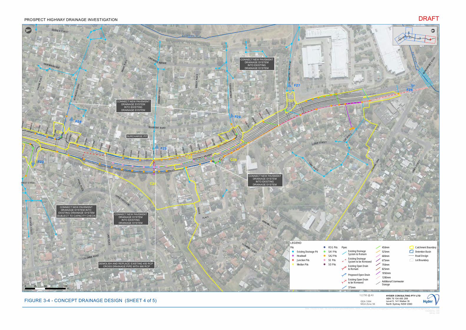
!!
!
!
!
!
!
!
!
!!
!
!
!
!!
!
!
!
!
!
!
!
!!
!!
!!
!!
!!
!
!
!
!!!
!
!
! !
!
!
!
!!!
!
!
!
!!
!!
!
!
!
!
!
!!
!
!
!
!!
!! !! !
!!
!
!!!
!
!
! !
!
!
!
!
!!!
!
!
!
!
!
!
!!
!
!!
!!
!
!!
!!!
!!!
!!
!
!
!
!
!
!
!
!
!
!
!
!!
!
!
!
!!
!
!!
!!
!
!
!
!
!
!
!
!
!
!
!
!
! !
!
!
!
!
!
!
!
!
!
!
!!
!
!
! ! ! !
!
!
!
!
!
!
!
!
! !
!
!
!
!
!
!
!
!
!
! ! ! ! !
!
!
!
!
!
!
!
!
!
!
!
!
!
!
!
!
!
! !
!
!
!
!
!
!
!2760.000
2780.000
2800.000
2820.000
2840.000
2860.000
2880.000
2900.000
2920.000
2940.000
2960.000
2980.000
3000.000
3020.000
3040.000
3060.000
3080.000
3100.000
3120.000
3140.000
3160.000
3180.000
3200.000
3220.000
3240.000
3260.000
3280.000
3300.000
3320.000
3340.000
3360.000
3380.000
3400.000
3420.000
C24
C25
C26 C28
C27
F23
F24
F25
F26
F28F27
!
CONNECT NEW PAVEMENT DRAINAGE SYSTEM INTO
EXISTING DRAINAGE SYSTEM(SUBJECT TO CAPACITY CHECK)
!
DEMOLISH AND REPLACE EXISTING 450 RCP CROSS DRAINAGE PIPE WITH 695 RCP
!
CONNECT NEW PAVEMENT DRAINAGE SYSTEM
INTO EXISTING DRAINAGE SYSTEM
!
CONNECT NEW PAVEMENT DRAINAGE SYSTEM
INTO EXISTING DRAINAGE SYSTEM
! CONNECT NEW PAVEMENT DRAINAGE SYSTEM
INTO EXISTING DRAINAGE SYSTEM
!
CONNECT NEW PAVEMENT DRAINAGE SYSTEM
INTO EXISTING DRAINAGE SYSTEM
!
CONNECT NEW PAVEMENT DRAINAGE SYSTEM
INTO EXISTING DRAINAGE SYSTEM
!
CONNECT NEW PAVEMENT DRAINAGE SYSTEM
INTO EXISTING DRAINAGE SYSTEM
!
SURCHARGE PIT
BLAC KTOWN CREEK
BLACKTOWN CREEK
PROSPECT HIGHWAY
EREST STREET
KEYW
ORT
H D
RIVE
LEAB
ONS LA
NE
CAVENDISH AVENUE
BEAUFORT ROAD
COLUMBIA ROAD
PEARL PLACE
BUNG
ARRIB
EE R
OAD
WINDMILL CLOSE
CATPL
ACE
HADRIAN AVENUE
JADE
PLAC
E
RID
LEY
PLA
CE
TYRO
NE P
LAC
E
YAWL
PLACE
VERMONT CO URT
HAW
KIN
S S
TRE
ET
HERRICK STREET
TUD
OR
AVE
NU
E
SLOOP STREET
VES
UV
IUS
STR
EET
DRAK
E PL
ACE
TOPAZ CRESCENT
STM
AR
TIN
SC
RE
SC
EN
T
RO
GE
R
PLACE
JAM
ES S
TREE
T
1
5
32 4
°
LEGEND
Pits
! Existing Drainage Pit
! Headwall
! Junction Pits
! Median Pits
! RSG Pits
! SA1 Pits
! SA2 Pits
! SE Pits
! SO Pits
Pipes
Existing Drainage System to Remain
Existing Drainage System to be Removed
Existing Open Drainto Remain
Proposed Open Drain
Existing Open Drain to be Removed
375mm
450mm
525mm
600mm
675mm
750mm
825mm
1050mm
1200mm
Additional Stormwater Storage
Catchment Boundary
Detention Basin
Road Design
Lot Boundary
Date: 7/02/2014 Path: \\hc-aus-ns-fs-01\jobs\AA005690\L-GIS\A_Current\B_Maps\DrainageReport\AA005690_DR_F003_PrelimDrainageDesign_r3v1.mxdCreated by : DD
QA by : AW
DRAFT
GDA 1994MGA Zone 56
0 50 10025m
FIGURE 3-4 - CONCEPT DRAINAGE DESIGN (SHEET 4 of 5)HYDER CONSULTING PTY LTDABN 76 104 485 289Level 5, 141 Walker StNorth Sydney NSW 2060
1:2,750 @ A3
PROSPECT HIGHWAY DRAINAGE INVESTIGATION
°
!
!!
!!
!!
!!
!
!
!
!
!!
! !!
!
!
!
!!!
!
!!
!
!!
!
! !
!!!
!
!
!!
!
!
!
!
!
!!!
!
!!! !
! !
!
!
!!
!!
!!
!!!
!
!
!
!
!
!
!
!
!
!
!!
!
!
!!!
!
!
!
!
!
!
!!!
!
!
!
!
!!
!
!
!
!
!
!
!
!!
!!!
!
!
!
!
!
!
!
!
!
!
!!
!
!
!!
!
!!
!!
!!
!
!
!!
!
!
!
!
!
!
!
!!
!!!
!
!!
! !
! !! !!!!
!!!!!
!
!
!
!
!
!
!
!
!
!!
!!!
!!
!!! !! !
!!
!!
!!
!!
!!!
!!
!
!
!
!
!
!
!
!
!!
!
!
!
!
!
!!
!!
!!
!!
! !
!
!
!
!!!
!!
!!
! !
!
!
! !
!
!
!
!!
!!
!
!
!!
!
!!
!
!!
!
!!
!
!
!
!!!
!
!
!
!
!
!
!!
!
!
!
!
!
!
!
!
!
!!
!
!
!!
!
!
!!!
!
!!
!
!
!!
!
!
!! !
!!
! !!
!
!
! ! !!
!!
!
!
!!
! !
!
!
!
!
!
!
!
!!
!
!
!
!
!
!!!
!
!
!
!
!
!
!
!
!
!
!
!
!
!!!
!
!!
!!
!!
!
!
!
!!!
!!
!!!
!!
!
!!
!
!
!
!
!
!
!
!
!!
!
!
!
!
!!
!
!
!
!!
!
!
!
!
!
!
!!!!!
!
!
!
!!
!!
!! ! !
!
!
!!
!
! !
!
!
!
!
!
!
!
!
!!
!!
!
!
!
!
! !
!!
!
!!
!!
!
!!
!
! !
!
!
!! !
!
!
!
!! !
!
!!
!
!
!!!!
!
!
!!
!
!!
!
!!
! !
!
!
!!
!
!
!!
!!! !
!
!!
!
!
!
!!
!!
!
!!
!!
!
!
!!
!
!
!
!
!
!
!!
!!
!
!
!
!
!!
!
!
!
!
!
! !
!
!
!
!
!
!
!
!
!!!!
!
!
!!!
!
!
!
!
!
!!!
!
!!
!!
!!
!!
!!
!
!
!
!
!!
!
!
!!
!!
!
!
!
!! !! !
!!
!!
!!
!!
!!!
!
!!
!
!!!
!!
!
!
!!
!
!
!
!
!!
!!
! !
!
!!!
!!
!
!
!
!
!! !
!
! !
!!
!
!
!!
!!
!
!!
!
!!
!
!
!
!
!
!
!!
!!
!
!
!
!
!!
!
!
!
!
!
!
!!
!
!
!
!!
!
!
!
!!
!!
!!
!
!!
!!!
!
!
!!
!
!
!!
!!
!
!
!
!
!
!
!
!
! !
!!
!
!!
!
!
!
!
!!
!
!!
!
!
!
!
! !
!
!!!
!
! !
!
!
! !! !
!
!
!
2520.000
2540.000
2560.000
2580.000
2600.000
2620.000
2640.000
2660.000
2680.000
2700.000
2720.000
2740.000
C23
F22
EV
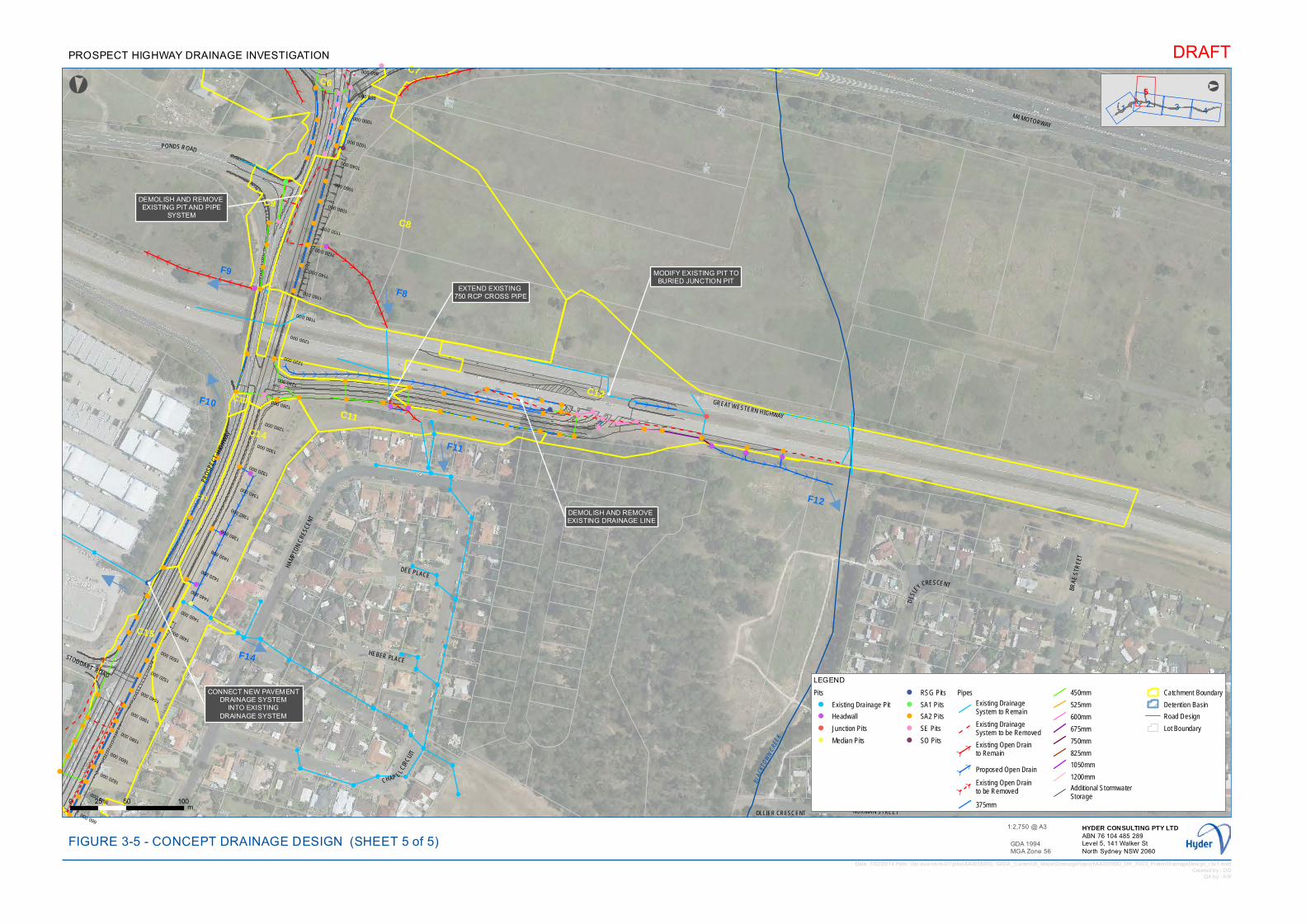
!
!
!
!!
!!
!
!
!
!
!!
!
!
!
!
!
!
!
!
!
!
!
!
!
!
!
!
!
!
! !
!
!
!
!! !
!
!!
!
!
!
!
!
!
!
!
!
!!
!
!
!
!
!
!
!!
!
!
!
!
!
!
!!
!
!
!
!!
!
!
!
!
!
!
!
!
!
!
!
!
!
!
!
!
!!
!
! !!
!!
!
!!
!!
!
! !!
!!
!!
!
!
!
!
!
!
!
!
!
!
!
!
!
!
!
!
!
!
!
!
!
!
!
!
!
!
!
!
!
!
!
!
!
!
!
!
!
!
!
!
!
!
!
!!
!
!
!
!
!
!
!
!!
!!!
!!!!
!
! !!
!! !
!
960.000
980.000
1000.000
1020.000
1040.000
1060.000
1080.000
1100.000
1120.000
1140.000
1160.000
1180.000
1200.000
1220.000
1240.000
1260.000
1280.000
1300.000
1320.000
1340.000
1360.000
1380.000
1400.000
1420.000
1440.000
1460.000
1480.000
1500.000
1520.000
1540.000
1560.000
1580.000
1600.000
1620.000
1640.000
660.000
C8
C7
C9
C12C11
C10
C14
C6
C13
C15
F8
F9
F11
F12
F10
F14
!
DEMOLISH AND REMOVE EXISTING DRAINAGE LINE
!DEMOLISH AND REMOVE EXISTING PIT AND PIPE
SYSTEM
!
CONNECT NEW PAVEMENT DRAINAGE SYSTEM
INTO EXISTING DRAINAGE SYSTEM
!
EXTEND EXISTING 750 RCP CROSS PIPE
!
MODIFY EXISTING PIT TOBURIED JUNCTION PIT
B LAC
KTOW
NCRE
E K
PONDS ROAD
PRO
SPEC
TH
IGH
WAY
GREAT WESTERN HIGHWAY
HAM
PTO
N C
RESC
ENT
NORMAN STREET
STODDART ROAD
DEE PLACE
CHAP ELCI
RCUI
T
BRAE
STR
EET
HEBER PLACE
DES
LEY CRESCENT
ORDE PLACE
M4 MOTORWAY
OLLIER CRESCENT
1 4325
°
LEGEND
Pits
! Existing Drainage Pit
! Headwall
! Junction Pits
! Median Pits
! RSG Pits
! SA1 Pits
! SA2 Pits
! SE Pits
! SO Pits
Pipes
Existing Drainage System to Remain
Existing Drainage System to be Removed
Existing Open Drainto Remain
Proposed Open Drain
Existing Open Drain to be Removed
375mm
450mm
525mm
600mm
675mm
750mm
825mm
1050mm
1200mm
Additional Stormwater Storage
Catchment Boundary
Detention Basin
Road Design
Lot Boundary
Date: 7/02/2014 Path: \\hc-aus-ns-fs-01\jobs\AA005690\L-GIS\A_Current\B_Maps\DrainageReport\AA005690_DR_F003_PrelimDrainageDesign_r3v1.mxdCreated by : DD
QA by : AW
DRAFT
GDA 1994MGA Zone 56
0 50 10025m
FIGURE 3-5 - CONCEPT DRAINAGE DESIGN (SHEET 5 of 5)HYDER CONSULTING PTY LTDABN 76 104 485 289Level 5, 141 Walker StNorth Sydney NSW 2060
1:2,750 @ A3
PROSPECT HIGHWAY DRAINAGE INVESTIGATION
°
!
!
!
!
!
!
!
!
!!
!
!
!
!!
!!
!
!!
!
!
!
!
!
!
!
!
!!
!!
!!
!
!
!
!!!
!
!
!
!
!
!
!
!
!
!
!
!
!
!
!
!
!
!!
!!
!
!
!
!!!
!
!!
!
!
!!
!
!
!
!!
!
!
!
!!
!
!
!
!
!!!!
!!
!
!
!
!
!!
!
!!!
!
!
!
!!
!
!
!
!
!!
!
!
!
!
!!
!!
!
!
!
! !
!
!
!
!
!
!!
!
!
!!
!
!
!!
!!
!!!
!!
!
!!
!
!
!
!!
!
!
!!!
!
!!
!
!
!
!!
!
!
!
!
!
!
!
!
!
!
!
!
!
!!
!
!
!
!!!
! !
!
!
!
!!
!
!
!
!
!
!
!
!
!
!
!
!!
!
!
!!!
!
!
!
!
!
!
!
!
!
!
!
!
!
!!!
!!!
!
!
!
!
!
!
!
!
!
!
!
!
!
!
!
!
!
!!
!
!
!
!
!
!!
!!
!
!
!!
!
!
!!
!
!
!!
!
!
!
!
!!
!
!
!
!!
!
!
!
!
!
!
!!
!! !!
!!!!!
!!
!
!
!
!
!
!
!
!
!!!!
!!
!!
!
!!!
!!
!!
!
!
!!
!!!
!
!
!
!
!
!
!
!
!
!
!
!
!
!
!
!
!
!
!!
!!!
!
!
!
!
!
!
!
!!!! !
!
!
!
!
!
!
!
!
!
!
!
!!
!
!!
!
!!
!
! !
!
!!
!
! !
!
!
!
!!
!
!
!
!
!
!
!
!
!!!
!
!
!
!
!
!
!
!
!
!
!
!!
!
!
!!
!
!
!!
!
!
!!
!
!
!
!
!
!
!
!
!!
!
!!
!
!!
!
!
!
! !!
!
!
!
!
!
!
!
!
!
!
!
!
!
!
!
!
!
!!!
!
!
!
!
!
!
!
!
!
!
!
!
!!!
!
!
!
!
!
!!
!
!
!
!
!
!
! !
!
!
!!
!
!
!
!
!
!
!
!
!
!
!
!
!
!
!
!
!
!
!
!
!
!!
!
!
!
!
!
!
!
!
!!!
!!
!
!
!
!
!
!!
!
!
!
!
!
!
!!
!
!
!
!
!! !
!
!
!
!
!
!
!!
!
!
!
!
!
!
!
!
!
!
!
!!
!
!
!!
!
!
!
!
!
!
!
!
!
!
!!
!
!
!!
!
!
!
! !!!
!
! !
!
!
!
!
!!
!
!
!
!
!!
!
!
!
!!
!!
!
!
!!
!
!
!
!!
!
!
!
!!
!!
!
!
!! !
!
!
!
!
!
!
!
!! !
!
!
!
!!
!
!
!!
!
!
!
!
!
!
!
!
!
!
!
!
!
!
!
!!
!
!
!
!
!
!
!
!
!
!
!
!
!!
!
!!!
!
!
!!
!!
!
!
!
!!
!
!
!
!
!!
!
!
!!
! ! !!
! !
!
!
!
! !
!!
!
!
!
!
!
!
!
!
!
!
!!
!
!
!
!
!
!!
!
!
!
!!
!!!
!
!
!
!
!
!
! !!
!
!
!
!!
!
!
!
!
!
!
!
!
!
!
!
!
!
!
!
!!
!
!!
!
!
!
!
!
!
!
!
!
!
!
!
!
! !!
!
!
!
!
!
!
!
!!
!
!
!
820.000
840.000
860.000
880.000
900.000
920.000
940.000
1
1680.000
1700.000
1720.000
F7F7
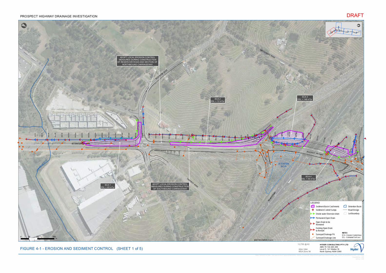
GG
GGGGG
G
GG
GG
GGG
G
G
G G
G G G
GGGG
GG
GG
GG
GGG
G
G G G
GG
G
G G
GG
GGGGGGGGGGGGG
GGG
GGGG G
G
GGGGGGG
G G G G
GG
G
G
G
G
G
G
G
G
Ç
Ç
Ç
Ç
!!
!
!!
!
!
!
!
!
!
!!!
!
!!!! !
!
!
!
! !
!
!
!
!
!
!
!
!
!
!
!
!
!
!
!!
!
!!
!
!
!
!
!
!
!!!
!
!!!! !
!
!
!
! !
!
!
!
!
!
!
!
!
!
!
!
!
!
!
!
!!
!
!!
!
!
!
!
!
!
!!!
!
!
!!!! !
!
!
!
!
!
!
!
!
!!
!
!
!
!
!
!
!
!
!
!
!
!
!
!
!
!
!
!
!
!
!
!
!
!
!
!
!
!
!
!
!
!!
!!!
!
!
!
!
!
!
!
!
!
!
!!
!
!! !
!
GGGG
G
GGGGGGGG G
GGG
GG
GG
G
GG
G
G
G
G
G
G
G G G
G
G
G
G
GG
GGGGGGG
GG
G
G
G G G G
G
G
G
G
G
Ç
Ç
ÇÇÇÇÇÇÇ0.0
00
20.000
40.000
60.000
80.000
100.000
120.000
140.000
160.000
180.000
200.000
220.000
240.000
260.000
280.000
300.000
320.000
340.000
360.000
380.000
400.000
420.000
440.000
460.000
480.000
500.000
520.000
540.000
560.000
580.000
600.000
620.000
640.000
660.000
680.000
700.000
720.000
740.000
760.000
780.000
800.000
820.000
840.000
860.000
880.000
900.000
920.000
940.000 960.000 980.000
!
ECA 1ESL = 49 m3/yr
!
ADOPT LOCAL EROSION CONTROLMEASURES DURING CONSTRUCTION
OF RESERVOIR ROAD AND SECTION OF NORTHBOUND CARRIAGEWAY
!
ADOPT LOCAL EROSION CONTROLMEASURES DURING CONSTRUCTION
OF SOUTHBOUND CARRIAGEWAY
!
ECA 2ESL = 12 m3/yr
!
ADOPT LOCAL EROSION CONTROLMEASURES DURING CONSTRUCTION
OF RESERVOIR ROAD AND SECTION OF NORTHBOUND CARRIAGEWAY
!
ECA 3ESL = 148 m3/yr
!
ECA 4ESL = 46 m3/yr
GIRRAW
EEN CREEK
PROSPECT HIGHWAY
RESERVOIRROAD
PON
DS
RO
AD
WATCH HOUSE ROAD
THORNLEY ROAD
RECONCILIATION ROAD
M4 M
OTORW
AY
BARTHOLOMEWS PLACE
DETENTIONBASIN
24
5
31
°
LEGEND
Sediment Basin Catchments
Sediment Control Sumps
G G Onsite water Diversion drain
G G Permanent Open Drain
G GOpen Drain to be Removed
G GExisting Open Drainto Remain
! Surveyed Drainage Pit
Surveyed Drainage Line
Detention Basin
Road Design
Lot Boundary
Date: 6/02/2014 Path: \\hc-aus-ns-fs-01\jobs\AA005690\L-GIS\A_Current\B_Maps\DrainageReport\AA005690_DR_F004_ErosionSedControl_r3v1.mxdCreated by : DD
QA by : AW
DRAFT
GDA 1994MGA Zone 56
0 50 10025m
FIGURE 4-1 - EROSION AND SEDIMENT CONTROLHYDER CONSULTING PTY LTDABN 76 104 485 289Level 5, 141 Walker StNorth Sydney NSW 2060
1:2,750 @ A3
PROSPECT HIGHWAY DRAINAGE INVESTIGATION
°
(SHEET 1 of 5)
NOTESECA - Erosion Control AreaESL - Estimated Soil Loss
G
G
G
G
G
G
GG
G
G
G
G
G
GG
G
G
G
G
!! !
!
!
!
!!
!!
!
!
!
!
!!
!!
!
!
!
!
!
!
!
!
!
!
!
!
!
!
!
!
!! !
!
!
!
!!
!!
!
!
!
!
!!
!!
!
!
!
!
!
!
!
!
!
!
!
!
!
!
!
!
!! !
!
!
!
!
!!
!!
!
!
!!
!!
!
!!
! !
!
!
!
!
!!
!
!
!
!
!
!
!!
!
!
!
!
!
!
!
!!
!
!
!
!
!
!
!
!
G
GG
GG
G
G
G
G
G
GG
G
G
G
G
G
G
G
G
G
G
G
G
G
G
G
G
G
G
G
G
1000.000 1020.000 1040.000 1060.000 1080.000 1100.000 1120.000 1140.000 1160.000 1180.000 1200.000 1220.000 1240.000 1260.000 1280.000 1300.000
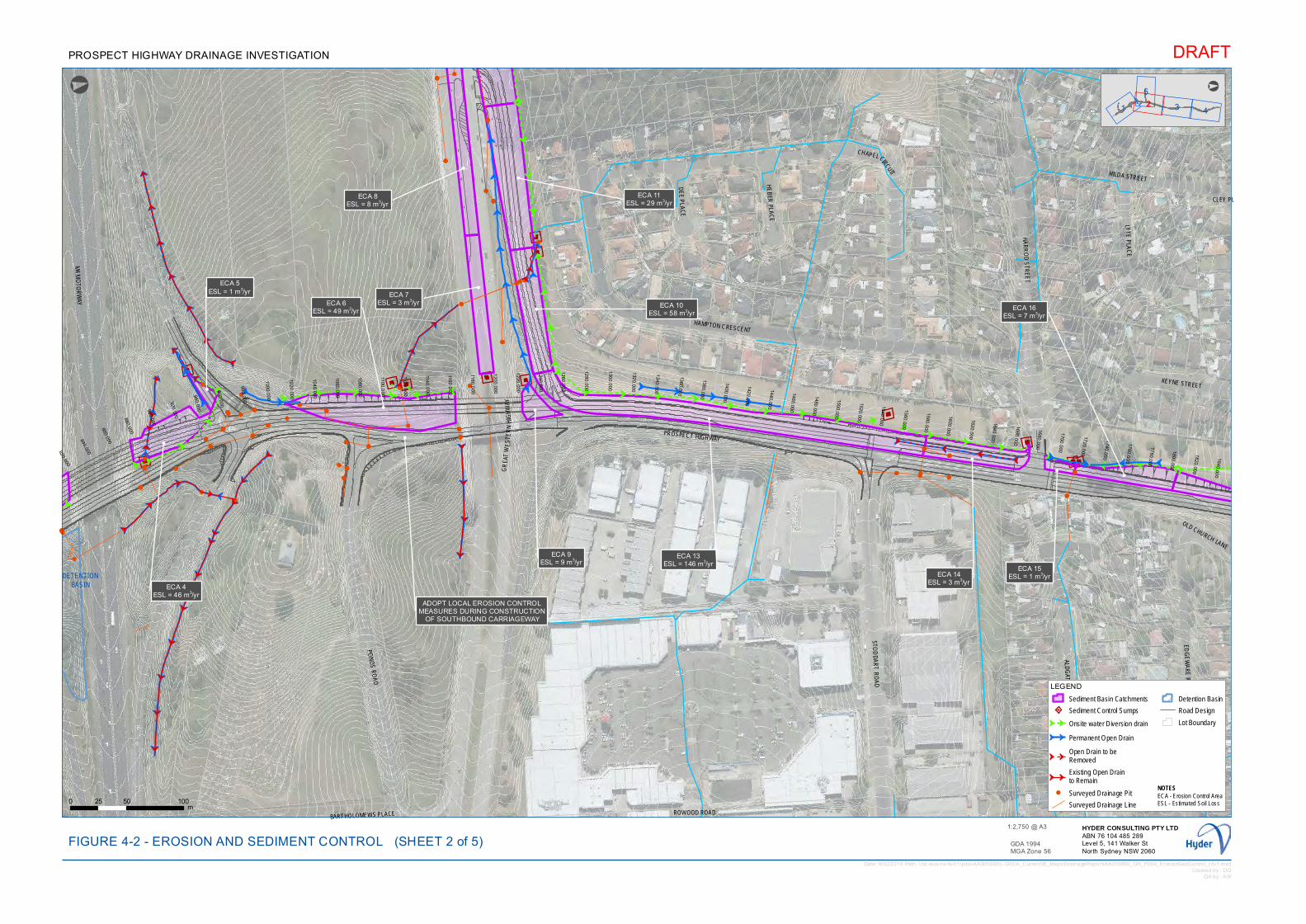
GG
G
G
G G G GG
G GG G
GG
G
GG G G
G
G
G
GGG
G G
G
GG
GG
GG
GG
G
G
G
G
G
G
G
G
G
GG
G
G
G
G
GG
GG
G
G
G
GG
GG
G
G
G
G
GG
GG
G
G
G
G
G
GG
GGGG
GG
!
!
!
!!
!
!
!
!
!
!
!!
!
!!
!
!
!
!
!
!
!
!
!
!!
!
!
!
!
!!
!
!
!
!
!
!
!!
!
!!
!
!
!
!
!
!
!
!
!
!!
!
!
!
!
!
!
!
!!
!
!
!
!
!
!
!
!!
!
!
!!!
!
!
!
!
!
!
! !
!
!
!
!
!
!
!
!
!
!!
!
!
!
!
!
!
!
!
!
!
! !! !
!
!!!
!
!
!
G
G
G
GG
GG
G
GG
GG
GG
GG
G
G
G
GG
GG
G
G
G
GG
G
G
G
G
G
G
G
G
G
G
G
GG
G
G
G
G
GG
GG
GG
GG
GG
GG
GG
G
820.000
840.000
860.000
880.000
900.000
920.000
940.000
960.000
980.000
1000.000
1020.000
1040.000
1060.000
1080.000
1100.0
00
1120.0
00
1140.0
00
1160.0
00
1180.0
00
1200.000
1220.000
1240.000
1260.000
1280.000
1300.000
1320.000
1340.000
1360.000
1380.000
1400.000
1420.000
1440.000
1460.000
1480.000
1500.000
1520.000
1540.000
1560.000
1580.000
1600.000
1620.000
1640.000
1660.000
1680.000
1700.000
1720.000
1740.000
1760.000
1780.000
1800.000
1820.000
1840.000
!
ECA 8ESL = 8 m3/yr
!
ECA 5ESL = 1 m3/yr
!
ECA 4ESL = 46 m3/yr
!
ADOPT LOCAL EROSION CONTROLMEASURES DURING CONSTRUCTION
OF SOUTHBOUND CARRIAGEWAY
!
ECA 7ESL = 3 m3/yr
!
ECA 11ESL = 29 m3/yr
! ECA 10ESL = 58 m3/yr
!
ECA 9ESL = 9 m3/yr
!
ECA 13ESL = 146 m3/yr
!
ECA 14ESL = 3 m3/yr
!
ECA 15ESL = 1 m3/yr
!
ECA 16ESL = 7 m3/yr
!
ECA 6ESL = 49 m3/yr
CLEY PL
ROWOOD ROAD
HILDA STREET
PROSPECT HIGHWAY
HAMPTON CRESCENT
GR
EAT
WE
ST E
RN
HIG
HW
AY
OLD CHURCH LANE
DE
E P
LAC
E
BARTHOLOMEWS PLACE
CHAPEL CIRCUIT
HE
BER
PLAC
E
KEYNE STREET
L YTE
PLA
CE
NORMAN STREET
EDG
EW
AR
E R
OA
D
M4 M
OTO
RW
AY
PON
DS ROAD
HA
RR
OD
STR
EE
T
ALDG
ATE
STR
EET
STOD
DA
RT R
OA
D
DETENTIONBASIN
1 4
5
32
°
LEGEND
Sediment Basin Catchments
Sediment Control Sumps
G G Onsite water Diversion drain
G G Permanent Open Drain
G GOpen Drain to be Removed
G GExisting Open Drainto Remain
! Surveyed Drainage Pit
Surveyed Drainage Line
Detention Basin
Road Design
Lot Boundary
Date: 6/02/2014 Path: \\hc-aus-ns-fs-01\jobs\AA005690\L-GIS\A_Current\B_Maps\DrainageReport\AA005690_DR_F004_ErosionSedControl_r3v1.mxdCreated by : DD
QA by : AW
DRAFT
GDA 1994MGA Zone 56
0 50 10025m
FIGURE 4-2 - EROSION AND SEDIMENT CONTROLHYDER CONSULTING PTY LTDABN 76 104 485 289Level 5, 141 Walker StNorth Sydney NSW 2060
1:2,750 @ A3
PROSPECT HIGHWAY DRAINAGE INVESTIGATION
°
(SHEET 2 of 5)
NOTESECA - Erosion Control AreaESL - Estimated Soil Loss
GG
G
G
G
G
G
GG
G G
G
G
G
GG
G
G
G
GG
GG
GG
G
G
G
G
G
G
G
G
G
G
G
G
G
G
G
G
G
G
GG
G
Ç
Ç
ÇÇ
!
!
!
!!
!!
!!
!
!
!
!
!
!
!
!
!
!
!
!!
!!
!!
!
!
!
!
!
!
!
!
!
!!!!
!
!!!
!
! !
!
!
!
!
!
!!
!
!!
!
! !
!!
!
!
!!
!
!
!
!
!
!
!
!
!
!
!
!
!
!
!
!
!
!
!
GGG
G G
G
G
G
G
G
G
G
G
G
GG
G
G
GG
GG
GG
G
G
G
GG
ÇÇ
Ç
Ç
Ç
Ç
Ç
Ç
Ç
560.000580.000
600.000
620.000
640.000
660.000
680.000
700.000
720.000740.000
760.000
780.000
800.000
1860.000
1880.000
1900.000
1920.000
1940.000
1960.000
1980.000
2000.000
2020.000
2040.000
2060.000
2080.000
2100.000
ACE

G G
G
GG
GGG
GGG
G G G
G
GG
!
!
!
!
!
!
!!
!
!
!
!
!
!
!
!
!
!
!
!!
!
!
!
!
!
!
!
!
!
!!
!!
!!
!
!
!
!!!!
!
!!!
!
!!!
!
!
!
!!
!
!
GGG
G G
GG
GG
1740.000
1760.000
1780.000
1800.000
1820.000
1840.000
1860.000
1880.000
1900.000
1920.000
1940.000
1960.000
1980.000
2000.000
2020.000
2040.000
2060.000
2080.000
2100.000
2120.000
2140.000
2160.000
2180.000
2200.000
2220.000
2240.000
2260.000
2280.000
2300.000
2320.000
2340.000
2360.000
2380.000
2400.000
2420.000
2440.000
2460.000
2480.000
2500.000
2520.000
2540.000
2560.000
2580.000
2600.000
2620.000
2640.000
2660.000
2680.000
2700.000
2720.000
2740.000
2760.000
2780.000
!
ADOPT LOCAL EROSION CONTROLMEASURES DURING CONSTRUCTION
OF SOUTHBOUND CARRIAGEWAY
!
ECA 16ESL = 7 m3/yr
!
ECA 17ESL = 40 m3/yr
!
ECA 18ESL = 21 m3/yr
!
ECA 19ESL = 101 m3/yr
!ADOPT LOCAL EROSION
CONTROL MEASURES DURING CONSTRUCTION OF PROPOSAL NORTH OF LANCELOT STREET
MY
RTLE
STR
EE
T
COLUMBIA ROAD
KEYNE STREETSHER PLACE
HILD
A STR
EET
CLEY P
LACE
JEM PLACE
LAN
CE
LOT S
TRE
ET
OLD CHURCH LANE
DINTON STREET
SIER
RA P
LAC
E
HOLLYDALE PLACE
HERRICK STREET
CASCADESTR
EET
LORN
EST
REE
T
FOSS
STR
EE T
NORMAN STREET
EIGER STR
EET
FIFE STREET
EVEREST STREET
LYT E
PL AC
E
DANBY STREET
CA
NN
ON
STR
EE
T
ERITH STREET
HADRIAN AVENUE
BRO
AD
STR
EE
T
PROSPE CT HIGHWAY
EDG
EW
AR
E R
OA
D
OZARK STREET
GROVE
PLA
CE
ELTH
AM S
TREE
T
VES
UV
IUS
STR
EET
HIMALAYA CRESCENT
PELLEA
S S
TRE
ET
KISDON CRESCENT
VIEW PARK STREET
DETENTIONBASIN
DETENTIONBASIN
DETENTIONBASIN
1 4
52 3
°
LEGEND
Sediment Basin Catchments
Sediment Control Sumps
G G Onsite water Diversion drain
G G Permanent Open Drain
G GOpen Drain to be Removed
G GExisting Open Drainto Remain
! Surveyed Drainage Pit
Surveyed Drainage Line
Detention Basin
Road Design
Lot Boundary
Date: 6/02/2014 Path: \\hc-aus-ns-fs-01\jobs\AA005690\L-GIS\A_Current\B_Maps\DrainageReport\AA005690_DR_F004_ErosionSedControl_r3v1.mxdCreated by : DD
QA by : AW
DRAFT
GDA 1994MGA Zone 56
0 50 10025m
FIGURE 4-3 - EROSION AND SEDIMENT CONTROLHYDER CONSULTING PTY LTDABN 76 104 485 289Level 5, 141 Walker StNorth Sydney NSW 2060
1:2,750 @ A3
PROSPECT HIGHWAY DRAINAGE INVESTIGATION
°
(SHEET 3 of 5)
NOTESECA - Erosion Control AreaESL - Estimated Soil Loss
G
GG
G GG
GG
!
!
!
!
!
!
!
!
!
!
!
!
!
!!
!!!
!
!
!
! !! !
!
GG
GG
GG
1460.000
1480.000
1500.000
1520.000
1540.000
1560.000
1580.000
1600.000
1620.000
1640.000
1660.000
1680.000
1700.000
1720.000
2800.000
2820.000
2840.000
2860.000
2880.000
2900.000
2920.000
2940.000
2960.000
2980.000
3000.000
3020.000
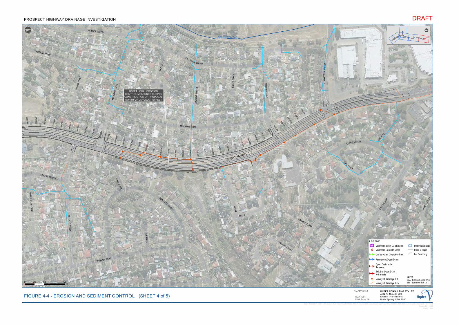
!
!
!
!
!
!
!
!
!!
!
!
!
!
!
!
!
!
!
!
!!
!
!
!
!!
!
!
!
! !
!
!
!
!
!
!!!
!
!
!!
! !
2680.000
2700.000
2720.000
2740.000
2760.000
2780.000
2800.000
2820.000
2840.000
2860.000
2880.000
2900.000
2920.000
2940.000
2960.000
2980.000
3000.000
3020.000
3040.000
3060.000
3080.000
3100.000
3120.000
3140.000
3160.000
3180.000
3200.000
3220.000
3240.000
3260.000
3280.000
3300.000
3320.000
3340.000
3360.000
3380.000
3400.000
3420.000
!
ADOPT LOCAL EROSION CONTROL MEASURES DURING CONSTRUCTION OF PROPOSAL NORTH OF LANCELOT STREET
BLACKTOWN CREEK
PROSPECT HIGHWAY
KEYW
ORT
H D
RIVE
CAVENDISH AVENUE
BEAUFORT ROAD
LEAB
ONS LA
NE
EVEREST STREET PEARL PLACE
WINDMILL CLOSE
COLUMBIA ROAD
CATPLA
CE
JADE
PLAC
E
RID
LEY
PLA
CE
HADRIAN AVENUE
TYRO
NE P
LAC
E
YAWL
PLACE
VERMONT COURT
HAW
KIN
S S
TRE
ET
HERRICK STREET
HIM
ALAYA C
RE
SC
EN
T
TUD
OR
AVE
NU
E
SLOOP STREET
JAM
ES S
TREE
T
VES
UV
IUS
STR
EET
DRAK
E PL
ACE
TOPAZ CRESCENT
ST
MA
RTI
NS
CR
ES
CEN
T
RO
GER
PLACE
1
5
32 4
°
LEGEND
Sediment Basin Catchments
Sediment Control Sumps
G G Onsite water Diversion drain
G G Permanent Open Drain
G GOpen Drain to be Removed
G GExisting Open Drainto Remain
! Surveyed Drainage Pit
Surveyed Drainage Line
Detention Basin
Road Design
Lot Boundary
Date: 6/02/2014 Path: \\hc-aus-ns-fs-01\jobs\AA005690\L-GIS\A_Current\B_Maps\DrainageReport\AA005690_DR_F004_ErosionSedControl_r3v1.mxdCreated by : DD
QA by : AW
DRAFT
GDA 1994MGA Zone 56
0 50 10025m
FIGURE 4-4 - EROSION AND SEDIMENT CONTROLHYDER CONSULTING PTY LTDABN 76 104 485 289Level 5, 141 Walker StNorth Sydney NSW 2060
1:2,750 @ A3
PROSPECT HIGHWAY DRAINAGE INVESTIGATION
°
(SHEET 4 of 5)
NOTESECA - Erosion Control AreaESL - Estimated Soil Loss
!
!
!
!
!
!
!
!
!!!
!!
!
2420.000
2440.000
2460.000
2480.000
2500.000
2520.000
2540.000
2560.000
2580.000
2600.000
2620.000
2640.000
2660.000

GG
G
G
G
G
G
G
G
G
G
G
G
G
G
GG
G
G
GG
GG
GG
GG
GG
GG
G
GG
GG
G
G
G
G
GG
G G G
G
G
G
G
G
G
G
G
G
G
GG
G
G
!
!
!
!
!
!
!
!
!
!!
!!!
!
!
!
!
!
!
!
!
!
!
!
!
!!
!
!
!
!
!
!
!
!
!
!
!!
!!!
!
!
!
!
!
!
!
!
!
!
!
!
!!
!
!
!
!
!
!
!
!
!
!
!
!
!
!!
!
!!
!!!
!
!
!
!
!
!
!
!
!
!
!
!
! !
!
!
!!
!
!
!! !
!
!!
!
!
!!
!
!!
!
!
!
G
G
G
G
G
G
G
G
G
G
G
G
G
G
G
GG
G G
G
G
G
G
G
G
G
G
G
G
G G GG
GG
G
G
GG
G
GG
960.000
980.000
1000.000
1020.000
1040.000
1060.000
1080.000
1100.000
1120.000
1140.000
1160.000
1180.000
1200.000
1220.000
1240.000
1260.000
1280.000
1300.000
1320.000
1340.000
1360.000
1380.000
1400.000
1420.000
1440.000
1460.000
1480.000
1500.000
1520.000
1540.000
1560.000
1580.000
1600.000
1620.000
1640.000
660.000
!
ECA 12ESL = 63 m3/yr
!
ECA 8ESL = 8 m3/yr
!
ECA 7ESL = 3 m3/yr
!ECA 11
ESL = 29 m3/yr
!
ECA 10ESL = 58 m3/yr
!
ECA 6ESL = 49 m3/yr
!
ECA 13ESL = 146 m3/yr
!
ECA 9ESL = 9 m3/yr
B LAC
KTOW
NCRE
E K
PONDS ROAD
PRO
SPEC
T HI
GH
WAY
GREAT WESTERN HIGHWAY
HAM
PTO
N C
RESC
ENT
NORMAN STREET
STODDART ROAD
DEE PLACE
CHAP ELCI
RCUI
T
BRAE
STR
EET
HEBER PLACE
DES
LEY CRESCENT
ORDE PLACE
M4 MOTORWAY
OLLIER CRESCENT
1 4325
°
LEGEND
Sediment Basin Catchments
Sediment Control Sumps
G G Onsite water Diversion drain
G G Permanent Open Drain
G GOpen Drain to be Removed
G GExisting Open Drainto Remain
! Surveyed Drainage Pit
Surveyed Drainage Line
Detention Basin
Road Design
Lot Boundary
Date: 6/02/2014 Path: \\hc-aus-ns-fs-01\jobs\AA005690\L-GIS\A_Current\B_Maps\DrainageReport\AA005690_DR_F004_ErosionSedControl_r3v1.mxdCreated by : DD
QA by : AW
DRAFT
GDA 1994MGA Zone 56
0 50 10025m
FIGURE 4-5 - EROSION AND SEDIMENT CONTROLHYDER CONSULTING PTY LTDABN 76 104 485 289Level 5, 141 Walker StNorth Sydney NSW 2060
1:2,750 @ A3
PROSPECT HIGHWAY DRAINAGE INVESTIGATION
°
(SHEET 5 of 5)
NOTESECA - Erosion Control AreaESL - Estimated Soil Loss
G
GG
GG
G
G
GGG
G
G
G
G
G G
G
G
G
G
G
G
G
G
G
G
G
!
!
!
!
!
!
!
!
!
!
!
!
!
!
!
!
! !
!!
!
!
!
!
!
!
!
G
G
G
G
G
G
GG
G
G
G
G
G
G
G
GG
G
G
G
G
G
G
G
G
G
G
G
G
G G
G
GG
G
G
780.000
800.000
820.000
840.000
860.000
880.000
900.000
920.000
940.000
1
1680.000
1700.000
1720.000
1740.000
1760.000


APPENDIX B
CONCEPT DRAINAGE LAYOUT ANDLONGITUDINAL SECTIONS

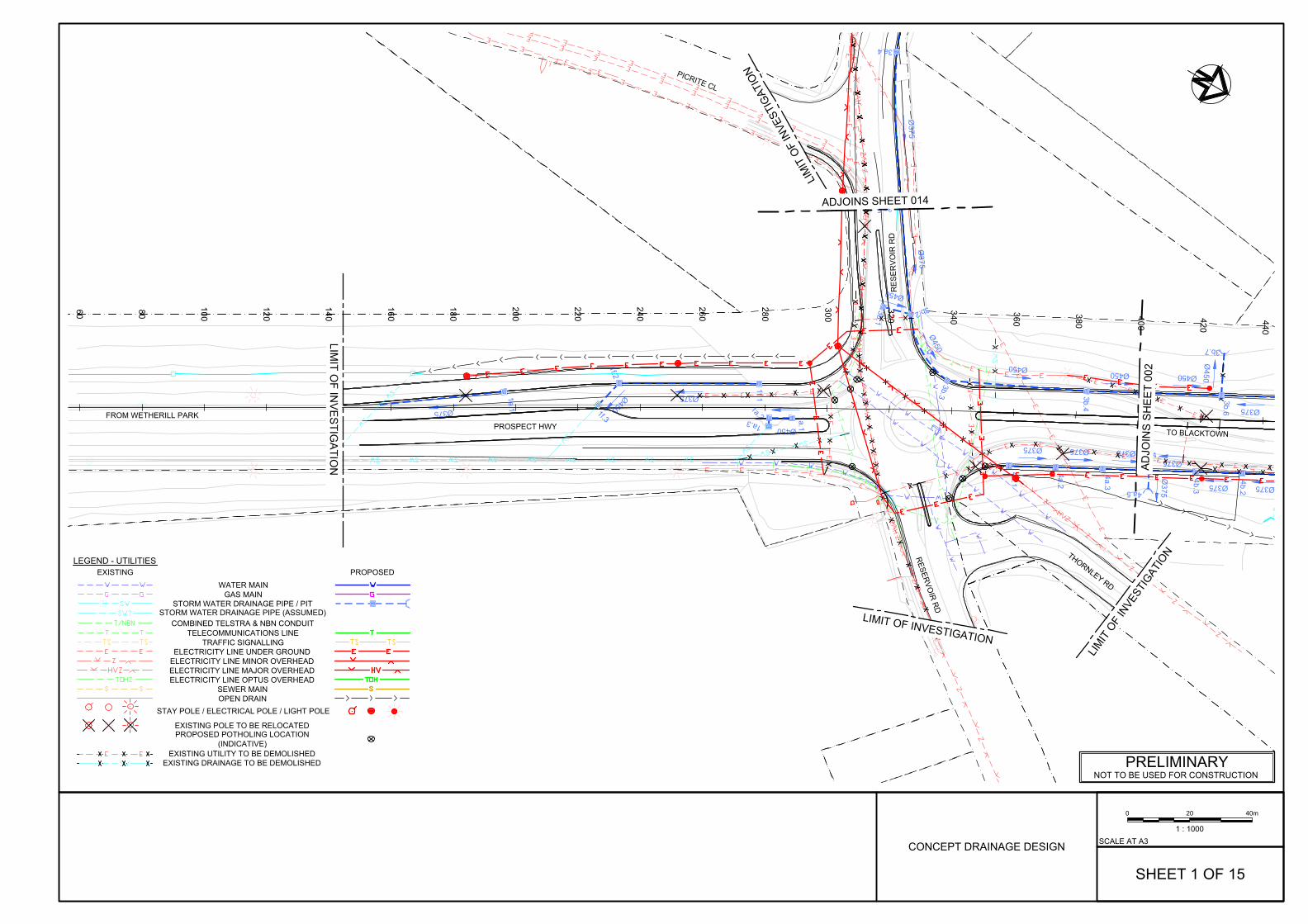
380
400
420
440
100
120
140
160
180
200
220
240
260
280
300
320
340
360
60 80
1a.1
1a.2
1a.3
1e.1
1f.1
1f.2
1f.3
4a.1
4a.2
4a.3
4a.4
4a.5
4b.2
4b.3
Ø450
Ø375
Ø375Ø450
Ø375 Ø375 Ø375
Ø375
Ø375Ø375
Ø375
Ø375
Ø375
3a.4
3a.5
Ø375
Ø450
Ø450
Ø450Ø450 Ø450
Ø450
3b.1
3b.2
3b.3 3b.4
3b.5
3b.6
3b.7
LIMIT O
F INV
ES
TIGA
TION
LIMIT OF INVESTIGATION
LIM
IT O
F IN
VEST
IGAT
ION
LIM
IT O
F IN
VEST
IGAT
ION
RE
SE
RV
OIR
RD
PROSPECT HWY
RESER
VOIR
RD
PICRITE CL
THORNLEY RD
FROM WETHERILL PARK
TO BLACKTOWN
AD
JOIN
S S
HE
ET
002
ADJOINS SHEET 014
STORM WATER DRAINAGE PIPE / PIT
WATER MAINGAS MAIN
TELECOMMUNICATIONS LINE
ELECTRICITY LINE UNDER GROUND
LEGEND - UTILITIESEXISTING
STAY POLE / ELECTRICAL POLE / LIGHT POLE
ELECTRICITY LINE MINOR OVERHEADELECTRICITY LINE MAJOR OVERHEADELECTRICITY LINE OPTUS OVERHEAD
PROPOSED
SEWER MAIN
EXISTING UTILITY TO BE DEMOLISHED
OPEN DRAIN
TRAFFIC SIGNALLING
STORM WATER DRAINAGE PIPE (ASSUMED)
EXISTING POLE TO BE RELOCATED
EXISTING DRAINAGE TO BE DEMOLISHED
COMBINED TELSTRA & NBN CONDUIT
PROPOSED POTHOLING LOCATION(INDICATIVE)
40m200
1 : 1000
SHEET 1 OF 15
CONCEPT DRAINAGE DESIGN
PRELIMINARYNOT TO BE USED FOR CONSTRUCTION
SCALE AT A3

3e.1
3e.2
3e.3
3e.4
3e.5
3e.6
3e.7
3e.8
3f.13f.2
3g.5
3g.6
3g.7
3h.1
3i.4
3i.53i.6
3z.1
3z.2
4a.1
4a.2
4a.3
4a.4
4a.5
4b.1
4b.2
4b.3
4c.1
4c.2
4c.3
4c.4
4c.5
4c.6
4c.7
4c.8
Ø450Ø450
Ø450Ø450Ø450Ø450
Ø450
Ø375
Ø450
Ø375
Ø450
Ø450Ø375
Ø375Ø375
Ø450
Ø450
Ø375 Ø375 Ø375
Ø375 Ø375Ø375
Ø375
Ø450Ø450Ø450Ø450Ø450Ø450Ø450
Ø375 3d.1
Ø450Ø450 Ø450
Ø450
3b.4
3b.5
3b.6
3b.7
700
720
740
380
400
420
440
460
480
500
520
540
560
580
600
620
640
660
680
360
LIMIT
OF
INVE
STIG
ATIO
N
LIMIT OF INVESTIGATION
LIMIT OF INVESTIGATION
PROSPECT HWY
M4 W/B ENTRY R
AMP
M4 W
/B EXIT RAM
P
THORNLEY RD
TO BLACKTOWN
FROM WETHERILL PARK
AD
JOIN
S S
HE
ET 001 AD
JOIN
S SH
EET
003
REMOVE EXISTING 375 DIAMETER PIPEAND RECONSTRUCT NEW 450DIAMETER PIPE NETWORK
STORM WATER DRAINAGE PIPE / PIT
WATER MAINGAS MAIN
TELECOMMUNICATIONS LINE
ELECTRICITY LINE UNDER GROUND
LEGEND - UTILITIESEXISTING
STAY POLE / ELECTRICAL POLE / LIGHT POLE
ELECTRICITY LINE MINOR OVERHEADELECTRICITY LINE MAJOR OVERHEADELECTRICITY LINE OPTUS OVERHEAD
PROPOSED
SEWER MAIN
EXISTING UTILITY TO BE DEMOLISHED
OPEN DRAIN
TRAFFIC SIGNALLING
STORM WATER DRAINAGE PIPE (ASSUMED)
EXISTING POLE TO BE RELOCATED
EXISTING DRAINAGE TO BE DEMOLISHED
COMBINED TELSTRA & NBN CONDUIT
PROPOSED POTHOLING LOCATION(INDICATIVE)
40m200
1 : 1000
SHEET 2 OF 15
PRELIMINARYNOT TO BE USED FOR CONSTRUCTION
SCALE AT A3CONCEPT DRAINAGE DESIGN

3e.1
3e.23f.1
3g.1
3g.23g.3
3g.4
3g.5
3g.6
3g.7
3h.1
3i.13i.23i.33i.4
3i.5
3i.6
3z.1
3z.2
6c.16c.2
6c.3
6c.4
6c.5
6c.6
6d.1
6e.1
6e.2
6e.3
6e.4
6e.5
6e.6
6e.7
6f.1
6f.2
6f.3
6f.4
6g.16h.1
6h.2
6h.3
6h.4
6h.56k.1
6k.2
6k.3
6k.4
6k.5
.1
Ø450
Ø
Ø375
Ø375
Ø375
Ø375Ø450
Ø450 Ø375
Ø375Ø375
Ø375Ø375Ø375
Ø450
Ø450
Ø450
Ø450Ø450
Ø450Ø450
Ø375
Ø375
Ø375
Ø375
Ø450
Ø450
Ø375
Ø375
Ø375
Ø375Ø450
Ø375Ø375
Ø375
Ø450Ø450
Ø375
Ø375Ø375
Ø375
Ø375
6y.1
6y.2
6y.3
700
720
740
760
780
800
820
840
680
860
880 900 920 940
960
980
1000
1020
1040
LIMIT OF INVESTIGATION
LIMIT OF INVESTIGATION
LIMIT OF INVESTIGATION
LIMIT OF INVESTIGATION
LIMIT OF INVESTIG
M4
W/B
ENT
RY R
AMP
PROSPECT HWY
M4
MO
TOR
WAY
WES
TBO
UN
DM
4 M
OTO
RW
AY E
ASTB
OU
ND
M4 W
/B EXIT RAMP
M4 E/B ENTRY RAMP
M4
E/B
EX
IT R
AM
P
POND
S RD
FRO
M P
ENRI
TH
TO S
YDNE
Y
FROM WETHERILL PARK
TO BLACKTOWN
ADJO
INS SH
EET 002 ADJO
INS
SHEE
T 00
4
DEPRESSED MEDIANINLET PIT
PIT IS LOCATED TO SATISFY 500mmCLEARANCE FROM THE PROPOSEDELECTRICAL CONDUIT
STORM WATER DRAINAGE PIPE / PIT
WATER MAINGAS MAIN
TELECOMMUNICATIONS LINE
ELECTRICITY LINE UNDER GROUND
LEGEND - UTILITIESEXISTING
STAY POLE / ELECTRICAL POLE / LIGHT POLE
ELECTRICITY LINE MINOR OVERHEADELECTRICITY LINE MAJOR OVERHEADELECTRICITY LINE OPTUS OVERHEAD
PROPOSED
SEWER MAIN
EXISTING UTILITY TO BE DEMOLISHED
OPEN DRAIN
TRAFFIC SIGNALLING
STORM WATER DRAINAGE PIPE (ASSUMED)
EXISTING POLE TO BE RELOCATED
EXISTING DRAINAGE TO BE DEMOLISHED
COMBINED TELSTRA & NBN CONDUIT
PROPOSED POTHOLING LOCATION(INDICATIVE)
40m200
1 : 1000
SHEET 3 OF 15
PRELIMINARYNOT TO BE USED FOR CONSTRUCTION
SCALE AT A3CONCEPT DRAINAGE DESIGN

FRO
M PEN
RITH
2
6e.1
6e.2
6e.3
6e.4
6f.1
6f.2
6f.3
6f.4
6g.1
6h.1
6h.2
6h.3
6h.4
6h.5 8h.1
8h.2
8h.3
8i.1
8i.2
8j.1
9a.1
9a.2
9a.3
9b.1
9b.2
9b.3
9b.4
13a.1
14a.1
14a.2
Ø375Ø375Ø375
Ø450
Ø375Ø375Ø375Ø375
Ø450
Ø375
Ø375Ø375
Ø450
Ø450
Ø375 Ø375 Ø375
Ø375 Ø375
Ø450
Ø450 Ø450
Ø450Ø450 Ø
450
Ø375
Ø375
Ø450
Ø450
Ø450
Ø450
Ø450
Ø525
Ø525
11a.1
11a.2
11a.3
11a.4
11a.5
11a.6
11a.7
11a.811a.9
Ø450
Ø450
11b.111b.2
Ø450
11c.1
Ø450
11d.1 Ø750
cross4.1
cross4.2
960
980
1000
1020
1040
1060
1080
1100
1120
1140
1160
1180
1200
1220
1240
1260
1280
1300
1320
1340
VESTIGATION
LIMIT OF INVESTIGATION
LIMIT OF INVESTIGATION
LIMIT OF INVESTIGATION
M4
E/B
ENTR
Y RA
MP
PROSPECT HWY
GR
EAT WESTER
N H
IGH
WAY
GR
EAT WESTER
N H
IGH
WAY
PON
DS
RD
TWO
WAY LIN
K RD
GWH E
/B E
NTRY RAMP
TO S
YD
NE
Y
AD
JOIN
S S
HE
ET
005AD
JOIN
S SHEET 003
FROM WETHERILL PARK TO BLACKTOWN
ADJOINS SHEET 015
RETAIN EXISTING BRIDGEDRAINAGE AND CONNECTIONTO PROPOSED DRAINAGE
EXTEND EXISTING Ø750mmCROSS DRAINAGE
PIPE CONNECTION
STORM WATER DRAINAGE PIPE / PIT
WATER MAINGAS MAIN
TELECOMMUNICATIONS LINE
ELECTRICITY LINE UNDER GROUND
LEGEND - UTILITIESEXISTING
STAY POLE / ELECTRICAL POLE / LIGHT POLE
ELECTRICITY LINE MINOR OVERHEADELECTRICITY LINE MAJOR OVERHEADELECTRICITY LINE OPTUS OVERHEAD
PROPOSED
SEWER MAIN
EXISTING UTILITY TO BE DEMOLISHED
OPEN DRAIN
TRAFFIC SIGNALLING
STORM WATER DRAINAGE PIPE (ASSUMED)
EXISTING POLE TO BE RELOCATED
EXISTING DRAINAGE TO BE DEMOLISHED
COMBINED TELSTRA & NBN CONDUIT
PROPOSED POTHOLING LOCATION(INDICATIVE)
40m200
1 : 1000
SHEET 4 OF 15
PRELIMINARYNOT TO BE USED FOR CONSTRUCTION
SCALE AT A3CONCEPT DRAINAGE DESIGN
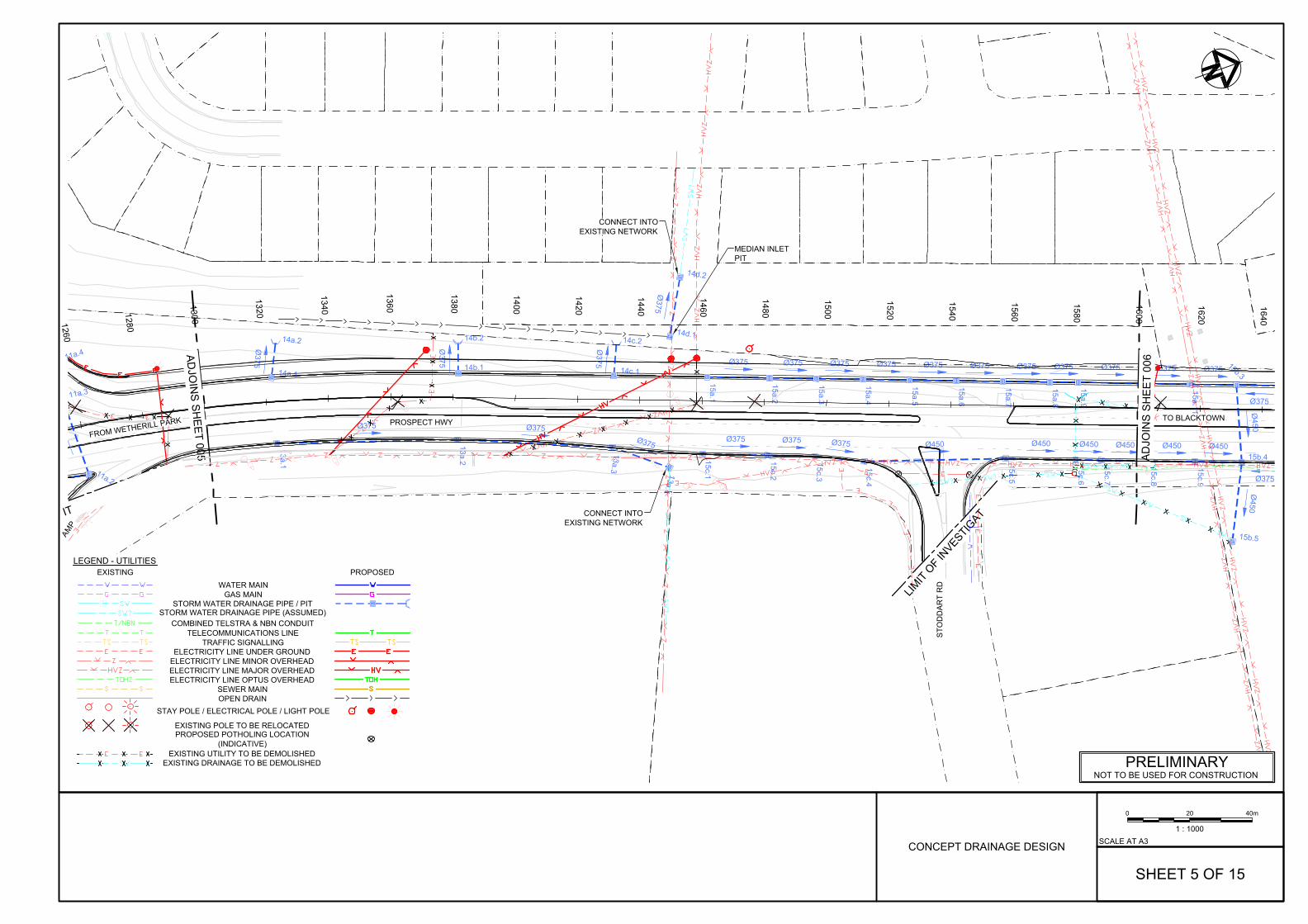
13a.1
13a.2
13a.3
13a.4
14a.1
14a.2
14b.1
14b.2
14c.1
14c.214d.1
14d.2
15a.1
15a.2
15a.3
15a.4
15a.5
15a.6
15a.7
15a.8
15a.9
15a.10
15a.11
15b.3
15b.415c.1
15c.2
15c.3
15c.4
15c.5
15c.6
15c.7
15c.8
15c.9
Ø375 Ø375Ø375
Ø375
Ø375
Ø375
Ø375
Ø375 Ø375 Ø375 Ø375 Ø375 Ø375 Ø375 Ø375 Ø375 Ø375 Ø375
Ø375
Ø450
Ø450
Ø375 Ø375 Ø375 Ø450 Ø450 Ø450 Ø450 Ø450 Ø450
Ø37511a.2
11a.3
11a.4
1260
1280
1300
1320
1340
1360
1380
1400
1420
1440
1460
1480
1500
1520
1540
1560
1580
1600
1620
1640
OF INVESTIGATION
ION
PROSPECT HWY
AD
JOIN
S S
HE
ET
006AD
JOIN
S SHEET 005
FROM WETHERILL PARK TO BLACKTOWN
MEDIAN INLETPIT
CONNECT INTOEXISTING NETWORK
15b.5
IT
LIMIT
OF INVESTIG
AT
AMP
STO
DD
AR
T R
D
CONNECT INTOEXISTING NETWORK
STORM WATER DRAINAGE PIPE / PIT
WATER MAINGAS MAIN
TELECOMMUNICATIONS LINE
ELECTRICITY LINE UNDER GROUND
LEGEND - UTILITIESEXISTING
STAY POLE / ELECTRICAL POLE / LIGHT POLE
ELECTRICITY LINE MINOR OVERHEADELECTRICITY LINE MAJOR OVERHEADELECTRICITY LINE OPTUS OVERHEAD
PROPOSED
SEWER MAIN
EXISTING UTILITY TO BE DEMOLISHED
OPEN DRAIN
TRAFFIC SIGNALLING
STORM WATER DRAINAGE PIPE (ASSUMED)
EXISTING POLE TO BE RELOCATED
EXISTING DRAINAGE TO BE DEMOLISHED
COMBINED TELSTRA & NBN CONDUIT
PROPOSED POTHOLING LOCATION(INDICATIVE)
40m200
1 : 1000
SHEET 5 OF 15
PRELIMINARYNOT TO BE USED FOR CONSTRUCTION
SCALE AT A3CONCEPT DRAINAGE DESIGN
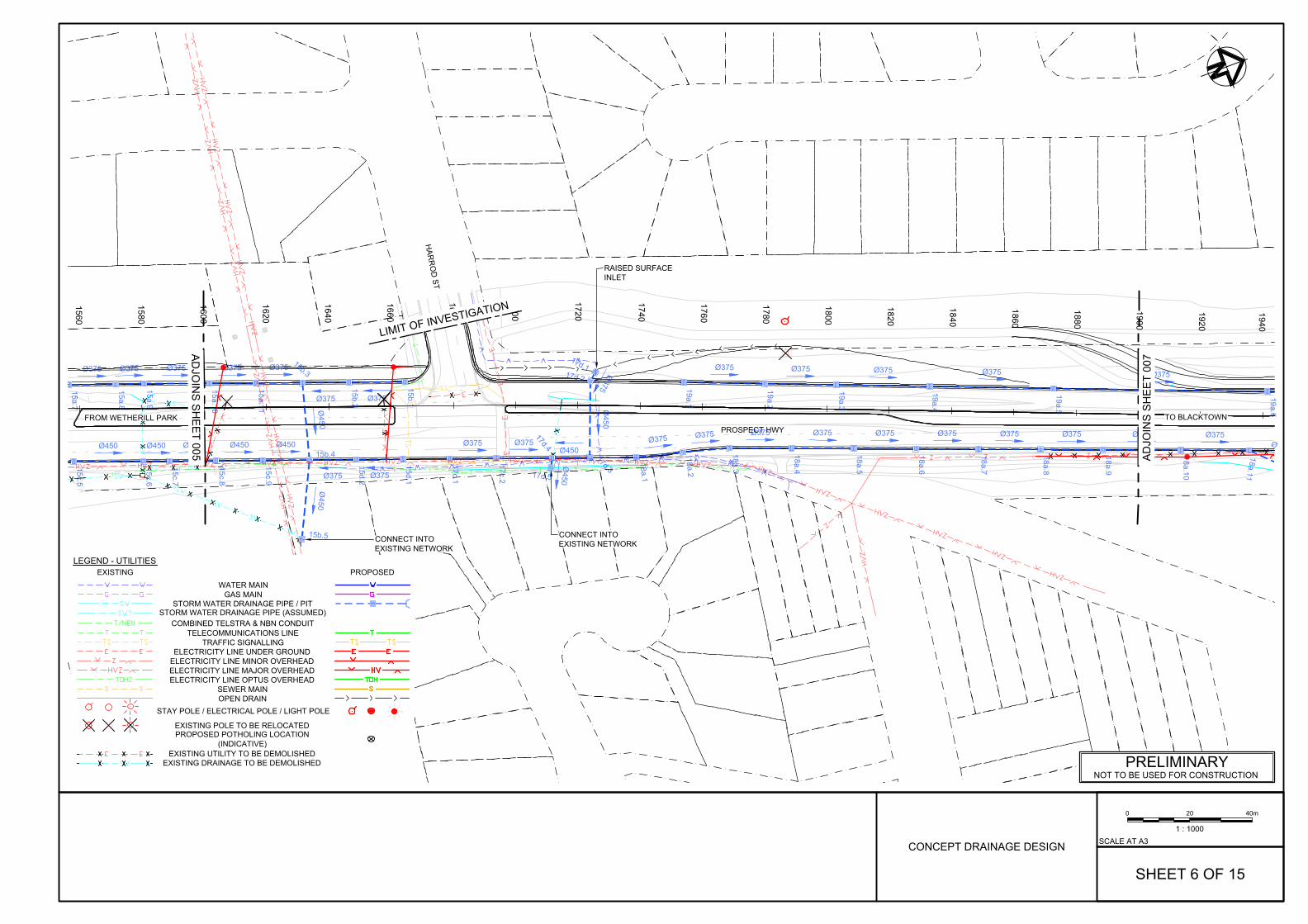
15a.7
15a.8
15a.9
15a.10
15a.11
15b.1
15b.2
15b.3
15b.4
15b.5
15c.5
15c.6
15c.7
15c.8
15c.9
15d.1
15d.2
17c.1
17c.2
17d.117d.2
17d.3
17d.4
17d.5
18a.1
18a.2
18a.3
18a.4
18a.5
18a.6
18a.7
18a.8
18a.9
18a.10
18a.11
19a.1
19a.2
19a.3
19a.4
19a.5
19a.6
Ø375 Ø375 Ø375 Ø375 Ø375
Ø375Ø375
Ø450
Ø450
Ø450 Ø450 Ø450 Ø450 Ø450
Ø375Ø375
Ø375 Ø375
Ø375
Ø450
Ø450
Ø450
Ø375 Ø375 Ø375 Ø375 Ø375 Ø375 Ø375 Ø375 Ø375 Ø375Ø
Ø375 Ø375 Ø375 Ø375 Ø375
1560
1580
1600
1620
1640
1660
1680
1700
1720
1740
1760
1780
1800
1820
1840
1860
1880
1900
1920
1940
LIMIT OF INVESTIGATION
PROSPECT HWY
HAR
RO
D ST
AD
JOIN
S S
HE
ET
007A
DJO
INS
SH
EE
T 005
FROM WETHERILL PARK TO BLACKTOWN
RAISED SURFACEINLET
CONNECT INTOEXISTING NETWORKCONNECT INTO
EXISTING NETWORK
STORM WATER DRAINAGE PIPE / PIT
WATER MAINGAS MAIN
TELECOMMUNICATIONS LINE
ELECTRICITY LINE UNDER GROUND
LEGEND - UTILITIESEXISTING
STAY POLE / ELECTRICAL POLE / LIGHT POLE
ELECTRICITY LINE MINOR OVERHEADELECTRICITY LINE MAJOR OVERHEADELECTRICITY LINE OPTUS OVERHEAD
PROPOSED
SEWER MAIN
EXISTING UTILITY TO BE DEMOLISHED
OPEN DRAIN
TRAFFIC SIGNALLING
STORM WATER DRAINAGE PIPE (ASSUMED)
EXISTING POLE TO BE RELOCATED
EXISTING DRAINAGE TO BE DEMOLISHED
COMBINED TELSTRA & NBN CONDUIT
PROPOSED POTHOLING LOCATION(INDICATIVE)
40m200
1 : 1000
SHEET 6 OF 15
PRELIMINARYNOT TO BE USED FOR CONSTRUCTION
SCALE AT A3CONCEPT DRAINAGE DESIGN

18a.8 18a.9 18a.10
18a.11
19a.5
19a.6
19a.719a.8
19a.9
19b.1
19b.2 19c.1
19c.2
19c.3
19c.4
19c.5
19d.1
19e.1
19e.2
19e.3
19e.4
19e.5
19e.6
19e.7
19f.1
19f.2
19f.3
19f.4
19f.5
20a.1
20a.2
20a.3
20a.4
20a.5
20a.6
20a.7 20a.8
20a.9
20b.1
20b.2
20b.3
20b.4
20b.5
20e.1
20k.1
20k.2
20k.3
20k.4
20k.5
Ø375Ø375
Ø375Ø375
Ø375
375
Ø375
Ø375
Ø450
Ø450
Ø450
Ø450
Ø375
Ø375
Ø450
Ø450
Ø375
Ø450
Ø450 Ø450 Ø450
Ø450Ø
450
Ø375 Ø375 Ø375 Ø375 Ø375Ø375 Ø375
Ø375Ø375
Ø375Ø375
Ø450Ø450
Ø
Ø375Ø375
Ø375Ø375
Ø450
Ø375Ø375
Ø375Ø375
Ø450
Ø450
Ø525
18a.12
18a.13
1860 1880 1900 1920 1940 1960
1980
2000
2020
2040
2060
2080
2100
2120
2140
2160
2180
2200
2220
2240
PROSPECT HWY
ADJO
INS
SHEE
T 00
8ADJO
INS SH
EET 006
FROM WETHERILL PARK TO BLACKTOWN
RETAIN EXISTINGCROSS DRAINAGE
PROPOSED EXCAVATION TO PROVIDEADDITIONAL 300m² STORAGE
CONNECT INTOEXISTING NETWORK
STORM WATER DRAINAGE PIPE / PIT
WATER MAINGAS MAIN
TELECOMMUNICATIONS LINE
ELECTRICITY LINE UNDER GROUND
LEGEND - UTILITIESEXISTING
STAY POLE / ELECTRICAL POLE / LIGHT POLE
ELECTRICITY LINE MINOR OVERHEADELECTRICITY LINE MAJOR OVERHEADELECTRICITY LINE OPTUS OVERHEAD
PROPOSED
SEWER MAIN
EXISTING UTILITY TO BE DEMOLISHED
OPEN DRAIN
TRAFFIC SIGNALLING
STORM WATER DRAINAGE PIPE (ASSUMED)
EXISTING POLE TO BE RELOCATED
EXISTING DRAINAGE TO BE DEMOLISHED
COMBINED TELSTRA & NBN CONDUIT
PROPOSED POTHOLING LOCATION(INDICATIVE)
40m200
1 : 1000
SHEET 7 OF 15
PRELIMINARYNOT TO BE USED FOR CONSTRUCTION
SCALE AT A3CONCEPT DRAINAGE DESIGN

20a.4
20a.5
20a.6
20a.7
20a.8
20a.9
20a.10
20a.11
20b.3
20b.4
20b.5
20c.1
20d.4
20d.5
20e.1
20g.5
20g.6
20h.1 20i.1
20k.2
20k.3
20k.4
20k.5
22b.1
22b.2
22b.3
22c.1
22c.2
Ø375 Ø375 Ø375 Ø375 Ø450 Ø450 Ø450 Ø450 Ø450
Ø375 Ø375 Ø375
Ø450
Ø375
Ø375
Ø375
Ø375
5 Ø375 Ø375 Ø375
Ø450
Ø375
2160
2180
2200
2220
2240
2260
2280
2300
2320
2340
2360
2380
2400
2420
2440
2460
2480
2500
2520
2540
AD
JOIN
S S
HE
ET
009A
DJO
INS
SH
EE
T 007
FROM WETHERILL PARK
TO BLACKTOWN
PROSPECT HWY
BLAC
KTO
WN
RD
LAN
CEL
OT
ST
CONNECT TOEXISTING NETWORK
CONSTRUCT DEPRESSEDMEDIAN PIT AT SAG
STORM WATER DRAINAGE PIPE / PIT
WATER MAINGAS MAIN
TELECOMMUNICATIONS LINE
ELECTRICITY LINE UNDER GROUND
LEGEND - UTILITIESEXISTING
STAY POLE / ELECTRICAL POLE / LIGHT POLE
ELECTRICITY LINE MINOR OVERHEADELECTRICITY LINE MAJOR OVERHEADELECTRICITY LINE OPTUS OVERHEAD
PROPOSED
SEWER MAIN
EXISTING UTILITY TO BE DEMOLISHED
OPEN DRAIN
TRAFFIC SIGNALLING
STORM WATER DRAINAGE PIPE (ASSUMED)
EXISTING POLE TO BE RELOCATED
EXISTING DRAINAGE TO BE DEMOLISHED
COMBINED TELSTRA & NBN CONDUIT
PROPOSED POTHOLING LOCATION(INDICATIVE)
40m200
1 : 1000
SHEET 8 OF 15
PRELIMINARYNOT TO BE USED FOR CONSTRUCTION
SCALE AT A3CONCEPT DRAINAGE DESIGN
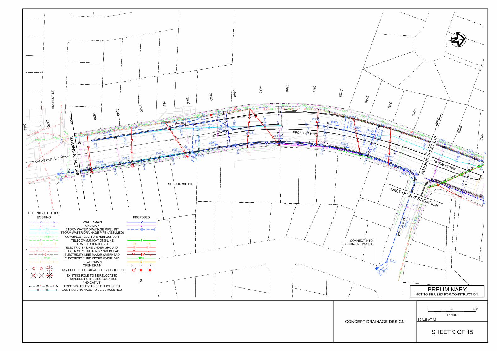
22b.1
22b.2
22b.3
22b.4
22b.5
22b.6
22c.1
22c.2
22c.3
22c.4
22c.5
22e.1
22e.2
22e.3
22e.4
22f.1
23a.1
23a.2
23a.3 23a.4
23a.5
23c.2
23c.3
23d.1
23e.1
23f.1
23f.2
23g.1
23h.1
24a.1
24a.2
24a.325c.1
Ø450
Ø375Ø375
Ø375Ø375
Ø450
Ø375Ø450
Ø450Ø450
Ø375 Ø375Ø450 Ø450
Ø450
Ø375
Ø375
Ø375
Ø450
Ø450
Ø450
Ø450
Ø450
Ø375
Ø375 5
Ø45023f.3
Ø375Ø375
Ø375Ø375
2460
2480
2500
2520
2540
2560
2580
2600
2620
2640
2660
2680
2700 2720 2740 2760 2780
2820
2840
2800
LIMIT OF INVESTIGATION
LAN
CE
LOT
ST
PROSPECT HWY
VESU
VIU
S ST
TO BLACKTOWN
ADJO
INS
SHEE
T 01
0
ADJO
INS SH
EET 008
FROM WETHERILL PARK
SURCHARGE PIT
CONNECT INTOEXISTING NETWORK
STORM WATER DRAINAGE PIPE / PIT
WATER MAINGAS MAIN
TELECOMMUNICATIONS LINE
ELECTRICITY LINE UNDER GROUND
LEGEND - UTILITIESEXISTING
STAY POLE / ELECTRICAL POLE / LIGHT POLE
ELECTRICITY LINE MINOR OVERHEADELECTRICITY LINE MAJOR OVERHEADELECTRICITY LINE OPTUS OVERHEAD
PROPOSED
SEWER MAIN
EXISTING UTILITY TO BE DEMOLISHED
OPEN DRAIN
TRAFFIC SIGNALLING
STORM WATER DRAINAGE PIPE (ASSUMED)
EXISTING POLE TO BE RELOCATED
EXISTING DRAINAGE TO BE DEMOLISHED
COMBINED TELSTRA & NBN CONDUIT
PROPOSED POTHOLING LOCATION(INDICATIVE)
40m200
1 : 1000
SHEET 9 OF 15
PRELIMINARYNOT TO BE USED FOR CONSTRUCTION
SCALE AT A3CONCEPT DRAINAGE DESIGN

23a.5
23e.1
23f.1
23f.2
23h.1
24a.1
24a.2
24a.3
24a.4
24a.5
24a.6
25b.1
25b.2
25b.3
25b.4
25b.5
25c.1
25c.2
25c.3
25c.4
25c.5
25c.6
25c.7
25c.8
25d.125d.2
25e.1
25e.2
25e.3
25y.1
25y.2
25y.3
25y.4
25z.125z.2
Ø450
Ø450
Ø450
Ø450
Ø450
Ø375 Ø375
Ø375
Ø375
Ø375
Ø375Ø375 Ø375 Ø375
Ø375
Ø375Ø375
Ø375Ø375 Ø375 Ø375
Ø375Ø375
Ø375
Ø375
Ø675
Ø675
Ø675
Ø375 Ø375Ø375
Ø375
Ø375
Ø375
Ø450
23f.3
25f.1Ø525
Ø525
Ø525
26a.2
26a.3
2760
2780
2820
2840
2860
2880
2900
2920
2940
2960
2980
3000
3020
3040
3060
3080
3100
3120
3140
3160
2800
LIMIT OF INVESTIGATION
LIMIT OF INVESTIGATION
VE
SU
VIU
S S
T
KE
NTW
OR
TH D
R
PROSPECT HWY
BEAUFORT RD
ADJO
INS
SHEE
T 01
1AD
JOIN
S S
HE
ET 009
FROM WETHERILL PARKTO BLACKTOWN
CONNECT INTOEXISTING NETWORK
SURCHARGE PIT
STORM WATER DRAINAGE PIPE / PIT
WATER MAINGAS MAIN
TELECOMMUNICATIONS LINE
ELECTRICITY LINE UNDER GROUND
LEGEND - UTILITIESEXISTING
STAY POLE / ELECTRICAL POLE / LIGHT POLE
ELECTRICITY LINE MINOR OVERHEADELECTRICITY LINE MAJOR OVERHEADELECTRICITY LINE OPTUS OVERHEAD
PROPOSED
SEWER MAIN
EXISTING UTILITY TO BE DEMOLISHED
OPEN DRAIN
TRAFFIC SIGNALLING
STORM WATER DRAINAGE PIPE (ASSUMED)
EXISTING POLE TO BE RELOCATED
EXISTING DRAINAGE TO BE DEMOLISHED
COMBINED TELSTRA & NBN CONDUIT
PROPOSED POTHOLING LOCATION(INDICATIVE)
40m200
1 : 1000
PRELIMINARYNOT TO BE USED FOR CONSTRUCTION
SCALE AT A3
SHEET 10 OF 15
CONCEPT DRAINAGE DESIGN
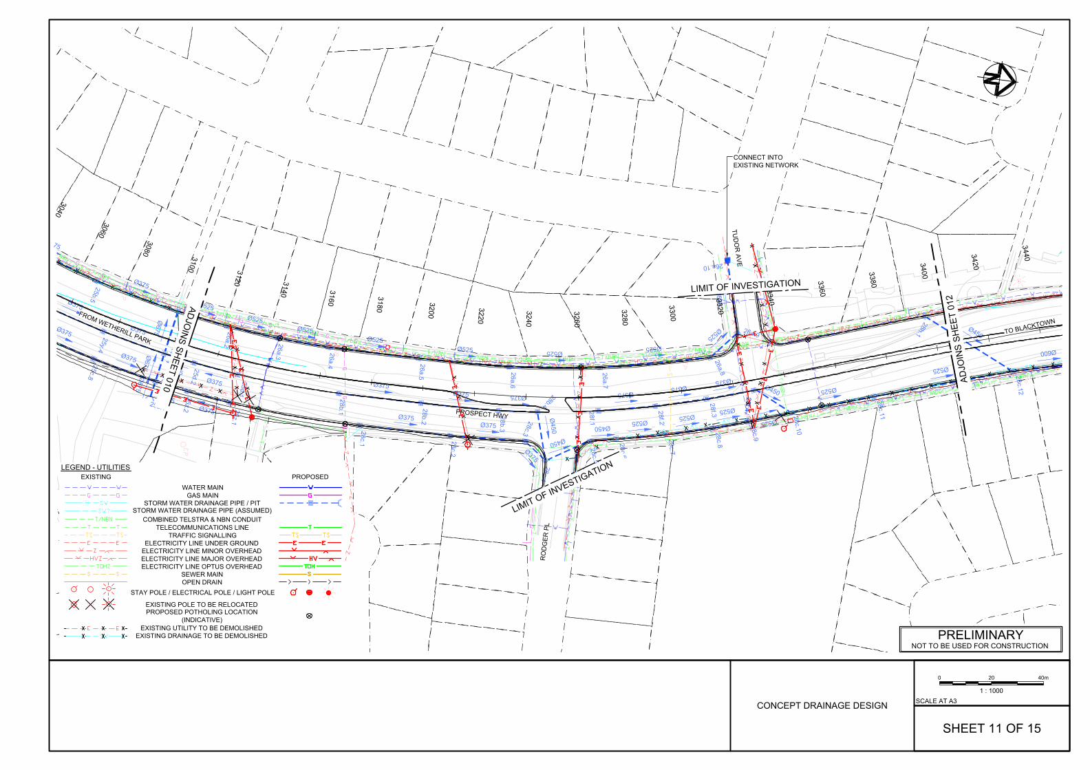
25b.525c.8
25d.1
25d.2
25e.1
25e.2
25e.3
25y.4
25z.1
25z.2
28b.1 28b.2
28b.3
28b.4
28c.1 28c.2
28c.3
28c.4
28c.5
28c.6
28f.1
28f.2
28f.3
28f.4
75
Ø375
Ø375
Ø375
Ø375
Ø375Ø675
Ø675
Ø675
Ø375
Ø375
Ø375
Ø375
Ø375Ø375 Ø375
Ø450
Ø375Ø375
Ø375
Ø450
Ø450
Ø375Ø375
Ø375Ø450
25f.1Ø525
Ø525Ø525
Ø525Ø525 Ø525
Ø525
Ø525
Ø525
26a.2 26a.3 26a.4 26a.5 26a.6
26a.7
26a.8
26a.9
26a.10
28f.4Ø525
Ø525Ø525
Ø525
Ø525
Ø60028c.7
28c.8
28c.9
28c.10
28c.11
28c.12
Ø450
28h.1
Ø525
3040
3060
3080 3100 3120 3140 3160
3180
3200
3220
3240
3260
3280
3300
3320
3340
3360
3380
3400
3420
3440
LIMIT OF INVESTIGATION
LIMIT OF INVESTIGATION
PROSPECT HWY
RO
DG
ER P
L
TUD
OR
AVE
FROM WETHERILL PARKTO BLACKTOWN
ADJO
INS SH
EET 010 ADJO
INS
SHEE
T 01
2
CONNECT INTOEXISTING NETWORK
STORM WATER DRAINAGE PIPE / PIT
WATER MAINGAS MAIN
TELECOMMUNICATIONS LINE
ELECTRICITY LINE UNDER GROUND
LEGEND - UTILITIESEXISTING
STAY POLE / ELECTRICAL POLE / LIGHT POLE
ELECTRICITY LINE MINOR OVERHEADELECTRICITY LINE MAJOR OVERHEADELECTRICITY LINE OPTUS OVERHEAD
PROPOSED
SEWER MAIN
EXISTING UTILITY TO BE DEMOLISHED
OPEN DRAIN
TRAFFIC SIGNALLING
STORM WATER DRAINAGE PIPE (ASSUMED)
EXISTING POLE TO BE RELOCATED
EXISTING DRAINAGE TO BE DEMOLISHED
COMBINED TELSTRA & NBN CONDUIT
PROPOSED POTHOLING LOCATION(INDICATIVE)
40m200
1 : 1000
SHEET 11 OF 15
PRELIMINARYNOT TO BE USED FOR CONSTRUCTION
SCALE AT A3CONCEPT DRAINAGE DESIGN

28l.1
28l.2
28l.3
28l.4
28m.1
28m.2
28n.1
Ø(2x)1050Ø(2x)1200 Ø(2x)1200
Ø450
Ø1050
Ø450
Ø450
28a.1
Ø525
Ø600
Ø600
Ø600 Ø600 Ø600 Ø750
28c.11
28c.12
28c.13
28c.14
28c.15
28c.16
28c.17
Ø375 Ø375 Ø450 Ø450 Ø450
Ø450
28x.1
28x.2
28x.3
28x.4
28x.5
28x.6
Ø450
28h.1
Ø5
3520
3540
3560
3580
3600
3380
3400
3420
3440
3460
3480
3500
LIMIT OF INVESTIGATION
LIM
IT O
F IN
VE
STI
GA
TIO
N
ST M
ARTI
NS
CR
ES
PROSPECT HWY
FROM WETHERILL PARK
TO BLACKTOWN
ADJO
INS SH
EET 011
AD
JOIN
S S
HE
ET 013
STORM WATER DRAINAGE PIPE / PIT
WATER MAINGAS MAIN
TELECOMMUNICATIONS LINE
ELECTRICITY LINE UNDER GROUND
LEGEND - UTILITIESEXISTING
STAY POLE / ELECTRICAL POLE / LIGHT POLE
ELECTRICITY LINE MINOR OVERHEADELECTRICITY LINE MAJOR OVERHEADELECTRICITY LINE OPTUS OVERHEAD
PROPOSED
SEWER MAIN
EXISTING UTILITY TO BE DEMOLISHED
OPEN DRAIN
TRAFFIC SIGNALLING
STORM WATER DRAINAGE PIPE (ASSUMED)
EXISTING POLE TO BE RELOCATED
EXISTING DRAINAGE TO BE DEMOLISHED
COMBINED TELSTRA & NBN CONDUIT
PROPOSED POTHOLING LOCATION(INDICATIVE)
40m200
1 : 1000
SHEET 12 OF 15
PRELIMINARYNOT TO BE USED FOR CONSTRUCTION
SCALE AT A3CONCEPT DRAINAGE DESIGN

28l.3
28l.4
28l.5
28l.6
0 Ø(2x)1200Ø(2x)1200
LIM
IT O
F IN
VE
STI
GA
TIO
N
TO BLACKTOWN
PROSPECT HWY
BLACKTO
WN
CR
EEK
BUNGARRIBEE R
D
LEABONS LA
NE
FROM WETHERILL PARK
AD
JOIN
S S
HE
ET 012
STORM WATER DRAINAGE PIPE / PIT
WATER MAINGAS MAIN
TELECOMMUNICATIONS LINE
ELECTRICITY LINE UNDER GROUND
LEGEND - UTILITIESEXISTING
STAY POLE / ELECTRICAL POLE / LIGHT POLE
ELECTRICITY LINE MINOR OVERHEADELECTRICITY LINE MAJOR OVERHEADELECTRICITY LINE OPTUS OVERHEAD
PROPOSED
SEWER MAIN
EXISTING UTILITY TO BE DEMOLISHED
OPEN DRAIN
TRAFFIC SIGNALLING
STORM WATER DRAINAGE PIPE (ASSUMED)
EXISTING POLE TO BE RELOCATED
EXISTING DRAINAGE TO BE DEMOLISHED
COMBINED TELSTRA & NBN CONDUIT
PROPOSED POTHOLING LOCATION(INDICATIVE)
40m200
1 : 1000
SHEET 13 OF 15
PRELIMINARYNOT TO BE USED FOR CONSTRUCTION
SCALE AT A3CONCEPT DRAINAGE DESIGN

4a.2
4a.3
4a.4
4a.5
Ø37
5
Ø37
5
Ø37
5
Ø375
Ø375Ø375
Ø375
Ø375
3a.1
3a.2
3a.3
3a.4
3a.5
Ø45
0
Ø450
Ø45
0
Ø45
0
Ø450
Ø450
3b.1
3b.2
3b.3
3b.4
3b.5
3b.7
380
400
420
300
320
340
360
ADJOINS SHEET 001
LIM
IT O
F IN
VEST
IGAT
ION
LIMIT OF INVESTIGATION
LIM
IT O
F IN
VEST
IGAT
ION
RESERVOIR RD
RESERVOIR RD
PICR
ITE CL
STORM WATER DRAINAGE PIPE / PIT
WATER MAINGAS MAIN
TELECOMMUNICATIONS LINE
ELECTRICITY LINE UNDER GROUND
LEGEND - UTILITIESEXISTING
STAY POLE / ELECTRICAL POLE / LIGHT POLE
ELECTRICITY LINE MINOR OVERHEADELECTRICITY LINE MAJOR OVERHEADELECTRICITY LINE OPTUS OVERHEAD
PROPOSED
SEWER MAIN
EXISTING UTILITY TO BE DEMOLISHED
OPEN DRAIN
TRAFFIC SIGNALLING
STORM WATER DRAINAGE PIPE (ASSUMED)
EXISTING POLE TO BE RELOCATED
EXISTING DRAINAGE TO BE DEMOLISHED
COMBINED TELSTRA & NBN CONDUIT
PROPOSED POTHOLING LOCATION(INDICATIVE)
40m200
1 : 1000
SHEET 14 OF 15
PRELIMINARYNOT TO BE USED FOR CONSTRUCTION
SCALE AT A3CONCEPT DRAINAGE DESIGN
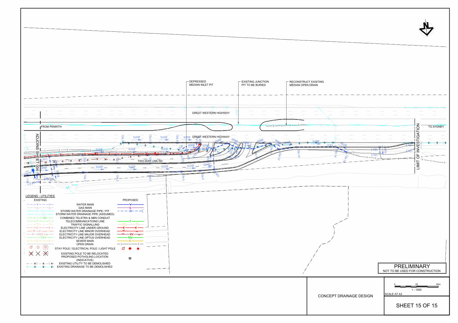
Ø525
Ø525
11a.7
11a.8
11a.9
Ø450
11d.1
Ø375 Ø375 Ø375
Ø375 Ø525
12a.1
12a.2
12a.3
12a.412a.5
Ø375
12c.1
12c.2
Ø375 Ø375 Ø375Ø375
Ø450
12d.1
12d.2
12d.3 12d.
4
12d.
5
Ø375 Ø375 Ø375 Ø375 Ø450
Ø375
Ø600 Ø600Ø600
Ø600Ø600 Ø600 Ø675
Ø750
12e.1
12e.2
12e.3
12e.4
12e.5
12e.6
12e.7
12e.8 12e.9
12e.10
12e.11 12e.12
12e.13
12e.14 12e.15
Ø375
12g.1
Ø375
12h.1
12h.2
12l.5
Ø75
0
cross4.1
cross4.2
LIM
IT O
F IN
VE
STI
GA
TIO
N
GREAT WESTERN HIGHWAY
GREAT WESTERN HIGHWAY
TWO-WAY LINK RD
FROM PENRITH TO SYDNEY
DEPRESSEDMEDIAN INLET PIT
EXISTING JUNCTIONPIT TO BE BURIED
RECONSTRUCT EXISTINGMEDIAN OPEN DRAIN
AD
JOIN
S S
HE
ET 004
STORM WATER DRAINAGE PIPE / PIT
WATER MAINGAS MAIN
TELECOMMUNICATIONS LINE
ELECTRICITY LINE UNDER GROUND
LEGEND - UTILITIESEXISTING
STAY POLE / ELECTRICAL POLE / LIGHT POLE
ELECTRICITY LINE MINOR OVERHEADELECTRICITY LINE MAJOR OVERHEADELECTRICITY LINE OPTUS OVERHEAD
PROPOSED
SEWER MAIN
EXISTING UTILITY TO BE DEMOLISHED
OPEN DRAIN
TRAFFIC SIGNALLING
STORM WATER DRAINAGE PIPE (ASSUMED)
EXISTING POLE TO BE RELOCATED
EXISTING DRAINAGE TO BE DEMOLISHED
COMBINED TELSTRA & NBN CONDUIT
PROPOSED POTHOLING LOCATION(INDICATIVE)
40m200
1 : 1000
SHEET 15 OF 15
PRELIMINARYNOT TO BE USED FOR CONSTRUCTION
SCALE AT A3CONCEPT DRAINAGE DESIGN
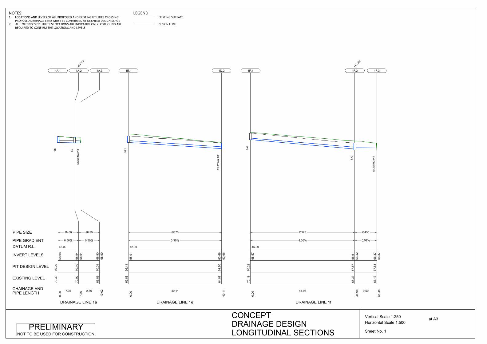
46.00
Ø450
0.50%
7.36
70.3
070
.29
0.00
68.9
8
1A.1
SE
Ø450
0.50%
2.66
70.0
270
.10
7.36
68.9
168
.94
1A.2-87
°57'
SE
69.8
970
.09
10.0
268
.90
68.9
0
1A.3
EX
ISTI
NG
PIT
CHAINAGE ANDPIPE LENGTH
EXISTING LEVEL
PIT DESIGN LEVEL
INVERT LEVELS
PIPE GRADIENT
PIPE SIZE
DATUM R.L.
DRAINAGE LINE 1a
42.00
Ø375
3.36%
40.11
66.8
866
.41
0.00
65.0
1
1E.1
SA
2
64.8
764
.90
40.1
163
.66
63.6
6
1D.2
EX
ISTI
NG
PIT
DRAINAGE LINE 1e
45.00
Ø375
4.36%
44.98
70.1
970
.02
0.00
68.5
7
1F.1
SA
2
Ø450
0.51%
9.50
68.3
367
.87
44.9
866
.42
66.6
1
1F.2-45
°24'
SA
2
66.1
367
.83
54.4
866
.37
66.3
7
1F.3
EX
ISTI
NG
PIT
DRAINAGE LINE 1f
Sheet No. 1
Horizontal Scale 1:500Vertical Scale 1:250 at A3CONCEPT
DRAINAGE DESIGNLONGITUDINAL SECTIONS
PRELIMINARYNOT TO BE USED FOR CONSTRUCTION
NOTES:1. LOCATIONS AND LEVELS OF ALL PROPOSED AND EXISTING UTILITIES CROSSING
PROPOSED DRAINAGE LINES MUST BE CONFIRMED AT DETAILED DESIGN STAGE2. ALL EXISTING “2D” UTILITIES LOCATIONS ARE INDICATIVE ONLY. POTHOLING ARE
REQUIRED TO CONFIRM THE LOCATIONS AND LEVELS
LEGENDEXISTING SURFACE
DESIGN LEVEL
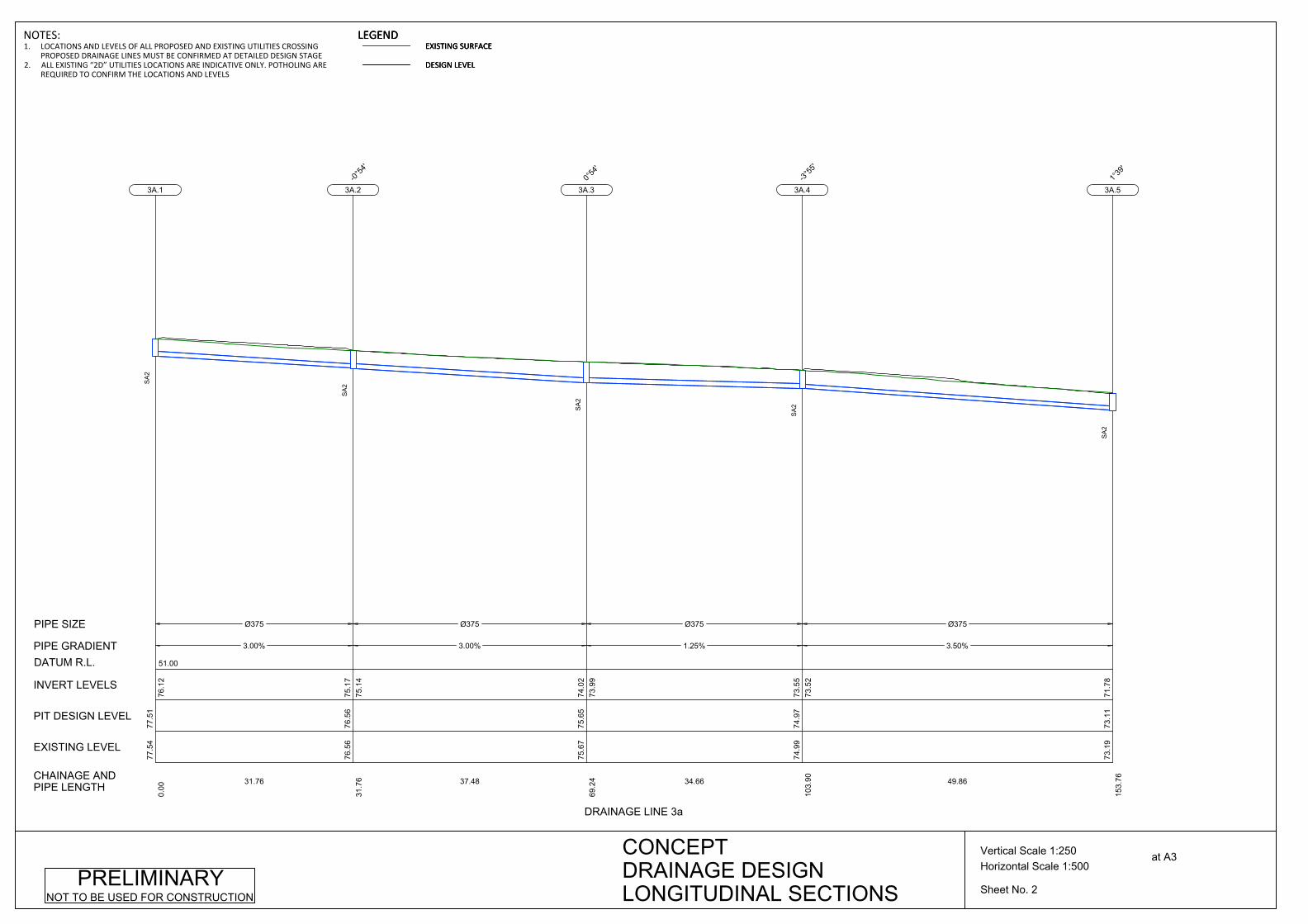
51.00
Ø375
3.00%
31.76
77.5
477
.51
0.00
76.1
2
3A.1
SA
2
Ø375
3.00%
37.48
76.5
676
.56
31.7
675
.14
75.1
7
3A.2-0°
54'
SA
2
Ø375
1.25%
34.66
75.6
775
.65
69.2
473
.99
74.0
2
3A.30°
54'
SA
2
Ø375
3.50%
49.86
74.9
974
.97
103.
9073
.52
73.5
5
3A.4-3°
55'
SA
2
73.1
973
.11
153.
7671
.78
3A.51°
39'
SA
2
CHAINAGE ANDPIPE LENGTH
EXISTING LEVEL
PIT DESIGN LEVEL
INVERT LEVELS
PIPE GRADIENT
PIPE SIZE
DATUM R.L.
DRAINAGE LINE 3a
Sheet No. 2
Horizontal Scale 1:500Vertical Scale 1:250 at A3CONCEPT
DRAINAGE DESIGNLONGITUDINAL SECTIONS
PRELIMINARYNOT TO BE USED FOR CONSTRUCTION
NOTES:1. LOCATIONS AND LEVELS OF ALL PROPOSED AND EXISTING UTILITIES CROSSING
PROPOSED DRAINAGE LINES MUST BE CONFIRMED AT DETAILED DESIGN STAGE2. ALL EXISTING “2D” UTILITIES LOCATIONS ARE INDICATIVE ONLY. POTHOLING ARE
REQUIRED TO CONFIRM THE LOCATIONS AND LEVELS
LEGENDEXISTING SURFACE
DESIGN LEVEL
LEGENDEXISTING SURFACE
DESIGN LEVEL
LEGENDEXISTING SURFACE
DESIGN LEVEL

49.00
Ø375
3.00%
34.61
73.1
973
.11
153.
7671
.75
71.7
8
3A.51°
39'
SA
2
72.3
172
.14
188.
3770
.67
70.7
1
3B.2
JUNCTIO
N LINE 3b
SA
2
CHAINAGE ANDPIPE LENGTH
EXISTING LEVEL
PIT DESIGN LEVEL
INVERT LEVELS
PIPE GRADIENT
PIPE SIZE
DATUM R.L.
DRAINAGE LINE 3a
48.00
CO
MM
S 1
00m
m IL
71.
7270
.67
8.69
Ø450
1.50%
9.10
72.2
672
.28
0.00
70.8
4
3B.1
SE
CO
MM
S 1
00m
m IL
71.
73
70.6
63.
18
D U
TIL
PR
OP
ELE
CTU
G 1
00m
m IL
71.
59
70.6
54.
99
WA
TER
300
mm
IL 7
0.20
70.5
818
.55
Ø450
0.50%
25.01
72.3
172
.14
9.10
70.6
770
.70
3B.269
°43'
JUNCTIO
N LINE 3a
SA
2
D U
TIL
PR
OP
ELE
CTU
G 1
00m
m IL
71.
1570
.47
10.3
8
CO
MM
S 1
00m
m IL
71.
3270
.45
12.6
0
Ø450
0.50%
44.85
71.9
071
.81
34.1
170
.52
70.5
5
3B.3-32
°51'
SA
1
Ø450
0.50%
21.13
71.9
571
.87
78.9
570
.26
70.2
9
3B.4-2°
28'
SA
2
Ø450
0.50%
22.23
72.1
971
.98
100.
0870
.13
70.1
6
3B.5
SA
2
71.4
172
.11
122.
3270
.02
3B.6-88
°01'
JUNCTIO
N LINE 3d
SA
2
DRAINAGE LINE 3b
Sheet No. 3
Horizontal Scale 1:500Vertical Scale 1:250 at A3CONCEPT
DRAINAGE DESIGNLONGITUDINAL SECTIONS
PRELIMINARYNOT TO BE USED FOR CONSTRUCTION
NOTES:1. LOCATIONS AND LEVELS OF ALL PROPOSED AND EXISTING UTILITIES CROSSING
PROPOSED DRAINAGE LINES MUST BE CONFIRMED AT DETAILED DESIGN STAGE2. ALL EXISTING “2D” UTILITIES LOCATIONS ARE INDICATIVE ONLY. POTHOLING ARE
REQUIRED TO CONFIRM THE LOCATIONS AND LEVELS
LEGENDEXISTING SURFACE
DESIGN LEVEL
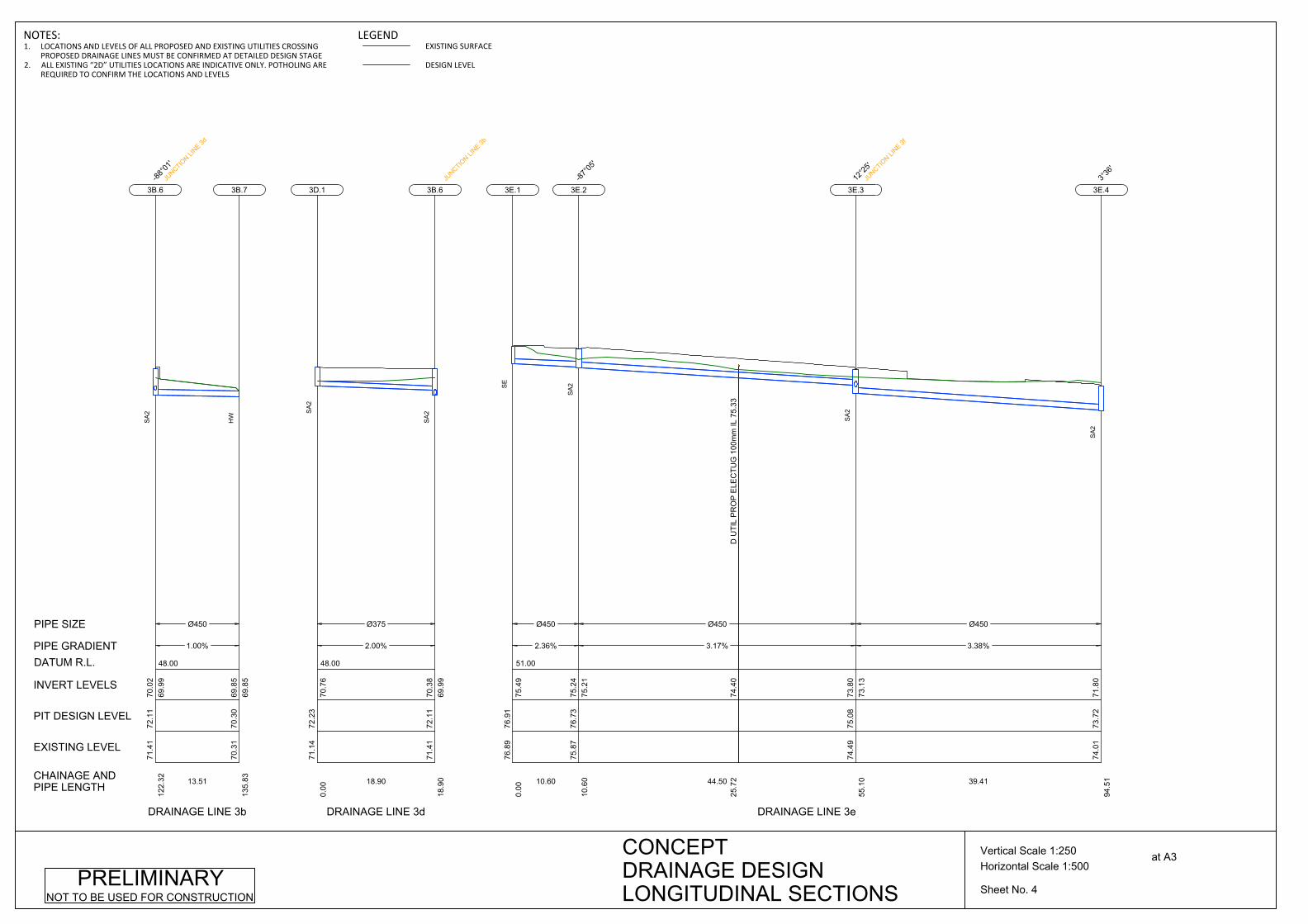
48.00
Ø450
1.00%
13.51
71.4
172
.11
122.
3269
.99
70.0
2
3B.6-88
°01'
JUNCTIO
N LINE 3d
SA
2
70.3
170
.30
135.
8369
.85
69.8
5
3B.7
HW
CHAINAGE ANDPIPE LENGTH
EXISTING LEVEL
PIT DESIGN LEVEL
INVERT LEVELS
PIPE GRADIENT
PIPE SIZE
DATUM R.L.
DRAINAGE LINE 3b
48.00
Ø375
2.00%
18.90
71.1
472
.23
0.00
70.7
6
3D.1
SA
2
71.4
172
.11
18.9
069
.99
70.3
8
3B.6
JUNCTIO
N LINE 3b
SA
2
DRAINAGE LINE 3d
51.00
Ø450
2.36%
10.60
76.8
976
.91
0.00
75.4
9
3E.1
SE
D U
TIL
PR
OP
ELE
CTU
G 1
00m
m IL
75.
3374
.40
25.7
2
Ø450
3.17%
44.50
75.8
776
.73
10.6
075
.21
75.2
4
3E.2-87
°05'
SA
2
Ø450
3.38%
39.41
74.4
975
.08
55.1
073
.13
73.8
0
3E.312
°25'
JUNCTIO
N LINE 3f
SA
2
74.0
173
.72
94.5
171
.80
3E.43°
36'
SA
2
DRAINAGE LINE 3e
Sheet No. 4
Horizontal Scale 1:500Vertical Scale 1:250 at A3CONCEPT
DRAINAGE DESIGNLONGITUDINAL SECTIONS
PRELIMINARYNOT TO BE USED FOR CONSTRUCTION
NOTES:1. LOCATIONS AND LEVELS OF ALL PROPOSED AND EXISTING UTILITIES CROSSING
PROPOSED DRAINAGE LINES MUST BE CONFIRMED AT DETAILED DESIGN STAGE2. ALL EXISTING “2D” UTILITIES LOCATIONS ARE INDICATIVE ONLY. POTHOLING ARE
REQUIRED TO CONFIRM THE LOCATIONS AND LEVELS
LEGENDEXISTING SURFACE
DESIGN LEVEL
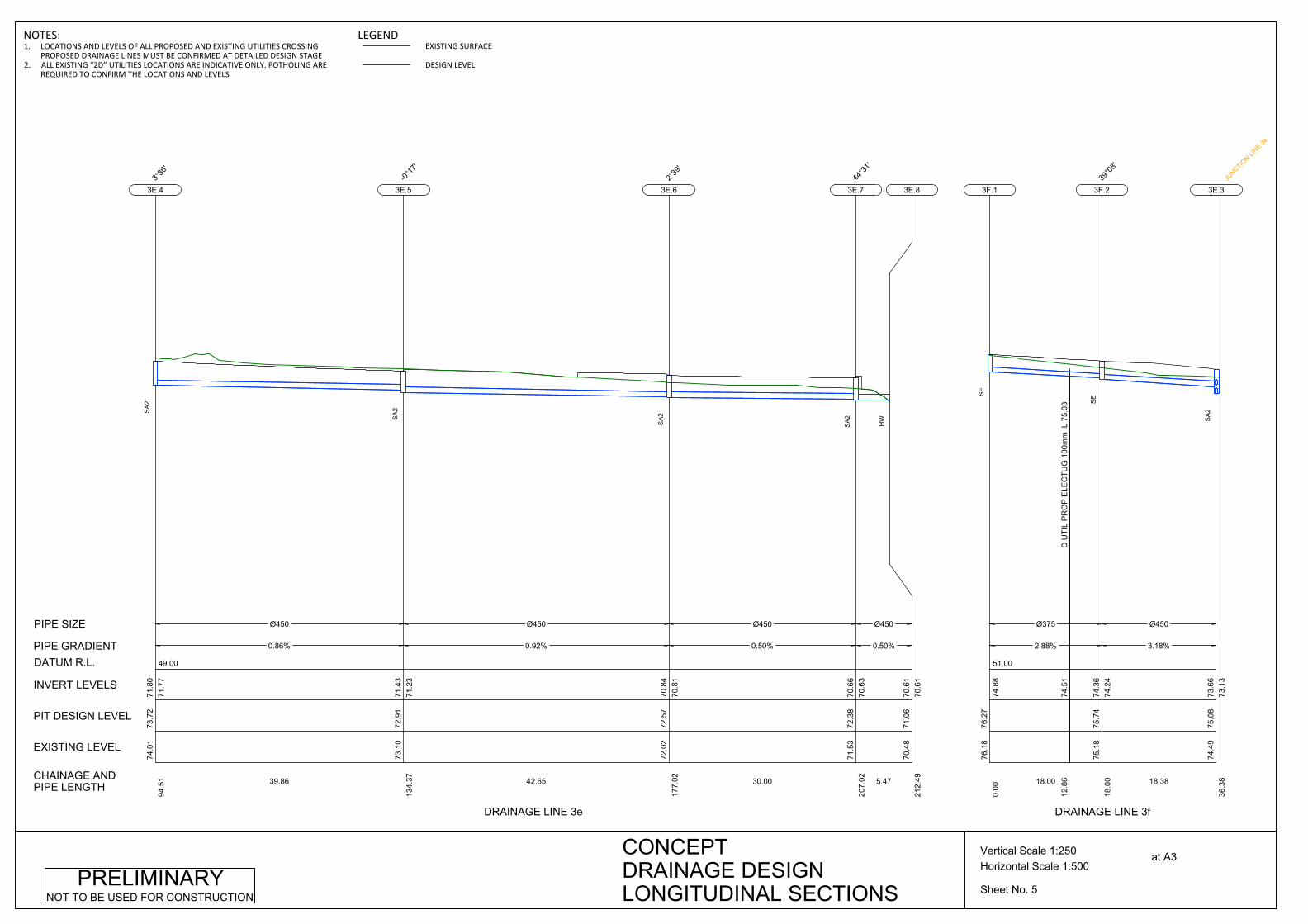
49.00
Ø450
0.86%
39.86
74.0
173
.72
94.5
171
.77
71.8
0
3E.43°
36'
SA
2
Ø450
0.92%
42.65
73.1
072
.91
134.
3771
.23
71.4
3
3E.5-0°
17'
SA
2
Ø450
0.50%
30.00
72.0
272
.57
177.
0270
.81
70.8
4
3E.62°
39'
SA
2
Ø450
0.50%
5.47
71.5
372
.38
207.
0270
.63
70.6
6
3E.744
°31'
SA
2
70.4
871
.06
212.
4970
.61
70.6
1
3E.8
HW
CHAINAGE ANDPIPE LENGTH
EXISTING LEVEL
PIT DESIGN LEVEL
INVERT LEVELS
PIPE GRADIENT
PIPE SIZE
DATUM R.L.
DRAINAGE LINE 3e
51.00
D U
TIL
PR
OP
ELE
CTU
G 1
00m
m IL
75.
0374
.51
12.8
6
Ø375
2.88%
18.00
76.1
876
.27
0.00
74.8
8
3F.1
SE
Ø450
3.18%
18.38
75.1
875
.74
18.0
074
.24
74.3
6
3F.239
°08'
SE
74.4
975
.08
36.3
873
.13
73.6
6
3E.3
JUNCTIO
N LINE 3e
SA
2
DRAINAGE LINE 3f
Sheet No. 5
Horizontal Scale 1:500Vertical Scale 1:250 at A3CONCEPT
DRAINAGE DESIGNLONGITUDINAL SECTIONS
PRELIMINARYNOT TO BE USED FOR CONSTRUCTION
NOTES:1. LOCATIONS AND LEVELS OF ALL PROPOSED AND EXISTING UTILITIES CROSSING
PROPOSED DRAINAGE LINES MUST BE CONFIRMED AT DETAILED DESIGN STAGE2. ALL EXISTING “2D” UTILITIES LOCATIONS ARE INDICATIVE ONLY. POTHOLING ARE
REQUIRED TO CONFIRM THE LOCATIONS AND LEVELS
LEGENDEXISTING SURFACE
DESIGN LEVEL

57.00
Ø375
3.00%
9.14
79.7
979
.90
0.00
79.5
2
3G.1
HW
Ø375
2.72%
29.90
79.4
180
.60
9.14
79.2
279
.25
3G.258
°58'
SA
2
Ø375
2.70%
30.68
84.1
179
.77
39.0
478
.37
78.4
0
3G.3-4°
09'
SA
2
Ø375
2.50%
29.40
82.4
378
.91
69.7
277
.52
77.5
5
3G.4-4°
07'
SA
2
D U
TIL
PR
OP
ELE
CTU
G 1
00m
m IL
77.
5476
.50
2.16
D U
TIL
PR
OP
ELE
CTU
G 1
00m
m IL
77.
4376
.42
9.93
Ø450
1.00%
14.51
77.9
178
.09
99.1
276
.52
76.7
8
3G.545
°20'
JUNCTIO
N LINE 3i
SA
2
ELE
C U
G 5
0mm
IL 7
7.19
76.1
316
.14
Ø450
1.00%
21.99
76.3
277
.58
113.
6376
.29
76.3
8
3G.68°
37'
JUNCTIO
N LINE 3h
MG
SG
76.0
176
.52
135.
6376
.07
76.0
7
3G.7
HW
CHAINAGE ANDPIPE LENGTH
EXISTING LEVEL
PIT DESIGN LEVEL
INVERT LEVELS
PIPE GRADIENT
PIPE SIZE
DATUM R.L.
DRAINAGE LINE 3g
54.00
D U
TIL
PR
OP
ELE
CTU
G 1
00m
m IL
77.
1776
.39
10.3
8
Ø375
1.00%
13.30
77.6
177
.58
0.00
76.5
0
3H.1
SA
1
76.3
277
.58
13.3
076
.29
76.3
7
3G.6
JUNCTIO
N LINE 3g
MG
SG
DRAINAGE LINE 3h
Sheet No. 6
Horizontal Scale 1:500Vertical Scale 1:250 at A3CONCEPT
DRAINAGE DESIGNLONGITUDINAL SECTIONS
PRELIMINARYNOT TO BE USED FOR CONSTRUCTION
NOTES:1. LOCATIONS AND LEVELS OF ALL PROPOSED AND EXISTING UTILITIES CROSSING
PROPOSED DRAINAGE LINES MUST BE CONFIRMED AT DETAILED DESIGN STAGE2. ALL EXISTING “2D” UTILITIES LOCATIONS ARE INDICATIVE ONLY. POTHOLING ARE
REQUIRED TO CONFIRM THE LOCATIONS AND LEVELS
LEGENDEXISTING SURFACE
DESIGN LEVEL
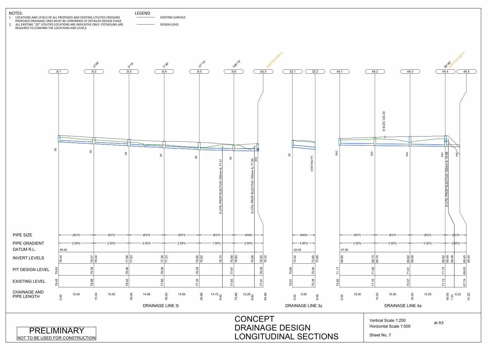
55.00
Ø375
2.50%
15.04
79.4
579
.83
0.00
78.4
4
3I.1
SE
Ø375
2.50%
15.00
78.8
879
.39
15.0
478
.04
78.0
7
3I.2
-2°08
'
SE
Ø375
2.50%
14.96
78.4
278
.96
30.0
477
.63
77.6
6
3I.35°
15'
SE
Ø375
2.50%
14.95
77.8
578
.58
45.0
077
.23
77.2
6
3I.47°
36'
SE
D U
TIL
PR
OP
ELE
CTU
G 1
00m
m IL
77.
4176
.72
9.92
Ø375
1.00%
14.72
77.3
578
.29
59.9
676
.82
76.8
5
3I.5-27
°14'
SE
D U
TIL
PR
OP
ELE
CTU
G 1
00m
m IL
77.
5076
.56
8.80
Ø450
0.50%
10.29
77.8
377
.81
74.6
876
.60
76.6
8
3I.6
108°
15'
SE
77.9
178
.09
84.9
676
.52
76.5
5
3G.5
JUNCTIO
N LINE 3g
SA
2
CHAINAGE ANDPIPE LENGTH
EXISTING LEVEL
PIT DESIGN LEVEL
INVERT LEVELS
PIPE GRADIENT
PIPE SIZE
DATUM R.L.
DRAINAGE LINE 3i
52.00
Ø450
4.90%
9.5975
.81
75.8
00.
0074
.32
3Z.1
SE
75.3
975
.40
9.59
73.8
573
.85
3Z.2
EX
ISTI
NG
PIT
DRAINAGE LINE 3z
47.00
Ø375
0.50%
15.00
70.8
271
.17
0.00
69.8
0
4A.1
SA
2
Ø375
0.50%
15.00
71.1
071
.46
15.0
069
.70
69.7
3
4A.2
SA
2
E E
LEC
UG
2d
Ø375
0.50%
15.00
70.3
771
.61
30.0
069
.59
69.6
2
4A.3
SA
2
D U
TIL
PR
OP
ELE
CTU
G 1
00m
m IL
70.
96
69.4
81.
23
Ø375
0.50%
6.22
71.1
371
.73
45.0
069
.49
69.5
2
4A.490
°46'
JUNCTIO
N LINE 4b
SA
2
67.7
469
.83
51.2
269
.45
69.4
5
4A.5
HW
DRAINAGE LINE 4a
Sheet No. 7
Horizontal Scale 1:500Vertical Scale 1:250 at A3CONCEPT
DRAINAGE DESIGNLONGITUDINAL SECTIONS
PRELIMINARYNOT TO BE USED FOR CONSTRUCTION
NOTES:1. LOCATIONS AND LEVELS OF ALL PROPOSED AND EXISTING UTILITIES CROSSING
PROPOSED DRAINAGE LINES MUST BE CONFIRMED AT DETAILED DESIGN STAGE2. ALL EXISTING “2D” UTILITIES LOCATIONS ARE INDICATIVE ONLY. POTHOLING ARE
REQUIRED TO CONFIRM THE LOCATIONS AND LEVELS
LEGENDEXISTING SURFACE
DESIGN LEVEL

48.00
Ø375
0.73%
15.00
72.4
172
.08
0.00
70.7
0
4B.1
SA
2
Ø375
0.57%
15.00
72.2
271
.96
15.0
070
.56
70.5
9
4B.2
SA
2
Ø375
0.57%
15.00
71.7
471
.85
30.0
070
.45
70.4
8
4B.3
SA
2
71.1
371
.73
45.0
069
.49
70.3
6
4A.4
JUNCTIO
N LINE 4a
SA
2
CHAINAGE ANDPIPE LENGTH
EXISTING LEVEL
PIT DESIGN LEVEL
INVERT LEVELS
PIPE GRADIENT
PIPE SIZE
DATUM R.L.
DRAINAGE LINE 4b
49.00
Ø450
1.92%
59.97
74.3
974
.36
0.00
72.8
8
4C.1
SA
2
Ø450
1.65%
30.00
73.2
873
.19
59.9
771
.68
71.7
3
4C.22°
18'
SA
2
Ø450
0.50%
15.00
73.0
172
.69
89.9
771
.16
71.1
9
4C.3
SA
2
Ø450
0.50%
15.00
72.9
072
.54
104.
9771
.05
71.0
8
4C.4
SA
2
72.7
872
.43
119.
9770
.98
4C.5
SA
2
DRAINAGE LINE 4c
Sheet No. 8
Horizontal Scale 1:500Vertical Scale 1:250 at A3CONCEPT
DRAINAGE DESIGNLONGITUDINAL SECTIONS
PRELIMINARYNOT TO BE USED FOR CONSTRUCTION
NOTES:1. LOCATIONS AND LEVELS OF ALL PROPOSED AND EXISTING UTILITIES CROSSING
PROPOSED DRAINAGE LINES MUST BE CONFIRMED AT DETAILED DESIGN STAGE2. ALL EXISTING “2D” UTILITIES LOCATIONS ARE INDICATIVE ONLY. POTHOLING ARE
REQUIRED TO CONFIRM THE LOCATIONS AND LEVELS
LEGENDEXISTING SURFACE
DESIGN LEVEL

48.00
Ø450
0.57%
15.00
72.7
872
.43
119.
9770
.95
70.9
8
4C.5
SA
2
Ø450
0.57%
15.00
72.6
572
.31
134.
9770
.83
70.8
6
4C.6
SA
2
D U
TIL
PR
OP
ELE
CTU
G 1
00m
m IL
71.
57
70.7
11.
35
Ø450
0.50%
7.73
72.5
572
.19
149.
9770
.72
70.7
5
4C.7-39
°17'
SA
2
70.1
071
.13
157.
7170
.68
70.6
8
4C.8
HW
CHAINAGE ANDPIPE LENGTH
EXISTING LEVEL
PIT DESIGN LEVEL
INVERT LEVELS
PIPE GRADIENT
PIPE SIZE
DATUM R.L.
DRAINAGE LINE 4c
59.00
Ø450
2.22%
24.34
84.6
784
.11
0.00
82.6
8
6C.1
SE
Ø450
2.00%
22.42
83.7
683
.66
24.3
482
.11
82.1
4
6C.277
°37'
SA
2Ø450
2.00%
20.00
85.5
283
.44
46.7
681
.63
81.6
6
6C.32°
38'
SA
2
Ø450
2.00%
20.00
86.0
183
.21
66.7
581
.20
81.2
3
6C.4-2°
45'
SA
2
Ø450
2.00%
16.52
83.9
582
.89
86.7
580
.77
80.8
0
6C.5-61
°57'
JUNCTIO
N LINE 6d
SA
2
ELE
C U
G IL
81.
7880
.05
6.38
Ø450
2.57%
7.26
80.3
182
.36
103.
2780
.22
80.4
4
6C.6-6°
02'
JUNCTIO
N LINE 6k
SE
82.0
782
.05
110.
5480
.03
6C.7-28
°39'
SE
DRAINAGE LINE 6c
Sheet No. 9
Horizontal Scale 1:500Vertical Scale 1:250 at A3CONCEPT
DRAINAGE DESIGNLONGITUDINAL SECTIONS
PRELIMINARYNOT TO BE USED FOR CONSTRUCTION
NOTES:1. LOCATIONS AND LEVELS OF ALL PROPOSED AND EXISTING UTILITIES CROSSING
PROPOSED DRAINAGE LINES MUST BE CONFIRMED AT DETAILED DESIGN STAGE2. ALL EXISTING “2D” UTILITIES LOCATIONS ARE INDICATIVE ONLY. POTHOLING ARE
REQUIRED TO CONFIRM THE LOCATIONS AND LEVELS
LEGENDEXISTING SURFACE
DESIGN LEVEL
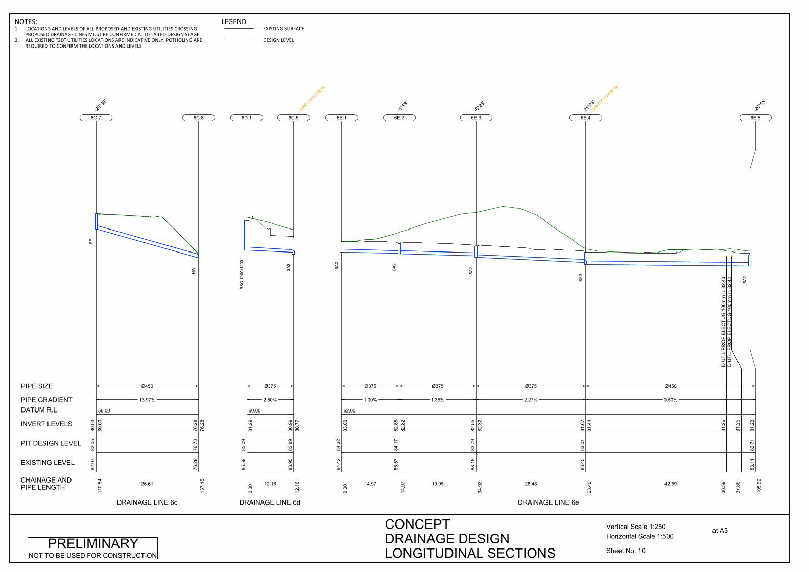
56.00
Ø450
13.97%
26.61
82.0
782
.05
110.
5480
.00
80.0
3
6C.7-28
°39'
SE
76.2
876
.73
137.
1576
.28
76.2
8
6C.8
HW
CHAINAGE ANDPIPE LENGTH
EXISTING LEVEL
PIT DESIGN LEVEL
INVERT LEVELS
PIPE GRADIENT
PIPE SIZE
DATUM R.L.
DRAINAGE LINE 6c
60.00
Ø375
2.50%
12.16
85.5
985
.09
0.00
81.2
9
6D.1
RS
G 1
200x
1200
83.9
582
.89
12.1
680
.77
80.9
9
6C.5
JUNCTIO
N LINE 6c
SA
2
DRAINAGE LINE 6d
62.00
Ø375
1.00%
14.97
84.4
284
.32
0.00
83.0
0
6E.1
SA
2
Ø375
1.35%
19.95
85.5
784
.17
14.9
782
.82
82.8
5
6E.2-5°
13'
SA
2
Ø375
2.27%
28.48
88.1
883
.79
34.9
282
.32
82.5
5
6E.3-6°
28'
SA
2
D U
TIL
PR
OP
ELE
CTU
G 1
00m
m IL
82.
4381
.26
36.5
9D
UTI
L P
RO
P E
LEC
TUG
100
mm
IL 8
2.42
81.2
537
.86
Ø450
0.50%
42.59
83.4
583
.01
63.4
081
.44
81.6
7
6E.421
°24'
JUNCTIO
N LINE 6g
SA
2
83.1
182
.71
105.
9981
.23
6E.5-20
°15'
SA
2
DRAINAGE LINE 6e
Sheet No. 10
Horizontal Scale 1:500Vertical Scale 1:250 at A3CONCEPT
DRAINAGE DESIGNLONGITUDINAL SECTIONS
PRELIMINARYNOT TO BE USED FOR CONSTRUCTION
NOTES:1. LOCATIONS AND LEVELS OF ALL PROPOSED AND EXISTING UTILITIES CROSSING
PROPOSED DRAINAGE LINES MUST BE CONFIRMED AT DETAILED DESIGN STAGE2. ALL EXISTING “2D” UTILITIES LOCATIONS ARE INDICATIVE ONLY. POTHOLING ARE
REQUIRED TO CONFIRM THE LOCATIONS AND LEVELS
LEGENDEXISTING SURFACE
DESIGN LEVEL

59.00
Ø450
1.30%
29.01
83.1
182
.71
105.
9981
.20
81.2
3
6E.5-20
°15'
SA
2
ELE
C U
G 5
0mm
IL 8
1.93
80.7
82.
49
Ø450
0.50%
3.50
82.2
682
.16
135.
0080
.79
80.8
2
6E.6-76
°21'
SA
2
81.0
081
.22
138.
5080
.77
80.7
7
6E.7
HW
CHAINAGE ANDPIPE LENGTH
EXISTING LEVEL
PIT DESIGN LEVEL
INVERT LEVELS
PIPE GRADIENT
PIPE SIZE
DATUM R.L.
DRAINAGE LINE 6e
60.00
Ø375
0.88%
15.00
84.1
684
.25
0.00
82.8
7
6F.1
SE
Ø375
0.54%
15.00
84.2
284
.11
15.0
082
.71
82.7
4
6F.2
-1°50
'
SE
Ø375
0.74%
15.00
84.0
584
.00
30.0
082
.60
82.6
3
6F.3-2°
03'
SE
Ø375
0.61%
10.00
83.8
083
.86
45.0
082
.46
82.4
9
6F.4-1°
45'
SE
83.7
383
.77
55.0
082
.22
82.4
0
6G.1JU
NCTION LI
NE 6g
SE
DRAINAGE LINE 6f
59.00
Ø450
3.55%
21.28
83.7
383
.77
0.00
82.2
2
6G.1JU
NCTION LI
NE 6f
JUNCTIO
N LINE 6h
SE
83.4
583
.01
21.2
881
.44
81.4
7
6E.4
JUNCTIO
N LINE 6e
SA
2
DRAINAGE LINE 6g
63.00
D U
TIL
PR
OP
ELE
CTU
G 1
00m
m IL
83.
8282
.99
3.99
Ø375
2.96%
5.58
84.4
884
.48
0.00
83.1
1
6H.1
SO
1
Ø375
0.67%
17.56
87.4
584
.32
5.58
82.9
282
.95
6H.286
°22'
SE
84.2
484
.17
23.1
482
.80
6H.33°
58'
SA
2
DRAINAGE LINE 6h
Sheet No. 11
Horizontal Scale 1:500Vertical Scale 1:250 at A3CONCEPT
DRAINAGE DESIGNLONGITUDINAL SECTIONS
PRELIMINARYNOT TO BE USED FOR CONSTRUCTION
NOTES:1. LOCATIONS AND LEVELS OF ALL PROPOSED AND EXISTING UTILITIES CROSSING
PROPOSED DRAINAGE LINES MUST BE CONFIRMED AT DETAILED DESIGN STAGE2. ALL EXISTING “2D” UTILITIES LOCATIONS ARE INDICATIVE ONLY. POTHOLING ARE
REQUIRED TO CONFIRM THE LOCATIONS AND LEVELS
LEGENDEXISTING SURFACE
DESIGN LEVEL

60.00
Ø375
0.50%
19.95
84.2
484
.17
23.1
482
.77
82.8
0
6H.33°
58'
SA
2
Ø450
0.71%
16.00
84.1
084
.04
43.0
982
.60
82.6
7
6H.4-12
°20'
SA
2
Ø450
1.75%
11.38
83.7
783
.94
59.0
982
.45
82.4
8
6H.5-12
4°41
'
SE
83.7
383
.77
70.4
782
.22
82.2
5
6G.1
JUNCTIO
N LINE 6g
SE
CHAINAGE ANDPIPE LENGTH
EXISTING LEVEL
PIT DESIGN LEVEL
INVERT LEVELS
PIPE GRADIENT
PIPE SIZE
DATUM R.L.
DRAINAGE LINE 6h
58.00
Ø375
0.96%
10.00
83.1
583
.11
0.00
81.7
4
6K.1
SE
Ø375
0.92%
10.00
83.0
583
.01
10.0
081
.61
81.6
4
6K.2-1°
25'
SE
Ø375
1.13%
10.00
83.0
582
.89
20.0
081
.49
81.5
2
6K.3-1°
25'
SE
Ø375
1.35%
10.00
82.9
782
.74
30.0
081
.35
81.3
8
6K.4-1°
25'
SE
Ø375
1.67%
11.0082
.89
82.5
840
.00
81.1
881
.21
6K.5-1°
29'
SE
80.3
182
.36
51.0
080
.22
81.0
0
6C.6
JUNCTIO
N LINE 6c
SE
DRAINAGE LINE 6k
60.00
D U
TIL
PR
OP
ELE
CTU
G 1
00m
m IL
83.
5082
.49
8.53
Ø375
1.00%
9.66
84.2
283
.74
0.00
82.5
8
6Y.1
SA
2
Ø375
1.00%
18.81
83.9
683
.66
9.66
82.4
582
.48
6Y.2-31
°22'
SA
2
82.5
282
.64
28.4
882
.27
82.2
7
6Y.3
HW
DRAINAGE LINE 6y
Sheet No. 12
Horizontal Scale 1:500Vertical Scale 1:250 at A3CONCEPT
DRAINAGE DESIGNLONGITUDINAL SECTIONS
PRELIMINARYNOT TO BE USED FOR CONSTRUCTION
NOTES:1. LOCATIONS AND LEVELS OF ALL PROPOSED AND EXISTING UTILITIES CROSSING
PROPOSED DRAINAGE LINES MUST BE CONFIRMED AT DETAILED DESIGN STAGE2. ALL EXISTING “2D” UTILITIES LOCATIONS ARE INDICATIVE ONLY. POTHOLING ARE
REQUIRED TO CONFIRM THE LOCATIONS AND LEVELS
LEGENDEXISTING SURFACE
DESIGN LEVEL
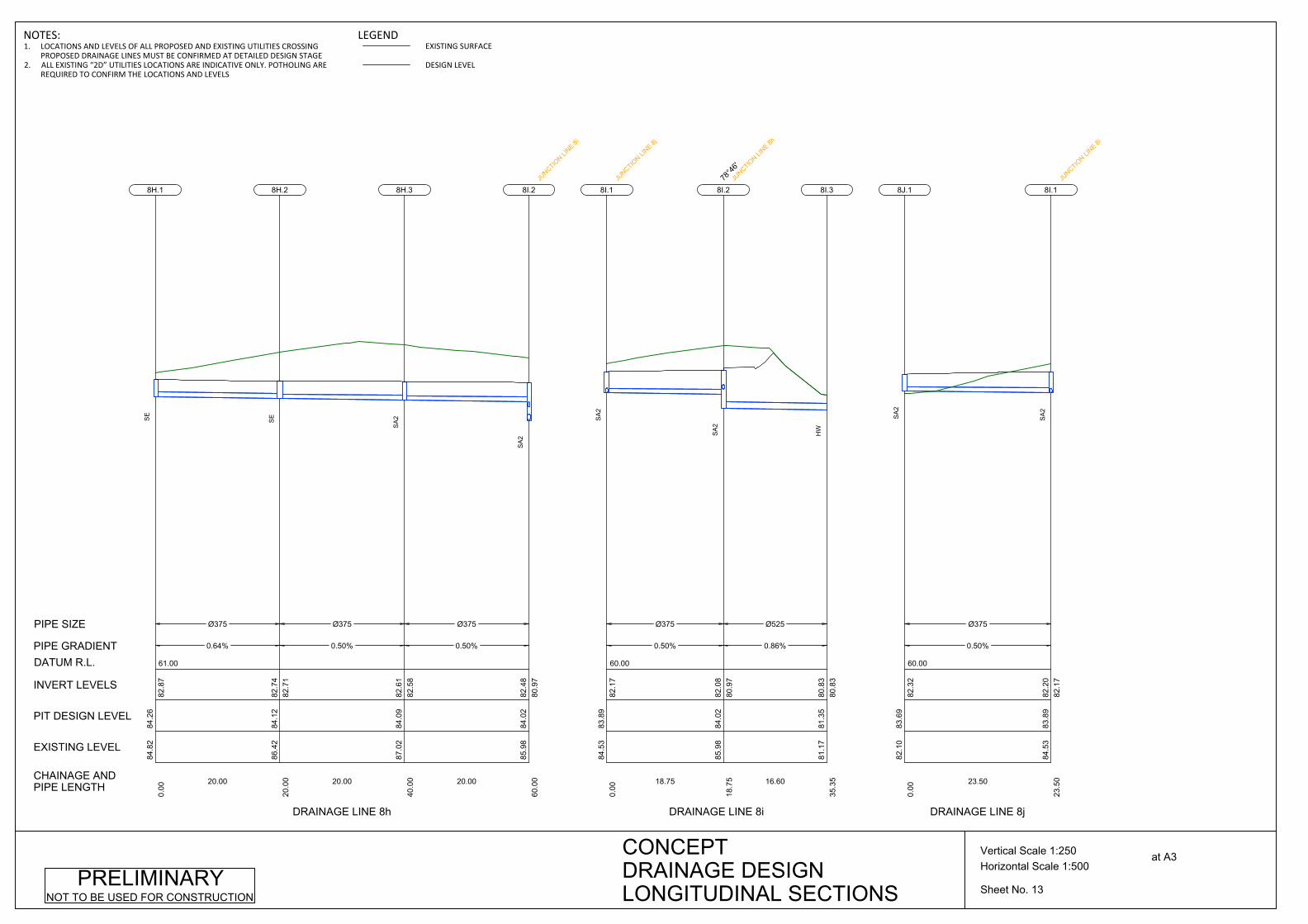
61.00
Ø375
0.64%
20.00
84.8
284
.26
0.00
82.8
7
8H.1
SE
Ø375
0.50%
20.00
86.4
284
.12
20.0
082
.71
82.7
4
8H.2
SE
Ø375
0.50%
20.00
87.0
284
.09
40.0
082
.58
82.6
1
8H.3
SA
2
85.9
884
.02
60.0
080
.97
82.4
8
8I.2
JUNCTIO
N LINE 8i
SA
2
CHAINAGE ANDPIPE LENGTH
EXISTING LEVEL
PIT DESIGN LEVEL
INVERT LEVELS
PIPE GRADIENT
PIPE SIZE
DATUM R.L.
DRAINAGE LINE 8h
60.00
Ø375
0.50%
18.75
84.5
383
.89
0.00
82.1
7
8I.1JU
NCTION LI
NE 8j
SA
2
Ø525
0.86%
16.60
85.9
884
.02
18.7
580
.97
82.0
8
8I.278
°46'
JUNCTIO
N LINE 8h
SA
2
81.1
781
.35
35.3
580
.83
80.8
3
8I.3
HW
DRAINAGE LINE 8i
60.00
Ø375
0.50%
23.50
82.1
083
.69
0.00
82.3
2
8J.1
SA
2
84.5
383
.89
23.5
082
.17
82.2
0
8I.1
JUNCTIO
N LINE 8i
SA
2
DRAINAGE LINE 8j
Sheet No. 13
Horizontal Scale 1:500Vertical Scale 1:250 at A3CONCEPT
DRAINAGE DESIGNLONGITUDINAL SECTIONS
PRELIMINARYNOT TO BE USED FOR CONSTRUCTION
NOTES:1. LOCATIONS AND LEVELS OF ALL PROPOSED AND EXISTING UTILITIES CROSSING
PROPOSED DRAINAGE LINES MUST BE CONFIRMED AT DETAILED DESIGN STAGE2. ALL EXISTING “2D” UTILITIES LOCATIONS ARE INDICATIVE ONLY. POTHOLING ARE
REQUIRED TO CONFIRM THE LOCATIONS AND LEVELS
LEGENDEXISTING SURFACE
DESIGN LEVEL

60.00
Ø450
0.50%
36.25
84.5
184
.17
0.00
82.7
5
9A.1
SA
1
Ø450
2.54%
8.37
84.1
184
.18
36.2
582
.54
82.5
7
9A.270
°24'
SE
Ø450
0.99%
19.65
84.4
383
.85
44.6
382
.29
82.3
2
9A.3-74
°05'
SA
2
83.5
483
.54
64.2
782
.07
82.1
0
9B.1
JUNCTIO
N LINE 9b
SA
2
CHAINAGE ANDPIPE LENGTH
EXISTING LEVEL
PIT DESIGN LEVEL
INVERT LEVELS
PIPE GRADIENT
PIPE SIZE
DATUM R.L.
DRAINAGE LINE 9a
59.00
Ø450
1.39%
20.07
83.5
483
.54
0.00
82.0
7
9B.1
JUNCTIO
N LINE 9a
SA
2Ø450
0.50%
19.72
83.0
183
.24
20.0
781
.76
81.7
9
9B.20°
54'
SA
2
Ø450
1.00%
4.62
83.2
083
.11
39.7
981
.63
81.6
6
9B.389
°41'
SA
2
81.6
082
.03
44.4
281
.58
81.5
8
9B.4
HW
DRAINAGE LINE 9b
59.00
Ø375
1.00%
34.91
83.0
883
.05
0.00
81.6
8
11A.1
SA
2
82.9
382
.75
34.9
181
.33
11A.2-99
°51'
SA
2
DRAINAGE LINE 11a
Sheet No. 14
Horizontal Scale 1:500Vertical Scale 1:250 at A3CONCEPT
DRAINAGE DESIGNLONGITUDINAL SECTIONS
PRELIMINARYNOT TO BE USED FOR CONSTRUCTION
NOTES:1. LOCATIONS AND LEVELS OF ALL PROPOSED AND EXISTING UTILITIES CROSSING
PROPOSED DRAINAGE LINES MUST BE CONFIRMED AT DETAILED DESIGN STAGE2. ALL EXISTING “2D” UTILITIES LOCATIONS ARE INDICATIVE ONLY. POTHOLING ARE
REQUIRED TO CONFIRM THE LOCATIONS AND LEVELS
LEGENDEXISTING SURFACE
DESIGN LEVEL
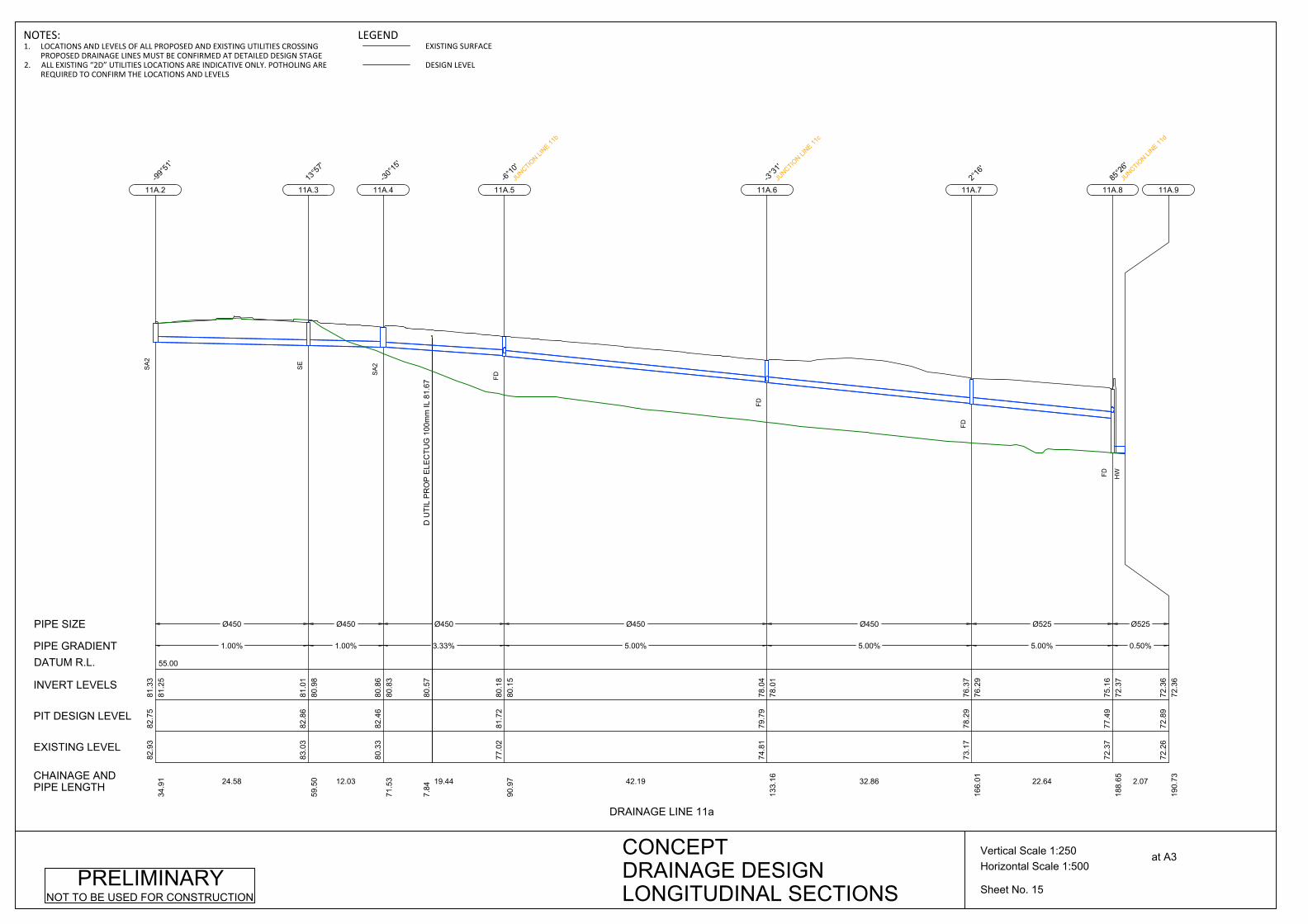
55.00
Ø450
1.00%
24.58
82.9
382
.75
34.9
181
.25
81.3
3
11A.2-99
°51'
SA
2
Ø450
1.00%
12.03
83.0
382
.86
59.5
080
.98
81.0
1
11A.313
°57'
SE
D U
TIL
PR
OP
ELE
CTU
G 1
00m
m IL
81.
6780
.57
7.84
Ø450
3.33%
19.44
80.3
382
.46
71.5
380
.83
80.8
6
11A.4-30
°15'
SA
2
Ø450
5.00%
42.19
77.0
281
.72
90.9
780
.15
80.1
8
11A.5-6°
10'
JUNCTIO
N LINE 11
b
FD
Ø450
5.00%
32.86
74.8
179
.79
133.
1678
.01
78.0
4
11A.6-3°
31'
JUNCTIO
N LINE 11
c
FD
Ø525
5.00%
22.64
73.1
778
.29
166.
0176
.29
76.3
7
11A.72°
16'
FD
Ø525
0.50%
2.07
72.3
777
.49
188.
6572
.37
75.1
6
11A.885
°26'
JUNCTIO
N LINE 11
d
FD
72.2
672
.89
190.
7372
.36
72.3
6
11A.9
HW
CHAINAGE ANDPIPE LENGTH
EXISTING LEVEL
PIT DESIGN LEVEL
INVERT LEVELS
PIPE GRADIENT
PIPE SIZE
DATUM R.L.
DRAINAGE LINE 11a
Sheet No. 15
Horizontal Scale 1:500Vertical Scale 1:250 at A3CONCEPT
DRAINAGE DESIGNLONGITUDINAL SECTIONS
PRELIMINARYNOT TO BE USED FOR CONSTRUCTION
NOTES:1. LOCATIONS AND LEVELS OF ALL PROPOSED AND EXISTING UTILITIES CROSSING
PROPOSED DRAINAGE LINES MUST BE CONFIRMED AT DETAILED DESIGN STAGE2. ALL EXISTING “2D” UTILITIES LOCATIONS ARE INDICATIVE ONLY. POTHOLING ARE
REQUIRED TO CONFIRM THE LOCATIONS AND LEVELS
LEGENDEXISTING SURFACE
DESIGN LEVEL

57.00
Ø450
4.02%
25.56
82.8
983
.14
0.00
81.7
5
11B.1
SA
2
D U
TIL
PR
OP
ELE
CTU
G 1
00m
m IL
81.
6780
.60
5.42
Ø450
1.79%
17.61
82.2
182
.51
25.5
680
.69
80.7
2
11B.2-37
°08'
SE
77.0
281
.72
43.1
780
.15
80.3
8
11A.5
JUNCTIO
N LINE 11
a
FD
CHAINAGE ANDPIPE LENGTH
EXISTING LEVEL
PIT DESIGN LEVEL
INVERT LEVELS
PIPE GRADIENT
PIPE SIZE
DATUM R.L.
DRAINAGE LINE 11b
54.00
Ø450
2.00%
16.11
79.0
679
.94
0.00
78.4
2
11C.1
SA
2
74.8
179
.79
16.1
178
.01
78.0
9
11A.6JU
NCTION LI
NE 11a
FD
DRAINAGE LINE 11c
52.00
Ø450
2.46%
16.08
76.9
777
.52
0.00
76.0
0
11D.1
SA
2
72.3
777
.49
16.0
872
.37
75.6
0
11A.8
JUNCTIO
N LINE 11
a
FD
DRAINAGE LINE 11d
52.00
Ø375
1.00%
25.27
75.7
376
.51
0.00
75.0
3
12A.1
SA
2
Ø375
1.00%
24.73
76.4
176
.41
25.2
774
.75
74.7
8
12A.2
SA
2
76.2
076
.25
50.0
074
.50
12A.3-0°
03'
SA
2
DRAINAGE LINE 12a
Sheet No. 16
Horizontal Scale 1:500Vertical Scale 1:250 at A3CONCEPT
DRAINAGE DESIGNLONGITUDINAL SECTIONS
PRELIMINARYNOT TO BE USED FOR CONSTRUCTION
NOTES:1. LOCATIONS AND LEVELS OF ALL PROPOSED AND EXISTING UTILITIES CROSSING
PROPOSED DRAINAGE LINES MUST BE CONFIRMED AT DETAILED DESIGN STAGE2. ALL EXISTING “2D” UTILITIES LOCATIONS ARE INDICATIVE ONLY. POTHOLING ARE
REQUIRED TO CONFIRM THE LOCATIONS AND LEVELS
LEGENDEXISTING SURFACE
DESIGN LEVEL
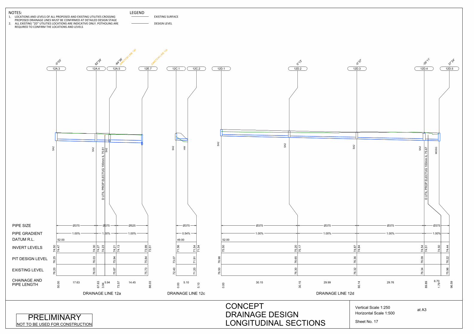
52.00
Ø375
1.00%
17.63
76.2
076
.25
50.0
074
.47
74.5
0
12A.3-0°
03'
SA
2
D U
TIL
PR
OP
ELE
CTU
G 1
00m
m IL
75.
6174
.23
3.94
Ø375
1.00%
5.94
76.0
376
.03
67.6
374
.27
74.3
0
12A.482
°29'
SA
2
Ø525
1.00%
14.45
75.8
775
.94
73.5
774
.13
74.2
1
12A.5-84
°36'
JUNCTIO
N LINE 12
d
SA
2
75.7
375
.84
88.0
373
.51
73.9
9
12E.7JU
NCTION LI
NE 12e
CHAINAGE ANDPIPE LENGTH
EXISTING LEVEL
PIT DESIGN LEVEL
INVERT LEVELS
PIPE GRADIENT
PIPE SIZE
DATUM R.L.
DRAINAGE LINE 12a
49.00
Ø375
0.54%
5.10
72.4
073
.07
0.00
71.5
6
12C.1
SA
2
71.2
071
.91
5.10
71.5
471
.54
12C.2
HW
DRAINAGE LINE 12c
52.00
Ø375
1.00%
30.15
76.5
076
.98
0.00
75.5
0
12D.1
SA
2
Ø375
1.00%
29.99
76.3
076
.65
30.1
575
.17
75.2
0
12D.20°
13'
SA
2
Ø375
1.00%
29.76
76.3
276
.36
60.1
474
.84
74.8
7
12D.3-0°
37'
SA
2
D U
TIL
PR
OP
ELE
CTU
G 1
00m
m IL
75.
67
74.5
01.
79
Ø375
1.00%
6.70
76.3
476
.09
89.8
974
.51
74.5
4
12D.4-39
°11'
SA
2
75.9
676
.22
96.5
974
.44
12D.537
°24'
MG
SG
DRAINAGE LINE 12d
Sheet No. 17
Horizontal Scale 1:500Vertical Scale 1:250 at A3CONCEPT
DRAINAGE DESIGNLONGITUDINAL SECTIONS
PRELIMINARYNOT TO BE USED FOR CONSTRUCTION
NOTES:1. LOCATIONS AND LEVELS OF ALL PROPOSED AND EXISTING UTILITIES CROSSING
PROPOSED DRAINAGE LINES MUST BE CONFIRMED AT DETAILED DESIGN STAGE2. ALL EXISTING “2D” UTILITIES LOCATIONS ARE INDICATIVE ONLY. POTHOLING ARE
REQUIRED TO CONFIRM THE LOCATIONS AND LEVELS
LEGENDEXISTING SURFACE
DESIGN LEVEL
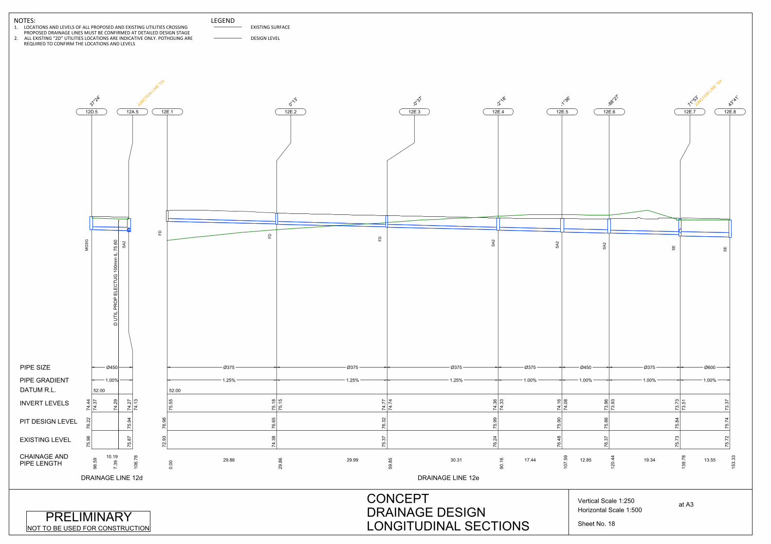
52.00
D U
TIL
PR
OP
ELE
CTU
G 1
00m
m IL
75.
6074
.29
7.39
Ø450
1.00%
10.19
75.9
676
.22
96.5
974
.37
74.4
4
12D.537
°24'
MG
SG
75.8
775
.94
106.
7874
.13
74.2
7
12A.5JU
NCTION LI
NE 12a
SA
2
CHAINAGE ANDPIPE LENGTH
EXISTING LEVEL
PIT DESIGN LEVEL
INVERT LEVELS
PIPE GRADIENT
PIPE SIZE
DATUM R.L.
DRAINAGE LINE 12d
52.00
Ø375
1.25%
29.86
72.9
376
.98
0.00
75.5
5
12E.1
FD
Ø375
1.25%
29.99
74.3
876
.65
29.8
675
.15
75.1
8
12E.20°
13'
FD
Ø375
1.25%
30.31
75.3
776
.32
59.8
574
.74
74.7
7
12E.3-0°
37'
FD
Ø375
1.00%
17.44
76.2
475
.99
90.1
674
.33
74.3
6
12E.4-2°
18'
SA
2
Ø450
1.00%
12.85
76.4
875
.90
107.
5974
.08
74.1
6
12E.5-1°
36'
SA
2
Ø375
1.00%
19.34
76.3
775
.86
120.
4473
.93
73.9
6
12E.6-88
°27'
SA
2
Ø600
1.00%
13.55
75.7
375
.84
139.
7873
.51
73.7
3
12E.771
°53'
JUNCTIO
N LINE 12
a
SE
75.7
275
.74
153.
3373
.37
12E.843
°41'
SE
DRAINAGE LINE 12e
Sheet No. 18
Horizontal Scale 1:500Vertical Scale 1:250 at A3CONCEPT
DRAINAGE DESIGNLONGITUDINAL SECTIONS
PRELIMINARYNOT TO BE USED FOR CONSTRUCTION
NOTES:1. LOCATIONS AND LEVELS OF ALL PROPOSED AND EXISTING UTILITIES CROSSING
PROPOSED DRAINAGE LINES MUST BE CONFIRMED AT DETAILED DESIGN STAGE2. ALL EXISTING “2D” UTILITIES LOCATIONS ARE INDICATIVE ONLY. POTHOLING ARE
REQUIRED TO CONFIRM THE LOCATIONS AND LEVELS
LEGENDEXISTING SURFACE
DESIGN LEVEL

51.00
Ø600
1.00%
11.12
75.7
275
.74
153.
3373
.34
73.3
7
12E.843
°41'
SE
Ø600
1.00%
14.15
75.4
575
.54
164.
45
73.2
073
.23
12E.9-18
°48'
JUNCTIO
N LINE 12
g
SE
Ø600
1.00%
16.23
75.6
175
.34
178.
60
73.0
373
.06
12E.10-21
°50'
SE
Ø600
1.00%
9.91
75.1
475
.15
194.
83
72.8
472
.87
12E.1153
°05'
SE
Ø600
1.00%
15.99
75.2
274
.90
204.
7472
.71
72.7
4
12E.12-42
°33'
SA
2
Ø675
1.00%
35.84
74.8
374
.60
220.
72
72.4
772
.55
12E.136°
57'
SA
2
Ø750
0.50%
11.2473
.17
73.8
825
6.56
72.0
472
.11
12E.1426
°44'
SA
2
72.2
672
.73
267.
8071
.98
71.9
8
12E.15
HW
CHAINAGE ANDPIPE LENGTH
EXISTING LEVEL
PIT DESIGN LEVEL
INVERT LEVELS
PIPE GRADIENT
PIPE SIZE
DATUM R.L.
DRAINAGE LINE 12e
52.00
Ø375
2.00%
8.70
76.6
175
.63
0.00
74.2
7
12G.1
SE
75.4
575
.54
8.70
73.2
074
.10
12E.9JU
NCTION LI
NE 12e
SE
DRAINAGE LINE 12g
49.00
Ø375
2.00%
5.35
72.8
572
.70
0.00
70.9
2
12H.1
SA
2
71.1
171
.19
5.35
70.8
170
.81
12H.2
HW
DRAINAGE LINE 12h
Sheet No. 19
Horizontal Scale 1:500Vertical Scale 1:250 at A3CONCEPT
DRAINAGE DESIGNLONGITUDINAL SECTIONS
PRELIMINARYNOT TO BE USED FOR CONSTRUCTION
NOTES:1. LOCATIONS AND LEVELS OF ALL PROPOSED AND EXISTING UTILITIES CROSSING
PROPOSED DRAINAGE LINES MUST BE CONFIRMED AT DETAILED DESIGN STAGE2. ALL EXISTING “2D” UTILITIES LOCATIONS ARE INDICATIVE ONLY. POTHOLING ARE
REQUIRED TO CONFIRM THE LOCATIONS AND LEVELS
LEGENDEXISTING SURFACE
DESIGN LEVEL
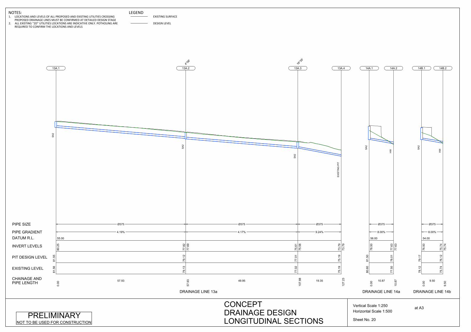
55.00
Ø375
4.19%
57.93
81.5
681
.55
0.00
80.2
5
13A.1
SA
2
Ø375
4.17%
49.95
79.1
379
.12
57.9
377
.69
77.8
2
13A.24°
06'
SA
2
Ø375
9.24%
19.35
77.0
277
.01
107.
8875
.58
75.6
1
13A.316
°35'
SA
2
75.1
975
.19
127.
2373
.79
73.7
9
13A.4
EX
ISTI
NG
PIT
CHAINAGE ANDPIPE LENGTH
EXISTING LEVEL
PIT DESIGN LEVEL
INVERT LEVELS
PIPE GRADIENT
PIPE SIZE
DATUM R.L.
DRAINAGE LINE 13a
56.00
Ø375
8.00%
10.87
80.6
081
.50
0.00
78.5
0
14A.1
SA
2
77.5
078
.01
10.8
777
.63
77.6
3
14A.2
HW
DRAINAGE LINE 14a
54.00
Ø375
8.00%
9.50
78.1
279
.17
0.00
76.5
0
14B.1
SA
2
75.7
476
.12
9.50
75.7
475
.74
14B.2
HW
DRAINAGE LINE 14b
Sheet No. 20
Horizontal Scale 1:500Vertical Scale 1:250 at A3CONCEPT
DRAINAGE DESIGNLONGITUDINAL SECTIONS
PRELIMINARYNOT TO BE USED FOR CONSTRUCTION
NOTES:1. LOCATIONS AND LEVELS OF ALL PROPOSED AND EXISTING UTILITIES CROSSING
PROPOSED DRAINAGE LINES MUST BE CONFIRMED AT DETAILED DESIGN STAGE2. ALL EXISTING “2D” UTILITIES LOCATIONS ARE INDICATIVE ONLY. POTHOLING ARE
REQUIRED TO CONFIRM THE LOCATIONS AND LEVELS
LEGENDEXISTING SURFACE
DESIGN LEVEL

53.00
Ø375
3.00%
9.84
76.7
377
.10
0.00
75.4
0
14C.1
SA
2
75.6
575
.48
9.84
75.1
075
.10
14C.2
HW
CHAINAGE ANDPIPE LENGTH
EXISTING LEVEL
PIT DESIGN LEVEL
INVERT LEVELS
PIPE GRADIENT
PIPE SIZE
DATUM R.L.
DRAINAGE LINE 14c
51.00
Ø375
5.00%
19.39
75.2
775
.27
0.00
73.8
5
14D.1
MG
DG
74.2
674
.26
19.3
972
.89
72.8
9
14D.2
EX
ISTI
NG
PIT
DRAINAGE LINE 14d
52.00
Ø375
1.61%
20.00
75.9
176
.30
0.00
74.9
0
15A.1
SA
2
Ø375
0.76%
15.00
75.5
475
.97
20.0
074
.55
74.5
8
15A.2
SA
2
Ø375
0.50%
15.00
75.5
975
.82
35.0
074
.41
74.4
4
15A.3
SA
2
Ø375
0.50%
15.00
75.5
575
.75
50.0
074
.30
74.3
3
15A.4
SA
2
Ø375
0.50%
15.00
75.4
575
.70
65.0
074
.20
74.2
3
15A.5
SA
2
Ø375
0.50%
15.00
75.3
675
.65
80.0
074
.09
74.1
2
15A.6
SA
2
Ø375
0.50%
15.00
75.2
675
.60
95.0
073
.99
74.0
2
15A.7
SA
2
Ø375
0.50%
9.08
75.1
275
.55
110.
0073
.88
73.9
1
15A.8-1°
08'
SA
2
74.9
175
.66
119.
0873
.84
15A.91°
38'
SA
2
DRAINAGE LINE 15a
Sheet No. 21
Horizontal Scale 1:500Vertical Scale 1:250 at A3CONCEPT
DRAINAGE DESIGNLONGITUDINAL SECTIONS
PRELIMINARYNOT TO BE USED FOR CONSTRUCTION
NOTES:1. LOCATIONS AND LEVELS OF ALL PROPOSED AND EXISTING UTILITIES CROSSING
PROPOSED DRAINAGE LINES MUST BE CONFIRMED AT DETAILED DESIGN STAGE2. ALL EXISTING “2D” UTILITIES LOCATIONS ARE INDICATIVE ONLY. POTHOLING ARE
REQUIRED TO CONFIRM THE LOCATIONS AND LEVELS
LEGENDEXISTING SURFACE
DESIGN LEVEL

51.00
Ø375
0.50%
20.92
74.9
175
.66
119.
0873
.81
73.8
4
15A.91°
38'
SA
2
Ø375
0.50%
15.00
74.7
675
.44
140.
0073
.67
73.7
0
15A.10-0°
30'
SA
2
Ø375
0.50%
15.00
74.9
175
.37
155.
0073
.57
73.6
0
15A.11
SA
2
75.0
975
.27
170.
0073
.45
73.4
9
15B.3
JUNCTIO
N LINE 15
b
SA
2
CHAINAGE ANDPIPE LENGTH
EXISTING LEVEL
PIT DESIGN LEVEL
INVERT LEVELS
PIPE GRADIENT
PIPE SIZE
DATUM R.L.
DRAINAGE LINE 15a
50.00
Ø375
0.50%
17.94
75.2
875
.04
0.00
73.6
7
15B.1
SA
2
Ø375
0.50%
15.00
75.1
375
.17
17.9
473
.55
73.5
8
15B.2
SA
2
Ø450
0.50%
24.89
75.0
975
.27
32.9
473
.45
73.4
8
15B.3-94
°50'
JUNCTIO
N LINE 15
a
SA
2
Ø450
7.43%
25.58
75.2
174
.96
57.8
372
.54
73.3
2
15B.410
°45'
JUNCTIO
N LINE 15
c
JUNCTIO
N LINE 15
d
SA
2
73.1
973
.19
83.4
170
.64
70.6
4
15B.5
EX
ISTI
NG
PIT
DRAINAGE LINE 15b
Sheet No. 22
Horizontal Scale 1:500Vertical Scale 1:250 at A3CONCEPT
DRAINAGE DESIGNLONGITUDINAL SECTIONS
PRELIMINARYNOT TO BE USED FOR CONSTRUCTION
NOTES:1. LOCATIONS AND LEVELS OF ALL PROPOSED AND EXISTING UTILITIES CROSSING
PROPOSED DRAINAGE LINES MUST BE CONFIRMED AT DETAILED DESIGN STAGE2. ALL EXISTING “2D” UTILITIES LOCATIONS ARE INDICATIVE ONLY. POTHOLING ARE
REQUIRED TO CONFIRM THE LOCATIONS AND LEVELS
LEGENDEXISTING SURFACE
DESIGN LEVEL

51.00
Ø375
1.64%
21.01
76.3
076
.22
0.00
74.8
4
15C.1
SA
2
Ø375
0.62%
14.98
75.8
975
.87
21.0
174
.46
74.4
9
15C.20°
15'
SA
2
Ø375
0.84%
15.94
75.7
275
.69
35.9
974
.34
74.3
7
15C.34°
39'
SA
2
Ø450
0.50%
45.60
75.5
075
.49
51.9
374
.04
74.2
1
15C.4-7°
05'
SA
2
Ø450
0.50%
22.34
75.3
875
.38
97.5
373
.78
73.8
1
15C.5
2°11
'
SA
2
Ø450
0.50%
8.39
75.3
175
.24
119.
8773
.64
73.6
7
15C.6-0°
10'
SA
2
Ø450
0.50%
15.00
75.2
275
.17
128.
2673
.56
73.5
9
15C.7
SA
2
Ø450
0.50%
15.00
75.1
175
.07
143.
2673
.46
73.4
9
15C.8
SA
2
Ø450
0.50%
15.00
75.2
275
.02
158.
2673
.35
73.3
8
15C.9
SA
2
75.2
174
.96
173.
2672
.54
73.2
8
15B.4JU
NCTION LI
NE 15b
SA
2
CHAINAGE ANDPIPE LENGTH
EXISTING LEVEL
PIT DESIGN LEVEL
INVERT LEVELS
PIPE GRADIENT
PIPE SIZE
DATUM R.L.
DRAINAGE LINE 15c
Sheet No. 23
Horizontal Scale 1:500Vertical Scale 1:250 at A3CONCEPT
DRAINAGE DESIGNLONGITUDINAL SECTIONS
PRELIMINARYNOT TO BE USED FOR CONSTRUCTION
NOTES:1. LOCATIONS AND LEVELS OF ALL PROPOSED AND EXISTING UTILITIES CROSSING
PROPOSED DRAINAGE LINES MUST BE CONFIRMED AT DETAILED DESIGN STAGE2. ALL EXISTING “2D” UTILITIES LOCATIONS ARE INDICATIVE ONLY. POTHOLING ARE
REQUIRED TO CONFIRM THE LOCATIONS AND LEVELS
LEGENDEXISTING SURFACE
DESIGN LEVEL
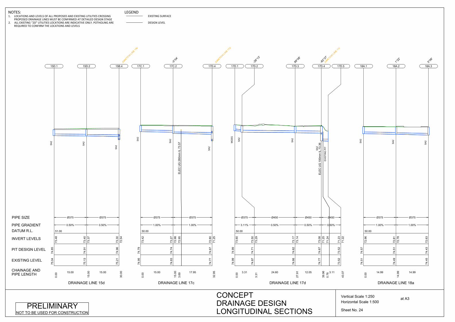
51.00
Ø375
0.50%
15.00
75.0
474
.85
0.00
73.4
8
15D.1
SA
2
Ø375
0.50%
15.00
75.1
374
.91
15.0
073
.37
73.4
0
15D.2
SA
2
75.2
174
.96
30.0
072
.54
73.3
0
15B.4JU
NCTION LI
NE 15b
SA
2
CHAINAGE ANDPIPE LENGTH
EXISTING LEVEL
PIT DESIGN LEVEL
INVERT LEVELS
PIPE GRADIENT
PIPE SIZE
DATUM R.L.
DRAINAGE LINE 15d
50.00
Ø375
1.00%
15.00
74.9
574
.79
0.00
73.4
2
17C.1
SA
2
ELE
C U
G 2
80m
m IL
73.
5772
.95
3.69
Ø375
1.00%
17.95
74.8
374
.74
15.0
072
.98
73.2
7
17C.2-0°
04'
SA
2
74.7
774
.67
32.9
571
.25
72.8
0
17D.4JU
NCTION LI
NE 17d
SA
2
DRAINAGE LINE 17c
50.00
Ø375
3.11%
3.31
74.9
974
.99
0.00
73.6
0
17D.1
MG
SG
Ø450
0.50%
24.60
74.8
774
.71
3.31
73.2
973
.50
17D.2-28
°13'
SA
2
Ø450
0.50%
12.05
74.6
674
.62
27.9
173
.14
73.1
7
17D.389
°08'
SA
2
ELE
C U
G 1
00m
m IL
73.
36
71.2
40.
78
Ø450
0.50%
3.11
74.7
774
.67
39.9
671
.25
73.0
8
17D.4-82
°37'
JUNCTIO
N LINE 17
c
SA
2
73.5
273
.52
43.0
771
.22
71.2
3
17D.5
EX
ISTI
NG
PIT
DRAINAGE LINE 17d
50.00
Ø375
1.00%
14.99
74.5
174
.57
0.00
72.9
6
18A.1
SA
2
Ø375
1.00%
14.99
74.4
974
.51
14.9
972
.78
72.8
1
18A.21°
22'
SA
2
74.4
574
.43
72.6
3
18A.3
5°06
'
SA
2
DRAINAGE LINE 18a
Sheet No. 24
Horizontal Scale 1:500Vertical Scale 1:250 at A3CONCEPT
DRAINAGE DESIGNLONGITUDINAL SECTIONS
PRELIMINARYNOT TO BE USED FOR CONSTRUCTION
NOTES:1. LOCATIONS AND LEVELS OF ALL PROPOSED AND EXISTING UTILITIES CROSSING
PROPOSED DRAINAGE LINES MUST BE CONFIRMED AT DETAILED DESIGN STAGE2. ALL EXISTING “2D” UTILITIES LOCATIONS ARE INDICATIVE ONLY. POTHOLING ARE
REQUIRED TO CONFIRM THE LOCATIONS AND LEVELS
LEGENDEXISTING SURFACE
DESIGN LEVEL

48.00
Ø375
1.00%
20.00
74.4
574
.43
29.9
772
.60
72.6
3
18A.35°
06'
SA
2
Ø375
1.25%
20.00
74.2
474
.23
49.9
772
.37
72.4
0
18A.40°
05'
SA
2
Ø450
2.00%
20.00
73.9
773
.95
69.9
772
.05
72.1
2
18A.5
SA
2
Ø450
2.00%
20.00
73.5
673
.55
89.9
771
.62
71.6
5
18A.6
SA
2
Ø450
2.00%
20.00
73.1
173
.13
109.
9771
.19
71.2
2
18A.7
SA
2
Ø450
2.50%
20.0072
.56
72.5
912
9.97
70.7
670
.79
18A.8
SA
2
Ø450
2.50%
25.00
71.9
872
.01
149.
9770
.23
70.2
6
18A.9
SA
2
Ø450
2.50%
22.00
71.4
671
.44
174.
9769
.57
69.6
0
18A.10-0°
01'
SA
2
71.1
671
.18
196.
9769
.02
18A.1124
°08'
SA
2
CHAINAGE ANDPIPE LENGTH
EXISTING LEVEL
PIT DESIGN LEVEL
INVERT LEVELS
PIPE GRADIENT
PIPE SIZE
DATUM R.L.
DRAINAGE LINE 18a
Sheet No. 25
Horizontal Scale 1:500Vertical Scale 1:250 at A3CONCEPT
DRAINAGE DESIGNLONGITUDINAL SECTIONS
PRELIMINARYNOT TO BE USED FOR CONSTRUCTION
NOTES:1. LOCATIONS AND LEVELS OF ALL PROPOSED AND EXISTING UTILITIES CROSSING
PROPOSED DRAINAGE LINES MUST BE CONFIRMED AT DETAILED DESIGN STAGE2. ALL EXISTING “2D” UTILITIES LOCATIONS ARE INDICATIVE ONLY. POTHOLING ARE
REQUIRED TO CONFIRM THE LOCATIONS AND LEVELS
LEGENDEXISTING SURFACE
DESIGN LEVEL
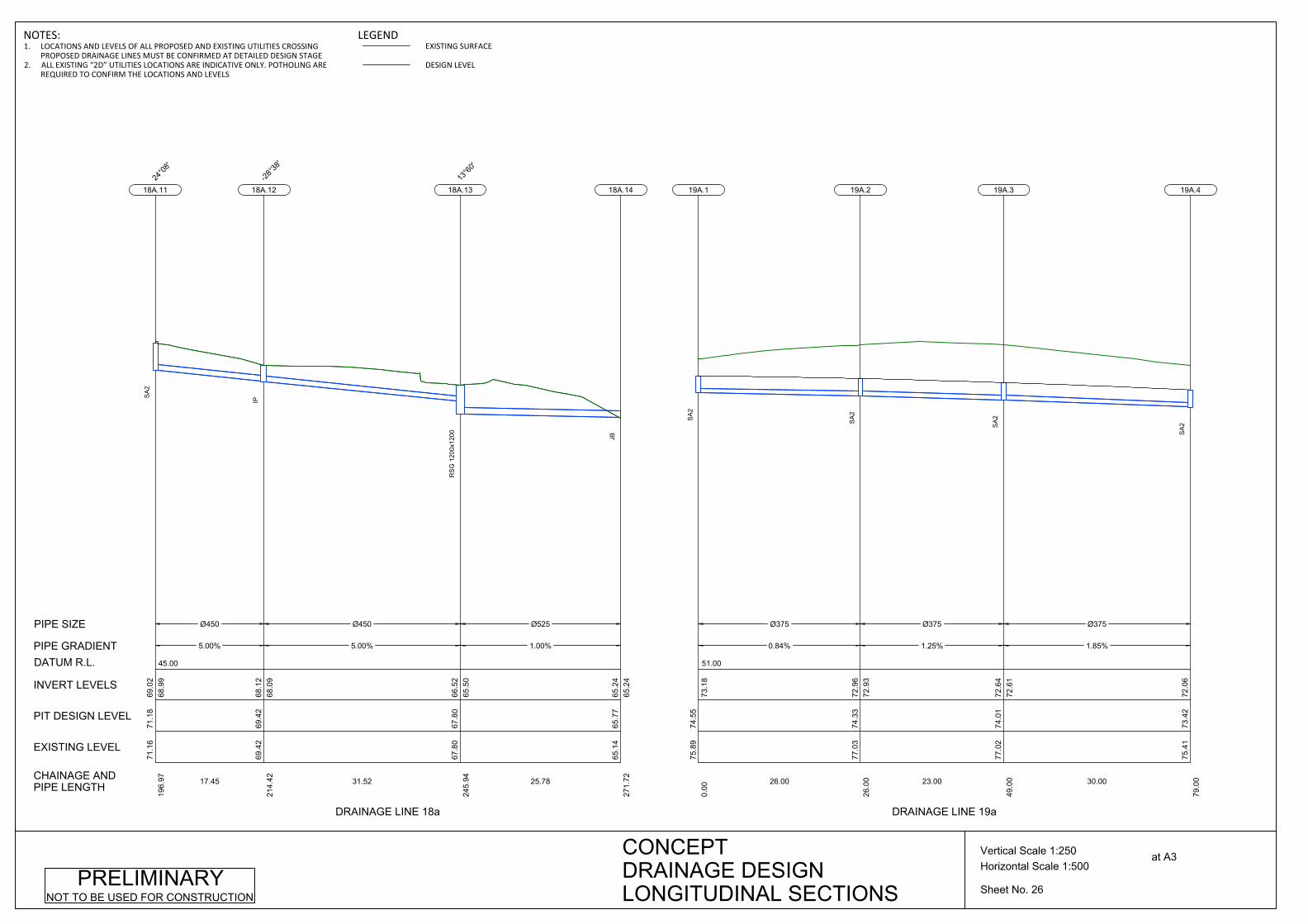
45.00
Ø450
5.00%
17.45
71.1
671
.18
196.
9768
.99
69.0
2
18A.1124
°08'
SA
2
Ø450
5.00%
31.52
69.4
269
.42
214.
4268
.09
68.1
2
18A.12-28
°38'
IP
Ø525
1.00%
25.78
67.8
067
.80
245.
9465
.50
66.5
2
18A.1313
°60'
RS
G 1
200x
1200
65.1
465
.77
271.
7265
.24
65.2
4
18A.14
JB
CHAINAGE ANDPIPE LENGTH
EXISTING LEVEL
PIT DESIGN LEVEL
INVERT LEVELS
PIPE GRADIENT
PIPE SIZE
DATUM R.L.
DRAINAGE LINE 18a
51.00
Ø375
0.84%
26.00
75.8
974
.55
0.00
73.1
8
19A.1
SA
2
Ø375
1.25%
23.00
77.0
374
.33
26.0
072
.93
72.9
6
19A.2
SA
2
Ø375
1.85%
30.00
77.0
274
.01
49.0
072
.61
72.6
4
19A.3
SA
2
75.4
173
.42
79.0
072
.06
19A.4
SA
2
DRAINAGE LINE 19a
Sheet No. 26
Horizontal Scale 1:500Vertical Scale 1:250 at A3CONCEPT
DRAINAGE DESIGNLONGITUDINAL SECTIONS
PRELIMINARYNOT TO BE USED FOR CONSTRUCTION
NOTES:1. LOCATIONS AND LEVELS OF ALL PROPOSED AND EXISTING UTILITIES CROSSING
PROPOSED DRAINAGE LINES MUST BE CONFIRMED AT DETAILED DESIGN STAGE2. ALL EXISTING “2D” UTILITIES LOCATIONS ARE INDICATIVE ONLY. POTHOLING ARE
REQUIRED TO CONFIRM THE LOCATIONS AND LEVELS
LEGENDEXISTING SURFACE
DESIGN LEVEL
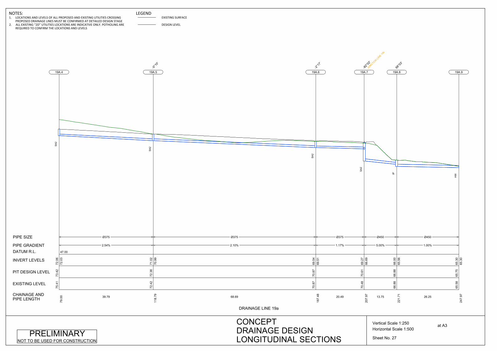
47.00
Ø375
2.54%
39.79
75.4
173
.42
79.0
072
.03
72.0
6
19A.4
SA
2
Ø375
2.10%
68.69
72.4
272
.38
118.
7970
.99
71.0
2
19A.5
-0°10
'
SA
2
Ø375
1.17%
20.49
70.8
770
.87
187.
4869
.51
69.5
4
19A.6-2°
17'
SA
2
Ø450
5.00%
13.75
70.4
870
.61
207.
9766
.69
69.2
7
19A.7-82
°02'
JUNCTIO
N LINE 19
b
SA
2
Ø450
1.00%
26.25
66.8
866
.88
221.
7165
.56
66.0
0
19A.868
°03'
IP
65.5
865
.75
247.
9765
.30
65.3
0
19A.9
HW
CHAINAGE ANDPIPE LENGTH
EXISTING LEVEL
PIT DESIGN LEVEL
INVERT LEVELS
PIPE GRADIENT
PIPE SIZE
DATUM R.L.
DRAINAGE LINE 19a
Sheet No. 27
Horizontal Scale 1:500Vertical Scale 1:250 at A3CONCEPT
DRAINAGE DESIGNLONGITUDINAL SECTIONS
PRELIMINARYNOT TO BE USED FOR CONSTRUCTION
NOTES:1. LOCATIONS AND LEVELS OF ALL PROPOSED AND EXISTING UTILITIES CROSSING
PROPOSED DRAINAGE LINES MUST BE CONFIRMED AT DETAILED DESIGN STAGE2. ALL EXISTING “2D” UTILITIES LOCATIONS ARE INDICATIVE ONLY. POTHOLING ARE
REQUIRED TO CONFIRM THE LOCATIONS AND LEVELS
LEGENDEXISTING SURFACE
DESIGN LEVEL

46.00
Ø450
1.39%
11.99
71.0
971
.04
0.00
69.5
9
19B.1
SE
Ø450
2.00%
11.30
70.9
270
.87
11.9
969
.39
69.4
2
19B.2-97
°46'
SE
70.4
870
.61
23.2
966
.69
69.1
7
19A.7JU
NCTION LI
NE 19a
SA
2
CHAINAGE ANDPIPE LENGTH
EXISTING LEVEL
PIT DESIGN LEVEL
INVERT LEVELS
PIPE GRADIENT
PIPE SIZE
DATUM R.L.
DRAINAGE LINE 19b
46.00
Ø375
0.71%
16.00
70.6
570
.70
0.00
69.3
2
19C.1
SE
Ø375
0.50%
12.00
70.5
570
.58
16.0
069
.18
69.2
1
19C.2-1°
15'
SE
Ø450
4.29%
11.93
70.4
670
.49
28.0
069
.03
69.1
2
19C.3-73
°57'
SE
Ø450
5.00%
6.96
69.4
670
.04
39.9
368
.49
68.5
2
19C.4-15
°21'
JUNCTIO
N LINE 19
d
SA
2
67.7
568
.59
46.8
968
.14
68.1
4
19C.5
HW
DRAINAGE LINE 19c
46.00
Ø375
0.86%
25.43
70.0
070
.27
0.00
68.9
2
19D.1
SA
2
69.4
670
.04
25.4
368
.49
68.7
1
19C.4JU
NCTION LI
NE 19c
SA
2
DRAINAGE LINE 19d
47.00
Ø450
0.80%
7.71
70.3
670
.38
0.00
68.9
6
19E.1
SA
2
Ø450
0.50%
18.00
70.3
270
.37
7.71
68.8
768
.90
19E.287
°40'
SE
Ø450
0.50%
16.00
70.2
070
.24
25.7
168
.75
68.7
8
19E.3-1°
31'
SE
E S
EW
ER
2d
70.0
970
.13
41.7
168
.67
19E.4-2°
05'
SE
DRAINAGE LINE 19e
Sheet No. 28
Horizontal Scale 1:500Vertical Scale 1:250 at A3CONCEPT
DRAINAGE DESIGNLONGITUDINAL SECTIONS
PRELIMINARYNOT TO BE USED FOR CONSTRUCTION
NOTES:1. LOCATIONS AND LEVELS OF ALL PROPOSED AND EXISTING UTILITIES CROSSING
PROPOSED DRAINAGE LINES MUST BE CONFIRMED AT DETAILED DESIGN STAGE2. ALL EXISTING “2D” UTILITIES LOCATIONS ARE INDICATIVE ONLY. POTHOLING ARE
REQUIRED TO CONFIRM THE LOCATIONS AND LEVELS
LEGENDEXISTING SURFACE
DESIGN LEVEL

46.00
Ø450
0.62%
31.00
70.0
970
.13
41.7
168
.64
68.6
7
19E.4-2°
05'
SE
Ø450
2.77%
20.15
69.8
869
.89
72.7
168
.42
68.4
5
19E.5-39
°51'
SE
Ø450
3.00%
17.55
69.1
669
.37
92.8
667
.83
67.8
6
19E.6-62
°14'
JUNCTIO
N LINE 19
f
SA
2
67.8
267
.75
110.
4167
.30
67.3
0
19E.7
HW
CHAINAGE ANDPIPE LENGTH
EXISTING LEVEL
PIT DESIGN LEVEL
INVERT LEVELS
PIPE GRADIENT
PIPE SIZE
DATUM R.L.
DRAINAGE LINE 19e
46.00
Ø375
0.69%
15.49
69.4
869
.92
0.00
68.5
7
19F.1
SA
2
Ø375
0.55%
14.48
69.0
669
.81
15.4
968
.43
68.4
6
19F.2-1°
26'
SA
2
E S
EW
ER
2d
Ø375
0.54%
14.99
69.0
369
.70
29.9
768
.32
68.3
5
19F.3-1°
24'
SA
2
Ø375
0.54%
14.99
68.8
969
.59
44.9
668
.21
68.2
4
19F.4-1°
26'
SA
2
Ø375
0.54%
14.99
68.9
569
.48
59.9
568
.10
68.1
3
19F.5-1°
26'
SA
2
69.1
669
.37
74.9
467
.83
68.0
2
19E.6JU
NCTION LI
NE 19e
SA
2
DRAINAGE LINE 19f
Sheet No. 29
Horizontal Scale 1:500Vertical Scale 1:250 at A3CONCEPT
DRAINAGE DESIGNLONGITUDINAL SECTIONS
PRELIMINARYNOT TO BE USED FOR CONSTRUCTION
NOTES:1. LOCATIONS AND LEVELS OF ALL PROPOSED AND EXISTING UTILITIES CROSSING
PROPOSED DRAINAGE LINES MUST BE CONFIRMED AT DETAILED DESIGN STAGE2. ALL EXISTING “2D” UTILITIES LOCATIONS ARE INDICATIVE ONLY. POTHOLING ARE
REQUIRED TO CONFIRM THE LOCATIONS AND LEVELS
LEGENDEXISTING SURFACE
DESIGN LEVEL

45.00
Ø375
0.70%
14.99
69.3
769
.26
0.00
67.9
0
20A.1
SA
2
Ø375
0.54%
14.98
69.2
369
.15
14.9
967
.76
67.7
9
20A.2-1°
26'
SA
2
Ø375
0.54%
15.08
68.9
969
.04
29.9
667
.65
67.6
8
20A.3-1°
26'
SA
2
Ø375
0.63%
14.91
68.9
068
.92
45.0
467
.54
67.5
7
20A.4-1°
19'
SA
2
Ø375
0.58%
15.00
68.8
268
.81
59.9
567
.42
67.4
5
20A.5-0°
15'
SA
2
Ø375
0.53%
15.09
68.6
968
.70
74.9
567
.30
67.3
3
20A.6
SA
2
Ø450
0.50%
15.00
68.5
868
.59
90.0
467
.11
67.2
2
20A.7JU
NCTION LI
NE 20b
SA
2
Ø450
0.50%
15.00
68.4
868
.48
105.
0467
.00
67.0
3
20A.8
SA
2
Ø450
0.53%
15.00
68.4
068
.37
120.
0466
.90
66.9
3
20A.9
SA
2
Ø450
0.50%
15.00
68.2
968
.26
135.
0466
.79
66.8
2
20A.10
SA
2
Ø450
0.50%
5.61
68.1
968
.16
150.
0466
.68
66.7
1
20A.111°
07'
SA
2
68.1
568
.13
155.
6566
.65
66.6
5
20D.5
SA
2
CHAINAGE ANDPIPE LENGTH
EXISTING LEVEL
PIT DESIGN LEVEL
INVERT LEVELS
PIPE GRADIENT
PIPE SIZE
DATUM R.L.
DRAINAGE LINE 20a
Sheet No. 30
Horizontal Scale 1:500Vertical Scale 1:250 at A3CONCEPT
DRAINAGE DESIGNLONGITUDINAL SECTIONS
PRELIMINARYNOT TO BE USED FOR CONSTRUCTION
NOTES:1. LOCATIONS AND LEVELS OF ALL PROPOSED AND EXISTING UTILITIES CROSSING
PROPOSED DRAINAGE LINES MUST BE CONFIRMED AT DETAILED DESIGN STAGE2. ALL EXISTING “2D” UTILITIES LOCATIONS ARE INDICATIVE ONLY. POTHOLING ARE
REQUIRED TO CONFIRM THE LOCATIONS AND LEVELS
LEGENDEXISTING SURFACE
DESIGN LEVEL

45.00
Ø375
0.74%
28.00
69.6
669
.70
0.00
68.3
2
20B.1
SE
Ø375
0.60%
22.00
69.4
769
.48
28.0
068
.09
68.1
2
20B.2
-2°14
'
SE
Ø375
0.50%
25.00
69.3
469
.32
50.0
067
.93
67.9
6
20B.3-2°
37'
SE
Ø375
0.76%
15.00
69.1
269
.24
74.9
967
.77
67.8
0
20B.4-0°
02'
SE
Ø450
2.23%
14.61
68.9
969
.03
89.9
967
.46
67.6
6
20B.5-66
°58'
JUNCTIO
N LINE 20
k
SE
68.5
868
.59
104.
6067
.11
67.1
4
20A.7JU
NCTION LI
NE 20a
SA
2
CHAINAGE ANDPIPE LENGTH
EXISTING LEVEL
PIT DESIGN LEVEL
INVERT LEVELS
PIPE GRADIENT
PIPE SIZE
DATUM R.L.
DRAINAGE LINE 20b
44.00
Ø375
0.50%
9.39
68.0
968
.06
0.00
66.6
9
20C.1
SA
2
68.1
568
.13
9.39
66.6
466
.64
20D.5
SA
2
DRAINAGE LINE 20c
44.00
Ø375
2.57%
27.89
68.5
568
.50
0.00
67.1
2
20E.1
SA
2
67.7
868
.11
27.8
966
.41
66.4
1
20D.4
EX
ISTI
NG
PIT
DRAINAGE LINE 20e
Sheet No. 31
Horizontal Scale 1:500Vertical Scale 1:250 at A3CONCEPT
DRAINAGE DESIGNLONGITUDINAL SECTIONS
PRELIMINARYNOT TO BE USED FOR CONSTRUCTION
NOTES:1. LOCATIONS AND LEVELS OF ALL PROPOSED AND EXISTING UTILITIES CROSSING
PROPOSED DRAINAGE LINES MUST BE CONFIRMED AT DETAILED DESIGN STAGE2. ALL EXISTING “2D” UTILITIES LOCATIONS ARE INDICATIVE ONLY. POTHOLING ARE
REQUIRED TO CONFIRM THE LOCATIONS AND LEVELS
LEGENDEXISTING SURFACE
DESIGN LEVEL
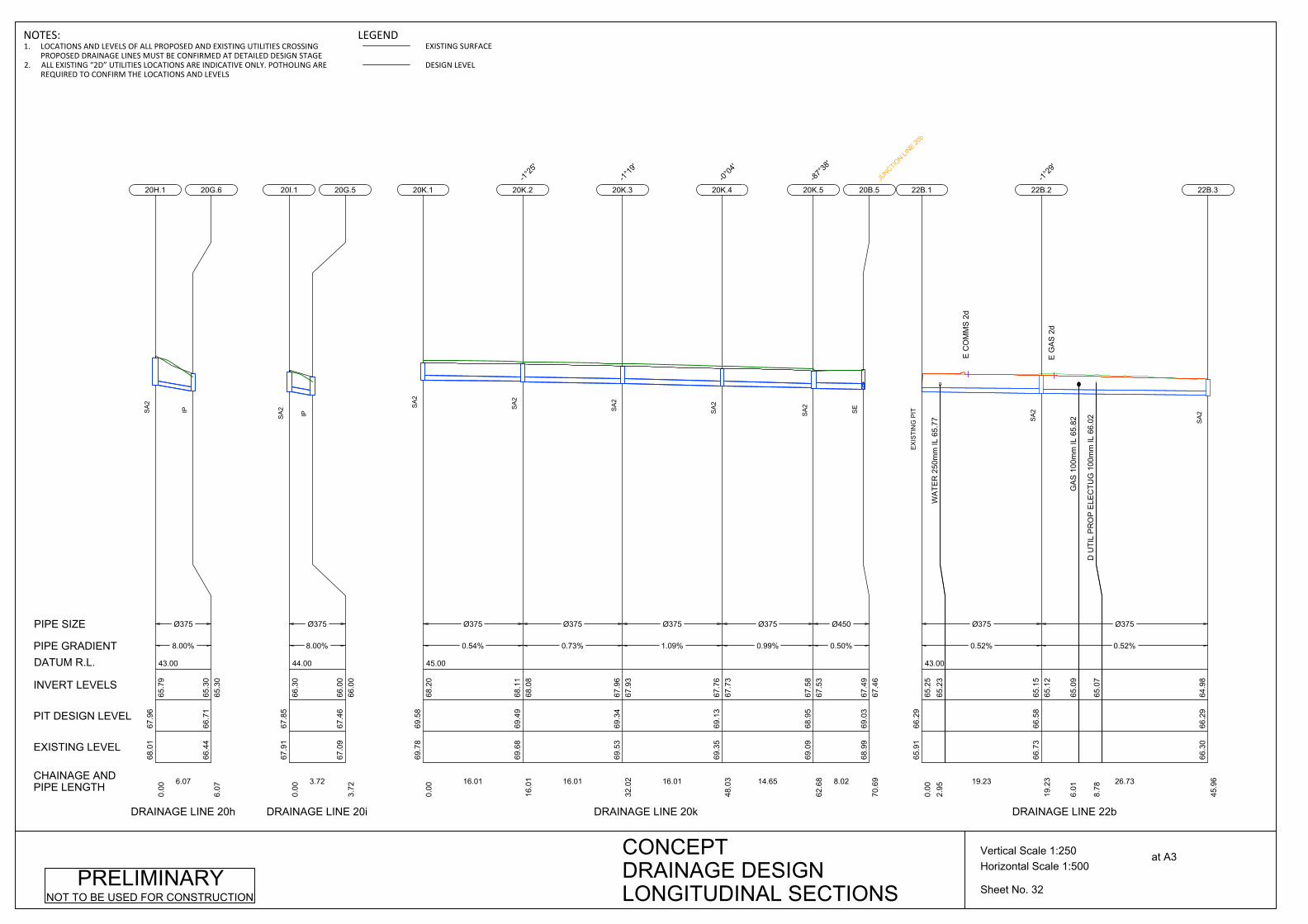
0.50%
8.02
69.0
968
.95
62.6
867
.53
67.5
8
20K.5-87
°38'
SA
2
68.9
969
.03
70.6
967
.46
67.4
9
20B.5JU
NCTION LI
NE 20b
SE
DRAINAGE LINE 20k
Sheet No. 32
Horizontal Scale 1:500Vertical Scale 1:250 at A3CONCEPT
DRAINAGE DESIGNLONGITUDINAL SECTIONS
PRELIMINARYNOT TO BE USED FOR CONSTRUCTION
43.00
Ø375
8.00%
6.07
68.0
167
.96
0.00
65.7
9
20H.1
SA
2
66.4
466
.71
6.07
65.3
065
.30
20G.6IP
CHAINAGE ANDPIPE LENGTH
EXISTING LEVEL
PIT DESIGN LEVEL
INVERT LEVELS
PIPE GRADIENT
PIPE SIZE
DATUM R.L.
DRAINAGE LINE 20h
44.00
Ø375
8.00%
3.72
67.9
167
.85
0.00
66.3
0
20I.1
SA
2
67.0
967
.46
3.72
66.0
066
.00
20G.5
IP
DRAINAGE LINE 20i
45.00
Ø375
0.54%
16.01
69.7
869
.58
0.00
68.2
0
20K.1
SA
2
Ø375
0.73%
16.01
69.6
869
.49
16.0
168
.08
68.1
1
20K.2-1°
25'
SA
2
Ø375
1.09%
16.01
69.5
369
.34
32.0
267
.93
67.9
6
20K.3-1°
19'
SA
2
Ø375
0.99%
14.65
69.3
569
.13
48.0
367
.73
67.7
6
20K.4
-0°04
'
SA
2
Ø450
19.2
365
.12
65.1
5
22B.2
-1°29
'
SA
2
E G
AS
2d
66.3
066
.29
45.9
664
.98
22B.3
SA
2
DRAINAGE LINE 22b
43.00
WA
TER
250
mm
IL 6
5.77
65.2
32.
95
Ø375
0.52%
19.23
65.9
166
.29
0.00
65.2
5
22B.1
EX
ISTI
NG
PIT
E C
OM
MS
2d
GA
S 1
00m
m IL
65.
8265
.09
6.01
D U
TIL
PR
OP
ELE
CTU
G 1
00m
m IL
66.
0265
.07
8.78
Ø375
0.52%
26.73
66.7
366
.58
NOTES:1. LOCATIONS AND LEVELS OF ALL PROPOSED AND EXISTING UTILITIES CROSSING
PROPOSED DRAINAGE LINES MUST BE CONFIRMED AT DETAILED DESIGN STAGE2. ALL EXISTING “2D” UTILITIES LOCATIONS ARE INDICATIVE ONLY. POTHOLING ARE
REQUIRED TO CONFIRM THE LOCATIONS AND LEVELS
LEGENDEXISTING SURFACE
DESIGN LEVEL
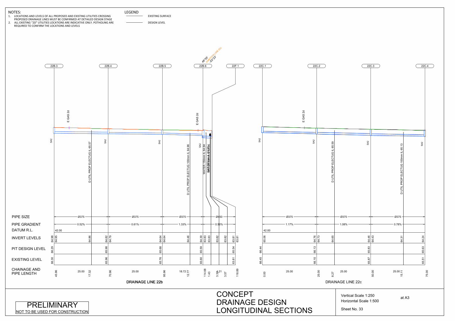
65.5
165
.63
75.0
064
.24
22C.4
SA
2
DRAINAGE LINE 22c
Sheet No. 33
Horizontal Scale 1:500Vertical Scale 1:250 at A3CONCEPT
DRAINAGE DESIGNLONGITUDINAL SECTIONS
PRELIMINARYNOT TO BE USED FOR CONSTRUCTION
DRAINAGE LINE 22b
42.00
Ø375
1.17%
25.00
66.4
566
.44
0.00
65.0
6
22C.1
SA
2
E G
AS
2d
D U
TIL
PR
OP
ELE
CTU
G IL
65.
5964
.65
8.27
Ø375
1.08%
25.00
66.1
066
.13
25.0
064
.73
64.7
6
22C.2
SA
2
D U
TIL
PR
OP
ELE
CTU
G 1
00m
m IL
65.
1364
.31
15.1
1
Ø375
0.78%
25.00
65.8
765
.83
50.0
064
.43
64.4
6
22C.3
SA
2
JUNCTIO
N LINE 22
c
-53°2
3'
SA
2
63.8
165
.54
118.
8963
.81
63.8
1
22F.1
CHAINAGE ANDPIPE LENGTH
EXISTING LEVEL
PIT DESIGN LEVEL
INVERT LEVELS
PIPE GRADIENT
PIPE SIZE
DATUM R.L.
DRAINAGE LINE 22b
42.00
D U
TIL
PR
OP
ELE
CTU
G IL
65.
5764
.86
17.3
2
Ø375
0.52%
25.00
66.3
066
.29
45.9
664
.95
64.9
8
22B.3
SA
2
E G
AS
2d
Ø375
0.61%
25.00
65.9
665
.98
70.9
664
.79
64.8
2
22B.4
SA
2
D U
TIL
PR
OP
ELE
CTU
G 1
00m
m IL
64.
9664
.46
12.7
7
Ø375
1.33%
18.72
65.7
665
.68
95.9
664
.64
64.6
4
22B.5
SA
2
E G
AS
2d
WA
TER
150
mm
IL 6
4.94
63.8
31.
43G
AS
350
mm
IL 6
4.38
63.8
23.
32
WA
TER
50m
m IL
64.
96
63.8
23.
57
Ø450
0.50%
4.21
65.6
065
.59
114.
6863
.83
64.3
9
22B.648
°55'
NOTES:1. LOCATIONS AND LEVELS OF ALL PROPOSED AND EXISTING UTILITIES CROSSING
PROPOSED DRAINAGE LINES MUST BE CONFIRMED AT DETAILED DESIGN STAGE2. ALL EXISTING “2D” UTILITIES LOCATIONS ARE INDICATIVE ONLY. POTHOLING ARE
REQUIRED TO CONFIRM THE LOCATIONS AND LEVELS
LEGENDEXISTING SURFACE
DESIGN LEVEL

42.00
Ø375
0.50%
11.25
65.5
165
.63
75.0
064
.21
64.2
4
22C.4
SA
2
E G
AS
2d
Ø450
0.50%
23.68
65.3
965
.59
86.2
564
.01
64.1
5
22C.5
101°
59'
JUNCTIO
N LINE 22
e
SA
2
65.6
065
.59
109.
9463
.83
63.8
9
22B.6
JUNCTIO
N LINE 22
b
SA
2
CHAINAGE ANDPIPE LENGTH
EXISTING LEVEL
PIT DESIGN LEVEL
INVERT LEVELS
PIPE GRADIENT
PIPE SIZE
DATUM R.L.
DRAINAGE LINE 22c
42.00
D U
TIL
PR
OP
ELE
CTU
G IL
65.
3764
.69
1.37
D U
TIL
PR
OP
ELE
CTU
G 1
00m
m IL
65.
1864
.62
13.9
1
Ø375
0.56%
26.99
66.0
666
.07
0.00
64.7
0
22E.1
SE
D U
TIL
PR
OP
WA
TER
250
mm
IL 6
3.75
64.3
65.
36
Ø450
1.23%
15.24
65.8
865
.91
26.9
964
.43
64.5
4
22E.239
°28'
SE
Ø450
0.67%
12.00
65.2
265
.67
42.2
464
.19
64.2
4
22E.3-40
°33'
SA
2
E G
AS
2d
Ø450
0.50%
8.7965
.30
65.5
854
.24
64.0
864
.11
22E.4
SA
2
65.3
965
.59
63.0
364
.01
64.0
4
22C.5
JUNCTIO
N LINE 22
c
SA
2
DRAINAGE LINE 22e
42.00
D U
TIL
PR
OP
ELE
CTU
G 1
00m
m IL
65.
4364
.65
9.37
Ø375
0.70%
15.00
66.4
666
.09
0.00
64.7
2
23A.1
SE
Ø375
1.06%
16.96
66.3
965
.98
15.0
064
.58
64.6
1
23A.24°
18'
SE
D U
TIL
PR
OP
ELE
CTU
G 1
00m
m IL
65.
0664
.11
11.0
1
Ø450
1.48%
18.00
66.0
865
.77
31.9
664
.27
64.4
0
23A.34°
15'JU
NCTION LI
NE 23g
SE
65.6
165
.45
49.9
564
.00
23A.40°
47'
SE
DRAINAGE LINE 23a
Sheet No. 34
Horizontal Scale 1:500Vertical Scale 1:250 at A3CONCEPT
DRAINAGE DESIGNLONGITUDINAL SECTIONS
PRELIMINARYNOT TO BE USED FOR CONSTRUCTION
NOTES:1. LOCATIONS AND LEVELS OF ALL PROPOSED AND EXISTING UTILITIES CROSSING
PROPOSED DRAINAGE LINES MUST BE CONFIRMED AT DETAILED DESIGN STAGE2. ALL EXISTING “2D” UTILITIES LOCATIONS ARE INDICATIVE ONLY. POTHOLING ARE
REQUIRED TO CONFIRM THE LOCATIONS AND LEVELS
LEGENDEXISTING SURFACE
DESIGN LEVEL

41.00
Ø450
1.81%
8.00
65.6
165
.45
49.9
563
.97
64.0
0
23A.40°
47'
SE
Ø450
1.00%
15.60
65.3
865
.28
57.9
563
.77
63.8
3
23A.599
°03'
JUNCTIO
N LINE 23
h
SE
65.3
065
.20
73.5
563
.19
63.6
2
23D.1
JUNCTIO
N LINE 23
d
SA
2
CHAINAGE ANDPIPE LENGTH
EXISTING LEVEL
PIT DESIGN LEVEL
INVERT LEVELS
PIPE GRADIENT
PIPE SIZE
DATUM R.L.
DRAINAGE LINE 23a
41.00
D U
TIL
PR
OP
WA
TER
250
mm
IL 6
4.56
63.8
632
.57
Ø375
0.50%
36.53
65.6
065
.59
0.00
64.0
2
22B.6JU
NCTION LI
NE 22c
SA
2
E G
AS
2d
D U
TIL
PR
OP
ELE
CTU
G 1
00m
m IL
65.
1563
.76
10.6
4
D U
TIL
PR
OP
ELE
CTU
G IL
65.
3363
.63
35.7
1
D U
TIL
PR
OP
ELE
CTU
G 1
00m
m IL
65.
2463
.46
69.1
3
Ø375
0.50%
73.27
65.8
665
.79
36.5
363
.81
63.8
4
23C.21°
03'
SA
2
E G
AS
2d
65.8
465
.79
109.
8163
.44
23C.34°
13'
SA
2
DRAINAGE LINE 23c
Sheet No. 35
Horizontal Scale 1:500Vertical Scale 1:250 at A3CONCEPT
DRAINAGE DESIGNPRELIMINARYNOT TO BE USED FOR CONSTRUCTION
NOTES:1. LOCATIONS AND LEVELS OF ALL PROPOSED AND EXISTING UTILITIES CROSSING
PROPOSED DRAINAGE LINES MUST BE CONFIRMED AT DETAILED DESIGN STAGE2. ALL EXISTING “2D” UTILITIES LOCATIONS ARE INDICATIVE ONLY. POTHOLING ARE
REQUIRED TO CONFIRM THE LOCATIONS AND LEVELS
LEGENDEXISTING SURFACE
DESIGN LEVEL
LONGITUDINAL SECTIONS

41.00
D U
TIL
PR
OP
WA
TER
250
mm
IL 6
4.82
63.3
317
.01
D U
TIL
PR
OP
WA
TER
250
mm
IL 6
4.81
63.3
218
.21
D U
TIL
PR
OP
ELE
CTU
G 1
00m
m IL
64.
7863
.25
33.5
1
Ø375
0.50%
38.48
65.8
465
.79
109.
8163
.41
63.4
4
23C.34°
13'
SA
2
65.3
065
.20
148.
2863
.19
63.2
2
23D.1JU
NCTION LI
NE 23d
SA
2
CHAINAGE ANDPIPE LENGTH
EXISTING LEVEL
PIT DESIGN LEVEL
INVERT LEVELS
PIPE GRADIENT
PIPE SIZE
DATUM R.L.
DRAINAGE LINE 23c
41.00
D U
TIL
PR
OP
ELE
CTU
G 1
00m
m IL
64.
2563
.09
20.6
1
Ø450
0.50%
36.96
65.3
065
.20
0.00
63.1
9
23D.1JU
NCTION LI
NE 23a
JUNCTIO
N LINE 23
c
SA
2
E C
OM
MS
2d
E G
AS
2d
64.3
964
.45
36.9
662
.32
63.0
1
23E.1
JUNCTIO
N LINE 23
e
SA
1
DRAINAGE LINE 23d
40.00
D U
TIL
PR
OP
WA
TER
250
mm
IL 6
3.41
62.3
02.
14G
AS
350
mm
IL 6
2.81
62.2
83.
92
Ø450
1.00%
13.0464
.39
64.4
50.
0062
.32
23E.1JU
NCTION LI
NE 23d
SA
1
E C
OM
MS
2d
63.6
163
.55
13.0
462
.16
62.1
9
23F.1
JUNCTIO
N LINE 23
f
SA
1
DRAINAGE LINE 23e
Sheet No. 36
Horizontal Scale 1:500Vertical Scale 1:250 at A3CONCEPT
DRAINAGE DESIGNLONGITUDINAL SECTIONS
PRELIMINARYNOT TO BE USED FOR CONSTRUCTION
NOTES:1. LOCATIONS AND LEVELS OF ALL PROPOSED AND EXISTING UTILITIES CROSSING
PROPOSED DRAINAGE LINES MUST BE CONFIRMED AT DETAILED DESIGN STAGE2. ALL EXISTING “2D” UTILITIES LOCATIONS ARE INDICATIVE ONLY. POTHOLING ARE
REQUIRED TO CONFIRM THE LOCATIONS AND LEVELS
LEGENDEXISTING SURFACE
DESIGN LEVEL
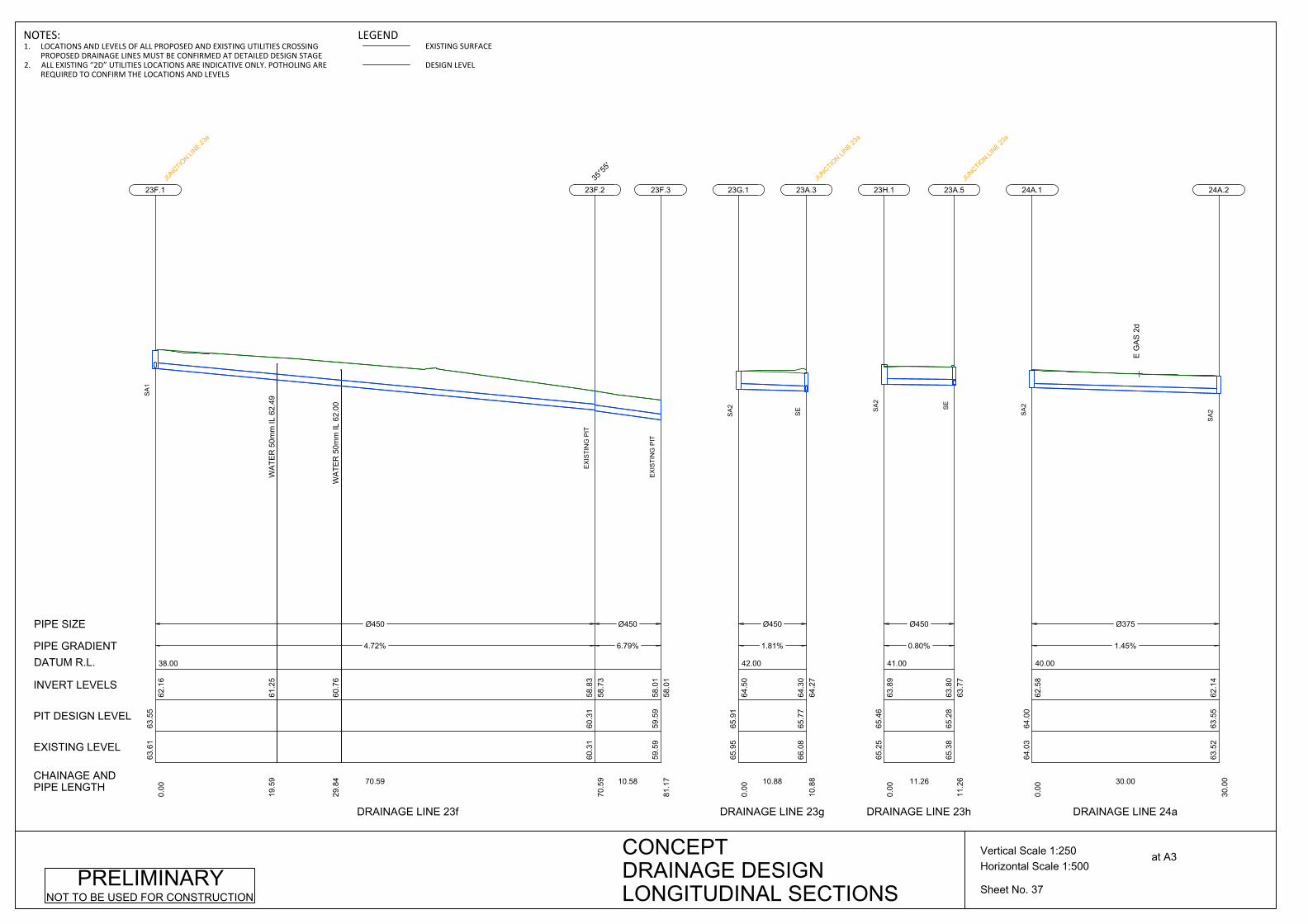
38.00
WA
TER
50m
m IL
62.
4961
.25
19.5
9
WA
TER
50m
m IL
62.
0060
.76
29.8
4
Ø450
4.72%
70.59
63.6
163
.55
0.00
62.1
6
23F.1JU
NCTION LI
NE 23e
SA
1
Ø450
6.79%
10.58
60.3
160
.31
70.5
958
.73
58.8
3
23F.235
°55'
EX
ISTI
NG
PIT
59.5
959
.59
81.1
758
.01
58.0
1
23F.3
EX
ISTI
NG
PIT
CHAINAGE ANDPIPE LENGTH
EXISTING LEVEL
PIT DESIGN LEVEL
INVERT LEVELS
PIPE GRADIENT
PIPE SIZE
DATUM R.L.
DRAINAGE LINE 23f
42.00
Ø450
1.81%
10.88
65.9
565
.91
0.00
64.5
0
23G.1
SA
2
66.0
865
.77
10.8
864
.27
64.3
0
23A.3JU
NCTION LI
NE 23a
SE
DRAINAGE LINE 23g
41.00
Ø450
0.80%
11.26
65.2
565
.46
0.00
63.8
9
23H.1
SA
2
65.3
865
.28
11.2
663
.77
63.8
0
23A.5JU
NCTION LI
NE 23a
SE
DRAINAGE LINE 23h
40.00
Ø375
1.45%
30.00
64.0
364
.00
0.00
62.5
8
24A.1
SA
2
E G
AS
2d
63.5
263
.55
30.0
062
.14
24A.2
SA
2
DRAINAGE LINE 24a
Sheet No. 37
Horizontal Scale 1:500Vertical Scale 1:250 at A3CONCEPT
DRAINAGE DESIGNLONGITUDINAL SECTIONS
PRELIMINARYNOT TO BE USED FOR CONSTRUCTION
NOTES:1. LOCATIONS AND LEVELS OF ALL PROPOSED AND EXISTING UTILITIES CROSSING
PROPOSED DRAINAGE LINES MUST BE CONFIRMED AT DETAILED DESIGN STAGE2. ALL EXISTING “2D” UTILITIES LOCATIONS ARE INDICATIVE ONLY. POTHOLING ARE
REQUIRED TO CONFIRM THE LOCATIONS AND LEVELS
LEGENDEXISTING SURFACE
DESIGN LEVEL

37.00
Ø375
0.50%
20.00
63.5
263
.55
30.0
062
.11
62.1
4
24A.2
SA
2
GA
S 3
50m
m IL
60.
8661
.42
13.3
9
Ø375
4.11%
16.59
63.3
263
.40
50.0
061
.98
62.0
1
24A.3-34
°49'
SA
2
E C
OM
MS
2d
E C
OM
MS
2d
Ø375
5.63%
53.16
62.2
562
.39
66.5
960
.59
61.3
0
24A.4-56
°26'
SA
1
Ø375
4.13%
33.39
59.3
459
.34
119.
7457
.57
57.6
0
24A.5
0°29
'
SA
2
57.6
657
.66
153.
1356
.19
56.1
9
24A.6
EX
ISTI
NG
PIT
CHAINAGE ANDPIPE LENGTH
EXISTING LEVEL
PIT DESIGN LEVEL
INVERT LEVELS
PIPE GRADIENT
PIPE SIZE
DATUM R.L.
DRAINAGE LINE 24a
39.00
D U
TIL
PR
OP
ELE
CTU
G 1
00m
m IL
62.
4961
.50
4.70
Ø375
0.50%
33.55
62.9
262
.90
0.00
61.5
2
25B.1
SA
2
62.7
862
.75
33.5
561
.35
25B.2
SA
2
DRAINAGE LINE 25b
Sheet No. 38
Horizontal Scale 1:500Vertical Scale 1:250 at A3CONCEPT
DRAINAGE DESIGNLONGITUDINAL SECTIONS
PRELIMINARYNOT TO BE USED FOR CONSTRUCTION
NOTES:1. LOCATIONS AND LEVELS OF ALL PROPOSED AND EXISTING UTILITIES CROSSING
PROPOSED DRAINAGE LINES MUST BE CONFIRMED AT DETAILED DESIGN STAGE2. ALL EXISTING “2D” UTILITIES LOCATIONS ARE INDICATIVE ONLY. POTHOLING ARE
REQUIRED TO CONFIRM THE LOCATIONS AND LEVELS
LEGENDEXISTING SURFACE
DESIGN LEVEL

38.00
D U
TIL
PR
OP
ELE
CTU
G 1
00m
m IL
62.
1961
.26
13.7
6
Ø375
0.50%
38.79
62.7
862
.75
33.5
561
.32
61.3
5
25B.2
SA
2
D U
TIL
PR
OP
ELE
CTU
G 1
00m
m IL
61.
9660
.96
12.5
2D
UTI
L P
RO
P E
LEC
TUG
100
mm
IL 6
1.94
60.9
414
.37
Ø375
1.13%
44.58
61.7
762
.51
72.3
461
.10
61.1
3
25B.3-2°
21'
EX
ISTI
NG
PIT
D U
TIL
PR
OP
ELE
CTU
G 1
00m
m IL
61.
0360
.15
16.2
2D
UTI
L P
RO
P E
LEC
TUG
100
mm
IL 6
1.02
60.1
416
.38
Ø375
2.58%
42.52
61.8
161
.99
116.
9260
.57
60.6
0
25B.4
-5°60
'
EX
ISTI
NG
PIT
Ø375
0.58%
33.62
60.1
660
.88
159.
4459
.44
59.4
7
25B.5-6°
55'
EX
ISTI
NG
PIT
59.2
160
.67
193.
0559
.25
59.2
5
25F.1
JUNCTIO
N LINE 26
a
SA
2
CHAINAGE ANDPIPE LENGTH
EXISTING LEVEL
PIT DESIGN LEVEL
INVERT LEVELS
PIPE GRADIENT
PIPE SIZE
DATUM R.L.
DRAINAGE LINE 25b
Sheet No. 39
Horizontal Scale 1:500Vertical Scale 1:250 at A3CONCEPT
DRAINAGE DESIGNLONGITUDINAL SECTIONS
PRELIMINARYNOT TO BE USED FOR CONSTRUCTION
NOTES:1. LOCATIONS AND LEVELS OF ALL PROPOSED AND EXISTING UTILITIES CROSSING
PROPOSED DRAINAGE LINES MUST BE CONFIRMED AT DETAILED DESIGN STAGE2. ALL EXISTING “2D” UTILITIES LOCATIONS ARE INDICATIVE ONLY. POTHOLING ARE
REQUIRED TO CONFIRM THE LOCATIONS AND LEVELS
LEGENDEXISTING SURFACE
DESIGN LEVEL

39.00
Ø375
0.61%
30.00
63.6
163
.59
0.00
62.2
0
25C.1
SA
2
D U
TIL
PR
OP
ELE
CTU
G 1
00m
m IL
62.
7461
.95
8.00
Ø375
0.50%
40.00
63.4
463
.40
30.0
061
.98
62.0
1
25C.2
SA
2
D U
TIL
PR
OP
ELE
CTU
G 1
00m
m IL
62.
8061
.70
11.6
7
Ø375
0.50%
40.00
63.3
763
.23
70.0
061
.75
61.7
8
25C.3
SA
2
D U
TIL
PR
OP
ELE
CTU
G 1
00m
m IL
62.
7761
.48
9.72
D U
TIL
PR
OP
ELE
CTU
G 1
00m
m IL
62.
7361
.39
27.1
1
Ø375
0.50%
31.02
63.4
863
.05
110.
0061
.52
61.5
5
25C.4-0°
27'
SA
2
D U
TIL
PR
OP
ELE
CTU
G 1
00m
m IL
62.
1661
.22
23.3
2
Ø375
0.50%
26.03
63.0
263
.13
141.
0261
.34
61.3
7
25C.5-3°
30'
SA
2
62.3
962
.66
167.
0461
.21
25C.6-3°
45'
SA
2
CHAINAGE ANDPIPE LENGTH
EXISTING LEVEL
PIT DESIGN LEVEL
INVERT LEVELS
PIPE GRADIENT
PIPE SIZE
DATUM R.L.
DRAINAGE LINE 25c
Sheet No. 40
Horizontal Scale 1:500Vertical Scale 1:250 at A3CONCEPT
DRAINAGE DESIGNLONGITUDINAL SECTIONS
PRELIMINARYNOT TO BE USED FOR CONSTRUCTION
NOTES:1. LOCATIONS AND LEVELS OF ALL PROPOSED AND EXISTING UTILITIES CROSSING
PROPOSED DRAINAGE LINES MUST BE CONFIRMED AT DETAILED DESIGN STAGE2. ALL EXISTING “2D” UTILITIES LOCATIONS ARE INDICATIVE ONLY. POTHOLING ARE
REQUIRED TO CONFIRM THE LOCATIONS AND LEVELS
LEGENDEXISTING SURFACE
DESIGN LEVEL
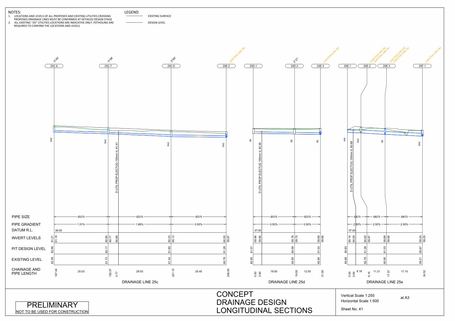
38.00
Ø375
1.51%
25.03
62.3
962
.66
167.
0461
.18
61.2
1
25C.6-3°
45'
SA
2
D U
TIL
PR
OP
ELE
CTU
G 1
00m
m IL
61.
4160
.69
4.77
Ø375
1.86%
29.03
61.7
362
.17
192.
0760
.77
60.8
0
25C.7-3°
58'
SA
2
Ø375
0.50%
25.45
61.3
461
.60
221.
1060
.13
60.2
3
25C.8-3°
60'
SA
2
60.7
961
.28
246.
5559
.97
60.0
0
25E.2JU
NCTION LI
NE 25e
SA
2
CHAINAGE ANDPIPE LENGTH
EXISTING LEVEL
PIT DESIGN LEVEL
INVERT LEVELS
PIPE GRADIENT
PIPE SIZE
DATUM R.L.
DRAINAGE LINE 25c
37.00
D U
TIL
PR
OP
ELE
CTU
G 1
00m
m IL
60.
3659
.86
3.90
Ø375
0.50%
19.00
60.9
561
.07
0.00
59.8
8
25D.1
SE
Ø375
0.50%
12.00
60.8
560
.99
19.0
059
.75
59.7
8
25D.22°
21'
SE
60.9
061
.03
31.0
059
.66
59.6
9
25E.3JU
NCTION LI
NE 25e
SE
DRAINAGE LINE 25d
37.00
D U
TIL
PR
OP
ELE
CTU
G 1
00m
m IL
60.
6860
.09
2.64
Ø675
2.50%
6.16
60.6
860
.83
0.00
60.1
6
25E.1
HW
Ø675
2.50%
11.21
60.7
961
.28
6.16
59.9
760
.00
25E.2JU
NCTION LI
NE 25c
JUNCTIO
N LINE 25
z
SA
2
Ø675
2.50%
17.15
60.9
061
.03
17.3
759
.66
59.6
9
25E.3JU
NCTION LI
NE 25d
JUNCTIO
N LINE 25
y
SE
59.2
160
.67
34.5
259
.25
59.2
4
25F.1
JUNCTIO
N LINE 26
a
SA
2
DRAINAGE LINE 25e
Sheet No. 41
Horizontal Scale 1:500Vertical Scale 1:250 at A3CONCEPT
DRAINAGE DESIGNLONGITUDINAL SECTIONS
PRELIMINARYNOT TO BE USED FOR CONSTRUCTION
NOTES:1. LOCATIONS AND LEVELS OF ALL PROPOSED AND EXISTING UTILITIES CROSSING
PROPOSED DRAINAGE LINES MUST BE CONFIRMED AT DETAILED DESIGN STAGE2. ALL EXISTING “2D” UTILITIES LOCATIONS ARE INDICATIVE ONLY. POTHOLING ARE
REQUIRED TO CONFIRM THE LOCATIONS AND LEVELS
LEGENDEXISTING SURFACE
DESIGN LEVEL
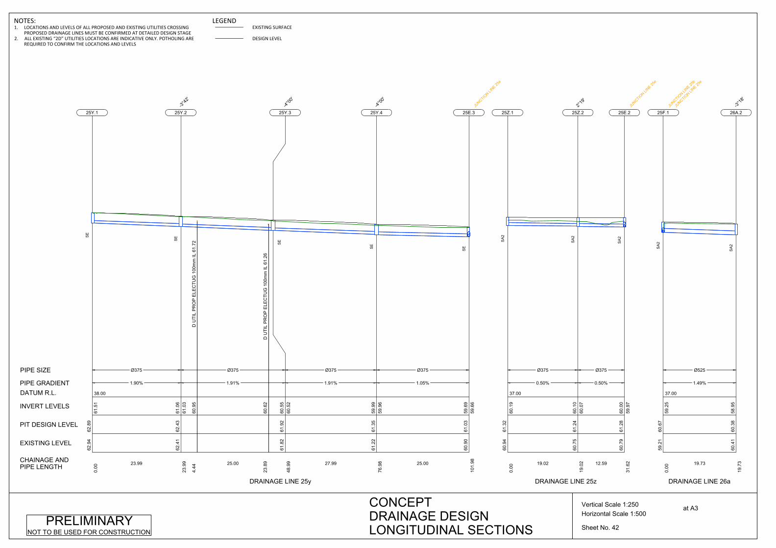
38.00
Ø375
1.90%
23.99
62.9
462
.89
0.00
61.5
1
25Y.1
SE
D U
TIL
PR
OP
ELE
CTU
G 1
00m
m IL
61.
7260
.95
4.44
D U
TIL
PR
OP
ELE
CTU
G 1
00m
m IL
61.
2660
.62
23.8
9
Ø375
1.91%
25.00
62.4
162
.43
23.9
961
.03
61.0
6
25Y.2-3°
42'
SE
Ø375
1.91%
27.99
61.8
261
.92
48.9
960
.52
60.5
5
25Y.3-4°
00'
SE
Ø375
1.05%
25.00
61.2
261
.35
76.9
859
.96
59.9
9
25Y.4-4°
00'
SE
60.9
061
.03
101.
9859
.66
59.6
9
25E.3JU
NCTION LI
NE 25e
SE
CHAINAGE ANDPIPE LENGTH
EXISTING LEVEL
PIT DESIGN LEVEL
INVERT LEVELS
PIPE GRADIENT
PIPE SIZE
DATUM R.L.
DRAINAGE LINE 25y
37.00
Ø375
0.50%
19.02
60.9
461
.32
0.00
60.1
9
25Z.1
SA
2
Ø375
0.50%
12.59
60.7
561
.24
19.0
260
.07
60.1
0
25Z.22°
19'
SA
2
60.7
961
.28
31.6
259
.97
60.0
0
25E.2
JUNCTIO
N LINE 25
e
SA
2
DRAINAGE LINE 25z
37.00
Ø525
1.49%
19.73
59.2
160
.67
0.00
59.2
5
25F.1
JUNCTIO
N LINE 25
b
JUNCTIO
N LINE 25
e
SA
2
60.4
160
.38
19.7
358
.95
26A.2
-3°18
'
SA
2
DRAINAGE LINE 26a
Sheet No. 42
Horizontal Scale 1:500Vertical Scale 1:250 at A3CONCEPT
DRAINAGE DESIGNLONGITUDINAL SECTIONS
PRELIMINARYNOT TO BE USED FOR CONSTRUCTION
NOTES:1. LOCATIONS AND LEVELS OF ALL PROPOSED AND EXISTING UTILITIES CROSSING
PROPOSED DRAINAGE LINES MUST BE CONFIRMED AT DETAILED DESIGN STAGE2. ALL EXISTING “2D” UTILITIES LOCATIONS ARE INDICATIVE ONLY. POTHOLING ARE
REQUIRED TO CONFIRM THE LOCATIONS AND LEVELS
LEGENDEXISTING SURFACE
DESIGN LEVEL

34.00
D U
TIL
PR
OP
ELE
CTU
G 1
00m
m IL
59.
96
58.9
21.
43D
UTI
L P
RO
P E
LEC
TUG
100
mm
IL 5
9.96
58.9
21.
65
Ø525
0.50%
20.00
60.4
160
.38
19.7
358
.92
58.9
5
26A.2-3°
18'
SA
2
WA
TER
50m
m IL
59.
90
58.7
90.
89
Ø525
0.50%
20.00
60.3
560
.32
39.7
358
.79
58.8
2
26A.3-3°
10'
SA
2
Ø525
1.09%
35.00
60.2
660
.23
59.7
258
.66
58.6
9
26A.4-3°
16'
SA
2
E G
AS
2d
D U
TIL
PR
OP
ELE
CTU
G 1
00m
m IL
58.
8857
.95
11.7
7
Ø525
2.55%
34.99
59.7
759
.65
94.7
258
.25
58.2
8
26A.5-1°
30'
SA
2
WA
TER
100
mm
IL 5
7.15
56.3
024
.80
D U
TIL
PR
OP
ELE
CTU
G IL
57.
0556
.15
28.3
6
Ø525
4.13%
34.99
58.6
958
.66
129.
7157
.33
57.3
6
26A.6-4°
55'
SA
2
57.2
057
.17
164.
7055
.88
26A.7-5°
49'
SA
2
CHAINAGE ANDPIPE LENGTH
EXISTING LEVEL
PIT DESIGN LEVEL
INVERT LEVELS
PIPE GRADIENT
PIPE SIZE
DATUM R.L.
DRAINAGE LINE 26a
Sheet No. 43
Horizontal Scale 1:500Vertical Scale 1:250 at A3CONCEPT
DRAINAGE DESIGNLONGITUDINAL SECTIONS
PRELIMINARYNOT TO BE USED FOR CONSTRUCTION
NOTES:1. LOCATIONS AND LEVELS OF ALL PROPOSED AND EXISTING UTILITIES CROSSING
PROPOSED DRAINAGE LINES MUST BE CONFIRMED AT DETAILED DESIGN STAGE2. ALL EXISTING “2D” UTILITIES LOCATIONS ARE INDICATIVE ONLY. POTHOLING ARE
REQUIRED TO CONFIRM THE LOCATIONS AND LEVELS
LEGENDEXISTING SURFACE
DESIGN LEVEL
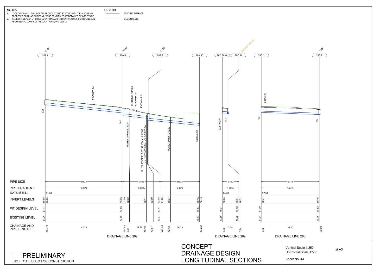
31.00
Ø525
5.20%
42.75
57.2
057
.17
164.
7055
.85
55.8
8
26A.7-5°
49'
SA
2
E S
EW
ER
2d
WA
TER
200
mm
IL 5
3.71
52.6
23.
54
D U
TIL
PR
OP
ELE
CTU
G 1
00m
m IL
52.
8552
.11
13.1
3D
UTI
L P
RO
P E
LEC
TUG
IL 5
2.87
52.0
913
.67
Ø525
5.00%
14.14
54.9
354
.89
207.
4552
.79
53.6
3
26A.8-36
°42'
SA
2
E C
OM
MS
2d
E C
OM
MS
2d
E C
OM
MS
NB
N 2
d
WA
TER
50m
m IL
52.
2950
.97
12.1
2
Ø525
5.00%
28.23
53.3
753
.47
221.
5951
.56
52.0
8
26A.9-55
°50'
SA
1
53.5
453
.54
249.
8250
.15
50.1
5
26A.10
EX
ISTI
NG
PIT
CHAINAGE ANDPIPE LENGTH
EXISTING LEVEL
PIT DESIGN LEVEL
INVERT LEVELS
PIPE GRADIENT
PIPE SIZE
DATUM R.L.
DRAINAGE LINE 26a
24.00
Ø450
1.32%
3.24
47.6
948
.07
0.00
46.5
5
28D.8AAA
EX
ISTI
NG
PIT
47.7
647
.90
3.24
46.3
146
.51
28C.14JU
NCTION LI
NE 28c
SA
2
DRAINAGE LINE 28a
37.00
Ø375
1.74%
32.00
61.3
461
.09
0.00
59.7
1
28B.1
SE
E G
AS
2d
60.7
060
.52
32.0
059
.16
28B.2-1°
09'
SE
DRAINAGE LINE 28b
Sheet No. 44
Horizontal Scale 1:500Vertical Scale 1:250 at A3CONCEPT
DRAINAGE DESIGNLONGITUDINAL SECTIONS
PRELIMINARYNOT TO BE USED FOR CONSTRUCTION
NOTES:1. LOCATIONS AND LEVELS OF ALL PROPOSED AND EXISTING UTILITIES CROSSING
PROPOSED DRAINAGE LINES MUST BE CONFIRMED AT DETAILED DESIGN STAGE2. ALL EXISTING “2D” UTILITIES LOCATIONS ARE INDICATIVE ONLY. POTHOLING ARE
REQUIRED TO CONFIRM THE LOCATIONS AND LEVELS
LEGENDEXISTING SURFACE
DESIGN LEVEL
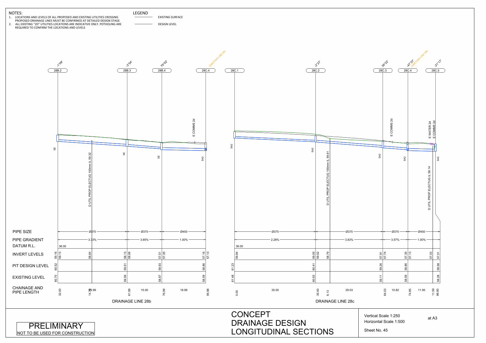
36.00
D U
TIL
PR
OP
ELE
CTU
G 1
00m
m IL
59.
3258
.64
14.7
5
Ø375
3.33%
29.99
60.7
060
.52
32.0
059
.13
59.1
6
28B.2-1°
09'
SE
Ø375
3.65%
15.00
59.5
959
.51
61.9
958
.06
58.1
3
28B.3-3°
54'
SE
Ø450
1.00%
18.99
58.8
758
.93
76.9
957
.35
57.5
1
28B.479
°02'
SE
E C
OM
MS
2d
58.5
958
.86
95.9
857
.13
57.1
6
28C.4
JUNCTIO
N LINE 28
c
SA
2
CHAINAGE ANDPIPE LENGTH
EXISTING LEVEL
PIT DESIGN LEVEL
INVERT LEVELS
PIPE GRADIENT
PIPE SIZE
DATUM R.L.
DRAINAGE LINE 28b
36.00
Ø375
2.28%
35.00
61.4
861
.23
0.00
59.8
4
28C.1
SA
2
D U
TIL
PR
OP
ELE
CTU
G 1
00m
m IL
59.
6158
.79
6.13
Ø375
3.83%
29.03
60.6
360
.41
35.0
059
.02
59.0
5
28C.2-2°
27'
SA
2
Ø375
3.57%
10.82
59.1
159
.26
64.0
357
.74
57.9
1
28C.339
°22'
SA
2
E C
OM
MS
2d
Ø450
1.00%
11.95
58.5
958
.86
74.8
557
.13
57.3
5
28C.4-47
°37'
JUNCTIO
N LINE 28
b
SA
2
58.2
858
.58
86.8
057
.01
28C.5-21
°17'
SA
2
DRAINAGE LINE 28c
Sheet No. 45
Horizontal Scale 1:500Vertical Scale 1:250 at A3CONCEPT
DRAINAGE DESIGNLONGITUDINAL SECTIONS
PRELIMINARYNOT TO BE USED FOR CONSTRUCTION
D U
TIL
PR
OP
ELE
CTU
G IL
58.
1411
.59
E C
OM
MS
2d
E W
ATE
R 2
d57
.03
NOTES:1. LOCATIONS AND LEVELS OF ALL PROPOSED AND EXISTING UTILITIES CROSSING
PROPOSED DRAINAGE LINES MUST BE CONFIRMED AT DETAILED DESIGN STAGE2. ALL EXISTING “2D” UTILITIES LOCATIONS ARE INDICATIVE ONLY. POTHOLING ARE
REQUIRED TO CONFIRM THE LOCATIONS AND LEVELS
LEGENDEXISTING SURFACE
DESIGN LEVEL

49.8
349
.90
259.
0448
.57
28C.123°
08'JU
NCTION LI
NE 28h
SA
2
CHAINAGE ANDPIPE LENGTH
EXISTING LEVEL
PIT DESIGN LEVEL
INVERT LEVELS
PIPE GRADIENT
PIPE SIZE
DATUM R.L.
DRAINAGE LINE 28c
Sheet No. 46
Horizontal Scale 1:500Vertical Scale 1:250 at A3CONCEPT
DRAINAGE DESIGNLONGITUDINAL SECTIONS
PRELIMINARYNOT TO BE USED FOR CONSTRUCTION
30.00
Ø450
2.50%
17.05
58.2
858
.58
86.8
056
.98
57.0
1
28C.5-21
°17'
SA
2
Ø525
5.00%
19.12
57.4
957
.60
103.
8556
.52
56.5
5
28C.620
°17'
SA
2
Ø525
5.00%
18.11
56.4
856
.66
122.
9655
.54
55.5
7
28C.7-2°
50'
SA
2
E S
EW
ER
2d
Ø525
5.00%
13.83
55.7
455
.77
141.
0754
.60
54.6
3
28C.8-2°
25'
SA
2
53.8
70.
59
53.7
23.
57
Ø525
5.00%
16.27
55.0
955
.08
154.
9153
.88
53.9
1
28C.9-1°
43'
SA
2
E C
OM
MS
NB
N 2
d
Ø525
5.00%
33.35
54.0
854
.30
171.
1852
.99
53.0
7
28C.101°
22'
JUNCTIO
N LINE 28
f
SA
2
Ø525
5.00%
54.50
52.4
352
.62
204.
5351
.29
51.3
2
28C.110°
32'
SA
2
D U
TIL
PR
OP
ELE
CTU
G 1
00m
m IL
54.
54
D U
TIL
PR
OP
ELE
CTU
G 1
00m
m IL
54.
38
NOTES:1. LOCATIONS AND LEVELS OF ALL PROPOSED AND EXISTING UTILITIES CROSSING
PROPOSED DRAINAGE LINES MUST BE CONFIRMED AT DETAILED DESIGN STAGE2. ALL EXISTING “2D” UTILITIES LOCATIONS ARE INDICATIVE ONLY. POTHOLING ARE
REQUIRED TO CONFIRM THE LOCATIONS AND LEVELS
LEGENDEXISTING SURFACE
DESIGN LEVEL

23.00
Ø600
4.00%
28.82
49.8
349
.90
259.
0448
.54
48.5
7
28C.123°
08'
JUNCTIO
N LINE 28
h
SA
2
Ø600
3.38%
29.97
48.8
348
.91
287.
8547
.35
47.3
8
28C.132°
30'
SA
2
E C
OM
MS
2d
Ø600
3.30%
41.92
47.7
647
.90
317.
8246
.31
46.3
4
28C.14
4°55
'JU
NCTION LI
NE 28a
SA
2
E G
AS
2d
Ø600
3.33%
38.08
46.3
946
.48
359.
7544
.90
44.9
3
28C.155°
58'
SA
2
Ø600
3.33%
20.44
44.9
245
.20
397.
8343
.60
43.6
3
28C.16
4°22
'
SA
2
Ø750
3.33%
14.20
44.3
044
.51
418.
2742
.77
42.9
2
28C.174°
07'JU
NCTION LI
NE 28x
SA
2
43.8
444
.14
432.
4741
.71
42.2
9
28L.1JU
NCTION LI
NE 28l
SE
CHAINAGE ANDPIPE LENGTH
EXISTING LEVEL
PIT DESIGN LEVEL
INVERT LEVELS
PIPE GRADIENT
PIPE SIZE
DATUM R.L.
DRAINAGE LINE 28c
Sheet No. 47
Horizontal Scale 1:500Vertical Scale 1:250 at A3CONCEPT
DRAINAGE DESIGNLONGITUDINAL SECTIONS
PRELIMINARYNOT TO BE USED FOR CONSTRUCTION
NOTES:1. LOCATIONS AND LEVELS OF ALL PROPOSED AND EXISTING UTILITIES CROSSING
PROPOSED DRAINAGE LINES MUST BE CONFIRMED AT DETAILED DESIGN STAGE2. ALL EXISTING “2D” UTILITIES LOCATIONS ARE INDICATIVE ONLY. POTHOLING ARE
REQUIRED TO CONFIRM THE LOCATIONS AND LEVELS
LEGENDEXISTING SURFACE
DESIGN LEVEL

32.00
Ø375
5.00%
22.00
57.7
857
.78
0.00
56.3
2
28F.1
SE
Ø375
5.09%
20.00
56.7
056
.70
22.0
055
.18
55.2
2
28F.2-3°
22'
SE
E S
EW
ER
2d
WA
TER
50m
m IL
53.
7553
.22
14.1
0D
UTI
L P
RO
P E
LEC
TUG
100
mm
IL 5
3.85
53.2
214
.13
Ø375
6.25%
15.00
55.6
955
.66
41.9
954
.13
54.1
6
28F.3-2°
24'
SE
D U
TIL
PR
OP
ELE
CTU
G 1
00m
m IL
53.
98
53.0
86.
78
Ø450
0.53%
18.74
54.9
855
.00
56.9
953
.12
53.1
9
28F.436
°05'
SE
E C
OM
MS
NB
N 2
d54
.08
54.3
075
.74
52.9
953
.02
28C.10JU
NCTION LI
NE 28c
SA
2
CHAINAGE ANDPIPE LENGTH
EXISTING LEVEL
PIT DESIGN LEVEL
INVERT LEVELS
PIPE GRADIENT
PIPE SIZE
DATUM R.L.
DRAINAGE LINE 28f
27.00
IL 5
0.14
49.2
221
.61
Ø450
4.25%
40.11
51.7
551
.62
0.00
50.1
4
28H.1
SA
2
49.8
349
.90
40.1
148
.54
48.4
3
28C.12JU
NCTION LI
NE 28c
SA
2
DRAINAGE LINE 28h
Sheet No. 48
Horizontal Scale 1:500Vertical Scale 1:250 at A3CONCEPT
DRAINAGE DESIGNLONGITUDINAL SECTIONS
PRELIMINARYNOT TO BE USED FOR CONSTRUCTION
NOTES:1. LOCATIONS AND LEVELS OF ALL PROPOSED AND EXISTING UTILITIES CROSSING
PROPOSED DRAINAGE LINES MUST BE CONFIRMED AT DETAILED DESIGN STAGE2. ALL EXISTING “2D” UTILITIES LOCATIONS ARE INDICATIVE ONLY. POTHOLING ARE
REQUIRED TO CONFIRM THE LOCATIONS AND LEVELS
LEGENDEXISTING SURFACE
DESIGN LEVEL
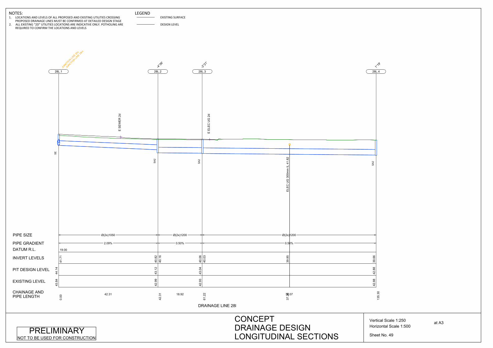
19.00
Ø(2x)1050
2.09%
42.31
43.8
444
.14
0.00
41.7
1
28L.1JU
NCTION LI
NE 28c
JUNCTIO
N LINE 28
m
SE
E S
EW
ER
2d
Ø(2x)1200
0.50%
18.92
42.9
943
.12
42.3
140
.16
40.8
2
28L.2
-4°36
'
SA
2
ELE
C U
G 3
00m
m IL
41.
8239
.85
37.2
6
Ø(2x)1200
0.50%
74.07
42.9
343
.04
61.2
240
.03
40.0
6
28L.3-2°
21'
SA
2
E E
LEC
UG
2d
42.8
842
.88
135.
3039
.66
28L.41°
19'
SA
2
CHAINAGE ANDPIPE LENGTH
EXISTING LEVEL
PIT DESIGN LEVEL
INVERT LEVELS
PIPE GRADIENT
PIPE SIZE
DATUM R.L.
DRAINAGE LINE 28l
Sheet No. 49
Horizontal Scale 1:500Vertical Scale 1:250 at A3CONCEPT
DRAINAGE DESIGNLONGITUDINAL SECTIONS
PRELIMINARYNOT TO BE USED FOR CONSTRUCTION
NOTES:1. LOCATIONS AND LEVELS OF ALL PROPOSED AND EXISTING UTILITIES CROSSING
PROPOSED DRAINAGE LINES MUST BE CONFIRMED AT DETAILED DESIGN STAGE2. ALL EXISTING “2D” UTILITIES LOCATIONS ARE INDICATIVE ONLY. POTHOLING ARE
REQUIRED TO CONFIRM THE LOCATIONS AND LEVELS
LEGENDEXISTING SURFACE
DESIGN LEVEL
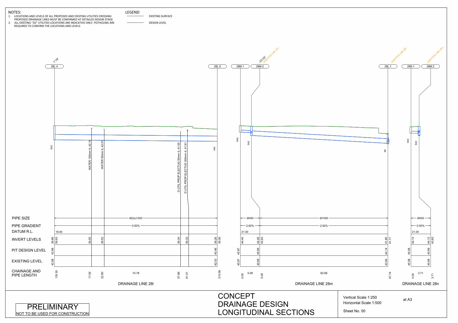
18.00
WA
TER
150
mm
IL 4
2.16
39.5
517
.09
WA
TER
50m
m IL
42.
0139
.52
22.8
0
D U
TIL
PR
OP
ELE
CTU
G 5
0mm
IL 4
1.55
39.3
457
.86
D U
TIL
PR
OP
ELE
CTU
G 3
00m
m IL
41.
6139
.33
61.0
1
Ø(2x)1200
0.50%
74.78
42.8
842
.88
135.
3039
.63
39.6
6
28L.41°
19'
SA
2
42.0
340
.46
210.
0839
.26
39.2
6
28L.5
HW
CHAINAGE ANDPIPE LENGTH
EXISTING LEVEL
PIT DESIGN LEVEL
INVERT LEVELS
PIPE GRADIENT
PIPE SIZE
DATUM R.L.
DRAINAGE LINE 28l
21.00
Ø450
2.82%
5.09
45.8
745
.87
0.00
44.4
0
28M.1
SA
2
Ø1050
2.92%
62.66
45.6
945
.69
5.09
43.6
344
.26
28M.2-72
°23'
JUNCTIO
N LINE 28
n
SA
2
43.8
444
.14
67.7
441
.71
41.8
0
28L.1
JUNCTIO
N LINE 28
l
SE
DRAINAGE LINE 28m
21.00
Ø450
0.50%
3.71
45.5
845
.58
0.00
44.1
4
28N.1
SA
2
45.6
945
.69
3.71
43.6
344
.12
28M.2
JUNCTIO
N LINE 28
m
SA
2
DRAINAGE LINE 28n
Sheet No. 50
Horizontal Scale 1:500Vertical Scale 1:250 at A3CONCEPT
DRAINAGE DESIGNLONGITUDINAL SECTIONS
PRELIMINARYNOT TO BE USED FOR CONSTRUCTION
NOTES:1. LOCATIONS AND LEVELS OF ALL PROPOSED AND EXISTING UTILITIES CROSSING
PROPOSED DRAINAGE LINES MUST BE CONFIRMED AT DETAILED DESIGN STAGE2. ALL EXISTING “2D” UTILITIES LOCATIONS ARE INDICATIVE ONLY. POTHOLING ARE
REQUIRED TO CONFIRM THE LOCATIONS AND LEVELS
LEGENDEXISTING SURFACE
DESIGN LEVEL

22.00
Ø375
3.00%
16.62
47.2
147
.18
0.00
45.6
4
28X.1
SA
2
Ø375
3.00%
14.42
46.6
946
.66
16.6
245
.12
45.1
5
28X.22°
10'
SA
2
Ø450
3.00%
15.54
46.2
446
.21
31.0
444
.61
44.6
8
28X.32°
05'
SA
2
Ø450
3.00%
16.50
45.7
445
.71
46.5
844
.11
44.1
4
28X.42°
14'
SA
2
Ø450
3.00%
12.88
45.1
345
.10
63.0
743
.59
43.6
2
28X.52°
03'
SA
2
Ø450
1.00%
27.00
44.5
944
.58
75.9
543
.17
43.2
0
28X.681
°18'
SA
2
44.3
044
.51
102.
9542
.77
42.9
0
28C.17JU
NCTION LI
NE 28c
SA
2CHAINAGE ANDPIPE LENGTH
EXISTING LEVEL
PIT DESIGN LEVEL
INVERT LEVELS
PIPE GRADIENT
PIPE SIZE
DATUM R.L.
DRAINAGE LINE 28x
52.00
Ø750
0.50%
7.42
72.2
573
.08
0.00
72.2
5
CROSS4.1
EX
ISTI
NG
PIT
72.8
773
.04
7.42
72.2
272
.22
CROSS4.2
HW
DRAINAGE LINE cross4
Sheet No. 51
Horizontal Scale 1:500Vertical Scale 1:250 at A3CONCEPT
DRAINAGE DESIGNLONGITUDINAL SECTIONS
PRELIMINARYNOT TO BE USED FOR CONSTRUCTION
NOTES:1. LOCATIONS AND LEVELS OF ALL PROPOSED AND EXISTING UTILITIES CROSSING
PROPOSED DRAINAGE LINES MUST BE CONFIRMED AT DETAILED DESIGN STAGE2. ALL EXISTING “2D” UTILITIES LOCATIONS ARE INDICATIVE ONLY. POTHOLING ARE
REQUIRED TO CONFIRM THE LOCATIONS AND LEVELS
LEGENDEXISTING SURFACE
DESIGN LEVEL
APPENDIX C
SKETCH OF PROPOSED PEDESTRIAN UNDERPASS (MC10 CH 1980) – SK90

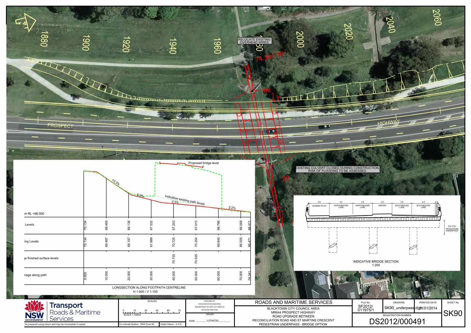

Related Documents