Prepared by: Ulteig Engineers, Inc. 4808 S. Technopolis Drive Sioux Falls, SD 57106 605-323-2306 FINAL DRAFT January 2004 PEL01 Drainage Masterplan City of Watertown, South Dakota Codington County, South Dakota

Welcome message from author
This document is posted to help you gain knowledge. Please leave a comment to let me know what you think about it! Share it to your friends and learn new things together.
Transcript

Prepared by: Ulteig Engineers, Inc. 4808 S. Technopolis Drive Sioux Falls, SD 57106 605-323-2306
FINAL DRAFT
January 2004
PEL01 Drainage Masterplan
City of Watertown, South Dakota
Codington County, South Dakota

PEL01 – DRAINAGE MASTER PLAN
City of Watertown, SD
Page 1 of 5
TABLE OF CONTENTS
PAGE
SECTION 1 – PROJECT OVERVIEW
1.1 Introduction………………………………………………………… 1
1.2 Project Area Description…………………………………………… 2
1.3 Project Scope and Approach……………………………………….. 5
1.4 Public Meeting #1………………………………………………….. 7
1.5 Public Meeting #2………………………………………………….. 7
1.6 Hydrologic and Hydraulic Data……………………………………. 10
1.7 Native Plantings …………………………………………………… 15
1.8 Drainage Easements………………………………………………... 17
SECTION 2 – DATA INVENTORY
2.1 Resource Summary………………………………………………… 1
2.2 Land Ownership ………………………………………………….... 2
2.3 Field Survey………………………………………………………… 3
2.4 Pre-developed Modeled Conditions ……………………………….. 3
2.5 Post-developed Modeled Conditions……………………….………. 4
2.6 Historic Maximum Elevation of Pelican Lake…………….……….. 4
SECTION 3 – WATERSHED A
3.1 Boundaries and Sub-watersheds…………………………………… 1
3.2 Goals……………………………………………………………….. 3
3.3 Pre-Developed Conditions…………………………………………. 4
3.3.1 Existing Culverts…………………………………………… 6
3.3.2 Existing Drainage Pattern………………………………..… 7
3.4 Post-Developed Modeled Conditions……………………………… 7
3.5 Alternatives Considered……………………………………………. 9
3.6 Recommendations………………………………………….……..... 11
3.6.1 Proposed Ponds…………………………………………..… 11
3.6.2 Proposed Channels and Routing………………………..….. 14
3.6.3 Proposed Culverts……………………………………..…… 24
3.7 Additional Comments………………………………………..…..... 28
SECTION 4 – WATERSHED B
4.1 Boundaries and Sub-watersheds…………………………..………. 1
4.2 Goals……………………………………………………….……… 2
4.3 Pre-Developed Conditions……………………………….….…….. 4
4.3.1 Existing Culverts………………………………..…………. 6
4.3.2 Existing Drainage Pattern……………………..…………… 6
4.4 Post-Developed Modeled Conditions………………………………. 6
4.5 Alternatives Considered…………………………………….…….. 8

PEL01 – DRAINAGE MASTER PLAN
City of Watertown, SD
Page 2 of 5
4.6 Recommendations………………………………………………… 9
4.6.1 Proposed Ponds……………………………………………. 9
4.6.2 Proposed Channels and Routing…………………………... 13
4.6.3 Proposed Culverts…………………………………………. 20
4.7 Additional Comments……………………………………………… 22
4.7.1 Information Points ………………………………………… 22
SECTION 5 – WATERSHED C
5.1 Boundaries and Sub-watershed………… ………………………… 1
5.2 Goals…………………………………… ……………………….… 1
5.3 Pre-Developed Conditions…………… …………………………… 1
5.3.1 Existing Culverts and Reaches…………………………….. 2
5.3.2 Existing Drainage Pattern………………………………….. 3
5.4 Post-Developed Modeled Conditions… ……………….………….. 3
5.4.1 Design Point 34 – 42nd Street Pond……..…………………. 5
5.4.2 Design Point 35 – Future Culvert .…………………………. 5
5.5 Alternatives Considered………………………………………….… 5
5.6 Recommendations………………………….…………………….… 7
5.6.1 Proposed Ponds…………………………………….………. 7
5.6.2 Proposed Channels and Routing………………………….… 7
5.6.3 Proposed Culverts………………………………………….. 10
5.7 Additional Comments………………………………………………. 10
5.7.1 Information Points ……………………………………….… 11
SECTION 6 – WATERSHED D
6.1 Boundaries and Sub-watershed…………………………………… 1
6.2 Goals……………………………………………………………… 1
6.3 Pre-Developed Conditions………………………………………... 2
6.3.1 Existing Culverts………………………………………….. 3
6.3.2 Existing Drainage Pattern…………………………………. 4
6.4 Post-Developed Modeled Conditions……………………………... 4
6.5 Alternatives Considered…………………………………………... 5
6.6 Recommendations………………………………………………… 7
6.6.1 Proposed Ponds……………………………………………. 7
6.6.2 Proposed Channels and Routing…………………………… 8
6.6.3 Proposed Culverts…………………………………………. 9
6.7 Additional Comments……………………………………………... 9
SECTION 7 – WATERSHED E
7.1 Boundaries and Sub-watershed………………………………….… 1
7.2 Goals…………………………………………………………….… 1
7.3 Pre-Developed Conditions……………………………………….... 1
7.3.1 Existing Culverts………………………………………….. 1
7.3.2 Existing Drainage Pattern…………………………………. 1
7.4 Post-Developed Modeled Conditions…………………… ……….. 1
PEL01 – DRAINAGE MASTER PLAN
City of Watertown, SD
Page 3 of 5
7.5 Alternatives Considered………………………………………….. 2
7.6 Recommendations………………………………………………… 2
7.6.1 Proposed Ponds……………………………………………. 2
7.6.2 Proposed Channels and Routing…………………………... 2
7.6.3 Proposed Culverts…………………………………………. 2
7.7 Additional Comments……………………………………………… 2
SECTION 8 – STORMWATER MANAGEMENT ORDINANCE DISCUSSION
8.1 Current City and County Regulations……………………………. 1
8.2 Review of Ordinance Revisions from Willow Creek 01 Study…... 2
8.3 Funding ………..……………………………………….………… 3
LIST OF FIGURES
1.1 Project Area Map……………………………… Sect. 1 Page 3
1.2 Watershed Boundaries Map…………………… Sect. 1 Page 4
2.1 Land Ownership Map…………………………. Sect. 2 Page 12
2.2 Post-Developed Land Use Map………………. Sect. 2 Page 13
2.3 Historic Flood Elevation Map of Lake Pelican Sect. 2 Page 14
3.1 Watershed A Map…………………………… Sect. 3 Page 28
3.2 4th Avenue Pond Map ……………………….. Sect. 3 Page 29
4.1 Watershed B Map………………………….… Sect. 4 Page 23
5.1 Watershed C Map………………………….… Sect. 5 Page 13
6.1 Watershed D Map…………………………… Sect. 6 Page 10
7.1 Watershed E Map…………………………… Sect. 7 Page 3

PEL01 – DRAINAGE MASTER PLAN
City of Watertown, SD
Page 4 of 5
LIST OF TABLES
Section 1 – Project Overview, no tables
Section 2 – Data Inventory
TABLE 2.1 - Land Ownership Data………………………………………. 5
Section 3 – Watershed A
TABLE 3.1 – Pre-Developed Modeled Conditions………………………. . 5
TABLE 3.2 – Peak Flow Rates from Pre-Developed Conditions…………. 5
TABLE 3.3 – Post-Developed Modeled Conditions………………………. 8
TABLE 3.4 - Land Use and Hydrological Data…………………………. 8
TABLE 3.5 – Peak Flow Rates from Post-Developed Conditions……….. . 9
TABLE 3.6 – 4th Ave Detention Pond, DP 6……………………………… 11
TABLE 3.7 – 35th Street Pond, DP18…………………………………….. 13
TABLE 3.8 – Outlet Routing from 35th Street Pond…………………….. 14
TABLE 3.9 – DP 1/Reach Ra1 (begin)………………………… 15
TABLE 3.10 – DP 5/Reach Ra2………………………………………….. 16
TABLE 3.11 – DP 40/Reach Ra3………………………………………… 16
TABLE 3.12 – DP 41/Reach Ra4………………………………………… 17
TABLE 3.13 – DP 9/Reach Ra7………………………………………….. 18
TABLE 3.14 - DP 12/Reach Ra8 (begin)…………………………………. 19
TABLE 3.15 – DP 10/Reach Ra10 (begin)……………………………….. 20
TABLE 3.16 – DP 16/Reach Ra12……………………………………….. 21
TABLE 3.17 – DP 17/Reach Ra13……………………………………….. 22
TABLE 3.18 – DP 18A\Reach Ra14 – Outlet for 35th St Pond…………. 23
Section 4 – Watershed B
TABLE 4.1 – Pre-Developed Modeled Conditions………………………. 4
TABLE 4.2 – Peak Flow Rates from Pre-Developed Conditions………… 4
TABLE 4.3 – Post-Developed Modeled Conditions……………………… 7
TABLE 4.4 - Land Use and Hydrological Data……………………….… 7
TABLE 4.5 – Peak Flow Rates from Post-Developed Conditions……….. 8
TABLE 4.6 – DP 27, 42nd Street Pond……………………………………. 10
TABLE 4.7 – DP 30, Wet Detention Pond of Sub-Watershed B8……….. 12
TABLE 4.8– DP 19/Reach Rb1………………………………………….. 14
TABLE 4.9 – DP 21/Reach Rb2………………………………………….. 15
TABLE 4.10 – DP 23/Reach Rb3……………………………………….... 16
TABLE 4.11 – DP 24/Reach Rb4………………………………………… 17
TABLE 4.12 – DP 25/Reach Rb5………………………………………… 17
TABLE 4.13 – DP 26/Reach Rb6………………………………………… 18
TABLE 4.14 – DP 30A, Emergency Over-flow to lake………………….. 19
Section 5 – Watershed C
TABLE 5.1 – Pre-Developed Modeled Conditions………………………. 2
TABLE 5.2 – Peak Flow Rates from Pre-Developed Conditions………… 2
TABLE 5.3 – Post-Developed Modeled Conditions……………………… 4
TABLE 5.4 – Peak Flow Rates from Post-Developed Conditions……….. 4

PEL01 – DRAINAGE MASTER PLAN
City of Watertown, SD
Page 5 of 5
TABLE 5.5 – DP 34, Storage Pond C……………………………………. 4
TABLE 5.6 – DP 35, Northern Third of Sub-Area C2
Post-Developed Peak Flow Rates……………………… 5
TABLE 5.7 – DP 31: Reach Rc1 Data…………………………………… 8
TABLE 5.8 – DP 32: Reach Rc2 Data…………………………………… 8
TABLE 5.9 – DP 33: Reach Rc3 Data…………………………………… 9
TABLE 5.10 – DP 34A, Emergency Overflow Channel
from Storage Pond C……………………………………. 10
Section 6 – Watershed D
TABLE 6.1 – Pre-Developed Modeled Conditions……………………….. 2
TABLE 6.2 – Peak Flow Rates from Pre-Developed Conditions………… 3
TABLE 6.3 – Post-Developed Modeled Conditions……………………… 4
TABLE 6.4 – Peak Flow Rates from Post-Developed Conditions……….. 4
TABLE 6.5 – DP 38, 20th Ave SW Pond…………………………………. 6
TABLE 6.6 - Channel sizing for “conveyance” option…………………… 7
TABLE 6.7 – DP 37, Reach Rd1 Data……………………………….. 8
Section 7 – Watershed E – no tables
APPENDICES
Appendix I Well Log Data
Appendix II Public Meeting #1
Appendix III Public Meeting #2 (pending)
Appendix IV Correspondence
Appendix V Wetland Delineation Report
Appendix VI Funding excerpted from Willow Creek
Tributary Drainage Master Plan
Appendix VII Runoff Potential Calculations (after Public Mtg #2)
Appendix VIII Cost Estimates (after Public Mtg #2)

PEL01 - DRAINAGE MASTER PLAN F I N A L D R A F T
City of Watertown, SD
Section 1 - PROJECT OVERVIEW Page 1 of 17
SECTION 1 – PROJECT OVERVIEW
1.1 INTRODUCTION
In a continuing effort to improve water quality and protect its citizens and infrastructure
from flooding, the City of Watertown, SD, in conjunction with a local developer,
commissioned the PEL01 Drainage Master Plan. This plan has multiple goals:
First, the City of Watertown has adopted a policy requiring all development to comply
with a local or regional drainage master plan. Because a developer wishes to pursue
development containing single family residences, referred to as KAK’s Lakeside
Addition, in a configuration approximating four units per acre, to comply with the
ordinance, a drainage master plan had to be developed. Therefore, with the approval of
this PEL01 Drainage Master Plan (Master Plan), development can proceed. Five distinct
drainage areas have been identified that contribute drainage through and adjacent to
KAK’s Lakeside Addition. These five areas constitute the subject of this Master Plan.
Second, the City of Watertown continues to take a pro-active approach in dealing with
storm management issues. Throughout this Master Plan, analysis of the following
objectives will be presented:
� Existing conditions will be described and assessed. This includes culvert sizes
and their capacities as well as identification of existing drainage patterns.
� Land owners involved in this study are identified. Where a subdivision
currently exists, the City represents their interests in terms of Drainage Master
Planning.
� Pre-Developed flow rates are generated and evaluated.
� Flow rates for Ultimate-Development, or Post-Developed flow rates are
generated and evaluated.
� 100-year flood elevations are developed for drainage channels and proposed
storm water management facilities (detention ponds). This will help the City
maintain its growth away from areas susceptible to flooding. Where
appropriate, engineered ponds may include an emergency overflow outlet for
the 500-year storm.
� The historic high-water elevation of Lake Pelican is identified.
� Locations and sizes of storm water treatment facilities are explored.
� The re-routing of post-developed flows and proposed pipe sizes are presented.
� Involving the public and other stakeholders.
� Costs of suggested improvements included as part of this Master Plan.
� A discussion of City Ordinances and suggested changes are also included.

PEL01 - DRAINAGE MASTER PLAN F I N A L D R A F T
City of Watertown, SD
Section 1 - PROJECT OVERVIEW Page 2 of 17
When combined, these objectives and the recommendations derived through this study
put the City of Watertown in a position to provide information to developers so that they
consider storm water management in their designs thus:
1. Minimizing the potential for storm-water to potentially threaten life and property.
2. Maintaining water quality through controlling and detaining runoff where possible.
3. Providing developers with clear guidance for complying with the City’s development and storm water management rules.
1.2 PROJECT AREA DESCRIPTION
The locations of the five watershed areas contained within this Master Plan are shown in
Figure 1.1 – Project Area Map. As can be seen from this map, the project area contains
land incorporated by the City of Watertown as well as unincorporated lands administered
by Codington County.
The project area includes 1727.6 acres (2.7 square miles) of land, all discharging its
runoff to Lake Pelican. Natural depressions exist having no outlet. These basins will be
taken advantage of, where practical, in storing storm water runoff. Other features that
influence runoff consist mainly of natural drainage channels and existing culverts under
roads including US Highway 212.
As stated previously, the project area has been divided into five sub-areas, each a distinct
watershed named Watershed A through Watershed E. The boundaries of these
watersheds are shown in Figure 1.2 - Watershed Boundaries.
The current land uses occurring within the study area include single-family
developments, farmsteads, commercial and industrial areas, farmland, and open range
lands. Some of these areas will likely fill in with development over the next two to five
years, while others may not fill into their ultimate developed use for 30-40 years. To
capture pre-developed conditions; “pre-European settlement” run-off flow rates and
volumes are used in this study as a baseline condition.
This approach is an important consideration because the natural drainage patterns
established over time have evolved and shaped the land forming its own equilibrium with
regard to slopes and sediment transport from heavy rain events. This is true for not only
this study area but for all of Lake Pelican’s Watershed and other rivers and streams.
This is significant in establishing what volumes of water should be detained so that
channels and structures downstream are not flooded from the increased runoff generated
by development. This study, poignantly illustrates how substantial this increase is when
comparing runoff flows generated from prairie grass fields to flows generated from paved
parking lots and businesses. It should be clear that existing development is not being


PEL01 - DRAINAGE MASTER PLAN F I N A L D R A F T
City of Watertown, SD
Section 1 - PROJECT OVERVIEW Page 5 of 17
ignored. Rather, this analysis yields an improved level of storm water quality and
quantity as compared to using existing conditions as a baseline. Man has all ready
disturbed nature and altered drainage patterns established by nature over time. For more
information on hydrology, see Section 1.6 –Hydrologic and Hydraulic Data.
1.3 PROJECT SCOPE AND APPROACH
Early in the development of this project, a list of tasks was generated in concert with City
staff that outlines the need for various meetings and levels of public involvement, as well
as other criteria required to successfully complete the project. As the project evolved,
minor modifications to the following tasks occurred as new information became
available.
1.3.1 Item 1 – Data Inventory and Collection. The City provided the materials shown
in Section 2.1.
1.3.2 Item 2 – Inventory Reconnaissance - In addition these materials, Inventory
Reconnaissance was conducted. Field data was gathered such as culvert
locations, size, and invert elevations. Furthermore, additional contour
information was surveyed that supplemented information the City provided. This
information was gathered using digital surveying equipment.
1.3.3 Item 3 - Survey Datum - Existing Vertical Datum was researched and gathered
survey information was rectified to meet the City’s standard referencing system.
The City of Watertown uses the following datum:
Vertical Reference: NGVD 1927 Horizontal Reference: NAD 1983
1.3.4 Item 4 – Pelican Lake Historic Stage Elevation – Several resources were
consulted to determine the historic maximum high water elevation of Lake
Pelican including, the City, FEMA, DENR, and the Corps of Engineers. The
1997 flood in Watertown also left high water marks on various structures within
the study area. Field reconnaissance captured these elevations. For more
discussion on this topic see Section 2.6 - Historic Maximum Elevation of Pelican
Lake.
1.3.5 Item 5 – Obtain City Contours. The City of Watertown provided the majority of
the 2-foot contour information in a digital formal suitable for use in
AutoCad/Land Development software. The remainder was gathered using digital
survey equipment.
1.3.6 Item 6 – Obtain Water Well Data. The purpose of gathering water well data is to
assess ground water elevations within the study area. It is desirable to avoid

PEL01 - DRAINAGE MASTER PLAN F I N A L D R A F T
City of Watertown, SD
Section 1 - PROJECT OVERVIEW Page 6 of 17
placing water quality treatment ponds at an elevation low enough to encounter
ground water. However, within the study area, groundwater typically varies 6-10
feet in any given year according to Jim Goodman of the South Dakota
Department of Environmental and Natural Resources (DENR) Water Rights
Division who also provided the following well log data.
Section Township Range Depth to Static
Water (FT) Average Depth
(FT)
33 117 N 53 W 21
33 117 N 53 W 16
33 117 N 53 W 21
33 117 N 53 W 19
33 117 N 53 W 9
33 117 N 53 W 9
33 117 N 53 W 12
33 117 N 53 W 12
33 117 N 53 W 22
33 117 N 53 W 20
33 117 N 53 W 20
33 117 N 53 W 7
33 117 N 53 W 11
33 117 N 53 W 9
33 117 N 53 W 36
33 117 N 53 W 12
33 117 N 53 W 9 15.6
3 116 N 53 W 17
3 116 N 53 W 25
3 116 N 53 W 24
3 116 N 53 W 24
3 116 N 53 W 20
3 116 N 53 W 8
3 116 N 53 W 25
3 116 N 53 W 24
3 116 N 53 W 8
3 116 N 53 W 10
3 116 N 53 W 15
3 116 N 53 W 26
3 116 N 53 W 18
3 116 N 53 W 24
3 116 N 53 W 12
3 116 N 53 W 24 19.0
34 116 N 53 W 151
34 116 N 53 W 340
34 116 N 53 W 105
34 116 N 53 W 4 150.0
Copies of these multiple well logs within the study area are included in the
Appendix.
PEL01 - DRAINAGE MASTER PLAN F I N A L D R A F T
City of Watertown, SD
Section 1 - PROJECT OVERVIEW Page 7 of 17
1.3.7 Analysis of existing conditions, development of watershed models, and
recommendations are covered in Section 2 – Data Inventory, and Sections
3 through 7 where each of the five watersheds are discussed.
1.4 PUBLIC MEETING #1
On August 13, 2003, a meeting was held at City Hall to introduce the scope and
intent of this study to the public. Postcards were mailed out to those potentially
affected by the watershed as identified by watershed boundaries and/or other
identified stakeholders.
About 35-40 people attended including Shannon Schultz and Wes Schon from
Ulteig Engineers, Inc, Rick Schlechter and Dave Petersen from the City of
Watertown. Twenty-five people signed the attendance sheet.
Materials handed out included a pamphlet with a comment form on the back side,
two 11x17 maps showing the boundaries and location of the study as well as land
ownership boundaries. No comments were received subsequent to this meeting.
Steve Horning, a landowner pursuing development and plat approval for a
residential development within the watershed study area, gave a short description
and history of his property and his intentions.
A presentation was made.
A copy of the meeting minutes are attached in Appendix along with a copy of the
slides from the presentation.
1.5 PUBLIC MEETING #2
An open-house meeting was held at City Hall March 22, 2004 from 4:00 pm to
7:00 pm to review the results and recommendations of the PEL01 Drainage
Masterplan as found in the Final Draft. Letters of invitation accompanied by a
summary map were mailed out to those potentially affected by the watershed as
identified by watershed boundaries and/or other identified stakeholders.
Display materials included all the maps contained in the report; most notably, the
existing landownership map, and proposed pond location maps were the centers of
interest. Formal comment forms were provided for the public to submit their
concerns in writing; four of which have been received to date (copies in appendix).
Also, a slide show was ongoing showing examples of how drainage features and
residential developments co-exist. No formal presentation was made.

PEL01 - DRAINAGE MASTER PLAN F I N A L D R A F T
City of Watertown, SD
Section 1 - PROJECT OVERVIEW Page 8 of 17
Steve Horning, a landowner pursuing development and plat approval for a
residential development within the watershed study area, attended and provided
general information to the City regarding his intentions. The City provided him
informal guidance on what steps would be required next to further his
development.
In general, the majority of people attending the meeting had the same question:
“Here is my property so how does this plan affect me?” -- the response to which is
-- existing landowners really will not be affected until either they wish to develop
the land or they sell the land to a developer. Then, as part of the development
process, the recommendations for conveyance systems (channels and associated
drainage easement areas), culvert sizing, and pond locations need to be included as
part of the development plans. Development may not reach 100% developed
(modeled) conditions for 40-60 years. This information quickly put landowners at
ease as they began to understand that the purpose of the study is to prevent
flooding and protect water quality as development occurs.
Clyde Morrison, a landowner who operates a sheep farm within the study area, was
concerned that a proposed pond would flood his property. Again, it was pointed
out that no pond would be constructed unless development upstream was eminent.
Thus, he would have to sell his land or develop it on his own, negating the need to
maintain a pasture for sheep. He was also concerned about land devaluation. We
pointed out that real estate appraisal is a specialized skill and that only licensed
appraisers can make qualified judgments regarding land values. Furthermore, he
would have to sell his land in order for development to occur so the developer
would be the party bringing forth land value concerns.
Mark Kienest, caretaker of the Ina Kahnke land holdings, provided information
regarding the location of water pumps that serve two pivot fields and also water
pumps and mains that serve an existing trailer court development. While this
information is important, it presents minimal impact to this study.
The pumps and wells feeding the trailer court are located west of 11th Avenue
South, west of the Born’s subdivision. Most likely, by the time the proposed large
retention pond is needed located west of this subdivision, the City will have either
annexed this property or will do so as part of the development/platting process thus
providing water and sanitary service through the area and to the trailer court.
However, if this is not the case, when 11th Avenue South is extended to the west,
maintaining the water service to the trailer courts would be required.
Similarly, the water well and pumps serving the two large circular pivot fields
located west of 36th Street West and just south of 16
th Avenue South would not be
required as the City, during its annexation of this land, would provide water and
sewer service.

PEL01 - DRAINAGE MASTER PLAN F I N A L D R A F T
City of Watertown, SD
Section 1 - PROJECT OVERVIEW Page 9 of 17
Furthermore, knowing these water wells and pumps exist present an opportunity
for the City of Watertown to fortify their own water distribution system as the
city’s westerly expansion occurs. For example, a new golf course or large park
could utilize this water supply.
In summary, depending on the timing and extent of development occurring
upstream of these areas of concern, the need for perpetuating these water systems
needs to be evaluated.
For the worst case scenario, the shape and location of the proposed detention pond
could be modified to allow the existing pump and supply systems to continue to
operate; although this scenario is unlikely. The City would probably annex land
between 36th Street West and 42
nd Street West providing city water and sewer
service which negates the need to perpetuate the existing private water supply.
Several land owners in Watershed D were concerned about the size of a needed
pond and the location of a needed conveyance channel. As the study points out,
recommendations to prevent flooding within Watershed D cannot be made final
until an agreement between landowners is reached. This will require several
meetings with the parties involved.
Rick Schlechter received a phone call from Jay Gilbertson who posed a question
regarding the need for a DENR Flood Control permit. Shannon Schultz contacted Eric
Gronlund of the Water Rights Program, DENR (605 773-3352),
His response is
“…Based on the information provided, the Water Rights Program does not believe
that flood control permitting is required and that this appears to be a municipal drainage issue.
If these facilities are constructed on a live watercourse or an impoundment is created with a permanent storage of greater than 25 acre feet of water, state permitting will likely be required.”
Four written comments from the public have been received to date (attached). Three of
the comments suggested that the City require more onsite detention using sediment traps
and water infiltration gardens on individuals’ property thereby treating the storm water
prior to releasing it downstream.
The fourth comment contained several concerns regarding the landowner being located
adjacent to a proposed pond: 1) Devaluation of property, 2) Water {from the pond}
backing up onto his property and water in basement, 3) weeds around the pond and
general appearance.

PEL01 - DRAINAGE MASTER PLAN F I N A L D R A F T
City of Watertown, SD
Section 1 - PROJECT OVERVIEW Page 10 of 17
1.6 HYDROLOGIC AND HYDRAULIC DATA
Four different software packages were applied in completing the analysis of this Master
Plan, WinTR-55, PondPak, CulvertMaster, and FlowMaster by Haestad Methods. Each
of their specific uses along with necessary inputs, assumptions, etc. are described below.
1.6.1 WinTR-55 Small Watershed Hydrology – This model is a single event rainfall-
runoff watershed model. It applies to both urban and agricultural areas generating
hydrographs from land areas and at selected points along the stream system.
Multiple sub-areas can be modeled. This model is based on Technical Release 55,
Urban Hydrology for Small Watershed, first issued in 1975 by the Soil
Conservation Service.
The primary use of this model for this Master Plan was to determine the flows
from individual and grouped watershed so that the geometries of downstream
flow channels and culverts could be determined and then used as inputs in the
PondPak model so that overtopping of said channels do not occur. A secondary
application of this model was to compare and cross-check the peak flows
generated by PondPak.
For determining pre-developed and post-developed flow rates, the following criteria were
used:
Area of Subarea: Acres of sub-areas were determined using AutoCad.
Weighted Runoff-Number (CN): Pasture, grassland, or range land in fair
condition was used for all predeveloped subareas. This represents the land as it
was prior to any disturbance from man: CN = 69 for Hydrologic Soil Group B.
No impervious areas were assumed to exist.
Type B soils dominate the landscape within the study area1. Average antecedent
moisture conditions are also assumed.
For post-developed conditions, the Runoff-Numbers include the
following using Hydrologic Soil Group C:
Cover Condition CN Avg. % Imperv.
Urban Commercial & Business 94 85
Urban Industrial 91 72
Residential -¼ Acre lots 83 38
Residential – 2 Acre lots 77 12
1 Soil Information gathered from Soil Survey of Codington County, South Dakota, issued in December 1966
by the US Department of Agriculture Soil Conservation Service.
PEL01 - DRAINAGE MASTER PLAN F I N A L D R A F T
City of Watertown, SD
Section 1 - PROJECT OVERVIEW Page 11 of 17
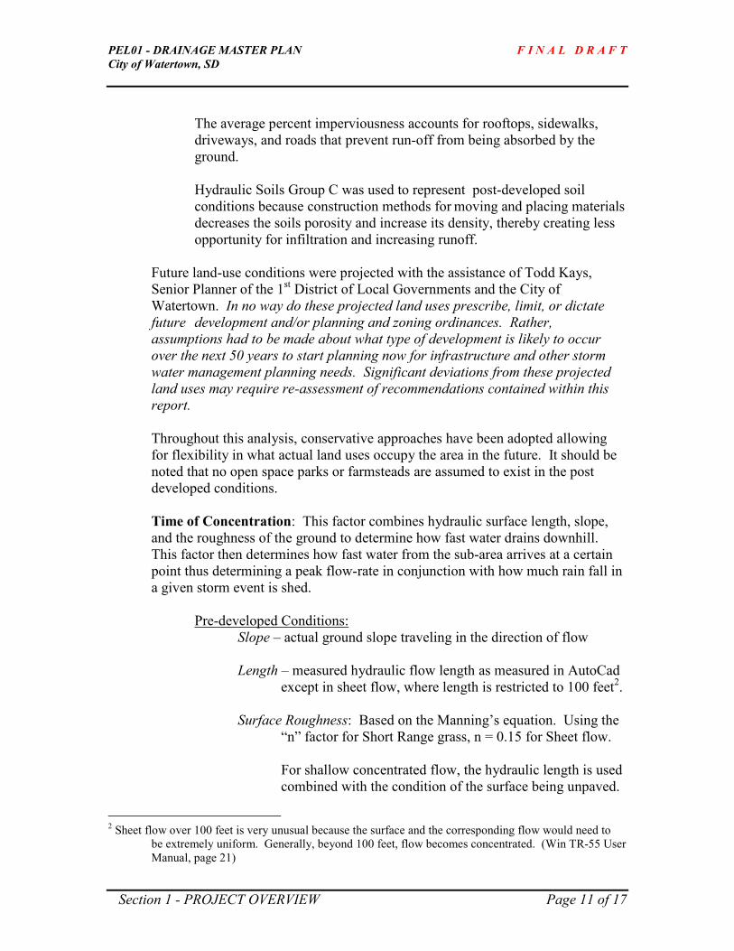
The average percent imperviousness accounts for rooftops, sidewalks,
driveways, and roads that prevent run-off from being absorbed by the
ground.
Hydraulic Soils Group C was used to represent post-developed soil
conditions because construction methods for moving and placing materials
decreases the soils porosity and increase its density, thereby creating less
opportunity for infiltration and increasing runoff.
Future land-use conditions were projected with the assistance of Todd Kays,
Senior Planner of the 1st District of Local Governments and the City of
Watertown. In no way do these projected land uses prescribe, limit, or dictate
future development and/or planning and zoning ordinances. Rather,
assumptions had to be made about what type of development is likely to occur
over the next 50 years to start planning now for infrastructure and other storm
water management planning needs. Significant deviations from these projected
land uses may require re-assessment of recommendations contained within this
report.
Throughout this analysis, conservative approaches have been adopted allowing
for flexibility in what actual land uses occupy the area in the future. It should be
noted that no open space parks or farmsteads are assumed to exist in the post
developed conditions.
Time of Concentration: This factor combines hydraulic surface length, slope,
and the roughness of the ground to determine how fast water drains downhill.
This factor then determines how fast water from the sub-area arrives at a certain
point thus determining a peak flow-rate in conjunction with how much rain fall in
a given storm event is shed.
Pre-developed Conditions:
Slope – actual ground slope traveling in the direction of flow
Length – measured hydraulic flow length as measured in AutoCad
except in sheet flow, where length is restricted to 100 feet2.
Surface Roughness: Based on the Manning’s equation. Using the
“n” factor for Short Range grass, n = 0.15 for Sheet flow.
For shallow concentrated flow, the hydraulic length is used
combined with the condition of the surface being unpaved.
2 Sheet flow over 100 feet is very unusual because the surface and the corresponding flow would need to
be extremely uniform. Generally, beyond 100 feet, flow becomes concentrated. (Win TR-55 User
Manual, page 21)

PEL01 - DRAINAGE MASTER PLAN F I N A L D R A F T
City of Watertown, SD
Section 1 - PROJECT OVERVIEW Page 12 of 17
Post-developed Conditions:
Slope – actual ground slope traveling in the direction of flow
Length – measured hydraulic flow length as measured in AutoCad
except in sheet flow, where length is restricted to 100 feet3.
Surface Roughness: Based on the Manning’s equation. Using the
“n” factor for Dense Grass, n = 0.24 for Sheet flow.
For shallow concentrated flow, the hydraulic length is used
combined with the condition of the surface being unpaved
for Residential – 2 acre lots, and Industrial areas and paved
for Residential ½ acre lots and Commercial areas. Paved
surfaces yield higher velocities and quicker travel
times from water traveling on hard surfaces such as streets,
gutters, and storm sewers.
Rainfall Distribution – For all modeling, a Type-II, 24-hour storm was used for
Codington County as published by the Natural Resource Conservation
Service. This data from the NRCS was slightly modified to reflect data used in a
recent study in Watertown. The Willow Creek Floodplain Study used slightly
higher rainfall events and was therefore adopted to be conservative. The rainfall
depths uses are as follows:
Frequency: 1 yr 2yr 5yr 10yr 25 yr 50yr 100yr 500yr
Depth (inches): 2.0 2.48 3.34 3.85 4.4 5.1 5.7 7.2
Reach Data: Reaches, or channels, are used to convey a hydrograph
downstream. They can receive a hydrograph from a sub-area or another reach.
They can pass a hydrograph downstream to either another reach or to the outlet of
the system.
Reach data for all conditions uses the following inputs:
Reach Length: The hydraulic distance water travels in the channel as
measured using AutoCad.
Surface Roughness: Again, using Manning’s “n”, n = 0.30 for short
rough bottom, grassy channels. It is assumed that channels will be
vegetated with native grasses. This assumption is slightly more
conservative versus using turf-grass as turf-grass is denser and slow the

PEL01 - DRAINAGE MASTER PLAN F I N A L D R A F T
City of Watertown, SD
Section 1 - PROJECT OVERVIEW Page 13 of 17
water more. However, native grasses have deeper rooting structure and
offer improve resistance to erosion, uptake of water, and provide natural
habitat.
Slope: The slope of the channel is determined by taking the difference in
elevation from the beginning of the reach to the end of the reach
and then dividing by the reach length.
Bottom Width: The width of the bottom of the channel. For all pre-
existing conditions, reaches were assumed to have a 2-foot bottom
width unless aerial photography showed a definite channel. In the
latter case, channel width was measured using AutoCad.
For post-developed conditions, FlowMaster was used to size the
bottom width so as to fully contain the post-developed 100-year
flows without over-topping the channel. One-foot of freeboard
was added to the calculated dimensions as a measure of
conservatism and to protect adjacent properties from flows
exceeding those generated from the 100-year event.
Average Side Slopes: Side slopes of pre-developed channels were
measured using AutoCad taking a representative cross-section
perpendicular to the channel’s flow length. Typically, slopes in the
study area approximate 2%, or 50:1 (horizontal:vertical).
For post-developed conditions, FlowMaster was used to determine
the geometry of the side slopes without over-topping the channel
for the post-developed flow created by the 100-year storm event,
with the additional one-foot of freeboard added for an added level
of safety. The conventions used for side slope configurations are
as follows:
Side slopes adjacent to US 212 = 6:1
Side slopes adjacent to other local roads or adjacent to
existing developments = 4:1
Side slopes in undeveloped areas = 10:1
1.6.2 PondPak by Haestad Methods – PondPak is a powerful stormwater modeling
program that analyzes and designs complex watershed networks, ponds, and
outlet structures. It is a far more robust program than WinTR-55 and thus
requires more data entry. However, many similarities exist. All the assumptions
and parameters used in WinTR-55 outlined above are used as inputs into PondPak
with the following added refinement:

PEL01 - DRAINAGE MASTER PLAN F I N A L D R A F T
City of Watertown, SD
Section 1 - PROJECT OVERVIEW Page 14 of 17
� The bottoms of reaches and ponds are allowed to pass water into the ground
through infiltration. An infiltration rate of 0.2 inches per hour was assumed
for all ponds and reaches.
This is a conservative approach as the Soil Survey for Codington County as
published by the Department of Agriculture Soil Conservation Service in 1966
shows that average infiltration for soils within the study area range from 0.14
inches per hour to 2.5 inches per hour. The predominate infiltration rates range
from .8 to 2.5 inches per hour. The factor of 0.2 inches per hour was chosen
because, over-time, fine sediments may plug soil pores and construction practices
increase soil density, thus decreasing infiltration potential and yet still offers some
credit for the ground to absorb water. The areas having less than 0.2 inches per
hour of infiltration are located in or near existing wetlands and so would not be
affected.
1.6.3 CulvertMaster by Haestad Methods - CulvertMaster is program that helps civil
engineers design and analyze culvert hydraulics, from single barrel to complex
multi-barrel culverts with roadway overtopping. CulvertMaster also solves for
most hydraulic variables, including culvert size, flow, and headwater, as well
as plot and generate output for rating tables showing computed flow
characteristics.
The extent to which this study used CulvertMaster is limited to two applications:
1) Determining the capacity of existing culverts, and
2) Determining the number and size of culverts needed to convey
peak flow rates generated from the post-developed flow rates.
The general approach used in designing culverts for the post-developed
conditions, as directed by the City of Watertown, includes the following:
� Culverts under US 212 shall pass post-developed flows generated from a 100-
year rainfall event without overtopping the road. US 212 is a national
highway and also serves as the only major east-west route through the City of
Watertown. During the 1997 flood, it was the only route passable on the west
side of town.
� Culverts under other major collectors such as 4th Avenue, 33
rd Street, and 42
nd
Street, shall pass the post-developed flows generated from a 25-year rainfall
event.
� Other minor collectors and urban streets will be handled on a case-by-case
basis as described in Sections 3-7 of this report, but generally shall also pass
the post-developed 25-year peak flows.
1.6.4 FlowMaster by Haestad Methods - FlowMaster is a program that helps civil
engineers with the hydraulics design and analysis of pipes, ditches, open channels,
drop inlets, etc. FlowMaster computes flows and pressures based on well-known

PEL01 - DRAINAGE MASTER PLAN F I N A L D R A F T
City of Watertown, SD
Section 1 - PROJECT OVERVIEW Page 15 of 17
formulas such as Darcy-Weisbach (Colebrook-White), Hazen-Williams, Kutter's,
and Manning's.
The extent to which this study used FlowMaster is limited to sizing channels
(reaches) using Manning’s equation. An “n” value of .030 was used for channel
lining representative of a rough channel with grass. Specifically, channel
geometry, channel slope, and the required post developed flow rate were input
into the model, then the model solved for channel depth. The City of Watertown
prefers shallow channels with gentle side slopes, so in general, bottom widths
were wide enough so as to limit channel depth to be less than 5’.
All hydraulic data and printouts from these models are contained in a
notebook separate from this report.
1.7 NATIVE PLANTINGS
Native plantings provide much greater resistance to erosion as their root structures
penetrate 12 to 36 inches into the earth versus the 4-6 inches turf grasses penetrate. Also,
native plantings are naturally resistant to drought and tend to be self-weeding once a
mature crop is established. Interestingly, because the size of the seeds are so small,
much less seed is needed (by weight) on a per-acre basis as compared to turf grasses.
The following information is taken from the website of Stock Seed,
(http://www.stockseed.com) which provides further information and identifies typical
seed selection and planting rates. There are other seed companies providing similar seed
mixtures, Stock Seed was shown here as an example and to provide further reference
regarding native plantings.
“Prairie Grass Mixture: Enjoy nature's beauty with this blend of three tall and
four mid-height grasses. This mixture provides excellent habitat for wildlife of all
sizes. It also serves as an effective sound barrier, dust collector and natural snow
fence when planted between roadways and living quarters. Its radiant red, gold
and purple colors add landscaping beauty throughout the fall and winter months.
Virginia wildrye has now been added for earlier green-up and enhanced early-
season habitat value.
Species include: Big Bluestem, Indiangrass, Switchgrass, Little Bluestem,
Sideoats Grama, Western Wheatgrass and Virginia
Wildrye. Varieties will be those adapted for your area.
Seeding rate: Broadcast: 1 PLS lb. per 2,000 sq. ft.; Drilled: 10 PLS
lbs./Acre

PEL01 - DRAINAGE MASTER PLAN F I N A L D R A F T
City of Watertown, SD
Section 1 - PROJECT OVERVIEW Page 16 of 17
“Floodplain Mixture: Use this blend of deep-rooted grasses to re-establish
damaged floodplains. This mixture also can withstand seasonal flooding and
contains grasses with different levels of tolerance. The grasses in this mixture and
their tolerance to inundation (standing water) vary: Western Wheatgrass has
shown tolerance up to 60 days; Red Top, Switchgrass and Canada Wildrye, 15 to
30 days; Big Bluestem, 7 to 14 days.
Temperature, soil type, water depth and age of stand all influence the grasses'
tolerance for inundation. Plants are more tolerant to flooding during early spring
than hot summer months. This mixture is recommended along fluctuating
shorelines, on dams and for lowland pasture.
Mixture includes: Virginia wildrye, Switchgrass, Canada Wildrye,
Western Wheatgrass, Red Top and Big Bluestem.
Seeding rate: 12-15 lbs./Acre in spring or in fall after frost. INCREASE
RATE WHEN WET CONDITIONS DICTATE BROADCAST SEEDING”
Other benefits of native plantings, (also referred to as “ soil bioengineering”) include
increased water quality treatment. Pollutants in storm water, such as phosphorous and
nitrogen, are broken down and absorbed by microbes in the plant roots instead of being
discharged downstream. These plants’ root structures also get stronger with age. Also,
during dry periods, some plants’ roots are hollow shoots allowing increased oxygen deep
into the soil enhancing microbial activity. These hollow roots also provide increased
penetration for surface water to replenish groundwater.
This study recommends using Prairie Grass Mixture, or similar, on the sides of all ponds
and channels and Floodplain Mixture, or similar, on the bottoms of all ponds and
channels where inundation of water is likely. Slopes steeper than 4:1 should be covered
with an erosion control blanket secured with stakes as recommended by its manufacturer.
Also, any time velocities in channels exceed 2 feet per second, a soil stabilization or
fiberous mat should be installed to prevent erosion until the plants’ root systems mature.
However, if channels and ponds are constructed well in advance of development, this
may not be required.
In summary, selected native plantings provide a multitude of benefits including:
� Providing increased resistance to erosion,
� Providing natural habitat,
� Increased heartiness during periods of drought and/or inundation,
� Requiring little or no maintenance once established,
� Improving water quality through microbial activity, and
� Enhancing groundwater recharge.

PEL01 - DRAINAGE MASTER PLAN F I N A L D R A F T
City of Watertown, SD
Section 1 - PROJECT OVERVIEW Page 17 of 17
1.8 DRAINAGE EASEMENTS
For securing land for overland flow channels (proposed reaches), it is the City’s practice,
as has been established through written policy, to purchase the easement areas in fee and
title. In general, the City prefers the width of drainage easements to be equal to the
nearest 10’ of top-width based on channel sizing, plus an additional 10’ on each side of
the channel for maintenance purposes and added buffer. The additional 10’ of added
buffer should slope toward the channel at a 2% cross slope.

PEL01 - DRAINAGE MASTER PLAN F I N A L D R A F T
City of Watertown, SD
Section 2 - DATA INVENTORY Page 1 of 14
SECTION 2 – DATA INVENTORY
2.1 Resource Summary
Early in project development, the City provided the following materials for reference:
1) City of Watertown Aquifer Protection Overlay Map (almost all of this study area lies in Zone B (yellow)).
2) Codington County Aquifer Protection map.
3) Feasibility Report and Environmental Assessment, Flood Control For Watertown and Vicinity, South
Dakota, August 1994 by Corps of Engineers, Omaha Distinct.
4) Report of Lake Kampeska, Report of Investigation 103, by Assad Barari, South Dakota Geological Survey,
1971, for the South Dakota Department of Game, Fish, and Parks
5) Water Supplies and Geology of Lake Kampeska, Report of Investigations No. 17 by E.P. Rothrock, State
Geologist for South Dakota Geological Survey., December 1933, Reprint in 1956
6) Ground Water Fluctuations in Eastern South Dakota, Report of Investigations No. 30 by E.P. Rothrock,
State Geologist for South Dakota Geological Survey., December 1938, Reprint in 1956
7) Ground Water Supply for the City of Watertown, Special Report No. 28 by Rukstad and Hedges, South
Dakota State Geological Survey, 1964
8) Major Aquifers in Codington and Grant Counties, South Dakota, Information Pamphlet 47 by Donald S.
Hansen, U.S. Geological Survey, 1994
9) Geology and Shallow Ground Water Resources of the Watertown-Estelline Area, South Dakota, Report of
Investigations, No. 85 by Fred V. Steece, University of South Dakota, June 1958
10) Sand and Gravel Resources in Codington County, South Dakota by Layne D. Schulz, Department of
Environment and Natural Resources, Division of Geological Survey, 1991
11) Informal map from Todd Kays, 1st District Senior Planner. This map will be used to create a “model map”
for determining surface types and corresponding land uses for the watershed models.
12) Engineering Design Standards for the City of Watertown (DRAFT), 1997
13) Codington County Official Zoning Map
14) City Limits and Zoning Map, Watertown, SD
15) Agreement between Steve Horning and Virgil Borns regarding water flow and storm water runoff.
16) Plat of Borns' First Addition, February 1995
17) Replat of Borns' First Addition, May 1995
18) Plat of Borns' Second Addition, March 1996
19) Master Plan of Borns’ Addition
20) Chapter 21.19 “AP” Aquifer Overlay District, City of Watertown Planning Commission
21) Willow Creek Tributaries, Drainage Master Plan, Final Report by EarthTech, July 2001
22) Update of the Comprehensive Plan for the City of Watertown by Watertown Planning Commission, August
18, 1995
23) Watertown Zoning and Subdivision Regulations for the City of Watertown (handbook version)
24) Soil Survey Codington County, South Dakota by USDA, Soil Conservation Service, 1966
25) City of Watertown Landscape Ordinances, via Watertown’s internet website
26) Sanitary Sewer Plan Sheet – Borns’ Addition (Sheets 457-460)
27) City Limits and Boundaries Map, Watertown (3-18-03)
28) Lake Kampeska Additions and Boundaries Map, Watertown (1-31-01, 3-26-03)
29) Flood Insurance Rate Map, City of Watertown, Panel 10 of 10, July 4, 2989
30) Flood Hazard Boundary Map, Codington County, Pages 5 and 8 of 9, January 24, 1978
31) Codington County Plat and Directory, 2002

PEL01 - DRAINAGE MASTER PLAN F I N A L D R A F T
City of Watertown, SD
Section 2 - DATA INVENTORY Page 2 of 14
2.2 Land Ownerships
Early in the project development stage of this project, the Director of Equalization Office
of Codington County was contacted to acquire land ownership information. The City of
Watertown requested to have each parcel’s owner identified and invited to participate in
the project. Each of the land owners identified were also invited to public meetings.
Where platted properties inside development platted within Additions to the City of
Watertown occur, for the purposes of this Master Plan, the City of Watertown represents
their interest.
See Figure 2.1 – Land Ownership Map located at the end of Section 2. The four and five
digit numbers are the Record Numbers used by the Director of Equalization Office to
capture property information in their database. These Record Numbers are cross
referenced in Table 2.1 – Land Ownership Data, also located at end of this section.
2.2.1 Other Stakeholders
The City of Watertown further suggested that the following people/groups be contacted,
informed about the project, and invited to participate. All correspondence received from
these people regarding this Master Plan is contained in the Appendix. Each person on
this list has been contacted and informed about this project and they have been invited to
all public meetings.
Dale Miller
Lake Pelican Preservation Society
4914 W Pelican Drive
Watertown SD 57201
Julian Wick
Lake Pelican Water Project District
4002 20th Avenue SW
Watertown SD 57201
John Hanten
222 54th Street SW
Watertown SD 57201
NRCS
810 10th Ave SE, Suite 3
Watertown SD 57201-5256
James Oehlerking
US Army Corps of Engineers
28563 Powerhouse Road, Rm 118
Pierre SD 57501
Commissioner Elmer Brinkman
Codington County Planning & Zoning
1212 7th Ave NE
Watertown SD 57201
Doug Alvine
Game, Fish, and Parks
400 W Kemp Ave
Watertown SD 57201
John Little
801 N Lake Drive
Watertown SD 57201
Ron Sherman, PE
Watertown Area Engineer - SD DOT
PO BOX 1446
Watertown SD 57201-1446
Ken Madison
DENR - Watertown Office
913 5th Street SE
Watertown SD 57201-5134

PEL01 - DRAINAGE MASTER PLAN F I N A L D R A F T
City of Watertown, SD
Section 2 - DATA INVENTORY Page 3 of 14
Todd Kays, Sr. Planner
1st District Association of Local Governments
PO BOX 1207
Watertown SD 57201-1207
2.3 Field Survey
A survey-crew, using global positioning survey instruments (GPS), gathered data
including culvert locations and their inlet and outlet inverts, surface elevations to fill in
missing contour data not available through the City. This data was then referenced to
City datum.
The survey-crew also captured high-water elevations from the flood event in 1997 on
structures existing within the study area. See Section 2.6 below for more information.
2.3.1 Wetland Delineation
A wetland delineation was performed in specific areas currently being considered for
development. See the Appendix to review a copy of the Wetland Delineation Report.
The need to identify wetland boundaries was identified by City staff in conjunction with
what a developer was proposing with Watershed A. Furthermore, the boundaries of any
wetlands needed to be identified in order to place tentative stormwater management
structures outside of the wetland. See Section 3 of this report to see how proposed
stormwater management features are located near wetlands without disturbance.
The delineation occurred only inside Watershed A. Other wetlands may exist in other
watersheds.
2.4 Pre-Developed Modeled Conditions
As stated previously in Section 1.6.1, pre-developed conditions modeled for this Master
Plan adopted the standard of using generated runoff from a landscape dominated by
prairie grasses. This convention captures peak runoff rates from a time prior to
disturbance by man. This approach is conservative and models the runoff rates that have
shaped natural drainage patterns over time. For more information regarding pre-
developed hydraulic and hydrologic inputs and assumptions, see Section 1.6.
It should be noted that existing culverts and roads were applied to the pre-developed
model. This somewhat contrasts with the purely “pre-European settlement;” however,
existing contour data provided by the City was the best information available. In
addition, using existing drainage patterns makes it easier to compare results between pre-
developed and post-developed conditions. Moreover, the most significant difference
between pre-developed and post-developed conditions is the land use. Slopes, reach

PEL01 - DRAINAGE MASTER PLAN F I N A L D R A F T
City of Watertown, SD
Section 2 - DATA INVENTORY Page 4 of 14
lengths, and drainage patterns are not that different from each other when comparing pre-
developed to post-developed conditions.
2.5 Post-Developed Modeled Conditions
Also stated previously in Section 1.6. are the assumptions and inputs used to model post-
developed conditions. A “model map” was developed with input from Todd Kays,
Senior Planner of 1st District Association of Local Governments. This map, Figure 2.2 –
Post-Developed Land Use Map located at the end of this section, demonstrates what
types of land uses would infill the landscape over the next 30-40 years. In other words, it
allows a model to be developed using the “ultimate build-out” conditions. In no way do
these land uses prescribe, limit, or dictate future development and/or planning and
zoning ordinances. Rather, assumptions had to be made about what type of development
is likely to occur over the next 50 years to start planning now for infrastructure and other
storm water management planning needs.
For analysis of individual watersheds and to compare their pre-developed peak flow rates
vs. post-developed flow rates, see Sections 3-7 of this report.
2.6 Historic Maximum Elevation of Pelican Lake
In 1997, a 2.5 inch rainfall event, combined with piled up wet snow, frozen ground, and
rapid snowmelt, created flooding problems in the City of Watertown. Lake Pelican
reached its historical high water elevation. For planning purposes, and potentially City
ordinance revisions, the City of Watertown desired to establish this high-water elevation.
A survey crew, using GPS equipment, established the high water elevation through taking
elevations from high water marks left on buildings within the study area. Their efforts
yield a high-water elevation of 1716.3 feet above sea-level (Vertical Reference: NDVD
1927).
Coincidentally, the US Army Corps of Engineers (CoE) is currently updating a
Flood Insurance Study commissioned by FEMA of the Watertown Reach of the
Big Sioux River and surrounding tributaries from Sioux Conifer Road to its
confluence with Willow Creek. The high-water elevation derived by the CoE for
Lake Pelican is 1716.5.
The normal pool elevation, (ie. ordinary high water mark) of Lake Pelican ranges
from 1709.9 to 1710.3 feet. Its outlet into the Big Sioux is controlled by a weir
structure at elevation 1709.7 feet.
Figure 2.3 – High Water Elevation for Lake Pelican, shows the CoE’s high water
elevation as projected by the Flood Insurance re-study. This figure is located at the
end of this section.

PEL01 - DRAINAGE MASTER PLAN F I N A L D R A F T
City of Watertown, SD
Section 2 - DATA INVENTORY Page 5 of 14
TABLE 2.1 – LAND OWNERSHIP DATA
O W N E R ' S N A M E A D D R E S S REC
# LAST FIRST & Other ADDRESS 1 ADDRESS 2 ADDRESS 3
ADDRESS 4
ADDRESS 5 SECT TOWN RNG
LEGAL DESCRIPTION
2575 JENSON DAN 3507 3 AVE NW WATERTOWN SD 57201 27 117 53 S388' W 561.3' E 1557' OF SE
1/4
2576 KAISER ANNE MARIE 214 S 6TH ST YAKIMA WA 98901 27 117 53 SE 1/4 LESS S 388' W 561.3
E 1557'
2596 STATE OF SOUTH DAKOTA
33 117 53 LOT H-2 IN S1/2 SW1/4 & LOT H-2 IN S1/2 SE1/4
2597 LUKONEN EA TRUSTEES
KENNETH J 4600 GOLF COURSE RD WATERTOWN SD 57201 33 117 53 NE 1/4 LESS RD. & E1/2 NW
1/4
2598 MINOR VERNON THOMAS & BETTY
5101 4 AVE SW WATERTOWN SD 57201-7209
33 117 53 E 200' OF N 435.6' OF S 468.6'
OF W 1/2 NW 1/4
2599 HANTEN JOHN H & PATRICIA J 222 54 ST SW WATERTOWN SD 57201 33 117 53
W 1/2 NW 1/4 LESS E200' OF N435.6' OF
S468.6' OF W1/2 OF NW1/4 AND LESS
LOT 1 PRAIRIE WINDS
2600 LUKONEN EA TRUSTEES
KENNETH J 4600 GOLF COURSE RD WATERTOWN SD 57201 33 117 53 LUKONEN'S OIL OF S 1/2
2601 HOLIEN DENNI D P O BOX 1445 WATERTOWN SD 57201 33 117 53 S 852.2' OF W302.01' E592' W963 OF SW1/4 LESS HY
2602 JONGBLOED SCOTT A & MARIA 719 54 ST SW WATERTOWN SD 57201 33 117 53 N 200' S 1052.2' W 435.6' OF S
1/2
2603 MCFARLAND ROGER & DAVID 17263 450 AVE WATERTOWN SD 57201 33 117 53
S1/2 LESS LOT H-2 & LESS LUKONENS OL & N200' S1052.2' W435.6' & LESS
S852.2' S963'
2603 MCFARLAND ROGER & DAVID R. 17263 450 AVE WATERTOWN SD 57201 33 117 53
S 1/2 LESS LOT H-2 & LESS LUKONENS OL & N 200' S 1052.2' W 435.6' & LESS S
852.2' S 963'
2604 SIEBRANDS MATTHEW & ALYCE 44187 US HWY 212 HENRY SD 57243 33 117 53 S852.2' OF W371' OF SW1/4
LESS HY
2605 SOUTH DAKOTA STATE OF 34 117 53 LOT H-2 IN SW1/4
2606 SOUTH DAKOTA STATE OF 34 117 53 LOT H-2 IN SE1/4
2607 CLENDENIN JAMES AND LUVINA 3707 4 AVE W WATERTOWN SD 57201 34 117 53 W3 ACRES OF SW1/4 SW1/4
NE1/4
2608 KOLB K % PATT HUSTEAD BOX #1 WALL SD 57790 34 117 53 W 1/2 NE 1/4 NE 1/4 & NW 1/4
SE 1/4 NE/1/4
2609 KOLB EA K % PATT HUSTEAD BOX #1 WALL SD 57790 34 117 53 NW 1/4 NE 1/4 & N 1/2 SW 1/4
NE 1/4 LESS JOHNSON'S ADD.

PEL01 - DRAINAGE MASTER PLAN F I N A L D R A F T
City of Watertown, SD
Section 2 - DATA INVENTORY Page 6 of 14
O W N E R ' S N A M E A D D R E S S REC
# LAST FIRST, AND OTHER ADDRESS 1 ADDRESS 2 ADDRESS 3 ADDRESS
4 ADDRESS
5 SECT TOWN RNG LEGAL DESCRIPTION
2610 MORRISON CLYDE R 3333 4 AVE SW WATERTOWN SD 57201 34 117 53 E 1/2 NE 1/4 NE 1/4 & NE 1/4
SE 1/4 NE 1/4
2611 STERN LYLE V 3447 4 AVE W WATERTOWN SD 57201 34 117 53 W 1/2 SW 1/4 SE 1/4 NE 1/4
2612 OELRICH, EA PAUL E 3637 4 AVE SW WATERTOWN SD 57201 34 117 53 E 462' SW 1/4 SW 1/4 NE 1/4
2613 MORRISON CLYDE R 3333 4 AVE SW WATERTOWN SD 57201 34 117 53 SE1/4 SE 1/4 NE1/4
2614 MORRISON CLYDE R 3333 4 AVE SW WATERTOWN SD 57201 34 117 53 E 1/2 SW 1/4 SE 1/4 NE 1/4
2615 FREIMARK TODD M 3825 4 AVE SW WATERTOWN SD 57201 34 117 53 E 1/2 E 1/2 SW 1/4 SE 1/4
NW 1/4
2616 STERLING P % PATT HUSTEAD BOX #1 WALL SD 57790 34 117 53 N1/2 NW1/4 & N1/2 SE1/4 NW1/4 & E1/2 NE1/4 SW1/4
NW1/4
2617 NORDSETH VERLYN A OR MAXINE 4123 4 AVE SW WATERTOWN SD 57201 34 117 53 SW 1/4 SW 1/4 NW 1/4
2618 CSS COMPANY A PARTHERSHIP 3334 9 AVE W
WATERTOWN SD 57201 34 117 53 S700.6' E684' SW1/4 11
ACRES
2619 ROSO BLANCH M AND LEONARD S
3945 4 AVE SW WATERTOWN SD 57201 34 117 53 N 70 RODS (1155') OF SW 1/4
2620 LUKONEN TRUSTEES
KENNETH J & ARLENE M 4600 GOLF COURSE RD WATERTOWN SD 57201 34 117 53
SW 1/4 LESS N 70 RODS (1155') & LESS S 17' TO CTY. & LESS RD. & LOT H - 2 &
LESS S 700.6' E 684'
2621 SPURRELL STANLEY & MARILYN L/E 431 33 ST SW WATERTOWN SD 57201 34 117 53 SE 1/4 LESS S 17' TO CO. &
LESS LOT H-2
2625 CAMENZIND ARTHUR 10406 STATE ST OMAHA NE 68122-1054
35 117 53 NW1/4 LESS E658' N329'
S1128'
2626 BOHN GAYLORD R & EDITH E 2719 9 AVE SW WATERTOWN SD 57201 35 117 53 SW 1/4 LESS LOT H - 3 AND
LESS BOHN ADD
2672 STEFFEN, EU MICHAEL E 3605 4 AVE SW WATERTOWN SD 57201 34 117 53 LOT 1 JOHNSONS ADD
2673 DEJONG RODNEY S & PAULA J 3517 4 AVE SW WATERTOWN SD 57201 34 117 53 LOTS 2 & 3 5.64 JOHNSONS
ADD
2685 KLATT EA DAVID L 4027 4 AVE SW WATERTOWN SD 57201 34 117 53 LOT 5 NW1/4 KOLBS ADD
2686 ROOT DOUGLAS W & SHELLY A 3919 4 AVE SW WATERTOWN SD 57201 34 117 53 LOT 9 OF NW 1/4 KOLBS ADD
2687 KLATT DAVID L & ROSEMARY L 4027 4 AVE SW WATERTOWN SD 57201 34 117 53 LOT 6 KOLBS ADD
2688 LAUSENG TODD W & ANN M 3940 4 AVE SW WATERTOWN SD 57201 34 117 53 LOT 7 KOLBS ADD
2689 NIEWOEHNER ROLAND E & SANDRA L 3931 4 AVE SW WATERTOWN SD 57201 34 117 53 LOT 8 KOLBS ADD
2690 BRACHT MICHAEL R & VICKY L 3847 4 AVE SW WATERTOWN SD 57201 34 117 53 LOTS 10 & 11 NW1/4 KOLBS
ADD
2691 STERNS DAVID A AND RACHEL 120 42 ST SW WATERTOWN SD 57201 34 117 53 LOT 2 KOLBS ADD

PEL01 - DRAINAGE MASTER PLAN F I N A L D R A F T
City of Watertown, SD
Section 2 - DATA INVENTORY Page 7 of 14
O W N E R ‘ S N A M E A D D R E S S REC # LAST FIRST, AND OTHER ADDRESS 1 ADDRESS 2 ADDRESS 3
ADDRESS 4
ADDRESS 5
SECT TOWN RANGE LEGAL DESCRIPTION
2692 STERNS DAVID A AND RACHEL 120 42 ST SW WATERTOWN SD 57201 34 117 53 LOT 1 & W1/2 NE1/4 SW1/4
NW1/4 KOLBS ADD
2693 ENGELS LYNN E 511 4 ST SW WATERTOWN SD 57201 34 117 53 LOT 4 KOLBS ADD
2699 MANZEY JOHN L & MARY JO 3727 4 AVE SW WATERTOWN SD 57201 34 117 53 LOT 1 MACKS SUB
2700 WHITLOCK GREGORY J & MICHELLE LYNN
3747 4 AVE SW WATERTOWN SD 57201 34 117 53 LOT 2 MACKS SUB
2701 HANSON ALVIN OR CAROL JEAN 3813 4 AVE SW WATERTOWN SD 57201 34 117 53 LOT 3 MACKS SUB
2939 REDLIN CHARLES A 20 N LAKE DR WATERTOWN SD 57201 2 116 53 LOTS 3-4 LESS N1035' GOVT LOT 4 LESS RR ADD & SW1/4
NW1/4
2940 REDLIN CHARLES A 20 N LAKE DR WATERTOWN SD 57201 2 116 53 GOVT LOT 6
2941 SOUTH DAKOTA STATE OF 3 116 53 LOTS H-2-4 IN NW 1/4 & LOTS H-2-3 IN NE 1/4 7.77 ACRES
2942 RADERSCHADT LEWIS 1112 17 ST NE WATERTOWN SD 57201 3 116 53 W120.33' E4523.5' N724' OF
N1/2 2.00 ACRES
2943 KAHNKE INA C % MARK KIENAST 1308 10 AVE SW WATERTOWN SD 57201 3 116 53
N 1/2 LESS DEEDED PARTS AND LESS RR ADD & LESS BORNS 1ST ADD & LESS
BORNS 2ND ADD
2944 CSS CO 3334 9 AVE SW WATERTOWN SD 57201 3 116 53 W461' E1014.5' N687' OF N1/2
LESS RR R/W & HY 5.00 ACRES
2945 FRATERNAL ORDER OF EAGLES
W HWY 212 WATERTOWN SD 57201 3 116 53 W500.2' E1514.7' N687' LESS S75' W295' LESS HY N1/2
2946 DAVID MANUFACTURING CO
P O BOX 482 CLEAR LAKE IA 50428-0482
3 116 53 W 250' E 1764.7' N 643' LESS HY. OF NE 1/4 3.69 ACRES
2947 GRIEPP BRADLEY C & DIANE M 1518 42 ST SW WATERTOWN SD 57201 3 116 53 N595' W835' N1/2 SW1/4 3-116-
53
2948 HORNING STEVEN T P O BOX 304 WATERTOWN SD 57201 3 116 53 GOVT LOTS 7 & 8
2948 HORNING STEVEN T P O BOX 304 WATERTOWN SD 57201 3 116 53 GOVT LOTS 7-8
2949 SOUTH DAKOTA STATE OF 4 116 53 LOT H-2 IN N 1/2 9.70 ACRES
2950 LUKONEN KENNETH & ARLENE M 4600 GOLF COURSE RD WATERTOWN SD 57201 4 116 53 N1/2 LYING N OF RY LESS LUKONEN ADD & LESS HY
2951 LUKONEN, TRUSTEES
KENNETH & ARLENE M 4600 GOLF COURSE RD WATERTOWN SD 57201 4 116 53 N1/2 LYING S OF RY
2952 MCFARLAND DAVID R 28181 AIRPORT RD GODFREY IL 62035 4 116 53 S1947' SW1/4

PEL01 - DRAINAGE MASTER PLAN F I N A L D R A F T
City of Watertown, SD
Section 2 - DATA INVENTORY Page 8 of 14
O W N E R ’ S NAME A D D R E S S REC # LAST FIRST, AND OTHER ADDRESS 1 ADDRESS 2 ADDRESS 3
ADDRESS 4
ADDRESS 5
SECT TOWN RNG LEGAL DESCRIPTION
2953 HORNBERGER JAMES H & TERI T 1723 42ST SW WATERTOWN SD 57201 4 116 53 N425' S1649' E330' SE1/4
2954 LONG GLEN E & SANDRA K 1833 42 ST SW WATERTOWN SD 57201 4 116 53 E20 RDS OF S56 RDS SE 1/4 7
ACRES
2985 GAME FISH & PARKS
523 E CAPITAL AVE PIERRE SD 57501 9 116 53 OL 1 IN GOVT LOTS 1-5
2985 SD GAME FISH & PARKS
523 E CAPITOL AVE PIERRE SD 57501 9 116 53 OL 1 IN GOVT LOTS 1-5
2986 EGGE JOHN 4116 20 AVE SW WATERTOWN SD 57201 9 116 53 GOVT LOTS 4-5 LESS OL 1 &
LESS LANOUES OL
2986 EGGE JOHN 4116 20 AVE SW WATERTOWN SD 57201 9 116 53 GOVT LOTS 4-5 LESS OL 1 &
LESS LANQUES OL
2987 MCFARLAND DAVID R & MARY DIANE 28181 AIRPORT RD GODFREY IL 62035 9 116 53 N1/2 NW1/4
2988 MCFARLAND DAVID R & MARY DIANE 28181 AIRPORT RD GODFREY IL 62035 9 116 53 GOVT LOTS 1-3 LESS OL 1
2988 MCFARLAND DAVID R & MARY DIANE 28181 AIRPORT RD GODFREY IL 62035 9 116 53 GOVT LOTS 1-3 LESS OL 1
3224 EGGE JOHN 4116 20 AVE SW WATERTOWN SD 57201 9 116 53 LANOUES OL OF G.L. 4 & 5 10.97 ACRES LA NOUES OL
3247 SCHULTZ ALAN W & PEGGY 4148 20 AVE SW WATERTOWN SD 57201 3 116 53 LOT A & B PORTER WHITE OL
3248 CARLSON DARWIN L. & KATHLEEN M
4134 20 AVE SW WATERTOWN SD 57201 3 116 53 LOT C & D PORTER WHITE OL
3249 EGGE NYLA 4116 20 AVE SW WATERTOWN SD 57201 3 116 53 LOT E PORTER WHITE OL
3250 LINDNER RODNEY J & SALLY A 4112 20 AVE SW WATERTOWN SD 57201 3 116 53 LOT F PORTER WHITE OL
3251 KRAEMER ARVID R & EILEEN M 4102 20 AVE SW WATERTOWN SD 57201 3 116 53 LOT G PORTER WHITE OL
3252 WICK JULIAN L & ROCHELLE A 4002 20 AVE SW WATERTOWN SD 57201 3 116 53 LOT H PORTER WHITE OL
3253 ROSSOW RICHARD A & LIANA J 3918 20 AVE SW WATERTOWN SD 57201 3 116 53 LOT I PORTER WHITE OL
3254 WIESNER NEIL R & FAY 3824 20 AVE SW WATERTOWN SD 57201 3 116 53 LOT J LESS W50' PORTER
WHITE OL
3255 JORAN, EU DEAN W. 3800 20 AVE SW WATERTOWN SD 57201 3 116 53 LOT K PORTER WHITE OL
11653 KNEELAND DAVID L & DIANE B 4125 20 AVE SW WATERTOWN SD 57201 3 116 53 LOT 8 HORNINGS 3RD ADD
13711 JOHNSON WAYNE L 24800 100 ST ZIMMERMAN MN 55398 33 117 53 S852.2' E290' W963' SW1/4
LESS HY
14060 BOERSMA LOUIS AND JOY 132 42 ST SW WATERTOWN SD 57201 34 117 53 LOT 3 KOLBS ADD
14173 HORNING STEVEN T P O BOX 304 WATERTOWN SD 57201 3 116 53
N1/2 SW1/4 LESS N595' OF W835' & GOVT LOTS 5 & 6
LESS PORTER WHITE OLS 3-116-53 LESS HORNINGS
THIRD ADD

PEL01 - DRAINAGE MASTER PLAN F I N A L D R A F T
City of Watertown, SD
Section 2 - DATA INVENTORY Page 9 of 14
O W N E R ‘ S N A M E A D D R E S S REC # LAST FIRST, AND OTHER ADDRESS 1 ADDRESS 2 ADDRESS 3
ADDRESS 4
ADDRESS 5
SECT TOWN RNG LEGAL DESCRIPTION
14173 HORNING STEVEN T P O BOX 304 WATERTOWN SD 57201 3 116 53
N1/2 SW1/4 LESS N595' OF W835' & GOVT LOTS 5 & 6
LESS PORTER WHITE OLS 3-116-53 LESS HORNINGS
14205 REDLIN CHARLES A 20 N LAKE DR WATERTOWN SD 57201 2 116 53 RAILROAD ADD LESS
PORTION LYING IN N1035' GOVT LOT 4 2-116-53
15361 CORNELIUS DAVID AND LORI 322 32 ST NW WATERTOWN SD 57201 1 400 LOT 1 BLK 4 HERZOGS FIFTH
ADD
15362 ORTMEIER JOSEPH B 3104 4 AVE NW WATERTOWN SD 57201 2 400 LOT 2 BLK 4 HERZOGS FIFTH
ADD
15363 JACOBSON DEBRA 3012 4 AVE NW WATERTOWN SD 57201 3 400 LOT 3 BLK 4 HERZOGS FIFTH
ADD
15364 NORTON KIMBERLY K 3011 DOWNS AVE NW WATERTOWN SD 57201 6 400 LOT 6 BLK 4 HERZOGS FIFTH
ADD
15365 DEVILLE CAMILLE BEMENT 3007 DOWNS AVE NW WATERTOWN SD 57201 5 400 LOT 5 BLK 4 HERZOGS FIFTH
ADD
15366 DEWALL KEN R & LAURIE L 3008 4 AVE NW WATERTOWN SD 57201 4 400 LOT 4 BLK 4 HERZOGS FIFTH
ADD
15367 WIRKUS JEFF L & SHARI L 3103 DOWNS AVE NW WATERTOWN SD 57201 7 400 LOT 7 BLK 4 HERZOGS FIFTH
ADD
15368 METTLER CHARLES P & NICOLE M 314 32 ST NW WATERTOWN SD 57201 8 400 LOT 8 BLK 4 HERZOGS FIFTH
ADD
15403 NEITZEL DAVID C & STEPHANIE L 323 32 ST NW WATERTOWN SD 57201 10 500 LOT 1 BLK 5 HERZOGS FIFTH
ADD
15404 GRIMES RANDY W & DAWNA N 321 32 ST NW WATERTOWN SD 57201 20 500 LOT 2 BLK 5 HERZOGS FIFTH
ADD
15405 THORSON LISA C 317 32 ST NW #11 WATERTOWN SD 57201 30 500 LOT 3 BLK 5 HERZOGS FIFTH
ADD
15406 PAYNE ALLAN O & RAE D 313 32 ST NW WATERTOWN SD 57201 40 500 LOT 4 BLK 5 HERZOGS FIFTH
ADD
15407 WATERTOWN CITY OF 50 500 LOT 5 BLK 5 HERZOGS FIFTH
ADD
15408 ANDERSON GREGORY A & DEANNE M
3112 DOWNS AVE NW WATERTOWN SD 57201 60 500 LOT 6 BLK 5 HERZOGS FIFTH
ADD
15409 STEWART TRACI E 3108 DOWNS AVE NW WATERTOWN SD 57201 70 500 LOT 7 BLK 5 HERZOGS FIFTH
ADD
15410 LINDGREN TROY M & TONYA M 3104 DOWNS AVE NW WATERTOWN SD 57201 80 500 LOT 8 BLK 5 HERZOGS FIFTH
ADD
15411 FREIH EDWARD S & DEBRA K 3012 DOWNS AVE NW WATERTOWN SD 57201 90 500 LOT 9 BLK 5 HERZOGS FIFTH
ADD
15412 FISHER CHAD L & TANYA J 3008 DOWNS AVE NW WATERTOWN SD 57201 100 500 LOT 10 BLK 5 HERZOGS
FIFTH ADD
15829 MAHOWALD ANDREW 505 12 ST SE WATERTOWN SD 57201 010 N471.6' OF LOT 1 LESS N150'

PEL01 - DRAINAGE MASTER PLAN F I N A L D R A F T
City of Watertown, SD
Section 2 - DATA INVENTORY Page 10 of 14
BOHN ADD
O W N E R ‘ S N A M E A D D R E S S REC # LAST FIRST, AND OTHER ADDRESS 1 ADDRESS 2 ADDRESS 3
ADDRESS 4
ADDRESS 5
SECT TOWN RNG LEGAL DESCRIPTION
15830 WATERTOWN CITY OF 012 LOT 1A BOHN ADD
15831 BOHN GAYLORD R & EDITH E 2719 9 AVE SW WATERTOWN SD 57201 020 LOT 2 BOHN ADD
15832 LUKEN MICHAEL V P O BOX 374 WATERTOWN SD 57201 030 LOT 3 BOHN ADD
15833 REDLIN CHARLES V 3100 9 AVE W WATERTOWN SD 57201 040 LOT 4 BOHN ADD
15834 COEV INC 3003 9 AVE SW WATERTOWN SD 57201 050 LOT 5 & 6 BOHN ADD
15835 BOHN GAYLORD R & EDITH E 2719 9 AVE SW WATERTOWN SD 57201 070 LOT 7 BOHN ADD
15876 HORNING STEVEN T & KATHRYN L P O BOX 304 WATERTOWN SD 57201 3 116 53 LOT 2 HORNINGS 3RD ADD
15877 BOEHNKE TERRY & RUTH 3821 20 AVE SW WATERTOWN SD 57201 3 116 53 LOT 10 HORNINGS THIRD
ADD
15894 ROTHS JAY S & ANDREA M 17260 450 AVE WATERTOWN SD 57201 4 116 53 N693' SW1/4
16066 LAPKA MIKE J & MARSHA A 4119 20 AVE SW WATERTOWN SD 57201-7034
3 116 53 LOT 5 HORNING THIRD ADD
16259 UREVIG PAUL A 3801 20 AVE SW WATERTOWN SD 57201 3 116 53 LOT 12 HORNING THIRD ADD
16273 WIESNER NEIL R & FAY 3824 20 AVE SW WATERTOWN SD 57201 3 116 53 LOT 9 HORNINGS 3RD ADD
16291 RICHTER GREGORY C & ANITA J 4001 20 AVE SW WATERTOWN SD 57201 3 116 53 LOT 6 HORNINGS 3RD ADD
16325 DAY PAUL E & SHEILA M 3921 20 AVE SW WATERTOWN SD 57201 3 116 53 LOT 7 HORNINGS 3RD ADD
16326 REEVES MELVIN P & PAMELA J 3811 20 AVE SW WATERTOWN SD 57201 3 116 53 LOT 11 HORNINGS 3RD ADD
16646 GEIGER KEVIN P & JULIE A 4121 20 AVE SW WATERTOWN SD 57201 3 116 53 LOT 1 HORNINGS 3RD ADD
16713 BACHMAN LARRY W & SHARLENE L 323 13 ST SW WATERTOWN SD 57201 40 LOT 4 HORNING'S 3RD ADD
16754 NEWMAN GEORGE & JANET 1017 18 ST NE WATERTOWN SD 57201 011
N 150' LOT 1 LESS W20' E48.1' S57' N84' N150' LOT 1 & LESS W18' E66.1' S57' N84' N150' LOT 1 & LESS W 18' E 84.1' S 57' N84' N150' L1
BOHNS ADD
16852 LUKONEN KEITH 17207 450 AVE WATERTOWN SD 57201 33 117 53 LUKONEN'S OIL S1/2
16888 HORNING STEVEN T 1169 SKYLINE DR WATERTOWN SD 57201 4 116 53 SE1/4 LESS E20 RDS S56 RDS
THEREOF & LESS N725' S1649' E330'
16889 STEINCO LLC P O BOX 293 WATERTOWN SD 57201 4 116 53 N300' S1224' E330' SE1/4
16984 CARLSON CARL J & MARVEL J 4216 11 AVE NW WATERTOWN SD 57201 1 W20' E48.1' S57' N84' N150'
LOT 1 & W 18'E66.1' S57' N84' N150' LOT 1 BOHN ADD

PEL01 - DRAINAGE MASTER PLAN F I N A L D R A F T
City of Watertown, SD
Section 2 - DATA INVENTORY Page 11 of 14
O W N E R ‘ S N A M E A D D R E S S REC # LAST FIRST AND OTHER ADDRESS 1 ADDRESS 2 ADDRESS 3
ADDRESS 4
ADDRESS 5
SECT TOWN RNG LEGAL DESCRIPTION
17191 REDLIN CHARLES A 20 N LAKE DR WATERTOWN SD 57201 2 116 53 N1035' OF GOVT LOT 4 OF 2-116-53 & INCLUDES PT OF RR ADD (CONTAINING 3.1 AC)
17247 WIESNER NEIL R & FAY 3824 20 AVE SW WATERTOWN SD 57201 3 116 53 W50' OF LOT J PORTER
WHITE OL
17267 UREVIG WADE & WENDY 517 6 ST SE WATERTOWN SD 57201 3 116 53 LOT 3 HORNINGS 3RD ADD
17269 WATERTOWN CITY OF MUNICIPAL UTILITIES 901 4 AVE SW WATERTOWN SD 57201 015 S428.4' LOT 1 INLCUDING LOT
1A BOHN ADD
17333 SCHMITT STANLEY, GRACE, WILLIAM & JULIE
1025 CAROLINE ST BILLINGS MT 59105 013 W18' E84.1' S57' N84' N150'
LOT 1 BOHN ADD


PEL01 - DRAINAGE MASTER PLAN F I N A L D R A F T
City of Watertown, SD
Section 3 – WATERSHED A Page 1 of 30
SECTION 3 – WATERSHED A
3.1 Watershed A – Boundaries and Sub-watersheds
Watershed A is comprised of 803 acres containing eleven sub-watersheds as shown in
Figure 3.1 – Watershed A. As can be seen in the figure, Watershed A is generally split
into thirds, trisected by 4th
Avenue and US 212. The single major north-south road
existing within its boundaries is 33rd
Street. Two wetlands were delineated adjacent to
Lake Pelican located within Sub-Watershed A11. The general flow of all run-off is from
the north to the south.
3.1.1 Sub-Watershed A1
Sub-Watershed A1 (A1) is 20.9 acres in size. Its southern boundary is 3rd
Avenue
and its eastern boundary is 33rd
Street. A1’s runoff flows south to a 15” pipe
under 3rd
Avenue (DP 1) into Sub-Watershed A3.
3.1.2 Sub-Watershed A2
Sub-Watershed A2 (A2) is 71.3 acres is size. Its western boundary is 33rd
Street.
Part of A2 exists north of 3rd
Ave but since this area is small, it was considered
part of A2. Plus, because this small area is all ready developed, it was assumed
that appropriate hydraulic analysis has been done and is functioning properly.
A2’s runoff passes under a 15” pipe (DP 3) under 33rd
Street and flows into Sub-
Watershed A3.
3.1.3 Sub-Watershed A3
Sub Watershed A3 is 101.7 acres in size. Its northern boundary is 3rd
Avenue and
is bounded to the south by 4th
Ave, and to the east by 33rd
Street. A3’s runoff
flows south, passing under 4th
Avenue through a 6’x3’ box culvert (DP 8) into
Sub-Watershed 8.
3.1.4 Sub-Watershed A4
Sub-Watershed A4 is 33 acres in size. It is bounded by 4th
Avenue to the south.
A4’s runoff flows in the northern ditch of 4th
Avenue (Reach Ra3/DP 40)
eastward to the 6’x3’ box culvert (DP 8) flowing into Sub-Watershed A8.

PEL01 - DRAINAGE MASTER PLAN F I N A L D R A F T
City of Watertown, SD
Section 3 – WATERSHED A Page 2 of 30
3.1.5 Sub-Watershed A5
Sub-Watershed A5 (A5) is 32 acres in size. It is bounded by 4th
Avenue to the
south. Its runoff flows south into a 30” pipe under 4th
Avenue (DP 10) into Sub-
Watershed A8.
3.1.6 Sub-Watershed A6
Sub-Watershed A6 (A6) is 20.2 acres in size. It is bounded by 4th
Avenue to the
south and 33rd
Street to the west. Its runoff flows west to a 24” culvert under 33rd
Street into Sub-Watershed A3.
3.1.7 Sub-Watershed A7
Sub-Watershed A7 (A7) is 8 acres in size. It is bounded by 4th
Avenue to the
north and 33rd
Street to the west. Its runoff flows west to a 24” culvert under 33rd
Street into Sub-Watershed A8.
3.1.8 Sub-Watershed A8
Sub-Watershed A8 (A8) is 233.3 acres in size. It is bounded by 4th
Avenue to the
north, 33rd
Avenue to the east, and US 212 to the south. A8’s runoff gathers in
two natural drainage channels (Reach Ra10 and Ra8) and flows under US 212
through three 51” x 31” (span x rise) arch pipes (DP 15) into Sub-Watershed A11.
3.1.9 Sub-Watershed A9
Sub-Watershed A9 (A9) is 49.7 acres in size. It is bounded by 33rd
Street to the
west and US 212 to the south. A9’s runoff flows south through a 30” pipe under
33rd
Street (DP 42) where it then flows in a ditch (Reach Ra11) on the north side
of US 212, passing under this road through the three arch pipes of Sub-Watershed
A8.
3.1.10 Sub-Watershed A10
Sub-Watershed A10 (A10) is 17.1 acres in size. It is bounded by US 212 to the
north and 33rd
Street to the west. A10’s runoff passes under 33rd
Street in an 18”
circular pipe on the south side of US 212 where it then flows in a ditch (Reach
Ra12) on the south side of US 212, into Sub-Watershed A11.

PEL01 - DRAINAGE MASTER PLAN F I N A L D R A F T
City of Watertown, SD
Section 3 – WATERSHED A Page 3 of 30
3.1.11 Sub-Watershed A11
Sub-Watershed A11 (A11) is 215.9 acres in size. It is bounded by US 212 to the
north, 33rd
Street to the east, and Lake Pelican to the south. Eventually, all the
runoff in all of Watershed A passes through A11 prior to discharging into Lake
Pelican. Two delineated wetlands exist within A11. See the Appendix for a copy
of the Wetland Delineation Report.
3.2 Watershed A – Goals
For convenience, the overall project goals are reprinted here from Section 1.1:
� Minimize the potential for storm-water to potentially threaten life and
property.
� Maintain water quality through controlling and detaining runoff where
possible.
� Provide developers with clear guidance for complying with the City’s
development and storm water management rules.
Because this watershed is so large and naturally is divided into (generally speaking) three
sub-watersheds:
- those north of 4th
Avenue flowing into and out of A3 (A1, A2, and A3),
- those generally located between 4th
Avenue and US 212 flowing into and
out of A8 (A4, A5, A6, A7, A8, and A9), and
- those south of US 212 (A10 and A11),
the three systems are treated somewhat independently. Note that run-off from A4 and A6
flow thru the bottom of A3 as ditch conveyance (Reach Ra3 and Ra4) located on the
north side of 4th
Avenue. These flows would flow into A8 and would not be captured by
the proposed pond. Also note that A5 flows into A8.
Therefore, the goals for Sub-Watersheds A1-3 are:
1) Explore the possibility of temporarily detaining stormwater runoff in a
pond located north of 4th
Avenue. This will minimize the required culvert
sizing under 4th
Avenue and also detain and treat stormwater prior to
discharging it downstream.
From aerial photography and contour data, natural channels are readily
apparent. Since they converge in currently undeveloped lot (referred to as
lot 2614 as found on Figure 2.1 - Land Ownership Map), this is the logical
place for such structure.

PEL01 - DRAINAGE MASTER PLAN F I N A L D R A F T
City of Watertown, SD
Section 3 – WATERSHED A Page 4 of 30
2) Determine appropriately sized channels and culverts for the post-
developed peak flow rates.
The goals for Sub-Watersheds A4-A9 are similar:
1) Explore the possibility of temporarily detaining stormwater runoff in a
pond located somewhere just north of US 212. This will minimize the
required culvert sizing under US 212 and also detain and treat stormwater
prior to discharging downstream.
2) Determine appropriately sized channels and culverts for the post-
developed peak flow rates.
This leaves Sub-Watersheds A9, A10, and A11. The goals for these watersheds are to:
1) Explore the possibility of temporarily detaining stormwater runoff in a
pond or long trapezoidal channel located north of the existing wetland and
west of the existing development known as Born’s First and Second
Additions.
2) Determine appropriately sized channels and culverts for the post-
developed peak flow rates.
3) Because Sub-Watershed A9 is large, rerouting its runoff to A10 instead of
A8 will also be investigated. This will decrease the volume of water (thus
decreasing) needing to pass under US 212 from A8.
3.3 Watershed A – Pre-Developed Conditions
The existing drainage patterns and culverts are generally described above in Section 3.1.
As stated through this study, baseline conditions, or pre-developed conditions, were
chosen to emulate run-off generated for the landscape prior to being disturbed by man.
Watershed A’s landscape currently contains a wide range of land-uses, from agriculture
row crops to farmsteads to commercial/industrial uses to dense residential development
but is largely undeveloped in terms of urbanization. Using the existing land-uses as a
baseline undershoots the goal of protecting properties down-stream from flooding due to
increased runoff and a greater percentage of impervious surfaces. Model inputs for pre-
developed conditions for Watershed A are shown in Table 3.1.
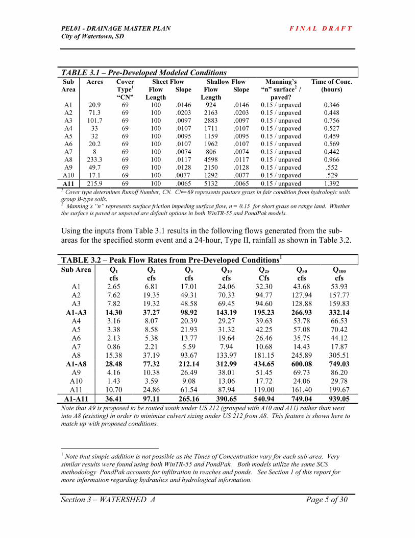
PEL01 - DRAINAGE MASTER PLAN F I N A L D R A F T
City of Watertown, SD
Section 3 – WATERSHED A Page 5 of 30
TABLE 3.1 – Pre-Developed Modeled Conditions Sheet Flow Shallow Flow Sub
Area
Acres Cover
Type1
“CN”
Flow
Length
Slope Flow
Length
Slope
Manning’s
“n” surface2 /
paved?
Time of Conc.
(hours)
A1 20.9 69 100 .0146 924 .0146 0.15 / unpaved 0.346
A2 71.3 69 100 .0203 2163 .0203 0.15 / unpaved 0.448
A3 101.7 69 100 .0097 2883 .0097 0.15 / unpaved 0.756
A4 33 69 100 .0107 1711 .0107 0.15 / unpaved 0.527
A5 32 69 100 .0095 1159 .0095 0.15 / unpaved 0.459
A6 20.2 69 100 .0107 1962 .0107 0.15 / unpaved 0.569
A7 8 69 100 .0074 806 .0074 0.15 / unpaved 0.442
A8 233.3 69 100 .0117 4598 .0117 0.15 / unpaved 0.966
A9 49.7 69 100 .0128 2150 .0128 0.15 / unpaved .552
A10 17.1 69 100 .0077 1292 .0077 0.15 / unpaved .529
A11 215.9 69 100 .0065 5132 .0065 0.15 / unpaved 1.392 1 Cover type determines Runoff Number, CN. CN=69 represents pasture grass in fair condition from hydrologic soils
group B-type soils. 2 Manning’s “n” represents surface friction impeding surface flow, n = 0.15 for short grass on range land. Whether
the surface is paved or unpaved are default options in both WinTR-55 and PondPak models.
Using the inputs from Table 3.1 results in the following flows generated from the sub-
areas for the specified storm event and a 24-hour, Type II, rainfall as shown in Table 3.2.
TABLE 3.2 – Peak Flow Rates from Pre-Developed Conditions1
Sub Area Q1
cfs
Q2
cfs
Q5
cfs
Q10
cfs
Q25
Cfs
Q50
cfs
Q100
cfs
A1 2.65 6.81 17.01 24.06 32.30 43.68 53.93
A2 7.62 19.35 49.31 70.33 94.77 127.94 157.77
A3 7.82 19.32 48.58 69.45 94.60 128.88 159.83
A1-A3 14.30 37.27 98.92 143.19 195.23 266.93 332.14
A4 3.16 8.07 20.39 29.27 39.63 53.78 66.53
A5 3.38 8.58 21.93 31.32 42.25 57.08 70.42
A6 2.13 5.38 13.77 19.64 26.46 35.75 44.12
A7 0.86 2.21 5.59 7.94 10.68 14.43 17.87
A8 15.38 37.19 93.67 133.97 181.15 245.89 305.51
A1-A8 28.48 77.32 212.14 312.99 434.65 600.08 749.03
A9 4.16 10.38 26.49 38.01 51.45 69.73 86.20
A10 1.43 3.59 9.08 13.06 17.72 24.06 29.78
A11 10.70 24.86 61.54 87.94 119.00 161.40 199.67
A1-A11 36.41 97.11 265.16 390.65 540.94 749.04 939.05
Note that A9 is proposed to be routed south under US 212 (grouped with A10 and A11) rather than west
into A8 (existing) in order to minimize culvert sizing under US 212 from A8. This feature is shown here to
match up with proposed conditions.
1 Note that simple addition is not possible as the Times of Concentration vary for each sub-area. Very
similar results were found using both WinTR-55 and PondPak. Both models utilize the same SCS
methodology PondPak accounts for infiltration in reaches and ponds. See Section 1 of this report for
more information regarding hydraulics and hydrological information.

PEL01 - DRAINAGE MASTER PLAN F I N A L D R A F T
City of Watertown, SD
Section 3 – WATERSHED A Page 6 of 30
A1-A8 reflects the sum-total of all drainage down to where these watersheds outlet from A8 under US 212.
No backwater effects of any culvert headwater was modeled thus representing pre-developed conditions to
the extent possible.
A1-A11 reflects the sum-total of all drainage where A11 outlets to Lake Pelican. No backwater effects of
any culvert headwater was modeled thus representing pre-developed conditions to the extent possible.
3.3.1 Existing Culverts
3.3.1.1 DP 1 This location represents a culvert passing under 3
rd Avenue that conveys runoff
from sub-area A1 (20.9 acres) to sub-area A3. The existing 15” pipe, is 40’ long
and laid at 1.05%, and has a capacity of 4 cfs. This culvert begins Reach Ra1.
3.3.1.2 DP 3 This location represents a culvert passing under 33
rd Street that conveys
runoff from sub-area A2 to the southern ditch of A3. The existing 15” pipe
is 30’ long, laid at 1.47% and has a capacity of 9 cfs. This culvert begins
Reach Ra2.
3.3.1.3 DP 4
This location represents a pipe under 33rd
Street (North of 4th
Ave) passing
water from sub-area A6 to A3. During field surveying, this pipe was
missed so no data is available. While on a field visit, a 24” in diameter
pipe was located. It is assumed that the slope of the pipe was 0.25% or
less, having the capacity of no more than 17 cfs. This culvert begins Reach
Ra4.
3.3.1.4 DP 8
This location represents a pipe under 4th
Avenue collecting drainage from
sub-areas A1, A2, A3, A4, and A6. The existing pipe is a 6’ x 3’ box
culvert laid at a 0.0% slope with a capacity of 40 cfs. The outlet of this
pipe establishes a point of beginning for Reach Ra8.
3.3.1.5 DP 9A
This location represents a pipe under 33rd
Street (South of 4th
Ave) passing
water from sub-area A7 to A8. During the survey phase, this pipe was
missed so no data is available. However, while on a field visit a 24”
diameter pipe was found. It is assumed the slope of the pipe is less than
0.25% having a capacity of 17 cfs. Reach Ra7 (DP 9)begins immediately
downstream of this pipe.

PEL01 - DRAINAGE MASTER PLAN F I N A L D R A F T
City of Watertown, SD
Section 3 – WATERSHED A Page 7 of 30
3.3.1.6 DP 10
This location represents a pipe under 4th
Avenue passing drainage from
sub-area A5 to A8. The existing 30” pipe is 45’ long, laid at a slope of
0.14% with a capacity of 14 cfs. Reach Ra10 begins immediately
downstream of this culvert.
3.3.1.7 DP 14A
This location represents a pipe under 33rd
Street passing drainage from A9
to A8. The existing 18” diameter, 70’ pipe is laid at a 1.5% slope having a
capacity of 5.7 cfs. This pipe’s outlet forms the beginning of Reach Ra11
(DP 14).
3.3.1.8 DP 15
This location represents the confluence of drainage from sub-areas A1-A9,
where three arch pipes cross under US 212. The existing arch pipes are 51”
x 31” (span x rise) having a combined capacity of 209 cfs. The outlet of
this pipe forms Reach Ra13.
3.3.1.9 DP 16A
This location represents a pipe under 33rd
Street passing drainage from A10
to A11. The existing 18” diameter 62’ pipe is laid at a 0.8% slope having a
capacity of 5 cfs. This pip’s outlet forms the beginning of Reach Ra12 (DP
16).
3.3.2 Existing Drainage Pattern – See Section 3.1 for the general drainage patterns
between sub-watersheds.
3.4 Watershed A – Post Developed Modeled Conditions
The data input for the post-developed conditions which PondPak used to determine the
peak run-off rates and generated volumes is shown below in Table 3.3.
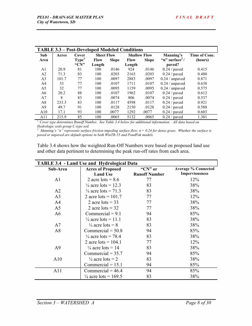
PEL01 - DRAINAGE MASTER PLAN F I N A L D R A F T
City of Watertown, SD
Section 3 – WATERSHED A Page 8 of 30
TABLE 3.3 – Post-Developed Modeled Conditions Sheet Flow Shallow Flow Sub
Area
Acres Cover
Type1
“CN”
Flow
Length
Slope Flow
Length
Slope
Manning’s
“n” surface2 /
paved?
Time of Conc.
(hours)
A1 20.9 81 100 .0146 924 .0146 0.24 / paved 0.415
A2 71.3 83 100 .0203 2163 .0203 0.24 / paved 0.480
A3 101.7 77 100 .0097 2883 .0097 0.24 / unpaved 0.871
A4 33 77 100 .0107 1711 .0107 0.24 / unpaved 0.638
A5 32 77 100 .0095 1159 .0095 0.24 / unpaved 0.575
A6 20.2 88 100 .0107 1962 .0107 0.24 / paved 0.612
A7 8 83 100 .0074 806 .0074 0.24 / paved 0.537
A8 233.3 83 100 .0117 4598 .0117 0.24 / paved 0.921
A9 49.7 91 100 .0128 2150 .0128 0.24 / paved 0.588
A10 17.1 93 100 .0077 1292 .0077 0.24 / paved 0.603
A11 215.9 85 100 .0065 5132 .0065 0.24 / paved 1.301 1 Cover type determines Runoff Number. See Table 3.4 below for additional information. All data based on
Hydrologic soils group C-type soil. 2 Manning’s “n” represents surface friction impeding surface flow, n = 0.24 for dense grass. Whether the surface is
paved or unpaved are default options in both WinTR-55 and PondPak models.
Table 3.4 shows how the weighted Run-Off Numbers were based on proposed land use
and other data pertinent to determining the peak run-off rates from each area.
TABLE 3.4 - Land Use and Hydrological Data
Sub-Area Acres of Proposed
Land Use
“CN” or
Runoff Number
Average % Connected
Imperviousness
A1 2 acre lots = 8.6
¼ acre lots = 12.3
77
83
12%
38%
A2 ¼ acre lots = 71.3 83 38%
A3 2 acre lots = 101.7 77 12%
A4 2 acre lots = 33 77 38%
A5 2 acre lots = 32 77 38%
A6 Commercial = 9.1
¼ acre lots = 11.1
94
83
85%
38%
A7 ¼ acre lots = 8 83 38%
A8 Commercial = 50.8
¼ acre lots = 78.4
2 acre lots = 104.1
94
83
77
85%
38%
12%
A9 ¼ acre lots = 14
Commercial = 35.7
83
94
38%
85%
A10 ¼ acre lots = 2
Commercial = 15.1
83
94
38%
85%
A11 Commercial = 46.4
¼ acre lots = 169.5
94
83
85%
38%

PEL01 - DRAINAGE MASTER PLAN F I N A L D R A F T
City of Watertown, SD
Section 3 – WATERSHED A Page 9 of 30
Then, from this data, the peak flows per sub-area were computed using PondPak as
shown in Table 3.5.
TABLE 3.5 – Peak Flow Rates from Post-Developed Conditions
Sub Area Q1
cfs
Q2
Cfs
Q5
cfs
Q10
cfs
Q25
Cfs
Q50
cfs
Q100
Cfs
A1 15.44 22.89 37.39 46.32 56.09 68.64 79.44
A2 64.01 89.73 137.20 165.68 196.46 235.61 269.10
A3 29.73 49.14 88.29 113.18 140.90 177.09 208.63
A1-A3 92.34 139.53 231.25 288.18 350.90 431.93 502.11
A4 12.10 19.91 35.63 45.63 56.77 71.29 83.94
A5 12.54 20.52 37.06 47.58 59.31 74.62 87.96
A6 22.67 30.14 43.54 51.46 59.96 70.73 79.91
A7 6.68 9.36 14.32 17.32 20.59 24.74 28.30
A8 108.6 160.12 258.22 318.27 383.83 467.91 540.22
A1-A8 222.23 339.35 565.39 705.38 859.83 1059.67 1232.91
A9 55.84 72.53 102.23 119.72 138.48 162.26 182.55
A10 22.18 28.42 39.49 46.01 53.02 61.89 69.47
A11 109.09 149.58 224.31 268.92 317.05 378.19 430.44
A1-A11 363.97 533.57 854.62 1052 1268 1547 1787
All of the flows shown in Table 3.5 are unmitigated, meaning, no detention or storage
slows the water down and treats it before discharging into Lake Pelican. Obviously, this
is undesirable. The remainder of this Section is dedicated to locating and sizing ponds to
minimize the amount of infrastructure needed in terms of culverts (or bridges) while also
evaluating improved routing which is consistent with the goals stated in Section 3.2.
Notice that the post-developed peak flow for the 100-year event over the entire watershed
is 190% higher than the pre-developed peak flow (1787 cfs vs. 939 cfs).
3.5 Watershed A – Alternatives Considered
3.5.1 Design Point 15A – US 212 Pond
Multiple pond options have been explored and presented to the City for review and
comment. One option included building a large pond that would capture all possible
drainage upstream of the major channel crossing US 212 which included the absence of
the 4th
Avenue Detention Pond (sub-watersheds A1-A7 and a majority of A8). A second
option was explored that included capturing all run-off generated from sub-watersheds
A4, A6, and the majority of A8 that assumed that the 4th
Avenue Detention Pond would
be in place.
However, it is the recommendation of this study in concert with City preferences to not
build a water quality treatment structure north of US 212 within sub-watershed A8 for the
following reasons in no particular order:

PEL01 - DRAINAGE MASTER PLAN F I N A L D R A F T
City of Watertown, SD
Section 3 – WATERSHED A Page 10 of 30
1) Only about 2/3’s of sub-watershed A8 would be captured.
2) This area is tentatively planned to be high-density residential and
commercial development. This implies that curb & gutter, a storm
sewer system, and city-provided water and sanitary sewer in block-
oriented development. The City prefers to maximize this developable
space. Placing a pond within this area would diminish this
opportunity for dense development to occur.
3) The City prefers to avoid placing any water quality treatment
structure immediately north and adjacent to US 212. This position
forces the likely location of a pond within sub-watershed A8 to be
about 400’ north of US 212 (about one city block). Doing so
eliminates about 38% of the area draining within sub-watershed A8
(89.6 acres out of 233.3 acres) to drain without being treated.
4) An emergency overflow structure and conveyance system from this
pond allowing storm events in excess of the 100-yr design storm to be
safely conveyed downstream and under US 212 would still be
required.
5) Two separate natural drainage channels exist within sub-watershed
A8. Improved conveyance within these channels is required
regardless if a pond is constructed or not. Capture and treatment of
stormwater from these channels creates an undesirable pond shape
whereby short-circuiting would occur, meaning that water entering
the pond would not have sufficient time and length (Stokes Law) for
adequate removal of total suspended solids within the water column.
A rule of thumb for good settlement to occur is to have the length of a
given pond be equal to three times its width. Whereas a pond
constructed within sub-watershed A8 that captures both channels’
run-off would have about a 1:1 length to width ratio.
For the above reasons, placing a pond within sub-watershed A8 has been
dismissed from further evaluation. Therefore, conveyance is the option. See
Design Points 10 thru 15 under Section 3.6.2 of this Section for more information
regarding the proposed conveyance systems.

PEL01 - DRAINAGE MASTER PLAN F I N A L D R A F T
City of Watertown, SD
Section 3 – WATERSHED A Page 11 of 30
3.6 Watershed A – Recommendations
3.6.1 Proposed Ponds
Two ponds are recommended for construction within Watershed A. The first pond,
referred to as the “4th
Avenue Pond” under section 3.6.1.1, and the “35th
Street Pond”
under section 3.6.1.2.
3.6.1.1 Design Point 6 - 4th Avenue Detention Pond
Using PondPak and AutoCad, it was found possible to store the 100-year post-developed
flows in a pond that discharges water at the pre-developed peak flow rate from Sub-
Watersheds A1-A3 (DP 6). This would occur on a property currently undeveloped
located just north of 4th
Avenue, referred to as parcel 2614 in the Landownership Map.
Table 3.6 is a copy of the PondMaker Worksheet from PondPak summarizing peak flows
and volume requirements reflecting post-developed conditions for A1-A3. It is assumed
that the location and ground where the pond would be constructed is capable of
infiltrating 0.2 inches per hour, a conservative assumption.
TABLE 3.6 – 4th Avenue Detention Pond, DP 6
Ignore W.S. Elevation and Freeboard Depth for the 500-year event.
Note that the 100-year Estimated Storage is 19.7 acre feet. The volume is achieved with
the following Elevation/Area configuration.
Elevation Area (acres)
1743 2.79
1744 2.93
1745 3.08
1746 3.22
1747 3.37
1748 3.52
1749 3.68
1750 4.07

PEL01 - DRAINAGE MASTER PLAN F I N A L D R A F T
City of Watertown, SD
Section 3 – WATERSHED A Page 12 of 30
Other preliminary design features of this detention pond include 4:1 (H:V) side-slopes, 1’
of free-board, and a top-of-pond elevation of 1750’. An additional refinement of this
pond would be to excavate an additional one or two feet for sediment storage equal to 10-
15% of the total volume for the purpose of sediment storage. A second refinement would
be to excavate a 2’ deep, v-bottom channel that would route the flows from small storm
event in a confined space creating a wetland channel for added variety of plantings and
additional storm-water treatment.
An outlet structure has also been modeled. This outlet retains discharge from the pond to
match pre-developed flow rates for the higher yield events. Details of the pond’s outlet
structure include a 90-degree V-notch weir having an invert elevation of 1745.6 feet. An
emergency overflow structure would be included for volumes exceeding elevation 1749
feet above the top of the V-notch weir.
The outflow from this pond combines with flows from Sub-Watersheds A4 and A6 prior
passing through a culvert under 4th
Avenue. See DP 8 for more detail.
3.6.1.2 Design Point 18 - 35th Street Pond
Because it was found undesirable to construct a pond north of US 212, a water quality
treatment structure is needed to treat and detain water prior to discharging storm water
run-off into Lake Pelican. Design Point 18 (DP 18) represents the recommended size and
location of a pond that treats storm water run-off coming from sub-watershed A4 thru
A10 and 55.3% of the total area A11 (216 acres).
The reason the proposed pond captures just over half of the area in sub-watershed A11 is
two-fold:
1) All of Born’s Subdivision located west of 33rd
Street West currently
discharges through its own system. This system will continue to
charge the wetland located south Born’s Subdivision.
2) It is desirable to treat such a large volume of storm water run-off
prior to crossing the property line between properties 14173 and
2943 because dense residential development within property 14173 is
planned to occur within the next one to five years. Furthermore,
conveying this large volume of water created from post-developed
conditions throughout the Watershed A would overwhelm the existing
wetland and rapidly fill it in with sediment. With this in mind,
placing a pond just north of this property boundary is prudent.
Thus, the combination of Born’s Subdivision and locating the pond toward the bottom
third of sub-watershed A11 reveals that 44.7% of the total area contained therein would
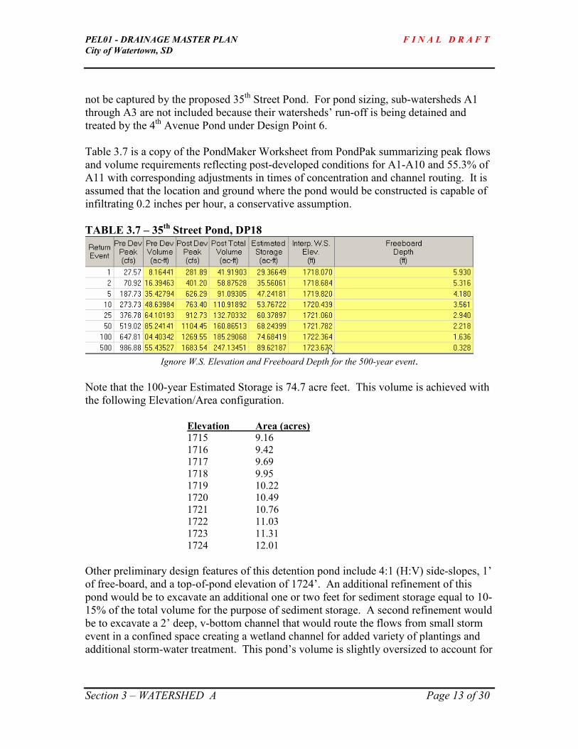
PEL01 - DRAINAGE MASTER PLAN F I N A L D R A F T
City of Watertown, SD
Section 3 – WATERSHED A Page 13 of 30
not be captured by the proposed 35th
Street Pond. For pond sizing, sub-watersheds A1
through A3 are not included because their watersheds’ run-off is being detained and
treated by the 4th
Avenue Pond under Design Point 6.
Table 3.7 is a copy of the PondMaker Worksheet from PondPak summarizing peak flows
and volume requirements reflecting post-developed conditions for A1-A10 and 55.3% of
A11 with corresponding adjustments in times of concentration and channel routing. It is
assumed that the location and ground where the pond would be constructed is capable of
infiltrating 0.2 inches per hour, a conservative assumption.
TABLE 3.7 – 35th Street Pond, DP18
Ignore W.S. Elevation and Freeboard Depth for the 500-year event.
Note that the 100-year Estimated Storage is 74.7 acre feet. This volume is achieved with
the following Elevation/Area configuration.
Elevation Area (acres)
1715 9.16
1716 9.42
1717 9.69
1718 9.95
1719 10.22
1720 10.49
1721 10.76
1722 11.03
1723 11.31
1724 12.01
Other preliminary design features of this detention pond include 4:1 (H:V) side-slopes, 1’
of free-board, and a top-of-pond elevation of 1724’. An additional refinement of this
pond would be to excavate an additional one or two feet for sediment storage equal to 10-
15% of the total volume for the purpose of sediment storage. A second refinement would
be to excavate a 2’ deep, v-bottom channel that would route the flows from small storm
event in a confined space creating a wetland channel for added variety of plantings and
additional storm-water treatment. This pond’s volume is slightly oversized to account for

PEL01 - DRAINAGE MASTER PLAN F I N A L D R A F T
City of Watertown, SD
Section 3 – WATERSHED A Page 14 of 30
potential placement of schools, churches, and other land uses having large areas of
impervious surfaces.
An outlet structure has also been modeled. This outlet retains discharge from the pond to
match pre-developed flow rates for the higher yield events. Details of the pond’s outlet
structure include a 60-degree V-notch weir having an invert elevation of 1716.6 feet. An
emergency overflow structure would be included for volumes exceeding elevation 1723.5
feet amounting to a low flat earthen-berm near the weir structure. This emergency
overflow would drain south into the same channel the V-notch weir drains into crossing
16th
Avenue South presuming that 16th
Avenue south were extended to the west.
TABLE 3.8 – Outlet Routing from 35th Street Pond
See Section 3.6.2.12 for more information regarding the channel receiving this pond’s
outlet flows and a discussion exploring what effect the 4th Avenue Pond has on the 35th
Street Pond and its outlet. The summary of which concludes that the revised outlet
works of this pond and its receiving channel (DP 18A) should accommodate 880 cfs in
order to receive peak outflows from the 4th Avenue pond.
3.6.2 Proposed Channels and Routing
3.6.2.1 DP 2 – Culvert under 3rd
Avenue from A1 to A3, also forming Reach Ra1.
The City prefers to allow the 25-year post-developed flow to pass under 3rd
Avenue without over-topping the road (DP 1). However, the channel is to
accommodate the full, post-developed 100-year peak flow (water not passing
through the pipe would over-top the road and make its way into the channel).
Therefore, as found in Table 3.5, this peak flow rate (79.4 cfs) establishes the
flow rate Reach Ra1 must accommodate at its beginning.

PEL01 - DRAINAGE MASTER PLAN F I N A L D R A F T
City of Watertown, SD
Section 3 – WATERSHED A Page 15 of 30
This flow, 79.4cfs, could be conveyed in a trapezoidal channel as shown
in Table 3.9.
TABLE 3.9 – Design Point 1/Reach Ra1 (begin)
Copied from FlowMaster by Haestad Methods
Adding 1-foot of additional freeboard in Reach Ra1 yields:
Final Depth of 2.2 feet, and
Top Width of 54 feet.
However, Reach Ra1 picks up drainage area as it moves south in A3. The
100-year post developed flow for the south end of Reach Ra1 is larger at
238 cfs. Using the same geometry found in Table 3.11 yields:
Final Depth of 3 feet, and
Top Width of 69 feet.
To comply with City preferences regarding drainage easements (See
Section 1.8 of this document) the drainage easement for Reach
Ra1(begin) would be 70 feet wide, and Reach Ra1(end) would be 90 feet
wide.
H:V H:V
Bottom Width (BW) ft
depth (D)
Top Width (TW) ft

PEL01 - DRAINAGE MASTER PLAN F I N A L D R A F T
City of Watertown, SD
Section 3 – WATERSHED A Page 16 of 30
3.6.2.2 DP 5/Reach Ra2
Reach Ra2 transports flows from A2 into A3 by way of a culvert under
33rd
Street (DP 3). A2’s post-developed 100-year flow rate is 269 cfs.
The design criteria for this trapezoidal channel, Reach Ra2 is shown in
Table 3.10.
TABLE 3.10 – DP 5/Reach Ra2
Copied from FlowMaster by Haestad Methods
Adding 1-foot of additional freeboard in Reach Ra2 yields:
Final Depth of 2.9 feet (3), and
Top Width of 69 feet.
To comply with City preferences regarding drainage easements (See
Section 1.8 of this document) the drainage easement for Reach Ra2
would be 90 feet wide.
3.6.2.3 Reach Ra3/Design Point 40
Reach Ra3 receives runoff from A4 and conveys it in a the northern ditch
of 4th
Avenue to a pipe (DP 8) passing flows into A8. The post-developed
100-year design flow from A4 is 85 cfs. The design criteria for this
trapezoidal channel, Reach Ra3 is shown in Table 3.11.
TABLE 3.11 – DP 40/Reach Ra3
Copied from FlowMaster by Haestad Methods

PEL01 - DRAINAGE MASTER PLAN F I N A L D R A F T
City of Watertown, SD
Section 3 – WATERSHED A Page 17 of 30
Adding 1-feet of freeboard in Reach Ra3 yields:
Final Depth of 2.9 feet (3), and
Top Width of 29 feet.
To comply with City preferences regarding drainage easements (See
Section 1.8 of this document) the drainage easement for Reach Ra3
would be 50 feet wide.
3.6.2.4 Reach Ra4/DP 41
Reach Ra4 receives runoff from A6 through a culvert under 33rd
Street
(DP 4) and conveys it to a culvert passing under 4th
Avenue into A8
(DP8). Sub-Watershed A6’s 100-year post-developed flow is 80 cfs. The
design criteria for this trapezoidal channel, Reach Ra4, is shown in Table
3.12.
TABLE 3.12 – DP 41/Reach Ra4
Copied from FlowMaster by Haestad Methods
Adding 1-feet of freeboard in Reach Ra4 yields:
Final Depth of 2.2 feet, and
Top Width of 28 feet.
To comply with City preferences regarding drainage easements (See
Section 1.8 of this document) the drainage easement for Reach Ra4
would be 50 feet wide.
3.6.2.5 Reach Ra7/DP 9
Reach Ra7 conveys flows from A7 passing through a culvert under 33rd
Street into Reach Ra8 (DP 12) located on the south side of 4th
Avenue.
The 100-year post-developed flow from A7 is 28.3 cfs. Table 3.13 shows
the design criteria for this trapezoidal channel, Reach Ra7.

PEL01 - DRAINAGE MASTER PLAN F I N A L D R A F T
City of Watertown, SD
Section 3 – WATERSHED A Page 18 of 30
TABLE 3.13 – DP 9/Reach Ra7
Copied from FlowMaster by Haestad Methods
Adding 1-feet of freeboard in Reach Ra7 yields:
Final Depth of 2, and
Top Width of 20 feet.
To comply with City preferences regarding drainage easements (See
Section 1.8 of this document) the drainage easement for Reach Ra7
would be 50 feet wide.
3.6.2.6 Reach Ra8/DP 12 & 13
Reach Ra8 receives run-off water from a culvert under 4th
Avenue (DP 8).
Existing conditions are that this culvert receives run-off from Sub-
Watersheds A1-A4, and A6, plus the flows coming from A7 through
Reach Ra7 (DP 9). This study recommends re-routing A4’s run-off under
4th
Avenue in a new culvert (DP 40) without allowing it to travel east to
the inlet of culvert draining A3 (DP 8). This allows the size of the pipe
under DP 8 so be small as possible. Nevertheless, A4’s flow still
contributes to the beginning of Reach Ra8.
Furthermore, this study recommends detaining run-off from A1-A3 in a
pond. See 3.5.1, DP 6 above. This pond’s post-developed 100-year
discharge rate is to be held to the pre-developed discharge rate of 332 cfs.
So, the total peak flow that must be carried in Reach Ra8 is somewhat
mitigated by the pond. Therefore, the total post-developed peak flow into
Reach Ra8 is the sum of the following:
Outflow from 4th
Avenue Pond = 332 cfs
Outflow from A6 through Ra4 = 80 cfs
Outflow from A7 through Ra7 = 28 cfs
Outflow from A4 through Ra3 = 84 cfs
Sum Total using Simple Addition 524 cfs

PEL01 - DRAINAGE MASTER PLAN F I N A L D R A F T
City of Watertown, SD
Section 3 – WATERSHED A Page 19 of 30
However, simple addition cannot be performed because of the varying
times of concentration within each sub-watershed and hydrograph
translation through the reaches. PondPak shows that a more correct peak
flow rate is 520 cfs, a difference of 0.8%. This difference would be higher
but for the assumption in the model that the pond and channels are
allowed to infiltrate 0.2 inches of water per hour. Backwater effects from
water pooling above culverts’ inlets is not considered in this analysis.
Doing so is more consistent with a final design and will create lower peak
flow rates, therefore, these results are conservative.
Based on this information and using 520 cfs as a peak flow rate, the
following table, Table 3.14, shows the design criteria for sizing a
trapezoidal appropriately sized.
TABLE 3.14 DP 12/Reach Ra8 (begin)
Copied from FlowMaster by Haestad Methods
Adding 1-foot of freeboard to the beginning of Reach Ra8 (DP 12) yields:
Final Depth of 3.4 feet, and
Top Width of 87 feet.
As Reach Ra8 travels through Sub-Watershed A8, it gradually continues
to pick up stormwater run-off. Calculations show that an additional 172
cfs makes its way into this channel for a new total of 692 cfs at the bottom
of Reach Ra8. Using similar geometry, and a 30-foot bottom (not 20 feet
as shown above), and adding the 1’of freeboard yields (DP 13):
Final Depth of 3.4 feet, and
Top Width of 98 feet.
To comply with City preferences regarding drainage easements (See
Section 1.8 of this document) the drainage easement for Reach
Ra8(begin) would be 110 feet wide, and for Reach Ra8(end) would be
120 feet wide.

PEL01 - DRAINAGE MASTER PLAN F I N A L D R A F T
City of Watertown, SD
Section 3 – WATERSHED A Page 20 of 30
3.6.2.7 Reach Ra10/DP 10 & 11
Reach Ra10 (DP 10) receives water from a culvert under 4th
Avenue
transporting run-off water from A5 into A8. DP 10 represents the top of
this reach, or its beginning; and DP 11 represents the bottom of this reach,
or its ending where it finds three existing arch pipe culverts passing water
under US 212.
The 100-year post-developed flow rate from A5 is 88 cfs (Note that the
culvert will be sized to pass the post-developed 25-year flow). The
following table, Table 3.15, shows the design criteria for the proposed
channel, Reach Ra10.
TABLE 3.15 – DP 10/Reach Ra10 (begin)
Copied from FlowMaster by Haestad Methods
Adding 1-foot of freeboard to Reach Ra10 (begin) yields:
Final Depth of 2.1 feet, and
Top Width of 52 feet.
As Reach Ra10 travels through Sub-Watershed A8, it gradually continues
to pick up stormwater run-off. Calculations show that an additional 368
cfs makes its way into this channel for a new total of 456 cfs at the bottom
of Reach Ra8. Using similar geometry, and a 20-foot bottom (not 10 feet
as shown above), and adding the 1’of freeboard yields (DP 11):
Final Depth of 3 feet, and
Top Width of 80 feet.
To comply with City preferences regarding drainage easements (See
Section 1.8 of this document) the drainage easement for Reach
Ra10(begin) would be 70 feet wide and the the width of Ra10(end) would
be 100 feet wide.
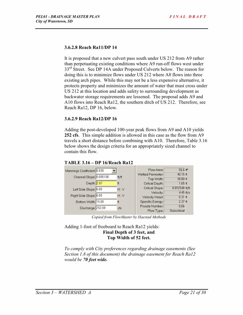
PEL01 - DRAINAGE MASTER PLAN F I N A L D R A F T
City of Watertown, SD
Section 3 – WATERSHED A Page 21 of 30
3.6.2.8 Reach Ra11/DP 14
It is proposed that a new culvert pass south under US 212 from A9 rather
than perpetuating existing conditions where A9 run-off flows west under
33rd
Street. See DP 14A under Proposed Culverts below. The reason for
doing this is to minimize flows under US 212 where A8 flows into three
existing arch pipes. While this may not be a less expensive alternative, it
protects property and minimizes the amount of water that must cross under
US 212 at this location and adds safety to surrounding development as
backwater storage requirements are lessened. The proposal adds A9 and
A10 flows into Reach Ra12, the southern ditch of US 212. Therefore, see
Reach Ra12, DP 16, below.
3.6.2.9 Reach Ra12/DP 16
Adding the post-developed 100-year peak flows from A9 and A10 yields
252 cfs. This simple addition is allowed in this case as the flow from A9
travels a short distance before combining with A10. Therefore, Table 3.16
below shows the design criteria for an appropriately sized channel to
contain this flow.
TABLE 3.16 – DP 16/Reach Ra12
Copied from FlowMaster by Haestad Methods
Adding 1-foot of freeboard to Reach Ra12 yields:
Final Depth of 3 feet, and
Top Width of 52 feet.
To comply with City preferences regarding drainage easements (See
Section 1.8 of this document) the drainage easement for Reach Ra12
would be 70 feet wide.

PEL01 - DRAINAGE MASTER PLAN F I N A L D R A F T
City of Watertown, SD
Section 3 – WATERSHED A Page 22 of 30
3.6.2.10 Reach Ra13/DP 17
Reach Ra13 represents the confluence of flows upstream generated from
Sub-Watersheds A1-A10 located south of three existing arch-pipe culverts
under US 212. Using the PondPak model, and assuming that the 4th
Avenue Pond exists, the 100-year post-developed peak flow at this point
equals 1292 cfs. Again, this is a conservative number in that the ponds
and channels are assumed to infiltrate 0.2 inches of water per hour.
Backwater effects from water pooling above culverts’ inlets is not
considered in this analysis. Doing so is more consistent with a final
design and will create lower peak flow rates. Therefore, Table 3.17 below
shows the design criteria for an appropriately sized channel to contain this
flow.
TABLE 3.17 – DP 17/Reach Ra13
Copied from FlowMaster by Haestad Methods
Adding 1-foot of freeboard to Reach Ra13 yields:
Final Depth of 4.5 feet, and
Top Width of 120 feet.
To comply with City preferences regarding drainage easements (See
Section 1.8 of this document) the drainage easement for Reach Ra13
would be 140 feet wide.
3.6.2.11 Reach Ra14/DP 18A
Reach Ra14/DP 18A represents an outlet channel from a proposed pond
located west of Born’s Addition within Sub-Watershed A11, known as the
35th
Street West pond. See 3.6.1.12 Design Point 18 - 35th Street Pond for
more information regarding this pond.
This pond stores storm water and allows it to discharge very near pre-
developed conditions; however, to accommodate flows arriving from the
4th
Avenue Pond, a revised channel capacity was found to be 880 cfs.

PEL01 - DRAINAGE MASTER PLAN F I N A L D R A F T
City of Watertown, SD
Section 3 – WATERSHED A Page 23 of 30
See Section 3.6.2.12 below for more information. The following
trapezoidal channel would be needed to contain this flow:
TABLE 3.18 – DP 18A\Reach Ra14 – Outlet for 35th St Pond
Adding 1-foot of freeboard to Reach Ra14 yields:
Final Depth of 3.6 feet, and
Top Width of 78 feet.
To comply with City preferences regarding drainage easements (See
Section 1.8 of this document) the drainage easement for Reach Ra14
would be 100 feet wide.
3.6.2.12 Translation of Hydrograph from Peak Outflows from
4th Avenue Pond into 35
th Street Pond
The volume designed in the 35th Street Pond does not include flows from
the 4th Avenue Pond because the 4th Avenue Pond treats and detains
flows prior to release of storm water run-off. So the water is all ready
treated. However, the outlet channel from the 35th Street Pond would
need to consider the peak flow arriving from the 4th Avenue Pond in order
to maintain the proposed volume.
Because outflows from the 4th Avenue Pond are hydraulically connected
to the 35th Street Pond and this outlet channel, an analysis was conducted
evaluating the time the peak flow from the 100-year post-developed flow
out of the 4th Avenue Pond takes to arrive at the 35th Street Pond
From Reaches Ra8 and Ra13, the velocities in the channels are known for
the 100-year post developed conditions: 5.11 fps and 5.67 fps
respectively. The length of Ra8 is roughly 2930 feet and the length of
Ra13 before it reaches the 35th Street Pond is roughly 910 feet. Taking
these velocities and dividing by their distances yields a total travel time of
0.2 hours. This travel time calculation does not account for delays at pipe
entrances where water would typically pool during the 100-yr event and

PEL01 - DRAINAGE MASTER PLAN F I N A L D R A F T
City of Watertown, SD
Section 3 – WATERSHED A Page 24 of 30
other miscellaneous obstructions so add 0.1 hours for a total travel time of
0.3 hours.
From PondPak, the time for the post-developed peak outflow of 366 cfs
from the 4th Avenue Pond occurs at time t = 12.6 hours. Adding the
travel time to this peak yields 12.9 hours pass after the beginning of the
100-yr design storm before this peak reaches the 35th
Street Pond.
The 35th
Street Pond is designed to treat and detain water from Sub-
Watersheds A4 thru A10 and 55.3% of the total area A11 (216 acres).
However, its outlet should accommodate this added peak flow arriving
from the 4th
Avenue Pond at time t=12.9 hours. This will prevent over-
topping of the 35th
Avenue Pond.
To determine this new design peak outflow for the outlet works at the 35th
Street Pond, contributions from the 4th
Avenue Pond need to be added to
the existing outflow of the 35th
Street Pond. This new combined peak is
880 cfs occurring at time t = 12.8 hours. This is actually 110 cfs less than
the sum of adding the two pre-developed peak flow rates for the 100-yr
storm event from all lands contributing stormwater run-off into the 4th
Avenue Pond and the 35th
Street Pond (333 + 648 = 990 cfs)!
In summary, after the beginning of the 24-hour, 100-yr event for post-
developed conditions, it takes 0.3 hours before the peak outflow from the
4th Avenue Pond reaches the 35th Street Pond. The translation of this
peak flow into the 35th
Street Pond required this pond’s outlet to pass a
total of 880 cfs so that existing pond storage volume requirements need
not be increased. There is no need to treat the volume of water coming
from the 4th
Avenue Pond twice. Also, the outlet channel (DP 18A) from
the 35th
Street Pond to the wetland would also have to accommodate 880
cfs.
Also note that, if 16th Avenue South is extended west, care should be
taken to design the finished street’s surface elevation and curb-cuts to
allow either overtopping of the street OR a sizeable culvert system would
be required. Preferably, a combination of culvert and roadway over-
topping should be explored during final design.
3.6.3 Proposed Culverts
It should be noted that all culvert’s presented here are preliminary based
on city provided 2’ contours. A field survey was done to gather inverts of
pipes at their inlet and outlets as well as length. For final design, each

PEL01 - DRAINAGE MASTER PLAN F I N A L D R A F T
City of Watertown, SD
Section 3 – WATERSHED A Page 25 of 30
pipe location should be fully surveyed including allowable headwater and
tail-water conditions. Special attention should be given to the design year
in term of over-topping the road during the final-design process.
For all sizes of recommended pipes it was assumed that headwater
conditions up to 4’ were allowed and tail-water conditions were basically
free-flow out of the outlet of the pipe; therefore, all pipes are inlet
controlled. The reason 4’ of headwater was assumed is that, generally
speaking, most pipes in this study are 24” or less in diameter located in
fairly flat terrain. Also, doubling the pipe diameter allows about 2’ of
storage above the top of the pipe before the road would be over-topped.
Where possible, recommended pipes were favored having minimal rises in
order to minimize pipe bury depths and still allow for some storage in the
ditches.
3.6.3.1 DP 1 This location represents a culvert passing under 3
rd Avenue that
conveys runoff from sub-area A1 to sub-area A3. The 25-year post
developed design flow is 56 cfs. Assuming a slope of 1% an
appropriate pipe size for this post developed flow rate would be one
of the following:
1 – 4’ x 2’ (span x rise) box culvert (preferred), or
1 – 42” diameter circular pipe., or
1 – 51” x 31” (span x rise) arch pipe.
3.6.3.2 DP 3 This location represents a culvert passing under 33
rd Street that
conveys runoff from sub-area A2 to A3. The post-developed 25-
year design flow is 197 cfs. Assuming a slope of 1%, pipe size for
this post developed flow rate would be one of the following:
2 – 6’ x 3’ box culverts (preferred)
3 – 42” diameter circular pipe, or
2 – 65” x 40” arch pipes.
3.6.3.3 DP 4A This location represents a pipe under 33
rd Street (North of 4
th Ave)
passing water from sub-area A6 to A3. The post-developed 25-year
design flow is 60 cfs. Assuming a slope of 0.5% an appropriate
pipe size for this post developed flow rate would be one of the
following:
1 – 4’ x 3’ (span x rise) box culvert (preferred), or
1 – 51” x 31” arch pipe, or
1 – 42”diameter circular pipe.

PEL01 - DRAINAGE MASTER PLAN F I N A L D R A F T
City of Watertown, SD
Section 3 – WATERSHED A Page 26 of 30
3.6.3.3 DP 8A This location represents a pipe under 4
th Avenue collecting drainage
from sub-areas A1, A2, A3, A5, and A6. Design flows are based on
25-year post-developed flows with the assumption that the 4th
Avenue Pond is in place. The outlet works (V-notch weir) of this
pond discharges 195 cfs for the post-developed 25-year peak,
matching up well with the pre-developed peak discharge rate.
Therefore, the design capacity of this culvert is 307 cfs. Assuming
a slope of 0.5% an appropriate pipe size for this post developed
flow rate includes the following:
3 – 6’ x 3’ box culverts (preferred), or
4 – 60” diameter circular pipes, or
3 – 73” x 45” (span x rise) arch pipes.
3.6.3.3 DP 9
This location represents a pipe under 33rd
Street (South of 4th
Ave)
passing water from sub-area A7 to A8. Assuming a 0.5% slope, an
appropriate pipe size for the post developed 25-year flow of 21 cfs
was not used. Because of A7’s small size (8 acres), the City
requests that this pipe pass the 100-year post-developed flow, or 28
cfs. For this flow an appropriate culvert size is one of the
following:
1 – 2’ x 2’ box culvert, or
1 – 30” diameter pipe, (preferred) or
1 – 36” x 22” arch pipe.
3.6.3.4 DP 10
This location represents a pipe under 4th
Avenue passing drainage
from sub-area A5 to A8. Assuming a slope of 0.5%, an appropriate
size of culvert to pass the post developed 25-year flow from the 32
acres in A5 of 59 cfs would be one of the following:
1 – 4’ x 2’ box culverts (preferred), or
1 – 42” diameter circular pipes, or,
1 – 51” x 31” arch pipes.
3.6.3.5 DP 14A
This location represents an existing pipe under 33rd
Street passing
drainage from A9 into A8 (west) where a default design capacity
would be based on the post-developed 25-year peak flow. However,
this study proposes to re-route this drainage south, under US 212

PEL01 - DRAINAGE MASTER PLAN F I N A L D R A F T
City of Watertown, SD
Section 3 – WATERSHED A Page 27 of 30
into A10, in which case the post-developed 100-year storm event
must be used as a basis for design, or 183 cfs. Assuming a 0.5%
slope, an appropriate size of culvert to pass this flow is one of the
following:
2 – 5’ x 3’ box culverts, (preferred) or
3 – 48” diameter culverts, or
2 – 65” x 40” (span x rise) arch pipes.
While this option is more costly in that a larger design storm is used
thereby requiring large pipe sizes, it is necessary to account for the
100-year event either way. In other words, if the 25-year event
were used as a default to pass water under 33rd
Street, the 100-year
event would still not be allowed to over-top US 212. So, whether
the 183 cfs peak flow passes under 33rd
or US 212 makes not
difference in terms of capacity. It does; however, mitigate some
pipe capacity at the larger pipes crossing under US 212 further west
where A8 drains south into A11. In effect, this 183 cfs is all ready
across US 212 at this point in Reach Ra12.
3.6.3.6 DP 15
This location represents the confluence of drainage from sub-areas
A1-A8 draining south from A8 into A11 under US 212. Proposed
pipe sizing also assumes that drainage from A9 passes under US
212 directly into A10, east of this location. Assuming that the 4th
Avenue Pond is built, the 100-year design flow for DP 15 is 532
cfs. This is a substantial amount of water and final design may
require structural analysis using a bridge or large steel plate arches
or some other hydraulic structure. For comparison purposes, the
following culverts pass this flow:
4 – 8’ x 5’ box culverts
4 – 102” x 62” (span x rise) arch pipes
4 – 68” x 106” (rise x span) horizontal ellipse
3.6.3.7 DP 16A This location represents an existing pipe under 33
rd Street passing
drainage from A10 into A11 (west) where a default design capacity
would be based on the post-developed 25-year peak flow. However,
this study proposes to re-route drainage from A9 into A10, under
US 212, in which case the post-developed 100-year storm event
must be used as a basis for design to avoid over-topping US 212.
This flow equals 252 cfs for post-developed conditions, 100-year
storm event. Assuming a 0.5% slope, an appropriate size of culvert
to pass this flow is one of the following:

PEL01 - DRAINAGE MASTER PLAN F I N A L D R A F T
City of Watertown, SD
Section 3 – WATERSHED A Page 28 of 30
2 – 7’ x 4’ box culverts (preferred), or
3 – 66” diameter pipes, or
3 – 88” x 54” (span x rise) arch pipes.
3.7 Additional Comments
Drain tile should be considered to be included into all ponds to ensure that they drain and
do not retain water over an extended period of time. The discharge of the drainage tile
would be located in the emergency overflow channels. In the rare event that two, back-
to-back, 100-yr storms occur within a 40-hour period, detained water will not have had
enough time to drain from ponds through their designed outlets. In the case where
proposed ponds are designed to have no outlet, the emergency overflow channel would
be the only source of water to exit the engineered depression.


PEL01 - DRAINAGE MASTER PLAN F I N A L D R A F T
City of Watertown, SD
Section 4 - WATERSHED B Page 1 of 24
SECTION 4 – WATERSHED B
4.1 Watershed B – Boundaries and Sub-watersheds
Watershed B is comprised of 504 acres containing eight sub-watersheds as shown in
Figure 4.1 – Watershed B. As can be seen in the figure, Watershed B is located on both
the north and south sides of US 212. Its western boundary abuts 54th Street and its
eastern boundary is about half-way between 42nd
and 33rd
Streets. Its northern boundary
exists just south of 4th Avenue while its southern boundary drains into Lake Pelican.
4.1.1 Sub-Watershed B1
Sub-Watershed B1 (B1) is 97.6 acres in size. Its northern boundary is located
south of 4th Avenue while its western boundary abuts 54
th Street. Interestingly,
the southern boundary is the middle of the two lanes of traffic that is US 212. It
receives run-off from Sub-Watershed B2 (B2) through a culvert under 42nd
Street
(DP 19). Flows from B2 are conveyed through B1 in Reach Rb1. The outlet of
B1 is a 24” diameter pipe under US 212 (DP 20) into Sub-Watershed B4. B1
contains a small, shallow, natural depression (DP 28).
4.1.2 Sub-Watershed B2
Sub-Watershed B2 (B2) is 9.8 acres in size and flows west into Sub-Watershed
B1 through an 18” diameter pipe under 42nd
Street (DP 19). B2 exists south of
42nd
Street and abuts 42nd
Street on its west side.
4.1.3 Sub-Watershed B3
Sub-Watershed B3 is 57.7 acres in size and generally flows south, passing its run-
off under US 212 in a 36” diameter pipe (DP 22) into Sub-Watershed B7 after
collecting in a ditch on the north side of US 212. B7 is located in the southeast
quadrant of the intersection of US 212 and 42nd
Street.
4.1.4 Sub-Watershed B4
Sub-Watershed B4 (B4) is 67.2 acres in size and generally flows east in the
southern ditch of US 212. It is located on the south side of US 212 with its
western boundary abutting 54th Street and its eastern boundary abutting 42
nd
Street. B4 receives run-off from Sub-Watershed B1. This flow is conveyed in a
channel, Reach Rb2 (DP 21), where the flows of B4 and B1 combine and outlet

PEL01 - DRAINAGE MASTER PLAN F I N A L D R A F T
City of Watertown, SD
Section 4 - WATERSHED B Page 2 of 24
through an 18” diameter pipe under 42nd
Street (DP 24) and flows into Sub-
Watershed B7.
4.1.5 Sub-Watershed B5
Sub-Watershed B5 (B5) is 19 acres in size and drains into Sub-Watershed B4 near
B4’s outlet pipe under 42nd
Street. B5 is located near the southwest intersection
of US 212 and 42nd
Street. A small, shallow, natural depression exists in B5 (DP
29).
4.1.6 Sub-Watershed B6
Sub-Watershed B6 is 15.4 acres in size and drains across 42nd
Street, into Sub-
Watershed B7 by over-topping the road (DP 26). B6 is located west of 42nd
Street.
4.1.7 Sub-Watershed B7
Sub-Watershed B7 (B7) is 102.6 acres in size and has no outlet. B7 is located in
the southeast quadrant of the intersection of US 212 and 42nd
Street. It receives
run-off from Sub-Watersheds B1 through B6 through two reaches. Reach Rb3
receives run-off from Sub-Watershed B3’s outlet pipe. Reach Rb3’s route starts
as the southern ditch of US 212 and flows west. Near, 42nd
Street, Reach Rb3
turns south in a natural channel and meets up with the outlet pipe from Sub-
Watershed B4 (Reach Rb4). Reaches Rb3 and Rb4 combine (which is really a
continuation of Rb3) to form Reach Rb5. Run-off collected in Reach Rb5 then
travels through a series of culverts under an abandoned rail-road and flows into a
large natural depression (DP 27). Similarly, run-off from Sub-watershed B6
flows into the natural depression by way of Reach Rb6.
4.1.8 Sub-Watershed B8
Sub-Watershed B8 is 135 acres in size -- all but 16 acres of which drain south into
Lake Pelican through a man-made stock dam and existing wetland. Run-off from
the remaining 16 acres drains south directly to Lake Pelican. The western
boundary of B8 abuts 42nd
Street while the eastern boundary extends about half-
way toward 33rd
Street.
4.2 WATERSHED B – Goals
For convenience, the overall project goals are reprinted here from Section 1.1:

PEL01 - DRAINAGE MASTER PLAN F I N A L D R A F T
City of Watertown, SD
Section 4 - WATERSHED B Page 3 of 24
� Minimize the potential for storm-water to potentially threaten life and
property.
� Maintain water quality through controlling and detaining runoff where
possible.
� Provide developers with clear guidance for complying with the City’s
development and storm water management rules.
More specifically, for Watershed B, these overall goals will be achieved by
accomplishing the following objectives:
1) Identify post-developed 100-year peak flow rates.
2) Establish what volume of run-off could be stored in the natural depression
(flood storage detention pond) found in Sub-Watershed B7.
3) If needed, determine the amount of excavation required to fully contain
the post-developed flows from the 100-year rain event.
4) If appropriate, explore how adding drain-tile within the expanded
depression would provide additional drainage and quicker draw-down
time thus allowing for some level of alternate use such as a park, soccer or
softball complex, etc.
The above four items pertain to Sub-Watershed B1-B7. For Sub-Watershed B8, the
objectives are to:
5) Identify the post-developed 100-year peak flow rate.
6) Design a conveyance system and a small water quality treatment pond
(wet detention basin) that safely passes the post-developed 100-yr design
flow. Native plantings will increase sediment removal and also increase
the channels ability to resist erosion and sediment transport during larger
storm events. See Section 1 of this report for a longer discussion
regarding Native Plantings.
This approach is preferred by the City to take advantage of the existing
stock-dam located just upstream of the delineated wetland bordering Lake
Pelican. Passage of the 100-yr design storm to Lake Pelican will be
minimal because of the short distance yet water quality treatment is
warranted prior to discharging to the wetland and lake. The stock-dam’s
location is an ideal placement for wet detention basin.

PEL01 - DRAINAGE MASTER PLAN F I N A L D R A F T
City of Watertown, SD
Section 4 - WATERSHED B Page 4 of 24
4.3 WATERSHED B – Pre-Developed Conditions
The existing drainage patterns and culverts are generally described above in Section 4.1.
As stated through this study, baseline conditions, or pre-developed conditions, were
chosen to emulate run-off generated for the landscape prior to being disturbed by man.
Watershed B’s landscape currently contains a wide range of land-uses, from open range
land to agriculture row crops to farmsteads to dense residential development but is mostly
undeveloped in terms of urbanization. Using the existing land-uses as a baseline
undershoots the goal of protecting properties down-stream from flooding due to increased
runoff and a greater percentage of impervious surfaces.
Model inputs for pre-developed conditions for Watershed B are shown in Table 4.1.
TABLE 4.1 – Pre-Developed Modeled Conditions Sheet Flow Shallow Flow Sub
Area
Acres Cover
Type1
“CN”
Flow
Length
Slope Flow
Length
Slope
Manning’s
“n” surface2 /
paved?
Time of Conc.
(hours)
B1 97.6 69 100 .0061 4892 .0061 0.15 / unpaved 1.381
B2 9.8 69 100 .0250 799 .0250 0.15 / unpaved 0.259
B3 57.7 69 100 .0178 2066 .0178 0.15 / unpaved 0.465
B4 67.2 69 100 .0054 5513 .0054 0.15 / unpaved 1.610
B5 19 69 100 .0061 658 .0061 0.15 / unpaved 0.448
B6 15.4 69 100 .0020 1039 .0020 0.15 / unpaved 0.874
B7 102.6 69 100 .0067 2071 .0067 0.15 / unpaved 0.728
B8 119 69 100 .0178 3374 .0178 0.15 / unpaved 0.633 1 Cover type determines Runoff Number, CN. CN=69 represents pasture grass in fair condition from hydrologic soils
group B-type soils. 2 Manning’s “n” represents surface friction impeding surface flow, n = 0.15 for short grass on range land. Whether
the surface is paved or unpaved are default options in both WinTR-55 and PondPak models.
Using the inputs from Table 4.1 results in the following flows generated from the
sub-areas for the specified storm event and a 24-hour, Type II, rainfall as shown
in Table 4.2.
TABLE 4.2 – Peak Flow Rates from Pre-Developed Conditions
Sub Area Q1
cfs
Q2
Cfs
Q5
cfs
Q10
cfs
Q25
cfs
Q50
cfs
Q100
cfs
B1 5.15 12.03 30.01 42.92 58.11 78.82 97.55
B2 1.49 3.79 9.27 13.02 17.47 23.51 28.94
B3 5.99 15.41 38.79 55.63 75.25 101.91 125.92
B4 3.20 7.47 18.38 26.20 35.41 48.31 60.07
B5 2.04 5.17 13.22 18.85 25.40 34.33 42.36
B6 1.08 2.62 6.69 9.59 12.98 17.60 21.76

PEL01 - DRAINAGE MASTER PLAN F I N A L D R A F T
City of Watertown, SD
Section 4 - WATERSHED B Page 5 of 24
B7 8.03 19.98 50.33 72.46 98.35 133.61 165.40
B1-B71 17.08 44.88 121.55 178.22 245.57 339.07 424.46
B8 10.13 24.94 64.33 92.20 124.73 168.95 208.77
Note that 16 acres of Sub-Watershed B8’s total of 135 acres flows directly to Lake
Pelican without entering into any natural drainages. This area is located east of the small
wetland to B8’s border with Sub-Watershed A11. For the purposes of this study, this
area is not included in modeling efforts for pond and channel design. Peak flow rates for
pre-developed and modeled conditions reflect this reduction as well.
Using PondPak to route the hydrographs of B1-B7 through the reaches and into the
natural depression produces peak flows shown in bold for B1-B7 in Table 4.2.
The existing depression in Sub-Watershed B7 is capable of storing 20.21 acre-feet below
elevation 1734’. Therefore, Goal #2 is achieved. The following data shows an excerpt
from PondPak indicating the volumes in acre-feet required to store the specific rainfall
events from the pre-developed conditions.
The existing volume of the natural depression is based on the following data interpreted
from existing contours using AutoCad:
Elevation Area(acres)
1734 10.91
1733 7.02
1732 5.14
1731 2.10
1730 0.997
1 Note that simple addition is not possible as the Times of Concentration vary for each sub-area. Very similar results were found using both WinTR-55 and PondPak. Both models utilize the same SCS
methodology PondPak accounts for infiltration in reaches and ponds. See Section 1 of this report for
more information regarding hydraulics and hydrological information.

PEL01 - DRAINAGE MASTER PLAN F I N A L D R A F T
City of Watertown, SD
Section 4 - WATERSHED B Page 6 of 24
From this information, the existing depression is capable of storing run-off from an event
between the 2-year and 5-year storm.
4.3.1 Existing Culverts
Four culverts exist within Sub-Watersheds B1-B7. They are referenced here
according to their Design Points (DP’s). For their locations, see Figure 4.1
located at the end of this section.
DP 19 This location represents the passing of flows from sub-watershed B2 to B1
under 42nd
Street. The existing pipe is 18” in diameter, 41’ long, and laid
at 1.05% slope having a capacity of 6.7 cfs. . Because the flows
generated from B2 would be relatively small, the City requests that the
proposed culvert be sized to pass the post-developed 100 year flows.
DP 20 This location represents an existing 184’long, 24” diameter pipe,
laid at 0.24% slope, crossing under US 212. This pipe carries flows
from sub-watershed areas B1 and B2 (through Rb1). Existing pipe
capacity is 22.4 cfs.
DP 22 This location represents an existing 36” pipe, 176’ long, laid at
0.23% slope with a capacity of 50 cfs crossing under US 212
conveying flows from sub-watershed area B3 to B7.
DP 24 This item is an existing culvert under 42nd
Street passing surface
drainage collected from sub-watersheds B1, B2, B4, and B5 into
sub-watershed B-7. The existing capacity of the 56’ long, 18”
diameter pipe, laid at 0.14% slope is 6.31 cfs.
4.3.2 Existing Drainage Pattern – See Section 4.1 for a written description and
Figure 4.1 of this Section to review the flow patterns within Watershed B.
Other culverts exist within this watershed. Knowing their design
capacities is not germane to this study as either they will remain in place
with no change in run-off between the pre-developed and post-developed
flows (as is the case for culverts draining the median of US 212), OR, they
would be removed as a consequence of development. For miscellaneous
culverts for approaches to individual properties, data shown later in this
section will reflect what design flows they need to pass by cross-
referencing the reaches in which they occur.

PEL01 - DRAINAGE MASTER PLAN F I N A L D R A F T
City of Watertown, SD
Section 4 - WATERSHED B Page 7 of 24
4.4 WATERSHED B – Post Developed Modeled Conditions
The data input for the post-developed conditions which PondPak used to determine the
peak run-off rates and generated volumes is shown below in Table 4.3.
TABLE 4.3 – Post-Developed Modeled Conditions Sheet Flow Shallow Flow Sub
Area
Acres Cover
Type1
“CN”
Flow
Length
Slope Flow
Length
Slope
Manning’s
“n” surface2 /
paved?
Time of Conc.
(hours)
B1 97.6 88 100 .0061 4892 .0061 0.24 /un paved 1.378
B2 9.8 77 100 .0250 799 .0250 0.24 / unpaved 0.0449
B3 57.7 88 100 .0178 2066 .0178 0.24 / unpaved 0.629
B4 67.2 94 100 .0054 5513 .0054 0.24 / unpaved 1.597
B5 19 88 100 .0061 658 .0061 0.24 / unpaved 0.507
B6 15.4 77 100 .0020 1039 .0020 0.24 / unpaved 0.762
B7 102.6 90 100 .0067 2071 .0067 0.24 / paved 0.708
B1-B7 369.3
B8 119 83 100 .0178 3374 .0178 0.24 / paved .628 1 Cover type determines Runoff Number. See Table 4.4 below for additional information. All data based on
Hydrologic soils group C-type soil. 2 Manning’s “n” represents surface friction impeding surface flow, n = 0.24 for dense grass. Whether the surface is
paved or unpaved are default options in both WinTR-55 and PondPak models.
Table 4.4 shows how the weighted Run-Off Numbers were based on proposed land use
and other data pertinent to determining the peak run-off rates from each area.
TABLE 4.4 - Land Use and Hydrological Data
Sub-Area Acres of Proposed
Land Use
“CN” or
Runoff Number
Average %
Connected
Imperviousness
B1 2 acre lots = 47.6
Industrial = 50
77
91
12%
72%
B2 2 acre lots = 9.8 77 12%
B3 Industrial = 28.6
2 acre lots = 29.1
91
77
72%
12%
B4 2 acre lots = 8.6
Industrial = 58.6
77
91
12%
72%
B5 2 acre lots = 9.3
Industrial = 58.6
77
91
12%
72%
B6 2 acre lots = 15.4 77 12%
B7 Commercial = 17.9
¼ acre lots = 84.7
94
83
85%
38%
B8 ¼ acre lots = 135 83 38%
Then, from this data, the peak flows were computed using PondPak as shown in
Table 4.5.

PEL01 - DRAINAGE MASTER PLAN F I N A L D R A F T
City of Watertown, SD
Section 4 - WATERSHED B Page 8 of 24
TABLE 4.5 – Peak Flow Rates from Post-Developed Conditions2
Sub Area Q1
cfs
Q2
Cfs
Q5
cfs
Q10
cfs
Q25
Cfs
Q50
cfs
Q100
cfs
B1 41.65 59.40 93.33 113.90 136.27 164.85 189.37
B2 7.08 11.35 19.87 25.30 31.32 39.14 45.93
B3 56.02 79.58 123.39 149.80 178.40 214.83 246.02
B4 37.21 49.02 70.37 82.98 96.52 113.68 128.32
B5 20.45 28.96 44.75 54.26 64.55 77.65 88.86
B6 5.48 9.09 16.38 21.01 26.17 32.91 38.78
B7 95.09 131.71 198.81 238.91 282.17 337.12 384.07
B1-B7 191.06 275.82 434.75 531.48 637.03 772.35 888.81
B8 56.56 87.82 149.44 187.89 230.28 285.09 332.54
4.5 WATERSHED B – Alternatives Considered
4.5.1 Sub-Watersheds B1-B7
Because this group of sub-watersheds function as a single watershed that has no
outlet, the range of alternatives is limited. This fact, combined with the above
data, answers two key questions regarding storm water management: How much
water will be generated from urbanization? and Where is the water going? The
most significant information gained from this data is that the existing depression
is not large enough to contain the 100-year post developed flows and needs to be
made larger.
Other minor alternatives considered are discussed below under Section 4.6 –
Recommendations and further within the context of the discussions centering
around Design Points.
4.5.2 Sub-Watershed B8
Instead of using a pond-volume capture rate derived from a 2” storm (a 1-year
storm event), a full-blown water quality treatment structure was modeled. This
2 Note that simple addition is not possible as the Times of Concentration vary for each sub-area. Very
similar results were found using both WinTR-55 and PondPak. Both models utilize the same SCS
methodology PondPak accounts for infiltration in reaches and ponds. See Section 1 of this report for
more information regarding hydraulics and hydrological information.

PEL01 - DRAINAGE MASTER PLAN F I N A L D R A F T
City of Watertown, SD
Section 4 - WATERSHED B Page 9 of 24
pond would capture run-off from the post-developed 100-yr design storm and
releasing it at pre-developed conditions. This pond’s top-surface elevation would
be equal to approximately 4.2 acres, or quadruple the size recommended under
DP 30 described above. The reasons this large pond is not recommended include
the following:
- Water quality treatment is provided prior to discharging to the lake
and wetland.
- Groundwater will likely be encountered this close to Lake Pelican,
which works nicely for wet detention pond design. In addition,
- There is very little developable space between the proposed pond and
Lake Pelican, so damage to property would be minimal using an
overflow routing channel for the post-developed, 100-yr storm event
from the pond to the lake.
4.6 WATERSHED B – Recommendations
4.6.1 Proposed Ponds
4.6.1.1 42nd Street Pond/DP 27
For Sub-Waterseds B1-B7, the only logical conclusion to provide flood protection
in the existing natural depression is to increase the amount of storage within the
existing natural depression thus transforming it into a flood storage area.
Note that in Table 4.5, the 100-year post-developed peak flow is 209% of the pre-
developed peak (888.81 cfs vs. 424.46 cfs) for Sub-Watershed B1-B7. This more
than doubling in peak flow rates is primarily due to the increase in impervious
surface area and decreased times of concentration.
Table 4.6 is a copy of the PondMaker Worksheet from PondPak summarizing
peak flows and volume requirements reflecting post-developed conditions for
Sub-Watersheds B1-B7. It is assumed that the ground where the depression
exists is capable of infiltrating 0.2 inches per hour, a conservative assumption.
Since the depression has no outlet, a routing analysis was not conducted. In other
words, Estimated Storage volumes equal necessary pond volume as no outflow
occurs.

PEL01 - DRAINAGE MASTER PLAN F I N A L D R A F T
City of Watertown, SD
Section 4 - WATERSHED B Page 10 of 24
TABLE 4.6 – PondMaker Worksheet DP27, 42nd Street Pond
Ignore W.S. Elevation and Freeboard Depth for the 500-year event.
Note that the Estimated Storage for the 100-year event is 136.5 acre-feet, roughly
7 times the volume found in the natural depression below elevation 1734 feet.
DP 27 (42nd Street Pond): For Sub-Watersheds B1-B7, the post-developed
storage required for the 100-year event is achieved with the following
Elevation/Area configuration:
Elevation Area (acres) 1724 13.72
1725 14.06
1726 14.40
1727 14.74
1728 15.09
1729 15.43
1730 15.78
1731 16.12
1732 16.49
1733 16.85
1734 17.76
The Estimated Storage and Interpreted Water Surface Elevation shown in Table
4.6 is based on the “engineered depression”, or flood storage area, shown above,
along with a pond depth of 8 feet with one-foot of freeboard, side-slopes equal to
6:1 (H:V), and a top-of-pond elevation of 1734 feet. Note that the post-developed
100-year volume in the pond with the specified configuration has just over 1’ of
freeboard before reaching elevation 1748. Additional storage could be provided if
the City desired to offer increased protection against flooding adjacent properties.
DP 27A, Emergency Outflow of 42nd Street Pond
Furthermore, in the event a very large storm occurs (in excess of the 100- year
storm), the pond should be designed to allow controlled over-topping which flows
to the south-east into Watershed B8 above elevation 1733. A drainage path would

PEL01 - DRAINAGE MASTER PLAN F I N A L D R A F T
City of Watertown, SD
Section 4 - WATERSHED B Page 11 of 24
need to be cut and coordinated as development occurs. Since the difference
between the post-developed 100-yr storm and the 500-yr storm is about 55 cfs, the
flat bottomed earthen overflow structure would need to be at least 20’ wide
assuming 10:1 side slopes and a 0.5% slope (DP 27-A). Adding width required
for the drainage easement yields a total width of 40’.
4.6.1.2 DP 30 (Wet Detention Pond):
Sub-Watershed B8 (B8) is 135 acres in size, and potentially could under-go
complete development within the next five to ten years with dense residential
units. Therefore, timely action is needed. Note that 16 acres of this watershed
flows directly into Lake Pelican without entering a natural channel that would be
connected to the proposed pond. Pond and routing calculations use the reduced
size of 119 acres for design.
The City prefers mostly a conveyance system with the addition of a Wet
Detention Pond to capture and treat run-off from the post-developed 2” storm
event, or a 1-yr design storm, and safely pass the 100-year storm event. The
reason a wet detention pond is preferred at this location is the water table will
likely be encountered this close to Lake Pelican, which works nicely for wet
detention pond design. Moreover, there is very little developable space between
the proposed pond and Lake Pelican, so damage to property would be minimal
using an overflow routing channel from the pond to the lake that would convey
post-developed 100-yr storms.
This approach is common in highly urbanized areas because treating the very
frequent storms offers the most efficient removal of sediment while minimizing
pond size. This is because, when storm events start, the initial surge of water
carries the majority of the pollutants being conveyed by the storm water. In other
words, smaller and more frequent storm events carry the highest concentrations of
pollutants. Since the pond will have standing water, when the new storm water
arrives into the pond, it pushes out the treated water and begins the cycle again.
Removal rates of wet detention ponds are well documented. Typically, total
suspended solids are reduced by 50-90%.
The criteria for the proposed Wet Detention Pond in Sub-Watershed A8 is as
follows:
- Volume shall be large enough to fully contain run-off from the post-
developed, 1-yr event, or 6.89 acre-feet (56.56 cfs), released at the pre-
developed level of 10.13 cfs to continue to charge the wetland.
- Outlet channel to safely convey 100-yr post developed storm water flows, or
333 cfs with 1’ of freeboard.

PEL01 - DRAINAGE MASTER PLAN F I N A L D R A F T
City of Watertown, SD
Section 4 - WATERSHED B Page 12 of 24
- The pool elevation for the 1-yr post developed conditions should be slightly
higher than the elevation of the wetland to the south allowing this wetland to
continually be charged from small rain events. Pool elevation is modeled at
1714 for initial conditions. This is a conservative assumption meaning that
the pond is assumed to full prior to receiving new run-off.
- The overflow spillway will convey water from the 100-yr, post-developed
conditions directly to Lake Pelican without passing through the wetland. See
DP 30A for channel configuration.
- An extra 10-15% of pool volume should be included in a forebay for the
purposes of removing sediment located near the inlet of the wet detention
pond. This was not included in the pond analysis and calculations, thus
assuming worst-case conditions.
For final design, all these parameters should be re-assessed.
Table 4.7 is a copy of the PondMaker Worksheet from PondPak summarizing
peak flows and volume requirements reflecting post-developed conditions for the
Wet Detention Pond proposed for Sub-watershed B8 for the 2” rain event, equal
to the 1-year design flow. It is assumed that the ground where the depression
exists is capable of infiltrating 0.2 inches per hour, a conservative assumption
TABLE 4.7 – PondMaker Worksheet, Wet Detention Pond of
Sub-Watershed B8 (DP 30)
Ignore W.S. Elevation and Freeboard Depth ALL events other than 1-year return
event.
Note that the Estimated Storage for the 1-year event is 3.79 acre-feet with a post-
developed peak flow rate into the pond of 57 cfs for the same event. This flow
would be routed to the existing wetland. For the emergency outlet channel from
the pond, the post-developed peak is 333 cfs for the 100-yr design event. This
flow would be routed directly to Lake Pelican without contributing flow to the
existing wetland. See DP 30A for more information regarding the emergency
over-flow outlet.
For Sub-Watershed B8, the post-developed storage required for the 1-year event
is achieved with the following Elevation/Area configuration:

PEL01 - DRAINAGE MASTER PLAN F I N A L D R A F T
City of Watertown, SD
Section 4 - WATERSHED B Page 13 of 24
Elevation Area (acres) 1708 0.489
1709 0.550
1710 0.613
1711 0.680
1712 0.748
1713 0.819
1714 0.893
1715 1.090
The Estimated Storage and Interpreted Water Surface Elevation shown in Table
4.7 is based on the flood storage area, shown above, along with a pond depth of 6
feet with one-foot of freeboard, side-slopes equal to 4:1 (H:V), and a top-of-pond
elevation of
1715 feet.
To drain the Wet Detention Pond at pre-developed flow rates for the 1-yr design
event, a 90-degree V-notch weir was modeled that continues to charge the
wetland. The bottom elevation of this weir is 1712.8 feet. Obviously, with
detention of the 1-yr storm, over-topping would occur without a second designed
outlet for anything greater than the 1-yr event. See DP 30A for more information
regarding the over-flow outlet conveying water to Lake Pelican.
Figure 4.1 located at the end of this Section depicts the size and location of the
recommended Wet Detention Pond that fully contains the volume of run-off
water generated from urbanization from a 1-yr event under post-developed
conditions. Routing channels from this pond are also shown.
4.6.2 Proposed Channels and Routing
4.6.2.1 DP 19 – Culvert under 42nd
Street from B2 to B1. Because
the flows generated from B2 would be relatively small, the City
requests that the proposed culvert be sized to pass the post-
developed 100 year flows.
This flow, 46 cfs, could be conveyed in either
1 - 4’ x 2’ box culvert, or
1 - 42” diameter pipe.
Final design may dictate different pipe sizing depending on
allowable headwater and tail-water conditions.

PEL01 - DRAINAGE MASTER PLAN F I N A L D R A F T
City of Watertown, SD
Section 4 - WATERSHED B Page 14 of 24
The City also pointed out the downstream reach, Rb1, should be
modified to have 4:1 side-slopes for the post 100-year developed
conditions.
The flows in Reach Rb1 are defined by the capacity of its upstream
pipe (DP 19). Therefore, the following channel configuration will
carry 46 cfs.
TABLE 4.8 – Design Point 19/Reach Rb1
Copied from FlowMaster by Haestad Methods
Adding 1-foot of additional freeboard in Reach Rb1 yields:
Final Depth of 2.2 feet
Top Width of 15 feet.
To comply with City preferences regarding drainage easements (See Section 1.8
of this document) the drainage easement for Reach Rb1 would be 30 feet wide.
4.6.2.2 DP 21 – Reach Rb2.
Reach Rb2 combines the flow from the culvert under US 212 with the flows
generated from Sub-Watershed B4, or 235 cfs plus 128 cfs for total of 363 cfs.
However, this simple addition is in error. PondPak shows that, at this junction,
for the 100-year post developed flows, the peak is 321 cfs. The design criteria for
the trapezoidal channel, Reach Rb2, is shown in Table 4.9.
H:V H:V
Bottom Width (BW) ft
depth (D)
Top Width (TW) ft

PEL01 - DRAINAGE MASTER PLAN F I N A L D R A F T
City of Watertown, SD
Section 4 - WATERSHED B Page 15 of 24
TABLE 4.9 – Design Point 21/Reach Rb2
Copied from FlowMaster by Haestad Methods
Adding 1-foot of additional freeboard in Reach Rb2 yields:
Final Depth of 3.8’ (4’)
Top Width of 61’
Freeboard is recommended to allow for variances in final development as
well as accumulation of sediments.
To comply with City preferences regarding drainage easements (See
Section 1.8 of this document) the drainage easement for Reach Rb2 would
be 80 feet wide
4.6.2.3 DP 23 --Reach Rb3
Reach Rb3 receives drainage from Sub-Watershed B3 through a culvert
under US 212 (DP 22) and transports it west in the southern ditch of US
212 to a point just east of 42nd
Street where it then turns south where flows
from another culvert under 42nd
Street (DP 24) combine to form Reach
Rb5 (DP 25). It is approximately 1344’ long with a slope of 0.24% along
its flow-line.
From Table 4.5, the post-developed flows from Sub-Watershed B3 are
246 cfs. The following table, Table 4.10, shows the design criteria for a
trapezoidal channel to carry this flow.

PEL01 - DRAINAGE MASTER PLAN F I N A L D R A F T
City of Watertown, SD
Section 4 - WATERSHED B Page 16 of 24
TABLE 4.10 – Design Point 23/Reach Rb3
Copied from FlowMaster by Haestad Methods
Adding 1-foot of freeboard in Reach Rb3 yields the following:
Final Depth of 3.7’
Top Width of 55’
To comply with City preferences regarding drainage easements (See
Section 1.8 of this document) the drainage easement for Reach Rb3 would
be 80 feet wide
Freeboard is recommended to allow for variances in final development as
well as accumulation of sediments. Also, it is recognized that some
drainage from US 212 will pass through Reach Rb3 coming from the east
side of the culvert.
4.6.2.4 DP 24 – Reach Rb4
Reach Rb4, a short channel, receives flows from a culvert under 42nd
Street (DP 24) from Reach Rb2 into Sub-Watershed B7. From Figure 4.1,
note that Sub-Watershed B5 contains a shallow depression (DP 29) that
outlets at elevation 1740 where run-off spills into Sub-Watershed B4.
Because this depression is only two feet deep, the City anticipates that
developers will desire to drain this existing shallow depression and blend
the drainage into their grading plans; therefore, the City is planning now
accordingly by reflecting the same approach in this Study. Hence, Sub-
Watershed B5 also contributes its flows into the culvert (DP 24), then into
Reach Rb4.
The total flow of run-off from the post-developed 100-year storm equals
flows from Reach Rb2 (DP 21) plus run-off from B5. PondPak shows this
confluence of flows to be 331 cfs.
The following table, Table 4.11, shows the design criteria for a trapezoidal
channel to carry this flow.
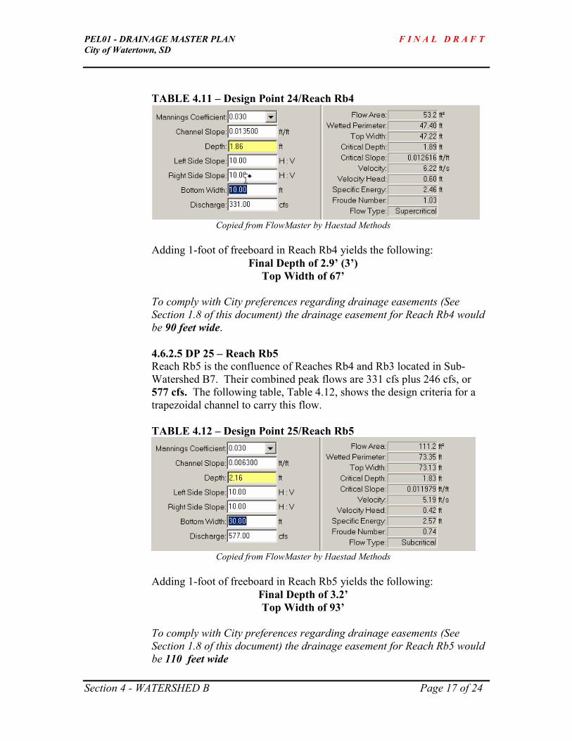
PEL01 - DRAINAGE MASTER PLAN F I N A L D R A F T
City of Watertown, SD
Section 4 - WATERSHED B Page 17 of 24
TABLE 4.11 – Design Point 24/Reach Rb4
Copied from FlowMaster by Haestad Methods
Adding 1-foot of freeboard in Reach Rb4 yields the following:
Final Depth of 2.9’ (3’)
Top Width of 67’
To comply with City preferences regarding drainage easements (See
Section 1.8 of this document) the drainage easement for Reach Rb4 would
be 90 feet wide.
4.6.2.5 DP 25 – Reach Rb5
Reach Rb5 is the confluence of Reaches Rb4 and Rb3 located in Sub-
Watershed B7. Their combined peak flows are 331 cfs plus 246 cfs, or
577 cfs. The following table, Table 4.12, shows the design criteria for a
trapezoidal channel to carry this flow.
TABLE 4.12 – Design Point 25/Reach Rb5
Copied from FlowMaster by Haestad Methods
Adding 1-foot of freeboard in Reach Rb5 yields the following:
Final Depth of 3.2’
Top Width of 93’
To comply with City preferences regarding drainage easements (See
Section 1.8 of this document) the drainage easement for Reach Rb5 would
be 110 feet wide

PEL01 - DRAINAGE MASTER PLAN F I N A L D R A F T
City of Watertown, SD
Section 4 - WATERSHED B Page 18 of 24
Note the bottom width of 30’. This has been chosen to keep the depth of
the channel shallow in order to minimize the depth required for the flood
storage detention pond.
Also note the two small culverts located just north of the storage pond
shown in Figure 4.1. It is assumed that these pipes, along with the built-
up earth, will be removed when the area is developed.
4.6.2.6 DP 26 – Reach Rb6 and New Culvert
Reach Rb6 represents an existing flow pattern where run-off from Sub-
Watershed B6 makes its way into the natural depression. This reach
requires expansion and definition when B6 develops. A new culvert will
need to be installed where one does not exist today.
Post-developed flows from B6 for the 100-year event equal 39 cfs. An
appropriately sized trapezoidal channel to carry this flow is shown in
Table 4.13.
TABLE 4.13 – Design Point 26/Reach Rb6
Copied from FlowMaster by Haestad Methods
Adding 1-foot of freeboard in Reach Rb6 yields the following:
Final Depth of 2.2’
Top Width of 27’
To comply with City preferences regarding drainage easements (See
Section 1.8 of this document) the drainage easement for Reach Rb6 would
be 50 feet wide.
4.6.2.7 DP 28 – Shallow Depression in Sub-Watershed B1
A small, shallow depression exists in Sub-Watershed B1 located just north
of US 212. It is 2’ deep, over-topping at elevation 1742 feet. Any water
pooling in this depression would discharge east and then find its way to
the ditch on the north side of US 212 and then into the pipe under the road
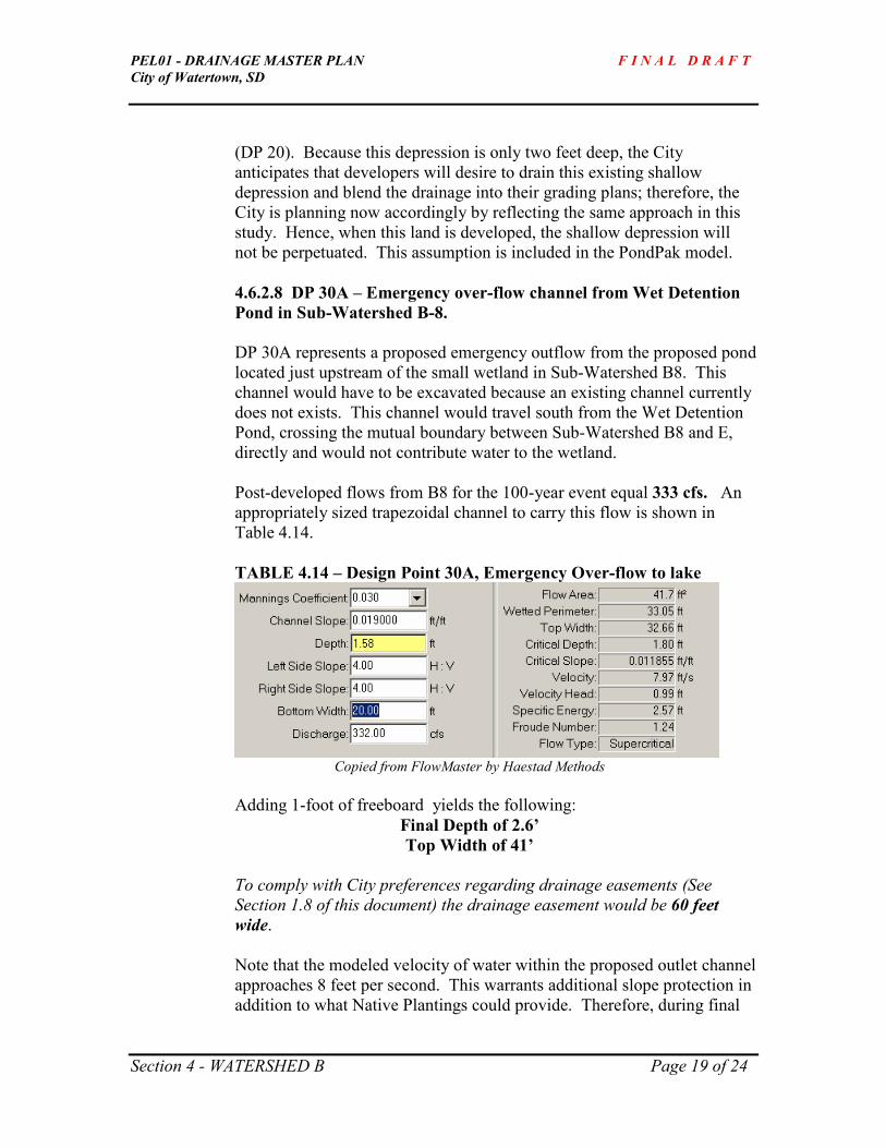
PEL01 - DRAINAGE MASTER PLAN F I N A L D R A F T
City of Watertown, SD
Section 4 - WATERSHED B Page 19 of 24
(DP 20). Because this depression is only two feet deep, the City
anticipates that developers will desire to drain this existing shallow
depression and blend the drainage into their grading plans; therefore, the
City is planning now accordingly by reflecting the same approach in this
study. Hence, when this land is developed, the shallow depression will
not be perpetuated. This assumption is included in the PondPak model.
4.6.2.8 DP 30A – Emergency over-flow channel from Wet Detention
Pond in Sub-Watershed B-8.
DP 30A represents a proposed emergency outflow from the proposed pond
located just upstream of the small wetland in Sub-Watershed B8. This
channel would have to be excavated because an existing channel currently
does not exists. This channel would travel south from the Wet Detention
Pond, crossing the mutual boundary between Sub-Watershed B8 and E,
directly and would not contribute water to the wetland.
Post-developed flows from B8 for the 100-year event equal 333 cfs. An
appropriately sized trapezoidal channel to carry this flow is shown in
Table 4.14.
TABLE 4.14 – Design Point 30A, Emergency Over-flow to lake
Copied from FlowMaster by Haestad Methods
Adding 1-foot of freeboard yields the following:
Final Depth of 2.6’
Top Width of 41’
To comply with City preferences regarding drainage easements (See
Section 1.8 of this document) the drainage easement would be 60 feet
wide.
Note that the modeled velocity of water within the proposed outlet channel
approaches 8 feet per second. This warrants additional slope protection in
addition to what Native Plantings could provide. Therefore, during final

PEL01 - DRAINAGE MASTER PLAN F I N A L D R A F T
City of Watertown, SD
Section 4 - WATERSHED B Page 20 of 24
design, the use of permanent turf reinforcement mats or other geotextile
fabrics should be explored.
4.6.3 Proposed Culverts
4.6.3.1 DP 19
Design Point 19 is a culvert under 42nd
Street from Sub-Watershed
B2 to Sub-Watershed B1. Outflow from this pipe flows into Reach
Rb1. Because the flows generated from B2 would be relatively
small, the City requests that the proposed culvert be sized to pass
the post-developed 100 year flows. This flow, 46 cfs, could be
conveyed in either
1 - 4’ x 2’ box culvert, (preferred) or
1 - 42” diameter pipe.
Final design may dictate different pipe sizing depending on allowable
headwater and tail-water conditions
4.6.3.2 DP 20
Design Point 20 is a culvert passing under US 212 that conveys water
from Sub-Watersheds B1 and B2 into Sub-Watershed B4. The
downstream channel from this culvert is Reach Rb2, where flows from
Sub-Watershed B4 are added (DP 21). Because it crosses US 212, this
pipe is to be sized to pass the post-developed 100-year flows without
overtopping the highway. Because of the moderate length of Reach Rb1
as compared to the flow length found in Sub-Watershed B1, simple
addition is used to size this pipe. Therefore, the capacity of this pipe must
carry is equal to the sum of the post-developed 100-year flows of B1 plus
B2, or 235 cfs.
Appropriate culverts to pass this flow include the following:
2 – 6’x5’ box culverts (preferred)
3 – 66” diameter circular pipe
2 – 102” x 62” (span x rise) arch pipes
4.6.3.3 DP 22
Design Point 22 is a culvert passing under US 212 that conveys water
from Sub-Watershed B3 into Sub-Watershed B7. This culvert outlets into
Reach Rb3. Since this culvert crosses US 212, the post-developed 100-

PEL01 - DRAINAGE MASTER PLAN F I N A L D R A F T
City of Watertown, SD
Section 4 - WATERSHED B Page 21 of 24
year event is the basis of designing its capacity which also matches the
criteria for sizing Reach Rb3, a peak flow of 246 cfs.
Culverts sized appropriately to pass this flow include the following:
2 – 7’x3’ box culverts (preferred)
3 – 54” diameter circular pipes
2 – 73”x 45” (span x rise) arch pipes
Final design may dictate different pipe sizing depending on allowable
headwater and tail-water conditions.
4.6.3.4 DP 24
Design Point 24 is a culvert passing under 42nd
Street that conveys water
from Reach Rb2 and Sub-Watershed B5 into Sub-Watershed B7. This
culvert outlets into Reach Rb4. It is the City’s preference to allow the
post-developed flows from a 25-year storm event to cross 42nd
Street
without overtopping. From the PondPak model, the peak flow rate for this
condition is 243 cfs.
Culverts sized appropriately to pass this flow include the following:
2 – 7’x3’ box culverts (preferred)
3 – 54” diameter circular pipes
2 – 73” x 45” (span x rise) arch pipes
Final design may dictate different pipe sizing depending on allowable
headwater and tail-water conditions.
4.6.3.5 DP 26
Design Point 26 is a recommended new culvert passing flows under 42nd
Street from Sub-Watershed B6 into Sub-Watershed B7. No pipe exists
there today. Since the area of B6 is small (15.4 acres), the City desires to
pass the 100-year peak flow from the post-developed conditions, or
39 cfs.
A 36” diameter circular pipe is capable of passing this flow. Final
design may dictate different pipe sizing depending on allowable headwater
and tail-water conditions.

PEL01 - DRAINAGE MASTER PLAN F I N A L D R A F T
City of Watertown, SD
Section 4 - WATERSHED B Page 22 of 24
4.7 Additional Comments
For the “engineered depression” or the flood storage pond described here under DP 27,
one additional consideration would be to place drain-tile below the bottom of the flood
storage pond and route it to a lower area. This would allow the ground to dry-out
between periods of high rain events thus allowing the land to be used for other activities
such as parks, soccer, or soft-ball complexes. This feature would also provide additional
opportunities for decorative plantings such as aspen, dogwood, willow, and other woody
forbs and wetland tolerant plants thus creating additional opportunities for habitat. The
volume of this trench should be sized to hold the “average storm” or approximately the
volume of water produced from a 1-year or 2-year storm event.
A second enhancement to DP 27 would be to over-excavate an area equal to 10-15% of
the total volume in order to store sediment. This option would localize the deposition of
larger sediments easing maintenance requirements. However, this option may not be
compatible with daytime recreation activities.
Drain tile should be considered to be included into all ponds to ensure that they drain and
do not retain water over an extended period of time. The discharge of the drainage tile
would be located in the emergency overflow channels. In the rare event that two, back-
to-back, 100-yr storms occur within a 40-hour period, detained water will not have had
enough time to drain from ponds through their designed outlets. In the case where
proposed ponds are designed to have no outlet, the emergency overflow channel would
be the only source of water to exit the engineered depression.
4.7.1 Information Points 1 and 6 (IP 1 and IP 6)
As a special request, the City of Watertown requested that, where large tracts of
undeveloped land exist, the flow rate (cfs) they contribute downstream to adjacent
properties be identified. Within Watershed B, this occurs at two locations as
labeled in Figure 4.1 as IP-1 and IP-6.
IP-1 is located within Sub-watershed B4 and represents an access to a private,
partially developed property within property 2950. Flows west of this location,
south of US 212, flow east within the ditch of US 212. The area of land draining
to this point is equal to 35.3 acres.
IP-6 is located within Sub-watershed B8. This location represents the confluence
of the property 2943 and 14173 and a natural drainage way. The area of land
upstream of this point that contributes to runoff is 35.2 acres.
Assuming post-developed conditions shown above in Table 4.4 and using TR-55,
the post-developed flow rates at this location would be the following (shown in

PEL01 - DRAINAGE MASTER PLAN F I N A L D R A F T
City of Watertown, SD
Section 4 - WATERSHED B Page 23 of 24
cubic feet per second) for the storm events shown. Note that TR-55 does not
include infiltration.
Q1 Q2 Q5 Q10 Q25 Q50 Q100
IP-1 32.21 42.18 64.64 77.3 92.23 107.63 120.28
IP-6 19.17 27.82 49.14 61.6 77.01 92.53 105.52


PEL01 - DRAINAGE MASTER PLAN F I N A L D R A F T
City of Watertown, SD
Section 5 - WATERSHED C Page 1 of 13
SECTION 5 – WATERSHED C
5.1 WATERSHED C – Boundaries and Sub-watersheds
Watershed C is comprised of 330.7 acres containing two sub-watersheds as shown in
Figure 5.1 – Watershed C. As can be seen in the figure, Watershed C exists west of 42nd
Street and south of Highway 212.
Sub-watershed C1 is 306.6 acres of gently rolling terrain. No outlet to Lake Pelican
exists. Run-off is collects in a natural depression. The top elevation of the depression
starts at 1728 ft. and the bottom of the depression is at elevation 1721 ft. Two main
channels (reaches) can be identified from contour data, Rc1, and Rc2 – each draining to
the natural depression.
Sub-watershed C2 is 24.1 acres of slightly steeper terrain that drains south to
Lake Pelican.
5.2 WATERSHED C – Goals
The goals for sub-watershed C1 are to:
1) Identify post-developed 100-year peak flows rate.
2) Establish what volume of run-off could potentially be stored in the natural
depression.
3) If needed, determine amount of excavation required to fully contain the
post-developed 100-year rain event.
4) If appropriate, explore how adding drain-tile within the expanded
depression would provide additional drainage and quicker draw down time
thus allowing for some level of alternate use such as park area, soccer or
softball complex, etc.
5.3 WATERSHED C – Pre-Developed Conditions
As stated throughout this study, baseline conditions, or pre-developed conditions, were
chosen to emulate run-off generated for the landscape prior to being disturbed by man.
Watershed C is perhaps the best example, within this study area, of what type of
landscape cover typically existed prior to settlement, although it is noted that 42nd
Street
bounds the eastern edge of Sub-watersheds C1 and C2.
Model inputs for pre-developed conditions of Sub-watersheds C1 and C2 conditions
include the following:

PEL01 - DRAINAGE MASTER PLAN F I N A L D R A F T
City of Watertown, SD
Section 5 - WATERSHED C Page 2 of 13
TABLE 5.1 – Pre-Developed Modeled Conditions Sheet Flow Shallow Flow Sub
Area
Acres Cover
Type1
“CN”
Flow
Length
Slope Flow
Length
Slope
Manning’s
“n” surface2 /
paved?
Time of Conc.
(hours)
C1 306.6 69 100 0.88% 5473 .088% 0.15 / unpaved 1.27
C2 24.4 69 100 1.37% 1455 1.37% 0.15 / unpaved 0.43 1 Cover type determines Runoff Number, CN. CN=69 represents pasture grass in fair condition from hydrologic soils
group B-type soils. 2 Manning’s “n” represents surface friction impeding surface flow, n = 0.15 for short grass on range land. Whether
the surface is paved or unpaved are default options in both WinTR-55 and PondPak models.
Using the inputs from Table 5.1 results in the following flows generated from the
sub-areas for the specified storm event and a 24-hour, Type II, synthetic rainfall
as shown in Table 5.2.
TABLE 5.2 – Peak Flow Rates from Pre-Developed Conditions
Sub Area Q1
cfs
Q2
cfs
Q5
cfs
Q10
cfs
Q25
cfs
Q50
cfs
Q100
cfs
C1 17.05 40.32 100.27 143.14 194.02 263.53 327.36
C2 2.73 6.18 17.12 24.44 33.87 44.16 53.00
The existing depression is capable of storing 68.06 acre-feet below elevation
1728’.
Elevation Area (acres)
1722 2.2
1723 4.0
1724 7.3
1725 10.8
1726 15.5
1727 19.1
1728 23.0
Therefore, Goal #2 is achieved by calculating the volume of water the
existing depression is capable of storing.
5.3.1 Existing Culverts and Reaches
No culverts or formal reaches currently exist in either sub-watershed. The
reaches identified (Rc1 and Rc2) in Figure 5.1 located at the end of this section
are shown for planning purposes. Because the modeled ultimate build-out
conditions are for one unit per 2 acres, it was assumed that no formal storm sewer
collection would be built within the development; therefore, the likelihood of

PEL01 - DRAINAGE MASTER PLAN F I N A L D R A F T
City of Watertown, SD
Section 5 - WATERSHED C Page 3 of 13
building roads with curb and gutters is low. Thus, no storm sewers would exist
and all runoff would be carried in overland flow and/or open ditches. See
Section 5.4 for more information regarding post-developed conditions.
5.3.2 Existing Drainage Pattern
The existing drainage pattern is not complex. In Sub-Watershed C1, all surfaces
drain to the existing depression. The average slopes range between 0.5% and
1.5%.
The existing drainage pattern in Sub-Watershed C2 flows to Lake Pelican. A
gravel road (20th
Avenue South) bisects area C2. This road is over-topped by
high-water events when water from the north builds to exceed elevation 1727’
(approximate).
5.4 WATERSHED C – Post-Developed Modeled Conditions
Goals #1, #3, and #4 for Watershed C, are repeated below.
1) Identify post-developed 100-year peak flows rate.
3) If needed, determine amount of excavation required to fully contain the
post-developed 100-year rain event.
4) If appropriate, explore how adding drain-tile within the expanded
depression would provide additional drainage and quicker draw down time
thus allowing for some level of alternate use such as park area, soccer or
softball complex, etc
These goals allude to the fact that the existing depression is not large enough to store the
post-developed 100-year flows, which is true since the existing depression can only hold
68.06 acre-feet. See Table 5.5 below. The data is excerpted from PondPak. Note that
the Estimated Storage for the 100-year post-developed flow is 89.65 acre-feet.
The data input for the post-developed conditions which PondPak used to determine the
data in Table 5.5 is found in Table 5.3. Peak flow rates for the post-developed conditions
are shown in Table 5.4.

PEL01 - DRAINAGE MASTER PLAN F I N A L D R A F T
City of Watertown, SD
Section 5 - WATERSHED C Page 4 of 13
TABLE 5.3 – Post-Developed Modeled Conditions Sheet Flow Shallow Flow Sub
Area
Acres Cover
Type1
“CN”
Flow
Length
Slope Flow
Length
Slope
Manning’s
“n” surface2 /
paved?
Time of Conc.
(hours)
C1 306.6 77 100 0.88% 5473 .088% 0.24 / unpaved 1.01
C2 24.4 77 100 1.37% 1455 1.37% 0.24 / unpaved 0.478 1 Cover type determines Runoff Number, CN. CN=77 represents fully developed conditions for 2-acre residential lots
averaging 12% connected impervious surface areas and hydrologic soils group C-type soils. 2 Manning’s “n” represents surface friction impeding surface flow, n = 0.24 for dense grass. Whether the surface is
paved or unpaved are default options in both WinTR-55 and PondPak models.
TABLE 5.4 – Peak Flow Rates from Post-Developed Conditions
Sub Area Q1
cfs
Q2
Cfs
Q5
cfs
Q10
cfs
Q25
Cfs
Q50
cfs
Q100
cfs
C1 63.03 103.82 187.81 241.92 302.38 381.48 450.60
C2 8.21 13.46 27.23 35.67 46.19 57.31 66.67
Note that the 100-year post-developed peak flows are 138% and 126% higher than the
pre-developed peak flow rates for sub-areas C1 and C2, respectively.
Table 5.5 is a copy of the PondMaker Worksheet from PondPak summarizing peak flows
and volume requirements for the Storage Pond C. It as assumed that the ground where
the depression exists is capable of infiltrating 0.2 inches per hour, a conservative
assumption. Since this depression has not outlet, a routing analysis was not conducted.
In other words, Estimated Storage volumes equal pond volume as no outflow occurs.
TABLE 5.5 – PondMaker Worksheet from PondPak, DP 34, Storage Pond C
Ignore W.S. Elevation and Freeboard Depth for the 500-year event.
Note that Estimated Storage for the 100-year event is 89.65 acre-feet, roughly 32% more
than what the natural depression can hold (68.06 acre-feet) below elevation 1728’.

PEL01 - DRAINAGE MASTER PLAN F I N A L D R A F T
City of Watertown, SD
Section 5 - WATERSHED C Page 5 of 13
5.4.1 DP 34/42nd Street Pond: The post-developed storage required for the 100-year
event is achieved with the following Elevation/Area configuration for sub-area C1:
Elevation Area (acres)
1722 14.72
1723 15.21
1724 15.71
1725 16.21
1726 17.05
1728 23.03
The Estimated Storage and Interpreted Water Surface Elevation shown in
Table 5.5 is based on the “engineered depression,” or flood storage area, shown
above, along with a pond depth of 6’ with 0.5’ of freeboard, side slopes equal
6:1 (H:V) and a top-of-pond- elevation of 1728’. Note that the post-developed
100-year volume in the pond with the specified configuration has 0.67’ of
freeboard before reaching elevation 1728’. Additional storage could be provided
if the City desired to offer increased protection against flooding of adjacent
property.
5.4.2 DP 35 A future culvert will be needed under 20th
Avenue South to pass drainage
from the northern third of Sub-Watershed C2, or 8.8 acres. Post-developed conditions,
similar to those found in Table 5.3, yield the following peak flow rates:
TABLE 5.6 – Northern Third of Sub-Area C2 (DP 35)
Peak Flow Rates from Post-Developed Conditions
Sub Area Q1
cfs
Q2
Cfs
Q5
cfs
Q10
cfs
Q25
Cfs
Q50
cfs
Q100
cfs
C2-N 1/3 3.12 5.1 10.31 13.47 17.48 21.61 25.16
Assuming a 1% slope, the size of culvert needed to pass the 25-year post-developed
storm event (17.5 cfs) is either a 4’ x 2’ box culvert or a 43.75” x 26.62”(width x rise)
arch-pipe or a 54” round pipe. The arch pipe or box is preferred because of their low rise
thus allowing for minimal excavation and ease of blending into existing contours. A final
design analysis may yield smaller culverts depending on allowable head-water and tail-
water conditions.
From the outlet if this culvert, the ground falls off quickly. Simply accounting for this
drainage when development is platted should be sufficient to convey upstream flows to
Lake Pelican. A drainage easement is not warranted.

PEL01 - DRAINAGE MASTER PLAN F I N A L D R A F T
City of Watertown, SD
Section 5 - WATERSHED C Page 6 of 13
5.5 WATERSHED C – Alternatives Considered
Alternatives, other than what is proposed under Design Points 34 and 35, that were
considered for flows exceeding those produced by a 100-year storm event include:
5.5.1 Providing an overflow at the lowpoint in the road south of the proposed
pond to convey flows produced from events greater than the 100-year
storm event, which would then flow into a designed over-flow channel
protected through an easement area.
5.5.2 A designed pumping station and force main system that would turn on
when the water stored in the pond reached a specified elevation. This
water would then be pumped to discharge into Lake Pelican.
This concept is not favored by the City of Watertown for several reasons.
Because the pump would run sporadically, perhaps up to 6 months at a
time, the reliability of the pump would be low requiring adding cost and
maintenance. Similarly, a duplex pump station would be required to
guarantee at least one pump would be working, adding more cost.
Furthermore, 600-700 feet of length of the force main conduit would need
to be buried and protected, adding more cost. This approach is typically
installed in highly urbanized areas where no other options exist.
5.5.3 An outlet pipe flowing into a designed channel.
This concept is also not preferred because a pipe with a large enough
opening greatly decreases the amount of storage available to the pond.
For example, the wetted perimeter of the pond under DP 34 occurs at
elevation 1727.3 for the 100-year post-developed flood. A round concrete
pipe typically required 2-feet of cover. The difference between the 100-
year and 500- year post developed flow rates equal about 35 cfs.
Assuming a slope of 1% in the pipe, at least a 30” culvert would be
needed. Add this to the 2’ feet of cover creates an invert of 5.5’ below
ground surface, thus beginning to drain the pond at elevation 1721.8,
which is below the bottom of the proposed pond. Adding a drainage pipe
to the proposed pond is not a feasible means of providing flood protection
from storm events exceeding the 100-year design storm under post-
developed conditions.
This leaves only the first option as being a reasonable and feasible way of
providing emergency over-flow routing from storm events exceeding the 100-year
event. A low point in the road, occurring at elevation 1728’, would then convey
emergency routing across the road. A channel would then be needed to convey

PEL01 - DRAINAGE MASTER PLAN F I N A L D R A F T
City of Watertown, SD
Section 5 - WATERSHED C Page 7 of 13
this flow south-easterly toward Lake Pelican conforming to natural drainage
patterns. This channel is referred to as DP 34A in Figure 5.1 located at the end of
this Section and under Section 5.6.2.4.
5.6 WATERSHED C – Recommendations
5.6.1 Proposed Ponds – See DP 34 above (page 4 of this section).
5.6.2 Proposed Channels and Routing
As shown in Figure 5.1 located at the end of this section, Reaches Rc1 and Rc2
indicate the flow line of how existing contours form a channel to route water to
the natural depression. When this area is developed, it is assumed that similar
channel routing will be perpetuated using ditches adjacent to roads and
constructed channels. Drainage easements are recommended.
5.6.2.1 DP 31 Design Point 31 represents the cross-sectional design of the size of
channel needed at the bottom (nearest the depression/flood storage area) of Reach
Rc1. The size of the sub-area draining into Reach Rc1 equals 105.82 acres.
Using WinTR-55 and similar inputs as found in Table 5.3 , the post-developed
peak flow from the 100-year event is 168 cfs. An appropriately sized trapezoidal
channel to convey this flow is shown in Table 5.7.
H:V H:V
Bottom Width (BW) ft
depth (D)
Top Width (TW) ft

PEL01 - DRAINAGE MASTER PLAN F I N A L D R A F T
City of Watertown, SD
Section 5 - WATERSHED C Page 8 of 13
TABLE 5.7 – Design Point 31: Reach Rc1 Data
Copied from FlowMaster by Haestad Methods
Adding 1-foot of additional freeboard in Reach Rc1 yields:
Final Depth of 2.5’
Top Width of 60 feet.
To comply with City preferences regarding drainage easements (See Section 1.8
of this document) the drainage easement for Reach Rc1 would be 80 feet wide
5.6.2.2 DP 32 - Design Point 32 represents the cross-sectional design of the size
of channel needed at the bottom (nearest the depression/flood storage area) of
Reach Rc2. The size of the sub-area draining into Reach Rc2 equals 68.66 acres.
Using WinTR-55 and similar inputs as found in Table 5.3 , the post-developed
peak flow from the 100-year event is 138 cfs. An appropriately sized trapezoidal
channel to convey this flow is shown in Table 5.9.
TABLE 5.8 – Design Point 32: Reach Rc2 Data
Copied from FlowMaster by Haestad Methods

PEL01 - DRAINAGE MASTER PLAN F I N A L D R A F T
City of Watertown, SD
Section 5 - WATERSHED C Page 9 of 13
Adding 1-foot of additional freeboard in Reach Rc2 yields:
Final Depth of 2.5’
Top Width of 55 feet.
To comply with City preferences regarding drainage easements (See Section 1.8
of this document) the drainage easement for Reach Rc2 would be 80 feet wide
5.6.2.3 DP 33 Design Point 33 represents the confluence of Reaches Rc1 and
Rc2. Their combined post-developed combined flow cannot be added directly
because the Time of Concentration is different for each sub-area. Using WinTR-
55 and similar data inputs as shown in Table 5.3, the post-developed peak flow
rate where Reach Rc1 and Rc2 combine is 292 cfs. An appropriately sized
trapezoidal channel to carry this flow is shown below in Table 5.10.
TABLE 5.9 – Design Point 33: Reach Rc3 Data
Copied from FlowMaster by Haestad Methods
Adding 1-foot of freeboard in Reach Rc3 yields:
Final Depth of 2.8’
Top Width of 66’.
To comply with City preferences regarding drainage easements (See Section 1.8
of this document) the drainage easement for Reach Rc3 would be 90 feet wide
5.6.2.4 DP 34A As mentioned above in Section 5.5, an emergency over-flow for
the proposed, land-locked pond referred to as Storage Pond C is needed. An over-
flow channel will take the over-flow across the road located just south of the
proposed pond. The emergency overflow will be an earthen berm with a spillway
elevation of 1727.5 taking the water across the road to the southeast. The low-
point elevation of 1727.5 should extend for a distance of at least 30 feet. An
appropriate sized channel to convey the difference between the 500-yr and 100-yr
post developed flow (35 cfs) is shown in Table 5.10.

PEL01 - DRAINAGE MASTER PLAN F I N A L D R A F T
City of Watertown, SD
Section 5 - WATERSHED C Page 10 of 13
Table 5.10 – DP 34A, Emergency Overflow Channel from Storage Pond
Copied from FlowMaster by Haestad Methods
Adding 1-foot of freeboard in the emergency overflow channel yields:
Final Depth of 2’
Top Width of 30’.
To comply with City preferences regarding drainage easements (See Section 1.8
of this document) the drainage easement for the Emergency Overflow Channel
from the Storage Pond C described under DP 34 would be 50 feet wide.
The need for this drainage easement is speculative as the pond is designed to
fully contain 100-yr, post-developed flows. Theoretically, Storm water runoff
would flow into this emergency overflow channel once every 100 years,
providing the area was fully developed. The City may prefer to not purchase
this drainage easement area in fee and title or perhaps wave their preference of
including an additional 10’ on each side of the top of the channel. Also, 10:1
side-slopes may be used whereby developers would provide a shared drainage
way located in the backs of lots.
5.6.3 Proposed Culverts – See DP 35 above (page 5 of this section).
5.7 Additional Comments
For the “engineered depression” described here under DP 34, one additional
consideration would be to place drain-tile below the bottom of the flood storage pond.
This would allow the ground to dry-out between periods of high rain events thus allowing
the land to be used for other activities such as parks, soccer, or soft-ball complexes. To
further the benefit of the drain-tile, an additional trench could be cut into the bottom of
the flood-storage area, located on one side, providing a specific area where the drain tile
can flow into. This feature would also provide additional opportunities for decorative
plantings such as aspen, dogwood, willow, and other woody forbs and wetland tolerant
plants thus creating additional opportunities for habitat. The volume of this trench should

PEL01 - DRAINAGE MASTER PLAN F I N A L D R A F T
City of Watertown, SD
Section 5 - WATERSHED C Page 11 of 13
be sized to hold the “average storm” or approximately the volume of water produced
from a 1-year or 2-year storm event.
A second enhancement to DP 34 would be to over-excavate an area equal to 10-15% of
the total volume in order to store sediment. This option would localize the deposition of
larger sediments easing maintenance requirements. However, this option may not be
compatible with daytime recreation activities.
Drain tile should be considered to be included into all ponds to ensure that they drain and
do not retain water over an extended period of time. The discharge of the drainage tile
would be located in the emergency overflow channels. In the rare event that two, back-
to-back, 100-yr storms occur within a 40-hour period, detained water will not have had
enough time to drain from ponds through their designed outlets. In the case where
proposed ponds are designed to have no outlet, the emergency overflow channel would
be the only source of water to exit the engineered depression.
5.7.1 Information Points 2,3,4, and 5 (IP 2-5)
As a special request, the City of Watertown requested that, where large tracts of
undeveloped land exist, the flow rate (cfs) they contribute downstream to adjacent
properties be identified. Within Watershed C, this occurs at four locations as
labeled in Figure 5.1 as IP-2 through IP-5. All of these lands are projected to be
2-acre residential lots for post-developed conditions.
IP-2 is located within Sub-Watershed C1 and represents a half-section line
splitting property 2951. This allows for the two halves of property 2951 to be
developed separately. The area that drains to this point is equal to 7.5 acres. Note
that there are multiple small natural drainage ways in this area.
IP-3 represents the confluence of where a natural drainage crosses the property
between 2951 and 15894. The area that drains to this point is equal to 17.2 acres.
IP-4 represents the confluence of where a natural drainage crosses 2951 and
16888. The area draining to this point is equal to 83.2 acres.
IP-5 represents the confluence of where a natural drainage crosses property 15894
and 16888. The area that drains to this point is equal to 47.5 acres.
Assuming post-developed conditions shown above in Table 5.3 and using TR-55,
the post-developed flow rates at these locations would be the following (shown in
cubic feet per second) for the storm events shown. Note that TR-55 does not
include infiltration.

PEL01 - DRAINAGE MASTER PLAN F I N A L D R A F T
City of Watertown, SD
Section 5 - WATERSHED C Page 12 of 13
Q1 Q2 Q5 Q10 Q25 Q50 Q100
IP-2 2.52 4.12 8.36 10.95 14.22 17.60 20.45
IP-3 5.35 8.80 17.85 23.41 30.40 37.56 43.84
IP-4 16.50 27.08 55.67 72.97 95.46 118.46 137.95
IP-5 11.12 18.33 37.43 49.19 64.09 79.49 92.84


PEL01 - DRAINAGE MASTER PLAN F I N A L D R A F T
City of Watertown, SD
Section 6 - WATERSHED D Page 1 of 10
SECTION 6 – WATERSHED D
6.1 WATERSHED D – Boundaries and Sub-watersheds
Watershed D is comprised of 68 acres containing two sub-watersheds as shown in
Figure 6.1 – Watershed D as can be seen at the end of this section, Watershed D is
somewhat bisected by 42nd Street and has no direct outlet. The southern boundary abuts
20th Avenue South.
Generally speaking, existing drainage patterns carry flows from north to south with Sub-
Watershed D1 flows being carried under 42nd Street through a culvert. An existing
depression collects run-off within Sub-Watershed D2, an area currently platted under
Horning’s Third Addition. The existing depression occurs in Lots 1-4. The highest
elevation of the existing depression occurs around elevation 1726 feet where water would
then overtop 20th Avenue Southwest to the south finding its way to Lake Pelican through
flowing over land. The approximate bottom of the existing depression occurs at elevation
1723 feet.
Watershed D poses an interesting challenge in that several lots have been developed
within the boundaries of the natural depression, thereby eliminating the ability to take
advantage of low lying areas and make them larger to mitigate storm water impacts from
urbanization.
6.2 WATERSHED D – Goals
In complying with the over-all goals of this Master Plan described in Section 1.1, restated
below, the objectives for addressing storm water issues within this watershed require
increased analysis and more creative solutions.
1. Minimize the potential for storm-water to threaten life and property.
2. Maintaining water quality through controlling and/or detaining run-off
where possible.
3. Provide developers with clear guidance for complying with the City’s
development and storm water management rules.
Achieving Goal #1 requires taking a reactive approach since homes and buildings
currently exist within the boundaries of the existing depression where water is stored
during high storm events. So, Goal #1 for Watershed D is to evaluate what volume of
run-off is produced from the post-developed 100-year event and then compare it to what
volume is available in the existing natural depression. If the existing depression is not
able to fully contain the post-developed flows from the 100-year event, either additional

PEL01 - DRAINAGE MASTER PLAN F I N A L D R A F T
City of Watertown, SD
Section 6 - WATERSHED D Page 2 of 10
storage must be provided to protect adjacent residences and buildings, OR a conveyance
system of channels must be excavated around and through existing developed property to
remove the threat of flooding adjacent properties.
Goal #2 will be achieved either way by detaining water and/or providing a long reach
with relatively low velocities allowing suspended solids to settle out of the water column.
Planting native species within the channel will also benefit removal of solids and
minimize sediment transport.
Goal #3 does not apply because development has occurred within the area most suitable
for flood storage. Any improvements to controlling run-off will be reactive from this
point forward. However, if the City were willing to purchase Lots 2 and 3, enough
additional storage could be provided to retain the post-developed 100-year event runoff.
This approach is explored later in this section under Section 6.5 – Alternatives
Considered.
6.3 WATERSHED D – Pre-Developed Conditions
As stated throughout this study, pre-developed conditions were chosen to emulate run-off
generated for the landscape prior to being disturbed by man. Watershed D contains
evidence of farming and is also experiencing development of residential housing. Model
inputs for pre-developed conditions of Sub-Watershed D1 and D2 include the following:
TABLE 6.1 – Pre-Developed Modeled Conditions Sheet Flow Shallow Flow Sub
Area
Acres Cover
Type1
“CN”
Flow
Length
Slope Flow
Length
Slope
Manning’s
“n” surface2 /
paved?
Time of Conc.
(hours)
D1 18.7 69 100 0.0060 1517 0.0060 0.15 / unpaved 0.642
D2 34.3 69 100 0.0119 1513 0.0119 0.15 / unpaved 0.471 1 Cover type determines Runoff Number, CN. CN=69 represents pasture grass in fair condition from hydrologic soils
group B-type soils. 2 Manning’s “n” represents surface friction impeding surface flow, n = 0.15 for short grass on range land. Whether
the surface is paved or unpaved are default options in both WinTR-55 and PondPak models.
Using these inputs from Table 6.1 results in the following flows generated from the sub-
areas for the specified storm events.

PEL01 - DRAINAGE MASTER PLAN F I N A L D R A F T
City of Watertown, SD
Section 6 - WATERSHED D Page 3 of 10
TABLE 6.2 – Peak Flow Rates from Pre-Developed Conditions1
Sub Area Q1
cfs
Q2
cfs
Q5
cfs
Q10
cfs
Q25
cfs
Q50
cfs
Q100
cfs
D1 1.58 3.94 10.00 14.35 19.43 26.35 32.68
D2 3.52 8.94 22.87 32.60 43.93 59.29 73.42
D1 & D2 4.82 12.29 31.42 45.29 62.52 83.59 103.50
The existing depression is capable of storing 3.99 acre-feet below elevation 1726 feet.
The following data shows an excerpt from PondPak indicating the volumes in acre-feet
required to store the specific rainfall events from the pre-developed conditions.
The existing volume of the natural depression is based on the following data interpreted
from existing contours using AutoCad:
Elevation Area (acres)
1726 2.921
1725 1.563
1724 0.925
1723 0.252
From this information, the existing depression is capable of storing run-off from the
5-year storm event below elevation 1726’ with no outlet.
6.3.1 Existing Culverts
One culvert exists within Watershed D. The existing culvert, 18” in diameter, 29’
long, laid at a 0.76% slope, having a capacity of 4.6 cfs, is located under 42nd
Street. This pipe drains area D1 into D2. However, as pointed out be Glenn Long
1 Note that simple addition is not possible as the Times of Concentration vary for each sub-area. Very
similar results were found using both WinTR-55 and PondPak. Both models utilize the same SCS
methodology PondPak accounts for infiltration in reaches and ponds. See Section 1 of this report for
more information regarding hydraulics and hydrological information.

PEL01 - DRAINAGE MASTER PLAN F I N A L D R A F T
City of Watertown, SD
Section 6 - WATERSHED D Page 4 of 10
(local resident), the pipe is filled in with sediment. There is no outlet in the ditch
that stores water flowing into the pipe. If enough water drains here, its only outlet
is to over-top the road. The City has contacted the Township in an attempt to get
this pipe cleared. From a field visit conducted on September 23, 2003, the pipe is
still plugged.
6.3.2 Existing Drainage Pattern
The existing drainage pattern in Sub-Watershed D1 flows over-land from north to
south located generally in the middle of the sub-area and then flows into the
existing culvert and then into the natural depression. Surface slopes range from
0.45% to 2.9%.
The existing drainage pattern in Sub-Watershed D2 flows over-land from north to
south and also east to west in the western half of the area. For the western half of
the area, flows concentrate in the ditch located on the east side of 42nd Street and
then drains into the natural depression. Surface slopes range from 0.48% to 6.5%.
6.4 WATERSHED D – Post-Developed Modeled Conditions
The data input for the post-developed conditions which PondPak used to determine the
peak run-off rates and generated volumes is shown below in Table 6.3.
TABLE 6.3 – Post-Developed Modeled Conditions Sheet Flow Shallow Flow Sub
Area
Acres Cover
Type1
“CN”
Flow
Length
Slope Flow
Length
Slope
Manning’s
“n” surface2 /
paved?
Time of Conc.
(hours)
D1 18.7 77 100 .0060 1517 .0060 0.24 /un paved 0..782
D2 34.3 83 100 .0119 1513 .0119% 0.24 / paved .712 1 Cover type determines Runoff Number, CN. CN=77 represents fully developed conditions for 2-acre residential lots
averaging 12% connected impervious surface areas and hydrologic soils group C-type soils. CN=83 represents fully
developed conditions for ¼ acre residential lots averaging 38% connected impervious surface areas and hydrologic
soils group C-type soils. 2 Manning’s “n” represents surface friction impeding surface flow, n = 0.24 for dense grass. Whether the surface is
paved or unpaved are default options in both WinTR-55 and PondPak models.
Table 6.4 below shows the resulting peak flow rates from the post-developed conditions.
TABLE 6.4 – Peak Flow Rates from Post-Developed Conditions1
Sub Area Q1
cfs
Q2
Cfs
Q5
cfs
Q10
cfs
Q25
Cfs
Q50
cfs
Q100
cfs
D1 5.91 9.74 17.46 22.36 27.86 35.07 41.36
D2 28.79 40.43 61.94 74.86 88.83 106.6 121.8
D1&D2 33.11 47.91 76.15 93.42 112.3 136.51 156.83

PEL01 - DRAINAGE MASTER PLAN F I N A L D R A F T
City of Watertown, SD
Section 6 - WATERSHED D Page 5 of 10
Note that the 100-year post-developed peak flow is 152% of the pre-developed peak
(156.83 cfs vs. 103.5 cfs).
6.5 WATERSHED D – Alternatives Considered
This watershed poses a unique challenge in that the current drainage pattern for
stormwater runoff is to collect in an existing depression that has no outlet located
in Sub-Watershed D2. Section 6.3 points out that the existing depression is only
large enough to store run-off from a 5-yr event for pre-developed conditions, up
to and including Elevation 1726.
Of the five lots that would be impacted by a pond adequate in size to fully contain
run-off from a 100-yr event with no outlet within Horning’s Third Addition, three
of them currently have structures and a fourth lot (Lot 3) is planned for
construction by way of a building permit issued by Coddington County. This
leaves a single lot (Lot 2) of land currently undeveloped. Furthermore, Lot 4
currently has a garage placed on it with a floor elevation of 1730.41. Therefore, it
is recommended that for any future water ponding or routing in this area, a
maximum wet surface elevation should be at or under elevation 1728.
For information purposes, the following is an analysis for what size of pond
would be required to fully contain the post-developed 100-yr storm with no outlet.
This fictitious pond size and location is shown in Figure 6.1 located at the end of
this section.
6.5.1 Design Point 38 -20th Avenue SW Pond
This option is not recommended for construction.
Using PondPak and AutoCad, it was found possible to store run-off from the 100-
year post-developed flows in a pond with no outlet from Sub-Watersheds D1 and
D2. This assumes Lots 2, 3, and 4 of Horning’s Third Addition were available for
purchase. Obviously, this is not feasible since homes and garages either exist or
are planned. This information is presented for information purposes only.
Table 6.5 is a copy of the PondMaker Worksheet from PondPak summarizing
peak flows and volume requirements reflecting post-developed conditions for
Sub-watershed D1 and D2 assuming no outlet. It is assumed that the location and
ground where the pond would be constructed is capable of infiltrating 0.2 inches
per hour, a conservative assumption.

PEL01 - DRAINAGE MASTER PLAN F I N A L D R A F T
City of Watertown, SD
Section 6 - WATERSHED D Page 6 of 10
TABLE 6.5 – PondMaker Worksheet from PondPak, DP 38, 20th Ave SW Pond
Ignore W.S. Elevation and Freeboard Depth for the 500-year event.
Note that the 100-year Estimated Storage is 18.16 acre feet. This volume is
achieved with the following Elevation/Area configuration.
Elevation Area (acres)
1720 2.52
1721 2.70
1722 2.88
1723 3.06
1724 3.25
1725 3.45
1726 3.64
Other preliminary design features of this detention pond include 6:1 (H:V) side-
slopes, 0.5’ of free-board, and a top-of-pond elevation of 1726’. An additional
refinement of this pond would be to excavate an additional one or two feet for
sediment storage equal to 10-15% of the total volume for the purpose of sediment
storage. In summary, the surface area for the top of this pond is equal to 3.64
acres.
An outlet structure has not been modeled. However, any outlet channel from a
pond at this location would need to cross 20th Street Southwest and convey the
run-off to Lake Pelican. This would require drainage easements from one or
several landowners located south of 20th Street SW residing in Porter White
Addition. The maximum out-flow rate a channel requires assuming no pond
would exist is equal to the 100-yr peak, post-developed flow of 156.8 cfs.
Assuming an average slope of 2%, an appropriately sized channel to convey 157
cfs to Lake Pelican is shown in Table 6.6.

PEL01 - DRAINAGE MASTER PLAN F I N A L D R A F T
City of Watertown, SD
Section 6 - WATERSHED D Page 7 of 10
Table 6.6- Maximum channel sizing for purely a “conveyance” option.
Copied from FlowMaster by Haestad Methods
Note that the velocity is high and warrants including turf reinforcement mats or
other geotextile fabrics placed within the wetted perimeter of the channel. Also
note that where this channel falls into Lake Pelican, there is a 6-10’ high bluff
warranting a drop structure or other designed outlet into the lake.
Adding 1’ of free-board to this channel yields a total top width of about 30’ and a
final depth of 2.4’. Adding the preferred criteria for drainage easements by the
City of Watertown yields a total maximum easement width of 50 feet.
The final solution for addressing increased run-off from urbanization within
Watershed D will likely be a combination of conveyance and smaller detention
ponds. Presented here are the two extreme examples of each.
6.6 WATERSHED D – Recommendations
6.6.1 Proposed Ponds –
Final Pond location and sizing cannot be determined at this time for reasons
stated above in Section 6.2. The information contained in Section 6.5 above –
Alternatives Considered is presented for the purposes of sharing information.
The final recommendation of how to mitigate the effects of increased
stormwater run-off from urbanization will evolve as developers submit plans for
City approval. The information contained in this report provides background
information regarding pre-developed and post-developed peak flow rates and
volume requirements for storage of storm-water runoff.
This report recommends that property owners and other stakeholders located
within this watershed be apprised of the information contained herein so that
they understand the potential increase of flooding when the area develops and
can plan accordingly.
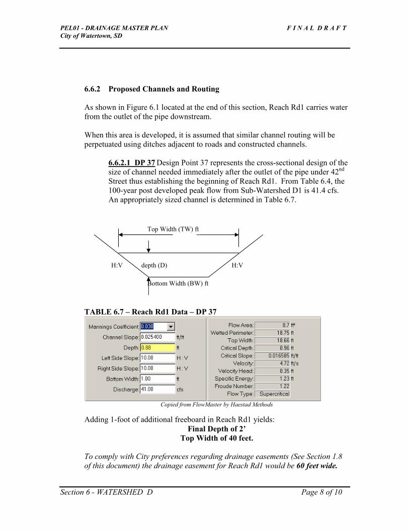
PEL01 - DRAINAGE MASTER PLAN F I N A L D R A F T
City of Watertown, SD
Section 6 - WATERSHED D Page 8 of 10
6.6.2 Proposed Channels and Routing
As shown in Figure 6.1 located at the end of this section, Reach Rd1 carries water
from the outlet of the pipe downstream.
When this area is developed, it is assumed that similar channel routing will be
perpetuated using ditches adjacent to roads and constructed channels.
6.6.2.1 DP 37 Design Point 37 represents the cross-sectional design of the
size of channel needed immediately after the outlet of the pipe under 42nd
Street thus establishing the beginning of Reach Rd1. From Table 6.4, the
100-year post developed peak flow from Sub-Watershed D1 is 41.4 cfs.
An appropriately sized channel is determined in Table 6.7.
TABLE 6.7 – Reach Rd1 Data – DP 37
Copied from FlowMaster by Haestad Methods
Adding 1-foot of additional freeboard in Reach Rd1 yields:
Final Depth of 2’
Top Width of 40 feet.
To comply with City preferences regarding drainage easements (See Section 1.8
of this document) the drainage easement for Reach Rd1 would be 60 feet wide.
H:V H:V
Bottom Width (BW) ft
depth (D)
Top Width (TW) ft

PEL01 - DRAINAGE MASTER PLAN F I N A L D R A F T
City of Watertown, SD
Section 6 - WATERSHED D Page 9 of 10
6.6.3 Proposed Culverts
6.6.3.1 DP 36 – As mentioned in Section 6.3.1, there is an existing
culvert passing water under 42nd Street from Sub-Watershed D1
into D2. The City’s preference is to size the future pipe to carry a
25-year post-developed flow, or 28 cfs. The following culverts
meet this capacity:
� 2 - 36” circular pipes, (preferred) or
� 1 – 6’ x 3’ box culvert, or
� 2 – 44” x 27” (span x rise) arch pipes.
A low point near this location on 42nd Street should be designed for
over-topping to pass high water into the channel (Reach Rd1). As
these options are very similar in terms of excavation and matching
up with surrounding contours, price governs.
6.7 Additional Comments
Drain tile should be considered to be included into all ponds to ensure that they drain and
do not retain water over an extended period of time. The discharge of the drainage tile
would be located in the emergency overflow channels. In the rare event that two, back-
to-back, 100-yr storms occur within a 40-hour period, detained water will not have had
enough time to drain from ponds through their designed outlets. In the case where
proposed ponds are designed to have no outlet, the emergency overflow channel would
be the only source of water to exit the engineered depression.


PEL01 - DRAINAGE MASTER PLAN F I N A L D R A F T
City of Watertown, SD
Section 7 - WATERSHED E Page 1 of 3
SECTION 7 – WATERSHED E
7.1 WATERSHED E – Boundaries and Sub-watersheds
Watershed E is comprised of 21 acres as shown in Figure 7.1 – Watershed E. As can be
seen in the figure, Watershed E is located just east of 42nd Street and is bisected by 20
th
Avenue Southwest. The area is 100% platted through the addition of two subdivisions:
Horning’s Third Addition (north of 20th Ave. SW) and Porter White Addition (south of
20th Ave SW), although not every platted property has a building on it. All drainage from
Watershed E flows directly to Lake Pelican.
In terms of this study, this watershed is a minor consideration and so little analysis is
presented in this section.
7.2 WATERSHED E – Goals
This area is all ready platted and is of a small size with no significant drainage patterns,
depressions. Storm water management concerns are minimal. Therefore, the singular
goal to manage storm water and protect properties from flooding is to develop post-
developed flows north of 20th Ave. SW in order to appropriately size culverts under the
road.
7.3 WATERSHED E – Predeveloped Conditions
7.3.1 Existing Culverts – A field inspection revealed no existing culverts
within the watershed.
7.3.2 Existing Drainage Pattern – Currently, the majority of run-off sheet
flows to Lake Pelican. Although difficult to determine based on existing
contours, it appears that two minor drainage channels exist: one sub-area is 2.02
acres and the other is 4.22 acres. See Section 7.6.3 for more detail.
7.4 WATERSHED E – Post Developed Modeled Conditions
Only two post-developed conditions of small sub-areas are presented here because
of the minimal threat of flooding and the areas’ small size, combined with the fact
that the area is all ready platted. The results of modeled conditions are presented
in Section 7.6.3 – Proposed Culverts.

PEL01 - DRAINAGE MASTER PLAN F I N A L D R A F T
City of Watertown, SD
Section 7 - WATERSHED E Page 2 of 3
7.5 WATERSHED E – Alternatives Considered – None.
7.6 WATERSHED E – Recommendations – See Section 7.6.3.
7.6.1 Proposed Ponds – None.
7.6.2 Proposed Channels and Routing – None.
7.6.3 Proposed Culverts
7.6.3.1 DP 50 Design Point 50 represents a point on 20
th Ave SW where 2.02 acres of run-off
flows south toward Lake Pelican. Without going into detail, the 25-year post-
developed peak flow from this area is 6.4 cfs. Assuming a 1% slope and minimal
headwater, a 21” circular pipe could pass this flow.
7.6.3.2 DP 51 Design Point 51 represents a second point on 20
th Ave SW where 4.22 acres of
run-off flows south toward Lake Pelican. The 25-year post-developed peak flow
from this area is 13.1 cfs. Assuming a 1% slope and allowing 2’ of headwater, a
24” circular pipe could pass this flow.
Neither of these pipes are a high priority, although they should be installed before
100% of the platted properties are populated with homes, garages, etc.
Perhaps a better solution would be to reactively place 15” culverts where storm
water tends to gather as the 2’ contours used in this effort are not accurate enough
to pinpoint exact drainage patterns and low points along 20th Ave SW. Plus, final
grading of lots as they develop will likely influence drainage patterns.
7.7 Additional Comments – None other than referring to Section 2.6 Historic
Maximum Elevation of Pelican Lake and the associated map shown in
Figure 2.3-Historic Flood Elevation Map of Lake Pelican.
“Run-off Potential” Calculations – Because Watershed E is fully platted, no
calculations are necessary.


PEL01 - DRAINAGE MASTER PLAN F I N A L D R A F T
City of Watertown, SD
Section 8 – Stormwater Ordinance Discussion Page 1 of 3
SECTION 8 – STORMWATER ORDINANCE DISCUSSION
and FUNDING
Federal standards exist to protect our nation’s waters. Namely, the Environmental
Protection Agency (EPA) administers a National Pollutant Discharge Elimination System
(NPDES) permit that addresses storm water runoff from municipal storm sewer systems,
construction activity, and industrial activities. Also, the State of South Dakota’s
Department of Natural Resources (DENR) administers several permit programs that serve
to facilitate federal programs and permit requirements.
As these rules and regulations are lengthy, and generally apply to construction projects
and not planning studies, they are not discussed in detail here. However, during the final
design phase of any recommended water quality treatment improvements contained in
this study, appropriate permitting authorities need to be consulted prior to any
construction activity occurring.
The remainder of this section is dedicated to providing a brief overview of local
regulations.
8.1 Current City and County Regulations
Current Codington County and City of Watertown regulations exist to guide and direct
how stormwater management issues are administered in the unincorporated and
incorporated areas within the limits of this study. In addition, the City of Watertown has
adopted several regulations to address flood damage and stormwater management within
the City limits.
Title 5 – Building Provisions of the Ordinances of the City of Watertown, South Dakota
provide regulatory guidance on all building activities.
Section 5.01 – Filling, Grading, Lagooning and Dredging requires a permit for any filling
or grading of the areas listed below. Dredging permits are required for work within 300
feet of high water marks.
- Streambeds and other natural water areas
- All areas within 300 feet of natural water ways including wetlands or
slopes exceeding 12%.
Conditions for earthwork may include:
- Minimization of the exposure of bare ground
- Appropriate erosion control
- Sediment traps

PEL01 - DRAINAGE MASTER PLAN F I N A L D R A F T
City of Watertown, SD
Section 8 – Stormwater Ordinance Discussion Page 2 of 3
- Including designed channels with side-slopes of at least 2:1.
Section 5.02 - Flood Damage Prevention addresses specific requirements for stormwater
management. Section 5.02 applies to all areas of special flood hazards as defined on the
City’s Flood Insurance Rate Map. To summarize, the ordinance requires specific
standards for flood hazard reduction, including the following:
- Anchoring of structures
- Use of construction materials and methods to reduce damage from
flooding
- Minimizaiton of infiltration of flood waters into the sewer system
- Provide adequate drainage
- Residential and Building foundations’ first floor for new construction to
be no less than 1.0 feet above the 100-yr flood elevation of the Big Sioux
River and 1.8 feet above the 100-yr flood elevation along Lake Kampeska.
- Commercial properties’ first floor elevation for new construction to be no
less than 1.8’ above the 100-yr flood elevation, or instill appropriate
measures to guarantee flood proofing.
- Construction in designated floodways shall not result in any increase in
flood levels.
Furthermore, the City of Watertown has Draft Engineering Design Standards dated 1996.
This document is used by City staff to control and mitigate stormwater impacts during the
development of the City’s infrastructure. This set of standards serve as guidance to
developers as their projects evolve and move through the City’s approval process.
Specifically, Chapter 11 addresses Design Criteria for Drainage Improvements. This
chapter dictates the design criteria for drainage improvements, including storm sewers,
culverts, channels, and detention. These requirements include using proposed land uses
in the analysis of stormwater runoff.
While the City’s 1996 Draft Standards work well for specific site developments, the
amount of time City Staff spend reviewing and providing direction on individual project
development may be reduced with a more comprehensive and specific set of new
standards related to stormwater management. The City of Watertown is aware of this and
they are currently in the planning stages of developing a City-wide comprehensive plan
that will streamline stormwater management issues and provide more detailed guidance.
8.2 Suggested Ordinances for PEL01-Drainage Master Plan
The following is a list of suggested ordinance topics that would either ease the
implementation of suggested drainage improvements from this study, or generally
provide enhanced treatment and temporary containment of stormwater runoff:
PEL01 - DRAINAGE MASTER PLAN F I N A L D R A F T
City of Watertown, SD
Section 8 – Stormwater Ordinance Discussion Page 3 of 3
1) Develop a set of standards that define the maximum storm event that would not
over-top specific roads according to their functional classification.
2) Develop a policy that outlines how drainage improvements will be paid for. For
instance, if the City is willing to pay for regional detention facilities, those lands
contributing run-off to that facility should be responsible to assist the City in
recovering some of the capital costs. OR,
3) In lieu of regional detention, provide an option whereby individual or grouped
developments would be allowed to treat their stormwater runoff prior to release
downstream if done in conjunction with an overall master plan.
4) Rain-gardens located on individual residential properties should be encouraged
through some tax incentives or other financial participation provided by the City.
Criteria and maintenance programs would be included.
5) In large commercial or industrial areas where large areas of turf grass may be
planned, property owners should be encouraged to seed with native plants, forbs,
and woody species to minimize runoff and increase biologic uptake of water and
nutrients. These areas would also require much less maintenance.
Not necessarily an ordinance, but a suggestion to improve communication between City
and County staff, is to instill a process whereby impacts from development could be
addressed formally on a periodic basis. While FEMA maps address flood hazard areas,
many issues related to potential impacts from storage and conveyance could be avoided.
8.3 FUNDING
Section 8 of the Willow Creek Tributaries Drainage Master Plan, dated July 2001, by
Earth Tech Engineering and Technology contains a good discussion of a variety of
funding options, all of which would also apply to this study. With permission from the
City of Watertown, this discussion is included in the Appendix.
Related Documents
![The Windsor Siding Masterplan [DRAFT]](https://static.cupdf.com/doc/110x72/58ed6efc1a28abc3058b468b/the-windsor-siding-masterplan-draft.jpg)


