Ashray – Online Child Abuse 09E21A0538,545,553&563. Chapter – 1 INTRODUCTION 1.1 INTRODUCTION TO PROJECT Our vision is to move beyond addressing the impact of child abuse by seeking out the root cause and identifying ways to prevent it. We have to create awareness amongst masses on the issues related to child abuse. The proposed system tracks suspicious incidents of child abuse by integrating reports based on numerous details and creating a statistics based on these reports. This system verifies and reports incidents of abusive parents, physical and sexual abuse. 1.2 PROBLEMS IN EXISTING SYSTEM The present system is not efficient and effective as the entire data is maintained across various files and systems. It is difficult to access the data and perform the necessary operations. The system cannot respond properly to emergency situations. Disadvantages of Existing system: 1

Welcome message from author
This document is posted to help you gain knowledge. Please leave a comment to let me know what you think about it! Share it to your friends and learn new things together.
Transcript
Ashray – Online Child Abuse 09E21A0538,545,553&563.
Chapter – 1
INTRODUCTION
1.1 INTRODUCTION TO PROJECT
Our vision is to move beyond addressing the impact of child abuse by
seeking out the root cause and identifying ways to prevent it. We have to
create awareness amongst masses on the issues related to child abuse. The
proposed system tracks suspicious incidents of child abuse by integrating
reports based on numerous details and creating a statistics based on these
reports. This system verifies and reports incidents of abusive parents, physical
and sexual abuse.
1.2 PROBLEMS IN EXISTING SYSTEM
The present system is not efficient and effective as the entire data is
maintained across various files and systems. It is difficult to access the data
and perform the necessary operations. The system cannot respond properly to
emergency situations.
Disadvantages of Existing system:
In the current system everything has to be maintained in files which are
burden to Police or NGO’s.
Affected childs may get fear to give complaint manually.
Lack of communication between users and higher authorities.
1.3 SOLUTION TO THESE PROBLEMS
The proposed system is a web based application, which maintains a
centralized repository of all scheme related information.The main objective of
proposed system is to create awareness among the people about child abuse.
1
Ashray – Online Child Abuse 09E21A0538,545,553&563.
Advantages of Proposed system:
The proposed system is the automated system.
Can create awareness among the people and can reduce child abuses.
2
Ashray – Online Child Abuse 09E21A0538,545,553&563.
Chapter - 2
SYSTEM ANALYSIS
2.1 INTRODUCTION
After analyzing the requirements of the task to be performed, the next
step is to analyze the problem and understand its context. The first activity in
the phase is studying the existing system and other is to understand the
requirements and domain of the new system. Both the activities are equally
important, but the first activity serves as a basis of giving the functional
specifications and then successful design of the proposed system.
Understanding the properties and requirements of a new system is more
difficult and requires creative thinking and understanding of existing running
system is also difficult, improper understanding of present system can lead
diversion from solution.
2.2 ANALYSIS MODEL
SDLC METHDOLOGIES
This document play a vital role in the development of life cycle
(SDLC) as it describes the complete requirement of the system. It means for
use by developers and will be the basic during testing phase. Any changes
made to the requirements in the future will have to go through formal change
approval process.
2.2.1 What is Rapid Application Development (RAD)?
James Martin, in his book first coining the term, wrote, “Rapid
Application Development (RAD) is a development lifecycle designed to give
much faster development and higher-quality results than those achieved with
the traditional lifecycle. It is designed to take the maximum advantage of
powerful development software that has evolved recently.”
Professor Clifford Kettemborough of Whitehead College, University of
Redlands, defines Rapid Application Development as “an approach to building
3
Ashray – Online Child Abuse 09E21A0538,545,553&563.
computer systems which combines Computer-Assisted Software Engineering
(CASE) tools and techniques, user-driven prototyping, and stringent project
delivery time limits into a potent, tested, reliable formula for top-notch quality
and productivity. RAD drastically raises the quality of finished systems while
reducing the time it takes to build them.”Online Knowledge defines Rapid
Application Development as “a methodology that enables organizations to
develop strategically important systems faster while reducing development
costs and maintaining quality. This is achieved by using a series of proven
application development techniques, within a well-defined methodology.”
In short, Rapid Application Development is exactly that. It is a process
through which the development cycle of an application is expedited. Rapid
Application Development thus enables quality products to be developed faster,
saving valuable resources. The magnitude of such savings is truly RAD!
2.2.2 Why do you need to be RAD?
The Gartner Group writes, “Many of the business processes devised
after World War II…have remained essentially the same. Corporations are now
finding that work organized stepwise incurs unavoidable delays and errors as
paper is handed off from person to person and unit to unit…IT is the single
most powerful tool for breaking traditional assumptions and rules about
business, and it is the tool that makes new ways of operation possible.” The
most revolutionary and successful change in IT business practices today is
Rapid Application Development.
RAD takes advantage of automated tools and techniques to restructure
the process of building information systems. This new process, extrapolated to
the entire IS organization, results in a profound transformation of information
systems development. RAD replaces hand-design and coding processes, which
are dependent upon the skills of isolated individuals, with automated design
and coding, which is an inherently more stable process. RAD may thus give an
IS organization its first real basis for continuous improvement. In addition to
being more stable, Rapid Application Development is a more capable process,
as it is much faster and less error prone than hand coding.
Most organizations are faced with a large backlog of new systems to be
developed. Over 65% of the typical Information System’s budget is spent on
4
Ashray – Online Child Abuse 09E21A0538,545,553&563.
the maintenance of existing systems. These systems have little documentation
and were developed with programming languages and database systems that
are difficult and time consuming to change. These organizations are thus faced
with upgrading their aging systems or building new applications. Traditional
development lifecycles, however, are too slow and rigid to meet the business
demands of today’s economy. A new methodology must be implemented, one
that allows organizations to build software applications faster, better, and
cheaper. RAD enables such development.
The availability of powerful CASE software makes it possible for
developers to create systems much faster than ever before. These new
integrated CASE toolsets are breaking out of the bubble of traditional software
development thought. They take application development beyond generation
coding, just as generation, many years ago, surpassed textual coding. These
tools enable a developer to drag-and-drop previously generated code, saving
that developer the time and effort of individually hand-coding the text of the
application. CASE tools also enable a developer to implement Rapid
Application Development irrespective of their programming language or
platform. CASEMaker’s Totem 5.0 brings Rapid Application Development to
those coding in COBOL, a traditional, yet far from defunct, programming
language.
Stanley Marcus of Neiman Marcus said, “There are only two things of
importance. One is the customer, and the other is the product. If you take care
of customers, they come back. If you take care of the product, it doesn’t come
back. It’s just that simple. And it’s just that difficult.” Rapid Application
Development, in addition to providing a more quality product in less time, also
ensures greater customer satisfaction. By reducing the elapsed time between
User Design and Cutover, RAD increases the likelihood that the system will
be satisfactory to the users, whose demands are met much quicker than ever
before. The RAD process also directly integrates the end-users in the
development of the application. Iterative prototyping mandates that the
development teams concentrate on delivering a series of fully functional
prototypes to designated user experts. Each prototype is tested by those users
and returned to the development team for reworking, at which point the cycle
repeats. The series of prototypes thus evolves into the final product, giving the
5
Ashray – Online Child Abuse 09E21A0538,545,553&563.
users the opportunity to fine-tune the requirements and review the resulting
software implementation.
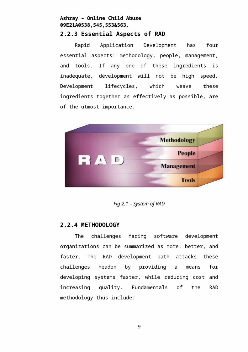
2.2.3 Essential Aspects of RAD
Rapid Application Development has four essential aspects:
methodology, people, management, and tools. If any one of these ingredients
is inadequate, development will not be high speed. Development lifecycles,
which weave these ingredients together as effectively as possible, are of the
utmost importance.
Fig 2.1 – System of RAD
2.2.4 METHODOLOGY
The challenges facing software development organizations can be
summarized as more, better, and faster. The RAD development path attacks
these challenges headon by providing a means for developing systems faster,
while reducing cost and increasing quality. Fundamentals of the RAD
methodology thus include:
Combine the best available techniques and specifying the sequence of
task that will make those techniques most effective.
Using evolutionary prototypes that eventually transformed into the fi-
nal product
6
Ashray – Online Child Abuse 09E21A0538,545,553&563.
Using workshops, instead of interviews, to gather requirements and re-
view design
Selecting a set of CASE tools to support modeling, prototyping, and
code reusability, as well as automating many of the combinations of
technique
Implementing time boxed development that allows development teams
to quickly build the core of the system and implement refinements in
subsequent release
Providing guidelines for success and describing pitfalls to avoid
Active user involvement throughout the RAD lifecycle ensures that
business requirements and user expectations are clearly understood. RAD
takes advantage of powerful application development tools to develop high
quality applications rapidly. Prototyping is used to help users visualize and
request changes to the system as it is being built, allowing applications to
evolve iteratively. RAD techniques are also very successful when faced with
unstable business requirements or when developing nontraditional systems.
The structure of the RAD lifecycle is thus designed to ensure that developers
build the systems that the users really need. This lifecycle, through the
following four stages, includes all of the activities and tasks required to scope
and define business requirements and design, develop, and implement the
application system that supports those requirements.
Requirements Planning
Also known as the Concept Definition Stage, this stage defines the
business functions and data subject areas that the system will support and
determines the system’s scope.
User Design
Also known as the Functional Design Stage, this stage uses workshops
to model the system’s data and processes and to build a working prototype of
critical system components.
Construction
Also known as the Development Stage, this stage completes the
construction of the physical application system, builds the conversion system,
7
Ashray – Online Child Abuse 09E21A0538,545,553&563.
and develops user aids and implementation work plans.
Implementation
Also known as the Deployment Stage, this stage includes final user
testing and training, data conversion, and the implementation of the
application system.
2.2.5 PEOPLE
The success of Rapid Application Development is contingent upon the
involvement of people with the right skills and talents. Excellent tools are
essential to fast application development, but they do not, by themselves,
guarantee success. Fast development relies equally heavily on the people
involved. These people must thus be carefully selected, highly trained, and
highly motivated. They must be able to use the tools and work together in
close-knit teams. Rapid development usually allows each person involved to
play several different roles, so a RAD project mandates a great degree of
cooperative effort among a relatively small group of people.
Each stage of a rapid development project includes activities that need
to move fast. As a result, it is critical that management initiates the project
quickly, cutting through any political delays or red tape. At the Requirements
Planning and User Design stages, key end users must be available to
participate in workshops. While the system is being constructed, the
Construction Team, which uses the CASE toolset to accomplish detailed
design and code generation, must be poised to move quickly. At the end of the
development cycle, the Cutover Team, which handles training and cutover,
must also be ready to move quickly.
The key players in a Rapid Application Development project include:
Sponsor
A high-level user executive who funds the system and is dedicated to
both the value of the new system and to achieving results quickly.
User Coordinator
A user appointed by the Sponsor to oversee the project from the user
perspective.
Requirements Planning Team
8
Ashray – Online Child Abuse 09E21A0538,545,553&563.
A team of high-level users who participate in the Joint Requirements
Planning workshop.
User Design Team
A team of users who participate in the design workshop. This team
should be comprised of both high-level users from the Planning Team and
lower-level users with a more detailed knowledge of the system.
User Review Board
A team of users who review the system after construction and decide
whether modifications are necessary before cutover.
Training Manager
The person responsible for training users to work with the new system.
Project Manager
The person who oversees the development effort.
Construction (SWAT) Team
The SWAT (Skilled Workers with Advanced Tools) Team is a small
team of two to six developers who are highly trained to work together at high
speed. To achieve the fastest possible development, the team members must be
highly skilled in the RAD methodology and in using the chosen CASE toolset.
Workshop Leader
The specialist who organizes and conducts the workshops for Joint
Requirements Planning and Joint Application Design.
2.2.6 MANAGEMENT
Achieving high-speed development is a complex process. Systems will
not be developed and deployed rapidly if bureaucracy and political obstacles
stand in the way or if users are not appropriately involved. Management must
be totally committed to RAD in order to manage the change in culture. They
must be prepared to motivate both users and IT staff, select and manage SWAT
teams, and demonstrate through the use of performance measurements that
RAD does mean speed, quality, and productivity. Good management and
dedication to the ideals of Rapid Application Development are thus essential
to faster system building.
To successfully introduce rapid development, management must pay
careful attention to human motivation. Managers should target those
9
Ashray – Online Child Abuse 09E21A0538,545,553&563.
professionals whom they deem as ‘Early Adapters.’ ‘Early Adapters’ are those
people who see the value of a new methodology and lead the way in making it
practical to use. These employees are enthusiastic about the new methodology
and they want to make it work well in their environment. Similarly, managers
must be aware of the type of motivation that is most effective for each
individual employee, whether it be money, pride, prestige, excitement, or
some combination thereof.
Because Rapid Application Development is such a sweeping change
from the conventional development methods, the best way for a manager to
introduce new rapid development techniques is to start small. Original
Construction Teams of two to four people should be established and their
members should be thoroughly trained in the use of the tools and techniques.
As these teams gain experience, they will be able to fine-tune the development
lifecycle to improve its effectiveness in their environment. Underlying all of
this progress, however, managers must remember the importance of
comprehensive and quality training in the use of tools. Good training with
tools that are exciting to use can have a profound impact on the attitude of IT
professionals, as well as ensure the uninterrupted success of the rapid
development project.
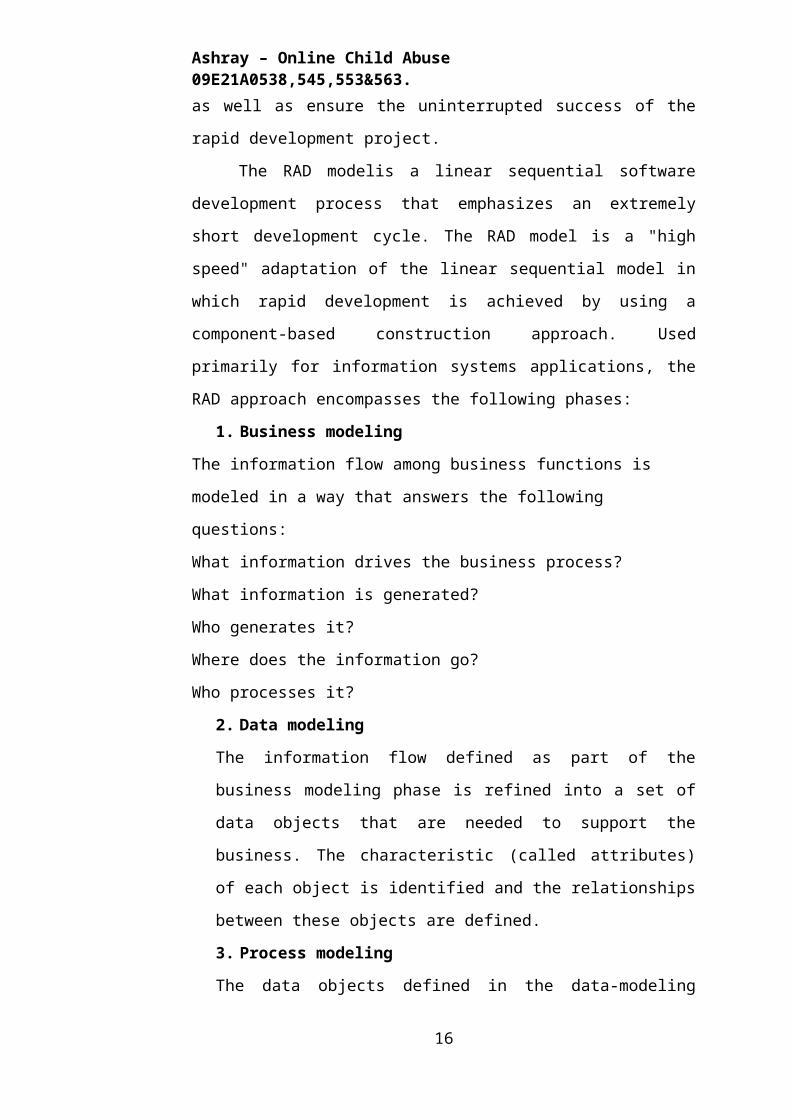
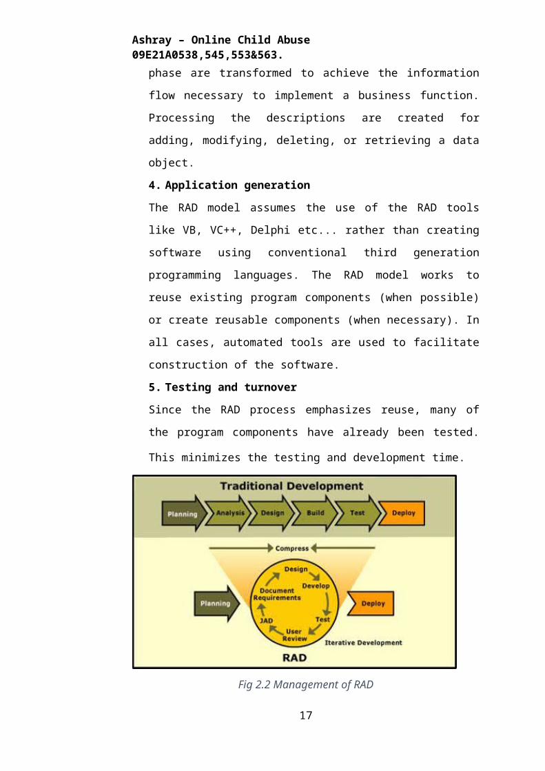
The RAD modelis a linear sequential software development process
that emphasizes an extremely short development cycle. The RAD model is a
"high speed" adaptation of the linear sequential model in which rapid
development is achieved by using a component-based construction approach.
Used primarily for information systems applications, the RAD approach
encompasses the following phases:
1. Business modeling
The information flow among business functions is modeled in a way that
answers the following questions:
What information drives the business process?
What information is generated?
Who generates it?
Where does the information go?
Who processes it?
2. Data modeling
10
Ashray – Online Child Abuse 09E21A0538,545,553&563.
The information flow defined as part of the business modeling phase is
refined into a set of data objects that are needed to support the business.
The characteristic (called attributes) of each object is identified and the
relationships between these objects are defined.
3. Process modeling
The data objects defined in the data-modeling phase are transformed to
achieve the information flow necessary to implement a business function.
Processing the descriptions are created for adding, modifying, deleting, or
retrieving a data object.
4. Application generation
The RAD model assumes the use of the RAD tools like VB, VC++, Delphi
etc... rather than creating software using conventional third generation
programming languages. The RAD model works to reuse existing program
components (when possible) or create reusable components (when
necessary). In all cases, automated tools are used to facilitate construction
of the software.
5. Testing and turnover
Since the RAD process emphasizes reuse, many of the program
components have already been tested. This minimizes the testing and
development time.
Fig 2.2 Management of RAD
11
Ashray – Online Child Abuse 09E21A0538,545,553&563.
Conclusion of Management:
Michael Hammer writes, “Radical surgery is needed in IS processes.
One of the first ideas that will have to go is the whole notion of traditional
development lifecycles.” Rapid Application Development is that surgery.
RAD, an outgrowth of prototyping methods and conceptual work by Barry
Boehm and Tom Gilb, has appeal in an environment where getting products
out quickly has changed from a competitive advantage to a competitive
necessity.
When one compares a RAD organization to a traditional IS
organization, one can clearly see an organization that is optimized for rapid
development and an organization that is optimized for maintenance.
Maintenance looks to the past, as it is threatened by change. Rapid
development, however, looks toward the future, embracing that change.
Professor Clifford Kettemborough thus states, “It is believed that the dominant
trend of our era—in technology no less than anywhere else in our businesses
—is unrelenting, accelerating change, and we expect that trend to continue for
the foreseeable future. If we are correct, [organizations] that fail to adopt
RAD…will simply be left behind.”
Rapid Application Development, the development of higher-quality,
cost-efficient software in a fraction of the time, has thus become a necessity as
we strive to meet the new demands of the software industry. Ed Yourdon
acknowledges that “information technology is now a consumer commodity”
and software developers must embrace this fact by challenging themselves to
adopt new, innovative means of meeting consumer demands. Rapid
Application Development, and its use of powerful CASE tools, is such a
means. It is a dynamic process that emphasizes throughput (getting things out
the door) while de-emphasizing control (blocking the door). It overcomes the
challenges of more, better, and faster. It provides both a framework and the
functional tools for achieving successful, accelerated software development.
Rapid Application Development is, quite simply, RAD.
12
Ashray – Online Child Abuse 09E21A0538,545,553&563.
2.3 STUDY OF THE SYSTEM
In the flexibility of the uses the interface has been developed a graphics
concept in mind, associated through a browser interface. The GUI’S at the top
level have been categorized as
1. Administrative user interface
2. The operational or generic user interface
The administrative user interface concentrates on the consistent
information that is practically, part of the organizational activities and which
needs proper authentication for the data collection. The interfaces help the
administrations with all the transactional states like Data insertion, Data
deletion and Data updating along with the extensive data search capabilities.
The operational or generic user interface helps the users upon the
system in transactions through the existing data and required services. The
operational user interface also helps the ordinary users in managing their own
information helps the ordinary users in managing their own information in a
customized manner as per the assisted flexibilities
2.4 PROPOSED SYSTEM
The development of this new system contains the following activities,
which try to automate the entire process keeping in the view of database
integration approach. User Friendliness is provided in the application with
various controls provided by system Rich User Interface. It can be accessed
over the Internet. The user information files can be stored in centralized
database which can be maintained by the system. This can give the good
security for user information because data is not in client machine.
Authentication is provided for this application only registered members can
access. Report generation features is provided using crystal reports to generate
different kind of reports.
13
Ashray – Online Child Abuse 09E21A0538,545,553&563.
2.5 NUMBER OF MODULE
The system is proposed to have the following modules:
1. Administrator module
2. user module
3. Social Activists (NGO’s) module
4. Investigation Agencies(Police)module,
5. Reports module.
Administrators
The Admin will build a complete picture of the suspect by computing a
correlation matrix on the basis of similarities in the related incidents. The
Admin will be able to categorize the reports on the basis of nature and severity
of abuse.
Social Activists ( NGO’s):
A regular news letter shall be sent to the registered users(NGO’s).
Facilitates appropriate communication between affected people and NGO’s
through forums.
Investigation Agencies(Police):
The investigating agencies will be able to build conclusive picture of
the suspect on the basis of reports and statistics provided by the Admin. Secure
Registration and profile management for Police
Eye witnesses & Affected People:
Eye witnesses/Affected People shall be able to report incidents, which
may not be conclusive in themselves ,but when viewed holistically, shows a
picture of imminent danger.
Anonymous Users & Reports:
This site provides support(educative) and resources to the concern on
taking preventive actions. Registration Confirmation, Reports regarding about
14
Ashray – Online Child Abuse 09E21A0538,545,553&563.
incidents, Area wise report about the crime, Newsletter review statistics.
2.6 INPUT AND OUTPUT
The major inputs and outputs and major functions of the system are
follows:
Inputs:
Admin enter his user id and password for login.
User enters his user id and password for login.
User Create new folder for personnel usage.
Admin enter user id or date for track the user login information
New user gives his completed personnel, address and phone details for
registration.
Admin gives different kind of user information for search the user data.
User gives his user id, hint question, answer for getting the forgotten
password.
Administrator giving information to generate various kinds of reports.
Outputs:
Admin can have his own home page.
Users enter their own home page.
The user defined folders can store in the centralized database.
Admin will get the login information of a particular user.
The new user’s data will be stored in the centralized database.
Admin get the search details of different criteria.
User can get his forgot password.
Different kind of reports is generated by administrator.
15
Ashray – Online Child Abuse 09E21A0538,545,553&563.
Chapter - 3
LITERATURE SURVEY REPORT
Preliminary investigation examine project feasibility, the likelihood the
system will be useful to the organization. The main objective of the feasibility
study is to test the Technical, Operational and Economical feasibility for
adding new modules and debugging old running system. All system is feasible
if they are unlimited resources and infinite time. There are aspects in the
feasibility study portion of the preliminary investigation:
Technical Literature Survey
Operational Literature Survey
Economical Literature Survey
3.1. TECHNICAL LITERATURE SURVEY
The technical issue usually raised during the feasibility stage of the
investigation includes the following:
Does the necessary technology exist to do what is suggested?
Do the proposed equipments have the technical capacity to hold the
data required to use the new system?
Will the proposed system provide adequate response to inquiries,
regardless of the number or location of users?
Can the system be upgraded if developed?
Are there technical guarantees of accuracy, reliability, ease of access
and data security?
Earlier no system existed to cater to the needs of ‘Secure Infrastructure
Implementation System’. The current system developed is technically feasible.
It is a web based user interface for audit workflow at NIC-CSD. Thus it
provides an easy access to the users. The database’s purpose is to create,
establish and maintain a workflow among various entities in order to facilitate
all concerned users in their various capacities or roles. Permission to the users
would be granted based on the roles specified. Therefore, it provides the
16
Ashray – Online Child Abuse 09E21A0538,545,553&563.
technical guarantee of accuracy, reliability and security. The software and hard
requirements for the development of this project are not many and are already
available in-house at NIC or are available as free as open source. The work for
the project is done with the current equipment and existing software
technology. Necessary bandwidth exists for providing a fast feedback to the
users irrespective of the number of users using the system.
3.2. OPERATIONAL LITERATURE SURVEY
Proposed projects are beneficial only if they can be turned out into
information system. That will meet the organization’s operating requirements.
Operational feasibility aspects of the project are to be taken as an important
part of the project implementation. Some of the important issues raised are to
test the operational feasibility of a project includes the following: -
Is there sufficient support for the management from the users?
Will the system be used and work properly if it is being developed and
implemented?
Will there be any resistance from the user that will undermine the
possible application benefits?
This system is targeted to be in accordance with the above-mentioned
issues. Beforehand, the management issues and user requirements have been
taken into consideration. So there is no question of resistance from the users
that can undermine the possible application benefits.
The well-planned design would ensure the optimal utilization of the computer
resources and would help in the improvement of performance status.
3.3. ECONOMICAL LITERATURE SURVEY
A system can be developed technically and that will be used if installed
must still be a good investment for the organization. In the economical
feasibility, the development cost in creating the system is evaluated against the
ultimate benefit derived from the new systems. Financial benefits must equal
or exceed the costs.
17
Ashray – Online Child Abuse 09E21A0538,545,553&563.
The system is economically feasible. It does not require any addition
hardware or software. Since the interface for this system is developed using
the existing resources and technologies available at NIC, There is nominal
expenditure and economical feasibility for certain.
18
Ashray – Online Child Abuse 09E21A0538,545,553&563.
Chapter - 4
SOFTWARE REQUIREMENT SPECIFICATION
4.1 SCOPE OF THE PROJECT
The software, Site Explorer is designed for management of web sites
from a remote location.
Purpose: The main purpose for preparing this document is to give a general
insight into the analysis and requirements of the existing system or situation
and for determining the operating characteristics of the system.
Scope: This Document plays a vital role in the development life cycle (SDLC)
and it describes the complete requirement of the system. It is meant for use by
the developers and will be the basic during testing phase. Any changes made
to the requirements in the future will have to go through formal change
approval process.
DEVELOPERS RESPONSIBILITIES OVERVIEW:
The developer is responsible for:
Developing the system, which meets the SRS and solving all the
requirements of the system?
Demonstrating the system and installing the system at client's location
after the acceptance testing is successful.
Submitting the required user manual describing the system interfaces
to work on it and also the documents of the system.
Conducting any user training that might be needed for using the
system.
Maintaining the system for a period of one year after installation.
4.2. FUNCTIONAL REQUIREMENTS
Functional Requirements refer to very important system requirements
in a software engineering process (or at micro level, a sub part of requirement
engineering) such as technical specifications, system design parameters and
guidelines, data manipulation, data processing and calculation modules etc.
19
Ashray – Online Child Abuse 09E21A0538,545,553&563.
Functional Requirements are in contrast to other software design
requirements referred to as Non-Functional Requirements which are primarily
based on parameters of system performance, software quality attributes,
reliability and security, cost, constraints in design/implementation etc.
The key goal of determining “functional requirements” in a software
product design and implementation is to capture the required behavior of a
software system in terms of functionality and the technology implementation
of the business processes.
The Functional Requirement document (also called Functional
Specifications or Functional Requirement Specifications), defines the
capabilities and functions that a System must be able to perform successfully.
Functional Requirements should include:
Descriptions of data to be entered into the system
Descriptions of operations performed by each screen
Descriptions of work-flows performed by the system
Descriptions of system reports or other outputs
Who can enter the data into the system?
How the system meets applicable regulatory requirements
The functional specification is designed to be read by a general
audience. Readers should understand the system, but no particular
technical knowledge should be required to understand the document.
Examples of Functional Requirements
Functional requirements should include functions performed by
specific screens, outlines of work-flows performed by the system and other
business or compliance requirements the system must meet.
20
Ashray – Online Child Abuse 09E21A0538,545,553&563.
4.2.1 Interface requirements
Field accepts numeric data entry
Field only accepts dates before the current date
Screen can print on-screen data to the printer
4.2.2 Business Requirements
Data must be entered before a request can approved
Clicking the Approve Button moves the request to the Approval
Workflow
All personnel using the system will be trained according to internal
training strategies
4.2.3 Regulatory/Compliance Requirements
The database will have a functional audit trail
The system will limit access to authorized users
The spreadsheet can secure data with electronic signatures
4.2.4 Security Requirements
Member of the Data Entry group can enter requests but not approve or
delete requests
Members of the Managers group can enter or approve a request, but
not delete requests
Members of the Administrators group cannot enter or approve requests,
but can delete requests
The functional specification describes what the system must do; how
the system does it is described in the Design Specification.
21
Ashray – Online Child Abuse 09E21A0538,545,553&563.
If a User Requirement Specification was written, all requirements
outlined in the user requirement specification should be addressed in the
functional requirements.
4.3 NON FUNCTIONAL REQUIREMENTS
All the other requirements which do not form a part of the above
specification are categorized as Non-Functional Requirements.
A system may be required to present the user with a display of the
number of records in a database. This is a functional requirement.
How up-to-date this number needs to be is a non-functional
requirement. If the number needs to be updated in real time, the system
architects must ensure that the system is capable of updating the displayed
record count within an acceptably short interval of the number of records
changing.
Sufficient network bandwidth may also be a non-functional
requirement of a system.
Other examples:
Accessibility
Availability
Backup
Certification
Compliance
Configuration Management
Documentation
Disaster Recovery
Efficiency (resource consumption for given load)
Effectiveness (resulting performance in relation to effort)
Extensibility (adding features, and carry-forward of customizations at
22
Ashray – Online Child Abuse 09E21A0538,545,553&563.
next major version upgrade)
Failure Management
Interoperability
Maintainability
Modifiability
Open Source
Operability
Performance
Platform compatibility
Price
Portability
Quality (e.g. Faults Discovered, Faults Delivered, Fault Removal
Efficacy)
Recoverability
Resilience
Resource constraints (processor speed, memory, disk space, network
bandwidth etc.)
Response time
Robustness
Scalability (horizontal, vertical)
Security
Software, tools, standards etc.
Stability
Safety
Supportability
Testability
Usability by target user community
Chapter - 5
SELECTED SOFTWARE
23

Ashray – Online Child Abuse 09E21A0538,545,553&563.
5.1 INTRODUCTION TO .NET FRAMEWORK
The Microsoft .NET Framework is a software technology that is
available with several Microsoft Windows operating systems. It includes a
large library of pre-coded solutions to common programming problems and a
virtual machine that manages the execution of programs written specifically
for the framework. The .NET Framework is a key Microsoft offering and is
intended to be used by most new applications created for the Windows
platform.
The pre-coded solutions that form the framework's Base Class Library
cover a large range of programming needs in a number of areas, including user
interface, data access, database connectivity, cryptography, web application
development, numeric algorithms, and network communications. The class
library is used by programmers, who combine it with their own code to
produce applications.
Programs written for the .NET Framework execute in a software
environment that manages the program's runtime requirements. Also part of
the .NET Framework, this runtime environment is known as the Common
Language Runtime (CLR). The CLR provides the appearance of an
application virtual machine so that programmers need not consider the
capabilities of the specific CPU that will execute the program. The CLR also
provides other important services such as security, memory management, and
exception handling. The class library and the CLR together compose the .NET
Framework.
5.1.1 Interoperability
24
Ashray – Online Child Abuse 09E21A0538,545,553&563.
Because interaction between new and older applications is
commonly required, the .NET Framework provides means to access
functionality that is implemented in programs that execute outside
the .NET environment. Access to COM components is provided in the
System.Runtime.InteropServices and System.EnterpriseServices
namespaces of the framework; access to other functionality is provided
using the P/rInvoke feature.
5.1.2 Common Runtime Engine
The Common Language Runtime (CLR) is the virtual machine
component of the .NET framework. All .NET programs execute under
the supervision of the CLR, guaranteeing certain properties and
behaviors in the areas of memory management, security, and exception
handling.
5.1.3 Base Class Library
The Base Class Library (BCL), part of the Framework Class
Library (FCL), is a library of functionality available to all languages
using the .NET Framework. The BCL provides classes which
encapsulate a number of common functions, including file reading and
writing, graphic rendering, database interaction and XML document
manipulation.
5.1.4 Simplified Deployment
Installation of computer software must be carefully managed to
ensure that it does not interfere with previously installed software, and
that it conforms to security requirements. The .NET framework
includes design features and tools that help address these requirements.
5.1.5 Security
25
Ashray – Online Child Abuse 09E21A0538,545,553&563.
The design is meant to address some of the vulnerabilities, such
as buffer overflows, that have been exploited by malicious software.
Additionally, .NET provides a common security model for all
applications.
5.1.6 Portability
The design of the .NET Framework allows it to theoretically be
platform agnostic, and thus cross-platform compatible. That is, a
program written to use the framework should run without change on
any type of system for which the framework is implemented.
Microsoft's commercial implementations of the framework cover
Windows, Windows CE, and the Xbox 360. In addition, Microsoft
submits the specifications for the Common Language Infrastructure
(which includes the core class libraries, Common Type System, and the
Common Intermediate Language), the C# language, and the C++/CLI
language to both ECMA and the ISO, making them available as open
standards. This makes it possible for third parties to create compatible
implementations of the framework and its languages on other
platforms.
26
Ashray – Online Child Abuse 09E21A0538,545,553&563.
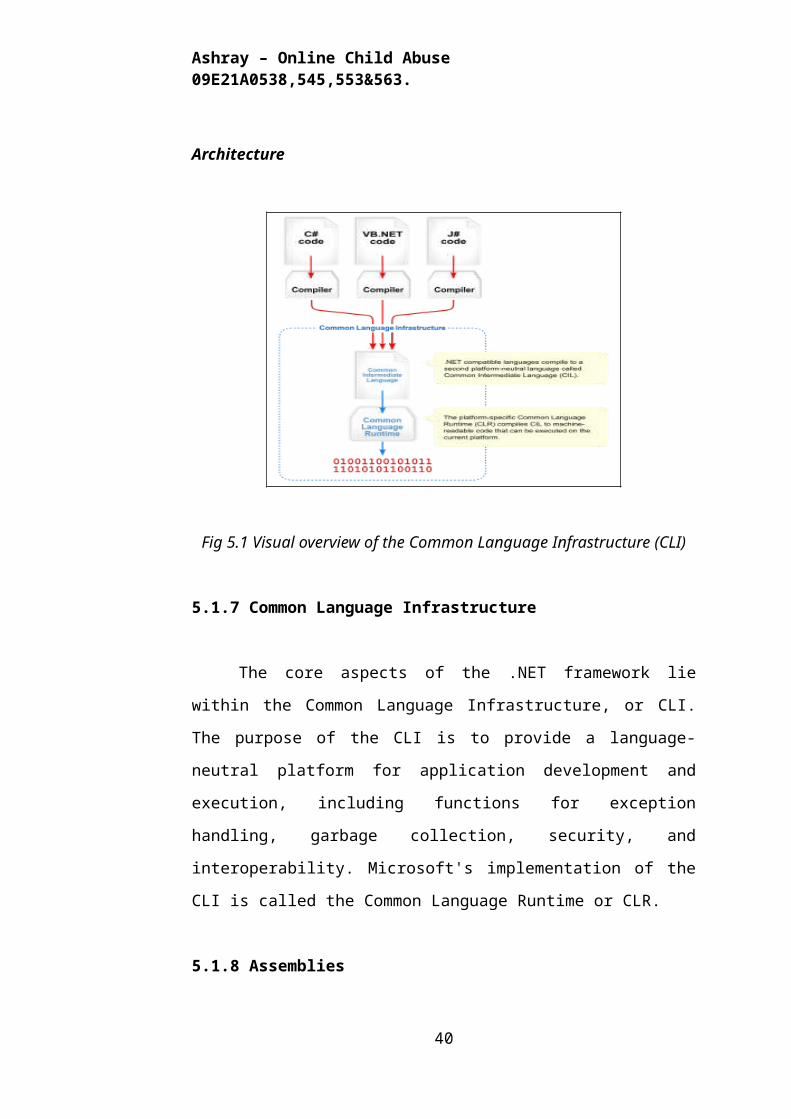
Architecture
Fig 5.1 Visual overview of the Common Language Infrastructure (CLI)
5.1.7 Common Language Infrastructure
The core aspects of the .NET framework lie within the Common
Language Infrastructure, or CLI. The purpose of the CLI is to provide a
language-neutral platform for application development and execution,
including functions for exception handling, garbage collection, security, and
interoperability. Microsoft's implementation of the CLI is called the Common
Language Runtime or CLR.
5.1.8 Assemblies
The intermediate CIL code is housed in .NET assemblies. As mandated
by specification, assemblies are stored in the Portable Executable (PE) format,
common on the Windows platform for all DLL and EXE files. The assembly
consists of one or more files, one of which must contain the manifest, which
has the metadata for the assembly. The complete name of an assembly (not to
be confused with the filename on disk) contains its simple text name, version
number, culture, and public key token. The public key token is a unique hash
27
Ashray – Online Child Abuse 09E21A0538,545,553&563.
generated when the assembly is compiled, thus two assemblies with the same
public key token are guaranteed to be identical from the point of view of the
framework. A private key can also be specified known only to the creator of
the assembly and can be used for strong naming and to guarantee that the
assembly is from the same author when a new version of the assembly is
compiled (required to add an assembly to the Global Assembly Cache).
5.1.9 Metadata
All CLI is self-describing through .NET metadata. The CLR checks the
metadata to ensure that the correct method is called. Metadata is usually
generated by language compilers but developers can create their own metadata
through custom attributes. Metadata contains information about the assembly,
and is also used to implement the reflective programming capabilities of .NET
Framework.
5.1.10 Security
.NET has its own security mechanism with two general features: Code
Access Security (CAS), and validation and verification. Code Access Security
is based on evidence that is associated with a specific assembly. Typically the
evidence is the source of the assembly (whether it is installed on the local
machine or has been downloaded from the intranet or Internet). Code Access
Security uses evidence to determine the permissions granted to the code. Other
code can demand that calling code is granted a specified permission. The
demand causes the CLR to perform a call stack walk: every assembly of each
method in the call stack is checked for the required permission; if any
assembly is not granted the permission a security exception is thrown.
When an assembly is loaded the CLR performs various tests. Two such
tests are validation and verification. During validation the CLR checks that the
assembly contains valid metadata and CIL, and whether the internal tables are
28
Ashray – Online Child Abuse 09E21A0538,545,553&563.
correct. Verification is not so exact. The verification mechanism checks to see
if the code does anything that is 'unsafe'. The algorithm used is quite
conservative; hence occasionally code that is 'safe' does not pass. Unsafe code
will only be executed if the assembly has the 'skip verification' permission,
which generally means code that is installed on the local machine..NET
Framework uses appdomains as a mechanism for isolating code running in a
process. Appdomains can be created and code loaded into or unloaded from
them independent of other appdomains. This helps increase the fault tolerance
of the application, as faults or crashes in one appdomain do not affect rest of
the application. Appdomains can also be configured independently with
different security privileges. This can help increase the security of the
application by isolating potentially unsafe code. The developer, however, has
to split the application into sub domains; it is not done by the CL
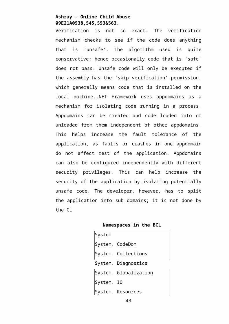
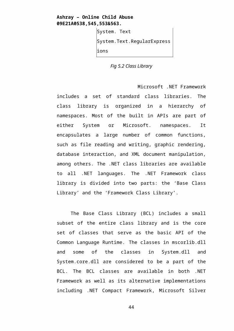
Namespaces in the BCL
System
System. CodeDom
System. Collections
System. Diagnostics
System. Globalization
System. IO
System. Resources
System. Text
System.Text.RegularExpressions
Fig 5.2 Class Library
Microsoft .NET Framework includes a set of standard class
libraries. The class library is organized in a hierarchy of namespaces. Most of
the built in APIs are part of either System or Microsoft. namespaces. It
encapsulates a large number of common functions, such as file reading and
writing, graphic rendering, database interaction, and XML document
manipulation, among others. The .NET class libraries are available to all .NET
29
Ashray – Online Child Abuse 09E21A0538,545,553&563.
languages. The .NET Framework class library is divided into two parts: the
‘Base Class Library’ and the ‘Framework Class Library’.
The Base Class Library (BCL) includes a small subset of the entire
class library and is the core set of classes that serve as the basic API of the
Common Language Runtime. The classes in mscorlib.dll and some of the
classes in System.dll and System.core.dll are considered to be a part of the
BCL. The BCL classes are available in both .NET Framework as well as its
alternative implementations including .NET Compact Framework, Microsoft
Silver light and Mono.
The Framework Class Library (FCL) is a superset of the BCL classes
and refers to the entire class library that ships with .NET Framework. It
includes an expanded set of libraries, including Win Forms, ADO.NET,
ASP.NET, Language Integrated Query, Windows Presentation Foundation,
Windows Communication Foundation among others. The FCL is much larger
in scope than standard libraries for languages like C++, and comparable in
scope to the standard libraries of Java.
5.1.11 Memory management
The .NET Framework CLR frees the developer from the burden of
managing memory (allocating and freeing up when done); instead it does the
memory management itself. To this end, the memory allocated to
instantiations of .NET types (objects) is done contiguously from the managed
heap, a pool of memory managed by the CLR. As long as there exists a
reference to an object, which might be either a direct reference to an object or
via a graph of objects, the object is considered to be in use by the CLR. When
there is no reference to an object, and it cannot be reached or used, it becomes
garbage. However, it still holds on to the memory allocated to it. .NET
Framework includes a garbage collector which runs periodically, on a separate
thread from the application's thread, that enumerates all the unusable objects
and reclaims the memory allocated to them.
30
Ashray – Online Child Abuse 09E21A0538,545,553&563.
The .NET Garbage Collector (GC) is a non-deterministic, compacting,
mark-and-sweep garbage collector. The GC runs only when a certain amount
of memory has been used or there is enough pressure for memory on the
system. Since it is not guaranteed when the conditions to reclaim memory are
reached, the GC runs are non-deterministic. Each .NET application has a set of
roots, which are pointers to objects on the managed heap (managed objects).
These include references to static objects and objects defined as local variables
or method parameters currently in scope, as well as objects referred to by CPU
registers. When the GC runs, it pauses the application, and for each object
referred to in the root, it recursively enumerates all the objects reachable from
the root objects and marks them as reachable. It uses .NET metadata and
reflection to discover the objects encapsulated by an object, and then
recursively walk them. It then enumerates all the objects on the heap (which
were initially allocated contiguously) using reflection. All objects not marked
as reachable are garbage. This is the mark phase. Since the memory held by
garbage is not of any consequence, it is considered free space. However, this
leaves chunks of free space between objects which were initially contiguous.
The objects are then compacted together, by using memory to copy them over
to the free space to make them contiguous again. Any reference to an object
invalidated by moving the object is updated to reflect the new location by the
GC. The application is resumed after the garbage collection is over.
The GC used by .NET Framework is actually generational. Objects are
assigned a generation; newly created objects belong to Generation 0. The
objects that survive a garbage collection are tagged as Generation 1, and the
Generation 1 objects that survive another collection are Generation 2 objects.
The .NET Framework uses up to Generation 2 objects. Higher generation
objects are garbage collected less frequently than lower generation objects.
This helps increase the efficiency of garbage collection, as older objects tend
to have a larger lifetime than newer objects. Thus, by removing older (and
thus more likely to survive a collection) objects from the scope of a collection
run, fewer objects need to be checked and compacted.
31
Ashray – Online Child Abuse 09E21A0538,545,553&563.
5.1.12 Versions
Microsoft started development on the .NET Framework in the late 1990s
originally under the name of Next Generation Windows Services (NGWS). By
late 2000 the first beta versions of .NET 1.0 were released.
Fig 5.3 the .NET Framework stack
Table 5.1 Versions of .net framework
5.2 ASP.NET
32
Version Version Number Release Date
1.0 1.0.3705.0 2002-01-05
1.1 1.1.4322.573 2003-04-01
2.0 2.0.50727.42 2005-11-07
3.0 3.0.4506.30 2006-11-06
3.5 3.5.21022.8 2007-11-09
Ashray – Online Child Abuse 09E21A0538,545,553&563.
5.2.1 SERVER APPLICATION DEVELOPMENT
Server-side applications in the managed world are implemented
through runtime hosts. Unmanaged applications host the common language
runtime, which allows your custom managed code to control the behavior of
the server. This model provides you with all the features of the common
language runtime and class library while gaining the performance and
scalability of the host server.
The following illustration shows a basic network schema with
managed code running in different server environments. Servers such as IIS
and SQL Server can perform standard operations while your application logic
executes through the managed code.
5.2.2 SERVER-SIDE MANAGED CODE
ASP.NET is the hosting environment that enables developers to use the
.NET Framework to target Web-based applications. However, ASP.NET is
more than just a runtime host; it is a complete architecture for developing Web
sites and Internet-distributed objects using managed code. Both Web Forms
and XML Web services use IIS and ASP.NET as the publishing mechanism for
applications, and both have a collection of supporting classes in the .NET
Framework.
XML Web services, an important evolution in Web-based technology,
are distributed, server-side application components similar to common Web
sites. However, unlike Web-based applications, XML Web services
components have no UI and are not targeted for browsers such as Internet
Explorer and Netscape Navigator. Instead, XML Web services consist of
reusable software components designed to be consumed by other applications,
such as traditional client applications, Web-based applications, or even other
XML Web services. As a result, XML Web services technology is rapidly
moving application development and deployment into the highly distributed
environment of the Internet.
If you have used earlier versions of ASP technology, you will
33
Ashray – Online Child Abuse 09E21A0538,545,553&563.
immediately notice the improvements that ASP.NET and Web Forms offers.
For example, you can develop Web Forms pages in any language that supports
the .NET Framework. In addition, your code no longer needs to share the same
file with your HTTP text (although it can continue to do so if you prefer). Web
Forms pages execute in native machine language because, like any other
managed application, they take full advantage of the runtime. In contrast,
unmanaged ASP pages are always scripted and interpreted. ASP.NET pages
are faster, more functional, and easier to develop than unmanaged ASP pages
because they interact with the runtime like any managed application.
The .NET Framework also provides a collection of classes and tools to
aid in development and consumption of XML Web services applications. XML
Web services are built on standards such as SOAP (a remote procedure-call
protocol), XML (an extensible data format), and WSDL ( the Web Services
Description Language). The .NET Framework is built on these standards to
promote interoperability with non-Microsoft solutions.
For example, the Web Services Description Language tool included
with the .NET Framework SDK can query an XML Web service published on
the Web, parse its WSDL description, and produce C# or Visual Basic source
code that your application can use to become a client of the XML Web service.
The source code can create classes derived from classes in the class library
that handle all the underlying communication using SOAP and XML parsing.
Although you can use the class library to consume XML Web services directly,
the Web Services Description Language tool and the other tools contained in
the SDK facilitate your development efforts with the .NET Framework.
If you develop and publish your own XML Web service, the .NET
Framework provides a set of classes that conform to all the underlying
communication standards, such as SOAP, WSDL, and XML. Using those
classes enables you to focus on the logic of your service, without concerning
yourself with the communications infrastructure required by distributed
software development.
Finally, like Web Forms pages in the managed environment, your XML
Web service will run with the speed of native machine language using the
scalable communication of IIS.
34
Ashray – Online Child Abuse 09E21A0538,545,553&563.
5.2.3 ACTIVE SERVER PAGES.NET
ASP.NET is a programming framework built on the common language
runtime that can be used on a server to build powerful Web applications.
ASP.NET offers several important advantages over previous Web development
models:
Enhanced Performance. ASP.NET is compiled common language
runtime code running on the server. Unlike its interpreted predecessors,
ASP.NET can take advantage of early binding, just-in-time compilation,
native optimization, and caching services right out of the box. This
amounts to dramatically better performance before you ever write a line of
code.
World-Class Tool Support. The ASP.NET framework is
complemented by a rich toolbox and designer in the Visual Studio
integrated development environment. WYSIWYG editing, drag-and-drop
server controls, and automatic deployment are just a few of the features
this powerful tool provides.
Power and Flexibility. Because ASP.NET is based on the common
language runtime, the power and flexibility of that entire platform is
available to Web application developers. The .NET Framework class
library, Messaging, and Data Access solutions are all seamlessly accessible
from the Web. ASP.NET is also language-independent, so you can choose
the language that best applies to your application or partition your
application across many languages. Further, common language runtime
interoperability guarantees that your existing investment in COM-based
development is preserved when migrating to ASP.NET.
Simplicity. ASP.NET makes it easy to perform common tasks, from
simple form submission and client authentication to deployment and site
configuration. For example, the ASP.NET page framework allows you to
build user interfaces that cleanly separate application logic from
presentation code and to handle events in a simple, Visual Basic — like
forms processing model. Additionally, the common language runtime
simplifies development, with managed code services such as automatic
reference counting and garbage collection.
Manageability. ASP.NET employs a text-based, hierarchical
35
Ashray – Online Child Abuse 09E21A0538,545,553&563.
configuration system, which simplifies applying settings to your server
environment and Web applications. Because configuration information is
stored as plain text, new settings may be applied without the aid of local
administration tools. This “zero local administration” philosophy extends
to deploying ASP.NET Framework applications as well. An ASP.NET
Framework application is deployed to a server simply by copying the
necessary files to the server. No server restart is required, even to deploy
or replace running compiled code.
Scalability and Availability. ASP.NET has been designed with
scalability in mind, with features specifically tailored to improve
performance in clustered and multiprocessor environments. Further,
processes are closely monitored and managed by the ASP.NET runtime, so
that if one misbehaves (leaks, deadlocks), a new process can be created in
its place, which helps keep your application constantly available to handle
requests.
Customizability and Extensibility. ASP.NET delivers a well-factored
architecture that allows developers to “plug-in” their code at the
appropriate level. In fact, it is possible to extend or replace any
subcomponent of the ASP.NET runtime with your own custom-written
component. Implementing custom authentication or state services has
never been easier.
Security. With built in Windows authentication and per-application
configuration, you can be assured that your applications are secure.
5.2.4 LANGUAGE SUPPORT
The Microsoft .NET Platform currently offers built-in support for three
languages: C#, Visual Basic, and Java Script.
WHAT IS ASP.NET WEB FORMS?
The ASP.NET Web Forms page framework is a scalable common
language runtime programming model that can be used on the server to
dynamically generate Web pages.
36
Ashray – Online Child Abuse 09E21A0538,545,553&563.
Intended as a logical evolution of ASP (ASP.NET provides syntax
compatibility with existing pages), the ASP.NET Web Forms framework has
been specifically designed to address a number of key deficiencies in the
previous model. In particular, it provides:
The ability to create and use reusable UI controls that can encapsulate
common functionality and thus reduce the amount of code that a page
developer has to write.
The ability for developers to cleanly structure their page logic in an
orderly fashion (not “spaghetti code”).
The ability for development tools to provide strong WYSIWYG design
support for pages (existing ASP code is opaque to tools).
ASP.NET Web Forms pages are text files with an .aspx file name
extension. They can be deployed throughout an IIS virtual root directory tree.
When a browser client requests .aspx resources, the ASP.NET runtime parses
and compiles the target file into a .NET Framework class. This class can then
be used to dynamically process incoming requests. (Note that the .aspx file is
compiled only the first time it is accessed; the compiled type instance is then
reused across multiple requests).
An ASP.NET page can be created simply by taking an existing HTML
file and changing its file name extension to .aspx (no modification of code is
required). For example, the following sample demonstrates a simple HTML
page that collects a user’s name and category preference and then performs a
form post back to the originating page when a button is clicked:
ASP.NET provides syntax compatibility with existing ASP pages. This
includes support for <% %> code render blocks that can be intermixed with
HTML content within an .aspx file. These code blocks execute in a top-down
manner at page render time.
5.2.5 CODE-BEHIND WEB FORMS
37
Ashray – Online Child Abuse 09E21A0538,545,553&563.
ASP.NET supports two methods of authoring dynamic pages. The first
is the method shown in the preceding samples, where the page code is
physically declared within the originating .aspx file. An alternative approach
—known as the code-behind method—enables the page code to be more
cleanly separated from the HTML content into an entirely separate file.
5.2.6 INTRODUCTION TO ASP.NET SERVER CONTROLS
In addition to (or instead of) using <% %> code blocks to program
dynamic content, ASP.NET page developers can use ASP.NET server controls
to program Web pages. Server controls are declared within an .aspx file using
custom tags or intrinsic HTML tags that contain a runat=”server” attributes
value. Intrinsic HTML tags are handled by one of the controls in the
System.Web.UI.HtmlControls namespace. Any tag that doesn’t explicitly map
system .Web.UI.HtmlControls.HtmlGenericControl.
Server controls automatically maintain any client-entered values
between round trips to the server. This control state is not stored on the server
(it is instead stored within an <input type=”hidden”> form field that is round-
tripped between requests). Note also that no client-side script is required.
In addition to supporting standard HTML input controls, ASP.NET
enables developers to utilize richer custom controls on their pages. For
example, the following sample demonstrates how the <asp:adrotator> control
can be used to dynamically display rotating ads on a page.
1. ASP.NET Web Forms provide an easy and powerful way to build
dynamic Web UI.
2. ASP.NET Web Forms pages can target any browser client (there are no
script library or cookie requirements).
3. ASP.NET Web Forms pages provide syntax compatibility with existing
ASP pages.
4. ASP.NET server controls provide an easy way to encapsulate common
functionality.
38
Ashray – Online Child Abuse 09E21A0538,545,553&563.
5. ASP.NET ships with 45 built-in server controls. Developers can also
use controls built by third parties.
6. ASP.NET server controls can automatically project both uplevel and
downlevel HTML.
7. ASP.NET templates provide an easy way to customize the look and
feel of list server controls.
8. ASP.NET validation controls provide an easy way to do declarative
client or server data validation.
5.2 C#.NET
5.3.1 ADO.NET OVERVIEW
ADO.NET is an evolution of the ADO data access model that directly
addresses user requirements for developing scalable applications. It was
designed specifically for the web with scalability, statelessness, and XML in
mind.
ADO.NET uses some ADO objects, such as the Connection and Command
objects, and also introduces new objects. Key new ADO.NET objects include
the Dataset, Data Reader, and Data Adapter.
The important distinction between this evolved stage of ADO.NET and
previous data architectures is that there exists an object -- the DataSet -- that is
separate and distinct from any data stores. Because of that, the DataSet
functions as a standalone entity. You can think of the DataSet as an always
disconnected recordset that knows nothing about the source or destination of
the data it contains. Inside a DataSet, much like in a database, there are tables,
columns, relationships, constraints, views, and so forth.
A Data Adapter is the object that connects to the database to fill the
DataSet. Then, it connects back to the database to update the data there, based
on operations performed while the DataSet held the data. In the past, data
processing has been primarily connection-based. Now, in an effort to make
39
Ashray – Online Child Abuse 09E21A0538,545,553&563.
multi-tiered apps more efficient, data processing is turning to a message-based
approach that revolves around chunks of information. At the center of this
approach is the DataAdapter, which provides a bridge to retrieve and save data
between a DataSet and its source data store. It accomplishes this by means of
requests to the appropriate SQL commands made against the data store.
The XML-based DataSet object provides a consistent programming
model that works with all models of data storage: flat, relational, and
hierarchical. It does this by having no 'knowledge' of the source of its data,
and by representing the data that it holds as collections and data types. No
matter what the source of the data within the DataSet is, it is manipulated
through the same set of standard APIs exposed through the DataSet and its
subordinate objects.
While the DataSet has no knowledge of the source of its data, the
managed provider has detailed and specific information. The role of the
managed provider is to connect, fill, and persist the DataSet to and from data
stores. The OLE DB and SQL Server .NET Data Providers
(System.Data.OleDb and System.Data.SqlClient) that are part of the .Net
Framework provide four basic objects: the Command, Connection,
DataReader and DataAdapter. In the remaining sections of this document,
we'll walk through each part of the DataSet and the OLE DB/SQL
Server .NET Data Providers explaining what they are, and how to program
against them.
The following sections will introduce you to some objects that have evolved,
and some that are new. These objects are:
Connections. For connection to and managing transactions against a
database.
Commands. For issuing SQL commands against a database.
Data Readers. For reading a forward-only stream of data records from
a SQL Server data source.
Data Set. For storing, Remoting and programming against flat data,
XML data and relational data.
Data Adapters. For pushing data into a DataSet, and reconciling data
40
Ashray – Online Child Abuse 09E21A0538,545,553&563.
against a database.
When dealing with connections to a database, there are two different
options: SQL Server .NET Data Provider (System.Data.SqlClient) and OLE
DB .NET Data Provider (System.Data.OleDb). In these samples we will use
the SQL Server .NET Data Provider. These are written to talk directly to
Microsoft SQL Server. The OLE DB .NET Data Provider is used to talk to any
OLE DB provider (as it uses OLE DB underneath).
5.3.2 Connections:
Connections are used to 'talk to' databases, and are represented by
provider-specific classes such as SqlConnection. Commands travel over
connections and resultsets are returned in the form of streams which can be
read by a DataReader object, or pushed into a DataSet object.
5.3.3 Commands:
Commands contain the information that is submitted to a database, and
are represented by provider-specific classes such as SqlCommand. A
command can be a stored procedure call, an UPDATE statement, or a
statement that returns results. You can also use input and output parameters,
and return values as part of your command syntax. The example below shows
how to issue an INSERT statement against the Northwind database.
5.3.4 Data Readers:
The Data Reader object is somewhat synonymous with a
read-only/forward-only cursor over data. The DataReader API supports flat as
well as hierarchical data. A DataReader object is returned after executing a
command against a database. The format of the returned DataReader object is
different from a recordset. For example, you might use the DataReader to
show the results of a search list in a web page.
5.3.5 DATA SETS AND DATA ADAPTERS:
DataSets
The Data set object is similar to the ADO Record set object, but more
41
Ashray – Online Child Abuse 09E21A0538,545,553&563.
powerful, and with one other important distinction: the Data Set is always
disconnected. The Data Set object represents a cache of data, with database-
like structures such as tables, columns, relationships, and constraints.
However, though a Data Set can and does behave much like a database, it is
important to remember that Data Set objects do not interact directly with
databases, or other source data. This allows the developer to work with a
programming model that is always consistent, regardless of where the source
data resides. Data coming from a database, an XML file, from code, or user
input can all be placed into Data Set objects. Then, as changes are made to the
Data Set they can be tracked and verified before updating the source data. The
Get Changes method of the Data Set object actually creates a second Data Set
that contains only the changes to the data. This Data Set is then used by a Data
Adapter (or other objects) to update the original data source.
The Data Set has many XML characteristics, including the ability to
produce and consume XML data and XML schemas. XML schemas can be
used to describe schemas interchanged via WebServices. In fact, a Data Set
with a schema can actually be compiled for type safety and statement
completion.
5.3.6 DATA ADAPTERS (OLEDB/SQL)
The Data Adapter object works as a bridge between the Data Set and
the source data. Using the provider-specific Sql Data Adapter (along with its
associated Sql Command and Sql Connection) can increase overall
performance when working with a Microsoft SQL Server databases. For other
OLE DB-supported databases, you would use the OleDb Data Adapter object
and its associated Ole Db Command and Ole Db Connection objects.
The Data Adapter object uses commands to update the data source
after changes have been made to the DataSet. Using the Fill method of the
Data Adapter calls the SELECT command; using the Update method calls the
INSERT, UPDATE or DELETE command for each changed row. You can
explicitly set these commands in order to control the statements used at
runtime to resolve changes, including the use of stored procedures. For ad-hoc
scenarios, a CommandBuilder object can generate these at run-time based
42
Ashray – Online Child Abuse 09E21A0538,545,553&563.
upon a select statement. However, this run-time generation requires an extra
round-trip to the server in order to gather required metadata, so explicitly
providing the INSERT, UPDATE, and DELETE commands at design time will
result in better run-time performance.
1. ADO.NET is the next evolution of ADO for the .Net Framework.
2. ADO.NET was created with n-Tier, statelessness and XML in the
forefront. Two new objects, the DataSet and DataAdapter, are provided for
these scenarios.
3. ADO.NET can be used to get data from a stream, or to store data in a
cache for updates.
4. There is a lot more information about ADO.NET in the documentation.
5. Remember, you can execute a command directly against the database
in order to do inserts, updates, and deletes. You don't need to first put data
into a DataSet in order to insert, update, or delete it.
Also, you can use a DataSet to bind to the data, move through the data, and
navigate data relationships
5.4 SQL SERVER -2005
A database management, or DBMS, gives the user access to their data
and helps them transform the data into information. Such database
management systems include dBase, paradox, IMS, SQL Server and SQL
Server. These systems allow users to create, update and extract information
from their database.
A database is a structured collection of data. Data refers to the
characteristics of people, things and events. SQL Server stores each data item
in its own fields. In SQL Server, the fields relating to a particular person,
thing or event are bundled together to form a single complete unit of data,
called a record (it can also be referred to as raw or an occurrence). Each
record is made up of a number of fields. No two fields in a record can have
the same field name.
During an SQL Server Database design project, the analysis of your
business needs identifies all the fields or attributes of interest. If your business
needs change over time, you define any additional fields or change the
definition of existing fields.
43
Ashray – Online Child Abuse 09E21A0538,545,553&563.
SQL SERVER TABLES
SQL Server stores records relating to each other in a table. Different
tables are created for the various groups of information. Related tables are
grouped together to form a database.
5.4.1 PRIMARY KEY
Every table in SQL Server has a field or a combination of fields that
uniquely identifies each record in the table. The Unique identifier is called the
Primary Key, or simply the Key. The primary key provides the means to
distinguish one record from all other in a table. It allows the user and the
database system to identify, locate and refer to one particular record in the
database.
5.4.2 RELATIONAL DATABASE
Sometimes all the information of interest to a business operation can be
stored in one table. SQL Server makes it very easy to link the data in multiple
tables. Matching an employee to the department in which they work is one
example. This is what makes SQL Server a relational database management
system, or RDBMS. It stores data in two or more tables and enables you to
define relationships between the table and enables you to define relationships
between the tables.
5.4.3 FOREIGN KEY
When a field is one table matches the primary key of another field is
referred to as a foreign key. A foreign key is a field or a group of fields in one
table whose values match those of the primary key of another table.
5.4.4 REFERENTIAL INTEGRITY
Not only does SQL Server allow you to link multiple tables, it also
maintains consistency between them. Ensuring that the data among related
tables is correctly matched is referred to as maintaining referential integrity.
5.4.5 DATA ABSTRACTION
A major purpose of a database system is to provide users with an
abstract view of the data. This system hides certain details of how the data is
stored and maintained. Data abstraction is divided into three levels.
44
Ashray – Online Child Abuse 09E21A0538,545,553&563.
Physical level: This is the lowest level of abstraction at which one describes
how the data are actually stored.
Conceptual Level: At this level of database abstraction all the attributed and
what data are actually stored is described and entries and relationship among
them.
View level: This is the highest level of abstraction at which one describes
only part of the database.
5.4.6 ADVANTAGES OF RDBMS
Redundancy can be avoided
Inconsistency can be eliminated
Data can be Shared
Standards can be enforced
Security restrictions ca be applied
Integrity can be maintained
Conflicting requirements can be balanced
Data independence can be achieved
.
5.4.7 DISADVANTAGES OF DBMS
A significant disadvantage of the DBMS system is cost. In addition to
the cost of purchasing of developing the software, the hardware has to be
upgraded to allow for the extensive programs and the workspace required for
their execution and storage. While centralization reduces duplication, the lack
of duplication requires that the database be adequately backed up so that in
case of failure the data can be recovered.
5.4.8 FEATURES OF SQL SERVER (RDBMS)
SQL SERVER is one of the leading database management systems
(DBMS) because it is the only Database that meets the uncompromising
requirements of today’s most demanding information systems. From complex
decision support systems (DSS) to the most rigorous online transaction
processing (OLTP) application, even application that require simultaneous
DSS and OLTP access to the same critical data, SQL Server leads the industry
in both performance and capability.
45
Ashray – Online Child Abuse 09E21A0538,545,553&563.
SQL SERVER is a truly portable, distributed, and open DBMS that
delivers unmatched performance, continuous operation and support for every
database.
SQL SERVER RDBMS is high performance fault tolerant DBMS
which is specially designed for online transactions processing and for handling
large database application.
SQL SERVER with transactions processing option offers two features
which contribute to very high level of transaction processing throughput,
which are
5.4.9 ENTERPRISE WIDE DATA SHARING
The unrivaled portability and connectivity of the SQL SERVER DBMS
enables all the systems in the organization to be linked into a singular,
integrated computing resource.
5.4.9.1 PORTABILITY
SQL SERVER is fully portable to more than 80 distinct hardware and
operating systems platforms, including UNIX, MSDOS, OS/2, Macintosh and
dozens of proprietary platforms. This portability gives complete freedom to
choose the database server platform that meets the system requirements.
5.4.9.2 OPEN SYSTEMS
SQL SERVER offers a leading implementation of industry –standard
SQL. SQL Server’s open architecture integrates SQL SERVER and non –SQL
SERVER DBMS with industry’s most comprehensive collection of tools,
application, and third party software products SQL Server’s Open architecture
provides transparent access to data from other relational database and even
non-relational database.
5.4.9.3 DISTRIBUTED DATA SHARING
SQL Server’s networking and distributed database capabilities to
access data stored on remote server with the same ease as if the information
was stored on a single local computer. A single SQL statement can access data
at multiple sites. You can store data where system requirements such as
performance, security or availability dictate.
5.4.9.3 UNMATCHED PERFORMANCE
The most advanced architecture in the industry allows the SQL
46
Ashray – Online Child Abuse 09E21A0538,545,553&563.
SERVER DBMS to deliver unmatched performance.
5.4.9.4 SOPHISTICATED CONCURRENCY CONTROL
Real World applications demand access to critical data. With most
database Systems application becomes “contention bound” – which
performance is limited not by the CPU power or by disk I/O, but user waiting
on one another for data access. SQL Server employs full, unrestricted row-
level locking and contention free queries to minimize and in many cases
entirely eliminates contention wait times.
5.4.9.5 NO I/O BOTTLENECKS
SQL Server’s fast commit groups commit and deferred write
technologies dramatically reduce disk I/O bottlenecks. While some database
write whole data block to disk at commit time, SQL Server commits
transactions with at most sequential log file on disk at commit time, On high
throughput systems, one sequential writes typically group commit multiple
transactions. Data read by the transaction remains as shared memory so that
other transactions may access that data without reading it again from disk.
Since fast commits write all data necessary to the recovery to the log file,
modified blocks are written back to the database independently of the
transaction commit, when written from memory to disk.
Chapter -6
SYSTEM DESIGN
47
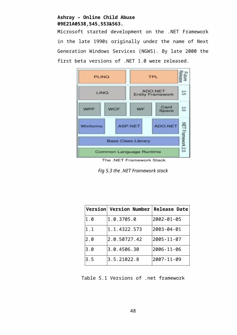
Ashray – Online Child Abuse 09E21A0538,545,553&563.
6.1. INTRODUCTION
Software design sits at the technical kernel of the software engineering
process and is applied regardless of the development paradigm and area of
application. Design is the first step in the development phase for any
engineered product or system. The designer’s goal is to produce a model or
representation of an entity that will later be built. Beginning, once system
requirement have been specified and analyzed, system design is the first of the
three technical activities -design, code and test that is required to build and
verify software.
The importance can be stated with a single word “Quality”. Design is
the place where quality is fostered in software development. Design provides
us with representations of software that can assess for quality. Design is the
only way that we can accurately translate a customer’s view into a finished
software product or system. Software design serves as a foundation for all the
software engineering steps that follow. Without a strong design we risk
building an unstable system – one that will be difficult to test, one whose
quality cannot be assessed until the last stage.
During design, progressive refinement of data structure, program
structure, and procedural details are developed reviewed and documented.
System design can be viewed from either technical or project management
perspective. From the technical point of view, design is comprised of four
activities – architectural design, data structure design, interface design and
procedural design.
6.2 NORMALIZATION
It is a process of converting a relation to a standard form. The process
is used to handle the problems that can arise due to data redundancy i.e.
repetition of data in the database, maintain data integrity as well as handling
problems that can arise due to insertion, updating, deletion anomalies.
Decomposing is the process of splitting relations into multiple relations
to eliminate anomalies and maintain anomalies and maintain data integrity. To
do this we use normal forms or rules for structuring relation.
48
Ashray – Online Child Abuse 09E21A0538,545,553&563.
Insertion anomaly: Inability to add data to the database due to absence of
other data.
Deletion anomaly: Unintended loss of data due to deletion of other data.
Update anomaly: Data inconsistency resulting from data redundancy and
partial update
Normal Forms: These are the rules for structuring relations that eliminate
anomalies.
6.2.1 FIRST NORMAL FORM:
A relation is said to be in first normal form if the values in the relation
are atomic for every attribute in the relation. By this we mean simply that no
attribute value can be a set of values or, as it is sometimes expressed, a
repeating group.
6.2.2 SECOND NORMAL FORM:
A relation is said to be in second Normal form is it is in first normal
form and it should satisfy any one of the following rules.
1) Primary key is a not a composite primary key
2) No non key attributes are present
3) Every non key attribute is fully functionally dependent on full set of
primary key.
6.2.3 THIRD NORMAL FORM:
A relation is said to be in third normal form if their exits no transitive
dependencies.
Transitive Dependency: If two non key attributes depend on each other as
well as on the primary key then they are said to be transitively dependent.
The above normalization principles were applied to decompose the
data in multiple tables thereby making the data to be maintained in a
consistent state.
6.3 E-R Diagrams
The relation upon the system is structure through a
conceptual ER-Diagram, which not only specifics the
existential entities but also the standard relations through which
the system exists and the cardinalities that are necessary for the
system state to continue.
49
Ashray – Online Child Abuse 09E21A0538,545,553&563.
The entity Relationship Diagram (ERD) depicts the relationship
between the data objects. The ERD is the notation that is used
to conduct the date modeling activity the attributes of each data
object noted is the ERD can be described resign a data object
descriptions.
The set of primary components that are identified by the ERD
are
Data object
Relationships
Attributes
Various types of indicators.
The primary purpose of the ERD is to represent data objects and their
relationships.
E-R Diagram:
Fig 6.1 Registration diagram
50
Ashray – Online Child Abuse 09E21A0538,545,553&563.
Fig 6.2 Complaints, Police, Stories, Area diagrams
Fig 6.3 News Letter Login diagram
51
Ashray – Online Child Abuse 09E21A0538,545,553&563.
6.4 DATA DICTIONARY
After carefully understanding the requirements of the client the
entire data storage requirements are divided into tables. The below tables are
normalized to avoid any anomalies during the course of data entry.
Tables
Table 6.1 – Area Table
Table 6.2 – Complaint Table
Table 6.3 – Employee Table
52
Ashray – Online Child Abuse 09E21A0538,545,553&563.
Table 6.4 - News Letter Table
Table 6.5 – Police Table
Table 6.6 – User Table
Table 6.7 – Story Table
53
Ashray – Online Child Abuse 09E21A0538,545,553&563.
Table 6.8 – Admin Table
54
Ashray – Online Child Abuse 09E21A0538,545,553&563.
6.5 DATA FLOW DIAGRAMS
A data flow diagram is graphical tool used to describe and analyze
movement of data through a system. These are the central tool and the basis
from which the other components are developed. The transformation of data
from input to output, through processed, may be described logically and
independently of physical components associated with the system. These are
known as the logical data flow diagrams. The physical data flow diagrams
show the actual implements and movement of data between people,
departments and workstations. A full description of a system actually consists
of a set of data flow diagrams. Using two familiar notations Yourdon, Gane
and Sarson notation develops the data flow diagrams. Each component in a
DFD is labeled with a descriptive name. Process is further identified with a
number that will be used for identification purpose. The development of
DFD’S is done in several levels. Each process in lower level diagrams can be
broken down into a more detailed DFD in the next level. The lop-level
diagram is often called context diagram. It consists a single process bit, which
plays vital role in studying the current system. The process in the context
level diagram is exploded into other process at the first level DFD.
The idea behind the explosion of a process into more process is that
understanding at one level of detail is exploded into greater detail at the next
level. This is done until further explosion is necessary and an adequate
amount of detail is described for analyst to understand the process.
Larry Constantine first developed the DFD as a way of expressing
system requirements in a graphical from, this lead to the modular design.
A DFD is also known as a “bubble Chart” has the purpose of clarifying
system requirements and identifying major transformations that will become
programs in system design. So it is the starting point of the design to the
lowest level of detail. A DFD consists of a series of bubbles joined by data
flows in the system.
6.5.1 DFD SYMBOLS:
In the DFD, there are four symbols
1. A square defines a source(originator) or destination of system data
2. An arrow identifies data flow. It is the pipeline through which the
information flows
55
Ashray – Online Child Abuse 09E21A0538,545,553&563.
3. A circle or a bubble represents a process that transforms incoming data
flow into outgoing data flows.
4. An open rectangle is a data store, data at rest or a temporary repository of
data
Process that transforms data flow.
Source or Destination of data
Data flow
Data Store
Fig 6.4 Symbols of DFD
6.5.2 CONSTRUCTING A DFD:
Several rules of thumb are used in drawing DFD’S:
1. Process should be named and numbered for an easy reference. Each name
should be representative of the process.
2. The direction of flow is from top to bottom and from left to right. Data
traditionally flow from source to the destination although they may flow
back to the source. One way to indicate this is to draw long flow line back
to a source. An alternative way is to repeat the source symbol as a
destination. Since it is used more than once in the DFD it is marked with a
short diagonal.
3. When a process is exploded into lower level details, they are numbered.
4. The names of data stores and destinations are written in capital letters.
Process and dataflow names have the first letter of each work capitalized.
A DFD typically shows the minimum contents of data store. Each data
store should contain all the data elements that flow in and out.
56
Ashray – Online Child Abuse 09E21A0538,545,553&563.
Questionnaires should contain all the data elements that flow in and
out. Missing interfaces redundancies and like is then accounted for often
through interviews.
6.5.3 SAILENT FEATURES OF DFD’S
1. The DFD shows flow of data, not of control loops and decision are
controlled considerations do not appear on a DFD.
2. The DFD does not indicate the time factor involved in any process
whether the dataflow take place daily, weekly, monthly or yearly.
3. The sequence of events is not brought out on the DFD.
6.5.4TYPES OF DATA FLOW DIAGRAMS
1. Current Physical
2. Current Logical
3. New Logical
4. New Physical
6.5.4.1 CURRENT PHYSICAL:
In Current Physical DFD process label include the name of people or
their positions or the names of computer systems that might provide some of
the overall system-processing label includes an identification of the
technology used to process the data. Similarly data flows and data stores are
often labels with the names of the actual physical media on which data are
stored such as file folders, computer files, business forms or computer tapes.
6.5.4.2 CURRENT LOGICAL:
The physical aspects at the system are removed as much as possible so
that the current system is reduced to its essence to the data and the processors
that transforms them regardless of actual physical form.
6.5.4.3 NEW LOGICAL:
This is exactly like a current logical model if the user were completely
happy with the user were completely with the functionality of the system but
had problems with how it was implemented typically through the new logical
model will differ from current logical model while having additional
functions, absolute function removal and inefficient flows recognized.
57

Ashray – Online Child Abuse 09E21A0538,545,553&563.
6.5.4.4 NEW PHYSICAL:
The new physical represents only the physical implementation of the
new system.
6.5.5 RULES GOVERNING THE DFD’S
PROCESS
1) No process can have only outputs.
2) No process can have only inputs. If an object has only inputs than it
must be a sink.
3) A process has a verb phrase label.
DATA STORE
1) Data cannot move directly from one data store to another data store, a
process must move data.
2) Data cannot move directly from an outside source to a data store, a
process, which receives, must move data from the source and place the
data into data store
3) A data store has a noun phrase label.
SOURCE OR SINK
The origin and /or destination of data.
1) Data cannot move direly from a source to sink it must be moved by a
process
2) A source and /or sink has a noun phrase land
DATA FLOW
1) A Data Flow has only one direction of flow between symbols. It may
flow in both directions between a process and a data store to show a read
before an update. The later is usually indicated however by two separate
arrows since these happen at different type.
2) A join in DFD means that exactly the same data comes from any of
two or more different processes data store or sink to a common location.
3) A data flow cannot go directly back to the same process it leads. There
must be at least one other process that handles the data flow produce some
58
Ashray – Online Child Abuse 09E21A0538,545,553&563.
other data flow returns the original data into the beginning process.
4) A Data flow to a data store means update (delete or change).
5) A data Flow from a data store means retrieve or use.
A data flow has a noun phrase label more than one data flow noun phrase can
appear on a single arrow as long as all of the flows on the same arrow move
together as one package.
Data Flow Diagrams
Context Level Diagram:
Fig 6.5 Context Level Diagram
59
Ashray – Online Child Abuse 09E21A0538,545,553&563.
Login DFD
Registration
in fail
in success
Fig 6.6 Login DFD
60
Open admin login form
Open admin login form
Enter uname & pwd
Enter uname & pwd
ValidationValidation
Admin home page
Admin home page
start
Ashray – Online Child Abuse 09E21A0538,545,553&563.
Administration Data Flow Model
Fig 6.7 Admin DFD
61
Ashray – Online Child Abuse 09E21A0538,545,553&563.
6.6 UML DIAGRAMS
The unified modeling language allows the software engineer to express
an analysis model using the modeling notation that is governed by a set of
syntactic semantic and pragmatic rules.
A UML system is represented using five different views that describe
the system from distinctly different perspective. Each view is defined by a set
of diagram, which is as follows.
User Model View
i. This view represents the system from the users perspective.
ii. The analysis representation describes a usage scenario from the
end-users perspective.
Structural model view
In this model the data and functionality are arrived from inside the
system.
This model view models the static structures.
Behavioral Model View
It represents the dynamic of behavioral as parts of the system,
depicting the interactions of collection between various structural elements
described in the user model and structural model view.
Implementation Model View
In this the structural and behavioral as parts of the system are
represented as they are to be built.
Environmental Model View
In this the structural and behavioral aspects of the environment in
which the system is to be implemented are represented.
62
Ashray – Online Child Abuse 09E21A0538,545,553&563.
UML is specifically constructed through two different domains they are
UML Analysis modeling, which focuses on the user model and
structural model views of the system?
UML design modeling, which focuses on the behavioral modeling,
implementation modeling and environmental model views.
Use case Diagrams represent the functionality of the system from a
user’s point of view. Use cases are used during requirements elicitation and
analysis to represent the functionality of the system. Use cases focus on the
behavior of the system from external point of view.
Actors are external entities that interact with the system. Examples of
actors include users like administrator, bank customer …etc., or another
system like central database.
Use case Model
Use case for user:
Fig 6.8 Use case for User
63
Ashray – Online Child Abuse 09E21A0538,545,553&563.
Use case for admin:
Fig 6.9 Use case for Admin
64
Ashray – Online Child Abuse 09E21A0538,545,553&563.
Use case for NGO and Police:
Fig 6.10 Use Case for NGO and Police
65
Ashray – Online Child Abuse 09E21A0538,545,553&563.
2. SEQUENCE DIAGRAM:
i. Sequence diagram for User:
Fig 6.11 Sequence diagram for User
ii .Sequence diagram for Admin:
Fig 6.12 Sequence diagram for Admin
iii.Sequence diagram for NGO:
66
Ashray – Online Child Abuse 09E21A0538,545,553&563.
Fig 6.13 Sequence diagram for NGO
iv.Sequence diagram for Police:
Fig 6.14 Sequence diagram for Police
3. Activity Diagram:
67
Ashray – Online Child Abuse 09E21A0538,545,553&563.
Fig 6.14 Active Diagram for Online child abuse data base
4. Collaborationdiagram:
68
Ashray – Online Child Abuse 09E21A0538,545,553&563.
Fig 6.15 Collaboration Diagram
5. Component diagram:
Fig 6.16 Component Diagram
6. Deployment diagram:
69
Ashray – Online Child Abuse 09E21A0538,545,553&563.
Fig 6.17 Development Diagram
Chapter – 7
Output SCREENS
70
Ashray – Online Child Abuse 09E21A0538,545,553&563.
7.1 This is the Home Page
Output Screen 7.1 – Home page
7.2 This is Post Complaints Page
71
Ashray – Online Child Abuse 09E21A0538,545,553&563.
Output Screen 7.2 – Post Complaints Page
7.3 This is Stories Page
72
Ashray – Online Child Abuse 09E21A0538,545,553&563.
Output Screen 7.3 – Stories Page
7.4 Here we can Read Stories by Click on Title
73
Ashray – Online Child Abuse 09E21A0538,545,553&563.
Output Screen 7.4 – Story Title Page
74
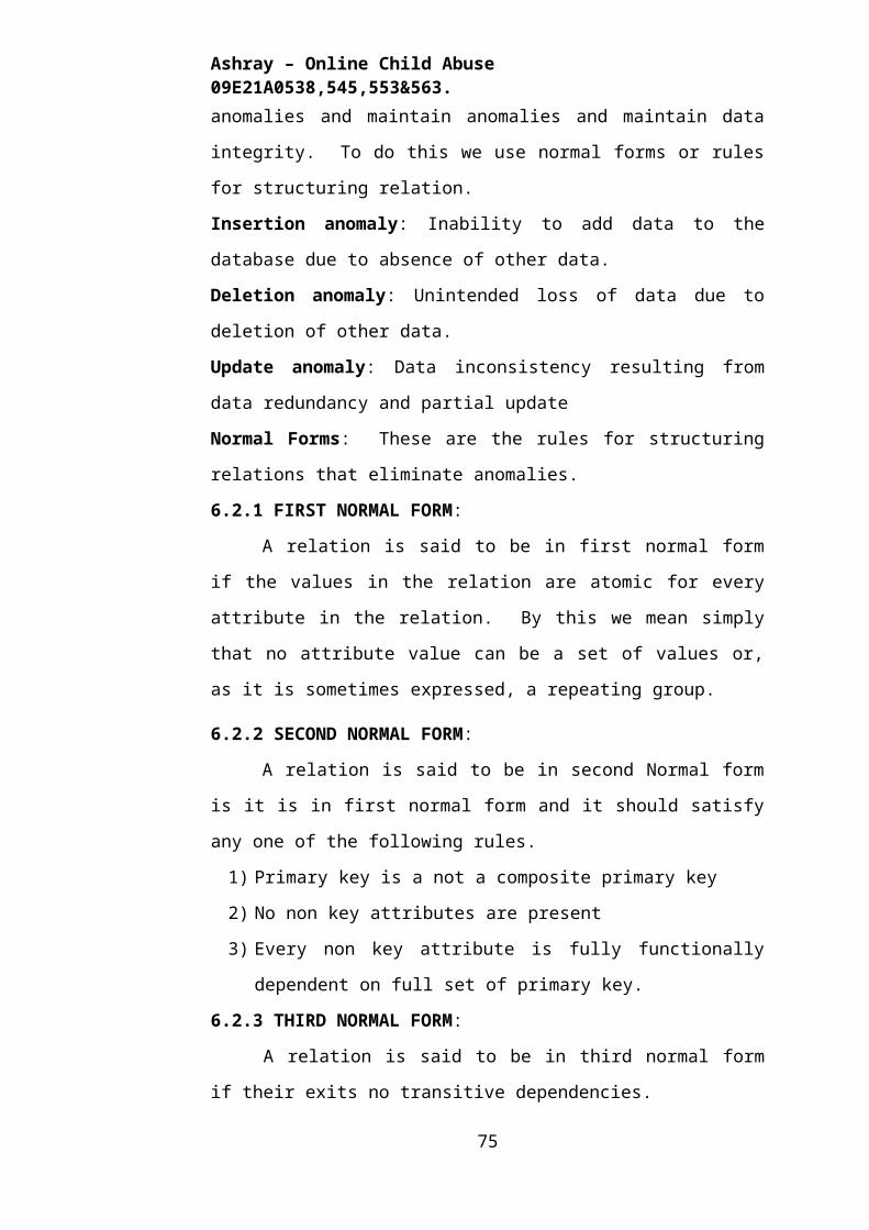
Ashray – Online Child Abuse 09E21A0538,545,553&563.
7.5 This is Admin Login Page
Output Screen 7.5 – Admin Login Page
75
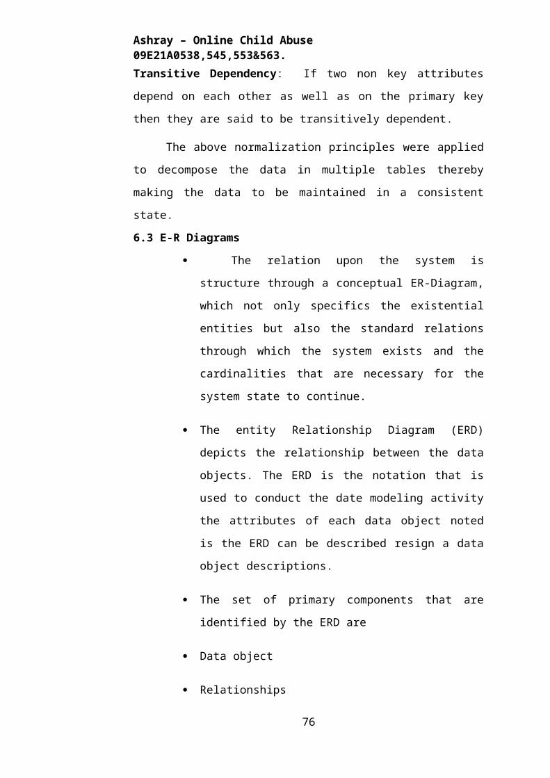
Ashray – Online Child Abuse 09E21A0538,545,553&563.
7.6 This is Admin Home Page
Output Screen 7.6 – Admin Home Page
76
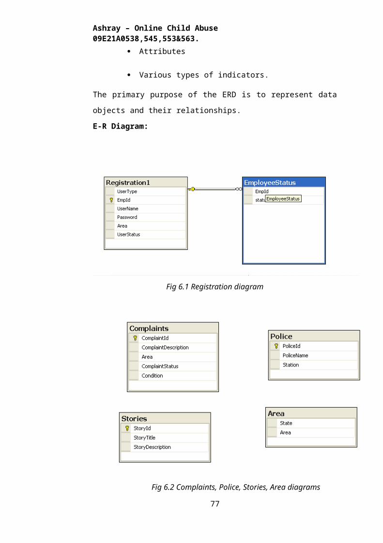
Ashray – Online Child Abuse 09E21A0538,545,553&563.
7.7 This is Admin Inbox Page
Output Screen 7.7 – Admin Inbox Page
77
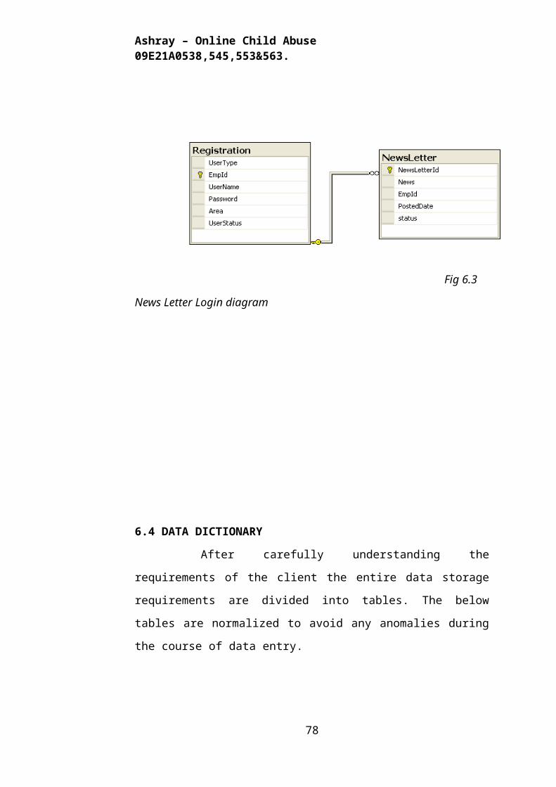
Ashray – Online Child Abuse 09E21A0538,545,553&563.
7.8 This is Admin Status Page
Output Screen 7.8 – Admin Status Page
78
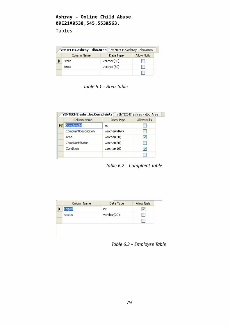
Ashray – Online Child Abuse 09E21A0538,545,553&563.
7.9 This is Admin Report Page
Output Screen 7.9 – Admin Report Page
79
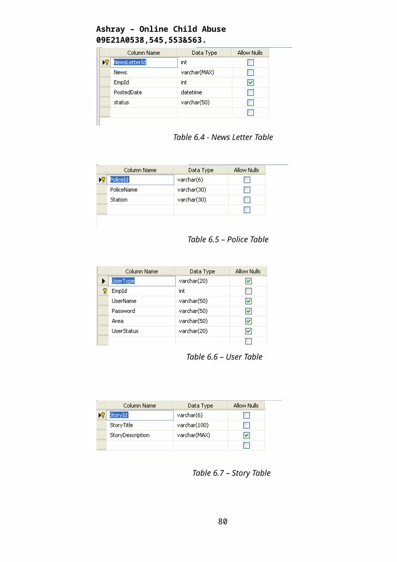
Ashray – Online Child Abuse 09E21A0538,545,553&563.
7.10 This is Area Wise Report Page
Output Screen 7.10 – Area Wise Report Page
80
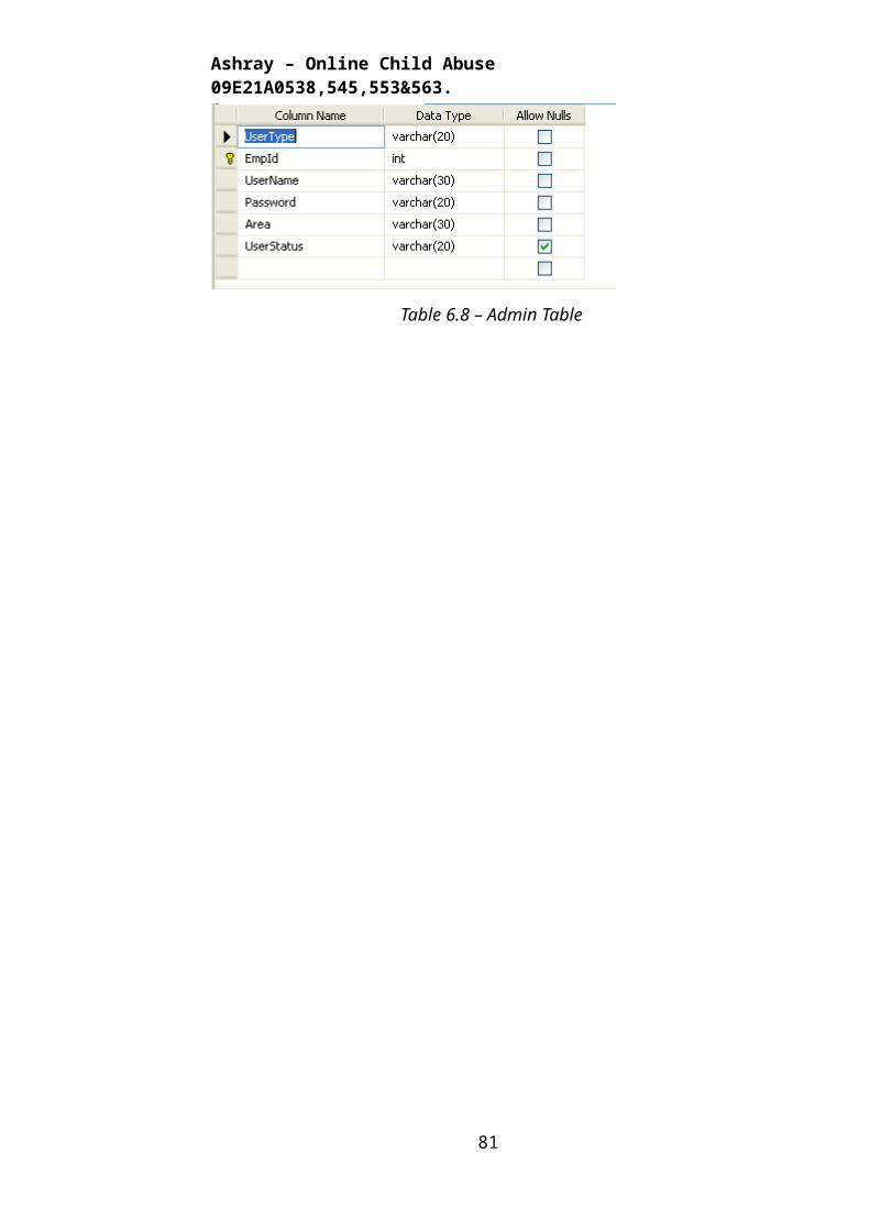
Ashray – Online Child Abuse 09E21A0538,545,553&563.
7.11 This is News Letter Review Page
Output Screen 7.11 – News Letter Review Page
81
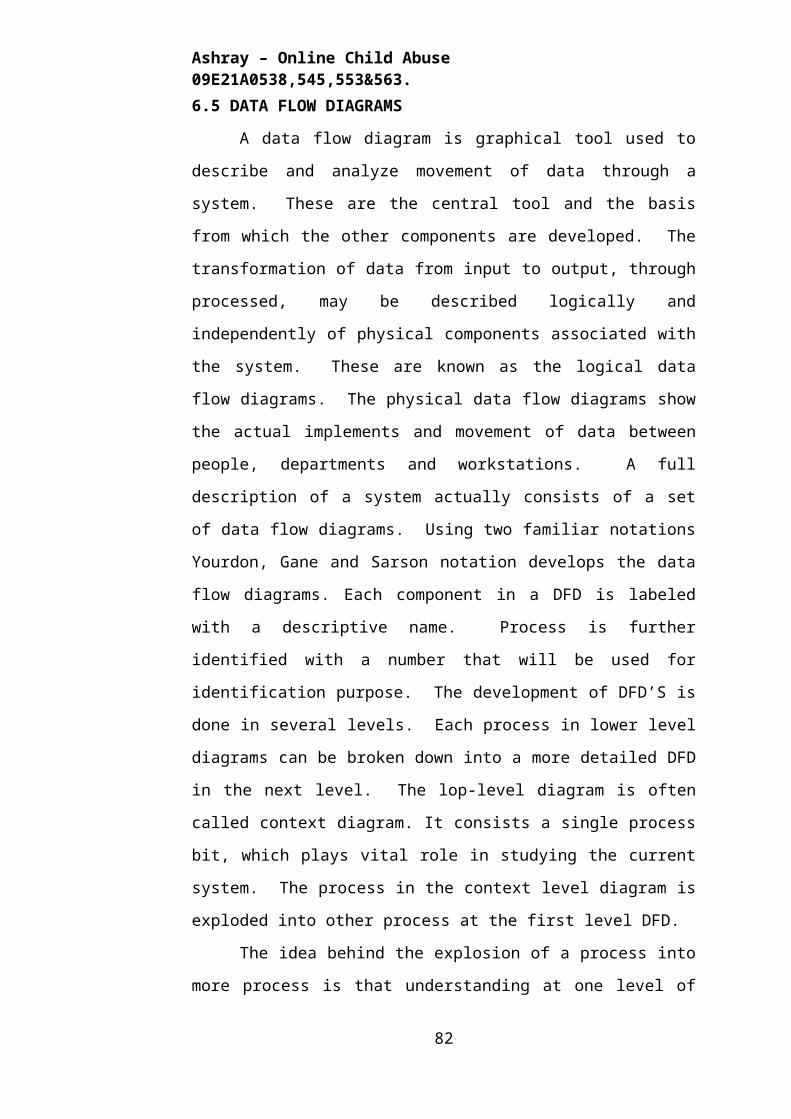
Ashray – Online Child Abuse 09E21A0538,545,553&563.
7.12 This is News Arrival Page for Admin
Output Screen 7.12 – News Letter Arrival Page
82
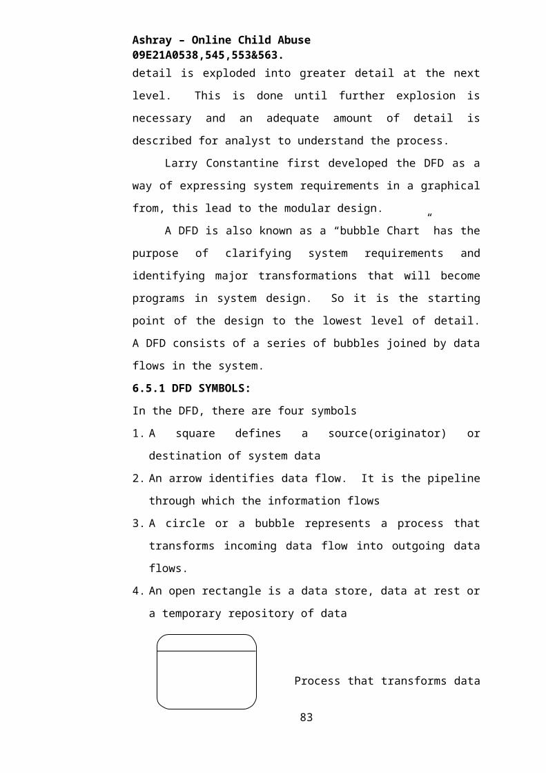
Ashray – Online Child Abuse 09E21A0538,545,553&563.
7.13 This is Police Approval Page
Output Screen 7.13 – Police Approval Page
83
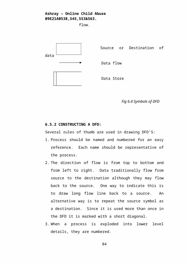
Ashray – Online Child Abuse 09E21A0538,545,553&563.
7.14 This is NGO Approval Page
Output Screen 7.14 – NGO Approval Page
84
Ashray – Online Child Abuse 09E21A0538,545,553&563.
7.15 This is Insert Stories Page
Output Screen 7.15 – Insert Stories Page
85
Ashray – Online Child Abuse 09E21A0538,545,553&563.
7.16 This is NGO’s Login Page
Output Screen 7.16 – NGO’s Login Page
86
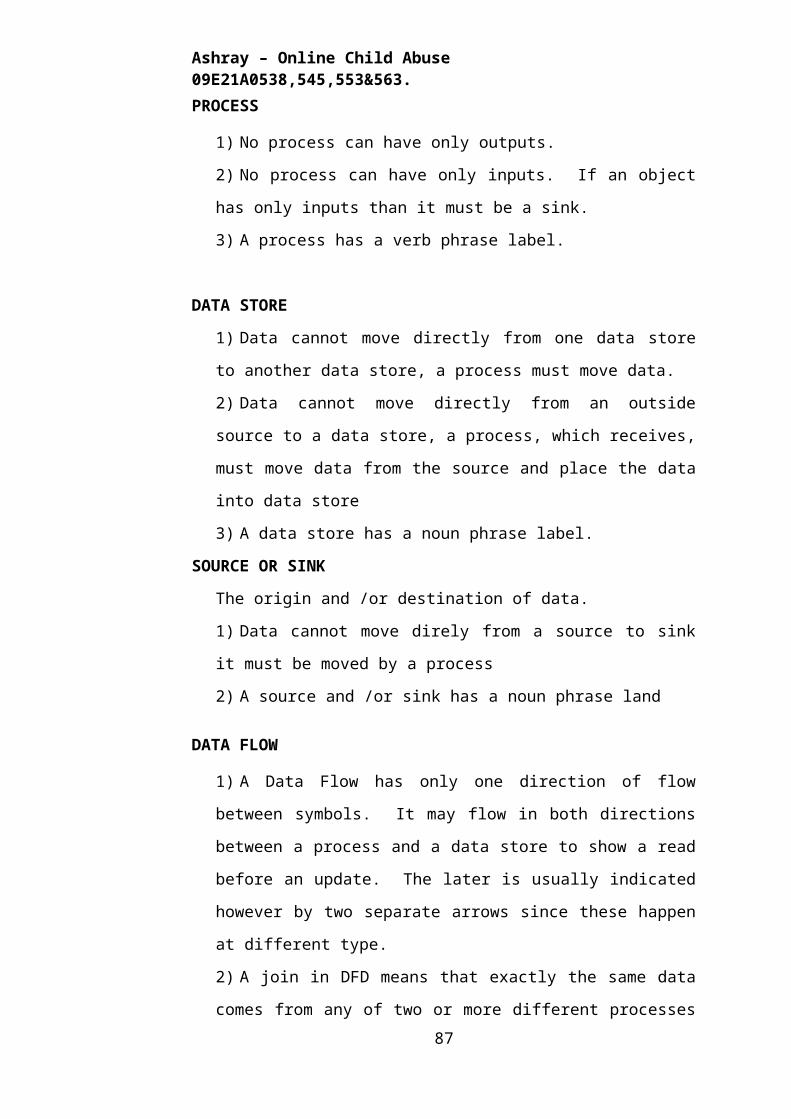
Ashray – Online Child Abuse 09E21A0538,545,553&563.
7.17 This is Ngo’s Home Page
Output Screen 7.17 – NGO’s Home page
87
Ashray – Online Child Abuse 09E21A0538,545,553&563.
7.18 This is NGO Inbox Page
Output Screen 7.18 – NGO’s Inbox page
88
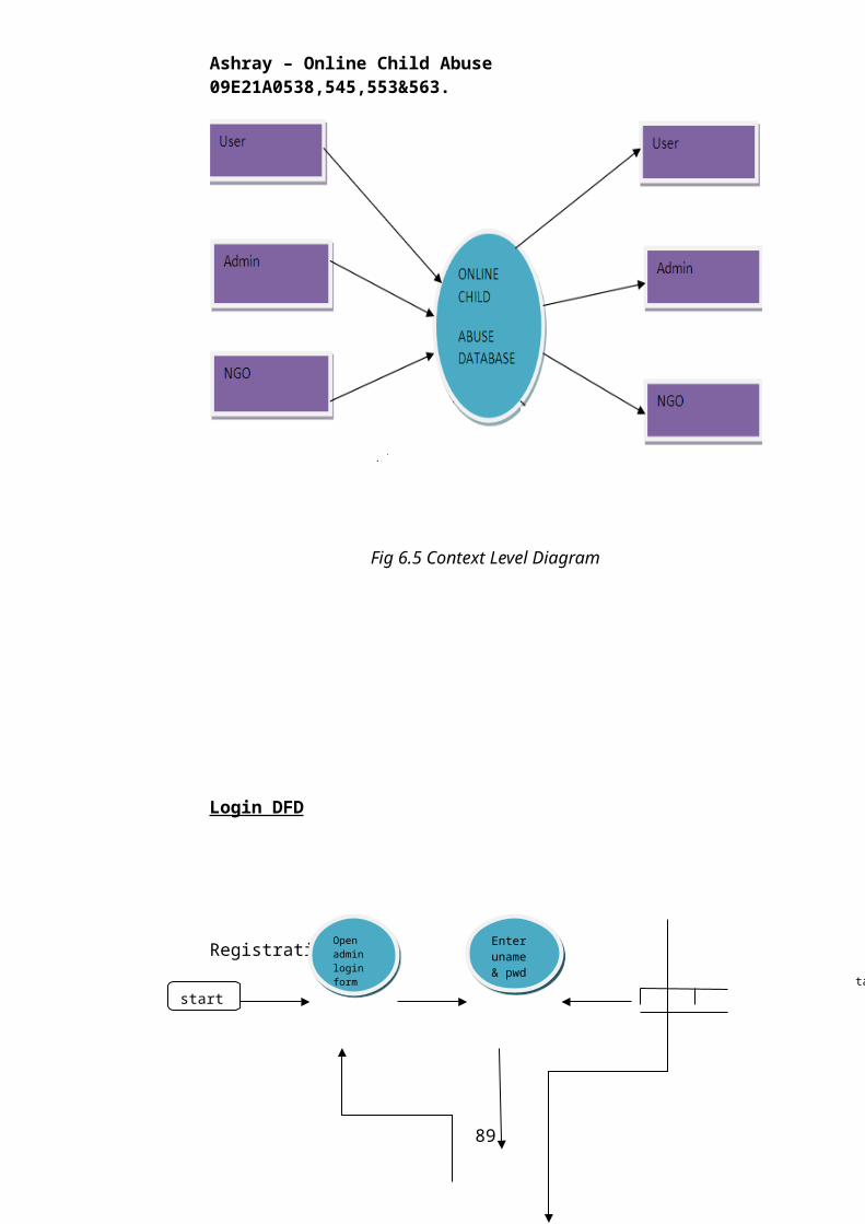
Ashray – Online Child Abuse 09E21A0538,545,553&563.
7.19 This is NGO’s Post News Letters Page
Output Screen 7.19 – NGO’s Post News Letters Page
89
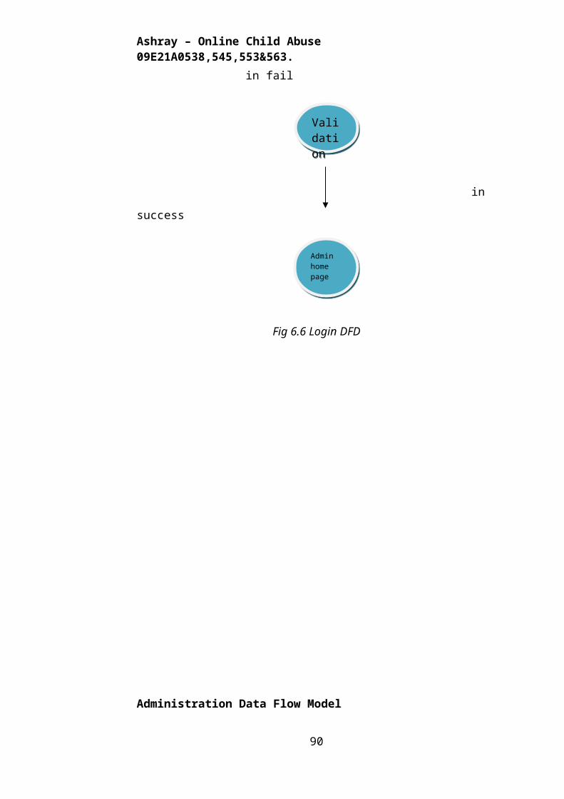
Ashray – Online Child Abuse 09E21A0538,545,553&563.
7.20 This is Login Page of Police
Output Screen 7.20 – Police Login Page
90
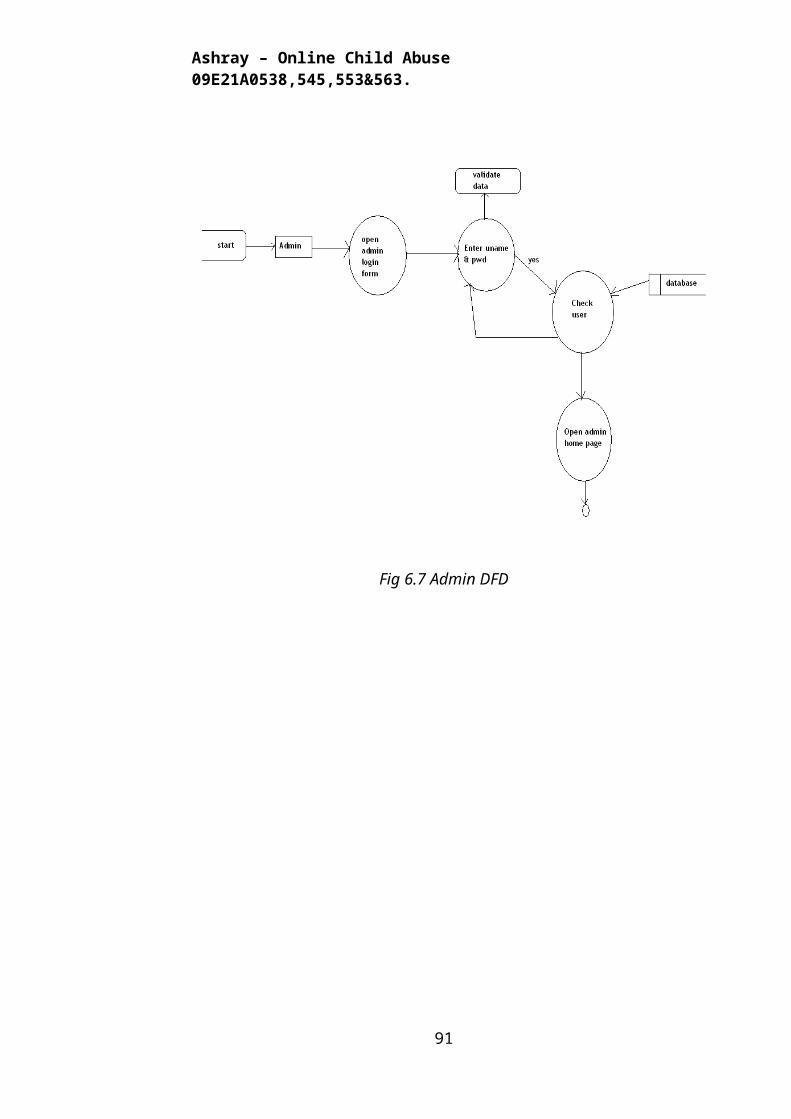
Ashray – Online Child Abuse 09E21A0538,545,553&563.
7.21 This is Home Page of Police (Investigation Team)
Output Screen 7.21 – Police Home Page
91
Ashray – Online Child Abuse 09E21A0538,545,553&563.
7.22 This Page is about Police Inbox
Output Screen 7.22 – Police Inbox
92
Ashray – Online Child Abuse 09E21A0538,545,553&563.
7.23 This is Page Police post news letter
Output screen – 7.23 Police Post News Letter
93
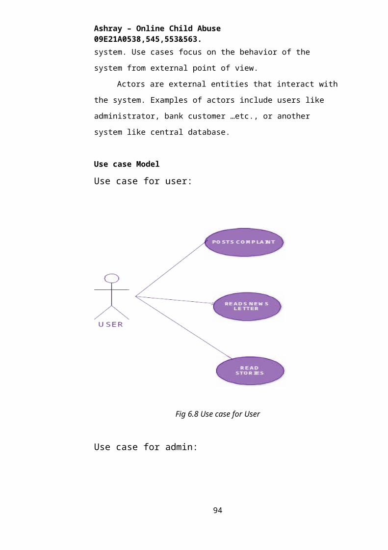
Ashray – Online Child Abuse 09E21A0538,545,553&563.
Chapter – 8
SYSTEM TESTING
8.1 INTRODUCTION
Software testing is a critical element of software quality assurance and
represents the ultimate review of specification, design and coding. In fact,
testing is the one step in the software engineering process that could be viewed
as destructive rather than constructive.
A strategy for software testing integrates software test case design
methods into a well-planned series of steps that result in the successful
construction of software. Testing is the set of activities that can be planned in
advance and conducted systematically. The underlying motivation of program
testing is to affirm software quality with methods that can economically and
effectively apply to both strategic to both large and small-scale systems.
8.2. STRATEGIC APPROACH TO SOFTWARE TESTING
The software engineering process can be viewed as a spiral. Initially
system engineering defines the role of software and leads to software
requirement analysis where the information domain, functions, behavior,
performance, constraints and validation criteria for software are established.
Moving inward along the spiral, we come to design and finally to coding. To
develop computer software we spiral in along streamlines that decrease the
level of abstraction on each turn.
A strategy for software testing may also be viewed in the context of the
spiral. Unit testing begins at the vertex of the spiral and concentrates on each
unit of the software as implemented in source code. Testing progress by
moving outward along the spiral to integration testing, where the focus is on
the design and the construction of the software architecture. Talking another
turn on outward on the spiral we encounter validation testing where
94
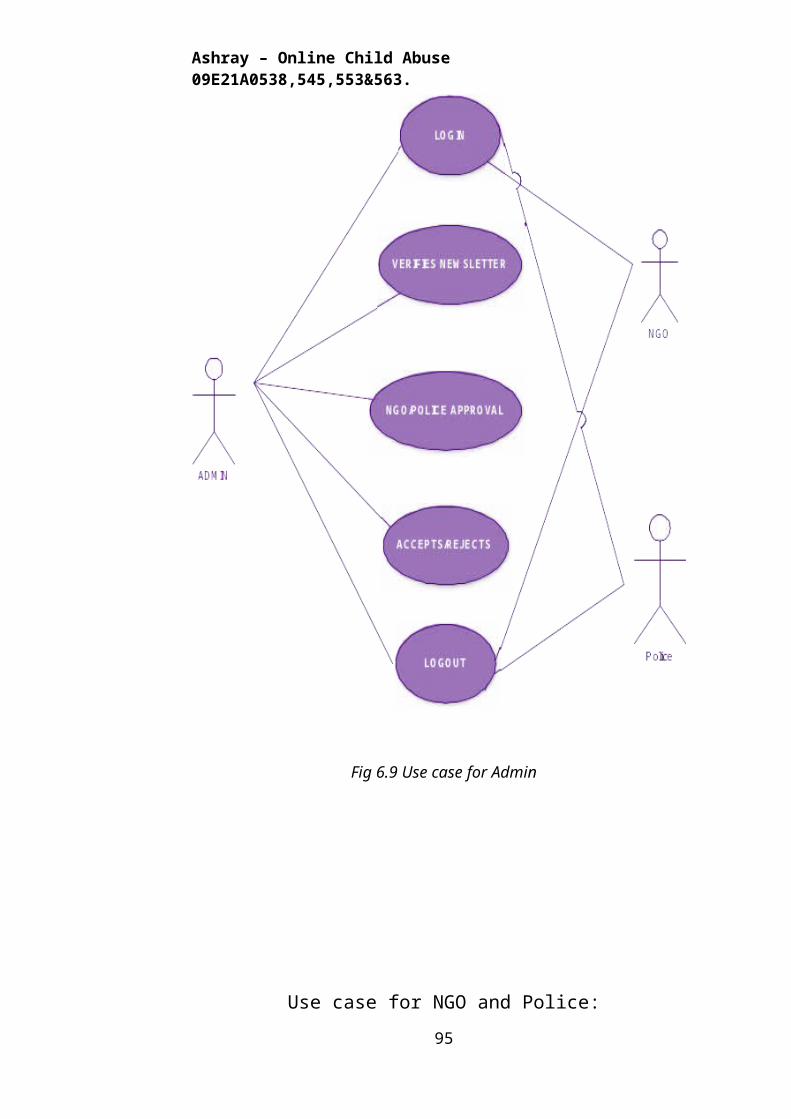
Ashray – Online Child Abuse 09E21A0538,545,553&563.
requirements established as part of software requirements analysis are
validated against the software that has been constructed. Finally we arrive at
system testing, where the software and system elements are tested as a whole.
Fig 8.1 – Software Testing Approaches
8.3. UNIT TESTING
Unit testing focuses verification effort on the smallest unit of software
design, the module. The unit testing we have is white box oriented and some
modules the steps are conducted in parallel.
8.3.1. WHITE BOX TESTING
This type of testing ensures that
All independent paths have been exercised at least once
All logical decisions have been exercised on their true and false sides
95
UNIT TESTING
MODULE TESTING
SUB-SYSTEM TESING
SYSTEM TESTING
ACCEPTANCE TESTING
Component Testing
Integration Testing
User Testing
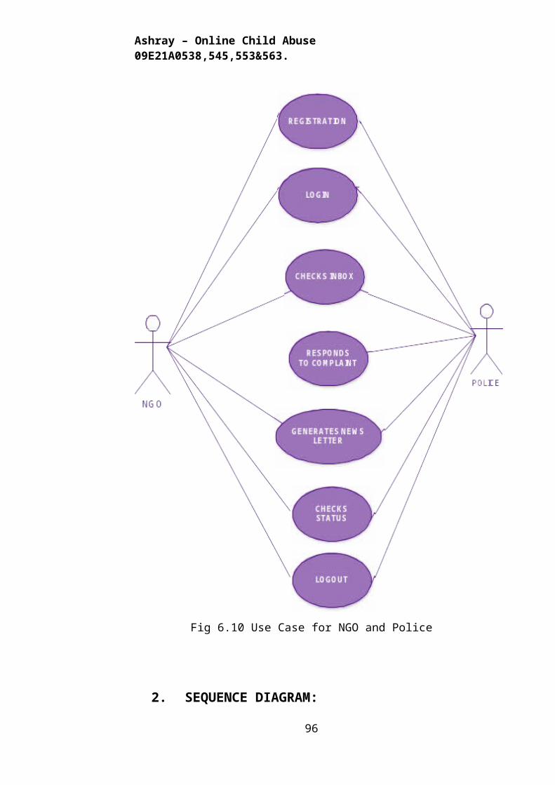
Ashray – Online Child Abuse 09E21A0538,545,553&563.
All loops are executed at their boundaries and within their operational
bounds
All internal data structures have been exercised to assure their validity.
To follow the concept of white box testing we have tested each
form .
we have created independently to verify that Data flow is correct, All
conditions are exercised to check their validity, All loops are executed on their
boundaries.
8.3.2. BASIC PATH TESTING
Established technique of flow graph with Cyclomatic complexity was
used to derive test cases for all the functions. The main steps in deriving test
cases were:
Use the design of the code and draw correspondent flow graph.
Determine the Cyclomatic complexity of resultant flow graph, using
formula:
V(G)=E-N+2 or
V(G)=P+1 or
V(G)=Number Of Regions
Where V(G) is Cyclomatic complexity,
E is the number of edges,
N is the number of flow graph nodes,
P is the number of predicate nodes.
Determine the basis of set of linearly independent paths.
8.3.3. CONDITIONAL TESTING
In this part of the testing each of the conditions were tested to both true
and false aspects. And all the resulting paths were tested. So that each path that
may be generate on particular condition is traced to uncover any possible
errors.
8.3.4. DATA FLOW TESTING
This type of testing selects the path of the program according to the
96
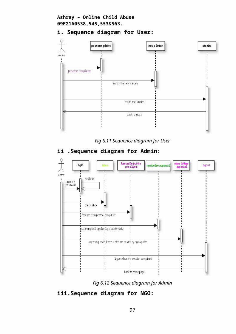
Ashray – Online Child Abuse 09E21A0538,545,553&563.
location of definition and use of variables. This kind of testing was used only
when some local variable were declared. The definition-use chain method was
used in this type of testing. These were particularly useful nested statements.
8.3.5. LOOP TESTING
In this type of testing all the loops are tested to all the limits possible. The
following exercise was adopted for all loops:
All the loops were tested at their limits, just above them and just below
them.
All the loops were skipped at least once.
For nested loops test the inner most loop first and then work outwards.
For concatenated loops the values of dependent loops were set with the
help of connected loop.
Unstructured loops were resolved into nested loops or concatenated loops
and tested as above.Each unit has been separately tested by the development
team itself and all the input have been validated.
8.4 INTEGRATION TESTING
Testing is done for each module. After testing all the modules, the
modules are integrated and testing of the final system is done with the test
data, specially designed to show that the system will operate successfully in all
its aspects conditions. Thus the system testing is a confirmation that all is
correct and an opportunity to show the user that the system works.
The purpose of integration testing is to verify functional, performance
and reliability requirements placed on major design items. These "design
items", i.e. assemblages (or groups of units), are exercised through their
interfaces using black box testing, success and error cases being simulated via
appropriate parameter and data inputs. Simulated usage of shared data areas
and inter-process communication is tested and individual subsystems are
exercised through their input interface.
Test cases are constructed to test that all components within
assemblages interact correctly, for example across procedure calls or process
activations, and this is done after testing individual modules, i.e. unit testing.
97
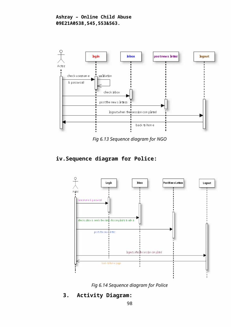
Ashray – Online Child Abuse 09E21A0538,545,553&563.
The overall idea is a "building block" approach, in which verified
assemblages are added to a verified base which is then used to support the
integration testing of further assemblages.
Chapter - 9
SYSTEM SECURITY
9.1 INTRODUCTION
The protection of computer based resources that includes hardware,
software, data, procedures and people against unauthorized use or natural
Disaster is known as System Security.
System Security can be divided into four related issues:
Security
Integrity
Privacy
Confidentiality
9.1.1 SYSTEM SECURITY refers to the technical innovations and
procedures applied to the hardware and operation systems to protect against
deliberate or accidental damage from a defined threat.
9.1.2 DATA SECURITY is the protection of data from loss, disclosure,
modification and destruction.
9.1.3 SYSTEM INTEGRITY refers to the power functioning of hardware
and programs, appropriate physical security and safety against external threats
such as eavesdropping and wiretapping.
9.1.4 PRIVACY defines the rights of the user or organizations to determine
what information they are willing to share with or accept from others and how
the organization can be protected against unwelcome, unfair or excessive
dissemination of information about it.
98
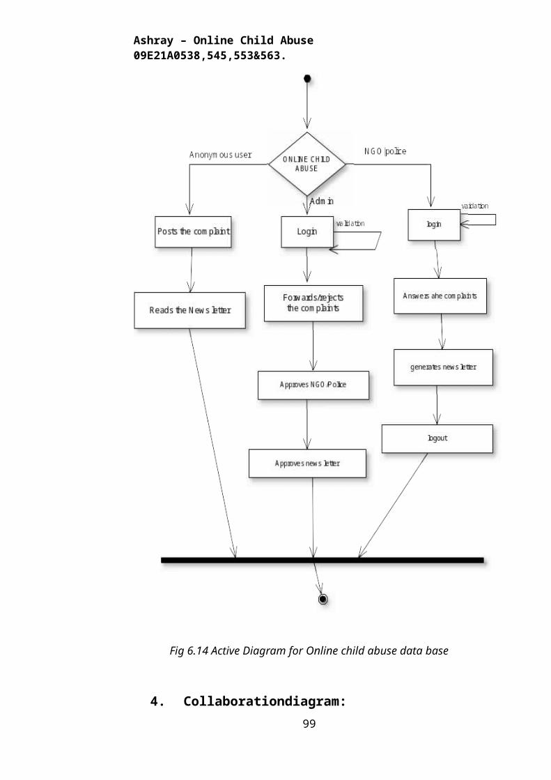
Ashray – Online Child Abuse 09E21A0538,545,553&563.
CONFIDENTIALITY is a special status given to sensitive information in a
database to minimize the possible invasion of privacy. It is an attribute of
information that characterizes its need for protection.
9.2 SECURITY SOFTWARE
System security refers to various validations on data in form of checks
and controls to avoid the system from failing. It is always important to ensure
that only valid data is entered and only valid operations are performed on the
system. The system employees two types of checks and controls:
9.2.1 CLIENT SIDE VALIDATION
Various client side validations are used to ensure on the client side that
only valid data is entered. Client side validation saves server time and load to
handle invalid data. Some checks imposed are:
VBScript in used to ensure those required fields are filled with suitable
data only. Maximum lengths of the fields of the forms are appropriately
defined.
Forms cannot be submitted without filling up the mandatory data so that
manual mistakes of submitting empty fields that are mandatory can be
sorted out at the client side to save the server time and load.
Tab-indexes are set according to the need and taking into account the ease
of user while working with the system.
9.2.2 SERVER SIDE VALIDATION
Some checks cannot be applied at client side. Server side checks are
necessary to save the system from failing and intimating the user that some
invalid operation has been performed or the performed operation is restricted.
Some of the server side checks imposed is:
Server side constraint has been imposed to check for the validity of
primary key and foreign key. A primary key value cannot be duplicated.
Any attempt to duplicate the primary value results into a message
99
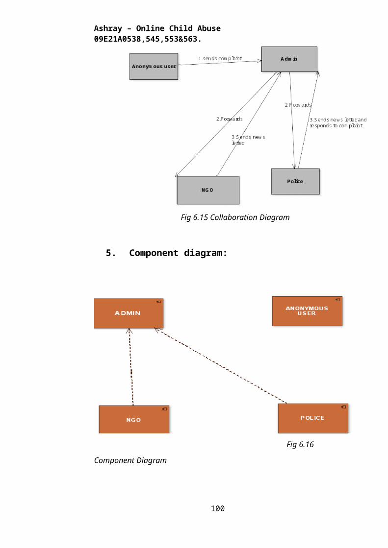
Ashray – Online Child Abuse 09E21A0538,545,553&563.
intimating the user about those values through the forms using foreign key
can be updated only of the existing foreign key values.
User is intimating through appropriate messages about the successful
operations or exceptions occurring at server side.
Various Access Control Mechanisms have been built so that one user may
not agitate upon another. Access permissions to various types of users are
controlled according to the organizational structure. Only permitted users
can log on to the system and can have access according to their category.
User- name, passwords and permissions are controlled o the server side.
Using server side validation, constraints on several restricted operations
are imposed.
100
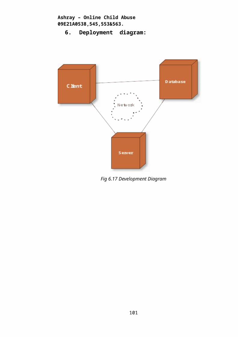
Ashray – Online Child Abuse 09E21A0538,545,553&563.
Chapter - 10
CONCLUSION
Preventing child abuse is not simply a matter of parents doing a better
job, but rather it is about creating a context in which “doing better” is easier.
Enlightened public policy and the replication of high-quality publicly
supported interventions are only part of what is needed to successfully
combat child abuse. It remains important to remind the public that child
abuse and neglect are serious threats to a child’s healthy development and
that overt violence toward children and a persistent lack of attention to their
care and supervision are unacceptable. Individuals have the ability to accept
personal responsibility for reducing acts of child abuse and neglect by
providing support to each other and offering protection to all children within
their family and their community.
Benefits:
The current system develops an efficient portal which can be used by
abused children's and there well-wisher’s.
Through this website we could abort the ongoing issues.
101
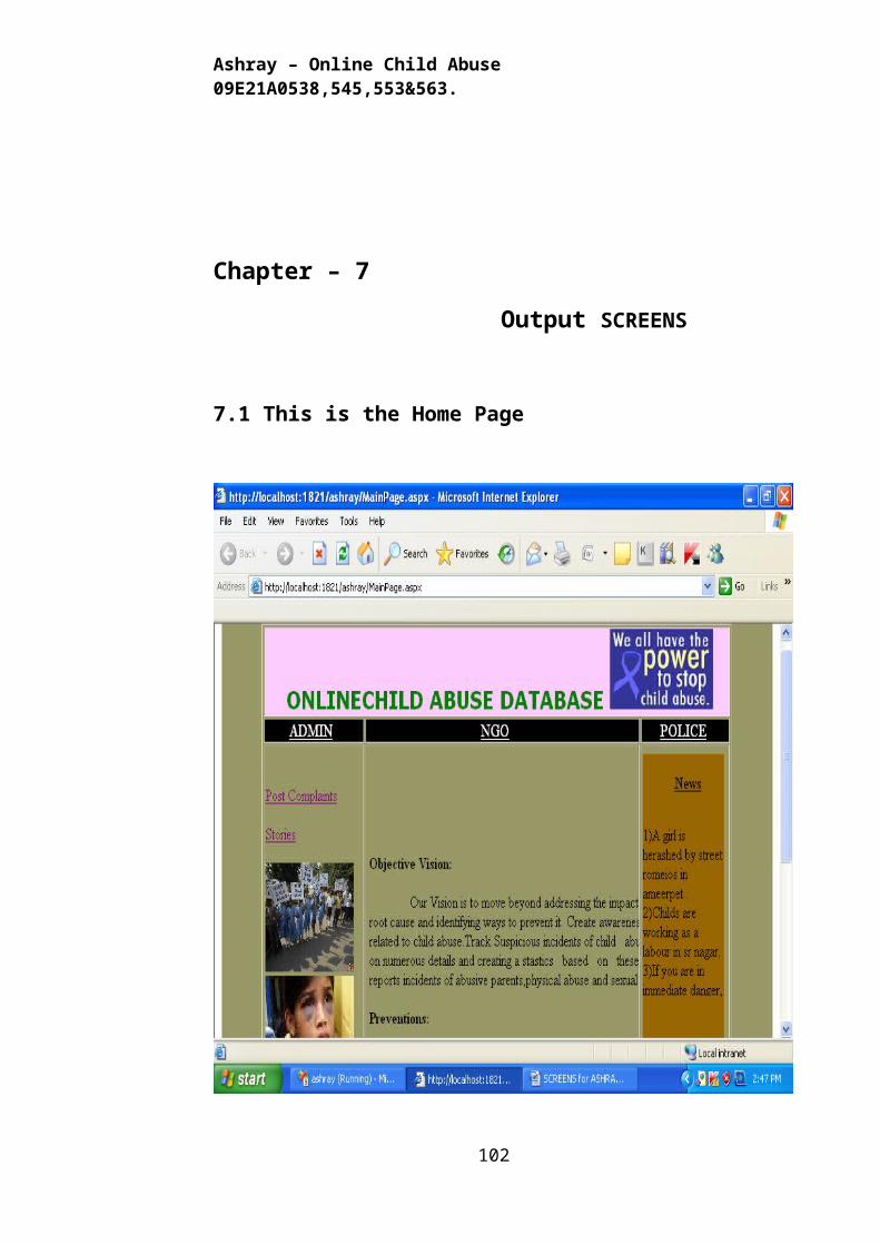
Ashray – Online Child Abuse 09E21A0538,545,553&563.
Chapter - 11
BIBLIOGRAPHY
FOR .NET INSTALLATION
www.support.mircosoft.com
FOR DEPLOYMENT AND PACKING ON SERVER
www.developer.com
www.15seconds.com
FOR SQL
www.msdn.microsoft.com
FOR ASP.NET
Asp.Net 3.5 Unleashed
www.msdn.microsoft.com/net/quickstart/aspplus/
default.com
www.asp.net
www.fmexpense.com/quickstart/aspplus/default.com
www.asptoday.com
www.aspfree.com
www.4guysfromrolla.com/index.aspx
Software Engineering (Roger’s Pressman)
102
Related Documents