Final Design Review: Wear Test Machine Sponsored by Marvin Engineering Co. Prepared by: Abraham Mitchell, Alexandra Pavano, Justin Hou, and Kaylla Son March 25, 2019 California Polytechnic State University, San Luis Obispo

Welcome message from author
This document is posted to help you gain knowledge. Please leave a comment to let me know what you think about it! Share it to your friends and learn new things together.
Transcript

Final Design Review: Wear Test Machine
Sponsored by Marvin Engineering Co. Prepared by: Abraham Mitchell, Alexandra Pavano, Justin Hou, and Kaylla Son
March 25, 2019 California Polytechnic State University, San Luis Obispo

Statement of Disclaimer
Since this project is a result of a class assignment, it has been graded and accepted as fulfillment of the course requirements. Acceptance does not imply technical accuracy or reliability. Any use of information in this report is done at the risk of the user. These risks may include catastrophic failure of the device or infringement of patent or copyright laws. California Polytechnic State University at San Luis Obispo and its staff cannot be held liable for any use or misuse of the project.
1
Table of Contents Abstract ………………………………………………………………………………………….. 5 1.0 Introduction ………………………………………………………………………………….. 5 2.0 Background ………………………………………………………………………………….. 6
2.1 Existing Designs ………………………………………………………..………..….. 6 2.2 Existing Patents …………………………………………………………………….... 7 2.3 Previous Wear Test Team’s Design ………………………………………………….. 7 2.4 Data Acquisition System …………………………………………………………….. 8 2.5 Industry Standards …………………………………………………………………. 11 2.6 Nitrogen Purge ……………………………………………………………………... 12 2.7 Material Selection ………………………………………………………………….. 14
3.0 Objectives ………………………………………………………………………………….. 15 4.0 Concept Design Development ……………………………………………………………... 19
4.1 Concept Development Process and Results ………………………………………... 19 4.2 Force Application …………………………………………………………………... 20 4.3 Purging ……………………………………………………………………………... 22 4.4 Chamber ……………………………………………………………………………. 23 4.5 Gearing ……………………………………………………………………………... 24 4.6 Existing Design Evaluation ……………………………………………………….... 25 4.7 Results …………………………………………………………………………….... 26 4.8 Preliminary Concept Design ……………………………………………………….. 27 4.9 Factors Prompting Design Changes ………………………………………………... 30
5.0 CDR Design ………………………………………………………………………………... 31 5.1 Data Acquisition System …………………………………………………………… 36 5.2 Safety, Maintenance and Repair …………………………………………………… 39 5.3 Material Selection and Sizing …………………………………………………….... 39 5.4 Cost Analysis ………………………………………………………………………. 40
6.0 Final Design ……...……………………………………………………………………….... 40 6.1 Manufacturing …………………………………………………………………….... 41 6.2 Assembly ………………………………………………………………………….... 44
7.0 Design Verification …....………………………………………………………………….... 47 8.0 Project Management ……………………………………………………………………….. 51 9.0 Conclusion …………………………………………………………………………………. 52 Attachments ……………………………………………………………………………………. 54 References …………………………………………………………………………………….... 54
2
List of Figures
Figure 1. R-Tec Vacuum Tribometer…………………………………………………………….. 6 Figure 2. Previous project teams concept model……………………………………………….... 7 Figure 3. Figure outlining the basic DAQ system components………………………………….. 8 Figure 4. Bridge Pressure Transducer…………………………………………………………..... 9 Figure 5. Capacitance Pressure Transducer…………………………………………………….... 9 Figure 6. Piezoelectric Pressure Transducer……………………………………………………. 10 Figure 7. Load Cells with Strain Gages in a Wheatstone Bridge Formation…………………….10 Figure 8. Schematic of the suggested pin on disk testing configuration featuring two specimens …………………………………………………………………………………………………... 11 Figure 9. Schematic of a Dry Gas Purging Kit…………………………………………………. 13 Figure 10. Schematic showing impinging jet created by nitrogen nozzle…………………….... 14 Figure 11. CAD rendering showing a partial acrylic cylinder enclosure……………………….. 14 Figure 12. Overall preliminary design functions and the relative generated ideas obtained throughout multiple brainstorming sessions……………………………………………………. 19 Figure 13. Spring loaded pin holder concept schematic………………………………………... 20 Figure 14. Pneumatic pin holder concept schematic…………………………………………… 21 Figure 15. Manually applied force concept schematic…………………………………………. 21 Figure 16. Three design considerations for purging the testing environment………………….. 22 Figure 17. Three design considerations for purging the purging chamber……………………... 23 Figure 18. A graph detailing how the radius of rotation and disk rpm affects the sliding speed of the pin on the disk……………………………………………………………………………..... 25 Figure 19. Renderings of the preliminary concept models……………………………………... 27 Figure 20. Renderings of the preliminary disk fixture………………………………………….. 28 Figure 21. Renderings of the preliminary pin holder………………………………………….... 29 Figure 22. Renderings of the previously proposed concept design and the final design concept. …………………………………………………………………………………………………....32 Figure 23. McMaster-Carr 4” 5C step collet used to hold disk in wear test assembly………..... 33 Figure 24. Rendering of the purging chamber, manufactured using clear polycarbonate to allow for visibility during testing…………………………………………………………………….... 34 Figure 25. Rendering of the pin holder base; Housing the pin holder, the radial force sensor, the nitrogen flow meter, and the purging chamber…………………………………………………. 35 Figure 26. Section view of the pin holder, demonstrating the assembly of the normal force sensor, the loading spring, the loading plates attached to the end of the springs, and the test pin specimen………………………………………………………………………………………... 35 Figure 27. This graph shows the ranges of force and friction coefficient that are out of range of the specified sensor. Note that both axes are log scale…………………………………………. 38
3
Figure 28. A FEA rendering of displacement of the pin holder and base under maximum loading conditions………………………………………………...…………...………………………... 40 Figure 29. Rendered image of the pin holder…………………………………………………... 42 Figure 30. Rendered image of the alignment plate……………………………………………... 42 Figure 31. Rendered image of the baseplate which will attach directly to the lathe via an AXA tool holder………………………………………………………………………………………. 43 Figure 32. Abraham and Alexandra machining the step collet using a rotary vice on a mill…... 44 Figure 33. Top view of assembled base plate…………………………………………………... 45 Figure 34. Front view of assembled base plate………………………………………………..... 45 Figure 35. Image of the final assembly of the base plate with holder, load cells and meter….... 46 Figure 36. Image of the final chamber assembly……………………………………………….. 46 Figure 37. Model of swirling flow in a cylindrical container with a rotating lid………………. 48 Figure 38. Front plane flow streamlines………………………………………………………... 49 Figure 39. Validation testing without a chamber……………………………………………….. 50 Figure 40. Results of dynamic test on device…………………………………………………... 51
List of Tables
Table 1. Tabulated design requirements provided by Marvin Engineering…………………….. 16 Table 2. Table of the wants and needs of Marvin Engineering obtained through sponsor meetings and provided project requirements…………………………………………………………….... 16 Table 3. Table of Engineering requirements as developed from the QFD…………………….... 16 Table 4. Table of sensor specifications…………………………………………………………. 17 Table 5. The radius of rotation of the pin specimen and the corresponding sliding speed at 120 RPM…………………………………………………………………………………………….. 31
4
Abstract A California Polytechnic State University Senior Project team has been tasked by Marvin Engineering Co. to design and build a friction wear test fixture; the fixture is to characterize the coefficient of friction and potential friction wear of various industry adopted metal pairings in an oxygen-free environment. This final design review serves to document project research, full design process, method of operation of final product, and a comprehensive testing procedure. The R&D department at Marvin Engineering Co. proposed this investigation in order to explore the phenomenon of friction and adhesive wear, specifically the occurrence of galling between stainless steel surfaces. With these findings, Marvin Engineering seeks to establish a test-based method to identify material pairs which provide low friction and wear in an oxygen-deprived environment. Additionally, test candidate material pairs and provide sufficient data to substantiate performance of tested materials. 1.0 Introduction Marvin Engineering Co. (MEC) is a defense contractor located in Inglewood, California, involved with product development and manufacturing of various systems for military aerospace and vehicles. The company specializes in aircraft bomb ejector racks, missile launchers, weapon and fuel pylons, as well as other associated equipment. These products are often dependent on the sliding motion of metal on metal, by which munitions are ejected from the racks by design. The specific design of these products has the metal operating in a de-oxygenated environment. When the sliding motion between mating surfaces occurs, the naturally occurring oxide layer prevalent on stainless steels that are desirable in low wear and friction applications is lost. Further, the absence of oxygen prevents the reformation of this naturally occurring surface oxide layer, thus bringing about the onset of galling and high friction at a higher rate than desired. This high friction can potentially cause the the equipment to seize up and not function properly. Accordingly, the design of a tribometer is desirable to quantify the significance of the galling phenomena and characterize metal pairings that can be utilized by Marvin Engineering to reduce its occurrence. The senior project team selected to work on this project consists of Alexandra Pavano, Abraham Mitchell, Kaylla Son, and Justin Hou - all Mechanical Engineering students attending California Polytechnic State University. Alexandra has experience from internships at multiple engineering companies that are primarily defense contractors. Abraham has six years of experience working for various engineering firms as a mechanical designer. Justin is in the mechatronics concentration of Mechanical Engineering department and has experience with controls and
5
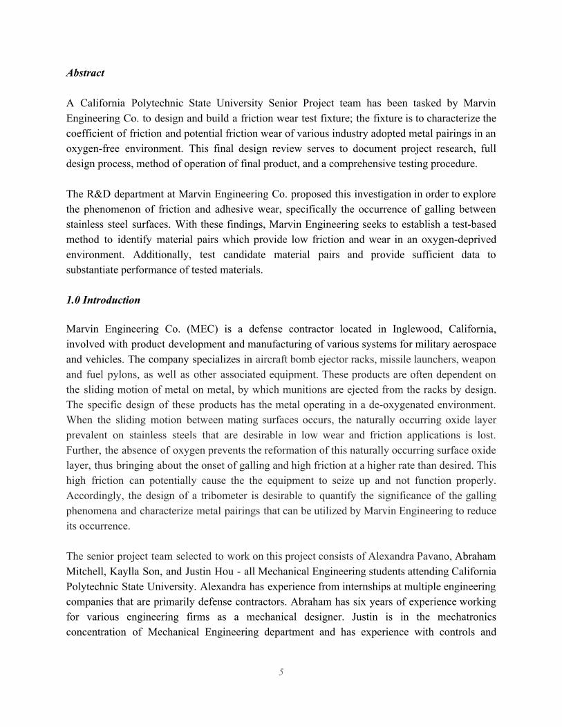
programming. And lastly, Kaylla is in the manufacturing concentration of Mechanical Engineering department and has experience with machining. 2.0 Background The measurement of friction is a field of science called tribology. A device that measures the friction is a tribometer. There are several types of tribometers, including four ball, pin-on-disk, ball-on-disk, ring-on-ring, reciprocating pin, block-on-ring, bouncing ball, and twin disk. In general, these devices consist of a pair of materials that slide against each other and sensors that measure the normal and axial loads to allow for the calculation of the friction factor between the two material. At the initiation of this project, MEC stated their preference for the pin-on-disk format to be used. The standard configuration of these tribometers is to be a benchtop or otherwise self-contained unit. However, MEC proposed that the designed pin-on-disk tribometer be powered by a lathe. 2.1 Existing Designs Research into existing designs yielded results of pin-on-disk tribometers available from numerous companies, including Anton-Paar, R-Tec, Kett and Ducom. Images of the R-Tec Vacuum Tribometer can be seen below in Figure 1. Overall, the designs are similar, with all being benchtop style units with automated controls and advanced data acquisition (DAQ) systems. They can operate at a range of speeds, apply a varying amount of force, and perform tests on a wide range of materials. Some features that vary among the systems are their ability to operate in a vacuum or humid environment, ability to add lubricants and oils, or the ability to operate at a high temperature. The range of speeds meet those as specified by MEC, and the applied loads meet the 10-100 psi requirement as well. However, some of the systems are not capable of applying a load of 1 ksi, and would need modification to operate in a de-oxygenated environment at atmospheric pressure. The cost of these systems, while publically available, exceeds the budget for this project.
Figure 1. R-Tec Vacuum Tribometer.
6
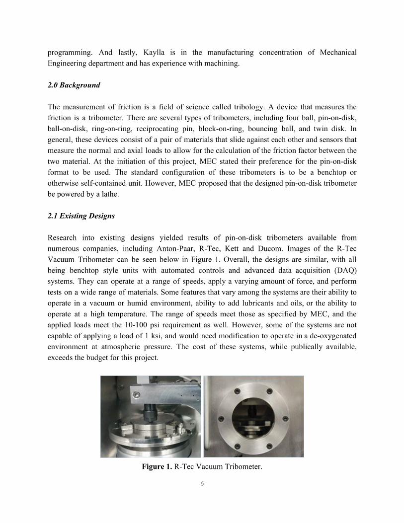
2.2 Existing Patents Research into existing Patents in the United States for pin-on-disk Tribometers yielded no results for one that is powered by a lathe. The research did include Patents relating to the improvement or specialization of standard pin-on-disk designs. One such design is seen in Patent US9581534, that utilizes lasers to measure movement of the test specimen, or the transfer film thickness, or to finely calibrate the results. However, the Patents did not have details or designs beyond what was found from the research into existing systems that are applicable to the specific requirements of this project. 2.3 Previous Wear Test Team’s Design Research was further conducted into the design from the previous team’s efforts on this project. Their preliminary design consisted of a fixture that would mount into a lathes T-slot, a disk that would be held by the lathe chuck, and utilize a spring and the movement of the carriage to apply the load from the fixture to the disk. The de-oxygenated environment would be provided by a continuous stream of gaseous Nitrogen impinging on the disk near the pin, providing a shielding layer of Nitrogen around the contact point. A concept model of the previous team’s effort is seen in Figure 2. While the previous team utilized a lathe fixture for their wear test machine design, research into both possibilities of the design of a lathe fixture compared to that of a benchtop fixture. Due to multiple concerning factors with the benchtop fixture, including but not limited to cost, complexity of controlling the motor, and power requirements, the benchtop fixture will not be evaluated further.
Figure 2. Previous project teams concept model.
7
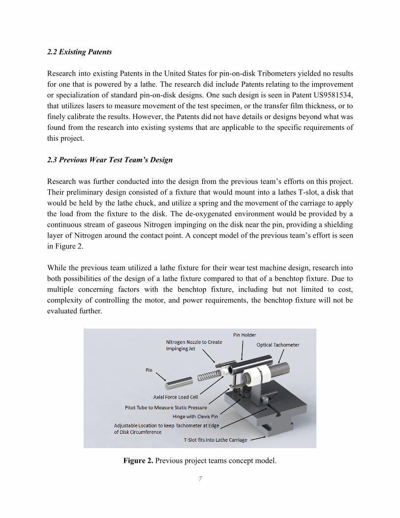
2.4 Data Acquisition System A Data Acquisition system (DAQ) is a physical system in which sampling signals measure real world physical conditions and convert the resulting samples into digital numeric values that can be manipulated by a computer. According to National Instruments as shown in Figure 3, DAQ systems consist of a sensor, a DAQ device, abus, and a computer. The sensor is the component that conducts the actual measurements; It takes the measurements and sends them as electrical signals to the DAQ device. The DAQ device then conditions the signals by filtering out the noise and scaling them to an appropriate size and periodically converts them from analog to digital with an A/D converter and sends them to the computer through the bus, such as Ethernet or USB.
Figure 3. Figure outlining the basic DAQ system components.
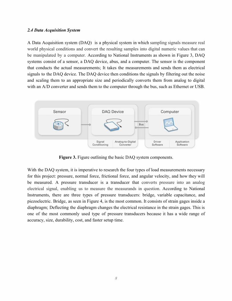
With the DAQ system, it is imperative to research the four types of load measurements necessary for this project: pressure, normal force, frictional force, and angular velocity, and how they will be measured. A pressure transducer is a transducer that converts pressure into an analog electrical signal, enabling us to measure the measurands in question. According to National Instruments, there are three types of pressure transducers: bridge, variable capacitance, and piezoelectric. Bridge, as seen in Figure 4, is the most common. It consists of strain gages inside a diaphragm; Deflecting the diaphragm changes the electrical resistance in the strain gages. This is one of the most commonly used type of pressure transducers because it has a wide range of accuracy, size, durability, cost, and faster setup time.
8
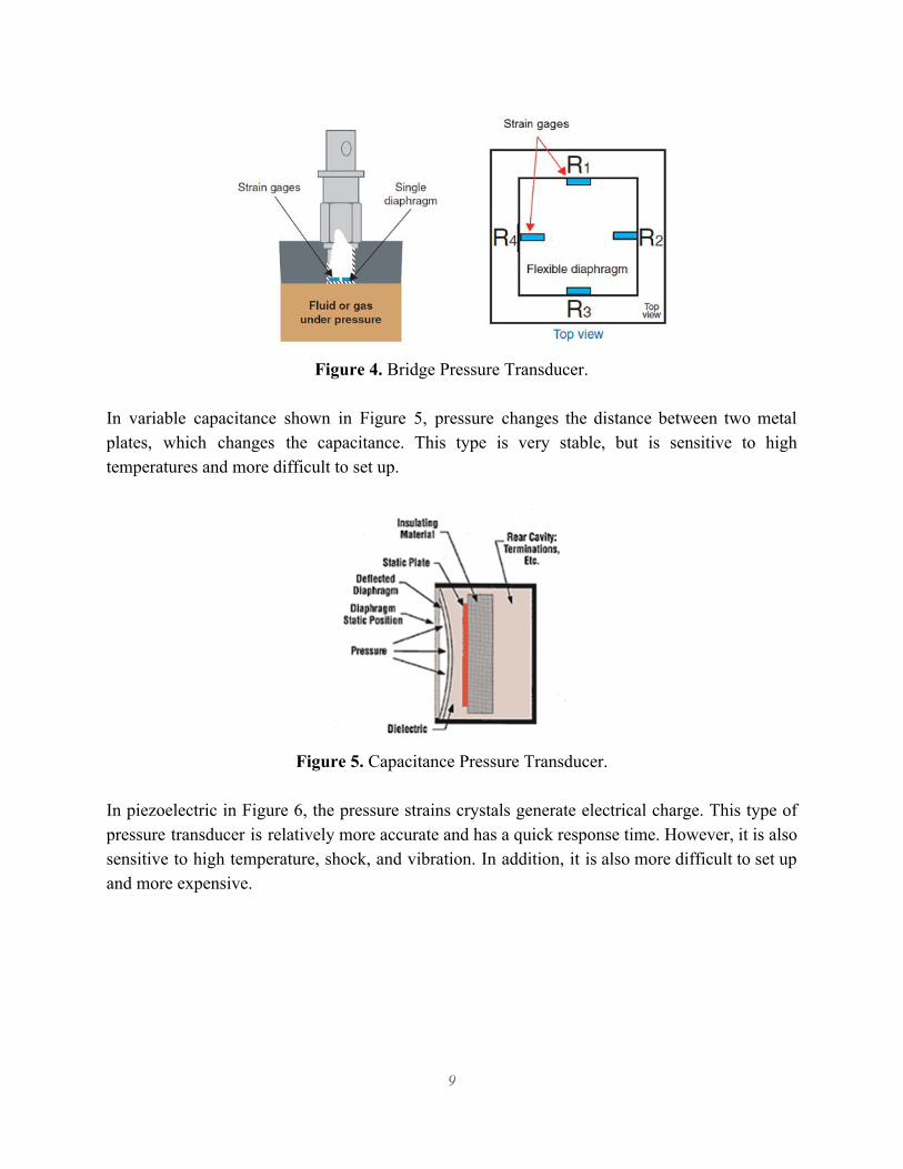
Figure 4. Bridge Pressure Transducer.
In variable capacitance shown in Figure 5, pressure changes the distance between two metal plates, which changes the capacitance. This type is very stable, but is sensitive to high temperatures and more difficult to set up.
Figure 5. Capacitance Pressure Transducer.
In piezoelectric in Figure 6, the pressure strains crystals generate electrical charge. This type of pressure transducer is relatively more accurate and has a quick response time. However, it is also sensitive to high temperature, shock, and vibration. In addition, it is also more difficult to set up and more expensive.
9
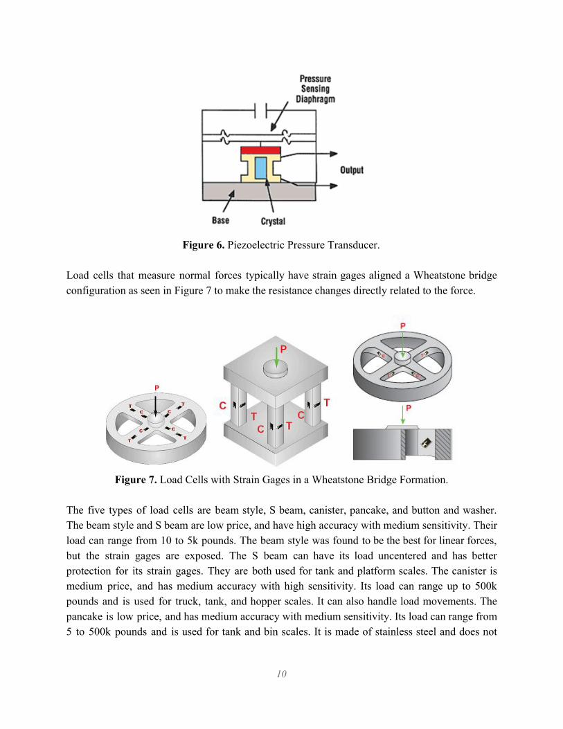
Figure 6. Piezoelectric Pressure Transducer.
Load cells that measure normal forces typically have strain gages aligned a Wheatstone bridge configuration as seen in Figure 7 to make the resistance changes directly related to the force.
Figure 7. Load Cells with Strain Gages in a Wheatstone Bridge Formation.
The five types of load cells are beam style, S beam, canister, pancake, and button and washer. The beam style and S beam are low price, and have high accuracy with medium sensitivity. Their load can range from 10 to 5k pounds. The beam style was found to be the best for linear forces, but the strain gages are exposed. The S beam can have its load uncentered and has better protection for its strain gages. They are both used for tank and platform scales. The canister is medium price, and has medium accuracy with high sensitivity. Its load can range up to 500k pounds and is used for truck, tank, and hopper scales. It can also handle load movements. The pancake is low price, and has medium accuracy with medium sensitivity. Its load can range from 5 to 500k pounds and is used for tank and bin scales. It is made of stainless steel and does not
10
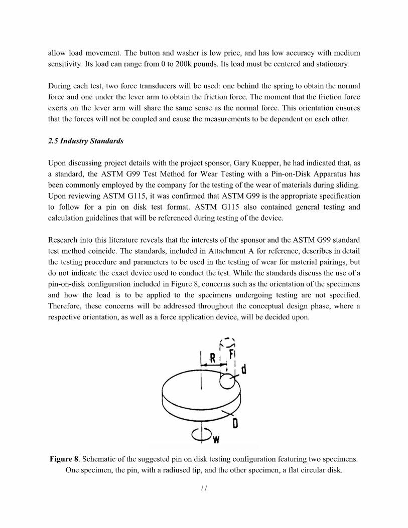
allow load movement. The button and washer is low price, and has low accuracy with medium sensitivity. Its load can range from 0 to 200k pounds. Its load must be centered and stationary. During each test, two force transducers will be used: one behind the spring to obtain the normal force and one under the lever arm to obtain the friction force. The moment that the friction force exerts on the lever arm will share the same sense as the normal force. This orientation ensures that the forces will not be coupled and cause the measurements to be dependent on each other. 2.5 Industry Standards Upon discussing project details with the project sponsor, Gary Kuepper, he had indicated that, as a standard, the ASTM G99 Test Method for Wear Testing with a Pin-on-Disk Apparatus has been commonly employed by the company for the testing of the wear of materials during sliding. Upon reviewing ASTM G115, it was confirmed that ASTM G99 is the appropriate specification to follow for a pin on disk test format. ASTM G115 also contained general testing and calculation guidelines that will be referenced during testing of the device. Research into this literature reveals that the interests of the sponsor and the ASTM G99 standard test method coincide. The standards, included in Attachment A for reference, describes in detail the testing procedure and parameters to be used in the testing of wear for material pairings, but do not indicate the exact device used to conduct the test. While the standards discuss the use of a pin-on-disk configuration included in Figure 8, concerns such as the orientation of the specimens and how the load is to be applied to the specimens undergoing testing are not specified. Therefore, these concerns will be addressed throughout the conceptual design phase, where a respective orientation, as well as a force application device, will be decided upon.
Figure 8. Schematic of the suggested pin on disk testing configuration featuring two specimens.
One specimen, the pin, with a radiused tip, and the other specimen, a flat circular disk.
11

The standards indicate that either the disk or the pin specimen will be in rotation, enabling the pin to revolve about the disks center. This will create a circular sliding path about the disk surface. The pin specimen will be pressed against the disk at a specified load, usually by means of an arm or lever and attached weights. Other loading methods have been used, such as, hydraulic or pneumatic, and will be considered throughout the conceptual design phase. These standards indicate that the amount of wear is determined by measuring appropriate linear dimensions of both specimens or by weighing both specimens before and after the test. The ASTM G99 standards include specific design constraints to be considered. The design must be able to hold a pin over the disk at a specified force and maintain that force throughout the test. The pin must be kept perpendicular to the disk to within plus or minus 1 degree during maximum lateral force and the pin will revolve around the disk specimen at a given radius during the test. This requires the arm holding the pin to be built with substantial stiffness to minimize lateral deflection during testing. Additionally, this specification requires that the pin holder and lever arm be of substantial mass to reduce vibrational motion during the test. The rotation is to be powered by a variable speed motor, capable of producing a constant rotational speed to within 1% of the motor’s rated full load speed. The motor must also be mounted in such a way that its vibrations do not disrupt the test during operation. ASTM G163 contains specifications for Data Acquisition for wear test devices. These specifications were used as a guide to develop and refine the specifications needed for the needs of our DAQ system. 2.6 Nitrogen Purge To create an oxygen deprived environment nitrogen will be used; since air already consists of 80% nitrogen, the use of nitrogen to purge the environment is both easier and cheaper. Additionally, using nitrogen is a safer alternative as opposed to other gases since nitrogen does not support combustion, and at standard conditions is a colorless, odorless, tasteless, non-irritating, and inert gas. For purging purpose, CO2 or Argon can also be used but CO2 is not recommended because of its ability to react with water to produce a corrosive carbonic acid. Argon is not recommended because it is generally more expensive than nitrogen. The process of nitrogen purging is used for a range of similar applications such as line or tank purging, drying, line clearing, pigging or pressure transferring. The following information includes three common methods for nitrogen purging.
12

The first method, the pressure-hold-vacuum method, is commonly used when the vessel being purged only has one opening or in batch operations like purging ethylene oxide sterilizers. Nitrogen is used to pressurize a vessel or line; it mixes with and dilutes the contents and then the diluted mixture is vented to emission control units. This process is repeated until the vessel is sufficiently purged. The second method, dilution purging and drying, nitrogen can continuously enter the vessel, dilute the mixture and exhaust through an exit preferably opposite the entrance. The geometry of the vessel and orientation of entry and exit points are important factors in the effectiveness of this method. Drying follows a similar process but allows for removal of residual materials. And lastly, the displacement purging and pigging method, in which nitrogen can be used to purge out a pipe run. A “pig,” a bullet shaped object, can also be pushed through the line using nitrogen gas pressure in order to purge the contents. Figure 9 shows AGM’s Through-Purge Kit which is a simple 2-point dry gas purging kit for removing unwanted moisture from a sealed container or enclosure.
Figure 9. Schematic of a Dry Gas Purging Kit.
Research was also conducted on previous group’s method of purging. In order to create an oxygen-free operating environment, they used a nozzle aimed at the disk to create an impinging jet of nitrogen on the rotating disk. As seen in figure 10, a pitot tube with a manometer is used to measure the static pressure within the boundary layer. If the static pressure is lower than the
13
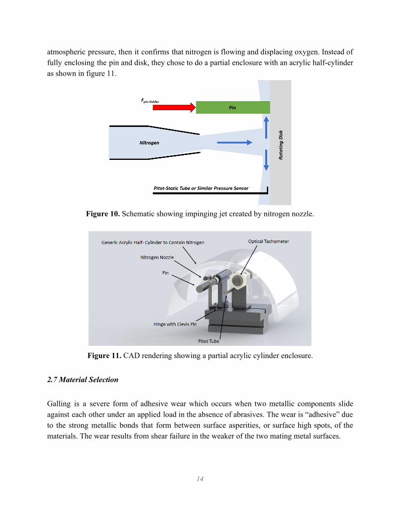
atmospheric pressure, then it confirms that nitrogen is flowing and displacing oxygen. Instead of fully enclosing the pin and disk, they chose to do a partial enclosure with an acrylic half-cylinder as shown in figure 11.
Figure 10. Schematic showing impinging jet created by nitrogen nozzle.
Figure 11. CAD rendering showing a partial acrylic cylinder enclosure.
2.7 Material Selection
Galling is a severe form of adhesive wear which occurs when two metallic components slide against each other under an applied load in the absence of abrasives. The wear is “adhesive” due to the strong metallic bonds that form between surface asperities, or surface high spots, of the materials. The wear results from shear failure in the weaker of the two mating metal surfaces.
14

Galling requires two properties common to most metals, cohesion through metallic-bonding attractions and plasticity. The tendency of a material to gall is affected by the ductility of the material. Typically, hardened materials are more resistant to galling whereas softer materials of the same type will gall more readily. The propensity of a material to gall is also affected by the specific arrangement of the atoms, because crystals arranged in a face-centered cubic lattice will usually allow material-transfer to a greater degree than a body-centered cubic. Stacking-fault energy is also one of the important factors that determines a material's resistance to galling. A material with high stacking-fault energy, such as aluminium or titanium, will be far more susceptible to galling than materials with low stacking-fault energy, like copper, bronze, or gold. Conversely, materials with a hexagonal close packed structure, such as cobalt-based alloys, are extremely resistant to galling. Methods of preventing galling include the use of lubricants like grease and oil, low-friction coatings and thin-film deposits like molybdenum disulfide or titanium nitride, and increasing the surface hardness of the metals using processes such as case hardening and induction hardening. For stainless steels, hardness is the most important factor for wear resistance. Austenitic stainless steel alloys are preferred over martensitic stainless alloys because austenitic metals have higher work-hardened hardness. Alloying additions in austenitic steels can help to increase the stability of the oxide layer, thus increasing the transition load for severe wear. Although martensitic alloys have a high hardness as well, their low carbon content results in a poor wear resistance. Because ferritic stainless steels also have a low carbon content and are not able to be hardened by heat treatment or work-hardening, they are not applicable for this experiment. Generally, a carbon content greater than 0.3% and a hardness greater than 53 Rockwell Hardness (HRC) are desired.
3.0 Objectives The team will design and build a friction wear test fixture using a pin-on-disc configuration that is adaptable to be used on most lathes. The pin and disk material are both to be interchangeable to allow the testing of various material pairings. The test fixture will measure the applied axial and resulting friction drag loads on the pin test specimen in order to characterize material pairing friction coefficients over time. The test is to be done within a de-oxygenated environment. Further design requirements as specified by MEC can be seen in Table 1. The test parameters for design and final validation testing have been defined by MEC.
15
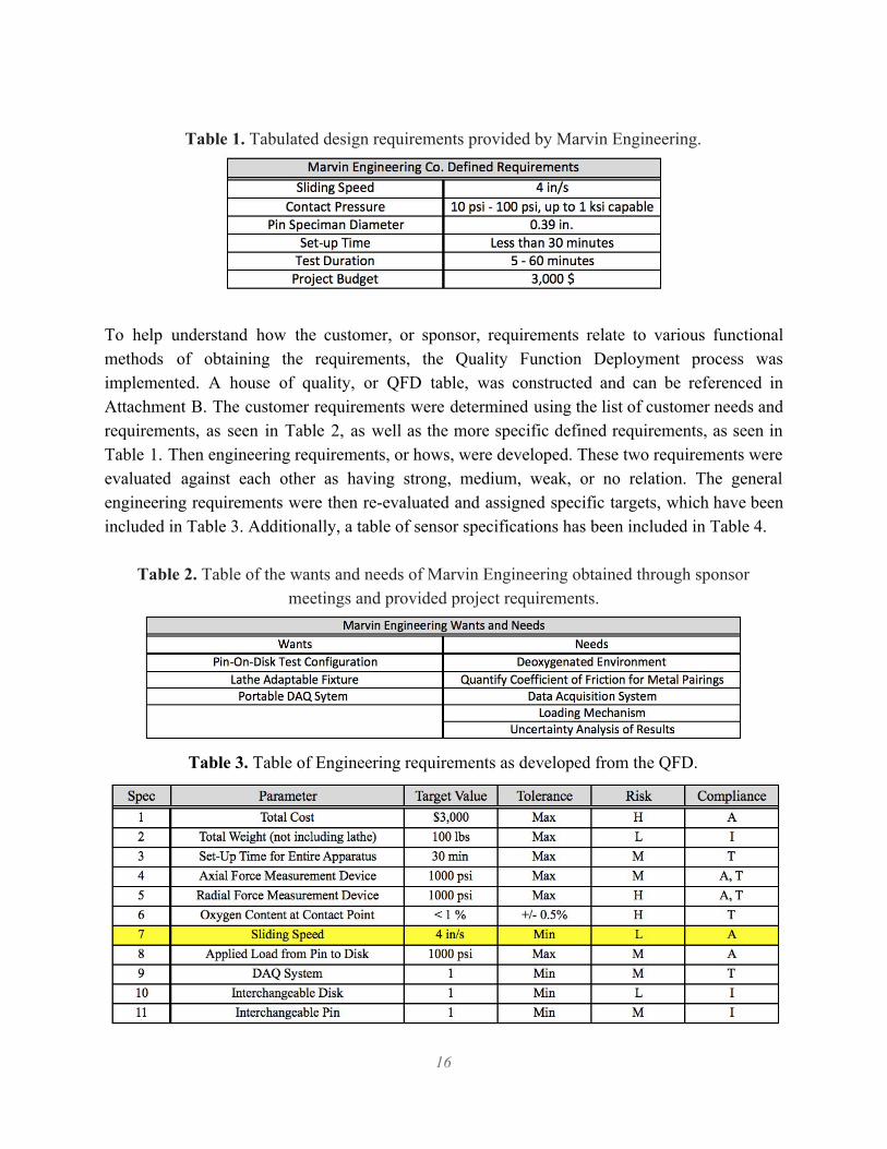
Table 1. Tabulated design requirements provided by Marvin Engineering.
To help understand how the customer, or sponsor, requirements relate to various functional methods of obtaining the requirements, the Quality Function Deployment process was implemented. A house of quality, or QFD table, was constructed and can be referenced in Attachment B. The customer requirements were determined using the list of customer needs and requirements, as seen in Table 2, as well as the more specific defined requirements, as seen in Table 1. Then engineering requirements, or hows, were developed. These two requirements were evaluated against each other as having strong, medium, weak, or no relation. The general engineering requirements were then re-evaluated and assigned specific targets, which have been included in Table 3. Additionally, a table of sensor specifications has been included in Table 4.
Table 2. Table of the wants and needs of Marvin Engineering obtained through sponsor meetings and provided project requirements.
Table 3. Table of Engineering requirements as developed from the QFD.
16
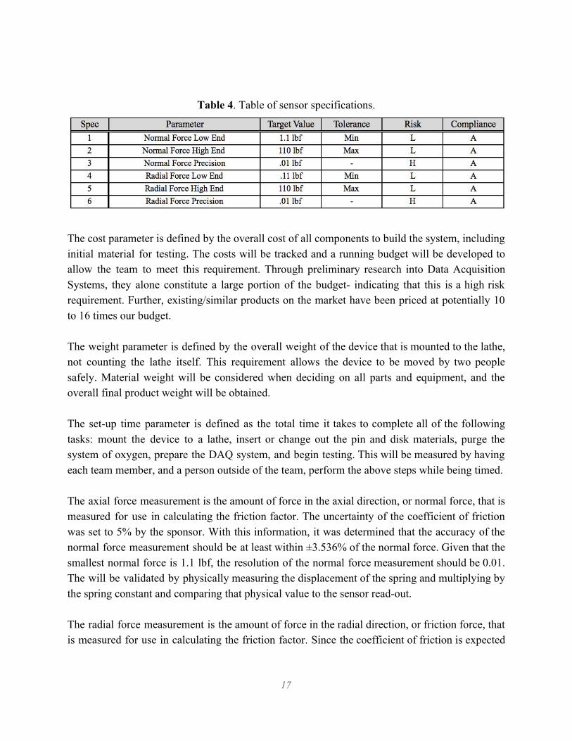
Table 4. Table of sensor specifications.
The cost parameter is defined by the overall cost of all components to build the system, including initial material for testing. The costs will be tracked and a running budget will be developed to allow the team to meet this requirement. Through preliminary research into Data Acquisition Systems, they alone constitute a large portion of the budget- indicating that this is a high risk requirement. Further, existing/similar products on the market have been priced at potentially 10 to 16 times our budget. The weight parameter is defined by the overall weight of the device that is mounted to the lathe, not counting the lathe itself. This requirement allows the device to be moved by two people safely. Material weight will be considered when deciding on all parts and equipment, and the overall final product weight will be obtained. The set-up time parameter is defined as the total time it takes to complete all of the following tasks: mount the device to a lathe, insert or change out the pin and disk materials, purge the system of oxygen, prepare the DAQ system, and begin testing. This will be measured by having each team member, and a person outside of the team, perform the above steps while being timed. The axial force measurement is the amount of force in the axial direction, or normal force, that is measured for use in calculating the friction factor. The uncertainty of the coefficient of friction was set to 5% by the sponsor. With this information, it was determined that the accuracy of the normal force measurement should be at least within ±3.536% of the normal force. Given that the smallest normal force is 1.1 lbf, the resolution of the normal force measurement should be 0.01. The will be validated by physically measuring the displacement of the spring and multiplying by the spring constant and comparing that physical value to the sensor read-out. The radial force measurement is the amount of force in the radial direction, or friction force, that is measured for use in calculating the friction factor. Since the coefficient of friction is expected
17

to range from 0.1 to 0.9, the resolution of the radial force measurement will need to be ten times greater. The oxygen content of the system is the amount of oxygen present around the pin and disk during testing. This may not be measured explicitly, but evaluated based on the purging procedure. The sliding speed is the speed at which the pin slides against the disk. This will not be explicitly measured but will be calculated based on lathe rotation speed and the radius of rotation. The applied load is the load applied from the pin to the disk. This will be measured by a load cell and validated against expect loading conditions. The DAQ system parameter is to have a functioning DAQ system to record, analyze and present the data received from the input measurement devices. This parameter will be measured by agreement of analysis with known values. The specifications that need to be considered when choosing the DAQ system include bit count, voltage range, sensitivity, gain error, offset error, linearity error, temperature drift, and system noise. The bit count and voltage range determine the resolution. The resolution and least significant bit root mean square (LSB RMS) determine the sensitivity. The total accuracy of the DAQ system is the summation of the last six specifications. This value needs to be equal to or less than 3.536% accuracy of the normal force. Since the voltage range of the DAQ is dependent on the sensor specifications, the sensors will need to be chosen before the DAQ. The interchangeable disk parameter is defined as having an easily changeable disk that withstand the 1000 psi load while providing a stable surface for the pin. The interchangeable pin parameter is defined as having an easily changeable pin that transmit the 1000 psi load while connecting to the measurement devices. Overall, the Quality Function Deployment process enabled us to consider all appropriate specifications for a the new design, relevant to the customer needs. The QFD revealed concerns that had not yet been discussed, nevertheless considered. Additionally, it showed that requirements vary in weight; some were deemed more important or challenging than others. Specifically, requirements such as the loading mechanism, the interchangeable disk, and the load measurement concerns- all areas that will require the most focus that, because of the QFD, we are aware of and will address.
18

4.0 Concept Design Development Prior to determining a proposed design in order to proceed in the design process, ideation sessions were conducted.
4.1 Concept Development Process and Results
Concept development initiated with the functional decomposition of the wear test machine. Main functions were identified as critical to analyze for the final design determination: force application, purging process, chamber, and others were analyzed. With the primary performance functions selected, ideation methods were used to begin the design process and generate a large number of solutions to assure these performance functions are achieved with the final design. First, classic brainstorming sessions were completed; this entailed writing ideas directly onto a whiteboard to assist in breaking out of the same pattern of thinking and develop new approaches to our design challenge. This process yielded the following information included in Figure 12.
Figure 12. Overall preliminary design functions and the relative generated ideas obtained
throughout multiple brainstorming sessions.
19

With a large number of ideas generated, controlled convergence coupled with pugh matrices were used to narrow many ideas into the top few for each category. Controlled convergence consisted of narrowing down ideas by means of feasibility and practicality. Once ideas were added, refined, or eliminated through the controlled convergence process, pugh matrices were used to further refine the design ideas to the top and final few. Pugh matrices are a tool in which several design options are evaluated according to their strengths and weakness relative to a reference concept or datum. All pugh matrices can be found in Attachment C and will be further discussed below.
4.2 Force Application
Ideas generated with regards to how the axial force will be applied by the pin upon the disk include the use of springs, weights, pneumatics, hydraulics, and other apparatuses. The top concepts determined using the pugh matrices were a spring loaded pin holder, a pneumatic piston pin holder, and a manually applied force by means of the lathe. The factors considered for this process were cost, complexity of design, ease of knowing applied force, ability to attain load precision, maintenance, manufacturability, and safety. The spring loaded pin holder concept is displayed in Figure 13; the design consists of an internally placed spring behind the pin specimen and would utilize Hooke’s Law to convert spring compression to applied force. This design was favorable in a majority of categories, deeming it the optimal force application design based upon the pugh matrices method. It was determined favorable in categories such as cost, complexity, maintenance, manufacturability, and safety. A clear advantage of this concept is cost, with the substantial ease of manufacturability, low maintenance, and low instrumentation cost. Additionally, it would be favorable its ability to know the load at which you are applying and the precision of said load.
Figure 13. Spring loaded pin holder concept schematic.
The pneumatic piston pin holder concept is displayed in Figure 14; the design consists of using a pneumatic piston located within the chamber of the pin holder. This idea was also favorable in
20
many categories, including cost, complexity, manufacturability, and the ability to know the load being applied. Upon initial idea conception, cost and complexity were assumed to be undesirable, however, upon further research, a pneumatic piston was determined to be feasible for the given project budget as well as easy to purchase for our needs. However, in categories such as maintenance and safety, the pneumatic piston design was deemed unfavorable.
Figure 14. Pneumatic pin holder concept schematic.
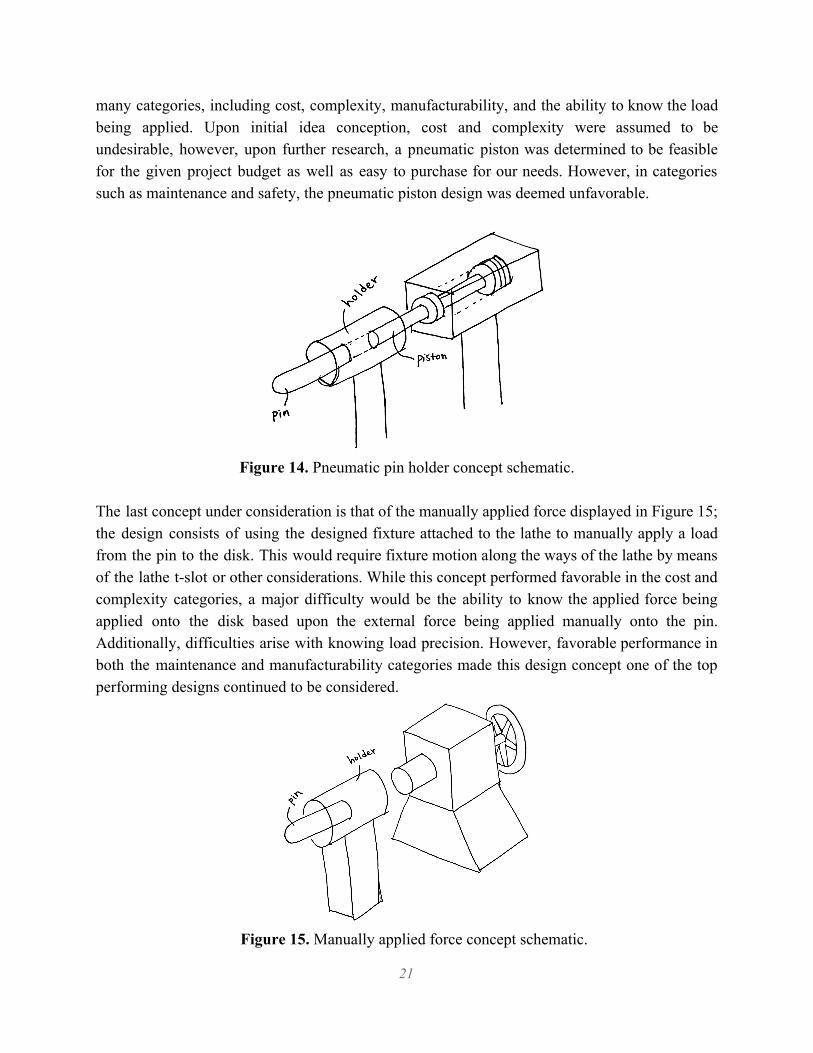
The last concept under consideration is that of the manually applied force displayed in Figure 15; the design consists of using the designed fixture attached to the lathe to manually apply a load from the pin to the disk. This would require fixture motion along the ways of the lathe by means of the lathe t-slot or other considerations. While this concept performed favorable in the cost and complexity categories, a major difficulty would be the ability to know the applied force being applied onto the disk based upon the external force being applied manually onto the pin. Additionally, difficulties arise with knowing load precision. However, favorable performance in both the maintenance and manufacturability categories made this design concept one of the top performing designs continued to be considered.
Figure 15. Manually applied force concept schematic.
21

Pugh matrix results yielded the previous three design concepts for force application. Of the three, the spring loaded pin holder concept scored the best and therefore is our force application device for our preliminary fixture design. 4.3 Purging Ideas generated with regards to how the testing environment will be purged of oxygen were primarily a continuous flow purging, a controlled flow purging, and a shielding jet. The factors considered for these processes were cost, complexity of design, maintenance, safety, size, and purging performance. All purging concept designs are illustrated in Figure 16.
Figure 16. Three design considerations for purging the testing environment- continuous flow
purging (left), controlled flow purging (center), and use of a shielding jet (right). Pugh matrices indicate that the shielding jet is the optimal choice; this design incorporates concentrated flow of nitrogen at the contact point on the disk. Performing well in many categories, the nitrogen flow must displace the air at all points on the surface of the disk. However, while the matrix led to one optimal design, further research and intuition led to a different option. For nitrogen can act as a simple asphyxiant by displacing the oxygen in air to levels below that required to support life. When the atmosphere’s oxygen content falls to the 6% to 4% range, coma can occur within seconds. The danger of nitrogen asphyxiation is highest in confined spaces. However, fatalities and injuries can occur in open spaces, including areas with ventilation, laboratories, buildings, and outside in the vicinity of equipment. This is a high risk design decision. With correspondence with the project sponsor, it was found that for the final housing of the wear test machine, ventilation of the nitrogen used throughout the open purge process of a shielding jet is a concern. Additionally, it was found that substantially large amounts of nitrogen would be necessary to conduct the purging process with the shielding jet apparatus in order to ascertain the testing environment is free of oxygen.
22

With the sponsors preference being a contained nitrogen purging method, the preliminary design includes a continuous purging method, despite the conflicting results with the pugh matrix. The continuous purging method involves the use of a chamber in which nitrogen continuously flows into and out of the chamber to ensure complete purging. 4.4 Chamber With the finalization of the purging method, it became necessary to consider nitrogen containing methods. Thus, chambers of various shapes, sizes, visibility were considered and analyzed using the pugh matrix. However, prior to using the pugh matrix to assist in design decisions, controlled convergence was performed. It was concluded that in order to complete a final design, functions such as visibility, sealing, and access to specimen through a chamber door must be considered. It was concluded that either the whole chamber or one chamber wall is to be made of a material to allow for visibility. Additionally, sealings will be a primary concern and whether or not the chamber is to enclose the entire fixture or solely the pin and disk. And finally, the final design for the chamber must allow for ease of changing out the specimen or merely accessing the specimen. With these decisions made, additional progress was made into the development of a preliminary chamber design. Pugh matrices were then used in order to determine the desirable shape for the chamber enclosing the nitrogen. Many factors were considered with regards to the chamber, whether it is to be collapsable or rigid, whether it is to have cone-shaped faces or flat face edges, and whether or not to have multiple chambers. Pugh matrices indicate that a rigid cube chamber with flat top and bottom faces would be the ideal design to use for the purging chamber. Figure 17 includes three primary chamber concepts.
Figure 17. Three design considerations for purging the purging chamber- a rigid cube with flat top and bottom faces (left), a rigid cube with cone shaped faces in order to better assist in the
flow of nitrogen (center), and a cylindrical chamber (right).
23
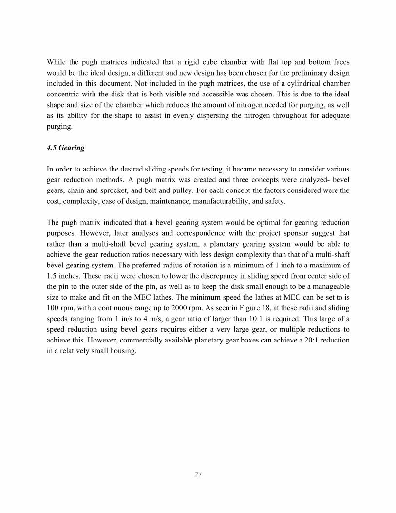
While the pugh matrices indicated that a rigid cube chamber with flat top and bottom faces would be the ideal design, a different and new design has been chosen for the preliminary design included in this document. Not included in the pugh matrices, the use of a cylindrical chamber concentric with the disk that is both visible and accessible was chosen. This is due to the ideal shape and size of the chamber which reduces the amount of nitrogen needed for purging, as well as its ability for the shape to assist in evenly dispersing the nitrogen throughout for adequate purging. 4.5 Gearing
In order to achieve the desired sliding speeds for testing, it became necessary to consider various gear reduction methods. A pugh matrix was created and three concepts were analyzed- bevel gears, chain and sprocket, and belt and pulley. For each concept the factors considered were the cost, complexity, ease of design, maintenance, manufacturability, and safety. The pugh matrix indicated that a bevel gearing system would be optimal for gearing reduction purposes. However, later analyses and correspondence with the project sponsor suggest that rather than a multi-shaft bevel gearing system, a planetary gearing system would be able to achieve the gear reduction ratios necessary with less design complexity than that of a multi-shaft bevel gearing system. The preferred radius of rotation is a minimum of 1 inch to a maximum of 1.5 inches. These radii were chosen to lower the discrepancy in sliding speed from center side of the pin to the outer side of the pin, as well as to keep the disk small enough to be a manageable size to make and fit on the MEC lathes. The minimum speed the lathes at MEC can be set to is 100 rpm, with a continuous range up to 2000 rpm. As seen in Figure 18, at these radii and sliding speeds ranging from 1 in/s to 4 in/s, a gear ratio of larger than 10:1 is required. This large of a speed reduction using bevel gears requires either a very large gear, or multiple reductions to achieve this. However, commercially available planetary gear boxes can achieve a 20:1 reduction in a relatively small housing.
24
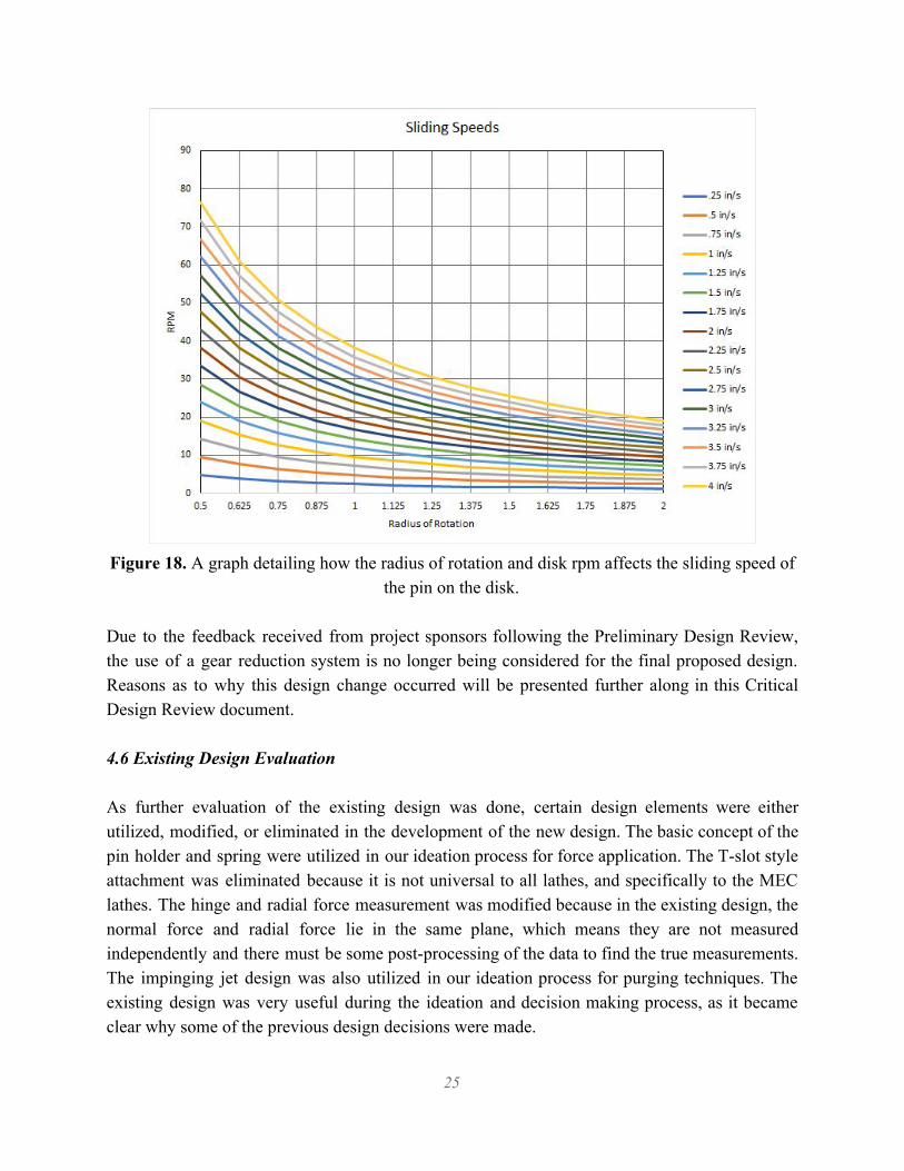
Figure 18. A graph detailing how the radius of rotation and disk rpm affects the sliding speed of
the pin on the disk. Due to the feedback received from project sponsors following the Preliminary Design Review, the use of a gear reduction system is no longer being considered for the final proposed design. Reasons as to why this design change occurred will be presented further along in this Critical Design Review document. 4.6 Existing Design Evaluation As further evaluation of the existing design was done, certain design elements were either utilized, modified, or eliminated in the development of the new design. The basic concept of the pin holder and spring were utilized in our ideation process for force application. The T-slot style attachment was eliminated because it is not universal to all lathes, and specifically to the MEC lathes. The hinge and radial force measurement was modified because in the existing design, the normal force and radial force lie in the same plane, which means they are not measured independently and there must be some post-processing of the data to find the true measurements. The impinging jet design was also utilized in our ideation process for purging techniques. The existing design was very useful during the ideation and decision making process, as it became clear why some of the previous design decisions were made.
25

4.7 Results At the conclusion of the this section of the ideation process four designs remained. Each remaining design was fundamentally different with regards to how the force was to be applied and how the nitrogen was to be contained. The first design used the top scoring force actuating device from the pugh matrix, an internally spring loaded actuation, with a chamber to enclose the nitrogen. As opposed to the spring loaded actuation device, the second design used a pneumatic piston actuation device coupled with a chamber to enclose the nitrogen. The third design again used an internally spring loaded actuation device, however, a chamber was not used to enclose the nitrogen, but yet a nitrogen shielded jet would be used for purging purposes. The fourth and final design consisted of a pneumatic piston for for actuation coupled with the nitrogen shielded jet for purging. These four design were then placed into a final decision matrix, in which all four were rated against each other for design factors such as cost, complexity, manufacturability, performance, safety, and their combined pugh matrix score. This decision matrix has been included in Attachment D. As shown by the decision matrix, the design in which an internally loaded spring force actuator coupled with a nitrogen shielding jet used is top rated. Closely following was that of the internally loaded spring force actuator except with a chamber to contain the nitrogen. While the shielded jet approach scores highly throughout the ideation process, as stated previously under force application considerations, major concerns arose with this concept post ideation. With the shielded jet, the evaluation and feasibility of this concept becomes a matter of fluid mechanics. With limited research into the boundary layer produced by such an impinging jet and how it is to be analyzed, it became difficult to quantify a successful purge for testing using this method. Additionally, ventilation concerns along with cost concerns due to using substantially large amounts of nitrogen in order to adequately complete the purge, the shielded jet was no longer a viable option. At the conclusion of the ideation process, a preliminary design for the wear test machine was obtained. The fixture is to consist of primarily two components, the pin holder and the disk holder. The pin holder will contain an internal spring to be used for force application while the disk will be held by means of a 4” 3-jaw chuck, preferably with reversible jaws. The disk will be housed by a cylindrical chamber composed of material such as plexiglass to allow for visual of the specimen throughout testing. Additionally, a chamber door will allow for easy setup/switch of testing specimen along with the appropriate sealing necessary to maintain purge. Between the lathe chuck and the disk a gear reduction system will be located; a planetary gear set will be used to achieve the sliding speeds necessary for testing. Preliminary concept solid models will be included and further discussed below.
26
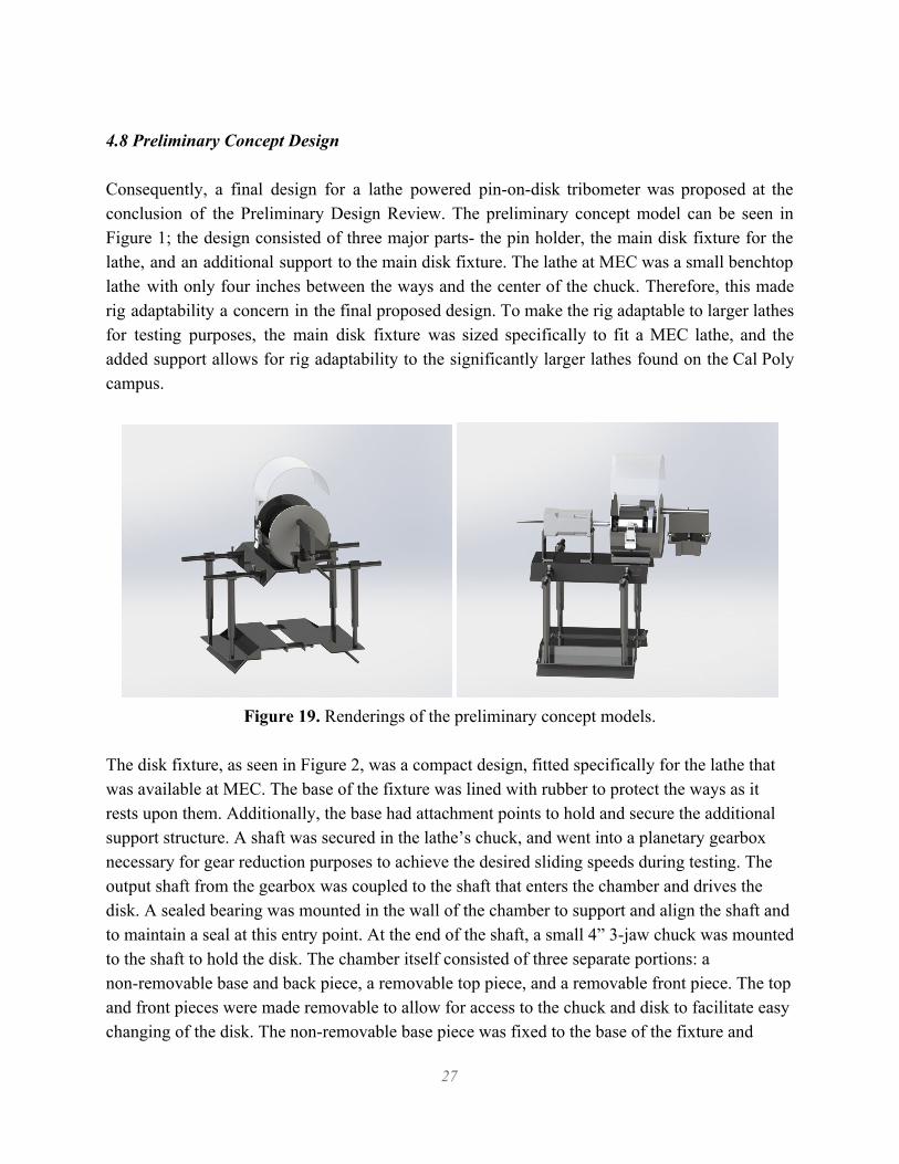
4.8 Preliminary Concept Design Consequently, a final design for a lathe powered pin-on-disk tribometer was proposed at the conclusion of the Preliminary Design Review. The preliminary concept model can be seen in Figure 1; the design consisted of three major parts- the pin holder, the main disk fixture for the lathe, and an additional support to the main disk fixture. The lathe at MEC was a small benchtop lathe with only four inches between the ways and the center of the chuck. Therefore, this made rig adaptability a concern in the final proposed design. To make the rig adaptable to larger lathes for testing purposes, the main disk fixture was sized specifically to fit a MEC lathe, and the added support allows for rig adaptability to the significantly larger lathes found on the Cal Poly campus.
Figure 19. Renderings of the preliminary concept models.
The disk fixture, as seen in Figure 2, was a compact design, fitted specifically for the lathe that was available at MEC. The base of the fixture was lined with rubber to protect the ways as it rests upon them. Additionally, the base had attachment points to hold and secure the additional support structure. A shaft was secured in the lathe’s chuck, and went into a planetary gearbox necessary for gear reduction purposes to achieve the desired sliding speeds during testing. The output shaft from the gearbox was coupled to the shaft that enters the chamber and drives the disk. A sealed bearing was mounted in the wall of the chamber to support and align the shaft and to maintain a seal at this entry point. At the end of the shaft, a small 4” 3-jaw chuck was mounted to the shaft to hold the disk. The chamber itself consisted of three separate portions: a non-removable base and back piece, a removable top piece, and a removable front piece. The top and front pieces were made removable to allow for access to the chuck and disk to facilitate easy changing of the disk. The non-removable base piece was fixed to the base of the fixture and
27
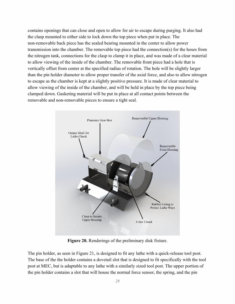
contains openings that can close and open to allow for air to escape during purging. It also had the clasp mounted to either side to lock down the top piece when put in place. The non-removable back piece has the sealed bearing mounted in the center to allow power transmission into the chamber. The removable top piece had the connection(s) for the hoses from the nitrogen tank, connections for the clasp to clamp it in place, and was made of a clear material to allow viewing of the inside of the chamber. The removable front piece had a hole that is vertically offset from center at the specified radius of rotation. The hole will be slightly larger than the pin holder diameter to allow proper transfer of the axial force, and also to allow nitrogen to escape as the chamber is kept at a slightly positive pressure. It is made of clear material to allow viewing of the inside of the chamber, and will be held in place by the top piece being clamped down. Gasketing material will be put in place at all contact points between the removable and non-removable pieces to ensure a tight seal.
Figure 20. Renderings of the preliminary disk fixture.
The pin holder, as seen in Figure 21, is designed to fit any lathe with a quick-release tool post. The base of the the holder contains a dovetail slot that is designed to fit specifically with the tool post at MEC, but is adaptable to any lathe with a similarly sized tool post. The upper portion of the pin holder contains a slot that will house the normal force sensor, the spring, and the pin
28
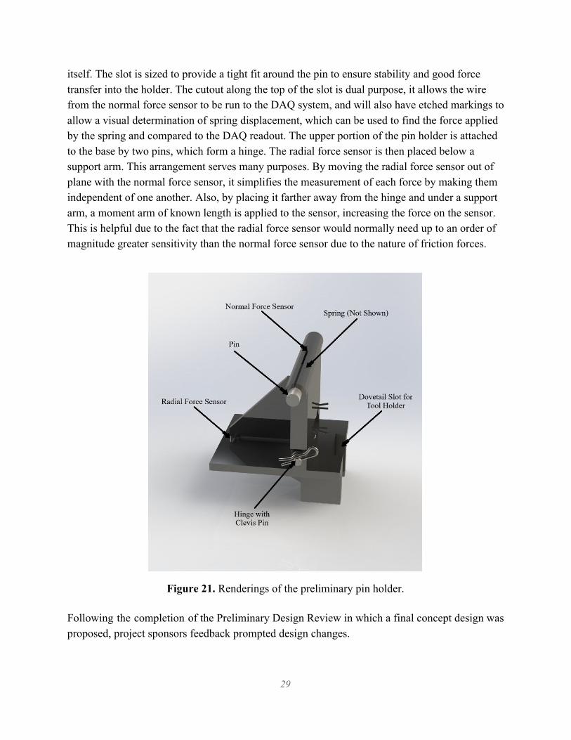
itself. The slot is sized to provide a tight fit around the pin to ensure stability and good force transfer into the holder. The cutout along the top of the slot is dual purpose, it allows the wire from the normal force sensor to be run to the DAQ system, and will also have etched markings to allow a visual determination of spring displacement, which can be used to find the force applied by the spring and compared to the DAQ readout. The upper portion of the pin holder is attached to the base by two pins, which form a hinge. The radial force sensor is then placed below a support arm. This arrangement serves many purposes. By moving the radial force sensor out of plane with the normal force sensor, it simplifies the measurement of each force by making them independent of one another. Also, by placing it farther away from the hinge and under a support arm, a moment arm of known length is applied to the sensor, increasing the force on the sensor. This is helpful due to the fact that the radial force sensor would normally need up to an order of magnitude greater sensitivity than the normal force sensor due to the nature of friction forces.
Figure 21. Renderings of the preliminary pin holder. Following the completion of the Preliminary Design Review in which a final concept design was proposed, project sponsors feedback prompted design changes.
29

4.9 Factors Prompting Design Changes As stated at the beginning of this Critical Design document, the R&D team at MEC previously utilized a benchtop lathe. The lathe at MEC heavily influenced the initial proposed design since it required that the rig be adaptable to larger lathes for testing purposes. However, since the completion of PDR, MEC acquired a new, much larger, lathe. So while the previous design required rig adaptability to larger lathes, that is no longer the case and resulted in significant design changes post PDR. Additionally, the design proposed during PDR involved the use of a gear reduction box to obtain the sliding speed MEC specified at the initiation of this project. However, after PDR, the project sponsors raised concerns about the inclusion of a gearbox in the final design. With the inclusion of a gearbox and additional components such as the couplings, additional variables of concern are introduced as well. Firstly, the concept of using a lathe as a means for powering this fixture arose from the fact that lathes are intrinsically rigid, precise, and controllable. With additional components branching off of the lathe, i.e. the gearbox and respective couplings, these intrinsic properties diminish fairly quickly. The inclusion of a gearbox increases the possibility for misalignment in the perpendicularity between the pin and the disk which is a critical to obtaining accurate forces throughout the testing process. Secondly, including a gearbox increases the complexity of the design, thus increasing the time it takes to assemble and disassemble the wear testing device. Since the lathe at MEC is located in a shared space, the project specifications called for an assembly/disassembly time below 30 minutes. A more complex design has the potential to cause greater assembly/disassembly time, resulting in a failure to meet the initial project specifications. Furthermore, a more complex design has a greater impact on the specified budget, introducing budgetary concerns. Including the gear reduction adds more cost to the project than originally intended and could potentially result in limited options with regards to the DAQ system. Thus, focus was placed on designing a rigid fixture that slides into an AXA series lathe tool post. As outlined in this CDR report, in order to achieve the desired sliding speeds for testing, it became necessary to consider various gear reduction methods. However, with these concerns raised regarding the inclusion of the gear reduction box in the design, it became necessary to re-evaluate the project specifications. For with the elimination of the gearbox, the initial specification of a sliding speed between 1 in/s and 4 in/s would no longer be satisfied. Therefore, MEC modified the sliding speed specification to allow for a more broad range of testing parameters, indicating that future projects will require testing at higher speeds than initially anticipated. Updated specifications call for the design to achieve a new 4 in/s minimum sliding speed.
30

In addition to a change in the project sliding speed specification, the elimination of the gearbox has other consequences. As can be seen in the following Table 5, a higher RPM results in a larger range of speeds across the head of the pin. With a testing specimen of ⅜ inches, at some radi, the pin could be experiencing significantly different magnitude sliding speeds across its head. MEC has indicated that this variation in speeds across the head of the pin will be monitored throughout testing.
Table 5. The radius of rotation of the pin specimen and the corresponding sliding speed at 120 RPM.
5.0 CDR Design Minor changes in project requirements resulted in significant changes to the final proposed design. However, the final design still follows the completed decision/pugh matrices included at the beginning of this document. The final design proposed post CDR highlights the following features; There is no longer a convoluted disk assembly, the design incorporates a modified pin holder and lathe features to add variable radius of rotation capabilities, and lastly, the final design utilizes a simplified chamber and sealing mechanism. The PDR design concept and the final proposed design concept can be seen in Figure 22.
31
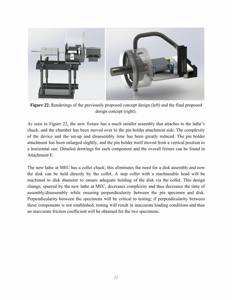
Figure 22. Renderings of the previously proposed concept design (left) and the final proposed
design concept (right).
As seen in Figure 22, the new fixture has a much smaller assembly that attaches to the lathe’s chuck, and the chamber has been moved over to the pin holder attachment side. The complexity of the device and the set-up and disassembly time has been greatly reduced. The pin holder attachment has been enlarged slightly, and the pin holder itself moved from a vertical position to a horizontal one. Detailed drawings for each component and the overall fixture can be found in Attachment E. The new lathe at MEC has a collet chuck; this eliminates the need for a disk assembly and now the disk can be held directly by the collet. A step collet with a machineable head will be machined to disk diameter to ensure adequate holding of the disk via the collet. This design change, spurred by the new lathe at MEC, decreases complexity and thus decreases the time of assembly/disassembly while ensuring perpendicularity between the pin specimen and disk. Perpendicularity between the specimens will be critical to testing; if perpendicularity between these components is not established, testing will result in inaccurate loading conditions and thus an inaccurate friction coefficient will be obtained for the two specimens.
32
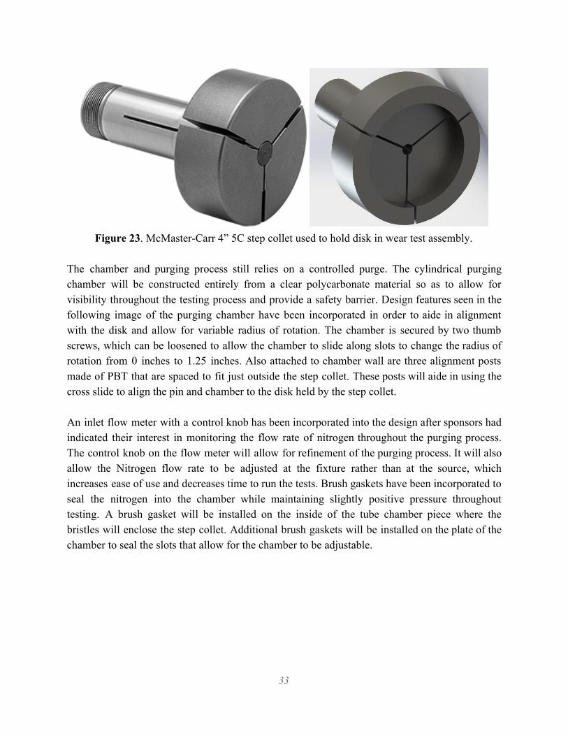
Figure 23. McMaster-Carr 4” 5C step collet used to hold disk in wear test assembly.
The chamber and purging process still relies on a controlled purge. The cylindrical purging chamber will be constructed entirely from a clear polycarbonate material so as to allow for visibility throughout the testing process and provide a safety barrier. Design features seen in the following image of the purging chamber have been incorporated in order to aide in alignment with the disk and allow for variable radius of rotation. The chamber is secured by two thumb screws, which can be loosened to allow the chamber to slide along slots to change the radius of rotation from 0 inches to 1.25 inches. Also attached to chamber wall are three alignment posts made of PBT that are spaced to fit just outside the step collet. These posts will aide in using the cross slide to align the pin and chamber to the disk held by the step collet. An inlet flow meter with a control knob has been incorporated into the design after sponsors had indicated their interest in monitoring the flow rate of nitrogen throughout the purging process. The control knob on the flow meter will allow for refinement of the purging process. It will also allow the Nitrogen flow rate to be adjusted at the fixture rather than at the source, which increases ease of use and decreases time to run the tests. Brush gaskets have been incorporated to seal the nitrogen into the chamber while maintaining slightly positive pressure throughout testing. A brush gasket will be installed on the inside of the tube chamber piece where the bristles will enclose the step collet. Additional brush gaskets will be installed on the plate of the chamber to seal the slots that allow for the chamber to be adjustable.
33

Figure 24. Rendering of the purging chamber, manufactured using clear polycarbonate to allow
for visibility during testing.
As previously stated, with the elimination of the gearbox in the design, emphasis was placed on designing a rigid fixture that is capable of sliding into an AXA series lathe tool post. Therefore, the pin holder base was redesigned, enabling it to attach to the lathe carriage via an AXA tool holder. The pin holder base will attach to the tool post using the screw holes typically used for securing the cutting tool in place. The pin holder base supports the pin holder, the radial force sensor, the nitrogen flow meter, and the purging chamber. The new design of the pin holder base features alignment of the pin holder and the radial force sensor that allows for the force to be transmitted 100%; No scaling or additional analysis needed, as was necessary with the previous design. This allows for the radial force to be read directly from the DAQ system. The main Z-shaped body of the pin holder base will be machined from a single piece of Aluminum. During this operation, additional slots will be machined out to locate various support plates that hold and support the pin holder itself. This technique was selected to ensure the pin holder is installed in such a manner that perpendicularity is achieved. Two gusset plates will be welded to the underside of the base to stiffen, reduce deflection and and reduce vibration during testing. An additional support post will be welded onto the base that will support the purging chamber. Thumb screws are used to attach the purge chamber to the pin holder base.
34
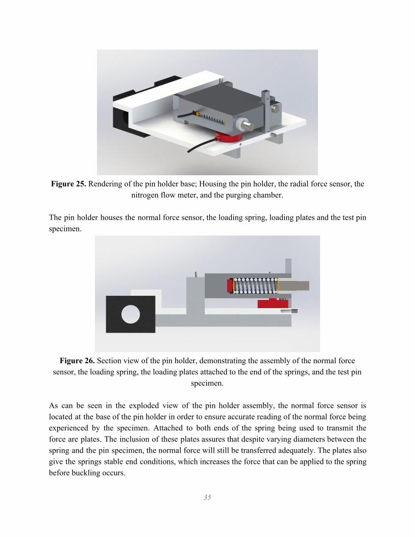
Figure 25. Rendering of the pin holder base; Housing the pin holder, the radial force sensor, the
nitrogen flow meter, and the purging chamber. The pin holder houses the normal force sensor, the loading spring, loading plates and the test pin specimen.
Figure 26. Section view of the pin holder, demonstrating the assembly of the normal force
sensor, the loading spring, the loading plates attached to the end of the springs, and the test pin specimen.
As can be seen in the exploded view of the pin holder assembly, the normal force sensor is located at the base of the pin holder in order to ensure accurate reading of the normal force being experienced by the specimen. Attached to both ends of the spring being used to transmit the force are plates. The inclusion of these plates assures that despite varying diameters between the spring and the pin specimen, the normal force will still be transferred adequately. The plates also give the springs stable end conditions, which increases the force that can be applied to the spring before buckling occurs.
35

Additionally, the design for the pin holder allows for interchangeable springs; interchangeable springs were included to allow for better force resolution across the wide range of loading requirements. Both springs have an uncompressed length of 1.75 inches, Spring 1 has spring constant of 12 lbs/in, while Spring 2 has a spring constant of 278 lbs/in. Spring 2 meets the loading specifications of 1.1 lbF to 111 lbF, however the compression required to get low forces is very small. Spring 1 was chosen to allow for greater resolution of force at the smaller loads. A concern while selecting springs was the potential for buckling. Calculations were done to ensure the springs will not exceed forces that would lead to buckling based on ideal end conditions. However, as we may not be able to design ideal end conditions, we will address any buckling during testing. Also seen in the exploded view, is a bushing that will be used to secure the pin specimen in the pin holder. The size of the normal force sensor and the spring diameter, as well as the ability to maintain access to these parts, required the pin to be held in place by a bushing. Additionally, as stated throughout this document, perpendicularity between the pin and disk is vital to obtain accurate values for the friction coefficients. The inclusion of a bushing will further assist in maintaining this perpendicularity and will help reduce vibrations in the pin while sliding along the disk during testing. 5.1 Data Acquisition System With regards to the data acquisition system, extensive time was spent in finding a system meeting the specifications of the project and the needs of our sponsor. MEC has approved the purchase of sensor and DAQ equipment from Transducer Techniques or Omega Engineering. It became apparent during evaluation of the available sensors from each vendor that Transducer Techniques had the preferred sensors. This because they have sensors that are TEDS compliant. TEDS, Transducer Electronic Data Sheet, allows for critical sensor information to be stored in EEPROM on the sensor itself. This essentially allows for the sensor to be used as a plug and play device. Critical information is stored in TEDS that allows the sensor and a compatible meter to properly calibrate, interface, scale, and characterize the sensors output automatically. This capability greatly increases ease of use for MEC, which will aide in meeting the criteria of a set-up of time of less than 30 minutes. After preferred sensors were selected, a compatible meter or data logger was needed. However, most of the available meters that were TEDS compliant only had a single input, which meant that two meters or data loggers would be required to receive the signal from our two sensors. Initially a portable data logger was the preferred device, but two of the devices would not work within
36
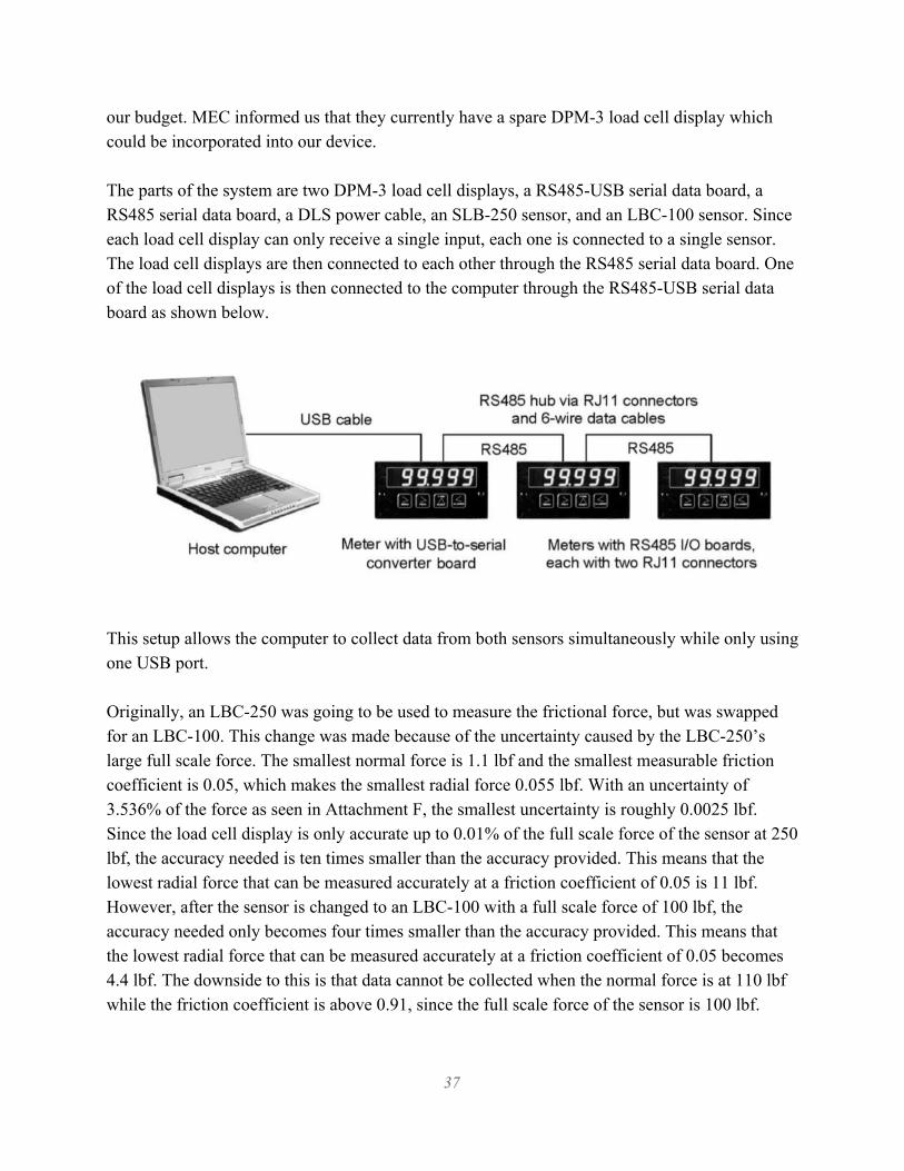
our budget. MEC informed us that they currently have a spare DPM-3 load cell display which could be incorporated into our device. The parts of the system are two DPM-3 load cell displays, a RS485-USB serial data board, a RS485 serial data board, a DLS power cable, an SLB-250 sensor, and an LBC-100 sensor. Since each load cell display can only receive a single input, each one is connected to a single sensor. The load cell displays are then connected to each other through the RS485 serial data board. One of the load cell displays is then connected to the computer through the RS485-USB serial data board as shown below.
This setup allows the computer to collect data from both sensors simultaneously while only using one USB port. Originally, an LBC-250 was going to be used to measure the frictional force, but was swapped for an LBC-100. This change was made because of the uncertainty caused by the LBC-250’s large full scale force. The smallest normal force is 1.1 lbf and the smallest measurable friction coefficient is 0.05, which makes the smallest radial force 0.055 lbf. With an uncertainty of 3.536% of the force as seen in Attachment F, the smallest uncertainty is roughly 0.0025 lbf. Since the load cell display is only accurate up to 0.01% of the full scale force of the sensor at 250 lbf, the accuracy needed is ten times smaller than the accuracy provided. This means that the lowest radial force that can be measured accurately at a friction coefficient of 0.05 is 11 lbf. However, after the sensor is changed to an LBC-100 with a full scale force of 100 lbf, the accuracy needed only becomes four times smaller than the accuracy provided. This means that the lowest radial force that can be measured accurately at a friction coefficient of 0.05 becomes 4.4 lbf. The downside to this is that data cannot be collected when the normal force is at 110 lbf while the friction coefficient is above 0.91, since the full scale force of the sensor is 100 lbf.
37
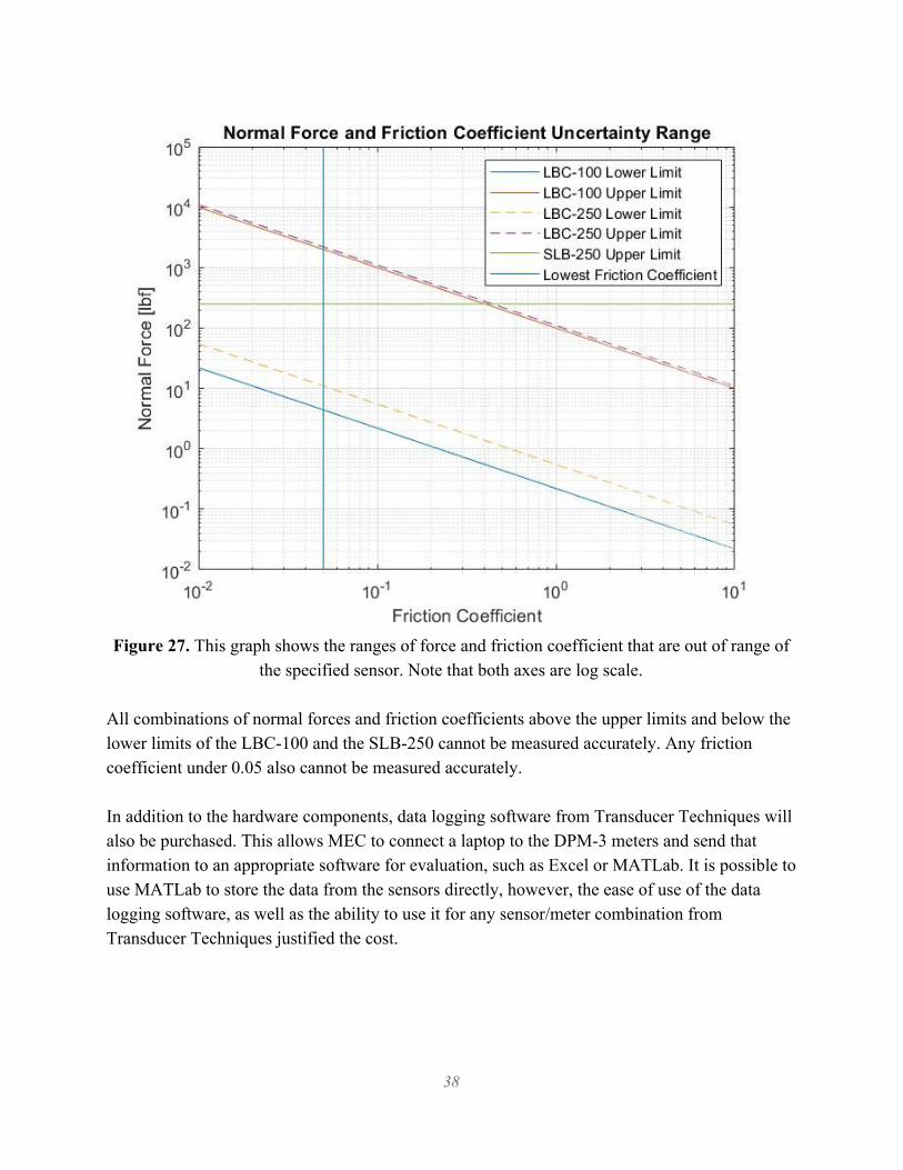
Figure 27. This graph shows the ranges of force and friction coefficient that are out of range of
the specified sensor. Note that both axes are log scale. All combinations of normal forces and friction coefficients above the upper limits and below the lower limits of the LBC-100 and the SLB-250 cannot be measured accurately. Any friction coefficient under 0.05 also cannot be measured accurately. In addition to the hardware components, data logging software from Transducer Techniques will also be purchased. This allows MEC to connect a laptop to the DPM-3 meters and send that information to an appropriate software for evaluation, such as Excel or MATLab. It is possible to use MATLab to store the data from the sensors directly, however, the ease of use of the data logging software, as well as the ability to use it for any sensor/meter combination from Transducer Techniques justified the cost.
38

5.2 Safety, Maintenance and Repair Safety is a important design factor in any device, and we have incorporated many safety measures. All safety concerns have been evaluated in the project Design Hazard Checklist which can be found in Attachment G. The chamber itself, being made of clear impact-resistant polycarbonate, will protect the user from and catastrophic failure at the pin and disk contact area. Attaching all components directly and securely to the lathe also uses the lathes intrinsic rigidity as a safety feature, ensuring that the entire device is stable and secure. Another area of concern is the nitrogen purge. The chamber size was reduced to allow for less nitrogen to be used during testing, and a flow meter with a control knob mounted on the pin holder attachment allows for the user to modify or shut of the Nitrogen flow from the test fixture. It is still recommended that the Nitrogen purge only be done in a location with proper ventilation. The device should require minimal maintenance over its lifespan. The disk and pin will be replaced after every test due to the requirements of each test. The springs inside the pin holder are easily accessible and are readily available for replacement on McMaster-Carr if needed. The sensors self-calibrate because of their TEDS capabilities, but are both easily accessible if they need to be inspected or replaced. All components are readily available from McMaster-Carr or Transducer Techniques, allow for easy replacement if needed. The system was designed with minimal welding processes done, so that most components can be replaced with ease. 5.3 Material Selection and Sizing The material for the pin and disk is the main focus of the device, material selection for the fabrication of the device was important as well. Stainless steel and aluminum were selected as the preferred materials for construction of the pin holder assembly for their availability and corrosion resistance. Upon developing the budget, the price of stainless steel became prohibitive and aluminum was chosen for the majority of fabricated parts. A single block of aluminum was machined to the final geometry of the base plate. Strength analysis was done on the device and the small size and relatively low loading of 110 lbF was verified to be below the allowable stress for the aluminum. The chamber material was chosen based on the requirement of being clear to allow visual observation during testing. Clear polycarbonate was chosen for its high strength and impact resistance, as well as its low cost.
39
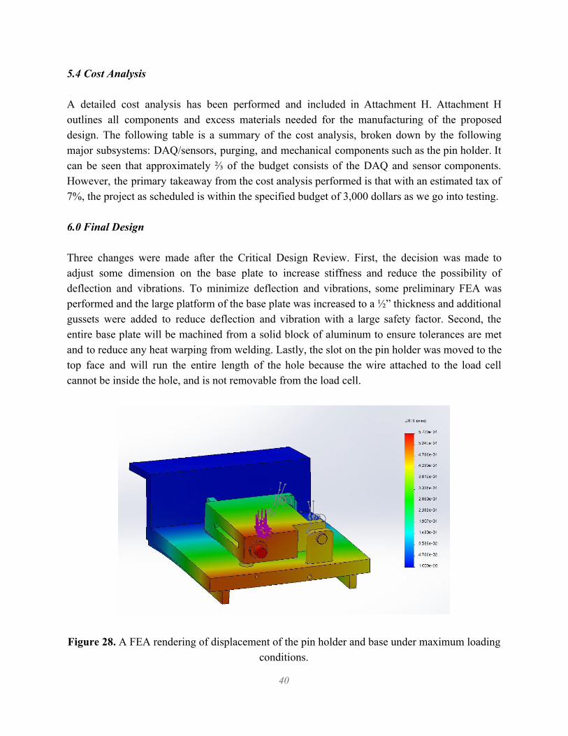
5.4 Cost Analysis A detailed cost analysis has been performed and included in Attachment H. Attachment H outlines all components and excess materials needed for the manufacturing of the proposed design. The following table is a summary of the cost analysis, broken down by the following major subsystems: DAQ/sensors, purging, and mechanical components such as the pin holder. It can be seen that approximately ⅔ of the budget consists of the DAQ and sensor components. However, the primary takeaway from the cost analysis performed is that with an estimated tax of 7%, the project as scheduled is within the specified budget of 3,000 dollars as we go into testing. 6.0 Final Design Three changes were made after the Critical Design Review. First, the decision was made to adjust some dimension on the base plate to increase stiffness and reduce the possibility of deflection and vibrations. To minimize deflection and vibrations, some preliminary FEA was performed and the large platform of the base plate was increased to a ½” thickness and additional gussets were added to reduce deflection and vibration with a large safety factor. Second, the entire base plate will be machined from a solid block of aluminum to ensure tolerances are met and to reduce any heat warping from welding. Lastly, the slot on the pin holder was moved to the top face and will run the entire length of the hole because the wire attached to the load cell cannot be inside the hole, and is not removable from the load cell.
Figure 28. A FEA rendering of displacement of the pin holder and base under maximum loading
conditions.
40
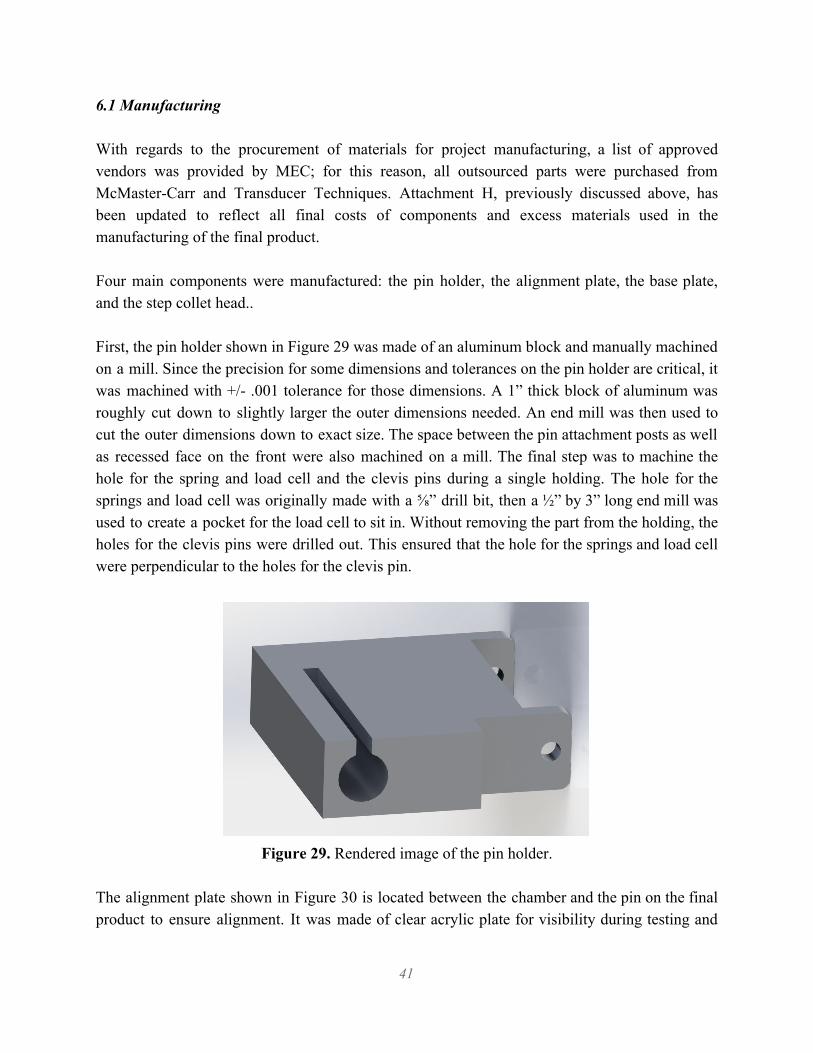
6.1 Manufacturing With regards to the procurement of materials for project manufacturing, a list of approved vendors was provided by MEC; for this reason, all outsourced parts were purchased from McMaster-Carr and Transducer Techniques. Attachment H, previously discussed above, has been updated to reflect all final costs of components and excess materials used in the manufacturing of the final product. Four main components were manufactured: the pin holder, the alignment plate, the base plate, and the step collet head.. First, the pin holder shown in Figure 29 was made of an aluminum block and manually machined on a mill. Since the precision for some dimensions and tolerances on the pin holder are critical, it was machined with +/- .001 tolerance for those dimensions. A 1” thick block of aluminum was roughly cut down to slightly larger the outer dimensions needed. An end mill was then used to cut the outer dimensions down to exact size. The space between the pin attachment posts as well as recessed face on the front were also machined on a mill. The final step was to machine the hole for the spring and load cell and the clevis pins during a single holding. The hole for the springs and load cell was originally made with a ⅝” drill bit, then a ½” by 3” long end mill was used to create a pocket for the load cell to sit in. Without removing the part from the holding, the holes for the clevis pins were drilled out. This ensured that the hole for the springs and load cell were perpendicular to the holes for the clevis pin.
Figure 29. Rendered image of the pin holder.
The alignment plate shown in Figure 30 is located between the chamber and the pin on the final product to ensure alignment. It was made of clear acrylic plate for visibility during testing and
41

for safety during laser cutting as polycarbonate produces toxic fumes and cannot be cut on the laser cutter. The laser cutter in Mustang 60 was used to manufacture the alignment plate.
Figure 30. Rendered image of the alignment plate.
The base plate was CNC machined out of a aluminum block. As shown in Figure 31, there is a Z shaped base plate, two pin holder locators, a pin force brace, and a column with a screw hole for the alignment plate. The decision to CNC machine the pin holder base stemmed from a need for precision since some dimensions and tolerances on the pin holder are critical to successful operation of the final product. Since it was important to maintain pin and disk perpendicularity throughout testing, the pin holder required tight tolerances to assist in achieving this. To reduce cost and CNC time, only the top of the pin holder base was done by CNC. The bottom and back end where the support gussets are located, as well as the space for the tool holder to attached were milled manually. Due to machining these features after the CNC was completed and the odd geometry after machining, a 1-2-3 block and shims were used to obtain a flat surface, which was checked by a dial indicator. Also, upon receiving the part from CNC, the rear clevis pin hole was not drilled all the way through. The part was manually adjusted in a vice to re-drill the hole to the best of our ability, but in doing so the guarantee of perpendicularity was lost.
42

Figure 31. Rendered image of the baseplate which will attach directly to the lathe via an AXA
tool holder.
For a test specimen pin, ⅜ inch diameter 304 Stainless Steel alloy steel rods was purchased from McMaster-Carr; because the minimum length is 1 foot long, they were cut down to a desired length for testing and both ends were machined to have flat and perpendicular surfaces. The 3” disk that was purchased from McMaster-Carr had a rough surface finish on both sides, so we decided to face one side on a lathe to get a better finish for the better testing data. After facing the side at a very slow constant speed, we were able to get a smooth surface finish that we desired. Machining the 5C Machinable Head Step Collet was one of the most difficult pieces to machine on campus due to the fact that there are no 5C chucks for any of the machines. After discussion with many shop techs and advisors, we started to machine the step collet on a lathe using a 5C hex block to hold it in the 3-Jaw chuck, and proceeded to bore out about a 1” diameter, ½” deep hole. At the point where the slots in the step collet transition from about a 1/16” to ⅛”, this larger interrupted cut broke two carbide boring bits before we decided to change to a mill. Using the same 5C hex block and a rotary vice on a mill, as seen in Figure 32, the step collet was machined to its final dimensions of a 3.01” diameter. This diameter allows the disk to be easily inserted into the head, but when the collet is place in the hex block or a chuck, it will clamp down with sufficient force to hold the disk in place.
43
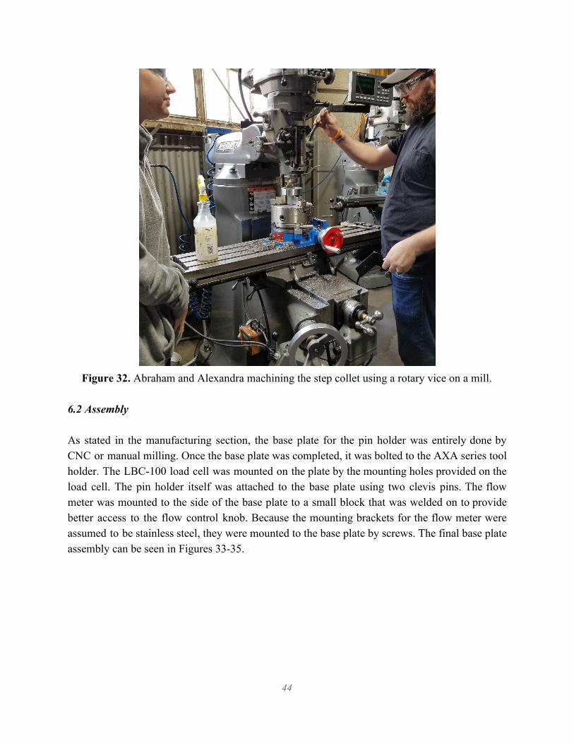
Figure 32. Abraham and Alexandra machining the step collet using a rotary vice on a mill.
6.2 Assembly As stated in the manufacturing section, the base plate for the pin holder was entirely done by CNC or manual milling. Once the base plate was completed, it was bolted to the AXA series tool holder. The LBC-100 load cell was mounted on the plate by the mounting holes provided on the load cell. The pin holder itself was attached to the base plate using two clevis pins. The flow meter was mounted to the side of the base plate to a small block that was welded on to provide better access to the flow control knob. Because the mounting brackets for the flow meter were assumed to be stainless steel, they were mounted to the base plate by screws. The final base plate assembly can be seen in Figures 33-35.
44

Figure 33. Top view of assembled base plate.
Figure 34. Front view of assembled base plate.
45
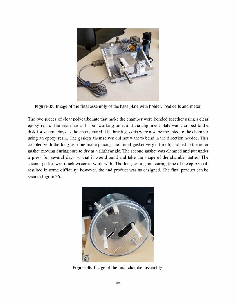
Figure 35. Image of the final assembly of the base plate with holder, load cells and meter.
The two pieces of clear polycarbonate that make the chamber were bonded together using a clear epoxy resin. The resin has a 1 hour working time, and the alignment plate was clamped to the disk for several days as the epoxy cured. The brush gaskets were also be mounted to the chamber using an epoxy resin. The gaskets themselves did not want to bend in the direction needed. This coupled with the long set time made placing the initial gasket very difficult, and led to the inner gasket moving during cure to dry at a slight angle. The second gasket was clamped and put under a press for several days so that it would bend and take the shape of the chamber better. The second gasket was much easier to work with; The long setting and curing time of the epoxy still resulted in some difficulty, however, the end product was as designed. The final product can be seen in Figure 36.
Figure 36. Image of the final chamber assembly.
46

The three guide posts in the chamber were screwed in place by 1 ½” long flat head screws. The guide posts, made of slippery polyester, were cut to length, with a pilot hole drilled in one end for the screw, and then held in place with vice grips while the screw was tightened. The chamber itself is mounted to the pin holder using two thumb screws and two threaded holes in the base plate. These holes were not drilled deep enough during CNC and had to be re-drilled and then tapped. However, because the hole is aluminum and the thumb screws are stainless steel, the hole threads got stripped rather quickly. This was addressed by adding teflon tape to the thread on the thumb screws.
7.0 Design Verification Prior to the commencement of material wear testing, a computational fluid dynamics analysis was performed in order to better visualize the flow pattern of nitrogen throughout the purging process. Initially, CFD was requested by the sponsor to validate the purging process of oxygen from the chamber. This was to be accomplished through the use of CFD software to model a multiple fluid flow, which would model the displacement of the oxygen with respect to the nitrogen as well as indicate the remaining oxygen levels in the chamber; These values obtained from the model would then be used to establish a purging time for the purpose of testing. To obtain insight into creating this model, a meeting was held with Kim Schollenberger, a Fluid Dynamics Professor from California Polytechnic State University who specializes in the diagnostic development and experimental design for thermal/fluid systems. After introducing her to the system and the potential for CFD analysis, Professor Schollenberger indicated that a model of this nature was not necessary for our application. For once a model was completed, without purchasing a sensor to measure oxygen levels in the chamber, there would be no way to ensure the model was accurately modeling the behavior of the system; Additionally, there would be no way to validate the values obtained for the oxygen remaining in the tank with respect to the length of the nitrogen purge. Since we are after the time necessary to adequately purge the system, she suggested that a CFD model of this complexity was unnecessary. In order to ensure that the chamber is purged of oxygen, Professor Schollenberger recommended a dynamic test be performed on material specimens of known wear, purging the chamber using a large factor of safety until the known wear characteristics are displayed. However, there is very little empirical data for friction measurements in a Nitrogen environment. With this recommendation, a CFD analysis was not used to determine the appropriate time for the purging process; However, an analysis was performed in order to obtain a better visual as to the fluid flow during the dilution purging process with the rotating disk at the center of the chamber.
47

Figure 37 includes an image of the model created for this application; Swirling flow in a cylindrical container with a rotating top face was used to model the system. Some considerations in constructing this model include- only one fluid is considered in this model, the cylinder dimensions are the same as those of the physical chamber, a boundary condition was inserted on the cylinder face with a set angular velocity to account for the rotation of the disk inside the chamber and its effect on fluid flow. Figure 38 includes a view of the enclosure with flow streamlines obtained by inserting flow trajectories into the model.
Figure 37. Model of swirling flow in a cylindrical container with a rotating lid.
48

Figure 38. Front plane flow streamlines.
The next design validation test was material wear testing. Material wear testing was conducted at Cal Poly Mustang 60. Each sensor was initially tested individually against static loads to ensure that the sensor and meter were working properly. This was done by using the carriage to compress the spring as would be done in normal operation, but with the disk stationary, to test the readouts of the normal force sensor. This initial testing resulted in the sensors indicating normal force values significantly lower than expected. The expected force values were approximated using Hooke’s law by simply knowing the characteristic spring constant as well as how far the carriage is displacing the spring. It was determined that the error was a result of buckling within the smaller of the two springs. Since the larger spring is larger in diameter, this enables it to be better centered on the spring end plates and thus, better directly transmit the normal force to the sensor. However, the spring smaller in diameter had more difficulty staying centered on the end plates; This caused buckling to occur, explaining why the forces being read out by the sensor were lower in magnitude than the force actually being applied. To rectify this, end caps were 3D printed which were used to beter center and stabilize the smaller of the two springs in an attempt to eliminate the buckling. With these end caps positioned on the smaller spring, static testing was again performed. The radial force sensor was tested by hanging a weight at the end of the pin to simulate the radial force. This test was done by hanging a 1.97 lb weight from the pin, and the resulting average load read by the load cell was 2.02 lb. This error of 2.5% is within acceptable limits.
49
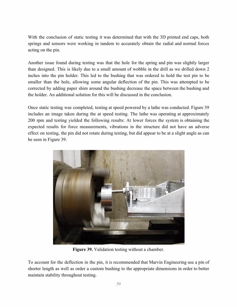
With the conclusion of static testing it was determined that with the 3D printed end caps, both springs and sensors were working in tandem to accurately obtain the radial and normal forces acting on the pin. Another issue found during testing was that the hole for the spring and pin was slightly larger than designed. This is likely due to a small amount of wobble in the drill as we drilled down 2 inches into the pin holder. This led to the bushing that was ordered to hold the test pin to be smaller than the hole, allowing some angular deflection of the pin. This was attempted to be corrected by adding paper shim around the bushing decrease the space between the bushing and the holder. An additional solution for this will be discussed in the conclusion. Once static testing was completed, testing at speed powered by a lathe was conducted. Figure 39 includes an image taken during the at speed testing. The lathe was operating at approximately 200 rpm and testing yielded the following results: At lower forces the system is obtaining the expected results for force measurements, vibrations in the structure did not have an adverse effect on testing, the pin did not rotate during testing, but did appear to be at a slight angle as can be seen in Figure 39.
Figure 39. Validation testing without a chamber.
To account for the deflection in the pin, it is recommended that Marvin Engineering use a pin of shorter length as well as order a custom bushing to the appropriate dimensions in order to better maintain stability throughout testing.
50
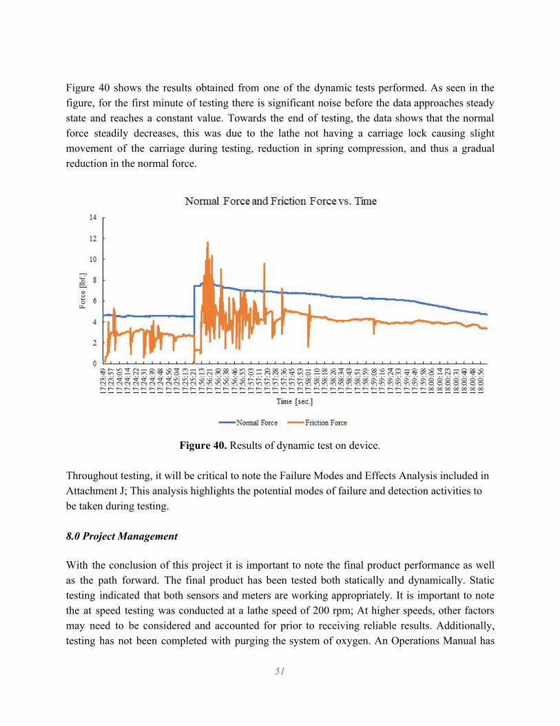
Figure 40 shows the results obtained from one of the dynamic tests performed. As seen in the figure, for the first minute of testing there is significant noise before the data approaches steady state and reaches a constant value. Towards the end of testing, the data shows that the normal force steadily decreases, this was due to the lathe not having a carriage lock causing slight movement of the carriage during testing, reduction in spring compression, and thus a gradual reduction in the normal force.
Figure 40. Results of dynamic test on device.
Throughout testing, it will be critical to note the Failure Modes and Effects Analysis included in Attachment J; This analysis highlights the potential modes of failure and detection activities to be taken during testing. 8.0 Project Management With the conclusion of this project it is important to note the final product performance as well as the path forward. The final product has been tested both statically and dynamically. Static testing indicated that both sensors and meters are working appropriately. It is important to note the at speed testing was conducted at a lathe speed of 200 rpm; At higher speeds, other factors may need to be considered and accounted for prior to receiving reliable results. Additionally, testing has not been completed with purging the system of oxygen. An Operations Manual has
51

been included in Attachment L; This operation manual includes the mechanical system setup, the hardware and software setup, as well as troubleshooting information obtained through our own experience with setting up the system in its entirety.
9.0 Conclusion
For this project, the team was tasked to design and build a friction wear test fixture using a pin-on-disc configuration that is adaptable to the lathes used at MEC. The pin and disk material were designed to both be interchangeable, allowing the testing of various material pairings. The test fixture measures the applied axial and resulting friction drag loads on the pin test specimen in order to characterize material pairing friction coefficients over time. Additionally, the final design allows for testing to be completed in a de-oxygenated environment, as requested by MEC. Both the static and dynamic testing of the system indicates that the final designed product is capable of meeting the goals outlined by this project. However, further testing may be necessary to characterize the behavior of the system at lathe speeds above and below 200 rpm. Additionally, while the system was designed and is capable of performing material wear tests in a de-oxygenated environment, no testing was performed with the system purged of oxygen. As with any design, manufacture and test process, experience and knowledge gained throughout the process gives insight into an improved iteration or modifications to the existing device. One example of this is the packing and overall assembly of the springs and pin into the pin holder. Even after modifying the spring end plates, the smaller spring still experienced some bucking and was not completely centered on the plates, leading to smaller loads from the load cell than expected. While we can correct for this with a correction factor applied to the data, a better solution would be implement something similar to a collapsible rod that attaches to the center of the end plate to keep the spring aligned along the axis. Another possible solution is to manufacture a type of sleeve that centers the spring in place. Finally, custom springs sized to the spring constant and diameter required could be used. Additionally, due to the larger hole diameter in the pin holder, a drill bushing with a custom outer diameter can be made to eliminate the space between the bushing and hole. Alternatively, the hole can be reamed for tighter tolerance with the a new bushing. The deflection we saw during testing can also be reduced by having shorter springs, allowing for more of the test pin and drill bushing to be housed inside the hole, therefore increasing stability and reducing deflection.
52

Lastly, a better gasketing solution is recommended. Not only due to difficulties that arose during installation of the gaskets, but also because once the gaskets were installed, it became difficult to reach inside the chamber, which is need to adjust the thumb screws for attachment and alignment to the base plate. The chamber should be easily adjustable to radii of rotations, and currently that task is more difficult that it should be. Any solution would require a new chamber to be made, which is readily done as extra polycarbonate tube was ordered initially. As simple solution to this is to shorten the chamber and install the brush gaskets on the outside circular face of the chamber, facing axially. This moves the brushes from hitting the center post of the collet chuck to hitting the back face of the collet chuck. The following list includes the project teams recommended course of action for MEC upon receiving the final product:
1. Perform at speed testing for lathe speeds above and below 200 rpm on known material pairs to ensure the system is yielding expected results; As was done previously and included in this document at a lathe speed of 200 rpm.
2. Connect the nitrogen supply line to the flow meter once the system has been setup for testing in a de-oxygenated environment.
3. Decrease length of pin specimen in order to reduce deflection of pin during at speed testing.
4. Specify shorter springs to allow for more of the pin to be within the chamber to increase stability of the pin.
5. Order a custom bushing for the pin specimen to maintain stability throughout testing; This would have been completed by the project team had it not been for the long lead time associated with custom parts.
53
Attachments: [A] ASTM G99 Standard Test Method for Wear Testing with a Pin on Disk Apparatus. [B] Quality Function Development Table. [C] Pugh Matrices. [D] Decision Matrix. [E] Drawing Package [F] DAQ Uncertainty Calculation [G] Design Hazard Checklist [H] Project Budget [J] FMEA [K] Gantt Chart [L] Operations Manual
References
ASTM G99, 2000, “Standard Test Method for Wear Testing with a Pin-on-Disk Apparatus,” ASTM International, West Conshohocken, PA, 2000, www.astm.org. “Data Acquisition.” Using NI-TimeSync to Configure IEEE 1588 and 802.1AS Time References - National Instruments, www.ni.com/data-acquisition. “What Is Data Acquisition?” Using NI-TimeSync to Configure IEEE 1588 and 802.1AS Time References - National Instruments, www.ni.com/data-acquisition/what-is. “Pressure Measurement Overview.” Using NI-TimeSync to Configure IEEE 1588 and 802.1AS Time References - National Instruments, www.ni.com/white-paper/13034/en/. “Measuring Load and Torque with Bridge-Based Sensors.” Using NI-TimeSync to Configure IEEE 1588 and 802.1AS Time References - National Instruments, www.ni.com/white-paper/14352/en/.
54
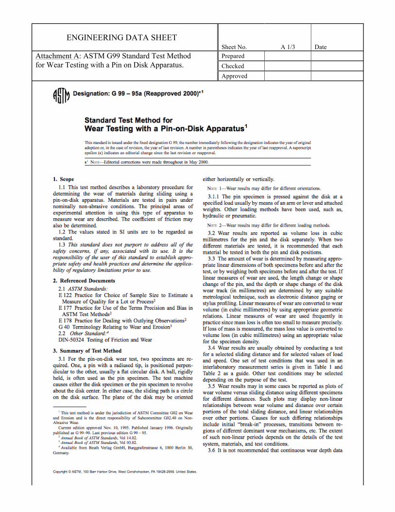
ENGINEERING DATA SHEET Sheet No. A 1/3 Date
Attachment A: ASTM G99 Standard Test Method for Wear Testing with a Pin on Disk Apparatus.
Prepared Checked Approved

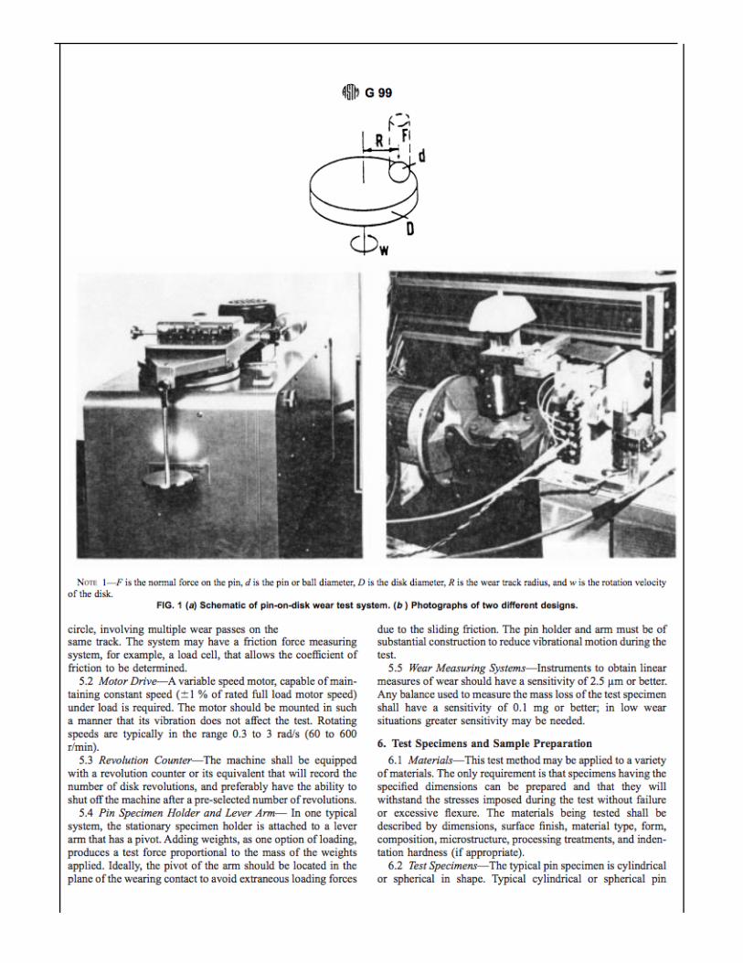

ENGINEERING DATA SHEET Sheet No. B 1/1 Date
Attachment B: Quality Function Development Table Prepared Checked Approved
Figure C1. Figure shows a section of the developed House of Quality Table, which identifies and classifies customer wants. The QFD requires assigning weight to said wants, identifying engineering
characteristics which may be relevant to those wants, and finding a correlation between the two to assign objectives and priorities for the overall design.
Figure C2. Figure shows another section of the developed House of Quality Table, which demonstrates clearly the tabulated results of the process. Indicating the determined target values, the difficulty of reaching
these values, and the relative weight between all considered values.
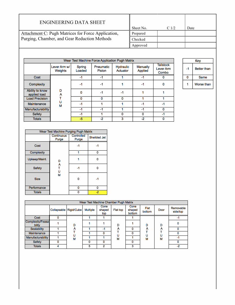
ENGINEERING DATA SHEET Sheet No. C 1/2 Date
Attachment C: Pugh Matrices for Force Application, Purging, Chamber, and Gear Reduction Methods
Prepared Checked Approved


ENGINEERING DATA SHEET Sheet No. D 1/1 Date
Attachment D: Decision Matrix for Final Four Prototype Concepts Measured Against Agreed Upon Decision Factors.
Prepared Checked
Approved
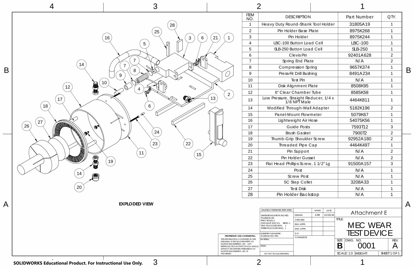
PROPRIETARY AND CONFIDENTIAL
THREE PLACE DECIMAL TWO PLACE DECIMAL
A A
B B
4
4
3
3
FINISH
MATERIAL
INTERPRET GEOMETRIC
BEND
TEST DEVICEA
DO NOT SCALE DRAWING
0001SHEET 1 OF 1
11/03/18AJM
UNLESS OTHERWISE SPECIFIED:
SCALE: 1:3 WEIGHT:
REVDWG. NO.
BSIZE
TITLE:
NAME DATE
COMMENTS:
Q.A.
MFG APPR.
ENG APPR.
2
2
CHECKED
1
TOLERANCING PER:
MEC WEARDRAWN
1
DIMENSIONS ARE IN INCHESTOLERANCES:FRACTIONALANGULAR: MACH
THE INFORMATION CONTAINED IN THISDRAWING IS THE SOLE PROPERTY OFMARVIN ENGINEERING, INC. ANY REPRODUCTION IN PART OR AS A WHOLEWITHOUT THE WRITTEN PERMISSION OFMARVIN ENGINEERING, INC IS PROHIBITED.
EXPLODED VIEW
ITEM NO. DESCRIPTION Part Number QTY.
1 Heavy Duty Round-Shank Tool Holder 31805A19 12 Pin Holder Base Plate 8975K268 13 Pin Holder 8975K244 14 LBC-100 Button Load Cell LBC-100 15 SLB-250 Button Load Cell SLB-250 16 Clevis Pin 92401A628 27 Spring End Plate N/A 28 Compression Spring 9657K374 19 Press-Fit Drill Bushing 8491A234 1
10 Test Pin N/A 111 Disk Alignment Plate 8508K95 112 6" Clear Chamber Tube 8585K58 1
13 Low Pressure, Straight Reducer, 1/4 x 1/8 NPT Male 4464K811 1
14 Modified Through-Wall Adapter 5182K196 215 Panel-Mount Flowmeter 5079K67 116 Lightweight Air Hose 54075K56 117 Guide Posts 7593T12 318 Brush Gasket 7900T2 219 Thumb-Grip Shoulder Screw 92952A180 220 Threaded Pipe Cap 4464K497 121 Pin Support N/A 222 Pin Holder Gusset N/A 223 Flat Head Phillips Screw, 1 1/2" Lg 91500A157 324 Post N/A 125 Screw Post N/A 126 5C Step Collet 3208A33 127 Test Disk N/A 128 Pin Holder Backstop N/A 1
6
213
6 21
2627
18
12
17
20
19
25
11
23 22
15
14
410
14
78
7
5316 1
9
24
28
SOLIDWORKS Educational Product. For Instructional Use Only.
Attachment E

FRONT VIEWSIDE VIEW
TOP VIEW
0.2
5
TO BE DETERMINEDBASED ON MECAND CALPOLY
LATHE DIMENSIONS0.16
2.25 1.76
8-32 UNC
THREE PLACE DECIMAL TWO PLACE DECIMAL
A A
B B
4
4
3
3
2
2
1
INTERPRET GEOMETRIC
BEND
BASE PLATEA
DO NOT SCALE DRAWING
0002SHEET 1 OF 1
11/03/18AJM
UNLESS OTHERWISE SPECIFIED:
SCALE: 1:2 WEIGHT:
REVDWG. NO.
BSIZE
TITLE:
NAME DATE
COMMENTS:
Q.A.
MFG APPR.
ENG APPR.
CHECKED
DRAWN
1
ALUMINUMFINISH
PIN HOLDER PROPRIETARY AND CONFIDENTIAL
MATERIAL
TOLERANCING PER:
DIMENSIONS ARE IN INCHESTOLERANCES:FRACTIONALANGULAR: MACH
THE INFORMATION CONTAINED IN THISDRAWING IS THE SOLE PROPERTY OFMARVIN ENGINEERING, INC. ANY REPRODUCTION IN PART OR AS A WHOLEWITHOUT THE WRITTEN PERMISSION OFMARVIN ENGINEERING, INC IS PROHIBITED.
5.25
3.25
3.50
TOOL HOLDERBASED ON AXA
0.2
5
0.75
R0.13 0.375
0.7
5
6.0
0
TO BE DETERMINED
1.6
3
MOUNTING REQUIREMENTSFOR FLOW METER TO BEDETERMINED UPON RECEIPT
HOLES TO MOUNTLOAD CELL TO BEDETERMINED UPONRECEIPT OF LOAD CELLS
SOLIDWORKS Educational Product. For Instructional Use Only.
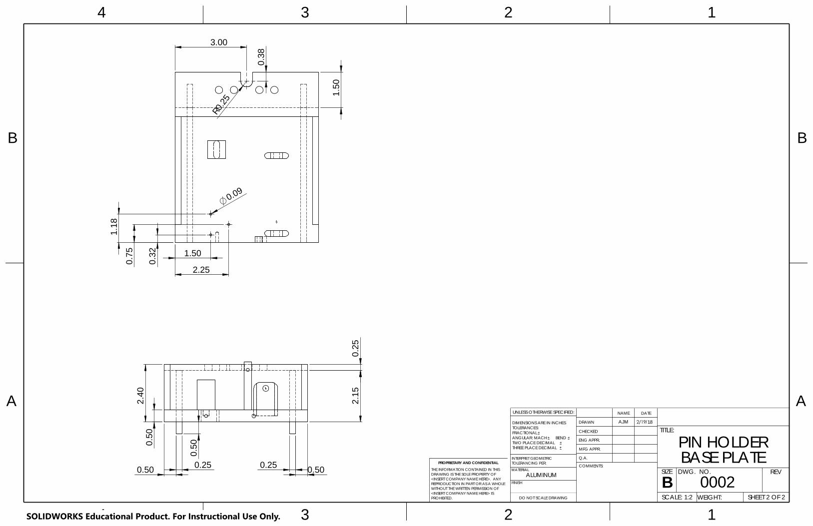
R0.2
5
3.00
0.3
8
1.5
0
0.09
1.50
2.25 0.3
2
0.7
5
1.1
8
A A
B B
4
4
3
3
2
2
1
1
DO NOT SCALE DRAWING
SHEET 2 OF 2
UNLESS OTHERWISE SPECIFIED:
SCALE: 1:2 WEIGHT:
REVDWG. NO.
BSIZE
TITLE:
NAME DATE
COMMENTS:
Q.A.
MFG APPR.
ENG APPR.
CHECKED
DRAWN
FINISH
MATERIAL
INTERPRET GEOMETRICTOLERANCING PER:
DIMENSIONS ARE IN INCHESTOLERANCES:FRACTIONALANGULAR: MACH BEND TWO PLACE DECIMAL THREE PLACE DECIMAL
PROPRIETARY AND CONFIDENTIALTHE INFORMATION CONTAINED IN THISDRAWING IS THE SOLE PROPERTY OF<INSERT COMPANY NAME HERE>. ANY REPRODUCTION IN PART OR AS A WHOLEWITHOUT THE WRITTEN PERMISSION OF<INSERT COMPANY NAME HERE> IS PROHIBITED.
0.50 0.50 0.25 0.25
2.4
0 0
.50
0.5
0
2.1
5 0
.25
SOLIDWORKS Educational Product. For Instructional Use Only.
ALUMINUM
PIN HOLDER BASE PLATE
0002
2/19/18AJM
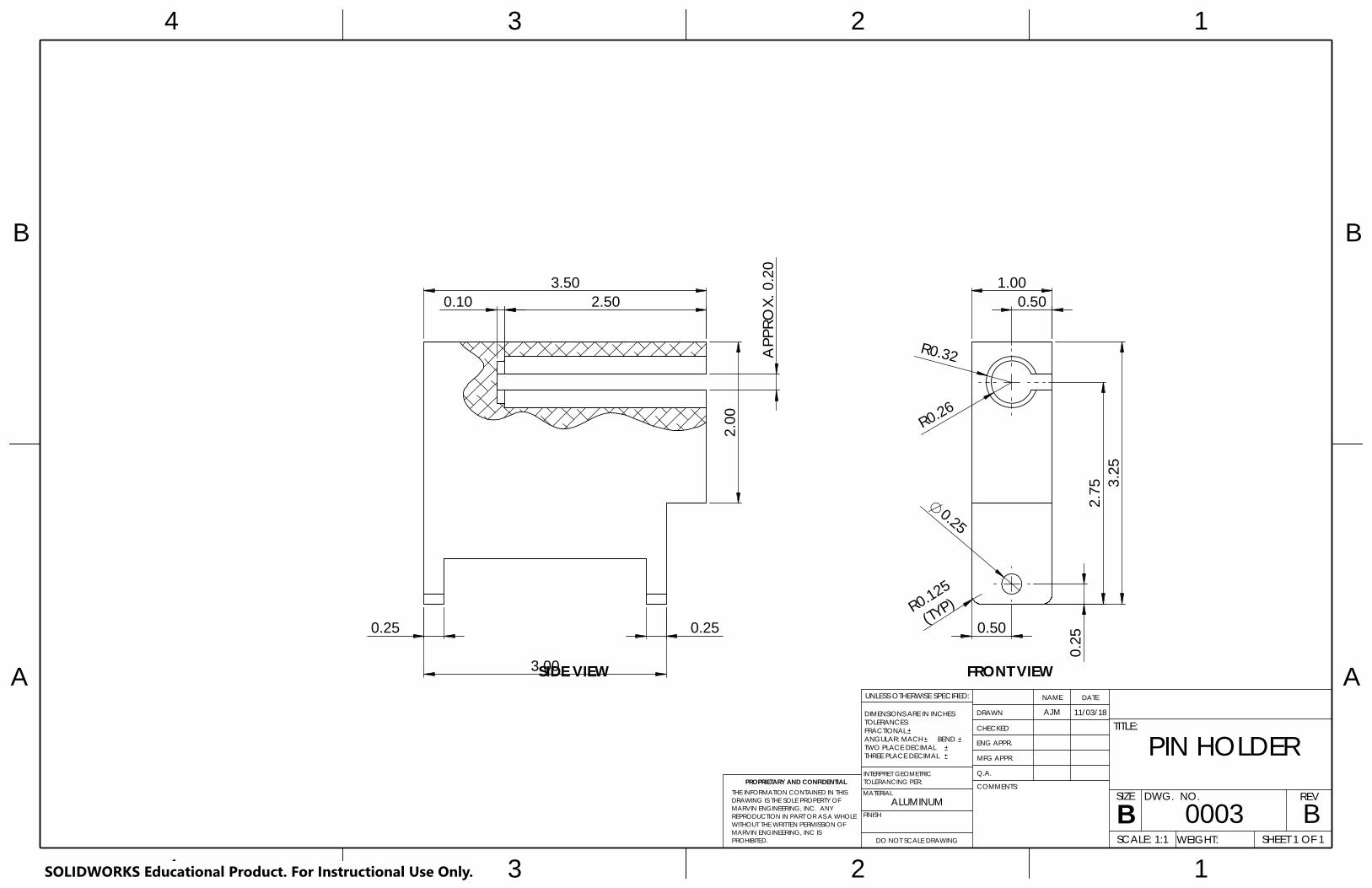
2.7
5 3.2
5
0.2
5
0.25
(TYP)
R0.32
R0.125
R0.26
0.50
0.50 1.00
SIDE VIEW FRONT VIEWA A
B B
4
4
3
3
2
2
1
1
ALUMINUM
PIN HOLDER
BDO NOT SCALE DRAWING
0003SHEET 1 OF 1
11/03/18AJM
UNLESS OTHERWISE SPECIFIED:
SCALE: 1:1 WEIGHT:
REVDWG. NO.
BSIZE
TITLE:
NAME DATE
COMMENTS:
Q.A.
MFG APPR.
ENG APPR.
CHECKED
DRAWN
FINISH
MATERIAL
BEND
TOLERANCING PER:INTERPRET GEOMETRIC
TWO PLACE DECIMAL THREE PLACE DECIMAL
PROPRIETARY AND CONFIDENTIAL
DIMENSIONS ARE IN INCHESTOLERANCES:FRACTIONALANGULAR: MACH
THE INFORMATION CONTAINED IN THISDRAWING IS THE SOLE PROPERTY OFMARVIN ENGINEERING, INC. ANY REPRODUCTION IN PART OR AS A WHOLEWITHOUT THE WRITTEN PERMISSION OFMARVIN ENGINEERING, INC IS PROHIBITED.
0.10
0.25
3.00
2.0
0
3.50
0.25
2.50
APP
ROX.
0.2
0
SOLIDWORKS Educational Product. For Instructional Use Only.

1.8
9
R0.35
1.09
(TYP)
1.0
3
R0.094 6.00
R0.078
R0.094
0.14
1.25
0.7
8
1.25 0.49
1.25
2.19
1.25
1.09
0.74
1.8
9
TOP VIEW
FRONT VIEW TWO PLACE DECIMAL
A A
B B
4
4
3
3
2
2
1
1
BEND
PLATEA
DO NOT SCALE DRAWING
0004SHEET 1 OF 1
11/03/18AJM
UNLESS OTHERWISE SPECIFIED:
SCALE: 1:1 WEIGHT:
REVDWG. NO.
BSIZE
TITLE:
NAME DATE
COMMENTS:
Q.A.
MFG APPR.
ENG APPR.
CHECKED
DRAWN
FINISH
POLYCARBONATE
DISK ALIGNMENT MATERIAL
TOLERANCING PER:
THREE PLACE DECIMAL
PROPRIETARY AND CONFIDENTIALINTERPRET GEOMETRIC
DIMENSIONS ARE IN INCHESTOLERANCES:FRACTIONALANGULAR: MACH
THE INFORMATION CONTAINED IN THISDRAWING IS THE SOLE PROPERTY OFMARVIN ENGINEERING, INC. ANY REPRODUCTION IN PART OR AS A WHOLEWITHOUT THE WRITTEN PERMISSION OFMARVIN ENGINEERING, INC IS PROHIBITED.
0.2
5 SOLIDWORKS Educational Product. For Instructional Use Only.

0.25
1.5
0
0.75
0.5
0
0.18
R0.313
0.035
2.0
0
0.25
1.6
75
0.30 0.15
8-32 UNC
1.4
0 1
.15
R0.25
SCREW POSTFRONT VIEW
SCREW POSTSIDE VIEW
SIDE VIEWSUPPORT PLATE
TOP VIEWSUPPORT PLATE
FRONT VIEWSUPPORT PLATE
FRONT VIEWBACKSTOP
GUSSET PLATEFRONT VIEW
BACKSTOPSIDE VIEW
FRONT VIEWSPRING PLATE
SIDE VIEWSPRING PLATE
SIDE VIEWGUSSET PLATE
PROPRIETARY AND CONFIDENTIAL
THREE PLACE DECIMAL
REV
A A
B B
4
4
3
3
2
FINISH
MATERIAL
INTERPRET GEOMETRIC
BEND
HOLDER PARTSA
TWO PLACE DECIMAL
0005SHEET 1 OF 1
11/03/18AJM
DO NOT SCALE DRAWING SCALE: 1:1 WEIGHT:
UNLESS OTHERWISE SPECIFIED:
DWG. NO.
BSIZE
TITLE:
NAME DATE
COMMENTS:
Q.A.
MFG APPR.
ENG APPR.
2
1
CHECKED
1
TOLERANCING PER:
ASSORTED PIN DRAWN
ALUMINUM
DIMENSIONS ARE IN INCHESTOLERANCES:FRACTIONALANGULAR: MACH
THE INFORMATION CONTAINED IN THISDRAWING IS THE SOLE PROPERTY OFMARVIN ENGINEERING, INC. ANY REPRODUCTION IN PART OR AS A WHOLEWITHOUT THE WRITTEN PERMISSION OFMARVIN ENGINEERING, INC IS PROHIBITED.
0.5
0
0.25
R0.125
0.2
5
1.00 5.50
SOLIDWORKS Educational Product. For Instructional Use Only.

ENGINEERING DATA SHEET Sheet No. F 1/1 Date
Attachment F: Uncertainty Calculation for DAQ Prepared Checked
Approved

ENGINEERING DATA SHEET Sheet No. G 1/1 Date
Attachment G: Design Hazard Checklist Prepared Checked
Approved
Abraham
Stamp
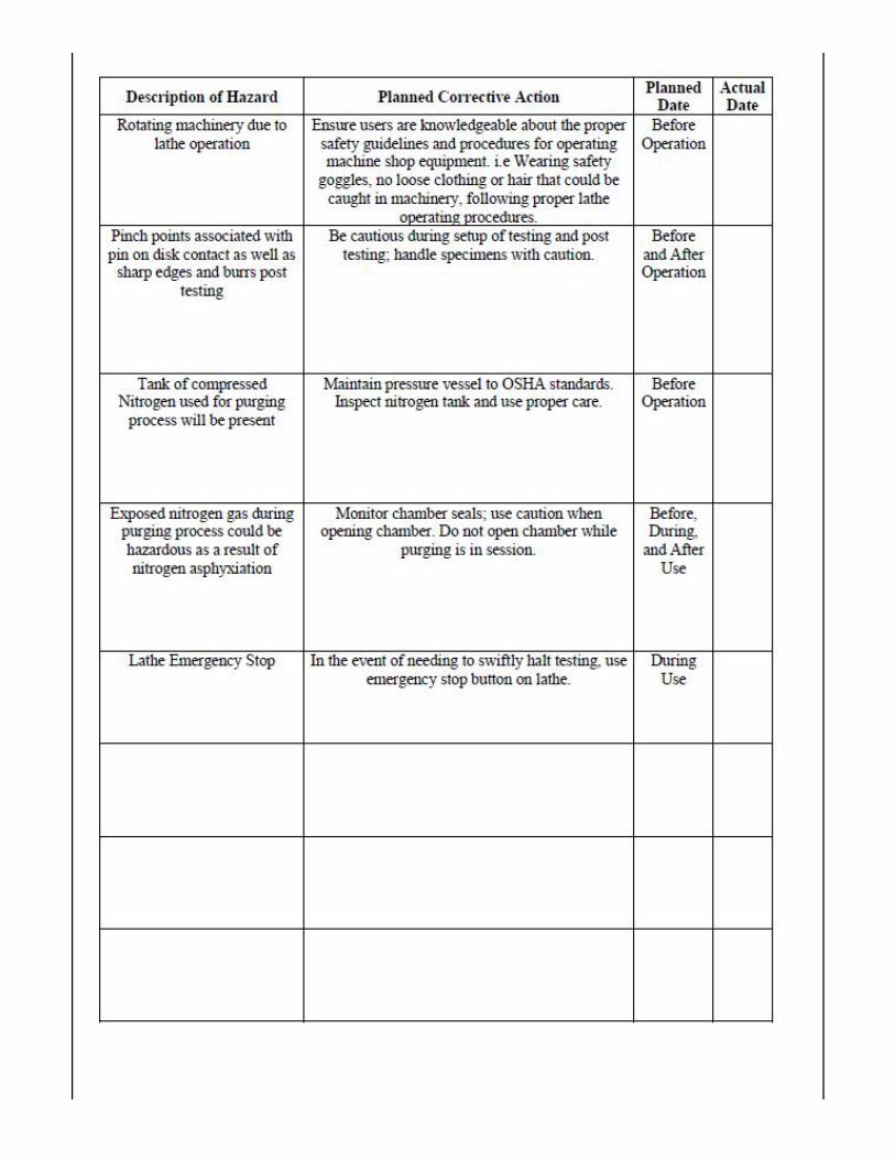

ENGINEERING DATA SHEET Sheet No. H
Attachment H- Project Cost Analysis Prepared Checked Approved
Table 1. DAQ and sensors subsystem cost analysis. All parts are to be purchased from Transducer Techniques, an MEC approved vendor. The subtotal is estimated to consume approximately 2/3 of the
overall project budget.
Sensors & DAQ/Meter
Item Part Description Part Number Vendor Quantity Unit Cost
Total Cost
1 Normal Load Sensor w/ TEDS option SLB-250 Transducer
Techniques 1 $470.00 $470.00
2 Axial Load Sensor w/ TEDS option LBC-100 Transducer
Techniques 1 $430.00 $430.00
3 Load Cell Meter DPM-3 Transducer Techniques 1 $445.00 $445.00
4 Serial Data Board (RS-485) DPM-3-OPT-TRS485
Transducer Techniques 1 $107.00 $107.00
5 Serial Data Board (USB & RS-485)
DPM-3-OPT-URS485
Transducer Techniques 1 $120.00 $120.00
6 Power Cable DPM-3-PC12 Transducer Techniques 1 $35.00 $35.00
7 Data Logging Software DPM-3-DLS Transducer Techniques 1 $349.00 $349.00
8 TEDS Adapter Connector DPM-3-AD9 Transducer Techniques 1 $55.00 $55.00
Subtotal $2,011.00
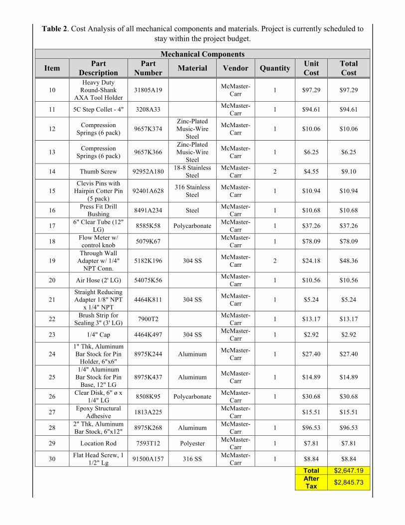
Table 2. Cost Analysis of all mechanical components and materials. Project is currently scheduled to stay within the project budget.
Mechanical Components
Item Part Description
Part Number Material Vendor Quantity Unit
Cost Total Cost
10 Heavy Duty
Round-Shank AXA Tool Holder
31805A19 McMaster-Carr 1 $97.29 $97.29
11 5C Step Collet - 4" 3208A33 McMaster-Carr 1 $94.61 $94.61
12 Compression Springs (6 pack) 9657K374
Zinc-Plated Music-Wire
Steel
McMaster-Carr 1 $10.06 $10.06
13 Compression Springs (6 pack) 9657K366
Zinc-Plated Music-Wire
Steel
McMaster-Carr 1 $6.25 $6.25
14 Thumb Screw 92952A180 18-8 Stainless Steel
McMaster-Carr 2 $4.55 $9.10
15 Clevis Pins with
Hairpin Cotter Pin (5 pack)
92401A628 316 Stainless Steel
McMaster-Carr 1 $10.94 $10.94
16 Press Fit Drill Bushing 8491A234 Steel McMaster-
Carr 1 $10.68 $10.68
17 6" Clear Tube (12" LG) 8585K58 Polycarbonate McMaster-
Carr 1 $37.26 $37.26
18 Flow Meter w/ control knob 5079K67 McMaster-
Carr 1 $78.09 $78.09
19 Through Wall
Adapter w/ 1/4" NPT Conn.
5182K196 304 SS McMaster-Carr 2 $24.18 $48.36
20 Air Hose (2' LG) 54075K56 McMaster-Carr 1 $10.56 $10.56
21 Straight Reducing Adapter 1/8" NPT
x 1/4" NPT 4464K811 304 SS McMaster-
Carr 1 $5.24 $5.24
22 Brush Strip for Sealing 3'' (3' LG) 7900T2 McMaster-
Carr 1 $13.17 $13.17
23 1/4" Cap 4464K497 304 SS McMaster-Carr 1 $2.92 $2.92
24 1" Thk, Aluminum Bar Stock for Pin
Holder, 6"x6" 8975K244 Aluminum McMaster-
Carr 1 $27.40 $27.40
25 1/4" Aluminum
Bar Stock for Pin Base, 12" LG
8975K437 Aluminum McMaster-Carr 1 $14.89 $14.89
26 Clear Disk, 6" ø x 1/4" LG 8508K95 Polycarbonate McMaster-
Carr 1 $30.68 $30.68
27 Epoxy Structural Adhesive 1813A225 McMaster-
Carr $15.51 $15.51
28 2" Thk, Aluminum Bar Stock, 6"x12" 8975K268 Aluminum McMaster-
Carr 1 $96.53 $96.53
29 Location Rod 7593T12 Polyester McMaster-Carr 1 $7.81 $7.81
30 Flat Head Screw, 1 1/2" Lg 91500A157 316 SS McMaster-
Carr 1 $8.84 $8.84
Total $2,647.19
After Tax $2,845.73
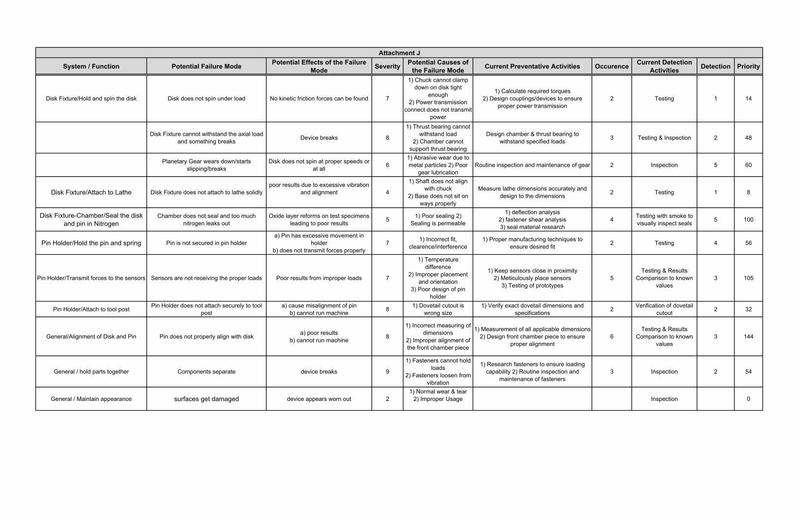
System / Function Potential Failure Mode Potential Effects of the Failure Mode Severity Potential Causes of
the Failure Mode Current Preventative Activities Occurence Current Detection Activities Detection Priority
Disk Fixture/Hold and spin the disk Disk does not spin under load No kinetic friction forces can be found 7
1) Chuck cannot clamp down on disk tight
enough2) Power transmission
connect does not transmit power
1) Calculate required torques2) Design couplings/devices to ensure
proper power transmission2 Testing 1 14
Disk Fixture cannot withstand the axial load and something breaks Device breaks 8
1) Thrust bearing cannot withstand load
2) Chamber cannot support thrust bearing
Design chamber & thrust bearing to withstand specified loads 3 Testing & Inspection 2 48
Planetary Gear wears down/starts slipping/breaks
Disk does not spin at proper speeds or at all 6
1) Abrasive wear due to metal particles 2) Poor
gear lubricationRoutine inspection and maintenance of gear 2 Inspection 5 60
Disk Fixture/Attach to Lathe Disk Fixture does not attach to lathe solidlypoor results due to excessive vibration
and alignment 4
1) Shaft does not align with chuck
2) Base does not sit on ways properly
Measure lathe dimensions accurately and design to the dimensions 2 Testing 1 8
Disk Fixture-Chamber/Seal the disk and pin in Nitrogen
Chamber does not seal and too much nitrogen leaks out
Oxide layer reforms on test specimens leading to poor results 5 1) Poor sealing 2)
Sealing is permeable
1) deflection analysis2) fastener shear analysis3) seal material research
4 Testing with smoke to visually inspect seals 5 100
Pin Holder/Hold the pin and spring Pin is not secured in pin holdera) Pin has excessive movement in
holderb) does not transmit forces properly
7 1) Incorrect fit, clearence/interference
1) Proper manufacturing techniques to ensure desired fit 2 Testing 4 56
Pin Holder/Transmit forces to the sensors Sensors are not receiving the proper loads Poor results from improper loads 7
1) Temperature difference
2) Improper placement and orientation
3) Poor design of pin holder
1) Keep sensors close in proximity 2) Meticulously place sensors
3) Testing of prototypes5
Testing & Results Comparison to known
values3 105
Pin Holder/Attach to tool post Pin Holder does not attach securely to tool post
a) cause misalignment of pinb) cannot run machine 8 1) Dovetail cutout is
wrong size1) Verify exact dovetail dimensions and
specifications 2 Verification of dovetail cutout 2 32
General/Alignment of Disk and Pin Pin does not properly align with disk a) poor results b) cannot run machine 8
1) Incorrect measuring of dimensions
2) Improper alignment of the front chamber piece
1) Measurement of all applicable dimensions2) Design front chamber piece to ensure
proper alignment6
Testing & Results Comparison to known
values3 144
General / hold parts together Components separate device breaks 9
1) Fasteners cannot hold loads
2) Fasteners loosen from vibration
1) Research fasteners to ensure loading capability 2) Routine inspection and
maintenance of fasteners3 Inspection 2 54
General / Maintain appearance surfaces get damaged device appears worn out 21) Normal wear & tear
2) Improper Usage Inspection 0
Attachment J

ENGINEERING DATA SHEET Sheet No. K 1/1 Date
Attachment K: Gantt Chart Prepared Checked Approved

Operations Manual Mechanical Setup
1) Place test disk in step collet and secure step collet in lathe step chuck. 2) Bolt boring bar holder to base plate and tighten with wrench. 3) Place LBC-100 onto locator pins on base plate. 4) Load SBC-250 into the pin holder. 5) Load springs plates and spring into pin holder. 6) Load test pin and drill bushing into end of pin holder. Ensure the entire assembly is
compactly loading but not compressing the spring. 7) Attach Chamber to base plate and tighten thumb screws. 8) Connect ⅛” tubing to upper chamber connection. 9) Place the assembly into lathe tool post, using chamber to ensure proper height of the
assembly and lock the tool holder in place. 10) Connect ⅛” Nitrogen supply line to flow meter.
Hardware Setup
1) Connect the RS485 cable to the middle-bottom port in the back of both meters 2) Connect the power cords to the green top-left port of each meter 3) Connect sensor ME0009157 to meter ME0009158 4) Connect sensor ME0009160 to meter ME0009159 5) Plug the power cords into power outlets 6) Connect USB cable to the meter with the USB port 7) Set "Tare" to "00000" for both meters (refer to p.15 in the instruction manual) 8) Set "Ser 1" to "150" for both meters (refer to p.31 in the instruction manual) 9) Set "Ser 2" to "0001" for meter ME0009159 (refer to p.31 in the instruction manual) 10) Set "Ser 2" to "0002" for Meter ME0009158 (refer to p.31 in the instruction manual) 11) Set "Ser 3" to "00000" for both meters (refer to p.31-32 in the instruction manual)
Software
1) Open "DPM-3 Data Logging" 2) Click "Setup File" 3) If there is already an existing setup file, click "Open" and open the existing setup file 4) If there is not already an existing setup file, click "New" to create a new setup file
Making a New Setup File
1) For making a new setup file, click on "Meter Setup" and "Create Meters (Tab 1, 2)" 2) Set ID to "1" and "2" 3) Set Caption to "Meter 1" and "Meter 2" 4) Set Type to "DPM-3" 5) Set SerAddr to "1" and "2" 6) Set Item # to "Reading" 7) Click "Menu"

8) Click "Setup File" and "Save As" a new setup file Taking Test Data
1) Create a new setup file or open an existing setup file 2) Click "Log Setup" 3) Under "Data File Name", click "Create a New Data File" 4) Name the new data file and click "Create" 5) Under "Header Record", check "Include Meter Captions" and "Include Meter ID's", and
uncheck "Include Date and Time Stamp" 6) Under Individual Records", check "Include Time Stamp" and "Include Alarm, Overload
Data with Each Value", and uncheck "Include Date Stamp" and "Leading Zero Suppression"
7) Under Data Logging, set "Logging Interval in Seconds" to "0000" and "Separator Character to "tab"
8) Click "Next" 9) Set "Comm Port" to the correct comm port that the USB cable is connected to 10) Set "Baud Rate" to "9600" 11) Set "Duplex" to "Full" 12) Check both boxes under "Log Enable" 13) Click "Establish Communications" 14) If "Comm Status" and "Meter Status" are checked and green for both meters, click "Next" 15) Press the "Tare" button on both meters before recording 16) Click "Start Recording" to start recording data 17) Click "Stop Recording" to stop recording data 18) If using Windows 10, the file location for the test data is: This PC-->Local Disk
(C:)-->Users-->[username]-->AppData-->Local-->VirtualStore-->Program Files (x86)-->TTI-->DPM-3-->Data Logging-->Files
19) Open the data file with Excel Troubleshooting
1) If both meters are connected to each other and only one meter passes the initial communication, make sure "Ser 1" on both meters is set to "150" (refer to p.31 in the instruction manual)
2) If both meters are connected to each other and both fail the initial communication, make sure the RS485 cable is not a "crossover-connection" cable. If it is, change the cable to a "direct-connection" cable. (refer to p.29 in the instruction manual)
3) If a meter does not automatically tare to 0 whenever it resets, set the "Tare" value on the meter to "00000" (refer to p.15 in the instruction manual)
4) If you select the incorrect comm port, select a different comm port until it is accepted by the software
Related Documents