Jeroen Uittenbogaard, Ton Versmissen FIMCAR IX – MDB Test Procedure: Initial Test Protocol The FIMCAR project was co-funded by the European Commission under the 7th Framework Programme (Grant Agreement no. 234216). The content of the publication reflects only the view of the authors and may not be considered as the opinion of the European Commission nor the individual partner organisations. This article is published at the digital repository of Technische Universität Berlin: URN urn:nbn:de:kobv:83-opus4-40880 [http://nbn-resolving.de/urn:nbn:de:kobv:83-opus4-40880] It is part of FIMCAR – Frontal Impact and Compatibility Assessment Research / Editor: Heiko Johannsen, Technische Universität Berlin, Institut für Land- und Seeverkehr. – Berlin: Universitätsverlag der TU Berlin, 2013 ISBN 978-3-7983-2614-9 (composite publication) frontal impact and compatibility assessment research

Welcome message from author
This document is posted to help you gain knowledge. Please leave a comment to let me know what you think about it! Share it to your friends and learn new things together.
Transcript
Jeroen Uittenbogaard, Ton Versmissen
FIMCAR
IX – MDB Test Procedure: Initial Test
Protocol
The FIMCAR project was co-funded by the European Commission under the
7th Framework Programme (Grant Agreement no. 234216).
The content of the publication reflects only the view of the authors and may
not be considered as the opinion of the European Commission nor the
individual partner organisations.
This article is
published at the digital repository of Technische Universität Berlin:
URN urn:nbn:de:kobv:83-opus4-40880 [http://nbn-resolving.de/urn:nbn:de:kobv:83-opus4-40880]
It is part of
FIMCAR – Frontal Impact and Compatibility Assessment Research / Editor:
Heiko Johannsen, Technische Universität Berlin, Institut für Land- und
Seeverkehr. – Berlin: Universitätsverlag der TU Berlin, 2013
ISBN 978-3-7983-2614-9 (composite publication)
frontal impact and compatibility assessment research

IX MDB Test Procedure: Initial Test Protocol CONTENT
EXECUTIVE SUMMARY .............................................................................................................. 1
1 INTRODUCTION .................................................................................................................. 2
1.1 FIMCAR Project .................................................................................................................. 2
1.2 Objective of this Deliverable .............................................................................................. 2
1.3 Structure of this Deliverable .............................................................................................. 2
2 TEST CONFIGURATION ....................................................................................................... 3
2.1 Trolley Mass ....................................................................................................................... 3
2.2 Deformable Barrier ............................................................................................................ 3
2.3 Impact Speed, Angle and Overlap ...................................................................................... 4
2.4 Proposed Test Set-Up......................................................................................................... 5
3 VEHICLE PREPARATION ...................................................................................................... 6
3.1 Unladen Kerb Mass ............................................................................................................ 6
3.2 Reference Loads ................................................................................................................. 6
3.3 Vehicle Width and Overlap ................................................................................................ 7
3.4 Vehicle Painting .................................................................................................................. 7
3.5 Propulsion of Vehicle and Trolley ...................................................................................... 7
3.6 Vehicle Marking ................................................................................................................. 8
3.7 Acceleration Measurements .............................................................................................. 8
4 DUMMIES ......................................................................................................................... 10
5 CAMERA POSITION ........................................................................................................... 11
6 STILLS ................................................................................................................................ 12
7 MOVING TROLLEY ............................................................................................................ 13
7.1 Trolley Design ................................................................................................................... 13
8 ASSESSMENT .................................................................................................................... 15
8.1 Self Protection .................................................................................................................. 15
8.2 Partner Protection............................................................................................................ 15
8.2.1 Digitisations of Barrier ................................................................................................... 15
8.2.2 Deformation/ Intrusions ................................................................................................ 16
8.2.3 Force Measurements ..................................................................................................... 18
9 REFERENCES ..................................................................................................................... 19
IX - a
frontal impact and compatibility assessment research

Executive Summary EXECUTIVE SUMMARY
This protocol describes the Mobile Progressive Deformable Barrier test. The MPDB protocol is derived from the PDB test protocol developed by UTAC [Edwards 2006/1], the FWDB test and assessment protocol developed by TRL [Edwards 2006/2], the Euro NCAP frontal impact testing protocol [Euro NCAP 2009] and ECE regulation No. 94 [ECE 2009]. The protocol describes a test between the test car and a 1500 kg moving trolley with a closing speed of 100 km/h. The off-set for the test car is 50% of the vehicle width. The trolley is equipped with a PDB deformable barrier face. Especially trolley weight and closing speed are subject to further analysis in order to define the test severity at an appropriate level for the existing range of vehicles. The objective of the test procedure is to assess the self- and partner protection, also known as compatibility.
IX - 1
frontal impact and compatibility assessment research

IX MDB Test Procedure: Initial Test Protocol 1 INTRODUCTION
1.1 FIMCAR Project
For the real life assessment of vehicle safety in frontal collisions the compatibility (described by the self and partner-protection level) between the opponents is crucial. Although compatibility has been analysed worldwide for years, no final assessment approach was defined. Taking into account the EEVC WG15 and the FP5 VC-COMPAT project activities, two test approaches are the most promising candidates for the assessment of compatibility. Both are composed of an off-set and a full overlap test procedure. However, no final decision was taken. In addition, another procedure (tests with a moving deformable barrier) is under discussion in today’s research programmes.
Within the FIMCAR project, different off-set, full overlap and MDB test procedures will be analysed to be able to propose a compatibility assessment approach, which will be accepted by a majority of the involved industry and research organisations The development work will be accompanied by harmonisation activities to include research results from outside the consortium and to disseminate the project results taking into account recent GRSP activities on ECE R94, Euro NCAP etc.
The FIMCAR project is organised in six different RTD work packages. Work package 1 (Accident and Cost Benefit Analysis) and Work Package 5 (Numerical Simulation) are supporting activities for WP2 (Offset Test Procedure), WP3 (Full Overlap Test Procedure) and WP4 (MDB Test Procedure). Work Package 6 (Synthesis of the Assessment Methods) gathers the results of WP1 – WP5 and combines them with car-to-car testing results in order to define an approach for frontal impact and compatibility assessment.
1.2 Objective of this Deliverable
Unlike the off-set and full overlap test procedures for frontal impact, a test protocol is not fixed for the frontal moving deformable barrier test procedures. Therefore, a test and assessment procedure is developed to assess frontal compatibility.
1.3 Structure of this Deliverable
First the test configuration is explained, where relevant parameters are chosen. Next, a detailed description is given about how to prepare the vehicle for the test. Then anthropometric test devices preparation and positioning are described. Finally the assessment criteria are explained.
IX - 2
frontal impact and compatibility assessment research

Test Configuration 2 TEST CONFIGURATION
In this test the test vehicle is assessed with a moving trolley equipped with a deformable barrier face in a frontal configuration. The trolley itself represents the most probable collision partner in terms of vehicle mass. The deformable element of the trolley represents a corresponding stiffness of a modern vehicle.
The impact speed and overlap are based on accident data and currently existing test procedures.
2.1 Trolley Mass
The mass of the trolley is based on a Swedish data showing the cumulative distribution of the vehicle fleet of Sweden in 2008 and the EU in 2005 [SIKA]. Both distributions are in-line and give an average vehicle mass of 1500 kg, without occupants. This is also backed up by the AE-MDB (Advanced European Moving Deformable Barrier) side impact trolley mass, which is also set to 1500 kg [Ellway 2005].
Remark
This average mass of 1500 kg is the starting point for the MDB test within the FIMCAR project. Tests with other masses, between 1300 kg and 1800 kg, will be carried out to define the optimal mass for future MDB tests.
Occupant masses are not taken into account as the restraint system will spread this mass over time during a collision.
Figure 2.1: Vehicle mass distribution for Sweden and Europe [SIKA].
2.2 Deformable Barrier
The deformable barrier in front of the trolley also needs to represent the most common collision partner in terms of stiffness. Using a pragmatic approach, the already well developed Progressive Deformable Barrier (PDB) is chosen as the deformable barrier. How the PDB compares, in terms of overall stiffness, with the current European vehicle fleet is shown in Figure 2.2. The average force-deflection curve of 26 cars tested within Euro NCAP from 2006-2009 together with the PDB calibration corridor is shown. The assumption is made that the ODB is fully bottomed out before the car starts to deform and therefore the
IX - 3
frontal impact and compatibility assessment research

IX MDB Test Procedure: Initial Test Protocol PDB dynamic calibration corridor is shifted by the depth of the ODB (450mm). It can be seen that the average stiffness of the 26 cars is in line with the bottom end of the PDB calibration corridor.
Figure 2.2: Average force-deflection curve of 26 cars tested within Euro NCAP from 2006 to 2009 together with the shifted PDB calibration corridor.
2.3 Impact Speed, Angle and Overlap
The impact speed, angle and overlap are based on real word accident data and existing test procedures.
The baseline situation for the current R94 is a frontal car-to-car collision with both vehicles travelling at 50 km/h with an overlap of 50% and an impact angle of 0 degrees. To best represent this baseline situation, the single vehicle-to-barrier test was derived and set to 56 km/h, an overlap of 40% with an impact angle of zero degrees.
Figure 2.3 shows the closing speed of front-to-front car collisions based on recent accident data. A closing speed of 100km/h, in-line with the baseline test, will cover 90% of the frontal car-to-car collisions in terms of speed [Data from GIDAS holding accidents from the Hannover and Dresden area in between 1999 to 2009 with no restriction on car model/age. Only front-to-front car-to-car crashes are included where the direction of force during the collision is in between 11, 12 and 1 o’clock. MAIS has been calculated on the basis of the maximum MAIS of all occupants of the subject car. Both cars are within 600 to 3500 kg curb weight and all collisions have an impact speeds below 150 km/h].
Within the VC-Compat project all car-to-car tests were performed with a closing speed of 112 km/h. This higher closing speed will only cover 4% more cases as shown in Figure 2.3.
One single MPDB-to-car test performed at a closing speed of 112 km/h using a small car showed that this test speed is very severe. Other MPDB tests at a closing speed of 90 km/h (covering around 85%) have shown that the severity is low and will not result in adjusted vehicle design. (To further investigate and fix the test speed another test with the Small Family Car 2 will be performed at a closing speed of 112 km/h.)
IX - 4
frontal impact and compatibility assessment research

Test Configuration
Figure 2.3: Cumulative distribution of closing speed in front to front collisions with MAIS 3+ and fatal injuries.
2.4 Proposed Test Set-Up
In summary the following test set-up is proposed.
Trolley mass: 1500 kg starting point; some test with masses between 1300 and 1800 kg
Deformable barrier: PDB-XT
Trolley speed: 50 km/h (to be determined; limits 45 – 56 km/h)
Vehicle speed: 50 km/h (to be determined; limits 45 – 56 km/h)
Overlap: 50%
Angle: 0 degrees
Figure 2.4: Test set-up.
IX - 5
frontal impact and compatibility assessment research

IX MDB Test Procedure: Initial Test Protocol 3 VEHICLE PREPARATION
The test mass is defined identical as can be found in the Euro NCAP test protocol [Euro NCAP 2009]:
3.1 Unladen Kerb Mass
3.1.1 The capacity of the fuel tank will be specified in the manufacturer’s booklet. This
volume will be referred to throughout as the “fuel tank capacity”.
3.1.2 Syphon most of the fuel from the tank and then run the car until it has run out of fuel.
3.1.3 Calculate the mass of the fuel tank capacity using a density for petrol of 0.745g/ml or
0.840g/ml for diesel. Record this figure in the test details.
3.1.4 Put water, or other ballast, to this mass in the fuel tank.
3.1.5 Check the oil level and top up to its maximum level if necessary. Similarly, top up the
levels of all other fluids to their maximum levels if necessary.
3.1.6 Ensure that the vehicle has its spare wheel on board along with any tools supplied with
the vehicle. Nothing else should be in the car.
3.1.7 Ensure that all tires are inflated according to the manufacturer’s instructions for half
load.
3.1.8 Measure the front and rear axle weights and determine the total weight of the vehicle.
The total weight is the ‘unladen kerb mass’ of the vehicle. Record this mass in the test
details.
3.1.9 Measure and record the ride heights of the vehicle at all four wheels
3.2 Reference Loads
3.2.1 Calculate 10 percent of the fuel tank capacity mass as determined in 2.1.3
3.2.2 Remove this mass of ballast from the fuel tank, leaving 90 percent of the mass in the
tank.
3.2.3 Place both front seats in their mid-positions. If there is no notch at this position, set the seat in the nearest notch rearward (this will be done more completely in Section 6).
3.2.4 Place a mass of equivalent to a Hybrid-III dummy (88kg with instrumentation and
cables) on each of the front seats.
3.2.5 Place 36kg in the luggage compartment of the vehicle. The normal luggage compartment should be used i.e. rear seats should not be folded to increase the luggage capacity. Spread the weights as evenly as possible over the base of the luggage compartment. If the weights cannot be evenly distributed, concentrate weights towards the centre of the compartment.
IX - 6
frontal impact and compatibility assessment research
Vehicle Preparation 3.2.6 Roll the vehicle back and forth to ‘settle’ the tyres and suspension with the extra weight on board. Weigh the front and rear axle weights of the vehicle. These loads are the “axle reference loads” and the total weight is the “reference mass” of the vehicle.
3.2.7 Record the axle reference loads and reference mass in the test details
3.2.8 Record the ride-heights of the vehicle at the point on the wheel arch in the same transverse plane as the wheel centers. Do this for all four wheels.
3.2.9 Remove the weights from the luggage compartment and the front and rear seats.
3.3 Vehicle Width and Overlap
3.3.1 Determine the widest point of the vehicle ignoring the rear-view mirrors, side marker lamps, tire pressure indicators, direction indicator lamps, position lamps, flexible mudguards and the deflected part of the tire side-walls immediately above the point of contact with the ground.
3.3.2 Record this width in test details.
3.3.3 Determine the centre-line of the vehicle.
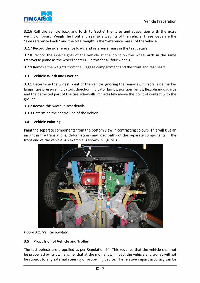
3.4 Vehicle Painting
Paint the separate components from the bottom view in contrasting colours. This will give an insight in the translations, deformations and load paths of the separate components in the front end of the vehicle. An example is shown in Figure 3.1.
Figure 3.1: Vehicle painting.
3.5 Propulsion of Vehicle and Trolley
The test objects are propelled as per Regulation 94. This requires that the vehicle shall not be propelled by its own engine, that at the moment of impact the vehicle and trolley will not be subject to any external steering or propelling device. The relative impact accuracy can be
IX - 7
frontal impact and compatibility assessment research

IX MDB Test Procedure: Initial Test Protocol checked by placing a small pin close to the edge of the barrier and mark the place where the pin should strike on the bumper of the car for which the given overlap is exactly achieved. The relative impact accuracy shall be within 25 mm laterally and 25 mm vertically out of line in either direction. The velocity accuracy shall within 0.5 km/h for both the vehicle and trolley.
3.6 Vehicle Marking
The vehicle shall be marked according to Figure 3.2.
Figure 3.2: Vehicle marking.
3.7 Acceleration Measurements
In the following tables the locations of the accelerometers are given for the test vehicle (Table 1) and for the moving trolley (Table 2). For a right hand drive (RHD) car: left (L) becomes right (R).
IX - 8
frontal impact and compatibility assessment research

Vehicle Preparation Table 1: Accelerometer location in the vehicle.
Name ISO-MME code X Y Z
Engine Top central 10ENGNTP0000 x
Engine bottom central 10ENGNBO0000 x
Gear box bottom 10GEARBO0000 x
Arm suspension LHS 11SUHOLO0000 x
Turret LHS 11SUDO000000 x
200 mm behind B-Pillar LHS 17CPILLO0000 x
A-Pillar LHS 11APILBO0000 x
Cross of the side member and the firewall 18FORAFRMI00 x
B-Pillar RHS 16BPILLO0000 x x X
B-Pillar LHS 14BPILLO0000 x x X
Total 14
Table 2: Accelerometer location on the trolley.
Name ISO-MME code X Y Z
CoG ?0MBARCG0000AC?? x x x
Frame left front CoG height ?0MBARLEFR00AC?? x x
Frame right front CoG height ?0MBARRIFR00AC?? x x
Frame left rear CoG height ?0MBARLERE00AC?? x x
Frame right rear CoG height ?0MBARRIRE00AC?? x x
Total 11
IX - 9
frontal impact and compatibility assessment research

IX MDB Test Procedure: Initial Test Protocol 4 DUMMIES
The dummy set-up is in line with R94 regulation, 2 instrumented Hybrid III 50 percentile on the front seats. The positioning of these dummies is in accordance with R94.
Table 3: Dummy (Hybrid III 50 percentile) instrumentation.
Dummies performance must be in line with specifications of the regulations.
IX - 10
frontal impact and compatibility assessment research

Camera Position 5 CAMERA POSITION
For research purposes within the FIMCAR project eight cameras, two detailed from each side (1,3), two side 45 degrees (2,4), two bottom (global and detail) (5,6), two from above (global and detail) (7,8) shall be used (see Figure 5.1). During the course of the project the final number of cameras will be determined based on test experience.
Figure 5.1: Initial proposal for camera positions.
IX - 11
frontal impact and compatibility assessment research

IX MDB Test Procedure: Initial Test Protocol 6 STILLS
The following list is an altered version of the list given in the Euro NCAP frontal impact test protocol [Euro NCAP 2009].
No. View
1. Front view of barrier. 2. Side view of barrier. 3. Side view of barrier at 45 degrees to front. 4. Side view of barrier with vehicle. 5. Car RHS, with camera centred on junction of B-post waist, showing full car. 6. Car RHS, with camera centred on B-post waist, showing rear passenger compartment. 7. Car RHS, with camera aimed at waist height, showing driver's compartment. 8. Car RHS at 45 degrees to front. 9. Front view of car. 10. Car LHS at 45 degrees to front. 11. Car LHS, with camera aimed at waist height, showing front passenger's compartment. 12. Car LHS, with camera centred on B-post waist, showing rear passenger compartment. 13. Car LHS, with camera centred on B-post waist, showing full car. 14. Top view of car 15. Bottom view of car 16. Driver and seat to show driver compartment and position of seat relative to the sill. 17. To show area immediately in front of driver. 18. To show driver's footwell area and location of dummy's feet and pedals. 19. Passenger and seat to show compartment and position of seat relative to sill. 20. To show area immediately in front of passenger. 21. To show passenger footwell area and dummy's feet. 22. *Overall view of where the car has come to rest after impact (including barrier). 23. *To show position of all door latches and/or open doors. 24. *To show driver knee contacts with facia (airbag should be lifted if obscuring view). 25. *To show passenger knee contacts with facia (airbag should be lifted if obscuring
view).
* Post-test only
IX - 12
frontal impact and compatibility assessment research

Moving Trolley 7 MOVING TROLLEY
7.1 Trolley Design
The trolley dimensions are based on specifications of European vehicles which are presented in Table 4. The inertia properties of the trolley are based on the values given in the NHTSA database for a large range of vehicles [NHTSA 2013].
During the FIMCAR project two different trolleys will be used:
- A trolley especially developed by TNO and FTSS to carry out MDB tests, based on the Table 4 specifications.
- A side impact trolley, according to ECE R95 specifications, modified to carry out frontal MDB tests
The tests with both trolleys will be used to specify the need for a special designed trolley.
Table 4: Trolley specs.
Description Value Mass 1500 kg Mass front axle 1100 kg Mass rear axle 400 kg Barrier face PDB-XT Barrier height 1.00 m Barrier width 0.70 m Barrier depth 0.70 m (0.80 m if extended) Barrier ground clearance 150 mm Barrier face location Left or Right (depending on LHD or RHD) outlined with
outside of wheels Overall Length 4.25 m (4.35 m if extended) Vehicle front to frontal axle 1.2 m (1.3 if extended) Axle height 0.28 m Wheel base 2.60 m Track width 1.20 m CoG x-dir (1) 1900 mm from front (2000 mm if extended) CoG x-dir (2) 700 mm from frontal axle CoG y-dir 0 (centre line) CoG z-dir 600 mm from ground Iyz Roll 550 kg*m2 (representative of the 1500 kg vehicle) Ixz Pitch 2550 kg*m2 (representative of the 1500 kg vehicle) Ixy Yaw 2650 kg*m2 (representative of the 1500 kg vehicle) Brakes 4 x disk brakes Tyres 205/55 R15 Tyre pressure 2.5 bar Load cell 48 x Light weight TSM
IX - 13
frontal impact and compatibility assessment research

IX MDB Test Procedure: Initial Test Protocol
Figure 7.1: Overview picture of the trolley
IX - 14
frontal impact and compatibility assessment research
Assessment 8 ASSESSMENT
For analysing the test procedure FIMCAR will focus on structural interaction, vehicle response, intrusion measurements. The dummy readings will be analysed with lower priority. However, it is envisaged to propose dummy limits at the end of the analysis phase.
8.1 Self Protection
Vehicle accelerations in comparison with R94 procedures.
Dummy readings in comparison with R94 procedures
8.2 Partner Protection
MPDB assessment in accordance with PDB assessment procedures (under development):
- Digitisations of barrier - Deformation/ intrusions - Force measurements (F = m * atrolley or global force from LCW)
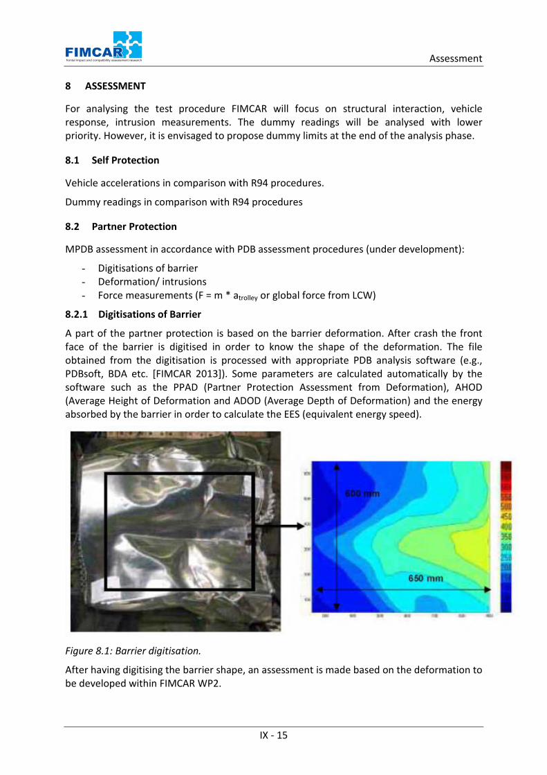
8.2.1 Digitisations of Barrier
A part of the partner protection is based on the barrier deformation. After crash the front face of the barrier is digitised in order to know the shape of the deformation. The file obtained from the digitisation is processed with appropriate PDB analysis software (e.g., PDBsoft, BDA etc. [FIMCAR 2013]). Some parameters are calculated automatically by the software such as the PPAD (Partner Protection Assessment from Deformation), AHOD (Average Height of Deformation and ADOD (Average Depth of Deformation) and the energy absorbed by the barrier in order to calculate the EES (equivalent energy speed).
Figure 8.1: Barrier digitisation.
After having digitising the barrier shape, an assessment is made based on the deformation to be developed within FIMCAR WP2.
IX - 15
frontal impact and compatibility assessment research
IX MDB Test Procedure: Initial Test Protocol 8.2.2 Deformation/ Intrusions
The deformation measurements are the same as for Euro NCAP frontal test protocol [Euro NCAP 2009], which includes:
• Establishing a measurement reference on the rear of the vehicle • The door reduction aperture at upper, waist and sill level, • The rearward movement of the A-Pillar at waist and sill level (relative measure), • The longitudinal, lateral and vertical movement of the centre of the top of the
steering column • Longitudinal and vertical movement of all the foot operated pedals.
In addition the following occupant compartment intrusion measurements should be taken (Dashboard, Footwell, Pedal axle)
Instrument Panel Top
1. Locate front lower corner of the side window in Z. 2. Locate outer edge of IP within height Z to Z+25mm and place target sticker. 3. Locate subsequent target stickers every 100mm (at height defined by 2.) inboard until
the centreline of the vehicle (typically 6 stickers)
Note: Z is positive in the downwards direction
Instrument Panel Base (IPB)
4. Locate the highest point along the centreline of the seat squab and determine height in Z and distance from vehicle centreline
5. Locate target sticker in on nearest point on the IP in the same Z height and distance from vehicle centreline
6. Locate target stickers every 100mm inboard and outboard along the IP until the centre console and the outer edge of the IP is reached
IX - 16
frontal impact and compatibility assessment research

Assessment
Figure 8.2: Measurement points at instrument panel.
Problems with IP Target Location
If significant deviation from the previous specification arises, then best judgement is needed and the criteria that need consideration are:
1. Try to locate target stickers on major components of the instrument panel – do not locate on the steering column surround as this will move independently of the majority of the IP.
2. At all times try to maintain the target stickers in the Z and X axis defined and only vary the Y axis by 100mm – if going below the instrument displays requires less deviation then proceeding around the top then place the target stickers in the former position.
Footwell Intrusion
1. Remove all carpet from the footwell requiring measurement. 2. Locate a target sticker behind the brake pedal in the same X and Z location as the brake
pedal.
IX - 17
frontal impact and compatibility assessment research

IX MDB Test Procedure: Initial Test Protocol 3. Place a pre-cut carpet with holes spaced at 100mm in the footwell and locate one of the
pre-cut holes over the target sticker defined in 2. (Carpet can follow the contours of the footwell). If the pre-cut carpet is not available, use the 3D arm to position target stickers.
4. Locate additional target stickers in the location of the pre-cut holes. Only place stickers up to a maximum of 200 mm either side of the brake pedal. Place stickers up to a maximum of 200 mm (if possible) above and 300 mm below the point defined in 2.
5. If location tie up with local features on the footwell (such as drain holes) then move target stickers the minimum distance to clear such feature.
Figure 8.3: Footwell grid.
Pedal axis
1. Locate the outboard end of the clutch/brake pedal pivot axis.
2. Locate a target sticker at point defined by 1.
Figure 8.4: Pedal axis.
8.2.3 Force Measurements
If it is needed and if it is proven that the force measurement is accurate, an assessment could be introduced for the front end force.
A minimum frontal force level could be fixed as a first step in order to improve compartment strength for small cars and to ensure a minimum self protection level.
IX - 18
frontal impact and compatibility assessment research

References 9 REFERENCES
[ECE 2009] Economic Commission for Europe: Regulation No. 94 Uniform provisions concerning the approval of vehicles with regard to the protection of the occupants in the event of a frontal collision (ECE R94. http://www.unece.org/fileadmin/DAM/trans/doc/2009/wp29grsp/ELSAsg-1-04e.pdf
[Edwards 2006/1] Edwards, M. Davies, H.; Martin, T.; van der Zweep, C.; Thomson, R.; Delannoy, P.; Faerber, E.; Della Valle, G.: "Test Procedures for Assessment of Frontal Impact Compatibility and Recommendations for Compatible Car Design (Appendix B – PDB Test and Assessment Protocol (UTAC)) ". Paper Number: GRD2-2001-50083. http://vc-compat.rtdproject.net/.2006.
[Edwards 2006/2] Edwards, M. Davies, H.; Martin, T.; van der Zweep, C.; Thomson, R.; Delannoy, P.; Faerber, E.; Della Valle, G.: "Test Procedures for Assessment of Frontal Impact Compatibility and Recommendations for Compatible Car Design (Appendix A – FWDB Test and Assessment Protocol (TRL)) ". Paper Number: GRD2-2001-50083. http://vc-compat.rtdproject.net/.2006.
[Ellway 2005] Ellway, J. D.: "The development of an advanced European mobile deformable barrier face (AE-MDB)". 19th Enhanced Safety Vehicle Conference 2005. Paper Number: 05-0239 2005. http://www-nrd.nhtsa.dot.gov/pdf/esv/esv19/05-0239-O.pdf.
[Euro NCAP 2009] Euro NCAP: Euro-NCAP - Frontal Testing Protocol v5.0 2009. http://nl.euroncap.com/technical/protocols.aspx
[FIMCAR 2013] Frontal Impact and Compatibility Assessment Research: Tools for analysing PDB deformations 2013. www.fimcar.eu/tools.
[NHTSA 2013] National Highway Traffic Safety Administration: Vehicle Dynamic Rollover Propensity. http://www.nhtsa.gov/Research/Vehicle+Dynamic+Rollover+Propensity.
[SIKA] SIKA: Sveriges officiella statistik. http://www.scb.se/.
IX - 19
frontal impact and compatibility assessment research
Related Documents