UNKI MINES (PRIVATE) LIMITED INSTALLATION OPERATION MAINTENANCE PRESSURE FILTER Serial Number 933 PF 60/96 M1 45

Welcome message from author
This document is posted to help you gain knowledge. Please leave a comment to let me know what you think about it! Share it to your friends and learn new things together.
Transcript
UNKI MINES (PRIVATE) LIMITED
INSTALLATION OPERATION
MAINTENANCE
PRESSURE FILTER
Serial Number 933 PF 60/96 M1 45

Personal Service
Larox’s strategically located service network delivers services promptly around the world. Every Larox client is provided a designated Larox support engineer, providing an efficient single point of contact. Each client’s support engineer is based in the nearest Larox office.
Supporting All Larox Filters
Larox supports end users of all Larox equipment:• Larox• Ceramec• Hoesch• Pannevis• Scheibler• Scanmec
Larox’s support is now available also for other than Larox’s own filter brands.
Maximum. Minimum. Optimum.
Larox’s mission is to work together with its clients on a day-to-day basis to achieve their system and process objectives for the life of the solution. To support clients in achieving competitiveness in their business, Larox helps them achieve maximum availability, minimum operating cost, and optimum process results.
Larox offers full-service cooperation agreements including preventive maintenance and spare part logistics planning, the actual service procedures, optimized spare parts services, and emergency services.
Performance for Life
Larox supports the client throughout the entire lifecycle of the solution with an extensive range of after-sales services.
• Services, including maintenance, inspection, emergency services, support services as well as productivity improvement consulting, for optimal system and process management• Spare parts, consumables and spare part stock planning• Modernization packages, the latest technological developments to maintain optimal system and process performance • Training for operation and maintenance to ensure maximum return on investment in Larox technology
Today’s industrial enterprises require reliable, global maintenance and spare parts services. The service concept developed by Larox has proved to be an optimized, cost-effective and high-quality approach that meets all clients’ needs.
Reliable Global Service
Performance for Life

North AmericaLarox Inc.8280 Stayton DriveSuite MJessup, MD 20794USATel +1 (301) 543 1200Fax +1 (301) 543 0002E-mail [email protected]
MexicoFiltros Larox Mexico S.A. de C.V. Av. Contreras 246-102Col. San Jeronimo LidiceC.P. 10200 Mexico D.F.Tel +52 (55) 568 14686Fax +52 (55) 568 15895E-mail [email protected]
South and Central AmericaLarox Chile S.A.Ricardo Lyon 222,Office No 170217th FL. “Edificio Paris”Providencia – SantiagoChileTel +56 (2) 434 0760Fax +56 (2) 434 0704E-mail [email protected]
Nordic and CIS countriesLarox Corporation, ServiceP.O. Box 29, Tukkikatu 153101 LappeenrantaFinlandTel +358 (0) 207 687 200Fax +358 (0) 207 687 380E-mail [email protected]
Central EuropeLarox GmbHEschweilerstr. 101-109D-52477 AlsdorfGermanyTel +49 (2404) 670 80Fax +49 (2404) 670 8200 E-mail [email protected]
Mediterranean Countries, Eastern Europe and Middle EastLarox Corporation, ServiceP.O. Box 29, Tukkikatu 153101 LappeenrantaFinlandTel +358 (0) 207 687 200Fax +358 (0) 207 687 380E-mail [email protected]
BrazilLarox – Tecnologia de Separacao de Liquidos e Sólidos LtdaAv. Luiz Paulo Franco,603 - 10º andarBelvedere, Belo Horizonte / MGBrazilTel +55 (31) 3228 4950Fax +55 (31) 3228 4951E-mail [email protected]
AfricaLarox Southern Africa (Pty.) Ltd.Unit 13, Alphen Square NorthCNR George & 16th Street,Midrand, 1685 Halfway HouseSouth AfricaTel +27 (11) 314 1428Fax +27 (11) 314 3173E-mail [email protected]
Larox Central Africa Ltd775 Lukasu DriveParklands, KitweZambiaTel +260 212 230 982Fax +260 212 232 237E-mail [email protected]
AsiaLarox Corporation, ServiceP.O. Box 29, Tukkikatu 153101 LappeenrantaFinlandTel +358 (0) 207 687 200Fax +358 (0) 207 687 380E-mail [email protected]
AustraliaLarox Pty. Ltd.Unit 1/28 Smith Street2067 Chatswood NSWAustraliaTel +61 (2) 9910 6400Fax +61 (2) 9910 6411E-mail [email protected]
Larox Pty. WA OfficeSuite 8, 176 Main St.6017 Osborne Park, WAAustraliaTel +61 (8) 9207 1966Fax +61 (8) 9207 1988E-mail [email protected]
For more information, contact your nearest Larox office.
Larox CorporationP.O. Box 2953101 Lappeenranta, FinlandPhone +358 (0) 207 687 200Fax +358 (0) 207 687 380E-Mail [email protected] www.larox.com
Certified Quality System SFS, Certificate No 1398-04. Complies with the requirements of standard SFS-EN ISO 9001 Copyright © 2008 Larox Corporation. All rights reserved. Larox is a registered trademark of Larox Corporation.The data is subject to change without notice.
4/08 © Larox Corporation
www.larox.com
Performance for Life

1 GENERAL INFORMATION
2 OPERATION INSTRUCTIONS
3 MAINTENANCE
4 HYDRAULIC SYSTEM
5 TROUBLE SHOOTING AND ALARMS
6 SPARE PARTS INFORMATION
7 LOAD CELL MODULE
PF 60-144 1-1
1 GENERAL INFORMATION
PF 60-144 1-2
CONTENTS 1 General information
For safety reasons.........................................................................................1-3 Preview of the instruction manual ..................................................................1-4 Warranty terms ..............................................................................................1-5 Manual error report ........................................................................................1-7 Main parts of the filter ....................................................................................1-8 Common layouts of filter ................................................................................1-9 Filter types ...................................................................................................1-17 Installation ...................................................................................................1-18 Ref installation/assy of Larox PF 60-144 .....................................................1-19 Disassembled filter installation ....................................................................1-20 Filter protection for sea shipments...............................................................1-25 Start-up inspection.......................................................................................1-26
1.1 Construction and operation......................................................................1-27 P&I Diagram ................................................................................................1-28
1.2 Principle of pressure filtration..................................................................1-29 1.2.3 Filtration ..............................................................................................1-29 1.2.2 Pressing I ............................................................................................1-29 1.2.3 Washing (optional) ..............................................................................1-29 1.2.4 Pressing II (optional) ...........................................................................1-29 1.2.5 Air drying .............................................................................................1-29 1.2.6 Discharge ............................................................................................1-29 Filter plate operation principle......................................................................1-30
1.3 Techinical description...............................................................................1-31

PF 60-144 1-3
For safety reasons Before starting the filter, read through and make sure you understand the operation and maintenance manual. This sign means: WARNING! An injury may follow if the instructions are not carefully followed. CAUTION! This text is a warning of a possible damage to property. Damage may occur if the instructions are not carefully followed. 1. Never start any maintenance or repair work during the operation of the filter. 2. Never open the hose shields during operation. Remember: 1. Before starting the filter, make sure there is no-one in the near distance of the
filter. 2. Before starting the filter, make sure that there are no strange objects between
the plates. 3. Take into account that the operation of the filter requires the use of pressing
air and water as well as hydraulic oils at high pressures. The slurry hoses operate under pressure as well. Damage in any of these pressure pipelines may be dangerous.
4. Take into account that the filter operates automatically and thus different parts may move without any separate measures.
5. When working close proximity to the filter, always use a helmet, goggles and overalls with long sleeves. When filtering corrosive or other dangerous materials, take into account special protection requirements.
6. During minor maintenance, repair or adjustment work, stop the filter at the end of the cycle and press the EMERGENCY STOP switch down.
7. For a longer stop, or whenever working in between the plates, stop the filter at the end of the cycle, lock the plate pack, close the manual valves and switch off the electricity from the main switch S700 (lockable). Note: Site specific lock-out procedures must be followed.
8. If the filter is located in a hazardous area where there is a danger of explosion, make sure that the cloth is wetted all around with conductive liquid (e.g. water) before it is moved.
Note! If the cloth is moved while dry, there must be no hazardous gases, dust or any other explosively sensitive materials in the same space with the filter.
PF 60-144 1-4
Preview of the instruction manual
This installation and operation manual includes the information for installing and operating the Larox pressure filter. The detailed technical data (e.g. drawings and spare parts list) and descriptions of the working methods, maintenance procedures etc. are contained in this operation and maintenance manual. An interleaf separates the groups of the main division from each other and the instructions in the main division are in numeric order.
CAUTION! Do not operate or perform maintenance on the automatic pressure filter until you have read and understood this operation and maintenance manual.
We hope this manual will help you to make the best use of your filter.
PF 60-144 1-5
Warranty terms
Warranty terms of the delivered goods are in accordance with the "contract" or the "contractual purchase order" or if otherwise not specified, then in accordance with general terms NL 85 and NLM 84 with the exception of the below mentioned amendments and additions: The warranty does not cover:
- Wearing parts such as filter cloths, diaphragms, seals, slide pieces, valve balls and sleeves, V-belts, chains, scrapers, grids, closing device, hydraulic hoses and hydraulic seals.
- Direct or consequential damages which have been caused by structural alterations or use of such parts, which are not of original manufacture.
- Any filter or part of the filter that has been resold by the original contractual purchaser unless agreed in writing with Larox of the transfer of the remaining warranty period to the new owner.
The claims against the warranty must be made by the purchaser in writing, within a reasonable time after the damage has been discovered. The following information must be indicated on the claims:
- The serial number of the filter - Date when the damage was discovered - Operational data of the filter when the damage was discovered - Full details of the damage
The damaged part must be sent with the claim to Larox, freight prepaid. If the mentioned terms are not followed properly, the purchaser may loose his right to the warranty.
Unless otherwise stated, the warranty of the repair work and/or replacement parts shall expire simultaneously with the warranty of the filter.
LAROX OYJ

PF 60-144 1-6
WARRANTY CLAIM CLAIM RETURNED GOODS DATE:
Customer´s name/Contact Affiliate or distributor
LAROX OYJ Address P.O.Box 29 FIN-53101 Lappeenranta, Finland Country
Telephone +358 (5) 668 811 E-mail: [email protected] Telephone
Telefax
Telefax +358 (5) 668 8277 Internet: www.larox.com
Filter type Model Filter No. Date of failure Principal part involved Part No. Operating cycles or time For Larox’s use only Business unit
Type of operation
Description of the case, place, circumstances etc.
Goods to be returned
Component delivered to customer with filter other delivery date:
Qty. Code Description
Signature
For Larox´s use only Warranty status Actions Warranty period Yes No
To be repaired
Date By
Claim returned for completion
To be scrapped
Claim accepted Rejected To be delivered to supplier for inspection
Date By Date of credit Credit invoice

PF 60-144 1-7
Manual error report
We have provided this form to help us track any errors that may exist in our manuals. Should you find an error in this manual, please describe it in the space below and fax this form to us. We appreciate your input.
Current Information
PF No. ____________Page number(s): ______________Figure number(s): ___________
Information as currently printed: Proposed Change Information as it should be printed: Any additional information: Address (optional): Name Title Company Address Telephone Telefax
Date Received Date resolved Manner Resolved

PF 60-144 1-8
Main parts of the filter
1 Lower part 12 Quick-action cylinders, fixing parts and shields 2 Lower pressing plate 13 Quick-action cylinders, fixing parts and shields 3 Columns 14 Quick-action cylinders, fixing parts and shields 4 Upper pressing plate 15 Hydraulic connections between hydraulic unit and filter 5 Top frame 16 Hydraulic unit 6 Cloth drive unit 17 Valves 7 Cloth tensioning device 18 Side protection shields 8 Plate pack 19 Hydraulic piping 9 Rollers 20 Control panel 10 Process pipelines 21 Filter cloth 11 Filter plate guide bars 25 Muffler

PF 60-144 1-9
Common layouts of filter
R
L
F
Top view of filter
R Right side of the filter 1 Column no. 1 L Left side of the filter 2 Column no. 2 F Front side of the filter 3 Column no. 3
HC51 Hydraulic cylinder no.1 4 Column no. 4 HC52 Hydraulic cylinder no.2 HC53 Hydraulic cylinder no.3 HC54 Hydraulic cylinder no.4
123
4
Plate pack 1 Filter plate, lowest (plate no. 1)* 2 Filter plate, right (plate no. 2) 3 Filter plate, left (plate no. 3) 4 Filter plate, top *filter plates are numbered from bottom to top
PF 60-144 1-10
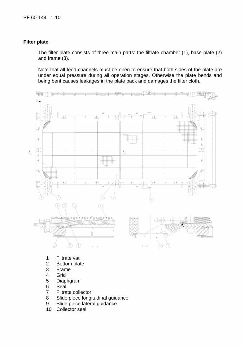
Filter plate
The filter plate consists of three main parts: the filtrate chamber (1), base plate (2) and frame (3). Note that all feed channels must be open to ensure that both sides of the plate are under equal pressure during all operation stages. Otherwise the plate bends and being bent causes leakages in the plate pack and damages the filter cloth.
1 Filtrate vat 2 Bottom plate 3 Frame 4 Grid 5 Diaphgram 6 Seal 7 Filtrate collector 8 Slide piece longitudinal guidance 9 Slide piece lateral guidance 10 Collector seal

PF 60-144 1-11
Filtrate chamber
The filtrate chamber collects the filtrate and leads it out through the collectors attached to the corners of the chamber.
Bottom plate
The bottom plate is the frame part to which all parts of the filter plate are attached. The pressing air channel is led through the bottom plate. The bottom plate and diaphragm form the pressing air chamber.
Frame
The frame serves as the fixing element for the diaphragm. The plate pack seal is fixed to the lower surface of the frame. The feed channels leading into the filtration chamber have been led through the frame.
Grid
The grid plates support the cloth and form outlet channels for the filtrate.
Diaphragm
The rubber diaphragm acts as a pressing element that by means of pressed air presses the cake against the filter cloth and grid so that liquid is removed from the cake through the filter cloth into the filtrate chamber. The maximum diaphragm pressure is 16 bar. As far as the durability of the diaphragm is concerned, it is much more recommendable to start with a pressure of 8 bar and then observe how the pressure changes effect the pressing time and residual moisture. In temperatures above +60 0C, a strong ageing phenomenon affects the rubber. In case the temperature of the slurry to be filtered is higher, observe the temperature continuously and follow the manufacturer's instructions. Observe the condition of the diaphragms continuously. In case the consumption of pressing air has increased and it flows into the chamber even at the end of pressing, change the damaged diaphragm immediately.
Seal
The seal is fixed to the frame on the chamber's side in order to prevent slurry leakages.
There is no seal below the cloth but the cloth and plastic surface are face to face. If any counter pressure is formed in the flow space below the cloth, it will cause filtrate leakage in the plate pack.
PF 60-144 1-12
Filtrate collectors
The filtrate collectors, when in the position "pack closed", form channels through which the filtrate is discharged from the plate pack. The alignment of the collectors should be observed. When moved from their places, the collectors cause leakage in the line; correct their position. These changes in alignment are due to wearing of slide pieces and/or moving of the filtrate chamber. See the paragraph "Adjustment of slide pieces", 3.5.
Closing mechanism
General
The closing mechanism comprises quick action cylinders (1), sealing cylinders (2) and locking pins (3) as indicated in the enclosed drawing. The closing of the plate pack takes place in two stages: first the plate pack is closed by means of quick action cylinders (1) and after closing, the plate pack is sealed with sealing cylinders (2).
Quick action
The plate pack is open after previous cycle. The plate pack closes when the top pressing plate (5) is driven to its low position by means of quick action cylinders (1). After this, the locking pins (3) fix the top pressing plate (5) to the columns (6) that have been fixed to the base plate (7). The filtration chambers have thus been formed, and the plate pack is now surrounded by the pressing plates, base plate and columns.
PF 60-144 1-13
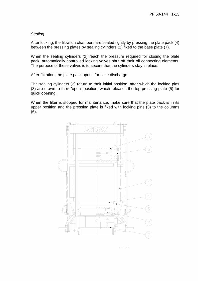
Sealing
After locking, the filtration chambers are sealed tightly by pressing the plate pack (4) between the pressing plates by sealing cylinders (2) fixed to the base plate (7). When the sealing cylinders (2) reach the pressure required for closing the plate pack, automatically controlled locking valves shut off their oil connecting elements. The purpose of these valves is to secure that the cylinders stay in place. After filtration, the plate pack opens for cake discharge. The sealing cylinders (2) return to their initial position, after which the locking pins (3) are drawn to their "open" position, which releases the top pressing plate (5) for quick opening. When the filter is stopped for maintenance, make sure that the plate pack is in its upper position and the pressing plate is fixed with locking pins (3) to the columns (6).
PF 60-144 1-14
Cloth conveyor unit
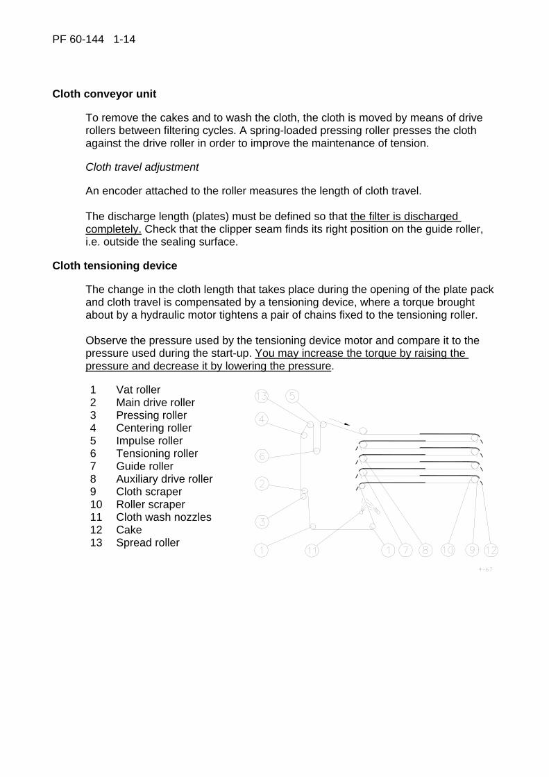
To remove the cakes and to wash the cloth, the cloth is moved by means of drive rollers between filtering cycles. A spring-loaded pressing roller presses the cloth against the drive roller in order to improve the maintenance of tension.
Cloth travel adjustment
An encoder attached to the roller measures the length of cloth travel. The discharge length (plates) must be defined so that the filter is discharged completely. Check that the clipper seam finds its right position on the guide roller, i.e. outside the sealing surface.
Cloth tensioning device
The change in the cloth length that takes place during the opening of the plate pack and cloth travel is compensated by a tensioning device, where a torque brought about by a hydraulic motor tightens a pair of chains fixed to the tensioning roller. Observe the pressure used by the tensioning device motor and compare it to the pressure used during the start-up. You may increase the torque by raising the pressure and decrease it by lowering the pressure.
1 Vat roller 2 Main drive roller 3 Pressing roller 4 Centering roller 5 Impulse roller 6 Tensioning roller 7 Guide roller 8 Auxiliary drive roller 9 Cloth scraper 10 Roller scraper 11 Cloth wash nozzles 12 Cake 13 Spread roller
PF 60-144 1-15
Filter cloth
General
The cloth functions both as a filtering element and as a conveyor belt transporting the cake out of the filter. Besides having a good filtering ability, the cloth must also be able to withstand heavy pulling. Only special type of fabrics can be used. The most commonly used material is a multifilament fabric which is lengthwise (warp) stronger than crosswise (weft). Pay special attention to possible holes in the cloth. Patch the holes immediately; solid matters entering through the holes wear the filtrate channels heavily especially during drying when the air flow speed is high.
Cloth wash
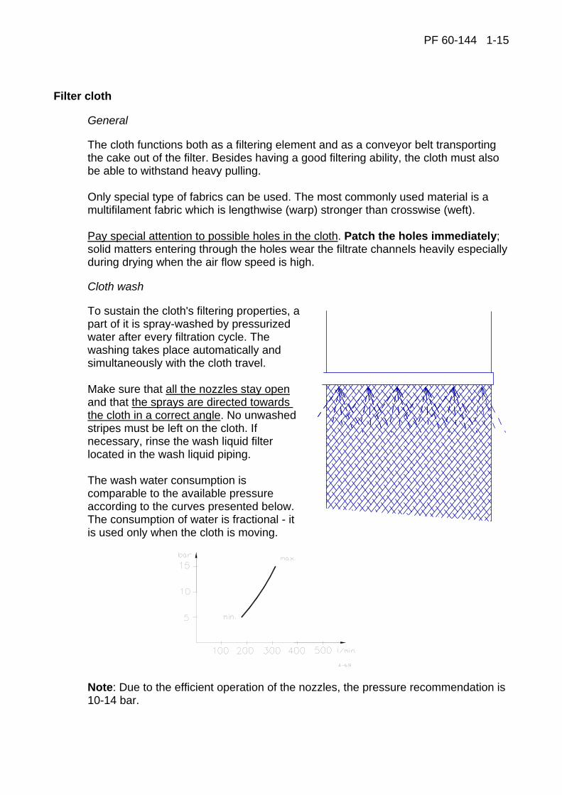
To sustain the cloth's filtering properties, a part of it is spray-washed by pressurized water after every filtration cycle. The washing takes place automatically and simultaneously with the cloth travel. Make sure that all the nozzles stay open and that the sprays are directed towards the cloth in a correct angle. No unwashed stripes must be left on the cloth. If necessary, rinse the wash liquid filter located in the wash liquid piping. The wash water consumption is comparable to the available pressure according to the curves presented below. The consumption of water is fractional - it is used only when the cloth is moving.
Note: Due to the efficient operation of the nozzles, the pressure recommendation is 10-14 bar.
PF 60-144 1-16
Cloth tracking
Cloth tracking operates automatically by means of a roller movable at its other end. The cloth may also be tracked manually with the help of buttons to a desired direction. Due to manufacture, there are slight bends on the cloth, which is why it drifts slightly to the sides while moving. When tracking the cloth manually, let the cloth circulate several times and make sure that it does not drift to either side systematically. If the cloth does not stay centered, the cloth seam is inclined or one of the rollers does not rotate.
OBSERVE THAT THE CLOTH STAYS IN THE CENTER AREA.

PF 60-144 1-17
Filter types
The automatic pressure filter is a further development of the chamber filter press principle and its main operating stages include filtering, diaphragm pressing, cake washing and compressed air drying.
Classed according to the construction materials used for parts in contact with the slurry:
1 Wetted parts made of stainless steel AISI 304L, used in processes in which pH = 4-14
2 Wetted parts made of stainless steel AISI316L, used in processes in which pH = 2-4
3 Wetted parts made of acid proof stainless steel ASTM NO8904, used in strongly acid processes in which pH = 1-2
5 Other steel material
Plastics and rubber parts are specified case by case.
The coding of Larox Pressure Filters
Larox PF 60/96 M1 45 Larox PF 60 96 M 1 45 Chamber height
45 mm chamber
60 mm chamber 75 mm chamber
Construction material code
1 = AISI 304L 2 = AISI 316L 3 = ASTM N08904L 5 = Other steel materials
Filter series
M = mining & metallurgy
C = chemical processing
Expandability Filtration area [m2] Pressure Filter
PF 60-144 1-18
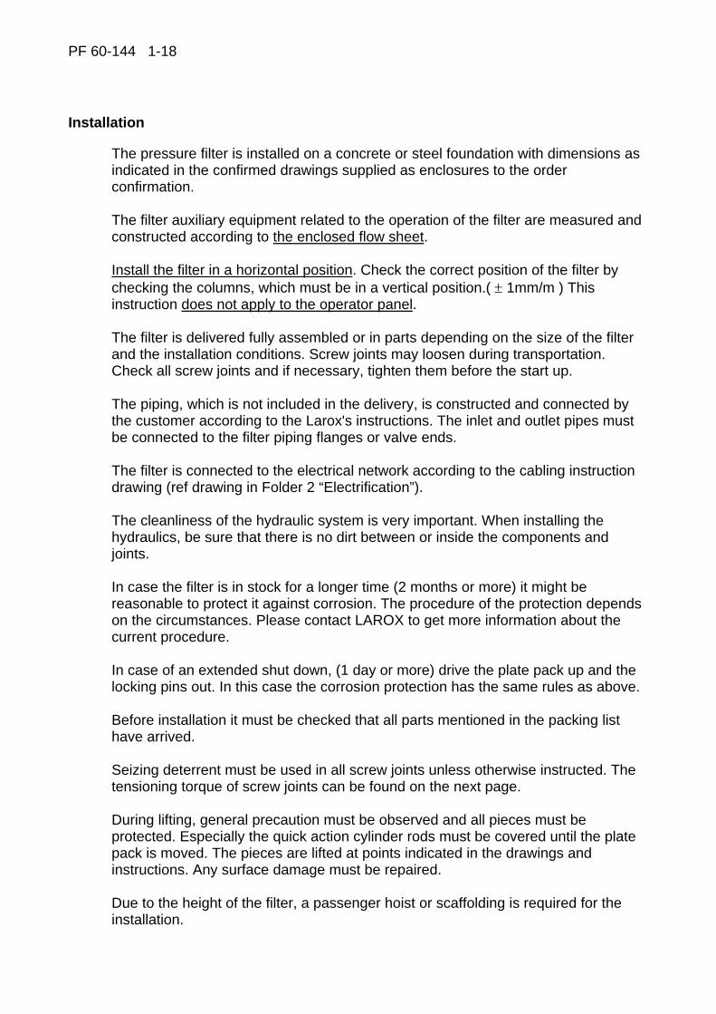
Installation
The pressure filter is installed on a concrete or steel foundation with dimensions as indicated in the confirmed drawings supplied as enclosures to the order confirmation. The filter auxiliary equipment related to the operation of the filter are measured and constructed according to the enclosed flow sheet. Install the filter in a horizontal position. Check the correct position of the filter by checking the columns, which must be in a vertical position.( ± 1mm/m ) This instruction does not apply to the operator panel. The filter is delivered fully assembled or in parts depending on the size of the filter and the installation conditions. Screw joints may loosen during transportation. Check all screw joints and if necessary, tighten them before the start up. The piping, which is not included in the delivery, is constructed and connected by the customer according to the Larox's instructions. The inlet and outlet pipes must be connected to the filter piping flanges or valve ends. The filter is connected to the electrical network according to the cabling instruction drawing (ref drawing in Folder 2 “Electrification”). The cleanliness of the hydraulic system is very important. When installing the hydraulics, be sure that there is no dirt between or inside the components and joints. In case the filter is in stock for a longer time (2 months or more) it might be reasonable to protect it against corrosion. The procedure of the protection depends on the circumstances. Please contact LAROX to get more information about the current procedure. In case of an extended shut down, (1 day or more) drive the plate pack up and the locking pins out. In this case the corrosion protection has the same rules as above. Before installation it must be checked that all parts mentioned in the packing list have arrived. Seizing deterrent must be used in all screw joints unless otherwise instructed. The tensioning torque of screw joints can be found on the next page. During lifting, general precaution must be observed and all pieces must be protected. Especially the quick action cylinder rods must be covered until the plate pack is moved. The pieces are lifted at points indicated in the drawings and instructions. Any surface damage must be repaired. Due to the height of the filter, a passenger hoist or scaffolding is required for the installation.
PF 60-144 1-19
The weights of different pieces are indicated in the installation instructions and packing lists. Special care and cleanliness must be observed during installation of hydraulics. The pipes/hoses and actuators must be kept plugged until connected. The instructions for the Hand Held operations should be read through carefully before testing any hydraulic functions.
Ref installation/assy of Larox PF 60-144
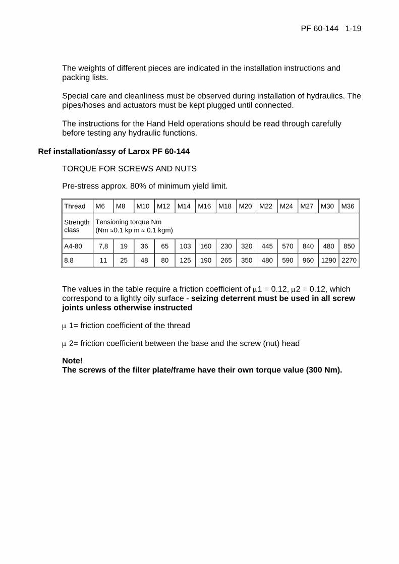
TORQUE FOR SCREWS AND NUTS
Pre-stress approx. 80% of minimum yield limit.
Thread M6 M8 M10 M12 M14 M16 M18 M20 M22 M24 M27 M30 M36
Strength class
Tensioning torque Nm (Nm ≈0.1 kp m ≈ 0.1 kgm)
A4-80 7,8 19 36 65 103 160 230 320 445 570 840 480 850
8.8 11 25 48 80 125 190 265 350 480 590 960 1290 2270
The values in the table require a friction coefficient of μ1 = 0.12, μ2 = 0.12, which correspond to a lightly oily surface - seizing deterrent must be used in all screw joints unless otherwise instructed
μ 1= friction coefficient of the thread
μ 2= friction coefficient between the base and the screw (nut) head
Note! The screws of the filter plate/frame have their own torque value (300 Nm).
PF 60-144 1-20
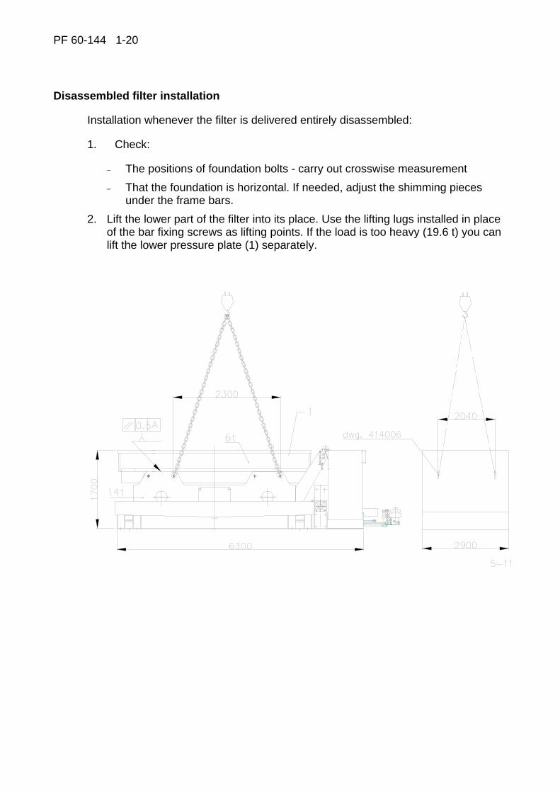
Disassembled filter installation
Installation whenever the filter is delivered entirely disassembled:
1. Check:
− The positions of foundation bolts - carry out crosswise measurement − That the foundation is horizontal. If needed, adjust the shimming pieces
under the frame bars. 2. Lift the lower part of the filter into its place. Use the lifting lugs installed in place
of the bar fixing screws as lifting points. If the load is too heavy (19.6 t) you can lift the lower pressure plate (1) separately.

PF 60-144 1-21
3. Lift the filter plates on top of the lower pressure plate. Check the order from the assembly drawing of the plate pack. Pile the plates as vertically as possible.
4. Fasten the lower parts of the columns into their places. Before fastening the column, check its right position, the columns are not interchangeable.
5. Lift the top pressing plate into its place. Before lifting, check the right position, e.g. which end belongs to the side of the tensioning device.

PF 60-144 1-22
6. Fasten the top ends of the columns and lift the upper frame into its place.
7. Check that the columns are vertical. If needed, you can adjust the position of the filter with a hydraulic jack (30 - 50 t). The lifting lugs for the jack are situated in the same place as the foundation bolts at the side of the U-bar frame.
8. Lift the cloth tensioning device into its place.
Dimension 5050 in the picture is for PF 96. Corresponding dimension to other filter sizes: PF 72: 4350 PF 120: 5750 PF 144: 6450
PF 60-144 1-23
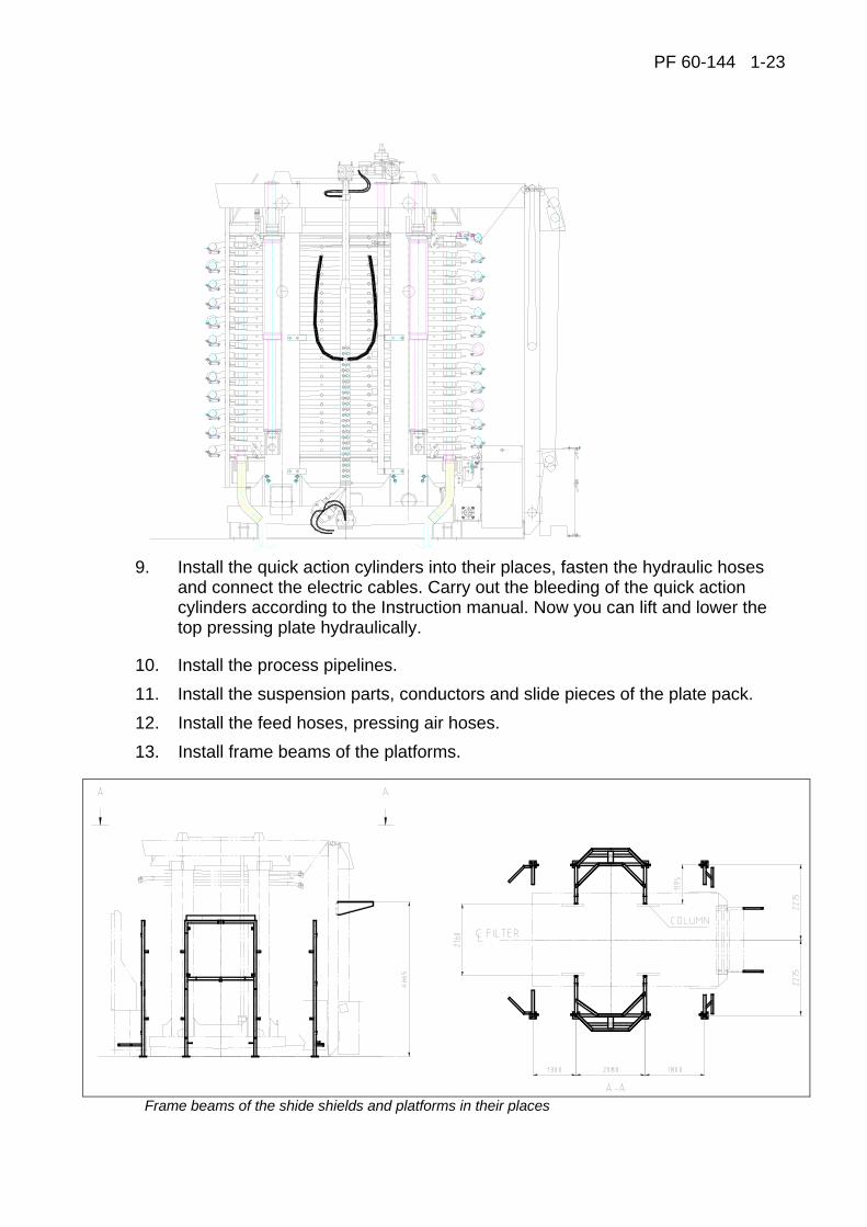
9. Install the quick action cylinders into their places, fasten the hydraulic hoses
and connect the electric cables. Carry out the bleeding of the quick action cylinders according to the Instruction manual. Now you can lift and lower the top pressing plate hydraulically.
10. Install the process pipelines. 11. Install the suspension parts, conductors and slide pieces of the plate pack. 12. Install the feed hoses, pressing air hoses. 13. Install frame beams of the platforms.
Frame beams of the shide shields and platforms in their places
PF 60-144 1-24
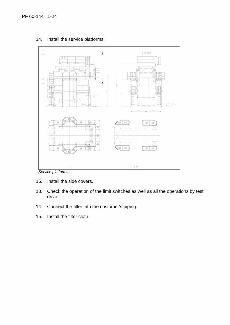
14. Install the service platforms.
Service platforms
15. Install the side covers.
13. Check the operation of the limit switches as well as all the operations by test drive.
14. Connect the filter into the customer's piping.
15. Install the filter cloth.
PF 60-144 1-25
Filter protection for sea shipments
Individually identified parts in each Larox filter are specially protected during transportation.
Protected parts
When delivered a whole filter:
− Piston rods of hydraulic cylinders
− Hydraulic blocks/valves/connectors
− Column holes
− Locking pins
When delivered dismantled filter and spare parts:
− In addition to the above, all machined, uncovered (not painted) surfaces
How to remove protection
A tin of thinner is delivered with each filter for removing protection. The person who starts up the filter removes the protection from the piston rods of hydraulic cylinders, locking pins and column holes.

PF 60-144 1-26
Start-up inspection
In order to carry out the start up without unnecessary delays certain things have to be ready and completed.
− Filter installed
− All dismantled (for packing and transportation) components assembled to the filter and it’s pipelines including limit switches
− All hydraulic hoses loosened for packing to be connected
− Pipelines built according to Larox design instructions
− Cake can be discharged from the filter, and the conveyor(s) meets Larox recommendations
− Voltage connected to control panel
− Voltage connected to filters motors
− Cables connected (Please see the cabling diagram)
− Cloth wash water available
− Cake wash water (liquid) available
− Compressed air available for pressing and cake drying, and capacity meets Larox recommendations
− Slurry pump installed
− Slurry available
− Hydraulic filter aggregate equipped with a 3-5µm filter available for hydraulic oil filling (Please see the manual, Section 4)
− Hydraulic oil available (for quality and quantity, please see the manual)
− Test cloth installed in the filter and production cloth available
− Start up spare parts kit available

PF 60-144 1-27
1.1 CONSTRUCTION AND OPERATION
The filtration elements (i.e. plates) of the PF filter are placed horizontally between two pressure plates. During filtration the plate pack is pressed together, and the pack is opened for cake discharge. The plate pack is opened and closed by means of hydraulic cylinders. The endless filter cloth zig-zags between the filter plates, which results in the filtered cake being formed on either side of the cloth. The filter cloth is thus automatically backflushed and any particles adhering to it or lodged in the filter cloth from the previous filtration cycle are washed out when filtering on the reverse side of the cloth. The cloth transports the cakes off the filter and, at the same time, the cloth is cleaned on both sides by high pressure water sprays. The cloth moving device is driven by the hydraulic motor which actuates the cloth drive roller. When the filter plates are opening and closing, the tension of the filter cloth is maintained at a constant level by a simple cloth tensioning device. The cloth tensioning device does not operate when the plate pack is closed. Slurry is fed into sealed filter chambers through the distribution piping. Wash water and drying air are fed in through the same pipe. The feed pipe is emptied through a drain valve on completion of the feed pumping cycle. The operation of the filter is controlled automatically by the operation unit containing the programmable logics and indicator lamps for all operations. The automatically controlled actuators for the pinch valves are hydraulic operated and for the ball valves pneumatic.
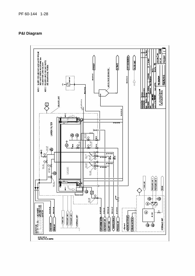
PF 60-144 1-28
P&I Diagram
PF 60-144 1-29
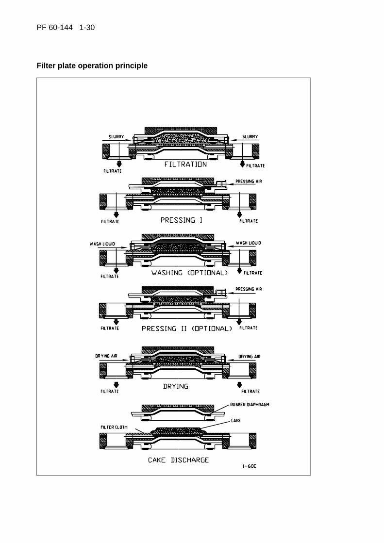
1.2 PRINCIPLE OF PRESSURE FILTRATION
1.2.3 Filtration
When the filter plate pack has been closed, slurry is pumped into the filter and fed simultaneously into each filter chamber through the distribution pipes. Filtrate flows through the cloth into the filtrate collection area, then out through the discharge pipe. The filtered material is collected on the cloth surface and forms the filter cake.
1.2.2 Pressing I
Pressing air flows in behind the rubber diaphragm. The diaphragm presses the cake against the cloth surface, thus pressing the filtrate from the cake through the cloth.
1.2.3 Washing (optional)
Wash liquid is pumped into the filter chambers in the same way as the slurry. As the water fills the filtration chamber, the diaphragm is lifted up and air is forced out from the upper side of the diaphragm. The wash liquid flows into the discharge pipes after passing through the filter cake and the cloth.
1.2.4 Pressing II (optional)
The wash liquid remaining in the chamber after the washing stage is pressed out of the cake as in stage 2 above.
1.2.5 Air drying
The final drying of the cake is accomplished with compressed air. The air enters through the distribution pipe, fills the filter chamber, raises the diaphragm and forces the pressing air above the diaphragm out of the filter. The air flow through the cake reduces its moisture content to the optimum and, at the same time, empties the filtrate chamber.
1.2.6 Discharge
When the air drying has been completed, the plate pack is opened and the cloth moving mechanism started. The filter cake on the cloth is discharged from both sides of the filter.
The four-stage (short) program does not include washing and second pressing stages.
PF 60-144 1-30
Filter plate operation principle

PF 60-144 1-31
1.3 TECHINICAL DESCRIPTION
Type LAROX PF60 SERIES Serial no. 933
60/96
Filtration area m2 60
Frame size 45
Plate size mm 1500 x 4010
Number of filter plates pcs 10
Chamber volume m3 2,7
Main dimensions length mm 7939
(with service platforms) width mm 5273
height mm 6258
Required floor area m2 110
Weight (Filter without auxiliary equipment)
t 82
Filter cloth width mm 1700
length m 68
Electric motors (525 V, 50 Hz)
- hydraulic unit kW - r/min 110 - 1500
Pressures
- Slurry feed bar 2.0 - 10.0
- Pressure air bar 2.0 - 16.0
- Pressure air (valve actuators) bar 6.0 – 12.0
- Air blow drying bar 4.0 - 12.0
- Cloth wash water bar 10.0 – 16.0

PF 60-144 2-1
2 OPERATION INSTRUCTIONS
PF 60-144 2-2
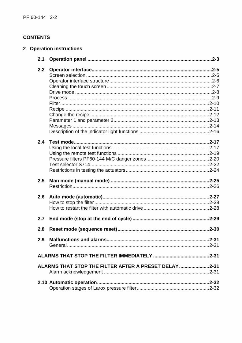
CONTENTS 2 Operation instructions
2.1 Operation panel ...........................................................................................2-3
2.2 Operator interface........................................................................................2-5 Screen selection ............................................................................................2-5 Operator interface structure...........................................................................2-6 Cleaning the touch screen .............................................................................2-7 Drive mode ....................................................................................................2-8 Process..........................................................................................................2-9 Filter.............................................................................................................2-10 Recipe .........................................................................................................2-11 Change the recipe .......................................................................................2-12 Parameter 1 and parameter 2......................................................................2-13 Messages ....................................................................................................2-14 Description of the indicator light functions ...................................................2-16
2.4 Test mode...................................................................................................2-17 Using the local test functions .......................................................................2-17 Using the remote test functions ...................................................................2-19 Pressure filters PF60-144 M/C danger zones..............................................2-20 Test selector S714.......................................................................................2-22 Restrictions in testing the actuators.............................................................2-24
2.5 Man mode (manual mode) ........................................................................2-25 Restriction....................................................................................................2-26
2.6 Auto mode (automatic)..............................................................................2-27 How to stop the filter ....................................................................................2-28 How to restart the filter with automatic drive ................................................2-28
2.7 End mode (stop at the end of cycle) ........................................................2-29
2.8 Reset mode (sequence reset)...................................................................2-30
2.9 Malfunctions and alarms...........................................................................2-31 General........................................................................................................2-31
ALARMS THAT STOP THE FILTER IMMEDIATELY .........................................2-31
ALARMS THAT STOP THE FILTER AFTER A PRESET DELAY......................2-31 Alarm acknowledgement .............................................................................2-31
2.10 Automatic operation..................................................................................2-32 Operation stages of Larox pressure filter.....................................................2-32

PF 60-144 2-3
2.1 OPERATION PANEL
The Operator Panel is used to facilitate the operation of the LAROX Pressure Filter. The Operator Panel incorporates switches, push buttons and an operator interface terminal, which are required for the operation. Each push-button, switch and indicator lamp is provided with a label briefly describing the function of the device. The flow diagram is located in the display of the operator interface terminal. The indicator lamps show the present state of the actuator or motor in question.
Operator interface terminal with a flow diagram.
The Operator Panel is illustrated on the following page.

PF 60-144 2-4
PF 60-144 2-5
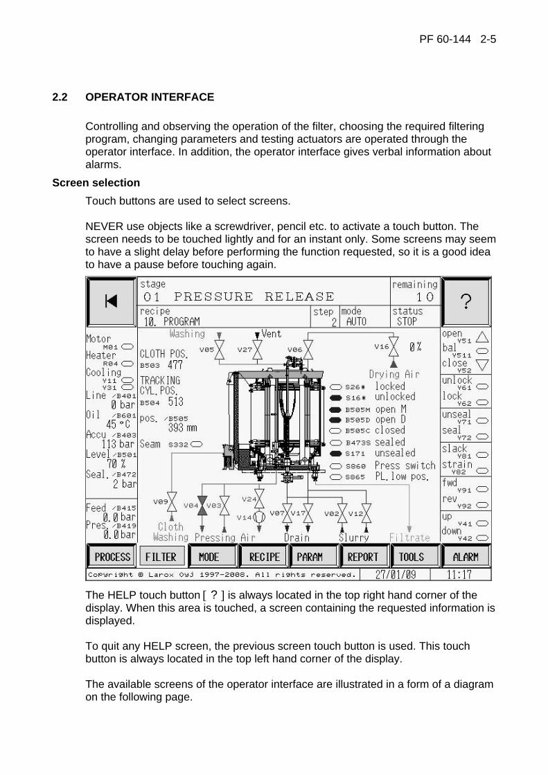
2.2 OPERATOR INTERFACE
Controlling and observing the operation of the filter, choosing the required filtering program, changing parameters and testing actuators are operated through the operator interface. In addition, the operator interface gives verbal information about alarms.
Screen selection Touch buttons are used to select screens. NEVER use objects like a screwdriver, pencil etc. to activate a touch button. The screen needs to be touched lightly and for an instant only. Some screens may seem to have a slight delay before performing the function requested, so it is a good idea to have a pause before touching again.
The HELP touch button [ ? ] is always located in the top right hand corner of the display. When this area is touched, a screen containing the requested information is displayed. To quit any HELP screen, the previous screen touch button is used. This touch button is always located in the top left hand corner of the display. The available screens of the operator interface are illustrated in a form of a diagram on the following page.

PF 60-144 2-6
HELP
HELP
ALARM 1HELP
ALARM 1HELP
ALARM 1HELP
PROCESSHELP
FILTERHELP
RECIPE HELP
PROCESS FILTERMODE
POP-UP RECIPE
PARAMETER HELP
PARAMETER2
PARAMETER1
REPORT HELP
REPORT
TESTMENU
TEST VALVE
TEST CLOTH
TESTPLATE PACK
TESTAUXILIARIES
HISTORY
PRESSUREGRAPHS
TOOLSHELP
TOOLS
ALARM &ALARMHISTORYHELP
ALARM
OUTPUTSTATUS
INPUTSTATUS
SCREEN CLEAN
PASSWORD
CALIBRATEHYDRAULICS
PASSWORD
SYSTEMCONFICURATION
ALARMHISTORY
ALARM 1HELP
LAST ALARMHELP
DIRECT ACCESS SCREENS*
Operator interface structure
*) Direct access screens (inside the grey frame) can be accessed directly from any screen inside the frame or linked to it.

PF 60-144 2-7
Cleaning the touch screen
It is an essential part of the unit maintenance to keep the screen clean. Even if great care is taken to touch the display with clean hands only (this is not necessary), dirt will still collect on the display surface. For cleaning of the display (since all screens have at least some part of the display active), a screen has been programmed into the display unit. This screen is accessed from the TOOLS screen and it is called the SCREEN CLEANING [CLS]. After the selected time the display will automatically return to the FILTER screen.
Cleaning the screen
To clean the display, use a soft cloth or paper towel and any ordinary window cleaner. To help prevent marring the plastic sheet on the surface of the display, carefully clean off any abrasive particles on the display surface, and then clean as advised above.
PF 60-144 2-8
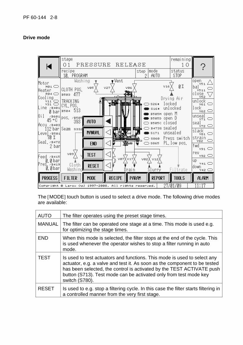
Drive mode
The [MODE] touch button is used to select a drive mode. The following drive modes are available:
AUTO The filter operates using the preset stage times.
MANUAL The filter can be operated one stage at a time. This mode is used e.g. for optimizing the stage times.
END When this mode is selected, the filter stops at the end of the cycle. This is used whenever the operator wishes to stop a filter running in auto mode.
TEST Is used to test actuators and functions. This mode is used to select any actuator, e.g. a valve and test it. As soon as the component to be tested has been selected, the control is activated by the TEST ACTIVATE push button (S713). Test mode can be activated only from test mode key switch (S780).
RESET Is used to e.g. stop a filtering cycle. In this case the filter starts filtering in a controlled manner from the very first stage.

PF 60-144 2-9
Process
The PROCESS screen displays the main devices of the filtering process as well as the process diagram. In addition to the filter, the slurry tank with level information, feed slurry pump, and cake conveyor are displayed. The rest of the basic screens can be accessed by means of the touch buttons in the lower part of the display. The drive mode can also be selected directly from this screen. List of symbols on the PROCESS screen:
M06 Cloth washing pump motor V14 Diaphragms lifting up valve M08 Cake conveyor motor V16 Flow control valve M09 Slurry feed pump motor V17 Manifold drain valve M15 Cake wash water pump motor V24 Ejector line valve V02 Slurry inlet valve V27 Feed manifold ventilation valve V03 Pressing air inlet valve B415 Feed manifold pressure V04 Pressing air outlet valve B419 Pressing manifold pressure V05 Cake wash water inlet valve B491 Wash water pressure V06 Drying air inlet valve V07 Manifold drain valve OK Slurry tank level OK V09 Cloth wash liquid inlet valve LOW Slurry tank level, min. V12 Slurry inlet valve B91* The filter weight (optional)

PF 60-144 2-10
Filter
List of symbols on the FILTER screen:
M01 Hydraulic unit motor Y511 Plate pack balancing R04 Hydraulic oil heater Y52 Plate pack closing Y11 Hydraulic oil cooler valve Y61 Locking pins unlocked Y31 Hydraulic pump 3 flow control valve Y62 Locking pins locked M05 Hydraulic oil cooler motor Y71 Unsealing B401 Hydraulic pressure transmitter Y72 Sealing B601 Hydraulic oil temperature transmitter Y81 Cloth slackening B403 Hydraulic accumulator pressure transmitter Y82 Cloth straining B472 Plate pack sealing pressure Y91 Cloth drive forward B501 Hydraulic oil level Y92 Cloth drive reverse B505 Plate pack position Y41 Cloth tracking cylinder out (the cloth to left) B415 Feed manifold pressure transmitter Y42 Cloth tracking cylinder in (the cloth to right) B419 Pressing manifold pressure transmitter V02 Slurry inlet valve B503 Cloth position V03 Pressing air inlet valve B504 Cloth tracking cylinder position V04 Pressing air outlet valve S332 Cloth seam detector V05 Cake wash water inlet valve S838A Cloth alignment limit switch, left V06 Drying air inlet valve S839A Cloth alignment limit switch, right V07 Manifold drain valve S26* Locking pins locked V09 Cloth wash liquid inlet valve S16* Locking pins unlocked V12 Slurry inlet valve B505M Plate pack open (maintenance) V14 Diaphragms lifting up valve B505D Plate pack open (discharge) V16 Flow control valve B505C Plate pack closed V17 Manifold drain valve S171 Seal plate down (unsealed) V24 Efector line valve Y51 Plate pack opening V27 Feed manifold ventilation valve

PF 60-144 2-11
Recipe
The RECIPE screen displays the filtering recipes the filter is provided with. The preset recipes (max. 10 pieces) can be scrolled, modified and activated. The [PREV] and [NEXT] touch buttons are used to scroll the recipes. The title of the recipe is displayed in the RECIPE field above the [ACTIVATE] button (the first 18 digits). To modify the control data, enter password from the keyboard and push [ENT]. The cursor will now move to the time value of the first stage. A new value is set accordingly. Use the arrow keys in the numerical keyboard in order to move to the previous/next stage. [CLR] is used to delete the field indicated by the cursor. If password is configured not to be in use, there is no need to enter it.
PF 60-144 2-12
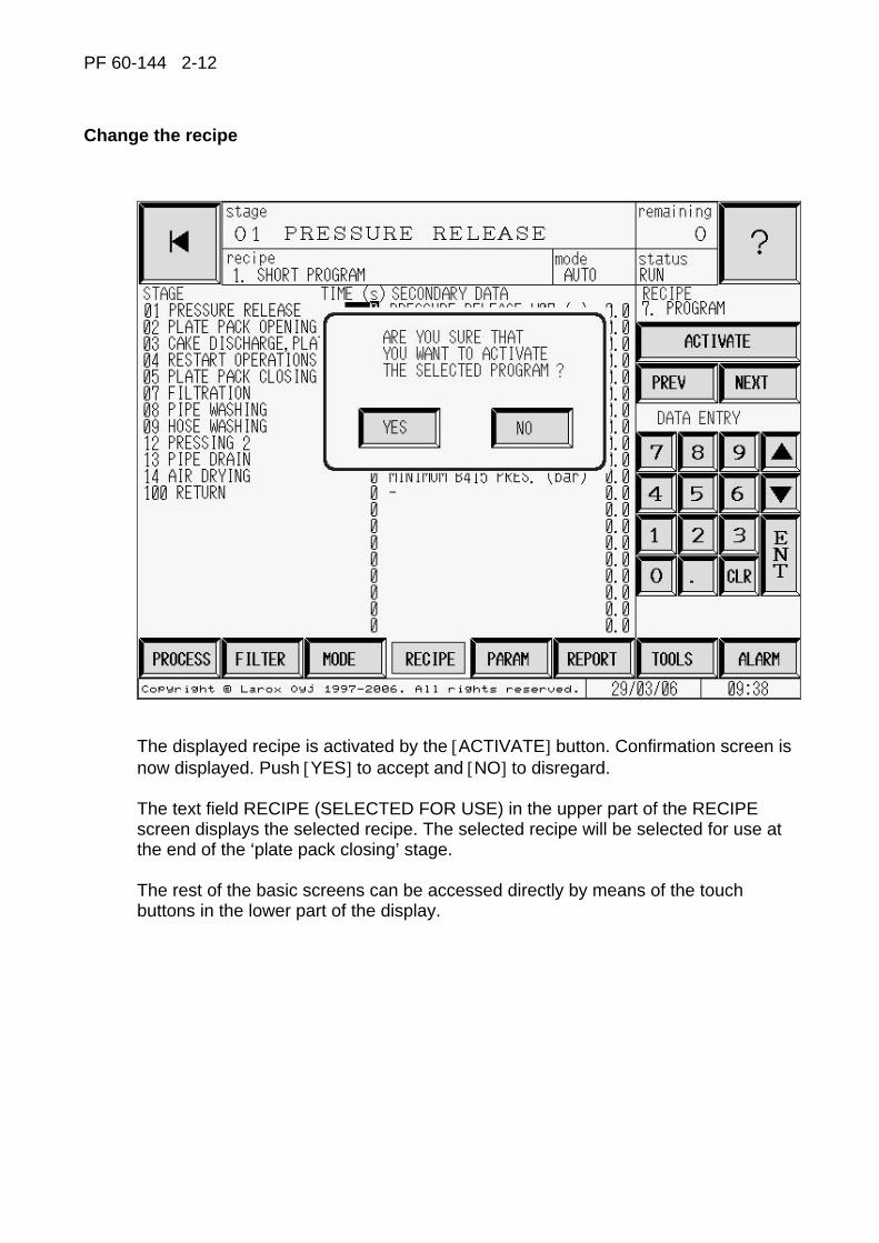
Change the recipe
The displayed recipe is activated by the [ACTIVATE] button. Confirmation screen is now displayed. Push [YES] to accept and [NO] to disregard. The text field RECIPE (SELECTED FOR USE) in the upper part of the RECIPE screen displays the selected recipe. The selected recipe will be selected for use at the end of the ‘plate pack closing’ stage. The rest of the basic screens can be accessed directly by means of the touch buttons in the lower part of the display.

PF 60-144 2-13
Parameter 1 and parameter 2
The PARAMETER screens display the filter control parameters that are valid for any recipe. The parameters are distributed between two screens, which can be scrolled by means of the [PAGE 1] and [PAGE 2] touch buttons.
Parameter 1 Parameter 2
To modify the values, enter password from the keyboard and push [ENT]. The cursor will now move to the value of the first parameter. A new value is set accordingly. Use the arrow key in the numerical keyboard in order to move to the previous/next parameter. [CLR] is used to delete the field indicated by the cursor. If the password has been entered in a RECIPE screen and a PARAMETER screen is selected next, there is no need to enter the password again. The RECIPE field of the PARAMETER screen displays the title of the active recipe. The rest of the basic screens can be accessed directly by means of the touch buttons in the lower part of the display. Drive mode can also be selected directly from this screen.
PF 60-144 2-14
Messages
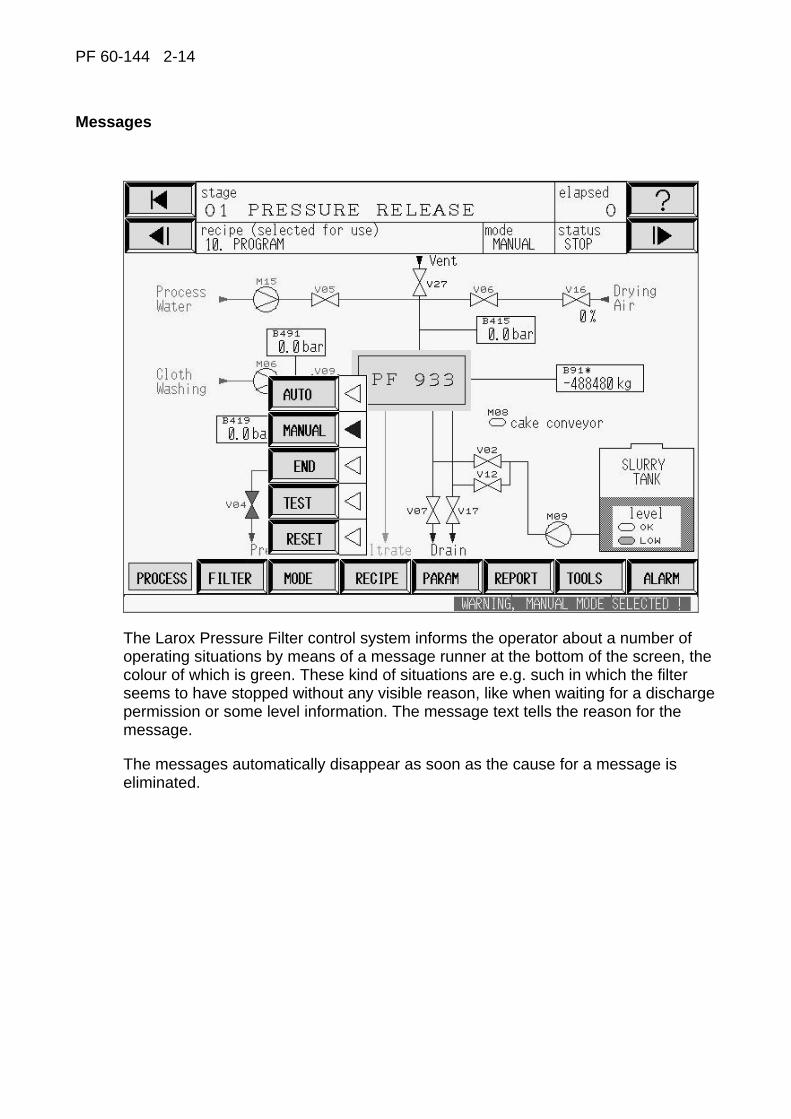
The Larox Pressure Filter control system informs the operator about a number of operating situations by means of a message runner at the bottom of the screen, the colour of which is green. These kind of situations are e.g. such in which the filter seems to have stopped without any visible reason, like when waiting for a discharge permission or some level information. The message text tells the reason for the message.
The messages automatically disappear as soon as the cause for a message is eliminated.
PF 60-144 2-15
Switching on the voltage
0
1
STOP / STOPPEDS708 / H708
START / RUNS710 / H710S701
EMERGENCY STOP
1
0
S700MAIN SWITCH
S755HYDRAULIC UNIT
S733 / H733ACKNL / ALARM
S713TEST / START TEST MODE
S780
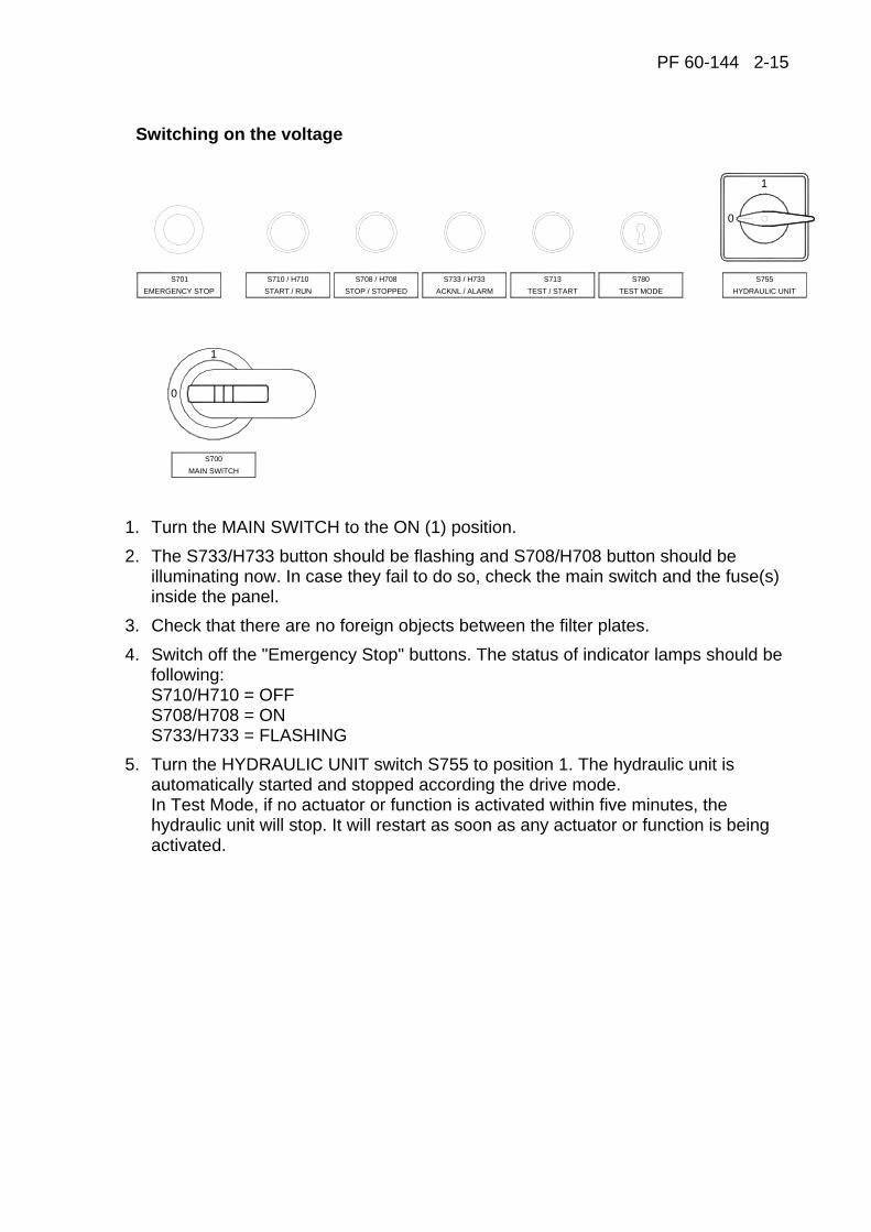
1. Turn the MAIN SWITCH to the ON (1) position. 2. The S733/H733 button should be flashing and S708/H708 button should be
illuminating now. In case they fail to do so, check the main switch and the fuse(s) inside the panel.
3. Check that there are no foreign objects between the filter plates. 4. Switch off the "Emergency Stop" buttons. The status of indicator lamps should be
following: S710/H710 = OFF S708/H708 = ON S733/H733 = FLASHING
5. Turn the HYDRAULIC UNIT switch S755 to position 1. The hydraulic unit is automatically started and stopped according the drive mode. In Test Mode, if no actuator or function is activated within five minutes, the hydraulic unit will stop. It will restart as soon as any actuator or function is being activated.
PF 60-144 2-16
Description of the indicator light functions
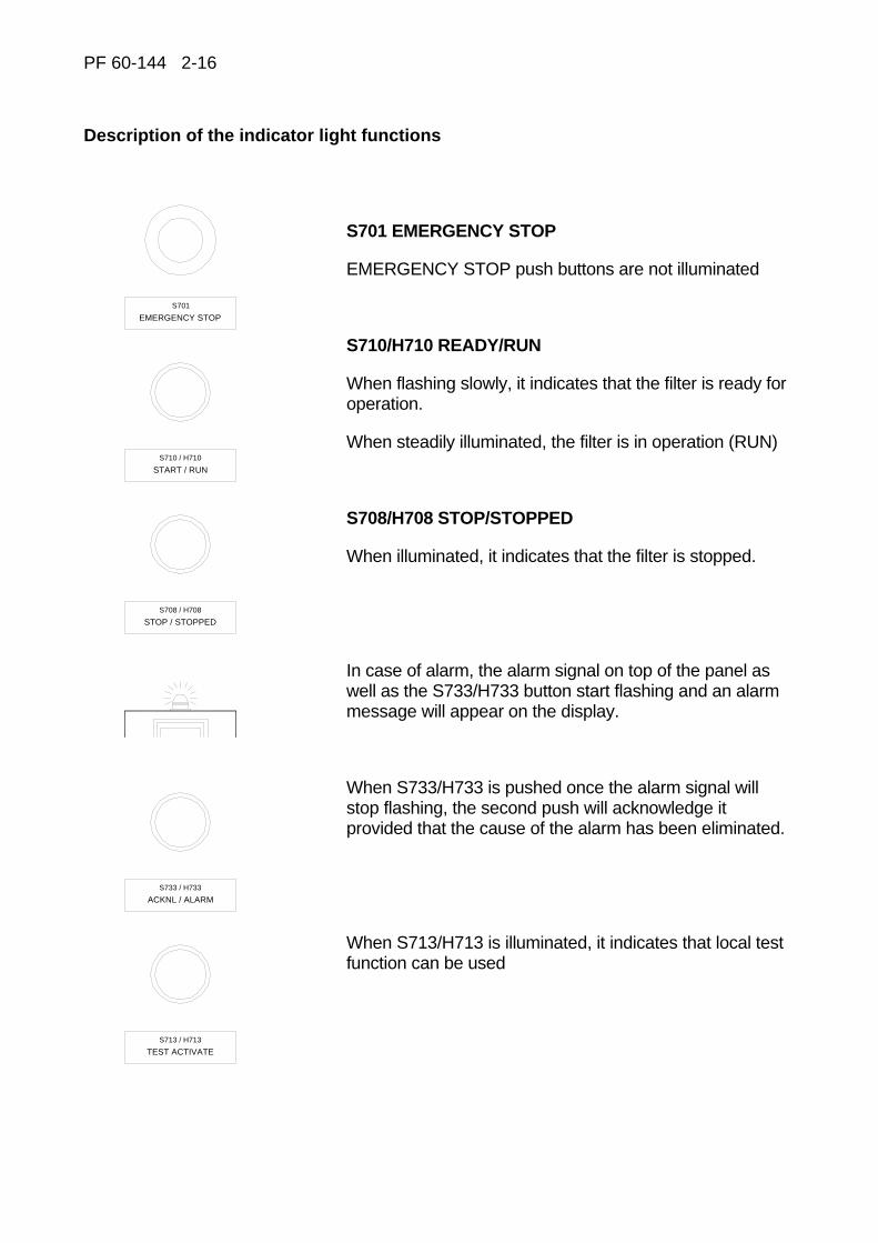
S701 EMERGENCY STOP
EMERGENCY STOP push buttons are not illuminated
S710/H710 READY/RUN
When flashing slowly, it indicates that the filter is ready for operation.
When steadily illuminated, the filter is in operation (RUN)
S708/H708 STOP/STOPPED
When illuminated, it indicates that the filter is stopped.
In case of alarm, the alarm signal on top of the panel as well as the S733/H733 button start flashing and an alarm message will appear on the display.
When S733/H733 is pushed once the alarm signal will stop flashing, the second push will acknowledge it provided that the cause of the alarm has been eliminated.
TEST ACTIVATE
ACKNL / ALARM
S713 / H713
S733 / H733
STOP / STOPPED
EMERGENCY STOP
S708 / H708
S710 / H710
START / RUN
S701
When S713/H713 is illuminated, it indicates that local test function can be used
PF 60-144 2-17
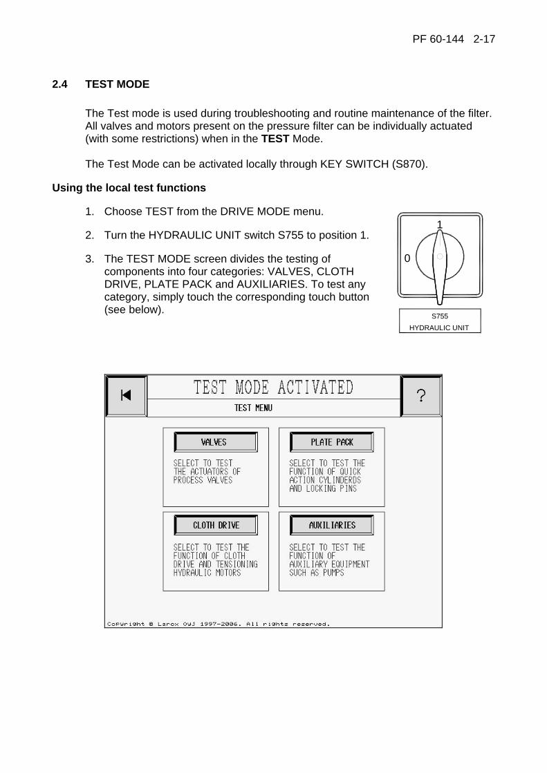
2.4 TEST MODE
The Test mode is used during troubleshooting and routine maintenance of the filter. All valves and motors present on the pressure filter can be individually actuated (with some restrictions) when in the TEST Mode. The Test Mode can be activated locally through KEY SWITCH (S870).
Using the local test functions
1. Choose TEST from the DRIVE MODE menu.
2. Turn the HYDRAULIC UNIT switch S755 to position 1.
3. The TEST MODE screen divides the testing of components into four categories: VALVES, CLOTH DRIVE, PLATE PACK and AUXILIARIES. To test any category, simply touch the corresponding touch button (see below).
1
0
S755HYDRAULIC UNIT
PF 60-144 2-18
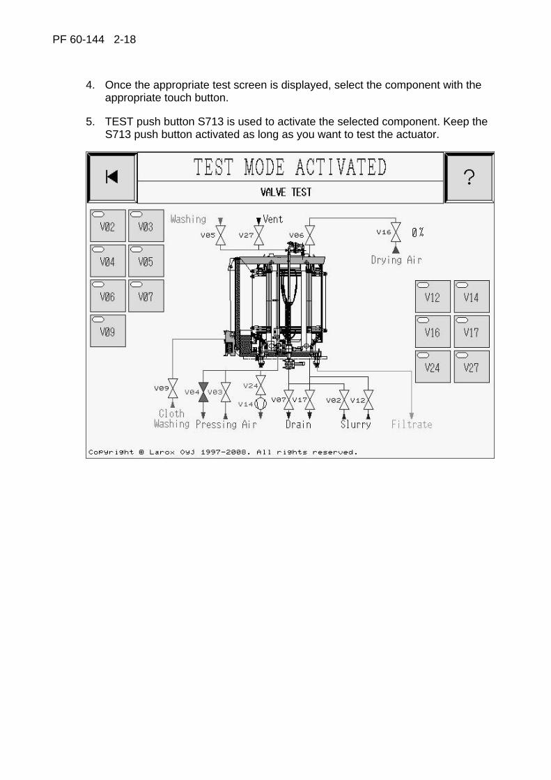
4. Once the appropriate test screen is displayed, select the component with the appropriate touch button.
5. TEST push button S713 is used to activate the selected component. Keep the S713 push button activated as long as you want to test the actuator.

PF 60-144 2-19
Using the remote test functions
Larox pressure filter is provided with a handheld test unit. The device, which is equipped with 15 m of cable is positioned on the right hand side of the cloth drive unit. This allows the handheld unit to be brought to the actuator to be tested facilitating thus maintenance and adjustments of the actuator. The handheld test unit has an Emergency Stop push button, test selector switch S714, and two push buttons S723 and S725. Test mode can be selected only with key switch S780. After activated, the handheld test unit can be used.
When the test operation is over, turn the selector switch to position “A” in the handheld unit and put the handheld unit back to its suspension hook. The filter is ready for normal process use. Select Auto-mode with the key switch S780.
After using test mode, remove key to prevent unauthorized test mode use.
HANDHELD TEST UNIT
Before operating the machine always ensure, that there is nobody near the danger zones (danger zones are described on the next page)!

PF 60-144 2-20
Pressure filters PF60-144 M/C danger zones
PF 60-144 2-21
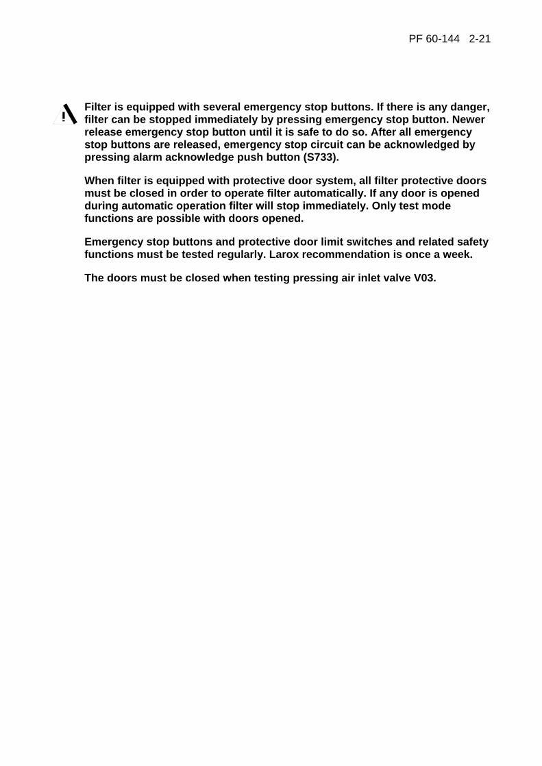
Filter is equipped with several emergency stop buttons. If there is any danger, filter can be stopped immediately by pressing emergency stop button. Newer release emergency stop button until it is safe to do so. After all emergency stop buttons are released, emergency stop circuit can be acknowledged by pressing alarm acknowledge push button (S733).
When filter is equipped with protective door system, all filter protective doors must be closed in order to operate filter automatically. If any door is opened during automatic operation filter will stop immediately. Only test mode functions are possible with doors opened.
Emergency stop buttons and protective door limit switches and related safety functions must be tested regularly. Larox recommendation is once a week.
The doors must be closed when testing pressing air inlet valve V03.

PF 60-144 2-22
Test selector S714
The Test selector S714 has several functions:
1. When in AUTO position, the eventual alarms during testing can be acknowledged directly from the handheld test unit.
2. VALVE side positions permit the testing of the process valves as shown on switch S714. The left hand side push button S725 activates the valve V0*. The eventual parallel valve V1* can be activated by the right hand side push button.
3. HYDRAULIC side positions permit testing of the hydraulics and motors as shown on switch S714. Note that there may be two devices or two directions for each position of S714. In case of two devices, the left hand side push button S725 operates the device listed on the left and the right hand side push button S723 operates the device listed on the right. If there are two directions in which the device may operate, the left hand side push button S725 runs the device either upwards or forward and the right hand side push button S723 runs the device either downwards or reverse.
PF 60-144 2-23
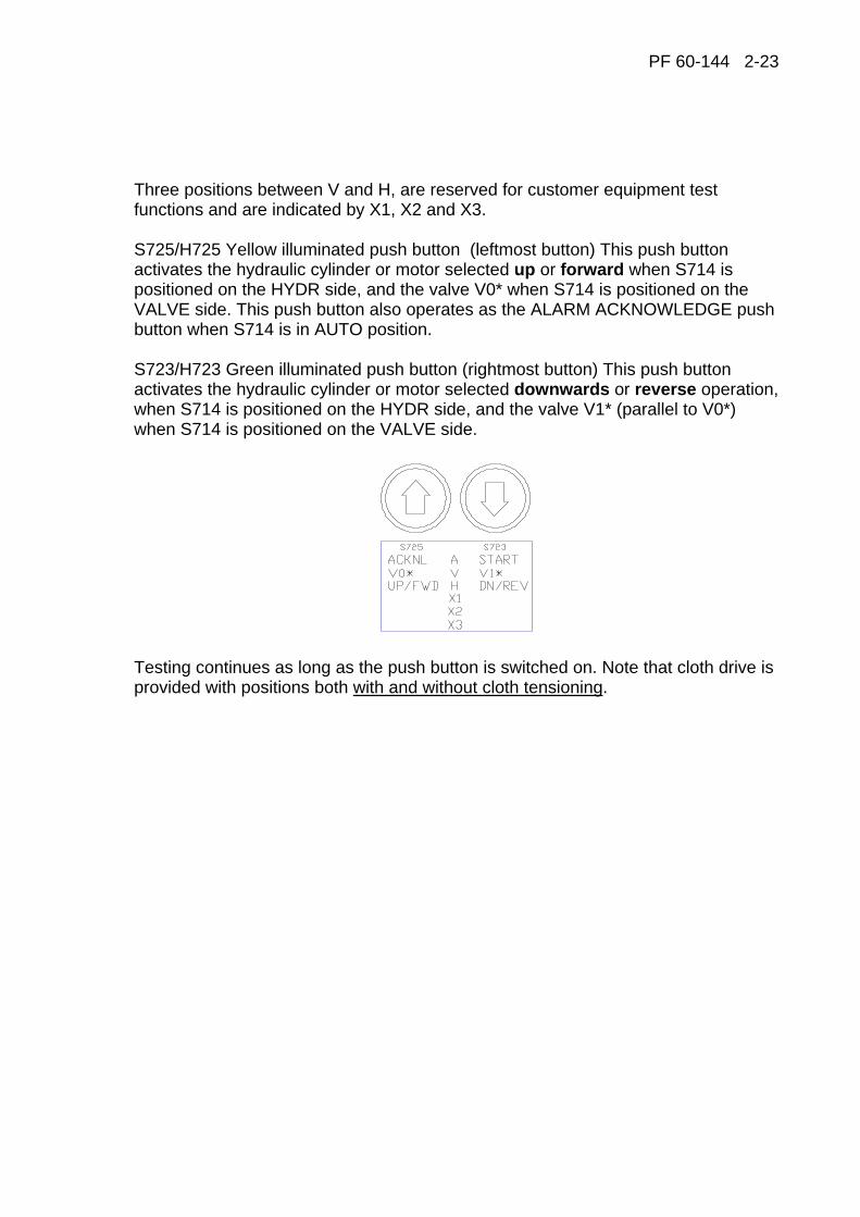
Three positions between V and H, are reserved for customer equipment test functions and are indicated by X1, X2 and X3. S725/H725 Yellow illuminated push button (leftmost button) This push button activates the hydraulic cylinder or motor selected up or forward when S714 is positioned on the HYDR side, and the valve V0* when S714 is positioned on the VALVE side. This push button also operates as the ALARM ACKNOWLEDGE push button when S714 is in AUTO position. S723/H723 Green illuminated push button (rightmost button) This push button activates the hydraulic cylinder or motor selected downwards or reverse operation, when S714 is positioned on the HYDR side, and the valve V1* (parallel to V0*) when S714 is positioned on the VALVE side.
Testing continues as long as the push button is switched on. Note that cloth drive is provided with positions both with and without cloth tensioning.
PF 60-144 2-24
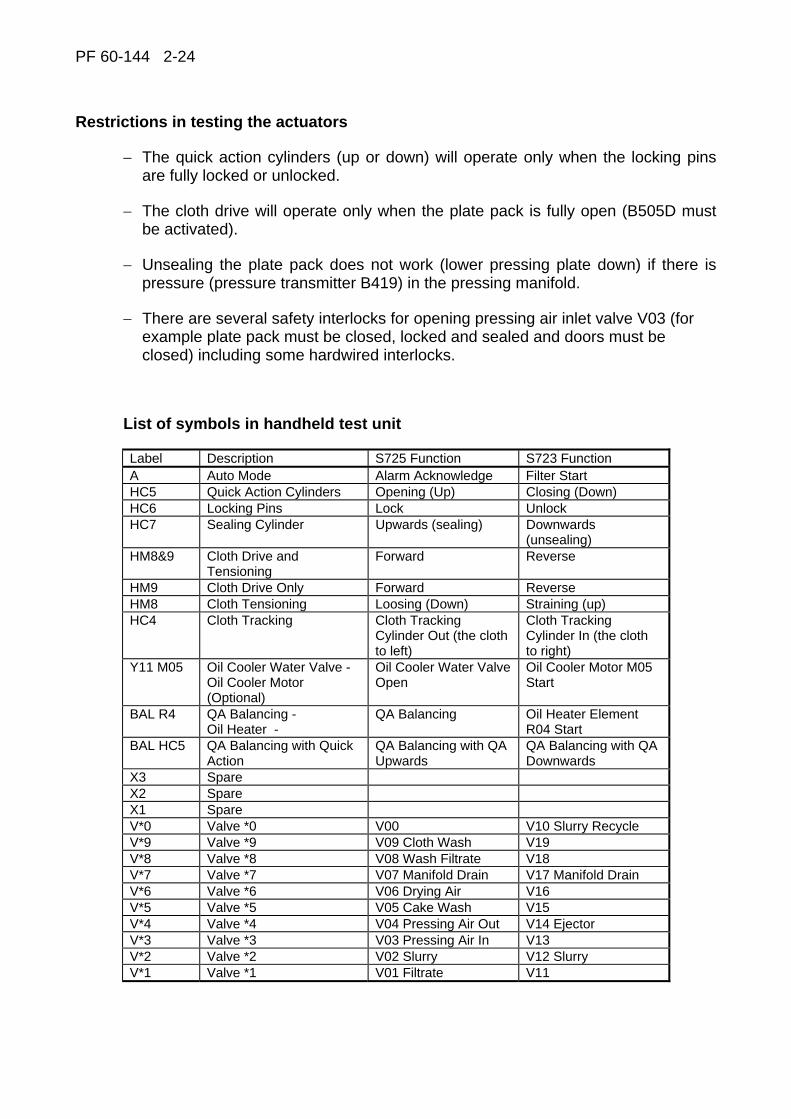
Restrictions in testing the actuators
− The quick action cylinders (up or down) will operate only when the locking pins are fully locked or unlocked.
− The cloth drive will operate only when the plate pack is fully open (B505D must be activated).
− Unsealing the plate pack does not work (lower pressing plate down) if there is pressure (pressure transmitter B419) in the pressing manifold.
− There are several safety interlocks for opening pressing air inlet valve V03 (for example plate pack must be closed, locked and sealed and doors must be closed) including some hardwired interlocks.
List of symbols in handheld test unit
Label Description S725 Function S723 Function A Auto Mode Alarm Acknowledge Filter Start HC5 Quick Action Cylinders Opening (Up) Closing (Down) HC6 Locking Pins Lock Unlock HC7 Sealing Cylinder Upwards (sealing) Downwards
(unsealing) HM8&9 Cloth Drive and
Tensioning Forward Reverse
HM9 Cloth Drive Only Forward Reverse HM8 Cloth Tensioning Loosing (Down) Straining (up) HC4 Cloth Tracking Cloth Tracking
Cylinder Out (the cloth to left)
Cloth Tracking Cylinder In (the cloth to right)
Y11 M05 Oil Cooler Water Valve - Oil Cooler Motor (Optional)
Oil Cooler Water Valve Open
Oil Cooler Motor M05 Start
BAL R4 QA Balancing - Oil Heater -
QA Balancing Oil Heater Element R04 Start
BAL HC5 QA Balancing with Quick Action
QA Balancing with QA Upwards
QA Balancing with QA Downwards
X3 Spare X2 Spare X1 Spare V*0 Valve *0 V00 V10 Slurry Recycle V*9 Valve *9 V09 Cloth Wash V19 V*8 Valve *8 V08 Wash Filtrate V18 V*7 Valve *7 V07 Manifold Drain V17 Manifold Drain V*6 Valve *6 V06 Drying Air V16 V*5 Valve *5 V05 Cake Wash V15 V*4 Valve *4 V04 Pressing Air Out V14 Ejector V*3 Valve *3 V03 Pressing Air In V13 V*2 Valve *2 V02 Slurry V12 Slurry V*1 Valve *1 V01 Filtrate V11
PF 60-144 2-25
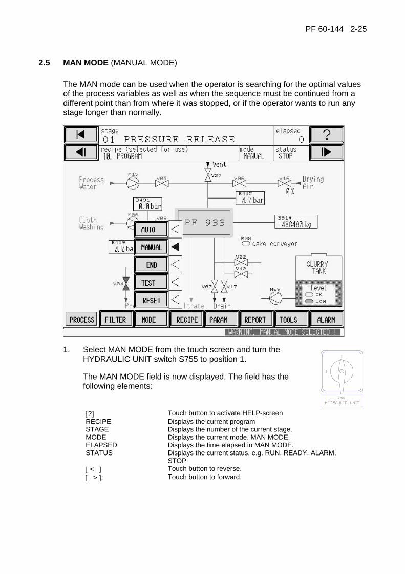
2.5 MAN MODE (MANUAL MODE)
The MAN mode can be used when the operator is searching for the optimal values of the process variables as well as when the sequence must be continued from a different point than from where it was stopped, or if the operator wants to run any stage longer than normally.
1. Select MAN MODE from the touch screen and turn the HYDRAULIC UNIT switch S755 to position 1.
The MAN MODE field is now displayed. The field has the following elements:
[?] Touch button to activate HELP-screen RECIPE Displays the current program STAGE Displays the number of the current stage. MODE Displays the current mode. MAN MODE. ELAPSED Displays the time elapsed in MAN MODE. STATUS Displays the current status, e.g. RUN, READY, ALARM,
STOP [ < | ] Touch button to reverse. [ | > ]: Touch button to forward.
PF 60-144 2-26
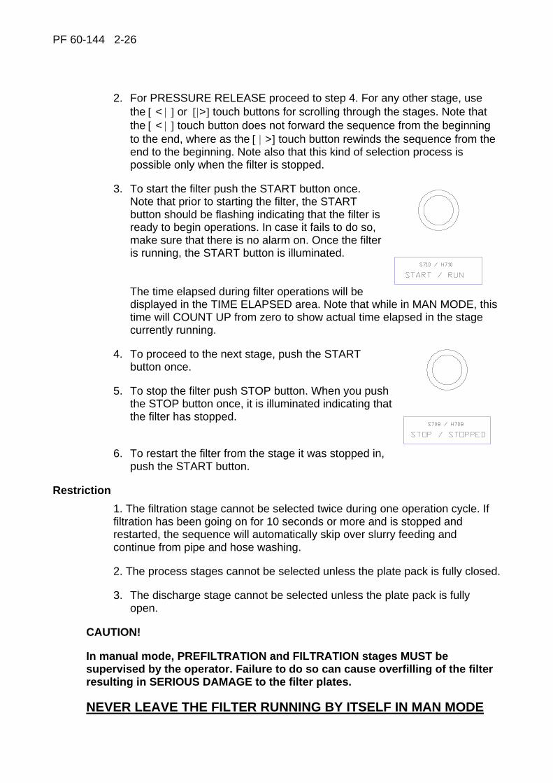
2. For PRESSURE RELEASE proceed to step 4. For any other stage, use
the [ < | ] or [|>] touch buttons for scrolling through the stages. Note that the [ < | ] touch button does not forward the sequence from the beginning to the end, where as the [ | >] touch button rewinds the sequence from the end to the beginning. Note also that this kind of selection process is possible only when the filter is stopped.
3. To start the filter push the START button once. Note that prior to starting the filter, the START button should be flashing indicating that the filter is ready to begin operations. In case it fails to do so, make sure that there is no alarm on. Once the filter is running, the START button is illuminated. The time elapsed during filter operations will be displayed in the TIME ELAPSED area. Note that while in MAN MODE, this time will COUNT UP from zero to show actual time elapsed in the stage currently running.
4. To proceed to the next stage, push the START button once.
5. To stop the filter push STOP button. When you push the STOP button once, it is illuminated indicating that the filter has stopped.
6. To restart the filter from the stage it was stopped in, push the START button.
Restriction 1. The filtration stage cannot be selected twice during one operation cycle. If filtration has been going on for 10 seconds or more and is stopped and restarted, the sequence will automatically skip over slurry feeding and continue from pipe and hose washing.
2. The process stages cannot be selected unless the plate pack is fully closed.
3. The discharge stage cannot be selected unless the plate pack is fully open.
CAUTION!
In manual mode, PREFILTRATION and FILTRATION stages MUST be supervised by the operator. Failure to do so can cause overfilling of the filter resulting in SERIOUS DAMAGE to the filter plates.
NEVER LEAVE THE FILTER RUNNING BY ITSELF IN MAN MODE
PF 60-144 2-27
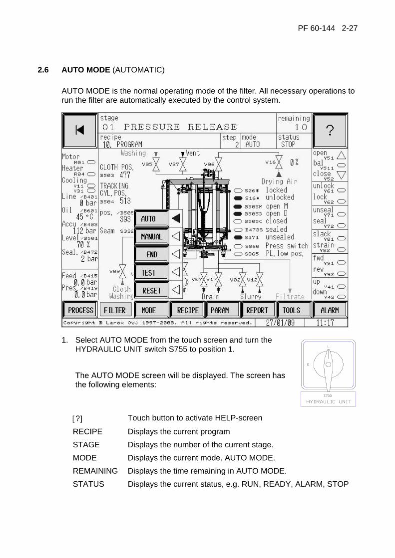
2.6 AUTO MODE (AUTOMATIC)
AUTO MODE is the normal operating mode of the filter. All necessary operations to run the filter are automatically executed by the control system.
1. Select AUTO MODE from the touch screen and turn the HYDRAULIC UNIT switch S755 to position 1.
The AUTO MODE screen will be displayed. The screen has the following elements:
[?] Touch button to activate HELP-screen
RECIPE Displays the current program STAGE Displays the number of the current stage. MODE Displays the current mode. AUTO MODE. REMAINING Displays the time remaining in AUTO MODE. STATUS Displays the current status, e.g. RUN, READY, ALARM, STOP
PF 60-144 2-28
2. To start the filter from the present stage push the START button once. Note that prior to starting the filter, the START button should be flashing indicating that the filter is ready to begin operations. In case it fails to do so, make sure that there is no alarm on. Once the filter is running, the START button is illuminated. The time remaining during filter operations will be displayed in the REMAINING area. Note that while in AUTO MODE, this time will COUNT DOWN from the preset to show the time remaining in each stage.
3. If you want to start from another stage, see instructions for program RESET in section RESET MODE and MANUAL START in section MANUAL MODE.
How to stop the filter
4. To stop the filter push STOP button. When you push the STOP button once, it is illuminated indicating that the filter has stopped. NOTE! The filter may be stopped due to an alarm or a voltage break. If the filter has been stopped and been sitting idle for a long period of time, it is recommended that the filter to be driven in the discharge stage in MAN MODE until the full length of the filter cloth has been washed. Once the full length has been washed, the AUTO MODE can be switched on, operating the filter normally.
How to restart the filter with automatic drive
5. If the filter has been stopped due to an alarm or if the STOP button has been pushed, proceed as follows:
I Locate and eliminate the alarm or malfunction prior to restarting the filter (see MALFUNCTIONS AND ALARMS).
II Push the START button once. The filter restarts from the stage it was stopped in and continues the automatic operation.

PF 60-144 2-29
2.7 END MODE (STOP AT THE END OF CYCLE)
The END mode is used to stop the filter automatically after complete cycle (after cake discharge), thereby freeing the operator from having to wait for the end of the present cycle. In this mode the filter will perform an orderly stopping after the end of cake discharge. All functions in END mode are similar to those in AUTO mode.
1. Select END mode from the touch screen.
2. The filter will continue its operation through the cycle as if in AUTO mode and stop after the end of cloth washing. At this time the filter will perform an orderly shutdown by closing the plate pack. The filter can be restarted at any time in either MAN mode or AUTO mode by pushing the START button (see MAN mode or AUTO mode). The filter will restart from PLATE PACK OPEN after END mode stop.

PF 60-144 2-30
2.8 RESET MODE (SEQUENCE RESET)
The RESET MODE is used to reset the program sequence back to the PRESSURE RELEASE stage and load into the operational area of the program any new data that has been entered.
Note: Before starting the filter from another point than where it was stopped, the program sequence must be reset.
1. Select RESET mode from the touch screen. The program then asks for a confirmation and requests you to stop the filter.
2. Push STOP button S708/H708 to RESET the filter program sequence.
3. The default starting stage after resetting the filter program sequence is PRESSURE RELEASE unless the plate pack is fully open. If the plate pack is fully open, the default starting point is CAKE DISCHARGE. To start the filter from another stage, see MAN MODE.
PF 60-144 2-31
2.9 MALFUNCTIONS AND ALARMS
General
Extensive diagnostic functions have been programmed into the control system of LAROX Filter.
ALARMS THAT STOP THE FILTER IMMEDIATELY
* Emergency stop
* Voltage break
ALARMS THAT STOP THE FILTER AFTER A PRESET DELAY
* Valve or sensor failure * Motor failure * Process pressures * Cloth drive * Plate pack movements * CPU battery low (If the CPU has a battery) * Failure in hydraulics * Level of process fluid tanks
Alarm acknowledgement
When in state of alarm, the filter will stop immediately. The ALARM BEACON on top of the control panel and the ALARM RESET button S733 will flash informing alarm or malfunction existing in the filter. Push the ALARM RESET button once to stop the ALARM BEACON and the ALARM RESET button from flashing. The ALARM RESET button remains illuminated. Once the cause of the alarm has been located and eliminated, push the ALARM RESET button again to acknowledge the alarm. Then the filter can be restarted by pushing the START button S710.
NOTE: ALWAYS DETERMINE THE CAUSE OF ALARM BEFORE RESTARTING THE FILTER.
Troubleshooting
If the cause of the alarm and its corrective measures are not known, the display screen can provide the operator with extensive help in determining the possible reasons for the alarm, and the measures that can be taken to correct it.

PF 60-144 2-32
2.10 AUTOMATIC OPERATION
Operation stages of Larox pressure filter
SBR01 Pressure release
For security reasons, pressure release is always the first stage when starting a LAROX PRESSURE FILTER. During this stage, the remaining pressure in the filter chambers is released for safe plate pack opening. This stage is divided into two periods of time: in the first and main period the inlet valves are closed. During the second period, the manifold drain valves V07 and V17 are opened.
SBR02 Plate pack opening
On completion of the PRESSURE RELEASE the plate pack is unsealed by driving the sealing cylinders downwards. The quick action cylinders are then driven to release the pins from the column holes. The locking pins are unlocked (pins move into the upper pressure plate). After the locking pins have been unlocked, the plate pack is opened by driving the quick action cylinders upwards until the plate pack is fully open. The cloth strain starts at the same time as the plate pack opening.
SBR03 Cake discharge
When the plate pack is fully open, the cloth drive motor HM09 is started and the cloth wash inlet valve V09 is opened. The cake formed on the cloth is then discharged into the cake chutes at both ends of the filter. After the first plate length of discharge, the speed of the cloth is increased reducing thus the cloth washing time.
SBR04 Restart operation
Operation delay. The system executes a restart check and proceeds to the next stage.
SBR05 Plate pack closing
On completion of the restart operations delay the filter begins to close the plate pack. First the quick action cylinders are moved downwards after which the locking pins are locked. Finally, the plate pack is sealed by driving the sealing cylinders upwards until the required sealing pressure is reached.
SBR06 Pre-filtration
When the filter plates are closed and sealed, the slurry is fed to the distribution pipe through V02 and V12 and further to each chamber through the feed collectors. The filtrate passes through the cloth into the filtrate pan and exits the filter chamber via filtrate collectors into the filtrate side pipe and out through the valve V08. Cake begins to form on the cloth. When the filtration time runs out, the filtration stage starts.

PF 60-144 2-33
SBR07 Filtration (slurry feed)
When the filter plates are closed and sealed, the slurry is fed through the distribution pipe to each chamber through the feed collectors. The filtrate passes through the cloth into the filtrate pan and exits the filter chamber via filtrate collectors into the filtrate side pipe and out through the valve V01. Cake begins to form on the cloth.
SBR08 Pipe washing
After the filtration stage, the distribution pipe is cleaned by opening the manifold drain valve V07 and V17 and feeding water through the pipe from cake wash inlet valve V05.
SBR09 hose washing
After the pipe washing stage, the slurry feed hoses are cleaned by opening the cake wash inlet valve V05 which forces water through the slurry feed hoses and into the filter chambers. The drain valve V07 and V17 are closed.
SBR10 Pressing 1
In the pressing stage, the pressing air enters through the pressing air pipe and the hoses into the space above the rubber diaphragms. All the remaining liquid from the filter chamber above the formed cake is forced through the cake and it exits the filter. Finally the cake is pressed for elimination of any liquid mechanically disposable still present in the cake. Proceed now to cake washing.
SBR11 Cake washing (optional)
The washing liquid is fed to the filter chamber through the wash liquid inlet valve V05. The washing liquid washes the cake and passes then through the cloth and into the filtrate collectors.
SBR12 Pressing 2 (optional)
After the washing stage the washing liquid remaining in the filter chamber is pressed out by introducing the pressing air into the diaphragms, like in the Pressing 1 stage.
SBR13 Drainage of distribution pipe
After the last pressing stage and before the cake air drying the distribution pipe is drained of water/slurry by opening valves V07, V17 and vent valve V27.
SBR14 Cake air drying
Drying of the cake is accomplished with compressed air. The air enters the distribution pipe through V06 and V16 valves. The air flowing through the cake reduces its moisture content to the optimum value simultaneously emptying the filter chamber from the pressing air.
PF 60-144 3-1
3 MAINTENANCE, REPAIRS AND ADJUSTMENTS

PF60-144 3-2
CONTENTS 3 Maintenance, repairs and adjustments
Safety ....................................................................................................................3-4
3.1 Preventitive maintenance ...........................................................................3-6 Daily maintenance .........................................................................................3-6 Regular maintenance.....................................................................................3-7 Maintenance check list ..................................................................................3-8 Lubrication chart ..........................................................................................3-10
3.2 FIlter cloth ..................................................................................................3-11 General........................................................................................................3-11 Installation of cloth.......................................................................................3-12 Replacement of cloth...................................................................................3-12 Mending of cloth ..........................................................................................3-13 Joining of cloth.............................................................................................3-14
3.3 Replacement of diaphragm.......................................................................3-15
3.4 Replacement of seal ..................................................................................3-20
3.5 Replacement and adjustment of slide pieces .........................................3-23 Adjustment of filter plates ............................................................................3-24
3.6 Adjustment and replacement of scrapers ...............................................3-25 Adjustment of scrapers ................................................................................3-25 Replacement of scrapers.............................................................................3-25
3.7 Installation and replacement of grids ......................................................3-26
3.8 Replacement of hoses...............................................................................3-27 L-coupling band circle installation................................................................3-27
3.9 Replacement of filtrate vat........................................................................3-29
3.10 Replacement of filter plate........................................................................3-30
3.11 Maintenance of cloth conveyor unit and tensioning device ..................3-35 Drive rollers .................................................................................................3-35 Cloth driving.................................................................................................3-35 Centering roller ............................................................................................3-36 Automatic cloth tracking...............................................................................3-36 Cloth tensioning device................................................................................3-38 Replacing of a plate roller bearing ...............................................................3-39 Replacement of plate roller..........................................................................3-41 Replacement of guide roller.........................................................................3-43 Replacement of auxiliary drive roller............................................................3-43
3.12 Adjustment of cloth wash spray nozzles.................................................3-44
PF 60-144 3-3
3.13 Inspection and replacement of suspension plates.................................3-45
3.14 Welfare measures during maintenance action .......................................3-51 Slackening of the filter cloth.........................................................................3-51 Space arrangement between the filter plates for maintenance....................3-52 Removing the upper part of the cake chute .................................................3-60

PF60-144 3-4
SAFETY
Before start working:
− make sure you know the structure of the filter. − get familiar with all different operation stages of the filter. − learn how to use the operator panel push buttons. − follow all safety regulations. − carry out check-ups regularly.
The filter operates automatically, thus never start any maintenance or repair work when the filter is in operation. Always before starting any maintenance or repair work, open the main switch and the fuses and lock the main switch in its OPEN position for the time the maintenance or repair work is being done.
When working on top of the filter, drive the plate pack to its open position and lock the top pressing plate to the columns with locking pins. In possible emergency situations, there are several Emergency-Stop switches. They are situated on the control panel, side of the cloth conveyor unit casing, hydraulic unit and Hand Held unit. The Emergency-Stop switches stop the filter immediately. Before a new start, be sure to release the switch itself.
Inspect the condition of the distribution pipelines and hoses for wear and tear, as well as their joints.
The filter uses hydraulic pressures so that in case of possible failure the pressure is released immediately. The filter is always open on its filtrate side. Check that the hose guards are in place, as they are meant to receive the force of the pressure blow in case of possible hose damage. When changing the cloth, beware of the pinch points formed by the rollers. Carefully follow the instructions for changing the cloth given in the Operation and Maintenance Manual.
In case the filter is located in a place where there is a danger of explosion, make sure that the cloth does not move before it is wetted all around with conductive liquid, e.g. water. Note! If the cloth is moved while dry, it has to be ensured that there are no hazardous gases, dust or any other explosion sensitive materials in the same space with the filter.
PF 60-144 3-5
In the case that there might be explosion sensitive material in the same space with the filter and the cloth has to be moved, similar approach to ensure the work safety is recommended as what is the mill practice, when carrying out maintenance work (e.g. welding at the same area). The reason for these safety precautions is a possibility of electrical charging of the cloth. The cloth can be charged with static electricity under some process conditions. If particles attaching to the cloth are electrically non-conductive and at the same time such that they can generate static charge, this can create a spark associated with rapid electrostatic discharge (ESD). The reliable operation and long life of the PF filter largely depend on the proper knowledge and following of the operation and maintenance instructions. These instructions are general and thus do not refer to measures required in special conditions. The customer's own maintenance instructions for the machinery and equipment, as well as the nature of the process and operating conditions largely determine the maintenance measures to be taken. Only properly qualified persons who are familiar with the functions of the pressure filter may carry out the filter maintenance. The persons responsible for the operation and maintenance of the automatics must be familiar with the safety regulations for electrical equipment as well as with the operation of the PF filter's electrical equipment.
IT IS ABSOLUTELY FORBIDDEN TO USE THE FILTER AND ITS AUTOMATIC DEVICES IF ANY FAULT HAS APPEARED.
The regular change of wearing parts, as well as ascertaining their premature failure and immediate repair constitute a condition for the validity of the warranty.
Pressure filter maintenance includes:
a) daily inspection and
b) preventative maintenance.
NOTE!
Always before starting any maintenance or repair work remember to lock the the main switch into its “OPEN” position.
Maintenance tools do not suffer process liquids. Do not preserve maintenance tools fixed in the filter.
PF60-144 3-6
3.1 PREVENTITIVE MAINTENANCE
Daily maintenance
The daily inspection and maintenance measures when the filter is started and stopped:
− Remove cake and foreign particles from between the filter plates and on the filter cloth.
− When the filter is operated in cold conditions and the temperature of the hydraulic oil has sunk below the recommended temperature for the oil in question, operate the filter first without slurry. Check the operation of the oil heater.
− Observe the sealing pressure of the sealing cylinders. A decrease in sealing pressure may cause leakages in the plate pack.
− The filter cloth must be free of holes and folds. Check cloth tracking.
− During the first filtration cycle, check that all filter plates have a cake of even thickness (i.e. the feed pipe connections are open).
− When the filter is stopped, complete the filtration by filling the filter with water, which enables you to clean the feed holes and grid space. Dry slurry stuck in the feed holes causes pressure differences, which may bend the filter plates. If corrosive slurries have been filtered, wash the filter outside, too.

PF 60-144 3-7
Regular maintenance
As far as standard components are concerned, follow the manufacturer's instructions.
A) Weekly maintenance:
− Visual inspection of scrapers − Checking the emergency stop function − Condition and fixing of limit switches − Checking the pressure of hydraulics. Check hydraulic pressures during on
cycle when the filter is in operation (see the pressure values in the hydraulic diagram).
− Observing the condition of slide pieces − Filling of grease nipples
B) Monthly maintenance:
− Inspection of filter plates, seals and diaphragms − Checking that the filter plates are straight and that the plates in the plate
pack are in line − Checking the hydraulic pipeline hoses − Checking the hydraulic cylinders and fixings − Checking the operation of locking pins − Checking the chains and sprockets − Checking the seam thread of the filter cloth
C) Semiannual maintenance:
− Analysis of a hydraulic oil and if necessary changing or fine filtration it with a separate filtration unit. The first oil analysis 1 month after start up. Oil recommendations have been presented in the hydraulic unit instructions, of this manual.
D) Replacement of wearing parts:
− NOTE: if the conditions are corrosive and the operating temperature is above 60 0C, special instructions must be required from the manufacturer.
− Pinch valve sleeves, filter cloth, pressing diaphragms, plate pack seals, slide pieces and scrapers must immediately be changed when noticed in order to prevent greater harm.

PF60-144 3-8
Maintenance check list
MAINTENANCE PERIOD x FILTERING CYCLE OR LIFETIME A = DAILY
B = WEEKLY
C = MONTHLY
D = SEMI-ANNUALLY 15 000 x
E = YEARLY 30 000 x
1 = CHECK/FILLING
2 = CHANGE
OBJECT A B C D E OPERATION
OPERATOR PANEL 1 CLEAN IF NECESSARY
DIAPHRAGM 1 2
EMERGENCY STOP SWITCHES
1
FILTER CLOTH 1 CLOTH CONDITION / CENTRING
SEAM OF FILTER CLOTH 1 CHECK CONDITION OF SEAM WIRE
FILTER PLATES 1 CHECK GRIDS + PLATES STRAIGHTNESS
SUSPENSION PLATES 1 CHECK/CHANGE
GREASE NIPPLES 1 LUBRICATION
HOSES 1 2 HOSE FIXING
HYDRAULIC UNIT 1 CHECK THE LEAKS
HYDRAULIC PIPING AND HOSES
1 CHECK CONNECTIONS CHANGE HOSES IN EVERY 3 YEARS
HYDRAULIC CYLINDERS 1 CHECK IF MOUNTED PROPERLY
HYDRAULIC MOTORS 1 CHECK WARMING UP AND SOUND
HYDRAULIC MOTOR COUPLINGS
1 CHECK FLEXIBLE ELEMENT AND CHANGE IF NECESSARY
HYDRAULIC OIL 2 CHANGE OR FINEFILTER THE OIL
HYDRAULIC PRESSURES 1 DURING OPERATION
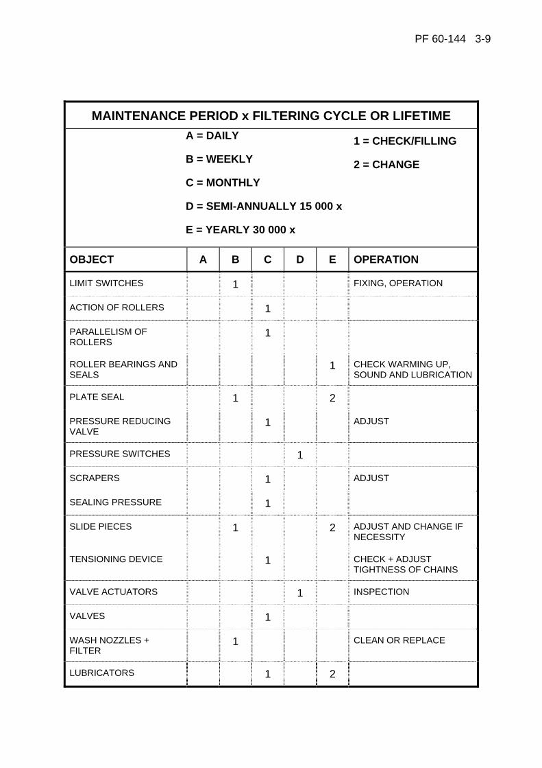
PF 60-144 3-9
MAINTENANCE PERIOD x FILTERING CYCLE OR LIFETIME A = DAILY
B = WEEKLY
C = MONTHLY
D = SEMI-ANNUALLY 15 000 x
E = YEARLY 30 000 x
1 = CHECK/FILLING
2 = CHANGE
OBJECT A B C D E OPERATION
LIMIT SWITCHES 1 FIXING, OPERATION
ACTION OF ROLLERS 1
PARALLELISM OF ROLLERS
1
ROLLER BEARINGS AND SEALS
1 CHECK WARMING UP, SOUND AND LUBRICATION
PLATE SEAL 1 2
PRESSURE REDUCING VALVE
1 ADJUST
PRESSURE SWITCHES 1
SCRAPERS 1 ADJUST
SEALING PRESSURE 1
SLIDE PIECES 1 2 ADJUST AND CHANGE IF NECESSITY
TENSIONING DEVICE 1 CHECK + ADJUST TIGHTNESS OF CHAINS
VALVE ACTUATORS 1 INSPECTION
VALVES 1
WASH NOZZLES + FILTER
1 CLEAN OR REPLACE
LUBRICATORS 1 2
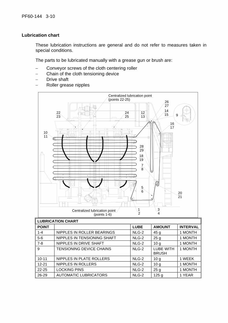
PF60-144 3-10
Lubrication chart
These lubrication instructions are general and do not refer to measures taken in special conditions.
The parts to be lubricated manually with a grease gun or brush are:
− Conveyor screws of the cloth centering roller − Chain of the cloth tensioning device − Drive shaft − Roller grease nipples
92223 25
24
Centralized lubrication point(points 22-25)
12
34
56 20
21
87
1918
2829
1617
1514
1312
2726
Centralized lubrication point(points 1-6)
1011
LUBRICATION CHART POINT LUBE AMOUNT INTERVAL1-4 NIPPLES IN ROLLER BEARINGS NLG-2 45 g 1 MONTH 5-6 NIPPLES IN TENSIONING SHAFT NLG-2 25 g 1 MONTH 7-8 NIPPLES IN DRIVE SHAFT NLG-2 10 g 1 MONTH 9 TENSIONING DEVICE CHAINS NLG-2 LUBE WITH
BRUSH 1 MONTH
10-11 NIPPLES IN PLATE ROLLERS NLG-2 10 g 1 WEEK 12-21 NIPPLES IN ROLLERS NLG-2 10 g 1 MONTH 22-25 LOCKING PINS NLG-2 25 g 1 MONTH 26-29 AUTOMATIC LUBRICATORS NLG-2 125 g 1 YEAR
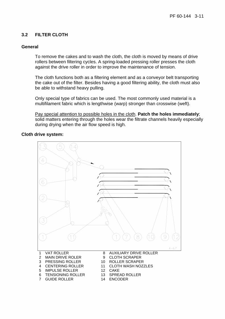
PF 60-144 3-11
3.2 FILTER CLOTH
General
To remove the cakes and to wash the cloth, the cloth is moved by means of drive rollers between filtering cycles. A spring-loaded pressing roller presses the cloth against the drive roller in order to improve the maintenance of tension. The cloth functions both as a filtering element and as a conveyor belt transporting the cake out of the filter. Besides having a good filtering ability, the cloth must also be able to withstand heavy pulling. Only special type of fabrics can be used. The most commonly used material is a multifilament fabric which is lengthwise (warp) stronger than crosswise (weft). Pay special attention to possible holes in the cloth. Patch the holes immediately; solid matters entering through the holes wear the filtrate channels heavily especially during drying when the air flow speed is high.
Cloth drive system:
1 VAT ROLLER 8 AUXILIARY DRIVE ROLLER 2 MAIN DRIVE ROLER 9 CLOTH SCRAPER 3 PRESSING ROLLER 10 ROLLER SCRAPER 4 CENTERING ROLLER 11 CLOTH WASH NOZZLES 5 IMPULSE ROLLER 12 CAKE 6 TENSIONING ROLLER 13 SPREAD ROLLER 7 GUIDE ROLLER 14 ENCODER

PF60-144 3-12
Installation of cloth
The installation of cloth takes place in the plate pack "open" position. The top pressing plate must be fixed to the columns with locking pins. Drive the tensioning roller (6) to its upper position by test drive. Close the restrictor valve beside the tensioning motor (this is to lock the tensioning roller in its position). Place the cloth pack on a rack outside the conveyor unit, whereon it can easily rotate. Open the conveyor unit hatches and bring the cloth end over the centering roller (4) on the roller (13), where from it is passed through the tensioning roller up on the roller (5). Bring the cloth end to the guide rollers (7) of the filter plates, where the cloth is passed between the scraper and the roller. Pass the cloth through the guide roller (7) and vat rollers (1) and between the wash nozzle pipes (11) onto the main drive roller (2). Loosen the pressing roller springs and pass the cloth between the pressing roller and main drive roller. Pull sufficiently enough, loosen and join the cloth ends. Bend one end of the joining thread double for about 10 mm. Pass the thread through the seam so that the bent end of the thread gets inside the seam. Clip off the excess length so that the other end of the thread remains about 5 - 10 mm over the width of the seam. Bend also the other end into the seam. Open the restrictor valve. Tighten the cloth and check the centering using the test drive. The cloth length is correct when there is a motion allowance of at least 700 mm for closing the plate pack above the tensioning roller in the plate pack "open" position. The recommended maximum allowance is approx. 2000 mm. Excess motion allowance decreases the tensioning allowance required for the cloth stretching.
Replacement of cloth
Place the cloth on a rack outside the conveyor unit where the new cloth is on top and the cloth to be changed is roller up around a tube underneath. Open the conveyor unit hatches. Follow the cloth seam and drive it by test drive next to the pressing roller. Loosen the cloth by driving the tensioning roller upwards and close the restrictor valve beside the tensioning motor. Open the cloth joint and fix a new cloth to the cloth to be replaced. Drive the cloth to its place by test drive and join it as instructed in the paragraph "Installation of cloth". Open the restrictor valve. Tighten the cloth and check the centring by test drive.
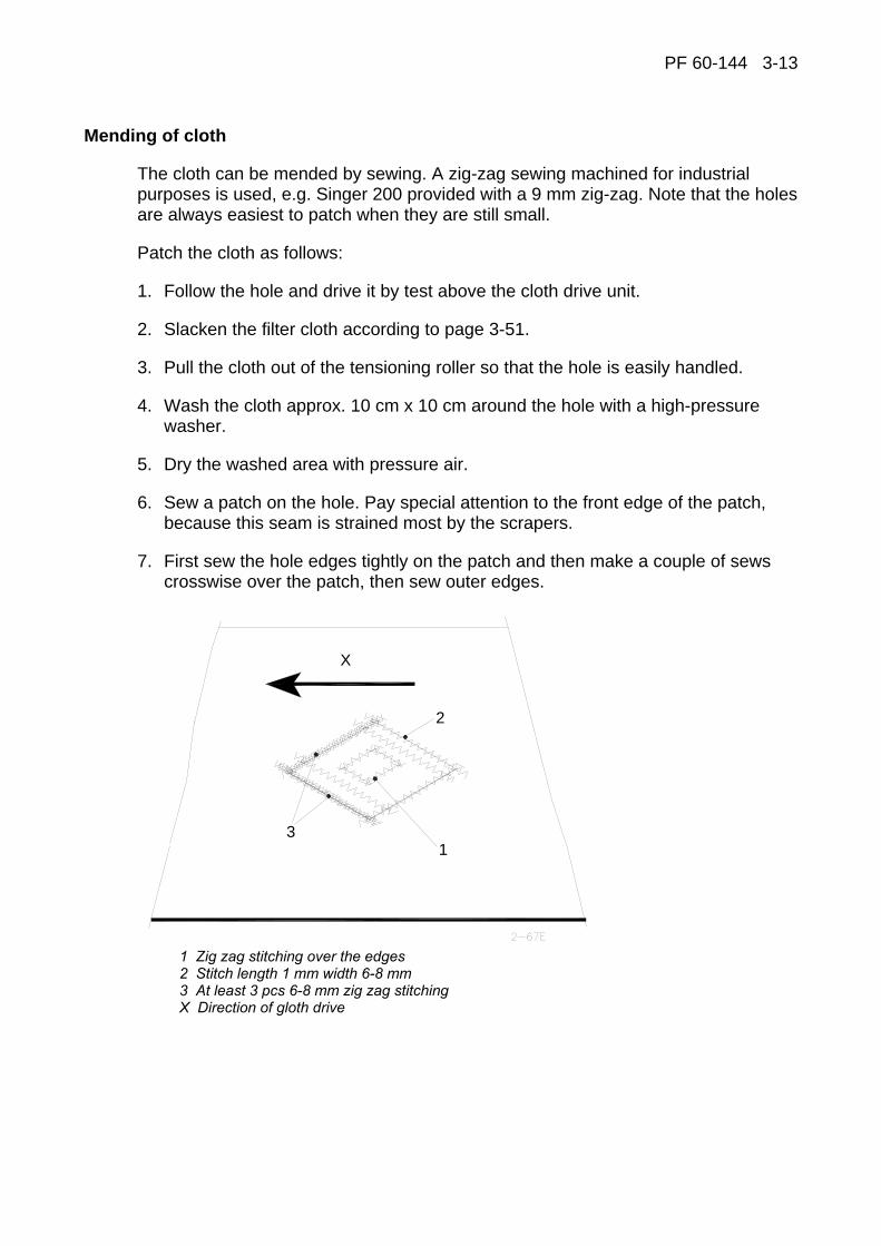
PF 60-144 3-13
Mending of cloth
The cloth can be mended by sewing. A zig-zag sewing machined for industrial purposes is used, e.g. Singer 200 provided with a 9 mm zig-zag. Note that the holes are always easiest to patch when they are still small.
Patch the cloth as follows:
1. Follow the hole and drive it by test above the cloth drive unit.
2. Slacken the filter cloth according to page 3-51.
3. Pull the cloth out of the tensioning roller so that the hole is easily handled.
4. Wash the cloth approx. 10 cm x 10 cm around the hole with a high-pressure washer.
5. Dry the washed area with pressure air.
6. Sew a patch on the hole. Pay special attention to the front edge of the patch, because this seam is strained most by the scrapers.
7. First sew the hole edges tightly on the patch and then make a couple of sews crosswise over the patch, then sew outer edges.
X
1
2
3
1 Zig zag stitching over the edges 2 Stitch length 1 mm width 6-8 mm 3 At least 3 pcs 6-8 mm zig zag stitching X Direction of gloth drive

PF60-144 3-14
Joining of cloth
The cloth is delivered in the ordered length and provided with a clipper seam joint that can be opened. If necessary, a part of the cloth can be renewed by making a sewn joint or if the joint has been damaged, separate clipper seams are available. Pay attention to the cloth length. The correct length has been defined in the paragraph "Installation of cloth". The sewn joints are made according to the enclosed instruction drawing. A zig-zag sewing machined for industrial purposes is used, e.g. Singer 200 provided with a 9 mm zig-zag.
NOTE! ONLY ONE CLIPPER SEAM JOINT IN THE CLOTH IS ALLOWED.
ALWAYS CHECK CLOTH CENTERING AFTER MAINTENANCE WORK.
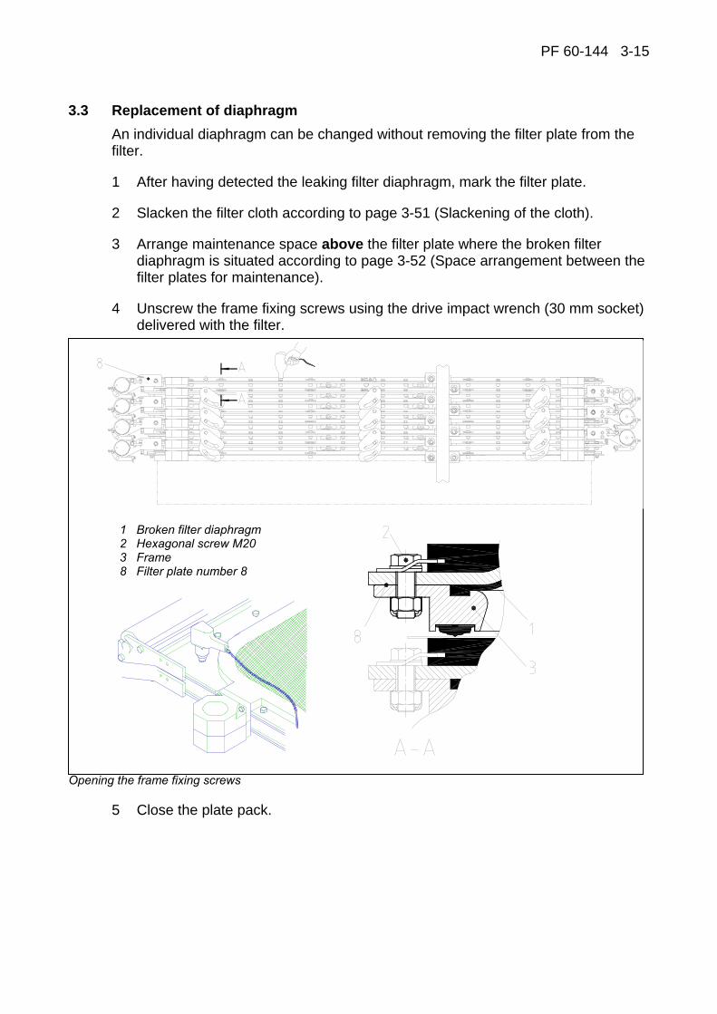
PF 60-144 3-15
3.3 Replacement of diaphragm An individual diaphragm can be changed without removing the filter plate from the filter.
1 After having detected the leaking filter diaphragm, mark the filter plate.
2 Slacken the filter cloth according to page 3-51 (Slackening of the cloth).
3 Arrange maintenance space above the filter plate where the broken filter diaphragm is situated according to page 3-52 (Space arrangement between the filter plates for maintenance).
4 Unscrew the frame fixing screws using the drive impact wrench (30 mm socket) delivered with the filter.
1 Broken filter diaphragm 2 Hexagonal screw M20 3 Frame 8 Filter plate number 8
Opening the frame fixing screws
5 Close the plate pack.
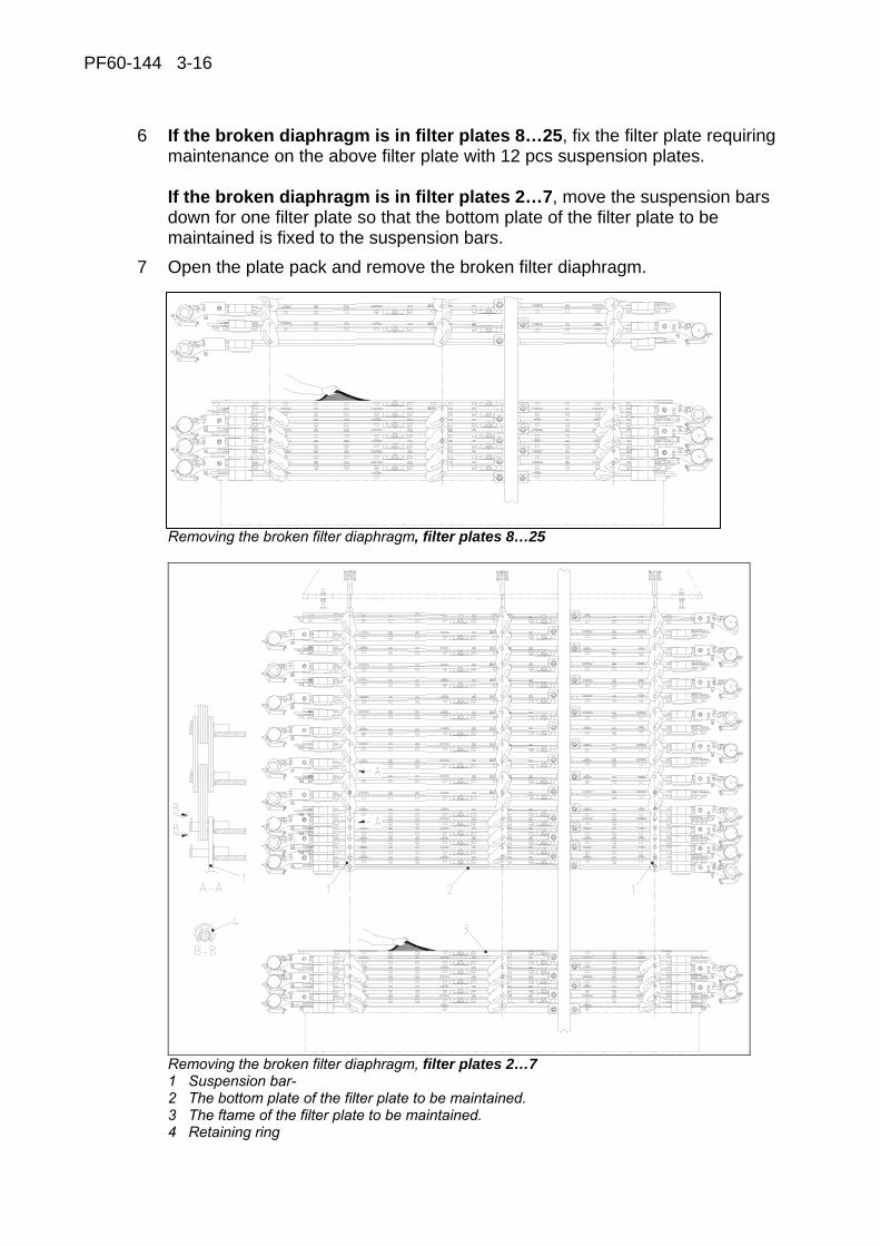
PF60-144 3-16
6 If the broken diaphragm is in filter plates 8…25, fix the filter plate requiring maintenance on the above filter plate with 12 pcs suspension plates. If the broken diaphragm is in filter plates 2…7, move the suspension bars down for one filter plate so that the bottom plate of the filter plate to be maintained is fixed to the suspension bars.
7 Open the plate pack and remove the broken filter diaphragm.
Removing the broken filter diaphragm, filter plates 8…25
Removing the broken filter diaphragm, filter plates 2…7 1 Suspension bar- 2 The bottom plate of the filter plate to be maintained. 3 The ftame of the filter plate to be maintained. 4 Retaining ring

PF 60-144 3-17
8 Place 4 pcs of support plates inside the frame to facilitate the installation of a
new filter diaphragm (e.g. polyurethane or polystyrene plate 40x1000x1500, (4 pcs).
Placing support plates inside the frame 1 Frame 2 Support plate 3 Diaphragm groove
9 Install the new filter diaphragm in its place by pressing the filter diaphragm edge in the frame groove. Check that the filter diaphragm edge is in the groove.
Installation of a new filter diaphragm 1 Frame 2 Support plate 3 New filter diaphragm
10 Close the plate pack.
11 If the filter plate under maintenance is among filter plates 8…25, remove the suspension plates from the filter plate under maintenance. If the filter plate under maintenance is among filter plates 2…7, move the suspension bars upwards so that the filter plates (7 pieces) are linked together immediately above filter plate to be maintained.
12 Open the plate pack.
13 Fix the frame screws back in their places (torque value 350Nm), apply Rocol J160 or similar to screws to prevent the threads from seizing.
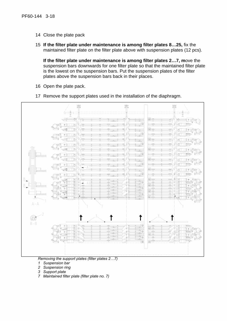
PF60-144 3-18
14 Close the plate pack
15 If the filter plate under maintenance is among filter plates 8…25, fix the maintained filter plate on the filter plate above with suspension plates (12 pcs). If the filter plate under maintenance is among filter plates 2…7, move the suspension bars downwards for one filter plate so that the maintained filter plate is the lowest on the suspension bars. Put the suspension plates of the filter plates above the suspension bars back in their places.
16 Open the plate pack.
17 Remove the support plates used in the installation of the diaphragm.
Removing the support plates (filter plates 2…7) 1 Suspension bar 2 Suspension ring 3 Support plate 7 Maintained filter plate (filter plate no. 7)

PF 60-144 3-19
18 Close the plate pack.
19 Install all suspension plates in their places and fix the suspension plate retaining locking rings.
The correct order of suspension plates.
20 Free the cloth tension device motor oil circulation by opening the valve on the lower part of the cloth drive device according to page 3-51.
21 Check the suspension plate operation by driving the plate pack to its open and close position.

PF60-144 3-20
3.4 REPLACEMENT OF SEAL
The seal of the filter plate can be changed without removing the filter plate from the filter.
Necessary equipments for seal replacement: screwdriver tongs chisel
hammer
Removing the old seal
1 After having detected the damaged seal, mark the filter plate.
2 Slacken the filter cloth according to page 3-51 (Slackening of the cloth).
3 Arrange maintenance space below the filter plate where the damaged seal is situated according to page 3-52 (Space arrangement between the filter plates for maintenance).
4 Remove old seal from filter plate: push a screwdriver between the frame and the seal. Squeeze the seal with the screwdriver at and the same time bend the other end up.
Removing the old seal 1 Seal 2 Frame 3 Bottom plate 4 Vat 5 Diaphragm
1
2
3
4
5
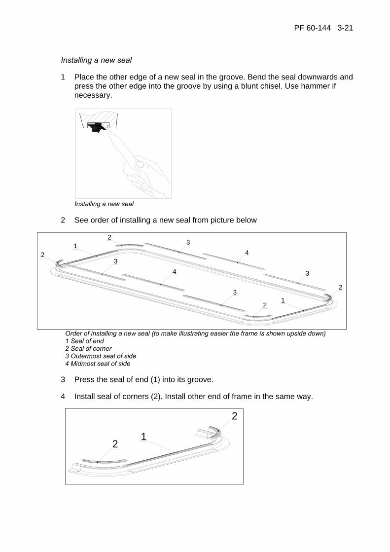
PF 60-144 3-21
Installing a new seal
1 Place the other edge of a new seal in the groove. Bend the seal downwards and press the other edge into the groove by using a blunt chisel. Use hammer if necessary.
Installing a new seal
2 See order of installing a new seal from picture below
1
12
2
2
2
3
3
3
3
4
4
Order of installing a new seal (to make illustrating easier the frame is shown upside down) 1 Seal of end 2 Seal of corner 3 Outermost seal of side 4 Midmost seal of side
3 Press the seal of end (1) into its groove.
4 Install seal of corners (2). Install other end of frame in the same way.
2
12

PF60-144 3-22
5 Press the seals of corners against the seal of end by chisel to make ~2 mm compression between seals, see picture below. Use hammer if necessary.
6 Install outermost seals of sides. Press the outermost seals against the seals of corners to make ~2 mm compression between seals.
7 Install finally midmost seals of both sides. Fix first ends of seals into groove and use chisel and hammer to get central part of seal into its groove.
A B
Installing of the midmost seals
NOTE! Do not shorten seals.

PF 60-144 3-23
3.5 REPLACEMENT AND ADJUSTMENT OF SLIDE PIECES
Wearing of slide pieces causes the plate to move in the direction of its longitudinal axis whereby the alignment of the filtrate collectors changes. This for its part results in collector line leakages and may damage the collector seals. Observe the slide pieces for possible wear, and adjust when necessary. When there is no adjustment allowance left, replace the slide pieces as follows:
− Unscrew the fixing nut, remove the eccentric sleeve and slide piece support, then remove the slide piece.
− Check the filter plate alignment and insert the new slide piece. Install the slide piece support and eccentric sleeve so that the maximum adjustment allowance remains for the slide piece wearing. Hold the adjusting lever of eccentric sleeve with a key (wrench) and tighten the nut.
PF60-144 3-24
Adjustment of filter plates
− Close the plate pack. − Lift up the first plate by driving the plate pack upwards. − Unscrew the slide pieces’ fixing nuts and eccentric sleeves. − Install the slide piece support and eccentric sleeve so that the maximum
adjustment allowance remains for the slide piece wearing. − Adjust the plates length wise with the slide pieces. Dimension A must be same
at both sides ± 1 mm. Hold the adjusting lever of eccentric sleeve with key (wrench) and tighten the nut.
− Lift up the second plate by driving the plate pack upwards and adjust the plate with slide pieces.
− When all plates are adjusted, remove the gap between the lateral guides and slide parts by unscrewing the guide’s fixing screws and pushing the guide against the slide parts. Tighten the fixing screws.
− Drive the plate pack upwards and check the gap between the lowest filter plate and pressing plate. Gap should be 15 mm. You can adjust the gap by screwing the nuts of the suspension bars. Screwing is easier while the plate pack is on its lower position.
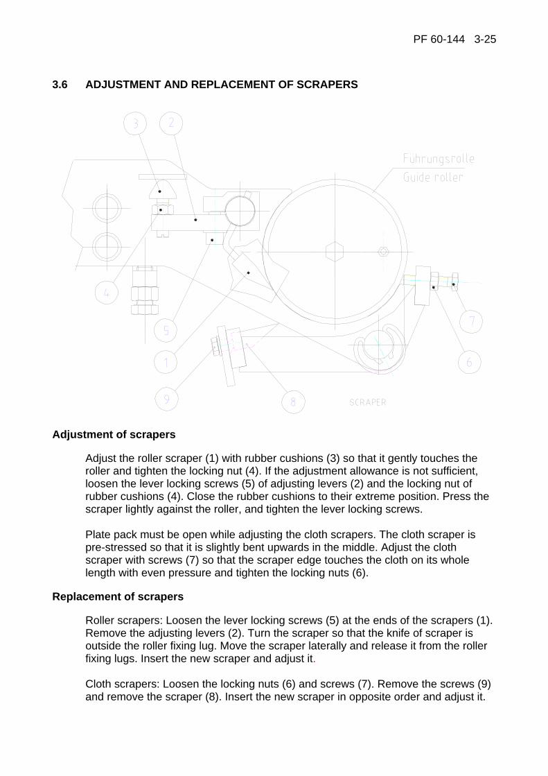
PF 60-144 3-25
3.6 ADJUSTMENT AND REPLACEMENT OF SCRAPERS
Adjustment of scrapers
Adjust the roller scraper (1) with rubber cushions (3) so that it gently touches the roller and tighten the locking nut (4). If the adjustment allowance is not sufficient, loosen the lever locking screws (5) of adjusting levers (2) and the locking nut of rubber cushions (4). Close the rubber cushions to their extreme position. Press the scraper lightly against the roller, and tighten the lever locking screws. Plate pack must be open while adjusting the cloth scrapers. The cloth scraper is pre-stressed so that it is slightly bent upwards in the middle. Adjust the cloth scraper with screws (7) so that the scraper edge touches the cloth on its whole length with even pressure and tighten the locking nuts (6).
Replacement of scrapers
Roller scrapers: Loosen the lever locking screws (5) at the ends of the scrapers (1). Remove the adjusting levers (2). Turn the scraper so that the knife of scraper is outside the roller fixing lug. Move the scraper laterally and release it from the roller fixing lugs. Insert the new scraper and adjust it. Cloth scrapers: Loosen the locking nuts (6) and screws (7). Remove the screws (9) and remove the scraper (8). Insert the new scraper in opposite order and adjust it.

PF60-144 3-26
3.7 INSTALLATION AND REPLACEMENT OF GRIDS
The grid set (two sets in each filtrate vat) in the filter chamber consists of four different pieces, ten middle pieces, three end pieces and two different corner pieces attached to each other by clamping pins in the grid. The middle pieces are interchangeable and end pieces are interchangeable (corner pieces are interchangeable to the opposite side of the filter chamber corners). To change the grids the cloth tension must be loosened. Lift the cloth and remove the grid plate from the other end of the plate. Now you can remove the broken grid plate from its clamping pins. Slip a new grid plate under the cloth and fasten it by pressing it into the next grid plates. Push the removed grid plate at the end of the plate into its place and check the grid fixings. Tighten the filter cloth before the start up and check the cloth centering.
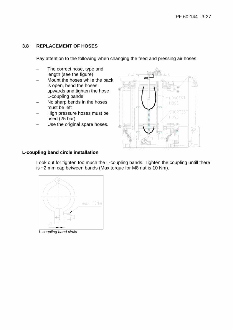
PF 60-144 3-27
3.8 REPLACEMENT OF HOSES
Pay attention to the following when changing the feed and pressing air hoses:
− The correct hose, type and length (see the figure)
− Mount the hoses while the pack is open, bend the hoses upwards and tighten the hose L-coupling bands
− No sharp bends in the hoses must be left
− High pressure hoses must be used (25 bar)
− Use the original spare hoses.
L-coupling band circle installation
Look out for tighten too much the L-coupling bands. Tighten the coupling untill there is ~2 mm cap between bands (Max torque for M8 nut is 10 Nm).
L-coupling band circle

PF60-144 3-28
Notice that the connectors are similar both in feed and pressing air hoses. This makes it possible to connect the hoses wrongly. The hoses must be connected as shown in the figure below.

PF 60-144 3-29
3.9 REPLACEMENT OF FILTRATE VAT
1. Remove the upper part of the cake chute, see page 3-60. 2. Slacken the filter cloth according to page 3-51 (Slackening of the filter cloth). 3. Arrange maintenance space above the filter plate requiring maintenance
according to page 3-52 (Space arrangement between the filter plates for maintenance).
4. At every other plate the filter cloth must be drawn to the side over the guide roller fixing lug. Before drawing the cloth to the side, loosen the cloth scraper, see the page 3-25.
5. Loosen the filtrate collectors. 6. Loosen the fixing elements of the filtrate vat: 5 pcs on both sides and 1 pcs at
each end.
1 Filtrate vat 7 Filtrate collector 2 Bottom plate 8 Slide piece longitudinal guidance 3 Frame 9 Slide piece lateral guidance 4 Grid 10 Collector seal 5 Diaphragm 11 Fixing element (1 pcs at each end) 6 Seal 12 Fixing element (5 pcs on both sides)
7. Draw the filtrate vat out from the plate pack. 8. The new filtrate vat is installed into its place in reverse order. Check alignment of
the collectors before tightening the fixing elements.

PF60-144 3-30
3.10 REPLACEMENT OF FILTER PLATE
1. Verify the load of crane (mass of the filter plate app. 1700 kg). 2. Necessary maintenance tools (included in Larox maintenance tools):
1
2
Nesessary maintenance tools (included in Larox maintenance tools) for replacement of filter plate 1 Suspension bar (4 pcs.) 2 Lifting bar (2 pcs.) 3 Lifting chains with lifting rings, hooks and chain tackle
When changing the top plate it is not possible to use the tools mentioned above. The frame part of the top plate leans on the top pressing plate, and thus its damaging is very unlikely. 3. Remove the upper part of the cake chute according to page 3-60. 4. Drive the plate pack to its open position by test drive and lock the plate pack. 5. Drive the cloth clipper seam to the above guide roller of the filter plate to be
removed.
1
2
1
2
3
Cloth clipper seam is drived to the above quide roller of the filter plate to be removed 1 The filter plate to be removed 2 Above quide roller of the filter plate to be removed 3 Clipper seam
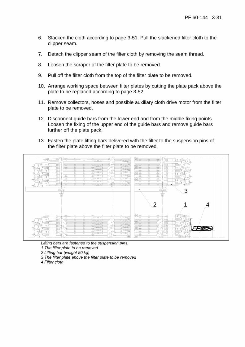
PF 60-144 3-31
6. Slacken the cloth according to page 3-51. Pull the slackened filter cloth to the clipper seam.
7. Detach the clipper seam of the filter cloth by removing the seam thread.
8. Loosen the scraper of the filter plate to be removed.
9. Pull off the filter cloth from the top of the filter plate to be removed.
10. Arrange working space between filter plates by cutting the plate pack above the plate to be replaced according to page 3-52.
11. Remove collectors, hoses and possible auxiliary cloth drive motor from the filter plate to be removed.
12. Disconnect guide bars from the lower end and from the middle fixing points. Loosen the fixing of the upper end of the guide bars and remove guide bars further off the plate pack.
13. Fasten the plate lifting bars delivered with the filter to the suspension pins of the filter plate above the filter plate to be removed.
3
2 1 4
Lifting bars are fastened to the suspension pins. 1 The filter plate to be removed 2 Lifting bar (weight 80 kg) 3 The filter plate above the filter plate to be removed 4 Filter cloth
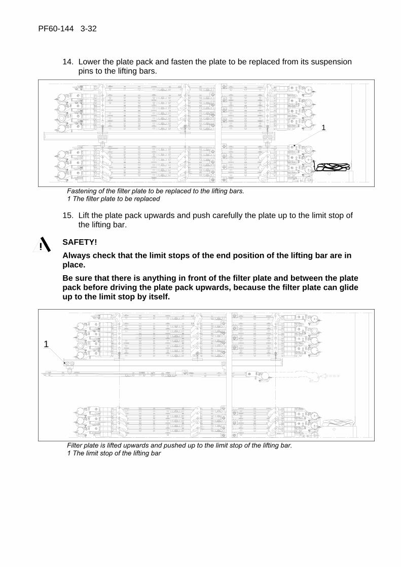
PF60-144 3-32
14. Lower the plate pack and fasten the plate to be replaced from its suspension pins to the lifting bars.
1
Fastening of the filter plate to be replaced to the lifting bars. 1 The filter plate to be replaced
15. Lift the plate pack upwards and push carefully the plate up to the limit stop of the lifting bar.
SAFETY! Always check that the limit stops of the end position of the lifting bar are in place. Be sure that there is anything in front of the filter plate and between the plate pack before driving the plate pack upwards, because the filter plate can glide up to the limit stop by itself.
1
Filter plate is lifted upwards and pushed up to the limit stop of the lifting bar. 1 The limit stop of the lifting bar
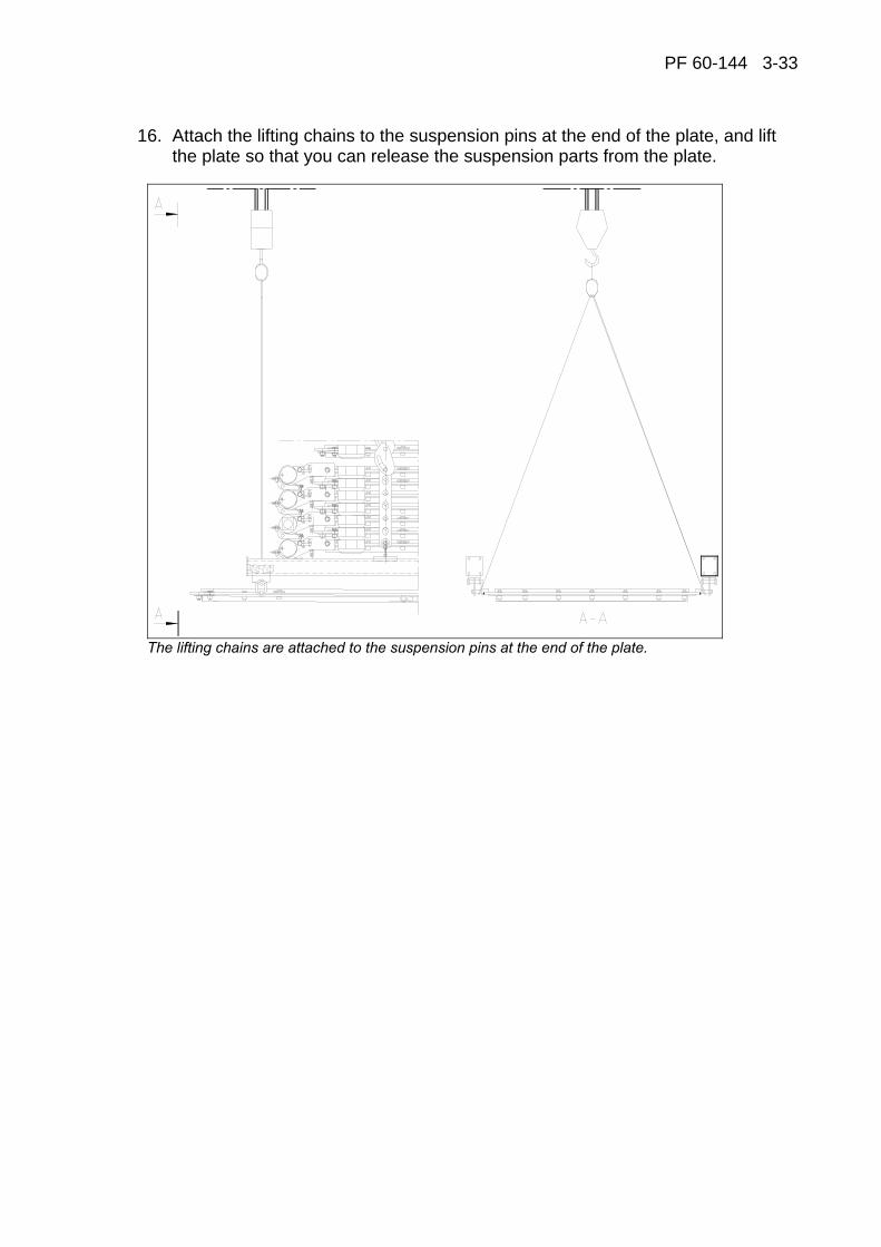
PF 60-144 3-33
16. Attach the lifting chains to the suspension pins at the end of the plate, and lift the plate so that you can release the suspension parts from the plate.
The lifting chains are attached to the suspension pins at the end of the plate.
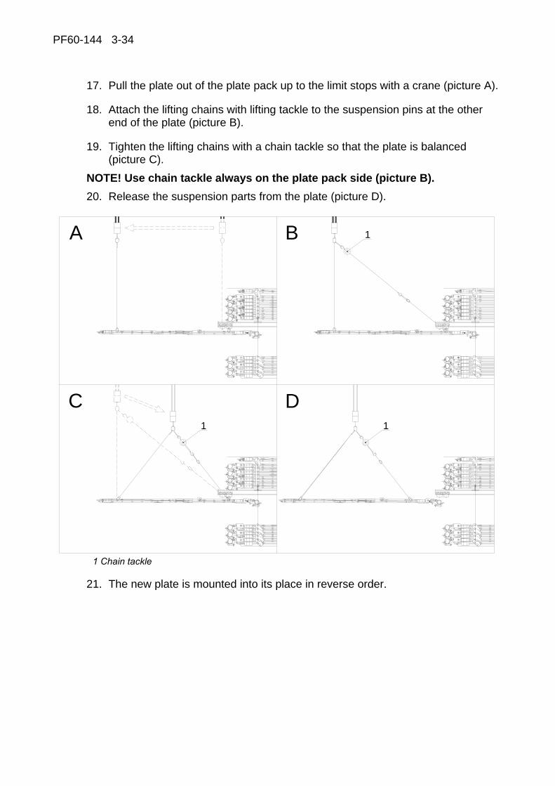
PF60-144 3-34
17. Pull the plate out of the plate pack up to the limit stops with a crane (picture A).
18. Attach the lifting chains with lifting tackle to the suspension pins at the other end of the plate (picture B).
19. Tighten the lifting chains with a chain tackle so that the plate is balanced (picture C).
NOTE! Use chain tackle always on the plate pack side (picture B). 20. Release the suspension parts from the plate (picture D).
A
C D1 1
B 1
1 Chain tackle
21. The new plate is mounted into its place in reverse order.

PF 60-144 3-35
3.11 MAINTENANCE OF CLOTH CONVEYOR UNIT AND TENSIONING DEVICE
The equipment should be inspected twice a year.
Drive rollers
The moving of the cloth is hydraulically controlled. The auxiliary drive rollers are placed in the plate pack. The rotation speed of the drive rollers has hydraulically been synchronized.
− Inspection and maintenance measures to be taken: − Hydraulic motor pressures − Hydraulic motor couplings − Roller bearings − Lubrication of main drive roller bearings
Cloth driving
The filter is provided with a seam detector. The driving system "positions" the seam automatically. An encoder (2) attached to the roller measures the length of cloth travel. The cloth is stopped by means of the seam detector switch S332 and encoder B331 (2). The discharge length (plates) must be defined so that the filter is discharged completely. It is recommendable for the cloth to travel forward for at least three plate lengths. The seam may stop on any roller as well as in the conveyor unit's area. Check that the clipper seam finds its right position on the guide roller, i.e. outside the sealing surface. The cloth clipper seam must not be allowed to stop in between the sealing surfaces of the plate pack.
2
1
The encoder attached to the roller on the upper part of the cloth conveyor 1 Tracking roller 2 Encoder

PF60-144 3-36
Centering roller
The extreme positions of the roller are adjusted by means of limit switches. Inspection and maintenance measures to be taken: − Fixing and function of limit switches − Checking and lubrication of the adjusting screw − Fixing of the worm gear − Worm gear oil quality and quantity
Automatic cloth tracking
Normally the filter cloth moves in the plate pack without crossing the guide roller edges. However, in case the cloth tends to be directed towards either of the edges, the automatic cloth tracking brings the cloth back into center position.
The cloth tracking takes place by moving the left end of the tracking roller in the cloth conveyor unit up or down moving it according to the signals of the cloth edge position transmitter B503 (angle transmitter) and cloth tracking cylinder position transmitter B504 by the automatic control operation. Tracking roller is moved up/down by using hydraulic cylinder HC4. This cylinder has built in position feedback (potentiometer). Automatic tracking control can be turned on/off from OIU configuration screen (“Automatic cloth tracking”). While automatic cloth tracking is off, tracking cylinder can be run from Hand Held unit or with push buttons S770 and S771.
The position of the cloth right edge is actively followed by means of a wheel fixed to the sensor B503 placed below the tracking roller. The effective range is +20°…-20° (+ 30…–30 mm). The adjustment range has been divided into 1000 parts, left edge 1000 in the middle 500 in the right 0.
Cloth alarm limit switch S838A or S839A cause the alarm, if cloth tracking device cannot control cloth to the center position, so it drifts too much to aside and cloth alarm switch is activated too long time (5 sec delay). Cloth edge sensors S838A (left) and S839A (right) are located on the both sides of the cloth tracking device. If the cloth drifts too much to the left, the switch S838A will become activated. If the cloth drifts too much to the right, the switch S839A will become activated.
See picture on the next page

PF 60-144 3-37
20° 20°1
2
60
b
a
3 54
6
Cloth tracking device a = 0,1 second (place of the cloth edge is read every 0,1 second by sensor B503). b = Tracking in steps (every tracking step take 0,25s) 1 Tracking roller 2 Cloth edge position transmitter B503 3 Perambulator B331 (see seam positioning) 4 Limit switch S838A 5 Limit switch S839A 6 Hydraulic cylinder HC4 with position transmitter B504
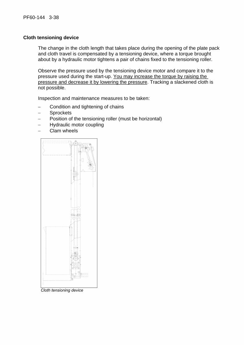
PF60-144 3-38
Cloth tensioning device
The change in the cloth length that takes place during the opening of the plate pack and cloth travel is compensated by a tensioning device, where a torque brought about by a hydraulic motor tightens a pair of chains fixed to the tensioning roller. Observe the pressure used by the tensioning device motor and compare it to the pressure used during the start-up. You may increase the torque by raising the pressure and decrease it by lowering the pressure. Tracking a slackened cloth is not possible.
Inspection and maintenance measures to be taken:
− Condition and tightening of chains − Sprockets − Position of the tensioning roller (must be horizontal) − Hydraulic motor coupling − Clam wheels
Cloth tensioning device
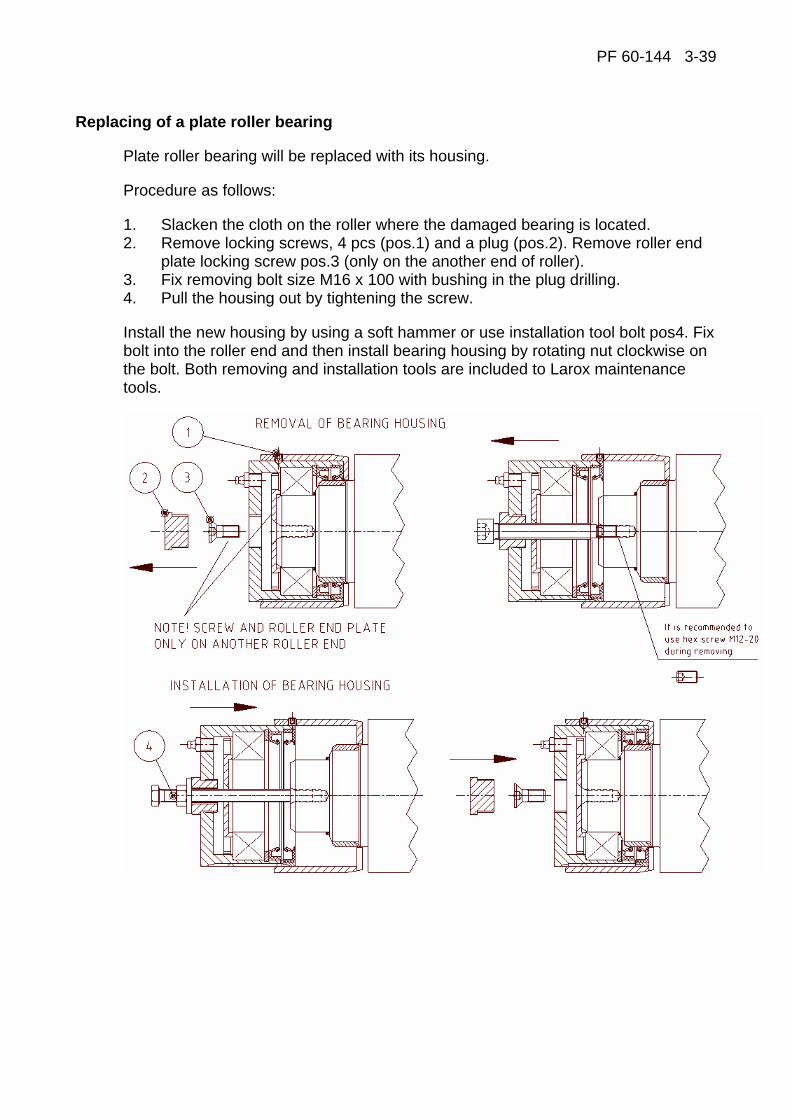
PF 60-144 3-39
Replacing of a plate roller bearing
Plate roller bearing will be replaced with its housing.
Procedure as follows:
1. Slacken the cloth on the roller where the damaged bearing is located. 2. Remove locking screws, 4 pcs (pos.1) and a plug (pos.2). Remove roller end
plate locking screw pos.3 (only on the another end of roller). 3. Fix removing bolt size M16 x 100 with bushing in the plug drilling. 4. Pull the housing out by tightening the screw.
Install the new housing by using a soft hammer or use installation tool bolt pos4. Fix bolt into the roller end and then install bearing housing by rotating nut clockwise on the bolt. Both removing and installation tools are included to Larox maintenance tools.
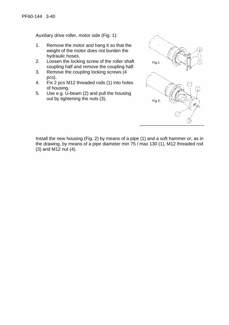
PF60-144 3-40
Auxiliary drive roller, motor side (Fig. 1):
1. Remove the motor and hang it so that the weight of the motor does not burden the hydraulic hoses.
2. Loosen the locking screw of the roller shaft coupling half and remove the coupling half.
3. Remove the coupling locking screws (4 pcs).
4. Fix 2 pcs M12 threaded rods (1) into holes of housing.
5. Use e.g. U-beam (2) and pull the housing out by tightening the nuts (3).
Install the new housing (Fig. 2) by means of a pipe (1) and a soft hammer or, as in the drawing, by means of a pipe diameter min 75 / max 130 (1), M12 threaded rod (3) and M12 nut (4).
Fig.1
Fig 2.
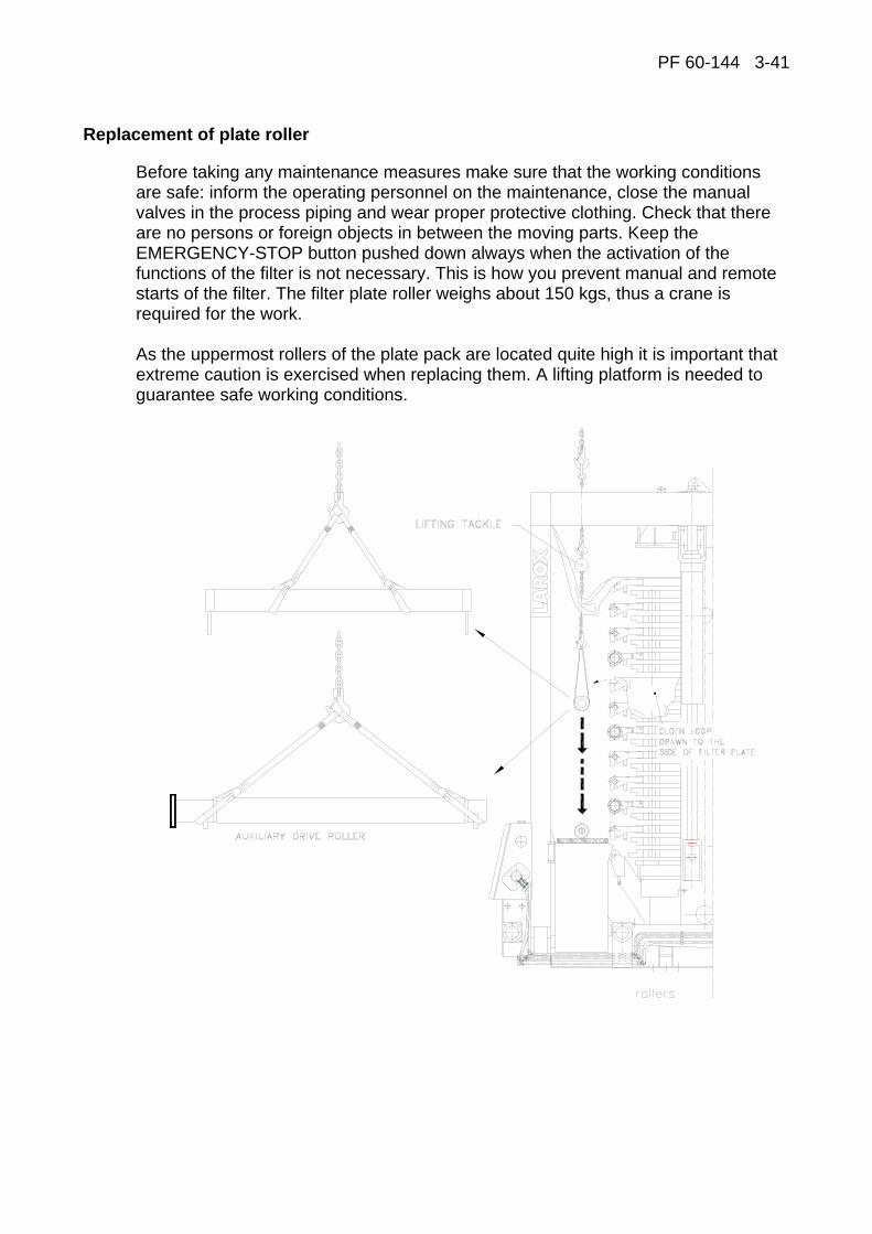
PF 60-144 3-41
Replacement of plate roller
Before taking any maintenance measures make sure that the working conditions are safe: inform the operating personnel on the maintenance, close the manual valves in the process piping and wear proper protective clothing. Check that there are no persons or foreign objects in between the moving parts. Keep the EMERGENCY-STOP button pushed down always when the activation of the functions of the filter is not necessary. This is how you prevent manual and remote starts of the filter. The filter plate roller weighs about 150 kgs, thus a crane is required for the work. As the uppermost rollers of the plate pack are located quite high it is important that extreme caution is exercised when replacing them. A lifting platform is needed to guarantee safe working conditions.

PF60-144 3-42
The roller is located at the end of the filter plate in a "loop" formed by the filter cloth. There are two possible ways to get the roller out. The first one is to drive the cloth so that the clipper seam stops at the roller to be changed. The seam is opened and the roller can be changed. Another possibility is to gather so much loose cloth at the roller which is to be changed by using the "extra" cloth in the tensioning device that the cloth can be drawn over the end of the roller to either side of the filter plate. The latter possibility is more recommendable. Moreover, when changing several rollers, the latter possibility is the quicker one. The change is explained below step by step.
1. Stop the filter, drive the plate pack completely open by hand held and drive the locking pins into their holes. (For exact instructions of the hand held as well as the symbols of the switches and actuators mentioned below, see the paragraph "Operation instructions".)
2. Slacken up the cloth (see “Installation of cloth” 3-12).
3. Remove scrapers. Roller scraper: Loosen the lever locking screws (5) at the ends of the scrapers (1). Unfasten the adjusting levers (2). Turn the scraper so that the knife of the scraper is outside the roller fixing lug. Move the scraper laterally and release it from the fixing lugs. Cloth scraper: Loosen the locking nuts (6) and screws (7). Remove the cotters (10) and remove the scraper.
4. The slack cloth is drawn up to the roller, which is to be changed, where it is moved on the side of the plate. Move the cloth on either side on top of the plate pack so that the overhead crane hook can be lowered down to the roller to be changed.

PF 60-144 3-43
Replacement of guide roller
1. Use lifting belts for lifting.
2. Hang the roller, loosen side guide rails, unfasten roller brackets by removing bolts (12) and pins (11) and lift the roller off (with brackets).
3. A firm enough plane must be provided on the cake chute at the end of the tensioning device on which the rollers can be placed. The cake chute at the free end of the filter must be removing off. A separate lifting platform is not necessary as the crane can freely move in the crosswise direction of the filter.
4. The new roller is put in place in the opposite order.
Replacement of auxiliary drive roller
1. Procedure with the cloth and the scraper is the same as when replacing a normal roller.
2. The hydraulic motor must first be removed from the auxiliary drive roller. The hydraulic hoses may stay fixed to the motor but the whole equipment must be supported in such a way that the motor does not hang on the hoses.
3. The lifting belts are fixed to the both ends of the roller and the roller is lightly lifted up. After this, the fixing screws of the roller lug are removed and after this the roller can be removed.
4. The new roller is put in place in the opposite order.
Replacement of auxiliary drive roller without removing the hydraulic motor:
In case the hydraulic motor is kept fixed to the auxiliary drive roller, the following points should be observed:
1. Make sure that the hydraulic unit has been stopped and that there is no pressure in the pipeline. De-pressurization can be done by choosing HM09 on the hand-held unit and pressing S725 and S723 in turns a few times.
2. Before removing the hydraulic hoses from the auxiliary drive roller, check that the marks for the hoses and the motor's openings are in place.
3. The hoses can now be removed. Plug the couplings on both the hoses and the motor.
4. Lifting and replacing the roller are performed according to previous chapter.
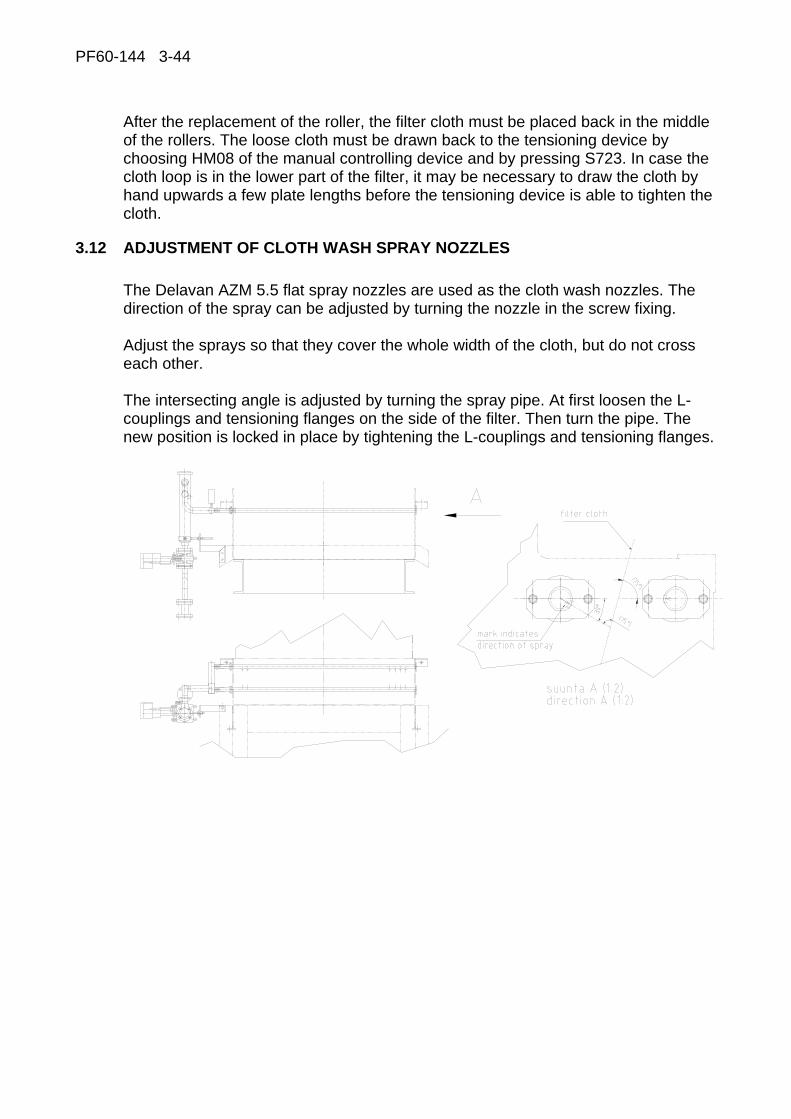
PF60-144 3-44
After the replacement of the roller, the filter cloth must be placed back in the middle of the rollers. The loose cloth must be drawn back to the tensioning device by choosing HM08 of the manual controlling device and by pressing S723. In case the cloth loop is in the lower part of the filter, it may be necessary to draw the cloth by hand upwards a few plate lengths before the tensioning device is able to tighten the cloth.
3.12 ADJUSTMENT OF CLOTH WASH SPRAY NOZZLES
The Delavan AZM 5.5 flat spray nozzles are used as the cloth wash nozzles. The direction of the spray can be adjusted by turning the nozzle in the screw fixing. Adjust the sprays so that they cover the whole width of the cloth, but do not cross each other. The intersecting angle is adjusted by turning the spray pipe. At first loosen the L-couplings and tensioning flanges on the side of the filter. Then turn the pipe. The new position is locked in place by tightening the L-couplings and tensioning flanges.

PF 60-144 3-45
3.13 INSPECTION AND REPLACEMENT OF SUSPENSION PLATES
Omitting of inspection and possible replacing of the suspension plates may lead to personal injury or damages of property, which Larox cannot be held responsible for if the instructions are not followed.
Check for possible cracks of all suspension plates annually and replace damaged suspension plates. The dimensioned maximum service life of suspension plate is 5 years. (Variations to both directions are possible depending of several reasons; number of working cycles, cake weight, number of filter plates, environmental factors etc…)
Checking/replacing of the suspension plates: 1. Close the plate pack. 2. Remove the locking nuts and sleeves of the topmost suspension plates. 3. Drive the upper pressing plate into its open position and lock the upper pressing
plate with locking pins.
1
2
3
4
4
A Closed position of the upper pressing plate B Removing the adjusting nuts C Driving the plate pack into its open position 1 Top suspension plate 2 Adjusting nut 3 Sleeve 4 Lug of the upper pressing plate
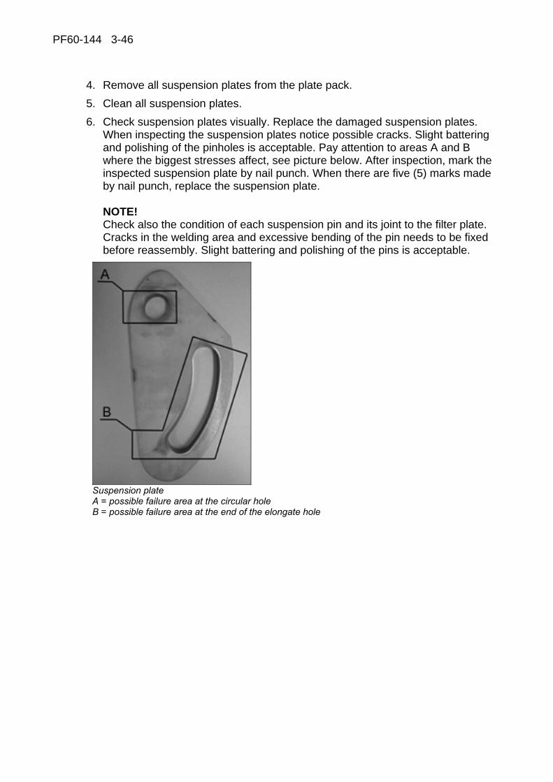
PF60-144 3-46
4. Remove all suspension plates from the plate pack. 5. Clean all suspension plates. 6. Check suspension plates visually. Replace the damaged suspension plates.
When inspecting the suspension plates notice possible cracks. Slight battering and polishing of the pinholes is acceptable. Pay attention to areas A and B where the biggest stresses affect, see picture below. After inspection, mark the inspected suspension plate by nail punch. When there are five (5) marks made by nail punch, replace the suspension plate. NOTE! Check also the condition of each suspension pin and its joint to the filter plate. Cracks in the welding area and excessive bending of the pin needs to be fixed before reassembly. Slight battering and polishing of the pins is acceptable.
Suspension plate A = possible failure area at the circular hole B = possible failure area at the end of the elongate hole
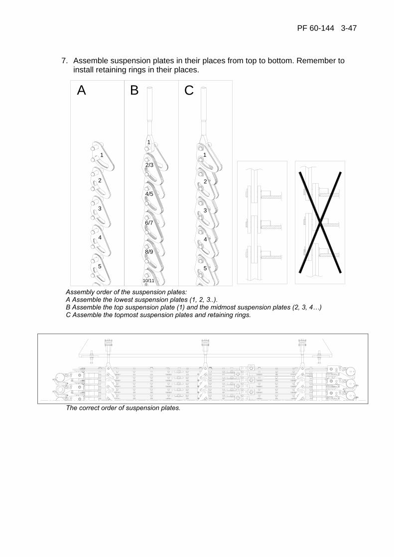
PF 60-144 3-47
7. Assemble suspension plates in their places from top to bottom. Remember to install retaining rings in their places.
1
2
3
4
A
5
1
1
2
3
4
5
B C
2/3
4/5
6/7
8/9
10/11
Assembly order of the suspension plates: A Assemble the lowest suspension plates (1, 2, 3..). B Assemble the top suspension plate (1) and the midmost suspension plates (2, 3, 4…) C Assemble the topmost suspension plates and retaining rings.
The correct order of suspension plates.

PF60-144 3-48
8. Drive the upper pressing plate downwards so that there is a gap (~30mm) between the upper end of the topmost suspension plate and bottom surface of the lug.
9. Install the sleeves one at a time in their places so that the studbolt of the topmost suspension plates is in the sleeve.
1
2
A B
2
1
3
Installing of the topmost suspension plates in their places. A Driving the Upper pressing plate downwards. B Installing of the sleeve. 1 Topmost suspension plate 2 Lug of the upper pressing plate 3 Sleeve of the topmost suspension plate X ≈ 30 = gap between the upper end of the topmost suspesion plate and bottom surface of the lug.
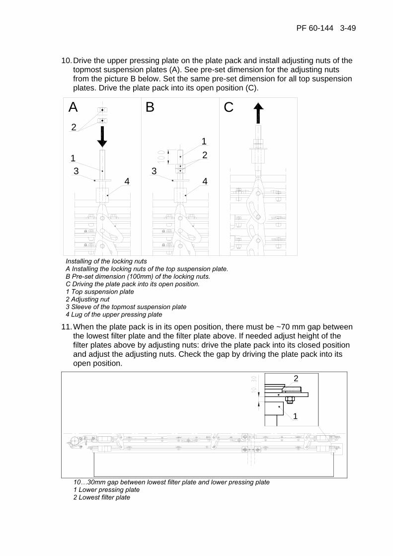
PF 60-144 3-49
10. Drive the upper pressing plate on the plate pack and install adjusting nuts of the topmost suspension plates (A). See pre-set dimension for the adjusting nuts from the picture B below. Set the same pre-set dimension for all top suspension plates. Drive the plate pack into its open position (C).
A B C2
1
12
4 433
Installing of the locking nuts A Installing the locking nuts of the top suspension plate. B Pre-set dimension (100mm) of the locking nuts. C Driving the plate pack into its open position. 1 Top suspension plate 2 Adjusting nut 3 Sleeve of the topmost suspension plate 4 Lug of the upper pressing plate
11. When the plate pack is in its open position, there must be ~70 mm gap between the lowest filter plate and the filter plate above. If needed adjust height of the filter plates above by adjusting nuts: drive the plate pack into its closed position and adjust the adjusting nuts. Check the gap by driving the plate pack into its open position.
1
2
10…30mm gap between lowest filter plate and lower pressing plate 1 Lower pressing plate 2 Lowest filter plate

PF60-144 3-50
12. When suspension of the plate pack is adjusted, close the plate pack and lock the adjusting nuts.
A B
Locking the adjusting nuts.
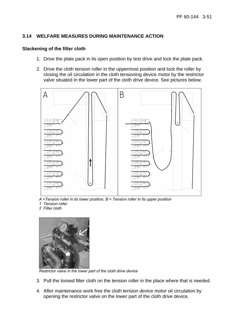
PF 60-144 3-51
3.14 WELFARE MEASURES DURING MAINTENANCE ACTION
Slackening of the filter cloth
1. Drive the plate pack in its open position by test drive and lock the plate pack.
2. Drive the cloth tension roller in the uppermost position and lock the roller by closing the oil circulation in the cloth tensioning device motor by the restrictor valve situated in the lower part of the cloth drive device. See pictures below.
A =Tension roller in its lower position, B = Tension roller in its upper position 1 Tension roller 2 Filter cloth
Restrictor valve in the lower part of the cloth drive device
3. Pull the loosed filter cloth on the tension roller in the place where that is needed.
4. After maintenance work free the cloth tension device motor oil circulation by opening the restrictor valve on the lower part of the cloth drive device.
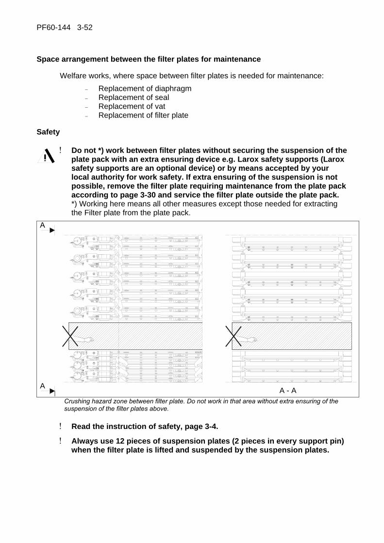
PF60-144 3-52
Space arrangement between the filter plates for maintenance
Welfare works, where space between filter plates is needed for maintenance: − Replacement of diaphragm − Replacement of seal − Replacement of vat − Replacement of filter plate
Safety
! Do not *) work between filter plates without securing the suspension of the plate pack with an extra ensuring device e.g. Larox safety supports (Larox safety supports are an optional device) or by means accepted by your local authority for work safety. If extra ensuring of the suspension is not possible, remove the filter plate requiring maintenance from the plate pack according to page 3-30 and service the filter plate outside the plate pack. *) Working here means all other measures except those needed for extracting the Filter plate from the plate pack.
A A - A
Crushing hazard zone between filter plate. Do not work in that area without extra ensuring of the suspension of the filter plates above.
! Read the instruction of safety, page 3-4.
! Always use 12 pieces of suspension plates (2 pieces in every support pin) when the filter plate is lifted and suspended by the suspension plates.
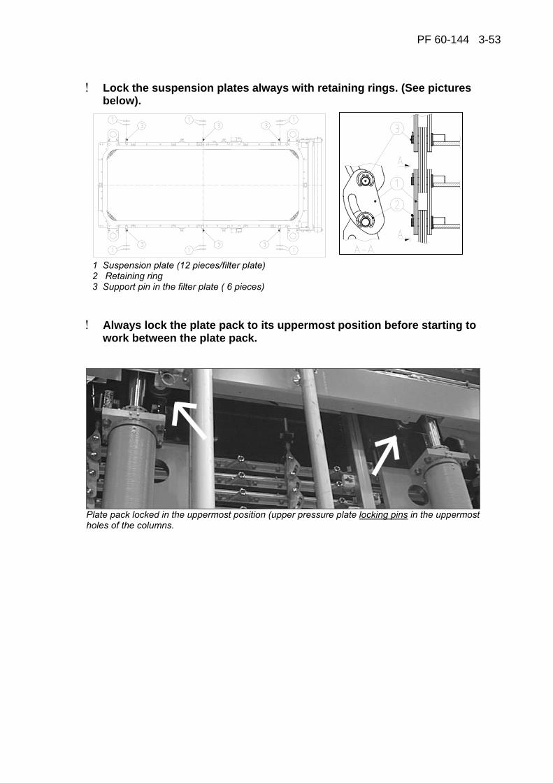
PF 60-144 3-53
! Lock the suspension plates always with retaining rings. (See pictures below).
1 Suspension plate (12 pieces/filter plate) 2 Retaining ring 3 Support pin in the filter plate ( 6 pieces)
! Always lock the plate pack to its uppermost position before starting to work between the plate pack.
Plate pack locked in the uppermost position (upper pressure plate locking pins in the uppermost holes of the columns.
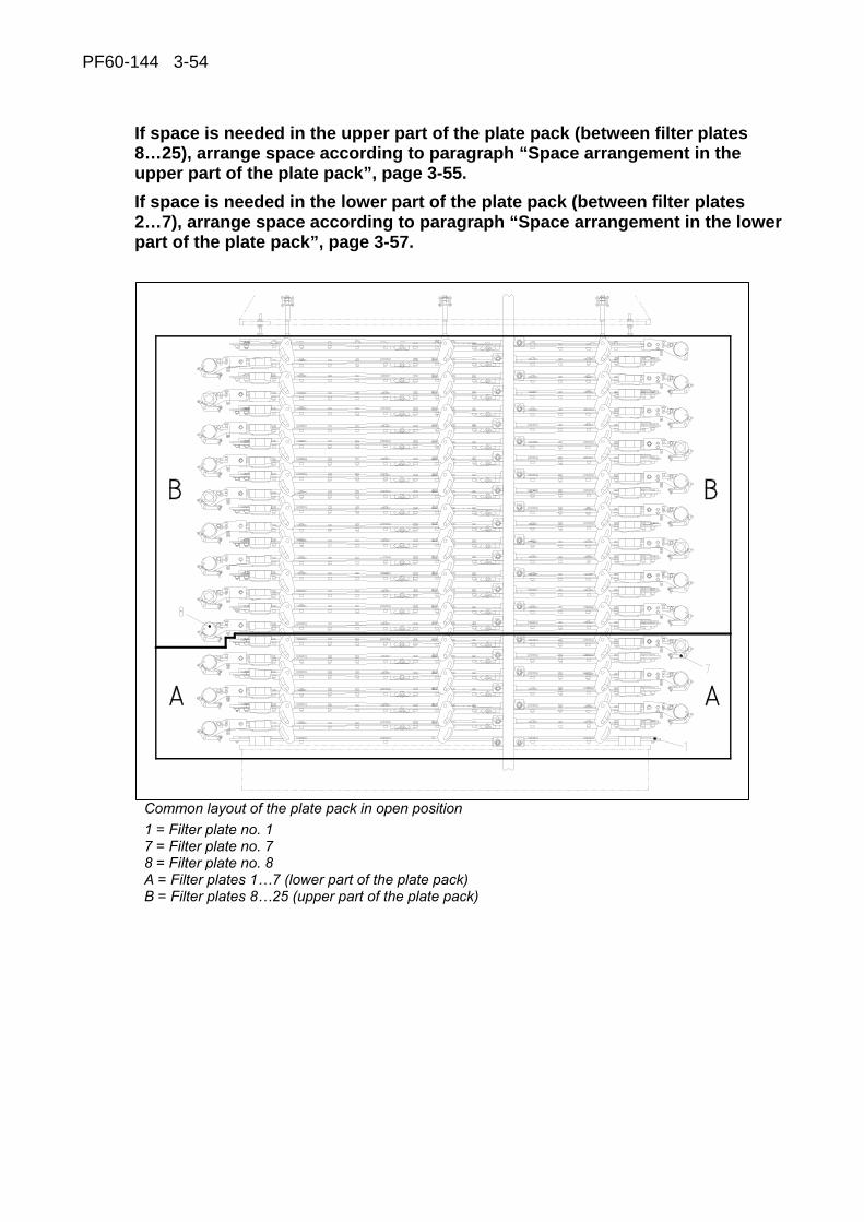
PF60-144 3-54
If space is needed in the upper part of the plate pack (between filter plates 8…25), arrange space according to paragraph “Space arrangement in the upper part of the plate pack”, page 3-55. If space is needed in the lower part of the plate pack (between filter plates 2…7), arrange space according to paragraph “Space arrangement in the lower part of the plate pack”, page 3-57.
Common layout of the plate pack in open position 1 = Filter plate no. 1 7 = Filter plate no. 7 8 = Filter plate no. 8 A = Filter plates 1…7 (lower part of the plate pack) B = Filter plates 8…25 (upper part of the plate pack)
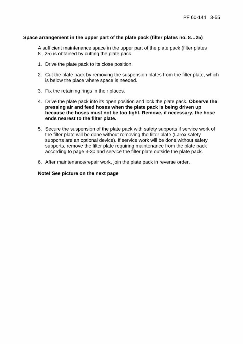
PF 60-144 3-55
Space arrangement in the upper part of the plate pack (filter plates no. 8…25)
A sufficient maintenance space in the upper part of the plate pack (filter plates 8...25) is obtained by cutting the plate pack.
1. Drive the plate pack to its close position.
2. Cut the plate pack by removing the suspension plates from the filter plate, which is below the place where space is needed.
3. Fix the retaining rings in their places.
4. Drive the plate pack into its open position and lock the plate pack. Observe the pressing air and feed hoses when the plate pack is being driven up because the hoses must not be too tight. Remove, if necessary, the hose ends nearest to the filter plate.
5. Secure the suspension of the plate pack with safety supports if service work of the filter plate will be done without removing the filter plate (Larox safety supports are an optional device). If service work will be done without safety supports, remove the filter plate requiring maintenance from the plate pack according to page 3-30 and service the filter plate outside the plate pack.
6. After maintenance/repair work, join the plate pack in reverse order. Note! See picture on the next page
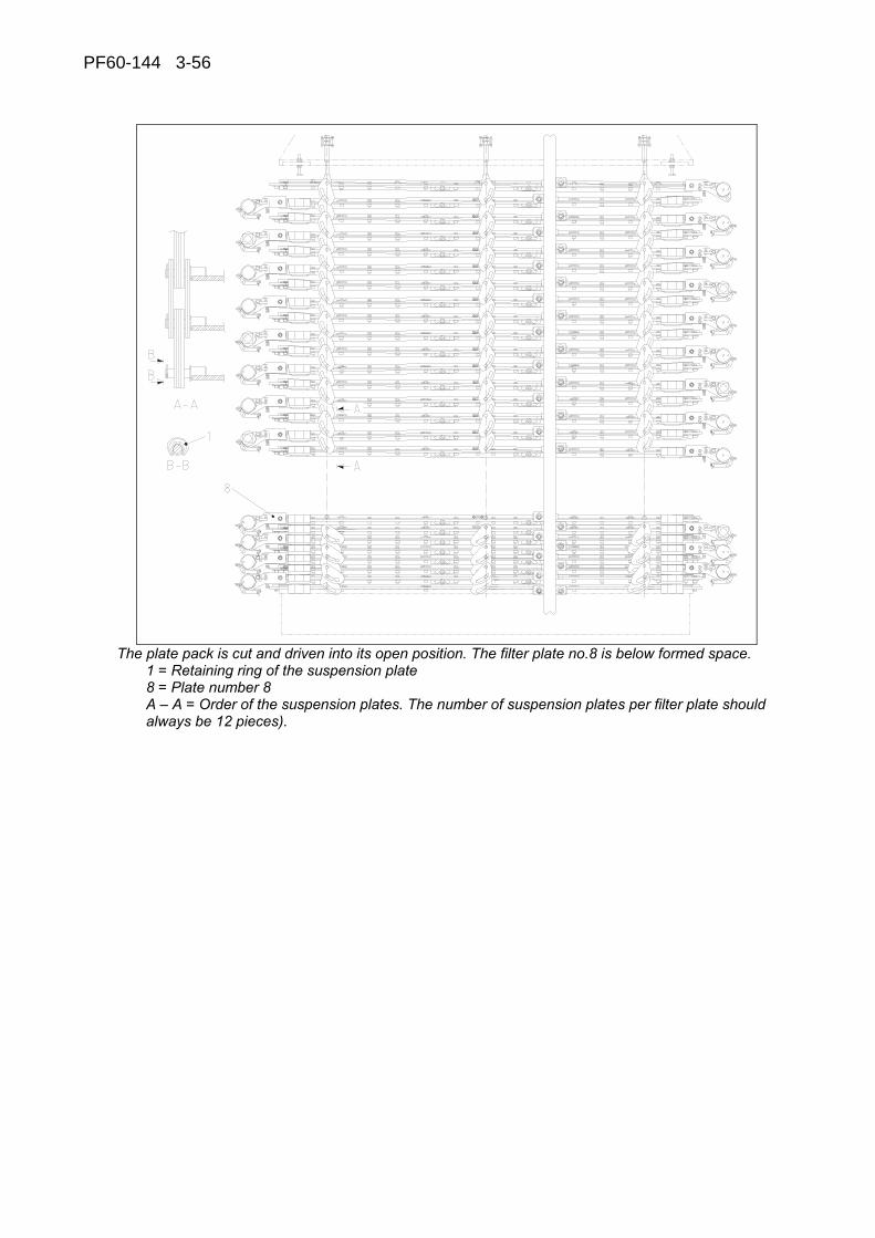
PF60-144 3-56
The plate pack is cut and driven into its open position. The filter plate no.8 is below formed space.
1 = Retaining ring of the suspension plate 8 = Plate number 8 A – A = Order of the suspension plates. The number of suspension plates per filter plate should always be 12 pieces).

PF 60-144 3-57
Space arrangement in the lower part of the plate pack (filter plates 2…7)
A sufficient maintenance space in the lower part of the plate pack (filter plates 2...7) is obtained by cutting the plate pack and using the suspension bars (4 pcs) delivered with the filter.
1. Drive the plate pack to its close position. 2. Cut the plate pack by removing the suspension plates from the filter plate, which
is below the place where space is needed. 3. Connect the filter plates (6 pcs) situated right above the filter plate, from where
the suspension plates were removed, by installing suspension bars in place of the suspension plates on both sides of the filter plates, at both ends.
4. Check the correct location of the suspension bars in figures on the next pages. 5. Fix the filter plates joined by using suspension bars on the filter plate above
using suspension plates (use 12 pcs of suspension plates according to the safety instructions (page 3-52).
6. Fix the retaining rings in their places. 7. Drive the plate pack in its open position and lock the plate pack. Observe the
pressing air and feed hoses when the plate pack is being driven up because the hoses must not be too tight. Remove, if necessary, the hose ends nearest to the filter plate.
8. Secure the suspension of the plate pack with safety supports if service work of the filter plate will be done without removing the filter plate (Larox safety supports are an optional device). If service work will be done without safety supports, remove the filter plate requiring maintenance from the plate pack according to page 3-30 and service the filter plate outside the plate pack.
9. After maintenance/repair work, join the plate pack in reverse order.

PF60-144 3-58
The plate pack is cut, suspension bars installed and plate pack driven to its open position. The filter plate no.7 is below formed space. 1 Suspension bar 2 The lowest filter plate fixed to suspension bar 3 Retaining ring 7 Plate number 7 A – A = the order of suspension plates and bars
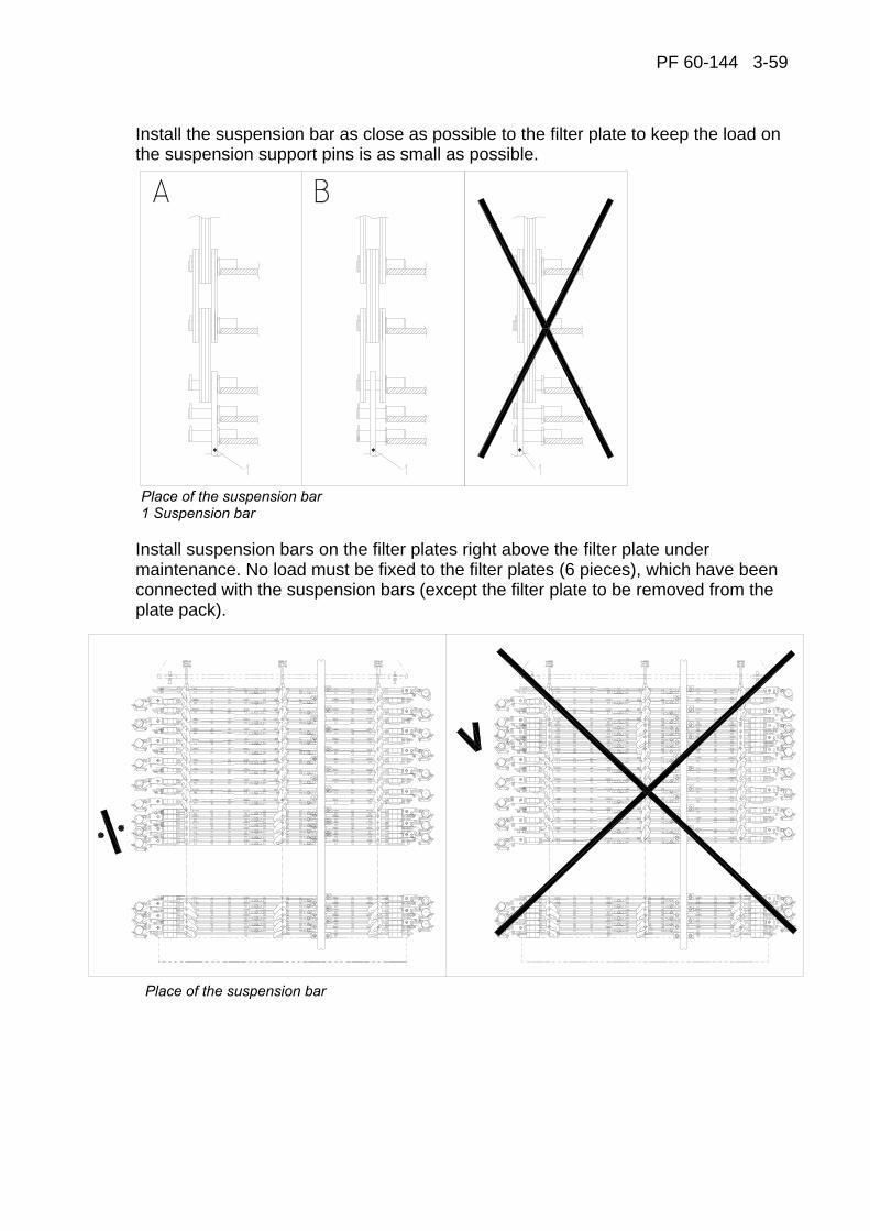
PF 60-144 3-59
Install the suspension bar as close as possible to the filter plate to keep the load on the suspension support pins is as small as possible.
Place of the suspension bar 1 Suspension bar
Install suspension bars on the filter plates right above the filter plate under maintenance. No load must be fixed to the filter plates (6 pieces), which have been connected with the suspension bars (except the filter plate to be removed from the plate pack).
Place of the suspension bar
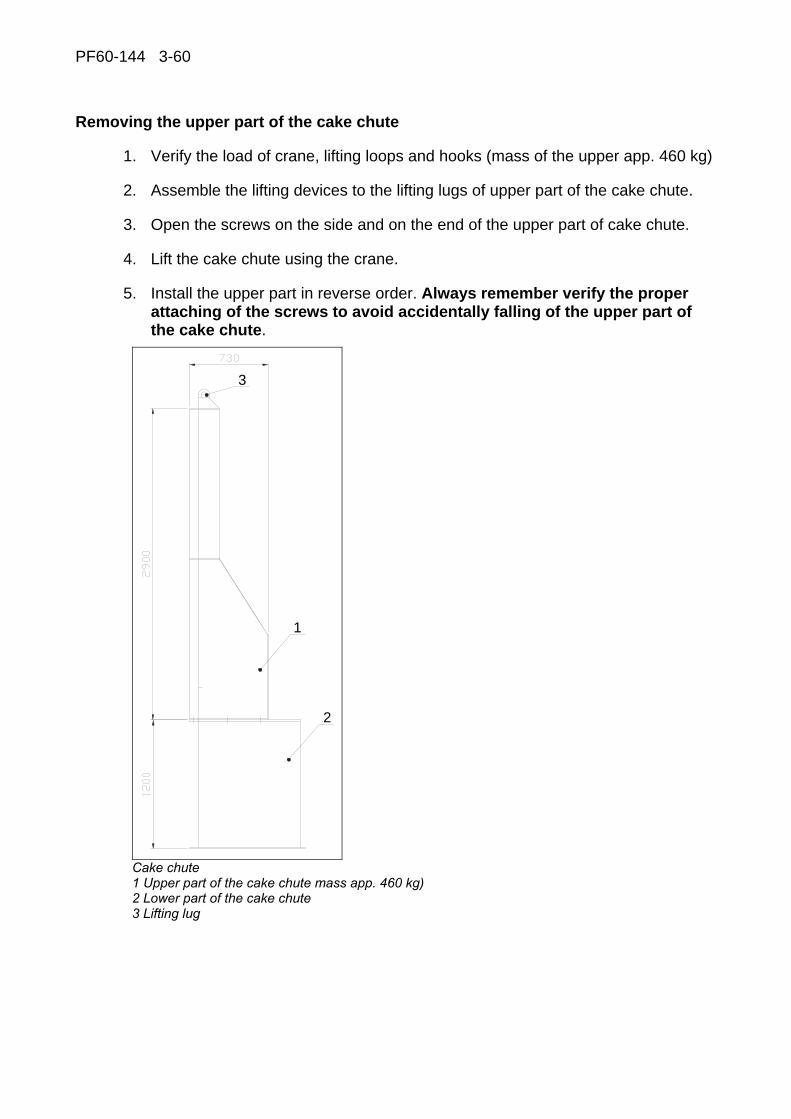
PF60-144 3-60
Removing the upper part of the cake chute
1. Verify the load of crane, lifting loops and hooks (mass of the upper app. 460 kg)
2. Assemble the lifting devices to the lifting lugs of upper part of the cake chute.
3. Open the screws on the side and on the end of the upper part of cake chute.
4. Lift the cake chute using the crane.
5. Install the upper part in reverse order. Always remember verify the proper attaching of the screws to avoid accidentally falling of the upper part of the cake chute.
1
2
3
Cake chute 1 Upper part of the cake chute mass app. 460 kg) 2 Lower part of the cake chute 3 Lifting lug
PF 60-144 4-1
4 THE HYDRAULIC SYSTEM
PF 60-144 4-2
CONTENTS
4 THE HYDRAULIC SYSTEM
4.1 Hydraulic power unit ...................................................................................4-3 Reservoir .......................................................................................................4-4 Hydraulic pumps............................................................................................4-5 Valve Unit ......................................................................................................4-6 Accumulator Circuit........................................................................................4-7 Filling the oil container ...................................................................................4-8 Start up ..........................................................................................................4-9
4.2 Hydraulic power unit adjustment .............................................................4-10 PR3 Pressure reduce valve (210 bar) of the pump P3 ................................4-10 PR01 Pressure Adjusting Valve of Pressure Line 3.....................................4-10
4.3 Adjusting pipeline components and bleeding of pipeline .....................4-10 Valves in the QAC block ..............................................................................4-10 HV 51 and HV 52 balancing valves action speed adjustment......................4-11 Bleeding of Quick-action Cylinders ..............................................................4-12 B472 Pressure Transmitter of Sealing Pressure..........................................4-12 Bleeding of Sealing Cylinders......................................................................4-13 PR8 (40 bar) Adjustment of Cloth Tensioning Force ...................................4-13 FC8 Adjusting of tensioning roller speed .....................................................4-13 Protecting valve of Cloth Drive Motors.........................................................4-13
4.4 Important remarks concerning the hydraulic system ............................4-14 Quality and cleanliness of hydraulic oil ........................................................4-14 Oil recommendation.....................................................................................4-15 Final remarks...............................................................................................4-15

PF 60-144 4-3
4.1 HYDRAULIC POWER UNIT The Hydraulic Power Unit (HPU) contains all elements to provide hydraulic power generation including fluid pressure and flow control. It also accommodates hydraulic fluid storage, filtration and temperature control. The HPU is a complete unit and may be situated in a separate space from the Larox pressure filter.

PF 60-144 4-4
Reservoir
The reservoir, volume of 600 liters (161 GAL) provides the storage of the hydraulic fluid. The fluid level is monitored with transmitter B501 and temperature with transmitter B601. Transmitters B501 and B601 are integrated into same apparatus. Safety switch S601 stop the pump if oil temperature is too high. The fluid temperature is controlled with air cooler (OC), or with alternative water cooler. Return fluid to the tank is passing through filter cartridge RF. The cartridge condition is monitored by differential pressure switch S410. To head side is situated thermometer TM and level indicator LE. For dusty environment is available air breather.
Alternative water cooler. Cooling water flow is controlled with thermostat.
Alternative air breather provides air filtration when fluid level changes
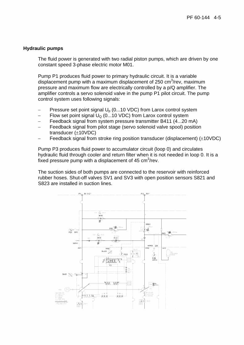
PF 60-144 4-5
Hydraulic pumps
The fluid power is generated with two radial piston pumps, which are driven by one constant speed 3-phase electric motor M01. Pump P1 produces fluid power to primary hydraulic circuit. It is a variable displacement pump with a maximum displacement of 250 cm3/rev, maximum pressure and maximum flow are electrically controlled by a p/Q amplifier. The amplifier controls a servo solenoid valve in the pump P1 pilot circuit. The pump control system uses following signals:
− Pressure set point signal Up (0...10 VDC) from Larox control system − Flow set point signal UQ (0...10 VDC) from Larox control system − Feedback signal from system pressure transmitter B411 (4...20 mA) − Feedback signal from pilot stage (servo solenoid valve spool) position
transducer (±10VDC) − Feedback signal from stroke ring position transducer (displacement) (±10VDC)
Pump P3 produces fluid power to accumulator circuit (loop 0) and circulates hydraulic fluid through cooler and return filter when it is not needed in loop 0. It is a fixed pressure pump with a displacement of 45 cm3/rev. The suction sides of both pumps are connected to the reservoir with reinforced rubber hoses. Shut-off valves SV1 and SV3 with open position sensors S821 and S823 are installed in suction lines.
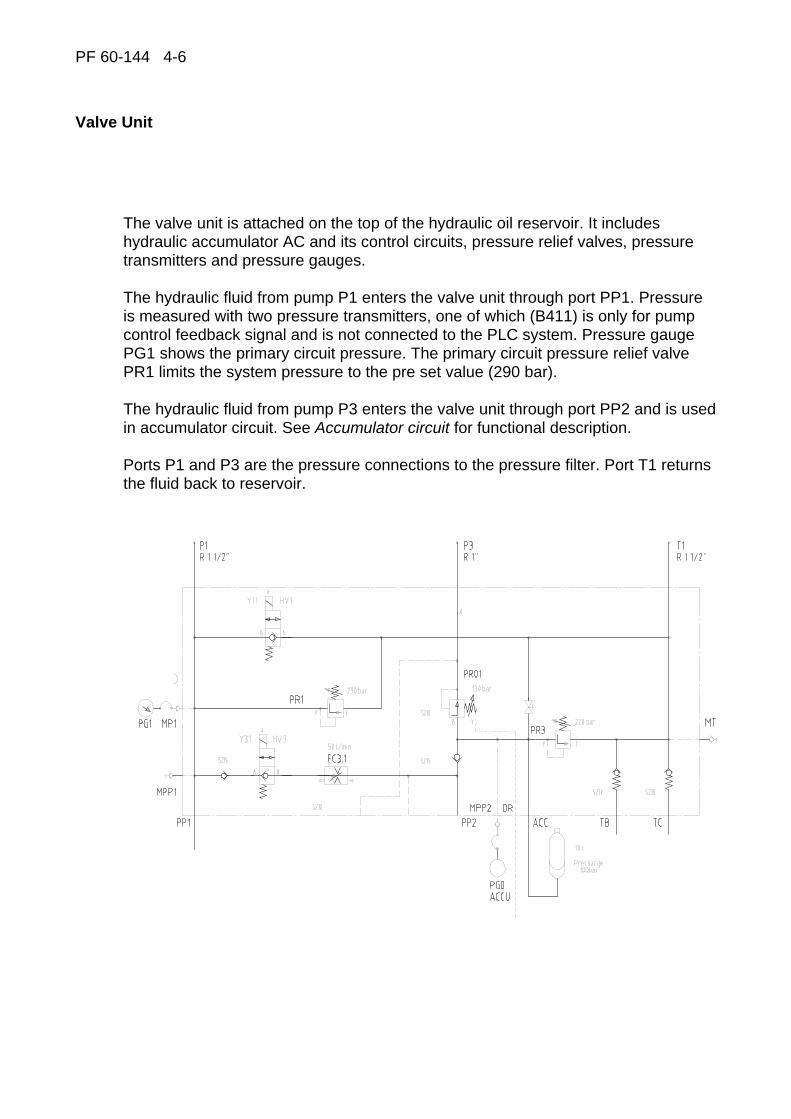
PF 60-144 4-6
Valve Unit
The valve unit is attached on the top of the hydraulic oil reservoir. It includes hydraulic accumulator AC and its control circuits, pressure relief valves, pressure transmitters and pressure gauges. The hydraulic fluid from pump P1 enters the valve unit through port PP1. Pressure is measured with two pressure transmitters, one of which (B411) is only for pump control feedback signal and is not connected to the PLC system. Pressure gauge PG1 shows the primary circuit pressure. The primary circuit pressure relief valve PR1 limits the system pressure to the pre set value (290 bar). The hydraulic fluid from pump P3 enters the valve unit through port PP2 and is used in accumulator circuit. See Accumulator circuit for functional description. Ports P1 and P3 are the pressure connections to the pressure filter. Port T1 returns the fluid back to reservoir.

PF 60-144 4-7
Accumulator Circuit
The accumulator AC is to provide fluid power during power failure and to power minor operations while the hydraulic pump is idling. The accumulator is a steel shell with rubber bladder pre-filled with Nitrogen gas to appropriate pressure. Accumulator pressure is monitored with pressure transmitter B403 and pressure gauge PG0. Maximum pressure is limited by pressure relief valve PR03, field pressure is controlled with pressure reducing valve PR01 and shown by pressure gauge PG3. Accumulator charging is controlled by pressure relief valve PR03. This valve is maintaining 220 bar pressure in accumulator. When the system is not charging the accumulator, the fluid is circulated through oil cooler OC and return oil filter RF back to reservoir. Accumulator pressure and recharging is monitored with an alarm circuit, see B403 for details.

PF 60-144 4-8
Filling the oil container
Before filling the oil container, it must be checked that the container is completely clean inside. The container is filled to the upper limit of the oil level gauge with oil according to the recommendations. Filling must take place by using a separate filtration pump unit, which is provided with a max. 5 um abs. full flow filter. The filling quick coupling in the hydraulic unit is located in connection with the return filter. Filling with an open vessel is forbidden.
Notice: The barrel oil delivered by oil companies is not clean enough as itself for the hydraulic system and without separate filtration, the oil filter will block within a few dNay's time. The blocking of the oil filter will cause informative alarm through pressure switch S410 and high pressure oil filter pressure switch S411.
Filtration pump unit for filling the hydraulic unit.
Oil filling quick coupling in the hydraulic unit

PF 60-144 4-9
Start up
Before the start-up of the hydraulic system, the following points must be checked:
∗ Check that the hydraulic piping or components have not been damaged during transportation.
∗ Check that the supply voltage and frequency are correct.
∗ Check that the rotation direction of the pump is according to the arrow.
Therefore starting the axial piston pump while oil temperature is below 10 °C must an incorrect procedure during start-up may damage the pump within a few seconds. Absolutely be avoided when the oil viscosity class is 46 cSt. Before starting the motor, the immersion heater of the container must warm up the oil until the temperature is at least 10 °C.
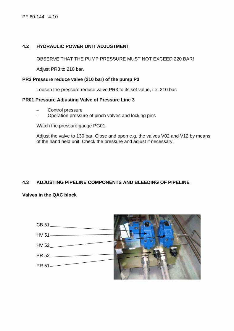
PF 60-144 4-10
4.2 HYDRAULIC POWER UNIT ADJUSTMENT
OBSERVE THAT THE PUMP PRESSURE MUST NOT EXCEED 220 BAR!
Adjust PR3 to 210 bar.
PR3 Pressure reduce valve (210 bar) of the pump P3
Loosen the pressure reduce valve PR3 to its set value, i.e. 210 bar.
PR01 Pressure Adjusting Valve of Pressure Line 3
− Control pressure − Operation pressure of pinch valves and locking pins
Watch the pressure gauge PG01.
Adjust the valve to 130 bar. Close and open e.g. the valves V02 and V12 by means of the hand held unit. Check the pressure and adjust if necessary.
4.3 ADJUSTING PIPELINE COMPONENTS AND BLEEDING OF PIPELINE
Valves in the QAC block
CB 51
HV 51
HV 52
PR 52
PR 51
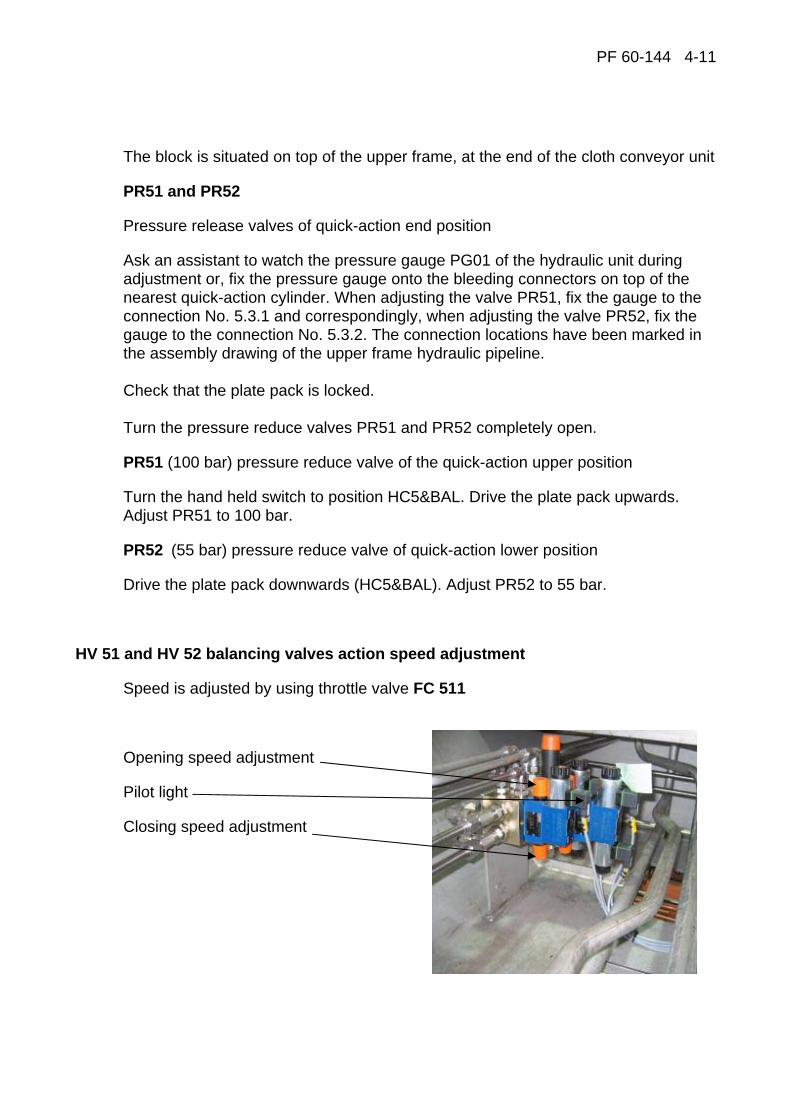
PF 60-144 4-11
The block is situated on top of the upper frame, at the end of the cloth conveyor unit
PR51 and PR52
Pressure release valves of quick-action end position
Ask an assistant to watch the pressure gauge PG01 of the hydraulic unit during adjustment or, fix the pressure gauge onto the bleeding connectors on top of the nearest quick-action cylinder. When adjusting the valve PR51, fix the gauge to the connection No. 5.3.1 and correspondingly, when adjusting the valve PR52, fix the gauge to the connection No. 5.3.2. The connection locations have been marked in the assembly drawing of the upper frame hydraulic pipeline. Check that the plate pack is locked. Turn the pressure reduce valves PR51 and PR52 completely open.
PR51 (100 bar) pressure reduce valve of the quick-action upper position
Turn the hand held switch to position HC5&BAL. Drive the plate pack upwards. Adjust PR51 to 100 bar.
PR52 (55 bar) pressure reduce valve of quick-action lower position
Drive the plate pack downwards (HC5&BAL). Adjust PR52 to 55 bar.
HV 51 and HV 52 balancing valves action speed adjustment
Speed is adjusted by using throttle valve FC 511
Opening speed adjustment
Pilot light
Closing speed adjustment

PF 60-144 4-12
Plate pack must be fully open position. Turn the hand held unit to its HC5 position. Drive downwards until pilot light Y 511 is off (10 – 15 cm). Drive upwards and check that pilot light switch on automatically. Adjust HV 51 and HV 52 opening speed by using FC 511 to top situated screw. Adjust closing speed from the FC 511 bottom screw. Good start setting for both adjusting screws is two turns open from closed position. Drive plate pack downwards and upwards and adjust until movement on the top position works smoothly. Tighten adjusting screws locking nuts.
WARNING! During the following adjusting measures, the plate pack must be opened and closed. After assembly, during start up or having repaired something that have caused outflow of oil from quick-action cylinders or pipeline, the quick-action cylinders must always be bled. See point 6.3.2
Bleeding of Quick-action Cylinders
The plate pack must be locked in its closed or open position. Turn the hand held unit to its HC5& BAL position. Drive the plate pack in turns up and down for 10...20 sec. The upper pressing plate can move a little in the locking pin holes. Watch the quick-action cylinders’ movement. Continue until they all move the same way. Open the locking pins. Turn the hand held unit to its HC5 position. Drive the plate pack carefully. Watch the quick-action cylinders and check that they all move equally. The length of movement can easily be checked by means of a metric measure. If the upper pressing plate starts to incline, drive the plate pack back to its end position and carry on bleeding. When you have driven the plate pack to its other end position, carry out bleeding also at this end. Check that the upper pressing plate is in a horizontal position. Drive the quick-action a few times against high and low positions.
B472 Pressure Transmitter of Sealing Pressure
This pressure transmitter is located beside the DV-block inside the cloth conveyor unit. Close and lock the plate pack. Turn the hand held unit to its HC7 position. Watch the pressure gauge fixed next to the pressure switch. The sealing pressure can be set through operator interface in RECIPE-screen. It is convertable from 30 up to 90 bar (the default value is 50 bar). During adjustment, the pressure must not exceed 90 bar.
PF 60-144 4-13
Bleeding of Sealing Cylinders
Close and lock the plate pack
Turn the hand held unit to its HC7 position.
Drive the sealing cylinders several times up and down whereby air is discharged from the cylinders.
PR8 (40 bar) Adjustment of Cloth Tensioning Force
The valve has been fixed below the main drive roller behind the doors on the left side wall.
Loosen the adjusting screw.
Turn the hand held unit to its HM8 position.
Tighten the cloth and adjust PR8 to 40 bar.
FC8 Adjusting of tensioning roller speed
Situated under the valve PR8, normally fully open. The speed can be slowed down when necessary.
Protecting valve of Cloth Drive Motors
This valve PR9 is adjusted by manufacturer and cannot be adjusted on site.
In case PR9 needs to be adjusted (the filter cloth moves badly during discharge), contact the local Larox Service.
PF 60-144 4-14
4.4 IMPORTANT REMARKS CONCERNING THE HYDRAULIC SYSTEM
Quality and cleanliness of hydraulic oil
Generally known manufacturers must be referred to when choosing oil for the Larox PF 60 - 144 pressure filter hydraulic system.
Use mineral oil type ISO 6743, ISO-L-HM ** (** = viscosity class /ISO 3448) - normally ISO VG32, 48 or 68.
The viscosity class depends on the operating temperature of the system, the oil viscosity should be 20...50 cSt, the optimum is 30 cSt.
Viscosity index VI, at best over 100, normally 105...160. A too high index is not recommended (VI > 200).
A new oil is never clean enough to be directly poured into the hydraulic system, thus a filling device provided with a filter is required for filling the system.
Instructions concerning the oil cleanliness
Oil impurities are the most common reason for faults in the hydraulic system.
− Required oil cleanliness class 16/13, ISO 4406 or class 7, NAS 1637.
− The oil filters must be kept clean, alarm sensors must be checked and filters changed every time there is an alarm.
− Oil samples must regularly be taken in order to follow the condition of seals and wearing grade of the system.
− Remember the bleeding device.
− The repair and maintenance measures of the hydraulic system must be performed carefully.
− Caution must be exercised in the repair and maintenance of the hydraulic system. Before opening joints or loosening any parts all sources of impurity must be removed.
− All parts of a new system must carefully be cleaned before installation.

PF 60-144 4-15
Oil recommendation
ASPO (Sunoco) Hydroll 821
SP Hyvis 32 S
BP Energol HLP 46
BP Energol SHF 46
CASTROL Hyspin AWS 46
ESSO Nuto HP 46
GULF Harmony 48 AW Oile Hydraulic
MOBIL Mobil DTE 15
Mobil DTE 25
SHELL Shell Tellus Oil 46
TEBOIL Tebo Larita Oil 68
Tebo Hydraulic oil 46
(Tebo Hydraulic Deck Oil)
Caution! Do not overfill the hydraulic unit. (Top limit in the oil level indicator glass)
Final remarks
The tightness of the system must be examined. Possible leakage must be repaired immediately. If any elements of the hydraulic system are opened, it must absolutely be ensured that no impurities like rubbish, dust or strange items get into them. The open joints can best be protected with a clean piece of cloth. The hydraulic system parts are maintained in a clean and dry place.
Be careful! All parts like springs, seals etc. are necessary for the operation of the system. See to that all dismantled parts are correctly reassembled.

PF 60-144 5 - 1
5 TROUBLE SHOOTING AND ALARMS

PF 60-144 5 - 2
CONTENTS 5 TROUBLE SHOOTING AND ALARMS
5.1 TROUBLE SHOOTING..............................................................................3
5.2 ALARM FUNCTIONS ................................................................................6
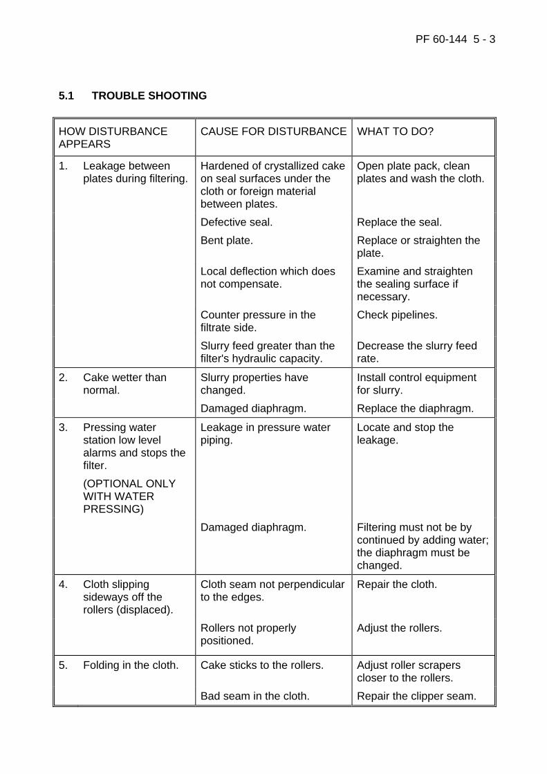
PF 60-144 5 - 3
5.1 TROUBLE SHOOTING
HOW DISTURBANCE APPEARS
CAUSE FOR DISTURBANCE WHAT TO DO?
1. Leakage between plates during filtering.
Hardened of crystallized cake on seal surfaces under the cloth or foreign material between plates.
Open plate pack, clean plates and wash the cloth.
Defective seal. Replace the seal. Bent plate. Replace or straighten the
plate. Local deflection which does
not compensate. Examine and straighten the sealing surface if necessary.
Counter pressure in the filtrate side.
Check pipelines.
Slurry feed greater than the filter's hydraulic capacity.
Decrease the slurry feed rate.
2. Cake wetter than normal.
Slurry properties have changed.
Install control equipment for slurry.
Damaged diaphragm. Replace the diaphragm.
3. Pressing water station low level alarms and stops the filter. (OPTIONAL ONLY WITH WATER PRESSING)
Leakage in pressure water piping.
Locate and stop the leakage.
Damaged diaphragm. Filtering must not be by continued by adding water; the diaphragm must be changed.
4. Cloth slipping sideways off the rollers (displaced).
Cloth seam not perpendicular to the edges.
Repair the cloth.
Rollers not properly positioned.
Adjust the rollers.
5. Folding in the cloth. Cake sticks to the rollers. Adjust roller scrapers closer to the rollers.
Bad seam in the cloth. Repair the clipper seam.
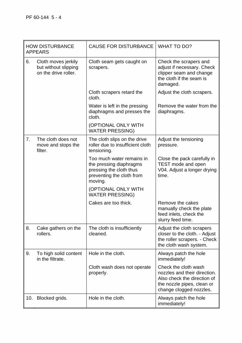
PF 60-144 5 - 4
HOW DISTURBANCE APPEARS
CAUSE FOR DISTURBANCE WHAT TO DO?
6. Cloth moves jerkily but without slipping on the drive roller.
Cloth seam gets caught on scrapers.
Check the scrapers and adjust if necessary. Check clipper seam and change the cloth if the seam is damaged.
Cloth scrapers retard the cloth.
Adjust the cloth scrapers.
Water is left in the pressing diaphragms and presses the cloth. (OPTIONAL ONLY WITH WATER PRESSING)
Remove the water from the diaphragms.
7. The cloth does not move and stops the filter.
The cloth slips on the drive roller due to insufficient cloth tensioning.
Adjust the tensioning pressure.
Too much water remains in the pressing diaphragms pressing the cloth thus preventing the cloth from moving. (OPTIONAL ONLY WITH WATER PRESSING)
Close the pack carefully in TEST mode and open V04. Adjust a longer drying time.
Cakes are too thick. Remove the cakes manually check the plate feed inlets, check the slurry feed time.
8. Cake gathers on the rollers.
The cloth is insufficiently cleaned.
Adjust the cloth scrapers closer to the cloth. - Adjust the roller scrapers. - Check the cloth wash system.
9. To high solid content in the filtrate.
Hole in the cloth. Always patch the hole immediately!
Cloth wash does not operate properly.
Check the cloth wash nozzles and their direction. Also check the direction of the nozzle pipes, clean or change clogged nozzles.
10. Blocked grids. Hole in the cloth. Always patch the hole immediately!
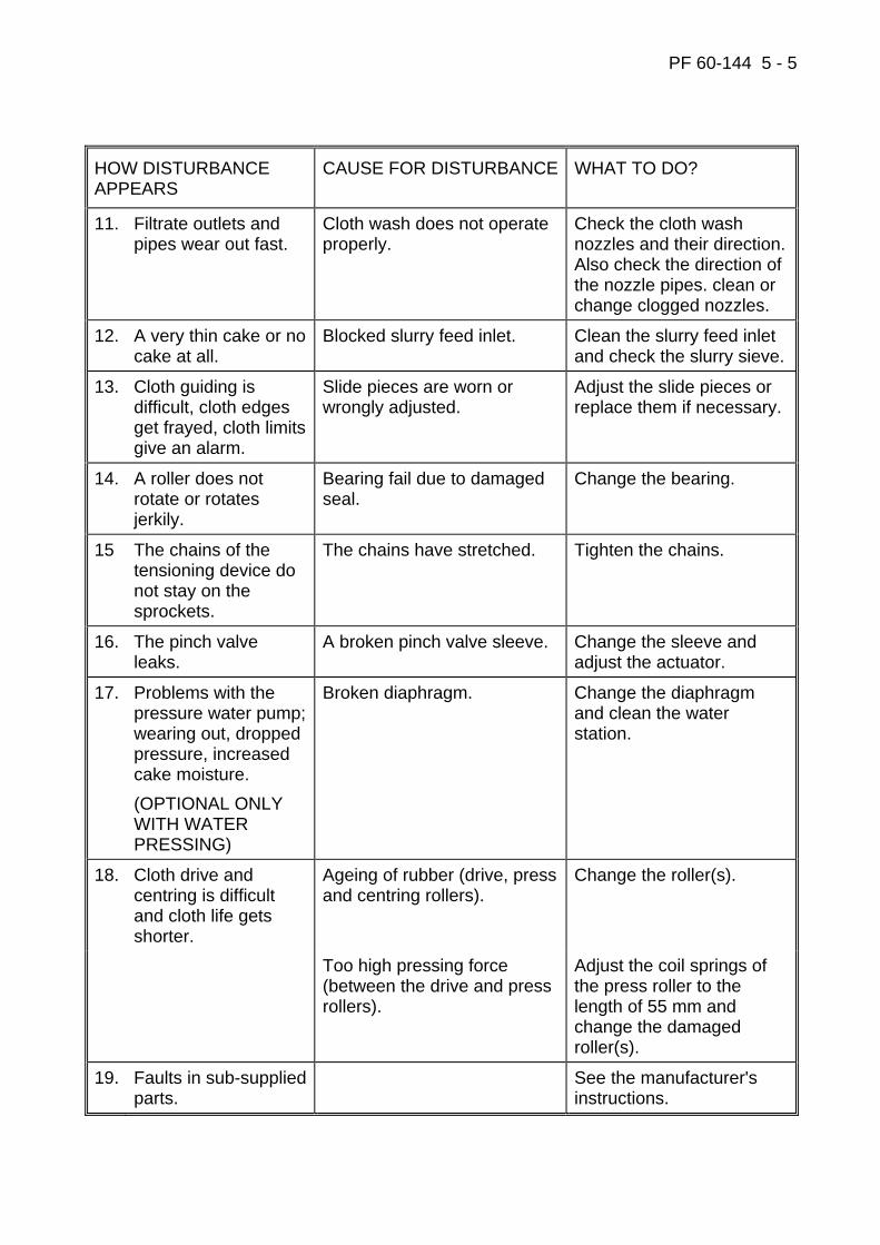
PF 60-144 5 - 5
HOW DISTURBANCE APPEARS
CAUSE FOR DISTURBANCE WHAT TO DO?
11. Filtrate outlets and pipes wear out fast.
Cloth wash does not operate properly.
Check the cloth wash nozzles and their direction. Also check the direction of the nozzle pipes. clean or change clogged nozzles.
12. A very thin cake or no cake at all.
Blocked slurry feed inlet. Clean the slurry feed inlet and check the slurry sieve.
13. Cloth guiding is difficult, cloth edges get frayed, cloth limits give an alarm.
Slide pieces are worn or wrongly adjusted.
Adjust the slide pieces or replace them if necessary.
14. A roller does not rotate or rotates jerkily.
Bearing fail due to damaged seal.
Change the bearing.
15 The chains of the tensioning device do not stay on the sprockets.
The chains have stretched. Tighten the chains.
16. The pinch valve leaks.
A broken pinch valve sleeve. Change the sleeve and adjust the actuator.
17. Problems with the pressure water pump; wearing out, dropped pressure, increased cake moisture. (OPTIONAL ONLY WITH WATER PRESSING)
Broken diaphragm. Change the diaphragm and clean the water station.
18. Cloth drive and centring is difficult and cloth life gets shorter.
Ageing of rubber (drive, press and centring rollers).
Change the roller(s).
Too high pressing force (between the drive and press rollers).
Adjust the coil springs of the press roller to the length of 55 mm and change the damaged roller(s).
19. Faults in sub-supplied parts.
See the manufacturer's instructions.
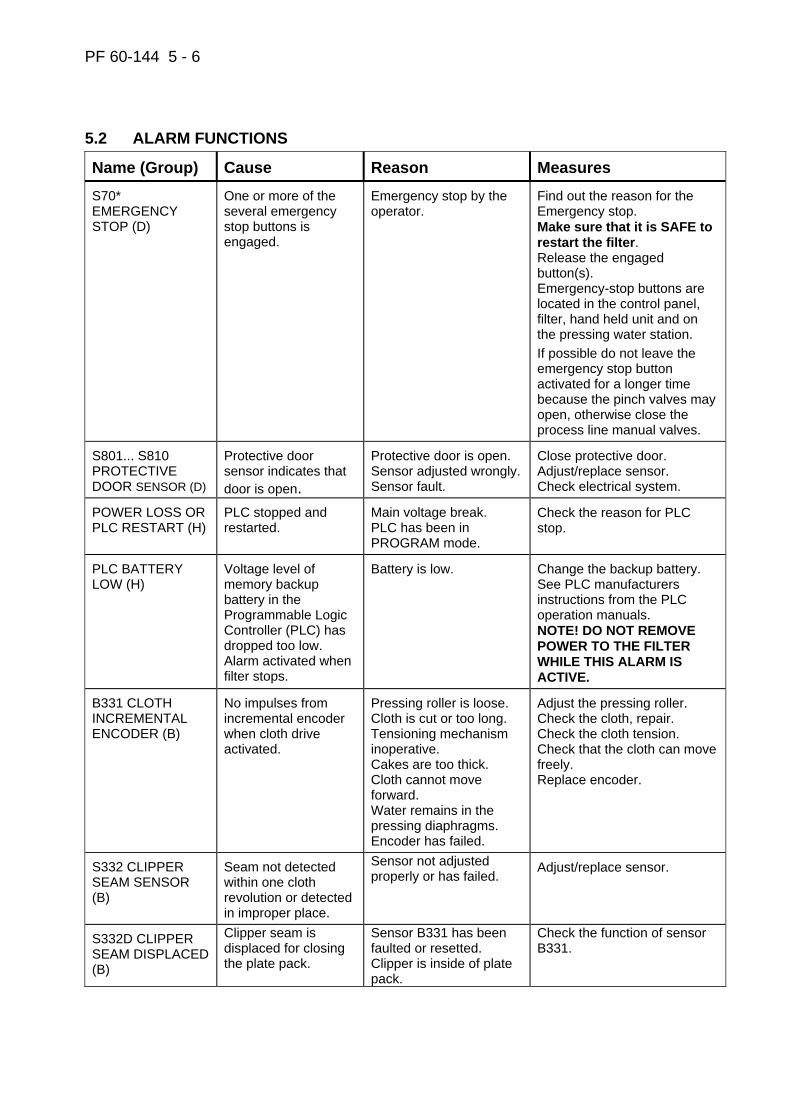
PF 60-144 5 - 6
5.2 ALARM FUNCTIONS
Name (Group) Cause Reason Measures S70* EMERGENCY STOP (D)
One or more of the several emergency stop buttons is engaged.
Emergency stop by the operator.
Find out the reason for the Emergency stop. Make sure that it is SAFE to restart the filter. Release the engaged button(s). Emergency-stop buttons are located in the control panel, filter, hand held unit and on the pressing water station. If possible do not leave the emergency stop button activated for a longer time because the pinch valves may open, otherwise close the process line manual valves.
S801... S810 PROTECTIVE DOOR SENSOR (D)
Protective door sensor indicates that door is open.
Protective door is open. Sensor adjusted wrongly. Sensor fault.
Close protective door. Adjust/replace sensor. Check electrical system.
POWER LOSS OR PLC RESTART (H)
PLC stopped and restarted.
Main voltage break. PLC has been in PROGRAM mode.
Check the reason for PLC stop.
PLC BATTERY LOW (H)
Voltage level of memory backup battery in the Programmable Logic Controller (PLC) has dropped too low. Alarm activated when filter stops.
Battery is low. Change the backup battery. See PLC manufacturers instructions from the PLC operation manuals. NOTE! DO NOT REMOVE POWER TO THE FILTER WHILE THIS ALARM IS ACTIVE.
B331 CLOTH INCREMENTAL ENCODER (B)
No impulses from incremental encoder when cloth drive activated.
Pressing roller is loose. Cloth is cut or too long. Tensioning mechanism inoperative. Cakes are too thick. Cloth cannot move forward. Water remains in the pressing diaphragms. Encoder has failed.
Adjust the pressing roller. Check the cloth, repair. Check the cloth tension. Check that the cloth can move freely. Replace encoder.
S332 CLIPPER SEAM SENSOR (B)
Seam not detected within one cloth revolution or detected in improper place.
Sensor not adjusted properly or has failed.
Adjust/replace sensor.
S332D CLIPPER SEAM DISPLACED (B)
Clipper seam is displaced for closing the plate pack.
Sensor B331 has been faulted or resetted. Clipper is inside of plate pack.
Check the function of sensor B331.
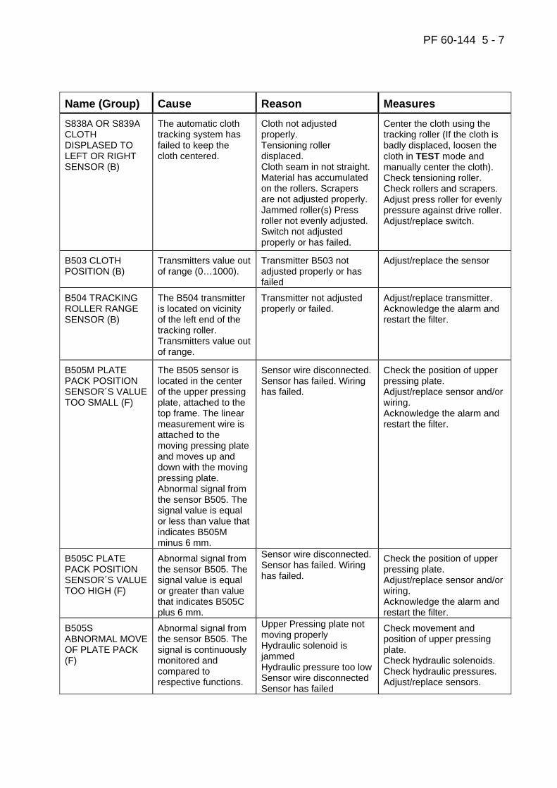
PF 60-144 5 - 7
Name (Group) Cause Reason Measures S838A OR S839A CLOTH DISPLASED TO LEFT OR RIGHT SENSOR (B)
The automatic cloth tracking system has failed to keep the cloth centered.
Cloth not adjusted properly. Tensioning roller displaced. Cloth seam in not straight. Material has accumulated on the rollers. Scrapers are not adjusted properly. Jammed roller(s) Press roller not evenly adjusted. Switch not adjusted properly or has failed.
Center the cloth using the tracking roller (If the cloth is badly displaced, loosen the cloth in TEST mode and manually center the cloth). Check tensioning roller. Check rollers and scrapers. Adjust press roller for evenly pressure against drive roller. Adjust/replace switch.
B503 CLOTH POSITION (B)
Transmitters value out of range (0…1000).
Transmitter B503 not adjusted properly or has failed
Adjust/replace the sensor
B504 TRACKING ROLLER RANGE SENSOR (B)
The B504 transmitter is located on vicinity of the left end of the tracking roller. Transmitters value out of range.
Transmitter not adjusted properly or failed.
Adjust/replace transmitter. Acknowledge the alarm and restart the filter.
B505M PLATE PACK POSITION SENSOR´S VALUE TOO SMALL (F)
The B505 sensor is located in the center of the upper pressing plate, attached to the top frame. The linear measurement wire is attached to the moving pressing plate and moves up and down with the moving pressing plate. Abnormal signal from the sensor B505. The signal value is equal or less than value that indicates B505M minus 6 mm.
Sensor wire disconnected. Sensor has failed. Wiring has failed.
Check the position of upper pressing plate. Adjust/replace sensor and/or wiring. Acknowledge the alarm and restart the filter.
B505C PLATE PACK POSITION SENSOR´S VALUE TOO HIGH (F)
Abnormal signal from the sensor B505. The signal value is equal or greater than value that indicates B505C plus 6 mm.
Sensor wire disconnected. Sensor has failed. Wiring has failed.
Check the position of upper pressing plate. Adjust/replace sensor and/or wiring. Acknowledge the alarm and restart the filter.
B505S ABNORMAL MOVE OF PLATE PACK (F)
Abnormal signal from the sensor B505. The signal is continuously monitored and compared to respective functions.
Upper Pressing plate not moving properly Hydraulic solenoid is jammed Hydraulic pressure too low Sensor wire disconnected Sensor has failed
Check movement and position of upper pressing plate. Check hydraulic solenoids. Check hydraulic pressures. Adjust/replace sensors.

PF 60-144 5 - 8
Name (Group) Cause Reason Measures B505D PLATE PACK NOT IN DISCHARGE POS. (F)
Plate pack is not in cake discharge position when cake discharge stage is active.
The plate pack has flown to down when filter has been stopped. Sensor has failed. Wiring has failed.
Check the position of pressing plate. Drive the plate pack to up with hand held. Adjust/replace sensor and/or wiring.
S161…S164 LOCKING PINS UNLOCKED SENSORS (F) S261…S264 LOCKING PINS LOCKED SENSORS (F)
Abnormal state of the displayed sensor when operating the locking pins (locking or unlocking).
Locking pin jammed in the mid position. Hydraulic pressure too low. Mechanical failure. Sensor not adjusted properly or has failed.
Inspect locking pin assembly. Test locking pin movement. Check hydraulic pressures. Adjust/replace sensor.
S171 SEALING PLATE DOWN SENSOR (F)
Abnormal state of the sensor S171 when driving down (unsealing) or up (sealing) the sealing cylinders HC7.
Sealing plate not moving properly. Hydraulic pressure too low. Sensor not adjusted properly or has failed.
Check movement of sealing plate. Check hydraulic pressures. Adjust/replace sensors.
S531 DIAPHRAGM LEAKAGE SENSOR (E)
S531 sensor is detecting moisture (slurry or water) in pressing manifold.
Diaphragms are leaking. Sensor S531 has failed..
Check if diaphragms are leaking. Check broken diaphragms. Change sensor S531.
S532 V06 SLEEVES LEAKAGE (E)
S532 sensor is detecting moisture (slurry or water) V06 sleeves.
Diaphragms are leaking. Sensor S532 has failed.
Check if diaphragms are leaking. Check broken diaphragms. Change sensor S532.
TARE MAX TARE ALARM (E) (OPTIONAL)
Measured weight is greater than max tare weight after plate pack closing stage.
Extra mass has been gathered to filter. Weight sensor or amplifier has failed.
Remove extra mass from filter. Repair or replace weight sensor/amplifier.
MINW MINIMUM WEIGHT ALARM (E) (OPTIONAL)
Cake weight after pressing is less than set minimum cake weight in parameters.
Slurry pump is failed. Slurry feed time is too short. Slurry density is too low. Weight sensor or amplifier has failed.
Skip over air drying stage for avoid filtration. Plates bending. Repair or replace weight sensor/amplifier.
S410 RETURN LINE OIL FILTER PRESSURE SWICH (G)
Pressure switch S410 signals a high differential pressure in the RETURN LINE oil filter.
Return line oil filter is clogged. Oil temp is too low or oil is too thick (improper viscosity). Cable is disconnected. Pressure switch S410 has failed.
Run the hydraulic unit to warm up the oil. If alarm is active when the oil is warm, replace the oil filter. Reconnect the cable. Replace S410.
S412 OIL FILTER PRESSURE SWITCH (G)
The differential pressure switch S412 signals a high differential pressure.
Oil filter is clogged. Oil temp is too low. Oil is too thick (Improper viscosity). Cable is disconnected. Pressure switch S412 has failed.
Run the hydraulic unit to warm up the oil. If alarm is active when the oil is warm, replace the oil filter. Reconnect the cable. Replace S412.

PF 60-144 5 - 9
Name (Group) Cause Reason Measures B491 CLOTH WASH WATER PRESSURE TRANSMITTER (E)
B491 transmitter is not detecting pressure while cloth is washed.
Hand valve is closed. Filter is blocked. Sensor B491 has failed.
Check if hand valves are closed and open them. Check and clean wash water filter. Change transmitter B491.
B501L OIL LEVEL LOW (G)
Oil level transmitter B501 in hydraulic oil reservoir is indicating low oil level.
Leak in the hydraulic system. Level transmitter B501 has failed.
Check the oil level and add oil if necessary. Check system for oil leaks. Never run the hydraulic pump if the tank is empty. Replace B501.
S821 OIL PUMP P1 MANUAL VALVE CLOSED (G)
Abnormal state of the sensor S821 when hydraulic unit motor is tried to start.
Manual valve SV1 is close. Sensor S821 has failed or wrong adjusted.
Open manual valve SV1. Adjust or replace the sensor S821.
S823 OIL PUMP P3 MANUAL VALVE CLOSED (G)
Abnormal state of the sensor S823 when hydraulic unit motor is tried to start.
Manual valve SV3 is close. Sensor S823 has failed or wrong adjusted.
Open manual valve SV3. Adjust or replace the sensor S823.
S601 OIL TEMPERATURE HIGH HIGH, T>700C (G)
Thermostat S601 in hydraulic oil reservoir is indicating high high oil temperature (above 70°C).
Oil cooler is not on. Oil heater has failed on. Transmitter B601 has failed. Thermostat S601 has failed or not adjusted properly.
Check that the oil cooler OC is on. Check that the oil heater R04 is off. Check oil temperature from the thermometer TM. Allow cooler to cool down the oil for 30 min. Replace S601, check adjustment of S601.
B601L OIL TEMPERATURE LOW (G)
Oil temperature transmitter B601 in hydraulic oil reservoir is indicating low oil temperature (below 10°C).
Oil heater is not on. Filter has been shut down when ambient temperature is low. Transmitter B601 has failed.
Check that the oil heater is on. Check oil temperature from the thermometer TM. Allow heater to warm up the oil for 30 minutes. Replace B601.
B601H OIL TEMPERATURE HIGH (G)
Oil temperature transmitter B601 in hydraulic oil reservoir is indicating high oil temperature (above 65°C).
Oil cooler is not on. Oil heater has failed on. Transmitter B601 has failed.
Check that the oil cooler OC is on. Check that the oil heater R04 is off. Check oil temperature from the thermometer TM. Allow cooler to cool down the oil for 30 minutes. Replace B601.
B601HH OIL TEMPERATURE HIGH HIGH (G)
Oil temperature transmitter B601 in hydraulic oil reservoir is indicating high oil temperature (above 70°C).
Oil cooler is not on. Oil heater has failed on. Transmitter B601 has failed.
Check that the oil cooler OC is on. Check that the oil heater R04 is off. Check oil temperature from the thermometer TM. Allow cooler to cool down the oil for 30 minutes. Replace B601.
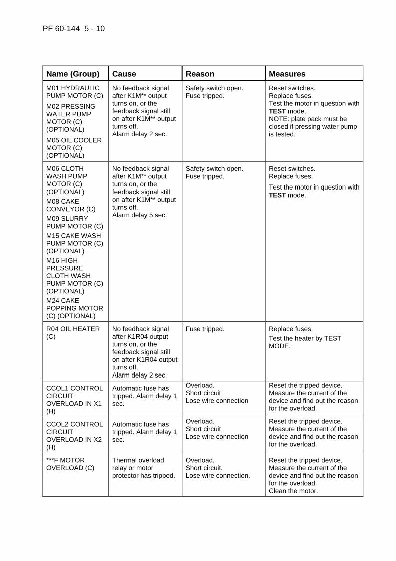
PF 60-144 5 - 10
Name (Group) Cause Reason Measures M01 HYDRAULIC PUMP MOTOR (C) M02 PRESSING WATER PUMP MOTOR (C) (OPTIONAL) M05 OIL COOLER MOTOR (C) (OPTIONAL)
No feedback signal after K1M** output turns on, or the feedback signal still on after K1M** output turns off. Alarm delay 2 sec.
Safety switch open. Fuse tripped.
Reset switches. Replace fuses. Test the motor in question with TEST mode. NOTE: plate pack must be closed if pressing water pump is tested.
M06 CLOTH WASH PUMP MOTOR (C) (OPTIONAL) M08 CAKE CONVEYOR (C) M09 SLURRY PUMP MOTOR (C) M15 CAKE WASH PUMP MOTOR (C) (OPTIONAL) M16 HIGH PRESSURE CLOTH WASH PUMP MOTOR (C) (OPTIONAL) M24 CAKE POPPING MOTOR (C) (OPTIONAL)
No feedback signal after K1M** output turns on, or the feedback signal still on after K1M** output turns off. Alarm delay 5 sec.
Safety switch open. Fuse tripped.
Reset switches. Replace fuses. Test the motor in question with TEST mode.
R04 OIL HEATER (C)
No feedback signal after K1R04 output turns on, or the feedback signal still on after K1R04 output turns off. Alarm delay 2 sec.
Fuse tripped. Replace fuses. Test the heater by TEST MODE.
CCOL1 CONTROL CIRCUIT OVERLOAD IN X1 (H)
Automatic fuse has tripped. Alarm delay 1 sec.
Overload. Short circuit Lose wire connection
Reset the tripped device. Measure the current of the device and find out the reason for the overload.
CCOL2 CONTROL CIRCUIT OVERLOAD IN X2 (H)
Automatic fuse has tripped. Alarm delay 1 sec.
Overload. Short circuit Lose wire connection
Reset the tripped device. Measure the current of the device and find out the reason for the overload.
***F MOTOR OVERLOAD (C)
Thermal overload relay or motor protector has tripped.
Overload. Short circuit. Lose wire connection.
Reset the tripped device. Measure the current of the device and find out the reason for the overload. Clean the motor.

PF 60-144 5 - 11
Name (Group) Cause Reason Measures VALVE SENSORS S1** is open sensor. S2** is closed sensor.
Abnormal state of sensor in valve V**.
Instrument air / hydraulic oil pressure low. Break in pneumatics/ hydraulics. Sensor not adjusted properly or has failed. Break in electrical wiring. Blown fuse in terminal box.
Actuate the valve in question in TEST mode. Follow the indicator LED's in the valve circuit for easy troubleshooting. Check instrument air/lines. Adjust/replace sensors. Check electrical system.
B415M FEED MANIFOLD PRESSURE HIGH (E)
Feed manifold pressure transmitter B415 is indicating too high pressure (above max. operating pressure set point in auxiliary parameters, typically 16.0 bar).
Slurry feed, wash water or drying air system produces excessive pressure. Transmitter B415 has failed.
Check feed manifold pressure from the pressure gauge. Correct the reason for over pressure. Replace B415.
B415F SLURRY FEED PRESSURE LOW (E)
Feed manifold pressure transmitter B415 is indicating low slurry feed pressure while slurry pump is running and slurry inlet valve V02 is open.
Slurry feed pump inoperative or cavitating. Slurry tank is empty. Manual valve closed. Pressure set point “MINIMUM FEED PRESSURE” incorrectly set. Transmitter B415 has failed
Start the slurry feed pump. Maintain correct slurry level. Open the manual valve. Enter correct value into “MINIMUM FEED PRESSURE” set point. Adjust/replace pressure transmitter B415.
B415H HOSE WASH PRESSURE (E) LOW
B415C CAKE WASH PRESSURE LOW (E)
Feed manifold pressure transmitter B415 is indicating low wash water pressure during HOSE WASH or CAKE WASH stage.
Wash water pump inoperative or cavitating. Wash water tank is empty. Manual valve closed. Pressure set point in Data 2 for HOSE WASH or CAKE WASH stage incorrectly set. Transmitter B415 has failed
Start the wash water pump. Maintain correct wash liquid level. Open the manual valve. Enter correct value into Data 2 set point. Adjust/replace pressure transmitter B415.
B415A DRYING AIR PRESSURE LOW (E)
Feed manifold pressure transmitter B415 is indicating low drying air pressure immediately after opening the valve V06 during DRYING stage.
Compressor not running. Manual valve closed. Low air pressure/volume. Pressure set point in Data 2 for DRYING stage incorrectly set. Transmitter B415 has failed.
Start up the compressor. Open the manual valve. Check operation of compressor. Enter correct value into Data 2 set point. Adjust/replace pressure transmitter B415.
B415N FEED MANIFOLD PRESSURE NOT RELEASED (E)
Feed manifold pressure transmitter B415 is indicating too high pressure after opening the drain valve V07.
Drain pipe is clogged. Slurry strainer is clogged. V07 valve failed. Transmitter B415 has failed
Ensure that pressure in feed manifold is released. Clean the pipeline. Check operation of valve V07. Adjust/replace pressure transmitter B415.
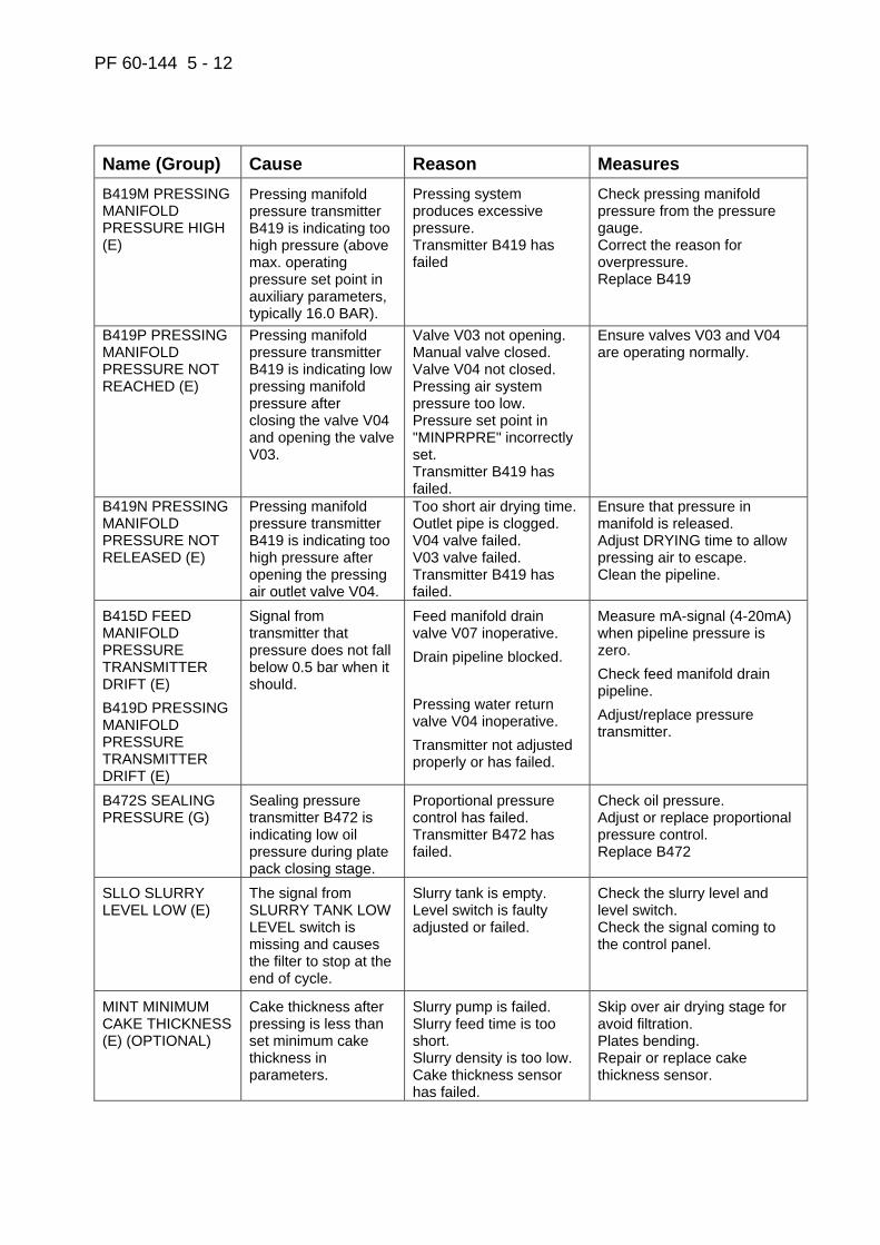
PF 60-144 5 - 12
Name (Group) Cause Reason Measures B419M PRESSING MANIFOLD PRESSURE HIGH (E)
Pressing manifold pressure transmitter B419 is indicating too high pressure (above max. operating pressure set point in auxiliary parameters, typically 16.0 BAR).
Pressing system produces excessive pressure. Transmitter B419 has failed
Check pressing manifold pressure from the pressure gauge. Correct the reason for overpressure. Replace B419
B419P PRESSING MANIFOLD PRESSURE NOT REACHED (E)
Pressing manifold pressure transmitter B419 is indicating low pressing manifold pressure after closing the valve V04 and opening the valve V03.
Valve V03 not opening. Manual valve closed. Valve V04 not closed. Pressing air system pressure too low. Pressure set point in "MINPRPRE" incorrectly set. Transmitter B419 has failed.
Ensure valves V03 and V04 are operating normally.
B419N PRESSING MANIFOLD PRESSURE NOT RELEASED (E)
Pressing manifold pressure transmitter B419 is indicating too high pressure after opening the pressing air outlet valve V04.
Too short air drying time. Outlet pipe is clogged. V04 valve failed. V03 valve failed. Transmitter B419 has failed.
Ensure that pressure in manifold is released. Adjust DRYING time to allow pressing air to escape. Clean the pipeline.
B415D FEED MANIFOLD PRESSURE TRANSMITTER DRIFT (E) B419D PRESSING MANIFOLD PRESSURE TRANSMITTER DRIFT (E)
Signal from transmitter that pressure does not fall below 0.5 bar when it should.
Feed manifold drain valve V07 inoperative. Drain pipeline blocked. Pressing water return valve V04 inoperative. Transmitter not adjusted properly or has failed.
Measure mA-signal (4-20mA) when pipeline pressure is zero. Check feed manifold drain pipeline. Adjust/replace pressure transmitter.
B472S SEALING PRESSURE (G)
Sealing pressure transmitter B472 is indicating low oil pressure during plate pack closing stage.
Proportional pressure control has failed. Transmitter B472 has failed.
Check oil pressure. Adjust or replace proportional pressure control. Replace B472
SLLO SLURRY LEVEL LOW (E)
The signal from SLURRY TANK LOW LEVEL switch is missing and causes the filter to stop at the end of cycle.
Slurry tank is empty. Level switch is faulty adjusted or failed.
Check the slurry level and level switch. Check the signal coming to the control panel.
MINT MINIMUM CAKE THICKNESS (E) (OPTIONAL)
Cake thickness after pressing is less than set minimum cake thickness in parameters.
Slurry pump is failed. Slurry feed time is too short. Slurry density is too low. Cake thickness sensor has failed.
Skip over air drying stage for avoid filtration. Plates bending. Repair or replace cake thickness sensor.
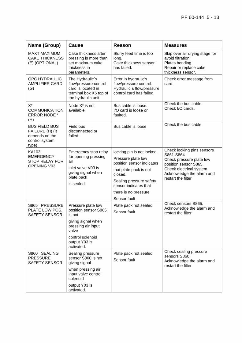
PF 60-144 5 - 13
Name (Group) Cause Reason Measures MAXT MAXIMUM CAKE THICKNESS (E) (OPTIONAL)
Cake thickness after pressing is more than set maximum cake thickness in parameters.
Slurry feed time is too long. Cake thickness sensor has failed.
Skip over air drying stage for avoid filtration. Plates bending. Repair or replace cake thickness sensor.
QPC HYDRAULIC AMPLIFIER CARD (G)
The Hydraulic´s flow/pressure control card is located in terminal box X5 top of the hydraulic unit.
Error in hydraulic's flow/pressure control. Hydraulic´s flow/pressure control card has failed.
Check error message from card.
X* COMMUNICATION ERROR NODE * (H)
Node X* is not available.
Bus cable is loose. I/O card is loose or faulted.
Check the bus cable. Check I/O cards.
BUS FIELD BUS FAILURE (H) (It depends on the control system type)
Field bus disconnected or failed.
Bus cable is loose Check the bus cable
KA103 EMERGENCY STOP RELAY FOR OPENING V03
Emergency stop relay for opening pressing air inlet valve V03 is giving signal when plate pack is sealed.
locking pin is not locked. Pressure plate low position sensor indicates that plate pack is not closed. Sealing pressure safety sensor indicates that there is no pressure Sensor fault
Check locking pins sensors S861-S864. Check pressure plate low position sensor S865. Check electrical system Acknowledge the alarm and restart the filter
S865 PRESSURE PLATE LOW POS. SAFETY SENSOR
Pressure plate low position sensor S865 is not giving signal when pressing air input valve control solenoid output Y03 is activated.
Plate pack not sealed Sensor fault
Check sensors S865. Acknowledge the alarm and restart the filter
S860 SEALING PRESSURE SAFETY SENSOR
Sealing pressure sensor S860 is not giving signal when pressing air input valve control solenoid output Y03 is activated.
Plate pack not sealed Sensor fault
Check sealing pressure sensors S860. Acknowledge the alarm and restart the filter
PF 60-144 6-1
6 SPARE PARTS INFORMATION
PF 60-144 6-2
6 SPARE PARTS INFORMATION ...........................................................................6-1
SPARE PARTS RECOMMENDATION..................................................................6-3
HOW TO ORDER SPARE PARTS........................................................................6-3
STORING INSTRUCTIONS FOR RUBBER PARTS .............................................6-4
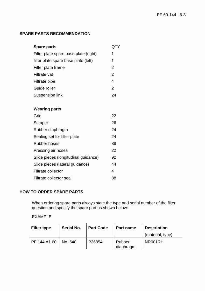
PF 60-144 6-3
SPARE PARTS RECOMMENDATION
Spare parts QTY
Filter plate spare base plate (right) 1
filter plate spare base plate (left) 1
Filter plate frame 2
Filtrate vat 2
Filtrate pipe 4
Guide roller 2
Suspension link 24
Wearing parts
Grid 22
Scraper 26
Rubber diaphragm 24
Sealing set for filter plate 24
Rubber hoses 88
Pressing air hoses 22
Slide pieces (longitudinal guidance) 92
Slide pieces (lateral guidance) 44
Filtrate collector 4
Filtrate collector seal 88
HOW TO ORDER SPARE PARTS
When ordering spare parts always state the type and serial number of the filter question and specify the spare part as shown below:
EXAMPLE
Filter type Serial No. Part Code Part name Description (material, type)
PF 144 A1 60 No. 540 P26854 Rubber diaphragm
NR601RH

PF 60-144 6-4
STORING INSTRUCTIONS FOR RUBBER PARTS
The properties of vulcanized rubber parts change during storing. Careful storing minimizes the damages.
Pay attention to the following:
1. Temperature
The storing temperature should not exceed +25°C, preferably below +15°C.
2. Humidity
Avoid high moisture contents in the surrounding air. Prevent water from condensing on products.
3. Light
Avoid ultraviolet light. Protect the products against straight sunlight.
4. Oxygen and ozone
Remove all equipment developing ozone from the room where products are stored. Minimize the store room ventilation.
5. Deformation
Store rubber and polyurethane parts (diaphragms, plate seals, rollers, scrapers) straight (not rolled) and so that they are free from tension.
6. Solutions and vapours from solvents
Keep the rubber parts off the chemical effect of solutions and solvent vapours.
7. Stock circulation
Try to keep the storing time of rubber parts as short as possible. Always use first the material which has been longest in stock.
In addition, take into consideration the following when storing the rubber parts:
− Coming into contact with certain metals − Compatibility of different rubber qualities − Storing methods used.
For further information refer to standard ISO 2230 and the standard proposal SFS 3553 or contact the manufacturer of the rubber parts.
PF 60-144 7 - 1
7 LOAD CELL MODULE

PF 60-144 7 - 2
CONTENTS 7 LOAD CELL MODULE
Load cell module.....................................................................................................3 Equipment description ......................................................................................3 Hardware installation ........................................................................................4
Important installation notes ...............................................................................................5 Operation instructions.......................................................................................6 Alarms ..............................................................................................................7
Minimum weight alarm ......................................................................................................7 Tare alarm.........................................................................................................................7
Calibration ........................................................................................................8
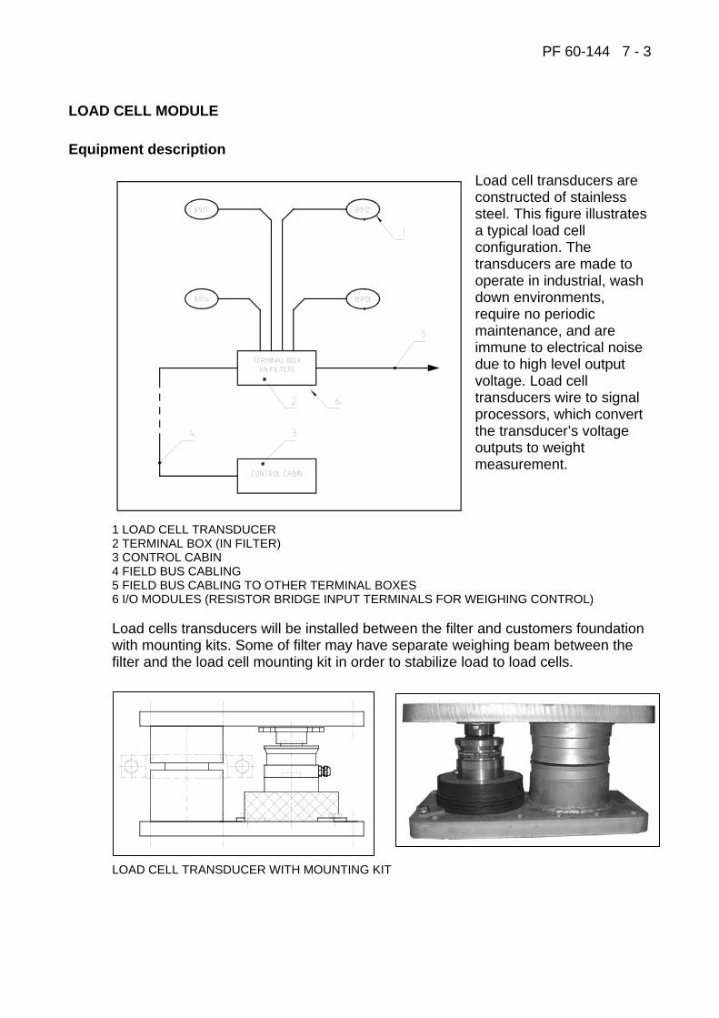
PF 60-144 7 - 3
LOAD CELL MODULE
Equipment description
Load cell transducers are constructed of stainless steel. This figure illustrates a typical load cell configuration. The transducers are made to operate in industrial, wash down environments, require no periodic maintenance, and are immune to electrical noise due to high level output voltage. Load cell transducers wire to signal processors, which convert the transducer’s voltage outputs to weight measurement.
1 LOAD CELL TRANSDUCER 2 TERMINAL BOX (IN FILTER) 3 CONTROL CABIN 4 FIELD BUS CABLING 5 FIELD BUS CABLING TO OTHER TERMINAL BOXES 6 I/O MODULES (RESISTOR BRIDGE INPUT TERMINALS FOR WEIGHING CONTROL) Load cells transducers will be installed between the filter and customers foundation with mounting kits. Some of filter may have separate weighing beam between the filter and the load cell mounting kit in order to stabilize load to load cells.
LOAD CELL TRANSDUCER WITH MOUNTING KIT

PF 60-144 7 - 4
Hardware installation
To achieve the most accurate weight measurement from the load cell transducers, there are factors to consider before installation:
− The surfaces where the base plates bolt down must be flat and horizontal with less than one degree of slope in any direction. Also, the surface must be clean and smooth.
− The foundation on which a filter rests must be of concrete or steel so that it does not allow excessive movement when the weight in the filter changes.
− Shock loads can damage load cells. If the load cell mounting kit can be struck by forklifts, trucks, etc., install protective barriers or stops to prevent vehicles from hitting the mounting kit.
PROCESS CONTROL SYSTEM WITHOUT BEAMS
PROCESS CONTROL SYSTEM WITH BEAMS

PF 60-144 7 - 5
Important installation notes
− During filter installation do not put all filter load on one transducer. − Position load cell transducers so that the transducer cable cannot be snagged
or chafed, and can be easily routed to the terminal box. − In case you need to weld near to the load cell, be sure the ground path is not
trough the load cell. The ground cable should be close to the welding, in between the welding and the load cell, i.e. the welding current must not in any conditions run trough the load cell. Also be careful with the heat. The load cell must always be so cool that you can touch it. Further, it is recommendable to disconnect the wires from the sensor, to avoid a ground loop via the electronics.
− Supporting structures of the pipelines connected to the filter should also carry the load of the filter’s pipelines. After the erection work, the filter’s pipelines are then released from the filter to stay on the supports of the pipelines connected to filter. Also, other vertical supports fixed to the filter, which may affect the process control system, have to be replaced by new supporting structures and disconnected from the filter.
PF 60-144 7 - 6
Operation instructions
The process control system can be separately activated to control FILTRATION, PRESSING and AIR DRYING stages. If the system is not activated, stages are controlled by preset time.
To activate the system to control the filtration stage, set parameter “MAX FILLING WEIGHT (kg)” in parameter screen No. 3. If parameter is Zero, control is not on. Similar parameters are optional for pressing and air drying stages, which are normally not used.
When the process control is activated, filtration (filling the chambers) is controlled by time, weight or maximum pumping pressure. Whatever reaches the set value first, stops filling. The weight setpoint is set into parameter “MAX FILLING WEIGHT (kg)”.
When the process control is activated, pressing is controlled by time and changing speed of the filter weight. Whatever reaches the set value first, stops pressing. The weight changing speed setpoint is set into parameter “WEIGHT CHANGE IN FILTRATION (KG/S)”. Note that this is optional and normally not used.
When the process control is activated, air drying is controlled by time and changing speed of the filter weight. Whatever reaches the set value first, will stop air drying. The weight changing speed setpoint is set into parameter “DRYING STOP WEIGHT CHANGE (kg/s)”. Note that this is optional and normally not used.
To get access to capacity information select REPORT screen and press HISTORY report button in the operator interface panel.
Screen information:
UNIT 1. Production per hour. Cumulative cake weights of the last hour. kg 2. Production per shift. Cumulative cake weights of the current 8 hour period. t 3. Production per day. Cumulative cake weights of the current day. t 4. Production per week. Cumulative cake weights of the current week. t 5. Production per month. Cumulative cake weights of the current month. t 6. Production per year. Cumulative cake weights of the current year. t 7. Total cake production from the start-up of the filter. t
Note: Production per shift is reset according to the shift start time parameters (PARAMETER screen No. 3).
PF 60-144 7 - 7
Alarms
Minimum weight alarm
Cause: Cake weight after pressing is less than minimum cake weight set in parameters.
Reason: Slurry pump is failed. Slurry feed time is too short. Slurry density is too low. Weight sensor or amplifier has failed.
Measures: Skip over air drying stage for avoid filtration plates pending. Repair or replace weight sensor/amplifier.
Tare alarm
Cause: Measured weight is greater than max tare weight after plate pack closing stage.
Reason: Extra mass has been gathered to filter. Weight sensor or amplifier has failed.
Measure: Remove extra mass from filter. Repair or replace weight sensor/amplifier.
Note: If the parameter “ MAX TARE WEIGHT (kg)” is set to zero, the alarm is not in use.
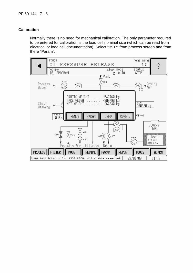
PF 60-144 7 - 8
Calibration
Normally there is no need for mechanical calibration. The only parameter required to be entered for calibration is the load cell nominal size (which can be read from electrical or load cell documentation). Select “B91*” from process screen and from there “Param”.

PF 60-144 7 - 9
Enter load cell nominal size.
In info screen all load cell (each load cell separately) related data (signal, reference voltage, weight) can be monitored:
This screen is only for information to monitor weighing system operation.