Figure 9.1 Conceptual Flow Chart for Sizing Storage Practices

Welcome message from author
This document is posted to help you gain knowledge. Please leave a comment to let me know what you think about it! Share it to your friends and learn new things together.
Transcript

Figure 9.1 Conceptual Flow Chart for Sizing Storage
Practices
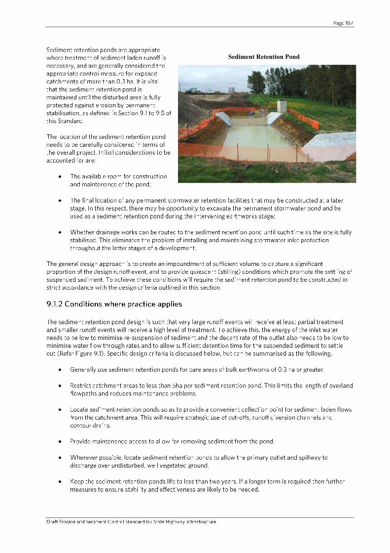
Sediment Retention Pond
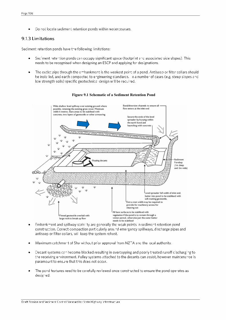
Figure 9.1 Schematic of a Sediment Retention Pond
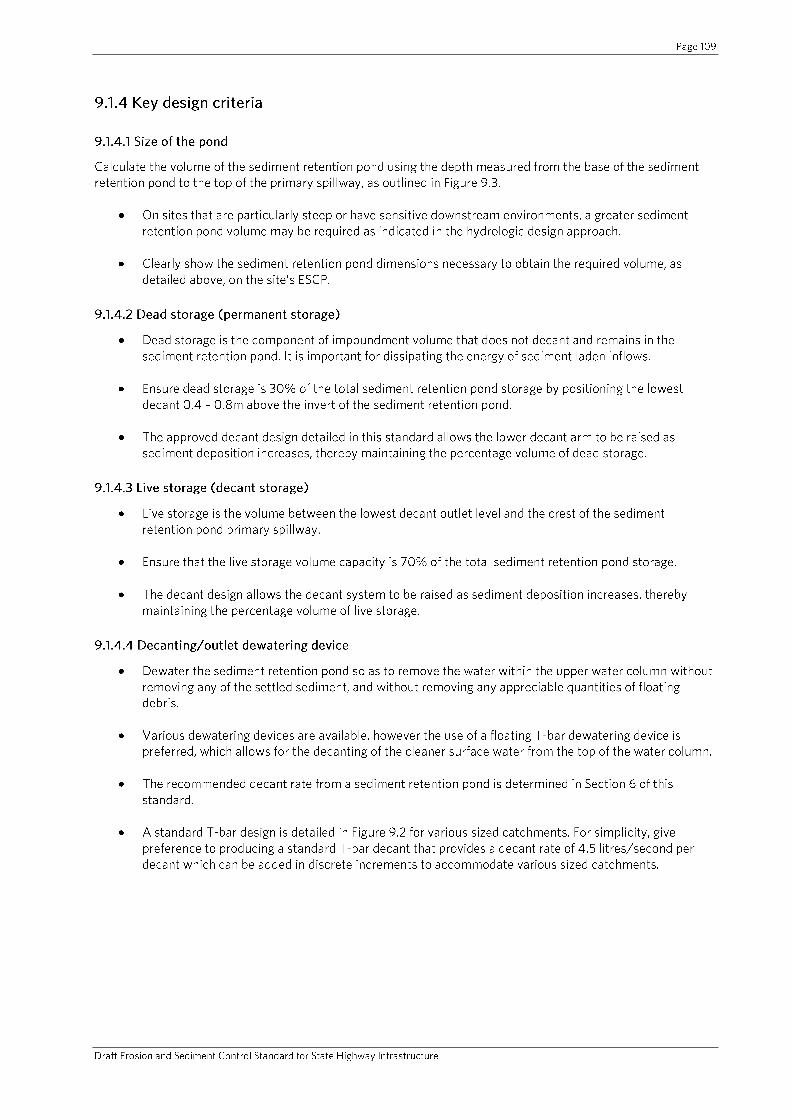
Figure 9.2 Sediment Retention Pond – Decant Detail

Figure 9.3 Sediment Retention Pond for Catchment < 1.5 ha

Figure 9.4 Sediment Retention Pond for Catchments Between 1.5 – 3 ha
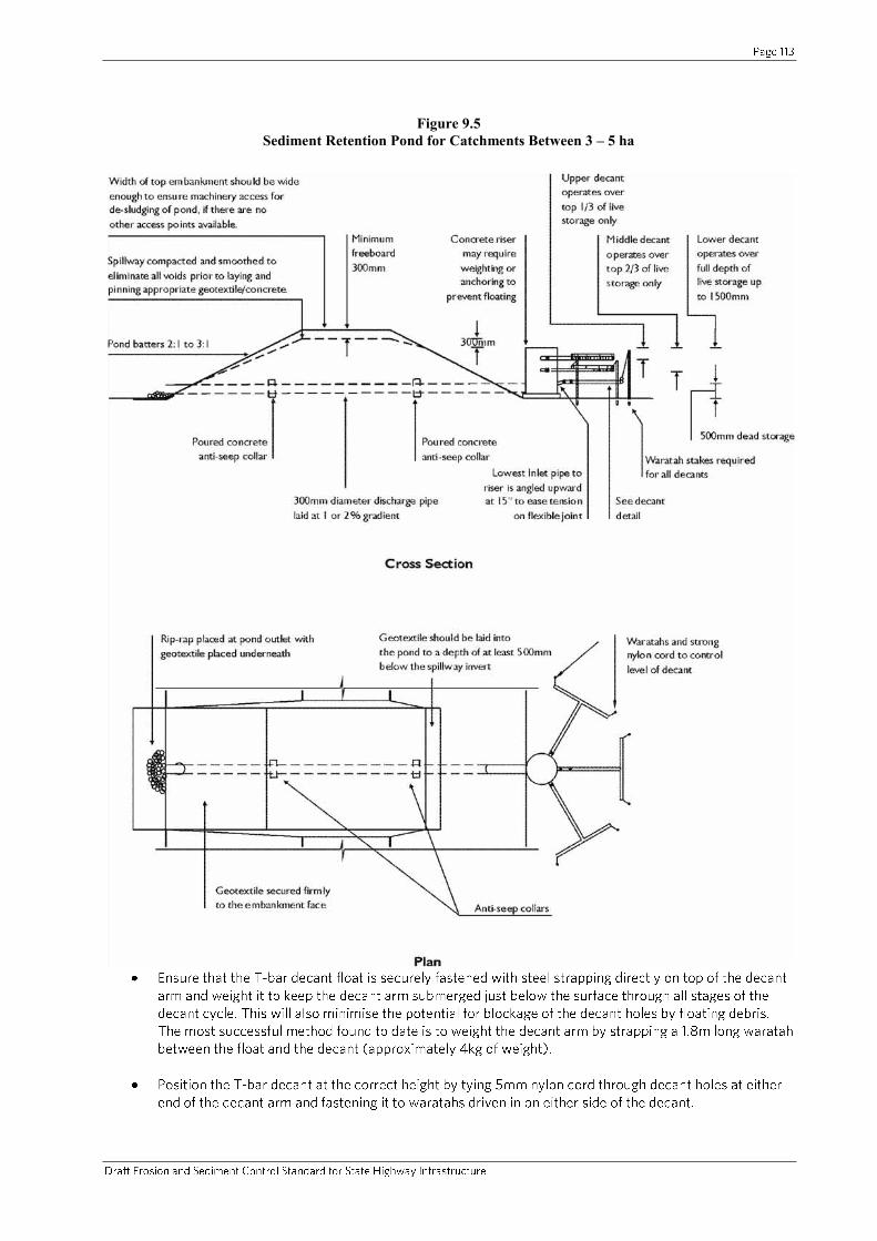
Figure 9.5 Sediment Retention Pond for Catchments Between 3 – 5 ha

-
o
o
-
o
o
o
o
o
o
o
Figure 9.6 Filter Collar Schematic Detail
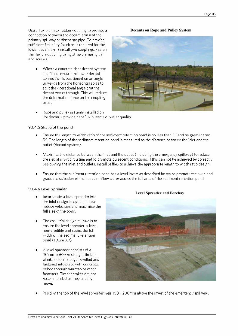
Decants on Rope and Pulley System
Level Spreader and Forebay
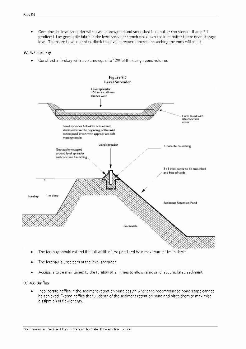
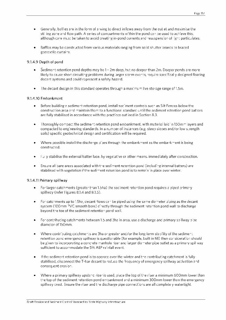
Figure 9.7 Level Spreader

Construction of a Sediment Retention Pond
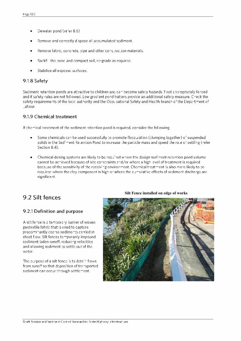
Silt Fence installed on edge of works

-
-
-
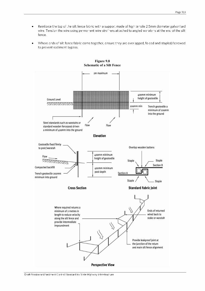
Figure 9.8 Schematic of a Silt Fence
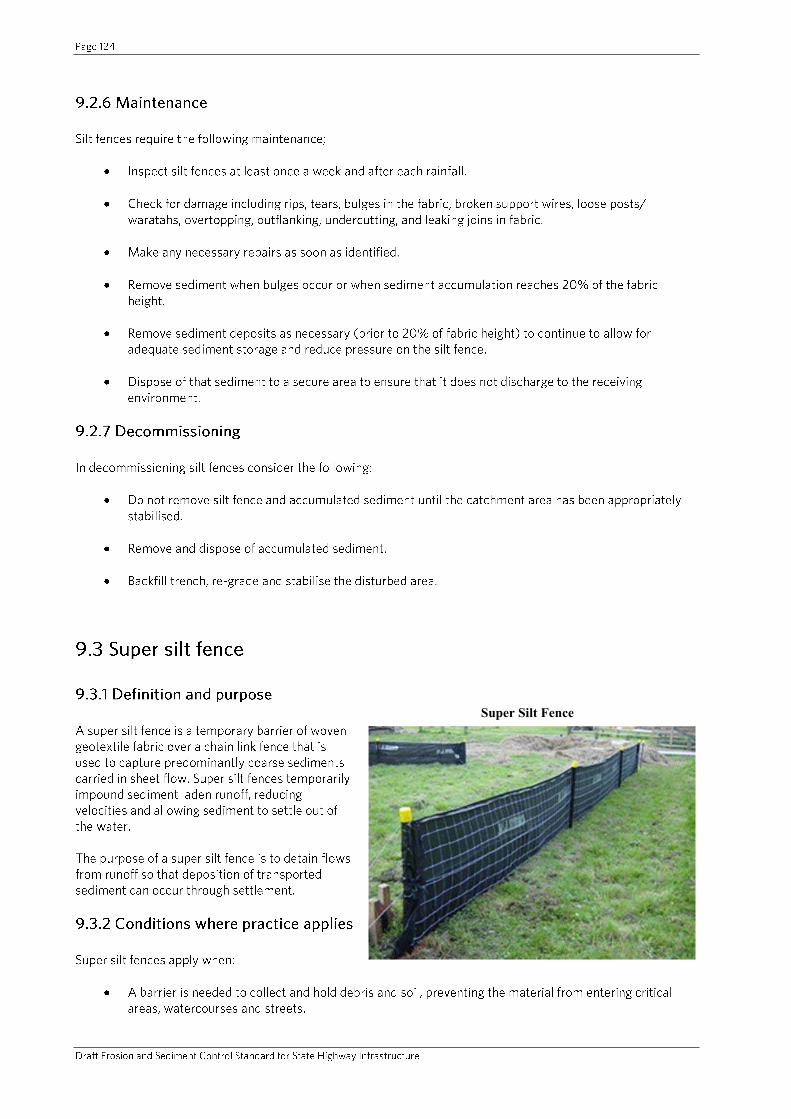
Super Silt Fence

-
-
-


Figure 9.9 Schematic of a Super Silt Fence
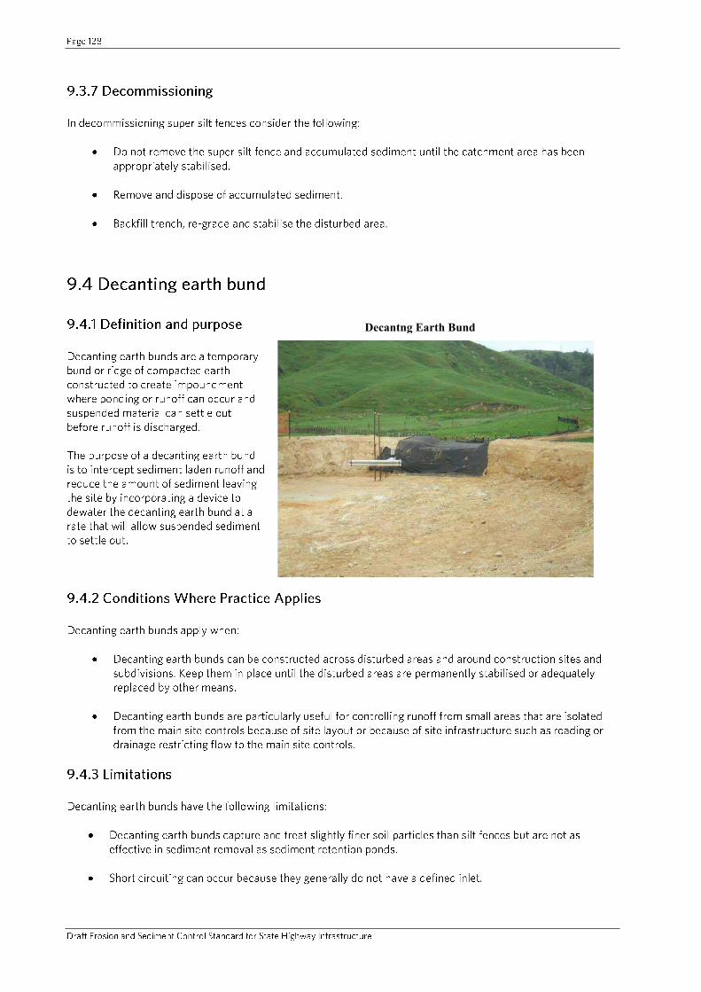
Decantng Earth Bund
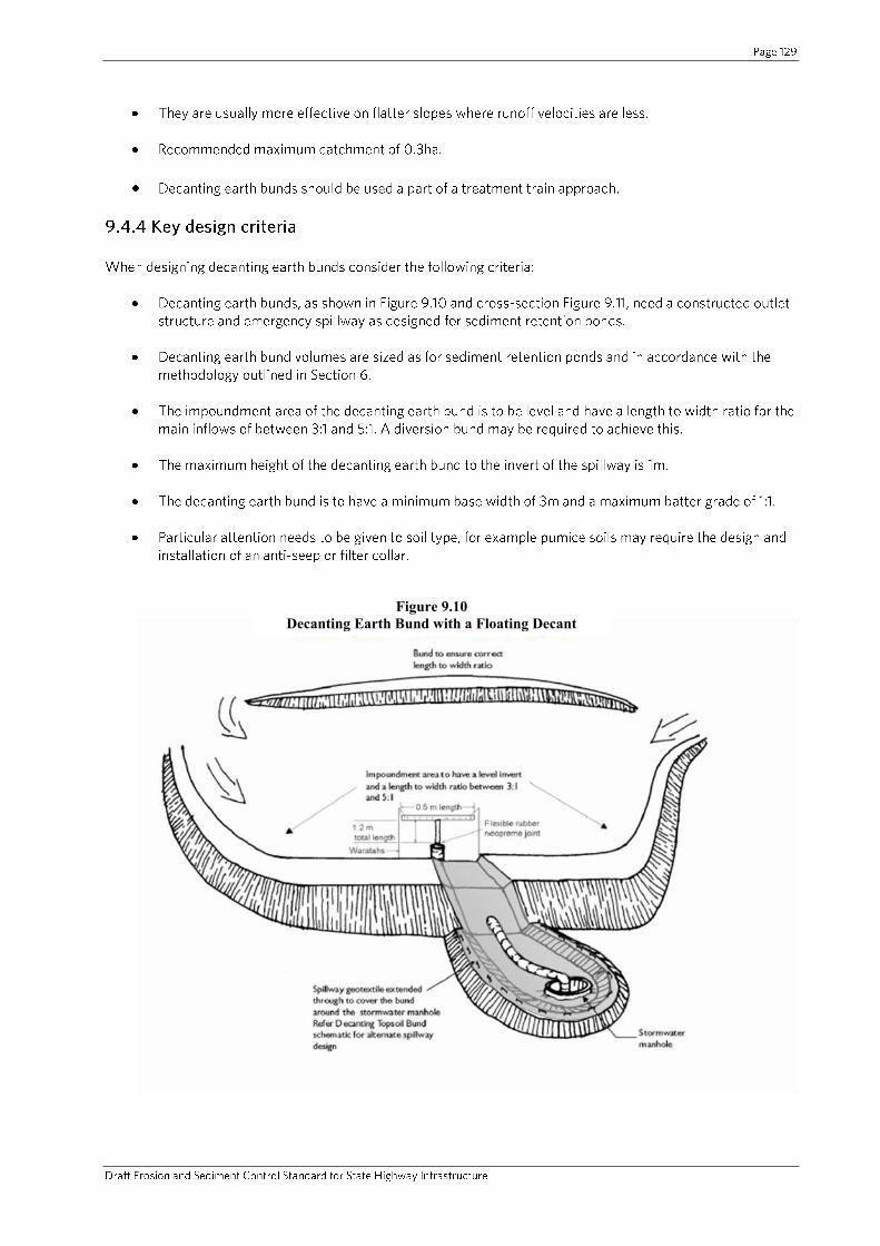
Figure 9.10 Decanting Earth Bund with a Floating Decant
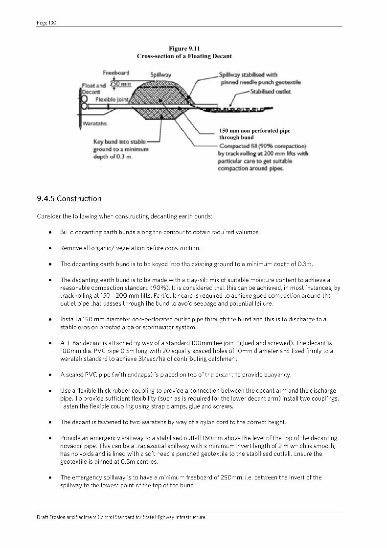
Figure 9.11 Cross-section of a Floating Decant
150 mm non perforated pipe through bund
-
-
-
-
-

-
-
-
-
Rain Activated Flocculant Dosing System

-
-
Figure 9.12 Flocculation System Components
Figure 9.13 Flocculation System Dosing Detail

-
-
-
-
-
-
Figure 9.14 Rainfall Catchment Tray
-
-
-
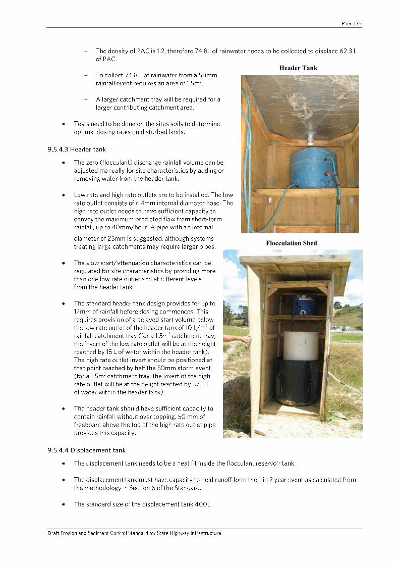
Header Tank
Flocculation Shed
-
-

-
-
-
-
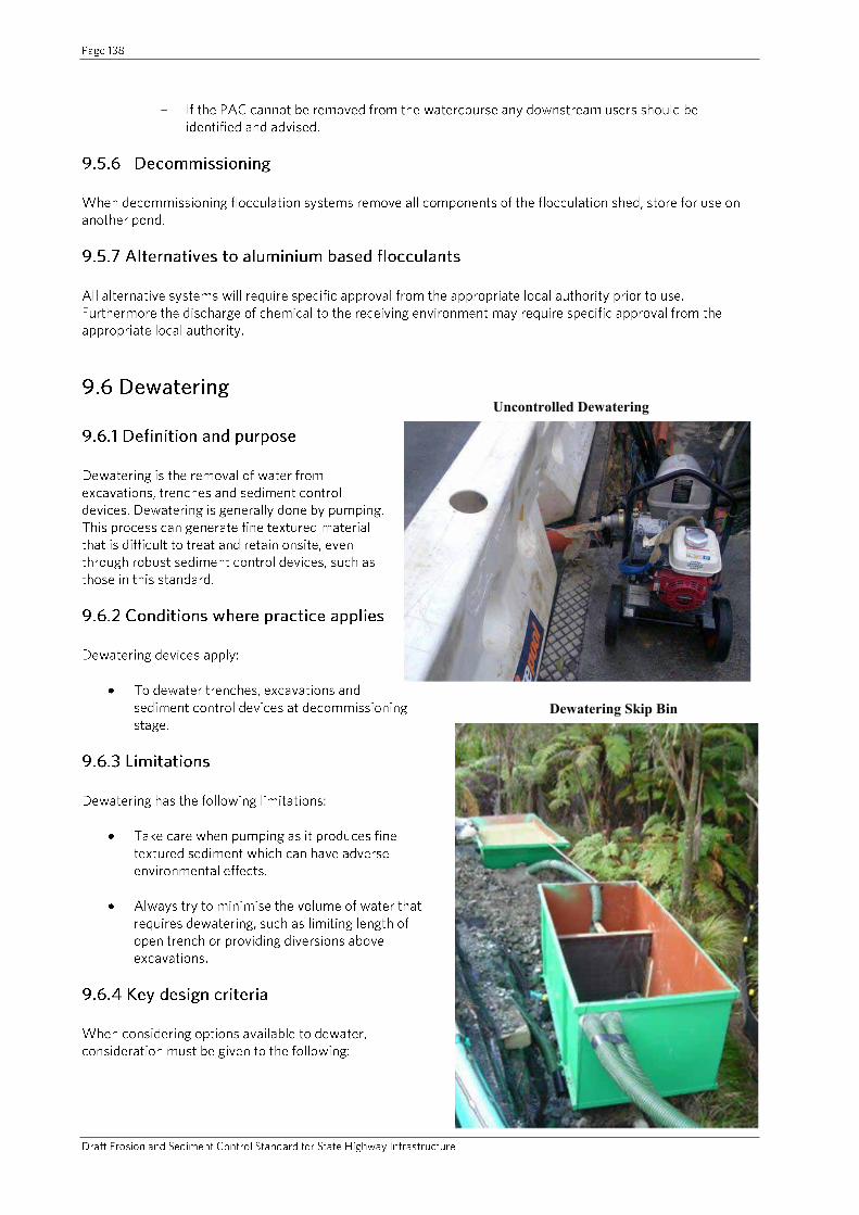
Uncontrolled Dewatering
Dewatering Skip Bin
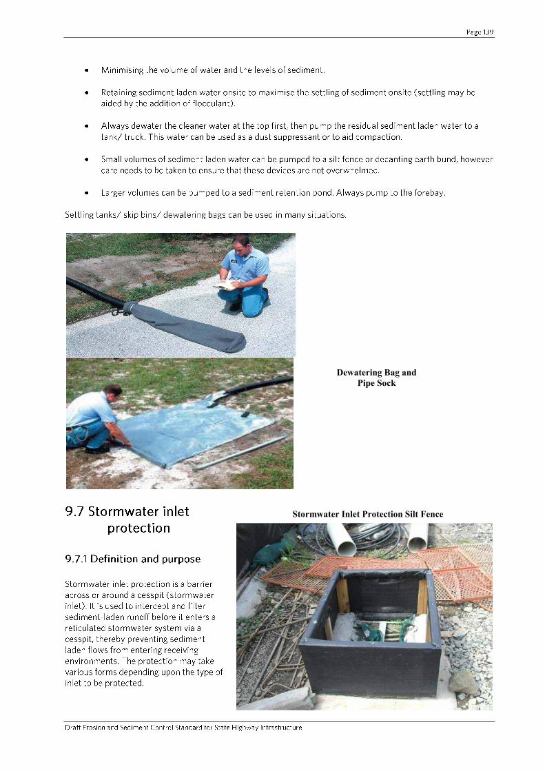
Dewatering Bag and Pipe Sock
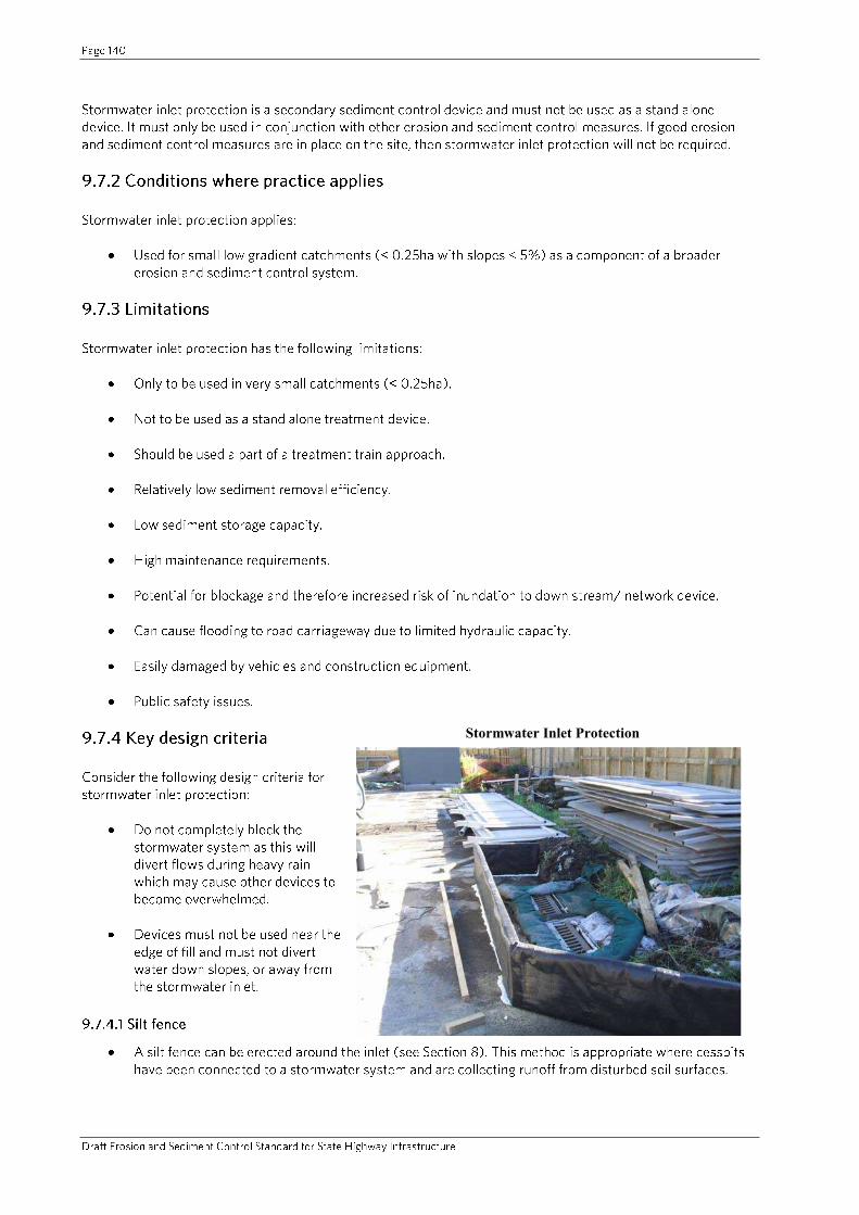
Stormwater Inlet Protection Silt Fence
Stormwater Inlet Protection
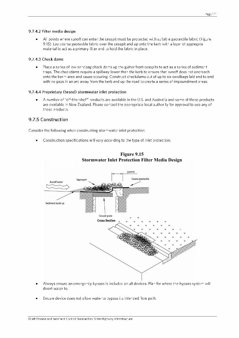
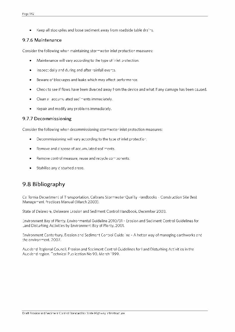
Figure 9.15 Stormwater Inlet Protection Filter Media Design
Related Documents