Ch 24. Geometric Optics Fig. 24–3 A point source of light P and its image P, in a plane mirror. Angle of incidence =angle of reflection.

Welcome message from author
This document is posted to help you gain knowledge. Please leave a comment to let me know what you think about it! Share it to your friends and learn new things together.
Transcript

text conceptCh 24. Geometric Optics
Fig. 24–3 A point source of light P and its image P, in a plane mirror. Angle of incidence =angle of reflection.

text ..
Fig. 24–5 Observer O sees the imageat point P, but observer O does notsee the image.
Fig. 24–4 The blue dashed line through object point P is perpendicular to the plane of amirror. The extension of any reflected light ray behind the mirror intersects this line at a pointP. Because the angle of reflection equals the angle of incidence, P is the same distance d fromthe mirror plane as the object point. This conclusion is valid for any light ray at any angle ofincidence. Thus all reflected rays appear to be coming from P
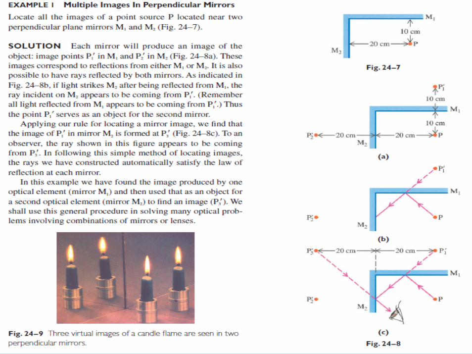
text Ex-1.

text ..Fig. 24–10 (a) A concave mirror.(b) A convex mirror.
(a) Parallel rays from a distant point source are reflected by a concave mirror and converge toform a real image. The distant object point is on the optical axis, a line perpendicular to thecenter of the reflecting surface. The image point F is called the focal point. The distance f fromthe mirror to the focal point is called the focal length. The center of curvature C is thecenter of the spherical reflecting surface.

text ..
(b) A point object at P a distance s from the mirror produces a real image at P a distance sfrom the mirror. In this drawing the incident and reflected rays at the top of the mirror make asmaller angle than in the preceding drawing. The object is closer to the mirror and the imageis farther away than in (a).

text ..
(c) The object P is at the same point occupied by the image in (b). Therefore the incident raysare just the reverse of the reflected rays in (b). The law of reflection then predicts that thereflected rays here will be the reverse of the former incident rays. The paths of the rays in bothfigures are the same, but the directions of the rays are opposite. This means that object andimage points are interchanged. This result is an example of a general principle, the principle ofoptical reversibility: One may always interchange an object and an image, reversingthe directions of all rays. This principle applies to both reflection and refraction and followsfrom the fact that the laws of reflection and refraction do not involve the direction of light rays.

text ..
(d) The object is placed at the focal point F. Applying the principle of optical reversibility to (a),where F was an image point, we find that the image here is at infinity, the location of the objectpoint in (a).
(e) When the object is placed inside the focal point, the incident and reflected rays form largerangles, and the reflected rays no longer intersect. Instead the reflected rays diverge from apoint P behind the mirror, forming a virtual image as in the case of a plane mirror.

text ..Fig. 24–12 Light rays diverging from object point P are reflected from a concave mirror andconverge at image point P. The image distance s depends on the object distance s and on themirror’s radius of curvature.
Fig. 24–13 Exterior angle '4 equals thesum of the two opposite interior angles,'1 and '2.

text conceptCh 24. Geometric Optics

text concept.

text .spherical mirror.
Fig. 24–14 (a) Rays from a distant pointsource on the optical axis are incident on aspherical mirror. Only paraxial rays convergeat the focal point.
(b) For a parabolic mirror all rays from a distant point source on the optical axis converge at the focal point.

text ..
Fig. 24–15 Derivation of an equation to locate the virtual image formed by a concave mirror when an object is inside the mirror’s focal point. If we take the image distance s to be negative, we obtain the same equation used for a real image.
Fig. 24–16 A virtual object point P. Lightrays converging toward P are interruptedby a mirror before reaching that point.

text ..
Fig. 24–17 (a) A lens forms a real image. (b) A concave mirror is placed in front of the image,which then serves as a “virtual” object for the mirror. The mirror image of this object is formedin front of the mirror.

text ..
Fig. 24–18 Image formation by a convex mirror.
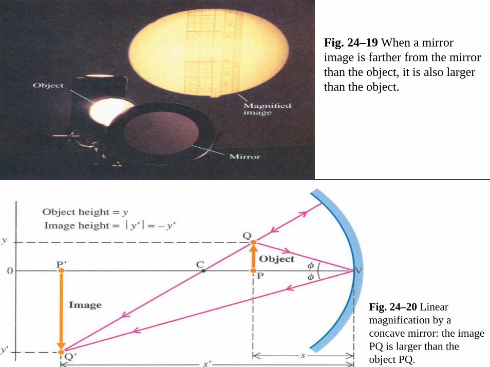
text ..Fig. 24–19 When a mirror image is farther from the mirror than the object, it is also larger than the object.
Fig. 24–20 Linear magnification by a concave mirror: the image PQ is larger than the object PQ.

text Ex-3.

text ..
Real object, real image
Real object, virtual image
Convex mirrors
Concave mirrors
Real object, virtual image
Virtual object, virtual image
NOT POSSIBLE

text Ex-4.

text Ex-5.

text ..(a) Convex converging surface (b) Concave converging surface
(c) Concave diverging surface (d) Convex diverging surface
Fig. 24–25 Determination of a surface as converging or diverging follows from the rule thatrays transmitted into a higher-index medium bend toward the normal, and rays transmitted intoa lower-index medium bend away from the normal.

text concept.
text concept.

text .lens.
(a) Converging lens
(b) Converging lens
(c) Diverging lens
(d) Diverging lens
Fig. 24–26 Spherical lenses.

text ..
Fig. 24–27 Refraction at a spherical surface produces an image at P of an object at P

text Ex-6.

text ..
Fig. 24–30 The image formed by alens’s first surface serves as an objectfor its second surface.
text ..
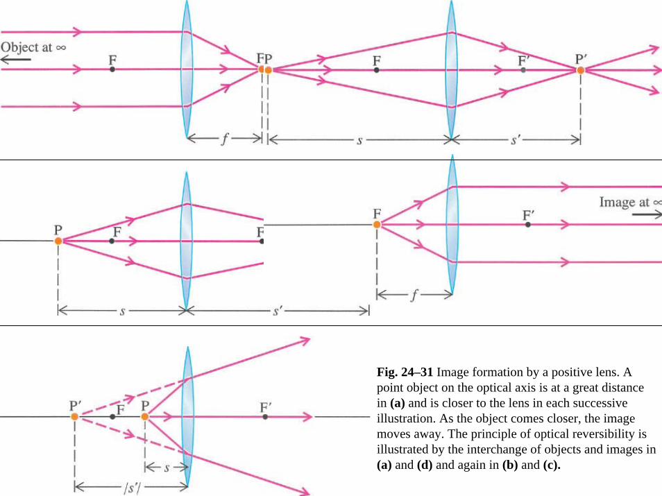
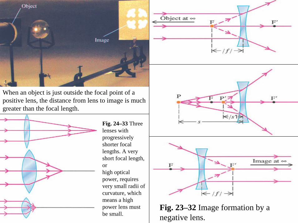
Fig. 24–31 Image formation by a positive lens. A point object on the optical axis is at a great distance in (a) and is closer to the lens in each successive illustration. As the object comes closer, the image moves away. The principle of optical reversibility isillustrated by the interchange of objects and images in (a) and (d) and again in (b) and (c).
text ..
When an object is just outside the focal point of a positive lens, the distance from lens to image is much greater than the focal length.
Fig. 23–32 Image formation by a negative lens.
Fig. 24–33 Three lenses with progressively shorter focal lengths. A very short focal length, orhigh optical power, requires very small radii of curvature, which means a high power lens mustbe small.

text Ex-7.

text Ex-7.

text Ex-8.

text ..
Fig. 24–36 Derivation of the magnification equation for a real image of a real object. The raystriking the center of the lens passes straight through. This section of the lens is approximatelylike a flat, thin sheet of glass and, as seen in Example 4, Chapter 23, will not change the directionof the incident ray.

text Ex-9.

text Ex-9.
text ..
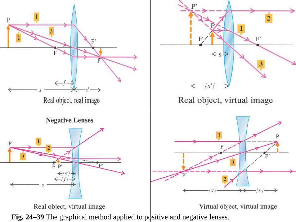
Fig. 24–39 The graphical method applied to positive and negative lenses.

text Ex-10.

text Ex-10.

text ..
Fig. 24–41 Chromatic aberration, illustrated in (a) and (b), is caused by dispersion of light in glass, a prismlike effect. The amount of dispersion depends on the kind of glass used for the lens. The negative lens in (b) uses a glass with greater dispersion (a larger variation in n) than the positive lens in (a), but because the shape of the negative lens results in less refraction (a longer focal length), the angular spread of the spectrum for the two lenses is the same. Thus combining the lenses, as shown in (c), results in a positive-focal-length lens, which displays no dispersion. Such a combination is called an “achromatic doublet.” Illustrations (a) and (b) show an exaggerated amount of dispersion, about 20 times that of typical glass.
text ..
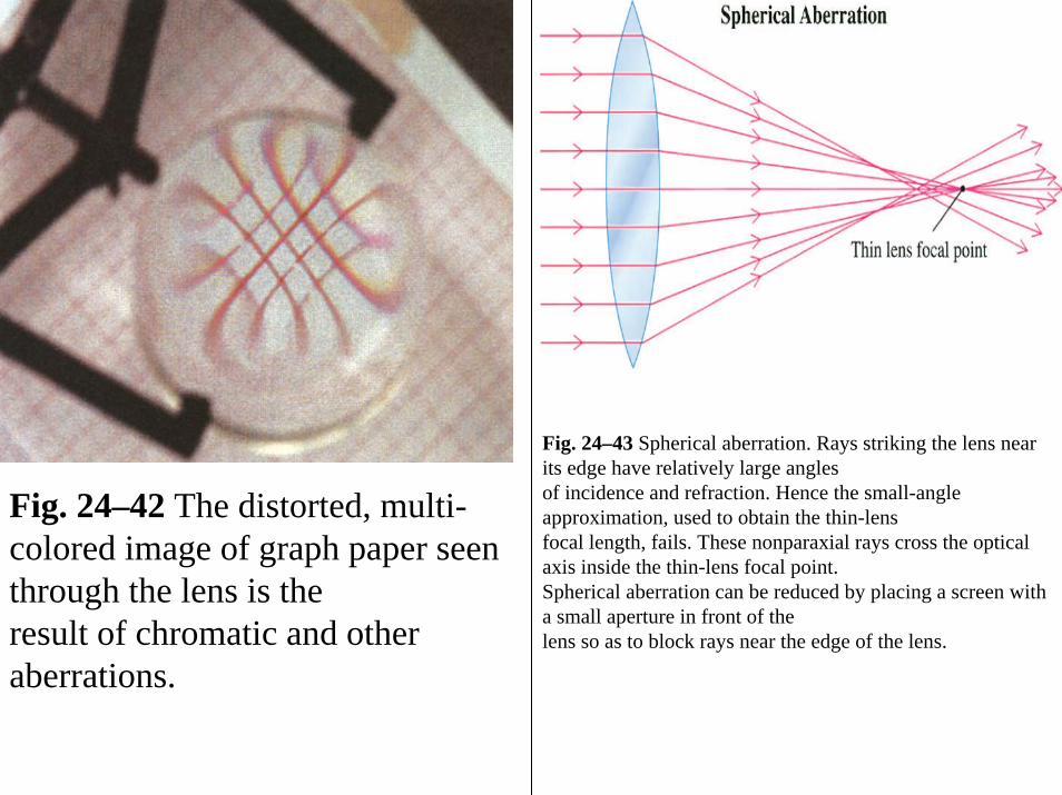
Fig. 24–42 The distorted, multi-colored image of graph paper seen through the lens is theresult of chromatic and other aberrations.
Fig. 24–43 Spherical aberration. Rays striking the lens near its edge have relatively large anglesof incidence and refraction. Hence the small-angle approximation, used to obtain the thin-lensfocal length, fails. These nonparaxial rays cross the optical axis inside the thin-lens focal point.Spherical aberration can be reduced by placing a screen with a small aperture in front of thelens so as to block rays near the edge of the lens.

text ..
Fig. 24–44 Light rays diverging from object point P are refracted by a convex spherical surfaceand converge at image point P. The image distance sdepends on the object distance s, on theradius of curvature R, and on the refractive indices n and n

text ---.
Related Documents


