CM119A High Integration/Low Cost USB Audio Controller www.cmedia.com.tw Copyright © C-Media Electronics Inc. Rev. 2.1 ︱ Page 1/33 USB TRX USB interface 4 byte FIFO USB control processing ISO out processing ( with x2 mod) PLL1 48 MHz ROM PLL2 12. 288/11. 2896 MHz with adjustment 12 MHz VREF (2.25V) power on reset reset 16 bit DAC bandgap 3.3V + - + - Vref 5 - > 3. 3 regulator REGV ISO in processing 300 x 16 SRAM 16 bit Sigma- Delta ADC 16 bit DAC + - Vref +22.5~ - 0 dB 16 steps Vref PLL3 12.288/ 11. 2896 MHz USB interrupt processing with 4 byte FIFO interface logics MUTER MCU I/F VOLDN VOLUP VREF MUTEP LOL LOR LEDO LEDR PDSW + - +22. 5 ~ 0 dB 16 steps Vref 0 ~ -45dB 38 steps voltage linear VBIAS 4.5 V ( drive typ 4mA) EEPROM interface CS SK DW DR USBDP USBDM XI XO MICIN + - Vref Vref + - + - Vref LOBS GPIO BOOST +20 dB boost enable 0 ~ -45dB 38 steps voltage linear PWRSEL MODE SEL pins TEST sync by VPR_CLK sync by VPL_CLK BUZZ SPDIFO High-Pass Filter BLOCK DIAGRAM DESCRIPTION CM119A is a highly integrated single chip USB audio controller specifically for VoIP (Voice over internet protocol) application. All essential analog modules are embedded in CM119A, including dual DAC and earphone driver, ADC, microphone booster, PLL, regulator, and USB transceiver. It’s also support 8GPIO pins and buzzer output pin for VoIP application. In addition, audio adjustment can be easily controlled via specific HID compliant volume control pins. Many features are programmable with jumper pins or external EEPROM. Vender can customize unique USB VID / PID / Product_String / Manufacture_String to EEPROM for VoIP software authentication. Moreover, individual unique phone number for each device is possible via serial number stored in external EEPROM. FEATURES Compliant with USB 2.0 Full Speed Operation Compliant with USB Audio Device class specification v1.0 Supports USB Suspend/Resume Mode and remote Wakeup with Volume Control pins Single 12MHz Crystal input with on-chip PLL and embedded USB transceiver Jumper Pin for Speaker Mode (Playback Only) or Headset Mode (Playback + Recording) For Headset Mode, USB audio function topology has 2 Input Terminals, 2 Output Terminals, 1 Mixer Unit, 1 Selector Unit, and 3 Feature Units Jumper Pin for Operation System Mixer Unit Enable/Disable under Headset Mode

Welcome message from author
This document is posted to help you gain knowledge. Please leave a comment to let me know what you think about it! Share it to your friends and learn new things together.
Transcript

CM119A High Integration/Low Cost USB Audio Controller
www.cmedia.com.tw Copyright © C-Media Electronics Inc. Rev. 2.1 ︱ Page 1/33
USB
TRX
USB
interface
4 byte
FIFO
USB control
processing
ISO out
processing
( with x2 mod)
PLL148 MHz
ROM
PLL2
12. 288 /11. 2896 MHz
with adjustment
12 MHz
VREF
(2.25V)
power on
reset
reset
16 bit
DAC
bandgap
3.3V
+
-
+-
Vref
5 - > 3. 3
regulator
REGV
ISO in
processing
300 x 16 SRAM
16 bit Sigma-
Delta ADC
16 bit
DAC
+
-
Vref
+22.5~ - 0 dB
16 steps
Vref
PLL3 12.288/
11. 2896 MHz
USB interrupt
processing with 4
byte FIFO
interface logics
MUTER MCU
I/F
VOLDN
VOLUP
VREF
MUTEP
LOL
LOR
LEDO
LEDR
PDSW
+
-
+22. 5 ~ 0 dB
16 steps
Vref
0 ~ -45dB
38 steps
voltage linear
VBIAS4.5 V ( drive typ 4mA)
EEPROM
interface
CS
SK
DW
DR
USBDP
USBDM
XI
XOMICIN
+-
Vref
Vref+-
+-
Vref
LOBS
GPIO
BOOST
+20 dB boost enable
0 ~ -45dB
38 steps
voltage linear
PWRSEL
MODE
SEL pins
TEST
sync by
VPR_CLK
sync by
VPL_CLK
BUZZ SPDIFO
High-Pass Filter
BLOCK DIAGRAM
DESCRIPTION
CM119A is a highly integrated single chip USB audio
controller specifically for VoIP (Voice over internet
protocol) application. All essential analog modules
are embedded in CM119A, including dual DAC and
earphone driver, ADC, microphone booster, PLL,
regulator, and USB transceiver. It’s also support
8GPIO pins and buzzer output pin for VoIP
application. In addition, audio adjustment can be
easily controlled via specific HID compliant volume
control pins. Many features are programmable with
jumper pins or external EEPROM. Vender can
customize unique USB VID / PID / Product_String /
Manufacture_String to EEPROM for VoIP software
authentication. Moreover, individual unique phone
number for each device is possible via serial
number stored in external EEPROM.
FEATURES
Compliant with USB 2.0 Full Speed Operation
Compliant with USB Audio Device class
specification v1.0
Supports USB Suspend/Resume Mode and remote
Wakeup with Volume Control pins
Single 12MHz Crystal input with on-chip PLL and
embedded USB transceiver
Jumper Pin for Speaker Mode (Playback Only) or
Headset Mode (Playback + Recording)
For Headset Mode, USB audio function topology
has 2 Input Terminals, 2 Output Terminals, 1
Mixer Unit, 1 Selector Unit, and 3 Feature Units
Jumper Pin for Operation System Mixer Unit
Enable/Disable under Headset Mode

CM119A High Integration/Low Cost USB Audio Controller
www.cmedia.com.tw Copyright © C-Media Electronics Inc. Rev. 2.1 ︱ Page 2/33
TABLE OF CONTENTS
1 Description and Overview ..................................................................... 3
2 Features .......................................................................................... 3
3 Pin/Signal Description .......................................................................... 5
3.1 Pin Assignment by Pin Number ................................................................................. 5
3.2 Pin-Out Diagram .................................................................................................. 5
3.3 Pin Signal Description ........................................................................................... 6
4 MCU Interface.................................................................................... 8
5 Block Diagram ................................................................................... 8
6 Ordering Information ........................................................................... 9
7 Function Description........................................................................... 10
7.1 USB Interface .................................................................................................... 10
7.1.1 Device Descriptor .............................................................................................. 10
7.1.2 Configuration Descriptor ...................................................................................... 11
7.1.3 Content Format for 93C46 .................................................................................... 12
7.1.4 USB Audio Topology Diagram ................................................................................. 13
7.2 Jumper Pins and Mode Setting: ............................................................................... 14
7.3 HID Feature and Descriptions ................................................................................. 14
7.3.1 HID Descriptor .................................................................................................. 15
7.3.2 Windows Software Architecture for HID .................................................................... 16
7.4 Internal Registers ............................................................................................... 16
7.4.1 Access via HID Class Command: .............................................................................. 17
7.4.2 Access via External Serial Interface by MCU: .............................................................. 20
7.4.3 Indirect Accessed Registers: .................................................................................. 22
7.5 MCU Interface .................................................................................................... 23
7.6 Buzzer Output ................................................................................................... 27
8 Electrical Characteristics ..................................................................... 28
8.1 Absolute Maximum Rating ..................................................................................... 28
8.2 Operation Conditions ........................................................................................... 28
8.3 Electrical Parameters ........................................................................................... 29
9 Frequency Response Graphs .................................................................. 30
9.1 Line Out Freq Response @ 48KHz Sample Rate (10K Ohm Loading) .................................... 30
9.2 Line Out THD+N @ 48KHz sample rate (10K Ohm Loading) .............................................. 30
9.3 Microphone Input Freq Response @ 48KHz Sample Rate ................................................. 31
9.4 Microphone InP put THD+N @ 48KHz Sample Rate ........................................................ 31
Reference ............................................................................................. 32

CM119A High Integration/Low Cost USB Audio Controller
www.cmedia.com.tw Copyright © C-Media Electronics Inc. Rev. 2.1 ︱ Page 3/33
1 Description and Overview
CM119A is a highly integrated single chip USB audio controller specifically for VoIP (Voice over internet
protocol) application. All essential analog modules are embedded in CM119A, including dual DAC and earphone
driver, ADC, microphone booster, PLL, regulator, and USB transceiver. It’s also support 8GPIO pins and buzzer
output pin for VoIP application. In addition, audio adjustment can be easily controlled via specific HID
compliant volume control pins. Many features are programmable with jumper pins or external EEPROM.
Vender can customize unique USB VID / PID / Product_String / Manufacture_String to EEPROM for VoIP
software authentication. Moreover, individual unique phone number for each device is possible via serial
number stored in external EEPROM. Moreover, CM119A provided I2C interface with MCU application for LCM
integrated and advanced functions.
VoIP applications are becoming increasing popular as VoIP can provide free or low-cost calling worldwide. To
provide a VoIP experience that is the same as using a regular phone and eliminate the poor call quality that
results from using the PC audio, C-Media has developed CM119A USB Controller that enables a regular phone,
handset, or headset which is interfaced to the USB port on the PC. With the C-Media OEMs can quickly bring to
market a family of low cost high quality VoIP products.
2 Features
Compliant with USB 2.0 Full Speed Operation
Compliant with USB Audio Device class specification v1.0
Supports USB Suspend/Resume Mode and remote Wakeup with Volume Control pins
Single 12MHz Crystal input with on-chip PLL and embedded USB transceiver
Jumper Pin for Speaker Mode (Playback Only) or Headset Mode (Playback + Recording)
For Headset Mode, USB audio function topology has 2 Input Terminals, 2 Output Terminals, 1 Mixer Unit, 1
Selector Unit, and 3 Feature Units
Jumper Pin for Operation System Mixer Unit Enable/Disable under Headset Mode
For Speaker Mode, USB audio function topology has 1 Input Terminal, 1 Output Terminal, and 1 Feature
Unit
Support one Control Endpoint, one Isochroous out Endpoint, one Isochroous in Endpoint, and one Interrupt
in Endpoint
Alternate zero bandwidth setting for releasing playback bandwidth on USB Bus when this device is inactive
Volume up, volume down, and playback mute support USB HID for Host Control Synchronization
Record Mute Pin with LED Indicator for Record Mute Status
External EEPROM Interface for Vendor Specific USB VID, PID, Product String, Manufacture String, and
Serial Number
Supports AES/EBU, IEC60958, S/PDIF Consumer Formats for Stereo PCM Data at S/PDIF Output
CM119A High Integration/Low Cost USB Audio Controller
www.cmedia.com.tw Copyright © C-Media Electronics Inc. Rev. 2.1 ︱ Page 4/33
8 GPIO Pins with Read/Write via HID
Embedded Buzzer Function controlled by Register
Support I2C Interface for External MCU Integrated
Jumper Pin for Power Mode Setting
Isochronous transfer uses Adaptive Mode with Internal PLL for Synchronization
48K / 44.1KHz Sampling Rate for both Playback and Recording
Soft Mute Function
Embedded High Performance 16 bit audio DAC with Earphone Phone Buffer
Host side data loss noise reduction function
Embedded 16 bit ADC input with Microphone Boost
Embedded power on Reset Block
Embedded 5V to 3.3V regulator for single External 5V Operation
Compatible with Win 2000 / Win XP / Win Vista / Win 7 and Mac OS X without Additional Driver
48 Pin LQFP Package
Optional Hardware SDK tool for third-party software or soft-phone development

CM119A High Integration/Low Cost USB Audio Controller
www.cmedia.com.tw Copyright © C-Media Electronics Inc. Rev. 2.1 ︱ Page 5/33
3 Pin/Signal Description
3.1 Pin Assignment by Pin Number
Pin # Signal Name Pin # Signal Name Pin # Signal Name Pin # Signal Name
1 SPDIFO 13 GPIO3 25 VBIAS 37 REGV
2 DW 14 DVSS1 26 VREF 38 MSEL
3 DR 15 GPIO4 27 MICIN 39 VOLUP
4 SK 16 GPIO5 28 N.C. 40 PDSW
5 CS 17 GPIO6 29 AVDD1 41 USBDP
6 MUTER 18 MUTEP 30 LOL 42 USBDM
7 PWRSEL 19 BUZZ 31 LOBS 43 GPIO1
8 XI 20 GPIO7 32 LOR 44 SCLK
9 XO 21 LEDR 33 AVSS2 45 MINT
10 MODE 22 GPIO8 34 AVDD2 46 SDAT
11 GPIO2 23 TEST 35 DVDD 47 MCLK
12 LEDO 24 AVSS1 36 DVSS2 48 VOLDN
3.2 Pin-Out Diagram
CM119A
LQFP-48
1 2 3 4 5 6 7 8 9 10
11
12
SPDIFO
DW DR
SK
CS
MUTER
PWRSEL XI
XO
MODE
GPIO2
LEDO
36
35
34
33
32
31
30
29
28
27
26
25
24
23
22
21
20
19
18
17
16
15
14
13
AVSS1
TEST
GPIO8
LEDR
GPIO7
BUZZ
MUTEP
GPIO6
GPIO5
GPIO4
DVSS1
GPIO3
37
38
39
40
41
42
43
44
45
46
47
48
REGV
MSEL
VOLUP
PDSW
USBDP
USBDM
GPIO1
SCLK
MINT
SDAT
MCLK
VOLDN
DVSS2
DVDD
AVDD2
AVSS2
LOR
LOBS
LOL
AVDD1
N.C.
MICIN
VREF
VBIAS
Pin Assignments ( Top View)

CM119A High Integration/Low Cost USB Audio Controller
www.cmedia.com.tw Copyright © C-Media Electronics Inc. Rev. 2.1 ︱ Page 6/33
3.3 Pin Signal Description
Pin # Symbol Type Description
1 SPDIFO DO, 8mA, SR SPDIF Output
2 DW DIO, 8mA, PD, 5VT USB Controller Data Read From EEPROM Interface. EEPROM Data Output.
3 DR DO, 4mA, SR USB Controller Data Writes to EEPROM Interface. EEPROM Data Input.
4 SK DO, 4mA, SR EEPROM Interface Clock (100KHz)
5 CS DO, 4mA, SR EEPROM Interface Chip Select
6 MUTER DI, ST, PU Mute Recording (Edge Trigger with de-Bouncing)
7
PWRSEL
DI, ST
H: Pull Up to 3.3V; L: Pull Down to Ground
Speaker Mode H:Self Power with 100mA;L:Bus Power with 500mA Headset
Mode H:Bus Power with 100mA;L:Bus Power with 500mA
8 XI DI Input Pin for 12MHz Oscillator
9 XO DO Output Pin for 12MHz Oscillator
10 MODE DI, ST H: Pull Up to 3.3V; L: Pull Down to Ground L:Headset Mode: Playback &
Recording H:Speaker Mode: Playback Only
11 GPIO2 DIO, 8mA, PD, 5VT GPIO Pin
12 LEDO DO, SR, 8mA LED for Operation; Output H for Power On; Toggling for Data Transmit
13 GPIO3 DIO, 8mA, PD, 5VT GPIO Pin
14 DVSS1 P Digital Grounding
15 GPIO4 DIO, 8mA, PD, 5VT GPIO Pin
16 GPIO5 DIO, 8mA, PD, 5VT GPIO Pin
17 GPIO6 DIO, 8mA, PD, 5VT GPIO Pin
18 MUTEP DI, ST, PU Mute Playback (Edge Trigger with de-Bouncing)
19 BUZZ DO, 8mA, SR Buzzer Output Pin
20 GPIO7 DIO, 8mA, PD, 5VT GPIO Pin
21 LEDR DO, SR, 8mA LED for Mute Recording Indicator; Output H when Recording is Muted
22 GPIO8 DIO, 8mA, PD, 5VT GPIO Pin
23 TEST DI, ST, PD Test Mode Select Pin; Pull Low for Normal Operation
24 AVSS1 P Analog Ground
25 VBIAS AO Microphone Bias Voltage Supply (4.5V)
26 VREF AO Connecting to External Decoupling Capacitor for Embedded Bandgap
Circuit; 2.25V Output 27 MICIN AI Microphone Input
CM119A High Integration/Low Cost USB Audio Controller
www.cmedia.com.tw Copyright © C-Media Electronics Inc. Rev. 2.1 ︱ Page 7/33
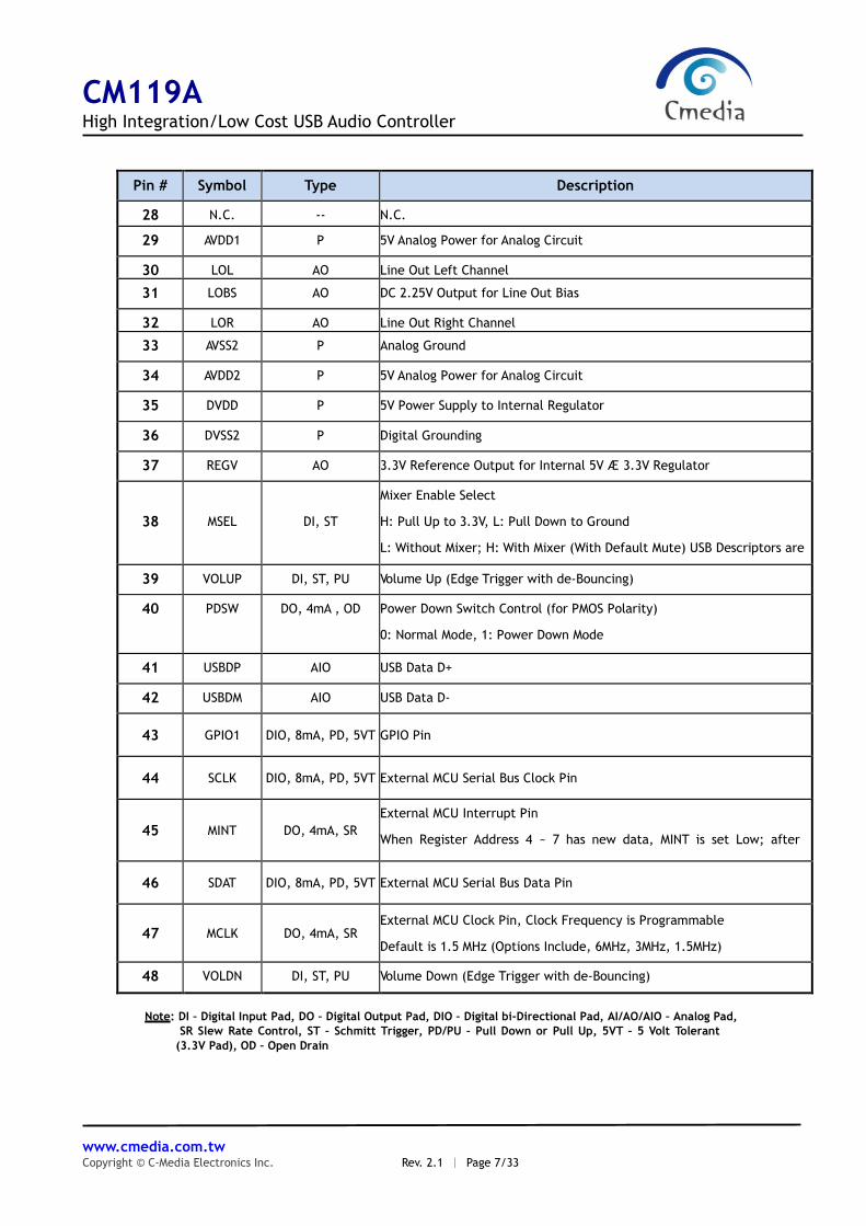
Pin # Symbol Type Description
28 N.C. -- N.C.
29 AVDD1 P 5V Analog Power for Analog Circuit
30 LOL AO Line Out Left Channel
31 LOBS AO DC 2.25V Output for Line Out Bias
32 LOR AO Line Out Right Channel
33 AVSS2 P Analog Ground
34 AVDD2 P 5V Analog Power for Analog Circuit
35 DVDD P 5V Power Supply to Internal Regulator
36 DVSS2 P Digital Grounding
37 REGV AO 3.3V Reference Output for Internal 5V Æ 3.3V Regulator
38
MSEL
DI, ST
Mixer Enable Select
H: Pull Up to 3.3V, L: Pull Down to Ground
L: Without Mixer; H: With Mixer (With Default Mute) USB Descriptors are
changed accordingly 39 VOLUP DI, ST, PU Volume Up (Edge Trigger with de-Bouncing)
40 PDSW DO, 4mA , OD Power Down Switch Control (for PMOS Polarity)
0: Normal Mode, 1: Power Down Mode
41 USBDP AIO USB Data D+
42 USBDM AIO USB Data D-
43 GPIO1 DIO, 8mA, PD, 5VT GPIO Pin
44 SCLK DIO, 8mA, PD, 5VT External MCU Serial Bus Clock Pin
45 MINT DO, 4mA, SR
External MCU Interrupt Pin
When Register Address 4 ~ 7 has new data, MINT is set Low; after
MCU read MINT is reset to H
46 SDAT DIO, 8mA, PD, 5VT External MCU Serial Bus Data Pin
47 MCLK DO, 4mA, SR External MCU Clock Pin, Clock Frequency is Programmable
Default is 1.5 MHz (Options Include, 6MHz, 3MHz, 1.5MHz)
48 VOLDN DI, ST, PU Volume Down (Edge Trigger with de-Bouncing)
Note: DI – Digital Input Pad, DO – Digital Output Pad, DIO – Digital bi-Directional Pad, AI/AO/AIO – Analog Pad,
SR Slew Rate Control, ST – Schmitt Trigger, PD/PU – Pull Down or Pull Up, 5VT – 5 Volt Tolerant
(3.3V Pad), OD – Open Drain

CM119A High Integration/Low Cost USB Audio Controller
www.cmedia.com.tw Copyright © C-Media Electronics Inc. Rev. 2.1 ︱ Page 8/33
4 MCU Interface
CM119A provides a serial MCU Interface for external MCU to access internal registers with these registers
access. MCU and host side software can have bi-directional communication. This interface can keep flexibility
for external module control and integrate, such as LCD panel.
5 Block Diagram
USB
TRX
USB
interface
4 byte
FIFO
USB control
processing
ISO out
processing
( with x2 mod)
PLL148 MHz
ROM
PLL2
12. 288 /11. 2896 MHz
with adjustment
12 MHz
VREF
(2.25V)
power on
reset
reset
16 bit
DAC
bandgap
3.3V
+
-
+-
Vref
5 - > 3. 3
regulator
REGV
ISO in
processing
300 x 16 SRAM
16 bit Sigma-
Delta ADC
16 bit
DAC
+
-
Vref
+22.5~ - 0 dB
16 steps
Vref
PLL3 12.288/
11. 2896 MHz
USB interrupt
processing with 4
byte FIFO
interface logics
MUTER MCU
I/F
VOLDN
VOLUP
VREF
MUTEP
LOL
LOR
LEDO
LEDR
PDSW
+-
+22. 5 ~ 0 dB
16 steps
Vref
0 ~ -45dB
38 steps
voltage linear
VBIAS4.5 V ( drive typ 4mA)
EEPROM
interface
CS
SK
DW
DR
USBDP
USBDM
XI
XOMICIN
+-
Vref
Vref+-
+-
Vref
LOBS
GPIO
BOOST
+20 dB boost enable
0 ~ -45dB
38 steps
voltage linear
PWRSEL
MODE
SEL pins
TEST
sync by
VPR_CLK
sync by
VPL_CLK
BUZZ SPDIFO
High-Pass Filter
Block Diagram Of CM119A

CM119A High Integration/Low Cost USB Audio Controller
www.cmedia.com.tw Copyright © C-Media Electronics Inc. Rev. 2.1 ︱ Page 9/33
6 Ordering Information
Model
Number Package
Operating Ambient
Temperature Supply Range
CM119A
48-Pin LQFP
7mm×7mm×1.4mm (Plastic)
0 o C to +70 o C
DVdd = 5V, AVdd = 5V
Outline Dimensions Dimensions shown in inches and (mm)
48-Lead Thin Plastic Quad Flatpack (LQFP)
Ordering Information Of CM119A

CM119A High Integration/Low Cost USB Audio Controller
www.cmedia.com.tw Copyright © C-Media Electronics Inc. Rev. 2.1 ︱ Page 10/33
7 Function Description
7.1 USB Interface
CM119A integrates USB transceiver, PLL, and regulator so only a few passive components are necessary for
the USB interface connection. Default USB descriptors are embedded in CM119A; therefore no additional
design effort is needed for a generic USB operation. PID changes with the jumper pin setting so different
setting have different PID. For customized product, customer can attach a 93C46 EEPROM to override
the embedded VID, PID and provide addition serial number for each set. CM119A automatically detects
93C46 existence and performs the overwrite function during power up.
7.1.1 Device Descriptor
Offset Field Size Value
(Hex) Description
0 bLength 1 12 Total 18 Bytes
1 bDescriptorType 1 01 Device Descriptor
2 bcdUSB 2 0110 USB 1.1 compliant.
4 bDeviceClass 1 00
5 bDeviceSubClass 1 00
6 bDeviceProtocol 1 00
7 bMaxPacketSize0 1 40 Endpoint zero Size = 64 bytes
8 idVendor 2 0D8C Vendor ID
10 idProduct 2 013A Product ID Programmable by MSEL and MODE pin
12 bcdDevice 2 0100 Device compliant to the Audio Device Class specification version 1.00
14 iManufacturer 1 01 Index of string descriptor describing manufacturer
15 iProduct 1 02 Index of string descriptor describing product
16 iSerialNumber 1 03 Index of string descriptor describing the device’s serial number
17 bNumConfigurations 1 01 Configurations number = 1
Note: VID, PID, and serial number can be overridden by external EEPROM content

CM119A High Integration/Low Cost USB Audio Controller
www.cmedia.com.tw Copyright © C-Media Electronics Inc. Rev. 2.1 ︱ Page 11/33
7.1.2 Configuration Descriptor
Offset Field Size Value
(Hex) Description
0 bLength 1 09 Total 9 Bytes
1 bDescriptorType 1 02 Configuration Descriptor
2 wTotalLength 2 Total length of data returned for this configuration
Programmable by MSEL and MODE pin
4 bNumInterfaces 1 04 or 03
Number of interfaces supported by this configuration
(Decided by Speaker Mode and Head Set mode):
0: control interface
1: ISO-OUT interface
2: ISO-IN interface (Option)
3: INT-IN(HID) interface
5 bConfigurationValue 1 01
6 iConfiguration 1 00
7 bmAttributes 1 A0 or E0 Programmable by PWRSEL
8 bMaxPower 2 32 or FA Maximum power consumption of the USB
Programmable by MODE and PWRSEL

CM119A High Integration/Low Cost USB Audio Controller
www.cmedia.com.tw Copyright © C-Media Electronics Inc. Rev. 2.1 ︱ Page 12/33
7.1.3 Content Format for 93C46
Addr
(Dec)
Addr
(Hex) Description
0 0x00
Magic Word
0x670X where X = bit 4, 3, 2, 1
bit 3 The value within address 0x2A,0x2B is valid 1: valid 0: invalid
bit 2 manufacture string enable 1: enable(default) 0: disable
bit 1 serial number enable control 1: enable 0: disable(default)
bit 0 product string enable control 1: enable(default) 0: disable
1 0x01 VID 2-byte
2 0x02 PID 2-byte
3 0x03 Serial number length
(low byte)
Serial number 1st byte
(high byte)
4
~
9
0x04
~
0x09
Serial number 12-byte
10 0x0A Product string length
(low byte)
Product string 1st byte
(high byte)
11
~
25
0x0B
~
0x19
Product string 30-byte (default: USB PnP Sound Device)
26 0x1A Manufacture string length
(low byte)
Manufacture string 1st
(high byte)
27
~
41
0x1B
~
0x29
Manufacture string 30-byte (default: C-Media Electronics Inc.)
42 0x2A
bit 15 ~ 8 DAC initial volume (7-bit) max:0x02 min:0x4a
bit 7 ~ 0 ADC initial volume (5-bit) max: 0x00 min:0x78
43 0x2B
bit 15 ~ bit 9 <reserved>
bit 8 Shutdown DAC analog 1:shutdown 0:active(default)
bit 7 Total Power Control 1:enable 0:disable(default)
bit 6 Reserved, should be 0
bit 5 MIC High Pass Filter 1:enable(default) 0:disable
bit 4 ADC synchronization mode 1:enable 0:disable(default)
bit 3 MIC BOOST 1:enable(default) 0:disable
bit 2 DAC Output Terminal property set to SPK or HP
1: Headset 0: Speaker(default)
bit 1 HID 1: enable(default) 0: disable
bit 0 Remote Wakeup enable/disable
1: enable 0: disable(default)
44
~
END
0x2C
~
END
<reserved>

CM119A High Integration/Low Cost USB Audio Controller
www.cmedia.com.tw Copyright © C-Media Electronics Inc. Rev. 2.1 ︱ Page 13/33
7.1.4 USB Audio Topology Diagram
USB Audio Topology Diagram

CM119A High Integration/Low Cost USB Audio Controller
www.cmedia.com.tw Copyright © C-Media Electronics Inc. Rev. 2.1 ︱ Page 14/33
7.2 Jumper Pins and Mode Setting:
Several jumper pins can set the configuration of CM119A. These jumper pin settings affect both USB
descriptors and USB audio topology. If MODE pin is pulled up to 3.3V (speaker mode), a playback only function
is activated and there is no recording function declared to the host. At this setting, MSEL pin is ignored and
only one input terminal, one output terminal and one feature unit is declared in USB audio topology.
If MODE pin is pulled low (headset mode), a full duplex playback and recording function is reported to the host.
MSEL pin setting activates one mixer unit and one feature unit. The following USB audio topology in Chapter:
7.1.4 is an example of headset mode. PWRSEL pin affects the power configuration of CM119A; together with
MODE pin totally 4 combinations are programmable.
Combinations MODE
3.3V GND
PWRSEL
3.3V
Speaker Mode :
Playback Only
(Self Power with 100mA)
Headset Mode :
Playback + Recording
(Bus Power with 100mA)
GND
Speaker Mode :
Playback Only
(Bus Power with 500mA)
Headset Mode :
Playback + Recording
(Bus Power with 500mA)
VSEL jumper pin sets the output voltage swing. When VSEL is connected to 5V, output voltage swing is
3.5Vpp; when VSEL is connected to ground, output voltage is 2.5Vpp.
7.3 HID Feature and Descriptions
HID feature is provided by CM119A so user setting to volume up, volume down, and playback mute button
pin is reported to the host to synchronize host side setting. In addition, all CM119A internal registers can be
accessed via HID function call.
USB protocols can configure devices at startup or when they are plugged in at run time. These devices are
broken into various device classes. Each device class defines the common behavior and protocols for
devices that serve similar functions. The HID (Human Interface Device) class is one of the device
classes.
The HID class consists primarily of devices that are used by humans to control the operation of computer
systems. Typical examples of HID class devices include:

CM119A High Integration/Low Cost USB Audio Controller
www.cmedia.com.tw Copyright © C-Media Electronics Inc. Rev. 2.1 ︱ Page 15/33
The HID class consists primarily of devices that are used by humans to control the operation of computer
systems. Typical examples of HID class devices include:
- Keyboards and pointing devices, for example: mouse, trackballs, and joysticks.
- Front-panel controls, for example: knobs, switches, buttons, and sliders.
- Controls that might be found on devices such as VCR remote controls, games or simulation devices, for
example: data gloves, throttles, and steering wheels.
- Devices that may not require human interaction but provide data in a similar format to HID class devices, for
example: bar-code readers, thermometers, or voltmeters.
7.3.1 HID Descriptor
HID Interface Descriptor
Offset Field Size Value (Hex) Description
0 bLength 1 09 Size of this descriptor: 9 byte
1 bDescriptorType 1 04 INTERFACE descriptor type
2 bInterfaceNumber 1 03 Number of Interface: 3
3 bAlternateSetting 1 00 alternate 0
4 bNumEndpoints 1 01 Number of endpoints used by this
Interface: 1
5 bInterfaceClass 1 03 HID Interface Class
6 bInterfaceSubClass 1 00 No Subclass
7 bInterfaceProtocol 1 00 Must be set to 0
8 iInterface 1 00 Index of a string descriptor that describes this
interface.
HID Descriptor
Offset Field Size Value (Hex) Description
0 bLength 1 09 Total 9 Bytes
1 bDescriptorType 1 21 HID Descriptor Type
2 bcdHID 2 0100 HID class version 1.00
4 bCountryCode 1 00
5 bNumDescriptors 1 01
6 bDescriptorType 1 22 Report Descriptor
7 wDescriptorLength 2 0030 Numeric expression that is the total size of the
optional descriptor: 48 Bytes

CM119A High Integration/Low Cost USB Audio Controller
www.cmedia.com.tw Copyright © C-Media Electronics Inc. Rev. 2.1 ︱ Page 16/33
Interrupt IN Endpoint Descriptor
Offset Field Size Value (Hex) Description
0 bLength 1 07 Total 7 Bytes
1 bDescriptorType 1 05 ENDPOINT Descriptor Type
2 bEndpointAddress 1 83 IN Endpoint
Endpoint number = 3
3 bmAttributes 1 03 Interrupt endpoint type
4 wMaxPacketSize 2 0004 Maximum packet size: 4 bytes
6 bInterval 1 2 2ms
7.3.2 Windows Software Architecture for HID
Note: Please contact with our sales for the C-Media SDK example if needed.
7.4 Internal Registers
All internal registers of CM119A can be accessed via generic HID functional calls without the need to develop
kernel mode driver. Totally 4 bytes of data can be read or write from HID. Input report is for read and output
report is for write. Internal registers of CM119A are used to control GPIO, S/PDIF output, EEPROM and MCU
data access. Host side HID or external MCU can access CM119A internal registers. With both sides accessed
to the same set of registers, two-way communication can be achieved.

CM119A High Integration/Low Cost USB Audio Controller
www.cmedia.com.tw Copyright © C-Media Electronics Inc. Rev. 2.1 ︱ Page 17/33
7.4.1 Access via HID Class Command:
HID_IR0 to HID_IR3 are HID input report and is use by host side receiving data to CM119A. HID_OR0 to
HID_OR3 are HID output report and is used by host side sending adta to CM119A
HID interrupt will occur when HID_IR0-3 are updated by button status MCU (and GPI in case HID_IR0[7:6] == 2’b00).
HID_IR0 (HID input report byte 0)
Offset : 0x00
Bits Read/Write Description Default
7-6 R
When HID_OR0[7] == 1’b0:
HID_IR0-3 are programmed by MCU (and GPI)
0: HID_IR1 is used as GPI
1: HID_IR0-3 are used as generic HID registers
2: Values written to HID_IR0-3 are also mapped to MCU_CTRL,
EEPROM_DATA0-1, EEPROM_CTRL
3: Reserved
0x0
5-4 R
When HID_OR0[7] == 1’b0:
Generic registers programmed by MCU When HID_OR0[7] ==
1’b1:
Mapped from MCU_CTRL[5:4]
0x0
3 R 0: No activity on Record-Mute button
1: Record-Mute button pressed then released 0x0
2 R 0: No activity on Playback-Mute button
1: Playback-Mute button pressed then released 0x0
1 R 0: Volume-Down button released
1: Volume-Down button pressed 0x0
0 R 0: Volume-Up button released
1: Volume-Up button pressed 0x0
HID_IR1 (HID input report byte 1)
Offset : 0x01
Bits Read/Write Description Default
7-0 R
When HID_OR0[7] == 1’b0:
GPI (when HID_IR0[7:6] == 2’b00); or Generic registers
programmed by MCU (otherwise) When HID_OR0[7] == 1’b1:
Mapped from EEPROM_DATA0
0x00
HID_IR2 (HID input report byte 2)
Offset : 0x02
Bits Read/Write Description Default
7-0 R
When HID_OR0[7] == 1’b0:
Generic registers programmed by MCU
When HID_OR0[7] == 1’b1:
Mapped from EEPROM_DATA1
0x00

CM119A High Integration/Low Cost USB Audio Controller
www.cmedia.com.tw Copyright © C-Media Electronics Inc. Rev. 2.1 ︱ Page 18/33
HID_IR3 (HID input report byte 3)
Offset : 0x03
Bits Read/Write Description Default
7-0 R
When HID_OR0[7] == 1’b0:
Generic registers programmed by MCU
When HID_OR0[7] == 1’b1:
Mapped from EEPROM_CTRL
0x00
HID_OR0 (HID output report byte 0)
Offset : 0x04
Bits Read/Write Description Default
7-6 R/W
0: HID_OR1-2 are used for GPO; HID_OR0,3 are used for buzzer
and SPDIF
1: HID_OR0-3 are used as generic HID registers
2: Values written to HID_OR0-3 are also mapped to MCU_CTRL,
EEPROM_DATA0-1, EEPROM_CTRL (see Note)
3: Reserved
0x0
5 R/W
When HID_OR0[7] == 1’b0:
0: Buzzer off
1: Buzzer on
When HID_OR0[7] == 1’b1:
Mapped to MCU_CTRL[5]
0x0
4 R/W
When HID_OR0[7] == 1’b0:
Valid bit in SPDIF frame
When HID_OR0[7] == 1’b1:
Mapped to MCU_CTRL[4]
0x0
3-0 R/W
When HID_OR0[7] == 1’b0:
First nibble of SPDIF status channel
When HID_OR0[7] == 1’b1:
Reserved
0x0
Note : When EEPROM access is done, HID interrupt will occur. USB host can get the result from interrupt pipe (endpoint 3).
HID_OR1 (HID output report byte 1)
Offset : 0x05
Bits Read/Write Description Default
7-0 R/W
When HID_OR0[7:6] == 2’b00:
0: GPO drives L
1: GPO drives H
When HID_OR0[7:6] == 2’b01: Generic HID registers
When HID_OR0[7:6] == 2’b1x: Mapped to EEPROM DATA0
0x00

CM119A High Integration/Low Cost USB Audio Controller
www.cmedia.com.tw Copyright © C-Media Electronics Inc. Rev. 2.1 ︱ Page 19/33
HID_OR2 (HID output report byte 2)
Offset : 0x06
Bits Read/Write Description Default
7-0 R/W
When HID_OR0[7:6] == 2’b00:
0: Set GPIO to input mode
1: Set GPIO to output mode When HID_OR0[7:6] == 2’b01:
Generic HID registers
When HID_OR0[7:6] == 2’b1x: Mapped to EEPROM_DATA1
0x00
HID_OR3 (HID output report byte 3)
Offset : 0x07
Bits Read/Write Description Default
7-0 R/W
When HID_OR0[7] == 1’b0:
Category byte of SPDIF status channel
When HID_OR0[7] == 1’b1: Mapped to EEPROM_CTRL
0x00
Note: HID_OR3 is used for SPDIF when SPDIF_CONFIG[5] == 1’b0

CM119A High Integration/Low Cost USB Audio Controller
www.cmedia.com.tw Copyright © C-Media Electronics Inc. Rev. 2.1 ︱ Page 20/33
7.4.2 Access via External Serial Interface by MCU:
External MCU can write data to HID_IR0 to HID_IR3 and read data from HID_OR0 to HID_OR3. MINT will be
active when HID_OR0-3 are updated by Set_Output_Report HID class command, and will be cleared after
HID_OR0-3 are read by MCU.
HID_IR0 (HID input report byte 0)
Offset : 0x00
Bits Read/Write Description Default
7-6 R/W
0: HID_IR0-3 are not used by MCU
1: HID_IR0-3 are used as generic HID registers
2: Values written to HID_IR0-3 are also mapped to MCU_CTRL,
EEPROM_DATA0-1, EEPROM_CTRL (see Note)
3: Reserved
0x0
5 R/W
When HID_IR0[7] == 1’b0:
0: Buzzer off
1: Buzzer on
When HID_IR0[7] == 1’b1:
Mapped to MCU_CTRL[5]
0x0
4 R/W
When HID_IR0[7] == 1’b0:
Generic HID register
When HID_IR0[7] == 1’b1:
Mapped to MCU_CTRL[4]
0x0
3 R 0: No activity on Record-Mute button
1: Record-Mute button pressed then released 0x0
2 R 0: No activity on Playback-Mute button
1: Playback-Mute button pressed then released 0x0
1 R 0: Volume-Down button released
1: Volume-Down button pressed 0x0
0 R 0: Volume-Up button released
1: Volume-Up button pressed 0x0
Note: When EEPROM access is done, MINT will be active. MCU should read HID_OR0-3 to get the result, and then MINT will
be cleared.

CM119A High Integration/Low Cost USB Audio Controller
www.cmedia.com.tw Copyright © C-Media Electronics Inc. Rev. 2.1 ︱ Page 21/33
HID_IR1 (HID input report byte 1)
Offset : 0x01
Bits Read/Write Description Default
7-0 R/W
When HID_IR0[7] == 1’b0:
Generic HID registers
When HID_IR0[7] == 1’b1:
Mapped to EEPROM_DATA0
0x00
HID_IR2 (HID input report byte 2)
Offset : 0x02
Bits Read/Write Description Default
7-0 R/W
When HID_IR0[7] == 1’b0:
Generic HID registers
When HID_IR0[7] == 1’b1:
Mapped to EEPROM_DATA1
0x00
HID_IR3 (HID input report byte 3)
Offset : 0x03
Bits Read/Write Description Default
7-0 R/W
When HID_IR0[7] == 1’b0:
Generic HID registers
When HID_IR0[7] == 1’b1:
Mapped to EEPROM_CTRL
0x00
HID_OR0 (HID output report byte 0)
Offset : 0x04
Bits Read/Write Description Default
7-6 R
When HID_IR0[7] == 1’b0:
HID_OR0-3 are programmed by USB host
0: HID_OR1-2 are used for GPO
1: HID_OR0-3 are used as generic HID registers
2: Values written to HID_OR0-3 are also mapped to
MCU_CTRL, EEPROM_DATA0-1, EEPROM_CTRL
3: Reserved
When HID_IR0[7] == 1’b1:
Always 2’b11
0x0
5-4 R
When HID_IR0[7] == 1’b0:
Generic registers programmed by USB host
When HID_IR0[7] == 1’b1:
Mapped from MCU_CTRL[5:4]
0x0
3-0 R
When HID_IR0[7] == 1’b0:
Generic registers programmed by USB host
When HID_IR0[7] == 1’b1:
Always 4’h0
0x0

CM119A High Integration/Low Cost USB Audio Controller
www.cmedia.com.tw Copyright © C-Media Electronics Inc. Rev. 2.1 ︱ Page 22/33
HID_OR1 (HID output report byte 1)
Offset : 0x05
Bits Read/Write Description Default
7-0 R
When HID_IR0[7] == 1’b0:
Generic registers programmed by USB host
When HID_IR0[7] == 1’b1:
Mapped from EEPROM_DATA0
0x00
HID_OR2 (HID output report byte 2)
Offset : 0x06
Bits Read/Write Description Default
7-0 R
When HID_IR0[7] == 1’b0:
Generic registers programmed by USB host
When HID_IR0[7] == 1’b1:
Mapped from EEPROM_DATA1
HID_OR3 (HID output report byte 3)
Offset : 0x07
Bits Read/Write Description Default
7-0 R
When HID_IR0[7] == 1’b0:
Generic registers programmed by USB host
When HID_IR0[7] == 1’b1:
Mapped from EEPROM_CTRL
0x00
7.4.3 Indirect Accessed Registers:
MCU_CTRL (MCU control)
Offset : 0x08
Bits Read/Write Description Default
7-6 -- Reserved 0x0
5-4 R/W
0: MCLK operating at 1.5MHz
1: MCLK operating at 3MHz
2: MCLK operating at 6MHz
3: Reserved
0x0
3-0 -- Reserved 0x0
EEPROM_DATA0 (Low byte of EEPROM data)
Offset : 0x09
Bits Read/Write Description Default
7-0 R/W Low byte of EEPROM data to be accessed 0x00
EEPROM_DATA1 (High byte of EEPROM data)
Offset : 0x0a
Bits Read/Write Description Default
7-0 R/W High byte of EEPROM data to be accessed 0x00

CM119A High Integration/Low Cost USB Audio Controller
www.cmedia.com.tw Copyright © C-Media Electronics Inc. Rev. 2.1 ︱ Page 23/33
EEPROM_CTRL (Serial EEPROM access control)
Offset : 0x0b
Bits Read/Write Description Default
7 R/W
When Register Read:
0: No EEPROM access pending
1: Last EEPROM access pending
When Register Write:
0: No action
1: Start EEPROM access (will clear to 0 automatically)
0x0
6 R/W 0: Read EEPROM
1: Write EEPROM 0x0
5-0 R/W Address of serial EEPROM 0x00
7.5 MCU Interface
On MCU serial interface, CM119A serves as a slave device with bit rate up to 400Kbps (fast mode). MCU
can read/write 3 bytes to CM119A device with a 2-bit register address. Since host side and MCU can both access
to all the internal registers, access contention when both host and MCU try to access the same register
should be avoided on application. The 7-bit slave address of CM119A is assigned as 7’b0111000.
When a one-byte data is written by MCU, CM119A will transfer totally 4 bytes to the USB host via an additional
interrupt pipe. The sequence of the upward HID report is the button status first (address 00), then register
with address 01, then register with address 02, then register with address 03. The USB host will keep
polling the upward HID report every 2mS. When there is any button pressed or released, or MCU data
coming, CM119A will transfer the 4 bytes of HID report to the USB host again.
CM119A can also transfer one byte MCU data from the USB host to its register. This is accomplished by a
‘Set Output Report’ HID class request via default control pipe. MCU can get this downward byte by interrupt
or polling.
CM119A has one input pin ‘SCLK’ where it gets serial clock from MCU, and one
open-drain output pin ‘SDAT’ where it sends or receives serial signal to/from MCU. As shown below, ‘SDAT’
should be stable when ‘SCLK’ is high, and can have transition only when ‘SCLK’ is low.

CM119A High Integration/Low Cost USB Audio Controller
www.cmedia.com.tw Copyright © C-Media Electronics Inc. Rev. 2.1 ︱ Page 24/33
START and STOP conditions shown below are the exception. Every transaction begins from a
START, and ends with a STOP, or another START (repeated START).
The figure below demonstrates a typical transaction. After every 8 bits sent by the transmitter, the receiver
should send one bit low for positive acknowledgement or one bit high for negative acknowledgement. After
the negative acknowledgement, a STOP or repeated START should follow. The next figure shows more detailed
about acknowledgement bit. Note that ‘SCLK’ is always driven by the master.
The figure below shows a complete data transfer. After a START, MCU should send 7-bit slave address
(7’b0111000) first, and then the 8th bit denotes a read transfer when it’s high; or a write transfer when it’s
low. The first acknowledgement is always from CM119A.

CM119A High Integration/Low Cost USB Audio Controller
www.cmedia.com.tw Copyright © C-Media Electronics Inc. Rev. 2.1 ︱ Page 25/33
In the write transfer, MCU keep acting as the master and the transfer direction is not changed. The following
figure gives an example of one byte write transfer.
CM119A regards the first DATA byte as the register address. The second DATA byte is the content that MCU
writes at the register address. If there is the third DATA byte, CM119A will auto-increment this byte to the
next register address.
The figure below shows an example of two bytes read transfer. Because CM119A has auto-increment function,
the second DATA byte will be the register data on the next address.

CM119A High Integration/Low Cost USB Audio Controller
www.cmedia.com.tw Copyright © C-Media Electronics Inc. Rev. 2.1 ︱ Page 26/33
Please note that the USB host tries to get new HID data every 2mS. It’s quite slow. If the continuous write
transfers are too close in time, the former transfer may have no effect.
The figure below shows typical transactions between MCU and CM119A. After a START, MCU should send
7-bit slave address (0111000) first, and then the 8th bit denotes a read transfer when it’s high; or a write
transfer when it’s low.
In a write transfer, MCU keeps acting as the transmitter. CM119A regards the first DATA byte as start register
address (it’s better to be 0x00). The following four DATA bytes are the content that MCU writes to the register
addresses. In a read transfer, two transactions are necessary. MCU resets start register address by the first
transaction. Then MCU changes to be the receiver during the second transaction to get four bytes of data.
Note 1: Bits 0~3 of the first HID byte always reflect button activity, so they can not be written by MCU.

CM119A High Integration/Low Cost USB Audio Controller
www.cmedia.com.tw Copyright © C-Media Electronics Inc. Rev. 2.1 ︱ Page 27/33
7.6 Buzzer Output
Each time the software set "1" to the register HID-OR0 bit 5, an embedded ringing sequence is played once.
Since the delay between one sequence and next sequence is long (around 1 second ~ 2 second), this delay to
be set by software, H/W only play one sequence and then stop for one register write.

CM119A High Integration/Low Cost USB Audio Controller
www.cmedia.com.tw Copyright © C-Media Electronics Inc. Rev. 2.1 ︱ Page 28/33
8 Electrical Characteristics
8.1 Absolute Maximum Rating
Symbol Parameter Value Unit
Dvmin Min Digital Supply Voltage – 0.3 V
Dvmax Max Digital Supply Voltage + 6 V
Avmin Min Analog Supply Voltage – 0.3 V
Avmax Max Analog Supply Voltage + 6 V
Dvinout Voltage on any Digital Input or
Output Pin –0.3 to +5.5 V
Avinout Voltage on any Analog Input or
Output Pin –0.3 to +5.5 V
Tstg Storage Temperature Range -40 to +125 0C
ESD (HBM) ESD Human Body Mode 4000 V
ESD (MM) ESD Machine Mode 200 V
8.2 Operation Conditions
Operation conditions
Min Typ Max Unit
Analog Supply Voltage 4.5 5.0 5.5 V
Digital Supply Voltage 4.5 5.0 5.5 V
Total Power Consumption - 35 - mA
Suspend Mode Power Consumption - 320 - uA
Operating ambient temperature 0 - 70 0C

CM119A High Integration/Low Cost USB Audio Controller
www.cmedia.com.tw Copyright © C-Media Electronics Inc. Rev. 2.1 ︱ Page 29/33
8.3 Electrical Parameters
Min Typ Max Unit
DAC (10K Ohm Loading)
Resolution - 16 - Bits
THD + N (-3dBr) - -74.29 - dB
SNR - 93.6 - dB
Silent SNR - 98.2 - dB
Dynamic range - 93.8 - dB
Frequency response 48KHz 20 - 20K Hz
Frequency Response 44.1KHz 20 - 20K Hz
Output Boltage (rms) - 1.25 - Vrms
Output Voltage Swing 0.5 - 4.0 V
ADC
Resolution - 16 - bit
THD + N (-3dBr) - -76.1 - dB
SNR - 83.1 - dB
Dynamic Range - 81.6 - dB
Frequency Response 48KHz 20 - 19.2K Hz
Frequency Response 44.1KHz 20 - 17.6K Hz
Input Range 0 - 2.88 Vpp
Amplification
Volume Control Level -45 - 0 dB
Volume Control Step - 38 - Steps
Microphone Input
Boost Gain - +20 - dB
Gain Adjustment Range 0 - 22.5 dB
Gain Adjustment Steps - 16 - Steps
Mixer Gain Adjustment -33.0 - 12.0 dB
Mixer Gain Adjustment Steps - 32 - Steps

CM119A High Integration/Low Cost USB Audio Controller
www.cmedia.com.tw Copyright © C-Media Electronics Inc. Rev. 2.1 ︱ Page 30/33
9 Frequency Response Graphs
9.1 Line Out Freq Response @ 48KHz Sample Rate (10K Ohm Loading)
Audio Precision 09/26/08 14:33:51
Vista-Frequency Response-M48k.at27
ColorSweep Trace Line Style Thick Data Axis Comment
1 1 Cyan Solid 1 Fasttest.Ch.1 Ampl!Normalize Left
1 2 Yellow Solid 1 Fasttest.Ch.2 Ampl!Normalize Left
-6
+1
-5
-4
-3
-2
-1
+0
-3.143
-0.01
d
B
r
A
20 20k50 100 200 500 1k 2k 5k 10k 19.998k
Hz
dx=-19.980 kHz dy=-3.132 dB
9.2 Line Out THD+N @ 48KHz sample rate (10K Ohm Loading)
Audio Precision 09/26/08 14:27:07
Vista-D-A THD+N.at27
ColorSweep Trace Line Style Thick Data Axis Comment
1 1 Cyan Solid 2 Anlr.THD+N Ampl Left
1 2 Yellow Solid 2 Anlr.THD+N Ampl Left
-120
+0
-110
-100
-90
-80
-70
-60
-50
-40
-30
-20
-10
d
B
r
A
20 20k50 100 200 500 1k 2k 5k 10k
Hz
CM119A High Integration/Low Cost USB Audio Controller
www.cmedia.com.tw Copyright © C-Media Electronics Inc. Rev. 2.1 ︱ Page 31/33
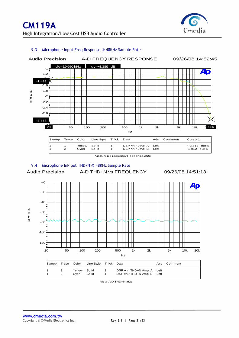
9.3 Microphone Input Freq Response @ 48KHz Sample Rate
Audio Precision 09/26/08 14:52:45 A-D FREQUENCY RESPONSE
Vista-A-D Frequency Response.at2c
ColorSweep Trace Line Style Thick Data Axis Comment Cursor1
1 1 Yellow Solid 1 DSP Anlr.Level A Left *-2.812 dBFS
1 2 Cyan Solid 1 DSP Anlr.Level B Left -2.812 dBFS
-3
-1
-2.8
-2.6
-2.4
-2.2
-2
-1.8
-1.6
-1.4
-1.2
-2.812
-1.423
d
B
F
S
20 20k50 100 200 500 1k 2k 5k 10k 20k20
Hz
dx=-19.980 kHz dy=+1.389 dB
9.4 Microphone InP put THD+N @ 48KHz Sample Rate
Audio Precision 09/26/08 14:51:13 A-D THD+N vs FREQUENCY
Vista-A-D THD+N.at2c
ColorSweep Trace Line Style Thick Data Axis Comment
1 1 Yellow Solid 1 DSP Anlr.THD+N Ampl A Left
1 2 Cyan Solid 1 DSP Anlr.THD+N Ampl B Left
-120
+0
-100
-80
-60
-40
-20
d
B
F
S
20 20k50 100 200 500 1k 2k 5k 10k
Hz

CM119A High Integration/Low Cost USB Audio Controller
www.cmedia.com.tw Copyright © C-Media Electronics Inc. Rev. 2.1 ︱ Page 32/33
Reference
USB-IF, USB Specification, Revision 1.1 and 2.0, and USB Audio Device Class Specification,
Revision 1.0.

CM119A High Integration/Low Cost USB Audio Controller
www.cmedia.com.tw Copyright © C-Media Electronics Inc. Rev. 2.1 ︱ Page 33/33
-End of Specifications-
C-MEDIA ELECTRONICS INC.
6F., 100, Sec. 4, Civil Boulevard, Taipei, Taiwan 106 R.O.C.
TEL:+886-2-8773-1100
FAX:+886-2-8773-2211
E-MAIL:[email protected]
Disclaimer: Information furnished by C-Media Electronics Inc. is believed to be accurate and reliable. However, no responsibility is assumed by C-Media Electronics Inc. for its use, nor for any infringements of patents or other rights of third parties that may result from its use. Specifications subject to change without notice. No license is granted by implication or otherwise under any patent or patent rights of C-Media. Trademark and registered trademark are the property of their respective owners.
Related Documents