D102758X012 FIELDVUE DVC6000 Series Digital Valve Controllers FIELDVUE DVC6000 Series digital valve controllers are communicating, microprocessor-based current-to- pneumatic instruments. In addition to the traditional function of converting a current signal to a pressure signal, DVC6000 Series digital valve controllers, using HART communications protocol, give easy access to information critical to process operation. This can be done using a Model 275 HART Communicator at the valve or at a field junction box, or by using a personal computer or a system console within the control room. Using HART communication protocol, information can be integrated into a control system or received on a single loop basis. DVC6000 Series digital valve controllers can be used on single- or double-acting actuators. The digital valve controller receives feedback of the valve travel position plus supply and actuator pneumatic pressure. This allows the instrument to diagnose not only itself, but also the valve and actuator to which it is mounted. This provides you with very cost effective maintenance in- formation, so that required maintenance can be per- formed on the instrument and valve when there really is a need. Wiring is economical because DVC6000 Series digital valve controllers use two-wire 4 to 20 mA loop power. This provides for low cost replacement of existing ana- log instrumentation. The DVC6000 Series digital valve controller’s two-wire design avoids the high cost of running separate power and signal wiring. Features Improved Control—Two-way digital communica- tions give you current valve conditions. You can rely on this real-time information to make sound process management decisions. By analyzing valve dynamics through AMS ValveLink software, you can identify con- trol areas needing improvement and maintain a high level of system performance. Figure 1. Type DVC6010 Digital Valve Controller Mounted on a Sliding-Stem Valve Actuator W7957 / IL Enhanced Safety—You can check instrument and valve operation and keep the process running smoothly and safely from a remote location. Access is possible at a field junction box, marshalling panel, or within the safety of the control room using either a HART Communicator, a notebook PC, or a system workstation. Your exposure to hazardous environ- ments is minimized and you can avoid having to ac- cess hard-to-reach valve locations. (continued on page 3) September 2000 Bulletin 62.1:DVC6000

Welcome message from author
This document is posted to help you gain knowledge. Please leave a comment to let me know what you think about it! Share it to your friends and learn new things together.
Transcript
D1
027
58
X0
12
FIELDVUE DVC6000 Series Digital Valve ControllersFIELDVUE DVC6000 Series digital valve controllersare communicating, microprocessor-based current-to-pneumatic instruments. In addition to the traditionalfunction of converting a current signal to a pressuresignal, DVC6000 Series digital valve controllers, usingHART communications protocol, give easy access toinformation critical to process operation. This can bedone using a Model 275 HART Communicator at thevalve or at a field junction box, or by using a personalcomputer or a system console within the control room.Using HART communication protocol, information canbe integrated into a control system or received on asingle loop basis.
DVC6000 Series digital valve controllers can be usedon single- or double-acting actuators. The digital valvecontroller receives feedback of the valve travel positionplus supply and actuator pneumatic pressure. Thisallows the instrument to diagnose not only itself, butalso the valve and actuator to which it is mounted. Thisprovides you with very cost effective maintenance in-formation, so that required maintenance can be per-formed on the instrument and valve when there reallyis a need.
Wiring is economical because DVC6000 Series digitalvalve controllers use two-wire 4 to 20 mA loop power.This provides for low cost replacement of existing ana-log instrumentation. The DVC6000 Series digital valvecontroller’s two-wire design avoids the high cost ofrunning separate power and signal wiring.
Features
Improved Control—Two-way digital communica-tions give you current valve conditions. You can relyon this real-time information to make sound processmanagement decisions. By analyzing valve dynamicsthrough AMS ValveLink software, you can identify con-trol areas needing improvement and maintain a highlevel of system performance.
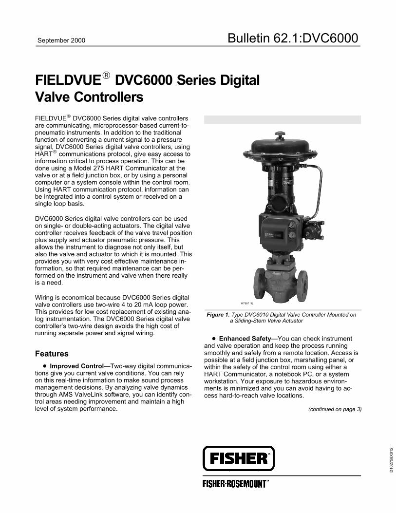
Figure 1. Type DVC6010 Digital Valve Controller Mounted ona Sliding-Stem Valve Actuator
W7957 / IL
Enhanced Safety—You can check instrumentand valve operation and keep the process runningsmoothly and safely from a remote location. Access ispossible at a field junction box, marshalling panel, orwithin the safety of the control room using either aHART Communicator, a notebook PC, or a systemworkstation. Your exposure to hazardous environ-ments is minimized and you can avoid having to ac-cess hard-to-reach valve locations.
(continued on page 3)
September 2000 Bulletin 62.1:DVC6000
Bulletin 62.1:DVC6000
2
Specifications
Available Configurations
DVC6010: Sliding-stem applicationsDVC6020: Rotary applications and long-stroke slid-ing-stem applicationsDVC6030: Quarter-turn rotary applications
DVC6000 Series digital valve controllers can bemounted on Fisher and other manufacturers rotaryand sliding-stem actuators.
Input Signal(1)
Point-to-Point:Analog Input Signal: 4–20 mA dc, nominal; splitranging availableMinimum Voltage Available at Instrument Terminalsmust be 10.5 volts dc for analog control, 11 volts dcfor HART communication (see instrument instruc-tion manual for details)Minimum Control Current: 4.0 mAMinimum Current w/o Microprocessor Restart: 3.5mAMaximum Voltage: 30 volts dcOvercurrent Protection: Input circuitry limits currentto prevent internal damageReverse Polarity Protection: No damage occursfrom reversal of loop current
Multi-drop:Instrument Power: 11 to 30 volts dc at approximate-ly 8 mAReverse Polarity Protection: No damage occursfrom reversal of loop current
Output Signal(1)
Pneumatic signal as required by the actuator, up to95% of supply pressureMinimum Span: 0.4 bar (6 psig)Maximum Span: 9.5 bar (140 psig)Action: Double, Single Direct, and SingleReverse
Supply Pressure
Minimum Recommended: 0.3 bar (5 psig) higherthan maximum actuator requirementsMaximum: 10.3 bar (150 psig) or maximum pres-sure rating of the actuator, whichever is lower
Steady-State Air Consumption(1)(2)(3)
At 1.4 bar (20 psig) supply pressure: Less than 0.4normal m3/hr (14 scfh)
At 5.5 bar (80 psig) supply pressure: Less than 1.3normal m3/hr (47 scfh)
Maximum Output Capacity(2)(3)
At 1.4 bar (20 psig) supply pressure: 10.7 normalm3/hr (400 scfh)At 5.5 bar (80 psig) supply pressure: 33.2 normalm3/hr (1240 scfh)
Independent Linearity(1)(4)
0.5% of output span
Electromagnetic Interference (EMI)
These instruments have the CE mark in accordancewith the Electromagnetic Compatibility (EMC Direc-tive. They meet the requirements of EN61326-1(emissions for light industry, immunity for industrialenvironment).
Electrical Classification
Hazardous Area: Approvals are pending from certi-fying agencies. Refer to Hazardous Area bulletins.Electrical Housing: Designed to meet NEMA 4X,IEC 60529 IP65 (approvals pending)
Connections
Supply Pressure: 1/4-inch NPT female and integralpad for mounting 67CFR regulatorOutput Pressure: 1/4-inch NPT femaleTubing: 3/8-inch metal, recommendedVent (pipe-away): 1/4-inch NPT femaleElectrical: 1/2-inch NPT female conduit connection,M20 adaptor optional
Operating Ambient Temperature Limits
–40 to 85 C (–40 to 185 F)
Construction Materials
Housing, module base and terminal box: ANSIB360.0 low copper aluminum alloyCover: ValoxElastomers: Nitrile (standard), or Fluorelas-tomer (optional)
Stem Travel
DVC6010: 0 to 102 mm (4 inches) maximum0 to 9.5 mm (3/8 inches) minimumDVC6020: 0 to 606 mm (23-7/8 inches) maximum
Shaft Rotation (DVC6020 and DVC6030)
0 to 50 degrees minimum0 to 90 degrees maximum
(continued)
Bulletin 62.1:DVC6000
3
Specifications (continued)
Mounting
Designed for direct actuator mounting. For weather-proof housing capability, the instrument must bemounted upright to allow the vent to drain.
Weight3.5 kg (7.7 lbs)
OptionsSupply and output pressure gauges or tire
valves, integral mounted filter regulator, Fluo-roelastomer O-rings
1. These terms are defined in ISA Standard S51.1.2. Normal m3/hr—Normal cubic meters per hour at 0 C and 1.01325 bar, absolute; Scfh—Standard cubic feet per hour at 60 F and 14.7 psia.3. Values at 1.4 bar (20 psig) based on a single-acting direct relay; values at 5.5 bar (80 psig) based on double-acting relay.4. Not applicable for Type DVC6020 digital valve controllers in long-stroke applications.
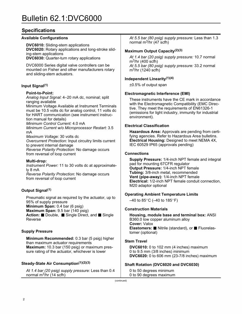
Figure 2. Type DVC6010 Digital Valve Controller Mounted on Type 585C Piston Actuator
W7960 / IL
Environmental Protection—You can avoid addi-tional field wiring by connecting a leak detector or limitswitch to the auxiliary terminals in the DVC6000 Seriesdigital valve controller. In this way, the instrument willissue an alert if limits are exceeded.
Hardware Savings—DVC6000 Series digitalvalve controllers, when used in an integrated system,allow you to realize significant hardware and installa-tion cost savings by replacing other devices in the pro-cess loop, such as positioners and limit switches, witha FIELDVUE digital valve controller.
Built to Survive—Field-tough DVC6000 Seriesdigital valve controllers have fully encapsulated printedwiring boards that resist the effects of vibration, tem-perature, and corrosive atmospheres. A separateweather-tight field wiring terminal box isolates field-wir-ing connections from other areas of the instrument.
Increased Uptime—With the self-diagnostic ca-pability of DVC6000 Series digital valve controllers,you can answer questions about a valve’s perfor-mance, without pulling the valve from the line. You cancompare the present valve/actuator signature (benchset, seat load, friction, etc.) against previously storedsignatures to discover performance changes, beforethey cause process control problems.
Faster Commissioning—The two-way commu-nication capability allows you to quickly commissionloops by remotely identifying each instrument, verifyingits calibration, reviewing stored maintenance notes,and more.
Easy Maintenance—DVC6000 Series digitalvalve controllers are modular in design. The singlemaster module can be removed from the instrumenthousing without disconnecting the field wiring, pneu-matic connections or stem linkages. This module con-tains the critical sub-modules so component removal isquick and simple.
DiagnosticsValve Assembly Diagnostics—DVC6000 Series
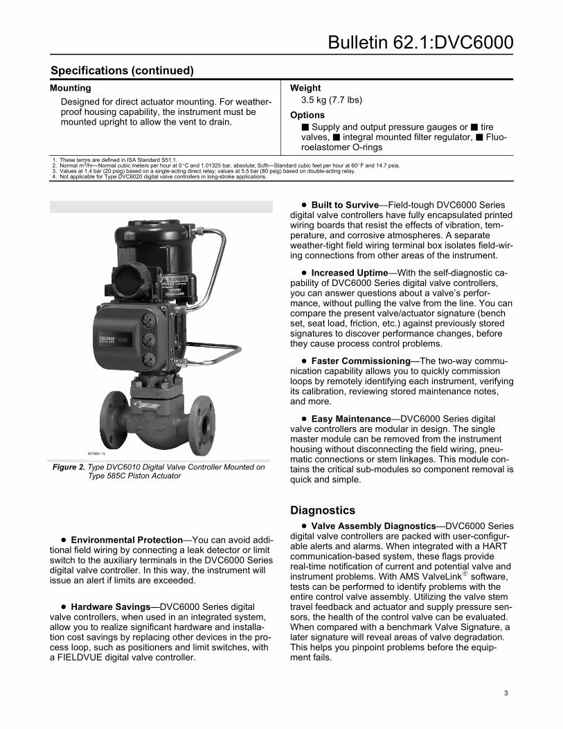
digital valve controllers are packed with user-configur-able alerts and alarms. When integrated with a HARTcommunication-based system, these flags providereal-time notification of current and potential valve andinstrument problems. With AMS ValveLink software,tests can be performed to identify problems with theentire control valve assembly. Utilizing the valve stemtravel feedback and actuator and supply pressure sen-sors, the health of the control valve can be evaluated.When compared with a benchmark Valve Signature, alater signature will reveal areas of valve degradation.This helps you pinpoint problems before the equip-ment fails.
Bulletin 62.1:DVC6000
4
Figure 3. The Valve Signature Diagnostic Test Can Reveal Areas of Degradation
Emerson Performance Solutions—EmersonPerformance Solutions (EPS) can use instrumentswith on-line diagnostics capability to evaluate the valveand the process while the loop is running. Using Per-formance Diagnostics, EPS will be able to identify andisolate the process element that is currently causingquality problems. Additionally, with the diagnostic toolsavailable, you can perform a predictive failure analysison DVC6000 Series equipped valves so that problemscan be identified before they affect the process.
Integration
Non-HART Systems—Because DVC6000 Se-ries digital valve controllers operate with a traditional 4to 20 mA control signal, they directly replace olderanalog instruments. Microprocessor-based electronicsprovide improved performance along with repeatableand reliable configuration and calibration.
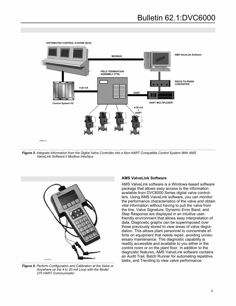
Modbus with AMS ValveLink Software andHART Multiplexers—HART communication allowsyou to extract more value from DVC6000 Series digitalvalve controllers beyond their inherent improved per-formance. When integrated into a multiplexer networkand using AMS ValveLink software, the device andvalve information is real-time. From the safety of acontrol room, multiple instruments can be monitoredfor alerts and alarms. Additionally, tasks such as con-figuration, calibration and diagnostic testing do not re-quire special trips to the field. AMS ValveLink softwarecan communicate via Modbus to the distributed controlsystem (DCS) to provide critical information such asvalve travel alerts and alarms.
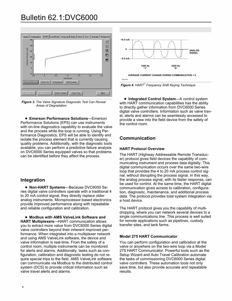
Figure 4. HART Frequency Shift Keying Technique
–0.5 mA
+0.5 mA
1200 Hz“1”
2200 Hz“0”
AVERAGE CURRENT CHANGE DURING COMMUNICATION = 0
ANALOGSIGNAL
0
A6174/IL
Integrated Control System—A control systemwith HART communication capabilities has the abilityto directly gather information from DVC6000 Seriesdigital valve controllers. Information such as valve trav-el, alerts and alarms can be seamlessly accessed toprovide a view into the field device from the safety ofthe control room.
Communication
HART Protocol Overview
The HART (Highway Addressable Remote Transduc-er) protocol gives field devices the capability of com-municating instrument and process data digitally. Thisdigital communication occurs over the same two-wireloop that provides the 4 to 20 mA process control sig-nal, without disrupting the process signal. In this way,the analog process signal, with its faster response, canbe used for control. At the same time, the HART digitalcommunication gives access to calibration, configura-tion, diagnostic, maintenance, and additional processdata. The protocol provides total system integration viaa host device.
The HART protocol gives you the capability of multi-dropping, where you can network several devices to asingle communications line. This process is well suitedfor remote applications such as pipelines, custodytransfer sites, and tank farms.
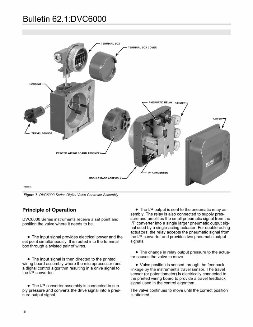
Model 275 HART Communicator
You can perform configuration and calibration at thevalve or anywhere on the two-wire loop via a Model275 HART Communicator. Powerful tools such as theSetup Wizard and Auto Travel Calibration automatethe tasks of commissioning DVC6000 Series digitalvalve controllers. These automation tools not onlysave time, but also provide accurate and repeatableresults.
Bulletin 62.1:DVC6000
5
Figure 5. Integrate Information from the Digital Valve Controller into a Non-HART Compatible Control System With AMS ValveLink Software’s Modbus Interface
W8082 / IL
AMS ValveLink Software
HART MULTIPLEXERControl System I/O
FIELD TERMINATION ASSEMBLY (FTA)
HART
4-20 mA
MODBUS
4-20 mA+
HART
DISTRIBUTED CONTROL SYSTEM (DCS)
RS232-TO-RS485CONVERTER
Figure 6. Perform Configuration and Calibration at the Valve or Anywhere on the 4 to 20 mA Loop with the Model 275 HART Communicator
W7125 / IL
AMS ValveLink Software
AMS ValveLink software is a Windows-based softwarepackage that allows easy access to the informationavailable from DVC6000 Series digital valve control-lers. Using AMS ValveLink software, you can monitorthe performance characteristics of the valve and obtainvital information without having to pull the valve fromthe line. Valve Signature, Dynamic Error Band, andStep Response are displayed in an intuitive user-friendly environment that allows easy interpretation ofdata. Diagnostic graphs can be superimposed overthose previously stored to view areas of valve degra-dation. This allows plant personnel to concentrate ef-forts on equipment that needs repair, avoiding unnec-essary maintenance. This diagnostic capability isreadily accessible and available to you either in thecontrol room or on the plant floor. In addition to thediagnostic features, AMS ValveLink software containsan Audit Trail, Batch Runner for automating repetitivetasks, and Trending to view valve performance.
Bulletin 62.1:DVC6000
6
TRAVEL SENSOR
TERMINAL BOX
TERMINAL BOX COVER
MODULE BASE ASSEMBLY
PRINTED WIRING BOARD ASSEMBLY
I/P CONVERTER
PNEUMATIC RELAY
HOUSING
GAUGES
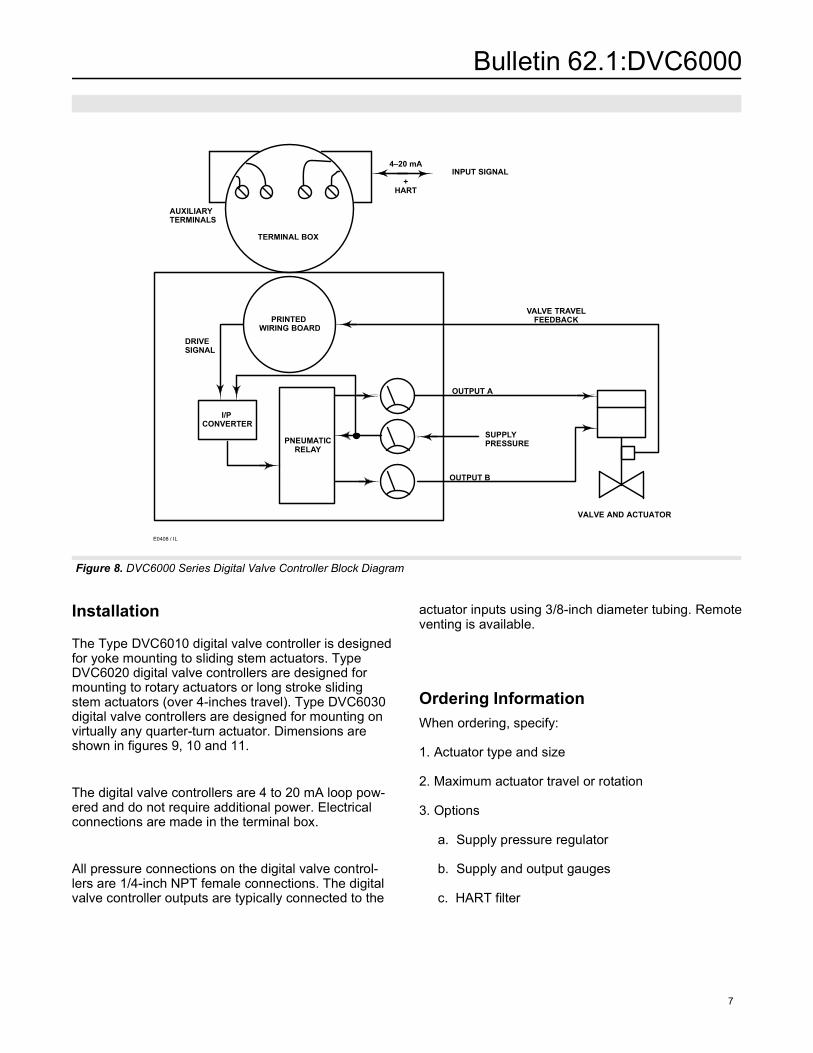
Figure 7. DVC6000 Series Digital Valve Controller Assembly
COVER
W8083 / IL
Principle of Operation
DVC6000 Series instruments receive a set point andposition the valve where it needs to be.
The input signal provides electrical power and theset point simultaneously. It is routed into the terminalbox through a twisted pair of wires.
The input signal is then directed to the printedwiring board assembly where the microprocessor runsa digital control algorithm resulting in a drive signal tothe I/P converter.
The I/P converter assembly is connected to sup-ply pressure and converts the drive signal into a pres-sure output signal.
The I/P output is sent to the pneumatic relay as-sembly. The relay is also connected to supply pres-sure and amplifies the small pneumatic signal from theI/P converter into a single larger pneumatic output sig-nal used by a single-acting actuator. For double-actingactuators, the relay accepts the pneumatic signal fromthe I/P converter and provides two pneumatic outputsignals.
The change in relay output pressure to the actua-tor causes the valve to move.
Valve position is sensed through the feedbacklinkage by the instrument’s travel sensor. The travelsensor (or potentiometer) is electrically connected tothe printed wiring board to provide a travel feedbacksignal used in the control algorithm.
The valve continues to move until the correct positionis attained.
Bulletin 62.1:DVC6000
7
Figure 8. DVC6000 Series Digital Valve Controller Block Diagram
E0408 / IL
INPUT SIGNAL4–20 mA
+HART
SUPPLYPRESSURE
PRINTEDWIRING BOARD
PNEUMATICRELAY
I/PCONVERTER
OUTPUT A
OUTPUT B
VALVE TRAVELFEEDBACK
AUXILIARYTERMINALS
TERMINAL BOX
DRIVESIGNAL
VALVE AND ACTUATOR
Installation
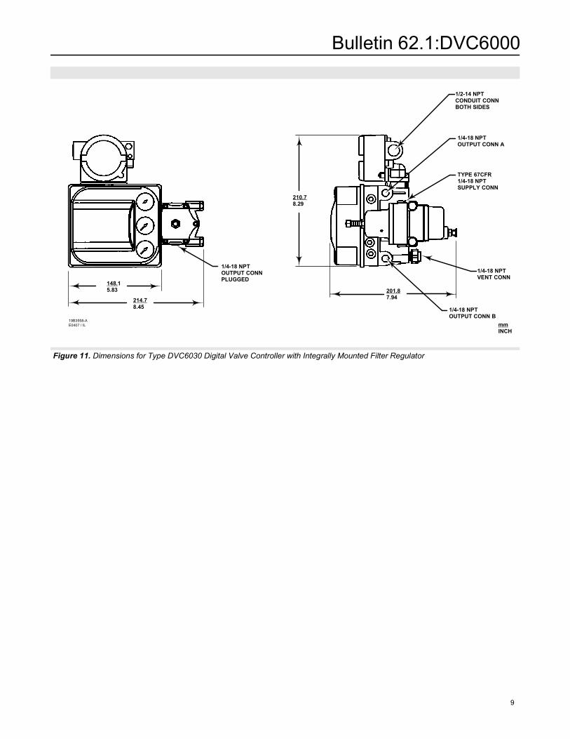
The Type DVC6010 digital valve controller is designedfor yoke mounting to sliding stem actuators. TypeDVC6020 digital valve controllers are designed formounting to rotary actuators or long stroke slidingstem actuators (over 4-inches travel). Type DVC6030digital valve controllers are designed for mounting onvirtually any quarter-turn actuator. Dimensions areshown in figures 9, 10 and 11.
The digital valve controllers are 4 to 20 mA loop pow-ered and do not require additional power. Electricalconnections are made in the terminal box.
All pressure connections on the digital valve control-lers are 1/4-inch NPT female connections. The digitalvalve controller outputs are typically connected to the
actuator inputs using 3/8-inch diameter tubing. Remoteventing is available.
Ordering Information
When ordering, specify:
1. Actuator type and size
2. Maximum actuator travel or rotation
3. Options
a. Supply pressure regulator
b. Supply and output gauges
c. HART filter
Bulletin 62.1:DVC6000
8
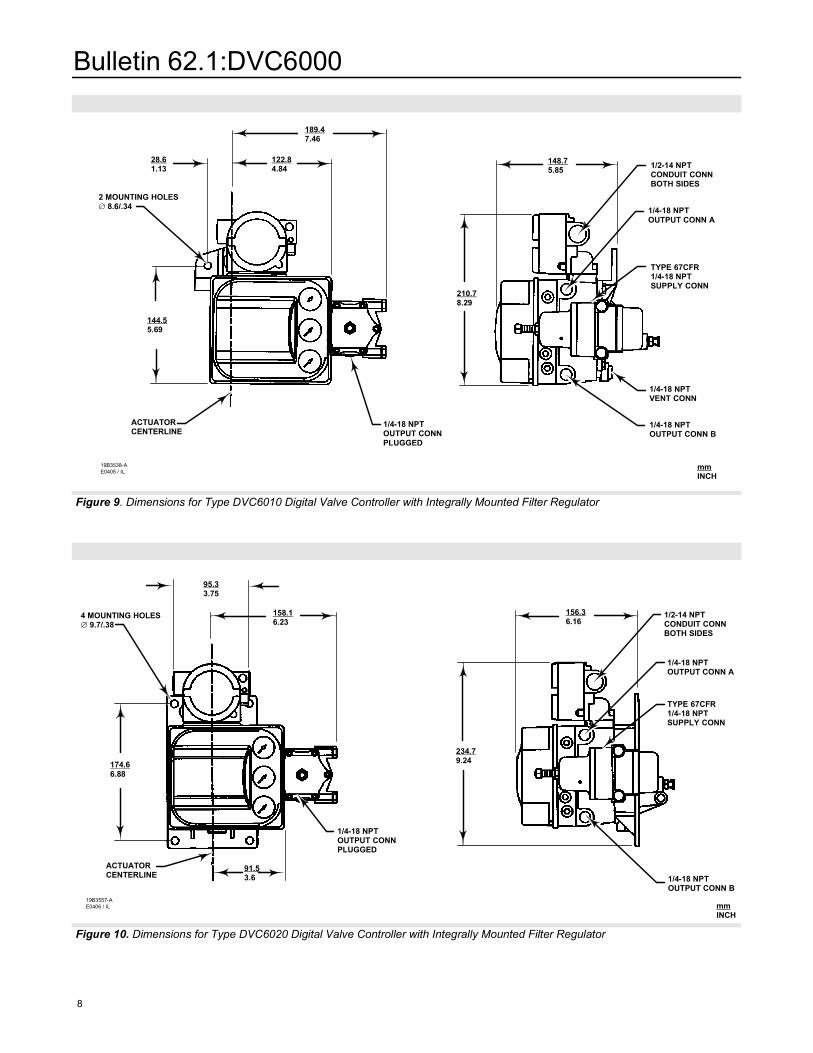
Figure 9. Dimensions for Type DVC6010 Digital Valve Controller with Integrally Mounted Filter Regulator
2 MOUNTING HOLES 8.6/.34
1/4-18 NPTOUTPUT CONN B
28.61.13
189.47.46
122.84.84
144.55.69
210.78.29
148.75.85
ACTUATORCENTERLINE
1/4-18 NPTOUTPUT CONNPLUGGED
1/2-14 NPTCONDUIT CONNBOTH SIDES
1/4-18 NPTOUTPUT CONN A
1/4-18 NPTVENT CONN
TYPE 67CFR1/4-18 NPTSUPPLY CONN
19B3538-AE0405 / IL
mmINCH
Figure 10. Dimensions for Type DVC6020 Digital Valve Controller with Integrally Mounted Filter Regulator
4 MOUNTING HOLES 9.7/.38
1/4-18 NPTOUTPUT CONN B
95.33.75
158.16.23
174.66.88
234.79.24
156.36.16
ACTUATORCENTERLINE
1/4-18 NPTOUTPUT CONNPLUGGED
1/2-14 NPTCONDUIT CONNBOTH SIDES
1/4-18 NPTOUTPUT CONN A
TYPE 67CFR1/4-18 NPTSUPPLY CONN
19B3557-AE0406 / IL mm
INCH
91.53.6
Bulletin 62.1:DVC6000
9
Figure 11. Dimensions for Type DVC6030 Digital Valve Controller with Integrally Mounted Filter Regulator
1/4-18 NPTOUTPUT CONN B
214.78.45
210.78.29
201.87.94
1/4-18 NPTOUTPUT CONNPLUGGED
1/2-14 NPTCONDUIT CONNBOTH SIDES
1/4-18 NPTOUTPUT CONN A
TYPE 67CFR1/4-18 NPTSUPPLY CONN
19B3558-AE0407 / IL mm
INCH
1/4-18 NPTVENT CONN
148.15.83
Bulletin 62.1:DVC6000
10
For information, contact Fisher:Marshalltown, Iowa 50158 USACernay 68700 France Sao Paulo 05424 BrazilSingapore 128461
Printed in U.S.A.
Fisher Controls International, Inc. 2000; All Rights Reserved
FIELDVUE, ValveLink, Fisher and Fisher-Rosemount are marks owned by Fisher Controls International, Inc. or Fisher-Rosemount Systems, Inc.HART is a mark owned by the HART Communications Foundation. All other marks are the property of their respective owners.
Related Documents