FIELD TESTING OF JET-GROUTED PILES AND DRILLED SHAFTS BDK-75-977-41 Project Managers: Peter Lai, P.E. Rodrigo Herrera, P.E. Researchers: Michael McVay, Ph.D. (PI) David Bloomquist, Ph.D., P.E. (Co-PI) Sudheesh Thiyyakkandi, Ph.D. James Stephenson GRIP 2013 August 8-9

Welcome message from author
This document is posted to help you gain knowledge. Please leave a comment to let me know what you think about it! Share it to your friends and learn new things together.
Transcript
1
FIELD TESTING OF JET-GROUTED PILES
AND DRILLED SHAFTS
BDK-75-977-41
Project Managers: Peter Lai, P.E.
Rodrigo Herrera, P.E.
Researchers: Michael McVay, Ph.D. (PI)
David Bloomquist, Ph.D., P.E. (Co-PI)
Sudheesh Thiyyakkandi, Ph.D.
James Stephenson
GRIP 2013 August 8-9
2 Objectives of the Research
Validate design and constructability of jet-grouted piles
Obtain combined torsion and lateral load response of drilled shafts
Verify FDOT’s revised design approach for drilled shafts supporting Mast arm structures
Compare axial, lateral, and combined torsion & lateral response of jet-grouted pile vs. drilled shaft
Cost comparison of jet-grouted piles vs. drilled shafts

3 Test Layout
Test site: FDOT site, Kingsley, Keystone Heights, FL
4 Review of GRIP’11 &12 Presentations
GRIP 2011: Background of the research
Design of Jet-grouted piles and Drilled shaft
Instrumentations
Soil exploration
GRIP 2012: Construction of Reaction and Test drilled shafts
CSL Tests on Drilled shafts
Design and fabrication of Mast arm assembly
Combined torsion and lateral load test on 12-ft deep shaft
Construction of precast piles, preparation and jetting
Design and construction of concrete cap
5 Presentation Overview
Side and tip grouting of piles
Axial response of drilled shaft and jet-grouted piles
Combined torsion and lateral response of drilled shafts
and jet-grouted piles
Lateral response of drilled shaft and jet-grouted pile

6 Side Grouting of Piles
Grout mixing and
pumping
Pile displacement and grout
pressure monitoring
Performed with the help of Applied Foundation Testing Inc. (AFT)

7 Side Grouting of Piles
0
25
50
75
100
125
150
175
200
225
0 50 100 150 200 250 300 350
Gro
ut
pre
ss
ure
(p
si)
Grout volume (gallon)
Pile 1 - top bag
0
25
50
75
100
125
150
175
200
225
0 50 100 150 200 250 300 350
Gro
ut
pre
ss
ure
(p
si)
Grout volume (gallon)
Pile 1 - bottom bag
Expansion ratio = Initial radius /final radius ≈ 1.64
Cylindrical cavity expansion curve (top bag) (Yu and Houlsby’s solution; 1991)
8
0
25
50
75
100
125
150
175
200
225
0 50 100 150 200 250 300 350
Gro
ut
pre
ss
ure
(p
si)
Grout volume (gallon)
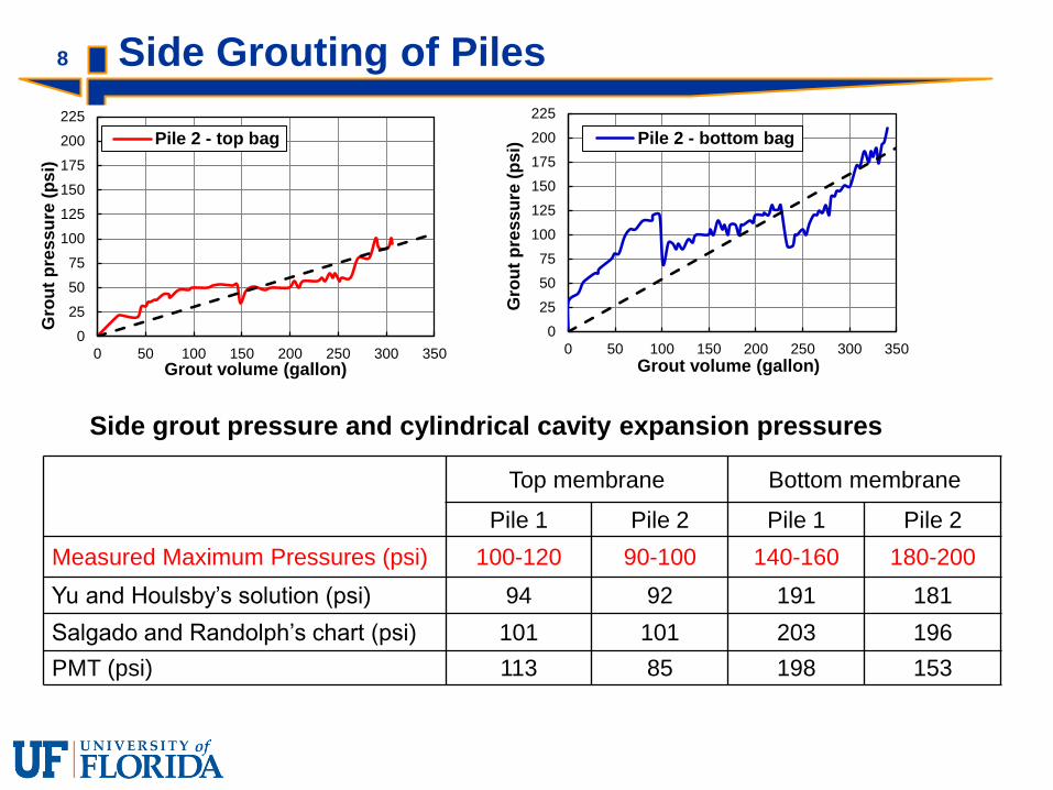
Pile 2 - top bag
0
25
50
75
100
125
150
175
200
225
0 50 100 150 200 250 300 350
Gro
ut
pre
ss
ure
(p
si)
Grout volume (gallon)
Pile 2 - bottom bag
Top membrane Bottom membrane
Pile 1 Pile 2 Pile 1 Pile 2
Measured Maximum Pressures (psi) 100-120 90-100 140-160 180-200
Yu and Houlsby’s solution (psi) 94 92 191 181
Salgado and Randolph’s chart (psi) 101 101 203 196
PMT (psi) 113 85 198 153
Side Grouting of Piles
Side grout pressure and cylindrical cavity expansion pressures

9 Tip Grouting of Piles
0
50
100
150
200
250
300
350
400
450
0 25 50 75 100 125 150
Gro
ut
pre
ss
ure
ps
i)
Grout volume (gallon)
Pile 1 Pile 2
0
0.1
0.2
0.3
0.4
0.5
0.6
0.7
0 25 50 75 100 125 150
Pil
e t
op
dis
pla
ce
me
nt
(in
)
Grout volume (gallon)
Pile 1 Pile 2
0
50
100
150
200
250
300
350
400
450
0 0.1 0.2 0.3 0.4 0.5 0.6 0.7
Gro
ut
pre
ss
ure
(p
si)
Pile top displacement (in)
Pile 1 Pile 2Tip grout pressure and spherical cavity
expansion pressure (psi)
Pile 1 Pile 2
Measured tip grout pressure 290 280-300
Yu and Houlsby’s (1991) 318 318
Salgado and Randolph (2001) 420 420
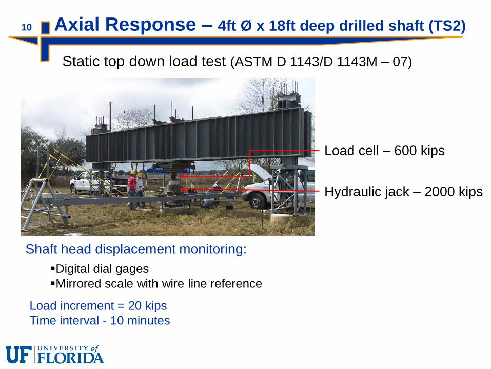
10 Axial Response – 4ft Ø x 18ft deep drilled shaft (TS2)
Static top down load test (ASTM D 1143/D 1143M – 07)
Shaft head displacement monitoring:
Digital dial gages
Mirrored scale with wire line reference
Load increment = 20 kips
Time interval - 10 minutes
Hydraulic jack – 2000 kips
Load cell – 600 kips

11 Axial Response – 4ft Ø x 18ft deep drilled shaft (TS2)
0
2
4
6
8
10
12
14
16
18
0 40 80 120 160 200 240 280 320 360
Dep
th (
ft)
Load (kips) Drilled shaft
Load distribution
0
50
100
150
200
250
300
350
0 0.1 0.2 0.3 0.4 0.5 0.6 0.7
Lo
ad
(kip
)
Displacement (in)
Top load
Tip load
Skin resistance
Maximum top displacement = 0.563in
Load-displacement response
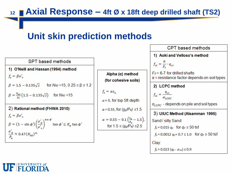
12 Axial Response – 4ft Ø x 18ft deep drilled shaft (TS2)
Unit skin prediction methods
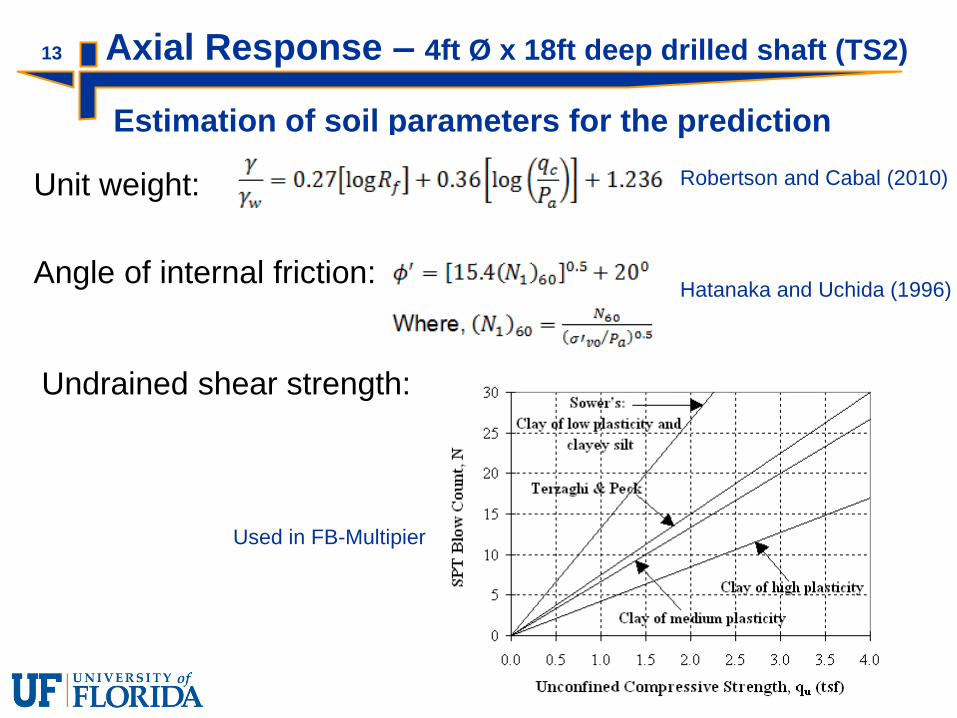
13 Axial Response – 4ft Ø x 18ft deep drilled shaft (TS2)
Estimation of soil parameters for the prediction
Unit weight: Robertson and Cabal (2010)
Angle of internal friction: Hatanaka and Uchida (1996)
Undrained shear strength:
Used in FB-Multipier

14 Axial Response – 4ft Ø x 18ft deep drilled shaft (TS2)
Predicted vs. Measured

15 Axial Response – Jet-grouted piles
Loading sequence: JP1 - Axial load test BEFORE torsion test
JP2 – Axial load test AFTER torsion test
Data acquisition
Displacement monitoring: Leica Digital levels
Digital dial gages
Mirrored scale with wire line reference

16 Axial Response – Jet-grouted piles
Pullout failure of reaction drilled shafts in both tests
Maximum top displacement of test piles: JP1: 0.16 in
JP2: 0.198 in
JP1 test JP2 test
1.19 in 0.334 in
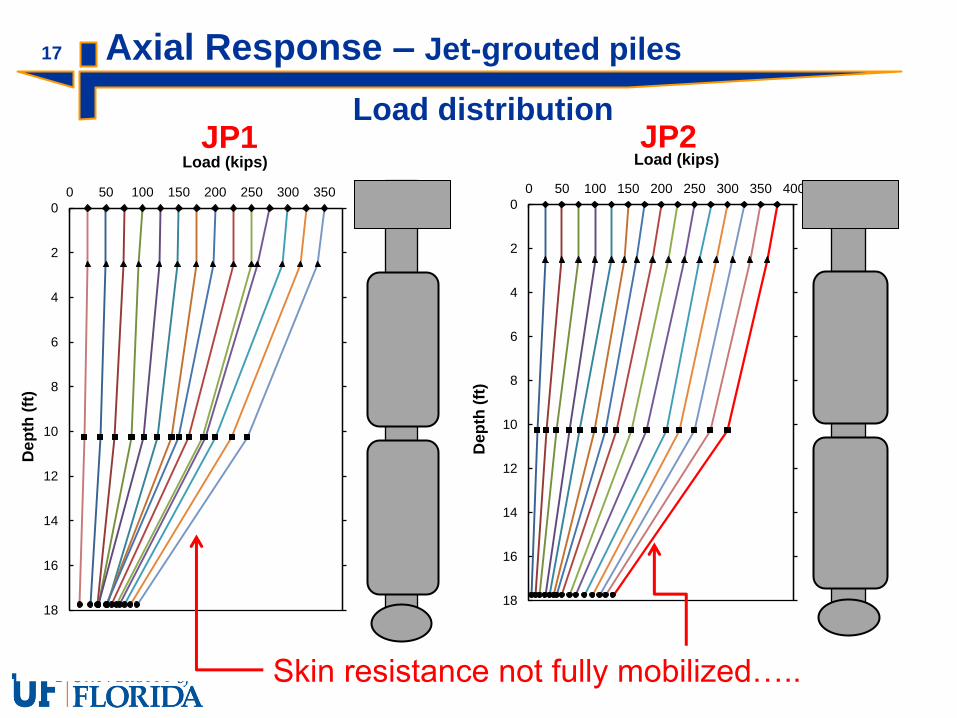
17 Axial Response – Jet-grouted piles
0
2
4
6
8
10
12
14
16
18
0 50 100 150 200 250 300 350
De
pth
(ft
)
Load (kips)
Load distribution
0
2
4
6
8
10
12
14
16
18
0 50 100 150 200 250 300 350 400
Dep
th (
ft)
Load (kips) JP2 JP1
Skin resistance not fully mobilized…..

0
50
100
150
200
250
300
350
400
0 0.1 0.2 0.3 0.4 0.5 0.6 0.7
Lo
ad
(kip
)
Displacement (in)
JP1-Top load
JP1-Tip load
JP1 - Skin resistance
18 Axial Response – Jet-grouted piles
0
50
100
150
200
250
300
350
400
0 0.1 0.2 0.3 0.4 0.5 0.6 0.7
Lo
ad
(kip
s)
Displacement (in)
JP2 -Top load
JP2 -Tip load
JP2 - Skin resistance
Load Displacement responses
JP1 JP2
0
50
100
150
200
250
300
350
400
0 0.1 0.2 0.3 0.4 0.5 0.6 0.7
To
tal L
oad
(kip
)
Displacement (in)
JP1
JP2
Comparison: JP1 vs. JP2
Similar stiffness response
Negligible influence of prior torque
test in JP2
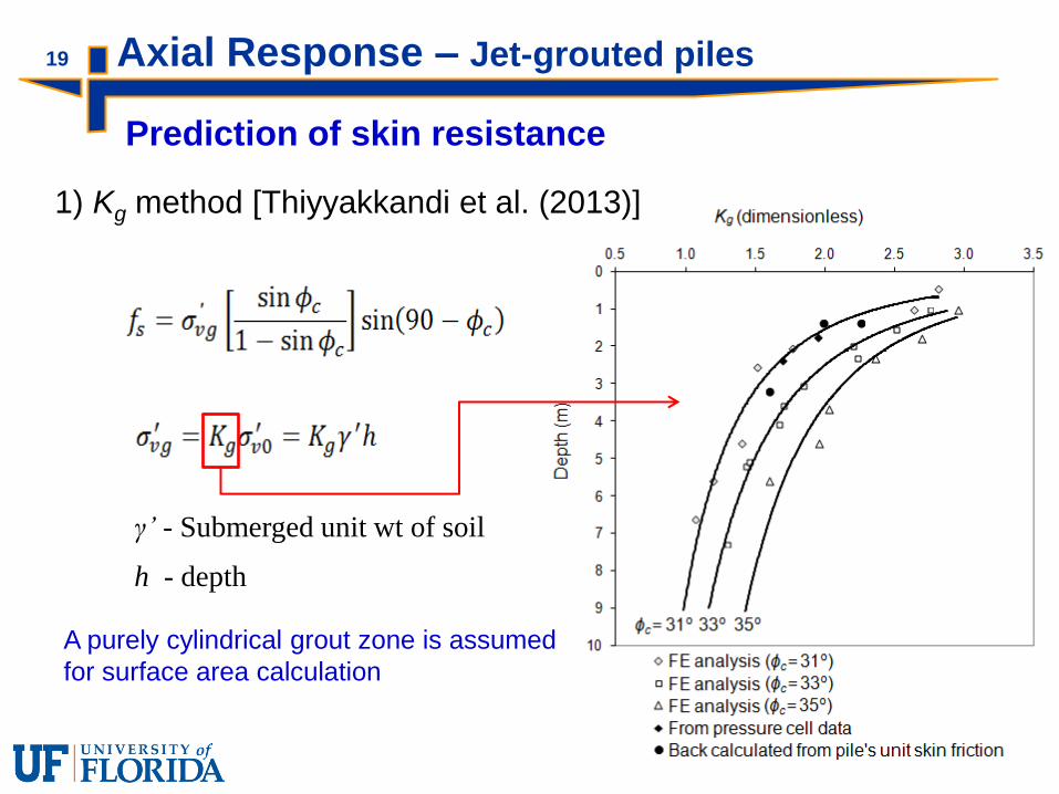
19 Axial Response – Jet-grouted piles
γ’ - Submerged unit wt of soil
h - depth
Prediction of skin resistance
1) Kg method [Thiyyakkandi et al. (2013)]
A purely cylindrical grout zone is assumed
for surface area calculation
0
20
40
60
80
100
120
140
160
180
0 20 40 60 80 100
Pre
ssu
re (
psi)
volume (cm3)
Pile2_ 8.5 ft depth
Pile2_ 16ft depth
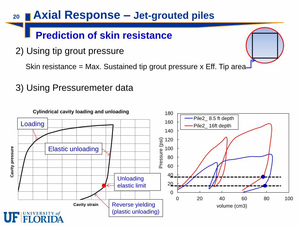
20 Axial Response – Jet-grouted piles
Prediction of skin resistance
2) Using tip grout pressure
Skin resistance = Max. Sustained tip grout pressure x Eff. Tip area
3) Using Pressuremeter data
Cav
ity p
ressu
re
Cavity strain
Cylindrical cavity loading and unloading
Elastic unloading
Unloading
elastic limit
Reverse yielding
(plastic unloading)
Loading
21
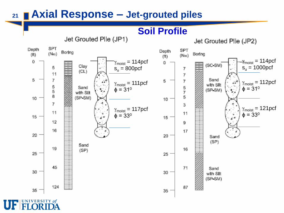
γmoist = 111pcf
ϕ = 310
γmoist = 114pcf
su = 800pcf
γmoist = 117pcf
ϕ = 330
γmoist = 112pcf
ϕ = 310
γmoist = 114pcf
su = 1000pcf
γmoist = 121pcf
ϕ = 330
Axial Response – Jet-grouted piles
Soil Profile
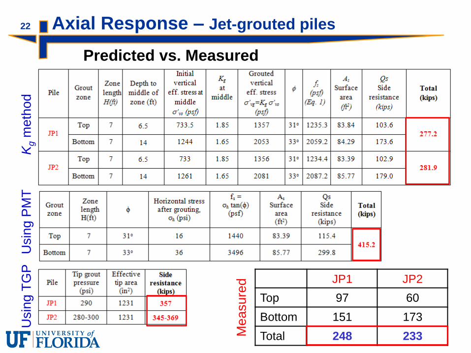
22 Axial Response – Jet-grouted piles U
sin
g P
MT
U
sin
g T
GP
JP1 JP2
Top 97 60
Bottom 151 173
Total 248 233
Kg m
eth
od
Me
asu
red
Predicted vs. Measured
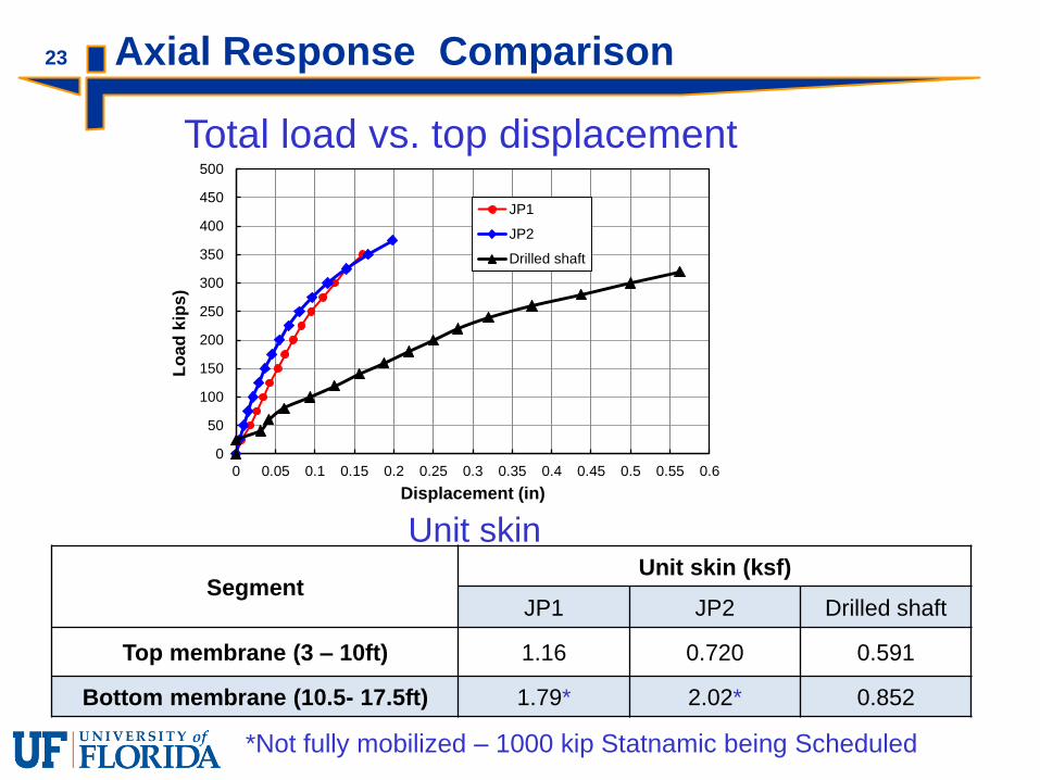
23 Axial Response Comparison
0
50
100
150
200
250
300
350
400
450
500
0 0.05 0.1 0.15 0.2 0.25 0.3 0.35 0.4 0.45 0.5 0.55 0.6
Lo
ad
kip
s)
Displacement (in)
JP1
JP2
Drilled shaft
Total load vs. top displacement
Segment Unit skin (ksf)
JP1 JP2 Drilled shaft
Top membrane (3 – 10ft) 1.16 0.720 0.591
Bottom membrane (10.5- 17.5ft) 1.79* 2.02* 0.852
Unit skin
*Not fully mobilized – 1000 kip Statnamic being Scheduled
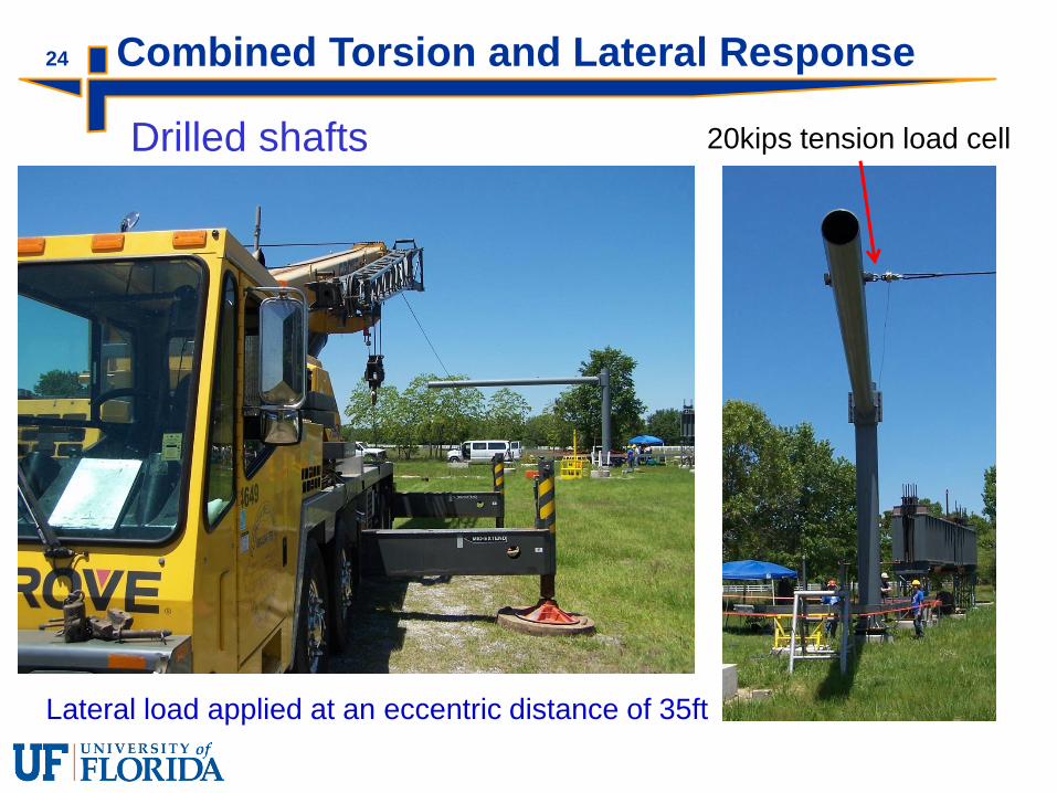
24 Combined Torsion and Lateral Response
Drilled shafts 20kips tension load cell
Lateral load applied at an eccentric distance of 35ft
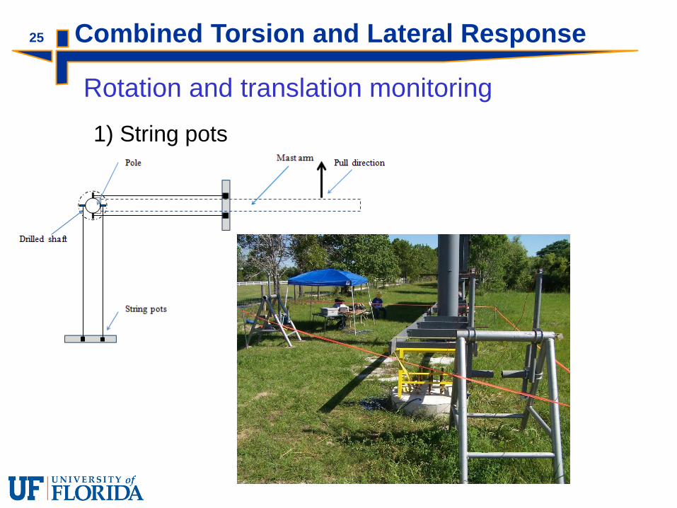
25 Combined Torsion and Lateral Response
Rotation and translation monitoring
1) String pots

26 Combined Torsion and Lateral Response
Rotation and translation monitoring
2) Total Stations
Reflective Targets

27 Combined Torsion and Lateral Response
Rotation and translation monitoring
3) Digital dial gages
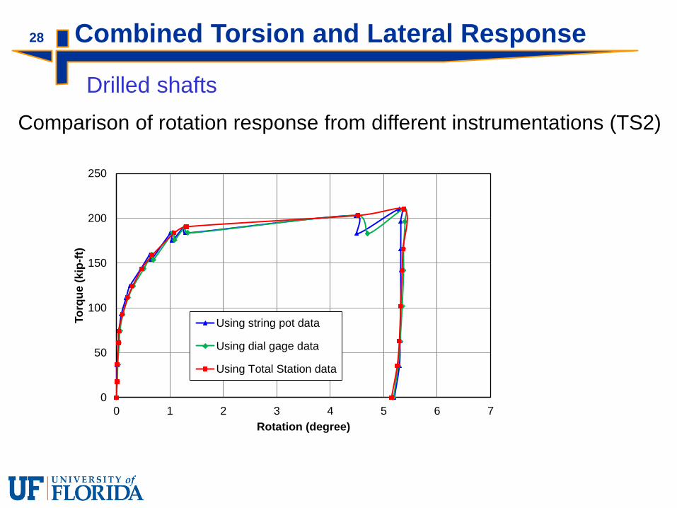
28 Combined Torsion and Lateral Response
Drilled shafts
0
50
100
150
200
250
0 1 2 3 4 5 6 7
To
rqu
e (
kip
-ft)
Rotation (degree)
Using string pot data
Using dial gage data
Using Total Station data
Comparison of rotation response from different instrumentations (TS2)

29 Combined Torsion and Lateral Response
Drilled shafts
0
50
100
150
200
250
0 2 4 6 8 10 12
To
rqu
e (
kip
-ft)
Rotation (degree)
TS3 (18ft shaft)
TS1 (12ft shaft)
TS2 (18ft shaft)
0
1
2
3
4
5
6
7
0 0.1 0.2 0.3 0.4 0.5 0.6L
ate
ral lo
ad
(kip
s)
Lateral displacement (in)
TS2 (18ft shaft)
TS3 (18ft shaft)
Torque vs. rotation Lateral load vs. displacement
TS1: Max. lateral displacement ≈4in
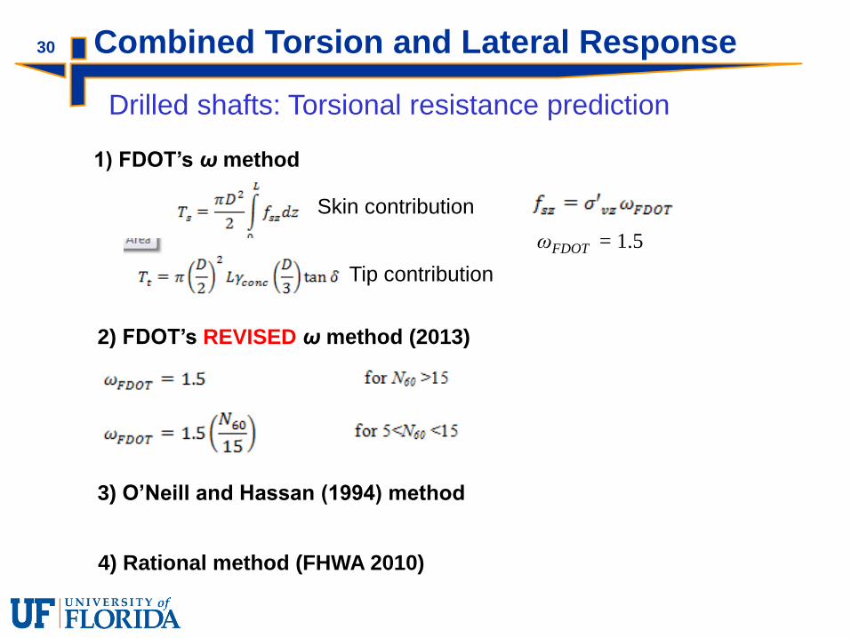
30 Combined Torsion and Lateral Response
Drilled shafts: Torsional resistance prediction
1) FDOT’s ω method
Skin contribution
Tip contribution
ωFDOT = 1.5
2) FDOT’s REVISED ω method (2013)
3) O’Neill and Hassan (1994) method
4) Rational method (FHWA 2010)

31 Combined Torsion and Lateral Response
Soil profile
WT
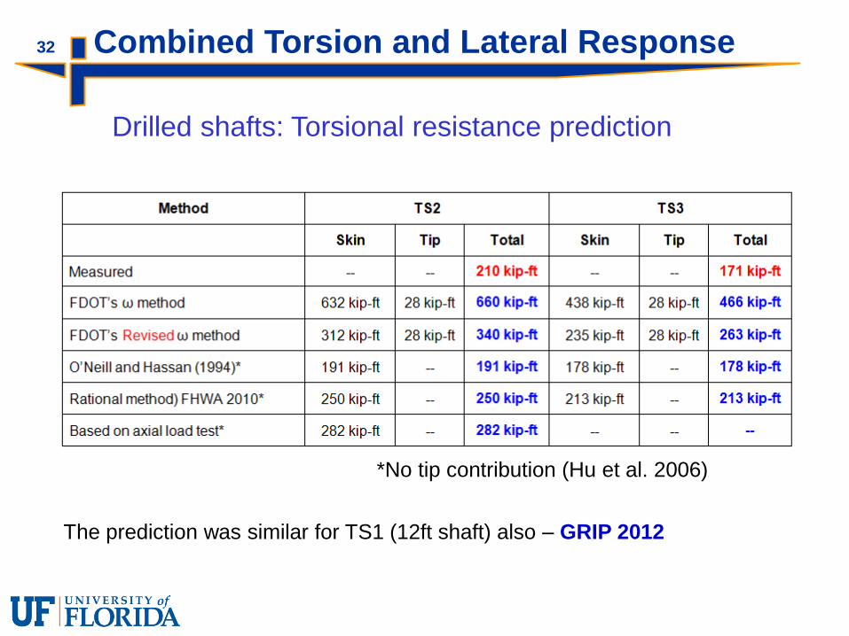
32 Combined Torsion and Lateral Response
Drilled shafts: Torsional resistance prediction
*No tip contribution (Hu et al. 2006)
The prediction was similar for TS1 (12ft shaft) also – GRIP 2012

33 Combined Torsion and Lateral Response
Jet-grouted pile
0
100
200
300
400
500
600
0 1 2 3 4 5 6
To
rqu
e (
kip
-ft)
Rotation (degree)
Pile 1
Pile 2
0
2
4
6
8
10
12
14
16
0 0.2 0.4 0.6 0.8 1 1.2 1.4 1.6 1.8 2L
ate
ral lo
ad
(kip
s)
Lateral displacement (in)
Pile 1
Pile 2
Loading sequence: JP1 - Torsion test AFTER axial load test
JP2 – Torsion test BEFORE axial load test
Torque vs. rotation Lateral load vs. displacement
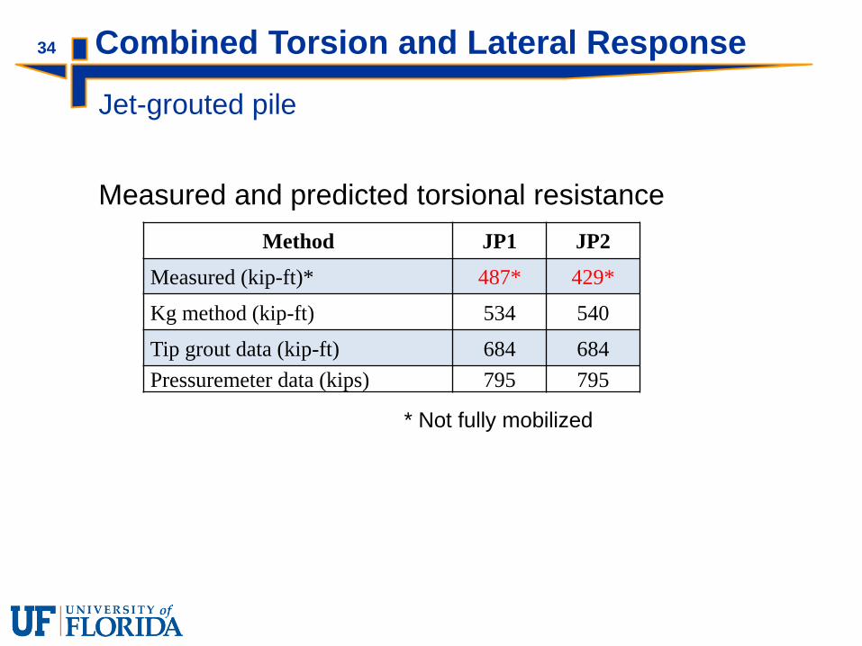
34 Combined Torsion and Lateral Response
Jet-grouted pile
Method JP1 JP2
Measured (kip-ft)* 487* 429*
Kg method (kip-ft) 534 540
Tip grout data (kip-ft) 684 684
Pressuremeter data (kips) 795 795
* Not fully mobilized
Measured and predicted torsional resistance
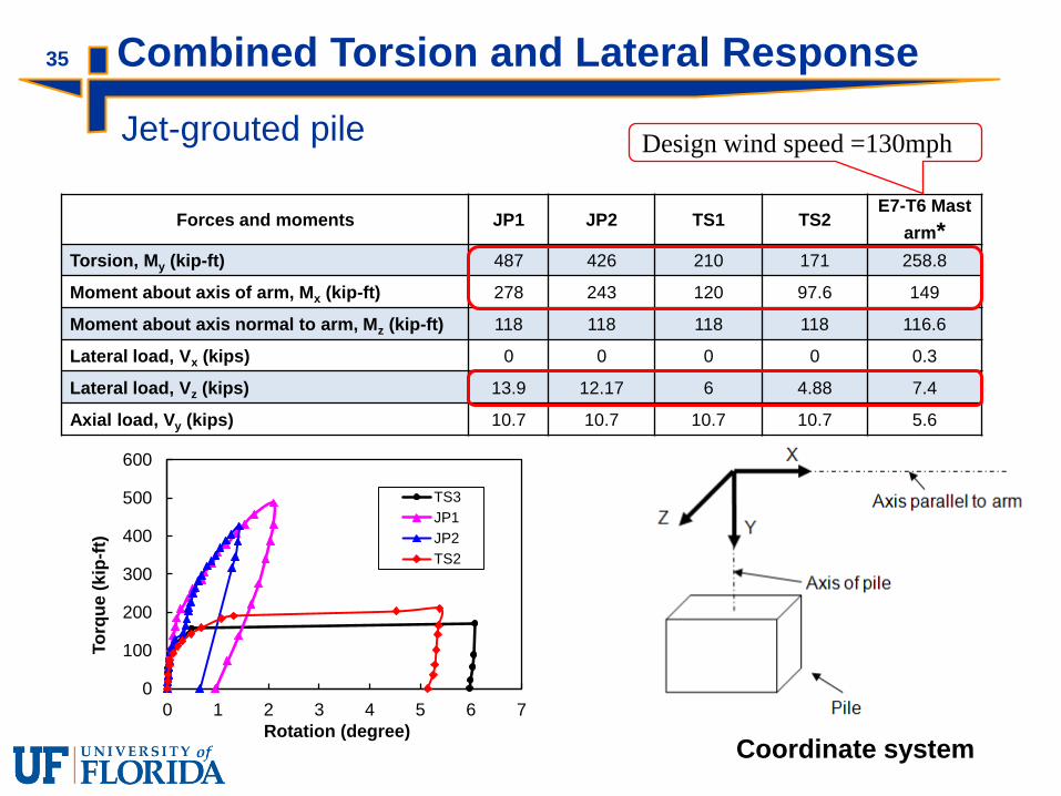
35
Forces and moments JP1 JP2 TS1 TS2 E7-T6 Mast
arm*
Torsion, My (kip-ft) 487 426 210 171 258.8
Moment about axis of arm, Mx (kip-ft) 278 243 120 97.6 149
Moment about axis normal to arm, Mz (kip-ft) 118 118 118 118 116.6
Lateral load, Vx (kips) 0 0 0 0 0.3
Lateral load, Vz (kips) 13.9 12.17 6 4.88 7.4
Axial load, Vy (kips) 10.7 10.7 10.7 10.7 5.6
Design wind speed =130mph
Coordinate system
Combined Torsion and Lateral Response
Jet-grouted pile
0
100
200
300
400
500
600
0 1 2 3 4 5 6 7
To
rqu
e (
kip
-ft)
Rotation (degree)
TS3
JP1
JP2
TS2
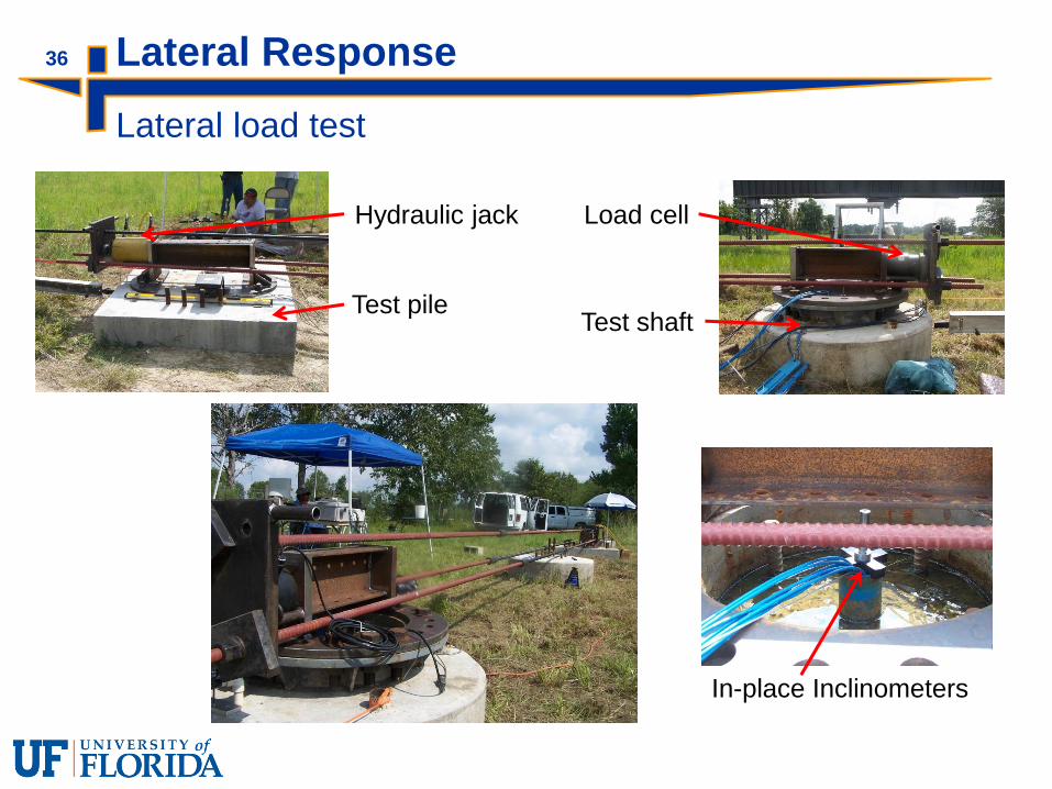
36 Lateral Response
Lateral load test
Test pile
Hydraulic jack
Test shaft
Load cell
In-place Inclinometers
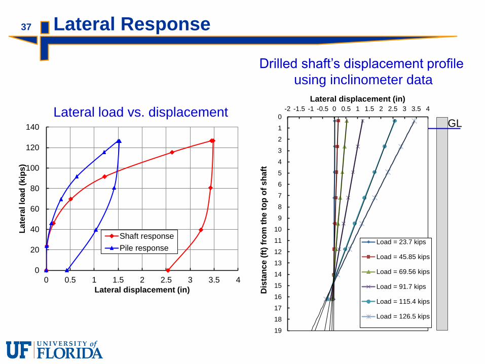
37 Lateral Response
0
20
40
60
80
100
120
140
0 0.5 1 1.5 2 2.5 3 3.5 4
Late
ral lo
ad
(kip
s)
Lateral displacement (in)
Shaft response
Pile response
Lateral load vs. displacement 0
1
2
3
4
5
6
7
8
9
10
11
12
13
14
15
16
17
18
19
-2 -1.5 -1 -0.5 0 0.5 1 1.5 2 2.5 3 3.5 4
Dis
tan
ce
(ft
) fr
om
th
e t
op
of
sh
aft
Lateral displacement (in)
Load = 23.7 kips
Load = 45.85 kips
Load = 69.56 kips
Load = 91.7 kips
Load = 115.4 kips
Load = 126.5 kips
GL
Drilled shaft’s displacement profile
using inclinometer data
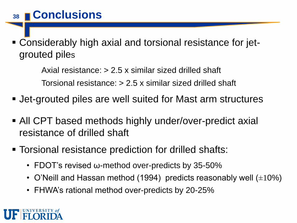
38
Considerably high axial and torsional resistance for jet-
grouted piles
Axial resistance: > 2.5 x similar sized drilled shaft
Torsional resistance: > 2.5 x similar sized drilled shaft
Jet-grouted piles are well suited for Mast arm structures
All CPT based methods highly under/over-predict axial
resistance of drilled shaft
Torsional resistance prediction for drilled shafts:
• FDOT’s revised ω-method over-predicts by 35-50%
• O’Neill and Hassan method (1994) predicts reasonably well (±10%)
• FHWA’s rational method over-predicts by 20-25%
Conclusions

39
1. Brown, D.A, Turner, J.P, and Castelli, R.J (2010) Drilled shafts: Construction Procedures and
LRFD design methods, FHWA NHI-10-016.
2. FDOT MathCAD Program: Mastarm v4.3.
3. FDOT Structures Manual, Vol. 9, 2013.
4. Hu, Z., McVay, M., Bloomquist, D.,; Herrera, R., Peter Lai, P., (2005) “Influence of Torque on
Lateral Capacity of Drilled Shafts in Sands”, Journal of Geotechnical and Geoenvironmental
Engineering, ASCE, Vol. 132, No. 4, p.456-464.
5. O’Neil, M. W., and Reese, L. C. (1999). “Drilled shafts: Construction procedures and design
methods,” FHWA, Publication No. FHWA-IF-95-025.
6. Salgado, R., and Randolph, M. F. (2001). “Analysis of Cavity Expansion in Sand,” International
Journal of Geomechanics, ASCE, 1(2), 175-192.
7. Thiyyakkandi, S., McVay, M., Bloomquist , D., and Lai P. (2013), “Measured and Predicted
Response of a New Jetted and Grouted Precast Pile with Membranes in Cohesionless Soils,”
Journal of Geotechnical and Geoenvironmental Engineering, 139 (8), 1334-1345.
8. Yu, H. S., and Houlsby, G.T. (1991). “Finite Cavity Expansion in Dilatant Soils – Loading
Analysis,” Geotechnique, 41(2), 173-183.
References

Thank You
40
Related Documents