Field Development & Construction

Welcome message from author
This document is posted to help you gain knowledge. Please leave a comment to let me know what you think about it! Share it to your friends and learn new things together.
Transcript

Field Development & Construction

Michael Cowie
Technical Director
Ecosse Subsea Systems Ltd

Ambient Lifting:A Real Alternative to Heavy Lift Vessels
4th February 2016, AECC, Michael Cowie
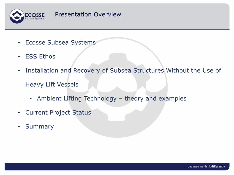
Presentation Overview
• Ecosse Subsea Systems
• ESS Ethos
• Installation and Recovery of Subsea Structures Without the Use of
Heavy Lift Vessels
• Ambient Lifting Technology – theory and examples
• Current Project Status
• Summary

Ecosse Subsea Systems
ESS is a Technology Based Company:
• Established in 1996
• 100% Scottish owned
• Initially O & G focused, diversified into Offshore Renewables
• Core business:
Subsea engineering consultancy
Offshore contracting
SCAR Seabed System
Route clearance, pre-cut trenching, backfilling
Technology development and implementation
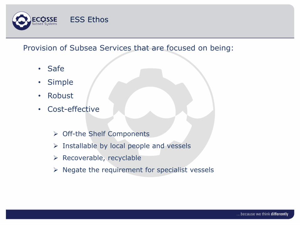
ESS Ethos
Provision of Subsea Services that are focused on being:
• Safe
• Simple
• Robust
• Cost-effective
Off-the Shelf Components
Installable by local people and vessels
Recoverable, recyclable
Negate the requirement for specialist vessels
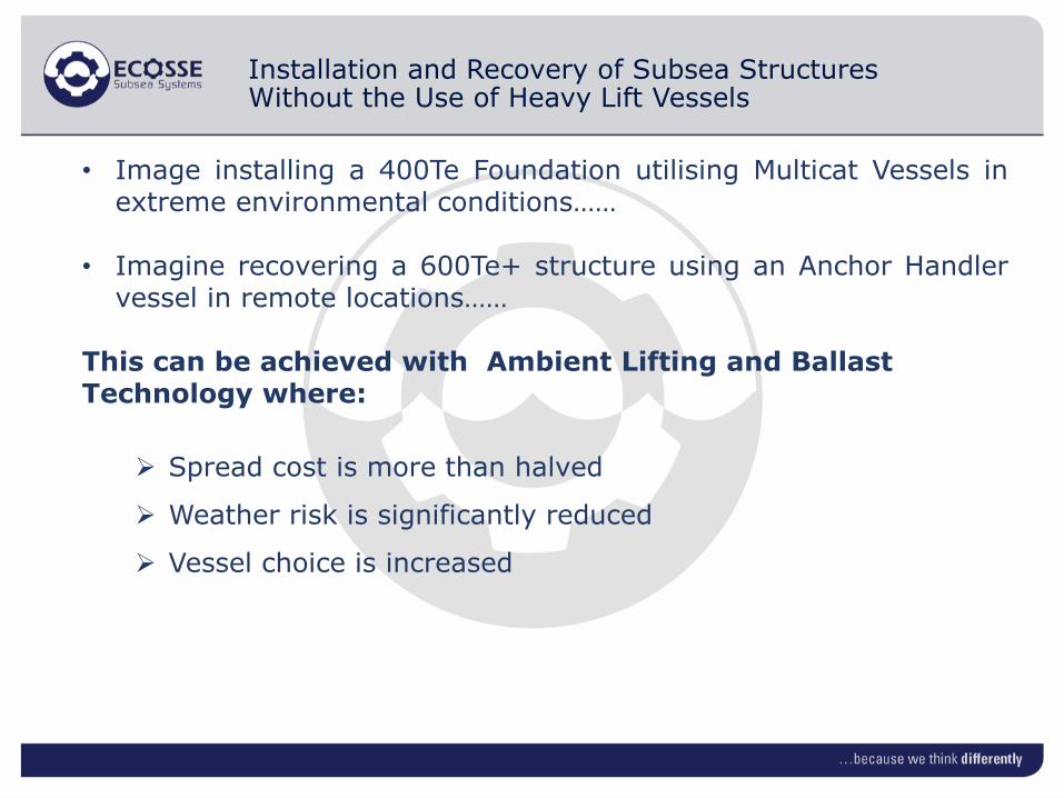
Installation and Recovery of Subsea Structures Without the Use of Heavy Lift Vessels
• Image installing a 400Te Foundation utilising Multicat Vessels inextreme environmental conditions……
• Imagine recovering a 600Te+ structure using an Anchor Handlervessel in remote locations……
This can be achieved with Ambient Lifting and Ballast Technology where:
Spread cost is more than halved
Weather risk is significantly reduced
Vessel choice is increased

Ambient Lifting
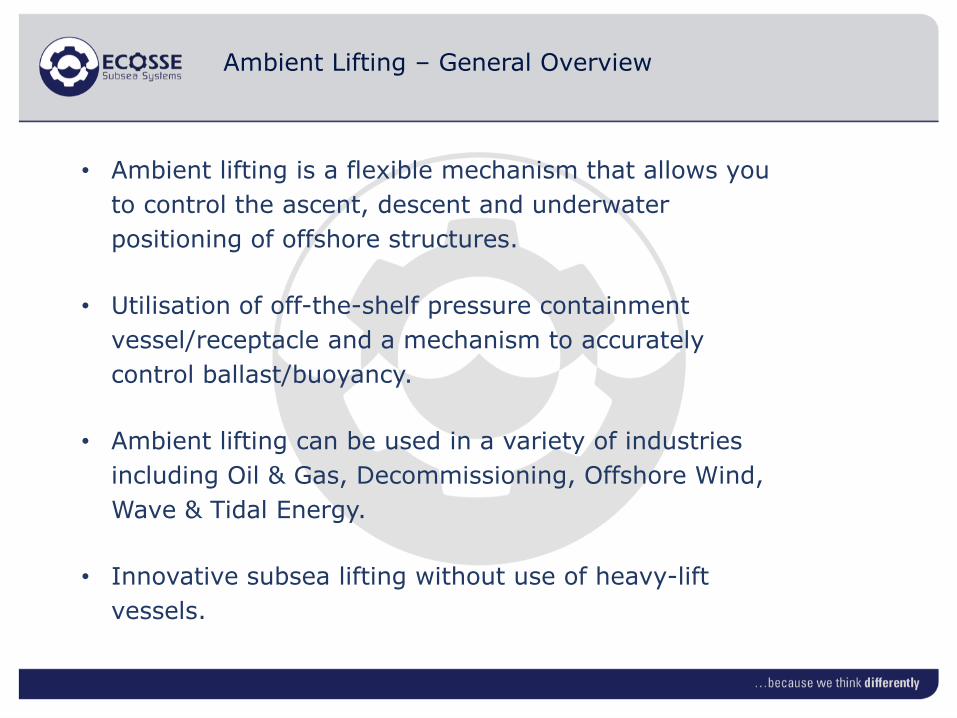
Ambient Lifting – General Overview
• Ambient lifting is a flexible mechanism that allows you
to control the ascent, descent and underwater
positioning of offshore structures.
• Utilisation of off-the-shelf pressure containment
vessel/receptacle and a mechanism to accurately
control ballast/buoyancy.
• Ambient lifting can be used in a variety of industries
including Oil & Gas, Decommissioning, Offshore Wind,
Wave & Tidal Energy.
• Innovative subsea lifting without use of heavy-lift
vessels.

Ambient Lifting:
Theory Examples

11
Te
250Te
0kg
• In air structural weight
Structure FOUNDATION Example
Low Friction Gel Pig
Liquid Gas

Te
12
250Te
Neutrally Buoyant
250Te
250Te
• In-water structural weight
• Buoyancy in receptacle
designed to ensure structure is
neutrally buoyant
Structure FOUNDATION Example

13
Te
250Te
250Te
0-200Te
250Te
• In-water weight increased by adding
ballast material
• Structure sinks to floor in a very
controlled manner
Structure FOUNDATION Example

14
Te
250Te
250Te
250Te
200Te
• Gas is replaced or compressed by
fluid
• Now in-water structural weight plus
weight generated by water in
receptacle
• Design ensures sufficient for
temporary stability
Structure FOUNDATION Example
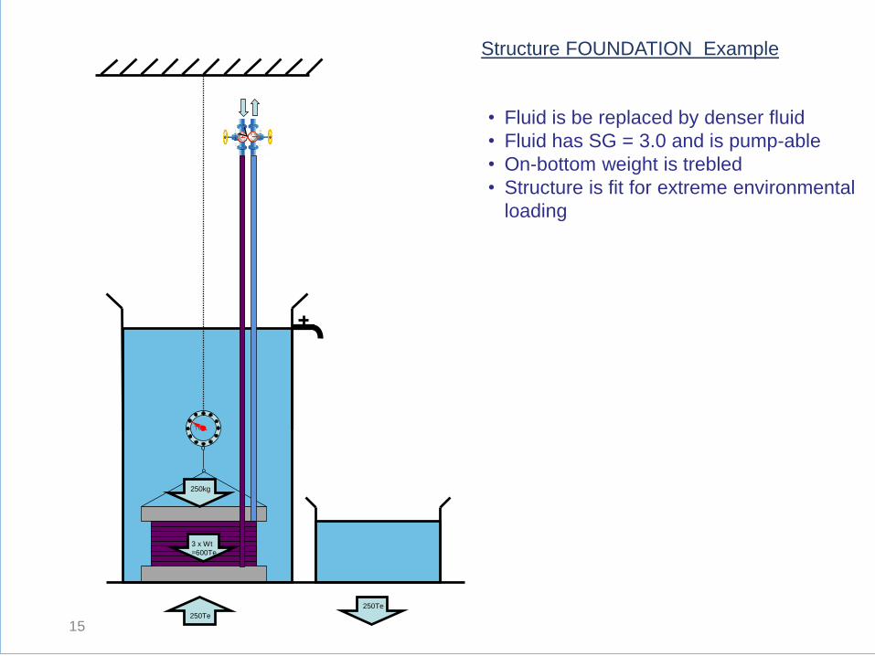
15
Te
250Te
250kg
250Te
3 x Wt
=600Te
• Fluid is be replaced by denser fluid
• Fluid has SG = 3.0 and is pump-able
• On-bottom weight is trebled
• Structure is fit for extreme environmental
loading
Structure FOUNDATION Example

16
Te
• Reverse process for recovery
• Fluid replaces heavy fluid
Structure FOUNDATION Example

17
Te
• Structure is neutrally buoyant
• Structure is returned to surface in a
very controlled manner
Structure FOUNDATION Example

Te
18
250Te
Neutrally Buoyant
• Structure on surface
• Can be towed to quayside for recovery
Structure FOUNDATION Example

19
Te
300Te
Neutrally Buoyant
• Structure is designed to be buoyant
when flooded with fluid
• Structure is positioned over structure
to be recovered
Structure INSTALLATION / RECOVERY Example

20
Te
• Structure is neutrally buoyant
• Structure encloses over top of structure
and is locked in
300Te
Structure INSTALLATION / RECOVERY Example
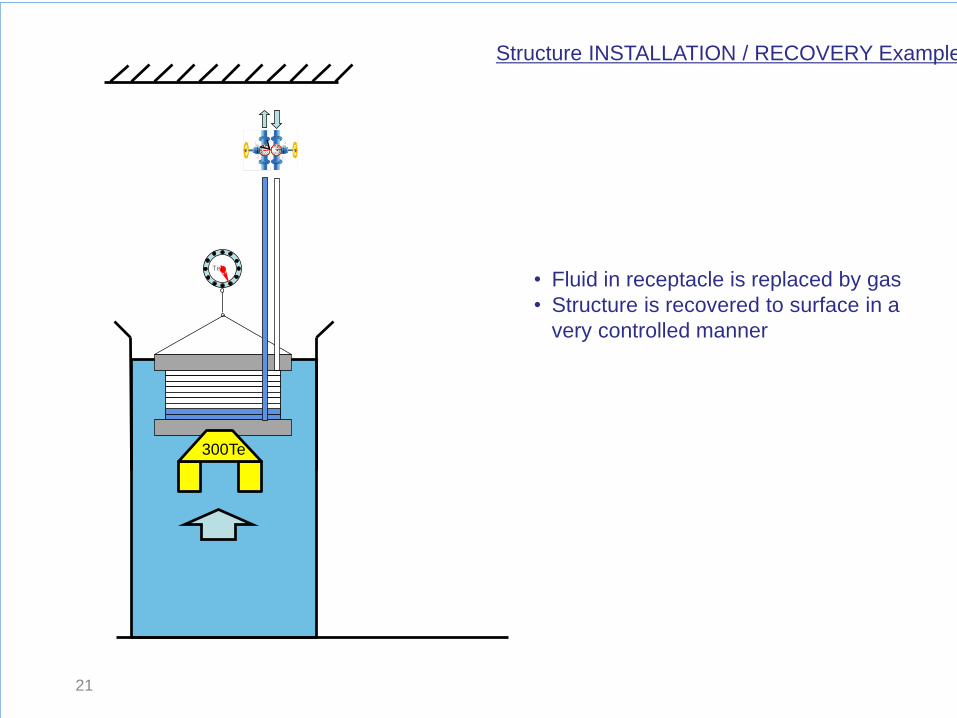
21
Te
• Fluid in receptacle is replaced by gas
• Structure is recovered to surface in a
very controlled manner
Structure INSTALLATION / RECOVERY Example
300Te

Foundation Installation/Recovery Example

Ambient Lifting – Typical Configuration

Steel Frame (Lower Section)
Lower pipework section
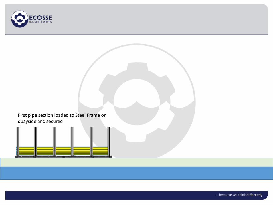
First pipe section loaded to Steel Frame on quayside and secured
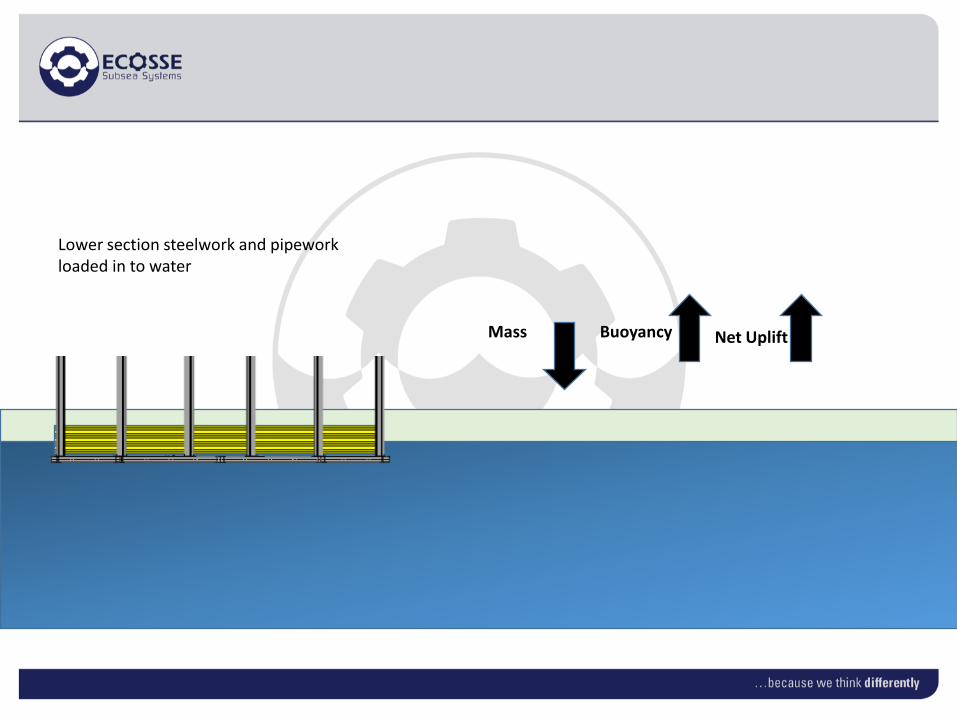
Lower section steelwork and pipework loaded in to water
Mass Buoyancy Net Uplift

Second pipework section loaded into Steel Frame in Quayside water
Mass Buoyancy Net Uplift
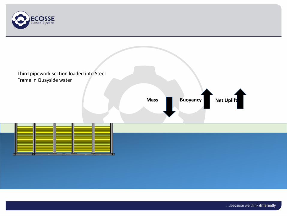
Third pipework section loaded into Steel Frame in Quayside water
Mass Buoyancy Net Uplift

Upper steelwork attached to Steel Frame in Quayside water
Mass Buoyancy Net Uplift
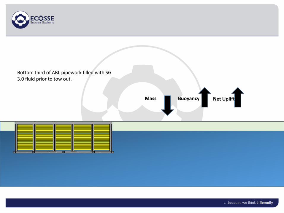
Bottom third of ABL pipework filled with SG 3.0 fluid prior to tow out.
Mass Buoyancy Net Uplift

External ballast added to frame prior to tow out.
Mass Buoyancy Net Uplift
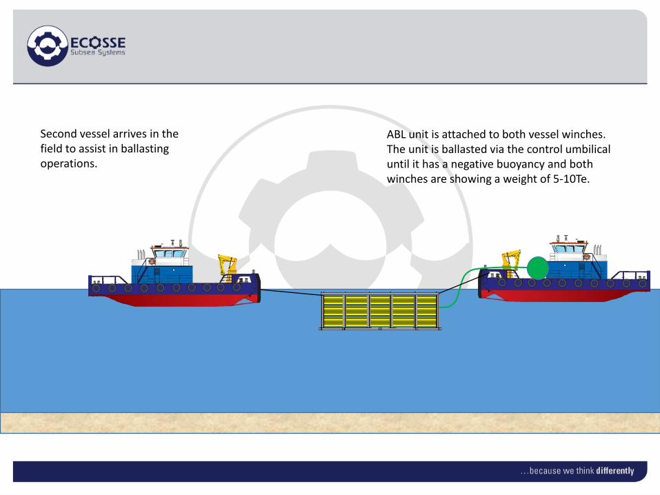
Second vessel arrives in the field to assist in ballasting operations.
ABL unit is attached to both vessel winches. The unit is ballasted via the control umbilical until it has a negative buoyancy and both winches are showing a weight of 5-10Te.
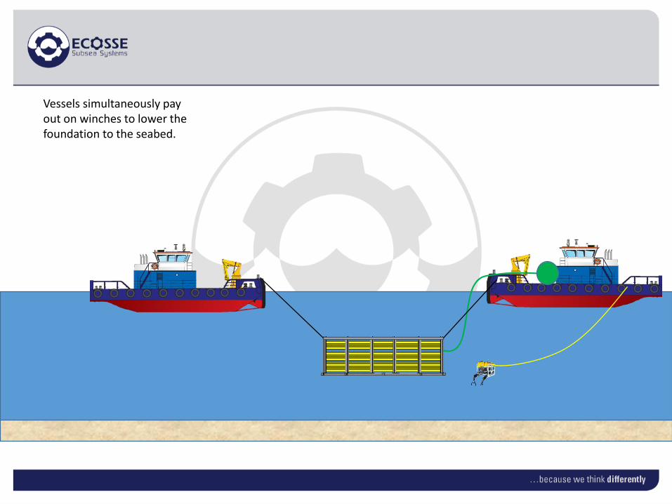
Vessels simultaneously pay out on winches to lower the foundation to the seabed.

Upon laydown on the seabed, the ABL unit can be fully water ballasted and then disconnected.
On bottom weight when fully water ballasted with bottom third filled with SG 3.0 fluid
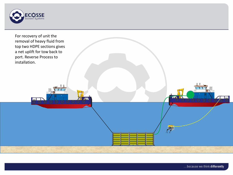
For recovery of unit the removal of heavy fluid from top two HDPE sections gives a net uplift for tow back to port. Reverse Process to installation.
Subsea Structure Recovery Example
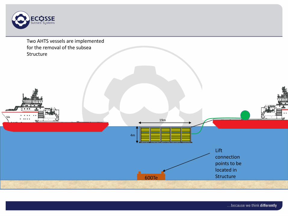
Two AHTS vessels are implemented for the removal of the subsea Structure
19m
4m
Lift connection points to be located in Structure600Te

The ABL unit is constrained by tow chains from the vessels.

The ABL unit ballasted down to connect to the Structure.
ABL attached to the Jacket Footing using the mechanical connectors shown on following slide.

Male portion attached to underside of Ambient Lifting frame
Female portion to be placed on the foundation.
Ambient Lifting – Innovative Mechanical Connection Option

Upon connection, buoyancy is added to ABL unit to lift Structure from the seabed.

The unit can be towed by a single vessel to port for decommissioning.
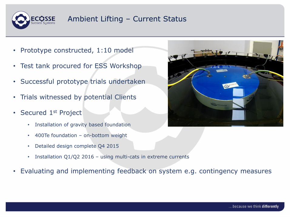
Ambient Lifting – Current Status
• Prototype constructed, 1:10 model
• Test tank procured for ESS Workshop
• Successful prototype trials undertaken
• Trials witnessed by potential Clients
• Secured 1st Project
• Installation of gravity based foundation
• 400Te foundation – on-bottom weight
• Detailed design complete Q4 2015
• Installation Q1/Q2 2016 – using multi-cats in extreme currents
• Evaluating and implementing feedback on system e.g. contingency measures

Ambient Lifting – Detailed Design Renewables

Summary
• Overview of Ecosse Subsea Capabilities
• Ambient Lifting theory has been summarised along with lifting and foundation examples
• Ambient lifting is shown to be a cost effective way of install/recover/relocate small to large subsea structures using:• simple construction methods• local companies/people• local vessels,
• Current status of Ambient Lifting presented for most recent project
• Had hoped to show Case Study of 450Te foundation installation without the use of Heavy Lift Vessel – installation will hopefully be in 2016

Related Documents