POLITECNICO DI TORINO ENGINEERING FACULTY Master’s degree course in Mechatronic Engineering FIDGET CHAIR: therapeutic treatment sitting for bariatric patients Master’s degree Thesis of: Chiara La Verghetta Master’s degree course in MECHATRONIC ENGINEERING Developed with: Julia Robin Master’s degree course in DESIGN SISTEMICO Supervisor: Prof. Marcello Chiaberge DET – Dipartimento di Elettronica e Telecomunicazioni Advisors: Prof. Giuseppe Quaglia DIMEAS – Dipartimento di Ingegneria Meccanica e Aereospaziale Prof. Valpreda Fabrizio DED – Dipartimento di Architettura e Design Academic year: 2018 / 2019

Welcome message from author
This document is posted to help you gain knowledge. Please leave a comment to let me know what you think about it! Share it to your friends and learn new things together.
Transcript
POLITECNICO DI TORINO
ENGINEERING FACULTY
Master’s degree course in Mechatronic Engineering
FIDGET CHAIR:
therapeutic treatment sitting for bariatric patients
Master’s degree Thesis of:
Chiara La Verghetta Master’s degree course in MECHATRONIC ENGINEERING
Developed with:
Julia Robin Master’s degree course in DESIGN SISTEMICO
Supervisor:
Prof. Marcello Chiaberge DET – Dipartimento di Elettronica e Telecomunicazioni
Advisors:
Prof. Giuseppe Quaglia DIMEAS – Dipartimento di Ingegneria Meccanica e Aereospaziale
Prof. Valpreda Fabrizio DED – Dipartimento di Architettura e Design
Academic year: 2018 / 2019

ABSTRACT
The aim of the project has been the realisation of a concept for a
rehabilitative chair for bariatric patient, which purpose is to motivate and
introduce movement in the first stage of their rehabilitation path. The main
guidelines came from the Medical Science Department of “Università di
Torino” and they have been considered as a starting point for the
developing of the product. The final purpose of this innovative system is to
recover mobility and muscle tone and as a consequence the patient should
be more aware, motivated and self-confident especially with work out.
The product concept came out from a multidisciplinary research such that
different areas of engineering and design were involved.
Starting from an analysis of obese people in the world, the focus moved to
this health issue in Italy. This first step helped to understand causes that
lead to obesity and all the physical and psychological aspects of the target
users. In this way, the user-machine interface can be better defined and
helped to realise a seat that can be pleasing not only to the eye but also
while is used.
The next step was to pay attention on movement that can be involved in a
seated position. Gym equipment state of art is analysed to better
understand which are the most important elements that can be integrated
in the chair. Biomechanical elements are also considered to take care about
joints and muscular health, such that injury risk can be avoided.
At this point, ergonomics and anthropometry were integrated to make the
seat more comfortable and adaptable to multiple individuals with different
stature and body proportions as well as their particular condition. Then,
indispensable regulations are chosen to make the seat the more adaptable
possible.
A kinematic analysis followed to define the elements needed for the seat
and to realize the exercises.
A mathematical model is defined to estimate forces exchanged between
patient and the machine. Afterward, a pneumatic actuation solution is
provided.
In the final step, thanks to all the research carried out, a final mechanical
3D model is realized providing a complete but not yet definitive concept of
the chair. Moreover, an aesthetic design study has been performed to meet
the need of distinguish the machine from the classical training equipment.
According to psychologist, indeed, bariatric patients show a relevant
reluctance to the classical way of training.
Index
ABSTRACT ......................................................................... III
List of Figures ...................................................................... 1
Chapter 1 ............................................................................. 7
Introduction ......................................................................... 7
1.1 Obesity in the World and in Italy ......................................... 7
1.2 Definition and evaluation .................................................... 9
1.3 Obesity triggering Factors ................................................. 12
1.4 Obese psychological analysis ............................................ 12
1.5 Physical consequences on health and life .......................... 14
1.5.1 Musculoskeletal system focus ............................................ 15
1.6.1 Perception of physical activity in the obese patient ............... 20
1.7 Design guidelines for obesity ............................................ 21
1.7.1 Bariatric chairs ................................................................. 22
Chapter 2 ........................................................................... 24
Project introduction ........................................................... 24
2.1 The request from Dipartimento di Scienze Mediche ........... 24
2.1.1 Team recruitment ............................................................. 24
2.2 Project steps ..................................................................... 25
2.3 Project specifications ........................................................ 28
Chapter 3 ........................................................................... 29
Exercises and gym machine ............................................... 29
3.1 Choice of physical exercises .............................................. 29
3.2 Exercises description and involved muscles ...................... 31
3.2.1 Biceps Curl ...................................................................... 31
3.2.2 Triceps Pushdown ............................................................. 32
3.2.3 Leg extension .................................................................. 32
3.2.4 Leg curl ........................................................................... 33
3.2.5 Exercises variations .......................................................... 33
3.3 Biomechanics of human body ............................................ 34
3.3.1 Muscular contraction classifications and efforts .................... 36
3.4 Gym machine analysis ....................................................... 36
3.4.1 Weight stack machines ..................................................... 37
3.4.2 Hydraulic gym machines ................................................... 40
3.4.3 Pneumatic gym machines .................................................. 41
3.4.4 Robotic gym machines ...................................................... 42
3.5 Effort and system actuation choice .................................... 43
Chapter 4 ........................................................................... 44
Anthropometry and ergonomics ......................................... 44
4.1 Ergonomics in sitting position ........................................... 44
4.2 The case study of a bariatric chair ..................................... 48
4.3 Patient Anthropometry ...................................................... 49
4.4 Project Guidelines ............................................................. 52
Chapter 5 ........................................................................... 54
Kinematics ......................................................................... 54
5.1 Reference systems ............................................................ 54
5.2 Nominal position definition ............................................... 56
5.3 Kinematics of the armrest ................................................. 57
5.4 Kinematics of the seat and backrest .................................. 59
5.5 Kinematics of the leg support ............................................ 59
5.6 Regulation overview .......................................................... 60
Chapter 6 ........................................................................... 62
Dynamics ........................................................................... 62
6.1 Armrest mechanism .......................................................... 62
6.2 Leg support Mechanism ..................................................... 66
6.3 Actuation system ............................................................... 70
6.3.1 Actuation system logic ...................................................... 82
6.3.2 Air consumption ............................................................... 85
Chapter 7 ........................................................................... 88
Final concept ...................................................................... 88
7.1 3D model ........................................................................... 88
7.2 Structure overview and solutions ...................................... 92
7.3 Accessories ....................................................................... 95
Final remark ....................................................................... 96
Bibliography ....................................................................... 97
1
List of Figures
Chapter 1
Figure 1.1: worldwide overview of adult obesity in 2015, OECD data elaboration, source: OECD Health Statistics 2017
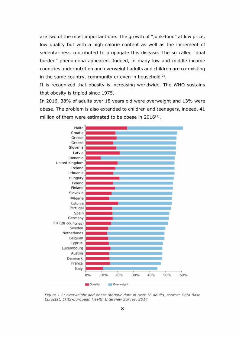
Figure 1.2: overweight and obese statistic data in over 18 adults, source: Data Base Eurostat, EHIS-European Health Interview Survey, 2014
Figure 1.3: Italian overview about the weight excess, source: sorveglianza PASSI (2014-2017)
Figure 1.4: BMI scale, source: C.Patterson,S. Hilton, 2013
Figure 1.5: android and gynoid biotype
Figure 1.6: summary of the psychological effects of the bariatric condition
Figure 1.7: anterior rotation of pelvis causing hyper lordosis and vertebral column deformation.
Figure 1.8: DEXA scan (Tomlinson et al,2016). (i) Comparison between a 48 BMI vs 24 BMI of a young woman. (ii) Comparison between a 48 BMI vs 24 BMI of an old woman.
Figure 1.9: principal obesity health complications on main body systems. Data rework of
By C.B. Ebbeling, D.B. Pawlak, D.S. Ludwig, Childhood obesity: public health crisis, common sense cure. Lancet, 2002, 360: 473-482.
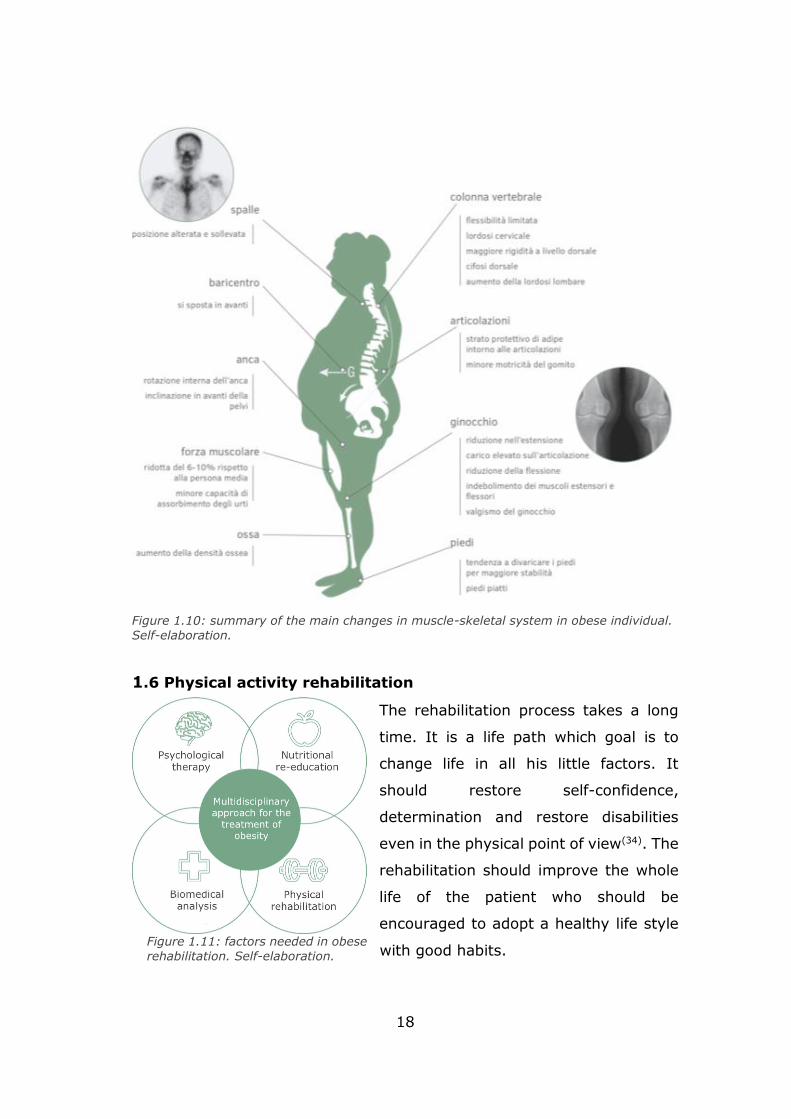
Figure 1.10: summary of the main changes in muscle-skeletal system in obese individual. Self-elaboration.
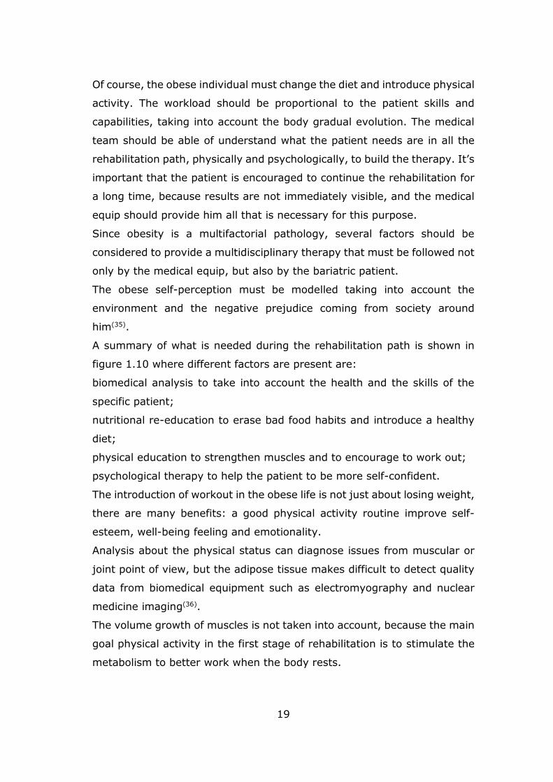
Figure 1.11: factors needed in obese rehabilitation. Self-elaboration.
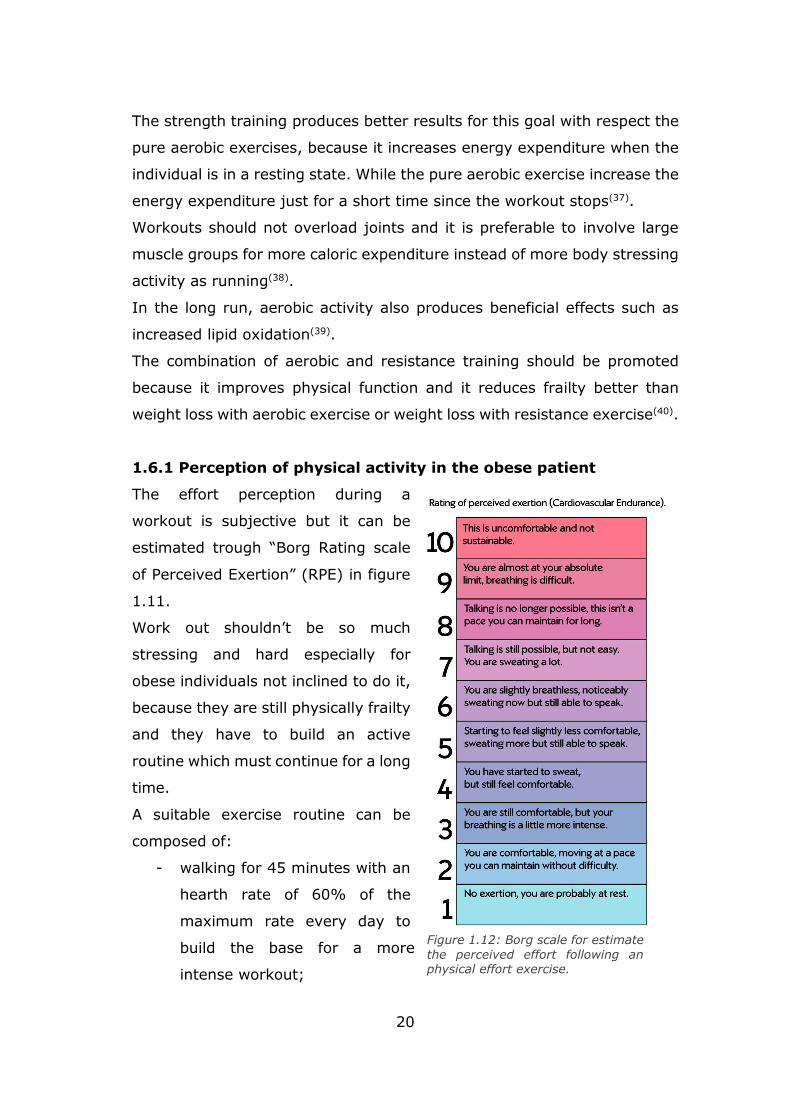
Figure 1.12: Borg scale for estimate the perceived effort following a physical effort exercise
Figure 1.13: Cache Serie, Terrace Hunt for Zenith. Designing bariatric chairs with the same
aesthetics of a standard one, the obese has a place to seat without feeling inadequate or observed for his size preserving his dignity.
Chapter 2
Figure 2.1: Team work origin areas. Self-elaboration
Figure 2.2: Overview about factors involved in the project.
Figure 2.3: Overview about factors involved in the project highlining areas
2
Chapter 3
Figure 3.1: movements and exercises that can be performed from a seated position. Self-elaboration
Figure 3.2: example of biceps curl with dumbbell
Figure 3.3: example of triceps pushdown with cables.
Figure 3.4: seated leg extension exercise
Figure 3.5: seated leg curl.
Figure 3.6: Schematic representation of muscles in selected exercises. Self-elaboration.
Figure 3.7: The tree types of lever in the human body. Source: A. Tozeren, Human Body Dynamics – Classical mechanics and human movement, Springer, New York, 2000.
Figure 3.8: Human body joint represented as rotational mechanical joint. Source: A.
Tozeren, Human Body Dynamics – Classical mechanics and human movement, Springer, New York, 2000.
Figure 3.9: the knee joint rotation. Source: R. Shenoy, P.S.Pastides, D,Nathwani, Biomechanics of the knee and TKR, Orthopaedics and trauma, Vol. 27, Issue 6:364-371.
Figure 3.10: Elbow range of motion. Source: Luttgens e Hamilton (1997)
Figure 3.11: Knee range of motion. Source: Luttgens e Hamilton (1997
Figure 3.12: 3 phases contraction involved in movements.
Figure 3.13: 3 leg extension machine, Thechnogym. Self-elaboration.
Figure 3.14: 3 leg curl machine, Thechnogym. Self-elaboration
Figure 3.15: arm curl machine, Thechnogym. Self-elaboation
Figure 3.16: arm extension machine, Technogym. Self-elaboration.
Figure 3.17: hydraulic gym machines of “Curves”; triceps/biceps on the left and leg curl/leg extension on the right.
Figure 3.18: pneumatic gym machines. “Hur” machine on the left allows multiple exercises. Keiser on right allows one exercise.
Figure 3.19: Kineo intelligent load.
3
Chapter 4
Figure 4.1: hip bone rotation while sitting, source: http://fkt.it/rachide-lombare.
Figure 4.2: B. Akerblom and G. Ekloef for Akerblom Stolen chair, Sweden, 1950.
Figure 4.3: frontal section according to different users. Source: X. Wanga, M. Cardoso, G. Beurier, Effects of seat parameters and sitters’ anthropometric dimensions on seat profile and optimal compressed seat pan surface, Applied Ergonomics 73 (2018) 13–21.
Figure 4.4: Lateral section according to different users. Source: X. Wanga, M. Cardoso, G. Beurier, Effects of seat parameters and sitters’ anthropometric dimensions on seat profile
and optimal compressed seat pan surface, Applied Ergonomics 73 (2018) 13–21.
Figure 4.5: human backbone
Figure 4.6: bariatric patient risk on a standard seat
Figure 4.7: Reference anthropometric models. Source: Henry Dreyfuss Associates, Milano, 1994.
Figure 4.8: Anthropometric data from Molinette Hospital- Medical science department
Figure 4.9: backrest concept. Figure 4.10: seat concept.
Figure 4.11: Armrest concept
Chapter 5
Figure 5.1: Global reference system.
Figure 5.2: Mobile reference systems with respect to the global one reference system.
Figure 5.3: reference posture.
Figure 5.4: mobile elements in nominal position
Figure 5.5 – 5.6: armrest functional scheme.
Figure 5.7: backrest-seat functional scheme
Figure 5.8: leg support functional scheme
Figure 5.9: chair overview functional scheme.
Figure 5.10: dimensions overview.
4
Chapter 6
Figure 6.1: functional scheme of armrest.
Figure 6.2: Right view of the 3D armrest model
Figure 6.3: as a function of .
Figure 6.4 rod CD for biceps curl.
Figure 6.5 rod CD for triceps push down.
Figure 6.6: Ptriceps_min and Fpy as a function of elbow angle.
Figure 6.7: functional scheme of leg support mechanism.
Figure 6.8: leg support mechanism in 3D view.
Figure 6.9: leg mechanism geometry focus.
Figure 6.10: leg mechanism angle behaviour.
Figura 6.11: rod AE focus.
Figure 6.12: leg curl functional scheme.
Figure 6.13: Plegcurl_min and Fpy behaviour as a function of the knee angle
Figure 6.13 Maximum forced developed in traction and compression by cylinders.
Figure 6.14 (a): forces behaviour as a function of angles in leg extension
Figure 6.14 (b): forces behaviour as a function of angles in leg curl.
Figure 6.14 (c): forces behaviour as a function of angles in biceps curl.
Figure 6.14 (d): forces behaviour as a function of angles in triceps pushdown
Figure 6.15 (a): pressure behaviour in the working chamber of the cylinder as a function of the angle alpha for leg extension.
Figure 6.15 (b): pressure behaviour in the working chamber of the cylinder as a function of
the angle alpha for leg curl.
Figure 6.15 (c): pressure behaviour in the working chamber of the cylinder as a function of the angle alpha for biceps curl.
Figure 6.15 (d): pressure behaviour in the working chamber of the cylinder as a function of the angle alpha for triceps pushdown.
Figure 6.16 (a): pneumatic functional scheme for arm exercises actuation system.
Figure 6.16 (b): pneumatic functional scheme for leg exercises actuation system.
5
Figure 6.17: logic of the proportional pressure regulator.
Figure 6.18: logic of pneumatic system leg extension and biceps
Figure 6.19: logic of pneumatic system leg curl and triceps
Chapter 7
Figure 7.1: the different sides of the seat are shown in the closed configuration.
Figure 7.2: the different sides of the seat are shown in the opened configuration.
Figure 7.3: the different sides of the seat are shown in the tilt configuration. Figure 7.4: project layout.
Figure 7.5: 3D model of the frame structure integrated with the principal mechanism. Figure 7.6: In red colour the accessories needed for the seat.

6

7
Chapter 1
Introduction
In this first part of the thesis, obesity issues are provided to understand
how this health problem is important to be addressed.
1.1 Obesity in the World
and in Italy
In 1948 obesity was
established to be a disease
by the World Health
Organization (WHO).
Nevertheless, in the last
decades of 19th century it is
considered to be a relevant
potential public health
problem by all the
governments and mass-
media, since researches
highlighted how the increase
of obesity is related with the
increasing rates of
cardiovascular disease (1).
Obesity emergence was
firstly related to an high
socioeconomic status, but
recent data showed the
prevalence of obese people
shifts from the higher to the
lower socioeconomic level.
This effect is due to multiple
factors. Urbanization and
globalization of food
production and marketing Figure 1.1: worldwide overview of adult obesity in 2015, OECD data elaboration, source: OECD Health Statistics 2017
8
are two of the most important one. The growth of “junk-food” at low price,
low quality but with a high calorie content as well as the increment of
sedentariness contributed to propagate this disease. The so called “dual
burden” phenomena appeared. Indeed, in many low and middle income
countries undernutrition and overweight adults and children are co-existing
in the same country, community or even in household(2).
It is recognized that obesity is increasing worldwide. The WHO sustains
that obesity is tripled since 1975.
In 2016, 38% of adults over 18 years old were overweight and 13% were
obese. The problem is also extended to children and teenagers, indeed, 41
million of them were estimated to be obese in 2016(3).
Figure 1.2: overweight and obese statistic data in over 18 adults, source: Data Base Eurostat, EHIS-European Health Interview Survey, 2014
9
A worldwide overview is shown in
figure 1.1, where the obese women
and men percentage is represented
in different countries.
In Italy the epidemic growth has
been slightly slower with respect to
other Europe countries. In fact, while
in Europe a mean value of 51,6% of
people are estimated to be
overweight, in Italy this value is
about 44,9%. Obesity percentage is
inferior too. In Italy is about 10,8%
against a 15% in Europe(4). The
Mediterranean diet and the low
alcohol consumption are the reasons
why the number of overweight and
obese people is the lowest in Europe(5). Data about overweight and obesity
in different in European countries is shown in figure 1.2.
It is interesting to highlight how the excess weight in Italian people is
increasing in the last 20 years. Nowadays, there are about +10% of
overweight people and +34% of obese with respect to 1994(6). Moreover,
data shows that in Italy, there are more male than female in overweight
and obese condition in adulthood (1/2 for men and one 1/3 for women).
This difference is evident until 65 years old, then it decreased in elderly.
It has been observed that the older is the person the more luckily is the
presence of an overweight condition.
1.2 Definition and evaluation
Obesity is a chronic disease caused by an abnormal and excessive
accumulation of adipose tissue due to an imbalance between energy intake
and consumption(7).
Figure 1.3: Italian overview about the weight excess, source: sorveglianza PASSI
(2014-2017)
10
BMI (Body Mass Index) is a parameter to indicate if health problems may
appear or not due to the excess of body fat. The unit measure is expressed
in kg/m2 and it is defined as:
𝐵𝑀𝐼 =𝑚𝑎𝑠𝑠
ℎ𝑒𝑖𝑔ℎ𝑡2
In such a way, the amount of tissue mass (fat, bone and muscles) can be
approximately quantified.
Health status is used to be classified in function of BMI to diagnose an
underweight, overweight or obese disease as indicated in table 1.1.
As can be seen, overweight individuals have a BMI≥25, while obese have
a BMI≥30. The last one can be also distinguished in classes according to
the severity.
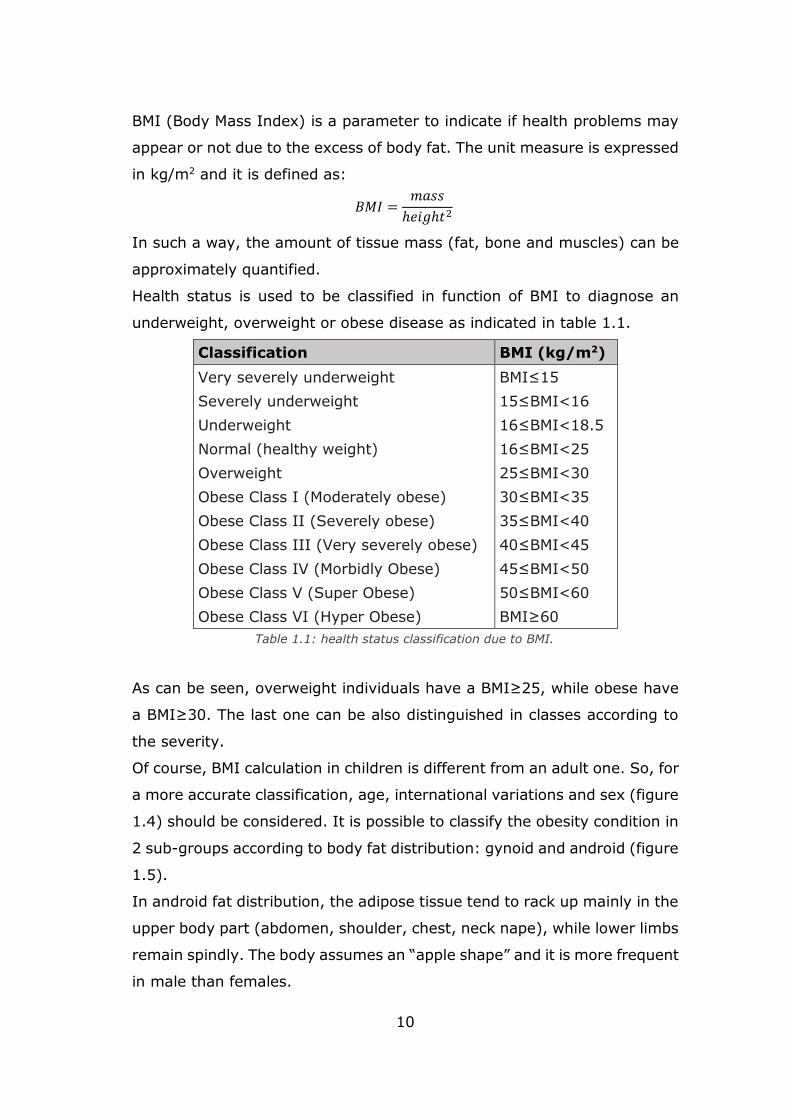
Of course, BMI calculation in children is different from an adult one. So, for
a more accurate classification, age, international variations and sex (figure
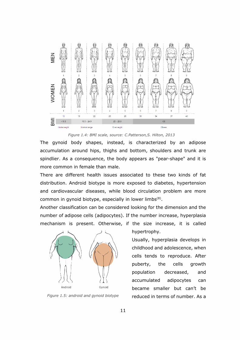
1.4) should be considered. It is possible to classify the obesity condition in
2 sub-groups according to body fat distribution: gynoid and android (figure
1.5).
In android fat distribution, the adipose tissue tend to rack up mainly in the
upper body part (abdomen, shoulder, chest, neck nape), while lower limbs
remain spindly. The body assumes an “apple shape” and it is more frequent
in male than females.
Classification BMI (kg/m2)
Very severely underweight BMI≤15
Severely underweight 15≤BMI<16
Underweight 16≤BMI<18.5
Normal (healthy weight) 16≤BMI<25
Overweight 25≤BMI<30
Obese Class I (Moderately obese) 30≤BMI<35
Obese Class II (Severely obese) 35≤BMI<40
Obese Class III (Very severely obese) 40≤BMI<45
Obese Class IV (Morbidly Obese) 45≤BMI<50
Obese Class V (Super Obese) 50≤BMI<60
Obese Class VI (Hyper Obese) BMI≥60
Table 1.1: health status classification due to BMI.
11
The gynoid body shapes, instead, is characterized by an adipose
accumulation around hips, thighs and bottom, shoulders and trunk are
spindlier. As a consequence, the body appears as "pear-shape" and it is
more common in female than male.
There are different health issues associated to these two kinds of fat
distribution. Android biotype is more exposed to diabetes, hypertension
and cardiovascular diseases, while blood circulation problem are more
common in gynoid biotype, especially in lower limbs(8).
Another classification can be considered looking for the dimension and the
number of adipose cells (adipocytes). If the number increase, hyperplasia
mechanism is present. Otherwise, if the size increase, it is called
hypertrophy.
Usually, hyperplasia develops in
childhood and adolescence, when
cells tends to reproduce. After
puberty, the cells growth
population decreased, and
accumulated adipocytes can
became smaller but can’t be
reduced in terms of number. As a
Figure 1.4: BMI scale, source: C.Patterson,S. Hilton, 2013
Figure 1.5: android and gynoid biotype
12
consequence, healing and recovery are harder and more complex.
Hypertrophy is developed in adulthood, because adipocytes react
becoming bigger to fat accumulation.
For this reasons it is important to intervene in case of obesity in childhood,
in such a way adulthood obesity risk can be prevented and it is easier to
be addressed(9).
1.3 Obesity triggering Factors
There are multiple factors that lead to this status, but the most important
ones are: genetical, psychological, social, environmental and metabolic.
Genetics contributes to the regulation mechanisms of energy, metabolism
and appetite and there are researches that are relating the tendency to
prefer certain foods or predisposition to physical activity. Sometimes
genetic factors leads to specific syndromes(10).
Metabolic endocrine diseases like hormonals ones can produce food
assimilation imbalances between consumed and provided calories(11).
Eating disorders such as compulsive food consumption are due to
psychological factors like stress and anxiety. These emotional disorders,
that can lead to depression, can come from obese social discriminations
and negative prejudices(12). So even social aspects are involved in obesity
causes. Moreover, in nowadays life style the increment of sedentary
creates a greater imbalance between intake and consumed energy(13).
Other involved factors can be pharmacological because of antidepressants
and corticosteroids that can increase hunger sensation and can change
metabolism reducing daily energy requirements or stimulating the
production of fat cells. If hypothalamus area is damaged can influence
appetite regulation(14).
1.4 Obese psychological analysis
Psychological disorders sometimes are triggering factor that lead to obesity
but living in this pathologic condition produces consequences at
psychological level.
13
According to WHO, depression is one of the pathologies linked to obesity.
An increased consumption of food and the poor physical activity can be
depression warning signals that can lead to overweight and obesity. On the
other side, the negative self-image in the society can produce low self-
esteem(15). Indeed, from 20 to 60% of obese individuals are more inclined
to develop depression and anxiety related to self-esteem lowering(16). They
aren’t self-confident with their body and, with the pathology growth, obese
don’t like looking in mirror until they try to avoid them(17).
They are often victims of different shape of discrimination and prejudices
that can lead to socializing issues. In fact, obese can be easily considered
as lazy in the workplace and not suitable for work. Often, negative
comments and unkind treatment can come from health care, work places,
casual people met in the streets or even from family members(18).
Although prejudices against obese people increased, attention, care and
sensibility towards them are also increased. Nowadays there’s greater
awareness of the risks and consequences of obesity in both socio-economic
and psycho-physical points of view(19).
If the obese individuals are subjected to these negative attitudes coming
from the people around them, they try to deny their problem seeking
external help and approval. Often, they assumes self-comforting attitudes
that leads to the further food consumption. This last option is more
frequent among women(20).
Other psychological disease can come from environmental barriers like too
narrow chairs or sanitary equipment not suitable for heavier people,
aggravated by the verbal comparison that often turns into negative
judgment(21).
There isn’t for sure a direct link between obesity or overweight and
psychological disorders such as depression, anxiety or self-esteem lack.
but judgements and the perception of today’s society influence negative
the obese and the overweight individual more than their health status.
14
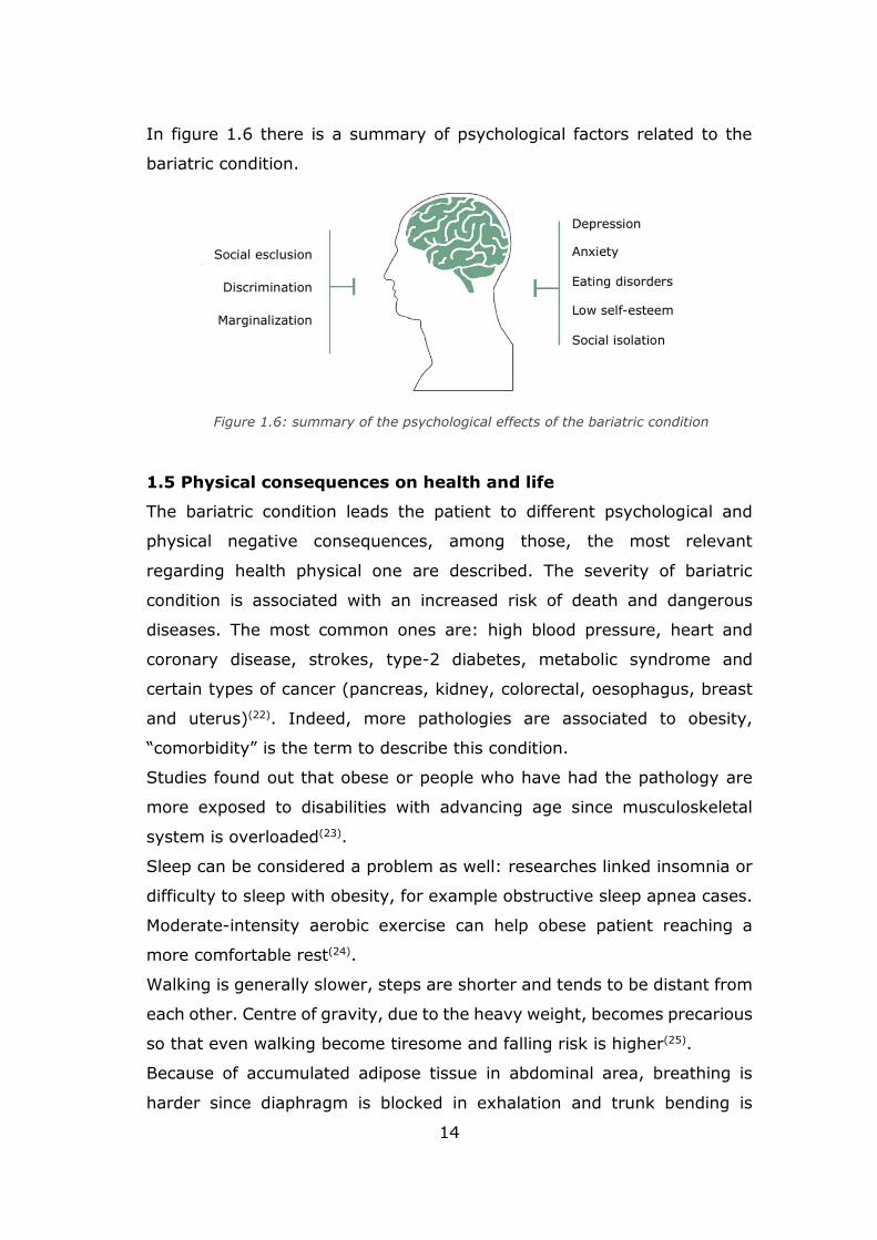
In figure 1.6 there is a summary of psychological factors related to the
bariatric condition.
1.5 Physical consequences on health and life
The bariatric condition leads the patient to different psychological and
physical negative consequences, among those, the most relevant
regarding health physical one are described. The severity of bariatric
condition is associated with an increased risk of death and dangerous
diseases. The most common ones are: high blood pressure, heart and
coronary disease, strokes, type-2 diabetes, metabolic syndrome and
certain types of cancer (pancreas, kidney, colorectal, oesophagus, breast
and uterus)(22). Indeed, more pathologies are associated to obesity,
“comorbidity” is the term to describe this condition.
Studies found out that obese or people who have had the pathology are
more exposed to disabilities with advancing age since musculoskeletal
system is overloaded(23).
Sleep can be considered a problem as well: researches linked insomnia or
difficulty to sleep with obesity, for example obstructive sleep apnea cases.
Moderate-intensity aerobic exercise can help obese patient reaching a
more comfortable rest(24).
Walking is generally slower, steps are shorter and tends to be distant from
each other. Centre of gravity, due to the heavy weight, becomes precarious
so that even walking become tiresome and falling risk is higher(25).
Because of accumulated adipose tissue in abdominal area, breathing is
harder since diaphragm is blocked in exhalation and trunk bending is
Figure 1.6: summary of the psychological effects of the bariatric condition
15
limited. In general, movements are restricted by body fat and pain. Even
the simplest action of everyday life are harder or in the most serious cases
they are compromised.
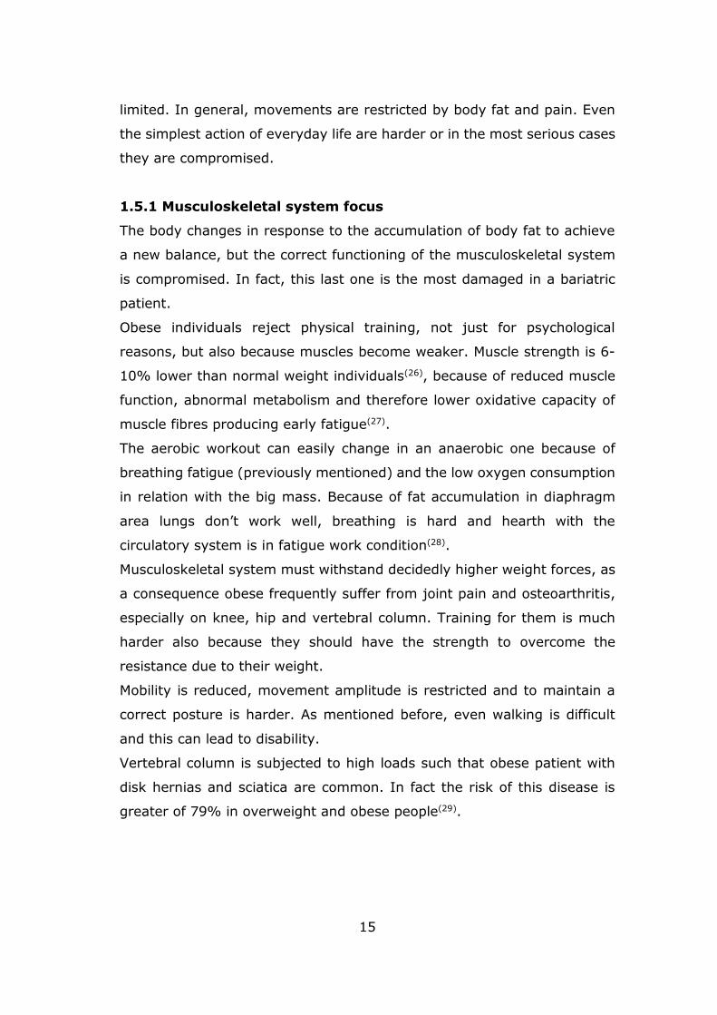
1.5.1 Musculoskeletal system focus
The body changes in response to the accumulation of body fat to achieve
a new balance, but the correct functioning of the musculoskeletal system
is compromised. In fact, this last one is the most damaged in a bariatric
patient.
Obese individuals reject physical training, not just for psychological
reasons, but also because muscles become weaker. Muscle strength is 6-
10% lower than normal weight individuals(26), because of reduced muscle
function, abnormal metabolism and therefore lower oxidative capacity of
muscle fibres producing early fatigue(27).
The aerobic workout can easily change in an anaerobic one because of
breathing fatigue (previously mentioned) and the low oxygen consumption
in relation with the big mass. Because of fat accumulation in diaphragm
area lungs don’t work well, breathing is hard and hearth with the
circulatory system is in fatigue work condition(28).
Musculoskeletal system must withstand decidedly higher weight forces, as
a consequence obese frequently suffer from joint pain and osteoarthritis,
especially on knee, hip and vertebral column. Training for them is much
harder also because they should have the strength to overcome the
resistance due to their weight.
Mobility is reduced, movement amplitude is restricted and to maintain a
correct posture is harder. As mentioned before, even walking is difficult
and this can lead to disability.
Vertebral column is subjected to high loads such that obese patient with
disk hernias and sciatica are common. In fact the risk of this disease is
greater of 79% in overweight and obese people(29).
16
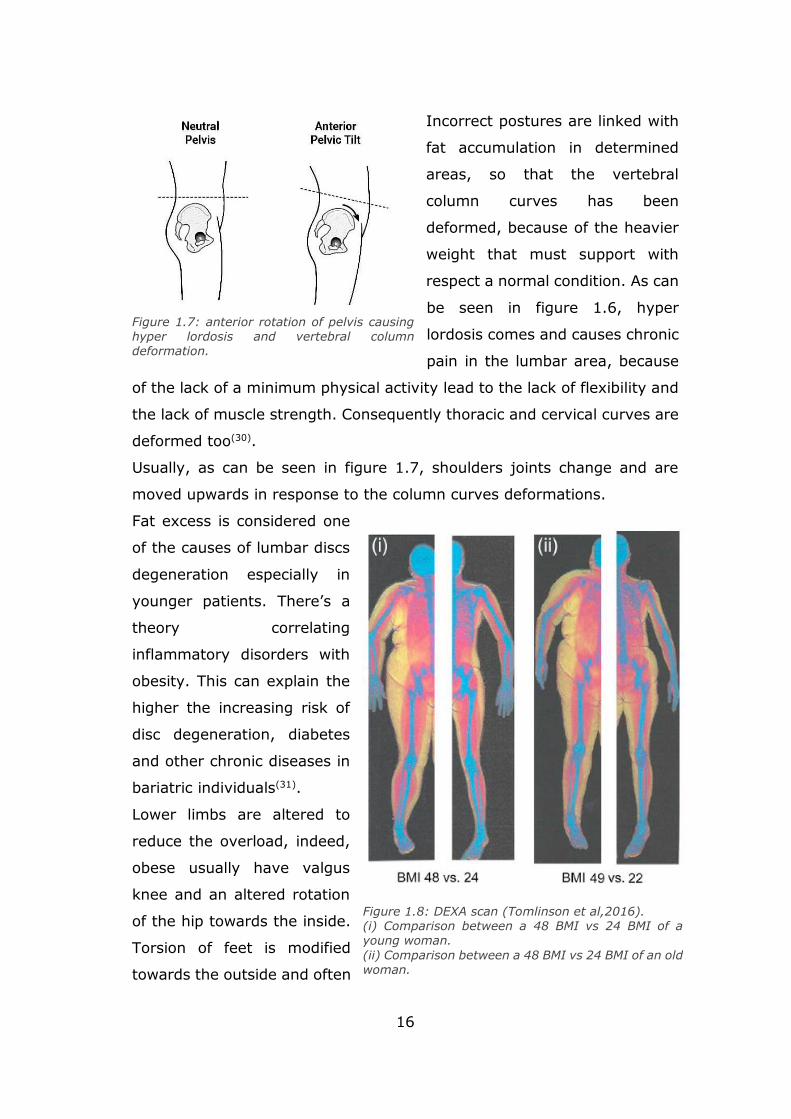
Incorrect postures are linked with
fat accumulation in determined
areas, so that the vertebral
column curves has been
deformed, because of the heavier
weight that must support with
respect a normal condition. As can
be seen in figure 1.6, hyper
lordosis comes and causes chronic
pain in the lumbar area, because
of the lack of a minimum physical activity lead to the lack of flexibility and
the lack of muscle strength. Consequently thoracic and cervical curves are
deformed too(30).
Usually, as can be seen in figure 1.7, shoulders joints change and are
moved upwards in response to the column curves deformations.
Fat excess is considered one
of the causes of lumbar discs
degeneration especially in
younger patients. There’s a
theory correlating
inflammatory disorders with
obesity. This can explain the
higher the increasing risk of
disc degeneration, diabetes
and other chronic diseases in
bariatric individuals(31).
Lower limbs are altered to
reduce the overload, indeed,
obese usually have valgus
knee and an altered rotation
of the hip towards the inside.
Torsion of feet is modified
towards the outside and often
Figure 1.7: anterior rotation of pelvis causing hyper lordosis and vertebral column deformation.
Figure 1.8: DEXA scan (Tomlinson et al,2016). (i) Comparison between a 48 BMI vs 24 BMI of a young woman.
(ii) Comparison between a 48 BMI vs 24 BMI of an old woman.
17
the “flat foot” is present to look for a better stability in an upright position
and for a less metabolic expenditure(32).
In a seated position the obese patient spread the legs to allow flexion of
the trunk and relieve the load on the pelvis(33).
Fat accumulation lead to reach a new equilibrium and the less metabolic
expenditure possible modifying all these muscle-skeletal features.
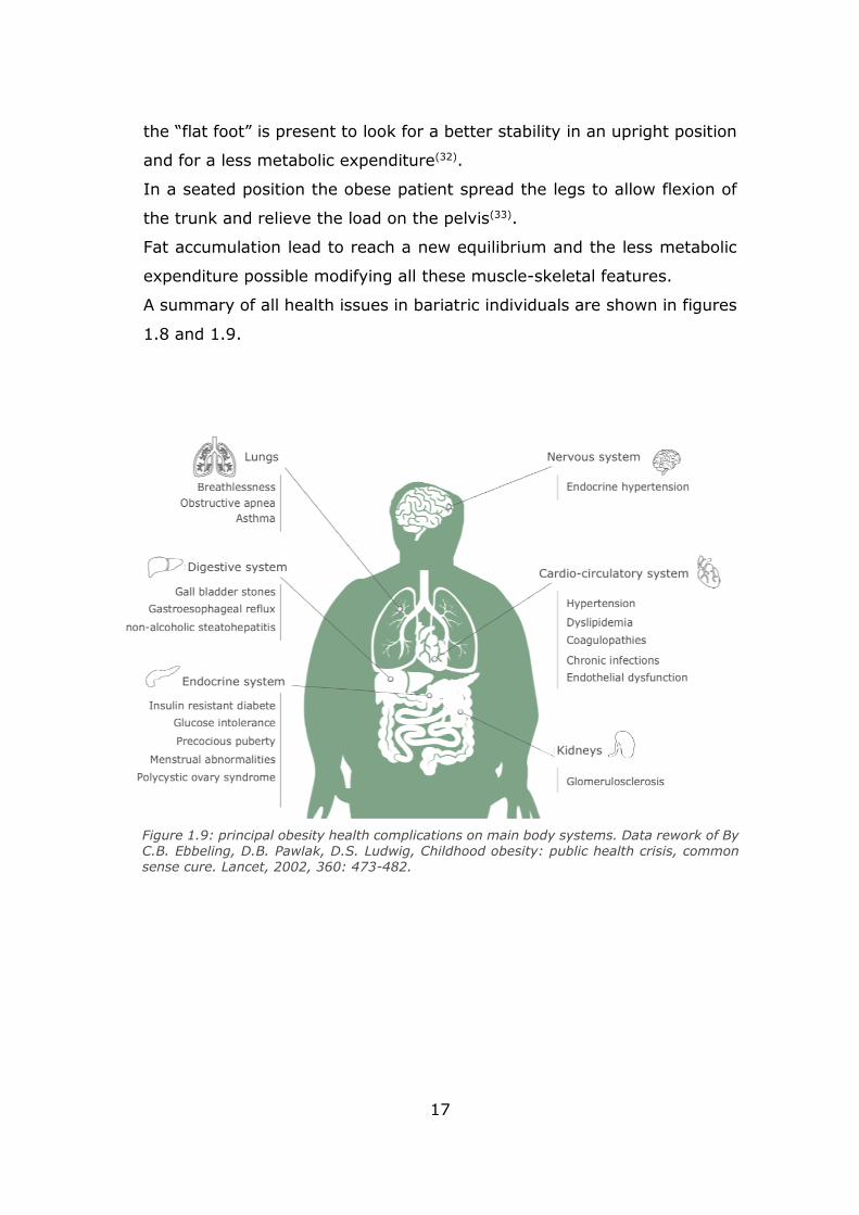
A summary of all health issues in bariatric individuals are shown in figures
1.8 and 1.9.
Figure 1.9: principal obesity health complications on main body systems. Data rework of By C.B. Ebbeling, D.B. Pawlak, D.S. Ludwig, Childhood obesity: public health crisis, common sense cure. Lancet, 2002, 360: 473-482.
18
1.6 Physical activity rehabilitation
The rehabilitation process takes a long
time. It is a life path which goal is to
change life in all his little factors. It
should restore self-confidence,
determination and restore disabilities
even in the physical point of view(34). The
rehabilitation should improve the whole
life of the patient who should be
encouraged to adopt a healthy life style
with good habits.
Figure 1.10: summary of the main changes in muscle-skeletal system in obese individual.
Self-elaboration.
Figure 1.11: factors needed in obese
rehabilitation. Self-elaboration.
19
Of course, the obese individual must change the diet and introduce physical
activity. The workload should be proportional to the patient skills and
capabilities, taking into account the body gradual evolution. The medical
team should be able of understand what the patient needs are in all the
rehabilitation path, physically and psychologically, to build the therapy. It’s
important that the patient is encouraged to continue the rehabilitation for
a long time, because results are not immediately visible, and the medical
equip should provide him all that is necessary for this purpose.
Since obesity is a multifactorial pathology, several factors should be
considered to provide a multidisciplinary therapy that must be followed not
only by the medical equip, but also by the bariatric patient.
The obese self-perception must be modelled taking into account the
environment and the negative prejudice coming from society around
him(35).
A summary of what is needed during the rehabilitation path is shown in
figure 1.10 where different factors are present are:
biomedical analysis to take into account the health and the skills of the
specific patient;
nutritional re-education to erase bad food habits and introduce a healthy
diet;
physical education to strengthen muscles and to encourage to work out;
psychological therapy to help the patient to be more self-confident.
The introduction of workout in the obese life is not just about losing weight,
there are many benefits: a good physical activity routine improve self-
esteem, well-being feeling and emotionality.
Analysis about the physical status can diagnose issues from muscular or
joint point of view, but the adipose tissue makes difficult to detect quality
data from biomedical equipment such as electromyography and nuclear
medicine imaging(36).
The volume growth of muscles is not taken into account, because the main
goal physical activity in the first stage of rehabilitation is to stimulate the
metabolism to better work when the body rests.
20
The strength training produces better results for this goal with respect the
pure aerobic exercises, because it increases energy expenditure when the
individual is in a resting state. While the pure aerobic exercise increase the
energy expenditure just for a short time since the workout stops(37).
Workouts should not overload joints and it is preferable to involve large
muscle groups for more caloric expenditure instead of more body stressing
activity as running(38).
In the long run, aerobic activity also produces beneficial effects such as
increased lipid oxidation(39).
The combination of aerobic and resistance training should be promoted
because it improves physical function and it reduces frailty better than
weight loss with aerobic exercise or weight loss with resistance exercise(40).
1.6.1 Perception of physical activity in the obese patient
The effort perception during a
workout is subjective but it can be
estimated trough “Borg Rating scale
of Perceived Exertion” (RPE) in figure
1.11.
Work out shouldn’t be so much
stressing and hard especially for
obese individuals not inclined to do it,
because they are still physically frailty
and they have to build an active
routine which must continue for a long
time.
A suitable exercise routine can be
composed of:
- walking for 45 minutes with an
hearth rate of 60% of the
maximum rate every day to
build the base for a more
intense workout;
Figure 1.12: Borg scale for estimate
the perceived effort following an physical effort exercise.
21
- exercises for large muscle groups in a time period between 45 or 60
minutes well distributed during the week (minimum 2 or 3 times a
week).
The purpose is to train the cardiovascular system to better respond to the
effort and to the workout, so it get used to it gradually(41).
It has been taken into account that bariatric patients are not used to
training and psychological barriers are often a great obstacle to overcome,
because they may feel inadequate and they may surrender to first
difficulties. Moreover, they may not endure physical exertion. So, training
and equipment must guarantee comfort and must avoid situations in which
the bariatric patient may feel inadequate.
Within the classical way of training, inside the gym, some issue must be
considered when dealing with severe obese people.
First at all, the maximum available carrying load of the equipment in order
to avoid safety issues and there should be enough space to accommodate
the size of an obese individual. The selected exercise must be done in
proper hidden place for possible embarrassing situations, then the lifting
weight must be proper chosen to make them able to execute the exercise
in the correct way. Exercises involving movements and extra “jiggle” of
adipose and soft body parts should be avoided to not create uneasiness
and embarrassment. Overload of skeleton joints must be considered as
well as exercises in which they have to get off from the floor, which is very
difficult for them(42).
Finally, the psychological factor must be properly analysed remembering
to provide them the right encouragement.
1.7 Design guidelines for obesity
With the obesity population increasing, the design of objects of everyday
life is developed to meet the obese needs, especially those ones in
domestic and health environment. Design goal is to improve life quality.
For example, new seats for seating can be found in public places to
accommodate people with a greater size.
22
Bariatric design precautions look for giving dignity to the obese trying to
well integrate these objects in the environment. The purpose is to avoid to
attract the attention and, at the same time, visibility or embarrassing and
frustrating situations(43).
The major studies come from the United States where the problem is
widespread. Healthcare and hospital environments are providing larger
seating and rigid enough to support heavier people in waiting rooms. Even
hospital beds need a bariatric design to accommodate a major size and
weight. Even transport equip should be adjusted for the heavier ones to
take care not only of patients but also of healthcare professional
workers(44).
Also, buildings and standard measures should be reworked to adapt them
to the obese sizes.
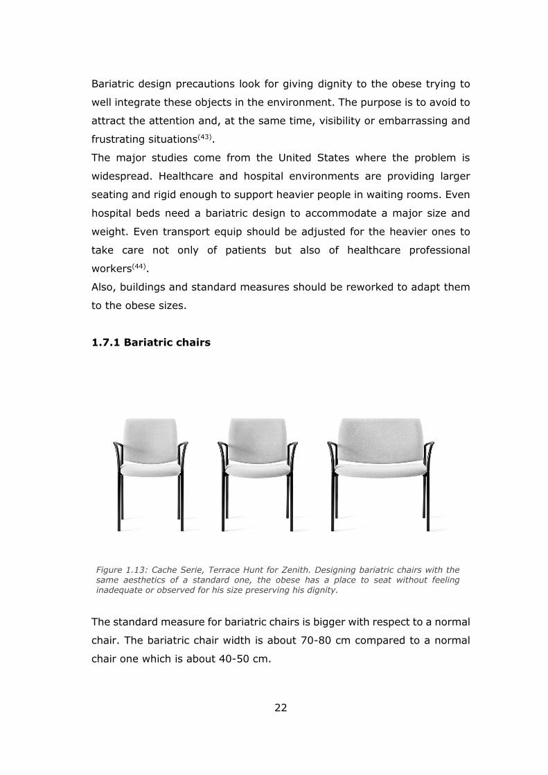
1.7.1 Bariatric chairs
The standard measure for bariatric chairs is bigger with respect to a normal
chair. The bariatric chair width is about 70-80 cm compared to a normal
chair one which is about 40-50 cm.
Figure 1.13: Cache Serie, Terrace Hunt for Zenith. Designing bariatric chairs with the same aesthetics of a standard one, the obese has a place to seat without feeling inadequate or observed for his size preserving his dignity.
23
It must be able to support a higher weight, especially health facilities
should be provided with chairs capable to sustain even 340 kg.
Other small tricks may be the inclusion of a shallow seat. This shrewdness
doesn’t allow the patient to give away, in this way the obese is facilitated
when getting up.
The armrest may be rigidi enough to bear a possible overload when the
obese individual tries to seat down or to get up. Moreover, the distance
between the armrests should be appropriate to the bariatric size.
The general guideline is to provide a good aesthetics and to look
comfortable to both physically and psychologically points of view. The
design should be able to guarantee a to improve the life quality supplying
a seat that makes movements easier. The chair should be able to attract
the target user to make use of it.
24
Chapter 2
Project introduction
2.1 The request from Dipartimento di Scienze Mediche
The project request comes from the “Dipartimento di Scienze Mediche” of
“Università di Torino”. It concerns the realization of a seat able to tempt
obese patient to physical training. The final goal should be the mobility
recovery, as a consequence the patient should be more aware, motivated
and self-confident especially with work out.
The rehabilitation path is structured with a first physical and health analysis
to establish the severity condition of the obese. Guidelines for nutrition and
proper diet are provided and a first objective is fixed that the patient should
reach in 6 months approximately. 150 minutes of light workout are
recommended.
This innovative system may be introduced in this first stage of recovery as
a complementary support to motivate the obese to move and to adopt a
more active and health life. A muscular tone recovery may be guaranteed,
then the patient should be prepared for a more intense work out.
The use of this innovative system is limited in the hospital environment
with doctor observation during meetings.
2.1.1 Team recruitment
Since the project requires multidisciplinary knowledge, it is included in
PIC4SeR (PoliTO Interdepartmental Centre for Service Robotics) activities.
At first, mechanical and mechatronic in engineering areas are involved, but
soon the designer role was considered essential. So, the teamwork may be
multidisciplinary, grouping designers, engineers and doctors. In figure 2.1,
engineering skills concerning mechanical and mechatronic aspects about
actuation, kinematics and dynamics to develop chair movements, the role
of the designer contributed are summarized all the areas involved in the
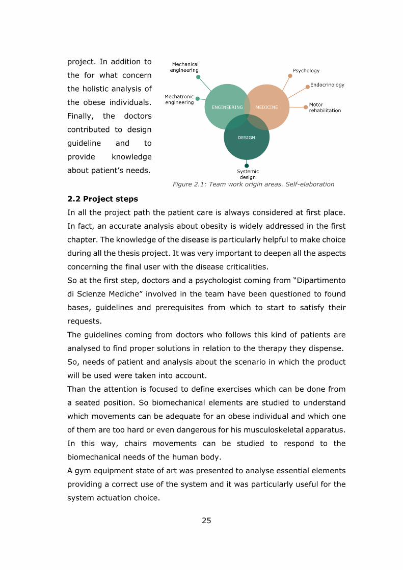
25
project. In addition to
the for what concern
the holistic analysis of
the obese individuals.
Finally, the doctors
contributed to design
guideline and to
provide knowledge
about patient’s needs.
2.2 Project steps
In all the project path the patient care is always considered at first place.
In fact, an accurate analysis about obesity is widely addressed in the first
chapter. The knowledge of the disease is particularly helpful to make choice
during all the thesis project. It was very important to deepen all the aspects
concerning the final user with the disease criticalities.
So at the first step, doctors and a psychologist coming from “Dipartimento
di Scienze Mediche” involved in the team have been questioned to found
bases, guidelines and prerequisites from which to start to satisfy their
requests.
The guidelines coming from doctors who follows this kind of patients are
analysed to find proper solutions in relation to the therapy they dispense.
So, needs of patient and analysis about the scenario in which the product
will be used were taken into account.
Than the attention is focused to define exercises which can be done from
a seated position. So biomechanical elements are studied to understand
which movements can be adequate for an obese individual and which one
of them are too hard or even dangerous for his musculoskeletal apparatus.
In this way, chairs movements can be studied to respond to the
biomechanical needs of the human body.
A gym equipment state of art was presented to analyse essential elements
providing a correct use of the system and it was particularly useful for the
system actuation choice.
Figure 2.1: Team work origin areas. Self-elaboration
26
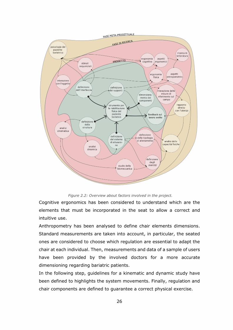
Cognitive ergonomics has been considered to understand which are the
elements that must be incorporated in the seat to allow a correct and
intuitive use.
Anthropometry has been analysed to define chair elements dimensions.
Standard measurements are taken into account, in particular, the seated
ones are considered to choose which regulation are essential to adapt the
chair at each individual. Then, measurements and data of a sample of users
have been provided by the involved doctors for a more accurate
dimensioning regarding bariatric patients.
In the following step, guidelines for a kinematic and dynamic study have
been defined to highlights the system movements. Finally, regulation and
chair components are defined to guarantee a correct physical exercise.
Figure 2.2: Overview about factors involved in the project.
27
Mathematical models have been provided for what concern the motion of
the chair parts which move with the patient during the physical exercises.
Given appropriate hypothesis, forces exchanged between the patient and
the system have been estimated.
A functional scheme of a pneumatic system has been provided with an logic
that should be implemented in an electronic board.
In this phase, all elements regarding bariatric physical and health condition
has been taken into account, while the psychological analysis has been
particularly helpful in to build the executive project. The realization of a 3d
model represent the thesis project final step.
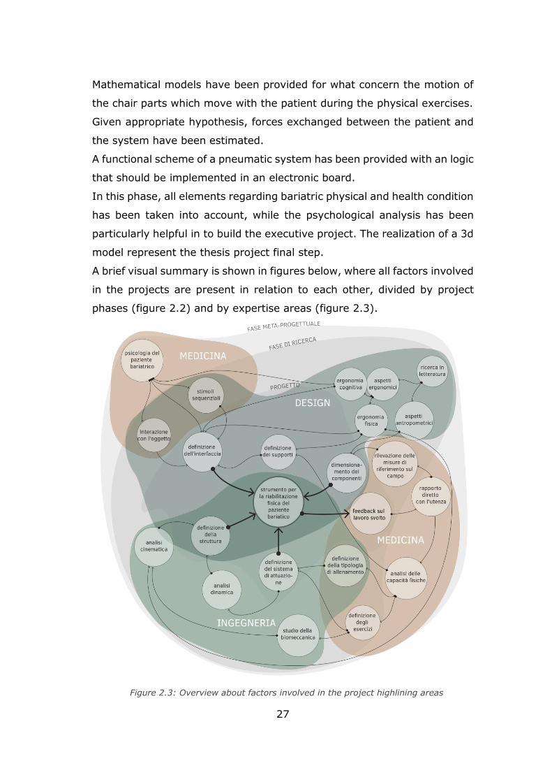
A brief visual summary is shown in figures below, where all factors involved
in the projects are present in relation to each other, divided by project
phases (figure 2.2) and by expertise areas (figure 2.3).
Figure 2.3: Overview about factors involved in the project highlining areas
28
2.3 Project specifications
As introduced in the previous paragraph, guidelines (figure 2.4) for the
thesis project have been given by doctors who have the need to stimulate
their obese patients to move and to in order to recover the muscular tone.
The object chosen is a seat or a chair where obese patient may perform
physical exercises. This choice is determined by observing the obese
attitudes.
The movements suggested by them should involve the large muscle
masses, such as quadriceps, hamstrings, biceps and triceps and if possible,
the abdominal part too. Movements with a low effort, but with a high
frequency are preferred. Moreover, the system should perform simple and
quick short movements such as the hand rapid beat on the armrest, or the
leg trembling. Since the cardiovascular system is overloaded as well as
joins which hold up the high weight, the exercise resistance load should be
light considering the general health status of users.
A motivational feedback should be provided to the patient to stimulate him
to continue the workout and to help him building a good mindset inclined
to improve himself and, as a consequence, self-esteem. The user should
not be tired or bored while training on the seat, so visual stimuli may be
useful for this purpose.
A feedback results should be shown both to patient and doctors to monitor
progressively the health status or the consumed energy or similar data
while training. The feedback shown to doctors may be different with
respect to those ones shown to patients, because they can be sensitive to
some of them.
Guidelines about the aesthetics concern the general shape that should not
be associated to a gym machine. Indeed, as the team psychologist said,
obese people generally has a negative impact for everything that concern
the classical gym in addition to develop a certain kind of denial for workout.
So, the system should be hidden and disguised as a normal chair or seat,
covering the mechanical parts, such that it invites the obese individual to
use it.
It’s preferable to minimize noises to make the training more comfortable.
29
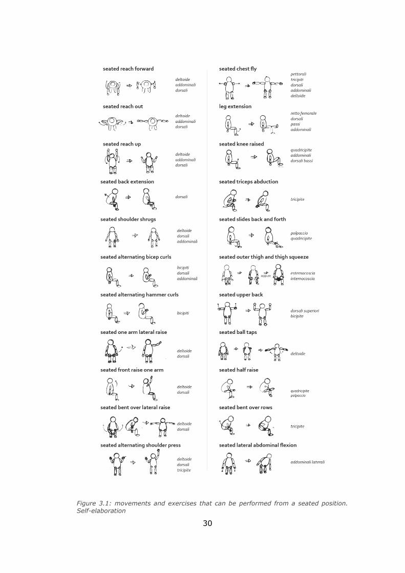
Chapter 3
Exercises and gym machine
3.1 Choice of physical exercises
According to specification projects, training has to be executed from a
seated position by obese patients. Movements have to be light to not
overload joints already stressed by the body fat.
Since great muscle bundles require more energy to be moved, according
to doctors, exercises involving quadriceps and hamstrings for legs and
biceps and triceps for arms are preferred. So, possible movements
involving these muscles are searched (figure 3.1).
Most of the analysed exercises were “bodyweight”, that means free or
without an extra weight, but they are also completely released from the
chair. At this step the main problem is to guarantee a correct exercise
performance. Furthermore, an obese, that has never done a training,
should be guided through it. Otherwise, the movement could be wrong and
in the worst case may damage joints and cause pain, creating the opposite
effect with respect to the desired one.
It has decided to choose exercises that can be done moving physical
elements connected to the chair. In this way the patient can “play” with
the system and enjoy more. This is another reason that leads to this
decision.
A soft load resistance may be considered if the patient acquires confidence
to exercises and accepts an harder challenge with doctors approval.
Finally, the exercises are chosen and can be divided in two subgroups. In
the first one there are those ones that an eventual soft load can be added,
and chair elements must follow the patient motion. These ones are listed
below:
- biceps curl;
- triceps pushdowns;
- leg curl;
- leg extension.
30
Figure 3.1: movements and exercises that can be performed from a seated position. Self-elaboration
31
In the second subgroup there are those ones that don’t require an extra
load, because they may be executed at high frequency, the range of
movement is restricted and don’t require too much muscle stress.
They are:
- foot or feet beat;
- heel or tiptoe beat;
- hand beat on the armrest;
- hand grasp on anti-stress elements.
3.2 Exercises description and involved muscles
In this paragraph the exercises are briefly analysed. In particular, those
ones that requires the chair motion. Even if these kinds of exercises may
be executed in different positions with different kind of gym equipment,
only description of the seated version of these exercises is helpful for the
project purpose. Then, the term “seated” is omitted, but all the exercises
refer to the seated version one.
Different variations are intended to activate and develop more some parts
of the muscle considered. Remembering that users of this tool are obese
people and its aim is to restore mobility and not to define muscles shape,
so all these little details are neglected. Furthermore, the back of the user
that perform the exercise is considered completely in touch with the
backrest in all the exercises avoiding vertebral column stress and overload.
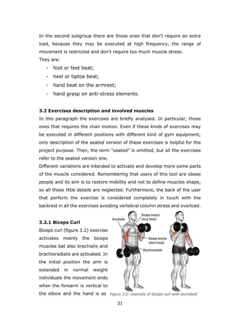
3.2.1 Biceps Curl
Biceps curl (figure 3.2) exercise
activates mainly the biceps
muscles bat also brachialis and
brachioradialis are activated. In
the initial position the arm is
extended in normal weight
individuals the movement ends
when the forearm is vertical to
the elbow and the hand is as Figure 3.2: example of biceps curl with dumbbell
32
close as possible to the shoulder. The greatest effort occurs when starting
from a position of complete extension of the elbow (initial position). Usually
a weight is held by hands. The exercises can be performed with different
downwards. Performing the exercise, the flexion of the elbow is involved.
handle position, but the chosen one is the classical one: the hand palm is
facing upwards. Then the arm return in the initial position following the
same movement in the opposite direction.
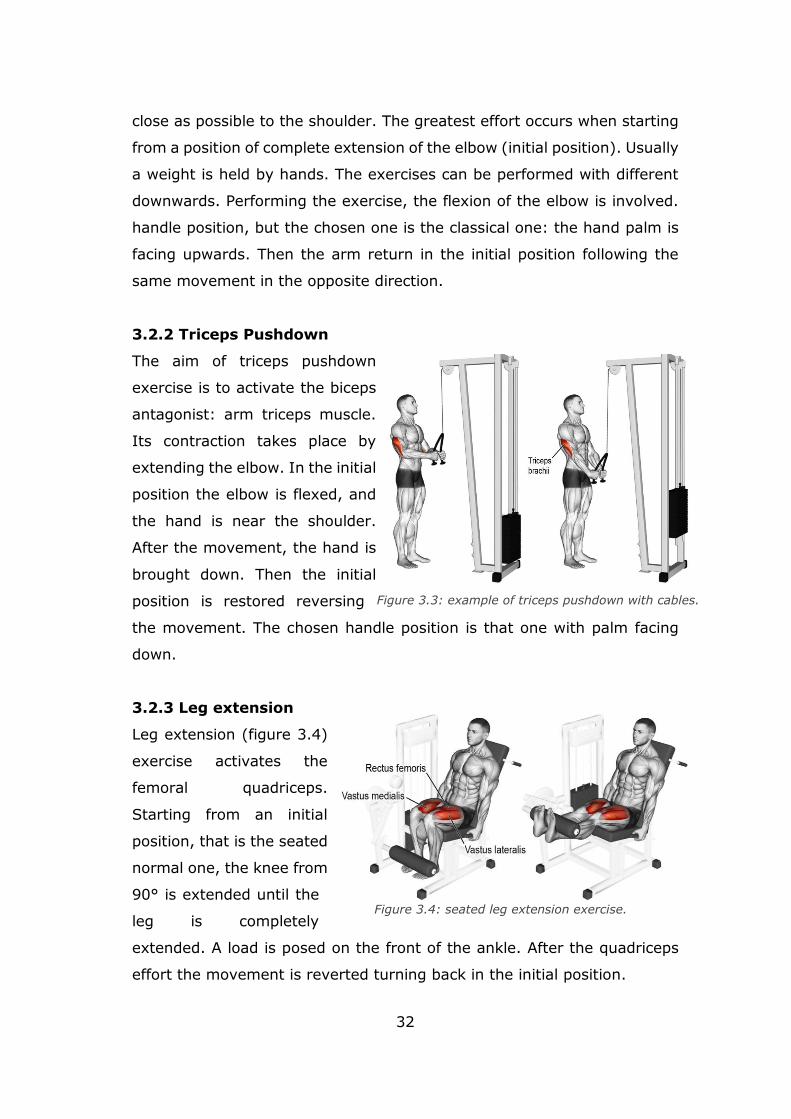
3.2.2 Triceps Pushdown
The aim of triceps pushdown
exercise is to activate the biceps
antagonist: arm triceps muscle.
Its contraction takes place by
extending the elbow. In the initial
position the elbow is flexed, and
the hand is near the shoulder.
After the movement, the hand is
brought down. Then the initial
position is restored reversing
the movement. The chosen handle position is that one with palm facing
down.
3.2.3 Leg extension
Leg extension (figure 3.4)
exercise activates the
femoral quadriceps.
Starting from an initial
position, that is the seated
normal one, the knee from
90° is extended until the
leg is completely
extended. A load is posed on the front of the ankle. After the quadriceps
effort the movement is reverted turning back in the initial position.
Figure 3.4: seated leg extension exercise.
Figure 3.3: example of triceps pushdown with cables.
33
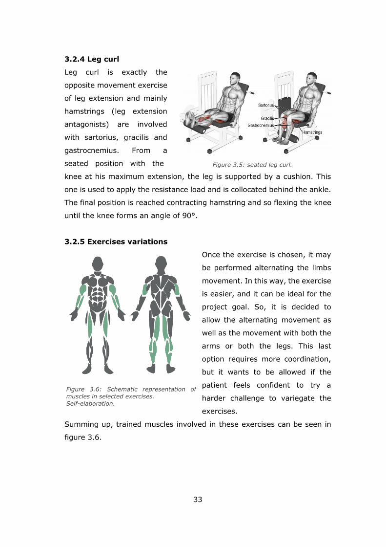
3.2.4 Leg curl
Leg curl is exactly the
opposite movement exercise
of leg extension and mainly
hamstrings (leg extension
antagonists) are involved
with sartorius, gracilis and
gastrocnemius. From a
seated position with the
knee at his maximum extension, the leg is supported by a cushion. This
one is used to apply the resistance load and is collocated behind the ankle.
The final position is reached contracting hamstring and so flexing the knee
until the knee forms an angle of 90°.
3.2.5 Exercises variations
Once the exercise is chosen, it may
be performed alternating the limbs
movement. In this way, the exercise
is easier, and it can be ideal for the
project goal. So, it is decided to
allow the alternating movement as
well as the movement with both the
arms or both the legs. This last
option requires more coordination,
but it wants to be allowed if the
patient feels confident to try a
harder challenge to variegate the
exercises.
Summing up, trained muscles involved in these exercises can be seen in
figure 3.6.
Figure 3.5: seated leg curl.
Figure 3.6: Schematic representation of muscles in selected exercises.
Self-elaboration.
34
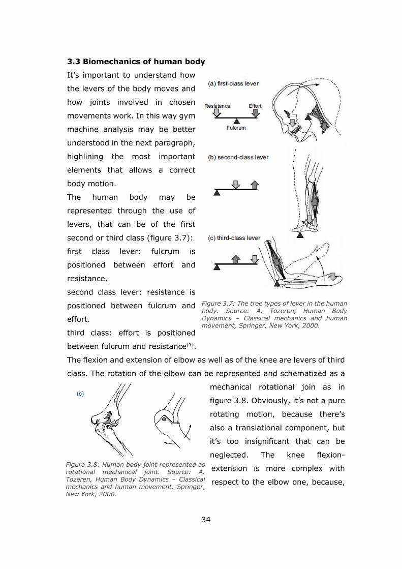
3.3 Biomechanics of human body
It’s important to understand how
the levers of the body moves and
how joints involved in chosen
movements work. In this way gym
machine analysis may be better
understood in the next paragraph,
highlining the most important
elements that allows a correct
body motion.
The human body may be
represented through the use of
levers, that can be of the first
second or third class (figure 3.7):
first class lever: fulcrum is
positioned between effort and
resistance.
second class lever: resistance is
positioned between fulcrum and
effort.
third class: effort is positioned
between fulcrum and resistance(1).
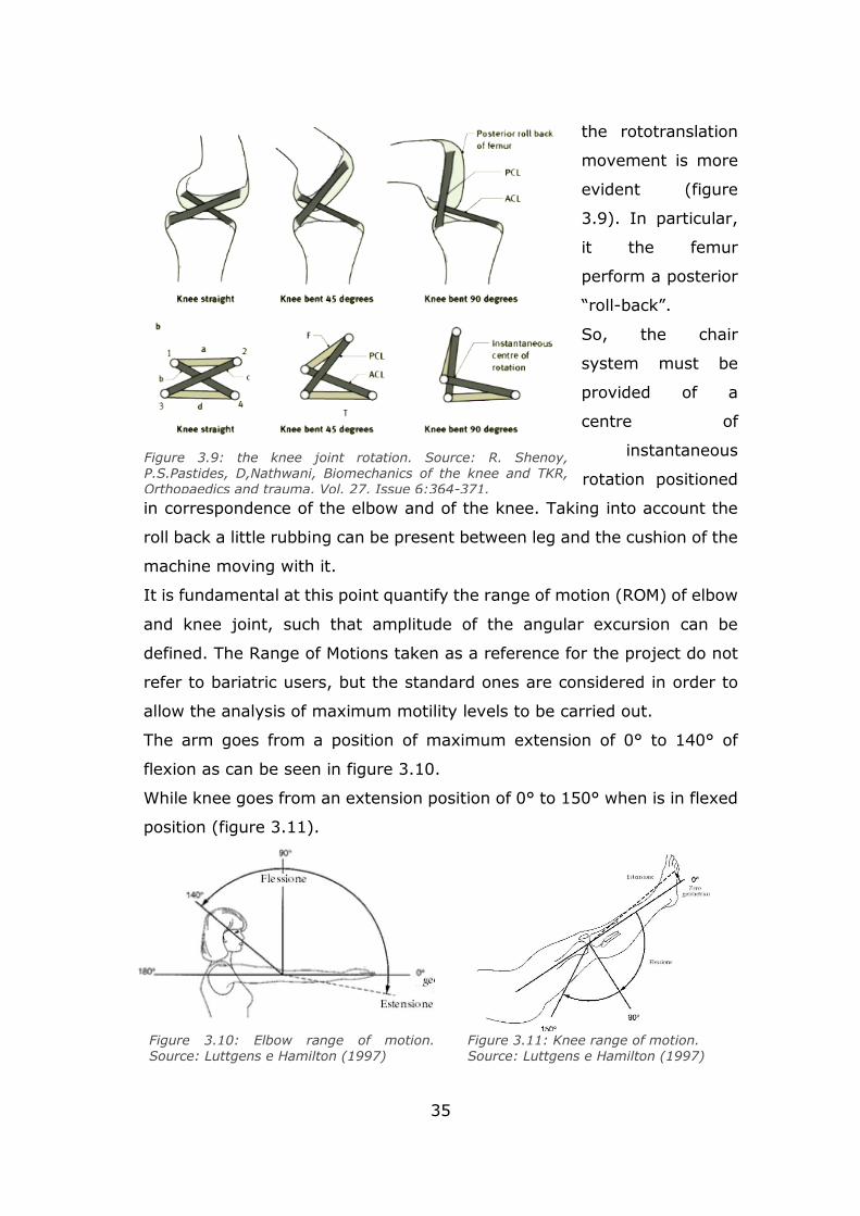
The flexion and extension of elbow as well as of the knee are levers of third
class. The rotation of the elbow can be represented and schematized as a
mechanical rotational join as in
figure 3.8. Obviously, it’s not a pure
rotating motion, because there’s
also a translational component, but
it’s too insignificant that can be
neglected. The knee flexion-
extension is more complex with
respect to the elbow one, because,
Figure 3.7: The tree types of lever in the human body. Source: A. Tozeren, Human Body Dynamics – Classical mechanics and human movement, Springer, New York, 2000.
Figure 3.8: Human body joint represented as rotational mechanical joint. Source: A. Tozeren, Human Body Dynamics – Classical
mechanics and human movement, Springer, New York, 2000.
35
the rototranslation
movement is more
evident (figure
3.9). In particular,
it the femur
perform a posterior
“roll-back”.
So, the chair
system must be
provided of a
centre of
instantaneous
rotation positioned
in correspondence of the elbow and of the knee. Taking into account the
roll back a little rubbing can be present between leg and the cushion of the
machine moving with it.
It is fundamental at this point quantify the range of motion (ROM) of elbow
and knee joint, such that amplitude of the angular excursion can be
defined. The Range of Motions taken as a reference for the project do not
refer to bariatric users, but the standard ones are considered in order to
allow the analysis of maximum motility levels to be carried out.
The arm goes from a position of maximum extension of 0° to 140° of
flexion as can be seen in figure 3.10.
While knee goes from an extension position of 0° to 150° when is in flexed
position (figure 3.11).
Figure 3.9: the knee joint rotation. Source: R. Shenoy, P.S.Pastides, D,Nathwani, Biomechanics of the knee and TKR, Orthopaedics and trauma, Vol. 27, Issue 6:364-371.
Figure 3.10: Elbow range of motion. Source: Luttgens e Hamilton (1997)
Figure 3.11: Knee range of motion. Source: Luttgens e Hamilton (1997)
36
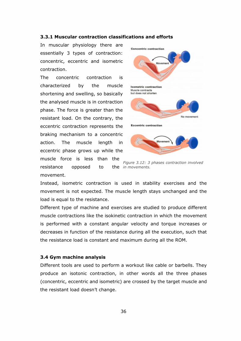
3.3.1 Muscular contraction classifications and efforts
In muscular physiology there are
essentially 3 types of contraction:
concentric, eccentric and isometric
contraction.
The concentric contraction is
characterized by the muscle
shortening and swelling, so basically
the analysed muscle is in contraction
phase. The force is greater than the
resistant load. On the contrary, the
eccentric contraction represents the
braking mechanism to a concentric
action. The muscle length in
eccentric phase grows up while the
muscle force is less than the
resistance opposed to the
movement.
Instead, isometric contraction is used in stability exercises and the
movement is not expected. The muscle length stays unchanged and the
load is equal to the resistance.
Different type of machine and exercises are studied to produce different
muscle contractions like the isokinetic contraction in which the movement
is performed with a constant angular velocity and torque increases or
decreases in function of the resistance during all the execution, such that
the resistance load is constant and maximum during all the ROM.
3.4 Gym machine analysis
Different tools are used to perform a workout like cable or barbells. They
produce an isotonic contraction, in other words all the three phases
(concentric, eccentric and isometric) are crossed by the target muscle and
the resistant load doesn’t change.
Figure 3.12: 3 phases contraction involved
in movements.
37
However, these methods may be easily associated with gym, so this choice
could produce bad result from the phycological point of view.
At this point, different gym machines are analysed to choose an actuation
system that can be easily integrated in a chair and what kind of muscle
effort produces. The resistance load can be applied with:
- weight stack;
- hydraulic cylinder;
- air cylinder;
- electric motor.
3.4.1 Weight stack machines
The most common gym machines are those one with a weight stack. They
use gravity, that act on the weight stack, to generate the resistant force.
This kind of machines produce an isotonic effort, such that the user, feel a
constant load during all the exercise. To allow this behaviour, usually, cams
are inserted in the machine system, usually in correspondence of joints.
Cam’s shape can be projected based on the effort curve through
biomechanical studies.
In figures below, “Technogym” machines are analysed for what concern
the 4 exercises chosen that needs an actuation. This research is helpful to
understand what kind of devices are integrate in a gym machine looking
at the products of an expert company in the sector such as Technogym.
Some of this characteristic described in figures can be neglected for what
concerning the thesis project, because these kinds of machines are built to
perform strength training with high weight. Some of these are:
the superior cushion of the leg curl, because the chair needs to be without
constraint for psychological reasons and because of low weight considered
in specifications; backrest inclination, because of the main goal isn’t
defining the shape of the muscle.
All the other features are really interesting, such that regulations and the
system to allow a constant effort with cam systems.
38
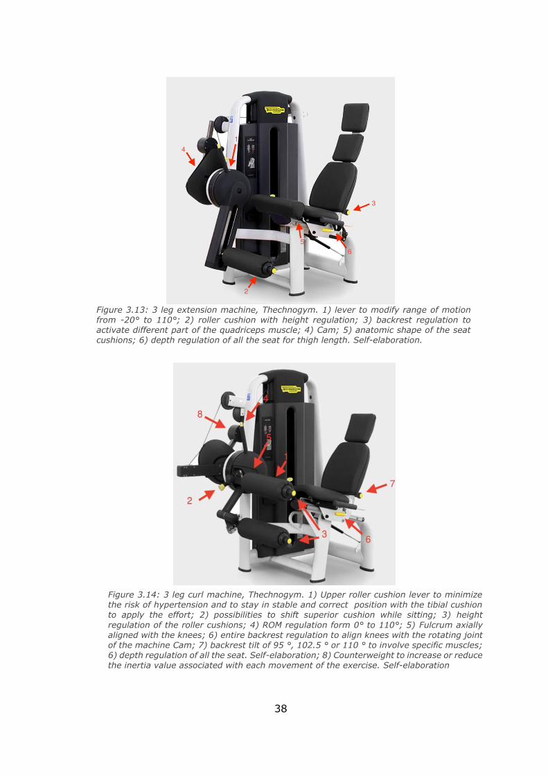
Figure 3.13: 3 leg extension machine, Thechnogym. 1) lever to modify range of motion from -20° to 110°; 2) roller cushion with height regulation; 3) backrest regulation to activate different part of the quadriceps muscle; 4) Cam; 5) anatomic shape of the seat cushions; 6) depth regulation of all the seat for thigh length. Self-elaboration.
Figure 3.14: 3 leg curl machine, Thechnogym. 1) Upper roller cushion lever to minimize the risk of hypertension and to stay in stable and correct position with the tibial cushion to apply the effort; 2) possibilities to shift superior cushion while sitting; 3) height
regulation of the roller cushions; 4) ROM regulation form 0° to 110°; 5) Fulcrum axially aligned with the knees; 6) entire backrest regulation to align knees with the rotating joint of the machine Cam; 7) backrest tilt of 95 °, 102.5 ° or 110 ° to involve specific muscles; 6) depth regulation of all the seat. Self-elaboration; 8) Counterweight to increase or reduce
the inertia value associated with each movement of the exercise. Self-elaboration
39
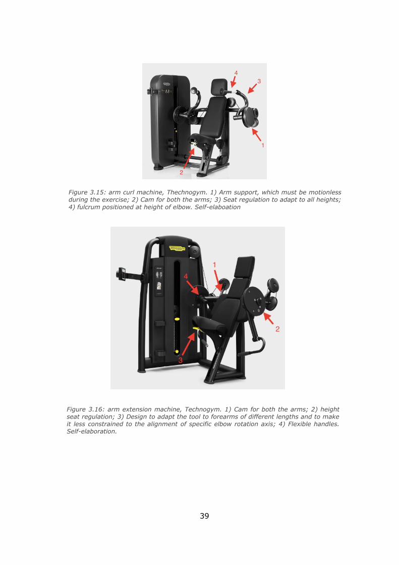
Figure 3.15: arm curl machine, Thechnogym. 1) Arm support, which must be motionless during the exercise; 2) Cam for both the arms; 3) Seat regulation to adapt to all heights;
4) fulcrum positioned at height of elbow. Self-elaboation
Figure 3.16: arm extension machine, Technogym. 1) Cam for both the arms; 2) height seat regulation; 3) Design to adapt the tool to forearms of different lengths and to make it less constrained to the alignment of specific elbow rotation axis; 4) Flexible handles. Self-elaboration.
40
However, this kind of machine are really bulky and can realize just one
exercise at a time. Moreover, the alternating type exercise is not intuitive
for leg extension and leg curl.
But the most important reasons to avoid weight stack are the big
dimensions and because they look like the classical gym equipment, which
from the point of view of a bariatric patient can lead to psychological issue.
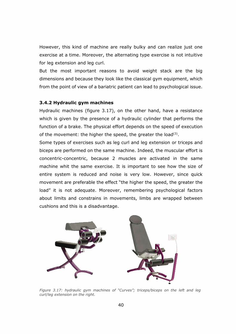
3.4.2 Hydraulic gym machines
Hydraulic machines (figure 3.17), on the other hand, have a resistance
which is given by the presence of a hydraulic cylinder that performs the
function of a brake. The physical effort depends on the speed of execution
of the movement: the higher the speed, the greater the load(3).
Some types of exercises such as leg curl and leg extension or triceps and
biceps are performed on the same machine. Indeed, the muscular effort is
concentric-concentric, because 2 muscles are activated in the same
machine whit the same exercise. It is important to see how the size of
entire system is reduced and noise is very low. However, since quick
movement are preferable the effect “the higher the speed, the greater the
load” it is not adequate. Moreover, remembering psychological factors
about limits and constrains in movements, limbs are wrapped between
cushions and this is a disadvantage.
Figure 3.17: hydraulic gym machines of “Curves”; triceps/biceps on the left and leg curl/leg extension on the right.
41
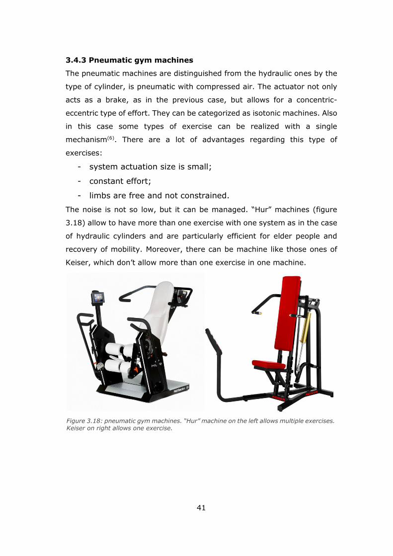
3.4.3 Pneumatic gym machines
The pneumatic machines are distinguished from the hydraulic ones by the
type of cylinder, is pneumatic with compressed air. The actuator not only
acts as a brake, as in the previous case, but allows for a concentric-
eccentric type of effort. They can be categorized as isotonic machines. Also
in this case some types of exercise can be realized with a single
mechanism(6). There are a lot of advantages regarding this type of
exercises:
- system actuation size is small;
- constant effort;
- limbs are free and not constrained.
The noise is not so low, but it can be managed. “Hur” machines (figure
3.18) allow to have more than one exercise with one system as in the case
of hydraulic cylinders and are particularly efficient for elder people and
recovery of mobility. Moreover, there can be machine like those ones of
Keiser, which don’t allow more than one exercise in one machine.
Figure 3.18: pneumatic gym machines. “Hur” machine on the left allows multiple exercises. Keiser on right allows one exercise.
42
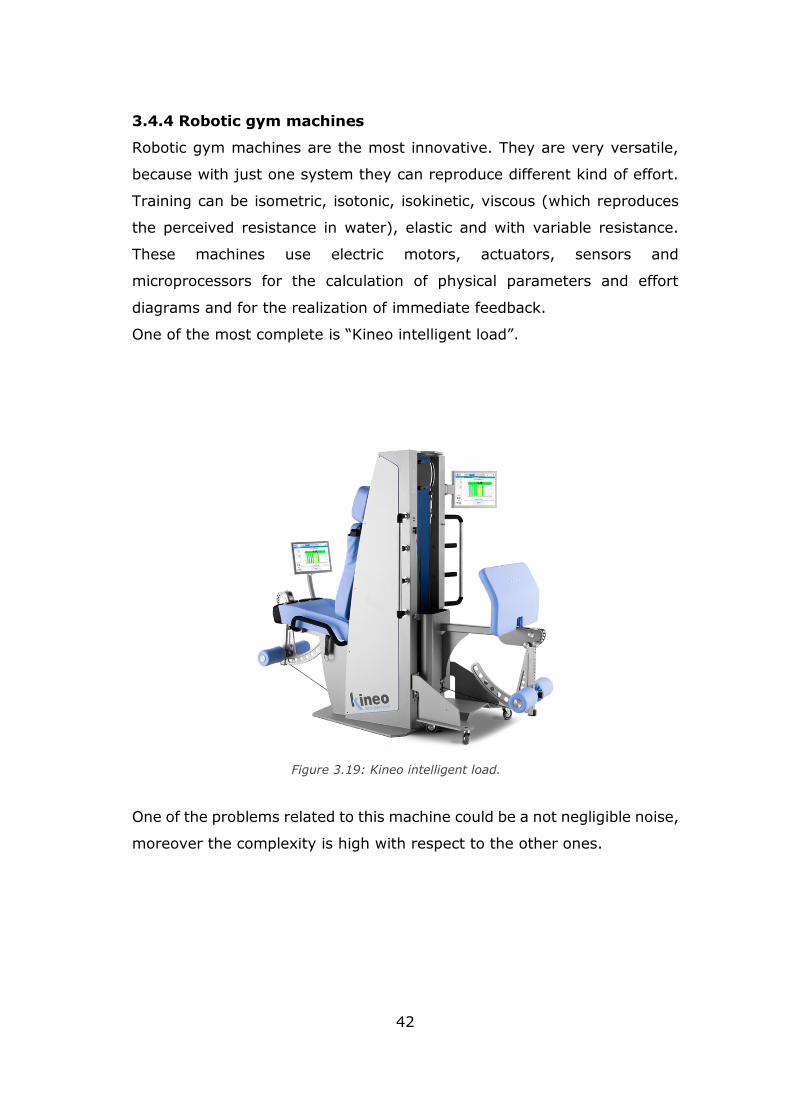
3.4.4 Robotic gym machines
Robotic gym machines are the most innovative. They are very versatile,
because with just one system they can reproduce different kind of effort.
Training can be isometric, isotonic, isokinetic, viscous (which reproduces
the perceived resistance in water), elastic and with variable resistance.
These machines use electric motors, actuators, sensors and
microprocessors for the calculation of physical parameters and effort
diagrams and for the realization of immediate feedback.
One of the most complete is “Kineo intelligent load”.
One of the problems related to this machine could be a not negligible noise,
moreover the complexity is high with respect to the other ones.
Figure 3.19: Kineo intelligent load.
43
3.5 Effort and system actuation choice
Taking into account all the effort analysis, according to doctors, the most
appropriate for bariatric patient is the isotonic contraction with all the 3
phases of concentric, eccentric and isometric phases.
Exercises may be performed with or without a resistance load and
repetitions may be high to perform an aerobic training, but also may be a
little bit harder, shifting in strength training, adding load or not alternating
limbs exercises.
In this way the training can be more complete and can allow to spend
energy and to tone muscles.
According to advantages and disadvantages for all the machine types,
merging all the need and matching the project specifications, a pneumatic
actuation may be adequate for the purpose.
44
Chapter 4
Anthropometry and ergonomics
4.1 Ergonomics in sitting position
During the design process of a training-chair for bariatric patients some
issues must be considered carefully to avoid the introduction of additional
musculoskeletal diseases. The seated position, indeed, could appear as a
“rest” situation while in reality, a wrong posture can lead to several and
also permanent damages.
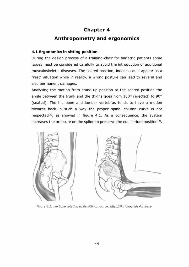
Analysing the motion from stand-up position to the seated position the
angle between the trunk and the thighs goes from 180° (erected) to 90°
(seated). The hip bone and lumbar vertebras tends to have a motion
towards back in such a way the proper spinal column curve is not
respected(1), as showed in figure 4.1. As a consequence, the system
increases the pressure on the spline to preserve the equilibrium position(2).
Figure 4.1: hip bone rotation while sitting, source: http://fkt.it/rachide-lombare.
45
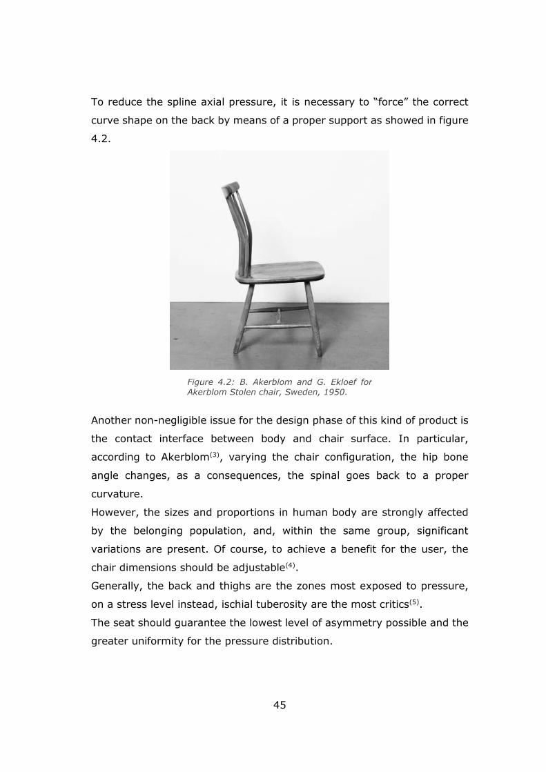
To reduce the spline axial pressure, it is necessary to “force” the correct
curve shape on the back by means of a proper support as showed in figure
4.2.
Another non-negligible issue for the design phase of this kind of product is
the contact interface between body and chair surface. In particular,
according to Akerblom(3), varying the chair configuration, the hip bone
angle changes, as a consequences, the spinal goes back to a proper
curvature.
However, the sizes and proportions in human body are strongly affected
by the belonging population, and, within the same group, significant
variations are present. Of course, to achieve a benefit for the user, the
chair dimensions should be adjustable(4).
Generally, the back and thighs are the zones most exposed to pressure,
on a stress level instead, ischial tuberosity are the most critics(5).
The seat should guarantee the lowest level of asymmetry possible and the
greater uniformity for the pressure distribution.
Figure 4.2: B. Akerblom and G. Ekloef for Akerblom Stolen chair, Sweden, 1950.
46
Figure 4.3: frontal section according to different users. Source: X. Wanga,
M. Cardoso, G. Beurier, Effects of seat parameters and sitters’ anthropome-
tric dimensions on seat profile and optimal compressed seat pan surface,
Applied Ergonomics 73 (2018) 13–21.
47
The exerted pressure in the contact zone between body and object, is an
important feature to be considered during the design process. The factors
that are influencing the pressure perception of the body are the external
shape and the material softness.
Recorded data regarding the pressure sensitiveness are the key to select
the kind of material in the interface between chair and user.
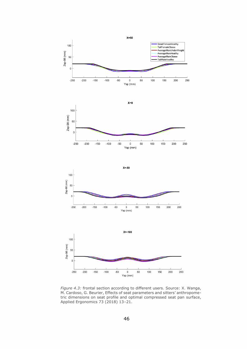
Regarding the seat, the most sensitive zones are the frontal one. According
to Wanga et al. (2018)(6) scans (fig. 33 – fig. 34), extrapolated from the
resultant pressure contour on a seat according to different typology of
users, it is possible to notice how the portion with the greatest grade of
variability is the frontal one. This means that this zone must be
characterised by a greater flexibility. In particular a “waterfall” shape in
the front section may prevent the user from experiencing a wrong blood
circulation(7).
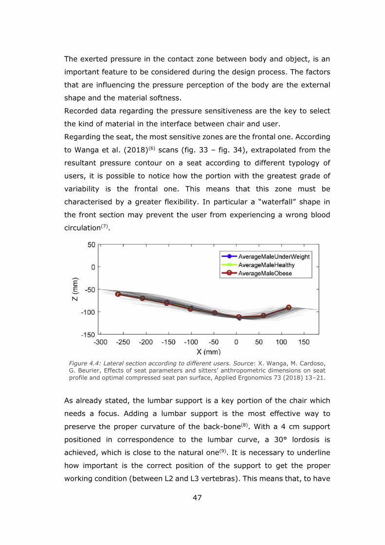
As already stated, the lumbar support is a key portion of the chair which
needs a focus. Adding a lumbar support is the most effective way to
preserve the proper curvature of the back-bone(8). With a 4 cm support
positioned in correspondence to the lumbar curve, a 30° lordosis is
achieved, which is close to the natural one(9). It is necessary to underline
how important is the correct position of the support to get the proper
working condition (between L2 and L3 vertebras). This means that, to have
Figure 4.4: Lateral section according to different users. Source: X. Wanga, M. Cardoso, G. Beurier, Effects of seat parameters and sitters’ anthropometric dimensions on seat
profile and optimal compressed seat pan surface, Applied Ergonomics 73 (2018) 13–21.
48
a chair suitable for a wider population, even the lumbar support height
should be adjustable.
4.2 The case study of a bariatric chair
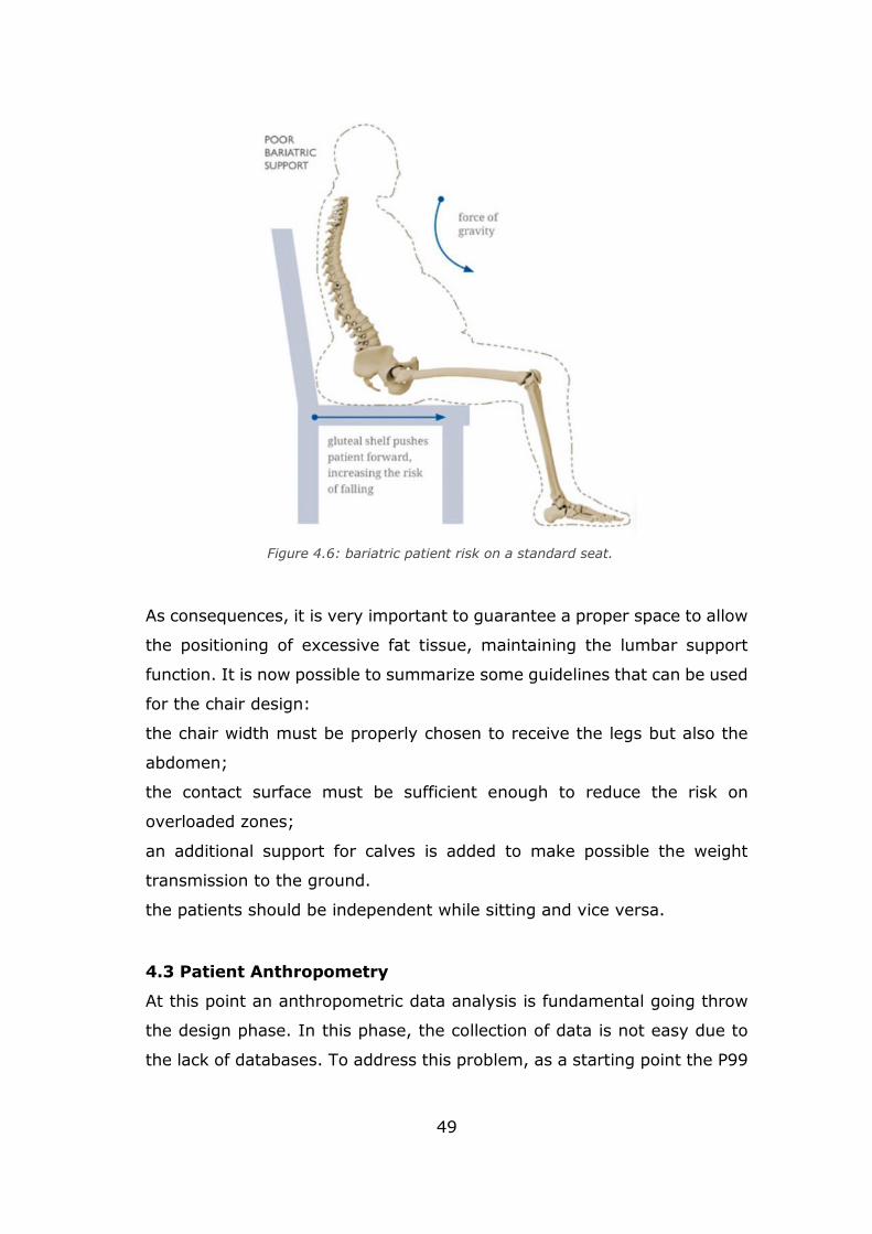
Dealing with the very peculiar case of bariatric patients, some additional
factor must be prioritized, especially, the weight of the patient, the range
of motion, the mobility of the patient itself. Moreover, the mass of the
patients prevents the lumbar support to be placed in the most correct zone.
The excessive fat, force the bariatric people to seat in a wrong way (fig-
4.6) that can lead to long term musculoskeletal disease, the risk is
increased during the motion from seated to stand and vice versa.
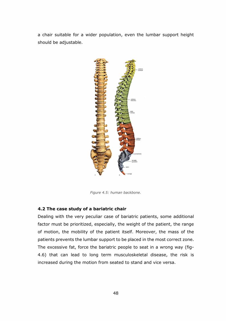
Figure 4.5: human backbone.
49
As consequences, it is very important to guarantee a proper space to allow
the positioning of excessive fat tissue, maintaining the lumbar support
function. It is now possible to summarize some guidelines that can be used
for the chair design:
the chair width must be properly chosen to receive the legs but also the
abdomen;
the contact surface must be sufficient enough to reduce the risk on
overloaded zones;
an additional support for calves is added to make possible the weight
transmission to the ground.
the patients should be independent while sitting and vice versa.
4.3 Patient Anthropometry
At this point an anthropometric data analysis is fundamental going throw
the design phase. In this phase, the collection of data is not easy due to
the lack of databases. To address this problem, as a starting point the P99
Figure 4.6: bariatric patient risk on a standard seat.
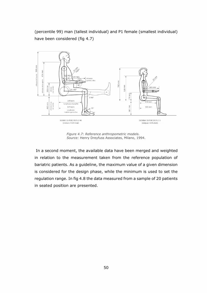
50
(percentile 99) man (tallest individual) and P1 female (smallest individual)
have been considered (fig 4.7)
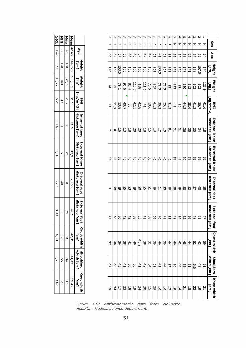
In a second moment, the available data have been merged and weighted
in relation to the measurement taken from the reference population of
bariatric patients. As a guideline, the maximum value of a given dimension
is considered for the design phase, while the minimum is used to set the
regulation range. In fig 4.8 the data measured from a sample of 20 patients
in seated position are presented.
Figure 4.7: Reference anthropometric models.
Source: Henry Dreyfuss Associates, Milano, 1994.
51
Figure 4.8: Anthropometric data from Molinette Hospital- Medical science department.
Se
xA
ge
He
igh
t [cm
]W
eig
ht
[kg
]B
MI
[kg
/m
^2
]In
tern
al k
ne
e
dista
nce
[cm]
Ex
tern
al K
ne
e
Dista
nce
[cm]
Inte
rna
l foo
t d
istan
ce [cm
]E
xte
rna
l foo
t d
istan
ce [cm
]C
he
st wid
th
[cm]
Sh
ou
lde
rs w
idth
[cm]
Kn
ee
wid
th
[cm]
1M
54
174
125,9
41,6
18
55
28
47
50
51
21
2M
62
167,5
103
36,7
34
53
40
61
43
48
19
3M
57
158
103
41,2
20
51
27
48
52
46,6
22
4M
26
171
113
38,6
35
58
32
56
44
51
18
5M
53
178
140
44,2
36
60
30
52
48
55
21
6M
57
170
88
30
21
41
19
39
42
44
16
7M
66
176
133
43
31
51
25
48
40
50
19
8F
31
163
83
31,2
51
40
18
35
44
37
17
9F
51
157
78,5
33,1
15
43
25
41
39
44
16
#F
42
166,5
79,5
28,2
17
40
31
40
40
42
16
#F
32
162
109
41,2
16
43
18
38
59
51
29
#F
47
155
73,5
30,6
15
33
21
38
31
34
15
#F
47
165
111,5
41
18
40
25
41
38
42
20
#F
37
166
118
42,8
20
45
20
35
43,2
41
24
#F
45
165
115,7
42,5
20
45
19
38
40
50
19
#F
44
158
82,4
33
18
40
23
42
42
36
18
#F
53
150
91,6
40,7
13
45
25
42
38
41
23
#F
57
153,5
79,1
33,8
16
38
19
36
36
43
17
#F
48
165
85
31,2
932
20
40
40
40
24
#F
44
174
94
31
725
825
37
42
15
Ag
eH
eig
ht
[cm]
We
igh
t [k
g]
BM
I [k
g/
m^
2]
Inte
rna
l kn
ee
d
istan
ce [cm
]E
xte
rna
l Kn
ee
D
istan
ce [cm
]In
tern
al fo
ot
dista
nce
[cm]
Ex
tern
al fo
ot
dista
nce
[cm]
Ch
est w
idth
[cm
]S
ho
uld
ers
wid
th [cm
]K
ne
e w
idth
[cm
]
Mean
47,65164,725100,335
36,15
21,5
43,9
23,65
42,1
42,31
44,43
19,45
Max
26
150
73,5
28,2
725
825
31
34
15
Min
66
178
140
43
51
60
40
61
59
55
29
Std.
10,47
7,79
19,77
5,28
10,65
8,86
6,79
8,09
6,23
5,71
3,62
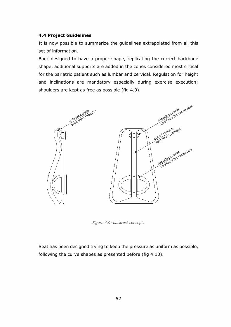
52
4.4 Project Guidelines
It is now possible to summarize the guidelines extrapolated from all this
set of information.
Back designed to have a proper shape, replicating the correct backbone
shape, additional supports are added in the zones considered most critical
for the bariatric patient such as lumbar and cervical. Regulation for height
and inclinations are mandatory especially during exercise execution;
shoulders are kept as free as possible (fig 4.9).
Seat has been designed trying to keep the pressure as uniform as possible,
following the curve shapes as presented before (fig 4.10).
Figure 4.9: backrest concept.
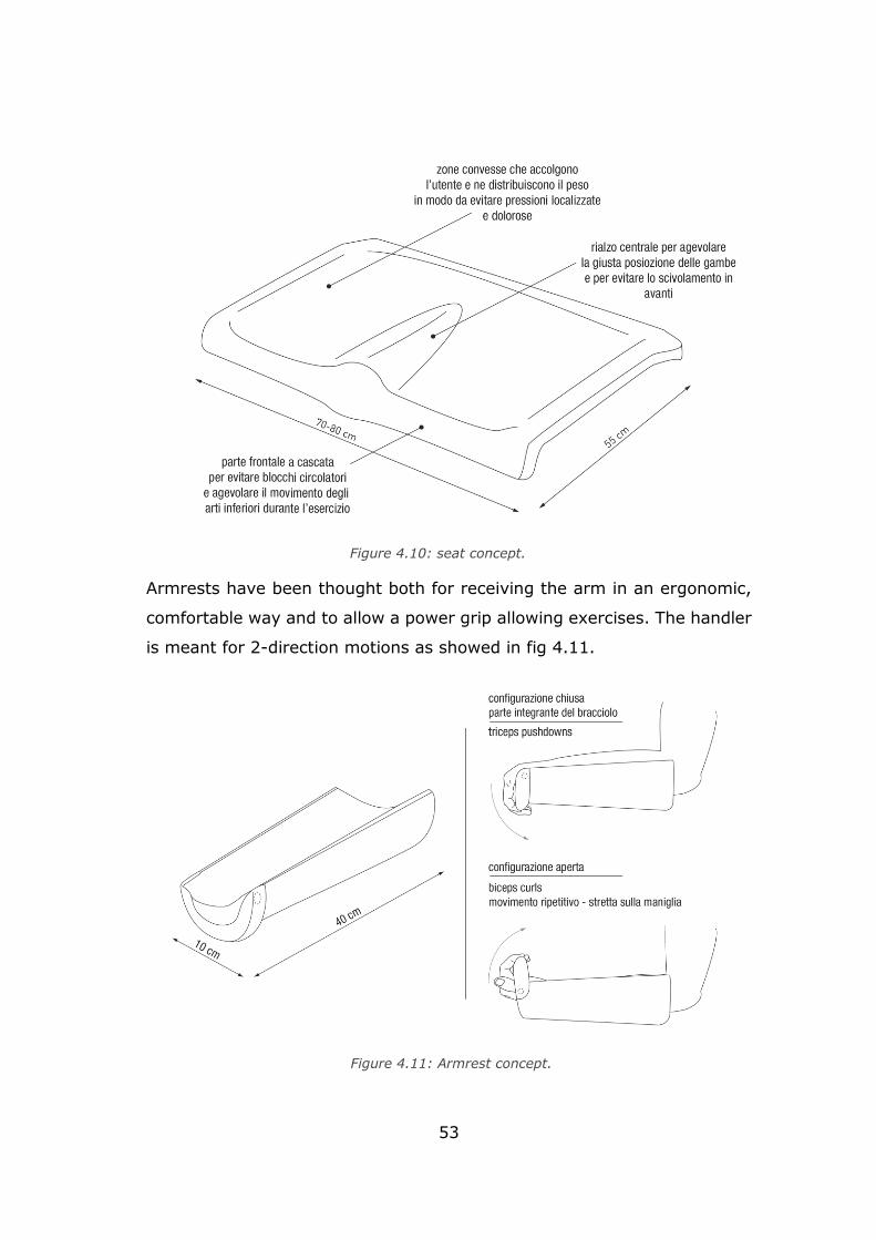
53
Armrests have been thought both for receiving the arm in an ergonomic,
comfortable way and to allow a power grip allowing exercises. The handler
is meant for 2-direction motions as showed in fig 4.11.
Figure 4.10: seat concept.
Figure 4.11: Armrest concept.
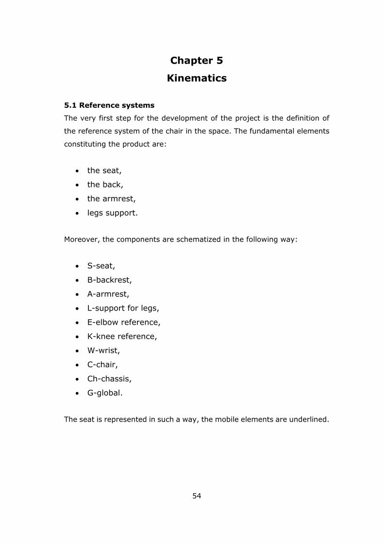
54
Chapter 5
Kinematics
5.1 Reference systems
The very first step for the development of the project is the definition of
the reference system of the chair in the space. The fundamental elements
constituting the product are:
• the seat,
• the back,
• the armrest,
• legs support.
Moreover, the components are schematized in the following way:
• S-seat,
• B-backrest,
• A-armrest,
• L-support for legs,
• E-elbow reference,
• K-knee reference,
• W-wrist,
• C-chair,
• Ch-chassis,
• G-global.
The seat is represented in such a way, the mobile elements are underlined.
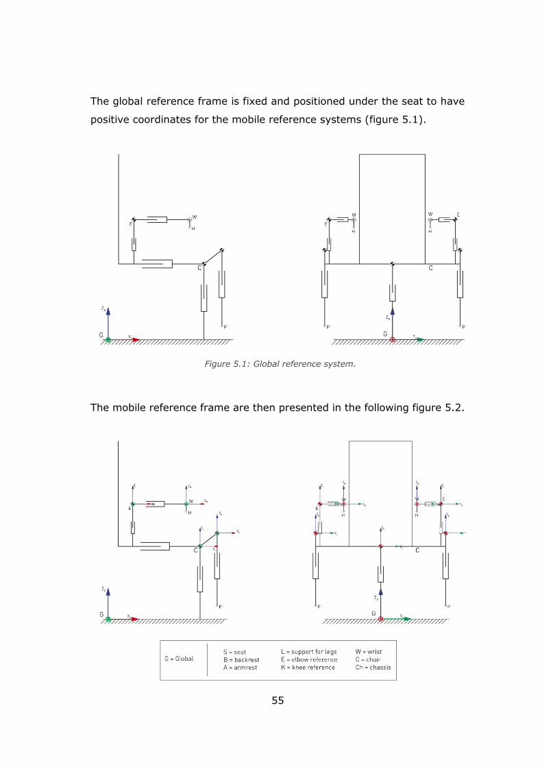
55
The global reference frame is fixed and positioned under the seat to have
positive coordinates for the mobile reference systems (figure 5.1).
The mobile reference frame are then presented in the following figure 5.2.
Figure 5.1: Global reference system.
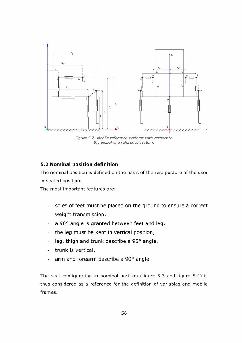
56
5.2 Nominal position definition
The nominal position is defined on the basis of the rest posture of the user
in seated position.
The most important features are:
- soles of feet must be placed on the ground to ensure a correct
weight transmission,
- a 90° angle is granted between feet and leg,
- the leg must be kept in vertical position,
- leg, thigh and trunk describe a 95° angle,
- trunk is vertical,
- arm and forearm describe a 90° angle.
The seat configuration in nominal position (figure 5.3 and figure 5.4) is
thus considered as a reference for the definition of variables and mobile
frames.
Figure 5.2: Mobile reference systems with respect to
the global one reference system.
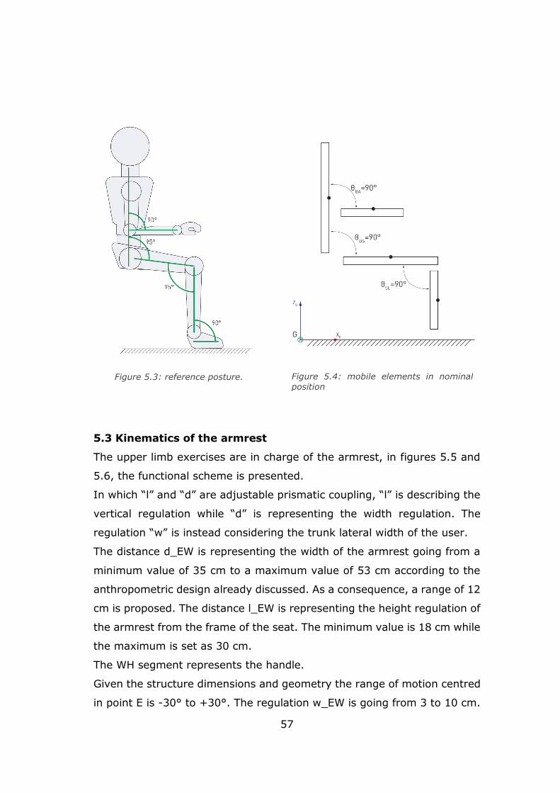
57
5.3 Kinematics of the armrest
The upper limb exercises are in charge of the armrest, in figures 5.5 and
5.6, the functional scheme is presented.
In which “l” and “d” are adjustable prismatic coupling, “l” is describing the
vertical regulation while “d” is representing the width regulation. The
regulation “w” is instead considering the trunk lateral width of the user.
The distance d_EW is representing the width of the armrest going from a
minimum value of 35 cm to a maximum value of 53 cm according to the
anthropometric design already discussed. As a consequence, a range of 12
cm is proposed. The distance l_EW is representing the height regulation of
the armrest from the frame of the seat. The minimum value is 18 cm while
the maximum is set as 30 cm.
The WH segment represents the handle.
Given the structure dimensions and geometry the range of motion centred
in point E is -30° to +30°. The regulation w_EW is going from 3 to 10 cm.
Figure 5.3: reference posture.
Figure 5.4: mobile elements in nominal position
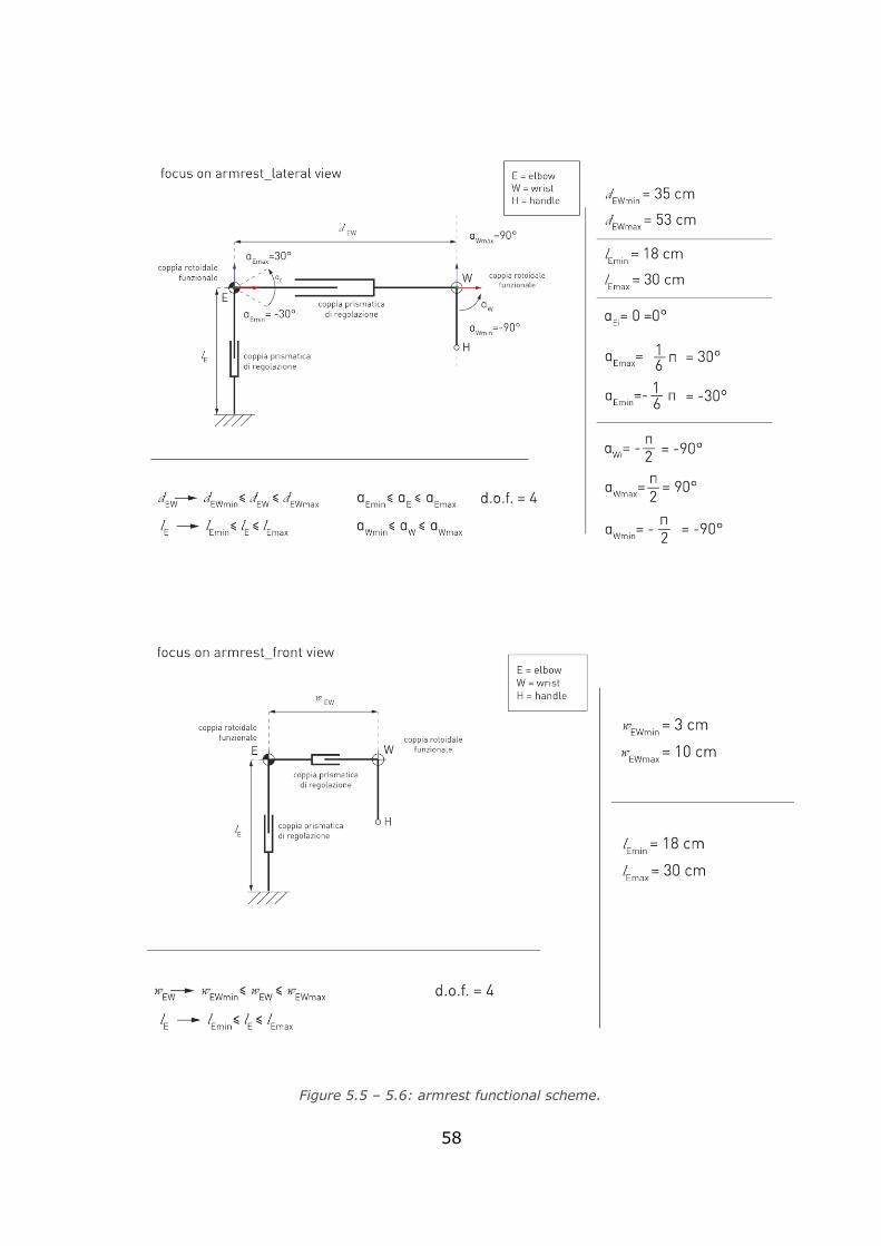
58
Figure 5.5 – 5.6: armrest functional scheme.
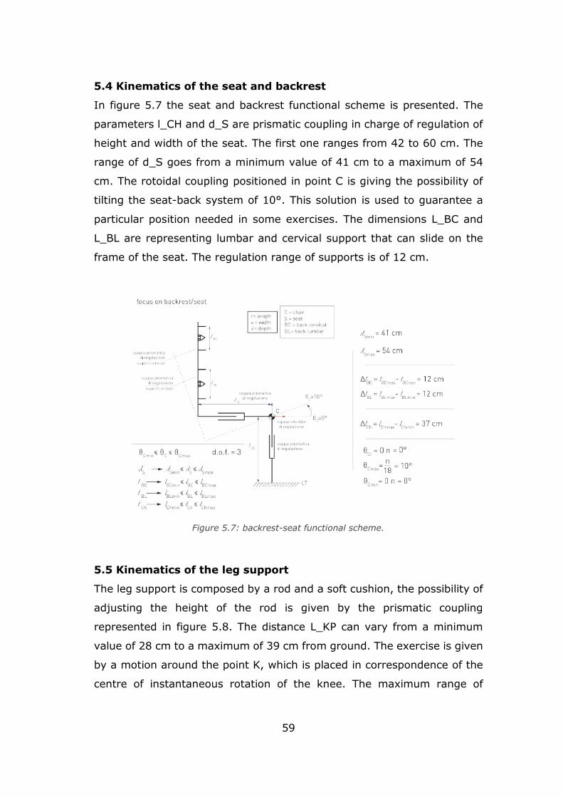
59
5.4 Kinematics of the seat and backrest
In figure 5.7 the seat and backrest functional scheme is presented. The
parameters l_CH and d_S are prismatic coupling in charge of regulation of
height and width of the seat. The first one ranges from 42 to 60 cm. The
range of d_S goes from a minimum value of 41 cm to a maximum of 54
cm. The rotoidal coupling positioned in point C is giving the possibility of
tilting the seat-back system of 10°. This solution is used to guarantee a
particular position needed in some exercises. The dimensions L_BC and
L_BL are representing lumbar and cervical support that can slide on the
frame of the seat. The regulation range of supports is of 12 cm.
5.5 Kinematics of the leg support
The leg support is composed by a rod and a soft cushion, the possibility of
adjusting the height of the rod is given by the prismatic coupling
represented in figure 5.8. The distance L_KP can vary from a minimum
value of 28 cm to a maximum of 39 cm from ground. The exercise is given
by a motion around the point K, which is placed in correspondence of the
centre of instantaneous rotation of the knee. The maximum range of
Figure 5.7: backrest-seat functional scheme.
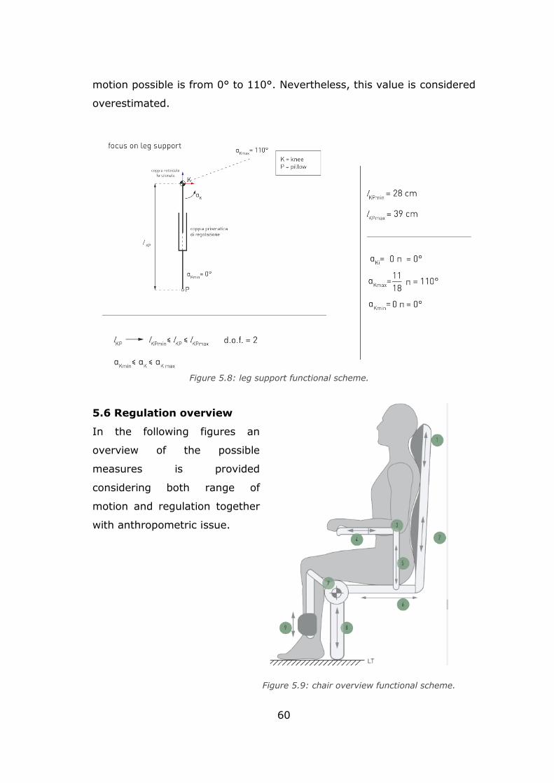
60
motion possible is from 0° to 110°. Nevertheless, this value is considered
overestimated.
5.6 Regulation overview
In the following figures an
overview of the possible
measures is provided
considering both range of
motion and regulation together
with anthropometric issue.
Figure 5.8: leg support functional scheme.
Figure 5.9: chair overview functional scheme.
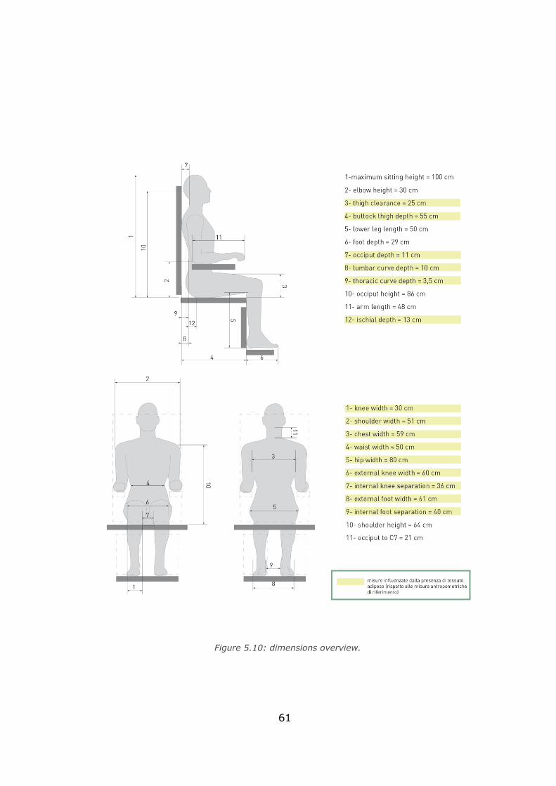
61
Figure 5.10: dimensions overview.
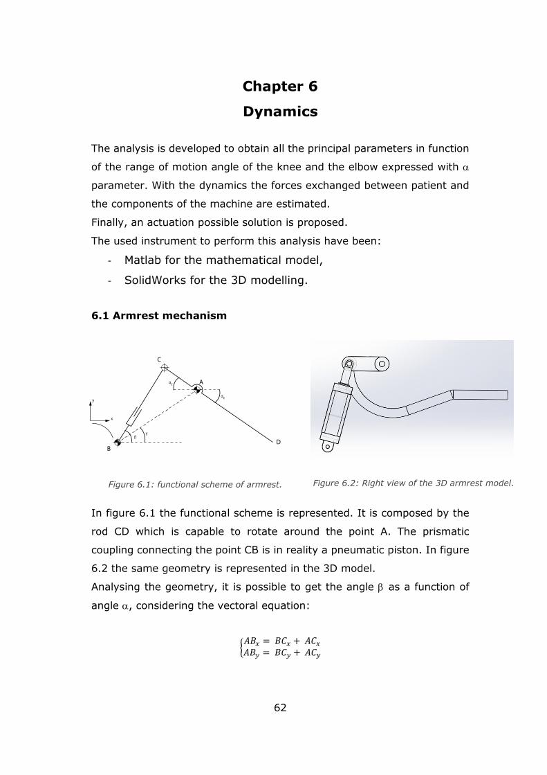
62
Chapter 6
Dynamics
The analysis is developed to obtain all the principal parameters in function
of the range of motion angle of the knee and the elbow expressed with
parameter. With the dynamics the forces exchanged between patient and
the components of the machine are estimated.
Finally, an actuation possible solution is proposed.
The used instrument to perform this analysis have been:
- Matlab for the mathematical model,
- SolidWorks for the 3D modelling.
6.1 Armrest mechanism
In figure 6.1 the functional scheme is represented. It is composed by the
rod CD which is capable to rotate around the point A. The prismatic
coupling connecting the point CB is in reality a pneumatic piston. In figure
6.2 the same geometry is represented in the 3D model.
Analysing the geometry, it is possible to get the angle as a function of
angle , considering the vectoral equation:
{𝐴𝐵𝑥 = 𝐵𝐶𝑥 + 𝐴𝐶𝑥
𝐴𝐵𝑦 = 𝐵𝐶𝑦 + 𝐴𝐶𝑦
Figure 6.2: Right view of the 3D armrest model. Figure 6.1: functional scheme of armrest.
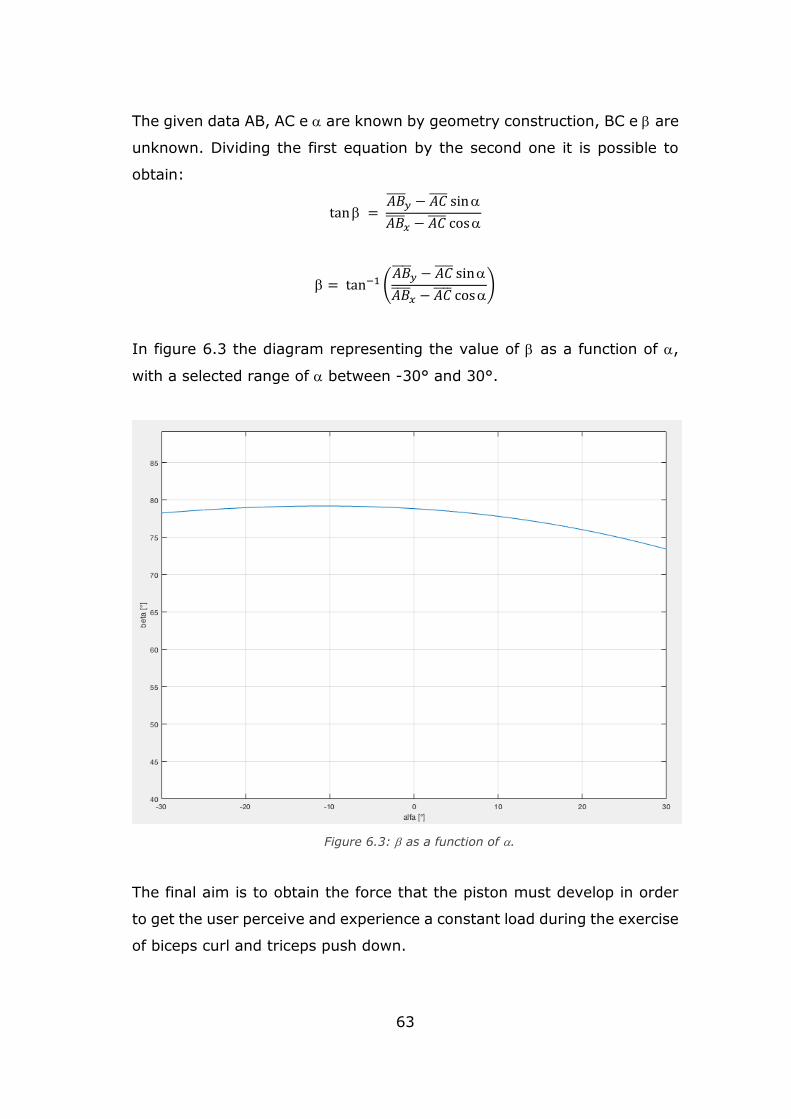
63
The given data AB, AC e are known by geometry construction, BC e are
unknown. Dividing the first equation by the second one it is possible to
obtain:
tan = 𝐴𝐵
𝑦 − 𝐴𝐶 sin
𝐴𝐵 𝑥 − 𝐴𝐶 cos
= tan−1 (𝐴𝐵
𝑦 − 𝐴𝐶 sin
𝐴𝐵 𝑥 − 𝐴𝐶 cos
)
In figure 6.3 the diagram representing the value of as a function of ,
with a selected range of between -30° and 30°.
The final aim is to obtain the force that the piston must develop in order
to get the user perceive and experience a constant load during the exercise
of biceps curl and triceps push down.
Figure 6.3: as a function of .
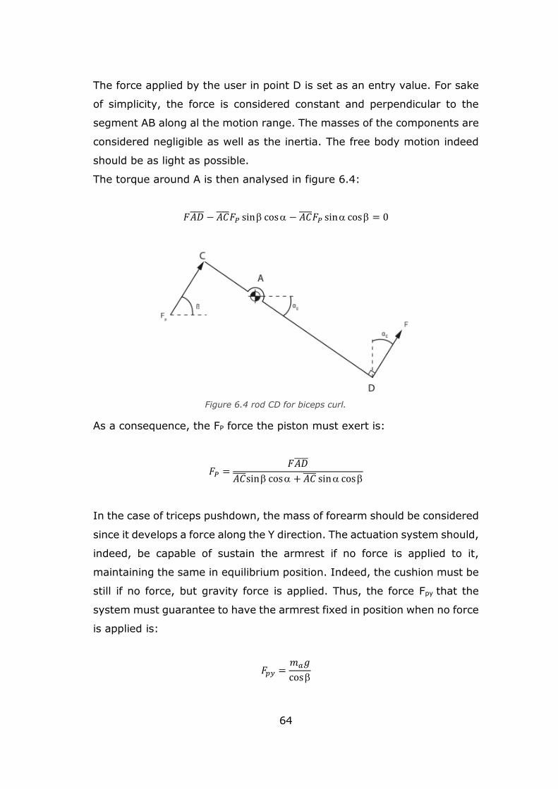
64
The force applied by the user in point D is set as an entry value. For sake
of simplicity, the force is considered constant and perpendicular to the
segment AB along al the motion range. The masses of the components are
considered negligible as well as the inertia. The free body motion indeed
should be as light as possible.
The torque around A is then analysed in figure 6.4:
𝐹𝐴𝐷 − 𝐴𝐶 𝐹𝑃 sin cos − 𝐴𝐶 𝐹𝑃 sin cos = 0
As a consequence, the FP force the piston must exert is:
𝐹𝑃 =𝐹𝐴𝐷
𝐴𝐶 sin cos + 𝐴𝐶 sin cos
In the case of triceps pushdown, the mass of forearm should be considered
since it develops a force along the Y direction. The actuation system should,
indeed, be capable of sustain the armrest if no force is applied to it,
maintaining the same in equilibrium position. Indeed, the cushion must be
still if no force, but gravity force is applied. Thus, the force Fpy that the
system must guarantee to have the armrest fixed in position when no force
is applied is:
𝐹𝑝𝑦 =𝑚𝑎𝑔
cos
Figure 6.4 rod CD for biceps curl.
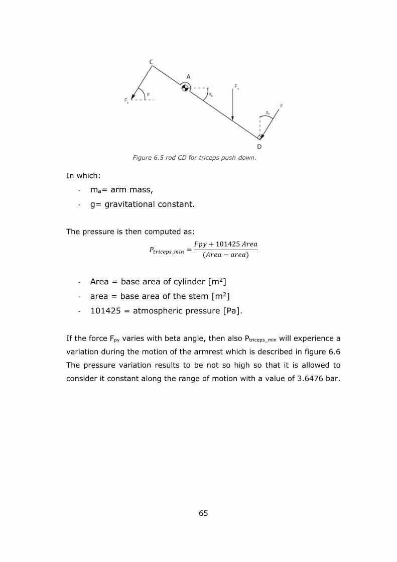
65
In which:
- ma= arm mass,
- g= gravitational constant.
The pressure is then computed as:
𝑃𝑡𝑟𝑖𝑐𝑒𝑝𝑠_𝑚𝑖𝑛 =𝐹𝑝𝑦 + 101425 𝐴𝑟𝑒𝑎
(𝐴𝑟𝑒𝑎 − 𝑎𝑟𝑒𝑎)
- Area = base area of cylinder [m2]
- area = base area of the stem [m2]
- 101425 = atmospheric pressure [Pa].
If the force Fpy varies with beta angle, then also Ptriceps_min will experience a
variation during the motion of the armrest which is described in figure 6.6
The pressure variation results to be not so high so that it is allowed to
consider it constant along the range of motion with a value of 3.6476 bar.
Figure 6.5 rod CD for triceps push down.
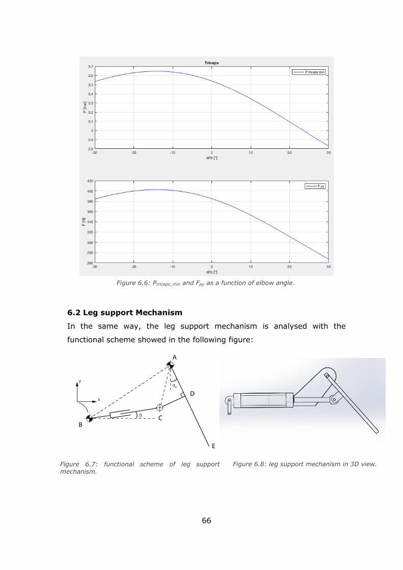
66
6.2 Leg support Mechanism
In the same way, the leg support mechanism is analysed with the
functional scheme showed in the following figure:
Figure 6.7: functional scheme of leg support mechanism.
Figure 6.8: leg support mechanism in 3D view.
Figure 6.6: Ptriceps_min and Fpy as a function of elbow angle.
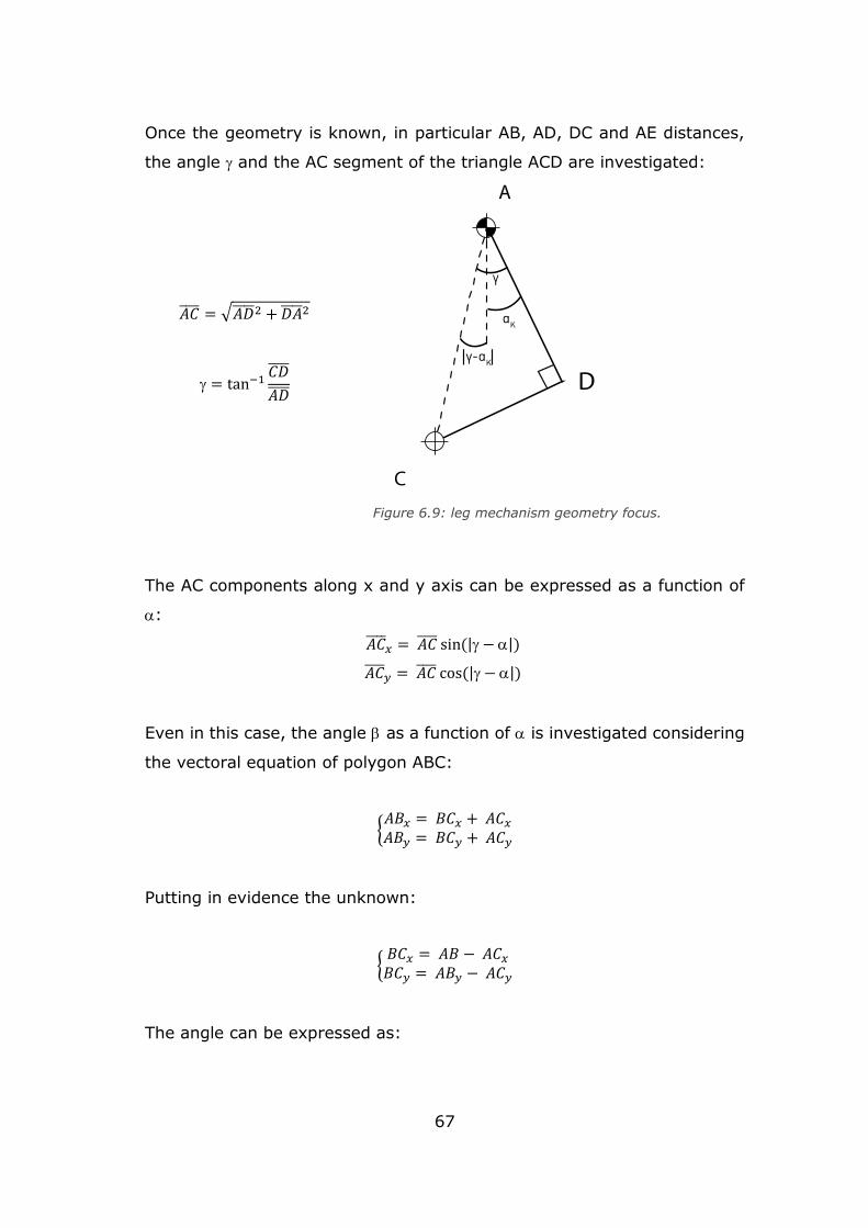
67
Once the geometry is known, in particular AB, AD, DC and AE distances,
the angle and the AC segment of the triangle ACD are investigated:
𝐴𝐶 = √𝐴𝐷 2 + 𝐷𝐴 2
= tan−1𝐶𝐷
𝐴𝐷
The AC components along x and y axis can be expressed as a function of
:
𝐴𝐶 𝑥 = 𝐴𝐶 sin(| − |)
𝐴𝐶 𝑦 = 𝐴𝐶 cos(| − |)
Even in this case, the angle as a function of is investigated considering
the vectoral equation of polygon ABC:
{𝐴𝐵𝑥 = 𝐵𝐶𝑥 + 𝐴𝐶𝑥
𝐴𝐵𝑦 = 𝐵𝐶𝑦 + 𝐴𝐶𝑦
Putting in evidence the unknown:
{𝐵𝐶𝑥 = 𝐴𝐵 − 𝐴𝐶𝑥
𝐵𝐶𝑦 = 𝐴𝐵𝑦 − 𝐴𝐶𝑦
The angle can be expressed as:
Figure 6.9: leg mechanism geometry focus.
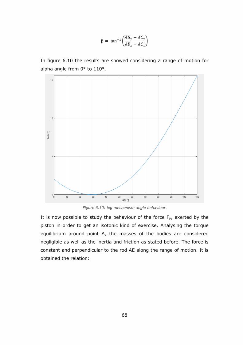
68
= tan−1 (𝐴𝐵
𝑦 − 𝐴𝐶𝑦
𝐴𝐵 𝑥 − 𝐴𝐶𝑥
)
In figure 6.10 the results are showed considering a range of motion for
alpha angle from 0° to 110°.
It is now possible to study the behaviour of the force Fp, exerted by the
piston in order to get an isotonic kind of exercise. Analysing the torque
equilibrium around point A, the masses of the bodies are considered
negligible as well as the inertia and friction as stated before. The force is
constant and perpendicular to the rod AE along the range of motion. It is
obtained the relation:
Figure 6.10: leg mechanism angle behaviour.
.
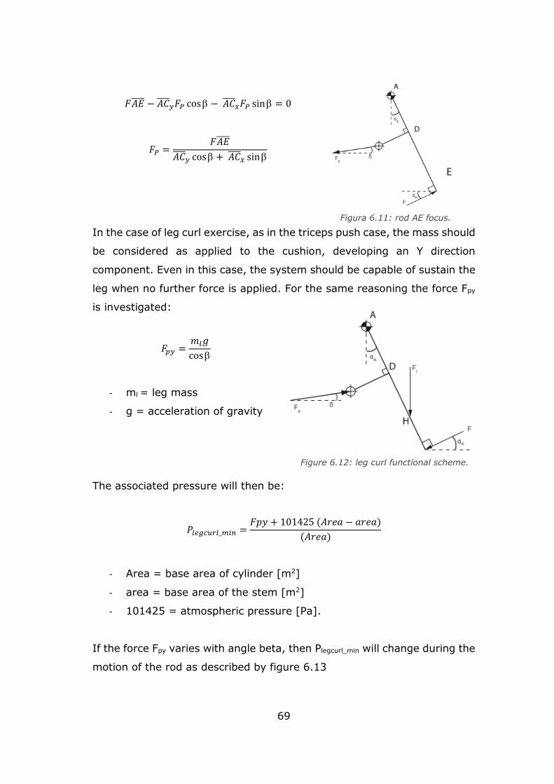
69
𝐹𝐴𝐸 − 𝐴𝐶 𝑦𝐹𝑃 cos − 𝐴𝐶
𝑥𝐹𝑃 sin = 0
𝐹𝑃 =𝐹𝐴𝐸
𝐴𝐶 𝑦 cos + 𝐴𝐶
𝑥 sin
In the case of leg curl exercise, as in the triceps push case, the mass should
be considered as applied to the cushion, developing an Y direction
component. Even in this case, the system should be capable of sustain the
leg when no further force is applied. For the same reasoning the force Fpy
is investigated:
𝐹𝑝𝑦 =𝑚𝑙𝑔
cos
- ml = leg mass
- g = acceleration of gravity
The associated pressure will then be:
𝑃𝑙𝑒𝑔𝑐𝑢𝑟𝑙_𝑚𝑖𝑛 =𝐹𝑝𝑦 + 101425 (𝐴𝑟𝑒𝑎 − 𝑎𝑟𝑒𝑎)
(𝐴𝑟𝑒𝑎)
- Area = base area of cylinder [m2]
- area = base area of the stem [m2]
- 101425 = atmospheric pressure [Pa].
If the force Fpy varies with angle beta, then Plegcurl_min will change during the
motion of the rod as described by figure 6.13
Figura 6.11: rod AE focus.
Figure 6.12: leg curl functional scheme.
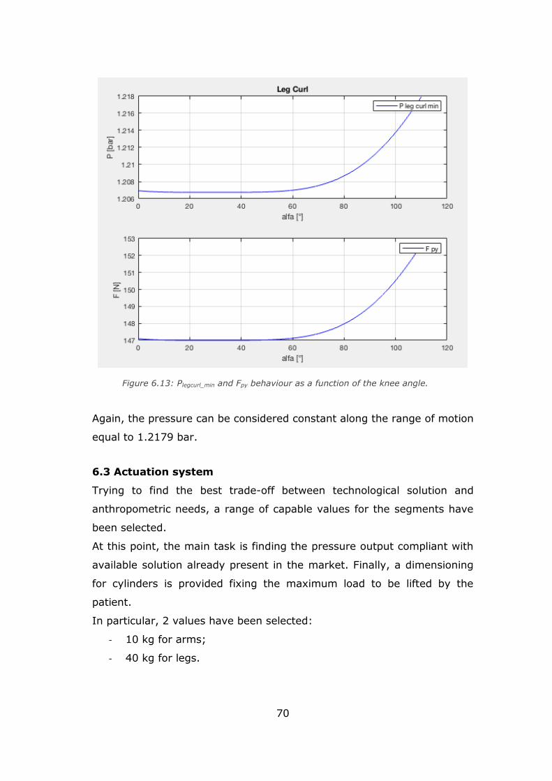
70
Again, the pressure can be considered constant along the range of motion
equal to 1.2179 bar.
6.3 Actuation system
Trying to find the best trade-off between technological solution and
anthropometric needs, a range of capable values for the segments have
been selected.
At this point, the main task is finding the pressure output compliant with
available solution already present in the market. Finally, a dimensioning
for cylinders is provided fixing the maximum load to be lifted by the
patient.
In particular, 2 values have been selected:
- 10 kg for arms;
- 40 kg for legs.
Figure 6.13: Plegcurl_min and Fpy behaviour as a function of the knee angle.
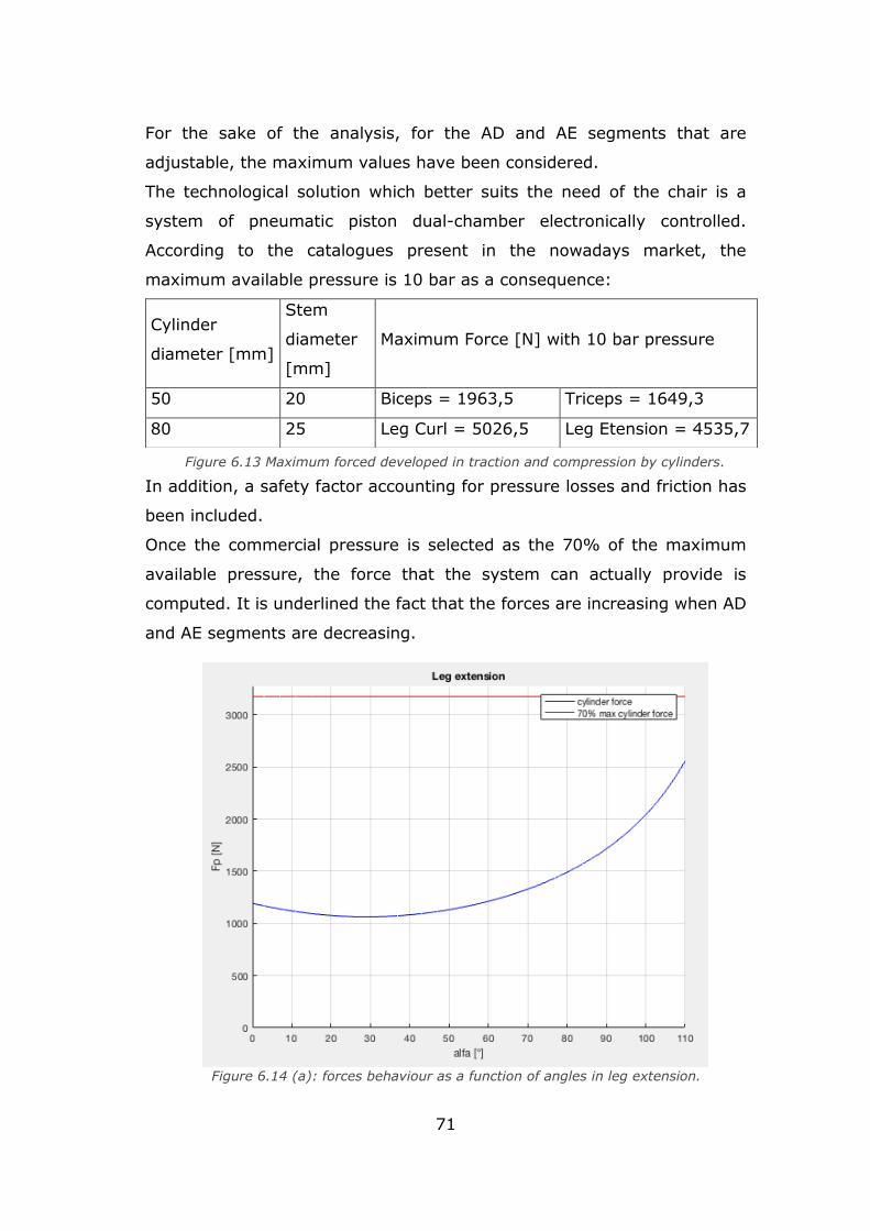
71
For the sake of the analysis, for the AD and AE segments that are
adjustable, the maximum values have been considered.
The technological solution which better suits the need of the chair is a
system of pneumatic piston dual-chamber electronically controlled.
According to the catalogues present in the nowadays market, the
maximum available pressure is 10 bar as a consequence:
In addition, a safety factor accounting for pressure losses and friction has
been included.
Once the commercial pressure is selected as the 70% of the maximum
available pressure, the force that the system can actually provide is
computed. It is underlined the fact that the forces are increasing when AD
and AE segments are decreasing.
Cylinder
diameter [mm]
Stem
diameter
[mm]
Maximum Force [N] with 10 bar pressure
50 20 Biceps = 1963,5 Triceps = 1649,3
80 25 Leg Curl = 5026,5 Leg Etension = 4535,7
Figure 6.13 Maximum forced developed in traction and compression by cylinders.
.
Figure 6.14 (a): forces behaviour as a function of angles in leg extension.
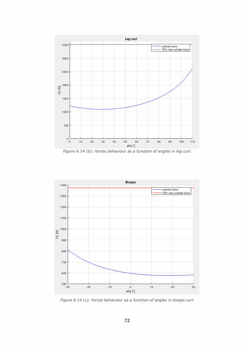
72
Figure 6.14 (c): forces behaviour as a function of angles in biceps curl.
Figure 6.14 (b): forces behaviour as a function of angles in leg curl.
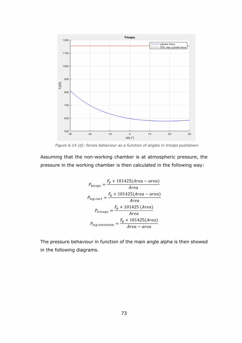
73
Assuming that the non-working chamber is at atmospheric pressure, the
pressure in the working chamber is then calculated in the following way:
𝑃𝑏𝑖𝑐𝑒𝑝𝑠 =𝐹𝑝 + 101425(𝐴𝑟𝑒𝑎 − 𝑎𝑟𝑒𝑎)
𝐴𝑟𝑒𝑎
𝑃𝑙𝑒𝑔 𝑐𝑢𝑟𝑙 =𝐹𝑝 + 101425(𝐴𝑟𝑒𝑎 − 𝑎𝑟𝑒𝑎)
𝐴𝑟𝑒𝑎
𝑃𝑡𝑟𝑖𝑐𝑒𝑝𝑠 =𝐹𝑝 + 101425 (𝐴𝑟𝑒𝑎)
𝐴𝑟𝑒𝑎
𝑃𝑙𝑒𝑔 𝑒𝑥𝑡𝑒𝑛𝑠𝑖𝑜𝑛 =𝐹𝑝 + 101425(𝐴𝑟𝑒𝑎)
𝐴𝑟𝑒𝑎 − 𝑎𝑟𝑒𝑎
The pressure behaviour in function of the main angle alpha is then showed
in the following diagrams.
Figure 6.14 (d): forces behaviour as a function of angles in triceps pushdown.
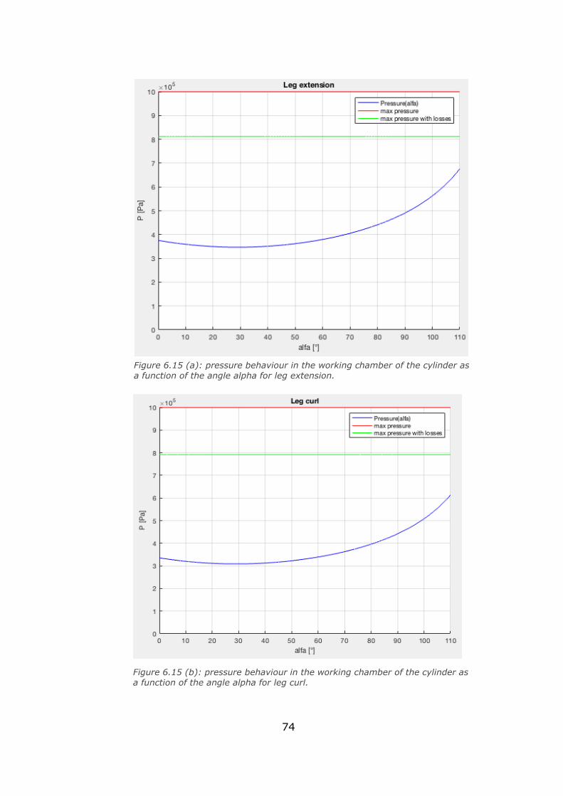
74
Figure 6.15 (b): pressure behaviour in the working chamber of the cylinder as a function of the angle alpha for leg curl.
Figure 6.15 (a): pressure behaviour in the working chamber of the cylinder as
a function of the angle alpha for leg extension.
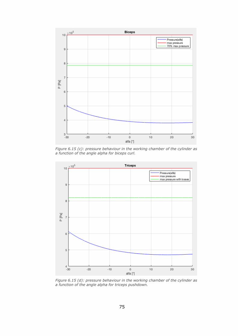
75
Figure 6.15 (d): pressure behaviour in the working chamber of the cylinder as
a function of the angle alpha for triceps pushdown.
Figure 6.15 (c): pressure behaviour in the working chamber of the cylinder as a function of the angle alpha for biceps curl.
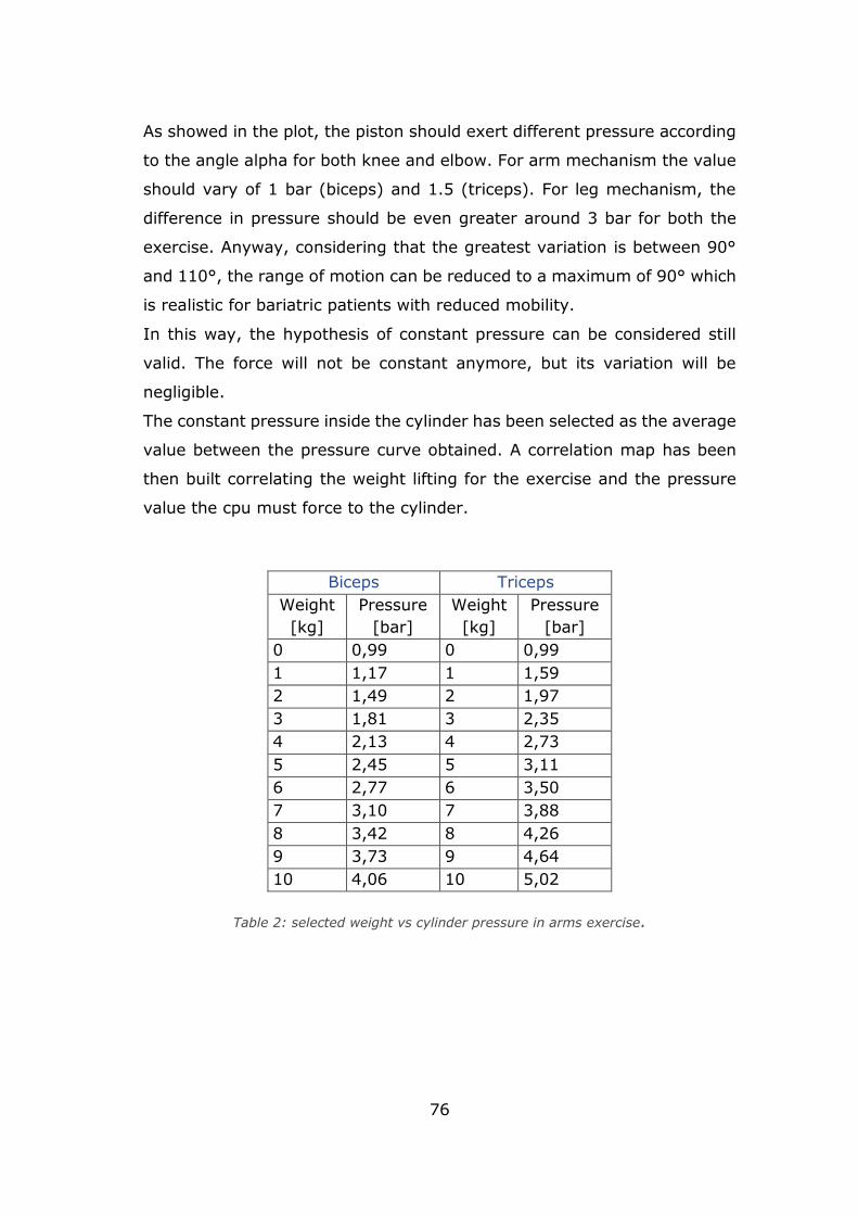
76
As showed in the plot, the piston should exert different pressure according
to the angle alpha for both knee and elbow. For arm mechanism the value
should vary of 1 bar (biceps) and 1.5 (triceps). For leg mechanism, the
difference in pressure should be even greater around 3 bar for both the
exercise. Anyway, considering that the greatest variation is between 90°
and 110°, the range of motion can be reduced to a maximum of 90° which
is realistic for bariatric patients with reduced mobility.
In this way, the hypothesis of constant pressure can be considered still
valid. The force will not be constant anymore, but its variation will be
negligible.
The constant pressure inside the cylinder has been selected as the average
value between the pressure curve obtained. A correlation map has been
then built correlating the weight lifting for the exercise and the pressure
value the cpu must force to the cylinder.
Biceps Triceps
Weight
[kg]
Pressure
[bar]
Weight
[kg]
Pressure
[bar]
0 0,99 0 0,99
1 1,17 1 1,59
2 1,49 2 1,97
3 1,81 3 2,35
4 2,13 4 2,73
5 2,45 5 3,11
6 2,77 6 3,50
7 3,10 7 3,88
8 3,42 8 4,26
9 3,73 9 4,64
10 4,06 10 5,02
Table 2: selected weight vs cylinder pressure in arms exercise.
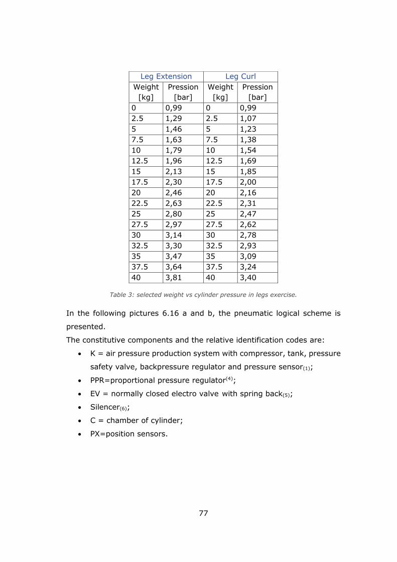
77
Table 3: selected weight vs cylinder pressure in legs exercise.
In the following pictures 6.16 a and b, the pneumatic logical scheme is
presented.
The constitutive components and the relative identification codes are:
• K = air pressure production system with compressor, tank, pressure
safety valve, backpressure regulator and pressure sensor(1);
• PPR=proportional pressure regulator(4);
• EV = normally closed electro valve with spring back(5);
• Silencer(6);
• C = chamber of cylinder;
• PX=position sensors.
Leg Extension Leg Curl
Weight
[kg]
Pression
[bar]
Weight
[kg]
Pression
[bar]
0 0,99 0 0,99
2.5 1,29 2.5 1,07
5 1,46 5 1,23
7.5 1,63 7.5 1,38
10 1,79 10 1,54
12.5 1,96 12.5 1,69
15 2,13 15 1,85
17.5 2,30 17.5 2,00
20 2,46 20 2,16
22.5 2,63 22.5 2,31
25 2,80 25 2,47
27.5 2,97 27.5 2,62
30 3,14 30 2,78
32.5 3,30 32.5 2,93
35 3,47 35 3,09
37.5 3,64 37.5 3,24
40 3,81 40 3,40
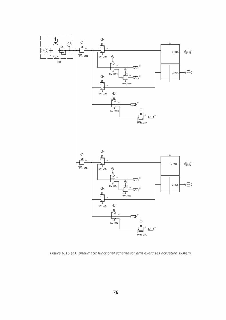
78
PPR_01R
PPR_02R
PPR_03R
EV_01R
EV_02R
EV_03R
EV_04R
C2R PX02R
PX01RC1R
12
4
1
3
5
1
(4) (5)
(4)
(5)
(7) (6)
(6)
2 on 4off
2 off 4on
(7)
(4) (6)
(6)
PPR_01L
PPR_02L
PPR_03L
EV_01L
EV_02L
EV_03L
EV_04L
C2L PX02L
PX01LC1L
12
4
1
3
5
1
(4) (5)
(4)
(5)
(6)
(6)
2 on 4off
2 off 4on(4) (6)
(6)
(7)
(7)
M
(1)
K01
(2)
(2)
C_02R
C_01R
C_02L
C_01L
Figure 6.16 (a): pneumatic functional scheme for arm exercises actuation system.
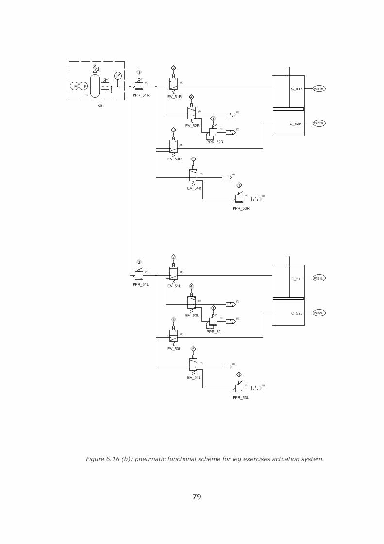
79
PPR_51R
PPR_52R
PPR_53R
EV_51R
EV_52R
EV_53R
EV_54R
C52R PX52R
PX51RC51R
12
4
1
3
5
1
(4) (5)
(4)
(5)
(6)
(6)
2 on 4off
2 off 4on(4) (6)
(6)
PPR_51L
PPR_52L
PPR_53L
EV_51L
EV_52L
EV_53L
EV_54L
C52L PX52L
PX51LC51L
12
4
1
3
5
1
(4) (5)
(4)
(5)
(6)
(6)
2 on 4off
2 off 4on
(4) (6)
(6)
K51(7)
(7)
(7)
(7)
M
(1)
C_51R
C_52R
C_51L
C_52L
Figure 6.16 (b): pneumatic functional scheme for leg exercises actuation system.
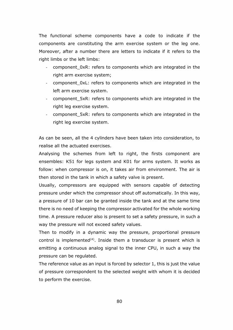
80
The functional scheme components have a code to indicate if the
components are constituting the arm exercise system or the leg one.
Moreover, after a number there are letters to indicate if it refers to the
right limbs or the left limbs:
- component_0xR: refers to components which are integrated in the
right arm exercise system;
- component_0xL: refers to components which are integrated in the
left arm exercise system.
- component_5xR: refers to components which are integrated in the
right leg exercise system.
- component_5xR: refers to components which are integrated in the
right leg exercise system.
As can be seen, all the 4 cylinders have been taken into consideration, to
realise all the actuated exercises.
Analysing the schemes from left to right, the firsts component are
ensembles: K51 for legs system and K01 for arms system. It works as
follow: when compressor is on, it takes air from environment. The air is
then stored in the tank in which a safety valve is present.
Usually, compressors are equipped with sensors capable of detecting
pressure under which the compressor shout off automatically. In this way,
a pressure of 10 bar can be granted inside the tank and at the same time
there is no need of keeping the compressor activated for the whole working
time. A pressure reducer also is present to set a safety pressure, in such a
way the pressure will not exceed safety values.
Then to modify in a dynamic way the pressure, proportional pressure
control is implemented(4). Inside them a transducer is present which is
emitting a continuous analog signal to the inner CPU, in such a way the
pressure can be regulated.
The reference value as an input is forced by selector 1, this is just the value
of pressure correspondent to the selected weight with whom it is decided
to perform the exercise.
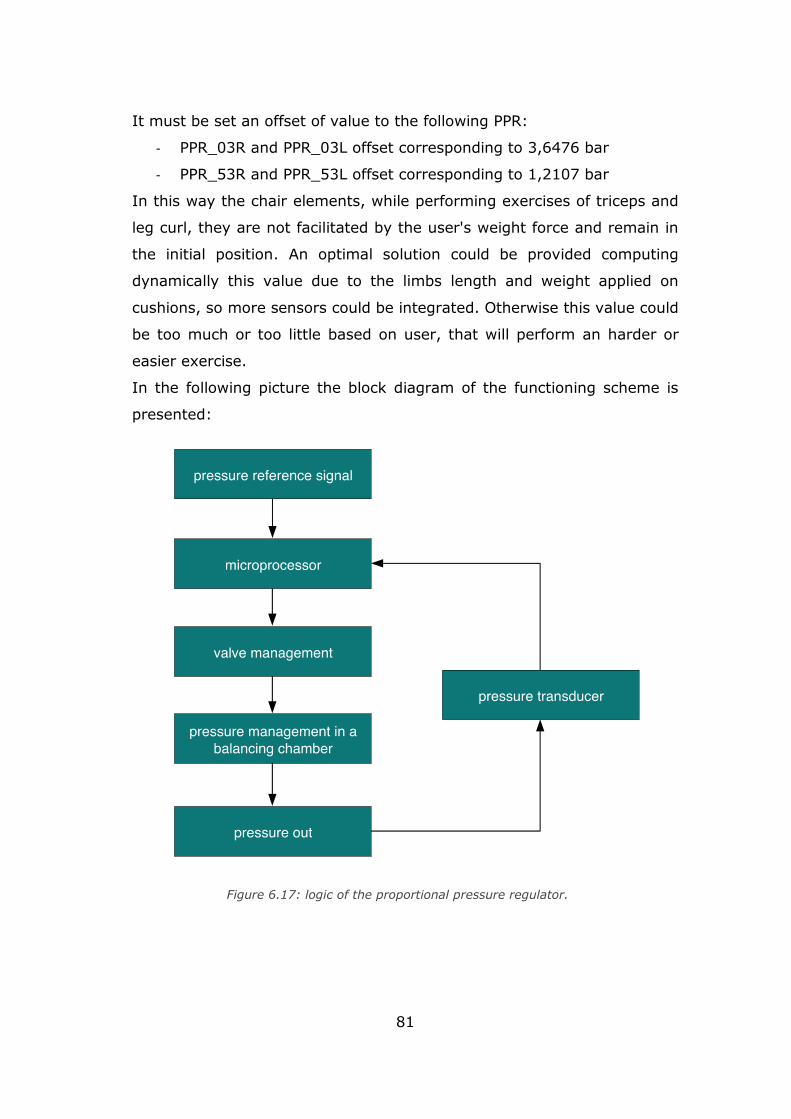
81
It must be set an offset of value to the following PPR:
- PPR_03R and PPR_03L offset corresponding to 3,6476 bar
- PPR_53R and PPR_53L offset corresponding to 1,2107 bar
In this way the chair elements, while performing exercises of triceps and
leg curl, they are not facilitated by the user's weight force and remain in
the initial position. An optimal solution could be provided computing
dynamically this value due to the limbs length and weight applied on
cushions, so more sensors could be integrated. Otherwise this value could
be too much or too little based on user, that will perform an harder or
easier exercise.
In the following picture the block diagram of the functioning scheme is
presented:
Figure 6.17: logic of the proportional pressure regulator.
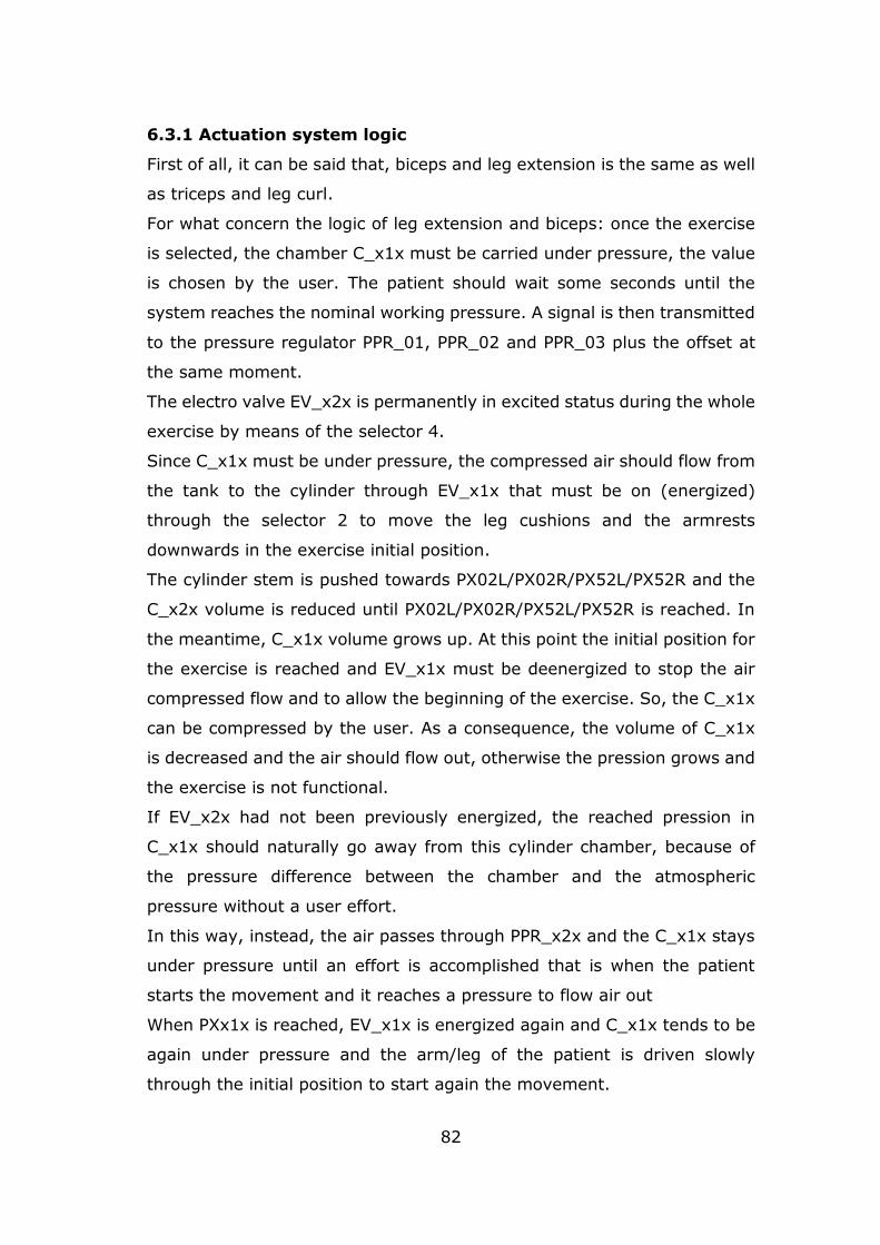
82
6.3.1 Actuation system logic
First of all, it can be said that, biceps and leg extension is the same as well
as triceps and leg curl.
For what concern the logic of leg extension and biceps: once the exercise
is selected, the chamber C_x1x must be carried under pressure, the value
is chosen by the user. The patient should wait some seconds until the
system reaches the nominal working pressure. A signal is then transmitted
to the pressure regulator PPR_01, PPR_02 and PPR_03 plus the offset at
the same moment.
The electro valve EV_x2x is permanently in excited status during the whole
exercise by means of the selector 4.
Since C_x1x must be under pressure, the compressed air should flow from
the tank to the cylinder through EV_x1x that must be on (energized)
through the selector 2 to move the leg cushions and the armrests
downwards in the exercise initial position.
The cylinder stem is pushed towards PX02L/PX02R/PX52L/PX52R and the
C_x2x volume is reduced until PX02L/PX02R/PX52L/PX52R is reached. In
the meantime, C_x1x volume grows up. At this point the initial position for
the exercise is reached and EV_x1x must be deenergized to stop the air
compressed flow and to allow the beginning of the exercise. So, the C_x1x
can be compressed by the user. As a consequence, the volume of C_x1x
is decreased and the air should flow out, otherwise the pression grows and
the exercise is not functional.
If EV_x2x had not been previously energized, the reached pression in
C_x1x should naturally go away from this cylinder chamber, because of
the pressure difference between the chamber and the atmospheric
pressure without a user effort.
In this way, instead, the air passes through PPR_x2x and the C_x1x stays
under pressure until an effort is accomplished that is when the patient
starts the movement and it reaches a pressure to flow air out
When PXx1x is reached, EV_x1x is energized again and C_x1x tends to be
again under pressure and the arm/leg of the patient is driven slowly
through the initial position to start again the movement.
83
During all the exercise C_x1x stays at a constant pressure, meanwhile
C_x2x is at a constant atmospheric pressure, because EV_x3x and EV_x4x
are not energized. In figure 17 there’s a flow diagram to describe this logic.
Figure 6.18: logic of pneumatic system leg extension and biceps
Figure 6.19: logic of pneumatic system leg curl and triceps
84
Triceps/ leg curl exercises have a similar logic. Once the exercise is
selected, the chamber C_x2x must be carried under pressure, the value is
chosen by the user. The patient should wait some seconds until the system
reaches the nominal working pressure. A signal is then transmitted to the
pressure regulator PPR_01x, PPR_02x and PPR_03x plus the offset at the
same moment.
The electro valve EV_x4x is permanently in excited status during the whole
exercise by means of the selector 5, its purpose is similar of what is has
been said about EV_x2x in the biceps/leg extension case.
Since C_x2x must be under pressure, the compressed air should flow from
the tank to the cylinder through EV_x3x that must be energized through
the selector 3 to move the leg cushions and the armrests upwards in the
exercise initial position.
The cylinder stem is pushed towards PX01L/PX01R/PX51L/PX51R and the
C_x1x volume is reduced until PX01L/PX02R/PX51L/PX51R is reached. In
the meantime, C_x2x volume grows up. At this point the initial position for
the exercise is reached and EV_x3x must be deenergized stopping the air
compressed flow and to allow the beginning of the exercise. So, the C_x2x
can be compressed by the user. As a consequence, the volume of C_x2x
is decreased and the air should flow out, otherwise the pression grows and
the exercise is not functional.
If EV_x4x had not been previously energized, the reached pression in
C_x1x should naturally go away from this cylinder chamber, because of
the pressure difference between the chamber and the atmospheric
pressure without a user effort.
In this way, instead, the air passes through PPR_x3x and the C_x2x stays
under pressure until an effort is accomplished that is when the patient
starts the movement and it reaches a pressure to flow the air out.
When PXx2x is reached, EV_x1x is energized again and C_x2x tends to be
again under pressure and the arm/leg of the patient is driven slowly
through the initial position to start again the movement.
85
During all the exercise C_x2x stays at a constant pressure, meanwhile
C_x1x is at a constant atmospheric pressure, because EV_x1x and EV_x3x
are not energized. In figure 18 there’s a flow diagram to describe this logic.
6.3.2 Air consumption
To get the tank dimension as well as the power of the compressor, the air
consumption in litres x minute is needed.
As a first approximation, it can be calculated as litres necessary for 1 serie:
𝑄𝑏𝑖𝑐𝑒𝑝𝑠 =𝜋𝐷2
4 𝐶 𝑃𝑚𝑒𝑎𝑛 𝑛𝑎𝑟𝑚 [𝑙/𝑠𝑒𝑟𝑖𝑒]
𝑄𝑡𝑟𝑖𝑐𝑒𝑝𝑠 =𝜋
4(𝐷 + 𝑑)(𝐷 − 𝑑) 𝐶 𝑃𝑚𝑒𝑎𝑛 𝑛𝑎𝑟𝑚 [𝑙/𝑠𝑒𝑟𝑖𝑒]
In which:
D = cylinder diameter [dm]
d = stem diameter [dm]
C = cylinder displacement [dm]
Pmean = absolute pressure [bar]
narm = number of stroke equal to the repetition each series
For this computation, it is necessary to make an assumption about the
number of series as a relation of the average selected pressure. The more
the number of repetitions, the less will be the lifting weight. This factor is
strictly related to the patients himself and his training level. Nevertheless,
the focus of this study is to make possible execute exercise with low weight
but large number of repetitions. So, a narm equal to 25 is selected, as a
result:
• Qbiceps= 4.9276 l/serie,
• Qtriceps= 5.6094 l/serie.
86
With a weight of 5 kg instead, a narm of 8 is considered, the results are:
• Qbiceps= 3.3024 l/serie,
• Qtriceps= 3.5206 l/serie.
Finally, a 6-litre tank for each pneumatic circuit of arms can be used, the
main objective is having the activation of the compressor not more then 1
time each exercise.
As well for the leg:
𝑄𝑙𝑒𝑔 𝑐𝑢𝑟𝑙 =𝜋𝐷2
4 𝐶 𝑃𝑚𝑒𝑎𝑛 𝑛𝑙𝑒𝑔 [𝑙/𝑠𝑒𝑟𝑖𝑒]
𝑄𝑙𝑒𝑔 𝑒𝑥𝑡𝑒𝑛𝑠𝑖𝑜𝑛 =𝜋
4(𝐷 + 𝑑)(𝐷 − 𝑑) 𝐶 𝑃𝑚𝑒𝑎𝑛 𝑛𝑙𝑒𝑔 [𝑙/𝑠𝑒𝑟𝑖𝑒]
With weight equal to 2.5 and n equal to 8 the results are:
• Qextension= 9.0765 l/serie
• Qlegcurl= 8,3364 l/serie.
The tank for the legs exercise should be around 10 l for each leg circuit.
As an assumption the unit measure of l/series can be considered equal to
l/min if we consider that no more than 1 min for each series is needed,
followed by a rest time of at least 1 min. It is now possible to go throw the
compressor choice, taking a look into the nowadays market, summarizing
the data a machine like that can be selected:
• 40 l/min
• 10 bar
• 120 W
• 12 V
87
With this feature, the compressor can feed in 1 minute all the 4 tanks at a
time, if 2 compressors are included, then the charging time is scaled.
Considering now a domestic plant in which the available current is of 220
V, it is necessary to connect the compressor by means of an external power
supply. For 120 W, with 12 V a 10 A current is needed, considering a safety
factor of 10%, a commercial model with these characteristics is selected:
• 220 V AC to 12 DC
• 12 A nominal current
88
Chapter 7
Final concept
7.1 3D model
A 3D layout has been realized in Rhino environment, putting together all
mechanical parts realized with Solidworks. This software has been
particularly helpful to cover what was necessary to make the seat more
pleasant to a bariatric user. All the mechanisms and systems implemented
are hidden at the eye for a better sensation and greater security. The goal
is to camouflage the machine to avoid associations with the gym
environment.
For greater comfort, the frame was almost completely covered with a thin
one layer of padding to cover any edges or dangerous protrusions of the
frame in steel.
All ergonomics and anthropometrics details have been considered. Support
surfaces (seat, backrest, leg cushions and armrests) are designed to
sustain the user while performing the training.
The limbs surfaces appear shaped to comfort arms and legs but also appear
suitable to perform exercises without remembering a gym machine, so that
cognitive design is also considered.
The seat has 3 possible configurations:
- totally closed, while all the anthropometric regulations are
minimum;
- totally open, while all the anthropometric regulations are maximum;
- inclined one to better perform the leg exercises.
In this way the seat is adequate for all bariatric users
Two details have been taken into account while realizing the structure:
- maximum depth in closed configuration is less than 90 cm to allows
the passage through hospital doors, because the minimum is of 95
cm(1). A width of 80 cm is considered to allow the passage through
normal doors;
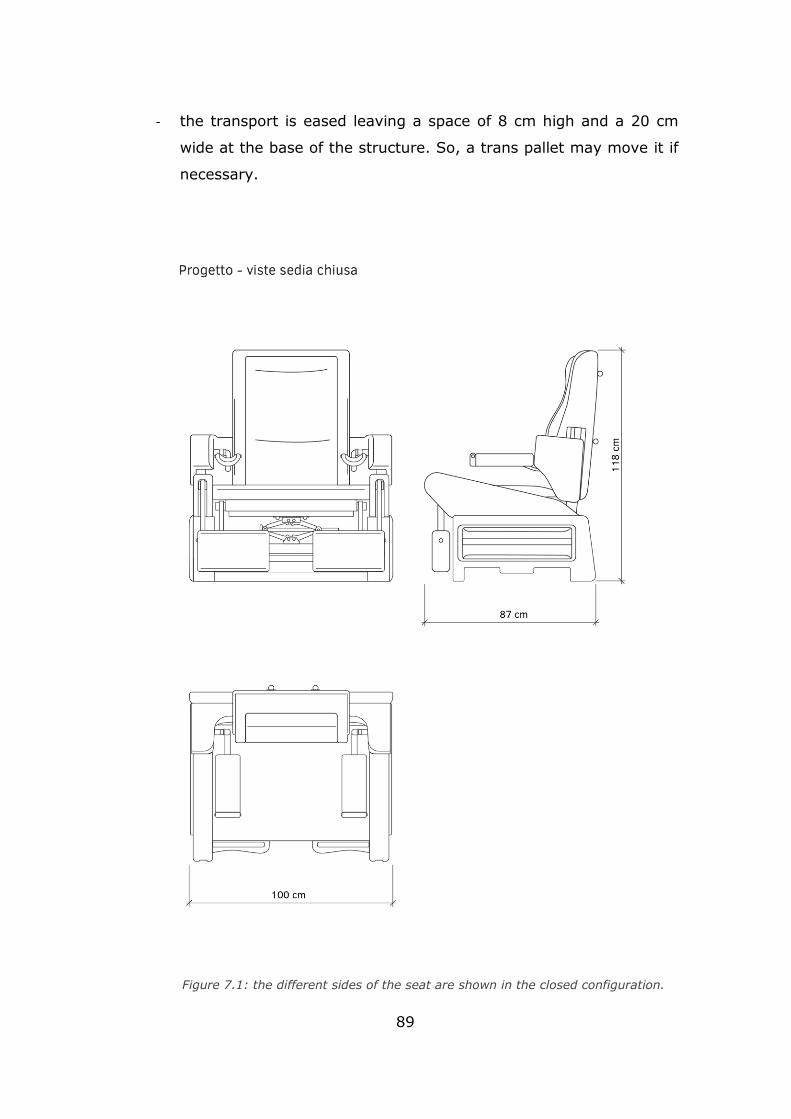
89
- the transport is eased leaving a space of 8 cm high and a 20 cm
wide at the base of the structure. So, a trans pallet may move it if
necessary.
Figure 7.1: the different sides of the seat are shown in the closed configuration.
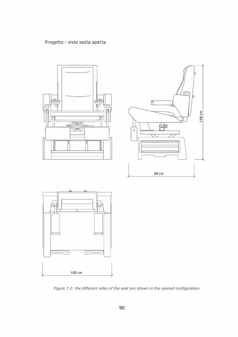
90
Figure 7.2: the different sides of the seat are shown in the opened configuration.
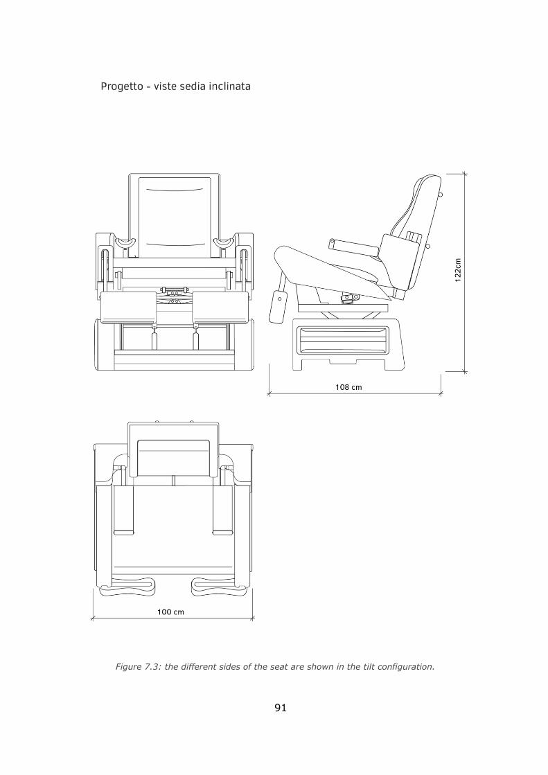
91
Figure 7.3: the different sides of the seat are shown in the tilt configuration.
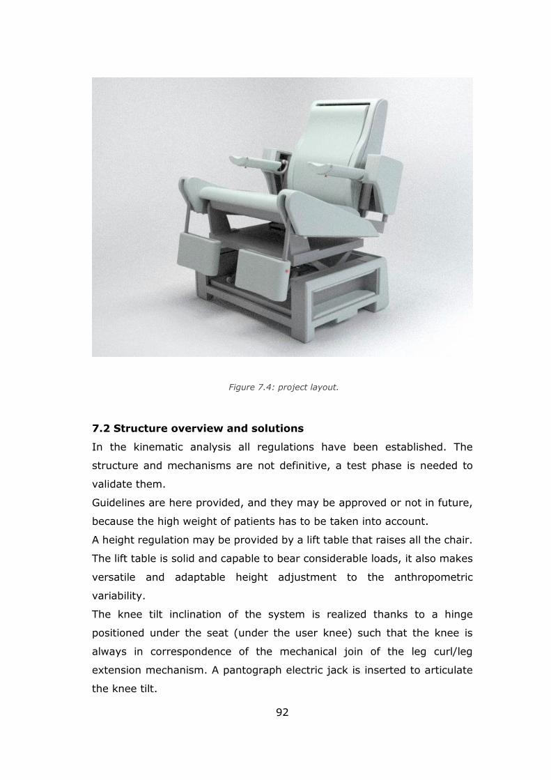
92
7.2 Structure overview and solutions
In the kinematic analysis all regulations have been established. The
structure and mechanisms are not definitive, a test phase is needed to
validate them.
Guidelines are here provided, and they may be approved or not in future,
because the high weight of patients has to be taken into account.
A height regulation may be provided by a lift table that raises all the chair.
The lift table is solid and capable to bear considerable loads, it also makes
versatile and adaptable height adjustment to the anthropometric
variability.
The knee tilt inclination of the system is realized thanks to a hinge
positioned under the seat (under the user knee) such that the knee is
always in correspondence of the mechanical join of the leg curl/leg
extension mechanism. A pantograph electric jack is inserted to articulate
the knee tilt.
Figure 7.4: project layout.
93
Seat depth adjustment is carried out by sliding the frame of the backrest
on the seat. This is achieved with a pipes system that run under the seat
moved by an electric linear actuator placed in the centre and bound to the
seat itself.
The same principle may be applied to regulation in height of the armrests,
which must necessarily take place with the backrest. Even in this case the
entire system moves by scrolling up tubes forming the backrest frame,
thanks to the action of an electric linear actuator.
The height regulation of the legs supports, the depth of the armrests and
the position of cervical and lumbar supports, are managed through the
application of lock pins a spring that maintain the chosen position by
anchoring to the sliding tubes. In this case the adjustment can be done
manually by the patient or by the doctors.
A last setting concerning the position of armrests in width, is resolved
through the application of a sliding system telescopic between the tubes
that constitute the supporting structure. Also in this case, the adjustment
is manual.
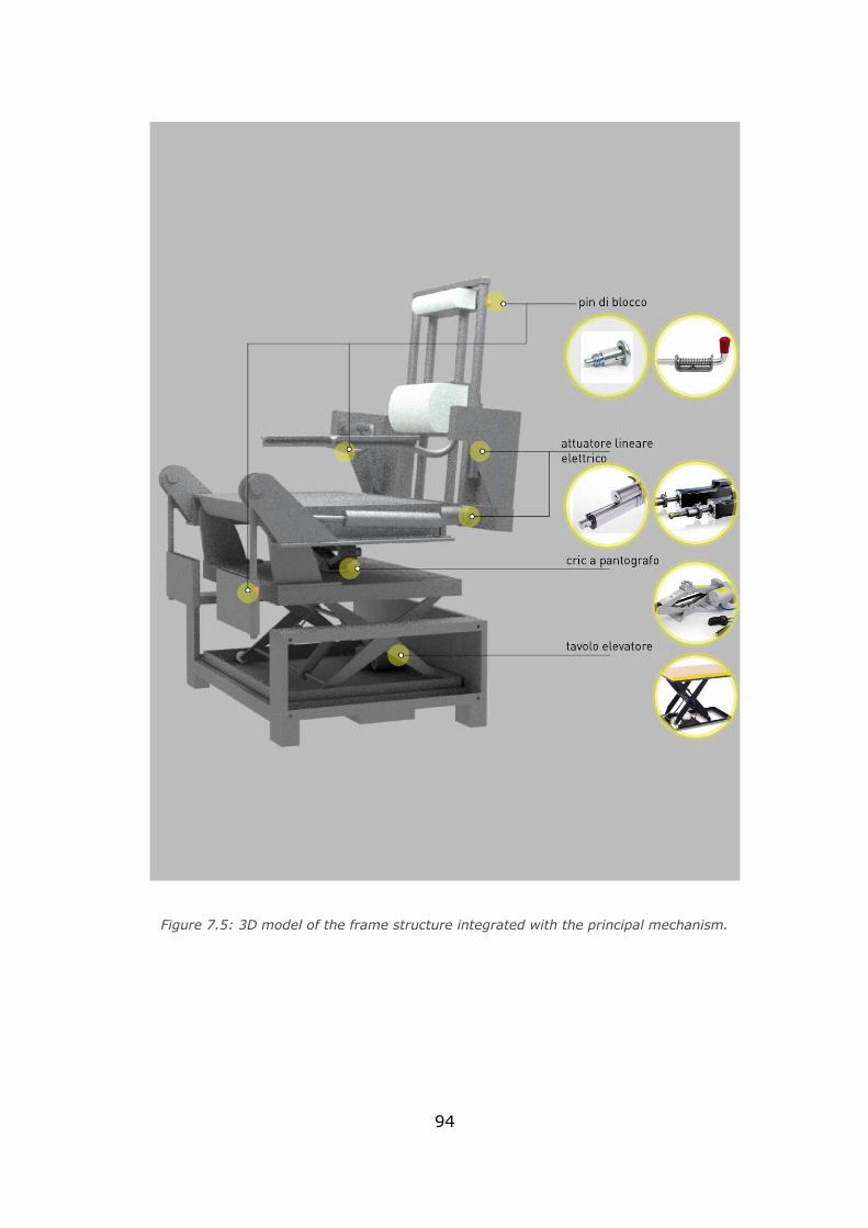
94
Figure 7.5: 3D model of the frame structure integrated with the principal mechanism.
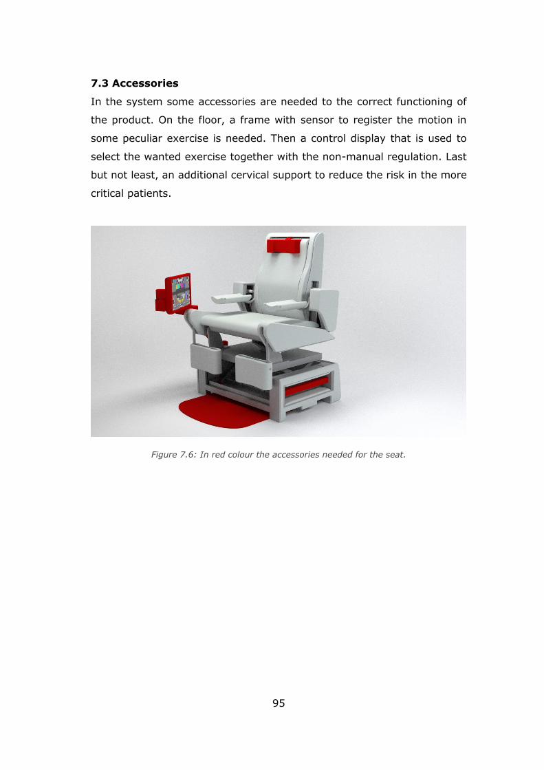
95
7.3 Accessories
In the system some accessories are needed to the correct functioning of
the product. On the floor, a frame with sensor to register the motion in
some peculiar exercise is needed. Then a control display that is used to
select the wanted exercise together with the non-manual regulation. Last
but not least, an additional cervical support to reduce the risk in the more
critical patients.
Figure 7.6: In red colour the accessories needed for the seat.
96
Final remark
With the accessories definition, the concept phase of the chair can be
considered concluded. The patient’s population have been studied and
appropriate physical exercise have been selected. Moreover, the particular
kind of problem shows the need of introducing non-standard dimensions
for the product.
Then, the project presents a detailed kinematic and dynamic analysis with
a 3D software-based study on interference of components. The required
exercises have been achieved and forces and pressure needed in the
system have been computed by means of a mathematical model developed
in Matlab. Finally, the solution for the pneumatic actuation system based
on the commercially available model of components is provided. The
concept is ready to enter in a verification phase which has not been
developed within this thesis for sake of time.
Nevertheless, this kind of preliminary project gives the possibility of
developing new different multidisciplinary scenarios.
Indeed, to reach the JOB 0 model of the chair some further analysis are
needed and, of course, recommended:
• FEM verification of single mechanism,
• FEM verification of the frame structure due to the load,
• Verification of the actuation system,
• Sensor and data managing development,
• Prototyping and production.
Other field of study must also be involved:
• Materials,
• Gaming interface for integration (exergames, mirror therapy),
• Biomedical studies.
97
Bibliography
Chapter 1
1) International Journal of Obesity (2008) 32, S120–S126
2) B. Caballero, The global epidemic of obesity: an overview, Epidemiologic
Reviews 2007, Vol. 29: 1-5.
3) WHO data.
4)Data Base Eurostat, EHIS-European Health Interview Survey, 2014.
5)L. Gargiulo, Epidemiologia dell’obesità in Italia e alcuni aspetti della
qualità della vita, 8° Rapporto sul’obesità in Italia dell’Istituto Auxologico
Italiano, Roma, 2015.
6)Istat, Indagine sulla salute 1994 e Aspetti della vita quotidiana 2005 e
2015.
7) S. Bo, V. Ponzo, I. Goitre, F. Di Michieli, F. Broglio, Alimentazione, stile
di vita e malattie metaboliche, Agricoltura, alimentazione e sostenibilità,
Scienza attiva, Torino, 2015-2016.
8) D. Carli, S. Di Giacomo, Preparazione atletica e riabilitazione.
Fondamenti del movimento umano, Scienza e traumatologia dello sport,
Principi di trattamento riabilitativo, C.G. Edizioni Medico Scientifiche s.r.l.,
2013, Torino
9) www.dietology.it/index.php/area-dietologica/cause-dell-aumento-di-
peso/12-area-diagnostica/58-classificazione-delle-obesita
10) S. Jebb, Obesity: causes and consequences. Women’s Health Med,
2004; 1(1): 38-41.
11) P. Magni, M. Ruscica, R. Verna, M.M. Corsi, Obesità: fisiopatologia e
nuove prospettive diagnostiche, 2003, Caleidoscopio italiano, Medical
Systems S.p.A., 164:11-19
12) R.M. Puhl, C.A. Moss-Racusin, M.B. Schwartz, Internalization of weight
bias: implications for binge eating and emotional wellbeing.2007, Obesity;
15:19–23
13) A. Prentice, S. Jebb, Energy intake/physical activity interactions in the
homeostasis of body weight regulation. 2004, Nutrition Reviews; 62 (suppl
s2): S98–104.
98
14) http://www.centro-obesi.com/it/cause_dell_obesita.php
15) C.E. Ross, Overweight and depression. 1994, Journal of Health and
Social Behaviour, 35:63–79.
16) K.M. Flegal, B.I. Graubard, D.F. Williamson, M.H. Gail, Excess deaths
associated with underweight, overweight, and obesity. JAMA. 2005;
293(15):1861–7.
17) Aylwin S, Al-Zaman Y, Emerging concepts in the medical and surgical
treatment of obesity. Front Horm Res. 2008; 36():229-59.
18) L.A. Baur, Changing perceptions of obesity-recollections of a
paediatrician, The art of medicine, 2011, The Lancet, Vol.378:762-763
19) P. Capodaglio, G. Castelnuovo, A. Brunani, L. Vismara, V. Villa, E. M.
Capodaglio, Functional Limitations and Occupational Issues in Obesity: A
Review, 2010, International Journal of Occupational Safety and
Ergonomics, 16(4):508-523
20) L. de Wit, F. Luppino, A. van Straten, B. Pennix, F. Zitman, P. Cuijpers,
Depression and obesity : a meta-analysis of community-based studies,
2010, Psychiatry Reasearch, 178:230-235.
21) K.E. Friedman, J.A. Ashmore, K.L. Applegate, Recent experiences of
weight-based stigmatization in a weight loss surgery population:
psychological and behavioral correlates. Obesity (Silver Spring)
2008;16(Suppl 2):S69–S74.
22) World Cancer Research Fund,American Institute for Cancer Research.
Food, Nutrition, Physical Activity, and the Prevention of Cancer: a Global
Perspective. Washington DC: AICR, 2007.
23) F. De Stefano, S. Zambon, L. Giacometti, G. Sergi, M.C. Corti, E.
Manzato, L. Busetto, Obesity, muscular strength, muscle composition and
physical performance in an elderly population, 2015, Journal of Nutrition,
Health
24) Hargens TA, Kaleth AS, Edwards ES, Butner KL. Association between
sleep disorders, obesity, and exercise: a review. Nat Sci Sleep. 2013;5:27-
35. Published 2013 Mar 1. doi:10.2147/NSS.S34838
25) Z. Pataky, S. Armand, S. Muller-Pinget, A. Golay, L. Allet, Effects of
Obesity on Functional Capacity, 2014, Obesity, 22:56–62
99
26) P.T. Katzmarzyk, I. Janssen, C.I. Ardern, Physical inactivity, excess
adiposity and premature mortality. Obesity Review. 2003; 4(4):257–90.
27) C.L. Lafortuna, N.A. Maffiuletti, F. Agosti, A. Sartorio, Gender
variations of body composition, muscle strength and power output in
morbid obesity. International Journal of Obesity (London).
2005;29(7):833–41.
28) P. Capodaglio, G. Castelnuovo, A. Brunani, L. Vismara, V. Villa, E. M.
Capodaglio, Functional Limitations and Occupational Issues in Obesity: A
Review, 2010, International Journal.
29) M.C. Corti, E. Manzato, L. Busetto, Op. cit., pp. 789
15 L. Vismara, F. Menegoni, F. Zaina, M. Galli, S. Negrini, P. Capodaglio,
Effect of obesity and low back pain on spinal mobility: a cross sectional
study in women, 2010, Journal of NeuroEngineering and Rehabilitation, 7:3
30) A.L. Rodacki, N.E. Fowler, C.L. Provensi, C. Rodacki, V.H. Dezan, Body
mass as a factor in stature change. Clinical Biomechanics (Bristol, Avon).
2005;20(8):799–805.
31) U.N. Das, Is obesity an inflammatory condition?, Nutrition 2001;17:
953–966.
32) D. Malatesta, L. Vismara, F. Menegoni, M. Galli, M. Romei, P.
Capodaglio. Mechanical external work and recovery at preferred walking
speed in obese subjects. Medicine and Science in Sports and Exercise,
2009;41(2):426–434.
33) C.L. Lafortuna, N.A. Maffiuletti, F. Agosti, A. Sartorio, Gender
variations of body composition, muscle strength and power output in
morbid obesity. International Journal of Obesity (London).
2005;29(7):833–41.
34) M. Souchet, Obésité, réadaptation à l’activité physique etergothérapie
: mesure de l’impact d’une prise en soins ergothérapiques sur la “
functional mobility ” de patients obèses adultes, hospitalisés au sein d’un
service de Soins de Suite et Réadaptation bariatrique, 2016, Institut
Universitaire de formation en ergotherapie, Univeristé d’Auvergne.
100
35) O. Ziegler, E. Bertin, B. Jouret, R. Calvar, F. Sanguignol, A. Avignon,
et al. Éducation thérapeutique et parcours de soins de la personne obèse.
Obésité, 2014, 9:302‑28.
36) M.A. Ghanem, N.A. Kazim, A.H. Elgazzar, Impact of Obesity on Nuclear
Medicine Imaging, 2011, Journal of Nuclear Medicine Technology ,Vol. 39,
No. 1:40-50.
37) C. Álvarez, R. Ramírez Campillo, Effects of a low intensity strength
training program on overweight/obese and premenopausal/menopausal
women, 2013, Brazilian Journal of Kinanthropometry and Human
Performance, Vol.15:427-436
38) V. Attalin, A.J. Romain, A. Avignon, Physical activity prescription for
obesity management in primary care: Attitudes and practices of GPs in a
southern French
city. Diabetes & Metabolism, 2012,38:243‑9
39) J. Gunstad, F. Luyster, J. Hughes, D. Waechter, J. Rosneck, R.
Josephson, The Effects of Obesity on Functional Work Capacity and Quality
of Life in Phase II Cardiac Rehabilitation, Preventive Cardiology,
2007,10:64‑7.
40) Villareal DT, Aguirre L, Gurney AB, et al. Aerobic or Resistance
Exercise, or Both, in Dieting Obese Older Adults. N Engl J Med.
2017;376(20):1943-1955.
41) P.A. Ades, P.D. Savage, J. Harvey-Berino, The Treatment of Obesity in
Cardiac Rehabilitation. Journal of Cardiopulmonary Rehabilitation and
Prevention. 2010,30:289‑98.
42) https://www.theptdc.com/2014/12/8-things-to-consider-when-
training-obese-clients/
43) H.Kim, Universal Design: Meeting the needs of the Bariatric Population,
Cornell University, 2009.
44) Ergonomics and the bariatric patient.
https://ergoweb.com/ergonomics-and-the-bariatric-patient/
45) Seating Bariatric Patients - what are the risks.
https://seatingmatters.com/bariatric-seating/
101
Chapter 3
1) A. Tozeren, Human Body Dynamics-Classical mechanics and human
movement, Springer, New York, 2000
2) K. Luttgens, N. Hamilton, Kinesiology: Scientific Basis of Human Motion,
9th Ed.,1997, Madison, WI: Brown & Benchmark.
3) B.A. Garner, Designing Strength-Proportional Hydraulic Resistance for
an Elbow Flexion-Extension Exercise Machine, 2007, Journal of Medical
Devices, Vol.1:3-13
4) The Advantages of Pneumatic Technology,
http://www.huraustralia.com.au/know-how/pneumatic-
resistance/advantages-pneumatic-technology
5) http://curves.com.ph
6) https://www.technogym.com/it/
7) https://www.keiser.com
8) https://www.hur.fi
Chapter 4
1) 1 Posizione seduta.
http://www.demauroy.net/SFIMO/posizione_seduta.htm
2) 2 G.B.J. Andersson, R. Örtengren. 1974, Lumbar disc pressure and
myoelectric back muscle activity during sitting. Scandinavian Journal of
Rehabilitation Medicine, 6, 115
3) 8 B. Akerblom, Standing and siting posture. With Special reference to
the construction of chairs, 1948, Translated by A. Synge, A. B. Nordiska
Bokhandeln, Stockholm
4) 11 M.G. Helander, L. Zhang, Field Studies of Comfort and Discomfort in
Sitting, 1997, Ergonomics, 40, 895–915.
5) M. Pivotto, Lombalgia: strategie di prevenzione nei tassisti, Tesi di
Laurea in Fisioterapia, Università degli Studi di Padova, rel. Dott. Papa
Angelo, 2016
102
6) X. Wanga, M. Cardoso, G. Beurier, Effects of seat parameters and sitters’
anthropometric dimensions on seat profile and optimal compressed seat
pan surface, 2018, Applied Ergonomics 73:13–21
7) M.G. Helander, Forget about ergonomics in chair design? Focus on
aesthetics and comfort! , 2003, Ergonomics, 46:13-14
8) L-Q. Zhang, Sitting with adjustable ischial and back supports:
biomechanical changes. Spine 2003, 28:1113–1122
9) D.E. De Carvalho, J.P. Callaghan, Spine Posture and Discomfort During
Prolonged Simulated Driving With Self-Selected Lumbar Support
Prominence, 2015, Human Factors, vol. 57,6:976–987.
Chapter 7
1) 1 P. Buxton (edited by), The Metric Handbook. Planning and Design
Data, Fifth Edition, Routledge, NY, 2015
Overall reference
The thesis work has been developed together with the student Julia Robin,
Master’s degree course in DESIGN SISTEMICO in Politecnico di Torino. Two
thesis work have been developed together, the current one with the
engineering focus, the Julia Robin one with the designer focus.
- “Fidget Chair, seduta a scopo terapeutico per la cura dei
grandi obesi”, Julia Robin, 2019.
Related Documents