INCITS 562-20xx Rev 0.1 i FIBRE CHANNEL Framing and Signaling - 6 (FC-FS-6) Rev 0.1 INCITS working draft proposed American National Standard for Information Technology January 11, 2019 Secretariat: Information Technology Industry Council NOTE: This is a working draft American National Standard of Accredited Standards Committee INCITS. As such this is not a completed standard. The T11 Technical Committee may modify this document as a result of comments received anytime, or during a future public review and its eventual approval as a Standard. Use of the information contained herein is at your own risk. Permission is granted to members of INCITS, its technical committees, and their associated task groups to reproduce this document for the purposes of INCITS standardization activities without further permission, provided this notice is included. All other rights are reserved. Any duplication of this document for commercial or for-profit use is strictly prohibited. POINTS OF CONTACT: Steven L. Wilson (T11 Chair) Craig W. Carlson (T11 Vice Chair) Broadcom Limited Marvell Semiconductor 130 Holger Way 12900 Whitewater Drive San Jose, CA 95134 Minnetonka, MN 55343 Voice: 408-333-8128 Voice: 952-687-2431 [email protected] [email protected] Craig W. Carlson (T11.3 Chair) David Peterson (FC-FS-6 Chair) Craig W. Carlson (FC-FS-6 Editor) Marvell Semiconductor Broadcom Limited Marvell Semiconductor 12900 Whitewater Drive 1230 Northland Dr 12900 Whitewater Drive Minnetonka, MN 55343 Mendota Heights, MN 55120 Minnetonka, MN 55343 Voice: 952-687-2431 Voice: 763-248-9374 Voice: 952-687-2431 [email protected] [email protected] [email protected]

Welcome message from author
This document is posted to help you gain knowledge. Please leave a comment to let me know what you think about it! Share it to your friends and learn new things together.
Transcript

INCITS 562-20xx Rev 0.1
i
FIBRE CHANNELFraming and Signaling - 6
(FC-FS-6)
Rev 0.1
INCITS working draft proposedAmerican National Standardfor Information Technology
January 11, 2019
Secretariat: Information Technology Industry Council
NOTE: This is a working draft American National Standard of Accredited Standards Committee INCITS. Assuch this is not a completed standard. The T11 Technical Committee may modify this document as a resultof comments received anytime, or during a future public review and its eventual approval as a Standard.Use of the information contained herein is at your own risk.
Permission is granted to members of INCITS, its technical committees, and their associated task groups toreproduce this document for the purposes of INCITS standardization activities without further permission,provided this notice is included. All other rights are reserved. Any duplication of this document forcommercial or for-profit use is strictly prohibited.
POINTS OF CONTACT:
Steven L. Wilson (T11 Chair) Craig W. Carlson (T11 Vice Chair)Broadcom Limited Marvell Semiconductor130 Holger Way 12900 Whitewater DriveSan Jose, CA 95134 Minnetonka, MN 55343Voice: 408-333-8128 Voice: [email protected] [email protected]
Craig W. Carlson (T11.3 Chair) David Peterson (FC-FS-6 Chair)Craig W. Carlson (FC-FS-6 Editor)
Marvell Semiconductor Broadcom Limited Marvell Semiconductor12900 Whitewater Drive 1230 Northland Dr 12900 Whitewater DriveMinnetonka, MN 55343 Mendota Heights, MN 55120 Minnetonka, MN 55343Voice: 952-687-2431 Voice: 763-248-9374 Voice: [email protected] [email protected] [email protected]

INCITS 562-20xx Rev 0.1
ii
Revision History
Rev 0.1 - January 11, 2019
a) Incorporated T11-2018-00047-v007.
b) Incorporated T11-2018-00266-v002.
INCITS 562-20xx Rev 0.1
iii
draft proposed American National Standard
for Information Technology
Fibre Channel –
Fibre Channel Framing and Signaling - 5 (FC-FS-5)
Secretariat
Information Technology Industry Council
Approved dd mmmmm, 200x
American National Standards Institute, Inc.
Abstract
This standard describes the framing and signaling requirements for Fibre Channel links. The PhysicalInterface requirements are described in Fibre Channel-Physical Interfaces (FC-PI-x). The Link Servicesrequirements are described in Fibre Channel-Link Services (FC-LS-4). This standard is recommended fornew implementations but does not obsolete the existing Fibre Channel standards.

INCITS 562-20xx Rev 0.1
iv
American National Standard
Approval of an American National Standard requires review by ANSI that the requirements for dueprocess, consensus, and other criteria for approval have been met by the standards developer.
Consensus is established when, in the judgement of the ANSI Board of Standards Review, substantialagreement has been reached by directly and materially affected interests. Substantial agreement meansmuch more than a simple majority, but not necessarily unanimity. Consensus requires that all views andobjections be considered, and that a concerted effort be made towards their resolution.
The use of American National Standards is completely voluntary; their existence does not in any respectpreclude anyone, whether he has approved the standards or not, from manufacturing, marketing,purchasing, or using products, processes, or procedures not conforming to the standards.
The American National Standards Institute does not develop standards and will in no circumstances givean interpretation of any American National Standard. Moreover, no person shall have the right or authorityto issue an interpretation of an American National Standard in the name of the American NationalStandards Institute. Requests for interpretations should be addressed to the secretariat or sponsor whosename appears on the title page of this standard.
CAUTION NOTICE: This American National Standard may be revised or withdrawn at any time. Theprocedures of the American National Standards Institute require that action be taken periodically toreaffirm, revise, or withdraw this standard. Purchasers of American National Standards may receivecurrent information on all standards by calling or writing the American National Standards Institute.
PATENTSTATEMENT
The developers of this standard have requested that holders of patents that may be required for theimplementation of the standard disclose such patents to the publisher. However, neither the developers northe publisher have undertaken a patent search in order to identify which, if any, patents may apply to thisstandard. As of the date of publication of this standard, following calls for the identification of patents thatmay be required for the implementation of the standard, notice of one or more such claims has beenreceived. By publication of this standard, no position is taken with respect to the validity of this claim or ofany rights in connection therewith. The known patent holder(s) has (have), however, filed a statement ofwillingness to grant a license under these rights on reasonable and nondiscriminatory terms and conditionsto applicants desiring to obtain such a license. Details may be obtained from the publisher. No furtherpatent search is conducted by the developer or publisher in respect to any standard it processes. Norepresentation is made or implied that this is the only license that may be required to avoid infringement inthe use of this standard.
INCITS 562-20xx Rev 0.1
v
Published by
American National Standards Institute, Inc.11 West 42nd Street, New York, NY 10036
Copyright © 2018 by Information Technology Industry Council (ITI)All rights reserved.
No part of this publication may be reproduced in any form, in an electronic retrieval system or otherwise,without prior written permission of ITI, 1250 Eye Street NW, Washington, DC 20005.
Printed in the United States of America
INCITS 562-20xx Rev 0.1
vi
Table of Contents
Contents Page
1 Scope - - - - - - - - - - - - - - - - - - - - - - - - - - - - - - - - - - - - - - - - - - - - - - - - - - - - - - - - - - - - - - - - - - 1
2 References - - - - - - - - - - - - - - - - - - - - - - - - - - - - - - - - - - - - - - - - - - - - - - - - - - - - - - - - - - - - - - 22.1 Qualification and availability of references - - - - - - - - - - - - - - - - - - - - - - - - - - - - - - - - - - - - - 22.2 Approved references - - - - - - - - - - - - - - - - - - - - - - - - - - - - - - - - - - - - - - - - - - - - - - - - - - - - 22.3 References under development - - - - - - - - - - - - - - - - - - - - - - - - - - - - - - - - - - - - - - - - - - - - 42.4 Other references - - - - - - - - - - - - - - - - - - - - - - - - - - - - - - - - - - - - - - - - - - - - - - - - - - - - - - 4
3 Definitions, abbreviations, conventions and keywords - - - - - - - - - - - - - - - - - - - - - - - - - - - - - 63.1 Definitions - - - - - - - - - - - - - - - - - - - - - - - - - - - - - - - - - - - - - - - - - - - - - - - - - - - - - - - - - - - 63.2 Editorial conventions - - - - - - - - - - - - - - - - - - - - - - - - - - - - - - - - - - - - - - - - - - - - - - - - - - - 183.3 State machines - - - - - - - - - - - - - - - - - - - - - - - - - - - - - - - - - - - - - - - - - - - - - - - - - - - - - - 193.3.1 Overview - - - - - - - - - - - - - - - - - - - - - - - - - - - - - - - - - - - - - - - - - - - - - - - - - - - - - - - - - - 193.3.2 States - - - - - - - - - - - - - - - - - - - - - - - - - - - - - - - - - - - - - - - - - - - - - - - - - - - - - - - - - - - - 193.3.3 State variables - - - - - - - - - - - - - - - - - - - - - - - - - - - - - - - - - - - - - - - - - - - - - - - - - - - - - - 193.3.4 State timers - - - - - - - - - - - - - - - - - - - - - - - - - - - - - - - - - - - - - - - - - - - - - - - - - - - - - - - - 193.3.5 State transitions - - - - - - - - - - - - - - - - - - - - - - - - - - - - - - - - - - - - - - - - - - - - - - - - - - - - - 203.3.6 State diagram conventions - - - - - - - - - - - - - - - - - - - - - - - - - - - - - - - - - - - - - - - - - - - - - 203.4 Abbreviations, acronyms, and symbols - - - - - - - - - - - - - - - - - - - - - - - - - - - - - - - - - - - - - - 213.4.1 Acronyms and other abbreviations - - - - - - - - - - - - - - - - - - - - - - - - - - - - - - - - - - - - - - - - 213.4.2 Symbols - - - - - - - - - - - - - - - - - - - - - - - - - - - - - - - - - - - - - - - - - - - - - - - - - - - - - - - - - - 233.5 Keywords - - - - - - - - - - - - - - - - - - - - - - - - - - - - - - - - - - - - - - - - - - - - - - - - - - - - - - - - - - - 23
4 Structure and concepts - - - - - - - - - - - - - - - - - - - - - - - - - - - - - - - - - - - - - - - - - - - - - - - - - - - 254.1 Introduction - - - - - - - - - - - - - - - - - - - - - - - - - - - - - - - - - - - - - - - - - - - - - - - - - - - - - - - - - 254.2 Functional levels - - - - - - - - - - - - - - - - - - - - - - - - - - - - - - - - - - - - - - - - - - - - - - - - - - - - - - 254.2.1 Overview - - - - - - - - - - - - - - - - - - - - - - - - - - - - - - - - - - - - - - - - - - - - - - - - - - - - - - - - - - 254.2.2 FC-0 general description - - - - - - - - - - - - - - - - - - - - - - - - - - - - - - - - - - - - - - - - - - - - - - 264.2.3 FC-1 general description - - - - - - - - - - - - - - - - - - - - - - - - - - - - - - - - - - - - - - - - - - - - - - 264.2.4 FC-2 general description - - - - - - - - - - - - - - - - - - - - - - - - - - - - - - - - - - - - - - - - - - - - - - 274.2.5 FC-3 general description - - - - - - - - - - - - - - - - - - - - - - - - - - - - - - - - - - - - - - - - - - - - - - 274.2.6 FC-4 general description - - - - - - - - - - - - - - - - - - - - - - - - - - - - - - - - - - - - - - - - - - - - - - 274.3 Architectural components of nodes - - - - - - - - - - - - - - - - - - - - - - - - - - - - - - - - - - - - - - - - - 284.4 Physical model - - - - - - - - - - - - - - - - - - - - - - - - - - - - - - - - - - - - - - - - - - - - - - - - - - - - - - - 294.5 Communication models - - - - - - - - - - - - - - - - - - - - - - - - - - - - - - - - - - - - - - - - - - - - - - - - - 314.6 Topology - - - - - - - - - - - - - - - - - - - - - - - - - - - - - - - - - - - - - - - - - - - - - - - - - - - - - - - - - - - 314.6.1 Types - - - - - - - - - - - - - - - - - - - - - - - - - - - - - - - - - - - - - - - - - - - - - - - - - - - - - - - - - - - - 314.6.2 Point-to-point topology - - - - - - - - - - - - - - - - - - - - - - - - - - - - - - - - - - - - - - - - - - - - - - - - 314.6.3 Fabric topology - - - - - - - - - - - - - - - - - - - - - - - - - - - - - - - - - - - - - - - - - - - - - - - - - - - - - 324.6.4 Arbitrated Loop topology - - - - - - - - - - - - - - - - - - - - - - - - - - - - - - - - - - - - - - - - - - - - - - - 334.7 Classes of service - - - - - - - - - - - - - - - - - - - - - - - - - - - - - - - - - - - - - - - - - - - - - - - - - - - - 344.7.1 General - - - - - - - - - - - - - - - - - - - - - - - - - - - - - - - - - - - - - - - - - - - - - - - - - - - - - - - - - - - 344.7.2 Class 2 service - multiplex - - - - - - - - - - - - - - - - - - - - - - - - - - - - - - - - - - - - - - - - - - - - - 344.7.3 Class 3 service - datagram - - - - - - - - - - - - - - - - - - - - - - - - - - - - - - - - - - - - - - - - - - - - - 344.7.4 Class F service - Fabric - - - - - - - - - - - - - - - - - - - - - - - - - - - - - - - - - - - - - - - - - - - - - - - 344.8 General Fabric model - - - - - - - - - - - - - - - - - - - - - - - - - - - - - - - - - - - - - - - - - - - - - - - - - - 344.8.1 General - - - - - - - - - - - - - - - - - - - - - - - - - - - - - - - - - - - - - - - - - - - - - - - - - - - - - - - - - - - 344.8.2 Fabric Ports (Fx_Ports) - - - - - - - - - - - - - - - - - - - - - - - - - - - - - - - - - - - - - - - - - - - - - - - 374.8.3 Frame delivery service - - - - - - - - - - - - - - - - - - - - - - - - - - - - - - - - - - - - - - - - - - - - - - - - 374.9 Generic Services - - - - - - - - - - - - - - - - - - - - - - - - - - - - - - - - - - - - - - - - - - - - - - - - - - - - - 374.10 Building Blocks - - - - - - - - - - - - - - - - - - - - - - - - - - - - - - - - - - - - - - - - - - - - - - - - - - - - - - 374.10.1 Building block hierarchy - - - - - - - - - - - - - - - - - - - - - - - - - - - - - - - - - - - - - - - - - - - - - - 37
INCITS 562-20xx Rev 0.1
vii
4.10.2 Frame - - - - - - - - - - - - - - - - - - - - - - - - - - - - - - - - - - - - - - - - - - - - - - - - - - - - - - - - - - - 384.10.3 Sequence - - - - - - - - - - - - - - - - - - - - - - - - - - - - - - - - - - - - - - - - - - - - - - - - - - - - - - - - 394.10.3.1 Introduction - - - - - - - - - - - - - - - - - - - - - - - - - - - - - - - - - - - - - - - - - - - - - - - - - - - - - - 394.10.3.2 Sequence_Identifier (SEQ_ID) - - - - - - - - - - - - - - - - - - - - - - - - - - - - - - - - - - - - - - - - 394.10.3.3 Sequence Status Blocks - - - - - - - - - - - - - - - - - - - - - - - - - - - - - - - - - - - - - - - - - - - - 394.10.4 Exchange - - - - - - - - - - - - - - - - - - - - - - - - - - - - - - - - - - - - - - - - - - - - - - - - - - - - - - - - 394.10.4.1 Introduction - - - - - - - - - - - - - - - - - - - - - - - - - - - - - - - - - - - - - - - - - - - - - - - - - - - - - - 394.10.4.2 Exchange_Identifiers (OX_ID and RX_ID) - - - - - - - - - - - - - - - - - - - - - - - - - - - - - - - - 404.10.4.3 Exchange Status Blocks - - - - - - - - - - - - - - - - - - - - - - - - - - - - - - - - - - - - - - - - - - - - 404.10.5 Protocols - - - - - - - - - - - - - - - - - - - - - - - - - - - - - - - - - - - - - - - - - - - - - - - - - - - - - - - - - 404.10.5.1 Primitive Sequence protocols - - - - - - - - - - - - - - - - - - - - - - - - - - - - - - - - - - - - - - - - - 404.10.5.2 Fabric Login protocol - - - - - - - - - - - - - - - - - - - - - - - - - - - - - - - - - - - - - - - - - - - - - - - 404.10.5.3 Additional N_Port_ID protocol - - - - - - - - - - - - - - - - - - - - - - - - - - - - - - - - - - - - - - - - - 414.10.5.4 N_Port Login protocol - - - - - - - - - - - - - - - - - - - - - - - - - - - - - - - - - - - - - - - - - - - - - - 414.10.5.5 Data transfer protocol - - - - - - - - - - - - - - - - - - - - - - - - - - - - - - - - - - - - - - - - - - - - - - 414.10.5.6 Nx_Port Logout protocol - - - - - - - - - - - - - - - - - - - - - - - - - - - - - - - - - - - - - - - - - - - - 414.10.5.7 Fabric Logout protocol - - - - - - - - - - - - - - - - - - - - - - - - - - - - - - - - - - - - - - - - - - - - - - 414.11 Segmentation and reassembly of application data - - - - - - - - - - - - - - - - - - - - - - - - - - - - - 414.12 Error detection and recovery - - - - - - - - - - - - - - - - - - - - - - - - - - - - - - - - - - - - - - - - - - - - 41
5 FC-1 transmission codes - - - - - - - - - - - - - - - - - - - - - - - - - - - - - - - - - - - - - - - - - - - - - - - - - - 435.1 Overview - - - - - - - - - - - - - - - - - - - - - - - - - - - - - - - - - - - - - - - - - - - - - - - - - - - - - - - - - - - 435.2 8B/10B transmission code - - - - - - - - - - - - - - - - - - - - - - - - - - - - - - - - - - - - - - - - - - - - - - - 435.2.1 Overview - - - - - - - - - - - - - - - - - - - - - - - - - - - - - - - - - - - - - - - - - - - - - - - - - - - - - - - - - - 435.2.2 Notation conventions - - - - - - - - - - - - - - - - - - - - - - - - - - - - - - - - - - - - - - - - - - - - - - - - - 445.2.3 Valid 8B/10B Transmission Characters - - - - - - - - - - - - - - - - - - - - - - - - - - - - - - - - - - - - 455.2.4 Running disparity - - - - - - - - - - - - - - - - - - - - - - - - - - - - - - - - - - - - - - - - - - - - - - - - - - - - 505.2.5 Generating Transmission Characters - - - - - - - - - - - - - - - - - - - - - - - - - - - - - - - - - - - - - - 515.2.6 Validity of received Transmission Characters - - - - - - - - - - - - - - - - - - - - - - - - - - - - - - - - 515.2.7 8B/10B Ordered Sets - - - - - - - - - - - - - - - - - - - - - - - - - - - - - - - - - - - - - - - - - - - - - - - - - 525.2.7.1 General - - - - - - - - - - - - - - - - - - - - - - - - - - - - - - - - - - - - - - - - - - - - - - - - - - - - - - - - - 525.2.7.2 8B/10B Frame delimiters - - - - - - - - - - - - - - - - - - - - - - - - - - - - - - - - - - - - - - - - - - - - - 535.2.7.3 8B/10B Primitive Signals - - - - - - - - - - - - - - - - - - - - - - - - - - - - - - - - - - - - - - - - - - - - - 555.2.7.4 Idle - - - - - - - - - - - - - - - - - - - - - - - - - - - - - - - - - - - - - - - - - - - - - - - - - - - - - - - - - - - - 565.2.7.5 8B/10B Primitive Sequences - - - - - - - - - - - - - - - - - - - - - - - - - - - - - - - - - - - - - - - - - - 565.3 64B/66B transmission code - - - - - - - - - - - - - - - - - - - - - - - - - - - - - - - - - - - - - - - - - - - - - - 575.3.1 Overview - - - - - - - - - - - - - - - - - - - - - - - - - - - - - - - - - - - - - - - - - - - - - - - - - - - - - - - - - - 575.3.2 64B/66B Transmission Word format - - - - - - - - - - - - - - - - - - - - - - - - - - - - - - - - - - - - - - 575.3.3 64B/66B scrambling - - - - - - - - - - - - - - - - - - - - - - - - - - - - - - - - - - - - - - - - - - - - - - - - - - 585.3.4 Invalid Synchronization Header - - - - - - - - - - - - - - - - - - - - - - - - - - - - - - - - - - - - - - - - - - 595.3.5 Data Transmission Words - - - - - - - - - - - - - - - - - - - - - - - - - - - - - - - - - - - - - - - - - - - - - - 595.3.6 Control Transmission Words - - - - - - - - - - - - - - - - - - - - - - - - - - - - - - - - - - - - - - - - - - - - 605.3.6.1 Idle or LPI followed by Idle or LPI - - - - - - - - - - - - - - - - - - - - - - - - - - - - - - - - - - - - - - - 625.3.6.2 Idle followed by SOF - - - - - - - - - - - - - - - - - - - - - - - - - - - - - - - - - - - - - - - - - - - - - - - - 625.3.6.3 EOF followed by Idle or LPI - - - - - - - - - - - - - - - - - - - - - - - - - - - - - - - - - - - - - - - - - - - 635.3.6.4 Idle / other Special Function - - - - - - - - - - - - - - - - - - - - - - - - - - - - - - - - - - - - - - - - - - - 645.3.6.5 Other Special Function / Idle - - - - - - - - - - - - - - - - - - - - - - - - - - - - - - - - - - - - - - - - - - 655.3.6.6 Other Special Function / other Special Function - - - - - - - - - - - - - - - - - - - - - - - - - - - - - 675.3.6.7 Other Special Function / SOF - - - - - - - - - - - - - - - - - - - - - - - - - - - - - - - - - - - - - - - - - - 675.3.6.8 SOF / data - - - - - - - - - - - - - - - - - - - - - - - - - - - - - - - - - - - - - - - - - - - - - - - - - - - - - - - 685.3.6.9 Data / EOF - - - - - - - - - - - - - - - - - - - - - - - - - - - - - - - - - - - - - - - - - - - - - - - - - - - - - - - 695.3.6.10 Receiver error reporting - - - - - - - - - - - - - - - - - - - - - - - - - - - - - - - - - - - - - - - - - - - - - 705.3.7 64B/66B representation of Special Functions - - - - - - - - - - - - - - - - - - - - - - - - - - - - - - - - 715.3.7.1 64B/66B frame delimiters - - - - - - - - - - - - - - - - - - - - - - - - - - - - - - - - - - - - - - - - - - - - - 71
INCITS 562-20xx Rev 0.1
viii
5.3.7.2 64B/66B Primitive Signals - - - - - - - - - - - - - - - - - - - - - - - - - - - - - - - - - - - - - - - - - - - - 725.3.7.3 64B/66B Primitive Sequences - - - - - - - - - - - - - - - - - - - - - - - - - - - - - - - - - - - - - - - - - 735.4 32GFC 256B/257B transmission code - - - - - - - - - - - - - - - - - - - - - - - - - - - - - - - - - - - - - - 735.4.1 Overview - - - - - - - - - - - - - - - - - - - - - - - - - - - - - - - - - - - - - - - - - - - - - - - - - - - - - - - - - - 735.4.2 64B/66B to 256B/257B Transcoding - - - - - - - - - - - - - - - - - - - - - - - - - - - - - - - - - - - - - - 745.4.3 Reed-Solomon encoder - - - - - - - - - - - - - - - - - - - - - - - - - - - - - - - - - - - - - - - - - - - - - - - 775.4.4 Scrambler - - - - - - - - - - - - - - - - - - - - - - - - - - - - - - - - - - - - - - - - - - - - - - - - - - - - - - - - - 775.4.5 Descrambler - - - - - - - - - - - - - - - - - - - - - - - - - - - - - - - - - - - - - - - - - - - - - - - - - - - - - - - 785.4.6 Reed-Solomon decoder - - - - - - - - - - - - - - - - - - - - - - - - - - - - - - - - - - - - - - - - - - - - - - - 785.4.7 32GFC 256B/257B to 64B/66B transcoder - - - - - - - - - - - - - - - - - - - - - - - - - - - - - - - - - - 785.4.8 Transmit Bit Ordering - - - - - - - - - - - - - - - - - - - - - - - - - - - - - - - - - - - - - - - - - - - - - - - - - 795.4.9 Receive Bit Ordering - - - - - - - - - - - - - - - - - - - - - - - - - - - - - - - - - - - - - - - - - - - - - - - - - 805.5 64GFC 256B/257B transmission code - - - - - - - - - - - - - - - - - - - - - - - - - - - - - - - - - - - - - - 825.5.1 Overview - - - - - - - - - - - - - - - - - - - - - - - - - - - - - - - - - - - - - - - - - - - - - - - - - - - - - - - - - - 825.5.2 64B/66B to 64GFC 256B/257B transcoding - - - - - - - - - - - - - - - - - - - - - - - - - - - - - - - - - 825.5.3 Alignment marker mapping and insertion - - - - - - - - - - - - - - - - - - - - - - - - - - - - - - - - - - - 825.5.4 Reed-Solomon encoder - - - - - - - - - - - - - - - - - - - - - - - - - - - - - - - - - - - - - - - - - - - - - - - 825.5.5 Gray mapping - - - - - - - - - - - - - - - - - - - - - - - - - - - - - - - - - - - - - - - - - - - - - - - - - - - - - - 835.5.6 Precoding - - - - - - - - - - - - - - - - - - - - - - - - - - - - - - - - - - - - - - - - - - - - - - - - - - - - - - - - - 835.5.7 Inverse precoding - - - - - - - - - - - - - - - - - - - - - - - - - - - - - - - - - - - - - - - - - - - - - - - - - - - 835.5.8 Inverse Gray mapping - - - - - - - - - - - - - - - - - - - - - - - - - - - - - - - - - - - - - - - - - - - - - - - - 835.5.9 Alignment lock - - - - - - - - - - - - - - - - - - - - - - - - - - - - - - - - - - - - - - - - - - - - - - - - - - - - - - 845.5.10 Reed-Solomon decoder - - - - - - - - - - - - - - - - - - - - - - - - - - - - - - - - - - - - - - - - - - - - - - 845.5.10.1 Overview - - - - - - - - - - - - - - - - - - - - - - - - - - - - - - - - - - - - - - - - - - - - - - - - - - - - - - - 845.5.10.2 Link Degrade Signaling - - - - - - - - - - - - - - - - - - - - - - - - - - - - - - - - - - - - - - - - - - - - - 845.5.11 Alignment marker removal - - - - - - - - - - - - - - - - - - - - - - - - - - - - - - - - - - - - - - - - - - - - 845.5.12 256B/257B to 64B/66B transcoder - - - - - - - - - - - - - - - - - - - - - - - - - - - - - - - - - - - - - - 845.5.13 Transmit Bit Ordering - - - - - - - - - - - - - - - - - - - - - - - - - - - - - - - - - - - - - - - - - - - - - - - - 855.5.14 Receive Bit Ordering - - - - - - - - - - - - - - - - - - - - - - - - - - - - - - - - - - - - - - - - - - - - - - - - 865.6 Transmitter Training Signal for LSN and 16GFC/32GFC Transmitter Training - - - - - - - - - - 865.6.1 Overview - - - - - - - - - - - - - - - - - - - - - - - - - - - - - - - - - - - - - - - - - - - - - - - - - - - - - - - - - - 865.6.2 Training Frame - - - - - - - - - - - - - - - - - - - - - - - - - - - - - - - - - - - - - - - - - - - - - - - - - - - - - 875.6.3 Training Pattern - - - - - - - - - - - - - - - - - - - - - - - - - - - - - - - - - - - - - - - - - - - - - - - - - - - - - 925.7 Transmitter Training Signal for 64GFC Transmitter Training - - - - - - - - - - - - - - - - - - - - - - - 925.7.1 Overview - - - - - - - - - - - - - - - - - - - - - - - - - - - - - - - - - - - - - - - - - - - - - - - - - - - - - - - - - - 925.7.2 Training Frame - - - - - - - - - - - - - - - - - - - - - - - - - - - - - - - - - - - - - - - - - - - - - - - - - - - - - 925.7.3 Training Pattern - - - - - - - - - - - - - - - - - - - - - - - - - - - - - - - - - - - - - - - - - - - - - - - - - - - - - 945.8 FEC for 128GFC - - - - - - - - - - - - - - - - - - - - - - - - - - - - - - - - - - - - - - - - - - - - - - - - - - - - - 945.8.1 Overview - - - - - - - - - - - - - - - - - - - - - - - - - - - - - - - - - - - - - - - - - - - - - - - - - - - - - - - - - - 945.8.2 Functional block diagram - - - - - - - - - - - - - - - - - - - - - - - - - - - - - - - - - - - - - - - - - - - - - - 955.8.2.1 64B/66B to 256B/257B Transcoder - - - - - - - - - - - - - - - - - - - - - - - - - - - - - - - - - - - - - - 955.8.2.2 Alignment marker mapping and insertion - - - - - - - - - - - - - - - - - - - - - - - - - - - - - - - - - - 965.8.2.3 Reed-Solomon encoder - - - - - - - - - - - - - - - - - - - - - - - - - - - - - - - - - - - - - - - - - - - - - - 965.8.2.4 Symbol distribution - - - - - - - - - - - - - - - - - - - - - - - - - - - - - - - - - - - - - - - - - - - - - - - - - 965.8.2.5 Transmit bit ordering - - - - - - - - - - - - - - - - - - - - - - - - - - - - - - - - - - - - - - - - - - - - - - - - 965.8.2.6 Alignment lock and deskew - - - - - - - - - - - - - - - - - - - - - - - - - - - - - - - - - - - - - - - - - - - 975.8.2.7 Lane reorder - - - - - - - - - - - - - - - - - - - - - - - - - - - - - - - - - - - - - - - - - - - - - - - - - - - - - - 975.8.2.8 Reed-Solomon decoder - - - - - - - - - - - - - - - - - - - - - - - - - - - - - - - - - - - - - - - - - - - - - - 975.8.2.9 Alignment marker removal - - - - - - - - - - - - - - - - - - - - - - - - - - - - - - - - - - - - - - - - - - - - 975.8.2.10 256B/257B to 64B/66B transcoder - - - - - - - - - - - - - - - - - - - - - - - - - - - - - - - - - - - - - 975.8.2.11 Receive bit ordering - - - - - - - - - - - - - - - - - - - - - - - - - - - - - - - - - - - - - - - - - - - - - - - - 975.9 FEC for 256GFC - - - - - - - - - - - - - - - - - - - - - - - - - - - - - - - - - - - - - - - - - - - - - - - - - - - - -1005.9.1 Overview - - - - - - - - - - - - - - - - - - - - - - - - - - - - - - - - - - - - - - - - - - - - - - - - - - - - - - - - - -1005.9.2 Functional block diagram - - - - - - - - - - - - - - - - - - - - - - - - - - - - - - - - - - - - - - - - - - - - - -100
INCITS 562-20xx Rev 0.1
ix
5.9.2.1 Overview - - - - - - - - - - - - - - - - - - - - - - - - - - - - - - - - - - - - - - - - - - - - - - - - - - - - - - - -1005.9.2.2 64B/66B to 256B/257B Transcoder - - - - - - - - - - - - - - - - - - - - - - - - - - - - - - - - - - - - - -1005.9.2.3 Alignment marker mapping and insertion - - - - - - - - - - - - - - - - - - - - - - - - - - - - - - - - - -1015.9.2.4 Reed-Solomon encoder - - - - - - - - - - - - - - - - - - - - - - - - - - - - - - - - - - - - - - - - - - - - - -1015.9.2.5 Symbol distribution - - - - - - - - - - - - - - - - - - - - - - - - - - - - - - - - - - - - - - - - - - - - - - - - -1015.9.2.6 Gray mapping - - - - - - - - - - - - - - - - - - - - - - - - - - - - - - - - - - - - - - - - - - - - - - - - - - - - -1025.9.2.7 Precoding - - - - - - - - - - - - - - - - - - - - - - - - - - - - - - - - - - - - - - - - - - - - - - - - - - - - - - - -1025.9.2.8 Transmit bit ordering - - - - - - - - - - - - - - - - - - - - - - - - - - - - - - - - - - - - - - - - - - - - - - - -1025.9.2.9 Inverse precoding - - - - - - - - - - - - - - - - - - - - - - - - - - - - - - - - - - - - - - - - - - - - - - - - - -1045.9.2.10 Inverse Gray mapping - - - - - - - - - - - - - - - - - - - - - - - - - - - - - - - - - - - - - - - - - - - - - -1045.9.2.11 Alignment lock and deskew - - - - - - - - - - - - - - - - - - - - - - - - - - - - - - - - - - - - - - - - - -1045.9.2.12 Lane reorder - - - - - - - - - - - - - - - - - - - - - - - - - - - - - - - - - - - - - - - - - - - - - - - - - - - - -1045.9.2.13 Reed-Solomon decoder - - - - - - - - - - - - - - - - - - - - - - - - - - - - - - - - - - - - - - - - - - - - -1045.9.2.14 Alignment marker removal - - - - - - - - - - - - - - - - - - - - - - - - - - - - - - - - - - - - - - - - - - -1045.9.2.15 256B/257B to 64B/66B transcoder - - - - - - - - - - - - - - - - - - - - - - - - - - - - - - - - - - - - -1045.9.2.16 Receive bit ordering - - - - - - - - - - - - - - - - - - - - - - - - - - - - - - - - - - - - - - - - - - - - - - - -105
6 FC-1 Transmission Word Synchronization - - - - - - - - - - - - - - - - - - - - - - - - - - - - - - - - - - - - -1076.1 Scope - - - - - - - - - - - - - - - - - - - - - - - - - - - - - - - - - - - - - - - - - - - - - - - - - - - - - - - - - - - - -1076.2 Introduction - - - - - - - - - - - - - - - - - - - - - - - - - - - - - - - - - - - - - - - - - - - - - - - - - - - - - - - - -1076.3 8B/10B Transmission Word Synchronization - - - - - - - - - - - - - - - - - - - - - - - - - - - - - - - - - -1076.3.1 State Diagram Overview - - - - - - - - - - - - - - - - - - - - - - - - - - - - - - - - - - - - - - - - - - - - - - -1076.3.2 Operational and not operational conditions - - - - - - - - - - - - - - - - - - - - - - - - - - - - - - - - - -1096.3.3 Transmission Word Synchronization Procedure - - - - - - - - - - - - - - - - - - - - - - - - - - - - - -1106.3.3.1 Bit Synchronization - - - - - - - - - - - - - - - - - - - - - - - - - - - - - - - - - - - - - - - - - - - - - - - - -1106.3.3.2 Transmission Word Synchronization detection - - - - - - - - - - - - - - - - - - - - - - - - - - - - - -1106.3.3.2.1 Introduction - - - - - - - - - - - - - - - - - - - - - - - - - - - - - - - - - - - - - - - - - - - - - - - - - - - - -1106.3.3.2.2 Achieving Transmission Word Synchronization - - - - - - - - - - - - - - - - - - - - - - - - - - - -1106.3.3.2.3 8B/10B Transmission Word Synchronization for speed negotiation - - - - - - - - - - - - - -1106.3.3.2.4 Transmission Word alignment methods - - - - - - - - - - - - - - - - - - - - - - - - - - - - - - - - -1116.3.3.2.4.1 Continuous-mode alignment - - - - - - - - - - - - - - - - - - - - - - - - - - - - - - - - - - - - - - - -1116.3.3.2.4.2 Explicit-mode alignment - - - - - - - - - - - - - - - - - - - - - - - - - - - - - - - - - - - - - - - - - - -1116.3.4 Loss of Transmission Word Synchronization - - - - - - - - - - - - - - - - - - - - - - - - - - - - - - - -1116.3.4.1 Introduction - - - - - - - - - - - - - - - - - - - - - - - - - - - - - - - - - - - - - - - - - - - - - - - - - - - - - -1116.3.4.2 Detection of an invalid Transmission Word - - - - - - - - - - - - - - - - - - - - - - - - - - - - - - - -1116.3.5 State transitions - - - - - - - - - - - - - - - - - - - - - - - - - - - - - - - - - - - - - - - - - - - - - - - - - - - - -1116.3.5.1 Default State - - - - - - - - - - - - - - - - - - - - - - - - - - - - - - - - - - - - - - - - - - - - - - - - - - - - - -1116.3.5.2 Loss of Synchronization state - - - - - - - - - - - - - - - - - - - - - - - - - - - - - - - - - - - - - - - - - -1126.3.5.3 Word Synchronization Acquired states - - - - - - - - - - - - - - - - - - - - - - - - - - - - - - - - - - -1126.3.5.3.1 Loss-of-Synchronization procedure - - - - - - - - - - - - - - - - - - - - - - - - - - - - - - - - - - - -1126.3.5.3.2 No Invalid Transmission Word Detected state - - - - - - - - - - - - - - - - - - - - - - - - - - - - -1126.3.5.3.3 First Invalid Transmission Word Detected state - - - - - - - - - - - - - - - - - - - - - - - - - - - -1136.3.5.3.4 Second Invalid Transmission Word Detected state - - - - - - - - - - - - - - - - - - - - - - - - -1136.3.5.3.5 Third Invalid Transmission Word Detection state - - - - - - - - - - - - - - - - - - - - - - - - - - -1136.3.5.4 Reset state - - - - - - - - - - - - - - - - - - - - - - - - - - - - - - - - - - - - - - - - - - - - - - - - - - - - - - -1136.4 64B/66B Transmission Word Synchronization - - - - - - - - - - - - - - - - - - - - - - - - - - - - - - - - -1146.4.1 Overview - - - - - - - - - - - - - - - - - - - - - - - - - - - - - - - - - - - - - - - - - - - - - - - - - - - - - - - - - -1146.4.2 64B/66B Transmission Word Synchronization for speed negotiation - - - - - - - - - - - - - - - -1146.4.3 Detection of an invalid 64B/66B Transmission Word - - - - - - - - - - - - - - - - - - - - - - - - - - -1146.5 Transmitter Training Signal Transmission Word Synchronization - - - - - - - - - - - - - - - - - - -1156.5.1 Introduction - - - - - - - - - - - - - - - - - - - - - - - - - - - - - - - - - - - - - - - - - - - - - - - - - - - - - - - -1156.5.2 Transmitter Training Transmission Word Synchronization for speed negotiation - - - - - - -1166.6 256B/257B Transmission Word Synchronization - - - - - - - - - - - - - - - - - - - - - - - - - - - - - - -1166.6.1 Overview - - - - - - - - - - - - - - - - - - - - - - - - - - - - - - - - - - - - - - - - - - - - - - - - - - - - - - - - - -116
INCITS 562-20xx Rev 0.1
x
6.6.2 RS-FEC rapid code Word Synchronization process - - - - - - - - - - - - - - - - - - - - - - - - - - - -116
7 FC_Port state machine - - - - - - - - - - - - - - - - - - - - - - - - - - - - - - - - - - - - - - - - - - - - - - - - - - - -1187.1 Scope - - - - - - - - - - - - - - - - - - - - - - - - - - - - - - - - - - - - - - - - - - - - - - - - - - - - - - - - - - - - -1187.2 Introduction - - - - - - - - - - - - - - - - - - - - - - - - - - - - - - - - - - - - - - - - - - - - - - - - - - - - - - - - -1187.3 Normal operation states - - - - - - - - - - - - - - - - - - - - - - - - - - - - - - - - - - - - - - - - - - - - - - - -1197.4 Active State (AC) - - - - - - - - - - - - - - - - - - - - - - - - - - - - - - - - - - - - - - - - - - - - - - - - - - - - -1217.5 Link Recovery - - - - - - - - - - - - - - - - - - - - - - - - - - - - - - - - - - - - - - - - - - - - - - - - - - - - - - -1227.5.1 Link Recovery hierarchy - - - - - - - - - - - - - - - - - - - - - - - - - - - - - - - - - - - - - - - - - - - - - - -1227.5.2 LR Transmit State (LR1) - - - - - - - - - - - - - - - - - - - - - - - - - - - - - - - - - - - - - - - - - - - - - - -1227.5.3 LR Receive State (LR2) - - - - - - - - - - - - - - - - - - - - - - - - - - - - - - - - - - - - - - - - - - - - - - -1227.5.4 LRR Receive State (LR3) - - - - - - - - - - - - - - - - - - - - - - - - - - - - - - - - - - - - - - - - - - - - - -1227.6 Link Failure - - - - - - - - - - - - - - - - - - - - - - - - - - - - - - - - - - - - - - - - - - - - - - - - - - - - - - - - -1237.6.1 NOS Receive State (LF1) - - - - - - - - - - - - - - - - - - - - - - - - - - - - - - - - - - - - - - - - - - - - - -1237.6.2 NOS Transmit State (LF2) - - - - - - - - - - - - - - - - - - - - - - - - - - - - - - - - - - - - - - - - - - - - -1237.7 Offline - - - - - - - - - - - - - - - - - - - - - - - - - - - - - - - - - - - - - - - - - - - - - - - - - - - - - - - - - - - - -1237.7.1 General - - - - - - - - - - - - - - - - - - - - - - - - - - - - - - - - - - - - - - - - - - - - - - - - - - - - - - - - - - -1237.7.2 OLS Transmit State (OL1) - - - - - - - - - - - - - - - - - - - - - - - - - - - - - - - - - - - - - - - - - - - - -1237.7.3 OLS Receive State (OL2) - - - - - - - - - - - - - - - - - - - - - - - - - - - - - - - - - - - - - - - - - - - - - -1247.7.4 Wait for OLS State (OL3) - - - - - - - - - - - - - - - - - - - - - - - - - - - - - - - - - - - - - - - - - - - - - -1247.8 Primitive Sequence Protocols - - - - - - - - - - - - - - - - - - - - - - - - - - - - - - - - - - - - - - - - - - - -1247.8.1 Functions - - - - - - - - - - - - - - - - - - - - - - - - - - - - - - - - - - - - - - - - - - - - - - - - - - - - - - - - -1247.8.2 Link Initialization Protocol - - - - - - - - - - - - - - - - - - - - - - - - - - - - - - - - - - - - - - - - - - - - - -1247.8.3 Link Reset Protocol - - - - - - - - - - - - - - - - - - - - - - - - - - - - - - - - - - - - - - - - - - - - - - - - - -1247.8.4 Link Failure Protocol - - - - - - - - - - - - - - - - - - - - - - - - - - - - - - - - - - - - - - - - - - - - - - - - -1257.8.5 Online-to-offline Protocol - - - - - - - - - - - - - - - - - - - - - - - - - - - - - - - - - - - - - - - - - - - - - -125
8 Link speed negotiation - - - - - - - - - - - - - - - - - - - - - - - - - - - - - - - - - - - - - - - - - - - - - - - - - - - -1268.1 Scope - - - - - - - - - - - - - - - - - - - - - - - - - - - - - - - - - - - - - - - - - - - - - - - - - - - - - - - - - - - - -1268.2 Speed negotiation overview - - - - - - - - - - - - - - - - - - - - - - - - - - - - - - - - - - - - - - - - - - - - - -1268.3 Link physical architecture and requirements - - - - - - - - - - - - - - - - - - - - - - - - - - - - - - - - - -1268.4 Speed negotiation requirements on L_Ports - - - - - - - - - - - - - - - - - - - - - - - - - - - - - - - - - -1288.5 Primitives - - - - - - - - - - - - - - - - - - - - - - - - - - - - - - - - - - - - - - - - - - - - - - - - - - - - - - - - - - -1288.5.1 Overview - - - - - - - - - - - - - - - - - - - - - - - - - - - - - - - - - - - - - - - - - - - - - - - - - - - - - - - - - -1288.5.2 32GFC speed negotiation - - - - - - - - - - - - - - - - - - - - - - - - - - - - - - - - - - - - - - - - - - - - - -1298.5.3 64GFC speed negotiation - - - - - - - - - - - - - - - - - - - - - - - - - - - - - - - - - - - - - - - - - - - - - -1298.5.4 128GFC and 256GFC speed negotiation - - - - - - - - - - - - - - - - - - - - - - - - - - - - - - - - - - -1308.6 Speed negotiation algorithm - - - - - - - - - - - - - - - - - - - - - - - - - - - - - - - - - - - - - - - - - - - - -1318.6.1 Algorithm overview - - - - - - - - - - - - - - - - - - - - - - - - - - - - - - - - - - - - - - - - - - - - - - - - - - -1318.6.2 Speed Negotiation stage specification conventions - - - - - - - - - - - - - - - - - - - - - - - - - - - -1338.6.2.1 Diagramming conventions - - - - - - - - - - - - - - - - - - - - - - - - - - - - - - - - - - - - - - - - - - - -1338.6.2.2 Terminology - - - - - - - - - - - - - - - - - - - - - - - - - - - - - - - - - - - - - - - - - - - - - - - - - - - - - -1358.6.3 Stage 1 - Wait_for_signal - - - - - - - - - - - - - - - - - - - - - - - - - - - - - - - - - - - - - - - - - - - - - -1378.6.4 Stage 2 - Negotiate_master and Watchdog timer - - - - - - - - - - - - - - - - - - - - - - - - - - - - -1388.6.5 Stage 3 - Negotiate_follow - - - - - - - - - - - - - - - - - - - - - - - - - - - - - - - - - - - - - - - - - - - - -1418.6.6 Optional Stage 5 - Slow_wait - - - - - - - - - - - - - - - - - - - - - - - - - - - - - - - - - - - - - - - - - - -1428.6.7 Timing requirements - - - - - - - - - - - - - - - - - - - - - - - - - - - - - - - - - - - - - - - - - - - - - - - - -1448.6.7.1 Overview - - - - - - - - - - - - - - - - - - - - - - - - - - - - - - - - - - - - - - - - - - - - - - - - - - - - - - - -1448.6.7.2 Timing requirements for Optical Module for speed changes during LSN - - - - - - - - - - - -146
9 Transmitter training - - - - - - - - - - - - - - - - - - - - - - - - - - - - - - - - - - - - - - - - - - - - - - - - - - - - - -1489.1 Scope - - - - - - - - - - - - - - - - - - - - - - - - - - - - - - - - - - - - - - - - - - - - - - - - - - - - - - - - - - - - -1489.2 Transmitter training - - - - - - - - - - - - - - - - - - - - - - - - - - - - - - - - - - - - - - - - - - - - - - - - - - - -1489.2.1 Overview - - - - - - - - - - - - - - - - - - - - - - - - - - - - - - - - - - - - - - - - - - - - - - - - - - - - - - - - - -1489.2.2 Transmitter training for 128GFC/32GFC/16GFC - - - - - - - - - - - - - - - - - - - - - - - - - - - - - -148
INCITS 562-20xx Rev 0.1
xi
9.2.3 Transmitter training state machines for 128/32/16GFC - - - - - - - - - - - - - - - - - - - - - - - - -1499.2.3.1 Overview - - - - - - - - - - - - - - - - - - - - - - - - - - - - - - - - - - - - - - - - - - - - - - - - - - - - - - - -1499.2.3.2 Timers - - - - - - - - - - - - - - - - - - - - - - - - - - - - - - - - - - - - - - - - - - - - - - - - - - - - - - - - - -1519.2.3.3 Variables - - - - - - - - - - - - - - - - - - - - - - - - - - - - - - - - - - - - - - - - - - - - - - - - - - - - - - - -1519.2.3.4 Training_Sequencer state machine - - - - - - - - - - - - - - - - - - - - - - - - - - - - - - - - - - - - - -1529.2.3.4.1 Overview - - - - - - - - - - - - - - - - - - - - - - - - - - - - - - - - - - - - - - - - - - - - - - - - - - - - - - -1529.2.3.4.2 States - - - - - - - - - - - - - - - - - - - - - - - - - - - - - - - - - - - - - - - - - - - - - - - - - - - - - - - - -1539.2.3.4.2.1 Train_Init - - - - - - - - - - - - - - - - - - - - - - - - - - - - - - - - - - - - - - - - - - - - - - - - - - - - -1539.2.3.4.2.2 Train_Lock - - - - - - - - - - - - - - - - - - - - - - - - - - - - - - - - - - - - - - - - - - - - - - - - - - - -1559.2.3.4.2.3 Train_Local - - - - - - - - - - - - - - - - - - - - - - - - - - - - - - - - - - - - - - - - - - - - - - - - - - - -1559.2.3.4.2.4 Train_Remote - - - - - - - - - - - - - - - - - - - - - - - - - - - - - - - - - - - - - - - - - - - - - - - - - -1559.2.3.4.2.5 Link_Ready - - - - - - - - - - - - - - - - - - - - - - - - - - - - - - - - - - - - - - - - - - - - - - - - - - - -1569.2.3.5 Cn_Controller state machines - - - - - - - - - - - - - - - - - - - - - - - - - - - - - - - - - - - - - - - - -1579.2.3.5.1 Overview - - - - - - - - - - - - - - - - - - - - - - - - - - - - - - - - - - - - - - - - - - - - - - - - - - - - - - -1579.2.3.5.2 States - - - - - - - - - - - - - - - - - - - - - - - - - - - - - - - - - - - - - - - - - - - - - - - - - - - - - - - - -1589.2.3.5.2.1 Tx_Ready - - - - - - - - - - - - - - - - - - - - - - - - - - - - - - - - - - - - - - - - - - - - - - - - - - - - -1589.2.3.5.2.2 Command - - - - - - - - - - - - - - - - - - - - - - - - - - - - - - - - - - - - - - - - - - - - - - - - - - - - -1589.2.3.5.2.3 Clear - - - - - - - - - - - - - - - - - - - - - - - - - - - - - - - - - - - - - - - - - - - - - - - - - - - - - - - -1599.2.3.5.2.4 GlobalCommand - - - - - - - - - - - - - - - - - - - - - - - - - - - - - - - - - - - - - - - - - - - - - - - -1599.2.3.5.2.5 GlobalClear - - - - - - - - - - - - - - - - - - - - - - - - - - - - - - - - - - - - - - - - - - - - - - - - - - - -1609.2.3.6 Cn_Responder state machines - - - - - - - - - - - - - - - - - - - - - - - - - - - - - - - - - - - - - - - - -1609.2.3.6.1 Overview - - - - - - - - - - - - - - - - - - - - - - - - - - - - - - - - - - - - - - - - - - - - - - - - - - - - - - -1609.2.3.6.2 States - - - - - - - - - - - - - - - - - - - - - - - - - - - - - - - - - - - - - - - - - - - - - - - - - - - - - - - - -1619.2.3.6.2.1 Rx_Ready - - - - - - - - - - - - - - - - - - - - - - - - - - - - - - - - - - - - - - - - - - - - - - - - - - - - -1619.2.3.6.2.2 Update - - - - - - - - - - - - - - - - - - - - - - - - - - - - - - - - - - - - - - - - - - - - - - - - - - - - - - -1629.2.3.6.2.3 Acknowledge - - - - - - - - - - - - - - - - - - - - - - - - - - - - - - - - - - - - - - - - - - - - - - - - - - -1639.2.3.7 Link_Qual_Check state machine - - - - - - - - - - - - - - - - - - - - - - - - - - - - - - - - - - - - - - -1649.2.3.7.1 Overview - - - - - - - - - - - - - - - - - - - - - - - - - - - - - - - - - - - - - - - - - - - - - - - - - - - - - - -1649.2.3.7.2 States - - - - - - - - - - - - - - - - - - - - - - - - - - - - - - - - - - - - - - - - - - - - - - - - - - - - - - - - -1649.2.3.7.2.1 Link_Test - - - - - - - - - - - - - - - - - - - - - - - - - - - - - - - - - - - - - - - - - - - - - - - - - - - - -1649.2.4 Transmitter training for 256GFC/64GFC - - - - - - - - - - - - - - - - - - - - - - - - - - - - - - - - - - - -1659.2.4.1 Overview - - - - - - - - - - - - - - - - - - - - - - - - - - - - - - - - - - - - - - - - - - - - - - - - - - - - - - - -1659.2.4.2 256G-64GFC_Training_Sequencer state machine - - - - - - - - - - - - - - - - - - - - - - - - - - -1669.3 Link Speed Negotiation/Transmitter Training flow diagram for 64GFC - - - - - - - - - - - - - - - -167
10 Energy Efficient Fibre Channel - - - - - - - - - - - - - - - - - - - - - - - - - - - - - - - - - - - - - - - - - - - - -17210.1 Overview - - - - - - - - - - - - - - - - - - - - - - - - - - - - - - - - - - - - - - - - - - - - - - - - - - - - - - - - - -17210.2 Energy Efficient Negotiation - - - - - - - - - - - - - - - - - - - - - - - - - - - - - - - - - - - - - - - - - - - - -17210.3 Energy Efficient Fibre Channel and FEC - - - - - - - - - - - - - - - - - - - - - - - - - - - - - - - - - - - -17210.4 Alert Signal - - - - - - - - - - - - - - - - - - - - - - - - - - - - - - - - - - - - - - - - - - - - - - - - - - - - - - - -17310.5 Transmitter Turn Off - - - - - - - - - - - - - - - - - - - - - - - - - - - - - - - - - - - - - - - - - - - - - - - - - -17310.6 LPI Mode - - - - - - - - - - - - - - - - - - - - - - - - - - - - - - - - - - - - - - - - - - - - - - - - - - - - - - - - - -17310.6.1 Overview - - - - - - - - - - - - - - - - - - - - - - - - - - - - - - - - - - - - - - - - - - - - - - - - - - - - - - - - -17310.6.2 LPI Mode Entry - - - - - - - - - - - - - - - - - - - - - - - - - - - - - - - - - - - - - - - - - - - - - - - - - - - -17310.6.3 LPI Mode Timing Parameters - - - - - - - - - - - - - - - - - - - - - - - - - - - - - - - - - - - - - - - - - -17410.6.4 Energy Efficient Fibre Channel State Diagrams - - - - - - - - - - - - - - - - - - - - - - - - - - - - - -17510.6.4.1 Energy Efficient State Variables - - - - - - - - - - - - - - - - - - - - - - - - - - - - - - - - - - - - - - -17510.6.4.2 LPI Mode Transmitter State Diagram - - - - - - - - - - - - - - - - - - - - - - - - - - - - - - - - - - -17610.6.4.3 LPI Mode Receiver State Diagram - - - - - - - - - - - - - - - - - - - - - - - - - - - - - - - - - - - - -177
11 Frame Transmission and Reception - - - - - - - - - - - - - - - - - - - - - - - - - - - - - - - - - - - - - - - - -18011.1 Scope - - - - - - - - - - - - - - - - - - - - - - - - - - - - - - - - - - - - - - - - - - - - - - - - - - - - - - - - - - - -18011.2 General frame format - - - - - - - - - - - - - - - - - - - - - - - - - - - - - - - - - - - - - - - - - - - - - - - - -18011.3 Frame transmission and reception - - - - - - - - - - - - - - - - - - - - - - - - - - - - - - - - - - - - - - - -18011.3.1 Overview - - - - - - - - - - - - - - - - - - - - - - - - - - - - - - - - - - - - - - - - - - - - - - - - - - - - - - - - -180
INCITS 562-20xx Rev 0.1
xii
11.3.2 Fill Words - - - - - - - - - - - - - - - - - - - - - - - - - - - - - - - - - - - - - - - - - - - - - - - - - - - - - - - -18011.3.3 Frame Transmission - - - - - - - - - - - - - - - - - - - - - - - - - - - - - - - - - - - - - - - - - - - - - - - - -18111.3.4 Frame byte order - - - - - - - - - - - - - - - - - - - - - - - - - - - - - - - - - - - - - - - - - - - - - - - - - - -18111.3.5 Emission Lowering Protocol - - - - - - - - - - - - - - - - - - - - - - - - - - - - - - - - - - - - - - - - - - -18311.3.6 Frame Scrambling - - - - - - - - - - - - - - - - - - - - - - - - - - - - - - - - - - - - - - - - - - - - - - - - - -18311.3.7 Start-of-Frame (SOF) delimiter - - - - - - - - - - - - - - - - - - - - - - - - - - - - - - - - - - - - - - - - -18411.3.7.1 Introduction - - - - - - - - - - - - - - - - - - - - - - - - - - - - - - - - - - - - - - - - - - - - - - - - - - - - - -18411.3.7.2 SOF Initiate (SOFix) - - - - - - - - - - - - - - - - - - - - - - - - - - - - - - - - - - - - - - - - - - - - - - - -18411.3.7.2.1 Applicability - - - - - - - - - - - - - - - - - - - - - - - - - - - - - - - - - - - - - - - - - - - - - - - - - - - -18411.3.7.2.2 SOF Initiate Class 2 (SOFi2) - - - - - - - - - - - - - - - - - - - - - - - - - - - - - - - - - - - - - - - -18411.3.7.2.3 SOF Initiate Class 3 (SOFi3) - - - - - - - - - - - - - - - - - - - - - - - - - - - - - - - - - - - - - - - -18411.3.7.3 SOF Normal (SOFnx) - - - - - - - - - - - - - - - - - - - - - - - - - - - - - - - - - - - - - - - - - - - - - - -18411.3.7.3.1 Applicability - - - - - - - - - - - - - - - - - - - - - - - - - - - - - - - - - - - - - - - - - - - - - - - - - - - -18411.3.7.3.2 SOF Normal Class 2 (SOFn2) - - - - - - - - - - - - - - - - - - - - - - - - - - - - - - - - - - - - - - -18511.3.7.3.3 SOF Normal Class 3 (SOFn3) - - - - - - - - - - - - - - - - - - - - - - - - - - - - - - - - - - - - - - -18511.3.7.4 SOF Fabric (SOFf) - - - - - - - - - - - - - - - - - - - - - - - - - - - - - - - - - - - - - - - - - - - - - - - -18511.3.8 End-of-Frame (EOF) delimiter - - - - - - - - - - - - - - - - - - - - - - - - - - - - - - - - - - - - - - - - - -18511.3.8.1 Introduction - - - - - - - - - - - - - - - - - - - - - - - - - - - - - - - - - - - - - - - - - - - - - - - - - - - - - -18511.3.8.2 Valid frame content - - - - - - - - - - - - - - - - - - - - - - - - - - - - - - - - - - - - - - - - - - - - - - - -18611.3.8.2.1 EOF Normal (EOFn) - - - - - - - - - - - - - - - - - - - - - - - - - - - - - - - - - - - - - - - - - - - - - -18611.3.8.2.2 EOF Terminate (EOFt) - - - - - - - - - - - - - - - - - - - - - - - - - - - - - - - - - - - - - - - - - - - -18611.3.8.3 Invalid frame content - - - - - - - - - - - - - - - - - - - - - - - - - - - - - - - - - - - - - - - - - - - - - - -18611.3.8.3.1 General - - - - - - - - - - - - - - - - - - - - - - - - - - - - - - - - - - - - - - - - - - - - - - - - - - - - - - -18611.3.8.3.2 End of Frame Abort (EOFa) - - - - - - - - - - - - - - - - - - - - - - - - - - - - - - - - - - - - - - - - -18611.3.8.3.3 EOF Invalid (EOFni) - - - - - - - - - - - - - - - - - - - - - - - - - - - - - - - - - - - - - - - - - - - - - -18611.3.9 Frame reception - - - - - - - - - - - - - - - - - - - - - - - - - - - - - - - - - - - - - - - - - - - - - - - - - - - -18711.3.9.1 Rules - - - - - - - - - - - - - - - - - - - - - - - - - - - - - - - - - - - - - - - - - - - - - - - - - - - - - - - - - -18711.3.9.2 Frame validity - - - - - - - - - - - - - - - - - - - - - - - - - - - - - - - - - - - - - - - - - - - - - - - - - - - -18711.3.9.3 Invalid frame processing - - - - - - - - - - - - - - - - - - - - - - - - - - - - - - - - - - - - - - - - - - - -18711.4 Frame Content - - - - - - - - - - - - - - - - - - - - - - - - - - - - - - - - - - - - - - - - - - - - - - - - - - - - - -18811.4.1 Scope - - - - - - - - - - - - - - - - - - - - - - - - - - - - - - - - - - - - - - - - - - - - - - - - - - - - - - - - - - -18811.4.2 Extended_Headers - - - - - - - - - - - - - - - - - - - - - - - - - - - - - - - - - - - - - - - - - - - - - - - - -18811.4.3 Frame_Header - - - - - - - - - - - - - - - - - - - - - - - - - - - - - - - - - - - - - - - - - - - - - - - - - - - -18811.4.4 Data_Field - - - - - - - - - - - - - - - - - - - - - - - - - - - - - - - - - - - - - - - - - - - - - - - - - - - - - - - -18811.4.5 CRC - - - - - - - - - - - - - - - - - - - - - - - - - - - - - - - - - - - - - - - - - - - - - - - - - - - - - - - - - - - -188
12 Frame_Header - - - - - - - - - - - - - - - - - - - - - - - - - - - - - - - - - - - - - - - - - - - - - - - - - - - - - - - - -19212.1 Scope - - - - - - - - - - - - - - - - - - - - - - - - - - - - - - - - - - - - - - - - - - - - - - - - - - - - - - - - - - - -19212.2 Introduction - - - - - - - - - - - - - - - - - - - - - - - - - - - - - - - - - - - - - - - - - - - - - - - - - - - - - - - -19212.3 Routing Control (R_CTL) - - - - - - - - - - - - - - - - - - - - - - - - - - - - - - - - - - - - - - - - - - - - - - -19212.3.1 Introduction - - - - - - - - - - - - - - - - - - - - - - - - - - - - - - - - - - - - - - - - - - - - - - - - - - - - - - -19212.3.2 ROUTING Field - - - - - - - - - - - - - - - - - - - - - - - - - - - - - - - - - - - - - - - - - - - - - - - - - - - -19312.3.3 INFORMATION Field - - - - - - - - - - - - - - - - - - - - - - - - - - - - - - - - - - - - - - - - - - - - - - - -19312.4 Address identifiers (D_ID, S_ID) - - - - - - - - - - - - - - - - - - - - - - - - - - - - - - - - - - - - - - - - - -19512.4.1 General - - - - - - - - - - - - - - - - - - - - - - - - - - - - - - - - - - - - - - - - - - - - - - - - - - - - - - - - - -19512.4.2 Reserved address identifiers - - - - - - - - - - - - - - - - - - - - - - - - - - - - - - - - - - - - - - - - - - -19512.4.3 Destination_ID (D_ID) - - - - - - - - - - - - - - - - - - - - - - - - - - - - - - - - - - - - - - - - - - - - - - -19512.4.4 Source_ID (S_ID) - - - - - - - - - - - - - - - - - - - - - - - - - - - - - - - - - - - - - - - - - - - - - - - - - - -19612.5 Class Specific Control (CS_CTL)/Priority - - - - - - - - - - - - - - - - - - - - - - - - - - - - - - - - - - -19612.5.1 Introduction - - - - - - - - - - - - - - - - - - - - - - - - - - - - - - - - - - - - - - - - - - - - - - - - - - - - - - -19612.5.1.1 CS_CTL - - - - - - - - - - - - - - - - - - - - - - - - - - - - - - - - - - - - - - - - - - - - - - - - - - - - - - - -19712.5.2 Priority - - - - - - - - - - - - - - - - - - - - - - - - - - - - - - - - - - - - - - - - - - - - - - - - - - - - - - - - -19712.6 Data structure type (TYPE) - - - - - - - - - - - - - - - - - - - - - - - - - - - - - - - - - - - - - - - - - - - - -19812.7 Frame Control (F_CTL) - - - - - - - - - - - - - - - - - - - - - - - - - - - - - - - - - - - - - - - - - - - - - - - -200
INCITS 562-20xx Rev 0.1
xiii
12.7.1 Introduction - - - - - - - - - - - - - - - - - - - - - - - - - - - - - - - - - - - - - - - - - - - - - - - - - - - - - - -20012.7.2 Exchange Context - - - - - - - - - - - - - - - - - - - - - - - - - - - - - - - - - - - - - - - - - - - - - - - - - -20212.7.3 Sequence Context - - - - - - - - - - - - - - - - - - - - - - - - - - - - - - - - - - - - - - - - - - - - - - - - - -20212.7.4 First_Sequence - - - - - - - - - - - - - - - - - - - - - - - - - - - - - - - - - - - - - - - - - - - - - - - - - - - -20312.7.5 Last_Sequence - - - - - - - - - - - - - - - - - - - - - - - - - - - - - - - - - - - - - - - - - - - - - - - - - - - -20312.7.6 End_Sequence - - - - - - - - - - - - - - - - - - - - - - - - - - - - - - - - - - - - - - - - - - - - - - - - - - - -20312.7.7 CS_CTL/Priority Enable - - - - - - - - - - - - - - - - - - - - - - - - - - - - - - - - - - - - - - - - - - - - - -20312.7.8 Sequence Initiative - - - - - - - - - - - - - - - - - - - - - - - - - - - - - - - - - - - - - - - - - - - - - - - - - -20312.7.9 ACK_Form - - - - - - - - - - - - - - - - - - - - - - - - - - - - - - - - - - - - - - - - - - - - - - - - - - - - - - -20412.7.10 Abort Sequence Condition - - - - - - - - - - - - - - - - - - - - - - - - - - - - - - - - - - - - - - - - - - -20412.7.11 Relative offset present - - - - - - - - - - - - - - - - - - - - - - - - - - - - - - - - - - - - - - - - - - - - - -20512.7.12 Exchange reassembly - - - - - - - - - - - - - - - - - - - - - - - - - - - - - - - - - - - - - - - - - - - - - -20512.7.13 Fill Bytes - - - - - - - - - - - - - - - - - - - - - - - - - - - - - - - - - - - - - - - - - - - - - - - - - - - - - - - -20512.7.14 F_CTL bits on Data frames - - - - - - - - - - - - - - - - - - - - - - - - - - - - - - - - - - - - - - - - - - -20612.7.15 F_CTL bits on Link_Control frames - - - - - - - - - - - - - - - - - - - - - - - - - - - - - - - - - - - - -20612.8 Sequence_ID (SEQ_ID) - - - - - - - - - - - - - - - - - - - - - - - - - - - - - - - - - - - - - - - - - - - - - - -20712.9 Data Field Control (DF_CTL) - - - - - - - - - - - - - - - - - - - - - - - - - - - - - - - - - - - - - - - - - - - -20812.10 Sequence count (SEQ_CNT) - - - - - - - - - - - - - - - - - - - - - - - - - - - - - - - - - - - - - - - - - - -20912.11 Originator Exchange_ID (OX_ID) - - - - - - - - - - - - - - - - - - - - - - - - - - - - - - - - - - - - - - - -20912.12 Responder Exchange_ID (RX_ID) - - - - - - - - - - - - - - - - - - - - - - - - - - - - - - - - - - - - - - -21012.13 Parameter - - - - - - - - - - - - - - - - - - - - - - - - - - - - - - - - - - - - - - - - - - - - - - - - - - - - - - - -210
13 Extended_Headers - - - - - - - - - - - - - - - - - - - - - - - - - - - - - - - - - - - - - - - - - - - - - - - - - - - - - -21113.1 Scope - - - - - - - - - - - - - - - - - - - - - - - - - - - - - - - - - - - - - - - - - - - - - - - - - - - - - - - - - - - -21113.2 Introduction - - - - - - - - - - - - - - - - - - - - - - - - - - - - - - - - - - - - - - - - - - - - - - - - - - - - - - - -21113.3 VFT_Header and Virtual Fabrics - - - - - - - - - - - - - - - - - - - - - - - - - - - - - - - - - - - - - - - - -21213.3.1 Overview - - - - - - - - - - - - - - - - - - - - - - - - - - - - - - - - - - - - - - - - - - - - - - - - - - - - - - - - -21213.3.2 VFT Tagging PN_Port Logical Model - - - - - - - - - - - - - - - - - - - - - - - - - - - - - - - - - - - - -21313.3.3 Tagging Process - - - - - - - - - - - - - - - - - - - - - - - - - - - - - - - - - - - - - - - - - - - - - - - - - - -21413.3.4 VFT_Header Format - - - - - - - - - - - - - - - - - - - - - - - - - - - - - - - - - - - - - - - - - - - - - - - -21513.4 Inter-Fabric Routing Extended Header (IFR_Header) - - - - - - - - - - - - - - - - - - - - - - - - - - -21613.4.1 Overview - - - - - - - - - - - - - - - - - - - - - - - - - - - - - - - - - - - - - - - - - - - - - - - - - - - - - - - - -21613.4.2 IFR_Header format - - - - - - - - - - - - - - - - - - - - - - - - - - - - - - - - - - - - - - - - - - - - - - - - -21613.5 Encapsulation Extended Header (Enc_Header) - - - - - - - - - - - - - - - - - - - - - - - - - - - - - - -217
14 Optional headers - - - - - - - - - - - - - - - - - - - - - - - - - - - - - - - - - - - - - - - - - - - - - - - - - - - - - - -21914.1 Scope - - - - - - - - - - - - - - - - - - - - - - - - - - - - - - - - - - - - - - - - - - - - - - - - - - - - - - - - - - - -21914.2 Introduction - - - - - - - - - - - - - - - - - - - - - - - - - - - - - - - - - - - - - - - - - - - - - - - - - - - - - - - -21914.3 ESP_Header - - - - - - - - - - - - - - - - - - - - - - - - - - - - - - - - - - - - - - - - - - - - - - - - - - - - - - -22314.3.1 Overview - - - - - - - - - - - - - - - - - - - - - - - - - - - - - - - - - - - - - - - - - - - - - - - - - - - - - - - - -22314.3.2 Application of End-to-end ESP_Header processing - - - - - - - - - - - - - - - - - - - - - - - - - - -22314.3.3 Application of Link-by-link ESP_Header processing to a frame with an Enc_Header - - -22514.3.4 Application of Link-by-link ESP_Header processing to a frame with a VFT_Header - - - -22814.4 Network_Header - - - - - - - - - - - - - - - - - - - - - - - - - - - - - - - - - - - - - - - - - - - - - - - - - - - - -23014.5 Device_Header - - - - - - - - - - - - - - - - - - - - - - - - - - - - - - - - - - - - - - - - - - - - - - - - - - - - - -23014.5.1 Overview - - - - - - - - - - - - - - - - - - - - - - - - - - - - - - - - - - - - - - - - - - - - - - - - - - - - - - - - -23014.5.2 Application_Header - - - - - - - - - - - - - - - - - - - - - - - - - - - - - - - - - - - - - - - - - - - - - - - - -230
15 Data frames and responses - - - - - - - - - - - - - - - - - - - - - - - - - - - - - - - - - - - - - - - - - - - - - - -23215.1 Scope - - - - - - - - - - - - - - - - - - - - - - - - - - - - - - - - - - - - - - - - - - - - - - - - - - - - - - - - - - - -23215.2 Data frames - - - - - - - - - - - - - - - - - - - - - - - - - - - - - - - - - - - - - - - - - - - - - - - - - - - - - - - -23215.2.1 Introduction - - - - - - - - - - - - - - - - - - - - - - - - - - - - - - - - - - - - - - - - - - - - - - - - - - - - - - -23215.2.2 Frame Delimiters - - - - - - - - - - - - - - - - - - - - - - - - - - - - - - - - - - - - - - - - - - - - - - - - - - -23215.2.3 Addressing - - - - - - - - - - - - - - - - - - - - - - - - - - - - - - - - - - - - - - - - - - - - - - - - - - - - - - -23215.2.4 Data_Field - - - - - - - - - - - - - - - - - - - - - - - - - - - - - - - - - - - - - - - - - - - - - - - - - - - - - - - -233
INCITS 562-20xx Rev 0.1
xiv
15.2.5 Payload size - - - - - - - - - - - - - - - - - - - - - - - - - - - - - - - - - - - - - - - - - - - - - - - - - - - - - -23315.2.6 Responses - - - - - - - - - - - - - - - - - - - - - - - - - - - - - - - - - - - - - - - - - - - - - - - - - - - - - - -23315.2.6.1 Introduction - - - - - - - - - - - - - - - - - - - - - - - - - - - - - - - - - - - - - - - - - - - - - - - - - - - - - -23315.2.6.2 ACK frames - successful Data frame delivery - - - - - - - - - - - - - - - - - - - - - - - - - - - - - -23315.2.6.3 Link_Response frames - Unsuccessful Data frame delivery - - - - - - - - - - - - - - - - - - - -23415.3 Link_Control Frames - - - - - - - - - - - - - - - - - - - - - - - - - - - - - - - - - - - - - - - - - - - - - - - - - -23415.3.1 Introduction - - - - - - - - - - - - - - - - - - - - - - - - - - - - - - - - - - - - - - - - - - - - - - - - - - - - - - -23415.3.2 Link_Continue function - - - - - - - - - - - - - - - - - - - - - - - - - - - - - - - - - - - - - - - - - - - - - - -23515.3.2.1 Introduction - - - - - - - - - - - - - - - - - - - - - - - - - - - - - - - - - - - - - - - - - - - - - - - - - - - - - -23515.3.2.2 Acknowledge (ACK) - - - - - - - - - - - - - - - - - - - - - - - - - - - - - - - - - - - - - - - - - - - - - - -23515.3.2.2.1 General - - - - - - - - - - - - - - - - - - - - - - - - - - - - - - - - - - - - - - - - - - - - - - - - - - - - - - -23515.3.2.2.2 ACK_1 - - - - - - - - - - - - - - - - - - - - - - - - - - - - - - - - - - - - - - - - - - - - - - - - - - - - - - - -23615.3.2.2.3 ACK_0 - - - - - - - - - - - - - - - - - - - - - - - - - - - - - - - - - - - - - - - - - - - - - - - - - - - - - - - -23715.3.2.2.4 Header definition for all ACK forms - - - - - - - - - - - - - - - - - - - - - - - - - - - - - - - - - - - -23715.3.2.2.4.1 Addressing - - - - - - - - - - - - - - - - - - - - - - - - - - - - - - - - - - - - - - - - - - - - - - - - - - -23715.3.2.2.4.2 F_CTL - - - - - - - - - - - - - - - - - - - - - - - - - - - - - - - - - - - - - - - - - - - - - - - - - - - - - -23715.3.2.2.4.3 SEQ_ID - - - - - - - - - - - - - - - - - - - - - - - - - - - - - - - - - - - - - - - - - - - - - - - - - - - - -23715.3.2.2.4.4 SEQ_CNT - - - - - - - - - - - - - - - - - - - - - - - - - - - - - - - - - - - - - - - - - - - - - - - - - - - -23715.3.2.2.4.5 Parameter field - - - - - - - - - - - - - - - - - - - - - - - - - - - - - - - - - - - - - - - - - - - - - - - -23715.3.2.2.5 Responses - - - - - - - - - - - - - - - - - - - - - - - - - - - - - - - - - - - - - - - - - - - - - - - - - - - - -23815.3.3 Link_Response - - - - - - - - - - - - - - - - - - - - - - - - - - - - - - - - - - - - - - - - - - - - - - - - - - - -23815.3.3.1 Introduction - - - - - - - - - - - - - - - - - - - - - - - - - - - - - - - - - - - - - - - - - - - - - - - - - - - - - -23815.3.3.2 Fabric Busy (F_BSY) - - - - - - - - - - - - - - - - - - - - - - - - - - - - - - - - - - - - - - - - - - - - - - -23815.3.3.2.1 Description - - - - - - - - - - - - - - - - - - - - - - - - - - - - - - - - - - - - - - - - - - - - - - - - - - - - -23815.3.3.2.2 Responses - - - - - - - - - - - - - - - - - - - - - - - - - - - - - - - - - - - - - - - - - - - - - - - - - - - - -23915.3.3.3 N_Port Busy (P_BSY) - - - - - - - - - - - - - - - - - - - - - - - - - - - - - - - - - - - - - - - - - - - - - -23915.3.3.3.1 Description - - - - - - - - - - - - - - - - - - - - - - - - - - - - - - - - - - - - - - - - - - - - - - - - - - - - -23915.3.3.3.2 Responses - - - - - - - - - - - - - - - - - - - - - - - - - - - - - - - - - - - - - - - - - - - - - - - - - - - - -24115.3.3.4 Reject (P_RJT, F_RJT) - - - - - - - - - - - - - - - - - - - - - - - - - - - - - - - - - - - - - - - - - - - - -24115.3.3.4.1 Introduction - - - - - - - - - - - - - - - - - - - - - - - - - - - - - - - - - - - - - - - - - - - - - - - - - - - -24115.3.3.4.2 Parameter field - - - - - - - - - - - - - - - - - - - - - - - - - - - - - - - - - - - - - - - - - - - - - - - - - -24215.3.3.4.2.1 Reject Code format - - - - - - - - - - - - - - - - - - - - - - - - - - - - - - - - - - - - - - - - - - - - -24215.3.3.4.2.2 Invalid D_ID - - - - - - - - - - - - - - - - - - - - - - - - - - - - - - - - - - - - - - - - - - - - - - - - - -24515.3.3.4.2.3 Invalid S_ID - - - - - - - - - - - - - - - - - - - - - - - - - - - - - - - - - - - - - - - - - - - - - - - - - - -24515.3.3.4.2.4 Nx_Port not available, temporary - - - - - - - - - - - - - - - - - - - - - - - - - - - - - - - - - - - -24515.3.3.4.2.5 Nx_Port not available, permanent - - - - - - - - - - - - - - - - - - - - - - - - - - - - - - - - - - -24615.3.3.4.2.6 Class not supported - - - - - - - - - - - - - - - - - - - - - - - - - - - - - - - - - - - - - - - - - - - - -24615.3.3.4.2.7 Delimiter usage error - - - - - - - - - - - - - - - - - - - - - - - - - - - - - - - - - - - - - - - - - - - -24615.3.3.4.2.8 TYPE not supported - - - - - - - - - - - - - - - - - - - - - - - - - - - - - - - - - - - - - - - - - - - - -24615.3.3.4.2.9 Invalid Link_Control - - - - - - - - - - - - - - - - - - - - - - - - - - - - - - - - - - - - - - - - - - - - -24615.3.3.4.2.10 Invalid R_CTL field - - - - - - - - - - - - - - - - - - - - - - - - - - - - - - - - - - - - - - - - - - - - -24615.3.3.4.2.11 Invalid F_CTL field - - - - - - - - - - - - - - - - - - - - - - - - - - - - - - - - - - - - - - - - - - - - -24615.3.3.4.2.12 Invalid OX_ID - - - - - - - - - - - - - - - - - - - - - - - - - - - - - - - - - - - - - - - - - - - - - - - -24615.3.3.4.2.13 Invalid RX_ID - - - - - - - - - - - - - - - - - - - - - - - - - - - - - - - - - - - - - - - - - - - - - - - -24615.3.3.4.2.14 Invalid SEQ_ID - - - - - - - - - - - - - - - - - - - - - - - - - - - - - - - - - - - - - - - - - - - - - - -24615.3.3.4.2.15 Invalid DF_CTL - - - - - - - - - - - - - - - - - - - - - - - - - - - - - - - - - - - - - - - - - - - - - - -24615.3.3.4.2.16 Invalid SEQ_CNT - - - - - - - - - - - - - - - - - - - - - - - - - - - - - - - - - - - - - - - - - - - - - -24715.3.3.4.2.17 Invalid Parameter field - - - - - - - - - - - - - - - - - - - - - - - - - - - - - - - - - - - - - - - - - -24715.3.3.4.2.18 Exchange Error - - - - - - - - - - - - - - - - - - - - - - - - - - - - - - - - - - - - - - - - - - - - - - -24715.3.3.4.2.19 Protocol Error - - - - - - - - - - - - - - - - - - - - - - - - - - - - - - - - - - - - - - - - - - - - - - - -24715.3.3.4.2.20 Incorrect length - - - - - - - - - - - - - - - - - - - - - - - - - - - - - - - - - - - - - - - - - - - - - - -24715.3.3.4.2.21 Unexpected ACK - - - - - - - - - - - - - - - - - - - - - - - - - - - - - - - - - - - - - - - - - - - - - -24715.3.3.4.2.22 Class of service not supported by entity at FF FF FEh - - - - - - - - - - - - - - - - - - - -24715.3.3.4.2.23 Login Required - - - - - - - - - - - - - - - - - - - - - - - - - - - - - - - - - - - - - - - - - - - - - - -247
INCITS 562-20xx Rev 0.1
xv
15.3.3.4.2.24 Excessive Sequences attempted - - - - - - - - - - - - - - - - - - - - - - - - - - - - - - - - - - -24715.3.3.4.2.25 Unable to Establish Exchange - - - - - - - - - - - - - - - - - - - - - - - - - - - - - - - - - - - - -24815.3.3.4.2.26 Fabric path not available - - - - - - - - - - - - - - - - - - - - - - - - - - - - - - - - - - - - - - - - -24815.3.3.4.2.27 Invalid CS_CTL Field - - - - - - - - - - - - - - - - - - - - - - - - - - - - - - - - - - - - - - - - - - -24815.3.3.4.2.28 Invalid class of service - - - - - - - - - - - - - - - - - - - - - - - - - - - - - - - - - - - - - - - - - -24815.3.3.4.2.29 Invalid Attachment - - - - - - - - - - - - - - - - - - - - - - - - - - - - - - - - - - - - - - - - - - - - -24815.3.3.4.2.30 Vendor Specific Reject - - - - - - - - - - - - - - - - - - - - - - - - - - - - - - - - - - - - - - - - - -24815.3.3.4.3 Responses - - - - - - - - - - - - - - - - - - - - - - - - - - - - - - - - - - - - - - - - - - - - - - - - - - - - -24815.3.4 Link_Control commands - - - - - - - - - - - - - - - - - - - - - - - - - - - - - - - - - - - - - - - - - - - - - -24815.3.4.1 Introduction - - - - - - - - - - - - - - - - - - - - - - - - - - - - - - - - - - - - - - - - - - - - - - - - - - - - - -24815.3.4.2 Link Credit Reset (LCR) - - - - - - - - - - - - - - - - - - - - - - - - - - - - - - - - - - - - - - - - - - - - -24815.3.4.2.1 Description - - - - - - - - - - - - - - - - - - - - - - - - - - - - - - - - - - - - - - - - - - - - - - - - - - - - -24815.3.4.2.2 Protocol - - - - - - - - - - - - - - - - - - - - - - - - - - - - - - - - - - - - - - - - - - - - - - - - - - - - - - -24915.3.4.2.3 Request Sequence - - - - - - - - - - - - - - - - - - - - - - - - - - - - - - - - - - - - - - - - - - - - - - -24915.3.4.2.4 Responses - - - - - - - - - - - - - - - - - - - - - - - - - - - - - - - - - - - - - - - - - - - - - - - - - - - - -24915.4 ACK generation assistance - - - - - - - - - - - - - - - - - - - - - - - - - - - - - - - - - - - - - - - - - - - - -24915.4.1 Introduction - - - - - - - - - - - - - - - - - - - - - - - - - - - - - - - - - - - - - - - - - - - - - - - - - - - - - - -24915.4.2 Capability Indication - - - - - - - - - - - - - - - - - - - - - - - - - - - - - - - - - - - - - - - - - - - - - - - - -24915.4.3 Applicability - - - - - - - - - - - - - - - - - - - - - - - - - - - - - - - - - - - - - - - - - - - - - - - - - - - - - - -25015.4.4 F_CTL bits - - - - - - - - - - - - - - - - - - - - - - - - - - - - - - - - - - - - - - - - - - - - - - - - - - - - - - -25015.4.5 Login rules - - - - - - - - - - - - - - - - - - - - - - - - - - - - - - - - - - - - - - - - - - - - - - - - - - - - - - -25015.4.6 ACK_Form errors - - - - - - - - - - - - - - - - - - - - - - - - - - - - - - - - - - - - - - - - - - - - - - - - - - -250
16 Basic Link Services - - - - - - - - - - - - - - - - - - - - - - - - - - - - - - - - - - - - - - - - - - - - - - - - - - - - -25116.1 Scope - - - - - - - - - - - - - - - - - - - - - - - - - - - - - - - - - - - - - - - - - - - - - - - - - - - - - - - - - - - -25116.2 Introduction - - - - - - - - - - - - - - - - - - - - - - - - - - - - - - - - - - - - - - - - - - - - - - - - - - - - - - - -25116.3 Basic Link Service commands - - - - - - - - - - - - - - - - - - - - - - - - - - - - - - - - - - - - - - - - - - -25116.3.1 Introduction - - - - - - - - - - - - - - - - - - - - - - - - - - - - - - - - - - - - - - - - - - - - - - - - - - - - - - -25116.3.2 Abort Sequence (ABTS) - - - - - - - - - - - - - - - - - - - - - - - - - - - - - - - - - - - - - - - - - - - - - -25216.3.2.1 Overview - - - - - - - - - - - - - - - - - - - - - - - - - - - - - - - - - - - - - - - - - - - - - - - - - - - - - - -25216.3.2.2 Aborting Sequences using ABTS - - - - - - - - - - - - - - - - - - - - - - - - - - - - - - - - - - - - - -25416.3.2.2.1 Introduction - - - - - - - - - - - - - - - - - - - - - - - - - - - - - - - - - - - - - - - - - - - - - - - - - - - -25416.3.2.2.2 ABTS Initiator - - - - - - - - - - - - - - - - - - - - - - - - - - - - - - - - - - - - - - - - - - - - - - - - - - -25416.3.2.2.3 ABTS Recipient - - - - - - - - - - - - - - - - - - - - - - - - - - - - - - - - - - - - - - - - - - - - - - - - -25516.3.2.2.4 Recovery Qualifier - - - - - - - - - - - - - - - - - - - - - - - - - - - - - - - - - - - - - - - - - - - - - - -25516.3.2.2.5 Protocol - - - - - - - - - - - - - - - - - - - - - - - - - - - - - - - - - - - - - - - - - - - - - - - - - - - - - - -25616.3.2.2.6 Request Sequence - - - - - - - - - - - - - - - - - - - - - - - - - - - - - - - - - - - - - - - - - - - - - - -25616.3.2.2.7 Reply Sequence - - - - - - - - - - - - - - - - - - - - - - - - - - - - - - - - - - - - - - - - - - - - - - - - -25616.3.2.3 Aborting Exchanges using ABTS - - - - - - - - - - - - - - - - - - - - - - - - - - - - - - - - - - - - - -25716.3.2.3.1 Introduction - - - - - - - - - - - - - - - - - - - - - - - - - - - - - - - - - - - - - - - - - - - - - - - - - - - -25716.3.2.3.2 ABTS sent by the last Sequence Initiator in an open Sequence - - - - - - - - - - - - - - -25816.3.2.3.3 ABTS sent by the last Sequence Initiator in a new Sequence - - - - - - - - - - - - - - - - -25816.3.2.3.4 ABTS sent in an open or new Sequence - - - - - - - - - - - - - - - - - - - - - - - - - - - - - - - -25816.3.2.3.5 ABTS by the last Sequence Recipient - - - - - - - - - - - - - - - - - - - - - - - - - - - - - - - - -25816.3.2.3.6 Request Sequence - - - - - - - - - - - - - - - - - - - - - - - - - - - - - - - - - - - - - - - - - - - - - - -25816.3.2.3.7 Reply Sequence - - - - - - - - - - - - - - - - - - - - - - - - - - - - - - - - - - - - - - - - - - - - - - - - -25916.3.3 Basic Accept (BA_ACC) - - - - - - - - - - - - - - - - - - - - - - - - - - - - - - - - - - - - - - - - - - - - - -26016.3.3.1 Description - - - - - - - - - - - - - - - - - - - - - - - - - - - - - - - - - - - - - - - - - - - - - - - - - - - - - -26016.3.3.2 Protocol - - - - - - - - - - - - - - - - - - - - - - - - - - - - - - - - - - - - - - - - - - - - - - - - - - - - - - - -26016.3.3.3 Request Sequence - - - - - - - - - - - - - - - - - - - - - - - - - - - - - - - - - - - - - - - - - - - - - - - -26016.3.3.4 Reply Sequence - - - - - - - - - - - - - - - - - - - - - - - - - - - - - - - - - - - - - - - - - - - - - - - - - -26016.3.4 Basic Reject (BA_RJT) - - - - - - - - - - - - - - - - - - - - - - - - - - - - - - - - - - - - - - - - - - - - - - -26116.3.4.1 Description - - - - - - - - - - - - - - - - - - - - - - - - - - - - - - - - - - - - - - - - - - - - - - - - - - - - - -26116.3.4.2 Protocol - - - - - - - - - - - - - - - - - - - - - - - - - - - - - - - - - - - - - - - - - - - - - - - - - - - - - - - -261
INCITS 562-20xx Rev 0.1
xvi
16.3.4.3 Request Sequence - - - - - - - - - - - - - - - - - - - - - - - - - - - - - - - - - - - - - - - - - - - - - - - -26116.3.4.4 Reply Sequence - - - - - - - - - - - - - - - - - - - - - - - - - - - - - - - - - - - - - - - - - - - - - - - - - -26116.3.5 No Operation (NOP) - - - - - - - - - - - - - - - - - - - - - - - - - - - - - - - - - - - - - - - - - - - - - - - - -26216.3.5.1 Description - - - - - - - - - - - - - - - - - - - - - - - - - - - - - - - - - - - - - - - - - - - - - - - - - - - - - -26216.3.5.2 Protocol - - - - - - - - - - - - - - - - - - - - - - - - - - - - - - - - - - - - - - - - - - - - - - - - - - - - - - - -26316.3.5.3 Request Sequence - - - - - - - - - - - - - - - - - - - - - - - - - - - - - - - - - - - - - - - - - - - - - - - -26316.3.5.4 Reply Sequence - - - - - - - - - - - - - - - - - - - - - - - - - - - - - - - - - - - - - - - - - - - - - - - - - -26316.3.6 Flush Exchange and verify status (FLUSH) - - - - - - - - - - - - - - - - - - - - - - - - - - - - - - - -26316.3.6.1 Overview - - - - - - - - - - - - - - - - - - - - - - - - - - - - - - - - - - - - - - - - - - - - - - - - - - - - - - -26316.3.6.2 Description - - - - - - - - - - - - - - - - - - - - - - - - - - - - - - - - - - - - - - - - - - - - - - - - - - - - - -26316.3.6.3 Request Sequence - - - - - - - - - - - - - - - - - - - - - - - - - - - - - - - - - - - - - - - - - - - - - - - -26416.3.6.4 Reply Sequence - - - - - - - - - - - - - - - - - - - - - - - - - - - - - - - - - - - - - - - - - - - - - - - - - -26516.3.7 Flush Exchange and verify status response (FLUSH_RSP) - - - - - - - - - - - - - - - - - - - - -26516.3.7.1 Description - - - - - - - - - - - - - - - - - - - - - - - - - - - - - - - - - - - - - - - - - - - - - - - - - - - - - -26516.3.8 Responder Error Detected (RED) - - - - - - - - - - - - - - - - - - - - - - - - - - - - - - - - - - - - - - -26816.3.8.1 Overview - - - - - - - - - - - - - - - - - - - - - - - - - - - - - - - - - - - - - - - - - - - - - - - - - - - - - - -26816.3.8.2 Intoduction - - - - - - - - - - - - - - - - - - - - - - - - - - - - - - - - - - - - - - - - - - - - - - - - - - - - - -26816.3.8.3 Request Sequence - - - - - - - - - - - - - - - - - - - - - - - - - - - - - - - - - - - - - - - - - - - - - - - -26816.3.8.4 Reply Sequence - - - - - - - - - - - - - - - - - - - - - - - - - - - - - - - - - - - - - - - - - - - - - - - - - -269
17 Classes of service - - - - - - - - - - - - - - - - - - - - - - - - - - - - - - - - - - - - - - - - - - - - - - - - - - - - - -27017.1 Scope - - - - - - - - - - - - - - - - - - - - - - - - - - - - - - - - - - - - - - - - - - - - - - - - - - - - - - - - - - - -27017.2 Introduction - - - - - - - - - - - - - - - - - - - - - - - - - - - - - - - - - - - - - - - - - - - - - - - - - - - - - - - -27017.3 Class 2 - Multiplex - - - - - - - - - - - - - - - - - - - - - - - - - - - - - - - - - - - - - - - - - - - - - - - - - - -27017.3.1 Function - - - - - - - - - - - - - - - - - - - - - - - - - - - - - - - - - - - - - - - - - - - - - - - - - - - - - - - - -27017.3.2 Rules - - - - - - - - - - - - - - - - - - - - - - - - - - - - - - - - - - - - - - - - - - - - - - - - - - - - - - - - - - -27117.3.3 Delimiters - - - - - - - - - - - - - - - - - - - - - - - - - - - - - - - - - - - - - - - - - - - - - - - - - - - - - - - -27217.3.4 Data_Field size - - - - - - - - - - - - - - - - - - - - - - - - - - - - - - - - - - - - - - - - - - - - - - - - - - - -27217.3.5 Flow control - - - - - - - - - - - - - - - - - - - - - - - - - - - - - - - - - - - - - - - - - - - - - - - - - - - - - - -27217.4 Class 3 - Datagram - - - - - - - - - - - - - - - - - - - - - - - - - - - - - - - - - - - - - - - - - - - - - - - - - - -27217.4.1 Function - - - - - - - - - - - - - - - - - - - - - - - - - - - - - - - - - - - - - - - - - - - - - - - - - - - - - - - - -27217.4.2 Rules - - - - - - - - - - - - - - - - - - - - - - - - - - - - - - - - - - - - - - - - - - - - - - - - - - - - - - - - - - -27217.4.3 Delimiters - - - - - - - - - - - - - - - - - - - - - - - - - - - - - - - - - - - - - - - - - - - - - - - - - - - - - - - -27317.4.4 Data_Field size - - - - - - - - - - - - - - - - - - - - - - - - - - - - - - - - - - - - - - - - - - - - - - - - - - - -27417.4.5 Flow control - - - - - - - - - - - - - - - - - - - - - - - - - - - - - - - - - - - - - - - - - - - - - - - - - - - - - - -27417.4.6 Sequence integrity - - - - - - - - - - - - - - - - - - - - - - - - - - - - - - - - - - - - - - - - - - - - - - - - - -274
18 Name_Identifier Formats - - - - - - - - - - - - - - - - - - - - - - - - - - - - - - - - - - - - - - - - - - - - - - - - -27518.1 Scope - - - - - - - - - - - - - - - - - - - - - - - - - - - - - - - - - - - - - - - - - - - - - - - - - - - - - - - - - - - -27518.2 Introduction - - - - - - - - - - - - - - - - - - - - - - - - - - - - - - - - - - - - - - - - - - - - - - - - - - - - - - - -27518.3 IEEE 48-bit Address - - - - - - - - - - - - - - - - - - - - - - - - - - - - - - - - - - - - - - - - - - - - - - - - - -27518.4 IEEE Extended - - - - - - - - - - - - - - - - - - - - - - - - - - - - - - - - - - - - - - - - - - - - - - - - - - - - - -27618.5 Locally Assigned - - - - - - - - - - - - - - - - - - - - - - - - - - - - - - - - - - - - - - - - - - - - - - - - - - - - -27718.6 IEEE Registered - - - - - - - - - - - - - - - - - - - - - - - - - - - - - - - - - - - - - - - - - - - - - - - - - - - - -27718.7 IEEE Registered Extended - - - - - - - - - - - - - - - - - - - - - - - - - - - - - - - - - - - - - - - - - - - - -27818.8 EUI-64 Mapped - - - - - - - - - - - - - - - - - - - - - - - - - - - - - - - - - - - - - - - - - - - - - - - - - - - - -27818.8.1 General - - - - - - - - - - - - - - - - - - - - - - - - - - - - - - - - - - - - - - - - - - - - - - - - - - - - - - - - - -27818.8.2 EUI-64 to WWN Mapping Rules - - - - - - - - - - - - - - - - - - - - - - - - - - - - - - - - - - - - - - - -27918.8.3 Encapsulated MAC-48 and EUI-48 translation - - - - - - - - - - - - - - - - - - - - - - - - - - - - - -279
19 Exchange, Sequence, and sequence count management - - - - - - - - - - - - - - - - - - - - - - - - -28119.1 Scope - - - - - - - - - - - - - - - - - - - - - - - - - - - - - - - - - - - - - - - - - - - - - - - - - - - - - - - - - - - -28119.2 Introduction - - - - - - - - - - - - - - - - - - - - - - - - - - - - - - - - - - - - - - - - - - - - - - - - - - - - - - - -28119.2.1 Data frame transfer - - - - - - - - - - - - - - - - - - - - - - - - - - - - - - - - - - - - - - - - - - - - - - - - -28119.2.2 Frame identification - - - - - - - - - - - - - - - - - - - - - - - - - - - - - - - - - - - - - - - - - - - - - - - - -281
INCITS 562-20xx Rev 0.1
xvii
19.2.3 Sequence - - - - - - - - - - - - - - - - - - - - - - - - - - - - - - - - - - - - - - - - - - - - - - - - - - - - - - - -28119.2.4 Streamed Sequences - - - - - - - - - - - - - - - - - - - - - - - - - - - - - - - - - - - - - - - - - - - - - - - -28119.2.5 SEQ_CNT - - - - - - - - - - - - - - - - - - - - - - - - - - - - - - - - - - - - - - - - - - - - - - - - - - - - - - - -28119.2.6 Exchange - - - - - - - - - - - - - - - - - - - - - - - - - - - - - - - - - - - - - - - - - - - - - - - - - - - - - - - -28219.2.7 Sequence Initiative - - - - - - - - - - - - - - - - - - - - - - - - - - - - - - - - - - - - - - - - - - - - - - - - - -28419.3 Applicability - - - - - - - - - - - - - - - - - - - - - - - - - - - - - - - - - - - - - - - - - - - - - - - - - - - - - - - -28419.4 Exchange rules - - - - - - - - - - - - - - - - - - - - - - - - - - - - - - - - - - - - - - - - - - - - - - - - - - - - - -28419.4.1 Exchange management - - - - - - - - - - - - - - - - - - - - - - - - - - - - - - - - - - - - - - - - - - - - - -28419.4.2 Exchange origination - - - - - - - - - - - - - - - - - - - - - - - - - - - - - - - - - - - - - - - - - - - - - - - -28519.4.3 Sequence delimiters - - - - - - - - - - - - - - - - - - - - - - - - - - - - - - - - - - - - - - - - - - - - - - - - -28519.4.4 Sequence initiation - - - - - - - - - - - - - - - - - - - - - - - - - - - - - - - - - - - - - - - - - - - - - - - - - -28619.4.5 Sequence management - - - - - - - - - - - - - - - - - - - - - - - - - - - - - - - - - - - - - - - - - - - - - -28619.4.6 SEQ_CNT - - - - - - - - - - - - - - - - - - - - - - - - - - - - - - - - - - - - - - - - - - - - - - - - - - - - - - - -28719.4.7 Normal ACK processing - - - - - - - - - - - - - - - - - - - - - - - - - - - - - - - - - - - - - - - - - - - - - -28719.4.8 Normal Sequence completion - - - - - - - - - - - - - - - - - - - - - - - - - - - - - - - - - - - - - - - - - -28819.4.9 Detection of missing frames - - - - - - - - - - - - - - - - - - - - - - - - - - - - - - - - - - - - - - - - - - -28919.4.10 Sequence errors - Class 2 - - - - - - - - - - - - - - - - - - - - - - - - - - - - - - - - - - - - - - - - - - - -29019.4.10.1 Rules common to all discard policies - - - - - - - - - - - - - - - - - - - - - - - - - - - - - - - - - - -29019.4.10.2 Discard multiple Sequences Error Policy - - - - - - - - - - - - - - - - - - - - - - - - - - - - - - - -29119.4.10.3 Discard a single Sequence Error Policy - - - - - - - - - - - - - - - - - - - - - - - - - - - - - - - - -29119.4.10.4 Process with infinite buffers Error Policy - - - - - - - - - - - - - - - - - - - - - - - - - - - - - - - -29219.4.11 Sequence errors - Class 3 - - - - - - - - - - - - - - - - - - - - - - - - - - - - - - - - - - - - - - - - - - - -29219.4.11.1 Rules common to all discard policies - - - - - - - - - - - - - - - - - - - - - - - - - - - - - - - - - - -29219.4.11.2 Process with infinite buffers Error Policy - - - - - - - - - - - - - - - - - - - - - - - - - - - - - - - -29219.4.12 Sequence Status Rules - - - - - - - - - - - - - - - - - - - - - - - - - - - - - - - - - - - - - - - - - - - - -29319.4.13 Exchange termination - - - - - - - - - - - - - - - - - - - - - - - - - - - - - - - - - - - - - - - - - - - - - - -29319.4.14 Exchange Status Rules - - - - - - - - - - - - - - - - - - - - - - - - - - - - - - - - - - - - - - - - - - - - - -29319.5 Exchange management - - - - - - - - - - - - - - - - - - - - - - - - - - - - - - - - - - - - - - - - - - - - - - - -29419.6 Exchange origination - - - - - - - - - - - - - - - - - - - - - - - - - - - - - - - - - - - - - - - - - - - - - - - - - -29419.6.1 Introduction - - - - - - - - - - - - - - - - - - - - - - - - - - - - - - - - - - - - - - - - - - - - - - - - - - - - - - -29419.6.2 Exchange Originator - - - - - - - - - - - - - - - - - - - - - - - - - - - - - - - - - - - - - - - - - - - - - - - - -29519.6.3 Exchange Responder - - - - - - - - - - - - - - - - - - - - - - - - - - - - - - - - - - - - - - - - - - - - - - - -29619.6.4 X_ID assignment - - - - - - - - - - - - - - - - - - - - - - - - - - - - - - - - - - - - - - - - - - - - - - - - - - -29619.6.5 X_ID interlock - - - - - - - - - - - - - - - - - - - - - - - - - - - - - - - - - - - - - - - - - - - - - - - - - - - - -29619.7 Sequence management - - - - - - - - - - - - - - - - - - - - - - - - - - - - - - - - - - - - - - - - - - - - - - -29719.7.1 Sequence identification - - - - - - - - - - - - - - - - - - - - - - - - - - - - - - - - - - - - - - - - - - - - - - -29719.7.2 Open and active Sequences - - - - - - - - - - - - - - - - - - - - - - - - - - - - - - - - - - - - - - - - - - -29719.7.3 Sequence_Qualifier management - - - - - - - - - - - - - - - - - - - - - - - - - - - - - - - - - - - - - - -29719.7.4 Sequence Initiative and termination - - - - - - - - - - - - - - - - - - - - - - - - - - - - - - - - - - - - - -29719.7.5 Transfer of Sequence Initiative - - - - - - - - - - - - - - - - - - - - - - - - - - - - - - - - - - - - - - - - -29719.7.6 Sequence Termination - - - - - - - - - - - - - - - - - - - - - - - - - - - - - - - - - - - - - - - - - - - - - - -29819.7.6.1 Introduction - - - - - - - - - - - - - - - - - - - - - - - - - - - - - - - - - - - - - - - - - - - - - - - - - - - - - -29819.7.6.2 Class 2 - - - - - - - - - - - - - - - - - - - - - - - - - - - - - - - - - - - - - - - - - - - - - - - - - - - - - - - - -29819.7.6.3 Class 3 - - - - - - - - - - - - - - - - - - - - - - - - - - - - - - - - - - - - - - - - - - - - - - - - - - - - - - - - -29819.7.6.4 End_Sequence - - - - - - - - - - - - - - - - - - - - - - - - - - - - - - - - - - - - - - - - - - - - - - - - - - -29919.8 Exchange termination - - - - - - - - - - - - - - - - - - - - - - - - - - - - - - - - - - - - - - - - - - - - - - - - -29919.8.1 Normal termination - - - - - - - - - - - - - - - - - - - - - - - - - - - - - - - - - - - - - - - - - - - - - - - - - -29919.8.2 Abnormal termination - - - - - - - - - - - - - - - - - - - - - - - - - - - - - - - - - - - - - - - - - - - - - - - -29919.9 Status blocks - - - - - - - - - - - - - - - - - - - - - - - - - - - - - - - - - - - - - - - - - - - - - - - - - - - - - - -29919.9.1 Exchange Status Block - - - - - - - - - - - - - - - - - - - - - - - - - - - - - - - - - - - - - - - - - - - - - - -29919.9.2 Sequence Status Block - - - - - - - - - - - - - - - - - - - - - - - - - - - - - - - - - - - - - - - - - - - - - - -301
20 Flow control management - - - - - - - - - - - - - - - - - - - - - - - - - - - - - - - - - - - - - - - - - - - - - - - -30320.1 Scope - - - - - - - - - - - - - - - - - - - - - - - - - - - - - - - - - - - - - - - - - - - - - - - - - - - - - - - - - - - -303
INCITS 562-20xx Rev 0.1
xviii
20.2 Introduction - - - - - - - - - - - - - - - - - - - - - - - - - - - - - - - - - - - - - - - - - - - - - - - - - - - - - - - -30320.2.1 Point-to-point topology - - - - - - - - - - - - - - - - - - - - - - - - - - - - - - - - - - - - - - - - - - - - - - -30320.2.2 End-to-end and Buffer-to-buffer flow control - - - - - - - - - - - - - - - - - - - - - - - - - - - - - - - -30320.2.3 Flow control dependencies on class of service - - - - - - - - - - - - - - - - - - - - - - - - - - - - - -30320.2.4 Credit and Credit_Count - - - - - - - - - - - - - - - - - - - - - - - - - - - - - - - - - - - - - - - - - - - - - -30420.3 End-to-end flow control - - - - - - - - - - - - - - - - - - - - - - - - - - - - - - - - - - - - - - - - - - - - - - - -30520.3.1 End-to-end management rules - - - - - - - - - - - - - - - - - - - - - - - - - - - - - - - - - - - - - - - - -30520.3.2 Sequence Initiator - - - - - - - - - - - - - - - - - - - - - - - - - - - - - - - - - - - - - - - - - - - - - - - - - -30620.3.3 Sequence Recipient - - - - - - - - - - - - - - - - - - - - - - - - - - - - - - - - - - - - - - - - - - - - - - - - -30720.3.3.1 General - - - - - - - - - - - - - - - - - - - - - - - - - - - - - - - - - - - - - - - - - - - - - - - - - - - - - - - -30720.3.3.2 ACK_0 - - - - - - - - - - - - - - - - - - - - - - - - - - - - - - - - - - - - - - - - - - - - - - - - - - - - - - - - -30720.3.3.3 ACK_1 - - - - - - - - - - - - - - - - - - - - - - - - - - - - - - - - - - - - - - - - - - - - - - - - - - - - - - - - -30720.3.3.4 Last ACK timeout - - - - - - - - - - - - - - - - - - - - - - - - - - - - - - - - - - - - - - - - - - - - - - - - -30820.3.3.5 Streamed Sequences - - - - - - - - - - - - - - - - - - - - - - - - - - - - - - - - - - - - - - - - - - - - - -30820.3.4 EE_Credit - - - - - - - - - - - - - - - - - - - - - - - - - - - - - - - - - - - - - - - - - - - - - - - - - - - - - - - -30820.3.5 EE_Credit_CNT - - - - - - - - - - - - - - - - - - - - - - - - - - - - - - - - - - - - - - - - - - - - - - - - - - - -30820.3.6 EE_Credit management - - - - - - - - - - - - - - - - - - - - - - - - - - - - - - - - - - - - - - - - - - - - - -30820.3.7 End-to-end flow control model - - - - - - - - - - - - - - - - - - - - - - - - - - - - - - - - - - - - - - - - - -30920.3.8 EE_Credit recovery - - - - - - - - - - - - - - - - - - - - - - - - - - - - - - - - - - - - - - - - - - - - - - - - -31020.3.9 Procedure to estimate end-to-end Credit - - - - - - - - - - - - - - - - - - - - - - - - - - - - - - - - - -31020.3.9.1 Introduction - - - - - - - - - - - - - - - - - - - - - - - - - - - - - - - - - - - - - - - - - - - - - - - - - - - - - -31020.3.9.2 Procedure steps - - - - - - - - - - - - - - - - - - - - - - - - - - - - - - - - - - - - - - - - - - - - - - - - - -31120.3.9.2.1 General - - - - - - - - - - - - - - - - - - - - - - - - - - - - - - - - - - - - - - - - - - - - - - - - - - - - - - -31120.3.9.2.2 Establish Streaming Sequence - - - - - - - - - - - - - - - - - - - - - - - - - - - - - - - - - - - - - -31220.3.9.2.3 Estimate Credit Sequence - - - - - - - - - - - - - - - - - - - - - - - - - - - - - - - - - - - - - - - - - -31320.3.9.2.4 Advise Credit Sequence - - - - - - - - - - - - - - - - - - - - - - - - - - - - - - - - - - - - - - - - - - -31320.4 Buffer-to-buffer flow control - - - - - - - - - - - - - - - - - - - - - - - - - - - - - - - - - - - - - - - - - - - - -31420.4.1 Introduction - - - - - - - - - - - - - - - - - - - - - - - - - - - - - - - - - - - - - - - - - - - - - - - - - - - - - - -31420.4.2 Buffer-to-buffer management rules - - - - - - - - - - - - - - - - - - - - - - - - - - - - - - - - - - - - - -31520.4.3 BB_Credit - - - - - - - - - - - - - - - - - - - - - - - - - - - - - - - - - - - - - - - - - - - - - - - - - - - - - - - -31520.4.4 BB_Credit_CNT - - - - - - - - - - - - - - - - - - - - - - - - - - - - - - - - - - - - - - - - - - - - - - - - - - - -31520.4.5 BB_Credit management - - - - - - - - - - - - - - - - - - - - - - - - - - - - - - - - - - - - - - - - - - - - - -31620.4.6 Buffer-to-buffer flow control model - - - - - - - - - - - - - - - - - - - - - - - - - - - - - - - - - - - - - - -31620.4.7 Class dependent frame flow - - - - - - - - - - - - - - - - - - - - - - - - - - - - - - - - - - - - - - - - - - -31720.4.8 R_RDY - - - - - - - - - - - - - - - - - - - - - - - - - - - - - - - - - - - - - - - - - - - - - - - - - - - - - - - - - -31920.4.9 BB_Credit Recovery - - - - - - - - - - - - - - - - - - - - - - - - - - - - - - - - - - - - - - - - - - - - - - - - -31920.4.10 Alternate buffer-to-buffer Credit management - - - - - - - - - - - - - - - - - - - - - - - - - - - - - -32120.5 Combined flow control considerations - - - - - - - - - - - - - - - - - - - - - - - - - - - - - - - - - - - - - -32120.5.1 BSY / RJT in flow control - - - - - - - - - - - - - - - - - - - - - - - - - - - - - - - - - - - - - - - - - - - - -32120.5.2 LCR in flow control - - - - - - - - - - - - - - - - - - - - - - - - - - - - - - - - - - - - - - - - - - - - - - - - - -32220.5.3 Integrated Class 2 flow control - - - - - - - - - - - - - - - - - - - - - - - - - - - - - - - - - - - - - - - - -325
21 Segmentation and reassembly - - - - - - - - - - - - - - - - - - - - - - - - - - - - - - - - - - - - - - - - - - - - -32721.1 Scope - - - - - - - - - - - - - - - - - - - - - - - - - - - - - - - - - - - - - - - - - - - - - - - - - - - - - - - - - - - -32721.2 Introduction - - - - - - - - - - - - - - - - - - - - - - - - - - - - - - - - - - - - - - - - - - - - - - - - - - - - - - - -32721.3 Identifying and classifying IUs - - - - - - - - - - - - - - - - - - - - - - - - - - - - - - - - - - - - - - - - - - -32721.4 Multiplexing IUs within a Sequence - - - - - - - - - - - - - - - - - - - - - - - - - - - - - - - - - - - - - - -32721.5 Relative offset of Data_Frames in an IU - - - - - - - - - - - - - - - - - - - - - - - - - - - - - - - - - - - -32821.6 Transporting portions of an IU out of relative offset order - - - - - - - - - - - - - - - - - - - - - - - -32821.7 Login - - - - - - - - - - - - - - - - - - - - - - - - - - - - - - - - - - - - - - - - - - - - - - - - - - - - - - - - - - - - -32921.8 Segmentation rules - - - - - - - - - - - - - - - - - - - - - - - - - - - - - - - - - - - - - - - - - - - - - - - - - - -32921.9 Reassembly rules - - - - - - - - - - - - - - - - - - - - - - - - - - - - - - - - - - - - - - - - - - - - - - - - - - - -330
22 Error detection/recovery - - - - - - - - - - - - - - - - - - - - - - - - - - - - - - - - - - - - - - - - - - - - - - - - - -33222.1 Scope - - - - - - - - - - - - - - - - - - - - - - - - - - - - - - - - - - - - - - - - - - - - - - - - - - - - - - - - - - - -332
INCITS 562-20xx Rev 0.1
xix
22.2 Introduction - - - - - - - - - - - - - - - - - - - - - - - - - - - - - - - - - - - - - - - - - - - - - - - - - - - - - - - -33222.3 Timeout periods - - - - - - - - - - - - - - - - - - - - - - - - - - - - - - - - - - - - - - - - - - - - - - - - - - - - -33222.3.1 Scope - - - - - - - - - - - - - - - - - - - - - - - - - - - - - - - - - - - - - - - - - - - - - - - - - - - - - - - - - - -33222.3.2 General - - - - - - - - - - - - - - - - - - - - - - - - - - - - - - - - - - - - - - - - - - - - - - - - - - - - - - - - - -33222.3.3 R_T_TOV - - - - - - - - - - - - - - - - - - - - - - - - - - - - - - - - - - - - - - - - - - - - - - - - - - - - - - - -33222.3.4 E_D_TOV - - - - - - - - - - - - - - - - - - - - - - - - - - - - - - - - - - - - - - - - - - - - - - - - - - - - - - - -33222.3.5 R_A_TOV - - - - - - - - - - - - - - - - - - - - - - - - - - - - - - - - - - - - - - - - - - - - - - - - - - - - - - - -33322.4 Link errors - - - - - - - - - - - - - - - - - - - - - - - - - - - - - - - - - - - - - - - - - - - - - - - - - - - - - - - - -33422.4.1 Scope - - - - - - - - - - - - - - - - - - - - - - - - - - - - - - - - - - - - - - - - - - - - - - - - - - - - - - - - - - -33422.4.2 Link Failure timeouts - - - - - - - - - - - - - - - - - - - - - - - - - - - - - - - - - - - - - - - - - - - - - - - -33422.4.3 Link Failure - - - - - - - - - - - - - - - - - - - - - - - - - - - - - - - - - - - - - - - - - - - - - - - - - - - - - - -33422.4.4 Code violations - - - - - - - - - - - - - - - - - - - - - - - - - - - - - - - - - - - - - - - - - - - - - - - - - - - -33422.4.5 Primitive Sequence protocol error - - - - - - - - - - - - - - - - - - - - - - - - - - - - - - - - - - - - - - -33422.4.6 Link Error Recovery - - - - - - - - - - - - - - - - - - - - - - - - - - - - - - - - - - - - - - - - - - - - - - - - -33422.4.7 Link Recovery - secondary effects - - - - - - - - - - - - - - - - - - - - - - - - - - - - - - - - - - - - - - -33522.4.7.1 Class 2 - - - - - - - - - - - - - - - - - - - - - - - - - - - - - - - - - - - - - - - - - - - - - - - - - - - - - - - - -33522.4.7.2 Class 3 - - - - - - - - - - - - - - - - - - - - - - - - - - - - - - - - - - - - - - - - - - - - - - - - - - - - - - - - -33522.4.8 Link Error Status Block - - - - - - - - - - - - - - - - - - - - - - - - - - - - - - - - - - - - - - - - - - - - - - -33622.4.9 FEC Status Block - - - - - - - - - - - - - - - - - - - - - - - - - - - - - - - - - - - - - - - - - - - - - - - - - -33622.4.10 Bit-Error-Rate Thresholding - - - - - - - - - - - - - - - - - - - - - - - - - - - - - - - - - - - - - - - - - - -33722.4.10.1 Introduction - - - - - - - - - - - - - - - - - - - - - - - - - - - - - - - - - - - - - - - - - - - - - - - - - - - - -33722.4.10.2 Types of Link Errors Caused by Bit Errors - - - - - - - - - - - - - - - - - - - - - - - - - - - - - - -33722.4.10.3 Error Intervals - - - - - - - - - - - - - - - - - - - - - - - - - - - - - - - - - - - - - - - - - - - - - - - - - - -33722.4.10.4 Bit-Error-Rate-Thresholding Measurement - - - - - - - - - - - - - - - - - - - - - - - - - - - - - - -33722.5 Exchange and Sequence errors - - - - - - - - - - - - - - - - - - - - - - - - - - - - - - - - - - - - - - - - - -33822.5.1 Scope - - - - - - - - - - - - - - - - - - - - - - - - - - - - - - - - - - - - - - - - - - - - - - - - - - - - - - - - - - -33822.5.2 Link timeout - - - - - - - - - - - - - - - - - - - - - - - - - - - - - - - - - - - - - - - - - - - - - - - - - - - - - - -33822.5.3 Sequence timeout - - - - - - - - - - - - - - - - - - - - - - - - - - - - - - - - - - - - - - - - - - - - - - - - - -33822.5.3.1 Introduction - - - - - - - - - - - - - - - - - - - - - - - - - - - - - - - - - - - - - - - - - - - - - - - - - - - - - -33822.5.3.2 Class 2 - - - - - - - - - - - - - - - - - - - - - - - - - - - - - - - - - - - - - - - - - - - - - - - - - - - - - - - - -33822.5.3.3 Class 3 - - - - - - - - - - - - - - - - - - - - - - - - - - - - - - - - - - - - - - - - - - - - - - - - - - - - - - - - -33922.5.3.4 End-to-end Class 2 Credit loss - - - - - - - - - - - - - - - - - - - - - - - - - - - - - - - - - - - - - - - -33922.5.4 Exchange Integrity - - - - - - - - - - - - - - - - - - - - - - - - - - - - - - - - - - - - - - - - - - - - - - - - - -33922.5.4.1 Applicability - - - - - - - - - - - - - - - - - - - - - - - - - - - - - - - - - - - - - - - - - - - - - - - - - - - - -33922.5.4.2 Exchange management - - - - - - - - - - - - - - - - - - - - - - - - - - - - - - - - - - - - - - - - - - - - -34022.5.4.3 Exchange Error Policies - - - - - - - - - - - - - - - - - - - - - - - - - - - - - - - - - - - - - - - - - - - - -34022.5.4.3.1 Introduction - - - - - - - - - - - - - - - - - - - - - - - - - - - - - - - - - - - - - - - - - - - - - - - - - - - -34022.5.4.3.2 Discard multiple Sequences - - - - - - - - - - - - - - - - - - - - - - - - - - - - - - - - - - - - - - - -34022.5.4.3.3 Discard a single Sequence - - - - - - - - - - - - - - - - - - - - - - - - - - - - - - - - - - - - - - - - -34022.5.4.3.4 Process with infinite buffering - - - - - - - - - - - - - - - - - - - - - - - - - - - - - - - - - - - - - - -34022.5.4.4 Sequence integrity - - - - - - - - - - - - - - - - - - - - - - - - - - - - - - - - - - - - - - - - - - - - - - - - -34122.5.4.5 Sequence error detection - - - - - - - - - - - - - - - - - - - - - - - - - - - - - - - - - - - - - - - - - - - -34122.5.4.6 X_ID processing - - - - - - - - - - - - - - - - - - - - - - - - - - - - - - - - - - - - - - - - - - - - - - - - - -34122.5.5 Sequence recovery - - - - - - - - - - - - - - - - - - - - - - - - - - - - - - - - - - - - - - - - - - - - - - - - -34122.5.5.1 Introduction - - - - - - - - - - - - - - - - - - - - - - - - - - - - - - - - - - - - - - - - - - - - - - - - - - - - - -34122.5.5.2 Abnormal Sequence termination - - - - - - - - - - - - - - - - - - - - - - - - - - - - - - - - - - - - - - -34222.5.5.2.1 Introduction - - - - - - - - - - - - - - - - - - - - - - - - - - - - - - - - - - - - - - - - - - - - - - - - - - - -34222.5.5.2.2 Abort Sequence Protocol - - - - - - - - - - - - - - - - - - - - - - - - - - - - - - - - - - - - - - - - - - -34222.5.5.2.2.1 General Case - - - - - - - - - - - - - - - - - - - - - - - - - - - - - - - - - - - - - - - - - - - - - - - - -34222.5.5.2.2.2 Special case - new Exchange - - - - - - - - - - - - - - - - - - - - - - - - - - - - - - - - - - - - - -34322.5.5.2.3 Recipient abnormal termination - - - - - - - - - - - - - - - - - - - - - - - - - - - - - - - - - - - - - -34322.5.5.2.4 End_Sequence - - - - - - - - - - - - - - - - - - - - - - - - - - - - - - - - - - - - - - - - - - - - - - - - - -34422.5.5.3 Stop Sequence Protocol - - - - - - - - - - - - - - - - - - - - - - - - - - - - - - - - - - - - - - - - - - - -34422.5.5.4 End-to-end Credit loss - - - - - - - - - - - - - - - - - - - - - - - - - - - - - - - - - - - - - - - - - - - - - -344
INCITS 562-20xx Rev 0.1
xx
22.6 Integrated error detection / actions - - - - - - - - - - - - - - - - - - - - - - - - - - - - - - - - - - - - - - - -34522.6.1 Errors detected - - - - - - - - - - - - - - - - - - - - - - - - - - - - - - - - - - - - - - - - - - - - - - - - - - - -34522.6.2 Actions by Initiator or Recipient - - - - - - - - - - - - - - - - - - - - - - - - - - - - - - - - - - - - - - - - -34722.6.2.1 Discard frame - - - - - - - - - - - - - - - - - - - - - - - - - - - - - - - - - - - - - - - - - - - - - - - - - - - -34722.6.2.2 Transmit P_RJT frame - - - - - - - - - - - - - - - - - - - - - - - - - - - - - - - - - - - - - - - - - - - - - -34722.6.2.3 Process Reject - - - - - - - - - - - - - - - - - - - - - - - - - - - - - - - - - - - - - - - - - - - - - - - - - - -34722.6.2.4 Transmit P_BSY frame - - - - - - - - - - - - - - - - - - - - - - - - - - - - - - - - - - - - - - - - - - - - -34722.6.2.5 Process Busy - - - - - - - - - - - - - - - - - - - - - - - - - - - - - - - - - - - - - - - - - - - - - - - - - - - -34722.6.2.6 Perform Link Reset Protocol - - - - - - - - - - - - - - - - - - - - - - - - - - - - - - - - - - - - - - - - - -34822.6.2.7 Set Abort Sequence Bits - - - - - - - - - - - - - - - - - - - - - - - - - - - - - - - - - - - - - - - - - - - -34822.6.2.8 Perform Abort Sequence Protocol - - - - - - - - - - - - - - - - - - - - - - - - - - - - - - - - - - - - - -34822.6.2.9 Abnormally terminate Sequence - - - - - - - - - - - - - - - - - - - - - - - - - - - - - - - - - - - - - - -34822.6.2.10 Retry Sequence - - - - - - - - - - - - - - - - - - - - - - - - - - - - - - - - - - - - - - - - - - - - - - - - -34822.6.2.11 Update LESB - - - - - - - - - - - - - - - - - - - - - - - - - - - - - - - - - - - - - - - - - - - - - - - - - - -34822.6.2.12 Perform Link Failure Protocol - - - - - - - - - - - - - - - - - - - - - - - - - - - - - - - - - - - - - - - -34822.6.2.13 Error Policy processing - - - - - - - - - - - - - - - - - - - - - - - - - - - - - - - - - - - - - - - - - - - -349
23 Broadcast - - - - - - - - - - - - - - - - - - - - - - - - - - - - - - - - - - - - - - - - - - - - - - - - - - - - - - - - - - - - -35023.1 Scope - - - - - - - - - - - - - - - - - - - - - - - - - - - - - - - - - - - - - - - - - - - - - - - - - - - - - - - - - - - -35023.2 Applicability - - - - - - - - - - - - - - - - - - - - - - - - - - - - - - - - - - - - - - - - - - - - - - - - - - - - - - - -35023.3 Broadcast operation - - - - - - - - - - - - - - - - - - - - - - - - - - - - - - - - - - - - - - - - - - - - - - - - - -35023.4 Other - - - - - - - - - - - - - - - - - - - - - - - - - - - - - - - - - - - - - - - - - - - - - - - - - - - - - - - - - - - - -350
24 Clock synchronization service - - - - - - - - - - - - - - - - - - - - - - - - - - - - - - - - - - - - - - - - - - - - -35124.1 Scope - - - - - - - - - - - - - - - - - - - - - - - - - - - - - - - - - - - - - - - - - - - - - - - - - - - - - - - - - - - -35124.2 Introduction - - - - - - - - - - - - - - - - - - - - - - - - - - - - - - - - - - - - - - - - - - - - - - - - - - - - - - - -35124.2.1 References - - - - - - - - - - - - - - - - - - - - - - - - - - - - - - - - - - - - - - - - - - - - - - - - - - - - - - -35124.2.2 Applicability - - - - - - - - - - - - - - - - - - - - - - - - - - - - - - - - - - - - - - - - - - - - - - - - - - - - - - -35124.2.3 Function - - - - - - - - - - - - - - - - - - - - - - - - - - - - - - - - - - - - - - - - - - - - - - - - - - - - - - - - -35124.2.4 Assumptions - - - - - - - - - - - - - - - - - - - - - - - - - - - - - - - - - - - - - - - - - - - - - - - - - - - - - -35124.2.5 Clock Synchronization Quality of Service - - - - - - - - - - - - - - - - - - - - - - - - - - - - - - - - - -35224.3 ELS Command Service - - - - - - - - - - - - - - - - - - - - - - - - - - - - - - - - - - - - - - - - - - - - - - - -35224.3.1 Scope - - - - - - - - - - - - - - - - - - - - - - - - - - - - - - - - - - - - - - - - - - - - - - - - - - - - - - - - - - -35224.3.2 ELS Commands - - - - - - - - - - - - - - - - - - - - - - - - - - - - - - - - - - - - - - - - - - - - - - - - - - - -35224.3.3 Fabric Topology - - - - - - - - - - - - - - - - - - - - - - - - - - - - - - - - - - - - - - - - - - - - - - - - - - - -35224.3.3.1 Model - - - - - - - - - - - - - - - - - - - - - - - - - - - - - - - - - - - - - - - - - - - - - - - - - - - - - - - - - -35224.3.3.2 Clock Synchronization Server Rules - - - - - - - - - - - - - - - - - - - - - - - - - - - - - - - - - - - -35224.3.3.3 Fabric Rules - - - - - - - - - - - - - - - - - - - - - - - - - - - - - - - - - - - - - - - - - - - - - - - - - - - - -35324.3.3.4 Fabric Options - - - - - - - - - - - - - - - - - - - - - - - - - - - - - - - - - - - - - - - - - - - - - - - - - - -35324.3.3.5 Client Rules - - - - - - - - - - - - - - - - - - - - - - - - - - - - - - - - - - - - - - - - - - - - - - - - - - - - -35324.3.3.6 Client Options - - - - - - - - - - - - - - - - - - - - - - - - - - - - - - - - - - - - - - - - - - - - - - - - - - - -35324.3.4 Loop Topology - - - - - - - - - - - - - - - - - - - - - - - - - - - - - - - - - - - - - - - - - - - - - - - - - - - - -35424.3.4.1 Model - - - - - - - - - - - - - - - - - - - - - - - - - - - - - - - - - - - - - - - - - - - - - - - - - - - - - - - - - -35424.3.4.2 L_Port Server Rules - - - - - - - - - - - - - - - - - - - - - - - - - - - - - - - - - - - - - - - - - - - - - - -35424.3.4.3 L_Port Server Options - - - - - - - - - - - - - - - - - - - - - - - - - - - - - - - - - - - - - - - - - - - - - -35424.3.4.4 L_Port Client Rules - - - - - - - - - - - - - - - - - - - - - - - - - - - - - - - - - - - - - - - - - - - - - - - -35524.3.4.5 Client Options - - - - - - - - - - - - - - - - - - - - - - - - - - - - - - - - - - - - - - - - - - - - - - - - - - - -35524.4 Primitive Signal Service - - - - - - - - - - - - - - - - - - - - - - - - - - - - - - - - - - - - - - - - - - - - - - - -35524.4.1 Scope - - - - - - - - - - - - - - - - - - - - - - - - - - - - - - - - - - - - - - - - - - - - - - - - - - - - - - - - - - -35524.4.2 Introduction - - - - - - - - - - - - - - - - - - - - - - - - - - - - - - - - - - - - - - - - - - - - - - - - - - - - - - -35524.4.3 Communication Model - - - - - - - - - - - - - - - - - - - - - - - - - - - - - - - - - - - - - - - - - - - - - - -35524.4.4 Requirements - - - - - - - - - - - - - - - - - - - - - - - - - - - - - - - - - - - - - - - - - - - - - - - - - - - - -35624.4.4.1 Introduction - - - - - - - - - - - - - - - - - - - - - - - - - - - - - - - - - - - - - - - - - - - - - - - - - - - - - -35624.4.4.2 Clock Synchronization Server Rules - - - - - - - - - - - - - - - - - - - - - - - - - - - - - - - - - - - -35824.4.4.3 Fabric Rules - - - - - - - - - - - - - - - - - - - - - - - - - - - - - - - - - - - - - - - - - - - - - - - - - - - - -358
INCITS 562-20xx Rev 0.1
xxi
24.4.4.4 Client Rules - - - - - - - - - - - - - - - - - - - - - - - - - - - - - - - - - - - - - - - - - - - - - - - - - - - - -359
Annex A FC-4 specific information and parameters - - - - - - - - - - - - - - - - - - - - - - - - - - - - - - -360A.1 Overview - - - - - - - - - - - - - - - - - - - - - - - - - - - - - - - - - - - - - - - - - - - - - - - - - - - - - - - - - - -360A.2 SCSI specific information and parameters - - - - - - - - - - - - - - - - - - - - - - - - - - - - - - - - - - -360
Annex B CRC generation and checking - - - - - - - - - - - - - - - - - - - - - - - - - - - - - - - - - - - - - - - -362B.1 Extract from FDDI - - - - - - - - - - - - - - - - - - - - - - - - - - - - - - - - - - - - - - - - - - - - - - - - - - - -362B.2 Frame check sequence (FCS) - - - - - - - - - - - - - - - - - - - - - - - - - - - - - - - - - - - - - - - - - - - -362B.3 Definitions - - - - - - - - - - - - - - - - - - - - - - - - - - - - - - - - - - - - - - - - - - - - - - - - - - - - - - - - - -362B.3.1 Basic terms - - - - - - - - - - - - - - - - - - - - - - - - - - - - - - - - - - - - - - - - - - - - - - - - - - - - - - - -362B.3.2 FCS generation equations - - - - - - - - - - - - - - - - - - - - - - - - - - - - - - - - - - - - - - - - - - - - -363B.3.3 FCS checking - - - - - - - - - - - - - - - - - - - - - - - - - - - - - - - - - - - - - - - - - - - - - - - - - - - - - -363B.4 CRC generation example for ACK_1 frame - - - - - - - - - - - - - - - - - - - - - - - - - - - - - - - - - - -363
Annex C Frame Scrambling - - - - - - - - - - - - - - - - - - - - - - - - - - - - - - - - - - - - - - - - - - - - - - - - -366C.1 Serial Frame Scrambling and Descrambling Implementations - - - - - - - - - - - - - - - - - - - - -366C.2 Parallel Frame Scrambling and Descrambling Implementations - - - - - - - - - - - - - - - - - - - -367C.3 Scrambler and Descrambler Implementations in C - - - - - - - - - - - - - - - - - - - - - - - - - - - - -371C.4 Scrambler and Descrambler Implementation with XORs - - - - - - - - - - - - - - - - - - - - - - - - -375C.5 Scrambled Data Example - - - - - - - - - - - - - - - - - - - - - - - - - - - - - - - - - - - - - - - - - - - - - - -376
Annex D Data transfer protocols and examples - - - - - - - - - - - - - - - - - - - - - - - - - - - - - - - - - -377D.1 Frame level protocol - - - - - - - - - - - - - - - - - - - - - - - - - - - - - - - - - - - - - - - - - - - - - - - - - - -377D.1.1 Class 2 frame level protocol - - - - - - - - - - - - - - - - - - - - - - - - - - - - - - - - - - - - - - - - - - - -377D.1.2 Class 3 Frame Level Protocol - - - - - - - - - - - - - - - - - - - - - - - - - - - - - - - - - - - - - - - - - - -379D.2 Sequence level protocol example - - - - - - - - - - - - - - - - - - - - - - - - - - - - - - - - - - - - - - - - -380D.3 Class 2 frame level protocol example - - - - - - - - - - - - - - - - - - - - - - - - - - - - - - - - - - - - - - -384D.4 Class 3 frame level protocol example - - - - - - - - - - - - - - - - - - - - - - - - - - - - - - - - - - - - - - -385
Annex E Out of order characteristics - - - - - - - - - - - - - - - - - - - - - - - - - - - - - - - - - - - - - - - - - -386E.1 Introduction - - - - - - - - - - - - - - - - - - - - - - - - - - - - - - - - - - - - - - - - - - - - - - - - - - - - - - - - -386E.2 Out of order Data frame delivery - - - - - - - - - - - - - - - - - - - - - - - - - - - - - - - - - - - - - - - - - -386E.3 Out of order ACK transmission - - - - - - - - - - - - - - - - - - - - - - - - - - - - - - - - - - - - - - - - - - -387
Annex F Link Error Status Block - - - - - - - - - - - - - - - - - - - - - - - - - - - - - - - - - - - - - - - - - - - - -388F.1 Introduction - - - - - - - - - - - - - - - - - - - - - - - - - - - - - - - - - - - - - - - - - - - - - - - - - - - - - - - - -388F.2 Link Failure Counters - - - - - - - - - - - - - - - - - - - - - - - - - - - - - - - - - - - - - - - - - - - - - - - - - -388F.3 Invalid Transmission Word - - - - - - - - - - - - - - - - - - - - - - - - - - - - - - - - - - - - - - - - - - - - - -388F.4 Invalid CRC Count - - - - - - - - - - - - - - - - - - - - - - - - - - - - - - - - - - - - - - - - - - - - - - - - - - - -388F.5 Link Failure Counter Triggers - - - - - - - - - - - - - - - - - - - - - - - - - - - - - - - - - - - - - - - - - - - -388
Annex G Clock Synchronization - - - - - - - - - - - - - - - - - - - - - - - - - - - - - - - - - - - - - - - - - - - - - -390G.1 Introduction - - - - - - - - - - - - - - - - - - - - - - - - - - - - - - - - - - - - - - - - - - - - - - - - - - - - - - - - -390G.2 Discussion - - - - - - - - - - - - - - - - - - - - - - - - - - - - - - - - - - - - - - - - - - - - - - - - - - - - - - - - -390G.2.1 Introduction - - - - - - - - - - - - - - - - - - - - - - - - - - - - - - - - - - - - - - - - - - - - - - - - - - - - - - -390G.2.2 A Model of an NL_Port - - - - - - - - - - - - - - - - - - - - - - - - - - - - - - - - - - - - - - - - - - - - - - -390G.2.3 Hardware-Assisted Clock Synchronization - - - - - - - - - - - - - - - - - - - - - - - - - - - - - - - - - -391G.2.4 A Point-to-Point System - - - - - - - - - - - - - - - - - - - - - - - - - - - - - - - - - - - - - - - - - - - - - - -392G.2.4.1 Introduction - - - - - - - - - - - - - - - - - - - - - - - - - - - - - - - - - - - - - - - - - - - - - - - - - - - - - -392G.2.4.2 Discussion of Errors - - - - - - - - - - - - - - - - - - - - - - - - - - - - - - - - - - - - - - - - - - - - - - - -394G.2.4.2.1 Introduction - - - - - - - - - - - - - - - - - - - - - - - - - - - - - - - - - - - - - - - - - - - - - - - - - - - - -394G.2.4.2.2 Client Oscillator Frequency Error - - - - - - - - - - - - - - - - - - - - - - - - - - - - - - - - - - - - - -395G.2.4.2.3 Link Propagation Delay Error - - - - - - - - - - - - - - - - - - - - - - - - - - - - - - - - - - - - - - - -396G.2.4.2.4 Unload Error - - - - - - - - - - - - - - - - - - - - - - - - - - - - - - - - - - - - - - - - - - - - - - - - - - - -397G.2.4.2.5 Load Error - - - - - - - - - - - - - - - - - - - - - - - - - - - - - - - - - - - - - - - - - - - - - - - - - - - - - -399G.2.4.2.6 R/T Clock Domain Error - - - - - - - - - - - - - - - - - - - - - - - - - - - - - - - - - - - - - - - - - - - -400
INCITS 562-20xx Rev 0.1
xxii
G.2.4.2.7 Server Oscillator Error - - - - - - - - - - - - - - - - - - - - - - - - - - - - - - - - - - - - - - - - - - - - -401G.2.4.3 Techniques for Reducing Deterministic Errors - - - - - - - - - - - - - - - - - - - - - - - - - - - - - -401G.2.4.3.1 A Fix for Differences in Oscillator Frequencies - - - - - - - - - - - - - - - - - - - - - - - - - - - -401G.2.4.3.2 A Fix for Link Propagation Delay Error - - - - - - - - - - - - - - - - - - - - - - - - - - - - - - - - - -403G.2.4.3.3 A Fix for Load Error - - - - - - - - - - - - - - - - - - - - - - - - - - - - - - - - - - - - - - - - - - - - - - -403G.2.4.3.4 A Fix for Unload Error - - - - - - - - - - - - - - - - - - - - - - - - - - - - - - - - - - - - - - - - - - - - -404G.2.4.4 Dealing With Non-Deterministic Error - - - - - - - - - - - - - - - - - - - - - - - - - - - - - - - - - - - -405G.2.4.5 Dealing With Non-Monotonicity - - - - - - - - - - - - - - - - - - - - - - - - - - - - - - - - - - - - - - - -405G.2.5 Fabric Considerations - - - - - - - - - - - - - - - - - - - - - - - - - - - - - - - - - - - - - - - - - - - - - - - -406G.2.5.1 Introduction - - - - - - - - - - - - - - - - - - - - - - - - - - - - - - - - - - - - - - - - - - - - - - - - - - - - - -406G.2.5.2 Discussion of Errors - - - - - - - - - - - - - - - - - - - - - - - - - - - - - - - - - - - - - - - - - - - - - - - -407G.2.5.2.1 Client Oscillator Frequency Error - - - - - - - - - - - - - - - - - - - - - - - - - - - - - - - - - - - - - -407G.2.5.2.2 Link Propagation Delay Error - - - - - - - - - - - - - - - - - - - - - - - - - - - - - - - - - - - - - - - -409G.2.5.2.3 Unload Error - - - - - - - - - - - - - - - - - - - - - - - - - - - - - - - - - - - - - - - - - - - - - - - - - - - -409G.2.5.2.4 Load Error - - - - - - - - - - - - - - - - - - - - - - - - - - - - - - - - - - - - - - - - - - - - - - - - - - - - - -409G.2.5.2.5 R/T Clock Domain Error - - - - - - - - - - - - - - - - - - - - - - - - - - - - - - - - - - - - - - - - - - - -410G.2.5.2.6 Server Oscillator Error - - - - - - - - - - - - - - - - - - - - - - - - - - - - - - - - - - - - - - - - - - - - -410G.2.5.3 Fixes for Fabric Errors - - - - - - - - - - - - - - - - - - - - - - - - - - - - - - - - - - - - - - - - - - - - - -410G.2.6 Loop Considerations - - - - - - - - - - - - - - - - - - - - - - - - - - - - - - - - - - - - - - - - - - - - - - - - -410G.2.6.1 Introduction - - - - - - - - - - - - - - - - - - - - - - - - - - - - - - - - - - - - - - - - - - - - - - - - - - - - - -410G.2.6.2 Discussion of Errors - - - - - - - - - - - - - - - - - - - - - - - - - - - - - - - - - - - - - - - - - - - - - - - -411G.2.6.3 Introduction - - - - - - - - - - - - - - - - - - - - - - - - - - - - - - - - - - - - - - - - - - - - - - - - - - - - - -411G.2.6.3.1 Node Delay - - - - - - - - - - - - - - - - - - - - - - - - - - - - - - - - - - - - - - - - - - - - - - - - - - - - -411G.2.6.3.2 Client Oscillator Frequency Error - - - - - - - - - - - - - - - - - - - - - - - - - - - - - - - - - - - - - -412G.2.6.3.3 Link Propagation Delay Error - - - - - - - - - - - - - - - - - - - - - - - - - - - - - - - - - - - - - - - -412G.2.6.3.4 Unload Error - - - - - - - - - - - - - - - - - - - - - - - - - - - - - - - - - - - - - - - - - - - - - - - - - - - -412G.2.6.3.5 Load Error - - - - - - - - - - - - - - - - - - - - - - - - - - - - - - - - - - - - - - - - - - - - - - - - - - - - - -412G.2.6.3.6 R/T Clock Domain Error - - - - - - - - - - - - - - - - - - - - - - - - - - - - - - - - - - - - - - - - - - - -412G.2.6.3.7 Server Oscillator Error - - - - - - - - - - - - - - - - - - - - - - - - - - - - - - - - - - - - - - - - - - - - -412G.2.6.4 Fixes for Loop Errors - - - - - - - - - - - - - - - - - - - - - - - - - - - - - - - - - - - - - - - - - - - - - - -413G.3 An Example - - - - - - - - - - - - - - - - - - - - - - - - - - - - - - - - - - - - - - - - - - - - - - - - - - - - - - - - -413
Annex H Speed negotiation details - - - - - - - - - - - - - - - - - - - - - - - - - - - - - - - - - - - - - - - - - - - -416H.1 Scope - - - - - - - - - - - - - - - - - - - - - - - - - - - - - - - - - - - - - - - - - - - - - - - - - - - - - - - - - - - - -416H.2 Basic assumptions - - - - - - - - - - - - - - - - - - - - - - - - - - - - - - - - - - - - - - - - - - - - - - - - - - - -416H.3 Supported configuration - - - - - - - - - - - - - - - - - - - - - - - - - - - - - - - - - - - - - - - - - - - - - - - -417H.4 Derivation of timing requirements and characteristics - - - - - - - - - - - - - - - - - - - - - - - - - - -417H.4.1 Introduction and diagram conventions - - - - - - - - - - - - - - - - - - - - - - - - - - - - - - - - - - - - -418H.4.2 Receiver cycle time, t_rxcycl - - - - - - - - - - - - - - - - - - - - - - - - - - - - - - - - - - - - - - - - - - -418H.4.3 Master transmitter cycle time, t_txcycl - - - - - - - - - - - - - - - - - - - - - - - - - - - - - - - - - - - - -418H.4.4 Speed stability time, t_stbl - - - - - - - - - - - - - - - - - - - - - - - - - - - - - - - - - - - - - - - - - - - - -419H.4.5 Watchdog timer threshold, t_fail - - - - - - - - - - - - - - - - - - - - - - - - - - - - - - - - - - - - - - - - -419H.4.6 Watchdog Timer test delay, t_wddly - - - - - - - - - - - - - - - - - - - - - - - - - - - - - - - - - - - - - -420H.4.7 Speed recording time, t_ncycl - - - - - - - - - - - - - - - - - - - - - - - - - - - - - - - - - - - - - - - - - - -420H.4.8 Speed recording time initial value, t_ncinit - - - - - - - - - - - - - - - - - - - - - - - - - - - - - - - - - -421H.4.9 Parameters relating to the optional slow_wait stage - - - - - - - - - - - - - - - - - - - - - - - - - - -422H.4.9.1 Low processing load sleep time, t_sleep - - - - - - - - - - - - - - - - - - - - - - - - - - - - - - - - - -422H.4.9.2 Slow_wait cycle transmit cycle delay, t_txdly - - - - - - - - - - - - - - - - - - - - - - - - - - - - - - -422H.4.9.3 Periodic sync search wake time, t_wake - - - - - - - - - - - - - - - - - - - - - - - - - - - - - - - - - -423H.4.10 Duration of disruption to single loops caused by connecting speed negotiating ports to hubs 424H.4.10.1 Introduction - - - - - - - - - - - - - - - - - - - - - - - - - - - - - - - - - - - - - - - - - - - - - - - - - - - - -424H.4.10.2 Maximum single disruption in Wait_for_signal stage - - - - - - - - - - - - - - - - - - - - - - - - -425H.4.10.3 Maximum single disruption in Slow_wait stage - - - - - - - - - - - - - - - - - - - - - - - - - - - -426
INCITS 562-20xx Rev 0.1
xxiii
H.4.10.4 Maximum single disruption in Negotiate_master stage - - - - - - - - - - - - - - - - - - - - - - -426H.4.10.5 Maximum single disruption in Negotiate_follow stage - - - - - - - - - - - - - - - - - - - - - - - -428H.4.10.6 Maximum disruption group - Wait_for_signal - - - - - - - - - - - - - - - - - - - - - - - - - - - - - -428H.4.10.7 Maximum disruption group - Slow_wait - - - - - - - - - - - - - - - - - - - - - - - - - - - - - - - - - -428H.4.10.8 Maximum disruption group - Negotiate_master - - - - - - - - - - - - - - - - - - - - - - - - - - - -429H.4.10.9 Maximum disruption group - Negotiate_follow - - - - - - - - - - - - - - - - - - - - - - - - - - - - -430H.4.10.10 Maximum single disruption overall - - - - - - - - - - - - - - - - - - - - - - - - - - - - - - - - - - - -430H.4.10.11 Maximum disruption group overall - - - - - - - - - - - - - - - - - - - - - - - - - - - - - - - - - - - -431H.4.10.12 Summary of loop disruption - - - - - - - - - - - - - - - - - - - - - - - - - - - - - - - - - - - - - - - - -432H.4.11 Algorithm convergence time - - - - - - - - - - - - - - - - - - - - - - - - - - - - - - - - - - - - - - - - - - -432H.5 Ports using separate PMD components - - - - - - - - - - - - - - - - - - - - - - - - - - - - - - - - - - - - -432H.6 Implementation notes - - - - - - - - - - - - - - - - - - - - - - - - - - - - - - - - - - - - - - - - - - - - - - - - - -434
Annex I IEEE company_ID - - - - - - - - - - - - - - - - - - - - - - - - - - - - - - - - - - - - - - - - - - - - - - - - - -435I.1 Overview - - - - - - - - - - - - - - - - - - - - - - - - - - - - - - - - - - - - - - - - - - - - - - - - - - - - - - - - - - -435I.2 Uses of IEEE registered Company_ID other than Name_Identifiers - - - - - - - - - - - - - - - - - -435I.3 IEEE tutorial on Fibre Channel uses of company_ID - - - - - - - - - - - - - - - - - - - - - - - - - - - - -435I.4 Guidelines for Fibre Channel Use of the Company_ID - - - - - - - - - - - - - - - - - - - - - - - - - - -435I.4.1 Overview - - - - - - - - - - - - - - - - - - - - - - - - - - - - - - - - - - - - - - - - - - - - - - - - - - - - - - - - - -436I.4.2 OUI-based IEEE formats used by Fibre Channel - - - - - - - - - - - - - - - - - - - - - - - - - - - - - -436I.4.3 Name_Identifier formats - - - - - - - - - - - - - - - - - - - - - - - - - - - - - - - - - - - - - - - - - - - - - - -437
Annex J WWN-to-EUI-64 Mapping - - - - - - - - - - - - - - - - - - - - - - - - - - - - - - - - - - - - - - - - - - - -441J.1 Background - - - - - - - - - - - - - - - - - - - - - - - - - - - - - - - - - - - - - - - - - - - - - - - - - - - - - - - - -441J.2 Solution - - - - - - - - - - - - - - - - - - - - - - - - - - - - - - - - - - - - - - - - - - - - - - - - - - - - - - - - - - - -441J.3 Case Study - - - - - - - - - - - - - - - - - - - - - - - - - - - - - - - - - - - - - - - - - - - - - - - - - - - - - - - - -442
Annex K Fibre Channel LAN Protocols Support - - - - - - - - - - - - - - - - - - - - - - - - - - - - - - - - - -444K.1 Overview - - - - - - - - - - - - - - - - - - - - - - - - - - - - - - - - - - - - - - - - - - - - - - - - - - - - - - - - - - -444K.2 LAN Capable Nx_Ports - - - - - - - - - - - - - - - - - - - - - - - - - - - - - - - - - - - - - - - - - - - - - - - - -444K.3 LAN Encapsulation - - - - - - - - - - - - - - - - - - - - - - - - - - - - - - - - - - - - - - - - - - - - - - - - - - - -444K.3.1 LAN Packet Formats - - - - - - - - - - - - - - - - - - - - - - - - - - - - - - - - - - - - - - - - - - - - - - - - -444K.3.2 FC Sequence Format for LAN Packets - - - - - - - - - - - - - - - - - - - - - - - - - - - - - - - - - - - -445K.3.3 LLC/SNAP Header - - - - - - - - - - - - - - - - - - - - - - - - - - - - - - - - - - - - - - - - - - - - - - - - - -446K.3.4 LLC Header - - - - - - - - - - - - - - - - - - - - - - - - - - - - - - - - - - - - - - - - - - - - - - - - - - - - - - -446K.3.5 Frame_Header Code Points - - - - - - - - - - - - - - - - - - - - - - - - - - - - - - - - - - - - - - - - - - - -446K.4 Multicast and Broadcast Mapping - - - - - - - - - - - - - - - - - - - - - - - - - - - - - - - - - - - - - - - - -447K.5 Sequence Management - - - - - - - - - - - - - - - - - - - - - - - - - - - - - - - - - - - - - - - - - - - - - - - -447K.6 Exchange Management - - - - - - - - - - - - - - - - - - - - - - - - - - - - - - - - - - - - - - - - - - - - - - - -447
Annex L RS-FEC Code Word Examples - - - - - - - - - - - - - - - - - - - - - - - - - - - - - - - - - - - - - - - -448L.1 32GFC - Idle Pattern with 64B/66B Scrambler Bypass Disabled (scr_bypass=0) - - - - - - - -448L.1.1 Overview - - - - - - - - - - - - - - - - - - - - - - - - - - - - - - - - - - - - - - - - - - - - - - - - - - - - - - - - - -448L.1.2 Input to the 64B/66B to 256B/257B transcoder - - - - - - - - - - - - - - - - - - - - - - - - - - - - - - -449L.1.3 Output of the 64B/66B to 256B/257B transcoder - - - - - - - - - - - - - - - - - - - - - - - - - - - - - -450L.1.4 Output of the RS(528,514) encoder - - - - - - - - - - - - - - - - - - - - - - - - - - - - - - - - - - - - - - -451L.1.5 Output of the PN-5280 scrambler - - - - - - - - - - - - - - - - - - - - - - - - - - - - - - - - - - - - - - - -452L.2 32GFC - Idle and LPI Patterns with 64B/66B Scrambler Bypass Enabled (scr_bypass=1) - -452L.2.1 Overview - - - - - - - - - - - - - - - - - - - - - - - - - - - - - - - - - - - - - - - - - - - - - - - - - - - - - - - - - -453L.2.2 Input to the 64B/66B to 256B/257B transcoder - - - - - - - - - - - - - - - - - - - - - - - - - - - - - - -453L.2.3 Output of the 64B/66B to 256B/257B transcoder - - - - - - - - - - - - - - - - - - - - - - - - - - - - - -455L.2.4 Output of the RS(528,514) encoder - - - - - - - - - - - - - - - - - - - - - - - - - - - - - - - - - - - - - - -457L.2.5 Output of the PN-5280 scrambler - - - - - - - - - - - - - - - - - - - - - - - - - - - - - - - - - - - - - - - -459L.3 128GFC - - - - - - - - - - - - - - - - - - - - - - - - - - - - - - - - - - - - - - - - - - - - - - - - - - - - - - - - - - - -460L.4 64GFC - Idle Pattern with 64B/66B Scrambler Bypass Disabled (scr_bypass=0) and Precoding Dis-abled - - - - - - - - - - - - - - - - - - - - - - - - - - - - - - - - - - - - - - - - - - - - - - - - - - - - - - - - - - - - - - - - -460
INCITS 562-20xx Rev 0.1
xxiv
L.4.1 Overview - - - - - - - - - - - - - - - - - - - - - - - - - - - - - - - - - - - - - - - - - - - - - - - - - - - - - - - - - -460L.4.2 Input to the 64B/66B to 256B/257B transcoder - - - - - - - - - - - - - - - - - - - - - - - - - - - - - - -461L.4.3 Output of the 64B/66B to 256B/257B transcoder - - - - - - - - - - - - - - - - - - - - - - - - - - - - - -461L.4.4 Output of the RS(544,514) encoder - - - - - - - - - - - - - - - - - - - - - - - - - - - - - - - - - - - - - - -462L.4.5 Output of the Gray mapper - - - - - - - - - - - - - - - - - - - - - - - - - - - - - - - - - - - - - - - - - - - - -464L.5 64GFC - Idle Pattern with 64B/66B Scrambler Bypass Disabled (scr_bypass=0) and Precoding En-abled - - - - - - - - - - - - - - - - - - - - - - - - - - - - - - - - - - - - - - - - - - - - - - - - - - - - - - - - - - - - - - - - -465L.5.1 Overview - - - - - - - - - - - - - - - - - - - - - - - - - - - - - - - - - - - - - - - - - - - - - - - - - - - - - - - - - -465L.5.2 Output of the precoder - - - - - - - - - - - - - - - - - - - - - - - - - - - - - - - - - - - - - - - - - - - - - - - -465L.6 64GFC - Alignment Marker and Idle Pattern with Precoding Disabled - - - - - - - - - - - - - - - -466L.6.1 Overview - - - - - - - - - - - - - - - - - - - - - - - - - - - - - - - - - - - - - - - - - - - - - - - - - - - - - - - - - -466L.6.2 Output of alignment marker mapping and insertion - - - - - - - - - - - - - - - - - - - - - - - - - - - -466L.6.3 Output of the RS(544,514) encoder - - - - - - - - - - - - - - - - - - - - - - - - - - - - - - - - - - - - - - -467L.6.4 Output of the Gray mapper - - - - - - - - - - - - - - - - - - - - - - - - - - - - - - - - - - - - - - - - - - - - -469L.7 256GFC - Idle Pattern and Precoding Disabled - - - - - - - - - - - - - - - - - - - - - - - - - - - - - - - -470L.7.1 Overview - - - - - - - - - - - - - - - - - - - - - - - - - - - - - - - - - - - - - - - - - - - - - - - - - - - - - - - - - -470L.7.2 Output of symbol distribution - - - - - - - - - - - - - - - - - - - - - - - - - - - - - - - - - - - - - - - - - - - -471L.7.3 Output of the Gray mapper - - - - - - - - - - - - - - - - - - - - - - - - - - - - - - - - - - - - - - - - - - - - -471L.8 256GFC - Idle Pattern and Precoding Enabled - - - - - - - - - - - - - - - - - - - - - - - - - - - - - - - -472L.8.1 Overview - - - - - - - - - - - - - - - - - - - - - - - - - - - - - - - - - - - - - - - - - - - - - - - - - - - - - - - - - -472L.8.2 Output of the precoder - - - - - - - - - - - - - - - - - - - - - - - - - - - - - - - - - - - - - - - - - - - - - - - -473L.9 256GFC - Alignment Marker and Idle Pattern with Precoding Disabled - - - - - - - - - - - - - - -473L.9.1 Overview - - - - - - - - - - - - - - - - - - - - - - - - - - - - - - - - - - - - - - - - - - - - - - - - - - - - - - - - - -474L.9.2 Output of alignment marker mapping and insertion - - - - - - - - - - - - - - - - - - - - - - - - - - - -474L.9.3 Output of the RS(544,514) encoder - - - - - - - - - - - - - - - - - - - - - - - - - - - - - - - - - - - - - - -475L.9.4 Output of symbol distribution - - - - - - - - - - - - - - - - - - - - - - - - - - - - - - - - - - - - - - - - - - - -476L.9.5 Output of the Gray mapper - - - - - - - - - - - - - - - - - - - - - - - - - - - - - - - - - - - - - - - - - - - - -477
Annex M Bibliography - - - - - - - - - - - - - - - - - - - - - - - - - - - - - - - - - - - - - - - - - - - - - - - - - - - - -479
INCITS 562-20xx Rev 0.1
xxii
List of Figures
Figures PageFigure 1 State diagram notation example - - - - - - - - - - - - - - - - - - - - - - - - - - - - - - - - - - - - - - - - - 20Figure 2 Fibre Channel structure - - - - - - - - - - - - - - - - - - - - - - - - - - - - - - - - - - - - - - - - - - - - - - - 26Figure 3 Node components and functional levels model - - - - - - - - - - - - - - - - - - - - - - - - - - - - - - 29Figure 4 Physical model - - - - - - - - - - - - - - - - - - - - - - - - - - - - - - - - - - - - - - - - - - - - - - - - - - - - - 30Figure 5 Point-to-point topology - - - - - - - - - - - - - - - - - - - - - - - - - - - - - - - - - - - - - - - - - - - - - - - 32Figure 6 Fabric topology - - - - - - - - - - - - - - - - - - - - - - - - - - - - - - - - - - - - - - - - - - - - - - - - - - - - 32Figure 7 Examples of the Arbitrated Loop topology - - - - - - - - - - - - - - - - - - - - - - - - - - - - - - - - - - 33Figure 8 Informative general Fabric model - - - - - - - - - - - - - - - - - - - - - - - - - - - - - - - - - - - - - - - - 36Figure 9 FC-2 building block hierarchy - - - - - - - - - - - - - - - - - - - - - - - - - - - - - - - - - - - - - - - - - - 38Figure 10 64B/66B Transmission Word composition - - - - - - - - - - - - - - - - - - - - - - - - - - - - - - - - - 58Figure 11 64B/66B data Transmission Word body - - - - - - - - - - - - - - - - - - - - - - - - - - - - - - - - - - 59Figure 12 64B/66B control Transmission Word body: Idle or LPI followed by Idle or LPI - - - - - - - - 62Figure 13 64B/66B control Transmission Word body: Idle followed by SOF - - - - - - - - - - - - - - - - 63Figure 14 64B/66B control Transmission Word body: EOF followed by Idle or LPI - - - - - - - - - - - - 64Figure 15 64B/66B control Transmission Word body: Idle / other Special Function - - - - - - - - - - - 65Figure 16 64B/66B control Transmission Word body: other Special Function / Idle - - - - - - - - - - - 66Figure 17 64B/66B control Transmission Word body: two other Special Functions - - - - - - - - - - - 67Figure 18 64B/66B control Transmission Word body: other Special Function / SOF - - - - - - - - - - - 68Figure 19 64B/66B data Transmission Word body: SOF / data - - - - - - - - - - - - - - - - - - - - - - - - - 69Figure 20 64B/66B data Transmission Word body: Data / EOF - - - - - - - - - - - - - - - - - - - - - - - - - 70Figure 21 64B/66B control Transmission Word body: receiver detected error - - - - - - - - - - - - - - - 71Figure 22 32GFC 256B/257B encoding of four data words - - - - - - - - - - - - - - - - - - - - - - - - - - - - 74Figure 23 32GFC 256B/257B encoding of three data words followed by one control word - - - - - - 75Figure 24 32GFC 256B/257B encoding of one control word followed by three data words - - - - - - 75Figure 25 32GFC 256B/257B encoding of four control words - - - - - - - - - - - - - - - - - - - - - - - - - - 76Figure 26 32GFC 256B/257B encoding of one data word, followed by one control word, followed by two data words - - - - - - - - - - - - - - - - - - - - - - - - - - - - - - - - - - - - - - - - - - - - - - - - - - - - - - - - - - - - - - - 76Figure 27 PN-5280 as a linear feedback shift register - - - - - - - - - - - - - - - - - - - - - - - - - - - - - - - - 77Figure 28 32GFC 256B/257B transmit bit ordering - - - - - - - - - - - - - - - - - - - - - - - - - - - - - - - - - - 79Figure 29 32GFC 256B/257B receive bit ordering - - - - - - - - - - - - - - - - - - - - - - - - - - - - - - - - - - - 81Figure 30 64GFC 256B/257B transmit bit ordering - - - - - - - - - - - - - - - - - - - - - - - - - - - - - - - - - - 85Figure 31 64GFC 256B/257B receive bit ordering - - - - - - - - - - - - - - - - - - - - - - - - - - - - - - - - - - - 86Figure 32 Transmitter Training Signal - - - - - - - - - - - - - - - - - - - - - - - - - - - - - - - - - - - - - - - - - - - 87Figure 33 Training Frame format - - - - - - - - - - - - - - - - - - - - - - - - - - - - - - - - - - - - - - - - - - - - - - - 88Figure 34 Differential Manchester coding - - - - - - - - - - - - - - - - - - - - - - - - - - - - - - - - - - - - - - - - - 88Figure 35 Frame marker signal - - - - - - - - - - - - - - - - - - - - - - - - - - - - - - - - - - - - - - - - - - - - - - - - 89Figure 36 32GFC frame marker signal - - - - - - - - - - - - - - - - - - - - - - - - - - - - - - - - - - - - - - - - - - - 89Figure 37 PRBS-11 as a linear feedback shift register - - - - - - - - - - - - - - - - - - - - - - - - - - - - - - - 92Figure 38 128GFC RS-FEC sub layer functional block diagram - - - - - - - - - - - - - - - - - - - - - - - - - 95Figure 39 Transmit bit ordering - - - - - - - - - - - - - - - - - - - - - - - - - - - - - - - - - - - - - - - - - - - - - - - - 98Figure 40 Receive bit ordering - - - - - - - - - - - - - - - - - - - - - - - - - - - - - - - - - - - - - - - - - - - - - - - - 99Figure 41 256GFC RS-FEC sub layer functional block diagram - - - - - - - - - - - - - - - - - - - - - - - - -100Figure 42 256GFC 256B/257B transmit bit ordering - - - - - - - - - - - - - - - - - - - - - - - - - - - - - - - - -103Figure 43 256GFC 256B/257B receive bit ordering - - - - - - - - - - - - - - - - - - - - - - - - - - - - - - - - - -106Figure 44 Receiver state diagram - - - - - - - - - - - - - - - - - - - - - - - - - - - - - - - - - - - - - - - - - - - - - -109Figure 45 FC_Port partial state machine transitions - - - - - - - - - - - - - - - - - - - - - - - - - - - - - - - - -119Figure 46 Physical architecture of the speed negotiating link - - - - - - - - - - - - - - - - - - - - - - - - - - -127Figure 47 128GFC and 256GFC speed negotiation state machine - - - - - - - - - - - - - - - - - - - - - - -130Figure 48 Overview of the speed negotiation algorithm stages - - - - - - - - - - - - - - - - - - - - - - - - -132Figure 49 Stage diagram symbols - - - - - - - - - - - - - - - - - - - - - - - - - - - - - - - - - - - - - - - - - - - - - -134Figure 50 Delay / test operations - - - - - - - - - - - - - - - - - - - - - - - - - - - - - - - - - - - - - - - - - - - - - -135
INCITS 562-20xx Rev 0.1
xxiii
Figure 51 Wait_for_signal flowchart - - - - - - - - - - - - - - - - - - - - - - - - - - - - - - - - - - - - - - - - - - - -137Figure 52 Negotiate_master and watchdog timer flowchart - - - - - - - - - - - - - - - - - - - - - - - - - - - -139Figure 53 Negotiate_follow flowchart - - - - - - - - - - - - - - - - - - - - - - - - - - - - - - - - - - - - - - - - - - - -141Figure 54 Slow_wait flowchart - - - - - - - - - - - - - - - - - - - - - - - - - - - - - - - - - - - - - - - - - - - - - - - -143Figure 55 Optical Module timing parameters - - - - - - - - - - - - - - - - - - - - - - - - - - - - - - - - - - - - - -146Figure 56 Transmitter training flow - - - - - - - - - - - - - - - - - - - - - - - - - - - - - - - - - - - - - - - - - - - - -150Figure 57 Diagram of Training_Sequencer state machine flow - - - - - - - - - - - - - - - - - - - - - - - - - -153Figure 58 Diagram of Cn_Controller state machine flow - - - - - - - - - - - - - - - - - - - - - - - - - - - - - -157Figure 59 Diagram of Cn_Responder state machine flow - - - - - - - - - - - - - - - - - - - - - - - - - - - - -161Figure 60 256G/64GFC transmitter training flow - - - - - - - - - - - - - - - - - - - - - - - - - - - - - - - - - - - -166Figure 61 Link speed negotiation to Transmitter Training for 64GFC links - - - - - - - - - - - - - - - - - -168Figure 62 Example LSN Tx rate change timing diagram - - - - - - - - - - - - - - - - - - - - - - - - - - - - - -169Figure 63 Example LSN Rx rate change timing diagram - - - - - - - - - - - - - - - - - - - - - - - - - - - - - -170Figure 64 Overview of LPI Mode operation - - - - - - - - - - - - - - - - - - - - - - - - - - - - - - - - - - - - - - -174Figure 65 LPI Mode transmitter state diagram - - - - - - - - - - - - - - - - - - - - - - - - - - - - - - - - - - - - -176Figure 66 LPI Mode receiver state diagram - - - - - - - - - - - - - - - - - - - - - - - - - - - - - - - - - - - - - - -178Figure 67 FC-2 frame format - - - - - - - - - - - - - - - - - - - - - - - - - - - - - - - - - - - - - - - - - - - - - - - - -180Figure 68 Informative diagram of mapping CRC scope to FCS input - - - - - - - - - - - - - - - - - - - - -190Figure 69 Informative diagram of mapping FCS coefficients to CRC field - - - - - - - - - - - - - - - - - -191Figure 70 VFT Tagging PN_Ports - - - - - - - - - - - - - - - - - - - - - - - - - - - - - - - - - - - - - - - - - - - - - -212Figure 71 Logical model of a VFT Tagging PN_Port - - - - - - - - - - - - - - - - - - - - - - - - - - - - - - - - -213Figure 72 The tagging process - - - - - - - - - - - - - - - - - - - - - - - - - - - - - - - - - - - - - - - - - - - - - - - -214Figure 73 Frame structure when ESP_Header is not used - - - - - - - - - - - - - - - - - - - - - - - - - - - -220Figure 74 Frame structure with End-to-end ESP_Header and ESP_Trailer - - - - - - - - - - - - - - - - -221Figure 75 Frame structure with Link-by-link ESP_Header and ESP_Trailer - - - - - - - - - - - - - - - - -222Figure 76 Exchange - Sequence relationship - - - - - - - - - - - - - - - - - - - - - - - - - - - - - - - - - - - - - -283Figure 77 Exchange origination - - - - - - - - - - - - - - - - - - - - - - - - - - - - - - - - - - - - - - - - - - - - - - -295Figure 78 Physical flow control model for Class 2 and Class 3 - - - - - - - - - - - - - - - - - - - - - - - - - -304Figure 79 End-to-end flow control model - - - - - - - - - - - - - - - - - - - - - - - - - - - - - - - - - - - - - - - - -310Figure 80 Procedure to estimate end-to-end Credit - - - - - - - - - - - - - - - - - - - - - - - - - - - - - - - - - -312Figure 81 Buffer-to-buffer flow control model - - - - - - - - - - - - - - - - - - - - - - - - - - - - - - - - - - - - - -316Figure 82 Buffer-to-buffer - Class 2 frame flow with delivery or non-delivery to a Fabric - - - - - - - -317Figure 83 Buffer-to-buffer - Class 2 frame flow with delivery or non-delivery to a PN_Port - - - - - -318Figure 84 Buffer-to-buffer - Class 3 frame flow - - - - - - - - - - - - - - - - - - - - - - - - - - - - - - - - - - - - -319Figure 85 LCR frame flow and possible responses - - - - - - - - - - - - - - - - - - - - - - - - - - - - - - - - - -323Figure 86 LCR flow control model - - - - - - - - - - - - - - - - - - - - - - - - - - - - - - - - - - - - - - - - - - - - - -324Figure 87 Integrated Class 2 flow control - - - - - - - - - - - - - - - - - - - - - - - - - - - - - - - - - - - - - - - - -325Figure 88 Link Recovery hierarchy - - - - - - - - - - - - - - - - - - - - - - - - - - - - - - - - - - - - - - - - - - - - -335Figure 89 ELS Clock Sync model – Fabric - - - - - - - - - - - - - - - - - - - - - - - - - - - - - - - - - - - - - - - -352Figure 90 ELS Clock Sync model – loop - - - - - - - - - - - - - - - - - - - - - - - - - - - - - - - - - - - - - - - - -354Figure 91 Clock Synchronization data distribution - - - - - - - - - - - - - - - - - - - - - - - - - - - - - - - - - - -356Figure 92 Synchronization primitive substitution for Idle srimitives in inter-frame interval - - - - - - -356
INCITS 562-20xx Rev 0.1
xxiv
List of Tables
Tables PageTable 1 Comparison of numbering conventions - - - - - - - - - - - - - - - - - - - - - - - - - - - - - - - - - - - - 18Table 2 Bit designations - - - - - - - - - - - - - - - - - - - - - - - - - - - - - - - - - - - - - - - - - - - - - - - - - - - - - 44Table 3 Conversion Example - - - - - - - - - - - - - - - - - - - - - - - - - - - - - - - - - - - - - - - - - - - - - - - - - 45Table 4 Valid Data Characters - - - - - - - - - - - - - - - - - - - - - - - - - - - - - - - - - - - - - - - - - - - - - - - - 46Table 5 Valid Special Characters - - - - - - - - - - - - - - - - - - - - - - - - - - - - - - - - - - - - - - - - - - - - - - 50Table 6 Delayed Code Violation example - - - - - - - - - - - - - - - - - - - - - - - - - - - - - - - - - - - - - - - - 52Table 7 8B/10B Frame Delimiters - - - - - - - - - - - - - - - - - - - - - - - - - - - - - - - - - - - - - - - - - - - - - - 54Table 8 8B/10B Primitive Signals - - - - - - - - - - - - - - - - - - - - - - - - - - - - - - - - - - - - - - - - - - - - - - 55Table 9 8B/10B Primitive Sequences - - - - - - - - - - - - - - - - - - - - - - - - - - - - - - - - - - - - - - - - - - - 56Table 10 Valid 64B/66B Transmission Word type values - - - - - - - - - - - - - - - - - - - - - - - - - - - - - - 60Table 11 Valid control code values - - - - - - - - - - - - - - - - - - - - - - - - - - - - - - - - - - - - - - - - - - - - - 61Table 12 Valid order code values - - - - - - - - - - - - - - - - - - - - - - - - - - - - - - - - - - - - - - - - - - - - - - 61Table 13 64B/66B representation of frame delimiter Special Functions - - - - - - - - - - - - - - - - - - - - 72Table 14 64B/66B representation of Primitive Signal Special Functions - - - - - - - - - - - - - - - - - - - 72Table 15 64B/66B representation of Primitive Sequence Special Functions - - - - - - - - - - - - - - - - 73Table 16 Training Frame Control field - - - - - - - - - - - - - - - - - - - - - - - - - - - - - - - - - - - - - - - - - - - 90Table 17 Training Frame Status field - - - - - - - - - - - - - - - - - - - - - - - - - - - - - - - - - - - - - - - - - - - - 91Table 18 64GFC Training Frame Control field - - - - - - - - - - - - - - - - - - - - - - - - - - - - - - - - - - - - - 93Table 19 64GFC Training Frame Status field - - - - - - - - - - - - - - - - - - - - - - - - - - - - - - - - - - - - - - 94Table 20 128GFC FEC Alignment Marker - - - - - - - - - - - - - - - - - - - - - - - - - - - - - - - - - - - - - - - - 96Table 21 256GFC FEC Alignment Marker - - - - - - - - - - - - - - - - - - - - - - - - - - - - - - - - - - - - - - - -101Table 22 FC_Port states - - - - - - - - - - - - - - - - - - - - - - - - - - - - - - - - - - - - - - - - - - - - - - - - - - - -120Table 23 Transitions from the Active State - - - - - - - - - - - - - - - - - - - - - - - - - - - - - - - - - - - - - - - -122Table 24 Timing parameters with a range - - - - - - - - - - - - - - - - - - - - - - - - - - - - - - - - - - - - - - - -146Table 25 Constant timing parameters - - - - - - - - - - - - - - - - - - - - - - - - - - - - - - - - - - - - - - - - - - -146Table 26 Optical module timing parameter values - - - - - - - - - - - - - - - - - - - - - - - - - - - - - - - - - -147Table 27 Transmitter LPI Mode timing parameters - - - - - - - - - - - - - - - - - - - - - - - - - - - - - - - - - -174Table 28 Receiver LPI Mode timing parameters - - - - - - - - - - - - - - - - - - - - - - - - - - - - - - - - - - - -175Table 29 Frame byte order - - - - - - - - - - - - - - - - - - - - - - - - - - - - - - - - - - - - - - - - - - - - - - - - - - -182Table 30 Frame_Header - - - - - - - - - - - - - - - - - - - - - - - - - - - - - - - - - - - - - - - - - - - - - - - - - - - -192Table 31 R_CTL - Type Code Summary - - - - - - - - - - - - - - - - - - - - - - - - - - - - - - - - - - - - - - - - -193Table 32 Device_Data Information Categories - - - - - - - - - - - - - - - - - - - - - - - - - - - - - - - - - - - - -193Table 33 Data Descriptor Payload - - - - - - - - - - - - - - - - - - - - - - - - - - - - - - - - - - - - - - - - - - - - - -194Table 34 FC-4 Link_Data Information Categories - - - - - - - - - - - - - - - - - - - - - - - - - - - - - - - - - - -194Table 35 Video_Data Information Categories - - - - - - - - - - - - - - - - - - - - - - - - - - - - - - - - - - - - - -195Table 36 Extended Routing Information Categories - - - - - - - - - - - - - - - - - - - - - - - - - - - - - - - - -195Table 37 Domain Controller and Well-known address identifiers - - - - - - - - - - - - - - - - - - - - - - - -196Table 38 CS_CTL field - - - - - - - - - - - - - - - - - - - - - - - - - - - - - - - - - - - - - - - - - - - - - - - - - - - - - -197Table 39 Priority field - - - - - - - - - - - - - - - - - - - - - - - - - - - - - - - - - - - - - - - - - - - - - - - - - - - - - - -197Table 40 TYPE codes - Link Service - - - - - - - - - - - - - - - - - - - - - - - - - - - - - - - - - - - - - - - - - - - -198Table 41 TYPE codes - Video_Data - - - - - - - - - - - - - - - - - - - - - - - - - - - - - - - - - - - - - - - - - - - -198Table 42 TYPE codes - FC-4 (Device_Data and Link_Data) - - - - - - - - - - - - - - - - - - - - - - - - - - -199Table 43 Exchange/Sequence Control (F_CTL) - - - - - - - - - - - - - - - - - - - - - - - - - - - - - - - - - - - -201Table 44 Abort Sequence Condition Bits Definition by Sequence Initiator - - - - - - - - - - - - - - - - - -204Table 45 Abort Sequence Condition Bits Definition by Sequence Recipient - - - - - - - - - - - - - - - -205Table 46 F_CTL bit interactions on Data frames - - - - - - - - - - - - - - - - - - - - - - - - - - - - - - - - - - - -206Table 47 F_CTL bit interactions on ACK, BSY or RJT - - - - - - - - - - - - - - - - - - - - - - - - - - - - - - - -207Table 48 DF_CTL bit definition - - - - - - - - - - - - - - - - - - - - - - - - - - - - - - - - - - - - - - - - - - - - - - - -208Table 49 Extended_Headers General Structure - - - - - - - - - - - - - - - - - - - - - - - - - - - - - - - - - - - -211Table 50 Extended_Headers Types - - - - - - - - - - - - - - - - - - - - - - - - - - - - - - - - - - - - - - - - - - - -211Table 51 VFT_Header Format - - - - - - - - - - - - - - - - - - - - - - - - - - - - - - - - - - - - - - - - - - - - - - - -215
INCITS 562-20xx Rev 0.1
xxv
Table 52 VF_ID Values - - - - - - - - - - - - - - - - - - - - - - - - - - - - - - - - - - - - - - - - - - - - - - - - - - - - -216Table 53 IFR_Header format - - - - - - - - - - - - - - - - - - - - - - - - - - - - - - - - - - - - - - - - - - - - - - - - -216Table 54 exp_timestamp field - - - - - - - - - - - - - - - - - - - - - - - - - - - - - - - - - - - - - - - - - - - - - - - - -217Table 55 Enc_Header format - - - - - - - - - - - - - - - - - - - - - - - - - - - - - - - - - - - - - - - - - - - - - - - - -218Table 56 End-to-end ESP_Header and ESP_Trailer - - - - - - - - - - - - - - - - - - - - - - - - - - - - - - - - -225Table 57 Link-by-link ESP_Header and ESP_Trailer in a frame with an Enc_Header - - - - - - - - - -227Table 58 Link-by-link ESP_Header and ESP_Trailer in a frame with a VFT_Header - - - - - - - - - -229Table 59 Network_Header - - - - - - - - - - - - - - - - - - - - - - - - - - - - - - - - - - - - - - - - - - - - - - - - - - -230Table 60 Application_Header - - - - - - - - - - - - - - - - - - - - - - - - - - - - - - - - - - - - - - - - - - - - - - - - -231Table 61 Allowable Data frame delimiters - - - - - - - - - - - - - - - - - - - - - - - - - - - - - - - - - - - - - - - -232Table 62 ACK Frames by Class - - - - - - - - - - - - - - - - - - - - - - - - - - - - - - - - - - - - - - - - - - - - - - -233Table 63 Link_Response Frames by Class - - - - - - - - - - - - - - - - - - - - - - - - - - - - - - - - - - - - - - -234Table 64 Link_Control Information Categories - - - - - - - - - - - - - - - - - - - - - - - - - - - - - - - - - - - - -234Table 65 Link_Control frame delimiters - - - - - - - - - - - - - - - - - - - - - - - - - - - - - - - - - - - - - - - - - -235Table 66 ACK precedence - - - - - - - - - - - - - - - - - - - - - - - - - - - - - - - - - - - - - - - - - - - - - - - - - - -236Table 67 F_BSY Reason Codes - - - - - - - - - - - - - - - - - - - - - - - - - - - - - - - - - - - - - - - - - - - - - - -239Table 68 P_BSY code format - - - - - - - - - - - - - - - - - - - - - - - - - - - - - - - - - - - - - - - - - - - - - - - - -240Table 69 P_BSY action codes - - - - - - - - - - - - - - - - - - - - - - - - - - - - - - - - - - - - - - - - - - - - - - - -241Table 70 P_BSY Reason Codes - - - - - - - - - - - - - - - - - - - - - - - - - - - - - - - - - - - - - - - - - - - - - - -241Table 71 Reject Code format - - - - - - - - - - - - - - - - - - - - - - - - - - - - - - - - - - - - - - - - - - - - - - - - -243Table 72 Reject Action Codes - - - - - - - - - - - - - - - - - - - - - - - - - - - - - - - - - - - - - - - - - - - - - - - -243Table 73 Reject Reason Codes - - - - - - - - - - - - - - - - - - - - - - - - - - - - - - - - - - - - - - - - - - - - - - -244Table 74 Basic Link Service Information Categories - - - - - - - - - - - - - - - - - - - - - - - - - - - - - - - -252Table 75 ABTS Parameter field - - - - - - - - - - - - - - - - - - - - - - - - - - - - - - - - - - - - - - - - - - - - - - -253Table 76 ABTS abort reason codes - - - - - - - - - - - - - - - - - - - - - - - - - - - - - - - - - - - - - - - - - - - - -253Table 77 BA_ACC Payload - - - - - - - - - - - - - - - - - - - - - - - - - - - - - - - - - - - - - - - - - - - - - - - - - -259Table 78 BA_RJT Payload Format - - - - - - - - - - - - - - - - - - - - - - - - - - - - - - - - - - - - - - - - - - - - -261Table 79 BA_RJT reason codes - - - - - - - - - - - - - - - - - - - - - - - - - - - - - - - - - - - - - - - - - - - - - - -262Table 80 BA_RJT Reason Code Explanation - - - - - - - - - - - - - - - - - - - - - - - - - - - - - - - - - - - - - -262Table 81 FLUSH Payload - - - - - - - - - - - - - - - - - - - - - - - - - - - - - - - - - - - - - - - - - - - - - - - - - - - -264Table 82 FLUSH_RSP Payload - - - - - - - - - - - - - - - - - - - - - - - - - - - - - - - - - - - - - - - - - - - - - - -266Table 83 Flags Field Definition - - - - - - - - - - - - - - - - - - - - - - - - - - - - - - - - - - - - - - - - - - - - - - - -267Table 84 NAA identifiers - - - - - - - - - - - - - - - - - - - - - - - - - - - - - - - - - - - - - - - - - - - - - - - - - - - -275Table 85 NAA IEEE 48-bit Address Name_Identifier format - - - - - - - - - - - - - - - - - - - - - - - - - - - -276Table 86 NAA IEEE Extended Name_Identifier format - - - - - - - - - - - - - - - - - - - - - - - - - - - - - - -276Table 87 NAA Locally Assigned Name_Identifier format - - - - - - - - - - - - - - - - - - - - - - - - - - - - - -277Table 88 NAA IEEE Registered Name_Identifier format - - - - - - - - - - - - - - - - - - - - - - - - - - - - - -277Table 89 NAA IEEE Registered Extended Name_Identifier format - - - - - - - - - - - - - - - - - - - - - - -278Table 90 NAA EUI-64 Mapped Name_Identifier Format - - - - - - - - - - - - - - - - - - - - - - - - - - - - - -279Table 91 Bit Position Map - - - - - - - - - - - - - - - - - - - - - - - - - - - - - - - - - - - - - - - - - - - - - - - - - - -280Table 92 Exchange Status Block - - - - - - - - - - - - - - - - - - - - - - - - - - - - - - - - - - - - - - - - - - - - - -300Table 93 E_STAT item in the Exchange Status Block - - - - - - - - - - - - - - - - - - - - - - - - - - - - - - - -300Table 94 Sequence Status Block - - - - - - - - - - - - - - - - - - - - - - - - - - - - - - - - - - - - - - - - - - - - - -301Table 95 S_STAT item of the Sequence Status Block - - - - - - - - - - - - - - - - - - - - - - - - - - - - - - - -302Table 96 Flow control applicability - - - - - - - - - - - - - - - - - - - - - - - - - - - - - - - - - - - - - - - - - - - - - -303Table 97 End-to-end flow control management - - - - - - - - - - - - - - - - - - - - - - - - - - - - - - - - - - - -306Table 98 Buffer-to-buffer flow control management - - - - - - - - - - - - - - - - - - - - - - - - - - - - - - - - - -315Table 99 Integrated Class 2 flow control management - - - - - - - - - - - - - - - - - - - - - - - - - - - - - - -326Table 100 Segmentation and reassembly rules summary - - - - - - - - - - - - - - - - - - - - - - - - - - - - -331Table 101 Link Error Status Block format for RLS command - - - - - - - - - - - - - - - - - - - - - - - - - - -336Table 102 FEC Status Block - - - - - - - - - - - - - - - - - - - - - - - - - - - - - - - - - - - - - - - - - - - - - - - - - -336Table 103 Detailed errors and actions - - - - - - - - - - - - - - - - - - - - - - - - - - - - - - - - - - - - - - - - - - -345Table 104 Neutral Disparity Character Values - - - - - - - - - - - - - - - - - - - - - - - - - - - - - - - - - - - - -357
INCITS 562-20xx Rev 0.1
xxvii
FOREWORD
(This Foreword is not part of INCITS.xxx-200x)
Technical Committee T11 of Accredited Standards Committee INCITS developed this standard during2011-2018. The standards approval process started in 2018. This document includes annexes that areinformative, and are not considered part of the standard.
Requests for interpretation, suggestions for improvement or addenda, or defect reports are welcome. Theyshould be sent to the InterNational Committee for Information Technology (INCITS), 1250 Eye Street, NW,Suite 200, Washington, DC 20005.
This standard was processed and approved for submittal to ANSI by INCITS. Committee approval of thestandard does not necessarily imply that all committee members voted for approval. At the time itapproved this standard, INCITS had the following members:
(to be filled in by INCITS)
INCITS 562-20xx Rev 0.1
xxviii
INCITS Technical Committee T11 on Fibre Channel Interfaces, which reviewed this standard, had thefollowing voting members:
Steven L. Wilson, ChairCraig W. Carlson, Vice-ChairRichard Johnson, Secretary
Organization Represented Name of RepresentativeCompany ....................................................................Principal
Alternate (Alt.)
INCITS 562-20xx Rev 0.1
xxix
INCITS Task Group T11.3 on Fibre Channel Interconnection Schemes, which developed and reviewed thisstandard, had the following members:
Craig W. Carlson, ChairRoger Hathorn, Vice-ChairPatty Driever, Secretary
Organization Represented Name of RepresentativeCompany ....................................................................Principal
Alternate (Alt.)

INCITS 562-20xx Rev 0.1
xxx
INCITS 562-20xx Rev 0.1
Draft Proposed American National Standardfor Information Technology –
Fibre Channel –Framing and Signaling - 6 (FC-FS-6)
1
1 Scope
This standard describes the framing and signaling interface of a high performance serial link for support ofFC-4s associated with upper level protocols (e.g., SCSI, IP, SBCCS, VI).
This standard is based on FC-FS-5 (ANSI INCITS 545-2018) with subsequent modifications approved bythe member body that originally authored and approved FC-FS-5.
INCITS 562-20xx Rev 0.1
2
2 References
2.1 Qualification and availability of references
The references listed in this clause contain provisions that, through reference in this text, constituteprovisions of this document. At the time of publication, the editions indicated were valid. All standards aresubject to revision, and parties to agreements based on this standard are encouraged to investigate thepossibility of applying the most recent editions of the standards listed in this clause.
Orders for ISO Standards and ISO publications should normally be addressed to the ISO member in yourcountry. If that is impractical, ISO Standards and ISO publications may be ordered from ISO CentralSecretariat (ISO/CS):
Phone +41 22 749 01 11 Fax +41 22 749 09 47 E-mail [email protected] Post ISO, 1, ch. de la Voie-Creuse, CH-1211
Geneva 20, Switzerland
In order to avoid delivery errors, it is important that you accurately quote the standard's reference numbergiven in the ISO catalogue. For standards published in several parts, you should specify the number(s) ofthe required part(s). If not, all parts of the standard will be provided.
Copies of the following documents may be obtained from ANSI, an ISO member organization:
Approved ANSI standards;approved international and regional standards (ISO and IEC); andapproved foreign standards (including JIS and DIN).
For further information, contact the ANSI Customer Service Department:
Phone +1 212-642-4980Fax: +1 212-302-1286Web: http://www.ansi.orgE-mail: [email protected]
or the InterNational Committee for Information Technology Standards (INCITS):
Phone 202-626-5738Web: http://www.incits.orgE-mail: [email protected]
IETF Request for Comments (RFCs) may be obtained directly from the IETF web site at http://www.ietf.org/rfc.html.
2.2 Approved references
10GFC: ISO/IEC 14165-116:2005, Information technology -- Fibre Channel -- Part 116: 10 Gigabit(10GFC) [ANSI INCITS 364-2003]
FC-AE-1553: ISO/IEC TR 14165-312:2009, Information technology -- Fibre Channel AvionicsEnvironment - Upper Layer Protocol and Profile based on MIL-STD-1553B Notice 2 [INCITS TR-42-2007]
INCITS 562-20xx Rev 0.1
3
FC-AE-ASM: INCITS/TR-41:2006, Information technology -- Fibre Channel Avionics Environment -Anonymous Subscriber Messaging (ASM)
FC-AL-2: ISO/IEC 14165-122:2005, Information technology -- Fibre Channel -- Part 122: ArbitratedLoop-2 [ANSI INCITS 332-1999 (R2004) with ANSI INCITS 332-1999/AM1-2003]
FC-AL-2 AM1: ISO/IEC 14165-122:2005/Amd 1:2008, Information technology -- Fibre Channel -- Part122: Arbitrated Loop-2 [ANSI INCITS 332-1999/AM2-2006]
FC-AV: ISO/IEC 14165-321:2009, Information technology -- Fibre Channel -- Part 321: Audio-Visual(FC-AV) [ANSI INCITS 356-2001]
FC-BaseT: ISO/IEC 14165-151:2017 (Ed. 1), Information technology -- Fibre Channel -- Part 151:Physical Interfaces -- 2 (FC-BaseT)
FC-BB-6: ANSI INCITS 509-2014, Fibre Channel – Backbone – 6 (FC-BB-6)
FC-FS-4: ANSI INCITS 488-2016: Framing and Signaling – 4 (FC-FS-4)
FC-GS-7: ANSI INCITS 510-2017, Fibre Channel – Generic Services – 7 (FC-GS-7)
FC-IFR: ANSI INCITS 475-2011, Fibre Channel – Interfabric Routing (FC-IFR)
FC-LS-3: ANSI INCITS 487-2018, Fibre Channel – Link Services -- 3 (FC-LS-3)
FC-NVMe: INCITS 540-2018, Fibre Channel – Non-Volatile Memory Express (FC-NVMe)
FC-PI-2: ANSI INCITS 404-2006, Information technology -- Fibre Channel -- Part 142: PhysicalInterfaces -- 2 (FC-PI-2)
FC-PI-3: ANSI INCITS 460-2011, Fibre Channel – Physical Interfaces -- 3 (FC-PI-3)
FC-PI-4: ANSI INCITS 450 -2009, Information technology -- Fibre Channel -- Part 142: PhysicalInterfaces -- 4 (FC-PI-4)
FC-PI-5: ANSI INCITS 479-2011, Fibre Channel – Physical Interfaces – 5 (FC-PI-5)
FC-PI-6: ANSI INCITS 512-2015, Fibre Channel – Physical Interfaces – 6 (FC-PI-6)
FC-PI-6P: INCITS 533-2016, Fibre Channel – Physical Interfaces – 6P 128GFC Four Lane Parallel(FC-PI-6P)
FC-SATA: ANSI INCITS 437:2008, Fibre Channel – SATA Tunnelling Protocol (FC-SATA)
FC-SB-6: ANSI INCITS 544-2017, Fibre Channel – Single Byte Command Set -- 6 (FC-SB-6)
FC-SP-2: ANSI INCITS 496-2012, Fibre Channel – Security Protocols – 2 (FC-SP-2)
FC-SP-2/AM1:ANSI INCITS 496-2012/AM1-2015, Fibre Channel – Security Protocols – 2 (FC-SP-2/AM1)
FC-SW-6: ANSI INCITS 511-2016, Information technology -- Fibre Channel -- Part : Switch Fabric - 6(FC-SW-6)
INCITS 562-20xx Rev 0.1
4
FC-VI: ISO/IEC 14165-331:2007, Information technology -- Fibre Channel -- Part 331: VirtualInterface Architecture Mapping (FC-VI) [ANSI INCITS 357-2001]
FCP-4: ISO/IEC 14776-224, Information technology -- Small computer system interface (SCSI) -- Part224: Fibre channel protocol for SCSI, fourth version
FDDI-MAC: ISO/IEC 9314-2:1989, Information processing systems -- Fibre Distributed Data Interface(FDDI) -- Part 2: Token Ring Media Access Control (MAC) [ANSI INCITS 139-1987]
IEEE 802: ISO/IEC TR 8802-1:2001, Information technology -- Telecommunications and informationexchange between systems -- Local and metropolitan area networks -- Specific requirements -- Part 1:Overview of Local Area Network Standards [ANSI IEEE standard 802-2001]
IEEE 802.1D:ISO/IEC 15802-3:1998, Information technology -- Telecommunications and informationexchange between systems -- Local and metropolitan area networks -- Common specifications -- Part 3:Media Access Control (MAC) Bridges [ANSI IEEE Standard 802.1D-1998]
IEEE 802.3-2015: IEEE 802.3-2015, Information technology -- Telecommunications and informationexchange between systems -- Local and metropolitan area networks -- Specific requirements -- Part 3:Carrier Sense Multiple Access with Collision Detection (CSMA/CD) access method and physical layerspecifications.
IEEE 802.3cd-2018: IEEE 802.3cd-2018: Standard for Ethernet Amendment: Media Access ControlParameters for 50 Gb/s and Physical Layers and Management Parameters for 50 Gb/s, 100 Gb/s, and 200Gb/s Operation
IEEE-LLC: ISO/IEC TR 8802-2:1998, Information technology -- Telecommunications and informationexchange between systems -- Local and metropolitan area networks -- Specific requirements -- Part 2:Logical link control [IEEE Standard 802-2:1998]
SAM-5: ISO/IEC 14776-415, Information technology -- Small computer system interface (SCSI) -- Part415: SCSI architecture model - 5 (SAM-5)
2.3 References under development
FC-GS-8: INCITS 548, Fibre Channel – Generic Services – 8 (FC-GS-8)
FC-LS-4: INCITS 553, Fibre Channel – Link Services – 4 (FC-LS-4)
FC-NVMe-2::INCITS 556, Fibre Channel - NVM Express over Fibre Channel – 2 (FC-NVMe-2)
FC-SW-7: INCITS 547, Fibre Channel – Switch Fabric – 7 (FC-SW-7)
FC-PI-7: INCITS 543, Fibre Channel – Physical Interface – 7 (FC-PI-7)
FC-PI-7P: INCITS 559, Fibre Channel – Physical Interface – 7P (FC-PI-7P)
2.4 Other references
ETHER TYPES: IEEE ETHER TYPES registry, maintained at URL http://standards.ieee.org/regauth/ethertype/eth.txt.
INCITS 562-20xx Rev 0.1
5
IETF Request for Comments (RFCs) may be obtained directly from the IETF web site (http://www.ietf.org/rfc.html).
RFC 791: IETF RFC 791, Internet Protocol
RFC 2030: IETF RFC 2030, Simple Network Time Protocol (SNTP) Version 4 for IPv4, IPv6 and OSI
RFC 2373: IETF RFC 2373, IP Version 6 Addressing Architecture
RFC 2460: IETF RFC 2460, Internet Protocol, Version 6 (IPv6) Specification
RFC 2597: IETF RFC 2597, Assured Forwarding PHB Group
RFC 2598: IETF RFC 2598, An Expedited Forwarding PHB
RFC 2625: IETF RFC 2625, IP and ARP over Fibre Channel
RFC 3831: IETF RFC 3831, Transmission of IPv6 Packets over Fibre Channel
RFC 4303: IETF RFC 4303, IP Encapsulating Security Payload (ESP)
RFC 4338: IETF RFC 4338, Transmission of IPv6, IPv4 and ARP Packets over Fibre Channel
ARINC 818 Avionics Digital Video Bus, High Data Rate Standard may be obtained from ARINC, 2551 RivaRoad, Annapolis, Maryland 21401 USA, www.arinc.com or www.arinc.com/cf/store.
ARINC 818: ARINC 818, Avionics Digital Video Bus, High data Rate
Use of the IEEE assigned Organizationally Unique Identifier with ANSI/IEEE Std 802-2001 Local and Metropolitan Area Networks by the IEEE Standards Association. Available at http://standards.ieee.org/regauth/oui/tutorials/lanman.html.
Guidelines for 64-bit Global Identifier (EUI-64™) Registration Authority by the IEEE Standards Association. Available at http://standards.ieee.org/regauth/oui/tutorials/EUI64.html.
SCSI OUI/Company_ID tutorial by the IEEE Standards Association. Available at http://standards.ieee.org/regauth/oui/tutorials/SCSI.html.
INCITS 562-20xx Rev 0.1
6
3 Definitions, abbreviations, conventions and keywords
3.1 Definitions
3.1.1 128GFCencoding of four parallel lanes of 32GFC in each direction (see FC-PI-6P)
3.1.2 16GFCFibre Channel speed (see FC-PI-5)
3.1.3 256B/257Btransformation of four consecutive 64B/66B Transmission Words into 256B/257B Transmission Words and from 256B/257B Transmission Words into four consecutive 64B/66B Transmission Words used in Fibre Channel to decrease the probability of undetected errors and improve the electrical balance of signals on a link (see 5.4)
3.1.4 256GFCencoding of four parallel lanes of 64GFC in each direction (see FC-PI-7P)
3.1.5 32GFCFibre Channel speed (see FC-PI-6)
3.1.6 64B/66Btransformation of pairs of words and/or Special Functions into Transmission Words and from TransmissionWords into pairs of words and/or Special Functions used in Fibre Channel to decrease the probability ofundetected errors and improve the electrical balance of signals on a link (see 5.3)
3.1.7 64GFCFibre Channel speed (see FC-PI-8
3.1.8 8B/10Btransformation of words or Special Functions into Transmission Words and from Transmission Words intowords and Special Functions used in Fibre Channel to decrease the probability of undetected errors andimprove the electrical balance of signals on a link (see 5.2)
3.1.9 acknowledged class of serviceclass of service that acknowledges a transfer (i.e., Class 2 service (see 4.7.2 and 17.3) and Class Fservice (see FC-SW-7))
3.1.10 address identifier address value used to identify source (S_ID) or destination (D_ID) of a frame (see 12.4)
3.1.11 Arbitrated Loop topologyFibre Channel topology where L_Ports use arbitration to gain access to the loop (see FC-AL-2)
3.1.12 buffer-to-buffer Credit (BB_Credit)limiting value for BB_Credit_CNT in the buffer-to-buffer flow control model (see 20.2.4)
3.1.13 buffer-to-buffer Credit_Count (BB_Credit_CNT)counter used in the buffer-to-buffer flow control model (see 20.2.4)
3.1.14 B_PortFabric inter-element port used to connect bridge devices with E_Ports on a Switch (see FC-SW-7)

INCITS 562-20xx Rev 0.1
7
3.1.15 bridgedevice that encapsulates/de-encapsulates Fibre Channel frames within another protocol (e.g., FibreChannel encapsulated within IP)
3.1.16 bufferlogical construct that holds a single frame
3.1.17 character encoding of a data byte or control value within an 8B/10B Transmission Word transmitted and interpretedby the FC-1 level of Fibre Channel (see 5.2)
3.1.18 circuitbi-directional path within the Fabric
3.1.19 class of servicetype of frame delivery service used by the communicating Nx_Ports that may also be supported through aFabric (see 4.7 and 17)
3.1.20 Class 2 serviceclass of service that multiplexes frames at frame boundaries to or from one or more Nx_Ports withacknowledgement provided (see 4.7.2 and 17.3)
3.1.21 Class 3 serviceclass of service that multiplexes frames at frame boundaries to or from one or more Nx_Ports withoutacknowledgement (see 4.7.3 and 17.4)
3.1.22 Class F serviceclass of service (see FC-SW-7) that multiplexes frames at frame boundaries with acknowledgementprovided
3.1.23 code violationerror condition that occurs when a received Transmission Word is not able to be decoded using the validitychecking rules specified by the transmission code (see 5)
3.1.24 commaseven-bit sequence 0011111b or 1100000b in an 8B/10B encoded stream (see 5.2.7.1)
3.1.25 continuously increasing relative offsetcondition of operation that requires frames ordered by SEQ_CNT within a Sequence to have a largerrelative offset value in each frame (see 21)
3.1.26 Core N_Port_NameN_Port_Name associated with a VFT Tagging PN_Port, and not with any other PN_Port or FC_Port withinthe scope of its Name_Identifier format (see 13.3.2)
3.1.27 Creditmaximum number of buffers available at a recipient to receive frames from a transmitting FC_Port (see20.2.4)
3.1.28 current running disparityrunning disparity present at a transmitter when 8B/10B encoding of a data byte or special code is initiated,or at a receiver when 8B/10B decoding of a Transmission Character is initiated (see 5.2.4)

INCITS 562-20xx Rev 0.1
8
3.1.29 data bytestring of eight contiguous unencoded bits within FC-1 that represents a value in the range 0 to 255,inclusive
3.1.30 data character8B/10B Transmission Character associated by the transmission code with a data byte (see 5.2.3)
3.1.31 Data frameDevice_Data frame, a Video_Data frame, or an FC-4 Link_Data frame (see 12.3.2)
3.1.32 decodingvalidity checking of received Transmission Words and generation of words and Special Functions fromthose Transmission Words (see 5)
3.1.33 delimiterOrdered Set used to indicate a frame boundary (see 5.2.7.2, 5.3.7.1, 11.3.7, and 11.3.8)
3.1.34 descramblingreversal of the mathematical transformation of the bits within data that is accomplished by FrameScrambling (see 11.3.6) or 64B/66B decoding (see 5.3)
3.1.35 Destination_Identifier (D_ID)address identifier used to indicate the targeted destination Nx_Port of the transmitted frame (see 12.4)
3.1.36 destination Nx_PortNx_Port to where a frame is targeted
3.1.37 discard policyerror handling policy where a Sequence Recipient is able to discard Data frames received followingdetection of a missing frame in a Sequence (see 22.5.4.3)
3.1.38 disparitydifference between the number of ones and zeros in an 8B/10B Transmission Character (see 5.2.4)
3.1.39 Domain Controllerentity that controls activity within a given domain
3.1.40 Domain_IDhighest or most significant hierarchical level in the three-level addressing hierarchy (i.e., the mostsignificant byte of the address identifier) (see 12.4.2 and see FC-SW-7)
3.1.41 Emission Lowering Protocoloption in the 8B/10B transmission code that uses the ARBff Primitive Signal, in place of the Idle PrimitiveSignal, as a Fill Word for maintaining link synchronization in the absence of other Transmission Words (see11.3.5)
3.1.42 encodinggeneration of Transmission Words from words and Special Functions (see 5)
3.1.43 end-to-end Credit (EE_Credit)limiting value for EE_Credit_CNT in the end-to-end flow control model (see 20.2.4)
3.1.44 end-to-end Credit_Count (EE_Credit_CNT)counter used in the end-to-end flow control model (see 20.2.4)

INCITS 562-20xx Rev 0.1
9
3.1.45 End-to-end ESP_HeaderESP_Header processing applied by a Sequence Initiator and removed by the Sequence Recipient on aframe-by-frame basis (see 14.3.2)
3.1.46 E_PortFabric expansion port that connects to another E_Port or B_Port to create an Inter-Switch Link (seeFC-SW-7)
3.1.47 Exchangeunit of protocol activity that transfers information between a specific Originator Nx_Port and specificResponder Nx_Port using one or more related non-concurrent Sequences that may flow in the same oropposite directions
3.1.48 Exchange_Identifier (X_ID)collective reference to OX_ID (see 12.11) and RX_ID (see 12.12)
3.1.49 Exchange Status Blocklogical construct that contains the status of an Exchange
3.1.50 Extended_Headersequence of words that may be present in a frame between the SOF delimiter and the Frame_Header tosupport frame handling functions not provided by the Frame_Header (see 13)
3.1.51 F_PortFC_Port within the Fabric that attaches to a PN_Port through a link
Note 1 to entry: An F_Port is addressable by Nx_Ports communicating through the PN_Port attached tothe F_Port by the F_Port Controller well-known address identifier (i.e., FF FF FEh) (see FC-SW-7).
3.1.52 Fabricentity that interconnects Nx_Ports attached to it and is capable of routing frames by using the D_IDinformation in a FC-2 Frame_Header (see 4.6.3)
3.1.53 Fabric_NameName_Identifier associated with a Fabric (see 18 and FC-LS-4)
3.1.54 FC-0 levellevel in the Fibre Channel architecture and standards set that defines transmission media, transmitters,and receivers and their interfaces (see FC-PI-x)
3.1.55 FC-1 levellevel in the Fibre Channel architecture and standards set that defines the transmission protocol thatincludes the serial encoding, decoding, and error control (see 4.2.3)
3.1.56 FC-2 levellevel in the Fibre Channel architecture and standards set that defines the rules and provides mechanismsneeded to transfer blocks of data end-to-end (see 4.2.4)
3.1.57 FC-2 Multiplexer sublevelsublevel (see 4.2.4) in the Fibre Channel architecture and standards set that routes frames between one ormore FC-2V instances (e.g., VN_Ports) and one or more LCFs, based on the D_ID in the Frame_Header(see 12.4) and the VF_ID in the VFT_Header if there is a VFT_Header (see 13.3.4)

INCITS 562-20xx Rev 0.1
10
3.1.58 FC-2 Physical sublevelsublevel in the Fibre Channel architecture and standards set that defines the rules and providesmechanisms that shall be used to transfer frames via a specific FC-1 level (see 4.2.4)
3.1.59 FC-2 Virtual sublevelsublevel in the Fibre Channel architecture and standards set that defines functions and facilities that aVN_Port may provide for use by an FC-4 level, regardless of the FC-1 that is used (see 4.2.4)
3.1.60 FC-3 levellevel in the Fibre Channel architecture and standards set that defines a set of services that are commonacross multiple Nx_Ports of a node
3.1.61 FC-4 levellevel in the Fibre Channel architecture and standards set that defines the mapping between the lowerlevels of the Fibre Channel and an Upper Level Protocol
Note 1 to entry: FC-4s are not specified by this standard.
3.1.62 FC_Portport that is capable of transmitting and receiving Fibre Channel frames according to the FC-0, FC-1,FC-2P, FC-2M, FC-2V, and FC-3 levels of the Fibre Channel standards
Note 1 to entry: An FC_Port contains at least one LCF and at least one VN_Port, and may contain othertypes of FC-2V instances (e.g., an F_Port Controller) (see FC-SW-7).
3.1.63 FL_PortF_Port that contains Arbitrated Loop functions associated with Arbitrated Loop topology (see FC-AL-2)
3.1.64 F_Port_NameName_Identifier associated with an F_Port (see 18 and FC-LS-4)
3.1.65 fibreunidirectional data communication medium used in a manner compliant with FC-PI-x or FC-AL-2
3.1.66 Fibre Channel interaction spaceset of Fibre Channel ports, devices, and Fabrics that are connected by Fibre Channel links or areaccessible by a common instance of an administrative tool or tools
3.1.67 Fibre Channel Protocol (FCP)standard SCSI device interface using Fibre Channel communication (see FCP-4)
3.1.68 Fill Wordspecial function transmitted when no frames or other Special Functions are being transmitted (see 11.3.2)
3.1.69 Forward Error Correction (FEC)encoding of a stream of 64B/66B Transmission Words to allow transparent correction of some bit errors(see 5.3.1)
3.1.70 frameindivisible unit of information used by FC-2 (see 11.2)
3.1.71 frame contentinformation contained in a frame between its SOF and EOF delimiters, excluding the delimiters (see 11.4)
INCITS 562-20xx Rev 0.1
11
3.1.72 Frame_Headersequence of words that follows the SOF delimiter and any Extended_Headers in a frame to control linkoperations and device protocol transfers as well as detect missing or out of order frames (see 12)
3.1.73 Frame Scramblingmodifying data to minimize repetitive character patterns (see 11.3.6)
3.1.74 Fx_Portswitch port capable of operating as an F_Port or FL_Port (see FC-AL-2)
3.1.75 gatewaydevice that converts an FC-4 protocol to another protocol (e.g., FCP to iSCSI)
3.1.76 Hostcomputer system that provides end users services such as computation and storage access
3.1.77 Host Electrical Transceiveridentifies the port of an electrical interface connected to an optical module (see FC-PI-x)
3.1.78 hubdevice that interconnects L_Ports but does not provide FL_Port capabilities
3.1.79 IdleOrdered Set that is normally transmitted between frames (see 5.2.7.3 and 5.2.7.2)
3.1.80 Infinite bufferamount of buffer available at the Sequence Recipient is unlimited at the FC-2V sublevel
3.1.81 Information Categorycategory to which the frame payload belongs (e.g., Solicited Data, Unsolicited Data, Solicited Control, andUnsolicited Control) (see 12.3.3)
3.1.82 Information Unitorganized collection of data specified by an upper level to be transferred as a single Sequence by FC-2V
3.1.83 initial relative offsetrelative offset value specified at the sending end by an upper level for a given Information Unit and used bythe sending FC-2V in the first frame of that Information Unit (see 21)
3.1.84 Internet Protocolprotocol for communicating data packets between identified endpoints on a multipoint network (see RFC791, RFC 2373, RFC 2460)
3.1.85 IP addressidentifier of an endpoint in Internet Protocol
3.1.86 lanepair of unidirectional transmission media (e.g., fibre, copper) transmitting in opposite directions and theirassociated transmitters and receivers in a link of two or more pairs
3.1.87 linkone or more pairs of unidirectional fibres transmitting in opposite directions and their associatedtransmitters and receivers
INCITS 562-20xx Rev 0.1
12
3.1.88 Link-by-link ESP_HeaderESP_Header processing applied to a frame at the transmitting end of a link and removed at the receivingend of the link (see 14.3.3 and 14.3.4)
3.1.89 Link Control Facility (LCF)hardware facility that attaches to an end of a link and manages transmission and reception of data (see4.4)
3.1.90 local Fx_PortFx_Port to which an Nx_Port is directly attached by a link or an Arbitrated Loop (see 4.4)
3.1.91 Low Power Idle (LPI)
primitive signal sent in place of Idle which indicates that the transmitter is operating in, or wishes to operate in Low Power mode (see 10)
3.1.92 LPI Mode
link state in which the link is operating or wishing to operate in lower power mode by sending LPI (see 10.6)
3.1.93 L_PortFC_Port that contains Arbitrated Loop functions associated with Arbitrated Loop topology (see FC-AL-2)
3.1.94 Multiplexerentity that provides the functions of the FC-2M sublevel
3.1.95 Name_Identifiervalue used to identify a Fibre Channel entity (see 18)
3.1.96 Network_Address_Authority (NAA)organization (e.g., IEEE) that administers network addresses (see 18)
3.1.97 Network_Address_Authority (NAA) identifierfour-bit identifier defined to indicate a Network_Address_Authority (NAA) (see 18)
3.1.98 NL_PortNx_Port communicating through a PN_Port that is operating a Loop Port State Machine (see FC-AL-2)
Note 1 to entry: Without the qualifier "Public" or "Private," an NL_Port is assumed to be a Public NL_Port.
3.1.99 nodecollection of one or more Nx_Ports controlled by a level above FC-2 (see 4.3)
3.1.100 Node_NameName_Identifier associated with a node (see 18 and FC-LS-4)
3.1.101 N_PortNx_Port communicating through a PN_Port that is not operating a Loop Port State Machine (see FC-AL-2)
Note 1 to entry: Services operating at well-known addresses are considered to be N_Ports (see 12.4.2).
3.1.102 N_Port_IDaddress identifier of an Nx_Port

INCITS 562-20xx Rev 0.1
13
3.1.103 N_Port_ID Virtualization (NPIV)ability of an F_Port or a PN_Port to support more than one VN_Port (see 4.3)
3.1.104 N_Port_NameName_Identifier associated with an Nx_Port (see 18 and FC-LS-4)
3.1.105 Nx_Portend point for Fibre Channel frame communication, having a distinct address identifier and Name_Identifier,providing an independent set of FC-2V functions to higher levels, and having the ability to act as anOriginator, a Responder, or both
3.1.106 openperiod of time starting when a Sequence or an Exchange is initiated until that Sequence or Exchange isnormally or abnormally terminated (see 19.7.2)
3.1.107 optical moduledevice which converts between one or more electrical and optical interfaces; on an electrical interface,identifies the port connected to a Host Electrical Transceiver, and on an optical interface, identifies the portconnected to a second module (see FC-PI-x)
3.1.108 Ordered Setpattern in encoded data sent or received by an FC_Port that, when decoded, communicates a SpecialFunction rather than a word (see 5)
3.1.109 Originatorlogical function associated with an Nx_Port responsible for originating an Exchange
3.1.110 Originator Exchange_ID (OX_ID)identifier assigned by an Originator to identify an Exchange (see 4.10.4.2)
3.1.111 payloadcontents of the Data_Field of a frame, excluding Optional Headers and fill bytes, if present (see table 29,and 11, 14, and 15.2)
3.1.112 PE_PortLCF within the Fabric that attaches to another PE_Port or to a B_Port through a link (see FC-SW-7)
3.1.113 PF_PortLCF within a Fabric that attaches to a PN_Port through a link (see FC-SW-7)
3.1.114 Platformcontainer for one or more nodes and one or more LCFs
Note 1 to entry: Any additional characteristics of a Platform are outside the scope of this standard (e.g.,see FC-GS-8).
3.1.115 PN_PortLCF that supports only Nx_Ports (see 4.3)
3.1.116 Policyrule used to determine how frames not received are handled during error recovery (see 22.5.4.3)
3.1.117 Port VF_IDconfigurable VF_ID that is associated with any untagged frame received by a VF capable PN_Port or

INCITS 562-20xx Rev 0.1
14
F_Port (see 13.3.2)
3.1.118 Primitive SequenceOrdered Set transmitted repeatedly and continuously until a specified response is received (see 5.2.7.5and 5.3.7.3)
3.1.119 Primitive SignalSpecial Function for which each instance has meaning independent of neighboring Special Functions (e.g.,an Idle or R_RDY) (see 5.2.7.3 and 5.3.7.2)
3.1.120 Private NL_PortNL_Port that does not attempt a Fabric Login and does not transmit OPN(00,x) (see FC-AL-2)
3.1.121 Public NL_PortNL_Port that attempts a Fabric Login (see FC-AL-2)
3.1.122 Quality of Service (QoS)set of frame delivery characteristics (e.g., bandwidth and latency) and/or policies (e.g., priority forresources) that a Fabric may attempt or guarantee for an identified set of frames
3.1.123 random relative offsetrelationship specified between relative offset values contained in frame (n) and frame (n+1) of anInformation Category within a single Sequence
Note 1 to entry: For a given Information Category I within a single Sequence, initial relative offset (ROI)
value for a frame (n+1) is unrelated to that of the previous frame (n) (see 21).
3.1.124 receiverportion of a LCF dedicated to receiving an encoded bit stream from a fibre, converting this bit stream intoTransmission Words, and decoding these Transmission Words using the rules specified by this standard(see 5)
3.1.125 Recovery_Qualifiercomposite of S_ID, D_ID, OX_ID and RX_ID in combination with a range of SEQ_CNT values (low andhigh) that identifies frames to be discarded in certain recovery processes (see 16.3.2.2.4)
3.1.126 relative offsetdisplacement, expressed in bytes, of the first byte of a payload related to an upper level defined origin for agiven Information Category (see 21)
3.1.127 relative offset spacevirtual address space defined by the sending upper level for a set of information carried in one or moreinformation units
3.1.128 remote Fx_Port with regards to an Nx_Port that is communicating through a Fabric to a remote Nx_Port, the Fx_Port towhich the remote Nx_Port is directly attached (see 4.4)
3.1.129 Responderlogical function in an Nx_Port responsible for supporting the Exchange initiated by the Originator inanother Nx_Port
3.1.130 Responder Exchange_ID (RX_ID)identifier assigned by a Responder to identify an Exchange and meaningful only to the Responder
INCITS 562-20xx Rev 0.1
15
3.1.131 run lengthnumber of consecutive identical bits in the transmitted signal (e.g., the pattern 0011111010b has amaximum run length of five and a minimum run length of one) (see 5.2.3)
3.1.132 running disparitybinary value indicating the cumulative encoded signal unbalance between the one and zero signal state ofall Transmission Characters since Transmission Word Synchronization was achieved using 8B/10Bencoding (see 5.2.4)
3.1.133 scramblingmathematical transformation of the bits within data by application of Frame Scrambling (see 11.3.6) or64B/66B encoding (see 5.3)
3.1.134 Sequenceset of one or more Data frames with a common Sequence_ID (SEQ_ID), transmitted unidirectionally fromone Nx_Port to another Nx_Port with a corresponding response, if applicable, transmitted in response toeach Data frame (see 19)
3.1.135 Sequence_ID (SEQ_ID)identifier used to identify a Sequence (see 19)
3.1.136 Sequence InitiatorNx_Port that initiates a Sequence and transmits Data frames to the destination Nx_Port (see 19)
3.1.137 Sequence_Qualifiercomposite of S_ID, D_ID, OX_ID, RX_ID, and SEQ_ID, used to uniquely identify open Sequences (see19.7.1)
3.1.138 Sequence RecipientNx_Port that receives Data frames from the Sequence Initiator and, if applicable, transmits responses (i.e.,Link_Control frames) to the Sequence Initiator (see 19)
3.1.139 Sequence Status Blocklogical construct that tracks the status of a Sequence
3.1.140 Signal Failurecondition in which an FC_Port capable of the speed negotiation procedure shall initiate that procedure(see 8.2)
3.1.141 Small Computer System Interface (SCSI)standard interface to storage devices, comprising an architecture, multiple device command sets, andmultiple transport protocols (see SAM-5)
3.1.142 Source_Identifier (S_ID)address identifier used to indicate the source Nx_Port of the transmitted frame (see 12.4.4)
3.1.143 source Nx_PortNx_Port where a frame is originated
3.1.144 special character8B/10B Transmission Character (see 5.2) considered valid by the transmission code but not equated to adata byte
INCITS 562-20xx Rev 0.1
16
3.1.145 special codecode that, when encoded using the rules specified by the 8B/10B transmission code, results in a specialcharacter
Note 1 to entry: Special codes are typically associated with control signals related to protocol management(e.g., K28.5) (see 5.2.2).
3.1.146 Special Functionlink control operation supporting a function (e.g., link initialization, frame delimiting, and interframe fill) (see5) that is communicated by Ordered Sets rather than by frame content
3.1.147 streamed Sequencenew sequence initiated by a Sequence Initiator in any class of service for an Exchange while it already hasSequences Open for that Exchange (see 19)
3.1.148 storage devicedevice that is capable of non-volatile data storage (e.g., disk device, tape device, disk array device, tapearray device)
3.1.149 SwitchFabric element conforming to the Fibre Channel Switch Fabric standard (see FC-SW-7)
3.1.150 synchronizationreceiver identification of a Transmission Word boundary (see 6)
3.1.151 topologycommunication infrastructure that provides Fibre Channel communication among a set of PN_Ports (e.g.,a Fabric, an Arbitrated Loop, or a combination of the two)
3.1.152 Training Frameelement of a Transmitter Training Signal that communicates training information from the recipient of aTransmitter Training Signal to the sender of a Transmitter Training Signal (see 5.6.2)
3.1.153 Training Patternelement of a Transmitter Training Signal that allows a receiver to evaluate the ability to achieve reliableFibre Channel communication across the link on which the Training Pattern is sent (see 5.6.3)
3.1.154 Transmission Charactervalid or invalid 8B/10B encoded character transmitted across a physical interface specified by FC-0
3.1.155 transmission codemeans of encoding data and Special Functions to enhance their transmission characteristics (see 5)
3.1.156 Transmission Wordsmallest unit of encoded information produced by a transmission code (see 5)
3.1.157 transmitterportion of a LCF dedicated to converting words and Special Functions into Transmission Words using therules specified by the transmission code, converting these Transmission Words into a bit stream, andtransmitting this bit stream onto the transmission medium (optical or electrical)
3.1.158 Transmitter Training Signaltransmission code that enables active feedback from a receiver to a transmitter to assist in adapting thetransmitter to the characteristics of the link that connects them (see 5.6)

INCITS 562-20xx Rev 0.1
17
3.1.159 Training Unit Interval (TUI)nominal duration of a single transmission bit (see Unit Interval in FC-PI-x)
3.1.160 Unrecognized Ordered SetOrdered Set (see 5.2.7.1) that is not defined to have meaning by this standard, but that may be defined byother standards (e.g., FC-AL-2)
3.1.161 upper levellevel above FC-2
3.1.162 Upper Level Protocol (ULP)protocol user of FC-4 (see 4)
3.1.163 valid frameframe received with a valid SOF, a valid EOF, valid data characters, and proper CRC of the Frame_Headerand Data_Field (see 11)
3.1.164 VFT_HeaderExtended_Header that identifies the Virtual Fabric to which a frame belongs (see 13.3)
3.1.165 VFT Tagging PF_PortPF_Port operating with a Multiplexer that has enabled processing of Virtual Fabric Tagging Headers (see13.3)
3.1.166 VFT Tagging PN_PortPN_Port operating with a Multiplexer that has enabled processing of Virtual Fabric Tagging Headers (see13.3)
3.1.167 Virtual Fabric (VF)Fabric composed of partitions of Switches and N_Ports having a single Fabric management domain, asingle set of Generic Services, and independence from all other Virtual Fabrics (e.g., independent addressspace) (see FC-SW-7)
3.1.168 Virtual Fabric Identifier (VF_ID)value that uniquely identifies a Virtual Fabric among all the Virtual Fabrics that share a set of Switches andN_Ports (see FC-SW-7)
3.1.169 Virtual Fabric Tagging Header (VFT_Header)Extended_Header that contains information to associate a frame to a specific Virtual Fabric (see 13.3)
3.1.170 VN_Portinstance of the FC-2V sublevel
Note 1 to entry: Synonymous with N_Port.
Note 2 to entry: VN_Port is used when it is desired to emphasize support for multiple Nx_Ports on a singleMultiplexer (e.g., via a single PN_Port).
3.1.171 vnodesynonymous with node
3.1.172 well-known addressesset of address identifiers defined in this standard to access Fabric and other functions (e.g., a nameserver) (see 12.4)
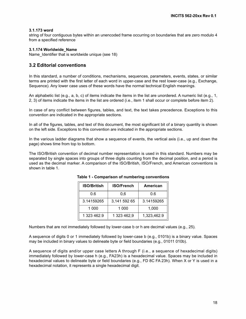
INCITS 562-20xx Rev 0.1
18
3.1.173 wordstring of four contiguous bytes within an unencoded frame occurring on boundaries that are zero modulo 4from a specified reference
3.1.174 Worldwide_NameName_Identifier that is worldwide unique (see 18)
3.2 Editorial conventions
In this standard, a number of conditions, mechanisms, sequences, parameters, events, states, or similarterms are printed with the first letter of each word in upper-case and the rest lower-case (e.g., Exchange,Sequence). Any lower case uses of these words have the normal technical English meanings.
An alphabetic list (e.g., a, b, c) of items indicate the items in the list are unordered. A numeric list (e.g., 1,2, 3) of items indicate the items in the list are ordered (i.e., item 1 shall occur or complete before item 2).
In case of any conflict between figures, tables, and text, the text takes precedence. Exceptions to thisconvention are indicated in the appropriate sections.
In all of the figures, tables, and text of this document, the most significant bit of a binary quantity is shownon the left side. Exceptions to this convention are indicated in the appropriate sections.
In the various ladder diagrams that show a sequence of events, the vertical axis (i.e., up and down thepage) shows time from top to bottom.
The ISO/British convention of decimal number representation is used in this standard. Numbers may beseparated by single spaces into groups of three digits counting from the decimal position, and a period isused as the decimal marker. A comparison of the ISO/British, ISO/French, and American conventions isshown in table 1.
Numbers that are not immediately followed by lower-case b or h are decimal values (e.g., 25).
A sequence of digits 0 or 1 immediately followed by lower-case b (e.g., 0101b) is a binary value. Spacesmay be included in binary values to delineate byte or field boundaries (e.g., 01011 010b).
A sequence of digits and/or upper case letters A through F (i.e., a sequence of hexadecimal digits)immediately followed by lower-case h (e.g., FA23h) is a hexadecimal value. Spaces may be included inhexadecimal values to delineate byte or field boundaries (e.g., FD 8C FA 23h). When X or Y is used in ahexadecimal notation, it represents a single hexadecimal digit.
Table 1 - Comparison of numbering conventions
ISO/British ISO/French American
0.6 0,6 0.6
3.14159265 3,141 592 65 3.14159265
1 000 1 000 1,000
1 323 462.9 1 323 462,9 1,323,462.9
INCITS 562-20xx Rev 0.1
19
3.3 State machines
3.3.1 Overview
The operation of a protocol or a function may be described by a state machine. The models presented bystate machines are intended as the primary specifications of functional behavior to be provided. However,it is important to distinguish between a model and a real implementation. The models are optimized forsimplicity and clarity of presentation, while any realistic implementation may place heavier emphasis onefficiency and suitability to a particular implementation technology. It is functional behavior that is specifiedby this standard, not internal structure. The internal details of a state machine model are useful only to theextent that they specify the external behavior clearly and precisely.
The specification of a state machine includes the conditions under which it is started, and may includeconditions under which it completes.
Multiple instances of the same state machine may operate concurrently.
3.3.2 States
Each state machine consists of a group of mutually exclusive states, each of which:
1) performs a set of actions on entry;
2) performs a set of ongoing actions continually while in the state; and
3) upon specified conditions, transitions to another state.
Only one state of a state machine is active at any given time.
The actions on entry to states are immediate and atomic (i.e., uninterruptible). When a state has performedall its specified entry actions one time, the state then continuously performs its ongoing actions,concurrently evaluating its exit conditions When the conditions for any of its exits is satisfied, controlpasses through a transition to the next state. No actions are taken outside of any state.
3.3.3 State variables
State variables carry information among the states within their scope. A variable may be within the scopeof the states of a machine or of a set of related machines. Variables have no default values. Their valuesare explicitly set before they are first used, and retain their values until explicitly set again, or until theirscope is completed.
3.3.4 State timers
State timers may limit the amount of time in a state or set of states within their scope. A timer may be withinthe scope of the states of a machine or of a set of related machines. An expiration value range is specifiedfor each timer. A timer is reset and starts monitoring elapsed time upon entering a state that includes anaction to start the timer. A timer expires at some elapsed time greater than the minimum value of itsexpiration range and less than the maximum value of its expiration range. A timer that has expired remainsexpired until the timer is reset or its scope completes. A timer is reset and stops counting upon entering astate that includes an action to stop the timer or when the scope of the timer completes.
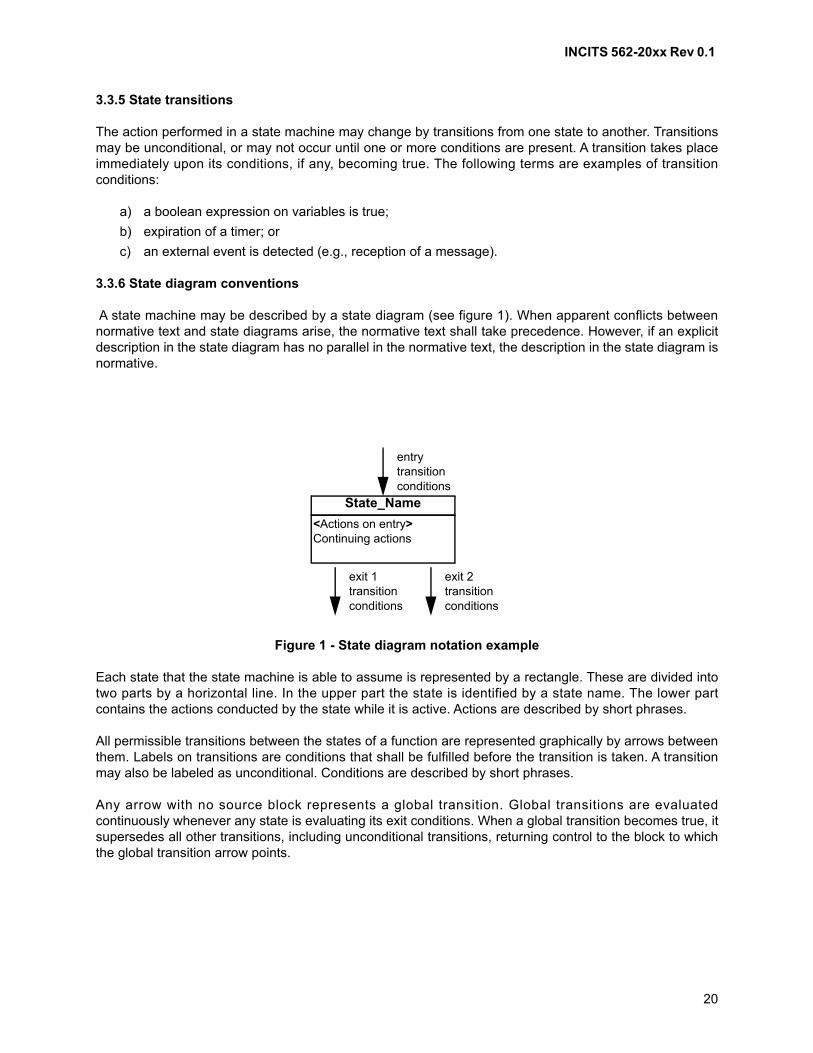
INCITS 562-20xx Rev 0.1
20
3.3.5 State transitions
The action performed in a state machine may change by transitions from one state to another. Transitionsmay be unconditional, or may not occur until one or more conditions are present. A transition takes placeimmediately upon its conditions, if any, becoming true. The following terms are examples of transitionconditions:
a) a boolean expression on variables is true;
b) expiration of a timer; or
c) an external event is detected (e.g., reception of a message).
3.3.6 State diagram conventions
A state machine may be described by a state diagram (see figure 1). When apparent conflicts betweennormative text and state diagrams arise, the normative text shall take precedence. However, if an explicitdescription in the state diagram has no parallel in the normative text, the description in the state diagram isnormative.
Each state that the state machine is able to assume is represented by a rectangle. These are divided intotwo parts by a horizontal line. In the upper part the state is identified by a state name. The lower partcontains the actions conducted by the state while it is active. Actions are described by short phrases.
All permissible transitions between the states of a function are represented graphically by arrows betweenthem. Labels on transitions are conditions that shall be fulfilled before the transition is taken. A transitionmay also be labeled as unconditional. Conditions are described by short phrases.
Any arrow with no source block represents a global transition. Global transitions are evaluatedcontinuously whenever any state is evaluating its exit conditions. When a global transition becomes true, itsupersedes all other transitions, including unconditional transitions, returning control to the block to whichthe global transition arrow points.
Figure 1 - State diagram notation example
<Actions on entry>Continuing actions
State_Name
entrytransitionconditions
exit 1transitionconditions
exit 2transitionconditions
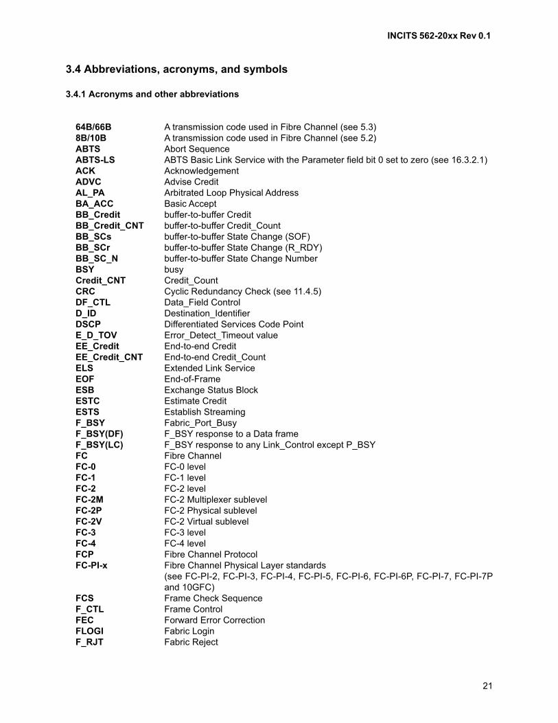
INCITS 562-20xx Rev 0.1
21
3.4 Abbreviations, acronyms, and symbols
3.4.1 Acronyms and other abbreviations
64B/66B A transmission code used in Fibre Channel (see 5.3)8B/10B A transmission code used in Fibre Channel (see 5.2)ABTS Abort Sequence ABTS-LS ABTS Basic Link Service with the Parameter field bit 0 set to zero (see 16.3.2.1) ACK Acknowledgement ADVC Advise Credit AL_PA Arbitrated Loop Physical AddressBA_ACC Basic Accept BB_Credit buffer-to-buffer Credit BB_Credit_CNT buffer-to-buffer Credit_Count BB_SCs buffer-to-buffer State Change (SOF)BB_SCr buffer-to-buffer State Change (R_RDY)BB_SC_N buffer-to-buffer State Change NumberBSY busyCredit_CNT Credit_Count CRC Cyclic Redundancy Check (see 11.4.5)DF_CTL Data_Field Control D_ID Destination_Identifier DSCP Differentiated Services Code PointE_D_TOV Error_Detect_Timeout value EE_Credit End-to-end Credit EE_Credit_CNT End-to-end Credit_Count ELS Extended Link ServiceEOF End-of-Frame ESB Exchange Status Block ESTC Estimate Credit ESTS Establish Streaming F_BSY Fabric_Port_Busy F_BSY(DF) F_BSY response to a Data frame F_BSY(LC) F_BSY response to any Link_Control except P_BSYFC Fibre ChannelFC-0 FC-0 levelFC-1 FC-1 levelFC-2 FC-2 levelFC-2M FC-2 Multiplexer sublevelFC-2P FC-2 Physical sublevelFC-2V FC-2 Virtual sublevelFC-3 FC-3 levelFC-4 FC-4 levelFCP Fibre Channel ProtocolFC-PI-x Fibre Channel Physical Layer standards
(see FC-PI-2, FC-PI-3, FC-PI-4, FC-PI-5, FC-PI-6, FC-PI-6P, FC-PI-7, FC-PI-7Pand 10GFC)
FCS Frame Check SequenceF_CTL Frame Control FEC Forward Error CorrectionFLOGI Fabric LoginF_RJT Fabric Reject
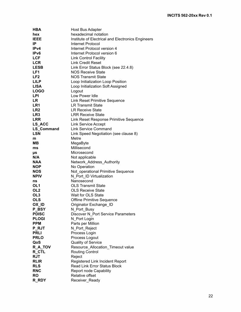
INCITS 562-20xx Rev 0.1
22
HBA Host Bus Adapterhex hexadecimal notation IEEE Institute of Electrical and Electronics EngineersIP Internet ProtocolIPv4 Internet Protocol version 4IPv6 Internet Protocol version 6LCF Link Control Facility LCR Link Credit Reset LESB Link Error Status Block (see 22.4.8)LF1 NOS Receive StateLF2 NOS Transmit StateLILP Loop Initialization Loop PositionLISA Loop Initialization Soft AssignedLOGO LogoutLPI Low Power IdleLR Link Reset Primitive SequenceLR1 LR Transmit StateLR2 LR Receive StateLR3 LRR Receive StateLRR Link Reset Response Primitive SequenceLS_ACC Link Service AcceptLS_Command Link Service CommandLSN Link Speed Negotiation (see clause 8)m MetreMB MegaBytems Millisecond µs Microsecond N/A Not applicable NAA Network_Address_Authority NOP No Operation NOS Not_operational Primitive Sequence NPIV N_Port_ID Virtualizationns Nanosecond OL1 OLS Transmit StateOL2 OLS Receive StateOL3 Wait for OLS StateOLS Offline Primitive Sequence OX_ID Originator Exchange_IDP_BSY N_Port_Busy PDISC Discover N_Port Service ParametersPLOGI N_Port LoginPPM Parts per MillionP_RJT N_Port_Reject PRLI Process LoginPRLO Process LogoutQoS Quality of ServiceR_A_TOV Resource_Allocation_Timeout value R_CTL Routing Control RJT RejectRLIR Registered Link Incident ReportRLS Read Link Error Status BlockRNC Report node CapabilityRO Relative offsetR_RDY Receiver_Ready
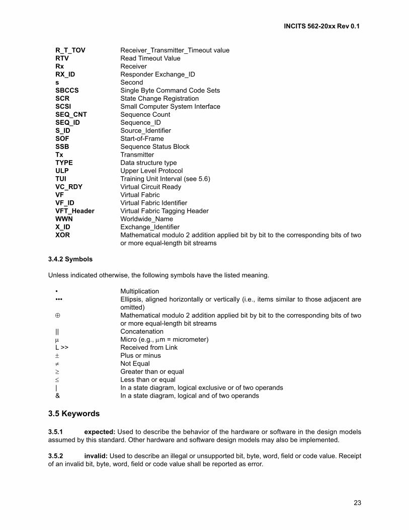
INCITS 562-20xx Rev 0.1
23
R_T_TOV Receiver_Transmitter_Timeout value RTV Read Timeout Value Rx Receiver RX_ID Responder Exchange_ID s Second SBCCS Single Byte Command Code Sets SCR State Change RegistrationSCSI Small Computer System InterfaceSEQ_CNT Sequence Count SEQ_ID Sequence_ID S_ID Source_Identifier SOF Start-of-Frame SSB Sequence Status Block Tx Transmitter TYPE Data structure type ULP Upper Level ProtocolTUI Training Unit Interval (see 5.6)VC_RDY Virtual Circuit ReadyVF Virtual FabricVF_ID Virtual Fabric IdentifierVFT_Header Virtual Fabric Tagging HeaderWWN Worldwide_NameX_ID Exchange_IdentifierXOR Mathematical modulo 2 addition applied bit by bit to the corresponding bits of two
or more equal-length bit streams
3.4.2 Symbols
Unless indicated otherwise, the following symbols have the listed meaning.
• Multiplication••• Ellipsis, aligned horizontally or vertically (i.e., items similar to those adjacent are
omitted) Mathematical modulo 2 addition applied bit by bit to the corresponding bits of two
or more equal-length bit streams|| Concatenation Micro (e.g., m = micrometer) L >> Received from Link Plus or minus Not Equal Greater than or equal Less than or equal| In a state diagram, logical exclusive or of two operands& In a state diagram, logical and of two operands
3.5 Keywords
3.5.1 expected: Used to describe the behavior of the hardware or software in the design modelsassumed by this standard. Other hardware and software design models may also be implemented.
3.5.2 invalid: Used to describe an illegal or unsupported bit, byte, word, field or code value. Receiptof an invalid bit, byte, word, field or code value shall be reported as error.
INCITS 562-20xx Rev 0.1
24
3.5.3 ignored: Used to describe a bit, byte, word, field or code value that shall not be examined bythe receiving port. The bit, byte, word, field or code value has no meaning in the specified context.
3.5.4 mandatory: A keyword indicating an item that is required to be implemented as defined in thisstandard.
3.5.5 may: A keyword that indicates flexibility of choice with no implied preference (equivalent to“may or may not”).
3.5.6 may not: A keyword that indicates flexibility of choice with no implied preference (equivalentto “may or may not”).
3.5.7 meaningful: A control field or bit that shall be applicable and that shall be interpreted by thereceiver.
3.5.8 not meaningful: A control field or bit that shall be ignored by the receiver.
3.5.9 obsolete: A keyword indicating that an item was defined in a prior Fibre Channel standard buthas been removed from this standard.
3.5.10 optional: A keyword that describes features that are not required to be implemented by thisstandard. However, if an optional feature defined by this standard is implemented, then it shall beimplemented as defined in this standard.
3.5.11 reserved: A keyword referring to bits, bytes, words, fields and code values that are set asidefor future standardization. A reserved bit, byte, word or field shall be set to zero, or in accordance with afuture extension to this standard. Recipients should not check reserved bits, bytes, words or fields for zerovalues. Receipt of reserved code values in defined fields shall be reported as an error.
3.5.12 restricted: A keyword referring to bits, bytes, words, and fields that are set aside for use inother standards. A restricted bit, byte, word, or field shall be treated as a reserved bit, byte, word or field forthe purposes of the requirements defined in this standard.
3.5.13 shall: A keyword indicating a mandatory requirement. Designers are required to implement allsuch mandatory requirements to ensure interoperability with other products that conform to this standard.This standard prescribes no specific response by a component if it receives information that violates amandatory behavior.
3.5.14 should: A keyword indicating flexibility of choice with a strongly preferred alternative;equivalent to the phrase “it is strongly recommended”.
3.5.15 should not: A keyword indicating flexibility of choice with a strongly preferred alternative;equivalent to the phrase “it is strongly recommended not to”.
3.5.16 vendor specific: Functions, code values, and bits not defined by this standard and set asidefor private usage between parties using this standard.
INCITS 562-20xx Rev 0.1
25
4 Structure and concepts
4.1 Introduction
This clause provides an overview of the structure, concepts, and mechanisms used in this standard. Thefollowing concepts are defined and described:
a) Functional levels (see 4.2);
b) Architectural components (see 4.3);
c) Physical model (see 4.4);
d) Communication models (see 4.5);
e) Interconnect topologies based on the presence or absence of a Fabric (see 4.6);
f) Classes of service provided by the Fabric and Nx_Ports (see 4.7);
g) General Fabric model (see 4.8);
h) Generic Services (see 4.9);
i) Building Blocks and their hierarchy (see 4.10);
j) Segmentation and reassembly (see 4.11); and
k) Error detection and recovery (see 4.12).
Fibre Channel (FC) is logically a bi-directional, point-to-point, serial data channel, structured for highperformance capability. Fibre Channel may be implemented using any combination of the following threetopologies:
a) a point-to-point link between two PN_Ports;
b) a set of PN_Ports interconnected by a switching network called a Fabric; and
c) a set of L_Ports interconnected with a loop topology as defined in FC-AL-2.
This standard provides a general transport vehicle for Upper Level Protocols (ULPs) (e.g., Small ComputerSystem Interface (SCSI) command sets, Internet Protocol (IP), and others). Other ULPs may also use andshare Fibre Channel, but such use is not defined as part of this standard.
The Fibre Channel protocol provides a range of implementation possibilities extending from minimum costto maximum performance. The transmission medium is isolated from the control protocol so that eachimplementation may use a technology best suited to the environment of use.
Effective transfer rate achieved by a Fibre Channel configuration is a function of physical variants, thecommunication model, Payload size, fibre speed, class of service and overhead specified by this standard.
4.2 Functional levels
4.2.1 Overview
Fibre Channel is structured as a set of hierarchical functions as illustrated in figure 2. This standardspecifies related functions FC-1, FC-2, and FC-3. Each of these functions is described as a level. FC-2 isfurther subdivided into sublevels FC-2P, FC-2M, and FC-2V. This standard does not restrictimplementations to specific interfaces between these levels.
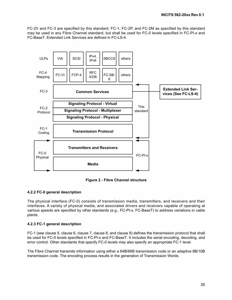
INCITS 562-20xx Rev 0.1
26
FC-2V and FC-3 are specified by this standard. FC-1, FC-2P, and FC-2M as specified by this standardmay be used in any Fibre Channel standard, but shall be used for FC-0 levels specified in FC-PI-x andFC-BaseT. Extended Link Services are defined in FC-LS-4.
4.2.2 FC-0 general description
The physical interface (FC-0) consists of transmission media, transmitters, and receivers and theirinterfaces. A variety of physical media, and associated drivers and receivers capable of operating atvarious speeds are specified by other standards (e.g., FC-PI-x, FC-BaseT) to address variations in cableplants.
4.2.3 FC-1 general description
FC-1 (see clause 5, clause 6, clause 7, clause 8, and clause 9) defines the transmission protocol that shallbe used for FC-0 levels specified in FC-PI-x and FC-BaseT. It includes the serial encoding, decoding, anderror control. Other standards that specify FC-0 levels may also specify an appropriate FC-1 level.
The Fibre Channel transmits information using either a 64B/66B transmission code or an adaptive 8B/10Btransmission code. The encoding process results in the generation of Transmission Words.
Figure 2 - Fibre Channel structure
ULPs VIA SCSIIPv4,IPv6 SBCCS others
FC-4Mapping FC-VI FCP-4
RFC 4338
FC-SB-6
others
Transmission Protocol
Transmitters and Receivers
Media
Common ServicesFC-3
FC-PI-x
FC-2Protocol
FC-1Coding
FC-0Physical
This standard
Extended Link Ser-vices (See FC-LS-4)
Signaling Protocol - Virtual
Signaling Protocol - Multiplexer
Signaling Protocol - Physical
INCITS 562-20xx Rev 0.1
27
Certain encoded bit patterns, referred to as Ordered Sets, are designated by this standard to have specialmeaning. Ordered Sets are used by the FC-2P sublevel specified by this standard to identify frameboundaries, transmit primitive function requests, and by the FC-1 level specified by this standard tomaintain proper link transmission characteristics during periods of inactivity.
Transmitter and receiver behavior is specified via a set of states and their interrelationships. These statesare divided into operational and not operational classes. Error monitoring capabilities and specialoperational modes are also defined for operational receivers and transmitters.
4.2.4 FC-2 general description
The FC-2 level serves as the transport mechanism of the Fibre Channel. The transported data istransparent to FC-2 and visible to FC-3 and above. FC-2 contains three sublevels: FC-2P (i.e., the FC-2Physical sublevel), FC-2M (i.e., the FC-2 Multiplexer sublevel), and FC-2V (i.e., the FC-2 Virtual sublevel).
FC-2P specifies the rules and provides mechanisms that shall be used to transfer frames via a specificFC-1 level. This standard specifies an FC-2P (see 11.3, 20.4, and 24.4) that shall be used to transferframes via the FC-1 that is specified by this standard. FC-2P functions specified in this standard includeframe transmission and reception, buffer-to-buffer flow control, and clock synchronization by use ofPrimitive Signals.
FC-2M (see 11.4, 12.4, clause 13, and clause 23) specifies the addressing and functions used to routeframes between a Link Control Facility and a VN_Port.
FC-2V (see 11.4, clause 12, clause 13, clause 14, clause 15, clause 17, clause 18, clause 19, 20.3, clause21, and 24.3) defines functions and facilities that an Nx_Port may provide for use by an FC-4 level,regardless of the FC-1 that is used. FC-2V functions include several classes of service, frame contentconstruction and analysis, Sequence disassembly and reassembly, Exchange management, andName_Identifiers.
4.2.5 FC-3 general description
FC-3 provides a set of services that are common across multiple Nx_Ports of a node. FC-3 includesprotocols for Basic Link Services (see clause 16), and Extended Link Services (see FC-LS-4). The LinkServices represent a mandatory function required by FC-2.
4.2.6 FC-4 general description
FC-4 is the highest level in the Fibre Channel standards set. An FC-4 defines the mapping between thelower levels of the Fibre Channel and an Upper Level Protocol (e.g., the SCSI and SBCCS command sets,IP, and other Upper Level Protocols (ULPs)). Fibre Channel provides a method for supporting a number ofUpper Level Protocols (ULPs).
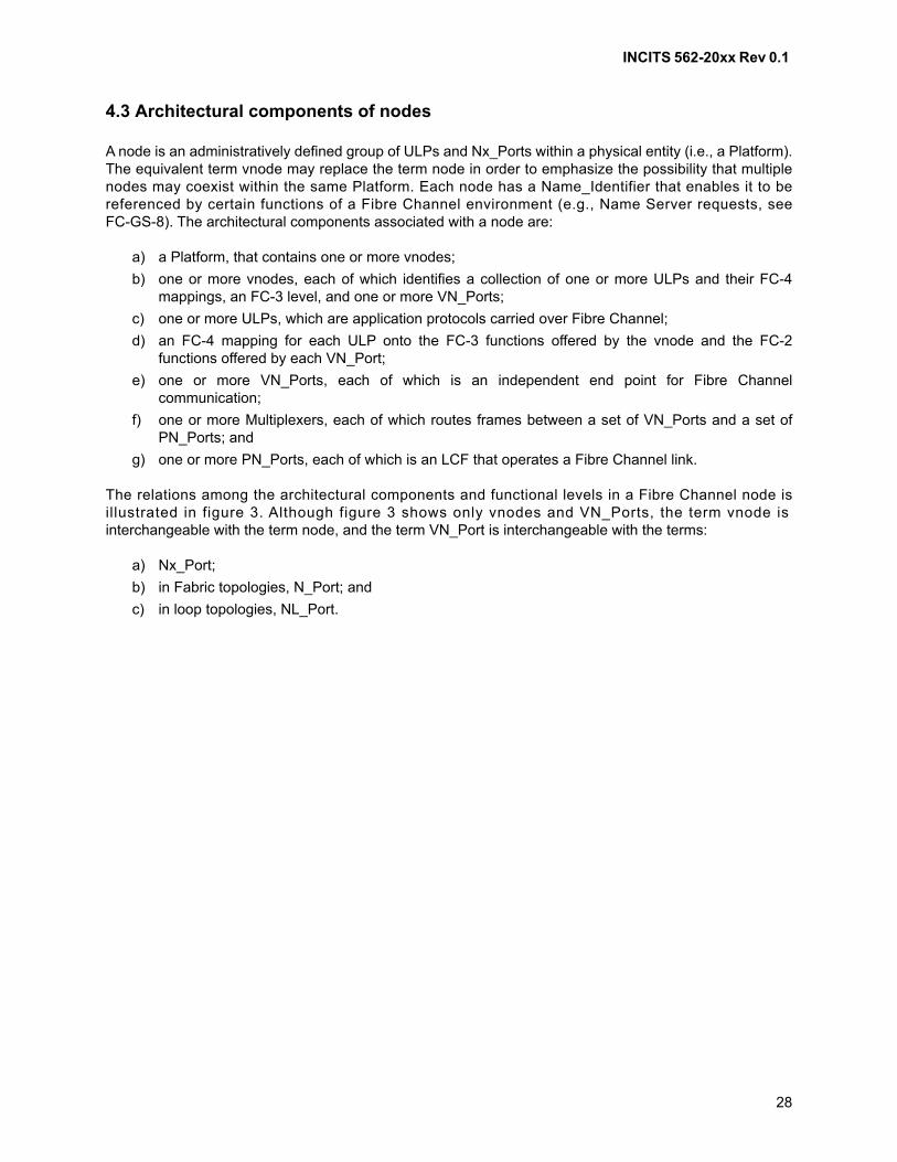
INCITS 562-20xx Rev 0.1
28
4.3 Architectural components of nodes
A node is an administratively defined group of ULPs and Nx_Ports within a physical entity (i.e., a Platform).The equivalent term vnode may replace the term node in order to emphasize the possibility that multiplenodes may coexist within the same Platform. Each node has a Name_Identifier that enables it to bereferenced by certain functions of a Fibre Channel environment (e.g., Name Server requests, seeFC-GS-8). The architectural components associated with a node are:
a) a Platform, that contains one or more vnodes;
b) one or more vnodes, each of which identifies a collection of one or more ULPs and their FC-4mappings, an FC-3 level, and one or more VN_Ports;
c) one or more ULPs, which are application protocols carried over Fibre Channel;
d) an FC-4 mapping for each ULP onto the FC-3 functions offered by the vnode and the FC-2functions offered by each VN_Port;
e) one or more VN_Ports, each of which is an independent end point for Fibre Channelcommunication;
f) one or more Multiplexers, each of which routes frames between a set of VN_Ports and a set ofPN_Ports; and
g) one or more PN_Ports, each of which is an LCF that operates a Fibre Channel link.
The relations among the architectural components and functional levels in a Fibre Channel node isillustrated in figure 3. Although figure 3 shows only vnodes and VN_Ports, the term vnode isinterchangeable with the term node, and the term VN_Port is interchangeable with the terms:
a) Nx_Port;
b) in Fabric topologies, N_Port; and
c) in loop topologies, NL_Port.
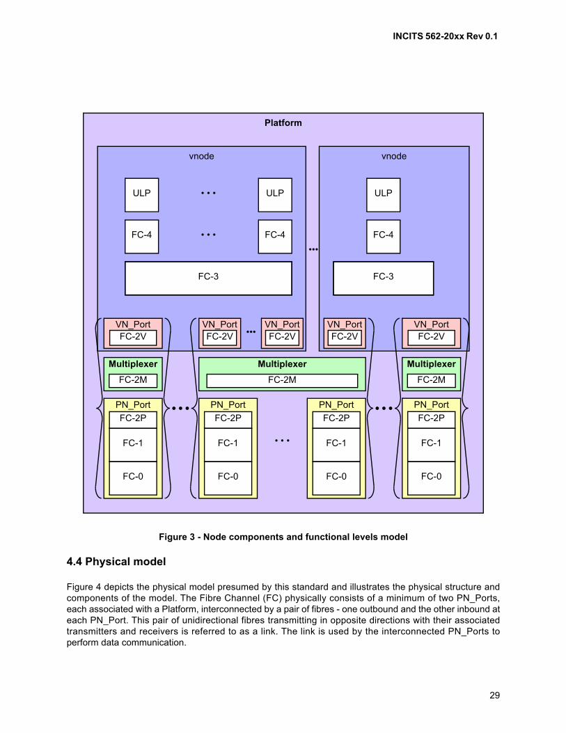
INCITS 562-20xx Rev 0.1
29
4.4 Physical model
Figure 4 depicts the physical model presumed by this standard and illustrates the physical structure andcomponents of the model. The Fibre Channel (FC) physically consists of a minimum of two PN_Ports,each associated with a Platform, interconnected by a pair of fibres - one outbound and the other inbound ateach PN_Port. This pair of unidirectional fibres transmitting in opposite directions with their associatedtransmitters and receivers is referred to as a link. The link is used by the interconnected PN_Ports toperform data communication.
Figure 3 - Node components and functional levels model
vnode
FC-3
• • •
vnode
VN_Port
FC-4FC-4
FC-1
FC-0
FC-2P
PN_Port
FC-2V
FC-1
FC-0
FC-2P
PN_Port
VN_PortFC-2V
VN_PortFC-2V
VN_PortFC-2V•••
•••
• • • ULPULP
FC-3
FC-4
ULP
Platform
FC-1
FC-0
FC-2P
PN_Port
• • •
Multiplexer
FC-2M
Multiplexer
FC-2M
FC-1
FC-0
FC-2P
PN_Port
VN_PortFC-2V
Multiplexer
FC-2M
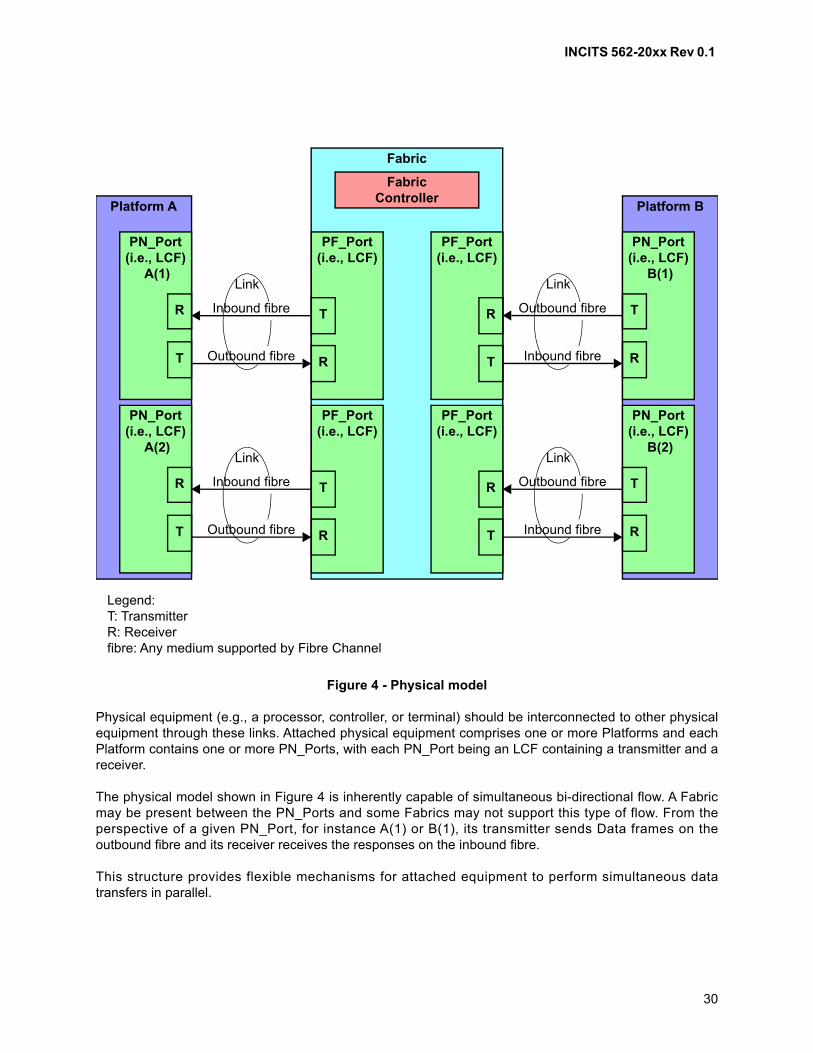
INCITS 562-20xx Rev 0.1
30
Physical equipment (e.g., a processor, controller, or terminal) should be interconnected to other physicalequipment through these links. Attached physical equipment comprises one or more Platforms and eachPlatform contains one or more PN_Ports, with each PN_Port being an LCF containing a transmitter and areceiver.
The physical model shown in Figure 4 is inherently capable of simultaneous bi-directional flow. A Fabricmay be present between the PN_Ports and some Fabrics may not support this type of flow. From theperspective of a given PN_Port, for instance A(1) or B(1), its transmitter sends Data frames on theoutbound fibre and its receiver receives the responses on the inbound fibre.
This structure provides flexible mechanisms for attached equipment to perform simultaneous datatransfers in parallel.
Figure 4 - Physical model
Legend:T: TransmitterR: Receiverfibre: Any medium supported by Fibre Channel
Link
Inbound fibre
Outbound fibre
Platform A
Fabric
FabricController
PF_Port(i.e., LCF)
R
T
Platform B
Link
Outbound fibre
Inbound fibre
Link
Outbound fibre
Inbound fibre
Link
Inbound fibre
Outbound fibre
T
R
PN_Port(i.e., LCF)
A(1)
T
R
PN_Port(i.e., LCF)
A(2)
R
T
PN_Port(i.e., LCF)
B(1)
R
T
PN_Port(i.e., LCF)
B(2)
PF_Port(i.e., LCF)
T
R
PF_Port(i.e., LCF)
T
R
PF_Port(i.e., LCF)
R
T

INCITS 562-20xx Rev 0.1
31
The Link Control facility (LCF) is a hardware facility that attaches to each end of a link and managestransmission and reception of data. In a node, an LCF is a PN_Port. In a Fabric, an LCF attached to aPN_Port is a PF_Port.
4.5 Communication models
A PN_Port transmits Data frames as a result of transfer requests made by an upper level at its end andreceives the Link_Control responses for those Data frames. A PN_Port receives Data frames from otherPN_Ports and transmits the appropriate Link_Control responses for those frames to the proper PN_Ports.
A PN_Port may operate according to these communication models:
a) simplex operation is defined as a PN_Port transferring Data frames in one direction only, withLink_Control frames flowing in the opposite direction;
b) full-duplex operation is defined as a PN_Port simultaneously transmitting and receiving Dataframes, with Link_Control frames flowing in both directions as well; or
c) half-duplex operation is defined as a PN_Port both transmitting and receiving data, but notsimultaneously. Data frames and Link_Control frames flow in both directions, but the flow islimited, to a single direction at a time.
4.6 Topology
4.6.1 Types
Topologies are defined, based on the capability and the presence or absence of Fabric between thePN_Ports. There are three basic types:
a) Point-to-point topology;
b) Fabric topology; and
c) Arbitrated Loop topology.
The protocols specified herein are topology independent. However, attributes of the topology may restrictoperation to certain communication models.
4.6.2 Point-to-point topology
The point-to-point topology is shown in figure 5, in which communication between PN_Ports occurs withoutthe use of a Fabric.
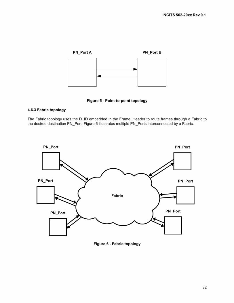
INCITS 562-20xx Rev 0.1
32
4.6.3 Fabric topology
The Fabric topology uses the D_ID embedded in the Frame_Header to route frames through a Fabric tothe desired destination PN_Port. Figure 6 illustrates multiple PN_Ports interconnected by a Fabric.
Figure 5 - Point-to-point topology
Figure 6 - Fabric topology
PN_Port A PN_Port B
Fabric
PN_Port
PN_Port
PN_Port
PN_Port
PN_Port
PN_Port
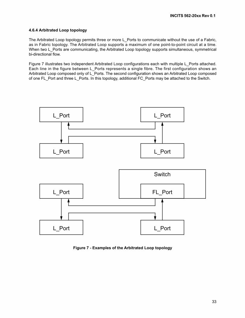
INCITS 562-20xx Rev 0.1
33
4.6.4 Arbitrated Loop topology
The Arbitrated Loop topology permits three or more L_Ports to communicate without the use of a Fabric,as in Fabric topology. The Arbitrated Loop supports a maximum of one point-to-point circuit at a time.When two L_Ports are communicating, the Arbitrated Loop topology supports simultaneous, symmetricalbi-directional flow.
Figure 7 illustrates two independent Arbitrated Loop configurations each with multiple L_Ports attached.Each line in the figure between L_Ports represents a single fibre. The first configuration shows anArbitrated Loop composed only of L_Ports. The second configuration shows an Arbitrated Loop composedof one FL_Port and three L_Ports. In this topology, additional FC_Ports may be attached to the Switch.
Figure 7 - Examples of the Arbitrated Loop topology
L_Port
L_Port L_Port
L_Port
L_Port
L_Port L_Port
FL_Port
Switch

INCITS 562-20xx Rev 0.1
34
4.7 Classes of service
4.7.1 General
Classes of service are distinguished primarily by the level of delivery integrity required for an application.Classes of service are topology independent. If a Fabric is not present, the class of service is provided asa special case of point-to-point. FC_Ports are not required to support all classes of service.
4.7.2 Class 2 service - multiplex
Class 2 is a frame delivery service multiplexing frames at frame boundaries with frame acknowledgement(see 17.3).
The transmitter transmits Class 2 Data frames in a sequential order within a given Sequence. However theFabric may not guarantee the order of delivery and frames may be delivered out of order.
The Fabric or the destination Nx_Port guarantees notification of delivery in the absence of link errors. Incase of link errors, notification is not guaranteed since the S_ID may not be error free.
4.7.3 Class 3 service - datagram
Class 3 is a frame delivery service with the Fabric multiplexing frames at frame boundaries without frameacknowledgement (see 17.4).
Class 3 supports only unacknowledged delivery where the destination Nx_Port does not send anyconfirmation of Link_Control frames on receipt of valid Data frames. Any acknowledgement of Class 3service is beyond the scope of this standard.
The transmitter transmits Class 3 Data frames in sequential order within a given Sequence. However, theFabric may not guarantee the order of delivery and frames may be delivered out of order.
The Fabric is expected to make a best effort to deliver the frame to the intended destination and does notissue a busy or reject frame to the source Nx_Port if unable to deliver the frame.
4.7.4 Class F service - Fabric
Class F is a frame delivery service used only for communication between switches in a Fabric (seeFC-SW-7).
4.8 General Fabric model
4.8.1 General
The primary function of the Fabric is to receive the frames from a source Nx_Port and route the frames tothe destination Nx_Port whose address identifier is specified in the frames. Each Nx_Port is physicallyattached through a link to the Fabric. FC-2 specifies the protocol between the Fabric and the attachedNx_Ports. A Fabric is characterized by a single address space where every Nx_Port has a uniqueN_Port_ID.
A Fabric specifies the classes of service it supports in its Service Parameters (see FC-LS-4). Fabrics areallowed to provide the classes of service through equivalent mechanisms and/or functions. See FC-SW-7for the details.

INCITS 562-20xx Rev 0.1
35
Figure 8 illustrates the general Fabric model. The model is conceptual and may provide the following majorfunctions:
a) bi-directional Physical Fabric Ports (PF_Ports);
b) receive buffer;
c) frame delivery service; and
d) receive buffer queue management.
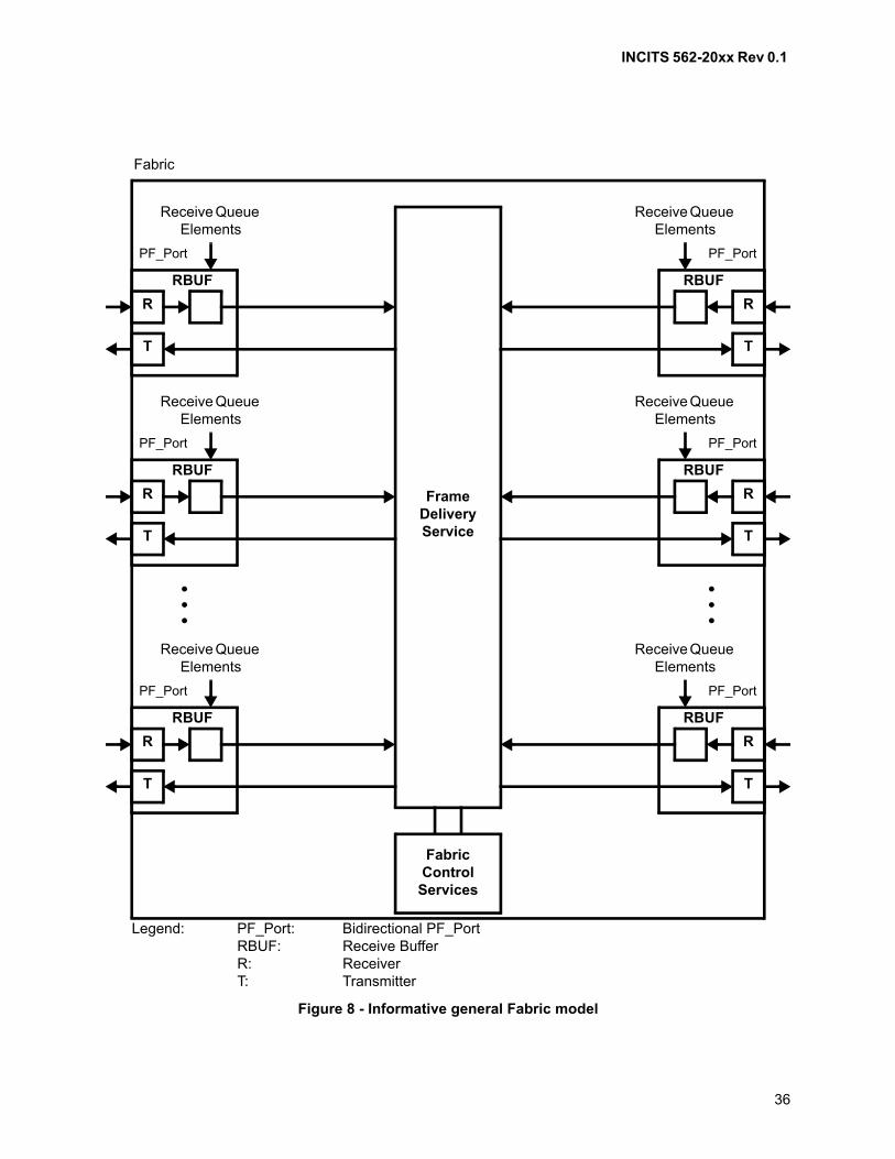
INCITS 562-20xx Rev 0.1
36
Figure 8 - Informative general Fabric model
Fabric
Legend: PF_Port: Bidirectional PF_PortRBUF: Receive BufferR: ReceiverT: Transmitter
Receive Queue Elements
PF_Port
R
T
RBUF
Receive Queue Elements
PF_Port
R
T
RBUF
Receive Queue Elements
PF_Port
R
T
RBUF
Receive Queue Elements
PF_Port
R
T
RBUF
Receive Queue Elements
PF_Port
R
T
RBUF
Receive Queue Elements
PF_Port
R
T
RBUF
FrameDeliveryService
FabricControl
Services

INCITS 562-20xx Rev 0.1
37
4.8.2 Fabric Ports (Fx_Ports)
The Fabric model contains two or more Fx_Ports. Each Fx_Port is attached to one or more Nx_Ports atone or more PN_Ports through a link. Each Fx_Port is bi-directional and supports one or morecommunication models. Frames are routed to the Fx_Port attached to the destination Nx_Port.
The receiving Fx_Port responds to the sending Nx_Port according to the FC-2 protocol. The Fabric mayverify the validity of the frame as it passes through the Fabric (see 11.3.8.3 and 11.3.9.2).
An Fx_Port may contain receive buffers for the incoming frames. The maximum Data_Field size that theFabric is able to handle for frames is determined during Login. One of the Fabric Service Parametersindicates the maximum Data_Field size for the entire Fabric (see FC-LS-4).
The Fabric routes the frame to the Fx_Port attached to the destination Nx_Port based on the value in theD_ID field embedded in the Frame_Header of the frame. The routing mechanisms within the Fabric aretransparent to Nx_Ports and are not specified in this standard.
4.8.3 Frame delivery service
A frame delivery service multiplexes frames at frame boundaries. Frame delivery service does notguarantee full link bandwidth between communicating Nx_Ports.
The Fabric notifies the transmitting Nx_Port with a reason code embedded in a Link_Response frame, if itis unable to deliver a Class 2 frame. In the case of a Class 3 frame, the Fabric does not notify thetransmitting Nx_Port.
If frames from multiple Nx_Ports are targeted for the same destination Nx_Port in Class 2 or Class 3,congestion of frames may occur within the Fabric. Management of this congestion is part of the framedelivery service and buffer-to-buffer flow control.
If any buffer-to-buffer flow control error occurs and as a result causes overflow (see 20.4), the Fabric logsthe error and may discard the overflow frame without notification. Error logging is vendor specific.
4.9 Generic Services
Generic Services (e.g., Directory Service) may be provided in a Fibre Channel configuration to meet theneeds of the configuration. Each of these services is addressed with an N_Port_ID for the Nx_Portproviding the service or with a well-known address (see 12.4.2). These well-known addresses arerecognized and routed to by the Fabric. These services may be centralized or distributed (see FC-GS-8).
4.10 Building Blocks
4.10.1 Building block hierarchy
The FC-2 building blocks are used in a hierarchical fashion, as illustrated in figure 9.
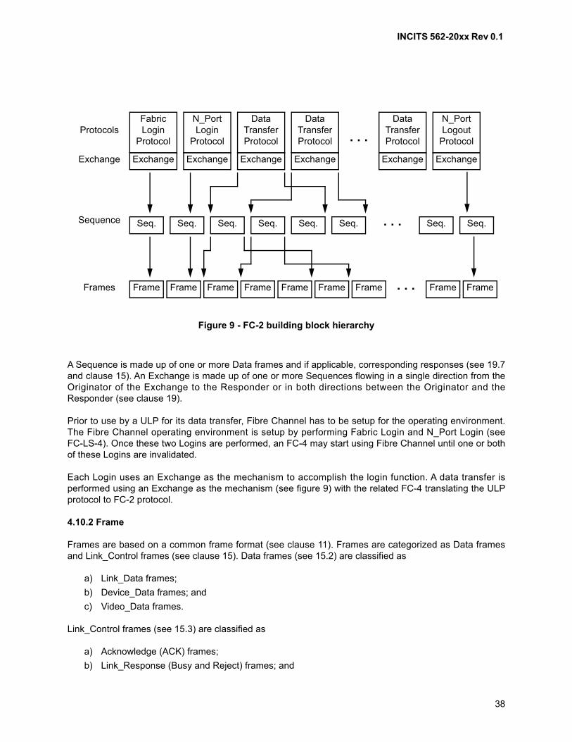
INCITS 562-20xx Rev 0.1
38
A Sequence is made up of one or more Data frames and if applicable, corresponding responses (see 19.7and clause 15). An Exchange is made up of one or more Sequences flowing in a single direction from theOriginator of the Exchange to the Responder or in both directions between the Originator and theResponder (see clause 19).
Prior to use by a ULP for its data transfer, Fibre Channel has to be setup for the operating environment.The Fibre Channel operating environment is setup by performing Fabric Login and N_Port Login (seeFC-LS-4). Once these two Logins are performed, an FC-4 may start using Fibre Channel until one or bothof these Logins are invalidated.
Each Login uses an Exchange as the mechanism to accomplish the login function. A data transfer isperformed using an Exchange as the mechanism (see figure 9) with the related FC-4 translating the ULPprotocol to FC-2 protocol.
4.10.2 Frame
Frames are based on a common frame format (see clause 11). Frames are categorized as Data framesand Link_Control frames (see clause 15). Data frames (see 15.2) are classified as
a) Link_Data frames;
b) Device_Data frames; and
c) Video_Data frames.
Link_Control frames (see 15.3) are classified as
a) Acknowledge (ACK) frames;
b) Link_Response (Busy and Reject) frames; and
Figure 9 - FC-2 building block hierarchy
DataTransferProtocol
Exchange
N_PortLogout
Protocol
Exchange
FabricLogin
Protocol
Exchange
N_PortLogin
Protocol
Exchange
DataTransferProtocol
Exchange
DataTransferProtocol
Exchange
Frame
Seq. Seq. Seq. Seq. Seq. Seq. Seq. Seq.
Protocols
Exchange
Frames
Sequence
Frame Frame Frame Frame Frame Frame Frame Frame. . .
. . .
. . .
INCITS 562-20xx Rev 0.1
39
c) Link_Control command frames.
Selective retransmission of frames for error recovery is not supported in this standard (see clause 22).However, an individual frame may be busied in Class 2 and the sender may later retransmit the busiedframe (see 15.3.3.2) up to the ability of the sender to retry. The number of times the sender may retry is notspecified in this standard.
4.10.3 Sequence
4.10.3.1 Introduction
A Sequence is a set of one or more related Data frames transmitted unidirectionally from one Nx_Port toanother Nx_Port with corresponding Link_Control frames, if specified, transmitted in response. An Nx_Portthat transmits a Sequence is referred to as the Sequence Initiator and the Nx_Port that receives theSequence is referred to as the Sequence Recipient. Sequence rules are specified in 19.7.
Error recovery is performed on the Sequence boundary at the discretion of a level higher than FC-2. If aframe is not transmitted error free, and the error policy requires error recovery, the Sequence containingthe frame may be retransmitted (see clause 22).
4.10.3.2 Sequence_Identifier (SEQ_ID)
The Sequence Initiator assigns to the Sequence a Sequence_Identifier (SEQ_ID). The SequenceRecipient uses the same SEQ_ID in its response frames. The Sequence Initiator at each of thecommunicating Nx_Ports assigns SEQ_IDs independent of the other.
4.10.3.3 Sequence Status Blocks
A Sequence Status Block (SSB) is a logical construct representing the content of the Sequence statusinformation (see 19.9.2). It is used to track the progress of a Sequence at an Nx_Port on a frame by framebasis. A Sequence Initiator SSB and a Sequence Recipient SSB are used by the respective Nx_Ports totrack the status of a given Sequence.
When a Sequence Initiator starts a Sequence, the Sequence Initiator allocates a SSB to be associatedwith the Sequence it has initiated. The Sequence Recipient subsequently allocates a SSB at its end,associated with the sequence that the Sequence Initiator has initiated. Both the Sequence Initiator andSequence Recipient Nx_Ports track the status of the Sequence through the Sequence Initiator and theSequence Recipient SSBs, respectively.
The maximum number of concurrent Sequences between two Nx_Ports is limited to the smaller of thenumber of SSBs available at these Nx_Ports. This value is established during N_Port Login through theService Parameters (see FC-LS-4).
4.10.4 Exchange
4.10.4.1 Introduction
An Exchange is composed of one or more non-concurrent Sequences (see clause 19). An Exchange maybe unidirectional or bi-directional. A unidirectional Exchange results when the same Nx_Port initiates allthe Sequences within the Exchange. A bi-directional Exchange results when the Sequences within theExchange are initiated by both the Nx_Ports, but not concurrently.
INCITS 562-20xx Rev 0.1
40
An FC-4 may achieve full bandwidth utilization between two Nx_Ports by supporting two or moreExchanges concurrently with the two Nx_Ports using different Exchanges to transmit information.Coordination of the Exchanges is FC-4 specific. All frames and Sequences of a given Exchange shall beperformed between the Nx_Ports that first originated and received the Exchange.
Exchanges are used by upper levels to relate sequences.
4.10.4.2 Exchange_Identifiers (OX_ID and RX_ID)
Exchange_Identifiers shall be used by the Originator and Responder to uniquely identify an Exchange.
The Originator assigns each new Exchange an Originator Exchange_ID (OX_ID) unique to the Originatoror Originator-Responder pair and embeds it in all frames of the Exchange.
The Responder may assign a Responder Exchange_ID (RX_ID) that is unique to the Responder orResponder-Originator pair and communicates it to the Originator before the end of the first Sequence ofthe Exchange in Class 2 (see 19.6). The Responder embeds the RX_ID along with OX_ID in allsubsequent frames of the Exchange.
On receiving the RX_ID from the Responder, the Originator embeds both the RX_ID and OX_ID in allsubsequent frames of the Exchange it originates.
The Originator may initiate multiple concurrent Exchanges, but each shall use a unique OX_ID.
4.10.4.3 Exchange Status Blocks
An Exchange Status Block (ESB) is a logical construct representing the format of the Exchange statusinformation (see 19.9.1). It is used to track the progress of an Exchange on a Sequence by Sequencebasis. An Originator and a Responder use an Originator ESB and a Responder ESB, respectively, to trackthe status of an Exchange.
When an Originator initiates an Exchange, it assigns an Originator ESB associated with the Exchange.The Originator references the Originator ESB through its respective OX_ID (see 19.9.1).
The Responder assigns a Responder ESB to the Exchange. The Responder references the ResponderESB through the fully qualified X_ID (see 19.9.1 and FCP-4).
Both the Originator and the Responder track the status of the Exchange at their respective Nx_Ports.
4.10.5 Protocols
4.10.5.1 Primitive Sequence protocols
Primitive Sequence protocols are based on Primitive Sequences and specified for Link Failure, LinkInitialization, Link Reset, and Online to Offline transition (see 7.8).
4.10.5.2 Fabric Login protocol
An Nx_Port may explicitly interchange Service Parameters with the Fabric, if present, by performing theFabric Login protocol. The Fabric Login protocol also creates the first VN_Port associated with thePN_Port and the Fabric. The Fabric Login protocol is an explicit Fabric Login procedure (see FC-LS-4) thatcompletes successfully (i.e., in an Exchange that completes with an LS_ACC).
INCITS 562-20xx Rev 0.1
41
4.10.5.3 Additional N_Port_ID protocol
An Nx_Port may create additional VN_Ports associated with the PN_Port and the Fabric using theAdditional N_Port_ID protocol. The Additional N_Port_ID protocol is an Additional N_Port_ID procedure(see FC-LS-4) that completes successfully (i.e., in an Exchange that completes with an LS_ACC).
4.10.5.4 N_Port Login protocol
Before performing data transfer, an Nx_Port may explicitly interchange Service Parameters with anotherNx_Port by performing the N_Port Login protocol. The N_Port Login protocol is an explicit N_Port Loginprocedure (see FC-LS-4) that completes successfully (i.e., in an Exchange that completes with anLS_ACC).
4.10.5.5 Data transfer protocol
The ULP data is transferred using data transfer protocols. Data transfer protocols are specified in FC-4standards. For examples, see FCP-4 and RFC 4338.
4.10.5.6 Nx_Port Logout protocol
An Nx_Port may explicitly request removal of its Service Parameters from another Nx_Port by performingan Nx_Port Logout protocol. This may be used to free up resources at the other Nx_Port. The Nx_PortLogout protocol is an explicit N_Port Logout procedure (see FC-LS-4) that completes successfully (i.e., inan Exchange that completes with an LS_ACC).
4.10.5.7 Fabric Logout protocol
An Nx_Port may explicitly request removal of its Service Parameters from the Fabric by performing aFabric Logout protocol. This may be used to free up resources at the Fabric. The Fabric Logout protocol isan explicit Fabric Logout procedure (see FC-LS-4) that completes successfully (i.e., in an Exchange thatcompletes with an LS_ACC).
4.11 Segmentation and reassembly of application data
Mapping application data to Upper Level Protocol (ULP) data blocks is outside the scope of this standard.Mapping ULP data blocks to FC-4 Information Units (IUs) is specified in FC-4 level standards (e.g., FCP-4,FC-SB-6). FC-4 IUs are mapped to Sequences. The transport of Sequences using Fibre Channel frames isspecified in this standard. Clause 21 specifies the following features of the FC-2V sublevel that supportefficient mapping of IUs onto frames:
a) identifying and classifying IUs (see 21.3);
b) multiplexing IUs within a Sequence (see 21.4);
c) relative offset of Data_Frames in an IU (see 21.5); and
d) transporting portions of an IU out of relative offset order (see 21.6).
Together, the rules for these features control the segmentation of IUs into transmitted frames and thereassembly of IUs from received frames.
4.12 Error detection and recovery
In general, detected errors fall into two broad categories, frame errors and link-level errors.
INCITS 562-20xx Rev 0.1
42
Frame errors result from missing frames or corrupted frames. Corrupted frames are discarded and forcorrupted frames the resulting error is detected at the Sequence level. At the Sequence level, a missingframe is detected or the Sequence t imes out due to one or more missing Data frames orAcknowledgments. If the discard policy (see 22.5.4.3) is used, the Sequence is aborted at the Sequencelevel once an error is detected. Sequence errors may also cause Exchange errors that may also cause theExchange to be aborted. Error recovery may be performed on the failing Sequence or Exchange with theinvolvement of the sending upper level. Other properly performing Sequences are unaffected.
Link-level errors result from errors detected at a lower level of granularity than frames, where the basicsignal characteristics are in question. Link-level errors include such errors as Loss-of-Signal,Loss-of-Synchronization and several link timeout errors that indicate no frame activity. Link-level errorsmay be isolated to a portion of the link. Transmission and reception of Primitive Sequences accomplishrecovery from link-level errors. Recovery at the link-level disturbs normal frame flow and may introduceSequence errors that may be resolved after recovery at the link-level.
See clause 22 for detailed error detection and recovery requirements.
INCITS 562-20xx Rev 0.1
43
5 FC-1 transmission codes
5.1 Overview
Transmission codes are a function of the FC-1 level. Communication of words and Special Functions areFC-1 functions. Use of Special Functions is an FC-2P function.
Information to be transmitted over a fibre shall be presented to the FC-1 level as a stream of words andSpecial Functions. It shall be encoded using one of the transmission codes specified in this clause into astream of Transmission Words that shall be sent across the link. Information shall be received over the linkas a stream of Transmission Words. The stream of Transmission Words shall be decoded using one of thetransmission codes specified in this clause into a stream of words and Special Functions that shall bedelivered to the FC-2P sublevel.
This standard specifies two types of transmission codes:
a) frame transfer transmission codes are specified to transfer Upper Level Protocol data; and
b) other transmission codes (e.g., the Transmitter Training Signal, see 5.6) are specified for purposesother than transferring Fibre Channel frames.
Both types of transmission code provide these functions:
a) maintaining Bit Synchronization and Transmission Word Synchronization;
b) communicating link control information; and
c) increasing the likelihood of detection of transmission errors.
Frame transfer transmission codes additionally provide these functions:
a) communicating link state machine transitions;
b) communicating other Special Functions;
c) denoting frame boundaries; and
d) communicating Upper Level Protocol data.
The encodings defined by the transmission code ensure that sufficient transitions are present in the serialbit stream to make clock recovery possible at the receiver. Such encoding also increases the likelihood ofdetecting any single or multiple bit errors that may occur during transmission and reception of information.In addition, the transmission code assures presence of a distinct and easily recognizable bit pattern thatassists a receiver in achieving Transmission Word alignment on the incoming bit stream.
An FC-0 standard for a physical variant may specify a transmission code. If an FC-0 standard for aphysical variant does not specify a transmission code, then the physical variant shall use the 8B/10Btransmission code (see 5.2).
5.2 8B/10B transmission code
5.2.1 Overview
An FC-0 standard (e.g., FC-PI-5) may specify the use of the 8B/10B transmission code as its frametransfer transmission code.
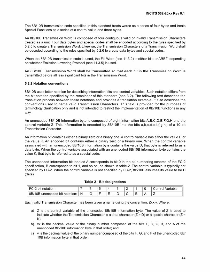
INCITS 562-20xx Rev 0.1
44
The 8B/10B transmission code specified in this standard treats words as a series of four bytes and treatsSpecial Functions as a series of a control value and three bytes.
An 8B/10B Transmission Word is composed of four contiguous valid or invalid Transmission Characterstreated as a unit. Four data bytes and special codes shall be encoded according to the rules specified by5.2.5 to create a Transmission Word. Likewise, the Transmission Characters of a Transmission Word shallbe decoded according to the rules specified by 5.2.6 to create data bytes and special codes.
When the 8B/10B transmission code is used, the Fill Word (see 11.3.2) is either Idle or ARBff, dependingon whether Emission Lowering Protocol (see 11.3.5) is used.
An 8B/10B Transmission Word shall be transmitted so that each bit in the Transmission Word istransmitted before all less significant bits in the Transmission Word.
5.2.2 Notation conventions
8B/10B uses letter notation for describing information bits and control variables. Such notation differs fromthe bit notation specified by the remainder of this standard (see 3.2). The following text describes thetranslation process between these notations and provides a translation example. It also describes theconventions used to name valid Transmission Characters. This text is provided for the purposes ofterminology clarification only and is not intended to restrict the implementation of 8B/10B functions in anyway.
An unencoded 8B/10B information byte is composed of eight information bits A,B,C,D,E,F,G,H and thecontrol variable Z. This information is encoded by 8B/10B into the bits a,b,c,d,e,i,f,g,h,j of a 10-bitTransmission Character.
An information bit contains either a binary zero or a binary one. A control variable has either the value D orthe value K. An encoded bit contains either a binary zero or a binary one. When the control variableassociated with an unencoded 8B/10B information byte contains the value D, that byte is referred to as adata byte. When the control variable associated with an unencoded 8B/10B information byte contains thevalue K, that byte is referred to as a special code.
The unencoded information bit labeled A corresponds to bit 0 in the bit numbering scheme of the FC-2specification, B corresponds to bit 1, and so on, as shown in table 2. The control variable is typically notspecified by FC-2. When the control variable is not specified by FC-2, 8B/10B assumes its value to be D(data).
Each valid Transmission Character has been given a name using the convention, Zxx.y. Where:
a) Z is the control variable of the unencoded 8B/10B information byte. The value of Z is used toindicate whether the Transmission Character is a data character (Z = D) or a special character (Z =K);
b) xx is the decimal value of the binary number composed of the bits E, D, C, B, and A of theunencoded 8B/10B information byte in that order; and
c) y is the decimal value of the binary number composed of the bits H, G, and F of the unencoded 8B/10B information byte in that order.
Table 2 - Bit designations
FC-2 bit notation: 7 6 5 4 3 2 1 0 Control Variable
8B/10B unencoded bit notation: H G F E D C B A Z
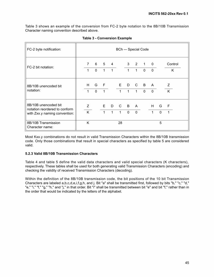
INCITS 562-20xx Rev 0.1
45
Table 3 shows an example of the conversion from FC-2 byte notation to the 8B/10B TransmissionCharacter naming convention described above.
Most Kxx.y combinations do not result in valid Transmission Characters within the 8B/10B transmissioncode. Only those combinations that result in special characters as specified by table 5 are consideredvalid.
5.2.3 Valid 8B/10B Transmission Characters
Table 4 and table 5 define the valid data characters and valid special characters (K characters),respectively. These tables shall be used for both generating valid Transmission Characters (encoding) andchecking the validity of received Transmission Characters (decoding).
Within the definition of the 8B/10B transmission code, the bit positions of the 10 bit TransmissionCharacters are labeled a,b,c,d,e,i,f,g,h, and j. Bit "a" shall be transmitted first, followed by bits "b," "c," "d,""e," "i," "f," "g," "h," and "j," in that order. Bit "i" shall be transmitted between bit "e" and bit "f," rather than inthe order that would be indicated by the letters of the alphabet.
Table 3 - Conversion Example
FC-2 byte notification: BCh –- Special Code
FC-2 bit notation:7 6 5 4 3 2 1 0 Control
1 0 1 1 1 1 0 0 K
8B/10B unencoded bit notation:
H G F E D C B A Z
1 0 1 1 1 1 0 0 K
8B/10B unencoded bit notation reordered to conform with Zxx.y naming convention:
Z E D C B A H G F
K 1 1 1 0 0 1 0 1
8B/10B Transmission Character name:
K 28 5
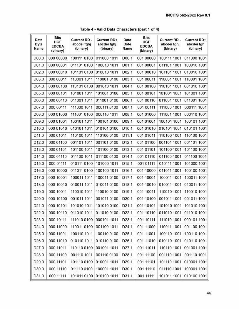
INCITS 562-20xx Rev 0.1
46
Table 4 - Valid Data Characters (part 1 of 4)
Data Byte
Name
BitsHGF
EDCBA (binary)
Current RD -abcdei fghj
(binary)
Current RD+abcdei fghj
(binary)
DataByte
Name
BitsHGF
EDCBA (binary)
Current RD -abcdei fghj
(binary)
Current RD+abcdei fgh
(binary)
D00.0 000 00000 100111 0100 011000 1011 D00.1 001 00000 100111 1001 011000 1001
D01.0 000 00001 011101 0100 100010 1011 D01.1 001 00001 011101 1001 100010 1001
D02.0 000 00010 101101 0100 010010 1011 D02.1 001 00010 101101 1001 010010 1001
D03.0 000 00011 110001 1011 110001 0100 D03.1 001 00011 110001 1001 110001 1001
D04.0 000 00100 110101 0100 001010 1011 D04.1 001 00100 110101 1001 001010 1001
D05.0 000 00101 101001 1011 101001 0100 D05.1 001 00101 101001 1001 101001 1001
D06.0 000 00110 011001 1011 011001 0100 D06.1 001 00110 011001 1001 011001 1001
D07.0 000 00111 111000 1011 000111 0100 D07.1 001 00111 111000 1001 000111 1001
D08.0 000 01000 111001 0100 000110 1011 D08.1 001 01000 111001 1001 000110 1001
D09.0 000 01001 100101 1011 100101 0100 D09.1 001 01001 100101 1001 100101 1001
D10.0 000 01010 010101 1011 010101 0100 D10.1 001 01010 010101 1001 010101 1001
D11.0 000 01011 110100 1011 110100 0100 D11.1 001 01011 110100 1001 110100 1001
D12.0 000 01100 001101 1011 001101 0100 D12.1 001 01100 001101 1001 001101 1001
D13.0 000 01101 101100 1011 101100 0100 D13.1 001 01101 101100 1001 101100 1001
D14.0 000 01110 011100 1011 011100 0100 D14.1 001 01110 011100 1001 011100 1001
D15.0 000 01111 010111 0100 101000 1011 D15.1 001 01111 010111 1001 101000 1001
D16.0 000 10000 011011 0100 100100 1011 D16.1 001 10000 011011 1001 100100 1001
D17.0 000 10001 100011 1011 100011 0100 D17.1 001 10001 100011 1001 100011 1001
D18.0 000 10010 010011 1011 010011 0100 D18.1 001 10010 010011 1001 010011 1001
D19.0 000 10011 110010 1011 110010 0100 D19.1 001 10011 110010 1001 110010 1001
D20.0 000 10100 001011 1011 001011 0100 D20.1 001 10100 001011 1001 001011 1001
D21.0 000 10101 101010 1011 101010 0100 D21.1 001 10101 101010 1001 101010 1001
D22.0 000 10110 011010 1011 011010 0100 D22.1 001 10110 011010 1001 011010 1001
D23.0 000 10111 111010 0100 000101 1011 D23.1 001 10111 111010 1001 000101 1001
D24.0 000 11000 110011 0100 001100 1011 D24.1 001 11000 110011 1001 001100 1001
D25.0 000 11001 100110 1011 100110 0100 D25.1 001 11001 100110 1001 100110 1001
D26.0 000 11010 010110 1011 010110 0100 D26.1 001 11010 010110 1001 010110 1001
D27.0 000 11011 110110 0100 001001 1011 D27.1 001 11011 110110 1001 001001 1001
D28.0 000 11100 001110 1011 001110 0100 D28.1 001 11100 001110 1001 001110 1001
D29.0 000 11101 101110 0100 010001 1011 D29.1 001 11101 101110 1001 010001 1001
D30.0 000 11110 011110 0100 100001 1011 D30.1 001 11110 011110 1001 100001 1001
D31.0 000 11111 101011 0100 010100 1011 D31.1 001 11111 101011 1001 010100 1001
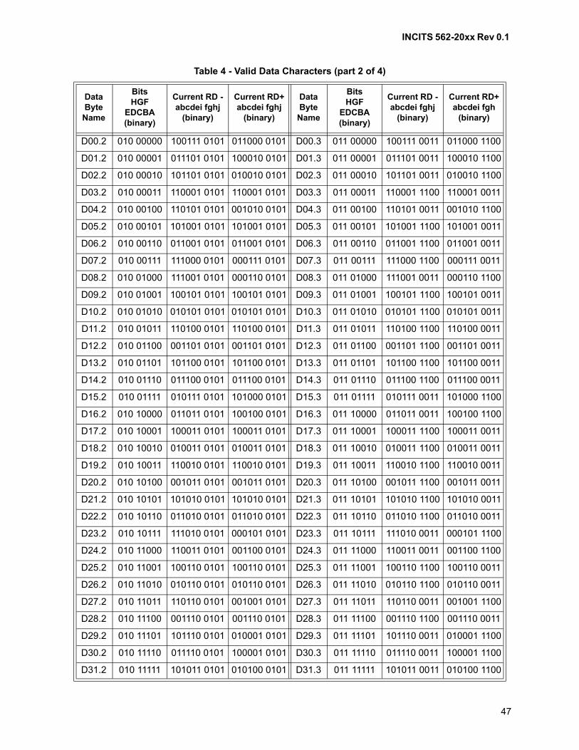
INCITS 562-20xx Rev 0.1
47
D00.2 010 00000 100111 0101 011000 0101 D00.3 011 00000 100111 0011 011000 1100
D01.2 010 00001 011101 0101 100010 0101 D01.3 011 00001 011101 0011 100010 1100
D02.2 010 00010 101101 0101 010010 0101 D02.3 011 00010 101101 0011 010010 1100
D03.2 010 00011 110001 0101 110001 0101 D03.3 011 00011 110001 1100 110001 0011
D04.2 010 00100 110101 0101 001010 0101 D04.3 011 00100 110101 0011 001010 1100
D05.2 010 00101 101001 0101 101001 0101 D05.3 011 00101 101001 1100 101001 0011
D06.2 010 00110 011001 0101 011001 0101 D06.3 011 00110 011001 1100 011001 0011
D07.2 010 00111 111000 0101 000111 0101 D07.3 011 00111 111000 1100 000111 0011
D08.2 010 01000 111001 0101 000110 0101 D08.3 011 01000 111001 0011 000110 1100
D09.2 010 01001 100101 0101 100101 0101 D09.3 011 01001 100101 1100 100101 0011
D10.2 010 01010 010101 0101 010101 0101 D10.3 011 01010 010101 1100 010101 0011
D11.2 010 01011 110100 0101 110100 0101 D11.3 011 01011 110100 1100 110100 0011
D12.2 010 01100 001101 0101 001101 0101 D12.3 011 01100 001101 1100 001101 0011
D13.2 010 01101 101100 0101 101100 0101 D13.3 011 01101 101100 1100 101100 0011
D14.2 010 01110 011100 0101 011100 0101 D14.3 011 01110 011100 1100 011100 0011
D15.2 010 01111 010111 0101 101000 0101 D15.3 011 01111 010111 0011 101000 1100
D16.2 010 10000 011011 0101 100100 0101 D16.3 011 10000 011011 0011 100100 1100
D17.2 010 10001 100011 0101 100011 0101 D17.3 011 10001 100011 1100 100011 0011
D18.2 010 10010 010011 0101 010011 0101 D18.3 011 10010 010011 1100 010011 0011
D19.2 010 10011 110010 0101 110010 0101 D19.3 011 10011 110010 1100 110010 0011
D20.2 010 10100 001011 0101 001011 0101 D20.3 011 10100 001011 1100 001011 0011
D21.2 010 10101 101010 0101 101010 0101 D21.3 011 10101 101010 1100 101010 0011
D22.2 010 10110 011010 0101 011010 0101 D22.3 011 10110 011010 1100 011010 0011
D23.2 010 10111 111010 0101 000101 0101 D23.3 011 10111 111010 0011 000101 1100
D24.2 010 11000 110011 0101 001100 0101 D24.3 011 11000 110011 0011 001100 1100
D25.2 010 11001 100110 0101 100110 0101 D25.3 011 11001 100110 1100 100110 0011
D26.2 010 11010 010110 0101 010110 0101 D26.3 011 11010 010110 1100 010110 0011
D27.2 010 11011 110110 0101 001001 0101 D27.3 011 11011 110110 0011 001001 1100
D28.2 010 11100 001110 0101 001110 0101 D28.3 011 11100 001110 1100 001110 0011
D29.2 010 11101 101110 0101 010001 0101 D29.3 011 11101 101110 0011 010001 1100
D30.2 010 11110 011110 0101 100001 0101 D30.3 011 11110 011110 0011 100001 1100
D31.2 010 11111 101011 0101 010100 0101 D31.3 011 11111 101011 0011 010100 1100
Table 4 - Valid Data Characters (part 2 of 4)
Data Byte
Name
BitsHGF
EDCBA (binary)
Current RD -abcdei fghj
(binary)
Current RD+abcdei fghj
(binary)
DataByte
Name
BitsHGF
EDCBA (binary)
Current RD -abcdei fghj
(binary)
Current RD+abcdei fgh
(binary)

INCITS 562-20xx Rev 0.1
48
D00.4 100 00000 100111 0010 011000 1101 D00.5 101 00000 100111 1010 011000 1010
D01.4 100 00001 011101 0010 100010 1101 D01.5 101 00001 011101 1010 100010 1010
D02.4 100 00010 101101 0010 010010 1101 D02.5 101 00010 101101 1010 010010 1010
D03.4 100 00011 110001 1101 110001 0010 D03.5 101 00011 110001 1010 110001 1010
D04.4 100 00100 110101 0010 001010 1101 D04.5 101 00100 110101 1010 001010 1010
D05.4 100 00101 101001 1101 101001 0010 D05.5 101 00101 101001 1010 101001 1010
D06.4 100 00110 011001 1101 011001 0010 D06.5 101 00110 011001 1010 011001 1010
D07.4 100 00111 111000 1101 000111 0010 D07.5 101 00111 111000 1010 000111 1010
D08.4 100 01000 111001 0010 000110 1101 D08.5 101 01000 111001 1010 000110 1010
D09.4 100 01001 100101 1101 100101 0010 D09.5 101 01001 100101 1010 100101 1010
D10.4 100 01010 010101 1101 010101 0010 D10.5 101 01010 010101 1010 010101 1010
D11.4 100 01011 110100 1101 110100 0010 D11.5 101 01011 110100 1010 110100 1010
D12.4 100 01100 001101 1101 001101 0010 D12.5 101 01100 001101 1010 001101 1010
D13.4 100 01101 101100 1101 101100 0010 D13.5 101 01101 101100 1010 101100 1010
D14.4 100 01110 011100 1101 011100 0010 D14.5 101 01110 011100 1010 011100 1010
D15.4 100 01111 010111 0010 101000 1101 D15.5 101 01111 010111 1010 101000 1010
D16.4 100 10000 011011 0010 100100 1101 D16.5 101 10000 011011 1010 100100 1010
D17.4 100 10001 100011 1101 100011 0010 D17.5 101 10001 100011 1010 100011 1010
D18.4 100 10010 010011 1101 010011 0010 D18.5 101 10010 010011 1010 010011 1010
D19.4 100 10011 110010 1101 110010 0010 D19.5 101 10011 110010 1010 110010 1010
D20.4 100 10100 001011 1101 001011 0010 D20.5 101 10100 001011 1010 001011 1010
D21.4 100 10101 101010 1101 101010 0010 D21.5 101 10101 101010 1010 101010 1010
D22.4 100 10110 011010 1101 011010 0010 D22.5 101 10110 011010 1010 011010 1010
D23.4 100 10111 111010 0010 000101 1101 D23.5 101 10111 111010 1010 000101 1010
D24.4 100 11000 110011 0010 001100 1101 D24.5 101 11000 110011 1010 001100 1010
D25.4 100 11001 100110 1101 100110 0010 D25.5 101 11001 100110 1010 100110 1010
D26.4 100 11010 010110 1101 010110 0010 D26.5 101 11010 010110 1010 010110 1010
D27.4 100 11011 110110 0010 001001 1101 D27.5 101 11011 110110 1010 001001 1010
D28.4 100 11100 001110 1101 001110 0010 D28.5 101 11100 001110 1010 001110 1010
D29.4 100 11101 101110 0010 010001 1101 D29.5 101 11101 101110 1010 010001 1010
D30.4 100 11110 011110 0010 100001 1101 D30.5 101 11110 011110 1010 100001 1010
D31.4 100 11111 101011 0010 010100 1101 D31.5 101 11111 101011 1010 010100 1010
Table 4 - Valid Data Characters (part 3 of 4)
Data Byte
Name
BitsHGF
EDCBA (binary)
Current RD -abcdei fghj
(binary)
Current RD+abcdei fghj
(binary)
DataByte
Name
BitsHGF
EDCBA (binary)
Current RD -abcdei fghj
(binary)
Current RD+abcdei fgh
(binary)

INCITS 562-20xx Rev 0.1
49
D00.6 110 00000 100111 0110 011000 0110 D00.7 111 00000 100111 0001 011000 1110
D01.6 110 00001 011101 0110 100010 0110 D01.7 111 00001 011101 0001 100010 1110
D02.6 110 00010 101101 0110 010010 0110 D02.7 111 00010 101101 0001 010010 1110
D03.6 110 00011 110001 0110 110001 0110 D03.7 111 00011 110001 1110 110001 0001
D04.6 110 00100 110101 0110 001010 0110 D04.7 111 00100 110101 0001 001010 1110
D05.6 110 00101 101001 0110 101001 0110 D05.7 111 00101 101001 1110 101001 0001
D06.6 110 00110 011001 0110 011001 0110 D06.7 111 00110 011001 1110 011001 0001
D07.6 110 00111 111000 0110 000111 0110 D07.7 111 00111 111000 1110 000111 0001
D08.6 110 01000 111001 0110 000110 0110 D08.7 111 01000 111001 0001 000110 1110
D09.6 110 01001 100101 0110 100101 0110 D09.7 111 01001 100101 1110 100101 0001
D10.6 110 01010 010101 0110 010101 0110 D10.7 111 01010 010101 1110 010101 0001
D11.6 110 01011 110100 0110 110100 0110 D11.7 111 01011 110100 1110 110100 1000
D12.6 110 01100 001101 0110 001101 0110 D12.7 111 01100 001101 1110 001101 0001
D13.6 110 01101 101100 0110 101100 0110 D13.7 111 01101 101100 1110 101100 1000
D14.6 110 01110 011100 0110 011100 0110 D14.7 111 01110 011100 1110 011100 1000
D15.6 110 01111 010111 0110 101000 0110 D15.7 111 01111 010111 0001 101000 1110
D16.6 110 10000 011011 0110 100100 0110 D16.7 111 10000 011011 0001 100100 1110
D17.6 110 10001 100011 0110 100011 0110 D17.7 111 10001 100011 0111 100011 0001
D18.6 110 10010 010011 0110 010011 0110 D18.7 111 10010 010011 0111 010011 0001
D19.6 110 10011 110010 0110 110010 0110 D19.7 111 10011 110010 1110 110010 0001
D20.6 110 10100 001011 0110 001011 0110 D20.7 111 10100 001011 0111 001011 0001
D21.6 110 10101 101010 0110 101010 0110 D21.7 111 10101 101010 1110 101010 0001
D22.6 110 10110 011010 0110 011010 0110 D22.7 111 10110 011010 1110 011010 0001
D23.6 110 10111 111010 0110 000101 0110 D23.7 111 10111 111010 0001 000101 1110
D24.6 110 11000 110011 0110 001100 0110 D24.7 111 11000 110011 0001 001100 1110
D25.6 110 11001 100110 0110 100110 0110 D25.7 111 11001 100110 1110 100110 0001
D26.6 110 11010 010110 0110 010110 0110 D26.7 111 11010 010110 1110 010110 0001
D27.6 110 11011 110110 0110 001001 0110 D27.7 111 11011 110110 0001 001001 1110
D28.6 110 11100 001110 0110 001110 0110 D28.7 111 11100 001110 1110 001110 0001
D29.6 110 11101 101110 0110 010001 0110 D29.7 111 11101 101110 0001 010001 1110
D30.6 110 11110 011110 0110 100001 0110 D30.7 111 11110 011110 0001 100001 1110
D31.6 110 11111 101011 0110 010100 0110 D31.7 111 11111 101011 0001 010100 1110
Table 4 - Valid Data Characters (part 4 of 4)
Data Byte
Name
BitsHGF
EDCBA (binary)
Current RD -abcdei fghj
(binary)
Current RD+abcdei fghj
(binary)
DataByte
Name
BitsHGF
EDCBA (binary)
Current RD -abcdei fghj
(binary)
Current RD+abcdei fgh
(binary)
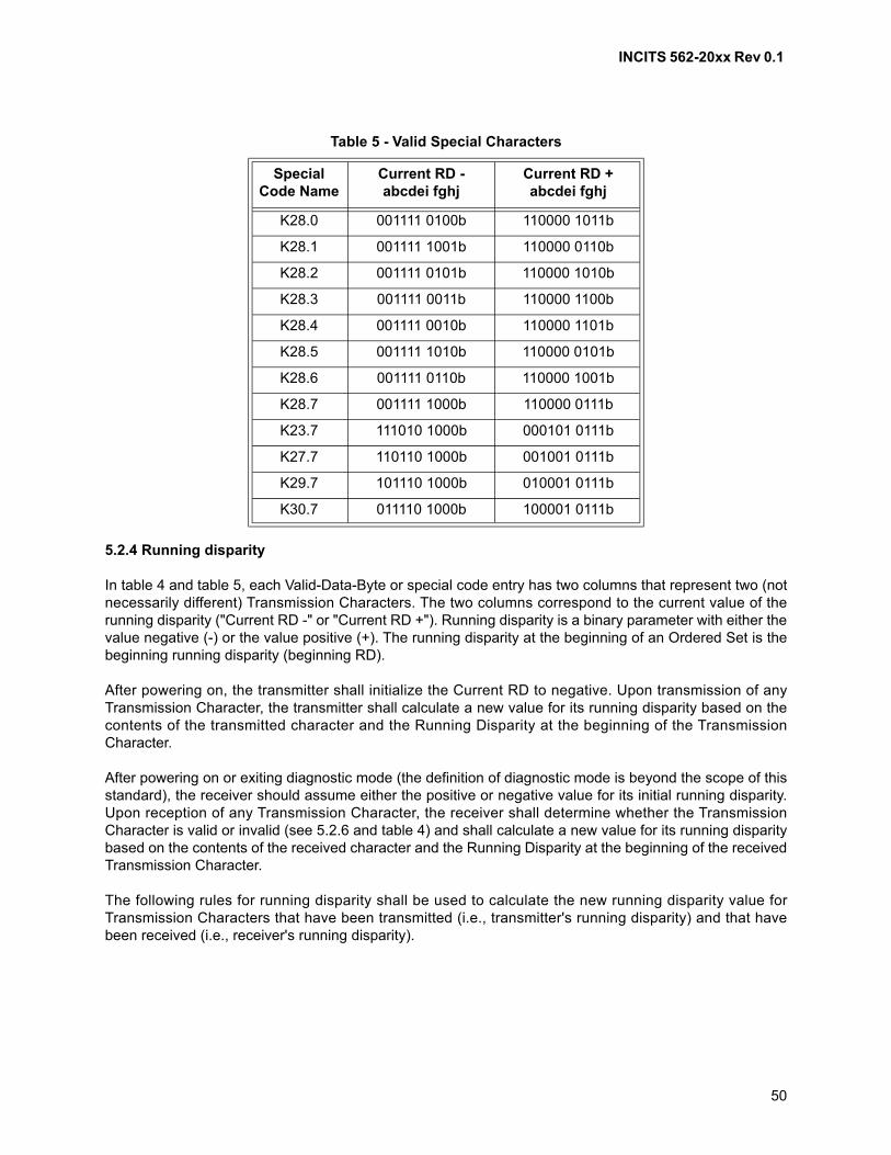
INCITS 562-20xx Rev 0.1
50
5.2.4 Running disparity
In table 4 and table 5, each Valid-Data-Byte or special code entry has two columns that represent two (notnecessarily different) Transmission Characters. The two columns correspond to the current value of therunning disparity ("Current RD -" or "Current RD +"). Running disparity is a binary parameter with either thevalue negative (-) or the value positive (+). The running disparity at the beginning of an Ordered Set is thebeginning running disparity (beginning RD).
After powering on, the transmitter shall initialize the Current RD to negative. Upon transmission of anyTransmission Character, the transmitter shall calculate a new value for its running disparity based on thecontents of the transmitted character and the Running Disparity at the beginning of the TransmissionCharacter.
After powering on or exiting diagnostic mode (the definition of diagnostic mode is beyond the scope of thisstandard), the receiver should assume either the positive or negative value for its initial running disparity.Upon reception of any Transmission Character, the receiver shall determine whether the TransmissionCharacter is valid or invalid (see 5.2.6 and table 4) and shall calculate a new value for its running disparitybased on the contents of the received character and the Running Disparity at the beginning of the receivedTransmission Character.
The following rules for running disparity shall be used to calculate the new running disparity value forTransmission Characters that have been transmitted (i.e., transmitter's running disparity) and that havebeen received (i.e., receiver's running disparity).
Table 5 - Valid Special Characters
SpecialCode Name
Current RD -abcdei fghj
Current RD +abcdei fghj
K28.0 001111 0100b 110000 1011b
K28.1 001111 1001b 110000 0110b
K28.2 001111 0101b 110000 1010b
K28.3 001111 0011b 110000 1100b
K28.4 001111 0010b 110000 1101b
K28.5 001111 1010b 110000 0101b
K28.6 001111 0110b 110000 1001b
K28.7 001111 1000b 110000 0111b
K23.7 111010 1000b 000101 0111b
K27.7 110110 1000b 001001 0111b
K29.7 101110 1000b 010001 0111b
K30.7 011110 1000b 100001 0111b
INCITS 562-20xx Rev 0.1
51
Running disparity for a Transmission Character shall be calculated on the basis of sub-blocks, where thefirst six bits (i.e., abcdei) form one sub-block (i.e., six-bit sub-block) and the second four bits (i.e., fghj) formthe other sub-block (i.e., four-bit sub-block). Running disparity at the beginning of the six-bit sub-block isthe running disparity at the end of the last Transmission Character. Running disparity at the beginning ofthe four-bit sub-block is the running disparity at the end of the six-bit sub-block. Running disparity at theend of the Transmission Character is the running disparity at the end of the four-bit sub-block.
Running disparity for the sub-blocks shall be calculated as follows:
a) running disparity at the end of any sub-block is positive:
A) if the sub-block contains more ones than zeros;
B) if at the end of the six-bit sub-block, the six-bit sub-block is 000111b; or
C) if at the end of the four-bit sub-block, the four-bit sub-block is 0011b;
b) running disparity at the end of any sub-block is negative:
A) if the sub-block contains more zeros than ones;
B) if at the end of the six-bit sub-block, the six-bit sub-block is 111000b; or
C) if at the end of the four-bit sub-block, the four-bit sub-block is 1100b;
or
c) otherwise, running disparity at the end of the sub-block is the same as at the beginning of thesub-block.
All sub-blocks with equal numbers of zeros and ones are disparity neutral. In order to limit the run length ofzeros or ones between sub-blocks, the 8B/10B transmission code rules specify that sub-blocks encodedas 000111b or 0011b are generated only when the running disparity at the beginning of the sub-block ispositive; thus, running disparity at the end of these sub-blocks shall also be positive. Likewise, sub-blockscontaining 111000b or 1100b are generated only when the running disparity at the beginning of thesub-block is negative; thus, running disparity at the end of these sub-blocks shall also be negative.
5.2.5 Generating Transmission Characters
The appropriate entry in the table shall be found for the data byte or special code used in generating(encoding) a Transmission Character. The current value of the transmitter's running disparity shall be usedto select the Transmission Character from its corresponding column. For each Transmission Charactertransmitted, a new value of the running disparity shall be calculated. This new value shall be used as thetransmitter's current running disparity for the next data byte or special code to be encoded and transmitted.
5.2.6 Validity of received Transmission Characters
The column corresponding to the current value of the receiver's running disparity shall be searched for thereceived Transmission Character. If the received Transmission Character is found in the proper column,then the Transmission Character shall be considered valid and the associated data byte or special codedetermined (decoded). If the received Transmission Character is not found in that column, then theTransmission Character shall be considered invalid and a code violation detected and reported to itsassociated port. Independent of the Transmission Character's validity, the received TransmissionCharacter shall be used to calculate a new value of running disparity. This new value shall be used as thereceiver's current running disparity for the next received Transmission Character.
Detection of a code violation does not necessarily indicate that the Transmission Character where thecode violation was detected is in error. Code violations may result from a prior error that altered the runningdisparity of the bit stream but that did not result in a detectable error at the Transmission Character wherethe error occurred. The example shown in table 6 exhibits this behavior.
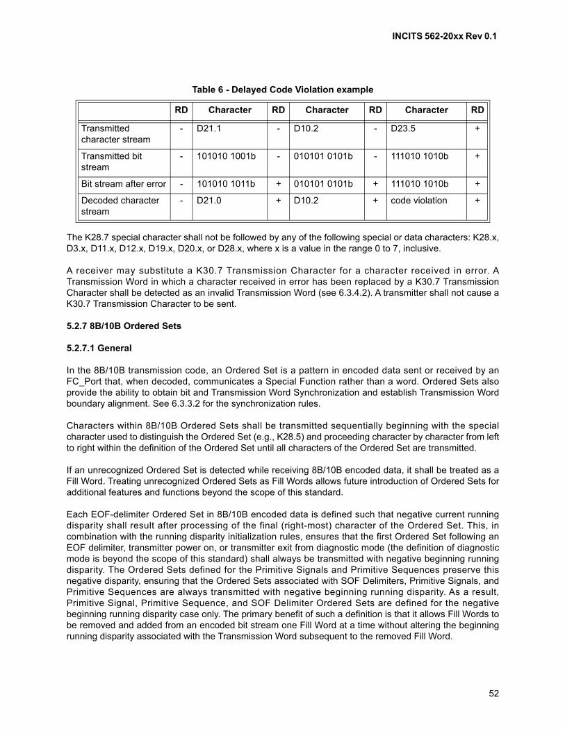
INCITS 562-20xx Rev 0.1
52
The K28.7 special character shall not be followed by any of the following special or data characters: K28.x,D3.x, D11.x, D12.x, D19.x, D20.x, or D28.x, where x is a value in the range 0 to 7, inclusive.
A receiver may substitute a K30.7 Transmission Character for a character received in error. ATransmission Word in which a character received in error has been replaced by a K30.7 TransmissionCharacter shall be detected as an invalid Transmission Word (see 6.3.4.2). A transmitter shall not cause aK30.7 Transmission Character to be sent.
5.2.7 8B/10B Ordered Sets
5.2.7.1 General
In the 8B/10B transmission code, an Ordered Set is a pattern in encoded data sent or received by anFC_Port that, when decoded, communicates a Special Function rather than a word. Ordered Sets alsoprovide the ability to obtain bit and Transmission Word Synchronization and establish Transmission Wordboundary alignment. See 6.3.3.2 for the synchronization rules.
Characters within 8B/10B Ordered Sets shall be transmitted sequentially beginning with the specialcharacter used to distinguish the Ordered Set (e.g., K28.5) and proceeding character by character from leftto right within the definition of the Ordered Set until all characters of the Ordered Set are transmitted.
If an unrecognized Ordered Set is detected while receiving 8B/10B encoded data, it shall be treated as aFill Word. Treating unrecognized Ordered Sets as Fill Words allows future introduction of Ordered Sets foradditional features and functions beyond the scope of this standard.
Each EOF-delimiter Ordered Set in 8B/10B encoded data is defined such that negative current runningdisparity shall result after processing of the final (right-most) character of the Ordered Set. This, incombination with the running disparity initialization rules, ensures that the first Ordered Set following anEOF delimiter, transmitter power on, or transmitter exit from diagnostic mode (the definition of diagnosticmode is beyond the scope of this standard) shall always be transmitted with negative beginning runningdisparity. The Ordered Sets defined for the Primitive Signals and Primitive Sequences preserve thisnegative disparity, ensuring that the Ordered Sets associated with SOF Delimiters, Primitive Signals, andPrimitive Sequences are always transmitted with negative beginning running disparity. As a result,Primitive Signal, Primitive Sequence, and SOF Delimiter Ordered Sets are defined for the negativebeginning running disparity case only. The primary benefit of such a definition is that it allows Fill Words tobe removed and added from an encoded bit stream one Fill Word at a time without altering the beginningrunning disparity associated with the Transmission Word subsequent to the removed Fill Word.
Table 6 - Delayed Code Violation example
RD Character RD Character RD Character RD
Transmitted character stream
- D21.1 - D10.2 - D23.5 +
Transmitted bit stream
- 101010 1001b - 010101 0101b - 111010 1010b +
Bit stream after error - 101010 1011b + 010101 0101b + 111010 1010b +
Decoded characterstream
- D21.0 + D10.2 + code violation +

INCITS 562-20xx Rev 0.1
53
The K28.5 special character is used as the first character of all 8B/10B Ordered Sets defined in thisstandard for the following reasons:
a) bits abcdeif make up a comma; this is a singular bit pattern that in the absence of transmissionerrors shall not appear in any other location of a Transmission Character and shall not begenerated across the boundaries of any two adjacent Transmission Characters. The commashould be used to easily find and verify Transmission Character and Transmission Wordboundaries of the received bit stream; and
b) bits ghj of the encoded character present the maximum number of transitions, simplifying receiveracquisition of Bit Synchronization.
The second character of the Ordered Sets used to represent 8B/10B EOF Delimiters differentiatesbetween normal and invalid frames. It also ensures that the running disparity resulting after processing ofan EOF Ordered Set is negative independent of the value of beginning running disparity. Link_Reset (LR)and Link_Reset_Response (LRR) Ordered Sets are also differentiated through the use of their secondcharacters.
The third and fourth characters of the Delimiter functions, Receiver_Ready, and the Fill Words arerepeated to ensure that an error affecting a single character shall not result in the recognition of anOrdered Set other than the one transmitted.
For some Primitive Signals and Primitive Sequences, the second byte of the Ordered Set specifies thefunction of the Ordered Set. Bytes 3 and 4 of the Ordered Set are used to carry parameter information. Thereceiving FC_Ports analyze the parameter information before taking any action.
5.2.7.2 8B/10B Frame delimiters
A frame delimiter is represented by an Ordered Set that immediately precedes or follows the contents of aframe. Separate and distinct Ordered Sets shall identify the start of a frame and the end of a frame andshall be recognized when a single Ordered Set is detected. The Ordered Sets used to represent framedelimiters are listed in table 7. See 11.3.7 and 11.3.8 for the usage of each.
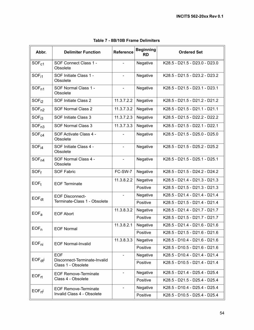
INCITS 562-20xx Rev 0.1
54
Table 7 - 8B/10B Frame Delimiters
Abbr. Delimiter Function ReferenceBeginning
RDOrdered Set
SOFc1 SOF Connect Class 1 - Obsolete
- Negative K28.5 - D21.5 - D23.0 - D23.0
SOFi1 SOF Initiate Class 1 - Obsolete
- Negative K28.5 - D21.5 - D23.2 - D23.2
SOFn1 SOF Normal Class 1 - Obsolete
- Negative K28.5 - D21.5 - D23.1 - D23.1
SOFi2 SOF Initiate Class 2 11.3.7.2.2 Negative K28.5 - D21.5 - D21.2 - D21.2
SOFn2 SOF Normal Class 2 11.3.7.3.2 Negative K28.5 - D21.5 - D21.1 - D21.1
SOFi3 SOF Initiate Class 3 11.3.7.2.3 Negative K28.5 - D21.5 - D22.2 - D22.2
SOFn3 SOF Normal Class 3 11.3.7.3.3 Negative K28.5 - D21.5 - D22.1 - D22.1
SOFc4 SOF Activate Class 4 - Obsolete
- Negative K28.5 - D21.5 - D25.0 - D25.0
SOFi4 SOF Initiate Class 4 - Obsolete
- Negative K28.5 - D21.5 - D25.2 - D25.2
SOFn4 SOF Normal Class 4 - Obsolete
- Negative K28.5 - D21.5 - D25.1 - D25.1
SOFf SOF Fabric FC-SW-7 Negative K28.5 - D21.5 - D24.2 - D24.2
EOFt EOF Terminate11.3.8.2.2 Negative K28.5 - D21.4 - D21.3 - D21.3
Positive K28.5 - D21.5 - D21.3 - D21.3
EOFdtEOF Disconnect- Terminate-Class 1 - Obsolete
- Negative K28.5 - D21.4 - D21.4 - D21.4
Positive K28.5 - D21.5 - D21.4 - D21.4
EOFa EOF Abort11.3.8.3.2 Negative K28.5 - D21.4 - D21.7 - D21.7
Positive K28.5 - D21.5 - D21.7 - D21.7
EOFn EOF Normal11.3.8.2.1 Negative K28.5 - D21.4 - D21.6 - D21.6
Positive K28.5 - D21.5 - D21.6 - D21.6
EOFni EOF Normal-Invalid11.3.8.3.3 Negative K28.5 - D10.4 - D21.6 - D21.6
Positive K28.5 - D10.5 - D21.6 - D21.6
EOFdtiEOF Disconnect-Terminate-Invalid Class 1 - Obsolete
- Negative K28.5 - D10.4 - D21.4 - D21.4
Positive K28.5 - D10.5 - D21.4 - D21.4
EOFrtEOF Remove-Terminate Class 4 - Obsolete
- Negative K28.5 - D21.4 - D25.4 - D25.4
Positive K28.5 - D21.5 - D25.4 - D25.4
EOFrtiEOF Remove-Terminate Invalid Class 4 - Obsolete
- Negative K28.5 - D10.4 - D25.4 - D25.4
Positive K28.5 - D10.5 - D25.4 - D25.4
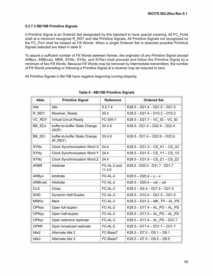
INCITS 562-20xx Rev 0.1
55
5.2.7.3 8B/10B Primitive Signals
A Primitive Signal is an Ordered Set designated by this standard to have special meaning. All FC_Portsshall at a minimum recognize R_RDY and Idle Primitive Signals. All Primitive Signals not recognized bythe FC_Port shall be treated as Fill Words. When a single Ordered Set is detected possible PrimitiveSignals detected are listed in table 8.
To assure a sufficient number of Fill Words between frames, the originator of any Primitive Signal (exceptARByx, ARB(val), MRK, SYNx, SYNy, and SYNz) shall precede and follow the Primitive Signal by aminimum of two Fill Words. Because Fill Words may be removed by intermediate transmitters, the numberof Fill Words preceding or following a Primitive Signal at a receiver may be reduced to zero.
All Primitive Signals in 8b/10B have negative beginning running disparity.
Table 8 - 8B/10B Primitive Signals
Abbr. Primitive Signal Reference Ordered Set
Idle Idle 5.2.7.4 K28.5 – D21.4 – D21.5 – D21.5
R_RDY Receiver_Ready 20.4 K28.5 – D21.4 – D10.2 – D10.2
VC_RDY Virtual Circuit Ready FC-SW-7 K28.5 – D21.7 – VC_ID – VC_ID
BB_SCs buffer-to-buffer State Change (SOF)
20.4.9 K28.5 - D21.4 – D22.4 – D22.4
BB_SCr buffer-to-buffer State Change (R_RDY)
20.4.9 K28.5 - D21.4 – D22.6 – D22.6
SYNx Clock Synchronization Word X 24.4 K28.5 – D31.3 – CS_X1 – CS_X2
SYNy Clock Synchronization Word Y 24.4 K28.5 – D31.5 – CS_Y1 – CS_Y2
SYNz Clock Synchronization Word Z 24.4 K28.5 – D31.6 – CS_Z1 – CS_Z2
ARBff Arbitrate FC-AL-2 and 11.3.5
K28.5 - D20.4 - D31.7 - D31.7
ARByx Arbitrate FC-AL-2 K28.5 – D20.4 – y – x
ARB(val) Arbitrate FC-AL-2 K28.5 – D20.4 – val – val
CLS Close FC-AL-2 K28.5 – D5.4 – D21.5 – D21.5
DHD Dynamic Half-Duplex FC-AL-2 K28.5 – D10.4 – D21.5 – D21.5
MRKtx Mark FC-AL-2 K28.5 – D31.2 – MK_TP – AL_PS
OPNyx Open full-duplex FC-AL-2 K28.5 – D17.4 – AL_PD – AL_PS
OPNyy Open half-duplex FC-AL-2 K28.5 – D17.4 – AL_PD – AL_PD
OPNyr Open selective replicate FC-AL-2 K28.5 – D17.4 – AL_PD – D31.7
OPNfr Open broadcast replicate FC-AL-2 K28.5 – D17.4 – D31.7 – D31.7
Idle2 Alternate Idle 2 FC-BaseT K28.5 – D7.0 – D9.1 – D9.1
Idle3 Alternate Idle 3 FC-BaseT K28.5 – D7.0 – D9.5 – D9.5
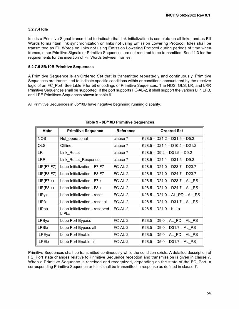
INCITS 562-20xx Rev 0.1
56
5.2.7.4 Idle
Idle is a Primitive Signal transmitted to indicate that link initialization is complete on all links, and as FillWords to maintain link synchronization on links not using Emission Lowering Protocol. Idles shall betransmitted as Fill Words on links not using Emission Lowering Protocol during periods of time whenframes, other Primitive Signals or Primitive Sequences are not required to be transmitted. See 11.3 for therequirements for the insertion of Fill Words between frames.
5.2.7.5 8B/10B Primitive Sequences
A Primitive Sequence is an Ordered Set that is transmitted repeatedly and continuously. PrimitiveSequences are transmitted to indicate specific conditions within or conditions encountered by the receiverlogic of an FC_Port. See table 9 for bit encodings of Primitive Sequences. The NOS, OLS, LR, and LRRPrimitive Sequences shall be supported. If the port supports FC-AL-2, it shall support the various LIP, LPB,and LPE Primitives Sequences shown in table 9.
All Primitive Sequences in 8b/10B have negative beginning running disparity.
Primitive Sequences shall be transmitted continuously while the condition exists. A detailed description ofFC_Port state changes relative to Primitive Sequence reception and transmission is given in clause 7.When a Primitive Sequence is received and recognized, depending on the state of the FC_Port, acorresponding Primitive Sequence or Idles shall be transmitted in response as defined in clause 7.
Table 9 - 8B/10B Primitive Sequences
Abbr Primitive Sequence Reference Ordered Set
NOS Not_operational clause 7 K28.5 – D21.2 – D31.5 – D5.2
OLS Offline clause 7 K28.5 – D21.1 – D10.4 – D21.2
LR Link_Reset clause 7 K28.5 – D9.2 – D31.5 – D9.2
LRR Link_Reset_Response clause 7 K28.5 – D21.1 – D31.5 – D9.2
LIP(F7,F7) Loop Initialization - F7,F7 FC-AL-2 K28.5 – D21.0 – D23.7 – D23.7
LIP(F8,F7) Loop Initialization - F8,F7 FC-AL-2 K28.5 – D21.0 – D24.7 – D23.7
LIP(F7,x) Loop Initialization - F7,x FC-AL-2 K28.5 – D21.0 – D23.7 – AL_PS
LIP(F8,x) Loop Initialization - F8,x FC-AL-2 K28.5 – D21.0 – D24.7 – AL_PS
LIPyx Loop Initialization - reset FC-AL-2 K28.5 – D21.0 – AL_PD – AL_PS
LIPfx Loop Initialization - reset all FC-AL-2 K28.5 – D21.0 – D31.7 – AL_PS
LIPba Loop Initialization - reserved LIPba
FC-AL-2 K28.5 – D21.0 – b – a
LPByx Loop Port Bypass FC-AL-2 K28.5 – D9.0 – AL_PD – AL_PS
LPBfx Loop Port Bypass all FC-AL-2 K28.5 – D9.0 – D31.7 – AL_PS
LPEyx Loop Port Enable FC-AL-2 K28.5 – D5.0 – AL_PD – AL_PS
LPEfx Loop Port Enable all FC-AL-2 K28.5 – D5.0 – D31.7 – AL_PS
INCITS 562-20xx Rev 0.1
57
A Primitive Sequence transmitted by an PN_Port shall be received and recognized by the locally attachedFx_Port, but not transmitted through the Fabric.
Recognition of a Primitive Sequence shall require consecutive detection of three instances of the sameOrdered Set without any intervening data indications from the receiver logic (FC-1).
5.3 64B/66B transmission code
5.3.1 Overview
An FC-0 standard (e.g., FC-PI-5) may specify the use of the 64B/66B transmission code as its frametransfer transmission code.
The 64B/66B transmission code specified by this standard treats a stream of words and Special Functionsin pairs, each pair being encoded as a 66-bit Transmission Word.
NOTE 1 - The IEEE 802.3-2015 specification of 64B/66B references as “blocks” what this standardreferences as “Transmission Words”.
A stream of 64B/66B Transmission Words on a link may be further encoded to provide Forward ErrorCorrection (i.e., FEC). The use of FEC is negotiated using the transmitter training (see 5.6). How anFC_Port determines to request use of FEC is not within the scope of this standard.
If the FC_Ports on a link determine to use FEC, the streams of 64B/66B Transmission Words in bothdirections on the link shall be encoded as specified in 5.3 and then further encoded as specified insubclause 74.7 and subclause 74.10 of IEEE 802.3-2015. If the FC_Ports on a link determine not to useFEC, the streams of 64B/66B Transmission Words in both directions on the link shall be encoded asspecified in 5.3.
5.3.2 64B/66B Transmission Word format
All 64B/66B Transmission Words consist of 66 bits. Transmission Words are either data TransmissionWords or control Transmission Words (see 5.3.5 and 5.3.6). The first two bits of a Transmission Word arethe synchronization header, and are set to either 01h or 10h. The remaining 64 bits of the TransmissionWord are the output of a scrambler (see 5.3.3) applied to the Transmission Word body. The TransmissionWord body is eight bytes that represent a pair of words and/or Special Functions. See figure 10.
NOTE 2 - The IEEE 802.3-2015 specification of 64B/66B references as “block payload” what thisstandard references as “Transmission Word body”.
Since the Transmission Word body is passed through the scrambler and the synchronization header is notpassed through the scrambler, the synchronization header is the only position in the Transmission Wordthat always contains a transition. This feature of the code is used to obtain Transmission WordSynchronization (see 6.4).
A 64B/66B Transmission Word shall be transmitted so that each bit in the Transmission Word istransmitted before all more significant bits in the Transmission Word.
NOTE 3 - The intention is that the resulting transmitted bit sequence for Fibre Channel 64B/66Btransmission coding is the same as 10GBASE-R PCS (see IEEE 802.3-2015 clause 49). IEEE802.3-2015 uses diagramming conventions that differ from those of this standard in certain ways: Lesssignificant bits within a byte are shown to the left of more significant bits, and bytes to be transmittedearlier are identified with less significant bits than bytes to be transmitted later. In order to providetransition from the conventions of this standard to the conventions of IEEE 802.3-2015, bit ordering
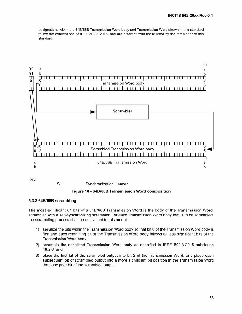
INCITS 562-20xx Rev 0.1
58
designations within the 64B/66B Transmission Word body and Transmission Word shown in this standardfollow the conventions of IEEE 802.3-2015, and are different from those used by the remainder of thisstandard.
5.3.3 64B/66B scrambling
The most significant 64 bits of a 64B/66B Transmission Word is the body of the Transmission Word,scrambled with a self-synchronizing scrambler. For each Transmission Word body that is to be scrambled,the scrambling process shall be equivalent to this model:
1) serialize the bits within the Transmission Word body so that bit 0 of the Transmission Word body isfirst and each remaining bit of the Transmission Word body follows all less significant bits of theTransmission Word body;
2) scramble the serialized Transmission Word body as specified in IEEE 802.3-2015 subclause49.2.6; and
3) place the first bit of the scrambled output into bit 2 of the Transmission Word, and place eachsubsequent bit of scrambled output into a more significant bit position in the Transmission Wordthan any prior bit of the scrambled output.
Key:SH: Synchronization Header
Figure 10 - 64B/66B Transmission Word composition
Transmission Word body00
63
00
01 Scrambled Transmission Word body
02
65
Scrambler
SH
00
01
lsb
msb
lsb
msb
64B/66B Transmission Word
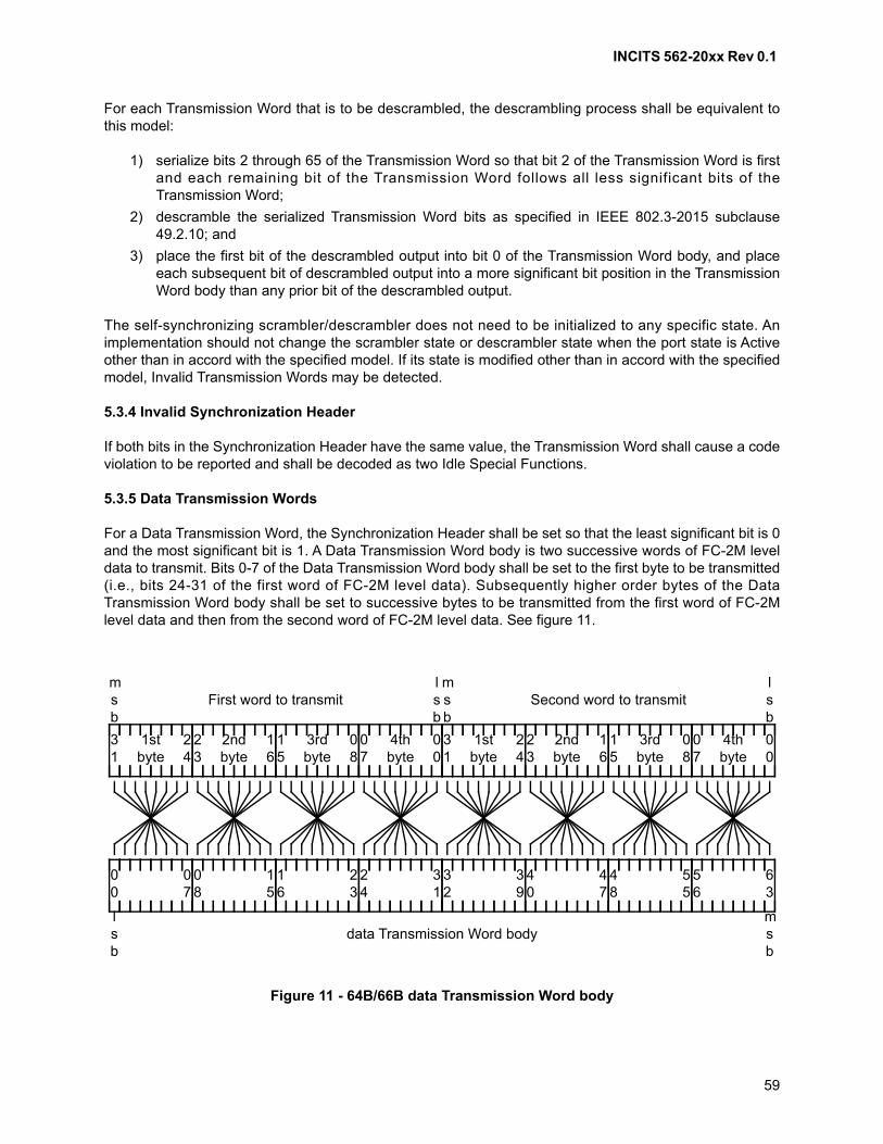
INCITS 562-20xx Rev 0.1
59
For each Transmission Word that is to be descrambled, the descrambling process shall be equivalent tothis model:
1) serialize bits 2 through 65 of the Transmission Word so that bit 2 of the Transmission Word is firstand each remaining bit of the Transmission Word follows all less significant bits of theTransmission Word;
2) descramble the serialized Transmission Word bits as specified in IEEE 802.3-2015 subclause49.2.10; and
3) place the first bit of the descrambled output into bit 0 of the Transmission Word body, and placeeach subsequent bit of descrambled output into a more significant bit position in the TransmissionWord body than any prior bit of the descrambled output.
The self-synchronizing scrambler/descrambler does not need to be initialized to any specific state. Animplementation should not change the scrambler state or descrambler state when the port state is Activeother than in accord with the specified model. If its state is modified other than in accord with the specifiedmodel, Invalid Transmission Words may be detected.
5.3.4 Invalid Synchronization Header
If both bits in the Synchronization Header have the same value, the Transmission Word shall cause a codeviolation to be reported and shall be decoded as two Idle Special Functions.
5.3.5 Data Transmission Words
For a Data Transmission Word, the Synchronization Header shall be set so that the least significant bit is 0and the most significant bit is 1. A Data Transmission Word body is two successive words of FC-2M leveldata to transmit. Bits 0-7 of the Data Transmission Word body shall be set to the first byte to be transmitted(i.e., bits 24-31 of the first word of FC-2M level data). Subsequently higher order bytes of the DataTransmission Word body shall be set to successive bytes to be transmitted from the first word of FC-2Mlevel data and then from the second word of FC-2M level data. See figure 11.
Figure 11 - 64B/66B data Transmission Word body
lsb
msb
data Transmission Word body
First word to transmitmsb
lsb
Second word to transmitmsb
lsb
00
07
08
15
16
23
24
31
32
39
40
47
48
55
56
63
1stbyte
31
24
2ndbyte
23
16
3rdbyte
15
08
4thbyte
07
00
1stbyte
31
24
2ndbyte
23
16
3rdbyte
15
08
4thbyte
07
00
INCITS 562-20xx Rev 0.1
60
5.3.6 Control Transmission Words
The Synchronization Header for all control Transmission Words shall be set so that the least significant bitis 1 and the most significant bit is 0. The body of a Control Transmission Word is either two SpecialFunctions or one Special Function and one word. The most significant byte of the body of a ControlTransmission Word is the Transmission Word type field. The Transmission Word type field indicates theformat of the remainder of the body of the Transmission Word. The Transmission Word type field shall beset to a value specified in table 10. If a Transmission Word type is decoded that is restricted in table 10, theTransmission Word shall cause a code violation to be reported and shall be decoded as two Idle SpecialFunctions.
For a control Transmission Word body that includes a representation of a frame delimiter Special Function(i.e., SOF Special Function or EOF Special Function), the Special Function is specified by theTransmission Word type field together with three modifier bytes (see table 13).
Idle Special Functions and receiver detected errors shall be represented as a series of four 7-bit controlcodes (see table 11). FC_Ports compliant with this standard shall not encode control codes other than thefollowing into a transmission word:
a) Idle (i.e., 00h), or
b) LPI (i.e., 06h), if the FC_Port supports Energy Efficient Fibre Channel.
If a control code value other than Idle or LPI if the FC_Port supports Energy Efficient Fibre Channel, isdecoded, the Transmission Word shall cause a code violation to be reported and the restricted controlcode shall be decoded as an Idle control code.
To communicate LPI Mode (see 10), the LPI control code (i.e., 06h) is sent in place of the Idle control code(i.e., 00h).
Table 10 - Valid 64B/66B Transmission Word type values
TransmissionWord type
valueTransmission Word content Reference
1Eh Idle or LPI Special Function followed by Idle or LPI Special Function; or Receiver Error
5.3.6.15.3.6.10
33h Idle Special Function followed by SOF Special Function 5.3.6.2
B4h EOF Special Function followed by Idle or LPI Special Function 5.3.6.3
2Dh Idle Special Function followed by other Special Function 5.3.6.4
4Bh Other Special Function followed by Idle Special Function 5.3.6.5
55h Other Special Function followed by other Special Function 5.3.6.6
66h Other Special Function followed by SOF Special Function 5.3.6.7
78h SOF Special Function followed by word of data 5.3.6.8
FFh Word of data followed by EOF Special Function 5.3.6.9
any other value Restricted for IEEE 802.3-2015, shall not be transmitted IEEE 802.3-2015
INCITS 562-20xx Rev 0.1
61
Other Special Functions shall be indicated by a 4-bit order code (see table 12) together with three modifierbytes (see table 14 and table 15). If a restricted order code value is decoded, the Special Function shallcause a code violation to be reported and shall be decoded as an Idle Special Function.
Table 11 - Valid control code values
Value(least significant
seven bits)Meaning Reference
00h Idle 5.3.7.2
06h LPI 10
1Eh Error. This code shall be used only for receiver error reporting (see 5.3.6.10)
5.3.6.10
any other value Restricted for IEEE 802.3-2015, shall not be transmitted IEEE 802.3-2015
Table 12 - Valid order code values
Value Ordered Set Reference
0h Primitive Sequence 5.3.7.3
Fh Primitive Signal 5.3.7.2
any other value Restricted for IEEE 802.3, shall not be transmitted IEEE 802.3-2015
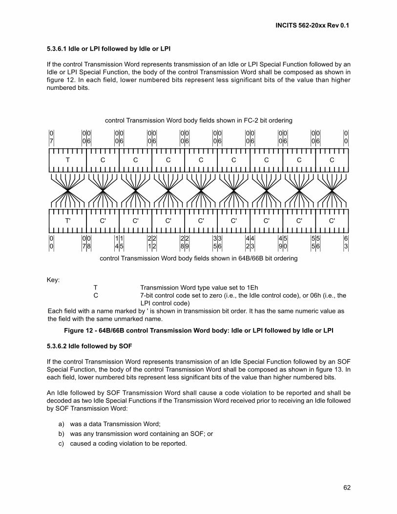
INCITS 562-20xx Rev 0.1
62
5.3.6.1 Idle or LPI followed by Idle or LPI
If the control Transmission Word represents transmission of an Idle or LPI Special Function followed by anIdle or LPI Special Function, the body of the control Transmission Word shall be composed as shown infigure 12. In each field, lower numbered bits represent less significant bits of the value than highernumbered bits.
5.3.6.2 Idle followed by SOF
If the control Transmission Word represents transmission of an Idle Special Function followed by an SOFSpecial Function, the body of the control Transmission Word shall be composed as shown in figure 13. Ineach field, lower numbered bits represent less significant bits of the value than higher numbered bits.
An Idle followed by SOF Transmission Word shall cause a code violation to be reported and shall bedecoded as two Idle Special Functions if the Transmission Word received prior to receiving an Idle followedby SOF Transmission Word:
a) was a data Transmission Word;
b) was any transmission word containing an SOF; or
c) caused a coding violation to be reported.
Key:T Transmission Word type value set to 1EhC 7-bit control code set to zero (i.e., the Idle control code), or 06h (i.e., the
LPI control code)Each field with a name marked by ' is shown in transmission bit order. It has the same numeric value as the field with the same unmarked name.
Figure 12 - 64B/66B control Transmission Word body: Idle or LPI followed by Idle or LPI
control Transmission Word body fields shown in 64B/66B bit ordering
T
control Transmission Word body fields shown in FC-2 bit ordering
00
06
00
07
C
14
08
C'T'
07
00
00
06
C
21
15
C'
00
06
C
28
22
C'
00
06
C
35
29
C'
00
06
C
42
36
C'
00
06
C
49
43
C'
00
06
C
55
50
C'
00
06
C
63
56
C'
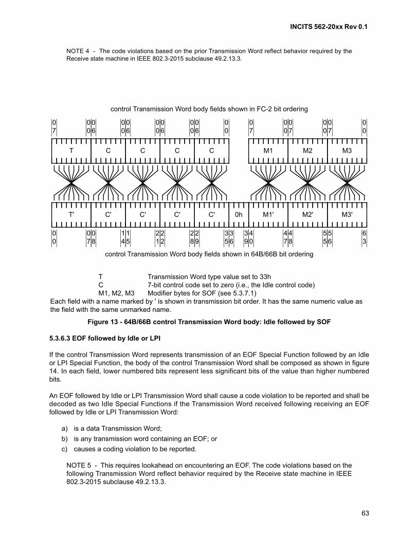
INCITS 562-20xx Rev 0.1
63
NOTE 4 - The code violations based on the prior Transmission Word reflect behavior required by theReceive state machine in IEEE 802.3-2015 subclause 49.2.13.3.
5.3.6.3 EOF followed by Idle or LPI
If the control Transmission Word represents transmission of an EOF Special Function followed by an Idleor LPI Special Function, the body of the control Transmission Word shall be composed as shown in figure14. In each field, lower numbered bits represent less significant bits of the value than higher numberedbits.
An EOF followed by Idle or LPI Transmission Word shall cause a code violation to be reported and shall bedecoded as two Idle Special Functions if the Transmission Word received following receiving an EOFfollowed by Idle or LPI Transmission Word:
a) is a data Transmission Word;
b) is any transmission word containing an EOF; or
c) causes a coding violation to be reported.
NOTE 5 - This requires lookahead on encountering an EOF. The code violations based on thefollowing Transmission Word reflect behavior required by the Receive state machine in IEEE802.3-2015 subclause 49.2.13.3.
T Transmission Word type value set to 33hC 7-bit control code set to zero (i.e., the Idle control code)M1, M2, M3 Modifier bytes for SOF (see 5.3.7.1)
Each field with a name marked by ' is shown in transmission bit order. It has the same numeric value as the field with the same unmarked name.
Figure 13 - 64B/66B control Transmission Word body: Idle followed by SOF
control Transmission Word body fields shown in 64B/66B bit ordering
T
control Transmission Word body fields shown in FC-2 bit ordering
00
06
00
07
C
14
08
C'T'
07
00
00
06
C
21
15
C'
00
06
C
28
22
C'
00
06
C
35
29
C'
M1
00
07
M1'
47
40
M2
00
07
M2'
55
48
M3
00
07
M3'
63
56
39
36
0h
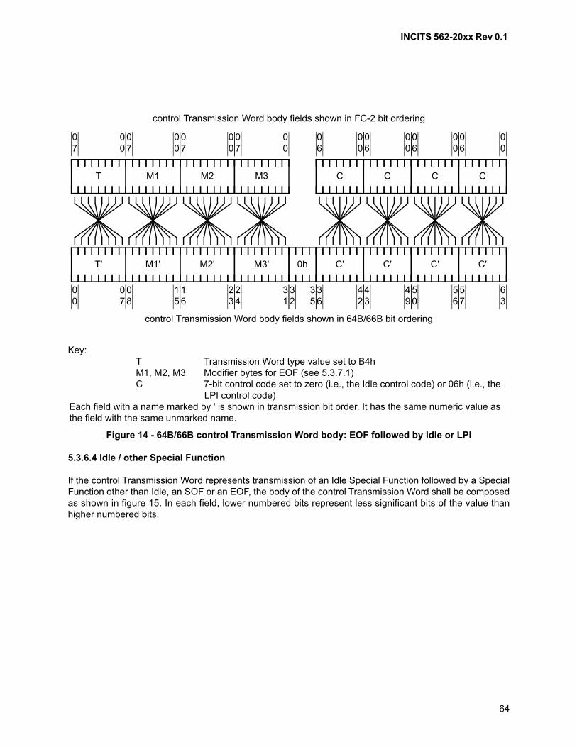
INCITS 562-20xx Rev 0.1
64
5.3.6.4 Idle / other Special Function
If the control Transmission Word represents transmission of an Idle Special Function followed by a SpecialFunction other than Idle, an SOF or an EOF, the body of the control Transmission Word shall be composedas shown in figure 15. In each field, lower numbered bits represent less significant bits of the value thanhigher numbered bits.
Key:T Transmission Word type value set to B4hM1, M2, M3 Modifier bytes for EOF (see 5.3.7.1)C 7-bit control code set to zero (i.e., the Idle control code) or 06h (i.e., the
LPI control code)Each field with a name marked by ' is shown in transmission bit order. It has the same numeric value as the field with the same unmarked name.
Figure 14 - 64B/66B control Transmission Word body: EOF followed by Idle or LPI
control Transmission Word body fields shown in 64B/66B bit ordering
T
control Transmission Word body fields shown in FC-2 bit ordering
00
07
T'
07
00
M1
00
07
M1'
15
08
M2
00
07
M2'
23
16
M3
00
07
M3'
31
24
35
32
0h
00
06
C
42
36
C'
00
06
C
49
43
C'
00
06
C
56
50
C'
00
06
C
63
57
C'
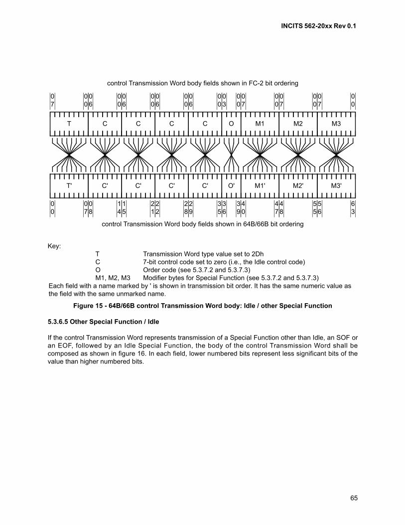
INCITS 562-20xx Rev 0.1
65
5.3.6.5 Other Special Function / Idle
If the control Transmission Word represents transmission of a Special Function other than Idle, an SOF oran EOF, followed by an Idle Special Function, the body of the control Transmission Word shall becomposed as shown in figure 16. In each field, lower numbered bits represent less significant bits of thevalue than higher numbered bits.
Key:T Transmission Word type value set to 2DhC 7-bit control code set to zero (i.e., the Idle control code)O Order code (see 5.3.7.2 and 5.3.7.3)M1, M2, M3 Modifier bytes for Special Function (see 5.3.7.2 and 5.3.7.3)
Each field with a name marked by ' is shown in transmission bit order. It has the same numeric value as the field with the same unmarked name.
Figure 15 - 64B/66B control Transmission Word body: Idle / other Special Function
control Transmission Word body fields shown in 64B/66B bit ordering
T
control Transmission Word body fields shown in FC-2 bit ordering
00
06
00
07
C
14
08
C'T'
07
00
00
06
C
21
15
C'
00
06
C
28
22
C'
00
06
C
35
29
C'
M1
00
07
M1'
47
40
M2
00
07
M2'
55
48
M3
00
07
M3'
63
56
00
03
O
39
36
O'
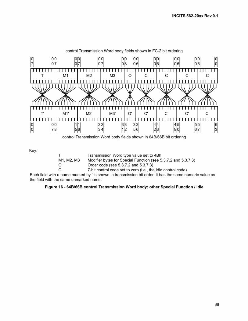
INCITS 562-20xx Rev 0.1
66
Key:T Transmission Word type value set to 4BhM1, M2, M3 Modifier bytes for Special Function (see 5.3.7.2 and 5.3.7.3)O Order code (see 5.3.7.2 and 5.3.7.3)C 7-bit control code set to zero (i.e., the Idle control code)
Each field with a name marked by ' is shown in transmission bit order. It has the same numeric value as the field with the same unmarked name.
Figure 16 - 64B/66B control Transmission Word body: other Special Function / Idle
control Transmission Word body fields shown in 64B/66B bit ordering
T
control Transmission Word body fields shown in FC-2 bit ordering
00
07
T'
07
00
M1
00
07
M1'
15
08
M2
00
07
M2'
23
16
M3
00
07
M3'
31
24
00
06
C
42
36
C'
00
06
C
49
43
C'
00
06
C
56
50
C'
00
06
C
63
57
C'
00
03
O
35
32
O'
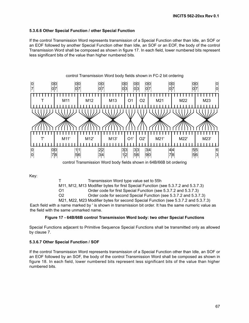
INCITS 562-20xx Rev 0.1
67
5.3.6.6 Other Special Function / other Special Function
If the control Transmission Word represents transmission of a Special Function other than Idle, an SOF oran EOF followed by another Special Function other than Idle, an SOF or an EOF, the body of the controlTransmission Word shall be composed as shown in figure 17. In each field, lower numbered bits representless significant bits of the value than higher numbered bits.
Special Functions adjacent to Primitive Sequence Special Functions shall be transmitted only as allowedby clause 7.
5.3.6.7 Other Special Function / SOF
If the control Transmission Word represents transmission of a Special Function other than Idle, an SOF oran EOF followed by an SOF, the body of the control Transmission Word shall be composed as shown infigure 18. In each field, lower numbered bits represent less significant bits of the value than highernumbered bits.
Key:T Transmission Word type value set to 55hM11, M12, M13 Modifier bytes for first Special Function (see 5.3.7.2 and 5.3.7.3)O1 Order code for first Special Function (see 5.3.7.2 and 5.3.7.3)O2 Order code for second Special Function (see 5.3.7.2 and 5.3.7.3)M21, M22, M23 Modifier bytes for second Special Function (see 5.3.7.2 and 5.3.7.3)
Each field with a name marked by ' is shown in transmission bit order. It has the same numeric value as the field with the same unmarked name.
Figure 17 - 64B/66B control Transmission Word body: two other Special Functions
control Transmission Word body fields shown in 64B/66B bit ordering
T
control Transmission Word body fields shown in FC-2 bit ordering
00
07
T'
07
00
M11
00
07
M11'
15
08
M12
00
07
M12'
23
16
M13
00
07
M13'
31
24
00
03
O1
35
32
O1'
00
03
O2
39
36
O2'
M21
00
07
M21'
47
40
M22
00
07
M22'
55
48
M23
00
07
M23'
63
56
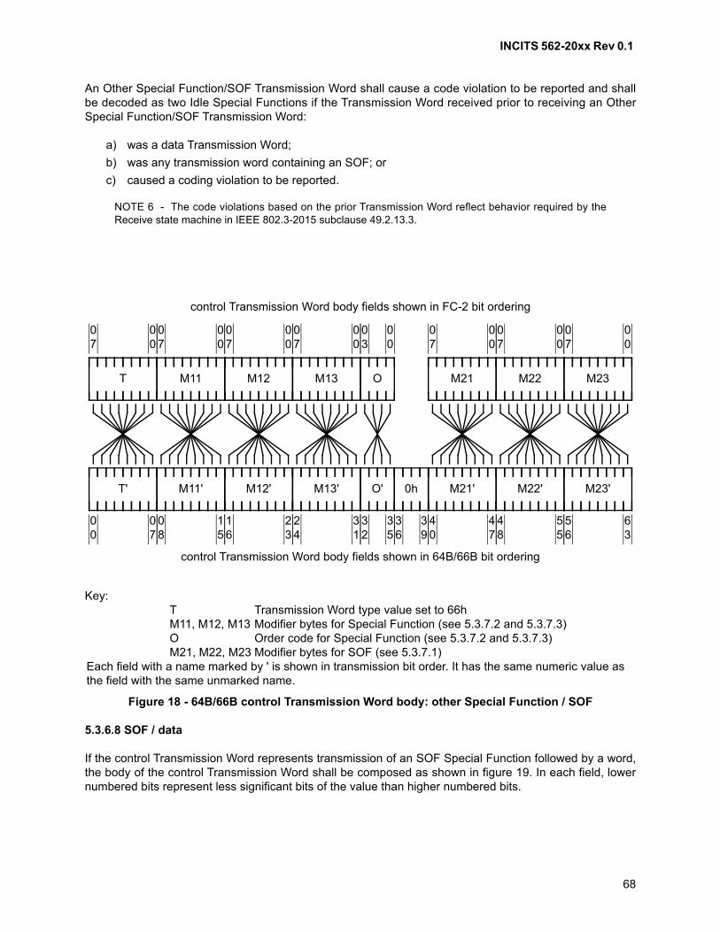
INCITS 562-20xx Rev 0.1
68
An Other Special Function/SOF Transmission Word shall cause a code violation to be reported and shallbe decoded as two Idle Special Functions if the Transmission Word received prior to receiving an OtherSpecial Function/SOF Transmission Word:
a) was a data Transmission Word;
b) was any transmission word containing an SOF; or
c) caused a coding violation to be reported.
NOTE 6 - The code violations based on the prior Transmission Word reflect behavior required by theReceive state machine in IEEE 802.3-2015 subclause 49.2.13.3.
5.3.6.8 SOF / data
If the control Transmission Word represents transmission of an SOF Special Function followed by a word,the body of the control Transmission Word shall be composed as shown in figure 19. In each field, lowernumbered bits represent less significant bits of the value than higher numbered bits.
Key:T Transmission Word type value set to 66hM11, M12, M13 Modifier bytes for Special Function (see 5.3.7.2 and 5.3.7.3)O Order code for Special Function (see 5.3.7.2 and 5.3.7.3)M21, M22, M23 Modifier bytes for SOF (see 5.3.7.1)
Each field with a name marked by ' is shown in transmission bit order. It has the same numeric value as the field with the same unmarked name.
Figure 18 - 64B/66B control Transmission Word body: other Special Function / SOF
control Transmission Word body fields shown in 64B/66B bit ordering
T
control Transmission Word body fields shown in FC-2 bit ordering
00
07
T'
07
00
M11
00
07
M11'
15
08
M12
00
07
M12'
23
16
M13
00
07
M13'
31
24
00
03
O
35
32
O'
39
36
0h
M21
00
07
M21'
47
40
M22
00
07
M22'
55
48
M23
00
07
M23'
63
56
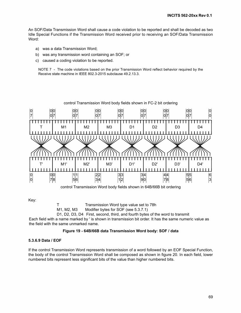
INCITS 562-20xx Rev 0.1
69
An SOF/Data Transmission Word shall cause a code violation to be reported and shall be decoded as twoIdle Special Functions if the Transmission Word received prior to receiving an SOF/Data TransmissionWord:
a) was a data Transmission Word;
b) was any transmission word containing an SOF; or
c) caused a coding violation to be reported.
NOTE 7 - The code violations based on the prior Transmission Word reflect behavior required by theReceive state machine in IEEE 802.3-2015 subclause 49.2.13.3.
5.3.6.9 Data / EOF
If the control Transmission Word represents transmission of a word followed by an EOF Special Function,the body of the control Transmission Word shall be composed as shown in figure 20. In each field, lowernumbered bits represent less significant bits of the value than higher numbered bits.
Key:T Transmission Word type value set to 78hM1, M2, M3 Modifier bytes for SOF (see 5.3.7.1)D1, D2, D3, D4 First, second, third, and fourth bytes of the word to transmit
Each field with a name marked by ' is shown in transmission bit order. It has the same numeric value as the field with the same unmarked name.
Figure 19 - 64B/66B data Transmission Word body: SOF / data
control Transmission Word body fields shown in 64B/66B bit ordering
T
control Transmission Word body fields shown in FC-2 bit ordering
00
07
T'
07
00
M1
00
07
M1'
15
08
M2
00
07
M2'
23
16
M3
00
07
M3'
31
24
D4
00
07
D4'
63
56
D1
00
07
D1'
39
32
D2
00
07
D2'
47
40
D3
00
07
D3'
55
48
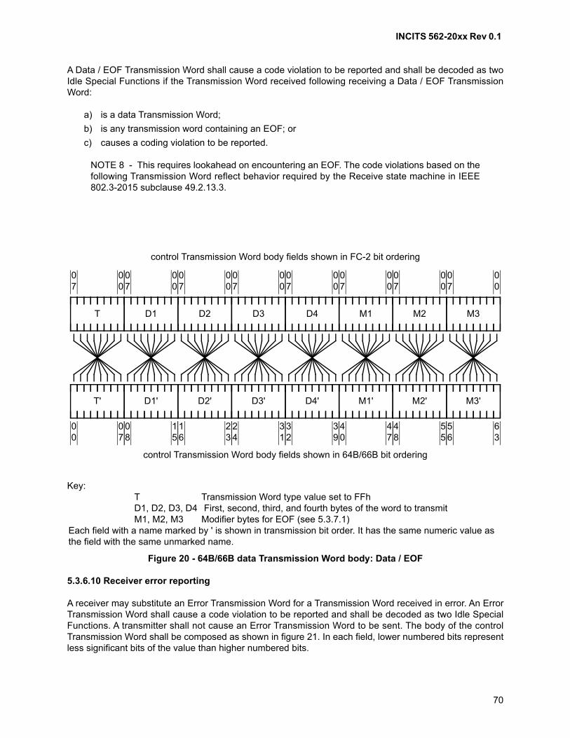
INCITS 562-20xx Rev 0.1
70
A Data / EOF Transmission Word shall cause a code violation to be reported and shall be decoded as twoIdle Special Functions if the Transmission Word received following receiving a Data / EOF TransmissionWord:
a) is a data Transmission Word;
b) is any transmission word containing an EOF; or
c) causes a coding violation to be reported.
NOTE 8 - This requires lookahead on encountering an EOF. The code violations based on thefollowing Transmission Word reflect behavior required by the Receive state machine in IEEE802.3-2015 subclause 49.2.13.3.
5.3.6.10 Receiver error reporting
A receiver may substitute an Error Transmission Word for a Transmission Word received in error. An ErrorTransmission Word shall cause a code violation to be reported and shall be decoded as two Idle SpecialFunctions. A transmitter shall not cause an Error Transmission Word to be sent. The body of the controlTransmission Word shall be composed as shown in figure 21. In each field, lower numbered bits representless significant bits of the value than higher numbered bits.
Key:T Transmission Word type value set to FFhD1, D2, D3, D4 First, second, third, and fourth bytes of the word to transmitM1, M2, M3 Modifier bytes for EOF (see 5.3.7.1)
Each field with a name marked by ' is shown in transmission bit order. It has the same numeric value as the field with the same unmarked name.
Figure 20 - 64B/66B data Transmission Word body: Data / EOF
control Transmission Word body fields shown in 64B/66B bit ordering
T
control Transmission Word body fields shown in FC-2 bit ordering
00
07
T'
07
00
M1
00
07
M1'
47
40
M2
00
07
M2'
55
48
M3
00
07
M3'
63
56
D4
00
07
D4'
39
32
D1
00
07
D1'
15
08
D2
00
07
D2'
23
16
D3
00
07
D3'
31
24
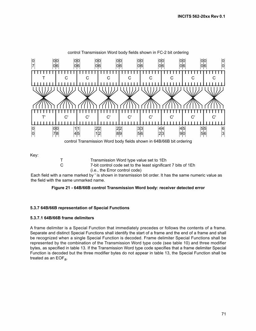
INCITS 562-20xx Rev 0.1
71
5.3.7 64B/66B representation of Special Functions
5.3.7.1 64B/66B frame delimiters
A frame delimiter is a Special Function that immediately precedes or follows the contents of a frame.Separate and distinct Special Functions shall identify the start of a frame and the end of a frame and shallbe recognized when a single Special Function is decoded. Frame delimiter Special Functions shall berepresented by the combination of the Transmission Word type code (see table 10) and three modifierbytes, as specified in table 13. If the Transmission Word type code specifies that a frame delimiter SpecialFunction is decoded but the three modifier bytes do not appear in table 13, the Special Function shall betreated as an EOFa.
Key:T Transmission Word type value set to 1EhC 7-bit control code set to the least significant 7 bits of 1Eh
(i.e., the Error control code)Each field with a name marked by ' is shown in transmission bit order. It has the same numeric value as the field with the same unmarked name.
Figure 21 - 64B/66B control Transmission Word body: receiver detected error
control Transmission Word body fields shown in 64B/66B bit ordering
T
control Transmission Word body fields shown in FC-2 bit ordering
00
06
00
07
C
14
08
C'T'
07
00
00
06
C
21
15
C'
00
06
C
28
22
C'
00
06
C
35
29
C'
00
06
C
42
36
C'
00
06
C
49
43
C'
00
06
C
55
50
C'
00
06
C
63
56
C'
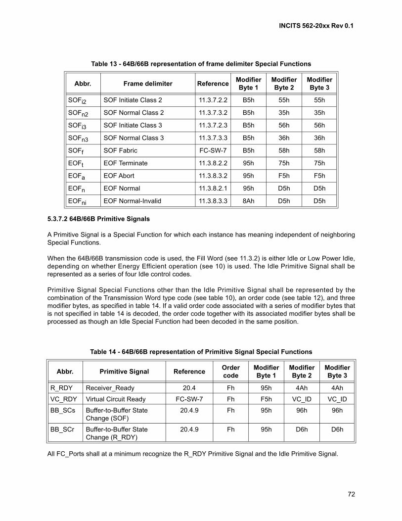
INCITS 562-20xx Rev 0.1
72
5.3.7.2 64B/66B Primitive Signals
A Primitive Signal is a Special Function for which each instance has meaning independent of neighboringSpecial Functions.
When the 64B/66B transmission code is used, the Fill Word (see 11.3.2) is either Idle or Low Power Idle,depending on whether Energy Efficient operation (see 10) is used. The Idle Primitive Signal shall berepresented as a series of four Idle control codes.
Primitive Signal Special Functions other than the Idle Primitive Signal shall be represented by thecombination of the Transmission Word type code (see table 10), an order code (see table 12), and threemodifier bytes, as specified in table 14. If a valid order code associated with a series of modifier bytes thatis not specified in table 14 is decoded, the order code together with its associated modifier bytes shall beprocessed as though an Idle Special Function had been decoded in the same position.
All FC_Ports shall at a minimum recognize the R_RDY Primitive Signal and the Idle Primitive Signal.
Table 13 - 64B/66B representation of frame delimiter Special Functions
Abbr. Frame delimiter ReferenceModifierByte 1
ModifierByte 2
ModifierByte 3
SOFi2 SOF Initiate Class 2 11.3.7.2.2 B5h 55h 55h
SOFn2 SOF Normal Class 2 11.3.7.3.2 B5h 35h 35h
SOFi3 SOF Initiate Class 3 11.3.7.2.3 B5h 56h 56h
SOFn3 SOF Normal Class 3 11.3.7.3.3 B5h 36h 36h
SOFf SOF Fabric FC-SW-7 B5h 58h 58h
EOFt EOF Terminate 11.3.8.2.2 95h 75h 75h
EOFa EOF Abort 11.3.8.3.2 95h F5h F5h
EOFn EOF Normal 11.3.8.2.1 95h D5h D5h
EOFni EOF Normal-Invalid 11.3.8.3.3 8Ah D5h D5h
Table 14 - 64B/66B representation of Primitive Signal Special Functions
Abbr. Primitive Signal ReferenceOrdercode
ModifierByte 1
ModifierByte 2
ModifierByte 3
R_RDY Receiver_Ready 20.4 Fh 95h 4Ah 4Ah
VC_RDY Virtual Circuit Ready FC-SW-7 Fh F5h VC_ID VC_ID
BB_SCs Buffer-to-Buffer State Change (SOF)
20.4.9 Fh 95h 96h 96h
BB_SCr Buffer-to-Buffer State Change (R_RDY)
20.4.9 Fh 95h D6h D6h
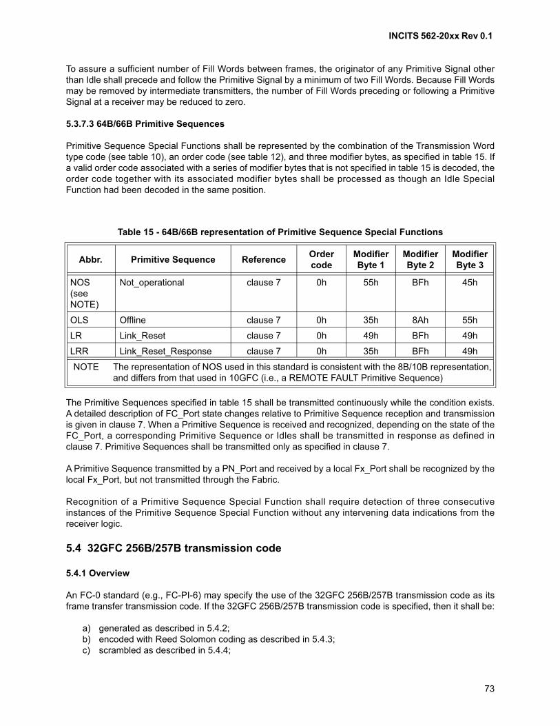
INCITS 562-20xx Rev 0.1
73
To assure a sufficient number of Fill Words between frames, the originator of any Primitive Signal otherthan Idle shall precede and follow the Primitive Signal by a minimum of two Fill Words. Because Fill Wordsmay be removed by intermediate transmitters, the number of Fill Words preceding or following a PrimitiveSignal at a receiver may be reduced to zero.
5.3.7.3 64B/66B Primitive Sequences
Primitive Sequence Special Functions shall be represented by the combination of the Transmission Wordtype code (see table 10), an order code (see table 12), and three modifier bytes, as specified in table 15. Ifa valid order code associated with a series of modifier bytes that is not specified in table 15 is decoded, theorder code together with its associated modifier bytes shall be processed as though an Idle SpecialFunction had been decoded in the same position.
The Primitive Sequences specified in table 15 shall be transmitted continuously while the condition exists.A detailed description of FC_Port state changes relative to Primitive Sequence reception and transmissionis given in clause 7. When a Primitive Sequence is received and recognized, depending on the state of theFC_Port, a corresponding Primitive Sequence or Idles shall be transmitted in response as defined inclause 7. Primitive Sequences shall be transmitted only as specified in clause 7.
A Primitive Sequence transmitted by a PN_Port and received by a local Fx_Port shall be recognized by thelocal Fx_Port, but not transmitted through the Fabric.
Recognition of a Primitive Sequence Special Function shall require detection of three consecutiveinstances of the Primitive Sequence Special Function without any intervening data indications from thereceiver logic.
5.4 32GFC 256B/257B transmission code
5.4.1 Overview
An FC-0 standard (e.g., FC-PI-6) may specify the use of the 32GFC 256B/257B transmission code as itsframe transfer transmission code. If the 32GFC 256B/257B transmission code is specified, then it shall be:
a) generated as described in 5.4.2;b) encoded with Reed Solomon coding as described in 5.4.3;c) scrambled as described in 5.4.4;
Table 15 - 64B/66B representation of Primitive Sequence Special Functions
Abbr. Primitive Sequence ReferenceOrdercode
ModifierByte 1
ModifierByte 2
ModifierByte 3
NOS(see NOTE)
Not_operational clause 7 0h 55h BFh 45h
OLS Offline clause 7 0h 35h 8Ah 55h
LR Link_Reset clause 7 0h 49h BFh 49h
LRR Link_Reset_Response clause 7 0h 35h BFh 49h
NOTE The representation of NOS used in this standard is consistent with the 8B/10B representation, and differs from that used in 10GFC (i.e., a REMOTE FAULT Primitive Sequence)
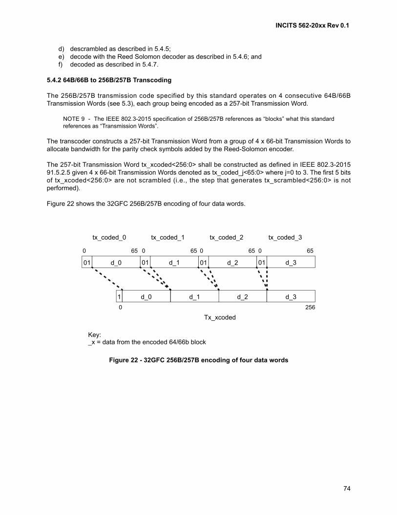
INCITS 562-20xx Rev 0.1
74
d) descrambled as described in 5.4.5;e) decode with the Reed Solomon decoder as described in 5.4.6; andf) decoded as described in 5.4.7.
5.4.2 64B/66B to 256B/257B Transcoding
The 256B/257B transmission code specified by this standard operates on 4 consecutive 64B/66BTransmission Words (see 5.3), each group being encoded as a 257-bit Transmission Word.
NOTE 9 - The IEEE 802.3-2015 specification of 256B/257B references as “blocks” what this standardreferences as “Transmission Words”.
The transcoder constructs a 257-bit Transmission Word from a group of 4 x 66-bit Transmission Words toallocate bandwidth for the parity check symbols added by the Reed-Solomon encoder.
The 257-bit Transmission Word tx_xcoded<256:0> shall be constructed as defined in IEEE 802.3-201591.5.2.5 given 4 x 66-bit Transmission Words denoted as tx_coded_j<65:0> where j=0 to 3. The first 5 bitsof tx_xcoded<256:0> are not scrambled (i.e., the step that generates tx_scrambled<256:0> is notperformed).
Figure 22 shows the 32GFC 256B/257B encoding of four data words.
Figure 22 - 32GFC 256B/257B encoding of four data words
01 d_0 01 d_1 01 d_2 01 d_3
d_3d_2d_1d_01
0 256
0 65 0 65 0 65 0 65
tx_coded_0 tx_coded_1 tx_coded_2 tx_coded_3
Tx_xcoded
Key:_x = data from the encoded 64/66b block
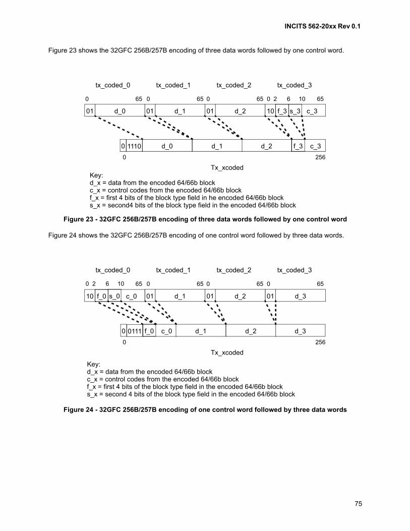
INCITS 562-20xx Rev 0.1
75
Figure 23 shows the 32GFC 256B/257B encoding of three data words followed by one control word.
Figure 24 shows the 32GFC 256B/257B encoding of one control word followed by three data words.
Figure 23 - 32GFC 256B/257B encoding of three data words followed by one control word
Figure 24 - 32GFC 256B/257B encoding of one control word followed by three data words
01 d_0 01 d_1 01 d_2 10 c_3
c_3d_2d_1d_00
0 256
0 65 0 65 0 65 0 2 6 10 65
tx_coded_0 tx_coded_1 tx_coded_2 tx_coded_3
Tx_xcoded
f_3 s_3
f_31110
Key:d_x = data from the encoded 64/66b blockc_x = control codes from the encoded 64/66b blockf_x = first 4 bits of the block type field in he encoded 64/66b blocks_x = second4 bits of the block type field in the encoded 64/66b block
d_3
01 d_301 d_1 01 d_2
c_0 d_2d_10
0 256
65 0 65 0 65 0 65
tx_coded_0 tx_coded_1 tx_coded_2 tx_coded_3
Tx_xcoded
f_00111
10 c_0f_0 s_0
0 2 6 10
Key:d_x = data from the encoded 64/66b blockc_x = control codes from the encoded 64/66b blockf_x = first 4 bits of the block type field in the encoded 64/66b blocks_x = second 4 bits of the block type field in the encoded 64/66b block
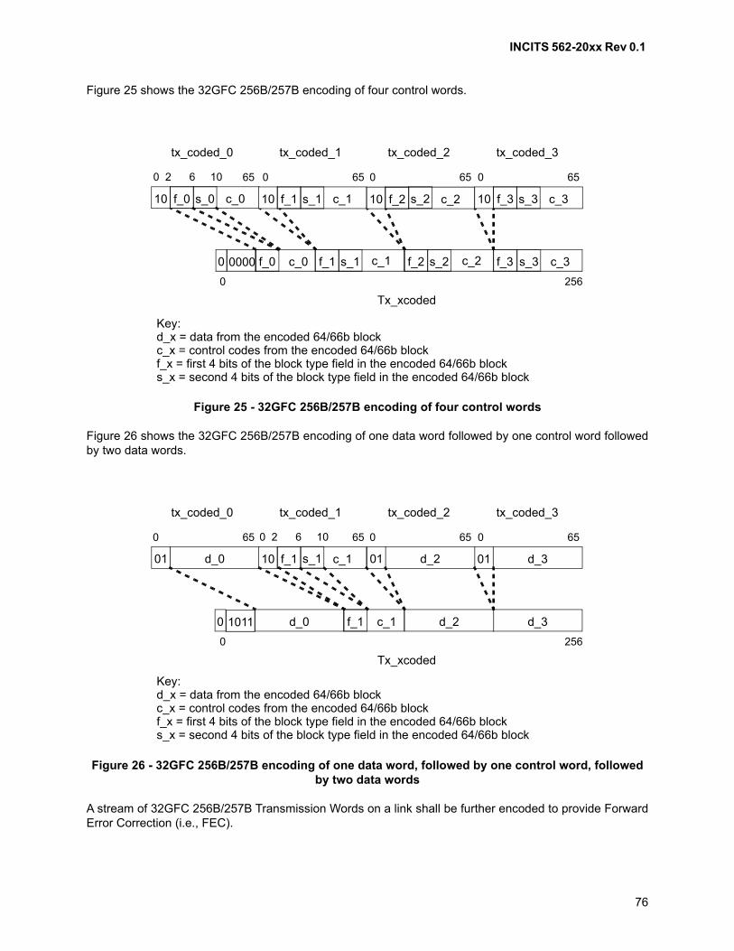
INCITS 562-20xx Rev 0.1
76
Figure 25 shows the 32GFC 256B/257B encoding of four control words.
Figure 26 shows the 32GFC 256B/257B encoding of one data word followed by one control word followedby two data words.
A stream of 32GFC 256B/257B Transmission Words on a link shall be further encoded to provide ForwardError Correction (i.e., FEC).
Figure 25 - 32GFC 256B/257B encoding of four control words
Figure 26 - 32GFC 256B/257B encoding of one data word, followed by one control word, followed by two data words
c_3c_0 c_2c_10
0 256
65 0 65 0 65 0 65
tx_coded_0 tx_coded_1 tx_coded_2 tx_coded_3
Tx_xcoded
f_00000
10 c_0f_0 s_0
0 2 6 10
10 c_2f_2 s_2 10 c_3f_3 s_310 c_1f_1 s_1
f_1 f_2 f_3s_1 s_2 s_3
Key:d_x = data from the encoded 64/66b blockc_x = control codes from the encoded 64/66b blockf_x = first 4 bits of the block type field in the encoded 64/66b blocks_x = second 4 bits of the block type field in the encoded 64/66b block
01 d_0 01 d_301 d_210 c_1
c_1 d_3d_2d_00
0 256
0 65 65 0 65 0 65
tx_coded_0 tx_coded_1 tx_coded_2 tx_coded_3
Tx_xcoded
f_1 s_1
f_11011
0 2 6 10
Key:d_x = data from the encoded 64/66b blockc_x = control codes from the encoded 64/66b blockf_x = first 4 bits of the block type field in the encoded 64/66b blocks_x = second 4 bits of the block type field in the encoded 64/66b block
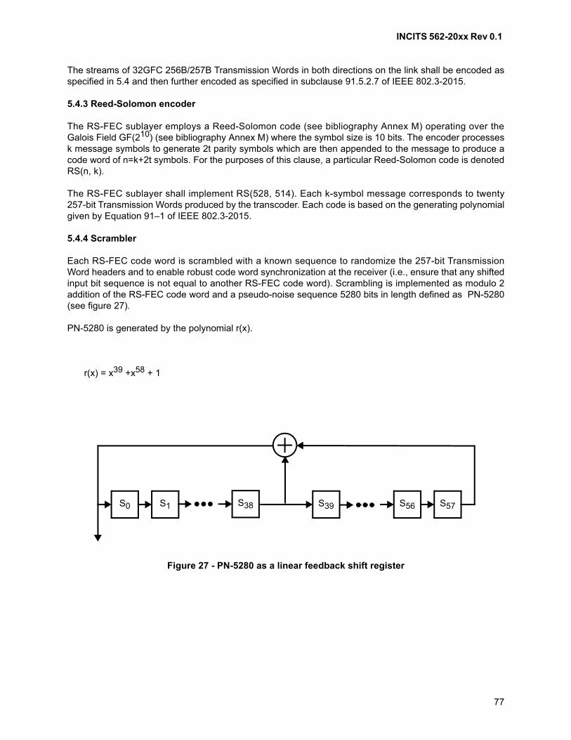
INCITS 562-20xx Rev 0.1
77
The streams of 32GFC 256B/257B Transmission Words in both directions on the link shall be encoded asspecified in 5.4 and then further encoded as specified in subclause 91.5.2.7 of IEEE 802.3-2015.
5.4.3 Reed-Solomon encoder
The RS-FEC sublayer employs a Reed-Solomon code (see bibliography Annex M) operating over theGalois Field GF(210) (see bibliography Annex M) where the symbol size is 10 bits. The encoder processesk message symbols to generate 2t parity symbols which are then appended to the message to produce acode word of n=k+2t symbols. For the purposes of this clause, a particular Reed-Solomon code is denotedRS(n, k).
The RS-FEC sublayer shall implement RS(528, 514). Each k-symbol message corresponds to twenty257-bit Transmission Words produced by the transcoder. Each code is based on the generating polynomialgiven by Equation 91–1 of IEEE 802.3-2015.
5.4.4 Scrambler
Each RS-FEC code word is scrambled with a known sequence to randomize the 257-bit TransmissionWord headers and to enable robust code word synchronization at the receiver (i.e., ensure that any shiftedinput bit sequence is not equal to another RS-FEC code word). Scrambling is implemented as modulo 2addition of the RS-FEC code word and a pseudo-noise sequence 5280 bits in length defined as PN-5280(see figure 27).
PN-5280 is generated by the polynomial r(x).
r(x) = x39 +x58 + 1
Figure 27 - PN-5280 as a linear feedback shift register
S0 S1 S38 S39 S56 S57
INCITS 562-20xx Rev 0.1
78
At the start of each RS-FEC code word, the initial state of the pseudo-noise generator is set to:
S57 = 1
Si–1 = Si XOR 1
(i.e., a binary sequence of alternating 1’s and 0’s).
5.4.5 Descrambler
Each code word shall be descrambled prior to decoding. Descrambling is implemented as the modulo 2addition of RS-FEC code word and the same pseudo-noise sequence PN-5280 defined for the scrambler(see 5.4.4).
5.4.6 Reed-Solomon decoder
The Reed-Solomon decoder extracts the message symbols from the code word, correcting them asnecessary, and discards the parity symbols. The message symbols correspond to 20 x 257-bitTransmission Words.
The Reed-Solomon decoder shall be capable of correcting any combination of up to t=7 symbol errors in acode word. It shall also be capable of indicating when a code word contains errors but was not corrected(e.g., it contains a number of errors in excess of the error correction capability).
5.4.7 32GFC 256B/257B to 64B/66B transcoder
The transcoder reconstructs a group of 4 x 66-bit Transmission Words from each received 257-bitTransmission Word.
The 4 x 66-bit Transmission Words, denoted as rx_coded_j<65:0> where j=0 to 3, shall be derived fromeach 257-bit Transmission Word rx_xcoded<256:0> as defined in IEEE 802.3-2015 91.5.3.5. As the first 5bits of rx_xcoded<256:0> are not scrambled, the step defined in IEEE 802.3-2015 that derives rx_xcodedfrom rx_scrambled is not performed on those bits.
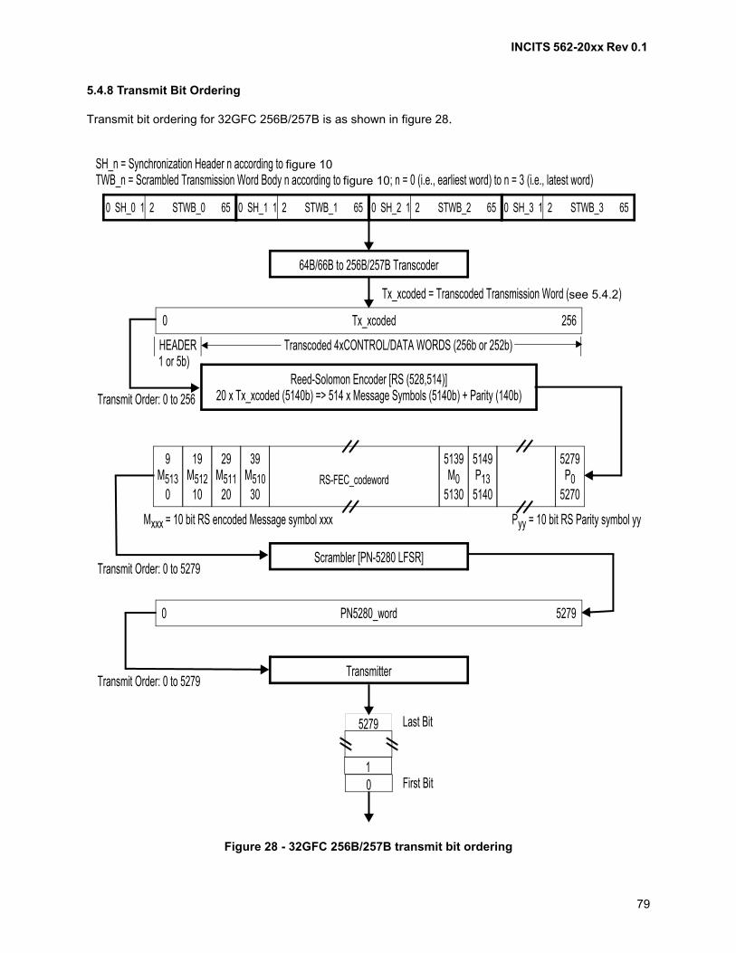
INCITS 562-20xx Rev 0.1
79
5.4.8 Transmit Bit Ordering
Transmit bit ordering for 32GFC 256B/257B is as shown in figure 28.
Figure 28 - 32GFC 256B/257B transmit bit ordering
0 SH_0 1 2 STWB_0 65 0 SH_1 1 2 STWB_1 65 0 SH_2 1 2 STWB_2 65 0 SH_3 1 2 STWB_3 65
64B/66B to 256B/257B Transcoder
Tx_xcoded0 256
Reed-Solomon Encoder [RS (528,514)]20 x Tx_xcoded (5140b) => 514 x Message Symbols (5140b) + Parity (140b)
29M511
20
39M510
30RS-FEC_codeword
5139M0
5130
5149P13
5140
5279P0
5270
9M513
0
19M512
10
Scrambler [PN-5280 LFSR]
PN5280_word0 5279
Transmitter
5279
10
SH_n = Synchronization Header n according to figure 10TWB_n = Scrambled Transmission Word Body n according to figure 10; n = 0 (i.e., earliest word) to n = 3 (i.e., latest word)
Tx_xcoded = Transcoded Transmission Word (see 5.4.2)
Transcoded 4xCONTROL/DATA WORDS (256b or 252b)HEADER1 or 5b)
Transmit Order: 0 to 256
Mxxx = 10 bit RS encoded Message symbol xxx Pyy = 10 bit RS Parity symbol yy
Transmit Order: 0 to 5279
Transmit Order: 0 to 5279
Last Bit
First Bit

INCITS 562-20xx Rev 0.1
80
5.4.9 Receive Bit Ordering
Receive bit ordering for 32GFC 256B/257B is as shown in figure 29.
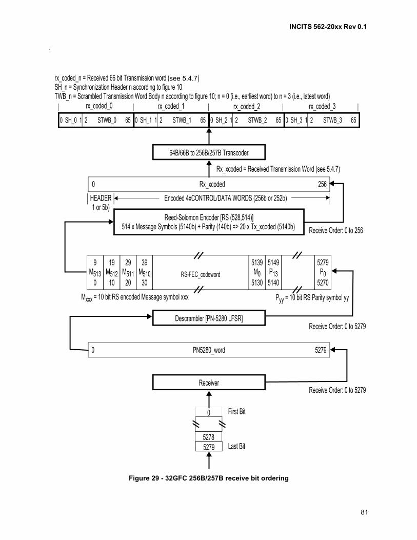
INCITS 562-20xx Rev 0.1
81
‘
Figure 29 - 32GFC 256B/257B receive bit ordering
0 SH_0 1 2 STWB_0 65 0 SH_1 1 2 STWB_1 65 0 SH_2 1 2 STWB_2 65 0 SH_3 1 2 STWB_3 65
64B/66B to 256B/257B Transcoder
Rx_xcoded0 256
Reed-Solomon Encoder [RS (528,514)]514 x Message Symbols (5140b) + Parity (140b) => 20 x Tx_xcoded (5140b)
29M511
20
39M510
30RS-FEC_codeword
5139M0
5130
5149P13
5140
5279P0
5270
9M513
0
19M512
10
Descrambler [PN-5280 LFSR]
PN5280_word0 5279
Receiver
0
52785279
SH_n = Synchronization Header n according to figure 10TWB_n = Scrambled Transmission Word Body n according to figure 10; n = 0 (i.e., earliest word) to n = 3 (i.e., latest word)
Rx_xcoded = Received Transmission Word (see 5.4.7)
Encoded 4xCONTROL/DATA WORDS (256b or 252b)HEADER1 or 5b)
Receive Order: 0 to 256
Mxxx = 10 bit RS encoded Message symbol xxx Pyy = 10 bit RS Parity symbol yy
Receive Order: 0 to 5279
Receive Order: 0 to 5279
First Bit
Last Bit
rx_coded_n = Received 66 bit Transmission word (see 5.4.7)
rx_coded_0 rx_coded_1 rx_coded_2 rx_coded_3
INCITS 562-20xx Rev 0.1
82
5.5 64GFC 256B/257B transmission code
5.5.1 Overview
An FC-0 standard (e.g., FC-PI-7) may specify the use of the 64GFC 256B/257B transmission code as itsframe transfer transmission code. If the 64GFC 256B/257B transmission code is specified, then it shall be:
a) generated as described in 5.5.2 and 5.5.3;b) encoded with Reed Solomon coding as described in 5.5.4;c) Gray mapped as described in 5.5.5;d) when enabled, precoded as described in 5.5.6;e) when enabled, inverse precoded as described in 5.5.7;f) inverse Gray mapped as described in 5.5.8;g) decoded with Reed Solomon decoder as described in 5.5.10; andh) recovered as described in 5.5.11 and 5.5.12.
5.5.2 64B/66B to 64GFC 256B/257B transcoding
64B/66B to 256B/257B transcoding is done as specified in 5.8.2.1.
5.5.3 Alignment marker mapping and insertion
The alignment insertion function inserts a unique data pattern (i.e., Alignment Marker) into the data streamto provide a framing pattern for aligning the FEC code words.
The first 257b of every 1024th FEC code word carries Alignment Marker information. The first 256 bits (i.e., 0 to255) of the Alignment Marker (i.e., AM) vector are composed of AM0, AM4, AM8 and AM12 from Table 82-2 ofIEEE 802.3-2015. AMx is the marker for PCS lane number x in Table 82-2. AM0 is the first marker transmitted onthe line, followed by AM4, AM8 and AM12. Each octet in the AM vector is transmitted LSB, rightmost bit, to MSB,leftmost bit, starting from the leftmost octet to the rightmost octet. The last bit (i.e., 256) is a pad bit that is alwaystransmitted as zero.
The BIP3 octet of AM0 carries Link degrade information associated with the link degrade function (see5.5.10.2). The bits of this octet are assigned as follows:
a) BIP3[0]=RD (see 5.5.10.2);
b) BIP3[3:1]=0, Reserved for future use; and
c) BIP3[7:4]=0xA.
The Remote Degrade indicator is in bit 24 of the AM[256:0] vector. The BIP7 octet is the bit-wise inverse ofBIP3 but conveys no useful information. As an example, the first 32 bits of the AM0 vector are ordered asfollows:
a) 1000_0011_0001_0110_1000_0100_RD000_0101.
For all other markers besides AM0, BIP3=0xAA and BIP7=0x55.
5.5.4 Reed-Solomon encoder
The RS-FEC sublayer employs a Reed-Solomon code (see Annex M) operating over the Galois FieldGF(210) (see Annex M) where the symbol size is 10 bits. The encoder processes k message symbols togenerate 2t parity symbols which are then appended to the message to produce a code word of n=k+2tsymbols. For the purposes of this clause, a particular Reed-Solomon code is denoted RS(n, k).
INCITS 562-20xx Rev 0.1
83
The RS-FEC sublayer shall implement RS(544, 514) as defined in IEEE 802.3cd D2.2 134.5.2.7. Eachk-symbol message corresponds to twenty 257-bit Transmission Words produced by the transcoder. Eachcode is based on the generating polynomial given by Equation 91–1 of IEEE 802.3-2015.
5.5.5 Gray mapping
The Gray mapping process shall map consecutive pairs of bits {A, B}, where A is the bit arriving first, to aGray-coded symbol as follows:
a) {0, 0} maps to 0;
b) {0, 1} maps to 1;
c) {1, 1} maps to 2; and
d) {1, 0} maps to 3.
5.5.6 Precoding
The transmit process shall provide 1/(1+D) mod 4 precoding capability for electrical variants specified inFC-PI-7 and FC-PI-7P.
For each Gray-coded symbol G(j), a precoded symbol P(j) shall be determined by the following algorithm,where j is an index indicating the symbol number:
P(j) = (G(j) – P(j-1)) mod 4
The decision to enable or disable transmitter precoding is determined by the remote receiver during thetransmitter training process (see 5.7).
5.5.7 Inverse precoding
The receive process optionally provides inverse precoding for electrical variants specified in FC-PI-7 andFC-PI-7P. When implemented and enabled, for each precoded symbol P(j), a Gray-code symbol G(j) shallbe determined by the following algorithm:
G(j) = (P(j) + P(j-1)) mod 4
When implemented, the decision to enable or disable remote transmitter precoding and receiver inverseprecoding is determined by the receiver during the transmitter training process. The method by which thereceiver determines whether or not to enable precoding is beyond the scope of this standard.
5.5.8 Inverse Gray mapping
The inverse Gray mapping process shall map Gray-coded PAM4 symbols to pairs of bits {A, B} where A isconsidered to be the first bit as follows:
a) 0 maps to {0, 0};
b) 1 maps to {0, 1};
c) 2 maps to {1, 1}; and
d) 3 maps to {1, 0}.
INCITS 562-20xx Rev 0.1
84
5.5.9 Alignment lock
The receive function obtains LOCK to the alignment markers as specified by the FEC synchronizationstate diagram in IEEE 802.3cd D2.2 figure 91-8, using the variable and counter definitions fromIEEE802.3cd 134.5.4 but modified for a single FEC lane operation.
5.5.10 Reed-Solomon decoder
5.5.10.1 Overview
The Reed-Solomon decoder extracts the message symbols from the code word, correcting them asnecessary, and discards the parity symbols. The message symbols correspond to 20 x 257-bitTransmission Words.
The Reed-Solomon decoder shall be capable of correcting any combination of up to t=15 symbol errors ina code word. It shall also be capable of indicating when a code word contains errors but was not corrected(e.g., it contains a number of errors in excess of the error correction capability).
5.5.10.2 Link Degrade Signaling
For 64GFC links, Link Degrade Signaling can be supported by monitoring errors in the FEC logic. The LinkDegrade Logic keeps track of the following parameters:
FEC_Degrade_interval – This is a 32 bit register that specifies the number of RS-FEC code words thatmake up a Degrade Interval.
RD – Remote Degrade Bit to be sent in the Alignment Marker field.
Degrade_Activate_Threshold – This is a 32 bit register that specifies a symbol error count. The value herecontrols the threshold used to activate RD.
Degrade_Deactivate_Threshold – This is a 32 bit register that specifies a symbol error count. The valuehere controls the threshold used to deactivate RD.
The Reed Solomon Decoder counts the number of symbol errors detected in all the code words within theFEC_Degrade_interval. If a codeword is uncorrectable, the number of symbol errors detected isincremented by 16. When the number of symbol errors detected within a FEC_Degrade_interval exceedsthe Degrade_Activate_Threshold, RD will be signaled to the remote link partner using a bit in theAlignment Marker. At the end of an interval, if the number of symbol errors is less than theDegrade_Deactivate_Threshold, RD will be de-asserted in the Alignment Marker.
5.5.11 Alignment marker removal
The first 257 message bits in every 1024th codeword is the vector am_rxmapped<256:0> where bit 0 is thefirst bit received. The specific codewords that include this vector are indicated by the alignment lockfunction (see 5.5.9).
The vector am_rxmapped shall be removed prior to transcoding.
5.5.12 256B/257B to 64B/66B transcoder
The first five bits of the received block rx_scrambled<256:0>, in reception order, are descrambled so thatrx_scrambled<256:0> generates rx_coded<256:0> as follows:
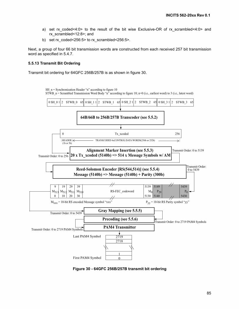
INCITS 562-20xx Rev 0.1
85
a) set rx_coded<4:0> to the result of the bit wise Exclusive-OR of rx_scrambled<4:0> andrx_scrambled<12:8>; and
b) set rx_coded<256:5> to rx_scrambled<256:5>.
Next, a group of four 66 bit transmission words are constructed from each received 257 bit transmissionword as specified in 5.4.7.
5.5.13 Transmit Bit Ordering
Transmit bit ordering for 64GFC 256B/257B is as shown in figure 30.
Figure 30 - 64GFC 256B/257B transmit bit ordering
M513 M512 M511 M510 RS-FEC_codeword M0 P29 P0
9 19 29 39 5139 5149 5439
0 10 20 30 5130 5140 5430
Mxxx = 10-bit RS encoded Message symbol “xxx” Pyy = 10-bit RS Parity symbol “yy”
0 SH_0 1 2 STWB_0 65 0 SH_1 1 2 STWB_1 65 0 SH_2 1 2 STWB_2 65 0 SH_3 1 2 STWB_3 65
SH_n = Synchronization Header “n” according to figure 10STWB_n = Scrambled Transmission Word Body “n” according to figure 10; n=0 (i.e., earliest word) to 3 (i.e., latest word)
64B/66B to 256B/257B Transcoder (see 5.5.2)
0 Tx_xcoded 256
| HEADER | TRANSCODED 4xCONTROL/DATA WORDS(256b or 252b) | (1b or 5b)
Alignment Marker Insertion (see 5.5.3)20 x Tx_xcoded (5140b) => 514 x Message Symbols w/ AM
Reed-Solomon Encoder [RS(544,514)] (see 5.5.4)Message (5140b) => Message (5140b) + Parity (300b)
Gray Mapping (see 5.5.5)
Precoding (see 5.5.6)
PAM4 Transmitter
2719 2718
1 0
Last PAM4 Symbol
First PAM4 Symbol
Transmit Order: 0 to 256
Transmit Order: 0 to 5139
Transmit Order:
Transmit Order: 0 to 5439
Transmit Order: 0 to 2719 PAM4 Symbols
Transmit Order: 0 to 2719 PAM4 Symbols
0 to 5439
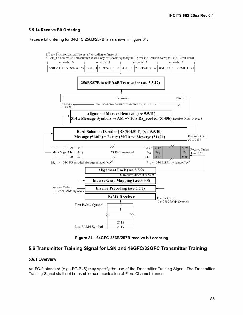
INCITS 562-20xx Rev 0.1
86
5.5.14 Receive Bit Ordering
Receive bit ordering for 64GFC 256B/257B is as shown in figure 31.
5.6 Transmitter Training Signal for LSN and 16GFC/32GFC Transmitter Training
5.6.1 Overview
An FC-0 standard (e.g., FC-PI-5) may specify the use of the Transmitter Training Signal. The TransmitterTraining Signal shall not be used for communication of Fibre Channel frames.
Figure 31 - 64GFC 256B/257B receive bit ordering
M513 M512 M511 M510 RS-FEC_codeword M0 P29 P0
9 19 29 39 5139 5149 5439
0 10 20 30 5130 5140 5430
Mxxx = 10-bit RS encoded Message symbol “xxx” Pyy = 10-bit RS Parity symbol “yy”
0 SH_0 1 2 STWB_0 65 0 SH_1 1 2 STWB_1 65 0 SH_2 1 2 STWB_2 65 0 SH_3 1 2 STWB_3 65
SH_n = Synchronization Header “n” according to figure 10STWB_n = Scrambled Transmission Word Body “n” according to figure 10; n=0 (i.e., earliest word) to 3 (i.e., latest word)
256B/257B to 64B/66B Transcoder (see 5.5.12)
0 Rx_xcoded 256
| HEADER | TRANSCODED 4xCONTROL/DATA WORDS(256b or 252b) | (1b or 5b)
Alignment Marker Removal (see 5.5.11)514 x Message Symbols w/ AM => 20 x Rx_xcoded (5140b)
Reed-Solomon Decoder [RS(544,514)] (see 5.5.10)Message (5140b) + Parity (300b) => Message (5140b)
Inverse Gray Mapping (see 5.5.8)
Inverse Precoding (see 5.5.7)
PAM4 Receiver
0 1
2718 2719
First PAM4 Symbol
Last PAM4 Symbol
Receive Order:
Alignment Lock (see 5.5.9)
Receive Order:
Receive Order: 0 to 5439
Receive Order:
Receive Order:
Receive Order: 0 to 256
rx_coded_0 rx_coded_1 rx_coded_2 rx_coded_3
_ _ ( )
: 0 to 5139
0 to 5439
0 to 2719 PAM4 Symbols
0 to 2719 PAM4 Symbols
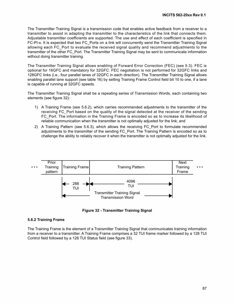
INCITS 562-20xx Rev 0.1
87
The Transmitter Training Signal is a transmission code that enables active feedback from a receiver to atransmitter to assist in adapting the transmitter to the characteristics of the link that connects them.Adjustable transmitter coefficients are supported. The use and effect of each coefficient is specified inFC-PI-x. It is expected that two FC_Ports on a link will concurrently send the Transmitter Training Signalallowing each FC_Port to evaluate the received signal quality and recommend adjustments to thetransmitter of the other FC_Port. The Transmitter Training Signal may be sent to communicate informationwithout doing transmitter training.
The Transmitter Training Signal allows enabling of Forward Error Correction (FEC) (see 5.3). FEC isoptional for 16GFC and mandatory for 32GFC. FEC negotiation is not performed for 32GFC links and128GFC links (i.e., four parallel lanes of 32GFC in each direction). The Transmitter Training Signal allowsenabling parallel lane support (see table 16) by setting Training Frame Control field bit 10 to one, if a laneis capable of running at 32GFC speeds.
The Transmitter Training Signal shall be a repeating series of Transmission Words, each containing twoelements (see figure 32):
1) A Training Frame (see 5.6.2), which carries recommended adjustments to the transmitter of thereceiving FC_Port based on the quality of the signal detected at the receiver of the sendingFC_Port. The information in the Training Frame is encoded so as to increase its likelihood ofreliable communication when the transmitter is not optimally adjusted for the link; and
2) A Training Pattern (see 5.6.3), which allows the receiving FC_Port to formulate recommendedadjustments to the transmitter of the sending FC_Port. The Training Pattern is encoded so as tochallenge the ability to reliably recover it when the transmitter is not optimally adjusted for the link.
5.6.2 Training Frame
The Training Frame is the element of a Transmitter Training Signal that communicates training informationfrom a receiver to a transmitter. A Training Frame comprises a 32 TUI frame marker followed by a 128 TUIControl field followed by a 128 TUI Status field (see figure 33).
Figure 32 - Transmitter Training Signal
Training Frame Training PatternNext
TrainingFrame
PriorTrainingpattern
• • •• • •
4096 TUI
288 TUI
Transmitter Training Signal Transmission Word
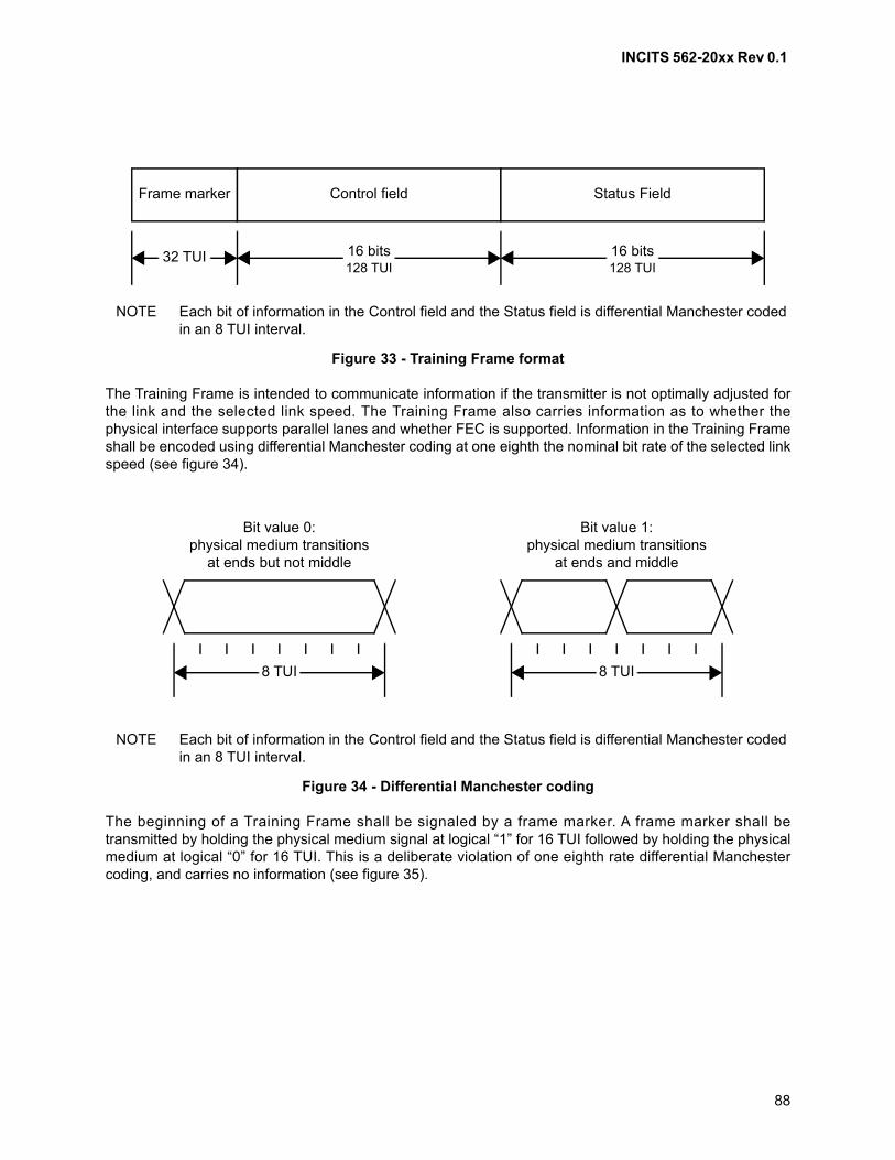
INCITS 562-20xx Rev 0.1
88
The Training Frame is intended to communicate information if the transmitter is not optimally adjusted forthe link and the selected link speed. The Training Frame also carries information as to whether thephysical interface supports parallel lanes and whether FEC is supported. Information in the Training Frameshall be encoded using differential Manchester coding at one eighth the nominal bit rate of the selected linkspeed (see figure 34).
The beginning of a Training Frame shall be signaled by a frame marker. A frame marker shall betransmitted by holding the physical medium signal at logical “1” for 16 TUI followed by holding the physicalmedium at logical “0” for 16 TUI. This is a deliberate violation of one eighth rate differential Manchestercoding, and carries no information (see figure 35).
NOTE Each bit of information in the Control field and the Status field is differential Manchester coded in an 8 TUI interval.
Figure 33 - Training Frame format
NOTE Each bit of information in the Control field and the Status field is differential Manchester coded in an 8 TUI interval.
Figure 34 - Differential Manchester coding
Frame marker Control field
32 TUI
Status Field
16 bits128 TUI
16 bits128 TUI
Bit value 1:physical medium transitions
at ends and middle
8 TUI
Bit value 0:physical medium transitions
at ends but not middle
8 TUI
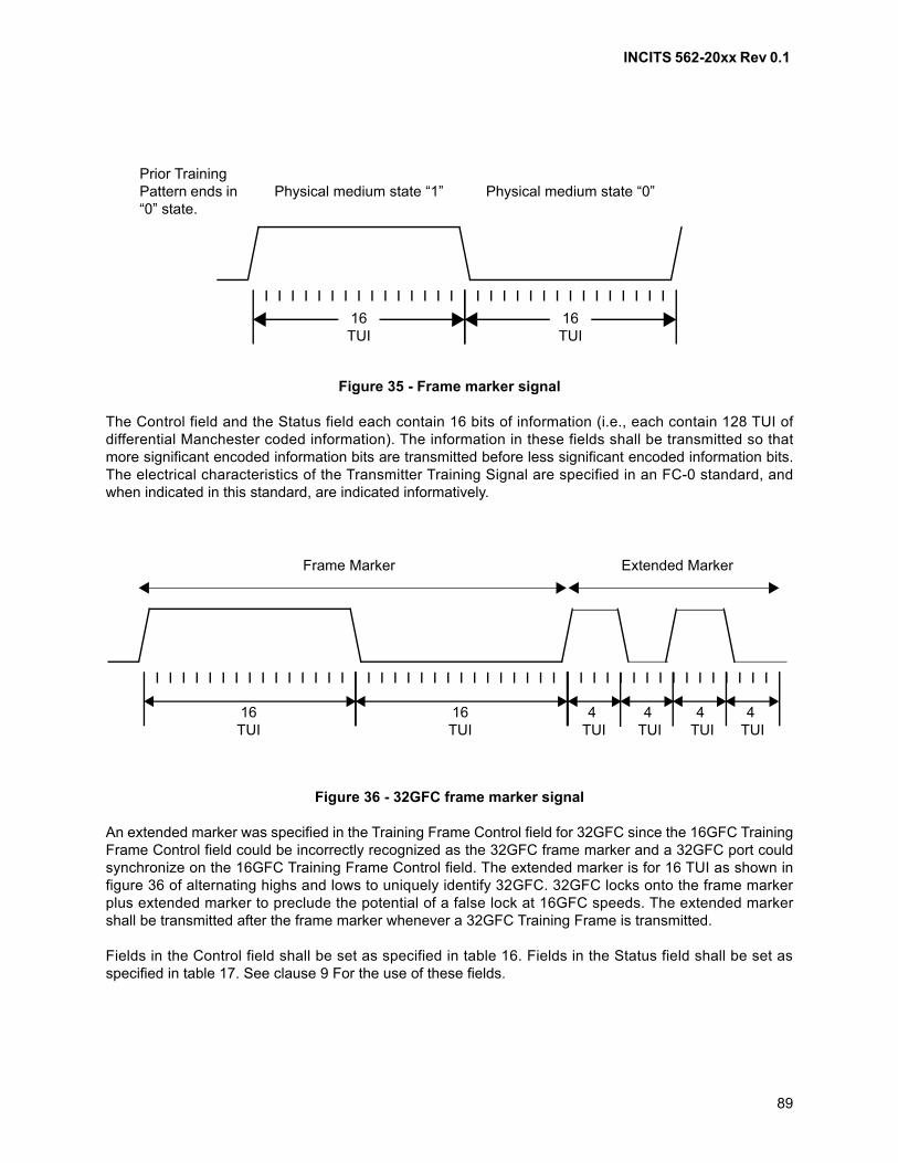
INCITS 562-20xx Rev 0.1
89
The Control field and the Status field each contain 16 bits of information (i.e., each contain 128 TUI ofdifferential Manchester coded information). The information in these fields shall be transmitted so thatmore significant encoded information bits are transmitted before less significant encoded information bits.The electrical characteristics of the Transmitter Training Signal are specified in an FC-0 standard, andwhen indicated in this standard, are indicated informatively.
An extended marker was specified in the Training Frame Control field for 32GFC since the 16GFC TrainingFrame Control field could be incorrectly recognized as the 32GFC frame marker and a 32GFC port couldsynchronize on the 16GFC Training Frame Control field. The extended marker is for 16 TUI as shown infigure 36 of alternating highs and lows to uniquely identify 32GFC. 32GFC locks onto the frame markerplus extended marker to preclude the potential of a false lock at 16GFC speeds. The extended markershall be transmitted after the frame marker whenever a 32GFC Training Frame is transmitted.
Fields in the Control field shall be set as specified in table 16. Fields in the Status field shall be set asspecified in table 17. See clause 9 For the use of these fields.
Figure 35 - Frame marker signal
Figure 36 - 32GFC frame marker signal
16 TUI
Physical medium state “1” Physical medium state “0”
16 TUI
Prior Training Pattern ends in “0” state.
16 TUI
16 TUI
4 TUI
4 TUI
4 TUI
4 TUI
Frame Marker Extended Marker
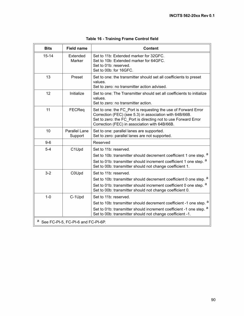
INCITS 562-20xx Rev 0.1
90
Table 16 - Training Frame Control field
Bits Field name Content
15-14 Extended Marker
Set to 11b: Extended marker for 32GFC.Set to 10b: Extended marker for 64GFC.Set to 01b: reserved.Set to 00b: for 16GFC.
13 Preset Set to one: the transmitter should set all coefficients to preset values.Set to zero: no transmitter action advised.
12 Initialize Set to one: The Transmitter should set all coefficients to initialize values.Set to zero: no transmitter action.
11 FECReq Set to one: the FC_Port is requesting the use of Forward Error Correction (FEC) (see 5.3) in association with 64B/66B.Set to zero: the FC_Port is directing not to use Forward Error Correction (FEC) in association with 64B/66B.
10 Parallel Lane Support
Set to one: parallel lanes are supported.Set to zero: parallel lanes are not supported.
9-6 Reserved
5-4 C1Upd Set to 11b: reserved.
Set to 10b: transmitter should decrement coefficient 1 one step. a
Set to 01b: transmitter should increment coefficient 1 one step. a
Set to 00b: transmitter should not change coefficient 1.
3-2 C0Upd Set to 11b: reserved.
Set to 10b: transmitter should decrement coefficient 0 one step. a
Set to 01b: transmitter should increment coefficient 0 one step. a
Set to 00b: transmitter should not change coefficient 0.
1-0 C-1Upd Set to 11b: reserved.
Set to 10b: transmitter should decrement coefficient -1 one step. a
Set to 01b: transmitter should increment coefficient -1 one step. a
Set to 00b: transmitter should not change coefficient -1.
a See FC-PI-5, FC-PI-6 and FC-PI-6P.
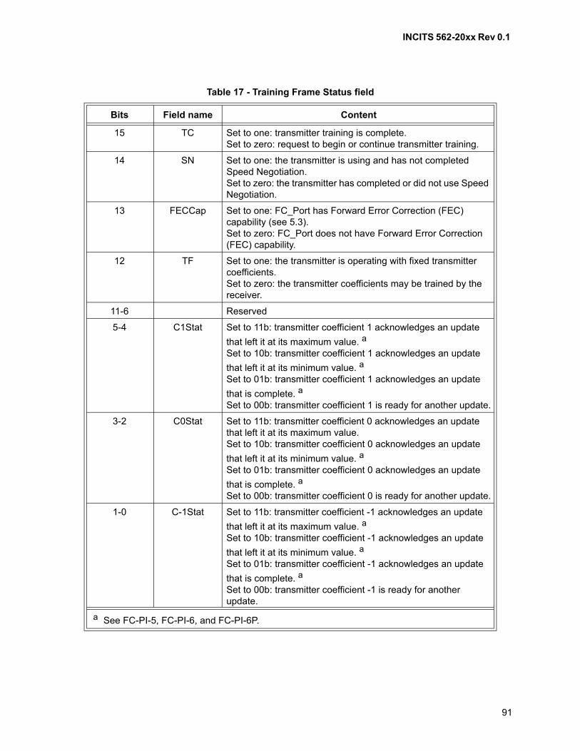
INCITS 562-20xx Rev 0.1
91
Table 17 - Training Frame Status field
Bits Field name Content
15 TC Set to one: transmitter training is complete.Set to zero: request to begin or continue transmitter training.
14 SN Set to one: the transmitter is using and has not completed Speed Negotiation.Set to zero: the transmitter has completed or did not use Speed Negotiation.
13 FECCap Set to one: FC_Port has Forward Error Correction (FEC) capability (see 5.3).Set to zero: FC_Port does not have Forward Error Correction (FEC) capability.
12 TF Set to one: the transmitter is operating with fixed transmitter coefficients.Set to zero: the transmitter coefficients may be trained by the receiver.
11-6 Reserved
5-4 C1Stat Set to 11b: transmitter coefficient 1 acknowledges an update
that left it at its maximum value. a
Set to 10b: transmitter coefficient 1 acknowledges an update
that left it at its minimum value. a
Set to 01b: transmitter coefficient 1 acknowledges an update
that is complete. a
Set to 00b: transmitter coefficient 1 is ready for another update.
3-2 C0Stat Set to 11b: transmitter coefficient 0 acknowledges an update that left it at its maximum value.Set to 10b: transmitter coefficient 0 acknowledges an update
that left it at its minimum value. a
Set to 01b: transmitter coefficient 0 acknowledges an update
that is complete. a
Set to 00b: transmitter coefficient 0 is ready for another update.
1-0 C-1Stat Set to 11b: transmitter coefficient -1 acknowledges an update
that left it at its maximum value. a
Set to 10b: transmitter coefficient -1 acknowledges an update
that left it at its minimum value. a
Set to 01b: transmitter coefficient -1 acknowledges an update
that is complete. a
Set to 00b: transmitter coefficient -1 is ready for another update.
a See FC-PI-5, FC-PI-6, and FC-PI-6P.

INCITS 562-20xx Rev 0.1
92
5.6.3 Training Pattern
The Training Pattern is the element of a Transmitter Training Signal that allows a receiver to evaluate itsability to achieve reliable Fibre Channel communication across the link on which the Training Pattern issent. The Training Pattern shall be composed of 4094 TUI of PRBS-11 followed by two TUI of zero.PRBS-11 (see figure 37) shall be equivalent to the output of an 11-bit linear feedback shift register that isinitialized to a value that is randomized to a non-zero value for each training frame, and that implementsthe polynomial
x11 +x9 + 1
5.7 Transmitter Training Signal for 64GFC Transmitter Training
5.7.1 Overview
An FC-0 standard (e.g., FC-PI-5) may specify the use of the Transmitter Training Signal. The TransmitterTraining Signal shall not be used for communication of Fibre Channel frames.
The Transmitter Training Signal is a transmission code that enables active feedback from a receiver to atransmitter to assist in adapting the transmitter to the characteristics of the link that connects them.Adjustable transmitter coefficients are supported. The use and effect of each coefficient is specified inFC-PI-x. It is expected that two FC_Ports on a link will concurrently send the Transmitter Training Signalallowing each FC_Port to evaluate the received signal quality and recommend adjustments to thetransmitter of the other FC_Port. The Transmitter Training Signal may be sent to communicate informationwithout doing transmitter training.
FEC is mandatory for 64GFC and FEC negotiation is not performed using the Transmitter Training Signal.The Transmitter Training Signal allows enabling parallel lane support (see table 16) by setting TrainingFrame Control field bit 10 to one, if a lane is capable of running at 64GFC speeds.
5.7.2 Training Frame
The training frame structure is specified in IEEE 802.3cd D2.2 136.8.11.1.
The training frame marker is specified in IEEE 802.3cd D2.2 136.8.11.1.1.
Figure 37 - PRBS-11 as a linear feedback shift register
x1 x2 x3 x8 x9 x10 x11
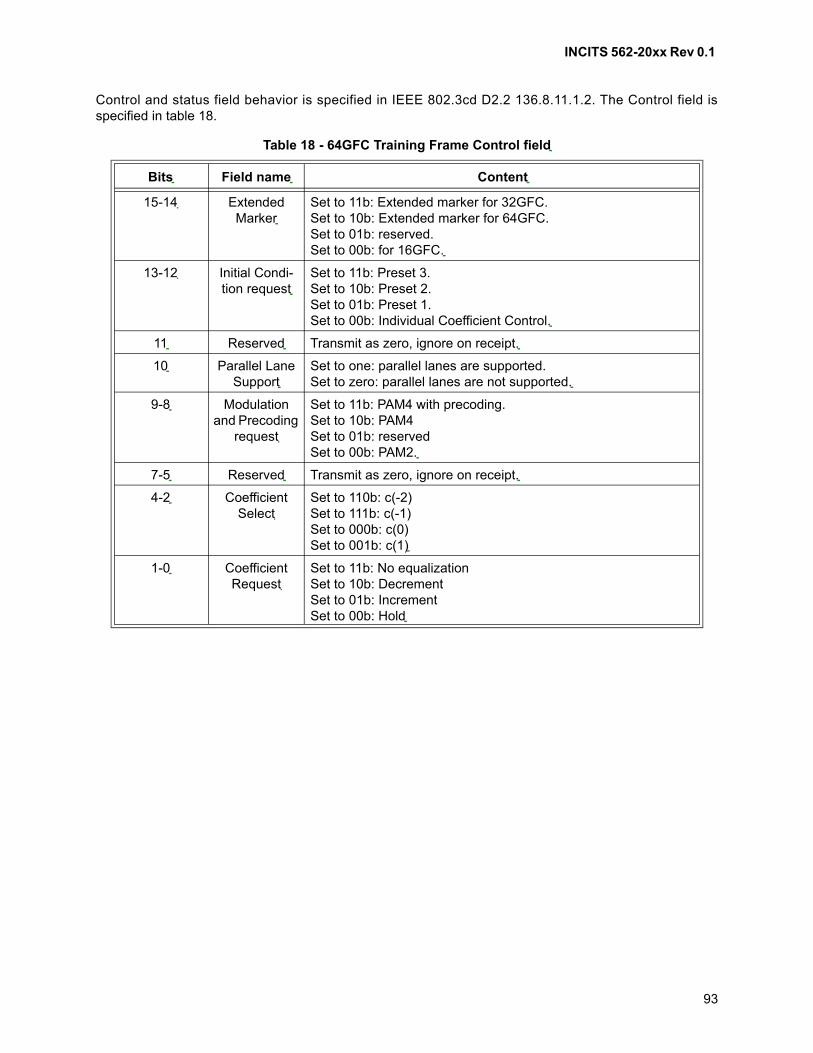
INCITS 562-20xx Rev 0.1
93
Control and status field behavior is specified in IEEE 802.3cd D2.2 136.8.11.1.2. The Control field isspecified in table 18.
Table 18 - 64GFC Training Frame Control field
Bits Field name Content
15-14 Extended Marker
Set to 11b: Extended marker for 32GFC.Set to 10b: Extended marker for 64GFC.Set to 01b: reserved.Set to 00b: for 16GFC.
13-12 Initial Condi-tion request
Set to 11b: Preset 3.Set to 10b: Preset 2.Set to 01b: Preset 1.Set to 00b: Individual Coefficient Control.
11 Reserved Transmit as zero, ignore on receipt.
10 Parallel Lane Support
Set to one: parallel lanes are supported.Set to zero: parallel lanes are not supported.
9-8 Modulation and Precoding
request
Set to 11b: PAM4 with precoding.Set to 10b: PAM4Set to 01b: reservedSet to 00b: PAM2.
7-5 Reserved Transmit as zero, ignore on receipt.
4-2 Coefficient Select
Set to 110b: c(-2)Set to 111b: c(-1)Set to 000b: c(0)Set to 001b: c(1)
1-0 Coefficient Request
Set to 11b: No equalizationSet to 10b: DecrementSet to 01b: IncrementSet to 00b: Hold
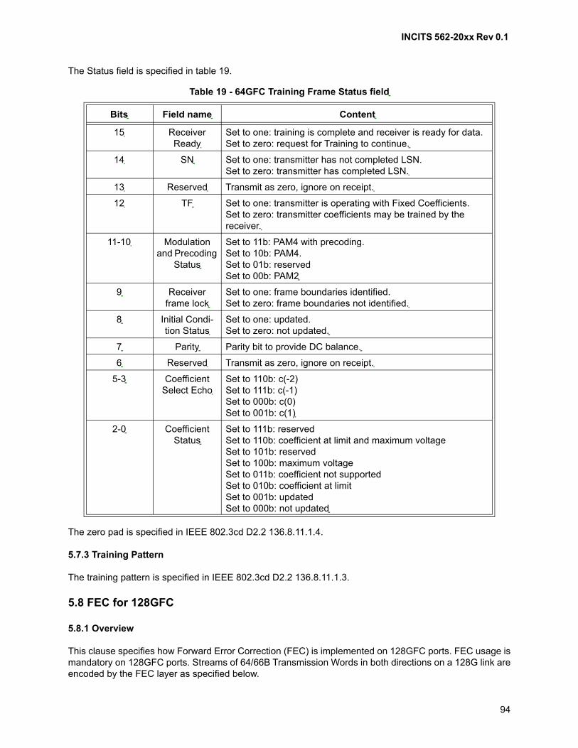
INCITS 562-20xx Rev 0.1
94
The Status field is specified in table 19.
The zero pad is specified in IEEE 802.3cd D2.2 136.8.11.1.4.
5.7.3 Training Pattern
The training pattern is specified in IEEE 802.3cd D2.2 136.8.11.1.3.
5.8 FEC for 128GFC
5.8.1 Overview
This clause specifies how Forward Error Correction (FEC) is implemented on 128GFC ports. FEC usage ismandatory on 128GFC ports. Streams of 64/66B Transmission Words in both directions on a 128G link areencoded by the FEC layer as specified below.
Table 19 - 64GFC Training Frame Status field
Bits Field name Content
15 Receiver Ready
Set to one: training is complete and receiver is ready for data.Set to zero: request for Training to continue.
14 SN Set to one: transmitter has not completed LSN.Set to zero: transmitter has completed LSN.
13 Reserved Transmit as zero, ignore on receipt.
12 TF Set to one: transmitter is operating with Fixed Coefficients.Set to zero: transmitter coefficients may be trained by the receiver.
11-10 Modulation and Precoding
Status
Set to 11b: PAM4 with precoding.Set to 10b: PAM4.Set to 01b: reservedSet to 00b: PAM2
9 Receiver frame lock
Set to one: frame boundaries identified.Set to zero: frame boundaries not identified.
8 Initial Condi-tion Status
Set to one: updated.Set to zero: not updated.
7 Parity Parity bit to provide DC balance.
6 Reserved Transmit as zero, ignore on receipt.
5-3 Coefficient Select Echo
Set to 110b: c(-2)Set to 111b: c(-1)Set to 000b: c(0)Set to 001b: c(1)
2-0 Coefficient Status
Set to 111b: reservedSet to 110b: coefficient at limit and maximum voltageSet to 101b: reservedSet to 100b: maximum voltageSet to 011b: coefficient not supportedSet to 010b: coefficient at limitSet to 001b: updatedSet to 000b: not updated
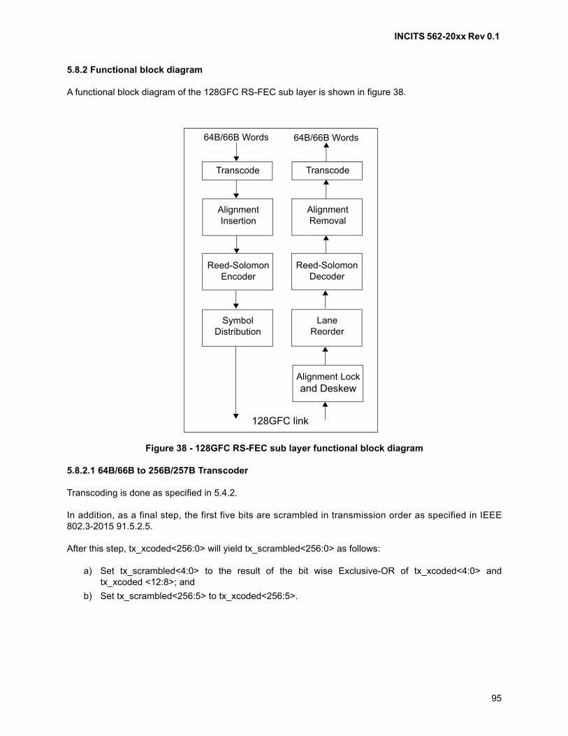
INCITS 562-20xx Rev 0.1
95
5.8.2 Functional block diagram
A functional block diagram of the 128GFC RS-FEC sub layer is shown in figure 38.
5.8.2.1 64B/66B to 256B/257B Transcoder
Transcoding is done as specified in 5.4.2.
In addition, as a final step, the first five bits are scrambled in transmission order as specified in IEEE802.3-2015 91.5.2.5.
After this step, tx_xcoded<256:0> will yield tx_scrambled<256:0> as follows:
a) Set tx_scrambled<4:0> to the result of the bit wise Exclusive-OR of tx_xcoded<4:0> andtx_xcoded <12:8>; and
b) Set tx_scrambled<256:5> to tx_xcoded<256:5>.
Figure 38 - 128GFC RS-FEC sub layer functional block diagram
Transcode Transcode
64B/66B Words 64B/66B Words
AlignmentInsertion
Reed-SolomonEncoder
SymbolDistribution
AlignmentRemoval
Reed-SolomonDecoder
LaneReorder
Alignment Lockand Deskew
128GFC link

INCITS 562-20xx Rev 0.1
96
5.8.2.2 Alignment marker mapping and insertion
The alignment insertion function inserts a unique data pattern (i.e., Alignment Marker) for each link into thedata stream to enable identification of which of the four links is which FEC lane. This function enables thereceiver to map the physical links to logical lanes allowing for random connections of the Transmit links tothe Receive links within the group of 4 links, in addition to providing a framing pattern for aligning the FECcode words.
The first 514b of every 4096th FEC code word carries Alignment Marker information.
The alignment marker bit sequence is identical to the first two re-mapped AM blocks specified in Clause82.2.7 and Clause 91.5.2.6 when replacing the BIP3 field in all four instances of the AM0 blocks with thevalue 0xCA, the BIP3 for AM4 with 0x9D, the BIP3 for AM5 with 0xD7, the BIP3 for AM6 with 0x6F, and theBIP3 for AM7 with 0xA1. Additionally the first bit of AM8 and AM9 that are part of the sequence is changedfrom 0->1 to maintain DC balance.
Table 20 shows the data stream that will appear on each of the 4 lanes after the RS symbol distribution ofthe AM pattern is done. The ‘d’ is the first 6b of data from block that follows the AM pattern. The underlinedvalues are the replaced BIP3 and BIP7 fields in the AM blocks.
5.8.2.3 Reed-Solomon encoder
Reed-Solomon encoding is done as specified in 5.4.3.
5.8.2.4 Symbol distribution
Once the data has been encoded, it is distributed to 4 lanes, in groups of 10 bit symbols.
Symbol distribution is done as specified in IEEE 802.3-2015 91.5.2.8.
5.8.2.5 Transmit bit ordering
Table 20 - 128GFC FEC Alignment Marker
AM bits Lane3 Lane2 Lane1 Lane0
[39:0] 0011000001 0011000001 0011000001 0011000001
[79:40] 0001011010 0001011010 0001011010 0001011010
[119:80] 0010100010 0010100010 0010100010 0010100010
[159:120] 0011111011 0011111011 0011111011 0011111011
[199:160] 1010010111 1010010111 1010010111 1010010111
[239:200] 0101110111 0101110111 0101110111 0101110111
[279:240] 1110110011 0110100011 0111010011 1101010011
[319:280] 0100010101 0100101010 0001010011 0000011111
[359:320] 0101100110 1100100110 1111000010 0100001001
[399:360] 0100101000 0101011011 0010110101 1010100111
[439:400] 1110101000 1101010110 1010110010 1110000000
[479:440] 1001100110 1101100110 0011110111 1111011011
[513:480] dddddd1110 0110010000 0100101000 0101100010
INCITS 562-20xx Rev 0.1
97
Transmit bit ordering is as shown in figure 39.
5.8.2.6 Alignment lock and deskew
The receive function creates 4 bit streams after concatenating the bits received on each lane. It thenobtains LOCK to the alignment markers on each lane as specified by the FEC synchronization statediagram in IEEE 802.3-2015 91.5.3.1.
After alignment marker lock is achieved on all four lanes, all inter lane skew is removed as specified by theFEC alignment state diagram in IEEE 802.3-2015 91.5.3.1. The FEC receive function will support amaximum skew of 180ns between lanes and a maximum skew variation of 4ns.
5.8.2.7 Lane reorder
FEC lanes may be received on different lanes of the service interface from which they were originallytransmitted.
The FEC receive function shall order the FEC lanes according to the FEC lane number per IEEE802.3-2015 91.5.3.2.The FEC lane number is defined by the alignment marker that is mapped to eachFEC lane.
After all FEC lanes are aligned, deskewed, and reordered, the FEC lanes are multiplexed together in theproper order to reconstruct the original stream of FEC code words.
5.8.2.8 Reed-Solomon decoder
Decoding is done as specified in 5.4.6.
5.8.2.9 Alignment marker removal
The first 514 bits in every 4096 code words are the mapped alignment marker bits. These are removedbefore sending the data to the transcode block.
5.8.2.10 256B/257B to 64B/66B transcoder
The first five bits of the of the received block rx_scrambled<256:0>, in reception order, are descrambled.Rx_scrambled<256:0> will yield rx_coded<256:0> as follows:
a) Set rx_coded<4:0> to the result of the bit wise Exclusive-OR of rx_scrambled<4:0> andrx_scrambled<12:8>; and
b) Set rx_coded<256:5> to rx_scrambled<256:5>.
Next, a group of four 66 bit transmission words are constructed from each received 257 bit transmissionword as specified in 5.4.7.
5.8.2.11 Receive bit ordering
Receive bit ordering is as specified in figure 40.
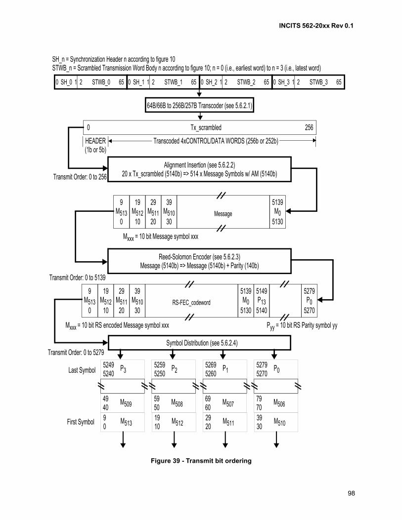
INCITS 562-20xx Rev 0.1
98
Figure 39 - Transmit bit ordering
0 SH_0 1 2 STWB_0 65 0 SH_1 1 2 STWB_1 65 0 SH_2 1 2 STWB_2 65 0 SH_3 1 2 STWB_3 65
64B/66B to 256B/257B Transcoder (see 5.6.2.1)
Tx_scrambled0 256
Alignment Insertion (see 5.6.2.2)20 x Tx_scrambled (5140b) => 514 x Message Symbols w/ AM (5140b)
29M511
20
39M510
30RS-FEC_codeword
5139M0
5130
5149P13
5140
5279P0
5270
9M513
0
19M512
10
Symbol Distribution (see 5.6.2.4)
SH_n = Synchronization Header n according to figure 10STWB_n = Scrambled Transmission Word Body n according to figure 10; n = 0 (i.e., earliest word) to n = 3 (i.e., latest word)
Transcoded 4xCONTROL/DATA WORDS (256b or 252b)HEADER(1b or 5b)
Transmit Order: 0 to 256
Mxxx = 10 bit RS encoded Message symbol xxx Pyy = 10 bit RS Parity symbol yy
Transmit Order: 0 to 5279
29M511
20
39M510
30Message
5139M0
5130
9M513
0
19M512
10
Mxxx = 10 bit Message symbol xxx
Reed-Solomon Encoder (see 5.6.2.3)Message (5140b) => Message (5140b) + Parity (140b)
Transmit Order: 0 to 5139
52495240
P3
4940
M509
90
M513
52595250
P2
5950
M508
1910
M512
52695260
P1
6960
M507
2920
M511
52795270
P0
7970
M506
3930
M510
Last Symbol
First Symbol
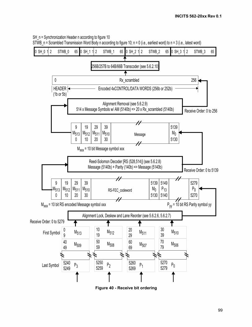
INCITS 562-20xx Rev 0.1
99
Figure 40 - Receive bit ordering
0 SH_0 1 2 STWB_0 65 0 SH_1 1 2 STWB_1 65 0 SH_2 1 2 STWB_2 65 0 SH_3 1 2 STWB_3 65
256B/257B to 64B/66B Transcoder (see 5.6.2.10)
Rx_scrambled0 256
Alignment Removal (see 5.6.2.9)514 x Message Symbols w/ AM (5140b) => 20 x Rx_scrambled (5140b)
29M511
20
39M510
30RS-FEC_codeword
5139M0
5130
5149P13
5140
5279P0
5270
9M513
0
19M512
10
Alignment Lock, Deskew and Lane Reorder (see 5.6.2.6, 5.6.2.7)
SH_n = Synchronization Header n according to figure 10STWB_n = Scrambled Transmission Word Body n according to figure 10; n = 0 (i.e., earliest word) to n = 3 (i.e., latest word)
Encoded 4xCONTROL/DATA WORDS (256b or 252b)HEADER(1b or 5b)
Receive Order: 0 to 256
Mxxx = 10 bit RS encoded Message symbol xxx Pyy = 10 bit RS Parity symbol yy
Receive Order: 0 to 5279
29M511
20
39M510
30Message
5139M0
5130
9M513
0
19M512
10
Mxxx = 10 bit Message symbol xxx
Reed-Solomon Decoder [RS (528,514)] (see 5.6.2.8)Message (5140b) + Parity (140b) => Message (5140b)
Receive Order: 0 to 5139
52405249
P3
4049
M509
09
M513
52505259
P2
5059
M508
1019
M512
52605269
P1
6069
M507
2029
M511
52705279
P0
7079
M506
3039
M510First Symbol
Last Symbol
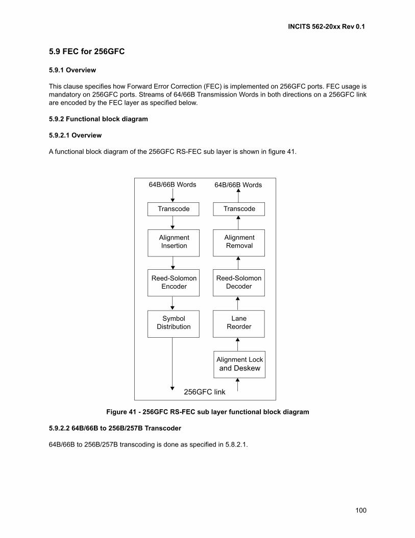
INCITS 562-20xx Rev 0.1
100
5.9 FEC for 256GFC
5.9.1 Overview
This clause specifies how Forward Error Correction (FEC) is implemented on 256GFC ports. FEC usage ismandatory on 256GFC ports. Streams of 64/66B Transmission Words in both directions on a 256GFC linkare encoded by the FEC layer as specified below.
5.9.2 Functional block diagram
5.9.2.1 Overview
A functional block diagram of the 256GFC RS-FEC sub layer is shown in figure 41.
5.9.2.2 64B/66B to 256B/257B Transcoder
64B/66B to 256B/257B transcoding is done as specified in 5.8.2.1.
Figure 41 - 256GFC RS-FEC sub layer functional block diagram
Transcode Transcode
64B/66B Words 64B/66B Words
AlignmentInsertion
Reed-SolomonEncoder
SymbolDistribution
AlignmentRemoval
Reed-SolomonDecoder
LaneReorder
Alignment Lockand Deskew
256GFC link

INCITS 562-20xx Rev 0.1
101
5.9.2.3 Alignment marker mapping and insertion
The alignment insertion function inserts a unique data pattern (i.e., Alignment Marker) for each link into thedata stream to enable identification of which of the four links is which FEC lane. This function enables thereceiver to map the physical links to logical lanes allowing for random connections of the Transmit links tothe Receive links within the group of 4 links, in addition to providing a framing pattern for aligning the FECcode words.
The first 514b of every 4096th FEC code word carries Alignment Marker information.
The alignment marker bit sequence is identical to the first two re-mapped AM blocks specified in Clause82.2.7 and Clause 91.5.2.6 when replacing the BIP3 field for Lane 1, Lane 2, and Lane 3 of the AM0blocks with the value 0xCA, the BIP3 for AM4 with 0x9D, the BIP3 for AM5 with 0xD7, the BIP3 for AM6with 0x6F, and the BIP3 for AM7 with 0xA1. For Lane0, the BIP3 field of AM0 carries Link degradeinformation associated with the link degrade function (see 5.5.10.2). Additionally the first bit of AM8 andAM9 that are part of the sequence is changed from 0->1 to maintain DC balance.
Table 21 shows the data stream that will appear on each of the 4 lanes after the RS symbol distribution ofthe AM pattern is done. The ‘d’ is the first 6b of data from block that follows the AM pattern. The underlinedvalues are the replaced BIP3 and BIP7 fields in the AM blocks.
5.9.2.4 Reed-Solomon encoder
Reed-Solomon encoding is done as specified in 5.5.4.
5.9.2.5 Symbol distribution
Once the data has been encoded, it is distributed to 4 lanes, in groups of 10 bit symbols.
Table 21 - 256GFC FEC Alignment Marker
AM bits Lane3 Lane2 Lane1 Lane0
[39:0] 0011000001 0011000001 0011000001 0011000001
[79:40] 0001011010 0001011010 0001011010 0001011010
[119:80] 0010100010 0010100010 0010100010 10000, RD,0010
[159:120] 0011111011 0011111011 0011111011 0011111010
[199:160] 1010010111 1010010111 1010010111 1010010111
[239:200] 0101110111 0101110111 0101110111 111, ~RD,110111
[279:240] 1110110011 0110100011 0111010011 1101010101
[319:280] 0100010101 0100101010 0001010011 0000011111
[359:320] 0101100110 1100100110 1111000010 0100001001
[399:360] 0100101000 0101011011 0010110101 1010100111
[439:400] 1110101000 1101010110 1010110010 1110000000
[479:440] 1001100110 1101100110 0011110111 1111011011
[513:480] dddddd1110 0110010000 0100101000 0101100010

INCITS 562-20xx Rev 0.1
102
Symbol distribution is done as specified in IEEE 802.3-2015 91.5.2.8.
5.9.2.6 Gray mapping
Gray mapping is done as specified in 5.5.5.
5.9.2.7 Precoding
Precoding is done independently for each of the 4 lanes as specified in 5.5.6.
5.9.2.8 Transmit bit ordering
Transmit bit ordering is as shown in figure 42.
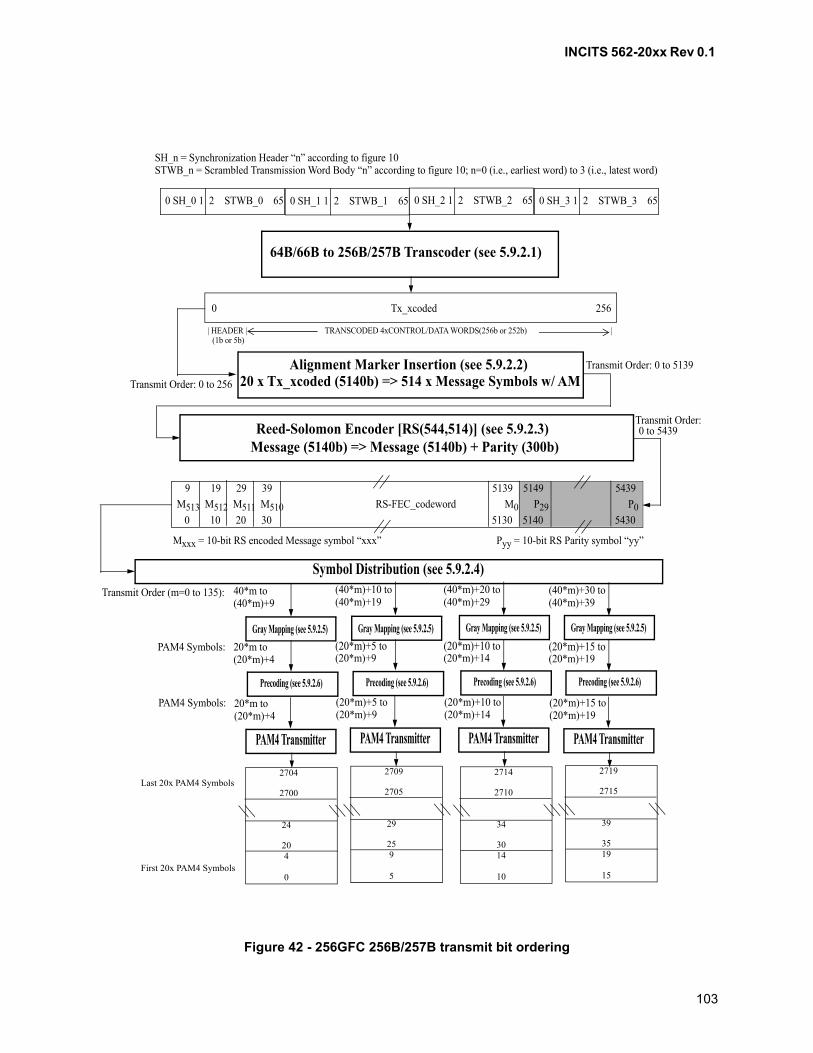
INCITS 562-20xx Rev 0.1
103
Figure 42 - 256GFC 256B/257B transmit bit ordering
M513 M512 M511 M510 RS-FEC_codeword M0 P29 P0
9 19 29 39 5139 5149 5439
0 10 20 30 5130 5140 5430
Mxxx = 10-bit RS encoded Message symbol “xxx” Pyy = 10-bit RS Parity symbol “yy”
0 SH_0 1 2 STWB_0 65 0 SH_1 1 2 STWB_1 65 0 SH_2 1 2 STWB_2 65 0 SH_3 1 2 STWB_3 65
SH_n = Synchronization Header “n” according to figure 10STWB_n = Scrambled Transmission Word Body “n” according to figure 10; n=0 (i.e., earliest word) to 3 (i.e., latest word)
64B/66B to 256B/257B Transcoder (see 5.9.2.1)
0 Tx_xcoded 256
| HEADER | TRANSCODED 4xCONTROL/DATA WORDS(256b or 252b) | (1b or 5b)
Alignment Marker Insertion (see 5.9.2.2)20 x Tx_xcoded (5140b) => 514 x Message Symbols w/ AM
Reed-Solomon Encoder [RS(544,514)] (see 5.9.2.3)Message (5140b) => Message (5140b) + Parity (300b)
Transmit Order: 0 to 256
Transmit Order: 0 to 5139
Transmit Order: 0 to 5439
Symbol Distribution (see 5.9.2.4)
Gray Mapping (see 5.9.2.5)
Precoding (see 5.9.2.6)
PAM4 Transmitter
Transmit Order (m=0 to 135):
20*m to(20*m)+4
40*m to(40*m)+9
PAM4 Symbols:
PAM4 Symbols: 20*m to(20*m)+4
PAM4 Transmitter
(20*m)+5 to(20*m)+9
(40*m)+10 to(40*m)+19
(20*m)+5 to(20*m)+9
PAM4 Transmitter
(20*m)+10 to(20*m)+14
(40*m)+20 to(40*m)+29
(20*m)+10 to(20*m)+14
PAM4 Transmitter
(20*m)+15 to(20*m)+19
(40*m)+30 to(40*m)+39
(20*m)+15 to(20*m)+19
2704
2700
24
20 4
0
Last 20x PAM4 Symbols
First 20x PAM4 Symbols
2709
2705
29
25 9
5
2714
2710
34
30 14
10
2719
2715
39
35 19
15
Gray Mapping (see 5.9.2.5)
Precoding (see 5.9.2.6)
Gray Mapping (see 5.9.2.5)
Precoding (see 5.9.2.6)
Gray Mapping (see 5.9.2.5)
Precoding (see 5.9.2.6)
INCITS 562-20xx Rev 0.1
104
5.9.2.9 Inverse precoding
Inverse precoding is done independently for each of the 4 lanes as specified in 5.5.7.
5.9.2.10 Inverse Gray mapping
Inverse Gray mapping is done as specified in 5.5.8.
5.9.2.11 Alignment lock and deskew
The receive function creates 4 bit streams after concatenating the bits received on each lane. It thenobtains LOCK to the alignment markers on each lane as specified by the FEC synchronization statediagram in IEEE 802.3-2015 91.5.3.1.
After alignment marker lock is achieved on all four lanes, all inter lane skew is removed as specified by theFEC alignment state diagram in IEEE 802.3-2015 91.5.3.1. The FEC receive function will support amaximum skew of 180ns between lanes and a maximum skew variation of 4ns.
5.9.2.12 Lane reorder
FEC lanes may be received on different lanes of the service interface from which they were originallytransmitted.
The FEC receive function shall order the FEC lanes according to the FEC lane number per IEEE802.3-2015 91.5.3.2.The FEC lane number is defined by the alignment marker that is mapped to eachFEC lane.
After all FEC lanes are aligned, deskewed, and reordered, the FEC lanes are multiplexed together in theproper order to reconstruct the original stream of FEC code words.
5.9.2.13 Reed-Solomon decoder
Decoding is done as specified in 5.5.10.1. In addition, link degrade signaling is done as specified in5.5.10.2.
5.9.2.14 Alignment marker removal
The first 514 bits in every 4096 code words are the mapped alignment marker bits. These are removedbefore sending the data to the transcode block.
5.9.2.15 256B/257B to 64B/66B transcoder
The first five bits of the of the received block rx_scrambled<256:0>, in reception order, are descrambled sothat rx_scrambled<256:0> generates rx_coded<256:0> as follows:
a) Set rx_coded<4:0> to the result of the bit wise Exclusive-OR of rx_scrambled<4:0> andrx_scrambled<12:8>; and
b) Set rx_coded<256:5> to rx_scrambled<256:5>.
Next, a group of four 66 bit transmission words are constructed from each received 257 bit transmissionword as specified in 5.4.7.

INCITS 562-20xx Rev 0.1
105
5.9.2.16 Receive bit ordering
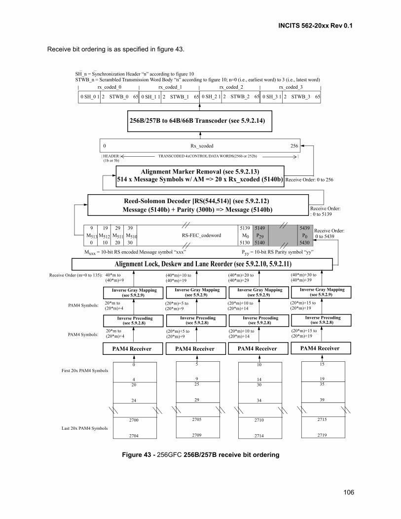
INCITS 562-20xx Rev 0.1
106
Receive bit ordering is as specified in figure 43.
Figure 43 - 256GFC 256B/257B receive bit ordering
M513 M512 M511 M510 RS-FEC_codeword M0 P29 P0
9 19 29 39 5139 5149 5439
0 10 20 30 5130 5140 5430
Mxxx = 10-bit RS encoded Message symbol “xxx” Pyy = 10-bit RS Parity symbol “yy”
0 SH_0 1 2 STWB_0 65 0 SH_1 1 2 STWB_1 65 0 SH_2 1 2 STWB_2 65 0 SH_3 1 2 STWB_3 65
SH_n = Synchronization Header “n” according to figure 10STWB_n = Scrambled Transmission Word Body “n” according to figure 10; n=0 (i.e., earliest word) to 3 (i.e., latest word)
256B/257B to 64B/66B Transcoder (see 5.9.2.14)
0 Rx_xcoded 256
| HEADER | TRANSCODED 4xCONTROL/DATA WORDS(256b or 252b) | (1b or 5b)
Alignment Marker Removal (see 5.9.2.13)514 x Message Symbols w/ AM => 20 x Rx_xcoded (5140b)
Reed-Solomon Decoder [RS(544,514)] (see 5.9.2.12)Message (5140b) + Parity (300b) => Message (5140b)
Receive Order:
Receive Order:
Receive Order: 0 to 256
rx_coded_0 rx_coded_1 rx_coded_2 rx_coded_3
_ _ ( )
: 0 to 5139
0 to 5439
Alignment Lock, Deskew and Lane Reorder (see 5.9.2.10, 5.9.2.11)
Inverse Gray Mapping
Inverse Precoding
PAM4 Receiver
Receive Order (m=0 to 135): 40*m to(40*m)+9
20*m to(20*m)+4
PAM4 Symbols:
20*m to(20*m)+4PAM4 Symbols:
PAM4 Receiver
(40*m)+10 to(40*m)+19
(20*m)+5 to(20*m)+9
(20*m)+5 to(20*m)+9
PAM4 Receiver
(40*m)+20 to(40*m)+29
(20*m)+10 to(20*m)+14
(20*m)+10 to(20*m)+14
PAM4 Receiver
(40*m)+30 to(40*m)+39
(20*m)+15 to(20*m)+19
(20*m)+15 to(20*m)+19
First 20x PAM4 Symbols
Last 20x PAM4 Symbols
0
4 20
24
2700
2704
5
9 25
29
2705
2709
10
14 30
34
2710
2714
15
19 35
39
2715
2719
(see 5.9.2.8)
(see 5.9.2.9)Inverse Gray Mapping
Inverse Precoding (see 5.9.2.8)
(see 5.9.2.9)Inverse Gray Mapping
Inverse Precoding (see 5.9.2.8)
(see 5.9.2.9)Inverse Gray Mapping
Inverse Precoding (see 5.9.2.8)
(see 5.9.2.9)
INCITS 562-20xx Rev 0.1
107
6 FC-1 Transmission Word Synchronization
6.1 Scope
Transmission Word Synchronization is a function of the FC-1 level.
6.2 Introduction
In the Fibre Channel architecture, the FC-0 level is responsible for bit transmission and reception (seeFC-PI-x). The FC-1 level is responsible for providing a stream of bits for the FC-0 level to transmit. No stateinformation is needed to accomplish this other than that necessary for 64B/66B scrambling and 8B/10Brunning disparity. The FC-1 level is also responsible for deriving Transmission Word Synchronization andTransmission Words from the received bit stream.
Whenever a signal (see FC-PI-x) is detected on a fibre, the receiver attached to that fibre shall attempt toachieve synchronization on both bit and Transmission Word boundaries of the received encoded bitstream. Bit Synchronization is defined in FC-PI-x. Transmission Word Synchronization is defined in thisclause. Synchronization failures on either bit or Transmission Word boundaries are not separatelyidentifiable; both cause Loss-of-Synchronization errors.
An FC_Port receiver has two mutually exclusive receiver Transmission Word Synchronization states, WordSynchronization Acquired and Loss of Synchronization. In the Word Synchronization Acquired state, theFC-1 level shall decode the received signal and pass information to the FC-2P level. In the Loss ofSynchronization state, the FC-1 level shall not pass information to the FC-2P level.
A receiver may provide an indication of a Loss-of-Signal condition (see FC-PI-x).
6.3 8B/10B Transmission Word Synchronization
6.3.1 State Diagram Overview
The Receiver State Diagram for 8B/10B Transmission Word Synchronization is shown in figure 44.
The Receiver states are as follows:
a) Loss of Synchronization state;
b) No Invalid Transmission Word Detected state;
c) First Invalid Transmission Word Detected state;
d) Second Invalid Transmission Word Detected state;
e) Third Invalid Transmission Word Detected state; and
f) Reset state.
Being in one of the Word Synchronization Acquired states refers to being in any of:
a) No Invalid Transmission Word Detected state;
b) First Invalid Transmission Word Detected state;
c) Second Invalid Transmission Word Detected state; or
d) Third Invalid Transmission Word Detected state.
INCITS 562-20xx Rev 0.1
108
The receiver state transitions are defined as follows:
a) Transition 1: Power-on;
b) Transition 2: Acquisition of Word Synchronization (see 6.3.3.2.2);
c) Transition 3: An invalid Transmission Word is detected (see 6.3.4.2);
d) Transition 4: A detection of a Loss-of-Signal condition (see 6.2);
e) Transition 5: Two consecutive Transmission Words that are not Invalid Transmission Words aredetected (see 6.3.4.2);
f) Transition 6: Reset condition imposed on the receiver (see 6.3.5.4); and
g) Transition 7: Exiting of receiver reset condition (see 6.3.5.4).
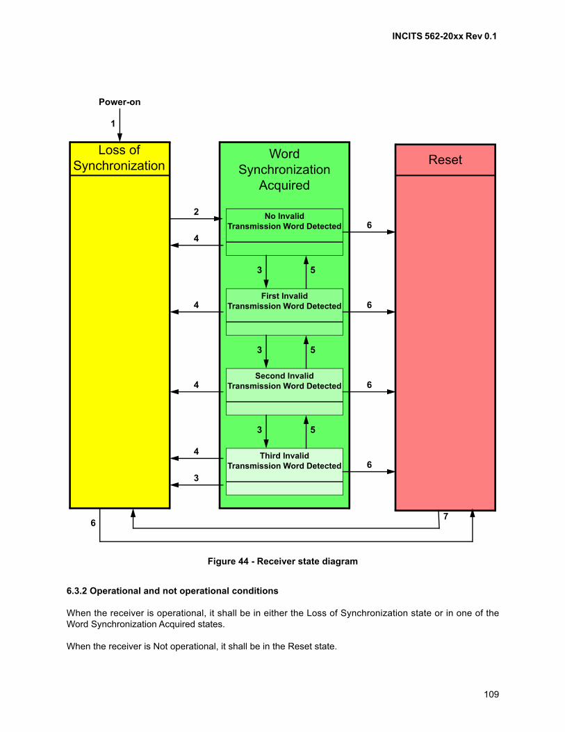
INCITS 562-20xx Rev 0.1
109
6.3.2 Operational and not operational conditions
When the receiver is operational, it shall be in either the Loss of Synchronization state or in one of theWord Synchronization Acquired states.
When the receiver is Not operational, it shall be in the Reset state.
Reset
Figure 44 - Receiver state diagram
Loss ofSynchronization
WordSynchronization
Acquired
First InvalidTransmission Word Detected
No InvalidTransmission Word Detected
Second InvalidTransmission Word Detected
Third InvalidTransmission Word Detected
2
4
4
4
4
6
6
6
6
3
3
7
5
3 5
3 5
1
Power-on
6
INCITS 562-20xx Rev 0.1
110
6.3.3 Transmission Word Synchronization Procedure
The Transmission Word Synchronization procedure consists of first achieving Bit Synchronization (see6.3.3.1), followed by achieving Transmission Word Synchronization (see 6.3.3.2).
6.3.3.1 Bit Synchronization
An operational receiver that is in the Loss of Synchronization state shall first acquire Bit Synchronizationbefore attempting to acquire Transmission Word Synchronization. Bit Synchronization is defined inFC-PI-x. After achieving Bit Synchronization, the receiver shall remain in the Loss of Synchronization stateuntil it achieves Transmission Word Synchronization.
6.3.3.2 Transmission Word Synchronization detection
6.3.3.2.1 Introduction
The comma contained within the K28.5 special character is a singular bit pattern that in the absence oftransmission errors shall not appear in any other location of a Transmission Character and shall not begenerated across the boundaries of any two adjacent Transmission Characters. This bit pattern issufficient to identify the Transmission Word alignment of the received bit stream. Some implementations(e.g., those that choose to implement the Transmission Word alignment function in Continuous-modealignment) may choose to align on the full K28.5 Ordered Set to decrease the likelihood of false alignmentwhen bit errors are present in the received bit stream.
Placement of a K28.5 Transmission Character at the left-most position of a received Transmission Wordensures proper alignment of that Transmission Word and of subsequently received Transmission Words.Ordered Set detection shall include both detection of the individual Transmission Characters that make upan Ordered Set and proper alignment of those characters (i.e., the Special Character used to designate anOrdered Set shall be aligned in the leading (left-most) character position of the received TransmissionWord).
6.3.3.2.2 Achieving Transmission Word Synchronization
A receiver that is in the Loss of Synchronization state and has acquired Bit Synchronization shall attemptto acquire Transmission Word Synchronization. Transmission Word Synchronization is acquired by thedetection of three Ordered Sets containing commas in their left-most bit positions without an interveninginvalid Transmission Word, as specified in 6.3.4.2. The third detected Ordered Set shall change the statefrom the Loss of Synchronization state to the No Invalid Transmission Word Detected state using transition2. The third detected Ordered Set shall be considered valid information and shall be decoded and providedby the receiver to its FC_Port. A receiver in any of the Word Synchronization Acquired states shall provideinformation that has been received from its attached fibre and decoded.
The method used by the receiver to implement the Transmission Word alignment function and to detectOrdered Sets is not defined by this standard.
6.3.3.2.3 8B/10B Transmission Word Synchronization for speed negotiation
If the link speed negotiation algorithm (see 8.6) is performed using 8B/10B, then the pass sync_test countshall be 1 000.
INCITS 562-20xx Rev 0.1
111
6.3.3.2.4 Transmission Word alignment methods
6.3.3.2.4.1 Continuous-mode alignment
Continuous-mode alignment allows the receiver to reestablish Transmission Word alignment at any pointin the incoming bit stream while the receiver is operational. Such realignment is likely (but not guaranteed)to result in code violations and subsequent Loss-of-Synchronization. Under certain conditions, it may bepossible to realign an incoming bit stream without Loss-of-Synchronization. If such a realignment occurswithin a received frame, detection of the resulting error condition is dependent upon higher-level function(e.g., invalid CRC, missing EOF Delimiter).
6.3.3.2.4.2 Explicit-mode alignment
Explicit-mode alignment allows the receiver to reestablish Transmission Word alignment under controlledcircumstances (e.g., while in the Loss of Synchronization State). Once synchronization has been acquired,the Transmission Word alignment function of the receiver is disabled.
6.3.4 Loss of Transmission Word Synchronization
6.3.4.1 Introduction
Loss of Transmission Word Synchronization shall occur in the following conditions:
a) a Loss-of-Signal is detected when in any of the Word Synchronization Acquired states; or
b) an invalid Transmission Word is detected in the Third Invalid Transmission Word Detected state.
6.3.4.2 Detection of an invalid Transmission Word
In each of the Word Synchronization Acquired states each received Transmission Word is tested todetermine the validity of the Transmission Word.
An invalid Transmission Word shall be recognized by the receiver when one of the following conditions isdetected:
a) a code violation, as specified by the 8B/10B transmission code (see 5.2), is detected within aTransmission Word. This is referred to as a code violation condition;
b) a K30.7 special character is detected in any character position of a Transmission Word. Thisindicates an error condition has been detected at a lower implementation level within the receiver;
c) any valid special character is detected in the second, third, or fourth character position of aTransmission Word. This is referred to as an invalid special code alignment condition; or
d) a defined Ordered Set (see clause 5) is received with improper beginning running disparity (e.g., aSOF delimiter is received with positive beginning running disparity, an EOF delimiter specified forpositive beginning running disparity is received when beginning running disparity for thatTransmission Word is negative). This is referred to as an invalid beginning running disparitycondition.
6.3.5 State transitions
6.3.5.1 Default State
A receiver shall enter the Loss of Synchronization state on power-on (i.e., default).
INCITS 562-20xx Rev 0.1
112
6.3.5.2 Loss of Synchronization state
The Loss of Synchronization State shall be entered upon the following conditions:
a) completion of the Loss-of-Synchronization procedure while in the Third Invalid Transmission WordDetected state using transition 3;
b) detection of Loss-of-Signal while in the No Invalid Transmission Word Detected state, the FirstInvalid Transmission Word Detected state, the Second Invalid Transmission Word Detected state,or the Third Invalid Transmission Word Detected state using transition 4; or
c) completion of the reset while in the Reset state using transition 7.
While in the Loss of Synchronization State, the receiver may attempt to reacquire Bit Synchronization. Insome instances, this may allow the receiver to regain Transmission Word Synchronization when itotherwise would not be possible. However, initiation of bit re synchronization may also delay thesynchronization process by forcing the receiver to reestablish a clock reference when suchreestablishment is otherwise unnecessary (see FC-PI-x for a detailed discussion of Bit Synchronization).
When Transmission Word Synchronization is acquired the receiver shall enter the No Invalid TransmissionWord Detected state using transition 2. Imposing a reset condition upon the receiver shall cause any stateto transition to the Reset state using transition 6.
6.3.5.3 Word Synchronization Acquired states
6.3.5.3.1 Loss-of-Synchronization procedure
The following four states are defined as Word Synchronization Acquired states:
a) No Invalid Transmission Word Detected state;
b) First Invalid Transmission Word Detected state;
c) Second Invalid Transmission Word Detected state; or
d) Third Invalid Transmission Word Detected state.
NOTE 10 - The rationale for the Loss-of-Synchronization procedure is to reduce the likelihood that asingle error results in a Loss-of-Synchronization. A single two-bit error positioned to overlap twoTransmission Words could result in the detection of three invalid Transmission Words; the twoTransmission Words directly affected by the error and a subsequent Transmission Word that was affectedby a disparity change resulting from the error. The procedure described above would maintainsynchronization in such a case.
6.3.5.3.2 No Invalid Transmission Word Detected state
When the procedure is in the No Invalid Transmission Word Detected state, checking for an invalidTransmission Word shall be performed. Any invalid Transmission Word shall cause the No InvalidTransmission Word Detected state to transition to the First Invalid Transmission Word Detected state(transition 3). A Loss-of-Signal condition shall cause the No Invalid Transmission Word Detected state totransition to the Loss of Synchronization state (transition 4). A reset condition imposed upon the receivershall cause the No Invalid Transmission Word Detected state to transition to the Reset state (transition 6).
INCITS 562-20xx Rev 0.1
113
6.3.5.3.3 First Invalid Transmission Word Detected state
When the procedure is in the First Invalid Transmission Word Detected state, checking for an invalidTransmission Word shall be performed. Any invalid Transmission Word shall cause the First InvalidTransmission Word Detected state to transition to the Second Invalid Transmission Word Detected state(transition 3). If two consecutive Transmission Words that are not Invalid Transmission Words arereceived, the First Invalid Transmission Word Detected state shall transition to the No Invalid TransmissionWord Detected state (transition 5). A Loss-of-Signal condition shall cause the First Invalid TransmissionWord Detected state to transition to the Loss of Synchronization state (transition 4). A reset conditionimposed upon the receiver shall cause the First Invalid Transmission Word Detected state to transition tothe Reset state (transition 6).
6.3.5.3.4 Second Invalid Transmission Word Detected state
When the procedure is in the Second Invalid Transmission Word Detected state, checking for an invalidTransmission Word shall be performed. Any invalid Transmission Word shall cause the Second InvalidTransmission Word Detected state to transition to the Third Invalid Transmission Word Detected state(transition 3). If two consecutive Transmission Words that are not Invalid Transmission Words arereceived, the Second Invalid Transmission Word Detected state shall transition to the First InvalidTransmission Word Detected state (transition 5). A Loss-of-Signal condition shall cause the Second InvalidTransmission Word Detected state to transition to the Loss of Synchronization state (transition 4). A resetcondition imposed upon the receiver shall cause the Second Invalid Transmission Word Detected state totransition to the Reset state (transition 6).
6.3.5.3.5 Third Invalid Transmission Word Detection state
When the procedure is in the Third Invalid Transmission Word Detected state, checking for an invalidTransmission Word shall be performed. Any invalid Transmission Word shall cause the Third InvalidTransmission Word Detected state to transition to the Loss of Synchronization state (transition 3). If twoconsecutive Transmission Words that are not Invalid Transmission Words are received, the Third InvalidTransmission Word Detected state shall transition to the Second Invalid Transmission Word Detected state(transition 5). A Loss-of-Signal condition shall cause the Third Invalid Transmission Word Detected state totransition to the Loss of Synchronization state (transition 4). A reset condition imposed upon the receivershall cause the Third Invalid Transmission Word Detected state to transition to the Reset state (transition6).
6.3.5.4 Reset state
When a receiver reset condition is imposed on a receiver, either internally or externally, the receiver shallenter the Reset state (transition 6). Once the Reset state is entered, the receiver shall become notoperational and shall remain in the Reset state until it is subsequently made operational by exiting thereceiver reset condition.
NOTE 11 - A typical use of receiver reset is to force a receiver in the Loss of Synchronization State toattempt reacquisition of Bit Synchronization. Entry into this state does not necessarily indicate loss of BitSynchronization.
When the receiver is operational after exiting from a receiver reset condition imposed upon it, eitherexternally or internally, the receiver shall enter the Loss of Synchronization state.
NOTE 12 - The conditions required for a receiver in the Reset state to exit that state are not defined bythis standard. Such conditions may be based on explicit indications. They may also be time-dependent innature.

INCITS 562-20xx Rev 0.1
114
6.4 64B/66B Transmission Word Synchronization
6.4.1 Overview
64B/66B Transmission Word Synchronization state shall be maintained as specified by the Lock statemachine and the BER monitor state machine of the Physical Coding Sublayer (PCS) for 64B/66B, type10GBASE-R (see subclause 49.2.13 of IEEE 802.3-2015):
a) if the block_lock flag of the Lock state machine is TRUE, the hi_ber flag of the BER monitor statemachine is FALSE, and the receiver is not indicating Loss-of-Signal, the receiver TransmissionWord Synchronization state shall be Word Synchronization Acquired; and
b) if the block_lock flag of the Lock state machine is FALSE, the hi_ber flag of the BER monitor statemachine is TRUE, or the receiver is indicating Loss-of-Signal, the receiver Transmission WordSynchronization state shall be Loss of Synchronization.
If a receiver is decoding 64B/66B that has been further encoded with FEC (see 5.3.1 and 9.2.3.7.2.1), lossof FEC block synchronization (see subclause 74.10 of IEEE 802.3-2015) is indicated by the value of thefec_signal_ok variable of the FEC block synchronization state machine. A value of FALSE for thefec_signal_ok variable of the FEC block synchronization state machine shall be treated as aLoss-of-Signal indication by the receiver.
The Lock state machine relies on the property of the 64B/66B Transmission code that a bit value transitionis always encoded between the two least significant bits of a Transmission Word, and because ofscrambling is unlikely to occur consistently at any other 66-bit period in the encoded bit stream.
Other than loss of Bit Synchronization, signal conditions (e.g., code violation detection) detected betweenexpected synchronization headers do not affect the receiver Transmission Word Synchronization stateduring use of the 64B/66B transmission code.
6.4.2 64B/66B Transmission Word Synchronization for speed negotiation
If the link speed negotiation algorithm (see 8.6) is performed using 64B/66B, then the pass sync_test countshall be 1 000.
6.4.3 Detection of an invalid 64B/66B Transmission Word
An invalid 64B/66B Transmission Word shall be recognized by the receiver:
a) if both bits in the Synchronization Header have the same value, then the Transmission Word shallcause a code violation (i.e., Invalid Synchronization Header, see 5.3.4) to be reported;
b) if a Transmission Word type is decoded that is restricted in table 10, then the Transmission Wordshall cause a code violation (i.e., Restricted Transmission Word type, see 5.3.6) to be reported;
c) if a control code value other than Idle or LPI (i.e., if the FC_Port supports Energy Efficient FibreChannel), is decoded, then the Transmission Word shall cause a code violation (i.e., RestrictedControl Code, see 5.3.6) to be reported;
d) if a restricted order code value is decoded, the Special Function shall cause a code violation (i.e.,Restricted Order Code, see 5.3.6) to be reported;
e) an Idle followed by SOF Transmission Word shall cause a code violation (i.e., Idle followed bySOF error, see 5.3.6.2) to be reported if the Transmission Word received prior to receiving an Idlefollowed by SOF Transmission Word:
A) was a data Transmission Word;
B) was any Transmission Word containing an SOF; or
INCITS 562-20xx Rev 0.1
115
C) caused a coding violation to be reported;
f) an EOF followed by Idle or LPI Transmission Word shall cause a code violation (i.e., EOF followedby Idle or LPI error, see 5.3.6.3) to be reported if the Transmission Word received followingreceiving an EOF followed by Idle or LPI Transmission Word:
A) is a data Transmission Word;
B) is any Transmission Word containing an EOF; or
C) causes a coding violation to be reported;
g) an Other Special Function/SOF Transmission Word shall cause a code violation (i.e., OtherSpecial Function / SOF error, see 5.3.6.7) to be reported if the Transmission Word received prior toreceiving an Other Special Function/SOF Transmission Word:
A) was a data Transmission Word;
B) was any Transmission Word containing an SOF; or
C) caused a coding violation to be reported;
h) a SOF/data Transmission Word shall cause a code violation (i.e., SOF/data error, see 5.3.6.8) tobe reported if the Transmission Word received prior to receiving an SOF/data Transmission Word:
A) was a data Transmission Word;
B) was any Transmission Word containing an SOF; or
C) caused a coding violation to be reported;
i) a data/EOF Transmission Word shall cause a code violation (i.e., data/EOF error, see 5.3.6.9) ifthe Transmission Word received following receiving a data/EOF Transmission Word:
A) is a data Transmission Word;
B) is any transmission word containing an EOF; or
C) causes a coding violation to be reported.,
j) if an Error Transmission Word is received, then a code violation (i.e., receiver detected error, see5.3.6.10) shall be reported;
k) an RX_E transition error shall be reported if a transition from the:
A) RX_INIT state to the RX_E state;
B) RX_C state to the RX_E state;, or
C) RX_D state to the RX_E state occurs (see IEEE Std 802.3-2015, figure 49-17).
6.5 Transmitter Training Signal Transmission Word Synchronization
6.5.1 Introduction
Transmitter Training Signal Transmission Word Synchronization state shall be maintained as specified bythe Frame lock state machine of the Physical Medium Dependent Sublayer and Baseband Medium, Type10GBASE-KR (see subclause 72.6.10.4.1 of IEEE 802.3-2015), except that the condition for entry to thestate machine is that the FC_Port initiates use of the Transmitter Training Signal. The training variable ofthe 10GBASE-KR Frame lock state machine shall be ignored:
a) if the frame_lock variable of the 10GBASE-KR Frame lock state machine is set to one and thereceiver is not indicating Loss-of-Signal, the receiver Transmission Word Synchronization stateshall be Word Synchronization Acquired; and
b) if the frame_lock variable of the 10GBASE-KR Frame lock state machine is set to zero or thereceiver is indicating Loss-of-Signal, the receiver Transmission Word Synchronization state shallbe Loss of Synchronization.
INCITS 562-20xx Rev 0.1
116
Transmitter Training Signal Transmission Word Synchronization relies on the properties of the TransmitterTraining Signal that each Transmission Word begins with a 32 TUI frame marker pattern that appearsnowhere else in any Transmission Word.
Other than an indication of Loss-of-Signal, the signal between expected frame markers shall not affectTransmitter Training Signal Transmission Word Synchronization state.
In the case of a DME coding violation, the Transmitter Training packet shall be ignored. See IEEE802.3-2015 for definition of DME code violation.
6.5.2 Transmitter Training Transmission Word Synchronization for speed negotiation
If the link speed negotiation algorithm (see 8.6) is performed using Transmitter Training Signal, then thepass sync_test count shall be 300.
6.6 256B/257B Transmission Word Synchronization
6.6.1 Overview
Transmission Word Synchronization is performed on the stream of 64B/66B Transmission Words asfollows:
1) given a candidate starting bit position for an RS-FEC code word, descramble the TransmissionWord and compute the syndrome and if the syndrome is:a) not zero, then choose the next candidate starting bit position and return to step 1; andb) zero, then set good transmission words count to 1 and go to step 2;
2) descramble the next Transmission Word received, starting at the candidate bit position, andattempt to correct it and if the Transmission Word:a) contains errors but is not corrected, then choose the next candidate starting bit position and
return to step 1; andb) is error-free or corrected, then:
i) increment the good transmission words count;ii) If the good transmission words count is less than 2, then go step 2; andiii) If the good transmission words count is not less than 2, then set codeword_sync to true,set bad transmission words count to 0, and go to step 3;
and3) while codeword_sync is true, descramble and attempt to correct next received code word, and if
the Transmission Word:a) is error-free or corrected, then set bad transmission words count to 0 and return to step 3;b) contains errors but is not corrected, then:
i) increment the bad transmission words count;ii) if the bad transmission words count is less than 3, then return to step 3;iii) if the bad transmission words count is not less than 3, then set codeword_sync to falseand return to step 1.
6.6.2 RS-FEC rapid code Word Synchronization process
The RS-FEC rapid code Word Synchronization process identifies the starting bit position of an RS-FECcode word and provides it to the Transmission Word Synchronization process to greatly reduce the time toachieve lock. It performs this function by searching for either of two known patterns that are sent by thetransmitter when scr_bypass is set to TRUE (i.e., one pattern includes Idle control codes while the otherincludes LPI control codes).

INCITS 562-20xx Rev 0.1
117
Upon a transition from rx_mode=QUIET to rx_mode=DATA, the receiver suspends the Transmission WordSynchronization process and starts a timer whose duration is Trs. During this time, the RS-FEC rapid codeWord Synchronization process attempts to identify either of the known patterns in the received bits.
When a known pattern is found, the corresponding starting bit position for the RS-FEC Codeword ispassed to the Transmission word synchronization process which is then released and resumes normaloperation.
If the timer expires before the known pattern is found, then the Transmission Word Synchronizationresumes normal operation.
INCITS 562-20xx Rev 0.1
118
7 FC_Port state machine
7.1 Scope
The FC_Port state machine is a function of the FC-2P sublevel.
7.2 Introduction
An FC_Port shall conform to the FC_Port state machine that is composed of up to three partial statemachines:
a) optional speed negotiation - An FC_Port in this partial state machine cycles through the speeds itsupports until it has selected the highest speed supported by its connected FC_Port and the linkthat connects them (see clause 8). This partial state machine does not require that the FC_Portand its connected FC_Port have previously negotiated its use (i.e., the connected FC_Port mayhave a fixed speed or the connected FC_Port may also implement this partial state machinecycling through the speeds it supports);
b) optional transmitter training - An FC_Port in this state machine attempts to negotiate use offorward error correction and optimize transmitter equalizer coefficients with its connected FC_Port(see clause 9). This partial state machine requires that the FC_Port and its connected FC_Porthave previously negotiated its use; and
c) mandatory normal operation (see 7.3).
If an FC-0 variant using the Transmitter Training Signal was either configured by administrative action orselected by the speed negotiation state machine, then the transmitter training partial state machine shallbe performed. Otherwise, optional partial state machines are present or absent based on the requirementsof other standards. Each partial state machine shall operate as specified in this standard. The FC_Portstate machine shall be specified by the partial state machine transitions as specified by figure 45 and bythe partial state machines. The Restart Link state is entered by failure of another partial state machine orby an event that is out of scope of this standard (e.g., power-on or administrative request).
Before starting transmitter training the FC_Port shall transmit a Transmitter Training Signal with the SN bitset to zero, and shall have received a Transmitter Training Signal with the SN bit set to zero.
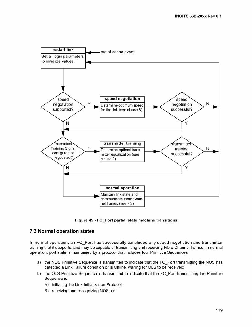
INCITS 562-20xx Rev 0.1
119
7.3 Normal operation states
In normal operation, an FC_Port has successfully concluded any speed negotiation and transmittertraining that it supports, and may be capable of transmitting and receiving Fibre Channel frames. In normaloperation, port state is maintained by a protocol that includes four Primitive Sequences:
a) the NOS Primitive Sequence is transmitted to indicate that the FC_Port transmitting the NOS hasdetected a Link Failure condition or is Offline, waiting for OLS to be received;
b) the OLS Primitive Sequence is transmitted to indicate that the FC_Port transmitting the PrimitiveSequence is:
A) initiating the Link Initialization Protocol;
B) receiving and recognizing NOS; or
Figure 45 - FC_Port partial state machine transitions
Maintain link state and communicate Fibre Chan-nel frames (see 7.3)
normal operation
Determine optimal trans-mitter equalization (see clause 9)
transmitter training
Determine optimum speed for the link (see clause 8)
speed negotiation
Set all login parameters to initialize values.
restart link
speednegotiationsupported?
Y
N
speednegotiationsuccessful?
N
Y
TransmitterTraining Signalconfigured or negotiated?
Y
N
transmittertraining
successful?N
Y
out of scope event
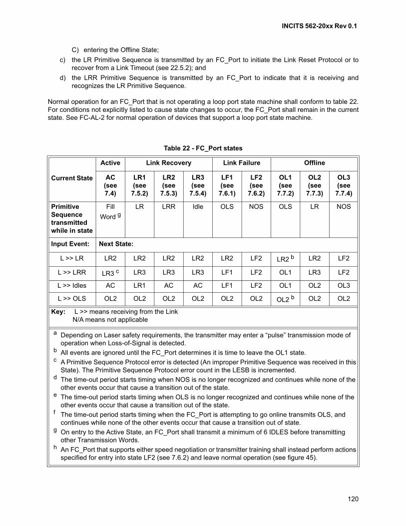
INCITS 562-20xx Rev 0.1
120
C) entering the Offline State;
c) the LR Primitive Sequence is transmitted by an FC_Port to initiate the Link Reset Protocol or torecover from a Link Timeout (see 22.5.2); and
d) the LRR Primitive Sequence is transmitted by an FC_Port to indicate that it is receiving andrecognizes the LR Primitive Sequence.
Normal operation for an FC_Port that is not operating a loop port state machine shall conform to table 22.For conditions not explicitly listed to cause state changes to occur, the FC_Port shall remain in the currentstate. See FC-AL-2 for normal operation of devices that support a loop port state machine.
Table 22 - FC_Port states
Current State
Active Link Recovery Link Failure Offline
AC(see 7.4)
LR1(see 7.5.2)
LR2(see 7.5.3)
LR3(see 7.5.4)
LF1(see 7.6.1)
LF2(see 7.6.2)
OL1(see 7.7.2)
OL2(see 7.7.3)
OL3(see 7.7.4)
Primitive Sequence transmitted while in state
Fill
Word gLR LRR Idle OLS NOS OLS LR NOS
Input Event: Next State:
L >> LR LR2 LR2 LR2 LR2 LR2 LF2 LR2 b LR2 LF2
L >> LRR LR3 c LR3 LR3 LR3 LF1 LF2 OL1 LR3 LF2
L >> Idles AC LR1 AC AC LF1 LF2 OL1 OL2 OL3
L >> OLS OL2 OL2 OL2 OL2 OL2 OL2 OL2 b OL2 OL2
Key: L >> means receiving from the LinkN/A means not applicable
a Depending on Laser safety requirements, the transmitter may enter a “pulse” transmission mode of operation when Loss-of-Signal is detected.
b All events are ignored until the FC_Port determines it is time to leave the OL1 state.c A Primitive Sequence Protocol error is detected (An improper Primitive Sequence was received in this
State). The Primitive Sequence Protocol error count in the LESB is incremented.d The time-out period starts timing when NOS is no longer recognized and continues while none of the
other events occur that cause a transition out of the state.e The time-out period starts timing when OLS is no longer recognized and continues while none of the
other events occur that cause a transition out of the state.f The time-out period starts timing when the FC_Port is attempting to go online transmits OLS, and
continues while none of the other events occur that cause a transition out of state.g On entry to the Active State, an FC_Port shall transmit a minimum of 6 IDLES before transmitting
other Transmission Words.h An FC_Port that supports either speed negotiation or transmitter training shall instead perform actions
specified for entry into state LF2 (see 7.6.2) and leave normal operation (see figure 45).
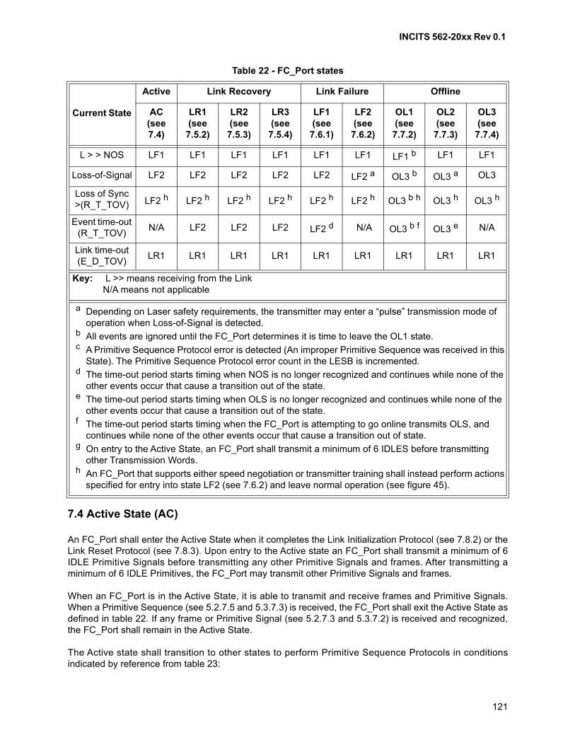
INCITS 562-20xx Rev 0.1
121
7.4 Active State (AC)
An FC_Port shall enter the Active State when it completes the Link Initialization Protocol (see 7.8.2) or theLink Reset Protocol (see 7.8.3). Upon entry to the Active state an FC_Port shall transmit a minimum of 6IDLE Primitive Signals before transmitting any other Primitive Signals and frames. After transmitting aminimum of 6 IDLE Primitives, the FC_Port may transmit other Primitive Signals and frames.
When an FC_Port is in the Active State, it is able to transmit and receive frames and Primitive Signals.When a Primitive Sequence (see 5.2.7.5 and 5.3.7.3) is received, the FC_Port shall exit the Active State asdefined in table 22. If any frame or Primitive Signal (see 5.2.7.3 and 5.3.7.2) is received and recognized,the FC_Port shall remain in the Active State.
The Active state shall transition to other states to perform Primitive Sequence Protocols in conditionsindicated by reference from table 23:
L > > NOS LF1 LF1 LF1 LF1 LF1 LF1 LF1 b LF1 LF1
Loss-of-Signal LF2 LF2 LF2 LF2 LF2 LF2 a OL3 b OL3 a OL3
Loss of Sync >(R_T_TOV) LF2 h LF2 h LF2 h LF2 h LF2 h LF2 h OL3 b h OL3 h OL3 h
Event time-out (R_T_TOV)
N/A LF2 LF2 LF2 LF2 d N/A OL3 b f OL3 e N/A
Link time-out (E_D_TOV)
LR1 LR1 LR1 LR1 LR1 LR1 LR1 LR1 LR1
Table 22 - FC_Port states
Current State
Active Link Recovery Link Failure Offline
AC(see 7.4)
LR1(see 7.5.2)
LR2(see 7.5.3)
LR3(see 7.5.4)
LF1(see 7.6.1)
LF2(see 7.6.2)
OL1(see 7.7.2)
OL2(see 7.7.3)
OL3(see 7.7.4)
Key: L >> means receiving from the LinkN/A means not applicable
a Depending on Laser safety requirements, the transmitter may enter a “pulse” transmission mode of operation when Loss-of-Signal is detected.
b All events are ignored until the FC_Port determines it is time to leave the OL1 state.c A Primitive Sequence Protocol error is detected (An improper Primitive Sequence was received in this
State). The Primitive Sequence Protocol error count in the LESB is incremented.d The time-out period starts timing when NOS is no longer recognized and continues while none of the
other events occur that cause a transition out of the state.e The time-out period starts timing when OLS is no longer recognized and continues while none of the
other events occur that cause a transition out of the state.f The time-out period starts timing when the FC_Port is attempting to go online transmits OLS, and
continues while none of the other events occur that cause a transition out of state.g On entry to the Active State, an FC_Port shall transmit a minimum of 6 IDLES before transmitting
other Transmission Words.h An FC_Port that supports either speed negotiation or transmitter training shall instead perform actions
specified for entry into state LF2 (see 7.6.2) and leave normal operation (see figure 45).

INCITS 562-20xx Rev 0.1
122
An FC_Port may also transition from Active State on the reception of an LPI (see 10).
7.5 Link Recovery
7.5.1 Link Recovery hierarchy
The Link Recovery hierarchy is shown in figure 88.
7.5.2 LR Transmit State (LR1)
An FC_Port shall enter the LR1 State to initiate the Link Reset Protocol. While in the LR1 State, theFC_Port shall transmit the LR Primitive Sequence. When a Primitive Sequence is received, the FC_Portshall respond as defined in table 22.
Within the FC_Port, the BB_Credit_CNT value shall be set to zero. An Fx_Port shall process or discardany Class 2 or Class 3 frames currently held in the receive buffer associated with the outbound fibre of theattached FC_Port. The Class 2 EE_Credit value shall not be affected.
7.5.3 LR Receive State (LR2)
An FC_Port shall enter the LR2 State when it receives and recognizes the LR Primitive Sequence while itis not in the OL3 or LF2 State. While in the LR2 State, the FC_Port shall transmit the LRR PrimitiveSequence. When a Primitive Sequence is received, the FC_Port shall respond as defined in table 22.
An FC_Port that receives and recognizes the Link Reset Primitive Sequence shall process or discardframes currently held in its receive buffers. Within the FC_Port, the BB_Credit_CNT value shall be set tozero.
7.5.4 LRR Receive State (LR3)
An FC_Port shall enter the LR3 State when it receives and recognizes the LRR Primitive Sequence while itis in the Active State, LR1 State, LR2 State, or OL2 State. While in the LR3 State, the FC_Port shalltransmit Idles. When a Primitive Sequence is received, the FC_Port shall respond as defined in table 22.
Table 23 - Transitions from the Active State
Primitive Sequence ProtocolTransition to
State
Reference for transition conditions
Link Initialization OL1 7.8.2
Link Reset LR1 7.8.3
Link Failure LF2 7.8.4
Online-to-Offline OL1 7.8.5
INCITS 562-20xx Rev 0.1
123
7.6 Link Failure
7.6.1 NOS Receive State (LF1)
An FC_Port shall enter the LF1 State when it receives and recognizes the NOS Primitive Sequence. Uponentry into the LF1 State, the FC_Port shall update the appropriate error counter in the Link Error StatusBlock (see 22.4.8). Only one error per Link Failure event shall be recorded. When a Primitive Sequence isreceived, the FC_Port shall respond as defined in table 22.
7.6.2 NOS Transmit State (LF2)
An FC_Port shall enter the LF2 State when a Link Failure condition is detected. Upon entry into the LF2State, the FC_Port shall update the appropriate error counter in the Link Error Status Block (see 22.4.8).Only one error per Link Failure event shall be recorded. The FC_Port shall remain in the LF2 State whilethe condition that caused the Link Failure exists. While in the LF2 State, the FC_Port shall transmit theNOS Primitive Sequence.
When the Link Failure condition is no longer detected, the FC_Port shall respond to Primitive Sequencesreceived as defined in table 22.
NOS transmission by a PN_Port shall be received and recognized by the locally attached Fx_Port, but nottransmitted through the Fabric. The Fx_Port shall respond by entering the LF1 State.
7.7 Offline
7.7.1 General
While Offline, an FC_Port shall not record receiver errors (e.g., Loss-of-Synchronization). NOS Receptionor Link Failure conditions that are detected shall not be recorded as Link Failure events in the Link ErrorStatus Block (see 22.4.8).
7.7.2 OLS Transmit State (OL1)
An FC_Port shall enter the OL1 State in order to:
a) perform the Link Initialization Protocol (see 7.8.2) in order to exit the Offline State; or
b) transition from Online-to-Offline using the Online-to-Offline Protocol (see 7.8.5).
When the FC_Port enters the OL1 State, it shall transmit OLS for a minimum time of 5 ms while ignoringany received data. After that period of time has elapsed, the FC_Port shall respond as defined table 22when a Primitive Sequence is received.
NOTE 13 - The timeout value of 5 ms allows a Port to enter the Offline State in the absence of anappropriate response from the attached Port.
While an FC_Port is attempting to go Online, if no Primitive Sequence is received or event detected thatcauses the FC_Port to exit the OL1 State after R_T_TOV, the FC_Port shall enter the OL3 State.
OLS transmission by a PN_Port shall be received and recognized by the locally attached Fx_Port, but nottransmitted through the Fabric. The Fx_Port shall respond by entering the OL2 State.
INCITS 562-20xx Rev 0.1
124
7.7.3 OLS Receive State (OL2)
An FC_Port shall enter the OL2 State when it receives and recognizes the OLS Primitive Sequence. Whena Primitive Sequence is received, the FC_Port shall respond as defined in table 22. Detection ofLoss-of-Signal or Loss-of-Synchronization shall not be counted as a Link Failure event in the Link ErrorStatus Block.
7.7.4 Wait for OLS State (OL3)
An FC_Port shall enter the OL3 State when it detects Loss-of-Signal or Loss-of-Synchronization for morethan a timeout period (R_T_TOV) while it is in the OLS Receive or Transmit State at an appropriate timeduring the Link Initialization Protocol (see 7.8.2).
Upon entry into the OL3 State, the FC_Port shall transmit the NOS Primitive Sequence. When a PrimitiveSequence is received, the FC_Port shall respond as defined in table 22.
7.8 Primitive Sequence Protocols
7.8.1 Functions
Primitive Sequence Protocols provide two basic functions. The first function is to notify the other end of thelink that a specific type of link error has occurred. The second function is to reset the link to a known stateat both ends.
7.8.2 Link Initialization Protocol
The Link Initialization Protocol shall be performed by an LCF after one of the following events hasoccurred:
a) powered-on;
b) internal reset (the definition of internal reset is beyond the scope of this standard); or
c) has been offline and desires to come back online.
The LCFs involved may be a PN_Port and PF_Port or two PN_Ports.
The Link Initialization Protocol begins when the LCF enters the OL1 State after one of the above eventshas been detected and is complete when the LCF enters the Active State.
The Link Initialization Protocol results in implicit Fabric Logout (see FC-LS-4).
7.8.3 Link Reset Protocol
The Link Reset Protocol shall be performed when any of the following conditions are detected:
a) link timeout (see 22.5.2); or
b) buffer-to-buffer overrun (i.e., an FC_Port receives a frame subject to buffer-to-buffer flow controlwithout a buffer available).
The Link Reset Protocol begins when the FC_Port enters the LR1 State after one of the above events hasbeen detected and is complete when the FC_Port enters the Active State.

INCITS 562-20xx Rev 0.1
125
7.8.4 Link Failure Protocol
The Link Failure Protocol shall be performed after an FC_Port has detected one of the followingconditions:
a) a Loss-of-Synchronization for a period of time greater than R_T_TOV;
b) Loss-of-Signal while not in the Offline State; or
c) Link Reset Protocol timeout error is detected (see 7.8.3).
The Link Failure Protocol begins when the FC_Port enters the LF2 State after one of the above events hasbeen detected and is complete when the Active State is entered.
7.8.5 Online-to-offline Protocol
The FC_Port shall perform the Online-to-offline Protocol to enter the Offline State from the Active State.This protocol should be performed in order to power-down and shall be performed in order to performdiagnostics (diagnostic requirements are beyond the scope of this standard). This Protocol provides anFC_Port with a graceful indication prior to Loss-of-Signal. This avoids logging an error event for a normalsystem function. The Online-to-offline Protocol shall start when the FC_Port enters the OL1 State.
After transmitting OLS for the time specified in 7.7.2, the FC_Port shall be Offline and may do any of thefollowing:
a) perform diagnostic procedures;
b) turn off its transmitter;
c) transmit any signal (excluding Primitive Sequences other than OLS) without errors being detectedby the attached FC_Port;
d) power-down; or
e) start the Link Initialization Protocol.
NOTE 14 - After entering the OL1 State and transmitting OLS for a minimum of 5 ms, the FC_Port maythen transmit any Transmission Word other than LR, LRR, NOS, or LIP without causing the remoteFC_Port to leave the OL2 State.
INCITS 562-20xx Rev 0.1
126
8 Link speed negotiation
8.1 Scope
Link speed negotiation is a function of the FC-2P sublevel.
8.2 Speed negotiation overview
The optional speed negotiation method may be used to enable ports that are capable of multiple datatransfer rates to establish in-band communications on a link (all port types). The term “speed” as used inthis clause refers to the bit transfer rate. This method finds the highest speed common to the ports and tothe infrastructure connecting the ports. Each port may support up to a maximum of 4 speeds in thenegotiation process. The exact speeds are not specified. Different ports may negotiate with different speedranges up to a maximum of 4 speeds each and speed negotiation shall converge provided there is at leastone common speed. The link quality for speed negotiation purposes is error free Transmission WordSynchronization for a minimum number of Transmission Words specified in clause 6 as the pass sync_testcount for the transmission code being used.
Because the link quality requirements for speed negotiation are not as stringent as for other operations it ispossible to complete speed negotiation yet have an excessive error rate in other operations. Determinationof excessive error rate outside of speed negotiation may be as specified for transmitter training (see 9.2) orby vendor specific methods. The response to a determination of excessive error rate in transmitter trainingis to re-enter speed negotiation, having eliminated the faulty speed from negotiation. The response to avendor specific determination of excessive error rate may also be to re-enter speed negotiation, havingeliminated the faulty speed from negotiation. A speed, having been eliminated, is restored to subsequentspeed negotiation upon vendor specific determination that the reliability of the link at that speed may haveimproved (e.g., detection of physical disconnect and reconnect of the link, or an administrative action out ofscope of this standard).
Transceivers may be able to transmit and detect error free bit streams even though they and other linkelements were not designed or specified for operation at the speed being used. This condition may allowlinks to achieve Transmission Word Synchronization and satisfactory error rates but with degraded margin.It is up to the implementer to ensure that the elements of the physical plant are designed to comply with therequirements specified for operation at the set speed.
Once a particular speed has been established, speed negotiation is not attempted again unless a SignalFailure is detected. Speed negotiation may disrupt communication in excess of a second. An FC_Portcapable of the speed negotiation procedure shall initiate Speed negotiation upon power on or SignalFailure. For this purpose, Signal Failure shall be presumed to pertain only in the following circumstances:
a) the port receiver circuit has indicated Loss of Signal;
b) the port receiver has remained in "Loss of Synchronization" state for a time in excess of R_T_TOV;or
c) the port transceiver has been reset by means other than power on.
An FC_Port should not initiate speed negotiation for other reasons.
8.3 Link physical architecture and requirements
The physical architecture of the link is assumed to be as shown in figure 46.
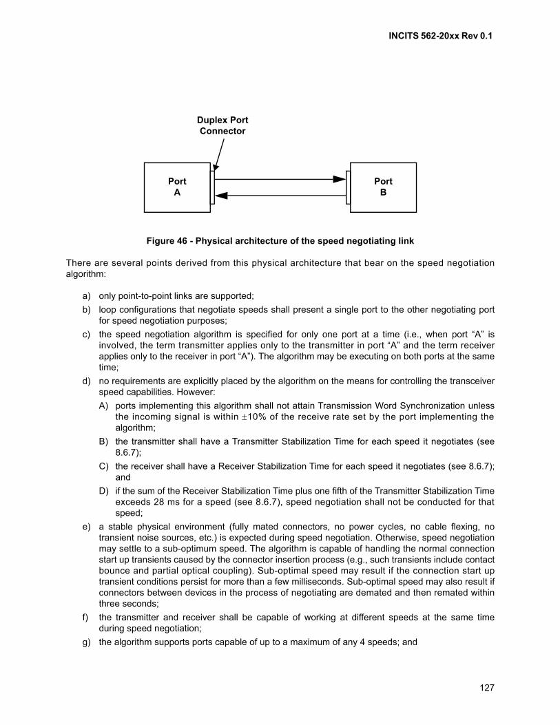
INCITS 562-20xx Rev 0.1
127
There are several points derived from this physical architecture that bear on the speed negotiationalgorithm:
a) only point-to-point links are supported;
b) loop configurations that negotiate speeds shall present a single port to the other negotiating portfor speed negotiation purposes;
c) the speed negotiation algorithm is specified for only one port at a time (i.e., when port “A” isinvolved, the term transmitter applies only to the transmitter in port “A” and the term receiverapplies only to the receiver in port “A”). The algorithm may be executing on both ports at the sametime;
d) no requirements are explicitly placed by the algorithm on the means for controlling the transceiverspeed capabilities. However:
A) ports implementing this algorithm shall not attain Transmission Word Synchronization unlessthe incoming signal is within 10% of the receive rate set by the port implementing thealgorithm;
B) the transmitter shall have a Transmitter Stabilization Time for each speed it negotiates (see8.6.7);
C) the receiver shall have a Receiver Stabilization Time for each speed it negotiates (see 8.6.7);and
D) if the sum of the Receiver Stabilization Time plus one fifth of the Transmitter Stabilization Timeexceeds 28 ms for a speed (see 8.6.7), speed negotiation shall not be conducted for thatspeed;
e) a stable physical environment (fully mated connectors, no power cycles, no cable flexing, notransient noise sources, etc.) is expected during speed negotiation. Otherwise, speed negotiationmay settle to a sub-optimum speed. The algorithm is capable of handling the normal connectionstart up transients caused by the connector insertion process (e.g., such transients include contactbounce and partial optical coupling). Sub-optimal speed may result if the connection start uptransient conditions persist for more than a few milliseconds. Sub-optimal speed may also result ifconnectors between devices in the process of negotiating are demated and then remated withinthree seconds;
f) the transmitter and receiver shall be capable of working at different speeds at the same timeduring speed negotiation;
g) the algorithm supports ports capable of up to a maximum of any 4 speeds; and
Figure 46 - Physical architecture of the speed negotiating link
Duplex PortConnector
PortA
PortB
INCITS 562-20xx Rev 0.1
128
h) if an L_Port configured for speed negotiation is attached to a loop, the L_Port either:
A) is being attached to a port in the loop that presents a single speed and does not performspeed negotiation; or
B) is being attached to a port in the loop that completes the speed negotiation algorithmdescribed here before inserting the L_Port into the loop.
8.4 Speed negotiation requirements on L_Ports
Removal of an L_Port from a loop shall not cause speed negotiation to occur on the remaining loop. Thisrequirement applies even if the removal of the L_Port allows negotiation of a higher common speed.
As an option to negotiating each hub port per the algorithm, multiple speed hubs may be set to a singlespeed during speed negotiation by some out-of-band means.
8.5 Primitives
8.5.1 Overview
For FC_Ports that do not support the Transmitter Training Signal, either OLS or NOS (for ports notoperating in Arbitrated Loop topology) or LIP (for ports operating in Arbitrated Loop topology) shall be theonly signals transmitted during speed negotiation.
For FC_Ports that support the Transmitter Training Signal:
a) if the FC_Port is transmitting using media and speeds that support the Transmitter Training Signal(see FC-PI-x), then the Transmitter Training Signal shall be transmitted during speed negotiation;
b) if the Transmitter Training Signal (see 5.6.2) is transmitted during speed negotiation, then the SNfield in the Training Status field shall be set to one;
c) if the FC_Port is transmitting using media and speeds that do not support the Transmitter TrainingSignal, then either OLS or NOS (for ports not operating in Arbitrated Loop topology) or LIP (forports operating in Arbitrated Loop topology) shall be transmitted using the required frame transfertransmission code (see FC-PI-x) during speed negotiation;
d) if the FC_Port is receiving on media at speeds that support the Transmitter Training Signal, thenTransmitter Training Signal Transmission Word Synchronization shall be attempted during speednegotiation;
e) if the Transmitter Training Signal is received during speed negotiation, then the setting of the fieldsin the Training Frame Control field (see table 16) and the Training Frame Status field (see table 17)shall be ignored, except for:
A) Parallel Lane Support (i.e., Training Frame Control field bit 10);
B) Extended Marker (i.e., Training Frame Control field bits 14 and 15); and
C) SN (i.e., Training Frame Status field bit 14).
f) if the FC_Port is receiving on media at speeds that do not support the Transmitter Training Signal,then Transmission Word Synchronization for the required frame transfer transmission code shallbe attempted during speed negotiation.
If a PN_Port negotiates among multiple physical variants that use different transmission codes, thetransmission code changes (e.g., from Transmitter Training Signal to 8B/10B and back) during speednegotiation, and the transmitter uses a different transmission code than the receiver at some times.
INCITS 562-20xx Rev 0.1
129
8.5.2 32GFC speed negotiation
For 32GFC the Transmitter Training Signal specified in 5.6 is used for speed negotiation. For copper links,transmitter training is performed if requested. For optical links transmitter training is outside the scope ofthe standard. Bit 10 in the Control field of the Training Frame shall be set to zero during speed negotiation.
8.5.3 64GFC speed negotiation
For 64GFC, the Transmitter Training Signal specified in 5.6 is used for speed negotiation. 64GFCcapability is indicated by setting Training Frame Control Field bits 15:14 (Extended Marker) to 10b.
For links that negotiate to 64GFC, the completion of LSN is always followed by mandatory TransmitterTraining for all link types. For optical links the Training Frame Status field bit 12 (TF) is set to one whichsignals that the transmitter is operating with fixed coefficients. Even though the Transmitter is operatingwith fixed coefficients, Transmitter Training allows time for the Local Rx Equalization to completeadaptation to a PAM4 signal, enabling robust link performance. The completion of Transmitter Training issignaled by setting Training Field Status bit 15 (Receiver Ready) to one.
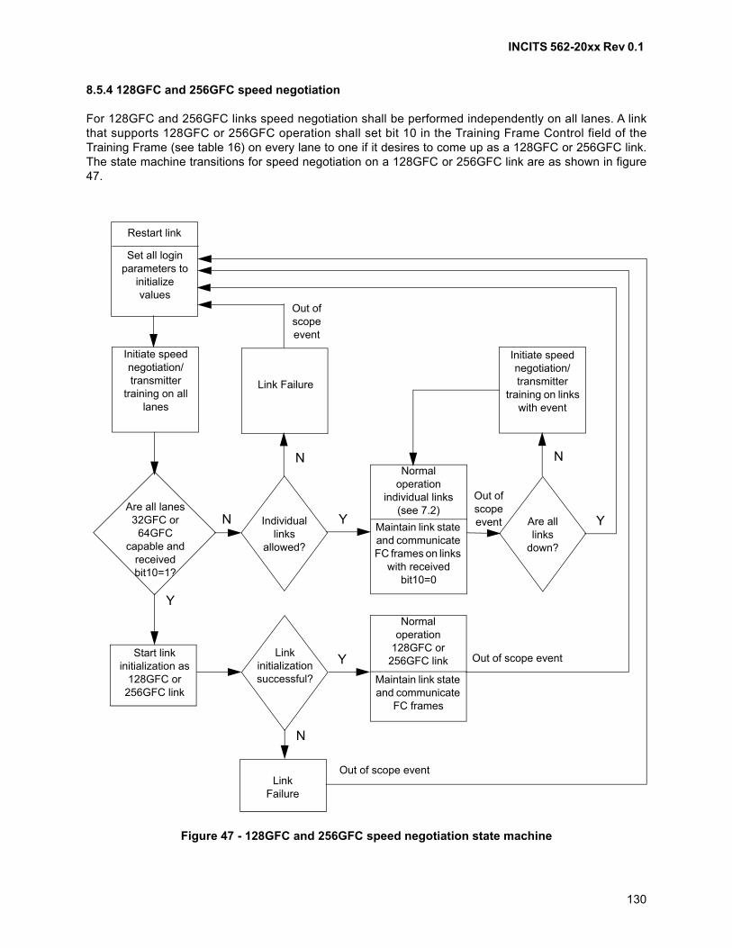
INCITS 562-20xx Rev 0.1
130
8.5.4 128GFC and 256GFC speed negotiation
For 128GFC and 256GFC links speed negotiation shall be performed independently on all lanes. A linkthat supports 128GFC or 256GFC operation shall set bit 10 in the Training Frame Control field of theTraining Frame (see table 16) on every lane to one if it desires to come up as a 128GFC or 256GFC link.The state machine transitions for speed negotiation on a 128GFC or 256GFC link are as shown in figure47.
Figure 47 - 128GFC and 256GFC speed negotiation state machine
Restart link
Set all loginparameters to
initializevalues
Initiate speed negotiation/transmitter
training on all lanes
Link Failure
Out of scope event
Are all lanes 32GFC or
64GFCcapable and
received bit10=1?
Individuallinks
allowed?
Normal operation
individual links (see 7.2)
Maintain link state and communicate FC frames on links
with received bit10=0
Are alllinks
down?
Initiate speed negotiation/transmitter
training on links with event
Start link initialization as
128GFC or 256GFC link
Linkinitializationsuccessful?
Normal operation
128GFC or 256GFC link
Maintain link state and communicate
FC frames
Out of scope event
Out of scope event
LinkFailure
Out of scope event
N
N N
N
Y
YY
Y
INCITS 562-20xx Rev 0.1
131
The ‘Out of scope event’ in the state diagram occurs if any of the following conditions are true on a128GFC and a 256GFC link:
a) Loss-of-Signal; or
b) Loss-of-Synchronization.
If parallel lanes are supported as indicated by receiving Training Frame Control field bit 10 set to one on alllanes and all the lanes negotiate to a speed of 32GFC or 64GFC, then the link may be able to operate at128GFC or 256GFC. If link initialization is successful, then the link shall enter normal operation as a128GFC or 256GFC link. If link initialization is unsuccessful as a 128GFC or 256GFC link, then the linktransitions to the Link Failure State and transitions to the Restart Link state if an out of scope event occurs.
If any of the lanes do not support 32GFC, 64GFC, or parallel lanes are not supported as indicated byreceiving Training Frame Control field bit 10 set to 0 on any lane, then 128GFC and 256GFC is notsupported and the lanes may operate as individual links at the highest negotiated speed. A link thatsupports 128GFC or 256GFC operation may support individual links of 16GFC, 32GFC, and 64GFC.Support for individual 32GFC or 64GFC links is allowed only if the value of bit 10 in the Training FrameControl field received is zero during speed negotiation.
If a lane is operating as an individual link and it becomes inoperable due to an out of scope event, and allfour lanes are in the link failure state, then the state machine transitions to the Restart Link state and speednegotiation is performed as a 128GFC or 256GFC link. If all four lanes are not in the link failure state, thenspeed negotiation is performed only on the failed link.
8.6 Speed negotiation algorithm
8.6.1 Algorithm overview
Figure 48 shows an overview of the speed negotiation algorithm. Dashed lines indicate optional features.
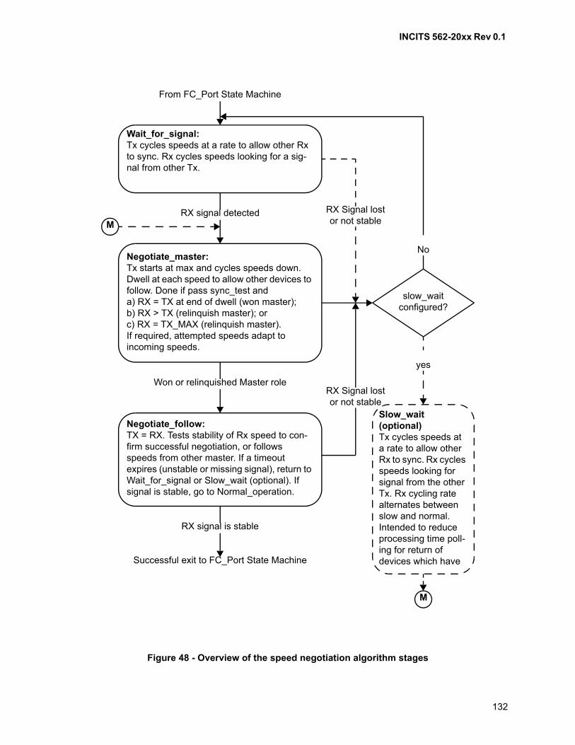
INCITS 562-20xx Rev 0.1
132
Figure 48 - Overview of the speed negotiation algorithm stages
Wait_for_signal:Tx cycles speeds at a rate to allow other Rx to sync. Rx cycles speeds looking for a sig-nal from other Tx.
Negotiate_master:Tx starts at max and cycles speeds down. Dwell at each speed to allow other devices to follow. Done if pass sync_test anda) RX = TX at end of dwell (won master);b) RX > TX (relinquish master); orc) RX = TX_MAX (relinquish master).If required, attempted speeds adapt to incoming speeds.
Negotiate_follow:TX = RX. Tests stability of Rx speed to con-firm successful negotiation, or follows speeds from other master. If a timeout expires (unstable or missing signal), return to Wait_for_signal or Slow_wait (optional). If signal is stable, go to Normal_operation.
RX signal detected
Won or relinquished Master role
RX signal is stable
From FC_Port State Machine
M
M
slow_waitconfigured?
RX Signal lostor not stable
RX Signal lostor not stable
No
yes
Slow_wait (optional)Tx cycles speeds at a rate to allow other Rx to sync. Rx cycles speeds looking for signal from the other Tx. Rx cycling rate alternates between slow and normal. Intended to reduce processing time poll-ing for return of devices which have Successful exit to FC_Port State Machine
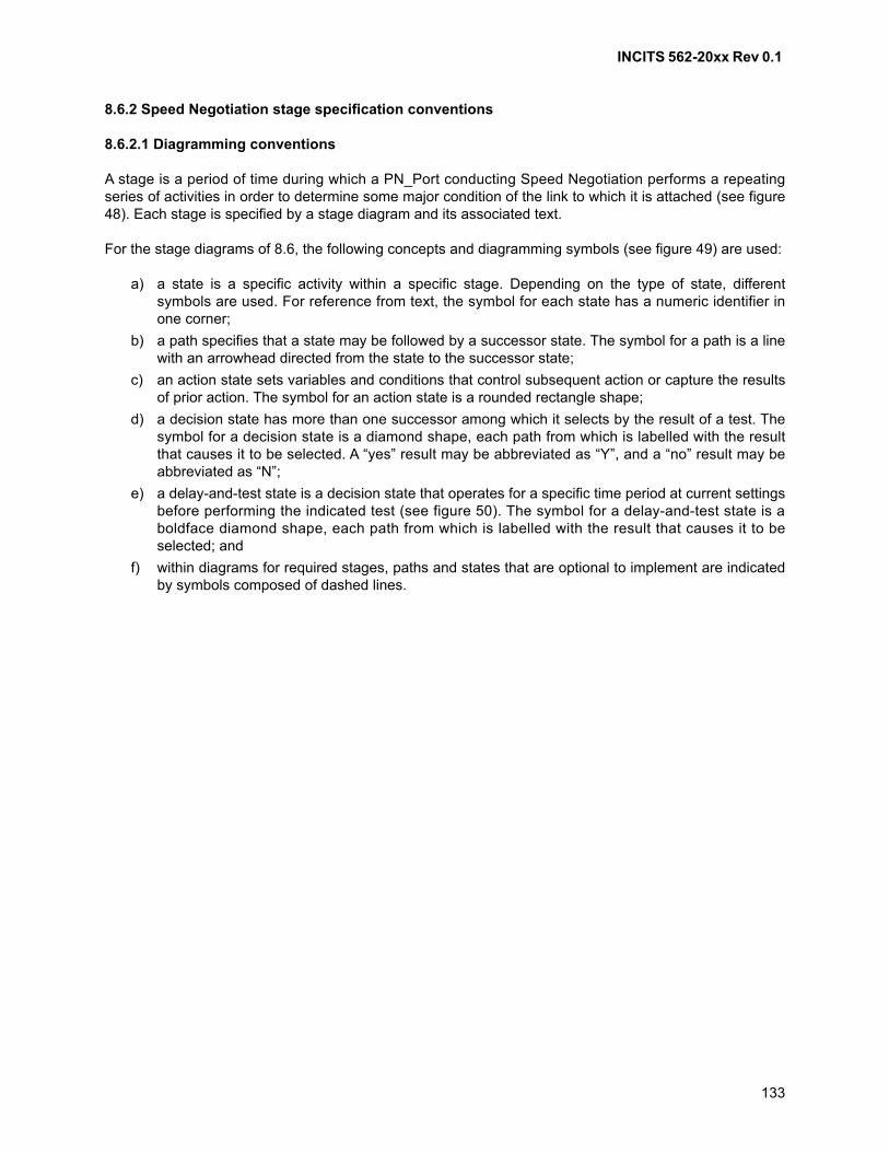
INCITS 562-20xx Rev 0.1
133
8.6.2 Speed Negotiation stage specification conventions
8.6.2.1 Diagramming conventions
A stage is a period of time during which a PN_Port conducting Speed Negotiation performs a repeatingseries of activities in order to determine some major condition of the link to which it is attached (see figure48). Each stage is specified by a stage diagram and its associated text.
For the stage diagrams of 8.6, the following concepts and diagramming symbols (see figure 49) are used:
a) a state is a specific activity within a specific stage. Depending on the type of state, differentsymbols are used. For reference from text, the symbol for each state has a numeric identifier inone corner;
b) a path specifies that a state may be followed by a successor state. The symbol for a path is a linewith an arrowhead directed from the state to the successor state;
c) an action state sets variables and conditions that control subsequent action or capture the resultsof prior action. The symbol for an action state is a rounded rectangle shape;
d) a decision state has more than one successor among which it selects by the result of a test. Thesymbol for a decision state is a diamond shape, each path from which is labelled with the resultthat causes it to be selected. A “yes” result may be abbreviated as “Y”, and a “no” result may beabbreviated as “N”;
e) a delay-and-test state is a decision state that operates for a specific time period at current settingsbefore performing the indicated test (see figure 50). The symbol for a delay-and-test state is aboldface diamond shape, each path from which is labelled with the result that causes it to beselected; and
f) within diagrams for required stages, paths and states that are optional to implement are indicatedby symbols composed of dashed lines.
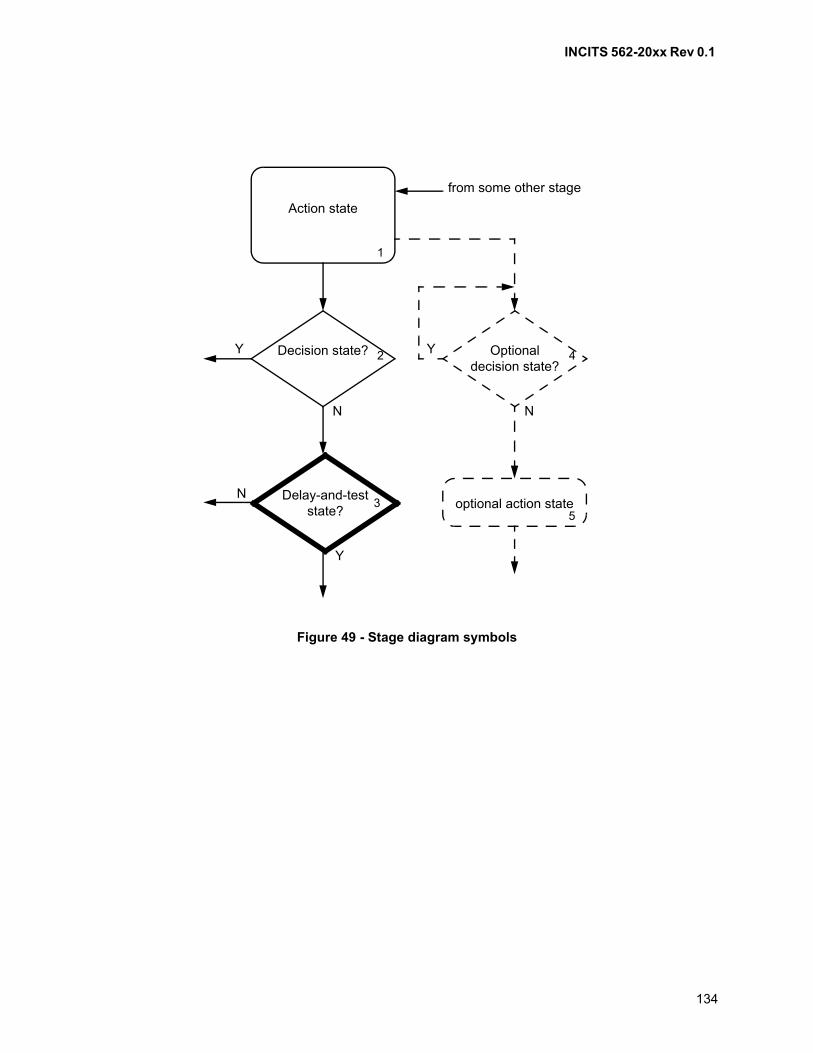
INCITS 562-20xx Rev 0.1
134
Figure 49 - Stage diagram symbols
optional action state5
Action state
1
from some other stage
Decision state? 2Y
N
Optionaldecision state?
4Y
N
Delay-and-test state?
3N
Y
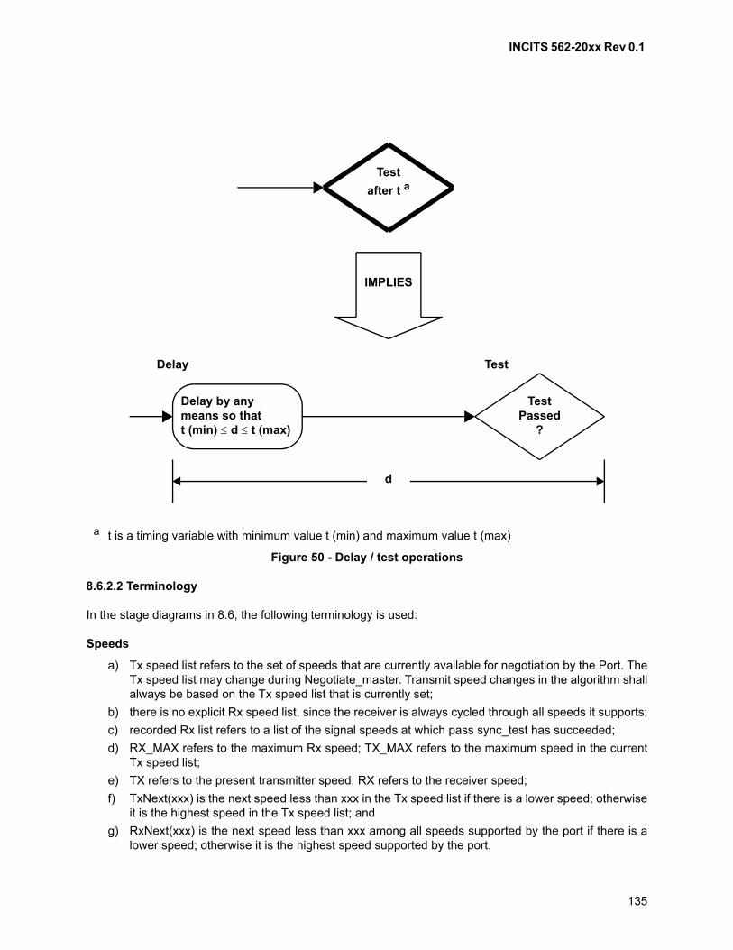
INCITS 562-20xx Rev 0.1
135
8.6.2.2 Terminology
In the stage diagrams in 8.6, the following terminology is used:
Speeds
a) Tx speed list refers to the set of speeds that are currently available for negotiation by the Port. TheTx speed list may change during Negotiate_master. Transmit speed changes in the algorithm shallalways be based on the Tx speed list that is currently set;
b) there is no explicit Rx speed list, since the receiver is always cycled through all speeds it supports;
c) recorded Rx list refers to a list of the signal speeds at which pass sync_test has succeeded;
d) RX_MAX refers to the maximum Rx speed; TX_MAX refers to the maximum speed in the currentTx speed list;
e) TX refers to the present transmitter speed; RX refers to the receiver speed;
f) TxNext(xxx) is the next speed less than xxx in the Tx speed list if there is a lower speed; otherwiseit is the highest speed in the Tx speed list; and
g) RxNext(xxx) is the next speed less than xxx among all speeds supported by the port if there is alower speed; otherwise it is the highest speed supported by the port.
a t is a timing variable with minimum value t (min) and maximum value t (max)
Figure 50 - Delay / test operations
Test
after t a
IMPLIES
TestPassed
?
Delay by any means so thatt (min) d t (max)
Delay Test
d
INCITS 562-20xx Rev 0.1
136
Timing
a) pass sync_test decision blocks (states 11, 21, 27, 34, 52, 56) requires that Transmission WordSynchronization be maintained for a monitoring period that shall equal or exceed receiving thepass sync_test count (see clause 6) of consecutive Transmission Words for the transmission codebeing used. The period of monitoring shall not exceed 100 microseconds. Counting of codeviolations may be used for the monitoring period to ensure robustness, if available to the firmware.If 64B/66B transmission code is used, then code violations shall be counted for the monitoringperiod. If counted, then the number of errors allowed shall be zero. If the number of errors is notzero, then Transmission Word Synchronization (Pass sync_test decision blocks) is not consideredto have occurred and a different speed is negotiated or the algorithm does not converge;
b) in contrast, Sync decision block in state 31 is Transmission Word Synchronization per clause 6;
c) in figures 51, 52, 53, and 54 a decision diamond with a bold-face outline indicates that a delay anda test are combined (see figure 50). In operations so indicated:
A) other activity may be implemented before the test is performed;
B) the test shall be completed after the minimum and before the maximum values of the delaytime parameter; and
C) the actual delay time may vary from test to test, but the test shall fall within the specified limits;
d) all flowchart atoms (action boxes or decision diamonds) that do not have a bold-face outline shallexecute in less than 100 microseconds, and no delays shall accrue between atoms (bold-faceoutline or not);
e) elapsed-time timers are compared against constants in several places:
A) ttx, tneg, and tsync start where shown being (re)set to 0 in the algorithm;
B) ttx is compared against t_txcycl;
C) tneg is compared against t_fail;
D) tsync is compared against t_stbl; and
E) tnc is compared against t_ncycl and may be set at several different places;
and
f) the R_T_TOV watchdog timer begins anytime Transmission Word Synchronization is lost duringNormal_operation. Because elapsed-time counters are tested at intervals determined by apreceding delay-and-test decision (see bullet above relating to decision diamonds), the actualelapsed time determined by the elapsed-time counter test may vary from the value of the counterup to its value plus the length of the delay. In most instances, the delay may be as much as themaximum value of the range of t_rxcycl. This value was chosen to tolerate the response times oftypical operating system kernels.
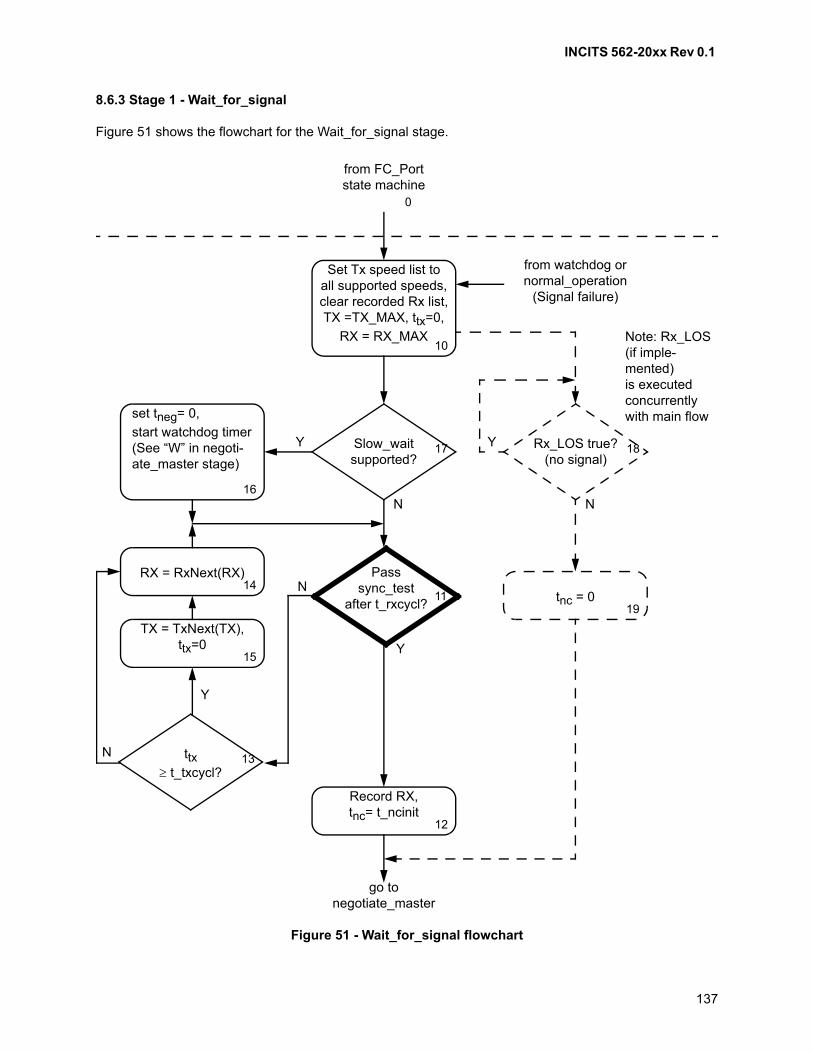
INCITS 562-20xx Rev 0.1
137
8.6.3 Stage 1 - Wait_for_signal
Figure 51 shows the flowchart for the Wait_for_signal stage.
Figure 51 - Wait_for_signal flowchart
tnc = 019
from FC_Portstate machine
0
Set Tx speed list toall supported speeds,clear recorded Rx list,TX =TX_MAX, ttx=0,
RX = RX_MAX10
from watchdog ornormal_operation
(Signal failure)
Slow_waitsupported?
17Y
N
set tneg= 0,
start watchdog timer(See “W” in negoti-ate_master stage)
16
RX = RxNext(RX)14
TX = TxNext(TX),ttx=0
15
Rx_LOS true?(no signal)
18Y
N
Passsync_test
after t_rxcycl? 11
N
Y
ttx t_txcycl?
13N
Y
Record RX,tnc= t_ncinit
12
go tonegotiate_master
Note: Rx_LOS(if imple-mented)is executedconcurrentlywith main flow
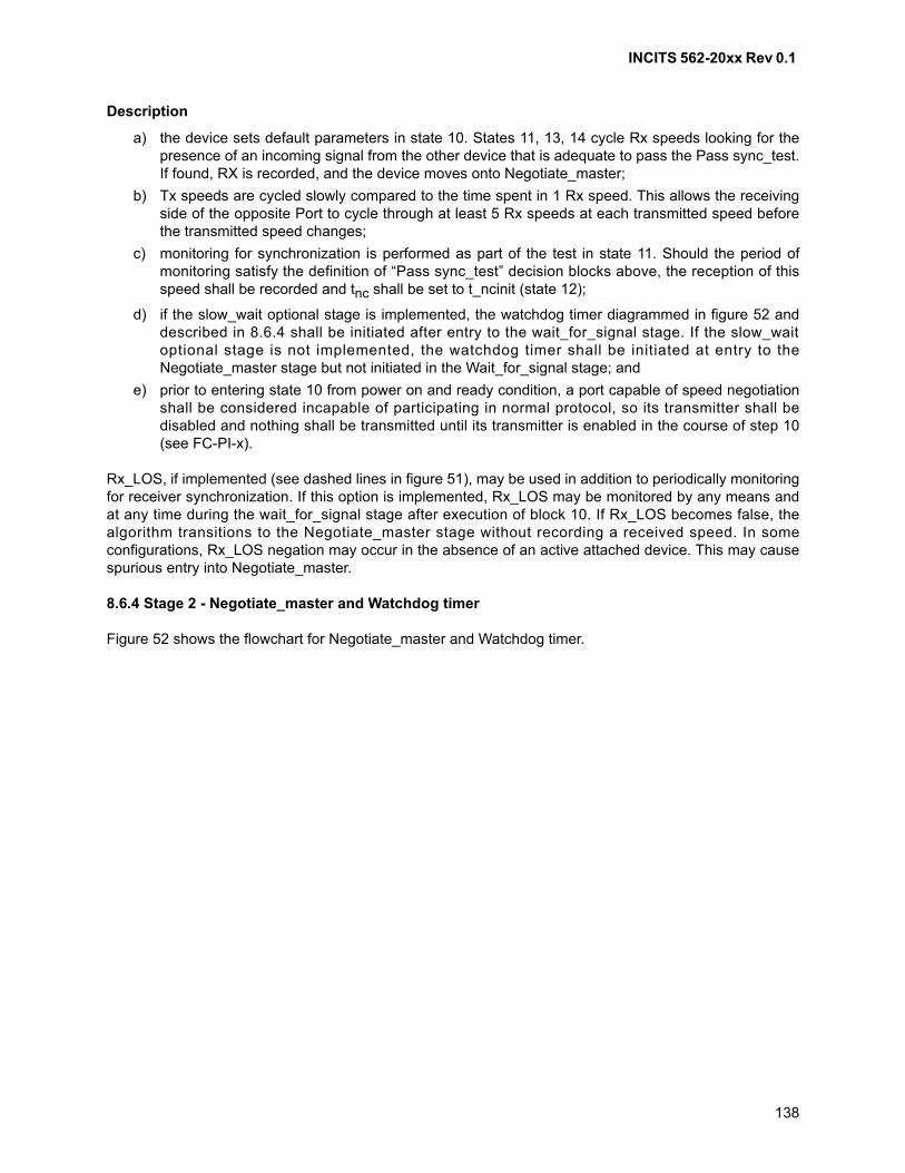
INCITS 562-20xx Rev 0.1
138
Description
a) the device sets default parameters in state 10. States 11, 13, 14 cycle Rx speeds looking for thepresence of an incoming signal from the other device that is adequate to pass the Pass sync_test.If found, RX is recorded, and the device moves onto Negotiate_master;
b) Tx speeds are cycled slowly compared to the time spent in 1 Rx speed. This allows the receivingside of the opposite Port to cycle through at least 5 Rx speeds at each transmitted speed beforethe transmitted speed changes;
c) monitoring for synchronization is performed as part of the test in state 11. Should the period ofmonitoring satisfy the definition of “Pass sync_test” decision blocks above, the reception of thisspeed shall be recorded and tnc shall be set to t_ncinit (state 12);
d) if the slow_wait optional stage is implemented, the watchdog timer diagrammed in figure 52 anddescribed in 8.6.4 shall be initiated after entry to the wait_for_signal stage. If the slow_waitoptional stage is not implemented, the watchdog timer shall be initiated at entry to theNegotiate_master stage but not initiated in the Wait_for_signal stage; and
e) prior to entering state 10 from power on and ready condition, a port capable of speed negotiationshall be considered incapable of participating in normal protocol, so its transmitter shall bedisabled and nothing shall be transmitted until its transmitter is enabled in the course of step 10(see FC-PI-x).
Rx_LOS, if implemented (see dashed lines in figure 51), may be used in addition to periodically monitoringfor receiver synchronization. If this option is implemented, Rx_LOS may be monitored by any means andat any time during the wait_for_signal stage after execution of block 10. If Rx_LOS becomes false, thealgorithm transitions to the Negotiate_master stage without recording a received speed. In someconfigurations, Rx_LOS negation may occur in the absence of an active attached device. This may causespurious entry into Negotiate_master.
8.6.4 Stage 2 - Negotiate_master and Watchdog timer
Figure 52 shows the flowchart for Negotiate_master and Watchdog timer.
INCITS 562-20xx Rev 0.1
139
ttx t_txcycl? 23 N
Y
N
Figure 52 - Negotiate_master and watchdog timer flowchart
TX = TX_MAX,RX = RX_MAX,
ttx=0, tneg=0
Start watchdog timer(see "W" below)
20
Passsync_test after
t_rxcycl? 21
YRX > TX or RX=TX_MAX?
24Y
N
RX = TX26
Passsync_test after
t_rxcycl? 27
N
Y
Add RX to recorded Rx list, tneg=0
25
RX_mem=RX22
RX=RxNext(RX)2C
tnc t_ncycl? 28
Y
N
TX=TxNext(TX)RX=RxNext(RX_mem
) 29
Set Tx speed list to recorded Rx list
2A
from wait_for_signal or optional slow_wait
go to negotiate_followtneg t_fail
after t_wddly? 2B
N
Y
W(Start
watchdog timer)
go to wait_for_signal or optional slow_wait
(see text)
INCITS 562-20xx Rev 0.1
140
Description:
a) the general operation of the algorithm is to start at the highest speed and step down until bothdevices agree on a speed. Lower speeds are tried only if higher speeds fail;
b) states 23 & 26-2A control TX. A transmit speed is forced (starting at the highest speed) forsufficient time (t_txcycl + t_rxcycl) for the other device to pass the Pass sync_test and follow (see8.6.5) and return TX back to the master. If NO from state 27, another (lower) Tx speed isattempted; if YES, the master role is assumed to be successful, and the algorithm moves to state30 in Negotiate_follow;
c) there are two conditions that may cause YES in state 27: (1) the other device is in follow mode asdescribed above, and (2) the other device is also in master mode transmitting at the same speed.If the latter, the master role is effectively relinquished to the other master;
d) if the port has had sufficient time to detect all possible speeds (maximum of 4 speeds) from theother port, but master role has not completed, states 28 & 2A adapt the Tx speed list to theincoming speeds recorded in the Rx list (state 25). This is usually does not occur unless the cableplant only supports a limited set of speeds;
e) states 21-25 control RX. To constantly monitor for an incoming rate that is higher than TX or equalto the maximum rate in the Tx speed list. If such a speed is found (Pass sync_test passed), thedevice relinquishes its master role to the other device, and transfers to the Negotiate_follow stage;and
f) a watchdog timer, tneg, keeps track of time between passed Pass sync_tests (states 11, 21, 27,
and 34). If tneg exceeds t_fail the port enters Slow_wait if the optional slow_wait stage is
implemented and enabled. If the optional Slow_wait stage is not implemented the Port returns towait_for_signal if tneg exceeds t_fail.
Rx_LOS shall not be used during Negotiate_master stage.

INCITS 562-20xx Rev 0.1
141
8.6.5 Stage 3 - Negotiate_follow
Figure 53 shows the flowchart for the Negotiate_follow stage.
Figure 53 - Negotiate_follow flowchart
Passsync_test after
t_rxcycl? 34
N Y
fromnegotiate _master
TX = RX,tsync=0, tneg=0
30
Stop watchdog timer
35
RX=RxNext(RX)33
Syncafter t_rxcycl?
31N
Y
tsync t_stbl? 32 N
Y
Successful exit to FC_Port State Machine
INCITS 562-20xx Rev 0.1
142
Description:
a) a Port in the Negotiate_follow stage attempts to transmit its incoming speed;
b) if sync is lost (e.g., due to an incoming signal speed change), the port seeks sync at another Rxspeed. If obtained, TX is adjusted to follow the new RX, and the test for t_stbl starts over;
c) this continues until sync is held for at least t_stbl in state 31 (in the case where the other master isnot driving other speeds). During this time, TX and RX have been matched, allowing the otherdevice to come to a YES decision in state 27. After t_stbl, the Port returns to the FC_Port statemachine (see 7.2) indicating successful Speed Negotiation; and
d) the same watchdog timer used in Negotiate_master is also used in Negotiate_follow.
Rx_LOS shall not be used during Negotiate_follow stage.
8.6.6 Optional Stage 5 - Slow_wait
Upon watchdog timer expiration, the Slow_wait stage may be entered as an alternative to returning to theWait_for_signal stage. Its implementation is optional, and if implemented, its use may be a configurationoption. Use of this optional stage reduces by approximately 80% the processing time required to monitor aPort that does not receive a valid signal at any supported speed (e.g., not cabled). However, the responseto a signal being presented may be delayed by up to t_sleep (see table 25). Figure 54 shows the flowchartfor the optional slow_wait stage.
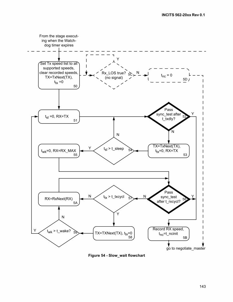
INCITS 562-20xx Rev 0.1
143
Figure 54 - Slow_wait flowchart
twk > t_wake? 59Y
N
Set Tx speed list to allsupported speeds,
clear recorded speeds,TX=TxNext(TX),
ttx =050
Rx_LOS true?(no signal)
5C N
Y
tnc = 05D
tsl =0, RX=TX51
Passsync_test after
t_txdly? 52
Y
N
TX=TxNext(TX),ttx=0, RX=TX
53
tsl > t_sleep 54Y
N
twk=0, RX=RX_MAX55
ttx > t_txcycl 57N
Y
Passsync_test
after t_rxcycl? 56
N Y
From the stage execut-ing when the Watch-
dog timer expires
go to negotiate_master
TX=TXNext(TX), ttx=058
RX=RxNext(RX)5A
Record RX speed,tnc=t_ncinit
5B
INCITS 562-20xx Rev 0.1
144
Description:
a) entry into the Slow_wait stage occurs when the watchdog timer expires regardless of the stageexecuting when the expiration occurs;
b) the device sets default parameters in state 50. Transmit speed cycling begins here and isuninterrupted throughout this stage, independent of cycling between slow and normal receiverspeed changes;
c) state 51 initializes the sleep timer that defines the low processing load portion of the algorithm(states 52, 53, and 54);
d) states 52, 53, and 54 cycle both transmitter and receiver speeds at the normal transmitter speedcycling rate, checking for synchronization with any incoming signal from the upstream devicebefore each speed change. Limiting the transmit time at each speed allows a downstream deviceto detect sync but not exit prematurely from Negotiate_follow. The synchronization test enablesprompt synchronization to a fixed speed upstream device, reducing loop disruption uponattachment to a hub, or to an upstream device in Negotiate_follow stage. Processing load isreduced because the normal transmitter speed cycle is approximately one fifth the rate of thenormal receiver speed cycle. This loop exits after operating for time t_sleep, or it transits to theNegotiate_master stage if synchronization is detected at the transmitted speed;
e) states 55 initializes the receive speed and the wake timer for a period of normal receiver speedcycling; and
f) states 56, 57, 58, 59, and 5A continue to cycle transmitter speeds but now cycle receiver speedsat their normal rate. This continues to present a signal for the downstream device to synchronize,while now attempting to synchronize with a negotiating upstream device. During this period, thebehavior and processing load of the slow_wait stage is the same as the wait_for_signal stage. Ifsynchronization is achieved, the receiver speed is recorded and the algorithm proceeds to theNegotiate_master stage. If the wake timer expires, the algorithm returns to the low processing loadmode of operation.
Rx_LOS, if implemented (see dashed lines in figure 54), may be used in addition to periodically monitoringfor receiver synchronization. If this option is implemented, Rx_LOS may be monitored by any means andat any time during the slow_wait stage. If Rx_LOS becomes false, the algorithm transitions to theNegotiate_master stage without recording a received speed. In some configurations, Rx_LOS negationmay occur in the absence of an active attached device. This may cause spurious entry intoNegotiate_master.
8.6.7 Timing requirements
8.6.7.1 Overview
This section describes the timing requirements for the speed negotiation algorithm.
The following are variables implemented to execute the algorithm:
a) ttx: a timer that indicates the length of time since a transmitter has most recently been instructed to
switch speeds. It is compared against t_txcycl to control duration of a transmitted speed;
b) tneg: a timer that indicates the length of time since the most recent:
A) successful Pass sync_test;
B) entry into Negotiate_master;
C) entry into Negotiate_follow; or
D) entry into Wait_for_signal if the optional Slow_wait stage is implemented.
c) tneg is compared against t_fail to timeout in case of Loss-of-Signal quality during negotiation; and
INCITS 562-20xx Rev 0.1
145
d) tsync: a timer that indicates the length of time that a receiver maintains Word_sync at a single
speed. Tsync is used to determine that the remote transmitter is stable and is not actively changing
speeds.
The following are parameters that define part of the criteria for decision points in the algorithm:
a) transmitter Stabilization Time: The maximum time that it takes for a transmitter to achievecompliant transmission of the signal it uses for speed negotiation in a speed when administrativelyrequested to change transmission to that speed. For any variant that does not specify aTransmitter Stabilization Time, including those specified in FC-PI-2, FC-PI-3, FC-PI-4, 10GFC, theTransmitter Stabilization Time shall be one millisecond. Other variants (e.g., those specified inFC-PI-5) may specify the Transmitter Stabilization Time to be greater than one millisecond. TheTransmitter Stabilization time pertains only to the transmitter in the Host Electrical Transceiver. Foroptical module transmitter stabilization times see 8.6.7.2;
b) receiver Stabilization Time: The maximum time that it takes for a receiver to stabilize detection ofthe signal it uses for speed negotiation in a speed when administratively requested to changereception to that speed, or when the signal presented to the receiver changes from any otherspeed to the speed at which the receiver is operating. For any variant that does not specify aReceiver Stabilization Time, including those specified in FC-PI-2, FC-PI-3, FC-PI-4, 10GFC, theReceiver Stabilization Time shall be one millisecond. Other variants (e.g., those specified inFC-PI-5) may specify the Receiver Stabilization Time to be greater than one millisecond. Thereceiver stabilization time pertains only to the receiver in the Host Electrical Transceiver. Foroptical module receiver stabilization times see 8.6.7.2. For 64GFC variants, the sum of thereceiver stabilization time and optical module receiver stabilization time (i.e., TmodulerxStabl) shallbe less than or equal to the receiver cycle time (i.e., t_rxcycl) minus one millisecond;
c) receiver Cycle Time, t_rxcycl: The limits for the time the receiver is set to a particular speed duringportions of the algorithm where the receiver is cycling speeds;
d) master_Transmitter Cycle Time, t_txcycl: The time threshold used to govern the transmission timeof a particular speed in the Wait_for_signal, Negotiate_master, and Slow_wait stages;
e) speed stability time, t_stbl: Time threshold required to ensure stability of the speed received fromthe other Port;
f) watchdog timer threshold, t_fail: Time allowed for the algorithm to continue without passing thePass sync_test at any supported speed;
g) low processing load sleep time, t_sleep: Threshold time for which the receiver may be cycled atthe transmitter cycling rate in the Slow_wait stage. During this interval, attachment to a negotiatingPort may not be detected, but attachment to a fixed speed Port is detected;
h) periodic sync search wake time, t_wake: Threshold time for normal cycling of receiver speeds inthe Slow_wait stage required to allow synchronization if the upstream Port is executing speednegotiation;
i) speed recording time, t_ncycl: A threshold time that ensures that all possible speeds from anothernegotiating Port have been sampled by the receiver during the Negotiate_master stage;
j) speed recording time initial value, t_ncinit: a constant describing the initial value for tnc when Pass
sync_test has been achieved at a speed before entry to Negotiate_master stage;
k) timer test delay, t_wddly: Denotes the limits on the delay that shall be included in each cycle of thewatchdog timer test (state 2B); and
l) slow_wait stage transmit cycle delay, t_txdly: Denotes the limits on the delay that shall be includedin each cycle of the low processing overhead loop implemented by states 52-54.
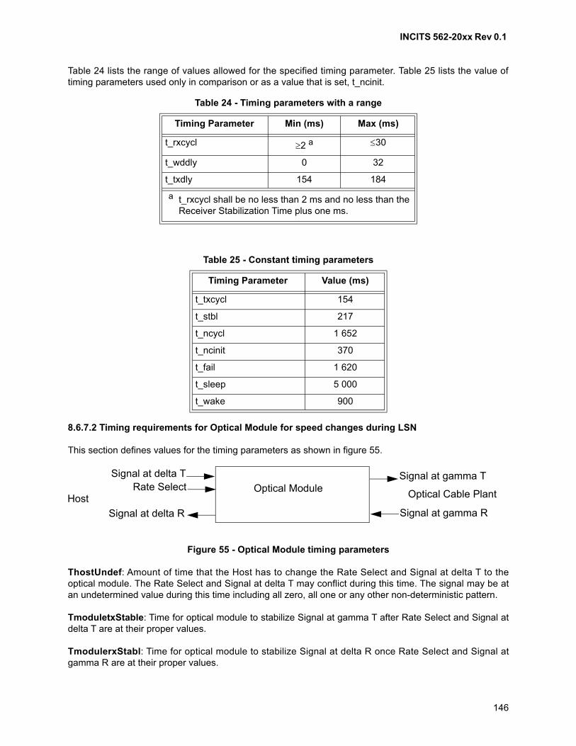
INCITS 562-20xx Rev 0.1
146
Table 24 lists the range of values allowed for the specified timing parameter. Table 25 lists the value oftiming parameters used only in comparison or as a value that is set, t_ncinit.
8.6.7.2 Timing requirements for Optical Module for speed changes during LSN
This section defines values for the timing parameters as shown in figure 55.
Figure 55 - Optical Module timing parameters
ThostUndef: Amount of time that the Host has to change the Rate Select and Signal at delta T to theoptical module. The Rate Select and Signal at delta T may conflict during this time. The signal may be atan undetermined value during this time including all zero, all one or any other non-deterministic pattern.
TmoduletxStable: Time for optical module to stabilize Signal at gamma T after Rate Select and Signal atdelta T are at their proper values.
TmodulerxStabl: Time for optical module to stabilize Signal at delta R once Rate Select and Signal atgamma R are at their proper values.
Table 24 - Timing parameters with a range
Timing Parameter Min (ms) Max (ms)
t_rxcycl 2 a 30
t_wddly 0 32
t_txdly 154 184
a t_rxcycl shall be no less than 2 ms and no less than the Receiver Stabilization Time plus one ms.
Table 25 - Constant timing parameters
Timing Parameter Value (ms)
t_txcycl 154
t_stbl 217
t_ncycl 1 652
t_ncinit 370
t_fail 1 620
t_sleep 5 000
t_wake 900
Optical ModuleSignal at gamma T
Optical Cable Plant
Signal at gamma R
Signal at delta TRate Select
Signal at delta R
Host
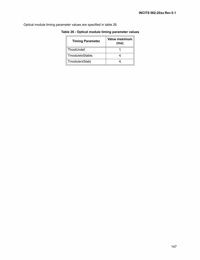
INCITS 562-20xx Rev 0.1
147
Optical module timing parameter values are specified in table 26.
Table 26 - Optical module timing parameter values
Timing ParameterValue maximum
(ms)
ThostUndef 1
TmoduletxStable 4
TmodulerxStabl 4
INCITS 562-20xx Rev 0.1
148
9 Transmitter training
9.1 Scope
Transmitter training is a function of the FC-2P sublevel.
9.2 Transmitter training
9.2.1 Overview
Transmitter training negotiates capabilities between the transmitters and receivers connected by a link:
a) values of transmitter equalizer coefficients that result in most reliable signal reception across thelink;
b) values for receiver adaptive equalization circuits for reliable signal reception;
c) use of FEC;
d) Parallel Lane Support; and
e) Extended Marker Present.
This clause specifies the protocol by which these capabilities shall be negotiated.
Transmitter training includes two steps:
a) active training; and
b) link quality check.
9.2.2 Transmitter training for 128GFC/32GFC/16GFC
Active training is performed while transmitting and receiving the Transmitter Training Signal (see 5.6).Information in the Training Frame (see 5.6.2) portion of the Transmitter Training Signal is used toimplement the protocol for negotiation of capabilities. The Training Pattern (see 5.6.3) portion of theTransmitter Training Signal allows each FC_Port to evaluate the received signal quality and recommendadjustments to the transmitter of the other FC_Port.
Training of transmitter equalizer coefficients is based on modeling the transmitter equalizer as having up tothree coefficients that may be controlled by information in the Training Frame of the Transmitter TrainingSignal (see 5.6.2). The use of each coefficient is specified by FC-PI-x for each FC-0 variant that supportstransmitter training. Each coefficient in the model has a minimum value, a maximum value, an initializevalue, a preset value, and a step size by which it may be adjusted. These values are specified by FC-PI-xfor each FC-0 physical variant that supports transmitter training.
An FC_Port that does not support training of transmitter equalizer coefficients acknowledges transmittertraining commands but takes no action on its transmitter.
Training of transmitter equalizer coefficients presumes an adaptation process that determines thefeedback requests to send to the remote transmitter and adjusts the local transmitter in response tofeedback requests from the remote transmitter. The adaptation process observes the sequence of eventsspecified by this standard, but the process by which it determines the need to send requests and adapts toreceived requests is not within the scope of this standard.
INCITS 562-20xx Rev 0.1
149
Link quality check confirms the ability of the link to be used for normal operation. Link quality check isperformed while transmitting and receiving 64B/66B transmission code. Link quality check for frametransfer transmission codes other than 64B/66B is out of the scope of this standard.
9.2.3 Transmitter training state machines for 128/32/16GFC
9.2.3.1 Overview
Transmitter training shall cause link behavior equivalent to the state machines specified in 9.2.3.
Active training is specified by seven state machines operating concurrently:
a) Training_Sequencer;
b) a Cn_Controller for each coefficient n (i.e., n=-1, 0, 1) in the equalizer model; and
c) a Cn_Responder for each coefficient n (i.e., n=-1, 0, 1) in the equalizer model.
Link quality check is specified by a single state machine, Link_Qual_Check.
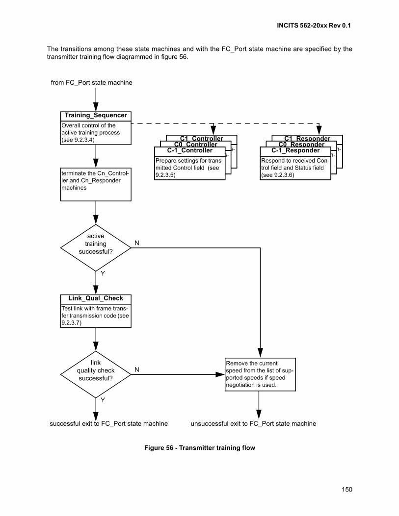
INCITS 562-20xx Rev 0.1
150
The transitions among these state machines and with the FC_Port state machine are specified by thetransmitter training flow diagrammed in figure 56.
Figure 56 - Transmitter training flow
Overall control of the active training process (see 9.2.3.4)
Training_Sequencer
activetraining
successful?N
Y
from FC_Port state machine
successful exit to FC_Port state machine
terminate the Cn_Control-ler and Cn_Responder machines
Test link with frame trans-fer transmission code (see 9.2.3.7)
Link_Qual_Check
linkquality checksuccessful?
N
Y
unsuccessful exit to FC_Port state machine
Remove the current speed from the list of sup-ported speeds if speed negotiation is used.
Prepare settings for trans-mitted Control field (see 9.2.3.5)
C1_Controller
Prepare settings for trans-mitted Control field (see 9.2.3.5)
C0_Controller
Prepare settings for trans-mitted Control field (see 9.2.3.5)
C-1_Controller Respond to received Con-trol field and Status field (see 9.2.3.6)
C1_Responder
Respond to received Con-trol field and Status field (see 9.2.3.6)
C0_Responder
Respond to received Con-trol field and Status field (see 9.2.3.6)
C-1_Responder
INCITS 562-20xx Rev 0.1
151
9.2.3.2 Timers
The timers specified in this subclause are visible to all state machines specified in 9.2.3.
train_fail_timer: a timer that limits the duration of active training. The train_fail_timer expires between 1 sand 1.5 s from the time it is started.
link_wait_timer: a timer that limits the duration in which the transmitter will transmit the TransmitterTraining Signal at fixed settings after the remote FC_Port indicates training complete to ensure that remoteFC_Port correctly detects the local interface state. The link_wait_timer expires between 32 s and 96 sfrom the time it is started.
link_test_timer: a timer that determines the delay in the LINK_TEST state before sampling of the linkquality. The link_test_timer expires between 30 ms and 45 ms from the time it is started.
9.2.3.3 Variables
The variables specified in this subclause are visible to all state machines specified in 9.2.3.
These variables are set on decoding the values received in arriving Training Frames (see table 16 andtable 17) during transmitter training. They are only set while the Transmitter Training Signal TransmissionWord Synchronization state is Word Synchronization Acquired (see 6.5.1):
a) rcv_Preset: the value in the Preset field of the Control field in the most recently received TrainingFrame;
b) rcv_Initialize: the value in the Initialize field of the Control field in the most recently receivedTraining Frame;
c) rcv_FECReq: the value in the FECReq field of the Control field in the most recently receivedTraining Frame;
d) rcv_C1Upd: the value in the C1Upd field of the Control field in the most recently received TrainingFrame;
e) rcv_C0Upd: the value in the C0Upd field of the Control field in the most recently received TrainingFrame;
f) rcv_C-1Upd: the value in the C-1Upd field of the Control field in the most recently receivedTraining Frame;
g) rcv_TC: the value in the TC field of the Status field in the most recently received Training Frame;
h) rcv_SN: the value in the SN field of the Status field in the most recently received Training Frame;
i) rcv_FECCap: the value in the FECCap field of the Status field in the most recently receivedTraining Frame;
j) rcv_TF: the value in the TF field of the Status field in the most recently received Training Frame;
k) rcv_C1Stat: the value in the C1Stat field of the Status field in the most recently received TrainingFrame;
l) rcv_C0Stat: the value in the C0Stat field of the Status field in the most recently received TrainingFrame; and
m) rcv_C-1Stat: the value in the C-1Stat field of the Status field in the most recently received TrainingFrame.
The term rcv_CnUpd is used to reference some member of rcv_C-1Upd, rcv_C0Upd, or rcv_C1Upd,specified by the context of the reference. The term rcv_CnStat is used to reference some member ofrcv_C-1Stat, rcv_C0Stat, or rcv_C1Stat, specified by the context of the reference.
INCITS 562-20xx Rev 0.1
152
These variables contain the values that are set in transmitted Training Frames (see table 16 and table 17)while the Transmitter Training Signal is being used during transmitter training:
a) send_Preset: the value to set in the Preset field of the Control field of subsequently sent TrainingFrames;
b) send_Initialize: the value to set in the Initialize field of the Control field of subsequently sentTraining Frames;
c) send_FECReq: the value to set in the FECReq field of the Control field of subsequently sentTraining Frames. The value of send_FECReq does not change;
d) send_C1Upd: the value to set in the C1Upd field of the Control field of subsequently sent TrainingFrames;
e) send_C0Upd: the value to set in the C0Upd field of the Control field of subsequently sent TrainingFrames;
f) send_C-1Upd: the value to set in the C-1Upd field of the Control field of subsequently sentTraining Frames;
g) send_TC: the value to set in the TC field of the Status field of subsequently sent Training Frames;
h) send_SN: the value to set in the SN field of the Status field of subsequently sent Training Frames;
i) send_FECCap: the value to set in the FECCap field of the Status field of subsequently sentTraining Frames. The value of send_FECCap does not change;
j) send_TF: the value to set in the TF field of the Status field of subsequently sent Training Frames.The value of send_TF does not change;
k) send_C1Stat: the value to set in the C1Stat field of the Status field of subsequently sent TrainingFrames;
l) send_C0Stat: the value to set in the C0Stat field of the Status field of subsequently sent TrainingFrames; and
m) send_C-1Stat: the value to set in the C-1Stat field of the Status field of subsequently sent TrainingFrames.
The term send_CnUpd is used to reference some member of send_C-1Upd, send_C0Upd, orsend_C1Upd, specified by the context of the reference. The term send_CnStat is used to reference somemember of send_C-1Stat, send_C0Stat, or send_C1Stat, specified by the context of the reference.
9.2.3.4 Training_Sequencer state machine
9.2.3.4.1 Overview
This state machine starts the concurrent state machines that manage training of individual equalizercoefficients (see 9.2.3.5 and 9.2.3.6), and then conducts the protocol to determine when training hasbecome stable or failed. A diagram for the Training_Sequencer state machine is given in figure 57.
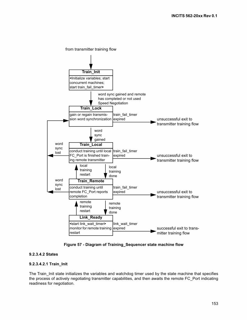
INCITS 562-20xx Rev 0.1
153
9.2.3.4.2 States
9.2.3.4.2.1 Train_Init
The Train_Init state initializes the variables and watchdog timer used by the state machine that specifiesthe process of actively negotiating transmitter capabilities, and then awaits the remote FC_Port indicatingreadiness for negotiation.
Figure 57 - Diagram of Training_Sequencer state machine flow
<Initialize variables; start concurrent machines; start train_fail_timer>
Train_Init
from transmitter training flow
gain or regain transmis-sion word synchronization
Train_Lock
conduct training until local FC_Port is finished train-ing remote transmitter
Train_Local
conduct training until remote FC_Port reports completion
Train_Remote
<start link_wait_timer>monitor for remote training restart
Link_Ready
word sync gained and remote has completed or not used Speed Negotiation
wordsyncgained
unsuccessful exit to transmitter training flow
train_fail_timer expired
local training done
wordsynclost
unsuccessful exit to transmitter training flow
train_fail_timer expired
local training restart
wordsynclost
unsuccessful exit to transmitter training flow
train_fail_timer expired
remote training done
remote training restart
successful exit to trans-mitter training flow
link_wait_timer expired
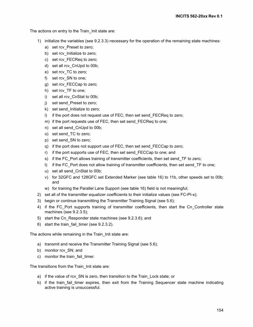
INCITS 562-20xx Rev 0.1
154
The actions on entry to the Train_Init state are:
1) initialize the variables (see 9.2.3.3) necessary for the operation of the remaining state machines:
a) set rcv_Preset to zero;
b) set rcv_Initialize to zero;
c) set rcv_FECReq to zero;
d) set all rcv_CnUpd to 00b;
e) set rcv_TC to zero;
f) set rcv_SN to one;
g) set rcv_FECCap to zero;
h) set rcv_TF to one;
i) set all rcv_CnStat to 00b;
j) set send_Preset to zero;
k) set send_Initialize to zero;
l) if the port does not request use of FEC, then set send_FECReq to zero;
m) if the port requests use of FEC, then set send_FECReq to one;
n) set all send_CnUpd to 00b;
o) set send_TC to zero;
p) set send_SN to zero;
q) if the port does not support use of FEC, then set send_FECCap to zero;
r) if the port supports use of FEC, then set send_FECCap to one; and
s) if the FC_Port allows training of transmitter coefficients, then set send_TF to zero;
t) if the FC_Port does not allow training of transmitter coefficients, then set send_TF to one;
u) set all send_CnStat to 00b;
v) for 32GFC and 128GFC set Extended Marker (see table 16) to 11b, other speeds set to 00b;and
w) for training the Parallel Lane Support (see table 16) field is not meaningful;
2) set all of the transmitter equalizer coefficients to their initialize values (see FC-PI-x);
3) begin or continue transmitting the Transmitter Training Signal (see 5.6);
4) if the FC_Port supports training of transmitter coefficients, then start the Cn_Controller statemachines (see 9.2.3.5);
5) start the Cn_Responder state machines (see 9.2.3.6); and
6) start the train_fail_timer (see 9.2.3.2).
The actions while remaining in the Train_Init state are:
a) transmit and receive the Transmitter Training Signal (see 5.6);
b) monitor rcv_SN; and
c) monitor the train_fail_timer.
The transitions from the Train_Init state are:
a) if the value of rcv_SN is zero, then transition to the Train_Lock state; or
b) if the train_fail_timer expires, then exit from the Training Sequencer state machine indicatingactive training is unsuccessful.
INCITS 562-20xx Rev 0.1
155
9.2.3.4.2.2 Train_Lock
The Train_Lock state establishes or recovers Transmitter Training Signal Transmission WordSynchronization (see 6.5) during the process of actively negotiating transmitter equalization.
There are no actions on entry to the Train_Lock state.
The actions while remaining in the Train_Lock state are:
a) transmit the Transmitter Training Signal;
b) monitor Transmitter Training Signal Transmission Word Synchronization (see 6.5); and
c) monitor the train_fail_timer.
The transitions from the Train_Lock state are:
a) if Transmitter Training Signal Transmission Word Synchronization is detected, then transition tothe Train_Local state; or
b) if the train_fail_timer expires, then exit from the Training Sequencer state machine indicatingactive training is unsuccessful.
9.2.3.4.2.3 Train_Local
The Train_Local state establishes or re-establishes stable equalization of the remote transmitter by thelocal FC_Port during the process of actively negotiating transmitter capabilities.
The actions on entry to the Train_Local state are:
a) set send_TC to zero.
The actions while remaining in the Train_Local state are:
a) if the value of send_TF is zero, then monitor for completion of the adaptation process in the localFC_Port, which is not within the scope of this standard;
b) monitor Transmitter Training Signal Transmission Word Synchronization (see 6.5); and
c) monitor the train_fail_timer.
The transitions from the Train_Local state are:
a) if completion of the adaptation process in the local FC_Port is detected, then transition to theTrain_Remote state;
b) if the value of send_TF is one, then transition to the Train_Remote state;
c) if the value of rcv_TF is one, then transition to the Train_Remote state;
d) if loss of Transmitter Training Signal Transmission Word Synchronization is detected, thentransition to the Train_Lock state; or
e) if the train_fail_timer expires, then exit from the Training Sequencer state machine indicatingactive training is unsuccessful.
9.2.3.4.2.4 Train_Remote
The Train_Remote state establishes stable equalization of the local transmitter by the remote FC_Portduring the process of actively negotiating transmitter capabilities.
INCITS 562-20xx Rev 0.1
156
The actions on entry to the Train_Remote state are:
a) set send_TC to one.
The actions while remaining in the Train_Remote state are:
a) monitor the value of rcv_TC;
b) monitor the value of rcv_TF;
c) if the value of send_TF is zero and rcv_TF is set to zero, then monitor for resumption of theadaptation process in the local FC_Port, which is not within the scope of this standard;
d) monitor Transmitter Training Signal Transmission Word Synchronization (see 6.5); and
e) monitor the train_fail_timer.
The transitions from the Train_Remote state are:
a) if the value of rcv_TC is one, then transition to the Link_Ready state;
b) if the value of send_TF is zero and the value of rcv_TF is zero and resumption of the adaptationprocess in the local FC_Port is detected, then transition to the Train_Local state;
c) if loss of Transmitter Training Signal Transmission Word Synchronization is detected, thentransition to the Train_Lock state; or
d) if the train_fail_timer expires, then exit from the Training Sequencer state machine indicatingactive training is unsuccessful.
9.2.3.4.2.5 Link_Ready
The Link_Ready state confirms stable negotiation between the local and remote FC_Ports during theprocess of actively negotiating transmitter equalization.
The actions on entry to the Link_Ready state are:
a) start the link_wait_timer.
The actions while remaining in the Link_Ready state are:
a) monitor the value of rcv_TC; and
b) monitor the link_wait_timer.
The transitions from the Link_Ready state are:
a) if the value of rcv_TC is zero, then transition to the Train_Remote state; or
b) if the link_wait_timer expires, then exit from the Training Sequencer state machine indicatingactive training is successful.
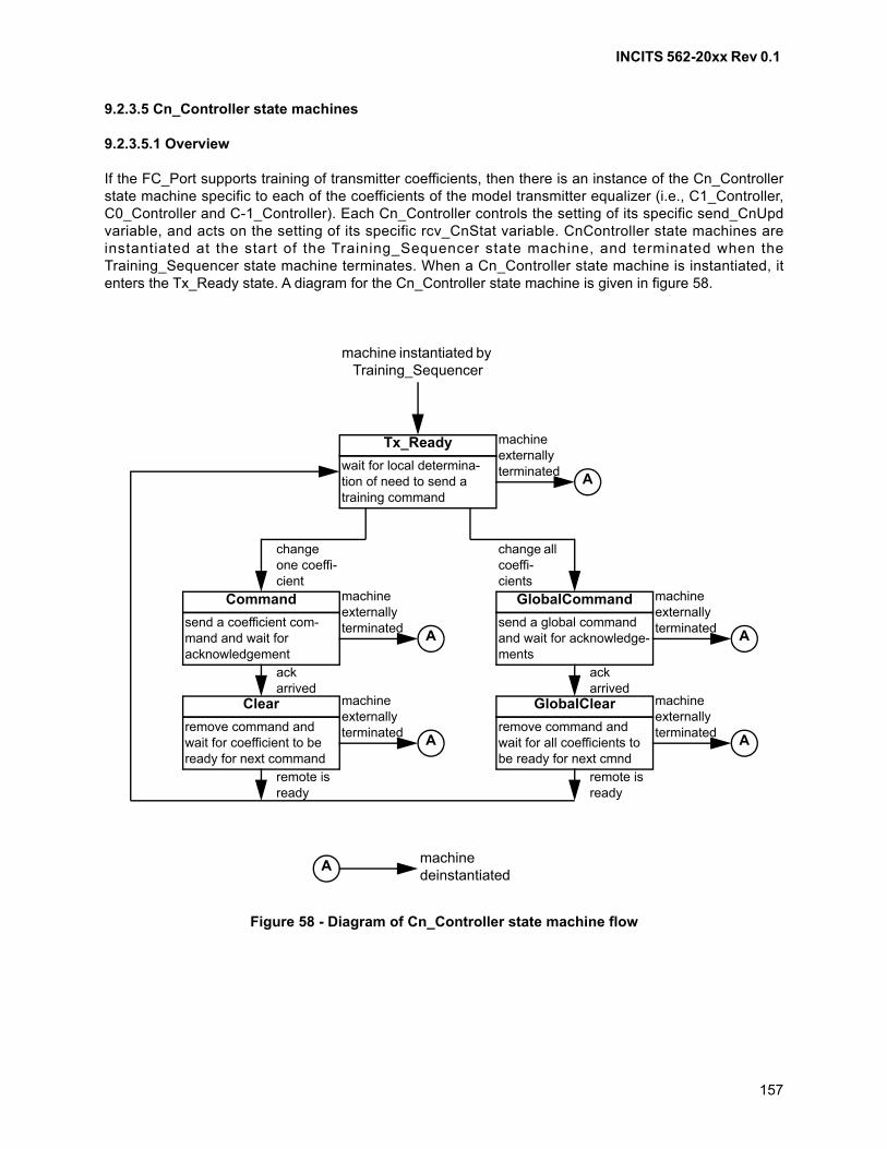
INCITS 562-20xx Rev 0.1
157
9.2.3.5 Cn_Controller state machines
9.2.3.5.1 Overview
If the FC_Port supports training of transmitter coefficients, then there is an instance of the Cn_Controllerstate machine specific to each of the coefficients of the model transmitter equalizer (i.e., C1_Controller,C0_Controller and C-1_Controller). Each Cn_Controller controls the setting of its specific send_CnUpdvariable, and acts on the setting of its specific rcv_CnStat variable. CnController state machines areinstantiated at the start of the Training_Sequencer state machine, and terminated when theTraining_Sequencer state machine terminates. When a Cn_Controller state machine is instantiated, itenters the Tx_Ready state. A diagram for the Cn_Controller state machine is given in figure 58.
Figure 58 - Diagram of Cn_Controller state machine flow
machine instantiated by Training_Sequencer
wait for local determina-tion of need to send a training command
Tx_Ready
send a coefficient com-mand and wait for acknowledgement
Command
remove command and wait for coefficient to be ready for next command
Clear
change one coeffi-cient
ack arrived
machinedeinstantiated
machine externally terminated
A
A
remote is ready
machine externally terminated
A
machine externally terminated
A
send a global command and wait for acknowledge-ments
GlobalCommand
remove command and wait for all coefficients to be ready for next cmnd
GlobalClear
ack arrived
machine externally terminated
A
remote is ready
machine externally terminated
A
change all coeffi-cients

INCITS 562-20xx Rev 0.1
158
9.2.3.5.2 States
9.2.3.5.2.1 Tx_Ready
In the Tx_Ready state, the Cn_Controller state machine has confirmed completion of its prior updatecommand and does not need to update its coefficient further.
The actions on entry to the Tx_Ready state are:
a) set send_Preset to zero;
b) set send_Initialize to zero; and
c) set send_CnUpd to 00b for the coefficient managed by this Cn_Controller state machine.
The actions while remaining in the Tx_Ready state are:
a) monitor the value of rcv_TF. If the value of rcv_TF is zero, then:
A) monitor for the need to set all coefficients to their initialize values (see FC-PI-x);
B) monitor for the need to set all coefficients to their preset values (see FC-PI-x); and
C) monitor for the need to increment or decrement the coefficient negotiated by this Cn_Con-troller state machine.
The processes by which a Cn_Controller determines the need to update the coefficient in the remotetransmitter that it negotiates and reset the negotiation are not within the scope of this standard; however,these processes shall not indicate the need for more than one command at the same time that affects thesame coefficient.
The transitions from the Tx_Ready state are:
a) if the value of rcv_TF is zero, the values of rcv_CnStat for all coefficients are 00b, and theCn_Controller state machine determines the need to set all coefficients to their initialize values,then transition to the GlobalCommand state;
b) if the value of rcv_TF is zero, the values of rcv_CnStat for all coefficients are 00b, and theCn_Controller state machine determines the need to set all coefficients to their preset values, thentransition to the GlobalCommand state; or
c) If the value of rcv_TF is zero and the value of the rcv_CnStat for the coefficient to be adjusted is00b, and the Cn_Controller state machine determines the need to increment or decrement thecoefficient negotiated by this Cn_Controller state machine, then transition to the Command state.
9.2.3.5.2.2 Command
In the Command state, the Cn_Controller is sending a command that affects only its coefficient, and iswaiting for acknowledgement that the command was received.
The actions on entry to the Command state are:
a) if the Cn_Controller state machine has determined the need to increment the coefficientnegotiated by this Cn_Controller state machine, then set send_Preset to zero, set send_Initializeto zero, and set send_CnUpd to 01b for the coefficient negotiated by this Cn_Controller statemachine; or
b) if the Cn_Controller state machine has determined the need to decrement the coefficientnegotiated by this Cn_Controller state machine, then set send_Preset to zero, set send_Initialize

INCITS 562-20xx Rev 0.1
159
to zero, and set send_CnUpd to 10b for the coefficient negotiated by this Cn_Controller statemachine.
The actions while remaining in the Command state are:
a) monitor the value of rcv_CnStat for the coefficient negotiated by this Cn_Controller state machine.
The transitions from the Command state are:
a) if the value of rcv_CnStat for the coefficient negotiated by this Cn_Controller state machine is not00b, then transition to the Clear state.
9.2.3.5.2.3 Clear
In the Clear state, the Cn_Controller has received acknowledgement for a command that affects only itscoefficient, and is waiting for notification that the remote FC_Port is ready for another command.
The actions on entry to the Clear state are:
a) set send_Preset to zero;
b) set send_Initialize to zero; and
c) set send_CnUpd to 00b for the coefficient managed by this Cn_Controller state machine.
The actions while remaining in the Clear state are:
a) monitor the value of rcv_CnStat for the coefficient negotiated by this Cn_Controller state machine.
The transitions from the Clear state are:
a) if the value of rcv_CnStat for the coefficient negotiated by this Cn_Controller state machine is 00b,then transition to the Tx_Ready state.
9.2.3.5.2.4 GlobalCommand
In the GlobalCommand state, the Cn_Controller is sending a command that affects all coefficients, and iswaiting for acknowledgement that the command was received.
The processes by which a Cn_Controller determines the need to update the coefficient in the remotetransmitter that it negotiates and reset the negotiation are not within the scope of this standard; however,these processes shall not indicate the need for more than one command at the same time that affects thesame coefficient.
The actions on entry to the GlobalCommand state are:
a) if the Cn_Controller state machine determines the need to reset all coefficients to their presetvalues, then set send_Preset to one, set send_Initialize to zero, and set send_CnUpd to 00b for allcoefficients; or
b) if the Cn_Controller state machine has determined the need to set all coefficients to their initializevalues, then set send_Preset to zero, set send_Initialize to one, and send_CnUpd to 00b for allcoefficients.
INCITS 562-20xx Rev 0.1
160
The actions while remaining in the GlobalCommand state are:
a) monitor the values of rcv_CnStat for all coefficients.
The transitions from the GlobalCommand state are:
a) if the values of rcv_CnStat for all coefficients are nonzero, then transition to the GlobalClear state.
9.2.3.5.2.5 GlobalClear
In the GlobalClear state, the Cn_Controller has received acknowledgement for a command that affects allcoefficients, and is waiting for notification that the remote FC_Port is ready for another command.
The actions on entry to the GlobalClear state are:
a) set send_Reset to zero;
b) set send_Initialize to zero; and
c) set send_CnUpd to 00b for all coefficients.
The actions while remaining in the GlobalClear state are:
a) monitor the values of rcv_CnStat for all coefficients.
The transitions from the GlobalClear state are:
a) if the values of rcv_CnStat for all coefficients are 00b, then transition to the Tx_Ready state.
9.2.3.6 Cn_Responder state machines
9.2.3.6.1 Overview
There is an instance of the Cn_Responder state machine specific to each of the coefficients of the modeltransmitter equalizer (i.e., C1_Responder, C0_Responder and C-1_Responder). Each Cn_Responder actson the setting of its specific rcv_CnUpd variable, and controls the setting of its specific send_CnStatvariable. Cn_Responder state machines are instantiated at the start of the Training_Sequencer statemachine, and terminated when the Training_Sequencer state machine terminates. When a Cn_Responderstate machine is instantiated, it enters the Rx_Ready state. A diagram for the Cn_Responder statemachine is given in figure 59.
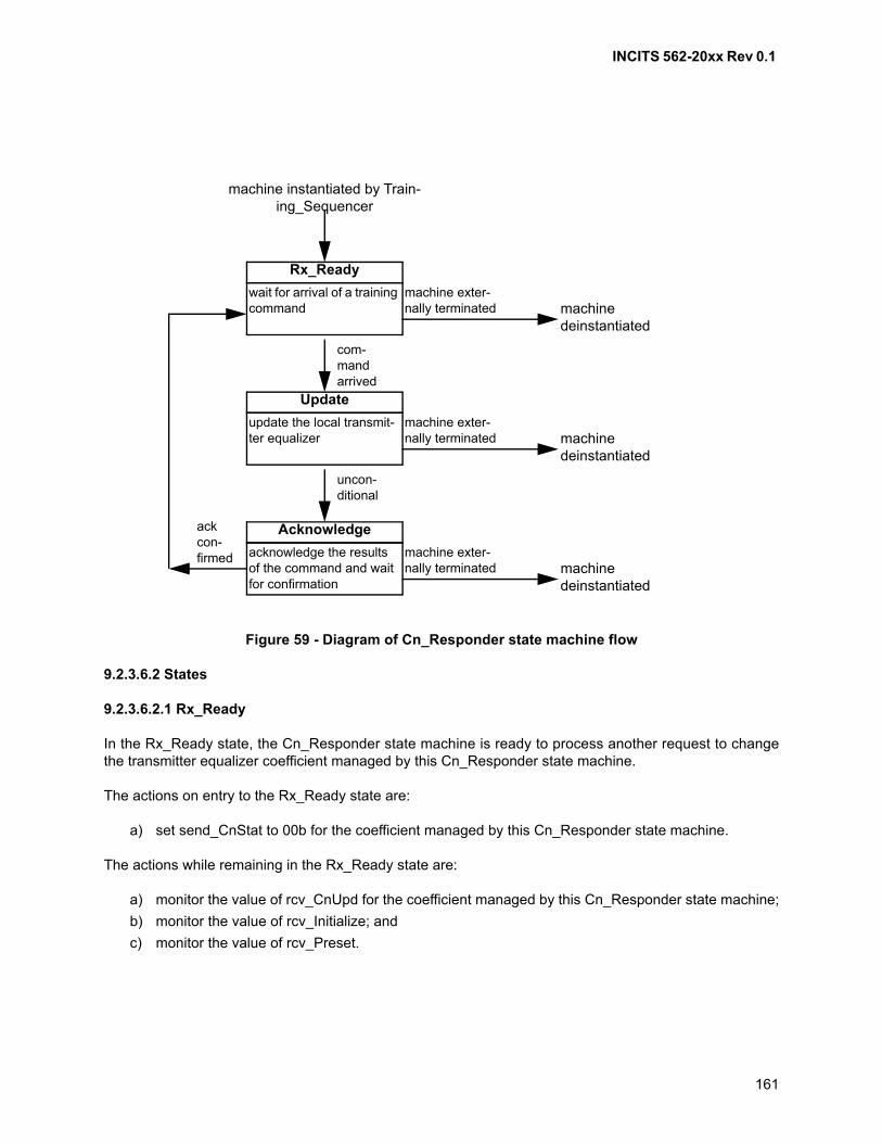
INCITS 562-20xx Rev 0.1
161
9.2.3.6.2 States
9.2.3.6.2.1 Rx_Ready
In the Rx_Ready state, the Cn_Responder state machine is ready to process another request to changethe transmitter equalizer coefficient managed by this Cn_Responder state machine.
The actions on entry to the Rx_Ready state are:
a) set send_CnStat to 00b for the coefficient managed by this Cn_Responder state machine.
The actions while remaining in the Rx_Ready state are:
a) monitor the value of rcv_CnUpd for the coefficient managed by this Cn_Responder state machine;
b) monitor the value of rcv_Initialize; and
c) monitor the value of rcv_Preset.
Figure 59 - Diagram of Cn_Responder state machine flow
machine instantiated by Train-ing_Sequencer
wait for arrival of a training command
Rx_Ready
update the local transmit-ter equalizer
Update
acknowledge the results of the command and wait for confirmation
Acknowledge
com-mand arrived
machinedeinstantiated
machine exter-nally terminated
uncon-ditional
machinedeinstantiated
machine exter-nally terminated
ack con-firmed
machinedeinstantiated
machine exter-nally terminated

INCITS 562-20xx Rev 0.1
162
The transitions from the Rx_Ready state are:
a) if the value of rcv_CnUpd is nonzero for the coefficient managed by this Cn_Responder statemachine, then transition to the Update state;
b) if the value of rcv_Initialize is nonzero, then transition to the Update state; and
c) if the value of rcv_Preset is nonzero, then transition to the Update state.
9.2.3.6.2.2 Update
In the Update state, the Cn_Responder state machine processes a command that affects the coefficientmanaged by this Cn_Responder state machine and reports the resulting status to the sender of thecommand.
The actions on entry to the Update state are:
a) if the value of send_TF is one, then set send_CnStat to any nonzero value for the coefficientmanaged by this Cn_Responder state machine;
b) if:
A) the value of send_TF is zero; and
B) the value of rcv_Preset is one,
then set the coefficient managed by this Cn_Responder state machine to its preset value (seeFC-PI-x) and then:
A) if the coefficient managed by this Cn_Responder state machine is not at its minimum valueand not at its maximum value, then set send_CnStat to 01b for the coefficient managed by thisCn_Responder state machine;
B) if the coefficient managed by this Cn_Responder state machine is at its minimum value, thenset send_CnStat to 10b for the coefficient managed by this Cn_Responder state machine; or
C) if the coefficient managed by this Cn_Responder state machine is at its maximum value, thenset send_CnStat to 11b for the coefficient managed by this Cn_Responder state machine;
c) if:
A) the value of send_TF is zero;
B) the value of rcv_Preset is zero; and
C) the value of rcv_Initialize is one,
then set the coefficient managed by this Cn_Responder state machine to its initialize value (seeFC-PI-x) and set send_CnStat to 01b for the coefficient managed by this Cn_Responder statemachine;
d) if
A) the value of send_TF is zero;
B) the value of rcv_Preset is zero;
C) the value of rcv_Initialize is zero; and
D) the value of rcv_CnUpd is 01b for the coefficient managed by this Cn_Responder statemachine,
then:
A) if the coefficient managed by this Cn_Responder state machine is at its maximum value, thenset send_CnStat to 11b for the coefficient managed by this Cn_Responder state machine; or
B) if the coefficient managed by this Cn_Responder state machine is not at its maximum valuethen increment the coefficient managed by this Cn_Responder state machine by its step size(see FC-PI-x) and then:

INCITS 562-20xx Rev 0.1
163
a) if the coefficient managed by this Cn_Responder state machine is not at its maximumvalue, then set send_CnStat to 01b for the coefficient managed by this Cn_Responderstate machine; or
b) if the coefficient managed by this Cn_Responder state machine is at its maximum value,then set send_CnStat to 11b for the coefficient managed by this Cn_Responder statemachine;
or
e) if
A) the value of send_TF is zero;
B) the value of rcv_Preset is zero;
C) the value of rcv_Initialize is zero; and
D) the value of rcv_CnUpd is 10b for the coefficient managed by this Cn_Responder statemachine,
then:
A) if the coefficient managed by this Cn_Responder state machine is at its minimum value, thenset send_CnStat to 10b for the coefficient managed by this Cn_Responder state machine; or
B) if the coefficient managed by this Cn_Responder state machine is not at its minimum valuethen decrement the coefficient managed by this Cn_Responder state machine by its step size(see FC-PI-x) and then:
a) if the coefficient managed by this Cn_Responder state machine is not at its minimumvalue, then set send_CnStat to 01b for the coefficient managed by this Cn_Responderstate machine; or
b) if the coefficient managed by this Cn_Responder state machine is at its minimum value,then set send_CnStat to 10b for the coefficient managed by this Cn_Responder statemachine.
There are no actions while remaining in the Update state.
The Update state transitions to the Acknowledge state on completing its actions on entry.
9.2.3.6.2.3 Acknowledge
In the Acknowledge state, the Cn_Responder maintains the status of its most recently processedcommand until the sender of the command indicates that the status has been received.
There are no actions on entry to the Acknowledge state.
The actions while remaining in the Acknowledge state are:
a) monitor the value of rcv_Preset;
b) monitor the value of rcv_Initialize; and
c) monitor the value of rcv_CnUpd for the coefficient managed by this Cn_Responder state machine.
The transitions from the Acknowledge state are:
a) If:
A) the value of rcv_Preset is zero;
B) the value of rcv_Initialize is zero; and
INCITS 562-20xx Rev 0.1
164
C) the value of rcv_CnUpd is zero for the coefficient managed by this Cn_Responder statemachine,
then transition to the Rx_Ready state.
9.2.3.7 Link_Qual_Check state machine
9.2.3.7.1 Overview
This state machine verifies that the FC_Port is able to reliably communicate over the link using 64B/66Bframe transfer transmission protocol (see 5.3). In this state machine, the NOS Primitive Sequence istransmitted.
9.2.3.7.2 States
9.2.3.7.2.1 Link_Test
The Link_Test state is the only state in the Link_Qual_Test state machine. It begins using the 64B/66Btransmission code, delays long enough for both the local and remote FC_Port to synchronize to the 64B/66B transmission code, and then verifies 64B/66B Transmission Word Synchronization has beenachieved.
The actions on entry to the Link_Test state are:
1) begin transmitting 64B/66B transmission code (see 5.3) with FEC determined by:
A) if either send_FECCap or rcv_FECCap is set to zero, then do not use FEC;
B) if neither send_FECReq nor rcv_FECReq is set to one, then do not use FEC; and
C) if both send_FECCap and rcv_FECCap are set to one and either send_FECReq orrcv_FECReq is set to one, then use FEC;
and
2) start the link_test_timer (see 9.2.3.2).
The actions while remaining in the Link_Test state are:
1) continue transmitting 64B/66B transmission code, with use of FEC as determined on entry to theLink_Test state, until the link_test_timer expires; and
2) Determine if Transmission Word Synchronization (see 6.4.1) is indicated.
The transitions from the Link_Test state are:
a) if Transmission Word Synchronization is indicated, then exit from the Link_Qual_Check statemachine indicating that link quality check was successful; or
b) if Transmission Word Synchronization is not indicated, then exit from the Link_Qual_Check statemachine indicating that link quality check was unsuccessful.
If the Link_Test state exits indicating that link quality check was successful, then the transmission codeselected on entry to the Link_Test state continues to be used in normal operation.
INCITS 562-20xx Rev 0.1
165
9.2.4 Transmitter training for 256GFC/64GFC
9.2.4.1 Overview
Transmitter training for 64GFC is performed using the Transmitter Training Signal for 64GFC specified in5.7. The following sections describe how the control and status field values are generated duringTransmitter Training.
Initial condition setting is done as specified in IEEE 802.3cd D2.2 136.8.11.4.1.
Coefficient update is done as specified in IEEE 802.3cd D2.2 136.8.11.4.2.
Handshake timing is done as specified in IEEE 802.3cd D2.2 136.8.11.6.
Variables, functions, timers, counters and state diagrams are specified in IEEE 802.3cd D2.2 136.8.11.7and the max_wait_timer value is specified in 9.3.
Active training is specified by the state machines specified in IEEE 802.3cd D2.2 136.8.11.7. Link qualitycheck is specified by a single state machine, Link_Qual_Check.
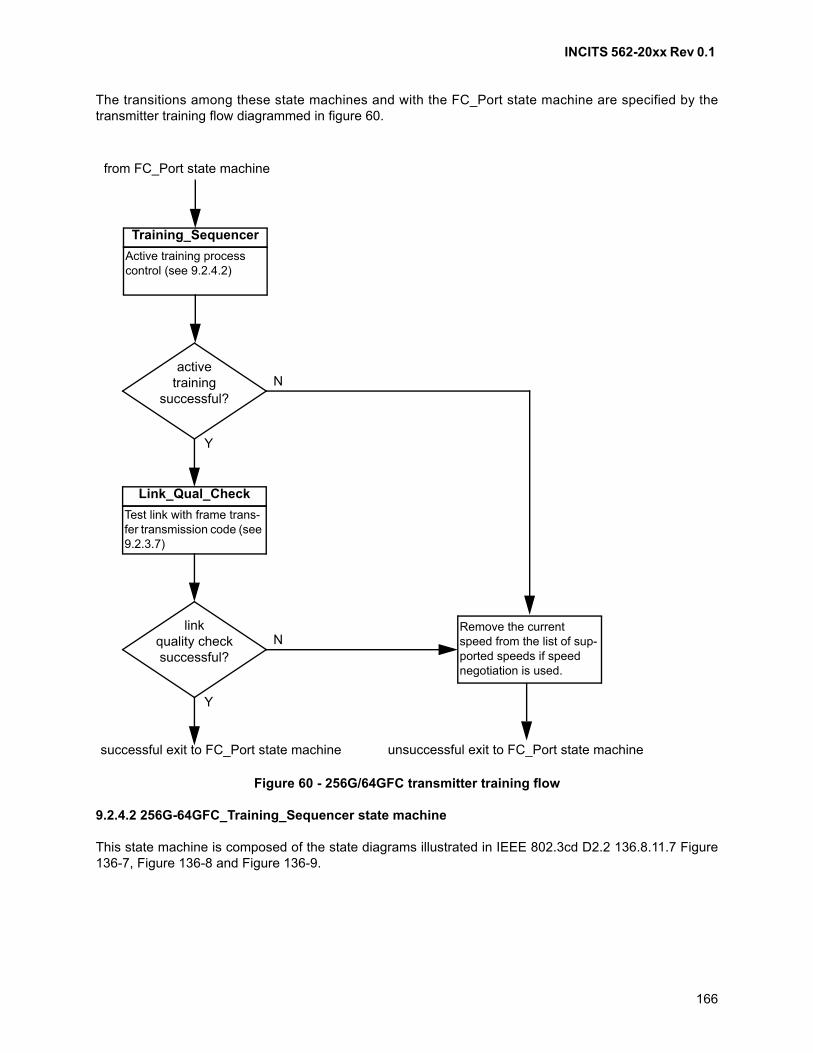
INCITS 562-20xx Rev 0.1
166
The transitions among these state machines and with the FC_Port state machine are specified by thetransmitter training flow diagrammed in figure 60.
9.2.4.2 256G-64GFC_Training_Sequencer state machine
This state machine is composed of the state diagrams illustrated in IEEE 802.3cd D2.2 136.8.11.7 Figure136-7, Figure 136-8 and Figure 136-9.
Figure 60 - 256G/64GFC transmitter training flow
Active training process control (see 9.2.4.2)
Training_Sequencer
activetraining
successful?N
Y
from FC_Port state machine
successful exit to FC_Port state machine
Test link with frame trans-fer transmission code (see 9.2.3.7)
Link_Qual_Check
linkquality checksuccessful?
N
Y
unsuccessful exit to FC_Port state machine
Remove the current speed from the list of sup-ported speeds if speed negotiation is used.
INCITS 562-20xx Rev 0.1
167
9.3 Link Speed Negotiation/Transmitter Training flow diagram for 64GFC
An example of the flow as the link moves from LSN to Transmitter Training for 64GFC links is shown isFigure 61 .
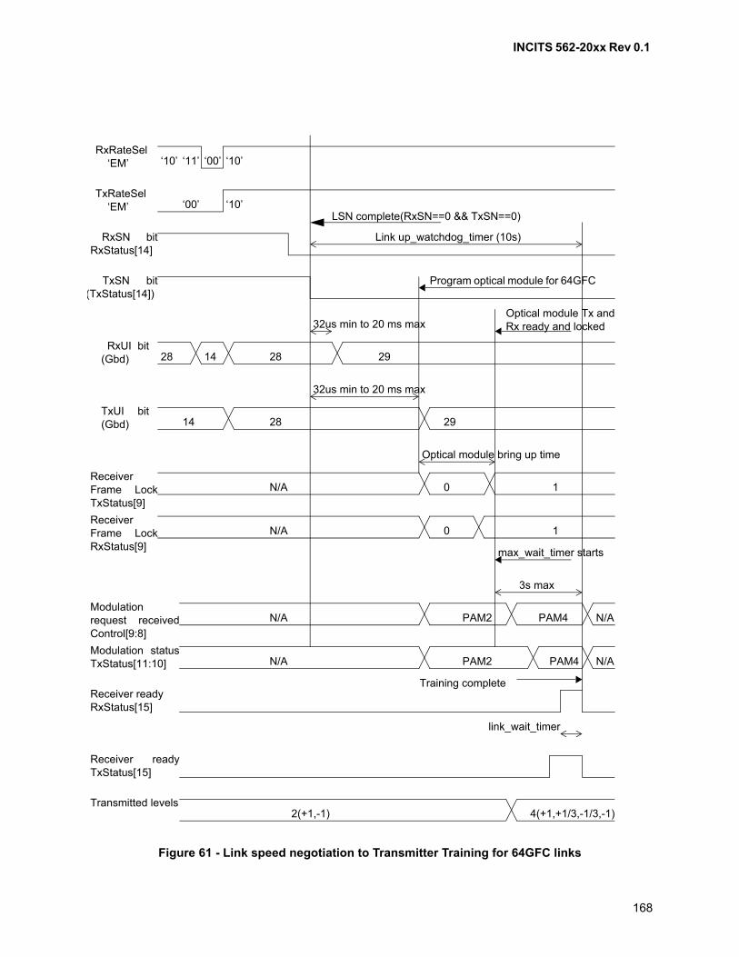
INCITS 562-20xx Rev 0.1
168
Figure 61 - Link speed negotiation to Transmitter Training for 64GFC links
‘10’ ‘11’ ‘00’ ‘10’ RxRateSel ‘EM’
‘00’ ‘10’ TxRateSel ‘EM’
RxSN bitRxStatus[14]
TxSN bit(TxStatus[14])
28 14 28 29 RxUI bit(Gbd)
LSN complete(RxSN==0 && TxSN==0)
14 28 29TxUI bit(Gbd)
0 1 N/A
ReceiverFrame LockRxStatus[9]
N/A 0 1
N/A PAM2 PAM4Modulationrequest receivedControl[9:8]
PAM4 N/A N/A PAM2Modulation statusTxStatus[11:10]
Link up_watchdog_timer (10s)
Program optical module for 64GFC
32us min to 20 ms max
N/A
Optical module Tx andRx ready and locked
ReceiverFrame LockTxStatus[9]
32us min to 20 ms max
Optical module bring up time
max_wait_timer starts
3s max
Training completeReceiver readyRxStatus[15]
Receiver readyTxStatus[15]
link_wait_timer
Transmitted levels 2(+1,-1) 4(+1,+1/3,-1/3,-1)
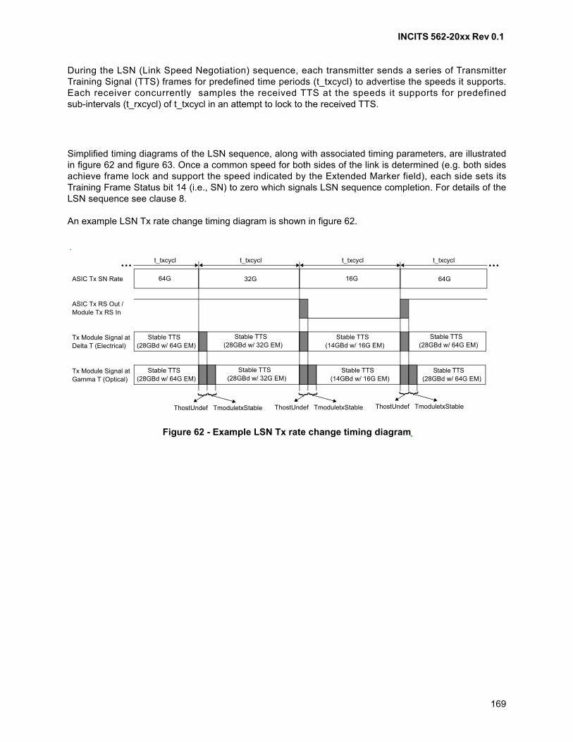
INCITS 562-20xx Rev 0.1
169
During the LSN (Link Speed Negotiation) sequence, each transmitter sends a series of TransmitterTraining Signal (TTS) frames for predefined time periods (t_txcycl) to advertise the speeds it supports.Each receiver concurrently samples the received TTS at the speeds it supports for predefinedsub-intervals (t_rxcycl) of t_txcycl in an attempt to lock to the received TTS.
Simplified timing diagrams of the LSN sequence, along with associated timing parameters, are illustratedin figure 62 and figure 63. Once a common speed for both sides of the link is determined (e.g. both sidesachieve frame lock and support the speed indicated by the Extended Marker field), each side sets itsTraining Frame Status bit 14 (i.e., SN) to zero which signals LSN sequence completion. For details of theLSN sequence see clause 8.
An example LSN Tx rate change timing diagram is shown in figure 62.
Figure 62 - Example LSN Tx rate change timing diagram
ASIC Tx SN Rate
ASIC Tx RS Out /Module Tx RS In
Tx Module Signal atDelta T (Electrical)
Tx Module Signal atGamma T (Optical)
Stable TTS(28GBd w/ 64G EM)
Stable TTS(28GBd w/ 64G EM)
Stable TTS(28GBd w/ 32G EM)
Stable TTS(14GBd w/ 16G EM)
Stable TTS(28GBd w/ 64G EM)
Stable TTS(28GBd w/ 64G EM)
Stable TTS(28GBd w/ 32G EM)
Stable TTS(14GBd w/ 16G EM)
64G 32G 16G 64G
{ {
ThostUndef TmoduletxStable
{ {
ThostUndef TmoduletxStable{ {
ThostUndef TmoduletxStable
t_txcycl t_txcycl t_txcycl t_txcycl
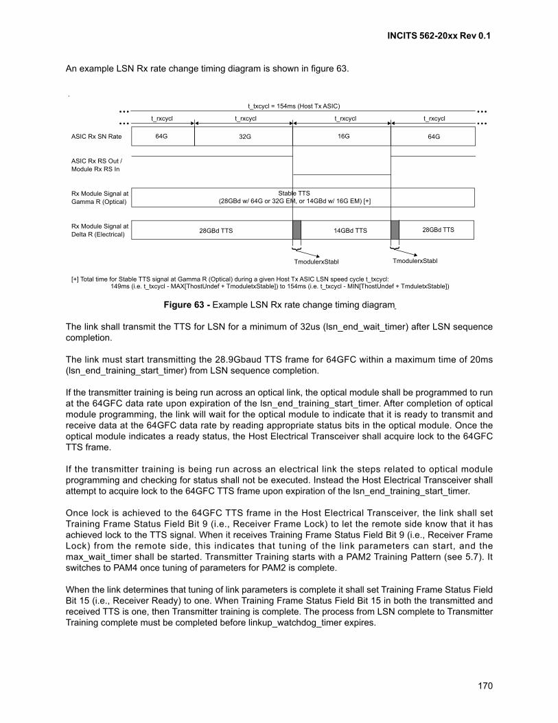
INCITS 562-20xx Rev 0.1
170
An example LSN Rx rate change timing diagram is shown in figure 63.
The link shall transmit the TTS for LSN for a minimum of 32us (lsn_end_wait_timer) after LSN sequencecompletion.
The link must start transmitting the 28.9Gbaud TTS frame for 64GFC within a maximum time of 20ms(lsn_end_training_start_timer) from LSN sequence completion.
If the transmitter training is being run across an optical link, the optical module shall be programmed to runat the 64GFC data rate upon expiration of the lsn_end_training_start_timer. After completion of opticalmodule programming, the link will wait for the optical module to indicate that it is ready to transmit andreceive data at the 64GFC data rate by reading appropriate status bits in the optical module. Once theoptical module indicates a ready status, the Host Electrical Transceiver shall acquire lock to the 64GFCTTS frame.
If the transmitter training is being run across an electrical link the steps related to optical moduleprogramming and checking for status shall not be executed. Instead the Host Electrical Transceiver shallattempt to acquire lock to the 64GFC TTS frame upon expiration of the lsn_end_training_start_timer.
Once lock is achieved to the 64GFC TTS frame in the Host Electrical Transceiver, the link shall setTraining Frame Status Field Bit 9 (i.e., Receiver Frame Lock) to let the remote side know that it hasachieved lock to the TTS signal. When it receives Training Frame Status Field Bit 9 (i.e., Receiver FrameLock) from the remote side, this indicates that tuning of the link parameters can start, and themax_wait_timer shall be started. Transmitter Training starts with a PAM2 Training Pattern (see 5.7). Itswitches to PAM4 once tuning of parameters for PAM2 is complete.
When the link determines that tuning of link parameters is complete it shall set Training Frame Status FieldBit 15 (i.e., Receiver Ready) to one. When Training Frame Status Field Bit 15 in both the transmitted andreceived TTS is one, then Transmitter training is complete. The process from LSN complete to TransmitterTraining complete must be completed before linkup_watchdog_timer expires.
Figure 63 - Example LSN Rx rate change timing diagram
ASIC Rx SN Rate
ASIC Rx RS Out /Module Rx RS In
Rx Module Signal atGamma R (Optical)
Rx Module Signal atDelta R (Electrical)
Stable TTS(28GBd w/ 64G or 32G EM, or 14GBd w/ 16G EM) [+]
28GBd TTS 28GBd TTS 14GBd TTS
64G 32G 16G 64G
{
TmodulerxStabl
{
TmodulerxStabl
t_rxcycl t_rxcycl t_rxcycl t_rxcycl
t_txcycl = 154ms (Host Tx ASIC)
[+] Total time for Stable TTS signal at Gamma R (Optical) during a given Host Tx ASIC LSN speed cycle t_txcycl: 149ms (i.e. t_txcycl - MAX[ThostUndef + TmoduletxStable]) to 154ms (i.e. t_txcycl - MIN[ThostUndef + TmduletxStable])
INCITS 562-20xx Rev 0.1
171
The link will now enter the LINK_READY state (see IEEE 802.3cd D2.2 figure 136-7). From the Link Readystate, upon expiration of the link_wait_timer, the link will move to the Link Quality Check State Machine(see 9.2.3.7) to perform a Link test. FEC is mandatory for 64GFC links, so exchanged FEC capability bitsare ignored while performing the Link test.
lsn_end_wait_timer: this timer is started after LSN sequence completion. The link sends additional TTSframes until this timer expires to ensure that the remote link partner receives a sufficient number of trainingframes to detect the link state. The minimum value of this timer shall be 32us.
lsn_end_training_start_timer: this timer is started after LSN sequence completion. The link startsswitching its Host Electrical Transceiver to transmit the TTS frames (see 5.7) for 64GFC transmittertraining after meeting the requirements specified in lsn_end_wait_timer and must complete this switchbefore lsn_end_training_start_timer expires. The maximum value of this timer shall be 20ms.
max_wait_timer: this timer sets the limit on how long transmitter training is allowed to operate to find theoptimal transmit coefficients and receiver adaptive equalization values for reliable link operation. For64GFC links, the value of the max_wait_timer shall be 3 seconds.
linkup_watchdog_timer: this timer is started upon LSN sequence completion. This timer sets themaximum amount of time from LSN complete to transmitter training complete. The value of this timer shallbe set to 10 seconds.
link_wait_timer: a timer that limits the duration in which the transmitter will transmit the TransmitterTraining Signal at fixed settings after the remote FC_Port indicates training complete to ensure that remoteFC_Port correctly detects the local interface state. The link_wait_timer expires between 32us and 96usfrom the time it is started.

INCITS 562-20xx Rev 0.1
172
10 Energy Efficient Fibre Channel
10.1 Overview
The Energy Efficient Fibre Channel capability provides a protocol and associated physical layercapabilities to allow a Fibre Channel link to operate at a lower power level. The goal of the Energy EfficientFibre Channel is:
a) provide a protocol to allow transitions to and from a lower power level;
b) allow such transition to occur without changing the link status, dropping, or corrupting frames; and
c) provide a transition time that is small enough such that it is transparent to the upper level protocols(i.e., minimum impact on link bandwidth and latency).
Energy Efficient operation is negotiated per link using a login bit either in the FLOGI/PLOGI, for N_Ports,and F_Ports, or in the ELP for E_Ports (see FC-LS-4).
Energy Efficient operation is achieved by entering the Low Power Idle (LPI) mode (see 10.6). During LowPower Idle mode, the link is still active, but enters periods of lower power level operation. When one of thelink partners has data to transmit, a wake-up signal is sent to indicate that the link should return to a fullpower operation.
Energy Efficient operation is not supported on NL_Ports.
10.2 Energy Efficient Negotiation
If supported, Energy Efficient operation shall be negotiated during login according to the following:
a) For N_Ports operating without a fabric, Word 2, Bits 24 and 25 of the Common ServiceParameters in the PLOGI and PLOGI LS_ACC shall be set to indicate Energy Efficient operationsupport (see FC-LS-4);
b) For N_Ports connecting to a fabric, Word 2, Bits 24 and 25 of the Common Service Parameters inthe FLOGI and FLOGI LS_ACC shall set to indicate Energy Efficient operation support (seeFC-LS-4). For N_Ports connected to a fabric, the Energy Efficient operation bit in any subsequentPLOGI or PLOGI LS_ACC shall be ignored; and
c) For E_Ports bits 10 and 11 in the Flags field of the ELP shall be set to indicate Energy Efficientoperation support (see FC-SW-6).
In order for any particular link to support Energy Efficient operation both N_Ports or E_Ports of the linkshall indicate support for Energy Efficient operation.
10.3 Energy Efficient Fibre Channel and FEC
For 16GFC FC_Ports which support FEC (see 5.3.1), a port implementing Energy Efficient Fibre Channelshall implement the FEC rapid block synchronization as defined in clause 74 of IEEE 802.3-2015. TheFibre Channel FEC block scrambled with PN-2112 sequence for the wake state in Energy Efficient FibreChannel, which uses Idle, and refresh state in FC-EE, which uses LPI, are identical to Annex 74A.5 andAnnex 74A.6 of IEEE 802.3-2015, respectively.
INCITS 562-20xx Rev 0.1
173
For 32GFC FC_Ports, a port implementing Energy Efficient Fibre Channel shall implement FEC rapidblock synchronization. Table L.11 provides the data stream at the output of the Reed-Solomon encoderafter the data is scrambled with the PN-5280 sequence as described in 5.4.4 when IDLE is sent. Theexample shows the stream of data in 257-bit format (20 257b symbols plus 140b parity) generated from theoutput of the Reed-Solomon encoder after the PN-5280 scrambler. Table L.12 provides the data stream atthe output of the Reed-Solomon encoder after the data is scrambled with the PN-5280 sequence asdescribed in 5.4.4 when LPI is sent. The example shows the stream of data in 257-bit format (20 257bsymbols plus 140b parity) generated from the output of the Reed-Solomon encoder after the PN-5280scrambler.
10.4 Alert Signal
The Alert Signal shall be sent to indicate wake up from quiet mode. The Alert Signal shall be a repeatingFF00h pattern.
NOTE 15 - The ALERT signal is generated to trigger energy_detect.
10.5 Transmitter Turn Off
During the quiet cycle, some transceiver types may not be capable of turning off the transmitter/receiver. Inthis case, LPI shall be transmitted during LPI Mode in order to indicate low power operation. This allowsthe port to turn off unused capabilities to save power. For ports not capable of turning off their localtransmitter, and/or whose receiver is not capable of supporting a remote transmitter which is turned off, thelpi_fw variable shall be set to TRUE at both sides of the port.
10.6 LPI Mode
10.6.1 Overview
Energy Efficient operation is accomplished by entering LPI Mode. LPI Mode operation is indicated by a setof Primitive Signals:
a) The transmitter indicates a request for LPI Mode by transmitting LPI in place of Idle. The processby which this is accomplished depends on the link encoding (see 5).
b) The receiver is notified of the link partner request for entry into LPI Mode by receipt of a LPI inplace of Idle.
While in LPI Mode, data traffic transmission is disabled if the transmitter/receiver pair supports it (see10.5), and the link operates in a quiet/refresh cycle until one of the link partners indicates a change back tofull power operation by sending a wake signal for a predetermined amount of time. This wake signalconsists of sending Idle (i.e., not an LPI) across the link. One reason for a return to full power operationwould be the presence of data to transmit.
Figure 64 shows an overview of LPI Mode operation. In LPI Mode, after the sleep time (i.e., Ts), the linkcycles between a quiet time (i.e., Tq) and a wake cycle in order to refresh the link. The sleep time (i.e., Ts),Quiet time (i.e., Tq), refresh cycle, and wake time (i.e. Tw) are defined in 10.6.3.
10.6.2 LPI Mode Entry
An FC_Port shall enter and exit LPI Mode only from the Active State (see 7.4).
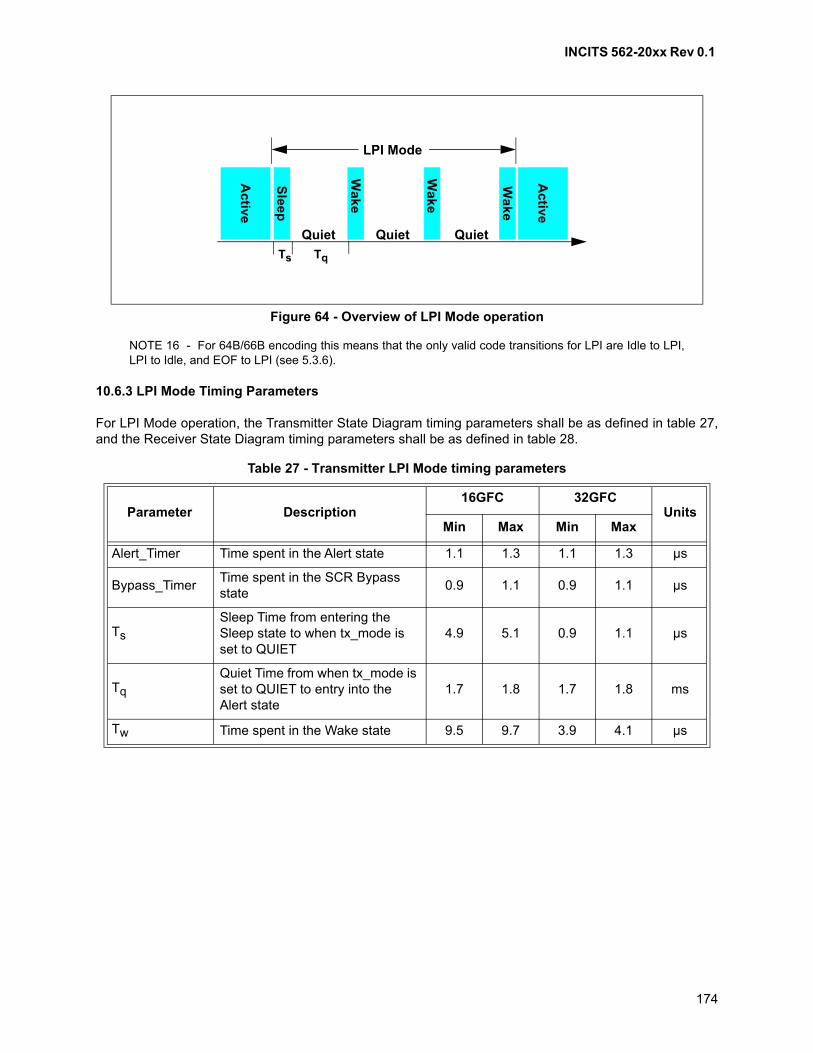
INCITS 562-20xx Rev 0.1
174
NOTE 16 - For 64B/66B encoding this means that the only valid code transitions for LPI are Idle to LPI,LPI to Idle, and EOF to LPI (see 5.3.6).
10.6.3 LPI Mode Timing Parameters
For LPI Mode operation, the Transmitter State Diagram timing parameters shall be as defined in table 27,and the Receiver State Diagram timing parameters shall be as defined in table 28.
Figure 64 - Overview of LPI Mode operation
Table 27 - Transmitter LPI Mode timing parameters
Parameter Description16GFC 32GFC
UnitsMin Max Min Max
Alert_Timer Time spent in the Alert state 1.1 1.3 1.1 1.3 μs
Bypass_TimerTime spent in the SCR Bypass state
0.9 1.1 0.9 1.1 μs
Ts
Sleep Time from entering the Sleep state to when tx_mode is set to QUIET
4.9 5.1 0.9 1.1 μs
Tq
Quiet Time from when tx_mode is set to QUIET to entry into theAlert state
1.7 1.8 1.7 1.8 ms
Tw Time spent in the Wake state 9.5 9.7 3.9 4.1 μs
Active
Active
Sle
ep
Wake
Wake
Wa
ke
Quiet Quiet Quiet
Ts Tq
LPI Mode
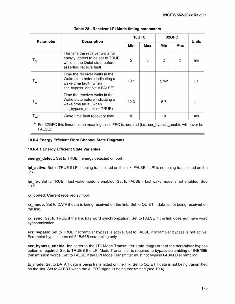
INCITS 562-20xx Rev 0.1
175
10.6.4 Energy Efficient Fibre Channel State Diagrams
10.6.4.1 Energy Efficient State Variables
energy_detect: Set to TRUE if energy detected on port.
lpi_active: Set to TRUE if LPI is being transmitted on the link. FALSE if LPI is not being transmitted on thelink.
lpi_fw: Set to TRUE if fast wake mode is enabled. Set to FALSE if fast wake mode is not enabled. See10.5.
rx_coded: Current received symbol.
rx_mode: Set to DATA if data is being received on the link. Set to QUIET if data is not being received onthe link.
rx_sync: Set to TRUE if the link has word synchronization. Set to FALSE if the link does not have wordsynchronization.
scr_bypass: Set to TRUE if scrambler bypass is active. Set to FALSE if scrambler bypass is not active.Scrambler bypass turns off 64B/66B scrambling only.
scr_bypass_enable: Indicates to the LPI Mode Transmitter state diagram that the scrambler bypassoption is required. Set to TRUE if the LPI Mode Transmitter is required to bypass scrambling of 64B/66Btransmission words. Set to FALSE if the LPI Mode Transmitter must not bypass 64B/66B scrambling.
tx_mode: Set to DATA if data is being transmitted on the link. Set to QUIET if data is not being transmittedon the link. Set to ALERT when the ALERT signal is being transmitted (see 10.4)
Table 28 - Receiver LPI Mode timing parameters
Parameter Description16GFC 32GFC
UnitsMin Max Min Max
Tq
The time the receiver waits for energy_detect to be set to TRUE while in the Quiet state before asserting receive fault
2 3 2 3 ms
Tw
Time the receiver waits in the Wake state before indicating a wake time fault. (when scr_bypass_enable = FALSE)
10.1 N/Aa μs
Tw
Time the receiver waits in the Wake state before indicating a wake time fault. (when scr_bypass_enable = TRUE)
12.3 5.7 μs
Twf Wake time fault recovery time 10 10 ms
a For 32GFC this timer has no meaning since FEC is required (i.e., scr_bypass_enable will never be FALSE).
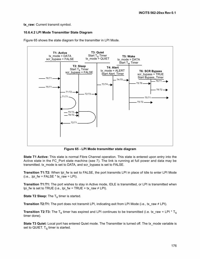
INCITS 562-20xx Rev 0.1
176
tx_raw: Current transmit symbol.
10.6.4.2 LPI Mode Transmitter State Diagram
Figure 65 shows the state diagram for the transmitter in LPI Mode.
State T1 Active: This state is normal Fibre Channel operation. This state is entered upon entry into theActive state in the FC_Port state machine (see 7). The link is running at full power and data may betransmitted. tx_mode is set to DATA, and scr_bypass is set to FALSE.
Transition T1:T2: When lpi_fw is set to FALSE, the port transmits LPI in place of Idle to enter LPI Mode(i.e., .lpi_fw = FALSE * tx_raw = LPI).
Transition T1:T1: The port wishes to stay in Active mode, IDLE is transmitted, or LPI is transmitted whenlpi_fw is set to TRUE (i.e., lpi_fw = TRUE + tx_raw ≠ LPI).
State T2 Sleep: The Ts timer is started.
Transition T2:T1: The port does not transmit LPI, indicating exit from LPI Mode (i.e., tx_raw ≠ LPI).
Transition T2:T3: The Ts timer has expired and LPI continues to be transmitted (i.e. tx_raw = LPI * Tstimer done).
State T3 Quiet: Local port has entered Quiet mode. The Transmitter is turned off. The tx_mode variable isset to QUIET. Tq timer is started.
Figure 65 - LPI Mode transmitter state diagram
T1: Activetx_mode = DATA
scr_bypass = FALSE
T3: QuietStart Tq Timer
tx_mode = QUIET
T2: SleepStart Ts Timer
scr_bypass = FALSE
T2:T3
T2:T1
T4:T5
T6: SCR Bypassscr_bypass = TRUEStart Bypass_Timer
T5: Waketx_mode = DATA
Start Tw Timer
T5:T6
T4: Alerttx_mode = ALERTStart Alert_Timer
T3:T4T6:T1
T6:T1
T5:T1T1:T1
T5:T1
T5:T2
T5:T2
T1:T2T6:T2
T6:T2

INCITS 562-20xx Rev 0.1
177
Transition T3:T4: Tq timer has expired, or the port does not transmit LPI (i.e., Tq timer done + tx_raw ≠LPI).
State T4 Alert: Set tx_mode to ALERT and send Alert Signal (see 10.4) until Alert_Timer expires.
Transition T4:T5: The Alert_Timer has expired.
State T5 Wake: Set tx_mode to DATA and start Tw timer.
Transition T5:T6: Tw timer has expired and scr_bypass_enable is TRUE (i.e., disable 64B/66Bscrambling) (i.e., Tw timer done * scr_bypass_enable = TRUE).
Transition T5:T1: Tw timer has expired and the port does not transmit LPI and scr_bypass_enable isFALSE indicating an exit from LPI Mode (i.e., tx_raw ≠ LPI * Tw timer done * scr_bypass_enable = FALSE).LPI is not transmitted to indicate to remote port that it should exit LPI Mode.
Transition T5:T2: Tw timer has expired and the port transmits LPI and scr_bypass_enable is FALSEindicating that the port stays in LPI Mode. Return to Sleep mode (i.e., tx_raw = LPI * Tw timer done *scr_bypass_enable = FALSE).
State T6 SCR Bypass: Disable 64B/66B scrambling for time defined by Bypass_Timer. StartBypass_Timer.
Transition T6:T2: The Bypass_Timer timer has expired, and the port transmits LPI, then re-enable 64B/66B scrambling (i.e., tx_raw = LPI * Bypass_Timer done).
Transition T6:T1: The Bypass_Timer timer has expired and the port does not transmit LPI indicating anexit from LPI Mode. LPI is not transmitted to indicate to remote port that it should exit LPI Mode (i.e.,tx_raw ≠ LPI * Bypass_Timer done).
10.6.4.3 LPI Mode Receiver State Diagram
Figure 66 shows the state diagram for the receiver in LPI Mode.
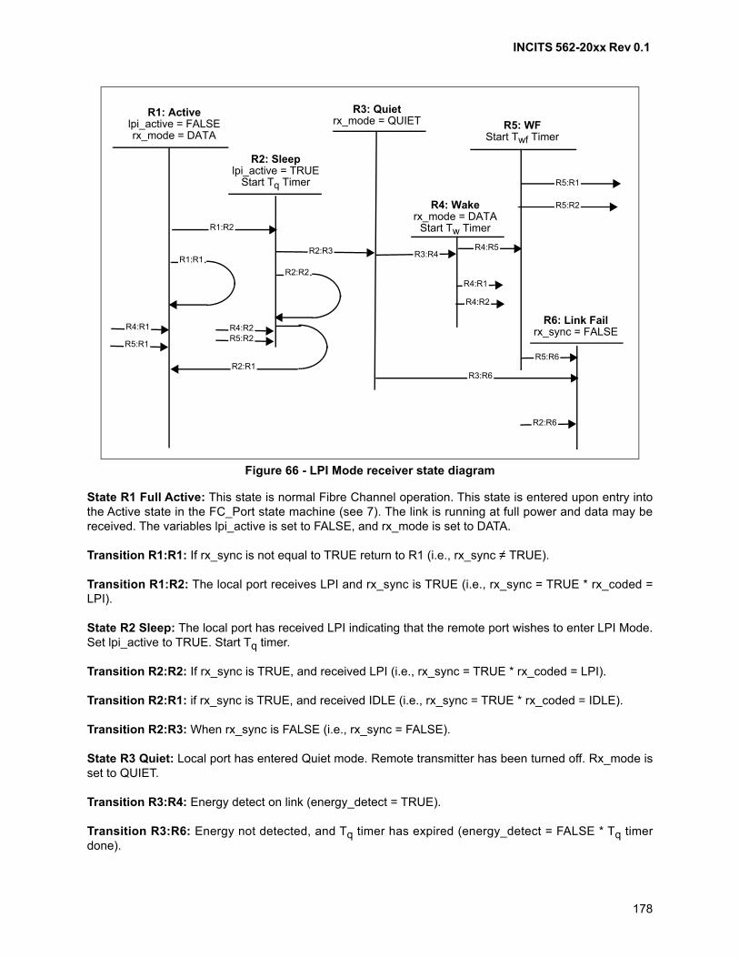
INCITS 562-20xx Rev 0.1
178
State R1 Full Active: This state is normal Fibre Channel operation. This state is entered upon entry intothe Active state in the FC_Port state machine (see 7). The link is running at full power and data may bereceived. The variables lpi_active is set to FALSE, and rx_mode is set to DATA.
Transition R1:R1: If rx_sync is not equal to TRUE return to R1 (i.e., rx_sync ≠ TRUE).
Transition R1:R2: The local port receives LPI and rx_sync is TRUE (i.e., rx_sync = TRUE * rx_coded =LPI).
State R2 Sleep: The local port has received LPI indicating that the remote port wishes to enter LPI Mode.Set lpi_active to TRUE. Start Tq timer.
Transition R2:R2: If rx_sync is TRUE, and received LPI (i.e., rx_sync = TRUE * rx_coded = LPI).
Transition R2:R1: if rx_sync is TRUE, and received IDLE (i.e., rx_sync = TRUE * rx_coded = IDLE).
Transition R2:R3: When rx_sync is FALSE (i.e., rx_sync = FALSE).
State R3 Quiet: Local port has entered Quiet mode. Remote transmitter has been turned off. Rx_mode isset to QUIET.
Transition R3:R4: Energy detect on link (energy_detect = TRUE).
Transition R3:R6: Energy not detected, and Tq timer has expired (energy_detect = FALSE * Tq timerdone).
Figure 66 - LPI Mode receiver state diagram
R5: WFStart Twf Timer
R1: Activelpi_active = FALSErx_mode = DATA
R3: Quietrx_mode = QUIET
R2: Sleeplpi_active = TRUE
Start Tq Timer
R1:R2
R2:R3
R2:R1
R3:R4
R4: Wakerx_mode = DATA
Start Tw Timer
R4:R1
R4:R1
R4:R5
R6: Link Failrx_sync = FALSE
R1:R1
R2:R2
R3:R6
R4:R2
R2:R6
R5:R6
R5:R1
R5:R2
R5:R1
R4:R2R5:R2

INCITS 562-20xx Rev 0.1
179
State R4 Wake: Remote transmitter is turned back on. Rx_mode is set to Data, Tw timer is started.
Transition R4:R1: Tw timer has not expired and rx_sync is TRUE and IDLE received (i.e., Tw timer notdone * rx_sync = TRUE * rx_coded = IDLE).
Transition R4:R2: Tw timer has not expired and rx_sync is TRUE and LPI received (i.e., Tw timer not done* rx_sync = TRUE * rx_coded = LPI).
Transition R4:R5: Tw timer has expired.
State R5 WF: Start Twf timer.
Transition R5:R1: Twf timer has not expired and rx_sync is TRUE and LPI is not received (i.e., Twf timernot done * rx_sync = TRUE = rx_coded ≠ LPI).
Transition R5:R2: Twf timer has not expired and rx_sync is TRUE and LPI received (i.e., Twf timer notdone * rx_sync = TRUE * rx_coded = LPI).
Transition R5:R6: Twf time has expired.
State R6 Link Fail: Port is in Link Failure and shall enter the link initialization state machine (see 7).
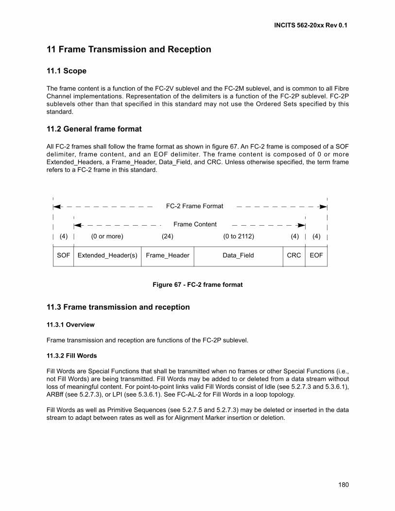
INCITS 562-20xx Rev 0.1
180
11 Frame Transmission and Reception
11.1 Scope
The frame content is a function of the FC-2V sublevel and the FC-2M sublevel, and is common to all FibreChannel implementations. Representation of the delimiters is a function of the FC-2P sublevel. FC-2Psublevels other than that specified in this standard may not use the Ordered Sets specified by thisstandard.
11.2 General frame format
All FC-2 frames shall follow the frame format as shown in figure 67. An FC-2 frame is composed of a SOFdelimiter, frame content, and an EOF delimiter. The frame content is composed of 0 or moreExtended_Headers, a Frame_Header, Data_Field, and CRC. Unless otherwise specified, the term framerefers to a FC-2 frame in this standard.
11.3 Frame transmission and reception
11.3.1 Overview
Frame transmission and reception are functions of the FC-2P sublevel.
11.3.2 Fill Words
Fill Words are Special Functions that shall be transmitted when no frames or other Special Functions (i.e.,not Fill Words) are being transmitted. Fill Words may be added to or deleted from a data stream withoutloss of meaningful content. For point-to-point links valid Fill Words consist of Idle (see 5.2.7.3 and 5.3.6.1),ARBff (see 5.2.7.3), or LPI (see 5.3.6.1). See FC-AL-2 for Fill Words in a loop topology.
Fill Words as well as Primitive Sequences (see 5.2.7.5 and 5.2.7.3) may be deleted or inserted in the datastream to adapt between rates as well as for Alignment Marker insertion or deletion.
FC-2 Frame Format
Frame Content
Figure 67 - FC-2 frame format
(0 to 2112)(24) (4) (4)(4) (0 or more)
EOFCRCData_FieldFrame_HeaderExtended_Header(s)SOF
INCITS 562-20xx Rev 0.1
181
Only an allowed Special Function (i.e., Primitive Sequence, Idle, ARBff, or LPI) may be inserted in the datastream. If a Special Function is inserted in the transmit data stream, then it shall be the same as theSpecial Function that was last transmitted. If a Special Function is inserted in the receive data stream, thenit shall be the same as the Special Function that was last received.
11.3.3 Frame Transmission
Frame transmission shall be performed by inserting a frame immediately following a series of Fill Words(see 11.3.2). Fill Words shall be transmitted immediately upon completion of the frame. A minimum of twoFill Words shall be transmitted consecutively following the EOF of each frame transmitted by any FC_Porttransmitter.
If an FC_Port transmitter is repeating the Transmission Word stream of a receiver that is not capable ofexercising buffer-to-buffer flow control (e.g., L_Ports with REPEAT true), the transmitter may insert orremove Fill Words from the Transmission Word stream in order to adjust for timing skew between thereceiver and transmitter; however, it shall retain at least two Fill Words consecutively following each EOF.
If an FC_Port transmitter is repeating the Transmission Word stream of a receiver that is capable ofexercising buffer-to-buffer flow control, the FC_Port shall transmit at least six Primitive Signals betweeneach EOF and the next SOF. Of the six or more Primitive Signals transmitted, at least four shall be FillWords.
If an FC_Port transmitter is not repeating the Transmission Word stream of a receiver, the FC_Port shalltransmit at least six Primitive Signals between each EOF and the next SOF, unless Alignment Markers arebeing inserted or rate adaptation requires Primitive Signal deletion. Of the six or more Primitive Signalstransmitted, at least four shall be Fill Words. If Alignment Marker insertion or rate adaptation requiredeletion of Primitive Signals, then the FC_Port shall retain at least two Fill Words consecutively followingeach EOF.
See FC-AL-2 for Arbitrated Loop specific frame transmission requirements. See 11.3.9 for frame receptionrequirements.
11.3.4 Frame byte order
The frame content shall be transmitted sequentially following the SOF delimiter as an ordered word streamwithin the definition of the frame as specified in figure 67, table 29, and figure 73 until the EOF delimiter istransmitted.
Table 29 relates the ordered byte stream transferred from the Upper Level Protocol (or FC-4) to the wordstream that is encoded and transmitted onto a link.
A frame shall be assembled into a word stream, encoded, and transmitted in the following byte order:
A0, A1, A2, A3, B0, B1, B2, B3, B4 ...
B32, B33, B34, B35, C0, C1, C2, C3.
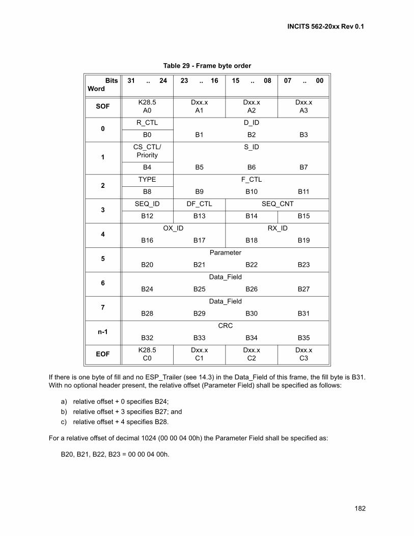
INCITS 562-20xx Rev 0.1
182
If there is one byte of fill and no ESP_Trailer (see 14.3) in the Data_Field of this frame, the fill byte is B31.With no optional header present, the relative offset (Parameter Field) shall be specified as follows:
a) relative offset + 0 specifies B24;
b) relative offset + 3 specifies B27; and
c) relative offset + 4 specifies B28.
For a relative offset of decimal 1024 (00 00 04 00h) the Parameter Field shall be specified as:
B20, B21, B22, B23 = 00 00 04 00h.
Table 29 - Frame byte order
BitsWord
31 .. 24 23 .. 16 15 .. 08 07 .. 00
SOFK28.5
A0Dxx.x
A1Dxx.x
A2Dxx.x
A3
0R_CTL D_ID
B0 B1 B2 B3
1
CS_CTL/Priority
S_ID
B4 B5 B6 B7
2TYPE F_CTL
B8 B9 B10 B11
3SEQ_ID DF_CTL SEQ_CNT
B12 B13 B14 B15
4OX_ID RX_ID
B16 B17 B18 B19
5Parameter
B20 B21 B22 B23
6Data_Field
B24 B25 B26 B27
7Data_Field
B28 B29 B30 B31
n-1CRC
B32 B33 B34 B35
EOFK28.5
C0Dxx.x
C1Dxx.x
C2Dxx.x
C3
INCITS 562-20xx Rev 0.1
183
11.3.5 Emission Lowering Protocol
An FC-0 standard (e.g., FC-PI-3) may specify the use of Emission Lowering Protocol when using the 8B/10B transmission code.
When Emission Lowering Protocol is used, the Fill Word shall be the ARBff Ordered Set.
When Emission Lowering Protocol is not used, the Fill Word shall be the Idle Ordered Set.
11.3.6 Frame Scrambling
An FC-0 standard (e.g., FC-PI-3) may specify the use of Frame Scrambling when using the 8B/10Btransmission code.
When Frame Scrambling is used, this clause defines how scrambling and descrambling shall beperformed.
Frame Scrambling is used to reduce the probability of long strings of repeated patterns appearing on a link.Frame Scrambling may not change the probability of long strings of repeated patterns appearing on a linkwhen the input data pattern is random. A scrambler and descrambler are specified that haveself-synchronizing capabilities.
The Frame Scrambling algorithm has a low probability of creating patterns from random data input thatmay have failure modes on particular link technologies. The retry mechanisms specified in clause 19require different values in the headers of the frames of the retried sequence and therefore will produce adifferent scrambled output, avoiding the identical failure mode.
All words transmitted between the Ordered Set used to denote the start of frame (SOF delimiter) and theOrdered Set used to denote the end of frame (EOF delimiter), including the CRC, shall be scrambled priorto performing 8B/10B encoding and descrambled after 8B/10B decoding. Ordered Sets shall not bescrambled.
Frame Scrambling shall be implemented so that its output is equivalent to the following function:
1) Upon transmission of the Ordered Set used to denote a start of frame (SOF delimiter), a 58-bitwide internal register is reset to an initial value of the low order 58 bits of the value029438798327338h. The bits of the register are denoted R(n) for some number n in the range 58.. 1. R(58) denotes the high-order bit of the register and R(1) denotes the low-order bit of theregister; and
2) For each word that is to be scrambled for transmission, XOR it with R(58 .. 27) and XOR the resultwith R(39 .. 8). The result of the second XOR operation is transmitted. Then the content of theregister is modified by first replacing R(58 .. 33) with R(26 .. 1) and then replacing R(32 .. 1) withthe scrambled word that was transmitted.
NOTE 17 - This is equivalent to a self-synchronizing scrambler based on a linear feedback shift register
that implements the polynomial G(x) = x58 + x39 + 1.
The scrambled words are transmitted in the same manner as unscrambled words, as defined in thisstandard.
INCITS 562-20xx Rev 0.1
184
Descrambling shall be implemented so that its output is equivalent to the following function:
1) Upon reception of the Ordered Set used to denote a start of frame (SOF delimiter), a 58-bit wideinternal register is reset to an initial value of the low order 58 bits of the value 029438798327338h.The bits of the register are denoted R(n) for some number n in the range 58 .. 1. R(58) denotes thehigh-order bit of the register and R(1) denotes the low-order bit of the register; and
2) For each word that is to be descrambled upon reception, XOR it with R(58 .. 27) and XOR theresult with R(39 .. 8). The result of the second XOR operation is the descrambled word that isreceived. Then the content of the register is modified by first replacing R(58 .. 33) with R(26 .. 1)and then replacing R(32 .. 1) with the scrambled word that was received.
NOTE 18 - This is equivalent to a self-synchronizing descrambler based on a linear feedback shift
register that implements the polynomial G(x) = x58 + x39 + 1.
Annex C contains information on scrambling and descrambling implementations.
11.3.7 Start-of-Frame (SOF) delimiter
11.3.7.1 Introduction
The Start-of-Frame (SOF) delimiter is represented by an Ordered Set that immediately precedes the framecontent. There are multiple SOF delimiters defined for Sequence control. Tables 61 and 65, respectively,specify allowable delimiters by class for Data and Link_Control frames. The bit encodings for the SOFdelimiters are defined in table 13 and table 7. SOFx is used to represent any SOF. The Ordered Set thatrepresents each defined SOF delimiter is designated by the same name as the SOF delimiter. In contextsthat do not make the distinction clear, the delimiter is designated by “SOFx delimiter” and the Ordered Setthat represents it is designated by “SOFx Ordered Set”.
11.3.7.2 SOF Initiate (SOFix)
11.3.7.2.1 Applicability
A Sequence shall be initiated and identified by using an SOFi2 Ordered Set or SOFi3 Ordered Set in thefirst frame. SOFix is used to represent these two SOF delimiters.
11.3.7.2.2 SOF Initiate Class 2 (SOFi2)
The SOFi2 Ordered Set shall be used on the first frame of a Sequence for Class 2 service.
11.3.7.2.3 SOF Initiate Class 3 (SOFi3)
The SOFi3 Ordered Set shall be used on the first frame of a Sequence for Class 3 service.
11.3.7.3 SOF Normal (SOFnx)
11.3.7.3.1 Applicability
The SOFn2 Ordered Set and SOFn3 Ordered Set identify the start of all frames other than the first frame ofa Sequence based on class of service. SOFnx is used to indicate SOFn2 and SOFn3.
INCITS 562-20xx Rev 0.1
185
11.3.7.3.2 SOF Normal Class 2 (SOFn2)
The SOFn2 Ordered Set shall be used for all frames except the first frame of a Sequence for Class 2service.
11.3.7.3.3 SOF Normal Class 3 (SOFn3)
The SOFn3 Ordered Set shall be used for all frames except the first frame of a Sequence for Class 3service.
11.3.7.4 SOF Fabric (SOFf)
If a PN_Port or Fx_Port receives a Class F frame, indicated by an SOFf Ordered Set, it shall be discardedby the PN_Port or Fx_Port. The receiving PN_Port or Fx_Port may send an R_RDY.
NOTE 19 - Sending an R_RDY for a Class F frame is optional for a port not internal to the Fabric (i.e., aPN_Port or non-switch internal port). This allows backwards compatibility with existing implementations.New Implementations should send an R_RDY for class F frames.
11.3.8 End-of-Frame (EOF) delimiter
11.3.8.1 Introduction
The End-of-Frame (EOF) delimiter is represented by an Ordered Set that immediately follows the CRC.The EOF Ordered Set shall designate the end of the frame content and shall be followed by Fill Words.The Ordered Set that represents each defined EOF delimiter is designated by the same name as the EOFdelimiter. In contexts that do not make the distinction clear, the delimiter is designated by “EOFx delimiter”and the Ordered Set that represents it is designated by “EOFx Ordered Set”.
Table 61 and table 65, respectively, specify allowable delimiters by class for Data and Link_Control frames.There are three categories of EOF Ordered Sets:
a) the first category shall indicate that the frame is valid from the sender's perspective and potentiallyvalid from the receiver's perspective;
b) the second category (EOFni) shall indicate that the frame content is invalid. This category shall
only be used by an Fx_Port that receives a complete frame and decodes it before forwarding it;and
c) the third category (EOFa) shall indicate the frame content is corrupted and the frame was
truncated during transmission. The third category shall be used by FC_Ports to indicate an internalmalfunction (e.g., a transmitter failure that does not allow the entire frame to be transmittednormally).
The bit encodings for the EOF Ordered Set are defined in table 13 and table 7.
All frames other than the last frame of a Sequence shall be terminated with an EOFn Ordered Set.
Each Sequence shall terminate with an EOFt Ordered Set.
If an Fx_Port detects a frame error, the Fx_Port shall replace either an EOFn Ordered Set or an EOFtOrdered Set of the frame in error with the EOFni Ordered Set.
EOFx is used to represent any EOF.

INCITS 562-20xx Rev 0.1
186
11.3.8.2 Valid frame content
11.3.8.2.1 EOF Normal (EOFn)
The EOFn Ordered Set shall identify the end of frame when one of the other EOF Ordered Sets indicatingvalid frame content is not required.
11.3.8.2.2 EOF Terminate (EOFt)
The EOFt Ordered Set shall indicate that the Sequence associated with this SEQ_ID is complete. EOFtshall be used to properly close a Sequence without error.
11.3.8.3 Invalid frame content
11.3.8.3.1 General
There are two EOF Ordered Sets that indicate that the frame content is invalid. If a frame is received by afacility internal to a Fabric and an error is detected within the frame content, the frame may be forwardedwith a modified EOF to indicate that an error was previously detected. Error detection in the frame contentby the Fabric is optional.
Errors such as code violation or CRC errors are examples of detectable frame errors.
When a frame is received with an EOF Ordered Set that indicates the frame content is invalid, the invalidframe condition shall be reported by the entity that replaces the EOF Ordered Set that indicates invalidframe content. The destination PN_Port, at its discretion, may report the event of receiving a frame withone of these delimiters.
Errors are counted at the point where they are detected. Events may also be reported at the point wherethey are recognized.
11.3.8.3.2 End of Frame Abort (EOFa)
The EOFa Ordered Set shall terminate a partial frame due to a malfunction in a link facility duringtransmission. The frame shall end on a word boundary and shall be discarded by the receiver withouttransmitting a reply. If the transmitter retransmits the aborted frame, it shall transmit the frame with thesame SEQ_CNT.
An invalid EOF (i.e., EOFni) Ordered Set may be changed to an EOFa Ordered Set under the conditionsspecified for EOFa.
EOFa Ordered Sets shall not be changed to an invalid EOF Ordered Set under any conditions.
It is also used by the Fabric to replace missing EOF Ordered Sets or to truncate over length frames.
11.3.8.3.3 EOF Invalid (EOFni)
The EOFni Ordered Set shall replace an EOFn Ordered Set or EOFt Ordered Set, indicating that the framecontent is invalid.
INCITS 562-20xx Rev 0.1
187
The receiver shall process the frame containing the EOFni Ordered Set in the following manner:
a) no response frame shall be transmitted; and
b) the Data_Field may be used at the receiver's discretion (see 11.3.9.3).
11.3.9 Frame reception
11.3.9.1 Rules
The following list specifies frame reception rules:
a) data bytes received outside the scope of a delimiter Ordered Set pair (SOF and EOF) shall bediscarded;
b) frame reception shall be started by recognition of a SOF Ordered Set;
c) detection of a code violation after frame reception is started but before frame reception isterminated shall be identified as an invalid Transmission Word within the frame;
d) frame reception shall continue until an Ordered Set, or a Link Failure is detected;
e) if the number of bytes in the Data_Field of the frame exceeds the maximum allowable Data_Fieldsize for the type of frame indicated by the SOF Ordered Set (see clause 17), an FC_Port mayconsider the frame invalid and discard Data_Field bytes as received. However, an Ordered Set orLink Failure shall still terminate frame reception. An FC_Port is also allowed to receive the entireframe. In acknowledged classes of service, if the frame is valid other than for its length:
A) a PN_Port shall respond with a P_RJT with Reason Code set to Incorrect length (i.e., 13h);and
B) an Fx_Port shall respond with an F_RJT with Reason Code set to Incorrect length (i.e., 13h);
and
f) in either process or discard policy, if an EOFa terminates frame reception, the entire frame shall be
discarded, including the Frame_Header and Data_Field.
11.3.9.2 Frame validity
A frame is valid at the FC-2P sublevel if it meets all of these conditions:
a) the Ordered Set terminating the frame is one of EOFn or EOFt;
b) the length of the frame content is a multiple of four bytes; and
c) the frame content includes no invalid Transmission Words.
11.3.9.3 Invalid frame processing
A frame is invalid if it does not meet the conditions for validity at the FC-2P sublevel (see 11.3.9.2) and theFC-2V sublevel (see 11.4.5).
During normal processing of valid frames, errors may be detected that are rejectable in Class 2 using theP_RJT Link_Response frame (see 15.3.3.4). P_RJT frames shall not be transmitted for invalid frames. If arejectable error condition or a busy condition is detected for a valid Class 3 frame, the frame shall bediscarded.
When errors (e.g., invalid Transmission Word and invalid CRC) are detected, the event count in the LinkError Status Block shall be updated (see 22.4.8). If delimiter usage does not follow allowable delimiters byclass as specified in tables 61 and 65, a valid frame shall be considered rejectable.
INCITS 562-20xx Rev 0.1
188
If a PN_Port is able to determine that an invalid frame is associated with an Exchange that is designatedas operating under Process policy, the PN_Port may process and use the Data_Field at its discretion,otherwise, the entire invalid frame shall be discarded.
When a frame is corrupted, it is not known if the Frame_Header is correct. The X_IDs, SEQ_ID,SEQ_CNT, and Parameter fields may not contain reliable information. The error may cause a misroutedframe to have a D_ID that appears to be correct. Such a frame may be used under very restrictedconditions.
11.4 Frame Content
11.4.1 Scope
Within the frame content, addressing information supports the functionality of the FC-2M sublevel and theFC-2V sublevel. All other frame content supports the functionality of the FC-2V sublevel, higher levels, andULPs.
11.4.2 Extended_Headers
Extended_Headers, if present, shall immediately follow the SOF delimiter. Each Extended_Header isidentified by a certain value of its first byte (R_CTL, see table 31). Extended_Headers shall be transmittedon a word boundary. Extended_Headers are defined in clause 13.
11.4.3 Frame_Header
The Frame_Header shall immediately follow the SOF delimiter if no Extended_Headers are present, orshall follow the last Extended_Header present, for all frames. The Frame_Header shall be transmitted on aword boundary. The Frame_Header is used by the LCF to control link operations, control device protocoltransfers, and detect missing or out of order frames. The Frame_Header is defined in clause 12.
11.4.4 Data_Field
The Data_Field shall follow the Frame_Header and shall be aligned on a word boundary. The size of theData_Field shall be a multiple of four bytes and may be zero.
11.4.5 CRC
The Cyclic Redundancy Check (CRC) is a four byte field that shall immediately follow the Data_Field andshall be used to verify the data integrity of the data within its scope. The CRC scope shall be theExtended_Headers, if any, the Frame_Header, and the Data_Field. SOF and EOF delimiters shall not beincluded in the CRC scope. The CRC field for a frame shall be calculated prior to encoding and anyscrambling of the frame for transmission and after decoding and any descrambling of the frame uponreception. The CRC field shall be aligned on a word boundary.
The CRC specified in this standard follows the Frame Check Sequence (FCS) specified in FiberDistributed Data Interface – Media Access Control (see FDDI-MAC). The FDDI-MAC FCS is specified as abinary polynomial arithmetic expression acting on a generator polynomial and a data input polynomialwhose coefficients are the bits of the CRC scope, and producing an FCS polynomial. The CRC scope shallbe mapped to a data polynomial for FDDI-MAC FCS calculation by:
1) reversing the order of the bits in the first byte of the CRC scope;
2) using the most significant bit of the revised first byte in the CRC scope as the most significantcoefficient of the data polynomial;
INCITS 562-20xx Rev 0.1
189
3) using successively less significant bits of the revised first byte in the CRC scope as successivelyless significant coefficients of the data polynomial; and
4) following steps 1-3 for each successive byte of the CRC scope to generate successively lesssignificant groups of eight coefficients of the data polynomial.
An informative diagram of this mapping is given in figure 68.
The CRC field value shall be mapped from the FCS polynomial derived from the FDDI-MAC FCScalculation by:
1) extending the FCS polynomial to 32 coefficients by adding zero value coefficients at the mostsignificant end;
2) reversing the order of the first eight coefficients of the FCS polynomial;
3) using the most significant coefficient of the revised first eight coefficients in the FCS polynomial asthe most significant bit of the CRC field value;
4) using successively less significant coefficients of the revised first eight coefficients in the FCSpolynomial as successively less significant bits of the CRC field value; and
5) following steps 2-4 for each successive eight coefficients of the FCS polynomial to generatesuccessively less significant bytes of the CRC field value.
An informative diagram of the mapping of the extended FCS polynomial to the CRC field value is given infigure 69.
See Annex B for informative extracts from the normative text in FDDI-MAC and an example of the CRCgeneration process for a frame.
If the frame CRC for a received frame is not valid, the frame is invalid at the FC-2V sublevel, and it shall beprocessed in the same manner as frames that are not valid at the FC-2P sublevel (see 11.3.9.2).
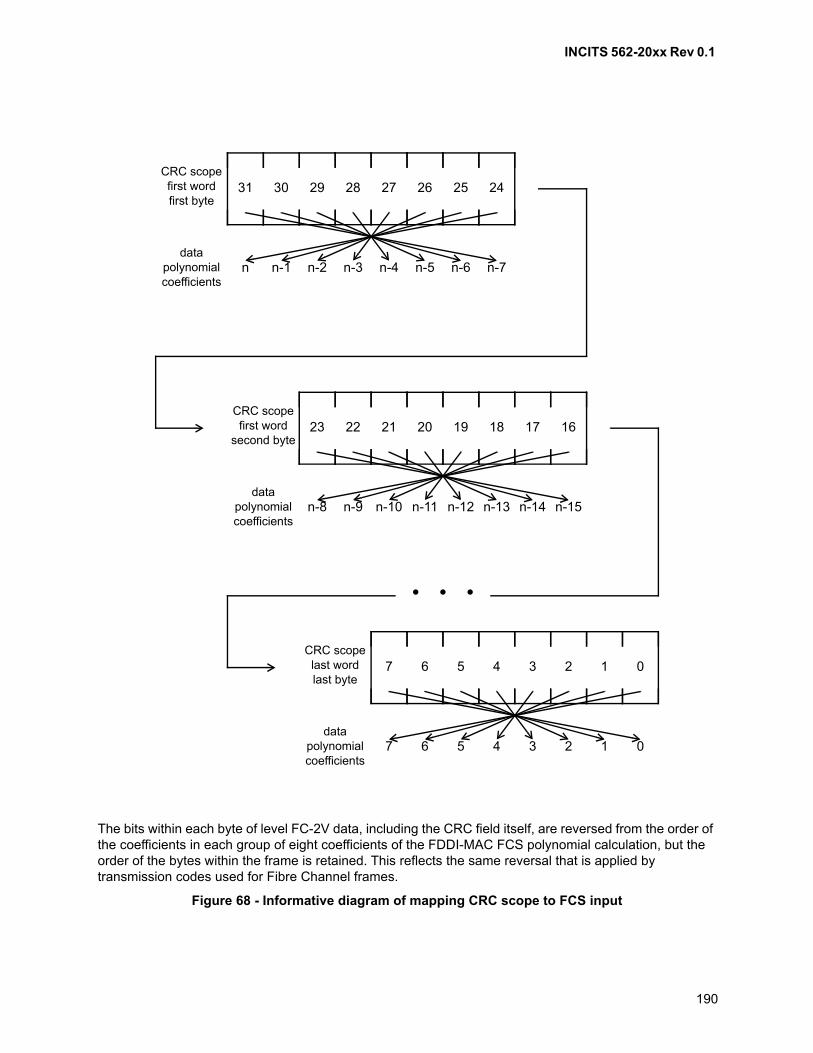
INCITS 562-20xx Rev 0.1
190
The bits within each byte of level FC-2V data, including the CRC field itself, are reversed from the order of the coefficients in each group of eight coefficients of the FDDI-MAC FCS polynomial calculation, but the order of the bytes within the frame is retained. This reflects the same reversal that is applied by transmission codes used for Fibre Channel frames.
Figure 68 - Informative diagram of mapping CRC scope to FCS input
31 30 29 28 27 26 25 24CRC scopefirst wordfirst byte
n n-1 n-2 n-3 n-4 n-5 n-6 n-7data
polynomialcoefficients
23 22 21 20 19 18 17 16CRC scopefirst word
second byte
n-8 n-9 n-10 n-11 n-12 n-13 n-14 n-15data
polynomialcoefficients
7 6 5 4 3 2 1 0CRC scopelast wordlast byte
7 6 5 4 3 2 1 0data
polynomialcoefficients
• • •
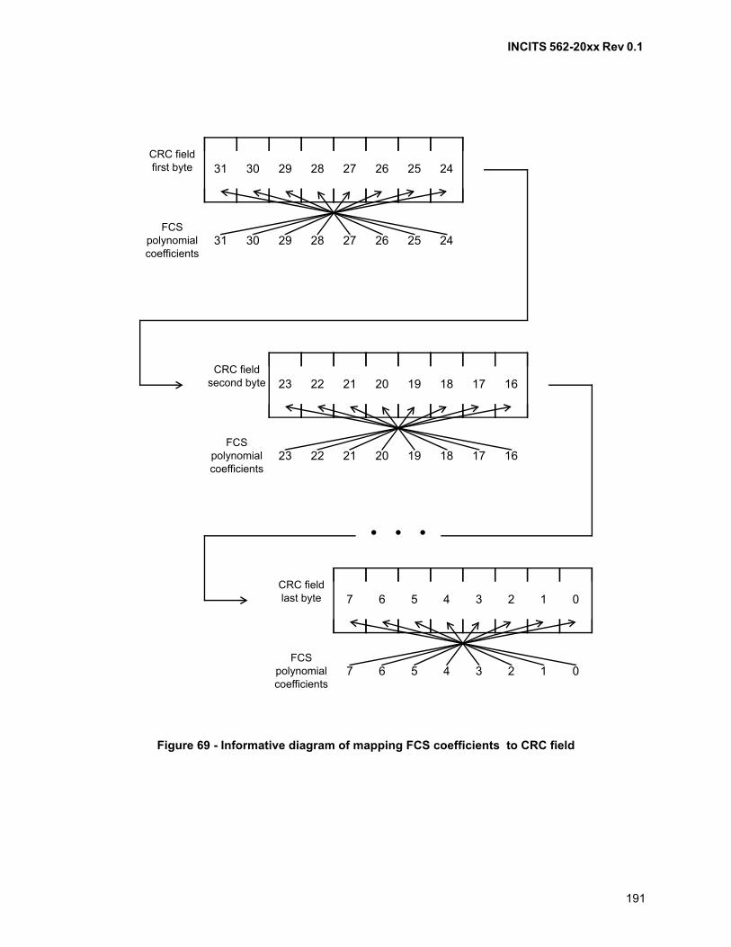
INCITS 562-20xx Rev 0.1
191
Figure 69 - Informative diagram of mapping FCS coefficients to CRC field
31 30 29 28 27 26 25 24CRC fieldfirst byte
31 30 29 28 27 26 25 24FCS
polynomialcoefficients
23 22 21 20 19 18 17 16CRC field
second byte
23 22 21 20 19 18 17 16FCS
polynomialcoefficients
7 6 5 4 3 2 1 0CRC fieldlast byte
7 6 5 4 3 2 1 0FCS
polynomialcoefficients
• • •
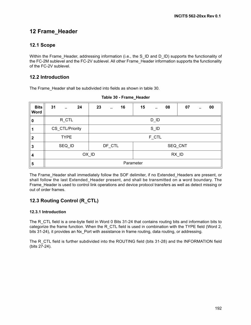
INCITS 562-20xx Rev 0.1
192
12 Frame_Header
12.1 Scope
Within the Frame_Header, addressing information (i.e., the S_ID and D_ID) supports the functionality ofthe FC-2M sublevel and the FC-2V sublevel. All other Frame_Header information supports the functionalityof the FC-2V sublevel.
12.2 Introduction
The Frame_Header shall be subdivided into fields as shown in table 30.
The Frame_Header shall immediately follow the SOF delimiter, if no Extended_Headers are present, orshall follow the last Extended_Header present, and shall be transmitted on a word boundary. TheFrame_Header is used to control link operations and device protocol transfers as well as detect missing orout of order frames.
12.3 Routing Control (R_CTL)
12.3.1 Introduction
The R_CTL field is a one-byte field in Word 0 Bits 31-24 that contains routing bits and information bits tocategorize the frame function. When the R_CTL field is used in combination with the TYPE field (Word 2,bits 31-24), it provides an Nx_Port with assistance in frame routing, data routing, or addressing.
The R_CTL field is further subdivided into the ROUTING field (bits 31-28) and the INFORMATION field(bits 27-24).
Table 30 - Frame_Header
BitsWord
31 .. 24 23 .. 16 15 .. 08 07 .. 00
0 R_CTL D_ID
1 CS_CTL/Priority S_ID
2 TYPE F_CTL
3 SEQ_ID DF_CTL SEQ_CNT
4 OX_ID RX_ID
5 Parameter
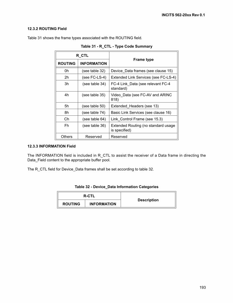
INCITS 562-20xx Rev 0.1
193
12.3.2 ROUTING Field
Table 31 shows the frame types associated with the ROUTING field.
12.3.3 INFORMATION Field
The INFORMATION field is included in R_CTL to assist the receiver of a Data frame in directing theData_Field content to the appropriate buffer pool.
The R_CTL field for Device_Data frames shall be set according to table 32.
Table 31 - R_CTL - Type Code Summary
R_CTLFrame type
ROUTING INFORMATION
0h (see table 32) Device_Data frames (see clause 15)
2h (see FC-LS-4) Extended Link Services (see FC-LS-4)
3h (see table 34) FC-4 Link_Data (see relevant FC-4 standard)
4h (see table 35) Video_Data (see FC-AV and ARINC 818)
5h (see table 50) Extended_Headers (see 13)
8h (see table 74) Basic Link Services (see clause 16)
Ch (see table 64) Link_Control Frame (see 15.3)
Fh (see table 36) Extended Routing (no standard usage is specified)
Others Reserved Reserved
Table 32 - Device_Data Information Categories
R-CTLDescription
ROUTING INFORMATION
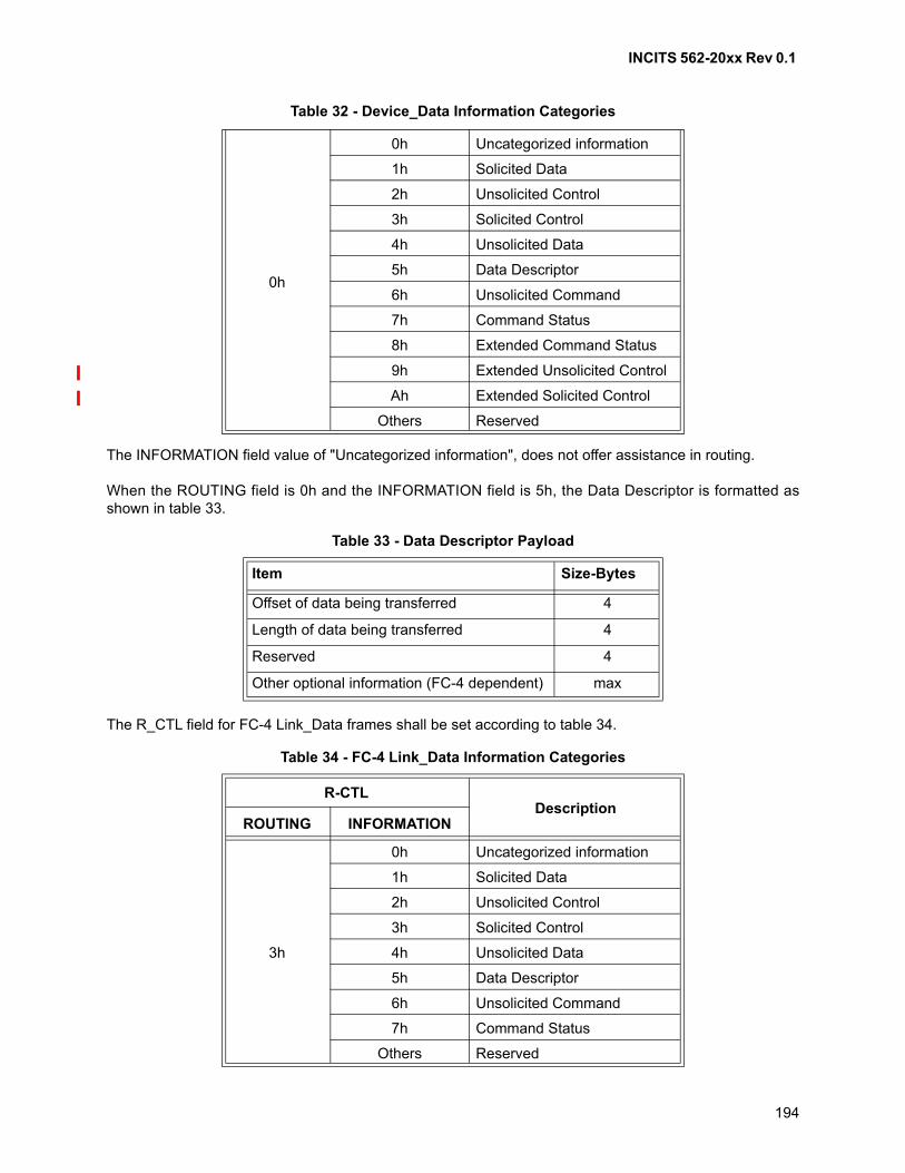
INCITS 562-20xx Rev 0.1
194
The INFORMATION field value of "Uncategorized information", does not offer assistance in routing.
When the ROUTING field is 0h and the INFORMATION field is 5h, the Data Descriptor is formatted asshown in table 33.
The R_CTL field for FC-4 Link_Data frames shall be set according to table 34.
0h
0h Uncategorized information
1h Solicited Data
2h Unsolicited Control
3h Solicited Control
4h Unsolicited Data
5h Data Descriptor
6h Unsolicited Command
7h Command Status
8h Extended Command Status
9h Extended Unsolicited Control
Ah Extended Solicited Control
Others Reserved
Table 33 - Data Descriptor Payload
Item Size-Bytes
Offset of data being transferred 4
Length of data being transferred 4
Reserved 4
Other optional information (FC-4 dependent) max
Table 34 - FC-4 Link_Data Information Categories
R-CTLDescription
ROUTING INFORMATION
3h
0h Uncategorized information
1h Solicited Data
2h Unsolicited Control
3h Solicited Control
4h Unsolicited Data
5h Data Descriptor
6h Unsolicited Command
7h Command Status
Others Reserved
Table 32 - Device_Data Information Categories
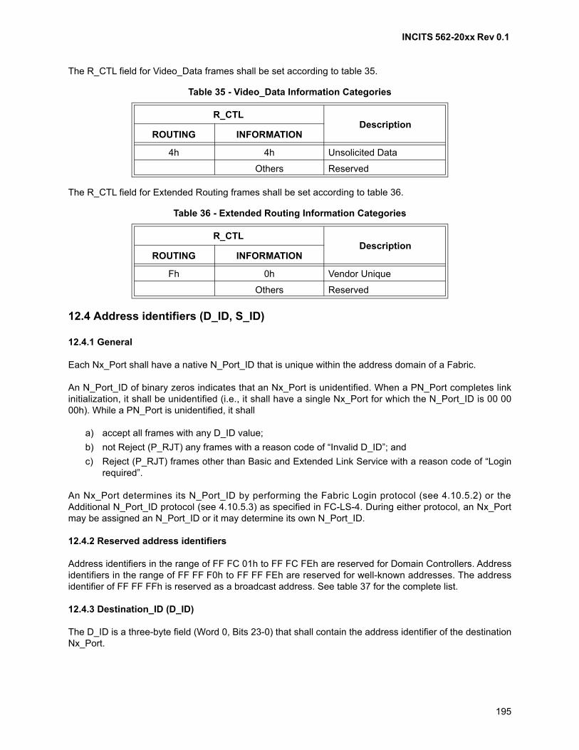
INCITS 562-20xx Rev 0.1
195
The R_CTL field for Video_Data frames shall be set according to table 35.
The R_CTL field for Extended Routing frames shall be set according to table 36.
12.4 Address identifiers (D_ID, S_ID)
12.4.1 General
Each Nx_Port shall have a native N_Port_ID that is unique within the address domain of a Fabric.
An N_Port_ID of binary zeros indicates that an Nx_Port is unidentified. When a PN_Port completes linkinitialization, it shall be unidentified (i.e., it shall have a single Nx_Port for which the N_Port_ID is 00 0000h). While a PN_Port is unidentified, it shall
a) accept all frames with any D_ID value;
b) not Reject (P_RJT) any frames with a reason code of “Invalid D_ID”; and
c) Reject (P_RJT) frames other than Basic and Extended Link Service with a reason code of “Loginrequired”.
An Nx_Port determines its N_Port_ID by performing the Fabric Login protocol (see 4.10.5.2) or theAdditional N_Port_ID protocol (see 4.10.5.3) as specified in FC-LS-4. During either protocol, an Nx_Portmay be assigned an N_Port_ID or it may determine its own N_Port_ID.
12.4.2 Reserved address identifiers
Address identifiers in the range of FF FC 01h to FF FC FEh are reserved for Domain Controllers. Addressidentifiers in the range of FF FF F0h to FF FF FEh are reserved for well-known addresses. The addressidentifier of FF FF FFh is reserved as a broadcast address. See table 37 for the complete list.
12.4.3 Destination_ID (D_ID)
The D_ID is a three-byte field (Word 0, Bits 23-0) that shall contain the address identifier of the destinationNx_Port.
Table 35 - Video_Data Information Categories
R_CTLDescription
ROUTING INFORMATION
4h 4h Unsolicited Data
Others Reserved
Table 36 - Extended Routing Information Categories
R_CTLDescription
ROUTING INFORMATION
Fh 0h Vendor Unique
Others Reserved
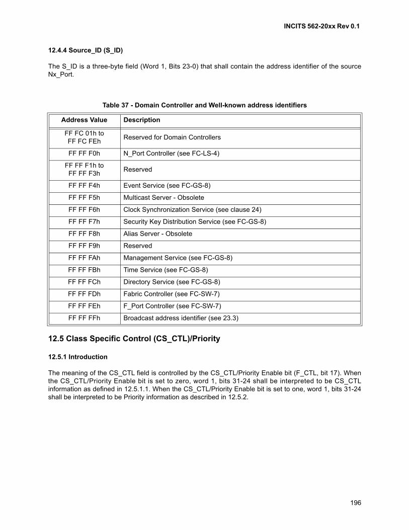
INCITS 562-20xx Rev 0.1
196
12.4.4 Source_ID (S_ID)
The S_ID is a three-byte field (Word 1, Bits 23-0) that shall contain the address identifier of the sourceNx_Port.
12.5 Class Specific Control (CS_CTL)/Priority
12.5.1 Introduction
The meaning of the CS_CTL field is controlled by the CS_CTL/Priority Enable bit (F_CTL, bit 17). Whenthe CS_CTL/Priority Enable bit is set to zero, word 1, bits 31-24 shall be interpreted to be CS_CTLinformation as defined in 12.5.1.1. When the CS_CTL/Priority Enable bit is set to one, word 1, bits 31-24shall be interpreted to be Priority information as described in 12.5.2.
Table 37 - Domain Controller and Well-known address identifiers
Address Value Description
FF FC 01h toFF FC FEh
Reserved for Domain Controllers
FF FF F0h N_Port Controller (see FC-LS-4)
FF FF F1h toFF FF F3h
Reserved
FF FF F4h Event Service (see FC-GS-8)
FF FF F5h Multicast Server - Obsolete
FF FF F6h Clock Synchronization Service (see clause 24)
FF FF F7h Security Key Distribution Service (see FC-GS-8)
FF FF F8h Alias Server - Obsolete
FF FF F9h Reserved
FF FF FAh Management Service (see FC-GS-8)
FF FF FBh Time Service (see FC-GS-8)
FF FF FCh Directory Service (see FC-GS-8)
FF FF FDh Fabric Controller (see FC-SW-7)
FF FF FEh F_Port Controller (see FC-SW-7)
FF FF FFh Broadcast address identifier (see 23.3)
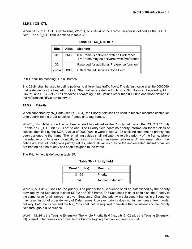
INCITS 562-20xx Rev 0.1
197
12.5.1.1 CS_CTL
When bit 17 of F_CTL is set to zero, Word 1, bits 31-24 of the Frame_Header is defined as the CS_CTLfield. The CS_CTL field is defined in table 38.
PREF shall be meaningful in all frames.
Bits 29-24 shall be used to define policies to differentiate traffic flows. The default value shall be 000000b,that is defined as the best effort QoS. Other values are defined in RFC 2597, “Assured Forwarding PHBGroup”, and RFC 2598, “An Expedited Forwarding PHB”. Values other than 000000b and those defined inthe referenced RFCs are reserved.
12.5.2 Priority
When supported by Nx_Ports (see FC-LS-4), the Priority field shall be used to resolve resource contentionor to determine the order to deliver frames or to tag frames.
Word 1, bits 31-24 of the Frame_Header shall be defined as the Priority field when the CS_CTL/PriorityEnable bit (F_CTL, bit 17) is set to one. The Priority field contains priority information for the class ofservice identified by the SOF. A value of 0000000b in word 1, bits 31-25 shall indicate that no priority hasbeen assigned to the frame. The remaining values shall indicate the relative priority of the frame, wherethe relative priority is monotonically increasing within an implemented range. An implementation maydefine a subset of contiguous priority values, where all values outside the implemented subset of valuesare treated as if no priority has been assigned to the frame.
The Priority field is defined in table 39.
Word 1, bits 31-25 shall be the priority. The priority for a Sequence shall be established by the priorityprovided by the Sequence Initiator SOFi2 or SOFi3 frame. The Sequence Initiator should set the Priority tothe same value for all frames in a given Sequence. Changing priority in subsequent frames in a Sequencemay result in out of order delivery of Data frames. However, priority does not in itself guarantee in orderdelivery. Both the Fabric and the Nx_Ports shall not be required to validate the consistency of the Priorityfield throughout a Sequence.
Word 1, bit 24 is the Tagging Extension. The whole Priority field (i.e., bits 31-25 plus the Tagging Extensionbit) is used to tag frames according to the Priority Tagging mechanism (see FC-LS-4).
Table 38 - CS_CTL field
Bits Abbr. Meaning
31 PREF 0 = Frame is delivered with no Preference1 = Frame may be delivered with Preference
30 Reserved for additional Preference function
29-24 DSCP Differentiated Services Code Point
Table 39 - Priority field
Word 1, bit(s) Meaning
31-25 Priority
24 Tagging Extension
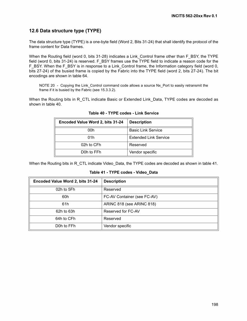
INCITS 562-20xx Rev 0.1
198
12.6 Data structure type (TYPE)
The data structure type (TYPE) is a one-byte field (Word 2, Bits 31-24) that shall identify the protocol of theframe content for Data frames.
When the Routing field (word 0, bits 31-28) indicates a Link_Control frame other than F_BSY, the TYPEfield (word 0, bits 31-24) is reserved. F_BSY frames use the TYPE field to indicate a reason code for theF_BSY. When the F_BSY is in response to a Link_Control frame, the Information category field (word 0,bits 27-24) of the busied frame is copied by the Fabric into the TYPE field (word 2, bits 27-24). The bitencodings are shown in table 64.
NOTE 20 - Copying the Link_Control command code allows a source Nx_Port to easily retransmit theframe if it is busied by the Fabric (see 15.3.3.2).
When the Routing bits in R_CTL indicate Basic or Extended Link_Data, TYPE codes are decoded asshown in table 40.
When the Routing bits in R_CTL indicate Video_Data, the TYPE codes are decoded as shown in table 41.
Table 40 - TYPE codes - Link Service
Encoded Value Word 2, bits 31-24 Description
00h Basic Link Service
01h Extended Link Service
02h to CFh Reserved
D0h to FFh Vendor specific
Table 41 - TYPE codes - Video_Data
Encoded Value Word 2, bits 31-24 Description
02h to 5Fh Reserved
60h FC-AV Container (see FC-AV)
61h ARINC 818 (see ARINC 818)
62h to 63h Reserved for FC-AV
64h to CFh Reserved
D0h to FFh Vendor specific
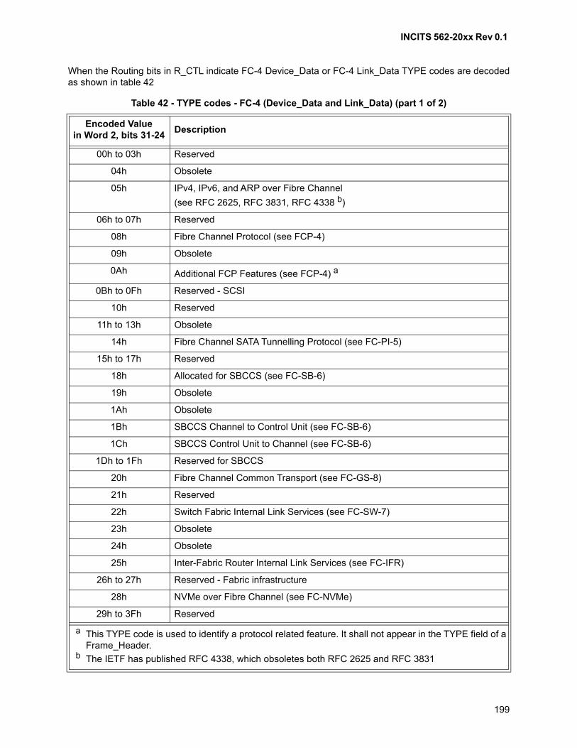
INCITS 562-20xx Rev 0.1
199
When the Routing bits in R_CTL indicate FC-4 Device_Data or FC-4 Link_Data TYPE codes are decodedas shown in table 42
Table 42 - TYPE codes - FC-4 (Device_Data and Link_Data) (part 1 of 2)
Encoded Valuein Word 2, bits 31-24
Description
00h to 03h Reserved
04h Obsolete
05h IPv4, IPv6, and ARP over Fibre Channel
(see RFC 2625, RFC 3831, RFC 4338 b)
06h to 07h Reserved
08h Fibre Channel Protocol (see FCP-4)
09h Obsolete
0Ah Additional FCP Features (see FCP-4) a
0Bh to 0Fh Reserved - SCSI
10h Reserved
11h to 13h Obsolete
14h Fibre Channel SATA Tunnelling Protocol (see FC-PI-5)
15h to 17h Reserved
18h Allocated for SBCCS (see FC-SB-6)
19h Obsolete
1Ah Obsolete
1Bh SBCCS Channel to Control Unit (see FC-SB-6)
1Ch SBCCS Control Unit to Channel (see FC-SB-6)
1Dh to 1Fh Reserved for SBCCS
20h Fibre Channel Common Transport (see FC-GS-8)
21h Reserved
22h Switch Fabric Internal Link Services (see FC-SW-7)
23h Obsolete
24h Obsolete
25h Inter-Fabric Router Internal Link Services (see FC-IFR)
26h to 27h Reserved - Fabric infrastructure
28h NVMe over Fibre Channel (see FC-NVMe)
29h to 3Fh Reserved
a This TYPE code is used to identify a protocol related feature. It shall not appear in the TYPE field of a Frame_Header.
b The IETF has published RFC 4338, which obsoletes both RFC 2625 and RFC 3831
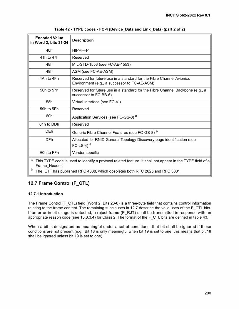
INCITS 562-20xx Rev 0.1
200
12.7 Frame Control (F_CTL)
12.7.1 Introduction
The Frame Control (F_CTL) field (Word 2, Bits 23-0) is a three-byte field that contains control informationrelating to the frame content. The remaining subclauses in 12.7 describe the valid uses of the F_CTL bits.If an error in bit usage is detected, a reject frame (P_RJT) shall be transmitted in response with anappropriate reason code (see 15.3.3.4) for Class 2. The format of the F_CTL bits are defined in table 43.
When a bit is designated as meaningful under a set of conditions, that bit shall be ignored if thoseconditions are not present (e.g., Bit 18 is only meaningful when bit 19 is set to one; this means that bit 18shall be ignored unless bit 19 is set to one).
40h HIPPI-FP
41h to 47h Reserved
48h MIL-STD-1553 (see FC-AE-1553)
49h ASM (see FC-AE-ASM)
4Ah to 4Fh Reserved for future use in a standard for the Fibre Channel Avionics Environment (e.g., a successor to FC-AE-ASM)
50h to 57h Reserved for future use in a standard for the Fibre Channel Backbone (e.g., a successor to FC-BB-6)
58h Virtual Interface (see FC-VI)
59h to 5Fh Reserved
60h Application Services (see FC-GS-8) a
61h to DDh Reserved
DEh Generic Fibre Channel Features (see FC-GS-8) a
DFh Allocated for RNID General Topology Discovery page identification (see
FC-LS-4) a
E0h to FFh Vendor specific
Table 42 - TYPE codes - FC-4 (Device_Data and Link_Data) (part 2 of 2)
Encoded Valuein Word 2, bits 31-24
Description
a This TYPE code is used to identify a protocol related feature. It shall not appear in the TYPE field of a Frame_Header.
b The IETF has published RFC 4338, which obsoletes both RFC 2625 and RFC 3831
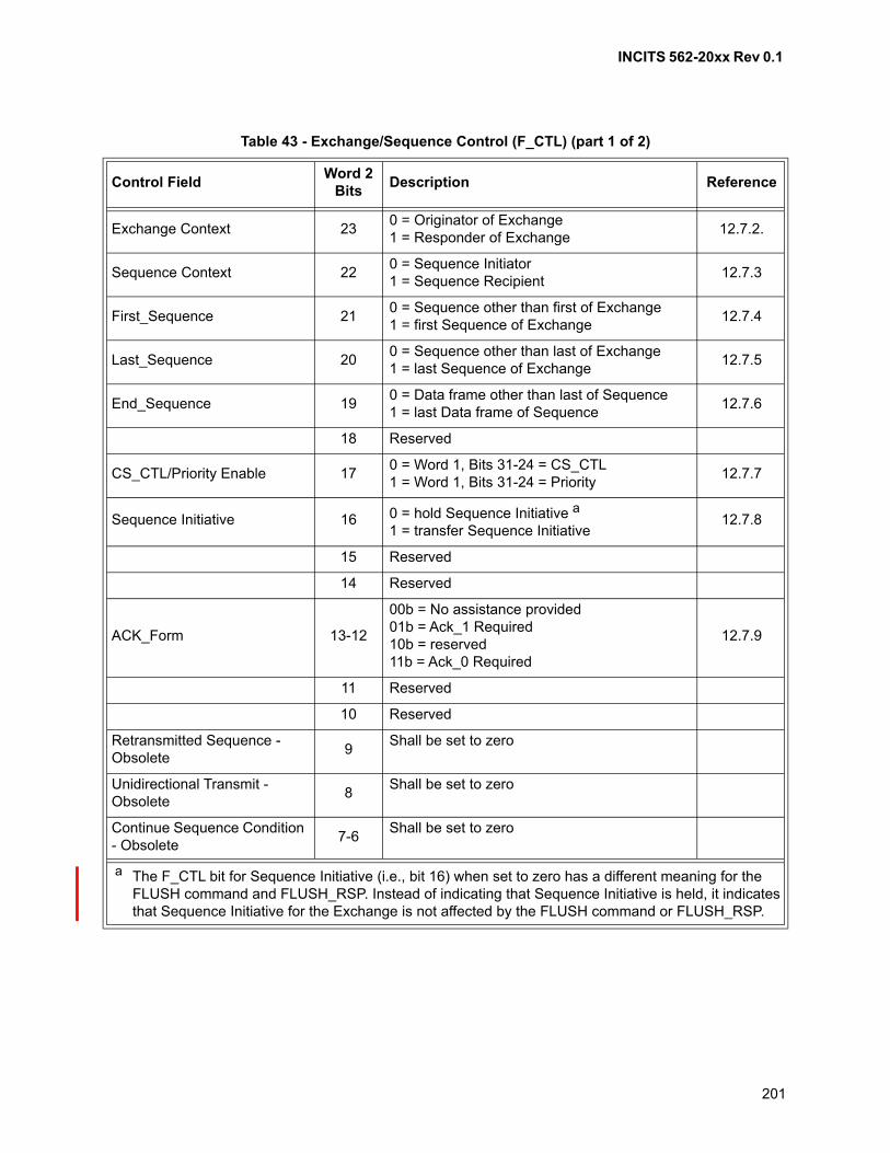
INCITS 562-20xx Rev 0.1
201
Table 43 - Exchange/Sequence Control (F_CTL) (part 1 of 2)
Control FieldWord 2
BitsDescription Reference
Exchange Context 230 = Originator of Exchange1 = Responder of Exchange
12.7.2.
Sequence Context 220 = Sequence Initiator1 = Sequence Recipient
12.7.3
First_Sequence 210 = Sequence other than first of Exchange1 = first Sequence of Exchange
12.7.4
Last_Sequence 200 = Sequence other than last of Exchange1 = last Sequence of Exchange
12.7.5
End_Sequence 190 = Data frame other than last of Sequence1 = last Data frame of Sequence
12.7.6
18 Reserved
CS_CTL/Priority Enable 170 = Word 1, Bits 31-24 = CS_CTL1 = Word 1, Bits 31-24 = Priority
12.7.7
Sequence Initiative 16 0 = hold Sequence Initiative a
1 = transfer Sequence Initiative12.7.8
15 Reserved
14 Reserved
ACK_Form 13-12
00b = No assistance provided01b = Ack_1 Required10b = reserved11b = Ack_0 Required
12.7.9
11 Reserved
10 Reserved
Retransmitted Sequence - Obsolete
9Shall be set to zero
Unidirectional Transmit - Obsolete
8Shall be set to zero
Continue Sequence Condition - Obsolete
7-6Shall be set to zero
a The F_CTL bit for Sequence Initiative (i.e., bit 16) when set to zero has a different meaning for the FLUSH command and FLUSH_RSP. Instead of indicating that Sequence Initiative is held, it indicates that Sequence Initiative for the Exchange is not affected by the FLUSH command or FLUSH_RSP.
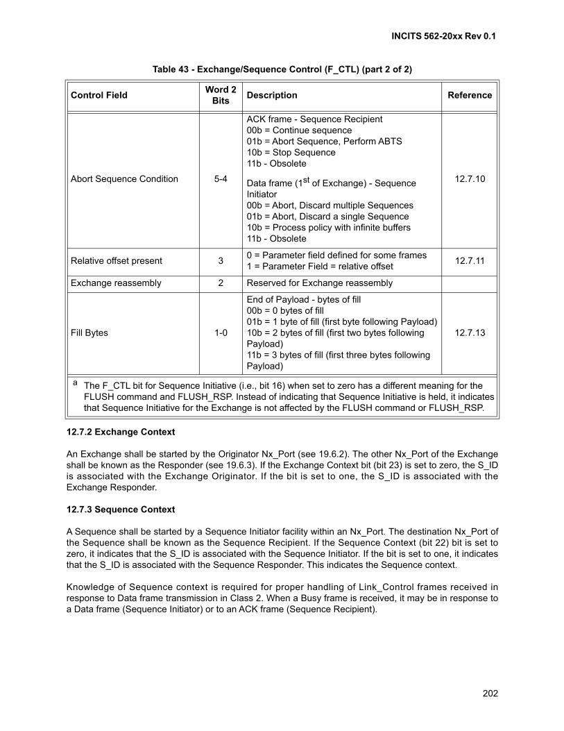
INCITS 562-20xx Rev 0.1
202
12.7.2 Exchange Context
An Exchange shall be started by the Originator Nx_Port (see 19.6.2). The other Nx_Port of the Exchangeshall be known as the Responder (see 19.6.3). If the Exchange Context bit (bit 23) is set to zero, the S_IDis associated with the Exchange Originator. If the bit is set to one, the S_ID is associated with theExchange Responder.
12.7.3 Sequence Context
A Sequence shall be started by a Sequence Initiator facility within an Nx_Port. The destination Nx_Port ofthe Sequence shall be known as the Sequence Recipient. If the Sequence Context (bit 22) bit is set tozero, it indicates that the S_ID is associated with the Sequence Initiator. If the bit is set to one, it indicatesthat the S_ID is associated with the Sequence Responder. This indicates the Sequence context.
Knowledge of Sequence context is required for proper handling of Link_Control frames received inresponse to Data frame transmission in Class 2. When a Busy frame is received, it may be in response toa Data frame (Sequence Initiator) or to an ACK frame (Sequence Recipient).
Abort Sequence Condition 5-4
ACK frame - Sequence Recipient00b = Continue sequence01b = Abort Sequence, Perform ABTS10b = Stop Sequence11b - Obsolete
12.7.10Data frame (1st of Exchange) - Sequence Initiator00b = Abort, Discard multiple Sequences01b = Abort, Discard a single Sequence 10b = Process policy with infinite buffers11b - Obsolete
Relative offset present 30 = Parameter field defined for some frames1 = Parameter Field = relative offset
12.7.11
Exchange reassembly 2 Reserved for Exchange reassembly
Fill Bytes 1-0
End of Payload - bytes of fill00b = 0 bytes of fill01b = 1 byte of fill (first byte following Payload)10b = 2 bytes of fill (first two bytes following Payload)11b = 3 bytes of fill (first three bytes following Payload)
12.7.13
Table 43 - Exchange/Sequence Control (F_CTL) (part 2 of 2)
Control FieldWord 2
BitsDescription Reference
a The F_CTL bit for Sequence Initiative (i.e., bit 16) when set to zero has a different meaning for the FLUSH command and FLUSH_RSP. Instead of indicating that Sequence Initiative is held, it indicates that Sequence Initiative for the Exchange is not affected by the FLUSH command or FLUSH_RSP.
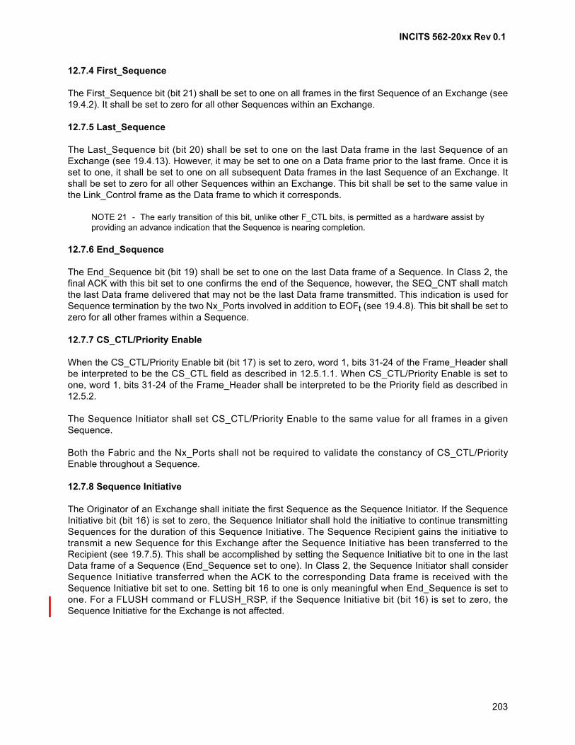
INCITS 562-20xx Rev 0.1
203
12.7.4 First_Sequence
The First_Sequence bit (bit 21) shall be set to one on all frames in the first Sequence of an Exchange (see19.4.2). It shall be set to zero for all other Sequences within an Exchange.
12.7.5 Last_Sequence
The Last_Sequence bit (bit 20) shall be set to one on the last Data frame in the last Sequence of anExchange (see 19.4.13). However, it may be set to one on a Data frame prior to the last frame. Once it isset to one, it shall be set to one on all subsequent Data frames in the last Sequence of an Exchange. Itshall be set to zero for all other Sequences within an Exchange. This bit shall be set to the same value inthe Link_Control frame as the Data frame to which it corresponds.
NOTE 21 - The early transition of this bit, unlike other F_CTL bits, is permitted as a hardware assist byproviding an advance indication that the Sequence is nearing completion.
12.7.6 End_Sequence
The End_Sequence bit (bit 19) shall be set to one on the last Data frame of a Sequence. In Class 2, thefinal ACK with this bit set to one confirms the end of the Sequence, however, the SEQ_CNT shall matchthe last Data frame delivered that may not be the last Data frame transmitted. This indication is used forSequence termination by the two Nx_Ports involved in addition to EOFt (see 19.4.8). This bit shall be set tozero for all other frames within a Sequence.
12.7.7 CS_CTL/Priority Enable
When the CS_CTL/Priority Enable bit (bit 17) is set to zero, word 1, bits 31-24 of the Frame_Header shallbe interpreted to be the CS_CTL field as described in 12.5.1.1. When CS_CTL/Priority Enable is set toone, word 1, bits 31-24 of the Frame_Header shall be interpreted to be the Priority field as described in12.5.2.
The Sequence Initiator shall set CS_CTL/Priority Enable to the same value for all frames in a givenSequence.
Both the Fabric and the Nx_Ports shall not be required to validate the constancy of CS_CTL/PriorityEnable throughout a Sequence.
12.7.8 Sequence Initiative
The Originator of an Exchange shall initiate the first Sequence as the Sequence Initiator. If the SequenceInitiative bit (bit 16) is set to zero, the Sequence Initiator shall hold the initiative to continue transmittingSequences for the duration of this Sequence Initiative. The Sequence Recipient gains the initiative totransmit a new Sequence for this Exchange after the Sequence Initiative has been transferred to theRecipient (see 19.7.5). This shall be accomplished by setting the Sequence Initiative bit to one in the lastData frame of a Sequence (End_Sequence set to one). In Class 2, the Sequence Initiator shall considerSequence Initiative transferred when the ACK to the corresponding Data frame is received with theSequence Initiative bit set to one. Setting bit 16 to one is only meaningful when End_Sequence is set toone. For a FLUSH command or FLUSH_RSP, if the Sequence Initiative bit (bit 16) is set to zero, theSequence Initiative for the Exchange is not affected.
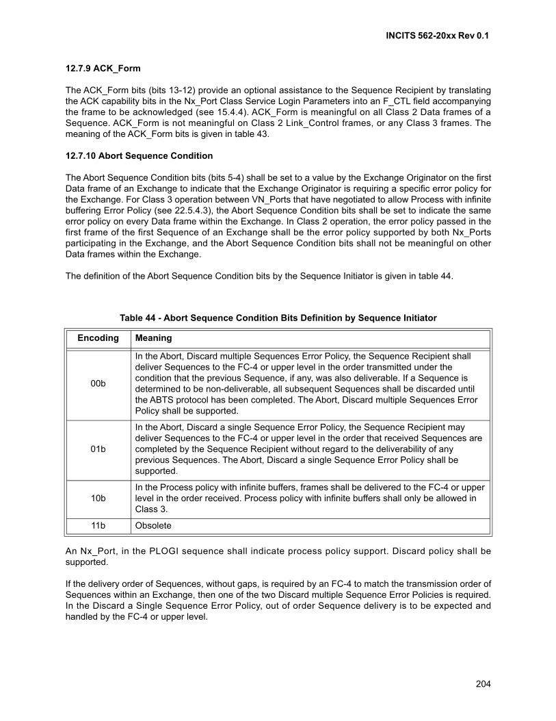
INCITS 562-20xx Rev 0.1
204
12.7.9 ACK_Form
The ACK_Form bits (bits 13-12) provide an optional assistance to the Sequence Recipient by translatingthe ACK capability bits in the Nx_Port Class Service Login Parameters into an F_CTL field accompanyingthe frame to be acknowledged (see 15.4.4). ACK_Form is meaningful on all Class 2 Data frames of aSequence. ACK_Form is not meaningful on Class 2 Link_Control frames, or any Class 3 frames. Themeaning of the ACK_Form bits is given in table 43.
12.7.10 Abort Sequence Condition
The Abort Sequence Condition bits (bits 5-4) shall be set to a value by the Exchange Originator on the firstData frame of an Exchange to indicate that the Exchange Originator is requiring a specific error policy forthe Exchange. For Class 3 operation between VN_Ports that have negotiated to allow Process with infinitebuffering Error Policy (see 22.5.4.3), the Abort Sequence Condition bits shall be set to indicate the sameerror policy on every Data frame within the Exchange. In Class 2 operation, the error policy passed in thefirst frame of the first Sequence of an Exchange shall be the error policy supported by both Nx_Portsparticipating in the Exchange, and the Abort Sequence Condition bits shall not be meaningful on otherData frames within the Exchange.
The definition of the Abort Sequence Condition bits by the Sequence Initiator is given in table 44.
An Nx_Port, in the PLOGI sequence shall indicate process policy support. Discard policy shall besupported.
If the delivery order of Sequences, without gaps, is required by an FC-4 to match the transmission order ofSequences within an Exchange, then one of the two Discard multiple Sequence Error Policies is required.In the Discard a Single Sequence Error Policy, out of order Sequence delivery is to be expected andhandled by the FC-4 or upper level.
Table 44 - Abort Sequence Condition Bits Definition by Sequence Initiator
Encoding Meaning
00b
In the Abort, Discard multiple Sequences Error Policy, the Sequence Recipient shall deliver Sequences to the FC-4 or upper level in the order transmitted under the condition that the previous Sequence, if any, was also deliverable. If a Sequence is determined to be non-deliverable, all subsequent Sequences shall be discarded until the ABTS protocol has been completed. The Abort, Discard multiple Sequences Error Policy shall be supported.
01b
In the Abort, Discard a single Sequence Error Policy, the Sequence Recipient may deliver Sequences to the FC-4 or upper level in the order that received Sequences are completed by the Sequence Recipient without regard to the deliverability of any previous Sequences. The Abort, Discard a single Sequence Error Policy shall be supported.
10bIn the Process policy with infinite buffers, frames shall be delivered to the FC-4 or upper level in the order received. Process policy with infinite buffers shall only be allowed in Class 3.
11b Obsolete
INCITS 562-20xx Rev 0.1
205
The Abort Sequence Condition bits shall be set to a value other than zeros by the Sequence Recipient inan ACK frame to indicate to the Sequence Initiator that the Sequence Recipient has detected an abnormalcondition, malfunction, or error.
The definition of the Abort Sequence Condition bits by the Sequence Recipient is given in table 45.
12.7.11 Relative offset present
When relative offset present (bit 3) is set to one in a Data frame, the Parameter Field (see 12.13) containsthe relative offset for the Payload of the frame as defined by the FC-4 protocol. Relative offset present isonly meaningful on Data frames of a Sequence and shall be ignored on all other frames. Relative offsetpresent is not meaningful on Link_Control or Basic Link Service Link Data frames. When relative offsetpresent is set to zero on a Data frame, the value in the Parameter Field shall be passed to the upper level(e.g., for FCP-4 Task Retry Identification).
12.7.12 Exchange reassembly
The Sequence Initiator shall set the Exchange reassembly bit (bit 2) to zero to indicate that the Payload inthis Data frame is associated with an Exchange between a single pair of Nx_Ports. Therefore, reassemblyis confined to a single destination Nx_Port.
The Exchange reassembly bit being set to one is reserved for future use to indicate that the Payload in thisData frame is associated with an Exchange being managed by a single node using multiple Nx_Ports ateither the source, destination, or both.
12.7.13 Fill Bytes
If the value of the Fill Bytes (bits 1-0) is non-zero, it notifies the Data frame receiver (Sequence Recipient)that one or more of the bytes following the Payload shall be ignored, except for CRC calculation. Thenumber of fill bytes plus the length of the Payload in bytes shall be a multiple of four. The fill byte value isnot specified by this standard.
Table 45 - Abort Sequence Condition Bits Definition by Sequence Recipient
Encoding Meaning
00b Continue Sequence
01b
A request by the Sequence Recipient to the Sequence Initiator to terminate this Sequence using the Abort Sequence protocol and then optionally perform Sequence recovery. See FC-LS-4 and 22.5.5.2.2 for a description of the Abort Sequence protocol.
10b
A request by the Sequence Recipient to the Sequence Initiator to stop this Sequence. This allows for a request for an early termination by the Sequence Recipient. Some of the data received may have been processed and some of the data discarded. Aborting the Sequence using the ABTS command is not necessary and shall not be used. Both the Sequence Initiator and Recipient end the Sequence in a normal manner. See 22.5.5.3 for a description of the Stop Sequence protocol.
11b Obsolete
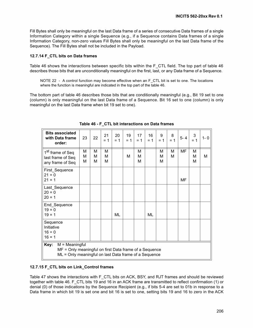
INCITS 562-20xx Rev 0.1
206
Fill Bytes shall only be meaningful on the last Data frame of a series of consecutive Data frames of a singleInformation Category within a single Sequence (e.g., if a Sequence contains Data frames of a singleInformation Category, non-zero values Fill Bytes shall only be meaningful on the last Data frame of theSequence). The Fill Bytes shall not be included in the Payload.
12.7.14 F_CTL bits on Data frames
Table 46 shows the interactions between specific bits within the F_CTL field. The top part of table 46describes those bits that are unconditionally meaningful on the first, last, or any Data frame of a Sequence.
NOTE 22 - A control function may become effective when an F_CTL bit is set to one. The locationswhere the function is meaningful are indicated in the top part of the table 46.
The bottom part of table 46 describes those bits that are conditionally meaningful (e.g., Bit 19 set to one(column) is only meaningful on the last Data frame of a Sequence. Bit 16 set to one (column) is onlymeaningful on the last Data frame when bit 19 set to one).
12.7.15 F_CTL bits on Link_Control frames
Table 47 shows the interactions with F_CTL bits on ACK, BSY, and RJT frames and should be reviewedtogether with table 46. F_CTL bits 19 and 16 in an ACK frame are transmitted to reflect confirmation (1) ordenial (0) of those indications by the Sequence Recipient (e.g., if bits 5-4 are set to 01b in response to aData frame in which bit 19 is set one and bit 16 is set to one, setting bits 19 and 16 to zero in the ACK
Table 46 - F_CTL bit interactions on Data frames
Bits associated with Data frame
order:23 22
21= 1
20= 1
19 = 1
17= 1
16= 1
9= 1
8= 1
5- 43
= 11- 0
1st frame of Seqlast frame of Seqany frame of Seq
MMM
MMM
MMM
MMMM
MMM
MM
MF MMM
M
First_Sequence21 = 021 = 1 MF
Last_Sequence20 = 020 = 1
End_Sequence19 = 019 = 1 ML ML
Sequence Initiative16 = 016 = 1
Key: M = MeaningfulMF = Only meaningful on first Data frame of a SequenceML = Only meaningful on last Data frame of a Sequence
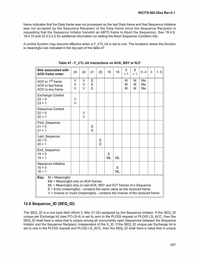
INCITS 562-20xx Rev 0.1
207
frame indicates that the Data frame was not processed as the last Data frame and that Sequence Initiativewas not accepted by the Sequence Recipient of the Data frame since the Sequence Recipient isrequesting that the Sequence Initiator transmit an ABTS frame to Abort the Sequence). See 19.4.8,19.4.10 and 22.5.5.2.2 for additional information on setting the Abort Sequence Condition bits.
A control function may become effective when a F_CTL bit is set to one. The locations where the functionis meaningful are indicated in the top part of the table 47.
12.8 Sequence_ID (SEQ_ID)
The SEQ_ID is a one byte field (Word 3, Bits 31-24) assigned by the Sequence Initiator. If the SEQ_IDunique per Exchange bit (see FC-LS-4) is set to zero in the PLOGI request or PLOGI LS_ACC, then theSEQ_ID shall have a value that is unique among all concurrently open Sequences between the SequenceInitiator and the Sequence Recipient, independent of the X_ID. If the SEQ_ID unique per Exchange bit isset to one in the PLOGI request and PLOGI LS_ACC, then the SEQ_ID shall have a value that is unique
Table 47 - F_CTL bit interactions on ACK, BSY or RJT
Bits associated with ACK frame order:
23 22 21 20 19 169
= 18
= 15- 4 3 1- 0
ACK to 1st frameACK to last frameACK to any frame
VVV
VVV
EEE
MMM
MMM
MaMaMa
Exchange Context23 = 023 = 1
VV
Sequence Context22 = 022 = 1
VV
First_Sequence21 = 021 = 1
EE
Last_Sequence20 = 020 = 1
EE
End_Sequence19 = 019 = 1
EML ML
Sequence Initiative16 = 016 = 1
EML
Key: M = MeaningfulMa = Meaningful only on ACK framesML = Meaningful only on last ACK, BSY and RJT frames of a SequenceE = Echo (meaningful) - contains the same value as the received frameV = Inverse or invert (meaningful) - contains the inverse of the received frame
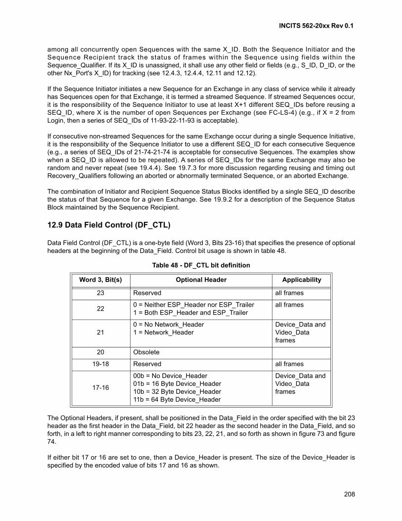
INCITS 562-20xx Rev 0.1
208
among all concurrently open Sequences with the same X_ID. Both the Sequence Initiator and theSequence Recipient track the status of frames within the Sequence using fields within theSequence_Qualifier. If its X_ID is unassigned, it shall use any other field or fields (e.g., S_ID, D_ID, or theother Nx_Port's X_ID) for tracking (see 12.4.3, 12.4.4, 12.11 and 12.12).
If the Sequence Initiator initiates a new Sequence for an Exchange in any class of service while it alreadyhas Sequences open for that Exchange, it is termed a streamed Sequence. If streamed Sequences occur,it is the responsibility of the Sequence Initiator to use at least X+1 different SEQ_IDs before reusing aSEQ_ID, where X is the number of open Sequences per Exchange (see FC-LS-4) (e.g., if X = 2 fromLogin, then a series of SEQ_IDs of 11-93-22-11-93 is acceptable).
If consecutive non-streamed Sequences for the same Exchange occur during a single Sequence Initiative,it is the responsibility of the Sequence Initiator to use a different SEQ_ID for each consecutive Sequence(e.g., a series of SEQ_IDs of 21-74-21-74 is acceptable for consecutive Sequences. The examples showwhen a SEQ_ID is allowed to be repeated). A series of SEQ_IDs for the same Exchange may also berandom and never repeat (see 19.4.4). See 19.7.3 for more discussion regarding reusing and timing outRecovery_Qualifiers following an aborted or abnormally terminated Sequence, or an aborted Exchange.
The combination of Initiator and Recipient Sequence Status Blocks identified by a single SEQ_ID describethe status of that Sequence for a given Exchange. See 19.9.2 for a description of the Sequence StatusBlock maintained by the Sequence Recipient.
12.9 Data Field Control (DF_CTL)
Data Field Control (DF_CTL) is a one-byte field (Word 3, Bits 23-16) that specifies the presence of optionalheaders at the beginning of the Data_Field. Control bit usage is shown in table 48.
The Optional Headers, if present, shall be positioned in the Data_Field in the order specified with the bit 23header as the first header in the Data_Field, bit 22 header as the second header in the Data_Field, and soforth, in a left to right manner corresponding to bits 23, 22, 21, and so forth as shown in figure 73 and figure74.
If either bit 17 or 16 are set to one, then a Device_Header is present. The size of the Device_Header isspecified by the encoded value of bits 17 and 16 as shown.
Table 48 - DF_CTL bit definition
Word 3, Bit(s) Optional Header Applicability
23 Reserved all frames
220 = Neither ESP_Header nor ESP_Trailer1 = Both ESP_Header and ESP_Trailer
all frames
210 = No Network_Header1 = Network_Header
Device_Data andVideo_Data frames
20 Obsolete
19-18 Reserved all frames
17-16
00b = No Device_Header01b = 16 Byte Device_Header10b = 32 Byte Device_Header11b = 64 Byte Device_Header
Device_Data andVideo_Data frames
INCITS 562-20xx Rev 0.1
209
If an Optional Header is not present as indicated by the appropriate bit in DF_CTL, no space shall beallocated for the Header in the Data_Field of the frame (e.g., if bits 23 and 22 are zero and bit 21 is one,the first data byte of the Data_Field contains the first byte of the Network_Header).
See clause 14 for Optional Headers requirements.
12.10 Sequence count (SEQ_CNT)
The sequence count (SEQ_CNT) is a two-byte field (Word 3, Bits 15-0) that shall indicate the sequentialorder of Data frame transmission within a single Sequence or multiple consecutive Sequences for thesame Exchange. The SEQ_CNT of the first Data frame of the first Sequence of the Exchange transmittedby either the Originator or Responder shall be binary zero. The SEQ_CNT of each subsequent Data framein the Sequence shall be incremented by one.
If a Sequence is streamed, the SEQ_CNT of the first Data frame of the Sequence shall be incremented byone from the SEQ_CNT of the last Data frame of the previously sent Sequence (this is termedcontinuously increasing SEQ_CNT). If a Sequence is non-streamed, the starting SEQ_CNT may becontinuously increasing or binary zero.
The same SEQ_ID and SEQ_CNT shall identify ACK and Link_Response frames as the frame to which itis responding. Frames are tracked on a SEQ_ID, SEQ_CNT basis within the scope of theSequence_Qualifier for that Sequence.
The SEQ_CNT shall wrap to zero after reaching a value of 65 535. The SEQ_CNT shall then only beincremented to (but not including) the SEQ_CNT of an unacknowledged frame of the same Sequence.Otherwise, data integrity is not ensured. Sequences of Data frames and SEQ_CNT values are discussedin clause 19. In order to ensure frame identification integrity, SEQ_CNT is a 16-bit field while theEnd-to-end Credit field of the Login Class Service Parameters (see FC-LS-4) is defined as a 15-bit field.This ensures that EE_Credit never exceeds one-half of the maximum SEQ_CNT.
12.11 Originator Exchange_ID (OX_ID)
The Originator Exchange_ID is a two-byte field (Word 4, Bits 31-16) that shall identify the Exchange_IDassigned by the Originator of the Exchange. Each Exchange shall be assigned an identifier unique to theOriginator or Originator-Responder pair. If the Originator is enforcing uniqueness via the OX_IDmechanism, it shall set a unique value for OX_ID other than FF FFh in the first Data frame of the firstSequence of an Exchange. An OX_ID of FF FFh indicates that the OX_ID is unassigned and that theOriginator is not enforcing uniqueness via the OX_ID mechanism. If an Originator uses the unassignedvalue of FF FFh to identify the Exchange, it shall have only one Exchange (OX_ID set to FF FFh) with agiven Responder.
An Originator Exchange Status Block associated with the OX_ID is used to track the progress of a series ofSequences that comprises an Exchange. See 19.9.1 for a description of the Exchange Status Block.
NOTE 23 - If FF FFh is used as the OX_ID throughout the Exchange, the Originator uses an alternateSequence tracking mechanism. If the OX_ID is unique, it may be used as an index into a control structurethat may be used in conjunction with other constructs to track frames.
INCITS 562-20xx Rev 0.1
210
12.12 Responder Exchange_ID (RX_ID)
The Responder Exchange_ID is a two byte field (Word 4, Bits 15-0) assigned by the Responder that shallprovide a unique, locally meaningful identifier at the Responder for an Exchange established by anOriginator and identified by an OX_ID. The Responder of the Exchange shall set a unique value for RX_IDother than FF FFh, if RX_ID is being used, by one of two methods:
a) in an ACK to a Data frame in the first Sequence of an Exchange in Class 2; or
b) in the first Sequence transmitted as a Sequence Initiator, if any, in Class 3.
An RX_ID of FF FFh shall indicate that the RX_ID is unassigned. If the Responder does not assign anRX_ID other than FF FFh by the end of the first Sequence, then the Responder is not enforcinguniqueness via the RX_ID mechanism.
When the Responder uses only FF FFh for RX_ID, it shall have the capability to identify the Exchangethrough the OX_ID and the S_ID of the Originator of the Exchange. Under all other circumstances, until avalue other than FF FFh is assigned, FF FFh value for RX_ID shall be used indicating that RX_ID isunassigned. After a value other than FF FFh is assigned, the assigned value shall be used for theremainder of the Exchange (see 19.4.2 and 19.6.3).
A Responder Exchange Status Block associated with the RX_ID is used to track the progress of a series ofSequences that compose an Exchange. See 19.9.1 for a description of the Exchange Status Block.
NOTE 24 - If FF FFh is used as the RX_ID throughout the Exchange, the Responder uses an alternateSequence tracking mechanism. If the RX_ID is unique, it may be used as an index into a control structurethat may be used in conjunction with other constructs to track frames.
12.13 Parameter
The Parameter field (Word 5, Bits 31-0) has meanings based on frame type. For Link_Control frames, theParameter field is used to carry information specific to the individual Link_Control frame. For Data frameswith the relative offset present bit set to 1, the Parameter field specifies relative offset, a four-byte field thatcontains the relative displacement of the first byte of the Payload of the frame from the base address asspecified by the ULP. Relative offset is expressed in terms of bytes (see 11.3.4). The use of the relativeoffset field is optional and is indicated as a Login Service Parameter. If relative offset is being used, thenumber of bytes transmitted relative to the protocol-specific base address shall be less than the maximumvalue of the relative offset (Parameter) field (232). For Data frames with the relative offset Present bit set tozero, the Parameter field shall be set and interpreted in a protocol specific manner that may depend on thetype of Information Unit carried by the frame.
Continuously increasing relative offset is the relationship specified between relative offset values containedin frame (n) and frame (n+1) of an Information Category within a single Sequence. Continuously increasingrelative offset (ROI) for a given Information Category I is specified by the following:
ROI(n+1) = ROI(n) + Length of PayloadI(n)
where n is 0 and represents the consecutive frame count of frames for a given Information Categorywithin a single Sequence. ROI(0) is the initial relative offset for the Information Category I.
See clause 21 for relative offset requirements. See clause 15 for requirements for using the Parameterfield in Link_Control frames. See clause 16 for requirements for using the Parameter field in Basic LinkData frames.
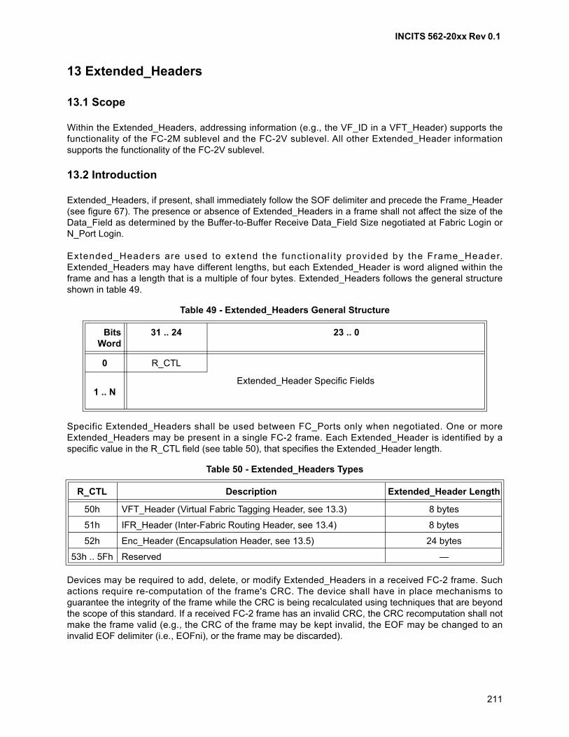
INCITS 562-20xx Rev 0.1
211
13 Extended_Headers
13.1 Scope
Within the Extended_Headers, addressing information (e.g., the VF_ID in a VFT_Header) supports thefunctionality of the FC-2M sublevel and the FC-2V sublevel. All other Extended_Header informationsupports the functionality of the FC-2V sublevel.
13.2 Introduction
Extended_Headers, if present, shall immediately follow the SOF delimiter and precede the Frame_Header(see figure 67). The presence or absence of Extended_Headers in a frame shall not affect the size of theData_Field as determined by the Buffer-to-Buffer Receive Data_Field Size negotiated at Fabric Login orN_Port Login.
Extended_Headers are used to extend the funct ional i ty provided by the Frame_Header.Extended_Headers may have different lengths, but each Extended_Header is word aligned within theframe and has a length that is a multiple of four bytes. Extended_Headers follows the general structureshown in table 49.
Specific Extended_Headers shall be used between FC_Ports only when negotiated. One or moreExtended_Headers may be present in a single FC-2 frame. Each Extended_Header is identified by aspecific value in the R_CTL field (see table 50), that specifies the Extended_Header length.
Devices may be required to add, delete, or modify Extended_Headers in a received FC-2 frame. Suchactions require re-computation of the frame's CRC. The device shall have in place mechanisms toguarantee the integrity of the frame while the CRC is being recalculated using techniques that are beyondthe scope of this standard. If a received FC-2 frame has an invalid CRC, the CRC recomputation shall notmake the frame valid (e.g., the CRC of the frame may be kept invalid, the EOF may be changed to aninvalid EOF delimiter (i.e., EOFni), or the frame may be discarded).
Table 49 - Extended_Headers General Structure
BitsWord
31 .. 24 23 .. 0
0 R_CTL
1 .. NExtended_Header Specific Fields
Table 50 - Extended_Headers Types
R_CTL Description Extended_Header Length
50h VFT_Header (Virtual Fabric Tagging Header, see 13.3) 8 bytes
51h IFR_Header (Inter-Fabric Routing Header, see 13.4) 8 bytes
52h Enc_Header (Encapsulation Header, see 13.5) 24 bytes
53h .. 5Fh Reserved —
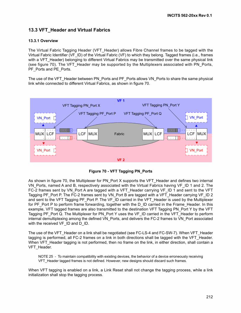
INCITS 562-20xx Rev 0.1
212
13.3 VFT_Header and Virtual Fabrics
13.3.1 Overview
The Virtual Fabric Tagging Header (VFT_Header) allows Fibre Channel frames to be tagged with theVirtual Fabric Identifier (VF_ID) of the Virtual Fabric (VF) to which they belong. Tagged frames (i.e., frameswith a VFT_Header) belonging to different Virtual Fabrics may be transmitted over the same physical link(see figure 70). The VFT_Header may be supported by the Multiplexers associated with PN_Ports,PF_Ports and PE_Ports.
The use of the VFT_Header between PN_Ports and PF_Ports allows VN_Ports to share the same physicallink while connected to different Virtual Fabrics, as shown in figure 70.
As shown in figure 70, the Multiplexer for PN_Port X supports the VFT_Header and defines two internalVN_Ports, named A and B, respectively associated with the Virtual Fabrics having VF_ID 1 and 2. TheFC-2 frames sent by VN_Port A are tagged with a VFT_Header carrying VF_ID 1 and sent to the VFTTagging PF_Port P. The FC-2 frames sent by VN_Port B are tagged with a VFT_Header carrying VF_ID 2and sent to the VFT Tagging PF_Port P. The VF_ID carried in the VFT_Header is used by the Multiplexerfor PF_Port P to perform frame forwarding, together with the D_ID carried in the Frame_Header. In thisexample, VFT tagged frames are also transmitted to the destination VFT Tagging PN_Port Y by the VFTTagging PF_Port Q. The Multiplexer for PN_Port Y uses the VF_ID carried in the VFT_Header to performinternal demultiplexing among the defined VN_Ports, and delivers the FC-2 frames to VN_Port associatedwith the received VF_ID and D_ID.
The use of the VFT_Header on a link shall be negotiated (see FC-LS-4 and FC-SW-7). When VFT_Headertagging is performed, all FC-2 frames on a link in both directions shall be tagged with the VFT_Header.When VFT_Header tagging is not performed, then no frame on the link, in either direction, shall contain aVFT_Header.
NOTE 25 - To maintain compatibility with existing devices, the behavior of a device erroneously receivingVFT_Header tagged frames is not defined. However, new designs should discard such frames.
When VFT tagging is enabled on a link, a Link Reset shall not change the tagging process, while a linkinitialization shall stop the tagging process.
LCF MUXLCFMUX
VN_Port
VF 1
VF 2
Figure 70 - VFT Tagging PN_Ports
VN_Port
VN_Port
VN_Port
VFT Tagging PN_Port X VFT Tagging PN_Port Y
FabricLCF MUX
VFT Tagging PF_Port P
LCFMUX
VFT Tagging PF_Port Q
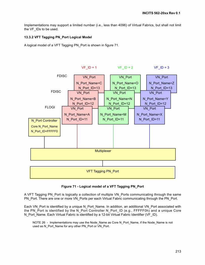
INCITS 562-20xx Rev 0.1
213
Implementations may support a limited number (i.e., less than 4096) of Virtual Fabrics, but shall not limitthe VF_IDs to be used.
13.3.2 VFT Tagging PN_Port Logical Model
A logical model of a VFT Tagging PN_Port is shown in figure 71.
A VFT Tagging PN_Port is logically a collection of multiple VN_Ports communicating through the samePN_Port. There are one or more VN_Ports per each Virtual Fabric communicating through the PN_Port.
Each VN_Port is identified by a unique N_Port_Name. In addition, an additional VN_Port associated withthe PN_Port is identified by the N_Port Controller N_Port_ID (e.g., FFFFF0h) and a unique CoreN_Port_Name. Each Virtual Fabric is identified by a 12-bit Virtual Fabric Identifier (VF_ID).
NOTE 26 - Implementations may use the Node_Name as Core N_Port_Name, if the Node_Name is notused as N_Port_Name for any other PN_Port or VN_Port.
Figure 71 - Logical model of a VFT Tagging PN_Port
Multiplexer
VN_Port
N_Port_Name=C
N_Port_ID=13
FDISC VN_Port
N_Port_Name=O
N_Port_ID=13
VN_Port
N_Port_Name=Z
N_Port_ID=13
VN_Port
N_Port_Name=B
N_Port_ID=12
FDISC VN_Port
N_Port_Name=N
N_Port_ID=12
VN_Port
N_Port_Name=Y
N_Port_ID=12
VN_Port
N_Port_Name=A
N_Port_ID=11
VN_Port
N_Port_Name=M
N_Port_ID=11
VN_Port
N_Port_Name=X
N_Port_ID=11
FLOGI
VF_ID = 1 VF_ID = 2 VF_ID = 3
Core N_Port_Name
N_Port_ID=FFFFF0
N_Port Controller
VFT Tagging PN_Port
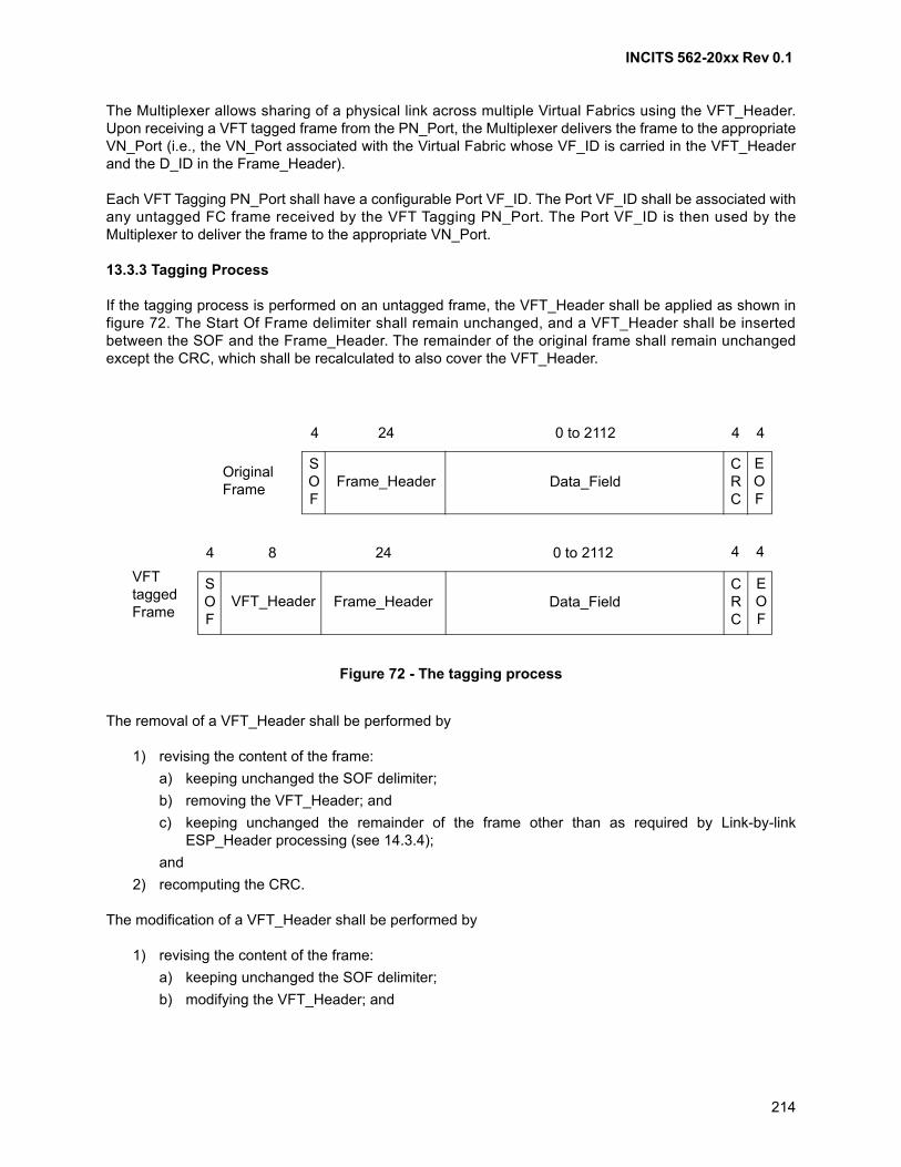
INCITS 562-20xx Rev 0.1
214
The Multiplexer allows sharing of a physical link across multiple Virtual Fabrics using the VFT_Header.Upon receiving a VFT tagged frame from the PN_Port, the Multiplexer delivers the frame to the appropriateVN_Port (i.e., the VN_Port associated with the Virtual Fabric whose VF_ID is carried in the VFT_Headerand the D_ID in the Frame_Header).
Each VFT Tagging PN_Port shall have a configurable Port VF_ID. The Port VF_ID shall be associated withany untagged FC frame received by the VFT Tagging PN_Port. The Port VF_ID is then used by theMultiplexer to deliver the frame to the appropriate VN_Port.
13.3.3 Tagging Process
If the tagging process is performed on an untagged frame, the VFT_Header shall be applied as shown infigure 72. The Start Of Frame delimiter shall remain unchanged, and a VFT_Header shall be insertedbetween the SOF and the Frame_Header. The remainder of the original frame shall remain unchangedexcept the CRC, which shall be recalculated to also cover the VFT_Header.
The removal of a VFT_Header shall be performed by
1) revising the content of the frame:
a) keeping unchanged the SOF delimiter;
b) removing the VFT_Header; and
c) keeping unchanged the remainder of the frame other than as required by Link-by-linkESP_Header processing (see 14.3.4);
and
2) recomputing the CRC.
The modification of a VFT_Header shall be performed by
1) revising the content of the frame:
a) keeping unchanged the SOF delimiter;
b) modifying the VFT_Header; and
SOF
EOF
Frame_HeaderCRC
Data_Field
SOF
EOF
Frame_HeaderCRC
Data_FieldVFT_Header
4 24 0 to 2112 4 4
4 24 0 to 2112 4 48
OriginalFrame
VFTtaggedFrame
Figure 72 - The tagging process
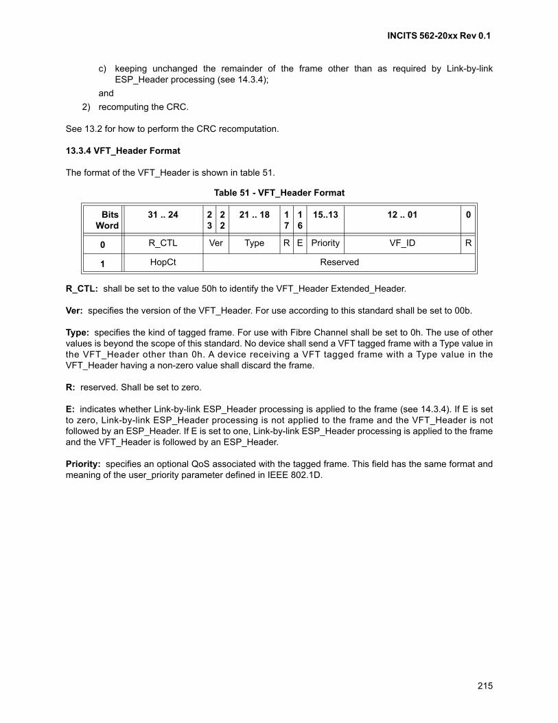
INCITS 562-20xx Rev 0.1
215
c) keeping unchanged the remainder of the frame other than as required by Link-by-linkESP_Header processing (see 14.3.4);
and
2) recomputing the CRC.
See 13.2 for how to perform the CRC recomputation.
13.3.4 VFT_Header Format
The format of the VFT_Header is shown in table 51.
R_CTL: shall be set to the value 50h to identify the VFT_Header Extended_Header.
Ver: specifies the version of the VFT_Header. For use according to this standard shall be set to 00b.
Type: specifies the kind of tagged frame. For use with Fibre Channel shall be set to 0h. The use of othervalues is beyond the scope of this standard. No device shall send a VFT tagged frame with a Type value inthe VFT_Header other than 0h. A device receiving a VFT tagged frame with a Type value in theVFT_Header having a non-zero value shall discard the frame.
R: reserved. Shall be set to zero.
E: indicates whether Link-by-link ESP_Header processing is applied to the frame (see 14.3.4). If E is setto zero, Link-by-link ESP_Header processing is not applied to the frame and the VFT_Header is notfollowed by an ESP_Header. If E is set to one, Link-by-link ESP_Header processing is applied to the frameand the VFT_Header is followed by an ESP_Header.
Priority: specifies an optional QoS associated with the tagged frame. This field has the same format andmeaning of the user_priority parameter defined in IEEE 802.1D.
Table 51 - VFT_Header Format
BitsWord
31 .. 24 23
22
21 .. 18 17
16
15..13 12 .. 01 0
0 R_CTL Ver Type R E Priority VF_ID R
1 HopCt Reserved
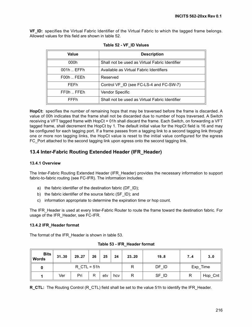
INCITS 562-20xx Rev 0.1
216
VF_ID: specifies the Virtual Fabric Identifier of the Virtual Fabric to which the tagged frame belongs.Allowed values for this field are shown in table 52.
HopCt: specifies the number of remaining hops that may be traversed before the frame is discarded. Avalue of 00h indicates that the frame shall not be discarded due to number of hops traversed. A Switchreceiving a VFT tagged frame with HopCt = 01h shall discard the frame. Each Switch, on forwarding a VFTtagged frame, shall decrement the HopCt by 1. The default initial value for the HopCt field is 16 and maybe configured for each tagging port. If a frame passes from a tagging link to a second tagging link throughone or more non tagging links, the HopCt value is reset to the initial value configured for the egressFC_Port attached to the second tagging link upon egress onto the second tagging link.
13.4 Inter-Fabric Routing Extended Header (IFR_Header)
13.4.1 Overview
The Inter-Fabric Routing Extended Header (IFR_Header) provides the necessary information to supportfabric-to-fabric routing (see FC-IFR). The information includes:
a) the fabric identifier of the destination fabric (DF_ID);
b) the fabric identifier of the source fabric (SF_ID); and
c) information appropriate to determine the expiration time or hop count.
The IFR_Header is used at every Inter-Fabric Router to route the frame toward the destination fabric. Forusage of the IFR_Header, see FC-IFR.
13.4.2 IFR_Header format
The format of the IFR_Header is shown in table 53.
R_CTL: The Routing Control (R_CTL) field shall be set to the value 51h to identify the IFR_Header.
Table 52 - VF_ID Values
Value Description
000h Shall not be used as Virtual Fabric Identifier
001h .. EFFh Available as Virtual Fabric Identifiers
F00h .. FEEh Reserved
FEFh Control VF_ID (see FC-LS-4 and FC-SW-7)
FF0h .. FFEh Vendor Specific
FFFh Shall not be used as Virtual Fabric Identifier
Table 53 - IFR_Header format
BitsWords
31..30 29..27 26 25 24 23..20 19..8 7..4 3..0
0 R_CTL = 51h R DF_ID Exp_Time
1 Ver Pri R etv hcv R SF_ID R Hop_Cnt
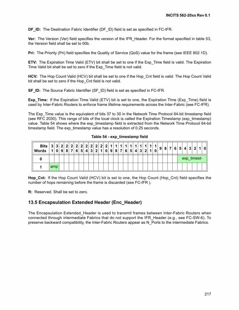
INCITS 562-20xx Rev 0.1
217
DF_ID: The Destination Fabric Identifier (DF_ID) field is set as specified in FC-IFR.
Ver: The Version (Ver) field specifies the version of the IFR_Header. For the format specified in table 53,the Version field shall be set to 00b.
Pri: The Priority (Pri) field specifies the Quality of Service (QoS) value for the frame (see IEEE 802.1D).
ETV: The Expiration Time Valid (ETV) bit shall be set to one if the Exp_Time field is valid. The ExpirationTime Valid bit shall be set to zero if the Exp_Time field is not valid.
HCV: The Hop Count Valid (HCV) bit shall be set to one if the Hop_Cnt field is valid. The Hop Count Validbit shall be set to zero if the Hop_Cnt field is not valid.
SF_ID: The Source Fabric Identifier (SF_ID) field is set as specified in FC-IFR.
Exp_Time: If the Expiration Time Valid (ETV) bit is set to one, the Expiration Time (Exp_Time) field isused by Inter-Fabric Routers to enforce frame lifetime requirements across the Inter-Fabric (see FC-IFR).
The Exp_Time value is the equivalent of bits 37 to 30 in the Network Time Protocol 64-bit timestamp field(see RFC 2030). This range of bits of the local clock is called the Expiration Timestamp (exp_timestamp)value. Table 54 shows where the exp_timestamp field is extracted from the Network Time Protocol 64-bittimestamp field. The exp_timestamp value has a resolution of 0.25 seconds.
Hop_Cnt: If the Hop Count Valid (HCV) bit is set to one, the Hop Count (Hop_Cnt) field specifies thenumber of hops remaining before the frame is discarded (see FC-IFR ).
R: Reserved. Shall be set to zero.
13.5 Encapsulation Extended Header (Enc_Header)
The Encapsulation Extended_Header is used to transmit frames between Inter-Fabric Routers whenconnected through intermediate Fabrics that do not support the IFR_Header (e.g., see FC-SW-6). Topreserve backward compatibility, the Inter-Fabric Routers appear as N_Ports to the intermediate Fabrics.
Table 54 - exp_timestamp field
BitsWords
31
30
29
28
27
26
25
24
23
22
21
20
19
18
17
16
15
14
13
12
11
10
9 8 7 6 5 4 3 2 1 0
0 exp_timest-
1 amp
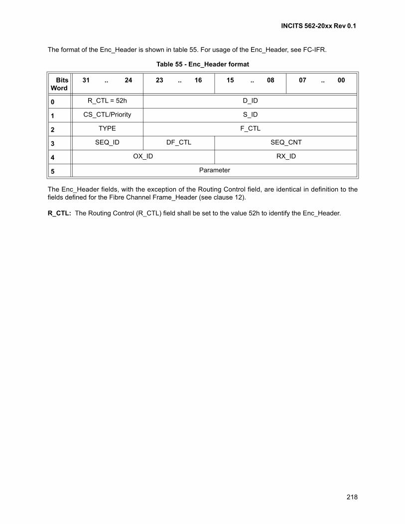
INCITS 562-20xx Rev 0.1
218
The format of the Enc_Header is shown in table 55. For usage of the Enc_Header, see FC-IFR.
The Enc_Header fields, with the exception of the Routing Control field, are identical in definition to thefields defined for the Fibre Channel Frame_Header (see clause 12).
R_CTL: The Routing Control (R_CTL) field shall be set to the value 52h to identify the Enc_Header.
Table 55 - Enc_Header format
BitsWord
31 .. 24 23 .. 16 15 .. 08 07 .. 00
0 R_CTL = 52h D_ID
1 CS_CTL/Priority S_ID
2 TYPE F_CTL
3 SEQ_ID DF_CTL SEQ_CNT
4 OX_ID RX_ID
5 Parameter
INCITS 562-20xx Rev 0.1
219
14 Optional headers
14.1 Scope
Optional headers are a function of the FC-2V sublevel.
14.2 Introduction
Optional headers defined within the Data_Field of a frame are:
a) ESP_Header and ESP_Trailer;
b) Network_Header; and
c) Device_Header.
Control bits in the DF_CTL field of the Frame_Header define the presence of optional headers (see 12.9).The sum of the length in bytes of the Payload, the number of fill bytes, and the lengths in bytes of alloptional headers shall not exceed 2 112. The sequential order of the optional headers, Payload, and theirsizes are indicated in figure 73, figure 74, and figure 75.
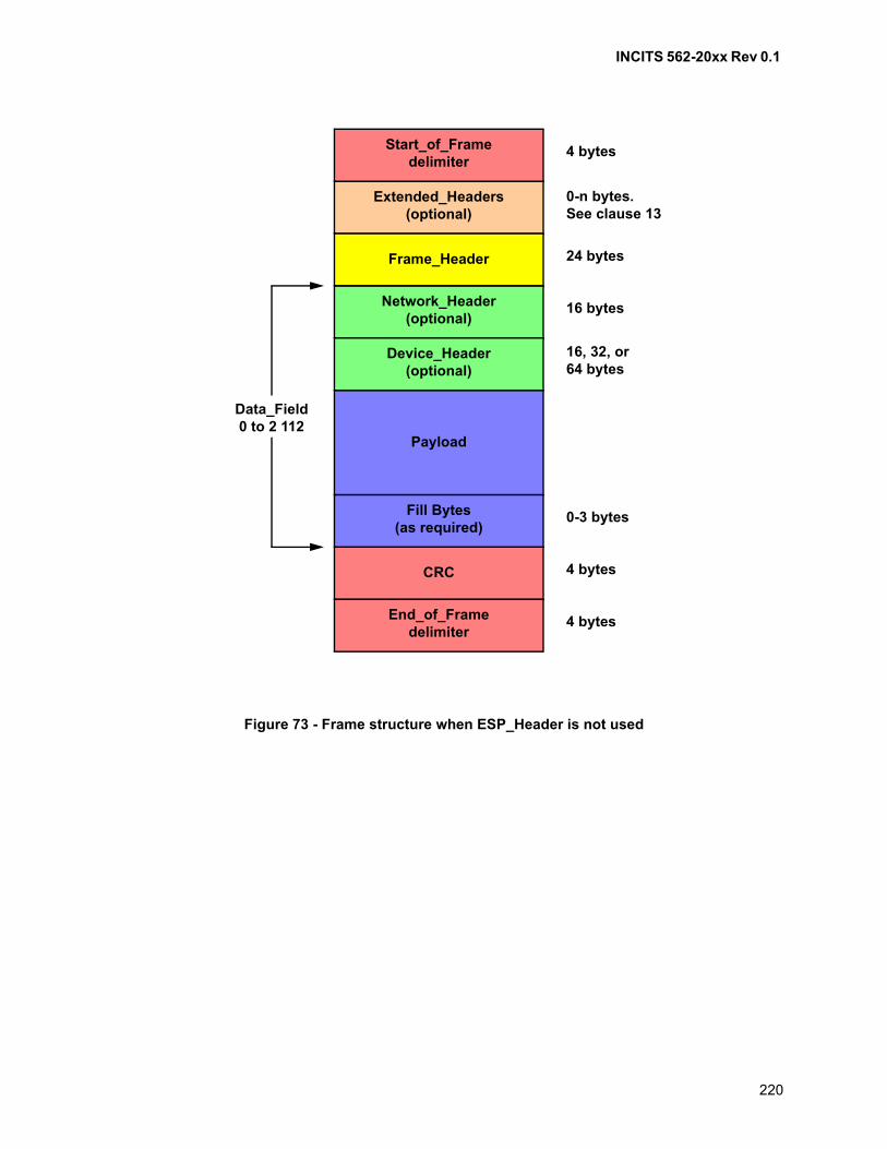
INCITS 562-20xx Rev 0.1
220
Figure 73 - Frame structure when ESP_Header is not used
Extended_Headers(optional)
End_of_Framedelimiter
Frame_Header
CRC
Network_Header(optional)
Device_Header(optional)
Fill Bytes(as required)
Payload
4 bytes
24 bytes
16 bytes
16, 32, or64 bytes
0-3 bytes
4 bytes
4 bytes
Data_Field0 to 2 112
Start_of_Framedelimiter
0-n bytes.See clause 13
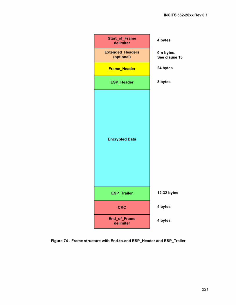
INCITS 562-20xx Rev 0.1
221
Figure 74 - Frame structure with End-to-end ESP_Header and ESP_Trailer
Start_of_Framedelimiter
End_of_Framedelimiter
Frame_Header
CRC
4 bytes
24 bytes
12-32 bytes
4 bytes
4 bytes
ESP_Trailer
Encrypted Data
ESP_Header 8 bytes
Extended_Headers(optional)
0-n bytes.See clause 13
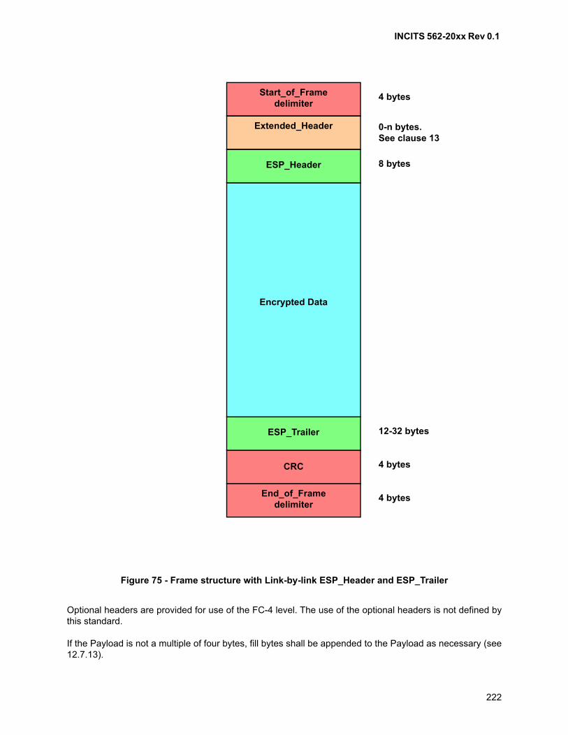
INCITS 562-20xx Rev 0.1
222
Optional headers are provided for use of the FC-4 level. The use of the optional headers is not defined bythis standard.
If the Payload is not a multiple of four bytes, fill bytes shall be appended to the Payload as necessary (see12.7.13).
Figure 75 - Frame structure with Link-by-link ESP_Header and ESP_Trailer
Start_of_Framedelimiter
End_of_Framedelimiter
CRC
4 bytes
12-32 bytes
4 bytes
4 bytes
ESP_Trailer
Encrypted Data
ESP_Header 8 bytes
Extended_Header 0-n bytes.See clause 13
INCITS 562-20xx Rev 0.1
223
14.3 ESP_Header
14.3.1 Overview
The Encapsulating Security Payload (ESP) is defined in the IETF document RFC 4303. It is a genericmechanism to provide confidentiality, data origin authentication, and anti-replay protection to IP packets.FC-SP-2 defines how to use ESP in Fibre Channel, including any negotiation procedure, additionalencryption/authentication algorithm and processing requirements. This clause defines the structure of aFibre Channel frame conveying an ESP_Header.
End-to-end ESP_Header processing shall be applied to FC frames in transport mode (see RFC 4303), andLink-by-link ESP_Header processing shall be applied to FC frames in tunnel mode (see RFC 4303). TheAuthentication option shall be used, Confidentiality may be negotiated by the two communicating FC_Ports(see FC-SP-2).
ESP_Header processing may be applied End-to-end, Link-by-link, or both. End-to-end ESP_Headerprocessing is indicated in the Frame_Header of the frame, is applied by the Nx_Port identified in the S_IDof the frame, and is removed by the Nx_Port identified in the D_ID of the frame. Link-by-link ESP_Headermay be indicated in an Extended_Header of the frame, is applied to a frame at the transmitting end of alink, and removed at the receiving end of the link.
NOTE 27 - An intended application of Link-by-link ESP_Header processing is to secure a link in a Fabricor between Fabrics without requiring use of ESP by every Nx_Port.
This specification adheres to RFC 4303 except for the ICV coverage. Variations of ICV coverage aredefined for each header in which a Fibre Channel ESP_Header is indicated.
14.3.2 Application of End-to-end ESP_Header processing
Table 56 shows the format of an FC frame to which End-to-end ESP_Header processing is applied.Presence of an End-to-end ESP_Header is indicated in the DF_CTL field of the Frame_Header. A sendershall apply End-to-end ESP_Header processing to an FC frame as follows:
1) Add a fixed length ESP_Header (8 bytes) following the Frame_Header, specifying a SecurityParameter Index (SPI) and an ESP Sequence Number;
2) Pad the concatenation of any other optional headers, the Payload, and any required fill bytes tothe block size required by the negotiated encryption/authentication algorithms. The Pad Lengthfield shall contain the length of this ESP padding;
3) Apply the negotiated encryption algorithm to the data resulting from item 2);
4) Compute an Integrity Check Value (ICV), using the negotiated authentication algorithm andparameters, covering:
i) the Frame_Header, with the S_ID, D_ID, and CS_CTL/Priority fields set to zero for thepurpose of the ICV computation;
ii) the ESP_Header; and
iii) the data resulting from item 3);
and
5) Add an ESP_Trailer containing the ICV computed in item 4). The length of the ESP_Trailer shallbe negotiated (see FC-SP-2) and shall be a multiple of 32 bits.
NOTE 28 - In step 4), the CS_CTL/Priority field is excluded because it is a mutable field, and the S_IDfield and D_ID field are excluded to permit address translation.
INCITS 562-20xx Rev 0.1
224
A receiver shall apply End-to-end ESP_Header processing to an FC frame as follows:
1) Check the ESP_Header, using the SPI to retrieve the negotiated parameters required to interpretthe received FC frame, and the ESP Sequence Number to avoid replay attacks (see RFC 4303).The length of the ESP_Trailer is one of the retrieved parameters;
2) Compute an ICV, using the retrieved parameters, covering:
i) the Frame_Header, with the S_ID, D_ID, and CS_CTL/Priority fields set to zero for thepurpose of the ICV computation;
ii) the ESP_Header; and
iii) the encrypted data;
3) Check the computed ICV with the content of the ESP_Trailer. If they are equal the authentication issuccessful, otherwise not;
4) Apply the negotiated decryption algorithm to the encrypted data; and
5) Remove the ESP padding and process the resulting optional headers, Payload, and fill bytes thatare present.
Processing of the ESP_Header and ESP_Trailer shall be performed before removing any fill bytesdetermined by the F_CTL Fill Bytes field in the Frame_Header.
The End-to-end ESP_Header processing shall be transparent to the FC-4. On the sending side theEnd-to-end ESP_Header processing shall be applied to every frame of a sequence to be protected. On thereceiving side, the End-to-end ESP_Header processing shall be applied to every frame that carries anESP_Header, and only after that the sequence shall be reassembled and sent to the FC-4.
The ESP_Header and ESP_Trailer, if used, shall be present in every frame of a Sequence. If the receivingFC_Port does not support the ESP_Header function, it shall discard the FC frame.
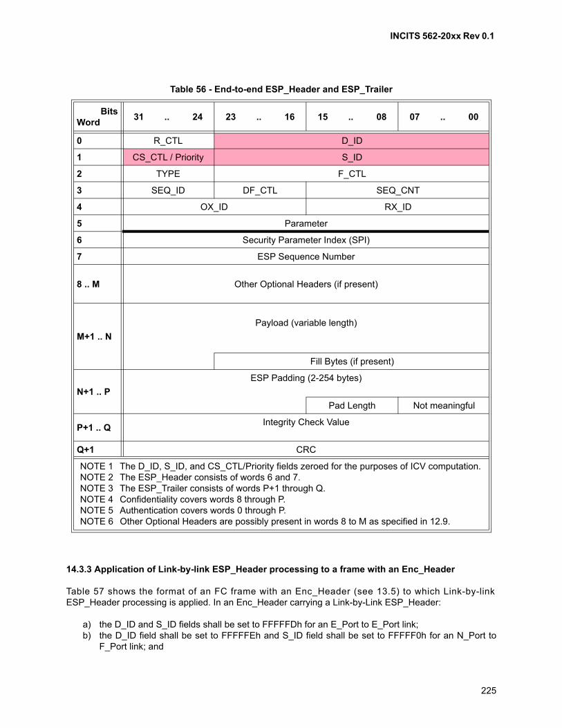
INCITS 562-20xx Rev 0.1
225
14.3.3 Application of Link-by-link ESP_Header processing to a frame with an Enc_Header
Table 57 shows the format of an FC frame with an Enc_Header (see 13.5) to which Link-by-linkESP_Header processing is applied. In an Enc_Header carrying a Link-by-Link ESP_Header:
a) the D_ID and S_ID fields shall be set to FFFFFDh for an E_Port to E_Port link;b) the D_ID field shall be set to FFFFFEh and S_ID field shall be set to FFFFF0h for an N_Port to
F_Port link; and
Table 56 - End-to-end ESP_Header and ESP_Trailer
BitsWord
31 .. 24 23 .. 16 15 .. 08 07 .. 00
0 R_CTL D_ID
1 CS_CTL / Priority S_ID
2 TYPE F_CTL
3 SEQ_ID DF_CTL SEQ_CNT
4 OX_ID RX_ID
5 Parameter
6 Security Parameter Index (SPI)
7 ESP Sequence Number
8 .. M Other Optional Headers (if present)
M+1 .. N
Payload (variable length)
Fill Bytes (if present)
N+1 .. P
ESP Padding (2-254 bytes)
Pad Length Not meaningful
P+1 .. QIntegrity Check Value
Q+1 CRC
NOTE 1 The D_ID, S_ID, and CS_CTL/Priority fields zeroed for the purposes of ICV computation.NOTE 2 The ESP_Header consists of words 6 and 7.NOTE 3 The ESP_Trailer consists of words P+1 through Q.NOTE 4 Confidentiality covers words 8 through P.NOTE 5 Authentication covers words 0 through P.NOTE 6 Other Optional Headers are possibly present in words 8 to M as specified in 12.9.
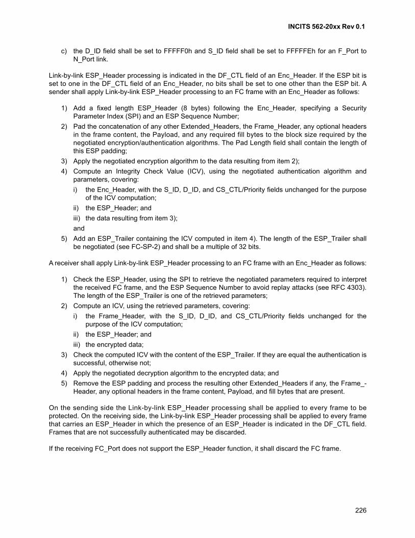
INCITS 562-20xx Rev 0.1
226
c) the D_ID field shall be set to FFFFF0h and S_ID field shall be set to FFFFFEh for an F_Port toN_Port link.
Link-by-link ESP_Header processing is indicated in the DF_CTL field of an Enc_Header. If the ESP bit isset to one in the DF_CTL field of an Enc_Header, no bits shall be set to one other than the ESP bit. Asender shall apply Link-by-link ESP_Header processing to an FC frame with an Enc_Header as follows:
1) Add a fixed length ESP_Header (8 bytes) following the Enc_Header, specifying a SecurityParameter Index (SPI) and an ESP Sequence Number;
2) Pad the concatenation of any other Extended_Headers, the Frame_Header, any optional headersin the frame content, the Payload, and any required fill bytes to the block size required by thenegotiated encryption/authentication algorithms. The Pad Length field shall contain the length ofthis ESP padding;
3) Apply the negotiated encryption algorithm to the data resulting from item 2);
4) Compute an Integrity Check Value (ICV), using the negotiated authentication algorithm andparameters, covering:
i) the Enc_Header, with the S_ID, D_ID, and CS_CTL/Priority fields unchanged for the purposeof the ICV computation;
ii) the ESP_Header; and
iii) the data resulting from item 3);
and
5) Add an ESP_Trailer containing the ICV computed in item 4). The length of the ESP_Trailer shallbe negotiated (see FC-SP-2) and shall be a multiple of 32 bits.
A receiver shall apply Link-by-link ESP_Header processing to an FC frame with an Enc_Header as follows:
1) Check the ESP_Header, using the SPI to retrieve the negotiated parameters required to interpretthe received FC frame, and the ESP Sequence Number to avoid replay attacks (see RFC 4303).The length of the ESP_Trailer is one of the retrieved parameters;
2) Compute an ICV, using the retrieved parameters, covering:
i) the Frame_Header, with the S_ID, D_ID, and CS_CTL/Priority fields unchanged for thepurpose of the ICV computation;
ii) the ESP_Header; and
iii) the encrypted data;
3) Check the computed ICV with the content of the ESP_Trailer. If they are equal the authentication issuccessful, otherwise not;
4) Apply the negotiated decryption algorithm to the encrypted data; and
5) Remove the ESP padding and process the resulting other Extended_Headers if any, the Frame_-Header, any optional headers in the frame content, Payload, and fill bytes that are present.
On the sending side the Link-by-link ESP_Header processing shall be applied to every frame to beprotected. On the receiving side, the Link-by-link ESP_Header processing shall be applied to every framethat carries an ESP_Header in which the presence of an ESP_Header is indicated in the DF_CTL field.Frames that are not successfully authenticated may be discarded.
If the receiving FC_Port does not support the ESP_Header function, it shall discard the FC frame.
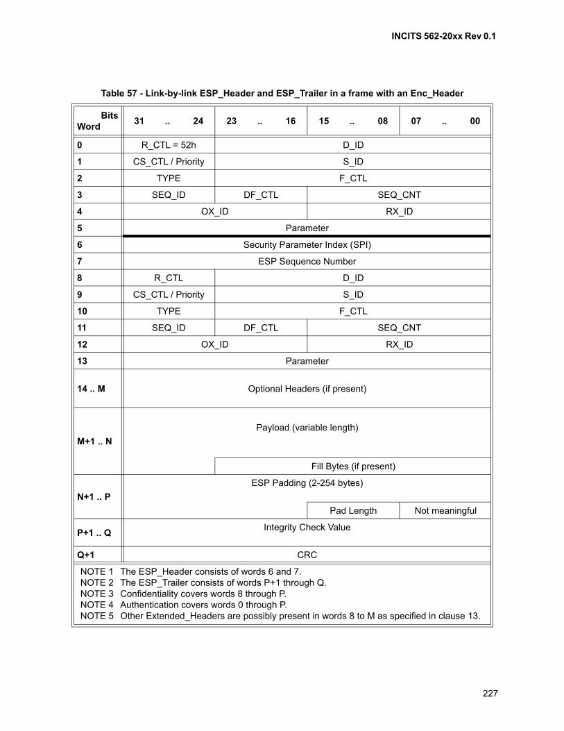
INCITS 562-20xx Rev 0.1
227
Table 57 - Link-by-link ESP_Header and ESP_Trailer in a frame with an Enc_Header
BitsWord
31 .. 24 23 .. 16 15 .. 08 07 .. 00
0 R_CTL = 52h D_ID
1 CS_CTL / Priority S_ID
2 TYPE F_CTL
3 SEQ_ID DF_CTL SEQ_CNT
4 OX_ID RX_ID
5 Parameter
6 Security Parameter Index (SPI)
7 ESP Sequence Number
8 R_CTL D_ID
9 CS_CTL / Priority S_ID
10 TYPE F_CTL
11 SEQ_ID DF_CTL SEQ_CNT
12 OX_ID RX_ID
13 Parameter
14 .. M Optional Headers (if present)
M+1 .. N
Payload (variable length)
Fill Bytes (if present)
N+1 .. P
ESP Padding (2-254 bytes)
Pad Length Not meaningful
P+1 .. QIntegrity Check Value
Q+1 CRC
NOTE 1 The ESP_Header consists of words 6 and 7.NOTE 2 The ESP_Trailer consists of words P+1 through Q.NOTE 3 Confidentiality covers words 8 through P.NOTE 4 Authentication covers words 0 through P.NOTE 5 Other Extended_Headers are possibly present in words 8 to M as specified in clause 13.
INCITS 562-20xx Rev 0.1
228
14.3.4 Application of Link-by-link ESP_Header processing to a frame with a VFT_Header
Table 58 shows the format of an FC frame with a VFT_Header (see 13.3) to which Link-by-linkESP_Header processing is applied. Link-by-link ESP_Header processing is indicated in the E field of aVFT_Header. A sender shall apply Link-by-link ESP_Header processing to an FC frame with aVFT_Header as follows:
1) Add a fixed length ESP_Header (8 bytes) following the VFT_Header, specifying a SecurityParameter Index (SPI) and an ESP Sequence Number;
2) Pad the concatenation of any other Extended_Headers, the Frame_Header, any optional headersin the frame content, the Payload, and any required fill bytes to the block size required by thenegotiated encryption/authentication algorithms. The Pad Length field shall contain the length ofthis ESP padding;
3) Apply the negotiated encryption algorithm to the data resulting from item 2);
4) Compute an Integrity Check Value (ICV), using the negotiated authentication algorithm andparameters, covering:
i) the VFT_Header;
ii) four words of zeros that are not transmitted;
iii) the ESP_Header; and
iv) the data resulting from item 3);
and
5) Add an ESP_Trailer containing the ICV computed in item 4). The length of the ESP_Trailer shallbe negotiated (see FC-SP-2) and shall be a multiple of 32 bits.
NOTE 29 - In step 4, four words of zeros that are not transmitted are included in the ICV computation tofacilitate common hardware implementations of all applications of Fibre Channel ESP.
A receiver shall apply Link-by-link ESP_Header processing to an FC frame with a VFT_Header as follows:
1) Check the ESP_Header, using the SPI to retrieve the negotiated parameters required to interpretthe received FC frame, and the ESP Sequence Number to avoid replay attacks (see RFC 4303).The length of the ESP_Trailer is one of the retrieved parameters;
2) Compute an ICV, using the retrieved parameters, covering:
i) the received VFT_Header;
ii) four words of zeros that are not received;
iii) the ESP_Header; and
iv) the encrypted data;
3) Check the computed ICV with the content of the ESP_Trailer. If they are equal the authentication issuccessful, otherwise not;
4) Apply the negotiated decryption algorithm to the encrypted data; and
5) Remove the ESP padding and process the resulting other Extended_Headers if any, the Frame_-Header, any optional headers in the frame content, Payload, and fill bytes that are present.
On the sending side the Link-by-link ESP_Header processing shall be applied to every frame to beprotected. On the receiving side, the Link-by-link ESP_Header processing shall be applied to every framethat carries an ESP_Header in which the E bit is set to one. Frames that are not successfully authenticatedmay be discarded.
If the receiving FC_Port does not support the ESP_Header function, it shall discard the FC frame.

INCITS 562-20xx Rev 0.1
229
Table 58 - Link-by-link ESP_Header and ESP_Trailer in a frame with a VFT_Header
BitsWord
31 .. 24 23
22
21 .. 18 17
16
15..13 12 .. 8 7-1 0
0 R_CTL Ver Type R 1 Priority VF_ID R
1 HopCt Reserved
00 00 00 00h (see NOTE 1)
00 00 00 00h (see NOTE 1)
00 00 00 00h (see NOTE 1)
00 00 00 00h (see NOTE 1)
2 Security Parameter Index (SPI)
3 ESP Sequence Number
4 R_CTL D_ID
5 CS_CTL / Priority S_ID
6 TYPE F_CTL
7 SEQ_ID DF_CTL SEQ_CNT
8 OX_ID RX_ID
9 Parameter
10 .. MOptional Headers (if present)
M+1 .. N
Payload (variable length)
Fill Bytes (if present)
N+1 .. PESP Padding (2-254 bytes)
Pad Length Not meaningful
P+1 .. QIntegrity Check Value
Q+1 CRC
NOTE 1 Four words of zero are appended to the VFT_Header for the purposes of ICV computation but are not transmitted or received.
NOTE 2 The ESP_Header consists of words 2 and 3.NOTE 3 The ESP_Trailer consists of words P+1 through Q.NOTE 4 Confidentiality covers words 4 through P.NOTE 5 Authentication covers words 0 through P.NOTE 6 Other Extended_Headers are possibly present in words 4 to M as specified in clause 13.

INCITS 562-20xx Rev 0.1
230
14.4 Network_Header
A bridge or a gateway node that interfaces to an external Network may use the Network_Header. TheNetwork_Header, if present, shall be 16 bytes in size.
The Network_Header, as shown in table 59, is an optional header within the Data_Field content. Itspresence shall be indicated by bit 21 in the DF_CTL field being set to one. The Network_Header may beused for routing between Fibre Channel networks of different Fabric address spaces, or Fibre Channel andnon-F ib re Channe l ne tworks . The Ne twork_Header con ta ins Name_Iden t i f i e rs fo rNetwork_Destination_Address and Network_Source_Address. See clause 18 for the definition of thesefields.
The Network_Header, if used, shall be present only in the first Data frame of a Sequence. If the receivingNx_Port does not support the header function, it shall ignore the header and skip the Data_Field by theheader length (16 bytes) . Dest inat ion Network_Address_Author i ty (D_NAA) or SourceNetwork_Address_Authority (S_NAA) field indicates the format of the Name_Identifier used for thenetwork address. See clause 18 for a description of the Name_Identifier formats.
14.5 Device_Header
14.5.1 Overview
The Device_Header, if present, shall be 16, 32, or 64 bytes in size. The contents of the Device_Header arecontrolled at a level above FC-2 based on the TYPE field (see 12.6).
The Device_Header, if present, shall be present either in the first Data frame or in all Data frames of aSequence. ULP types may use a Device_Header, requiring the Device_Header to be supported. TheDevice_Header may be ignored and skipped, if not needed. If a Device_Header is present for a ULP thatdoes not require it, the related FC-4 may reject the frame with the reason code of “TYPE not supported”.
14.5.2 Application_Header
The Application_Header is constructed as a 16 byte Device_Header. The Application_Header, if present,shall be present in all Data frames of a Sequence. The Application_Header may be present on someSequences of an Exchange, and not present on other Sequences of an Exchange. Application identifiersare allocated by the Application Server (see FC-GS-8).
An FC_Port indicates Application_Header support via the Application Header Support bit in the loginCommon Service Parameters (see FC-LS-4).
Table 59 - Network_Header
BitsWord
31 .. 28 23 .. 00
0 D_NAA Network_Destination_Address (high order bits)
1 Network_Destination_Address (low order bits)
2 S_NAA Network_Source_Address (high order bits)
3 Network_Source_Address (low order bits)
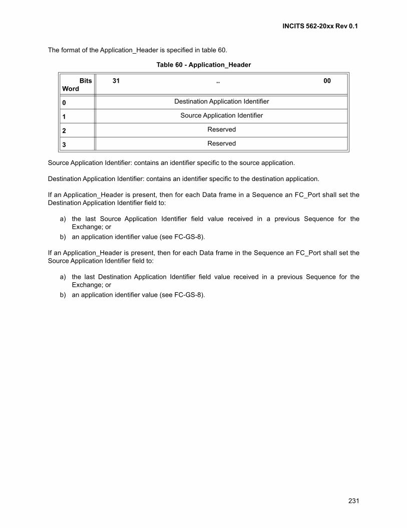
INCITS 562-20xx Rev 0.1
231
The format of the Application_Header is specified in table 60.
Source Application Identifier: contains an identifier specific to the source application.
Destination Application Identifier: contains an identifier specific to the destination application.
If an Application_Header is present, then for each Data frame in a Sequence an FC_Port shall set theDestination Application Identifier field to:
a) the last Source Application Identifier field value received in a previous Sequence for theExchange; or
b) an application identifier value (see FC-GS-8).
If an Application_Header is present, then for each Data frame in the Sequence an FC_Port shall set theSource Application Identifier field to:
a) the last Destination Application Identifier field value received in a previous Sequence for theExchange; or
b) an application identifier value (see FC-GS-8).
Table 60 - Application_Header
BitsWord
31 .. 00
0 Destination Application Identifier
1 Source Application Identifier
2 Reserved
3 Reserved
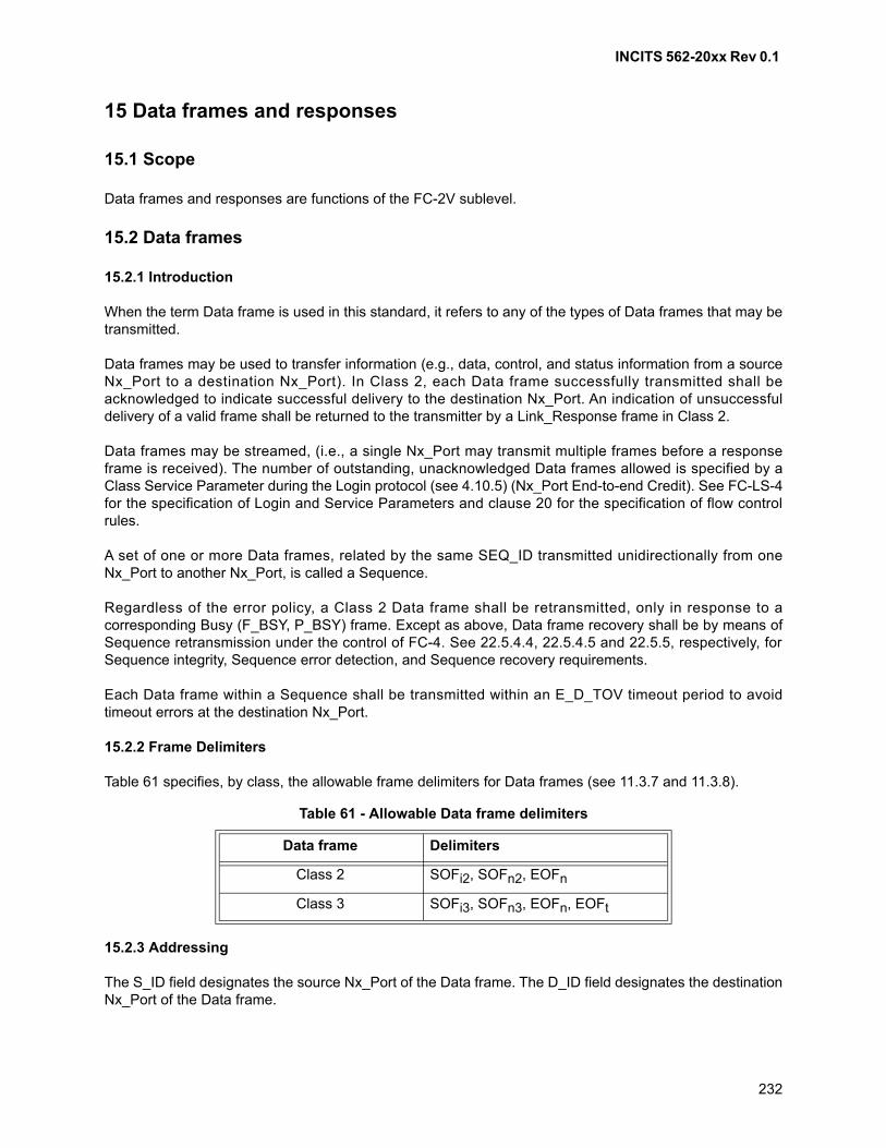
INCITS 562-20xx Rev 0.1
232
15 Data frames and responses
15.1 Scope
Data frames and responses are functions of the FC-2V sublevel.
15.2 Data frames
15.2.1 Introduction
When the term Data frame is used in this standard, it refers to any of the types of Data frames that may betransmitted.
Data frames may be used to transfer information (e.g., data, control, and status information from a sourceNx_Port to a destination Nx_Port). In Class 2, each Data frame successfully transmitted shall beacknowledged to indicate successful delivery to the destination Nx_Port. An indication of unsuccessfuldelivery of a valid frame shall be returned to the transmitter by a Link_Response frame in Class 2.
Data frames may be streamed, (i.e., a single Nx_Port may transmit multiple frames before a responseframe is received). The number of outstanding, unacknowledged Data frames allowed is specified by aClass Service Parameter during the Login protocol (see 4.10.5) (Nx_Port End-to-end Credit). See FC-LS-4for the specification of Login and Service Parameters and clause 20 for the specification of flow controlrules.
A set of one or more Data frames, related by the same SEQ_ID transmitted unidirectionally from oneNx_Port to another Nx_Port, is called a Sequence.
Regardless of the error policy, a Class 2 Data frame shall be retransmitted, only in response to acorresponding Busy (F_BSY, P_BSY) frame. Except as above, Data frame recovery shall be by means ofSequence retransmission under the control of FC-4. See 22.5.4.4, 22.5.4.5 and 22.5.5, respectively, forSequence integrity, Sequence error detection, and Sequence recovery requirements.
Each Data frame within a Sequence shall be transmitted within an E_D_TOV timeout period to avoidtimeout errors at the destination Nx_Port.
15.2.2 Frame Delimiters
Table 61 specifies, by class, the allowable frame delimiters for Data frames (see 11.3.7 and 11.3.8).
15.2.3 Addressing
The S_ID field designates the source Nx_Port of the Data frame. The D_ID field designates the destinationNx_Port of the Data frame.
Table 61 - Allowable Data frame delimiters
Data frame Delimiters
Class 2 SOFi2, SOFn2, EOFn
Class 3 SOFi3, SOFn3, EOFn, EOFt
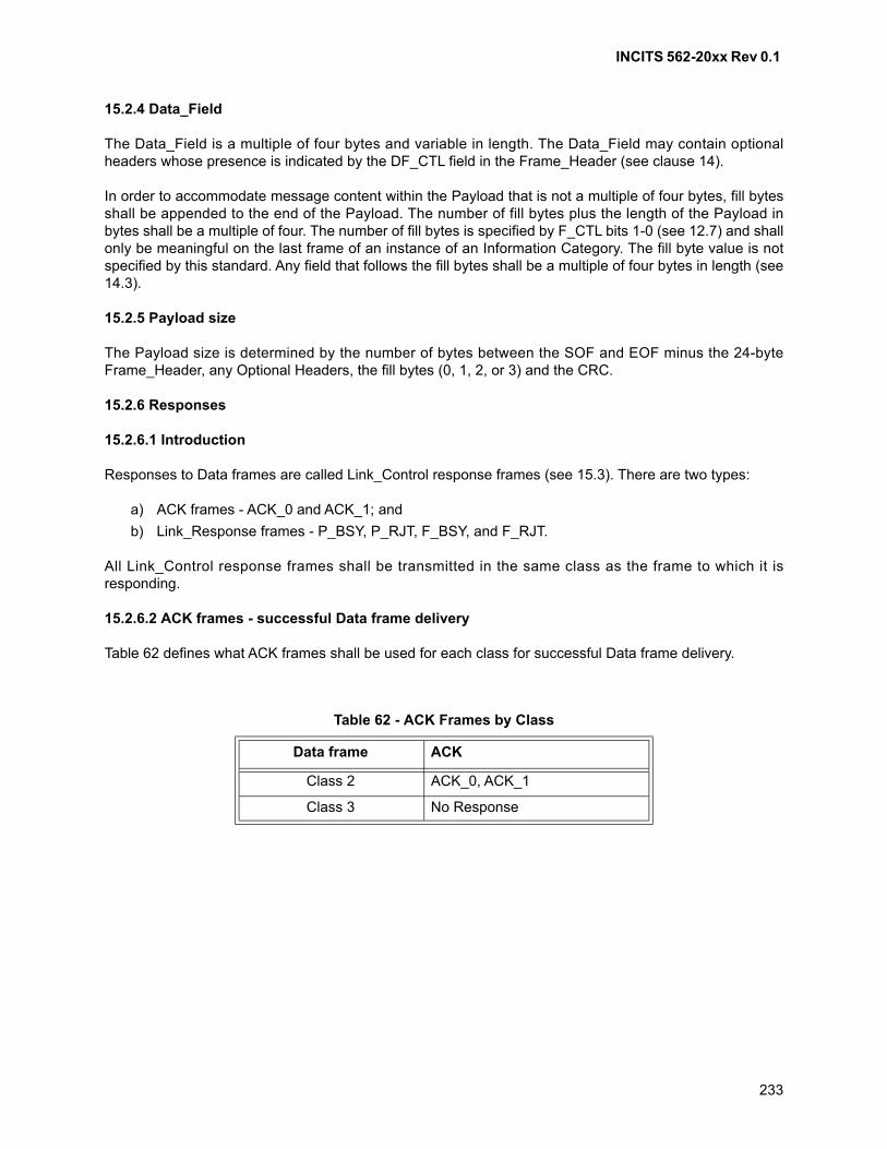
INCITS 562-20xx Rev 0.1
233
15.2.4 Data_Field
The Data_Field is a multiple of four bytes and variable in length. The Data_Field may contain optionalheaders whose presence is indicated by the DF_CTL field in the Frame_Header (see clause 14).
In order to accommodate message content within the Payload that is not a multiple of four bytes, fill bytesshall be appended to the end of the Payload. The number of fill bytes plus the length of the Payload inbytes shall be a multiple of four. The number of fill bytes is specified by F_CTL bits 1-0 (see 12.7) and shallonly be meaningful on the last frame of an instance of an Information Category. The fill byte value is notspecified by this standard. Any field that follows the fill bytes shall be a multiple of four bytes in length (see14.3).
15.2.5 Payload size
The Payload size is determined by the number of bytes between the SOF and EOF minus the 24-byteFrame_Header, any Optional Headers, the fill bytes (0, 1, 2, or 3) and the CRC.
15.2.6 Responses
15.2.6.1 Introduction
Responses to Data frames are called Link_Control response frames (see 15.3). There are two types:
a) ACK frames - ACK_0 and ACK_1; and
b) Link_Response frames - P_BSY, P_RJT, F_BSY, and F_RJT.
All Link_Control response frames shall be transmitted in the same class as the frame to which it isresponding.
15.2.6.2 ACK frames - successful Data frame delivery
Table 62 defines what ACK frames shall be used for each class for successful Data frame delivery.
Table 62 - ACK Frames by Class
Data frame ACK
Class 2 ACK_0, ACK_1
Class 3 No Response
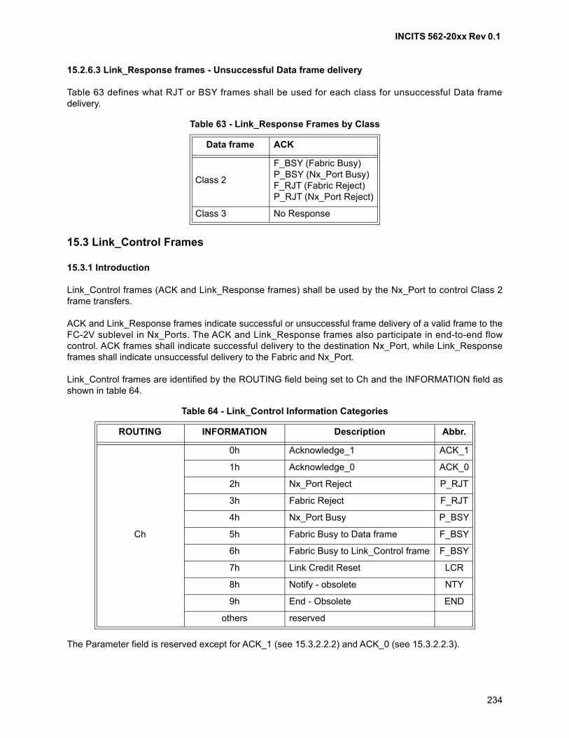
INCITS 562-20xx Rev 0.1
234
15.2.6.3 Link_Response frames - Unsuccessful Data frame delivery
Table 63 defines what RJT or BSY frames shall be used for each class for unsuccessful Data framedelivery.
15.3 Link_Control Frames
15.3.1 Introduction
Link_Control frames (ACK and Link_Response frames) shall be used by the Nx_Port to control Class 2frame transfers.
ACK and Link_Response frames indicate successful or unsuccessful frame delivery of a valid frame to theFC-2V sublevel in Nx_Ports. The ACK and Link_Response frames also participate in end-to-end flowcontrol. ACK frames shall indicate successful delivery to the destination Nx_Port, while Link_Responseframes shall indicate unsuccessful delivery to the Fabric and Nx_Port.
Link_Control frames are identified by the ROUTING field being set to Ch and the INFORMATION field asshown in table 64.
The Parameter field is reserved except for ACK_1 (see 15.3.2.2.2) and ACK_0 (see 15.3.2.2.3).
Table 63 - Link_Response Frames by Class
Data frame ACK
Class 2
F_BSY (Fabric Busy)P_BSY (Nx_Port Busy)F_RJT (Fabric Reject)P_RJT (Nx_Port Reject)
Class 3 No Response
Table 64 - Link_Control Information Categories
ROUTING INFORMATION Description Abbr.
Ch
0h Acknowledge_1 ACK_1
1h Acknowledge_0 ACK_0
2h Nx_Port Reject P_RJT
3h Fabric Reject F_RJT
4h Nx_Port Busy P_BSY
5h Fabric Busy to Data frame F_BSY
6h Fabric Busy to Link_Control frame F_BSY
7h Link Credit Reset LCR
8h Notify - obsolete NTY
9h End - Obsolete END
others reserved
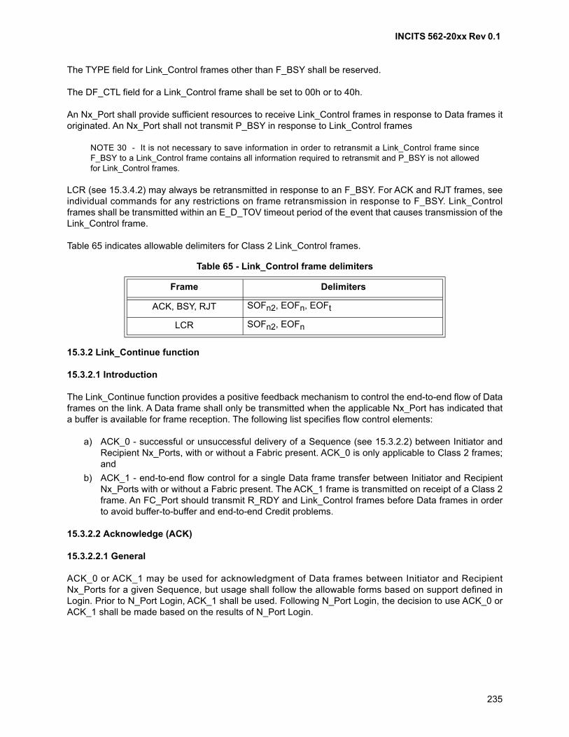
INCITS 562-20xx Rev 0.1
235
The TYPE field for Link_Control frames other than F_BSY shall be reserved.
The DF_CTL field for a Link_Control frame shall be set to 00h or to 40h.
An Nx_Port shall provide sufficient resources to receive Link_Control frames in response to Data frames itoriginated. An Nx_Port shall not transmit P_BSY in response to Link_Control frames
NOTE 30 - It is not necessary to save information in order to retransmit a Link_Control frame sinceF_BSY to a Link_Control frame contains all information required to retransmit and P_BSY is not allowedfor Link_Control frames.
LCR (see 15.3.4.2) may always be retransmitted in response to an F_BSY. For ACK and RJT frames, seeindividual commands for any restrictions on frame retransmission in response to F_BSY. Link_Controlframes shall be transmitted within an E_D_TOV timeout period of the event that causes transmission of theLink_Control frame.
Table 65 indicates allowable delimiters for Class 2 Link_Control frames.
15.3.2 Link_Continue function
15.3.2.1 Introduction
The Link_Continue function provides a positive feedback mechanism to control the end-to-end flow of Dataframes on the link. A Data frame shall only be transmitted when the applicable Nx_Port has indicated thata buffer is available for frame reception. The following list specifies flow control elements:
a) ACK_0 - successful or unsuccessful delivery of a Sequence (see 15.3.2.2) between Initiator andRecipient Nx_Ports, with or without a Fabric present. ACK_0 is only applicable to Class 2 frames;and
b) ACK_1 - end-to-end flow control for a single Data frame transfer between Initiator and RecipientNx_Ports with or without a Fabric present. The ACK_1 frame is transmitted on receipt of a Class 2frame. An FC_Port should transmit R_RDY and Link_Control frames before Data frames in orderto avoid buffer-to-buffer and end-to-end Credit problems.
15.3.2.2 Acknowledge (ACK)
15.3.2.2.1 General
ACK_0 or ACK_1 may be used for acknowledgment of Data frames between Initiator and RecipientNx_Ports for a given Sequence, but usage shall follow the allowable forms based on support defined inLogin. Prior to N_Port Login, ACK_1 shall be used. Following N_Port Login, the decision to use ACK_0 orACK_1 shall be made based on the results of N_Port Login.
Table 65 - Link_Control frame delimiters
Frame Delimiters
ACK, BSY, RJT SOFn2, EOFn, EOFt
LCR SOFn2, EOFn
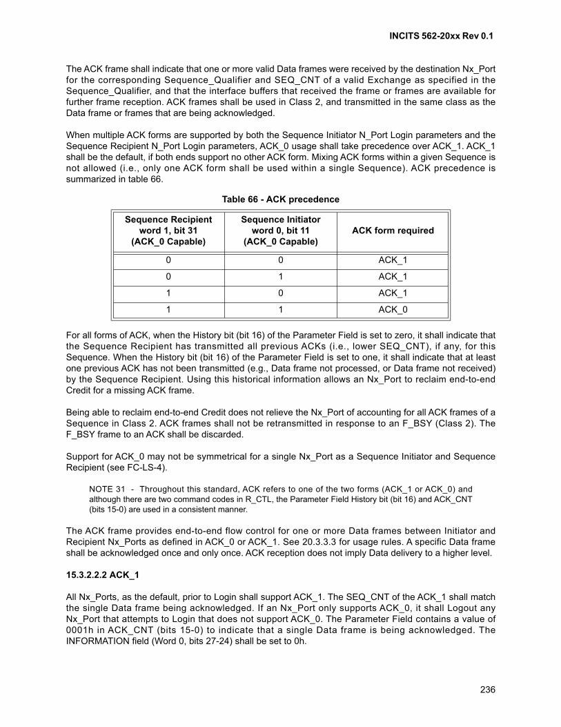
INCITS 562-20xx Rev 0.1
236
The ACK frame shall indicate that one or more valid Data frames were received by the destination Nx_Portfor the corresponding Sequence_Qualifier and SEQ_CNT of a valid Exchange as specified in theSequence_Qualifier, and that the interface buffers that received the frame or frames are available forfurther frame reception. ACK frames shall be used in Class 2, and transmitted in the same class as theData frame or frames that are being acknowledged.
When multiple ACK forms are supported by both the Sequence Initiator N_Port Login parameters and theSequence Recipient N_Port Login parameters, ACK_0 usage shall take precedence over ACK_1. ACK_1shall be the default, if both ends support no other ACK form. Mixing ACK forms within a given Sequence isnot allowed (i.e., only one ACK form shall be used within a single Sequence). ACK precedence issummarized in table 66.
For all forms of ACK, when the History bit (bit 16) of the Parameter Field is set to zero, it shall indicate thatthe Sequence Recipient has transmitted all previous ACKs (i.e., lower SEQ_CNT), if any, for thisSequence. When the History bit (bit 16) of the Parameter Field is set to one, it shall indicate that at leastone previous ACK has not been transmitted (e.g., Data frame not processed, or Data frame not received)by the Sequence Recipient. Using this historical information allows an Nx_Port to reclaim end-to-endCredit for a missing ACK frame.
Being able to reclaim end-to-end Credit does not relieve the Nx_Port of accounting for all ACK frames of aSequence in Class 2. ACK frames shall not be retransmitted in response to an F_BSY (Class 2). TheF_BSY frame to an ACK shall be discarded.
Support for ACK_0 may not be symmetrical for a single Nx_Port as a Sequence Initiator and SequenceRecipient (see FC-LS-4).
NOTE 31 - Throughout this standard, ACK refers to one of the two forms (ACK_1 or ACK_0) andalthough there are two command codes in R_CTL, the Parameter Field History bit (bit 16) and ACK_CNT(bits 15-0) are used in a consistent manner.
The ACK frame provides end-to-end flow control for one or more Data frames between Initiator andRecipient Nx_Ports as defined in ACK_0 or ACK_1. See 20.3.3.3 for usage rules. A specific Data frameshall be acknowledged once and only once. ACK reception does not imply Data delivery to a higher level.
15.3.2.2.2 ACK_1
All Nx_Ports, as the default, prior to Login shall support ACK_1. The SEQ_CNT of the ACK_1 shall matchthe single Data frame being acknowledged. If an Nx_Port only supports ACK_0, it shall Logout anyNx_Port that attempts to Login that does not support ACK_0. The Parameter Field contains a value of0001h in ACK_CNT (bits 15-0) to indicate that a single Data frame is being acknowledged. TheINFORMATION field (Word 0, bits 27-24) shall be set to 0h.
Table 66 - ACK precedence
Sequence Recipientword 1, bit 31
(ACK_0 Capable)
Sequence Initiatorword 0, bit 11
(ACK_0 Capable)ACK form required
0 0 ACK_1
0 1 ACK_1
1 0 ACK_1
1 1 ACK_0
INCITS 562-20xx Rev 0.1
237
15.3.2.2.3 ACK_0
ACK_0 is the designation used when the ACK_CNT (bits 15-0) of the Parameter Field of the ACK_0 framecontains a value 0000h to indicate that all Data frames of a Sequence are being acknowledged. TheSEQ_CNT of the ACK_0 shall match the SEQ_CNT of the last Data frame received within the Sequence.The INFORMATION field (Word 0, bits 27-24) shall be set to 1h.
The ACK_0 frame may be used for both Discard and Process Exchange Error Policies. For both policytypes, ACK_0 support as indicated by Login also specifies that infinite buffering shall be used.
When multiple ACK forms are supported by both Sequence Initiator N_Port Login parameters and thedestination Nx_Port Sequence Recipient N_Port Login parameters, ACK_0 usage shall take precedenceover ACK_1. ACK_1 shall be the default, if both ends support no other common ACK form.
If both Sequence Initiator and Sequence Recipient support ACK_0, a single ACK_0 per Sequence shall beused to indicate successful Sequence delivery or to set Abort Sequence Condition bits. An additionalACK_0 shall be used within a Sequence to perform X_ID interlock.
ACK_0 shall not participate in end-to-end Credit management. Mixing ACK forms in a Sequence is notallowed.
Although infinite buffers is indicated at the level specified by this standard within an Nx_Port, individualFC-4s (e.g., FCP-4) may agree on a maximum Information Unit size that limits the maximum Sequencesize. By further controlling the maximum number of concurrent Sequences, each Nx_Port may limit theamount of buffering that is actually required.
15.3.2.2.4 Header definition for all ACK forms
15.3.2.2.4.1 Addressing
The D_ID field designates the source of the Data frame (Sequence Initiator) being replied to by the ACK,while the S_ID field designates the source of the ACK frame (Sequence Recipient).
15.3.2.2.4.2 F_CTL
The F_CTL field is returned with both Sequence and Exchange Context bits inverted in the ACK frame.Other bits may also be set according to table 47.
15.3.2.2.4.3 SEQ_ID
Equal to the SEQ_ID of the frame being replied to by ACK.
15.3.2.2.4.4 SEQ_CNT
Shall be equal to the SEQ_CNT of the highest Data frame being replied to by the ACK.
15.3.2.2.4.5 Parameter field
The Parameter Field is defined as follows:
a) History Bit (bit 16):
A) 0 = all previous ACKs transmitted; or
INCITS 562-20xx Rev 0.1
238
B) 1 = at least one previous ACK not transmitted;
and
b) ACK_CNT (bits 15 - 0):
A) N = 0 All Data frames (ACK_0);
B) N = 1 Data frame (ACK_1); or
C) N > 1 Reserved.
15.3.2.2.5 Responses
The responses to ACK are F_RJT, P_RJT or F_BSY.
15.3.3 Link_Response
15.3.3.1 Introduction
Link_Response frames shall be sent for Class 2. An FC_Port shall only send Link_Response frames inreply to valid frames (see 11.3.9.2).
A Link_Response frame indicates that the frame identified by the Sequence_Qualifier and SEQ_CNT wasnot delivered to or processed by the destination Nx_Port. When an FC_Port generates a Link_Responseframe, it is routed to the Nx_Port indicated by the D_ID in the frame. Link_Response frames may be:
a) Busy - indicates a busy condition was encountered by the FC_Port; or
b) Reject - indicates that delivery of the frame is being denied.
15.3.3.2 Fabric Busy (F_BSY)
15.3.3.2.1 Description
The F_BSY frame shall indicate that the FC_Port generating the F_BSY is temporarily occupied with otherlink activity and is unable to deliver the frame. A reason code is identified in the TYPE field (word 2, bits31-28). In Class 2, any Data frame or ACK frame may receive an F_BSY response. A Busy response shallnot be used in Class 3.
There are two different Link_Control codes defined for F_BSY as shown in table 64. When word 0, bits27-24 has a value of 5h, the F_BSY is in response to a Data frame. When word 0, bits 27-24 has a value of6h, F_BSY is in response to a Link_Control frame.
A F_BSY frame shall not be transmitted in response to another busy frame (either F_BSY or P_BSY). Ifthe Fabric is unable to deliver the F_BSY frame, it shall be discarded.
When an Nx_Port receives an F_BSY frame in response to a Data frame, the Nx_Port shall retransmit thebusied frame if it has not exhausted its ability to retry. Therefore, an Nx_Port shall save sufficientinformation for Data frames with a SOFx2 delimiter for retransmission until an ACK or RJT is received orretry is exhausted.
If an Nx_Port has exhausted its ability to retry Data frames in response to an F_BSY, it shall notify the FC-4or an upper level. The Nx_Port may perform the Abort Sequence Protocol based on the Exchange ErrorPolicy.
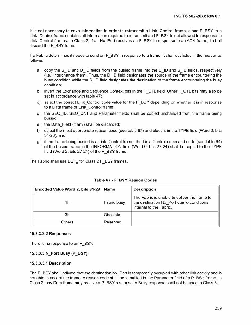
INCITS 562-20xx Rev 0.1
239
It is not necessary to save information in order to retransmit a Link_Control frame, since F_BSY to aLink_Control frame contains all information required to retransmit and P_BSY is not allowed in response toLink_Control frames. In Class 2, if an Nx_Port receives an F_BSY in response to an ACK frame, it shalldiscard the F_BSY frame.
If a Fabric determines it needs to send an F_BSY in response to a frame, it shall set fields in the header asfollows:
a) copy the S_ID and D_ID fields from the busied frame into the D_ID and S_ID fields, respectively(i.e., interchange them). Thus, the D_ID field designates the source of the frame encountering thebusy condition while the S_ID field designates the destination of the frame encountering the busycondition;
b) invert the Exchange and Sequence Context bits in the F_CTL field. Other F_CTL bits may also beset in accordance with table 47;
c) select the correct Link_Control code value for the F_BSY depending on whether it is in responseto a Data frame or Link_Control frame;
d) the SEQ_ID, SEQ_CNT and Parameter fields shall be copied unchanged from the frame beingbusied;
e) the Data_Field (if any) shall be discarded;
f) select the most appropriate reason code (see table 67) and place it in the TYPE field (Word 2, bits31-28); and
g) if the frame being busied is a Link_Control frame, the Link_Control command code (see table 64)of the busied frame in the INFORMATION field (Word 0, bits 27-24) shall be copied to the TYPEfield (Word 2, bits 27-24) of the F_BSY frame.
The Fabric shall use EOFn for Class 2 F_BSY frames.
15.3.3.2.2 Responses
There is no response to an F_BSY.
15.3.3.3 N_Port Busy (P_BSY)
15.3.3.3.1 Description
The P_BSY shall indicate that the destination Nx_Port is temporarily occupied with other link activity and isnot able to accept the frame. A reason code shall be identified in the Parameter field of a P_BSY frame. InClass 2, any Data frame may receive a P_BSY response. A Busy response shall not be used in Class 3.
Table 67 - F_BSY Reason Codes
Encoded Value Word 2, bits 31-28 Name Description
1h Fabric busyThe Fabric is unable to deliver the frame to the destination Nx_Port due to conditions internal to the Fabric.
3h Obsolete
Others Reserved
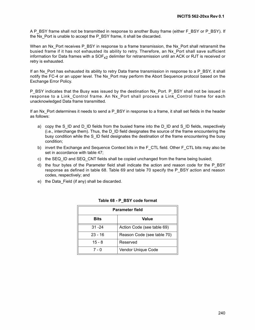
INCITS 562-20xx Rev 0.1
240
A P_BSY frame shall not be transmitted in response to another Busy frame (either F_BSY or P_BSY). Ifthe Nx_Port is unable to accept the P_BSY frame, it shall be discarded.
When an Nx_Port receives P_BSY in response to a frame transmission, the Nx_Port shall retransmit thebusied frame if it has not exhausted its ability to retry. Therefore, an Nx_Port shall save sufficientinformation for Data frames with a SOFx2 delimiter for retransmission until an ACK or RJT is received orretry is exhausted.
If an Nx_Port has exhausted its ability to retry Data frame transmission in response to a P_BSY, it shallnotify the FC-4 or an upper level. The Nx_Port may perform the Abort Sequence protocol based on theExchange Error Policy.
P_BSY indicates that the Busy was issued by the destination Nx_Port. P_BSY shall not be issued inresponse to a Link_Control frame. An Nx_Port shall process a Link_Control frame for eachunacknowledged Data frame transmitted.
If an Nx_Port determines it needs to send a P_BSY in response to a frame, it shall set fields in the headeras follows:
a) copy the S_ID and D_ID fields from the busied frame into the D_ID and S_ID fields, respectively(i.e., interchange them). Thus, the D_ID field designates the source of the frame encountering thebusy condition while the S_ID field designates the destination of the frame encountering the busycondition;
b) invert the Exchange and Sequence Context bits in the F_CTL field. Other F_CTL bits may also beset in accordance with table 47;
c) the SEQ_ID and SEQ_CNT fields shall be copied unchanged from the frame being busied;
d) the four bytes of the Parameter field shall indicate the action and reason code for the P_BSYresponse as defined in table 68. Table 69 and table 70 specify the P_BSY action and reasoncodes, respectively; and
e) the Data_Field (if any) shall be discarded.
Table 68 - P_BSY code format
Parameter field
Bits Value
31 -24 Action Code (see table 69)
23 - 16 Reason Code (see table 70)
15 - 8 Reserved
7 - 0 Vendor Unique Code
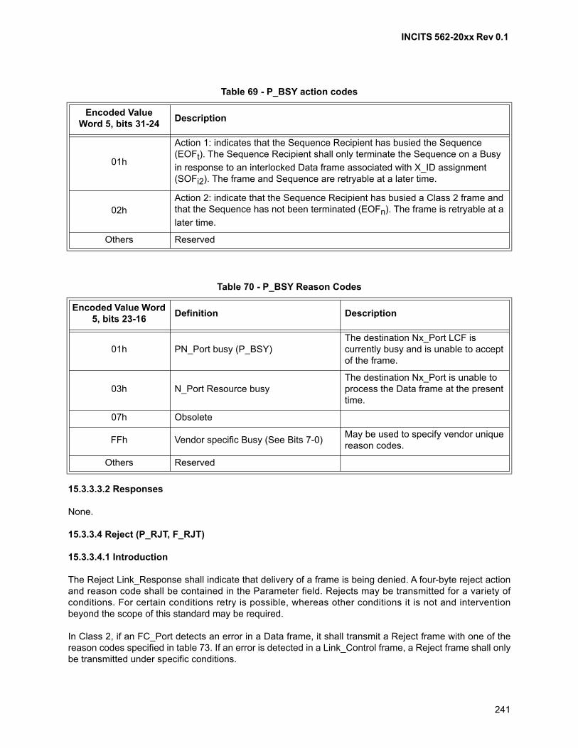
INCITS 562-20xx Rev 0.1
241
15.3.3.3.2 Responses
None.
15.3.3.4 Reject (P_RJT, F_RJT)
15.3.3.4.1 Introduction
The Reject Link_Response shall indicate that delivery of a frame is being denied. A four-byte reject actionand reason code shall be contained in the Parameter field. Rejects may be transmitted for a variety ofconditions. For certain conditions retry is possible, whereas other conditions it is not and interventionbeyond the scope of this standard may be required.
In Class 2, if an FC_Port detects an error in a Data frame, it shall transmit a Reject frame with one of thereason codes specified in table 73. If an error is detected in a Link_Control frame, a Reject frame shall onlybe transmitted under specific conditions.
Table 69 - P_BSY action codes
Encoded Value Word 5, bits 31-24
Description
01h
Action 1: indicates that the Sequence Recipient has busied the Sequence (EOFt). The Sequence Recipient shall only terminate the Sequence on a Busy
in response to an interlocked Data frame associated with X_ID assignment (SOFi2). The frame and Sequence are retryable at a later time.
02hAction 2: indicate that the Sequence Recipient has busied a Class 2 frame and that the Sequence has not been terminated (EOFn). The frame is retryable at a
later time.
Others Reserved
Table 70 - P_BSY Reason Codes
Encoded Value Word 5, bits 23-16
Definition Description
01h PN_Port busy (P_BSY)The destination Nx_Port LCF is currently busy and is unable to accept of the frame.
03h N_Port Resource busyThe destination Nx_Port is unable to process the Data frame at the present time.
07h Obsolete
FFh Vendor specific Busy (See Bits 7-0)May be used to specify vendor unique reason codes.
Others Reserved
INCITS 562-20xx Rev 0.1
242
A Fabric shall only reject a Link_Control frame for the following reasons:
a) Class not supported;
b) Invalid D_ID;
c) Invalid S_ID;
d) Nx_Port not available-temporary;
e) Nx_Port not available-permanent; or
f) Login required (Fabric).
An Nx_Port shall only reject a Link_Control frame if it is an unexpected ACK. If an Nx_Port rejects anunexpected ACK, it shall use Reject Action code 2 as specified in table 72.
If an Nx_Port detects an error in a Link_Control frame for a valid Exchange for a reason not listed above, itshall initiate the Abort Sequence Protocol and not transmit a Reject frame. For an unidentified or invalidExchange, if an error is detected in a Link_Control frame, the Nx_Port shall discard the frame and ignorethe Link_Control frame error. If a Class 3 frame satisfies a rejectable condition, the frame shall bediscarded. A Reject frame (F_RJT, P_RJT) shall not be transmitted in response to another Reject frame(either F_RJT or P_RJT); the received Reject frame in error shall be discarded.
If an Nx_Port determines it needs to send a Reject (either F_RJT or P_RJT) in response to a frame, it shallset fields in the header as follows:
a) copy the S_ID and D_ID fields from the rejected frame into the D_ID and S_ID fields, respectively(i.e., interchange them). Thus, the D_ID field designates the source of the frame encountering thereject condition while the S_ID field designates the destination of the frame encountering the rejectcondition;
b) invert the Exchange and Sequence Context bits in the F_CTL field. Other F_CTL bits may also beset in accordance with table 47;
c) the SEQ_ID and SEQ_CNT shall be copied unchanged from the frame being rejected;
d) the four bytes of the Parameter field shall indicate the action and reason for the Reject responseas defined in table 71. Table 72 and table 73 specify the Reject Action codes and Reject ReasonCodes respectively; and
e) the Data_Field (if any) shall be discarded.
15.3.3.4.2 Parameter field
15.3.3.4.2.1 Reject Code format
The four bytes of this field shall indicate the action code and reason for rejecting the request (see table 71,table 72 and table 73).
The first error detected shall be the error reported; the order of checking is not specified.
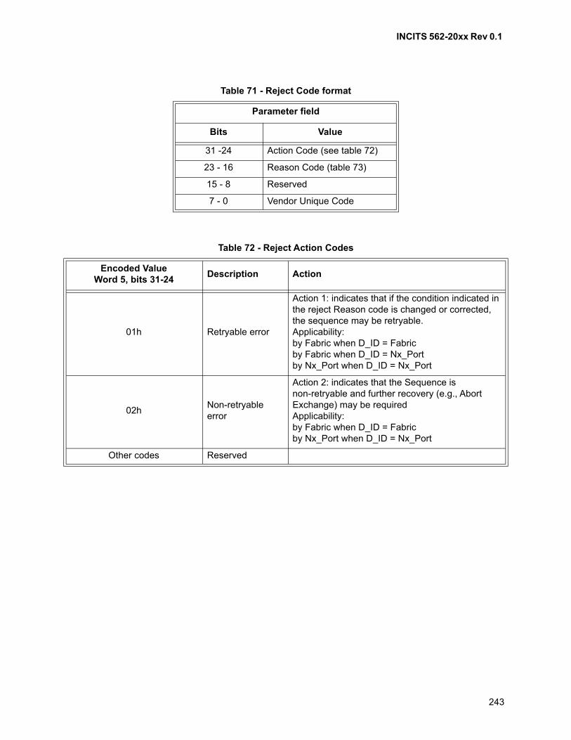
INCITS 562-20xx Rev 0.1
243
Table 71 - Reject Code format
Parameter field
Bits Value
31 -24 Action Code (see table 72)
23 - 16 Reason Code (table 73)
15 - 8 Reserved
7 - 0 Vendor Unique Code
Table 72 - Reject Action Codes
Encoded ValueWord 5, bits 31-24
Description Action
01h Retryable error
Action 1: indicates that if the condition indicated in the reject Reason code is changed or corrected, the sequence may be retryable.Applicability:by Fabric when D_ID = Fabricby Fabric when D_ID = Nx_Portby Nx_Port when D_ID = Nx_Port
02hNon-retryable error
Action 2: indicates that the Sequence is non-retryable and further recovery (e.g., Abort Exchange) may be requiredApplicability:by Fabric when D_ID = Fabricby Nx_Port when D_ID = Nx_Port
Other codes Reserved
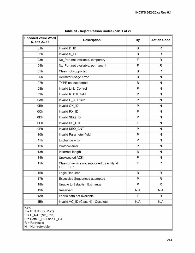
INCITS 562-20xx Rev 0.1
244
Table 73 - Reject Reason Codes (part 1 of 2)
Encoded Value Word 5, bits 23-16
Description By Action Code
01h Invalid D_ID B R
02h Invalid S_ID B R
03h Nx_Port not available, temporary F R
04h Nx_Port not available, permanent F R
05h Class not supported B R
06h Delimiter usage error B N
07h TYPE not supported B N
08h Invalid Link_Control P N
09h Invalid R_CTL field P N
0Ah Invalid F_CTL field P N
0Bh Invalid OX_ID P N
0Ch Invalid RX_ID P N
0Dh Invalid SEQ_ID P N
0Eh Invalid DF_CTL F N
0Fh Invalid SEQ_CNT P N
10h Invalid Parameter field P N
11h Exchange error P N
12h Protocol error P N
13h Incorrect length B N
14h Unexpected ACK P N
15h Class of service not supported by entity at FF FF FEh
F R
16h Login Required B R
17h Excessive Sequences attempted P R
18h Unable to Establish Exchange P R
19h Reserved N/A N/A
1Ah Fabric path not available F R
1Bh Invalid VC_ID (Class 4) - Obsolete N/A N/A
Key:F = F_RJT (Fx_Port)P = P_RJT (Nx_Port)B = Both F_RJT and P_RJTR = RetryableN = Non-retryable
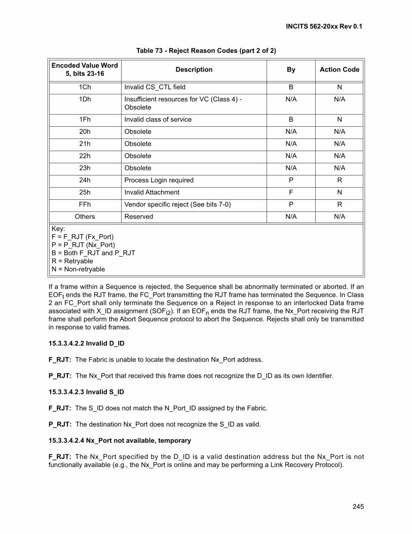
INCITS 562-20xx Rev 0.1
245
If a frame within a Sequence is rejected, the Sequence shall be abnormally terminated or aborted. If anEOFt ends the RJT frame, the FC_Port transmitting the RJT frame has terminated the Sequence. In Class2 an FC_Port shall only terminate the Sequence on a Reject in response to an interlocked Data frameassociated with X_ID assignment (SOFi2). If an EOFn ends the RJT frame, the Nx_Port receiving the RJTframe shall perform the Abort Sequence protocol to abort the Sequence. Rejects shall only be transmittedin response to valid frames.
15.3.3.4.2.2 Invalid D_ID
F_RJT: The Fabric is unable to locate the destination Nx_Port address.
P_RJT: The Nx_Port that received this frame does not recognize the D_ID as its own Identifier.
15.3.3.4.2.3 Invalid S_ID
F_RJT: The S_ID does not match the N_Port_ID assigned by the Fabric.
P_RJT: The destination Nx_Port does not recognize the S_ID as valid.
15.3.3.4.2.4 Nx_Port not available, temporary
F_RJT: The Nx_Port specified by the D_ID is a valid destination address but the Nx_Port is notfunctionally available (e.g., the Nx_Port is online and may be performing a Link Recovery Protocol).
1Ch Invalid CS_CTL field B N
1Dh Insufficient resources for VC (Class 4) - Obsolete
N/A N/A
1Fh Invalid class of service B N
20h Obsolete N/A N/A
21h Obsolete N/A N/A
22h Obsolete N/A N/A
23h Obsolete N/A N/A
24h Process Login required P R
25h Invalid Attachment F N
FFh Vendor specific reject (See bits 7-0) P R
Others Reserved N/A N/A
Table 73 - Reject Reason Codes (part 2 of 2)
Encoded Value Word 5, bits 23-16
Description By Action Code
Key:F = F_RJT (Fx_Port)P = P_RJT (Nx_Port)B = Both F_RJT and P_RJTR = RetryableN = Non-retryable
INCITS 562-20xx Rev 0.1
246
15.3.3.4.2.5 Nx_Port not available, permanent
F_RJT: The Nx_Port specified by the D_ID is a valid destination address but the Nx_Port is notfunctionally available. The Nx_Port is Offline or Powered Down.
15.3.3.4.2.6 Class not supported
F_RJT or P_RJT: The class specified by the SOF delimiter of the frame being rejected is not supported.
15.3.3.4.2.7 Delimiter usage error
F_RJT or P_RJT: The SOF or EOF is not appropriate for the current conditions. See tables 61 and 65 forallowable delimiters by class.
15.3.3.4.2.8 TYPE not supported
F_RJT or P_RJT: The TYPE field of the frame being rejected is not supported by the FC_Port replyingwith the Reject frame.
15.3.3.4.2.9 Invalid Link_Control
P_RJT: The command specified in the Information Category bits within R_CTL field in the frame beingrejected is invalid or not supported as a Link_Control frame.
15.3.3.4.2.10 Invalid R_CTL field
P_RJT: The R_CTL field is invalid or inconsistent with the other Frame_Header fields or conditionspresent.
15.3.3.4.2.11 Invalid F_CTL field
P_RJT: The F_CTL field is invalid or inconsistent with the other Frame_Header fields or conditionspresent.
15.3.3.4.2.12 Invalid OX_ID
P_RJT: The OX_ID specified is invalid or inconsistent with the other Frame_Header fields or conditionspresent.
15.3.3.4.2.13 Invalid RX_ID
P_RJT: The RX_ID specified is invalid or inconsistent with the other Frame_Header fields or conditionspresent.
15.3.3.4.2.14 Invalid SEQ_ID
P_RJT: The SEQ_ID specified is invalid or inconsistent with the other Frame_Header fields or conditionspresent.
15.3.3.4.2.15 Invalid DF_CTL
P_RJT: The DF_CTL field is invalid.
INCITS 562-20xx Rev 0.1
247
15.3.3.4.2.16 Invalid SEQ_CNT
P_RJT: The SEQ_CNT specified is inconsistent with the other Frame_Header fields or conditionspresent. A SEQ_CNT reject is not used to indicate out of order or missing Data frames (see 12.7 bits 5-4(F_CTL Abort Sequence Condition)).
15.3.3.4.2.17 Invalid Parameter field
P_RJT: The Parameter field is incorrectly specified or invalid.
15.3.3.4.2.18 Exchange Error
P_RJT: An error has been detected in the identified Exchange (OX_ID). This could indicate Data frametransmission without Sequence Initiative or other logical errors in handling an Exchange.
15.3.3.4.2.19 Protocol Error
P_RJT: This indicates that an error has been detected that violates the rules of FC-2 signaling protocolthat are not specified by other error codes.
15.3.3.4.2.20 Incorrect length
F_RJT or P_RJT: The frame being rejected is an incorrect length for the conditions present.
15.3.3.4.2.21 Unexpected ACK
P_RJT: An ACK was received from:
a) an Nx_Port that is not Logged in (i.e., an unexpected S_ID);
b) an Nx_Port that is Logged-in but not for an open Sequence or Exchange referenced in the ACK; or
c) an Nx_Port that is Logged-in, for an open Sequence or Exchange referenced in the ACK, but thathas no outstanding frames to acknowledge.
The EOF delimiter for the P_RJT shall be EOFn.
15.3.3.4.2.22 Class of service not supported by entity at FF FF FEh
F_RJT: The class specified by the SOF delimiter of the frame being rejected is not supported by theFx_Port (FF FF FEh)
15.3.3.4.2.23 Login Required
F_RJT or P_RJT: An Exchange is being initiated before the interchange of Service Parameters (i.e.,Login) has been performed. The Fabric may issue F_RJT in order to notify an Nx_Port that a Login withthe Fabric is required due to changes within the Fabric. The Fabric shall not issue F_RJT in order toconvey Login status of a destination Nx_Port.
15.3.3.4.2.24 Excessive Sequences attempted
P_RJT: A new Sequence was initiated by an Nx_Port that exceeded the capability of the SequenceRecipient as specified in the Service Parameters during Login.
INCITS 562-20xx Rev 0.1
248
15.3.3.4.2.25 Unable to Establish Exchange
P_RJT: A new Exchange was initiated by an Nx_Port that exceeded the capability of the Responderfacilities.
15.3.3.4.2.26 Fabric path not available
F_RJT: The speed of the source and destination PN_Ports do not match. Other Fabric characteristicsrelated to multiple Fabric domains may also use this reason code.
15.3.3.4.2.27 Invalid CS_CTL Field
F_RJT or P_RJT: The CS_CTL field is invalid.
15.3.3.4.2.28 Invalid class of service
F_RJT or P_RJT: The class of service indicated by the SOF is invalid for the conditions present
15.3.3.4.2.29 Invalid Attachment
F_RJT: The attached Port has failed a security check and become an Invalid Attachment.
15.3.3.4.2.30 Vendor Specific Reject
F_RJT or P_RJT: The Vendor specific Reject bits (bits 7-0) may be used to specify vendor specificreason codes.
15.3.3.4.3 Responses
The responses to F_RJT or P_RJT are F_BSY or none.
15.3.4 Link_Control commands
15.3.4.1 Introduction
Link_Control commands are Link_Control frames that initiate a low-level action at the destination Nx_Port.These commands are limited in scope and are normally associated with functions such as reset.Link_Control commands do not require end-to-end Credit and do not participate in end-to-end flow controlwith regard to incrementing or decrementing EE_Credit_CNT. Link_Control commands shall not beconsidered to be part of any existing Exchange or Sequence.
15.3.4.2 Link Credit Reset (LCR)
15.3.4.2.1 Description
The LCR frame shall indicate that the Nx_Port specified by the S_ID requests that the Nx_Port specified bythe D_ID reset any buffers containing Data frames from the S_ID in order to allow the S_ID to set itsEE_Credit_Count to zero. Both Nx_Ports abnormally terminate all active Sequences with the S_ID asSequence Initiator and the D_ID as Sequence Recipient for all classes of service.
INCITS 562-20xx Rev 0.1
249
The Nx_Port specified by the S_ID shall perform Exchange and Sequence recovery at the discretion of theappropriate Upper Level Protocol. After transmitting the LCR frame, the Nx_Port that requested the CreditReset shall wait R_A_TOV before initiating Sequences with the destination Nx_Port. The LCR frame shallnot be transmitted as part of an existing Sequence or Exchange. All fields other than R_CTL, D_ID, andS_ID are reserved and ignored by the receiver except for CRC calculation.
Link Credit Reset shall only be transmitted in Class 2. See 22.5.3.4 for a discussion of end-to-end Creditloss in Class 2 resulting from Sequence timeout. Any Class 3 Data frames in the destination Nx_Portbuffers with the S_ID equal to the S_ID in the LCR and the D_ID equal to the D_ID in the LCR are alsoreset. LCR shall be transmitted with SOFn2 and EOFn.
15.3.4.2.2 Protocol
a) LCR; and
b) no reply frame.
15.3.4.2.3 Request Sequence
Addressing: The S_ID field designates the Nx_Port that is requesting a buffer reset by the destinationNx_Port or D_ID.
15.3.4.2.4 Responses
The possible responses are:
a) none;
b) F_RJT, P_RJT; or
c) F_BSY.
NOTE 32 - F_RJT may be returned for any of the reasons allowed by the Fabric. P_RJT is only returnedfor "Invalid D_ID" or "Class not supported" in order to allow an Nx_Port to avoid special casing LCR inClass 2. However, the Nx_Port transmitting LCR should be aware of possibility of F_RJT or P_RJT inorder to avoid EE_Credit_CNT problems. In particular, the zero values of OX_ID, RX_ID, SEQ_ID, andSEQ_CNT should be noted for possible conflict with an existing Exchange.
15.4 ACK generation assistance
15.4.1 Introduction
If a Sequence Recipient supports multiple ACK forms, an indication about the required ACK form by theSequence Initiator as indicated during Login may be of assistance to the Sequence Recipient in generatingit. This shall be done in accordance with table 66. See FC-LS-4 for definition of the Login bits referenced intable 66.
15.4.2 Capability Indication
The ACK generation assistance capability is indicated during N_Port Login in the Nx_Port Class ServiceParameters.
The Initiator Control Flags are specified in FC-LS-4.
INCITS 562-20xx Rev 0.1
250
15.4.3 Applicability
The ACK precedence determined during Login is applicable to all Class 2 Data frames.
ACK form is meaningful on all Class 2 Data frames of a Sequence. ACK form is not meaningful on Class 2Link_Control frames or any Class 3 frames.
15.4.4 F_CTL bits
F_CTL Bits 13-12 (ACK_Form bits) are set by Sequence Initiator to provide an optional assistance to theSequence Recipient by indicating in this F_CTL field (see table 43) its ACK capability determined duringN_Port Login.
15.4.5 Login rules
Only ACK_1 shall be used during or before the establishment of Login parameters. Additional rules arespecified for ACK_Form bits usage during these conditions:
a) in Class 2, ACK_1 shall be used to acknowledge PLOGI and FLOGI and the correspondingLS_ACC;
b) if ACK generation assistance is not provided, the ACK_Form bits shall be set to 00b on the FLOGIor PLOGI frame and the corresponding LC_ACC frame;
c) if ACK generation assistance is provided, the ACK_Form bits shall be set to 01b on the FLOGI orPLOGI frame and the corresponding LC_ACC frame; and
d) once established, the ability or inability to provide ACK generation assistance shall not changeuntil logout or Relogin occurs.
15.4.6 ACK_Form errors
If a Sequence Recipient receives an ACK_Form value that it does not support, it shall issue a P_RJT withthe reason code "Protocol error".
INCITS 562-20xx Rev 0.1
251
16 Basic Link Services
16.1 Scope
Basic Link Services are FC-3 functions.
16.2 Introduction
Link Services are low-level operations to manage the communications between Fibre Channel devices andthe interaction between a device and the Fabric to which it is attached. There are three Link Service types:
a) Basic Link Services -- single frame, single sequence commands, which may be embedded in anunrelated Exchange;
b) Extended Link Services -- commands sent by means of a dedicated Exchange; and
c) FC-4 Link Services -- Link Services performed by a specific FC-4 protocol.
Basic Link Services are specified in this standard. The set of Extended Link Services (ELSs) along with theframe format and protocol for both ELSs and FC-4 Link Services are described in FC-LS-4. FC-4 LinkService functions are specified in the applicable FC-4 specification.
Link Service frames and Sequences are composed of Link_Data frames and shall operate according to theACK and Link_Response rules specified in clause 15 and the flow control rules specified in clause 20.
Basic Link Service commands consist of only a single Basic Link_Data frame and are interspersed or arepart of a Sequence for an Exchange performing a specific protocol other than Basic Link Service. In suchcases, the Basic Link Service command does not constitute a separate Information Category in specifyingthe number of Information Categories in a Sequence as a Login parameter. Basic Link Service commandssupport low-level functions (e.g., passing control bit information in a NOP, or aborting a Sequence usingABTS). Login shall not be required prior to using Basic Link Service commands.
16.3 Basic Link Service commands
16.3.1 Introduction
Nx_Ports shall support all Basic Link Service commands.
The DF_CTL field shall be set to 00h or to 40h.
The R_CTL field shall be set as defined in table 74 to indicate Basic Link Service commands.
The TYPE field (Word 1 bits 31-24) shall be set to zero.
The timeout for a Basic Link Service shall be 2 • R_A_TOV except for FLUSH and RED that do not have atimeout..
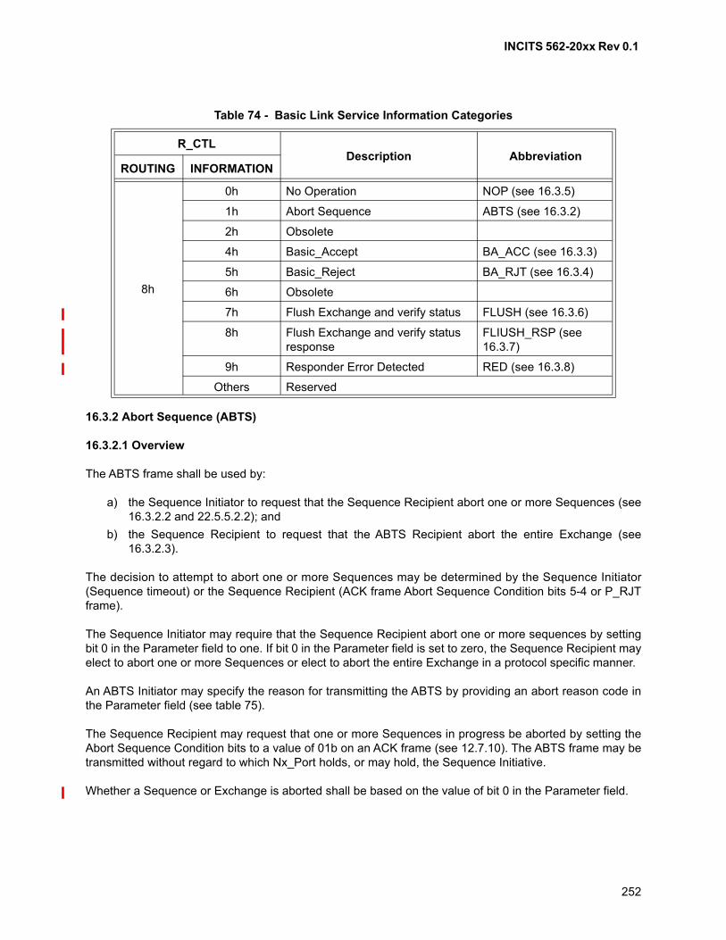
INCITS 562-20xx Rev 0.1
252
16.3.2 Abort Sequence (ABTS)
16.3.2.1 Overview
The ABTS frame shall be used by:
a) the Sequence Initiator to request that the Sequence Recipient abort one or more Sequences (see16.3.2.2 and 22.5.5.2.2); and
b) the Sequence Recipient to request that the ABTS Recipient abort the entire Exchange (see16.3.2.3).
The decision to attempt to abort one or more Sequences may be determined by the Sequence Initiator(Sequence timeout) or the Sequence Recipient (ACK frame Abort Sequence Condition bits 5-4 or P_RJTframe).
The Sequence Initiator may require that the Sequence Recipient abort one or more sequences by settingbit 0 in the Parameter field to one. If bit 0 in the Parameter field is set to zero, the Sequence Recipient mayelect to abort one or more Sequences or elect to abort the entire Exchange in a protocol specific manner.
An ABTS Initiator may specify the reason for transmitting the ABTS by providing an abort reason code inthe Parameter field (see table 75).
The Sequence Recipient may request that one or more Sequences in progress be aborted by setting theAbort Sequence Condition bits to a value of 01b on an ACK frame (see 12.7.10). The ABTS frame may betransmitted without regard to which Nx_Port holds, or may hold, the Sequence Initiative.
Whether a Sequence or Exchange is aborted shall be based on the value of bit 0 in the Parameter field.
Table 74 - Basic Link Service Information Categories
R_CTLDescription Abbreviation
ROUTING INFORMATION
8h
0h No Operation NOP (see 16.3.5)
1h Abort Sequence ABTS (see 16.3.2)
2h Obsolete
4h Basic_Accept BA_ACC (see 16.3.3)
5h Basic_Reject BA_RJT (see 16.3.4)
6h Obsolete
7h Flush Exchange and verify status FLUSH (see 16.3.6)
8h Flush Exchange and verify status response
FLIUSH_RSP (see 16.3.7)
9h Responder Error Detected RED (see 16.3.8)
Others Reserved
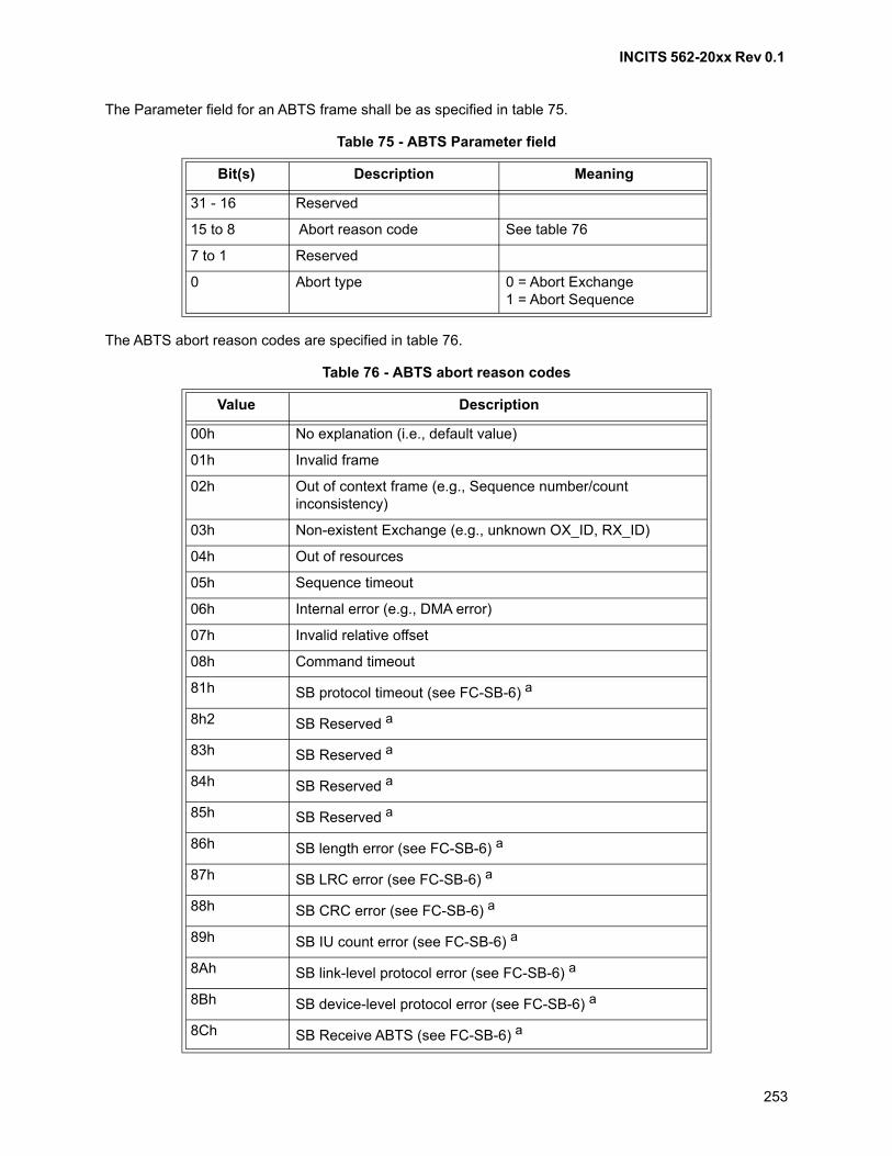
INCITS 562-20xx Rev 0.1
253
The Parameter field for an ABTS frame shall be as specified in table 75.
The ABTS abort reason codes are specified in table 76.
Table 75 - ABTS Parameter field
Bit(s) Description Meaning
31 - 16 Reserved
15 to 8 Abort reason code See table 76
7 to 1 Reserved
0 Abort type 0 = Abort Exchange1 = Abort Sequence
Table 76 - ABTS abort reason codes
Value Description
00h No explanation (i.e., default value)
01h Invalid frame
02h Out of context frame (e.g., Sequence number/countinconsistency)
03h Non-existent Exchange (e.g., unknown OX_ID, RX_ID)
04h Out of resources
05h Sequence timeout
06h Internal error (e.g., DMA error)
07h Invalid relative offset
08h Command timeout
81h SB protocol timeout (see FC-SB-6) a
8h2 SB Reserved a
83h SB Reserved a
84h SB Reserved a
85h SB Reserved a
86h SB length error (see FC-SB-6) a
87h SB LRC error (see FC-SB-6) a
88h SB CRC error (see FC-SB-6) a
89h SB IU count error (see FC-SB-6) a
8Ah SB link-level protocol error (see FC-SB-6) a
8Bh SB device-level protocol error (see FC-SB-6) a
8Ch SB Receive ABTS (see FC-SB-6) a
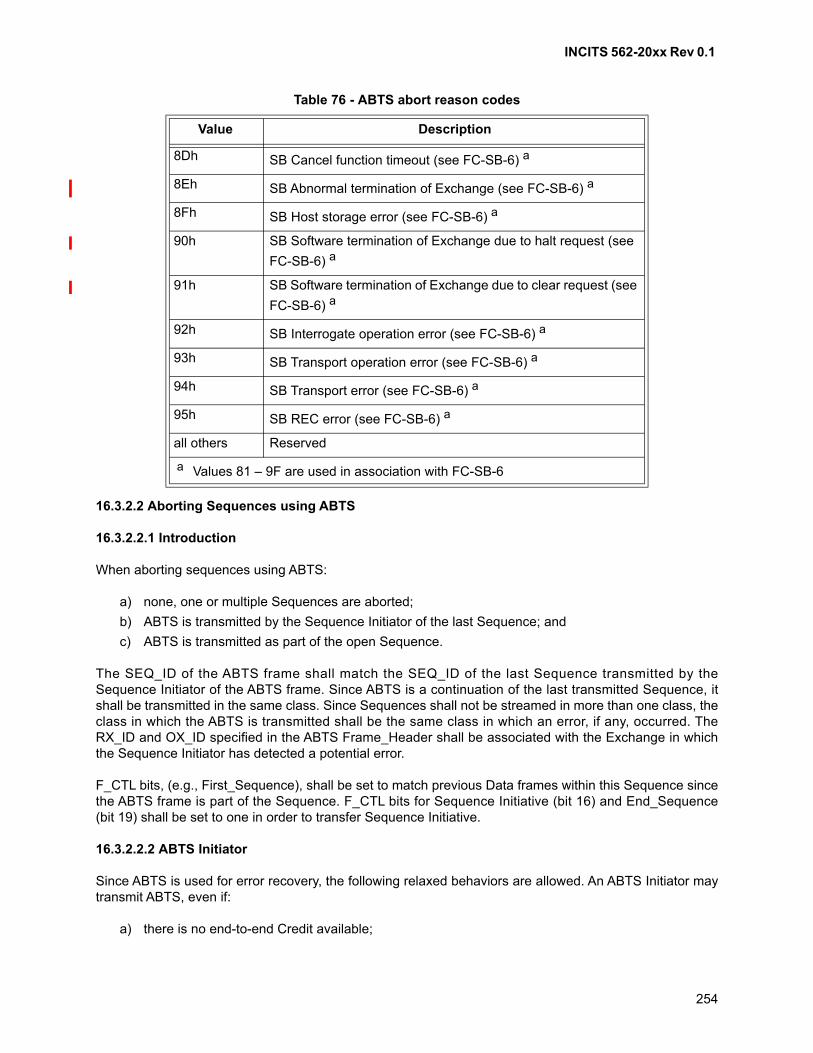
INCITS 562-20xx Rev 0.1
254
16.3.2.2 Aborting Sequences using ABTS
16.3.2.2.1 Introduction
When aborting sequences using ABTS:
a) none, one or multiple Sequences are aborted;
b) ABTS is transmitted by the Sequence Initiator of the last Sequence; and
c) ABTS is transmitted as part of the open Sequence.
The SEQ_ID of the ABTS frame shall match the SEQ_ID of the last Sequence transmitted by theSequence Initiator of the ABTS frame. Since ABTS is a continuation of the last transmitted Sequence, itshall be transmitted in the same class. Since Sequences shall not be streamed in more than one class, theclass in which the ABTS is transmitted shall be the same class in which an error, if any, occurred. TheRX_ID and OX_ID specified in the ABTS Frame_Header shall be associated with the Exchange in whichthe Sequence Initiator has detected a potential error.
F_CTL bits, (e.g., First_Sequence), shall be set to match previous Data frames within this Sequence sincethe ABTS frame is part of the Sequence. F_CTL bits for Sequence Initiative (bit 16) and End_Sequence(bit 19) shall be set to one in order to transfer Sequence Initiative.
16.3.2.2.2 ABTS Initiator
Since ABTS is used for error recovery, the following relaxed behaviors are allowed. An ABTS Initiator maytransmit ABTS, even if:
a) there is no end-to-end Credit available;
8Dh SB Cancel function timeout (see FC-SB-6) a
8Eh SB Abnormal termination of Exchange (see FC-SB-6) a
8Fh SB Host storage error (see FC-SB-6) a
90h SB Software termination of Exchange due to halt request (see
FC-SB-6) a
91h SB Software termination of Exchange due to clear request (see
FC-SB-6) a
92h SB Interrogate operation error (see FC-SB-6) a
93h SB Transport operation error (see FC-SB-6) a
94h SB Transport error (see FC-SB-6) a
95h SB REC error (see FC-SB-6) a
all others Reserved
a Values 81 – 9F are used in association with FC-SB-6
Table 76 - ABTS abort reason codes
Value Description
INCITS 562-20xx Rev 0.1
255
b) it does not hold the Sequence Initiative;
c) there is no Sequence open; and
d) maximum number of Concurrent Sequences supported are in use.
After transmitting the ABTS frame, an Nx_Port shall consider the status of the Exchange in which it wastransmitted to be in an indeterminate condition and shall not deliver any Sequences or notification ofSequence delivery to an upper level until the BA_ACC is received, processed, and recovery, if any, isperformed. Due to out of order delivery and special ACK transmission rules, an ACK to a Data frame withinthe range of a Recovery_Qualifier may mislead the Sequence Initiator of the ABTS prior to reception of theBA_ACC.
NOTE 33 - The ABTS frame may be transmitted after a Sequence timeout. The Sequence Initiator of theABTS frame should reset the E_D_TOV and R_A_TOV timers when the ABTS frame is transmitted, justas any other Data frame transmitted for a Sequence.
16.3.2.2.3 ABTS Recipient
When the ABTS Request frame is received, the Sequence Recipient may abort no Sequences, oneSequence, or multiple Sequences based on the status of each Sequence within an Exchange and theExchange Error Policy (see 22.5.4.3). After receiving the ABTS frame, the Recipient shall determine arange of SEQ_CNT values found in error, if any, associated with the identified Exchange. Data frames forany deliverable Sequences (see 19.4.1) may be processed after the ABTS frame is received based on thepolicy for the Exchange, but before the BA_ACC is transmitted.
Transmission of the BA_ACC to the ABTS frame is an atomic function in that any Data frames identified inthe range of the Recovery_Qualifier (identified in the BA_ACC Payload) shall be discarded after theBA_ACC is transmitted to the Sequence Initiator. The BA_ACC provides a synchronization point betweenthe Sequence Initiator and Sequence Recipient. The ABTS Sequence Recipient is not required to timeoutwaiting for any missing frames before transmitting the BA_ACC. The ABTS Sequence Recipient shall setF_CTL bit 16 to zero in the BA_ACC to indicate that it holds the Sequence Initiative for the Exchange or setit to one to indicate that the ABTS Sequence Initiator holds the Sequence Initiative.
The format of the BA_ACC Payload is shown in table 77. The SEQ_ID, if indicated as valid, shall be thelast deliverable Sequence transmitted by the Sequence Initiator (of ABTS). If the SEQ_ID is indicated asinvalid, then the Sequence Recipient has no information on the last deliverable Sequence. The lowSEQ_CNT value shall be equal to the SEQ_CNT of the last Data frame of the last deliverable Sequence.The high SEQ_CNT value shall be equal to the SEQ_CNT of the ABTS frame.
In the BA_ACC Payload, if the low SEQ_CNT equals high SEQ_CNT and the last valid SEQ_ID in theBA_ACC matches the last Sequence that was transmitted, then no Sequences have been aborted (i.e., allwere deliverable), no Recovery_Qualifier is identified, and no recovery is required. If the low SEQ_CNT isnot equal to the high SEQ_CNT or the last SEQ_ID is not the last Sequence transmitted, then at least oneSequence is in error.
16.3.2.2.4 Recovery Qualifier
If the ABTS frame was transmitted and and at least one Sequence is in error as indicated by the sequencecounts in the BA_ACC, a Recovery_Qualifier shall be established for both Nx_Ports. A Recovery_Qualifierrange is identified by the S_ID, D_ID, OX_ID and RX_ID in combination with a range of SEQ_CNT values(low and high). If a Recovery_Qualifier exists, the Sequence Initiator of the ABTS frame shall discard ACKand Link_Response frames received that correspond to the Recovery_Qualifier between the low and highSEQ_CNT values. After transmission of the BA_ACC to the ABTS frame the Sequence Recipient of the
INCITS 562-20xx Rev 0.1
256
ABTS frame shall discard Data frames received that correspond to the Recovery_Qualifier between thelow and high SEQ_CNT values if a Recovery_Qualifier exists. While the Recovery_Qualifier exists, theSequence Initiator shall not transmit Data frames for the Recovery_Qualifier within the specified low andhigh SEQ_CNT values.
If a Recovery_Qualifier has been established, based on the BA_ACC Payload, the Sequence Initiator ofthe ABTS shall issue a Reinstate Recovery Qualifier (RRQ) ELS Request Sequence (see FC-LS-4) afterwaiting an R_A_TOV timeout period after reception of the BA_ACC.
After the BA_ACC has been transmitted and the Sequence status has been posted in the Exchange StatusBlock as Aborted, if the Sequence Recipient receives any Data frames for the Aborted Sequence orAborted Sequences (based on the range of a Recovery_Qualifier), the frames shall be discarded. See22.5.5.2 and 22.5.3 for more discussion on abnormal termination of Sequences and Sequence timeout.See 22.5.5.2.2 for examples of the ABTS protocol that include several special cases (e.g., the start of anExchange and Class 3). Additional information regarding Sequence recovery and the effects of ABTSbased on different Exchange Error Policies is also discussed.
Following reception of the BA_ACC to the Abort Sequence frame, the Sequence Initiator may performSequence recovery under guidance from the appropriate FC-4.
16.3.2.2.5 Protocol
a) Abort Sequence Request frame; and
b) BA_ACC or BA_RJT Reply frame.
16.3.2.2.6 Request Sequence
Addressing: The D_ID field designates the Sequence Recipient Nx_Port. The S_ID field designates thesource Sequence Initiator Nx_Port that is requesting that a Sequence or Sequences be aborted.
X_ID: Both the RX_ID and OX_ID shall correspond to the current values as determined by the SequenceInitiator of the ABTS frame.
SEQ_ID and SEQ_CNT: The SEQ_ID shall be the same as the last Sequence transmitted for thisExchange by the Nx_Port transmitting ABTS, even if the last Data frame has been transmitted. TheSEQ_CNT shall be set to a value one greater than the previous Data frame transmitted, indicating thehighest SEQ_CNT transmitted for this SEQ_ID and the highest SEQ_CNT for this range of SEQ_CNTsover multiple Sequences.
Parameter: The Parameter field shall be set as specified in table 75.
Payload: The Abort Sequence Basic Link Service command has no Payload.
16.3.2.2.7 Reply Sequence
BA_RJT: BA_RJT signifies rejection of the ABTS command, however, the Sequence may have beenaborted without Sequence information (see 16.3.4).
The SEQ_ID, if indicated as valid, shall be the last deliverable Sequence transmitted by the SequenceInitiator. If the SEQ_ID is indicated as invalid, then the Sequence Recipient has no information on the lastdeliverable Sequence.
INCITS 562-20xx Rev 0.1
257
BA_ACC: BA_ACC signifies that the destination Nx_Port has aborted and discarded no Sequences, oneSequence, or multiple Sequences.
The high SEQ_CNT shall be equal to the SEQ_CNT of the ABTS frame. The low SEQ_CNT value shall beone of the following:
a) same as SEQ_CNT of the ABTS frame;
b) equal to the SEQ_CNT of the last Data frame of the last deliverable Sequence; or
c) set to 00 00h.
The Payload is specified for each of the permitted cases:
a) to indicate that the current Sequence in which ABTS has been received is the last deliverableSequence, and no Sequences are aborted at its end, the Sequence Recipient shall set, in theBA_ACC Payload:
A) SEQ_ID Validity equal valid (80h);
B) SEQ_ID equal the SEQ_ID of the Sequence in which the ABTS has been received from theSequence Initiator; and
C) low SEQ_CNT equal High SEQ_CNT equal SEQ_CNT of the ABTS frame;
b) to indicate that it has the information on the last deliverable Sequence but one or more Sequencesare aborted at its end, the Sequence Recipient shall set, in the BA_ACC Payload:
A) SEQ_ID Validity equal valid (80h);
B) SEQ_ID equal the SEQ_ID of the last deliverable Sequence received from the SequenceInitiator but is not equal to the SEQ_ID of the Sequence in which ABTS frame has beenreceived;
C) low SEQ_CNT equal the SEQ_CNT of the last Data frame of the last deliverable Sequence;and
D) high SEQ_CNT equal the SEQ_CNT of the ABTS frame;
and
c) to indicate that it has no information on the last deliverable Sequence, and one or moreSequences are aborted at its end, the Sequence Recipient shall set, in the BA_ACC Payload,independent of continuously increasing SEQ_CNT use:
A) SEQ_ID Validity equal invalid (00h);
B) SEQ_ID equal invalid in this case;
C) low SEQ_CNT equal 00 00h; and
D) high SEQ_CNT equal the SEQ_CNT of the ABTS frame.
16.3.2.3 Aborting Exchanges using ABTS
16.3.2.3.1 Introduction
Using ABTS to abort an Exchange is specified in this section. In this method,
a) an entire Exchange is aborted;
b) ABTS is transmitted by the Sequence Initiator or the Sequence Recipient of the last Sequence;and
c) ABTS is transmitted as part of the open Sequence or in a new Sequence.
INCITS 562-20xx Rev 0.1
258
16.3.2.3.2 ABTS sent by the last Sequence Initiator in an open Sequence
If the last Sequence is open and the Sequence Initiator of the last Sequence transmits the ABTS frame,the SEQ_ID of this ABTS frame shall match the SEQ_ID of the last Sequence transmitted by the lastSequence Initiator. The SEQ_CNT of the ABTS frame shall be one greater than the SEQ_CNT of the lastData frame transmitted for this last Sequence.
16.3.2.3.3 ABTS sent by the last Sequence Initiator in a new Sequence
If the last Sequence has been completed and is therefore not open, and the Sequence Initiator of the lastSequence transmits the ABTS frame, the ABTS shall be transmitted in a new Sequence with a validSEQ_ID not in use at that time.
16.3.2.3.4 ABTS sent in an open or new Sequence
Since ABTS is a continuation of the last transmitted Sequence, it shall be transmitted in the same class.Since Sequences shall not be streamed in more than one class, the class in which the ABTS is transmittedshall be the same class in which an error, if any, occurred. The RX_ID and OX_ID specified in the ABTSFrame_Header shall be associated with the Exchange in which the Sequence Initiator has detected apotential error.
F_CTL bits for Sequence Initiative (bit 16) and End_Sequence (bit 19) shall be set to one in order totransfer Sequence Initiative. If the ABTS frame is part of the last Sequence, F_CTL bits (e.g.,First_Sequence) shall be set to match previous Data frames within this Sequence. If the ABTS istransmitted in a new Sequence, F_CTL bits shall be set to match the new Sequence.
16.3.2.3.5 ABTS by the last Sequence Recipient
If the last Sequence Recipient transmits an ABTS frame, it shall transmit ABTS in a new Sequence with aSEQ_ID available for use from its Nx_Port as the Sequence Initiator. The new Sequence shall followapplicable rules for the Sequence. The class in which the ABTS is transmitted shall be the same class inwhich an error, if any, occurred. The RX_ID and OX_ID specified for the new Sequence shall beassociated with the Exchange in which the Sequence Recipient has detected a potential error.
If the Sequence Initiator has not transferred the Sequence Initiative or has transferred the SequenceInitiative but has not received the confirmation, but receives the ABTS frame then the Sequence Initiatorshall abort the Exchange by setting the Last_Sequence bit to one in the BA_ACC.
NOTE 34 - If the Sequence Initiator has transferred the Sequence Initiative, received the confirmationbut receives ABTS, then it is treated as the ABTS sent by the new Sequence Initiator and thecorresponding rules are followed.
16.3.2.3.6 Request Sequence
Addressing: The D_ID field designates the ABTS Recipient Nx_Port. The S_ID field designates theABTS Initiator Nx_Port that is requesting that an Exchange be aborted.
X_ID: Both the RX_ID and OX_ID shall correspond to the current values as determined by the SequenceInitiator of the ABTS frame.
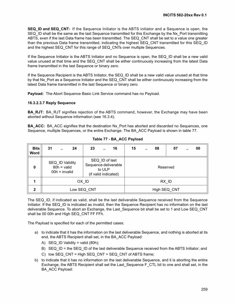
INCITS 562-20xx Rev 0.1
259
SEQ_ID and SEQ_CNT: If the Sequence Initiator is the ABTS initiator and a Sequence is open, theSEQ_ID shall be the same as the last Sequence transmitted for this Exchange by the Nx_Port transmittingABTS, even if the last Data frame has been transmitted. The SEQ_CNT shall be set to a value one greaterthan the previous Data frame transmitted, indicating the highest SEQ_CNT transmitted for this SEQ_IDand the highest SEQ_CNT for this range of SEQ_CNTs over multiple Sequences.
If the Sequence Initiator is the ABTS Initiator and no Sequence is open, the SEQ_ID shall be a new validvalue unused at that time and the SEQ_CNT shall be either continuously increasing from the latest Dataframe transmitted in the last Sequence or binary zero.
If the Sequence Recipient is the ABTS Initiator, the SEQ_ID shall be a new valid value unused at that timeby that Nx_Port as a Sequence Initiator and the SEQ_CNT shall be either continuously increasing from thelatest Data frame transmitted in the last Sequence or binary zero.
Payload: The Abort Sequence Basic Link Service command has no Payload.
16.3.2.3.7 Reply Sequence
BA_RJT: BA_RJT signifies rejection of the ABTS command, however, the Exchange may have beenaborted without Sequence information (see 16.3.4).
BA_ACC: BA_ACC signifies that the destination Nx_Port has aborted and discarded no Sequences, oneSequence, multiple Sequences, or the entire Exchange. The BA_ACC Payload is shown in table 77.
The SEQ_ID, if indicated as valid, shall be the last deliverable Sequence received from the SequenceInitiator. If the SEQ_ID is indicated as invalid, then the Sequence Recipient has no information on the lastdeliverable Sequence. To abort an Exchange, the Last_Sequence bit shall be set to 1 and Low SEQ_CNTshall be 00 00h and High SEQ_CNT FF FFh.
The Payload is specified for each of the permitted cases:
a) to indicate that it has the information on the last deliverable Sequence, and nothing is aborted at itsend, the ABTS Recipient shall set, in the BA_ACC Payload:
A) SEQ_ID Validity = valid (80h);
B) SEQ_ID = the SEQ_ID of the last deliverable Sequence received from the ABTS Initiator; and
C) low SEQ_CNT = High SEQ_CNT = SEQ_CNT of ABTS frame;
b) to indicate that it has no information on the last deliverable Sequence, and it is aborting the entireExchange, the ABTS Recipient shall set the Last_Sequence F_CTL bit to one and shall set, in theBA_ACC Payload:
Table 77 - BA_ACC Payload
BitsWord
31 .. 24 23 .. 16 15 .. 08 07 .. 00
0SEQ_ID Validity
80h = valid00h = invalid
SEQ_ID of last Sequence deliverable
to ULP (if valid indicated)
Reserved
1 OX_ID RX_ID
2 Low SEQ_CNT High SEQ_CNT
INCITS 562-20xx Rev 0.1
260
A) SEQ_ID Validity = invalid (00h);
B) SEQ_ID = invalid in this case;
C) low SEQ_CNT = 00 00h; and
D) high SEQ_CNT = FF FFh;
and
c) to indicate that it has information on the last deliverable Sequence, but it is aborting the entireExchange due to uncertainty (e.g., Sequence Initiative ownership or lack of its capability to resolvethe conflict), the ABTS Recipient shall set the Last_Sequence F_CTL bit to 1 and shall set, in theBA_ACC Payload:
A) SEQ_ID Validity = valid (80h);
B) SEQ_ID = the SEQ_ID of the last deliverable Sequence received from the ABTS Initiator;
C) low SEQ_CNT = 00 00h; and
D) high SEQ_CNT = FF FFh.
16.3.3 Basic Accept (BA_ACC)
16.3.3.1 Description
BA_ACC is a single frame Link Service Reply Sequence that notifies the transmitter of a Basic LinkService Request frame that the request has been completed. The BA_ACC Link Service Reply Sequenceshall transfer the Sequence Initiative by setting the Sequence Initiative bit (Bit 16) to one in F_CTL on thelast Data frame of the Reply Sequence if the Sequence Initiative for the Exchange is held by thetransmitter of the ABTS frame. The Sequence Initiative (Bit 16) shall be set to zero to indicate that thetransmitter of the BA_ACC holds the Sequence Initiative for the Exchange. The OX_ID and RX_ID shall beset to match the Exchange in which the ABTS frame was transmitted. The SEQ_ID shall be assignedfollowing the normal rules for SEQ_ID assignment.
16.3.3.2 Protocol
BA_ACC is the Reply Sequence to Abort Sequence Basic Link Service command.
16.3.3.3 Request Sequence
Addressing: The D_ID field designates the source of the Link Service frame being accepted while theS_ID field designates the destination of the request Data frame Sequence being accepted.
Payload: The Payload content is defined within individual Basic Link Service command (ABTS).
16.3.3.4 Reply Sequence
none
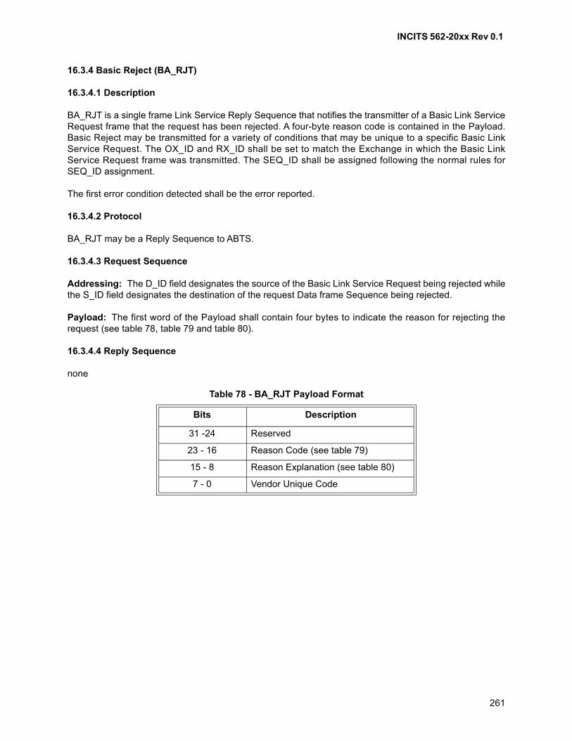
INCITS 562-20xx Rev 0.1
261
16.3.4 Basic Reject (BA_RJT)
16.3.4.1 Description
BA_RJT is a single frame Link Service Reply Sequence that notifies the transmitter of a Basic Link ServiceRequest frame that the request has been rejected. A four-byte reason code is contained in the Payload.Basic Reject may be transmitted for a variety of conditions that may be unique to a specific Basic LinkService Request. The OX_ID and RX_ID shall be set to match the Exchange in which the Basic LinkService Request frame was transmitted. The SEQ_ID shall be assigned following the normal rules forSEQ_ID assignment.
The first error condition detected shall be the error reported.
16.3.4.2 Protocol
BA_RJT may be a Reply Sequence to ABTS.
16.3.4.3 Request Sequence
Addressing: The D_ID field designates the source of the Basic Link Service Request being rejected whilethe S_ID field designates the destination of the request Data frame Sequence being rejected.
Payload: The first word of the Payload shall contain four bytes to indicate the reason for rejecting therequest (see table 78, table 79 and table 80).
16.3.4.4 Reply Sequence
none
Table 78 - BA_RJT Payload Format
Bits Description
31 -24 Reserved
23 - 16 Reason Code (see table 79)
15 - 8 Reason Explanation (see table 80)
7 - 0 Vendor Unique Code
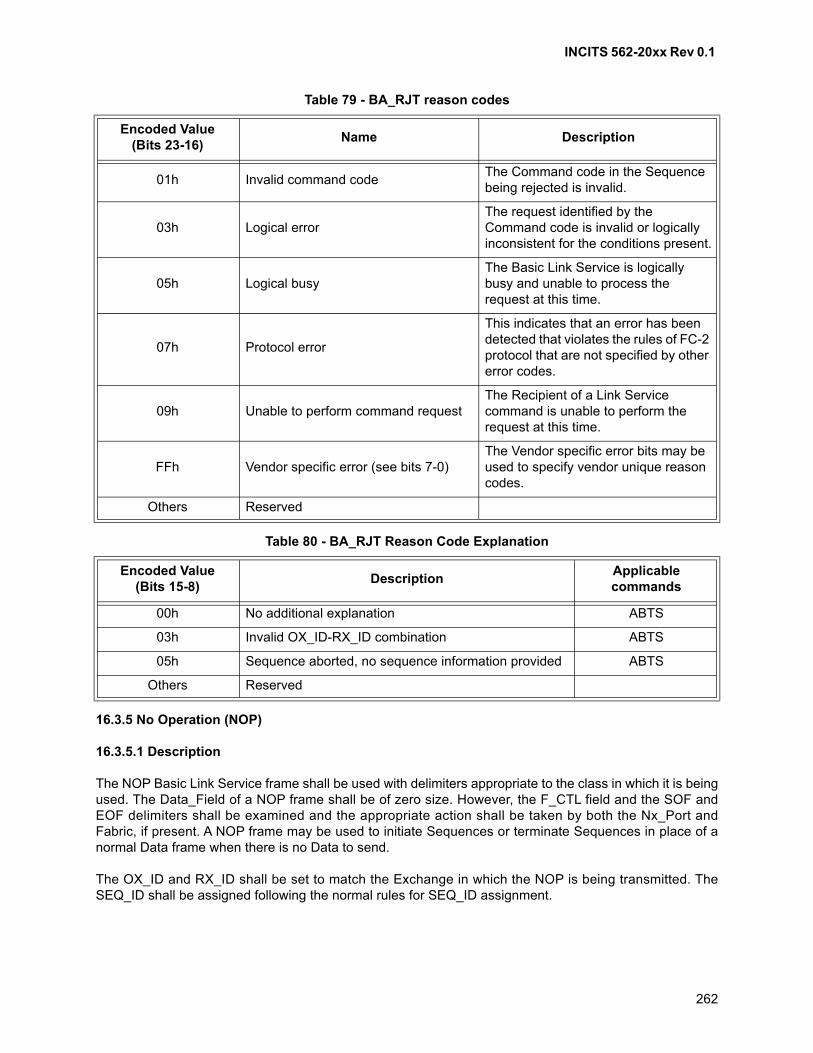
INCITS 562-20xx Rev 0.1
262
16.3.5 No Operation (NOP)
16.3.5.1 Description
The NOP Basic Link Service frame shall be used with delimiters appropriate to the class in which it is beingused. The Data_Field of a NOP frame shall be of zero size. However, the F_CTL field and the SOF andEOF delimiters shall be examined and the appropriate action shall be taken by both the Nx_Port andFabric, if present. A NOP frame may be used to initiate Sequences or terminate Sequences in place of anormal Data frame when there is no Data to send.
The OX_ID and RX_ID shall be set to match the Exchange in which the NOP is being transmitted. TheSEQ_ID shall be assigned following the normal rules for SEQ_ID assignment.
Table 79 - BA_RJT reason codes
Encoded Value(Bits 23-16)
Name Description
01h Invalid command codeThe Command code in the Sequence being rejected is invalid.
03h Logical errorThe request identified by the Command code is invalid or logically inconsistent for the conditions present.
05h Logical busyThe Basic Link Service is logically busy and unable to process the request at this time.
07h Protocol error
This indicates that an error has been detected that violates the rules of FC-2 protocol that are not specified by other error codes.
09h Unable to perform command requestThe Recipient of a Link Service command is unable to perform the request at this time.
FFh Vendor specific error (see bits 7-0)The Vendor specific error bits may be used to specify vendor unique reason codes.
Others Reserved
Table 80 - BA_RJT Reason Code Explanation
Encoded Value(Bits 15-8)
DescriptionApplicable commands
00h No additional explanation ABTS
03h Invalid OX_ID-RX_ID combination ABTS
05h Sequence aborted, no sequence information provided ABTS
Others Reserved
INCITS 562-20xx Rev 0.1
263
16.3.5.2 Protocol
a) No Operation Request; and
b) No Reply frame.
16.3.5.3 Request Sequence
Addressing: The D_ID field designates the destination of the frame while the S_ID field designates thesource of the frame.
Payload: The NOP Basic Link Service command has no Payload.
16.3.5.4 Reply Sequence
none
16.3.6 Flush Exchange and verify status (FLUSH)
16.3.6.1 Overview
The FLUSH command may be transmitted by an Nx_Port to ensure all Exchange frames for a specifiedOX_ID/RX_ID have been received by the FLUSH Recipient, and may be used to verify the state of theExchange. This command may be used to indicate or determine if error recovery is required. Use of thiscommand is defined by the FC-4 (e.g., FC-NVMe-2).
16.3.6.2 Description
The FLUSH command,
a) shall only be transmitted within an open Exchange;
b) the OX_ID and RX_ID in the Frame_Header shall be associated with the open Exchange; and
c) may be transmitted even if the Nx_Port does not hold Sequence Initiative.
The FLUSH command may be issued periodically. For each FLUSH command issued, the Count field (seetable 81) is incremented by one. The FLUSH Recipient shall send a FLUSH_RSP corresponding to theFLUSH command with the highest received Count value and is not required to respond to earlier FLUSHcommands on the Exchange. This may occur if a prior FLUSH command was not delivered to the FLUSHRecipient.
If the HT bit in the FLUSH Payload (see table 81) is set to one, then the F_CTL bit for Sequence Initiative(i.e., bit 16) shall be set to one and the bit for End_Sequence (i.e., bit 19) shall be set to one. If the HT bitin the FLUSH Payload is set to zero, then the F_CTL bit for Sequence Initiative (i.e., bit 16) shall be set tozero (i.e., to not affect Sequence Initiative) and the F_CTL bit for End_Sequence (i.e., bit 19) shall be set toone . The FLUSH command may be transmitted as part of the last Sequence or in a new Sequence.
NOTE 35 - The F_CTL bit for Sequence Initiative (i.e., bit 16) when set to zero has a different meaningfor the FLUSH command. Instead of indicating that Sequence Initiative is held, it indicates that SequenceInitiative for the Exchange is not affected by the FLUSH command.
The value of the Parameter field in the Frame_Header of a FLUSH command is described by the FC-4(e.g., FC-NVME-2). The F_CTL Relative offset present bit of a FLUSH command shall be set to zero.
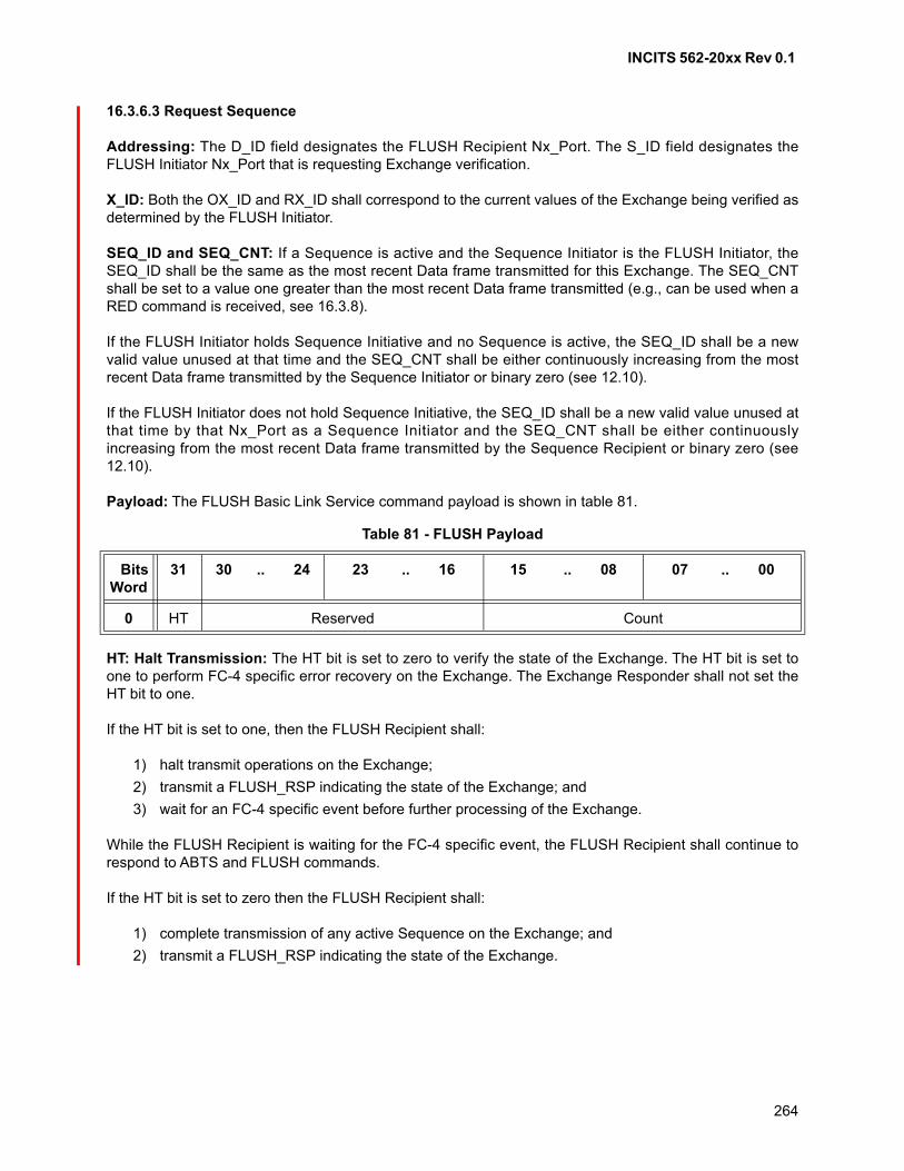
INCITS 562-20xx Rev 0.1
264
16.3.6.3 Request Sequence
Addressing: The D_ID field designates the FLUSH Recipient Nx_Port. The S_ID field designates theFLUSH Initiator Nx_Port that is requesting Exchange verification.
X_ID: Both the OX_ID and RX_ID shall correspond to the current values of the Exchange being verified asdetermined by the FLUSH Initiator.
SEQ_ID and SEQ_CNT: If a Sequence is active and the Sequence Initiator is the FLUSH Initiator, theSEQ_ID shall be the same as the most recent Data frame transmitted for this Exchange. The SEQ_CNTshall be set to a value one greater than the most recent Data frame transmitted (e.g., can be used when aRED command is received, see 16.3.8).
If the FLUSH Initiator holds Sequence Initiative and no Sequence is active, the SEQ_ID shall be a newvalid value unused at that time and the SEQ_CNT shall be either continuously increasing from the mostrecent Data frame transmitted by the Sequence Initiator or binary zero (see 12.10).
If the FLUSH Initiator does not hold Sequence Initiative, the SEQ_ID shall be a new valid value unused atthat time by that Nx_Port as a Sequence Initiator and the SEQ_CNT shall be either continuouslyincreasing from the most recent Data frame transmitted by the Sequence Recipient or binary zero (see12.10).
Payload: The FLUSH Basic Link Service command payload is shown in table 81.
HT: Halt Transmission: The HT bit is set to zero to verify the state of the Exchange. The HT bit is set toone to perform FC-4 specific error recovery on the Exchange. The Exchange Responder shall not set theHT bit to one.
If the HT bit is set to one, then the FLUSH Recipient shall:
1) halt transmit operations on the Exchange;
2) transmit a FLUSH_RSP indicating the state of the Exchange; and
3) wait for an FC-4 specific event before further processing of the Exchange.
While the FLUSH Recipient is waiting for the FC-4 specific event, the FLUSH Recipient shall continue torespond to ABTS and FLUSH commands.
If the HT bit is set to zero then the FLUSH Recipient shall:
1) complete transmission of any active Sequence on the Exchange; and
2) transmit a FLUSH_RSP indicating the state of the Exchange.
Table 81 - FLUSH Payload
BitsWord
31 30 .. 24 23 .. 16 15 .. 08 07 .. 00
0 HT Reserved Count
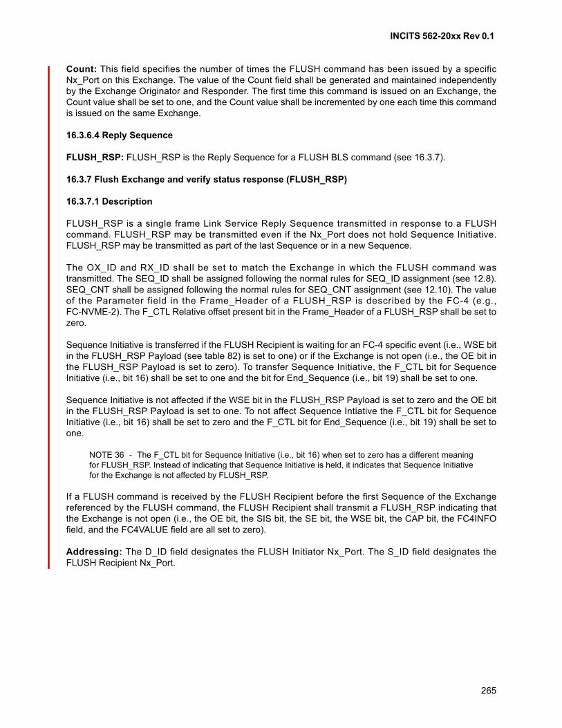
INCITS 562-20xx Rev 0.1
265
Count: This field specifies the number of times the FLUSH command has been issued by a specificNx_Port on this Exchange. The value of the Count field shall be generated and maintained independentlyby the Exchange Originator and Responder. The first time this command is issued on an Exchange, theCount value shall be set to one, and the Count value shall be incremented by one each time this commandis issued on the same Exchange.
16.3.6.4 Reply Sequence
FLUSH_RSP: FLUSH_RSP is the Reply Sequence for a FLUSH BLS command (see 16.3.7).
16.3.7 Flush Exchange and verify status response (FLUSH_RSP)
16.3.7.1 Description
FLUSH_RSP is a single frame Link Service Reply Sequence transmitted in response to a FLUSHcommand. FLUSH_RSP may be transmitted even if the Nx_Port does not hold Sequence Initiative.FLUSH_RSP may be transmitted as part of the last Sequence or in a new Sequence.
The OX_ID and RX_ID shall be set to match the Exchange in which the FLUSH command wastransmitted. The SEQ_ID shall be assigned following the normal rules for SEQ_ID assignment (see 12.8).SEQ_CNT shall be assigned following the normal rules for SEQ_CNT assignment (see 12.10). The valueof the Parameter field in the Frame_Header of a FLUSH_RSP is described by the FC-4 (e.g.,FC-NVME-2). The F_CTL Relative offset present bit in the Frame_Header of a FLUSH_RSP shall be set tozero.
Sequence Initiative is transferred if the FLUSH Recipient is waiting for an FC-4 specific event (i.e., WSE bitin the FLUSH_RSP Payload (see table 82) is set to one) or if the Exchange is not open (i.e., the OE bit inthe FLUSH_RSP Payload is set to zero). To transfer Sequence Initiative, the F_CTL bit for SequenceInitiative (i.e., bit 16) shall be set to one and the bit for End_Sequence (i.e., bit 19) shall be set to one.
Sequence Initiative is not affected if the WSE bit in the FLUSH_RSP Payload is set to zero and the OE bitin the FLUSH_RSP Payload is set to one. To not affect Sequence Intiative the F_CTL bit for SequenceInitiative (i.e., bit 16) shall be set to zero and the F_CTL bit for End_Sequence (i.e., bit 19) shall be set toone.
NOTE 36 - The F_CTL bit for Sequence Initiative (i.e., bit 16) when set to zero has a different meaningfor FLUSH_RSP. Instead of indicating that Sequence Initiative is held, it indicates that Sequence Initiativefor the Exchange is not affected by FLUSH_RSP.
If a FLUSH command is received by the FLUSH Recipient before the first Sequence of the Exchangereferenced by the FLUSH command, the FLUSH Recipient shall transmit a FLUSH_RSP indicating thatthe Exchange is not open (i.e., the OE bit, the SIS bit, the SE bit, the WSE bit, the CAP bit, the FC4INFOfield, and the FC4VALUE field are all set to zero).
Addressing: The D_ID field designates the FLUSH Initiator Nx_Port. The S_ID field designates theFLUSH Recipient Nx_Port.
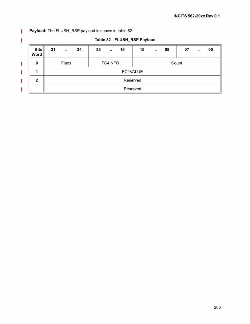
INCITS 562-20xx Rev 0.1
266
Payload: The FLUSH_RSP payload is shown in table 82.
Table 82 - FLUSH_RSP Payload
BitsWord
31 .. 24 23 .. 16 15 .. 08 07 .. 00
0 Flags FC4INFO Count
1 FC4VALUE
2 Reserved
Reserved
INCITS 562-20xx Rev 0.1
267
Flags: The Flags field is defined as shown in table 83.
Table 83 - Flags Field Definition
BitsBit
NameDescription
7 SIS Sequence Initiative State: The Sequence Initiative State bit shall be set to one if the FLUSH Recipient holds Sequence Initiative for the Exchange after the FLUSH_RSP is transmitted. The SIS bit shall be set to zero if the Exchange is not open, or if the FLUSH Recipient does not hold Sequence Initiative for the Exchange after the FLUSH_RSP is transmitted.
6 OE Open Exchange: The Open Exchange bit shall be set to zero if the FLUSH Recipient does not have an open Exchange for the S_ID, OX_ID, RX_ID and any other qualifiers specified by the FC-4 provided in the FLUSH command. If the RX_ID field in the FLUSH command is set to FFFFh, then the FLUSH Recipient shall not use the RX_ID field to qualify the Exchange. If the Exchange is open, the OE bit shall be set to one.
5 SE Sequence Error: If the FLUSH Recipient has not detected a Sequence error for the Exchange or if the FLUSH Recipient is the Exchange Originator, then the SE bit shall be set to zero. If the FLUSH Recipient is the Exchange Responder and has detected a Sequence error for the Exchange, then the SE bit shall be set to one. If the SE bit is set to one, then the FLUSH Recipient shall:
1) transmit a FLUSH_RSP indicating the state of the Exchange; and
2) wait for an FC-4 specific event before further processing of theExchange.
While the FLUSH Recipient is waiting for the FC-4 specific event, the FLUSH Recipient shall continue to respond to ABTS and FLUSH commands.If the SE bit has been set to one in a prior FLUSH_RSP for this Exchange and a subsequent FLUSH command is received for this Exchange before the FC-4 specific event occurs, then the SE bit shall be set to one in the subsequent FLUSH_RSP.
4 WSE Waiting for FC-4 Specific Event: This bit, when set to one, indicates that the FLUSH Recipient is waiting for the FLUSH Initiator to send an FC-4 specific event before further processing of the Exchange. The WSE bit shall be set to one:
a) if the FLUSH command is received with the HT bit set to one;
b) if the FLUSH_RSP is sent with the SE bit set to one; or
c) if the WSE bit has been set to one in a prior FLUSH_RSP for thisExchange and a subsequent FLUSH command is received for thisExchange before the FC-4 specific event occurs.
Otherwise, the WSE bit shall be set to zero
3 CAP FC-4 Capability: The CAP field is described by the FC-4 protocol (e.g., FC-NVMe-2).
All others Reserved
INCITS 562-20xx Rev 0.1
268
FC4INFO: The FC4INFO field is described by the FC-4 protocol (e.g., FC-NVMe-2).
Count: The Count field shall be set to the Count value received in the FLUSH command.
FC4VALUE: The FC4VALUE field is described by the FC-4 protocol (e.g., FC-NVMe-2).
16.3.8 Responder Error Detected (RED)
16.3.8.1 Overview
The RED command may be transmitted by an Exchange Responder to indicate to the Exchange Originatorthat a Sequence error was detected on an open Exchange. This command shall be used only for purposesspecific to an FC-4 and may be used to indicate that FC-4 specific error recovery is required.
16.3.8.2 Intoduction
The RED command,
a) shall be transmitted within an open Exchange;
b) the S_ID, D_ID, OX_ID and RX_ID in the Frame_Header shall be associated with the openExchange;
c) shall only be transmitted by the Exchange Responder if a Sequence error was detected;
d) shall not be transmitted if this Sequence error has already been reported to the Exchange Origi-nator in a FLUSH_RSP;
e) may be transmitted even if the Nx_Port does not hold Sequence Initiative; and
f) shall have the F_CTL bit for Sequence Initiative (i.e., bit 16) set to one and the bit for End_Se-quence (i.e., bit 19) set to one.
After the Exchange Responder transmits a RED command, it shall wait for an FC-4 specific event beforefurther processing of the Exchange. While the Exchange Responder is waiting for the FC-4 specific event,the Exchange Responder shall continue to respond to ABTS and FLUSH commands.
The RED command may be reissued until a FLUSH command or an FC-4 specific event is received for theExchange associated with the Sequence error. If a FLUSH command is received after transmission of aRED command and before an FC-4 specific event is received, a FLUSH_RSP shall be transmitted with theOE, SE and WSE bits set to one.
If a new Sequence error is detected on the Exchange after an FC-4 specific event is received for theExchange, a RED command may be transmitted indicating the new Sequence error.
16.3.8.3 Request Sequence
Addressing: The D_ID field designates the RED Recipient Nx_Port. The S_ID field designates the REDInitiator Nx_Port that is transmitting the Sequence error detected notification.
X_ID: Both the OX_ID and RX_ID shall correspond to the current values as determined by the ExchangeResponder. If the Exchange Initiator has not received an IU with an assigned RX_ID (i.e., an RX_ID otherthan FFFFh) from the Exchange Responder, then the Exchange Initiator shall not use the RX_ID field toqualify the Exchange.

INCITS 562-20xx Rev 0.1
269
SEQ_ID and SEQ_CNT: The SEQ_ID shall be a new valid value unused at that time and the SEQ_CNTshall be either continuously increasing from the most recent frame transmitted by the ExchangeResponder or binary zero (see 12.10).
Payload: The RED Basic Link Service command shall have a zero size Payload.
16.3.8.4 Reply Sequence
There is no Reply Sequence for a RED command.
INCITS 562-20xx Rev 0.1
270
17 Classes of service
17.1 Scope
Classes of service are functions of the FC-2V sublevel.
17.2 Introduction
Two classes of service are specified in this standard. These classes of service are distinguished primarilyby the level of delivery integrity required for an application.
A given Fabric or Nx_Port may support one or both of the following classes of service:
a) Class 2 - Multiplex; and
b) Class 3 - Datagram.
Class 2 and Class 3 may be supported with any of the three topologies.
In both classes of service, the FC-2V Segmentation and Reassembly function makes available to thereceiving ULP the same image of application data as transmitted by the sending ULP (see clause 21).
In both classes of service, for each frame received, the Fabric shall do one of the following:
a) deliver only one instance of the frame to any single Nx_Port;
b) issue a F_BSY;
c) issue a F_RJT; or
d) discard the frame without issuing any response.
17.3 Class 2 - Multiplex
17.3.1 Function
This class of service provides frame delivery service with notification of non-delivery between twoNx_Ports. This class of service allows one Nx_Port to transmit consecutive frames to multiple destinations.Conversely, this class of service also allows one Nx_Port to receive consecutive frames from one or moreNx_Ports.
A Class 2 service is requested by an Nx_Port on a frame by frame basis. The Fabric, if present, routeseach frame to the Nx_Port indicated by the D_ID of the frame.
NOTE 37 - The Fabric routes a Class 2 frame to its D_ID even if the D_ID is assigned to the samePN_Port from which the Fabric received the frame.
Class 2 Delimiters are used to indicate the requested service and to initiate and terminate one or moreSequences as described in 17.3.3.
INCITS 562-20xx Rev 0.1
271
17.3.2 Rules
To provide Class 2 service, the transmitting and receiving Nx_Ports, and the Fabric shall obey the followingrules:
a) except as explicitly stated in FC-LS-4 for a given Link Service protocol, an Nx_Port supportingClass 2 service is required to have logged in with the Fabric and the Nx_Ports with which it intendsto communicate, either explicitly or implicitly. To Login explicitly, the requesting Nx_Port shall useFabric and N_Port Login protocols;
b) the Fabric routes the frames between communicating Nx_Ports. To obtain Class 2 service from theFabric, the Nx_Port shall use the Class 2 Delimiters as specified in 17.3.3;
c) an Nx_Port may send consecutive frames to one or more destinations. This enables an Nx_Port todemultiplex multiple Sequences to a single or multiple destinations concurrently (see 17.3.3);
d) a given Nx_Port may receive consecutive frames from different sources. Each source may sendconsecutive frames for one or more Sequences;
e) a destination Nx_Port shall provide an acknowledgement to the source for each valid Data framereceived. The destination Nx_Port shall use ACK for the acknowledgement (see 17.3.5). If unableto deliver ACK, the Fabric shall return a F_BSY or F_RJT;
f) the Sequence Initiator shall increment the SEQ_CNT field of each successive frame transmittedwithin a Sequence. However, the Fabric may not guarantee delivery to the destination in the sameorder of transmission (see 19.4.6);
g) an Nx_Port may originate multiple Exchanges and initiate multiple Sequences with one or moredestination Nx_Ports. The Nx_Port originating an Exchange shall set the OX_ID in accord with12.11 and the Responder of the Exchange shall set the RX_ID in accord with 12.12. TheSequence Initiator shall assign a SEQ_ID, for each Sequence it initiates in accord with 19.7.3;
h) if the Fabric is unable to deliver the frame to the destination Nx_Port, the source is notified of eachframe not delivered by an F_BSY or F_RJT frame from the Fabric with corresponding D_ID, S_ID,OX_ID, RX_ID, SEQ_ID, and SEQ_CNT. The source is also notified of valid frames busied orrejected by the destination Nx_Port by P_BSY or P_RJT;
i) a busy or reject may be issued by an Fx_Port or the destination Nx_Port with a valid reason code.(see 15.3);
j) if a Class 2 Data frame is busied, the sender shall retransmit the busied frame up to the ability ofthe sender to retry, including zero;
k) the Credit established during Login by interchanging Service Parameters shall be honored (see20.2.4 for more on Credit). Class 2 may share buffer-to-buffer Credit with Class 3 frames;
l) effective transfer rate between any given Nx_Port pair is dependent upon the number of Nx_Portsa given Nx_Port is demultiplexing to and multiplexing from;
m) frames within a Sequence are tracked on a Sequence_Qualifier (see 19.7.1) and SEQ_CNT (see12.10) basis;
n) an FC_Port shall be able to recognize SOF delimiters for both classes of service, whether or notthe FC_Port supports both classes of service, and provide appropriate responses for both classesof service with appropriate delimiters. An Nx_Port that supports only Class 2 shall discard Class 3frames, while obeying the buffer-to-buffer flow control rules. An Fx_Port that supports only Class 2shall discard Class 3 frames, while obeying the buffer-to-buffer flow control rules; and
o) the Class 2 PREF field is a class of service specific use of the CS_CTL field. When PREF is set tozero, the Fabric shall deliver the frame normally. When PREF is set to one, the Fabric may deliverthe frame to the destination Nx_Port prior to frames that have PREF set to zero. If the Fabricindicated through Login that it guarantees order-of-delivery, the Fabric shall deliver frames with thesame PREF value to a destination in the same order received from the source.
INCITS 562-20xx Rev 0.1
272
17.3.3 Delimiters
Sequences are initiated by transmitting a frame started by a SOFi2. A SOFn2 starts subsequent frameswithin a Sequence. A Sequence is normally terminated with a frame ended by EOFt. All frames other thanthe last frame within the Sequence are ended with an EOFn.
17.3.4 Data_Field size
The number of bytes in the Data_Field of each frame transmitted is limited by the smaller value of theBuffer-to-Buffer Receive Data_Field Size (see FC-LS-4) of the Fabric or the Receive Data_Field Size (seeFC-LS-4) of the receiving Nx_Port. Each frame is routed through the Fabric, if present, as a separateentity.
17.3.5 Flow control
All Class 2 frames shall follow both buffer-to-buffer flow control rules (see 20.4) and end-to-end flow controlrules (see 20.3).
ACK frames are used to perform end-to-end flow control. ACK frames shall begin with SOFn2. The ACKused to terminate a Sequence shall end with EOFt. All ACK frames that do not terminate a Sequence shallend with EOFn.
17.4 Class 3 - Datagram
17.4.1 Function
This class of service provides frame delivery service without any notification of non-delivery (BSY or RJT),delivery (ACK), or end-to-end flow control between two communicating Nx_Ports. The Fabric, if present,and the destination Nx_Port are allowed to discard Class 3 frames without any notification to thetransmitting Nx_Port. This class of service allows one Nx_Port to transmit consecutive frames to multipledestinations. Conversely, this class of service also allows one Nx_Port to receive consecutive frames fromone or more Nx_Ports.
A Class 3 service is requested by an Nx_Port on a frame by frame basis. The Fabric, if present, routeseach frame to the Nx_Port indicated by the D_ID of the frame.
NOTE 38 - The Fabric routes a Class 3 frame to its D_ID even if the D_ID is assigned to the samePN_Port from which the Fabric received the frame.
Class 3 Delimiters are used to indicate the requested service and to initiate and terminate one or moreSequences as described in 17.4.3.
17.4.2 Rules
To provide Class 3 service, the transmitting and receiving Nx_Ports, and the Fabric shall obey the followingrules:
a) except as explicitly stated in FC-LS-4 for a given Link Service protocol specification, an Nx_Portsupporting Class 3 service is required to have logged in with the Fabric or the Nx_Ports, eitherexplicitly or implicitly. To Login explicitly, the requesting Nx_Port shall use Fabric and N_Port Loginprotocols (see FC-LS-4);
b) the Fabric routes the frames between communicating Nx_Ports. To obtain Class 3 service from theFabric, the Nx_Port shall use the Class 3 Delimiters as specified in 17.4.3;
INCITS 562-20xx Rev 0.1
273
c) a given Nx_Port may send consecutive frames to one or more destinations. This enables anNx_Port to demultiplex multiple Sequences to single or multiple destinations concurrently;
d) a given Nx_Port may receive consecutive frames from one or more source Nx_Ports. Each sourceNx_Port may send consecutive frames for one or more Sequences;
e) a destination Nx_Port shall not provide acknowledgement (ACK) to the source for any valid framereceived;
f) the Sequence Initiator shall increment the SEQ_CNT field of each successive frame transmittedwithin a Sequence. However, the Fabric may not guarantee delivery at the receiver in the sameorder of transmission (see 19.4.6);
g) an Nx_Port may originate Exchanges and initiate Sequences with one or more destinationNx_Ports. The Nx_Port originating an Exchange shall set the OX_ID in accord with 12.11 and theResponder of the Exchange shall set the RX_ID in accord with 12.12. The Responder may assignan RX_ID in the first Sequence it transmits. The Sequence Initiator shall assign a SEQ_ID for eachSequence it initiates in accord with 19.7.3;
h) the local Fx_Port exercises buffer-to-buffer flow control with the transmitting Nx_Port. The remoteFx_Port exercises buffer to-buffer flow control with the receiving Nx_Port. R_RDY is used forbuffer-to-buffer flow control;
i) if the Fabric is unable to deliver the frame to the destination Nx_Port, the frame is discarded andthe source is not notified. If the destination Nx_Port is unable to receive the frame, the frame isdiscarded and the source is not notified;
j) effective transfer rate between any given Nx_Port pair is dependent upon the number of Nx_Portsa given Nx_Port is demultiplexing to and multiplexing from;
k) neither the Fx_Port nor Nx_Port shall issue busy or reject to Class 3 frames;
l) frames within a Sequence are tracked on a Sequence_Qualifier (see 19.7.1) and SEQ_CNT (see12.10) basis;
m) an Nx_Port or Fx_Port shall be able to recognize SOF delimiters of both classes of service,whether or not the Nx_Port or Fx_Port supports both classes of service, and provide appropriateresponses for both classes of service with appropriate delimiters. An Nx_Port that supports onlyClass 3 shall issue a P_RJT for Class 2 frames with appropriate Class 2 delimiters while obeyingthe buffer-to-buffer flow control rules. An Fx_Port that supports only Class 3 shall issue a F_RJTfor Class 2 frames with appropriate Class 2 delimiters, while obeying the buffer-to-buffer flowcontrol rules;
n) an Nx_Port may obtain the delivery status of Class 3 Sequences transferred by using AbortSequence protocol (see 22.5.5.2.2) and thus verify the integrity of the delivered Sequences; and
o) the Class 3 PREF field is a class specific use of the CS_CTL field. When PREF is set to zero, theFabric shall deliver the frame normally. When PREF is set to one, the Fabric may deliver the frameto the destination Nx_Port prior to frames that have PREF set to zero. If the Fabric indicatedthrough Login that it guarantees order-of-delivery, the Fabric shall deliver frames with the samePREF value to a destination in the same order received from the source.
17.4.3 Delimiters
Sequences are initiated by transmitting a frame started by a SOFi3. A SOFn3 starts subsequent frameswithin a Sequence. A Sequence is terminated with a Data frame ended by EOFt. An EOFn terminates allframes other than the last frame within the Sequence.

INCITS 562-20xx Rev 0.1
274
17.4.4 Data_Field size
The number of bytes in the Data_Field of each frame transmitted is limited by the smaller value of theBuffer-to-Buffer Receive Data_Field Size (see FC-LS-4) of the Fabric or the Receive Data_Field Size (seeFC-LS-4) of the receiving Nx_Port. Each frame is routed through the Fabric, if present, as a separateentity.
17.4.5 Flow control
All Class 3 frames shall follow buffer-to-buffer flow control rules (see 20.4). Class 3 frames are not subjectto end-to-end flow control (see 20.3).
17.4.6 Sequence integrity
With a missing Class 3 Data frame, the Sequence Recipient is capable of detecting the error of non-receiptof the frame, but has no method to communicate it to the Sequence Initiator due to absence of ACK inClass 3. However, using Abort Sequence protocol (see 19.4.11 and 22.5.5), the Sequence Initiator mayverify if one or more transmitted Sequences were received without any Sequence error. This usage ofAbort Sequence protocol makes it possible to verify the integrity of Class 3 Sequences delivered.
If a sending ULP relies on the receiving ULP for ensuring Sequence integrity, the Sequence Initiator maynot use the Abort Sequence protocol to confirm Sequence delivery.

INCITS 562-20xx Rev 0.1
275
18 Name_Identifier Formats
18.1 Scope
Name_Identifier Formats are functions of the FC-2V sublevel.
18.2 Introduction
Name_Identifiers are used to identify entities in Fibre Channel such as an N_Port, node, F_Port, Fabric orother Fibre Channel objects. The Name_Identifier for an entity shall be unique within the Fibre Channelinteraction space.
The NAA field (bits 31-28 of Word 0) within the Name_Identifier specifies its format and length. A list ofsupported formats is given in table 84.
An NAA field value of "Name not present” (0h) indicated that the Name Value field does not contain anvalid Name_Identifier, and shall be ignored.
18.3 IEEE 48-bit Address
When the Name_Identifier format is IEEE 48-bit Address, the name value field shall contain a 48-bit IEEEStandard 802.1A Universal LAN MAC Address (ULA) (see IEEE 802). The ULA shall be represented as anordered string of six bytes numbered from 0 to 5. ULA Bytes 0, 1, and 2 are generated using the IEEECompany_ID. Reference Annex I for information on obtaining an IEEE Company_ID. ULA Bytes 3, 4, and5 represent a unique value provided by the identified company.
The least significant two bits of byte 0 are the Individual/Group Address (I/G) bit and the Universally orLocally Administered Address (U/L) bit. These bits shall be zero when a ULA is used in a Name_Identifier.Table 85 shows how the bytes of an ULA shall be mapped to two words in the Name_Identifier.
Table 84 - NAA identifiers
Words 0, bits 31 - 28 NAA Length Reference
0h Name not present 18.2
1h IEEE 48-bit Address 64 18.3
2h IEEE Extended 64 18.4
3h Locally Assigned 64 18.5
4h Reserved
5h IEEE Registered 64 18.6
6h IEEE Registered Extended 128 18.7
7h to Bh Reserved
Ch EUI-64 Mapped 64 18.8
Dh EUI-64 Mapped 64 18.8
Eh EUI-64 Mapped 64 18.8
Fh EUI-64 Mapped 64 18.8
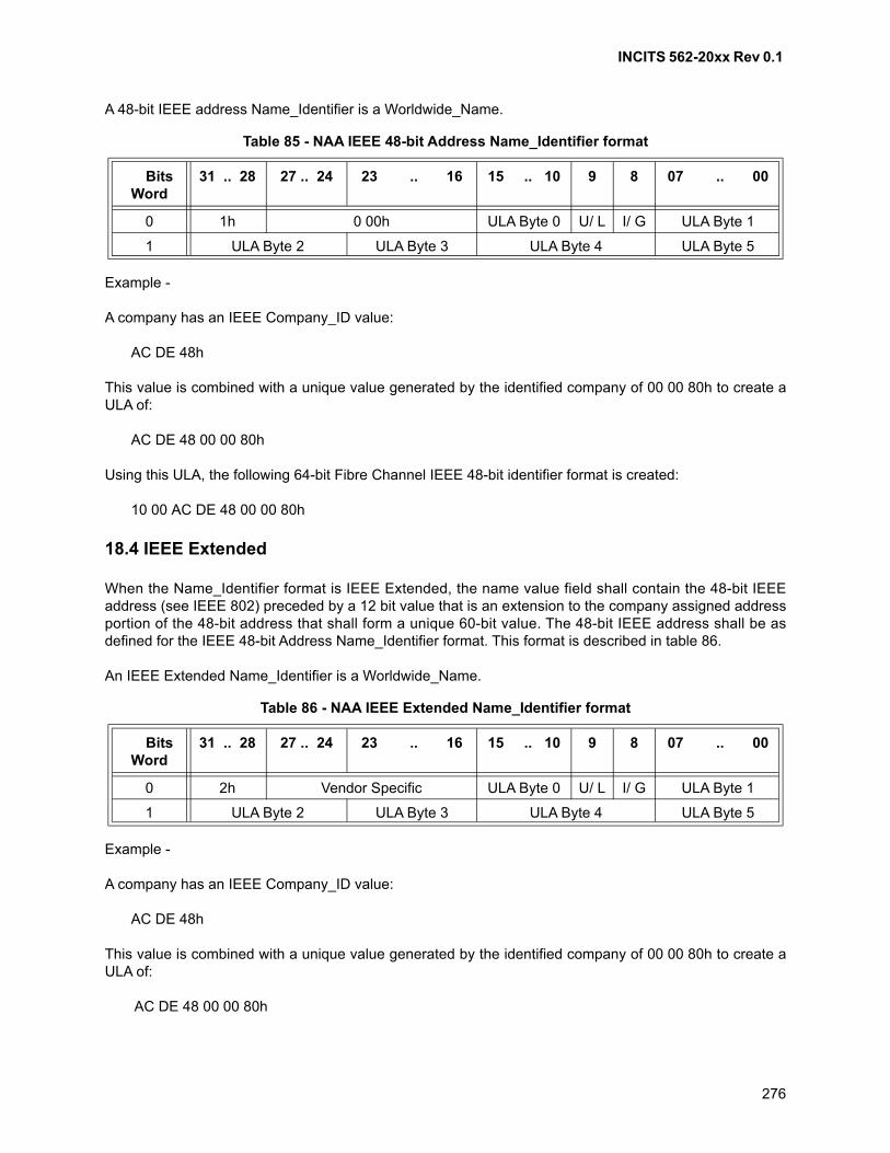
INCITS 562-20xx Rev 0.1
276
A 48-bit IEEE address Name_Identifier is a Worldwide_Name.
Example -
A company has an IEEE Company_ID value:
AC DE 48h
This value is combined with a unique value generated by the identified company of 00 00 80h to create aULA of:
AC DE 48 00 00 80h
Using this ULA, the following 64-bit Fibre Channel IEEE 48-bit identifier format is created:
10 00 AC DE 48 00 00 80h
18.4 IEEE Extended
When the Name_Identifier format is IEEE Extended, the name value field shall contain the 48-bit IEEEaddress (see IEEE 802) preceded by a 12 bit value that is an extension to the company assigned addressportion of the 48-bit address that shall form a unique 60-bit value. The 48-bit IEEE address shall be asdefined for the IEEE 48-bit Address Name_Identifier format. This format is described in table 86.
An IEEE Extended Name_Identifier is a Worldwide_Name.
Example -
A company has an IEEE Company_ID value:
AC DE 48h
This value is combined with a unique value generated by the identified company of 00 00 80h to create aULA of:
AC DE 48 00 00 80h
Table 85 - NAA IEEE 48-bit Address Name_Identifier format
BitsWord
31 .. 28 27 .. 24 23 .. 16 15 .. 10 9 8 07 .. 00
0 1h 0 00h ULA Byte 0 U/ L I/ G ULA Byte 1
1 ULA Byte 2 ULA Byte 3 ULA Byte 4 ULA Byte 5
Table 86 - NAA IEEE Extended Name_Identifier format
BitsWord
31 .. 28 27 .. 24 23 .. 16 15 .. 10 9 8 07 .. 00
0 2h Vendor Specific ULA Byte 0 U/ L I/ G ULA Byte 1
1 ULA Byte 2 ULA Byte 3 ULA Byte 4 ULA Byte 5
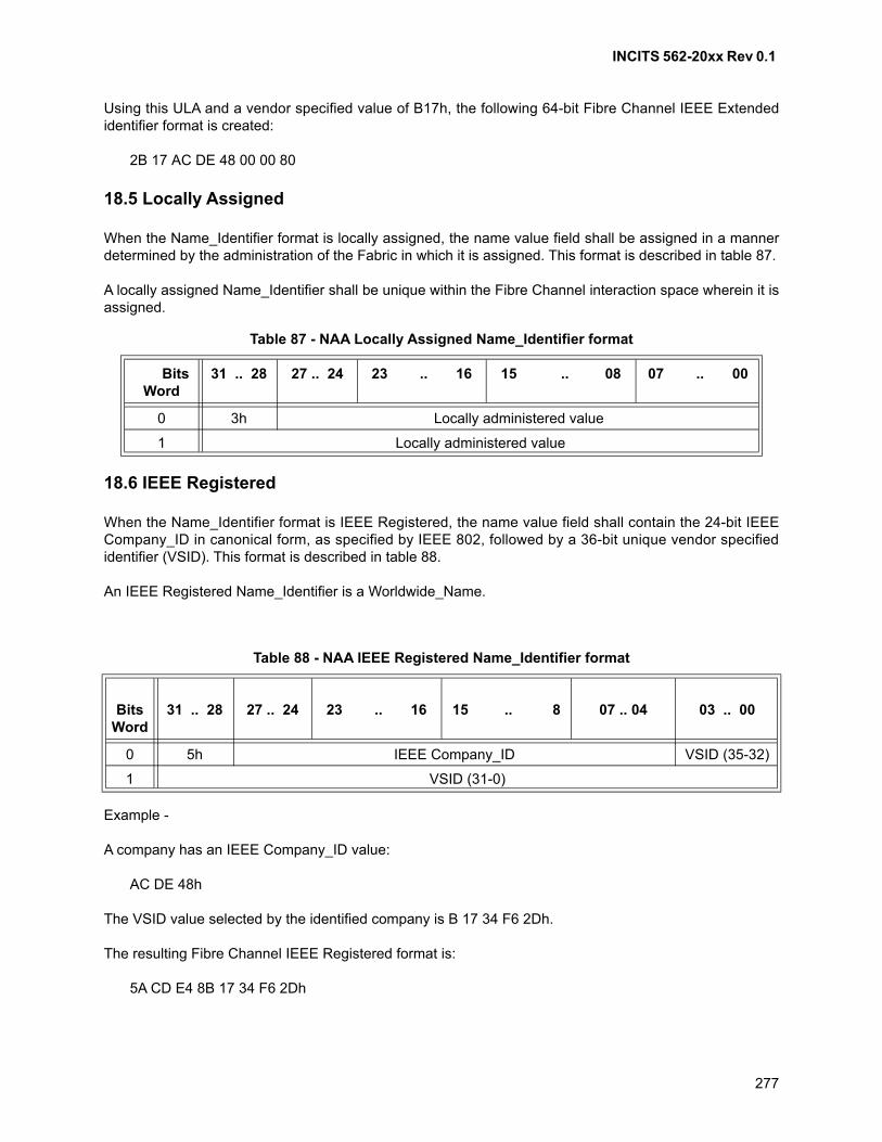
INCITS 562-20xx Rev 0.1
277
Using this ULA and a vendor specified value of B17h, the following 64-bit Fibre Channel IEEE Extendedidentifier format is created:
2B 17 AC DE 48 00 00 80
18.5 Locally Assigned
When the Name_Identifier format is locally assigned, the name value field shall be assigned in a mannerdetermined by the administration of the Fabric in which it is assigned. This format is described in table 87.
A locally assigned Name_Identifier shall be unique within the Fibre Channel interaction space wherein it isassigned.
18.6 IEEE Registered
When the Name_Identifier format is IEEE Registered, the name value field shall contain the 24-bit IEEECompany_ID in canonical form, as specified by IEEE 802, followed by a 36-bit unique vendor specifiedidentifier (VSID). This format is described in table 88.
An IEEE Registered Name_Identifier is a Worldwide_Name.
Example -
A company has an IEEE Company_ID value:
AC DE 48h
The VSID value selected by the identified company is B 17 34 F6 2Dh.
The resulting Fibre Channel IEEE Registered format is:
5A CD E4 8B 17 34 F6 2Dh
Table 87 - NAA Locally Assigned Name_Identifier format
BitsWord
31 .. 28 27 .. 24 23 .. 16 15 .. 08 07 .. 00
0 3h Locally administered value
1 Locally administered value
Table 88 - NAA IEEE Registered Name_Identifier format
Bits
Word31 .. 28 27 .. 24 23 .. 16 15 .. 8 07 .. 04 03 .. 00
0 5h IEEE Company_ID VSID (35-32)
1 VSID (31-0)
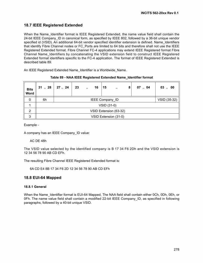
INCITS 562-20xx Rev 0.1
278
18.7 IEEE Registered Extended
When the Name_Identifier format is IEEE Registered Extended, the name value field shall contain the24-bit IEEE Company_ID in canonical form, as specified by IEEE 802, followed by a 36-bit unique vendorspecified id (VSID). An additional 64-bit vendor specified identifier extension is defined. Name_Identifiersthat identify Fibre Channel nodes or FC_Ports are limited to 64 bits and therefore shall not use the IEEERegistered Extended format. Fibre Channel FC-4 applications may extend IEEE Registered format FibreChannel Name_Identifiers by concatenating the VSID extension field to construct IEEE RegisteredExtended format identifiers specific to the FC-4 application. The format of IEEE Registered Extended isdescribed table 89.
An IEEE Registered Extended Name_Identifier is a Worldwide_Name.
Example -
A company has an IEEE Company_ID value:
AC DE 48h
The VSID value selected by the identified company is B 17 34 F6 2Dh and the VSID extension is12 34 56 78 90 AB CD EFh.
The resulting Fibre Channel IEEE Registered Extended format is:
6A CD E4 8B 17 34 F6 2D 12 34 56 78 90 AB CD EFh
18.8 EUI-64 Mapped
18.8.1 General
When the Name_Identifier format is EUI-64 Mapped, The NAA field shall contain either 0Ch, 0Dh, 0Eh, or0Fh. The name value field shall contain a modified 22-bit IEEE Company_ID, as specified in followingparagraphs, followed by a 40-bit unique VSID.
Table 89 - NAA IEEE Registered Extended Name_Identifier format
Bits
Word
31 .. 28 27 .. 24 23 .. 16 15 .. 8 07 .. 04 03 .. 00
0 6h IEEE Company_ID VSID (35-32)
1 VSID (31-0)
2 VSID Extension (63-32)
3 VSID Extension (31-0)
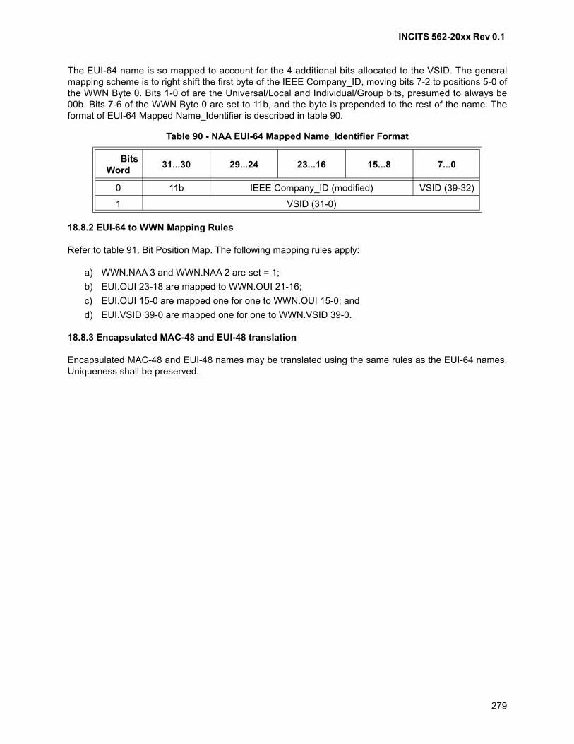
INCITS 562-20xx Rev 0.1
279
The EUI-64 name is so mapped to account for the 4 additional bits allocated to the VSID. The generalmapping scheme is to right shift the first byte of the IEEE Company_ID, moving bits 7-2 to positions 5-0 ofthe WWN Byte 0. Bits 1-0 of are the Universal/Local and Individual/Group bits, presumed to always be00b. Bits 7-6 of the WWN Byte 0 are set to 11b, and the byte is prepended to the rest of the name. Theformat of EUI-64 Mapped Name_Identifier is described in table 90.
18.8.2 EUI-64 to WWN Mapping Rules
Refer to table 91, Bit Position Map. The following mapping rules apply:
a) WWN.NAA 3 and WWN.NAA 2 are set = 1;
b) EUI.OUI 23-18 are mapped to WWN.OUI 21-16;
c) EUI.OUI 15-0 are mapped one for one to WWN.OUI 15-0; and
d) EUI.VSID 39-0 are mapped one for one to WWN.VSID 39-0.
18.8.3 Encapsulated MAC-48 and EUI-48 translation
Encapsulated MAC-48 and EUI-48 names may be translated using the same rules as the EUI-64 names.Uniqueness shall be preserved.
Table 90 - NAA EUI-64 Mapped Name_Identifier Format
BitsWord
31...30 29...24 23...16 15...8 7...0
0 11b IEEE Company_ID (modified) VSID (39-32)
1 VSID (31-0)
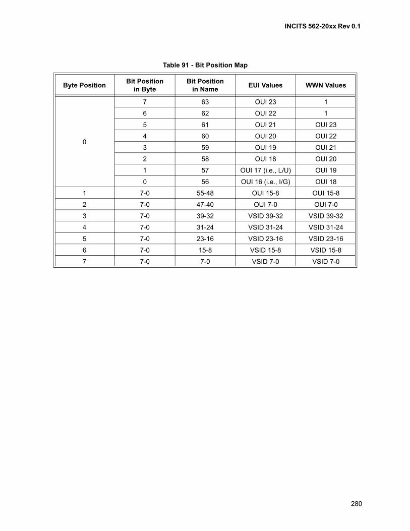
INCITS 562-20xx Rev 0.1
280
Table 91 - Bit Position Map
Byte Position Bit Position
in ByteBit Position
in NameEUI Values WWN Values
0
7 63 OUI 23 1
6 62 OUI 22 1
5 61 OUI 21 OUI 23
4 60 OUI 20 OUI 22
3 59 OUI 19 OUI 21
2 58 OUI 18 OUI 20
1 57 OUI 17 (i.e., L/U) OUI 19
0 56 OUI 16 (i.e., I/G) OUI 18
1 7-0 55-48 OUI 15-8 OUI 15-8
2 7-0 47-40 OUI 7-0 OUI 7-0
3 7-0 39-32 VSID 39-32 VSID 39-32
4 7-0 31-24 VSID 31-24 VSID 31-24
5 7-0 23-16 VSID 23-16 VSID 23-16
6 7-0 15-8 VSID 15-8 VSID 15-8
7 7-0 7-0 VSID 7-0 VSID 7-0
INCITS 562-20xx Rev 0.1
281
19 Exchange, Sequence, and sequence count management
19.1 Scope
Exchange, Sequence, and sequence count management are functions of the FC-2V sublevel.
19.2 Introduction
19.2.1 Data frame transfer
Transfer of information between two Nx_Ports is based on transmission of:
1) a Data frame by a source Nx_Port; and
2) in Class 2 only, an ACK response frame by the Nx_Port receiving the Data frame, to acknowledgeData frame delivery.
19.2.2 Frame identification
D_ID, S_ID, SEQ_ID, SEQ_CNT, and Sequence Context (see clause 12) uniquely identify a single frame.The OX_ID and RX_ID fields (collectively defined as X_ID, see 19.6.4) may be used by a SequenceInitiator or Recipient Nx_Port to provide a locally assigned value that may be used in place of S_ID, D_ID,and SEQ_ID to identify frames in a non-streamed Sequence or when only one Sequence is open. WhenSequences are streamed, or more than one Sequence is open, the X_ID field may be used in place of theS_ID and D_ID to identify the Sequence Initiator and Recipient Nx_Ports associated with a specific frame.The X_ID field may also be used in conjunction with S_ID, D_ID, or SEQ_ID to relate one or moreSequences to actions initiated by Upper Level Protocols.
19.2.3 Sequence
A Sequence is a set of one or more related Data frames transmitted unidirectionally from one Nx_Port toanother Nx_Port within an Exchange. The relationship between Sequences and Exchanges is shown infigure 76. In Class 2 an ACK_1 frame is transmitted in response to each Data frame or a single ACK_0 istransmitted for all Data frames of a Sequence. A Sequence is assigned a SEQ_ID by the SequenceInitiator. A Sequence shall only be initiated when an Nx_Port holds the Sequence Initiative for a givenExchange.
19.2.4 Streamed Sequences
This standard allows an Nx_Port to initiate a new Sequence for the same Exchange while it already hasSequences open for that Exchange. The new Sequence is termed a streamed Sequence. See 12.8 formore information regarding the assignment of SEQ_IDs for additional rules when streaming Sequences.
19.2.5 SEQ_CNT
Each frame within a Sequence contains a SEQ_CNT that represents the sequential number of each Dataframe within one or multiple Sequences transmitted by an Exchange Originator or Responder. In Class 2,an ACK response frame contains a SEQ_CNT that is set equal to the Data frame SEQ_CNT to which it isresponding.
INCITS 562-20xx Rev 0.1
282
19.2.6 Exchange
An Exchange is the fundamental mechanism for coordinating the interchange of information and databetween two Nx_Ports. All Data transmission shall be part of an Exchange. This discusses Exchangesbetween Nx_Ports. This standard does not address the means to manage Exchanges across multipleNx_Ports within a node.
An Exchange is a set of one or more related Sequences. Sequences for the same Exchange may flow inthe same or opposite direction between a pair of Nx_Ports but not simultaneously (i.e., Data flows in onedirection at a time within an Exchange for a single Nx_Port pair). An Exchange may be unidirectional orbi-directional. Within a single Exchange only one Sequence shall be active at any given time for a singleinitiating Nx_Port (i.e., a Sequence Initiator shall complete transmission of Data frames for a Sequencebefore initiating another Sequence for the same Exchange).
Unless stated otherwise by the upper level, Class 3 Sequences shall not be transmitted in the sameExchange with Class 2 Sequences. The ability to send or receive Class 3 Sequences in the sameExchange as Class 2 Sequences is not a requirement of this standard. A Sequence Initiator shall notstream Sequences that are in different classes of service.
NOTE 39 - In Class 2, when Sequences are streamed, a Recipient Nx_Port may see multiple activeSequences for the same Initiator because of out of order delivery.
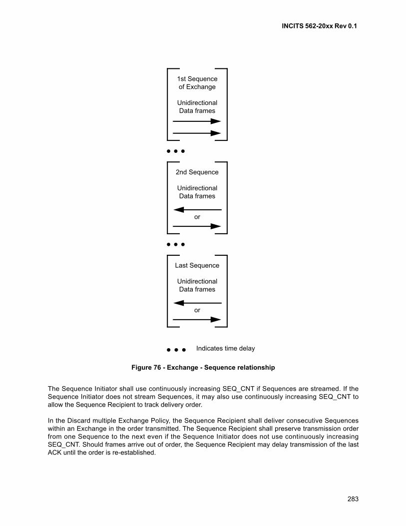
INCITS 562-20xx Rev 0.1
283
The Sequence Initiator shall use continuously increasing SEQ_CNT if Sequences are streamed. If theSequence Initiator does not stream Sequences, it may also use continuously increasing SEQ_CNT toallow the Sequence Recipient to track delivery order.
In the Discard multiple Exchange Policy, the Sequence Recipient shall deliver consecutive Sequenceswithin an Exchange in the order transmitted. The Sequence Recipient shall preserve transmission orderfrom one Sequence to the next even if the Sequence Initiator does not use continuously increasingSEQ_CNT. Should frames arrive out of order, the Sequence Recipient may delay transmission of the lastACK until the order is re-established.
Figure 76 - Exchange - Sequence relationship
Last Sequence
UnidirectionalData frames
1st Sequenceof Exchange
UnidirectionalData frames
2nd Sequence
UnidirectionalData frames
or
or
Indicates time delay
INCITS 562-20xx Rev 0.1
284
An Exchange is assigned an OX_ID by the Originator and an RX_ID by the Responder. When anExchange is originated, there is a binding of resources in both the Originator and Responder.
An Exchange Status Block exists throughout the life of an Exchange and is located by using one or morefields of the Sequence_Qualifier (e.g., an Nx_Port's X_ID).
19.2.7 Sequence Initiative
The Exchange Originator is the Initiator of the first Sequence of the Exchange and holds the initiative totransmit Sequences. At the end of each Sequence of the Exchange, the Initiator of the Sequence maytransfer the initiative to transmit the next Sequence to the other Nx_Port, or it may retain the initiative totransmit the next Sequence.
19.3 Applicability
FC-2V manages:
a) opening and closing of Exchanges;
b) initiation and termination of Sequences;
c) assignment of X_IDs;
d) Sequence Initiative;
e) assignment of SEQ_IDs;
f) Segmentation and Reassembly;
g) Sequences;
h) SEQ_CNT of frames; and
i) detection of frame Sequence errors.
In addition to the above, for Class 2 FC-2V manages notification of frame Sequence errors.
For Class 2, the Sequence Initiator shall assign SEQ_IDs from 0 to 255. The Sequence Recipient assignsthe SEQ_ID to an available Recipient Sequence Status Block.
For Class 3, the Sequence Initiator shall assign SEQ_IDs from 0 to 255.
19.4 Exchange rules
19.4.1 Exchange management
The following rules apply to Exchange management:
a) over the life of an Exchange, the Sequence Recipient shall deliver Data to FC-4 or an upper levelon a Sequence basis;
b) in the Discard multiple Sequences Error Policy, each Sequence shall be delivered in the order inwhich the Sequence was transmitted relative to other Sequences transmitted for the Exchange;
c) in the Discard multiple Sequences Error Policy, a Sequence shall be deliverable if the Sequencecompletes normally and the previous Sequence, if any, is deliverable;
d) in the Discard a single Sequence Error Policy, each Sequence shall be delivered in the order inwhich the Sequence was received relative to other Sequences received for the Exchange;
INCITS 562-20xx Rev 0.1
285
e) in the Discard a single Sequence Error Policy, a Sequence shall be deliverable if the Sequencecompletes normally without regard to the deliverability of other Sequences within the sameExchange;
f) in all discard policies, a Sequence is complete with regard to Data content if all valid Data framesfor the Sequence were received without rejectable errors being detected;
g) in Process policy with infinite buffers in Class 3, a sequence is complete if a frame of anothersequence is received or E_D_TOV expires before the last frame of the current sequence isreceived; and
h) the ordering relationship and deliverability of Sequences between two separate Exchanges isoutside the scope of this standard. Certain specific cases of Basic Link Services and ExtendedLink Services do, however, specify collision cases (e.g., FLOGI, PLOGI, and RSI).
19.4.2 Exchange origination
The following rules apply to Exchange origination:
a) an Exchange being originated for ELSs before Login is complete or for the purpose of Login shallfollow default Login parameters and special ELSs rules specified in FC-LS-4;
b) a new Exchange, other than ELSs, may be originated if three conditions are met:
A) the originating Nx_Port has performed Login with the destination Nx_Port;
B) the originating Nx_Port has an OX_ID and Exchange resources available for use; and
C) the originating Nx_Port is able to initiate a new Sequence;
c) each frame within the first Sequence of an Exchange shall set the First_Sequence F_CTL bit toone;
d) the first frame of the first Sequence of the Exchange shall specify the Error Policy for theExchange in F_CTL bits 5-4 of the Frame_Header. The Exchange Error Policy shall be consistentwith the error policies supported by both the Originator and Responder;
e) the Originator shall transmit the first Data frame of the Exchange with its assigned OX_ID and anunassigned RX_ID of FF FFh;
f) if the Responder requires X_ID interlock (Login), the Originator (and Sequence Initiator) shall nottransmit additional Data frames for this Exchange until the ACK to the first frame of the Exchangeis received. The RX_ID in the ACK frame shall be used in subsequent frames of the Exchange;
g) if the Responder (Login) does not require X_ID interlock, the Originator may transmit additionalframes of the Sequence. In Class 2, the Responder shall return its X_ID no later than in the ACKcorresponding to the last Data frame of the Sequence. The next Sequence of the Exchange shallcontain both the OX_ID and RX_ID assigned in the previous Sequence;
h) in Class 2, the Sequence Initiator shall receive at least one ACK from the Recipient before theInitiator attempts to initiate subsequent Sequences for the Exchange; and
i) the rules specified in Sequence initiation and termination specify the method for assigning X_IDs.
19.4.3 Sequence delimiters
For a more complete description of Data frame and Link_Control delimiters see tables 61 and 65. Thefollowing rules summarize the management of frame delimiters within a Sequence:
a) A Sequence shall be initiated by transmitting the first frame with a SOFix;
b) Intermediate frames within a Sequence shall be transmitted with SOFnx and EOFn; and
INCITS 562-20xx Rev 0.1
286
c) The Sequence shall be complete when an EOFt has been transmitted or received for the
appropriate SEQ_ID and all previous Data frames and ACKs (if any) have been accounted for bythe Initiator and Recipient, respectively.
19.4.4 Sequence initiation
The following rules apply to Sequence initiation:
a) a new Sequence may be initiated if three conditions are met:
A) the initiating Nx_Port holds the initiative to transmit (Sequence Initiative);
B) the initiating Nx_Port has a SEQ_ID available for use; and
C) the total number of active Sequences initiated by the initiating Nx_Port with the RecipientNx_Port does not exceed any of the following:
a) total concurrent Sequences (see FC-LS-4);
b) concurrent Sequences per class (see FC-LS-4); and
c) open Sequences per Exchange (see FC-LS-4);
b) a SOFix shall start the first Data frame of the Sequence;
c) the Sequence Initiator shall assign a SEQ_ID. If the SEQ_ID unique per Exchange bit (seeFC-LS-4) is set to zero in the PLOGI request or PLOGI LS_ACC, then the SEQ_ID shall have avalue that is unique among all concurrently open Sequences between the Sequence Initiator andthe Sequence Recipient, independent of the X_ID. If the SEQ_ID unique per Exchange bit is set toone in the PLOGI request and PLOGI LS_ACC, then the SEQ_ID shall have a value that is uniqueamong all concurrently open Sequences with the same X_ID. The SEQ_ID shall not match the lastSEQ_ID transmitted by the Sequence Initiator for this Exchange for the current SequenceInitiative. For streamed Sequences for the same Exchange, the Sequence Initiator shall use X+1different subsequent SEQ_IDs where X is the number of open Sequences per Exchange so thatthe Exchange Status Block contains status of the last deliverable Sequence;
d) the Sequence Initiator shall not initiate the (X+1)th streamed Sequence until the first Sequencestatus is known (e.g., if X = 3 and the Sequence Initiator transmits SEQ_ID = 3, then 4, then 7, itshall not initiate another Sequence for the same Exchange until it resolves the completion status ofSEQ_ID = 3, regardless of the completion status of SEQ_ID = 4 or 7);
e) the Sequence_Qualifier shall be unique until an open Sequence is ended normally or until theRecovery_Qualifier is determined by the Abort Sequence Protocol (ABTS);
f) in Class 2 and 3, each Data frame of the Sequence shall be limited in size to the lesser of theFx_Port and destination Nx_Port capabilities as specified by Login;
g) sequence status shall be associated with the Exchange in which the Sequence is beingtransmitted; and
h) frame transmission shall follow Flow Control Rules specified in clause 20.
19.4.5 Sequence management
The Sequence Recipient and the Sequence Initiator shall verify that frames received for a Sequenceadhere to the items listed. If the Sequence Recipient determines that one of the following conditions is notmet in Class 2, it shall transmit a P_RJT. If the Sequence Initiator determines that one of the followingconditions is not met, it shall abort the Sequence (Abort Sequence Protocol).
a) each frame shall contain the assigned SEQ_ID, OX_ID, and RX_ID values;
b) FF FFh shall be used for unassigned X_ID values;
c) each frame shall indicate the Exchange context;
INCITS 562-20xx Rev 0.1
287
d) each frame shall indicate the Sequence context;
e) each frame shall contain a SEQ_CNT that follow the rules as defined in 19.4.6;
f) frame transmission shall follow Flow Control Rules as defined in clause 20;
g) the Data_Field size of each frame of the Sequence shall be less than or equal to the maximumallowable Data_Field size for the type of frame indicated by the SOF delimiter (see 17.3.4 and17.4.4);
h) a Sequence shall be transmitted in one class; or
i) each Data frame in a Sequence shall be transmitted within an E_D_TOV timeout period of theprevious Data frame transmitted within the same Sequence. Otherwise, a Sequence timeout shallbe detected.
19.4.6 SEQ_CNT
Within a Data frame Sequence, SEQ_CNT is used to identify each Data frame for verification of deliveryand transmission order. The following rules specify the SEQ_CNT of each frame of a Sequence:
a) the SEQ_CNT of the first Data frame of the first Sequence of the Exchange transmitted by eitherthe Originator or Responder shall be binary zero;
b) the SEQ_CNT of each subsequent Data frame within the Sequence shall be incremented by onefrom the previous Data frame;
c) the SEQ_CNT of the first Data frame of a streamed Sequence shall be incremented by one fromthe last Data frame of the previous sent Sequence;
d) the SEQ_CNT of the first Data frame of a non-streamed Sequence may be incremented by onefrom the last Data frame of the previous sent Sequence or may be zero;
e) the SEQ_CNT of each Link_Response in Class 2 shall be set to the SEQ_CNT of the Data frameto which it is responding;
f) the SEQ_CNT of each ACK_1 frame in Class 2 shall be set to the SEQ_CNT of the Data frame towhich it is responding. See 20.3.3.3 for ACK_1 rules;
g) the SEQ_CNT of each ACK_0 frame in Class 2 shall be set to the SEQ_CNT of the last Dataframe transmitted (End_Sequence = 1) for the Sequence. See 20.3.3.2 for ACK_0 rules;
h) if infinite buffers and ACK_0 is being used for Sequences in which the SEQ_CNT may wrap, frameuniqueness is not being ensured (See 20.3.3.2 and FC-LS-4 for ACK_0 rules); and
i) within an acknowledged class of service, the SEQ_CNT of any frame shall not be reused until thatframe is acknowledged.
19.4.7 Normal ACK processing
The following rules apply to normal ACK processing:
a) based on N_Port Login parameters (Initiator support indicated in Initiator Control and Recipientsupport in Recipient Control in Class Service Parameters), if both Nx_Ports support multiple ACKforms, ACK_0 usage shall take precedence over ACK_1. ACK_0 use may be asymmetricalbetween two Nx_Ports (see FC-LS-4);
b) mixing ACK forms in a Sequence is not allowed;
c) ACK_0 may be used for both Discard and Process Error Policies. A single ACK_0 per Sequenceshall be used to indicate successful Sequence delivery or to set Abort Sequence Condition bits toa value other than 00b. ACK_0 shall not participate in end-to-end Credit management. Anadditional ACK_0 shall be used within a Sequence to perform X_ID interlock;
INCITS 562-20xx Rev 0.1
288
d) ACK frames may be transmitted in the order in which the Data frames are processed and need notbe transmitted in SEQ_CNT order, however, the History bit (bit 16) of the Parameter Field shallindicate transmission status of previous ACK frame transmission for the current Sequence;
e) the final ACK of a Sequence shall be terminated with EOFt and shall be transmitted according to
the rules for normal Sequence completion in the absence of detected errors;
f) ACK_1 or ACK_0 shall be transmitted during X_ID interlock (see 19.6.5);
g) if a Sequence Recipient receives a Data frame in Class 2 that falls within the SEQ_CNT range of aRecovery_Qualifier, it shall discard the Data_Field of the frame and shall not deliver the Payload.The Sequence Recipient may transmit an ACK for the corresponding Data frame;
h) if a Sequence Initiator receives an ACK for a Data frame in Class 2 that falls within the SEQ_CNTrange of a Recovery_Qualifier, it shall discard and ignore the ACK frame;
i) see 20.3.3.2 and 20.3.3.3 for the role of acknowledgement frames (ACK) in flow control; and
j) each ACK shall be transmitted within an E_D_TOV timeout period of the event that prompts theinitiative to transmit an ACK frame (i.e., when using ACK_1, it shall be transmitted withinE_D_TOV of the Data frame reception, and when using ACK_0, it shall be transmitted withinE_D_TOV of receiving the last Data frame of the Sequence).
19.4.8 Normal Sequence completion
The following rules apply to normal Sequence completion:
a) the Last Data frame of a Sequence shall be indicated by setting the F_CTL End_Sequence bit(F_CTL Bit 19) to one;
b) an Exchange Event shall be defined when the End_Sequence bit (Bit 19) = 1, and any of thefollowing F_CTL bits are set as indicated:
A) Sequence Initiative (Bit 16) = 1; or
B) Last Sequence (Bit 20) = 1;
c) a Sequence Event shall be defined when the End_Sequence bit (Bit 19) = 1 in the absence of anExchange Event;
d) in Class 2 the Sequence Initiator shall consider a Sequence as deliverable (to the ULP) andcomplete when it receives the final ACK for the Sequence (ACK with EOFt delimiter). However, the
Sequence Initiator shall account for all ACKs before reusing the SEQ_ID for this Exchange;
e) for Class 3 Sequences, this standard provides no deliverability guarantees;
f) a Class 2 Sequence shall be considered complete by the Sequence Recipient if:
A) all Data frames are received;
B) no Sequence errors are detected; and
C) acknowledgements, if any, prior to acknowledgment of the last Data frame received have beentransmitted;
g) a Class 3 Sequence shall be considered complete by the Sequence Recipient if:
A) all Data frames are received;
B) no Sequence errors are detected; and
C) an EOFt terminates the last Data frame;
h) in Class 2, if the last Data frame (End_Sequence = 1) transmitted is the last Data frame receivedfor the Sequence, or if the last Data frame (End_Sequence = 1) received indicates an Exchangeevent (item b), the Sequence Recipient shall transmit an ACK frame (i.e., ACK_1 or ACK_0) withEOFt in response to the last Data frame of the Sequence (i.e., End_Sequence bit in F_CTL = 1)
when the Sequence is deliverable. The End_Sequence bit in F_CTL of the ACK shall be set toone. A Sequence is deliverable:
INCITS 562-20xx Rev 0.1
289
A) in Discard multiple Sequences Error Policy, when all preceding ACK frames have beentransmitted and the previous Sequence, if any, is deliverable; and
B) in Discard a single Sequence Error Policy, when all preceding ACK frames have beentransmitted without regard to a previous Sequence;
i) in Class 2, if a frame with the End_Sequence bit set to one is received, and this frame causes aSequence Event, and not all frames of the Sequence have been received, the Sequence Recipientmay either:
A) withhold transmission of the ACK corresponding to the Data frame with the End_Sequence bitset to one until all previous ACKs have been transmitted and the Sequence is deliverable; or
B) transmit the ACK corresponding to the Data frame with the End_Sequence bit set to one. ThisACK shall have EOFn and the End_Sequence bit set to zero. When the last missing Data
frame of the Sequence is received and the Sequence is deliverable, the Sequence Recipientshall transmit an ACK with EOFt, the End_Sequence bit set to one, and the SEQ_CNT and
other fields that match the last missing Data frame of the Sequence;
NOTE 40 - When Sequences are being streamed in Class 2 with out of order delivery, transmission ofACK (EOFn) in response to the last Data frame of the Sequence (End_Sequence = 1) avoids costing the
Initiator an extra Credit of one for the last Data frame of the Sequence while the Sequence Recipient waitsfor the last frame to be delivered.
j) in Class 2, the Sequence Initiator shall transmit the last Data frame with an EOFn;
k) in Class 3 the Sequence Initiator shall transmit the last Data frame with an EOFt;
l) in the last Data frame of a Sequence, the Sequence Initiator shall set the:
A) Sequence Initiative bit in F_CTL to 0 to hold or not affect Sequence Initiative (see 12.7.8); or
B) Sequence Initiative bit in F_CTL to 1 to transfer Sequence Initiative;
m) in Class 2, the Sequence Initiative is considered to be passed to the Sequence Recipient when theSequence Initiator receives the final ACK (EOFt) of the Sequence with the Sequence Initiative bit =
1; and
n) Sequence status in the Exchange Status Block is available until X+2 Sequences have beencompleted (where X is the number of open Sequences per Exchange supported by the SequenceRecipient as specified during Login) or the Exchange is terminated.
19.4.9 Detection of missing frames
The following methods of detecting missing frames apply to a non-streamed Sequence or multiplestreamed Sequences with continuously increasing SEQ_CNT:
a) with out of order delivery, a potentially missing Data frame is detected if a frame is received with aSEQ_CNT that is not one greater than the previously received frame, except when a SEQ_CNTwrap to zero occurs. If the potentially missing Data frame is not received within the E_D_TOVtimeout period, a missing frame error is detected;
b) in Class 2, with in order delivery, a potentially missing Data frame is detected if a frame is receivedwith a SEQ_CNT that is not one greater than the previously received frame, except when aSEQ_CNT wrap to zero occurs. If the potentially missing Data frame is not received within theE_D_TOV timeout period, a missing frame error is detected;
NOTE 41 - With in order delivery, a Class 2 frame may be delivered with its SEQ_CNT that is not onegreater than the previously received frame, if a Class 2 frame that was transmitted earlier has been issuedF_BSY or F_RJT. This frame is potentially missing, since it may be retransmitted.
INCITS 562-20xx Rev 0.1
290
c) in Class 3, with in order delivery, a missing Data frame is detected if a frame is received with aSEQ_CNT that is not one greater than the previously received frame, except when a SEQ_CNTwrap to zero occurs; and
d) a Sequence Recipient may also detect missing Data frames through the use of a missing framewindow. The size of the missing frame window, W, is set by the Sequence Recipient and is notspecified by this standard. A frame is considered missing by a Sequence Recipient if its SEQ_CNTis less than the highest SEQ_CNT received for that Sequence minus W. It is suggested that W beat least equal to End-to-end Credit.
NOTE 42 - Fabric characteristics should be taken into account when attempting to establish a missingframe window - W. Too small a value may give false errors, whereas too large a value may create out ofCredit conditions.
When a missing frame error is detected, the expected SEQ_CNT is saved in the Error SEQ_CNT field ofthe appropriate Sequence Status Block and a Sequence error is posted in the S_STAT field in the sameSequence Status Block for a given Exchange (OX_ID, RX_ID). Only the first error is saved.
19.4.10 Sequence errors - Class 2
19.4.10.1 Rules common to all discard policies
Either the Sequence Initiator or the Sequence Recipient may detect errors within a Sequence.
In discard policy, the Recipient shall discard the Data_Field portion of Data frames (FC-2 Header isprocessed) received after the point at which the error is detected and including the frame in which the errorwas detected. In all cases except the Stop Sequence condition, the Sequence Recipient shall discard theentire Sequence. The following rules apply:
a) the types of Sequence errors that shall be detected by an Nx_Port include:
A) detection of a missing frame based on SEQ_CNT;
B) detection of a missing frame based on a timeout (E_D_TOV);
C) detection of an error within a frame (P_RJT);
D) reception of a Reject frame (F_RJT or P_RJT); or
E) detection of an internal malfunction;
b) if a Recipient receives a Data frame for a Sequence that the Recipient ULP wishes to stopreceiving, the Recipient shall indicate the Stop Sequence condition to the Initiator by using theAbort Sequence Condition bits (10b) in F_CTL (see 22.5.5.3);
c) if a Recipient detects an error within a valid frame of a Sequence, it shall indicate that error to theInitiator by transmitting a P_RJT with a reason code;
d) if a Recipient receives a Data frame for an active Sequence that has previously had one or moreData frames rejected, the Recipient shall indicate that previous error to the Initiator on subsequentACK frames using the Abort Sequence Condition bits (01b) in F_CTL in the same manner as itwould if a missing frame were detected;
e) if the Recipient has transmitted an ACK with the Abort Sequence Condition bits set, or a P_RJT inresponse to a Data frame, it shall post that information in the Sequence Status;
f) if an Initiator receives an ACK with the Abort Sequence Condition bits in F_CTL requesting StopSequence (10b), it shall end the Sequence by transmitting the End_Sequence bit set to 1 in thenext Data frame. If the last Data frame has already been transmitted, the Sequence Initiator shallnot respond to the Stop Sequence request but shall notify the FC-4;
INCITS 562-20xx Rev 0.1
291
g) if an Initiator detects a missing frame, internal error, or receives an ACK with a detected rejectablecondition, it shall abort the Sequence by transmitting an Abort Sequence (ABTS) Basic LinkService command (see 16.3.2);
h) if an Initiator receives an ACK with the Abort Sequence Condition bits (01b) in F_CTL requestingthat the Sequence be aborted, it shall abort the Sequence by transmitting an Abort Sequence(ABTS) Basic Link Service command (see 16.3.2);
i) if an Initiator receives a Reject frame (F_RJT, or P_RJT), it shall abort the Sequence bytransmitting an Abort Sequence (ABTS) Basic Link Service command (see 16.3.2) if the Sequencehas not been terminated by the Sequence Recipient or Fabric using an EOFt on the RJT; and
j) if the Sequence Initiator detects a Sequence timeout (see 22.5.3), it shall:
A) abort the Sequence using ABTS; or
B) transmit Link Credit Reset to the Recipient if no end-to-end Credit is available.
End-to-end Credit is not required in order to exercise option A; however, if ABTS is sent inabsence of end-to-end Credit, it is possible that the ABTS frame may be lost, forcing further errorrecovery process.
19.4.10.2 Discard multiple Sequences Error Policy
These rules apply to Discard multiple Sequences Error Policy:
a) if a Sequence Recipient detects a missing frame error, transmits a P_RJT, or detects an internalmalfunction for a Sequence within an Exchange that requested Discard multiple Sequences ErrorPolicy, it shall request that the Sequence be aborted by setting the Abort Sequence Condition bitsto 01b in F_CTL on the ACK corresponding to the Data frame during which the missing frame errorwas detected. For detected errors other than missing frame, the Abort Sequence Condition bitsshall be set to 01b in F_CTL for any subsequent ACKs transmitted. The Sequence Recipient maycontinue to transmit ACKs for subsequent frames of the Sequence and any subsequent streamedSequences until the ABTS frame is received. Any ACKs transmitted for frames in this Sequence orany subsequent Sequences shall continue to set the Abort Sequence Condition bits to 01b (see22.5.5.2). If an ACK is transmitted for the last Data frame of a Sequence, F_CTL bit 19(End_Sequence), F_CTL bit 17 (Priority Enable), and F_CTL bit 16 (Sequence Initiative) settingson the Data frame shall be ignored, and in the ACK frame those bits shall be set to zero in additionto setting F_CTL bits 5-4 (Abort Sequence Condition) to 01b.
19.4.10.3 Discard a single Sequence Error Policy
If a Sequence Recipient detects a missing frame error, or detects an internal malfunction for a Sequencewithin an Exchange that requested Discard a single Sequence Error Policy, it shall request that theSequence be aborted by setting the Abort Sequence Condition bits to 01b in F_CTL on the ACKcorresponding to the Data frame during which the missing frame error was detected. For errors detectedother than missing frame, the Abort Sequence Condition bits 01b in F_CTL shall be transmitted for anysubsequent ACKs transmitted for this Sequence.
The Sequence Recipient may continue to transmit ACKs for subsequent frames of the Sequence until theABTS frame is received. However, it shall not continue to set the Abort Sequence Condition bits in anysubsequent streamed Sequences. If the final ACK (EOFt) to the Sequence is transmitted, F_CTL bits 19,17, 16, and 14 settings on the Data frame shall be ignored and shall be set to zero in the ACK frame, andbits 5-4 shall be set to 01b in the ACK frame (see 22.5.5.2).
INCITS 562-20xx Rev 0.1
292
19.4.10.4 Process with infinite buffers Error Policy
In process policy, the Recipient shall ignore errors detected on intermediate frames, or timeout errors suchthat ABTS is not requested. However, such errors shall be reported to an upper level.
If a Recipient detects an internal error related to a Sequence, or it detects that the first or last frame of aSequence is missing, it shall request that the Sequence be aborted by setting the Abort SequenceCondition bits (01b) in F_CTL on subsequent ACK frames. The Recipient shall continue to respond in thesame manner as defined under Discard a single Sequence Error Policy.
NOTE 43 - Missing last Data frame is detected by the Sequence timeout.
If a Sequence Recipient detects an error within a valid frame of a Sequence, it shall indicate that error tothe Initiator by transmitting a P_RJT with a reason code.
19.4.11 Sequence errors - Class 3
19.4.11.1 Rules common to all discard policies
The Sequence Recipient may only detect errors within a Sequence.
In both discard policies, the Sequence Recipient shall discard Sequences in the same manner as in Class2 with the exception that an ACK indication of Abort Sequence shall not be transmitted. In discard policy,the Recipient shall discard frames received after the point at which the error is detected. Individual FC-4sor upper levels may recover the entire Sequence or only that portion after which the error is detected.
a) the types of errors that shall be detected by an Nx_Port are:
A) detection of a missing frame based on timeout; or
B) detection of an internal malfunction;
b) if a Recipient detects an internal error, it shall abnormally terminate the Sequence, post theappropriate status, and notify the FC-4 or upper level. One or more Sequences shall not bedelivered based on single or multiple Sequence discard Error Policy;
c) if a Recipient detects a missing frame, it shall abnormally terminate the Sequence, post theappropriate status, and notify the FC-4 or upper level. One or more Sequences shall not bedelivered based on single or multiple Sequence discard Error Policy;
d) in the Discard multiple Sequences Error Policy in Class 3, the Sequence Recipient shall not berequired to utilize a timeout value of R_A_TOV following detection of a missing frame. Therefore,frames may be discarded for an Exchange forever if the Sequence Initiator does not utilize otherdetection mechanisms; and
e) notification of the Sequence error condition to the Initiator is the responsibility of the FC-4 or upperlevel.
19.4.11.2 Process with infinite buffers Error Policy
In process Policy, the Recipient shall ignore errors detected on all frames, or timeout errors. However,such errors shall be reported to an upper level.
NOTE 44 - Ignoring an error on the first frame of a Sequence or an Exchange may cause the frame to bedelivered to the wrong Recipient.
INCITS 562-20xx Rev 0.1
293
19.4.12 Sequence Status Rules
The following rules summarize Sequence Status Block processing:
a) the Sequence Initiator shall consider a Sequence open and active after transmission of the firstframe of the Sequence. The Sequence shall remain active until the Sequence Initiator hastransmitted the last frame of the Sequence. The Sequence Initiator shall consider the Sequenceopen until:
A) it receives the ACK (EOFt);
B) BA_ACC is received to an ABTS frame; or
C) a Logout Link Service request is completed;
b) a Sequence shall be considered open and active, and an Sequence Status Block opened, by theSequence Recipient when any frame in a Sequence is received for the first Sequence of a newExchange as indicated in F_CTL bit 21. An Exchange Status Block is opened at the same time andthe Exchange is then considered open;
c) a Sequence shall be considered open and active, and a Sequence Status Block opened, by theSequence Recipient when any frame in a Sequence is received for an open Exchange;
d) if the Sequence Recipient transmits an ACK frame with the Abort Sequence Condition bits otherthan 00b, it shall post that status in the Sequence Status Block status;
e) if a Sequence completes normally and is deliverable, its status shall be posted in the SequenceStatus Block;
f) if a Sequence completes abnormally by the Abort Sequence Protocol, its status shall be posted inthe Sequence Status Block; and
g) the Exchange Status Block shall be updated with Sequence Status information when theSequence becomes abnormally complete, or normally complete.
19.4.13 Exchange termination
a) the last Sequence of the Exchange shall be indicated by setting the F_CTL Last_Sequence bit toone in the last Data frame of a Sequence. The Last_Sequence bit may be set to one prior to thelast Data frame. Once it has been set to one, it shall remain set to one for the remainder of theSequence;
b) the Exchange shall be terminated when the last Sequence is completed by normal Sequencecompletion rules;
c) an Exchange may be abnormally terminated using ABTS-LS. A Recovery_Qualifier timeout maybe required; and
d) an Exchange shall be abnormally terminated following Logout with the other Nx_Port involved inthe Exchange (either Originator or Responder). A Recovery_Qualifier timeout may be required.
19.4.14 Exchange Status Rules
The following rules summarize handling of Exchange Status Block processing:
a) an Exchange shall be considered open, and an Exchange Status Block opened, by the Originatorafter transmission of the first frame of the first Sequence;
b) an Exchange shall be considered open, and an Exchange Status Block opened, by the SequenceRecipient when any frame in the first Sequence is received;
c) an Exchange shall be remain open until:
A) the last Sequence of the Exchange completes normally;
INCITS 562-20xx Rev 0.1
294
B) a timeout period of E_D_TOV has elapsed since the last Sequence of the Exchangecompleted abnormally; or
C) the Exchange is successfully aborted with ABTS-LS (that includes a Recovery_Qualifiertimeout, if necessary);
and
d) when an Exchange is no longer open, it shall be complete and the Exchange resources associatedwith the Exchange, including the Exchange Status Block, are available for reuse. An upper levelmay choose to complete an Exchange with an interlocked protocol in order to ensure that both theOriginator and Responder agree that the Exchange is complete. Such a protocol is outside thescope of this standard.
19.5 Exchange management
An Exchange is managed as a series of Sequences of Data frames. The Originator of the Exchange shalltransmit the initial Sequence. F_CTL bits within the Frame_Header identify and manage Sequences withinan Exchange.
If Priority is in use in an Exchange (see 12.7.7), then all frames of all Sequences of the Exchange shouldhave the same value of the Priority field (see 12.5.2).
Following the initial Sequence, subsequent Sequences may be transmitted by either the Originator or theResponder facilities based on which facility holds the Sequence Initiative.
19.6 Exchange origination
19.6.1 Introduction
The key facilities, functions, and events involved in the origination of an Exchange by both the Originatorand Responder are diagrammed in figure 77. An Exchange for Data transfer may be originated with adestination Nx_Port following N_Port Login. Login provides information necessary for managing anExchange and Sequences (e.g., class, the number of Concurrent Sequences, Credit, and ReceiveData_Field Size). An Exchange is originated through the initiation of a Sequence. The rules in 19.4.2specify the requirements for originating an Exchange.
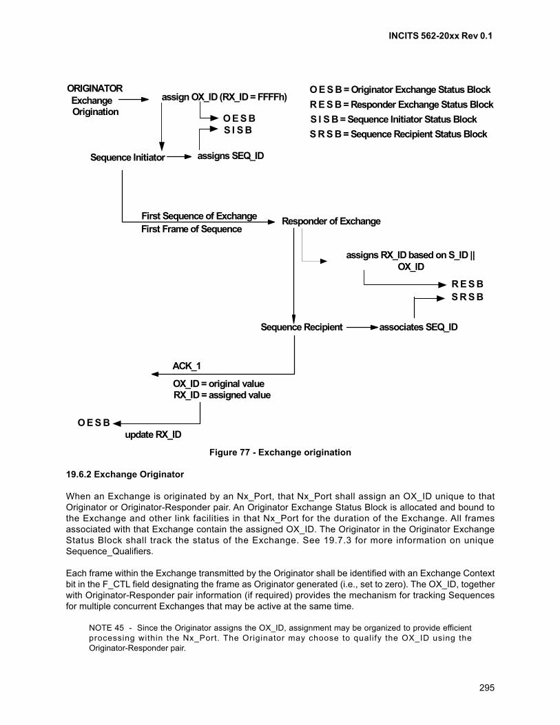
INCITS 562-20xx Rev 0.1
295
Figure 77 - Exchange origination
19.6.2 Exchange Originator
When an Exchange is originated by an Nx_Port, that Nx_Port shall assign an OX_ID unique to thatOriginator or Originator-Responder pair. An Originator Exchange Status Block is allocated and bound tothe Exchange and other link facilities in that Nx_Port for the duration of the Exchange. All framesassociated with that Exchange contain the assigned OX_ID. The Originator in the Originator ExchangeStatus Block shall track the status of the Exchange. See 19.7.3 for more information on uniqueSequence_Qualifiers.
Each frame within the Exchange transmitted by the Originator shall be identified with an Exchange Contextbit in the F_CTL field designating the frame as Originator generated (i.e., set to zero). The OX_ID, togetherwith Originator-Responder pair information (if required) provides the mechanism for tracking Sequencesfor multiple concurrent Exchanges that may be active at the same time.
NOTE 45 - Since the Originator assigns the OX_ID, assignment may be organized to provide efficientprocessing within the Nx_Port. The Originator may choose to qualify the OX_ID using theOriginator-Responder pair.
ORIGINATORExchangeOrigination
assign OX_ID (RX_ID = FFFFh)
Sequence Initiator assigns SEQ_ID
O E S BS I S B
O E S B = Originator Exchange Status Block
R E S B = Responder Exchange Status Block
S I S B = Sequence Initiator Status Block
S R S B = Sequence Recipient Status Block
First Sequence of ExchangeFirst Frame of Sequence
Responder of Exchange
assigns RX_ID based on S_ID ||OX_ID
associates SEQ_ID
R E S BS R S B
Sequence Recipient
ACK_1
OX_ID = original valueRX_ID = assigned value
O E S Bupdate RX_ID
INCITS 562-20xx Rev 0.1
296
19.6.3 Exchange Responder
The destination Nx_Port shall be designated as the Responder for the duration of the Exchange. When thedestination Nx_Port receives the first Sequence of the Exchange, that Nx_Port shall assign an RX_ID tothe newly established Exchange. This RX_ID is associated with the OX_ID from a given S_ID to aResponder Exchange Status Block (S_ID||OX_ID). See 19.7.3 for more information on uniqueSequence_Qualifiers.
In Class 2, the assigned RX_ID shall be transmitted to the Originator on the ACK frame responding to thelast Data frame of the Sequence or earlier, if possible. In a Class 3 bi-directional Exchange, the assignedRX_ID shall be transmitted to the Originator in the first Data frame transmitted by the Responder. If theSequence Recipient has specified X_ID interlock during Login, the RX_ID shall be assigned in the ACK tothe first Data frame of the Sequence. The Originator shall withhold additional frame transmission for theExchange until the ACK is received. The Responder Exchange_ID provides the mechanism for trackingSequences for multiple concurrent Exchanges from multiple S_IDs or the same S_ID.
NOTE 46 - Since the Responder assigns the RX_ID, assignment may be organized to provide efficientprocessing within the Nx_Port.
Each frame within the Exchange transmitted by the Responder is identified with an Exchange Context bitin the F_CTL field designating the frame as Responder generated (i.e., set to one). Each frame within theExchange transmitted by the Responder is identified with the assigned RX_ID. The Responder in theResponder Exchange Status Block shall track the status of the Exchange.
19.6.4 X_ID assignment
In the first frame of an Exchange, the Originator shall set the OX_ID to an assigned value and the RX_IDvalue to FF FFh (unassigned). When the Responder receives the first Sequence of an Exchange, it shallassign an RX_ID and in Class 2 shall return the RX_ID in the ACK frame sent in response to the last Dataframe in the Sequence, or in an earlier ACK. In a Class 3 bi-directional Exchange, the Responder shallassign an RX_ID in the first Data frame transmitted.
For all remaining frames within the Exchange, the OX_ID and RX_ID fields retain these assigned values.
A given Exchange Originator may choose to provide frame tracking outside of the signaling protocol of thisstandard. Setting the OX_ID to FF FFh indicates this. This implies that the Exchange Originator shall onlyhave one Exchange open with a given destination Nx_Port. If an Nx_Port chooses an alternative frametracking mechanism outside the scope of this standard, it is still responsible for providing proper SEQ_IDand SEQ_CNT values. In addition, it shall return the RX_ID assigned by the Exchange Responder.
A given Exchange Responder may choose to provide frame tracking outside of the signaling protocol ofthis standard. Setting the RX_ID to FF FFh indicates this. If an Nx_Port chooses an alternative frametracking mechanism outside the scope of this standard, it is still responsible for providing proper SEQ_IDand SEQ_CNT values. In addition, it shall return the OX_ID assigned by the Exchange Originator.
19.6.5 X_ID interlock
X_ID interlock is only applicable to Class 2. When an Nx_Port initiates a Sequence with an Nx_Port thathas specified during Login that X_ID interlock is required and the Recipient's X_ID is invalid or unassigned,the initiating Nx_Port shall transmit the first frame of the Sequence with the Recipient's X_ID set to FF FFhand shall withhold transmission of additional frames until the corresponding ACK with an assigned X_IDhas been received from the Recipient. The assigned X_ID is then used in all subsequent frames in theSequence.
INCITS 562-20xx Rev 0.1
297
19.7 Sequence management
19.7.1 Sequence identification
The set of IDs S_ID, D_ID, OX_ID, RX_ID, and SEQ_ID is referred to as the Sequence_Qualifier. AnNx_Port implementation makes use of these IDs in a manner to uniquely identify open Sequences.
NOTE 47 - An Nx_Port's freedom to assign a SEQ_ID is based on Sequence context (Initiator orRecipient). This may affect how an Nx_Port implementation chooses to uniquely identify Sequences. See19.4.4.
19.7.2 Open and active Sequences
From the standpoint of the Sequence Initiator, a Sequence is active for the period of time from theallocation of the SSB for the sequence until the end of the last Data frame of the Sequence is transmitted.In Class 2, the Sequence Initiator considers the Sequence open until the ACK with EOFt is received, theSequence is aborted by performing the ABTS Protocol, or the Sequence is abnormally terminated. InClass 3, the Sequence Initiator considers the Sequence open until the deliverability is confirmed, an FC-4specific event occurs, a vendor specific event occurs, or an R_A_TOV timeout period has expired. Thedetermination of deliverability of Class 3 Sequences is beyond the scope of this standard, which providesno deliverability guarantees for Class 3 Sequences.
In Class 2, from the standpoint of the Sequence Recipient, a Sequence is open and active from the timeany Data frame is received until the EOFt is transmitted in the ACK to the last Data frame, or abnormaltermination of the Sequence. In Class 3, from the standpoint of the Sequence Recipient, a Sequence isopen and active from the time the initiating Data frame is received until all Data frames up to the framecontaining EOFt have been received.
19.7.3 Sequence_Qualifier management
The Sequence Initiator assigns a SEQ_ID (see clause 19.4.4). When the Sequence completes normally orabnormally, the SEQ_ID is reusable by the Sequence Initiator for any Sequence_Qualifier, including thesame Recipient and Exchange providing that Sequence rules are followed (see 19.4.4). If a Sequence isaborted using the Abort Sequence Protocol, a Recovery_Qualifier may be specified by the SequenceRecipient (see 22.5.5.2), however, SEQ_ID shall not be included in the Recovery_Qualifier.
19.7.4 Sequence Initiative and termination
When a Sequence is terminated in a normal manner, the last Data frame transmitted by the SequenceInitiator is used to identify two conditions:
a) Sequence Initiative; and
b) Sequence termination.
19.7.5 Transfer of Sequence Initiative
The Sequence Initiator controls which Nx_Port shall be allowed to initiate the next Sequence for theExchange. The Sequence Initiator may hold the initiative to transmit the next Sequence of the Exchange orthe Sequence Initiator may transfer the initiative to transmit the next Sequence of the Exchange. Thedecision to hold or transfer initiative shall be indicated by Sequence Initiative bit in F_CTL.

INCITS 562-20xx Rev 0.1
298
In Class 2, the Sequence Recipient shall not consider Sequence Initiative to have been passed until theSequence that passes the Sequence Initiative is completed successfully and the ACK (EOFt) has beentransmitted with the Sequence Initiative bit (F_CTL bit 16) = 1.
In Class 2, when a Sequence Initiator detects a Data frame (excluding the ABTS, FLUSH, FLUSH_RSPand RED frames) from the Recipient for an Exchange in which it holds the Sequence Initiative, it shalltransmit a P_RJT with a reason code of “Exchange error”. In Class 3, when a Sequence Initiator detects aData frame (excluding the ABTS, FLUSH, FLUSH_RSP and RED frames) from the Recipient for anExchange in which it holds the Sequence Initiative, it shall abnormally terminate the Exchange and discardall frames for the Exchange.
When the Sequence Initiator is ending the current Sequence, it shall set the End_Sequence bit in F_CTLto one on the last Data frame of the Sequence.
19.7.6 Sequence Termination
19.7.6.1 Introduction
Setting the End_Sequence bit in F_CTL to one indicates the last Data frame transmitted by the SequenceInitiator. The Sequence is terminated by either the Initiator or the Recipient transmitting a frame terminatedby EOFt. The Sequence Initiator is in control of terminating the Sequence. Transmission of the EOFt mayoccur in two ways:
a) in Class 2, the Sequence Recipient transmits an ACK frame of ACK_1 or ACK_0 with EOFt in
response to the last Data frame received for the Sequence; or
b) in Class 3, the Sequence Initiator transmits the last Data frame of the Sequence with EOFt.
19.7.6.2 Class 2
Since Class 2 frames may be delivered out of order, Sequence processing is only completed after allframes (both Data and ACK) have been received, accounted for, and processed by the respectiveNx_Ports.
When the Sequence is completed by each Nx_Port, the appropriate Exchange Status Block associatedwith the Sequence shall be updated in each Nx_Port to indicate that the Sequence was completed andwhether the Originator or Responder facility holds the Sequence Initiative. Link facilities associated withthe Sequence (including the Sequence Status Block) are released and available for other use.
NOTE 48 - Since ACKs may arrive out of order, the Sequence Initiator may receive the ACK thatcontains EOFt before ACKs for the same Sequence. The Sequence Initiator shall not consider theSequence normally terminated until it has received the final ACK (see 22.5.5.4).
19.7.6.3 Class 3
The Sequence Initiator shall terminate the last Data frame of the Sequence with EOFt. Acknowledgment ofSequence completion is the responsibility of the Upper Level Protocol.
When the Sequence is completed by each Nx_Port, the appropriate Exchange Status Block associatedwith the Sequence shall be updated in each Nx_Port to indicate that the Sequence was completed andwhether the Originator or Responder facility holds the Sequence Initiative. Link facilities associated withthe Sequence (including Sequence Status Block) are released and available for other use.
INCITS 562-20xx Rev 0.1
299
19.7.6.4 End_Sequence
When the Sequence Initiator is ending the current Sequence, it shall set the End_Sequence bit in F_CTLto one on the last Data frame of the Sequence.
19.8 Exchange termination
19.8.1 Normal termination
Either the Originator or the Responder may terminate an Exchange. The facility terminating the Exchangeshall indicate Exchange termination on the last Sequence of the Exchange by setting the Last_Sequencebit in F_CTL on the last frame, or earlier, if possible, of the last Sequence of the Exchange.
The Sequence shall be terminated according to normal Sequence termination rules. When the lastSequence of the Exchange is terminated normally, the Exchange shall also be terminated. The OX_ID andRX_ID and associated Exchange Status Blocks are released and available for reuse.
19.8.2 Abnormal termination
Either the Originator or the Responder may abnormally terminate an Exchange by using the ABTS-LSProtocol (see 16.3.2.3) or Sequence timeout of the last Sequence of the Exchange. In general, receptionof a reject frame with an action code of 2 as specified in 15.3.3 is not recoverable at the Sequence leveland aborting of the Exchange is probable. Other reasons to abort an Exchange are FC-4 protocoldependent and not defined in this standard.
19.9 Status blocks
19.9.1 Exchange Status Block
The Exchange Status Block is a logical collection of information that is required internally for tracking ofExchanges, but it is not required to be supplied to any other Nx_Port or the FC-4 level. The ExchangeStatus Block (see table 92) associates the OX_ID, RX_ID, D_ID and S_ID of an Exchange. The ExchangeStatus Block is used throughout the Exchange to track the progress of the Exchange and to identify whichNx_Port holds the Sequence Initiative. Information equivalent to the Exchange Status Block recordsExchange status information To support error recovery, the Exchange Status Block shall include status forup to X+2 completed Sequences, where X is the value of the Open Sequences per Exchange ClassService Parameter negotiated at N_Port Login. When status has been retained for X+2 Sequences, statusfor the next completed Sequence shall replace the oldest saved status.
Retained status for completed Sequences shall be equivalent to the following information from theSequence Status Block:
a) SEQ_ID;b) Lowest SEQ_CNT;c) Highest SEQ_CNT; andd) S_STAT.
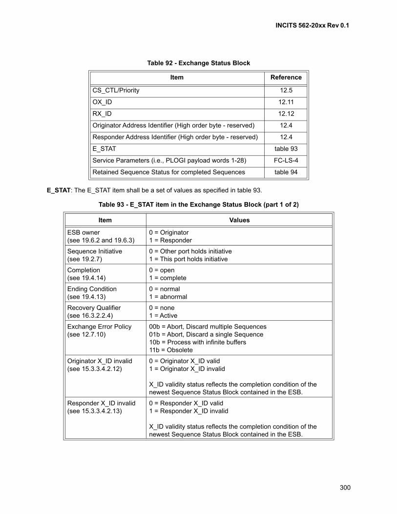
INCITS 562-20xx Rev 0.1
300
E_STAT: The E_STAT item shall be a set of values as specified in table 93.
Table 92 - Exchange Status Block
Item Reference
CS_CTL/Priority 12.5
OX_ID 12.11
RX_ID 12.12
Originator Address Identifier (High order byte - reserved) 12.4
Responder Address Identifier (High order byte - reserved) 12.4
E_STAT table 93
Service Parameters (i.e., PLOGI payload words 1-28) FC-LS-4
Retained Sequence Status for completed Sequences table 94
Table 93 - E_STAT item in the Exchange Status Block (part 1 of 2)
Item Values
ESB owner(see 19.6.2 and 19.6.3)
0 = Originator1 = Responder
Sequence Initiative(see 19.2.7)
0 = Other port holds initiative1 = This port holds initiative
Completion(see 19.4.14)
0 = open1 = complete
Ending Condition(see 19.4.13)
0 = normal1 = abnormal
Recovery Qualifier(see 16.3.2.2.4)
0 = none1 = Active
Exchange Error Policy(see 12.7.10)
00b = Abort, Discard multiple Sequences01b = Abort, Discard a single Sequence10b = Process with infinite buffers11b = Obsolete
Originator X_ID invalid(see 15.3.3.4.2.12)
0 = Originator X_ID valid1 = Originator X_ID invalid
X_ID validity status reflects the completion condition of the newest Sequence Status Block contained in the ESB.
Responder X_ID invalid(see 15.3.3.4.2.13)
0 = Responder X_ID valid1 = Responder X_ID invalid
X_ID validity status reflects the completion condition of the newest Sequence Status Block contained in the ESB.
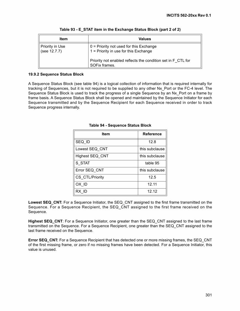
INCITS 562-20xx Rev 0.1
301
19.9.2 Sequence Status Block
A Sequence Status Block (see table 94) is a logical collection of information that is required internally fortracking of Sequences, but it is not required to be supplied to any other Nx_Port or the FC-4 level. TheSequence Status Block is used to track the progress of a single Sequence by an Nx_Port on a frame byframe basis. A Sequence Status Block shall be opened and maintained by the Sequence Initiator for eachSequence transmitted and by the Sequence Recipient for each Sequence received in order to trackSequence progress internally.
Lowest SEQ_CNT: For a Sequence Initiator, the SEQ_CNT assigned to the first frame transmitted on theSequence. For a Sequence Recipient, the SEQ_CNT assigned to the first frame received on theSequence.
Highest SEQ_CNT: For a Sequence Initiator, one greater than the SEQ_CNT assigned to the last frametransmitted on the Sequence. For a Sequence Recipient, one greater than the SEQ_CNT assigned to thelast frame received on the Sequence.
Error SEQ_CNT: For a Sequence Recipient that has detected one or more missing frames, the SEQ_CNTof the first missing frame, or zero if no missing frames have been detected. For a Sequence Initiator, thisvalue is unused.
Priority in Use(see 12.7.7)
0 = Priority not used for this Exchange1 = Priority in use for this Exchange
Priority not enabled reflects the condition set in F_CTL for SOFix frames.
Table 94 - Sequence Status Block
Item Reference
SEQ_ID 12.8
Lowest SEQ_CNT this subclause
Highest SEQ_CNT this subclause
S_STAT table 95
Error SEQ_CNT this subclause
CS_CTL/Priority 12.5
OX_ID 12.11
RX_ID 12.12
Table 93 - E_STAT item in the Exchange Status Block (part 2 of 2)
Item Values
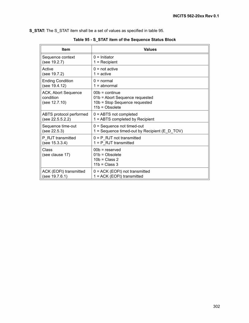
INCITS 562-20xx Rev 0.1
302
S_STAT: The S_STAT item shall be a set of values as specified in table 95.
Table 95 - S_STAT item of the Sequence Status Block
Item Values
Sequence context(see 19.2.7)
0 = Initiator1 = Recipient
Active(see 19.7.2)
0 = not active1 = active
Ending Condition(see 19.4.12)
0 = normal1 = abnormal
ACK, Abort Sequence condition(see 12.7.10)
00b = continue01b = Abort Sequence requested10b = Stop Sequence requested11b = Obsolete
ABTS protocol performed(see 22.5.5.2.2)
0 = ABTS not completed1 = ABTS completed by Recipient
Sequence time-out(see 22.5.3)
0 = Sequence not timed-out1 = Sequence timed-out by Recipient (E_D_TOV)
P_RJT transmitted(see 15.3.3.4)
0 = P_RJT not transmitted1 = P_RJT transmitted
Class(see clause 17)
00b = reserved01b = Obsolete10b = Class 211b = Class 3
ACK (EOFt) transmitted(see 19.7.6.1)
0 = ACK (EOFt) not transmitted1 = ACK (EOFt) transmitted
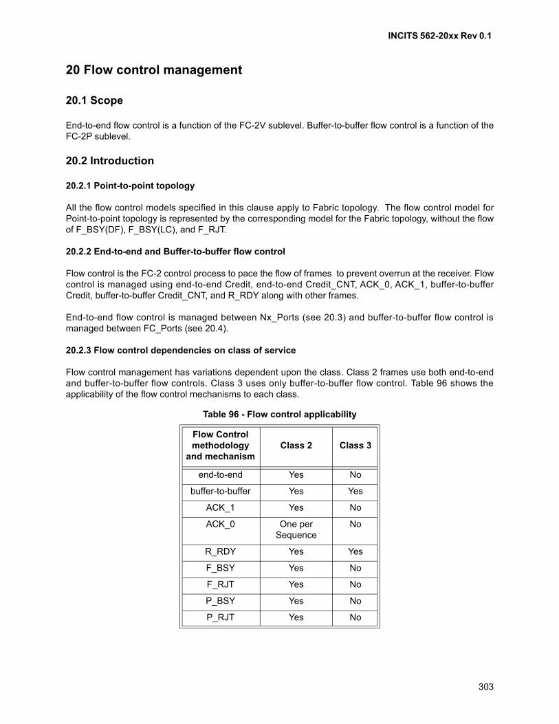
INCITS 562-20xx Rev 0.1
303
20 Flow control management
20.1 Scope
End-to-end flow control is a function of the FC-2V sublevel. Buffer-to-buffer flow control is a function of theFC-2P sublevel.
20.2 Introduction
20.2.1 Point-to-point topology
All the flow control models specified in this clause apply to Fabric topology. The flow control model forPoint-to-point topology is represented by the corresponding model for the Fabric topology, without the flowof F_BSY(DF), F_BSY(LC), and F_RJT.
20.2.2 End-to-end and Buffer-to-buffer flow control
Flow control is the FC-2 control process to pace the flow of frames to prevent overrun at the receiver. Flowcontrol is managed using end-to-end Credit, end-to-end Credit_CNT, ACK_0, ACK_1, buffer-to-bufferCredit, buffer-to-buffer Credit_CNT, and R_RDY along with other frames.
End-to-end flow control is managed between Nx_Ports (see 20.3) and buffer-to-buffer flow control ismanaged between FC_Ports (see 20.4).
20.2.3 Flow control dependencies on class of service
Flow control management has variations dependent upon the class. Class 2 frames use both end-to-endand buffer-to-buffer flow controls. Class 3 uses only buffer-to-buffer flow control. Table 96 shows theapplicability of the flow control mechanisms to each class.
Table 96 - Flow control applicability
Flow Control methodology
and mechanismClass 2 Class 3
end-to-end Yes No
buffer-to-buffer Yes Yes
ACK_1 Yes No
ACK_0 One per Sequence
No
R_RDY Yes Yes
F_BSY Yes No
F_RJT Yes No
P_BSY Yes No
P_RJT Yes No
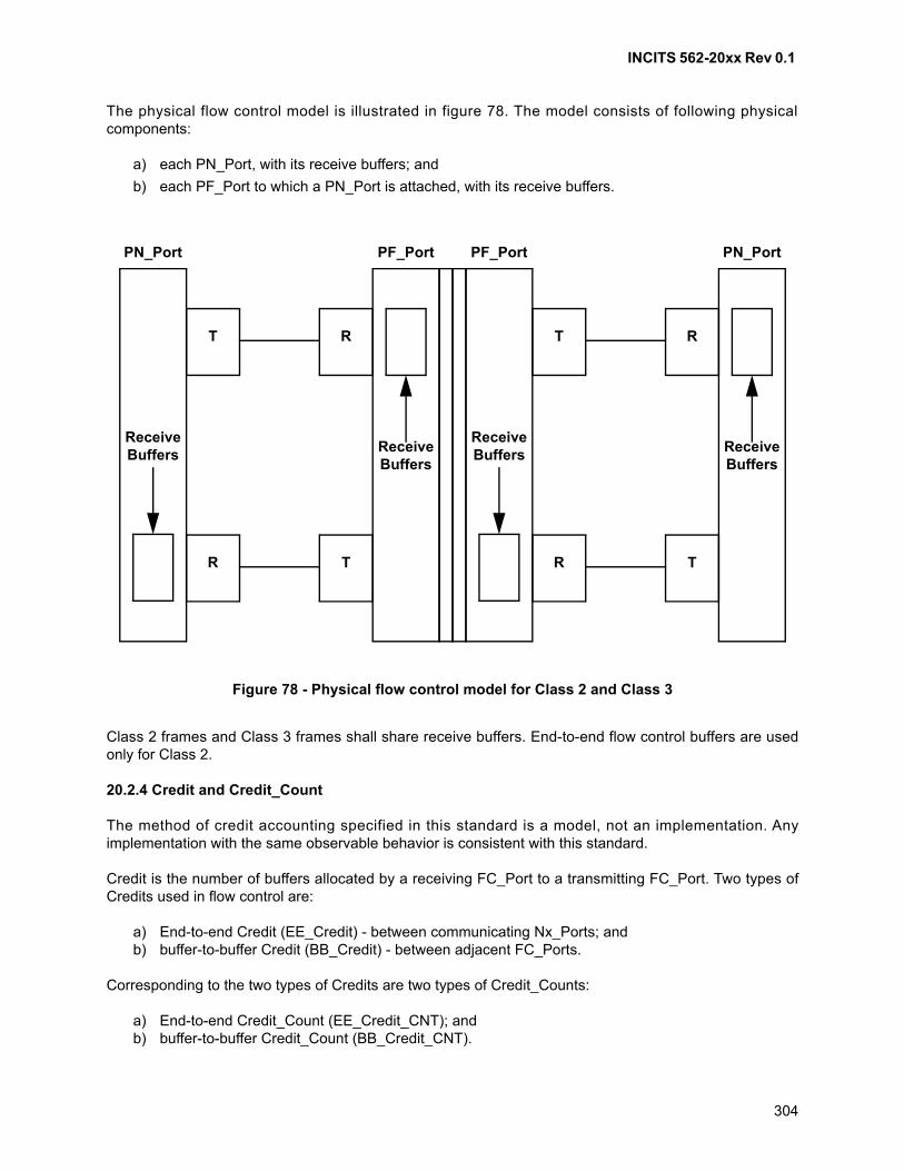
INCITS 562-20xx Rev 0.1
304
The physical flow control model is illustrated in figure 78. The model consists of following physicalcomponents:
a) each PN_Port, with its receive buffers; and
b) each PF_Port to which a PN_Port is attached, with its receive buffers.
Class 2 frames and Class 3 frames shall share receive buffers. End-to-end flow control buffers are usedonly for Class 2.
20.2.4 Credit and Credit_Count
The method of credit accounting specified in this standard is a model, not an implementation. Anyimplementation with the same observable behavior is consistent with this standard.
Credit is the number of buffers allocated by a receiving FC_Port to a transmitting FC_Port. Two types ofCredits used in flow control are:
a) End-to-end Credit (EE_Credit) - between communicating Nx_Ports; andb) buffer-to-buffer Credit (BB_Credit) - between adjacent FC_Ports.
Corresponding to the two types of Credits are two types of Credit_Counts:
a) End-to-end Credit_Count (EE_Credit_CNT); andb) buffer-to-buffer Credit_Count (BB_Credit_CNT).
Figure 78 - Physical flow control model for Class 2 and Class 3
T
R
PN_Port
R
T
PF_Port
ReceiveBuffers
ReceiveBuffers
T
R
PF_Port
R
T
PN_Port
ReceiveBuffers
ReceiveBuffers
INCITS 562-20xx Rev 0.1
305
Credit_Counts represent the amount of a Credit that is in use. A transmitting FC_Port has no Creditavailable with a receiving FC_Port if its Credit_Count equals its Credit. The transmitting FC_Port managesthe Credit_Count (see table 97, table 98, and table 99). The Credit_Count management is internal to thetransmitting FC_Port and is transparent to the receiving FC_Port.
The Nx_Port transmitting Class 2 Data frames shall use the EE_Credit allocated by the receiving Nx_Portfor end-to-end flow control and manage the corresponding EE_Credit_Count (see 20.3). Class 3 Dataframes do not participate in end-to-end flow control. When an FC_Port is transmitting Data frames orLink_Control frames, it shall use BB_Credit allocated by the receiving FC_Port for buffer-to-buffer flowcontrol and manage the corresponding BB_Credit_Count (see 20.4).
20.3 End-to-end flow control
20.3.1 End-to-end management rules
End-to-end flow control is an FC-2V control process to pace the flow of frames between Nx_Ports. AnNx_Port pair in Class 2 uses end-to-end flow control.
End-to-end flow control is performed with EE_Credit_CNT and EE_Credit as the controlling parameter.
End-to-end management rules are given in following subclauses for those cases where no error occurs.Management of EE_Credit_CNT is summarized in table 97. The EE_Credit recovery is specified in 20.3.8.
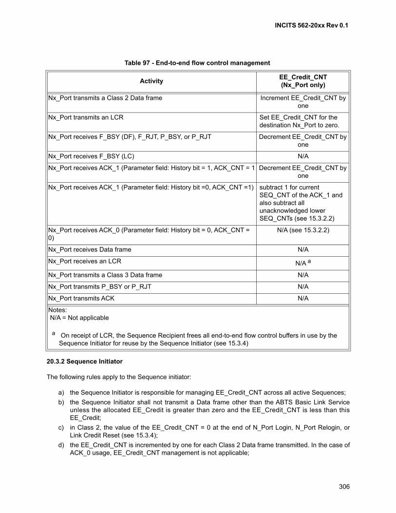
INCITS 562-20xx Rev 0.1
306
20.3.2 Sequence Initiator
The following rules apply to the Sequence initiator:
a) the Sequence Initiator is responsible for managing EE_Credit_CNT across all active Sequences;
b) the Sequence Initiator shall not transmit a Data frame other than the ABTS Basic Link Serviceunless the allocated EE_Credit is greater than zero and the EE_Credit_CNT is less than thisEE_Credit;
c) in Class 2, the value of the EE_Credit_CNT = 0 at the end of N_Port Login, N_Port Relogin, orLink Credit Reset (see 15.3.4);
d) the EE_Credit_CNT is incremented by one for each Class 2 Data frame transmitted. In the case ofACK_0 usage, EE_Credit_CNT management is not applicable;
Table 97 - End-to-end flow control management
ActivityEE_Credit_CNT(Nx_Port only)
Nx_Port transmits a Class 2 Data frame Increment EE_Credit_CNT by one
Nx_Port transmits an LCR Set EE_Credit_CNT for the destination Nx_Port to zero.
Nx_Port receives F_BSY (DF), F_RJT, P_BSY, or P_RJT Decrement EE_Credit_CNT by one
Nx_Port receives F_BSY (LC) N/A
Nx_Port receives ACK_1 (Parameter field: History bit = 1, ACK_CNT = 1 Decrement EE_Credit_CNT by one
Nx_Port receives ACK_1 (Parameter field: History bit =0, ACK_CNT =1) subtract 1 for current SEQ_CNT of the ACK_1 and also subtract all unacknowledged lower SEQ_CNTs (see 15.3.2.2)
Nx_Port receives ACK_0 (Parameter field: History bit = 0, ACK_CNT = 0)
N/A (see 15.3.2.2)
Nx_Port receives Data frame N/A
Nx_Port receives an LCR N/A a
Nx_Port transmits a Class 3 Data frame N/A
Nx_Port transmits P_BSY or P_RJT N/A
Nx_Port transmits ACK N/A
Notes: N/A = Not applicable
a On receipt of LCR, the Sequence Recipient frees all end-to-end flow control buffers in use by the Sequence Initiator for reuse by the Sequence Initiator (see 15.3.4)
INCITS 562-20xx Rev 0.1
307
e) the Sequence Initiator decrements the EE_Credit_CNT by a value of one for each ACK_1(parameter field: History bit = 1, ACK_CNT = 1), F_BSY(DF), F_RJT, P_BSY, or P_RJT received;
f) for an ACK_1 (parameter field: History bit = 0, ACK_CNT = 1) received, the Sequence Initiatorshall decrement the EE_Credit_CNT by one for the current SEQ_CNT in the ACK_1 and by onefor each unacknowledged Data frame with lower SEQ_CNT. If any of these ACKs with lowerSEQ_CNT is received later, it is ignored and Credit_Count is not decremented;
g) for an ACK_0 (parameter field: History bit = 0, ACK_CNT = 0) received, the Sequence Initiatorrecognizes that the Sequence has been received successfully or unsuccessfully, or that theinterlock is being completed (see 15.3.2), but does not perform any EE_Credit_CNT management;and
h) for an ACK_1 received with EOFt and either value of the History bit, the Sequence Initiator shall
recover the Credit for the Sequence by decrementing the EE_Credit_CNT by one for eachunacknowledged Data frame with lower SEQ_CNT of the Sequence. If any of these ACKs withlower SEQ_CNT is received later, it is ignored and Credit_Count is not decremented.
20.3.3 Sequence Recipient
20.3.3.1 General
The Sequence Recipient is responsible for acknowledging valid Data frames received (see 15.3.2.2).
The Sequence Recipient may use ACK_0 and ACK_1 as determined during N_Port Login (see FC-LS-4).The Sequence Recipient rules for using ACK_0 and ACK_1 are different and are listed for a non-streamedSequence first, followed by additional rules for streamed Sequences.
20.3.3.2 ACK_0
If ACK_0 is used (see 15.3.2), the following rules apply to the Sequence Recipient:
a) ACK_0 shall not participate in end-to-end flow control;
b) a single ACK_0 per Sequence shall be used to indicate successful or unsuccessful Sequencedelivery at the end of the Sequence except under specified conditions;
c) both the History bit and the ACK_CNT of the Parameter field shall be set to zero; and
d) the ACK_0 used at the end of a Sequence shall have the End_Sequence bit set to 1. The ACK_0used at the end of a Sequence shall be ended with EOFt in Class 2.
20.3.3.3 ACK_1
If ACK_1 is used, the following rules apply to the Sequence Recipient:
a) for each valid Data frame acknowledged an ACK_1 shall be sent with ACK_CNT set to 1;
b) the History bit of the Parameter field shall be set to 1 if at least one ACK is pending for a previousSEQ_CNT for the Sequence, or shall be set to zero if no ACK is pending for any previousSEQ_CNT for the Sequence (see 15.3.2.2); and
c) in Class 2, the last ACK_1 shall be issued by the Sequence Recipient in one of the two waysspecified:
A) in Class 2 the Sequence Recipient shall withhold transmission of the last ACK_1 until allpreceding Data frames with lower SEQ_CNTs have been received, processed, andcorresponding ACK_1s transmitted (see 19.4.7). In this case, the last ACK_1 transmitted bythe Sequence Recipient shall have the End_Sequence bit set to 1, History bit set to zero andshall contain EOFt; or
INCITS 562-20xx Rev 0.1
308
B) in Class 2, in response to the last Data frame (End_Sequence bit = 1) transmitted by theSequence Initiator, if any of the Data frame is pending for the Sequence, the SequenceRecipient may transmit ACK_1 (with End_Sequence bit set to zero) but with EOFn in lieu of
EOFt. In this case, the last ACK_1 transmitted by the Sequence Recipient shall have the
End_Sequence bit set to 1, History bit set to 1 and shall contain EOFt.
20.3.3.4 Last ACK timeout
If a Sequence error is detected or the E_D_TOV expires when the Sequence Recipient is withholding thelast ACK for a Sequence and waiting to send other ACKs for that Sequence, the Sequence Recipientsupporting discard policy shall set Abort Sequence bits and transmit the last ACK. The SequenceRecipient supporting the Process Policy shall transmit the last ACK without setting the Abort Sequence bits(see 19.4.10.4).
20.3.3.5 Streamed Sequences
Each of the streamed Sequences shall follow all the rules for a non-streamed Sequence as defined in20.3.3.1 and 20.3.3.3 above. In addition, in the case of multiple Sequence discard policy, the last ACK forthe succeeding Sequence shall be withheld until all the previous Sequences are complete and deliverable.This additional withholding, for previous Sequences to complete and be deliverable, is not applicable to thecase of Single Sequence discard policy.
20.3.4 EE_Credit
EE_Credit is the number of end-to-end flow control buffers in the Sequence Recipient that have beenallocated to a given Sequence Initiator. EE_Credit represents the maximum number of unacknowledged oroutstanding frames that may be transmitted without the possibility of overrunning the receiver at theSequence Recipient. EE_Credit is defined for Class 2 per Sequence Recipient and managed by theSequence Initiator. EE_Credit represents the number of end-to-end flow control buffers allocated to theSequence Initiator. The value of EE_Credit allocated to the Sequence Initiator is conveyed to this Nx_Portthrough the Nx_Port End-to-end Credit field of the PLOGI Class Service Parameters (see FC-LS-4). Theminimum or default value of EE_Credit is one.
The sum of allocated Class 2 EE_Credit may exceed the total number of Class 2 end-to-end flow controlbuffers supported at the Sequence Recipient. This excess buffer allocation shall not result in overrun.Class 2 EE_Credit allocation depends upon system requirements, which are outside the scope of thisstandard.
EE_Credit is used as a controlling parameter in end-to-end flow control.
EE_Credit is not applicable to Class 3.
20.3.5 EE_Credit_CNT
EE_Credit_CNT is defined as the number of unacknowledged or outstanding frames awaiting a responseand represents the number of end-to-end flow control buffers that are occupied at the Sequence Recipient.To track the number of frames transmitted and outstanding, the Sequence Initiator uses theEE_Credit_CNT variable.
20.3.6 EE_Credit management
EE_Credit management involves an Nx_Port establishing and revising EE_Credit with the other Nx_Port itintends to communicate with using Class 2.
INCITS 562-20xx Rev 0.1
309
Since Class 2 supports demultiplexing to multiple Sequence Recipients, the Sequence Initiator managesan EE_Credit_CNT for each Sequence Recipient currently active, with the EE_Credit for that SequenceRecipient as the upper bound.
N_Port Login is used to establish and optionally revise these EE_Credit values. The Estimate Creditprocedure may be used to estimate and revise end-to-end Credit for streaming. The Advise CreditSequence and associated LS_ACC Sequence may also be used as a stand-alone procedure to revise theEE_Credit. The Service Parameters interchanged during N_Port Login provide the Class 2 EE_Credit.
A Sequence Initiator, during N_Port Login obtains EE_Credit from the Nx_Port to which it is logging in.EE_Credit allocated by the Sequence Recipient forms the maximum limit for the EE_Credit_CNT value.The EE_Credit_CNT value shall be set to zero upon leaving the Active link state, Login, or Relogin. TheEE_Credit_CNT is incremented, decremented or left unaltered as specified by the flow controlmanagement rules (see 20.3.1). The EE_Credit_CNT shall not exceed the EE_Credit value to avoidpossible overflow at the receiver except that the EE_Credit_CNT may exceed the EE_Credit value as aresult of transmitting an ABTS Basic Link Service.
The Sequence Initiator shall allocate the total EE_Credit associated with a Sequence Recipient among allactive Sequences associated with that Sequence Recipient. The Sequence Initiator function maydynamically alter the EE_Credit associated with each active Sequence as long as the total EE_Creditspecified for the Sequence Recipient is not exceeded. In the event of an abnormal termination of aSequence using the Abort Sequence Protocol, the Sequence Initiator may reclaim the SequenceEE_Credit allocation when the BA_ACC response has been received to the Abort Sequence frame.
The Nx_Port is responsible for managing EE_Credit_CNT using EE_Credit as the upper bound on a perNx_Port basis except that the EE_Credit_CNT may exceed the EE_Credit value as a result of transmittingan ABTS Basic Link Service.
20.3.7 End-to-end flow control model
The end-to-end flow control model is illustrated in figure 79. The model includes flow control parameters,control variables and resources for a Data frame from a Sequence Initiator and ACK_1 or BSY/RJT inresponse from the Sequence Recipient.
a) the Sequence Recipient provides a number of end-to-end flow control receive buffers;
b) the Sequence Initiator obtains the allocation of Class 2 end-to-end flow control buffers, as Class 2EE_Credits. That allocation is distributed among all the open Sequences for a specific SequenceRecipient; and
c) the Sequence Initiator manages the end-to-end flow by managing Class 2 EE_Credit_CNT(s).That management is distributed among all the active Sequences for a specific SequenceRecipient.
The model illustrates all possible replies to the Data frame. The EE_Credit_CNT is decremented by onewhen the ACK_1 frame is received.
For more details on incrementing and decrement EE_Credit_CNT see table 97.
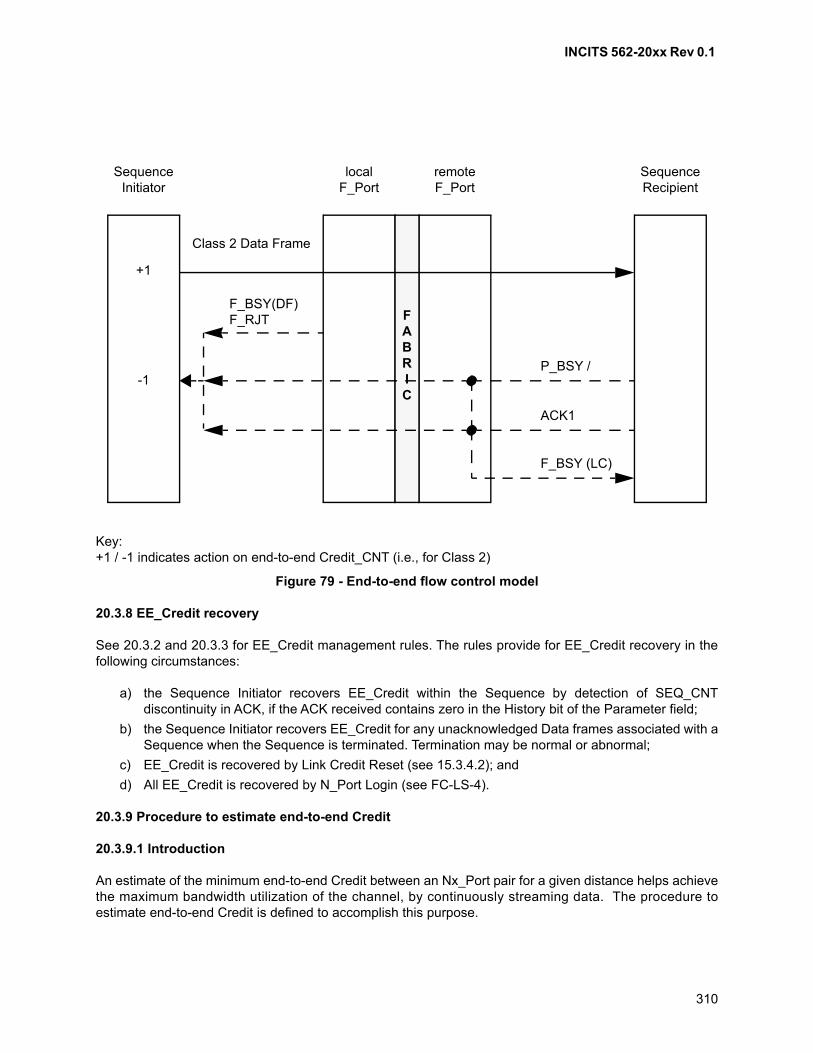
INCITS 562-20xx Rev 0.1
310
20.3.8 EE_Credit recovery
See 20.3.2 and 20.3.3 for EE_Credit management rules. The rules provide for EE_Credit recovery in thefollowing circumstances:
a) the Sequence Initiator recovers EE_Credit within the Sequence by detection of SEQ_CNTdiscontinuity in ACK, if the ACK received contains zero in the History bit of the Parameter field;
b) the Sequence Initiator recovers EE_Credit for any unacknowledged Data frames associated with aSequence when the Sequence is terminated. Termination may be normal or abnormal;
c) EE_Credit is recovered by Link Credit Reset (see 15.3.4.2); and
d) All EE_Credit is recovered by N_Port Login (see FC-LS-4).
20.3.9 Procedure to estimate end-to-end Credit
20.3.9.1 Introduction
An estimate of the minimum end-to-end Credit between an Nx_Port pair for a given distance helps achievethe maximum bandwidth utilization of the channel, by continuously streaming data. The procedure toestimate end-to-end Credit is defined to accomplish this purpose.
Key:+1 / -1 indicates action on end-to-end Credit_CNT (i.e., for Class 2)
Figure 79 - End-to-end flow control model
SequenceInitiator
localF_Port
remoteF_Port
SequenceRecipient
FABRIC
+1
-1P_BSY /
ACK1
F_BSY (LC)
F_BSY(DF)F_RJT
Class 2 Data Frame
INCITS 562-20xx Rev 0.1
311
Link Service Sequences that support this procedure are optional. This procedure shall be performed afterLogin between this Nx_Port pair. Login determines a number of Service Parameters (e.g., the maximumData_Field size that each Nx_Port is capable of receiving).
The procedure and the continuous streaming function may also be limited by the buffer-to-buffer Credit.
The procedure shall be invoked by the Link Service support of the source Nx_Port and responded to by theLink Service support of the destination Nx_Port. Since the ELS requests used to perform this procedureare optional, LS_RJT (see FC-LS-4) may be received to any request (except ESTC which has no reply)with a reason code of “Command not supported”.
20.3.9.2 Procedure steps
20.3.9.2.1 General
This procedure is optional and consists of following three request Sequences:
a) Establish Streaming Sequence;
b) Estimate Credit Sequence; and
c) Advise Credit Sequence.
The procedure is illustrated with these request Sequences and their respective reply Sequences in figure80.
The procedure shall be performed in Class 2 with respective delimiters, as specified in 17.3.
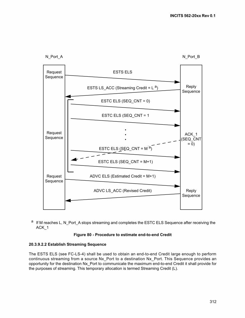
INCITS 562-20xx Rev 0.1
312
20.3.9.2.2 Establish Streaming Sequence
The ESTS ELS (see FC-LS-4) shall be used to obtain an end-to-end Credit large enough to performcontinuous streaming from a source Nx_Port to a destination Nx_Port. This Sequence provides anopportunity for the destination Nx_Port to communicate the maximum end-to-end Credit it shall provide forthe purposes of streaming. This temporary allocation is termed Streaming Credit (L).
a If M reaches L, N_Port_A stops streaming and completes the ESTC ELS Sequence after receiving the ACK_1
Figure 80 - Procedure to estimate end-to-end Credit
N_Port_A N_Port_B
RequestSequence
ESTS ELS
ESTS LS_ACC (Streaming Credit = L a)
ESTC ELS (SEQ_CNT = 0)
ESTC ELS (SEQ_CNT = 1
ESTC ELS (SEQ_CNT = M+1)
ADVC LS_ACC (Revised Credit)
ADVC ELS (Estimated Credit = M+1)
•••
RequestSequence
RequestSequence
ReplySequence
ReplySequence
ACK_1(SEQ_CNT
= 0)ESTC ELS (SEQ_CNT = M a)
INCITS 562-20xx Rev 0.1
313
This Sequence shall be used between an Nx_Port pair after the Nx_Port pair have logged in with eachother. This Sequence shall be initiated as a new Exchange. The Originator of the Exchange shall initiatethe Sequence.
1) the source shall transmit the ESTS ELS;
2) the destination shall reply with a LS_ACC frame;
3) the Class Validity bit for Class 2 service shall be set to one (see FC-LS-4); and
4) the Payload of LS_ACC shall have the same format as the Service Parameters for N_Port Login.The Payload shall contain Streaming Credit (L) allocated in the end-to-end Credit field of the Class2 Service Parameters (word 2, bits 14-0 of the class group). The receiver shall ignore the otherfields.
20.3.9.2.3 Estimate Credit Sequence
The Estimate Credit (see FC-LS-4) ELS shall be performed immediately following the completion of theEstablish Streaming Sequence. This Sequence requires the use of ACK_1 and may not be executed by allNx_Ports.
a) the source Nx_Port shall stream ESTC (see FC-LS-4) frames consecutively until it receives thefirst ACK (ACK_1) from the destination Nx_Port with the Abort Sequence bits (F_CTL bits 5-4) setto 10b. The source shall not exceed the Streaming Credit obtained during the Establish StreamingSequence;
b) if the source does not receive ACK_1 after it has reached the limit imposed by the StreamingCredit value, it shall stop streaming and wait for the first ACK to be received with the AbortSequence bits (F_CTL bits 5-4) set to 10b;
c) the size of the Data_Field of the ESTC frame shall be the normal size frames transmitted by aFC-4 based on the Service Parameters from N_Port Login;
d) the Payload shall contain data bytes;
e) the SEQ_CNT shall follow the normal rules for Sequence transmission;
f) the destination Nx_Port shall respond with ACK for Data frames received;
g) if the highest SEQ_CNT transmitted by the source Nx_Port at the time it receives the first ACK isM, the number of outstanding frames (i.e., Credit estimated for continuous streaming) shall equalM+1. If ACK is received within the Streaming Credit limit (L > M), this value of M+1 represents theminimum Credit required to utilize the maximum bandwidth of the fibre. If the ACK is received afterreaching the Streaming Credit limit, this value is less than the optimal Credit required to utilize themaximum bandwidth of the fibre; and
h) the source Nx_Port shall follow all the rules in closing the Sequence, by sending the last Dataframe of the Sequence and waiting for corresponding ACK to be received.
20.3.9.2.4 Advise Credit Sequence
The Advise Credit (see FC-LS-4) shall be performed immediately following completion of the EstimateCredit Sequence. The source Nx_Port that performed the Estimate Credit Sequence shall advise thedestination Nx_Port of the Estimated Credit in ADVC Data_Field. The destination Nx_Port shall reply usinga LS_ACC frame, with a revised end-to-end Credit value in its Payload. This value is determined by thedestination Nx_Port based on its buffering scheme, buffer management, buffer availability and Nx_Portprocessing time. This is the final value to be used by the source Nx_Port for revised end-to-end Credit.
This Sequence provides a complementary function to Login. In contrast to the Login frame, the ADVCframe contains the end-to-end Credit it would like to be allocated for continuous streaming.
INCITS 562-20xx Rev 0.1
314
If the Estimated Credit (M+1) is less than or equal to the Streaming Credit, the destination may choose toreallocate the estimated end-to-end Credit. If the Streaming Credit is smaller than needed for continuousstreaming, the source Nx_Port is bound to run short of end-to-end Credit and the source Nx_Port mayadvise the reallocated estimated end-to-end Credit value as the Estimated Credit.
a) the source Nx_Port shall transmit Advise Credit frame with the Estimated Credit (M+1);
b) the Payload of the ADVC shall have the same format as the Service Parameters for Login. ThePayload shall contain the Estimated Credit (M+1) in end-to-end Credit field of the Class 2 ServiceParameters. The Class Validity bit for Class 2 service shall be set to one (see FC-LS-2). Thereceiver shall ignore the other fields. The destination Nx_Port shall determine the revisedend-to-end Credit value. The destination shall determine the value based on its buffermanagement, buffer availability and port processing time and may add a factor to the EstimatedCredit value. This is the final value to be used by the source Nx_Port for end-to-end Credit; and
c) the destination Nx_Port replies with a LS_ACC frame that successfully completes the Protocol.The LS_ACC Sequence shall contain the end-to-end Credit allocated to the source Nx_Port. ThePayload of LS_ACC shall have the same format as the Service Parameters for Login. The Payloadshall contain the final end-to-end Credit in end-to-end Credit field of the Class 2 ServiceParameters. The receiver shall ignore the other fields.
Since the maximum Data_Field size, and thus the maximum frame size, is permitted to be unequal inforward and reverse directions, the Estimate Credit procedure may be performed separately for eachdirection of transfer. Credit modification applies only to the direction of the transfer of Estimate Creditframes.
The Estimate Credit procedure provides an approximation of the distance involved on a single path. Ifthere are concerns that in a Fabric in which the length (and time) of the paths assigned may vary, theprocedure may be repeated several times to improve the likelihood that the Estimated end-to-end Creditvalue is valid.
Alternatively, a source may accept the Estimated end-to-end Credit value. If, at a later time, data transfersare unable to stream continuously, the source may re-initiate the Estimate Credit Procedure, or arbitrarilyrequest an increase in Estimated end-to-end Credit by using an ADVC Link request Sequence.
20.4 Buffer-to-buffer flow control
20.4.1 Introduction
Buffer-to-buffer flow control is an FC-2P staged control process to pace the flow of frames. Thebuffer-to-buffer control occurs in both directions between:
a) Sequence Initiator and the local Fx_Port;
b) remote Fx_Port and the PN_Port of the Sequence Recipient Nx_Port;
c) E_Ports within the Fabric; and
d) the PN_Ports of the Sequence Initiator and Sequence Recipient Nx_Ports in point to-pointtopology.
INCITS 562-20xx Rev 0.1
315
20.4.2 Buffer-to-buffer management rules
Buffer-to-buffer flow control rules are as follows:
a) each FC_Port is responsible for managing its own BB_Credit_CNT;
b) the sending FC_Port shall not transmit a frame unless the allocated BB_Credit is greater than zeroand the BB_Credit_CNT is less than this BB_Credit. To avoid possible overrun at the receiver,each FC_Port is responsible for maintaining BB_Credit_CNT less than BB_Credit;
c) each FC_Port shall set the BB_Credit_CNT value to zero at the end of Login or Relogin in apoint-to-point topology, at the end of Login or Relogin to the Fabric in a Fabric topology, or uponrecognition of any Primitive Sequence Protocol;
d) each FC_Port increments BB_Credit_CNT by one for each SOFx2 or SOFx3 transmitted and
decrements by one for each R_RDY received; and
e) recognition of SOFx2 or SOFx3 shall be responded to by a transmission of an R_RDY when the
buffer becomes available.
Managing BB_Credit_CNT is given in table 98. BB_Credit_CNT for E_Ports and B_Ports is specified inFC-SW-7.
20.4.3 BB_Credit
BB_Credit represents the number of receive buffers supported by an FC_Port for receiving frames.BB_Credit values of the attached FC_Ports are mutually conveyed to each other during the Fabric Loginthrough the Buffer-to-buffer Credit field of the FLOGI Common Service Parameters. The minimum ordefault value of BB_Credit is one.
BB_Credit is used as the controlling parameter in buffer-to-buffer flow control.
20.4.4 BB_Credit_CNT
BB_Credit_CNT is defined as the number of unacknowledged or outstanding frames awaiting R_RDYresponses from the directly attached FC_Port. It represents the number of receive buffers that areoccupied at the attached FC_Port. To track the number of frames transmitted for which R_RDY responsesare outstanding, the transmitting FC_Port uses the BB_Credit_CNT.
Table 98 - Buffer-to-buffer flow control management
Activity BB_Credit_CNT
FC_Port transmits any frame (including F_BSY(DF), F_BSY(LC), F_RJT, P_BSY, P_RJT or LCR)
Increment BB_Credit_CNT by one
FC_Port receives R_RDY Decrement BB_Credit_CNT by one
FC_Port receives any frame (including F_BSY(DF), F_BSY(LC), F_RJT, P_BSY, P_RJT or LCR)
N/A
FC_Port transmits R_RDY N/A
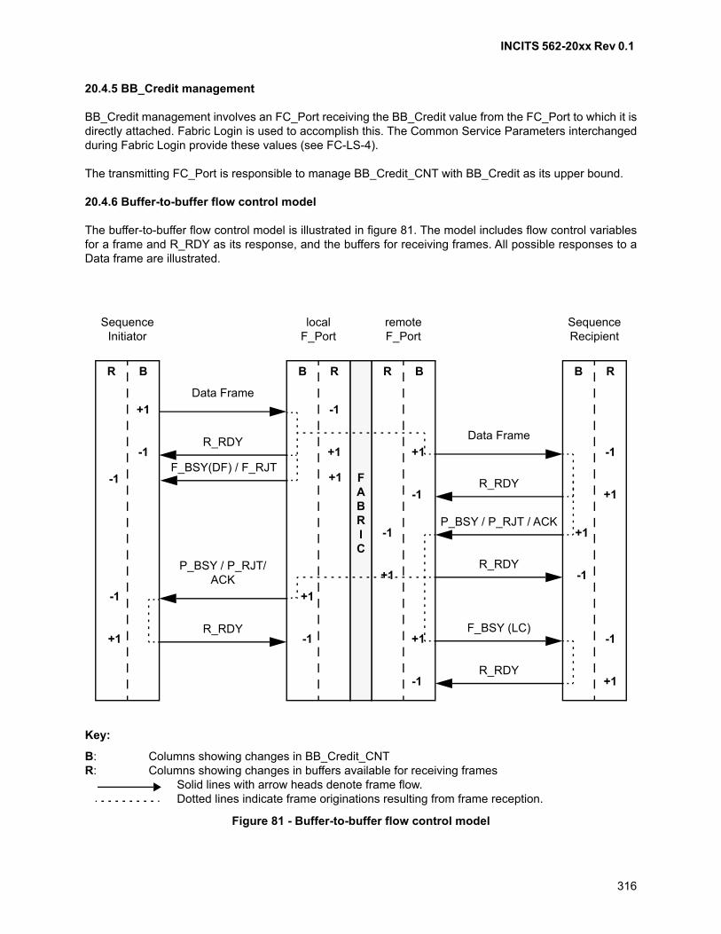
INCITS 562-20xx Rev 0.1
316
20.4.5 BB_Credit management
BB_Credit management involves an FC_Port receiving the BB_Credit value from the FC_Port to which it isdirectly attached. Fabric Login is used to accomplish this. The Common Service Parameters interchangedduring Fabric Login provide these values (see FC-LS-4).
The transmitting FC_Port is responsible to manage BB_Credit_CNT with BB_Credit as its upper bound.
20.4.6 Buffer-to-buffer flow control model
The buffer-to-buffer flow control model is illustrated in figure 81. The model includes flow control variablesfor a frame and R_RDY as its response, and the buffers for receiving frames. All possible responses to aData frame are illustrated.
Key:
B: Columns showing changes in BB_Credit_CNTR: Columns showing changes in buffers available for receiving frames
Solid lines with arrow heads denote frame flow.Dotted lines indicate frame originations resulting from frame reception.
Figure 81 - Buffer-to-buffer flow control model
FABRIC
BR RBRB BR
SequenceInitiator
localF_Port
remoteF_Port
SequenceRecipient
+1 -1
Data Frame
R_RDY-1 +1+1-1
+1 -1
Data Frame
R_RDY
F_BSY (LC)
R_RDY
+1-1
-1 +1
+1 -1
+1 -1
P_BSY / P_RJT/ACK
R_RDY
P_BSY / P_RJT / ACK
R_RDY
-1 +1
+1 -1
F_BSY(DF) / F_RJT+1 -1
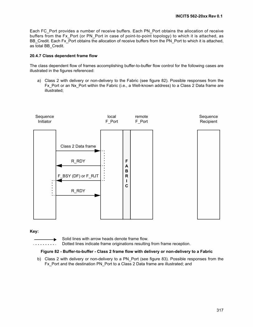
INCITS 562-20xx Rev 0.1
317
Each FC_Port provides a number of receive buffers. Each PN_Port obtains the allocation of receivebuffers from the Fx_Port (or PN_Port in case of point-to-point topology) to which it is attached, asBB_Credit. Each Fx_Port obtains the allocation of receive buffers from the PN_Port to which it is attached,as total BB_Credit.
20.4.7 Class dependent frame flow
The class dependent flow of frames accomplishing buffer-to-buffer flow control for the following cases areillustrated in the figures referenced:
a) Class 2 with delivery or non-delivery to the Fabric (see figure 82). Possible responses from theFx_Port or an Nx_Port within the Fabric (i.e., a Well-known address) to a Class 2 Data frame areillustrated;
b) Class 2 with delivery or non-delivery to a PN_Port (see figure 83). Possible responses from theFx_Port and the destination PN_Port to a Class 2 Data frame are illustrated; and
Key:
Solid lines with arrow heads denote frame flow.Dotted lines indicate frame originations resulting from frame reception.
Figure 82 - Buffer-to-buffer - Class 2 frame flow with delivery or non-delivery to a Fabric
SequenceInitiator
localF_Port
remoteF_Port
SequenceRecipient
FABRIC
Class 2 Data frame
R_RDY
F_BSY (DF) or F_RJT
R_RDY
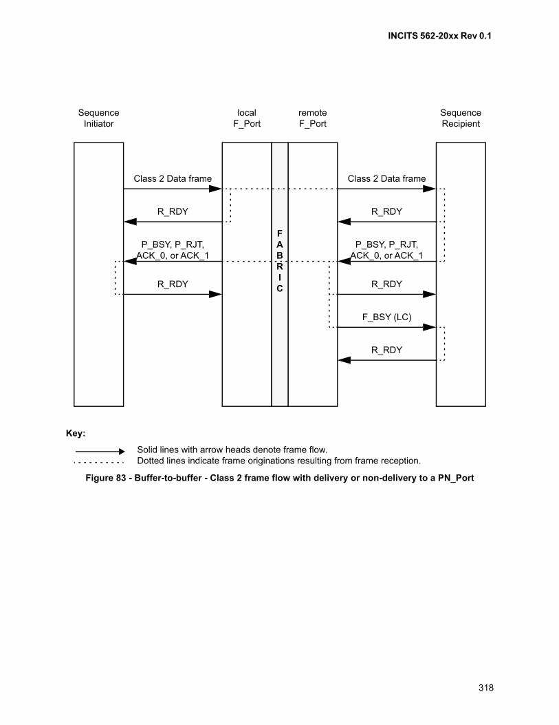
INCITS 562-20xx Rev 0.1
318
Key:
Solid lines with arrow heads denote frame flow.Dotted lines indicate frame originations resulting from frame reception.
Figure 83 - Buffer-to-buffer - Class 2 frame flow with delivery or non-delivery to a PN_Port
SequenceInitiator
localF_Port
remoteF_Port
SequenceRecipient
FABRIC
Class 2 Data frame
R_RDY
F_BSY (LC)
R_RDY
Class 2 Data frame
P_BSY, P_RJT, ACK_0, or ACK_1
R_RDY
P_BSY, P_RJT, ACK_0, or ACK_1
R_RDY
R_RDY
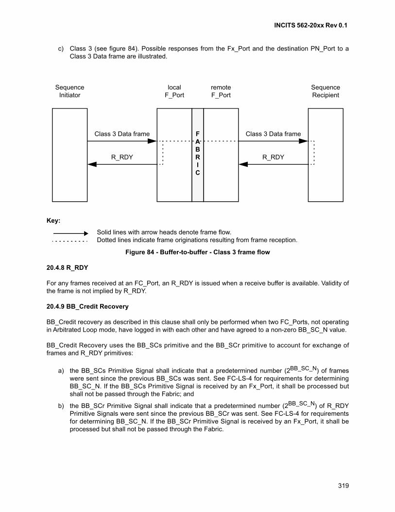
INCITS 562-20xx Rev 0.1
319
c) Class 3 (see figure 84). Possible responses from the Fx_Port and the destination PN_Port to aClass 3 Data frame are illustrated.
20.4.8 R_RDY
For any frames received at an FC_Port, an R_RDY is issued when a receive buffer is available. Validity ofthe frame is not implied by R_RDY.
20.4.9 BB_Credit Recovery
BB_Credit recovery as described in this clause shall only be performed when two FC_Ports, not operatingin Arbitrated Loop mode, have logged in with each other and have agreed to a non-zero BB_SC_N value.
BB_Credit Recovery uses the BB_SCs primitive and the BB_SCr primitive to account for exchange offrames and R_RDY primitives:
a) the BB_SCs Primitive Signal shall indicate that a predetermined number (2BB_SC_N) of frameswere sent since the previous BB_SCs was sent. See FC-LS-4 for requirements for determiningBB_SC_N. If the BB_SCs Primitive Signal is received by an Fx_Port, it shall be processed butshall not be passed through the Fabric; and
b) the BB_SCr Primitive Signal shall indicate that a predetermined number (2BB_SC_N) of R_RDYPrimitive Signals were sent since the previous BB_SCr was sent. See FC-LS-4 for requirementsfor determining BB_SC_N. If the BB_SCr Primitive Signal is received by an Fx_Port, it shall beprocessed but shall not be passed through the Fabric.
Key:
Solid lines with arrow heads denote frame flow.Dotted lines indicate frame originations resulting from frame reception.
Figure 84 - Buffer-to-buffer - Class 3 frame flow
SequenceInitiator
localF_Port
remoteF_Port
SequenceRecipient
FABRIC
Class 3 Data frame
R_RDY
Class 3 Data frame
R_RDY
INCITS 562-20xx Rev 0.1
320
An FC_Port that supports BB_Credit Recovery, shall maintain the following BB_Credit Recovery counters:
a) BB_SC_N is the log2 of BB_Credit Recovery modulus;
b) BB_RDY_N counts the number of R_RDY primitives received modulo 2BB_SC_N; and
c) BB_FRM_N counts the number of frames received modulo 2BB_SC_N.
After having transmitted or received an LS_ACC during the processing of an appropriate Login, whetherthe first Login after reset or a Relogin:
a) if the BB_SC_N value communicated by the other FC_Port in the Login is zero, then the FC_Portshall set BB_SC_N, BB_RDY_N, and BB_FRM_N to zero; or
b) if the BB_SC_N value communicated by the other FC_Port is not zero, then the FC_Port shall setBB_SC_N to the greater of the BB_SC_N value from the other FC_Port's Login parameters orBB_SC_N value from its own Login parameters, and set BB_RDY_N and BB_FRM_N to zero.
An FC_Port capable of supporting BB_Credit Recovery shall:
a) if an appropriate Login has successfully completed, then set BB_SC_N to the Login value uponrecognition of the Link Reset Protocol;
b) set BB_RDY_N and BB_FRM_N to zero upon recognition of the Link Reset Protocol; and
c) set BB_SC_N, BB_RDY_N, and BB_FRM_N to zero upon recognition of the Link InitializationProtocol or Link Failure Protocol.
BB_SC_N, BB_RDY_N, and BB_FRM_N shall be set to zero after explicit or implicit logout.
To recover any lost BB_Credit, each FC_Port shall perform the following operations. Each operation shallbe processed atomically (i.e., each operation shall be completed before any other BB_Credit recoveryoperation):
a) transmit a BB_SCs primitive if 2BB_SC_N number of frames that require BB_Credit have been sentsince the completion of Login, link reset, or since the last time a BB_SCs primitive was sent;
b) transmit a BB_SCr primitive if 2BB_SC_N number of R_RDY primitives have been sent since thecompletion of Login, link reset, or since the last time a BB_SCr primitive was sent;
c) after receiving each R_RDY, increment BB_RDY_N by one. If BB_RDY_N equals 2BB_SC_N, setBB_RDY_N to zero;
d) after receiving each frame, increment BB_FRM_N by one. If BB_FRM_N equals 2BB_SC_N, setBB_FRM_N to zero;
e) when a BB_SCr primitive is received, the number of BB_Credits lost may be calculated using thefollowing equation:
BB_Credits lost = (2BB_SC_N - BB_RDY_N) modulo 2BB_SC_N.
The BB_Credit_CNT shall then be decremented by the number of BB_Credits lost. BB_RDY_N isthen set to zero, before the next R_RDY is received; and
f) when a BB_SCs primitive is received, the number of BB_Credits the other FC_Port has lost maybe calculated using the following equation:
BB_Credits lost by other FC_Port = (2BB_SC_N - BB_FRM_N) modulo 2BB_SC_N.
One R_RDY shall be resent for each BB_Credit that is lost. BB_FRM_N shall be set to zero beforethe next frame is received.
INCITS 562-20xx Rev 0.1
321
When the two FC_Ports performing Login specify different non-zero values of BB_SC_N, the larger valueshall be used. If either FC_Port specifies a BB_SC_N value of zero, the BB_Credit recovery process shallnot be performed and no BB_SCx primitive shall be sent.
NOTE 49 - If all frames or R_RDY primitives sent between two BB_SCx primitives are lost, 2BB_SC_N
number of BB_Credits are lost, and are not recovered by the scheme outlined in 20.4.9. Therefore
BB_SC_N should be chosen so that the probability of loosing 2BB_SC_N number of consecutive framesor R_RDY primitives is deemed negligible. The recommended value of BB_SC_N is 8.
20.4.10 Alternate buffer-to-buffer Credit management
An alternate buffer-to-buffer Credit management may be used instead of the one described in 20.4.
NOTE 50 - Alternate buffer-to-buffer Credit management is specified in FC-AL-2, and is currently usedonly in Arbitrated Loop topologies.
The use of alternate buffer-to-buffer Credit management shall be indicated by the PN_Port through anN_Port Login Service Parameter during Fabric Login and N_Port Login (see FC-LS-4).
Alternate BB_Credit management rules are summarized (see FC-AL-2 for additional details):
a) each Port is responsible for managing the Alternate BB_Credit;
b) during Login, BB_Credit shall be set to a value that represents the number of receive buffers that aFC_Port shall guarantee to have available as soon as a circuit is established. If this value isgreater than zero, the FC_Port may start transmitting a frame without waiting for R_RDYs. If thisvalue is equal to zero, the sending FC_Port shall wait to receive at least one R_RDY, beforetransmitting a frame;
c) the receiving FC_Port shall transmit at least one R_RDY, representing the number of additionalreceive buffers available, before, during, or after the reception of frames;
d) the transmitting FC_Port shall decrement BB_Credit by one for each frame transmitted andincrement by one for each R_RDY received; and
e) for transmitting frames, the Available Credit shall be greater than zero. The Available Credit at anygiven time is expressed by the following equation:
Available Credit = Login_BB_Credit + (Number of R_RDYs received - Login_BB_Credit)- Number of frames transmitted
where
A) number of R_RDYs received Login_BB_Credit; and
B) the parenthetical expression is applicable only if it is positive, otherwise it is zero.
20.5 Combined flow control considerations
20.5.1 BSY / RJT in flow control
In Class 2 end-to-end flow control, F_BSY, F_RJT, P_BSY or P_RJT may occur for any Data frame. Eachof these responses contributes to end-to-end and buffer-to-buffer flow controls.
INCITS 562-20xx Rev 0.1
322
End-to-end Class 2 buffers at the Sequence Recipient Nx_Port are shared by multiple source Nx_Portsthat may be multiplexing Data frames. This Class 2 multiplexing requires the distribution of Class 2EE_Credit to each source Nx_Port to be honored to prevent BSY or RJT. Unless an adequate number ofend-to-end Class 2 buffers are available and EE_Credit distribution is honored, a BSY or RJT may occur inClass 2. If buffer-to-buffer flow control rules are not obeyed by the transmitter, the results are unpredictable(e.g., if a Class 2 frame is received with no BB_Credit available and the receiver does not have a buffer toreceive it, the receiver may discard the frame without issuing a P_BSY or P_RJT).
20.5.2 LCR in flow control
LCR does not need EE_Credit and does not participate in end-to-end flow control. LCR participates only inbuffer-to-buffer flow control as Class 2. (see figure 85). In response to an LCR, the Fabric shall issue anR_RDY and may issue a F_BSY or F_RJT. The destination PN_Port shall issue an R_RDY and may issuea P_RJT (see 15.3.3.4). The destination Nx_Port shall not issue a P_BSY to an LCR.
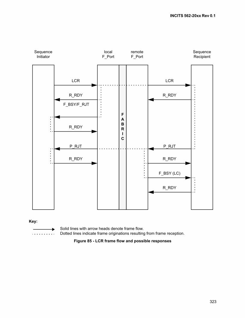
INCITS 562-20xx Rev 0.1
323
Key:
Solid lines with arrow heads denote frame flow.Dotted lines indicate frame originations resulting from frame reception.
Figure 85 - LCR frame flow and possible responses
SequenceInitiator
localF_Port
remoteF_Port
SequenceRecipient
FABRIC
F_BSY (LC)
R_RDY
LCR
P_RJT
R_RDY
P_RJT
R_RDY
R_RDY
F_BSY/F_RJT
R_RDY
LCR
R_RDY
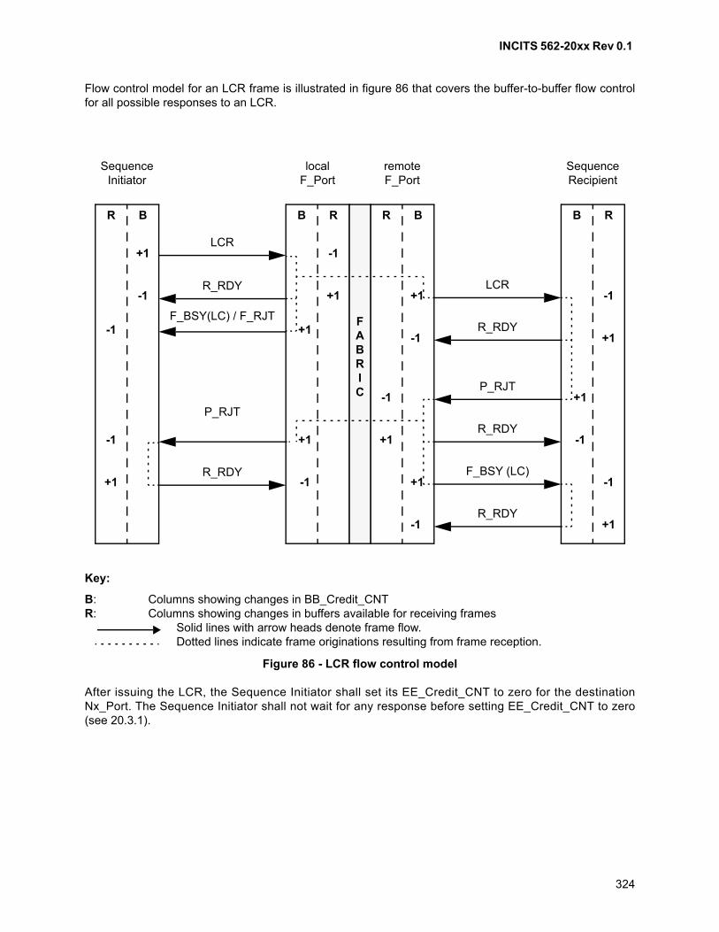
INCITS 562-20xx Rev 0.1
324
Flow control model for an LCR frame is illustrated in figure 86 that covers the buffer-to-buffer flow controlfor all possible responses to an LCR.
After issuing the LCR, the Sequence Initiator shall set its EE_Credit_CNT to zero for the destinationNx_Port. The Sequence Initiator shall not wait for any response before setting EE_Credit_CNT to zero(see 20.3.1).
Key:
B: Columns showing changes in BB_Credit_CNTR: Columns showing changes in buffers available for receiving frames
Solid lines with arrow heads denote frame flow.Dotted lines indicate frame originations resulting from frame reception.
Figure 86 - LCR flow control model
FABRIC
BR RBRB BR
SequenceInitiator
localF_Port
remoteF_Port
SequenceRecipient
+1 -1LCR
R_RDY-1 +1+1-1
+1 -1
LCR
R_RDY
F_BSY (LC)
R_RDY
+1-1
-1 +1 +1 -1
+1 -1
P_RJT
R_RDY
P_RJT
R_RDY
-1 +1
+1 -1
-1 +1F_BSY(LC) / F_RJT
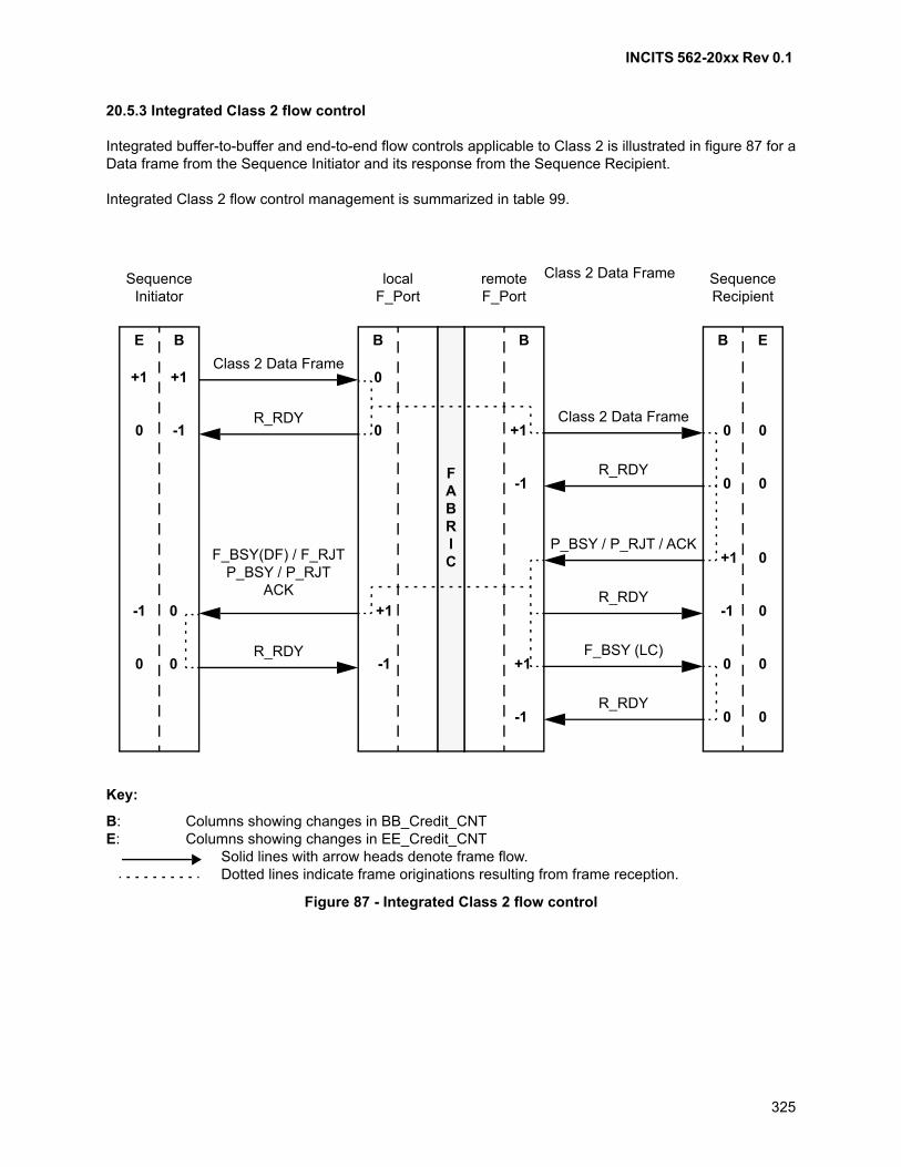
INCITS 562-20xx Rev 0.1
325
20.5.3 Integrated Class 2 flow control
Integrated buffer-to-buffer and end-to-end flow controls applicable to Class 2 is illustrated in figure 87 for aData frame from the Sequence Initiator and its response from the Sequence Recipient.
Integrated Class 2 flow control management is summarized in table 99.
Key:
B: Columns showing changes in BB_Credit_CNTE: Columns showing changes in EE_Credit_CNT
Solid lines with arrow heads denote frame flow.Dotted lines indicate frame originations resulting from frame reception.
Figure 87 - Integrated Class 2 flow control
FABRIC
BE EBB B
SequenceInitiator
localF_Port
remoteF_Port
SequenceRecipient
+1+1 0Class 2 Data Frame
R_RDY0 0 +10-10
0 0 -1
Class 2 Data Frame
R_RDY
F_BSY (LC)
R_RDY
+1 0
-1 0 +1 -1 0
0 0 -1
F_BSY(DF) / F_RJTP_BSY / P_RJT
ACK
R_RDY
P_BSY / P_RJT / ACK
R_RDY
0 0 +1
0 0 -1
Class 2 Data Frame
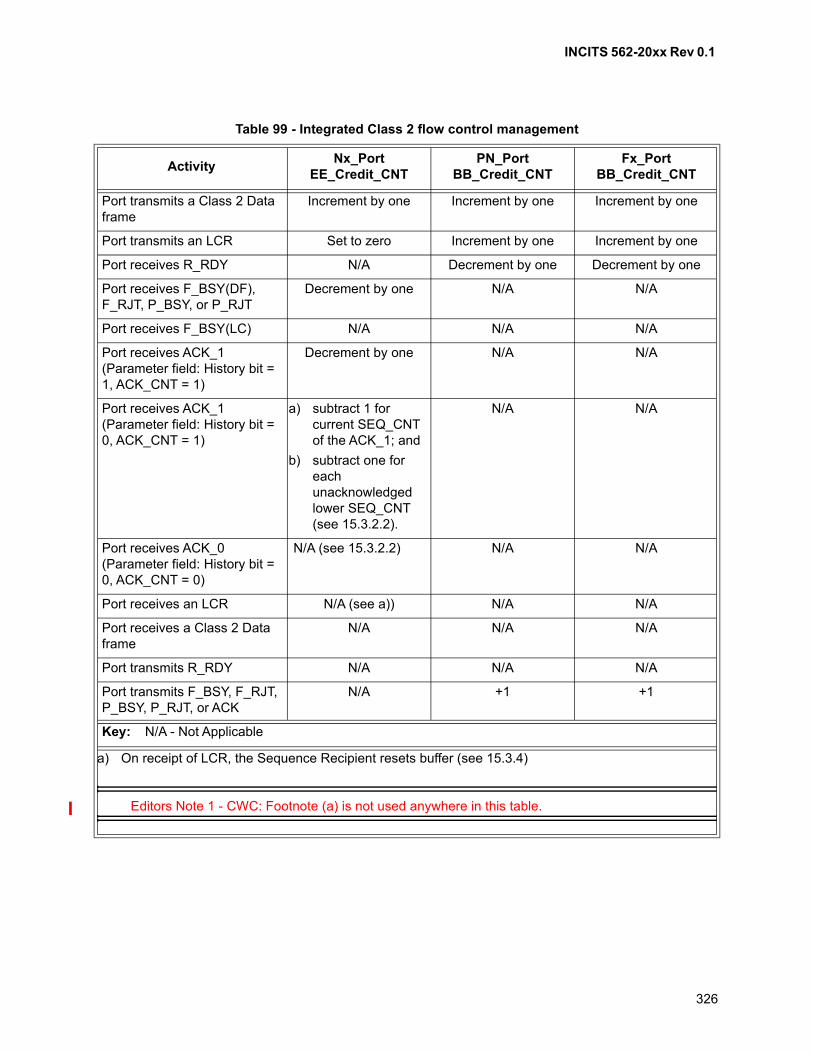
INCITS 562-20xx Rev 0.1
326
Table 99 - Integrated Class 2 flow control management
ActivityNx_Port
EE_Credit_CNTPN_Port
BB_Credit_CNTFx_Port
BB_Credit_CNT
Port transmits a Class 2 Data frame
Increment by one Increment by one Increment by one
Port transmits an LCR Set to zero Increment by one Increment by one
Port receives R_RDY N/A Decrement by one Decrement by one
Port receives F_BSY(DF), F_RJT, P_BSY, or P_RJT
Decrement by one N/A N/A
Port receives F_BSY(LC) N/A N/A N/A
Port receives ACK_1(Parameter field: History bit = 1, ACK_CNT = 1)
Decrement by one N/A N/A
Port receives ACK_1(Parameter field: History bit = 0, ACK_CNT = 1)
a) subtract 1 for current SEQ_CNT of the ACK_1; and
b) subtract one for each unacknowledged lower SEQ_CNT (see 15.3.2.2).
N/A N/A
Port receives ACK_0(Parameter field: History bit = 0, ACK_CNT = 0)
N/A (see 15.3.2.2) N/A N/A
Port receives an LCR N/A (see a)) N/A N/A
Port receives a Class 2 Data frame
N/A N/A N/A
Port transmits R_RDY N/A N/A N/A
Port transmits F_BSY, F_RJT, P_BSY, P_RJT, or ACK
N/A +1 +1
Key: N/A - Not Applicable
a) On receipt of LCR, the Sequence Recipient resets buffer (see 15.3.4)
Editors Note 1 - CWC: Footnote (a) is not used anywhere in this table.
INCITS 562-20xx Rev 0.1
327
21 Segmentation and reassembly
21.1 Scope
Segmentation and reassembly are functions of the FC-2V sublevel.
21.2 Introduction
Mapping application data to Upper Level Protocol (ULP) data blocks is outside the scope of this standard.Mapping ULP data blocks to FC-4 Information Units (IUs) is specified in FC-4 level standards (e.g., FCP-4,FC-SB-6). FC-4 IUs are mapped to Sequences. The transport of Sequences using Fibre Channel frames isspecified in this standard. This subclause introduces several features of the FC-2V sublevel that supportefficient mapping of IUs onto frames:
a) identifying and classifying IUs (see 21.3);
b) multiplexing IUs within a Sequence (see 21.4);
c) relative offset of Data_Frames in an IU (see 21.5); and
d) transporting portions of an IU out of relative offset order (see 21.6).
Together, the rules for these features control the segmentation of IUs into transmitted frames and thereassembly of IUs from received frames.
21.3 Identifying and classifying IUs
FC-2V defines the R_CTL field in the Frame_Header (see 12.3) that may be used to classify frames fordifferent treatment by the Nx_Port that receives them. All FC-4 IUs are transported in frames with theROUTING subfield of the R_CTL field set to Device_Data (see 12.3.2). The INFORMATION subfield of theR_CTL field (i.e., the Information Category) may be used at the discretion of individual FC-4 protocols tofurther classify how IUs are treated. Each FC-4 IU shall be transported over Fibre Channel as Device_Dataframes within a single Sequence that have the same value of the R_CTL field. Within a single Sequence,all Device_Data frames with the same Information Category shall be part of the same IU. Device_Dataframes with different Information Categories shall not be part of the same IU. Frames in differentSequences shall not be part of the same IU.
21.4 Multiplexing IUs within a Sequence
An Nx_Port indicates the extent of its ability to multiplex IUs of different Information Categories in the sameSequence by setting the Categories per Sequence subfield of the Class Service Parameters during N_PortLogin (see FC-LS-4). The FC-4 shall follow the Categories per Sequence ability of the Sequence Initiatorand the Sequence Recipient. If the Sequence Initiator and the Sequence Recipient permit more than oneInformation Category per Sequence, the FC-4 may direct the FC-2 to combine IUs of different InformationCategories in a single Sequence. If frames of different Information Categories are received within a singleSequence consistent with the abilities indicated by the Sequence Recipient during N_Port Login, theSequence Recipient shall reassemble each Information Category into a different IU.
NOTE 51 - An FC-4 may require support for more than one Information Category per Sequence.
INCITS 562-20xx Rev 0.1
328
21.5 Relative offset of Data_Frames in an IU
Each IU is mapped to a relative offset space that is arbitrarily defined by the FC-4. Any relationshipbetween the relative offset spaces of different IUs is outside the scope of this standard, even if the IUs aremultiplexed into a single Sequence by using different Information Categories. Each IU presented by anFC-4 to FC-2 for transmission shall be transmitted within a single Sequence and may be divided intoframes by FC-2. Received frames with the same Information Category within a single Sequence shall bereassembled into a single IU for delivery to the FC-4.
An Nx_Port may be able to use the Parameter field in the Frame_Header (see 12.13) of each frame thatcarries an IU to specify the relative offset of the Payload of the frame within the relative offset space of theIU. An Nx_Port indicates its ability to send and receive relative offset information by setting the relativeoffset by category subfield of the Common Service Parameters during N_Port Login (see FC-LS-4). ASequence Initiator shall follow the relative offset by category capability indicated by the SequenceRecipient.
If the Parameter field of the Frame_Header of a transmitted frame is used to specify relative offset, theParameter field of the frame shall be set to the relative offset of the first byte of the Payload of the framewithin the IU. If the Parameter field of the Frame_Header of a received frame is used to specify relativeoffset, the first byte of the Payload of the frame shall be placed within the IU at the relative offset specifiedby the Parameter field.
If the Parameter field of the Frame_Header of a frame is not used to indicate relative offset, the first byte ofthe Payload of the frame shall be located within the IU following the last byte of the Payload of the framewith the next lesser SEQ_CNT among frames of the same Information Category. If the SEQ_CNT wraps tozero from FF FFh within a Sequence, the reassembly shall be continued according to modulo 65 536arithmetic (i.e., SEQ_CNT = 00 00h follows SEQ_CNT = FF FFh).
NOTE 52 - An FC-4 may require the ability to use the Parameter field in the Frame_Header for relativeoffset.
21.6 Transporting portions of an IU out of relative offset order
An Nx_Port that is able to specify the relative offset of frames may be able to accept, transport, and deliverportions of an IU in an order other than increasing relative offset address order (i.e., random relativeoffset). An Nx_Port indicates its ability to accept, transport, and deliver portions of an IU in an order otherthan increasing relative offset order by setting the random relative offset bit of the Common ServiceParameters during N_Port Login (see FC-LS-4). An Nx_Port indicates its inability to accept, transport, anddeliver portions of an IU in an order other than byte order by setting the continuously increasing relativeoffset bit and resetting the random relative offset bit of the Common Service Parameters during N_PortLogin. The Sequence Initiator shall follow the random relative offset and continuously increasing relativeoffset capabilities indicated by the Sequence Recipient.
If an Nx_Port supports random relative offset, an FC-4 at that Nx_Port may request transmission of an IUin portions to another Nx_Port that supports random relative offset. Each portion of the IU shall specify itsbeginning relative offset, and the beginning relative offset of each portion of the IU may be independent ofthe relative offset of other portions.
If an Nx_Port does not support random relative offset, an FC-4 shall request transmission of an IU in asingle portion to or from that Nx_Port. The first frame of the IU shall specify its beginning relative offset,and the relative offset of each successive frame of the IU shall be the first byte following the last byte of theprior frame of the IU.
INCITS 562-20xx Rev 0.1
329
NOTE 53 - An FC-4 may require support for either random relative offset or continuously increasingrelative offset or both.
By appropriate use of relative offset, an IU may occupy all, part, or multiple noncontiguous portions, of therelative offset space into which it is mapped.
21.7 Login
The following Service Parameters related to segmentation and reassembly are exchanged during N_PortLogin (see FC-LS-4):
a) Categories per Sequence;
b) relative offset by Information Category;
c) continuously increasing relative offset; and
d) random relative offset.
Through the exchange of these Login parameters, the Nx_Port indicates its segmentation and reassemblyrequirements as a Sequence Recipient. The Nx_Port indicates its requirement for Categories perSequence separately for each class of service it supports. The Nx_Port indicates relative offset support ornon-support for each Information Category independent of class of service. For the Information Categoriesthat support relative offset, the Nx_Port collectively indicates its requirement for continuously increasing orrandom relative offset independent of class of service.
The Sequence Initiator shall follow the segmentation and reassembly requirements of the SequenceRecipient.
21.8 Segmentation rules
Segmentation summary rules are listed and referred to table 100:
a) the Sequence Initiator shall segment each Information Category within the relative offset spacespecified by the sending upper level. The Sequence Initiator shall follow the relative offsetrequirements of the Sequence Recipient for Information Categories;
b) an upper level at the sending end shall specify to the sending FC-2 one or more IUs to betransferred as a Sequence, the Information Category for each IU, an relative offset space, and theinitial relative offset for each Information Category. The initial relative offset value may be zero ornon-zero;
c) the Sequence Initiator shall use the specified relative offset space for each Information Categoryand transfer one or more IUs specified in a single Sequence;
d) if the Sequence Recipient does not support relative offset for one or more Information Categories,the Sequence Initiator shall transmit each of these Information Categories as a contiguous IU. TheSequence Initiator shall set the relative offset present bit in F_CTL to zero, indicating that theparameter field is not meaningful to FC-2 and shall be passed to the upper level;
e) if the Sequence Recipient supports relative offset for one or more Information Categories and hasspecified during Login this support as continuously increasing relative offset, the SequenceInitiator shall transmit each of these Information Categories with continuously increasing relativeoffset:
A) the Sequence Initiator shall set the relative offset present F_CTL bit to one;
INCITS 562-20xx Rev 0.1
330
B) the Sequence Initiator shall use the initial relative offset specified by the upper level for therelative offset ROi in the first frame of each IU, namely, ROi(0) = initial relative offset for the
Information Category i;
C) the Sequence Initiator shall use for all other frames of the IU, the relative offset computed asfollows: ROi(n+1) = ROi(n) + Length of Payloadi(n) where n is 0 and represents the
consecutive frame count of frames for a given Information Category within a single Sequence;and
D) above steps A) through C) shall be repeated independently for each IU within the Sequence;
and
f) if the Sequence Recipient supports relative offset for one or more Information Categories and hasspecified during Login this support as random relative offset, the Sequence Initiator is permitted totransmit each of these Information Categories with random relative offset:
A) the Sequence Initiator shall set the relative offset present F_CTL bit to one;
B) the Sequence Initiator shall use for all frames of the IU a relative offset within the relative offsetspace of the Information Category; and
C) above steps A) and B) shall be repeated independently for each IU within the Sequence.
21.9 Reassembly rules
Reassembly rules are listed and referred to table 100.
a) the Sequence Recipient shall reassemble each Information Category received within theSequence. The Sequence Recipient shall use relative offset or SEQ_CNT field, as specified, toperform the reassembly and make the IUs available to the receiving upper level as sent by thesending upper level;
b) the Sequence Recipient shall reassemble each Information Category within its relative offsetspace specified by the sending upper level;
c) if the Sequence Recipient receives a frame in an Information Category for which the SequenceRecipient has specified during Login non support of relative offset, and the relative offset presentbit in the frame (F_CTL bit 3) is set to zero, the Sequence Recipient shall reassemble that frameusing SEQ_CNT;
d) if the Sequence Recipient receives a frame in an Information Category for which the SequenceRecipient has specified during Login non support of relative offset, and the relative offset presentbit in the frame (F_CTL bit 3) is set to one, the Sequence Recipient shall discard the frame, and inan acknowledged class of service shall issue a P_RJT with a reason code of "relative offset notsupported";
e) if the Sequence Recipient receives a frame in an Information Category for which the SequenceRecipient has specified during Login support of relative offset and the relative offset present bit inthe frame (F_CTL bit) is set to one, the Sequence Recipient shall reassemble that frame usingrelative offset;
f) if the Sequence Recipient receives a frame in an Information Category for which the SequenceRecipient has specified during Login support of relative offset and the relative offset present bit inthe frame (F_CTL bit 3) is set to zero, the Sequence Recipient shall reassemble that frame usingSEQ_CNT; and
g) if the Sequence Recipient supports continuously increasing relative offset and detects randomrelative offsets, the Sequence Recipient shall discard the frame, and in an acknowledged class ofservice shall issue P_RJT with the reason code of "relative offset out of bounds".
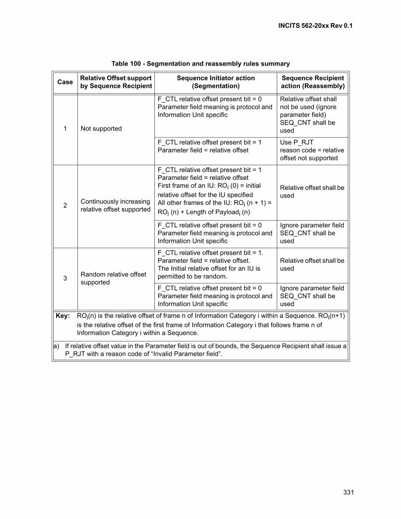
INCITS 562-20xx Rev 0.1
331
Table 100 - Segmentation and reassembly rules summary
CaseRelative Offset support by Sequence Recipient
Sequence Initiator action (Segmentation)
Sequence Recipient action (Reassembly)
1 Not supported
F_CTL relative offset present bit = 0Parameter field meaning is protocol and Information Unit specific
Relative offset shall not be used (ignore parameter field)SEQ_CNT shall be used
F_CTL relative offset present bit = 1Parameter field = relative offset
Use P_RJTreason code = relative offset not supported
2Continuously increasing relative offset supported
F_CTL relative offset present bit = 1Parameter field = relative offsetFirst frame of an IU: ROi (0) = initial
relative offset for the IU specifiedAll other frames of the IU: ROi (n + 1) =
ROi (n) + Length of Payloadi (n)
Relative offset shall be used
F_CTL relative offset present bit = 0Parameter field meaning is protocol and Information Unit specific
Ignore parameter fieldSEQ_CNT shall be used
3Random relative offset supported
F_CTL relative offset present bit = 1. Parameter field = relative offset.The Initial relative offset for an IU is permitted to be random.
Relative offset shall be used
F_CTL relative offset present bit = 0Parameter field meaning is protocol and Information Unit specific
Ignore parameter fieldSEQ_CNT shall be used
Key: ROi(n) is the relative offset of frame n of Information Category i within a Sequence. ROi(n+1)
is the relative offset of the first frame of Information Category i that follows frame n of Information Category i within a Sequence.
a) If relative offset value in the Parameter field is out of bounds, the Sequence Recipient shall issue a P_RJT with a reason code of “Invalid Parameter field”.
INCITS 562-20xx Rev 0.1
332
22 Error detection/recovery
22.1 Scope
Error detection and recovery are functions of both FC-2P and FC-2V.
22.2 Introduction
Link integrity and Sequence integrity are the two fundamental levels of error detection in this standard. Linkintegrity focuses on the inherent quality of the received transmission signal. When the integrity of the link isin question, a hierarchy of Primitive Sequences is used to reestablish link integrity. When PrimitiveSequence Protocols are performed, additional data recovery on a Sequence basis may be required.
A Sequence within an Exchange provides the basis for ensuring the integrity of the IU transmitted andreceived. Exchange management ensures that Sequences are delivered in the manner specified by theExchange Error Policy (see 22.5.4.3). Each frame within a Sequence is tracked on the basis ofExchange_ID, Sequence_ID, and a SEQ_CNT within the Sequence. Each frame is verified for validityduring reception. Sequence retransmission may be used to recover from any frame errors within theSequence and requires involvement, guidance, or authorization from an upper level.
Credit loss is an indirect result of frame loss or errors. Credit loss is discussed in regard to methodsavailable to reclaim apparent lost Credit resulting from other errors. See clause 20 for a more completediscussion on flow control, buffer-to-buffer Credit, and end-to-end Credit.
22.3 Timeout periods
22.3.1 Scope
These timeout periods may be used in either FC-2P or FC-2V.
22.3.2 General
The actual value used for a timeout shall not be less than the specified value and shall not exceed thespecified value by more than 20%.
22.3.3 R_T_TOV
The Receiver_Transmitter timeout value (R_T_TOV) is used by the receiver logic to detectLoss-of-Synchronization. The default value for R_T_TOV is 100 milliseconds. A shorter value of 100microseconds is allowed. FC_Ports that use the shorter value indicate this by setting the R_T_TOV bit inthe Common Service Parameters during Login. An FC_Port may determine another FC_Port’s R_T_TOVvalue using the Read Timeout Value (RTV) ELS (see FC-LS-4).
22.3.4 E_D_TOV
The Error_Detect_Timeout Value (E_D_TOV) is used as the timeout value for detecting an error condition.The value of E_D_TOV represents a timeout value for detection of a response to a timed event (i.e., duringData frame transmission it represents a timeout value for a Data frame to be delivered, the destinationNx_Port to transmit a Link_Response, and the Link_Response to be delivered to the Sequence Initiator).
INCITS 562-20xx Rev 0.1
333
The E_D_TOV value selected should consider configuration and Nx_Port processing parameters. Thedefault value is 2 seconds. However, a valid E_D_TOV value shall also adhere to the proper relationship tothe R_A_TOV value. When an Nx_Port performs Fabric Login, the Common Service Parameters providedby the Fx_Port specify the proper value for E_D_TOV.
When an Nx_Port performs N_Port Login in a point-to-point topology, the Common Service Parametersprovided by each Nx_Port specify a value for E_D_TOV. If the two values differ, each Nx_Port shall use thelonger time. An FC_Port may determine another FC_Port’s value for E_D_TOV via the Read TimeoutValue (RTV) ELS (see FC-LS-4). Timeout values as specified in the Payload of the LS_ACC are counts ofeither 1 ms or 1 ns increments, depending on the resolution specified (e.g., a value of 00 00 00 0Ahspecifies a time period of either 10 ms or 10 ns).
There are three cases when E_D_TOV is used as an upper limit, that is, an action shall be performed inless than an E_D_TOV timeout period:
a) transmission of consecutive Data frames within a single Sequence;
b) retransmission of a Class 2 Data frame in response to an F_BSY or P_BSY; and
c) transmission of ACK frames from the point in time that the event that prompted theacknowledgment action.
For all other cases, E_D_TOV shall expire before an action is taken. Two such examples include:
a) Link timeout (see 22.5.2); and
b) Sequence timeout (see 22.5.3).
22.3.5 R_A_TOV
The Resource_Allocation_Timeout Value (R_A_TOV) is used as the timeout value for determining when toreinstate a Recovery_Qualifier. The value of R_A_TOV represents E_D_TOV plus twice the maximum timethat a frame may be delayed within a Fabric and still be delivered. The default value of R_A_TOV is 10seconds.
When an Nx_Port performs Fabric Login, the Common Service Parameters provided by the Fx_Portspecify the value for R_A_TOV. When an Nx_Port performs N_Port Login in a point-to-point topology, theCommon Service Parameters provided by each Nx_Port only specify a value for E_D_TOV. R_A_TOVshall be set to twice the E_D_TOV value in a point-to-point topology. An FC_Port may determine anotherFC_Port's value for R_A_TOV via the RTV ELS (see FC-LS-4).
When R_A_TOV is used to determine when to reuse an Nx_Port resource (i.e., Recovery_Qualifier), theresource shall not be reused until R_A_TOV has expired for all frames previously transmitted that fallwithin the SEQ_CNT range of the Recovery_Qualifier. This may be accomplished by restarting theR_A_TOV timer as each Data frame of a Sequence is transmitted. Other techniques not specified by thisstandard may also be employed.
From the Fabric viewpoint, the maximum time that a frame may be delayed within the Fabric and still bedelivered is in the range of 1 to 231 -1 ms. The Fabric shall ensure delivery within the maximum deliverytime by requiring each Fabric Element to timeout frames stored in receive buffers within the Element.Individual Elements may use different timeout values, possibly one for each class. The maximum Fabricdelivery time is variable and is the cumulative timeout value for elements along the path or paths joiningthe source and destination Nx_Ports.
INCITS 562-20xx Rev 0.1
334
22.4 Link errors
22.4.1 Scope
Link error detection and recovery are functions of the FC-2P sublevel.
22.4.2 Link Failure timeouts
A Link Failure is detected under the following timeout conditions:
a) Loss-of-Signal (see 6.2);
b) Loss-of-Synchronization (see 6.2) > timeout period (R_T_TOV); and
c) Link Reset Protocol timeout (> R_T_TOV) (see 7.8.3).
22.4.3 Link Failure
The first level of link error detection is at the receiver. Link Failure is detected under the followingconditions:
a) Link Failure timeouts (see 22.4.2); or
b) reception of the NOS Primitive Sequence (see 7.6.1).
Recovery from Link Failure is accomplished by performing the Link Failure Protocol (see 7.8.4).
22.4.4 Code violations
Code violations are link errors that result from an invalid transmission code point or disparity error. If acode violation occurs during Primitive Signals, it is recorded in the Link Error Status Block by incrementingthe Invalid Transmission Word count by one. If a code violation occurs during frame reception (see 11.3.9),the Link Error Status Block shall also be updated by incrementing the Invalid Transmission Word count byone and the frame identified as invalid. The Data_Field of the invalid frame may be discarded or processedbased on the Exchange Error Policy.
NOTE 54 - When a code violation is detected, the actual location of the error may precede the location atwhich the code violation is detected (see table 6). In particular, even if the code violation is detectedfollowing the Frame_Header, fields in the header may not be valid.
22.4.5 Primitive Sequence protocol error
If a PN_Port is in the Active State and it receives LRR, it shall detect a Primitive Sequence protocol errorthat is counted in the LESB.
22.4.6 Link Error Recovery
The Link Recovery hierarchy is shown in figure 88.
The recovery protocols are nested and organized from the most serious to least serious link action.
a) Link Failure Protocol (see 7.8.4);
b) Link Initialization Protocol (see 7.8.2); and
c) Link Reset Protocol (see 7.8.3).
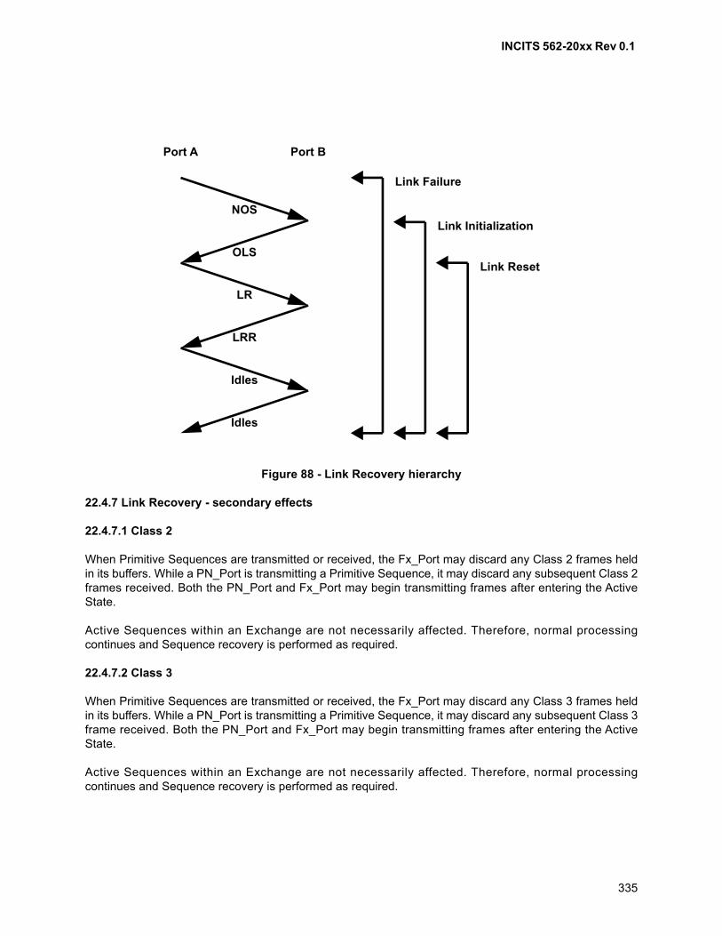
INCITS 562-20xx Rev 0.1
335
22.4.7 Link Recovery - secondary effects
22.4.7.1 Class 2
When Primitive Sequences are transmitted or received, the Fx_Port may discard any Class 2 frames heldin its buffers. While a PN_Port is transmitting a Primitive Sequence, it may discard any subsequent Class 2frames received. Both the PN_Port and Fx_Port may begin transmitting frames after entering the ActiveState.
Active Sequences within an Exchange are not necessarily affected. Therefore, normal processingcontinues and Sequence recovery is performed as required.
22.4.7.2 Class 3
When Primitive Sequences are transmitted or received, the Fx_Port may discard any Class 3 frames heldin its buffers. While a PN_Port is transmitting a Primitive Sequence, it may discard any subsequent Class 3frame received. Both the PN_Port and Fx_Port may begin transmitting frames after entering the ActiveState.
Active Sequences within an Exchange are not necessarily affected. Therefore, normal processingcontinues and Sequence recovery is performed as required.
Figure 88 - Link Recovery hierarchy
Link InitializationNOS
OLS
LR
LRR
Idles
Idles
Port BPort A
Link Failure
Link Reset
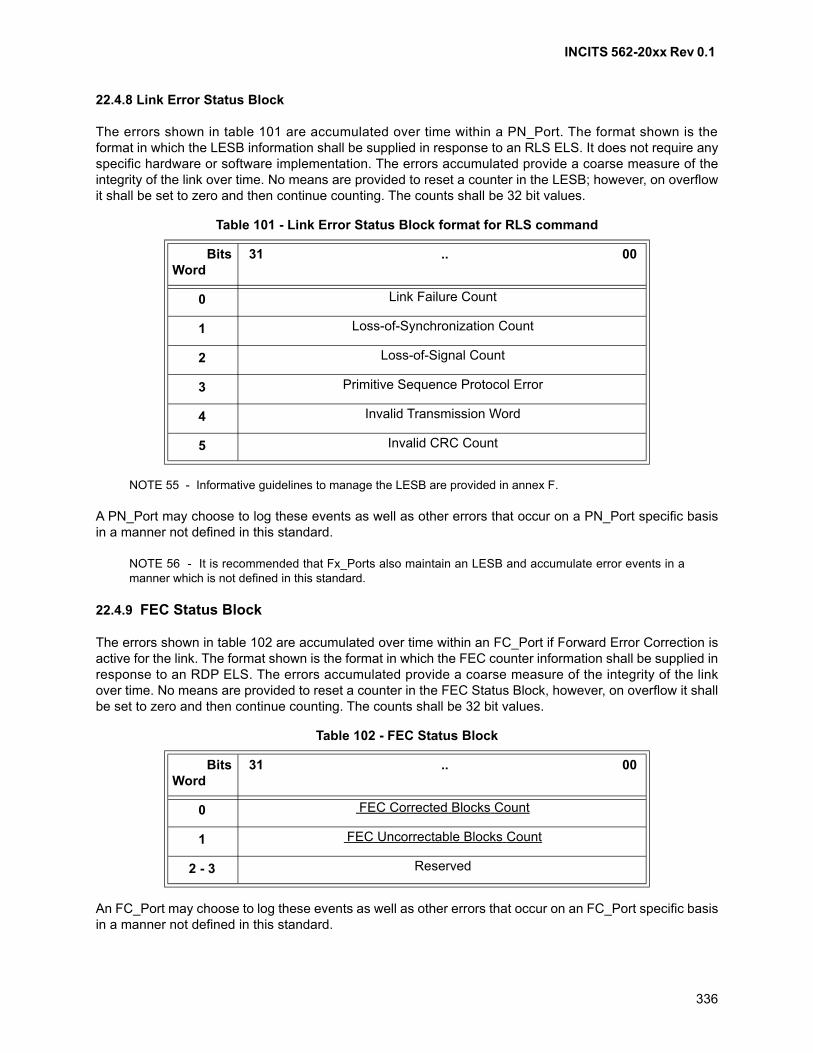
INCITS 562-20xx Rev 0.1
336
22.4.8 Link Error Status Block
The errors shown in table 101 are accumulated over time within a PN_Port. The format shown is theformat in which the LESB information shall be supplied in response to an RLS ELS. It does not require anyspecific hardware or software implementation. The errors accumulated provide a coarse measure of theintegrity of the link over time. No means are provided to reset a counter in the LESB; however, on overflowit shall be set to zero and then continue counting. The counts shall be 32 bit values.
NOTE 55 - Informative guidelines to manage the LESB are provided in annex F.
A PN_Port may choose to log these events as well as other errors that occur on a PN_Port specific basisin a manner not defined in this standard.
NOTE 56 - It is recommended that Fx_Ports also maintain an LESB and accumulate error events in amanner which is not defined in this standard.
22.4.9 FEC Status Block
The errors shown in table 102 are accumulated over time within an FC_Port if Forward Error Correction isactive for the link. The format shown is the format in which the FEC counter information shall be supplied inresponse to an RDP ELS. The errors accumulated provide a coarse measure of the integrity of the linkover time. No means are provided to reset a counter in the FEC Status Block, however, on overflow it shallbe set to zero and then continue counting. The counts shall be 32 bit values.
An FC_Port may choose to log these events as well as other errors that occur on an FC_Port specific basisin a manner not defined in this standard.
Table 101 - Link Error Status Block format for RLS command
BitsWord
31 .. 00
0 Link Failure Count
1 Loss-of-Synchronization Count
2 Loss-of-Signal Count
3 Primitive Sequence Protocol Error
4 Invalid Transmission Word
5 Invalid CRC Count
Table 102 - FEC Status Block
BitsWord
31 .. 00
0 FEC Corrected Blocks Count
1 FEC Uncorrectable Blocks Count
2 - 3 Reserved
INCITS 562-20xx Rev 0.1
337
22.4.10 Bit-Error-Rate Thresholding
22.4.10.1 Introduction
The optional bit-error-rate thresholding process is designed to detect an increased error rate beforeperformance degradation becomes serious. When the specified bit-error-rate threshold is reached, aRegistered Link Incident Report (RLIR) ELS shall be generated as required by the RLIR ELS (seeFC-LS-4).
The bit-error rate is measured during frame, Primitive Signal, and Primitive Sequence reception. Thebit-error rate is not calculated during times when Transmission Word Synchronization has been lost, whenin the Offline State, or when in a Link-Failure State. The terms used to define the bit-error-rate thresholdingprocess are defined in the Set Bit-error Reporting Parameters (SBRP) ELS (see FC-LS-4).
22.4.10.2 Types of Link Errors Caused by Bit Errors
Bit errors are not detected directly, however they usually result in the recognition of invalid TransmissionWords, Primitive Sequence protocol errors, CRC errors, or other events. If 8b/10b encoding is used, thenonly recognition of Invalid Transmission Words are counted toward the bit-error rate threshold. If 64b/66bencoding is used without FEC, then recognition of Invalid Transmission Words and CRC errors arecounted toward the bit error rate threshold. If 64b/66b encoding is used with FEC, then recognition ofInvalid Transmission Words and uncorrectable FEC Blocks (see 22.4.9) are counted toward the bit errorrate threshold.
22.4.10.3 Error Intervals
A single error may result in several related errors occurring closely together that in turn may result inmultiple counts. A character might have a single bit error in it that causes a code-violation error. A disparityerror might occur on a following character, caused by the same single error. To prevent multiple errorcounts from a single cause, the following concept of an Error Interval is introduced:
a) an Error Interval is a time period during which one or more invalid Transmission Words arerecognized. This time may be exceeded due to infrequent unusual conditions;
b) only the first error in an Error Interval is counted toward the Error Threshold; and
c) the default value for the Error Interval is 1.5 seconds with a tolerance of 10%.
22.4.10.4 Bit-Error-Rate-Thresholding Measurement
Measurement of bit-error-rate thresholding shall be accomplished by counting the number of ErrorIntervals that occur in an Error Window. When the Error Interval Count equals the Error Threshold, thethreshold is exceeded and an RLIR shall be generated. A maximum of one RLIR ELS reporting bit errorthreshold exceeded shall be generated for each link during one Error Window. The default value for theError Threshold is 15.
The default value for the Error Window is 300 seconds and the tolerance is + 1 Error Interval or - 0 ErrorIntervals.
The bit-error-counting process shall be restarted when Active State is entered and when avendor-dependent amount of time has elapsed after the Error Threshold is exceeded. In addition, thebit-error-counting process may be restarted whenever the Error Window has expired even though an ErrorThreshold is not reached. The bit-error-counting process may also be reset and restarted when aninitialization procedure occurs.
INCITS 562-20xx Rev 0.1
338
22.5 Exchange and Sequence errors
22.5.1 Scope
Exchange and Sequence error recovery are functions of the FC-2V sublevel.
22.5.2 Link timeout
A Link timeout error shall be detected if one or more R_RDY Primitive Signals are not received withinE_D_TOV after BB_Credit_CNT has reached BB_Credit.
Recovery from Link timeout is accomplished by performing the Link Reset Protocol (see 7.8.3).
Link timeout values need to take Fabric characteristics into consideration. The concern is the maximumtime required for frame delivery by the worst case route with any associated delays within the Fabric.
22.5.3 Sequence timeout
22.5.3.1 Introduction
The basic mechanism for detecting errors within a Sequence is the Sequence timeout. Other mechanismsthat detect frame errors within a Sequence are performance enhancements in order to detect an errorsooner than the timeout period. Since an active Sequence utilizes Nx_Port resources, Sequence timeout isapplicable to both the discard policy and the process policy.
22.5.3.2 Class 2
Both the Sequence Initiator and the Sequence Recipient use a timer facility with a timeout period(E_D_TOV) between expected events. The expected event for the Sequence Initiator to Data frametransmission is an ACK response. The expected event for the Sequence Recipient is another Data framefor the same Sequence that is active and not complete. Other events (e.g., Link Credit Reset andABTS-LS) shall also stop the Sequence timer. When a Sequence Recipient receives the last Data frametransmitted for the Sequence, it shall verify that all frames have been received before transmitting the finalACK (EOFt) for the Sequence.
If the timeout period (E_D_TOV) expires for an expected event before the Sequence is complete, aSequence timeout is detected. Timeouts are detectable by both the Sequence Initiator and the SequenceRecipient. If a Sequence Initiator detects a Sequence timeout, it shall transmit the ABTS frame to performthe Abort Sequence Protocol. If a timeout is detected by the Sequence Initiator before the last Data frameis transmitted, ABTS notifies the Sequence Recipient that an error was detected by the Sequence Initiator(see 22.5.5.2.2). Detection of a Sequence timeout by the Sequence Initiator may also result in aborting theExchange (see 16.3.2.3).
If a Sequence Recipient detects a Sequence timeout, it shall set the Abort Sequence Condition (i.e.,F_CTL bits 5-4) in an ACK to 01b to indicate a missing frame error condition. The Sequence Recipientshall also post the detected condition in the Exchange Status Block associated with the Sequence. ASequence timeout results in either aborting the Sequence (see 16.3.2.2) by the Sequence Initiator,abnormal termination of a Sequence (see 22.5.5.2) by the Sequence Recipient, or aborting the Exchangeby either the Sequence Initiator or Sequence Recipient (see 16.3.2.3).
INCITS 562-20xx Rev 0.1
339
In Class 2, if a Sequence has been aborted and the Sequence Recipient supplies the Recovery_Qualifier(i.e., OX_ID, RX_ID, and a SEQ_CNT range, low and high SEQ_CNT values), the Sequence Initiator shallnot transmit any Data frames within that range within a timeout period of R_A_TOV. Both the SequenceInitiator and Sequence Recipient discard frames within that range. After R_A_TOV has expired, theSequence Initiator shall reinstate the Recovery_Qualifier using a Reinstate Recovery Qualifier Link Servicerequest.
22.5.3.3 Class 3
In Class 3, the expected event for the Recipient is another Data frame for the same Sequence. Otherevents (e.g., ABTS-LS) shall also stop the Sequence timer. When a Sequence Recipient receives the lastData frame transmitted for the Sequence, it shall verify that all frames have been received.
NOTE 57 - For environments that do not use a request/response protocol, the Sequence Initiator mayperiodically transmit an ABTS frame and the Sequence Recipient is able to inform the Sequence Initiatorof the last deliverable Sequence. If the Sequence Initiator does not transmit ABTS frames, in Discardmultiple Sequences Exchange Error Policy following an error in a Single Sequence, the SequenceRecipient may continue to abnormally terminate subsequent Sequences and not deliver them to the FC-4or upper level due to the requirement of in-order delivery of Sequences in the order transmitted.
NOTE 58 - For environments that use a request/response protocol, ABTS should not be used to forwardprogress of a transmission. For bi-directional Exchanges, it is possible to infer proper Sequence deliverywithout the use of ABTS, if Sequence Initiative has been transferred and the reply Sequence for the sameExchange is received.
22.5.3.4 End-to-end Class 2 Credit loss
In Class 2 it is possible to have no available end-to-end Credit as a result of one or more Sequencetimeouts. The LCR Link_Control frame shall be transmitted by the Sequence Initiator, that has no availableend-to-end Credit, to the Sequence Recipient. The Sequence Initiator (indicated by the S_ID in the LCRframe) shall perform normal recovery for the Sequence that timed out (see 22.5.5).
The Fabric may return F_BSY if unable to deliver the LCR frame. A Reject may also be returned if eitherthe S_ID or D_ID is invalid or an invalid delimiter is used.
When an Nx_Port receives a LCR, it shall discard the Data in its buffers associated with the S_ID of theLCR frame and abnormally terminate the Sequences associated with any discarded frames.
22.5.4 Exchange Integrity
22.5.4.1 Applicability
Since Class 3 does not use ACK or Link_Response frames, Sequence integrity is verified at the SequenceRecipient on a Sequence by Sequence basis. In Class 3, only the Recipient is aware of a missing framecondition and communication of that information to the Initiator is the responsibility of the FC-4 or upperlevel.
The remaining discussion concentrates on Class 2. Items applicable to Class 3 shall be specified explicitly.
INCITS 562-20xx Rev 0.1
340
22.5.4.2 Exchange management
An Exchange is managed according to the rules specified in 19.4.1. When an Exchange is originated, theOriginator specifies the Exchange Error Policy for the duration of the Exchange. Delivery of Data within aSequence from the Originator to the Responder or from the Responder to the Originator shall be in thesame order as transmitted. The discarding of Sequences, the delivery order of Sequences, and therecovery of Sequences varies based on the Exchange Error Policy identified by the Originator AbortSequence Condition bits (i.e., F_CTL bits 5-4). (see 12.7.10)
22.5.4.3 Exchange Error Policies
22.5.4.3.1 Introduction
There are two fundamental Exchange Error Policies, the discard policy and the process policy. Discardpolicy means that a Sequence is delivered in its entirety or it is not delivered at all. There are two variationsof discard policy that relate to the deliverability of ordered Sequences. Process policy allows an incompleteSequence to be deliverable. Process policy allows the Data portion of invalid frames to be delivered if theSequence Recipient has reason to believe that it is part of the proper Exchange. See 19.4.10 for rules thatdiscuss detailed requirements for each type of Exchange Error Policy.
22.5.4.3.2 Discard multiple Sequences
The Discard multiple Sequences Error Policy requires that for a Sequence to be deliverable, it shall becomplete (all Data frames received and accounted for) and any previous Sequences, if any, for the sameExchange from the Sequence Initiator are also deliverable. This policy is useful if the ordering of Sequencedelivery (i.e., Sequence A followed by Sequence D, followed by Sequence T, and so forth) is important tothe FC-4 or upper level. Sequences shall be delivered to the FC-4 or upper level on a Sequence basis inthe same order as transmitted.
22.5.4.3.3 Discard a single Sequence
The Discard a single Sequence Error Policy requires that for a Sequence to be deliverable, it shall becomplete (i.e., all Data frames received and accounted for). There shall be no requirement on thedeliverability of previous Sequences for the Exchange. This policy is useful if the Payload of theSequences delivered contains sufficient FC-4 or upper level information to process the Sequenceindependently of other Sequences within the Exchange. Sequences shall be delivered to the FC-4 orupper level on a Sequence basis in the same order as received.
22.5.4.3.4 Process with infinite buffering
The Process with infinite buffering Error Policy does not require that a Sequence be complete or that anyprevious Sequences be deliverable. Process policy allows an Nx_Port to utilize the Data_Field of invalidframes under certain restrictive conditions (see 11.3.9.2 and 11.3.9.3). The Process with infinite bufferingError Policy is intended for applications (e.g., a video frame buffer) in which loss of a single frame hasminimal effect or no effect on the Sequence being delivered. Frames shall be delivered to the FC-4 orupper level in the same order as received.
Process with infinite buffering in shall not be requested in classes of service other than Class 3.
INCITS 562-20xx Rev 0.1
341
22.5.4.4 Sequence integrity
Sequence management and integrity involves:
a) proper initiation of Sequences (see 19.4.4);
b) proper control of the ordering of Sequences (SEQ_ID usage) with continuously increasingSEQ_CNT (see 19.4.6);
c) proper control of Data frames by SEQ_CNT within single Sequence (see 19.4.6); and
d) proper completion of a Sequence (see 19.4.8).
Frame identification (see 19.2.2) and Sequence identification (see 19.7.1) provide the appropriateuniqueness to ensure the integrity of the Data delivered. A Sequence Recipient shall not reassemble anddeliver the Data frames of a single Sequence unless all of the Data frames adhere to the Sequencemanagement rules specified in 19.4.5.
22.5.4.5 Sequence error detection
Sequence errors are detected in three ways:
a) detection of a missing frame (see 19.4.10 and 19.4.11);
b) detection of a Sequence timeout (see 22.5.3); and
c) detection of rejectable condition within a frame (see 15.3.3.4).
Detection of Sequence errors by the Recipient is conveyed in the Abort Sequence Condition bits (i.e.,F_CTL 5-4) in an ACK frame or by a P_RJT frame (except Class 3). Otherwise, either the SequenceInitiator or Sequence Recipient or both detect a Sequence timeout.
Exchange and Sequence status are tracked in the Exchange Status Block (see 19.9.1 and 19.4.14) andthe Sequence Status Block (see 19.9.2 and 19.4.12), respectively.
22.5.4.6 X_ID processing
During certain periods in an Exchange, one or both X_ID fields may be unassigned. If an X_ID isunassigned, special error recovery for both the Sequence Initiator and the Sequence Recipient may berequired that is beyond the scope of this standard.
22.5.5 Sequence recovery
22.5.5.1 Introduction
Sequence recovery is under control of the individual FC-4 or upper level as well as options within a specificimplementation. Such control may be exercised in the form of guidance, authorization to automaticallyperform recovery, a requirement to inform the upper level prior to recovery, or no Sequence recovery withinthe Exchange encountering a Sequence error. This standard specifies procedures to terminate or abort aSequence, recover end-to-end Credit, handle missing or delayed frames, and synchronize both Nx_Portswith respect to Sequence and Exchange status. This standard does not require Sequence retransmissionwithin the same Exchange in which a Sequence error is detected.
INCITS 562-20xx Rev 0.1
342
22.5.5.2 Abnormal Sequence termination
22.5.5.2.1 Introduction
There are multiple methods by which a Sequence may complete abnormally and one method by which aSequence completes but is only partially received by the Sequence Recipient. When a Sequencecompletes abnormally, it shall not be delivered to the FC-4 or upper level. The rules for normal Sequencecompletion are specified in 19.4.8. The methods by which a Sequence completes abnormally include:
a) the Sequence Initiator aborts the Sequence with an ABTS frame utilizing the Abort SequenceProtocol. At the time the ABTS frame is received, one or more Sequences are incomplete;
b) if the Exchange of which a Sequence is a member is abnormally terminated, each open Sequenceshall also be abnormally completed (see 19.4.13); and
c) Logout (see FC-LS-4).
A Sequence may complete normally with only a part of the Sequence being received by the SequenceRecipient in the Stop Sequence Protocol.
22.5.5.2.2 Abort Sequence Protocol
22.5.5.2.2.1 General Case
The Sequence Initiator shall begin the Abort Sequence Protocol (i.e., ABTS Protocol) by transmitting theABTS Basic Link Services frame. The SEQ_ID shall match the SEQ_ID of the last Sequence transmittedeven if the last Data frame has been transmitted. The ABTS frame may be transmitted without regard towhether transfer of Sequence Initiative has already been attempted or completed. The SEQ_CNT of theABTS frame shall be one greater than the SEQ_CNT of the last frame transmitted for this Exchange by theSequence Initiator of the ABTS frame.
The Sequence Recipient shall accept an ABTS frame even if the Sequence Initiative has been previouslytransferred. The Recipient determines the last deliverable Sequence as the Recipient for this Exchangeand it includes that SEQ_ID in the BA_ACC Payload along with a valid indication (see table 77). ThePayload of the BA_ACC also includes the current OX_ID and RX_ID for the Exchange in progress. Lowand high SEQ_CNT values are also returned. The low SEQ_CNT value is equal to the SEQ_CNT of thelast Data frame (i.e., End_Sequence = 1) of the last deliverable Sequence. If there was no deliverableSequence, the low value is zero.
The high SEQ_CNT value shall match the SEQ_CNT of the ABTS frame. The combination of OX_ID,RX_ID, low SEQ_CNT and high SEQ_CNT defines the range of a Recovery_Qualifier. This rangeindicates a range of Data frames that were not and shall never be delivered to the FC-4 or upper level inthe Discard multiple Sequences Error Policy. In the Discard a single Sequence Error Policy, theRecovery_Qualifier may contain Sequences that have been delivered.
If the ABTS frame is transmitted in Class 2 or Class 3, the Recovery_Qualifier shall be timed out by theSequence Initiator of the ABTS frame for a timeout period of R_A_TOV. After the R_A_TOV timeout hasexpired, the Sequence Initiator of the ABTS frame shall issue a Reinstate Recovery Qualifier Link Servicerequest in order to purge the Recovery_Qualifier. Timing out the Recovery_Qualifier for R_A_TOV allowsboth Nx_Ports to discard frames received in the range of the Recovery_Qualifier. This ensures the Dataintegrity of the Exchange.
INCITS 562-20xx Rev 0.1
343
Transmission of BA_ACC by the Sequence Recipient is a synchronizing, atomic event. The SequenceRecipient shall discard any frames received within the range of the Recovery_Qualifier, if timeout isrequired, the instant that the BA_ACC is transmitted and thereafter, until it receives a Reinstate RecoveryQualifier (RRQ) ELSs request. The Sequence Initiative F_CTL bit setting in the BA_ACC shall indicatewhether the Sequence Initiative is held or transferred to the Sequence Initiator of the ABTS frame. If theSequence Recipient of the ABTS frame holds Sequence Initiative, it shall withhold Sequence Initiativetransfer until the ACK to the BA_ACC is received.
In like manner, after the Sequence Initiator has received the BA_ACC to the ABTS frame, it shall discardany frames received within the range of the Recovery_Qualifier. The Sequence Initiator shall retire theSEQ_CNT range within the Recovery Qualifier until R_A_TOV has expired, or it shall abort the Exchange(the Recovery_Qualifier for the Exchange times out R_A_TOV).
When the Sequence Initiator has received the BA_ACC, it may reclaim any outstanding end-to-end Creditfor all unacknowledged Data frames within the SEQ_CNT range of the Recovery_Qualifier. After theSequence Initiator of the ABTS frame has received the BA_ACC with Sequence Initiative transferred to theInitiator, it may retransmit the Sequences that it determines as non-deliverable by the Sequence Recipient(see 19.4.8 and 19.4.11).
If a Recovery_Qualifier exists and is being timed out (R_A_TOV) and another Sequence error occurs thatwould cause transmission of the ABTS frame, the Exchange shall be aborted using ABTS-LS. However, ifthe Reinstate Recovery Qualifier request has been completed such that the Recovery_Qualifier has beenpurged, the ABTS Protocol may be utilized and a new Recovery_Qualifier may be established.
22.5.5.2.2.2 Special case - new Exchange
If a Sequence Initiator of the ABTS frame attempts to originate a new Exchange and a Sequence timeoutoccurs, the Sequence Initiator shall transmit the ABTS frame as in the ABTS protocol defined. If theSequence Recipient receives an ABTS frame for an Exchange that is unknown, it shall open an ExchangeStatus Block, with OX_ID = value of ABTS, RX_ID = FF FFh, and post the SEQ_ID of the ABTS frame. TheBA_ACC Payload shall indicate invalid SEQ_ID, a low SEQ_CNT set to zero, and a high SEQ_CNT set toSEQ_CNT of the ABTS frame.
The Sequence Initiator of the ABTS frame shall timeout the Recovery_Qualifier, if required, and transmitthe Reinstate Recovery Qualifier in the normal manner.
22.5.5.2.3 Recipient abnormal termination
If no Data frames are being received for a Sequence in error, the Sequence Recipient shall timeout theSequence and abnormally terminate the Sequence by setting status in the Sequence Status Block toindicate Sequence timed-out by Recipient, update the Sequence status in the Exchange Status Block, andrelease link facilities associated with the Sequence. If an ABTS frame for the abnormally terminatedSequence is received, the Abort Sequence Protocol shall be performed and completed.
The Sequence Recipient may timeout the Exchange in a system dependent manner and timeout period.
INCITS 562-20xx Rev 0.1
344
22.5.5.2.4 End_Sequence
If the last Data frame of a Sequence has been transmitted with the Last_Sequence bit set and theSequence Initiator detects a Sequence timeout, the Initiator may initiate an Exchange with a REC ELSrequest to determine Exchange status. If the Initiator is in the process of timing out a Sequence for amissing EOFt with Sequence Initiative transferred and it receives a new Sequence initiated by theRecipient (new Initiator), it shall assume that the previous Sequence ended successfully. In order to makesuch an assumption, the N_Port_ID, OX_ID, and RX_ID shall be the same for the new Sequence as theSequence that transferred Sequence Initiative.
From a Recipient view, if the last Data frame is lost, the Recipient abnormally terminates the Sequencewhen a Sequence timeout is detected.
22.5.5.3 Stop Sequence Protocol
The Stop Sequence Protocol shall be used by a Sequence Recipient to terminate a Sequence withoutinvoking a drastic recovery protocol. To cause a Sequence to be terminated by the Initiator, the SequenceRecipient shall set the Abort Sequence Condition bits in F_CTL to a 10b value in the ACK to each Dataframe received after the Recipient recognizes the need to terminate the Sequence. When the SequenceInitiator receives the first ACK with the Stop Sequence Condition indicated, it shall terminate the Sequenceby transmitting a Data frame of the Sequence with End_Sequence = 1. If the Sequence Initiator hasalready transmitted the last Data frame of the Sequence, no further action is required of it except thatwhich may be required by the FC-4 or upper level.
Once the Sequence Recipient has indicated the Stop Sequence condition, it shall not report Sequenceerrors related to Data frames with a SEQ_CNT greater than that of the Data frame at which the StopSequence condition was recognized. However, it shall observe the normal Sequence timeout protocolsbefore transmitting the ACK to the frame with the End_Sequence bit set and shall recover Credit in thenormal manner.
NOTE 59 - When the Sequence Initiator stops the Sequence, or if it sent the last Data frame beforereceiving the Stop-Sequence indication, it may either hold or pass Sequence Initiative as determined bythe Upper Level Protocol. It is the responsibility of the Upper Level Protocol to define the protocol forindicating to the Sequence Initiator why the Sequence was stopped, if such an indication is needed, andthe protocol for transferring Sequence Initiative if needed.
NOTE 60 - A common use of this protocol is to signal that there is no more room in the Upper LevelProtocol buffer for the Data being received. To terminate the Sequence when the Upper Level Protocolbuffer is exhausted, the Sequence Recipient stores as much data as possible from the first frame whosePayload is not completely stored and indicates the Stop Sequence condition in the Abort SequenceCondition bits in F_CTL in the ACK to that Data frame and in each subsequent ACK until the end of theSequence. When the Sequence ends, the ULP protocol may send a message from the SequenceRecipient to the Initiator that includes the count of the number of bytes in the Sequence that were storedbefore the ULP buffer was exhausted.
22.5.5.4 End-to-end Credit loss
This standard does not define the method to be employed for Credit allocation to a destination Nx_Port. Ifdestination end-to-end Credit is allocated on a Sequence basis, then that portion of end-to-end Credit isreclaimed when the Sequence is aborted or abnormally terminated. When a Sequence is aborted, anyend-to-end Credit for outstanding ACK frames associated with that Sequence may be reclaimed. Thisapplies only to Class 2.
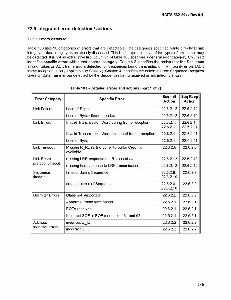
INCITS 562-20xx Rev 0.1
345
22.6 Integrated error detection / actions
22.6.1 Errors detected
Table 103 lists 10 categories of errors that are detectable. The categories specified relate directly to linkintegrity or data integrity as previously discussed. This list is representative of the types of errors that maybe detected. It is not an exhaustive list. Column 1 of table 103 specifies a general error category. Column 2identifies specific errors within that general category. Column 3 identifies the action that the SequenceInitiator takes on ACK frame errors detected for Sequences being transmitted or link integrity errors (ACKframe reception is only applicable to Class 2). Column 4 identifies the action that the Sequence Recipienttakes on Data frame errors detected for the Sequences being received or link integrity errors.
Table 103 - Detailed errors and actions (part 1 of 2)
Error Category Specific ErrorSeq Init Action
Seq Recp Action
Link Failure Loss-of-Signal 22.6.2.12 22.6.2.12
Loss of Sync> timeout period 22.6.2.12 22.6.2.12
Link Errors Invalid Transmission Word during frame reception 22.6.2.1, 22.6.2.11
22.6.2.1, 22.6.2.11
Invalid Transmission Word outside of frame reception 22.6.2.11 22.6.2.11
Loss of Sync 22.6.2.11 22.6.2.11
Link Timeout Missing R_RDYs (no buffer-to-buffer Credit is available)
22.6.2.6 22.6.2.6
Link Reset protocol timeout
missing LRR response to LR transmission 22.6.2.12 22.6.2.12
missing Idle response to LRR transmission 22.6.2.12 22.6.2.12
Sequence timeout
timeout during Sequence 22.6.2.8, 22.6.2.10
22.6.2.9
timeout at end of Sequence 22.6.2.8, 22.6.2.10
22.6.2.9
Delimiter Errors Class not supported 22.6.2.2 22.6.2.2
Abnormal frame termination 22.6.2.1 22.6.2.1
EOFa received 22.6.2.1 22.6.2.1
Incorrect SOF or EOF (see tables 61 and 63) 22.6.2.1 22.6.2.1
Address Identifier errors
incorrect D_ID 22.6.2.2 22.6.2.2
incorrect S_ID 22.6.2.2 22.6.2.2
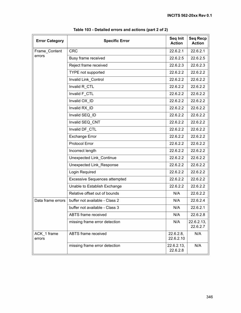
INCITS 562-20xx Rev 0.1
346
Frame_Content errors
CRC 22.6.2.1 22.6.2.1
Busy frame received 22.6.2.5 22.6.2.5
Reject frame received 22.6.2.3 22.6.2.3
TYPE not supported 22.6.2.2 22.6.2.2
Invalid Link_Control 22.6.2.2 22.6.2.2
Invalid R_CTL 22.6.2.2 22.6.2.2
Invalid F_CTL 22.6.2.2 22.6.2.2
Invalid OX_ID 22.6.2.2 22.6.2.2
Invalid RX_ID 22.6.2.2 22.6.2.2
Invalid SEQ_ID 22.6.2.2 22.6.2.2
Invalid SEQ_CNT 22.6.2.2 22.6.2.2
Invalid DF_CTL 22.6.2.2 22.6.2.2
Exchange Error 22.6.2.2 22.6.2.2
Protocol Error 22.6.2.2 22.6.2.2
Incorrect length 22.6.2.2 22.6.2.2
Unexpected Link_Continue 22.6.2.2 22.6.2.2
Unexpected Link_Response 22.6.2.2 22.6.2.2
Login Required 22.6.2.2 22.6.2.2
Excessive Sequences attempted 22.6.2.2 22.6.2.2
Unable to Establish Exchange 22.6.2.2 22.6.2.2
Relative offset out of bounds N/A 22.6.2.2
Data frame errors buffer not available - Class 2 N/A 22.6.2.4
buffer not available - Class 3 N/A 22.6.2.1
ABTS frame received N/A 22.6.2.8
missing frame error detection N/A 22.6.2.13, 22.6.2.7
ACK_1 frame errors
ABTS frame received 22.6.2.8, 22.6.2.10
N/A
missing frame error detection 22.6.2.13, 22.6.2.8
N/A
Table 103 - Detailed errors and actions (part 2 of 2)
Error Category Specific ErrorSeq Init Action
Seq Recp Action
INCITS 562-20xx Rev 0.1
347
22.6.2 Actions by Initiator or Recipient
22.6.2.1 Discard frame
In both the discard policy and the process policy, a frame that is terminated with an EOFa shall bediscarded:
a) Discard policy - If an invalid frame is detected, the entire invalid frame shall be discarded. If a validframe is received and a rejectable or busy condition in Class 3 is detected, the entire frame shallbe discarded; and
b) Process policy - If an Nx_Port is able to determine that an invalid frame is associated with anExchange which is designated as operating under Process policy, the Nx_Port may process anduse the Data_Field at its discretion, otherwise, the entire invalid frame shall be discarded.
22.6.2.2 Transmit P_RJT frame
If a valid Data frame (see 11.3.9.2) is received that contains information in the Frame_Header that isinvalid or incorrect, then:
a) in Class 2, a P_RJT frame shall be transmitted with the appropriate reason code as specified in15.3.3.4. Reason codes are defined such that the first error detected is returned as the reasoncode; and
b) in any class of service, the received frame shall be discarded and R_RDY shall be transmitted inresponse to the discarded frame.
22.6.2.3 Process Reject
When a P_RJT or F_RJT frame is received in response to a frame transmission, the reject informationshall be passed to the appropriate Upper Level Protocol in order to process. Certain errors are recoverableby taking an appropriate action (e.g., Login). The Sequence shall be aborted using the Abort SequenceProtocol, regardless of possible recovery actions. For typical non-retryable errors the Exchange shall alsobe aborted.
If a P_RJT or F_RJT frame is received that contains information in the Frame_Header that is invalid orincorrect, the frame shall be discarded.
22.6.2.4 Transmit P_BSY frame
An Nx_Port shall track the status of its buffers such that if a Class 2 Data frame is received and noEE_buffer is available, a P_BSY shall be returned to the transmitter of the frame. If a Class 2 Data frame isreceived and no BB_buffer is available, the Recipient may discard the frame without issuing a P_BSY orP_RJT. Portions of the frame other than the Frame_Header are discarded. The Frame_Header is capturedin order to generate a proper P_BSY Link_Response frame.
An R_RDY is transmitted in response to a Class 2 frame regardless of the disposition of the receivedframe.
22.6.2.5 Process Busy
When an F_BSY or P_BSY is received in response to a Class 2 Data frame, and if the Nx_Port has thecapability to retransmit, the Nx_Port shall retransmit the Class 2 Data frame within E_D_TOV of the lastData frame transmission. In order to avoid reissuing a frame for an extended number of retries an Nx_Portmay choose to count the number of retries and decide to shutdown communication with a specific Nx_Port.
INCITS 562-20xx Rev 0.1
348
When an F_BSY is received in response to an ACK frame (Class 2), the Nx_Port shall not retransmit theACK frame.
22.6.2.6 Perform Link Reset Protocol
When a PN_Port has no buffer-to-buffer Credit available and has exceeded the Link timeout period(E_D_TOV), a Link timeout is detected. When a Link timeout is detected, the PN_Port or Fx_Port beginsthe Link Reset Protocol.
22.6.2.7 Set Abort Sequence Bits
When a Sequence Recipient detects a Sequence error by missing frame detection or other internalprocessing errors, the Recipient sets the appropriate Abort Sequence in F_CTL bits 5-4 to:
a) 00b = Continue Sequence;
b) 01b = Abort, perform ABTS; or
c) 10b = Stop Sequence.
The SEQ_CNT of the first missing frame is saved in the Sequence Status Block. Only the first error issaved in the Sequence Status Block. This information shall not be required by the Sequence Initiator forrecovery purposes.
22.6.2.8 Perform Abort Sequence Protocol
When a Sequence Initiator detects a Sequence error or receives an appropriate Abort Sequence Condition(01b) in F_CTL bits 5-4 in an ACK for an active Sequence, the Initiator shall transmit an Abort SequenceLink Service request to the Recipient and transfers Sequence Initiative in order to complete AbortSequence processing (see 22.5.5.2).
When a Sequence Recipient receives an ABTS frame, it shall respond as specified in 22.5.5.2.2 and16.3.2.
22.6.2.9 Abnormally terminate Sequence
When a Sequence Recipient detects a Sequence timeout (E_D_TOV) and no Data frames are beingreceived for the Sequence, the Recipient shall terminate the Sequence and update the Exchange StatusBlock.
22.6.2.10 Retry Sequence
When a Sequence has been abnormally terminated, the Sequence Initiator may retransmit the Sequenceunder guidance, authorization, or control of the FC-4 or upper level.
22.6.2.11 Update LESB
The Link Error Status Block is updated to track errors not directly related to an Exchange.
22.6.2.12 Perform Link Failure Protocol
Transmission or reception of the not operational Primitive Sequence initiates the Link Failure Protocol.

INCITS 562-20xx Rev 0.1
349
22.6.2.13 Error Policy processing
When an error is detected within a Sequence, the Sequence is either processed normally (process policy),or discarded (discard policy). See 22.5.4.3 for additional information.
INCITS 562-20xx Rev 0.1
350
23 Broadcast
23.1 Scope
Broadcast is a function of the FC-2M sublevel.
23.2 Applicability
Broadcast provides a service based on Fabric routing of Class 3 frames.
Broadcast operations are not applicable to Class 2.
23.3 Broadcast operation
A frame addressed to the Well-known address for Broadcast (i.e., FF FF FFh) is a Broadcast frame. TheFabric shall attempt to send the Broadcast frame to all possible Nx_Ports within zoning constraints.However, the Fabric may not be able to deliver to all Nx_Ports for any number of reasons (e.g., classmismatch or Nx_Port not operational).
An Nx_Port may discard a Broadcast frame.
An Nx_Port shall send and receive Class 3 Broadcast Data frames in the context of an implicit BroadcastPort Login. The implicit Broadcast Port Login is particular because it is not tied to any remoteN_Port_Name and Node_Name, but it is tied to the destination address identifier FF FF FFh.
The implicit Broadcast Port Login specifies the service parameters to be used for broadcastcommunications. An FC-4 using the Broadcast functionality may specify the service parameters that itrequires in the implicit Broadcast Port Login. In absence of such a specification, the default Loginparameters specified in FC-LS-4 shall be used.
23.4 Other
Other forms of broadcast and multicast are available in topology specific configurations. For examples seeFC-AL-2 for a description of Selective Replicate to perform dynamic multicasting.
INCITS 562-20xx Rev 0.1
351
24 Clock synchronization service
24.1 Scope
ELS Command service (see 24.3) is a function of the FC-3 level. Primitive Signal service (see 24.4) is afunction of the FC-2P sublevel.
24.2 Introduction
24.2.1 References
See Informative annex G for implementation details related to Clock Synchronization.
24.2.2 Applicability
Conventional network technologies utilize clock distribution protocols (e.g., Network Time Protocol) thatsynchronize the computer’s time-of-day clock. Such protocols typically provide clock synchronizationaccuracies on the order of a few milliseconds with highly tuned versions producing accuracies on the orderof 50 microseconds.
The protocols defined in this clause allow clocks located within nodes to be readily synchronized tomicrosecond accuracies. If all sources of error are accounted for, higher accuracies are possible.
24.2.3 Function
Clock Synchronization over Fibre Channel is attained through a Clock Synchronization Server thatcontains a reference clock. The Server synchronizes Client’s clocks to the reference clock on a periodicbasis using either Primitive Signals or ELS frames. The Server may be built into a Fabric or it may beimplemented as an independent node that services one or more Nx_Ports in either a Fabric or anArbitrated Loop topology.
When all the Clients are synchronized with the Server, they shall be synchronized with each other. Bytagging data with the current value of their synchronized clock, one client may accurately exchange timesensitive data with another client.
24.2.4 Assumptions
A simplifying assumption in both the ELS and Primitive methods is that propagation delays over themedium are insignificant. This eliminates the need for the Server to calculate and maintain the media delayto each Client.
Very accurate clock synchronization is accomplished without the use of media propagation delays throughthe techniques described in this clause. If the system requires even greater accuracy, “canned”propagation delays could be added in the Client’s software or hardware. This and other sources of errorare discussed in annex G.
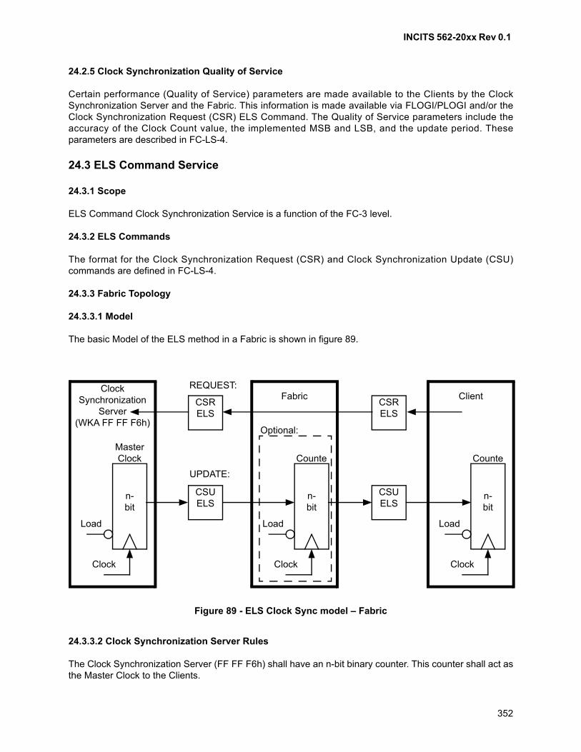
INCITS 562-20xx Rev 0.1
352
24.2.5 Clock Synchronization Quality of Service
Certain performance (Quality of Service) parameters are made available to the Clients by the ClockSynchronization Server and the Fabric. This information is made available via FLOGI/PLOGI and/or theClock Synchronization Request (CSR) ELS Command. The Quality of Service parameters include theaccuracy of the Clock Count value, the implemented MSB and LSB, and the update period. Theseparameters are described in FC-LS-4.
24.3 ELS Command Service
24.3.1 Scope
ELS Command Clock Synchronization Service is a function of the FC-3 level.
24.3.2 ELS Commands
The format for the Clock Synchronization Request (CSR) and Clock Synchronization Update (CSU)commands are defined in FC-LS-4.
24.3.3 Fabric Topology
24.3.3.1 Model
The basic Model of the ELS method in a Fabric is shown in figure 89.
24.3.3.2 Clock Synchronization Server Rules
The Clock Synchronization Server (FF FF F6h) shall have an n-bit binary counter. This counter shall act asthe Master Clock to the Clients.
Figure 89 - ELS Clock Sync model – Fabric
Client
n-bit
Counte
Clock
Load
ClockSynchronization
Server(WKA FF FF F6h)
n-bit
MasterClock
Clock
Load
Fabric
n-bit
Counte
Clock
Load
CSRELS
CSRELS
CSUELS
CSUELS
Optional:
REQUEST:
UPDATE:

INCITS 562-20xx Rev 0.1
353
The Server shall periodically issue the Clock Synchronization Update (CSU) ELS command to the Clients.When a CSU command is sent, the Server shall place the current value of the Master Clock in the Payload.
The Server shall support at least one method for providing its Clock Synchronization Quality of Servicecapabilities to Clients. The available methods are N_Port Login and the Clock Synchronization Request(CSR) ELS command. The Server shall provide Clock Synchronization to Clients with the Quality ofService indicated in the N_Port Login LS_ACC Payload or the CSR ELS LS_ACC Payload.
The Clock Synchronization ELS Capable bit in the Initiator Control section of the Nx_Port Class ServiceParameters shall be used to indicate whether the Server is capable of providing Clock Synchronization toClients.
24.3.3.3 Fabric Rules
When a CSU is received from the Server, the Fabric shall transmit the clock value contained in the Payloadto the D_ID specified in the header.
The Fabric shall support at least one method for providing its Clock Synchronization Quality of Servicecapabilities to Clients. The available methods are Fabric Login and the Clock Synchronization Request(CSR) ELS command. The Fabric shall provide Clock Synchronization to Clients with the Quality ofService indicated in the Fabric Login LS_ACC Payload or the CSR ELS LS_ACC Payload.
The Clock Synchronization ELS Capable bit in the Recipient Control section of the Fabric Class ServiceParameters shall be used to indicate whether the Fabric is capable of transferring CSU ELS frames fromthe Server to the Clients.
24.3.3.4 Fabric Options
A Fabric may have its own n-bit binary counter as shown in figure 89. If this is done, the Fabric shall loadits counter with the value in the Payload of the incoming CSU command, regardless of the content of theD_ID field of the header. The Fabric shall then place the current value of its counter in the Payload of theoutgoing CSU command and update the CRC value. All other elements of the outgoing CSU frame shallbe the same as in the incoming CSU frame.
24.3.3.5 Client Rules
A Client shall have an n-bit binary counter.
When a CSU is received, the Client shall load its counter with the incoming value in the Payload of theCSU command.
The Clock Synchronization ELS Capable bit in the Recipient Control section of the Class ServiceParameters shall be used to indicate whether the Client is capable of receiving CSU ELS frames.
24.3.3.6 Client Options
Clients have the option of requesting particular Quality of Service parameters to the Server and the Fabricvia Login or the CSR ELS command. However, the Server and Fabric may or may not be able to providethe Quality of Service requested.

INCITS 562-20xx Rev 0.1
354
24.3.4 Loop Topology
24.3.4.1 Model
The basic Model of the ELS method in a Loop is shown in figure 90.
24.3.4.2 L_Port Server Rules
The Clock Synchronization Server shall have an n-bit binary counter. This counter shall act as the MasterClock to the Clients.
The Server shall periodically issue the Clock Synchronization Update (CSU) ELS command to the Clients.When a CSU command is sent, the Server shall place the current value of the Master Clock in the Payload.
The Server shall support at least one method for providing its Clock Synchronization Quality of Servicecapabilities to Clients. The available methods are N_Port Login and the Clock Synchronization Request(CSR) ELS command. The Server shall provide Clock Synchronization to Clients with the Quality ofService indicated in the N_Port Login LS_ACC Payload or the CSR ELS LS_ACC Payload.
The Clock Synchronization ELS Capable bit in the Initiator Control section of the PLOGI Class ServiceParameters shall be used to indicate whether the Server is capable of providing Clock Synchronization toClients.
24.3.4.3 L_Port Server Options
Depending on the implementation, the Server may receive the Clock Synchronization Request (CSR) ELScommand from Clients to initiate Clock Sync Service. The format of the CSR command is defined inFC-LS-4. When the Server accepts the CSR command, it shall notify the Client that Clock Sync Service isenabled.
Figure 90 - ELS Clock Sync model – loop
ClockSynchronization
Server(WKA FF FF F6h)
CSUELS
CSUELS
UPDATE:
n-bit
MasterClock
Clock
Load
L_PortClient(s)
n-bit
Counter
Clock
Load
L_PortClient(s)
n-bit
Counter
Clock
Load
LPSMRepeater
LPSMRepeater
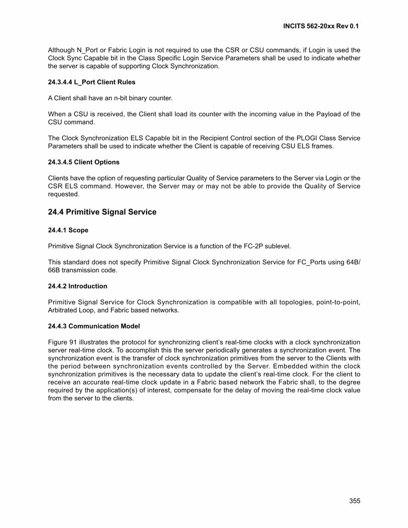
INCITS 562-20xx Rev 0.1
355
Although N_Port or Fabric Login is not required to use the CSR or CSU commands, if Login is used theClock Sync Capable bit in the Class Specific Login Service Parameters shall be used to indicate whetherthe server is capable of supporting Clock Synchronization.
24.3.4.4 L_Port Client Rules
A Client shall have an n-bit binary counter.
When a CSU is received, the Client shall load its counter with the incoming value in the Payload of theCSU command.
The Clock Synchronization ELS Capable bit in the Recipient Control section of the PLOGI Class ServiceParameters shall be used to indicate whether the Client is capable of receiving CSU ELS frames.
24.3.4.5 Client Options
Clients have the option of requesting particular Quality of Service parameters to the Server via Login or theCSR ELS command. However, the Server may or may not be able to provide the Quality of Servicerequested.
24.4 Primitive Signal Service
24.4.1 Scope
Primitive Signal Clock Synchronization Service is a function of the FC-2P sublevel.
This standard does not specify Primitive Signal Clock Synchronization Service for FC_Ports using 64B/66B transmission code.
24.4.2 Introduction
Primitive Signal Service for Clock Synchronization is compatible with all topologies, point-to-point,Arbitrated Loop, and Fabric based networks.
24.4.3 Communication Model
Figure 91 illustrates the protocol for synchronizing client’s real-time clocks with a clock synchronizationserver real-time clock. To accomplish this the server periodically generates a synchronization event. Thesynchronization event is the transfer of clock synchronization primitives from the server to the Clients withthe period between synchronization events controlled by the Server. Embedded within the clocksynchronization primitives is the necessary data to update the client’s real-time clock. For the client toreceive an accurate real-time clock update in a Fabric based network the Fabric shall, to the degreerequired by the application(s) of interest, compensate for the delay of moving the real-time clock valuefrom the server to the clients.
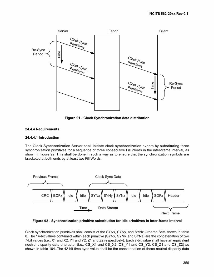
INCITS 562-20xx Rev 0.1
356
24.4.4 Requirements
24.4.4.1 Introduction
The Clock Synchronization Server shall initiate clock synchronization events by substituting threesynchronization primitives for a sequence of three consecutive Fill Words in the inter-frame interval, asshown in figure 92. This shall be done in such a way as to ensure that the synchronization symbols arebracketed at both ends by at least two Fill Words.
Clock synchronization primitives shall consist of the SYNx, SYNy, and SYNz Ordered Sets shown in table8. The 14-bit values contained within each primitive (SYNx, SYNy, and SYNz) are the concatenation of two7-bit values (i.e., X1 and X2, Y1 and Y2, Z1 and Z2 respectively). Each 7-bit value shall have an equivalentneutral disparity data character (i.e., CS_X1 and CS_X2, CS_Y1 and CS_Y2, CS_Z1 and CS_Z2) asshown in table 104. The 42-bit time sync value shall be the concatenation of these neutral disparity data
Figure 91 - Clock Synchronization data distribution
Server Fabric Client
Re-SyncPeriod
Re-SyncPeriod
Clock SyncPrimitives
Clock SyncPrimitives
Clock SyncPrimitives
Clock SyncPrimitives
Tim
e
Tim
e
Figure 92 - Synchronization primitive substitution for Idle srimitives in inter-frame interval
CRC EOFx Idle Idle SYNx SYNy SYNz Idle Idle SOFx Header
Previous Frame
Next Frame
Clock Sync Data
Time Data Stream
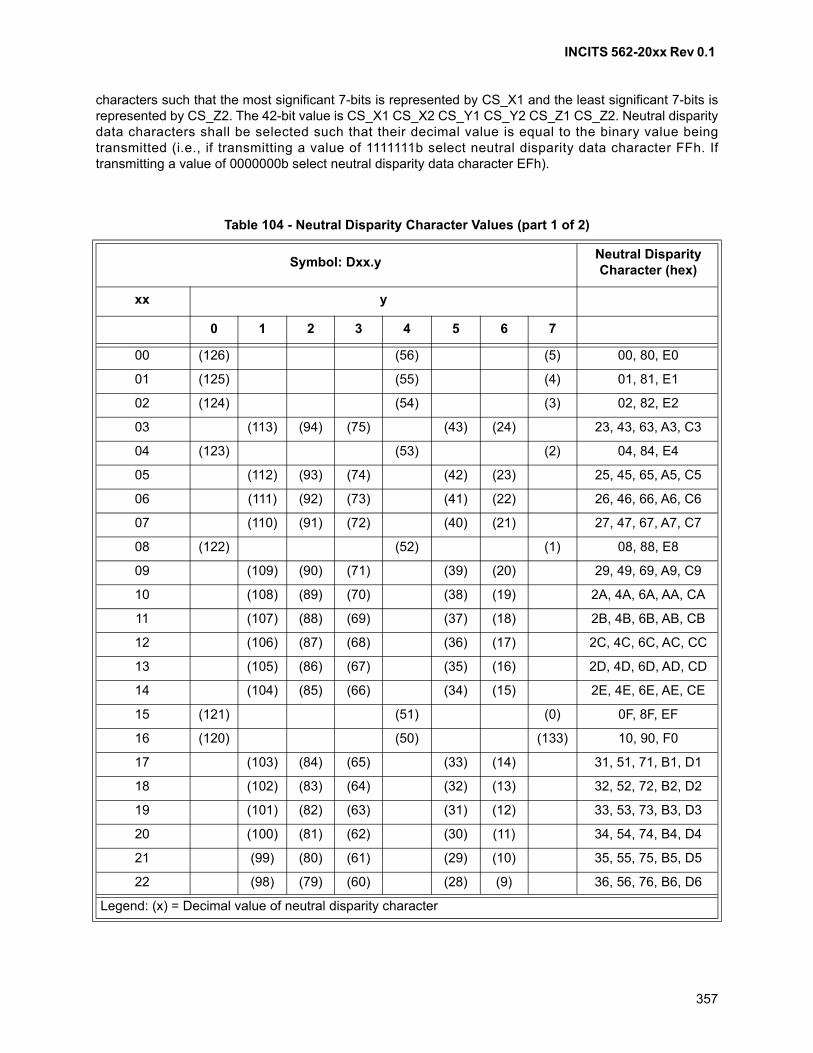
INCITS 562-20xx Rev 0.1
357
characters such that the most significant 7-bits is represented by CS_X1 and the least significant 7-bits isrepresented by CS_Z2. The 42-bit value is CS_X1 CS_X2 CS_Y1 CS_Y2 CS_Z1 CS_Z2. Neutral disparitydata characters shall be selected such that their decimal value is equal to the binary value beingtransmitted (i.e., if transmitting a value of 1111111b select neutral disparity data character FFh. Iftransmitting a value of 0000000b select neutral disparity data character EFh).
Table 104 - Neutral Disparity Character Values (part 1 of 2)
Symbol: Dxx.yNeutral Disparity Character (hex)
xx y
0 1 2 3 4 5 6 7
00 (126) (56) (5) 00, 80, E0
01 (125) (55) (4) 01, 81, E1
02 (124) (54) (3) 02, 82, E2
03 (113) (94) (75) (43) (24) 23, 43, 63, A3, C3
04 (123) (53) (2) 04, 84, E4
05 (112) (93) (74) (42) (23) 25, 45, 65, A5, C5
06 (111) (92) (73) (41) (22) 26, 46, 66, A6, C6
07 (110) (91) (72) (40) (21) 27, 47, 67, A7, C7
08 (122) (52) (1) 08, 88, E8
09 (109) (90) (71) (39) (20) 29, 49, 69, A9, C9
10 (108) (89) (70) (38) (19) 2A, 4A, 6A, AA, CA
11 (107) (88) (69) (37) (18) 2B, 4B, 6B, AB, CB
12 (106) (87) (68) (36) (17) 2C, 4C, 6C, AC, CC
13 (105) (86) (67) (35) (16) 2D, 4D, 6D, AD, CD
14 (104) (85) (66) (34) (15) 2E, 4E, 6E, AE, CE
15 (121) (51) (0) 0F, 8F, EF
16 (120) (50) (133) 10, 90, F0
17 (103) (84) (65) (33) (14) 31, 51, 71, B1, D1
18 (102) (83) (64) (32) (13) 32, 52, 72, B2, D2
19 (101) (82) (63) (31) (12) 33, 53, 73, B3, D3
20 (100) (81) (62) (30) (11) 34, 54, 74, B4, D4
21 (99) (80) (61) (29) (10) 35, 55, 75, B5, D5
22 (98) (79) (60) (28) (9) 36, 56, 76, B6, D6
Legend: (x) = Decimal value of neutral disparity character
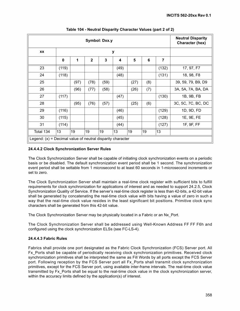
INCITS 562-20xx Rev 0.1
358
24.4.4.2 Clock Synchronization Server Rules
The Clock Synchronization Server shall be capable of initiating clock synchronization events on a periodicbasis or be disabled. The default synchronization event period shall be 1 second. The synchronizationevent period shall be settable from 1 microsecond to at least 60 seconds in 1-microsecond increments orset to zero.
The Clock Synchronization Server shall maintain a real-time clock register with sufficient bits to fulfillrequirements for clock synchronization for applications of interest and as needed to support 24.2.5, ClockSynchronization Quality of Service. If the server’s real-time clock register is less than 42-bits, a 42-bit valueshall be generated by concatenating the real-time clock value with bits having a value of zero in such away that the real-time clock value resides in the least significant bit positions. Primitive clock synccharacters shall be generated from this 42-bit value.
The Clock Synchronization Server may be physically located in a Fabric or an Nx_Port.
The Clock Synchronization Server shall be addressed using Well-Known Address FF FF F6h andconfigured using the clock synchronization ELSs (see FC-LS-4).
24.4.4.3 Fabric Rules
Fabrics shall provide one port designated as the Fabric Clock Synchronization (FCS) Server port. AllFx_Ports shall be capable of periodically receiving clock synchronization primitives. Received clocksynchronization primitives shall be interpreted the same as Fill Words by all ports except the FCS Serverport. Following reception by the FCS Server port all Fx_Ports shall transmit clock synchronizationprimitives, except for the FCS Server port, using available inter-frame intervals. The real-time clock valuetransmitted by Fx_Ports shall be equal to the real-time clock value in the clock synchronization server,within the accuracy limits defined by the application(s) of interest.
23 (119) (49) (132) 17, 97, F7
24 (118) (48) (131) 18, 98, F8
25 (97) (78) (59) (27) (8) 39, 59, 79, B9, D9
26 (96) (77) (58) (26) (7) 3A, 5A, 7A, BA, DA
27 (117) (47) (130) 1B, 9B, FB
28 (95) (76) (57) (25) (6) 3C, 5C, 7C, BC, DC
29 (116) (46) (129) 1D, 9D, FD
30 (115) (45) (128) 1E, 9E, FE
31 (114) (44) (127) 1F, 9F, FF
Total 134 13 19 19 19 13 19 19 13
Table 104 - Neutral Disparity Character Values (part 2 of 2)
Symbol: Dxx.yNeutral Disparity Character (hex)
xx y
0 1 2 3 4 5 6 7
Legend: (x) = Decimal value of neutral disparity character

INCITS 562-20xx Rev 0.1
359
24.4.4.4 Client Rules
Clients that support clock synchronization shall be capable of periodically receiving clock synchronizationprimitives Clients that do not support clock synchronization shall interpret received clock synchronizationprimitives the same as Fill Words or ignore them.
Supporting clients shall maintain a real-time clock register with sufficient bits to fulfill requirements for clocksynchronization for applications of interest. The real-time clock register shall be loaded, upon receipt ofthree consecutive clock synchronization primitives, with the value received.
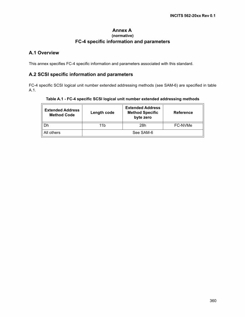
INCITS 562-20xx Rev 0.1
360
Annex A (normative)
FC-4 specific information and parameters
A.1 Overview
This annex specifies FC-4 specific information and parameters associated with this standard.
A.2 SCSI specific information and parameters
FC-4 specific SCSI logical unit number extended addressing methods (see SAM-6) are specified in tableA.1.
Table A.1 - FC-4 specific SCSI logical unit number extended addressing methods
Extended Address Method Code
Length codeExtended Address Method Specific
byte zeroReference
Dh 11b 28h FC-NVMe
All others See SAM-6

INCITS 562-20xx Rev 0.1
361

INCITS 562-20xx Rev 0.1
362
Annex B (informative)
CRC generation and checking
B.1 Extract from FDDI
First part of this annex is an extract from Fiber Distributed Data Interface - Media Access Control (seeFDDI-MAC). FDDI's Frame Check Sequence (FCS) methodology, polynomials and equations are used byCyclic Redundancy Check (CRC) in FC-2. The term FCS is unique to FDDI and not used by FibreChannel. CRC coverage is defined in 11.4.5.
B.2 Frame check sequence (FCS)
This annex specifies the generation and checking of the FCS field. This field is used to detect erroneousdata bits within the frame as well as erroneous addition or deletion of bits to the frame. The fields coveredby the FCS field include the FC, DA, SA, INFO, and FCS fields.
B.3 Definitions
B.3.1 Basic terms
F(x): A degree k-1 polynomial that is used to represent the k bits of the frame covered by the FCSsequence (see 11.4.5). For the purposes of the FCS, the coefficient of the highest order term is the first bittransmitted.
L(x): A degree 31 polynomial with all of the coefficients equal to one, i.e.,
L(x) = X31 + X30 + X29 + ••• + X2 + X1 + 1
G(x): The standard generator polynomial
G(x) = X32 + X26 + X23 + X22 + X16 + X12 + X11 + X10 + X8 + X7 + X5 + X4 + X2 + X + 1
R(x): The remainder polynomial that is of degree less than 32
P(x): The remainder polynomial on the receive checking side that is of degree less than 32
FCS: The FCS polynomial that is of degree less than 32
Q(x): The greatest multiple of G(x) in
[X32 • F(x) + Xk • L(x)]
Q*(x): X32 • Q(x)
M(x): The sequence that is transmitted
M*(x): The sequence that is received
INCITS 562-20xx Rev 0.1
363
C(x): A unique polynomial remainder produced by the receiver upon reception of an error freesequence. This polynomial has the value
C(X) = X32 • L(X) / G(X)
= X31 + X30 + X26 + X25 + X24 + X18 + X15 + X14 + X12 + X11 + X10 + X8 + X6 + X5 + X4 + X3 + X + 1
B.3.2 FCS generation equations
The equations that are used to generate the FCS sequence from F(x), are as follows:
a) FCS = L(X) + R(X) = R$(X)
where R$(X) is the one's complement of R(X);
NOTE 61 - Adding L(x) (all ones) to R(x) simply produces the one's complement of R(x); this equation isspecifying that the R(x) is inverted before it is sent out.
b) [X32 • F(x) + Xk • L(X)] / G(X) = Q(X) + R(X) / G(X); and
c) M(x) = x32 • F(x) + FCS.
NOTE 62 - All arithmetic is modulo 2.
NOTE 63 - Equation c) above specifies that the FCS is appended to the end of F(x).
B.3.3 FCS checking
The received sequence M*(x) may differ from the transmitted sequence M(x) if there are transmissionerrors. The process of checking the sequence for validity involves dividing the received sequence by G(x)and testing the remainder. Direct division, however, does not yield a unique remainder because of thepossibility of leading zeros. Thus a term L(x) is prepended to M*(x) before it is divided. Mathematically, thereceived checking is shown in the following equation:
X32 [M*(X)+Xk • L(X)] / G(X) = Q*(X) + P(X) / G(X)
In the absence of errors, the unique remainder is the remainder of the division
P(X) / G(X) = X32 • L(X) / G(X) = C(X)
B.4 CRC generation example for ACK_1 frame
An example of CRC generation for an ACK_1 frame is provided in a set of tables B.1 through B.8. TableB.1 shows an example of an ACK_1 fields without CRC and table B.2 shows the hexadecimal values foreach field. Table B.3 shows the transmit bit order (03 80 40 C..0 80h) with the bytes in table B.2transposed. Table B.4 shows the bit stream X32 • F(x) + Xk • L(x) (FC 7F..0 80h) for the sample. Table B.5
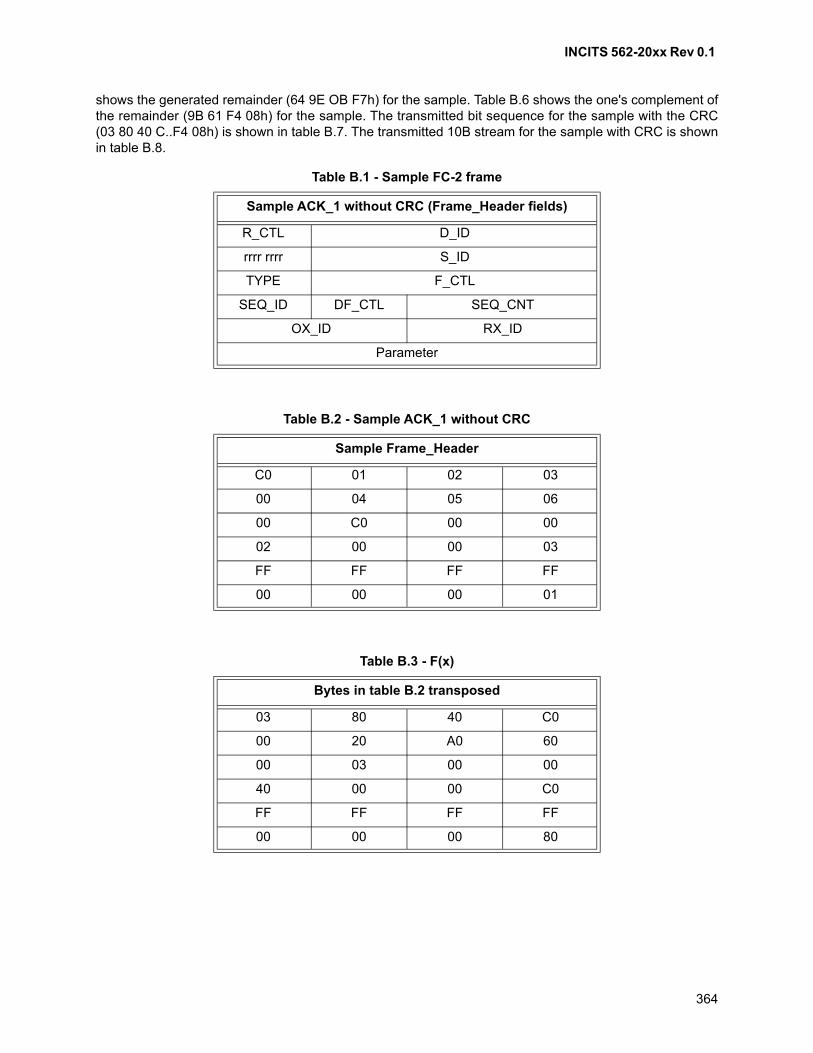
INCITS 562-20xx Rev 0.1
364
shows the generated remainder (64 9E OB F7h) for the sample. Table B.6 shows the one's complement ofthe remainder (9B 61 F4 08h) for the sample. The transmitted bit sequence for the sample with the CRC(03 80 40 C..F4 08h) is shown in table B.7. The transmitted 10B stream for the sample with CRC is shownin table B.8.
Table B.1 - Sample FC-2 frame
Sample ACK_1 without CRC (Frame_Header fields)
R_CTL D_ID
rrrr rrrr S_ID
TYPE F_CTL
SEQ_ID DF_CTL SEQ_CNT
OX_ID RX_ID
Parameter
Table B.2 - Sample ACK_1 without CRC
Sample Frame_Header
C0 01 02 03
00 04 05 06
00 C0 00 00
02 00 00 03
FF FF FF FF
00 00 00 01
Table B.3 - F(x)
Bytes in table B.2 transposed
03 80 40 C0
00 20 A0 60
00 03 00 00
40 00 00 C0
FF FF FF FF
00 00 00 80
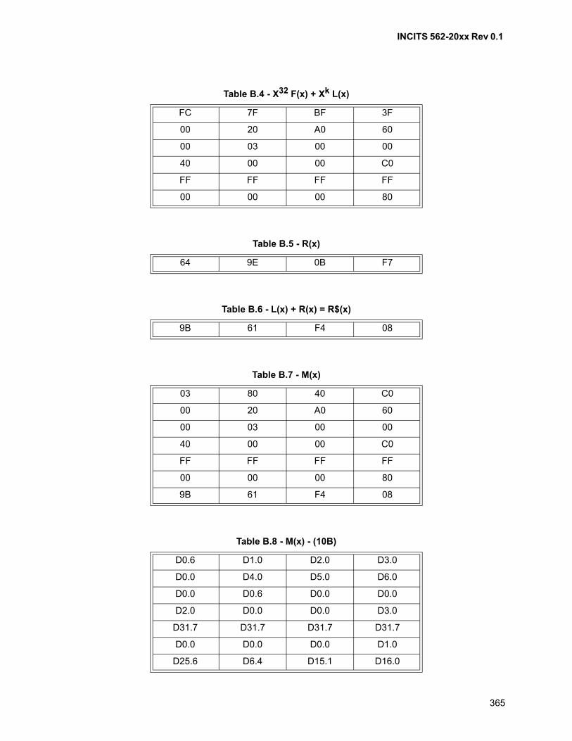
INCITS 562-20xx Rev 0.1
365
Table B.4 - X32 F(x) + Xk L(x)
FC 7F BF 3F
00 20 A0 60
00 03 00 00
40 00 00 C0
FF FF FF FF
00 00 00 80
Table B.5 - R(x)
64 9E 0B F7
Table B.6 - L(x) + R(x) = R$(x)
9B 61 F4 08
Table B.7 - M(x)
03 80 40 C0
00 20 A0 60
00 03 00 00
40 00 00 C0
FF FF FF FF
00 00 00 80
9B 61 F4 08
Table B.8 - M(x) - (10B)
D0.6 D1.0 D2.0 D3.0
D0.0 D4.0 D5.0 D6.0
D0.0 D0.6 D0.0 D0.0
D2.0 D0.0 D0.0 D3.0
D31.7 D31.7 D31.7 D31.7
D0.0 D0.0 D0.0 D1.0
D25.6 D6.4 D15.1 D16.0
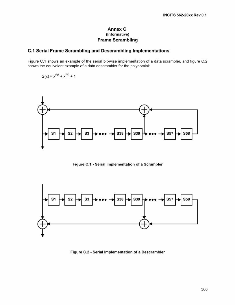
INCITS 562-20xx Rev 0.1
366
Annex C (Informative)
Frame Scrambling
C.1 Serial Frame Scrambling and Descrambling Implementations
Figure C.1 shows an example of the serial bit-wise implementation of a data scrambler, and figure C.2shows the equivalent example of a data descrambler for the polynomial:
G(x) = x58 + x39 + 1
Figure C.1 - Serial Implementation of a Scrambler
Figure C.2 - Serial Implementation of a Descrambler
S1 S2 S3 S38 S39 S57 S58
S1 S2 S3 S38 S39 S57 S58
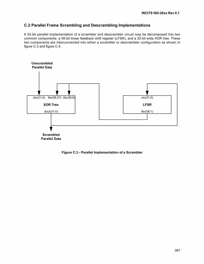
INCITS 562-20xx Rev 0.1
367
C.2 Parallel Frame Scrambling and Descrambling Implementations
A 32-bit parallel implementation of a scrambler and descrambler circuit may be decomposed into twocommon components: a 58-bit linear feedback shift register (LFSR), and a 32-bit wide XOR tree. Thesetwo components are interconnected into either a scrambler or descrambler configuration as shown infigure C.3 and figure C.4.
Figure C.3 - Parallel Implementation of a Scrambler
UnscrambledParallel Data
XOR Tree LFSR
ScrambledParallel Data
dout(31:0)
din(31:0) lfsr(39:8)lfsr(58:27) xin(31:0)
lfsr(58:1)
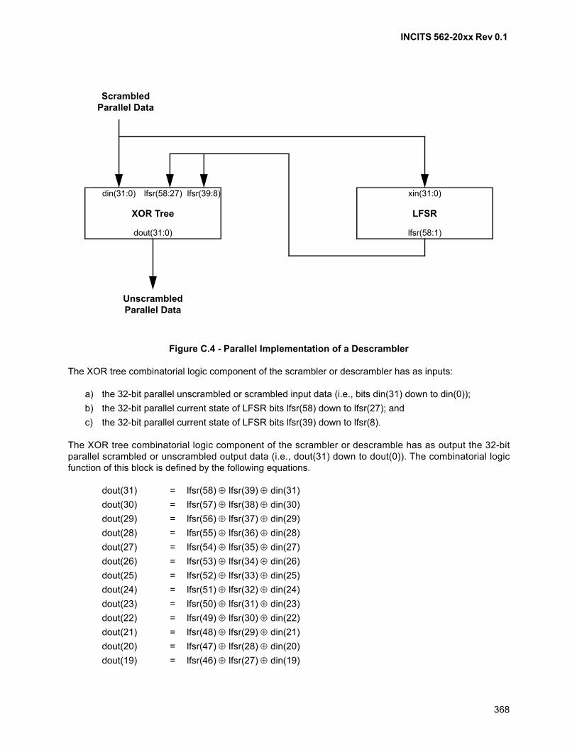
INCITS 562-20xx Rev 0.1
368
Figure C.4 - Parallel Implementation of a Descrambler
The XOR tree combinatorial logic component of the scrambler or descrambler has as inputs:
a) the 32-bit parallel unscrambled or scrambled input data (i.e., bits din(31) down to din(0));
b) the 32-bit parallel current state of LFSR bits lfsr(58) down to lfsr(27); and
c) the 32-bit parallel current state of LFSR bits lfsr(39) down to lfsr(8).
The XOR tree combinatorial logic component of the scrambler or descramble has as output the 32-bitparallel scrambled or unscrambled output data (i.e., dout(31) down to dout(0)). The combinatorial logicfunction of this block is defined by the following equations.
dout(31) = lfsr(58) lfsr(39) din(31)
dout(30) = lfsr(57) lfsr(38) din(30)
dout(29) = lfsr(56) lfsr(37) din(29)
dout(28) = lfsr(55) lfsr(36) din(28)
dout(27) = lfsr(54) lfsr(35) din(27)
dout(26) = lfsr(53) lfsr(34) din(26)
dout(25) = lfsr(52) lfsr(33) din(25)
dout(24) = lfsr(51) lfsr(32) din(24)
dout(23) = lfsr(50) lfsr(31) din(23)
dout(22) = lfsr(49) lfsr(30) din(22)
dout(21) = lfsr(48) lfsr(29) din(21)
dout(20) = lfsr(47) lfsr(28) din(20)
dout(19) = lfsr(46) lfsr(27) din(19)
ScrambledParallel Data
XOR Tree LFSR
UnscrambledParallel Data
dout(31:0)
din(31:0) lfsr(39:8)lfsr(58:27) xin(31:0)
lfsr(58:1)
INCITS 562-20xx Rev 0.1
369
dout(18) = lfsr(45) lfsr(26) din(18)
dout(17) = lfsr(44) lfsr(25) din(17)
dout(16) = lfsr(43) lfsr(24) din(16)
dout(15) = lfsr(42) lfsr(23) din(15)
dout(14) = lfsr(41) lfsr(22) din(14)
dout(13) = lfsr(40) lfsr(21) din(13)
dout(12) = lfsr(39) lfsr(20) din(12)
dout(11) = lfsr(38) lfsr(19) din(11)
dout(10) = lfsr(37) lfsr(18) din(10)
dout(9) = lfsr(36) lfsr(17) din(9)
dout(8) = lfsr(35) lfsr(16) din(8)
dout(7) = lfsr(34) lfsr(15) din(7)
dout(6) = lfsr(33) lfsr(14) din(6)
dout(5) = lfsr(32) lfsr(13) din(5)
dout(4) = lfsr(31) lfsr(12) din(4)
dout(3) = lfsr(30) lfsr(11) din(3)
dout(2) = lfsr(29) lfsr(10) din(2)
dout(1) = lfsr(28) lfsr(9) din(1)
dout(0) = lfsr(27) lfsr(8) din(0)
The LFSR combinatorial logic component of the scrambler or descrambler has as input the scrambled data(i.e., xin(31) down to xin(0) in the following equations) and has as output the 58-bit current state of theLFSR (i.e., lfsr(58) down to lfsr(1) in the following equations). The next state of the LFSR (i.e., next_lfsr(58)down to next_lfsr(1) in the following equations) is reached by a state transition defined by the followingequations.
next_lfsr(58) = lfsr(26)
next_lfsr(57) = lfsr(25)
next_lfsr(56) = lfsr(24)
next_lfsr(55) = lfsr(23)
next_lfsr(54) = lfsr(22)
next_lfsr(53) = lfsr(21)
next_lfsr(52) = lfsr(20)
next_lfsr(51) = lfsr(19)
next_lfsr(50) = lfsr(18)
next_lfsr(49) = lfsr(17)
next_lfsr(48) = lfsr(16)
next_lfsr(47) = lfsr(15)
next_lfsr(46) = lfsr(14)
next_lfsr(45) = lfsr(13)
next_lfsr(44) = lfsr(12)
next_lfsr(43) = lfsr(11)
next_lfsr(42) = lfsr(10)
next_lfsr(41) = lfsr(9)
next_lfsr(40) = lfsr(8)
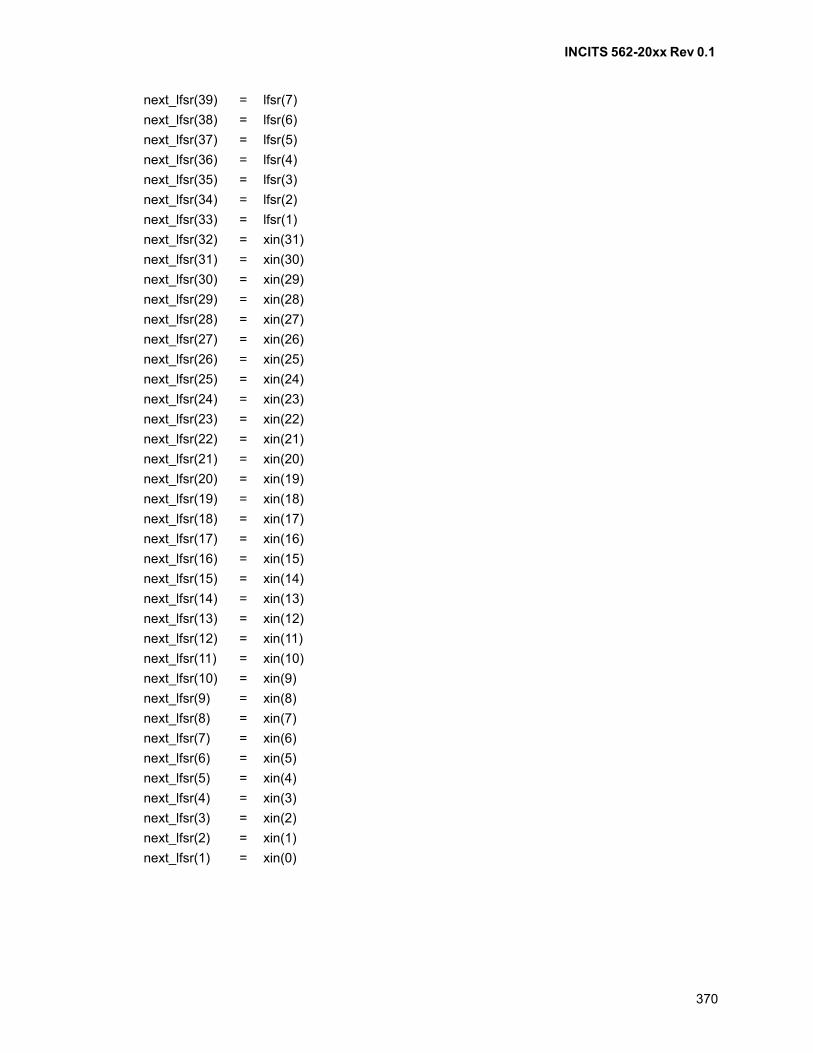
INCITS 562-20xx Rev 0.1
370
next_lfsr(39) = lfsr(7)
next_lfsr(38) = lfsr(6)
next_lfsr(37) = lfsr(5)
next_lfsr(36) = lfsr(4)
next_lfsr(35) = lfsr(3)
next_lfsr(34) = lfsr(2)
next_lfsr(33) = lfsr(1)
next_lfsr(32) = xin(31)
next_lfsr(31) = xin(30)
next_lfsr(30) = xin(29)
next_lfsr(29) = xin(28)
next_lfsr(28) = xin(27)
next_lfsr(27) = xin(26)
next_lfsr(26) = xin(25)
next_lfsr(25) = xin(24)
next_lfsr(24) = xin(23)
next_lfsr(23) = xin(22)
next_lfsr(22) = xin(21)
next_lfsr(21) = xin(20)
next_lfsr(20) = xin(19)
next_lfsr(19) = xin(18)
next_lfsr(18) = xin(17)
next_lfsr(17) = xin(16)
next_lfsr(16) = xin(15)
next_lfsr(15) = xin(14)
next_lfsr(14) = xin(13)
next_lfsr(13) = xin(12)
next_lfsr(12) = xin(11)
next_lfsr(11) = xin(10)
next_lfsr(10) = xin(9)
next_lfsr(9) = xin(8)
next_lfsr(8) = xin(7)
next_lfsr(7) = xin(6)
next_lfsr(6) = xin(5)
next_lfsr(5) = xin(4)
next_lfsr(4) = xin(3)
next_lfsr(3) = xin(2)
next_lfsr(2) = xin(1)
next_lfsr(1) = xin(0)
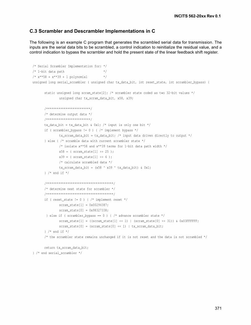
INCITS 562-20xx Rev 0.1
371
C.3 Scrambler and Descrambler Implementations in C
The following is an example C program that generates the scrambled serial data for transmission. Theinputs are the serial data bits to be scrambled, a control indication to reinitialize the residual value, and acontrol indication to bypass the scrambler and hold the present state of the linear feedback shift register.
/* Serial Scrambler Implementation for: */
/* 1-bit data path */
/* x**58 + x**39 + 1 polynomial */
unsigned long serial_scrambler ( unsigned char tx_data_bit, int reset_state, int scrambler_bypass) {
static unsigned long scram_state[2]; /* scrambler state coded as two 32-bit values */
unsigned char tx_scram_data_bit, x58, x39;
/*************************/
/* determine output data */
/*************************/
tx_data_bit = tx_data_bit & 0x1; /* input is only one bit */
if ( scrambler_bypass != 0 ) { /* implement bypass */
tx_scram_data_bit = tx_data_bit; /* input data driven directly to output */
} else { /* scramble data with current scrambler state */
/* isolate x**58 and x**39 terms for 1-bit data path width */
x58 = ( scram_state[1] >> 25 );
x39 = ( scram_state[1] >> 6 );
/* calculate scrambled data */
tx_scram_data_bit = (x58 ^ x39 ^ tx_data_bit) & 0x1;
} /* end if */
/**************************************/
/* determine next state for scrambler */
/**************************************/
if ( reset_state != 0 ) { /* implement reset */
scram_state[1] = 0x00294387;
scram_state[0] = 0x98327338;
} else if ( scrambler_bypass == 0 ) { /* advance scrambler state */
scram_state[1] = ((scram_state[1] << 1) | (scram_state[0] >> 31)) & 0x03FFFFFF;
scram_state[0] = (scram_state[0] << 1) | tx_scram_data_bit;
} /* end if */
/* the scrambler state remains unchanged if it is not reset and the data is not scrambled */
return tx_scram_data_bit;
} /* end serial_scrambler */
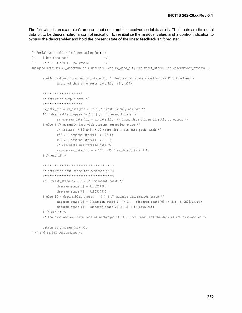
INCITS 562-20xx Rev 0.1
372
The following is an example C program that descrambles received serial data bits. The inputs are the serialdata bit to be descrambled, a control indication to reinitialize the residual value, and a control indication tobypass the descrambler and hold the present state of the linear feedback shift register.
/* Serial Descrambler Implementation for: */
/* 1-bit data path */
/* x**58 + x**39 + 1 polynomial */
unsigned long serial_descrambler ( unsigned long rx_data_bit, int reset_state, int descrambler_bypass) {
static unsigned long descram_state[2]; /* descrambler state coded as two 32-bit values */
unsigned char rx_unscram_data_bit, x58, x39;
/*********************/
/* determine output data */
/*********************/
rx_data_bit = rx_data_bit & 0x1; /* input is only one bit */
if ( descrambler_bypass != 0 ) { /* implement bypass */
rx_unscram_data_bit = rx_data_bit; /* input data driven directly to output */
} else { /* scramble data with current scrambler state */
/* isolate x**58 and x**39 terms for 1-bit data path width */
x58 = ( descram_state[1] >> 25 );
x39 = ( descram_state[1] >> 6 );
/* calculate unscrambled data */
rx_unscram_data_bit = (x58 ^ x39 ^ rx_data_bit) & 0x1;
} /* end if */
/****************************************/
/* determine next state for descrambler */
/****************************************/
if ( reset_state != 0 ) { /* implement reset */
descram_state[1] = 0x00294387;
descram_state[0] = 0x98327338;
} else if ( descrambler_bypass == 0 ) { /* advance descrambler state */
descram_state[1] = ((descram_state[1] << 1) | (descram_state[0] >> 31)) & 0x03FFFFFF;
descram_state[0] = (descram_state[0] << 1) | rx_data_bit;
} /* end if */
/* the descrambler state remains unchanged if it is not reset and the data is not descrambled */
return rx_unscram_data_bit;
} /* end serial_descrambler */
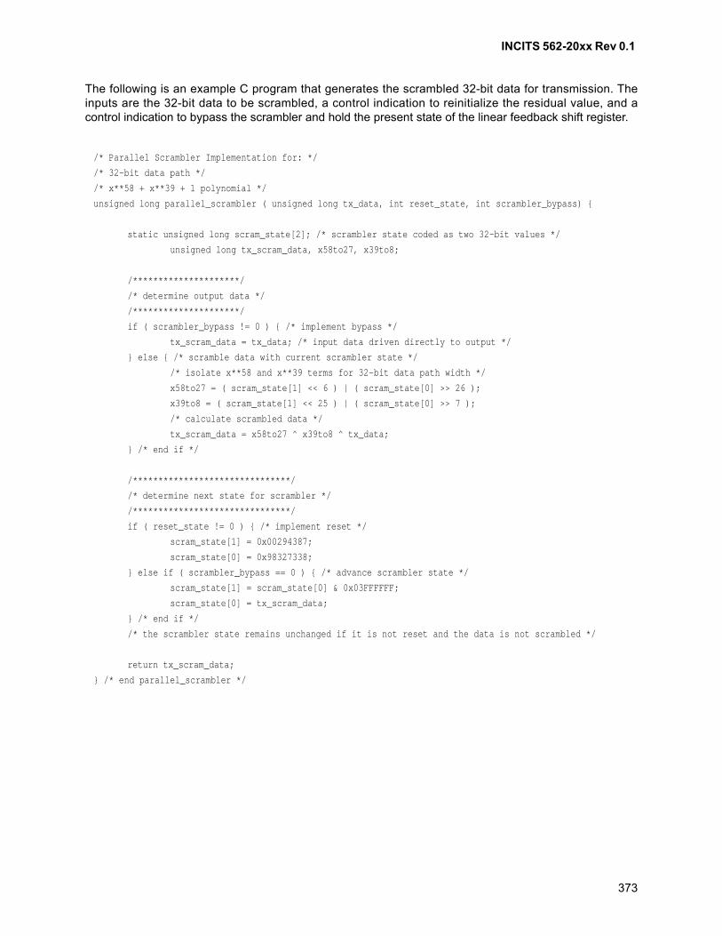
INCITS 562-20xx Rev 0.1
373
The following is an example C program that generates the scrambled 32-bit data for transmission. Theinputs are the 32-bit data to be scrambled, a control indication to reinitialize the residual value, and acontrol indication to bypass the scrambler and hold the present state of the linear feedback shift register.
/* Parallel Scrambler Implementation for: */
/* 32-bit data path */
/* x**58 + x**39 + 1 polynomial */
unsigned long parallel_scrambler ( unsigned long tx_data, int reset_state, int scrambler_bypass) {
static unsigned long scram_state[2]; /* scrambler state coded as two 32-bit values */
unsigned long tx_scram_data, x58to27, x39to8;
/*********************/
/* determine output data */
/*********************/
if ( scrambler_bypass != 0 ) { /* implement bypass */
tx_scram_data = tx_data; /* input data driven directly to output */
} else { /* scramble data with current scrambler state */
/* isolate x**58 and x**39 terms for 32-bit data path width */
x58to27 = ( scram_state[1] << 6 ) | ( scram_state[0] >> 26 );
x39to8 = ( scram_state[1] << 25 ) | ( scram_state[0] >> 7 );
/* calculate scrambled data */
tx_scram_data = x58to27 ^ x39to8 ^ tx_data;
} /* end if */
/*******************************/
/* determine next state for scrambler */
/*******************************/
if ( reset_state != 0 ) { /* implement reset */
scram_state[1] = 0x00294387;
scram_state[0] = 0x98327338;
} else if ( scrambler_bypass == 0 ) { /* advance scrambler state */
scram_state[1] = scram_state[0] & 0x03FFFFFF;
scram_state[0] = tx_scram_data;
} /* end if */
/* the scrambler state remains unchanged if it is not reset and the data is not scrambled */
return tx_scram_data;
} /* end parallel_scrambler */
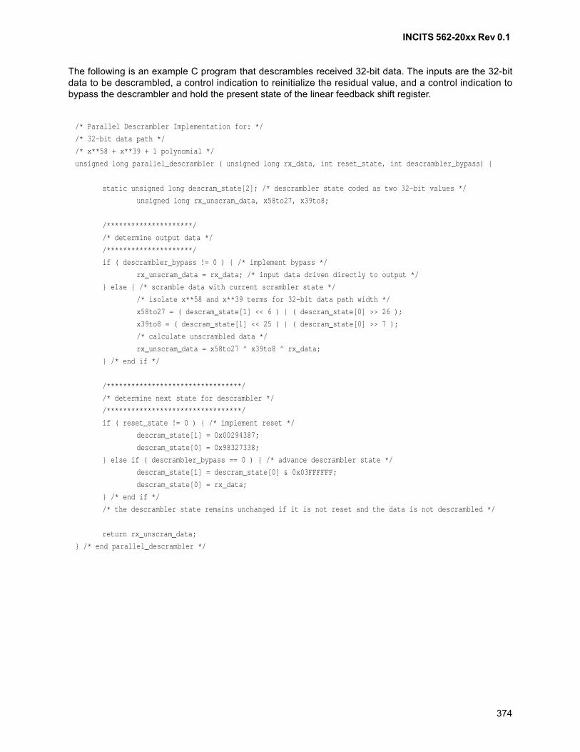
INCITS 562-20xx Rev 0.1
374
The following is an example C program that descrambles received 32-bit data. The inputs are the 32-bitdata to be descrambled, a control indication to reinitialize the residual value, and a control indication tobypass the descrambler and hold the present state of the linear feedback shift register.
/* Parallel Descrambler Implementation for: */
/* 32-bit data path */
/* x**58 + x**39 + 1 polynomial */
unsigned long parallel_descrambler ( unsigned long rx_data, int reset_state, int descrambler_bypass) {
static unsigned long descram_state[2]; /* descrambler state coded as two 32-bit values */
unsigned long rx_unscram_data, x58to27, x39to8;
/*********************/
/* determine output data */
/*********************/
if ( descrambler_bypass != 0 ) { /* implement bypass */
rx_unscram_data = rx_data; /* input data driven directly to output */
} else { /* scramble data with current scrambler state */
/* isolate x**58 and x**39 terms for 32-bit data path width */
x58to27 = ( descram_state[1] << 6 ) | ( descram_state[0] >> 26 );
x39to8 = ( descram_state[1] << 25 ) | ( descram_state[0] >> 7 );
/* calculate unscrambled data */
rx_unscram_data = x58to27 ^ x39to8 ^ rx_data;
} /* end if */
/*********************************/
/* determine next state for descrambler */
/*********************************/
if ( reset_state != 0 ) { /* implement reset */
descram_state[1] = 0x00294387;
descram_state[0] = 0x98327338;
} else if ( descrambler_bypass == 0 ) { /* advance descrambler state */
descram_state[1] = descram_state[0] & 0x03FFFFFF;
descram_state[0] = rx_data;
} /* end if */
/* the descrambler state remains unchanged if it is not reset and the data is not descrambled */
return rx_unscram_data;
} /* end parallel_descrambler */
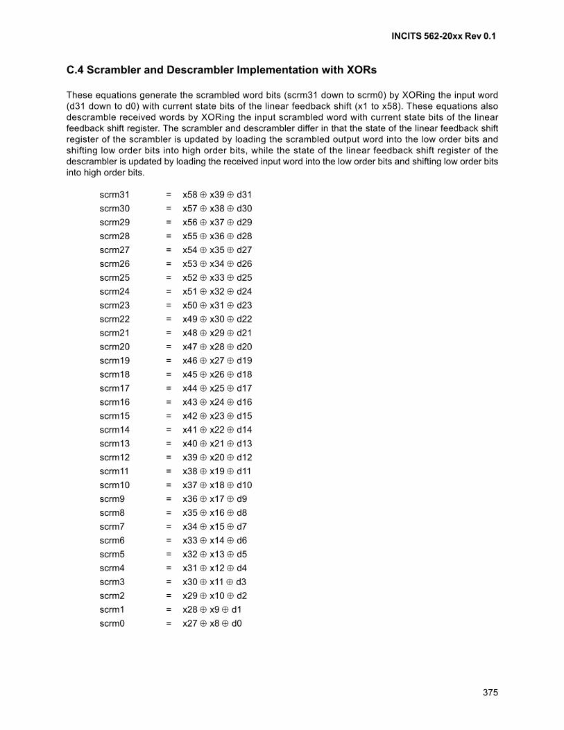
INCITS 562-20xx Rev 0.1
375
C.4 Scrambler and Descrambler Implementation with XORs
These equations generate the scrambled word bits (scrm31 down to scrm0) by XORing the input word(d31 down to d0) with current state bits of the linear feedback shift (x1 to x58). These equations alsodescramble received words by XORing the input scrambled word with current state bits of the linearfeedback shift register. The scrambler and descrambler differ in that the state of the linear feedback shiftregister of the scrambler is updated by loading the scrambled output word into the low order bits andshifting low order bits into high order bits, while the state of the linear feedback shift register of thedescrambler is updated by loading the received input word into the low order bits and shifting low order bitsinto high order bits.
scrm31 = x58 x39 d31
scrm30 = x57 x38 d30
scrm29 = x56 x37 d29
scrm28 = x55 x36 d28
scrm27 = x54 x35 d27
scrm26 = x53 x34 d26
scrm25 = x52 x33 d25
scrm24 = x51 x32 d24
scrm23 = x50 x31 d23
scrm22 = x49 x30 d22
scrm21 = x48 x29 d21
scrm20 = x47 x28 d20
scrm19 = x46 x27 d19
scrm18 = x45 x26 d18
scrm17 = x44 x25 d17
scrm16 = x43 x24 d16
scrm15 = x42 x23 d15
scrm14 = x41 x22 d14
scrm13 = x40 x21 d13
scrm12 = x39 x20 d12
scrm11 = x38 x19 d11
scrm10 = x37 x18 d10
scrm9 = x36 x17 d9
scrm8 = x35 x16 d8
scrm7 = x34 x15 d7
scrm6 = x33 x14 d6
scrm5 = x32 x13 d5
scrm4 = x31 x12 d4
scrm3 = x30 x11 d3
scrm2 = x29 x10 d2
scrm1 = x28 x9 d1
scrm0 = x27 x8 d0

INCITS 562-20xx Rev 0.1
376
C.5 Scrambled Data Example
Table C.1 is an example of a scrambled frame. The linear feedback shift register of the scrambler is resetto an initial state of 029438798327338h by the SOF delimiter.
Table C.1 - Scrambled Frame Example
Word Position Word Contents Scrambled Data
Starting delimiter <SOF> <SOF>
0h 060405EFh 036480EFh
1h 000404E8h 7C9E03E9h
2h 08290000h 0FF007D8h
3h 00000000h F59F1A4Ch
4h 8018FFFFh CDF237F6h
5h 00000000h FE5D775Ch
6h 00000000h 91714751h
7h 00000000h 2E7F35AAh
8h 00000002h FE0D2A22h
9h 12018300h D830F3EBh
Ah 20000000h E6FAE951h
Bh 00000000h DBF10F2Bh
Ch 00000000h 1D0DB668h
Dh 00000020h AA79D18Bh
Eh AA92695Ch 38AB00D5h
Ending delimiter <EOF> <EOF>
INCITS 562-20xx Rev 0.1
377
Annex D (informative)
Data transfer protocols and examples
This annex provides Data transfer protocol examples.
D.1 Frame level protocol
D.1.1 Class 2 frame level protocol
The Class 2 frame level protocol employs:
a) Data frame;
b) ACK; and
c) R_RDY.
The Class 2 frame level protocol is illustrated in figure D.1.
1) The Originator initiates the Sequence with a Data frame embedded with SOFi2;
2) The Fx_Port responds with an R_RDY and forwards the Data frame to the destination;
3) The destination responds with an R_RDY, in addition to ACK;
4) The Fx_Port and the PN_Port respond each with R_RDY on receipt of ACK;
5) The Originator streams multiple Data frames and the Responder responds with ACK.
A) ACK returns some information contained in F_CTL of the Data frame to which it is respondingunaltered:
a) First_Sequence bit;
b) Last_Sequence bit;
c) End_Sequence bit; and
d) Sequence Initiative bit;
and
B) ACK toggles some information contained in F_CTL of the Data frame:
a) Exchange Context bit; and
b) Sequence Context bit.
F_CTL usage for the Sequence is described in table D.1;
6) For each of these frames received, each PN_Port or Fx_Port returns a R_RDY;
7) SOFn2 is used to indicate the Sequence in progress;
8) The Sequence Initiator indicates the end of Sequence by the End_Sequence bit in F_CTL.However, the Sequence ends in the perspective of Sequence Recipient, only when all Data framesare received or accounted for; and
9) The Sequence Recipient transmits EOFt only in the final ACK after all Data frames are received or
accounted for.
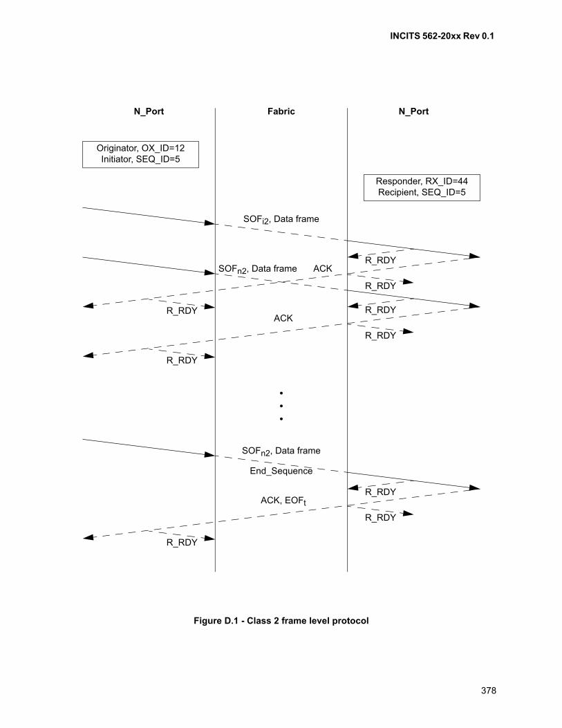
INCITS 562-20xx Rev 0.1
378
Figure D.1 - Class 2 frame level protocol
N_Port Fabric N_Port
ACK
R_RDY
R_RDY
SOFi2, Data frame
•••
R_RDY
ACK
R_RDY
R_RDY
SOFn2, Data frame
R_RDY
End_Sequence
ACK, EOFt
R_RDY
R_RDY
SOFn2, Data frame
R_RDY
Originator, OX_ID=12Initiator, SEQ_ID=5
Responder, RX_ID=44Recipient, SEQ_ID=5
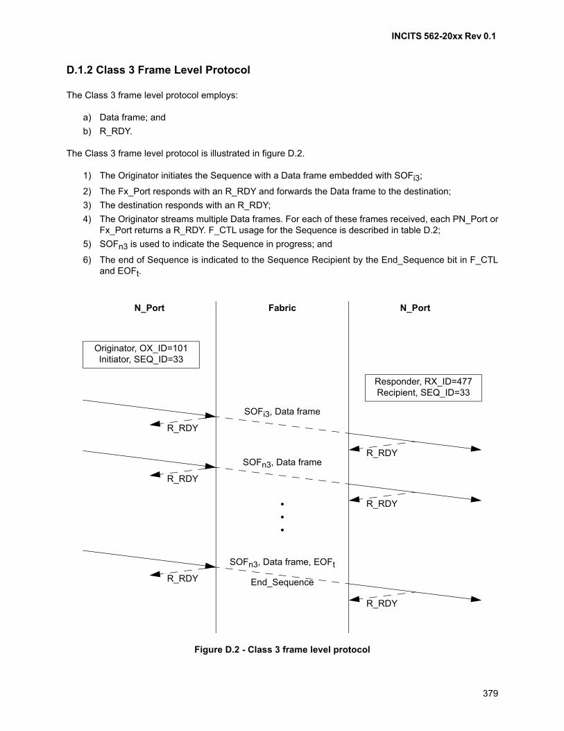
INCITS 562-20xx Rev 0.1
379
D.1.2 Class 3 Frame Level Protocol
The Class 3 frame level protocol employs:
a) Data frame; and
b) R_RDY.
The Class 3 frame level protocol is illustrated in figure D.2.
1) The Originator initiates the Sequence with a Data frame embedded with SOFi3;
2) The Fx_Port responds with an R_RDY and forwards the Data frame to the destination;
3) The destination responds with an R_RDY;
4) The Originator streams multiple Data frames. For each of these frames received, each PN_Port orFx_Port returns a R_RDY. F_CTL usage for the Sequence is described in table D.2;
5) SOFn3 is used to indicate the Sequence in progress; and
6) The end of Sequence is indicated to the Sequence Recipient by the End_Sequence bit in F_CTLand EOFt.
Figure D.2 - Class 3 frame level protocol
N_Port Fabric N_Port
R_RDY
R_RDY
SOFi3, Data frame
•••
R_RDY
R_RDY
SOFn3, Data frame
End_SequenceR_RDY
R_RDY
SOFn3, Data frame, EOFt
Originator, OX_ID=101Initiator, SEQ_ID=33
Responder, RX_ID=477Recipient, SEQ_ID=33
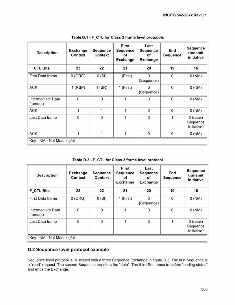
INCITS 562-20xx Rev 0.1
380
D.2 Sequence level protocol example
Sequence level protocol is illustrated with a three Sequence Exchange in figure D.3. The first Sequence isa “read” request. The second Sequence transfers the “data”. The third Sequence transfers “ending status”and ends the Exchange.
Table D.1 - F_CTL for Class 2 frame level protocols
DescriptionExchange Context
SequenceContext
FirstSequence
of Exchange
LastSequence
of Exchange
EndSequence
Sequence transmit initiative
F_CTL Bits 23 22 21 20 19 16
First Data frame 0 (ORG) 0 (SI) 1 (First) 0 (Sequence)
0 0 (NM)
ACK 1 (RSP) 1 (SR) 1 (First) 0 (Sequence)
0 0 (NM)
Intermediate Data frame(s)
0 0 1 0 0 0 (NM)
ACK 1 1 1 0 0 0 (NM)
Last Data frame 0 0 1 0 1 0 (retainSequenceInitiative)
ACK 1 1 1 0 0 0 (NM)
Key - NM - Not Meaningful
Table D.2 - F_CTL for Class 3 frame level protocol
DescriptionExchange Context
SequenceContext
First Sequence
of Exchange
Last Sequence
of Exchange
EndSequence
Sequence transmit initiative
F_CTL Bits 23 22 21 20 19 16
First Data frame 0 (ORG) 0 (SI) 1 (First) 0 (Sequence)
0 0 (NM)
Intermediate Data frame(s)
0 0 1 0 0 0 (NM)
Last Data frame 0 0 1 0 1 0 (retain Sequence Initiative)
Key - NM - Not Meaningful
INCITS 562-20xx Rev 0.1
381
Frames 1, 2, and 3 represent the first Sequence of an Exchange. In this example a Command Request fora Read operation is sent as a request Sequence. Note that Sequence Initiative is transferred to theSequence Recipient.
Frames 4, 5, and 6 represent the first, intermediate and last frames of the data transferred in response tothe Read request. Note that the Sequence Initiative is retained in order to start a Sequence with endingstatus.
Frames 7, 8, and 9 represent the ending status for the preceding data transfer and end the Exchange.Depending on the FC-4 Protocol, the Responder may not be allowed to end the Exchange, but transfer theSequence Initiative to the Originator to complete the Exchange.
F_CTL usage
Use of F_CTL bits for these example Sequences are shown in table D.3.
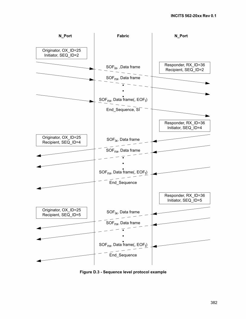
INCITS 562-20xx Rev 0.1
382
Figure D.3 - Sequence level protocol example
N_Port Fabric N_Port
Originator, OX_ID=25Initiator, SEQ_ID=2
Responder, RX_ID=36Recipient, SEQ_ID=2
SOFix, ,Data frame
•••
SOFnx, Data frame
End_Sequence, SI
SOFnx, Data frame(, EOFt)
Responder, RX_ID=36Initiator, SEQ_ID=4
Originator, OX_ID=25Recipient, SEQ_ID=4
SOFix, Data frame
•••
SOFnx, Data frame
End_Sequence
SOFnx, Data frame(, EOFt)
Responder, RX_ID=36Initiator, SEQ_ID=5
Originator, OX_ID=25Recipient, SEQ_ID=5
SOFix, Data frame
•••
SOFnx, Data frame
End_Sequence
SOFnx, Data frame(, EOFt)
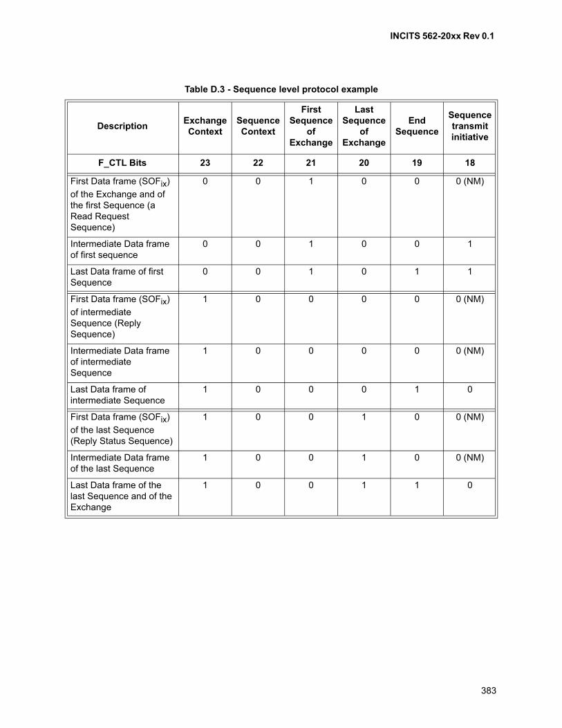
INCITS 562-20xx Rev 0.1
383
Table D.3 - Sequence level protocol example
DescriptionExchange Context
Sequence Context
First Sequence
ofExchange
Last Sequence
ofExchange
End Sequence
Sequence transmit initiative
F_CTL Bits 23 22 21 20 19 18
First Data frame (SOFix)
of the Exchange and of the first Sequence (a Read Request Sequence)
0 0 1 0 0 0 (NM)
Intermediate Data frame of first sequence
0 0 1 0 0 1
Last Data frame of first Sequence
0 0 1 0 1 1
First Data frame (SOFix)
of intermediate Sequence (Reply Sequence)
1 0 0 0 0 0 (NM)
Intermediate Data frame of intermediate Sequence
1 0 0 0 0 0 (NM)
Last Data frame of intermediate Sequence
1 0 0 0 1 0
First Data frame (SOFix)
of the last Sequence (Reply Status Sequence)
1 0 0 1 0 0 (NM)
Intermediate Data frame of the last Sequence
1 0 0 1 0 0 (NM)
Last Data frame of the last Sequence and of the Exchange
1 0 0 1 1 0
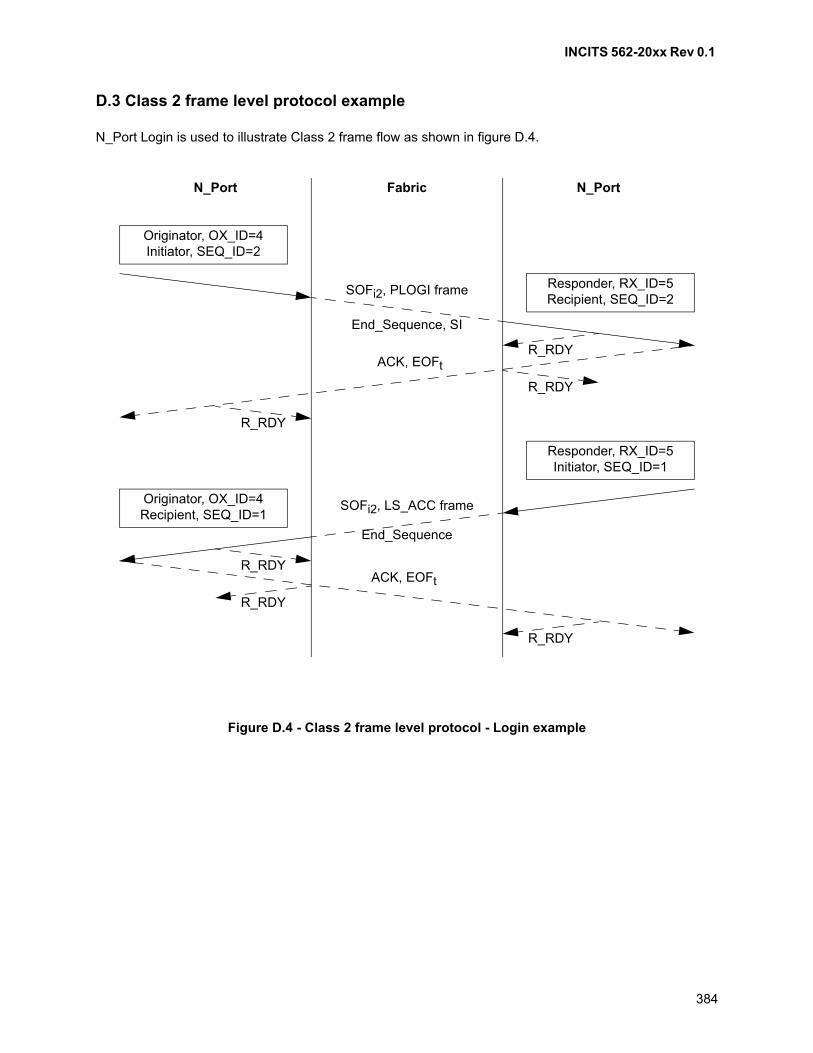
INCITS 562-20xx Rev 0.1
384
D.3 Class 2 frame level protocol example
N_Port Login is used to illustrate Class 2 frame flow as shown in figure D.4.
Figure D.4 - Class 2 frame level protocol - Login example
N_Port Fabric N_Port
Originator, OX_ID=4Initiator, SEQ_ID=2
Responder, RX_ID=5Recipient, SEQ_ID=2
End_Sequence, SI
ACK, EOFt
R_RDY
R_RDY
SOFi2, PLOGI frame
R_RDY
Responder, RX_ID=5Initiator, SEQ_ID=1
Originator, OX_ID=4Recipient, SEQ_ID=1
End_Sequence
ACK, EOFt
R_RDY
R_RDY
SOFi2, LS_ACC frame
R_RDY
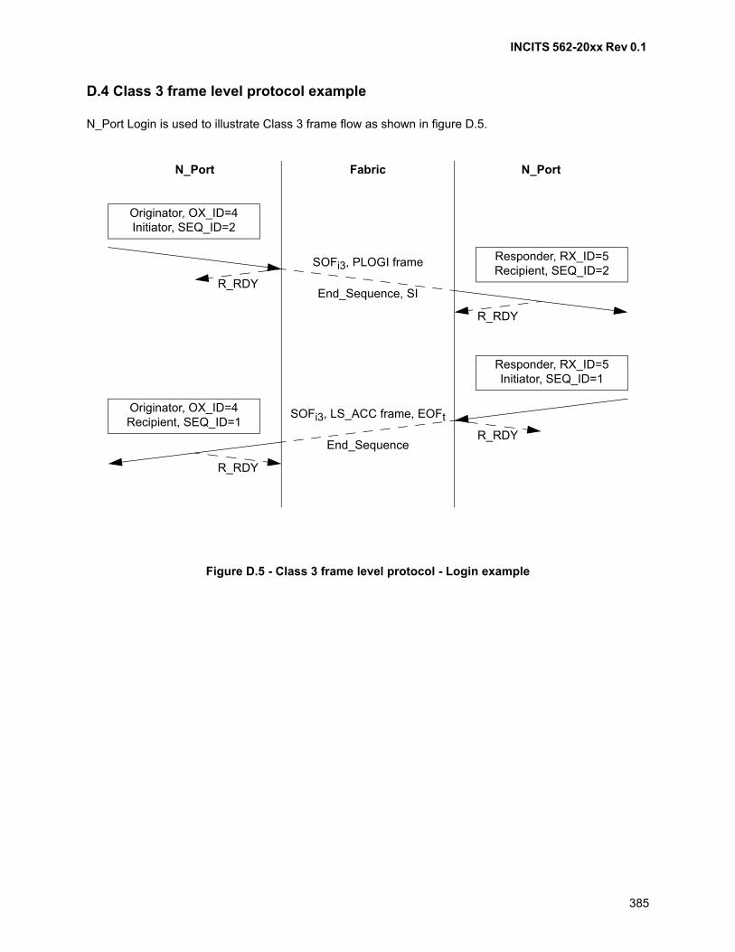
INCITS 562-20xx Rev 0.1
385
D.4 Class 3 frame level protocol example
N_Port Login is used to illustrate Class 3 frame flow as shown in figure D.5.
Figure D.5 - Class 3 frame level protocol - Login example
N_Port Fabric N_Port
Originator, OX_ID=4Initiator, SEQ_ID=2
Responder, RX_ID=5Recipient, SEQ_ID=2
End_Sequence, SIR_RDY
R_RDY
SOFi3, PLOGI frame
Responder, RX_ID=5Initiator, SEQ_ID=1
Originator, OX_ID=4Recipient, SEQ_ID=1
End_SequenceR_RDY
R_RDY
SOFi3, LS_ACC frame, EOFt

INCITS 562-20xx Rev 0.1
386
Annex E (informative)
Out of order characteristics
E.1 Introduction
This annex describes some of the implications of out of order transfer. There are two cases considered:
a) out of order transfer of Data frames due to the inability of a Fabric to maintain order; and
b) out of order transmission of ACKs by an Nx_Port due to its buffer availability algorithms.
E.2 Out of order Data frame delivery
Based on Fx_Port service parameters, the delivery of frames during Class 2 service may occur as:
a) “Misordered Delivery”. The destination Nx_Port receives frames in an order different than a sourceNx_Port sent them (i.e., the Fabric does not maintain the ordering of the frames); and
b) “Ordered Delivery”. The destination Nx_Port receives frames in the same order as the sourceNx_Port sent them (i.e., the Fabric maintains the ordering of the frames).
The following is a discussion of the implications of misordered delivery of frames and class 2 Sequencerecovery.
Misordered frame delivery may occur whenever there are multiple routes, within the Fabric, between twocommunicating Nx_Ports. When a Sequence is initiated, the individual frames of the Sequence areindependently routed by the Fabric and, therefore, may take different routes through the Fabric, with someroutes being longer or shorter than others. This may cause the misordered delivery of frames to thedestination Nx_Port. Also, since each frame is independently routed, it is very difficult for the Fabric topurge, or flush from the Fabric, all the frames for a Sequence.
Because of the above, this standard has provided the following functions to aid in the detection andrecovery of Sequences abnormally terminated due to time-out, e.g., because a frame was lost:
a) the R_A_TOV timeout to discard in transit frames (see 22.3.5); and
b) establishment of a Recovery_Qualifier for the duration of the R_A_TOV time (see 16.3.2.2.4).
These functions have several implications:
a) when an Nx_Port is initialized, it may not have knowledge of Sequences initiated prior toinitialization, (e.g., an Nx_Port may be powered off after sending a Sequence, and then poweredback on). Some (or all) frames of this prior Sequence may still be traversing the Fabric after theNx_Port has been initialized. After initialization, an Nx_Port waits R_A_TOV time before it initiatesany Sequences so that any duplicate frames in the Fabric are discarded (see 22.3.5);
b) the specification for Recovery_Qualifiers (see 16.3.2.2.4) implies that
A) an Nx_Port maintains a list of Recovery_Qualifiers;
B) entries are added to this list when a Sequence is abnormally terminated;
C) entries are deleted from this list when R_A_TOV has expired for the entry; and
D) the list is referenced prior to sequence initiation to ensure that a Data frame that falls within therange of a Recovery_Qualifier is not transmitted;
and
INCITS 562-20xx Rev 0.1
387
c) if a subset of the entire Sequence_Qualifier (e.g., X_ID) is used to route and store incomingframes, a frame falling within the range of a Recovery_Qualifier may not be detected until after theframe is placed in a receive buffer and the Frame_Header is validated. This has implications onCredit and buffer management.
The Sequence to which this frame belongs was abnormally terminated and all the Credit for theSequence was recovered. As a result, this frame is an “unexpected” frame that is not accountedfor by the current Credit management within the Nx_Port. Therefore, it may be occupying a bufferthat a source Nx_Port believes is available. This may cause another frame to receive a P_BSY,even though the sender of the busied frame obeyed the Credit rules.
E.3 Out of order ACK transmission
The transmission of ACK frames in Class 2 service may occur as:
a) misordered transmission. In this case, the Sequence Recipient is not acknowledging Data framesin the SEQ_CNT order, (i.e., the corresponding ACK frames are not being sent in SEQ_CNTorder); and
b) ordered transmission. In this case, the Sequence Recipient is acknowledging Data frames in theSEQ_CNT order, (i.e., the corresponding ACK frames are being sent in SEQ_CNT order).
The implications of misordered transmission of ACKs and ordered transmission of ACKs are:
a) with misordered transmission, the Credit for a lost ACK is not recovered until after a Sequencetime-out is detected, (i.e., the Credit is lost until the E_D_TOV time has expired); and
b) with ordered transmission, the reception of an ACK recovers the Credit for all Data frames withthat SEQ_CNT or lower, regardless of whether previous ACKs were received. This is trueregardless of whether the Fabric supports misordered delivery or ordered delivery.
INCITS 562-20xx Rev 0.1
388
Annex F (informative)
Link Error Status Block
F.1 Introduction
In this annex, guidelines are provided to manage the Link Error Status Block (see 22.4.8).
F.2 Link Failure Counters
Four types of Link Failures are recorded in individual counters in LESB. The Link Failure Counters are:
a) Link Failure Count (Word 0) counts miscellaneous link errors;
b) Loss-of-Synchronization Count (Word 1) counts confirmed and persistent synchronization losses;
c) Loss-of-Signal Count (Word 2); and
d) Primitive Sequence Protocol Error Count (Word 3).
The conditions under which individual counters increment are summarized in table F.1. For specific statechanges, related nomenclature, considerations and conditions, see table 22.
F.3 Invalid Transmission Word
The Invalid Transmission Word Counter (Word 4) increments, once for every Invalid Transmission Wordreceived (see 6.3.4.2), and once for every Invalid 64B/66B Transmission Word (see 6.4.3), except:
a) no Transmission Word errors are counted if the receiver is in the Loss-of-Synchronization state(see 6.2); and
b) no Transmission Word errors are counted if the Port is in the OL2 State or the OL3 State (see 7.7).
F.4 Invalid CRC Count
The Invalid CRC Count (Word 5) increments, once for every received frame that meets one of the followingconditions:
a) the Port is in the Active State and the received frame's CRC is in error and the frame is eithermissing an EOF delimiter or the EOF delimiter is an EOFn or EOFt (see 5.2.7.2 and 5.3.7.1); or
b) the Port is in the Active State and the received frame's CRC is in error (see 11.4.5).
NOTE 64 - The frames received with EOFni or EOFa may be excluded from consideration.
F.5 Link Failure Counter Triggers
Table F.1 shows the specific Link Failure Counters that are incremented when an input event occurs. A “-”in a cell indicates that no link error count is incremented. Any other entry in a cell indicates that if thespecific input event occurs in that state, the indicated link error counter shall be incremented.
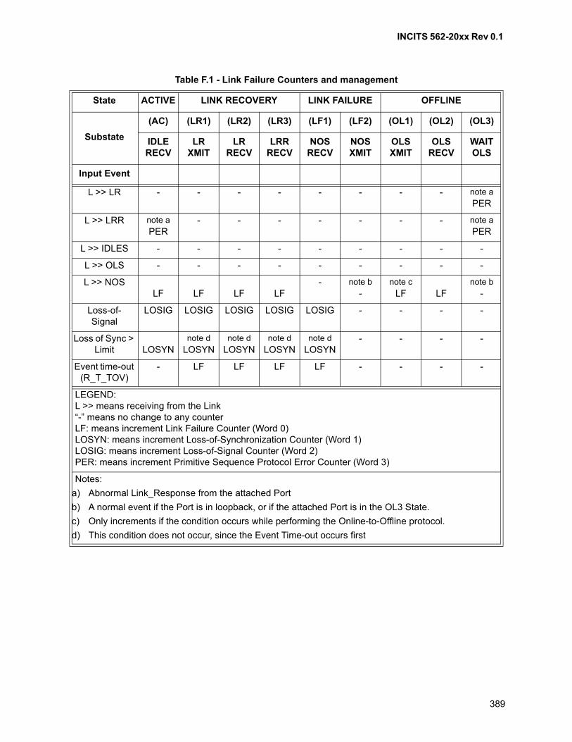
INCITS 562-20xx Rev 0.1
389
Table F.1 - Link Failure Counters and management
State ACTIVE LINK RECOVERY LINK FAILURE OFFLINE
Substate
(AC) (LR1) (LR2) (LR3) (LF1) (LF2) (OL1) (OL2) (OL3)
IDLE RECV
LR XMIT
LR RECV
LRR RECV
NOS RECV
NOS XMIT
OLS XMIT
OLS RECV
WAIT OLS
Input Event
L >> LR - - - - - - - - note a
PER
L >> LRR note a
PER- - - - - - - note a
PER
L >> IDLES - - - - - - - - -
L >> OLS - - - - - - - - -
L >> NOSLF LF LF LF
- note b
-note c
LF LFnote b
-
Loss-of-Signal
LOSIG LOSIG LOSIG LOSIG LOSIG - - - -
Loss of Sync > Limit LOSYN
note d
LOSYNnote d
LOSYNnote d
LOSYNnote d
LOSYN- - - -
Event time-out (R_T_TOV)
- LF LF LF LF - - - -
LEGEND:L >> means receiving from the Link“-” means no change to any counterLF: means increment Link Failure Counter (Word 0)LOSYN: means increment Loss-of-Synchronization Counter (Word 1)LOSIG: means increment Loss-of-Signal Counter (Word 2)PER: means increment Primitive Sequence Protocol Error Counter (Word 3)
Notes:
a) Abnormal Link_Response from the attached Port
b) A normal event if the Port is in loopback, or if the attached Port is in the OL3 State.
c) Only increments if the condition occurs while performing the Online-to-Offline protocol.
d) This condition does not occur, since the Event Time-out occurs first
INCITS 562-20xx Rev 0.1
390
Annex G (informative)
Clock Synchronization
G.1 Introduction
The goal of the Clock Synchronization Service described in clause 24 is to provide each participating nodewith a continuously-running counter that, at all times, contains exactly the same value that is found in thecounter in every other participating node. Clause 24 provides the message definitions and formats requiredto accomplish this goal in an interoperable way. But the extent to which the value in a given node's counteractually matches the value in any other node's counter is dependent on the techniques used to implementthe elements described in clause 24.
For systems with low accuracy requirements, the CSU ELS frames could be handled in software with nospecial hardware/firmware support. The client software could use any existing timer resources to maintainits local version of the counter. For systems that require the higher levels of accuracy, dedicated hardwareassistance would be needed.
It is the purpose of this annex to present several possible hardware implementations and to discuss thesources of error in each of them.
Clause 24 defines two separate mechanisms for transfer of the synchronizing information -- the ELSmethod and the Primitive Signal method. This annex addresses only the ELS method.
G.2 Discussion
G.2.1 Introduction
The approach used is to first present a basic model of an NL_Port, in order to give a context for the rest ofthe discussion. Then basic hardware-based implementations for each topology is presented along with adiscussion of the various sources of error and approaches for reducing these errors. The topologiesdiscussed include point-to-point (see G.2.4), Fabric (see G.2.5), and loop (see G.2.6).
G.2.2 A Model of an NL_Port
Figure G.1 presents a model of a generic NL_Port that is used as the basis for the discussions in thisannex. The elasticity buffer in the receive path and the multiplexer in the transmit path exist to support theoperation of the port in an Arbitrated Loop topology. The remainder of the components support alltopologies. For purposes of this annex, the interaction of the host with the port logic occurs entirely throughdata structures in the port's Memory that the host accesses via the Host Bus.
As Transmission Words are received, they pass through a Deserializer/Decoder (Des/Decode), and arechecked for validity and for the various types of frame delimiters (CRC/Valid). Valid frames destined for thelocal node are pushed onto the Receive FIFO. From the Receive FIFO, frames are stored as datastructures in the Memory. The host is informed of the presence of incoming frames via an unspecifiedmechanism, and the data is then transferred to the host via the host bus.
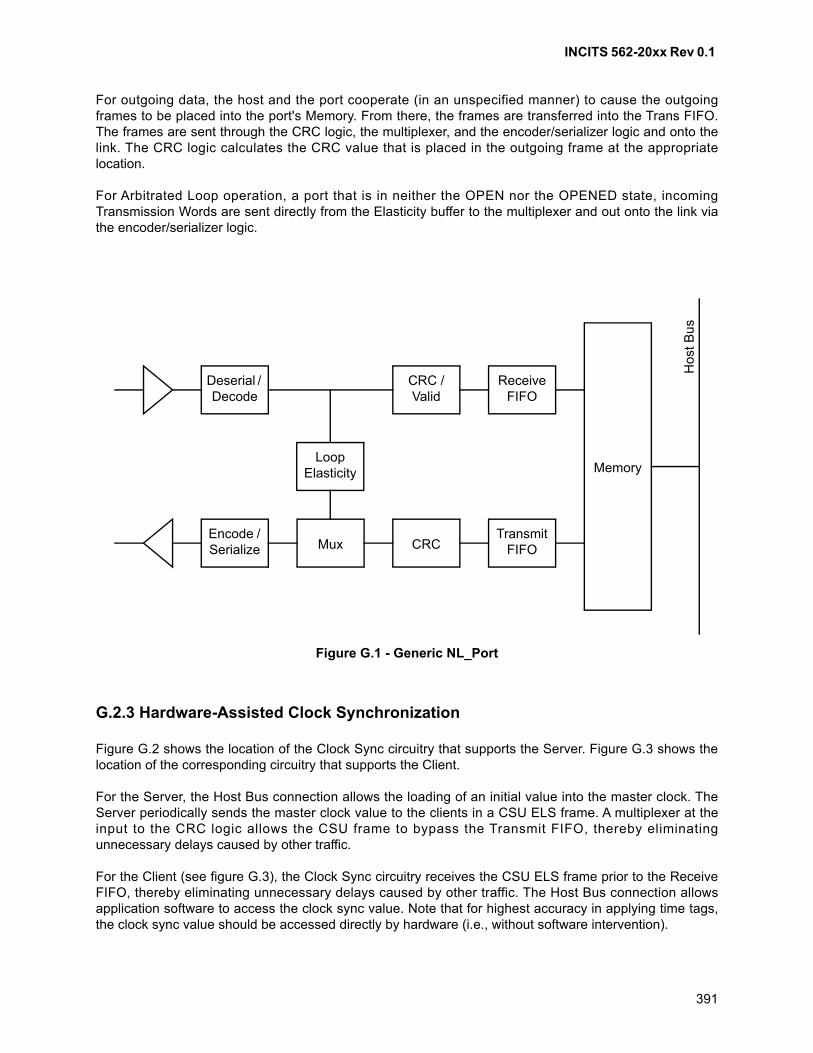
INCITS 562-20xx Rev 0.1
391
For outgoing data, the host and the port cooperate (in an unspecified manner) to cause the outgoingframes to be placed into the port's Memory. From there, the frames are transferred into the Trans FIFO.The frames are sent through the CRC logic, the multiplexer, and the encoder/serializer logic and onto thelink. The CRC logic calculates the CRC value that is placed in the outgoing frame at the appropriatelocation.
For Arbitrated Loop operation, a port that is in neither the OPEN nor the OPENED state, incomingTransmission Words are sent directly from the Elasticity buffer to the multiplexer and out onto the link viathe encoder/serializer logic.
G.2.3 Hardware-Assisted Clock Synchronization
Figure G.2 shows the location of the Clock Sync circuitry that supports the Server. Figure G.3 shows thelocation of the corresponding circuitry that supports the Client.
For the Server, the Host Bus connection allows the loading of an initial value into the master clock. TheServer periodically sends the master clock value to the clients in a CSU ELS frame. A multiplexer at theinput to the CRC logic allows the CSU frame to bypass the Transmit FIFO, thereby eliminatingunnecessary delays caused by other traffic.
For the Client (see figure G.3), the Clock Sync circuitry receives the CSU ELS frame prior to the ReceiveFIFO, thereby eliminating unnecessary delays caused by other traffic. The Host Bus connection allowsapplication software to access the clock sync value. Note that for highest accuracy in applying time tags,the clock sync value should be accessed directly by hardware (i.e., without software intervention).
Figure G.1 - Generic NL_Port
Memory
Hos
t B
us
Encode / Serialize
Loop Elasticity
Transmit FIFOCRCMux
Receive FIFO
CRC / Valid
Deserial / Decode
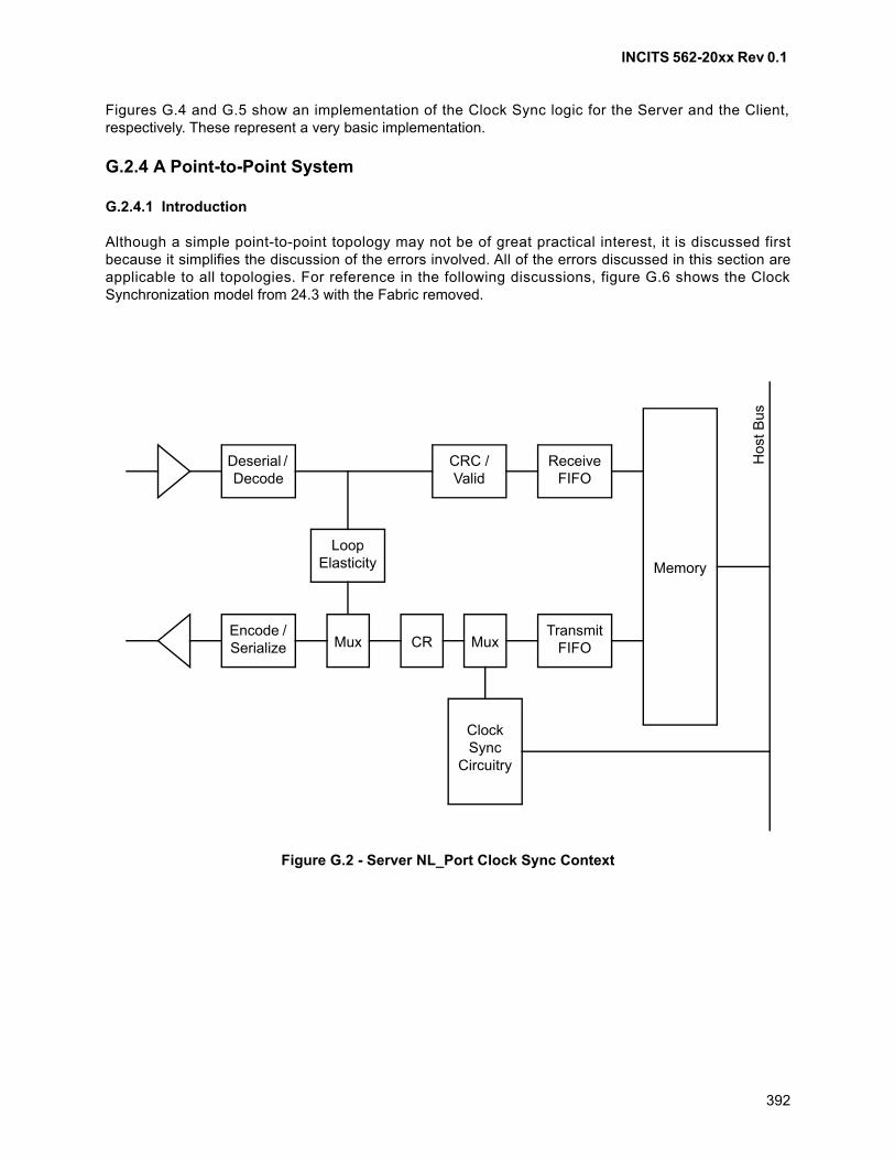
INCITS 562-20xx Rev 0.1
392
Figures G.4 and G.5 show an implementation of the Clock Sync logic for the Server and the Client,respectively. These represent a very basic implementation.
G.2.4 A Point-to-Point System
G.2.4.1 Introduction
Although a simple point-to-point topology may not be of great practical interest, it is discussed firstbecause it simplifies the discussion of the errors involved. All of the errors discussed in this section areapplicable to all topologies. For reference in the following discussions, figure G.6 shows the ClockSynchronization model from 24.3 with the Fabric removed.
Figure G.2 - Server NL_Port Clock Sync Context
Encode / Serialize
Loop Elasticity Memory
Transmit FIFOCRMux
Receive FIFO
CRC / Valid
Deserial / Decode
Ho
st B
us
Mux
ClockSync
Circuitry
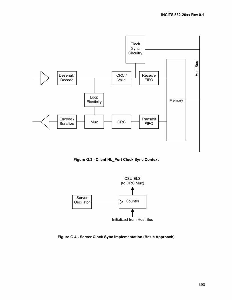
INCITS 562-20xx Rev 0.1
393
Figure G.3 - Client NL_Port Clock Sync Context
Figure G.4 - Server Clock Sync Implementation (Basic Approach)
Loop Elasticity Memory
Receive FIFO
CRC / Valid
Deserial / Decode
Hos
t Bus
ClockSync
Circuitry
Encode / Serialize
Transmit FIFOCRCMux
Server Oscillator Counter
CSU ELS(to CRC Mux)
Initialized from Host Bus
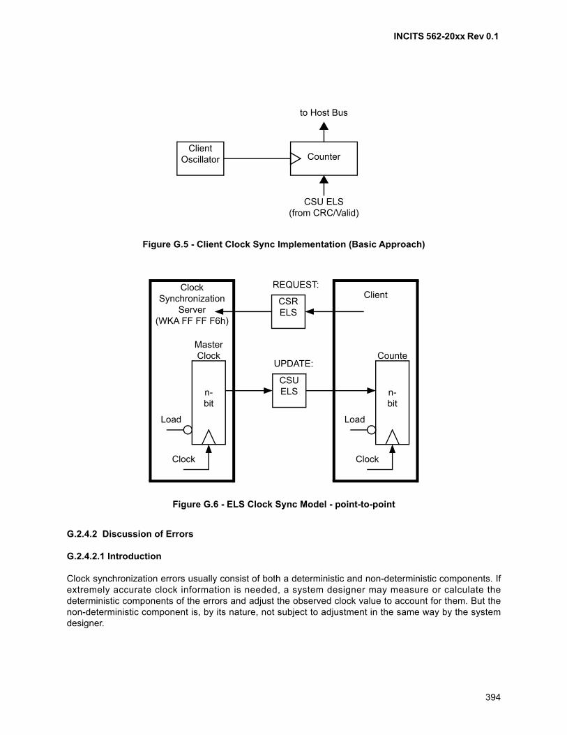
INCITS 562-20xx Rev 0.1
394
G.2.4.2 Discussion of Errors
G.2.4.2.1 Introduction
Clock synchronization errors usually consist of both a deterministic and non-deterministic components. Ifextremely accurate clock information is needed, a system designer may measure or calculate thedeterministic components of the errors and adjust the observed clock value to account for them. But thenon-deterministic component is, by its nature, not subject to adjustment in the same way by the systemdesigner.
Figure G.5 - Client Clock Sync Implementation (Basic Approach)
Client Oscillator Counter
to Host Bus
CSU ELS(from CRC/Valid)
Figure G.6 - ELS Clock Sync Model - point-to-point
Client
n-bit
Counte
Clock
Load
ClockSynchronization
Server(WKA FF FF F6h)
n-bit
MasterClock
Clock
Load
CSRELS
CSUELS
REQUEST:
UPDATE:

INCITS 562-20xx Rev 0.1
395
G.2.4.2.2 Client Oscillator Frequency Error
Even though the counters in the server and the client nominally count at the same frequency, theoscillators that drive them are independently subject to the tolerances specified in the Fibre Channelstandard. So even if they were to contain the exact same value at some point in time (e.g., just after receiptof the CSU ELS at the client), the values would slowly drift apart as time passes, until the next CSU ELSarrives. Figure G.7 illustrates this effect. The client oscillator is assumed to be of slightly higher frequencythan that of the server. Near the center of the figure, it is assumed that another CSU ELS is received at theclient. This results in the value of the client clock being corrected so that it again matches the server clock.
The correction of the client's clock when it receives the CSU ELS limits the maximum error as seen by theuser of the client's clock. However, it may also result in that user seeing time appear to run backwards.Reading the clock just prior to receipt of the CSU ELS may return a value that is larger than the valuereturned if the clock is read just after receipt of the CSU ELS. This non-monotonic behavior may causedifficulties with some algorithms that are intended to interpret these values.
The error due to oscillator frequency differences is essentially deterministic. A given client may determinethe degree to which its oscillator frequency exceeds (or falls behind) that of the server by observing thetime between receipt of CSU ELS frames, and the degree to which it's clock value exceeds (or lags) thevalue in the received CSU ELS. This error may then be largely compensated for, either by hardware or bysoftware algorithms.
Figure G.7 - Client Clock Drift
Client
CSU ELSreceived
Server
Time
Cou
nter
Va
lue
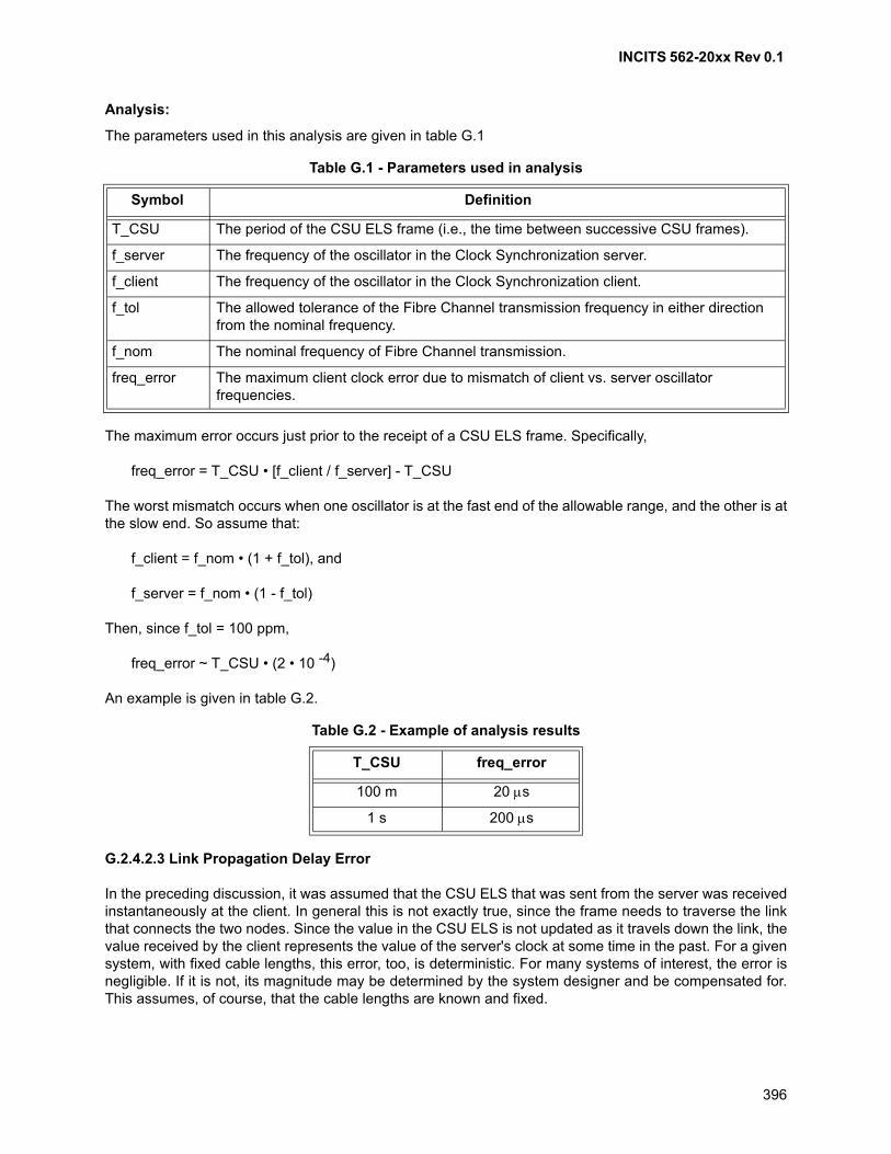
INCITS 562-20xx Rev 0.1
396
Analysis:
The parameters used in this analysis are given in table G.1
The maximum error occurs just prior to the receipt of a CSU ELS frame. Specifically,
freq_error = T_CSU • [f_client / f_server] - T_CSU
The worst mismatch occurs when one oscillator is at the fast end of the allowable range, and the other is atthe slow end. So assume that:
f_client = f_nom • (1 + f_tol), and
f_server = f_nom • (1 - f_tol)
Then, since f_tol = 100 ppm,
freq_error ~ T_CSU • (2 • 10 -4)
An example is given in table G.2.
G.2.4.2.3 Link Propagation Delay Error
In the preceding discussion, it was assumed that the CSU ELS that was sent from the server was receivedinstantaneously at the client. In general this is not exactly true, since the frame needs to traverse the linkthat connects the two nodes. Since the value in the CSU ELS is not updated as it travels down the link, thevalue received by the client represents the value of the server's clock at some time in the past. For a givensystem, with fixed cable lengths, this error, too, is deterministic. For many systems of interest, the error isnegligible. If it is not, its magnitude may be determined by the system designer and be compensated for.This assumes, of course, that the cable lengths are known and fixed.
Table G.1 - Parameters used in analysis
Symbol Definition
T_CSU The period of the CSU ELS frame (i.e., the time between successive CSU frames).
f_server The frequency of the oscillator in the Clock Synchronization server.
f_client The frequency of the oscillator in the Clock Synchronization client.
f_tol The allowed tolerance of the Fibre Channel transmission frequency in either direction from the nominal frequency.
f_nom The nominal frequency of Fibre Channel transmission.
freq_error The maximum client clock error due to mismatch of client vs. server oscillator frequencies.
Table G.2 - Example of analysis results
T_CSU freq_error
100 m 20 s
1 s 200 s
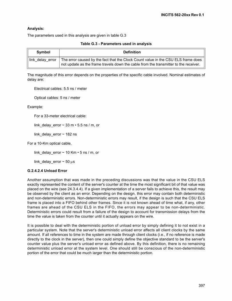
INCITS 562-20xx Rev 0.1
397
Analysis:
The parameters used in this analysis are given in table G.3
The magnitude of this error depends on the properties of the specific cable involved. Nominal estimates ofdelay are:
Electrical cables: 5.5 ns / meter
Optical cables: 5 ns / meter
Example:
For a 33-meter electrical cable:
link_delay_error ~ 33 m • 5.5 ns / m, or
link_delay_error ~ 182 ns
For a 10-Km optical cable,
link_delay_error ~ 10 Km • 5 ns / m, or
link_delay_error ~ 50 s
G.2.4.2.4 Unload Error
Another assumption that was made in the preceding discussions was that the value in the CSU ELSexactly represented the content of the server's counter at the time the most significant bit of that value wasplaced on the wire (see 24.3.4.4). If a given implementation of a server fails to achieve this, the result maybe observed by the client as an error. Depending on the design, this error may contain both deterministicand non-deterministic errors. Non-deterministic errors may result, if the design is such that the CSU ELSframe is placed into a FIFO behind other frames. Since it is not known ahead of time what, if any, otherframes are ahead of the CSU ELS in the FIFO, the errors may appear to be non-deterministic.Deterministic errors could result from a failure of the design to account for transmission delays from thetime the value is taken from the counter until it actually appears on the wire.
It is possible to deal with the deterministic portion of unload error by simply defining it to not exist in aparticular system. Note that the server's deterministic unload error affects all client clocks by the sameamount. If all references to time in the system are made through client clocks (i.e., if no reference is madedirectly to the clock in the server), then one could simply define the objective standard to be the server'scounter value plus the server's unload error as defined above. By this definition, there is no remainingdeterministic unload error at the system level. One should still be conscious of the non-deterministicportion of the error that could be much larger than the deterministic portion.
Table G.3 - Parameters used in analysis
Symbol Definition
link_delay_error The error caused by the fact that the Clock Count value in the CSU ELS frame does not update as the frame travels down the cable from the transmitter to the receiver.
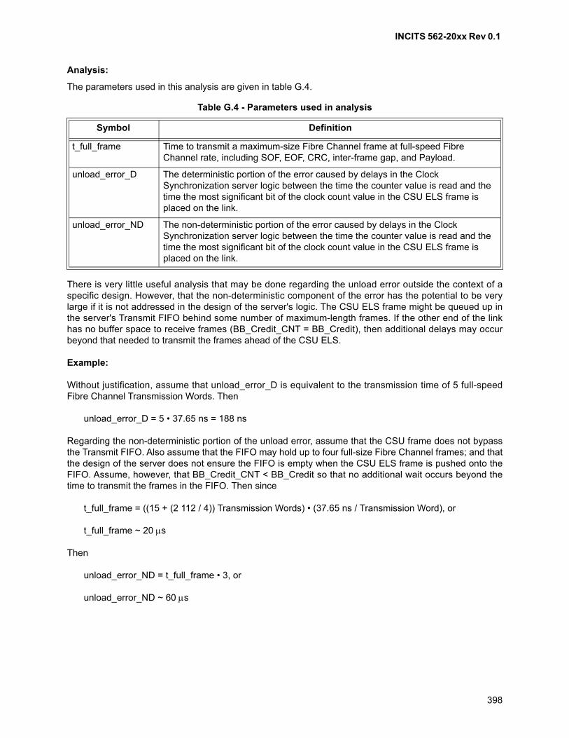
INCITS 562-20xx Rev 0.1
398
Analysis:
The parameters used in this analysis are given in table G.4.
There is very little useful analysis that may be done regarding the unload error outside the context of aspecific design. However, that the non-deterministic component of the error has the potential to be verylarge if it is not addressed in the design of the server's logic. The CSU ELS frame might be queued up inthe server's Transmit FIFO behind some number of maximum-length frames. If the other end of the linkhas no buffer space to receive frames (BB_Credit_CNT = BB_Credit), then additional delays may occurbeyond that needed to transmit the frames ahead of the CSU ELS.
Example:
Without justification, assume that unload_error_D is equivalent to the transmission time of 5 full-speedFibre Channel Transmission Words. Then
unload_error_D = 5 • 37.65 ns = 188 ns
Regarding the non-deterministic portion of the unload error, assume that the CSU frame does not bypassthe Transmit FIFO. Also assume that the FIFO may hold up to four full-size Fibre Channel frames; and thatthe design of the server does not ensure the FIFO is empty when the CSU ELS frame is pushed onto theFIFO. Assume, however, that BB_Credit_CNT < BB_Credit so that no additional wait occurs beyond thetime to transmit the frames in the FIFO. Then since
t_full_frame = ((15 + (2 112 / 4)) Transmission Words) • (37.65 ns / Transmission Word), or
t_full_frame ~ 20 s
Then
unload_error_ND = t_full_frame • 3, or
unload_error_ND ~ 60 s
Table G.4 - Parameters used in analysis
Symbol Definition
t_full_frame Time to transmit a maximum-size Fibre Channel frame at full-speed Fibre Channel rate, including SOF, EOF, CRC, inter-frame gap, and Payload.
unload_error_D The deterministic portion of the error caused by delays in the Clock Synchronization server logic between the time the counter value is read and the time the most significant bit of the clock count value in the CSU ELS frame is placed on the link.
unload_error_ND The non-deterministic portion of the error caused by delays in the Clock Synchronization server logic between the time the counter value is read and the time the most significant bit of the clock count value in the CSU ELS frame is placed on the link.
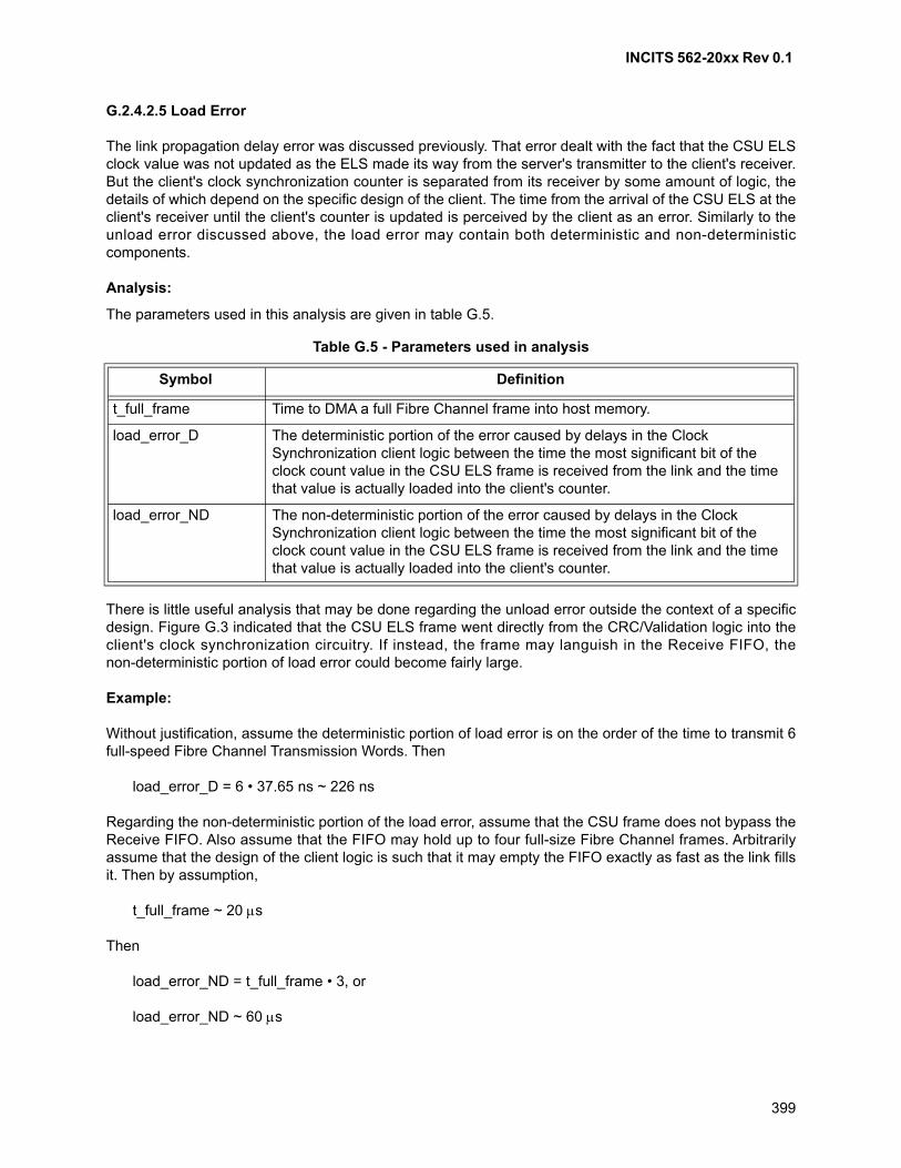
INCITS 562-20xx Rev 0.1
399
G.2.4.2.5 Load Error
The link propagation delay error was discussed previously. That error dealt with the fact that the CSU ELSclock value was not updated as the ELS made its way from the server's transmitter to the client's receiver.But the client's clock synchronization counter is separated from its receiver by some amount of logic, thedetails of which depend on the specific design of the client. The time from the arrival of the CSU ELS at theclient's receiver until the client's counter is updated is perceived by the client as an error. Similarly to theunload error discussed above, the load error may contain both deterministic and non-deterministiccomponents.
Analysis:
The parameters used in this analysis are given in table G.5.
There is little useful analysis that may be done regarding the unload error outside the context of a specificdesign. Figure G.3 indicated that the CSU ELS frame went directly from the CRC/Validation logic into theclient's clock synchronization circuitry. If instead, the frame may languish in the Receive FIFO, thenon-deterministic portion of load error could become fairly large.
Example:
Without justification, assume the deterministic portion of load error is on the order of the time to transmit 6full-speed Fibre Channel Transmission Words. Then
load_error_D = 6 • 37.65 ns ~ 226 ns
Regarding the non-deterministic portion of the load error, assume that the CSU frame does not bypass theReceive FIFO. Also assume that the FIFO may hold up to four full-size Fibre Channel frames. Arbitrarilyassume that the design of the client logic is such that it may empty the FIFO exactly as fast as the link fillsit. Then by assumption,
t_full_frame ~ 20 s
Then
load_error_ND = t_full_frame • 3, or
load_error_ND ~ 60 s
Table G.5 - Parameters used in analysis
Symbol Definition
t_full_frame Time to DMA a full Fibre Channel frame into host memory.
load_error_D The deterministic portion of the error caused by delays in the Clock Synchronization client logic between the time the most significant bit of the clock count value in the CSU ELS frame is received from the link and the time that value is actually loaded into the client's counter.
load_error_ND The non-deterministic portion of the error caused by delays in the Clock Synchronization client logic between the time the most significant bit of the clock count value in the CSU ELS frame is received from the link and the time that value is actually loaded into the client's counter.
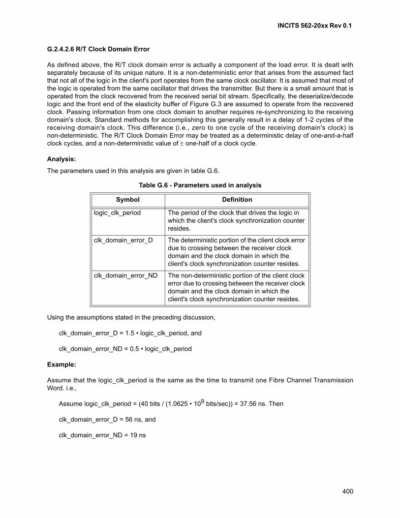
INCITS 562-20xx Rev 0.1
400
G.2.4.2.6 R/T Clock Domain Error
As defined above, the R/T clock domain error is actually a component of the load error. It is dealt withseparately because of its unique nature. It is a non-deterministic error that arises from the assumed factthat not all of the logic in the client's port operates from the same clock oscillator. It is assumed that most ofthe logic is operated from the same oscillator that drives the transmitter. But there is a small amount that isoperated from the clock recovered from the received serial bit stream. Specifically, the deserialize/decodelogic and the front end of the elasticity buffer of Figure G.3 are assumed to operate from the recoveredclock. Passing information from one clock domain to another requires re-synchronizing to the receivingdomain's clock. Standard methods for accomplishing this generally result in a delay of 1-2 cycles of thereceiving domain's clock. This difference (i.e., zero to one cycle of the receiving domain's clock) isnon-deterministic. The R/T Clock Domain Error may be treated as a deterministic delay of one-and-a-halfclock cycles, and a non-deterministic value of one-half of a clock cycle.
Analysis:
The parameters used in this analysis are given in table G.6.
Using the assumptions stated in the preceding discussion,
clk_domain_error_D = 1.5 • logic_clk_period, and
clk_domain_error_ND = 0.5 • logic_clk_period
Example:
Assume that the logic_clk_period is the same as the time to transmit one Fibre Channel TransmissionWord. i.e.,
Assume logic_clk_period = (40 bits / (1.0625 • 109 bits/sec)) = 37.56 ns. Then
clk_domain_error_D = 56 ns, and
clk_domain_error_ND = 19 ns
Table G.6 - Parameters used in analysis
Symbol Definition
logic_clk_period The period of the clock that drives the logic in which the client's clock synchronization counter resides.
clk_domain_error_D The deterministic portion of the client clock error due to crossing between the receiver clock domain and the clock domain in which the client's clock synchronization counter resides.
clk_domain_error_ND The non-deterministic portion of the client clock error due to crossing between the receiver clock domain and the clock domain in which the client's clock synchronization counter resides.
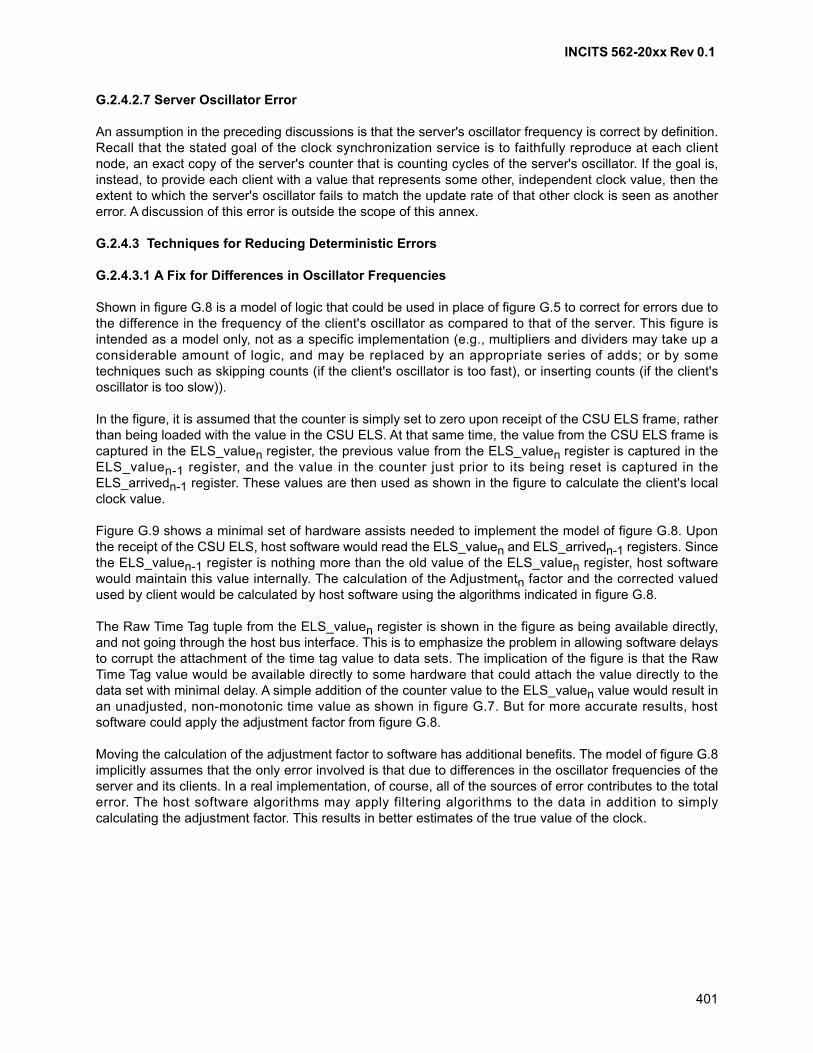
INCITS 562-20xx Rev 0.1
401
G.2.4.2.7 Server Oscillator Error
An assumption in the preceding discussions is that the server's oscillator frequency is correct by definition.Recall that the stated goal of the clock synchronization service is to faithfully reproduce at each clientnode, an exact copy of the server's counter that is counting cycles of the server's oscillator. If the goal is,instead, to provide each client with a value that represents some other, independent clock value, then theextent to which the server's oscillator fails to match the update rate of that other clock is seen as anothererror. A discussion of this error is outside the scope of this annex.
G.2.4.3 Techniques for Reducing Deterministic Errors
G.2.4.3.1 A Fix for Differences in Oscillator Frequencies
Shown in figure G.8 is a model of logic that could be used in place of figure G.5 to correct for errors due tothe difference in the frequency of the client's oscillator as compared to that of the server. This figure isintended as a model only, not as a specific implementation (e.g., multipliers and dividers may take up aconsiderable amount of logic, and may be replaced by an appropriate series of adds; or by sometechniques such as skipping counts (if the client's oscillator is too fast), or inserting counts (if the client'soscillator is too slow)).
In the figure, it is assumed that the counter is simply set to zero upon receipt of the CSU ELS frame, ratherthan being loaded with the value in the CSU ELS. At that same time, the value from the CSU ELS frame iscaptured in the ELS_valuen register, the previous value from the ELS_valuen register is captured in theELS_valuen-1 register, and the value in the counter just prior to its being reset is captured in theELS_arrivedn-1 register. These values are then used as shown in the figure to calculate the client's localclock value.
Figure G.9 shows a minimal set of hardware assists needed to implement the model of figure G.8. Uponthe receipt of the CSU ELS, host software would read the ELS_valuen and ELS_arrivedn-1 registers. Sincethe ELS_valuen-1 register is nothing more than the old value of the ELS_valuen register, host softwarewould maintain this value internally. The calculation of the Adjustmentn factor and the corrected valuedused by client would be calculated by host software using the algorithms indicated in figure G.8.
The Raw Time Tag tuple from the ELS_valuen register is shown in the figure as being available directly,and not going through the host bus interface. This is to emphasize the problem in allowing software delaysto corrupt the attachment of the time tag value to data sets. The implication of the figure is that the RawTime Tag value would be available directly to some hardware that could attach the value directly to thedata set with minimal delay. A simple addition of the counter value to the ELS_valuen value would result inan unadjusted, non-monotonic time value as shown in figure G.7. But for more accurate results, hostsoftware could apply the adjustment factor from figure G.8.
Moving the calculation of the adjustment factor to software has additional benefits. The model of figure G.8implicitly assumes that the only error involved is that due to differences in the oscillator frequencies of theserver and its clients. In a real implementation, of course, all of the sources of error contributes to the totalerror. The host software algorithms may apply filtering algorithms to the data in addition to simplycalculating the adjustment factor. This results in better estimates of the true value of the clock.
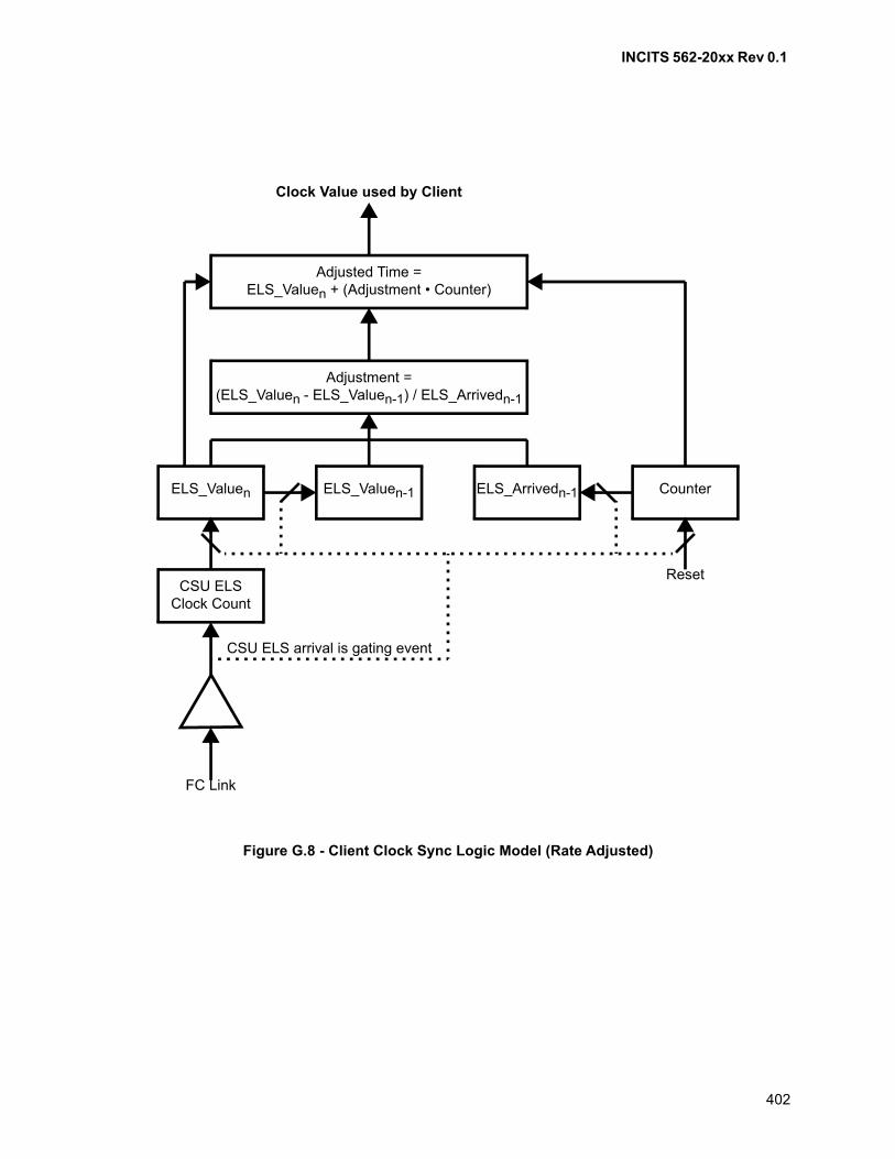
INCITS 562-20xx Rev 0.1
402
Figure G.8 - Client Clock Sync Logic Model (Rate Adjusted)
Adjustment =(ELS_Valuen - ELS_Valuen-1) / ELS_Arrivedn-1
CounterELS_Arrivedn-1ELS_Valuen-1ELS_Valuen
Adjusted Time =ELS_Valuen + (Adjustment • Counter)
CSU ELSClock Count
FC Link
Reset
Clock Value used by Client
CSU ELS arrival is gating event
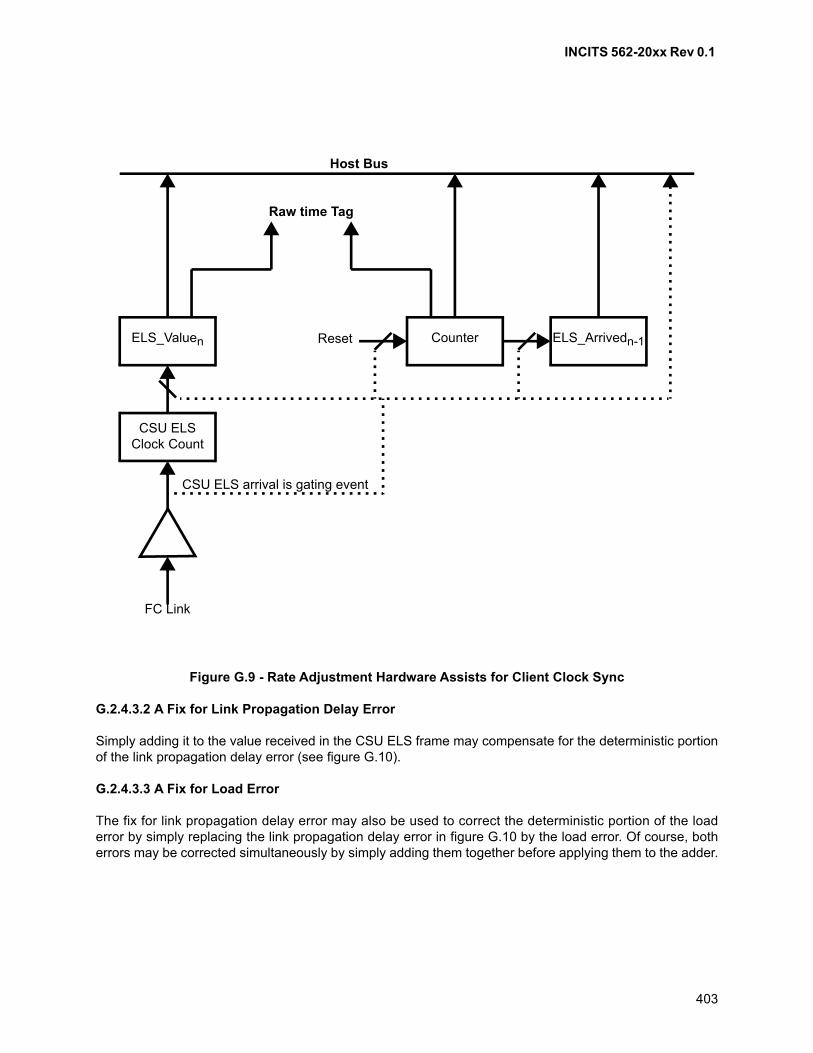
INCITS 562-20xx Rev 0.1
403
G.2.4.3.2 A Fix for Link Propagation Delay Error
Simply adding it to the value received in the CSU ELS frame may compensate for the deterministic portionof the link propagation delay error (see figure G.10).
G.2.4.3.3 A Fix for Load Error
The fix for link propagation delay error may also be used to correct the deterministic portion of the loaderror by simply replacing the link propagation delay error in figure G.10 by the load error. Of course, botherrors may be corrected simultaneously by simply adding them together before applying them to the adder.
Figure G.9 - Rate Adjustment Hardware Assists for Client Clock Sync
Counter ELS_Arrivedn-1ELS_Valuen
CSU ELSClock Count
FC Link
Reset
CSU ELS arrival is gating event
Host Bus
Raw time Tag
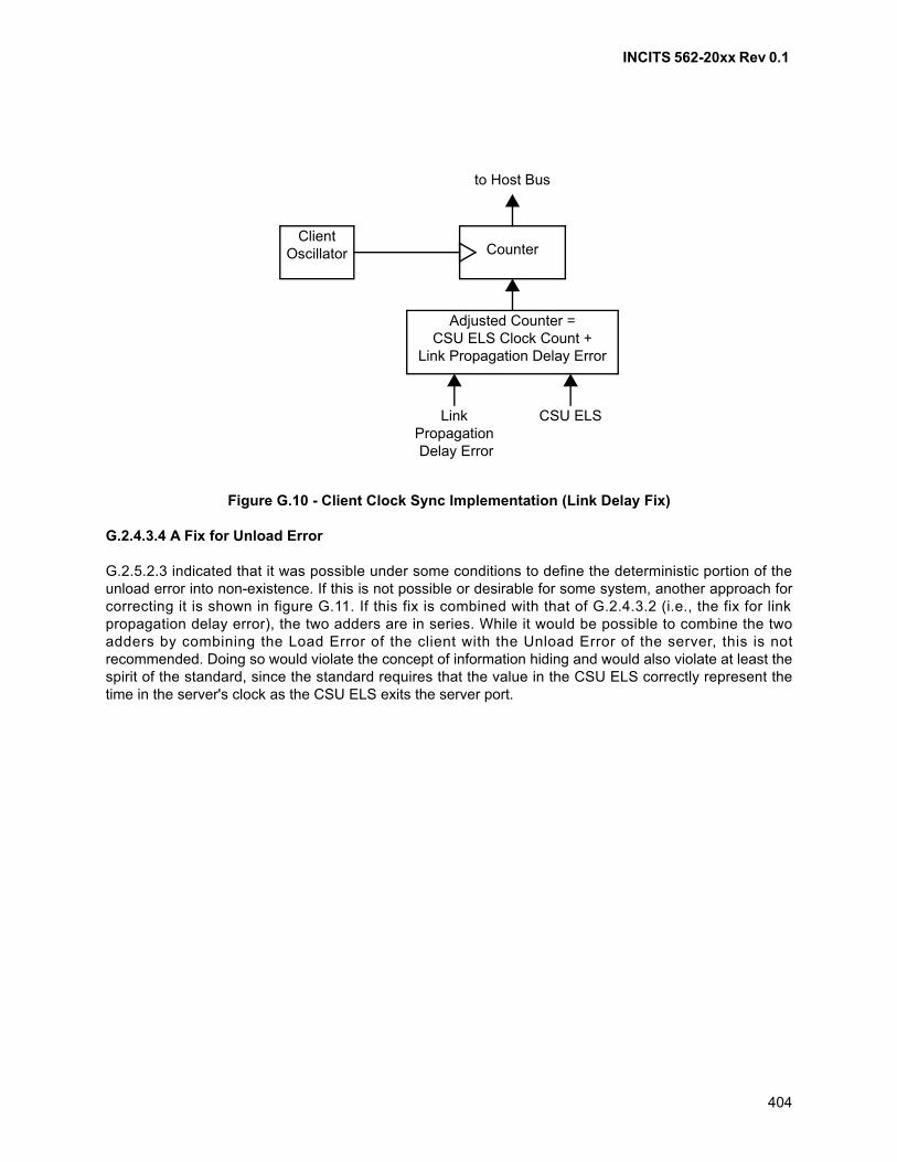
INCITS 562-20xx Rev 0.1
404
G.2.4.3.4 A Fix for Unload Error
G.2.5.2.3 indicated that it was possible under some conditions to define the deterministic portion of theunload error into non-existence. If this is not possible or desirable for some system, another approach forcorrecting it is shown in figure G.11. If this fix is combined with that of G.2.4.3.2 (i.e., the fix for linkpropagation delay error), the two adders are in series. While it would be possible to combine the twoadders by combining the Load Error of the client with the Unload Error of the server, this is notrecommended. Doing so would violate the concept of information hiding and would also violate at least thespirit of the standard, since the standard requires that the value in the CSU ELS correctly represent thetime in the server's clock as the CSU ELS exits the server port.
Figure G.10 - Client Clock Sync Implementation (Link Delay Fix)
Client Oscillator Counter
to Host Bus
LinkPropagation Delay Error
Adjusted Counter =CSU ELS Clock Count +
Link Propagation Delay Error
CSU ELS
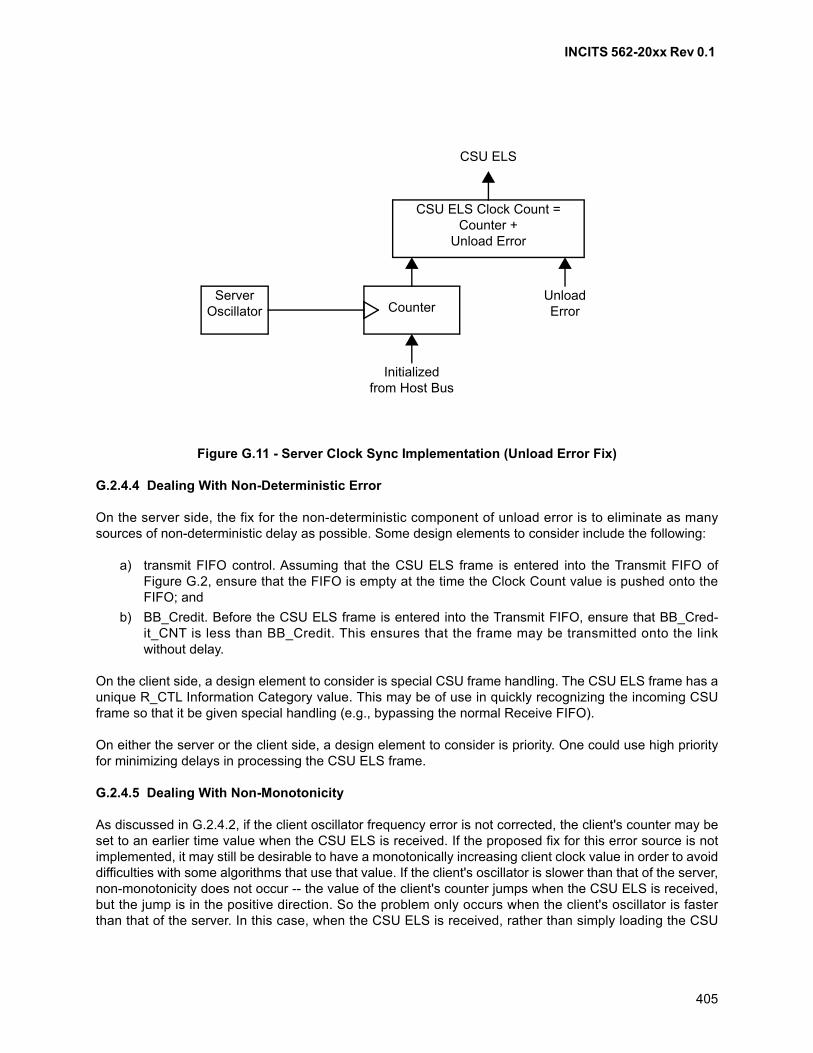
INCITS 562-20xx Rev 0.1
405
G.2.4.4 Dealing With Non-Deterministic Error
On the server side, the fix for the non-deterministic component of unload error is to eliminate as manysources of non-deterministic delay as possible. Some design elements to consider include the following:
a) transmit FIFO control. Assuming that the CSU ELS frame is entered into the Transmit FIFO ofFigure G.2, ensure that the FIFO is empty at the time the Clock Count value is pushed onto theFIFO; and
b) BB_Credit. Before the CSU ELS frame is entered into the Transmit FIFO, ensure that BB_Cred-it_CNT is less than BB_Credit. This ensures that the frame may be transmitted onto the linkwithout delay.
On the client side, a design element to consider is special CSU frame handling. The CSU ELS frame has aunique R_CTL Information Category value. This may be of use in quickly recognizing the incoming CSUframe so that it be given special handling (e.g., bypassing the normal Receive FIFO).
On either the server or the client side, a design element to consider is priority. One could use high priorityfor minimizing delays in processing the CSU ELS frame.
G.2.4.5 Dealing With Non-Monotonicity
As discussed in G.2.4.2, if the client oscillator frequency error is not corrected, the client's counter may beset to an earlier time value when the CSU ELS is received. If the proposed fix for this error source is notimplemented, it may still be desirable to have a monotonically increasing client clock value in order to avoiddifficulties with some algorithms that use that value. If the client's oscillator is slower than that of the server,non-monotonicity does not occur -- the value of the client's counter jumps when the CSU ELS is received,but the jump is in the positive direction. So the problem only occurs when the client's oscillator is fasterthan that of the server. In this case, when the CSU ELS is received, rather than simply loading the CSU
Figure G.11 - Server Clock Sync Implementation (Unload Error Fix)
Server Oscillator Counter
UnloadError
Initializedfrom Host Bus
CSU ELS Clock Count =Counter +
Unload Error
CSU ELS
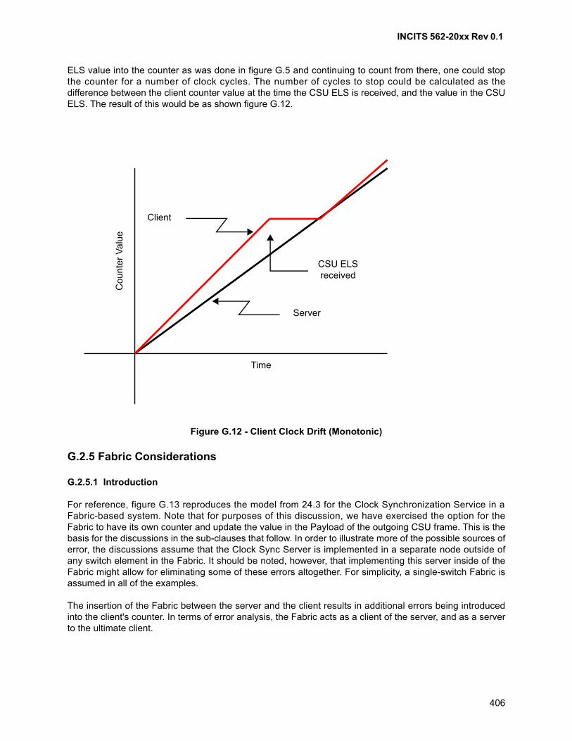
INCITS 562-20xx Rev 0.1
406
ELS value into the counter as was done in figure G.5 and continuing to count from there, one could stopthe counter for a number of clock cycles. The number of cycles to stop could be calculated as thedifference between the client counter value at the time the CSU ELS is received, and the value in the CSUELS. The result of this would be as shown figure G.12.
G.2.5 Fabric Considerations
G.2.5.1 Introduction
For reference, figure G.13 reproduces the model from 24.3 for the Clock Synchronization Service in aFabric-based system. Note that for purposes of this discussion, we have exercised the option for theFabric to have its own counter and update the value in the Payload of the outgoing CSU frame. This is thebasis for the discussions in the sub-clauses that follow. In order to illustrate more of the possible sources oferror, the discussions assume that the Clock Sync Server is implemented in a separate node outside ofany switch element in the Fabric. It should be noted, however, that implementing this server inside of theFabric might allow for eliminating some of these errors altogether. For simplicity, a single-switch Fabric isassumed in all of the examples.
The insertion of the Fabric between the server and the client results in additional errors being introducedinto the client's counter. In terms of error analysis, the Fabric acts as a client of the server, and as a serverto the ultimate client.
Figure G.12 - Client Clock Drift (Monotonic)
Client
CSU ELSreceived
Server
Time
Cou
nter
Va
lue
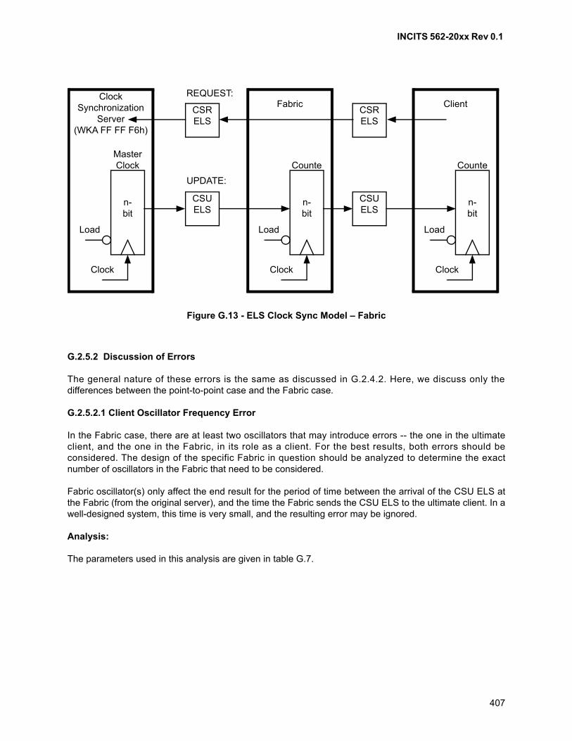
INCITS 562-20xx Rev 0.1
407
G.2.5.2 Discussion of Errors
The general nature of these errors is the same as discussed in G.2.4.2. Here, we discuss only thedifferences between the point-to-point case and the Fabric case.
G.2.5.2.1 Client Oscillator Frequency Error
In the Fabric case, there are at least two oscillators that may introduce errors -- the one in the ultimateclient, and the one in the Fabric, in its role as a client. For the best results, both errors should beconsidered. The design of the specific Fabric in question should be analyzed to determine the exactnumber of oscillators in the Fabric that need to be considered.
Fabric oscillator(s) only affect the end result for the period of time between the arrival of the CSU ELS atthe Fabric (from the original server), and the time the Fabric sends the CSU ELS to the ultimate client. In awell-designed system, this time is very small, and the resulting error may be ignored.
Analysis:
The parameters used in this analysis are given in table G.7.
Figure G.13 - ELS Clock Sync Model – Fabric
Client
n-bit
Counte
Clock
Load
ClockSynchronization
Server(WKA FF FF F6h)
n-bit
MasterClock
Clock
Load
Fabric
n-bit
Counte
Clock
Load
CSRELS
CSRELS
CSUELS
CSUELS
REQUEST:
UPDATE:
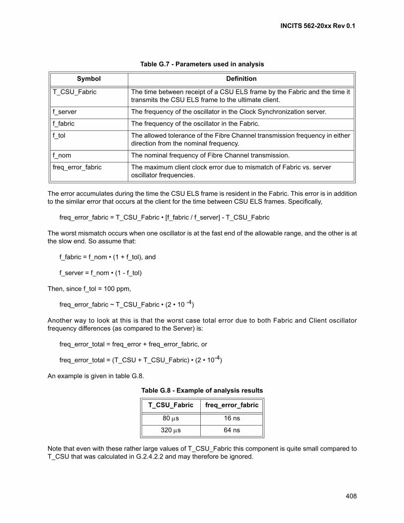
INCITS 562-20xx Rev 0.1
408
The error accumulates during the time the CSU ELS frame is resident in the Fabric. This error is in additionto the similar error that occurs at the client for the time between CSU ELS frames. Specifically,
freq_error_fabric = T_CSU_Fabric • [f_fabric / f_server] - T_CSU_Fabric
The worst mismatch occurs when one oscillator is at the fast end of the allowable range, and the other is atthe slow end. So assume that:
f_fabric = f_nom • (1 + f_tol), and
f_server = f_nom • (1 - f_tol)
Then, since f_tol = 100 ppm,
freq_error_fabric ~ T_CSU_Fabric • (2 • 10 -4)
Another way to look at this is that the worst case total error due to both Fabric and Client oscillatorfrequency differences (as compared to the Server) is:
freq_error_total = freq_error + freq_error_fabric, or
freq_error_total = (T_CSU + T_CSU_Fabric) • (2 • 10-4)
An example is given in table G.8.
Note that even with these rather large values of T_CSU_Fabric this component is quite small compared toT_CSU that was calculated in G.2.4.2.2 and may therefore be ignored.
Table G.7 - Parameters used in analysis
Symbol Definition
T_CSU_Fabric The time between receipt of a CSU ELS frame by the Fabric and the time it transmits the CSU ELS frame to the ultimate client.
f_server The frequency of the oscillator in the Clock Synchronization server.
f_fabric The frequency of the oscillator in the Fabric.
f_tol The allowed tolerance of the Fibre Channel transmission frequency in either direction from the nominal frequency.
f_nom The nominal frequency of Fibre Channel transmission.
freq_error_fabric The maximum client clock error due to mismatch of Fabric vs. server oscillator frequencies.
Table G.8 - Example of analysis results
T_CSU_Fabric freq_error_fabric
80 s 16 ns
320 s 64 ns
INCITS 562-20xx Rev 0.1
409
G.2.5.2.2 Link Propagation Delay Error
In the case of the Fabric, there are two links that contribute to the error (i.e., one from the original server tothe Fabric, and one from the Fabric to the ultimate client). These errors should be commensurate witheach other.
G.2.5.2.3 Unload Error
There are two sources of unload error (i.e., one in the original server, and one in the Fabric as it acts as aserver for the ultimate client). These errors should be commensurate with each other.
Caution should be used when ignoring the deterministic portion of unload error. The unload errorassociated with the server itself may still be ignored. The unload error associated with the Fabric may onlybe ignored if it is known that the path from the server to each client goes through the same number ofFabric elements; and that the Fabric elements all have identical unload errors. If this is true, though, theunload error of the Fabric may be treated the same as that of the server.
The considerations of G.2.4.3.4 may be applied to lessen the non-deterministic portion of unload error inthe Fabric.
Analysis:
The presence of the Fabric has two potential effects. First, and most obviously, the circuitry in the Fabricthat maintains the counter and that acts as the surrogate server for the client, has its own unload error.This error simply adds to the unload error of the original Server. Secondly, contention in the Fabric mayaffect the unload error of the original Server if care is not taken in the design of the Server. Specifically, ifthe Server design takes the value from the counter and puts it in the CSU ELS frame before ensuring thatthe BB_Credit_CNT is less than BB_Credit, then contention in the Fabric causes a delay in getting theCSU ELS onto the wire. This increases the Server's unload error.
Example:
Regarding the non-deterministic portion of the unload error, assume in the Fabric case that the TransmitFIFO may hold up to four full-size Fibre Channel frames; and that the design of the server does not ensurethe FIFO is empty when the CSU ELS frame is pushed onto the FIFO. Again without justification, assumethat each of the frames (including the CSU ELS frame) waits for delivery of, say, four full-size FibreChannel frames before it receives BB_Credit so that it may proceed. Then since
t_full_frame = ((15 + (2 112 / 4)) Transmission Words) • (37.65 ns / Transmission Word), or
t_full_frame ~ 20 s
Then
unload_error_ND = t_full_frame • (3 • (4+1) + (4)), or
unload_error_ND ~ 380 s
G.2.5.2.4 Load Error
There are two sources of load error (i.e., one in the ultimate client, and one in the Fabric as it acts as aclient of the original server). These errors should be commensurate with each other.
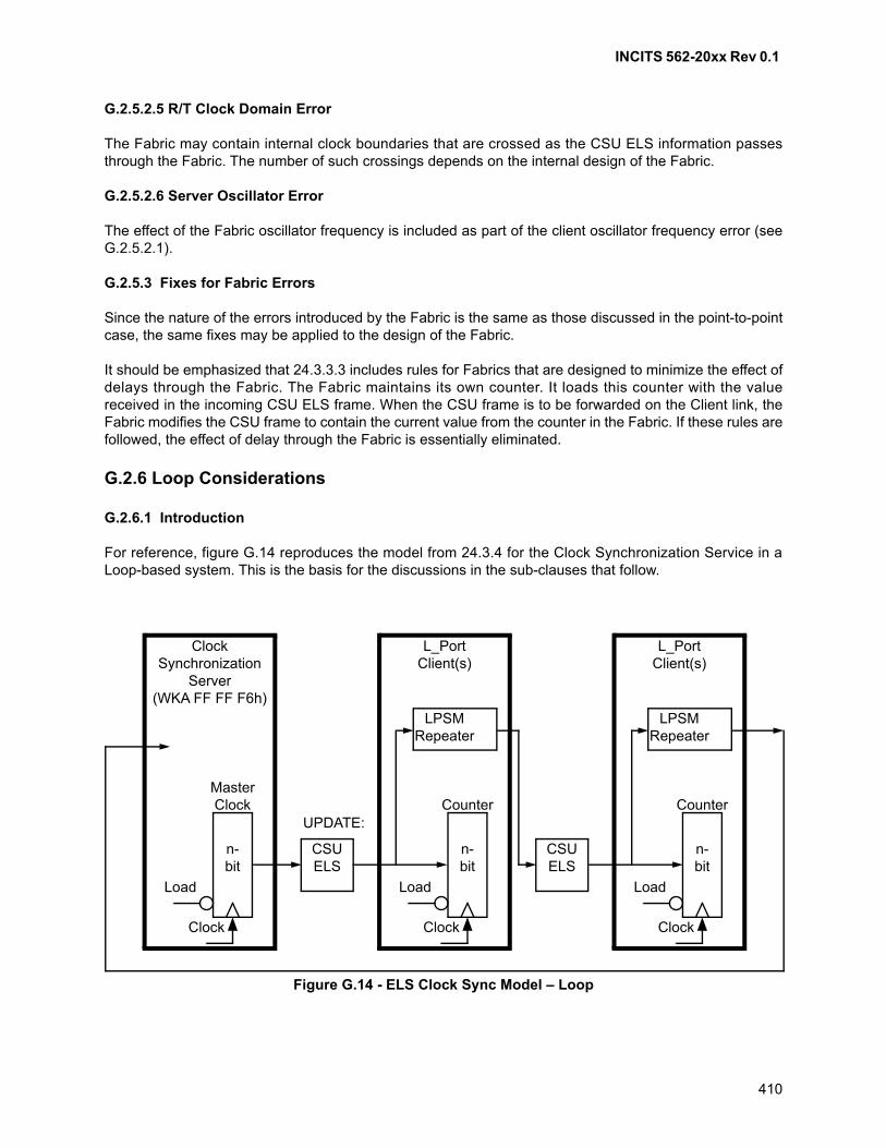
INCITS 562-20xx Rev 0.1
410
G.2.5.2.5 R/T Clock Domain Error
The Fabric may contain internal clock boundaries that are crossed as the CSU ELS information passesthrough the Fabric. The number of such crossings depends on the internal design of the Fabric.
G.2.5.2.6 Server Oscillator Error
The effect of the Fabric oscillator frequency is included as part of the client oscillator frequency error (seeG.2.5.2.1).
G.2.5.3 Fixes for Fabric Errors
Since the nature of the errors introduced by the Fabric is the same as those discussed in the point-to-pointcase, the same fixes may be applied to the design of the Fabric.
It should be emphasized that 24.3.3.3 includes rules for Fabrics that are designed to minimize the effect ofdelays through the Fabric. The Fabric maintains its own counter. It loads this counter with the valuereceived in the incoming CSU ELS frame. When the CSU frame is to be forwarded on the Client link, theFabric modifies the CSU frame to contain the current value from the counter in the Fabric. If these rules arefollowed, the effect of delay through the Fabric is essentially eliminated.
G.2.6 Loop Considerations
G.2.6.1 Introduction
For reference, figure G.14 reproduces the model from 24.3.4 for the Clock Synchronization Service in aLoop-based system. This is the basis for the discussions in the sub-clauses that follow.
Figure G.14 - ELS Clock Sync Model – Loop
ClockSynchronization
Server(WKA FF FF F6h)
CSUELS
CSUELS
UPDATE:
n-bit
MasterClock
Clock
Load
L_PortClient(s)
n-bit
Counter
Clock
Load
L_PortClient(s)
n-bit
Counter
Clock
Load
LPSMRepeater
LPSMRepeater
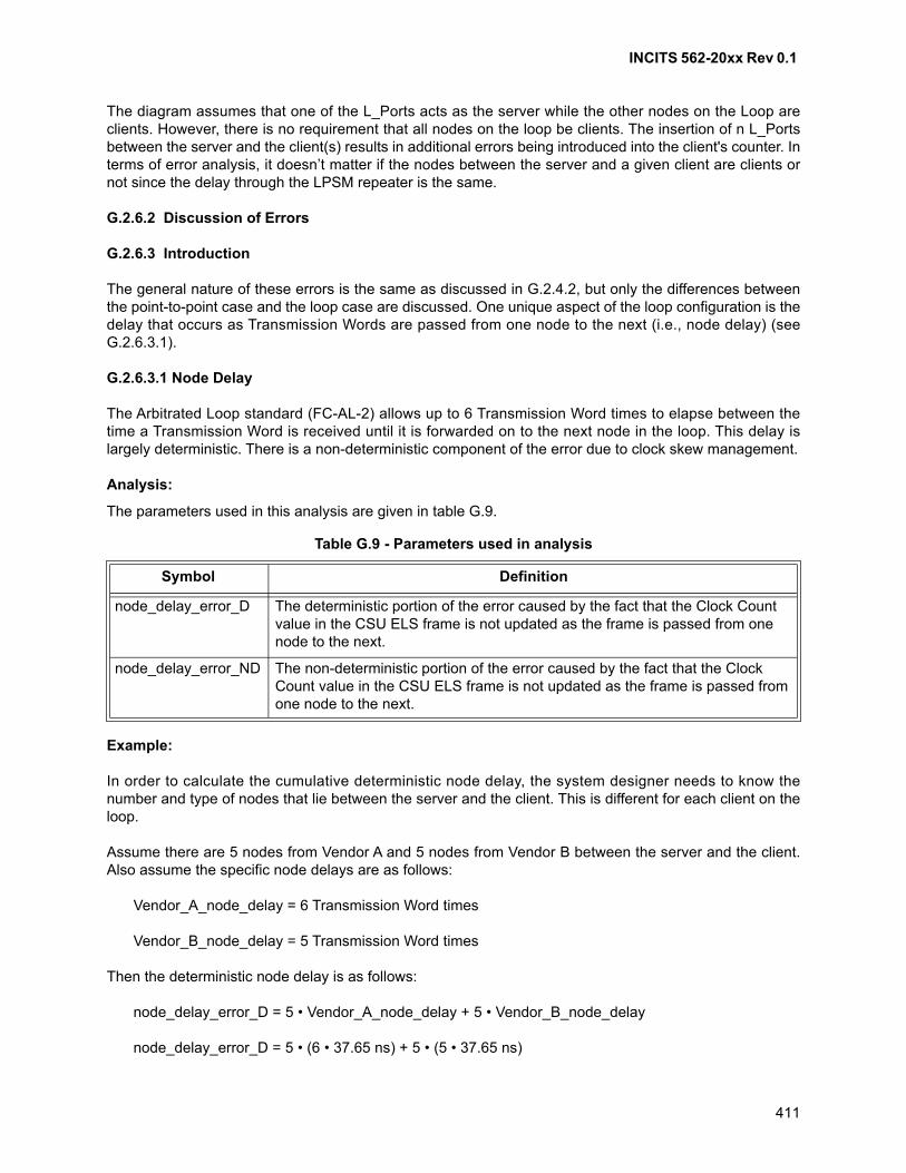
INCITS 562-20xx Rev 0.1
411
The diagram assumes that one of the L_Ports acts as the server while the other nodes on the Loop areclients. However, there is no requirement that all nodes on the loop be clients. The insertion of n L_Portsbetween the server and the client(s) results in additional errors being introduced into the client's counter. Interms of error analysis, it doesn’t matter if the nodes between the server and a given client are clients ornot since the delay through the LPSM repeater is the same.
G.2.6.2 Discussion of Errors
G.2.6.3 Introduction
The general nature of these errors is the same as discussed in G.2.4.2, but only the differences betweenthe point-to-point case and the loop case are discussed. One unique aspect of the loop configuration is thedelay that occurs as Transmission Words are passed from one node to the next (i.e., node delay) (seeG.2.6.3.1).
G.2.6.3.1 Node Delay
The Arbitrated Loop standard (FC-AL-2) allows up to 6 Transmission Word times to elapse between thetime a Transmission Word is received until it is forwarded on to the next node in the loop. This delay islargely deterministic. There is a non-deterministic component of the error due to clock skew management.
Analysis:
The parameters used in this analysis are given in table G.9.
Example:
In order to calculate the cumulative deterministic node delay, the system designer needs to know thenumber and type of nodes that lie between the server and the client. This is different for each client on theloop.
Assume there are 5 nodes from Vendor A and 5 nodes from Vendor B between the server and the client.Also assume the specific node delays are as follows:
Vendor_A_node_delay = 6 Transmission Word times
Vendor_B_node_delay = 5 Transmission Word times
Then the deterministic node delay is as follows:
node_delay_error_D = 5 • Vendor_A_node_delay + 5 • Vendor_B_node_delay
node_delay_error_D = 5 • (6 • 37.65 ns) + 5 • (5 • 37.65 ns)
Table G.9 - Parameters used in analysis
Symbol Definition
node_delay_error_D The deterministic portion of the error caused by the fact that the Clock Count value in the CSU ELS frame is not updated as the frame is passed from one node to the next.
node_delay_error_ND The non-deterministic portion of the error caused by the fact that the Clock Count value in the CSU ELS frame is not updated as the frame is passed from one node to the next.
INCITS 562-20xx Rev 0.1
412
node_delay_error_D = 2.07 microseconds
For estimating the non-deterministic error, consider the discussion in FC-AL-2 concerning L_Port Elasticitybuffer management, which requires that no more than 4 Transmission Words are deleted between frames.Using this assumption, the worst case non-deterministic error would be:
node_delay_error_ND = 4 • 37.56 ns
node_delay_error_ND = 150.24 ns
This shows that even under worst case conditions the non-deterministic node delay error is smallcompared to the deterministic error, depending on the size of the loop. The larger the loop the smaller theerror is.
G.2.6.3.2 Client Oscillator Frequency Error
This error is the same as discussed in G.2.4.2.2. Only the server's oscillator and the oscillator of the clientunder consideration need to be considered. The effect of oscillators in other nodes is considered as part ofthe non-deterministic component of node delay error.
G.2.6.3.3 Link Propagation Delay Error
The nature of this error is the same as discussed in G.2.4.2.3. In the case of the loop, of course, thenumber of links to consider is generally larger. The links to consider are all of the links that lie between theserver's transmitter and the client’s receiver, which is different for each client on the loop.
G.2.6.3.4 Unload Error
This error is the same as discussed in G.2.4.2.4. Even in the loop configuration, there is only one unloaderror that is due to the server. There is no unload error in intermediate nodes because the counter value issimply transferred from input to output without being loaded into a counter and then unloaded from thecounter.
G.2.6.3.5 Load Error
This error is the same as discussed in G.2.4.2.5. Even in the loop configuration, there is only one load errorthat applies to any given client. That is the load error in that client. There is no load error in intermediatenodes because the counter value is simply transferred from input to output without being loaded into acounter and then unloaded from the counter.
G.2.6.3.6 R/T Clock Domain Error
This error is the same as discussed in G.2.4.2.6. Even in the loop configuration, there is only one R/T clockdomain error that applies to any given client. That is the R/T clock domain error in that client. The effect ofclock domain crossings in other nodes is considered as part of the non-deterministic component of nodedelay error.
G.2.6.3.7 Server Oscillator Error
The Loop does not introduce any additional errors in this area.
INCITS 562-20xx Rev 0.1
413
G.2.6.4 Fixes for Loop Errors
Since the nature of the errors introduced in a loop is generally the same as those discussed in thepoint-to-point or Fabric cases, the same fixes may be applied to the design of the loop.
There is one source of error that is unique to loops, that being the node delay. The deterministic portion ofthe node delay error may be subtracted out at the client, as was done for other deterministic errors.Another approach to minimizing node delay error is to position the most time-sensitive nodes as close aspossible to the server (on the downstream side).
G.3 An Example
Figure G.15 shows a hypothetical example of the application of clock synchronization to a tactical avionicssystem. The system contains two independent sensor subsystems, a processing subsystem, and aweapon delivery subsystem. The sensor subsystems receive energy from their environment, convert it to aseries of digital samples, and send the sample set to the processing subsystem. Based on the combinedinformation from the two sensor subsystems, the processing subsystem determines whether potentialtargets are present and if so, their tracking information. This data is presented to the pilot. The processingsubsystem then computes data for attacking a target identified by the pilot. This data is sent to the weapondelivery subsystem that causes the weapon to be targeted and released at the appropriate time foraccurate delivery.
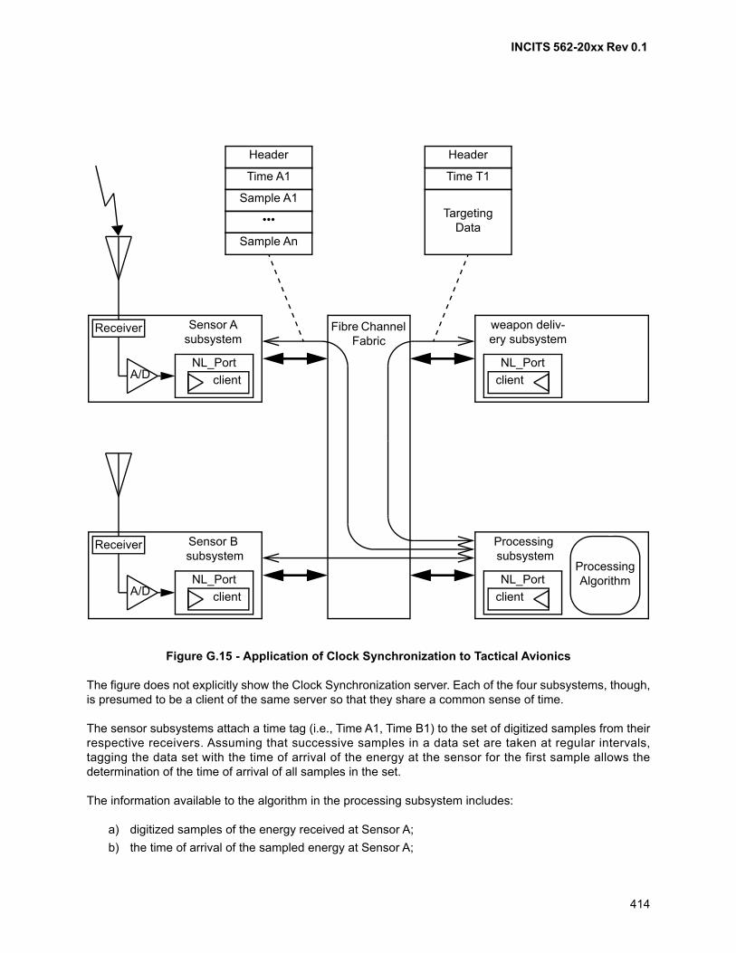
INCITS 562-20xx Rev 0.1
414
The figure does not explicitly show the Clock Synchronization server. Each of the four subsystems, though,is presumed to be a client of the same server so that they share a common sense of time.
The sensor subsystems attach a time tag (i.e., Time A1, Time B1) to the set of digitized samples from theirrespective receivers. Assuming that successive samples in a data set are taken at regular intervals,tagging the data set with the time of arrival of the energy at the sensor for the first sample allows thedetermination of the time of arrival of all samples in the set.
The information available to the algorithm in the processing subsystem includes:
a) digitized samples of the energy received at Sensor A;
b) the time of arrival of the sampled energy at Sensor A;
Figure G.15 - Application of Clock Synchronization to Tactical Avionics
Fibre Channel Fabric
client
NL_Port
Sensor Asubsystem
client
NL_Port
Processing subsystem
Receiver
A/D client
NL_Port
weapon deliv-ery subsystem
client
NL_Port
Sensor B subsystem
Receiver
A/D
ProcessingAlgorithm
Header
TargetingData
Time A1
Header
Time T1
Sample A1
•••
Sample An
INCITS 562-20xx Rev 0.1
415
c) Characteristics of Sensor A, including the orientation of the receiving aperture;
d) Digitized samples of the energy received at Sensor B;
e) The time of arrival of the sampled energy at Sensor B;
f) Characteristics of Sensor B, including the orientation of the receiving aperture; and
g) The current time.
Note that once the time tag has been attached to the samples by the sensor subsystems, the processingsubsystem has no need to further tag them (e.g., it is not necessary for it to note the time at which theframes containing the samples arrived at its FL_Port). What is important is the time at which the energyfrom potential targets arrived at the sensors. The current time may be important so that the processingsubsystem does not present stale data to the pilot. It is also important so that any computed targetinginformation be prepared for a time that is still in the future (i.e., It would do little good to tell the weapondelivery subsystem what it should have done at some time in the past). The sense of shared time betweenthe processing subsystem and the weapon delivery subsystem ensures that the weapon is triggered at thetime most appropriate for precise delivery of the weapon.
In this example, the critical associations of time and data occur in the sensor subsystems and in theweapon delivery subsystem. If software is involved in reading the time counter and attaching it to a dataset, the accuracy of the time tag may be worse by at least one, and probably two orders of magnitude ascompared to a hardware-based time tagging. So for maximum precision, the sensor subsystems woulduse hardware to capture a time value from the counter at the precise time that the sample comes from theanalog-to-digital converter (i.e., even greater inaccuracy would result if the samples were to travel throughthe Fabric and be time-tagged when they arrive at the processing subsystem).
Similarly, in the weapon delivery subsystem, the actual triggering of the weapon would be accomplished byhardware directly linked to the synchronized time counter.
In contrast to these considerations, the software in the processing subsystem has a more relaxed need forknowledge of time. Its primary need is to ensure that the information it presents to the pilot represents thecurrent situation; and that the targeting data that it computes for the weapon delivery subsystem is forsome time in the future. But the time that is used in the algorithm itself as part of the interpretation of thesample data is the time attached to that data by the sensor subsystems. So the processing subsystemprobably has no need for a direct hardware-based tagging of information.
As a final comment, if the adjustment for oscillator frequencies (see G.2.4.3) is desired, but the sensornodes have no embedded processor to apply the adjustment factors, the simple Time A1 value indicated infigure G.15 could be replaced by the following tuple:
a) counter;
b) ELS_value n;
c) ELS_value n-1; and
d) ELS_arrived n-1.
Of course, the hardware in the sensor that attaches this tuple to the data set should be able to do anatomic reading of all components of the tuple so that values in the tuple are coherent.
Algorithms in the processing subsystem could then apply the adjustment algorithms separately for eachsensor before using the time tag in its tracking and targeting algorithms.
INCITS 562-20xx Rev 0.1
416
Annex H (informative)
Speed negotiation details
H.1 Scope
This annex contains supplementary information on the goals, assumptions, and methodology for thedesign of the speed negotiation algorithm specified in clause 8 of this standard.
H.2 Basic assumptions
The speed negotiation method is based on the following set of assumptions:
a) the objective is to find the highest common speed that actually operates for all elements in theFibre Channel link involved in the speed negotiation.
Functionality is demanded from the entire link at the speed selected including all cables,connectors, hubs, transceivers, Serdes, and conversion devices. The design capabilities of thecomponents are not sufficient criteria for acceptance – actual hardware is required to perform;
b) error free Transmission Word Synchronization for 1 000 Transmission Word times is an adequatequality measure for speed negotiation purposes. This is not the same as verifying operation at theFibre Channel bit error rate;
c) link quality issues detected after the speed has been determined are addressed by other means;
d) once a speed has been negotiated, it is permissible that the speed not be changed after conditionsare improved such that operation at a higher speed would now be possible. Forcing are-negotiation is done with higher level protocols or out-of-band;
e) speed negotiation concludes promptly unless it is physically impossible for any common speed toexist;
f) only point-to-point topology is supported.
Loop configurations that negotiate speeds are assumed to present a single port to the othernegotiating port for speed negotiation purposes;
g) ports capable of speed negotiation are not required to support a common 1Gbits/second speed;
h) the transmitter and receiver of a port are assumed to be capable of working at different speeds atthe same time during speed negotiation;
i) a port is assumed to negotiate among up to a maximum of any four speeds;
j) the speed negotiation method is independent of and compatible with the link protocol (e.g.,operating, or not operating in Arbitrated Loop topology);
k) the same speed negotiation method supports both copper and optical ports;
l) the algorithm is realizable in a host driver or in port firmware;
m) the algorithm assumes loop infrastructure (e.g., hub) that has a port attachment scheme thatsupports sensing of the operating speed of the infrastructure by the attaching port receiver. Thisport attachment scheme prevents the attaching port transmitter from connecting into the existinginfrastructure unless the proper speed is established;
n) as an option to negotiating each hub port per the algorithm, multiple speed hubs may be set to asingle speed during speed negotiation by some out-of-band means;
o) connection of Speed Negotiating ports to an operating set of devices does not disrupt theoperation of those devices unless the ports being connected are transmitting at their speed;
p) once a particular speed has been established speed negotiation is not attempted again unless aLINK FAILURE is detected or by means outside the scope of this standard;
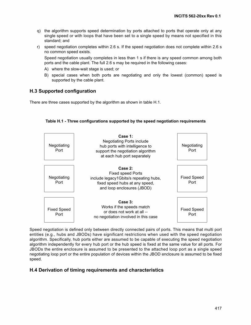
INCITS 562-20xx Rev 0.1
417
q) the algorithm supports speed determination by ports attached to ports that operate only at anysingle speed or with loops that have been set to a single speed by means not specified in thisstandard; and
r) speed negotiation completes within 2.6 s. If the speed negotiation does not complete within 2.6 sno common speed exists.
Speed negotiation usually completes in less than 1 s if there is any speed common among bothports and the cable plant. The full 2.6 s may be required in the following cases:
A) where the slow-wait stage is used; or
B) special cases when both ports are negotiating and only the lowest (common) speed issupported by the cable plant.
H.3 Supported configuration
There are three cases supported by the algorithm as shown in table H.1.
Speed negotiation is defined only between directly connected pairs of ports. This means that multi portentities (e.g., hubs and JBODs) have significant restrictions when used with the speed negotiationalgorithm. Specifically, hub ports either are assumed to be capable of executing the speed negotiationalgorithm independently for every hub port or the hub speed is fixed at the same value for all ports. ForJBODs the entire enclosure is assumed to be presented to the attached loop port as a single speednegotiating loop port or the entire population of devices within the JBOD enclosure is assumed to be fixedspeed.
H.4 Derivation of timing requirements and characteristics
Table H.1 - Three configurations supported by the speed negotiation requirements
Negotiating Port
Case 1:Negotiating Ports include
hub ports with intelligence tosupport the negotiation algorithm
at each hub port separately
Negotiating Port
Negotiating Port
Case 2:Fixed speed Ports
include legacy1Gbits/s repeating hubs,fixed speed hubs at any speed,
and loop enclosures (JBOD)
Fixed SpeedPort
Fixed SpeedPort
Case 3:Works if the speeds matchor does not work at all --
no negotiation involved in this case
Fixed SpeedPort
INCITS 562-20xx Rev 0.1
418
H.4.1 Introduction and diagram conventions
In this subclause the derivation of the timing requirements is shown. The derivations used in this subclausemay not be mathematically rigorous for some parameters. They do, however, represent the bestengineering judgment available and have been borne out by extensive simulations.
The examples in H.4 attempt to describe extreme cases for the timing parameters and as such involvemarginal conditions and timings.
The timing diagrams in H.4 use the notational conventions listed here:
a) each number represents a speed (SP#). x represents a speed other than the incoming speed(states 26, 27, etc.);
b) letters represent major stages or modes of the algorithm. Different type case is used for thedifferent stages to enable easier graphical visualization;
c) some timing examples show approximate timing and may not exactly match the numerical values;
d) w indicates Wait_for_signal stage; s indicates Slow_wait stage; M indicates Negotiate_masterstage; F indicates Negotiate_follow stage; n indicates Normal operation;
e) Bold/underline indicates a successful result from a Pass sync_test (>1 000 error freeTransmission Words, etc.);
f) Underline without bold indicates just missing passing a Pass sync_test for any reason; and
g) Italics indicates legacy hub disruption between cable connection and completion of algorithm.
Time values a) through e) are used in the graphical and analytical explanations. The derivation of thesevalues follows:
a) 30 ms = t_rxcycl (max) (see table 24);
b) 184 ms = t_txcycl + t_rcycl (max). This is maximum duration of a transmit speed inWait_for_signal;
c) 156 ms = t_txcycl + t_rxcycl (min). This is the minimum duration of a transmit speed inNegotiate_master;
d) 214 ms = t_txcycl + 2 • t_rxcycl (max). This is the maximum duration of a transmit speed inNegotiate_master; and
e) 247 ms = t_stbl + t_rcycl (max). This is the maximum length of time a port transmits at a singlespeed in Negotiate_follow while receiving a stable input signal.
These are examples. Other configurations and/or sequencing may lead to the same results.
H.4.2 Receiver cycle time, t_rxcycl
The minimum for this timing value is 2 ms that allows receiver stabilization time plus margin. The maximumis 30 ms that allows for responsiveness of the current generation of firmware implementations.
H.4.3 Master transmitter cycle time, t_txcycl
= 5 • (t_rxcycl (max) + n • (100 s)) + (Transmitter Stabilization Time) + margin
= 5 • (30.2 ms - .2 • (Transmitter Stabilization Time) + 5 • (100 s)) + (Transmitter Stabilization Time) +.5 ms
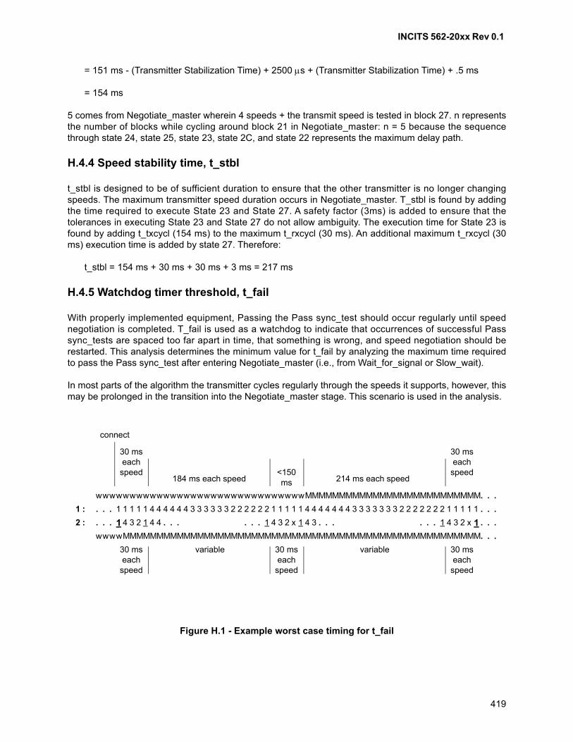
INCITS 562-20xx Rev 0.1
419
= 151 ms - (Transmitter Stabilization Time) + 2500 s + (Transmitter Stabilization Time) + .5 ms
= 154 ms
5 comes from Negotiate_master wherein 4 speeds + the transmit speed is tested in block 27. n representsthe number of blocks while cycling around block 21 in Negotiate_master: n = 5 because the sequencethrough state 24, state 25, state 23, state 2C, and state 22 represents the maximum delay path.
H.4.4 Speed stability time, t_stbl
t_stbl is designed to be of sufficient duration to ensure that the other transmitter is no longer changingspeeds. The maximum transmitter speed duration occurs in Negotiate_master. T_stbl is found by addingthe time required to execute State 23 and State 27. A safety factor (3ms) is added to ensure that thetolerances in executing State 23 and State 27 do not allow ambiguity. The execution time for State 23 isfound by adding t_txcycl (154 ms) to the maximum t_rxcycl (30 ms). An additional maximum t_rxcycl (30ms) execution time is added by state 27. Therefore:
t_stbl = 154 ms + 30 ms + 30 ms + 3 ms = 217 ms
H.4.5 Watchdog timer threshold, t_fail
With properly implemented equipment, Passing the Pass sync_test should occur regularly until speednegotiation is completed. T_fail is used as a watchdog to indicate that occurrences of successful Passsync_tests are spaced too far apart in time, that something is wrong, and speed negotiation should berestarted. This analysis determines the minimum value for t_fail by analyzing the maximum time requiredto pass the Pass sync_test after entering Negotiate_master (i.e., from Wait_for_signal or Slow_wait).
In most parts of the algorithm the transmitter cycles regularly through the speeds it supports, however, thismay be prolonged in the transition into the Negotiate_master stage. This scenario is used in the analysis.
Figure H.1 - Example worst case timing for t_fail
MMMMMMMMMMMMMMMMMMMMM MMMMMw wwwwwwwwwwwwwwwwwwwwwwwww . . .
wwww MMMMMMMMMMMMMMMMMMMMMMMMMMMMMMMMMMMMMMMMMMMMMMMMMMM MM. . .
wwwww
. . . 41 1 1 1 1 4 4 4 4 4 3 3 3 3 3 3 2 2 2 2 2 2 1 1 1 1 1 4 4 4 4 4 4 4 3 3 3 3 3 3 3 2 2 2 2 2 2 2 1 1 1 1 1 . . .1 :
2 : . . . 1 234 1 44 . . . . . . . . .1 4 3 2 x 1 4 3 . . . 1 4 3 2 x 1 . . .
30 ms each
speed
30 ms each
speed
30 ms each
speed
30 ms each
speed
30 ms each
speed
184 ms each speed 214 ms each speed
variablevariable
<150 ms
connect
INCITS 562-20xx Rev 0.1
420
These conventions and assumptions apply to figure H.1, figure H.2, and figure H.3:
a) the 1st row (1:) is the incoming speed received from the other port, Port 1;
b) the 2nd row (2:) is the Rx speed of the receiving port, Port 2;
c) the cable plant into Port 2 only supports SP1. It was connected just ahead of the beginning of thenumbered sequence;
d) Port 2 detects Port 1 just after the beginning of the sequence; and
e) Port 1 detects Port 2 in the middle of the sequence (i.e., a cable plug event) with Rx_LOS falseindicated by the change from Wait_for_signal to Negotiate_master.
Figure H.1 shows that the first occurrence of the next Pass sync_test may occur up to 1 614 ms after entryinto Negotiate_master, the event that starts tneg. Adding comfortable margin brings t_fail to 1 620 ms.Although detection of Port 1 is shown with Pass sync_test, for purposes of t_fail there is no difference if itis accomplished by Rx_LOS false.
H.4.6 Watchdog Timer test delay, t_wddly
The delay that is designed to be included in each cycle of the watchdog timer test loop is not critical. Thereis no requirement for a nonzero lower limit on the delay between watchdog timer tests. The choice of itsupper limit balances two objectives:
a) the value of t_ncycl may be reduced by keeping the maximum t_wddly small; and
b) it should be large enough to allow an attractively simple implementation of the watchdog test thatembeds it in the main algorithm adjacent to each Pass sync_test.
This implementation leads to the interval between successive watchdog tests being the duration of a Passsync_test (t_rxcycl) plus the delay associated with execution of the maximum code that separates twosuccessive Pass sync_test instances (a few hundred s). To allow this, t_wddly is permitted to range up toa small margin above the maximum t_rxcycl.
0 t_wddly t_rxcycl (max) + margin = 32 ms
H.4.7 Speed recording time, t_ncycl
Due to some system configurations with ports that are capable of three or four speeds but share only oneor two common speeds (e.g., due to a limiting cable plant), it is possible for speed negotiation to becomeprolonged. If this behavior is observed, negotiation may be hastened by reducing the list of transmittedspeeds to match the list of detected receiver speeds. T_ncycl is used to determine that sufficient time haspassed to have seen all possible speeds and to reduce the transmit speed list. This analysis determinesthe minimum value for t_ncycl by analyzing the maximum time required to record all speeds after exitingWait_for_signal or Slow_wait.

INCITS 562-20xx Rev 0.1
421
Conventions and assumptions a) - e) in H.4.5 apply to figure H.2.
Port 2 detects a signal, not necessarily at the receiver speed, with Rx_LOS instead of using the Passsync_test at the beginning of the sequence (i.e., Rx_LOS false causes entry into Negotiate_master, theevent that starts tneg, but no speed is recorded).
The requirement for t_ncycl is the same as for t_fail: 1 614 ms. However, certain fault cases may result inno speeds being detected during t_ncycl. To avoid the need for special logic for these cases, t_ncycl isextended to exceed the maximum possible watchdog timer expiration interval. This assures the watchdogtimer triggers restart before the speed-reduction logic terminates without a speed.
t_ncycl = maximum [(t_ncycl(above), t_fail + t_wddly)] = 1 652 ms
Any/all other speeds would be detected within this time window.
H.4.8 Speed recording time initial value, t_ncinit
In the t_ncinit analysis no speed was recorded upon entry into Negotiate_master because Rx_LOS wasused. In contrast, if the Pass sync_test is used to enter Negotiate_master, then one speed has alreadybeen recorded, and the issue is to determine the minimum time required to observe the remaining speeds.
Figure H.2 - Example worst case timing for t_ncycl using Rx_LOS
MMMMMMMMMMMMMMMMMMMMM MMMMMw wwwwwwwwwwwwwwwwwwwwwwwww . . .
wwww MMMMMMMMMMMMMMMMMMMMMMMMMMMMMMMMMMMMMMMMMMMMMMMMMMM MM. . .
wwwww
. . . 41 1 1 1 1 4 4 4 4 4 3 3 3 3 3 3 2 2 2 2 2 2 1 1 1 1 1 4 4 4 4 4 4 4 3 3 3 3 3 3 3 2 2 2 2 2 2 2 1 1 1 1 1 . . .1 :
2 : . . . 1 234 1 44 . . . . . . . . .1 4 3 2 x 1 4 3 . . . 1 4 3 2 x 1 . . .
30 ms each
speed
30 ms each
speed
30 ms each
speed
30 ms each
speed
30 ms each
speed
184 ms each speed 214 ms each speed
variablevariable
<150 ms
connect
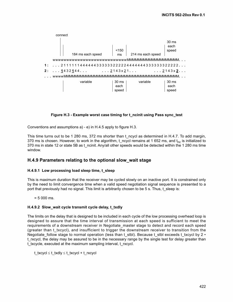
INCITS 562-20xx Rev 0.1
422
Conventions and assumptions a) - e) in H.4.5 apply to figure H.3.
This time turns out to be 1 280 ms, 372 ms shorter than t_ncycl as determined in H.4.7. To add margin,370 ms is chosen. However, to work in the algorithm, t_ncycl remains at 1 652 ms, and tnc is initialized to370 ms in state 12 or state 5B as t_ncinit. Any/all other speeds would be detected within the 1 280 ms timewindow.
H.4.9 Parameters relating to the optional slow_wait stage
H.4.9.1 Low processing load sleep time, t_sleep
This is maximum duration that the receiver may be cycled slowly on an inactive port. It is constrained onlyby the need to limit convergence time when a valid speed negotiation signal sequence is presented to aport that previously had no signal. This limit is arbitrarily chosen to be 5 s. Thus, t_sleep is:
= 5 000 ms.
H.4.9.2 Slow_wait cycle transmit cycle delay, t_txdly
The limits on the delay that is designed to be included in each cycle of the low processing overhead loop isdesigned to assure that the time interval of transmission at each speed is sufficient to meet therequirements of a downstream receiver in Negotiate_master stage to detect and record each speed(greater than t_txcycl), and insufficient to trigger the downstream receiver to transition from theNegotiate_follow stage to normal operation (less than t_stbl). Because t_stbl exceeds t_txcycl by 2 •t_rxcycl, the delay may be assured to be in the necessary range by the single test for delay greater thant_txcycle, executed at the maximum sampling interval, t_rxcycl.
t_txcycl t_txdly t_txcycl + t_rxcycl
Figure H.3 - Example worst case timing for t_ncinit using Pass sync_test
wwwwwwwwwwwwwwwwwwwwwwwwwww MMMMMMMMMMMMMMMM M
. . . . . .
. . .. . .. . . . . .2 :
. . .
. . .. . .
2 1 1 1 1 1 1 4 4 4 4 4 4 3 3 3 3 3 3 2 2 2 2 2 4 4 4 4 4 4 4 3 3 3 3 3 3 3 2 2 2 2 2
MM
1 :
1 4 3 2 1 4 4. . . . . . 2 1 4 3 x 2 1 2 1 4 3 x 2
wwwwMMMMMMMMMMMMMMMMMMMMMMMMMMMMMMMMMMMMMMMMMM
30 ms each speed
30 ms each speed
30 ms each
speed
184 ms each speed 214 ms each speed
variablevariable
<150 ms
connect
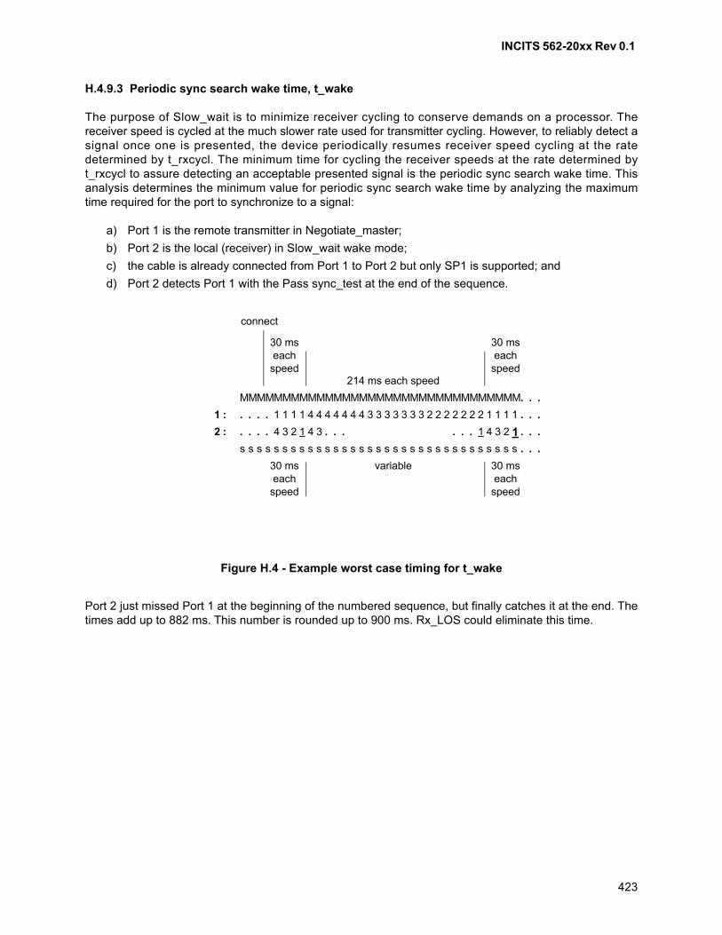
INCITS 562-20xx Rev 0.1
423
H.4.9.3 Periodic sync search wake time, t_wake
The purpose of Slow_wait is to minimize receiver cycling to conserve demands on a processor. Thereceiver speed is cycled at the much slower rate used for transmitter cycling. However, to reliably detect asignal once one is presented, the device periodically resumes receiver speed cycling at the ratedetermined by t_rxcycl. The minimum time for cycling the receiver speeds at the rate determined byt_rxcycl to assure detecting an acceptable presented signal is the periodic sync search wake time. Thisanalysis determines the minimum value for periodic sync search wake time by analyzing the maximumtime required for the port to synchronize to a signal:
a) Port 1 is the remote transmitter in Negotiate_master;
b) Port 2 is the local (receiver) in Slow_wait wake mode;
c) the cable is already connected from Port 1 to Port 2 but only SP1 is supported; and
d) Port 2 detects Port 1 with the Pass sync_test at the end of the sequence.
Port 2 just missed Port 1 at the beginning of the numbered sequence, but finally catches it at the end. Thetimes add up to 882 ms. This number is rounded up to 900 ms. Rx_LOS could eliminate this time.
Figure H.4 - Example worst case timing for t_wake
1
MMMMMMMMMMMMMMMMMMMMMMMMMMMMMMMMM
. . .
. . .
s s s s s s s s s s s s s s s s s s s s s s s s s s s s s s s s s . . .
. . .
. . .1 : .
2 :
1 1 1 4 4 4 4 4 4 4 3 3 3 3 3 3 3 2 2 2 2 2 2 2 1 1 1 1
. . . . . . .. . .4 3 2 1 4 3 1 4 3 2 1
connect
30 ms each
speed
30 ms each
speed
30 ms each
speed
30 ms each
speed
214 ms each speed
variable
INCITS 562-20xx Rev 0.1
424
H.4.10 Duration of disruption to single loops caused by connecting speed negotiating ports to hubs
H.4.10.1 Introduction
While a port that is in Arbitrated Loop topology is executing speed negotiation, the port is required totransmit some flavor of LIP. If this transmission is allowed to enter an active loop, it disrupts the operationof the loop. The scope and duration of this disruption may be limited by attaching Speed Negotiating portsto a loop only through hubs with this behavior:
a) if the hub participates in speed negotiation, it prevents disruption until the attached port hascompleted speed negotiation;
b) if the hub does not participate in negotiation, it is set to a fixed speed by design or by configurationaction not specified herein; or
c) if the hub is operating at a fixed speed, it bypasses an attached port that is not presenting a signalat the operating speed of the hub.
A port executing speed negotiation does not disrupt a loop if it is attached to the loop via a negotiating hubor if the port does not support the speed at which a fixed speed hub is operating. However, during speednegotiation with a fixed-speed hub, if a port transmits at the speed of the hub, the hub inserts the port andloop disruption occurs. The following discussion derives the limits on the duration of these disruptions.
In the following discussion, only worst-case timings are presented. The disruption is considered to be thetime(s) during which the port prevents normal operation of the loop before the port begins loopinitialization.
NOTE 65 - Non-simultaneous duplex cable connections: If the cable plant from the attaching portconnects the port’s transmitter into the hub’s receiver, periodic hub disruption occurs when/while theattaching port is transmitting at the hub's speed. This periodic disruption continues until shortly after thepath from the hub’s transmitter to the port’s receiver is completed with sufficient time to complete speednegotiation before allowing port initialization. Hub disruption is limited to the normal port insertiondisruption if the path from the hub’s transmitter to the port’s receiver is completed with sufficient time tocomplete speed negotiation before allowing the port’s transmitter to be connected to the hub’s receiver.
In general, if the path carrying the signal from the hub to the port is completed before the other path fromthe hub to the port in the duplex connection is completed, the port moves through speed negotiation withless, or without, initial disruption caused by the Slow_wait or Wait_for_signal stages.
Normal duplex connections with presently defined connectors do not control the sequencing of theconnections.
The derivations here assume a realistic worst case of non-simultaneous cable direction connection wherethe signal from the port to the hub is presented t_rxcycl prior to the presentation of signal from the hub tothe port. This allows up to 30 ms of disruption by the port before speed negotiation allows it to detect andpossibly respond to the signal from the hub.
Each stage of speed negotiation may produce one or more disruptions. In some circumstances, thedisruptions produced in successive stages may be contiguous, resulting in a longer single disruption. Inother circumstances, transitions from one stage to the next may change transmitter speeds, causing thedisruption to be discontinuous, but prolonging the overall interval during which disruptions occur.Subclauses H.4.10.2 through H.4.10.12 derive maximum single disruptions and groups of disruptions foreach stage of speed negotiation and then uses these to derive the overall maximum disruption for thespeed negotiation process.
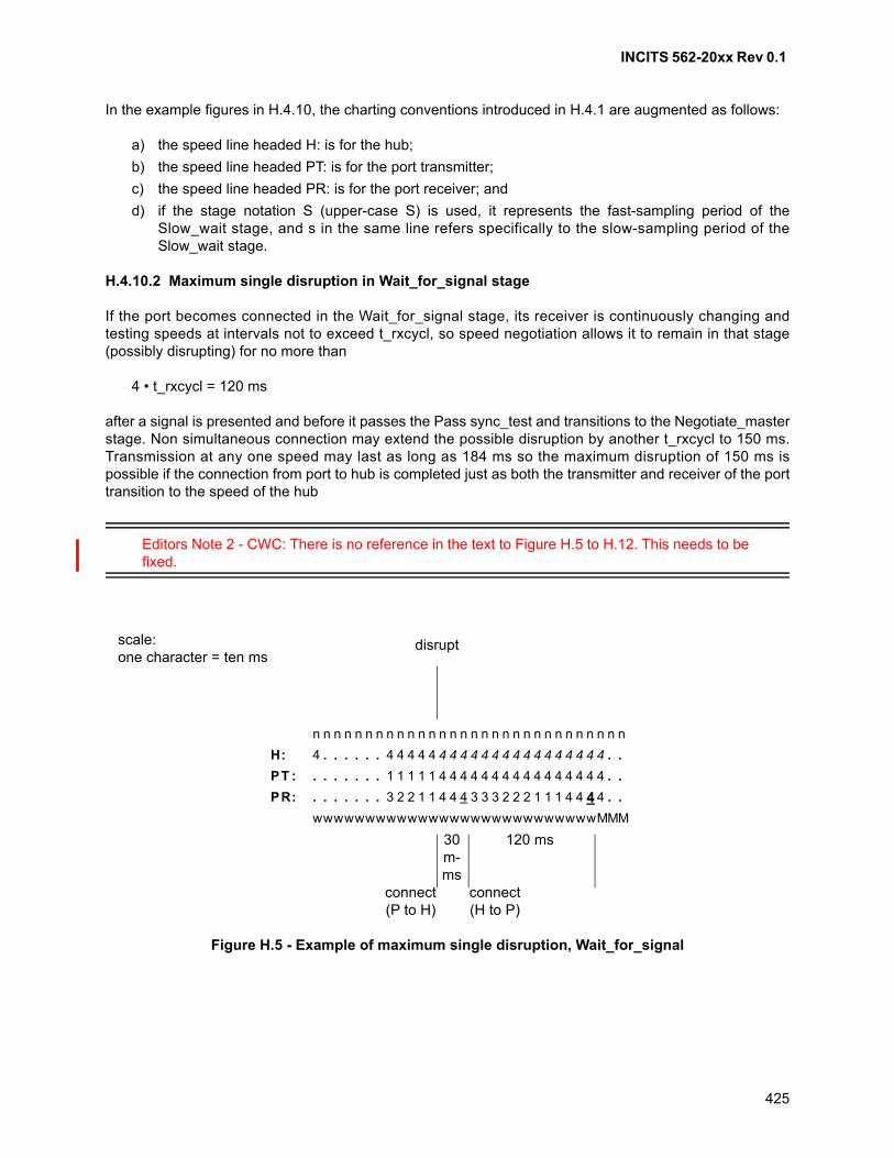
INCITS 562-20xx Rev 0.1
425
In the example figures in H.4.10, the charting conventions introduced in H.4.1 are augmented as follows:
a) the speed line headed H: is for the hub;
b) the speed line headed PT: is for the port transmitter;
c) the speed line headed PR: is for the port receiver; and
d) if the stage notation S (upper-case S) is used, it represents the fast-sampling period of theSlow_wait stage, and s in the same line refers specifically to the slow-sampling period of theSlow_wait stage.
H.4.10.2 Maximum single disruption in Wait_for_signal stage
If the port becomes connected in the Wait_for_signal stage, its receiver is continuously changing andtesting speeds at intervals not to exceed t_rxcycl, so speed negotiation allows it to remain in that stage(possibly disrupting) for no more than
4 • t_rxcycl = 120 ms
after a signal is presented and before it passes the Pass sync_test and transitions to the Negotiate_masterstage. Non simultaneous connection may extend the possible disruption by another t_rxcycl to 150 ms.Transmission at any one speed may last as long as 184 ms so the maximum disruption of 150 ms ispossible if the connection from port to hub is completed just as both the transmitter and receiver of the porttransition to the speed of the hub
Editors Note 2 - CWC: There is no reference in the text to Figure H.5 to H.12. This needs to be fixed.
Figure H.5 - Example of maximum single disruption, Wait_for_signal
n n n n n n n n n n n n n n n n n n n n n n n n n n n n n n
. .
. .
. .. .
PR:
PT :
H:
. . . .
. .. . . . .
4 4 4 4 4 4 4 44 4 4 4 4 4 44 4 4 4 4 4 4
. .. . . . .
1 1 1 1 1 4 4 4 44 4 4 44 4 4 44 4 4 4
3 2 2 1 1 4 4 4 3 3 3 2 2 2 1 1 1 4 4 4 4
scale:one character = ten ms
wwwwwwwwwwwwwwwwwwwwwwwwwwwMMM
disrupt
connect(P to H)
connect(H to P)
30m-ms
120 ms
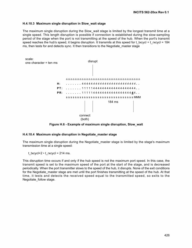
INCITS 562-20xx Rev 0.1
426
H.4.10.3 Maximum single disruption in Slow_wait stage
The maximum single disruption during the Slow_wait stage is limited by the longest transmit time at asingle speed. This length disruption is possible if connection is established during the slow-samplingperiod of the stage when the port is not transmitting at the speed of the hub. When the port's transmitspeed reaches the hub's speed, it begins disruption. It transmits at this speed for t_txcycl + t_rxcycl = 184ms, then tests for and detects sync. It then transitions to the Negotiate_master stage
H.4.10.4 Maximum single disruption in Negotiate_master stage
The maximum single disruption during the Negotiate_master stage is limited by the stage's maximumtransmission time at a single speed:
t_txcycl+2 • t_rxcycl = 214 ms.
This disruption time occurs if and only if the hub speed is not the maximum port speed. In this case, thetransmit speed is set to the maximum speed of the port at the start of the stage, and is decreasedperiodically. When the port transmitter slows to the speed of the hub, it disrupts. None of the exit conditionsfor the Negotiate_master stage are met until the port finishes transmitting at the speed of the hub. At thattime, it tests and detects the received speed equal to the transmitted speed, so exits to theNegotiate_follow stage.
Figure H.6 - Example of maximum single disruption, Slow_wait
nn n n n n n n n n nn n n n n n n n n n nn n n n n n n n n n n
H . . . . . . . . .: 4 4 4 4 4 4 4 4 4 4 4 4 4 44 4 4 4 4 4 4 4 4 4
PT : . . . . . . . . .1 1 1 1 1 4 4 4 4 4 4 4 4 44 4 4 4 4 4 4 4 4 4
PR: . . . . . . . . .1 1 1 1 1 4 4 4 4 4 4 4 4 44 4 4 4 4 4 4 4 4 4
s s s s s s s s s s s s s s s s s s s ss s s s s s s s s s MMM
scale:one character = ten ms disrupt
connect(both)
184 ms
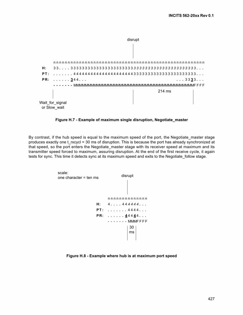
INCITS 562-20xx Rev 0.1
427
By contrast, if the hub speed is equal to the maximum speed of the port, the Negotiate_master stageproduces exactly one t_rxcycl = 30 ms of disruption. This is because the port has already synchronized atthat speed, so the port enters the Negotiate_master stage with its receiver speed at maximum and itstransmitter speed forced to maximum, assuring disruption. At the end of the first receive cycle, it againtests for sync. This time it detects sync at its maximum speed and exits to the Negotiate_follow stage.
Figure H.7 - Example of maximum single disruption, Negotiate_master
n n n n n n n n n nn n n n n n n n n nn n n n n n n n n nn n n n n n n n n n n n n n n n n n n n n n n
H: 3 3 3 3. . . . ..3 3 3 3 3 3 3 3 3 3 3 3 3 3 3 3 3 3 3 3 3 3 3 3 3 3 3 3 3 3 3 3 .3 3 3 3 3 3 3 3 3 3
PT . . .. . . . . . .: 4 4 4 4 4 4 4 3 3 3 3 3 3 3 3 3 3 3 3 3 3 3 3 3 3 3 3 3 34 4 4 4 4 4 4 4 4 4 4 4 4 4
PR: . . . . . . 3 3 3 3 3. . . . . .. . .4 4
- - - - - - - MMMMMMMMMMMMMMMMMMMMMMMMMMMMMMMMMMMMMMMMMMF F F F
disrupt
214 ms
Wait_for_signalor Slow_wait
Figure H.8 - Example where hub is at maximum port speed
n n n n n n n n n n n n n n
H: 4 4 4 4 4 4 4. . . . . . .
PT : . . . . . . . . . .4 4 4 4
PR: . . . . . . 4 . . .4 4 4 4
- - - - - - - MMMF F F F
disruptscale:one character = ten ms
30ms
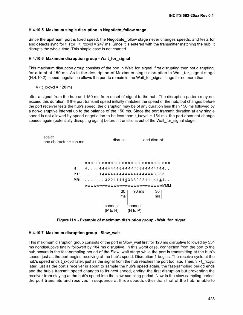
INCITS 562-20xx Rev 0.1
428
H.4.10.5 Maximum single disruption in Negotiate_follow stage
Since the upstream port is fixed speed, the Negotiate_follow stage never changes speeds, and tests forand detects sync for t_stbl + t_rxcycl = 247 ms. Since it is entered with the transmitter matching the hub, itdisrupts the whole time. This simple case is not charted.
H.4.10.6 Maximum disruption group - Wait_for_signal
This maximum disruption group consists of the port in Wait_for_signal, first disrupting then not disrupting,for a total of 150 ms. As in the description of Maximum single disruption in Wait_for_signal stage(H.4.10.2), speed negotiation allows the port to remain in the Wait_for_signal stage for no more than:
4 • t_rxcycl = 120 ms
after a signal from the hub and 150 ms from onset of signal to the hub. The disruption pattern may notexceed this duration. If the port transmit speed initially matches the speed of the hub, but changes beforethe port receiver tests the hub's speed, the disruption may be of any duration less than 150 ms followed bya non-disruptive interval up to the balance of the 150 ms. Since the port transmit duration at any singlespeed is not allowed by speed negotiation to be less than t_txcycl = 154 ms, the port does not changespeeds again (potentially disrupting again) before it transitions out of the Wait_for_signal stage.
H.4.10.7 Maximum disruption group - Slow_wait
This maximum disruption group consists of the port in Slow_wait first for 120 ms disruptive followed by 554ms nondisruptive finally followed by 184 ms disruptive. In this worst case, connection from the port to thehub occurs in the fast-sampling period of the Slow_wait stage while the port is transmitting at the hub'sspeed, just as the port begins receiving at the hub's speed. Disruption 1 begins. The receive cycle at thehub's speed ends t_rxcycl later, just as the signal from the hub reaches the port too late. Then, 3 • t_rxcycllater, just as the port’s receiver is about to sample the hub's speed again, the fast-sampling period endsand the hub's transmit speed changes to its next speed, ending the first disruption but preventing thereceiver from staying at the hub's speed into the slow-sampling period. Now in the slow-sampling period,the port transmits and receives in sequence at three speeds other than that of the hub, unable to
Figure H.9 - Example of maximum disruption group - Wait_for_signal
n n n n n n n n n n n n n n n n n n n n n n n n n n n n n n
H: . . . . . .4 4 4 4 4 4 4 4 4 4 4 4 44 4 4 4 4 4 4 4 4 4 4
PT : . . . . . . .1 4 4 4 4 4 4 4 4 4 4 4 4 4 4 4 4 4 4 3 3 3 3
PR: . . . . . . .. . 3 2 2 1 1 4 4 4 3 3 3 2 2 2 1 1 1 4 4 4 4
wwwwwwwwwwwwwwwwwwwwwwwwwwwMMM
disrupt end disrupt
connect(P to H)
connect(H to P)
30ms
90 ms 30ms
scale:one character = ten ms
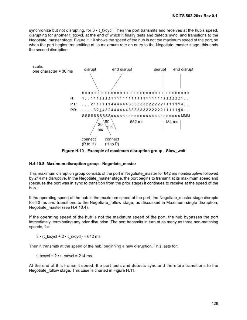
INCITS 562-20xx Rev 0.1
429
synchronize but not disrupting, for 3 • t_txcycl. Then the port transmits and receives at the hub's speed,disrupting for another t_txcycl, at the end of which it finally tests and detects sync, and transitions to theNegotiate_master stage. Figure H.10 shows the speed of the hub is not the maximum speed of the port, sowhen the port begins transmitting at its maximum rate on entry to the Negotiate_master stage, this endsthe second disruption.
H.4.10.8 Maximum disruption group - Negotiate_master
This maximum disruption group consists of the port in Negotiate_master for 642 ms nondisruptive followedby 214 ms disruptive. In the Negotiate_master stage, the port begins to transmit at its maximum speed and(because the port was in sync to transition from the prior stage) it continues to receive at the speed of thehub.
If the operating speed of the hub is the maximum speed of the port, the Negotiate_master stage disruptsfor 30 ms and transitions to the Negotiate_follow stage, as discussed in Maximum single disruption,Negotiate_master (see H.4.10.4).
If the operating speed of the hub is not the maximum speed of the port, the hub bypasses the portimmediately, terminating any prior disruption. The port transmits in turn at as many as three non-matchingspeeds, for:
3 • (t_txcycl + 2 • t_rxcycl) = 642 ms.
Then it transmits at the speed of the hub, beginning a new disruption. This lasts for:
t_txcycl + 2 • t_rxcycl = 214 ms.
At the end of this transmit speed, the port tests and detects sync and therefore transitions to theNegotiate_follow stage. This case is charted in Figure H.11.
Figure H.10 - Example of maximum disruption group - Slow_wait
n n n n n n n n nn n n n n n n n n n n n n n n n n n n n n n n n n n n n
1 1 1 1 1 1 1 1 11 . . 1 1 1 1 1 1 1 1 1 1 1 1 1 1 1 1 1 1 1 1 1 1 1 . .H:
1 4 4 4 4 4 4 3 3. . . 2 1 1 1 1 1 3 3 3 3 2 2 2 2 2 2 1 1 1 1 1 1 4 . .PT :
2 4 4 4 4 4 4 3 3. . . . 3 2 1 4 3 3 3 3 3 2 2 2 2 2 2 1 1 1 1 1 1 4 . .PR:
Ss s s s s s s sSSSSSSSSS s s s s s s s s s s s s s s s s MMM
disrupt end disruptdisrupt end disrupt
connect(P to H)
connect(H to P)
90 ms
552 ms30ms
184 ms
scale:one character = 30 ms
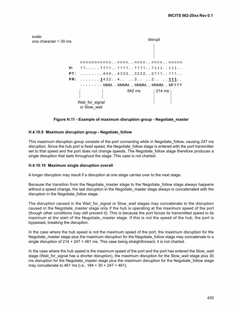
INCITS 562-20xx Rev 0.1
430
H.4.10.9 Maximum disruption group - Negotiate_follow
This maximum disruption group consists of the port connecting while in Negotiate_follow, causing 247 msdisruption. Since the hub port is fixed speed, the Negotiate_follow stage is entered with the port transmitterset to that speed and the port does not change speeds. The Negotiate_follow stage therefore produces asingle disruption that lasts throughout the stage. This case is not charted.
H.4.10.10 Maximum single disruption overall
A longer disruption may result if a disruption at one stage carries over to the next stage.
Because the transition from the Negotiate_master stage to the Negotiate_follow stage always happenswithout a speed change, the last disruption in the Negotiate_master stage always is concatenated with thedisruption in the Negotiate_follow stage.
The disruption caused in the Wait_for_signal or Slow_wait stages may concatenate to the disruptioncaused in the Negotiate_master stage only if the hub is operating at the maximum speed of the port(though other conditions may still prevent it). This is because the port forces its transmitted speed to itsmaximum at the start of the Negotiate_master stage. If this is not the speed of the hub, the port isbypassed, breaking the disruption.
In the case where the hub speed is not the maximum speed of the port, the maximum disruption for theNegotiate_master stage plus the maximum disruption for the Negotiate_follow stage may concatenate to asingle disruption of 214 + 247 = 461 ms. This case being straightforward, it is not charted.
In the case where the hub speed is the maximum speed of the port and the port has entered the Slow_waitstage (Wait_for_signal has a shorter disruption), the maximum disruption for the Slow_wait stage plus 30ms disruption for the Negotiate_master stage plus the maximum disruption for the Negotiate_follow stagemay concatenate to 461 ms (i.e., 184 + 30 + 247 = 461).
Figure H.11 - Example of maximum disruption group - Negotiate_master
n n . . n n n n .n n n n n n n n n . n n n n . . n n n n . . n n n n n
1 1 . . 1 1 1 1 .1 1 . . . . . 1 1 . 1 1 1 1 . . 1 1 1 1 . . 1 1 1 . .H:
4 4 . . 4 3 3 3 .. . . . . . . . 4 . 3 2 2 2 . . 2 1 1 1 . . 1 1 1 . .PT :
3 2 . . 4 . . .. . . . . . . 1 4 . 3 . . . . 2 . . . . 1 1 1 . .PR:
MM. . MMMM.- - - - - - - - M . MMMM. . MMMM. . MF F F F
disruptscale:one character = 30 ms
642 ms 214 ms
Wait_for_signalor Slow_wait
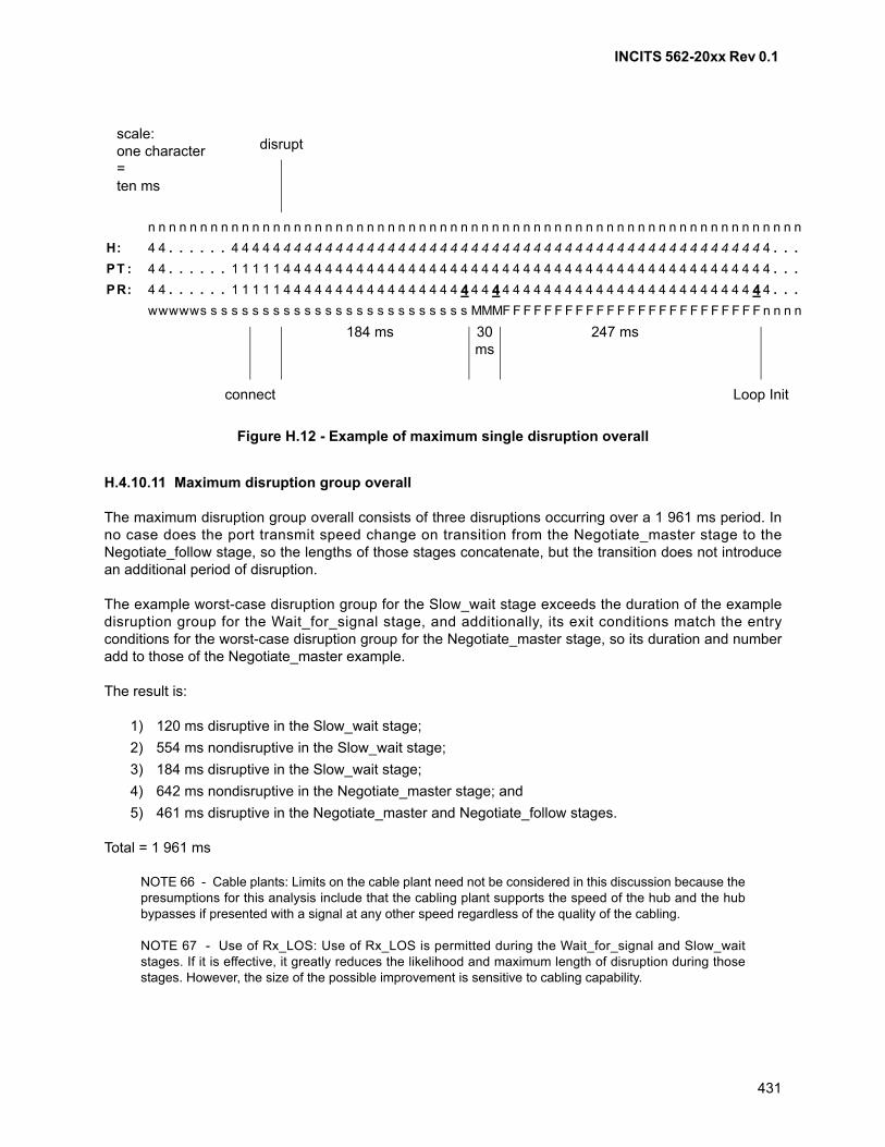
INCITS 562-20xx Rev 0.1
431
H.4.10.11 Maximum disruption group overall
The maximum disruption group overall consists of three disruptions occurring over a 1 961 ms period. Inno case does the port transmit speed change on transition from the Negotiate_master stage to theNegotiate_follow stage, so the lengths of those stages concatenate, but the transition does not introducean additional period of disruption.
The example worst-case disruption group for the Slow_wait stage exceeds the duration of the exampledisruption group for the Wait_for_signal stage, and additionally, its exit conditions match the entryconditions for the worst-case disruption group for the Negotiate_master stage, so its duration and numberadd to those of the Negotiate_master example.
The result is:
1) 120 ms disruptive in the Slow_wait stage;
2) 554 ms nondisruptive in the Slow_wait stage;
3) 184 ms disruptive in the Slow_wait stage;
4) 642 ms nondisruptive in the Negotiate_master stage; and
5) 461 ms disruptive in the Negotiate_master and Negotiate_follow stages.
Total = 1 961 ms
NOTE 66 - Cable plants: Limits on the cable plant need not be considered in this discussion because thepresumptions for this analysis include that the cabling plant supports the speed of the hub and the hubbypasses if presented with a signal at any other speed regardless of the quality of the cabling.
NOTE 67 - Use of Rx_LOS: Use of Rx_LOS is permitted during the Wait_for_signal and Slow_waitstages. If it is effective, it greatly reduces the likelihood and maximum length of disruption during thosestages. However, the size of the possible improvement is sensitive to cabling capability.
Figure H.12 - Example of maximum single disruption overall
n n n n n n n n n n n n n n n n n n n n n n n n n n n n n n n n n n n n n n n n n n n n n n n n n n n n n n n n n n n n n n n
. . . . . . . . .H: 4 4 4 4 4 4 4 44 4 4 4 4 4 4 4 4 44 4 4 4 4 4 4 4 44 4 4 4 4 4 4 4 44 4 4 4 4 4 4 4 44 4 4 4 4 4 4 4 4
. . . . . . . . .PT : 4 4 1 1 1 1 1 44 4 4 4 4 4 4 4 4 44 4 4 4 4 4 4 4 4 4 4 4 4 4 4 4 4 4 4 4 4 4 4 4 4 4 4 4 4 4 4 4 4 4 4 4
. . . . . . . . .PR: 4 4 1 1 1 1 1 44 4 4 4 4 4 4 4 4 44 4 4 4 4 4 4 4 4 4 4 4 4 4 4 4 4 4 4 4 4 4 4 4 4 4 4 4 4 4 4 4 4 4 4 4
wwwwws s s s s ss s s s s s s s s s s s s s s s s s s s MMMF F F F F F F F F F F F F F F F F F F F F F F F F n n n n
scale:one character =ten ms
disrupt
30ms
247 ms184 ms
connect Loop Init
INCITS 562-20xx Rev 0.1
432
H.4.10.12 Summary of loop disruption
Attaching a port capable of speed negotiation to an Arbitrated Loop hub may generate up to threedisruptions to existing loop operation. The properties of these disruptions are summarized here:
a) t_disrupt1: The maximum single disruption duration is 461 ms; and
b) t_disrupt2: The maximum duration of a series of disruptions is 1 961 ms.
Both single and concatenated series disruption times may be significantly reduced, and the greatestnumber of disruptions reduced to two, by disabling the Slow_wait stage or by using Rx_LOS, if it is reliable,to initially detect a signal.
H.4.11 Algorithm convergence time
This subclause describes the convergence time properties of the algorithm. Use of this result is beyond thescope of this annex.
The longest convergence time, including Wait_for_signal, is conservatively 2 571 ms (i.e., 11 times themaximum transmitter time (214ms) + t_stbl (217 ms)). The longest convergence time is with both portscapable of negotiating at all four speeds and where the infrastructure only supports the lowest speed.Based on this calculation a maximum convergence time of 2.6 s is used for the speed negotiationalgorithm.
Convergence time is the elapsed time between start and stop as defined here:
a) start = the last of (port A beginning speed negotiation, port B beginning speed negotiationconnection of port A to port B cable plant, connection of port B to port A cable plant); and
b) stop = the latter of (port A entering Normal_operation, port B entering Normal_operation).
If the optional slow_wait stage is implemented and enabled, Slow_wait replaces Wait_for_signal after anegotiation failure. Since Slow_wait is t_sleep of transmit cycling time alternating with logic equivalent tothe Wait_for_signal algorithm, the maximum length of Slow_wait is approximately the maximum length ofWait_for_signal plus t_sleep. The net is extending the maximum convergence time by t_sleep, givingabout 7.5 s if Slow_wait is enabled.
In the highly unlikely event that the Slow_wait port is actively testing for Transmission WordSynchronization just as its attached port is transitioning from a wait stage to Negotiate_master stage, it ispossible for the test to fail. This causes an additional delay of up to t_sleep + t_wake = 5 900 ms,extending the convergence time to about 13.5 s.
H.5 Ports using separate PMD components
This subclause describes the issues with using separate PMD components in a speed agile application.Figure H.13 shows the general relationship of the two ports and the physical architecture within one of theports.
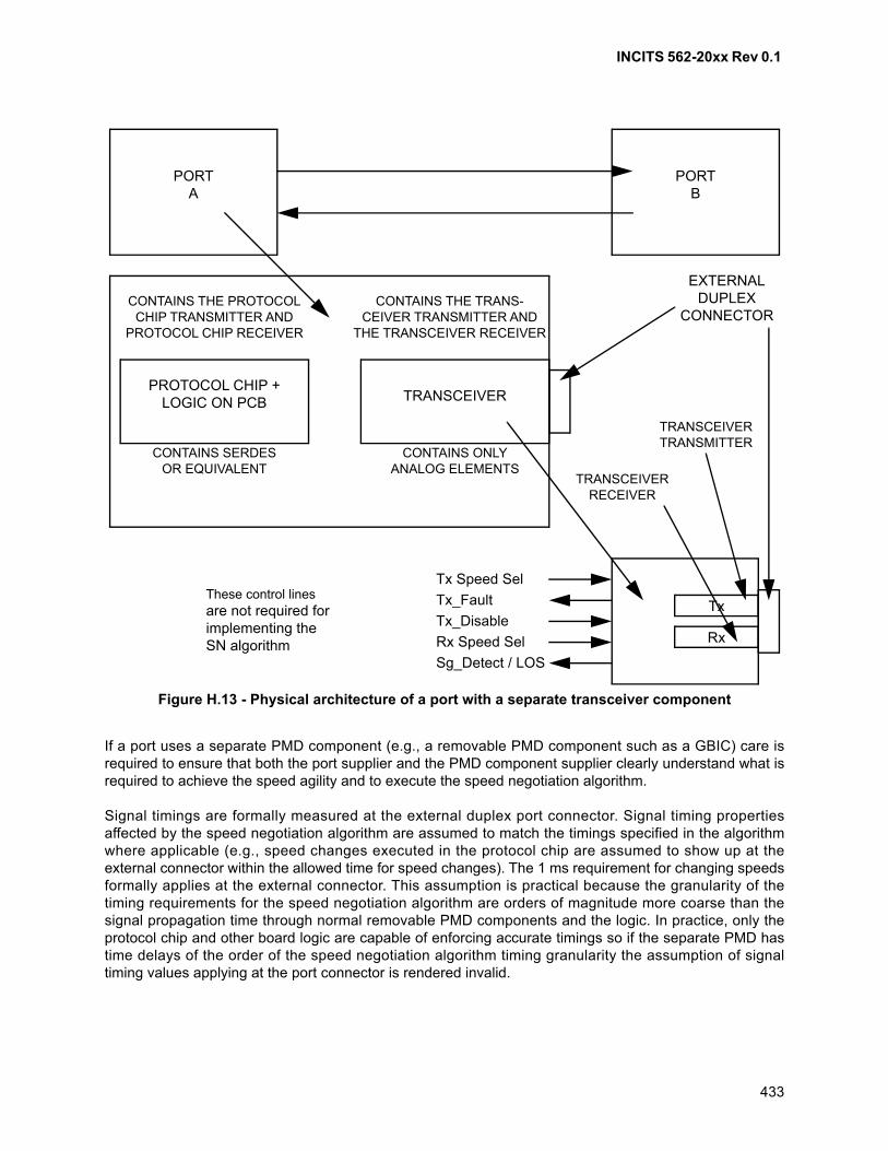
INCITS 562-20xx Rev 0.1
433
If a port uses a separate PMD component (e.g., a removable PMD component such as a GBIC) care isrequired to ensure that both the port supplier and the PMD component supplier clearly understand what isrequired to achieve the speed agility and to execute the speed negotiation algorithm.
Signal timings are formally measured at the external duplex port connector. Signal timing propertiesaffected by the speed negotiation algorithm are assumed to match the timings specified in the algorithmwhere applicable (e.g., speed changes executed in the protocol chip are assumed to show up at theexternal connector within the allowed time for speed changes). The 1 ms requirement for changing speedsformally applies at the external connector. This assumption is practical because the granularity of thetiming requirements for the speed negotiation algorithm are orders of magnitude more coarse than thesignal propagation time through normal removable PMD components and the logic. In practice, only theprotocol chip and other board logic are capable of enforcing accurate timings so if the separate PMD hastime delays of the order of the speed negotiation algorithm timing granularity the assumption of signaltiming values applying at the port connector is rendered invalid.
Figure H.13 - Physical architecture of a port with a separate transceiver component
PORTB
PORTA
CONTAINS THE PROTOCOL CHIP TRANSMITTER AND
PROTOCOL CHIP RECEIVER
CONTAINS THE TRANS-CEIVER TRANSMITTER AND
THE TRANSCEIVER RECEIVER
CONTAINS SERDESOR EQUIVALENT
CONTAINS ONLYANALOG ELEMENTS
PROTOCOL CHIP + LOGIC ON PCB TRANSCEIVER
EXTERNALDUPLEX
CONNECTOR
Tx
Rx
Tx Speed Sel
Tx_Disable
Rx Speed Sel
Tx_Fault
Sg_Detect / LOS
TRANSCEIVERTRANSMITTER
TRANSCEIVERRECEIVER
These control linesare not required forimplementing theSN algorithm
INCITS 562-20xx Rev 0.1
434
Several additional considerations of separate PMDs are listed here:
a) the protocol chip and other board logic may be supplied from different sources than thetransceiver. In the design of speed negotiation, the protocol chip and other board logic were nottreated as a unit with the transceiver. Specifications have been placed specifically on one or theother (or both separately) and the use of any control signals have been noted;
b) there are effectively two transmitters and two receivers in each port. The receiver in thetransceiver is termed the transceiver receiver and the receiver in the protocol chip or on the board,but not part of the transceiver is termed the protocol chip receiver. Similarly: transceiver transmitterand protocol chip transmitter;
c) the speed of the transceiver transmitter is controlled by the protocol chip and other board logic bychanging the speed of the data signals driven from the protocol chip. However, the launchamplitude and /or other properties of the transceiver transmitter either needs to be:
A) common to all supported speeds;
B) a control signal to the transceiver is used to set the amplitude of the transceiver transmitter; or
C) internal circuitry within the transceiver senses the incoming bit rate and adjusts the amplitudeaccordingly;
NOTE 68 - The requirements for full speed and double speed are not mutually exclusive (i.e., it ispossible to design a transceiver transmitter that meets both the full speed and the double speedrequirements without any change).
and
d) the speed of the transceiver receiver is similarly controlled by either:
A) having the transceiver receiver specifications common to all supported speeds;
B) a control signal to the transceiver is used to set the properties of the transceiver receiver; or
C) internal circuitry within the transceiver senses the incoming bit rate and adjusts the receiverparameters accordingly.
NOTE 69 - The requirements for full speed and double speed are not mutually exclusive (i.e., it ispossible to design a transceiver receiver that meets both the full speed and the double speedrequirements without any change). For any speeds higher than double speed the transceiver receiverneeds to change its properties in order to meet the transceiver receiver requirements.
H.6 Implementation notes
The Slow_wait stage described in 8.6.6 may be implemented as a means of reducing processing timerequired to poll ports that remain unconnected or unused for extended periods of time. The speednegotiation algorithm may also be disabled for ports determined to be inactive by methods not controlledby this standard, such as:
a) commands from an out of band management system;
b) hardware jumpers;
c) using a signal detect function (Rx_LOS) to detect when a connection is made (may not be areliable indication that the Tx side is connected and requires that the opposite connected port betransmitting in a manner that allows signal detection to function); or
d) using an automatic sensing of connector retention engagement or the presence of a removablePMD device to sense plausible device attachment (does not guarantee that the opposite end ofthe link is connected).
INCITS 562-20xx Rev 0.1
435
Annex I (informative)
IEEE company_ID
I.1 Overview
The IEEE Registration Authority for a fee provides a registered number that is guaranteed to be unique.The unique number may be provided in either of two formats, depending on the requirements of themanufacturer. The number is provided as a 6 hexadecimal number value as the IEEE company_id. Thenumber is provided as three hexadecimal-digit pairs in canonical form representing the 3 octets of the24-bit number as the IEEE Organizationally Unique Identifier (OUI). A manufacturer for all its products thatuse an IEEE registration uses the same number. A manufacturer shall base all its identifiers on the samenumber, even if the identifiers have different formats. A manufacturer shall not purchase a newcompany_id until at least one of the identifier spaces using the company_id is substantially exhausted.Other identifier spaces shall continue using the original company_id until they are also exhausted.
The IEEE Registration Authority may be contacted at http://standards.ieee.org/regauth/oui/index.shtml or:
IEEE Registration AuthorityIEEE Standards Dept.445 Hoes Lane, P.O. Box 1331Piscataway, NJ 08855-1331
I.2 Uses of IEEE registered Company_ID other than Name_Identifiers
In addition to construction of several forms of Name_Identifiers (see I.3), Fibre Channel uses thecompany_ID in the RNFT LS_ACC (see FC-LS-4).
I.3 IEEE tutorial on Fibre Channel uses of company_ID
The following text replicates the tutorial on Fibre Channel uses of company_ID submitted to IEEE by T11.
I.4 Guidelines for Fibre Channel Use of the Company_ID
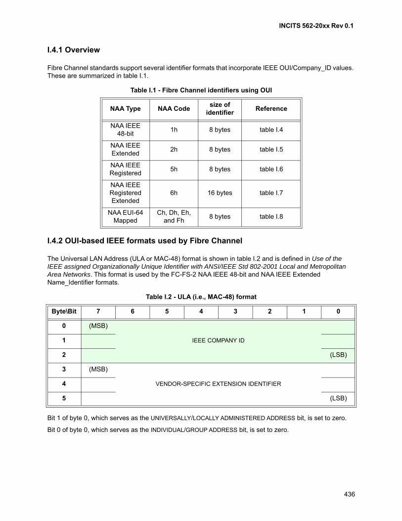
INCITS 562-20xx Rev 0.1
436
I.4.1 Overview
Fibre Channel standards support several identifier formats that incorporate IEEE OUI/Company_ID values. These are summarized in table I.1.
I.4.2 OUI-based IEEE formats used by Fibre Channel
The Universal LAN Address (ULA or MAC-48) format is shown in table I.2 and is defined in Use of the IEEE assigned Organizationally Unique Identifier with ANSI/IEEE Std 802-2001 Local and Metropolitan Area Networks. This format is used by the FC-FS-2 NAA IEEE 48-bit and NAA IEEE Extended Name_Identifier formats.
Bit 1 of byte 0, which serves as the UNIVERSALLY/LOCALLY ADMINISTERED ADDRESS bit, is set to zero.
Bit 0 of byte 0, which serves as the INDIVIDUAL/GROUP ADDRESS bit, is set to zero.
Table I.1 - Fibre Channel identifiers using OUI
NAA Type NAA Codesize of
identifierReference
NAA IEEE 48-bit
1h 8 bytes table I.4
NAA IEEE Extended
2h 8 bytes table I.5
NAA IEEE Registered
5h 8 bytes table I.6
NAA IEEE Registered Extended
6h 16 bytes table I.7
NAA EUI-64 Mapped
Ch, Dh, Eh, and Fh
8 bytes table I.8
Table I.2 - ULA (i.e., MAC-48) format
Byte\Bit 7 6 5 4 3 2 1 0
0 (MSB)
IEEE COMPANY ID1
2 (LSB)
3 (MSB)
VENDOR-SPECIFIC EXTENSION IDENTIFIER4
5 (LSB)
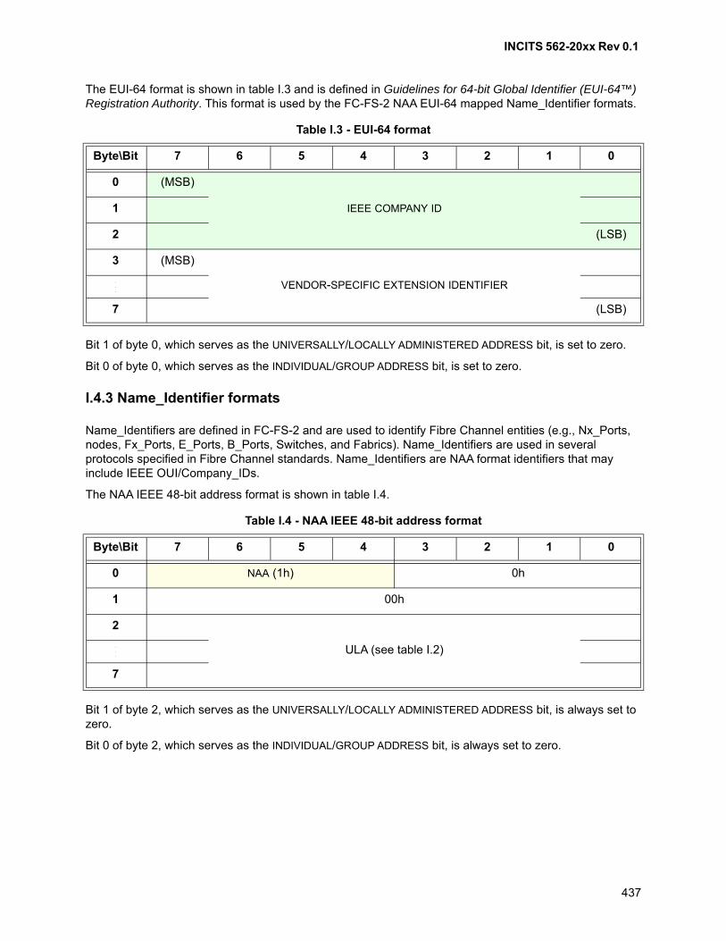
INCITS 562-20xx Rev 0.1
437
The EUI-64 format is shown in table I.3 and is defined in Guidelines for 64-bit Global Identifier (EUI-64™) Registration Authority. This format is used by the FC-FS-2 NAA EUI-64 mapped Name_Identifier formats.
Bit 1 of byte 0, which serves as the UNIVERSALLY/LOCALLY ADMINISTERED ADDRESS bit, is set to zero.
Bit 0 of byte 0, which serves as the INDIVIDUAL/GROUP ADDRESS bit, is set to zero.
I.4.3 Name_Identifier formats
Name_Identifiers are defined in FC-FS-2 and are used to identify Fibre Channel entities (e.g., Nx_Ports, nodes, Fx_Ports, E_Ports, B_Ports, Switches, and Fabrics). Name_Identifiers are used in several protocols specified in Fibre Channel standards. Name_Identifiers are NAA format identifiers that may include IEEE OUI/Company_IDs.
The NAA IEEE 48-bit address format is shown in table I.4.
Bit 1 of byte 2, which serves as the UNIVERSALLY/LOCALLY ADMINISTERED ADDRESS bit, is always set to zero.
Bit 0 of byte 2, which serves as the INDIVIDUAL/GROUP ADDRESS bit, is always set to zero.
Table I.3 - EUI-64 format
Byte\Bit 7 6 5 4 3 2 1 0
0 (MSB)
IEEE COMPANY ID1
2 (LSB)
3 (MSB)
VENDOR-SPECIFIC EXTENSION IDENTIFIER...
7 (LSB)
Table I.4 - NAA IEEE 48-bit address format
Byte\Bit 7 6 5 4 3 2 1 0
0 NAA (1h) 0h
1 00h
2
ULA (see table I.2)...
7
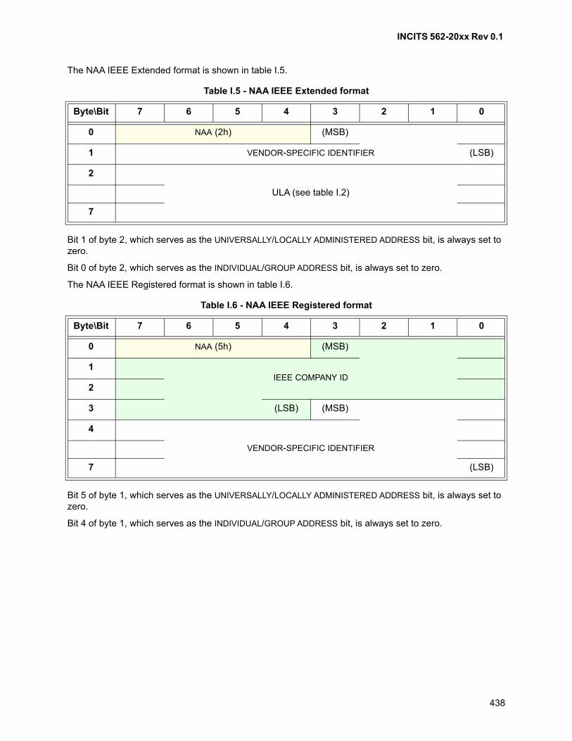
INCITS 562-20xx Rev 0.1
438
The NAA IEEE Extended format is shown in table I.5.
Bit 1 of byte 2, which serves as the UNIVERSALLY/LOCALLY ADMINISTERED ADDRESS bit, is always set to zero.
Bit 0 of byte 2, which serves as the INDIVIDUAL/GROUP ADDRESS bit, is always set to zero.
The NAA IEEE Registered format is shown in table I.6.
Bit 5 of byte 1, which serves as the UNIVERSALLY/LOCALLY ADMINISTERED ADDRESS bit, is always set to zero.
Bit 4 of byte 1, which serves as the INDIVIDUAL/GROUP ADDRESS bit, is always set to zero.
Table I.5 - NAA IEEE Extended format
Byte\Bit 7 6 5 4 3 2 1 0
0 NAA (2h) (MSB)
1 VENDOR-SPECIFIC IDENTIFIER (LSB)
2
ULA (see table I.2)...
7
Table I.6 - NAA IEEE Registered format
Byte\Bit 7 6 5 4 3 2 1 0
0 NAA (5h) (MSB)
1IEEE COMPANY ID
2
3 (LSB) (MSB)
4
VENDOR-SPECIFIC IDENTIFIER...
7 (LSB)
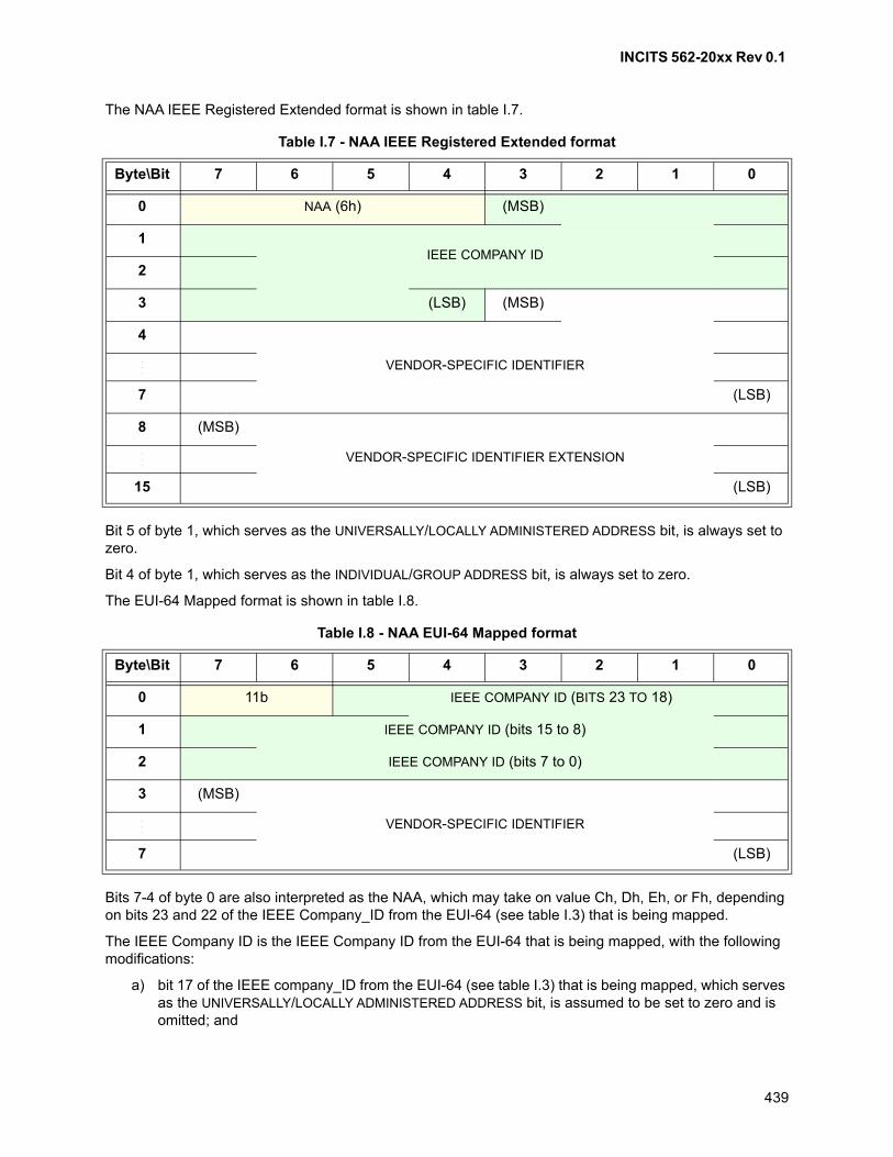
INCITS 562-20xx Rev 0.1
439
The NAA IEEE Registered Extended format is shown in table I.7.
Bit 5 of byte 1, which serves as the UNIVERSALLY/LOCALLY ADMINISTERED ADDRESS bit, is always set to zero.
Bit 4 of byte 1, which serves as the INDIVIDUAL/GROUP ADDRESS bit, is always set to zero.
The EUI-64 Mapped format is shown in table I.8.
Bits 7-4 of byte 0 are also interpreted as the NAA, which may take on value Ch, Dh, Eh, or Fh, depending on bits 23 and 22 of the IEEE Company_ID from the EUI-64 (see table I.3) that is being mapped.
The IEEE Company ID is the IEEE Company ID from the EUI-64 that is being mapped, with the following modifications:
a) bit 17 of the IEEE company_ID from the EUI-64 (see table I.3) that is being mapped, which serves as the UNIVERSALLY/LOCALLY ADMINISTERED ADDRESS bit, is assumed to be set to zero and is omitted; and
Table I.7 - NAA IEEE Registered Extended format
Byte\Bit 7 6 5 4 3 2 1 0
0 NAA (6h) (MSB)
1IEEE COMPANY ID
2
3 (LSB) (MSB)
4
VENDOR-SPECIFIC IDENTIFIER...
7 (LSB)
8 (MSB)
VENDOR-SPECIFIC IDENTIFIER EXTENSION...
15 (LSB)
Table I.8 - NAA EUI-64 Mapped format
Byte\Bit 7 6 5 4 3 2 1 0
0 11b IEEE COMPANY ID (BITS 23 TO 18)
1 IEEE COMPANY ID (bits 15 to 8)
2 IEEE COMPANY ID (bits 7 to 0)
3 (MSB)
VENDOR-SPECIFIC IDENTIFIER...
7 (LSB)

INCITS 562-20xx Rev 0.1
440
b) bit 16 of the IEEE company_ID from the EUI-64 (see table I.3) that is being mapped, which serves as the INDIVIDUAL/GROUP ADDRESS bit, is assumed to be set to zero and is omitted.
VENDOR-SPECIFIC IDENTIFIER is the vendor specific identifier from the EUI-64 (see table I.3) that is being mapped.
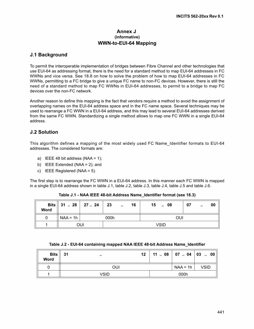
INCITS 562-20xx Rev 0.1
441
Annex J (informative)
WWN-to-EUI-64 Mapping
J.1 Background
To permit the interoperable implementation of bridges between Fibre Channel and other technologies thatuse EUI-64 as addressing format, there is the need for a standard method to map EUI-64 addresses in FCWWNs and vice versa. See 18.8 on how to solve the problem of how to map EUI-64 addresses in FCWWNs, permitting to a FC bridge to give a unique FC name to non-FC devices. However, there is still theneed of a standard method to map FC WWNs in EUI-64 addresses, to permit to a bridge to map FCdevices over the non-FC network.
Another reason to define this mapping is the fact that vendors require a method to avoid the assignment ofoverlapping names on the EUI-64 address space and in the FC name space. Several techniques may beused to rearrange a FC WWN in a EUI-64 address, and this may lead to several EUI-64 addresses derivedfrom the same FC WWN. Standardizing a single method allows to map one FC WWN in a single EUI-64address.
J.2 Solution
This algorithm defines a mapping of the most widely used FC Name_Identifier formats to EUI-64addresses. The considered formats are:
a) IEEE 48 bit address (NAA = 1);
b) IEEE Extended (NAA = 2); and
c) IEEE Registered (NAA = 5).
The first step is to rearrange the FC WWN in a EUI-64 address. In this manner each FC WWN is mappedin a single EUI-64 address shown in table J.1, table J.2, table J.3, table J.4, table J.5 and table J.6.
Table J.1 - NAA IEEE 48-bit Address Name_Identifier format (see 18.3)
BitsWord
31 .. 28 27 .. 24 23 .. 16 15 .. 08 07 .. 00
0 NAA = 1h 000h OUI
1 OUI VSID
Table J.2 - EUI-64 containing mapped NAA IEEE 48-bit Address Name_Identifier
BitsWord
31 .. 12 11 .. 08 07 .. 04 03 .. 00
0 OUI NAA = 1h VSID
1 VSID 000h
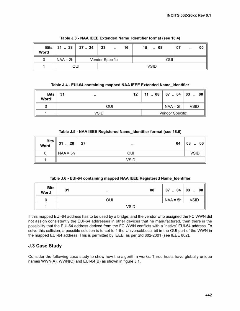
INCITS 562-20xx Rev 0.1
442
If this mapped EUI-64 address has to be used by a bridge, and the vendor who assigned the FC WWN didnot assign consistently the EUI-64 addresses in other devices that he manufactured, then there is thepossibility that the EUI-64 address derived from the FC WWN conflicts with a “native” EUI-64 address. Tosolve this collision, a possible solution is to set to 1 the Universal/Local bit in the OUI part of the WWN inthe mapped EUI-64 address. This is permitted by IEEE, as per Std 802-2001 (see IEEE 802).
J.3 Case Study
Consider the following case study to show how the algorithm works. Three hosts have globally uniquenames WWN(A), WWN(C) and EUI-64(B) as shown in figure J.1.
Table J.3 - NAA IEEE Extended Name_Identifier format (see 18.4)
BitsWord
31 .. 28 27 .. 24 23 .. 16 15 .. 08 07 .. 00
0 NAA = 2h Vendor Specific OUI
1 OUI VSID
Table J.4 - EUI-64 containing mapped NAA IEEE Extended Name_Identifier
BitsWord
31 .. 12 11 .. 08 07 .. 04 03 .. 00
0 OUI NAA = 2h VSID
1 VSID Vendor Specific
Table J.5 - NAA IEEE Registered Name_Identifier format (see 18.6)
BitsWord
31 .. 28 27 .. 04 03 .. 00
0 NAA = 5h OUI VSID
1 VSID
Table J.6 - EUI-64 containing mapped NAA IEEE Registered Name_Identifier
BitsWord
31 .. 08 07 .. 04 03 .. 00
0 OUI NAA = 5h VSID
1 VSID
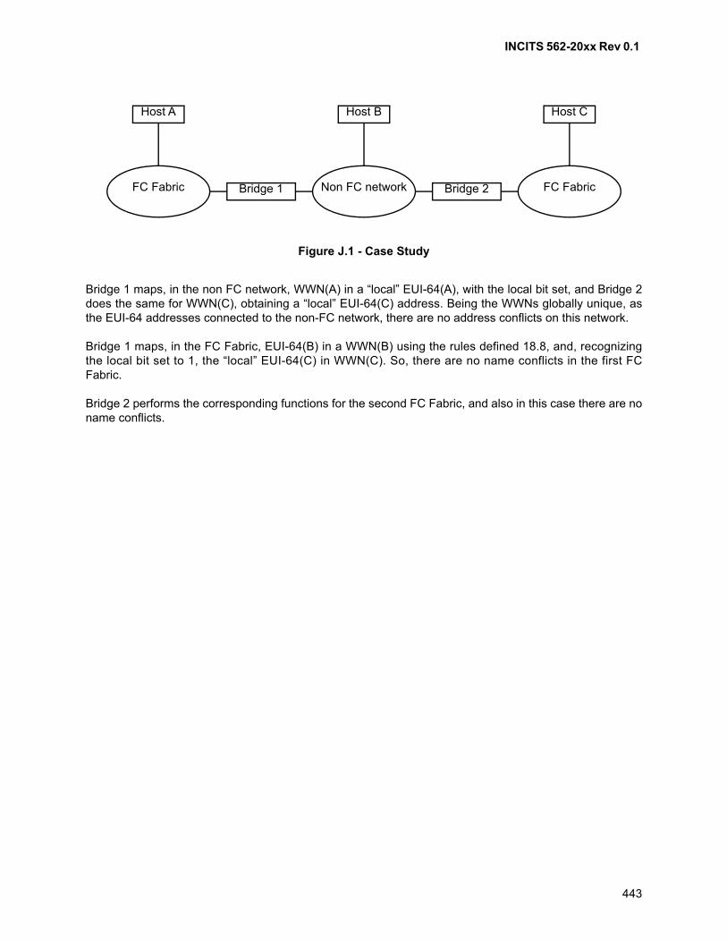
INCITS 562-20xx Rev 0.1
443
Bridge 1 maps, in the non FC network, WWN(A) in a “local” EUI-64(A), with the local bit set, and Bridge 2does the same for WWN(C), obtaining a “local” EUI-64(C) address. Being the WWNs globally unique, asthe EUI-64 addresses connected to the non-FC network, there are no address conflicts on this network.
Bridge 1 maps, in the FC Fabric, EUI-64(B) in a WWN(B) using the rules defined 18.8, and, recognizingthe local bit set to 1, the “local” EUI-64(C) in WWN(C). So, there are no name conflicts in the first FCFabric.
Bridge 2 performs the corresponding functions for the second FC Fabric, and also in this case there are noname conflicts.
Figure J.1 - Case Study
Bridge 2Bridge 1
Host CHost BHost A
FC Fabric Non FC network FC Fabric
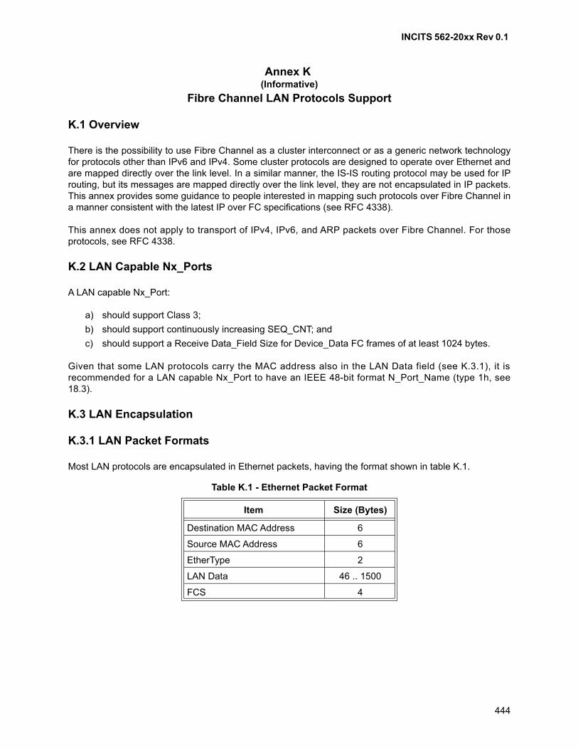
INCITS 562-20xx Rev 0.1
444
Annex K (Informative)
Fibre Channel LAN Protocols Support
K.1 Overview
There is the possibility to use Fibre Channel as a cluster interconnect or as a generic network technologyfor protocols other than IPv6 and IPv4. Some cluster protocols are designed to operate over Ethernet andare mapped directly over the link level. In a similar manner, the IS-IS routing protocol may be used for IProuting, but its messages are mapped directly over the link level, they are not encapsulated in IP packets.This annex provides some guidance to people interested in mapping such protocols over Fibre Channel ina manner consistent with the latest IP over FC specifications (see RFC 4338).
This annex does not apply to transport of IPv4, IPv6, and ARP packets over Fibre Channel. For thoseprotocols, see RFC 4338.
K.2 LAN Capable Nx_Ports
A LAN capable Nx_Port:
a) should support Class 3;
b) should support continuously increasing SEQ_CNT; and
c) should support a Receive Data_Field Size for Device_Data FC frames of at least 1024 bytes.
Given that some LAN protocols carry the MAC address also in the LAN Data field (see K.3.1), it isrecommended for a LAN capable Nx_Port to have an IEEE 48-bit format N_Port_Name (type 1h, see18.3).
K.3 LAN Encapsulation
K.3.1 LAN Packet Formats
Most LAN protocols are encapsulated in Ethernet packets, having the format shown in table K.1.
Table K.1 - Ethernet Packet Format
Item Size (Bytes)
Destination MAC Address 6
Source MAC Address 6
EtherType 2
LAN Data 46 .. 1500
FCS 4
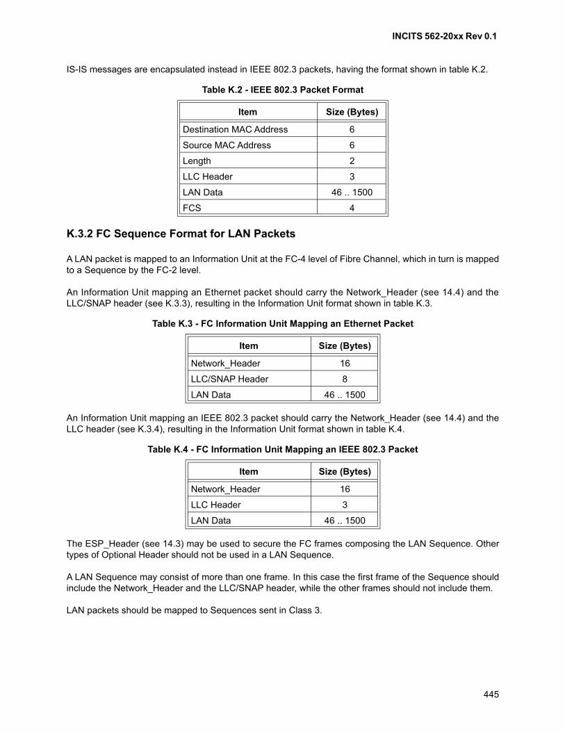
INCITS 562-20xx Rev 0.1
445
IS-IS messages are encapsulated instead in IEEE 802.3 packets, having the format shown in table K.2.
K.3.2 FC Sequence Format for LAN Packets
A LAN packet is mapped to an Information Unit at the FC-4 level of Fibre Channel, which in turn is mappedto a Sequence by the FC-2 level.
An Information Unit mapping an Ethernet packet should carry the Network_Header (see 14.4) and theLLC/SNAP header (see K.3.3), resulting in the Information Unit format shown in table K.3.
An Information Unit mapping an IEEE 802.3 packet should carry the Network_Header (see 14.4) and theLLC header (see K.3.4), resulting in the Information Unit format shown in table K.4.
The ESP_Header (see 14.3) may be used to secure the FC frames composing the LAN Sequence. Othertypes of Optional Header should not be used in a LAN Sequence.
A LAN Sequence may consist of more than one frame. In this case the first frame of the Sequence shouldinclude the Network_Header and the LLC/SNAP header, while the other frames should not include them.
LAN packets should be mapped to Sequences sent in Class 3.
Table K.2 - IEEE 802.3 Packet Format
Item Size (Bytes)
Destination MAC Address 6
Source MAC Address 6
Length 2
LLC Header 3
LAN Data 46 .. 1500
FCS 4
Table K.3 - FC Information Unit Mapping an Ethernet Packet
Item Size (Bytes)
Network_Header 16
LLC/SNAP Header 8
LAN Data 46 .. 1500
Table K.4 - FC Information Unit Mapping an IEEE 802.3 Packet
Item Size (Bytes)
Network_Header 16
LLC Header 3
LAN Data 46 .. 1500
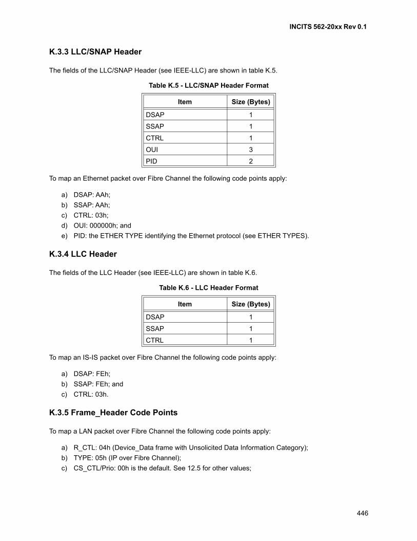
INCITS 562-20xx Rev 0.1
446
K.3.3 LLC/SNAP Header
The fields of the LLC/SNAP Header (see IEEE-LLC) are shown in table K.5.
To map an Ethernet packet over Fibre Channel the following code points apply:
a) DSAP: AAh;
b) SSAP: AAh;
c) CTRL: 03h;
d) OUI: 000000h; and
e) PID: the ETHER TYPE identifying the Ethernet protocol (see ETHER TYPES).
K.3.4 LLC Header
The fields of the LLC Header (see IEEE-LLC) are shown in table K.6.
To map an IS-IS packet over Fibre Channel the following code points apply:
a) DSAP: FEh;
b) SSAP: FEh; and
c) CTRL: 03h.
K.3.5 Frame_Header Code Points
To map a LAN packet over Fibre Channel the following code points apply:
a) R_CTL: 04h (Device_Data frame with Unsolicited Data Information Category);
b) TYPE: 05h (IP over Fibre Channel);
c) CS_CTL/Prio: 00h is the default. See 12.5 for other values;
Table K.5 - LLC/SNAP Header Format
Item Size (Bytes)
DSAP 1
SSAP 1
CTRL 1
OUI 3
PID 2
Table K.6 - LLC Header Format
Item Size (Bytes)
DSAP 1
SSAP 1
CTRL 1
INCITS 562-20xx Rev 0.1
447
d) DF_CTL: If the ESP_Header is not used, then 20h (Network_Header) for the first frame of a LANSequence, 00h for the following frames. If the ESP_Header is used, then 60h for the first frame ofa LAN Sequence, 40h for the following frames;
e) F_CTL, SEQ_ID, SEQ_CNT, OX_ID, RX_ID: see K.5 and K.6; and
f) Parameter: if Relative Offset is not used, the content of this field should be ignored by the receiver,and should be set to zero by the sender. If Relative Offset is used, see 12.13.
K.4 Multicast and Broadcast Mapping
LAN multicast and broadcast packets should be mapped to FC Sequences addressed to the broadcastN_Port_ID FFFFFFh, sent in Class 3 in a unidirectional Exchange (see K.6). The DestinationN_Port_Name field of the Network_Header should be set to the value 1000-FFFF-FFFF-FFFFh for LANbroadcast packets, and to the LAN multicast address prepended with 1000h for LAN multicast packets.
An Nx_Port supporting LAN protocols should be able to map a received broadcast Class 3 Device_Dataframe to an implicit Port Login context in order to handle LAN multicast or broadcast packets. The ReceiveData_Field Size of this implicit Port Login should be the same across all the Nx_Ports connected to thesame Fabric, otherwise FC broadcast transmission does not work. In order to reduce the need for FCSequence segmentation, the Receive Data_Field Size of this implicit Port Login should be 1024 bytes.This Receive Data_Field Size requirement applies to broadcast Device_Data frames, not to ELSs.
K.5 Sequence Management
FC Sequences carrying LAN packets should be non-streamed. In order to avoid missing frame aliasing bySequence_ID reuse, an Nx_Port supporting LAN packets should use continuously increasing SEQ_CNT.Each Exchange should start by setting SEQ_CNT to zero in the first frame, and every frame transmittedafter that should increment the previous SEQ_CNT by one.
K.6 Exchange Management
To transmit LAN packets to another Nx_Port or to a multicast/broadcast address, an Nx_Port should usededicated unidirectional Exchanges (i.e., Exchanges dedicated to LAN packet transmission and that do nottransfer Sequence Initiative). As such, the Sequence Initiative bit in the F_CTL field of the Frame_Headershould be set to zero. The RX_ID field of the Frame_Header should be set to FFFFh.
Unicast FC Sequences carrying unicast Control Protocol packets should be sent in short livedunidirectional Exchanges (i.e., Exchanges containing only one Sequence, in which both theFirst_Sequence and Last_Sequence bits in the F_CTL field of the Frame_Header are set to one). UnicastFC Sequences carrying other LAN packets should be sent in a long lived unidirectional Exchange (i.e., anExchange containing one or more Sequences). LAN multicast packets should not be carried in unicastSequences (see K.4).
Broadcast FC Sequences carrying multicast or broadcast Control Protocol packets should be sent in shortlived unidirectional Exchanges. Broadcast FC Sequences carrying other LAN multicast traffic may be sentin long lived unidirectional Exchanges to enable a more efficient multicast distribution.
Reasons to terminate a long lived Exchange include the termination of Port Login and the completion ofthe LAN communication. A long lived Exchange may be terminated by setting to one the Last_Sequencebit in the F_CTL field of the Frame_Header, or via the ABTS (Abort Sequence) protocol. A long livedExchange should not be terminated by transmitting the LOGO ELS, since this may terminate openExchanges on other FC-4s (see FC-LS-4).
INCITS 562-20xx Rev 0.1
448
Annex L (Informative)
RS-FEC Code Word Examples
L.1 32GFC - Idle Pattern with 64B/66B Scrambler Bypass Disabled (scr_bypass=0)
L.1.1 Overview
This annex provides example RS-FEC codewords produced by 64B/66B to 256B/257B transcoding (see5.4.2), Reed-Solomon encoding (see 5.4.3) and scrambling (see 5.4.4) computations. Results of eachcomputation are provided in a tabular form. The contents of the tables are transmitted from left to rightwithin each row starting from the top row and ending at the bottom row. The tables contain both binary andhexadecimal representations of the data. For the hexadecimal representation, the most significant bit ofeach hex symbol is transmitted first.
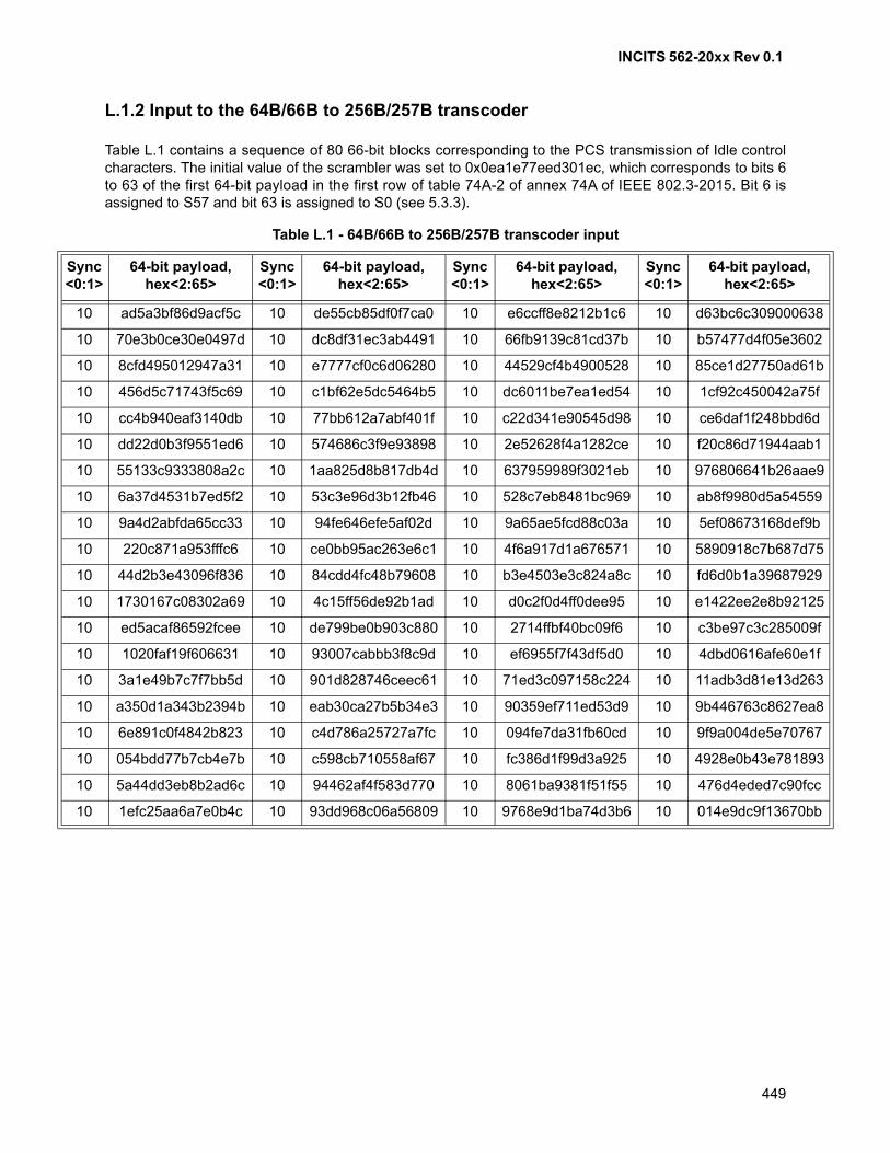
INCITS 562-20xx Rev 0.1
449
L.1.2 Input to the 64B/66B to 256B/257B transcoder
Table L.1 contains a sequence of 80 66-bit blocks corresponding to the PCS transmission of Idle controlcharacters. The initial value of the scrambler was set to 0x0ea1e77eed301ec, which corresponds to bits 6to 63 of the first 64-bit payload in the first row of table 74A-2 of annex 74A of IEEE 802.3-2015. Bit 6 isassigned to S57 and bit 63 is assigned to S0 (see 5.3.3).
Table L.1 - 64B/66B to 256B/257B transcoder input
Sync <0:1>
64-bit payload, hex<2:65>
Sync <0:1>
64-bit payload, hex<2:65>
Sync <0:1>
64-bit payload, hex<2:65>
Sync <0:1>
64-bit payload, hex<2:65>
10 ad5a3bf86d9acf5c 10 de55cb85df0f7ca0 10 e6ccff8e8212b1c6 10 d63bc6c309000638
10 70e3b0ce30e0497d 10 dc8df31ec3ab4491 10 66fb9139c81cd37b 10 b57477d4f05e3602
10 8cfd495012947a31 10 e7777cf0c6d06280 10 44529cf4b4900528 10 85ce1d27750ad61b
10 456d5c71743f5c69 10 c1bf62e5dc5464b5 10 dc6011be7ea1ed54 10 1cf92c450042a75f
10 cc4b940eaf3140db 10 77bb612a7abf401f 10 c22d341e90545d98 10 ce6daf1f248bbd6d
10 dd22d0b3f9551ed6 10 574686c3f9e93898 10 2e52628f4a1282ce 10 f20c86d71944aab1
10 55133c9333808a2c 10 1aa825d8b817db4d 10 637959989f3021eb 10 976806641b26aae9
10 6a37d4531b7ed5f2 10 53c3e96d3b12fb46 10 528c7eb8481bc969 10 ab8f9980d5a54559
10 9a4d2abfda65cc33 10 94fe646efe5af02d 10 9a65ae5fcd88c03a 10 5ef08673168def9b
10 220c871a953fffc6 10 ce0bb95ac263e6c1 10 4f6a917d1a676571 10 5890918c7b687d75
10 44d2b3e43096f836 10 84cdd4fc48b79608 10 b3e4503e3c824a8c 10 fd6d0b1a39687929
10 1730167c08302a69 10 4c15ff56de92b1ad 10 d0c2f0d4ff0dee95 10 e1422ee2e8b92125
10 ed5acaf86592fcee 10 de799be0b903c880 10 2714ffbf40bc09f6 10 c3be97c3c285009f
10 1020faf19f606631 10 93007cabbb3f8c9d 10 ef6955f7f43df5d0 10 4dbd0616afe60e1f
10 3a1e49b7c7f7bb5d 10 901d828746ceec61 10 71ed3c097158c224 10 11adb3d81e13d263
10 a350d1a343b2394b 10 eab30ca27b5b34e3 10 90359ef711ed53d9 10 9b446763c8627ea8
10 6e891c0f4842b823 10 c4d786a25727a7fc 10 094fe7da31fb60cd 10 9f9a004de5e70767
10 054bdd77b7cb4e7b 10 c598cb710558af67 10 fc386d1f99d3a925 10 4928e0b43e781893
10 5a44dd3eb8b2ad6c 10 94462af4f583d770 10 8061ba9381f51f55 10 476d4eded7c90fcc
10 1efc25aa6a7e0b4c 10 93dd968c06a56809 10 9768e9d1ba74d3b6 10 014e9dc9f13670bb
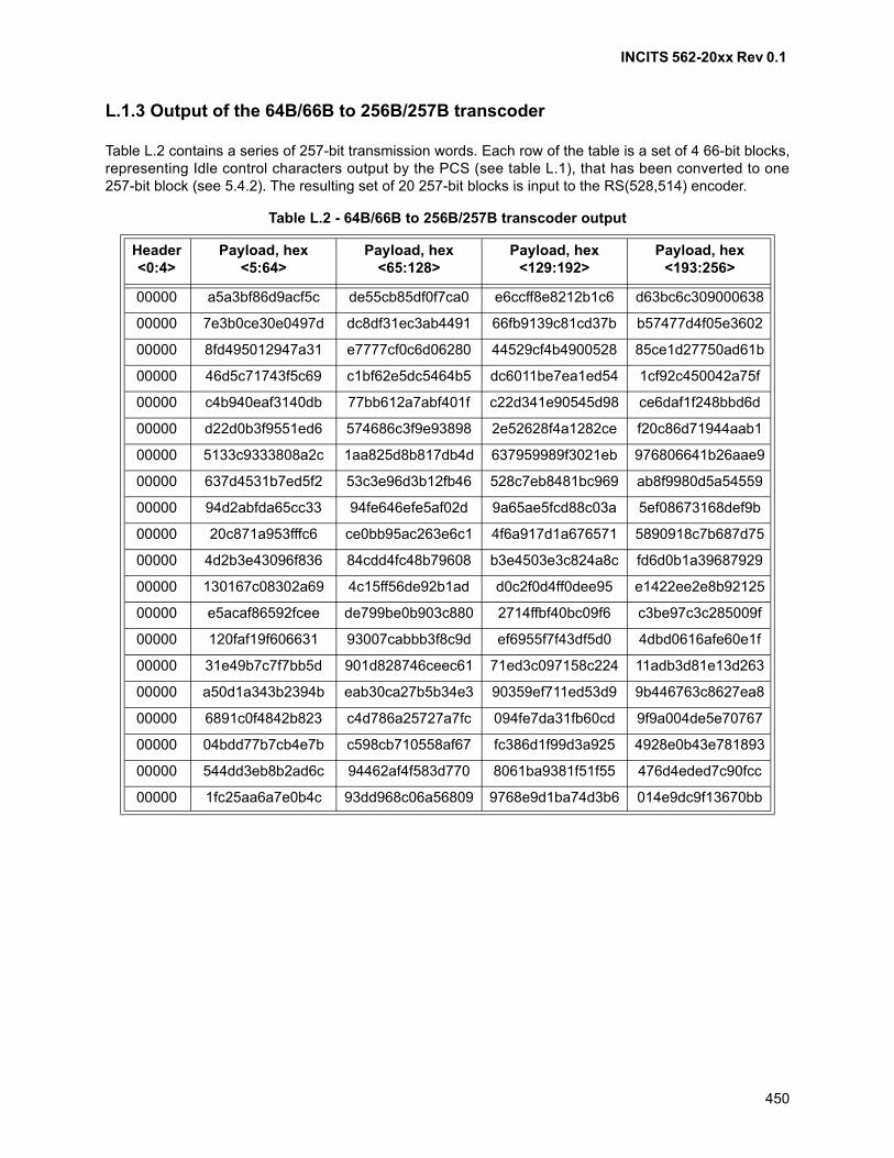
INCITS 562-20xx Rev 0.1
450
L.1.3 Output of the 64B/66B to 256B/257B transcoder
Table L.2 contains a series of 257-bit transmission words. Each row of the table is a set of 4 66-bit blocks,representing Idle control characters output by the PCS (see table L.1), that has been converted to one257-bit block (see 5.4.2). The resulting set of 20 257-bit blocks is input to the RS(528,514) encoder.
Table L.2 - 64B/66B to 256B/257B transcoder output
Header <0:4>
Payload, hex <5:64>
Payload, hex <65:128>
Payload, hex <129:192>
Payload, hex <193:256>
00000 a5a3bf86d9acf5c de55cb85df0f7ca0 e6ccff8e8212b1c6 d63bc6c309000638
00000 7e3b0ce30e0497d dc8df31ec3ab4491 66fb9139c81cd37b b57477d4f05e3602
00000 8fd495012947a31 e7777cf0c6d06280 44529cf4b4900528 85ce1d27750ad61b
00000 46d5c71743f5c69 c1bf62e5dc5464b5 dc6011be7ea1ed54 1cf92c450042a75f
00000 c4b940eaf3140db 77bb612a7abf401f c22d341e90545d98 ce6daf1f248bbd6d
00000 d22d0b3f9551ed6 574686c3f9e93898 2e52628f4a1282ce f20c86d71944aab1
00000 5133c9333808a2c 1aa825d8b817db4d 637959989f3021eb 976806641b26aae9
00000 637d4531b7ed5f2 53c3e96d3b12fb46 528c7eb8481bc969 ab8f9980d5a54559
00000 94d2abfda65cc33 94fe646efe5af02d 9a65ae5fcd88c03a 5ef08673168def9b
00000 20c871a953fffc6 ce0bb95ac263e6c1 4f6a917d1a676571 5890918c7b687d75
00000 4d2b3e43096f836 84cdd4fc48b79608 b3e4503e3c824a8c fd6d0b1a39687929
00000 130167c08302a69 4c15ff56de92b1ad d0c2f0d4ff0dee95 e1422ee2e8b92125
00000 e5acaf86592fcee de799be0b903c880 2714ffbf40bc09f6 c3be97c3c285009f
00000 120faf19f606631 93007cabbb3f8c9d ef6955f7f43df5d0 4dbd0616afe60e1f
00000 31e49b7c7f7bb5d 901d828746ceec61 71ed3c097158c224 11adb3d81e13d263
00000 a50d1a343b2394b eab30ca27b5b34e3 90359ef711ed53d9 9b446763c8627ea8
00000 6891c0f4842b823 c4d786a25727a7fc 094fe7da31fb60cd 9f9a004de5e70767
00000 04bdd77b7cb4e7b c598cb710558af67 fc386d1f99d3a925 4928e0b43e781893
00000 544dd3eb8b2ad6c 94462af4f583d770 8061ba9381f51f55 476d4eded7c90fcc
00000 1fc25aa6a7e0b4c 93dd968c06a56809 9768e9d1ba74d3b6 014e9dc9f13670bb
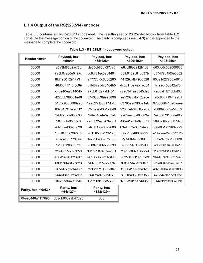
INCITS 562-20xx Rev 0.1
451
L.1.4 Output of the RS(528,514) encoder
Table L.3 contains an RS(528,514) codeword. The resulting set of 20 257-bit blocks from table L.2constitute the message portion of the codeword. The parity is computed (see 5.4.3) and is appended to themessage to complete the codeword.
Table L.3 - RS(528,514) codeword output
Header <0:4>Payload, hex
<5:64>Payload, hex
<65:128>Payload, hex
<129:192>Payload, hex
<193:256>
00000 a5a3bf86d9acf5c de55cb85df0f7ca0 e6ccff8e8212b1c6 d63bc6c309000638
00000 7e3b0ce30e0497d dc8df31ec3ab4491 66fb9139c81cd37b b57477d4f05e3602
00000 8fd495012947a31 e7777cf0c6d06280 44529cf4b4900528 85ce1d27750ad61b
00000 46d5c71743f5c69 c1bf62e5dc5464b5 dc6011be7ea1ed54 1cf92c450042a75f
00000 c4b940eaf3140db 77bb612a7abf401f c22d341e90545d98 ce6daf1f248bbd6d
00000 d22d0b3f9551ed6 574686c3f9e93898 2e52628f4a1282ce f20c86d71944aab1
00000 5133c9333808a2c 1aa825d8b817db4d 637959989f3021eb 976806641b26aae9
00000 637d4531b7ed5f2 53c3e96d3b12fb46 528c7eb8481bc969 ab8f9980d5a54559
00000 94d2abfda65cc33 94fe646efe5af02d 9a65ae5fcd88c03a 5ef08673168def9b
00000 20c871a953fffc6 ce0bb95ac263e6c1 4f6a917d1a676571 5890918c7b687d75
00000 4d2b3e43096f836 84cdd4fc48b79608 b3e4503e3c824a8c fd6d0b1a39687929
00000 130167c08302a69 4c15ff56de92b1ad d0c2f0d4ff0dee95 e1422ee2e8b92125
00000 e5acaf86592fcee de799be0b903c880 2714ffbf40bc09f6 c3be97c3c285009f
00000 120faf19f606631 93007cabbb3f8c9d ef6955f7f43df5d0 4dbd0616afe60e1f
00000 31e49b7c7f7bb5d 901d828746ceec61 71ed3c097158c224 11adb3d81e13d263
00000 a50d1a343b2394b eab30ca27b5b34e3 90359ef711ed53d9 9b446763c8627ea8
00000 6891c0f4842b823 c4d786a25727a7fc 094fe7da31fb60cd 9f9a004de5e70767
00000 04bdd77b7cb4e7b c598cb710558af67 fc386d1f99d3a925 4928e0b43e781893
00000 544dd3eb8b2ad6c 94462af4f583d770 8061ba9381f51f55 476d4eded7c90fcc
00000 1fc25aa6a7e0b4c 93dd968c06a56809 9768e9d1ba74d3b6 014e9dc9f13670bb
Parity, hex <0:63>Parity, hex <64:127>
Parity, hex <128:139>
0be96448a1153f95 d8adb9032ab47d9c d0b
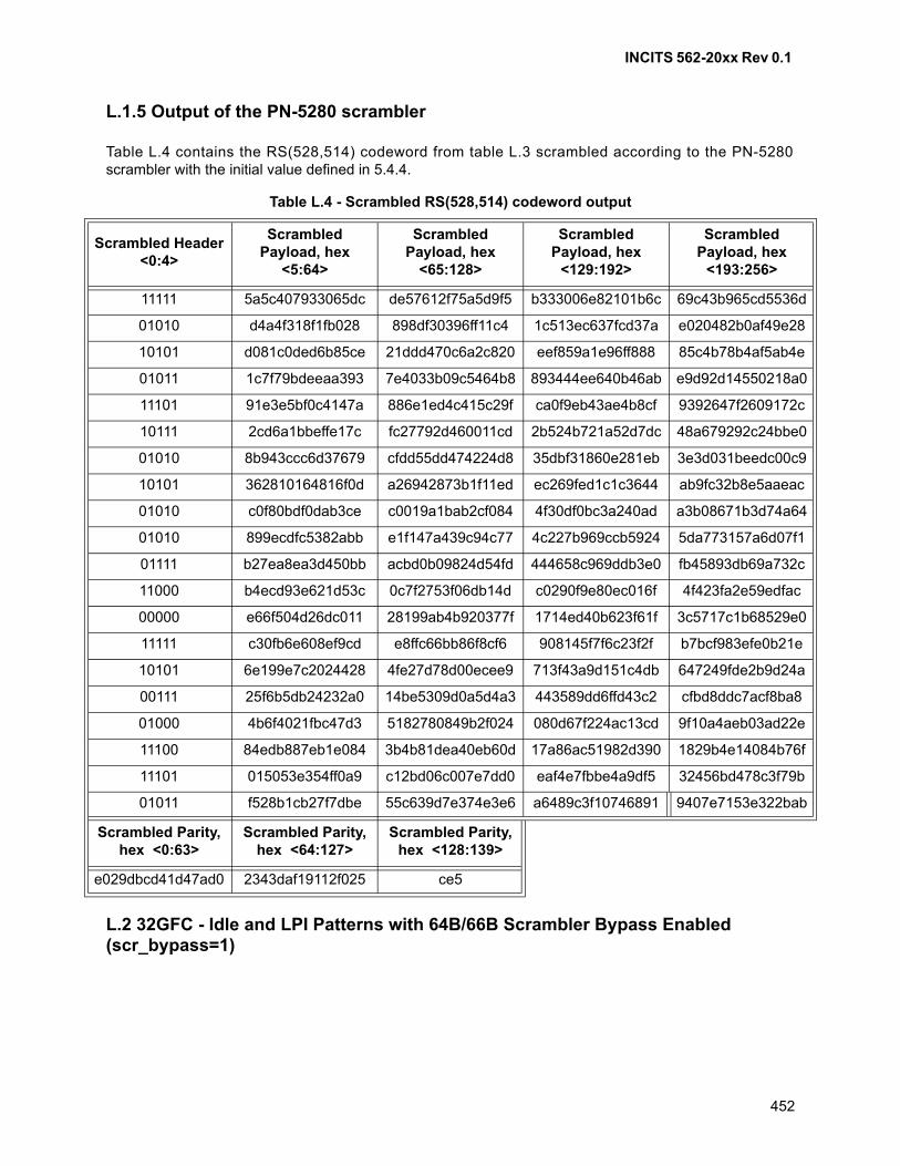
INCITS 562-20xx Rev 0.1
452
L.1.5 Output of the PN-5280 scrambler
Table L.4 contains the RS(528,514) codeword from table L.3 scrambled according to the PN-5280scrambler with the initial value defined in 5.4.4.
L.2 32GFC - Idle and LPI Patterns with 64B/66B Scrambler Bypass Enabled (scr_bypass=1)
Table L.4 - Scrambled RS(528,514) codeword output
Scrambled Header <0:4>
Scrambled Payload, hex
<5:64>
Scrambled Payload, hex
<65:128>
Scrambled Payload, hex
<129:192>
Scrambled Payload, hex
<193:256>
11111 5a5c407933065dc de57612f75a5d9f5 b333006e82101b6c 69c43b965cd5536d
01010 d4a4f318f1fb028 898df30396ff11c4 1c513ec637fcd37a e020482b0af49e28
10101 d081c0ded6b85ce 21ddd470c6a2c820 eef859a1e96ff888 85c4b78b4af5ab4e
01011 1c7f79bdeeaa393 7e4033b09c5464b8 893444ee640b46ab e9d92d14550218a0
11101 91e3e5bf0c4147a 886e1ed4c415c29f ca0f9eb43ae4b8cf 9392647f2609172c
10111 2cd6a1bbeffe17c fc27792d460011cd 2b524b721a52d7dc 48a679292c24bbe0
01010 8b943ccc6d37679 cfdd55dd474224d8 35dbf31860e281eb 3e3d031beedc00c9
10101 362810164816f0d a26942873b1f11ed ec269fed1c1c3644 ab9fc32b8e5aaeac
01010 c0f80bdf0dab3ce c0019a1bab2cf084 4f30df0bc3a240ad a3b08671b3d74a64
01010 899ecdfc5382abb e1f147a439c94c77 4c227b969ccb5924 5da773157a6d07f1
01111 b27ea8ea3d450bb acbd0b09824d54fd 444658c969ddb3e0 fb45893db69a732c
11000 b4ecd93e621d53c 0c7f2753f06db14d c0290f9e80ec016f 4f423fa2e59edfac
00000 e66f504d26dc011 28199ab4b920377f 1714ed40b623f61f 3c5717c1b68529e0
11111 c30fb6e608ef9cd e8ffc66bb86f8cf6 908145f7f6c23f2f b7bcf983efe0b21e
10101 6e199e7c2024428 4fe27d78d00ecee9 713f43a9d151c4db 647249fde2b9d24a
00111 25f6b5db24232a0 14be5309d0a5d4a3 443589dd6ffd43c2 cfbd8ddc7acf8ba8
01000 4b6f4021fbc47d3 5182780849b2f024 080d67f224ac13cd 9f10a4aeb03ad22e
11100 84edb887eb1e084 3b4b81dea40eb60d 17a86ac51982d390 1829b4e14084b76f
11101 015053e354ff0a9 c12bd06c007e7dd0 eaf4e7fbbe4a9df5 32456bd478c3f79b
01011 f528b1cb27f7dbe 55c639d7e374e3e6 a6489c3f10746891 9407e7153e322bab
Scrambled Parity, hex <0:63>
Scrambled Parity, hex <64:127>
Scrambled Parity, hex <128:139>
e029dbcd41d47ad0 2343daf19112f025 ce5
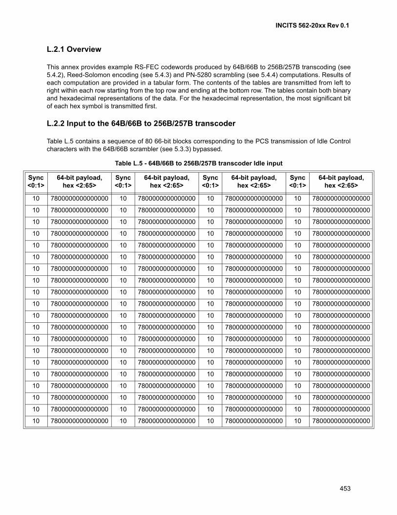
INCITS 562-20xx Rev 0.1
453
L.2.1 Overview
This annex provides example RS-FEC codewords produced by 64B/66B to 256B/257B transcoding (see5.4.2), Reed-Solomon encoding (see 5.4.3) and PN-5280 scrambling (see 5.4.4) computations. Results ofeach computation are provided in a tabular form. The contents of the tables are transmitted from left toright within each row starting from the top row and ending at the bottom row. The tables contain both binaryand hexadecimal representations of the data. For the hexadecimal representation, the most significant bitof each hex symbol is transmitted first.
L.2.2 Input to the 64B/66B to 256B/257B transcoder
Table L.5 contains a sequence of 80 66-bit blocks corresponding to the PCS transmission of Idle Controlcharacters with the 64B/66B scrambler (see 5.3.3) bypassed.
Table L.5 - 64B/66B to 256B/257B transcoder Idle input
Sync<0:1>
64-bit payload,hex <2:65>
Sync<0:1>
64-bit payload,hex <2:65>
Sync<0:1>
64-bit payload,hex <2:65>
Sync<0:1>
64-bit payload,hex <2:65>
10 7800000000000000 10 7800000000000000 10 7800000000000000 10 7800000000000000
10 7800000000000000 10 7800000000000000 10 7800000000000000 10 7800000000000000
10 7800000000000000 10 7800000000000000 10 7800000000000000 10 7800000000000000
10 7800000000000000 10 7800000000000000 10 7800000000000000 10 7800000000000000
10 7800000000000000 10 7800000000000000 10 7800000000000000 10 7800000000000000
10 7800000000000000 10 7800000000000000 10 7800000000000000 10 7800000000000000
10 7800000000000000 10 7800000000000000 10 7800000000000000 10 7800000000000000
10 7800000000000000 10 7800000000000000 10 7800000000000000 10 7800000000000000
10 7800000000000000 10 7800000000000000 10 7800000000000000 10 7800000000000000
10 7800000000000000 10 7800000000000000 10 7800000000000000 10 7800000000000000
10 7800000000000000 10 7800000000000000 10 7800000000000000 10 7800000000000000
10 7800000000000000 10 7800000000000000 10 7800000000000000 10 7800000000000000
10 7800000000000000 10 7800000000000000 10 7800000000000000 10 7800000000000000
10 7800000000000000 10 7800000000000000 10 7800000000000000 10 7800000000000000
10 7800000000000000 10 7800000000000000 10 7800000000000000 10 7800000000000000
10 7800000000000000 10 7800000000000000 10 7800000000000000 10 7800000000000000
10 7800000000000000 10 7800000000000000 10 7800000000000000 10 7800000000000000
10 7800000000000000 10 7800000000000000 10 7800000000000000 10 7800000000000000
10 7800000000000000 10 7800000000000000 10 7800000000000000 10 7800000000000000
10 7800000000000000 10 7800000000000000 10 7800000000000000 10 7800000000000000
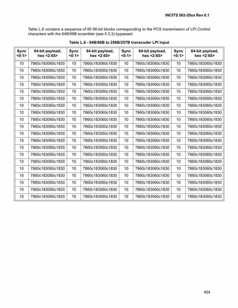
INCITS 562-20xx Rev 0.1
454
Table L.6 contains a sequence of 80 66-bit blocks corresponding to the PCS transmission of LPI Controlcharacters with the 64B/66B scrambler (see 5.3.3) bypassed.
Table L.6 - 64B/66B to 256B/257B transcoder LPI input
Sync<0:1>
64-bit payload,hex <2:65>
Sync<0:1>
64-bit payload,hex <2:65>
Sync<0:1>
64-bit payload,hex <2:65>
Sync<0:1>
64-bit payload,hex <2:65>
10 7860c183060c1830 10 7860c183060c1830 10 7860c183060c1830 10 7860c183060c1830
10 7860c183060c1830 10 7860c183060c1830 10 7860c183060c1830 10 7860c183060c1830
10 7860c183060c1830 10 7860c183060c1830 10 7860c183060c1830 10 7860c183060c1830
10 7860c183060c1830 10 7860c183060c1830 10 7860c183060c1830 10 7860c183060c1830
10 7860c183060c1830 10 7860c183060c1830 10 7860c183060c1830 10 7860c183060c1830
10 7860c183060c1830 10 7860c183060c1830 10 7860c183060c1830 10 7860c183060c1830
10 7860c183060c1830 10 7860c183060c1830 10 7860c183060c1830 10 7860c183060c1830
10 7860c183060c1830 10 7860c183060c1830 10 7860c183060c1830 10 7860c183060c1830
10 7860c183060c1830 10 7860c183060c1830 10 7860c183060c1830 10 7860c183060c1830
10 7860c183060c1830 10 7860c183060c1830 10 7860c183060c1830 10 7860c183060c1830
10 7860c183060c1830 10 7860c183060c1830 10 7860c183060c1830 10 7860c183060c1830
10 7860c183060c1830 10 7860c183060c1830 10 7860c183060c1830 10 7860c183060c1830
10 7860c183060c1830 10 7860c183060c1830 10 7860c183060c1830 10 7860c183060c1830
10 7860c183060c1830 10 7860c183060c1830 10 7860c183060c1830 10 7860c183060c1830
10 7860c183060c1830 10 7860c183060c1830 10 7860c183060c1830 10 7860c183060c1830
10 7860c183060c1830 10 7860c183060c1830 10 7860c183060c1830 10 7860c183060c1830
10 7860c183060c1830 10 7860c183060c1830 10 7860c183060c1830 10 7860c183060c1830
10 7860c183060c1830 10 7860c183060c1830 10 7860c183060c1830 10 7860c183060c1830
10 7860c183060c1830 10 7860c183060c1830 10 7860c183060c1830 10 7860c183060c1830
10 7860c183060c1830 10 7860c183060c1830 10 7860c183060c1830 10 7860c183060c1830
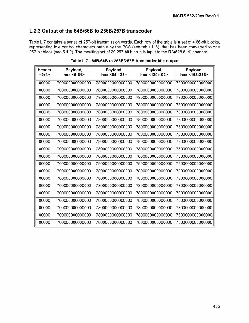
INCITS 562-20xx Rev 0.1
455
L.2.3 Output of the 64B/66B to 256B/257B transcoder
Table L.7 contains a series of 257-bit transmission words. Each row of the table is a set of 4 66-bit blocks,representing Idle control characters output by the PCS (see table L.5), that has been converted to one257-bit block (see 5.4.2). The resulting set of 20 257-bit blocks is input to the RS(528,514) encoder.
Table L.7 - 64B/66B to 256B/257B transcoder Idle output
Header<0:4>
Payload,hex <5:64>
Payload, hex <65:128>
Payload, hex <129:192>
Payload, hex <193:256>
00000 700000000000000 7800000000000000 7800000000000000 7800000000000000
00000 700000000000000 7800000000000000 7800000000000000 7800000000000000
00000 700000000000000 7800000000000000 7800000000000000 7800000000000000
00000 700000000000000 7800000000000000 7800000000000000 7800000000000000
00000 700000000000000 7800000000000000 7800000000000000 7800000000000000
00000 700000000000000 7800000000000000 7800000000000000 7800000000000000
00000 700000000000000 7800000000000000 7800000000000000 7800000000000000
00000 700000000000000 7800000000000000 7800000000000000 7800000000000000
00000 700000000000000 7800000000000000 7800000000000000 7800000000000000
00000 700000000000000 7800000000000000 7800000000000000 7800000000000000
00000 700000000000000 7800000000000000 7800000000000000 7800000000000000
00000 700000000000000 7800000000000000 7800000000000000 7800000000000000
00000 700000000000000 7800000000000000 7800000000000000 7800000000000000
00000 700000000000000 7800000000000000 7800000000000000 7800000000000000
00000 700000000000000 7800000000000000 7800000000000000 7800000000000000
00000 700000000000000 7800000000000000 7800000000000000 7800000000000000
00000 700000000000000 7800000000000000 7800000000000000 7800000000000000
00000 700000000000000 7800000000000000 7800000000000000 7800000000000000
00000 700000000000000 7800000000000000 7800000000000000 7800000000000000
00000 700000000000000 7800000000000000 7800000000000000 7800000000000000
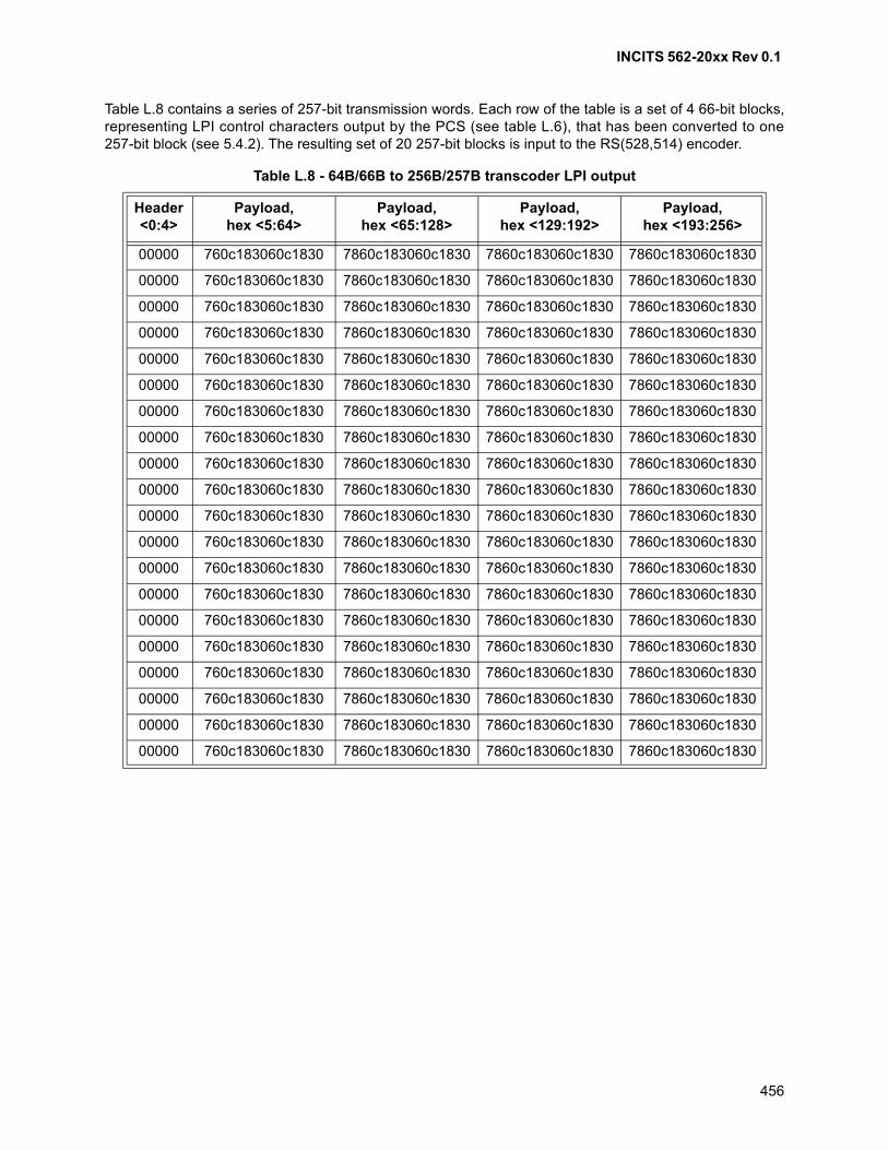
INCITS 562-20xx Rev 0.1
456
Table L.8 contains a series of 257-bit transmission words. Each row of the table is a set of 4 66-bit blocks,representing LPI control characters output by the PCS (see table L.6), that has been converted to one257-bit block (see 5.4.2). The resulting set of 20 257-bit blocks is input to the RS(528,514) encoder.
Table L.8 - 64B/66B to 256B/257B transcoder LPI output
Header<0:4>
Payload,hex <5:64>
Payload, hex <65:128>
Payload, hex <129:192>
Payload, hex <193:256>
00000 760c183060c1830 7860c183060c1830 7860c183060c1830 7860c183060c1830
00000 760c183060c1830 7860c183060c1830 7860c183060c1830 7860c183060c1830
00000 760c183060c1830 7860c183060c1830 7860c183060c1830 7860c183060c1830
00000 760c183060c1830 7860c183060c1830 7860c183060c1830 7860c183060c1830
00000 760c183060c1830 7860c183060c1830 7860c183060c1830 7860c183060c1830
00000 760c183060c1830 7860c183060c1830 7860c183060c1830 7860c183060c1830
00000 760c183060c1830 7860c183060c1830 7860c183060c1830 7860c183060c1830
00000 760c183060c1830 7860c183060c1830 7860c183060c1830 7860c183060c1830
00000 760c183060c1830 7860c183060c1830 7860c183060c1830 7860c183060c1830
00000 760c183060c1830 7860c183060c1830 7860c183060c1830 7860c183060c1830
00000 760c183060c1830 7860c183060c1830 7860c183060c1830 7860c183060c1830
00000 760c183060c1830 7860c183060c1830 7860c183060c1830 7860c183060c1830
00000 760c183060c1830 7860c183060c1830 7860c183060c1830 7860c183060c1830
00000 760c183060c1830 7860c183060c1830 7860c183060c1830 7860c183060c1830
00000 760c183060c1830 7860c183060c1830 7860c183060c1830 7860c183060c1830
00000 760c183060c1830 7860c183060c1830 7860c183060c1830 7860c183060c1830
00000 760c183060c1830 7860c183060c1830 7860c183060c1830 7860c183060c1830
00000 760c183060c1830 7860c183060c1830 7860c183060c1830 7860c183060c1830
00000 760c183060c1830 7860c183060c1830 7860c183060c1830 7860c183060c1830
00000 760c183060c1830 7860c183060c1830 7860c183060c1830 7860c183060c1830

INCITS 562-20xx Rev 0.1
457
L.2.4 Output of the RS(528,514) encoder
Table L.9 contains an RS(528,514) codeword output result using input from table L.7. The resulting set of20 257-bit blocks constitute the message portion of the codeword. The parity is computed (see 5.4.3) andis appended to the message to complete the codeword.
Table L.9 - RS(528,514) codeword Idle output
Header<0:4>
Payload,hex <5:64>
Payload, hex <65:128>
Payload, hex <129:192>
Payload, hex <193:256>
00000 700000000000000 7800000000000000 7800000000000000 7800000000000000
00000 700000000000000 7800000000000000 7800000000000000 7800000000000000
00000 700000000000000 7800000000000000 7800000000000000 7800000000000000
00000 700000000000000 7800000000000000 7800000000000000 7800000000000000
00000 700000000000000 7800000000000000 7800000000000000 7800000000000000
00000 700000000000000 7800000000000000 7800000000000000 7800000000000000
00000 700000000000000 7800000000000000 7800000000000000 7800000000000000
00000 700000000000000 7800000000000000 7800000000000000 7800000000000000
00000 700000000000000 7800000000000000 7800000000000000 7800000000000000
00000 700000000000000 7800000000000000 7800000000000000 7800000000000000
00000 700000000000000 7800000000000000 7800000000000000 7800000000000000
00000 700000000000000 7800000000000000 7800000000000000 7800000000000000
00000 700000000000000 7800000000000000 7800000000000000 7800000000000000
00000 700000000000000 7800000000000000 7800000000000000 7800000000000000
00000 700000000000000 7800000000000000 7800000000000000 7800000000000000
00000 700000000000000 7800000000000000 7800000000000000 7800000000000000
00000 700000000000000 7800000000000000 7800000000000000 7800000000000000
00000 700000000000000 7800000000000000 7800000000000000 7800000000000000
00000 700000000000000 7800000000000000 7800000000000000 7800000000000000
00000 700000000000000 7800000000000000 7800000000000000 7800000000000000
Parity, hex <0:63>
Parity, hex <64:127>
Parity, hex <128:139>
d2dc96cbdac17213 73bea79e7d8a84cb e1c
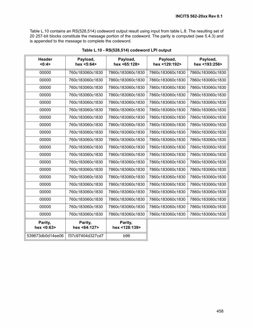
INCITS 562-20xx Rev 0.1
458
Table L.10 contains an RS(528,514) codeword output result using input from table L.8. The resulting set of20 257-bit blocks constitute the message portion of the codeword. The parity is computed (see 5.4.3) andis appended to the message to complete the codeword.
Table L.10 - RS(528,514) codeword LPI output
Header<0:4>
Payload,hex <5:64>
Payload, hex <65:128>
Payload, hex <129:192>
Payload, hex <193:256>
00000 760c183060c1830 7860c183060c1830 7860c183060c1830 7860c183060c1830
00000 760c183060c1830 7860c183060c1830 7860c183060c1830 7860c183060c1830
00000 760c183060c1830 7860c183060c1830 7860c183060c1830 7860c183060c1830
00000 760c183060c1830 7860c183060c1830 7860c183060c1830 7860c183060c1830
00000 760c183060c1830 7860c183060c1830 7860c183060c1830 7860c183060c1830
00000 760c183060c1830 7860c183060c1830 7860c183060c1830 7860c183060c1830
00000 760c183060c1830 7860c183060c1830 7860c183060c1830 7860c183060c1830
00000 760c183060c1830 7860c183060c1830 7860c183060c1830 7860c183060c1830
00000 760c183060c1830 7860c183060c1830 7860c183060c1830 7860c183060c1830
00000 760c183060c1830 7860c183060c1830 7860c183060c1830 7860c183060c1830
00000 760c183060c1830 7860c183060c1830 7860c183060c1830 7860c183060c1830
00000 760c183060c1830 7860c183060c1830 7860c183060c1830 7860c183060c1830
00000 760c183060c1830 7860c183060c1830 7860c183060c1830 7860c183060c1830
00000 760c183060c1830 7860c183060c1830 7860c183060c1830 7860c183060c1830
00000 760c183060c1830 7860c183060c1830 7860c183060c1830 7860c183060c1830
00000 760c183060c1830 7860c183060c1830 7860c183060c1830 7860c183060c1830
00000 760c183060c1830 7860c183060c1830 7860c183060c1830 7860c183060c1830
00000 760c183060c1830 7860c183060c1830 7860c183060c1830 7860c183060c1830
00000 760c183060c1830 7860c183060c1830 7860c183060c1830 7860c183060c1830
00000 760c183060c1830 7860c183060c1830 7860c183060c1830 7860c183060c1830
Parity, hex <0:63>
Parity, hex <64:127>
Parity, hex <128:139>
539673db0d14ee06 f37c97404d327cd7 b96
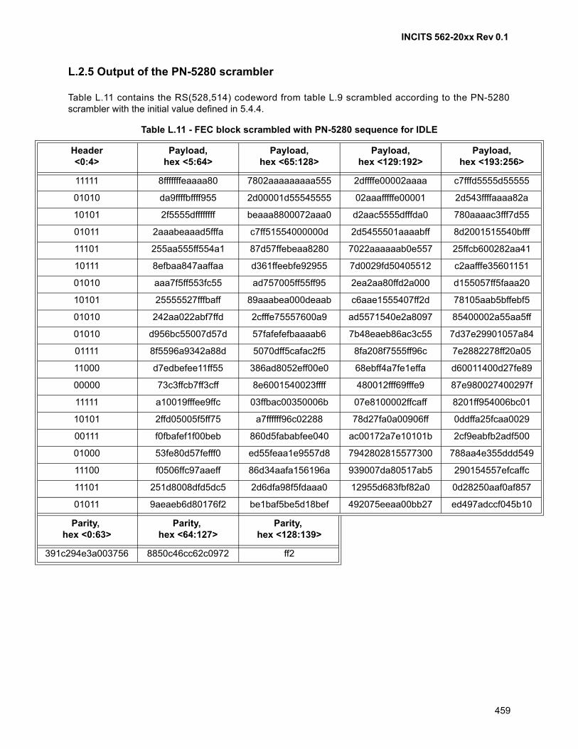
INCITS 562-20xx Rev 0.1
459
L.2.5 Output of the PN-5280 scrambler
Table L.11 contains the RS(528,514) codeword from table L.9 scrambled according to the PN-5280scrambler with the initial value defined in 5.4.4.
Table L.11 - FEC block scrambled with PN-5280 sequence for IDLE
Header<0:4>
Payload,hex <5:64>
Payload, hex <65:128>
Payload, hex <129:192>
Payload, hex <193:256>
11111 8fffffffeaaaa80 7802aaaaaaaaa555 2dffffe00002aaaa c7fffd5555d55555
01010 da9ffffbffff955 2d00001d55545555 02aaafffffe00001 2d543ffffaaaa82a
10101 2f5555dffffffff beaaa8800072aaa0 d2aac5555dfffda0 780aaaac3fff7d55
01011 2aaabeaaad5fffa c7ff51554000000d 2d5455501aaaabff 8d2001515540bfff
11101 255aa555ff554a1 87d57ffebeaa8280 7022aaaaaab0e557 25ffcb600282aa41
10111 8efbaa847aaffaa d361ffeebfe92955 7d0029fd50405512 c2aafffe35601151
01010 aaa7f5ff553fc55 ad757005ff55ff95 2ea2aa80ffd2a000 d155057ff5faaa20
10101 25555527fffbaff 89aaabea000deaab c6aae1555407ff2d 78105aab5bffebf5
01010 242aa022abf7ffd 2cfffe75557600a9 ad5571540e2a8097 85400002a55aa5ff
01010 d956bc55007d57d 57fafefefbaaaab6 7b48eaeb86ac3c55 7d37e29901057a84
01111 8f5596a9342a88d 5070dff5cafac2f5 8fa208f7555ff96c 7e2882278ff20a05
11000 d7edbefee11ff55 386ad8052eff00e0 68ebff4a7fe1effa d60011400d27fe89
00000 73c3ffcb7ff3cff 8e6001540023ffff 480012fff69fffe9 87e980027400297f
11111 a10019fffee9ffc 03ffbac00350006b 07e8100002ffcaff 8201ff954006bc01
10101 2ffd05005f5ff75 a7ffffff96c02288 78d27fa0a00906ff 0ddffa25fcaa0029
00111 f0fbafef1f00beb 860d5fababfee040 ac00172a7e10101b 2cf9eabfb2adf500
01000 53fe80d57fefff0 ed55feaa1e9557d8 7942802815577300 788aa4e355ddd549
11100 f0506ffc97aaeff 86d34aafa156196a 939007da80517ab5 290154557efcaffc
11101 251d8008dfd5dc5 2d6dfa98f5fdaaa0 12955d683fbf82a0 0d28250aaf0af857
01011 9aeaeb6d80176f2 be1baf5be5d18bef 492075eeaa00bb27 ed497adccf045b10
Parity, hex <0:63>
Parity, hex <64:127>
Parity, hex <128:139>
391c294e3a003756 8850c46cc62c0972 ff2
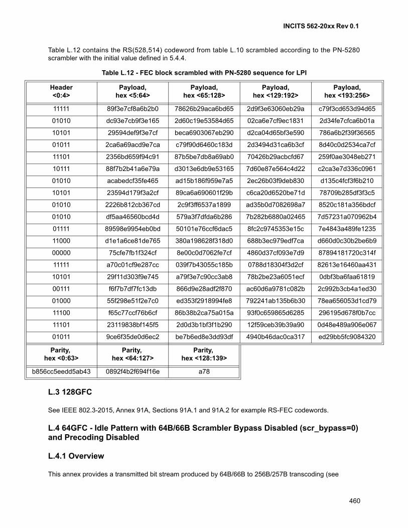
INCITS 562-20xx Rev 0.1
460
Table L.12 contains the RS(528,514) codeword from table L.10 scrambled according to the PN-5280scrambler with the initial value defined in 5.4.4.
L.3 128GFC
See IEEE 802.3-2015, Annex 91A, Sections 91A.1 and 91A.2 for example RS-FEC codewords.
L.4 64GFC - Idle Pattern with 64B/66B Scrambler Bypass Disabled (scr_bypass=0) and Precoding Disabled
L.4.1 Overview
This annex provides a transmitted bit stream produced by 64B/66B to 256B/257B transcoding (see
Table L.12 - FEC block scrambled with PN-5280 sequence for LPI
Header<0:4>
Payload,hex <5:64>
Payload, hex <65:128>
Payload, hex <129:192>
Payload, hex <193:256>
11111 89f3e7cf8a6b2b0 78626b29aca6bd65 2d9f3e63060eb29a c79f3cd653d94d65
01010 dc93e7cb9f3e165 2d60c19e53584d65 02ca6e7cf9ec1831 2d34fe7cfca6b01a
10101 29594def9f3e7cf beca6903067eb290 d2ca04d65bf3e590 786a6b2f39f36565
01011 2ca6a69acd9e7ca c79f90d6460c183d 2d3494d31ca6b3cf 8d40c0d2534ca7cf
11101 2356bd659f94c91 87b5be7db8a69ab0 70426b29acbcfd67 259f0ae3048eb271
10111 88f7b2b41a6e79a d3013e6db9e53165 7d60e87e564c4d22 c2ca3e7d336c0961
01010 acabedcf35fe465 ad15b186f959e7a5 2ec26b03f9deb830 d135c4fcf3f6b210
10101 23594d179f3a2cf 89ca6a690601f29b c6ca20d6520be71d 78709b285df3f3c5
01010 2226b812cb367cd 2c9f3ff6537a1899 ad35b0d7082698a7 8520c181a356bdcf
01010 df5aa46560bcd4d 579a3f7dfda6b286 7b282b6880a02465 7d57231a070962b4
01111 89598e9954eb0bd 50101e76ccf6dac5 8fc2c9745353e15c 7e4843a489fe1235
11000 d1e1a6ce81de765 380a198628f318d0 688b3ec979edf7ca d660d0c30b2be6b9
00000 75cfe7fb1f324cf 8e00c0d7062fe7cf 4860d37cf093e7d9 87894181720c314f
11111 a70c01cf9e287cc 039f7b43055c185b 0788d18304f3d2cf 82613e16460aa431
10101 29f11d303f9e745 a79f3e7c90cc3ab8 78b2be23a6051ecf 0dbf3ba6faa61819
00111 f6f7b7df7fc13db 866d9e28adf2f870 ac60d6a9781c082b 2c992b3cb4a1ed30
01000 55f298e51f2e7c0 ed353f2918994fe8 792241ab135b6b30 78ea656053d1cd79
11100 f65c77ccf76b6cf 86b38b2ca75a015a 93f0c659865d6285 296195d678f0b7cc
11101 23119838bf145f5 2d0d3b1bf3f1b290 12f59ceb39b39a90 0d48e489a906e067
01011 9ce6f35de0d6ec2 be7b6ed8e3dd93df 4940b46dac0ca317 ed29bb5fc9084320
Parity, hex <0:63>
Parity, hex <64:127>
Parity, hex <128:139>
b856cc5eedd5ab43 0892f4b2f694f16e a78
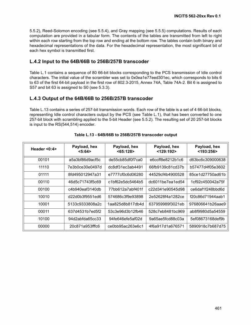
INCITS 562-20xx Rev 0.1
461
5.5.2), Reed-Solomon encoding (see 5.5.4), and Gray mapping (see 5.5.5) computations. Results of eachcomputation are provided in a tabular form. The contents of the tables are transmitted from left to rightwithin each row starting from the top row and ending at the bottom row. The tables contain both binary andhexadecimal representations of the data. For the hexadecimal representation, the most significant bit ofeach hex symbol is transmitted first.
L.4.2 Input to the 64B/66B to 256B/257B transcoder
Table L.1 contains a sequence of 80 66-bit blocks corresponding to the PCS transmission of Idle controlcharacters. The initial value of the scrambler was set to 0x0ea1e77eed301ec, which corresponds to bits 6to 63 of the first 64-bit payload in the first row of 802.3-2015, Annex 74A, Table 74A-2. Bit 6 is assigned toS57 and bit 63 is assigned to S0 (see 5.3.3).
L.4.3 Output of the 64B/66B to 256B/257B transcoder
Table L.13 contains a series of 257-bit transmission words. Each row of the table is a set of 4 66-bit blocks,representing Idle control characters output by the PCS (see Table L.1), that has been converted to one257-bit block with scrambling applied to the 5-bit Header (see 5.5.2). The resulting set of 20 257-bit blocksis input to the RS(544,514) encoder.
Table L.13 - 64B/66B to 256B/257B transcoder output
Header <0:4>Payload, hex
<5:64>Payload, hex
<65:128>Payload, hex
<129:192>Payload, hex
<193:256>
00101 a5a3bf86d9acf5c de55cb85df0f7ca0 e6ccff8e8212b1c6 d63bc6c309000638
11110 7e3b0ce30e0497d dc8df31ec3ab4491 66fb9139c81cd37b b57477d4f05e3602
01111 8fd495012947a31 e7777cf0c6d06280 44529cf4b4900528 85ce1d27750ad61b
00110 46d5c71743f5c69 c1bf62e5dc5464b5 dc6011be7ea1ed54 1cf92c450042a75f
00100 c4b940eaf3140db 77bb612a7abf401f c22d341e90545d98 ce6daf1f248bbd6d
10010 d22d0b3f9551ed6 574686c3f9e93898 2e52628f4a1282ce f20c86d71944aab1
10001 5133c9333808a2c 1aa825d8b817db4d 637959989f3021eb 976806641b26aae9
00011 637d4531b7ed5f2 53c3e96d3b12fb46 528c7eb8481bc969 ab8f9980d5a54559
10100 94d2abfda65cc33 94fe646efe5af02d 9a65ae5fcd88c03a 5ef08673168def9b
00000 20c871a953fffc6 ce0bb95ac263e6c1 4f6a917d1a676571 5890918c7b687d75
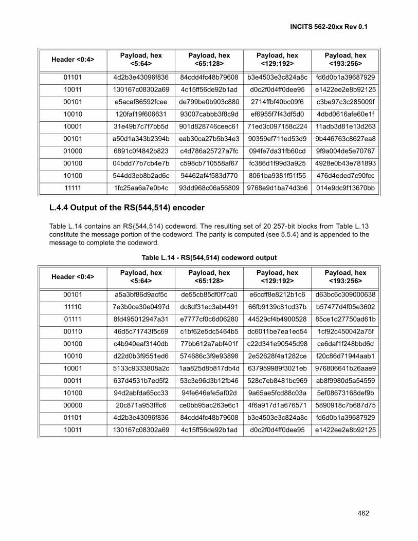
INCITS 562-20xx Rev 0.1
462
L.4.4 Output of the RS(544,514) encoder
Table L.14 contains an RS(544,514) codeword. The resulting set of 20 257-bit blocks from Table L.13constitute the message portion of the codeword. The parity is computed (see 5.5.4) and is appended to themessage to complete the codeword.
01101 4d2b3e43096f836 84cdd4fc48b79608 b3e4503e3c824a8c fd6d0b1a39687929
10011 130167c08302a69 4c15ff56de92b1ad d0c2f0d4ff0dee95 e1422ee2e8b92125
00101 e5acaf86592fcee de799be0b903c880 2714ffbf40bc09f6 c3be97c3c285009f
10010 120faf19f606631 93007cabbb3f8c9d ef6955f7f43df5d0 4dbd0616afe60e1f
10001 31e49b7c7f7bb5d 901d828746ceec61 71ed3c097158c224 11adb3d81e13d263
00101 a50d1a343b2394b eab30ca27b5b34e3 90359ef711ed53d9 9b446763c8627ea8
01000 6891c0f4842b823 c4d786a25727a7fc 094fe7da31fb60cd 9f9a004de5e70767
00100 04bdd77b7cb4e7b c598cb710558af67 fc386d1f99d3a925 4928e0b43e781893
10100 544dd3eb8b2ad6c 94462af4f583d770 8061ba9381f51f55 476d4eded7c90fcc
11111 1fc25aa6a7e0b4c 93dd968c06a56809 9768e9d1ba74d3b6 014e9dc9f13670bb
Table L.14 - RS(544,514) codeword output
Header <0:4>Payload, hex
<5:64>Payload, hex
<65:128>Payload, hex
<129:192>Payload, hex
<193:256>
00101 a5a3bf86d9acf5c de55cb85df0f7ca0 e6ccff8e8212b1c6 d63bc6c309000638
11110 7e3b0ce30e0497d dc8df31ec3ab4491 66fb9139c81cd37b b57477d4f05e3602
01111 8fd495012947a31 e7777cf0c6d06280 44529cf4b4900528 85ce1d27750ad61b
00110 46d5c71743f5c69 c1bf62e5dc5464b5 dc6011be7ea1ed54 1cf92c450042a75f
00100 c4b940eaf3140db 77bb612a7abf401f c22d341e90545d98 ce6daf1f248bbd6d
10010 d22d0b3f9551ed6 574686c3f9e93898 2e52628f4a1282ce f20c86d71944aab1
10001 5133c9333808a2c 1aa825d8b817db4d 637959989f3021eb 976806641b26aae9
00011 637d4531b7ed5f2 53c3e96d3b12fb46 528c7eb8481bc969 ab8f9980d5a54559
10100 94d2abfda65cc33 94fe646efe5af02d 9a65ae5fcd88c03a 5ef08673168def9b
00000 20c871a953fffc6 ce0bb95ac263e6c1 4f6a917d1a676571 5890918c7b687d75
01101 4d2b3e43096f836 84cdd4fc48b79608 b3e4503e3c824a8c fd6d0b1a39687929
10011 130167c08302a69 4c15ff56de92b1ad d0c2f0d4ff0dee95 e1422ee2e8b92125
Header <0:4>Payload, hex
<5:64>Payload, hex
<65:128>Payload, hex
<129:192>Payload, hex
<193:256>
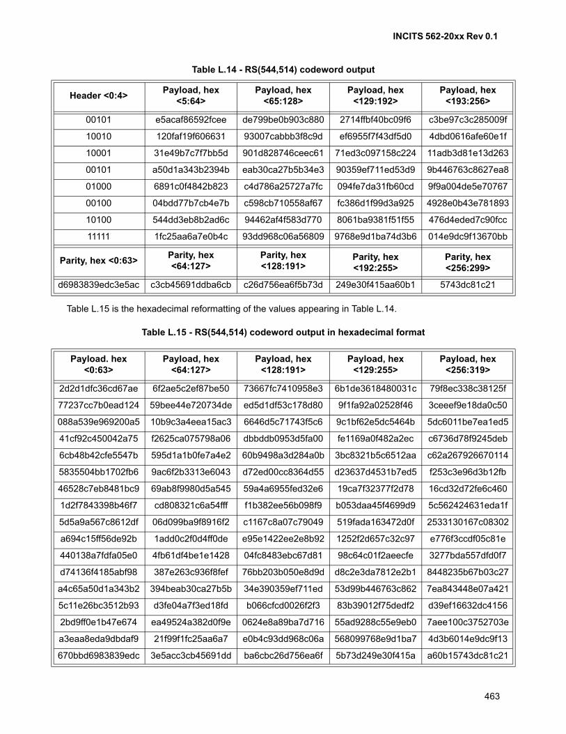
INCITS 562-20xx Rev 0.1
463
Table L.15 is the hexadecimal reformatting of the values appearing in Table L.14.
Table L.15 - RS(544,514) codeword output in hexadecimal format
00101 e5acaf86592fcee de799be0b903c880 2714ffbf40bc09f6 c3be97c3c285009f
10010 120faf19f606631 93007cabbb3f8c9d ef6955f7f43df5d0 4dbd0616afe60e1f
10001 31e49b7c7f7bb5d 901d828746ceec61 71ed3c097158c224 11adb3d81e13d263
00101 a50d1a343b2394b eab30ca27b5b34e3 90359ef711ed53d9 9b446763c8627ea8
01000 6891c0f4842b823 c4d786a25727a7fc 094fe7da31fb60cd 9f9a004de5e70767
00100 04bdd77b7cb4e7b c598cb710558af67 fc386d1f99d3a925 4928e0b43e781893
10100 544dd3eb8b2ad6c 94462af4f583d770 8061ba9381f51f55 476d4eded7c90fcc
11111 1fc25aa6a7e0b4c 93dd968c06a56809 9768e9d1ba74d3b6 014e9dc9f13670bb
Parity, hex <0:63>Parity, hex <64:127>
Parity, hex <128:191>
Parity, hex <192:255>
Parity, hex <256:299>
d6983839edc3e5ac c3cb45691ddba6cb c26d756ea6f5b73d 249e30f415aa60b1 5743dc81c21
Payload. hex <0:63>
Payload, hex <64:127>
Payload, hex <128:191>
Payload, hex <129:255>
Payload, hex <256:319>
2d2d1dfc36cd67ae 6f2ae5c2ef87be50 73667fc7410958e3 6b1de3618480031c 79f8ec338c38125f
77237cc7b0ead124 59bee44e720734de ed5d1df53c178d80 9f1fa92a02528f46 3ceeef9e18da0c50
088a539e969200a5 10b9c3a4eea15ac3 6646d5c71743f5c6 9c1bf62e5dc5464b 5dc6011be7ea1ed5
41cf92c450042a75 f2625ca075798a06 dbbddb0953d5fa00 fe1169a0f482a2ec c6736d78f9245deb
6cb48b42cfe5547b 595d1a1b0fe7a4e2 60b9498a3d284a0b 3bc8321b5c6512aa c62a267926670114
5835504bb1702fb6 9ac6f2b3313e6043 d72ed00cc8364d55 d23637d4531b7ed5 f253c3e96d3b12fb
46528c7eb8481bc9 69ab8f9980d5a545 59a4a6955fed32e6 19ca7f32377f2d78 16cd32d72fe6c460
1d2f7843398b46f7 cd808321c6a54fff f1b382ee56b098f9 b053daa45f4699d9 5c562424631eda1f
5d5a9a567c8612df 06d099ba9f8916f2 c1167c8a07c79049 519fada163472d0f 2533130167c08302
a694c15ff56de92b 1add0c2f0d4ff0de e95e1422ee2e8b92 1252f2d657c32c97 e776f3ccdf05c81e
440138a7fdfa05e0 4fb61df4be1e1428 04fc8483ebc67d81 98c64c01f2aeecfe 3277bda557dfd0f7
d74136f4185abf98 387e263c936f8fef 76bb203b050e8d9d d8c2e3da7812e2b1 8448235b67b03c27
a4c65a50d1a343b2 394beab30ca27b5b 34e390359ef711ed 53d99b446763c862 7ea843448e07a421
5c11e26bc3512b93 d3fe04a7f3ed18fd b066cfcd0026f2f3 83b39012f75dedf2 d39ef16632dc4156
2bd9ff0e1b47e674 ea49524a382d0f9e 0624e8a89ba7d716 55ad9288c55e9eb0 7aee100c3752703e
a3eaa8eda9dbdaf9 21f99f1fc25aa6a7 e0b4c93dd968c06a 568099768e9d1ba7 4d3b6014e9dc9f13
670bbd6983839edc 3e5acc3cb45691dd ba6cbc26d756ea6f 5b73d249e30f415a a60b15743dc81c21
Table L.14 - RS(544,514) codeword output
Header <0:4>Payload, hex
<5:64>Payload, hex
<65:128>Payload, hex
<129:192>Payload, hex
<193:256>
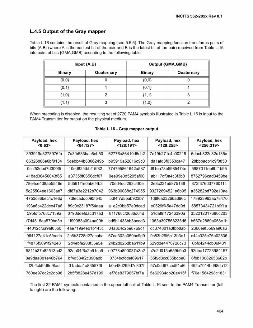
INCITS 562-20xx Rev 0.1
464
L.4.5 Output of the Gray mapper
Table L.16 contains the result of Gray mapping (see 5.5.5). The Gray mapping function transforms pairs ofbits {A,B} (where A is the earliest bit of the pair and B is the latest bit of the pair) received from Table L.15into pairs of bits {GMA,GMB} according to the following table:
When precoding is disabled, the resulting set of 2720 PAM4 symbols illustrated in Table L.16 is input to thePAM4 Transmitter for output on the physical medium.
Table L.16 - Gray mapper output
The first 32 PAM4 symbols contained in the upper left cell of Table L.16 sent to the PAM4 Transmitter (leftto right) are the following:
Input {A,B} Output {GMA,GMB}
Binary Quaternary Binary Quaternary
{0,0} 0 {0,0} 0
{0,1} 1 {0,1} 1
{1,0} 2 {1,1} 3
{1,1} 3 {1,0} 2
Payload. hex <0:63>
Payload, hex <64:127>
Payload, hex <128:191>
Payload, hex <129:255>
Payload, hex <256:319>
393919a8278976fb 7a3fb583bac6eb50 62776a86410d5cb2 7e19b271c4c00218 6dacb822c82c135a
66326886e0bf9134 5debb44b6306249b b95919a52816c9c0 da1afd3f0353ca47 28bbbadb1c9f0850
0ccf52dbd7d300f5 10ed82f4bbf15f82 774795861642a587 d81ea73b5985474e 5987011eb6bf1b95
418ad38450043f65 a37358f0656dcf07 9ee99e0d5295af00 ab117df0a4c3f3b8 8762796cad3459be
78e4ce438ab5546e 5d591f1e0ab6f4b3 70ed4dcf293c4f0e 2e8c231e587513ff 873f376d37760114
5c25504ee1603ae7 df87a3e2212b7042 963b90088c274955 93272694521e6b95 a35282bd792e13ae
4753c86bec4c1e8d 7dfecaddc095f545 5df4f7d55ab923b7 1d8f6a23266a396c 178923963ab78470
193a6c422dce47a6 89c0c23187f54aaa a1e2c3bb57e0dcad e0529ff45a47dd9d 58573434721b9f1a
595fdf5768c7139a 0790ddefdacd17a3 811768cf0686d04d 51daf9f17246390a 352212017680c203
f7d4815aa579bd3e 1f99083a094aa09b bd5b1433bb3bced3 1353a397568238d6 b667a2889a058c1b
44012cf6a9af05b0 4ae719a4eb1b143c 04a8c4c2be8769c1 dc874801a3fbb8ab 2366e9f5569a90a6
964127a41c5feadc 2c6b3728d27acaba 67ee302e050bc9d9 9c83b29f6c13b3e1 c44c325e76e02836
f4875f5091f242e3 2d4ebfe208f36e5e 24b2d025dba611b9 529dde4476728c73 6bfc4244cb06f431
5811b37e82513ed2 92ab04f6a2b91ca9 e0778a890037a3a2 c2e2d013a659b9a3 92dba17723984157
3e9daa0b1e46b764 bf4d534f2c390adb 0734bcfcdef69617 55f9d3cc855bdbe0 6fbb10082653602b
f2bffcb9fd9e9fad 31adda1a835ff7f6 b0e48d299d7c807f 57c0dd67cbd91ef6 492e7014bd98da12
760ee97dc2c2db98 2b5f8828e457d199 ef78e8379657bf7a 5e62934db20a415f f70e1564298c1831
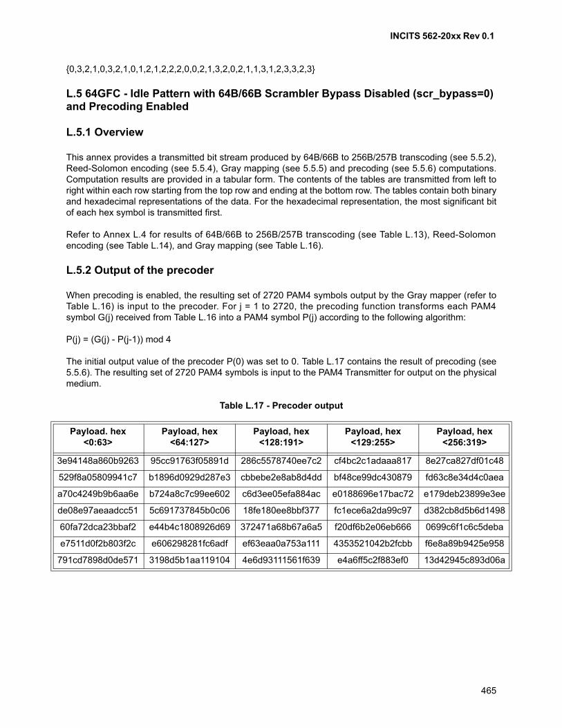
INCITS 562-20xx Rev 0.1
465
{0,3,2,1,0,3,2,1,0,1,2,1,2,2,2,0,0,2,1,3,2,0,2,1,1,3,1,2,3,3,2,3}
L.5 64GFC - Idle Pattern with 64B/66B Scrambler Bypass Disabled (scr_bypass=0) and Precoding Enabled
L.5.1 Overview
This annex provides a transmitted bit stream produced by 64B/66B to 256B/257B transcoding (see 5.5.2),Reed-Solomon encoding (see 5.5.4), Gray mapping (see 5.5.5) and precoding (see 5.5.6) computations.Computation results are provided in a tabular form. The contents of the tables are transmitted from left toright within each row starting from the top row and ending at the bottom row. The tables contain both binaryand hexadecimal representations of the data. For the hexadecimal representation, the most significant bitof each hex symbol is transmitted first.
Refer to Annex L.4 for results of 64B/66B to 256B/257B transcoding (see Table L.13), Reed-Solomonencoding (see Table L.14), and Gray mapping (see Table L.16).
L.5.2 Output of the precoder
When precoding is enabled, the resulting set of 2720 PAM4 symbols output by the Gray mapper (refer toTable L.16) is input to the precoder. For j = 1 to 2720, the precoding function transforms each PAM4symbol G(j) received from Table L.16 into a PAM4 symbol P(j) according to the following algorithm:
P(j) = (G(j) - P(j-1)) mod 4
The initial output value of the precoder P(0) was set to 0. Table L.17 contains the result of precoding (see5.5.6). The resulting set of 2720 PAM4 symbols is input to the PAM4 Transmitter for output on the physicalmedium.
Table L.17 - Precoder output
Payload. hex <0:63>
Payload, hex <64:127>
Payload, hex <128:191>
Payload, hex <129:255>
Payload, hex <256:319>
3e94148a860b9263 95cc91763f05891d 286c5578740ee7c2 cf4bc2c1adaaa817 8e27ca827df01c48
529f8a05809941c7 b1896d0929d287e3 cbbebe2e8ab8d4dd bf48ce99dc430879 fd63c8e34d4c0aea
a70c4249b9b6aa6e b724a8c7c99ee602 c6d3ee05efa884ac e0188696e17bac72 e179deb23899e3ee
de08e97aeaadcc51 5c691737845b0c06 18fe180ee8bbf377 fc1ece6a2da99c97 d382cb8d5b6d1498
60fa72dca23bbaf2 e44b4c1808926d69 372471a68b67a6a5 f20df6b2e06eb666 0699c6f1c6c5deba
e7511d0f2b803f2c e606298281fc6adf ef63eaa0a753a111 4353521042b2fcbb f6e8a89b9425e958
791cd7898d0de571 3198d5b1aa119104 4e6d93111561f639 e4a6ff5c2f883ef0 13d42945c893d06a
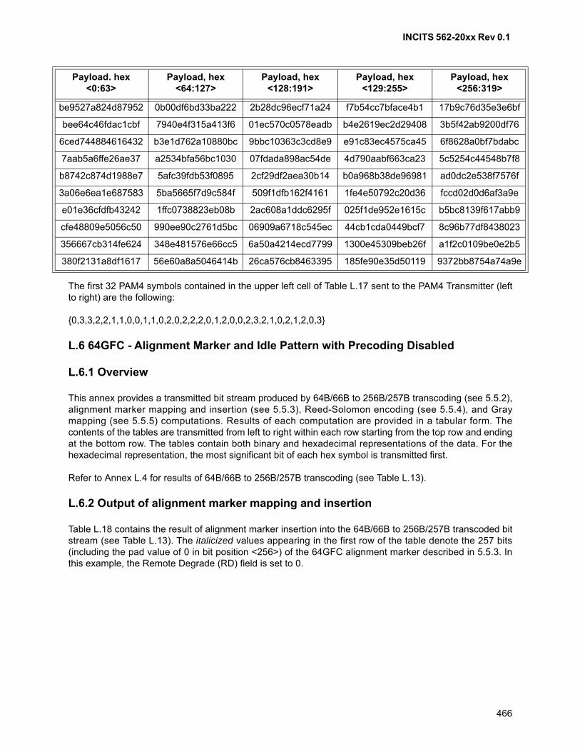
INCITS 562-20xx Rev 0.1
466
The first 32 PAM4 symbols contained in the upper left cell of Table L.17 sent to the PAM4 Transmitter (leftto right) are the following:
{0,3,3,2,2,1,1,0,0,1,1,0,2,0,2,2,2,0,1,2,0,0,2,3,2,1,0,2,1,2,0,3}
L.6 64GFC - Alignment Marker and Idle Pattern with Precoding Disabled
L.6.1 Overview
This annex provides a transmitted bit stream produced by 64B/66B to 256B/257B transcoding (see 5.5.2),alignment marker mapping and insertion (see 5.5.3), Reed-Solomon encoding (see 5.5.4), and Graymapping (see 5.5.5) computations. Results of each computation are provided in a tabular form. Thecontents of the tables are transmitted from left to right within each row starting from the top row and endingat the bottom row. The tables contain both binary and hexadecimal representations of the data. For thehexadecimal representation, the most significant bit of each hex symbol is transmitted first.
Refer to Annex L.4 for results of 64B/66B to 256B/257B transcoding (see Table L.13).
L.6.2 Output of alignment marker mapping and insertion
Table L.18 contains the result of alignment marker insertion into the 64B/66B to 256B/257B transcoded bitstream (see Table L.13). The italicized values appearing in the first row of the table denote the 257 bits(including the pad value of 0 in bit position <256>) of the 64GFC alignment marker described in 5.5.3. Inthis example, the Remote Degrade (RD) field is set to 0.
be9527a824d87952 0b00df6bd33ba222 2b28dc96ecf71a24 f7b54cc7bface4b1 17b9c76d35e3e6bf
bee64c46fdac1cbf 7940e4f315a413f6 01ec570c0578eadb b4e2619ec2d29408 3b5f42ab9200df76
6ced744884616432 b3e1d762a10880bc 9bbc10363c3cd8e9 e91c83ec4575ca45 6f8628a0bf7bdabc
7aab5a6ffe26ae37 a2534bfa56bc1030 07fdada898ac54de 4d790aabf663ca23 5c5254c44548b7f8
b8742c874d1988e7 5afc39fdb53f0895 2cf29df2aea30b14 b0a968b38de96981 ad0dc2e538f7576f
3a06e6ea1e687583 5ba5665f7d9c584f 509f1dfb162f4161 1fe4e50792c20d36 fccd02d0d6af3a9e
e01e36cfdfb43242 1ffc0738823eb08b 2ac608a1ddc6295f 025f1de952e1615c b5bc8139f617abb9
cfe48809e5056c50 990ee90c2761d5bc 06909a6718c545ec 44cb1cda0449bcf7 8c96b77df8438023
356667cb314fe624 348e481576e66cc5 6a50a4214ecd7799 1300e45309beb26f a1f2c0109be0e2b5
380f2131a8df1617 56e60a8a5046414b 26ca576cb8463395 185fe90e35d50119 9372bb8754a74a9e
Payload. hex <0:63>
Payload, hex <64:127>
Payload, hex <128:191>
Payload, hex <129:255>
Payload, hex <256:319>
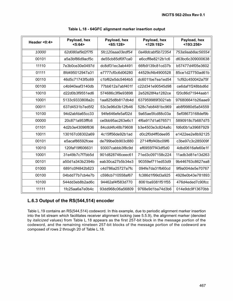
INCITS 562-20xx Rev 0.1
467
Table L.18 - 64GFC alignment marker insertion output
L.6.3 Output of the RS(544,514) encoder
Table L.19 contains an RS(544,514) codeword. In this example, due to periodic alignment marker insertioninto the bit stream which facilitates receiver alignment locking (see 5.5.9), the alignment marker (denotedby italicized values) from Table L.18 appears as the first 257-bit block in the message portion of thecodeword, and the remaining nineteen 257-bit blocks of the message portion of the codeword arecomposed of rows 2 through 20 of Table L.18.
Header <0:4>Payload, hex
<5:64>Payload, hex
<65:128>Payload, hex
<129:192>Payload, hex
<193:256>
10000 62d080af9d2f7f5 5fc120aaa03edf54 0a48dcabf5b72354 753a9aab8ac56554
00101 a5a3bf86d9acf5c de55cb85df0f7ca0 e6ccff8e8212b1c6 d63bc6c309000638
11110 7e3b0ce30e0497d dc8df31ec3ab4491 66fb9139c81cd37b b57477d4f05e3602
01111 8fd495012947a31 e7777cf0c6d06280 44529cf4b4900528 85ce1d27750ad61b
00110 46d5c71743f5c69 c1bf62e5dc5464b5 dc6011be7ea1ed54 1cf92c450042a75f
00100 c4b940eaf3140db 77bb612a7abf401f c22d341e90545d98 ce6daf1f248bbd6d
10010 d22d0b3f9551ed6 574686c3f9e93898 2e52628f4a1282ce f20c86d71944aab1
10001 5133c9333808a2c 1aa825d8b817db4d 637959989f3021eb 976806641b26aae9
00011 637d4531b7ed5f2 53c3e96d3b12fb46 528c7eb8481bc969 ab8f9980d5a54559
10100 94d2abfda65cc33 94fe646efe5af02d 9a65ae5fcd88c03a 5ef08673168def9b
00000 20c871a953fffc6 ce0bb95ac263e6c1 4f6a917d1a676571 5890918c7b687d75
01101 4d2b3e43096f836 84cdd4fc48b79608 b3e4503e3c824a8c fd6d0b1a39687929
10011 130167c08302a69 4c15ff56de92b1ad d0c2f0d4ff0dee95 e1422ee2e8b92125
00101 e5acaf86592fcee de799be0b903c880 2714ffbf40bc09f6 c3be97c3c285009f
10010 120faf19f606631 93007cabbb3f8c9d ef6955f7f43df5d0 4dbd0616afe60e1f
10001 31e49b7c7f7bb5d 901d828746ceec61 71ed3c097158c224 11adb3d81e13d263
00101 a50d1a343b2394b eab30ca27b5b34e3 90359ef711ed53d9 9b446763c8627ea8
01000 6891c0f4842b823 c4d786a25727a7fc 094fe7da31fb60cd 9f9a004de5e70767
00100 04bdd77b7cb4e7b c598cb710558af67 fc386d1f99d3a925 4928e0b43e781893
10100 544dd3eb8b2ad6c 94462af4f583d770 8061ba9381f51f55 476d4eded7c90fcc
11111 1fc25aa6a7e0b4c 93dd968c06a56809 9768e9d1ba74d3b6 014e9dc9f13670bb
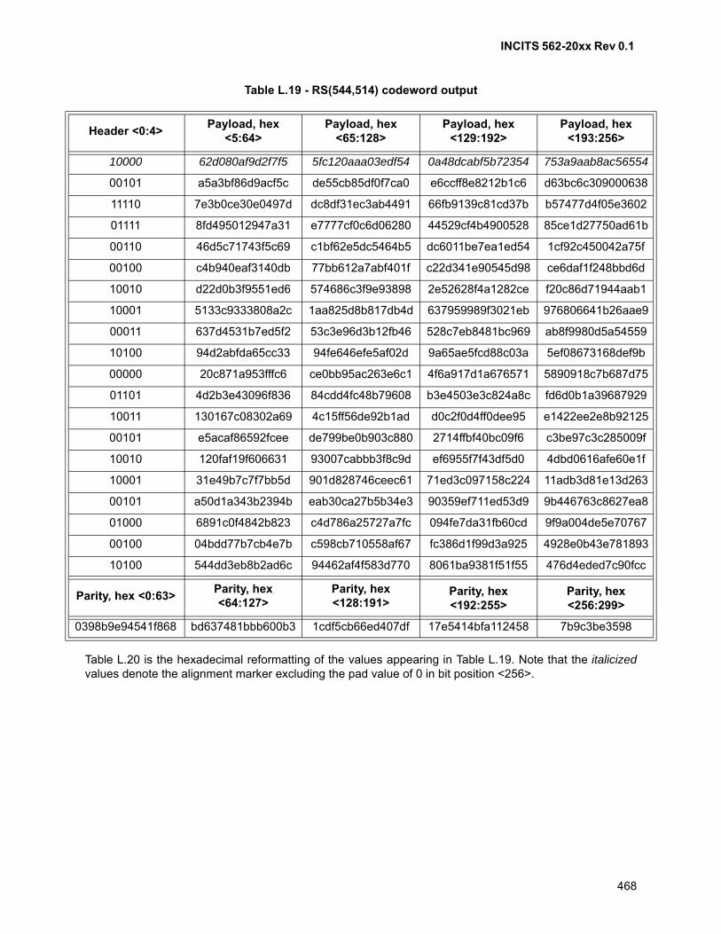
INCITS 562-20xx Rev 0.1
468
Table L.19 - RS(544,514) codeword output
Table L.20 is the hexadecimal reformatting of the values appearing in Table L.19. Note that the italicizedvalues denote the alignment marker excluding the pad value of 0 in bit position <256>.
Header <0:4>Payload, hex
<5:64>Payload, hex
<65:128>Payload, hex
<129:192>Payload, hex
<193:256>
10000 62d080af9d2f7f5 5fc120aaa03edf54 0a48dcabf5b72354 753a9aab8ac56554
00101 a5a3bf86d9acf5c de55cb85df0f7ca0 e6ccff8e8212b1c6 d63bc6c309000638
11110 7e3b0ce30e0497d dc8df31ec3ab4491 66fb9139c81cd37b b57477d4f05e3602
01111 8fd495012947a31 e7777cf0c6d06280 44529cf4b4900528 85ce1d27750ad61b
00110 46d5c71743f5c69 c1bf62e5dc5464b5 dc6011be7ea1ed54 1cf92c450042a75f
00100 c4b940eaf3140db 77bb612a7abf401f c22d341e90545d98 ce6daf1f248bbd6d
10010 d22d0b3f9551ed6 574686c3f9e93898 2e52628f4a1282ce f20c86d71944aab1
10001 5133c9333808a2c 1aa825d8b817db4d 637959989f3021eb 976806641b26aae9
00011 637d4531b7ed5f2 53c3e96d3b12fb46 528c7eb8481bc969 ab8f9980d5a54559
10100 94d2abfda65cc33 94fe646efe5af02d 9a65ae5fcd88c03a 5ef08673168def9b
00000 20c871a953fffc6 ce0bb95ac263e6c1 4f6a917d1a676571 5890918c7b687d75
01101 4d2b3e43096f836 84cdd4fc48b79608 b3e4503e3c824a8c fd6d0b1a39687929
10011 130167c08302a69 4c15ff56de92b1ad d0c2f0d4ff0dee95 e1422ee2e8b92125
00101 e5acaf86592fcee de799be0b903c880 2714ffbf40bc09f6 c3be97c3c285009f
10010 120faf19f606631 93007cabbb3f8c9d ef6955f7f43df5d0 4dbd0616afe60e1f
10001 31e49b7c7f7bb5d 901d828746ceec61 71ed3c097158c224 11adb3d81e13d263
00101 a50d1a343b2394b eab30ca27b5b34e3 90359ef711ed53d9 9b446763c8627ea8
01000 6891c0f4842b823 c4d786a25727a7fc 094fe7da31fb60cd 9f9a004de5e70767
00100 04bdd77b7cb4e7b c598cb710558af67 fc386d1f99d3a925 4928e0b43e781893
10100 544dd3eb8b2ad6c 94462af4f583d770 8061ba9381f51f55 476d4eded7c90fcc
Parity, hex <0:63>Parity, hex <64:127>
Parity, hex <128:191>
Parity, hex <192:255>
Parity, hex <256:299>
0398b9e94541f868 bd637481bbb600b3 1cdf5cb66ed407df 17e5414bfa112458 7b9c3be3598
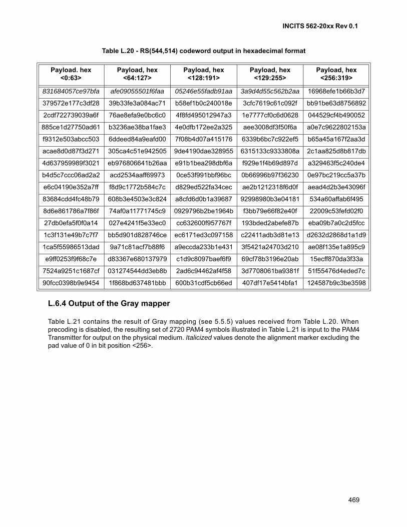
INCITS 562-20xx Rev 0.1
469
Table L.20 - RS(544,514) codeword output in hexadecimal format
L.6.4 Output of the Gray mapper
Table L.21 contains the result of Gray mapping (see 5.5.5) values received from Table L.20. Whenprecoding is disabled, the resulting set of 2720 PAM4 symbols illustrated in Table L.21 is input to the PAM4Transmitter for output on the physical medium. Italicized values denote the alignment marker excluding thepad value of 0 in bit position <256>.
Payload. hex <0:63>
Payload, hex <64:127>
Payload, hex <128:191>
Payload, hex <129:255>
Payload, hex <256:319>
831684057ce97bfa afe09055501f6faa 05246e55fadb91aa 3a9d4d55c562b2aa 16968efe1b66b3d7
379572e177c3df28 39b33fe3a084ac71 b58ef1b0c240018e 3cfc7619c61c092f bb91be63d8756892
2cdf722739039a6f 76ae8efa9e0bc6c0 4f8fd495012947a3 1e7777cf0c6d0628 044529cf4b490052
885ce1d27750ad61 b3236ae38ba1fae3 4e0dfb172ee2a325 aee3008df3f50f6a a0e7c9622802153a
f9312e503abcc503 6ddeed84a9eafd00 7f08b4d07a415176 6339b6bc7c922ef5 b65a45a167f2aa3d
acae8d0d87f3d271 305ca4c51e942505 9de4190dae328955 6315133c9333808a 2c1aa825d8b817db
4d637959989f3021 eb976806641b26aa e91b1bea298dbf6a f929e1f4b69d897d a329463f5c240de4
b4d5c7ccc06ad2a2 acd2534aaff69973 0ce53f991bbf96bc 0b66996b97f36230 0e97bc219cc5a37b
e6c04190e352a7ff f8d9c1772b584c7c d829ed522fa34cec ae2b1212318f6d0f aead4d2b3e43096f
83684cdd4fc48b79 608b3e4503e3c824 a8cfd6d0b1a39687 92998980b3e04181 534a60affab6f495
8d6e861786a7f86f 74af0a11771745c9 0929796b2be1964b f3bb79e66f82e40f 22009c53fefd02f0
27db0efa5f0f0a14 027e4241f5e33ec0 cc632600f957767f 193bded2abefe87b eba09b7a0c2d5fcc
1c3f131e49b7c7f7 bb5d901d828746ce ec6171ed3c097158 c22411adb3d81e13 d2632d2868d1a1d9
1ca5f55986513dad 9a71c81acf7b88f6 a9eccda233b1e431 3f5421a24703d210 ae08f135e1a895c9
e9ff0253f9f68c7e d83367e680137979 c1d9c8097baef6f9 69cf78b3196e20ab 15ecff870da3f33a
7524a9251c1687cf 031274544dd3eb8b 2ad6c94462af4f58 3d7708061ba9381f 51f55476d4eded7c
90fcc0398b9e9454 1f868bd637481bbb 600b31cdf5cb66ed 407df17e5414bfa1 124587b9c3be3598
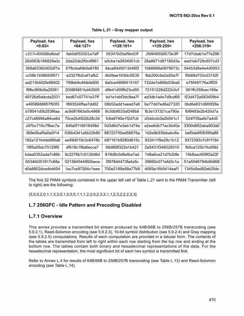
INCITS 562-20xx Rev 0.1
470
Table L.21 - Gray mapper output
The first 32 PAM4 symbols contained in the upper left cell of Table L.21 sent to the PAM4 Transmitter (leftto right) are the following:
{3,0,0,2,0,1,1,3,3,0,1,0,0,0,1,1,1,2,2,0,2,3,3,1,1,2,3,2,2,2,3,3}
L.7 256GFC - Idle Pattern and Precoding Disabled
L.7.1 Overview
This annex provides a transmitted bit stream produced by 64B/66B to 256B/257B transcoding (see5.9.2.1), Reed-Solomon encoding (see 5.9.2.3), 10-bit symbol distribution (see 5.9.2.4) and Gray mapping(see 5.9.2.5) computations. Results of each computation are provided in a tabular form. The contents ofthe tables are transmitted from left to right within each row starting from the top row and ending at thebottom row. The tables contain both binary and hexadecimal representations of the data. For thehexadecimal representation, the most significant bit of each hex symbol is transmitted first.
Refer to Annex L.4 for results of 64B/66B to 256B/257B transcoding (see Table L.13) and Reed-Solomonencoding (see Table L.14).
Payload. hex <0:63>
Payload, hex <64:127>
Payload, hex <128:191>
Payload, hex <129:255>
Payload, hex <256:319>
c217c40568bd6eaf fab0d055501a7aff 05347b55af9ed1ff 2fd949558573e3ff 17d7cbab1e77e296
26d563b166829a3c 2de22ab2f0c4f861 e5cba1e0834001cb 28a8671d87180d3a eed1eb729c657cd3
389a63362d02df7a 67fbcbafdb0e8780 4aca94d5013d46f2 1b66668a0879073c 04453d8a4e4d0053
cc58b1936650f971 e2327fb2cef1afb2 4b09ae163bb3f235 fbb200c9a2a50a7f f0b68d733c03152f
ad213b502fe88502 799bb9c4fdbfa900 6a0ce4906f415167 722de7e868d33ba5 e75f45f176a3ff29
f8fbc909c6a29361 2058f4851bd43505 d9b41d09fb23cd55 72151228d222c0cf 381ffc359cec169e
49726d5ddcda2031 bed67c07741e37ff bd1e1ebf3dc9ea7f ad3db1a4e7d9cd69 f23d472a583409b4
e4958688807f93f3 f893524ffaa7dd62 08b52add1eead7e8 0e77dd7ed6a27320 0bd6e831d885f26e
b78041d0b253f6aa ac9d81663e5c4868 9c3db9533af248b8 fb3e131321ca790a fbf9493e2b420d7a
c27c48994a84ce6d 70ce2b4502b28c34 fc8a9790e1f2d7c6 d3ddcdc0e2b041c1 524f70faafe7a4d5
c97bc716c7f6ac7a 64fa0f116616458d 0d3d6d7e3eb1d74e a2ee6db77ac3b40a 3300d852aba903a0
369e0baf5a0a0f14 036b4341a5b22b80 88723700ad56676a 1d2e9b93febabc6e bef0de6f08395a88
182a121b4de686a6 ee59d019c3c6478b b87161b9280d615c 833411f9e29c1b12 9372393c7c91f19d
18f5a55dc75129f9 df618c1f8a6ecca7 fdb889f322e1b421 2a5431f346029310 fb0ca125b1fcd58d
bdaa0352ada7c86b 9c2276b7c0126d6d 819d8c0d6efba7ad 7d8a6ce21d7b30fe 15b8aac609f2a22f
6534fd351817c68a 021364544992bece 3f978d4473fa4a5c 29660c071efd2c1a 51a5546794b9b968
d0a8802dcedbd454 1ac7ce97264c1eee 700e2189a58e77b9 4069a16b5414eaf1 1345c6ed82eb25dc
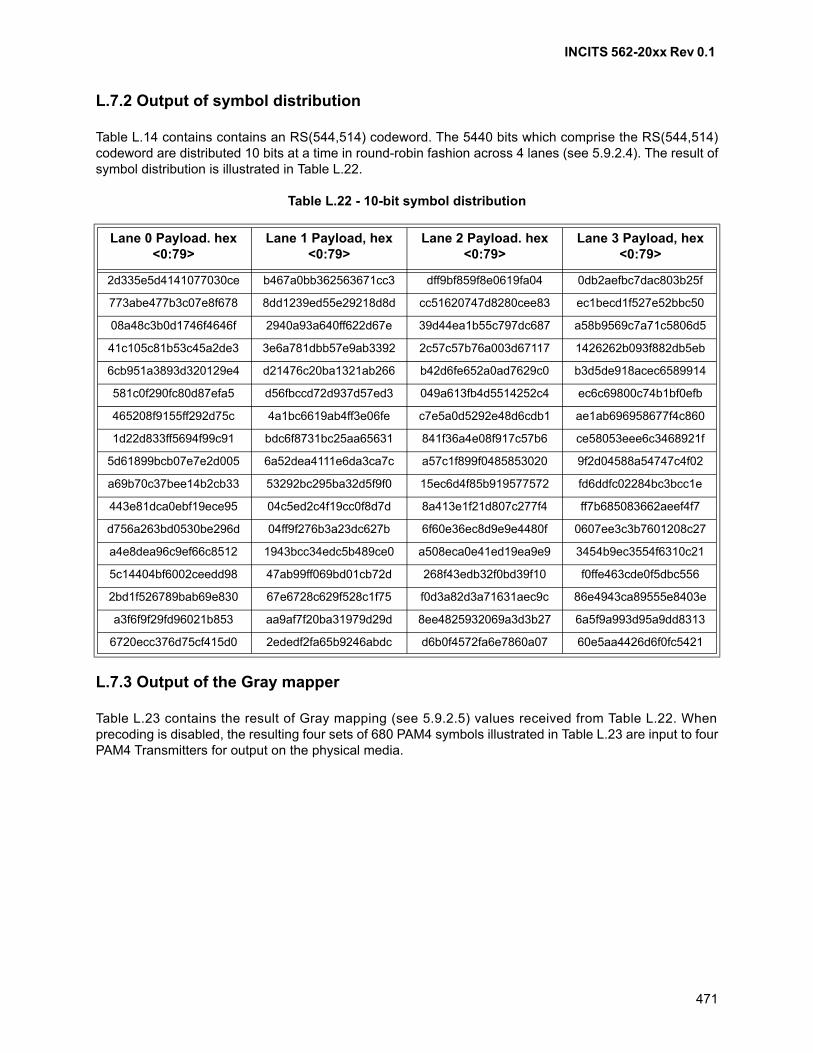
INCITS 562-20xx Rev 0.1
471
L.7.2 Output of symbol distribution
Table L.14 contains contains an RS(544,514) codeword. The 5440 bits which comprise the RS(544,514)codeword are distributed 10 bits at a time in round-robin fashion across 4 lanes (see 5.9.2.4). The result ofsymbol distribution is illustrated in Table L.22.
Table L.22 - 10-bit symbol distribution
L.7.3 Output of the Gray mapper
Table L.23 contains the result of Gray mapping (see 5.9.2.5) values received from Table L.22. Whenprecoding is disabled, the resulting four sets of 680 PAM4 symbols illustrated in Table L.23 are input to fourPAM4 Transmitters for output on the physical media.
Lane 0 Payload. hex <0:79>
Lane 1 Payload, hex <0:79>
Lane 2 Payload. hex <0:79>
Lane 3 Payload, hex <0:79>
2d335e5d4141077030ce b467a0bb362563671cc3 dff9bf859f8e0619fa04 0db2aefbc7dac803b25f
773abe477b3c07e8f678 8dd1239ed55e29218d8d cc51620747d8280cee83 ec1becd1f527e52bbc50
08a48c3b0d1746f4646f 2940a93a640ff622d67e 39d44ea1b55c797dc687 a58b9569c7a71c5806d5
41c105c81b53c45a2de3 3e6a781dbb57e9ab3392 2c57c57b76a003d67117 1426262b093f882db5eb
6cb951a3893d320129e4 d21476c20ba1321ab266 b42d6fe652a0ad7629c0 b3d5de918acec6589914
581c0f290fc80d87efa5 d56fbccd72d937d57ed3 049a613fb4d5514252c4 ec6c69800c74b1bf0efb
465208f9155ff292d75c 4a1bc6619ab4ff3e06fe c7e5a0d5292e48d6cdb1 ae1ab696958677f4c860
1d22d833ff5694f99c91 bdc6f8731bc25aa65631 841f36a4e08f917c57b6 ce58053eee6c3468921f
5d61899bcb07e7e2d005 6a52dea4111e6da3ca7c a57c1f899f0485853020 9f2d04588a54747c4f02
a69b70c37bee14b2cb33 53292bc295ba32d5f9f0 15ec6d4f85b919577572 fd6ddfc02284bc3bcc1e
443e81dca0ebf19ece95 04c5ed2c4f19cc0f8d7d 8a413e1f21d807c277f4 ff7b685083662aeef4f7
d756a263bd0530be296d 04ff9f276b3a23dc627b 6f60e36ec8d9e9e4480f 0607ee3c3b7601208c27
a4e8dea96c9ef66c8512 1943bcc34edc5b489ce0 a508eca0e41ed19ea9e9 3454b9ec3554f6310c21
5c14404bf6002ceedd98 47ab99ff069bd01cb72d 268f43edb32f0bd39f10 f0ffe463cde0f5dbc556
2bd1f526789bab69e830 67e6728c629f528c1f75 f0d3a82d3a71631aec9c 86e4943ca89555e8403e
a3f6f9f29fd96021b853 aa9af7f20ba31979d29d 8ee4825932069a3d3b27 6a5f9a993d95a9dd8313
6720ecc376d75cf415d0 2ededf2fa65b9246abdc d6b0f4572fa6e7860a07 60e5aa4426d6f0fc5421
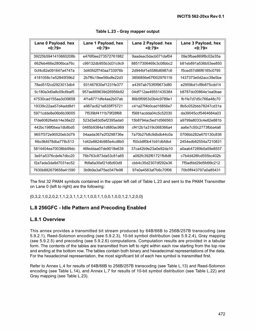
INCITS 562-20xx Rev 0.1
472
Table L.23 - Gray mapper output
The first 32 PAM4 symbols contained in the upper left cell of Table L.23 and sent to the PAM4 Transmitteron Lane 0 (left to right) are the following:
{0,3,2,1,0,2,0,2,1,1,2,3,1,1,2,1,1,0,0,1,1,0,0,1,0,0,1,2,1,2,0,0}
L.8 256GFC - Idle Pattern and Precoding Enabled
L.8.1 Overview
This annex provides a transmitted bit stream produced by 64B/66B to 256B/257B transcoding (see5.9.2.1), Reed-Solomon encoding (see 5.9.2.3), 10-bit symbol distribution (see 5.9.2.4), Gray mapping(see 5.9.2.5) and precoding (see 5.9.2.6) computations. Computation results are provided in a tabularform. The contents of the tables are transmitted from left to right within each row starting from the top rowand ending at the bottom row. The tables contain both binary and hexadecimal representations of the data.For the hexadecimal representation, the most significant bit of each hex symbol is transmitted first.
Refer to Annex L.4 for results of 64B/66B to 256B/257B transcoding (see Table L.13) and Reed-Solomonencoding (see Table L.14), and Annex L.7 for results of 10-bit symbol distribution (see Table L.22) andGray mapping (see Table L.23).
Lane 0 Payload. hex <0:79>
Lane 1 Payload, hex <0:79>
Lane 2 Payload. hex <0:79>
Lane 3 Payload, hex <0:79>
39225b5941410660208b e476f0ee273572761882 9aadeac5dacb071daf04 09e3fbae869f8c02e35a
662feb466e2806bca76c c99132db955b3d31c9c9 88517306469c3c08bbc2 b81eb891a536b53ee850
0cf4c82e091647a4747a 3d40fd2f740aa733976b 2d944bf1e5586d6987c6 f5ced57d86f6185c0795
4181058c1e52845f39b2 2b7f6c19ee56bdfe22d3 3856856e67f002976116 1437373e0d2acc39e5be
78ed51f2cd2923013db4 931467830ef1231fe377 e4397ab753f0f9673d80 e2959bd1cf8b875cdd14
5c180a3d0a8c09c6baf5 957ae889639d26956b92 04df712ae49551435384 b8787dc00864e1ea0bae
47530cad155aa3d39658 4f1e8771dfe4aa2b07ab 86b5f0953d3b4c9789e1 fb1fe7d7d5c766a48c70
19339c22aa57d4add8d1 e987ac621e835ff75721 c41a27f4b0cad16856e7 8b5c052bbb78247cd31a
5971cdde8e06b6b39005 7f539bf4111b79f28f68 f5681acdda04c5c52030 da39045ccf5464684a03
f7de60826ebb14e38e22 523d3e83d5ef2395ada0 15b8794ac5ed1d566563 a9799a8033c4e82e881b
442bc198f0bea1db8bd5 0485b9384a1d880ac969 cf412b1a319c068366a4 aa6e7c50c2773fbba4a6
9657f372e90520eb3d79 04aada367e2f3298736e 7a70b27b8c9dbdb44c0a 0706bb282e670130c836
f4bc9bfd78dba778c513 1d42e8824b985e4cd8b0 f50cb8f0b41b91dbfdbd 2454edb82554a7210831
5814404ea70038bb99dc 46feddaa07de9018e639 37ca42b9e23a0e92da10 a0aab47289b0a59e8557
3e91a5376cdefe7dbc20 76b763c873da53c81a65 a092fc392f61721fb8d8 c7b4d428fcd555bc402b
f2a7ada3da9d7031ec52 ffdfa6a30ef21d6d93d9 cbb4c35d2307df292e36 7f5adfdd29d5fd99c212
7630b882679658a41590 3b9b9a3af75ed347fe98 97e0a4563af7b6c70f06 70b5ff443797a0a85431
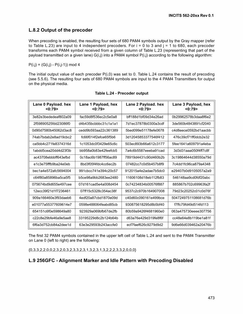
INCITS 562-20xx Rev 0.1
473
L.8.2 Output of the precoder
When precoding is enabled, the resulting four sets of 680 PAM4 symbols output by the Gray mapper (referto Table L.23) are input to 4 independent precoders. For i = 0 to 3 and j = 1 to 680, each precodertransforms each PAM4 symbol received from a given column of Table L.23 (representing that part of thepayload transmitted on a given lane) G(i,j) into a PAM4 symbol P(i,j) according to the following algorithm:
P(i,j) = (G(i,j) - P(i,j-1)) mod 4
The initial output value of each precoder P(i,0) was set to 0. Table L.24 contains the result of precoding(see 5.5.6). The resulting four sets of 680 PAM4 symbols are input to the 4 PAM4 Transmitters for outputon the physical media.
Table L.24 - Precoder output
The first 32 PAM4 symbols contained in the upper left cell of Table L.24 and sent to the PAM4 Transmitteron Lane 0 (left to right) are the following:
{0,3,3,2,2,0,0,2,3,2,0,3,2,3,3,2,3,1,3,2,3,1,3,2,2,2,3,3,2,0,0,0}
L.9 256GFC - Alignment Marker and Idle Pattern with Precoding Disabled
Lane 0 Payload. hex <0:79>
Lane 1 Payload, hex <0:79>
Lane 2 Payload. hex <0:79>
Lane 3 Payload, hex <0:79>
3e82e3bededeaf802a09 fac59d8f536ec2c5e0a8 bff188d1bf09d34e26ad 0b29962578b3daa8f6e2
2f59890525fdd23086f0 d4b435bcbbbc31c1a1a1 7d1ec37878b0300a3cdf 3de560b4843891cf2040
0d90d7580b45062d3ac8 cedd9b593aa22c361389 5bed099e51178efe0678 c4d8eece0592bd1aacbb
74ab7bdab2e8ad19cbc2 fc66f014f2efce65f5b6 3d12045853377546f412 476c39cf71ff0dcb2e32
ca5bb4c271fe8374316d 1c1053dc0f3429e65c6c 503ec893b66a612c3177 5fee1641a609791a4eba
1abdd5cea20dd4d23f3b bb958a0b83e42feefcb5 7a4c6b5587eeeba91cad 3d3d31aaa050f4ff7c8f
ac43708ebbbff643efbd 0c18ac6b1987ff56ac89 78919d4431c90d460b2b 3c19864644d38550a79d
e1c3e75fffb9ba24e0eb 8bd3f05f4fdc4cc6ec2b 07482cc7c0d5b457b8f9 7c4dd1fc96ca879a4348
bec1a4e572afc5694004 991cbcc741e394c20c57 912015a4e2adae7b5dc0 e29407b0d9105057a2a9
c64f80a85896ba5ca5f5 b5ce98a9bb2683ee2480 11606108d18eb112fb83 546148aa9cd0fdf20abc
075674bd9d655e497cee 07d161cad5e4a008d454 0c74234834b00576f887 885867b702c69963fa2f
12ecc39f21d1f7236461 07ff15c5328c354ac38f 9537c2c970b164907008 79d23c20252c01c0d76f
909a166460e3f93daeb6 4edf20a87cbd1870e09d c40d60c090161e499bce 5047249751108681d76b
e01077a55377609614e7 0598e488064feabd85cb 930875618295d8b5bf40 f7ffc79fd49d514fd113
654151c6f0e598649a80 923929a069bfb67de2fb 80b59a9426f4681960e0 063a475730eeee307756
c22c8e29bfe46a9e5ae8 33195229d8c2b124b64b d63a76e429d319fe8f6f cc48e64e8b119be1a81f
6f6a3d752cb84a2dee1d 63e3e29593b243accfe0 ecf7faef626c9279d9d2 9d6e66d039462a20476b
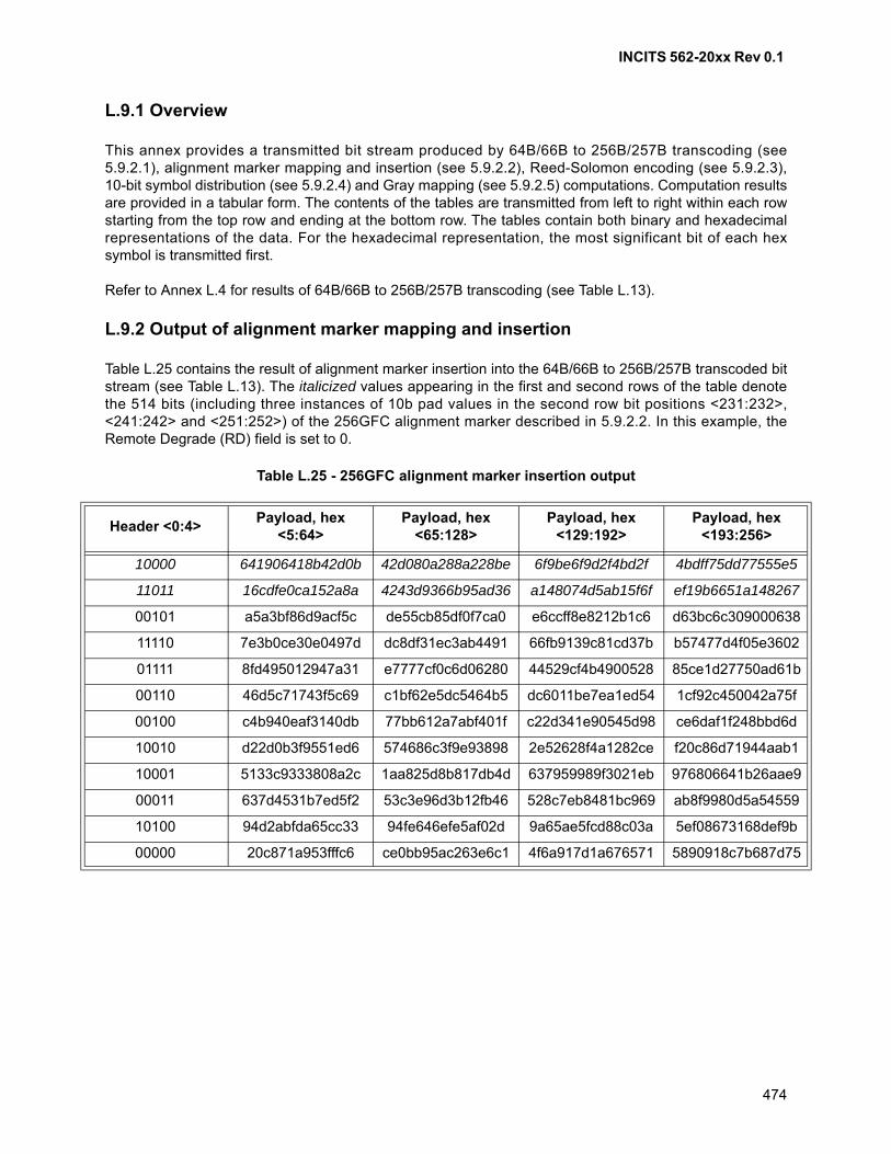
INCITS 562-20xx Rev 0.1
474
L.9.1 Overview
This annex provides a transmitted bit stream produced by 64B/66B to 256B/257B transcoding (see5.9.2.1), alignment marker mapping and insertion (see 5.9.2.2), Reed-Solomon encoding (see 5.9.2.3),10-bit symbol distribution (see 5.9.2.4) and Gray mapping (see 5.9.2.5) computations. Computation resultsare provided in a tabular form. The contents of the tables are transmitted from left to right within each rowstarting from the top row and ending at the bottom row. The tables contain both binary and hexadecimalrepresentations of the data. For the hexadecimal representation, the most significant bit of each hexsymbol is transmitted first.
Refer to Annex L.4 for results of 64B/66B to 256B/257B transcoding (see Table L.13).
L.9.2 Output of alignment marker mapping and insertion
Table L.25 contains the result of alignment marker insertion into the 64B/66B to 256B/257B transcoded bitstream (see Table L.13). The italicized values appearing in the first and second rows of the table denotethe 514 bits (including three instances of 10b pad values in the second row bit positions <231:232>,<241:242> and <251:252>) of the 256GFC alignment marker described in 5.9.2.2. In this example, theRemote Degrade (RD) field is set to 0.
Table L.25 - 256GFC alignment marker insertion output
Header <0:4>Payload, hex
<5:64>Payload, hex
<65:128>Payload, hex
<129:192>Payload, hex
<193:256>
10000 641906418b42d0b 42d080a288a228be 6f9be6f9d2f4bd2f 4bdff75dd77555e5
11011 16cdfe0ca152a8a 4243d9366b95ad36 a148074d5ab15f6f ef19b6651a148267
00101 a5a3bf86d9acf5c de55cb85df0f7ca0 e6ccff8e8212b1c6 d63bc6c309000638
11110 7e3b0ce30e0497d dc8df31ec3ab4491 66fb9139c81cd37b b57477d4f05e3602
01111 8fd495012947a31 e7777cf0c6d06280 44529cf4b4900528 85ce1d27750ad61b
00110 46d5c71743f5c69 c1bf62e5dc5464b5 dc6011be7ea1ed54 1cf92c450042a75f
00100 c4b940eaf3140db 77bb612a7abf401f c22d341e90545d98 ce6daf1f248bbd6d
10010 d22d0b3f9551ed6 574686c3f9e93898 2e52628f4a1282ce f20c86d71944aab1
10001 5133c9333808a2c 1aa825d8b817db4d 637959989f3021eb 976806641b26aae9
00011 637d4531b7ed5f2 53c3e96d3b12fb46 528c7eb8481bc969 ab8f9980d5a54559
10100 94d2abfda65cc33 94fe646efe5af02d 9a65ae5fcd88c03a 5ef08673168def9b
00000 20c871a953fffc6 ce0bb95ac263e6c1 4f6a917d1a676571 5890918c7b687d75
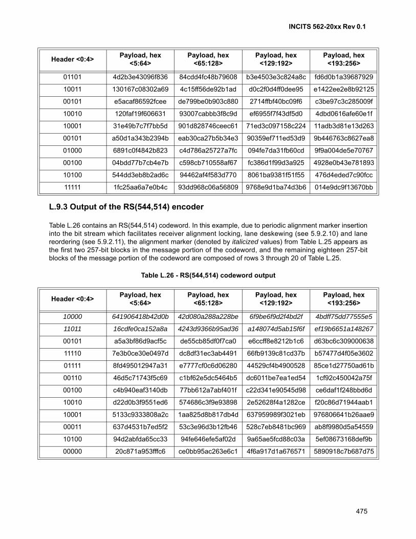
INCITS 562-20xx Rev 0.1
475
L.9.3 Output of the RS(544,514) encoder
Table L.26 contains an RS(544,514) codeword. In this example, due to periodic alignment marker insertioninto the bit stream which facilitates receiver alignment locking, lane deskewing (see 5.9.2.10) and lanereordering (see 5.9.2.11), the alignment marker (denoted by italicized values) from Table L.25 appears asthe first two 257-bit blocks in the message portion of the codeword, and the remaining eighteen 257-bitblocks of the message portion of the codeword are composed of rows 3 through 20 of Table L.25.
Table L.26 - RS(544,514) codeword output
01101 4d2b3e43096f836 84cdd4fc48b79608 b3e4503e3c824a8c fd6d0b1a39687929
10011 130167c08302a69 4c15ff56de92b1ad d0c2f0d4ff0dee95 e1422ee2e8b92125
00101 e5acaf86592fcee de799be0b903c880 2714ffbf40bc09f6 c3be97c3c285009f
10010 120faf19f606631 93007cabbb3f8c9d ef6955f7f43df5d0 4dbd0616afe60e1f
10001 31e49b7c7f7bb5d 901d828746ceec61 71ed3c097158c224 11adb3d81e13d263
00101 a50d1a343b2394b eab30ca27b5b34e3 90359ef711ed53d9 9b446763c8627ea8
01000 6891c0f4842b823 c4d786a25727a7fc 094fe7da31fb60cd 9f9a004de5e70767
00100 04bdd77b7cb4e7b c598cb710558af67 fc386d1f99d3a925 4928e0b43e781893
10100 544dd3eb8b2ad6c 94462af4f583d770 8061ba9381f51f55 476d4eded7c90fcc
11111 1fc25aa6a7e0b4c 93dd968c06a56809 9768e9d1ba74d3b6 014e9dc9f13670bb
Header <0:4>Payload, hex
<5:64>Payload, hex
<65:128>Payload, hex
<129:192>Payload, hex
<193:256>
10000 641906418b42d0b 42d080a288a228be 6f9be6f9d2f4bd2f 4bdff75dd77555e5
11011 16cdfe0ca152a8a 4243d9366b95ad36 a148074d5ab15f6f ef19b6651a148267
00101 a5a3bf86d9acf5c de55cb85df0f7ca0 e6ccff8e8212b1c6 d63bc6c309000638
11110 7e3b0ce30e0497d dc8df31ec3ab4491 66fb9139c81cd37b b57477d4f05e3602
01111 8fd495012947a31 e7777cf0c6d06280 44529cf4b4900528 85ce1d27750ad61b
00110 46d5c71743f5c69 c1bf62e5dc5464b5 dc6011be7ea1ed54 1cf92c450042a75f
00100 c4b940eaf3140db 77bb612a7abf401f c22d341e90545d98 ce6daf1f248bbd6d
10010 d22d0b3f9551ed6 574686c3f9e93898 2e52628f4a1282ce f20c86d71944aab1
10001 5133c9333808a2c 1aa825d8b817db4d 637959989f3021eb 976806641b26aae9
00011 637d4531b7ed5f2 53c3e96d3b12fb46 528c7eb8481bc969 ab8f9980d5a54559
10100 94d2abfda65cc33 94fe646efe5af02d 9a65ae5fcd88c03a 5ef08673168def9b
00000 20c871a953fffc6 ce0bb95ac263e6c1 4f6a917d1a676571 5890918c7b687d75
Header <0:4>Payload, hex
<5:64>Payload, hex
<65:128>Payload, hex
<129:192>Payload, hex
<193:256>
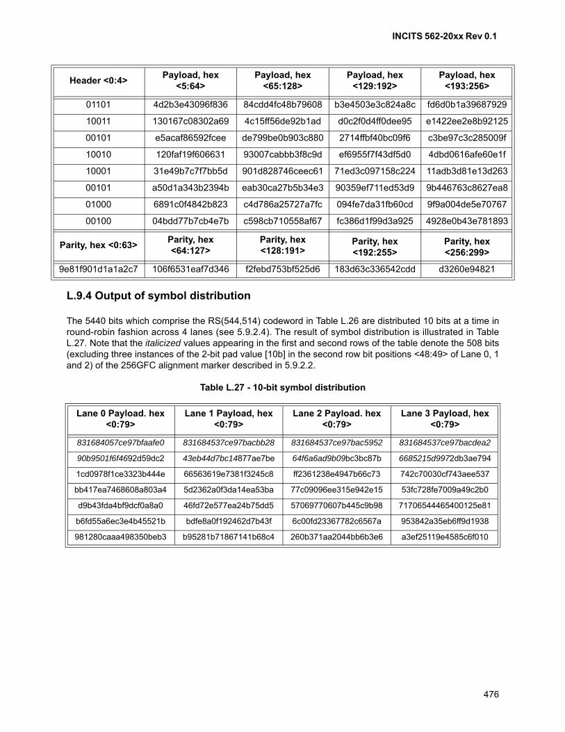
INCITS 562-20xx Rev 0.1
476
L.9.4 Output of symbol distribution
The 5440 bits which comprise the RS(544,514) codeword in Table L.26 are distributed 10 bits at a time inround-robin fashion across 4 lanes (see 5.9.2.4). The result of symbol distribution is illustrated in TableL.27. Note that the italicized values appearing in the first and second rows of the table denote the 508 bits(excluding three instances of the 2-bit pad value [10b] in the second row bit positions <48:49> of Lane 0, 1and 2) of the 256GFC alignment marker described in 5.9.2.2.
Table L.27 - 10-bit symbol distribution
01101 4d2b3e43096f836 84cdd4fc48b79608 b3e4503e3c824a8c fd6d0b1a39687929
10011 130167c08302a69 4c15ff56de92b1ad d0c2f0d4ff0dee95 e1422ee2e8b92125
00101 e5acaf86592fcee de799be0b903c880 2714ffbf40bc09f6 c3be97c3c285009f
10010 120faf19f606631 93007cabbb3f8c9d ef6955f7f43df5d0 4dbd0616afe60e1f
10001 31e49b7c7f7bb5d 901d828746ceec61 71ed3c097158c224 11adb3d81e13d263
00101 a50d1a343b2394b eab30ca27b5b34e3 90359ef711ed53d9 9b446763c8627ea8
01000 6891c0f4842b823 c4d786a25727a7fc 094fe7da31fb60cd 9f9a004de5e70767
00100 04bdd77b7cb4e7b c598cb710558af67 fc386d1f99d3a925 4928e0b43e781893
Parity, hex <0:63>Parity, hex <64:127>
Parity, hex <128:191>
Parity, hex <192:255>
Parity, hex <256:299>
9e81f901d1a1a2c7 106f6531eaf7d346 f2febd753bf525d6 183d63c336542cdd d3260e94821
Lane 0 Payload. hex <0:79>
Lane 1 Payload, hex <0:79>
Lane 2 Payload. hex <0:79>
Lane 3 Payload, hex <0:79>
831684057ce97bfaafe0 831684537ce97bacbb28 831684537ce97bac5952 831684537ce97bacdea2
90b9501f6f4692d59dc2 43eb44d7bc14877ae7be 64f6a6ad9b09bc3bc87b 6685215d9972db3ae794
1cd0978f1ce3323b444e 66563619e7381f3245c8 ff2361238e4947b66c73 742c70030cf743aee537
bb417ea7468608a803a4 5d2362a0f3da14ea53ba 77c09096ee315e942e15 53fc728fe7009a49c2b0
d9b43fda4bf9dcf0a8a0 46fd72e577ea24b75dd5 57069770607b445c9b98 71706544465400125e81
b6fd55a6ec3e4b45521b bdfe8a0f192462d7b43f 6c00fd23367782c6567a 953842a35eb6ff9d1938
981280caaa498350beb3 b95281b71867141b68c4 260b371aa2044bb6b3e6 a3ef25119e4585c6f010
Header <0:4>Payload, hex
<5:64>Payload, hex
<65:128>Payload, hex
<129:192>Payload, hex
<193:256>
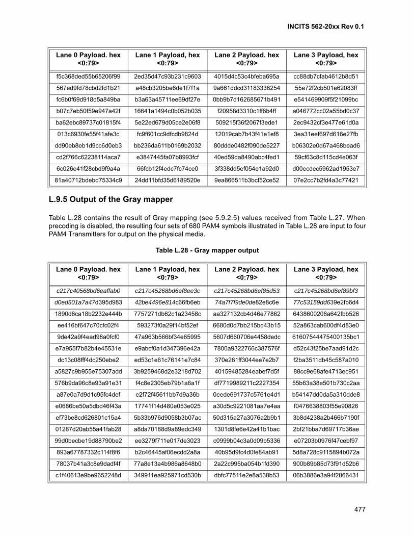
INCITS 562-20xx Rev 0.1
477
L.9.5 Output of the Gray mapper
Table L.28 contains the result of Gray mapping (see 5.9.2.5) values received from Table L.27. Whenprecoding is disabled, the resulting four sets of 680 PAM4 symbols illustrated in Table L.28 are input to fourPAM4 Transmitters for output on the physical media.
Table L.28 - Gray mapper output
f5c368ded55b65206f99 2ed35d47c93b231c9603 4015d4c53c4bfeba695a cc88db7cfab4612b8d51
567ed9fd78cbd2fd1b21 a48cb3205be6de1f7f1a 9a661ddcd31183336254 55e72f2cb501e62083ff
fc6b0f69d918d5a849ba b3a63a45711ee69df27e 0bb9b7d162685671b491 e541469909f5f21099bc
b07c7eb50f59e947a42f 16641a1494c0b052b035 f20958d3310c1ff6b4ff a046772cc02a55bd0c37
ba62ebc89737c01815f4 5e22ed679d05ce2e06f8 509215f36f2067f3ede1 2ec9432cf3e477e61d0a
013c6930fe55f41afe3c fc9f601cc9dfcdb9824d 12019cab7b43f41e1ef8 3ea31eef697d616e27fb
dd90eb8eb1d9cc6d0eb3 bb236da611b0169b2032 80ddde0482f090de5227 b06302e0d67a468bead6
cd2f766c62238114aca7 e3847445fa07b8993fcf 40ed59da8490abc4fed1 59cf63c8d115cd4e063f
6c026e41f28cbd9f9a4a 66fcb12f4edc7fc74ce0 3f338dd5ef054e1a92d0 d00ecdec5962ad1953e7
81a40712bdebd75334c9 24dd11bfd35d6189520e 9ea866511b3bcf52ce52 07e2cc7b2fd4a3c77421
Lane 0 Payload. hex <0:79>
Lane 1 Payload, hex <0:79>
Lane 2 Payload. hex <0:79>
Lane 3 Payload, hex <0:79>
c217c40568bd6eaffab0 c217c45268bd6ef8ee3c c217c45268bd6ef85d53 c217c45268bd6ef89bf3
d0ed501a7a47d395d983 42be4496e814c66fb6eb 74a7f7f9de0de82e8c6e 77c53159dd639e2fb6d4
1890d6ca18b2232e444b 7757271db62c1a23458c aa327132cb4d46e77862 6438600208a642fbb526
ee416bf647c70cfc02f4 593273f0a29f14bf52ef 6680d0d7bb215bd43b15 52a863cab600df4d83e0
9de42a9f4ead98a0fcf0 47a963b566bf34e65995 5607d660706e4458dedc 61607544475400135bc1
e7a955f7b82b4e45531e e9abcf0a1d347396e42a 7800a9322766c387576f d52c43f25be7aad91d2c
dc13c08fff4dc250ebe2 ed53c1e61c76141e7c84 370e261ff3044ee7e2b7 f2ba3511db45c587a010
a5827c9b955e75307add 3b9259468d2e3218d702 40159485284eabef7d5f 88cc9e68afe4713ec951
576b9da96c8e93a91e31 f4c8e2305eb79b1a6a1f df7719989211c2227354 55b63a38e501b730c2aa
a87e0a7d9d1c95fc4def e2f72f45611bb7d9a36b 0eede691737c5761e4d1 b54147dd0da5a310dde8
e0686be50a5dbd46f43a 17741f14d480e053e025 a30d5c9221081aa7e4aa f0476638803f55e90826
ef73be8cd626801c15a4 5b33b976d9058b3b07ac 50d315a27a3076a2b9b1 3b8d4238a2b466b7190f
01287d20ab55a41fab28 a8da70188d9a89edc349 1301d8fe6e42a41b1bac 2bf21bba7d69717b36ae
99d0becbe19d88790be2 ee3279f711e017de3023 c0999b04c3a0d09b5336 e07203b0976f47cebf97
893a67787332c114f8f6 b2c46445af06ecdd2a8a 40b95d9fc4d0fe84ab91 5d8a728c9115894b072a
78037b41a3c8e9dadf4f 77a8e13a4b986a8648b0 2a22c995ba054b1fd390 900b89b85d73f91d52b6
c1f40613e9be9652248d 349911ea925971cd530b dbfc77511e2e8a538b53 06b3886e3a94f2866431
Lane 0 Payload. hex <0:79>
Lane 1 Payload, hex <0:79>
Lane 2 Payload. hex <0:79>
Lane 3 Payload, hex <0:79>

INCITS 562-20xx Rev 0.1
478
The first 32 PAM4 symbols contained in the upper left cell of Table L.28 and sent to the PAM4 Transmitteron Lane 0 (left to right) are the following:
{3,0,0,2,0,1,1,3,3,0,1,0,0,0,1,1,1,2,2,0,2,3,3,1,1,2,3,2,2,2,3,3}

INCITS 562-20xx Rev 0.1
479
Annex M (Informative)
Bibliography
1) Lin, Shu and Daniel J. Costello, Error Control Coding, Prentice Hall; 2nd edition, April 1, 2004.

INCITS 562-20xx Rev 0.1
480
Related Documents