Photonic Techniques for Frequency & Timing A Tutorial 1998 IEEE International Frequency Control Symposium May 26, 1998 X. Steve Yao Jet Propulsion Laboratory California Institute of Technology Tel: 818-393-9031 Fax: 818-393-6773 Email: [email protected] Other contributors: Lute Maleki, George Lutes, Malcolm Calhoun, William Shieh Presented at the 2000 IEEE Int'l Frequency Control Symposium Tutorials June 6, 2000, Kansas City, Missouri, USA

Welcome message from author
This document is posted to help you gain knowledge. Please leave a comment to let me know what you think about it! Share it to your friends and learn new things together.
Transcript
8/6/2019 FIBRA YAO Tutorial
http://slidepdf.com/reader/full/fibra-yao-tutorial 1/66
Photonic Techniques for Frequency & Timing
A Tutorial1998 IEEE International
Frequency Control SymposiumMay 26, 1998
X. Steve Yao
Jet Propulsion LaboratoryCalifornia Institute of TechnologyTel: 818-393-9031 Fax: 818-393-6773
Email: [email protected]
Other contributors: Lute Maleki, George Lutes, Malcolm Calhoun, William Shieh
Presented at the 2000 IEEE Int'l Frequency Control Symposium Tutorials
June 6, 2000, Kansas City, Missouri, USA
8/6/2019 FIBRA YAO Tutorial
http://slidepdf.com/reader/full/fibra-yao-tutorial 2/66
Contents
1. Basics of Optical Fiber 1-19
i. History 1
ii. Advantages 2
iii. Fiber vs. coax (data) 3-8
a. Bandwidth vs. cable length 3
b. Attenuation vs. frequency 4-5
c. Group delay vs. temperature 6-7
d. Temperature stability 8
iv. How fiber works 9-13
v. Discussion of fiber dispersion 14-19
2. Basic Photonic Links for RF applications 203. Characteristics of Fiber Optic Components 21-31
i. Fiber 21-23
ii. Choices of operation wavelengths 24-26
iii. Lasers 27-28
iv. Photodetectors 29
v. Modulators 30
vi. Other commercially available fiber optic devices 31
8/6/2019 FIBRA YAO Tutorial
http://slidepdf.com/reader/full/fibra-yao-tutorial 3/66
4. Noise sources in photonic systems 32-38
i. White noise: Thermal, shot, and RIN 33
ii. 1/f RIN and relaxation oscillation RIN 34
iii. Interferometric noise 35-36
iv. Double Rayleigh scattering & Brillouin scattering 37
v. Fiber thermal fluctuation 38
vi. Fiber dispersion mediated noise 38
5. Fiber Optic Frequency Standard Distribution 39-43
6. Photonic Technology for signal mixing & multiplication 44-54
7. Photonic Techniques for generating RF signals 55-69
Contents

8/6/2019 FIBRA YAO Tutorial
http://slidepdf.com/reader/full/fibra-yao-tutorial 4/66
Basics of Optical Fiber
• 1910: Concept conceived by Hondros & Debye
• 1915: Existence of a dielectrically guided wave
demonstrated by Zahn, Ruter & Schriever
• 1959: Waveguide modes in optical fiber observed by Snitzer
& Hicks.
• 1965: Fibers with a loss less than 20-dB/km for fiber optic
communications proposed by Kao.
• 1970: Practical fiber with 20 dB/km loss announced by
Kapron, Keck, & Maurer.
• 1972: 4 dB/km loss fiber developed by Corning.
• Today: Fiber has a loss of 0.2 dB/km @ 1550 nm
History
1 Steve Yao, JPL
8/6/2019 FIBRA YAO Tutorial
http://slidepdf.com/reader/full/fibra-yao-tutorial 5/66
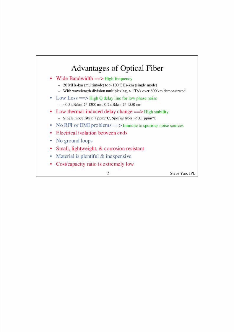
Advantages of Optical Fiber• Wide Bandwidth ==> High frequency
– 20 MHz-km (multimode) to > 100 GHz-km (single mode)
– With wavelength division multiplexing, > 1Tb/s over 600 km demonstrated.
• Low Loss ==> High Q delay line for low phase noise
– ~0.5 dB/km @ 1300 nm, 0.2 dB/km @ 1550 nm
• Low thermal-induced delay change ==> High stability
– Single mode fiber: 7 ppm/°C, Special fiber: < 0.1 ppm/°C
• No RFI or EMI problems ==> Immune to spurious noise sources
• Electrical isolation between ends• No ground loops
• Small, lightweight, & corrosion resistant
• Material is plentiful & inexpensive
• Cost/capacity ratio is extremely low
Steve Yao, JPL2

8/6/2019 FIBRA YAO Tutorial
http://slidepdf.com/reader/full/fibra-yao-tutorial 6/66
How Fiber Works
Mirror
PoPo- Loss
All mirrored surfaces have loss!!
Reflectionn1 (Low index of refraction)
Total Internal Reflection
No Loss!!
Critical angle
Po Po
n2 (High index of refraction)
Snell Law
* n = c/vc = the speed of light in a vacuum (3 x 10⁸ m/s)
v = the speed of light in the material (~ 2 x 10⁸ m/s in glass)
* The index of refraction of glass can be changed by adding
impurities (doping)
Steve Yao, JPL9

8/6/2019 FIBRA YAO Tutorial
http://slidepdf.com/reader/full/fibra-yao-tutorial 7/66

8/6/2019 FIBRA YAO Tutorial
http://slidepdf.com/reader/full/fibra-yao-tutorial 8/66

8/6/2019 FIBRA YAO Tutorial
http://slidepdf.com/reader/full/fibra-yao-tutorial 9/66

8/6/2019 FIBRA YAO Tutorial
http://slidepdf.com/reader/full/fibra-yao-tutorial 10/66

8/6/2019 FIBRA YAO Tutorial
http://slidepdf.com/reader/full/fibra-yao-tutorial 11/66

8/6/2019 FIBRA YAO Tutorial
http://slidepdf.com/reader/full/fibra-yao-tutorial 12/66

8/6/2019 FIBRA YAO Tutorial
http://slidepdf.com/reader/full/fibra-yao-tutorial 13/66

8/6/2019 FIBRA YAO Tutorial
http://slidepdf.com/reader/full/fibra-yao-tutorial 14/66

8/6/2019 FIBRA YAO Tutorial
http://slidepdf.com/reader/full/fibra-yao-tutorial 15/66

8/6/2019 FIBRA YAO Tutorial
http://slidepdf.com/reader/full/fibra-yao-tutorial 16/66

8/6/2019 FIBRA YAO Tutorial
http://slidepdf.com/reader/full/fibra-yao-tutorial 17/66
Basic Photonic links for RF applicationsDirectly modulated Link Externally modulated link
Laser Detector
E/O converter O/E converter
RF inFiber RF out
Detector
E/O converter O/E converter
RF in Fiber RF out
Laser EOM
RF signal directly drives the laserRF signal drives an E/O modulator
external to the laser
Input current
O p t i c
a l P o w e r
ITH
S l o p e
( m W
/ m A )
Lower dynamic range
most CATV systems
High dynamic range
High performance systems
1.0
0.8
0.6
0.4
0.2
0.0
543210
Applied voltage (V)
T r a n s m
i s s i o n
Steve Yao, JPL20
8/6/2019 FIBRA YAO Tutorial
http://slidepdf.com/reader/full/fibra-yao-tutorial 18/66
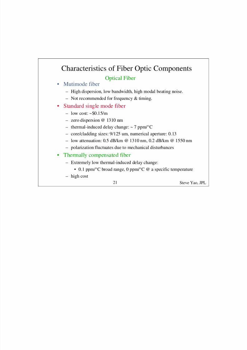
Characteristics of Fiber Optic Components
• Mutimode fiber
– High dispersion, low bandwidth, high modal beating noise.
– Not recommended for frequency & timing.
• Standard single mode fiber
– low cost: ~$0.15/m
– zero dispersion @ 1310 nm
– thermal-induced delay change: ~ 7 ppm/°C
– core/cladding sizes: 9/125 um, numerical aperture: 0.13
– low attenuation: 0.5 dB/km @ 1310 nm, 0.2 dB/km @ 1550 nm– polarization fluctuates due to mechanical disturbances
• Thermally compensated fiber
– Extremely low thermal-induced delay change:
• 0.1 ppm/°C broad range, 0 ppm/°C @ a specific temperature
– high cost
Optical Fiber
Steve Yao, JPL21

8/6/2019 FIBRA YAO Tutorial
http://slidepdf.com/reader/full/fibra-yao-tutorial 19/66
• Polarization Maintaining (PM) Fiber
– support two polarization modes
– No polarization fluctuation
– Expensive: ~ $20.00/m
– difficult to connect: fiber axis alignment required
– higher loss: < 2 dB/km @ 1310 nm & 1550 nm
– Slightly smaller core size & larger NA than standard fiber
• Polarizing (PZ) Fiber
– support only one polarization mode ==> fiber polarizer
– most expensive ~ $90.00/m
– higher loss: <2 dB/km @ 1310 nm, <7 dB/km @ 1550 nm
– higher bending loss
-- continue Characteristics of Fiber Optic Components
Steve Yao, JPL22

8/6/2019 FIBRA YAO Tutorial
http://slidepdf.com/reader/full/fibra-yao-tutorial 20/66
-- continue Characteristics of Fiber Optic Components
• Dispersion-shifted fiber (DSF)
– Zero dispersion shifted to 1550 nm, where loss is the lowest
– mode-field/cladding sizes: 8.1/125 um, NA = 0.17
– effective area: 50 um2
• Non-zero dispersion-shifted fiber (NZ-DSF)
– Minimum but non-zero dispersion at 1550nm
– reducing fiber nonlinear effects
– mode-field/cladding sizes: 8.4/125 um, NA = 0.16
– effective area: 55 um2
• Large core non-zero-dispersion-shifted fiber
– Minimum but non-zero dispersion at 1550nm
– mode-field/cladding: 9/125 um,
– larger effective area: 72 um2
– further reducing fiber nonlinear effects
Steve Yao, JPL23

8/6/2019 FIBRA YAO Tutorial
http://slidepdf.com/reader/full/fibra-yao-tutorial 21/66
• 1310 nm range• most analog links & past installed digital links
• low cost standard fiber off-the-shelf
• optical amplifier available
• low noise diode-pumped YAG laser off-the-shelf
• high speed modulators & detectors off-the-shelf
• high speed semiconductor laser off-the-shelf • high power semiconductor lasers off-the-shelf
• other fiber optic components off-the-shelf
• low dispersion ==> low PM to AM noise conversion
• low loss
Choices of operating wavelengths
Steve Yao, JPL24

8/6/2019 FIBRA YAO Tutorial
http://slidepdf.com/reader/full/fibra-yao-tutorial 22/66
Choices of operating wavelengths
• 1550 nm range• most present & future digital links, WDM systems
• lowest attenuation
• Er+ doped fiber amplifiers (EDFA) off-the-shelf
• low cost standard fiber off-the-shelf
• dispersion shifted fibers (DSF) off-the-shelf
• high speed modulators & detectors off-the-shelf
• high speed semiconductor laser off-the-shelf
• high power semiconductor lasers off-the-shelf
• other fiber optic components off-the-shelf
• low dispersion with DSF ==> low PM to AM noise conversion
• most industrial support in the future
Steve Yao, JPL25
8/6/2019 FIBRA YAO Tutorial
http://slidepdf.com/reader/full/fibra-yao-tutorial 23/66
Choices of operating wavelengths
• Other wavelengths --1060, 820, 780, & 630 nm• high fiber attenuation
• high cost optical fiber
• high cost modulator
• high cost lasers & detectors
• high speed semiconductor laser not off-the-shelf
• high power semiconductor lasers (single-mode fiber
pigtailed) not off-the shelf • expensive custom-made fiber optic components
• high dispersion ==> high PM to AM noise conversion
• least industrial support in the future
Steve Yao, JPL26

8/6/2019 FIBRA YAO Tutorial
http://slidepdf.com/reader/full/fibra-yao-tutorial 24/66
Fabry-Perot laser
(F-P laser)
Distributed feedback laser
(DFB laser)
* Optical feedback provided
by the end mirrors
* multi-longitudinal modes
* higher noise due to mode
competition
* Optical feedback provided
by the grating on top of the
gain medium
* single longitudinal mode
* lower noise
Grating
Gain mediumGain medium
wavelength wavelength
Commonly used lasers for RF systems
Steve Yao, JPL27
8/6/2019 FIBRA YAO Tutorial
http://slidepdf.com/reader/full/fibra-yao-tutorial 25/66
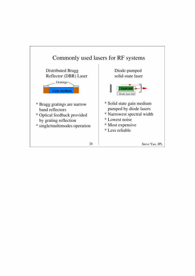
Commonly used lasers for RF systems
Distributed Bragg
Reflector (DBR) Laser
Diode-pumped
solid-state laser
Gain medium
Gratings
* Bragg gratings are narrow
band reflectors* Optical feedback provided
by grating reflection
* single/multimodes operation
* Solid state gain medium
pumped by diode lasers
* Narrowest spectral width
* Lowest noise
* Most expensive
* Less reliable
Diode laser bar
Laser rod
Steve Yao, JPL28
8/6/2019 FIBRA YAO Tutorial
http://slidepdf.com/reader/full/fibra-yao-tutorial 26/66
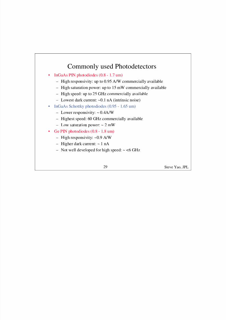
Commonly used Photodetectors• InGaAs PIN photodiodes (0.8 - 1.7 um)
– High responsivity: up to 0.95 A/W commercially available
– High saturation power: up to 15 mW commercially available
– High speed: up to 25 GHz commercially available
– Lowest dark current: ~0.1 nA (intrinsic noise)
• InGaAs Schottky photodiodes (0.95 - 1.65 um)
– Lower responsivity: ~ 0.4A/W
– Highest speed: 60 GHz commercially available
– Low saturation power: ~ 2 mW
• Ge PIN photodiodes (0.8 - 1.8 um)
– High responsivity: ~0.9 A/W
– Higher dark current: ~ 1 nA
– Not well developed for high speed: ~ <6 GHz
Steve Yao, JPL29
8/6/2019 FIBRA YAO Tutorial
http://slidepdf.com/reader/full/fibra-yao-tutorial 27/66
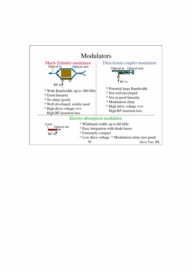
Modulators
RF in
Optical in Optical outs
RF in
Optical in Optical outsMach-Zehnder modulator Directional coupler modulator
* Wide Bandwidth: up to 100 GHz
* Good linearity
* No chirp (good)
* Well developed, widely used
* High drive voltage ==>High RF insertion loss
* Potential large Bandwidth
* Not well developed
* Not as good linearity
* Modulation chirp
* High drive voltage ==>
High RF insertion loss
RF in
Optical out
Electro-absorption modulator
* Wideband width: up to 60 GHz
* Easy integration with diode lasers
* Extremely compact
* Low drive voltage * Modulation chirp (not good)
Laser
Steve Yao, JPL30

8/6/2019 FIBRA YAO Tutorial
http://slidepdf.com/reader/full/fibra-yao-tutorial 28/66
Other fiber optic devices available
• Directional couplers (ratio: 1 - 50%, backreflection < -65 dBo)
• Isolators (insertion loss: < 0.6 dBo, isolation > 40 dBo)
• Circulators (insertion loss: < 0.8 dB, isolation > 40 dBo)
• Polarizers (insertion loss: < 0. 4 dB, backreflection < -60 dB)
• Polarization controllers (no loss, no backreflection)
• Filters (insertion loss < 0.5 dB, BW: 0.8 nm and up)
• Faraday polarization rotator and mirror
• connectors: Physical contact (PC) and angled physical contact(APC)
– loss < 0. 25 dB, backreflection: PC < -40 dB, APC < -65 dB
• Fiber optic amplifiers: doped fiber & semiconductor
Steve Yao, JPL31

8/6/2019 FIBRA YAO Tutorial
http://slidepdf.com/reader/full/fibra-yao-tutorial 29/66
Noise sources in photonic systems
• Thermal noise: kT
• Shot noise: 2eIR• Laser RIN (relative intensity noise): <∆P2>/P2
• 1/f RIN (at < 10 kHz)
• Relaxation oscillation RIN peak
• Interferometric noise
• Double Rayleigh scattering noise• Brillouin scattering caused noise
• Fiber dispersion mediated noise
• Fiber thermal noise
Steve Yao, JPL32
8/6/2019 FIBRA YAO Tutorial
http://slidepdf.com/reader/full/fibra-yao-tutorial 30/66
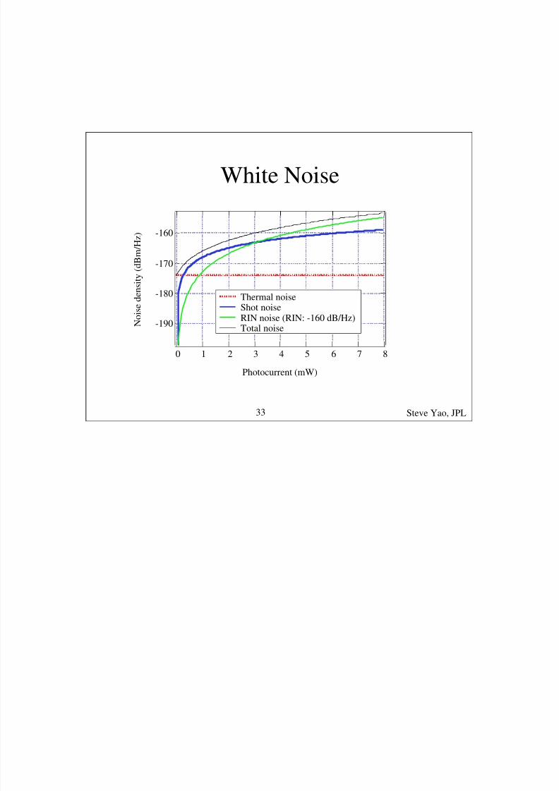
White Noise
-190
-180
-170
-160
N o i s e d e n s i t y ( d B m / H z )
876543210
Photocurrent (mW)
Thermal noiseShot noise
RIN noise (RIN: -160 dB/Hz)Total noise
Steve Yao, JPL33

8/6/2019 FIBRA YAO Tutorial
http://slidepdf.com/reader/full/fibra-yao-tutorial 31/66
1/f RIN & Relaxation Oscillation RIN
R I N N o i s e ( d B / H z
)
1/f
1 Hz 10kHz 200 kHz 10 MHz
-135 dB/Hz
-115 dB/Hz
-90 dB/Hz
< -160 dB/Hz
-145 dB/Hz
Frequency
Typical diode pump YAG laser
* The low frequency 1/f noise & relaxation oscillation peak
will be multiplied up by the modulator & affect the signal
Steve Yao, JPL34

8/6/2019 FIBRA YAO Tutorial
http://slidepdf.com/reader/full/fibra-yao-tutorial 32/66
8/6/2019 FIBRA YAO Tutorial
http://slidepdf.com/reader/full/fibra-yao-tutorial 33/66
8/6/2019 FIBRA YAO Tutorial
http://slidepdf.com/reader/full/fibra-yao-tutorial 34/66
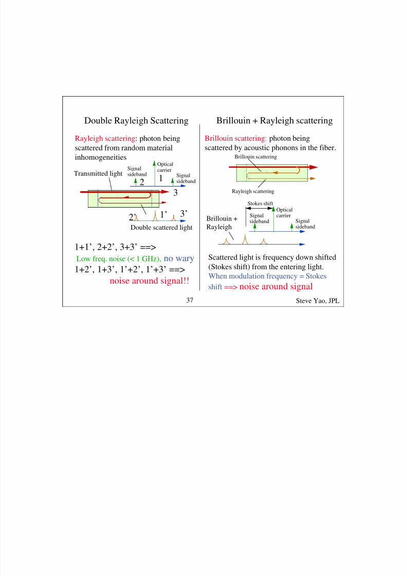
Double Rayleigh Scattering Brillouin + Rayleigh scattering
Rayleigh scattering: photon being
scattered from random material
inhomogeneitiesOpticalcarrier
Signalsideband
Signalsideband
Double scattered light
Transmitted light12
3
1’2’ 3’
1+1’, 2+2’, 3+3’ ==>
Low freq. noise (< 1 GHz), no wary
1+2’, 1+3’, 1’+2’, 1’+3’ ==>
noise around signal!!
Brillouin scattering: photon being
scattered by acoustic phonons in the fiber.
Brillouin scattering
Rayleigh scattering
Opticalcarrier
Signalsideband
Signalsideband
Stokes shift
Scattered light is frequency down shifted
(Stokes shift) from the entering light.
When modulation frequency = Stokes
shift ==> noise around signal
Brillouin +
Rayleigh
Steve Yao, JPL37

8/6/2019 FIBRA YAO Tutorial
http://slidepdf.com/reader/full/fibra-yao-tutorial 35/66
8/6/2019 FIBRA YAO Tutorial
http://slidepdf.com/reader/full/fibra-yao-tutorial 36/66
• Frequency standards are extremely expensive• Multiple users at different location share one
standard ==> big money saving
• Distribution system should not degrade the
performance of the standard
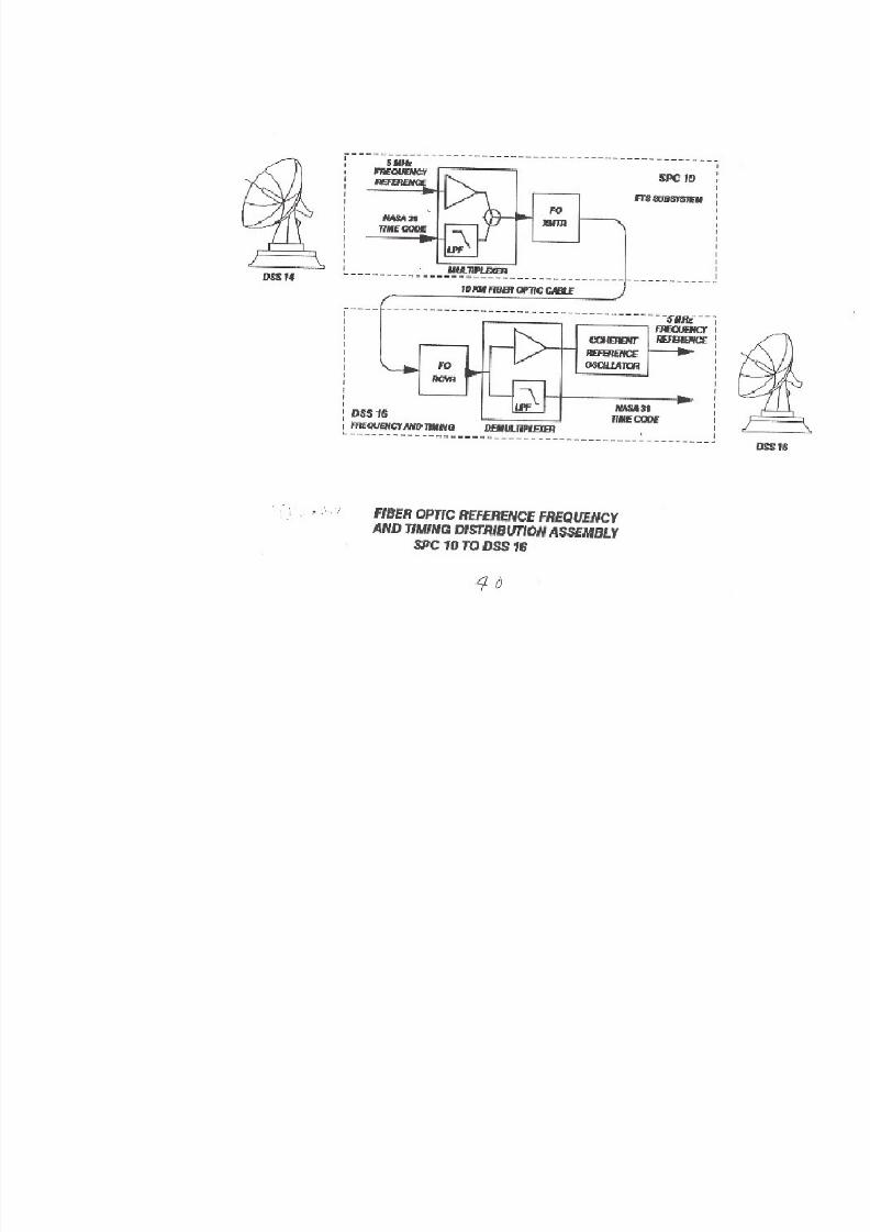
• In 1981, JPL pioneered the fiber opticfrequency standard distribution
• The only workable solution so far
Fiber Optic Frequency Standard Distribution
Steve Yao, JPL39
8/6/2019 FIBRA YAO Tutorial
http://slidepdf.com/reader/full/fibra-yao-tutorial 37/66

8/6/2019 FIBRA YAO Tutorial
http://slidepdf.com/reader/full/fibra-yao-tutorial 38/66

8/6/2019 FIBRA YAO Tutorial
http://slidepdf.com/reader/full/fibra-yao-tutorial 39/66
8/6/2019 FIBRA YAO Tutorial
http://slidepdf.com/reader/full/fibra-yao-tutorial 40/66
Photonic technology for signal
mixing & multiplication
• Photonic links w/ traditional & photonic mixers
• Pros & cons of present photonic signal mixing
• SOA based photonic mixing links
• Brillouin Selective Sideband Amplification
(BSSA) of RF signals• BSSA based photonic mixing links
• OEO based photonic mixing links
• Summary
Steve Yao, JPL44
8/6/2019 FIBRA YAO Tutorial
http://slidepdf.com/reader/full/fibra-yao-tutorial 41/66
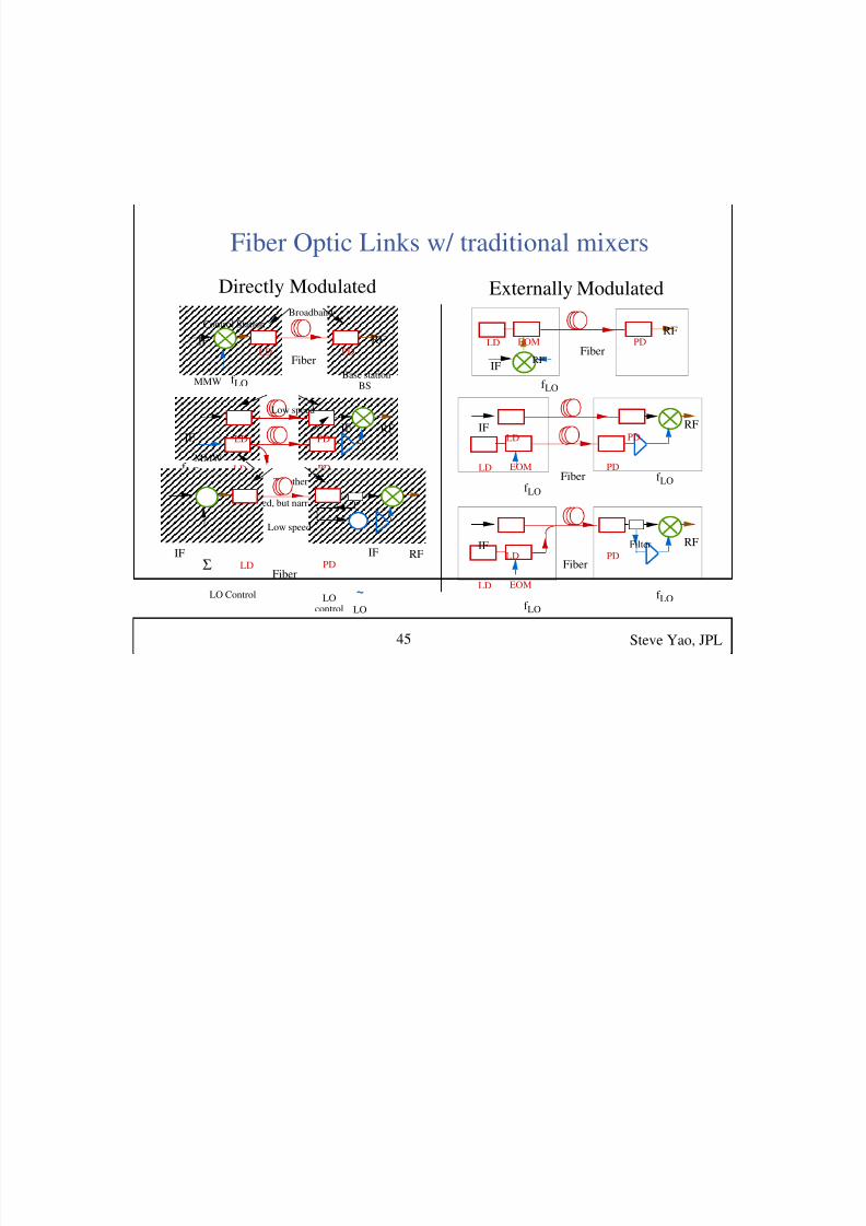
Fiber Optic Links w/ traditional mixers
LD PDFiber
RFEOM
f LO
IFRF
LD PDFiber
EOM
f LO
IFLD PD
RF
f LO
LD
Fiber
EOM
f LO
IFLD PD
RF
f LO
Filter
LD PD
f LO
IF
Fiber
RF
Base station
Control StationBroadband
MMW BS
LD PD
f LO
IFIF
LD PDMMW
RF
To other BS
Low speed
High speed, but narrow bandwidth
LD PDIF
Fiber
IF
Low speed
Σ
LO Control
RF
~LO
LOcontrol
Directly Modulated Externally Modulated
Steve Yao, JPL45

8/6/2019 FIBRA YAO Tutorial
http://slidepdf.com/reader/full/fibra-yao-tutorial 42/66
8/6/2019 FIBRA YAO Tutorial
http://slidepdf.com/reader/full/fibra-yao-tutorial 43/66
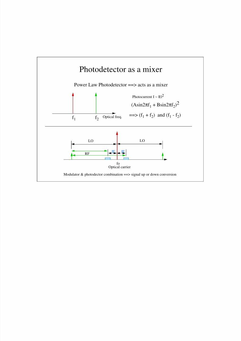
Photodetector as a mixer
(Asin2πf 1 + Bsin2πf 2)2
==> (f 1 + f 2) and (f 1 - f 2)f 1 f 2
Optical freq.
Photocurrent I ~ |E|2
foOptical carrier
IF IF
LO LO
RF
Power Law Photodetector ==> acts as a mixer
Modulator & photodector combination ==> signal up or down conversion

8/6/2019 FIBRA YAO Tutorial
http://slidepdf.com/reader/full/fibra-yao-tutorial 44/66
Pros & Cons of Present Photonic Mixing Links
Pros Cons
* Separate LO trans. not needed
* Harmonic up/down conversion
==> Lower freq. LO & circuit
* Slow detector for down conv.
==> lower cost, higher power
* Slow laser/EOM for up conv.
==> lower cost
* Infinite isolation: LO & RF
* Low efficiency (most cases)
* High LO power (some cases)
* Freq. locking circuits needed
(some cases)
Steve Yao, JPL47

8/6/2019 FIBRA YAO Tutorial
http://slidepdf.com/reader/full/fibra-yao-tutorial 45/66
All-Optical RF Mixing Using a Semiconductor Optical Amplifier (SOA)
SOAλLO
λRF G(t) λRF
Pin ( t)
Pout( t) = G(t) * P in ( t) ωLO
ωRF
ωRF-ωLO
ωRF+ωLO
SOAλLO
λRF G(t) λRF
Pin ( t)
Pout( t) = G(t) * P in ( t) ωLO
ωRF
ωRF-ωLO
ωRF+ωLO
LO Modulatesthe Gain
LD1 Modulator
SOA OpticalDetector
Optical Filter@1312 nm RF
SpectrumAnalyzer
LD2 Modulator
1312 nm
1320 nm
6 GHz
5 GHz
(b)
RF
LO
Advantages:
* Mixing with Gain* Flexible LO location
* LO can be distributed
in the network
Gain Mod. Bandwidth > 50 GHz
Steve Yao, JPL48
8/6/2019 FIBRA YAO Tutorial
http://slidepdf.com/reader/full/fibra-yao-tutorial 46/66
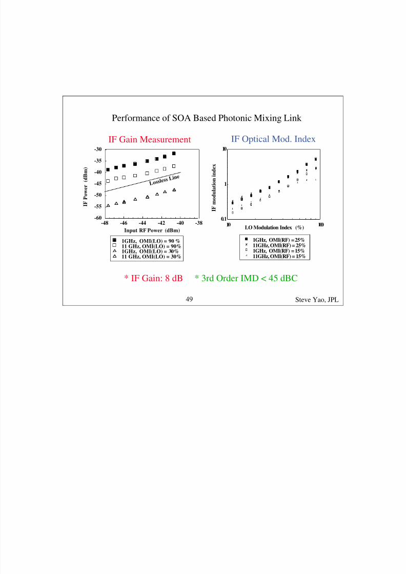
1GHz, OMI(LO) = 90 %11 GHz, OMI(LO) = 90%1GHz, OMI(LO) = 30%11 GHz, OMI(LO) = 30%
1GHz, OMI(RF) = 25%11GHz, OMI(RF) = 25%1GHz, OMI(RF) = 15%11GHz, OMI(RF) = 15%
0.1
1
10
10 100LO Modulation Index (%)
I F m o d u l a t i o n i n d e x
IF Gain Measurement IF Optical Mod. Index
Performance of SOA Based Photonic Mixing Link
Input RF Power (dBm)
-48 -46 -44 -42 -40 -38-60
-55
-50
-45
-40
-35
-30
I F P o w e r ( d B m )
L o s s l e s s
L i n e
* IF Gain: 8 dB * 3rd Order IMD < 45 dBC
Steve Yao, JPL49

8/6/2019 FIBRA YAO Tutorial
http://slidepdf.com/reader/full/fibra-yao-tutorial 47/66
Brillouin Selective Sideband Amplification
BSSA
-80
-60
-40
R F
P o w e r ( d B m )
-80
-60
-40
R F P o w e r ( d B m )
5.485.465.455.44 5.47Frequency (GHz)
-12.17 dBm
-2.17 dBm
2.83 dBm
7.83 dBm
40
30
20
10
0
R F G a i n ( d B )
20151050Optical Pump Power (mW)
RF input:
FM Signal: 10 MHz BW
G = 40 dB
TX PD
LD
Bias Tee
PumpFreq. Locking
RF RF
υpump
BW: ~10 MHz
υTX
Freq.
Freq.
12.8 GHz @ 1.3 um10 GHz @ 1.5 um
* Fiber as gain medium
* Low pump power ~ 10 mW
* Dispersion robust
* Highly efficient
Steve Yao, JPL50

8/6/2019 FIBRA YAO Tutorial
http://slidepdf.com/reader/full/fibra-yao-tutorial 48/66
υpump
υTX
Opt. Freq.
Opt. Freq.
BSSA as a tuner for SCM systems
Tuning pump laser frequency
to selectively amplify a channel
Filter + Gain
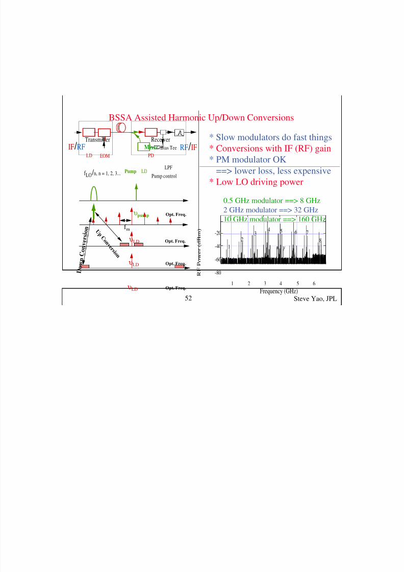
Frequency multiplication
υpump
υLD
Freq.
Freq.f m
-80
-70
-60
-50
-40
-30
-20
P o w e r ( d B m
)
2520151050
Frequency (GHz)
5 GHz
10 GHz
15 GHz20 GHz
25 GHz
LD PD
LDPump Tuning pump freq.
EOM
f m
Steve Yao, JPL51
8/6/2019 FIBRA YAO Tutorial
http://slidepdf.com/reader/full/fibra-yao-tutorial 49/66
8/6/2019 FIBRA YAO Tutorial
http://slidepdf.com/reader/full/fibra-yao-tutorial 50/66

8/6/2019 FIBRA YAO Tutorial
http://slidepdf.com/reader/full/fibra-yao-tutorial 51/66

8/6/2019 FIBRA YAO Tutorial
http://slidepdf.com/reader/full/fibra-yao-tutorial 52/66
Photonic Techniques for generating RF signals
• Requirements of Photonic Signal Sources
• Evolution of Oscillators
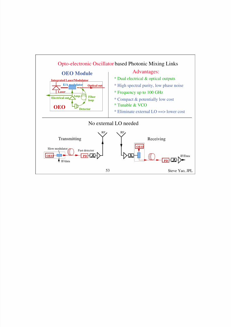
• Opto-electronic oscillators (OEO)
• Properties of OEO
• Experimental results
• Comparison with other type oscillators
• Coupled Opto-electronic oscillators (COEO)
• Summary
Steve Yao, JPL55

8/6/2019 FIBRA YAO Tutorial
http://slidepdf.com/reader/full/fibra-yao-tutorial 53/66
Special Requirement of Signal Sources
For Photonic Applications
E OO O
EO
* Photonic Systems are Electro-Optic Hybrid Systems
===> Ideal Signal Source: both Electrical & Optical Signals
Avoid high loss E/O and O/E conversions
===> High Frequency
===> Wide Tuning Range
===> Can be Interfaced with the System both Electrically & Optically.
* Photonic systems are Broadband Systems
Steve Yao, JPL56

8/6/2019 FIBRA YAO Tutorial
http://slidepdf.com/reader/full/fibra-yao-tutorial 54/66
Evolution of Oscillators
• Mechanical Oscillators: Pendulum, tuning fork ==>
• Electronic Oscillators: Van der Pol oscillator ==>
• electromechanical Hybrid Oscillators: Quartz Oscillator ==>
• Atomic Oscillators: Maser, Cesium beam standard ==>
• Optical Oscillators: Laser ==>
• 6. Electro-Optic Hybrid Oscillator? ==> OEO & COEO
OEO is a new class of oscillators
Electrical & Optical Hybrid
Steve Yao, JPL57
8/6/2019 FIBRA YAO Tutorial
http://slidepdf.com/reader/full/fibra-yao-tutorial 55/66
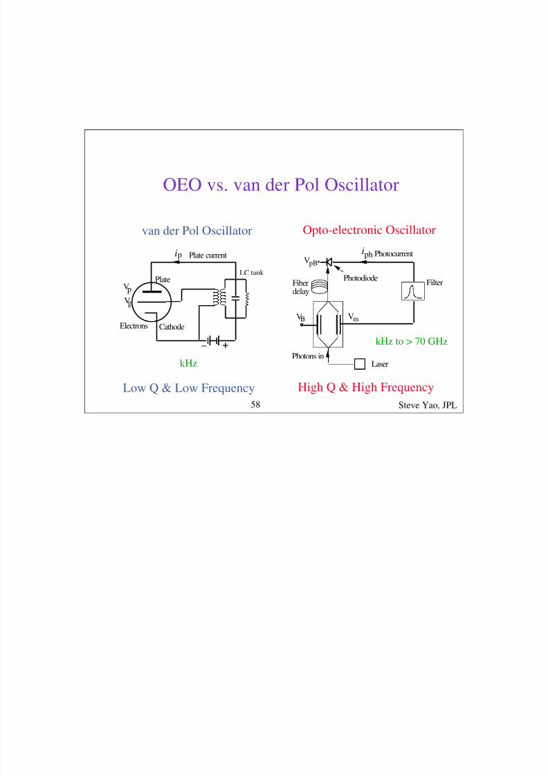
OEO vs. van der Pol Oscillator
+_
Vg
ip
Plate
CathodeElectrons
Vp
Plate current
VB
Photons in
iph Photocurrent
Filter
Laser
Vm
VpB
PhotodiodeFiberdelay
van der Pol Oscillator Opto-electronic Oscillator
LC tank
Low Q & Low Frequency High Q & High Frequency
kHz to > 70 GHz
kHz
Steve Yao, JPL58

8/6/2019 FIBRA YAO Tutorial
http://slidepdf.com/reader/full/fibra-yao-tutorial 56/66
8/6/2019 FIBRA YAO Tutorial
http://slidepdf.com/reader/full/fibra-yao-tutorial 57/66
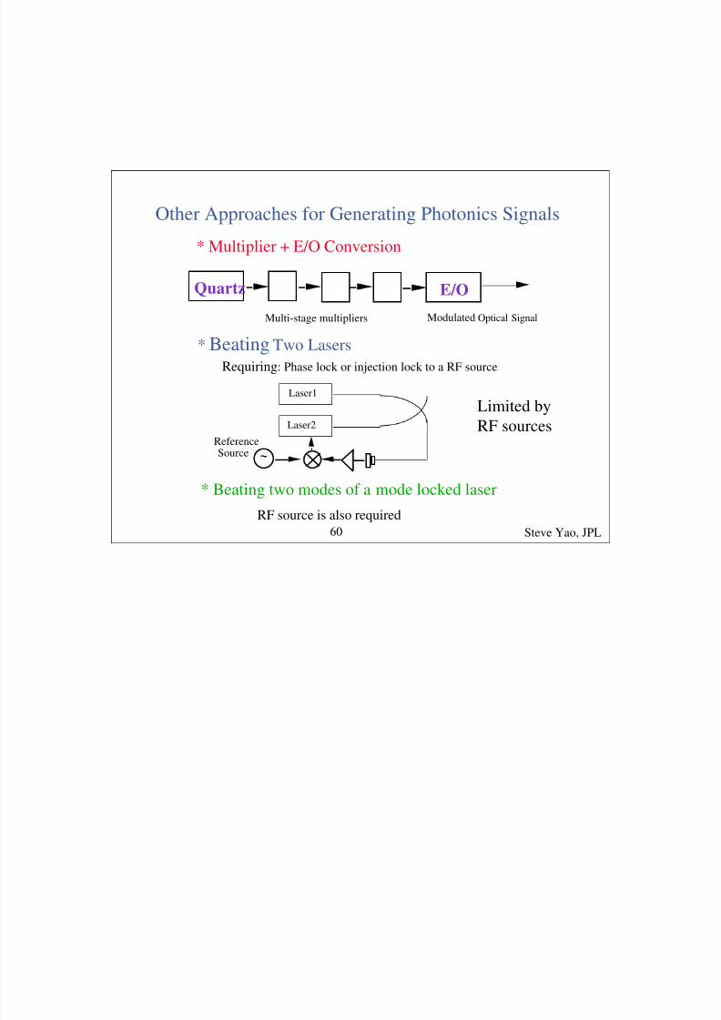
Other Approaches for Generating Photonics Signals
* Multiplier + E/O Conversion
Multi-stage multipliers
Quartz E/O
Modulated Optical Signal
* Beating Two Lasers
Requiring: Phase lock or injection lock to a RF source
* Beating two modes of a mode locked laser
Laser1
Laser2
Reference Source ~
RF source is also required
Limited byRF sources
Steve Yao, JPL60

8/6/2019 FIBRA YAO Tutorial
http://slidepdf.com/reader/full/fibra-yao-tutorial 58/66
Performance Characteristics of OEO
0.7
0.6
0.5
0.4
0.3
0.2
0.1
0.0
V o s c / V
π
2.01.81.61.41.21.0
Open Loop Voltage Gain
Data5th order fit3rd order fit
Data & Fit
Oscillation Amplitude vs. Open Loop Gain
Steve Yao, JPL61

8/6/2019 FIBRA YAO Tutorial
http://slidepdf.com/reader/full/fibra-yao-tutorial 59/66
-150
-140
-130
-120
-110
-100
P h a s e N o i s e (
d B c / H z )
3 4 5 6 7 8 9
104
2 3 4 5 6 7 8 9
105
Frequency offset (Hz)
-140
-135
-130
-125
-120
P h a s e N o i s e ( d B c / H z )
6 7 8 9
0.12 3 4 5 6 7 8 9
1
Loop delay (µs)
Corrected data
-142.21-20*log(delay)
-28.70-20logf Po=13.33 dBm-34.84-20logf Po=13.00 dBm-38.14-20logf Po=12.67 dBm-40.61-20logf Po=12.67 dBm-50.45-20logf Po=10.33 dBm
0.06 µs0.13 µs0.21 µs0.28 µs
1.2 µs
Phase noise vs. frequency offset
Phase noise vs. loop delay time
Steve Yao, JPL62

8/6/2019 FIBRA YAO Tutorial
http://slidepdf.com/reader/full/fibra-yao-tutorial 60/66
OEO Phase noise as a function of oscillation frequency
(b)-125
-120
-115
-110
-105
-100
100 200
Oscillation Frequency (MHz)
Datamultiplied resultData Fit
P h a s e N o i s e ( d B c
/ H z )
300 400 500 600700800
-140
-135
-130
-125
-120
-115
-110
P h a s e N o i s e ( d B c / H z )
3 4 5 6 7 8 9
104
2 3 4 5 6 7 8 9
105
Frequency offset (Hz)
(a)
100MHz300MHz700MHz800MHz
Steve Yao, JPL63
8/6/2019 FIBRA YAO Tutorial
http://slidepdf.com/reader/full/fibra-yao-tutorial 61/66
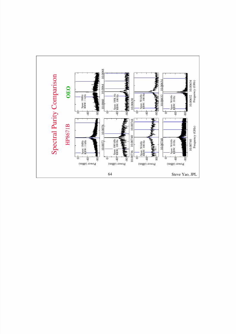
- 8 0
- 4 0 0
P o w e r ( d B m )
1 0 . 0
0 7 6
1 0 . 0
0 7 2
S p a n : 1 M H z
R B W : 1 k H z
- 8 0
- 4 0 0
P o w e r ( d B m )
1 0 . 0
0 7 4 4
1 0 . 0
0 7 4 0
1 0 . 0
0 7 3 6
S p a n : 1 0 0 k H z
R B W : 1 0 0 H z
- 8 0
- 4 0 0
P o w e r ( d B m )
1 0 . 0
0 7 4 0
S p a n : 5 0 k H z
R B W : 1 0 0 H z
- 8 0
- 4 0 0
P o w e r ( d B m )
1 0 . 0
0 7 4 0
F r e q u e n c y
( G H z )
S p a n : 5 0 k H z
R B W : 1 0 H z
- 8 0
- 4 0 0
1 0 . 0
0 6 8
1 0 . 0 0 6 4
1 0 . 0
0 6 0
S p a n : 1 M H z
R B W : 1 k H z
1 0 . 0
0 6 3 0
- 8 0
- 4 0 0
S p a n : 1 0 0 k H z
R B W : 1 0 0 H z
- 8 0
- 4 0 0
1 0 . 0
0 6 3 4
1 0 . 0
0 6 3 2
- 8 0
- 4 0 0
1 0 . 0
0 6 3 4
1 0 . 0
0 6 3 2
S p a n : 5 0 k H z
R B W : 1 0 0 H z
S p a n : 5 0 k H z
R B W : 1 0 H z
F r e q u e n c y
( G H z )
S p e c t r a
l P u r i t y C o m p a
r i s o n
O E O
H P 8 6 7 1 B
Steve Yao, JPL64

8/6/2019 FIBRA YAO Tutorial
http://slidepdf.com/reader/full/fibra-yao-tutorial 62/66
Comparison with Commercial Oscillators
• 1st OEO bench unit at 10 GHz: -140 dBc/Hz
Phase Noise @ 10 GHz, 10 kHz from carrier
• HP high performance synthesizer: -94 dBc/Hz
• Best quartz multiplied to 10 GHz: -114 dBc/Hz
Steve Yao, JPL65
8/6/2019 FIBRA YAO Tutorial
http://slidepdf.com/reader/full/fibra-yao-tutorial 63/66
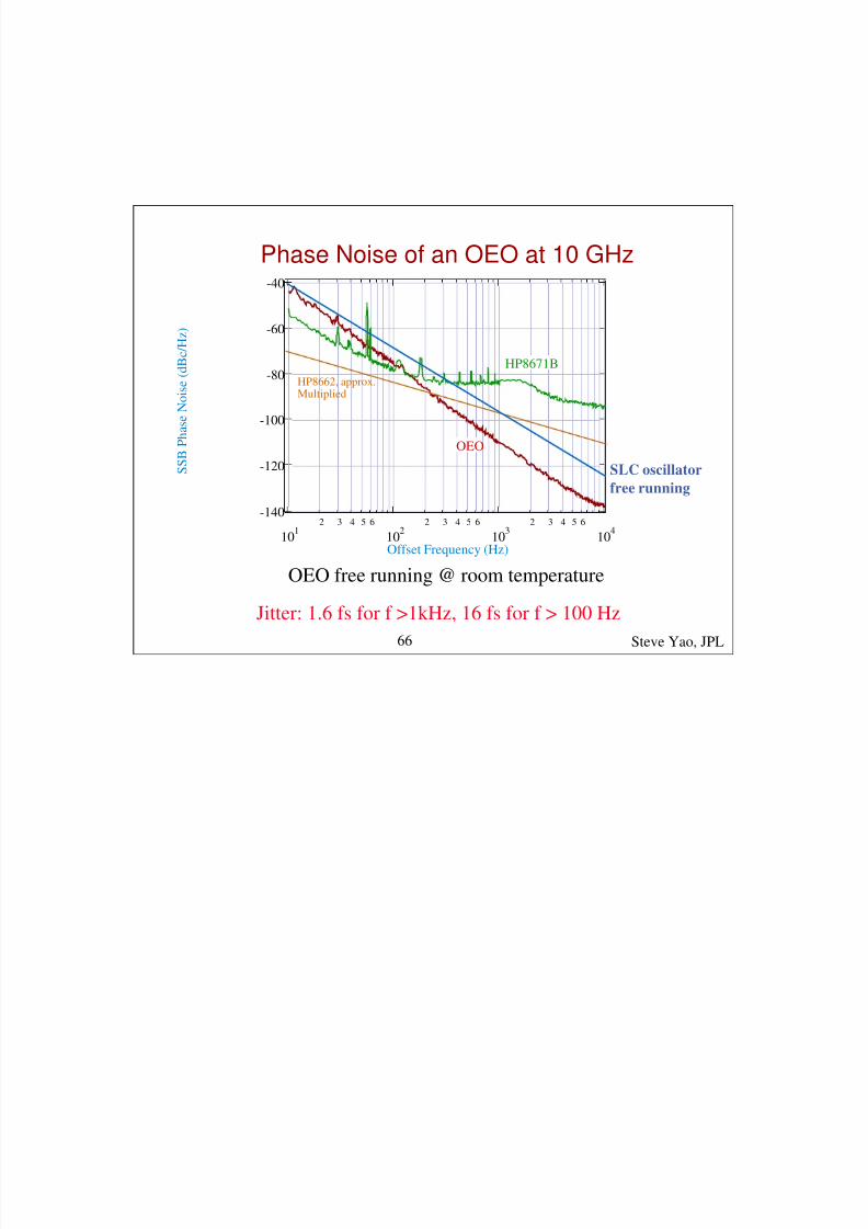
-140
-120
-100
-80
-60
-40
S S B P h a s e N o i s e ( d B c / H z )
101
2 3 4 5 6
102
2 3 4 5 6
103
2 3 4 5 6
104
Offset Frequency (Hz)
OEO
HP8671B
HP8662, approx.Multiplied
Phase Noise of an OEO at 10 GHz
OEO free running @ room temperature
Jitter: 1.6 fs for f >1kHz, 16 fs for f > 100 Hz
Steve Yao, JPL66
SLC oscillator
free running
8/6/2019 FIBRA YAO Tutorial
http://slidepdf.com/reader/full/fibra-yao-tutorial 64/66
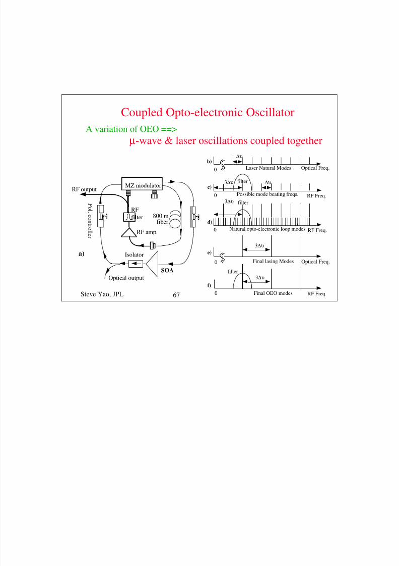
MZ modulator
800 mfiber
RF amp.
RF
filter
Optical output
RF output
SOA
P ol . c on t r
ol l e r
Isolatora)
Laser Natural Modes
∆υ
Optical Freq.0
b)
Final lasing Modes
3∆υ
Optical Freq.0
e)
Possible mode beating freqs. RF Freq.
∆υ
0
c)3∆υ
filter
Final OEO modes
3∆υ
RF Freq.0
f)
Natural opto-electronic loop modes RF Freq.0
d)
filter3∆υ
filter
Coupled Opto-electronic Oscillator
A variation of OEO ==>
µ-wave & laser oscillations coupled together
Steve Yao, JPL 67

8/6/2019 FIBRA YAO Tutorial
http://slidepdf.com/reader/full/fibra-yao-tutorial 65/66
50 ps
Pulse width: 17 ps
Optical Pulse measurement Phase Noise Measurement
w/ a 40 GHz detector and Tek CSA 803 Using Frequency Discrimination Method
10 GHz
-140
-120
-100
-80
-60
-40
P h
a s e N o i s e ( d B c / H z )
Offset Frequency (Hz)
HP8671B
COEO
OEO
10 100 1000 10000
1 st 10 GHz COEO
Steve Yao, JPL68

8/6/2019 FIBRA YAO Tutorial
http://slidepdf.com/reader/full/fibra-yao-tutorial 66/66
• OEO & COEO hold promise as high freq., lowphase noise, & low jitter µ-wave & optical sources
• Lowest phase noise @ 10 GHz of any free running
oscillator at room temperature
• Further phase noise reduction using noise
reduction techniques
• Low jitter reference signal for µ-wave, mm-wave
communication & photonic A/D
Steve Yao, JPL69
Section summary
Related Documents