© 2014 tii Technologies FTTA Fiber to the Antenna Surge Protection Nisar Chaudhry Tii Technologies, Inc Presented at Protection Engineers Group 2014 - Conference

Welcome message from author
This document is posted to help you gain knowledge. Please leave a comment to let me know what you think about it! Share it to your friends and learn new things together.
Transcript

© 2014 tii Technologies
FTTA Fiber to the Antenna
Surge Protection
Nisar ChaudhryTii Technologies, Inc
Presented at Protection Engineers Group
2014 - Conference
© 2014 tii Technologies
What is being presented?
1. Overview of wireless communications
2. Integration of PSTN with Cellular Services
3. Fiber to the Antenna architecture
4. Applicable Surge Protection Standards
5. FTTA Surge Protection Products and Specifications
6. Conclusions
© 2014 tii Technologies
Overview of Wireless Communications
The telecommunication sector has seen major advances in the past few decades. Cellular mobile systems, personal communication systems , and in particular wireless local area networks have gone through a phenomenal growth.
The phenomenal rapid growth in mobile wireless communications in recent years has spurred the development of new modulation methods, forward error control coding, voice and video compression techniques, and signal processing technologies.
The goal is to make best use of the limited amount of available spectrum more efficiently. Minimize the impact of interference and fading. These reasons have bee the principal reasons behind recent advances in wireless technologies.

© 2014 tii Technologies
Frequency Assignments for Mobile Communications
Cellular SystemBase Stations (BTS) Transmit (MHz): 869 – 894Mobile Stations (Cell Phones etc.)Transmit (MHz): 824 – 849Number of Channels: 832Bandwidth of each channel (kHz) : 30
PCS SystemBase Transmit (MHz): 1850 - 1910Mobile Transmit (MHz): 1930 – 1990Number of Channels and Bandwidth: Operator’s Choice

© 2014 tii Technologies
BASE STATION ANTENNAS - CELL SITE
The primary function of the cell site or base station antenna is to provide adequate radio coverage over the entire cellular area. At a cell site more than one antenna may be needed to obtain a satisfactory propagation pattern.
Multiple narrow beam antennas, adaptive beam formers and steerable beam smart antenna are alternative to conventional omnidirectional and broad sector beam antennas.
Overall system capacity improves from 33 users for conventional omnidirectional antenna to 1107 for an antenna consisting of 36 beams, each having a width of 10 degrees.

© 2014 tii Technologies
Integration of PSTN with Cellular Services
In early days cell sites were connected to the PSTN through T1 lines. A T1 line could carry 64 conversation channels over one twisted pair. Signals were then processed and amplified at the cellular site base. Amplified RF Signals then carried all the way to top of the Cell Tower for transmission.
Later, fiber brought multiple channels to the cell site parameter. Where optical signals were converted to electrical signals over the Ethernet connection. This increased PSTN to Cell site transmission bandwidth tremendously.However, the losses in the transmission of signals from base station to cell tower remains main hurdle in increasing the throughput.
Latest push to improve higher data rates, the RF amplifiers and other equipment like Remote Radio Units(RRU), achieved due to advancement in technology and size reduction, are being moved to the top of cell towers. In this set up fiber link is taken all the way to the cell tower.
All electronics that moved to the cell tower is powered with 48 volts DC power fed from the base of the cell tower.

© 2014 tii Technologies
Traditional Cell Site Architecture
• BTS = Base Transceiver Station. Also called BS = Base Station or less often BCS = Base Controller Station
• Each service provider (Sprint, AT&T, etc.) will have their own BTS located on the ground in a hut or hardened cabinet
• BTS contains almost all active signal processing electronics, filters, and RF amplifiers
• RF signal brought up tower using large coax cables to feed passive antennas
Notes: 1) DC power often brought over Coax to remotely control
antenna positioning2) Masthead Amplifiers amplify the received signal only, placing
it close to receive antenna increases performance. They are not always used.

© 2014 tii Technologies
Traditional Cell Site Architecture Cont’d
• Antennas are often arranged in threes, each one covering 120 degrees field of view.
• Newer services such as LTE may have 12 antennas and six Remote Radio Units
• Each (2G, 3G, LTE, AWS) by each service provider requires a minimum of 3 antennas. So each service provider may have 6-24+ antennas per tower
• Cell site and Tower can get very crowded
• Lots of coax cables running up tower
Verizon
T‐Mobile
Sprint
AT&T
Look at all this bundles of coax!

© 2014 tii Technologies
Cell tower with multiple
Levels of Antennas
Not only there are standard cellular antennas, on this tower one can see some microwave antenna dishes as well.
These may be needed to network call reporting, transfer and maintenance etc.

© 2014 tii Technologies
Traditional Cell Site Coax Problem
• Not like home TV coax – can be up to 2” diameter and weigh a pound per foot
• Creates congestion, size, weight and wind loading problems on many towers
• Coax is lossy, resulting in RF signal loss, requiring higher power RF amplifiers
© 2014 tii Technologies
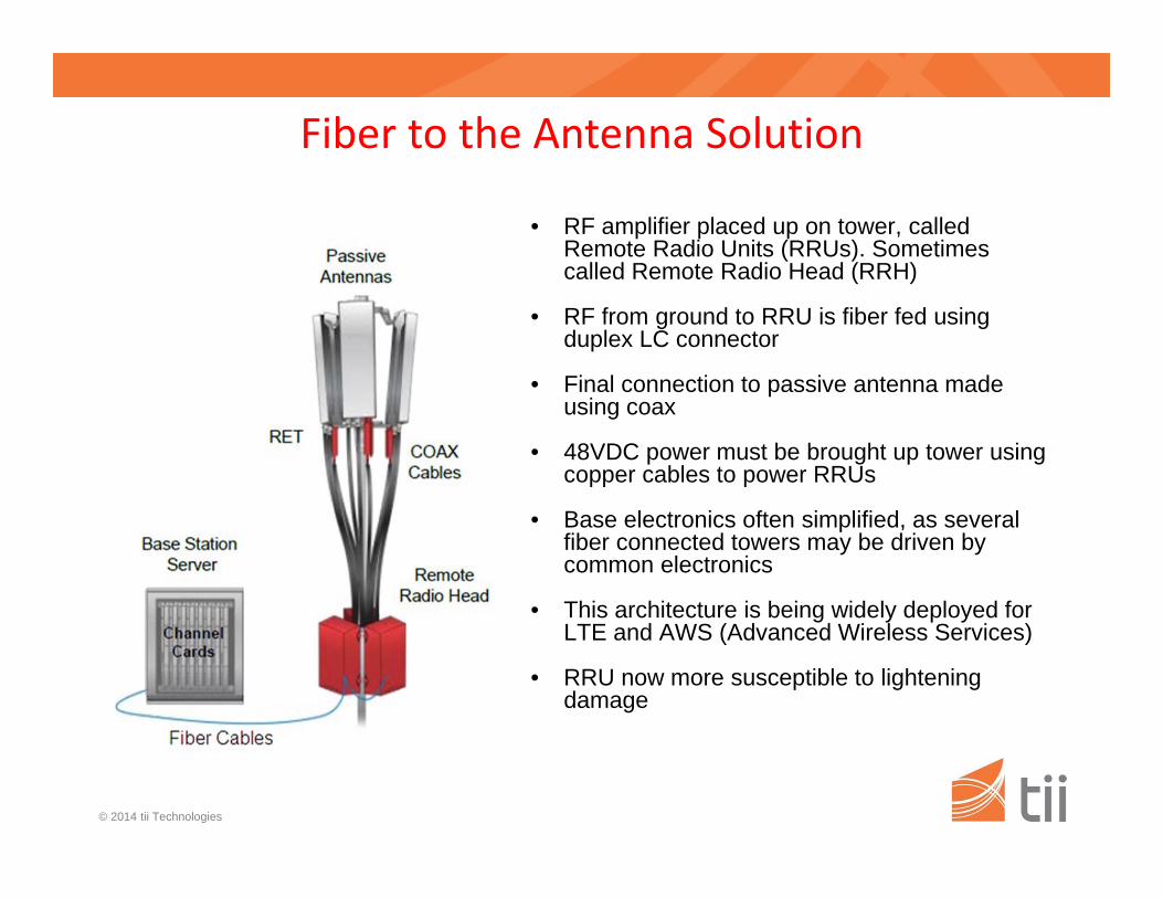
Fiber to the Antenna Solution
• RF amplifier placed up on tower, called Remote Radio Units (RRUs). Sometimes called Remote Radio Head (RRH)
• RF from ground to RRU is fiber fed using duplex LC connector
• Final connection to passive antenna made using coax
• 48VDC power must be brought up tower using copper cables to power RRUs
• Base electronics often simplified, as several fiber connected towers may be driven by common electronics
• This architecture is being widely deployed for LTE and AWS (Advanced Wireless Services)
• RRU now more susceptible to lightening damage
© 2014 tii Technologies
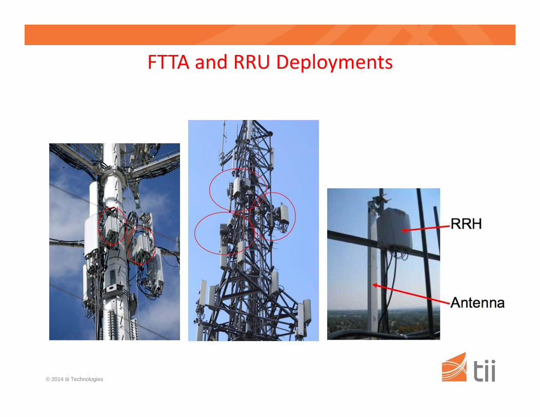
FTTA and RRU Deployments
© 2014 tii Technologies
Surge Environment for the FTTA protectors
Cell towers are made of steel and have lightning conductors on top, therefore direct lightning hits may not be very common.High induced currents could result due to high lightning currents through the cell tower structure.
Since, lots of communication traffic will be interrupted if any of the RF device deployed on the cell tower is damaged, it is therefore, essential to have a very robust surge protection.
Replacement of the damaged surge protection device is not simple since some of the cell towers are hundreds of feet tall and will require specialized equipment which could cause long delays in restoring the services.

© 2014 tii Technologies
Selection of Surge Protection Technology
Following surge protection technologies could be deployed in the FTTA surge protection:
1. Metal Oxide Varistor (MOV): Seem to be the most commonly used surge protection elements in the FTTA applications. MOVs are not too expensive and can absorb reasonably high surge energies.
2. Spark Gaps: mostly are use in conjunction with MOVs as their break over voltages are high. Spark Gaps can handle lots of surge energy.
3. Gas discharge tubes: A single Gas Discharge Tube may continue to conduct after the surge event is over due to hold over properties. However, array of multiple GDTs, can be used to handle high surge capability and high break over voltage. Cost and size of such device could become large.

© 2014 tii Technologies
Surge Protector Fail‐Safe ModesThere are two fail-safe modes that a MOV based surge protector can be designed.
1. Fail-Open mode: In this mode, the protector will disconnect itself from the line being protected. The service to the connected equipment will continue with a risk of equipment being damaged from subsequent surge event that might take place before the defective surge protector is replaced. Relay alarm contacts provisioned with such protectors will send alarm that the protector needs to be replaced.
2. Fail-Short mode: In this mode, the protector will fail in a short to ground condition. This mode of failure though a rare possibility, if the design is robust enough, still could happen. With this, the protector will short the power supply voltage powering the Remote Radio Units to ground and will interrupt service till some one disconnects the device from the circuit.

© 2014 tii Technologies
Typical FTTA Cell Site Architecture
(Coax)
Base Junction BoxBase
Station
FTTA‐DDT
Hybrid or Discrete Fiber/Copper Cables
• Base Junction Box various functions:Combine copper and fiberSplice/junction point for copper and fiberSlack storageHouse circuit breakers
• Vertical cables can be Hybrid or Discrete:
• Fiber to the Antenna - Dome Distribution Terminal (FTTA-DDT) provides:
Fiber junction point from vertical cable to each RRUCopper junction point from vertical cable to each RRUOvervoltage surge protection for RRU
• RRU connects to antenna using short coax cable

© 2014 tii Technologies
Remote Radio Head Din Rail Mount Surge Protector Unit

© 2014 tii Technologies
Schematic of an MOV based, Din Rail Mountable FTTA surge protector

© 2014 tii Technologies
Applicable Surge Protection Standards
There is no specific Surge Protection Standards which addresses the requirements for the Fiber to the Antenna Surge Protection Devices
Presently manufacturers of Fiber to the Antenna Surge protection devices refer to following:
1. UL 1449 – A national standard for Transient Voltage Surge suppressors for AC circuits
2. IEC 61643 – An International Standard for low voltage Surge Protection Devices

© 2014 tii Technologies
Requirements under UL 1449
UL tests for following key parameters:
1. Leakage current2. Dielectric withstand3. Surge current withstand of up to 20 kA, 8/20 uS4. Voltage Protection levels for FTTA lowest : 330
volts5. Devices are tested with up to 85 % relative
humidity6. Testing is generally done at room temperature

© 2014 tii Technologies
Requirements under IEC 61643
1. Operating frequency 48 to 62 Hz AC or DC2. Altitude on not greater than 2000 meters3. Operating temperature of -5 to 40C (extended
range -40 to 70C)4. Relative Humidity of 30 – 90 %5. Maximum Continuous Operating Voltage6. Nominal Discharge Current of up to 20 kA,
8/20 uS surge.7. Voltage Protection Level to be specified

© 2014 tii Technologies
Some FTTA Surge Protection Specifications
Standby power consumption: 90 - 150 m VA
Maximum Discharge Surge Current: 30 - 140 kA, 8/20 uS Surge
Nominal Discharge Surge Current: 10 – 20 kA, 8/20 uS Surge
Lightning Test Current: Max. 12.5 kA, 10/350 uS Surge
Response time: 1 – 25 n Seconds
© 2014 tii Technologies
ConclusionsThere is need for an industry standard that adequately addresses:
1. Normal safe operating conditions
2. Maximum clamping voltage requirements
3. Maximum Surge Current levels
4. Expected Surge Life of the SPD
5. Acceptable failure modes
6. Remote alarm intimation requirement
© 2014 tii Technologies
QUESTIONS ?
Related Documents