Martin A. Freilich, DDS Department of Prosthodontics and Operative Dentistry University of Connecticut School of Dental Medicine Farmington, Connecticut Jonathan C. Meiers, DMD, MS Department of Prosthodontics and Operative Dentistry University of Connecticut School of Dental Medicine Farmington, Connecticut Jacqueline P. Duncan, DMD, MDSc Department of Prosthodontics and Operative Dentistry University of Connecticut School of Dental Medicine Farmington, Connecticut A. Jon Goldberg, PhD Department of Prosthodontics and Operative Dentistry Center for Biomaterials University of Connecticut School of Dental Medicine Farmington, Connecticut

Welcome message from author
This document is posted to help you gain knowledge. Please leave a comment to let me know what you think about it! Share it to your friends and learn new things together.
Transcript

Martin A. Freilich, DDSDepartment of Prosthodontics and Operative Dentistry
University of ConnecticutSchool of Dental MedicineFarmington, Connecticut
Jonathan C. Meiers, DMD, MSDepartment of Prosthodontics and Operative Dentistry
University of ConnecticutSchool of Dental MedicineFarmington, Connecticut
Jacqueline P. Duncan, DMD, MDScDepartment of Prosthodontics and Operative Dentistry
University of ConnecticutSchool of Dental MedicineFarmington, Connecticut
A. Jon Goldberg, PhDDepartment of Prosthodontics and Operative Dentistry
Center for BiomaterialsUniversity of ConnecticutSchool of Dental MedicineFarmington, Connecticut
Ali
logo
Library of Congress Cataloging-in-Publication Data
Fiber-reinforced composites in clinical dentistry / Martin A. Freilich ... [et al.]. p.; cm.
Includes bibliographical references and index.ISBN 0-86715-373-31. Fibrous composites in dentistry. I. Freilich, Martin A.[DNLM: ] . Dental Materials. 2. Composite Resins. 3. Dental Prosthesis Design. WU
190 F443 1999]RK655.3 .F53 1999617.6'95 dc2l 99-046512
Ali
logo 2
Ali
logo 2

The authors dedicate this book to their families, for their loveand support, and to their mentors, who have helped themachieve success in their professional careers.
Preface
■ Several years ago our research group at the University ofConnecticut became intrigued by the question of why fiber-re-inforced composite materials, which had been used success-fully in a variety of commercial applications, were not morewidely used in dentistry. After a careful review of the literatureand some preliminary research, it became clear to us that theuse of fiber-reinforced composites in existing dental applica-tions was compromised by three important limitations: low fibercontent, insufficient fiber wetting, and the difficulty of ma-nipulating free fibers. Through the development of pre-im-pregnation technology, which has served as the primary focusof our research group over the past 10 years, these problemshave been largely overcome.
Fiber-reinforced materials have highly favorable mechanicalproperties, and their strength-to-weight ratios are superior tothose of most alloys.When compared to metals they offer manyother advantages as well, including noncorrosiveness, translu-cency, good bonding properties, and ease of repair. Since theyalso offer the potential for chairside and laboratory fabrication, itis not surprising that fiber-reinforced composites have potentialfor use in many applications in dentistry.
Ali
logo

While early clinical trials validated many ofour concepts, the need for improved laboratoryand clinical procedures soon became apparent.Some procedures were refined, and additionalapplications were studied in both the laboratoryand the clinic. Our research group has collabo-rated with the Jeneric/Pentron company to de-velop a pre-impregnated, fiber-reinforced com-posite substructure material tradenamedFibreKor. Ivoclar has used a similar pre-impreg-nation technology to produce a fiber-reinforcedcomposite material, also for use in fixed prostho-dontics, tradenamed Vectris. Both of these com-mercially available systems are being used by agrowing number of dental practitioners.
To realize the full potential of using fiber-re-inforced composites, it is essential that the clin-ician and laboratory technician understandconcepts of tooth preparation and frameworkdesign. In this book we have attempted to pre-sent the clinical information necessary to allowthe reader to identify appropriate cases, selectwell-suited materials, and carry out related pro-cedures. The publisher has graciously encour-aged the liberal use of clinical photographs anddiagrams to make these details clear. At thesame time, we have provided background in-formation and other details about the materialsthemselves so that the practitioner may appre-ciate the rationale for their use in various clini-cal situations. Every effort has been made to in-clude the most widely used products fromdifferent manufacturers along with the differentcharacteristics and relative advantages ofeach.
The field of fiber-reinforced compositescontinues to expand at a rapid pace. New prod-ucts are being introduced even at this writing.We hope that the procedures described in thisbook will allow clinicians to incorporate the useof these materials into everyday practice andthat the background will provide a basis for un-derstanding future products and procedures.
The authors would like to acknowledge theearly scientific contr ibut ions made by DrCharles J. Burstone to the development offiber-reinforced composites, including his ideasfor potential clinical applications in dentistry. DrJames V. Altieri's work with an early FRC is alsoacknowledged. Dr Ajit Karmaker was an impor-tant member of the group that developed thefirst light-polymerized formulation, and contin-ues to be of assistance to the authors.
They also gratefully acknowledgeConnecticut Innovations, Inc, whose financialsupport of university-industry collaborationsenabled important development and commer-cialization efforts. Several companies produc-ing fiber-reinforced composites for dentistry—Ribbond, Glasspan, and Kerr—providedmaterials, freely discussed their technologies,and offered useful comments about this andearlier publications. Additionally, Ivoclar, Inc gra-ciously provided materials, equipment, and par-ticipation in the TargisNectris Training Program.
A special acknowledgment goes to theJeneric/Pentron Corporation for the compre-hensive collaborative relationship they havemaintained with the University of ConnecticutHealth Center to help bring fiber reinforcementto the dental profession.
The authors also express their gratitude toDr Howard E. Strassler for contributing clinicalphotographs and text for chapter 4; Dr ThomasN.Trinkner, Dr Bruce Marcucci, and Dr Anil Patelfor cont r ibu t ing clinical photographs; MrEverett Pearson and TPI Composites for con-tr ibuting photographs of their fiber-reinforcedproducts; and Dr Reza Kazemi for contributingillustrations.
Finally, the authors would like to thank MsDiane Kosis, MPH Coordinator of the Universityof Connecticut Clinical Dental Research Center,and Ms Shirley Carrolla and Ms Kimberly Haser,laboratory staff of the University of ConnecticutBiomaterials Center.
8
Rationale for theClinical Use of
Fiber-reinforcedComposites
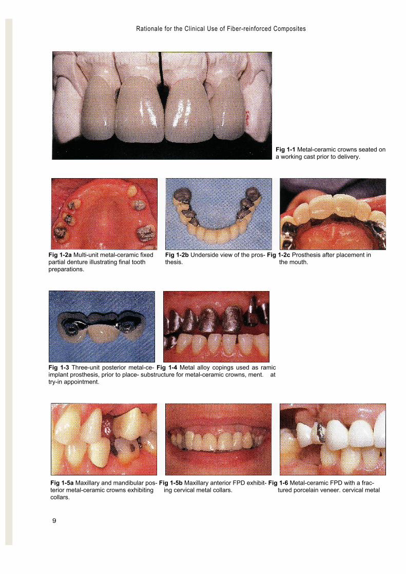
■The technology and materials available to today's restorativedentists offer various solutions to many complex problems.Missing tooth structure can be replaced through the use of ad-hesives or metal-ceramic crowns (Fig 1-1), and missing teethcan be replaced with any of a variety of fixed prostheses sup-ported by teeth (Fig 1-2) or implants (Fig 1-3). Porcelain-fused-to-metal substructures continue to be a mainstay of fixedprosthodontics, and polymethyl methacrylate (PMMA) polymerremains the material of choice for complete denture bases.
As popular and successful as these materials are, they ex-hibit shortcomings that frequently cause clinical problems:
1. The metal alloys used to make substructures that reinforcecrowns and fixed prostheses are strong and rigid, but theyare not esthetic (Figs 1-4 and 1-5). Furthermore, the basemetal alloys commonly used in clinical practice may cor-rode and some patients have an allergic reaction to them.'Certain components of some base metal alloys may evenpose acute and chronic health hazards to laboratory per-sonnel.8 '9
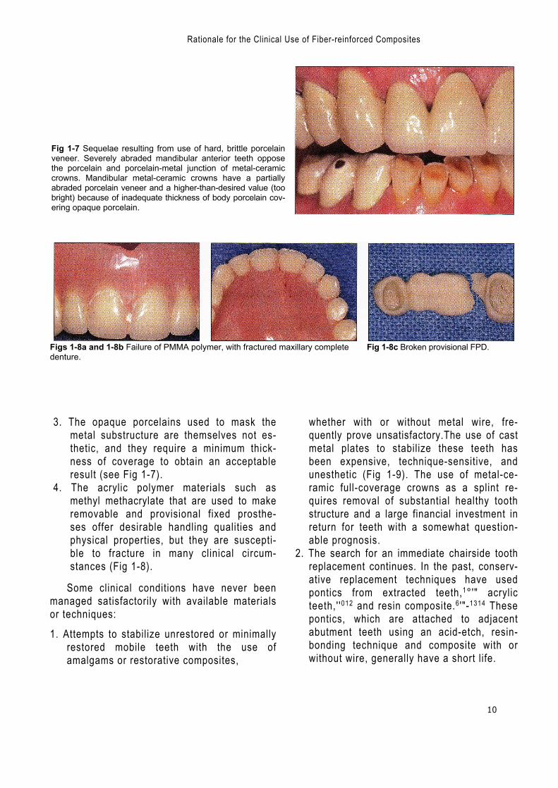
2. Ceramic materials such as porcelain may exhibit good opti-cal qualities, but they are also brittle and hard,they have thepotential to lose structural integrity (Fig 1-6),and they some-times abrade or fracture the opposing teeth (Fig 1-7).
Ali
logo
Rationale for the Clinical Use of Fiber-reinforced Composites
9
Fig 1-1 Metal-ceramic crowns seated ona working cast prior to delivery.
Fig 1-2a Multi-unit metal-ceramic fixed Fig 1-2b Underside view of the pros- Fig 1-2c Prosthesis after placement inpartial denture illustrating final tooth thesis. the mouth.preparations.
Fig 1-3 Three-unit posterior metal-ce- Fig 1-4 Metal alloy copings used as ramicimplant prosthesis, prior to place- substructure for metal-ceramic crowns, ment. attry-in appointment.
Fig 1-5a Maxillary and mandibular pos- Fig 1-5b Maxillary anterior FPD exhibit- Fig 1-6 Metal-ceramic FPD with a frac-terior metal-ceramic crowns exhibiting ing cervical metal collars. tured porcelain veneer. cervical metalcollars.
Rationale for the Clinical Use of Fiber-reinforced Composites
10
Fig 1-7 Sequelae resulting from use of hard, brittle porcelainveneer. Severely abraded mandibular anterior teeth opposethe porcelain and porcelain-metal junction of metal-ceramiccrowns. Mandibular metal-ceramic crowns have a partiallyabraded porcelain veneer and a higher-than-desired value (toobright) because of inadequate thickness of body porcelain cov-ering opaque porcelain.
Figs 1-8a and 1-8b Failure of PMMA polymer, with fractured maxillary complete Fig 1-8c Broken provisional FPD.denture.
3. The opaque porcelains used to mask themetal substructure are themselves not es-thetic, and they require a minimum thick-ness of coverage to obtain an acceptableresult (see Fig 1-7).
4. The acrylic polymer materials such asmethyl methacrylate that are used to makeremovable and provisional fixed prosthe-ses offer desirable handling qualities andphysical properties, but they are suscepti-ble to fracture in many clinical circum-stances (Fig 1-8).
Some clinical conditions have never beenmanaged satisfactorily with available materialsor techniques:
1. Attempts to stabilize unrestored or minimallyrestored mobile teeth with the use ofamalgams or restorative composites,
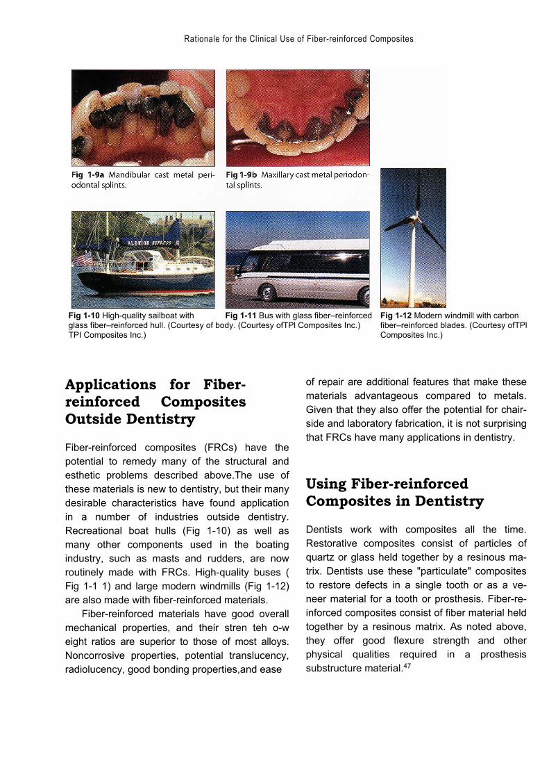
whether with or without metal wire, fre-quently prove unsatisfactory.The use of castmetal plates to stabilize these teeth hasbeen expensive, technique-sensitive, andunesthetic (Fig 1-9). The use of metal-ce-ramic full-coverage crowns as a splint re-quires removal of substantial healthy toothstructure and a large financial investment inreturn for teeth with a somewhat question-able prognosis.
2. The search for an immediate chairside toothreplacement continues. In the past, conserv-ative replacement techniques have usedpontics from extracted teeth,1°'" acrylicteeth,' '012 and resin composite.6 '"-1314 Thesepontics, which are attached to adjacentabutment teeth using an acid-etch, resin-bonding technique and composite with orwithout wire, generally have a short life.
Rationale for the Clinical Use of Fiber-reinforced Composites
Fig 1-10 High-quality sailboat with Fig 1-11 Bus with glass fiber–reinforced Fig 1-12 Modern windmill with carbonglass fiber–reinforced hull. (Courtesy of body. (Courtesy ofTPl Composites Inc.) fiber–reinforced blades. (Courtesy ofTPlTPI Composites Inc.) Composites Inc.)
Applications for Fiber-reinforced CompositesOutside Dentistry
Fiber-reinforced composites (FRCs) have thepotential to remedy many of the structural andesthetic problems described above.The use ofthese materials is new to dentistry, but their manydesirable characteristics have found applicationin a number of industries outside dentistry.Recreational boat hulls (Fig 1-10) as well asmany other components used in the boatingindustry, such as masts and rudders, are nowroutinely made with FRCs. High-quality buses (Fig 1-1 1) and large modern windmills (Fig 1-12)are also made with fiber-reinforced materials.
Fiber-reinforced materials have good overallmechanical properties, and their stren teh o-weight ratios are superior to those of most alloys.Noncorrosive properties, potential translucency,radiolucency, good bonding properties,and ease
of repair are additional features that make thesematerials advantageous compared to metals.Given that they also offer the potential for chair-side and laboratory fabrication, it is not surprisingthat FRCs have many applications in dentistry.
Using Fiber-reinforcedComposites in Dentistry
Dentists work with composites all the time.Restorative composites consist of particles ofquartz or glass held together by a resinous ma-trix. Dentists use these "particulate" compositesto restore defects in a single tooth or as a ve-neer material for a tooth or prosthesis. Fiber-re-inforced composites consist of fiber material heldtogether by a resinous matrix. As noted above,they offer good flexure strength and otherphysical qualities required in a prosthesissubstructure material.47
12
Using Fiber-reinforced Composites in Dentistry —
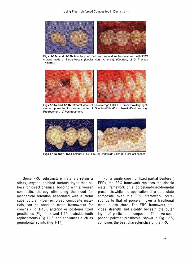
Figs 1-13a and 1-13b Maxillary left first and second molars restored with FRCcrowns made of Targis/Vectris (Ivoclar North America). (Courtesy of Dr ThomasTrinkner.)
Figs 1-14a and 1-14b Intraoral views of full-coverage FRC FPD from maxillary rightsecond premolar to canine made of Scupture/FibreKor (Jeneric/Pentron). (a)Pretreatment. (b) Posttreatment.
Figs 1-15a and 1-15b Posterior FRC FPD. (a) Underside view. (b) Occlusal aspect.
Some FRC substructure materials retain asticky, oxygen-inhibited surface layer that al-lows for direct chemical bonding with a veneercomposite, thereby eliminating the need formechanical retention associated with a metalsubstructure. Fiber-reinforced composite mate-rials can be used to make frameworks forcrowns (Fig 1-13), anterior or posterior fixedprostheses (Figs 1-14 and 1-15),chairside toothreplacements (Fig 1-16),and appliances such asperiodontal splints (Fig 1-17).
For a single crown or fixed partial denture (FPD), the FRC framework replaces the classicmetal framework of a porcelain-fused-to-metalprosthesis,while the application of a particulatecomposite over this FRC framework corre-sponds to that of porcelain over a traditionalmetal substructure. The FRC framework pro-vides strength and rigidity beneath the outerlayer of particulate composite. This two-com-ponent polymer prosthesis, shown in Fig 1-18,combines the best characteristics of the FRC

Rationale for the Clinical Use of Fiber-reinforced Composites
13
Figs 1-16a and 1-16b Intraoral views of a chairside-fabricated FRC FPD from max-illary left second premolar to second molar. (a) Pretreatment. (b) Posttreatment.
Fig 1-17 Chairside-fabricated FRC peri- Fig 1-18 Illustration of the FRC sub- Fig 1-19 Illustration of the FRC sub-odontal splint made on the lingual as- structure for an anterior 3-unit FPD. structure partially overlayed with cover-pect of maxillary anterior teeth. (Special thanks to Dr Reza Kazemi.) ing particulate composite, showing the
support that the substructure providesfor the composite veneer. (Specialthanks to Dr Reza Kazemi.)
(strength and rigidity) with the best character-istics of the particulate composite (wear resis-tance and esthetics). Since it can be bonded di-rectly to abutment teeth, such a prosthesis isuseful where there is less-than-optimal reten-tion and resistance form.
Essential Clinical Skills
Fiber-reinforced materials have wide potentialfor application in a variety of clinical situations,but the clinician must understand the basicstructure of these materials and the differenttypes available. Awareness of the advantagesand limitations of each type of FRC enables theclinician to select the best FRC material for eachparticular clinical circumstance.
For splints, crowns, and fixed prostheses, theclinician must be able to make FRC toothpreparations that allow the dental laboratory toplace an adequate volume of FRC to make adurable, biocompatible framework and pros-thesis.The clinician needs to understand frame-work design concepts because there is strongevidence that this is a crucial factor in the suc-cess or failure of a fiber-reinforced prosthesis.Lastly, the clinician must be able to performtechniques for luting an indirect prosthesis orfabricating a direct prosthesis or appliance.Thechapters that follow are intended to providethese essential skills to the clinician anddemonstrate many additional applications forthis technology.
14
— References —
References
1. Antonson DE. Immediate temporary bridge using anextracted tooth. Dent Sury 1980;56:22–25.
2. Council on Dental Materials, Instruments, and Equipment.Report on base metal alloys for crown and bridgeapplications: Benefits and risks.] Am Dent Assoc 1985;111:479-483.
3. Davila JM, Gwinnett AV. Clinical and microscopic evalu-ation of a bridge using the acid-etch technique. J DentChild 1978;45:228–232.
4. Freilich MA, Karmaker AC, Burstone CJ, Goldberg AJ.Flexure strength of fiber-reinforced composites de-signedfor prosthodontic application [abstract 999]. J Dent Res1997;76(special issue):138.
5. Ibsen RL. Fixed prosthetics with a natural crown ponticusing an adhesive composite.J South Calif Dent Assoc1973;41:100–102.
6. Jensen ME, Meiers JC. Resin-Bonded Retainers inClinical Dentistry, vol 4. Philadelphia: Harper and Row,1984:4-5.
7. Karmaker AC, DiBenedetto AT, Goldberg AJ. Fiber-rein-forced composite materials for dental appliances.Presented at the Society of Plastic Engineers AnnualTechnical Conference, Indianapolis, 5–9 May 1996.
8. Moffa JP, Beck WD, Hoke AW. Allergic response to nickel-containing dental alloys [abstract 107]. J Dent Res 1977;56:1378.
9. Morris H F. Veterans Administration Cooperative StudiesProject No.147. IV. Biocompatibility of base metal alloys. JDent 1987;56(special issue):B78.
10. Portnoy LL.Constructing a composite pontic in a singlevisit. Dent Sury 1973;49:20-23.
11. Simonsen RJ. Clinical Applications of the Acid EtchTechnique. Chicago: Quintessence, 1978:71.
12. Simonsen RJ.The acid etch technique in fixed prosthe-ses. An update. Quintessence Int 1980;9:33.
13. Simonsen R, Thompson V, Barrack G. Etched CastRestorations: Clinical and Laboratory Techniques.Chicago: Quintessence, 1983.
14. Stolpa JB. An adhesive technique for small anterior fixedpartial dentures.] Prosthet Dent 1975;34:513-519.
Ali
logo 2
Ali
logo 2

16
Composition,Architecture, and Mechanical
Properties ofFiber-reinforced Composites
■ Fiber-reinforced composites (FRCs) are structural materialsthat have at least two distinct constituents. The reinforcingcomponent provides strength and stiffness, while the sur-rounding matrix supports the reinforcement and providesworkability. One of the constituents may be metal, ceramic, orpolymer; in dental applications, polymeric or resin matrices re-inforced with glass, polyethylene, or carbon fiber are most com-mon. The fibers may be arranged in various configurations: "unidirectional" fibers (Fig 2-1)—long, continuous, and parallel—are the most popular, followed by braided and woven fibers (Fig2-2).Typically, fibers are 7 to 10 pm in diameter and span thelength of the prosthesis or appliance. By comparison, theparticles used in standard restorative dental composites are 1 to5 pm in diameter, or submicron in size (Fig 2-3).
The type of fiber used to make an FRC depends on how it isintended to be used and the characteristics that are needed forthat purpose.Glass fibers of various kinds are commonly used indental laboratory products, while polymeric reinforcements,such as polyethylene, are often used for chairside applications.Posts are made of carbon or glass fibers.Table 2-1 lists differenttypes of fiber and the important mechanical and physical char-acteristics of each.The types of fiber and architecture found invarious products are shown in Table 2-2; products are classifiedaccording to their clinical uses and whether the fiber bundles
Ali
logo 2

17
Composition, Architecture, and Mechanical Properties of Fiber-reinforced Composites
Fig 2-2 Scanning electron micrographs of various fiber architectures.
18
— Composition, Architecture, and Mechanical Properties of Fiber-reinforced Composites —
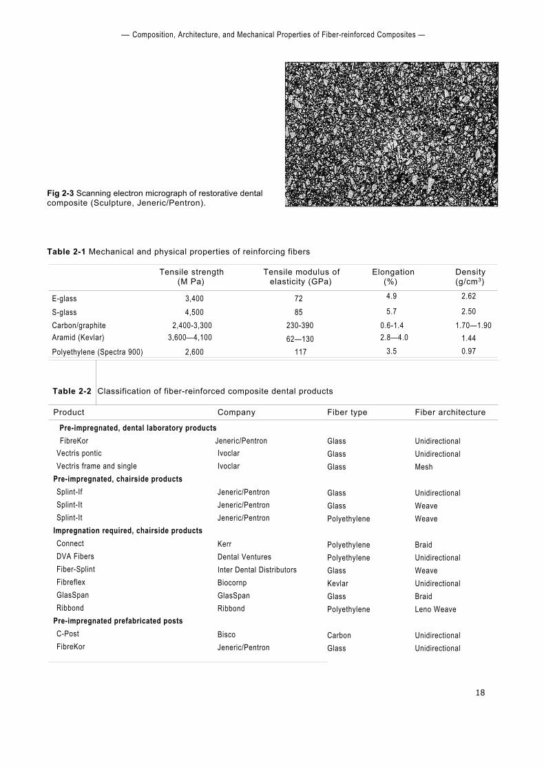
Fig 2-3 Scanning electron micrograph of restorative dentalcomposite (Sculpture, Jeneric/Pentron).
Table 2-1 Mechanical and physical properties of reinforcing fibers
Tensile strength(M Pa)
Tensile modulus ofelasticity (GPa)
Elongation(%)
Density(g/cm3)
E-glass 3,400 72 4.9 2.62
S-glass 4,500 85 5.7 2.50Carbon/graphite 2,400-3,300 230-390 0.6-1.4 1.70—1.90Aramid (Kevlar) 3,600—4,100 62—130 2.8—4.0 1.44Polyethylene (Spectra 900) 2,600 117 3.5 0.97
Table 2-2 Classification of fiber-reinforced composite dental products
Product Company Fiber type Fiber architecture
Pre-impregnated, dental laboratory productsFibreKor Jeneric/Pentron Glass
GlassGlass
GlassGlassPolyethylene
PolyethylenePolyethyleneGlassKevlarGlassPolyethylene
CarbonGlass
UnidirectionalUnidirectionalMesh
UnidirectionalWeaveWeave
BraidUnidirectionalWeaveUnidirectionalBraidLeno Weave
UnidirectionalUnidirectional
Vectris ponticVectris frame and single
Pre-impregnated, chairside productsSplint-IfSplint-ItSplint-It
Impregnation required, chairside productsConnectDVA FibersFiber-SplintFibreflexGlasSpanRibbond
Pre-impregnated prefabricated postsC-PostFibreKor
IvoclarIvoclar
Jeneric/PentronJeneric/PentronJeneric/Pentron
KerrDental VenturesInter Dental DistributorsBiocornpGlasSpanRibbond
BiscoJeneric/Pentron

Composition, Architecture, and Mechanical Properties of Fiber-reinforced Composites
19
Fig 2-4 Scanning electron micrographs of glass-reinforced thermoplastics showing the degree ofwetting of the fibers by the matrix.
Fig 2-4a Poor wetting, resulting in weaker mechanicalproperties.
are pre-impregnated with resin by the manu-facturer or resination is required by the dentistor laboratory technician. Dental manufacturersuse only standard industrial fibers; however,there is wide variation between products in fibersurface treatments, methods for incorporatingthe fibers into the polymeric resin, and chairsideand laboratory processing methods.
History of FiberReinforcement in Dentistry
The first attempts to use fiber reinforcement inclinical dentistry began more than 35 years ago.In the 1960s and 1970s, investigators sought toreinforce standard polymethyl methacrylatedentures with glass34 or carbon fibers.26,33 In the1980s, similar attempts were repeated,5 '16 andinitial efforts were made to fabricate fiber-rein-forced prosthodontic frameworks for implants 4,
$3' fixed prosthodontic restorations,25 orthodonticretainers,67 and splints.24 While these materialsand techniques demonstrated improvedmechanical properties, they failed to
Fig 2-4b Effective wetting and coupling. Failure occurredaway from the fiber-matrix interface.
achieve general clinical acceptance because ofinsufficient enhancement of properties andawkward clinical manipulat ing procedures. Mostof the proposed procedures involved intuitivemanual placement of fibers into dental resinsthat were otherwise processed with routinemethods.This approach was cumbersome sincefree fibers are difficult to handle and great caremust be taken to avoid either damaging orcontaminating them. Furthermore, while theaddition of fibers increased mechanical proper-ties, the degree of improvement was far belowthat achieved in other commercial applications.There were two reasons for the lower-than-ex-pected mechanical results. First, the actualamount of fiber incorporated into the dentalresins was low, typically less than 15% by vol-ume. (Industrial products may contain 50% oreven as much as 70% fiber by volume.) Second,the fiber reinforcement was not as effective asin theory because poor wetting of the fiberbundles by the resin led to insufficient couplingor even gaps between the fibers and resin" (Fig2-4a). During testing, effective coupling usuallyresults in failure not at the fiber-matrix interfacebut within the matrix" (Fig 2-4b).
20
History of Fiber Reinforcement in Dentistry
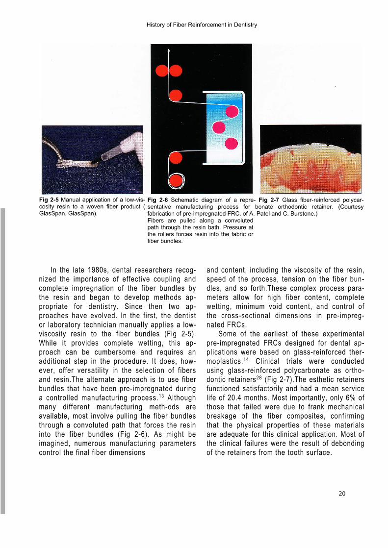
Fig 2-6 Schematic diagram of a repre- Fig 2-7 Glass fiber-reinforced polycar-sentative manufacturing process for bonate orthodontic retainer. (Courtesyfabrication of pre-impregnated FRC. of A. Patel and C. Burstone.)Fibers are pulled along a convolutedpath through the resin bath. Pressure atthe rollers forces resin into the fabric orfiber bundles.
Fig 2-5 Manual application of a low-vis-cosity resin to a woven fiber product (GlasSpan, GlasSpan).
In the late 1980s, dental researchers recog-nized the importance of effective coupling andcomplete impregnation of the fiber bundles bythe resin and began to develop methods ap-propriate for dentistry. Since then two ap-proaches have evolved. In the first, the dentistor laboratory technician manually applies a low-viscosity resin to the fiber bundles (Fig 2-5).While it provides complete wetting, this ap-proach can be cumbersome and requires anadditional step in the procedure. It does, how-ever, offer versatility in the selection of fibersand resin.The alternate approach is to use fiberbundles that have been pre-impregnated duringa controlled manufacturing process.13 Althoughmany different manufacturing meth-ods areavailable, most involve pulling the fiber bundlesthrough a convoluted path that forces the resininto the fiber bundles (Fig 2-6). As might beimagined, numerous manufacturing parameterscontrol the final fiber dimensions
and content, including the viscosity of the resin,speed of the process, tension on the fiber bun-dles, and so forth.These complex process para-meters allow for high fiber content, completewetting, minimum void content, and control ofthe cross-sectional dimensions in pre-impreg-nated FRCs.
Some of the earliest of these experimentalpre-impregnated FRCs designed for dental ap-plications were based on glass-reinforced ther-moplastics.14 Clinical trials were conductedusing glass-reinforced polycarbonate as ortho-dontic retainers28 (Fig 2-7).The esthetic retainersfunctioned satisfactorily and had a mean servicelife of 20.4 months. Most importantly, only 6% ofthose that failed were due to frank mechanicalbreakage of the fiber composites, confirmingthat the physical properties of these materialsare adequate for this clinical application. Most ofthe clinical failures were the result of debondingof the retainers from the tooth surface.
Composition, Architecture, and Mechanical Properties of Fiber-reinforced Composites
21
A subsequent clinical trial evaluated the useof pre-impregnated glass-reinforced polycar-bonate as the framework for acid-etched fixedpartial dentures (FPDs).2 Fourteen 3-unit restora-tions were placed both in anterior and posteriorlocations using adhesive techniques only and notooth preparation. After 9 years, 3 restorationswere still in service. All 11 failures were associ-ated with separation in the region of the tooth-restoration interface; none was caused by frankmechanical breakage of the fiber-reinforcedframework. The clinical failures occurred at theadhesive-tooth interface, the adhesive–fibercomposite interface, or within the outer matrix ofthe fiber-reinforced composite. This studyconfirmed the adequate mechanical propertiesof FRCs for use in prosthodontic applications;however, it also demonstrated that the thermo-plastic resin matrix is difficult to manipulate andoffers poor bonding to tooth structures. Theseproblems were resolved by switching to abisphenol glycidyl methacrylate (bis-GMA)–based resin as the matrix for the FRCs.
Four-year clinical trials of carbon fiber–rein-forced polymethyl methacrylate implant-sup-ported prostheses also demonstrated the poten-tial for prosthodontic applications? After 4 years,only 5 (19%) of 27 original prostheses had frac-tured; however,these experimental materials hadless than half the strength of the commercial ma-terials currently used!'" Researchers recognizedthe potential for fiber-reinforced frameworks, butacknowledged the need for improved materials.Recent laboratory studies of provisional restora-tions have demonstrated that proper reinforce-ment with woven polyethylene fiber32 or glassfiber'° improves fracture resistance.
Continued research on glass-reinforced bis-GMA systems, combined with important manu-facturer-designed fiber impregnation and pack-aging systems, has led to the commercial pre-impregnated systems available today:Sculpture/FibreKor, Splint-It (Jeneric/Pentron);and Targis/Vectris (Ivoclar). In both systems, the
fiber-reinforced strips typically measure severalmillimeters in cross section and several cen-timeters in length and are packaged in sepa-rately sealed, light-tight containers (Fig 2-8).
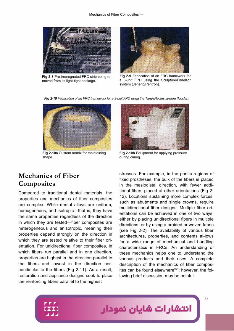
Using either pre-impregnated or hand-im-pregnated strips, a dentist or technician formsand fabricates the desired restoration, splint, orappliance, which is then cured. For most of theFRC procedures, a direct or indirect method canbe used. Splints are commonly fabricated with adirect approach and light-cured, while fixedprostheses are typically fabricated by dental lab-oratories to minimize chair time and to allow foroptimum esthetic and mechanical results. Bothhand-impregnated and pre-impregnated sys-tems are commercially available to the labora-tory, although the latter are more widely used.Two commercial pre-impregnated systems areavailable for dental laboratories. Both use fibercomposites to fabricate the framework, and thefinal tooth shape is then built with particulate-reinforced restorative composite. One system,Sculpture/FibreKor (Jeneric/Pentron), uses handfabrication to form the framework and con-densethe strips (Fig 2-9). The other system,Targis/Vectris (Ivoclar), uses custom-made matri-ces (Fig 2-10a) and special equipment (Fig 2-10b) to apply pressure to the fiber strips duringfabrication. In both systems, the main goals inthe fabrication of the framework are to incorpo-rate a sufficient amount of fiber reinforcement,minimize voids, and ensure strong bonding be-tween both the layers of pre-impregnated fiberstrips and the fiber framework and restorativecomposite. Clinical trials of the commercial sys-tems, now in their third year, demonstrate satis-factory performance when appropriate designs,fiber volume, and manipulative procedures arefollowed, although a loss of surface luster wasoften observed soon after placement.12 Someearly designs of fiber-reinforced FPDs requiredreplacement of the facings, but repair methodshave been described to minimize the need toreplace the complete restoration.29
22
Mechanics of Fiber Composites —
Fig 2-8 Pre-impregnated FRC strip being re-moved from its light-tight package.
Fig 2-9 Fabrication of an FRC framework fora 3-unit FPD using the Sculpture/FibreKorsystem (Jeneric/Pentron).
Fig 2-10 Fabrication of an FRC framework for a 3-unit FPD using the TargisNectris system (Ivoclar).
Fig 2-10a Custom matrix for maintainingshape.
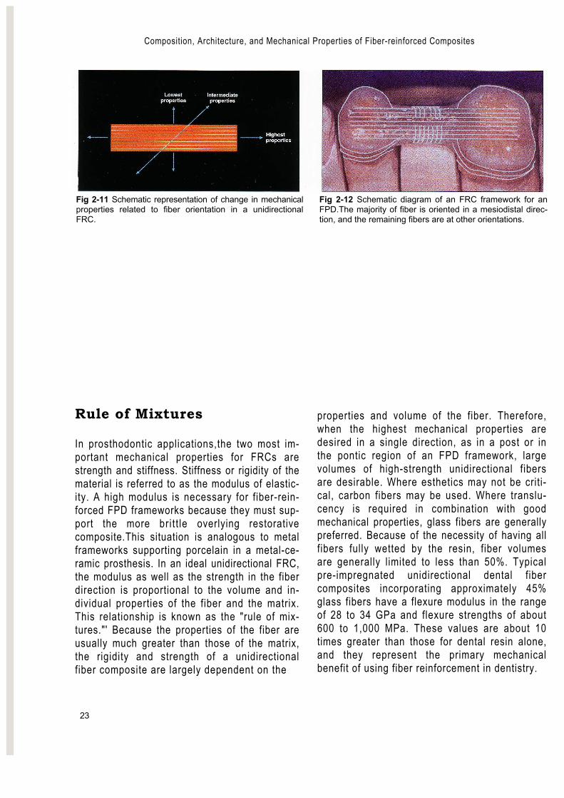
Mechanics of FiberCompositesCompared to traditional dental materials, theproperties and mechanics of fiber compositesare complex. While dental alloys are uniform,homogeneous, and isotropic—that is, they havethe same properties regardless of the directionin which they are tested—fiber composites areheterogeneous and anisotropic, meaning theirproperties depend strongly on the direction inwhich they are tested relative to their fiber ori-entation. For unidirectional fiber composites, inwhich fibers run parallel and in one direction,properties are highest in the direction parallel tothe fibers and lowest in the direction per-pendicular to the fibers (Fig 2-11). As a result,restoration and appliance designs seek to placethe reinforcing fibers parallel to the highest
Fig 2-10b Equipment for applying pressureduring curing.
stresses. For example, in the pontic regions offixed prostheses, the bulk of the fibers is placedin the mesiodistal direction, with fewer addi-tional fibers placed at other orientations (Fig 2-12). Locations sustaining more complex forces,such as abutments and single crowns, requiremultidirectional fiber designs. Multiple fiber ori-entations can be achieved in one of two ways:either by placing unidirectional fibers in multipledirections, or by using a braided or woven fabric(see Fig 2-2). The availability of various fiberarchitectures, properties, and contents al-lowsfor a wide range of mechanical and handlingcharacteristics in FRCs. An understanding ofthese mechanics helps one to understand thevarious products and their uses. A completedescription of the mechanics of fiber compos-ites can be found elsewhere''Z'; however, the fol-lowing brief discussion may be helpful.
Ali
logo 2
Composition, Architecture, and Mechanical Properties of Fiber-reinforced Composites
23
Fig 2-11 Schematic representation of change in mechanicalproperties related to fiber orientation in a unidirectionalFRC.
Fig 2-12 Schematic diagram of an FRC framework for anFPD.The majority of fiber is oriented in a mesiodistal direc-tion, and the remaining fibers are at other orientations.
Rule of Mixtures
In prosthodontic applications,the two most im-portant mechanical properties for FRCs arestrength and stiffness. Stiffness or rigidity of thematerial is referred to as the modulus of elastic-ity. A high modulus is necessary for fiber-rein-forced FPD frameworks because they must sup-port the more bri t t le overlying restorativecomposite.This situation is analogous to metalframeworks supporting porcelain in a metal-ce-ramic prosthesis. In an ideal unidirectional FRC,the modulus as well as the strength in the fiberdirection is proportional to the volume and in-dividual properties of the fiber and the matrix.This relationship is known as the "rule of mix-tures."' Because the properties of the fiber areusually much greater than those of the matrix,the rigidity and strength of a unidirectionalfiber composite are largely dependent on the
properties and volume of the fiber. Therefore,when the highest mechanical properties aredesired in a single direction, as in a post or inthe pontic region of an FPD framework, largevolumes of high-strength unidirectional fibersare desirable. Where esthetics may not be criti-cal, carbon fibers may be used. Where translu-cency is required in combination with goodmechanical properties, glass fibers are generallypreferred. Because of the necessity of having allfibers fully wetted by the resin, fiber volumesare generally limited to less than 50%. Typicalpre-impregnated unidirectional dental fibercomposites incorporating approximately 45%glass fibers have a flexure modulus in the rangeof 28 to 34 GPa and flexure strengths of about600 to 1,000 MPa. These values are about 10times greater than those for dental resin alone,and they represent the primary mechanicalbenefit of using fiber reinforcement in dentistry.
24
- Flexure Strength
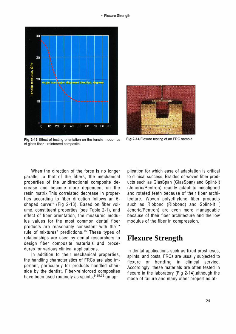
Fig 2-13 Effect of testing orientation on the tensile modu- lusof glass fiber—reinforced composite.
When the direction of the force is no longerparallel to that of the fibers, the mechanicalproperties of the unidirectional composite de-crease and become more dependent on theresin matrix.This correlated decrease in proper-ties according to fiber direction follows an 5-shaped curve's (Fig 2-13). Based on fiber vol-ume, constituent properties (see Table 2-1), andeffect of fiber orientation, the measured modu-lus values for the most common dental fiberproducts are reasonably consistent with the "rule of mixtures" predictions.15 These types ofrelationships are used by dental researchers todesign fiber composite materials and proce-dures for various clinical applications.
In addition to their mechanical properties,the handling characteristics of FRCs are also im-portant, particularly for products handled chair-side by the dentist. Fiber-reinforced compositeshave been used routinely as splints,9,35,36 an ap-
plication for which ease of adaptation is criticalto clinical success. Braided or woven fiber prod-ucts such as GlasSpan (GlasSpan) and Splint-It(Jeneric/Pentron) readily adapt to misalignedand rotated teeth because of their fiber archi-tecture. Woven polyethylene fiber productssuch as Ribbond (Ribbond) and Splint-It (Jeneric/Pentron) are even more manageablebecause of their fiber architecture and the lowmodulus of the fiber in compression.
Flexure Strength
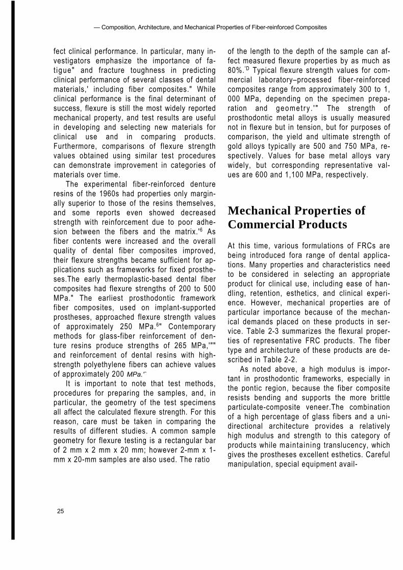
In dental applications such as fixed prostheses,splints, and posts, FRCs are usually subjected toflexure or bend ing in clinical service.Accordingly, these materials are often tested inflexure in the laboratory (Fig 2-14),although themode of failure and many other properties af-
Fig 2-14 Flexure testing of an FRC sample.
— Composition, Architecture, and Mechanical Properties of Fiber-reinforced Composites
25
fect clinical performance. In particular, many in-vestigators emphasize the importance of fa-t igue" and fracture toughness in predictingclinical performance of several classes of dentalmaterials,' including fiber composites." Whileclinical performance is the final determinant ofsuccess, flexure is still the most widely reportedmechanical property, and test results are usefulin developing and selecting new materials forclinical use and in comparing products.Furthermore, comparisons of flexure strengthvalues obtained using similar test procedurescan demonstrate improvement in categories ofmaterials over time.
The experimental fiber-reinforced dentureresins of the 1960s had properties only margin-ally superior to those of the resins themselves,and some reports even showed decreasedstrength with reinforcement due to poor adhe-sion between the fibers and the matrix.'6 Asfiber contents were increased and the overallquality of dental fiber composites improved,their flexure strengths became sufficient for ap-plications such as frameworks for fixed prosthe-ses.The early thermoplastic-based dental fibercomposites had flexure strengths of 200 to 500MPa." The earliest prosthodontic frameworkfiber composites, used on implant-supportedprostheses, approached flexure strength valuesof approximately 250 MPa.6" Contemporarymethods for glass-fiber reinforcement of den-ture resins produce strengths of 265 MPa,'""and reinforcement of dental resins with high-strength polyethylene fibers can achieve valuesof approximately 200 MPa.'`
It is important to note that test methods,procedures for preparing the samples, and, inparticular, the geometry of the test specimensall affect the calculated flexure strength. For thisreason, care must be taken in comparing theresults of different studies. A common samplegeometry for flexure testing is a rectangular barof 2 mm x 2 mm x 20 mm; however 2-mm x 1-mm x 20-mm samples are also used. The ratio
of the length to the depth of the sample can af-fect measured flexure properties by as much as80%. 'D Typical flexure strength values for com-mercial laboratory–processed fiber-reinforcedcomposites range from approximately 300 to 1,000 MPa, depending on the specimen prepa-ration and geomet ry . ' " The strength ofprosthodontic metal alloys is usually measurednot in flexure but in tension, but for purposes ofcomparison, the yield and ultimate strength ofgold alloys typically are 500 and 750 MPa, re-spectively. Values for base metal alloys varywidely, but corresponding representative val-ues are 600 and 1,100 MPa, respectively.
Mechanical Properties ofCommercial Products
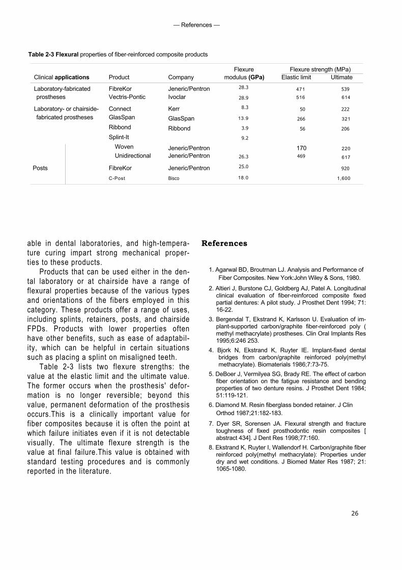
At this time, various formulations of FRCs arebeing introduced fora range of dental applica-tions. Many properties and characteristics needto be considered in selecting an appropriateproduct for clinical use, including ease of han-dling, retention, esthetics, and clinical experi-ence. However, mechanical properties are ofparticular importance because of the mechan-ical demands placed on these products in ser-vice. Table 2-3 summarizes the flexural proper-ties of representative FRC products. The fibertype and architecture of these products are de-scribed in Table 2-2.
As noted above, a high modulus is impor-tant in prosthodontic frameworks, especially inthe pontic region, because the fiber compositeresists bending and supports the more brittleparticulate-composite veneer.The combinationof a high percentage of glass fibers and a uni-directional architecture provides a relativelyhigh modulus and strength to this category ofproducts while mainta in ing translucency, whichgives the prostheses excellent esthetics. Carefulmanipulation, special equipment avail-
— References —
Table 2-3 Flexural properties of fiber-reinforced composite products
26
Flexure Flexure strength (MPa)Clinical applications Product Company modulus (GPa) Elastic limit Ultimate
Laboratory-fabricated FibreKor Jeneric/Pentron 28.3 471 539
prostheses Vectris-Pontic Ivoclar 28.9 516 614
Laboratory- or chairside- Connect Kerr 8.3 50 222
fabricated prostheses GlasSpan GlasSpan 13.9 266 321
Ribbond Ribbond 3.9 56 206
Splint-ItWoven Jeneric/Pentron
9.2
170 220Unidirectional Jeneric/Pentron 26.3 469 617
Posts FibreKor Jeneric/Pentron 25.0 920
C-Post Bisco 18.0 1,600
able in dental laboratories, and high-tempera-ture curing impart strong mechanical proper-ties to these products.
Products that can be used either in the den-tal laboratory or at chairside have a range offlexural properties because of the various typesand orientations of the fibers employed in thiscategory. These products offer a range of uses,including splints, retainers, posts, and chairsideFPDs. Products with lower properties oftenhave other benefits, such as ease of adaptabil-ity, which can be helpful in certain situationssuch as placing a splint on misaligned teeth.
Table 2-3 lists two flexure strengths: thevalue at the elastic limit and the ultimate value.The former occurs when the prosthesis' defor-mation is no longer reversible; beyond thisvalue, permanent deformation of the prosthesisoccurs.This is a clinically important value forfiber composites because it is often the point atwhich failure initiates even if it is not detectablevisually. The ultimate flexure strength is thevalue at final failure.This value is obtained withstandard testing procedures and is commonlyreported in the literature.
References
1. Agarwal BD, Broutrnan LJ. Analysis and Performance ofFiber Composites. New York:John Wiley & Sons, 1980.
2. Altieri J, Burstone CJ, Goldberg AJ, Patel A. Longitudinalclinical evaluation of fiber-reinforced composite fixedpartial dentures: A pilot study. J Prosthet Dent 1994; 71:16-22.
3. Bergendal T, Ekstrand K, Karlsson U. Evaluation of im-plant-supported carbon/graphite fiber-reinforced poly (methyl methacrylate) prostheses. Clin Oral Implants Res1995;6:246 253.
4. Bjork N, Ekstrand K, Ruyter IE. Implant-fixed dentalbridges from carbon/graphite reinforced poly(methylmethacrylate). Biomaterials 1986;7:73-75.
5. DeBoer J, Vermilyea SG, Brady RE. The effect of carbonfiber orientation on the fatigue resistance and bendingproperties of two denture resins. J Prosthet Dent 1984;51:119-121.
6. Diamond M. Resin fiberglass bonded retainer. J ClinOrthod 1987;21:182-183.
7. Dyer SR, Sorensen JA. Flexural strength and fracturetoughness of fixed prosthodontic resin composites [abstract 434]. J Dent Res 1998;77:160.
8. Ekstrand K, Ruyter I, Wallendorf H. Carbon/graphite fiberreinforced poly(methyl methacrylate): Properties underdry and wet conditions. J Biomed Mater Res 1987; 21:1065-1080.

— Composition, Architecture, and Mechanical Properties of Fiber-reinforced Composites
27
9. Freilich MA, Goldberg AJ.The use of a pre-impregnated,fiber-reinforced composite in the fabrication of a peri-odontal splint: A preliminary report. Pract PeriodonticsAesthet Dent 1997;9:873-876.
10. Freilich MA, Karmaker AC, Burstone CJ, Goldberg AJ.Flexure strength of fiber-reinforced composites de-signed for prosthodontic application [abstract 999]. JDent Res 1997;76:138.
11. Freilich MA, Karmaker AC, Burstone CJ, Goldberg AJ.Development and clinical applications of a light-poly-merized fiber-reinforced composite. J Prosthet Dent1998;80:311-318.
12. Freilich MA, Duncan JP, Meiers JC, Goldberg AJ.Clinical evaluation of fiber-reinforced fixed partialdentures: Preliminary data [abstract 2218]. J Dent Res1999; 78:383.
13. Goldberg AJ, Burstone CJ. The use of continuous fiberreinforcement in dentistry. Dent Mater 1992;8:197-202.
14. Goldberg AJ, Burstone CJ, Hadjinikolau I, Jancar J.Screening of matrices and fibers for reinforced thermo-plastics intended for dental applications. J BiomedMater Res 1994;28:167-173.
15. Goldberg AJ, Freilich MA, Haser KA, Audi JH. Flexureproperties and fiber architecture of commercial fiber-reinforced composites [abstract 967]. J Dent Res 1998;77:226.
16. Grave AMH, Chandler HD, Wolfaardt JF. Denture baseacrylic reinforced with high modulus fibre. Dent Mater1985;1:185-187.
17. Jancar J, DiBenedetto AT. Fiber reinforced thermoplasticcomposites for dentistry. Part 1. Hydrolytic stability ofthe interface. J Mater Sci Mater Med 1993;4:555-561.
18. Kacir L, Narkis M, Ishai O.Oriented short glass fibercomposites. III. Structure and mechanical properties ofmolded sheets. Polym Eng Sci 1977;17:234-241.
19. Karmaker AC, DiBenedetto AT, Goldberg AJ. Extent ofconversion and its effect on the mechanical perfor-rnance of Bis-GMA/PEGDMA-based resins and theircomposites with continuous glass fibers. J Mater SciMater Med 1997;8:369-374.
20. Karmaker AC, Freilich MA, Burstone CJ, Goldberg AJ,Prasad A. Performance of fiber-reinforced compositesintended for prosthodontic frameworks [abstract]. TransSoc Biomaterials 23rd Annual Meeting 1997:231.
21. Kaw AK. Mechanics of Composite Materials. BocaRaton: CRC Press, 1997.
22. Kelly JR. Perspectives on strength. Dent Mater 1995;11:103-110.
23. Ladizesky NH, Chow TW.The effect of interface adhe-sion, water immersion and anatomical notches on themechanical properties of denture base resins rein-forcedwith continuous high performance polyethylene fibres.Aust Dent J 1992;37:277-289.
24. Levenson MF.The use of a clear, pliable film to form afiberglass-reinforced splint. J Am Dent Assoc 1986;112:79-80.
25. Malquarti G, Berruet RG, Bois D. Prosthetic use ofcarbon fiber-reinforced epoxy resin for esthetic crownsand fixed partial dentures.J Prosthet Dent 1990;63:251-257.
26. Manley TR, Bowman AJ, Cook M. Denture bases rein-forced with carbon fibers. Br Dent J 1979;146:25.
27. Mullarky RH. Aramid fiber reinforcement for acrylic ap-pliances.) Clin Orthod 1985;19:655-658.
28. Patel A, Burstone CJ, Goldberg AJ.Clinical study offiber-reinforced thermoplastic as orthodontic retainers [abstract 87].J Dent Res 1992;71:526.
29. Rosentritt M, Behr M, Leibrock A, Handel G, Karl-HeinzF. Intraoral repair of fiber-reinforced composite fixedpar-tial dentures.J Prosthet Dent 1998;79:393-398.
30. Rudo DN, Karbhari V. Physical behaviors of fiber rein-forcement as applied to tooth stabilization. Dent ClinNorth Am 1999;43:7-35.
31. Ruyter IF, Ekstrand K, Bjork N. Development of car-bon/graphite fiber reinforced poly(methyl methacrylate)suitable for implant-fixed dental bridges. Dent Mater1986;2:6-9.
32. Samadzadeh A, Kugel G, H urley E, Ahoushala A.Fracture strengths of provisional restorations reinforcedwith plasma-treated woven polyethylene fibers. JProsthet Dent 1997;78:447-450.
33. Schreiber CK. The clinical application of carbonfiber/polymer denture resin. Br Dent J 1974;137:21-22.
34. Smith DC. Recent developments and prospects in den-tal polymer.) Prosthet Dent 1962;12:1066.
35. Strassler HE, LoPresti J, Scherer W, Rudo D. Clinicalevaluation of a woven polyethylene ribbon used forsplinting. Esthet Dent Update 1995;6:80-84.
36. Strassler HE, Haeri A, Gultz JP. New-generationbonded reinforcing materials for anterior periodontaltooth stabilization and splinting. Dent Clin North Am1999; 43:105-126.
37. Vallittu PK, Lassila VP, Lappalainen R.Transversestrength and fatigue of denture acrylic-glass fibercomposite. Dent Mater 1994;10:1 16-121.
38. Vallittu PK. Comparison of the in vitro fatigue resistanceof an acrylic resin removable partial denture reinforcedwith continuous glass fibers or metal wires. JProsthodont 1996;5:115-121.

— References
28
39. Vallittu PK. A review of fiber-reinforced denture baseresins.J Prosthodont 1996;5:270-276.
40. Vallittu PK, Docent DT. The effect of glass fiber rein-forcement on the fracture resistance of a provisionalfixed partial denture.J Prosthet Dent 1998;79:125-130.
Laboratory-fabricatedTooth-supported Fixed
Prostheses
30
Composition of an FRC FixedProsthesis
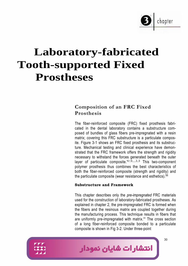
The fiber-reinforced composite (FRC) fixed prosthesis fabri-cated in the dental laboratory contains a substructure com-posed of bundles of glass fibers pre-impregnated with a resinmatrix; covering this FRC substructure is a particulate compos-ite. Figure 3-1 shows an FRC fixed prosthesis and its substruc-ture. Mechanical testing and clinical experience have demon-strated that the FRC framework offers the strength and rigiditynecessary to withstand the forces generated beneath the outerlayer of particulate composite.'4,',9,,,,,3,,5 This two-componentpolymer prosthesis thus combines the best characteristics ofboth the fiber-reinforced composite (strength and rigidity) andthe particulate composite (wear resistance and esthetics).56
Substructure and Framework
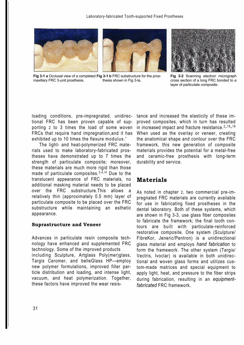
This chapter describes only the pre-impregnated FRC materialsused for the construction of laboratory-fabricated prostheses. Asexplained in chapter 2, the pre-impregnated FRC is formed whenthe fibers and the resinous matrix are coupled together duringthe manufacturing process. This technique results in fibers thatare uniformly pre-impregnated with matrix.''' The cross sectionof a long fiber-reinforced composite bonded to a particulatecomposite is shown in Fig 3-2. Under three-point
Ali
logo 2
Laboratory-fabricated Tooth-supported Fixed Prostheses
31
Fig 3-1 a Occlusal view of a completed Fig 3-1 b FRC substructure for the pros-maxillary FRC 3-unit prosthesis. thesis shown in Fig 3-la.
Fig 3-2 Scanning electron micrographcross section of a long FRC bonded to alayer of particulate composite.
loading conditions, pre-impregnated, unidirec-tional FRC has been proven capable of sup-porting 2 to 3 times the load of some wovenFRCs that require hand impregnation,and it hasexhibited up to 10 times the flexure modulus . '
The light- and heat-polymerized FRC mate-rials used to make laboratory-fabricated pros-theses have demonstrated up to 7 times thestrength of particulate composite; moreover,these materials are much more rigid than thosemade of particulate composites.3,4, '4 Due to thetranslucent appearance of FRC materials, noadditional masking material needs to be placedover the FRC substructure.This allows arelatively thin (approximately 0.5 mm) layer ofparticulate composite to be placed over the FRCsubstructure while maintaining an estheticappearance.
Suprastructure and Veneer
Advances in particulate resin composite tech-nology have enhanced and supplemented FRCtechnology. Some of the improved productsincluding Sculpture, Artglass Poly(mer)glass,Targis Ceromer, and belleGlass HP—employnew polymer formulations, improved filler par-ticle distribution and loading, and intense light,vacuum, and heat polymerization. Together,these factors have improved the wear resis-
tance and increased the elasticity of these im-proved composites, which in turn has resultedin increased impact and fracture resistance.2-16-18
When used as the overlay or veneer, creatingthe anatomical shape and contour over the FRCframework, this new generation of compositematerials provides the potential for a metal-freeand ceramic-free prosthesis with long-termdurability and service.
Materials
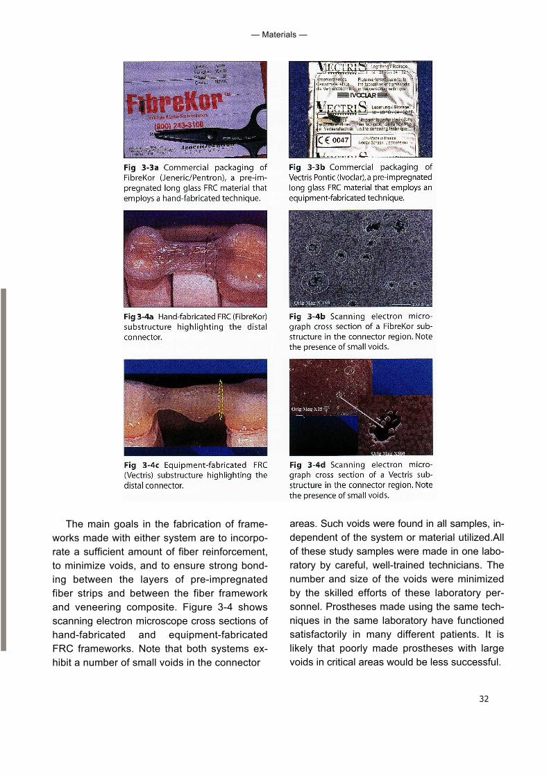
As noted in chapter 2, two commercial pre-im-pregnated FRC materials are currently availablefor use in fabricating fixed prostheses in thedental laboratory. Both of these systems, whichare shown in Fig 3-3, use glass fiber compositesto fabricate the framework; the final tooth con-tours are bui l t w i th particulate-reinforcedrestorative composite. One system (Sculpture/FibreKor, Jeneric/Pentron) is a unidirectionalglass material and employs hand fabrication toform the framework. The other system (Targis/Vectris, Ivoclar) is available in both unidirec-tional and woven glass forms and utilizes cus-tom-made matrices and special equipment toapply light, heat, and pressure to the fiber stripsduring fabrication, resulting in an equipment-fabricated FRC framework.
32
— Materials —
The main goals in the fabrication of frame-works made with either system are to incorpo-rate a sufficient amount of fiber reinforcement,to minimize voids, and to ensure strong bond-ing between the layers of pre-impregnatedfiber strips and between the fiber frameworkand veneering composite. Figure 3-4 showsscanning electron microscope cross sections ofhand-fabricated and equipment-fabricatedFRC frameworks. Note that both systems ex-hibit a number of small voids in the connector
areas. Such voids were found in all samples, in-dependent of the system or material utilized.Allof these study samples were made in one labo-ratory by careful, well-trained technicians. Thenumber and size of the voids were minimizedby the skilled efforts of these laboratory per-sonnel. Prostheses made using the same tech-niques in the same laboratory have functionedsatisfactorily in many different patients. It islikely that poorly made prostheses with largevoids in critical areas would be less successful.
33
— Laboratory-fabricated Tooth-supported Fixed Prostheses
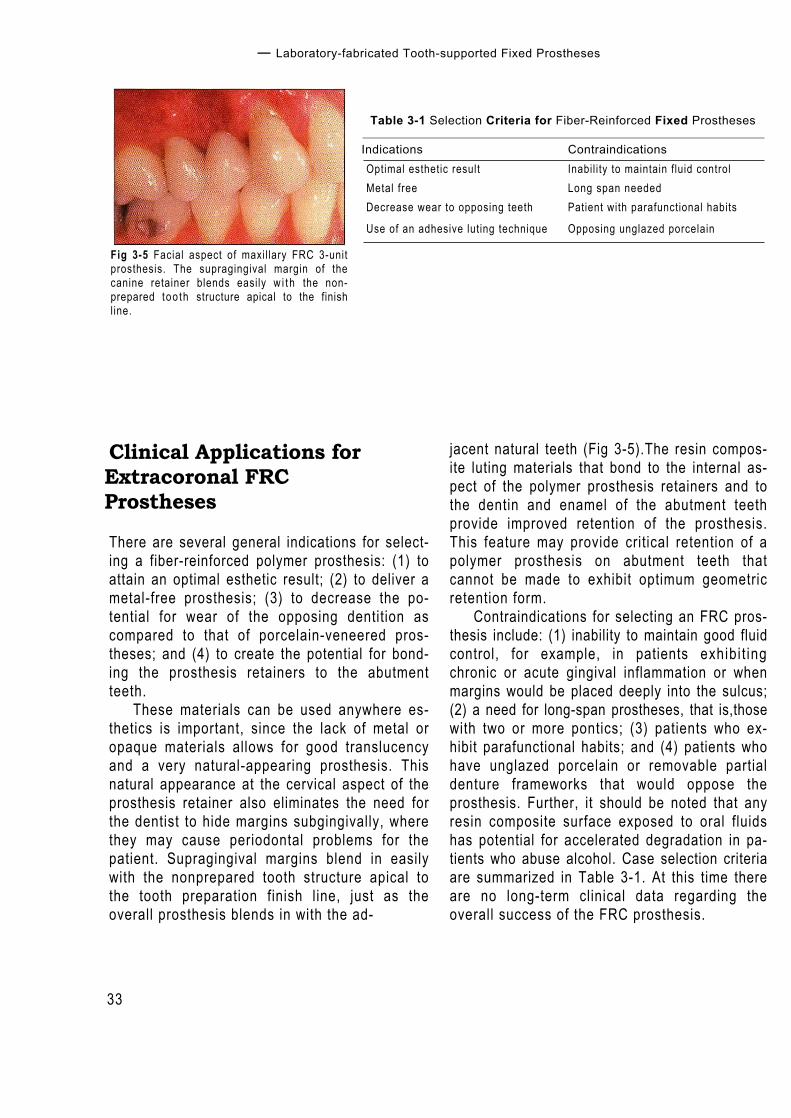
Fig 3-5 Facial aspect of maxil lary FRC 3-unitprosthesis. The supragingival margin of thecanine retainer blends easily w i t h the non-prepared too th structure apical to the finishline.
Table 3-1 Selection Criteria for Fiber-Reinforced Fixed Prostheses
Indications ContraindicationsOptimal esthetic result Inabil i ty to maintain fluid controlMetal free Long span neededDecrease wear to opposing teeth Patient with parafunctional habits
Use of an adhesive luting technique Opposing unglazed porcelain
Clinical Applications forExtracoronal FRCProstheses
There are several general indications for select-ing a fiber-reinforced polymer prosthesis: (1) toattain an optimal esthetic result; (2) to deliver ametal-free prosthesis; (3) to decrease the po-tential for wear of the opposing dentition ascompared to that of porcelain-veneered pros-theses; and (4) to create the potential for bond-ing the prosthesis retainers to the abutmentteeth.
These materials can be used anywhere es-thetics is important, since the lack of metal oropaque materials allows for good translucencyand a very natural-appearing prosthesis. Thisnatural appearance at the cervical aspect of theprosthesis retainer also eliminates the need forthe dentist to hide margins subgingivally, wherethey may cause periodontal problems for thepatient. Supragingival margins blend in easilywith the nonprepared tooth structure apical tothe tooth preparation finish line, just as theoverall prosthesis blends in with the ad-
jacent natural teeth (Fig 3-5).The resin compos-ite luting materials that bond to the internal as-pect of the polymer prosthesis retainers and tothe dentin and enamel of the abutment teethprovide improved retention of the prosthesis.This feature may provide critical retention of apolymer prosthesis on abutment teeth thatcannot be made to exhibit optimum geometricretention form.
Contraindications for selecting an FRC pros-thesis include: (1) inability to maintain good fluidcontrol, for example, in patients exhibi t ingchronic or acute gingival inflammation or whenmargins would be placed deeply into the sulcus;(2) a need for long-span prostheses, that is,thosewith two or more pontics; (3) patients who ex-hibit parafunctional habits; and (4) patients whohave unglazed porcelain or removable partialdenture frameworks that would oppose theprosthesis. Further, it should be noted that anyresin composite surface exposed to oral fluidshas potential for accelerated degradation in pa-tients who abuse alcohol. Case selection criteriaare summarized in Table 3-1. At this time thereare no long-term clinical data regarding theoverall success of the FRC prosthesis.
34
Clinical and Laboratory Procedures for Extracoronal FRC Prostheses
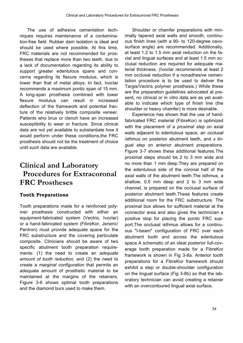
The use of adhesive cementation tech-niques requires maintenance of a contamina-tion-free field. Rubber dam isolation is ideal andshould be used where possible. At this time,FRC materials are not recommended for pros-theses that replace more than two teeth, due toa lack of documentation regarding its ability tosupport greater edentulous spans and con-cerns regarding its flexure modulus, which islower than that of metal alloys. In fact, Ivoclarrecommends a maximum pontic span of 15 mm.A long-span prosthesis combined with lowerflexure modulus can result in increaseddeflection of the framework and potential frac-ture of the relatively brittle composite veneer.Patients who brux or clench have an increasedsusceptibility to wear or fracture. Since clinicaldata are not yet available to substantiate how itwould perform under these conditions,the FRCprosthesis should not be the treatment of choiceuntil such data are available.
Clinical and LaboratoryProcedures for Extracoronal
FRC Prostheses
Tooth Preparations
Tooth preparations made for a reinforced poly-mer prosthesis constructed with either anequipment-fabricated system (Vectris, Ivoclar)or a hand-fabricated system (FibreKor, Jeneric/Pentron) must provide adequate space for theFRC substructure and the covering particulatecomposite. Clinicians should be aware of twospecific abutment tooth preparation require-ments: (1) the need to create an adequateamount of tooth reduction, and (2) the need tocreate a marginal configuration that permits anadequate amount of prosthetic material to bemaintained at the margins of the retainers.Figure 3-6 shows optimal tooth preparationsand the diamond burs used to make them.
Shoulder or chamfer preparations with min-imally tapered axial walls and smooth, continu-ous finish lines (with a 90- to 120-degree cavo-surface angle) are recommended. Additionally,at least 1.2 to 1.5 mm axial reduction on the fa-cial and lingual surfaces and at least 1.5 mm oc-clusal reduction are required for adequate ma-terial thickness. (Ivoclar recommends at least 2mm occlusal reduction if a nonadhesive cemen-tation procedure is to be used to deliver theTargis/Vectris polymer prosthesis.) While theseare the preparation guidelines advocated at pre-sent, no clinical or in vitro data are as yet avail-able to indicate which type of finish line (theshoulder or heavy chamfer) is more desirable.
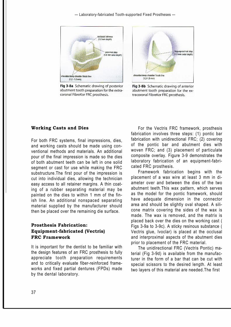
Experience has shown that the use of hand-fabricated FRC material (FibreKor) is optimizedwith the placement of a proximal step on axialwalls adjacent to edentulous space, an occlusalisthmus on posterior abutment teeth, and a lin-gual step on anterior abutment preparations.Figure 3-7 shows these additional features.Theproximal steps should be 2 to 3 mm wide andno more than 1 mm deep.They are prepared onthe edentulous side of the coronal half of theaxial walls of the abutment teeth.The isthmus, ashallow, 0.5 mm deep and 2 to 3 mm widechannel, is prepared on the occlusal surface ofposterior abutment teeth.These features createadditional room for the FRC substructure. Theproximal box allows for sufficient material at theconnector area and also gives the technician apositive stop for placing the pontic FRC sup-port.The occlusal isthmus allows for a continu-ous "I-beam" configuration of FRC over eachabutment tooth and across the edentulousspace.A schematic of an ideal posterior full-cov-erage tooth preparation made for a FibreKorframework is shown in Fig 3-8a. Anterior toothpreparations for a FibreKor framework shouldexhibit a step or double-shoulder configurationon the lingual surface (Fig 3-8b) so that the lab-oratory technician can avoid creating a retainerwith an overcontoured lingual axial surface.
35
Laboratory-fabricated Tooth-supported Fixed Prostheses —
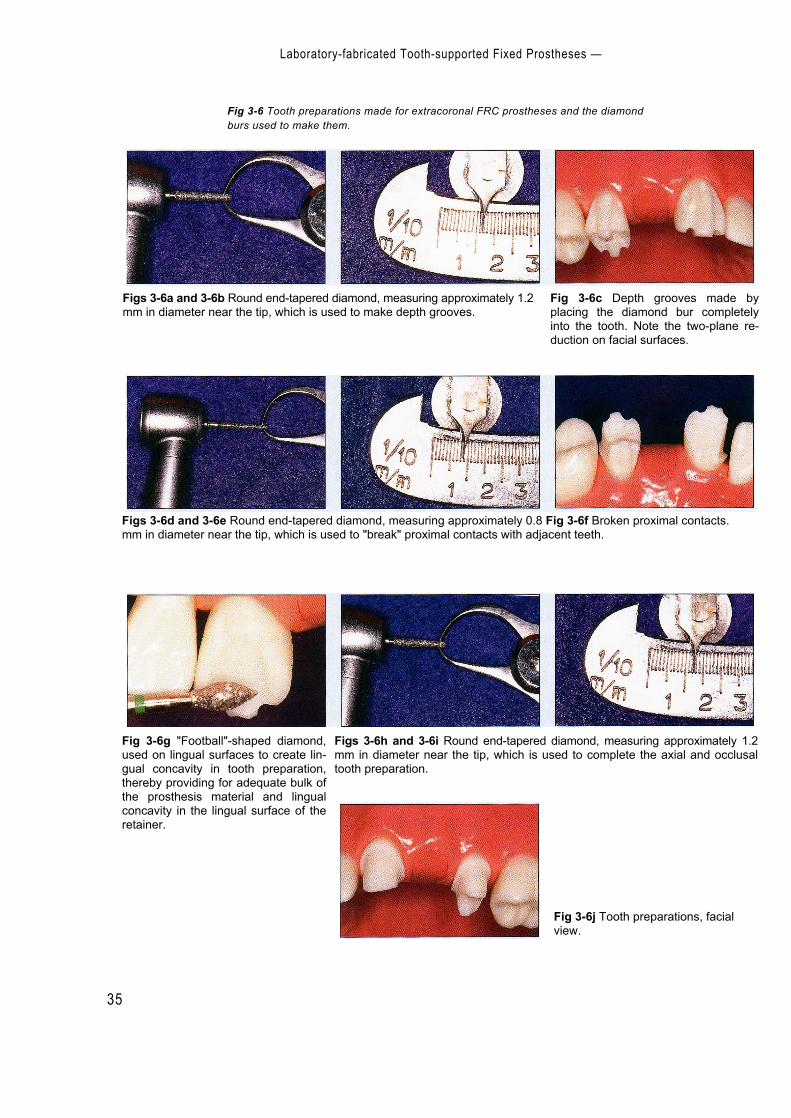
Fig 3-6 Tooth preparations made for extracoronal FRC prostheses and the diamondburs used to make them.
Figs 3-6a and 3-6b Round end-tapered diamond, measuring approximately 1.2mm in diameter near the tip, which is used to make depth grooves.
Fig 3-6c Depth grooves made byplacing the diamond bur completelyinto the tooth. Note the two-plane re-duction on facial surfaces.
Figs 3-6d and 3-6e Round end-tapered diamond, measuring approximately 0.8 Fig 3-6f Broken proximal contacts.mm in diameter near the tip, which is used to "break" proximal contacts with adjacent teeth.
Figs 3-6h and 3-6i Round end-tapered diamond, measuring approximately 1.2mm in diameter near the tip, which is used to complete the axial and occlusaltooth preparation.
Fig 3-6g "Football"-shaped diamond,used on lingual surfaces to create lin-gual concavity in tooth preparation,thereby providing for adequate bulk ofthe prosthesis material and lingualconcavity in the lingual surface of theretainer.
Fig 3-6j Tooth preparations, facialview.
— Clinical and Laboratory Procedures for Extracoronal FRC Prostheses
36
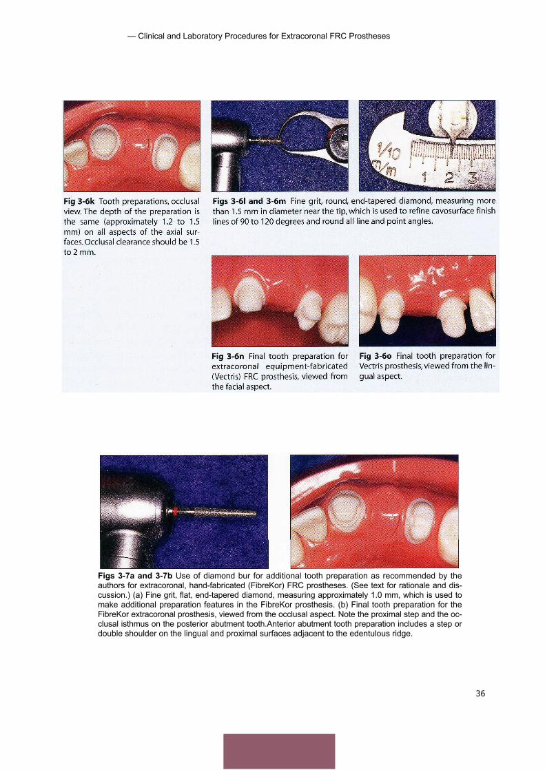
Figs 3-7a and 3-7b Use of diamond bur for additional tooth preparation as recommended by theauthors for extracoronal, hand-fabricated (FibreKor) FRC prostheses. (See text for rationale and dis-cussion.) (a) Fine grit, flat, end-tapered diamond, measuring approximately 1.0 mm, which is used tomake additional preparation features in the FibreKor prosthesis. (b) Final tooth preparation for theFibreKor extracoronal prosthesis, viewed from the occlusal aspect. Note the proximal step and the oc-clusal isthmus on the posterior abutment tooth.Anterior abutment tooth preparation includes a step ordouble shoulder on the lingual and proximal surfaces adjacent to the edentulous ridge.
37
— Laboratory-fabricated Tooth-supported Fixed Prostheses —
Working Casts and Dies
For both FRC systems, final impressions, dies,and working casts should be made using con-ventional methods and materials. An additionalpour of the final impression is made so the diesof both abutment teeth can be left in one solidsegment or cast for use while making the FRCsubstructure.The first pour of the impression iscut into individual dies, allowing the technicianeasy access to all retainer margins. A thin coat-ing of a rubber separating material may bepainted on the dies to within 1 mm of the fin-ish l ine. An additional nonspaced separatingmaterial supplied by the manufacturer shouldthen be placed over the remaining die surface.
Prosthesis Fabrication:Equipment-fabricated (Vectris)FRC Framework
It is important for the dentist to be familiar withthe design features of an FRC prosthesis to fullyappreciate too th preparation requirementsand to critically evaluate fiber-reinforced frame-works and fixed partial dentures (FPDs) madeby the dental laboratory.
For the Vectris FRC framework, prosthesisfabrication involves three steps: (1) pontic barfabrication with unidirectional FRC; (2) coveringof the pontic bar and abutment dies withwoven FRC; and (3) placement of particulatecomposite overlay. Figure 3-9 demonstrates thelaboratory fabrication of an equipment-fabri-cated FRC prosthesis.
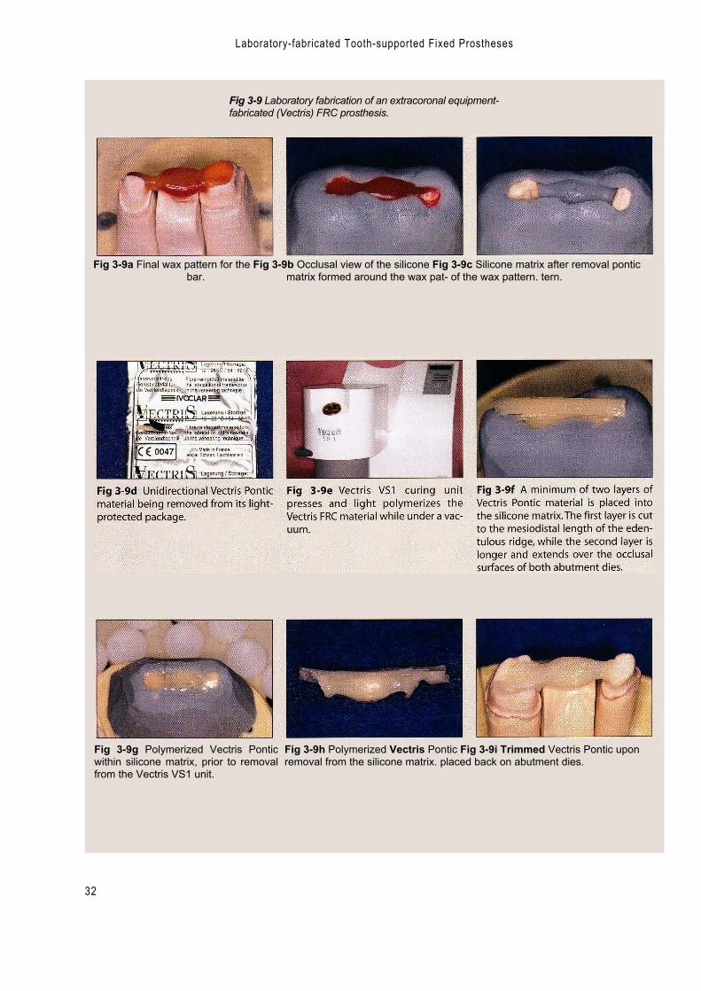
Framework fabrication begins with theplacement of a wax wire at least 3 mm in di-ameter over and between the dies of the twoabutment teeth.This wax pattern, which servesas the model for the pontic framework, shouldhave adequate dimension in the connectorarea and should be slightly oval shaped. A sili-cone matrix covering the sides of the wax ismade. The wax is removed, and the matrix isplaced back over the dies on the working cast (Figs 3-9a to 3-9c). A sticky resinous substance (Vectris glue, Ivoclar) is placed at the occlusaland interproximal aspects of the abutment diesprior to placement of the FRC material.
The unidirectional FRC (Vectris Pontic) ma-terial (Fig 3-9d) is available from the manufac-turer in the form of a bar that can be cut withspecial scissors to the desired length. At leasttwo layers of this material are needed.The first
— Clinical and Laboratory Procedures for Extracoronal FRC Prostheses
38
layer is cut to the mesiodistal length of theedentulous space and placed into the matrix.The second layer is cut to cover the length ofthe occlusal surfaces as well as the edentulousspace. This longer FRC layer is placed directlyover the first layer. The cast is placed into theVectris VS] curing unit (Fig 3-9e),where the FRCis pressed (condensed and light polymerized)under vacuum.The polymerized FRC pontic isremoved from the silicone matrix and trimmedwith tungsten carbide burs. The gingival-oc-clusal thickness of the FRC covering the diesshould be at least 0.3 mm and must cover atleast three fourths of the occlusal surface. Thefinished pontic bar is air abraded with aluminumoxide at low pressure and then steam cleaned.Placement of the unidirectional FRC into thematrix, along with the untrimmed and thentrimmed FRC pontic, is shown in Figs 3-9f to 3-9i.
Woven FRC (Vectris Frame) is used to coverthe abutment dies and the previously polymer-ized pontic bar. In preparation for this, separatormaterial is applied to the abutment dies andadjacent areas. All undercuts are blocked outwith silicone putty material (Fig 3-9j). Vectriswetting agent (silane) is applied to the externalpontic surfaces, and the excess is blown offafter 60 seconds.The pontic bar may be held inplace on the dies and within the silicone matrixwith Vectris glue material. The woven VectrisFrame FRC is removed from its package,trimmed to size, and placed over the pontic bar (Fig 3-9k).The cast is again placed into the VS1curing unit for light polymerization under vac
uum (Figs 3-91 to 3-9o). The woven FRC istrimmed to within 1 to 2 mm of the abutment diefinish line. The finished framework is airabraded with aluminum oxide and then steamcleaned. Vectris wetting agent is applied to allexternal surfaces of the finished framework, andthe excess is blown off prior to placement of theparticulate composite veneer material. Figures3-9p to 3-9r show the FRC composition ofdifferent areas of the framework.
A modification of this technique is used ifthe prosthesis is to be cemented with a con-ventional, nonadhesive technique. In that case,the retainer component of the framework ismade with additional thickness: woven VectrisSingle is pressed and polymerized directly overthe abutment dies before the pontic bar ismade. Increasing the thickness of the frame-work increases its flexure modulus and rigidity.
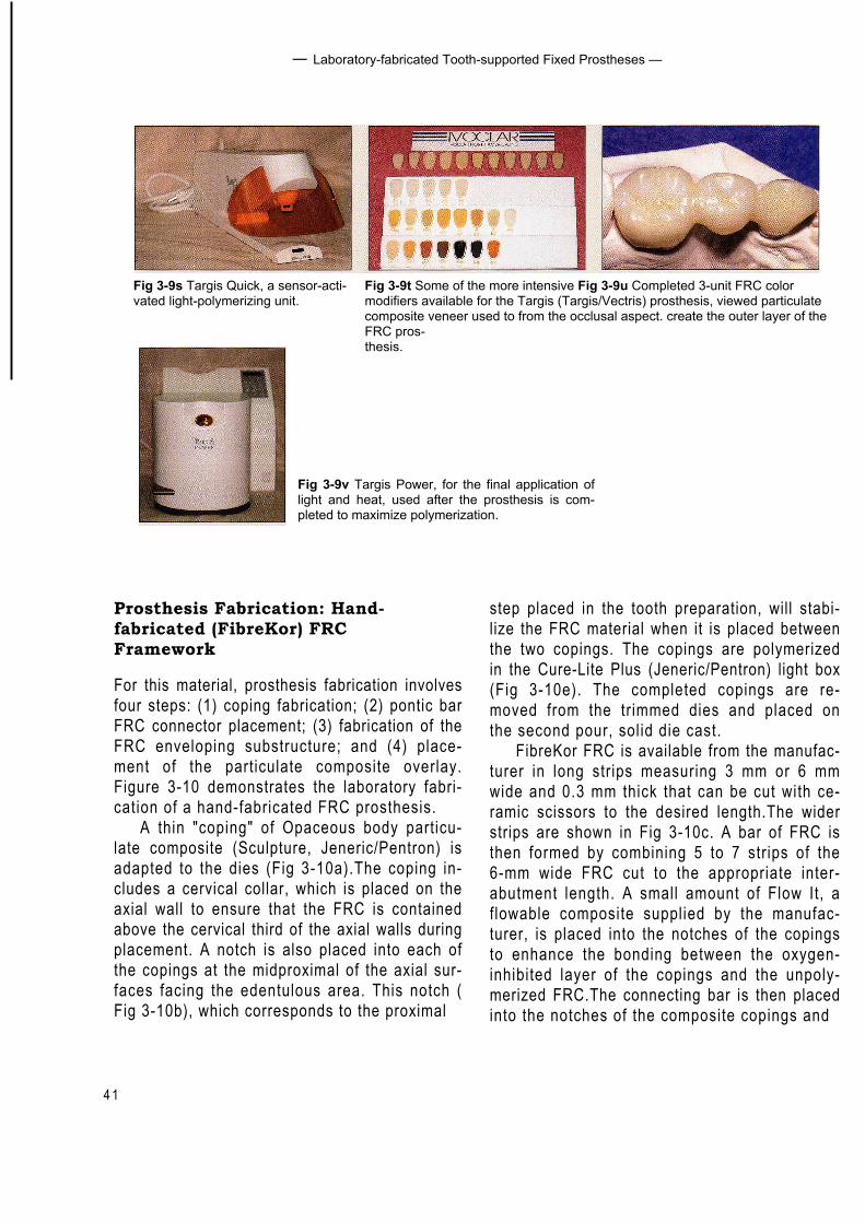
Targis is the particulate composite veneermaterial used to create the outer layer of thisFRC prosthesis.TheTargis material is built incre-mentally using Targis Quick, a sensor-activatedlight-polymerizing unit (Fig 3-9s). This tech-nique allows for the placement of a base color,dentin, incisal, and transparent materials, alongwith more intensive modifiers (Fig 3-9t). Thecompleted 3-unit prosthesis is shown in Fig 3-9u. Following shaping and finishing, the pros-thesis is placed into the Targis Power unit (Fig 3-9v) for the final application of light and heat tocomplete polymerization and maximize strengthand other physical characteristics. Once thisfinal polymerization is attained, the prosthesisis polished.
Ali
logo 2
Laboratory-fabricated Tooth-supported Fixed Prostheses
32
Fig 3-9 Laboratory fabrication of an extracoronal equipment-fabricated (Vectris) FRC prosthesis.
Fig 3-9a Final wax pattern for the Fig 3-9b Occlusal view of the silicone Fig 3-9c Silicone matrix after removal ponticbar. matrix formed around the wax pat- of the wax pattern. tern.
Fig 3-9g Polymerized Vectris Ponticwithin silicone matrix, prior to removalfrom the Vectris VS1 unit.
Fig 3-9h Polymerized Vectris Pontic Fig 3-9i Trimmed Vectris Pontic uponremoval from the silicone matrix. placed back on abutment dies.

40
Clinical and Laboratory Procedures for Extracoronal FRC Prostheses
Fig 3-9k Woven glass Vectris Frame Fig 3-91 Polymerized and trimmedmaterial cut to size and placed over Vectris Pontic once again placed overthe abutment dies. the abutment dies prior to final place-
ment and polymerization of VectrisFrame.
Fig 3-9j Undercuts apical to finishlines on abutment dies blocked outwith silicone material.
Fig 3-9m Combined Vectris Ponticand Vectris Frame immediately afterpolymerization but prior to removalfrom dies.
Fig 3-9n Undersurface of Vectris sub-structure after polymerization.
Fig 3-90 Completed Vectris substruc-ture. An initial layer of particulate com-posite veneer is being added to the fa-cial margin of the mesial retainer. Notethe apicocoronal location of the ponticbar-coping interface, allowing space forthe gingival embrasure in the completedprosthesis.
Fig 3-9p Scanning electron micro-graph of the pontic, showing the vari-able architecture of FRC; woven mate-rial (Vectris Frame) external to thecross section of the long fibers (VectrisPontic) is seen on the inside.
Fig 3-9q Scanning electron micro-graphshowing woven FRC at the distalretainer.
Fig 3-9r Higher-magnification scanningelectron micrograph of the area shownin Fig 3-9q.
4 1
— Laboratory-fabricated Tooth-supported Fixed Prostheses —
Fig 3-9t Some of the more intensive Fig 3-9u Completed 3-unit FRC colormodifiers available for the Targis (Targis/Vectris) prosthesis, viewed particulatecomposite veneer used to from the occlusal aspect. create the outer layer of theFRC pros-thesis.
Fig 3-9s Targis Quick, a sensor-acti-vated light-polymerizing unit.
Fig 3-9v Targis Power, for the final application oflight and heat, used after the prosthesis is com-pleted to maximize polymerization.
Prosthesis Fabrication: Hand-fabricated (FibreKor) FRCFramework
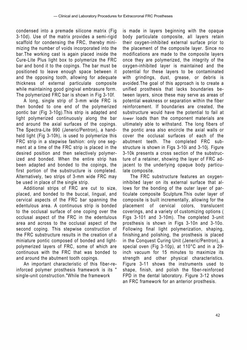
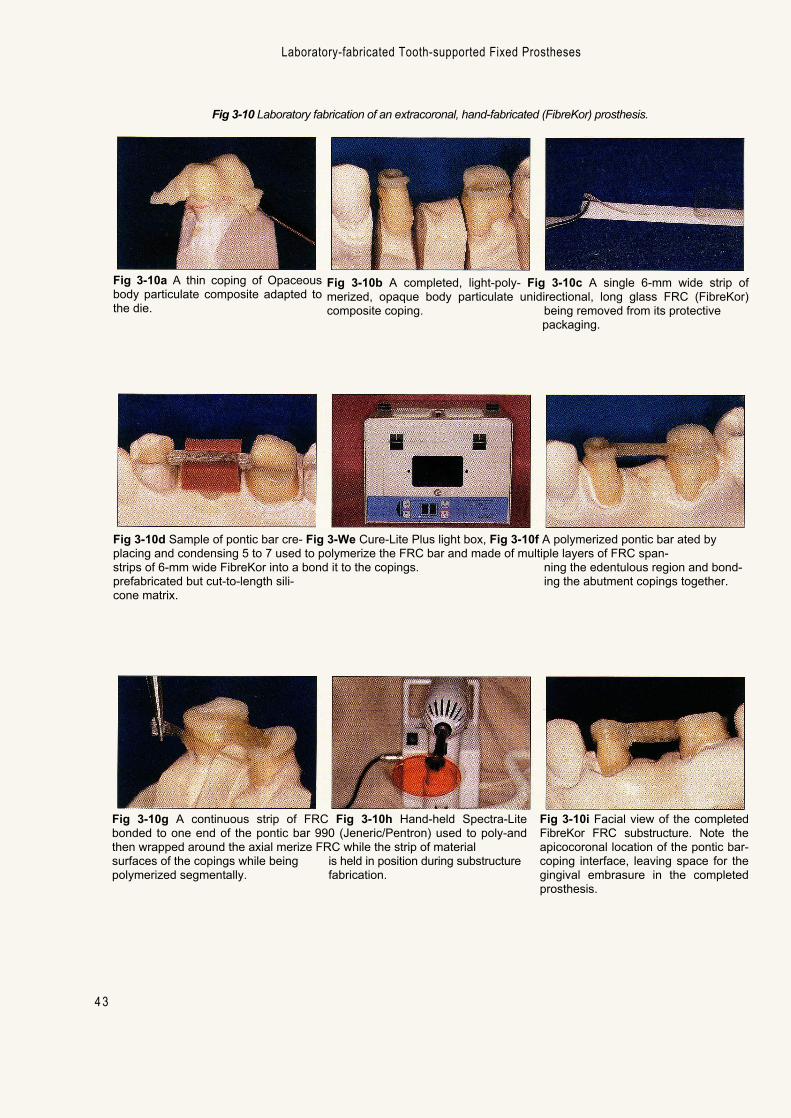
For this material, prosthesis fabrication involvesfour steps: (1) coping fabrication; (2) pontic barFRC connector placement; (3) fabrication of theFRC enveloping substructure; and (4) place-ment of the particulate composite overlay.Figure 3-10 demonstrates the laboratory fabri-cation of a hand-fabricated FRC prosthesis.
A thin "coping" of Opaceous body particu-late composite (Sculpture, Jeneric/Pentron) isadapted to the dies (Fig 3-10a).The coping in-cludes a cervical collar, which is placed on theaxial wall to ensure that the FRC is containedabove the cervical third of the axial walls duringplacement. A notch is also placed into each ofthe copings at the midproximal of the axial sur-faces facing the edentulous area. This notch (Fig 3-10b), which corresponds to the proximal
step placed in the tooth preparation, will stabi-lize the FRC material when it is placed betweenthe two copings. The copings are polymerizedin the Cure-Lite Plus (Jeneric/Pentron) light box(Fig 3-10e). The completed copings are re-moved from the trimmed dies and placed onthe second pour, solid die cast.
FibreKor FRC is available from the manufac-turer in long strips measuring 3 mm or 6 mmwide and 0.3 mm thick that can be cut with ce-ramic scissors to the desired length.The widerstrips are shown in Fig 3-10c. A bar of FRC isthen formed by combining 5 to 7 strips of the6-mm wide FRC cut to the appropriate inter-abutment length. A small amount of Flow It, aflowable composite supplied by the manufac-turer, is placed into the notches of the copingsto enhance the bonding between the oxygen-inhibited layer of the copings and the unpoly-merized FRC.The connecting bar is then placedinto the notches of the composite copings and
42
— Clinical and Laboratory Procedures for Extracoronal FRC Prostheses
condensed into a premade silicone matrix (Fig3-10d). Use of the matrix provides a semi-rigidscaffold for condensing the FRC, thereby mini-mizing the number of voids incorporated into thebar.The working cast is again placed inside theCure-Lite Plus light box to polymerize the FRCbar and bond it to the copings. The bar must bepositioned to leave enough space between itand the opposing tooth, allowing for adequatethickness of external particulate compositewhile maintaining good gingival embrasure form.The polymerized FRC bar is shown in Fig 3-10f.
A long, single strip of 3-mm wide FRC isthen bonded to one end of the polymerizedpontic bar (Fig 3-10g).This strip is adapted andlight polymerized continuously along the barand around the axial surfaces of the copings.The Spectra-Lite 990 (Jeneric/Pentron), a hand-held light (Fig 3-10h), is used to polymerize thisFRC strip in a stepwise fashion: only one seg-ment at a time of the FRC strip is placed in thedesired position and then selectively polymer-ized and bonded. When the entire strip hasbeen adapted and bonded to the copings, thefirst portion of the substructure is completed.Alternatively, two strips of 3-mm wide FRC maybe used in place of the single strip.
Additional strips of FRC are cut to size,placed, and bonded to the buccal, lingual, andcervical aspects of the FRC bar spanning theedentulous area. A continuous strip is bondedto the occlusal surface of one coping over theocclusal aspect of the FRC in the edentulousarea and across to the occlusal aspect of thesecond coping. This stepwise construction ofthe FRC substructure results in the creation of aminiature pontic composed of bonded and light-polymerized layers of FRC, some of which arecontinuous with the FRC that was bonded toand around the abutment tooth copings.
An important characteristic of this fiber-re-inforced polymer prosthesis framework is its "single-unit construction."While the framework
is made in layers beginning with the opaquebody particulate composite, all layers retaintheir oxygen-inhibited external surface prior tothe placement of the composite layer. Since nomodifications are made to the composite layersonce they are polymerized, the integrity of theoxygen-inhibited layer is maintained and thepotential for these layers to be contaminatedwith grindings, dust, grease, or debris isavoided.The goal of this approach is to create aunified prosthesis that lacks boundaries be-tween layers, since these may serve as areas ofpotential weakness or separation within the fiberreinforcement. If boundaries are created, thesubstructure would have the potential to fail atlower loads than the component materials areultimately able to withstand. The long fibers ofthe pontic area also encircle the axial walls orcover the occlusal surfaces of each of theabutment teeth. The completed FRC sub-structure is shown in Figs 3-10i and 3-10j. Figure3-10k presents a cross section of the substruc-ture of a retainer, showing the layer of FRC ad-jacent to the underlying opaque body particu-late composite.
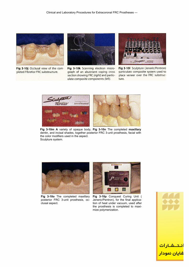
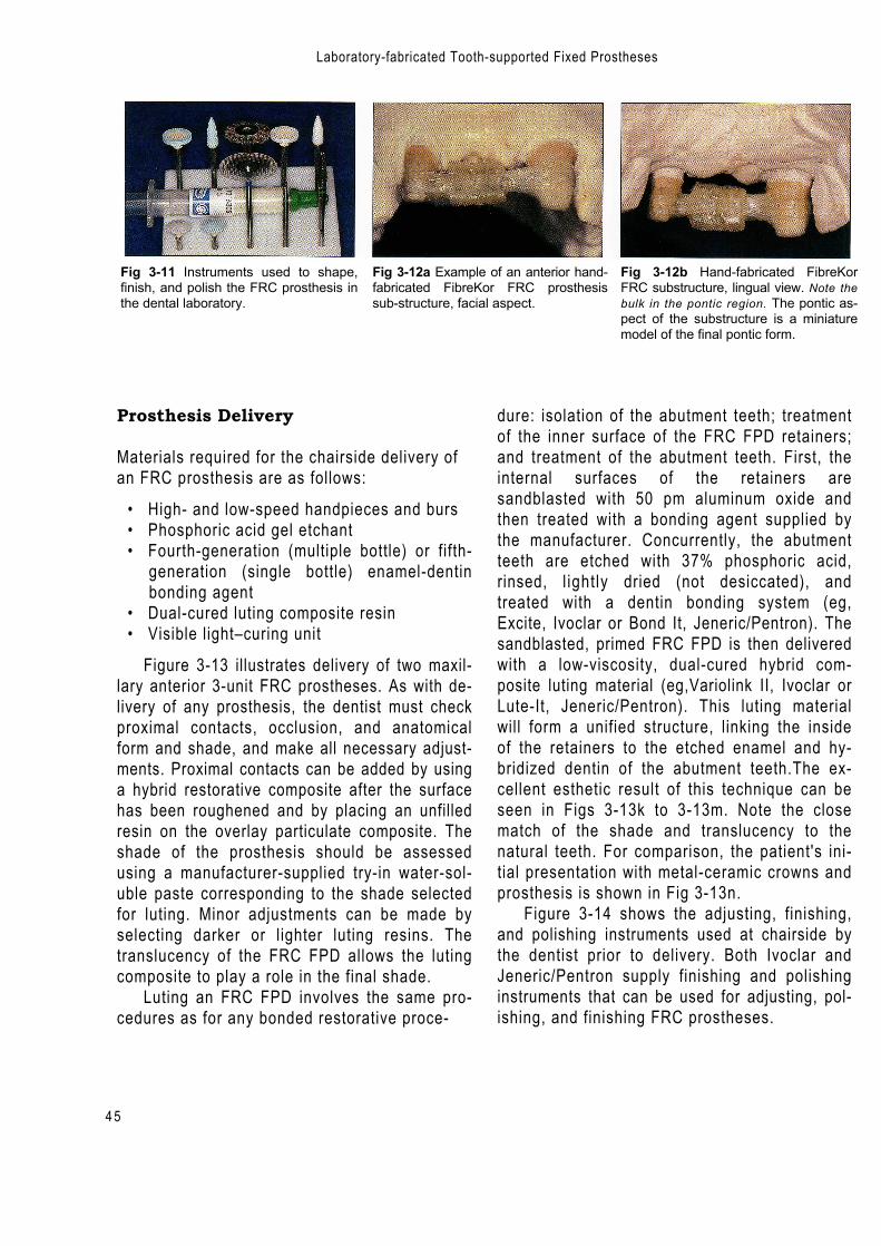
The FRC substructure features an oxygen-inhibited layer on its external surface that al-lows for the bonding of the outer layer of par-ticulate composite Sculpture.This outer layer ofcomposite is built incrementally, allowing for theplacement of cervical colors, translucentcoverings, and a variety of customizing options (Figs 3-101 and 3-10m). The completed 3-unitprosthesis is shown in Figs 3-10n and 3-10o.Following final light polymerization, shaping,finishing,and polishing, the prosthesis is placedin the Conquest Curing Unit (Jeneric/Pentron), aspecial oven (Fig 3-10p), at 110°C and in a 29-inch vacuum for 15 minutes to maximize itsstrength and other physical characteristics.Figure 3-11 shows the instruments used toshape, finish, and polish the fiber-reinforcedFPD in the dental laboratory. Figure 3-12 showsan FRC framework for an anterior prosthesis.
Laboratory-fabricated Tooth-supported Fixed Prostheses
Fig 3-10 Laboratory fabrication of an extracoronal, hand-fabricated (FibreKor) prosthesis.
4 3
Fig 3-10b A completed, light-poly- Fig 3-10c A single 6-mm wide strip ofmerized, opaque body particulate unidirectional, long glass FRC (FibreKor)composite coping. being removed from its protective
packaging.
Fig 3-10d Sample of pontic bar cre- Fig 3-We Cure-Lite Plus light box, Fig 3-10f A polymerized pontic bar ated byplacing and condensing 5 to 7 used to polymerize the FRC bar and made of multiple layers of FRC span-strips of 6-mm wide FibreKor into a bond it to the copings. ning the edentulous region and bond-prefabricated but cut-to-length sili- ing the abutment copings together.cone matrix.
Fig 3-10a A thin coping of Opaceousbody particulate composite adapted tothe die.
Fig 3-10g A continuous strip of FRC Fig 3-10h Hand-held Spectra-Litebonded to one end of the pontic bar 990 (Jeneric/Pentron) used to poly-andthen wrapped around the axial merize FRC while the strip of materialsurfaces of the copings while being is held in position during substructurepolymerized segmentally. fabrication.
Fig 3-10i Facial view of the completedFibreKor FRC substructure. Note theapicocoronal location of the pontic bar-coping interface, leaving space for thegingival embrasure in the completedprosthesis.
Clinical and Laboratory Procedures for Extracoronal FRC Prostheses —
44
Fig 3-10m A variety of opaque body, Fig 3-10n The completed maxillarydentin, and incisal shades, together posterior FRC 3-unit prosthesis, facial withthe color modifiers used in the aspect.Sculpture system.
Fig 3-10o The completed maxillaryposterior FRC 3-unit prosthesis, oc-clusal aspect.
Fig 3-10p Conquest Curing Unit (Jeneric/Pentron), for the final applica-tion of heat under vacuum, used afterthe prosthesis is completed to maxi-mize polymerization.
Ali
logo
Laboratory-fabricated Tooth-supported Fixed Prostheses
4 5
Fig 3-11 Instruments used to shape,finish, and polish the FRC prosthesis inthe dental laboratory.
Fig 3-12a Example of an anterior hand-fabricated FibreKor FRC prosthesissub-structure, facial aspect.
Fig 3-12b Hand-fabricated FibreKorFRC substructure, lingual view. Note thebulk in the pontic region. The pontic as-pect of the substructure is a miniaturemodel of the final pontic form.
Prosthesis Delivery
Materials required for the chairside delivery ofan FRC prosthesis are as follows:
• High- and low-speed handpieces and burs• Phosphoric acid gel etchant• Fourth-generation (multiple bottle) or fifth-
generation (single bottle) enamel-dentinbonding agent
• Dual-cured luting composite resin• Visible light–curing unit
Figure 3-13 illustrates delivery of two maxil-lary anterior 3-unit FRC prostheses. As with de-livery of any prosthesis, the dentist must checkproximal contacts, occlusion, and anatomicalform and shade, and make all necessary adjust-ments. Proximal contacts can be added by usinga hybrid restorative composite after the surfacehas been roughened and by placing an unfilledresin on the overlay particulate composite. Theshade of the prosthesis should be assessedusing a manufacturer-supplied try-in water-sol-uble paste corresponding to the shade selectedfor luting. Minor adjustments can be made byselecting darker or lighter luting resins. Thetranslucency of the FRC FPD allows the lutingcomposite to play a role in the final shade.
Luting an FRC FPD involves the same pro-cedures as for any bonded restorative proce-
dure: isolation of the abutment teeth; treatmentof the inner surface of the FRC FPD retainers;and treatment of the abutment teeth. First, theinternal surfaces of the retainers aresandblasted with 50 pm aluminum oxide andthen treated with a bonding agent supplied bythe manufacturer. Concurrently, the abutmentteeth are etched with 37% phosphoric acid,rinsed, l ight ly dried (not desiccated), andtreated with a dentin bonding system (eg,Excite, Ivoclar or Bond It, Jeneric/Pentron). Thesandblasted, primed FRC FPD is then deliveredwith a low-viscosity, dual-cured hybrid com-posite luting material (eg,Variolink II, Ivoclar orLute-It, Jeneric/Pentron). This luting materialwill form a unified structure, linking the insideof the retainers to the etched enamel and hy-bridized dentin of the abutment teeth.The ex-cellent esthetic result of this technique can beseen in Figs 3-13k to 3-13m. Note the closematch of the shade and translucency to thenatural teeth. For comparison, the patient's ini-tial presentation with metal-ceramic crowns andprosthesis is shown in Fig 3-13n.
Figure 3-14 shows the adjusting, finishing,and polishing instruments used at chairside bythe dentist prior to delivery. Both Ivoclar andJeneric/Pentron supply finishing and polishinginstruments that can be used for adjusting, pol-ishing, and finishing FRC prostheses.
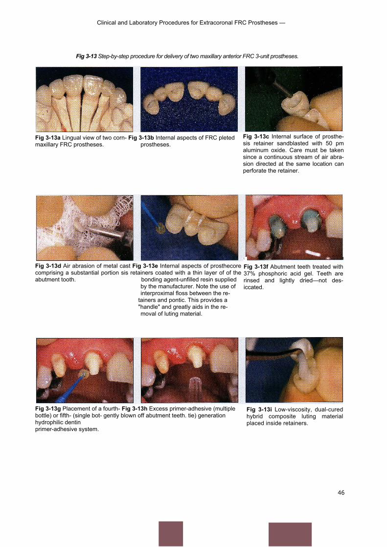
Clinical and Laboratory Procedures for Extracoronal FRC Prostheses —
Fig 3-13 Step-by-step procedure for delivery of two maxillary anterior FRC 3-unit prostheses.
46
Fig 3-13a Lingual view of two corn- Fig 3-13b Internal aspects of FRC pletedmaxillary FRC prostheses. prostheses.
Fig 3-13d Air abrasion of metal cast Fig 3-13e Internal aspects of prosthecorecomprising a substantial portion sis retainers coated with a thin layer of of theabutment tooth. bonding agent-unfilled resin supplied
by the manufacturer. Note the use ofinterproximal floss between the re-
tainers and pontic. This provides a"handle" and greatly aids in the re-moval of luting material.
Fig 3-13c Internal surface of prosthe-sis retainer sandblasted with 50 pmaluminum oxide. Care must be takensince a continuous stream of air abra-sion directed at the same location canperforate the retainer.
L
Fig 3-13f Abutment teeth treated with37% phosphoric acid gel. Teeth arerinsed and lightly dried—not des-iccated.
Fig 3-13g Placement of a fourth- Fig 3-13h Excess primer-adhesive (multiplebottle) or fifth- (single bot- gently blown off abutment teeth. tie) generationhydrophilic dentinprimer-adhesive system.
Fig 3-13i Low-viscosity, dual-curedhybrid composite luting materialplaced inside retainers.
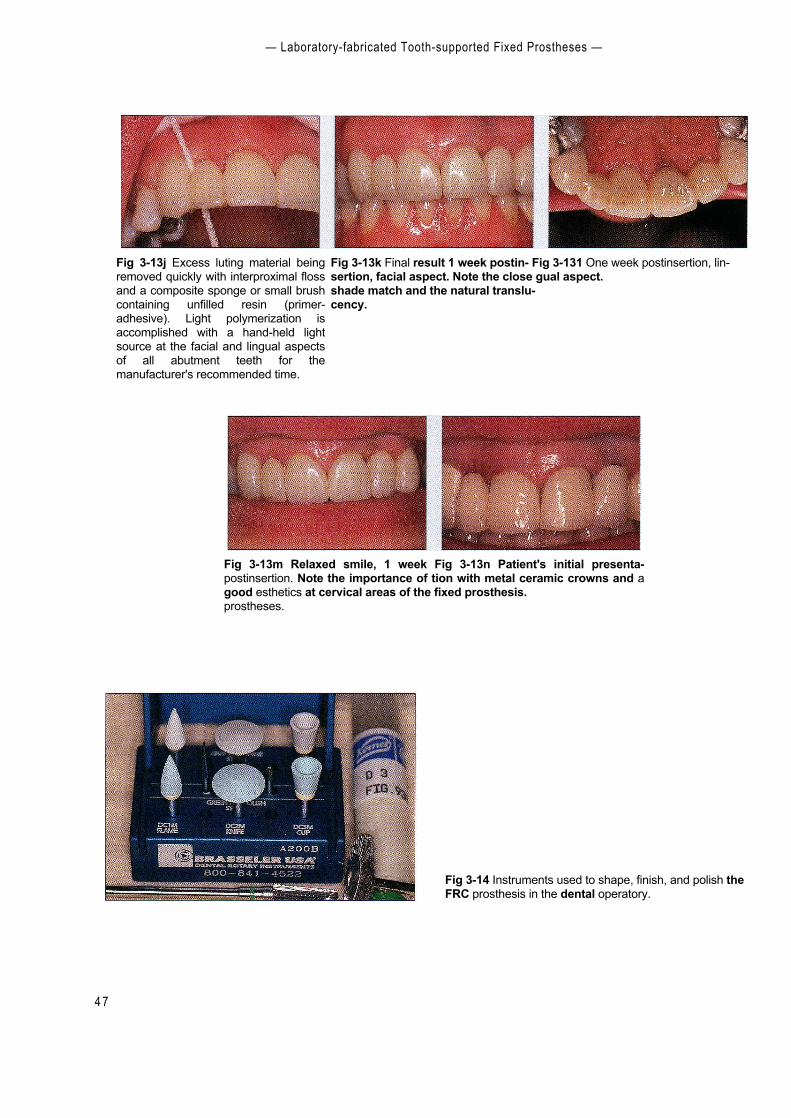
— Laboratory-fabricated Tooth-supported Fixed Prostheses —
4 7
Fig 3-13m Relaxed smile, 1 week Fig 3-13n Patient's initial presenta-postinsertion. Note the importance of tion with metal ceramic crowns and agood esthetics at cervical areas of the fixed prosthesis.prostheses.
Fig 3-13j Excess luting material beingremoved quickly with interproximal flossand a composite sponge or small brushcontaining unfilled resin (primer-adhesive). Light polymerization isaccomplished with a hand-held lightsource at the facial and lingual aspectsof all abutment teeth for themanufacturer's recommended time.
Fig 3-13k Final result 1 week postin- Fig 3-131 One week postinsertion, lin-sertion, facial aspect. Note the close gual aspect.shade match and the natural translu-cency.
Fig 3-14 Instruments used to shape, finish, and polish theFRC prosthesis in the dental operatory.
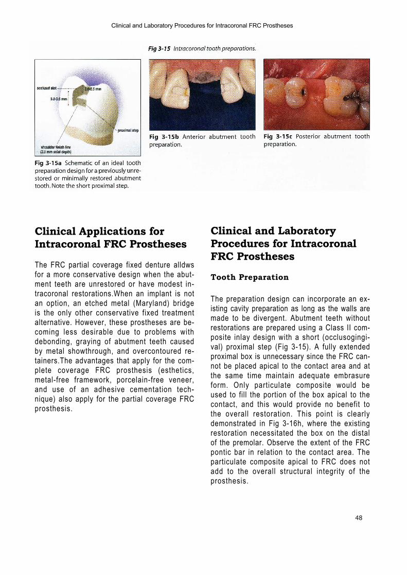
48
Clinical and Laboratory Procedures for Intracoronal FRC Prostheses
Clinical Applications forIntracoronal FRC Prostheses
The FRC partial coverage fixed denture alldwsfor a more conservative design when the abut-ment teeth are unrestored or have modest in-tracoronal restorations.When an implant is notan option, an etched metal (Maryland) bridgeis the only other conservative fixed treatmentalternative. However, these prostheses are be-coming less desirable due to problems withdebonding, graying of abutment teeth causedby metal showthrough, and overcontoured re-tainers.The advantages that apply for the com-plete coverage FRC prosthesis (esthetics,metal-free framework, porcelain-free veneer,and use of an adhesive cementation tech-nique) also apply for the partial coverage FRCprosthesis.
Clinical and LaboratoryProcedures for IntracoronalFRC Prostheses
Tooth Preparation
The preparation design can incorporate an ex-isting cavity preparation as long as the walls aremade to be divergent. Abutment teeth withoutrestorations are prepared using a Class II com-posite inlay design with a short (occlusogingi-val) proximal step (Fig 3-15). A fully extendedproximal box is unnecessary since the FRC can-not be placed apical to the contact area and atthe same time maintain adequate embrasureform. Only particulate composite would beused to fill the portion of the box apical to thecontact, and this would provide no benefit tothe overall restoration. This point is clearlydemonstrated in Fig 3-16h, where the existingrestoration necessitated the box on the distalof the premolar. Observe the extent of the FRCpontic bar in relation to the contact area. Theparticulate composite apical to FRC does notadd to the overall structural integrity of theprosthesis.
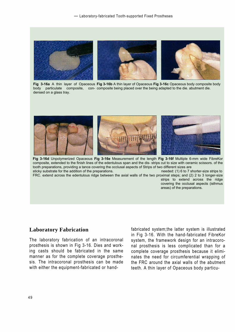
— Laboratory-fabricated Tooth-supported Fixed Prostheses
Fig 3-16 Construction of an intracoronal FRC prosthesis substructure using hand-fabricated FibreKor FRC.
4 9
Fig 3-16a A thin layer of Opaceousbody particulate composite, con-densed on a glass tray.
Fig 3-16b A thin layer of Opaceous Fig 3-16c Opaceous body composite bodycomposite being placed over the being adapted to the die. abutment die.
Fig 3-16d Unpolymerized Opaceous Fig 3-16e Measurement of the length Fig 3-16f Multiple 6-mm wide FibreKorcomposite, extended to the finish lines of the edentulous span and the dis- strips cut to size with ceramic scissors. of thetooth preparations, providing a tance covering the occlusal aspects of Strips of two different sizes aresticky substrate for the addition of the preparations. needed: (1) 6 to 7 shorter-size strips toFRC. extend across the edentulous ridge between the axial walls of the two proximal steps; and (2) 2 to 3 longer-size
strips to extend across the ridgecovering the occlusal aspects (isthmusareas) of the preparations.
Laboratory Fabrication
The laboratory fabrication of an intracoronalprosthesis is shown in Fig 3-16. Dies and work-ing casts should be fabricated in the samemanner as for the complete coverage prosthe-sis. The intracoronal prosthesis can be madewith either the equipment-fabricated or hand-
fabricated system;the latter system is illustratedin Fig 3-16. With the hand-fabricated FibreKorsystem, the framework design for an intracoro-nal prosthesis is less complicated than for acomplete coverage prosthesis because it elimi-nates the need for circumferential wrapping ofthe FRC around the axial walls of the abutmentteeth. A thin layer of Opaceous body particu-
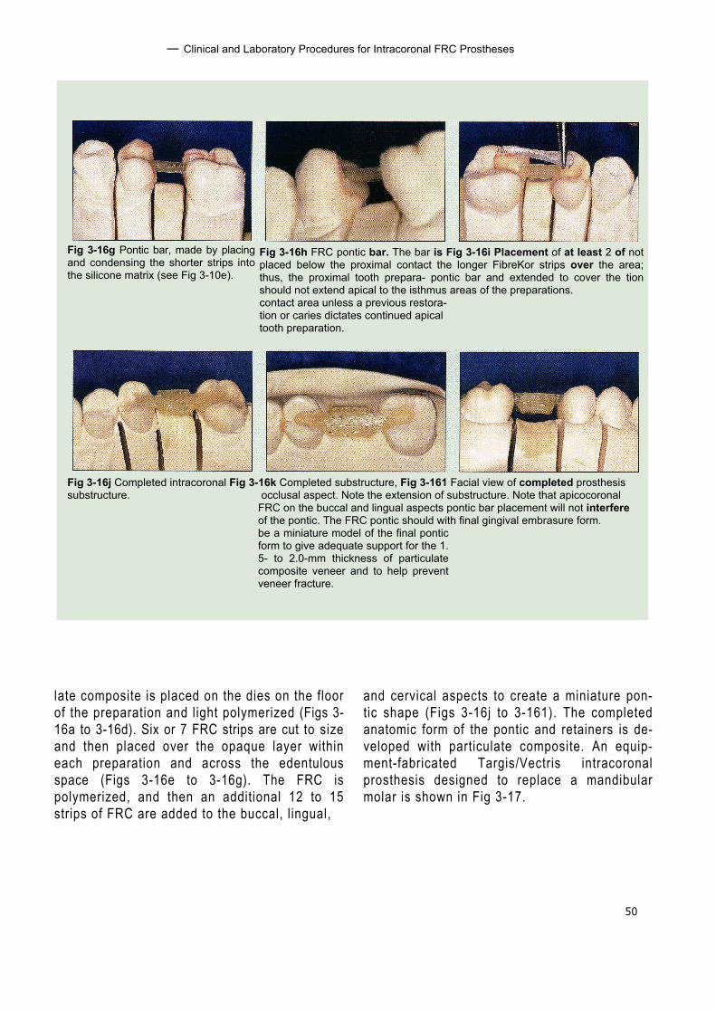
50
— Clinical and Laboratory Procedures for Intracoronal FRC Prostheses
Fig 3-16h FRC pontic bar. The bar is Fig 3-16i Placement of at least 2 of notplaced below the proximal contact the longer FibreKor strips over the area;thus, the proximal tooth prepara- pontic bar and extended to cover the tionshould not extend apical to the isthmus areas of the preparations.contact area unless a previous restora-tion or caries dictates continued apicaltooth preparation.
Fig 3-16j Completed intracoronal Fig 3-16k Completed substructure, Fig 3-161 Facial view of completed prosthesissubstructure. occlusal aspect. Note the extension of substructure. Note that apicocoronal
FRC on the buccal and lingual aspects pontic bar placement will not interfereof the pontic. The FRC pontic should with final gingival embrasure form.be a miniature model of the final ponticform to give adequate support for the 1.5- to 2.0-mm thickness of particulatecomposite veneer and to help preventveneer fracture.
Fig 3-16g Pontic bar, made by placingand condensing the shorter strips intothe silicone matrix (see Fig 3-10e).
late composite is placed on the dies on the floorof the preparation and light polymerized (Figs 3-16a to 3-16d). Six or 7 FRC strips are cut to sizeand then placed over the opaque layer withineach preparation and across the edentulousspace (Figs 3-16e to 3-16g). The FRC ispolymerized, and then an additional 12 to 15strips of FRC are added to the buccal, lingual,
and cervical aspects to create a miniature pon-tic shape (Figs 3-16j to 3-161). The completedanatomic form of the pontic and retainers is de-veloped with particulate composite. An equip-ment-fabricated Targis/Vectris intracoronalprosthesis designed to replace a mandibularmolar is shown in Fig 3-17.

— Laboratory-fabricated Tooth-supported Fixed Prostheses
5 1
Fig 3-17 TargisNectris intracoronal FRC prosthesis replacing a mandibular molar. (Courtesy of Dr Thomas Trinkner.)
Fig 3-17a Preoperative view ofmandibular posterior quadrant withminimally restored abutment teeth.
Fig 3-17b Occlusal view of intracoro- Fig 3-17c Completed Vectris intra-naltooth preparations. coronal FRC prosthesis, occlusal view.
Fig 3-17d Vectris prosthesis, facial Fig 3-17e Completed Vectris prostheview.sis postdelivery.
Prosthesis Delivery
Materials required for the chairside delivery ofan intracoronal FRC prosthesis are as follows:
• Rubber dam• High- and low-speed handpieces and burs• Phosphoric acid gel etchant• Fourth-generation (multiple bottle) or fifth-
generation (single bottle) enamel-dentinbonding agent
• Dual-cure luting composite resin• Visible light—curing unit
Figure 3-18 illustrates delivery of an intra-coronal FRC prosthesis, beginning with verifica-tion of marginal fit, occlusion, and shade. Water-soluble shades of the luting composite may be
used as recommended for complete coverageprostheses. After adjustments are made, theteeth should be isolated with a rubber dam.Theabutments are then etched and coated with adentin primer-adhesive.The inner aspects of theinlay retainers are lightly sandblasted with 50pm aluminum oxide and then coated withprimer-adhesive followed by a dual-cure lutingcomposite. After light polymerization and re-moval of the rubber dam, occlusion is recon-firmed. Any final adjustments can be made with30 fluted carbide finishing burs and paper disks.Rubber polishing points can be used for thefinal finish.The final esthetic result is shown inFig 3-18h. A combination intracoronal-extra-coronal FRC prosthesis and its framework isshown from a variety of views in Fig 3-19.

52
Clinical and Laboratory Procedures for Intracoronal FRC Prostheses —
Fig 3-18 Step-by-step procedure for delivery of an intracoronal FibreKor FRC3-unit prosthesis.
Fig 3-18a Internal aspects of prosthe- Fig 3-18b Final intracoronal abutsisretainers carefully sandblasted with ment tooth preparations with rubber 50 pmaluminum oxide. Internal as- dam.pects of prosthesis retainers coatedwith a thin layer of bonding agent-un-filled resin supplied by the manufac-turer.
Fig 3-18c Abutment teeth treated with37% phosphoric acid gel. Teeth arerinsed and lightly dried—not des-iccated.
Fig 3-18d Placement of a fourth-(multiple bottle) or fifth- (single bottle)generation hydrophilic dentin primer-adhesive system. Excess primer-adhe-sive is gently blown off the abutmentteeth.
Fig 3-18e Low-viscosity, dual-curedhybrid composite luting material beingplaced inside the retainers.
Fig 3-18f Excess luting material beingremoved quickly with a compositesponge containing unfilled resin (primer-adhesive). Light polymeriza-tion is accomplished with a hand-heldlight source at the facial and lingual as-pects of all abutment teeth for themanufacturer's recommended time.
Fig 3-18g Final adjustment of the oc- Fig 3-18h Final finishing with a rub-clusion with multifluted carbide finish- ber point.ing burs. Special note: occlusal adjust-ment should not be attempted until afterdelivery. Fracture of retainers mayoccur if occlusion is adjusted prior toluting of the prosthesis to abutmentteeth.
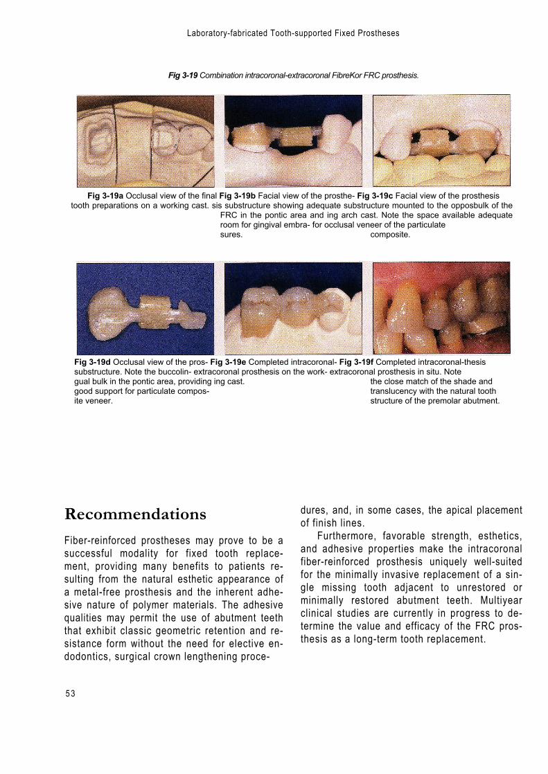
5 3
Laboratory-fabricated Tooth-supported Fixed Prostheses
Fig 3-19 Combination intracoronal-extracoronal FibreKor FRC prosthesis.
Fig 3-19a Occlusal view of the final Fig 3-19b Facial view of the prosthe- Fig 3-19c Facial view of the prosthesistooth preparations on a working cast. sis substructure showing adequate substructure mounted to the opposbulk of the
FRC in the pontic area and ing arch cast. Note the space available adequateroom for gingival embra- for occlusal veneer of the particulatesures. composite.
Fig 3-19d Occlusal view of the pros- Fig 3-19e Completed intracoronal- Fig 3-19f Completed intracoronal-thesissubstructure. Note the buccolin- extracoronal prosthesis on the work- extracoronal prosthesis in situ. Notegual bulk in the pontic area, providing ing cast. the close match of the shade andgood support for particulate compos- translucency with the natural toothite veneer. structure of the premolar abutment.
RecommendationsFiber-reinforced prostheses may prove to be asuccessful modality for fixed tooth replace-ment, providing many benefits to patients re-sulting from the natural esthetic appearance ofa metal-free prosthesis and the inherent adhe-sive nature of polymer materials. The adhesivequalities may permit the use of abutment teeththat exhibit classic geometric retention and re-sistance form without the need for elective en-dodontics, surgical crown lengthening proce-
dures, and, in some cases, the apical placementof finish lines.
Furthermore, favorable strength, esthetics,and adhesive properties make the intracoronalfiber-reinforced prosthesis uniquely well-suitedfor the minimally invasive replacement of a sin-gle missing tooth adjacent to unrestored orminimally restored abutment teeth. Multiyearclinical studies are currently in progress to de-termine the value and efficacy of the FRC pros-thesis as a long-term tooth replacement.
54
References
References
1. Altieri JV, Burstone CJ, Goldberg AJ, Patel AP.Longitudinal clinical evaluation of fiber-reinforcedcomposite fixed partial dentures: A pilot study. J ProsthetDent 1994;71:16-22.
2. Fahl N, Casellini RC. Ceramor/FRC technology: The fu-ture of biofunctional adhesive aesthetic dentistry.Signature 1997;4(2):7-13.
3. Freilich MA, Karmaker AC, Burstone CJ, Goldberg AJ.Flexure strength of fiber-reinforced composites de-signedfor prosthodontic application [abstract 999]. J Dent Res1997;76(special issue):138.
4. Freilich MA, Karmaker AC, Burstone CJ, Goldberg AJ.Flexure strength and handling characteristics of fiber-reinforced composites used in prosthodontics [abstract1361].) Dent Res 1997;76:184.
5. Freilich MA, Duncan JP, Meiers JC, Goldberg AJ.Preimpregnated, fiber-reinforced prostheses. Part I. Basicrationale and complete-coverage and intracoronal fixedpartial denture designs. Quintessence Int 1998;29:689–696.
6. Freilich MA, Karmaker AC, Burstone CJ, Goldberg AJ.Development and clinical applications of a light-poly-merized fiber-reinforced composite. J Prosthet Dent 1998;80:311-318.
7. Freilich MA, Duncan I f Meiers JC, Goldberg AJ. Clinicalevaluation of fiber-reinforced fixed partial dentures:Preliminary data [abstract 2218].) Dent Res 1999;78:383.
8. Goldberg AJ, Burstone CJ.The use of continuous fiberreinforcement in dentistry. Dent Mater 1992;8:197-202.
9. Goldberg AJ, Burstone CJ, Hadjinikolaou I, Jancar J.Screening of matrices and fibers for reinforced thermo-plastics intended for dental applications. J Biomed MaterRes 1994;28:167-173.
10. Goldberg AJ, Freilich MA, Haser KA, Audi JH. Flexureproperties and fiber architecture of commercial fiberreinforced composites [abstract 967]. J Dent Res 1998;77:226..
11. Hadjinikolaou I, Goldberg AJ. Flexural behavior of clini-cally relevant fiber-reinforced composites [abstract 1190].J Dent Res 1992;71:664.
12. Jancar J, DiBenedetto AT, Goldberg AJ. Thermoplasticfibre-reinforced composites for dentistry. Part II. Effect ofmoisture on flexural properties of unidirectional com-posites. J Mater Sci Mater Med 1993;4:562–568.
13. Karmaker AC, DiBenedetto AT, Goldberg AJ. Extent ofconversion and its effect on the mechanical performanceof Bis-GMA/PEGDMA based resins and their compositeswith continuous glass fibers. J Mater Sci Mater Med 1997;8:369-376.
14. Karmaker AC, DiBenedetto AT, Goldberg AJ. Fiber rein-forced composite materials for dental appliances.Presented at Society of Plastic Engineers AnnualTechnical Conference, Indianapolis, 5-9 May 1996.
15. Patel A, Burstone CJ, Goldberg AJ. Clinical study of fiber-reinforced thermoplastic as orthodontic retainers [ab-stract 87].J Dent Res 1992;71:526.
16. Radz GM, Nash RW, Leinfelder VF. An improved com-posite-onlay system. Compend Contin Educ Dent 1997;18(2):98,100–102,104.
17. Samadzadeh A, Bardwell D, Abdoushela A. Marginaladaptability of two different ceramic inlay systems in vitro [abstract 1434]. J Dent Res 1997;76(special issue):193.
18. Suzuki S,Suzuki SH, Kramer C. Enamel wear againstresin composite and ceramic C&B materials [abstract2454].) Dent Res 1997;76(special issue):320.
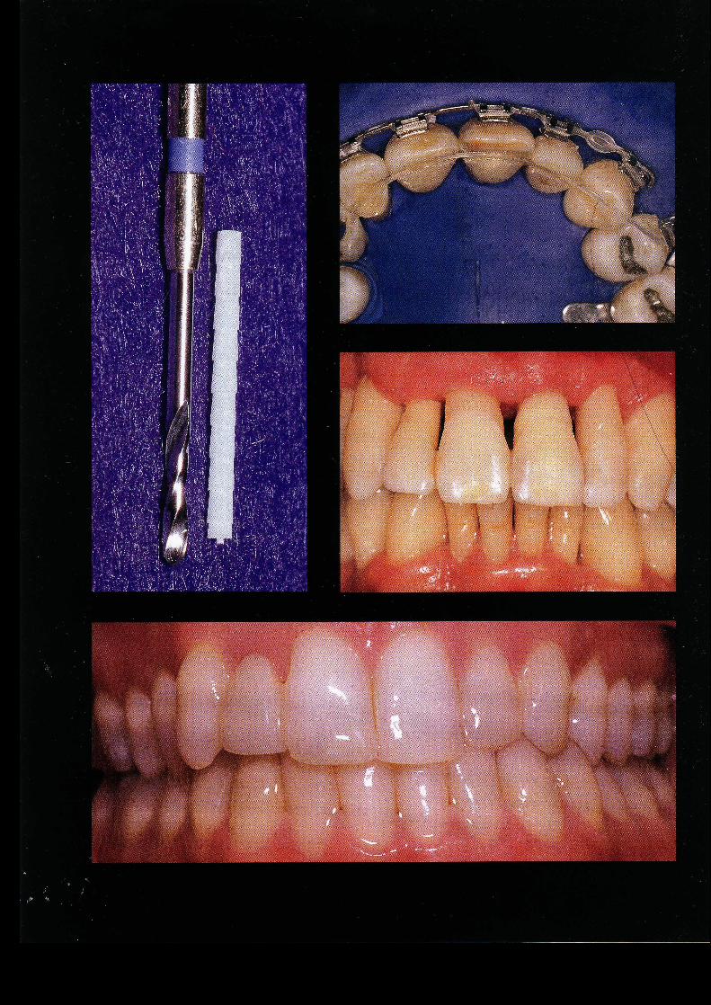
ChairsideApplications
of FRC
56
■ The properties of fiber-reinforced composites (FRCs) thatmake them well suited for various chairside applications i n - /clude strength; desirable esthetic characteristics; ease of usadaptability to various shapes; and potential for direct bondiingto tooth structure. Among the many direct intraoral app!/icationsfor this technology are splinting of mobile teeth, rep,l'acement ofmissing teeth, and fabrication of endodontic ports.
Tooth Stabilization and Splints
FRC materials are an excellent choice for the abilization of hy-permobile teeth. Chairside-fabricated fixed splints have previ-ously been made from material combinations that have in-cluded resin composites,2 ' ,23,2834 wire,' wire mesh,'° ,20,33 wireembedded in amalgam,29,33 and resin and fiber mesh embeddedin composite.26 ' All of these materials suffered from variousproblems: poor handling characteristics, overbulking, insufficientbonding of the internal structural materials to the dental resins,and poor esthetic outcome.
FRC stabilization can be either intracoronal or extracoronal,depending on the clinical situation.The intracoronal techniquerequires a prepared horizontal channel that will accommodatethe width and thickness of the FRC reinforcement material.42,43
The dimensions of this channel usually range from 2.0 to 3.0mm wide and from 1.0 to 2.0 mm deep. This channel is pre-pared in the middle to incisal third of the teeth. Mandibular
Ali
logo 2
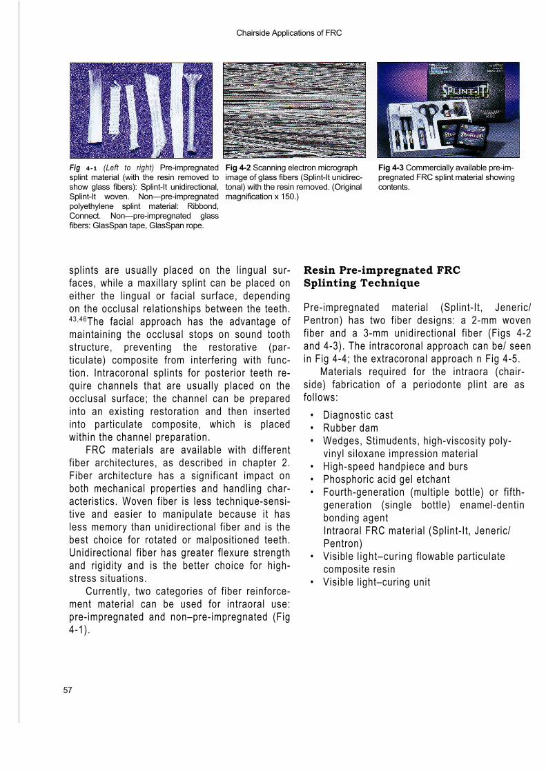
Chairside Applications of FRC
57
Fig 4-1 (Left to right) Pre-impregnatedsplint material (with the resin removed toshow glass fibers): Splint-It unidirectional,Splint-It woven. Non—pre-impregnatedpolyethylene splint material: Ribbond,Connect. Non—pre-impregnated glassfibers: GlasSpan tape, GlasSpan rope.
Fig 4-2 Scanning electron micrograph Fig 4-3 Commercially available pre-im-image of glass fibers (Splint-It unidirec- pregnated FRC splint material showingtonal) with the resin removed. (Original contents.magnification x 150.)
splints are usually placed on the lingual sur-faces, while a maxillary splint can be placed oneither the lingual or facial surface, dependingon the occlusal relationships between the teeth.43,46The facial approach has the advantage ofmaintaining the occlusal stops on sound toothstructure, preventing the restorative (par-ticulate) composite from interfering with func-tion. Intracoronal splints for posterior teeth re-quire channels that are usually placed on theocclusal surface; the channel can be preparedinto an existing restoration and then insertedinto particulate composite, which is placedwithin the channel preparation.
FRC materials are available with differentfiber architectures, as described in chapter 2.Fiber architecture has a significant impact onboth mechanical properties and handling char-acteristics. Woven fiber is less technique-sensi-tive and easier to manipulate because it hasless memory than unidirectional fiber and is thebest choice for rotated or malpositioned teeth.Unidirectional fiber has greater flexure strengthand rigidity and is the better choice for high-stress situations.
Currently, two categories of fiber reinforce-ment material can be used for intraoral use:pre-impregnated and non–pre-impregnated (Fig4-1).
Resin Pre-impregnated FRCSplinting Technique
Pre-impregnated material (Splint-It, Jeneric/Pentron) has two fiber designs: a 2-mm wovenfiber and a 3-mm unidirectional fiber (Figs 4-2and 4-3). The intracoronal approach can be/ seenin Fig 4-4; the extracoronal approach n Fig 4-5.
Materials required for the intraora (chair-side) fabrication of a periodonte plint are asfollows:
• Diagnostic cast• Rubber dam• Wedges, Stimudents, high-viscosity poly-
vinyl siloxane impression material• High-speed handpiece and burs• Phosphoric acid gel etchant• Fourth-generation (multiple bottle) or fifth-
generation (single bottle) enamel-dentinbonding agentIntraoral FRC material (Splint-It, Jeneric/Pentron)
• Visible l ight–curing flowable particulatecomposite resin
• Visible light–curing unit
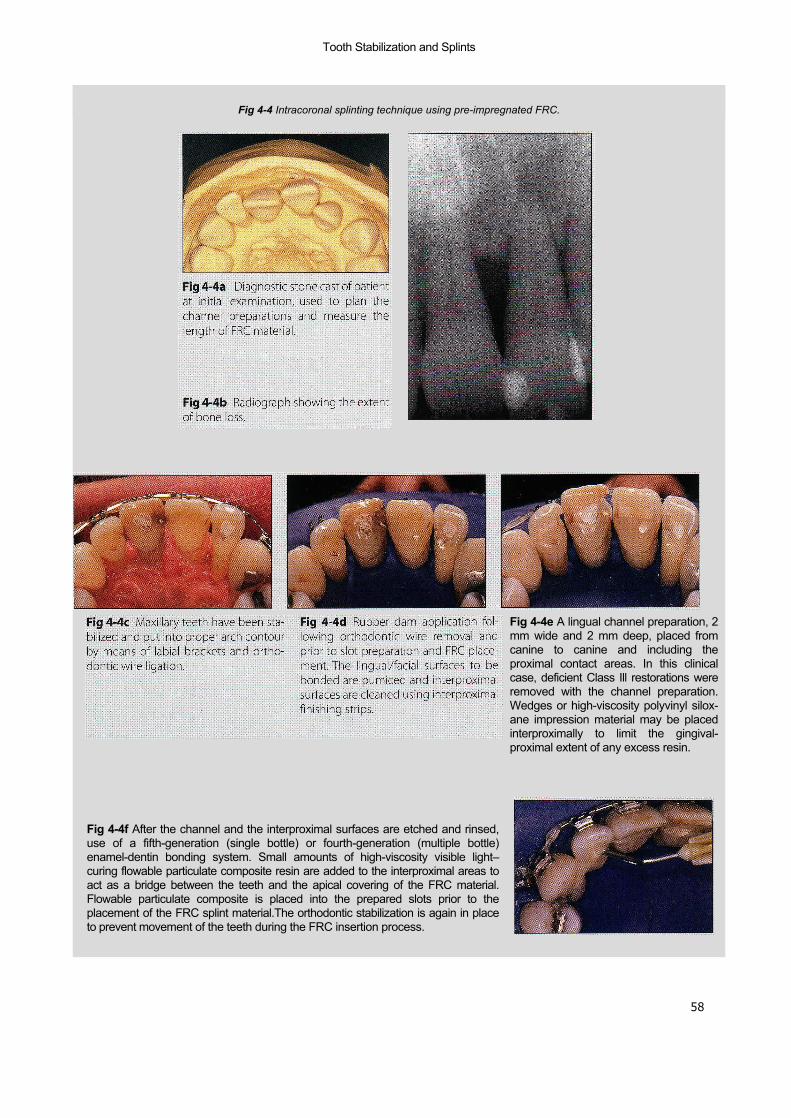
58
Tooth Stabilization and Splints
Fig 4-4 Intracoronal splinting technique using pre-impregnated FRC.
Fig 4-4e A lingual channel preparation, 2mm wide and 2 mm deep, placed fromcanine to canine and including theproximal contact areas. In this clinicalcase, deficient Class Ill restorations wereremoved with the channel preparation.Wedges or high-viscosity polyvinyl silox-ane impression material may be placedinterproximally to limit the gingival-proximal extent of any excess resin.
Fig 4-4f After the channel and the interproximal surfaces are etched and rinsed,use of a fifth-generation (single bottle) or fourth-generation (multiple bottle)enamel-dentin bonding system. Small amounts of high-viscosity visible light–curing flowable particulate composite resin are added to the interproximal areas toact as a bridge between the teeth and the apical covering of the FRC material.Flowable particulate composite is placed into the prepared slots prior to theplacement of the FRC splint material.The orthodontic stabilization is again in placeto prevent movement of the teeth during the FRC insertion process.
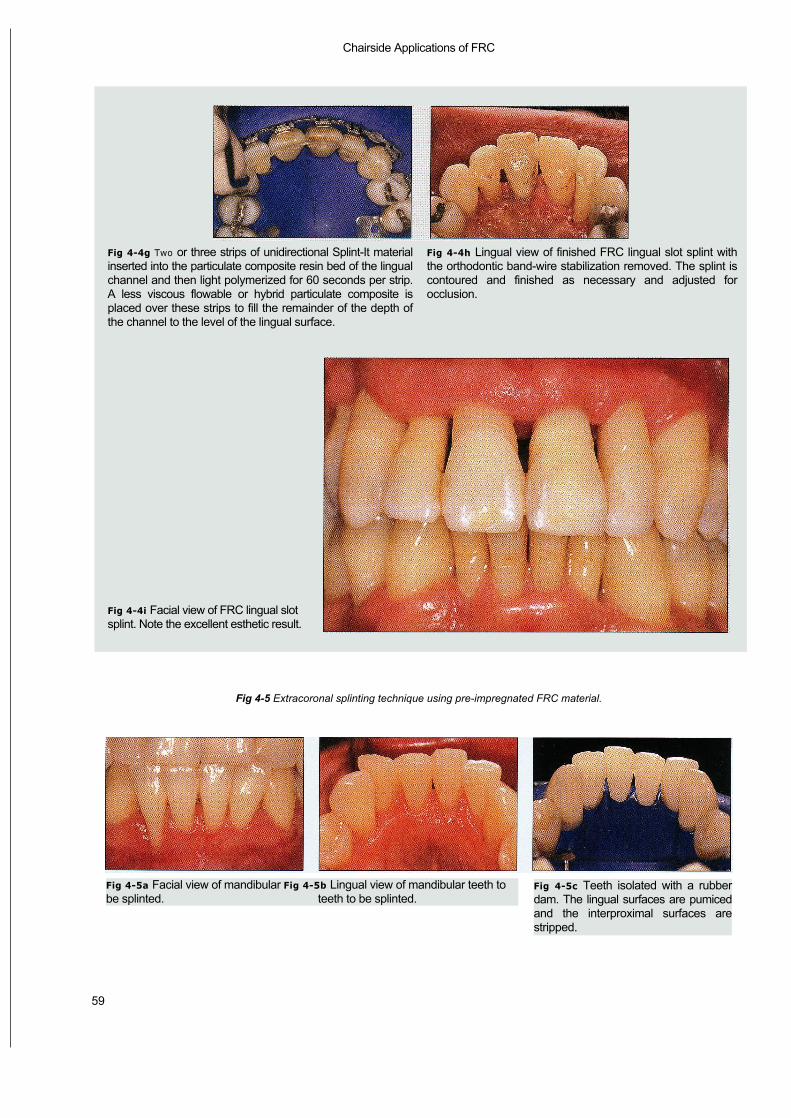
Chairside Applications of FRC
59
Fig 4-5 Extracoronal splinting technique using pre-impregnated FRC material.
Fig 4-4g Two or three strips of unidirectional Splint-It materialinserted into the particulate composite resin bed of the lingualchannel and then light polymerized for 60 seconds per strip.A less viscous flowable or hybrid particulate composite isplaced over these strips to fill the remainder of the depth ofthe channel to the level of the lingual surface.
Fig 4-4i Facial view of FRC lingual slotsplint. Note the excellent esthetic result.
Fig 4-4h Lingual view of finished FRC lingual slot splint withthe orthodontic band-wire stabilization removed. The splint iscontoured and finished as necessary and adjusted forocclusion.
Fig 4-5a Facial view of mandibular Fig 4-5b Lingual view of mandibular teeth tobe splinted. teeth to be splinted.
Fig 4-5c Teeth isolated with a rubberdam. The lingual surfaces are pumicedand the interproximal surfaces arestripped.

— Tooth Stabilization and Splints —
60
Fig 4-5d Wedges placed to limit theextent of resin interproximally. The lin-gual surfaces are etched and rinsed, anda fourth-generation (multiple bottle) orfifth-generation (single bottle) enamel-dentin bonding system is applied to theetched lingual surfaces.
Fig 4-5e Flowable particulate compos-ite resin being applied to the etched lin-gual surfaces.
Fig 4-5f Premeasured and cut Splint-Itunidirectional FRC material positionedto be tacked into the lingual particulatecomposite resin.
Fig 4-5g The FRC splint material beingfoil-protected to prevent polymerizationof the nonembedded section during lightcuring of an embedded segment. Thistechnique allows the clinician adequateworking time to properly place andembed the FRC along the arch in asequential manner for maximum adap-tation.
Fig 4-5h A plastic instrument beingused to embed the FRC and hold theterminal segment while it is being lightpolymerized. The FRC must be com-pletely embedded in the particulatecomposite to protect the glass fibersfrom oral exposure.
Fig 4-5i Lingual view of the extracoro-nal FRC splinted mandibular anteriorarch. The particulate composite is con-toured for comfort if necessary.
Fig 4-5j Facial view of the extracoronalFRC splinted teeth. When compared toFig 4-5a, there is no visual indication thatthe teeth have been splinted.
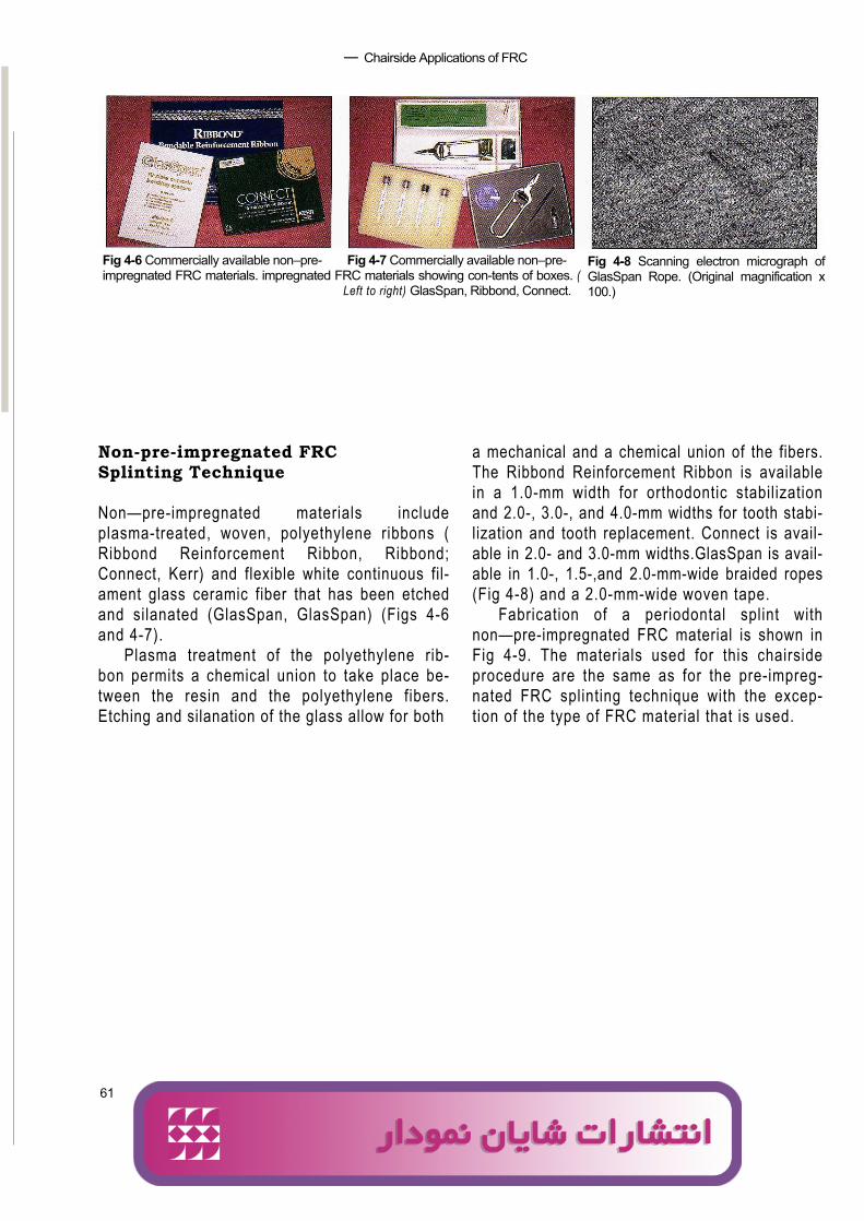
61
— Chairside Applications of FRC
Fig 4-6 Commercially available non–pre- Fig 4-7 Commercially available non–pre-impregnated FRC materials. impregnated FRC materials showing con-tents of boxes. (
Left to right) GlasSpan, Ribbond, Connect.
Fig 4-8 Scanning electron micrograph ofGlasSpan Rope. (Original magnification x100.)
Non-pre-impregnated FRCSplinting Technique
Non—pre-impregnated materials includeplasma-treated, woven, polyethylene ribbons (Ribbond Reinforcement Ribbon, Ribbond;Connect, Kerr) and flexible white continuous fil-ament glass ceramic fiber that has been etchedand silanated (GlasSpan, GlasSpan) (Figs 4-6and 4-7).
Plasma treatment of the polyethylene rib-bon permits a chemical union to take place be-tween the resin and the polyethylene fibers.Etching and silanation of the glass allow for both
a mechanical and a chemical union of the fibers.The Ribbond Reinforcement Ribbon is availablein a 1.0-mm width for orthodontic stabilizationand 2.0-, 3.0-, and 4.0-mm widths for tooth stabi-lization and tooth replacement. Connect is avail-able in 2.0- and 3.0-mm widths.GlasSpan is avail-able in 1.0-, 1.5-,and 2.0-mm-wide braided ropes(Fig 4-8) and a 2.0-mm-wide woven tape.
Fabrication of a periodontal splint withnon—pre-impregnated FRC material is shown inFig 4-9. The materials used for this chairsideprocedure are the same as for the pre-impreg-nated FRC splinting technique with the excep-tion of the type of FRC material that is used.
Ali
logo 2
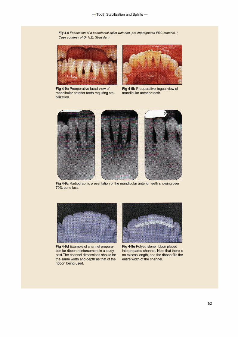
— Tooth Stabilization and Splints —
62
Fig 4-9 Fabrication of a periodontal splint with non–pre-impregnated FRC material. (Case courtesy of Dr H.E. Strassler.)
Fig 4-9a Preoperative facial view of Fig 4-9b Preoperative lingual view ofmandibular anterior teeth requiring sta- mandibular anterior teeth.bilization.
Fig 4-9c Radiographic presentation of the mandibular anterior teeth showing over70% bone loss.
Fig 4-9d Example of channel prepara- Fig 4-9e Polyethylene ribbon placedtion for ribbon reinforcement in a study into prepared channel. Note that there iscast.The channel dimensions should be no excess length, and the ribbon fills thethe same width and depth as that of the entire width of the channel.ribbon being used.
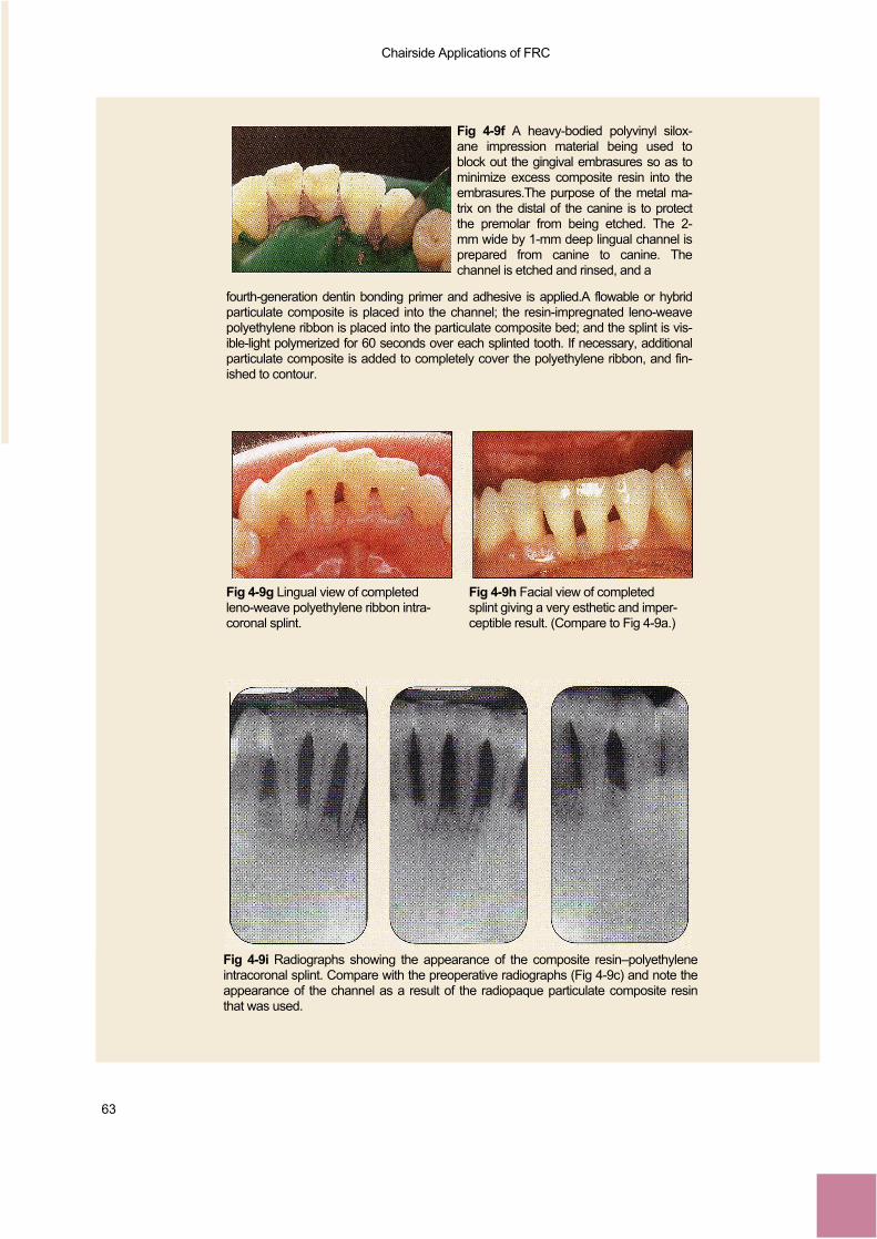
Chairside Applications of FRC
63
Fig 4-9f A heavy-bodied polyvinyl silox-ane impression material being used toblock out the gingival embrasures so as tominimize excess composite resin into theembrasures.The purpose of the metal ma-trix on the distal of the canine is to protectthe premolar from being etched. The 2-mm wide by 1-mm deep lingual channel isprepared from canine to canine. Thechannel is etched and rinsed, and a
fourth-generation dentin bonding primer and adhesive is applied.A flowable or hybridparticulate composite is placed into the channel; the resin-impregnated leno-weavepolyethylene ribbon is placed into the particulate composite bed; and the splint is vis-ible-light polymerized for 60 seconds over each splinted tooth. If necessary, additionalparticulate composite is added to completely cover the polyethylene ribbon, and fin-ished to contour.
Fig 4-9g Lingual view of completed Fig 4-9h Facial view of completedleno-weave polyethylene ribbon intra- splint giving a very esthetic and imper-coronal splint. ceptible result. (Compare to Fig 4-9a.)
Fig 4-9i Radiographs showing the appearance of the composite resin–polyethyleneintracoronal splint. Compare with the preoperative radiographs (Fig 4-9c) and note theappearance of the channel as a result of the radiopaque particulate composite resinthat was used.
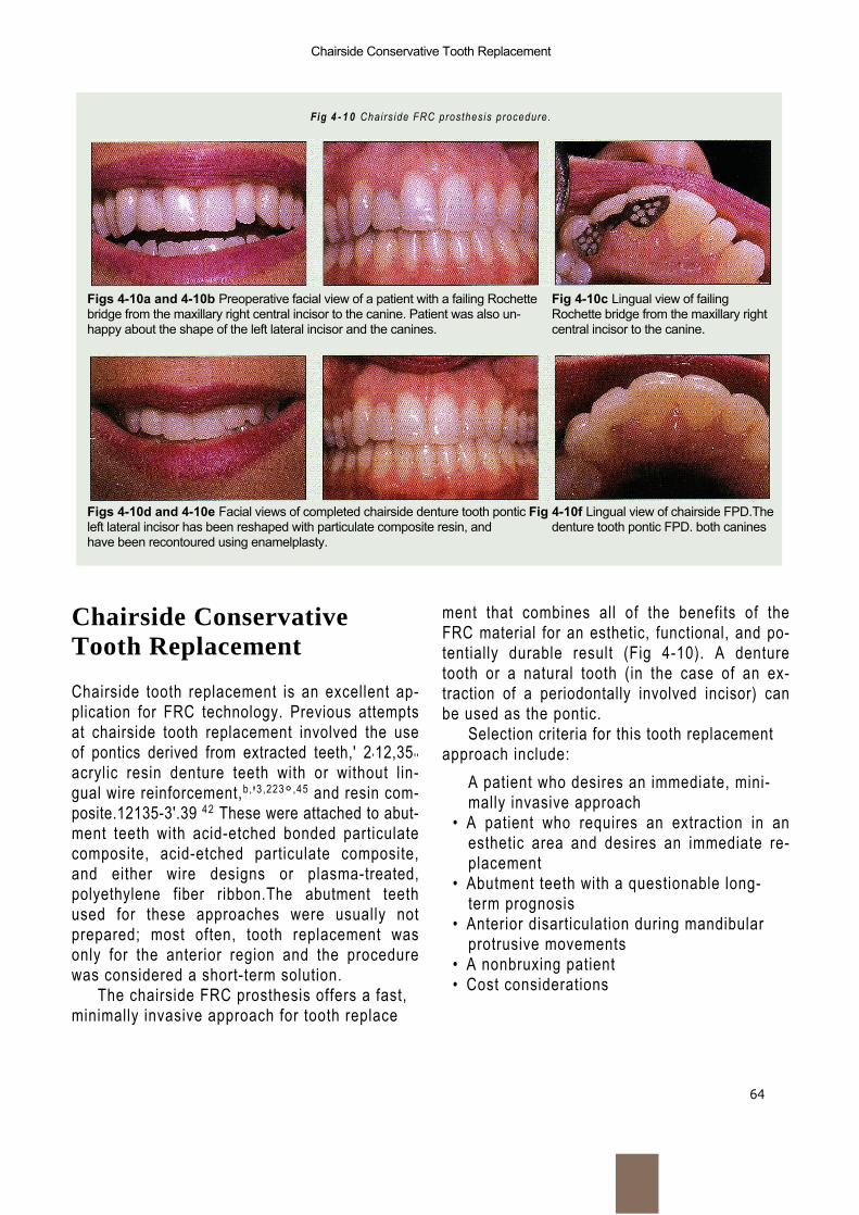
64
Chairside Conservative Tooth Replacement
Fig 4 - 1 0 Chairs ide FRC prosthesis procedure.
Figs 4-10a and 4-10b Preoperative facial view of a patient with a failing Rochette Fig 4-10c Lingual view of failingbridge from the maxillary right central incisor to the canine. Patient was also un- Rochette bridge from the maxillary righthappy about the shape of the left lateral incisor and the canines. central incisor to the canine.
Figs 4-10d and 4-10e Facial views of completed chairside denture tooth pontic Fig 4-10f Lingual view of chairside FPD.Theleft lateral incisor has been reshaped with particulate composite resin, and denture tooth pontic FPD. both canineshave been recontoured using enamelplasty.
Chairside ConservativeTooth Replacement
Chairside tooth replacement is an excellent ap-plication for FRC technology. Previous attemptsat chairside tooth replacement involved the useof pontics derived from extracted teeth,' 2 '12,35 ' 'acrylic resin denture teeth with or without lin-gual wire reinforcement,b, '3,223° ,45 and resin com-posite.12135-3'.39 42 These were attached to abut-ment teeth with acid-etched bonded particulatecomposite, acid-etched particulate composite,and either wire designs or plasma-treated,polyethylene fiber ribbon.The abutment teethused for these approaches were usually notprepared; most often, tooth replacement wasonly for the anterior region and the procedurewas considered a short-term solution.
The chairside FRC prosthesis offers a fast,minimally invasive approach for tooth replace
ment that combines all of the benefits of theFRC material for an esthetic, functional, and po-tentially durable result (Fig 4-10). A denturetooth or a natural tooth (in the case of an ex-traction of a periodontally involved incisor) canbe used as the pontic.
Selection criteria for this tooth replacementapproach include:
A patient who desires an immediate, mini-mally invasive approach
• A patient who requires an extraction in anesthetic area and desires an immediate re-placement
• Abutment teeth with a questionable long-term prognosis
• Anterior disarticulation during mandibularprotrusive movements
• A nonbruxing patient• Cost considerations
Chairside Applications of FRC
65
Materials required for the chairside FRCprosthesis procedure are as follows:
• Diagnostic casts• Denture or natural tooth• Intraoral putty occlusal-incisal pontic index• Phosphoric acid gel etchant• Fourth-generation (multiple bottle) or fifth-
generation (single bottle) enamel-dentinbonding system
• Visible light—curing flowable particulatecomposite
• Unidirectional pre-impregnated FRC• Finishing and polishing burs and points
Chairside Fixed Partial Denture
Figures 4-11 and 4-12 demonstrate chairsideposterior and anterior FRC fixed partial denture (FPD) procedures.
Initial VisitDuring the initial visit, a shade is selected for thedenture tooth, and an alginate impression of thearch in which the FPD will be placed is taken tocreate a diagnostic cast.This diagnostic cast isused for selecting and modifying the denturetooth pontic.
Denture Tooth ModificationA denture tooth of appropriate shade that bestfits the shape of the edentulous space and thatmatches the anatomic shape of the adjacentteeth is selected. It is modified so as to lightlycontact the proximal surfaces of the abutmentteeth and to conform to the ridge of the eden-tulous space. The denture tooth is then tackedto the cast in an optimal position and a line isinscribed on its occlusal/lingual surface to indi-cate where the slots are to be placed in theabutment teeth at the time of insertion (Figs 4-11c to 4-11e and 4-12b to 4-12c).The adjusteddenture tooth is modified as follows (1) ProximalClass III preparations are placed on the
mesial and distal facial surfaces. These will beused to tack the denture tooth interproximally tothe abutment teeth when first positioned in themouth. (2) An occlusal/lingual groove, at least 2mm wide and 2 mm deep, is prepared, with thebase undercut following the occlusal/lingual linedrawn earlier.This groove will receive the FRC (Figs 4-11f and 4-12d).
Alternative Technique UsingExtracted ToothIf the natural tooth is unsalvagable and must beextracted, it can be used as the pontic. Thelength of the tooth is determined by measuringfrom the extraction site to the incisal edge of theadjacent teeth; the root is then cut from thetooth crown at this determined length.The rootcanal opening at the apical end is restored bypreparing the root canal with a 330 bur to adepth of 1.5 mm. The preparation is restoredwith particulate composite using an adhesivetechnique.The technique for placing the naturaltooth crown is similar to that for a denture tooth.
Fabrication of an Intraoral,Occlusal-Incisal Pontic IndexThe denture tooth is positioned on the diag-nostic cast and a positioning index is fabricatedto aid in the accurate alignment of the denturetooth pontic in the mouth. Fabricated from vinylsiloxane putty, the positioning index encom-passes the occlusal-incisal portion of the ponticand the adjacent abutment teeth and fills theocclusal/lingual groove for the FRC.The gingivalextension should not block facial access to theClass III proximal retentive forms of the pontic (Figs 4-11g to 4-11h and 4-12h).
Chairside Insertion TechniqueThe abutment teeth are anesthetized; the den-ture tooth is tried in to verify fit, shade, and con-tour; and a rubber dam is placed. Grooves areprepared in the abutment teeth to align with thegroove in the denture tooth (Figs 4-11 k and
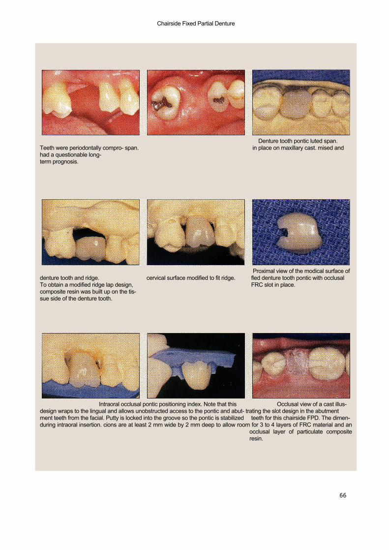
Chairside Fixed Partial Denture
Fig 4-11 Chairside posterior FPD procedures using FRC materials.
66
Fig 4-11a Buccal view of edentulous Fig 4-11b Occlusal view of edentulous Fig 4-11c Denture tooth pontic luted span.Teeth were periodontally compro- span. in place on maxillary cast. mised andhad a questionable long-term prognosis.
Fig 4 - l i d Discrepancy between cervi- Fig 4 - l i e Denture tooth pontic with Fig 4-11f Proximal view of the modical surface ofdenture tooth and ridge. cervical surface modified to fit ridge. fled denture tooth pontic with occlusalTo obtain a modified ridge lap design, FRC slot in place.composite resin was built up on the tis-sue side of the denture tooth.
Figs 4-11g and 4-11h Intraoral occlusal pontic positioning index. Note that this Fig 4-11i Occlusal view of a cast illus-design wraps to the lingual and allows unobstructed access to the pontic and abut- trating the slot design in the abutmentment teeth from the facial. Putty is locked into the groove so the pontic is stabilized teeth for this chairside FPD. The dimen-during intraoral insertion. cions are at least 2 mm wide by 2 mm deep to allow room for 3 to 4 layers of FRC material and an
occlusal layer of particulate compositeresin.
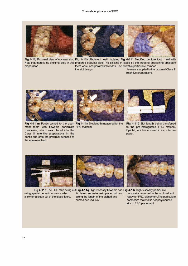
Chairside Applications of FRC
67
Fig 4-11k Abutment teeth isolated Fig 4-111 Modified denture tooth held withprepared occlusal slots.The existing in place by the intraoral positioning amalgamteeth were incorporated into index. The flowable particulate compos-the slot design. ite resin is applied to the proximal Class Ill
retentive preparations.
Fig 4-11j Proximal view of occlusal slot.Note that there is no proximal step in thispreparation.
Fig 4-11 m Pontic tacked to the abut-ment teeth with flowable particulatecomposite, which was placed into theClass Ill retentive preparations in thepontic and onto the proximal surfaces ofthe abutment teeth.
Fig 4-11n Slot length measured for theFRC material.
Fig 4-110 Slot length being transferredto the pre-impregnated FRC material,Splint-It, which is encased in its protectivepaper.
Fig 4-11p The FRC strip being cut Fig 4-11q High-viscosity flowable par- Fig 4-11r High-viscosity particulateusing special ceramic scissors, which ticulate composite resin placed into and composite resin bed in the occlusal slotallow for a clean cut of the glass fibers. along the length of the etched and ready for FRC placement.The particulate
primed occlusal slot. composite material is not polymerizedprior to FRC placement.

Chairside Fixed Partial Denture
68
Fig 4-11s Three strips of FRC placed intothe composite resin bed within theocclusal slot. Additional particulate com-posite resin will be added to cover theFRC completely.
Fig 4-11t Occlusal view of the finished Fig 4-11u Buccal view of the finishedchairside FRC FPD. chairside FRC FPD.
4-12g); these are to be at least 2 mm wide and2 mm deep so as to duplicate the groove in thepontic (Figs 4-11i to 4-11 j and 4-12f). The oc-clusal/l ingual groove in the denture tooth pon-tic is sandblasted with 50 pm aluminum oxide.The occlusal/lingual grooves and the interprox-imal areas of the abutment teeth adjacent tothe edentulous space are etched and treatedwith a dentin bonding agent. The denture toothis placed in the putty index and positioned inthe mouth (Figs 4-111 and 4-12h). A flowablecomposite is placed and l ight cured into theClass III interproximal preparations and onto theproximal surfaces of the abutment teeth. Thiswil l tack the pontic in place and allow for theremoval of the putty index with-out dislodgingor moving the denture tooth
(Figs 4-11m and 4-1 2i).A small amount of high-viscosity flowable particulate composite resin issyringed into the occlusal/lingual grooves, andthe proper length of FRC is added into the par-ticulate composite–based groove (Figs 4-11qand 4-11 r).Three or more pieces of FRC shouldbe placed and condensed into the groove,below the occlusal/l ingual surface of the abut-ment teeth or pontic, and then light cured (Fig4-11 s). A less viscous flowable particulate com-posite resin is used to completely f i l l the re-maining portion of the groove and l ight cured (Figs 4-1 1t and 4-12k to 4-121).The rubber damis removed and occlusal adjustments are madeusing a high-speed handpiece with a compos-ite f inishing bur.
Ali
logo 2
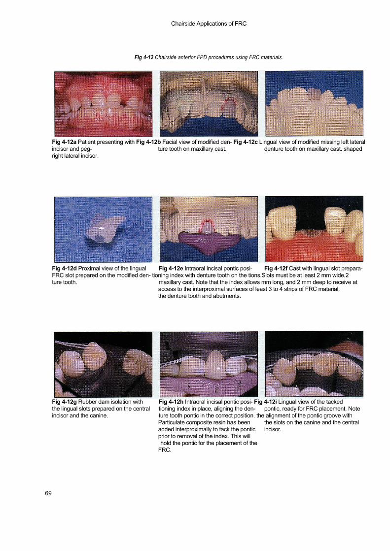
Chairside Applications of FRC
Fig 4-12 Chairside anterior FPD procedures using FRC materials.
69
Fig 4-12a Patient presenting with Fig 4-12b Facial view of modified den- Fig 4-12c Lingual view of modified missing left lateralincisor and peg- ture tooth on maxillary cast. denture tooth on maxillary cast. shapedright lateral incisor.
Fig 4-12d Proximal view of the lingual Fig 4-12e Intraoral incisal pontic posi- Fig 4-12f Cast with lingual slot prepara-FRC slot prepared on the modified den- tioning index with denture tooth on the tions.Slots must be at least 2 mm wide,2ture tooth. maxillary cast. Note that the index allows mm long, and 2 mm deep to receive at
access to the interproximal surfaces of least 3 to 4 strips of FRC material.the denture tooth and abutments.
Fig 4-12g Rubber dam isolation with Fig 4-12h Intraoral incisal pontic posi- Fig 4-12i Lingual view of the tackedthe lingual slots prepared on the central tioning index in place, aligning the den- pontic, ready for FRC placement. Noteincisor and the canine. ture tooth pontic in the correct position. the alignment of the pontic groove with
Particulate composite resin has been the slots on the canine and the centraladded interproximally to tack the pontic incisor.prior to removal of the index. This willhold the pontic for the placement of the
FRC.
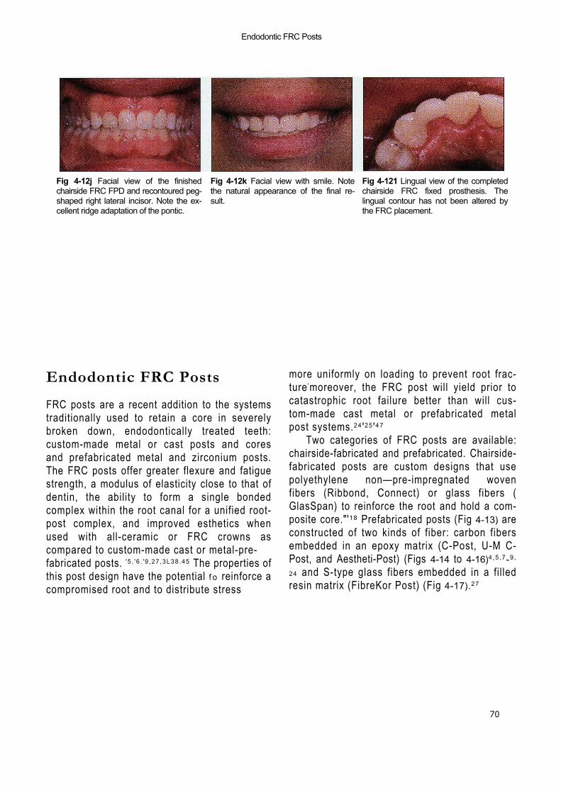
Endodontic FRC Posts
70
Fig 4-12j Facial view of the finishedchairside FRC FPD and recontoured peg-shaped right lateral incisor. Note the ex-cellent ridge adaptation of the pontic.
Fig 4-12k Facial view with smile. Notethe natural appearance of the final re-sult.
Fig 4-121 Lingual view of the completedchairside FRC fixed prosthesis. Thelingual contour has not been altered bythe FRC placement.
Endodontic FRC Posts
FRC posts are a recent addition to the systemstraditionally used to retain a core in severelybroken down, endodontically treated teeth:custom-made metal or cast posts and coresand prefabricated metal and zirconium posts.The FRC posts offer greater flexure and fatiguestrength, a modulus of elasticity close to that ofdentin, the ability to form a single bondedcomplex within the root canal for a unified root-post complex, and improved esthetics whenused with all-ceramic or FRC crowns ascompared to custom-made cast or metal-pre-fabricated posts. ' 5 , ' 6 . ' 9 ,27 ,3L38 .45 The properties ofthis post design have the potential f o reinforce acompromised root and to distribute stress
more uniformly on loading to prevent root frac-ture 'moreover, the FRC post will yield prior tocatastrophic root failure better than will cus-tom-made cast metal or prefabricated metalpost systems.24 '25 '47
Two categories of FRC posts are available:chairside-fabricated and prefabricated. Chairside-fabricated posts are custom designs that usepolyethylene non—pre-impregnated wovenfibers (Ribbond, Connect) or glass fibers (GlasSpan) to reinforce the root and hold a com-posite core."'18 Prefabricated posts (Fig 4-13) areconstructed of two kinds of fiber: carbon fibersembedded in an epoxy matrix (C-Post, U-M C-Post, and Aestheti-Post) (Figs 4-14 to 4-16)4 ,5 ,7-9 ,
24 and S-type glass fibers embedded in a fil ledresin matrix (FibreKor Post) (Fig 4-17).27
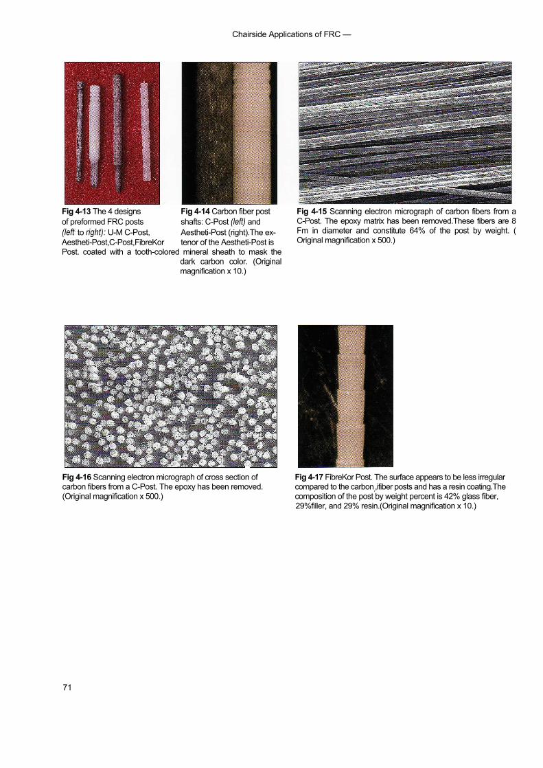
Chairside Applications of FRC —
71
Fig 4-13 The 4 designs Fig 4-14 Carbon fiber postof preformed FRC posts shafts: C-Post (left) and(left: to right): U-M C-Post, Aestheti-Post (right).The ex-Aestheti-Post,C-Post,FibreKor tenor of the Aestheti-Post isPost. coated with a tooth-colored mineral sheath to mask the
dark carbon color. (Originalmagnification x 10.)
Fig 4-15 Scanning electron micrograph of carbon fibers from aC-Post. The epoxy matrix has been removed.These fibers are 8Fm in diameter and constitute 64% of the post by weight. (Original magnification x 500.)
Fig 4-16 Scanning electron micrograph of cross section of Fig 4-17 FibreKor Post. The surface appears to be less irregularcarbon fibers from a C-Post. The epoxy has been removed. compared to the carbon,,ifiber posts and has a resin coating.The(Original magnification x 500.) composition of the post by weight percent is 42% glass fiber,
29%filler, and 29% resin.(Original magnification x 10.)
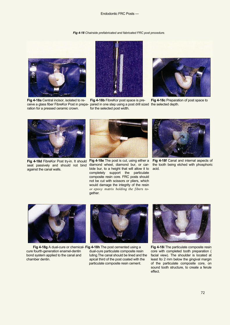
Endodontic FRC Posts —
Fig 4-18 Chairside prefabricated and fabricated FRC post procedure.
72
Fig 4-18c Preparation of post space tothe selected depth.
Fig 4-18a Central incisor, isolated to re- Fig 4-18b FibreKor post space is pre-ceive a glass fiber FibreKor Post in prepa- pared in one step using a post drill sizedration for a pressed ceramic crown. for the selected post width.
Fig 4-18d FibreKor Post try-in. It shouldseat passively and should not bindagainst the canal walls.
Fig 4-18e The post is cut, using either adiamond wheel, diamond bur, or car-bide bur, to a height that will allow it tocompletely support the particulatecomposite resin core. FRC posts shouldnot be cut with scissors or pliers, whichwould damage the integrity of the resinor epoxy matrix holding the fibers to-gether.
Fig 4-18f Canal and internal aspects ofthe tooth being etched with phosphoricacid.
Fig 4-18g A dual-cure or chemical- Fig 4-18h The post cemented using acure fourth-generation enamel-dentin dual-cure particulate composite resinbond system applied to the canal and luting.The canal should be lined and thechamber dentin. apical third of the post coated with the
particulate composite resin cement.
Fig 4-18i The particulate composite resincore with completed tooth preparation (facial view). The shoulder is located atleast Ito 2 mm below the gingival marginof the particulate composite core, onsound tooth structure, to create a feruleeffect.

Chairside Applications of FRC —
73
Fig 4-18j FibreKor Post and compositeresin core with completed tooth prepa-ration (incisal view).The end of the postcan be seen through the lingual incisalof the core.
Fig 4-18k Central incisor, isolated to re-ceive a carbon fiber Aestheti-Post inpreparation for a pressed ceramiccrown.
Fig 4-181 The canal for this post is pre-pared in two steps. A preshaping drill (far right) is used to prepare the postspace to its final depth and to guide thefinal canal preparation. A finishing drill (middle) is used to shape the canal so asto accept the carbon fiber post and tocreate a 30-mm space for resin cement.
Fig 4-18m Aestheti-Post seated afterpost space preparation and height ad-justment. Note that the height is enoughto allow complete extension of the postto provide support for the particulatecomposite core.
Fig 4-18n Completed Aestheti-Post andparticulate composite resin core (facialview).
Fig 4-18o Completed Aestheti-Post andparticulate composite resin core withtooth prepared to receive a pressed ce-ramic crown (incisal view). Note the endof the carbon fiber post on the lingual in-cisal portion of the core.
Fig 4-18p A carbon fiber C-Post ce-mented into a tooth in preparation for aparticulate composite resin core (facialview). The same steps followed for theAestheti-Post placement, above, a pply tothe C-Post.
Fig 4-18q Finished C-Post and particu-late composite resin with completedtooth preparation to receive a pressedceramic crown (facial view). Dependingon the buccolingual width of the com-posite core,this type of FRC post may re-sult in a core with lower value because ofits color
Fig 4-18r Finished C-Post and particu-late composite resin core with com-pleted tooth preparation (incisal view).Note that the C-Post is visible at the lin-gual incisal edge of the core.
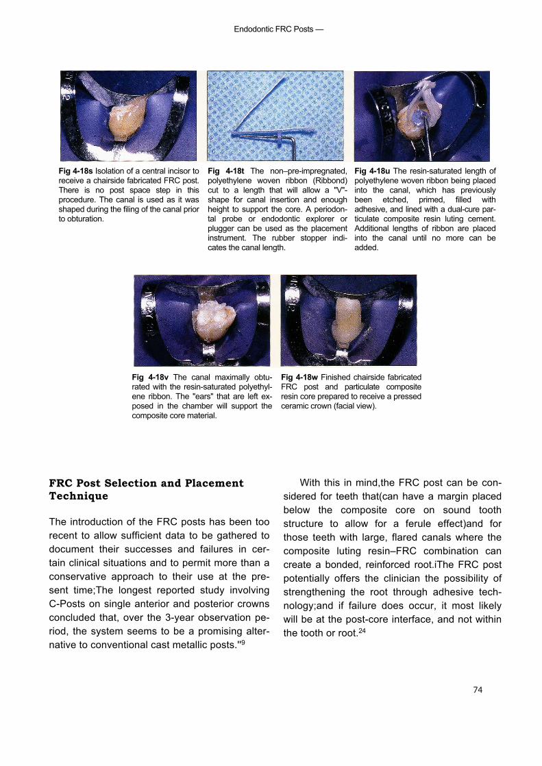
Endodontic FRC Posts —
74
Fig 4-18s Isolation of a central incisor toreceive a chairside fabricated FRC post.There is no post space step in thisprocedure. The canal is used as it wasshaped during the filing of the canal priorto obturation.
Fig 4-18t The non–pre-impregnated,polyethylene woven ribbon (Ribbond)cut to a length that will allow a "V"-shape for canal insertion and enoughheight to support the core. A periodon-tal probe or endodontic explorer orplugger can be used as the placementinstrument. The rubber stopper indi-cates the canal length.
Fig 4-18u The resin-saturated length ofpolyethylene woven ribbon being placedinto the canal, which has previouslybeen etched, primed, filled withadhesive, and lined with a dual-cure par-ticulate composite resin luting cement.Additional lengths of ribbon are placedinto the canal until no more can beadded.
Fig 4-18v The canal maximally obtu-rated with the resin-saturated polyethyl-ene ribbon. The "ears" that are left ex-posed in the chamber will support thecomposite core material.
Fig 4-18w Finished chairside fabricatedFRC post and particulate compositeresin core prepared to receive a pressedceramic crown (facial view).
FRC Post Selection and PlacementTechnique
The introduction of the FRC posts has been toorecent to allow sufficient data to be gathered todocument their successes and failures in cer-tain clinical situations and to permit more than aconservative approach to their use at the pre-sent time;The longest reported study involvingC-Posts on single anterior and posterior crownsconcluded that, over the 3-year observation pe-riod, the system seems to be a promising alter-native to conventional cast metallic posts.''9
With this in mind,the FRC post can be con-sidered for teeth that(can have a margin placedbelow the composite core on sound toothstructure to allow for a ferule effect)and forthose teeth with large, flared canals where thecomposite luting resin–FRC combination cancreate a bonded, reinforced root.iThe FRC postpotentially offers the clinician the possibility ofstrengthening the root through adhesive tech-nology;and if failure does occur, it most likelywill be at the post-core interface, and not withinthe tooth or root.24
Chairside Applications of FRC —
75
Materials required for the chairside prefabri-cated/fabricated FRC post procedure, il lus-trated in Fig 4-18, are as follows:
• Rubber dam, retraction clamps (eg, Ivory212)• FRC prefabricated post kit (C-Post, U-M C-
Post, Aestheti-Post, FibreKor Post) or poly-ethylene woven ribbon (Ribbond, Connect)
• Peeso reemers, endodontic pluggers, alco-hol lamp/bunsen burner, to remove gutta-purcha from canal(s)
• Fourth-generation dual-cure or chemical-cure dentin bonding system
• Dual-cure composite luting resin• Particulate composite resin core paste
Step-by-Step Prefabricated FRC Post andCore Procedure
1. Using a rubber dam and a gingival retrac-tion clamp (eg, Ivory 212) or floss ligation,isolate the tooth.
2. Using either heat or a Peeso reemer,remove gutta-percha from within the canalto 4 to 5 mm of apex.
3. Using proper drills, select the size ofprefabricated posts to fit within the canaland select proper size preparation drillsand post hole preparation.
4. Using either a diamond disk or a diamondbur, cut the selected, fitted post to the cor-rect height.
5. Etch and rinse the root canal, chamber, andremaining tooth structure, and apply afourth-generation chemical-cure dentinbond primer and adhesive.
6. Coat the FRC post with primer and place adual-cure or chemical-cure particulate com-posite resin luting cement into the rootcanal and on the apical third of the post andinsert the post into the canal.
7. Add particulate composite-resin core mate-rial to the remaining chamber and crownand the core prepared for a crown.
Step-by-Step Fabricated FRC Post andCore Procedure
1. Perform steps 1 and 2, above, for the pre-fabricated FRC post and core procedure.
2. Do not enlarge or shape the existing canalspace, but cut strips of polyethylene wovenribbon in excess of twice the post space.
3. Etch, rinse, and apply a fourth-generationchemical-cure dentin bonding system to thecanal space, pulp chamber, and remainingtooth structure.
4. Apply dual-cure or chemical-cure particu-late composite resin luting cement into thecanal.
5. Saturate the polyethylene woven ribbon withresin, form it into a "V" shape, and place itinto the canal, leaving the excess as an "ear"out into the chamber/remaining toothstructure. Place as many pieces of polyethyl-ene woven ribbon as will fit into the canal.
6. Apply particulate composite resin core ma-terial to the polyethylene woven ribboncoronal extensions to create a core and pre-pare a crown preparation of the core-toothcomplex.
Acknowledgment
Dr H.E. Strassler contributed the series of slidesand text that appear on pages 57-58.
References
1. Antonoson DE. Immediate temporary bridge using anextracted tooth. Dent Sury 1980:22;208-211.
2. Bounocore MG. The uses of adhesives in dentistry.Springfield IL: Charles C Thomas, 1975:334.
3. Ciancio SG, Nisengard RJ. Resins in periodontal splinting. Dent Clin North Am 1975;19(2):235-242.
4. Composiposte. Technical document: Meylan Cedex,France RTD; 1994.
5. Dallari A, Rovatti L. Six years of in vitro/in vivo experiencewith Composipost. Compend Contin Educ Dent 1996;17(520):SS 8.
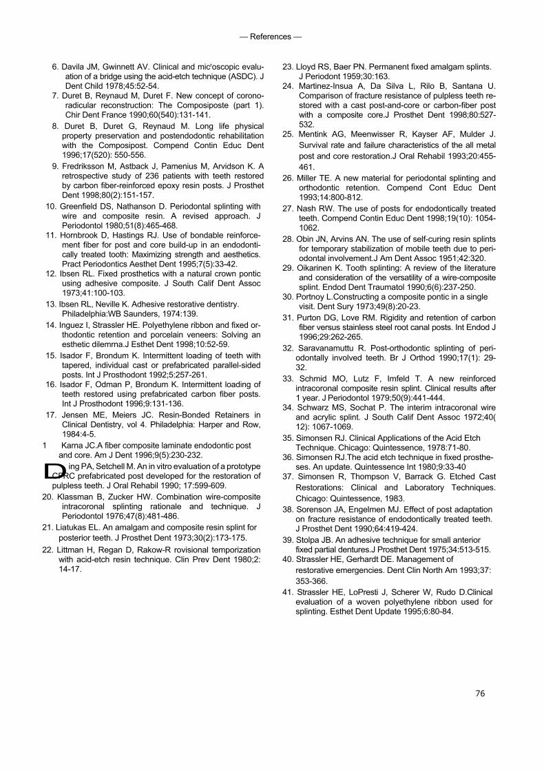
76
— References —
6. Davila JM, Gwinnett AV. Clinical and microscopic evalu-ation of a bridge using the acid-etch technique (ASDC). JDent Child 1978;45:52-54.
7. Duret B, Reynaud M, Duret F. New concept of corono-radicular reconstruction: The Composiposte (part 1).Chir Dent France 1990;60(540):131-141.
8. Duret B, Duret G, Reynaud M. Long life physicalproperty preservation and postendodontic rehabilitationwith the Composipost. Compend Contin Educ Dent1996;17(520): 550-556.
9. Fredriksson M, Astback J, Pamenius M, Arvidson K. Aretrospective study of 236 patients with teeth restoredby carbon fiber-reinforced epoxy resin posts. J ProsthetDent 1998;80(2):151-157.
10. Greenfield DS, Nathanson D. Periodontal splinting withwire and composite resin. A revised approach. JPeriodontol 1980;51(8):465-468.
11. Hornbrook D, Hastings RJ. Use of bondable reinforce-ment fiber for post and core build-up in an endodonti-cally treated tooth: Maximizing strength and aesthetics.Pract Periodontics Aesthet Dent 1995;7(5):33-42.
12. Ibsen RL. Fixed prosthetics with a natural crown ponticusing adhesive composite. J South Calif Dent Assoc1973;41:100-103.
13. Ibsen RL, Neville K. Adhesive restorative dentistry.Philadelphia:WB Saunders, 1974:139.
14. Inguez I, Strassler HE. Polyethylene ribbon and fixed or-thodontic retention and porcelain veneers: Solving anesthetic dilemrna.J Esthet Dent 1998;10:52-59.
15. Isador F, Brondum K. Intermittent loading of teeth withtapered, individual cast or prefabricated parallel-sidedposts. Int J Prosthodont 1992;5:257-261.
16. Isador F, Odman P, Brondum K. Intermittent loading ofteeth restored using prefabricated carbon fiber posts.Int J Prosthodont 1996;9:131-136.
17. Jensen ME, Meiers JC. Resin-Bonded Retainers inClinical Dentistry, vol 4. Philadelphia: Harper and Row,1984:4-5.
1 Karna JC.A fiber composite laminate endodontic postand core. Am J Dent 1996;9(5):230-232.
Ding PA, Setchell M. An in vitro evaluation of a prototypeCFRC prefabricated post developed for the restoration ofpulpless teeth. J Oral Rehabil 1990; 17:599-609.
20. Klassman B, Zucker HW. Combination wire-compositeintracoronal splinting rationale and technique. JPeriodontol 1976;47(8):481-486.
21. Liatukas EL. An amalgam and composite resin splint forposterior teeth. J Prosthet Dent 1973;30(2):173-175.
22. Littman H, Regan D, Rakow-R rovisional temporizationwith acid-etch resin technique. Clin Prev Dent 1980;2:14-17.
23. Lloyd RS, Baer PN. Permanent fixed amalgam splints.J Periodont 1959;30:163.
24. Martinez-Insua A, Da Silva L, Rilo B, Santana U.Comparison of fracture resistance of pulpless teeth re-stored with a cast post-and-core or carbon-fiber postwith a composite core.J Prosthet Dent 1998;80:527-532.
25. Mentink AG, Meenwisser R, Kayser AF, Mulder J.Survival rate and failure characteristics of the all metalpost and core restoration.J Oral Rehabil 1993;20:455-461.
26. Miller TE. A new material for periodontal splinting andorthodontic retention. Compend Cont Educ Dent1993;14:800-812.
27. Nash RW. The use of posts for endodontically treatedteeth. Compend Contin Educ Dent 1998;19(10): 1054-1062.
28. Obin JN, Arvins AN. The use of self-curing resin splintsfor temporary stabilization of mobile teeth due to peri-odontal involvement.J Am Dent Assoc 1951;42:320.
29. Oikarinen K. Tooth splinting: A review of the literatureand consideration of the versatility of a wire-compositesplint. Endod Dent Traumatol 1990;6(6):237-250.
30. Portnoy L.Constructing a composite pontic in a singlevisit. Dent Sury 1973;49(8):20-23.
31. Purton DG, Love RM. Rigidity and retention of carbonfiber versus stainless steel root canal posts. Int Endod J1996;29:262-265.
32. Saravanamuttu R. Post-orthodontic splinting of peri-odontally involved teeth. Br J Orthod 1990;17(1): 29-32.
33. Schmid MO, Lutz F, Imfeld T. A new reinforcedintracoronal composite resin splint. Clinical results after1 year. J Periodontol 1979;50(9):441-444.
34. Schwarz MS, Sochat P. The interim intracoronal wireand acrylic splint. J South Calif Dent Assoc 1972;40(12): 1067-1069.
35. Simonsen RJ. Clinical Applications of the Acid EtchTechnique. Chicago: Quintessence, 1978:71-80.
36. Simonsen RJ.The acid etch technique in fixed prosthe-ses. An update. Quintessence Int 1980;9:33-40
37. Simonsen R, Thompson V, Barrack G. Etched CastRestorations: Clinical and Laboratory Techniques.Chicago: Quintessence, 1983.
38. Sorenson JA, Engelmen MJ. Effect of post adaptationon fracture resistance of endodontically treated teeth.J Prosthet Dent 1990;64:419-424.
39. Stolpa JB. An adhesive technique for small anteriorfixed partial dentures.J Prosthet Dent 1975;34:513-515.
40. Strassler HE, Gerhardt DE. Management ofrestorative emergencies. Dent Clin North Am 1993;37:353-366.
41. Strassler HE, LoPresti J, Scherer W, Rudo D.Clinicalevaluation of a woven polyethylene ribbon used forsplinting. Esthet Dent Update 1995;6:80-84.

Chairside Applications of FRC —
77
42. Strassler HE. Planing with diagnostic casts for successwith direct composite bonding. J Esthet Dent 1995;7(1):32-40.
43. Strassler HE, Serio FG. Stabilization of the naturaldentition in periodontal cases using adhesiverestorative materials. Perio Insights 1997;4:4-10.
44. Sweeney EJ, Moore DL, Dooner JJ. Retentive strengthof acid-etched anterior fixed partial dentures: An invitro comparison of attachment techniques. J Am DentAssoc 1980;100198-201.
45. Torbjorner A, Karlsson 5, Syverud M, Hensten-Pettersen A. Carbon fiber reinforced root canal posts.Mechanical
• and cytotoxic properties. Eur J Oral Sci 1996;104: 605-611.
46. Vitsentzos SI, Koidis PT. Facial approach to stabilizationof mobile maxillary anterior teeth with steep overlapand occlusal trauma.J Prosthet Dent 1997;77:550-552.
47. Yaman P, Thorsteinsson T. Effects of core materials onstress distribution of posts. J Prosthet Dent 1992; 68:416-420.
79
■ For several decades, acrylic resins have been used to fabricatevarious types of removable prostheses and provisional fixedpartial dentures (FPDs). These resins are esthetic and easy tomanipulate, and they offer satisfactory mechanical properties;however,fractures resulting from impact and flexural fatigue dooccur. Depending on their timing and circumstances, thesefractures are inconvenient both for patient and practitioner andpotentially disastrous.
Repairs to these prostheses are generally made by applying "band-aid" patches of resin to the site of the fracture. Laboratorystudies have documented that these repairs are even weakerthan the original prostheses,'' ' ' ' and clinical experience hasshown that the repaired prosthesis often refractures in the sameplace within a short period of time.
Wires and metal meshworks have been incorporated intothese repairs for the purpose of providing additional reinforce-ment. However, the parent resin does not bond to these metalalloys, and the nonresin reinforcement merely holds the twopieces of the prosthesis together when it ultimately fracturesagain.
Until the development of glass fiber—reinforced compos-ites, a predictable, convenient, and esthetic technique for re-pairing resin prostheses has not been available. Its superior flex-ure strength, combined with the capacity of its resinous matrixboth to uniformly wet the fibers and to chemically bond to theparent resin, makes glass fiber—reinforced composite an idealmaterial for long-term resin repairs.' ' '
Repair ofAcrylic Resin
Prostheses
Ali
logo 2
— Repair of Acrylic Resin Prostheses
80
Both unidirectional and woven light-poly-merized FRC strips can be used effectively forchairside repairs of fractured acrylic resin pros-theses. As noted in chapter 3, FibreKor (Jeneric/Pentron) and Vectris (Ivoclar/Williams)are unidirectional materials available for labora-tory use. Splint-It (Jeneric/Pentron), anotherchairside material, is available either as a unidi-rectional ora woven fiber. All of these materialshave significantly greater flexural properties thanunreinforced resin.' As explained earlier, wovenFRC has a shorter memory than unidirectionalFRC, which makes it easier to handle; however,unidirectional FRC has superior flex-uralproperties and will likely provide a strongerrepair.
Indications and Proceduresfor Chairside Repairs withLight-polymerized FRC
Virtually any acrylic resin prosthesis or appliancecan be repaired with light-polymerized FRC:
• Complete dentures• Acrylic bases of partial dentures• Provisional removable partial dentures• Provisional FPDs• Obturators
• Palatal lift appliances• Orthodontic retainers• Occlusal splints and night guards
Techniques for repairing partial and totalfractures of complete dentures are illustrated inFigs 5-1 and 5-2, respectively. The same set ofprinciples can easily be applied to any of thesituations listed above, with positive results.Repair of a provisional FPD is shown in Fig 5-3.
Materials required for chairside repair ofacrylic resin prostheses are as follows:
• Low-speed handpiece and acrylic burs• Visible light—curing flowable composite resin• Pre-impregnated FRC material (unidirec-
tional or woven)• Ceramic scissors• Visible light—curing unit• Acrylic resin (parent material or other ap-
plicable self-polymerizing resin)• Paintbrush/dappen dishes• Ruler• Pressure pot• Pumice wheel and lathe
If the prosthesis or appliance is completelyfractured, the following additional items will beneeded:
• Sticky wax• Cyanoacrylate• Dental stone

— Indications and Procedure for Chairside Repairs with Light-Polymerized FRC -
Fig 5-1 Step-by-step procedure for the repair of a partially fractured acrylic resin maxillarydenture using light-polymerized FRC.
Fig 5-la If the denture (or other re- Fig 5-lb The surface of the cavity is Fig 5-lc The width of the cavity is movable resinprosthesis/appliance) is prepared by wetting it first with acrylic measured. cracked but still in one piece, a T- resinmonomer and then with special shaped cavity approximately 1.5 to 2.0 resin (Jeneric/Pentron). This resin layer mmdeep is created over the crack. is not polymerized, and it creates an
adhesive surface that allows for theFRC to be "tacked down."
Figs 5-1 d and 5-1 a Four or more strips of either unidirectional (d) or woven FRC Fig 5-1 f The FRC is light polymerized(e) are cut to size and placed horizontally over the fracture. for 4 minutes.
Fig 5-1g The remainder of the cavity Fig 5-1h The prosthesis is placed in a isfilled with acrylic resin. pressure pot at 20 psi with warm
water. After 15 minutes, the prosthesisis removed, pumiced, and polished.
75
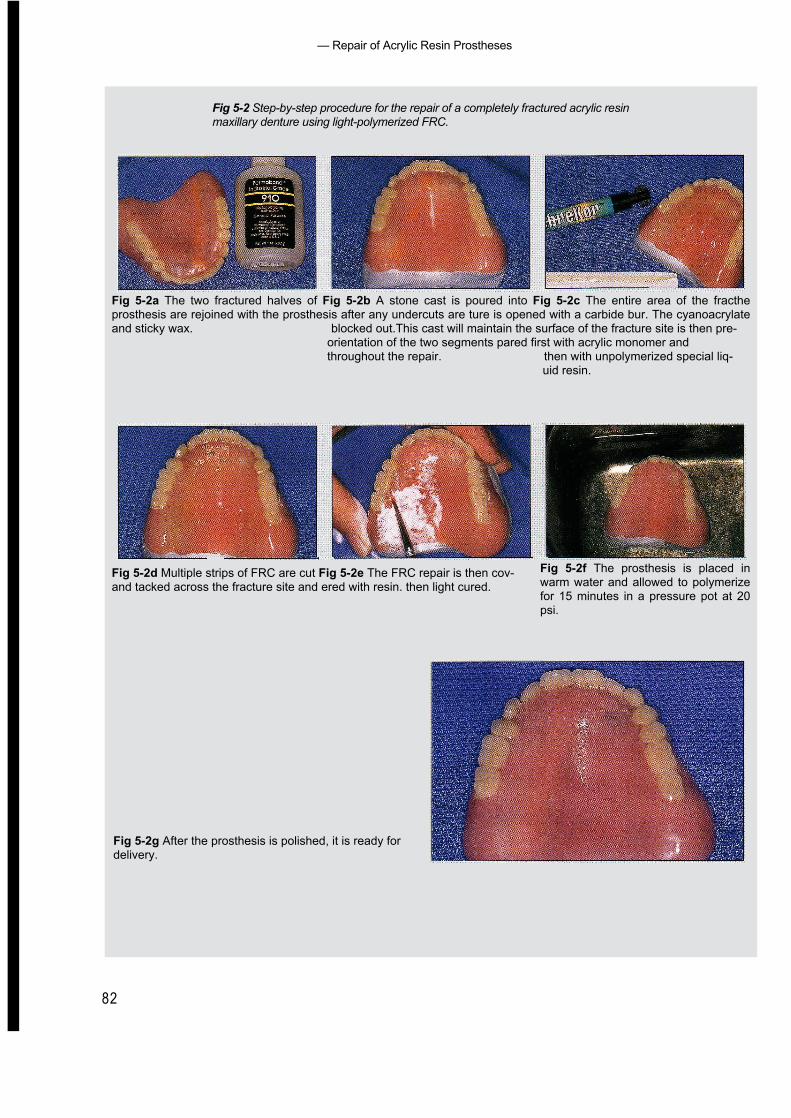
— Repair of Acrylic Resin Prostheses
82
Fig 5-2 Step-by-step procedure for the repair of a completely fractured acrylic resinmaxillary denture using light-polymerized FRC.
Fig 5-2a The two fractured halves of Fig 5-2b A stone cast is poured into Fig 5-2c The entire area of the fractheprosthesis are rejoined with the prosthesis after any undercuts are ture is opened with a carbide bur. The cyanoacrylateand sticky wax. blocked out.This cast will maintain the surface of the fracture site is then pre-
orientation of the two segments pared first with acrylic monomer andthroughout the repair. then with unpolymerized special liq-
uid resin.
Fig 5-2d Multiple strips of FRC are cut Fig 5-2e The FRC repair is then cov-and tacked across the fracture site and ered with resin. then light cured.
Fig 5-2f The prosthesis is placed inwarm water and allowed to polymerizefor 15 minutes in a pressure pot at 20psi.
Fig 5-2g After the prosthesis is polished, it is ready fordelivery.
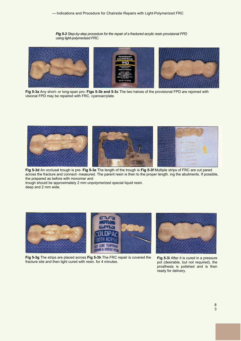
— Indications and Procedure for Chairside Repairs with Light-Polymerized FRC
83
Fig 5-3 Step-by-step procedure for the repair of a fractured acrylic resin provisional FPDusing light-polymerized FRC.
Fig 5-3a Any short- or long-span pro- Figs 5-3b and 5-3c The two halves of the provisional FPD are rejoined withvisional FPD may be repaired with FRC. cyanoacrylate.
Fig 5-3d An occlusal trough is pre- Fig 5-3e The length of the trough is Fig 5-3f Multiple strips of FRC are cut paredacross the fracture and connect- measured. The parent resin is then to the proper length. ing the abutments. If possible,the prepared as before with monomer andtrough should be approximately 2 mm unpolymerized special liquid resin.deep and 2 mm wide.
Fig 5-3g The strips are placed across Fig 5-3h The FRC repair is covered thefracture site and then light cured with resin. for 4 minutes.
Fig 5-3i After it is cured in a pressurepot (desirable, but not required), theprosthesis is polished and is thenready for delivery.
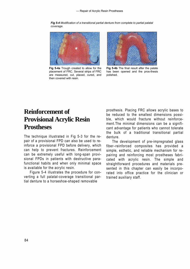
— Repair of Acrylic Resin Prostheses
84
Fig 5-4 Modification of a transitional partial denture from complete to partial palatalcoverage.
Fig 5-4a Trough created to allow for theplacement of FRC. Several strips of FRCare measured, cut, placed, cured, andthen covered with resin.
Fig 5-4b The final result after the palatehas been opened and the pros-thesispolished.
Reinforcement ofProvisional Acrylic ResinProsthesesThe technique illustrated in Fig 5-3 for the re-pair of a provisional FPD can also be used to re-inforce a provisional FPD before delivery, whichcan help to prevent fractures. Reinforcementcan be extremely useful with long-span provi-sional FPDs in patients with destructive para-functional habits and when only minimal spaceis available for the acrylic resin.
Figure 5-4 illustrates the procedure for con-verting a full palatal-coverage transitional par-tial denture to a horseshoe-shaped removable
prosthesis. Placing FRC allows acrylic bases tobe reduced to the smallest dimensions possi-ble, which would fracture without reinforce-ment.The minimal dimensions can be a signifi-cant advantage for patients who cannot toleratethe bulk of a traditional transitional partialdenture.
The development of pre-impregnated glassfiber–reinforced composites has provided asimple, esthetic, and reliable mechanism for re-pairing and reinforcing most prostheses fabri-cated with acrylic resin. The simple andstraightforward procedures and materials pre-sented in this chapter can easily be incorpo-rated into office practice for the clinician ortrained auxiliary staff.

85
— References —
References
1. Berge M. Bending strength of intact and repaired denturebase resin.Acta Odontol Scand 1983;41:187-191.
2. Freilich MA, Karmaker AC, Burstone CJ, Goldberg AJ.Flexure strength and handling characteristics of fiber-reinforced composites used in prosthodontics [abstract1361]. J Dent Res 1997;76:184.
3. Freilich MA, Karmaker AC, Burstone CJ, Goldberg AJ.Flexure strength of fiber-reinforced composites de-signedfor prosthodontic application [abstract 999]. J Dent Res1997;76:138.
4. Goldberg AJ, Burstone CJ. The use of continuous fiberreinforcement in dentistry. Dent Mater 1992;8:197-202.
5. Koumjian JH, Nimmo A. Evaluation of fracture resistanceof resins used for provisional restorations. J ProsthetDent 1990;64:654-657.
6. Vallitu PK, Lassial VP, Lappalainen R. Wetting the repairsurface with methyl methacrylate affects the transversestrength of repaired heat-polymerized resin. J ProsthetDent 1994;72:639-643.
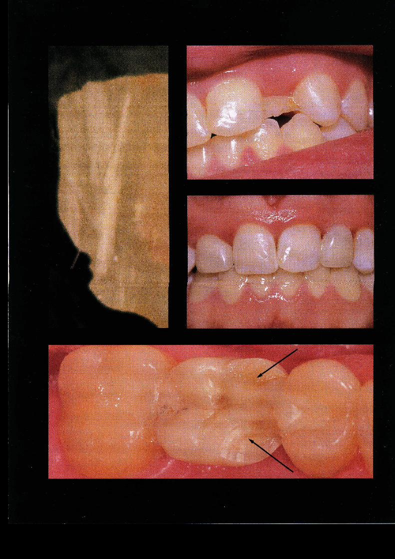
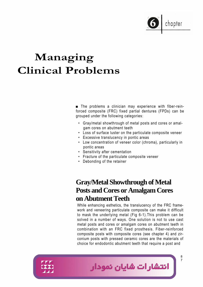
ManagingClinical Problems
87
■ The problems a clinician may experience with fiber-rein-forced composite (FRC) fixed partial dentures (FPDs) can begrouped under the following categories:
• Gray/metal showthrough of metal posts and cores or amal-gam cores on abutment teeth
• Loss of surface luster on the particulate composite veneer• Excessive translucency in pontic areas• Low concentration of veneer color (chroma), particularly in
pontic areas• Sensitivity after cementation• Fracture of the particulate composite veneer• Debonding of the retainer
Gray/Metal Showthrough of MetalPosts and Cores or Amalgam Coreson Abutment TeethWhile enhancing esthetics, the translucency of the FRC frame-work and veneering particulate composite can make it difficultto mask the underlying metal (Fig 6-1).This problem can besolved in a number of ways. One solution is not to use castmetal posts and cores or amalgam cores on abutment teeth incombination with an FRC fixed prosthesis. Fiber-reinforcedcomposite posts with composite cores (see chapter 4) and zir-conium posts with pressed ceramic cores are the materials ofchoice for endodontic abutment teeth that require a post and
Ali
logo 2
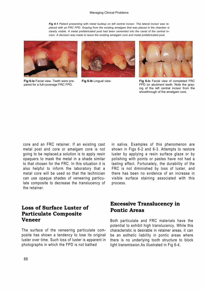
88
Fig 6-1 Patient presenting with metal buildup on left central incisor. The lateral incisor was re-placed with an FRC FPD. Graying from the existing amalgam that was placed in the chamber isclearly visible. A metal prefabricated post had been cemented into the canal of the central in-cisor. A decision was made to leave the existing amalgam core and metal prefabricated post.
Fig 6-la Facial view. Teeth were pre- Fig 6-lb Lingual view.pared for a full-coverage FRC FPD.
Fig 6-lc Facial view of completed FRCFPD on abutment teeth. Note the gray-ing of the left central incisor from theshowthrough of the amalgam core.
core and an FRC retainer. If an existing castmetal post and core or amalgam core is notgoing to be replaced,a solution is to apply resinopaquers to mask the metal in a shade similarto that chosen for the FRC. In this situation it isalso helpful to inform the laboratory that ametal core will be used so that the techniciancan use opaque shades of veneering particu-late composite to decrease the translucency ofthe retainer.
in saliva. Examples of this phenomenon areshown in Figs 6-2 and 6-3. Attempts to restoreluster by applying a resin surface glaze or bypolishing with points or pastes have not had alasting effect. Fortunately, the durability of theFRC is not diminished by loss of luster, andthere has been no evidence of an increase invisible surface staining associated with thisprocess.
Loss of Surface Luster ofParticulate CompositeVeneer
The surface of the veneering particulate com-posite has shown a tendency to lose its originalluster over time. Such loss of luster is apparent inphotographs in which the FPD is not bathed
Excessive Translucency inPontic Areas
Both particulate and FRC materials have thepotential to exhibit high translucency. While thischaracteristic is desirable in retainer areas, it canbe an esthetic liability in pontic areas wherethere is no underlying tooth structure to blocklight transmission.As illustrated in Fig 6-4,
Managing Clinical Problems
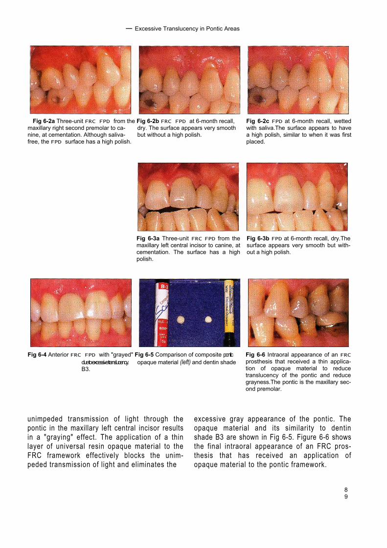
89
— Excessive Translucency in Pontic Areas
Fig 6-2a Three-unit FRC FPD from the Fig 6-2b FRC FPD at 6-month recall,maxillary right second premolar to ca- dry. The surface appears very smoothnine, at cementation. Although saliva- but without a high polish.free, the FPD surface has a high polish.
Fig 6-2c FPD at 6-month recall, wettedwith saliva.The surface appears to havea high polish, similar to when it was firstplaced.
Fig 6-3a Three-unit FRC FPD from themaxillary left central incisor to canine, atcementation. The surface has a highpolish.
Fig 6-3b FPD at 6-month recall, dry.Thesurface appears very smooth but with-out a high polish.
Fig 6-4 Anterior FRC FPD with "grayed" Fig 6-5 Comparison of composite ponticdue to excessive translucency. opaque material (left) and dentin shadeB3.
Fig 6-6 Intraoral appearance of an FRCprosthesis that received a thin applica-tion of opaque material to reducetranslucency of the pontic and reducegrayness.The pontic is the maxillary sec-ond premolar.
unimpeded transmission of light through thepontic in the maxillary left central incisor resultsin a "graying" effect. The application of a thinlayer of universal resin opaque material to theFRC framework effectively blocks the unim-peded transmission of light and eliminates the
excessive gray appearance of the pontic. Theopaque material and its similarity to dentinshade B3 are shown in Fig 6-5. Figure 6-6 showsthe final intraoral appearance of an FRC pros-thesis that has received an application ofopaque material to the pontic framework.
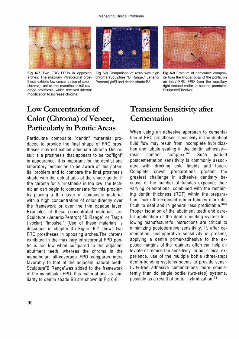
- Managing Clinical Problems
90
Fig 6-7 Two FRC FPDs in opposingarches. The maxillary intracoronal pros-thesis exhibits low concentration of color (chroma), unlike the mandibular full-cov-erage prosthesis, which received internalmodification to increase chroma.
Fig 6-8 Comparison of resin with highchroma (Sculpture "B Range," Jeneric/Pentron) (left) and dentin shade B3.
Fig 6-9 Fracture of particulate compos-ite from the lingual cusp of the pontic onan inlay FRC FPD from the maxillaryright second molar to second premolar.Sculpture/FibreKor.
Low Concentration ofColor (Chroma) of Veneer,Particularly in Pontic AreasParticulate composite "dentin" materials pro-duced to provide the final shape of FRC pros-theses may not exhibit adequate chroma.The re-sult is a prosthesis that appears to be too"light"in appearance. It is important for the dentist andlaboratory technician to be aware of this poten-tial problem and to compare the final prosthesisshade with the actual tabs of the shade guide. Ifthe chroma for a prosthesis is too low, the tech-nician can begin to compensate for this problemby placing a thin layer of composite materialwith a high concentration of color directly overthe framework or over the thin opaque layer.Examples of these concentrated materials areSculpture (Jeneric/Pentron) "B Range" or Targis(Ivoclar) "Impulse." (Use of these materials isdescribed in chapter 3.) Figure 6-7 shows twoFRC prostheses in opposing arches.The chromaexhibited in the maxillary intracoronal FPD pon-tic is too low when compared to the adjacentabutment teeth, whereas the chroma in themandibular full-coverage FPD compares morefavorably to that of the adjacent natural teeth.Sculpture"B Range"was added to the frameworkof the mandibular FPD; this material and its sim-ilarity to dentin shade B3 are shown in Fig 6-8.
Transient Sensitivity afterCementationWhen using an adhesive approach to cementa-tion of FRC prostheses, sensitivity in the dentinalfluid flow may result from incomplete hybridiza-tion and tubule sealing in the dentin adhesive—resin cement complex. ' ' ' ' Such patientpostcementation sensitivity is commonly associ-ated with drinking cold liquids and touch.Complete crown preparations present thegreatest challenge in adhesive dentistry be-cause of the number of tubules exposed; theirvarying orientations, combined with the remain-ing dentin thickness (RDT) within the prepara-tion, make the exposed dentin tubules more dif-ficult to seal and in general less predictable.8 ' '°Proper isolation of the abutment teeth and care-ful application of the dentin-bonding system fol-lowing manufacturer's instructions are critical tominimizing postoperative sensitivity. If, after ce-mentation, postoperative sensitivity is present,applying a dentin primer-adhesive to the ex-posed margins of the retainers often can help al-leviate or reduce the sensitivity. In our clinical ex-perience, use of the multiple bottle (three-step)dentin-bonding systems seems to provide sensi-tivity-free adhesive cementations more consis-tently than do single bottle (two-step) systems,possibly as a result of better hybridization.13
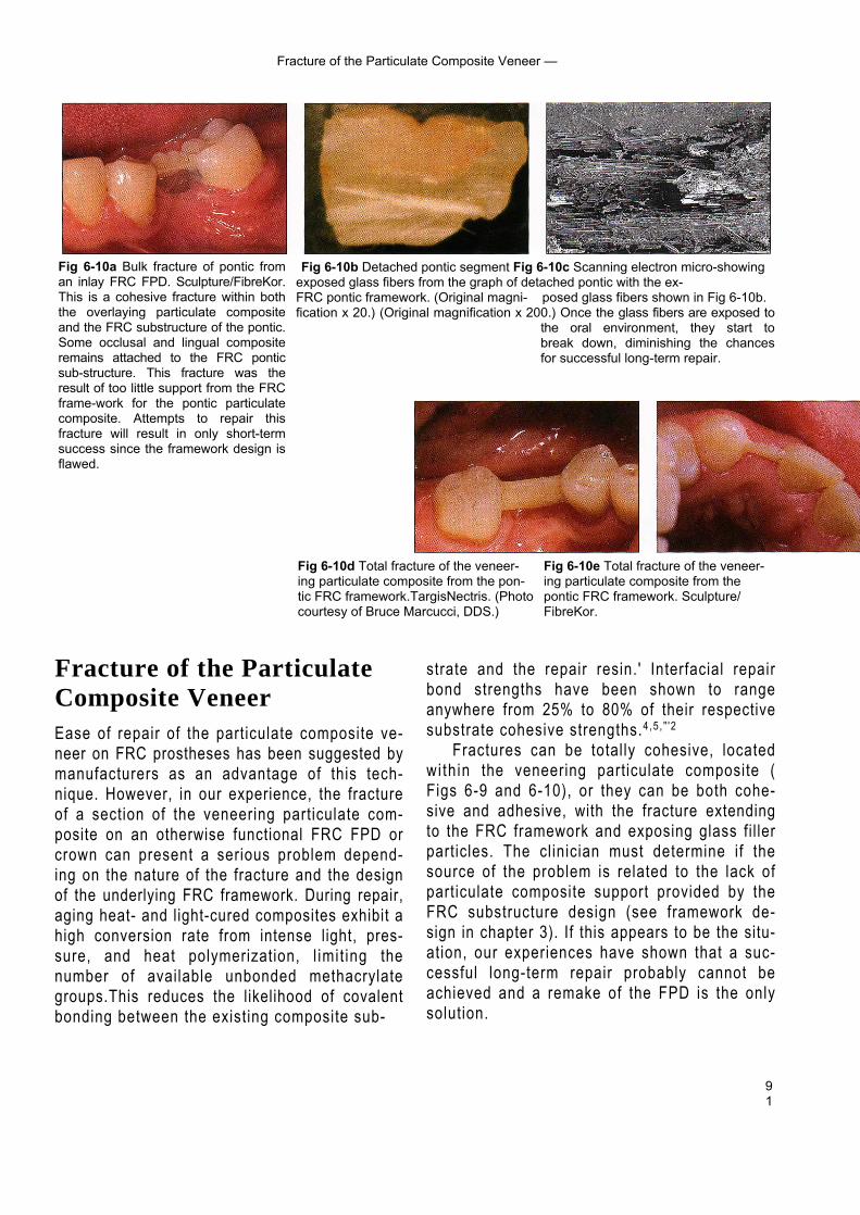
91
Fracture of the Particulate Composite Veneer —
Fig 6-10b Detached pontic segment Fig 6-10c Scanning electron micro-showingexposed glass fibers from the graph of detached pontic with the ex-FRC pontic framework. (Original magni- posed glass fibers shown in Fig 6-10b.fication x 20.) (Original magnification x 200.) Once the glass fibers are exposed to
the oral environment, they start tobreak down, diminishing the chancesfor successful long-term repair.
Fig 6-10d Total fracture of the veneer- Fig 6-10e Total fracture of the veneer-ing particulate composite from the pon- ing particulate composite from thetic FRC framework.TargisNectris. (Photo pontic FRC framework. Sculpture/courtesy of Bruce Marcucci, DDS.) FibreKor.
Fig 6-10a Bulk fracture of pontic froman inlay FRC FPD. Sculpture/FibreKor.This is a cohesive fracture within boththe overlaying particulate compositeand the FRC substructure of the pontic.Some occlusal and lingual compositeremains attached to the FRC ponticsub-structure. This fracture was theresult of too little support from the FRCframe-work for the pontic particulatecomposite. Attempts to repair thisfracture will result in only short-termsuccess since the framework design isflawed.
Fracture of the ParticulateComposite VeneerEase of repair of the particulate composite ve-neer on FRC prostheses has been suggested bymanufacturers as an advantage of this tech-nique. However, in our experience, the fractureof a section of the veneering particulate com-posite on an otherwise functional FRC FPD orcrown can present a serious problem depend-ing on the nature of the fracture and the designof the underlying FRC framework. During repair,aging heat- and light-cured composites exhibit ahigh conversion rate from intense light, pres-sure, and heat polymerization, l imit ing thenumber of available unbonded methacrylategroups.This reduces the likelihood of covalentbonding between the existing composite sub-
strate and the repair resin.' Interfacial repairbond strengths have been shown to rangeanywhere from 25% to 80% of their respectivesubstrate cohesive strengths.4,5 , " '2
Fractures can be totally cohesive, locatedwith in the veneering particulate composite (Figs 6-9 and 6-10), or they can be both cohe-sive and adhesive, with the fracture extendingto the FRC framework and exposing glass fi l lerparticles. The clinician must determine if thesource of the problem is related to the lack ofparticulate composite support provided by theFRC substructure design (see framework de-sign in chapter 3). If this appears to be the situ-ation, our experiences have shown that a suc-cessful long-term repair probably cannot beachieved and a remake of the FPD is the onlysolution.
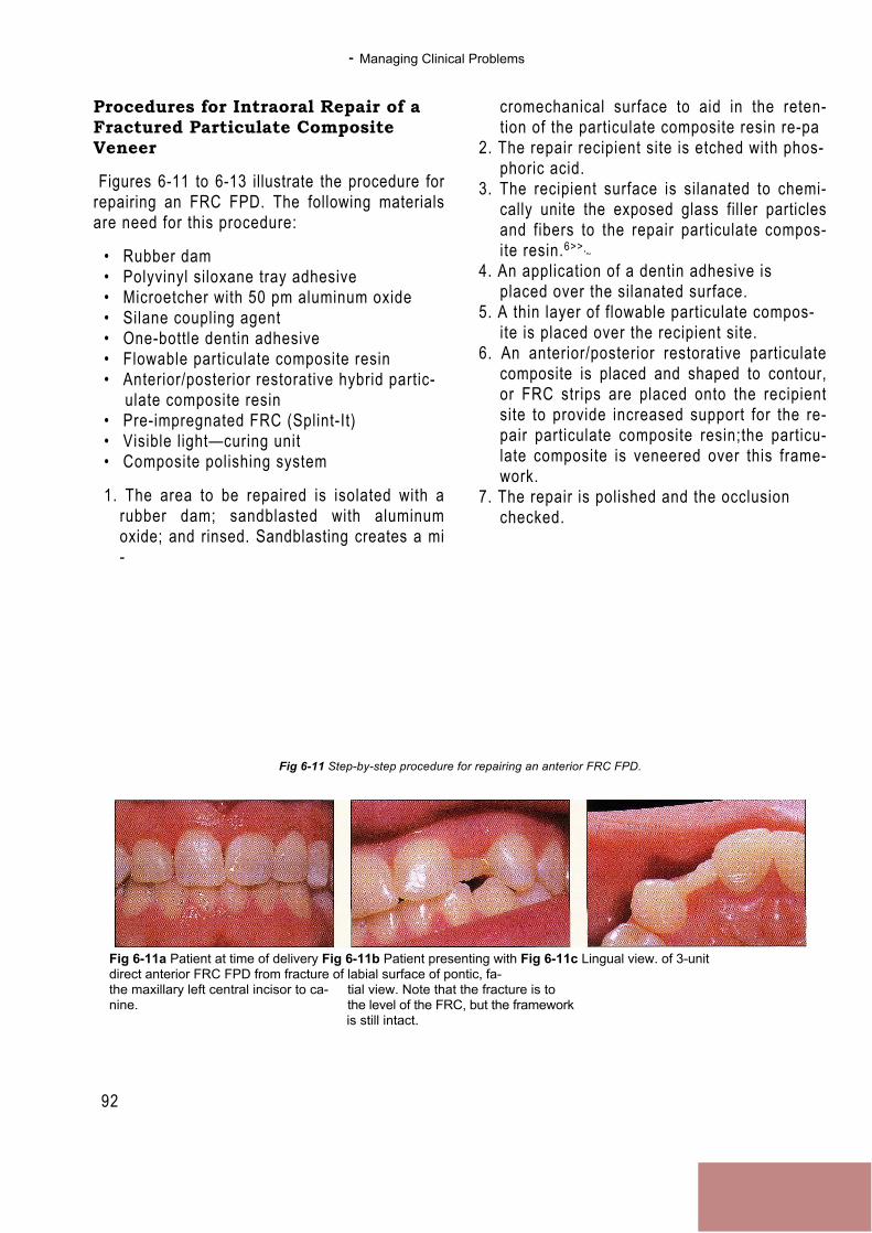
- Managing Clinical Problems
92
Procedures for Intraoral Repair of aFractured Particulate CompositeVeneer
Figures 6-11 to 6-13 illustrate the procedure forrepairing an FRC FPD. The following materialsare need for this procedure:
• Rubber dam• Polyvinyl siloxane tray adhesive• Microetcher with 50 pm aluminum oxide• Silane coupling agent• One-bottle dentin adhesive• Flowable particulate composite resin• Anterior/posterior restorative hybrid partic-
ulate composite resin• Pre-impregnated FRC (Splint-It)• Visible light—curing unit• Composite polishing system
1. The area to be repaired is isolated with arubber dam; sandblasted with aluminumoxide; and rinsed. Sandblasting creates a mi-
cromechanical surface to aid in the reten-tion of the particulate composite resin re-pa
2. The repair recipient site is etched with phos-phoric acid.
3. The recipient surface is silanated to chemi-cally unite the exposed glass filler particlesand fibers to the repair particulate compos-ite resin.6>>
'~
4. An application of a dentin adhesive isplaced over the silanated surface.
5. A thin layer of flowable particulate compos-ite is placed over the recipient site.
6. An anterior/posterior restorative particulatecomposite is placed and shaped to contour,or FRC strips are placed onto the recipientsite to provide increased support for the re-pair particulate composite resin;the particu-late composite is veneered over this frame-work.
7. The repair is polished and the occlusionchecked.
Fig 6-11 Step-by-step procedure for repairing an anterior FRC FPD.
Fig 6-11a Patient at time of delivery Fig 6-11b Patient presenting with Fig 6-11c Lingual view. of 3-unitdirect anterior FRC FPD from fracture of labial surface of pontic, fa-the maxillary left central incisor to ca- tial view. Note that the fracture is tonine. the level of the FRC, but the framework
is still intact.
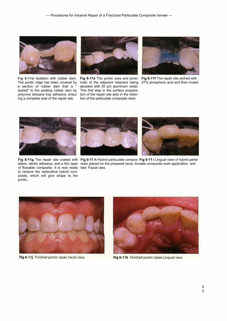
93
— Procedures for Intraoral Repair of a Fractured Particulate Composite Veneer —
Fig 6-11d Isolation with rubber dam.The pontic ridge has been covered bya section of rubber dam that is "tacked" to the existing rubber dam bypolyvinyl siloxane tray adhesive, ensuring a complete seal of the repair site.
Fig 6-11e The pontic area and proxi-mals of the adjacent retainers beingabraded with 50 pm aluminum oxide.This first step in the surface prepara-tion of the repair site aids in the reten-tion of the particulate composite resin.
Fig 6-11f The repair site etched with37% phosphoric acid and then rinsed.
Fig 6-11g The repair site coated withsilane, dentin adhesive, and a thin layerof flowable composite. It is now readyto receive the restorative hybrid com-posite, which will give shape to thepontic.
Fig 6-11 h Hybrid particulate compos- Fig 6-11 i Lingual view of hybrid pariteresin placed on the prepared recip- ticulate composite resin application. ientbed. Facial view.

— Managing Clinical Problems —
Fig 6-12 Step-by-step procedure for repair of a posterior FRC FPD.
94
Figs 6-12a and 6-12b Facial and lingual views of posterior inlay FRC FPD at de-livery.
Fig 6-12c FPD with bulk particulatecomposite fracture of pontic. Althoughthe fracture was at the level of the FRCpontic framework, it did not expose anyglass fibers.
Fig 6-12d Rubber dam application Fig 6-12e Air abrasion to start the sur- Fig 6-12f Etching of repair site with withpontic ridge covered for corn- face preparation of the repair site. 37% phosphoric acid. plete isolationof the repair site.
Fig 6-12g Repair site being silanated. Fig 6-12h Flowable composite resin Fig 6-12i Initial increment of particu-A dentinadhesive is then applied. being applied prior to the restorative late composite resin initiating the re-
particulate composite resin. covery of the pontic shape.
Fig 6-12j Finished pontic repair, facial view. Fig 6-12k Finished pontic repair, occlusal view.This repairwas predictably short-lived because of the lack of FRC pon-tic framework support in the initial design of the FPD.
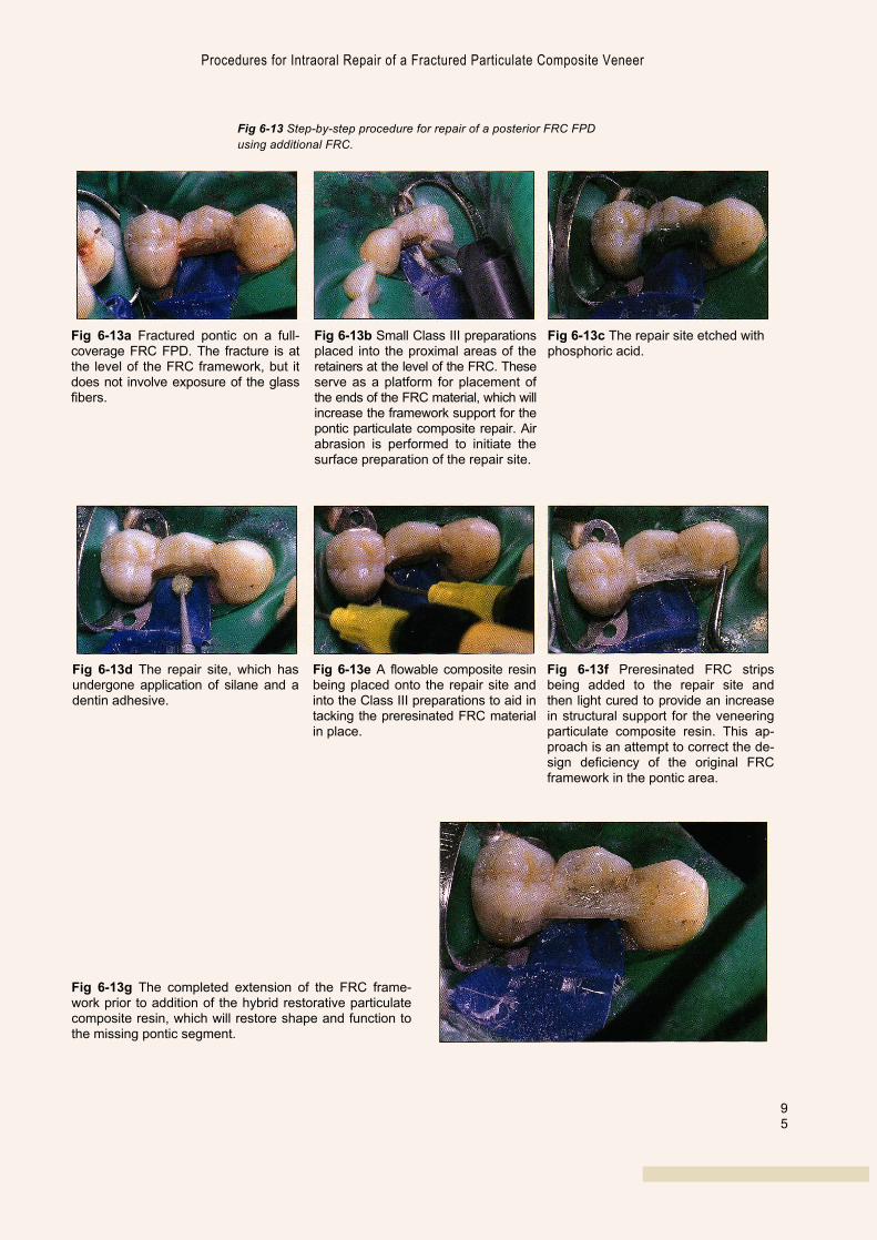
95
Fig 6-13a Fractured pontic on a full-coverage FRC FPD. The fracture is atthe level of the FRC framework, but itdoes not involve exposure of the glassfibers.
Fig 6-13b Small Class III preparationsplaced into the proximal areas of theretainers at the level of the FRC. Theseserve as a platform for placement ofthe ends of the FRC material, which willincrease the framework support for thepontic particulate composite repair. Airabrasion is performed to initiate thesurface preparation of the repair site.
Fig 6-13c The repair site etched withphosphoric acid.
Fig 6-13d The repair site, which hasundergone application of silane and adentin adhesive.
Fig 6-13e A flowable composite resinbeing placed onto the repair site andinto the Class III preparations to aid intacking the preresinated FRC materialin place.
Fig 6-13f Preresinated FRC stripsbeing added to the repair site andthen light cured to provide an increasein structural support for the veneeringparticulate composite resin. This ap-proach is an attempt to correct the de-sign deficiency of the original FRCframework in the pontic area.
Fig 6-13g The completed extension of the FRC frame-work prior to addition of the hybrid restorative particulatecomposite resin, which will restore shape and function tothe missing pontic segment.
Procedures for Intraoral Repair of a Fractured Particulate Composite Veneer
Fig 6-13 Step-by-step procedure for repair of a posterior FRC FPDusing additional FRC.
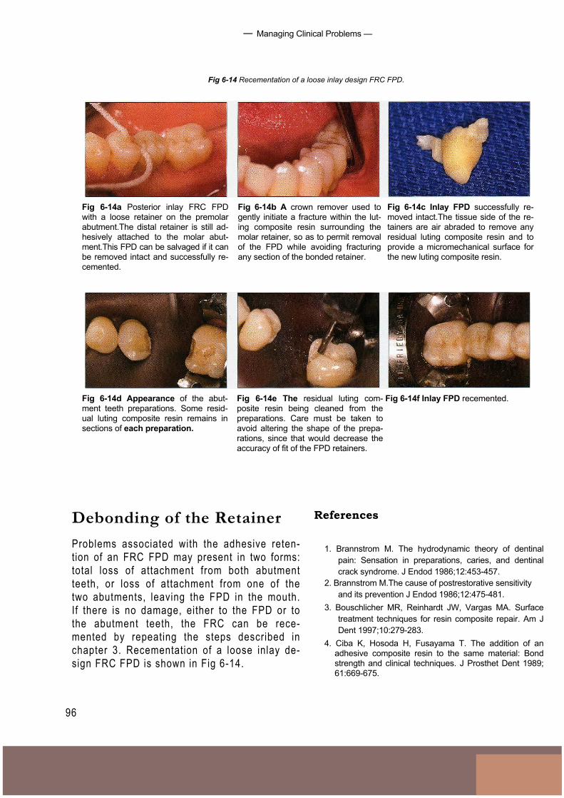
— Managing Clinical Problems —
Fig 6-14 Recementation of a loose inlay design FRC FPD.
96
Fig 6-14a Posterior inlay FRC FPDwith a loose retainer on the premolarabutment.The distal retainer is still ad-hesively attached to the molar abut-ment.This FPD can be salvaged if it canbe removed intact and successfully re-cemented.
Fig 6-14b A crown remover used togently initiate a fracture within the lut-ing composite resin surrounding themolar retainer, so as to permit removalof the FPD while avoiding fracturingany section of the bonded retainer.
Fig 6-14c Inlay FPD successfully re-moved intact.The tissue side of the re-tainers are air abraded to remove anyresidual luting composite resin and toprovide a micromechanical surface forthe new luting composite resin.
Fig 6-14f Inlay FPD recemented.Fig 6-14d Appearance of the abut-ment teeth preparations. Some resid-ual luting composite resin remains insections of each preparation.
Fig 6-14e The residual luting com-posite resin being cleaned from thepreparations. Care must be taken toavoid altering the shape of the prepa-rations, since that would decrease theaccuracy of fit of the FPD retainers.
Debonding of the RetainerProblems associated with the adhesive reten-tion of an FRC FPD may present in two forms:total loss of attachment from both abutmentteeth, or loss of attachment from one of thetwo abutments, leaving the FPD in the mouth.If there is no damage, either to the FPD or tothe abutment teeth, the FRC can be rece-mented by repeating the steps described inchapter 3. Recementation of a loose inlay de-sign FRC FPD is shown in Fig 6-14.
References
1. Brannstrom M. The hydrodynamic theory of dentinalpain: Sensation in preparations, caries, and dentinalcrack syndrome. J Endod 1986;12:453-457.
2. Brannstrom M.The cause of postrestorative sensitivityand its prevention J Endod 1986;12:475-481.
3. Bouschlicher MR, Reinhardt JW, Vargas MA. Surfacetreatment techniques for resin composite repair. Am JDent 1997;10:279-283.
4. Ciba K, Hosoda H, Fusayama T. The addition of anadhesive composite resin to the same material: Bondstrength and clinical techniques. J Prosthet Dent 1989;61:669-675.
97
— References
5. Heymann HO, Haywood VB, Andreaus SB, Bayne SC.Bonding agent strengths with processed compositeresin veneers. Dent Mater 1987;3:121-124.
6. Imamura GM, Reinhardt JW, Boyer DB, Swift EJ.Enhancement of resin bonding to heat-cured compositeresin. Oper Dent 1996;21:249-256.
7. Pashley DH. Dentin permeability, dentin sensitivity, andtreatment through tubule occlusion. J Endod 1986; 12:465-474.
8. Pashley EL, Comer RW, Simpson MD, Horner JA,Pashley DH, Caughman WF. Dentin permeability:Sealing the dentin in crown preparations. Oper Dent1992; 17:13-20.
9. Puckett AD, Holder R, O'Hara JW. Strength of posteriorcomposite repairs using different composite/bondingagent combinations. Oper Dent 1991;16:136-140.
10. Richardson D, Tao L, Pashley DH. Dentin permeability:Effects of crown preparation. lnt J Prosthodont 1991;4:219-225.
11. Rosentritt M, Behr M, Leibrock A, Handel G, Friedl K-H.Intraoral repair of fiber-reinforced composite fixed par-tial dentures.J Prosthet Dent 1998;79:393-398.
12. Turner CW, Meiers JC. Repair of an aged,contaminated indirect composite resin with a direct,visible-lightcured composite resin.Oper Dent 1993;18:187-194.
13. Van Meerbeek B, Yoshida Y, Snauwaert J, HellemansL, Lambrechts P, Vanherle G, Wakasa K, Pashley DH.Hybridization effectiveness of a two-step versus a three-step smear layer removing adhesive system examinedcorrelatiely by TEM and AFM. J Adhes Dent 1999;1:7-23.
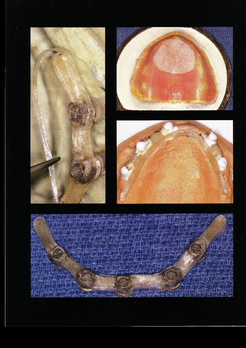
FutureApplications
of FRC
99
■ Previous chapters have shown that fiber-reinforced compos-ites (FRCS) can be used to fabricate tooth-supported fixed pros-theses. Both chairside and laboratory techniques have beenused with success to create these restorations. Fiber-reinforcedcomposites are also used to make posts and space maintainersand to repair acrylic resin prostheses and appliances.These rep-resent only the first of many applications of this material in den-tistry. Presented below are some concepts and techniques thatmay become popular in dentistry in the near future.
Implants
Dental implants have become a standard of care for tooth re-placement in both partially and completely edentulous arches.Implants are routinely restored with overdentures, fixed partialdentures (FPDs), or hybrid (fixed-removable) prostheses. Shortedentulous spans can be successfully restored with fiber-rein-forced FPDs (Fig 7-1). Despite the short-term success that hasbeen achieved in restoring short edentulous spans, the stan-dard metallic or cylinder form abutment is less than ideal be-cause of its esthetic and bonding limitations and because it hasproven unacceptable for restoring a hybrid type of prosthesis.'
Ali
logo 2

Future App l i ca t ions o f FRC
100
Fig 7-1 Three-unit FRC FPD restoring ITI implants with cementable-type abutments.
Fig 7-la Intraoral view of ITI ce- Fig 7-lb Fiber-reinforced framework Fig 7-7c Intraoral view of cementedmentable-type abutments. for 3-unit FPD on implants. FRC FPD.
The standard technique for restoring a mul-tiple-unit implant-supported prosthesis is touse a cast metal framework. A prosthesis madewith an FRC framework and correspondingabutments and cylinders has several advan-tages over the standard techniques:1. The laboratory procedure for creating a
fiber-reinforced framework takes less timethan current methods.
2. The fewer labor hours combined with lowermaterial costs results in a prosthesis that isless expensive than its traditional counter-part.
3. The need for sectioning and soldering, aswith long-span metal frameworks, iseliminated.
4. The overlaying suprastructure (whether
polymethyl methacrylate [PMMA] for a hy-brid prosthesis or composite veneers for anFPD) will mechanically and chemically bondto the FRC framework. Polymethylmethacrylate and porcelain do not chemi-cally bond to the metal framework currentlyused for these prostheses.
5. The use of composite resin materials hasdistinct advantages over porcelain veneers:they are less brittle, they cause no wear tothe opposing dentition, they may be re-paired, and so forth.
6. It is not necessary to block out the metalframework with opaque materials, so thefinal result has an even greater esthetic po-tential.

101
- Implants
Fig 7-2a Prototype metal cylinder withproximal and buccal grooves to retain,support, and aid in positioning of theFRC framework.
Fig 7-2b Prototype cylinder screwedinto place on an ITI octabutment.
Prototype metal cylinders have been devel-oped by the authors for use in multiple-unitprostheses supported by several implants (Fig7-2). These cylinders, which are screwed intothe standard abutment, are designed to sup-port, position, and retain the FRC framework.Additional cylinder and abutment designs havebeen conceptualized, including an all-ceramiccylinder,a polymer-coated cylinder, and aUCLA-type abutment. All of these designs havethe potential to enhance the structural in-
tegrity and esthetic possibil i t ies of the finalrestoration.
In conjunction with the prototype metalcylinders, the authors have also developed amethod for fabricating a successful hybridprosthesis supported by multiple implants inthe edentulous arch (Fig 7-3).
Further laboratory and clinical develop-ment are needed before these materials andtechniques will be readily available to the prac-tit ioner, but this area shows great promise.
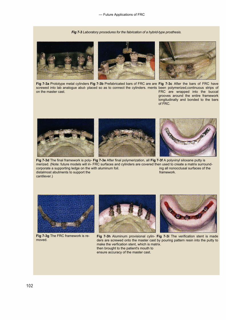
102
— Future Applications of FRC
Fig 7-3 Laboratory procedures for the fabrication of a hybrid-type prosthesis.
Fig 7-3a Prototype metal cylinders Fig 7-3b Prefabricated bars of FRC are arescrewed into lab analogue abut- placed so as to connect the cylinders. mentson the master cast.
Fig 7-3c After the bars of FRC havebeen polymerized,continuous strips ofFRC are wrapped into the buccalgrooves around the entire frameworklongitudinally and bonded to the barsof FRC.
Fig 7-3d The final framework is poly- Fig 7-3e After final polymerization, all Fig 7-3f A polyvinyl siloxane putty ismerized. (Note: future models will in- FRC surfaces and cylinders are covered then used to create a matrix surround-corporate a supporting ledge on the with aluminum foil. ing all nonocclusal surfaces of thedistalmost abutments to support the framework.cantilever.)
Fig 7-3h Aluminum provisional cylin- Fig 7-3i The verification stent is madeders are screwed onto the master cast by pouring pattern resin into the putty tomake the verfication stent, which is matrix.then brought to the patient's mouth toensure accuracy of the master cast.
Fig 7-3g The FRC framework is re-moved.
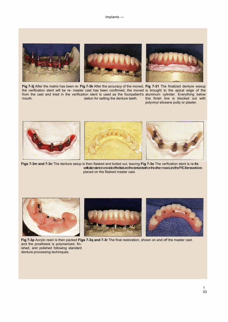
103
Implants —
Fig 7-3j After the matrix has been re- Fig 7-3k After the accuracy of the moved,the verification stent will be re- master cast has been confirmed, the movedfrom the cast and tried in the verification stent is used as the founpatient'smouth. dation for setting the denture teeth.
Fig 7-31 The finalized denture waxupis brought to the apical edge of thealuminum cylinder. Everything belowthis finish line is blocked out withpolyvinyl siloxane putty or plaster.
Figs 7-3m and 7-3n The denture setup is then flasked and boiled out, leaving Fig 7-3o The verfication stent is re-theverification stent on one side of the flask and the denture teeth on the other. moved, and the FRC framework is re-placed on the flasked master cast.
Fig 7-3p Acrylic resin is then packed Figs 7-3q and 7-3r The final restoration, shown on and off the master cast.and the prosthesis is polymerized, fin-ished, and polished following standarddenture-processing techniques.
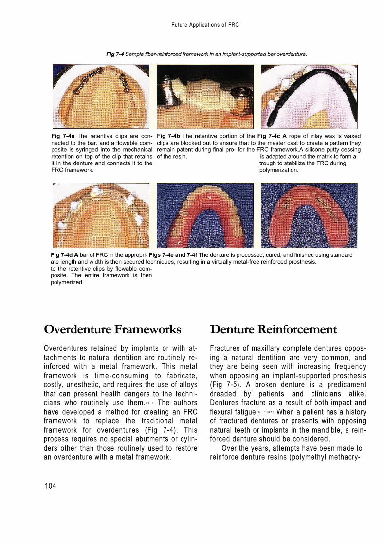
104
Fig 7-4 Sample fiber-reinforced framework in an implant-supported bar overdenture.
Fig 7-4a The retentive clips are con-nected to the bar, and a flowable com-posite is syringed into the mechanicalretention on top of the clip that retainsit in the denture and connects it to theFRC framework.
Fig 7-4b The retentive portion of the Fig 7-4c A rope of inlay wax is waxedclips are blocked out to ensure that to the master cast to create a pattern theyremain patent during final pro- for the FRC framework.A silicone putty cessingof the resin. is adapted around the matrix to form a
trough to stabilize the FRC duringpolymerization.
Fig 7-4d A bar of FRC in the appropri- Figs 7-4e and 7-4f The denture is processed, cured, and finished using standardate length and width is then secured techniques, resulting in a virtually metal-free reinforced prosthesis.to the retentive clips by flowable com-posite. The entire framework is thenpolymerized.
Overdenture FrameworksOverdentures retained by implants or with at-tachments to natural dentition are routinely re-inforced with a metal framework. This metalframework is t ime-consuming to fabricate,costly, unesthetic, and requires the use of alloysthat can present health dangers to the techni-cians who routinely use them.13 , ' 4 The authorshave developed a method for creating an FRCframework to replace the traditional metalframework for overdentures (Fig 7-4). Thisprocess requires no special abutments or cylin-ders other than those routinely used to restorean overdenture with a metal framework.
Denture ReinforcementFractures of maxillary complete dentures oppos-ing a natural dentition are very common, andthey are being seen with increasing frequencywhen opposing an implant-supported prosthesis(Fig 7-5). A broken denture is a predicamentdreaded by patients and clinicians alike.Dentures fracture as a result of both impact andflexural fatigue.8 '°'1821 When a patient has a historyof fractured dentures or presents with opposingnatural teeth or implants in the mandible, a rein-forced denture should be considered.
Over the years, attempts have been made toreinforce denture resins (polymethyl methacry-
Future Applications of FRC

105
Denture Reinforcement
Fig 7-5 Maxillary dentures most commonly fracture through the frenal notch andare associated with an intact opposing dentition.
Fig 7-5b Fractured denture opposing an implant-supported prosthesis.
late with metal wires and plates4,9 , ,6 ,Z° carbonfibers;'" aramid fibers,2 "s polyethylene fibers,3 i"and glass fibers.6719 While it has been demon-strated that PMMA can be significantly rein-forced, a predictable, convenient, and esthetictechnique for reinforcement of PMMA has notbeen found.
In fact, the method accepted by many den-tists when repeated fractures occur is to fabri-cate the denture with a metal framework (Fig 7-6). Though reliable, this technique is alsoexpensive, unesthetic, and time-consuming,and does not allow the denture to be relined orrebased if necessary.
As noted in earlier chapters, the superiorflexure strength of a glass FRC, combined withthe abil i ty of its resinous matrix to both uni-formly wet the fibers and chemically bond to
the parent resin, makes it an ideal material forresin reinforcement. Furthermore, glass FRCshave been shown to have significantly greaterflexural properties than unreinforced PMMA.22
Initially, only strips of light-polymerized FRCwere used for denture reinforcement.While thismaterial is effective for chairside repairs, it is notideal for incorporat ing dur ing processing.When reinforcing a complete denture, the useof l ight polymerization and the handling andcutting of the individual FRC strips are cumber-some additions to the processing technique.Atthe packing stage, the individual strips must beplaced and then polymerized with visible l ightbefore the flasks can be closed (Fig 7-7). Theseextra procedures encroach upon the workingtime of the denture resin and require a l ight-curing unit.
Fig 7-6 A maxillary denture with a metal-rein-forced palate used in cases of repeated fractures.
Fig 7-5a Fractured denture opposing a removablepartial denture.
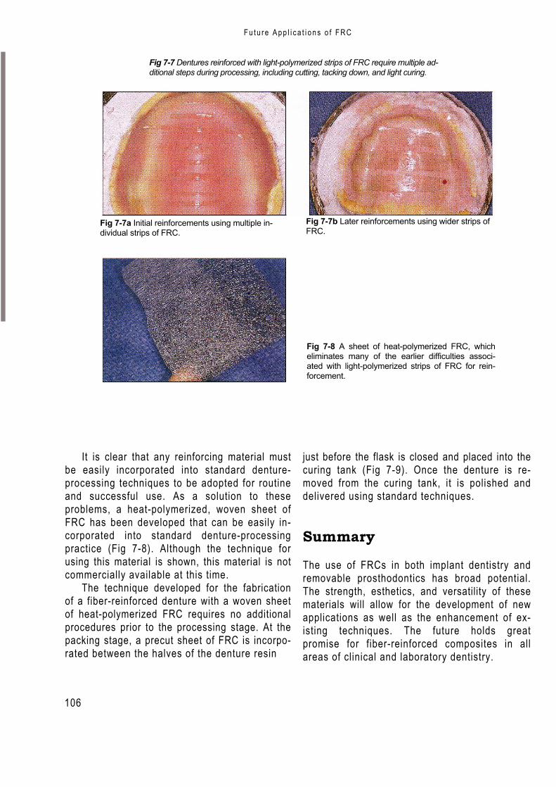
106
F u t u r e A p p l i c a t i o n s o f F R C
Fig 7-7 Dentures reinforced with light-polymerized strips of FRC require multiple ad-ditional steps during processing, including cutting, tacking down, and light curing.
Fig 7-7a Initial reinforcements using multiple in-dividual strips of FRC.
Fig 7-7b Later reinforcements using wider strips ofFRC.
Fig 7-8 A sheet of heat-polymerized FRC, whicheliminates many of the earlier difficulties associ-ated with light-polymerized strips of FRC for rein-forcement.
It is clear that any reinforcing material mustbe easily incorporated into standard denture-processing techniques to be adopted for routineand successful use. As a solution to theseproblems, a heat-polymerized, woven sheet ofFRC has been developed that can be easily in-corporated into standard denture-processingpractice (Fig 7-8). Although the technique forusing this material is shown, this material is notcommercially available at this time.
The technique developed for the fabricationof a fiber-reinforced denture with a woven sheetof heat-polymerized FRC requires no additionalprocedures prior to the processing stage. At thepacking stage, a precut sheet of FRC is incorpo-rated between the halves of the denture resin
just before the flask is closed and placed into thecuring tank (Fig 7-9). Once the denture is re-moved from the curing tank, it is polished anddelivered using standard techniques.
Summary
The use of FRCs in both implant dentistry andremovable prosthodontics has broad potential.The strength, esthetics, and versatility of thesematerials will allow for the development of newapplications as well as the enhancement of ex-isting techniques. The future holds greatpromise for fiber-reinforced composites in allareas of clinical and laboratory dentistry.
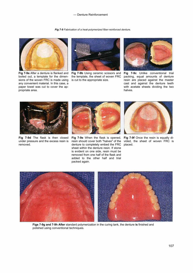
107
— Denture Reinforcement
Fig 7-9 Fabrication of a heat-polymerized fiber-reinforced denture.
Fig 7-9a After a denture is flanked andboiled out, a template for the dimen-sions of the woven FRC is made usingany convenient material. In this case, apaper towel was cut to cover the ap-propriate area.
Fig 7-9b Using ceramic scissors andthe template, the sheet of woven FRCis cut to the appropriate size.
Fig 7-9c Unlike conventional trialpacking, equal amounts of dentureresin are placed against the mastercast and against the denture teethwith acetate sheets dividing the twohalves.
Fig 7-9d The flask is then closedunder pressure and the excess resin isremoved.
Fig 7-9e When the flask is opened,resin should cover both "halves" of thedenture to completely embed the FRCsheet within the denture resin. If stoneis evident on one side, resin must beremoved from one half of the flask andadded to the other half and trialpacked again.
Fig 7-9f Once the resin is equally di-vided, the sheet of woven FRC isplaced.
Figs 7-9g and 7-9h After standard polymerization in the curing tank, the denture is finished andpolished using conventional techniques.
108
— Future Applications of FRC
References1. Bergendal T, Ekstrand K, Karlsson U. Evaluation of im-
plant-supported carbon/graphite fiber-reinforced poly (methyl methacrylate) prostheses.A longitudinal multi-center study. Clin Oral Implants Res 1995;6:246-253.
2. Berrong JM, Weed RW Young JM. Fracture resistanceof kevlar-reinforced poly(methacrylate) resin: A prelimi-nary study. I nt J Prosthodont 1990;3:391-395.
3. Braden M, Davy KWM, Parker S, Ladizesky NH, WardIM. Denture base poly(methacrylate) reinforced withultra-high modulus polyethylene fibers. Br Dent J 1988;164:109-113.
4. Carroll C, von Fraunhofer J. Wire reinforcement of acrylicresin prostheses.J Prosthet Dent 1984;52:639-641.
5. Ekstrand K, Ruyter I,Wellendorf H.Carbon/graphite fiberreinforced poly(methylmethacrylate): Properties underdry and wet conditions. J Biomed Mater Res 1987; 21:1065-1080.
6. Freilich MA, Karmaker AC, Burstone CJ, Goldberg AJ.Flexure strength of fiber-reinforced composites de-signed for prosthodontic application [abstract 999]. JDent Res 1997;76:138.
7. Goldberg AJ, Freilich MA, Haser KA, Audi JH. Flexureproperties and fiber architecture of commercial fiberreinforced composites [abstract 967]. J Dent Res 1998;77:226.
8. Johnston EP, Nicholls JI, Smith DE. Flexure fatigue of 10commonly used denture base resins. J Prosthet Dent1981;46:478-483.
9. Kawano F, Miyamoto M, Tada N, Matsumoto N.Reinforcement of acrylic resin denture base with NI-Cralloy plate. Int J Prosthodont 1990;3:484-488.
10. Kelly E. Fatigue failure in denture base polymers. JProsthet Dent 1969;21:257-266.
11. Lad izesky NH, Ho CF, Chow TW. Reinforcement ofcomplete denture bases with continuous high perfor-mance polyethylene fibers. J Prosthet Dent 1992; 68:934-939.
12. Manley TR, Bowman AJ, Cook M. Denture bases rein-forced with carbon fibers. Br Dent J 1979;146:25.
13. Moffa JP. Allergic response to nickel containing dentalalloys [abstract 107].J Dent Res 1977;56:1378.
14. Morris HF.Veterans Administration Cooperative StudiesProject No. 147. IV. Biocompatibility of base metal alloys.J Dent 1987;58:1.
15. Mullarky R. Aramid fiber reinforcement of acrylic appli-ances. J Clin Orthod 1985;19:655-658.
16. Ruffino A. Effect of steel strengtheners on fracture resis-tance of the acrylic resin complete denture base. JProsthet Dent 1985;54:75-78.
17. Schreiber C. Polymethylmethacrylate reinforced withcarbon fibers. Br Dent J 1971;130:29-30.
18. Smith DC. The acrylic denture:Mechanical evaluation ofmid-line fracture. Br Dent J 1961;110:257-267.
19. Solnit G. The effect of methyl methacrylate reinforce-ment with silane-treated and untreated glass fibers. JProsthet Dent 1991;66:310-314.
20. Vallittu P. Reinforcement of acrylic resin denture basematerial with metal or fiber strengtheners. J OralRehabil 1992;19:225-230.
21. Vallittu PK, Lassila VP, Lappalainen R. Number and typeof damages of removable dentures in two cities inFinland. Acta Odontol Scand 1993;51:363-369.
22. Vallittu PK. Flexural properties of acrylic resin polymersreinforced with unidirectional and woven glass fibers.JProsthet Dent 1999;8I:318-326.
109
References with "t"denote tables; "f"denote anterior, 58-61, 59f-60f shortcomings of present techniquesfigures posterior, 58, 61, 62f-63f or materials, 3
fixed splints Clinical problemsmandibular, 49-50 gray/metal showthrough of metal posts
A materials for, 50f and cores or amalgam cores on abut-nonimpregnated technique ment teeth, 81-82, 82f
Abutment teeth materials for, 54,54flow concentration of color of veneer (incylinders, for fiber-reinforced composite for periodontal splint creation, 54,
pontic areas), 84, 84fimplant-supported prostheses, 95, 55f-56f95f non-reinforced composite types of 49 overview of 81
loss of attachment from, 90, 90f resin pre-impregnated technique particulate composite veneer fracturepreparations of extracoronal use, 52f-53f cause determinations, 85for extracoronal fixed prosthesis, 30f intracoronal use,51f-52f description of 85for intracoronal fixed prosthesis,41f materials for, 50 illustration of, 84f-85f
Acrylic resin prostheses woven fibers, 50f repair procedure forproperties of, 73 posts anterior fixed prosthetic denture,
reinforcement of, 78 advantages of,63 86f-87frepair chairside-fabricated materials, 86
fiber-reinforced composite advan- description of, 63, 64f posterior fixed prosthetic denture,tages for, 73 procedure, 65f-67f, 68 88f-89f
light-polymerized fiber-reinforced clinical studies of, 66 technique, 86composites for, 74, 75f-77f indications,66 retainer debonding, 90, 90f
overview of, 73 prefabricated sensitivity after cementation, 84,85fwire use for, 73 description of 63,64f surface luster loss of particulate compos-
uses of, 73 procedure, 65f-67f, 68 ite veneer, 82, 83fAlloys. See Metal alloys. tooth replacement
translucency in pontic areas, 82-83,83fdescription of, 57
Color considerationsC fiber-reinforced composites for
classification of, 11 t concentration of in pontic areas, 84, 84fCarbon/graphite fibers description of 5, 6f gray/metal showthrough,81-82,82findications, 16 ideal characteristics, 49 Compositesmechanical and physical properties of, fixed prostheses prevalence of 4
11t advantages 4, 57 restorative, 4for posts, 63, 64f anterior denture, 58-61, 59f-60f Conquest Curing Unit, 35, 37f
Ceramic materials description of, 38, 39f-40f Crownillustration of, 2f illustration of, 39f-40f, 57f fiber-reinforced composite, 5fshortcomings of 1 materials for, 57-658 metal, 1, 2f
Chairside applications posterior denture, 58, 61, 62f-63f Cylinders, for implant-supported prosthe-fixed partial denture selection criteria for, 57-58 ses, 95, 95f
110
- Index --
See Mechanical description of, 82-83, 83fD mechanical properties.
properties. opaque materials for, 83, 83fDentin-resin cement complex, 84 modern improvements in, 18 Fixed splintsDenture. See also Fixed prostheses; non-dentistry uses of 4 mandibular, 49-50
Implants. versus standard composites, 9,10f materials for, 50ffixed partial.See Fixed partial denture. Fibers. See Reinforcing fibers. nonimpregnated techniquefractures of, 98, 99f FibreKor system materials for, 54, 54foverdentures, 98, 98f fixed prosthesis for periodontal splint creation, 54,reinforcement of extracoronal, 34-35, 36f-37f 55f-56f
glass fiber use, 99,100f-101f intracoronal, 42f, 42-43, 45f non-reinforced composite types of 49heat-polymerized fiber-reinforced intracoronal and extracoronal,46f resin pre-impregnated technique
composites for, 100,101 f posts, 63, 64f extracoronal use, 52f-53flight-polymerized fiber-reinforced Fixed partial denture intracoronal use, 51f-52f
composites, 99-100,100f anterior materials for, 50metal framework, 99, 99f chairside applications, 58-61, 59f-60f woven fibers, 50fnon-fiber-reinforced composite meth- veneer fracture repair, 86f-87f Flexure strength, 17f,17-19, 19t
ods, 98-99 for edentulous spans, 93, 94f FPD. See Fixed partial denture.Denture tooth, for chairside fixed partial fiber-reinforced composite advantages Framework, for fiber-reinforced composite
denture creation, 58, 61,61 for, 5-6, 94-95 prosthesesDiamond burs, 27, 28f-29f metal-unit, 2f equipment-fabricated
posterior description of, 24, 25f, 2758, 61, 62f-63f of, 25
E chairside applications,illustration of, 5f illustration of, 25f
Edentulous spans, fiber-reinforced fixed veneer fracture repair, 88f-89f Vectris system fabrication processpartial denture for, 93, 94f Fixed prostheses for extracoronal prosthesis, 30-31,
Equipment-fabricated framework cementation of, sensitivity problems 32f-34fdescription of, 24, 25f, 27 secondary to, 84, 85f for intracoronal prosthesis, 43, 44fgoals of,25 composition hand-fabricatedillustration of, 25f equipment fabrication, 24, 25f description of, 24, 27Vectris system fabrication process framework., 23-24 FibreKor system fabrication process
for extracoronal prosthesis, 30-31, hand fabrication, 24, 25f for extracoronal prosthesis, 34-35,32f-34f materials, 24-25 36f-37f
for intracoronal prosthesis, 43,44f overview of, 23 for intracoronal and extracoronalExtracoronal fixed prostheses substructure, 23-24 prostheses, 46fabutment teeth preparations for, 30f suprastructure, 24 for intracoronal prosthesis, 42f,chairside delivery of, 38, 39f-40f veneer, 24 42-43, 45fequipment-fabricated (Vectris) frame- contraindications, 26t, 26-27 goals of, 25
work, 30-31, 32f-34f extracoronal illustration of, 25fhand-fabricated (FibreKor) framework, abutment teeth preparations for, 30f hybrid prosthesis, 96f-97f
34-35,36f-37f chairside delivery of, 38, 39f-40f overdentures, 98, 98fluting of, 38,40f equipment-fabricated (Vectris) frame- voids associated with, 24tooth preparations, 27, 28f-29f work, 30-31, 32f-34f FRC. See Fiber-reinforced composites.working casts and dies, 30 hand-fabricated (FibreKor) framework,
FFiber-reinforced composites. See also spe-
cific applications.advantages of,4classification of, 9, 1 1 tclinical skills necessary for,6constituents of,9definition of, 9dentistry uses of, 4-6handling characteristics of, 17 heat-
polymerized. See Heat-polymerized fiber-reinforced composites.
history of, 12-14,18 light-polyrnerized.SeeLight-polymerized
fiber-reinforced composites.manufacturing of, 13,13f
34-35, 36f-37fand intracoronal, 44,46fluting of, 38,40ftooth preparations, 27, 28f-29fworking casts and dies, 30
fabrication of, 14flexure properties,19tindications, 26, 26tintracoronal
abutment teeth preparations for,41fadvantages of, 41applications of,41chairside delivery of, 44, 45f-46fand extracorona I, 44, 46flaboratory fabrication of, 42f-44f, 42-43tooth preparation for,41,41f
standard types of, 1, 2ftranslucency problems associated with
G
Glass fibersbraided, 10ffor denture reinforcement, 99,100f-101 fflexure modulus of,16indications, 15mechanical and physical properties of, 11 twoven, 10f
Glass-reinforced bis-GMA systems, 14Gray/metal showthrough of metal posts
and cores, solutions for dealing with,81-82, 82f
H
Hand-fabricated frameworkdescription of, 24, 27
111
Index --
FibreKor system fabrication processfor extracoronal prosthesis, 34-35,36f-37f
for intracoronal and extracoronal pros-theses, 46f
for intracoronal prosthesis, 421,42-43,45f
goals of, 25illustration of, 25f
Handling characteristics, 1 7 Heat-polymerized fiber-reinforced compositesfor denture reinforcement, 100, 101fstrength of, 24
IImplants. See also Denture.
description of, 1, 2f, 93-94prosthesesfixed. See Fixed prostheses.fixed partial denture. See Fixed partial
denture.hybrid, 96f-97f
Intracoronal fixed prostheses abutmentteeth preparations for, 41f advantagesof,41applications of,41chairside delivery of, 44, 45f-46flaboratory fabrication of, 42f-44f, 42-43tooth preparation for, 41, 41f
KKevlar fibers, mechanical and physical
properties of, 11t
LLight-polymerized fiber-reinforced composites
for denture reinforcement, 99-100, 100f forrepair of acrylic resin prostheses, 74, 75f-77fstrength of, 24
Luster loss, 82, 83fLuting materials, for fixed prosthesis, 26, 38,
40f
MMechanical properties
of commercial products,18-19,19tfiber orientation and, 15,16fflexure strength, 17-18of multidirectional fibers, 15, 16fof unidirectional fibers, 15
Metal alloysflexure strength testing of, 18illustration of, 2fshortcomings of, 1
Metal crowns, 1, 2fModulus of elasticity, 16
NNon impregnated resin technique, for fixed
splintsmaterials for, 54,54ffor periodontal splint creation, 54,
55f-56f
0Occlusal-incisal pontic index, 58Overdentures, 98, 98f
PPeriodontal splintsdescription of, 5, 6fusing nonimpregnated resin technique,
54, 55f-56fPMMA. See Polymethyl methacrylate.Polyethylene fibers braided, l0fmechanical and physical properties of,
11twoven, 10f
Polyethylene ribbon, 54, 54f, 56fPolymethyl methacrylatecarbon fiber-reinforced, 14denture reinforcement using, 99description of,1fiber-reinforced composite and, compar-
isons for implant-supported prosthe-ses, 94
shortcomings of, 1, 3fPonticillustration of, 59ftranslucency problems associated with,
82-83, 831Porcelainillustration of, 3f
shortcomings of, 3Postsadvantages of, 63chairside-fabricateddescription of,63, 64f
procedure, 65f-67f, 68clinical studies of,66commercial products for, 11tcomposition of, 9 indications,66metal, gray/metal showthrough associ-
ated with, 81-82, 82fprefabricated
description of, 63, 64fprocedure, 65f-67f,68
properties 01 63 Pre-impregnated systems
acrylic resin prosthesis repair and rein-forcement using, 78. See also Acrylicresin prostheses.
advantages of, 78approach for, 14clinical trials of 14types of,14,15f
Problems. See Clinical problems.Prostheses. See Denture; Fixed prostheses;Implants.
RReinforcing fibers
arrangement configuration, 9, 10fdevelopment of,12-14 function of,9low-viscosity resin application, 13mechanical and physical properties as-
sociated with, l 1 t, 50types of, 9wetting of,12,12f, 16
Resin pre-impregnated technique, for fixedsplints
extracoronal use, 52f-53fintracoronal use, 51f-52fmaterials for, 50woven fibers, 50f
Rubber dam, 27, 62fRule of mixtures, 16-17
SSplints
fabrication of, 14intracoronal, 56fmandibular, 49-50materials for, 50fnon-fiber-reinforced composite types
of, 49nonimpregnated resin techniquematerials for, 54, 54f
for periodontal splint creation, 54,55f-56f
periodontaldescription of, 5, 6fusing nonimpregnated resin tech-
nique, 54, 55f-56fresin pre-impregnated techniqueextracoronal use, 52f-53f
intracoronal use, 51f-52fmaterials for, 50 woven
fibers, 50f Stabilization, ofteeth, 49-50
Stiffness, 16Strength
flexure, 17-18of unidirectional fibers, 15
Supragingival margins, 26

— Index —
TTarg is, for equipment-fabricated (Vectris)
fiber-reinforced composite framework,31,34f
Tooth preparationsfor extracoronal fixed prosthesis, 27, 28f-
29ffor intracoronal fixed prostheses,41,41f
Tooth replacementchairside applications for
description of,57fiber-reinforced composites forclassification of, 11tdescription of, 5, 6fideal characteristics, 49
fixed prosthesesadvantages of, 57anterior denture, 58-61, 59f-60fdescription of, 38, 39f-40fillustration of, 39f-40f, 57fmaterials for, 57-658posterior denture, 58, 61,62f-63fselection criteria for, 57-58shortcomings of present techniques ormaterials, 3
implants for, 93-94, 94fTooth stabilization, 49-50Translucency
gray/metal showthrough of metal postsand cores secondary to, 81-82, 82f
opaque material for blockage of 83, 83fin pontic areas, 82-83, 83f
UUnidirectional fibers
characteristics of, 50mechanics of, 15for repair of acrylic resin prostheses, 74strength of 15
V
Vectris system, for fiber-reinforced com-posite fixed prosthesis
for extracoronal prosthesis, 30-31,32f-34f
for intracoronal prosthesis, 43, 44fVeneer
description of 24
fracture ofcause determinations, 85description of 85illustration of 84f-85frepair procedure foranterior fixed prosthetic denture,
86f-87fmaterials, 86
posterior fixed prosthetic denture,88f-89f technique, 86
porcelain, 3f
W
Wetting, of fibers, 12,12f 16Woven fibers
characteristics of 50glass, 10findications
acrylic resin prosthesis repair, 74denture reinforcement, 100, l Ol fpolyethylene, l0fof Vectris system, 31, 33f
Ali
logo 2
Related Documents