Fiber Optics, Prof. R.K. Shevgaonkar, Dept. of Electrical Engineering, IIT Bombay Page 1 FIBER OPTICS Prof. R.K. Shevgaonkar Department of Electrical Engineering Indian Institute of Technology, Bombay Lecture: 2 Characteristics of Light

Welcome message from author
This document is posted to help you gain knowledge. Please leave a comment to let me know what you think about it! Share it to your friends and learn new things together.
Transcript
Fiber Optics, Prof. R.K. Shevgaonkar, Dept. of Electrical Engineering, IIT Bombay Page 1
FIBER OPTICS Prof. R.K. Shevgaonkar
Department of Electrical Engineering
Indian Institute of Technology, Bombay
Lecture: 2
Characteristics of Light
Fiber Optics, Prof. R.K. Shevgaonkar, Dept. of Electrical Engineering, IIT Bombay Page 2
The search for a medium for transmission of light over long distances led the
scientist to investigate glass which was already in use for laboratory optical
experimentations. But, it was found that laboratory-used glass, either in the form of
prisms or lenses, had a very high loss figure of about 1000 dB/Km. However,
investigations also showed that this high loss was not an intrinsic characteristic of
glass but was due to the impurities that were present in the glass. In other words, the
high loss of optical energy was not due to glass molecules but was caused by the
impurities in it that remained in it during its manufacture. So, with the best possible
manufacturing technology scientists prepared purified glass which was then found to
have a loss figure of only 20 dB/Km. Although in modern days this loss is in no way
small, but in early times it was very much comparable to the other available
alternatives for wide band communication medium like the coaxial cables. Gradually,
technologies improved and highly purified glass started to be manufactured which
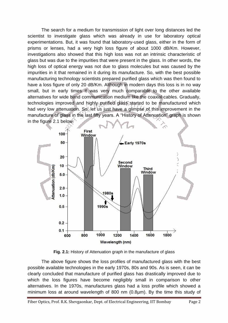
had very low attenuation. So, let us just have a glimpse of this improvement in the
manufacture of glass in the last fifty years. A “History of Attenuation” graph is shown
in the figure 2.1 below.
Fig. 2.1: History of Attenuation graph in the manufacture of glass
The above figure shows the loss profiles of manufactured glass with the best
possible available technologies in the early 1970s, 80s and 90s. As is seen, it can be
clearly concluded that manufacture of purified glass has drastically improved due to
which the loss figures have become negligibly small in comparison to other
alternatives. In the 1970s, manufactures glass had a loss profile which showed a
minimum loss at around wavelength of 800 nm (0.8µm). By the time this study of

Fiber Optics, Prof. R.K. Shevgaonkar, Dept. of Electrical Engineering, IIT Bombay Page 3
glass was going on, LASERs also were invented which used a semiconductor
material named Gallium Arsenide (GaAs) for emission of light. GaAs intrinsically is
capable of emitting light of wavelength 800nm. So, coincidently we had glass which
had minimum loss at the wavelength that was emitted by LASERs, and so it proved
to be great combination. So initial optical communications were started at 800nm
wavelength region and hence it is called as the “First Window” of optical
communication.
As technology improved, glass was further purified and it showed a region of
minimum loss at 1300nm and 1550nm regions in the 1980s as shown in figure 2.1.
There was no minimum in the 800nm window and hence GaAs LASERs could not be
used as sources. But in this course of time the semiconductor material technology
had also improved simultaneously and we had sources available which could emit
light both in 1300nm and the 1550nm regions. So, optical communications were now
shifted to these regions and were called as the “Second Window” and “Third
Window” of optical communication. The 1300nm window not only has low loss but
also can support high data rates. But today, most of the optical transmission take
place in the 1550nm window because though the 1300nm window had high
bandwidth, it also had higher loss which significantly affected the performance of the
communication system since distances became considerable large. The 1550nm
window allows the installation of optical amplifiers at regular distance intervals that
can amplify the light in the optical domain without converting it into electrical signal.
This leads to a more reliable communication and hence today most optical
communications lie in the third window.
Let us now look into the advantages of optical communication:
ADVANTAGES OF OPTICAL COMMUNICATION
Optical Communication provides an ultra-high bandwidth for communication
of the order of Terahertz (THz). This advantage meets the first requirement of
a high quality reliable communication system.
The loss figure of optical communication is very low, about 0.2 dB/Km. So this
system has high SNR values. This advantage provides a reliable
communication system. No other medium today, can provide such low loss
figures as optical medium.
Optical communication systems have very low or even negligible
electromagnetic interference (EMI).
Optical Communication provides high security data transmission. This is
because optical signal travels through optical fibers which do not allow
leakage of light energy. So tapping of transmitted information is very difficult in
optical communication.
Fiber Optics, Prof. R.K. Shevgaonkar, Dept. of Electrical Engineering, IIT Bombay Page 4
Optical communication systems have very low manufacturing cost. Whatever
cost is incurred is only due to the technology. This is because optical medium-
glass is made from silica, which is freely abundant in nature. So, the only cost
is in moulding it to a form of optical medium like optical fibre. The cost per
voice channel of an optical fibre is also very much smaller than cost per voice
channel of any other medium like coaxial cable though the two may have
comparable costs per kilometre. This is because the bandwidth of optical fibre
is almost 1000 times larger than a coaxial cable. So, cost per channel of an
optical fiber would be one thousandth of that in a coaxial cable.
Applications where space and weight are constraints, optical fiber serves
adequately because optical fibers have low weight and low volume compared
to other media.
The only flaw, if at all to be pointed out, is that optical communication is a
point-to-point communication technology. We already saw that satellite
communication technology in this regard is advantageous in that it is a broadcast
type of technology. But in modern scenario where optical fibres are reaching to every
home, atleast in an urban area, information can be broadcasted to every home in a
very short time. Thus we see that optical communication has a lot of advantages
over any other mode of communication, which make it the most desirable option for
communication today. These advantages were precisely the reasons behind the
rapid developments in the field of optical communication that revolutionized itself
almost every 10 years and is still in a fast pace of developments. Today, most of the
networks are composed of optical fibers using the optical networking technology.
New developments to increase the capacity of an optical communication system
have also taken place such as wavelength division multiplexing (WDM) technology.
Let us now look deeper into this new domain of communication with more
detailed prospective. But before going into the details, let us revise some basic
characteristics of light.
CHARACTERISTICS OF LIGHT
We know that light is a form of electromagnetic radiation. We are also familiar
with the propagation of light in the form of rays which help us to prove different laws
like laws of reflection, Snell’s law, interference, diffraction, etc. We are well
acquainted with phenomena like photonic emission, photo-electricity which define a
particle nature for light in the form of photons. So basically, the nature of light
depends on the context of which we talk about. So, in this course we first treat light
in the context of the Ray Model and study different phenomena based on the ry
model of light. Proceeding further, when we find the ray model is inadequate in
explaining some phenomena, we depart from the ray model and then adopt a higher
model for light which is the wave-model where light is treated as an electromagnetic
Fiber Optics, Prof. R.K. Shevgaonkar, Dept. of Electrical Engineering, IIT Bombay Page 5
wave. And in those situations where we find even the wave-model inadequate in
explain certain phenomena like interaction light with matter, we adopt the quantum
model of light where light will be treated as a photons. So, in this course, we will treat
light in the following three models:
Ray Model
Wave Model
Quantum Model
CHARACTERIZATION OF A LIGHT SOURCE
A very elementary question that may now come to the reader’s mind is how to
characterise or describe a light source? A source of light can be characterized by the
following factors:
Intensity of the light: Intensity of light is defined as the power per unit solid
angle. So for a given power of the source, if the emitted light is scattered into a very
wide solid angle then the source has low intensity. If the emitted light is confined to
very narrow cone, the source appears to be very bright because its intensity
increases. This happens in case of a LASER whose light appears to be much
brighter and travels long distance than a normal 60W bulb though the power of the
LASER is much smaller than 60W. The intensity of the source is indicative of how
focussed is the emitted light.
Wavelength of Light (λ): The second characteristic on which a source is
characterized is the wavelength of the emitted light. The wavelength of light is
indicative of the colour of the light and so many a times it is also called as the colour
of the source. The visible light lies within a wavelength range of 400nm to 700nm. If
we look into figure 2.1, we find that glass which appears so transparent to us in daily
life is not actually that transparent to wavelengths of 400nm to 700nm. In fact, it is
much more transparent to lights of wavelengths 1300nm and 1550nm, which lie in
the infrared region. Since these regions are not in the visible range, colour does not
have any meaning, yet we may retain the colour as one of the characteristic to
categorize light. Depending on the desired loss performance of the optical
communication system λ can be chosen either 1300nm or 1550nm. So, the choice of
wavelength of transmission has a direct relation to the SNR of the transmission.
Spectral Width of Source (∆λ): It is basically the wavelength range over
which the emission takes place. In other words, it is the range of wavelengths
emitted by the source. Thus the spectral width may be considered to be indicative of
the purity of the colour of the light source. That is, if we have a source with a wide
spectral width, say for example if it emits all the wavelengths ranging from blue to
red, we get a light from the source which will look like white light. If we reduce the
Fiber Optics, Prof. R.K. Shevgaonkar, Dept. of Electrical Engineering, IIT Bombay Page 6
spectral width to near red, we would get a sharp red colour light. If we reduce it to
near blue, we would get a blue coloured light and so on. Thus reducing the spectral
width increases the purity of the colour. Spectral width is a very important parameter
of a source because we would later discover that spectral width of a source is related
to the data rate upto which a source can be used as a transmitter of optical signal.
Smaller the value of ∆λ more will be the purity of the source and also higher would
be the data rate of the source. In other words, higher will be the bandwidth of the
communication system. So, the choice of ∆λ has a direct relation to the bandwidth of
the transmission.
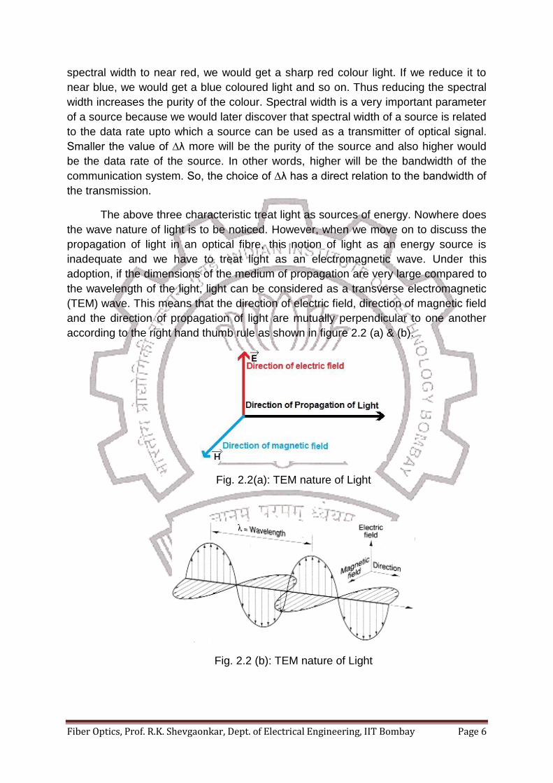
The above three characteristic treat light as sources of energy. Nowhere does
the wave nature of light is to be noticed. However, when we move on to discuss the
propagation of light in an optical fibre, this notion of light as an energy source is
inadequate and we have to treat light as an electromagnetic wave. Under this
adoption, if the dimensions of the medium of propagation are very large compared to
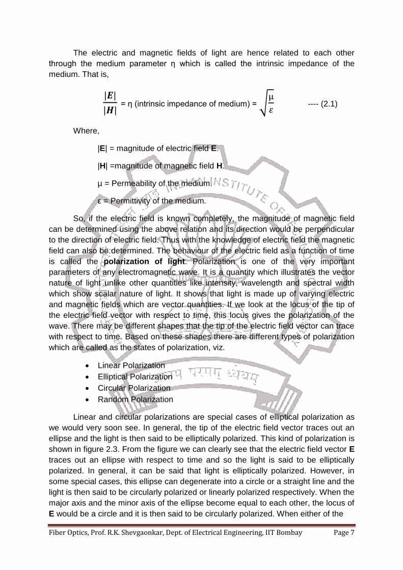
the wavelength of the light, light can be considered as a transverse electromagnetic
(TEM) wave. This means that the direction of electric field, direction of magnetic field
and the direction of propagation of light are mutually perpendicular to one another
according to the right hand thumb rule as shown in figure 2.2 (a) & (b).
Fig. 2.2(a): TEM nature of Light
Fig. 2.2 (b): TEM nature of Light
Fiber Optics, Prof. R.K. Shevgaonkar, Dept. of Electrical Engineering, IIT Bombay Page 7
The electric and magnetic fields of light are hence related to each other
through the medium parameter η which is called the intrinsic impedance of the
medium. That is,
= η (intrinsic impedance of medium) = √
---- (2.1)
Where,
|E| = magnitude of electric field E.
|H| =magnitude of magnetic field H.
µ = Permeability of the medium.
ε = Permittivity of the medium.
So, if the electric field is known completely, the magnitude of magnetic field
can be determined using the above relation and its direction would be perpendicular
to the direction of electric field. Thus with the knowledge of electric field the magnetic
field can also be determined. The behaviour of the electric field as a function of time
is called the polarization of light. Polarization is one of the very important
parameters of any electromagnetic wave. It is a quantity which illustrates the vector
nature of light unlike other quantities like intensity, wavelength and spectral width
which show scalar nature of light. It shows that light is made up of varying electric
and magnetic fields which are vector quantities. If we look at the locus of the tip of
the electric field vector with respect to time, this locus gives the polarization of the
wave. There may be different shapes that the tip of the electric field vector can trace
with respect to time. Based on these shapes there are different types of polarization
which are called as the states of polarization, viz.
Linear Polarization
Elliptical Polarization
Circular Polarization
Random Polarization
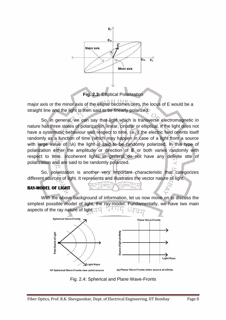
Linear and circular polarizations are special cases of elliptical polarization as
we would very soon see. In general, the tip of the electric field vector traces out an
ellipse and the light is then said to be elliptically polarized. This kind of polarization is
shown in figure 2.3. From the figure we can clearly see that the electric field vector E
traces out an ellipse with respect to time and so the light is said to be elliptically
polarized. In general, it can be said that light is elliptically polarized. However, in
some special cases, this ellipse can degenerate into a circle or a straight line and the
light is then said to be circularly polarized or linearly polarized respectively. When the
major axis and the minor axis of the ellipse become equal to each other, the locus of
E would be a circle and it is then said to be circularly polarized. When either of the
Fiber Optics, Prof. R.K. Shevgaonkar, Dept. of Electrical Engineering, IIT Bombay Page 8
Fig. 2.3: Elliptical Polarization
major axis or the minor axis of the ellipse becomes zero, the locus of E would be a
straight line and the light is then said to be linearly polarized.
So, in general, we can say that light which is transverse electromagnetic in
nature has three states of polarization, linear, circular or elliptical. If the light does not
have a systematic behaviour with respect to time, i.e. if the electric field orients itself
randomly as a function of time (which may happen in case of a light from a source
with large value of ∆λ) the light is said to be randomly polarized. In this type of
polarization either the amplitude or direction of E or both varies randomly with
respect to time. Incoherent lights in general do not have any definite stte of
polarization and are said to be randomly polarized.
So, polarization is another very important characteristic that categorizes
different sources of light. It represents and illustrates the vector nature of light.
RAY-MODEL OF LIGHT
With the above background of information, let us now move on to discuss the
simplest possible model of light, the ray-model. Fundamentally, we have two main
aspects of the ray nature of light.
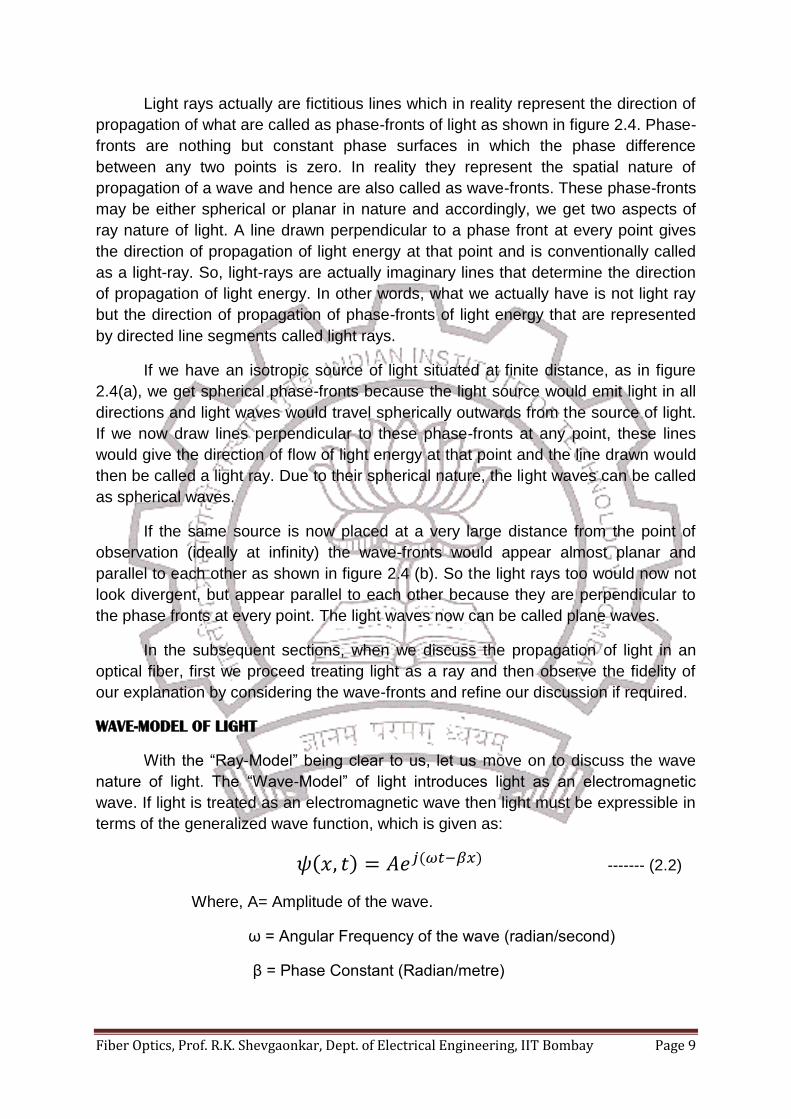
Fig. 2.4: Spherical and Plane Wave-Fronts
Fiber Optics, Prof. R.K. Shevgaonkar, Dept. of Electrical Engineering, IIT Bombay Page 9
Light rays actually are fictitious lines which in reality represent the direction of
propagation of what are called as phase-fronts of light as shown in figure 2.4. Phase-
fronts are nothing but constant phase surfaces in which the phase difference
between any two points is zero. In reality they represent the spatial nature of
propagation of a wave and hence are also called as wave-fronts. These phase-fronts
may be either spherical or planar in nature and accordingly, we get two aspects of
ray nature of light. A line drawn perpendicular to a phase front at every point gives
the direction of propagation of light energy at that point and is conventionally called
as a light-ray. So, light-rays are actually imaginary lines that determine the direction
of propagation of light energy. In other words, what we actually have is not light ray
but the direction of propagation of phase-fronts of light energy that are represented
by directed line segments called light rays.
If we have an isotropic source of light situated at finite distance, as in figure
2.4(a), we get spherical phase-fronts because the light source would emit light in all
directions and light waves would travel spherically outwards from the source of light.
If we now draw lines perpendicular to these phase-fronts at any point, these lines
would give the direction of flow of light energy at that point and the line drawn would
then be called a light ray. Due to their spherical nature, the light waves can be called
as spherical waves.
If the same source is now placed at a very large distance from the point of
observation (ideally at infinity) the wave-fronts would appear almost planar and
parallel to each other as shown in figure 2.4 (b). So the light rays too would now not
look divergent, but appear parallel to each other because they are perpendicular to
the phase fronts at every point. The light waves now can be called plane waves.
In the subsequent sections, when we discuss the propagation of light in an
optical fiber, first we proceed treating light as a ray and then observe the fidelity of
our explanation by considering the wave-fronts and refine our discussion if required.
WAVE-MODEL OF LIGHT
With the “Ray-Model” being clear to us, let us move on to discuss the wave
nature of light. The “Wave-Model” of light introduces light as an electromagnetic
wave. If light is treated as an electromagnetic wave then light must be expressible in
terms of the generalized wave function, which is given as:
( ) ( ) ------- (2.2)
Where, A= Amplitude of the wave.
ω = Angular Frequency of the wave (radian/second)
β = Phase Constant (Radian/metre)
Fiber Optics, Prof. R.K. Shevgaonkar, Dept. of Electrical Engineering, IIT Bombay Page 10
The wave function is a generalized function of space (x) and time (t). The term
(ωt-βx) is the phase function of ψ(x,t). Thus the phase of the wave is a function of
space and time. If we now freeze space, i.e. take x=constant or in other words
observe at a particular point, we see that there is a sinusoidal variation of the wave
amplitude as a function of time having an angular frequency of ω rad/s. If we freeze
time, i.e. take t=constant or in other words observe the whole wave simultaneously,
we see that the amplitude of the wave has a sinusoidal variation with a phase
constant β rad/m. So these two phenomena together constitute a wave phenomenon
represented by the generalized wave equation.
The phase constant β is defined as the phase change per unit distance. The
wavelength (λ) of a wave is the distance between two consecutive points on the
wave which are in the same phase. The phase difference between two points in the
same phase is either zero or an integral multiple of 2π. Thus the wavelength of a
wave is measured between two points that have a phase difference of 2π. Hence the
phase constant β can be calculated as:
------- (2.3)
So, if we know the wavelength (λ) of a wave in a medium, we can calculate
the phase constant of the wave in that medium and vice–versa. One basic question
that may come to the reader’s mind is that, once the frequency of light (f) is known,
the wavelength (λ) can be readily calculated from the relation:
-------- (2.4)
Where, c = velocity of light, then what is so special about β? But the reader
should note at this point that velocity of light is a medium dependent parameter. It is
c (3x10⁸m/s) in vacuum, but is different in different media. In the same medium too,
the velocity of light may vary if the medium is made bound. Thus the velocity of light
is a medium dependent parameter. So, the wavelength of light is not always given by
equation (2.4) but can be found from:
( )
-------- (2.5)
And
( )
( ) -------- (2.6)
Once the frequency of light is known, we may calculate the value of β(medium)
and then from equation (2.6), we can calculate the value of λ(medium) and then find the
velocity of light from equation (2.5).
Treating light as an electromagnetic wave, let us now define an important
optical parameter of a medium called the refractive index of the medium. Refractive
Fiber Optics, Prof. R.K. Shevgaonkar, Dept. of Electrical Engineering, IIT Bombay Page 11
index of a medium is defined as the ratio of the velocity of light in vacuum to the
velocity of light in that medium. It is denoted by n. Since refractive index is a ratio of
two velocities, it is a pure number and has no unit.
Refractive index of medium (n(medium))= ( )
( ) -- (2.7)
For most media, n(medium) < 1, i.e. the velocity of light reduces from its value in
vacuum. In fact, light travels fastest in vacuum and in any other medium it slows
down. For example, the refractive index of material glass is about 1.5, i.e. light
travels 1.5 times faster in vacuum than in glass. Similarly the refractive index of
water is 1.33. In other words, refractive index of a medium indicates the factor by
which the speed of light reduces in the medium. As we study further, we would
encounter another type of refractive index, called the effective refractive index which
is denoted by neff and is given by,
-------- (2.8)
Where v’ is not the necessarily the velocity of light in an unbound medium but
is a generalized velocity of light in a bound medium like optical fibres, optical
waveguides, etc. and it is structure or size dependent velocity. For example, the
actual refractive index of glass in unbound form is 1.5. But if glass is made in the
form of a bound medium (say an optical fiber) its refractive index changes because
the velocity of light in it changes. The refractive index of this particular bound form or
structure of glass is then the effective refractive index of this structure of glass and
would change again if we alter this form.
We have already seen that in general, whenever we discuss issues related to
light, conventionally, we discuss them in terms of the wavelength of light rather than
frequency. This was precisely the reasons for defining the three windows of optical
communication in terms of wavelengths and not in terms of frequencies. We have
also come across the quantity called the spectral width of the source of light which is
the range of wavelengths that are emitted by a source of light. In general,
wavelength of light is given by the relation (2.5). That is,
-------- (2.8)
Where, λ = wavelength of light in a medium.
v = velocity of light in the medium.
f = frequency of the light under study.
The spectral width can be calculated from (2.8) as,
-------- (2.9)
Fiber Optics, Prof. R.K. Shevgaonkar, Dept. of Electrical Engineering, IIT Bombay Page 12
Or, ∆λ (
) (
)
The quantity (v/f) is the wavelength and so, the above relation (2.9) can be
rewritten as,
-------- (2.10)
Let us now take a small example. Let us assume an operating wavelength (λ)
of about 1000 nm and an optical window of operation (∆λ) of about 1000 nm, then
from the relation (2.10), we find the value of bandwidth (∆f) of our assumed optical
communication system to be about 3x10¹³ Hz. Though this is a very crude and small
example, but yet it gives the reader an idea about the enormous bandwidth that
optical communication can provide. Thus an optical communication system is really
a very wideband system compared to a conventional microwave communication
system.
With this basis of knowledge about the characteristics of light, let us now look
into the very basic component of an optical communication system, the optical fiber.
Constructionally, an optical fiber is a solid cylindrical glass rod called the core,
through which light in the form of optical signals propagates. This rod is surrounded
by another coaxial cylindrical shell made of glass of lower refractive index called the
cladding. This basic arrangement that guides light over long distances is shown in
figure 2.5.
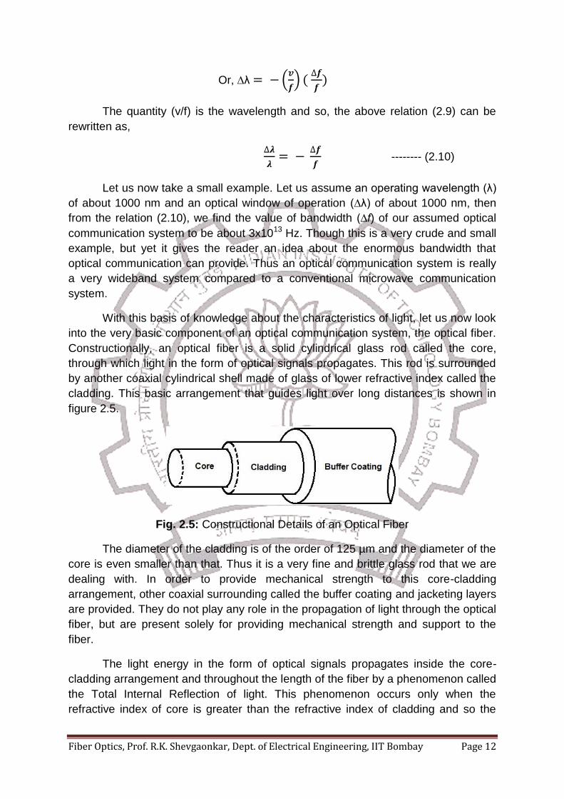
Fig. 2.5: Constructional Details of an Optical Fiber
The diameter of the cladding is of the order of 125 µm and the diameter of the
core is even smaller than that. Thus it is a very fine and brittle glass rod that we are
dealing with. In order to provide mechanical strength to this core-cladding
arrangement, other coaxial surrounding called the buffer coating and jacketing layers
are provided. They do not play any role in the propagation of light through the optical
fiber, but are present solely for providing mechanical strength and support to the
fiber.
The light energy in the form of optical signals propagates inside the core-
cladding arrangement and throughout the length of the fiber by a phenomenon called
the Total Internal Reflection of light. This phenomenon occurs only when the
refractive index of core is greater than the refractive index of cladding and so the
Fiber Optics, Prof. R.K. Shevgaonkar, Dept. of Electrical Engineering, IIT Bombay Page 13
cladding is made from glass of lower refractive index. By multiple total internal
reflections at the core-cladding interface the light propagates throughout the fiber
over very long distances with low attenuation.
Related Documents