Welcome message from author
This document is posted to help you gain knowledge. Please leave a comment to let me know what you think about it! Share it to your friends and learn new things together.
Transcript
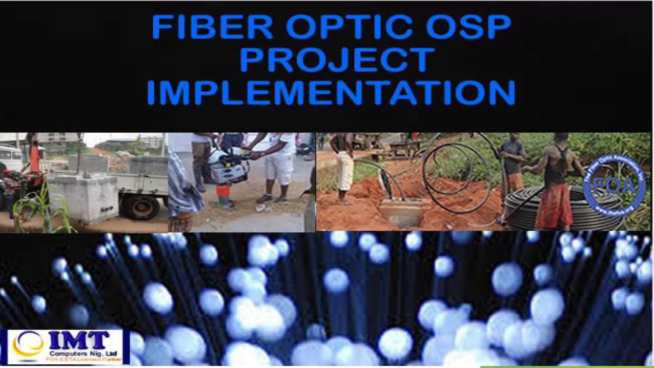

WHAT HAPPENS
IN -BETWEEN
IS THE
MANAGEMENT
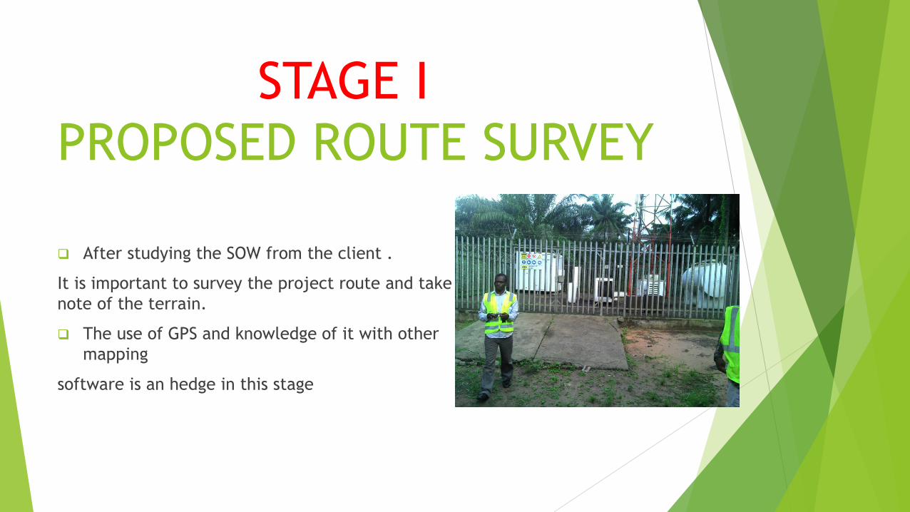
STAGE I
PROPOSED ROUTE SURVEY
After studying the SOW from the client .
It is important to survey the project route and take
note of the terrain.
The use of GPS and knowledge of it with other
mapping
software is an hedge in this stage

IT IS ALL ABOUT
COMPLING WITH
PROCESS
..it has start and end

It begins with
SURVEY of the
PROPOSED ROUTE

STAGE II
DRAFTING AND DRAWING OF
THE SURVEY
IN AUTO-CAD FORMAT
MH 1 MH 2 IN
MH 3
IN
MH 5 OUT
MH 4 OUT
MH 6 MH 7

STAGE III
TRENCHING
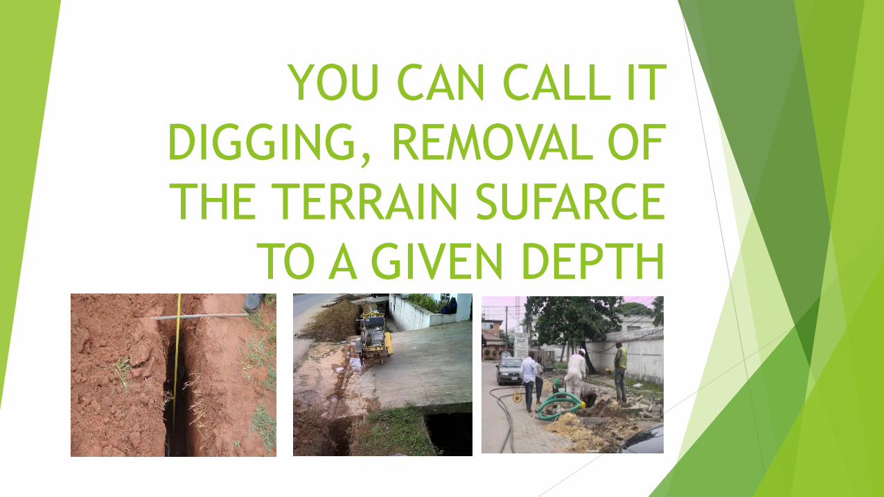
YOU CAN CALL IT
DIGGING, REMOVAL OF
THE TERRAIN SUFARCE
TO A GIVEN DEPTH
ASPHALT CUTTING, CONCRETE
BREAKING, THRUST BORING, PAVE
STONES, SWAMP AREAS, BRIGDE
CROSSING are some of the terrain to
work with during
TRENCHING
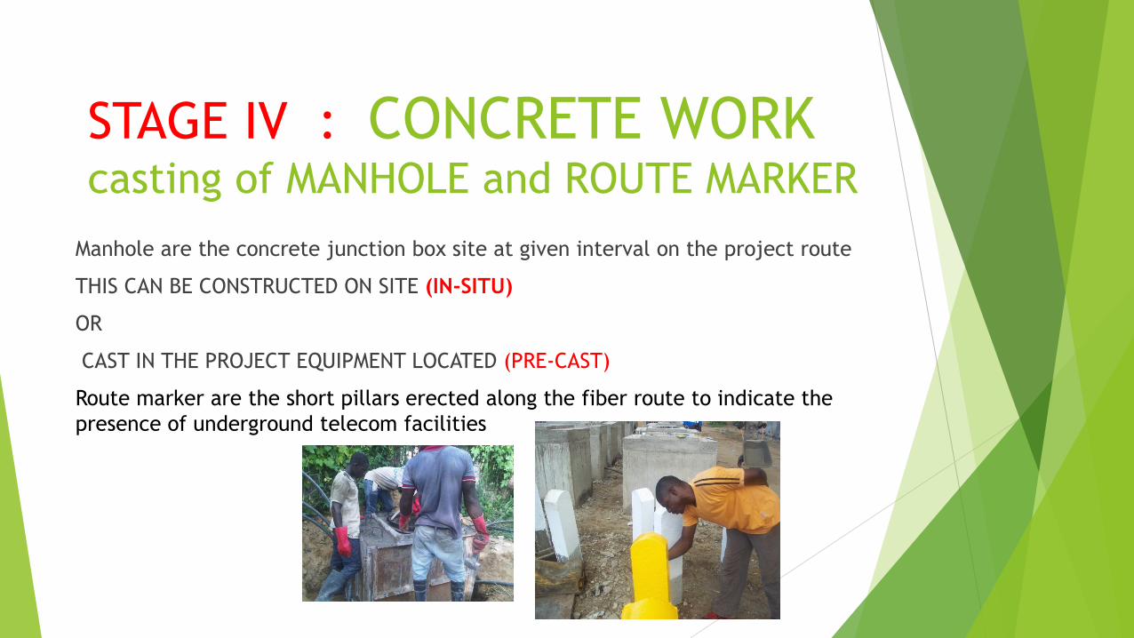
STAGE IV : CONCRETE WORK casting of MANHOLE and ROUTE MARKER
Manhole are the concrete junction box site at given interval on the project route
THIS CAN BE CONSTRUCTED ON SITE (IN-SITU)
OR
CAST IN THE PROJECT EQUIPMENT LOCATED (PRE-CAST)
Route marker are the short pillars erected along the fiber route to indicate the
presence of underground telecom facilities
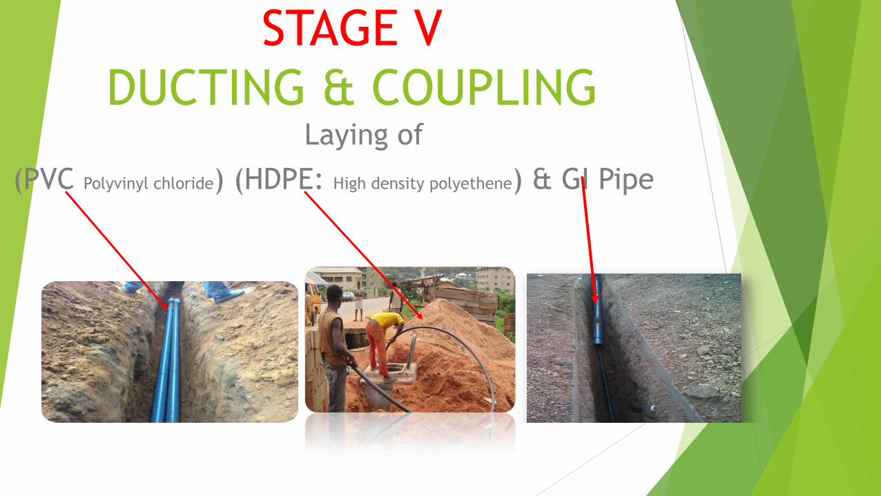
STAGE V
DUCTING & COUPLING Laying of
(PVC Polyvinyl chloride) (HDPE: High density polyethene) & GI Pipe

WHAT IS COUPLING JOINING OF DUCTS TOGETHER FOR CONTINUITY
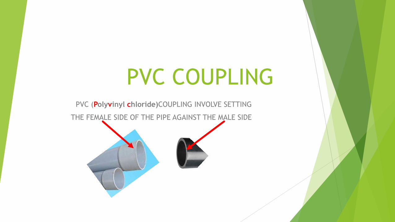
PVC COUPLING PVC (Polyvinyl chloride)COUPLING INVOLVE SETTING
THE FEMALE SIDE OF THE PIPE AGAINST THE MALE SIDE
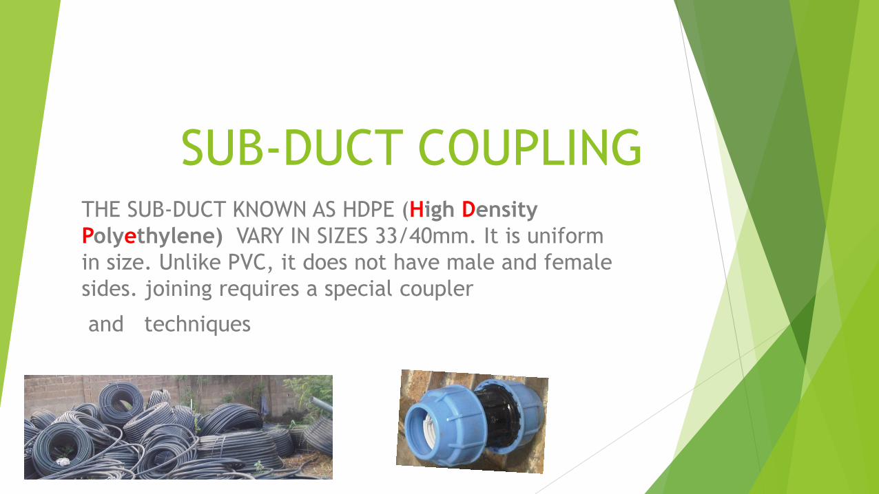
SUB-DUCT COUPLING THE SUB-DUCT KNOWN AS HDPE (High Density
Polyethylene) VARY IN SIZES 33/40mm. It is uniform
in size. Unlike PVC, it does not have male and female
sides. joining requires a special coupler
and techniques
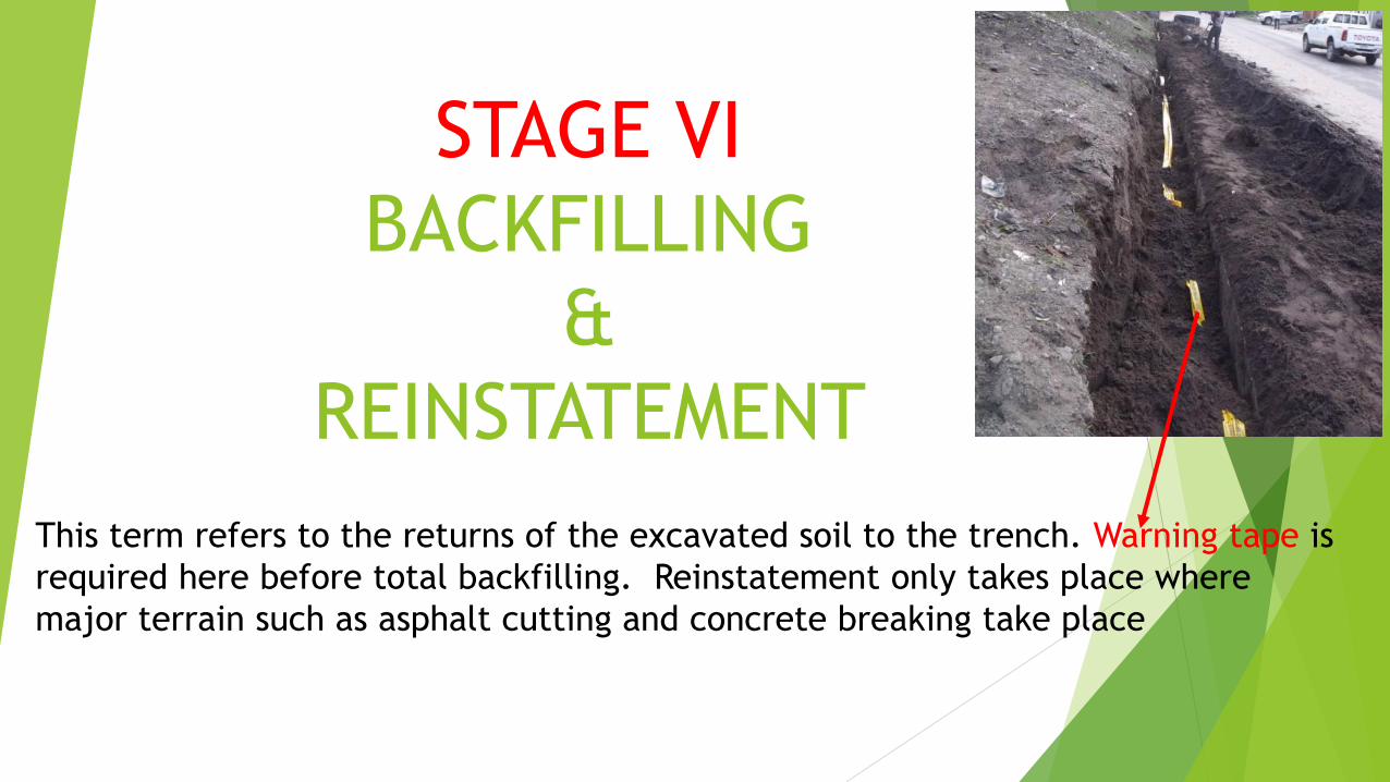
STAGE VI
BACKFILLING
&
REINSTATEMENT
This term refers to the returns of the excavated soil to the trench. Warning tape is
required here before total backfilling. Reinstatement only takes place where
major terrain such as asphalt cutting and concrete breaking take place
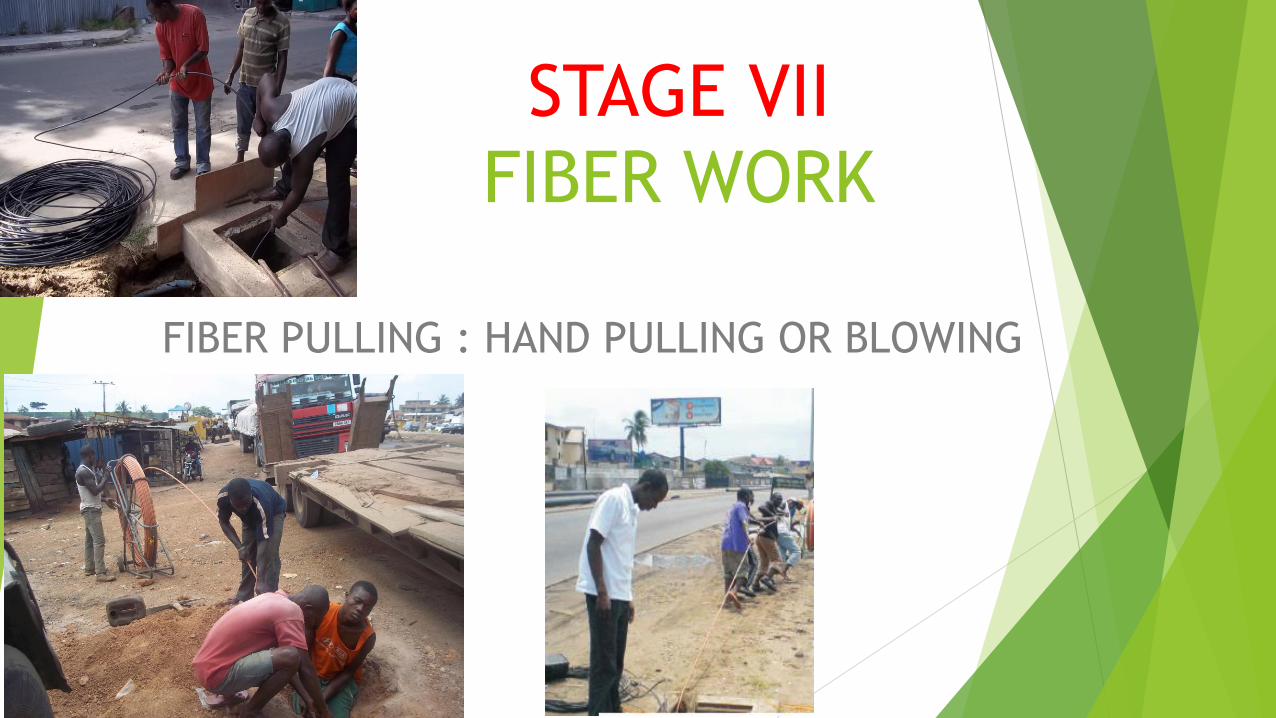
STAGE VII
FIBER WORK
FIBER PULLING : HAND PULLING OR BLOWING
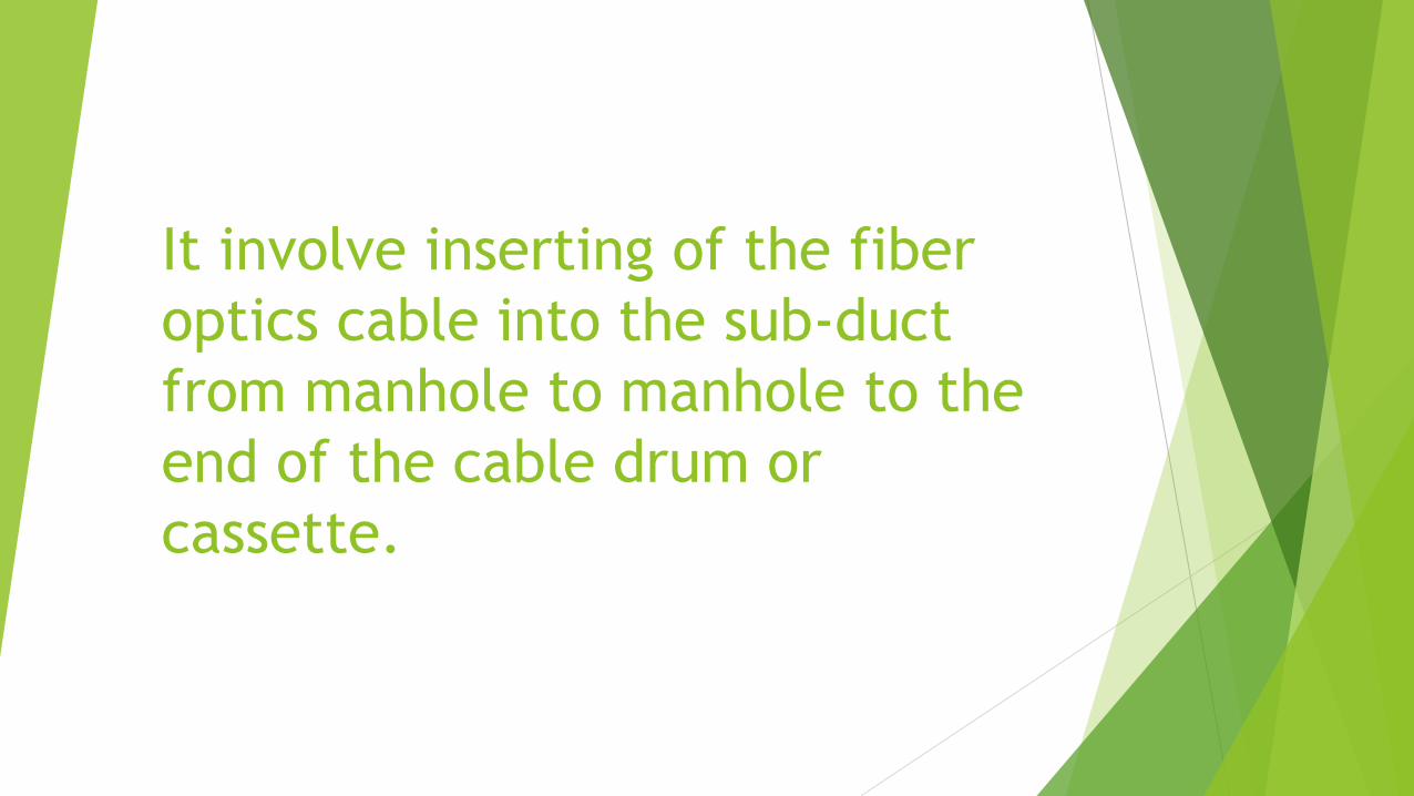
It involve inserting of the fiber
optics cable into the sub-duct
from manhole to manhole to the
end of the cable drum or
cassette.
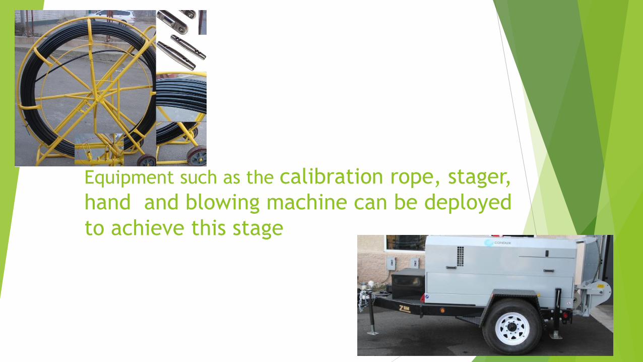
Equipment such as the calibration rope, stager,
hand and blowing machine can be deployed
to achieve this stage
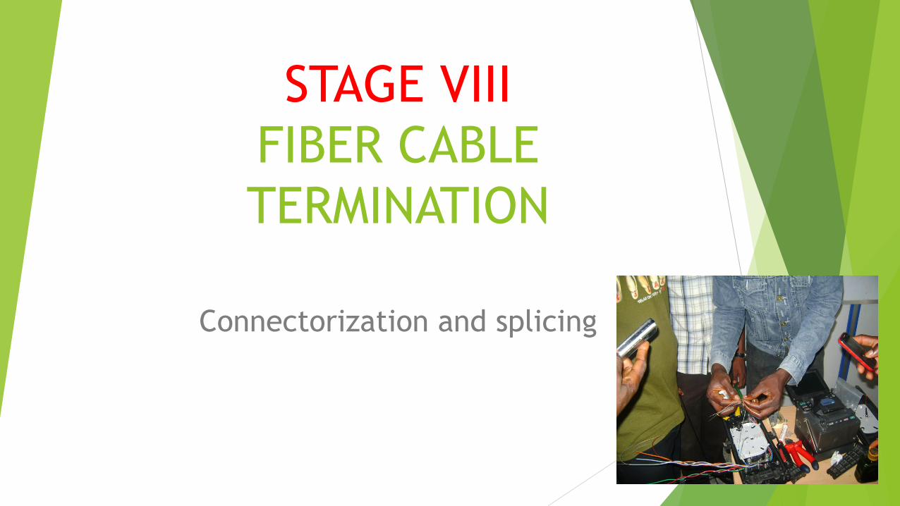
STAGE VIII
FIBER CABLE
TERMINATION
Connectorization and splicing
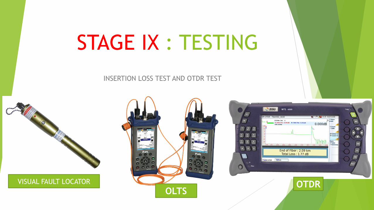
STAGE IX : TESTING
INSERTION LOSS TEST AND OTDR TEST
VISUAL FAULT LOCATOR
OLTS OTDR

STAGE X DOCUMENTATION OF THE TEST RESULT, AS- BUILT DRAWING

For all your
fiber Optics certification
training
in
Nigeria
visit
www.imtfiber.com
and
www.imtcomputer.net
Related Documents