Fiber Optic Passive Components

Welcome message from author
This document is posted to help you gain knowledge. Please leave a comment to let me know what you think about it! Share it to your friends and learn new things together.
Transcript

Fiber Optic Passive Components

Max RothwanglManaging Director
( (+43) (0)3862 23990 410
6 (+43) (0)3862 23990 452
Managing Director:
Robert Hofreiter Key Account Manager (A, AL, BIH, HR, KOS, MK, MNE, SLO, SRB)
( (+43) (0)3862 23990 683
6 (+43) (0)3862 23990 672
Key Account Manager:
Sales Director:
Uwe Löcker Key Account Manager (B, BG, BY, CH, CY, DK, E, EST, FIN, GR, H, I, IRL, L, LT, LV,
N, P, RO, S)
( (+43) (0)3862 23990 690
6 (+43) (0)3862 23990 672
Holger Quest Key Account Manager (D)
( (+49) (0)172 95 99 471
6 (+43) (0)3862 23990 672
Product Development Manager:
Gerd Pichler Product Development Manager Fiber Optic Key Account Manager (I, NL, D)
( (+43) (0)3862 23990 441
6 (+43) (0)3862 23990 672
Robert Maier Product Development Manager Copper Cables
( (+43) (0)3862 23990 684
6 (+43) (0)3862 23990 672
PENGG KABEL GmbH is an Austrian producer of high-tech telecomcopper and fiber optic cables and their components with usage in awide range of applications in the area of railway technology, telecom-munication and infrastructure. We have two sites, one in Kapfenbergwhere we produce copper cables and the second in Wartberg wherewe are specialised on fiber optic cables and components.
In addition to a quality management system according to EN ISO9001 we set a high value on the fact that the loads of the environmentare kept as small as possible. Therefore we have also implementedan environmental management system according to EN ISO 14001.
The rapid development of modern regional and supra-regional high-speed data networks makes steadily increasing demands on fiber optical cables and fiber optical cable plugs and components. We takethis market request into consideration and produce fiber optic cablesand pre-assembled connectors with singlemode, multimode andNZDS fibers for highest requirements.
The range of types covers all usual ground cable constructions in jelly-filled and dry-filled design as well as metallic and metal-free (PA) rodent protection. Beyond that also metal-free overhead cables(ADSS) in self-supporting design for spans up to 700m and for 20kVor high voltage systems will be manufactured. Also special cable designs can be manufactured in Wartberg according to customers requirements.
By means of most modern measuring equipment the fiber optic cables are submitted according to international standards and regulations by permanent tests and checks. These measurement results serves as a basis for the constant advancement of our fiberoptic cables.
With a constant expansion of most modern finishing technique withintegrated production logistics, we are in the position to supply fiberoptic cables on drums with all fiber types available on the free fibermarket safely and reliably for its customer.
Flexibility and customer proximity are the bases for a successful development on the market. New developments and product improvements are always necessary. Apart of the permanent searchfor improvements of our products, our efforts for the future run towards reduction of production time, increase of flexibility and constant improvement of quality, in order to be a reliable partner forour customers.
Contact Persons

Fiber Optic Passive ComponentsIndex
3Fiber Optic Passive Components • 02/2017 • © by Pengg Kabel GmbH • Subject to technical alterations
Pre-assembled Connectors from page 5
Optical Distribution System (OPDISYS®) from page 15
Termination System for 19“ Technology from page 51
Splice Cassettes from page 57
Termination Boxes and Wall Outlets from page 61
Interconnect Cases and Distribution Cabinets from page 73
Fiber Optic Enclosures from page 83
Equipment for laying cables near rails from page 101


Pre-assembled Connectors / Adapters
5Fiber Optic Passive Components • 02/2017 • © by Pengg Kabel GmbH • Subject to technical alterations
Connector mounting, Installation services page 6
Fiber Pigtails, Patch Cable, Breakout Cable, Assembled Patch Panels page 7
FC/PC, FC/APC page 8
SC/PC, SC/APC page 9
LC/PC, LC/APC page 10
E2000/PC, E2000/APC page 11
Pre
-ass
emb
led
C
onne
ctor
s /
Ad
apte
rs
ST/PC, FSMA page 12
MTRJ, DIN page 13
MU/PC page 14
Measuring launch fiber page 14

Pre-assembled Connectors / Adapters
Connector mounting, Installation services
6 Fiber Optic Passive Components • 02/2017 • © by Pengg Kabel GmbH • Subject to technical alterations
Connector Mounting
Fiber- or cablepigtails, patchca-
bles and fiber-optic cables are
cut in required lengthes, accor-
dingly to customers requests
and then prepared for the con-
nector assembling.
The following assembling pro-
cess consists of several steps
like uncovering and adhesive
bonding the fiber into the ferrule
and hardening, which is made
with precise equipment and by
expert personnel to meet spe-
cified loss values. After harde-
ning the connector ferrules are polished in several steps on accordant machines to give the connector ferrules the final shape and surface
quality. The finished and polished connectors are running through our quality control department. The connectors are tested for insertion loss,
return loss by OTDR and for geometrical surface quality by interferometer.
All these processes of manufacturing and quality controlling are done by qualified and expert personnel at our new fiber optic facilities in Wart-
berg. These rooms meet all the requirements concerning climatisation and workspace for optimum working conditions.
Installation services
In the field of passive fiber optic components technology, we also offer
you installation services.
Numerous references attest to our diversified know-how - here is a
selection:
highway A9 – project Tunnel Wald and Pretallerkogeltunnel (2016)•
highway A9 – project Gleinalmtunnel (2016)•
highway A10 – project Kroislerwandtunnel (2016)•
highway A1 – project Tunnel Liefering (2016)•
motorway B67a – project Ringstraße Südgürtel Graz (2016)•
highway A10 – project Oswaldibergtunnel (2016)•
highway A9 – project INS VAK TU Wartberg (2015)•
highway A44 – project Tunnel Birth D (2014 – 2015)•
highway S1 – project Tunnel Hennersdorf Ast Güterterminal (2014-2015)•
mediacenter Graz, MCG (2014)•

7Fiber Optic Passive Components • 02/2017 • © by Pengg Kabel GmbH • Subject to technical alterations
Pre-assembled Connectors / Adapters
Fiber Pigtail
Fiber pigtails, 900µm, pre-assembled with one or two connectors
(connectors see page 8 - 14); only for installation in cabinets.
Fiber pigtails are not suitable for patch-connections or for the
installation in conduits and cabinets.
Patch Cable
Indoor cable, 2-3 mm, pre-assembled connectors on both ends
(connectors see page 8 - 14); for connection of terminals or patch
panels / cabinets.
Because of their mechanical stability, patch cables can be used in
cabinets, sleeves and with some restrictions in cable ducts. However,
they may not be drawn in or injected.
On request
• Duplex-cables, Zip Cords
• with different connectors
Breakout Cable
Breakout cable, pre-assembled at one or both ends (connectors see
page 8 - 14); cable length up to 1000 m.
For connection of terminals across greater distances.
On request
• length >1000 m
• with cable protective tube for safe laying (to be removed after
laying)
• Center-unitubecable with distribution-adapter for splice-free
mounting
• pre-assembled cables on drums
Assembled Patch Panels
Patch panels and boxes pre-assembled with adapters and fiber pigtails. Due the preparing and stripping the pigtails in the correct length in the
splice cassette they are ready for splicing.
Fiber Pigtails, Patch Cable, Breakout Cable, Assembled Patch Panels

Pre-assembled Connectors / Adapters
FC/PC, FC/APC
8 Fiber Optic Passive Components • 02/2017 • © by Pengg Kabel GmbH • Subject to technical alterations
Connector / Adapter FC/PC
Description
• usable for SM and MM fibers
• each connector tuned for minimum insertion loss
• colour of boot: blue
• locks with coupling ring
• metal housing with zirconia ferrule
• 100% adjustment and testing on optical powermeter
• adapter with flange mount or D-hole
On request
• other attenuation values (IL & RL)
• other colours of boot
• other connector manufacturer
Technical Data
standard IEC 60874
insertion loss (IL) for SM (typical)
mean value < 0.08 dB (to reference connector)
max. value < 0.20 dB (to reference connector)
return loss (RL) > 50 dB (SM)
UPC-polishing
for Ø 0.9 mm and Ø 2.0-3.0 mm cables
Connector / Adapter FC/APC
Description
• typical usable for SM fibers
• colour of boot: green
• locks with coupling ring
• metal housing with zirconia ferrule
• adapter with flange mount or D-hole
On request
• other attenuation values (IL & RL)
• other connector manufacturer
Technical Data
standard IEC 60874
insertion loss (IL) (typical)
mean value < 0.20 dB (to reference connector)
max. value < 0.30 dB (to reference connector)
return loss (RL) > 65 dB
8° polishing (APC-polishing)
for Ø 0,9 mm and Ø 2.0-3.0 mm cables

9Fiber Optic Passive Components • 02/2017 • © by Pengg Kabel GmbH • Subject to technical alterations
Pre-assembled Connectors / Adapters
SC/PC, SC/APC
Pre
-ass
emb
led
C
onne
ctor
s /
Ad
apte
rs
Connector / Adapter SC/PC
Description
• usable for SM and MM fibers
• colour of boot: blue (SM), beige (MM)
• automatic lock in adapter
• unlocks by pulling on housing („push-pull“)
• plastic housing with zirconia ferrule
• can be used as duplex connector with duplex clip
• adapter with flange mount or snap in mount
On request
• adapter versions with different shutters available
• other attenuation values (IL & RL)
• other colour of boot
• other connector manufacturer
Technical Data
standard IEC 60874
Insertion loss (IL) for SM (typical)
mean value < 0.15 dB (to reference connector)
max. value < 0.25 dB (to reference connector)
return loss (RL) > 50 dB (SM)
UPC polishing
for Ø 0.9 mm and Ø 2.0-3..0 mm cable
Connector / Adapter SC/APC
Description
• typical usable for SM fibers
• colour of boot: green
• automatic lock in adapter
• unlocks by pulling on housing („push-pull“)
• plastic housing with zirconia ferrule
• can be used as duplex connector with duplex clip
• adapter with flange mount or snap in mount
On request
• adapter versions with different shutters available
• other attenuation values (IL & RL)
• other connector manufacturer
Technical Data
standard IEC 60874
insertion loss (IL) (typical)
mean value < 0.20 dB (to reference connector)
max. value < 0.30 dB (to reference connector)
return loss (RL) > 65 dB
8° polishing (APC-polishing)
for Ø 0.9 mm and Ø 2.0-3.0 mm cable

Pre-assembled Connectors / Adapters
LC/PC, LC/APC
10 Fiber Optic Passive Components • 02/2017 • © by Pengg Kabel GmbH • Subject to technical alterations
Connector / Adapter LC/PC
Description
• one-half the size of current industry standards
• increases panel density - provides duplex connection in 50 %
less space
• available in SM, MM versions (SM-blue / MM-beige)
• user-friendly audible latch to indicate proper mating
• simplex and duplex version available
• push-pull locking
• plastic housing with zirconia ferrule
• adapter with flange mount or snap in mount
• duplex adapter fits in one SC-simplex hole
Connector / Adapter LC/APC
Description
• one-half the size of current industry standards
• increases panel density - provides duplex connection in 50 %
less space
• green boot and housing
• SM-Angle (APC) polishing
• user-friendly audible latch to indicate proper mating
• simplex and duplex version available
• push-pull locking
• plastic housing with zirconia ferrule
• adapter with flange mount or snap in mount
• duplex adapter fits in one SC-simplex hole
Technical Data
standard IEC 61754-20
insertion loss (IL) for SM (typical)
mean value < 0.15 dB (to reference connector)
max. value < 0.25 dB (to reference connector)
return loss (RL) > 50 dB (SM)
for Ø 0.9 mm and Ø 2.0-3.0 mm
strain relief 100N
Technical Data
standard IEC 61754-20
insertion loss (IL) for SM (typical)
mean value < 0.15 dB (to reference connector)
max. value < 0.30 dB (to reference connector)
return loss (RL) > 65 dB
for Ø 0.9 mm and Ø 2.0-3.0 mm
strain relief 100N

11Fiber Optic Passive Components • 02/2017 • © by Pengg Kabel GmbH • Subject to technical alterations
Pre-assembled Connectors / Adapters
E2000/PC, E2000/APC
Pre
-ass
emb
led
C
onne
ctor
s /
Ad
apte
rs
Connector / Adapter E2000/PC
Description
• usable for SM and MM fibers
• each connector tuned for minimum insertion loss
• colour of boot and housing: blue (SM), beige (MM)
• locks with locking lever
• plastic housing with zirconia ferrule
• automatic dust protection flap
• simplex and duplex versions available
On request
• other attenuation values (IL & RL)
• other boot colours
• accessories
Connector / Adapter E2000/APC
Description
• usable for SM fibers
• each connector tuned for minimum insertion loss
• colour of boot and housing: green
• locks with locking lever
• plastic housing with zirconia ferrule
• automatic dust protection flap
• simplex and duplex versions available
On request
• other attenuation values (IL & RL)
• other boot colours
• accessories
Technical Data
standard -
insertion loss (IL ):
mean value < 0,10 dB (to reference connector)
max. value < 0.20 dB (to reference connector)
return loss (RL) > 65 dB
8° polishing (APC-polishing)
for Ø 0,9 mm and Ø 2.0-3.0 mm cables
Technical Data
standard -
insertion loss (IL ) (typical)
mean value < 0.10 dB (to reference connector)
max. value < 0.20 dB (to reference connector)
return loss (RL) > 50 dB (SM)
PC polishing
for Ø 0.9 mm and Ø 2.0-3.0 mm cables
ST/PC, FSMA
12 Fiber Optic Passive Components • 02/2017 • © by Pengg Kabel GmbH • Subject to technical alterations
Connector / Adapter FSMA
Description
• usable for MM fibers
• colour of boot: black
• locks with coupling ring
• metal housing with metal ferrule
• adapter with D-hole
On request
• other attenuation values (IL & RL)
• other colour of boot
• other connector manufacturer
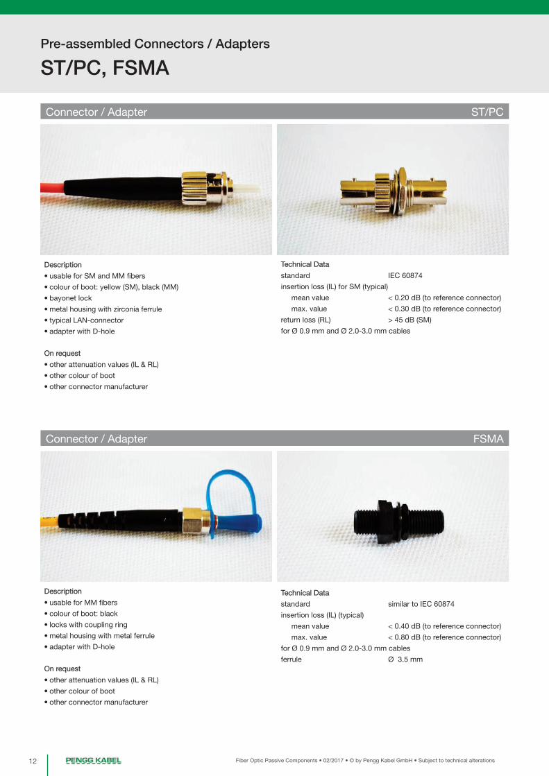
Connector / Adapter ST/PC
Description
• usable for SM and MM fibers
• colour of boot: yellow (SM), black (MM)
• bayonet lock
• metal housing with zirconia ferrule
• typical LAN-connector
• adapter with D-hole
On request
• other attenuation values (IL & RL)
• other colour of boot
• other connector manufacturer
Pre-assembled Connectors / Adapters
Technical Data
standard IEC 60874
insertion loss (IL) for SM (typical)
mean value < 0.20 dB (to reference connector)
max. value < 0.30 dB (to reference connector)
return loss (RL) > 45 dB (SM)
for Ø 0.9 mm and Ø 2.0-3.0 mm cables
Technical Data
standard similar to IEC 60874
insertion loss (IL) (typical)
mean value < 0.40 dB (to reference connector)
max. value < 0.80 dB (to reference connector)
for Ø 0.9 mm and Ø 2.0-3.0 mm cables
ferrule Ø 3.5 mm

13Fiber Optic Passive Components • 02/2017 • © by Pengg Kabel GmbH • Subject to technical alterations
Pre-assembled Connectors / Adapters
MTRJ, DIN
Pre
-ass
emb
led
C
onne
ctor
s /
Ad
apte
rs
Connector / Adapter MTRJ
Description
• usable for MM fibers
• colour of boot: black
• „snap in” - lock
• plastic housing
• adapter with flange mount
Note
• please order with type of connector (female or male)
On request
• other attenuation values (IL & RL)
Connector / Adapter DIN
Description
• usable for SM and MM fibers
• colour of boot: yellow (SM), black (MM)
• locks with coupling ring
• metal housing with zirconia ferrule
• adapter with D-hole
On request
• APC-polishing
• other attenuation values (IL & RL)
• other boot colour
• other connector manufacturer
Technical Data
standard DIN 47256 (LSA)
insertion loss (IL )for SM (typical)
mean value < 0.25 dB (to reference connector)
max. value < 0.35 dB (to reference connector)
return loss (RL) > 45 dB (SM)
PC-polishing
for Ø 0.9 mm and Ø 2.0-3.0 mm cables
Technical Data
Standard -
insertion loss (IL ) (typical)
mean value < 0.50 dB (to reference connector)
max. value < 0.70 dB (to reference connector)
return loss (RL) > 30 dB
for Mini-Duplex cables

Pre-assembled Connectors / Adapters
MU/PC, Measuring launch fiber
14 Fiber Optic Passive Components • 02/2017 • © by Pengg Kabel GmbH • Subject to technical alterations
Connector / Adapter MU/PC
Description
• usable for SM and MM fibers
• plastic housing with zirconia ferrule
• unlocks by pulling on housing („push-pull“)
• colour of boot: brown
• can be used as duplex connector with duplex clip
• usable for mini simplex / duplex cable
• adapter with „snap-in“ mount
• adapter available in Duplex-design
On request
• other attenuation values (IL & RL)
• other boot colours
Measuring launch fiber
Description
• Both fibers are configurable with different:
fiber types | fiber lengths | connectors
• The connection cables of both launch fibers are wound
separately and thereby independently usable
• Water and dust-repellent
• 100% servicing - Measuring connector damaged or other than
planned? No problem: Spare parts available at any time!
• Including interferometer protocol
Technical Data
standard IEC 60874
insertion loss (IL) for SM (typical)
mean value < 0.20 dB (to reference connector)
max. value < 0.30 dB (to reference connector)
return loss (RL) > 40 dB (SM)
PC-polishing
for Ø 0.9 mm and Ø 2.0-3.0 mm cables
Technical Data
size 235x195x105mm
fiber length 500m, 1000m (max. 2 x 1000m)
weight 1,6 kg
material - plastic (shock proofed box)
- inside made of aluminium
connection length 3m at dual fiber, 5m at single fiber

Optical Distribution System (OPDISYS®)
15Fiber Optic Passive Components • 02/2017 • © by Pengg Kabel GmbH • Subject to technical alterations
OPDISYS® - Racks page 17
OPDISYS® - Fiber modules page 21
OPDISYS® - Accessories page 25
OPDISYS® - Planning process, Ordering checklist page 27
OPDISYS® - Dimensions page 28
OPDISYS® - Configuration examples page 29
Pre
-ass
emb
led
C
onne
ctor
s /
Ad
apte
rsO
ptic
al D
istr
ibut
ion
Sys
tem
(OP
DIS
YS
®)
OPDISYS® - Integration into other systems page 31
OPDISYS® intelligent (patch management system) page 32
OPDISYS® compact page 36
OPDISYS® page 16
OPDISYS® compact - Carrier page 37
OPDISYS® compact - Fiber modules page 42
OPDISYS® compact - Multi tube cable divider page 44
OPDISYS® compact - Examples of installation page 49

Optical Distribution System (OPDISYS®)
OPDISYS® - Racks
16 Fiber Optic Passive Components • 02/2017 • © by Pengg Kabel GmbH • Subject to technical alterations
Field of Application
OPDISYS® is an optical fibre distribution/
patch system for Passive Optical Networks
(PON). The main application of the system
is fiber termination in Central Offices of
FTTH networks. Our OPDISYS® combines
all the advantages of the Central Office sy-
stems available on the market.
- Maximum fiber density for standard
rack: 960/1920 (SC/LC)
- Comfortable patching with two-sided
overlength patchcord storage
- 3 different rack heights: 32HU/1800mm,
40HU/2200mm, 48HU/2600mm
- 2 optional extensions (for cable gui-
dance and gas blocker integration)
- Open and closed rack version
- Removable and rotatable splice/patch
Fiber Module
- 0.5HU as well as 1HU Fiber Module
available
- Fiber Module frontplate with two diffe-
rent cut-outs and adapter mounting
through snap-in angled holder
- 45 degrees snap-in angled holders for
all conventional adapter types: SCsx,
LCdx, E2000, LX.5, FC, ST
- Possibility to blow fibers directly up to
the fiber modules
- Integration of gas-blockers on incoming
tubes possible
Features
Product description - OPDISYS®-Optical Distribution Frame
OPDISYS® is an Optical Distribution Frame (ODF) system specially designed for Fiber-To-The-Home (FTTH) applications. It is a modular system
consisting of a basic rack, cable management, Mandrel Extension Racks and Gasblocker Extension Racks and Fiber Modules. Thanks to its
design this system is very flexible. The extension racks can be ordered and combined individually according to the customer´s needs. Each
Fiber Module has a front plate with two types of uniform cut-out patterns into which snap-in angled holders fitting into the required adapter
type can be inserted. This snap-in angled holder also ensures a 45 degree angle of the adapter is maintained. Each fiber module can be used
as a left-side as well as a right-side Fiber Module.
Two different types of fiber protection are supported, either high rigidity harness PBT tubes or microduct tubes. If microduct tubes are used in
conjunction with gasblockers, the Gasblocker Extension Rack ensures an orderly cable guidance and mounting of the gasblockers. The
OPDISYS®-System can be integrated into a 19’’ rack as well as into an outdoor street cabinet (see page 35 for additional information).

17Fiber Optic Passive Components • 02/2017 • © by Pengg Kabel GmbH • Subject to technical alterations
Optical Distribution System (OPDISYS®)
OPDISYS® - Racks
Pre
-ass
emb
led
C
onne
ctor
s /
Ad
apte
rsO
ptic
al D
istr
ibut
ion
Sys
tem
(OP
DIS
YS
®)
Product description - OPDISYS®-rack
The OPDISYS®-rack is the core component of every OPDISYS®-system. Both, an open
version as well as a closed version, are available. An open version rack is turned into a
closed version rack by installing side panels and doors. The rack accommodates the
fiber module carrier, the cable entry plates, all types of extension modules and, if a clo-
sed version is required, the side panels as well as the front doors.
Rack features:
- Top or bottom cable entry possible.
- Top cover provides openings for cables (optionally with brushes)
- Easy expansion with side-by-side or back-to-back mounting of racks.
- Solutions for cross-connect and interconnect configurations.
- Backside vertical cable guidance for incoming cables.
- Bending radius protection of 30mm for fibers and patchcords.
- Intelligent patchcord management.
- Vertical patchcord cable guidance on left and right side.
- Mandrels on left and right side of the rack provide sufficient space for patchcord
overlength storage.
- Integrated patchcord management to adjacent racks avoids the usage of external
ducts.
Colour RAL 7035, light grey
Material Powder coated steel
Flammability UL 94V-0
Technical specifications
Single row racks
The Single row racks for the OPDISYS®-System are available in three different heights.
The Single Row Rack can be equipped optionally with two extension racks as well as
side panels and one single door. When adding extension racks, several combinations
are possible:
- one Mandrel Extension Rack
- one Gasblocker Extension Rack
- a combination of one Gasblocker Extension Rack and one Mandrel Extension Rack
Various fixing sets (see information in the accessories section of this document) are avai-
lable which allow you to mount the rack to either wall or ceiling or floor. It is possible to
mount several racks next to each other back-to-back (requires only floor mounting) or
next to each other (requires mounting both to floor and ceiling or wall for stability rea-
sons). A stand-alone Single Row Rack should always be fixed to both floor and ceiling
or wall.

Optical Distribution System (OPDISYS®)
OPDISYS® - Racks
18 Fiber Optic Passive Components • 02/2017 • © by Pengg Kabel GmbH • Subject to technical alterations
Double row racks
The Double row racks are available in three different heights. The Double Row Rack can
be equipped optionally with two extension racks as well as side panels and a pair of
doors. For the Double Row Rack it is possible to add up to two extension racks on each
side. It can be either a Mandrel Extension Rack or a Gasblocker Extension Rack.
Various fixing sets (see information in the accessories section of this document) are avai-
lable which allow you to mount the rack to either wall or ceiling or floor. It is possible to
mount several racks next to each other back-to-back (requires only floor mounting) or
next to each other (requires mounting both to floor and ceiling or wall for stability rea-
sons). A stand-alone Double Row Rack should always be fixed to both floor and ceiling
or wall.
FODR 450/32HU FODR 450/40HU FODR 450/48HU
Rack height 1800mm 2200mm 2600mm
Rack width 450mm 450mm 450mm
Rack weight (open / closed) 50kg / 77kg 62kg / 92kg 74kg / 106kg
Max. amount of modules 32 full size or 64 half size 40 full size or 80 half size 48 full size or 96 half size
Max. amount of fiber 384 SC/E2000 480 SC/E2000 576 SC/E2000
Terminations 768 LC/LX.5 960 LC/LX.5 1152 LC/LX.5
Dimensions & Capacity - without extensions
FODR 600/32HU FODR 600/40HU FODR 600/48HU
Rack height 1800mm 2200mm 2600mm
Rack width 600mm 600mm 600mm
Rack weight (open / closed) 60kg / 88kg 72kg / 105kg 84kg / 122kg
Max. amount of modules 32 full size or 64 half size 40 full size or 80 half size 48 full size or 96 half size
Max. amount of fiber 384 SC/E2000 480 SC/E2000 576 SC/E2000
Terminations 768 LC/LX.5 960 LC/LX.5 1152 LC/LX.5
Dimensions & Capacity - with mandrels
FODR 750/32HU FODR 750/40HU FODR 750/48HU
Rack height 1800mm 2200mm 2600mm
Rack width 750mm 750mm 750mm
Rack weight (open / closed) 71kg / 99kg 83kg / 116kg 98kg / 132kg
Max. amount of modules 32 full size or 64 half size 40 full size or 80 half size 48 full size or 96 half size
Max. amount of fiber 384 SC/E2000 480 SC/E2000 576 SC/E2000
Terminations 768 LC/LX.5 960 LC/LX.5 1152 LC/LX.5
Dimensions & Capacity - with mandrels and gasblocker integration

19Fiber Optic Passive Components • 02/2017 • © by Pengg Kabel GmbH • Subject to technical alterations
Optical Distribution System (OPDISYS®)
OPDISYS® - Racks
Pre
-ass
emb
led
C
onne
ctor
s /
Ad
apte
rsO
ptic
al D
istr
ibut
ion
Sys
tem
(OP
DIS
YS
®)
Extension racks and additional components
Mandrel Extension Rack
The mandrels are used for cable guidance of the jumper patchcords. An optionally available
back panel for the Mandrel Extension Rack must be installed when a closed version is nee-
ded.
Gasblocker Extension Rack
When using blow-in systems, gasblockers are essential in order to protect the installation
against gas and/or water entry. The Gasblocker Extension Rack can accommodate the gas-
blockers. The Gasblocker Extension Rack has a built-in back panel, so no extra back panel is
needed in order to turn it into a closed version.
Rack doors
If a closed rack version is required, doors can be attached to the single or double row rack.
Each door has an opening angle of 180°. The doors are equipped with an integrated lever and
lock and have an A4 document holder on their inner side.
Side and back panels
Side and back panels must be mounted with screws to achieve a closed rack version. The
side panel for the Single/Double Row Rack is different to the side panel for an Extension Rack.
Each side panel is useable for right as well as for left side mounting.
FODR 700/32HU FODR 700/40HU FODR 700/48HU
Rack height 1800mm 2200mm 2600mm
Rack width 700mm (750mm closed rack) 700mm (750mm closed rack) 700mm (750mm closed rack)
Rack weight (open / closed) 83kg / 112kg 98kg / 133kg 115kg / 162kg
Max. amount of modules 64 full size or 128 half size 80 full size or 160 half size 96 full size or 192 half size
Max. amount of fiber 768 SC/E2000 960 SC/E2000 1152 SC/E2000
Terminations 1536 LC/LX.5 1920 LC/LX.5 2304 LC/LX.5
Dimensions & Capacity - without extensions
Dimensions & Capacity - with mandrels
Dimensions & Capacity - with mandrels and gasblocker integration
FODR 1000/32HU FODR 1000/40HU FODR 1000/48HU
Rack height 1800mm 2200mm 2600mm
Rack width 1000mm 1000mm 1000mm
Rack weight (open / closed) 98kg / 142kg 118kg / 170kg 138kg / 197kg
Max. amount of modules 64 full size or 128 half size 80 full size or 160 half size 96 full size or 192 half size
Max. amount of fiber 768 SC/E2000 960 SC/E2000 1152 SC/E2000
Terminations 1536 LC/LX.5 1920 LC/LX.5 2304 LC/LX.5
FODR 1300/32HU FODR 1300/40HU FODR 1300/48HU
Rack height 1800mm 2200mm 2600mm
Rack width 1300mm 1300mm 1300mm
Rack weight (open / closed) 123kg / 171kg 148kg / 205kg 174kg / 233kg
Max. amount of modules 64 full size or 128 half size 80 full size or 160 half size 96 full size or 192 half size
Max. amount of fiber 768 SC/E2000 960 SC/E2000 1152 SC/E2000
Terminations 1536 LC/LX.5 1920 LC/LX.5 2304 LC/LX.5

Optical Distribution System (OPDISYS®)
OPDISYS® - Racks
20 Fiber Optic Passive Components • 02/2017 • © by Pengg Kabel GmbH • Subject to technical alterations
Scope of supply
Additionally to your ordered rack and extension parts and to the side and back panels the basis rack is preassembled as follows:
- Assembled vertical cable guidance
- Assembled patchcord guidance (on both sides for Single row racks)
- Assembled cable trough
- Assembled 8HU carrier units
- Assembled back side cable guidance
All fiber modules have to be ordered separately.
Required rack accessories, fiber protection type and length will be determined according to the OPDISYS® configuration process and have to
be ordered separately.

21Fiber Optic Passive Components • 02/2017 • © by Pengg Kabel GmbH • Subject to technical alterations
Optical Distribution System (OPDISYS®)
OPDISYS® - Fiber modules
Pre
-ass
emb
led
C
onne
ctor
s /
Ad
apte
rsO
ptic
al D
istr
ibut
ion
Sys
tem
(OP
DIS
YS
®)
Product description - Fiber modules
The multi-circuit management fiber modules are used as combined splice & patch modules. They
offer highest fiber density along with best maintainability. Maximum flexibility is guaranteed by metal
frontplates and 45° angled adapter holders for all conventional adapter types.
The fiber modules are available in 2 sizes:
- as half-size fiber modules with a height of 0,5HU
- as full-size fiber modules with a height of 1HU
Fiber modules can be equipped with different adapter types or with a closed frontplate without ad-
apters for a splice-through version (in this case, a loop- back connection of fibers can be done via
splices).
The material of the LSZH fiber modules is a Polycarbonate / ABS blend. The symmetrical design of
the multi-circuit management fiber modules allows you to use the same module for left- and right-
side mounting. A uniform module colour optimizes stock keeping, while individual threefold colour
code labelling (on front, side and cover) provides fast and clear module and fiber identification.
Features:
- Fiber Modules can be rotated by 90° and are removable from the rack
- Incoming fibers and pigtails are stored in separate areas
- Easy to snap in adapter holders allow comfortable cleaning of pigtail-connector ferrules by taking
off the adapter holders.
- Identical splice protection holder for both shrink and crimp splice protection
- Two-sided, easy to remove transparent covers per fiber module - bending radius protection for all
fibers and pigtails
- Overlength storage of incoming cable subtube is possible on the bottom side of the module
- Integration of splitters up to 1x64 possible
Colour RAL 7035, light grey
Material Powder coated steel
Flammability UL 94V-0
Weight (half size module) 105 grams (without adapters and pigtails)
Weight (full size module) 145 grams (without adapters and pigtails)
Technical specifications
SCsx LCdx E2000sx E2000dx LX.5 ST FC
Half Size Fiber Module 6 6 6 - 6 6 6
Full Size Fiber Module 12/16 12 12/16 12 12 12/16 12/16
SCsx LCdx E2000sx E2000dx LX.5 ST FC
Half Size Fiber Module 6 12 6 - 12 6 6
Full Size Fiber Module 12/16 24 12/16 24 24 12/16 12/16
Max. amount of adapters
Max. amount of pigtails
Heat shrink splice protection Crimp splice protection
Half Size Fiber Module 16 16
Full Size Fiber Module 32 48
Max. amount of splices

Optical Distribution System (OPDISYS®)
OPDISYS® - Fiber modules
22 Fiber Optic Passive Components • 02/2017 • © by Pengg Kabel GmbH • Subject to technical alterations
Scope of supply
Each Fiber Module is equipped with:
- Frontplate
- Snap-in angled holders
- Rubber shrink/crimp splice protection holder
- Fiber protection pipe holder
- Two transparent covers.
- Designation label
- Door latch
- Inserted adapters and pigtails
A shrink or crimp splice protection is not included in the fiber module and has to be ordered separately.

23Fiber Optic Passive Components • 02/2017 • © by Pengg Kabel GmbH • Subject to technical alterations
Optical Distribution System (OPDISYS®)
OPDISYS® - Fiber modules
Pre
-ass
emb
led
C
onne
ctor
s /
Ad
apte
rsO
ptic
al D
istr
ibut
ion
Sys
tem
(OP
DIS
YS
®)
Product description - Splitter Fiber modules
There are different types of Splitter Fiber Modules available in order to integrate a PLC
splitter into the Fiber Module. It is possible to integrate all types of splitters starting
from 1:4 up to 1:128.
The Splitter Fiber Module consists of either two Half Size Fiber Modules or one or two
Full Size Fiber Modules (depending on the splitter ratio needed). Special frontplates
designed for splitter usage ensure clearly arranged cable guidance for both incoming
signal patchcable and outgoing signal patchcables. We offer various pre configured
adapter configurations with integrated splitters, ready to use. Other adapter combi-
nations are available upon request.
The Splitter Fiber Modules are available as 1:8, 1:16, 1:32 and 1:64 versions. The ratio
indicates the amout of SC simplex ports, the actual ratio can be higher when using
higher denisty adapter systems such as LC (see „Splitter Fiber Modules - Technical
Specification“-table below).
All other technical parameters for the Splitter Fiber Modules are equivalent to those
of the standard Fiber Modules. For PLC splitter technical details please see separate
datasheet.
Max. amount of splicesMax. amount
of imputs
Max. amount
of outputs
Amount of
modules
Space in module
carrier needed
1:8 Splitter Fiber Module 1 81) / 162) 1 Full Size 1HU
1:16 Splitter Fiber Module 2 161) / 322) 2 Half Size 2HU
1:32 Splitter Fiber Module 1 321) / 642) 2 Half Size 3HU
1:64 Splitter Fiber Module 1 641) / 1282) 2 Full Size 4HU
Scope of supply
Each Splitter Fiber Module is equipped with:
- Frontplate
- Snap-in angled holders
- Two transparent covers
- Designation label
- Door latch
- Inserted adapters and pigtails and PLC splitter (if ordered as assembled version)
1) When using SCsx, FCsx, STsx, LX.5sx, E2000sx adapters2) When using LCdx, E2000dx adapters

Optical Distribution System (OPDISYS®)
OPDISYS® - Fiber modules
24 Fiber Optic Passive Components • 02/2017 • © by Pengg Kabel GmbH • Subject to technical alterations
MPO/MTP® integration into OPDISYS®
We also offers MPO/MTP® ready Fiber Modules. In general, there are two possibilities to integrate the MPO/MTP® system into a OPDISYS®
rack. You can use either MPO/MTP®-ready Fiber Modules or you can use separate MPO/MTP® patch fields at the top of the fiber module area
or at the extension bars.
MPO/MTP®-ready Fiber Modules
The MPO/MTP®-ready Fiber Module contains a MPO/MTP® adapter holder inside the module. To connect the adapters at the frontplate with
the MPO/MTP® adapter inside the module, a MTP® direct split cable is used. The MPO/MTP®-ready Fiber Module is based on the standard
Fiber Module, containing an MPO/MTP® adapter holder instead of the fiber protection sleeve holder.
Product description - MPO/MTB®
The MPO/MTP®-ready Fiber Module can be ordered preassembled as shown above with mounted adapters and a MTP® direct split cable
already installed. This ensures a quick installation as the Fiber Module comes ready for use. Just connect your incoming MPO/MTP® cable to
the MPO/MTP® adapter located inside the Fiber Module and the Fiber Module is integrated into your network. The MPO/MTP®-ready Fiber Mo-
dule is available only as a Full Size Fiber Module (1HU).
MPO/MTP® patching areas
If the OPDISYS®-rack is equipped with MPO/MTP® patching areas which can either be located on top of the Fiber Module rows or at the ex-
tension racks, a MTP® fanout cable is used to connect the front plate adapters to the MPO/MTP® patch field. The Fiber Module needed can be
ordered preassembled as well, equipped with adapters and the MPO/MTP® cable. The divider for the fanout cable is located inside the Fiber
Module. The cable leads from the Fiber Module directly to the MPO/MTP® patching area, therefore its length must be specified upon ordering.
Top patching area
MPO/MTP® patching area above the Fiber
Module mounting area. Available for Single
row racks as well as for Double row racks.
Side patching area
MPO/MTP® patching area is integrated into
the Gasblocker Extension Rack.
MPO fanout for patching areas
If the MPO/MTP® patching is installed on top
of the rack or at the extension bar, a MTP® fa-
nout cable, which leads to the MPO/MTP®
patching area, must be installed into the Fiber
Module.
Scope of supply
Each MPO/MTP®-ready Fiber Module is equipped with:
- Frontplate
- Snap-in angled holders
- Two transparent covers.
- Designation label
- Door latch
- MPO/MTP® adapter holder
- Inserted adapters and MTP® direct split cable (if ordered as assembled version).
25Fiber Optic Passive Components • 02/2017 • © by Pengg Kabel GmbH • Subject to technical alterations
Optical Distribution System (OPDISYS®)
OPDISYS® - Accessories
Pre
-ass
emb
led
C
onne
ctor
s /
Ad
apte
rsO
ptic
al D
istr
ibut
ion
Sys
tem
(OP
DIS
YS
®)
We offer various accessories in order to install a OPDISYS® system on location and to ensure a proper cable guidance and feeding. Each fiber
module must be mounted to the basis rack by using a module carrier unit. Two different fiber protection systems are supported by OPDISYS®.
Product description - Accessories
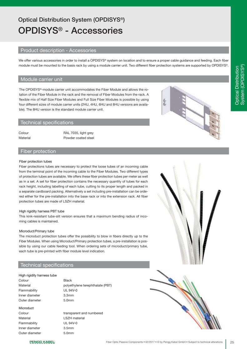
Module carrier unit
The OPDISYS®-module carrier unit accommodates the Fiber Module and allows the ro-
tation of the Fiber Module in the rack and the removal of Fiber Modules from the rack. A
flexible mix of Half Size Fiber Modules and Full Size Fiber Modules is possible by using
four different sizes of module carrier units (2HU, 4HU, 6HU and 8HU versions are availa-
ble). The 8HU version is the standard module carrier unit.
Colour RAL 7035, light grey
Material Powder coated steel
Technical specifications
Fiber protection
Fiber protection tubes
Fiber protections tubes are necessary to protect the loose tubes of an incoming cable
from the terminal point of the incoming cable to the Fiber Modules. Two different types
of protection tubes are available. We offers these fiber protection tubes per meter as well
as in a set. A set for fiber protection contains the necessary quantity of tubes for each
rack height, including labelling of each tube, cutting to its proper length and packed in
a separate cardboard packing. Alternatively a set including pre-installation can be orde-
red either for the pre-installation into the base rack or into the extension rack. All fiber
protection tubes are made of LSZH material.
High rigidity harness PBT tube
This kink-resistant tube-slit version ensures that a maximum bending radius of inco-
ming cables is maintained.
Microduct/Primary tube
The microduct protection tubes offer the possibility to blow in fibers directly up to the
Fiber Modules. When using Microduct/Primary protection tubes, a pre-installation is pos-
sible by using our cable feeding tool. When ordering sets of microduct/primary tube,
each tube is pre-printed with fiber module level indication.
High rigidity harness tube
Colour Black
Material polyethylene terephthalate (PBT)
Flammability UL 94V-0
Inner diameter 3.3mm
Outer diameter 5.0mm
Microduct
Colour transparent and numbered
Material LSZH material
Flammability UL 94V-0
Inner diameter 3.5mm
Outer diameter 5.0mm
Technical specifications
Optical Distribution System (OPDISYS®)
OPDISYS® - Accessories
26 Fiber Optic Passive Components • 02/2017 • © by Pengg Kabel GmbH • Subject to technical alterations
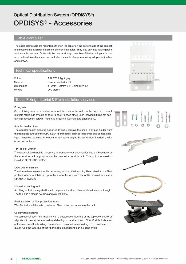
Cable clamp set
The cable clamp sets are mounted either on the top or on the bottom side of the cabinet
and secures the strain relief element of incoming cables. They also serve as holding point
for the cable conduits. Optionally the central strength member of the incoming cable can
also be fixed. A cable clamp set includes the cable clamp, mounting rail, protection bar
and screws.
Colour RAL 7035, light grey
Material Powder coated steel
Dimensions 140mm x 90mm x 51.7mm (HxWxD)
Weight 250 grams
Technical specifications
Tools, Fixing material & Pre-Installation services
Fixing sets
Several fixing sets are available to mount the rack to the wall, on the floor or to mount
multiple racks side by side or back to back to each other. Each individual fixing set con-
tains all necessary screws, mounting brackets, washers and anchor pins.
Adapter holder pincer
The adapter holder pincer is designed to easily remove the snap-in angled holder from
the frontplate cutout of the OPDISYS® fiber module. Thanks to its small and compact de-
sign it ensures the smooth removal of a snap-in angled holder without interfering with
other connections.
Torx socket wrench
The torx socket wrench is necessary to mount various accessories into the base rack or
the extension rack, e.g. spools in the mandrel extension rack. This tool is required to
install an OPDISYS®-System.
Draw wire or element
The draw wire or element tool is necessary to insert the incoming fiber cable into the fiber
protection tube which is fed up to the fiber optic module. This tool is required to install a
OPDISYS®-System.
Micro duct cutting tool
A cutting tool with integrated knife to help cut microduct tubes easily to the correct length.
The tool has a plastic housing and a metal knife.
Pre-Installation of fiber protection tubes
We offer to install the sets of selected fiber protection tubes into the rack.
Customized labelling
We can deliver each fiber module with a customized labelling of the top cover (index of
all ports with description) as well as a labelling of the side of each Fiber Module (indication
of the street and the building this module is assigned to) according to the customer’s re-
quest. Also the labelling of the fiber module numbering can be done by us.

27Fiber Optic Passive Components • 02/2017 • © by Pengg Kabel GmbH • Subject to technical alterations
Optical Distribution System (OPDISYS®)
OPDISYS® - Planning process, Ordering checklist
Pre
-ass
emb
led
C
onne
ctor
s /
Ad
apte
rsO
ptic
al D
istr
ibut
ion
Sys
tem
(OP
DIS
YS
®)
Planning process
The OPDISYS® planning process usually starts with the selection of the adapter system.
The next step is to specify how many terminations (splices) are necessary on site.
Depending on the type and the method how the cable is fed into the system, the proper cable clamp setmust be chosen.
Within this step you must specify what kind of fiber protection tube is needed and if gasblok-kers are required.
The next step is to assign the fiber terminations to fiber modules.
Based on the termination assignment you can choose which Fiber Modulesare needed (0.5HU or 1HU) and which quantity is necessary.
With the given limitations for the rack types (dimensions, open/closed versions) the type and amount of required racks can becalculated.
With this figure, a floor plan can be created.
Ordering checklist
Base rack
Base rack (single row or double row version)mandatory
Extension racks, doors & side panels
Mandrel or gasblocker extension racks, doors & side panels to achieve closed rackoptional
Fiber Modules
Fiber modules according to your needs (0.5HU/1.0HU), with specified adapter systemmandatory
Module carrier unit
The quantity depends on the quantity of Fiber Modules neededmandatory
Fiber protection tube
Either high rigidity harness PBT tube or microductmandatory
Fiber protection tube set
Fiber protection tube cut to correct length with or without pre-installationoptional
Cable clamp set
The quantity depends on the type of the incoming cablemandatory
Fixing sets
Fixing sets to mount a rack to the floor, to the wall or two racks side by sidemandatory
Tools
Various tools to install a OPDISYS®-rackrecommended
The following checklist helps you make sure that you have ordered all parts which are required to build up OPDISYS®.

Optical Distribution System (OPDISYS®)
OPDISYS® - Dimensions
28 Fiber Optic Passive Components • 02/2017 • © by Pengg Kabel GmbH • Subject to technical alterations
Dimensions of the OPDISYS®-Components
OPDISYS®-Rack
Dimensions of OPDISYS®-Rack with Mandrel Extension Rack and Gasblocker Extension Rack.
Front view of the rack, side view and guidance of Gasblocker Extension Rack.
OPDISYS®-cable clamp
Dimensions of the cable clamp for fixing and
strain relief of incoming cables.
Fiber Modules
Outer Dimensions of Half Size Fiber Modules and Full Size Fiber Modules. All kind of Fiber Modules have equivalent outer dimensions (except
some types of Splitter Fiber Modules).

29Fiber Optic Passive Components • 02/2017 • © by Pengg Kabel GmbH • Subject to technical alterations
Optical Distribution System (OPDISYS®)
OPDISYS® - Configuration examples
Pre
-ass
emb
led
C
onne
ctor
s /
Ad
apte
rsO
ptic
al D
istr
ibut
ion
Sys
tem
(OP
DIS
YS
®)
Connecting your subscribers to the network
The main application of OPDISYS® is fiber termination in central offices of FTTH networks. This distribution/patch system can be placed as dis-
tribution node within the passive distribution network or between active components and the passive distribution network. The following sketches
of connections and cabling show different approaches how to connect the subscribers to the active equipment respectively to the network
backbone using one or more OPDISYS®-racks.
Configurations with one OPDISYS®-Rack
Interconnect configuration
The line cable, which establishes the con-
nection to the passive optical distribution
network, comes from the bottom. The exter-
nal patchcord connection establishes the
connection to the active optical equipment
such as transmitters and receivers.
Crossconnect configuration
The line cable, which establishes the con-
nection to the passive optical distribution
network, comes from the bottom. It is for in-
coming as well as for outgoing signals. The
rack is used for patching in the distribution
part of the optical network.
Crossconnect configuration
In this configuration example the rack is split
into a system’s part and a line’s part. The line
cable, which establishes the connection to
the passive optical distribution network,
comes from the bottom while the external
connection cable comes from the top. Both
line and external cable are terminated by
Fiber Modules. An internal patchcord is used
to connect the system part with the line part
of the network.

Optical Distribution System (OPDISYS®)
OPDISYS® - Configuration examples
30 Fiber Optic Passive Components • 02/2017 • © by Pengg Kabel GmbH • Subject to technical alterations
Configuration with two OPDISYS®-Racks
Crossconnect configuration with two racks
In this configuration example there is one rack for the line part of the system, the second rack is split into a system part and a line part. The line
cables, which establish the connection to the passive optical distribution network, is comes from the bottom while the external connection
cable is coming from the top. Both, line and external cable are terminated by Fiber Modules. An internal patchcord is used to connect the
system part with the line part of the network. The internal patchcord is also used to cross connections between the two Racks.

31Fiber Optic Passive Components • 02/2017 • © by Pengg Kabel GmbH • Subject to technical alterations
Optical Distribution System (OPDISYS®)
OPDISYS® - Integration into other systems
Pre
-ass
emb
led
C
onne
ctor
s /
Ad
apte
rsO
ptic
al D
istr
ibut
ion
Sys
tem
(OP
DIS
YS
®)
Carrier for 19’’ system
OPDISYS® can also be used in a 19“ system by using a 19“ carrier. This carrier with a horizontal patch cable guiding can accommodate up to
10 pcs. of Full Size Fiber Modules or 20 pcs. of Half Size Fiber Modules at a height of 8HU.
OPDISYS® can be integrated into an outdoor street
cabinet. Different types of carriers ensure that the
OPDISYS®-System is compatible to the most common
types of outdoor street cabinets.
Street cabinet
The figure shows a street carbinet with an integrated
OPDISYS® system on the right side with space for active
components on the left side.
The OPDISYS® support space for 21 full-size or 42 half-
size fiber modules. The maximum capacity of a fully-
equipped distribution box would here be 252 fibers.

Optical Distribution System (OPDISYS®)
OPDISYS® Intelligent (Patch Management System)
32 Fiber Optic Passive Components • 02/2017 • © by Pengg Kabel GmbH • Subject to technical alterations
If you want to fully meet the requirements set by modern network administration,
it is necessary to maintain process safety from the planning stage right up to the
physical setup of a connection.
OPDISYS®-Intelligent is our intelligent system solution. It is capable to detect
plugged connections inside cable distributors such as patch panels, distribution
cabinets for fiber-to-the-home applications or street-side distributors and to
transmit this information to a network management software.
In other words, the system is capable to identify connecting paths, connector and coupling types and to store this information in a
documentation data base. This makes sure that faulty patchings are automatically detected and that an alarm is triggered in case of
unauthorized changes to your connections.
This picture shows you our OPDISYS®-Intelligent system, using the OPDISYS® distribution cabinet for FTTH-networks as an example. Thanks
to its flexible construction scheme, our Patch Management System can also be used in any other cable distribution system such as patch
panels or street-side distributors.

33Passive Glasfasersystemkomponenten • 01/2017 • © by Pengg Kabel GmbH • Technische Änderungen vorbehalten
Vork
onfe
ktio
nier
te
Ste
cker
/ K
upp
lung
enO
ptic
al D
istr
ibut
ion
Sys
tem
(OP
DIS
YS
®)
Optical Distribution System (OPDISYS®)
OPDISYS® Intelligent (Patch Management System)
The basis for our intelligent system
solution is a technology based on
the well-known “Radio-Frequency-
Identification (RFID)“ technology.
This system helps you determine
plugged connections within a patch
field and to correlate them with spe-
cific mechanical conditions.
RFID-transponders are clipped onto
both connectors of the patch cable.
They are compatible with all current
connector systems and can be easily
fitted onto existing patch cables.
All data collected by the fiber modules are transmitted - to the analyzer - via a bus system. The analyzer couples
the bus to an Ethernet network via which information from the fiber modules is transmitted to a network
management software.
The fiber module is fitted
with an electronic unit with
integrated RFID antenna
which recognizes an
inserted patch cable and
reads the information
contained in the trans-
ponder.

34 Passive Glasfasersystemkomponenten • 01/2017 • © by Pengg Kabel GmbH • Technische Änderungen vorbehalten
Optical Distribution System (OPDISYS®)
OPDISYS® Intelligent (Patch Management System)
Each RFID-transponder has a unique number identifying each patch cable. This number allows
you also to retrieve specific information related to the patch cable, such as measured values,
manufacturer's information, batch numbers or the number of connecting cycles.
Additionally, it is possible to transmit other information about the fiber module to the documentation
software, i.e. coupling type used, number of ports or product type.
Integrated LEDs visualize the current port status or ongoing work processes.
The Network Operation Center gathers the entire information flow in the central network management software. Our OPDISYS®-Intelligent is
a manufacturer-independent solution and allows you to work with various software solutions as it meets current international standards.

35Fiber Optic Passive Components • 02/2017 • © by Pengg Kabel GmbH • Subject to technical alterations
Pre
-ass
emb
led
C
onne
ctor
s /
Ad
apte
rsO
ptic
al D
istr
ibut
ion
Sys
tem
(OP
DIS
YS
®)
Return of investment
Action Instrumental entity Without PMS With PMS
Planning Network administrator 6 min 3 min
Create workorder Network administrator 5 min 0 min
Patching Technician 5 min 1 min
Update database Network administrator 5 min 0 min
Comparison of the required time with and without Patch Management System
The installation of a patch management system is indisputably associated with significant installation costs. Consequently, the cost of such a
solution must be demonstrated - "nice to have" is not a tenable basis for argumentation. Such calculations cannot get generalized - due to the
different structures of companys. Also the level of detail is mostly different so here is only the basis of such a calculation.
The build-up costs of active components in a POP (point of presence) are
about 150 EUR per port (In addition to highly integrated switching technology
also security components, such as VPN-concentrators and firewalls added).
An optimization of the port utilization, i.e. the avoidance of unused connecti-
ons by 1% brings the saving of: 1,50 EUR / port. Gets patching not or not
properly documented, documentation database must regularly be reconciled
with the real wiring - each port on average every 2 years. The port adjustment
costs the equivalent of 6 EUR, this means 3 EUR per year.
Advantage through the system
With using the patch management system the operations of the network administrators and their technicians can be re-defined and structured
efficiently. This makes it possible to support larger networks with less effort. Valuable time is saved and can be used elsewhere. The times in
which the administrator is searching for wrong patches and were errors in the documentation and the system can be done are counted. A very
simple automatic recording of the actual state and the comparison with the target state are also part of the benefits, such as returning to the
state of a secured system with very little effort. Not least, the automatic documentation of activities in a system an unbiased, accurate and
also expense less characteristic of the system. The obtained information contributes to a large extent to the security of a network. The schedules
of the planed patches can be done very detailed in advance. A predictable timing of resource work is thus easy and possible.
The current hardware technical features of the system already offers the possibility of already planned future developments, such as the men-
tioned local control element to integrate into the system without installation work only with software and interface customization.
Optical Distribution System (OPDISYS®)
OPDISYS® Intelligent (Patch Management System)

Optical Distribution System (OPDISYS®)
OPDISYS® compact
36 Fiber Optic Passive Components • 02/2017 • © by Pengg Kabel GmbH • Subject to technical alterations
Field of Application
OPDISYS® compact is a convenient and
flexible fiber patching system. It can be
used for fiber splicing only or to terminate
an incoming loose tube or tight buffered
cable. As OPDISYS® compact can handle
a high density of fiber cores and offers
flexible cross and interconnect capabilities
with an convenient cable guidance, it is the
ideal choice for datacenter and LAN instal-
lations.
- Eurocard Fiber Modules
- 1HU, 3HU and 4HU subracks available
- Support for all common types of
adapters
- Open and closed version available
Features
Product description - OPDISYS®compact - Eurocard Module System
OPDISYS® compact is a new cable management system for datacenter. Intelligent cable guidance and the easy installation and maintenance
make it a convenient solution for your network. Interoperability is ensured through the eurocard standard. The system consists of different kinds
of subracks and various OPDISYS® compact Fiber Modules. A OPDISYS® compact Module is an Eurocard module consists of a front plate and
body based on a PC/ABS blend. It can accommodate a splice cassette and is designed either for patching or as a splice through module.
37Fiber Optic Passive Components • 02/2017 • © by Pengg Kabel GmbH • Subject to technical alterations
Optical Distribution System (OPDISYS®)
OPDISYS® compact - Carrier
Pre
-ass
emb
led
C
onne
ctor
s /
Ad
apte
rsO
ptic
al D
istr
ibut
ion
Sys
tem
(OP
DIS
YS
®)
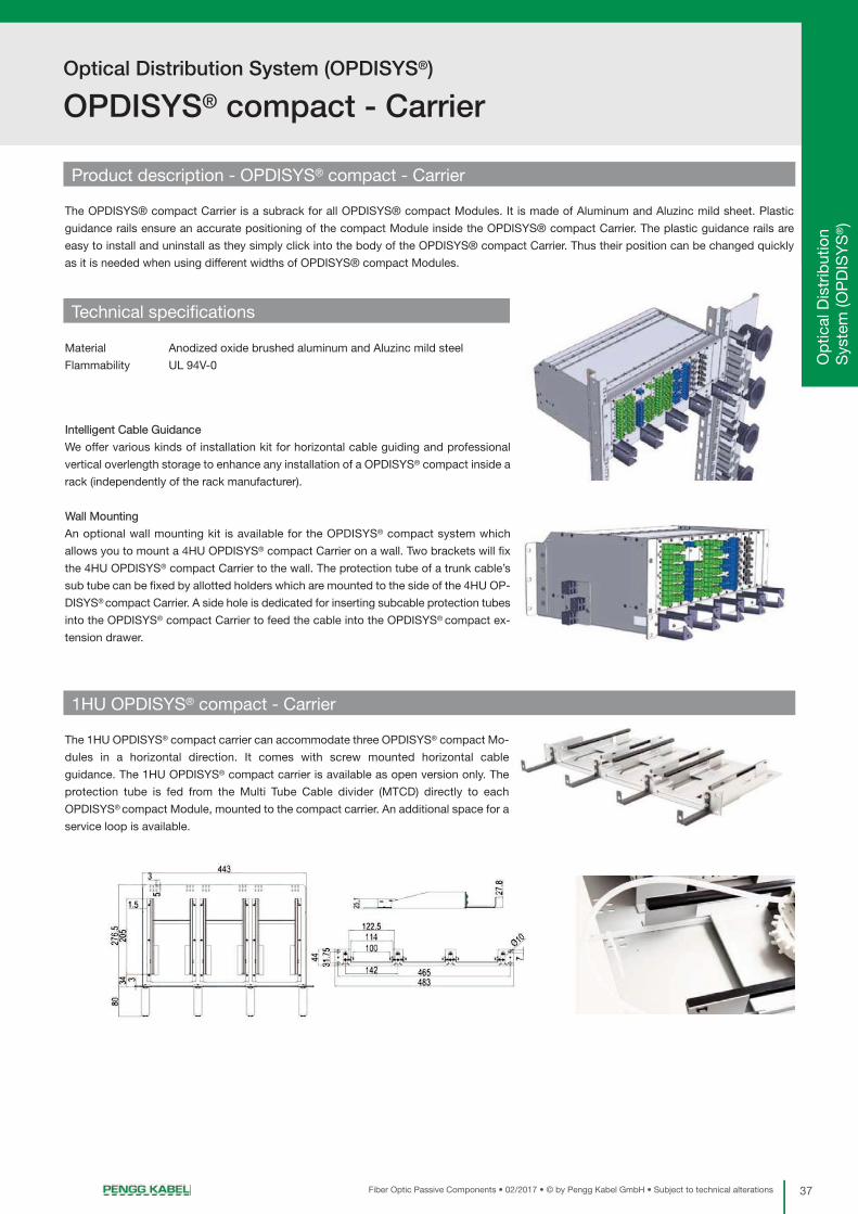
Product description - OPDISYS® compact - Carrier
The OPDISYS® compact Carrier is a subrack for all OPDISYS® compact Modules. It is made of Aluminum and Aluzinc mild sheet. Plastic
guidance rails ensure an accurate positioning of the compact Module inside the OPDISYS® compact Carrier. The plastic guidance rails are
easy to install and uninstall as they simply click into the body of the OPDISYS® compact Carrier. Thus their position can be changed quickly
as it is needed when using different widths of OPDISYS® compact Modules.
Material Anodized oxide brushed aluminum and Aluzinc mild steel
Flammability UL 94V-0
Technical specifications
1HU OPDISYS® compact - Carrier
Intelligent Cable Guidance
We offer various kinds of installation kit for horizontal cable guiding and professional
vertical overlength storage to enhance any installation of a OPDISYS® compact inside a
rack (independently of the rack manufacturer).
Wall Mounting
An optional wall mounting kit is available for the OPDISYS® compact system which
allows you to mount a 4HU OPDISYS® compact Carrier on a wall. Two brackets will fix
the 4HU OPDISYS® compact Carrier to the wall. The protection tube of a trunk cable’s
sub tube can be fixed by allotted holders which are mounted to the side of the 4HU OP-
DISYS® compact Carrier. A side hole is dedicated for inserting subcable protection tubes
into the OPDISYS® compact Carrier to feed the cable into the OPDISYS® compact ex-
tension drawer.
The 1HU OPDISYS® compact carrier can accommodate three OPDISYS® compact Mo-
dules in a horizontal direction. It comes with screw mounted horizontal cable
guidance. The 1HU OPDISYS® compact carrier is available as open version only. The
protection tube is fed from the Multi Tube Cable divider (MTCD) directly to each
OPDISYS® compact Module, mounted to the compact carrier. An additional space for a
service loop is available.
38 Fiber Optic Passive Components • 02/2017 • © by Pengg Kabel GmbH • Subject to technical alterations
Optical Distribution System (OPDISYS®)
OPDISYS® compact - Carrier
3HU OPDISYS® compact - Carrier
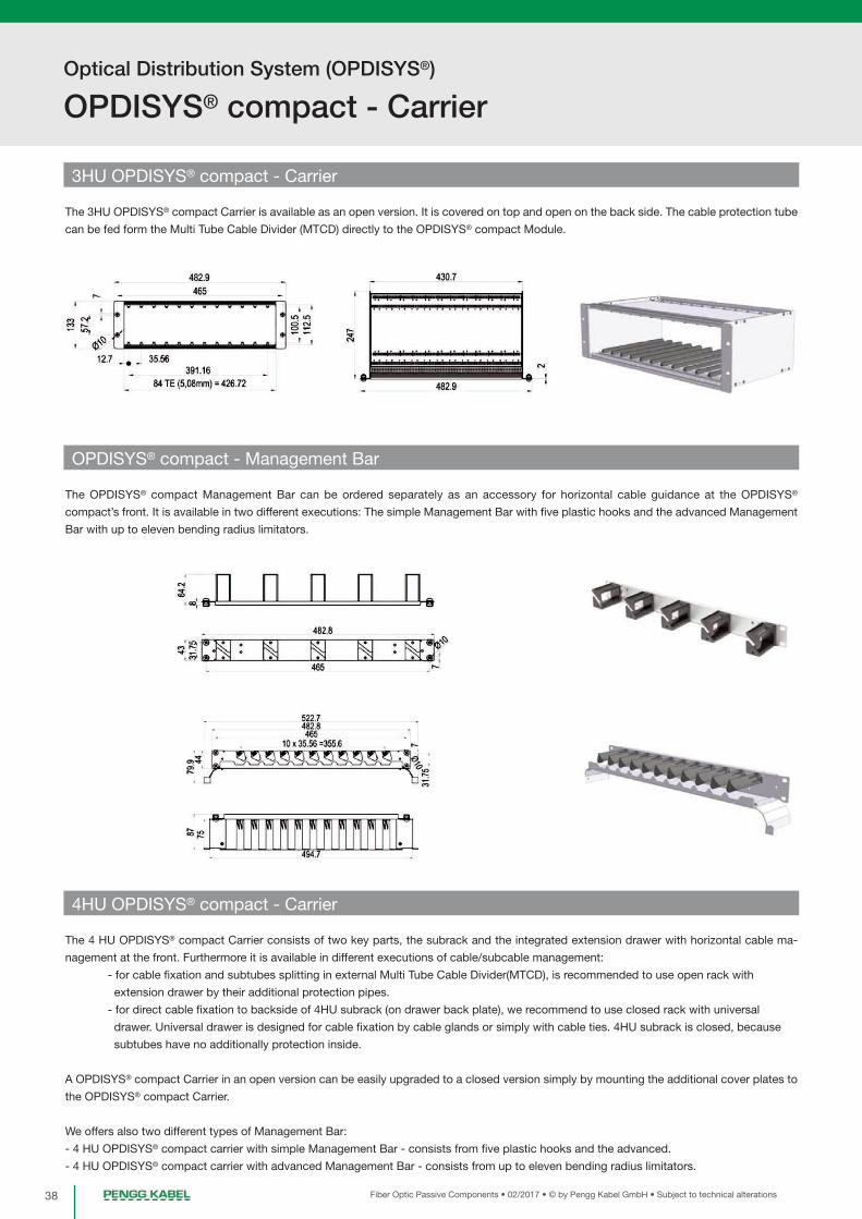
The 3HU OPDISYS® compact Carrier is available as an open version. It is covered on top and open on the back side. The cable protection tube
can be fed form the Multi Tube Cable Divider (MTCD) directly to the OPDISYS® compact Module.
OPDISYS® compact - Management Bar
The OPDISYS® compact Management Bar can be ordered separately as an accessory for horizontal cable guidance at the OPDISYS®
compact’s front. It is available in two different executions: The simple Management Bar with five plastic hooks and the advanced Management
Bar with up to eleven bending radius limitators.
4HU OPDISYS® compact - Carrier
The 4 HU OPDISYS® compact Carrier consists of two key parts, the subrack and the integrated extension drawer with horizontal cable ma-
nagement at the front. Furthermore it is available in different executions of cable/subcable management:
- for cable fixation and subtubes splitting in external Multi Tube Cable Divider(MTCD), is recommended to use open rack with
extension drawer by their additional protection pipes.
- for direct cable fixation to backside of 4HU subrack (on drawer back plate), we recommend to use closed rack with universal
drawer. Universal drawer is designed for cable fixation by cable glands or simply with cable ties. 4HU subrack is closed, because
subtubes have no additionally protection inside.
A OPDISYS® compact Carrier in an open version can be easily upgraded to a closed version simply by mounting the additional cover plates to
the OPDISYS® compact Carrier.
We offers also two different types of Management Bar:
- 4 HU OPDISYS® compact carrier with simple Management Bar - consists from five plastic hooks and the advanced.
- 4 HU OPDISYS® compact carrier with advanced Management Bar - consists from up to eleven bending radius limitators.

39Fiber Optic Passive Components • 02/2017 • © by Pengg Kabel GmbH • Subject to technical alterations
Pre
-ass
emb
led
C
onne
ctor
s /
Ad
apte
rsO
ptic
al D
istr
ibut
ion
Sys
tem
(OP
DIS
YS
®)
Optical Distribution System (OPDISYS®)
OPDISYS® compact - Carrier
OPDISYS® compact - Extension/Universal drawer
The OPDISYS® compact Extension/Universal drawer is an integrated part, only
available for the 4HU OPDISYS® compact Carrier. It provides an additional space for
the service loop of the cable which is a necessary overlength to pull out the OPDISYS®
compact Module from the Carrier. Furthermore, it accommodates the OPDISYS®
compact Management Bar.
We offers these modification:
- OPDISYS® compact Extension Drawer with simple Management Bar
- OPDISYS® compact Extension Drawer with advanced Management Bar
- OPDISYS® compact Universal Drawer with simple Management Bar
- OPDISYS® compact Universal Drawer with advanced Management Bar
Universal Drawer modul support fixation of incomming cables by cable glands.
Extension Drawer support fixation of incomming tubes by fixing of protection tubes.
4 HU OPDISYS® compact - Carrier with simple Management Bar
4 HU OPDISYS® compact - Carrier with advanced Management Bar
4 HU OPDISYS® compact - Carrier with simple Management Bar and Extension Drawer

Optical Distribution System (OPDISYS®)
OPDISYS® compact - Carrier
40 Fiber Optic Passive Components • 02/2017 • © by Pengg Kabel GmbH • Subject to technical alterations
4 HU OPDISYS® compact - Carrier with simple Management Bar and Universal Drawer
4 HU OPDISYS® compact - Carrier with simple Management Bar and 12 x PG16 Drawer
OPDISYS® compact Carrier - Accessories
Angled Cable Entry Plate PG16/M20:
Angled cable entry plates allow to bring the cable to drawer by 45 degrees angle. This part is mounting by 2 screws on back side of drawer.
Straight Cable Entry Plate PG13,5/PG16:
Straight cable entry plates allow to bring the cable to drawer by 90 degrees angle. This part is mounting by 2 screws on back side of drawer.

41Fiber Optic Passive Components • 02/2017 • © by Pengg Kabel GmbH • Subject to technical alterations
Optical Distribution System (OPDISYS®)
OPDISYS® compact - Fiber modules
Pre
-ass
emb
led
C
onne
ctor
s /
Ad
apte
rsO
ptic
al D
istr
ibut
ion
Sys
tem
(OP
DIS
YS
®)
1HU Carrier 3HU Carrier 4HU Carrier (open) 4HU Carrier (closed)
Carrier depth 275mm 300mm 300mm 300mm
Carrier width 483mm (19“) 483mm (19“) 483mm (19“) 483mm (19“)
Carrier height 1HU 3HU 4HU 4HU
Max. amount of modules 3 12 12 12
Max. amount of ports 36 288 288 288
OPDISYS® compact - Dimensions & Capacity
Scope of supply
Each OPDISYS® compact 1HU Carrier consists of:
1 pc. OPDISYS® compact Carrier body
6 pcs. Plastic guidance rails (pre-assembled to the body)
1 set Fixation screws M6
4 pcs. Front patch cable support clamps (for horizontal patchocord guidance)
Each OPDISYS® compact 3HU Carrier consists of:
1 pc. OPDISYS® compact Carrier body
24 pcs. Plastic guidance rails (pre-assembled to the body)
1 set Fixation screws M6
1 pc. Back cover (in case of closed version)
Each OPDISYS® compact 4HU Carrier consists of:
1 pc. OPDISYS® compact Carrier body with integrated OPDISYS® compact Extension/Universal Drawer
1 pc. Simple or advanced Management Bar (upon order, preassembled to the OPDISYS® compact Extension/Universal Drawer)
24 pcs. Plastic guidance rails (pre-assembled to the body)
1 set Fixation screws M6
1 pc. Back cover (in case of closed version)
Loose tube divider:
Loose tube divider is one of the cable management oportunities inside drawer. Devider being mounted in drawer by doublesided tape.
Protection tube organizer:
Protection tube organizer is very useful for manage protection tubes of fibers inside of drawers. Organizer being mounted in drawer by double-
sided tape. Protection tubes going to inside of drawer, where are fixing in protection tube organizer.
42 Fiber Optic Passive Components • 02/2017 • © by Pengg Kabel GmbH • Subject to technical alterations
Optical Distribution System (OPDISYS®)
OPDISYS® compact - Fiber modules
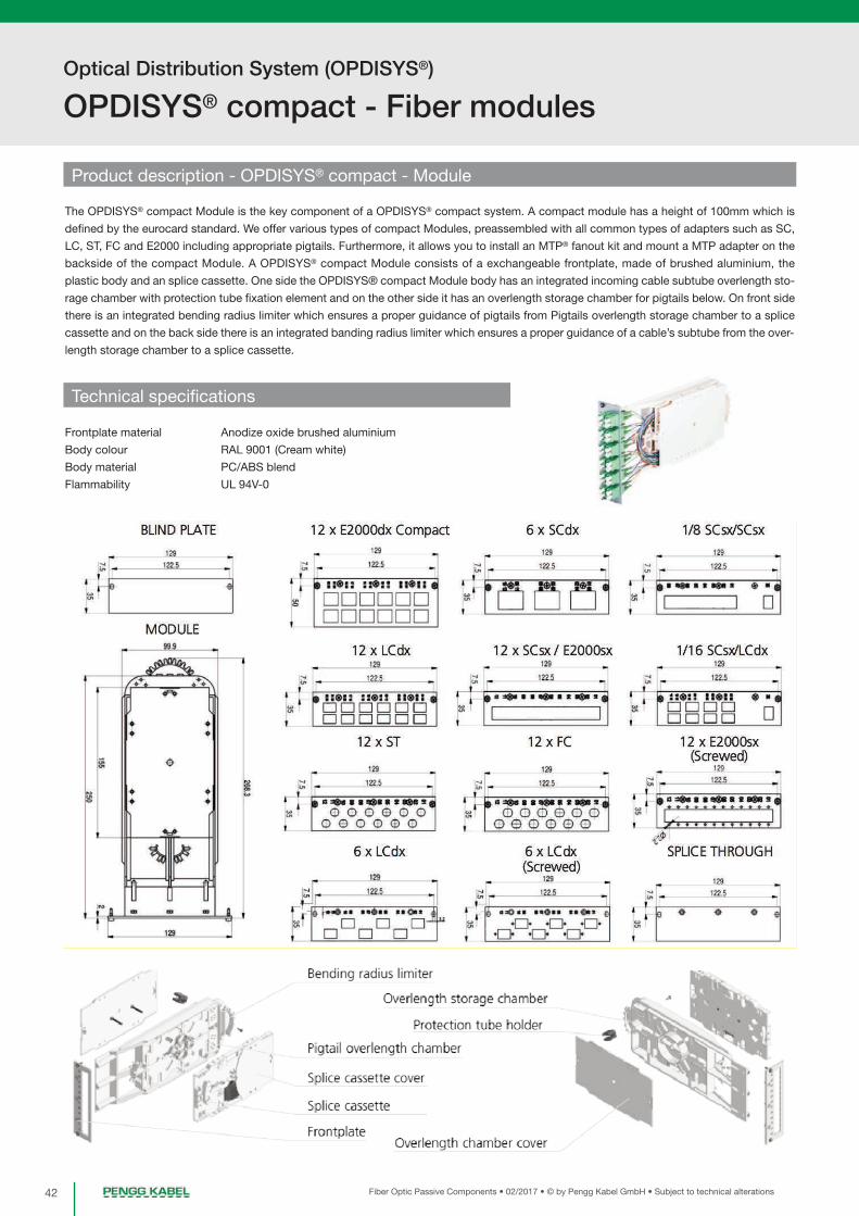
Product description - OPDISYS® compact - Module
The OPDISYS® compact Module is the key component of a OPDISYS® compact system. A compact module has a height of 100mm which is
defined by the eurocard standard. We offer various types of compact Modules, preassembled with all common types of adapters such as SC,
LC, ST, FC and E2000 including appropriate pigtails. Furthermore, it allows you to install an MTP® fanout kit and mount a MTP adapter on the
backside of the compact Module. A OPDISYS® compact Module consists of a exchangeable frontplate, made of brushed aluminium, the
plastic body and an splice cassette. One side the OPDISYS® compact Module body has an integrated incoming cable subtube overlength sto-
rage chamber with protection tube fixation element and on the other side it has an overlength storage chamber for pigtails below. On front side
there is an integrated bending radius limiter which ensures a proper guidance of pigtails from Pigtails overlength storage chamber to a splice
cassette and on the back side there is an integrated banding radius limiter which ensures a proper guidance of a cable’s subtube from the over-
length storage chamber to a splice cassette.
Frontplate material Anodize oxide brushed aluminium
Body colour RAL 9001 (Cream white)
Body material PC/ABS blend
Flammability UL 94V-0
Technical specifications

43Fiber Optic Passive Components • 02/2017 • © by Pengg Kabel GmbH • Subject to technical alterations
Pre
-ass
emb
led
C
onne
ctor
s /
Ad
apte
rsO
ptic
al D
istr
ibut
ion
Sys
tem
(OP
DIS
YS
®)
Optical Distribution System (OPDISYS®)
OPDISYS® compact - Fiber modules
OPDISYS® compact Splitter Module
Different types of Splitter compact Modules are available in order to integrate a PLC
splitter into a OPDISYS® compact Module. It is possible to integrate all types of
splitters starting from 1:4 up to 1:16.
The Splitter compact Module consists of a conventional OPDISYS® compact Module
with a special front plate designed for splitter usage. We offer various preconfigured
adapter configurations with integrated splitters, ready to use.
OPDISYS® compact MPO® Module
We offer also MPO/MTP® ready compact Modules. The MPO/MTP® ready compact
Module consists of a conventional OPDISYS® compact Module with a special lid for
MPO adapter accommodation on the backside of the compact Module body.
Metal cable glands holder for 2xPG7 or 2xPG9
Additional metal plate for 2xPG7 or 2xPG9 glands fixation on module.
Metal cable glands holder can be offered with mouting on OPDISYS® compact
Module or we offer only separately item without mounting.
Designation paper holder set for frontplates
We offer simply additionally labelling solutions. The main advantage of this set is
possible to marked with own identification values. This set can be offered with
mounting on OPDISYS® compact Module or we offer only separately item without
mounting.
Scope of supply
Each OPDISYS® compact Module is equipped with:
- Frontplate
- Splice cassette
- Splice protection holder (for shrink or crimp splice protection sleeve - upon customer’s request)
- Cover for splice cassette and cable overlength chamber
- Fixation screws
- Inserted adapters and pigtails
- Protection tube holder
OPDISYS® compact - Splitter and MPO® integration
44 Fiber Optic Passive Components • 02/2017 • © by Pengg Kabel GmbH • Subject to technical alterations
Optical Distribution System (OPDISYS®)
OPDISYS® compact - Multi tube cable divider
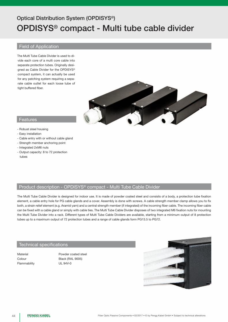
Field of Application
The Multi Tube Cable Divider is used to di-
vide each core of a multi core cable into
separate protection tubes. Originally desi-
gned as Cable Divider for the OPDISYS®
compact system, it can actually be used
for any patching system requiring a sepa-
rate cable outlet for each loose tube of
tight buffered fiber.
- Robust steel housing
- Easy installation
- Cable entry with or without cable gland
- Strength member anchoring point
- Integrated 2xM6 nuts
- Output capacity: 8 to 72 protection
tubes
Features
Product description - OPDISYS® compact - Multi Tube Cable Divider
The Multi Tube Cable Divider is designed for indoor use. It is made of powder coated steel and consists of a body, a protection tube fixation
element, a cable entry hole for PG cable glands and a cover. Assembly is done with screws. A cable strength member clamp allows you to fix
both, a strain relief element (e.g. Aramid yarn) and a central strength member (if integrated) of the incoming fiber cable. The incoming fiber cable
can be fixed with a cable gland or simply with cable ties. The Multi Tube Cable Divider disposes of two integrated M6 fixation nuts for mounting
the Multi Tube Divider into a rack. Different types of Multi Tube Cable Dividers are available, starting from a minimum output of 8 protection
tubes up to a maximum output of 72 protection tubes and a range of cable glands form PG13.5 to PG72.
Material Powder coated steel
Colour Black (RAL 9005)
Flammability UL 94V-0
Technical specifications

45Fiber Optic Passive Components • 02/2017 • © by Pengg Kabel GmbH • Subject to technical alterations
Pre
-ass
emb
led
C
onne
ctor
s /
Ad
apte
rsO
ptic
al D
istr
ibut
ion
Sys
tem
(OP
DIS
YS
®)
Optical Distribution System (OPDISYS®)
OPDISYS® compact - Multi tube cable divider
1 to 8 divider with PG13.5 cable gland
The Multi Tube Cable Divider 1/8-13 is a small and compact cable divider for fiber optic
cables. It accommodates one PG13.5 cable gland for the incoming multi tube cable.
One protection tube fixing element is used to attach the fiber protection tubes for the
outgoing cables. The maximum capacity of the 1 to 8 divider is 8 outgoing fiber protec-
tion tubes.
Cable entry PG13.5 cable gland (ø 6.5 mm - ø 12.0 mm)
No. of outgoing tubes 8
Dimensions 38x34x150 mm / 38x34x182 mm (WxHxL)
Weight 0.34 kgs (with cable gland)
Technical specifications
1 to 16 divider with PG16 cable gland
The Multi Tube Cable Divider 1/16-16 is a small and compact cable divider for fiber optic
cables. It accommodates one PG16 cable gland for the incoming multi tube cable. Two
protection tube fixing elements are used to attach the fiber protection tubes for the out-
going cables. The maximum capacity of the 1 to 16 divider is 16 outgoing fiber protection
tubes.
Cable entry PG16 cable gland (ø 9.0 mm - ø 14.0 mm)
No. of outgoing tubes 16
Dimensions 38x49x150 mm / 38x49x184 mm (WxHxL)
Weight 0.40 kgs (with cable gland)
Technical specifications

46 Fiber Optic Passive Components • 02/2017 • © by Pengg Kabel GmbH • Subject to technical alterations
Optical Distribution System (OPDISYS®)
OPDISYS® compact - Multi tube cable divider
1 to 32 divider with PG21 cable gland
The Multi Tube Cable Divider 1/32-21 is a compact cable divider for fiber optic cables.
It accommodates one PG21 cable gland for the incoming multi tube cable. Four pro-
tection tube fixing elements (two of each are fixed one above in two columns) are used
to attach the fiber protection tubes for the outgoing cables. The maximum capacity of
the 1 to 32 divider is 32 outgoing fiber protection tubes.
Cable entry PG21 cable gland (ø 13.0 mm - ø 18.0 mm)
No. of outgoing tubes 32
Dimensions 60x49x180 mm / 60x49x218 mm (WxHxL)
Weight 0.60 kgs (with cable gland)
Technical specifications
1 to 32 divider with PG29 cable gland
The Multi Tube Cable Divider 1/32-29 is a compact cable divider for fiber optic cables.
It accommodates one PG29 cable gland for the incoming multi tube cable. Four pro-
tection tube fixing elements (two of each are fixed one above in two columns) are used
to attach the fiber protection tubes for the outgoing cables. The maximum capacity of
the 1 to 32 divider is 32 outgoing fiber protection tubes.
Cable entry PG29 cable gland (ø 14.0 mm - ø 25.0 mm)
No. of outgoing tubes 32
Dimensions 60x54x180 mm / 60x54x225 mm (WxHxL)
Weight 0.66 kgs (with cable gland)
Technical specifications
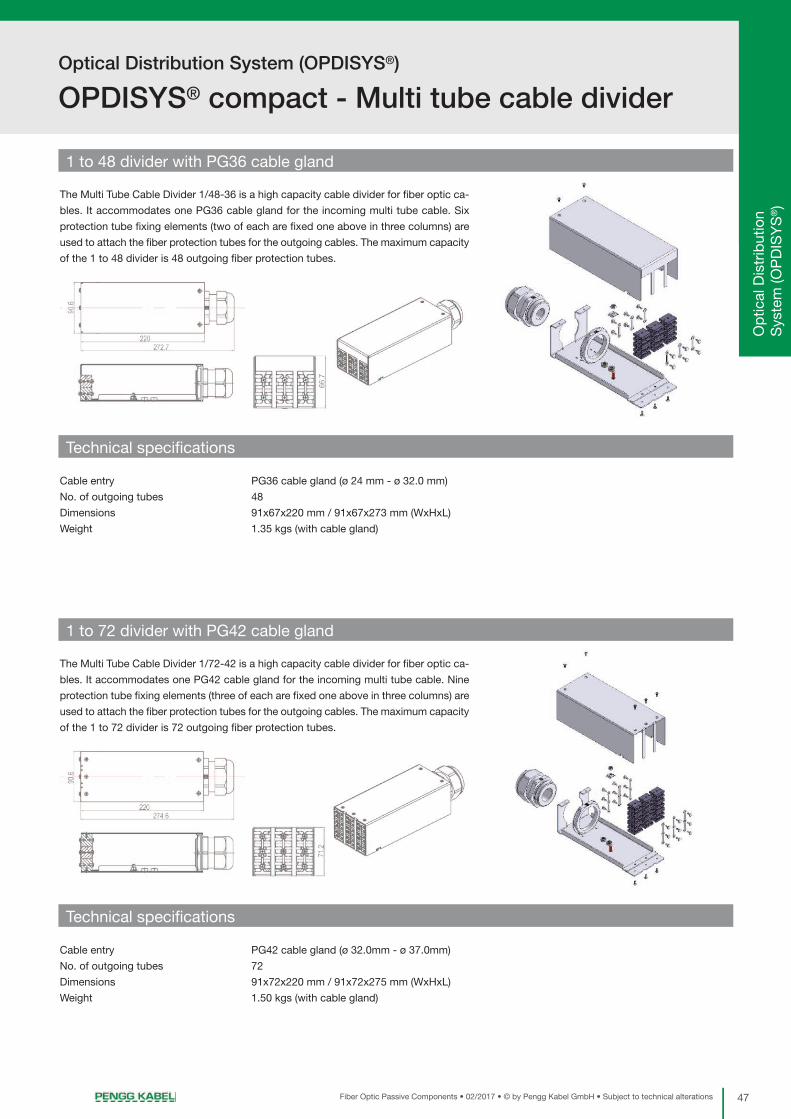
47Fiber Optic Passive Components • 02/2017 • © by Pengg Kabel GmbH • Subject to technical alterations
Pre
-ass
emb
led
C
onne
ctor
s /
Ad
apte
rsO
ptic
al D
istr
ibut
ion
Sys
tem
(OP
DIS
YS
®)
Optical Distribution System (OPDISYS®)
OPDISYS® compact - Multi tube cable divider
1 to 48 divider with PG36 cable gland
The Multi Tube Cable Divider 1/48-36 is a high capacity cable divider for fiber optic ca-
bles. It accommodates one PG36 cable gland for the incoming multi tube cable. Six
protection tube fixing elements (two of each are fixed one above in three columns) are
used to attach the fiber protection tubes for the outgoing cables. The maximum capacity
of the 1 to 48 divider is 48 outgoing fiber protection tubes.
Cable entry PG36 cable gland (ø 24 mm - ø 32.0 mm)
No. of outgoing tubes 48
Dimensions 91x67x220 mm / 91x67x273 mm (WxHxL)
Weight 1.35 kgs (with cable gland)
Technical specifications
1 to 72 divider with PG42 cable gland
The Multi Tube Cable Divider 1/72-42 is a high capacity cable divider for fiber optic ca-
bles. It accommodates one PG42 cable gland for the incoming multi tube cable. Nine
protection tube fixing elements (three of each are fixed one above in three columns) are
used to attach the fiber protection tubes for the outgoing cables. The maximum capacity
of the 1 to 72 divider is 72 outgoing fiber protection tubes.
Cable entry PG42 cable gland (ø 32.0mm - ø 37.0mm)
No. of outgoing tubes 72
Dimensions 91x72x220 mm / 91x72x275 mm (WxHxL)
Weight 1.50 kgs (with cable gland)
Technical specifications

48 Fiber Optic Passive Components • 02/2017 • © by Pengg Kabel GmbH • Subject to technical alterations
Optical Distribution System (OPDISYS®)
OPDISYS® compact - Multi tube cable divider
Multi Tube Cable Divider - Parts & components
Scope of Delivery
Each OPDISYS® compact Multi Tube Cable Divider gets delivered with:
- 1pc. Multi Tube Cable Divider body with anchoring point and 2xM6 fixation nuts
- 1pc. Removable cover
- 1-9pcs. Fiber protection tube fixation element
- 1set Fixation material

49Fiber Optic Passive Components • 02/2017 • © by Pengg Kabel GmbH • Subject to technical alterations
Pre
-ass
emb
led
C
onne
ctor
s /
Ad
apte
rsO
ptic
al D
istr
ibut
ion
Sys
tem
(OP
DIS
YS
®)
Optical Distribution System (OPDISYS®)
OPDISYS® compact - Examples of installation
Multi Tube Cable Divider (MTCD)
The Multi Tube Cable Divider can
be installed into the rack and pro-
vides a splitting of the sub-
cables of an incoming cable. Fur-
thermore, it provides a fixation
point for the subcable protection
tubes which lead to the OP-
DISYS® compact Carrier.
OPDISYS® compact - Multi Tube Cable Divider - Examples of installation

50 Fiber Optic Passive Components • 02/2017 • © by Pengg Kabel GmbH • Subject to technical alterations
Optical Distribution System (OPDISYS®)
OPDISYS® compact - Examples of installation
OPDISYS® compact - Examples of installation
OPDISYS® compact - Rack-
mounting (rear side)
The picture shows a OPDISYS®
compact system with a 4HU
rack (with integrated drawer) and
an underlying open 3HU OP-
DISYS® compact management
system with bar and a 1HU OP-
DISYS® compact unit at the bot-
tom.
OPDISYS® compact with drawer
The 4HU OPDISYS® compact
carrier has an integrated drawer
which cannot be detached. In
this example it is equipped with
a simple Management Bar for
horizontal patchcord guidance.

Termination System for 19“ Technology
51Fiber Optic Passive Components • 02/2017 • © by Pengg Kabel GmbH • Subject to technical alterations
Fiber Optic Splice Box - PENGG solution page 52
Fiber Optic Splice Box - traversable page 54
Fiber Optic Management Box page 55
Fiber Optic Patch Cable Storage Box - drawer design page 56
Pre
-ass
emb
led
C
onne
ctor
s /
Ad
apte
rsO
ptic
al D
istr
ibut
ion
Sys
tem
(OP
DIS
YS
®)
Term
inat
ion
Sys
tem
fo
r 19
“ Te
chno
logy

Termination System for 19“ Technology
Fiber Optic Splice Box - PENGG solution
52 Fiber Optic Passive Components • 02/2017 • © by Pengg Kabel GmbH • Subject to technical alterations
Description
• Designed to storage fiber optic cables and splicing cassettes
• Functional and easy to install, featured by highest flexibility
• Intended for installing in 19” rack system
• Enable fiber optic termination and distribution
This Fiber Optic Splice Box can be equipped according your requirements - mounted only with adapters and also fully equipped with adapters
and pigtails.
Features
• Model offered: Resetable and sliding
• Available heights: 1U and 2U
• Installation depth: 250 mm
• Material: steel
• Powder coated
• Colour: RAL 7024 (Graphite Grey) or RAL
7035 (Light Grey) - other colours optionally
on request
• No. of Connectors / Openings: 2, 12, 24,
36, 48, 72 or 96
• Universal splice cassette holding system:
fixed & booklet mounting option
• Equipped with removable splice cassette
holder and anti-twist system
Fiber Optic Splice Box - PENGG solution
Rechangeable Front Plates
• SC/E-2000, SC Duplex, ST, FC, FC-ST and LC
• 45°-version for 24xSC/E-2000 and 24xLC
• 2x latches snap in
Rechangeable Cable Entry Plates
Straight (PG), angular (PG),
without, blind closed
19” and ETSI
for depth adjustment (stepless)
Front View Rear View
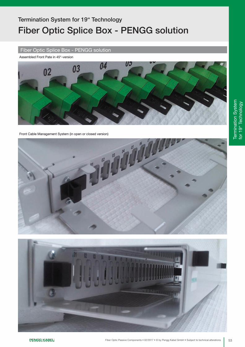
53Fiber Optic Passive Components • 02/2017 • © by Pengg Kabel GmbH • Subject to technical alterations
Termination System for 19“ Technology
Fiber Optic Splice Box - PENGG solution
Pre
-ass
emb
led
C
onne
ctor
s /
Ad
apte
rsO
ptic
al D
istr
ibut
ion
Sys
tem
(OP
DIS
YS
®)
Term
inat
ion
Sys
tem
fo
r 19
“ Te
chno
logy
Fiber Optic Splice Box - PENGG solutionAssembled Front Pate in 45°-version
Front Cable Management System (in open or closed version)

Fiber Optic Splice Box - traversable
54 Fiber Optic Passive Components • 02/2017 • © by Pengg Kabel GmbH • Subject to technical alterations
Termination System for 19“ Technology
Fiber Optic Splice Box - traversable
Description
• Designed to storage fiber optic cables and splicing cassettes
• Functional and easy to install, featured by highest flexibility
• Intended for installing in 19” rack system
• Enable fiber optic termination and distribution
This Fiber Optic Splice Box can be equipped according your requirements - mounted only with adapters and also fully equipped with adapters
and pigtails.
Features
• High mechanical protection of the patch area inside thanks to the traversable adapter plate with closed front design.
• Suitable for cables with large number of fibers, in combination with the management box and connection tubes, only the loose tube of the
cable is inserted into the splice box. For direct cable insertion a slanted cable entry and a installation point for cable strain relief is delivered.
• Available heights: 1HU
• Material: steel, powder coated or V2A on request
• Powder coated
• Colour: RAL 7035 (Light Grey) - other colours optionally on request
• No. of connectors: 24 (48 LC)
• No. of splice cassettes: 2 (removable)

55Fiber Optic Passive Components • 02/2017 • © by Pengg Kabel GmbH • Subject to technical alterations
Termination System for 19“ Technology
Fiber Optic Management Box
Pre
-ass
emb
led
C
onne
ctor
s /
Ad
apte
rsO
ptic
al D
istr
ibut
ion
Sys
tem
(OP
DIS
YS
®)
Term
inat
ion
Sys
tem
fo
r 19
“ Te
chno
logy
Fiber Optic Management Box
Description
• Designed to storage fiber optic cables and splicing cassettes
• Functional and easy to install, featured by highest flexibility
• Intended for installing in 19” rack system
Features
• The Fiber Optic Management Box is designed for distributing and storing multi-fiber loose tubes of a fiber optic cable with a large number
of fibers to several patch panels.
• To cover the possibility for several fiber management structures, slice cassettes can be integrated in the management box for jointing cable
fibers together.
• Connection tubes are used for mechanical protection of the loose tubes which are routed to the patch panels.
• Slanted cable entries and installation points for cable strain relief
• Available heights: 1HU, 2HU
• Capacity: 1HU - 2 cables, 2HU - 4 cables
• Material: steel, powder coated or V2A on request

Termination System for 19“ Technology
Fiber Optic Patch Cable Storage Box - drawer design
56 Fiber Optic Passive Components • 02/2017 • © by Pengg Kabel GmbH • Subject to technical alterations
Fiber Optic Patch Cable Storage Box - drawer design
Description
• Designed to storage and protect reserve + excess length of fiber optic cables
• Functional and easy to install, featured by highest flexibility
• Intended for installing in 19” rack system
Features
• High mechanical protection through the closed design
• Easy access by drawer system
• Patch cable entry with dust-protection brush strip
• Available heights: 1HU, 2HU
• Material: steel, powder coated or V2A on request
Splice Cassettes
57Fiber Optic Passive Components • 02/2017 • © by Pengg Kabel GmbH • Subject to technical alterations
Splice Cassette ...-SK/120.. page 58
Splice Cassette ...-SK/121.. page 58
Splice Cassette PENGG 2000 page 59
Splice Protection Holder page 59
Splice Protection Tube Ø 2.5mm page 59
Sandwich Splice Protector, DNW-SW32 page 59
Pre
-ass
emb
led
C
onne
ctor
s /
Ad
apte
rsO
ptic
al D
istr
ibut
ion
Sys
tem
(OP
DIS
YS
®)
Term
inat
ion
Sys
tem
fo
r 19
“ Te
chno
logy
Sp
lice
Cas
sett
es

Splice Cassettes
Splice Cassettes ...-SK/120.. and ...-SK/121..
58 Fiber Optic Passive Components • 02/2017 • © by Pengg Kabel GmbH • Subject to technical alterations
Splice Cassette ...-SK/120..
Stripping dimen-sions (cm):Windings Min. Max.1.5 59 682 76 862.5 89 1053 108 1253.5 124 144
With the possibility for mounting the hinge:
• Splice storage for all kinds of optical fibres • Splice cassettes can be piled one on top of the other • With or without the possibility for mounting the hinge• Installation of different splice protection holders is possible through the snap-on system• Laying in an 8-shaped loop is possible • Bending radius: >30 mm• Capacity Splices 16 splice protection tubes Ø 2.5 mm (heat-shrinkable) 24 sandwich splice protectors (sandwich) Splice protection holders 2x ...-SRH8 or 2x ...-SWH12• Reserve fibre length approx. 40 m• Material: Polystyrene• Weight: 36 g• Scope of delivery: 1 Splice cassette (excl. splice protection holder, excl. hinge)
Note: Is not suitable for splice protection holder with 12 splice protection tubes (heat-shrink).
Without the possibility for mounting the hinge:
Splice Cassette ...-SK/121..
• Splice storage for all kinds of optical fibres• Splice cassettes can be piled one on top of the other, so they can be “leafed through” like a book• Mounting of different splice protection holders is possible through the snap-on system• Laying in an 8-shaped loop is possible • Bending radius: >35 mm• Capacity Splices 16 splice protection tubes Ø 2.5 mm (heat-shrinkable) 24 sandwich splice protectors (sandwich) Splice protection holders 2x ...-SRH8, 2x ...SRH12 or 2x ...-SWH12• Reserve fibre length approx. 80 m• Material: Polypropylene• Weight: 62 g• Scope of delivery: 1 Splice cassette (excl. splice protection holder)
Stripping dimen-sions (cm):Windings Min. Max.1 37 491.5 54 732 69 952.5 86 1183 104 1443.5 116 164
Height of the cassette: 8 mm
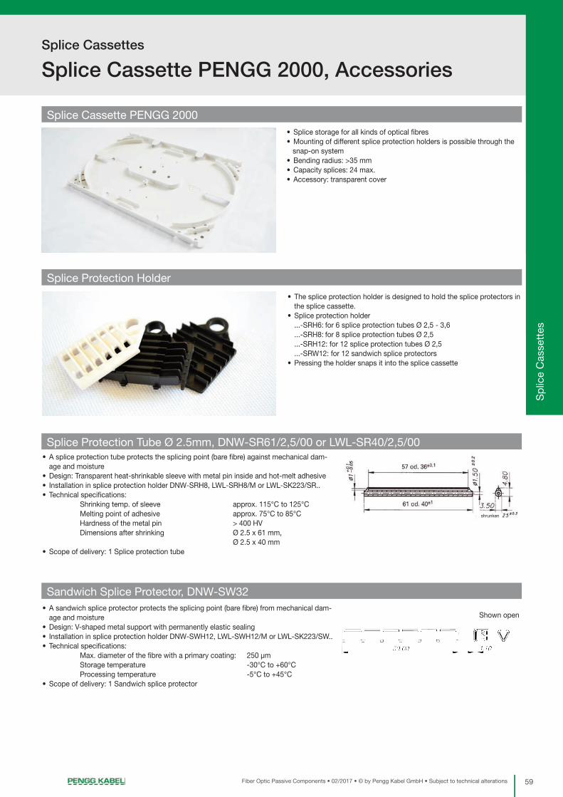
59Fiber Optic Passive Components • 02/2017 • © by Pengg Kabel GmbH • Subject to technical alterations
Splice Cassettes
Splice Cassette PENGG 2000, Accessories
Pre
-ass
emb
led
C
onne
ctor
s /
Ad
apte
rsO
ptic
al D
istr
ibut
ion
Sys
tem
(OP
DIS
YS
®)
Term
inat
ion
Sys
tem
fo
r 19
“ Te
chno
logy
Sp
lice
Cas
sett
es
Splice Cassette PENGG 2000
Splice Protection Holder
• The splice protection holder is designed to hold the splice protectors inthe splice cassette.
• Splice protection holder ...-SRH6: for 6 splice protection tubes Ø 2,5 - 3,6 ...-SRH8: for 8 splice protection tubes Ø 2,5 ...-SRH12: for 12 splice protection tubes Ø 2,5 ...-SRW12: for 12 sandwich splice protectors• Pressing the holder snaps it into the splice cassette
• Splice storage for all kinds of optical fibres• Mounting of different splice protection holders is possible through the
snap-on system• Bending radius: >35 mm• Capacity splices: 24 max.• Accessory: transparent cover
• A splice protection tube protects the splicing point (bare fibre) against mechanical dam-age and moisture
• Design: Transparent heat-shrinkable sleeve with metal pin inside and hot-melt adhesive • Installation in splice protection holder DNW-SRH8, LWL-SRH8/M or LWL-SK223/SR..• Technical specifications:
Shrinking temp. of sleeve approx. 115°C to 125°C Melting point of adhesive approx. 75°C to 85°C Hardness of the metal pin > 400 HV Dimensions after shrinking Ø 2.5 x 61 mm, Ø 2.5 x 40 mm
• Scope of delivery: 1 Splice protection tube
• A sandwich splice protector protects the splicing point (bare fibre) from mechanical dam-age and moisture
• Design: V-shaped metal support with permanently elastic sealing • Installation in splice protection holder DNW-SWH12, LWL-SWH12/M or LWL-SK223/SW..• Technical specifications:
Max. diameter of the fibre with a primary coating: 250 µm Storage temperature -30°C to +60°C Processing temperature -5°C to +45°C
• Scope of delivery: 1 Sandwich splice protector
Splice Protection Tube Ø 2.5mm, DNW-SR61/2,5/00 or LWL-SR40/2,5/00
Sandwich Splice Protector, DNW-SW32
Shown open
shrunken
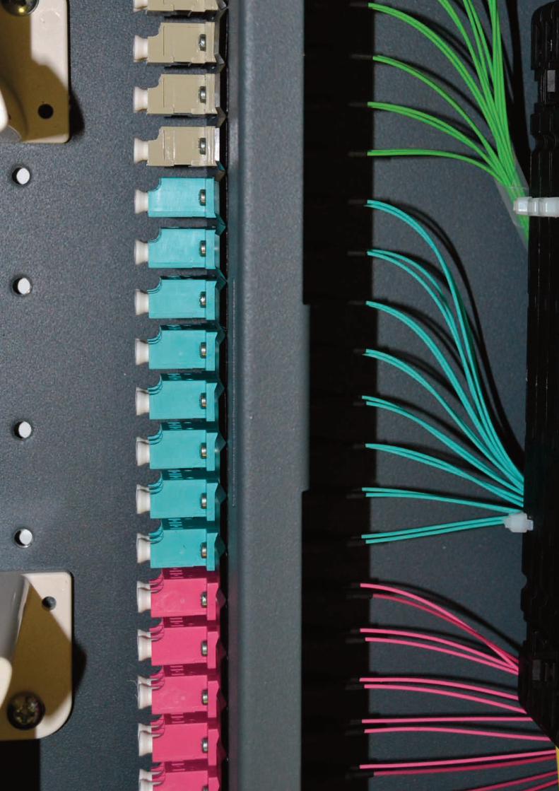

Termination Boxes and Wall Outlets
61Fiber Optic Passive Components • 02/2017 • © by Pengg Kabel GmbH • Subject to technical alterations
Wall outlet mini page 62
Wall outlet standard page 62
Distribution Enclosure OM10-4.. page 63
Distribution Enclosures OM page 64
Distribution Enclosure IML page 66
Distribution Enclosures IM page 67
Pre
-ass
emb
led
C
onne
ctor
s /
Ad
apte
rsO
ptic
al D
istr
ibut
ion
Sys
tem
(OP
DIS
YS
®)
Term
inat
ion
Sys
tem
fo
r 19
“ Te
chno
logy
Sp
lice
Cas
sett
esTe
rmin
atio
n B
oxes
an
d W
all O
utle
ts
Distribution Enclosure VK5 page 69
House Distribution Enclosure HEV10 page 70
Wall-mounted Splice Box WSB10 page 71
Wall-mounted Splice Box PKG page 72
FTTH Installation Box page 63

Termination Boxes and Wall Outlets
Wall outlet mini and standard
62 Fiber Optic Passive Components • 02/2017 • © by Pengg Kabel GmbH • Subject to technical alterations
Wall outlet mini
• Small termination box, especially suitable where space is limited
• Suitable for indoor wall-mounting in living rooms
• Traversable splice storage frame with splice protection holders
• Entries for one FTTH mini cable
• Splice protection holder integrated
• Adapters 2x SC, SC/APC, E2000, LC duplex, LC/APC duplex
• Number of fibres terminated 2 (4 with LC-adapters)
• Material High heat and high impact resistance Polystyrene (PS454C), RAL 9010
• Flammability UL94 HB
• Weight Approx. 60 g
• Scope of delivery
1 wall outlet box, 1 splice storage frame, 1 copy of Instructions for Installation, 2 cable tie wraps, screws
Wall outlet standard
• Small termination box, especially suitable where space is limited
• Suitable for indoor wall-mounting in living rooms
• Traversable splice storage frame with splice protection holders
• Connectors are protected in the housing
• Entries for one FTTH mini cable
• Splice protection holder integrated
• Adapters 2x SC, SC/APC, E2000, LC duplex, LC/APC duplex
• Number of fibres terminated 2 (4 with LC-adapters)
• Material High heat and high impact resistance Polystyrene (PS454C), RAL 9010
• Flammability UL94 HB
• Weight Approx. 95 g
• Scope of delivery
1 wall outlet box, 1 splice storage frame, 1 copy of Instructions for Installation, 2 cable tie wraps, screws

63Fiber Optic Passive Components • 02/2017 • © by Pengg Kabel GmbH • Subject to technical alterations
Termination Boxes and Wall Outlets
FTTH Installation Box and Enclosure OM10-4..
Pre
-ass
emb
led
C
onne
ctor
s /
Ad
apte
rsO
ptic
al D
istr
ibut
ion
Sys
tem
(OP
DIS
YS
®)
Term
inat
ion
Sys
tem
fo
r 19
“ Te
chno
logy
Sp
lice
Cas
sett
esTe
rmin
atio
n B
oxes
an
d W
all O
utle
ts
Distribution Enclosure OM10-4..
• The distribution enclosure serves as a terminal for fibre optic cables routed to connectors and for storing splices
• Small termination box, especially suitable where space is limited
• Suitable for indoor wall-mounting and installation in moist rooms
• Pull-out splice storage frame with splice protection holders
• Installation point for strain relief element (Kevlar)
• Provides sufficient space for multi-fibre loose tube reserves under the splice storage frame
• Entries 1 PG13 cable ø 6-12 mm
• Splice protection holder 1 SRH8 or 1 SWH12
• Adapters 4x FC/PC, ST, SC simplex, E2000 or LC duplex
• Degree of protection of the empty enclosure IP64
• Material
Enclosure Polystyrene, similar to RAL 7035
Splice storage frame Powder-coated aluminium, RAL 7035
PG Cable entry gland Plastic
• Weight Approx. 0.7 kg
• Scope of delivery 1 Enclosure, 1 splice storage frame, 1 copy of Instructions for Installation,
1 PG13 cable gland, 2 cable tie wraps, 2 PC121 pigtail clips,
1 SRH8/SWH12 splice protection holder
FTTH Installation box
Our convenient FTTH installation box gives you everything you need for a quick installation:
- Installation cable rolled up on an inside moving cardboard reel (customized length)
- Wall outlet - pre-assembled according to your needs
For example:
• I-VQ(ZN)H 4E9/125 FTTH in house cable preassembled with 2 LC/APC 8° connectors

Termination Boxes and Wall Outlets
Distribution Enclosures OM
64 Fiber Optic Passive Components • 02/2017 • © by Pengg Kabel GmbH • Subject to technical alterations
Description of OM2 and OM3 Distribution Enclosures
• These distribution enclosures serve as a terminal for a fibre optic cable routed to a connector and for storing splices
• Small termination boxes, particularly suitable where space is limited
• Suitable for indoor wall-mounting and installation in moist rooms
• For easy mounting, the base plate with splice cassette is removable
• Installation point for strain relief element (Kevlar)
• Provides sufficient space for storing multi-fibre loose tube reserves under the splice cassette
• A wall mounting set is available as accessory for easy wall mounting
• Degree of protection of the empty enclosure: IP64
• Material
Enclosure: ABS similar to RAL 7035
Base plates: Powder-coated aluminium, RAL 7035
• Weight
OM2: Approx.1 kg
OM3: Approx.1.2 kg
• Scope of delivery
Basic enclosure: 1 Enclosure, 1 base plate, 1 copy of Instructions for Installation
Adapter holes: 1 Hole in the basic enclosure
Cable entry: 1 Hole in the basic enclosure, 1 PG cable gland, 1 PG counternut
• Cable entries 1 or 2 cables
PG11 cable ø 5-10 mm
PG13 cable ø 6-12 mm
PG16 cable ø 8-14 mm
PG21 cable ø 10-18 mm
• Splice cassettes 1 x SK121
• Adapters 4 or 8 fibres FC/PC, ST; 12 fibres SC simplex, SC duplex or E2000; 24 fibres LC duplex
Distribution Enclosures OM, Individual Assembly, LWL-...
OM 2 Basic Enclosure LWL-OM2/GG/M

65Fiber Optic Passive Components • 02/2017 • © by Pengg Kabel GmbH • Subject to technical alterations
Termination Boxes and Wall Outlets
Distribution Enclosures OM
Pre
-ass
emb
led
C
onne
ctor
s /
Ad
apte
rsO
ptic
al D
istr
ibut
ion
Sys
tem
(OP
DIS
YS
®)
Term
inat
ion
Sys
tem
fo
r 19
“ Te
chno
logy
Sp
lice
Cas
sett
esTe
rmin
atio
n B
oxes
an
d W
all O
utle
ts
• Cable entries 1, 2, 3 or 4 cables
PG11 cable ø 5-10 mm
PG13 cable ø 6-12 mm
PG16 cable ø 8-14 mm
PG21 cable ø 10-18 mm
• Splice cassettes Max. 4 x SK121
• Adapters 12 or 16 fibres FC/PC, ST; 12 fibres SC simplex/E2000; 24 fibres SC simplex/E2000 or LC duplex;
48 fibres LC duplex
Distribution Enclosures OM, Individual Assembly, LWL-...
PG Cable Entry LWL-KDF/D..
• For sealing cables with a PG cable gland
• Cable diameters
LWL-KDF/D/PG11.. 5 to 10 mm
LWL-KDF/D/PG13.. 6 to 12 mm
LWL-KDF/D/PG16.. 8 to 14 mm
LWL-KDF/D/PG21.. 10 to 18 mm
• Degree of protection: IP68
• Material: Polyamide
• Weight: Approx. 15g
• Scope of delivery: 1 PG cable gland, 1 counternut
OM 3 Basic Enclosure LWL-OM3/GG/M
Accessories for OM2 and OM3 Distribution Enclosures

Termination Boxes and Wall Outlets
Distribution Enclosure IML
66 Fiber Optic Passive Components • 02/2017 • © by Pengg Kabel GmbH • Subject to technical alterations
Description of IML
• The distribution enclosures serves as a terminal for a fibre optic cable routed to a connector and for storing splices
• Small termination boxes, particularly suitable where space is limited
• Suitable for indoor wall-mounting
• Robust metal enclosure
• Installation point for strain relief element (Kevlar)
• Provides sufficient space for storing multi-fibre loose tube reserves under the splice cassette
• Degree of protection of the enclosure: IP30
• Material
Enclosure: Powder-coated sheet steel, RAL 7035
Plates: Powder-coated sheet steel, RAL 7011
• Weight: approx. 2.3 kg
• Dimensions WxHxD: approx. 230x70x260 mm
• Scope of delivery
Basic enclosure: 1 Enclosure consisting of trough and cover
Adapter plate: 1 Front plate with holes (adapters not included)
Cable entry plate: 1 Entry plate for 2 cables, 2 PG-cable glands, 1 blind plug, incl. counternuts
• Cable entries 2 cable glands of the same type
PG11 cable ø 8-10 mm
PG13 cable ø 10-12 mm
PG16 cable ø 12-14 mm
• Splice cassettes 4 small splice cassettes (SK120S) or
3 large splice cassettes (SK121)
• Adapters 12 or 24 fibres FC, ST, SC simplex, SC duplex, E2000
24 or 48 fibres LC duplex
Distribution Enclosure IML, Individual Assembly, LWL-...
IML Basic Enclosure LWL-IML/GG/M

67Fiber Optic Passive Components • 02/2017 • © by Pengg Kabel GmbH • Subject to technical alterations
Termination Boxes and Wall Outlets
Distribution Enclosure IM
Pre
-ass
emb
led
C
onne
ctor
s /
Ad
apte
rsO
ptic
al D
istr
ibut
ion
Sys
tem
(OP
DIS
YS
®)
Term
inat
ion
Sys
tem
fo
r 19
“ Te
chno
logy
Sp
lice
Cas
sett
esTe
rmin
atio
n B
oxes
an
d W
all O
utle
ts
Distribution Enclosure IM, Individual Assembly, LWL-...Description of IM2, IM3 and IM3/1 Distribution Enclosures
• These distribution enclosures serve as a terminal for a fibre optic cable routed to a connector and for storing splices
• Small termination boxes, particularly suitable where space is limited
• Suitable for indoor wall-mounting
• For easy mounting, the base plate with splice cassette is removable
• Installation point for strain relief element (Kevlar)
• Provides sufficient space for storing multi-fibre loose tube reserves under the splice cassette
• A set of wall brackets is available as accessory for easy wall mounting
• Degree of protection of the empty enclosure: IP40
• Material
Enclosure: ABS similar to RAL 7035
Base plate: Powder-coated aluminium, RAL 7035
Adapter-, Cable entry plate: ABS similar to RAL 7035
• Weight
IM2: Approx. 0.9 kg
IM3: Approx.1.4 kg
IM3/1: Approx. 2 kg
• Scope of delivery
Basic enclosure: 1 Enclosure, 1 base plate, 1 copy of Instructions for Installation
Adapter plate: 1 Front plate with holes (without adapters)
Cable entry plate: 1 Cable entry plate, PG cable glands, PG counternuts
• Cable entries 1 or 2 cables
PG11 cable ø 8-10 mm
PG13 cable ø 10-12 mm
PG16 cable ø 12-14 mm
• Splice cassettes 1 x SK121
• Adapters 4 or 8 fibres FC/PC, ST, SC simplex, SC duplex, E2000
8 or 16 fibres LC duplex
IM2 Basic Enclosure LWL-IM2/GG/M

Termination Boxes and Wall Outlets
Distribution Enclosure IM
68 Fiber Optic Passive Components • 02/2017 • © by Pengg Kabel GmbH • Subject to technical alterations
Distribution Enclosure IM, Individual Assembly, LWL-...
• Cable entries 1 or 2 cables
PG11 cable ø 8-10 mm
PG13 cable ø 10-12 mm
PG16 cable ø 12-14 mm
• Splice cassettes Max. 2 x SK121
• Adapters 8, 12 or 16 fibres FC/PC, ST, SC simplex, SC duplex, E2000
16, 24 or 32 fibres LC duplex
• Cable entries 1, 2 or 3 cables
PG11 cable ø 8-10 mm
PG13 cable ø 10-12 mm
PG16 cable ø 12-14 mm
• Splice cassettes Max. 4 x SK121
• Adapters 24 or 36 fibres FC/PC, ST, SC simplex, SC duplex, E2000
48 or 72 fibres LC duplex
IM3/1 Basic Enclosure LWL-IM3/1/GG/M
IM3 Basic Enclosure LWL-IM3/GG/M

69Fiber Optic Passive Components • 02/2017 • © by Pengg Kabel GmbH • Subject to technical alterations
Termination Boxes and Wall Outlets
Distribution Enclosure VK5
Pre
-ass
emb
led
C
onne
ctor
s /
Ad
apte
rsO
ptic
al D
istr
ibut
ion
Sys
tem
(OP
DIS
YS
®)
Term
inat
ion
Sys
tem
fo
r 19
“ Te
chno
logy
Sp
lice
Cas
sett
esTe
rmin
atio
n B
oxes
an
d W
all O
utle
ts
Description
• The VK5 distribution enclosure serves as a terminal for a fibre optic cable routed to a connector and for storing splices
• Small termination box, particularly suitable where space is limited
• Suitable for indoor wall-mounting, in particular for robust industrial applications
• Separate access to splice and plug connections
• Split cabinet available with 1 or 2 doors
• Doors are right-hinged, optionally either with lock or latch
• 2 Areas
top area for splicing
bottom area for patching
• Split foamed material entry strip for sealing the patch cords
• Strain relief and sealing of the cables on an intermediate plate with PG cable glands
• For easy mounting, the base plate with splice cassette is removable
• Installation points for central strength member and strain relief element (Kevlar)
• Provides sufficient space for storing multi-fibre loose tube reserves under the splice cassette
• Degree of protection IP53
• Cable entries 1 or 2 cables
PG11 cable ø 8-10 mm
PG13 cable ø 10-12 mm
PG16 cable ø 12-14 mm
• Splice cassettes Max. 2 x SK121
• Adapters 12 fibres FC/PC, ST, SC simplex, E2000
24 fibres LC duplex
• Material
Basic enclosure Powder-coated sheet steel, RAL 7035
Base plate Powder-coated aluminium, RAL 7035
• Weight Approx. 6 kg
• Scope of delivery
Basic enclosure: 1 Cabinet, 1 base plate, 3 plastic twisting clamps, 1 or 2
doors
Closure: 1 Lock or latch, fixing material, 1 key
Intermediate plate: 1 Intermediate plate with holes, fastening screws
Distribution Enclosure VK5, Individual Assembly, LWL-...
VK5 Basic Enclosure LWL-VK5/.T/GG/M

Termination Boxes and Wall Outlets
House Distribution Enclosure HEV10
70 Fiber Optic Passive Components • 02/2017 • © by Pengg Kabel GmbH • Subject to technical alterations
House Distribution Enclosure HEV10, Individual Assembly, LWL-...Description
• The house distribution enclosure serves as a terminal for a fibre optic cable routed to a connector, for storing splices and connecting copper data ca-
bles
• Especially designed for hybrid cables
• Suitable for indoor wall mounting
• Suitable for uncut cables
• Lockable hood (lock)
• Cable entry through a split foamed material strip
• Cable strain relief through tie wraps
• Installation point for strain relief element (Kevlar)
• For ease of installation, the base plate with the splice cassette can be removed
• Provides sufficient space to store multi-fibre loose tube reserves under the splice cassette
• Mounting plate for fastening LSA PLUS terminal rails
• Tightness Dust-proof
• Cable entries 2 Cables of up to ø 16 mm, uncut
• Splice cassettes Max. 4 x SK121
• Adapters 8 or 12 fibres FC/PC, ST, SC simplex, E2000
16 or 24 fibres LC duplex
• LSA PLUS terminal rails Max. 20 dual wires (4x 5 dual wires)
• Material Powder-coated aluminium, RAL 7035
• Weight Approx. 2 kg
• Scope of delivery
Basic enclosure: 1 Base plate, 1 hood, 1 mounting plate, 1 split foamed
material cable entry, 1 copy of Instructions for Installation
Adapter angle: 1 Angle, fastening screws
LSA PLUS terminal rail: 1 LSA PLUS terminal rail - 5 dual wires, fastening screws
Shown without cover
Basic Enclosure HEV10, LWL-HEV10/GG/M

71Fiber Optic Passive Components • 02/2017 • © by Pengg Kabel GmbH • Subject to technical alterations
Termination Boxes and Wall Outlets
Wall-mounted Splice Box WSB10
Pre
-ass
emb
led
C
onne
ctor
s /
Ad
apte
rsO
ptic
al D
istr
ibut
ion
Sys
tem
(OP
DIS
YS
®)
Term
inat
ion
Sys
tem
fo
r 19
“ Te
chno
logy
Sp
lice
Cas
sett
esTe
rmin
atio
n B
oxes
an
d W
all O
utle
ts
Description
• The wall-mounted splice box serves as a terminal for a fibre optic cable routed to a connector and for storing splices
• Enclosure for in-line connections and branch-offs
• Compact enclosure which provides a space-saving facility and an optimal protection of the fibres
• Suitable for indoor wall-mounting, in particular as a floor distributor
• Separate access to splice and plug connections
• Enclosure optionally with 1 or 2 locks (single-door locking)
• 2 Areas
left area for splicing
right area for patching
• Patch cord entry/exit covered by a brush strip
• Patch cord guides for routing the patch cords properly
• Strain relief points for central strength member and Kevlar reinforcement
• Provides sufficient space for storing multi-fibre loose tube reserves under the splice cassette
• Cable entries
Splicing area: 1 or 2 cables with cable gland (on top and bottom)
M16 cable Ø 5-10 mm
M20 cable Ø 8-13 mm
M25 cable Ø 11-15 mm
Patching area: Rectangular opening 100 x 30 mm with brush strip
(on top and bottom)
• Splice cassettes Max. 6 x SK121
• Adapters 24 or 48 fibres FC/PC, ST, SC simplex, SC duplex,
E2000
48 or 96 fibres LC duplex
• Material
Basic enclosure, Adapter plate Powder-coated sheet steel, RAL 7011
• Weight Approx. 3.9 kg
• Scope of delivery
Basic enclosure: 1 Enclosure incl. doors, 1 or 2 locks with keys, 2 patch
cord guides, 2 brush strips, 4 blind plugs
Adapter plate: 1 Adapter plate with holes, fixing material
Wall-mounted Splice Box WSB10, Individual Assembly, LWL-...
Basic Enclosure, LWL-WSB10/.S/GG/M

Termination Boxes and Wall Outlets
Wall-mounted Splice Box PKG
72 Fiber Optic Passive Components • 02/2017 • © by Pengg Kabel GmbH • Subject to technical alterations
Wall-mounted Splice Box PKGDescription
• The wall-mounted splice box serves as a terminal for a fibre optic cable routed to connectors and for storing splices
• Enclosure for in-line connections and branch-offs
• Compact enclosure which provides a space-saving facility and an optimal protection of the fibres
• Suitable for indoor wall-mounting, in particular as a floor distributor
• Separate access to splice and plug connections
• Enclosure optionally with 1 or 2 locks (single-door locking)
• 2 Areas
left area for splicing
right area for patching
• Patch cord entry/exit with cable gland
• Patch cord guides for routing the patch cords properly
• Strain relief points for central strength member and Kevlar reinforcement
• Provides sufficient space for storing multi-fibre loose tube reserves under the splice cassette
• degree of protection: IP53
• Cable entries
Splicing area: 1 or 2 cables with cable gland (on top and bottom)
M16 cable Ø 5-10 mm
M20 cable Ø 8-13 mm
M25 cable Ø 11-15 mm
Patching area: M25 cable gland
• Splice cassettes Max. 4 x SK120
• Adapters 24 fibres FC/PC, ST, SC simplex, SC duplex,
E2000
48 fibres LC duplex
• Material
Basic enclosure, Adapter plate Powder-coated sheet steel, RAL 7011
• Weight Approx. 3.9 kg
• Scope of delivery
Basic enclosure: 1 Enclosure incl. doors, 1 or 2 locks with keys, 2 patch
cord guides, 4 blind plugs
Adapter plate: 1 Adapter plate with holes, fixing material

Interconnect Cases and Distribution Cabinets
73Fiber Optic Passive Components • 02/2017 • © by Pengg Kabel GmbH • Subject to technical alterations
Interconnect Case RGV20 page 74
Interconnect Case RGV20 TL page 75
Interconnect Case RGV30 page 76
Interconnect Case RGV30 TL page 77
Plastic Distribution Cabinet, VK1-SO-K-SH/00 page 78
Universal Distribution Cabinet, VK1-SO/AP/M-SH/00 page 79
Pre
-ass
emb
led
C
onne
ctor
s /
Ad
apte
rsO
ptic
al D
istr
ibut
ion
Sys
tem
(OP
DIS
YS
®)
Term
inat
ion
Sys
tem
fo
r 19
“ Te
chno
logy
Sp
lice
Cas
sett
esTe
rmin
atio
n B
oxes
an
d W
all O
utle
tsIn
terc
onne
ct C
ases
and
D
istr
ibut
ion
Cab
inet
s
Interconnect Enclosures, RGH6455 144.. page 80
Interconnect Case, RGH6455 TL page 81

Interconnect Cases and Distribution Cabinets
Interconnect Case RGV20
74 Fiber Optic Passive Components • 02/2017 • © by Pengg Kabel GmbH • Subject to technical alterations
Description
• The interconnect case serves for storing splices and for interconnecting fibre optic cables
• Enclosure for in-line connections and branch-offs
• Suitable for wall mounting
• Suitable for indoor and outdoor applications
• Suitable for uncut cables
• Door is right-hinged and easy to remove
• Cylinder lock
• Door sealing inside
• Degree of protection IP66 acc. to EN 60529 with heat-shrinkable entry, IP54 with PG cable entry
• Strain relief points for central strength member and Kevlar reinforcement
• Storage for cut/uncut multi-fibre loose tubes
• Swing-type false floor for mounting splice cassettes and patch drawers
• Protected against unintended swing-out through a locking pin
• Cable entries
Heat-shrink cable entries 2 cables Ø 10-25mm, oval entry port, uncut
1 cable Ø 3-16mm
1 cable Ø 6-22mm
PG cable entries Ø 8-10mm (PG11)
Ø 10-12mm (PG13)
Ø 12-14mm (PG16)
Ø 14-17mm (PG21)
24x Ø 3mm (PG29) for patch cords
• Splice cassettes 6 x SK/121
• Adapters 24 FC/PC, ST, SC, E2000 or LC duplex
• Permanent temperature Max. 150°C
• Colour RAL 7035
• Material
Enclosure Thermoformed, self-extinguishing, halogen-free,
glass fibre reinforced polyester
Inside components Powder-coated sheet steel RAL 7035
• Weight Approx. 7.8 kg
• Scope of delivery Enclosure with door, cylinder lock, sealing, false floor,
spiral tapes
Dimensions (mm) Options for Interconnecting
Patch cord
Interconnecting with patch cords Interconnecting with pigtails
Interconnect Case RGV20, Individual Assembly, LWL-RGV20...
Basic Enclosure LWL-RGV20/GG/M

75Fiber Optic Passive Components • 02/2017 • © by Pengg Kabel GmbH • Subject to technical alterations
Interconnect Cases and Distribution Cabinets
Interconnect Case RGV20 TL
Pre
-ass
emb
led
C
onne
ctor
s /
Ad
apte
rsO
ptic
al D
istr
ibut
ion
Sys
tem
(OP
DIS
YS
®)
Term
inat
ion
Sys
tem
fo
r 19
“ Te
chno
logy
Sp
lice
Cas
sett
esTe
rmin
atio
n B
oxes
an
d W
all O
utle
tsIn
terc
onne
ct C
ases
and
D
istr
ibut
ion
Cab
inet
s
Description
• The interconnect case serves for storing splices and interconnecting fibre optic cables
• The tubeless version is particularly suitable for Single Circuit (SC) and Single Element (SE)
Single Circuit: Distribution of the fibres from one multi-fibre loose tube to several splice cassettes through fibre guiding channels
Single Element: For multi-fibre loose tube management (multi-fibre loose tube upon multi-fibre loose tube)
• Tubeless laying of fibres from the entry to the splice cassette
• Up to 24 individual splice cassettes thanks to the “cassette in a cassette” system
• Enclosure for in-line connections and branch-offs
• Suitable for wall, pole and tower mounting
• Suitable for indoor and outdoor applications
• Suitable for uncut cables
• Door is right-hinged and easy to remove• Clip-down handle• Door sealing inside• Degree of protection IP66 according to EN 60529 with heat-shrinkable entries,
IP 54 with PG cable entry• Strain relief points for central strength member and Kevlar reinforcement• Storage area for cut/uncut multi-fibre loose tubes• The removable cassette-ground plate is used for fastening the multi-fibre loose tubes and also to
assembly the splice cassette set LWL-SEC23/TL/6SK... onto the mounting plate• The entry module permits fibre routing to any cassette entry • Cable entries Heat-shrink cable entries 2 cables Ø 10-25mm, oval entry port, uncut 1 cable Ø 3-16mm 1 cable Ø 6-22mm PG cable entries Ø 8-10mm (PG11) Ø 10-12mm (PG13) Ø 12-14mm (PG16) Ø 14-17mm (PG21) 24x Ø 3mm (PG29) for patch cords• Splice cassettes 24 x SK123 or SK223 Available as sets of 6 splice cassettes each => max. 2 sets Splice cassettes are engaged in a slanted position Swing-type splice cassettes (90°) provide easy access to each splice• Adapters 12 FC/PC, ST, SC, E2000 or LC duplex 24 SC, E2000 or LC duplex• Permanent temperature Max. 150°C• Material Enclosure Thermoformed, self-extinguishing, halogen-free, glass-fibre reinforced polyester, colour RAL 7035 Mounting-, Base plate Powder-coated sheet steel, RAL 7035 Patch-, Fastening angle Powder-coated sheet steel, RAL 7011• Weight Approx. 5.1 kg• Scope of delivery
Basic enclosure: 1 Cabinet incl. door, clip-down handle and sealing, 1 mounting plate, 1 base plate, 1 entry module with cover, 1 fastening anglePatch angle: 1 Angle with holes, fastening screws
Options for Interconnecting
B C
A415
315 175
Patch cord
Interconnecting with patch cords Interconnecting with pigtails
Interconnect Case RGV20 TL (Tubeless System), Individual Assembly, LWL-RGV20...
Dimensions (mm)
Basic Enclosure LWL-RGV20/GG/M

Interconnect Cases and Distribution Cabinets
Interconnect Case RGV30
76 Fiber Optic Passive Components • 02/2017 • © by Pengg Kabel GmbH • Subject to technical alterations
Description
• The interconnect case serves for splice storage and connecting fibre optic cables
• Enclosure for in-line connections and branch-offs
• Suitable for wall, pole and tower mounting
• Suitable for indoor and outdoor applications
• Suitable for uncut cables
Dimensions (mm) Types of interconnecting
B C
A615
415 230
Interconnect Case RGV30, Individual Assembly, LWL-RGV30...
Patch cord
Interconnecting with patch cords Interconnecting with pigtails
Basic Enclosure, LWL-RGV30/GG/M
• Door is hinged on the right side and easy to remove
• 3-Point-lock through clip-down handle and bar lock
• Suitable for installation of a semi-cylinder
Length 40mm with an up to 2.5mm protruding cylinder head
• Door sealing inside
• Degree of protection IP66 according to EN 60529 with heat-shrinkable entries,
IP54 with PG cable entry
• Separate strain relief points for central strength member and Kevlar reinforcement
• Storage for cut/uncut multi-fibre loose tubes
• Removable and pivoting false floor for mounting the splice cassettes,
patch drawers and for reserve lengths storage
• Protected against unintended swing-out through a locking pin
• Storage of reserve lengths for compensating differences in the length of pigtails
and patch cords
• Single Circuit (SC) management possible through further accessories LWL-ES/UFM/6455..
• Cable entries
Heat-shrink cable entries 2 cables Ø 10-25mm, oval entry port, uncut
1 cable Ø 3-16mm
1 cable Ø 6-22mm
PG cable entries Ø 8-10mm (PG11)
Ø 10-12mm (PG13)
Ø 12-14mm (PG16)
Ø 14-17mm (PG21)
24x Ø 3mm (PG29) for patch cords
• Splice cassettes 36 x SK/120/S or 14 x SK/121
Splice cassette SK120S engaged in a slanted position
Pivoting splice cassette (90°) to provide easy access to each splice
• Adapters 72 FC/PC, ST, SC, E2000 or LC duplex
• Permanent temperature Max. 150°C
• Colour RAL 7035
• Material
Enclosure Thermoformed, self-extinguishing, halogen-free,
glass-fibre reinforced polyester
Inside components Powder-coated aluminium and steel sheet,
RAL 7035
• Weight Approx. 10.75 kg
• Scope of delivery Enclosure with door, clip-down handle and bar
lock, sealing and false floor

77Fiber Optic Passive Components • 02/2017 • © by Pengg Kabel GmbH • Subject to technical alterations
Interconnect Cases and Distribution Cabinets
Interconnect Case RGV30 TL
Pre
-ass
emb
led
C
onne
ctor
s /
Ad
apte
rsO
ptic
al D
istr
ibut
ion
Sys
tem
(OP
DIS
YS
®)
Term
inat
ion
Sys
tem
fo
r 19
“ Te
chno
logy
Sp
lice
Cas
sett
esTe
rmin
atio
n B
oxes
an
d W
all O
utle
tsIn
terc
onne
ct C
ases
and
D
istr
ibut
ion
Cab
inet
s
Description
• The interconnect case serves for storing splices and interconnecting fibre optic cables
• The tubeless version is particularly suitable for Single Circuit (SC) and Single Element (SE)
Single Circuit: Distribution of the fibres from one multi-fibre loose tube to several splice cassettes through fibre guiding channels
Single Element: For multi-fibre loose tube management (multi-fibre loose tube upon multi-fibre loose tube)
• Tubeless laying of fibres from the entry to the splice cassette
• Up to 48 individual splice cassettes thanks to the “cassette in a cassette” system
• Enclosure for in-line connections and branch-offs
• Suitable for wall, pole and tower mounting
• Suitable for indoor and outdoor applications
• Suitable for uncut cables
• Door is right-hinged and easy to remove
• 3-Point-lock through clip-down handle and bar lock
• Suitable for installation of a semi-cylinder
40mm long, with an up to 2.5mm protruding cylinder head
• Door sealing inside
• Degree of protection IP66 according to EN 60529 with heat-shrinkable entries,
IP 54 with PG cable entry
• Separate strain relief points for central strength member and Kevlar reinforcement
• Storage area for cut/uncut multi-fibre loose tubes
• Removable and swing-type false floor for mounting the splice cassettes,
patch drawers and for storing excess lengths
• Protected against unintended swing-out through a rotary bolt latch
• Storage area for reserve lengths to compensate differences in the length of pigtails and patch cords
• Cable entries
Heat-shrink cable entries 2 cables Ø 10-25mm, oval entry port, uncut
1 cable Ø 3-16mm
1 cable Ø 6-22mm
PG cable entries Ø 8-10mm (PG11)
Ø 10-12mm (PG13)
Ø 12-14mm (PG16)
Ø 14-17mm (PG21)
24x Ø 3mm (PG29) for patch cords
• Splice cassettes 24 x SK123 or SK223
Available as sets of 6 splice cassettes each => max. 4 sets
Splice cassettes are engaged in a slanted position
Swing-type splice cassettes (90°) provide easy access to each splice
• Adapters 72 FC/PC, ST, SC, E2000 or LC duplex
• Permanent temperature Max. 150°C
• Colour RAL 7035
• Material
Enclosure Thermoformed, self-extinguishing, halogen-free,
glass-fibre reinforced polyester
Inside components Powder-coated aluminium and sheet steel,
RAL 7035
• Weight Approx. 10.75 kg
• Scope of delivery Enclosure with door, clip-down handle and bar lock,
sealing, false floor
Interconnect Case RGV30 TL (Tubeless System), Individual Assembly, LWL-RGV30...
Dimensions (mm) Types of interconnecting
See previous page
Basic Enclosure LWL-RGV30/GG/M

Interconnect Cases and Distribution Cabinets
Plastic Distribution Cabinet, VK1-SO-K-SH/00
78 Fiber Optic Passive Components • 02/2017 • © by Pengg Kabel GmbH • Subject to technical alterations
• Distribution cabinet for outdoor base mounting (Austrian standard ÖNORM E 4382 size S5 or
DIN 43629 size 1)
• Junction for several fibre optic cables
• 90° swing-type mounting frame for mounting an RGH6455 interconnect enclosure
• Additional adapter rails and a mounting plate for wall mounting allow the installation of OM1 and
KM3 sleeves
• Cable insertion at the bottom, through the base
• Cable protection plate for orderly insertion and laying of the cables
• Support frame for approx.15 m cable reserve at the rear
• Door with clip-down handle for semi-cylinder, 40 mm long and up to 2.5 mm protruding cylinder
head
• Degree of protection: IP43
• Material
Cabinet and door: Glass-fibre reinforced polyester, RAL 7035
Inside elements: Sheet steel, galvanized or powder-coated, RAL 7035
• Weight: Approx. 36 kg
• Scope of delivery: 1 Cabinet, 1 door (pre-assembled), 1 mounting frame, 1
strain relief rail, 1 cable protection plate, 1 clip-down
handle
• Base for mounting the distribution cabinet VK1-SO-K-SH/00
• Fastening dimensions according to Austrian standard ÖNORM E4382 size S5 or DIN 43629 size 1
• Height 900 mm
• C-profile rail for strain relief of fibre optic tubes with cable clips
• Sealing of the fibre optic tubes with UF1 universal fitting or RAS tube end closure
• Material: Glass-fibre reinforced polyester, RAL 7035
• Weight: Approx. 18 kg
• Scope of delivery: 1 Base, 1 C-profile rail, 4 M12 x 30mm screws
Sectional view - Mountingframe with RGH swung out
Plastic VK1
RGH
Cable protec-tiondevice
Base
Plastic Distribution Cabinet VK1-SO-K-SH/00
Base for VK1-SO

79Fiber Optic Passive Components • 02/2017 • © by Pengg Kabel GmbH • Subject to technical alterations
Interconnect Cases and Distribution Cabinets
Universal Distribution Cabinet, VK1-SO/AP/M-SH/00
Pre
-ass
emb
led
C
onne
ctor
s /
Ad
apte
rsO
ptic
al D
istr
ibut
ion
Sys
tem
(OP
DIS
YS
®)
Term
inat
ion
Sys
tem
fo
r 19
“ Te
chno
logy
Sp
lice
Cas
sett
esTe
rmin
atio
n B
oxes
an
d W
all O
utle
tsIn
terc
onne
ct C
ases
and
D
istr
ibut
ion
Cab
inet
s
• Distribution cabinet for outdoor base mounting (Austrian standard ÖNORM E 4382 size S5 or DIN
43629 size 1), surface mounting and pole/tower mounting
• Junction for several fibre optic cables
• 90° swing-type mounting frame for mounting an RGH6455 interconnect enclosure
• Additional mounting rails and a mounting plate for wall mounting allow the installation of OM1 and
KM3 sleeves
• Insertion of cables at the bottom, through the base, in case of wall or pole/tower mounting inser-
tion through bottom plates
• Different bottom plates for surface mounting and pole/tower mounting
• Support for approx. 15 m cable reserve at the rear
• Door with clip-down handle for semi-cylinder, 40 mm long and up to 2.5 mm protruding cylinder
head
• Degree of protection: IP43
• Material
Cabinet and door: Powder-coated aluminium, RAL 7035
Inside elements: Sheet steel, galvanized or powder-coated, RAL 7035
• Weight: Approx. 45 kg
• Scope of delivery: 1 Cabinet, 1 door (pre-assembled), 1 mounting frame, 1
strain relief rail, 1 clip-down handle
• Base for mounting the VK1-SO/AP/M-SH/00 distribution cabinet
• Fastening dimensions according to Austrian standard ÖNORM E4382 size S5 or DIN 43629 size 1
• Height 950 mm, ground excavation depth 600 mm
• C-profile rail for strain relief of fibre optic tubes with cable clips
• Sealing of the fibre optic tubes with UF1 universal fitting or RAS tube end closure
• Material: Polyester, RAL 7032
• Weight: Approx. 20 kg
• Scope of delivery: 1 Base, 1 C-profile rail, 4 M12 x 30mm screws
• Bottom plates for insertion of cables in case of surface mounting or pole/tower mounting
• Different versions for surface mounting and pole/tower mounting with the suitable fixing devices and external strain relief (aluminium or plastic
clamps)
• Versions:
Bottom plate - blank Cable entries to be drilled at site as required
Bottom plate 3P213B21 3x PG21 (cable ø 10-18 mm), 3x PG21 blank
Bottom plate, split Split entry for uncut cables of max. 25 mm
Bottom plate, split, 1P212B21 Split entry for uncut cables of max. 25 mm, 1x PG21 (cable ø 10-18 mm), 2x PG21 blank
Base mounting
Base
Mounting frame for theinstallation of equipmentwith a strain relief rail,can be swung out ap-prox. 90°
Strain relief clampStrain relief rail
Bottom coverSpacer plate Fastening strip
Surfacemounting
Pole and towermounting
Universal Distribution Cabinet VK1-SO/AP/M-SH/00
Bottom Plates
Base for VK1-SO/AP/M

Interconnect Cases and Distribution Cabinets
Interconnect Enclosures, RGH6455 144..
80 Fiber Optic Passive Components • 02/2017 • © by Pengg Kabel GmbH • Subject to technical alterations
Interconnect Enclosures RGH6455 144…
• The interconnect enclosure serves for storing splices and for interconnecting fibre optic cables
• Enclosure allowing easy access to connections and branch-offs
• Suitable for wall and duct mounting as well as for installation in the cabinet (VK1-...)
• Swing-type false floor with storage frame for patch cord excess lengths and 6 x 24 swing-type adapter drawers
• False floor and adapter drawers are secured through snap-in closures
• Lower level for cable entries, storage of excess lengths of multi-fibre loose tubes, 2 tiers of splice cassettes
• Delivered with cable entries closed through removable blanks
• For cable insertion use either an oval cable entry set (included in the scope of delivery) and/or heatshrinkable LWL-KDF/S/3/16 cable entries
• Entries 2 Cables 10-25 mm, uncut
4 Cables 3-16mm
• Splice cassettes 56x SK/120/S
• Adapters 144x FC/PC, SC or E2000
• Degree of protection IP66
• Material
Enclosure Powder-coated aluminium, RAL 7035
Adapter strip Powder-coated aluminium, RAL 7011
Sealing EPDM
• Weight Approx.16.5 kg
• Scope of delivery
1 Enclosure with cover, 4 16-mm heat-shrinkable blanking plugs, 1 oval cable entry, 1 oval cable entry set, 24 SK120S splice cassettes,
48 SRH8 splice protection holders, 8 patchcord guides, 250g drying agent, 4 velcro straps, 1 copy of Instructions for Installation
Options for Interconnecting
Patch cord
Interconnecting with patch cords Interconnecting with pigtails

81Fiber Optic Passive Components • 02/2017 • © by Pengg Kabel GmbH • Subject to technical alterations
Interconnect Cases and Distribution Cabinets
Interconnect Case, RGH6455 TL
Pre
-ass
emb
led
C
onne
ctor
s /
Ad
apte
rsO
ptic
al D
istr
ibut
ion
Sys
tem
(OP
DIS
YS
®)
Term
inat
ion
Sys
tem
fo
r 19
“ Te
chno
logy
Sp
lice
Cas
sett
esTe
rmin
atio
n B
oxes
an
d W
all O
utle
tsIn
terc
onne
ct C
ases
and
D
istr
ibut
ion
Cab
inet
s
Interconnect Case RGH6455 TL (Tubeless System), Individual Assembly, LWL-RGH6455... Description
• The interconnect enclosure serves for storing splices and interconnecting fibre optic cables
• The tubeless version is particularly suitable for Single Circuit (SC) and Single Element (SE)
Single Element: For multi-fibre loose tube management (multi-fibre loose tube upon multi-fibre loose tube)
Single Circuit: Distribution of the fibres from one multi-fibre loose tube to several splice cassettes through fibre guiding channels
• Tubeless laying of fibres from the entry to the splice cassette
• Up to 96 individual splice cassettes thanks to the “cassette in a cassette” system
• Enclosure offers easy access to in-line connections and branch-offs
• Suitable for wall and duct mounting as well as for installation in an additional outer cabinet (VK1-...)
• Suitable for uncut cables
• Cable entries 2 Cables 10-25 mm, uncut
4 Cables 3-16mm
• Splice cassettes 48x SK123 or SK223
Available as sets of 6 splice cassettes each => max. 8 sets
Splice cassettes are engaged in a slanted position
Swing-type splice cassettes (90°) provide easy access to each splice
• Adapters 144x FC/PC, ST, SC or E2000
• Degree of protection IP66
• Material
Enclosure Powder-coated aluminium, RAL 7035
Adapter strip Powder-coated aluminium, RAL 7011
Sealing EPDM
• Weight Approx. 17 kg
• Scope of delivery
1 Enclosure with cover, 4 16mm heat-shrinkable blanking plugs, 1 oval cable entry, 1 oval cable entry set, 2 entry modules with cover, 8 patchcord
guides, 250g drying agent, 4 velcro straps, 1 copy of Instructions for Installation
Options for Interconnecting
• Swing-type false floor with storage area for patch cord excess lengths, can accommodate 2 patch drawer sets
• False floor and patch drawers are secured through quick opening devices
• Lower level for cable entries, storage of excess lengths of multi-fibre loos tubes, 2 tiers of splice cassettes
• The entry module permits fibre routing to any cassette entry
• Delivered with cable entries closed through removable blanks
• For cable insertion use either an oval cable entry set (included in scope of delivery) and/or LWL-KDF/S/3/16 heat shrinkable cable entries
Basic Enclosure LWL-RGH6455/TL/GG/M
See previous page


Fiber Optic Enclosures
83Fiber Optic Passive Components • 02/2017 • © by Pengg Kabel GmbH • Subject to technical alterations
Dome Enclosure SEC15 page 84
Dome Enclosure SEC23 Classic page 85
Dome Enclosure SEC23 Single Element II page 86
Dome Enclosure SEC23 Management II page 87
Dome Enclosure SEC23 Tubeless Short page 88
Dome Enclosure SEC23 Tubeless page 89
Pre
-ass
emb
led
C
onne
ctor
s /
Ad
apte
rsO
ptic
al D
istr
ibut
ion
Sys
tem
(OP
DIS
YS
®)
Term
inat
ion
Sys
tem
fo
r 19
“ Te
chno
logy
Sp
lice
Cas
sett
esTe
rmin
atio
n B
oxes
an
d W
all O
utle
tsIn
terc
onne
ct C
ases
and
D
istr
ibut
ion
Cab
inet
sFi
ber
Op
tic
Enc
losu
res
Accessories for Dome Enclosures Type SEC... page 90
Dome Enclosure PLP - FibreGuard page 92
Universal Plastic Sleeve KM3 page 94
Universal Plastic Sleeve OM1 page 95
Protective Sleeve SM/2F..+2B page 96
Dome Enclosure OM-HM page 97
Accessories for Dome Enclosure OM-HM page 98
Wire and Cable Storage Frames LWL-SSP page 99

Fiber Optic Enclosures
Dome Enclosure SEC15
84 Fiber Optic Passive Components • 02/2017 • © by Pengg Kabel GmbH • Subject to technical alterations
Description
• The SEC15 Dome Enclosure is particularly suitable for connecting fibre optic cables featuring a small number of fibres
• Enclosure for in-line connections and branch-offs
• Suitable for underground, duct, wall and pole/tower mounting
• Suitable for uncut cables
• Assembly/disassembly of the dome without any tools
• Sealings can be used again
• Separate strain relief points for central strength member and Kevlar reinforcement
• Storage of cut/uncut multi-fibre loose tubes
• Cable entries 2 Cables 10-25 mm, uncut
3 Cables, 10-20 mm
• Splice cassettes 8 x SK120S
• Degree of protection >IP68
• Max. splice capacity
Splice protection tube 128
Sandwich splice protector 192
• Tests According to DIN 47624 Draft 4/97
Mechanical strength
Load (15 min) 1000 N at the centre of the enclosure,
contact area 5 cm2
Impact (once) 1 kg Steel ball, 2 m fall,
at the centre of the enclosure
Pressure resistance
Permanent pressure 0.4 bar above atmospheric
Tight from -40°C to +70C°
Tightness with cable
Strain (15 min) 1000 N
Shearing/bending (twice) Deflection 45° or a max. of 500 N bending force,
Point of application 250 mm from cable entry
Torsion (twice) ±90° rotation angle or a max. torque of 50 Nm,
Point of application 500 mm from cable entry
Vibration 168 hours; both cable ends fastened,
Amplitude ±3 mm, frequency 10 Hz
Temperature changes -40°C to +70°C, 10 times
Immersion in wetting agent 168 hours
External pressure resistance 4 m water column
Water vapour permeation < 240 µg/h at 10°C
• Material
Base plate, dome, locking ring
and snap-in lock Environmentally friendly, UV-resistant polypropylene
Strain relief angle Stainless steel
Cassette support Powder-coated aluminium sheet, RAL 7035
• Weight Approx. 2 kg
• Scope of delivery Base plate, dome, locking ring incl. snap-in lock, securing
pin, sealing ring, cassette support, drying agent, 1 copy of
Instructions for Installation
SEC15 Dome Enclosure, Individual Assembly, LWL-S...
Basic Enclosure LWL-SEC15/GM/M

85Fiber Optic Passive Components • 02/2017 • © by Pengg Kabel GmbH • Subject to technical alterations
Fiber Optic Enclosures
Dome Enclosure SEC23 Classic
Pre
-ass
emb
led
C
onne
ctor
s /
Ad
apte
rsO
ptic
al D
istr
ibut
ion
Sys
tem
(OP
DIS
YS
®)
Term
inat
ion
Sys
tem
fo
r 19
“ Te
chno
logy
Sp
lice
Cas
sett
esTe
rmin
atio
n B
oxes
an
d W
all O
utle
tsIn
terc
onne
ct C
ases
and
D
istr
ibut
ion
Cab
inet
sFi
ber
Op
tic
Enc
losu
res
Description
• The SEC 23 Classic Dome Enclosure is particularly suitable for connecting fibre optic cables featuring a large number of fibres
• Enclosure for in-line connections and branch-offs
• Suitable for underground, duct, wall and pole/tower mounting
• Suitable for uncut cables
• Assembly/disassembly of the dome without any tools
• Sealings can be used again
• Separate strain relief points for central strength member and Kevlar reinforcement
• Storage of cut/uncut multi-fibre loose tubes
• Cable entries 2 Cables 10-25 mm, uncut
2 Cables 10-25 mm, 4 cables 10-20 mm
3 Cable entries with cable glands with
heat-shrinkable sleeves (3-16 mm) optional
• Splice cassettes 20 x SK120S or 12 x SK121
• Degree of protection >IP68
• Max. splice capacity
Splice protection tube 320 (SK120S), 192 (SK121)
Sandwich splice protector 480 (SK120S), 288 (SK121)
• Tests According to DIN 47624 Draft 4/97
Mechanical strength
Load (15 min) 1000 N at the centre of the enclosure,
contact area 5 cm2
Impact (once) 1 kg Steel ball, 2 m fall, at the centre of the enclosure
Pressure resistance
Permanent pressure 0.4 bar above atmospheric
Tight from -40°C to +70C°
Tightness with cable
Strain (15 min) 1000 N
Shearing/bending (twice) Deflection 45° or a max. of 500 N bending force,
Point of application 250 mm from cable entry
Torsion (twice) ±90° rotation angle or a max. torque of 50 Nm,
Point of application 500 mm from cable entry
Vibration 168 hours; both cable ends fastened,
Amplitude ±3 mm, frequency 10 Hz
Temperature changes -40°C to +70°C, 10 times
Immersion in wetting agent 168 hours
External pressure resistance 4 m water column
Water vapour permeation < 600 µg/h at 10°C
• Material
Base plate, dome, locking ring
and snap-in lock Environmentally friendly, UV-resistant polypropylene
Strain relief angle Stainless steel
Cassette support Powder-coated aluminium sheet, RAL 7035
• Weight Approx. 4 kg
• Scope of delivery Base plate, dome, locking ring incl. snap-in lock, securing
pin, sealing ring, cassette support, drying agent, 1 copy of
Instructions for Installation
SEC23 Classic Dome Enclosure, Individual Assembly, LWL-S...
Basic Enclosure LWL-SEC23/S/C/GM/M

Fiber Optic Enclosures
Dome Enclosure SEC23 Single Element II
86 Fiber Optic Passive Components • 02/2017 • © by Pengg Kabel GmbH • Subject to technical alterations
Description
• Single Element (SE) version, especially for multi-fibre loose tube management (multi-fibre loose tube upon multi-fibre loose tube)
• In-line connection and branch-off enclosure
• Suitable for ground, duct, wall, pole and tower mounting
• Suitable for uncut cables
• Assembly/disassembly of the dome without any tools
• Sealings can be used again
• Separate strain relief points for central strength member and Kevlar reinforcement
• Pivoting storage frame for cut/uncut multi-fibre loose tubes
• Cable entries 2 cables of 10-25 mm, uncut
2 cables of 10-25 mm, 4 cables of 10-20 mm
3 cable entries with cable glands with heat-shrink-
able sleeves (3-16 mm) optional
• Splice cassettes 38 x SK123 or SK223
Splice cassettes engaged in a slanted position
Pivoting splice cassettes (90°) to provide easy access to each splice
• Degree of protection >IP68
• Max. splice capacity
Splice protection tube 608
Sandwich splice protector 912
• Tests According to DIN 47624 Draft 4/97
Mechanical strength
Load (15 min) 1000 N at centre of the enclosure, contact area 5 cm2
Impact (once) 1 kg steel ball, 2 m fall, centre of the enclosure
Pressure resistance
Permanent pressure 0.4 bar above atmospheric
Tight from -40°C to +70C°
Tightness with cable
Strain (15 min) 1000 N
Shearing/Bending (twice) Deflection 45° or a max. of 500 N bending force,
Point of application 250 mm from cable entry
Torsion (twice) ±90° rotation angle or a max. torque of 50 Nm
Point of application 500 mm from cable entry
Vibration 168 hours; both cable ends fastened,
Amplitude ±3 mm, frequency 10 Hz
Temperature changes -40°C to +70°C, 10 times
Immersion in wetting agent 168 hours
External pressure resistance 4 m water column
Water vapour permeation < 600 µg/h at 10°C
• Material
Base plate, dome, locking ring
and snap-in lock Environmentally friendly, UV-resistant polypropylene
Strain relief angle Stainless steel
Cassette support Powder-coated aluminium sheet, RAL 7035
• Weight Approx. 4 kg
• Scope of delivery Base plate, dome, locking ring with snap-in lock, securing
pin, sealing ring, cassette support, drying agent, instruc-
tions for installation, 2 fastening ledges for multi-fibre
loose tubes
SEC23 Single Element II, Individual Assembly, LWL-S...
Base Enclosure, LWL-SEC23/SEII/GM/M

87Fiber Optic Passive Components • 02/2017 • © by Pengg Kabel GmbH • Subject to technical alterations
Fiber Optic Enclosures
Dome Enclosure SEC23 Management II
Pre
-ass
emb
led
C
onne
ctor
s /
Ad
apte
rsO
ptic
al D
istr
ibut
ion
Sys
tem
(OP
DIS
YS
®)
Term
inat
ion
Sys
tem
fo
r 19
“ Te
chno
logy
Sp
lice
Cas
sett
esTe
rmin
atio
n B
oxes
an
d W
all O
utle
tsIn
terc
onne
ct C
ases
and
D
istr
ibut
ion
Cab
inet
sFi
ber
Op
tic
Enc
losu
res
Description
• Management version, suitable especially for Single Circuit (SC) and Single Element (SE).
Single Circuit: Distribution of the fibres from one multi-fibre loose tube to several splice cassettes through fibre protection tubes
• In-line connection and branch-off enclosure
• Suitable for ground, duct, wall, pole and tower mounting
• Suitable for uncut cables
• Assembly/disassembly of the dome without any tools
• Sealings can be used again
• Separate strain relief points for central strength member and Kevlar reinforcement
• Pivoting storage frame for cut/uncut multi-fibre loose tubes
• Cable entries 2 cables of 10-25 mm, uncut
2 cables of 10-25 mm, 4 cables of 10-20 mm
3 cable entries with cable glands with heat-shrink-
able sleeves (3-16 mm) optional
• Splice cassettes 38 x SK123 or SK223
Splice cassettes engaged in a slanted position
Pivoting splice cassettes (90°) to provide easy access to each splice
• Degree of protection >IP68
• Max. splice capacity
Splice protection tube SE: 608
Sandwich splice protector SE: 912
2 splices per cassette SC: 152
• Tests According to DIN 47624 Draft 4/97
Mechanical strength
Load (15 min) 1000 N at centre of the enclosure, contact area 5 cm2
Impact (once) 1 kg steel ball, 2 m fall, centre of the enclosure
Pressure resistance
Permanent pressure 0.4 bar above atmospheric
Tight from -40°C to +70C°
Tightness with cable
Strain (15 min) 1000 N
Shearing/Bending (twice) Deflection 45° or a max. of 500 N bending force,
Point of application 250 mm from cable entry
Torsion (twice) ±90° rotation angle or a max. torque of 50 Nm,
Point of application 500 mm from cable entry
Vibration 168 hours; both cable ends fastened,
Amplitude ±3 mm, frequency 10 Hz
Temperature changes -40°C to +70°C, 10 times
Immersion in wetting agent 168 hours
External pressure resistance 4 m water column
Water vapour permeation < 600 µg/h at 10°C
• Material
Base plate, dome, locking ring
and snap-in lock Environmentally friendly, UV-resistant polypropylene
Strain relief angle Stainless steel
Cassette support Powder-coated aluminium sheet, RAL 7035
• Weight Approx. 3.85 kg
• Scope of delivery Base plate, dome, locking ring with snap-in lock, securing
pin, sealing ring, cassette support, drying agent, instruc-
tions for installation
SEC23 Management II, Individual Assembly, LWL-S...
Base Enclosure, LWL-SEC23/MII/GM/M

Fiber Optic Enclosures
Dome Enclosure SEC23 Tubeless Short
88 Fiber Optic Passive Components • 02/2017 • © by Pengg Kabel GmbH • Subject to technical alterations
Description
• Tubeless version suitable especially for Single Circuit (SC) and Single Element (SE).
Single Circuit: Distribution of the fibres from one multi-fibre loose tube to several splice cassettes through fibre guiding channels
• Tubeless laying of the fibres from entry to splice cassette
• Up to 72 individual splice cassettes thanks to the “cassette in a cassette” system
• In-line connection and branch-off enclosure
• Suitable for ground, duct, wall, pole and tower mounting
• “Short” version especially for manholes or cable ducts
• Suitable for uncut cables
• Assembly/disassembly of the dome without any tools
• Sealings can be used again
• Separate strain relief points for central strength member and Kevlar reinforcement
• An entry module permits fibre guidance to any desired cassette entry
• Cable entries 2 cables 10-25 mm, uncut
2 cables 10-25 mm, 4 cables 10-20 mm
• Splice cassettes 36 x SK123 or SK223
Available in cassette sets of 6 splice cassettes each ⇒ max. 6 sets (3 units on either side).
Splice cassettes engaged in a slanted position
Pivoting splice cassettes (90°) to provide easy access to each splice
• Degree of protection >IP68
• Max. splice capacity
Splice protection tube SE: 576
Sandwich splice protector SE: 864
2 splices per cassette SC: 144
• Tests According to DIN 47624 Draft 4/97
Mechanical strength
Load (15 min) 1000 N at centre of the enclosure, contact area 5 cm2
Impact (once) 1 kg steel ball, 2 m fall, centre of the enclosure
Pressure resistance
Permanent pressure 0.4 bar above atmospheric
Tight from -40°C to +70C°
Tightness with cable
Strain (15 min) 1000 N
Shearing/bending (twice) Deflection 45° or a max. of 500 N bending force,
Point of application 250 mm from cable entry
Torsion (twice) ±90° rotation angle or a max. torque of 50 Nm,
Point of application 500 mm from cable entry
Vibration 168 hours; both cable ends fastened,
Amplitude ±3 mm, frequency 10 Hz
Temperature changes -40°C to +70°C, 10 times
Immersion in wetting agent 168 hours
External pressure resistance 4 m water column
Water vapour permeation < 600 µg/h at 10°C
• Material
Base plate, dome, locking ring
and snap-in lock Environmentally friendly, UV-resistant polypropylene
Strain relief angle Stainless steel
Cassette support Powder-coated aluminium sheet, RAL 7035
• Weight Approx. 3.5 kg
• Scope of delivery Base plate, dome, locking ring with snap-in lock, securing
pin, sealing ring, cassette support, drying agent, instruc-
tions for installation, 2 entry modules incl. cover
SEC23 Tubeless Short, Individual Assembly, LWL-S...
Base Enclosure, LWL-SEC23/S/TL/GM/M

89Fiber Optic Passive Components • 02/2017 • © by Pengg Kabel GmbH • Subject to technical alterations
Fiber Optic Enclosures
Dome Enclosure SEC23 Tubeless
Pre
-ass
emb
led
C
onne
ctor
s /
Ad
apte
rsO
ptic
al D
istr
ibut
ion
Sys
tem
(OP
DIS
YS
®)
Term
inat
ion
Sys
tem
fo
r 19
“ Te
chno
logy
Sp
lice
Cas
sett
esTe
rmin
atio
n B
oxes
an
d W
all O
utle
tsIn
terc
onne
ct C
ases
and
D
istr
ibut
ion
Cab
inet
sFi
ber
Op
tic
Enc
losu
res
Description
• Tubeless version suitable especially for Single Circuit (SC) and Single Element (SE).
Single Circuit: Distribution of the fibres from one multi-fibre loose tube to several splice cassettes through fibre guiding channels
• Tubeless laying of the fibres from entry to splice cassette
• Up to 144 individual splice cassettes thanks to the “cassette in a cassette” system
• In-line connection and branch-off enclosure
• Suitable for ground, duct, wall, pole and tower mounting
• Suitable for uncut cables
• Assembly/disassembly of the dome without any tools
• Sealings can be used again
• Separate strain relief points for central strength member and Kevlar reinforcement
• An entry module permits fibre guidance to any desired cassette entry
• Cable entries 2 cables 10-25 mm, uncut
2 cables 10-25 mm, 4 cables 10-20 mm
• Splice cassettes 72 x SK123 or SK223
Available in cassette sets of 6 splice cassettes each ½ max. 12 sets (6 units on either side).
Splice cassettes engaged in a slanted position
Pivoting splice cassettes (90°) to provide easy access to each splice
• Degree of protection >IP68
• Max. splice capacity
Splice protection tube SE: 1152
Sandwich splice protector SE: 1728
2 splices per cassette SC: 288
• Tests According to DIN 47624 Draft 4/97
Mechanical strength
Load (15 min) 1000 N at centre of the enclosure, contact area 5 cm2
Impact (once) 1 kg steel ball, 2 m fall, centre of the enclosure
Pressure resistance
Permanent pressure 0.4 bar above atmospheric
Tight from -40°C to +70C°
Tightness with cable
Strain (15 min) 1000 N
Shearing/bending (twice) Deflection 45° or a max. of 500 N bending force,
Point of application 250 mm from cable entry
Torsion (twice) ±90° rotation angle or a max. torque of 50 Nm,
Point of application 500 mm from cable entry
Vibration 168 hours; both cable ends fastened,
Amplitude ±3 mm, frequency 10 Hz
Temperature changes -40°C to +70°C, 10 times
Immersion in wetting agent 168 hours
External pressure resistance 4 m water column
Water vapour permeation < 600 µg/h at 10°C
• Material
Base plate, dome, locking ring
and snap-in lock Environmentally friendly, UV-resistant polypropylene
Strain relief angle Stainless steel
Cassette support Powder-coated aluminium sheet, RAL 7035
• Weight Approx. 4 kg
• Scope of delivery Base plate, dome, locking ring with snap-in lock, securing
pin, sealing ring, cassette support, drying agent, instruc-
tions for installation, 2 entry modules incl. cover
SEC23 Tubeless, Individual Assembly, LWL-S...
Base Enclosure, LWL-SEC23/TL/GM/M

Fiber Optic Enclosures
Accessories for Dome Enclosures Type SEC...
90 Fiber Optic Passive Components • 02/2017 • © by Pengg Kabel GmbH • Subject to technical alterations
• Fastening angle for convenient wall-mounting
• Material: Powder-coated 3-mm aluminium sheet,
RAL 7035
• Scope of delivery: Wall-mounting set
SEC15
SEC23
SEC23 Short
• Clamping support for steel lattice towers
• For angle sections with a leg length of
40 - 125 mm
• Section angle 60°-90°
• No drilling required
• Vertical adjustment of the enclosure along 2
axes
• Enclosure can be engaged
• Material: Powder-coated 3-mm aluminium
sheet, RAL 7035
• Scope of delivery: Steel tower mounting set,
installation material
N1501
• Fastening set for securing the enclosure to a
round pole
• U-shaped support plate is secured to the
pole by means of steel strips
• No drilling required
• Independent of pole diameter (min.: 100mm)
• Enclosure can be engaged
• Material: Powder-coated 3-mm aluminium
sheet,
RAL 7035
• Steel strip and closing buckles not included
• Scope of delivery: Round pole mounting set,
installation material
SEC15 SEC23
SEC15 SEC23
Accessories for Dome Enclosures Type SEC...
Wall-mounting Set, LWL-SEC../WM
Steel Tower Mounting Set, LWL-SEC../SM
Round Pole Mounting Set, LWL-SEC../RM...

91Fiber Optic Passive Components • 02/2017 • © by Pengg Kabel GmbH • Subject to technical alterations
Fiber Optic Enclosures
Accessories for Dome Enclosures Type SEC...
Pre
-ass
emb
led
C
onne
ctor
s /
Ad
apte
rsO
ptic
al D
istr
ibut
ion
Sys
tem
(OP
DIS
YS
®)
Term
inat
ion
Sys
tem
fo
r 19
“ Te
chno
logy
Sp
lice
Cas
sett
esTe
rmin
atio
n B
oxes
an
d W
all O
utle
tsIn
terc
onne
ct C
ases
and
D
istr
ibut
ion
Cab
inet
sFi
ber
Op
tic
Enc
losu
res
• Clamping support for corner sections of steel
lattice towers
• No drilling required
• For angle sections with a leg length of
a = 100-200 mm (version 01) or up to
320 mm (version 02)
• Enclosure can be engaged
• Material: Powder-coated 3-mm aluminium
sheet, RAL 7035
• Scope of delivery: Corner post mounting set,
installation material
• Especially for cables resistant to bending and torsion (e.g. optical ground wires)
• External clamping by means of aluminium clamps
• In case of round connection bushes, double clamping with aluminium clamps up to size 2 is possi-
ble
• Suitable for installation on any mounting set
• Enclosure can still be engaged on any mounting set
• Material: Powder-coated 3-mm aluminium sheet, RAL 7035
• Clamps and mounting set not included
• Scope of delivery: Strain relief angle, 4 strain relief rails, installation material
SEC15 SEC23
Accessories for Dome Enclosures Type SEC...
External Strain Relief Set, LWL-SEC../KZX
Corner Post Mounting Set - Small and Large, LWL-SEC../EK/0...

Fiber Optic Enclosures
Dome Enclosure PLP - FibreGuard
92 Fiber Optic Passive Components • 02/2017 • © by Pengg Kabel GmbH • Subject to technical alterations
PLP - FibreGuard Closure
FibreGuard Closure Information
ClosureDesignation
ExpressPort Sizes
Drop PortSizes
ClosureLength
ClosureDiameter
Max. No.of Splice
Trays
Splice Capacity
12 pertray
24 pertray
36 pertray
FibreGuard500 2 x 10 - 25 2 x 10 - 25 515 130 4 48 96 -
FibreGuard650 2 x 10 - 25 3 x 10 - 25 600 165 5 60 120 180
FibreGuard800 2 x 10 - 25 5 x 10 - 25 700 203 9 108 216 324
FibreGuard800S
2 x 10 - 25 5 x 10 - 25 480 203 9 108 216 324
Grommet Drop Port Combinations
GrommetDesignation
Cable RangeNumber of
Entries
A 10 - 15 mm 1
B 15 - 21 mm 1
C 21 - 25 mm 1
2-H 7 - 11 mm 2
4-H 3 - 7 mm 4
8-H 3 - 7 mm 8
8-H 4 - 8 mm 8
12-H 3.5 - 4.5 mm 12
24-H 1.8 - 2.5 mm 24
Strand mount
Pole wall mountapplication
Underground hand holeapplication
Tower mount application
Pedestalapplication
Versatility
• Accepts a wide range of fibre management systems
• Ready access (10 second entry)
• Re-usable
• Mechanical cable and closure sealing system
• No flame required
• Wide opening express cable ports
• Extensive size of cable ranges accepted
• Expandable split grommets
• Multi drop ability from one port
• Split cable sealing system
• Proven “O”-ring sealing system from dome to end plate
• Security locking device
• Splice I.D. plate
• Sizes to accommodate most fibre counts
• OPGW/ADSS compatible
Technical & commercial benefits
• No special tools required
• Easy future drop cable installation
• No gas equipment cost
• Re-usable, no re-entry kits required
• Flash testing to prove closure integrity
• Minimal cable preparation required
• Cost effective
Measurements are in mm

93Fiber Optic Passive Components • 02/2017 • © by Pengg Kabel GmbH • Subject to technical alterations
Fiber Optic Enclosures
Dome Enclosure PLP - FibreGuard
Pre
-ass
emb
led
C
onne
ctor
s /
Ad
apte
rsO
ptic
al D
istr
ibut
ion
Sys
tem
(OP
DIS
YS
®)
Term
inat
ion
Sys
tem
fo
r 19
“ Te
chno
logy
Sp
lice
Cas
sett
esTe
rmin
atio
n B
oxes
an
d W
all O
utle
tsIn
terc
onne
ct C
ases
and
D
istr
ibut
ion
Cab
inet
sFi
ber
Op
tic
Enc
losu
res
PLP - FibreGuard Closure
Security LockingFacility
Flash TestAir-Valve
GrommetDriver and Cap
Express Ports withGrommet Sealing
System
Effort Saving CapTightening Tool
Various GroundingFacilities Available
Drop Cable Grom-mets for Single Port,
Multi-Cable Entry
Factory Sealed DropPorts with clean
“Knock-out” FacilitySimple Finger Locking
Cover to End PlateSealing System
Loose Buffer TubeStorage System
COYOTE Stacked FibreTray System and Transition
Tray Compatable(FibreGuard 800 & 650 only)
SLIDE-N-LOCKFibre Tray Access
Technology
IdentificationName Plate
“O”-Ring Cover/EndPlate Sealing System
Strength Mem-ber and CableFastening Sy-
stem
“FANG” BufferTube Guide
(FibreGuard 800 &650 only)
(FibreGuard 500only)

Fiber Optic Enclosures
Universal Plastic Sleeve KM3
94 Fiber Optic Passive Components • 02/2017 • © by Pengg Kabel GmbH • Subject to technical alterations
Description
• The KM3 Universal Plastic Sleeve is particularly suitable for connecting fibre optic cables featuring a small number of fibres
• Sleeve for in-line connections and branch-offs
• Suitable for underground, duct and wall mounting as well as for installation in a protective sleeve
• Suitable for uncut cables
• Sealings can be used again
• Separate strain relief points for central strength member and Kevlar reinforcement
• Removable mounting insert for storing cut/uncut multi-fibre loose tubes
• Cable sealing with a special cable gland, which can be divided, and with an onion ring sealing
• Cable entries 4 Cables 9-25 mm
• Splice cassettes 6 x SK121
• Tests
Mechanical strength
Load (15 min) 1000 N at the centre of the sleeve,
contact area 5 cm2
Impact (once) 1 kg Steel ball, 2 m fall, at the centre of the sleeve
Pressure resistance
Permanent pressure 0.4 bar above atmospheric
Tight from -30°C to +60C°
Tightness with cable
Strain (15 min) 1000 N
Push (15 min) 1000 N
Shearing/bending (twice) Deflection 45° or a max. of 500 N bending force,
Point of application 250 mm from cable entry
Torsion (twice) 90° rotation angle or a max. torque of 50 Nm,
Point of application 400 mm from cable entry
Vibration 168 hours; both cable ends fixed off the vibration
desk (500 mm from cable entry)
Temperature changes -30°C to +60°C, 10 times
Immersion in wetting agent 168 hours
External pressure resistance 4 m water column
Water vapour permeation < 160 µg/h at 10°C
• Material
Top and bottom, cable gland Environmentally friendly, UV-resistant polypropylene
External components Stainless steel
Internal components Powder-coated aluminium, RAL 7035
Sealings Special rubber compound
• Weight Approx. 3.5 kg
• Scope of delivery 1 Basic enclosure, 4 cable glands, 1 mounting insert, 1
cassette base plate, 1 cable cleaning cloth, 1 copy of
Instructions for Installation, 1 lubricant for sealings, 1
wrench, drying agent, fastening screws
Universal Plastic Sleeve KM3, Individual Assembly, LWL-...
Basic Sleeve LWL-KM3/GM/M
Accessories for KM3 Universal Plastic Sleeves - Cable Entry Set
• For cable sealing (all types of jackets)
• Cable diameter 9-25 mm, adjustable on site through an onion ring sealing
• Non-flammable cable sealing
• Blank cable entry set for spare cable entries
• Material: Special rubber compound
• Scope of delivery
1 Onion ring sealing, 2 tie wraps or 1 blanking plug

95Fiber Optic Passive Components • 02/2017 • © by Pengg Kabel GmbH • Subject to technical alterations
Fiber Optic Enclosures
Universal Plastic Sleeve OM1
Pre
-ass
emb
led
C
onne
ctor
s /
Ad
apte
rsO
ptic
al D
istr
ibut
ion
Sys
tem
(OP
DIS
YS
®)
Term
inat
ion
Sys
tem
fo
r 19
“ Te
chno
logy
Sp
lice
Cas
sett
esTe
rmin
atio
n B
oxes
an
d W
all O
utle
tsIn
terc
onne
ct C
ases
and
D
istr
ibut
ion
Cab
inet
sFi
ber
Op
tic
Enc
losu
res
Wall Mounting Set LWL-UKM/WM
• For wall-mounting of Universal Plastic Sleeves KM3 and OM1 and of Distribution Enclosures OM2 and OM3
• Material: Powder-coated aluminium, RAL 7035
• Scope of delivery: 2 Rails, fastening screws
Description
• OM1 Universal Plastic Sleeves are particularly suitable for connecting fibre optic cables
• Sleeves for in-line connections and branch-offs
• Suitable for underground, duct and wall mounting as well as for installation in a protective sleeve
• With oval cable entry it is suitable for uncut cables
• Sealings can be used again
• Strain relief point for central strength member and Kevlar reinforcement
• Storage of cut/uncut multi-fibre loose tubes
• For sealing of cables with heat-shrinkable cable entries or for preparing a cable insertion for a
heat-shrinkable blanking plug
• With uncut cables, sealing is carried out with an oval cable entry and an oval cable entry set
• Cable entries 4 Cables 10-25 mm uncut, or
8 Cables 3-16 mm or
6 Cables 6-22 mm
• Splice cassettes 5 x SK121 with ...-OM1..
8 x SK121 with ...-OM1/1..
13 x SK121 with ...-OM1/2..
• Tests
Mechanical strength
Load (15 min) 1000 N at the centre of the sleeve,
contact area 5 cm2
Impact (once) 1 kg Steel ball, 2 m fall, at the centre of the sleeve
Pressure resistance
Permanent pressure 0.4 bar above atmospheric
Tight from -30°C to +60C°
Tightness with cable
Strain (15 min) 1000 N
Push (15 min) 500 N
Shearing/bending (twice) Deflection 45° or a max. of 500 N bending force,
Point of application 250 mm from cable entry
Torsion (twice) 90° rotation angle or a max. torque of 50 Nm,
Point of application 400 mm from cable entry
Cable vibration 168 hours; both cable ends fixed off the vibration
desk (500 mm from cable entry)
Temperature changes -30°C to +60°C, 10 times
Immersion in wetting agent 168 hours
External pressure resistance 4 m water column
Water vapour permeation < 120 µg/h at room temperature
• Material
Top and bottom Environmentally friendly, UV-resistant polypropylene
External components Stainless steel
Internal components Powder-coated aluminium, RAL 7035
Sealings Special rubber compound
• Weight Approx. 1.5 kg
• Scope of delivery 1 Basic enclosure, 1 cassette base plate, 1 cleaning cloth,
1 emery cloth, 1 copy of Instructions for Installation, dry-
ing agent, fastening screws
Universal Plastic Sleeve OM1, Individual Assembly, LWL-...
Accessories for KM3 Universal Plastic Sleeves - Cable Entry Set
Basic Sleeves LWL-OM1../GM/M
Versions

Fiber Optic Enclosures
Protective Sleeve SM/2F..+2B
96 Fiber Optic Passive Components • 02/2017 • © by Pengg Kabel GmbH • Subject to technical alterations
• The protective sleeve is an additional enclosure used for accommodating and protecting cable
reserves and sleeves
• Especially designed for underground laying
• The split design makes it suitable for uncut cables
• Can also be used for the storage of reserve lengths
• 4 Entries for the installation of UF1 universal end fitting (cable entry) or double strain relief cone
(blind plugs for spare entries)
• Integrated support frame for the installation of OM1, OM1/1, OM1/2 and KM3 sleeves
• Integrated support frame for the storage of 2 x 20m cable reserves
• Installation point for an Electronic Marker System (EMS)
• Entries 4x Universal end fitting LWL-UF1/R./KU/00
Tube ø 40 or 50 mm
Cable ø 10-20 mm
• Tests
Mechanical strength
Load (5 min.) 18 kN, contact surface over the entire sleeve
Impact (10 times) 6 kg guillotine, 90 cm fall, at the centre of the sleeve
Impact (once) 7 kg sharp impact device, 80 cm fall, penetration depth
< 20 mm at the centre of the sleeve
Tightness with UF1
universal end fitting mud-tight
• Material
Top and bottom Glass-fibre reinforced polyester - yellow (similar to
RAL 1018)
Universal end fitting POM
Support frame Powder-coated sheet steel, RAL 7035
Screws and washers Stainless steel
• Weight Approx. 27 kg
• Scope of delivery 1 Basic enclosure, 1 support frame, 1 copy of Instruc-
tions for Installation, 2 universal end fittings, 2 double
strain relief cones, fixing material
Protective Sleeve SM/2F..+2B

97Fiber Optic Passive Components • 02/2017 • © by Pengg Kabel GmbH • Subject to technical alterations
Fiber Optic Enclosures
Dome Enclosure OM-HM
Pre
-ass
emb
led
C
onne
ctor
s /
Ad
apte
rsO
ptic
al D
istr
ibut
ion
Sys
tem
(OP
DIS
YS
®)
Term
inat
ion
Sys
tem
fo
r 19
“ Te
chno
logy
Sp
lice
Cas
sett
esTe
rmin
atio
n B
oxes
an
d W
all O
utle
tsIn
terc
onne
ct C
ases
and
D
istr
ibut
ion
Cab
inet
sFi
ber
Op
tic
Enc
losu
res
Dome Enclosure OM-HM, Individual Assembly, LWL-...Description
• The OM-HM dome enclosure is especially designed for connecting optical ground wires to high-voltage towers
• Sleeves for in-line connections and branch-offs
• Suitable for wall, pole and tower mounting
• The dome is both a protection against mechanical strain and UV rays
• Different basic enclosures for OM1 and OM1/1 sleeves
• Strain relief for wires and cables through strain relief rails and aluminium clamps
• Basic enclosure single with one strain relief rail
double with two strain relief rails
• Cable entries 4 Optical ground wires 8-27 mm or
4 Cables 3-16 mm or 3 Cables 6-22 mm
• Splice cassettes 5 x SK121 with OM1
8 x SK121 with OM1/1
• Material
Base plate, dome Powder-coated aluminium, RAL 7035
Strain relief plate Aluminium
External components Stainless steel
• Weight Approx. 4 kg
• Scope of delivery 1 Dome, 1 base plate, 1 or 2 strain relief rails, 1 copy of
Instructions for installation, fastening screws
Basic Enclosure LWL-HM/OM1../.Z/GG/M
Wall Mounting Set LWL-HM/WM/M
Accessories for OM-HM and HM-LASH Metal Dome Enclosures
• For mounting the dome enclosure onto a wall
• The dome enclosure can be engaged in pre-mounted screws and then fastened since the
wall brackets are open at the bottom.

Fiber Optic Enclosures
Accessories for Dome Enclosure OM-HM
98 Fiber Optic Passive Components • 02/2017 • © by Pengg Kabel GmbH • Subject to technical alterations
SteelTower Mounting Set LWL-HM/SM/M
Accessories for OM-HM and HM-LASH Metal Dome Enclosures
• Clamping support for steel lattice towers
• For angle sections with a leg length of 40-125 mm
• Section angle 60°-90°
• No drilling required
• Vertical adjustment of the enclosure is possible along two axes
• Enclosure can be engaged
• Material: Powder-coated 3 mm aluminium sheet, RAL 7035
• Scope of delivery: Steel tower mounting set, fixing material
Round Pole Mounting Set LWL-HM/RM/M
• Fastening set for securing the enclosure to a round pole
• U-shaped support plate is secured to the pole by means of steel strips
• No drilling required
• Independent of pole diameter (min. 100mm)
• Enclosure can be engaged
• Material: Powder-coated 3-mm aluminium sheet, RAL 7035
• Steel strip and closing buckles not included in scope of delivery
• Scope of delivery: Round pole mounting set, installation material
Corner Post Mounting Set LWL-HM/EK/O./M
• Clamping support for corner sections of steel lattice towers
• No drilling required
• For angle sections with a leg length of
a = 100-200 mm (version 01) or
up to 320 mm (version 02)
• Enclosure can be engaged
• Material: Powder-coated 3-mm aluminium sheet, RAL 7035
• Scope of delivery: Corner post mounting set, installation material
Accessories for OM-HM Metal Dome Enclosures
Entry Set for Optical Ground Wires LWL-HM/ES/LES..• For sealing optical ground wires with integrated fibre• One set is required for each optical ground wire to be inserted• Material: Cross-linked polyolefine, inside coated with thermoplastic adhesive• Scope of delivery: Various heat-shrinkable sleeves
Anti-Insect Seal• Keeps insects out of the dome enclosure• Material: Powder-coated aluminium, RAL 7035• Scope of delivery: 2 Angles, foamed material strips

99Fiber Optic Passive Components • 02/2017 • © by Pengg Kabel GmbH • Subject to technical alterations
Fiber Optic Enclosures
Wire and Cable Storage Frames LWL-SSP
Pre
-ass
emb
led
C
onne
ctor
s /
Ad
apte
rsO
ptic
al D
istr
ibut
ion
Sys
tem
(OP
DIS
YS
®)
Term
inat
ion
Sys
tem
fo
r 19
“ Te
chno
logy
Sp
lice
Cas
sett
esTe
rmin
atio
n B
oxes
an
d W
all O
utle
tsIn
terc
onne
ct C
ases
and
D
istr
ibut
ion
Cab
inet
sFi
ber
Op
tic
Enc
losu
res
• For orderly storage of wire and cable reserves
• Suitable for indoor and outdoor applications, for wall, duct, pole and tower mounting
• C-Profile rail for strain relief of tubes or cables with cable clips
• Type ../OS comes without C-profile rail
• With type LWL-SSP/88 and LWL-SSP/88/OS cables are wound in loops from outside
• With type ../A cables are wound in loops from inside, particularly suitable for very rigid wires or
cables
• Split version for installation in ducts with narrow manholes
• Mounting of the enclosure 1x OM-HM
1x SEC15 + Wall fastening
1x SEC23 + Wall fastening
• Cable reserves with ø 12 mm LWL-SSP/88, LWL-SSP/88/OS: 50 to 60 m
LWL-SSP/88/A, LWL-SSP/88/A/GET, LWL-SSP/88/A/OS: 50 m
LWL-SSP/113/A, LWL-SSP/113/A/OS: 60 m
• Bending radius LWL-SSP/88, LWL-SSP/88/OS: 400 mm
LWL-SSP/88/A, LWL-SSP88/A/GET, LWL-SSP/88/A/OS: 535 mm
LWL-SSP/113/A, LWL-SSP/113/A/OS: 670 mm
• Material Hot-dip galvanized steel
• Weight Approx. 11.4 kg
• Scope of delivery 1 Wire and cable storage frame
LWL-SSP/88
LWL-SSP/88/A
Cable loop min. diam. 800
Cable loop max. diam. 1070
Wire and Cable Storage Frames, LWL-SSP
Entry Set for Optical Ground Wires LWL-HM/ES/LES..• For sealing optical ground wires with integrated fibre• One set is required for each optical ground wire to be inserted• Material: Cross-linked polyolefine, inside coated with thermoplastic adhesive• Scope of delivery: Various heat-shrinkable sleeves
Anti-Insect Seal• Keeps insects out of the dome enclosure• Material: Powder-coated aluminium, RAL 7035• Scope of delivery: 2 Angles, foamed material strips


Equipment for laying cables near rails
101Fiber Optic Passive Components • 02/2017 • © by Pengg Kabel GmbH • Subject to technical alterations
Rail foot clamp SFK page 102
Rail foot clamp SFK-V page 103
Rail foot clamp SFK-V, two-parts page 103
Rail foot branch SFA and SFA-K page 104
Rail foot branch SFA-KS page 104
Rail foot branch SFA-M page 104
Pre
-ass
emb
led
C
onne
ctor
s /
Ad
apte
rsO
ptic
al D
istr
ibut
ion
Sys
tem
(OP
DIS
YS
®)
Term
inat
ion
Sys
tem
fo
r 19
“ Te
chno
logy
Sp
lice
Cas
sett
esTe
rmin
atio
n B
oxes
an
d W
all O
utle
tsIn
terc
onne
ct C
ases
and
D
istr
ibut
ion
Cab
inet
sFi
ber
Op
tic
Enc
losu
res
Eq
uip
men
t fo
r la
ying
ca
ble
s ne
ar r
ails
Rail foot branch SFA-M-Y page 104

Equipment for laying cables near rails
Rail foot clamps
102 Fiber Optic Passive Components • 02/2017 • © by Pengg Kabel GmbH • Subject to technical alterations
Rail foot clamps and branchesLaying cables at the rail foot is an economical alternative, and can supplement the cables laid
on the ground, in a cable trough, or on masts.
With the optimal pressure they apply to the cables, the SFK rail foot clamps ensure reliable an-
choring of the cable on the rail foot, without influencing the transmission characteristics and
electrical parameters of the cable. They can be mounted without the need for any special tools.
• for 1 unreinforced rail foot cable
type for cable diameter [mm] for railtype
SFK-125-18/0 15-21, PZB-signal cable S49, S54
SFK-125-25/0 22-29 S49, S54
SFK-150-18/0 15-21, PZB-signal cable UIC60
SFK-150-25/0 22-29 UIC60
• for several PZB-signal cable
type number of PZB-signal cable for railtype
SFK-125-18/18 2 S49, S54
SFK-125-3x18(PZB) 3 S49, S54
SFK-150-18/18 2 UIC60
Rail foot clamp SFK
The cable is fed out of the rail foot using SFA rail foot branches. These ensure that the permissible
bending diameter of the cable at the rail foot is complied with, for installation and at the final po-
sition.
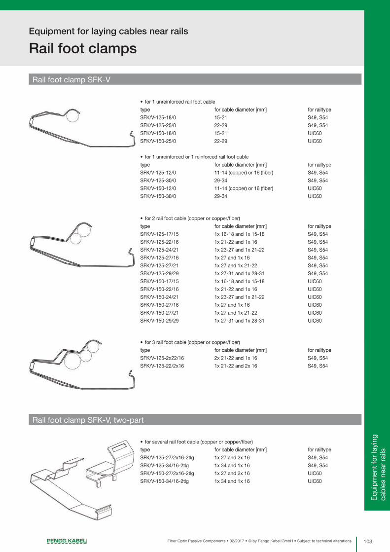
103Fiber Optic Passive Components • 02/2017 • © by Pengg Kabel GmbH • Subject to technical alterations
Equipment for laying cables near rails
Rail foot clamps
Pre
-ass
emb
led
C
onne
ctor
s /
Ad
apte
rsO
ptic
al D
istr
ibut
ion
Sys
tem
(OP
DIS
YS
®)
Term
inat
ion
Sys
tem
fo
r 19
“ Te
chno
logy
Sp
lice
Cas
sett
esTe
rmin
atio
n B
oxes
an
d W
all O
utle
tsIn
terc
onne
ct C
ases
and
D
istr
ibut
ion
Cab
inet
sFi
ber
Op
tic
Enc
losu
res
Eq
uip
men
t fo
r la
ying
ca
ble
s ne
ar r
ails
Rail foot clamp SFK-V
• for 1 unreinforced rail foot cable
type for cable diameter [mm] for railtype
SFK/V-125-18/0 15-21 S49, S54
SFK/V-125-25/0 22-29 S49, S54
SFK/V-150-18/0 15-21 UIC60
SFK/V-150-25/0 22-29 UIC60
• for 1 unreinforced or 1 reinforced rail foot cable
type for cable diameter [mm] for railtype
SFK/V-125-12/0 11-14 (copper) or 16 (fiber) S49, S54
SFK/V-125-30/0 29-34 S49, S54
SFK/V-150-12/0 11-14 (copper) or 16 (fiber) UIC60
SFK/V-150-30/0 29-34 UIC60
• for 2 rail foot cable (copper or copper/fiber)
type for cable diameter [mm] for railtype
SFK/V-125-17/15 1x 16-18 and 1x 15-18 S49, S54
SFK/V-125-22/16 1x 21-22 and 1x 16 S49, S54
SFK/V-125-24/21 1x 23-27 and 1x 21-22 S49, S54
SFK/V-125-27/16 1x 27 and 1x 16 S49, S54
SFK/V-125-27/21 1x 27 and 1x 21-22 S49, S54
SFK/V-125-29/29 1x 27-31 and 1x 28-31 S49, S54
SFK/V-150-17/15 1x 16-18 and 1x 15-18 UIC60
SFK/V-150-22/16 1x 21-22 and 1x 16 UIC60
SFK/V-150-24/21 1x 23-27 and 1x 21-22 UIC60
SFK/V-150-27/16 1x 27 and 1x 16 UIC60
SFK/V-150-27/21 1x 27 and 1x 21-22 UIC60
SFK/V-150-29/29 1x 27-31 and 1x 28-31 UIC60
• for 3 rail foot cable (copper or copper/fiber)
type for cable diameter [mm] for railtype
SFK/V-125-2x22/16 2x 21-22 and 1x 16 S49, S54
SFK/V-125-22/2x16 1x 21-22 and 2x 16 S49, S54
• for several rail foot cable (copper or copper/fiber)
type for cable diameter [mm] for railtype
SFK/V-125-27/2x16-2tlg 1x 27 and 2x 16 S49, S54
SFK/V-125-34/16-2tlg 1x 34 and 1x 16 S49, S54
SFK/V-150-27/2x16-2tlg 1x 27 and 2x 16 UIC60
SFK/V-150-34/16-2tlg 1x 34 and 1x 16 UIC60
Rail foot clamp SFK-V, two-part

Equipment for laying cables near rails
Rail foot branches
104 Fiber Optic Passive Components • 02/2017 • © by Pengg Kabel GmbH • Subject to technical alterations
• for protected lead in or lead out of a rail foot cable with a cable diameter of up to 21 mm and a
bending diameter of up to 400 mm
• for standard sleeper and short sleeper
type branch length of sleeper sleeper spacing for rail type
SFA-LI left ≥ 2600 mm not relevant S49, S54, UIC60
SFA-RE right ≥ 2600 mm not relevant S49, S54, UIC60
SFA-K-LI left < 2600 mm not relevant S49, S54, UIC60
SFA-K-RE right < 2600 mm not relevant S49, S54, UIC60
Delivery unit:
1 carrier, 1 cover plate, 2 tube clamps
Rail foot branch SFA and SFA-K
• for protected lead in or lead out of a rail foot cable with a cable diameter of up to 21 mm and a
bending diameter of up to 400 mm
• pivoting for short concrete sleeper with slanted sleeper head
type branch length of sleeper sleeper spacing for rail type
SFA-KS-LI left ≤ 2300 mm not relevant S49, S54, UIC60
SFA-KS-RE right ≤ 2300 mm not relevant S49, S54, UIC60
Delivery unit:
1 carrier, 1 cover plate, 2 tube clamps
• for protected lead in and lead out of a rail foot cable with a cable diameter of 22-34 mm and a
bending diameter of > 400 mm
• 1 set for 1 lead in and 1 lead out
type branch length of sleeper sleeper spacing for rail type
SFA-M-600 both sides not relevant 600±50 mm not relevant
SFA-M-650 both sides not relevant 650±40 mm not relevant
SFA-M-725 both sides not relevant 725±60 mm not relevant
Delivery unit:
2 cover plates, 2 tube clamps to fix the KSS
• for protected lead in and lead out of a rail foot cable with a cable diameter up to 34 mm at
Y-steel sleeper Y-No-600 or Y-No-650
• 1 set for 1 lead in and 1 lead out
type branch length of sleeper sleeper spacing for rail type
SFA-M-Y-600 both sides not relevant 600 mm not relevant
SFA-M-Y-650 both sides not relevant 650 mm not relevant
Delivery unit:
2 cover plates with fixation elements M8 to be installed at Y-steel sleeper,
2 tube clamps to fix the KSS
Rail foot branch SFA-KS
Rail foot branch SFA-M
Rail foot branch SFA-M-Y

105Fiber Optic Passive Components • 02/2017 • © by Pengg Kabel GmbH • Subject to technical alterations
Pre
-ass
emb
led
C
onne
ctor
s /
Ad
apte
rsO
ptic
al D
istr
ibut
ion
Sys
tem
(OP
DIS
YS
®)
Term
inat
ion
Sys
tem
fo
r 19
“ Te
chno
logy
Sp
lice
Cas
sett
esTe
rmin
atio
n B
oxes
an
d W
all O
utle
tsIn
terc
onne
ct C
ases
and
D
istr
ibut
ion
Cab
inet
sFi
ber
Op
tic
Enc
losu
res
Eq
uip
men
t fo
r la
ying
ca
ble
s ne
ar r
ails
Terms of deliveryfor cables, furnitures and insulated cords from Pengg Kabel GmbH, later named seller.
1. Scope
1.1. These General Terms shall govern legal transactions between business enter-prises, namely the delivery of commodities and, mutatis mutandis, the renderingof services. Software transactions are with precedence governed by the Soft-ware Conditions issued by the Austrian Electrical and Electronics Industry As-sociation, assembly work by the Terms and Conditions for Assembly Workissued by the Austrian Power Current and Light Current Engineering Industryand/or (where applicable) the Terms and Conditions for the Assembly of Elec-trical Equipment used in Medicine issued by the Austrian Electrical and Elec-tronics Industry (the current versions are available at www.feei.at).
1.2. Any departure from the terms and conditions mentioned in 1.1 above shall bevalid only if expressly accepted in writing by Seller.
2. Submission of offers
2.1. Seller’s offers shall be deemed offers without engagement.
2.2. Tender documents and project documentation must not be duplicated nor madeavailable to third parties without the permission of Seller. They may be claimedback at any time and shall be returned to Seller immediately if the order is placedelsewhere.
3. Conclusion of contract
3.1. The contract shall be deemed concluded upon written confirmation by Seller ofan order received or upon dispatch of a delivery.
3.2. Particulars appearing in catalogues, folders etc. as well as any oral or writtenstatements shall only be binding if Seller makes express reference to them inthe confirmation of the order.
3.3. Subsequent amendments of or additions to the contract shall be subject to writ-ten confirmation.
4. Prices
4.1. Prices shall be quoted ex works or ex Seller’s warehouse without VAT, packingand packaging, loading, disassembly, take-back and proper recycling and dis-posal of waste electrical and electronic equipment for commercial purposes asdefined by the Ordinance Regulating the Handling of Waste Electrical Equip-ment. Buyer shall be liable for any and all charges, taxes or other duties leviedin respect of delivery. If the terms of delivery include transport to a destinationdesignated by Buyer, transport costs as well as the cost of any transport insu-rance desired by Buyer shall be borne by the latter. Delivery does not, however,include unloading and subsequent handling. Packaging materials will be takenback only by express agreement.
4.2. Seller reserves the right to modify prices if the order placed is not in accordancewith the offer submitted.
4.3. Prices are based on costs obtaining at the time of the first quotation. In theevent that the costs have increased by the time of delivery, Seller shall have theright to adjust prices accordingly.
4.4. In carrying out repair orders, Seller shall provide all services deemed expedientand shall charge Buyer for the same on the basis of the work input and/or ex-penditures required. The same holds for any services or additional services theexpediency of which becomes apparent only as the repair order is executed. Insuch an event special notification of Buyer shall not be required.
4.5. Expenses for estimates of costs of repair and maintenance or for expert valua-tions shall be invoiced to Buyer.
5. Delivery
5.1. The period allowed for delivery shall commence at the latest of the followingdates:
a) the date of order confirmation by Seller;
b) the date of fulfilment by Buyer of all the conditions, technical, commercialand other, for which he is responsible;
c) the date of receipt by Seller of a deposit or security due before delivery of thegoods in question.
5.2. Buyer shall obtain whatever licences or approvals may be required from autho-rities or third parties for the construction of plant and equipment. If the grantingof such licences or approvals is delayed for any reason the delivery period shallbe extended accordingly.
5.3. Seller may carry out, and charge Buyer for, partial or advance deliveries. If de-livery on call is agreed upon, the commodity shall be deemed called off at thelatest one year after the order was placed.
5.4. In case of unforeseeable circumstances or circumstances beyond the partiescontrol, such as all cases of force majeure, which impede compliance with theagreed period of delivery, the latter shall be extended in any case for the durationof such circumstances; these include in particular armed conflicts, official inter-ventions and prohibitions, delays in transport or customs clearance, damagesin transit, energy shortage and raw materials scarcity, labour disputes, anddefault on performance by a major component supplier who is difficult to re-place. The aforesaid circumstances shall be deemed to prevail irrespective ofwhether they affect Seller or his subcontractor(s).
5.5. If a contractual penalty for default of delivery was agreed upon by contractingparties when the contract was concluded, it shall be executed as follows, andany deviations concerning individual items shall not affect the remaining provi-sions: Where delay in performance can be shown to have occurred solelythrough the fault of Seller, Buyer may claim for each completed week of delay
an indemnity of at most one half of one per cent, a total of no more than 5 %,however, of the value of that part of the goods to be delivered which cannot beused on account of Seller’s failure to deliver an essential part thereof, providedthe Buyer has suffered a damage to the aforesaid extent. Assertion of rights ofdamages exceeding this extent is precluded.
6. Passage of risk and place of performance
6.1. Unless otherwise agreed, the delivery of goods is considered sold EXW in ac-cordance with INCOTERMS® 2010.
6.2. For services, the place of performance shall be the place indicated in the writtenorder confirmation, secondary to that at which the service is actually renderedby Seller. The risk in respect of such services or any part thereof shall pass toBuyer at the time the services have been rendered.
7. Payment
7.1. Unless otherwise agreed, one third of the purchase price shall fall due at thetime of receipt by Buyer of the order confirmation of Seller, one third after halfthe delivery period has elapsed and the balance at the time of delivery. Irrespec-tive thereof the turnover tax comprised in the amount of the invoice shall bepaid within 30 days of the invoice date. If bankruptcy proceedings are institutedagainst the assets of Buyer or if an application for bankruptcy proceedings isnot granted for insufficiency of assets, deliveries shall only be made againstcash in advance.
7.2. In the case of part settlements the individual part payments shall fall due uponreceipt of the respective invoices. The same shall apply to amounts invoiced foradditional deliveries or resulting from additional agreements beyond the scopeof the original contract, irrespective of the terms of payment agreed upon forthe principal delivery.
7.3. Payment shall be made without any discount free Seller’s domicile in the agreedcurrency. Drafts and checks shall be accepted on account of payment only, withall interest, fees and charges in connection therewith (such as collection anddiscounting charges) to be borne by Buyer.
7.4. Buyer shall not be entitled to withhold or offset payment on the grounds of anywarranty claims or other counterclaims.
7.5. Payment shall be deemed to have been effected on the date at which theamount in question is at Seller’s disposal.
7.6. If Buyer fails to meet the terms of payment or any other obligation arising fromthis or other legal transactions, Seller may without prejudice to his other rights
a) suspend performance of his own obligations until payments have been madeor other obligations fulfilled, and exercise his right to extend the period of deli-very to a reasonable extent,
b) call in debts arisen from this or any other legal transactions and charge defaultinterest amounting to 1.25 % per month plus turnover tax for these amountsbeginning with the due dates, unless Seller proves costs exceeding this.
c) only perform other legal transactions against cash in advance in the case ofqualified insolvency, in other words, following two delays in payment.
In any case Seller has the right to invoice all expenses arising prior to a lawsuit,especially reminder charges and lawyer’s fees.
7.7. Discounts or bonuses are subject to complete payment in due time.
7.8. Seller retains title to all goods delivered by him until receipt of all amounts in-voiced including interests and charges.
Buyer herewith assigns his claim out of a resale of conditional commodities,even if they are processed, transformed or combined with other commodities,to Seller to secure the latter’s purchase money claim. In the case of resale gran-ting respite Buyer shall have the power of disposal of the product under reten-tion of ownership only with the proviso that upon reselling Buyer notifies thesecondary buyer of the assignment for security or enters the assignment in hisaccount books. Upon request Buyer has to notify the assigned claim and thedebtor thereof to Seller, and to make all information and material required forhis debt collection available and to notify the assignment to the third-party deb-tor. If the goods are attached or otherwise levied upon, Buyer shall draw atten-tion to Sellers title and immediately inform Seller of the attachment or levy.
8. Warranty and acceptance of obligation to repair defects
8.1. Once the agreed terms of payment have been complied with, Seller shall, sub-ject to the conditions hereunder, remedy any defect existing at the time of ac-ceptance of the article in question whether due to faulty design, material ormanufacture, that impairs the functioning of said article. From particulars ap-pearing in catalogues, folders, promotional literature as well as written or oralstatements which have not been included in the agreement no warranty obliga-tions may be deduced.
8.2. Unless special warranty periods operate for individual items the warranty periodshall be 12 months. These conditions shall also apply to any goods supplied,or services rendered in respect of goods supplied, that are firmly attached tobuildings or the ground. The warranty period begins at the point of passage ofrisk acc. to paragraph 6.
8.3. For improved or exchanged parts, the warranty period shall start again, but shallend in any case 6 months after the original warranty period has expired.
8.4. If delivery or the performance of services is delayed for reasons outside the con-trol of Seller, the warranty period shall begin 2 weeks after Seller is ready to deliver or perform services.

106 Fiber Optic Passive Components • 02/2017 • © by Pengg Kabel GmbH • Subject to technical alterations
8.5. The foregoing warranty obligations are conditional upon the Buyer giving withina reasonable period notice in writing of any defects that have occurred and suchnotice reaching the Seller. Buyer shall prove within a reasonable period the pre-sence of a defect, in particular he shall make available within a reasonable pe-riod to Seller all material and data in his possession. Upon receipt of such noticeSeller shall, in the case of a defect covered by the warranty under 8.1 above,have the option to replace the defective goods or defective parts thereof or elseto repair them on Buyer’s premises or have them returned for repair, or to granta fair and reasonable price reduction.
8.6. Any expenses incurred in connection with rectifying defects (e. g. expenses forassembly and disassembly, transport, waste disposal, travel and site-to-quar-ters time) shall be borne by Buyer. For warranty work on Buyer’s premises Buyershall make available free of charge any assistance, hoisting gear, scaffoldingand sundry supplies and incidentals that may he required. Replaced parts shallbecome the property of Seller.
8.7. If an article is manufactured by Seller on the basis of design data, design draw-ings, models or other specifications supplied by Buyer, Seller’s warranty shallbe restricted to non-compliance with Buyers specifications.
8.8. Seller’s warranty obligation shall not extend to any defects due to assembly andinstallation work not undertaken by Seller, inadequate equipment, or due to non-compliance with installation requirements and operating conditions, overloadingof parts in excess of the design values stipulated by Seller, negligent or faultyhandling or the use of inappropriate materials, nor for defects attributable tomaterial supplied by Buyer. Nor shall Seller be li- able for damage due to actsof third parties, atmospheric discharges. Excess voltage and chemical influen-ces. The warranty does not cover the replacement of parts subject to naturalwear and tear. Seller accepts no warranty for the sale of used goods.
8.9. The warranty shall lapse immediately if, without written consent of Seller, Buyerhimself or a third party not expressly authorised undertakes modifications or re-pairs on any items delivered.
8.10. Claims acc. to § 933b ABGB are struck by the statute of limitation with lapse ofthe period mentioned under point 8.2.
8.11. The provisions of sub-paragraphs 8.1 to 8.10 shall apply, mutatis mutandis, toall cases where the obligation to repair defects has to be accepted for otherreasons laid down by law.
9. Withdrawal from contract
9.1. Buyer may withdraw from the contract only in the event of delays caused bygross negligence on the part of Seller and only after a reasonable period of gracehas elapsed. Withdrawal from contract shall be notified in writing by registeredmail.
9.2. Irrespective of his other rights Seller shall be entitled to withdraw from the con-tract
a) if the execution of delivery or the inception or continuation of services to berendered under the contract is made impossible for reasons within the respon-sibility of Buyer and if the delay is extended beyond a reasonable period of graceallowed;
b) if doubts have arisen as to Buyer’s creditworthiness and if same fails, on Sel-ler’s request, to make an advance payment or to provide adequate security priorto delivery, or
c) if, for reasons mentioned in 5.4, the period allowed for delivery is extendedby more than half of the period originally agreed or by at least 6 months, or
d) if Buyer does not or does not properly meet the obligations imposed as perparagraph 13.
9.3. For the reasons given above withdrawal from the contract shall also be possiblein respect of any outstanding part of the delivery or service contracted for.
9.4. If bankruptcy proceedings are instituted against Buyer or an application forbankruptcy proceedings is not granted for insufficiency of assets, Seller maywithdraw from the contract without allowing a period of grace. If this withdrawalis taken, it shall take effect immediately upon the decision that the business willnot be continued. If the business will be continued, a withdrawal shall not takeeffect until 6 months after the institution of bankruptcy proceedings or after anapplication for bankruptcy proceedings has not been granted for insufficiencyof assets. In any case, the contract shall be terminated immediately unless thebankruptcy law to which Buyer is subject conflicts with this or if termination ofthe contract is necessary to prevent significant damages to Seller.
9.5. Without prejudice to Seller’s claim for damages including expenses arising priorto a lawsuit, upon withdrawal from contract any open accounts in respect ofdeliveries made or services rendered in whole or in part shall be settled accor-ding to contract This provision also covers deliveries or services not yet accep-ted by Buyer as well as any preparatory acts performed by Seller. Seller shall,however, have the option alternatively to require the restitution of articles alreadydelivered.
9.6. Withdrawal from contract shall have no consequences other than those stipu-lated above.
9.7. The assertion of claims on the ground of laesio enormis, error, or lapse of pur-pose by the Buyer is excluded.
10. Disposal of waste electrical and electronic equipment
10.1. The Buyer of electrical/electronic equipment for commercial purposes, incor-porated in Austria, is responsible for the financing of the collection and treatmentof waste electrical and electronic equipment as defined by the Ordinance Re-
gulating the Handling of Waste Electrical Equipment, if he is himself the user ofthe electrical/electronic equipment. If the Buyer is not the end user, he shalltransfer the full financial commitment to his customer by agreement and furnishproof thereof to the Seller.
10.2. The Buyer incorporated in Austria shall ensure that the Seller is provided withall information necessary to meet the Seller’s obligations as manufacturer/im-porter, particularly according to §§ 11 and 24 of the Ordinance Regulating theHandling of Waste Electrical Equipment and the Waste Management Act.
10.3. The Buyer incorporated in Austria is liable vis-à-vis the Seller for any dam- ageand other financial disadvantages incurred by Seller due to Buyer’s failure tomeet or fully meet his financing commitment or any other obligations accordingto Article 10. The Buyer shall bear the burden of proof of performance of thisobligation.
11. Seller’s liability
11.1. Outside the scope of the Product Liability Act, Seller shall be liable only if thedamage in question is proved to be due to intentional acts or acts of gross ne-gligence, within the limits of statutory provisions. Seller's total liability in casesof gross negligence is limited to the net value of the order or EUR 500,000, de-pending on which amount is lower.
11.2. For each incident of damage, Seller shall be liable for 25% of the net value ofthe order or EUR 125,000, depending on which amount is lower.
11.3. Seller shall not be liable for damage due to acts of ordinary negligence nor forconsequential damages or damages for pure economic loss, indirect damages,loss of production, financing costs, costs for replacement energy, loss of energy,data or information, loss of profits, loss of savings or interest, or damage resul-ting from third-party claims against buyer.
11.4. Seller shall not be liable for damages in case of non-compliance with instructi-ons for assembly, commissioning and operation (such as are contained in in-structions for use) or non-compliance with licensing requirements.
11.5. Claims that exceed the contractual penalties that were agreed on are excludedfrom the respective title. The provisions of paragraph 11 apply exclusively forall claims by Buyer against Seller, regardless of the legal basis or entitlement,and also apply to all employees, subcontractors and subsuppliers of Seller.
12. Industrial property rights and copyrights
12.1. Buyer shall indemnify Seller and hold him harmless against any claims for anyinfringement of industrial property rights raised against him if Seller manufactu-res an article pursuant to any design data, design drawings, models or otherspecifications made available to him by Buyer.
12.2. Design documents such as plans and drawings and other technical specifica-tions as well as samples, catalogues, prospectuses, pictures and the like shallremain the intellectual property of Seller and are subject to the relevant statutoryprovisions governing reproduction, imitation, competition etc. The provisions of2.2 above shall also cover design documents.
13. Compliance with export provisions
13.1. When passing on goods delivered by Seller to third parties (as well as any rela-ted documentation, regardless of the method of provision or the services per-formed by Seller [including technical support of any kind]), Buyer must complywith the applicable regulations of national and international (re-)export provisi-ons. In any case, Buyer must observe the (re-)export provisions of Seller's coun-try of residence, the European Union and the United States of America.
13.2. If necessary for export controls, Buyer must provide Seller with all necessaryinformation immediately after being requested to do so, for example, informationabout the final recipient, final destination and purpose of the goods or services.
14. General
Should individual provisions of the contract or of these provisions be invalid thevalidity of the other provisions shall not be affected. The invalid provision shallbe replaced by a valid one, which comes as close to the target goal as possi-ble.
15. Jurisdiction and applicable law
Any litigations arising under the contract including litigations over the existenceor non-existence thereof shall fall within the exclusive jurisdiction of the com-petent court at Sellers domicile; the competent court of the Bezirksgericht InnereStadt, Vienna, shall have exclusive jurisdiction if Seller is domiciled in Vienna.The contract is subject to Austrian law excluding the referral rules. Applicationof the UN Convention on Contracts for the International Sale of Goods is re-nounced.
16. Proviso
The execution of the contract by Seller is subject to the condition that there areno obstacles standing in the way of execution due to national or international(re-)export provisions, and especially no embargos and/or other sanctions.
Last revised in September 2011

^êÉ~=êÉéêÉëÉåí~íáîÉë
Fiber optic cables
Fiber optic passive components
Fiber optic installation services
Fiber to the home - solutions
Telecommunication cables
Railway cables
Copper cable installation services
PENGG KABEL GmbH Plant Optic | Breitenfeldgasse 5 | 8661 Sankt Barbara
Plant Copper | Mariazellerstraße 125 | 8605 KapfenbergTel.: +43 3862 / 23990-0 | Fax.: +43 3862 / 23990-672
[email protected] | www.penggkabel.at
Related Documents