1 Precision Trepanning with a Fiber Laser Dr. Paul Jacobs Vice President of R&D LFI Inc. Smithfield, RI February 2008 Abstract: An analysis is developed to establish the optimal parameters for precision trepanning using a 200 watt fiber laser. Recent test results are also presented to document the mean values and standard deviations of fiber laser trepanned holes for a number of materials, hole diameters, and thicknesses. Analytical constraints are established for each of the following: (1) maintaining sufficient laser irradiance to assure rapid trepanning speed without inducing plasma self-absorption, (2) selecting a laser pulse repetition frequency sufficiently high to maintain a molten metal interface and hence increased absorption at the laser wavelength, while not exceeding the kinematic limit of current trepanning heads, (3) establishing an optimum trepan “overlap ratio” to minimize perimeter irregularities consistent with high speed operation, (4) optimizing the focused spot diameter to achieve the desired irradiance consistent with modest laser power and cost, (5) choosing a programmable continuous motion trepanning head and a spiral trepanning path to improve precision while minimizing cycle time and perimeter artifacts, and (6) satisfying adiabatic energy requirements in the shortest practical time. The paper also presents important test data indicating initial standard deviations under 3 μm when trepanning 500 μm diameter cylindrical holes with a system not yet fully optimized! Introduction: By June 2008 LFI Inc. will have purchased, integrated, acceptance tested, and commenced operational use of a precision laser trepanning system consisting of the following major components: (1) a 200 watt average power output fiber laser, (2) an automated safety enclosure, (3) a part loading carousel, (4) a robotic motion system and (5) a programmable trepanning head. This system should enable accurate, efficient, and cost effective trepanning of extremely precise and highly repeatable holes for a wide range of production aerospace and medical applications. The following analysis and initial experimental test results are presented to both establish and verify optimum fiber laser parameters for the economical generation of millions of precision trepanned holes.

Welcome message from author
This document is posted to help you gain knowledge. Please leave a comment to let me know what you think about it! Share it to your friends and learn new things together.
Transcript
1
Precision Trepanning with a Fiber Laser
Dr. Paul Jacobs
Vice President of R&D LFI Inc.
Smithfield, RI
February 2008 Abstract: An analysis is developed to establish the optimal parameters for precision trepanning using a 200 watt fiber laser. Recent test results are also presented to document the mean values and standard deviations of fiber laser trepanned holes for a number of materials, hole diameters, and thicknesses. Analytical constraints are established for each of the following: (1) maintaining sufficient laser irradiance to assure rapid trepanning speed without inducing plasma self-absorption, (2) selecting a laser pulse repetition frequency sufficiently high to maintain a molten metal interface and hence increased absorption at the laser wavelength, while not exceeding the kinematic limit of current trepanning heads, (3) establishing an optimum trepan “overlap ratio” to minimize perimeter irregularities consistent with high speed operation, (4) optimizing the focused spot diameter to achieve the desired irradiance consistent with modest laser power and cost, (5) choosing a programmable continuous motion trepanning head and a spiral trepanning path to improve precision while minimizing cycle time and perimeter artifacts, and (6) satisfying adiabatic energy requirements in the shortest practical time. The paper also presents important test data indicating initial standard deviations under 3 µm when trepanning 500 µm diameter cylindrical holes with a system not yet fully optimized! Introduction: By June 2008 LFI Inc. will have purchased, integrated, acceptance tested, and commenced operational use of a precision laser trepanning system consisting of the following major components: (1) a 200 watt average power output fiber laser, (2) an automated safety enclosure, (3) a part loading carousel, (4) a robotic motion system and (5) a programmable trepanning head. This system should enable accurate, efficient, and cost effective trepanning of extremely precise and highly repeatable holes for a wide range of production aerospace and medical applications. The following analysis and initial experimental test results are presented to both establish and verify optimum fiber laser parameters for the economical generation of millions of precision trepanned holes.
2
Laser Trepanning: Laser drilled holes can be generated by percussion drilling or trepanning. The significant advantages of trepanning with a fiber laser will become evident as this paper unfolds. We begin with a model of the process of laser trepanning a cylindrical hole of diameter D at an angle θ to the substrate. Assume a focused trepanning spot of diameter, d <<D. We also define the following four dimensionless quantities, each of which is less than unity: α ≡ d / D = Ratio of the trepanning laser spot diameter d, to the hole diameter D. β ≡ δ / d = Ratio of the distance between the centers of adjacent laser trepanning spots,δ
to the laser trepanning spot diameter d. Γ ≡ Δ / D = Ratio of the maximum cusp heightΔ, to the diameter of the hole D. A (λL,T,θ) = Absorptivity of the workpiece material at the laser wavelength, λL, at
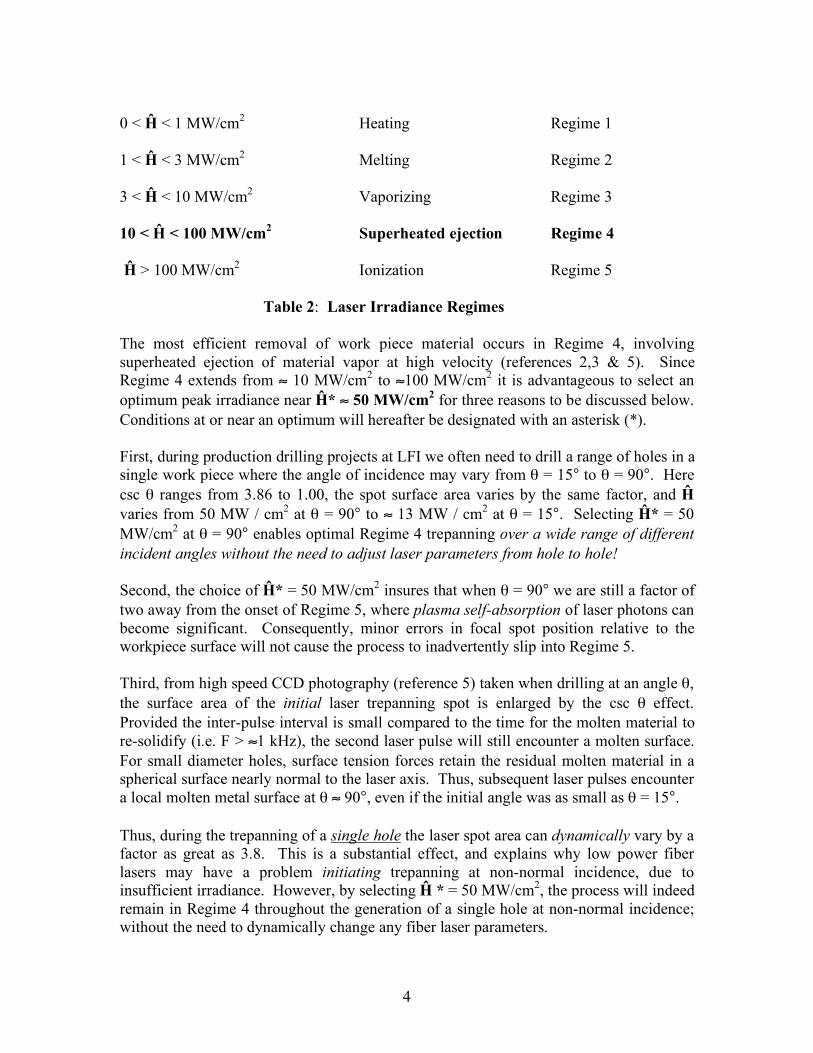
temperature T, and at incidence angle θ. Figures 1A and 1B illustrate the “spiral trepanning” process for two cases. In the first case adjacent trepanning spots are mutually tangent, and the “overlap ratio” Ω = 1- β = 0. For the second case Ω = 0.8 and β = 0.2. The large circle represents the desired hole perimeter, and the smaller circles the individual laser trepanning spots. The residual cusps are especially evident in Figure 1-A, where β = 1.
Figure 1-A Figure 1-B Spiral Trepanning for β = 1 Spiral Trepanning for β = 0.2. From the geometry of circles tangent to the perimeter of the desired hole it can be shown that for an arbitrary value of β :
3
Γ ≡ Δ / D = ½ α [1 – (1-β2)1/2] (1) Values of Ω, β , and Γ are listed in Table 1, for α =0.1. Corresponding values of Δ are also listed for the case where D = 500 µm. Ω β Γ Δ 0.0 1.00 0.050000 25.0 µm 0.1 0.90 0.028206 14.1 µm 0.2 0.80 0.020000 10.0 µm 0.3 0.70 0.014293 7.2 µm 0.5 0.50 0.006699 3.3 µm 0.7 0.30 0.002303 1.2 µm 0.8 0.20 0.001010 0.5 µm Table 1: Residual Cusp Functions
Setting Ω =0.8, or equivalently β=0.2 results in maximum residual cusp irregularities on the perimeter of a 500 µm diameter laser trepanned hole that are of the order of the wavelength of visible light! Further reduction in β will not result in any measurable improvement in hole quality, but will increase cycle time, which is counter-productive. If the thickness of the work piece is h, the slant length of a through-hole trepanned at an angle θ is L = h / sin θ = h csc θ. We define the diameter of the trepanning laser spot on the work piece, at normal incidence, as d. Since csc (90°) = 1, the surface area of that spot on the work piece is thus Sθ=90° = ¼ πd2. At non-normal incidence the laser spot becomes elliptical, with the surface area increasing (approximately) to:
Sθ = ¼ πd2 cscθ (2)
For a fiber laser with a uniform, or so-called “Top Hat” distribution, the peak irradiance, Ĥ is given by: Ĥ ≡ (ε/τ) / Sθ = 4(ε/τ) sin θ / πd2 (3) Where: ε = laser output energy per pulse (J) τ = laser pulse duration (sec) d = focused laser spot diameter (cm) From references.1-5, and considerable prior experience at LFI, the peak laser irradiance incident on the work piece is the single most important parameter when laser drilling! Table 2 shows five significant peak irradiance / material interaction “Regimes”, with their correspondingly induced physical phenomena.
4
0 < Ĥ < 1 MW/cm2 Heating Regime 1 1 < Ĥ < 3 MW/cm2 Melting Regime 2 3 < Ĥ < 10 MW/cm2 Vaporizing Regime 3 10 < Ĥ < 100 MW/cm2 Superheated ejection Regime 4 Ĥ > 100 MW/cm2 Ionization Regime 5 Table 2: Laser Irradiance Regimes The most efficient removal of work piece material occurs in Regime 4, involving superheated ejection of material vapor at high velocity (references 2,3 & 5). Since Regime 4 extends from ≈ 10 MW/cm2 to ≈100 MW/cm2 it is advantageous to select an optimum peak irradiance near Ĥ* ≈ 50 MW/cm2 for three reasons to be discussed below. Conditions at or near an optimum will hereafter be designated with an asterisk (*). First, during production drilling projects at LFI we often need to drill a range of holes in a single work piece where the angle of incidence may vary from θ = 15° to θ = 90°. Here csc θ ranges from 3.86 to 1.00, the spot surface area varies by the same factor, and Ĥ varies from 50 MW / cm2 at θ = 90° to ≈ 13 MW / cm2 at θ = 15°. Selecting Ĥ* = 50 MW/cm2 at θ = 90° enables optimal Regime 4 trepanning over a wide range of different incident angles without the need to adjust laser parameters from hole to hole! Second, the choice of Ĥ* = 50 MW/cm2 insures that when θ = 90° we are still a factor of two away from the onset of Regime 5, where plasma self-absorption of laser photons can become significant. Consequently, minor errors in focal spot position relative to the workpiece surface will not cause the process to inadvertently slip into Regime 5. Third, from high speed CCD photography (reference 5) taken when drilling at an angle θ, the surface area of the initial laser trepanning spot is enlarged by the csc θ effect. Provided the inter-pulse interval is small compared to the time for the molten material to re-solidify (i.e. F > ≈1 kHz), the second laser pulse will still encounter a molten surface. For small diameter holes, surface tension forces retain the residual molten material in a spherical surface nearly normal to the laser axis. Thus, subsequent laser pulses encounter a local molten metal surface at θ ≈ 90°, even if the initial angle was as small as θ = 15°. Thus, during the trepanning of a single hole the laser spot area can dynamically vary by a factor as great as 3.8. This is a substantial effect, and explains why low power fiber lasers may have a problem initiating trepanning at non-normal incidence, due to insufficient irradiance. However, by selecting Ĥ * = 50 MW/cm2, the process will indeed remain in Regime 4 throughout the generation of a single hole at non-normal incidence; without the need to dynamically change any fiber laser parameters.
5
The following are representative values for a 200 W average power fiber laser in 2008: ε = 20 mJ /pulse = 2 x 10⁻² J / pulse τ = 20 µsec / pulse = 2 x 10⁻⁵ sec / pulse F = 10 kHz = 104 sec-1 From Equation (3), after simple algebra: d* = 2 [(ε / τ) / π Ĥ*]½ (sin θ)½ (4) Setting Ĥ* = 50 x 106 W/cm2, ε = 2 x 10⁻² J , and τ = 2 x 10⁻⁵ sec.:
d* = 5.05 x 10⁻³ (sin θ)1/2 cm (5)
Equation (5) establishes an “optimum irradiance constraint”. Note that when trepanning at non-normal incidence (sin θ)1/2 < 1 and thus a smaller trepanning spot diameter is optimal. For the case of special interest to LFI, where D = 0.05 cm= 500 µm, and θ = 90°, the optimum value of d* ≈ 50 µm, and thus, α* ≡ d* / D ≈ 0.1. This is a result in good agreement with our experience at LFI. If the selected value of α is too large the amount of material to be removed increases, increasing the required fiber laser power and the trepanning time; both of which are counter-productive. Conversely, if the selected value of α is too small, the trepanning kerf is so narrow that the central plug, resembling a tiny “hockey puck”, will often remain lodged in the hole, especially when θ < 45°. The Trepanning Process: There are basically three approaches to trepanning. The first involves acceleration, translation, deceleration, and “settling” for each laser pulse. This approach takes additional time, but has the benefit of enabling so-called “spiral trepanning” where the initial laser penetration can occur at a location interior to the perimeter. The trepanning orbit is completed M many times (e.g. if M =2, this would involve one orbit to trepan and a second to “clean-up” the hole). Significantly, the trepanning path also spirals back inside the circular perimeter. An advantage is that both the initial penetration and the final pulse in a trepanning sequence do NOT take place adjacent to the perimeter of the hole, thus avoiding drilling artifacts. However, additional time is needed for acceleration, deceleration and settling at every laser pulse location throughout each trepan orbit. The second approach involves “continuous circular motion” without stopping and starting at the location of each trepanning pulse. This has the benefit of eliminating the time required to: accelerate from the center of a laser trepanning spot, decelerate towards the center of the adjacent spot, settle accurately at the new location, fire another laser pulse, and then repeat this process for each of the hundreds of laser pulses per orbit. This
6
approach has the shortcoming that the initial and final laser pulses occur adjacent to the desired perimeter, which can produce undesirable artifacts on the part. The third approach might be termed “programmable continuous - motion automated spiral trepanning” or “PC-MAST” for brevity. Here the motion is continuous; eliminating hundreds of acceleration, deceleration, and settling steps. The PC-MAST approach requires that the laser pulse frequency be synchronized with the motion of the trepanning head. Furthermore, by using pre-programmed software to achieve the desired path geometry PC-MAST also enables the initial and final laser pulses to occur interior to the hole perimeter, thereby avoiding undesirable artifacts. We previously optimized α* ≈ 0.1 from a Regime 4 irradiance constraint. We also optimized β* ≈ 0.2 based upon minimizing residual trepanning cusp height consistent with rapid cycle time. From experience at LFI we have found that the quality of a hole is improved by taking one orbit (M=1) to trepan the hole, a second orbit (M=2), to “clean up” the hole, and ≈15% of the perimeter as “lead in” and another 15% as “lead out” to avoid perimeter artifacts. The resulting M* = 2.3 value yields excellent hole quality. In general, the cycle time required to trepan a single hole can be expressed as: Tcycle = Tcenter + Ttrepan + Tacc (6) Here: Tcycle = the total cycle time required to production trepan a single hole.
Tcenter = the time for the robot system to move the trepanning head and associated output fiber from the center of one hole to the center of the next hole.
Ttrepan = the time to accomplish continuous circular trepanning Tacc = the time to accelerate, decelerate, and settle between laser pulses. If we
use a PC-MAST head then, by definition, Tacc = 0.
Consider the process of precision trepanning a cylindrical hole, where the laser spot is moved a distance δ between adjacent laser pulses. From our earlier definitions:
δ = βd = α β D (7) If the laser pulses are synchronized with the trepanning head at frequency F, then the inter-pulse interval is simply Δt ≡ 1/ F (seconds / pulse). From Equation (7) the average speed of the trepanning motion, Ū can then be expressed as: Ū ≡ δ / Δt = δF = αβDF. Since the actual motion is limited by the kinematics of the trepanning head, which has a maximum possible speed of Umax, it is important to select parameters such that Ū < Umax. Thus, Ū = αβDF < Umax (8) The total number of laser pulses to trepan a hole, N, can be expressed as: N = n M where n = the number of laser pulses per orbit, and M = the number of orbits required per hole. The perimeter of the desired cylindrical hole is simply P = πD. Also, the center location of each pulse is displaced by the linear distance δ from the center location of its neighboring pulse. Thus, n = P / δ = πD / δ = π / αβ , and therefore:
7
N* = π M* / α*β* (9)
Note that the optimum number of pulses necessary to trepan a cylindrical hole is independent of the diameter of the hole! This occurs because the perimeter of the hole is proportional to D, but so also is the spot size, d, and therefore δ. Hence the diameter exactly cancels out. Since π is a constant, then for optimal trepanning of a cylindrical hole the total number of pulses required is also a constant! Specifically, N* = 361. Equation (8) shows that provided Ū < Umax which is a kinematic constraint on the trepanning head, then:
T*trepan ≡ MP/ Ū = M*πD / α*β*DF = (π M* / α*β*) / F = N* / F. (10) Note that the trepan time is also independent of the hole-diameter! This occurs because the trepanning perimeter is proportional to D, but Ū is also proportional to D, and thus the diameter again cancels out, leading to the amazingly simple result: T*trepan = 361 / F. We will now optimize the laser pulse repetition rate, F* based on two constraints. First, it is beneficial to maintain A (λL, T, θ) at its maximum possible value throughout the trepanning process, by selecting inter-pulse intervals sufficiently short to assure that molten material does not re-solidify between pulses. This places a lower bound on F at about 1 kHz for most metals (references 1,3). Second, we do not want to approach the kinematic limit of the trepanning head. Presently, the maximum trepanning head speed is Umax = 100 mm/sec. For a 30% kinematic “safety margin”, let us set Ū* = 70 mm/sec. We now solve for the optimum value of the product (FD)* from Equation (8):
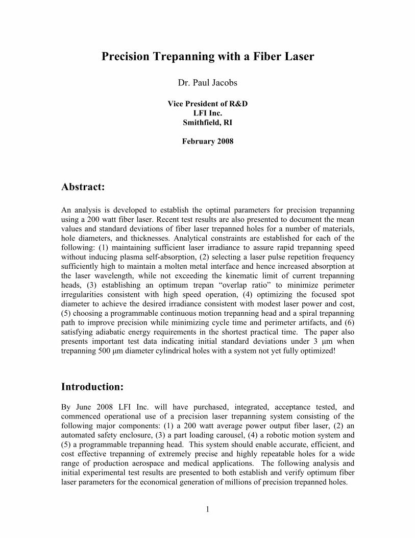
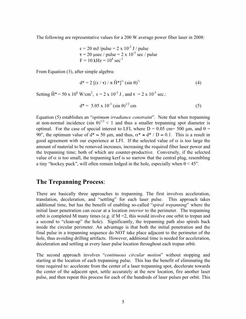
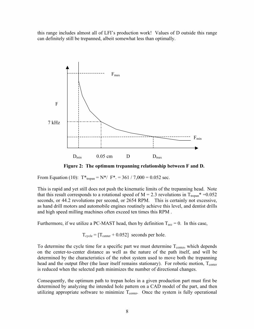
(FD)* = Ū* / α*β* = 3500 mm/sec. (11) Equation (11) is a hyperbolic relationship between the hole-diameter, D, and the optimum laser pulse repetition frequency, F, based upon the kinematic constraint for optimum laser trepanning, and the conditions needed to maintain a molten metal interface. Figure 2 shows this schematically. Here Fmax is the maximum available fiber laser pulse repetition rate, and Fmin the value below which molten material will re-solidify between laser pulses resulting in less efficient drilling due to reduced laser absorption. Thus, the larger the desired hole diameter, the smaller the optimum value of F, which may seem counter-intuitive. From Equation (11) for D = 0.5 mm, the optimum value of the fiber laser pulse repetition frequency becomes F* = 7 kHz. Note that Figure 2 implies the existence of both maximum and minimum bounds on the optimum hole diameter D subject to the constraints noted previously (viz. maintaining molten metal throughout the process to enhance spectral absorptivity, while also avoiding the kinematic constraint on the trepanning head). Since fiber lasers currently can operate up to Fmax = 50 kHz , the range of hole diameters where optimum trepanning conditions prevail would extend from Dmin ≈ 0.07 mm (70 µm) up to Dmax ≈ 3.5 mm. Fortunately,
8
this range includes almost all of LFI’s production work! Values of D outside this range can definitely still be trepanned, albeit somewhat less than optimally.
Figure 2: The optimum trepanning relationship between F and D. From Equation (10): T*trepan = N*/ F*. = 361 / 7,000 = 0.052 sec. This is rapid and yet still does not push the kinematic limits of the trepanning head. Note that this result corresponds to a rotational speed of M = 2.3 revolutions in Ttrepan* =0.052 seconds, or 44.2 revolutions per second, or 2654 RPM. This is certainly not excessive, as hand drill motors and automobile engines routinely achieve this level, and dentist drills and high speed milling machines often exceed ten times this RPM . Furthermore, if we utilize a PC-MAST head, then by definition Tacc = 0. In this case, Tcycle = [Tcenter + 0.052] seconds per hole. To determine the cycle time for a specific part we must determine Tcenter, which depends on the center-to-center distance as well as the nature of the path itself, and will be determined by the characteristics of the robot system used to move both the trepanning head and the output fiber (the laser itself remains stationary). For robotic motion, Tcenter is reduced when the selected path minimizes the number of directional changes. Consequently, the optimum path to trepan holes in a given production part must first be determined by analyzing the intended hole pattern on a CAD model of the part, and then utilizing appropriate software to minimize Tcenter. Once the system is fully operational
F
D
Fmax
7 kHz
0.05 cm
Fmin
Dmax Dmin
9
and such data is available, LFI will report measured values for Tcenter and for Tcycle , the overall production cycle time, for a range of production components. Laser Trepanning vs. Percussion Drilling: The previous analysis shows that a 200 watt average power fiber laser can achieve the requisite laser irradiance, Ĥ for Regime 4 laser trepanning. The elevated levels of Ĥ are the combined result of: short pulse durations (τ = 20 µs), and small spot diameter (d = 50 µm) and a tiny focused spot surface area (Sθ=90 ≈ 2x10⁻⁵cm2). A fundamental advantage of fiber lasers is their excellent optical quality which enables a very small focused spot diameter. Nonetheless, the maximum energy delivered from a single pulse of a 200 watt average power fiber laser is actually relatively modest at only 20 mJ. The ability to easily focus the beam to a small spot size is the major reason why trepanning with a fiber laser is so advantageous! If we attempted to percussion drill the same D = 500 µm hole using a d =500 µm diameter spot, Ĥ would decrease by the ratio α2 = 0.01, from 50 MW/cm2 when trepanning, to only 0.5 MW/cm2 when percussion drilling. Not only would Ĥ fall completely out of Regime 4, it would drop all the way to Regime 1, and percussion drilling would become extremely inefficient and impractical. An increase in ε by a factor of 50, corresponding to a 10KW average power fiber laser could move the process back into Regime 4 with Ĥ = 25 MW/cm2, but would still provide a smaller than desired margin for csc θ effects. Unfortunately, a 10 kW average power fiber laser required to accomplish percussion drilling would: (a) be physically much larger, (b) consume 50 times more electrical power, (c) demand additional valuable floor space, (d) involve more extensive cooling, and (e) be dramatically more expensive! Two additional advantages obtain for trepanning vs. percussion drilling. First, the annular volume to be heated, melted, vaporized and ejected is smaller than the cylindrical volume, so less laser energy is needed to trepan the same diameter hole relative to percussion drilling, independent of the peak irradiance. Reduced laser energy input to the work piece results in a smaller heat affected zone or “HAZ”, which is always beneficial. Second, from experience at LFI, and the included test results, trepanned holes are often more precise; with a smaller standard deviation than laser percussion drilled holes (ref. 4). For all these reasons a fiber laser is superbly adapted to precision laser trepanning. Absorbed Energy Considerations: Not all the laser energy is absorbed by the work piece. With the high pulse repetition rates available from fiber lasers, Δt = 1/F is sufficiently short (i.e. < 10-3 sec) that there is insufficient time for molten material to re-solidify prior to the arrival of the next laser pulse. For β* = 0.2 the laser spot is 80% overlapped with the region heated by the previous laser pulse, and the laser photons are incident on molten material, except for the initial pulse in a trepanning sequence. From reference 1, the absorptivity A (λL, T, θ) of
10
most metals increases with temperature, and is usually higher in the liquid phase than in the initial solid phase. Many of the aerospace components drilled by LFI are made from nickel based super-alloys such as Inconel, Waspalloy and Hastelloy. Detailed A (λL, T, θ) data for these alloys is difficult to obtain, especially as a function of temperature. Such data does exist for pure nickel, and since nickel is a major constituent of these materials, our estimates of the relevant physical and thermal properties will hopefully be reasonably accurate. Consider the adiabatic heating, melting, additional heating, vaporization, and ejection of superheated vapor characterized by Regime 4. Since an inevitable temperature gradient must exist from the laser heated regions to the more distant surrounding regions, some heat transfer must occur to the surrounding workpiece. However, owing to the brevity of each laser pulse the approximation of an adiabatic process is not unreasonable, and this assumption enables a vast simplification in the resulting energy balance. The energy absorbed by the workpiece per pulse is simply ε A(λL, T, θ). The mass of the annular trepanning volume is m = πρDdh cscθ = πραD2L, where ρ is the density of the material, and all other quantities have been previously defined. For an adiabatic process the trepanning energy balance may be written in the form:
ETOTAL = NεA(λL, T, θ) = πραD2L [Cp (TV- T0) +LF + LV + EK] (12)
Here EK is the kinetic energy per unit mass of the ejected superheated material. Substituting from Equation (9) into Equation (12) and performing simple algebra:
ε = G d2L (13)
Where: G ≡ ρ β* [Cp (TV- T0) +LF + LV + EK] / M* A(λL, T, θ) (14)
Note that G, the specific energy (J/cm3) is a function of the physical and thermal properties of the material, the temperature of the region where laser photons are absorbed, the angle of incidence θ, and the optimum values of M* and β*. Equation (13) shows that based on adiabatic energy constraints the optimum laser energy per pulse is proportional to the square of the laser spot diameter and the total depth of the hole. As the product d2L increases, the required optimum value of ε also increases. Equation (13) is a concise mathematical explanation of a fundamental benefit of laser trepanning. Since one effectively replaces D with d, the required laser energy per pulse and consequently the required fiber laser average power are reduced by a factor of α 2, or two orders of magnitude relative to percussion drilling! We now evaluate G. For nickel: ρ = 8.9 grams / cm3 Cp = 0.44 J / gram -°K TV = 3005 °K LF = 300 J / gram
11
T0 = 293 °K LV = 6392 J / gram A detailed calculation of EK requires knowledge of the velocity distribution of the trepanned exhaust vapor. Lacking this information, we do know from high speed CCD photographs of the drilling sequence (Ref. 5), that the exhaust vapor was supersonic and exhibited shock diamonds at angles corresponding to a vapor Mach number of about 1.2. Thus, EK = ½ v2 = ½ (1.2a)2 where a = the speed of sound in the vapor. As the vapor temperature of nickel is 3005 K, and the exhaust in Mode 4 is super-heated, its temperature will be higher. Conservatively assuming a = 300 m/sec [3005 / 293]1/2 = 960 m/ sec, EK = ½ (1.2a)2 = 0.5 (1.15 x 105 cm/sec)2 = 663 x 107 ergs/gram = 663 J / gram. Substituting:
G = 0.2 x 8.9 [0.44 (3005 -293) + 300 + 6392 + 663] / 2.3 x 0.7 = 9450 J/cm3 Substituting G into Equation (13), for the specific case d = 50 µm = 5 x 10⁻³ cm, we obtain the very practical result for a nickel work piece:
ε = 0.136 L J / pulse (15)
Here, the effective slant thickness of the work piece, L is expressed in cm. For the case of a 200 watt average power fiber laser, with maximum available output energy per pulse εmax, from Equation (15) we obtain the important practical result: Lmax = εmax / 0.136 = [0.020 J / pulse] / [0.136 J / pulse / cm] = 0.147 cm = 1.47 mm If the effective slant thickness of the cylindrical hole exceeds ≈ 1.5 mm, this does NOT mean that a 200 watt average power fiber laser cannot trepan the desired hole. However, adiabatic energy constraints will require more than the optimum number (N* = 361) pulses. Fundamentally, if Lmax > 1.5 mm, due either to workpiece thickness, or to the need to drill at a slant angle, then from Equation (10): Ttrepan > 361 / F*. From Equation (9) the total cycle time to drill a hole, Tcycle also includes the time for the robot to move to and settle the trepanning head at the location of the next hole, Tcenter. At the current state-of-the-art for robotic systems: Tcenter ≈ 10 T*trepan. Therefore, the implication of a case where N > N* is not substantially negative, since a modest increase in Ttrepan will have a relatively small impact on the overall production cycle time per part. Summarizing our results, optimum fiber laser trepanning occurs when we have selected laser parameters consistent with each of the following constraints: (1) Using a sufficiently low value of F to stay below the trepanning head speed limit. (2) Selecting a sufficiently high value of F to maintain molten metal at the interface. (3) Picking a sufficiently small value of β to minimize cusp height irregularities. (4) Providing optimum “Regime 4” laser irradiance. (5) Avoiding plasma self absorption. (6) Selecting a sufficiently small value of α to minimize fiber laser average power.
12
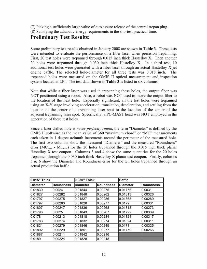
(7) Picking a sufficiently large value of α to assure release of the central trepan plug. (8) Satisfying the adiabatic energy requirements in the shortest practical time. Preliminary Test Results: Some preliminary test results obtained in January 2008 are shown in Table 3. These tests were intended to evaluate the performance of a fiber laser when precision trepanning. First, 20 test holes were trepanned through 0.015 inch thick Hastelloy X. Then another 20 holes were trepanned through 0.030 inch thick Hastelloy X. In a third test, 10 additional test holes were generated with a fiber laser through an actual Hastelloy X jet engine baffle. The selected hole-diameter for all three tests was 0.018 inch. The trepanned holes were measured on the OMIS II optical measurement and inspection system located at LFI. The test data shown in Table 3 is listed in six columns. Note that while a fiber laser was used in trepanning these holes, the output fiber was NOT positioned using a robot. Also, a robot was NOT used to move the output fiber to the location of the next hole. Especially significant, all the test holes were trepanned using an X-Y stage involving acceleration, translation, deceleration, and settling from the location of the center of a trepanning laser spot to the location of the center of the adjacent trepanning laser spot. Specifically, a PC-MAST head was NOT employed in the generation of these test holes. Since a laser drilled hole is never perfectly round, the term “Diameter” is defined by the OMIS II software as the mean value of 360 “maximum chord” or “MC” measurements each taken in 1 degree azimuth increments around the perimeter of the measured hole. The first two columns show the measured “Diameter” and the measured “Roundness” error (MCmax - MCmin) for the 20 holes trepanned through the 0.015 inch thick planar Hastelloy X test coupon. Columns 3 and 4 show the same quantities for the 20 holes trepanned through the 0.030 inch thick Hastelloy X planar test coupon. Finally, columns 5 & 6 show the Diameter and Roundness error for the ten holes trepanned through an actual production baffle. 0.015" Thick 0.030" Thick Baffle Diameter Roundness Diameter Roundness Diameter Roundness 0.01839 0.0024 0.01844 0.00275 0.01776 0.0031 0.01827 0.00282 0.01848 0.00262 0.01813 0.00326 0.01797 0.00275 0.01827 0.00286 0.01868 0.00289 0.01797 0.00263 0.01828 0.00277 0.0179 0.00331 0.01807 0.00247 0.01836 0.00268 0.01818 0.00273 0.01796 0.0025 0.01843 0.00267 0.01722 0.00339 0.0178 0.00213 0.01818 0.00284 0.01824 0.00317 0.01783 0.00274 0.01832 0.00274 0.01824 0.00311 0.01821 0.00279 0.01846 0.00249 0.0171 0.00325 0.01892 0.00229 0.01851 0.00277 0.01779 0.00266 0.01887 0.00211 0.01842 0.00216 0.0189 0.00224 0.01828 0.00248
13
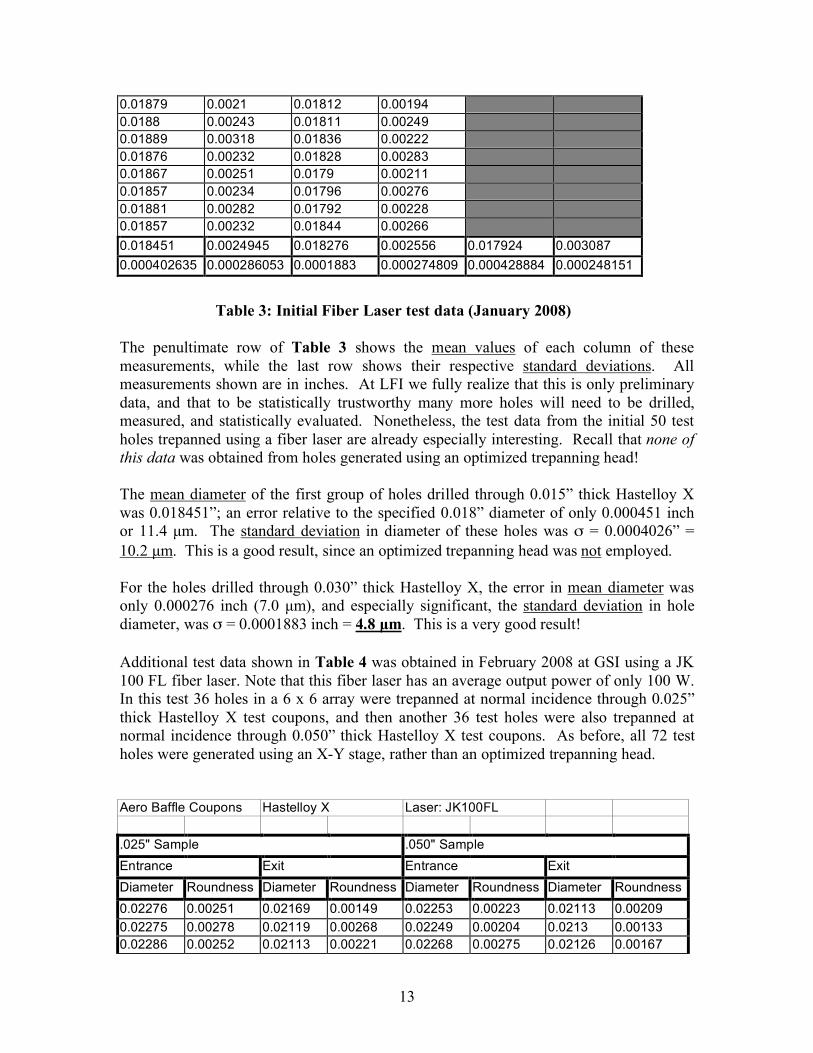
0.01879 0.0021 0.01812 0.00194 0.0188 0.00243 0.01811 0.00249 0.01889 0.00318 0.01836 0.00222 0.01876 0.00232 0.01828 0.00283 0.01867 0.00251 0.0179 0.00211 0.01857 0.00234 0.01796 0.00276 0.01881 0.00282 0.01792 0.00228 0.01857 0.00232 0.01844 0.00266 0.018451 0.0024945 0.018276 0.002556 0.017924 0.003087 0.000402635 0.000286053 0.0001883 0.000274809 0.000428884 0.000248151
Table 3: Initial Fiber Laser test data (January 2008)
The penultimate row of Table 3 shows the mean values of each column of these measurements, while the last row shows their respective standard deviations. All measurements shown are in inches. At LFI we fully realize that this is only preliminary data, and that to be statistically trustworthy many more holes will need to be drilled, measured, and statistically evaluated. Nonetheless, the test data from the initial 50 test holes trepanned using a fiber laser are already especially interesting. Recall that none of this data was obtained from holes generated using an optimized trepanning head! The mean diameter of the first group of holes drilled through 0.015” thick Hastelloy X was 0.018451”; an error relative to the specified 0.018” diameter of only 0.000451 inch or 11.4 µm. The standard deviation in diameter of these holes was σ = 0.0004026” = 10.2 µm. This is a good result, since an optimized trepanning head was not employed. For the holes drilled through 0.030” thick Hastelloy X, the error in mean diameter was only 0.000276 inch (7.0 µm), and especially significant, the standard deviation in hole diameter, was σ = 0.0001883 inch = 4.8 µm. This is a very good result! Additional test data shown in Table 4 was obtained in February 2008 at GSI using a JK 100 FL fiber laser. Note that this fiber laser has an average output power of only 100 W. In this test 36 holes in a 6 x 6 array were trepanned at normal incidence through 0.025” thick Hastelloy X test coupons, and then another 36 test holes were also trepanned at normal incidence through 0.050” thick Hastelloy X test coupons. As before, all 72 test holes were generated using an X-Y stage, rather than an optimized trepanning head. Aero Baffle Coupons Hastelloy X Laser: JK100FL .025" Sample .050" Sample Entrance Exit Entrance Exit Diameter Roundness Diameter Roundness Diameter Roundness Diameter Roundness 0.02276 0.00251 0.02169 0.00149 0.02253 0.00223 0.02113 0.00209 0.02275 0.00278 0.02119 0.00268 0.02249 0.00204 0.0213 0.00133 0.02286 0.00252 0.02113 0.00221 0.02268 0.00275 0.02126 0.00167
14
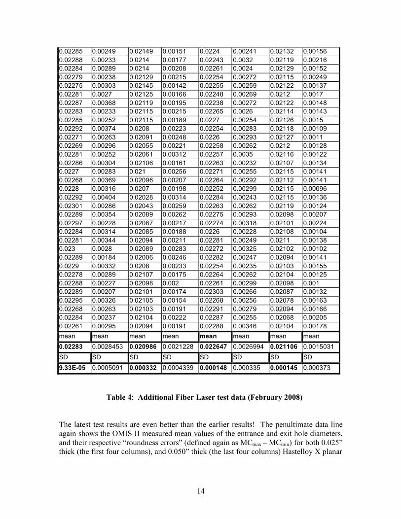
0.02285 0.00249 0.02149 0.00151 0.0224 0.00241 0.02132 0.00156 0.02288 0.00233 0.0214 0.00177 0.02243 0.0032 0.02119 0.00216 0.02284 0.00289 0.0214 0.00208 0.02261 0.0024 0.02129 0.00152 0.02279 0.00238 0.02129 0.00215 0.02254 0.00272 0.02115 0.00249 0.02275 0.00303 0.02145 0.00142 0.02255 0.00259 0.02122 0.00137 0.02281 0.0027 0.02125 0.00166 0.02248 0.00269 0.0212 0.0017 0.02287 0.00368 0.02119 0.00195 0.02238 0.00272 0.02122 0.00148 0.02283 0.00233 0.02115 0.00215 0.02265 0.0026 0.02114 0.00143 0.02285 0.00252 0.02115 0.00189 0.0227 0.00254 0.02126 0.0015 0.02292 0.00374 0.0208 0.00223 0.02254 0.00283 0.02118 0.00109 0.02271 0.00263 0.02091 0.00248 0.0226 0.00293 0.02127 0.0011 0.02269 0.00296 0.02055 0.00221 0.02258 0.00262 0.0212 0.00128 0.02281 0.00252 0.02061 0.00312 0.02257 0.0035 0.02116 0.00122 0.02286 0.00304 0.02106 0.00161 0.02263 0.00232 0.02107 0.00134 0.0227 0.00283 0.021 0.00256 0.02271 0.00255 0.02115 0.00141 0.02268 0.00369 0.02096 0.00207 0.02264 0.00292 0.02112 0.00141 0.0228 0.00316 0.0207 0.00198 0.02252 0.00299 0.02115 0.00096 0.02292 0.00404 0.02028 0.00314 0.02284 0.00243 0.02115 0.00136 0.02301 0.00286 0.02043 0.00259 0.02263 0.00262 0.02119 0.00124 0.02289 0.00354 0.02089 0.00262 0.02275 0.00293 0.02098 0.00207 0.02297 0.00228 0.02087 0.00217 0.02274 0.00318 0.02101 0.00224 0.02284 0.00314 0.02085 0.00188 0.0226 0.00228 0.02108 0.00104 0.02281 0.00344 0.02094 0.00211 0.02281 0.00249 0.0211 0.00138 0.023 0.0028 0.02089 0.00283 0.02272 0.00325 0.02102 0.00102 0.02289 0.00184 0.02006 0.00246 0.02282 0.00247 0.02094 0.00141 0.0229 0.00332 0.0208 0.00233 0.02254 0.00235 0.02103 0.00155 0.02278 0.00289 0.02107 0.00175 0.02264 0.00262 0.02104 0.00125 0.02288 0.00227 0.02098 0.002 0.02261 0.00299 0.02098 0.001 0.02289 0.00207 0.02101 0.00174 0.02303 0.00266 0.02087 0.00132 0.02295 0.00326 0.02105 0.00154 0.02268 0.00256 0.02078 0.00163 0.02268 0.00263 0.02103 0.00191 0.02291 0.00279 0.02094 0.00166 0.02284 0.00237 0.02104 0.00222 0.02287 0.00255 0.02068 0.00205 0.02261 0.00295 0.02094 0.00191 0.02288 0.00346 0.02104 0.00178 mean mean mean mean mean mean mean mean 0.02283 0.0028453 0.020986 0.0021228 0.022647 0.0026994 0.021106 0.0015031 SD SD SD SD SD SD SD SD 9.33E-05 0.0005091 0.000332 0.0004339 0.000148 0.000335 0.000145 0.000373
Table 4: Additional Fiber Laser test data (February 2008) The latest test results are even better than the earlier results! The penultimate data line again shows the OMIS II measured mean values of the entrance and exit hole diameters, and their respective “roundness errors” (defined again as MCmax – MCmin) for both 0.025” thick (the first four columns), and 0.050” thick (the last four columns) Hastelloy X planar
15
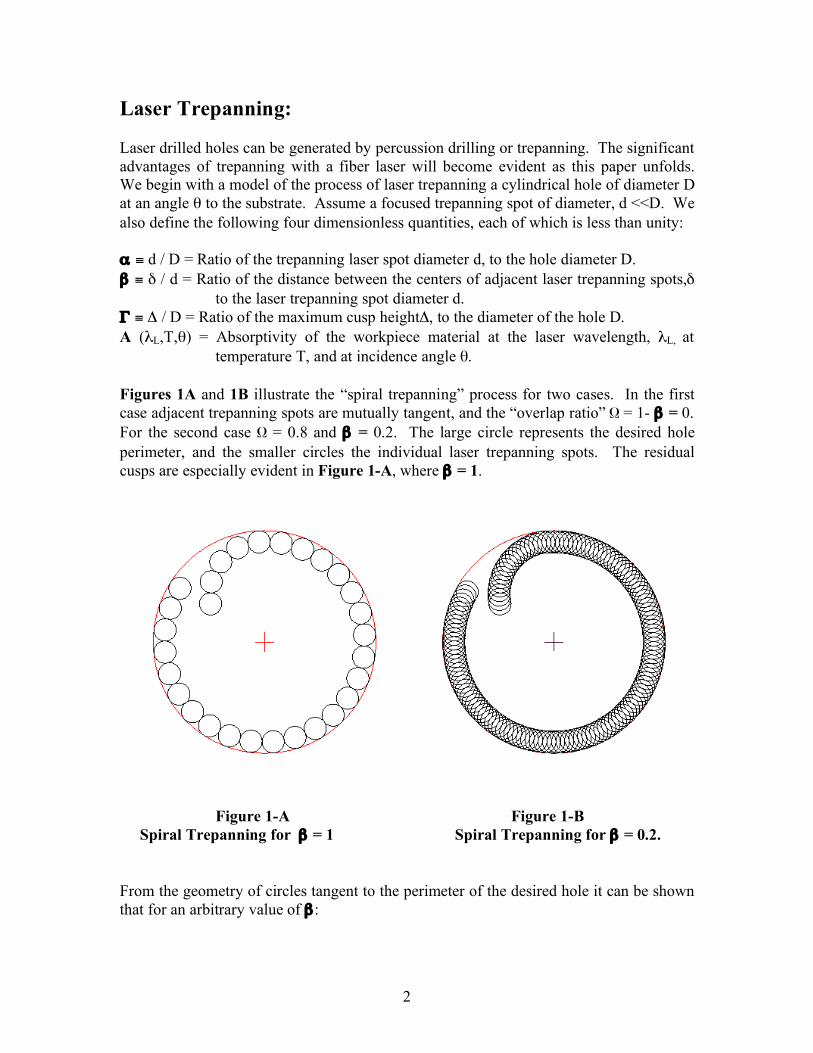
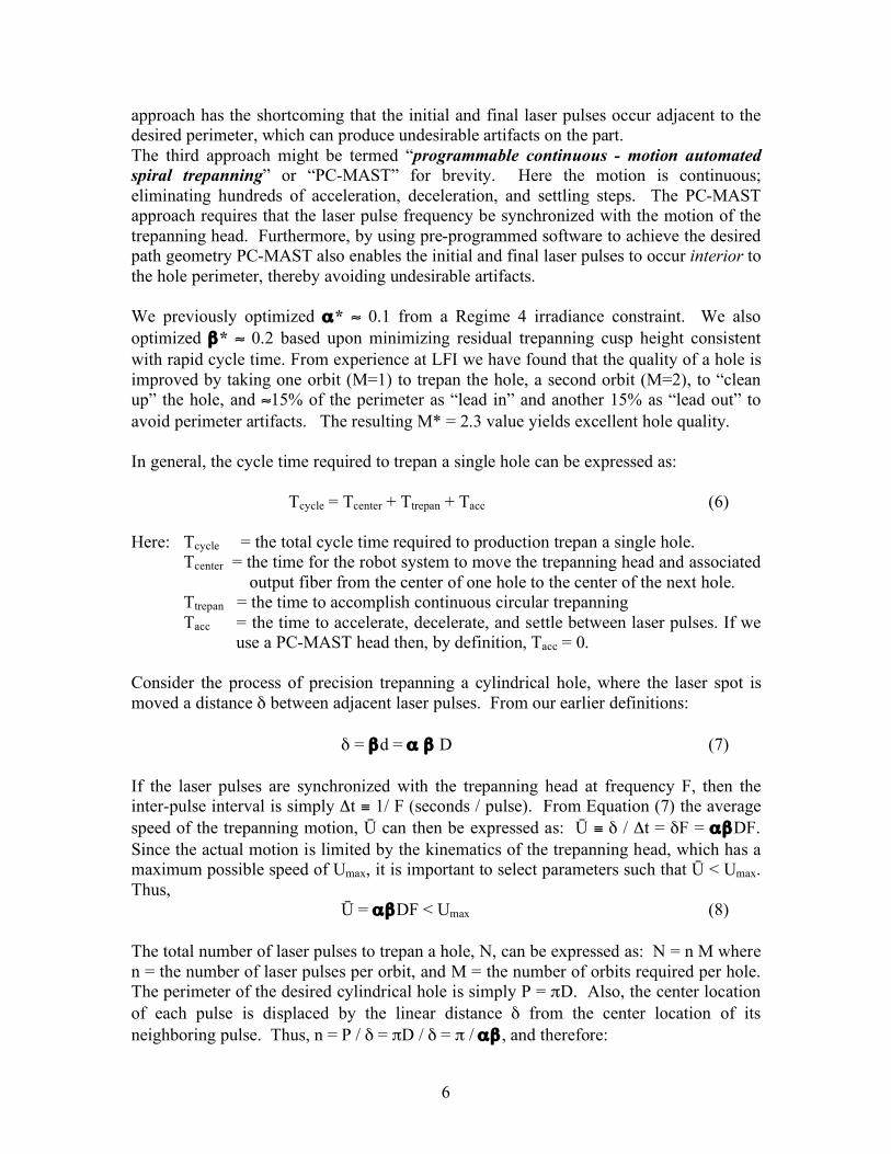
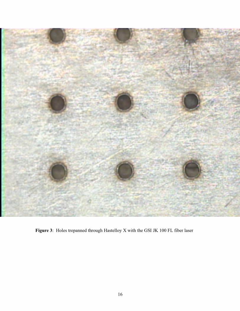
test coupons. The last line from this table again shows the calculated standard deviations in hole diameter, expressed in inches for each of these cases. The following preliminary trepanning test results using a fiber laser are especially noteworthy: A. The standard deviation of the entrance diameters for the test coupon shown in
Figure 3 was measured on the OMIS II system at LFI. For the 0.025” thick planar Hastelloy X test coupon, σ = 9.33 x 10⁻⁵ inch = 2.37 µm! This is a truly outstanding preliminary test result. With a properly calibrated PC-MAST head it is very likely that LFI will soon achieve σ < 2 µm, and it is possible that we may approach σ ≈ 1 µm; a result comparable to the wavelength of the laser photons used to trepan each hole! To the best of our knowledge this would represent a new worldwide standard for precision laser generated cylindrical holes in aerospace production components.
B. The standard deviation of the entrance diameters of the 36 holes trepanned
through the 0.050” thick planar Hastelloy X test coupon was determined by the OMIS II system to be σ = 0.000148 inch = 3.76 µm. This coupon is thicker than any of the production baffles currently being drilled by LFI. Furthermore, the 36 holes were trepanned using an average fiber laser output power of only 60 watts, albeit with a 25 µm diameter laser spot. This is a remarkable result since it was achieved using only 60 watts, though 1.27 mm thick Hastelloy X, without using an optimized trepanning head!
C. The standard deviation of the exit diameters for the same 0.050” thick planar
Hastelloy X test coupon, again determined using the OMIS II system at LFI was σ = 0.000145 inch = 3.68 µm. This is also an excellent result, indicating a very cylindrical hole, with minimal taper.
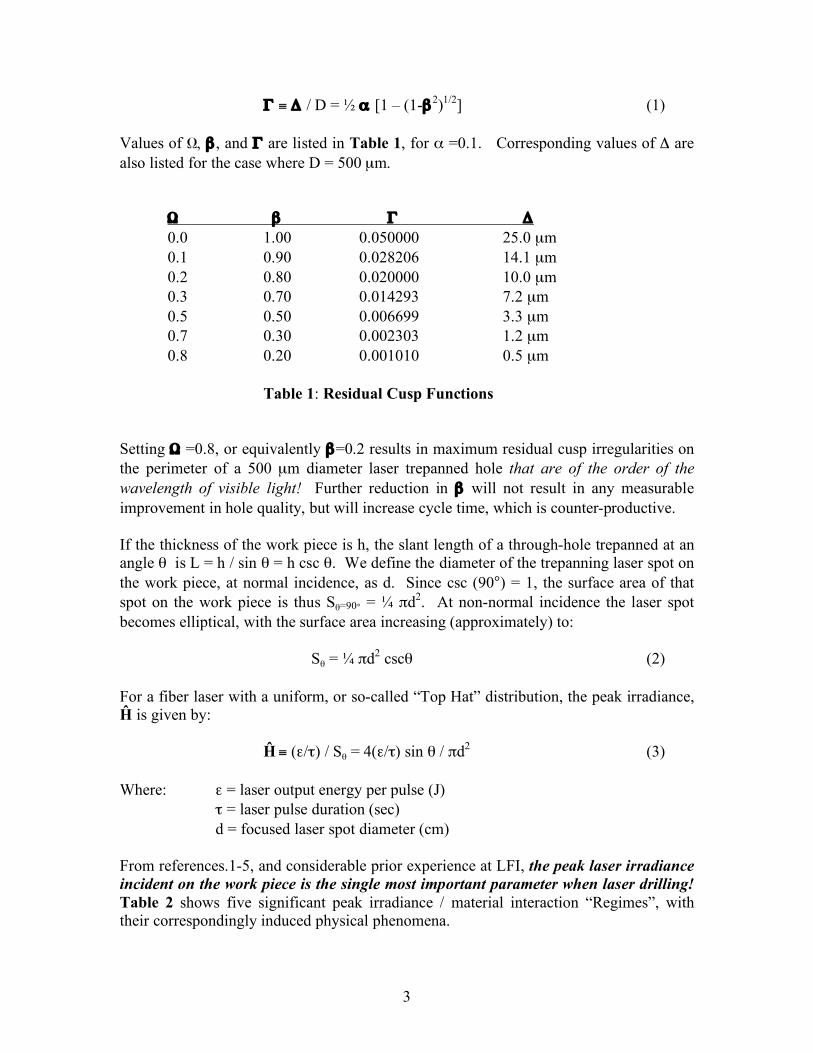
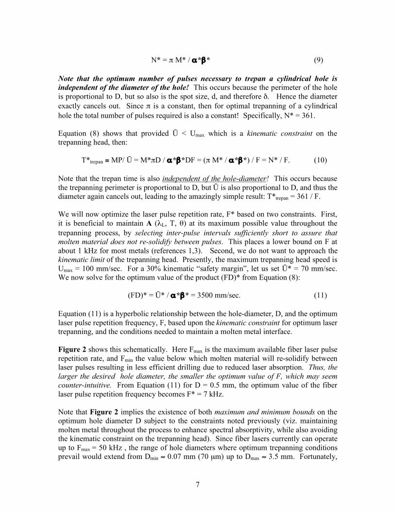
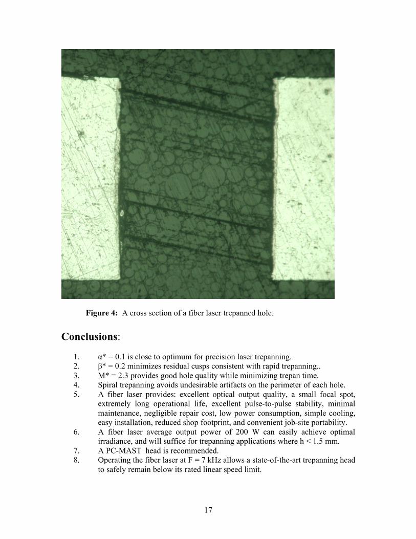
D. Figure 4 shows a magnified cross-section of one of the 36 fiber laser trepanned
holes taken from the 0.050” planar Hastelloy X test coupon. The virtually parallel walls and absence of taper, “barrel shape”, or any entrance or exit “flare” is clearly evident.
16
Figure 3: Holes trepanned through Hastelloy X with the GSI JK 100 FL fiber laser
17
Figure 4: A cross section of a fiber laser trepanned hole. Conclusions:
1. α* = 0.1 is close to optimum for precision laser trepanning. 2. β* = 0.2 minimizes residual cusps consistent with rapid trepanning.. 3. M* = 2.3 provides good hole quality while minimizing trepan time. 4. Spiral trepanning avoids undesirable artifacts on the perimeter of each hole. 5. A fiber laser provides: excellent optical output quality, a small focal spot,
extremely long operational life, excellent pulse-to-pulse stability, minimal maintenance, negligible repair cost, low power consumption, simple cooling, easy installation, reduced shop footprint, and convenient job-site portability.
6. A fiber laser average output power of 200 W can easily achieve optimal irradiance, and will suffice for trepanning applications where h < 1.5 mm.
7. A PC-MAST head is recommended. 8. Operating the fiber laser at F = 7 kHz allows a state-of-the-art trepanning head
to safely remain below its rated linear speed limit.
18
9. For applications where hole-depth significantly exceeds 1.5 mm, an average fiber laser power > 200 watts is beneficial to achieve optimum performance.
10. Preliminary test results obtained without utilizing an optimized trepanning head show a standard deviation in hole-diameter as small as 2.37 microns!
11. In the near future additional data will be gathered at LFI using an optimized programmable continuous motion spiral trepanning head, to determine the level of precision attainable with that system. When this data becomes available, and has been statistically analyzed at LFI, we will update this paper.
References:
1. J. F. Ready, Editor, Handbook of Laser Materials Processing, Chapter 13, “Hole Drilling”, Chen, Elza & Maynard, pp 471-474, Laser Institute of America, 2001.
2. J.F. Ready, “Effects of High Power Laser Radiation, Chapter 3, pp. 98-107,
Academic Press, 1971.
3. N. Rykalin, A Uglov, I Zuev & A. Kokora, Laser and Electron Beam Material Processing, Chapter 9, pp. 419 – 428, MIR Publishers, Moscow, 1988.
4. P. Jacobs, Final Report, USAF Phase II SBIR Program, “Drilling 170 Micron
Diameter Holes”, USAF Contract F29601-03-C-0192, December 2005.
5. P. Jacobs, M, Hayman, T. Marsico, P. Denney, A. Ilumoka, & R. Bright, “Acoustic Phenomena During Laser Drilling”, ICALEO 2007, Orlando, FL.
Related Documents