Fiber Optics Book: Optical Communication Sytems by John Gowar Optical Fiber Communication by Gerd Keiser Optical Fiber Communications by John M. Senior Optical Fiber Communications by Selvarajan and Kar Introduction to Fiber Optics by Ghatak and Thyagrajan Optoelectronics by Wilson and Hawkes Introduction to Optical Electronics by Keneth E Jones Introduction to Optical Electronics by Keneth E Jones Fiber Optic Communication Technology by Djafer K Mynbaev and Lowell L Scheiner

Welcome message from author
This document is posted to help you gain knowledge. Please leave a comment to let me know what you think about it! Share it to your friends and learn new things together.
Transcript
Fiber Optics
Book:
Optical Communication Sytems by John Gowar
Optical Fiber Communication by Gerd Keiser
Optical Fiber Communications by John M. Senior
Optical Fiber Communications by Selvarajan and Kar
Introduction to Fiber Optics by Ghatak and Thyagrajan
Optoelectronics by Wilson and Hawkes
Introduction to Optical Electronics by Keneth E JonesIntroduction to Optical Electronics by Keneth E Jones
Fiber Optic Communication Technology by Djafer K Mynbaev and
Lowell L Scheiner

TAT-8 (Eighth Trans Atlantic under sea fiber optics Link between New Jersy (USA) TAT-8 (Eighth Trans Atlantic under sea fiber optics Link between New Jersy (USA)
to France (Europe)
TAT-7 link Predecessor of TAT-8 based on metal cables carried 5000 voice
channels whereas TAT-8 carried 37800 channels.
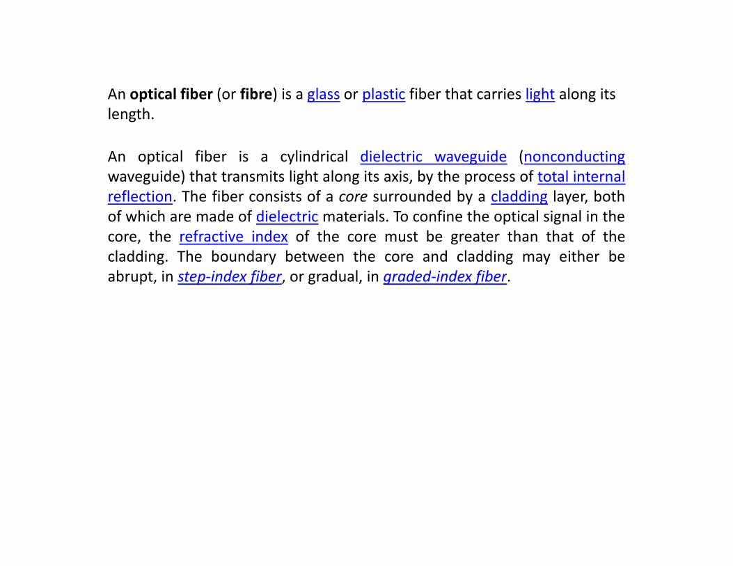
An optical fiber (or fibre) is a glass or plastic fiber that carries light along its
length.
An optical fiber is a cylindrical dielectric waveguide (nonconducting
waveguide) that transmits light along its axis, by the process of total internal
reflection. The fiber consists of a core surrounded by a cladding layer, both
of which are made of dielectric materials. To confine the optical signal in the
core, the refractive index of the core must be greater than that of the
cladding. The boundary between the core and cladding may either be
abrupt, in step-index fiber, or gradual, in graded-index fiber.abrupt, in step-index fiber, or gradual, in graded-index fiber.

Total internal reflection
When light traveling in a dense medium hits a boundary at a steep angle (larger
than the "critical angle" for the boundary), the light will be completely reflected.
This effect is used in optical fibers to confine light in the core. Light travels along
the fiber bouncing back and forth off of the boundary.
Because the light must strike the boundary with an angle greater than the critical
angle, only light that enters the fiber within a certain range of angles can travel
down the fiber without leaking out.
This range of angles is called the acceptance cone of the fiber. The size of this
acceptance cone is a function of the refractive index difference between the acceptance cone is a function of the refractive index difference between the
fiber's core and cladding.
In simpler terms, there is a maximum angle from the fiber axis at which light may
enter the fiber so that it will propagate, or travel, in the core of the fiber.
The sine of this maximum angle is the numerical aperture (NA) of the fiber.
Fiber with a larger NA requires less precision to splice and work with than fiber
with a smaller NA. Single-mode fiber has a small NA.

Modal Dispersion

Fiber Types

Step Index Multi-Mode cable has a little bit bigger diameter, with a common
diameters in the 50-to-100 micron range for the light carry component (the
most common size is 62.5um). POF is a newer plastic-based cable which
promises performance similar to glass cable on very short runs, but at a lower
cost. Multimode fiber gives high bandwidth at high speeds (10 to 100MBS -
Gigabit to 275m to 2km) over medium distances.
Light waves are dispersed into numerous paths, or modes, as they travel
through the cable's core typically 850 or 1300nm. Typical multimode fiber
core diameters are 50, 62.5, and 100 micrometers. However, over long runs
multiple paths of light can cause signal distortion at the receiving end,
resulting in an unclear and incomplete data transmission so designers nowresulting in an unclear and incomplete data transmission so designers now
use single mode fiber in new applications using Gigabit and beyond.
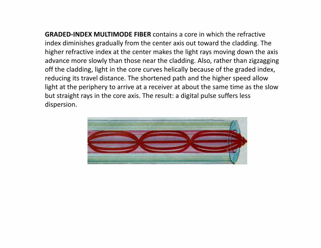
GRADED-INDEX MULTIMODE FIBER contains a core in which the refractive
index diminishes gradually from the center axis out toward the cladding. The
higher refractive index at the center makes the light rays moving down the axis
advance more slowly than those near the cladding. Also, rather than zigzagging
off the cladding, light in the core curves helically because of the graded index,
reducing its travel distance. The shortened path and the higher speed allow
light at the periphery to arrive at a receiver at about the same time as the slow
but straight rays in the core axis. The result: a digital pulse suffers less
dispersion.

SINGLE-MODE FIBER has a narrow core (8-10 microns), and the index of
refraction between the core and the cladding changes less than it does for
multimode fibers. Light thus travels parallel to the axis, creating little pulse
dispersion. It is a relatively narrow diameter, through which only one mode
propagate typically 1310 or 1550nm. Synonyms mono-mode optical fiber,
single-mode fiber, single-mode optical waveguide, uni-mode fiber.

Distribution Cables
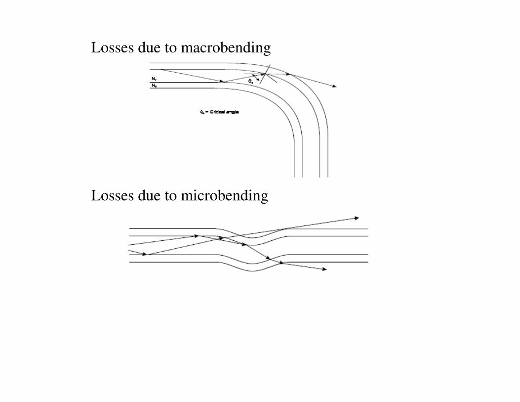
Losses due to macrobending
Losses due to microbending Losses due to microbending


Fiber Materials
1. Plastics Fibers
The plastics offers advantages in terms of cost, ease of fabrication and have high
mechanical flexibility. They have high transmission losses and are often useful for
short distance communication.
Polystyrene core (refractive index = 1.6) and Polymethylmethaacrylate (PMMA)
cladding (refractive index = 1.49) => NA=0.583 and acceptance angle =35.66 deg.
Two main type of materials are there for making optical fibers.
Polymethylmethaacrylate core (refractive index = 1.49) and Polymer cladding
2. Glasses Fibers
Mainly two types of glass fibers are there based on the
(i) Silica glass (SiO2)
(ii) Soft glasses such as Sodium borosilicates, Sodium calcium silicates,
and Lead silicates. These are high purity low loss optical fibers.
Polymethylmethaacrylate core (refractive index = 1.49) and Polymer cladding
(refractive index = 1.40) => NA=0.51 and acceptance angle = 30.66 degrees.

Obvious requirement of the material is that it must be possible to vary the
refractive index by addition of other impurities.
Pure Silica has refractive index =1.46 at 1 micron.
Other dopants like (Fluorine, Boron, Phosphorus, Germanium, Aluminium and
Titanium are added to it to change its refractive index.
Glass fibers can be made with a relatively wide range of refractive index but the
control of impurity content is more difficult than with silica where it can be
controlled up to 1ppb level.controlled up to 1ppb level.

Among the various fabrication techniques there are two methods used for
making low loss optical fibers.
Double Crucible Method
Chemical Vapour Deposition Techniques
Fiber Fabrication Methods

Double Crucible Method
Pure glass material with appropriate dopants is taken in two platinum crucibles. At the
bottom of each crucibles is a circular nozzle, both being concentric, the inner nozzle
is slightly above the outer one.
The inner crucible contains core material and the outer one contains cladding
material. The two crucibles are kept inside the furnace which is heated to high
temperature. When the temperature of the furnace is raised sufficiently high by
switching on the heating power, the core material flows through the inner nozzle into
the center of the flow stream of the outer crucible.
The fiber is then allowed to pass through a bath containing molten plastic for
protective coating of plastic over the fiber. Below this is curing oven and then a
rotating take up drum on which composite fiber is wound onto it.
If the two materials remain separated then step index fiber will result. By using
glasses that diffuses (or by having dopants that do so) graded index fiber can be
obtained. The index profile can be controlled by diffusion process.


Standard optical fibers are made by first constructing a large-diameter
preform, with a carefully controlled refractive index profile, and then pulling
the preform to form the long, thin optical fiber.
The preform is commonly made by chemical vapor deposition methods:
inside vapor deposition, outside vapor deposition

Chemical Vapour Deposition Techniques
It is one of the variety of vapour phase deposition techniques, that produces fibers
having minimal impurity content. In this techniques a doped silica layer is
deposited onto the inner surface of a pure silica tube. The deposition occurs as a
result of a chemical reaction taking place between the vapour constituents that are
being passed through the tube. Typical vapours used are SiCl4, GeCl4, BCl3,
SiF4, TiCl4, etc. and the various reactions that may takes place may be written as
follows:
SiCl + O = SiO + 2Cl GeCl + O = GeO2 + 2ClSiCl4+ O2 = SiO2 + 2Cl2 GeCl4+ O2 = GeO2 + 2Cl2
SiF4+ O2 = SiO2 + 2F2 TiCl4+ O2 = TiO2 + 2Cl2
4BCl3+ 3O2 = 2B2O3 + 6Cl2 4POCl3+ 3O2 = 2P2O5 + 6Cl2

The zone where reaction takes place is moved along the tube by locally heating
the tube to the temperature in the range 1200-1600C with a travelling oxy-
hydrogen flame as shown in figure. If the process is repeated with different
input concentrations of the dopant vapours, the layers of different impurity
concentrations may be built up sequentially. This technique thus allows the
fabrication of graded index fiber with much greater control over the index
profiles than does the double crucible method.
After the deposition process is complete, the tube is heated to its softening
temperature (~2000ºC). The tube then collapses into a solid rod called perform.temperature (~2000ºC). The tube then collapses into a solid rod called perform.
The fiber is subsequently produced by drawing from the heated tip of the
perform as it is lowered into a furnace. To have finite control over the fiber
diameter, a thickness monitoring gauge is used before the fiber is drawn onto
the take up drum and feedback is applied to the take up drum speed.
Similar to earlier method a protective plastic coating is often applied to the
outside of the fiber and resulting coating is then cured bypassing it through a
further furnace.

Modified
chemical
vapour
deposition
(inside)
process


The preform, however constructed, is then placed in a device known
as a drawing tower, where the preform tip is heated and the optic
fiber is pulled out as a string. By measuring the resultant fiber width,
the tension on the fiber can be controlled to maintain the fiber
thickness.
Fiber optic coatings are UV-cured urethane acrylate composite
materials applied to the outside of the fiber during the drawing
process. The coatings protect the very delicate strands of glass fiber—
about the size of a human hair—and allow it to survive the rigors ofabout the size of a human hair—and allow it to survive the rigors of
manufacturing, proof testing, cabling and installation.

The core and cladding material is
deposited inside tube
Fiber wire drawingFurther heating collapses the tube


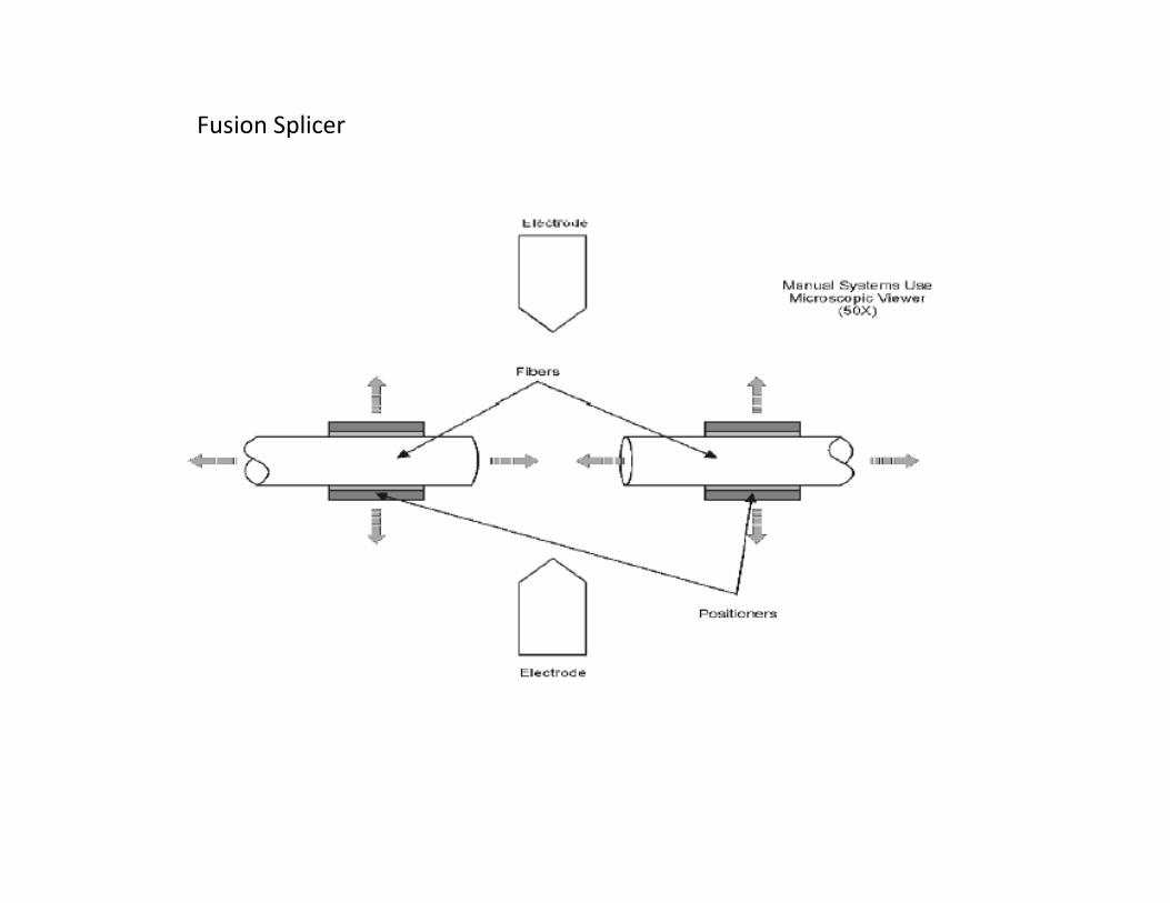
Fusion Splicer


Splice alignment structures
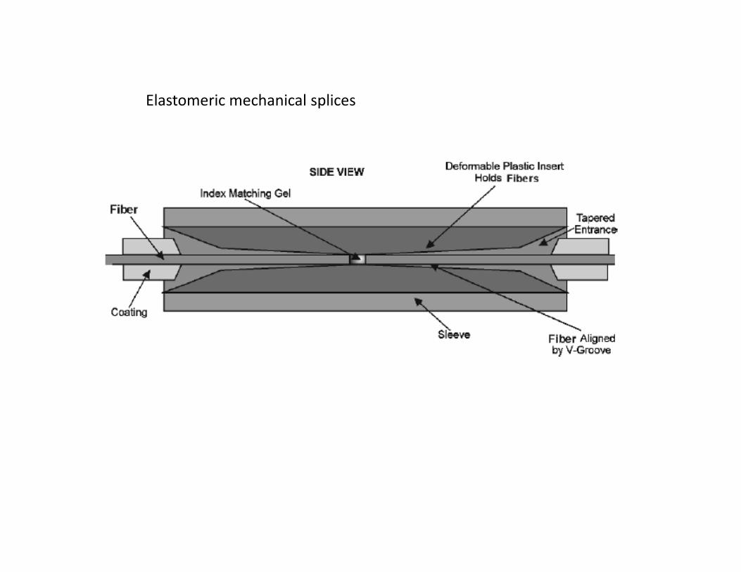
Elastomeric mechanical splices
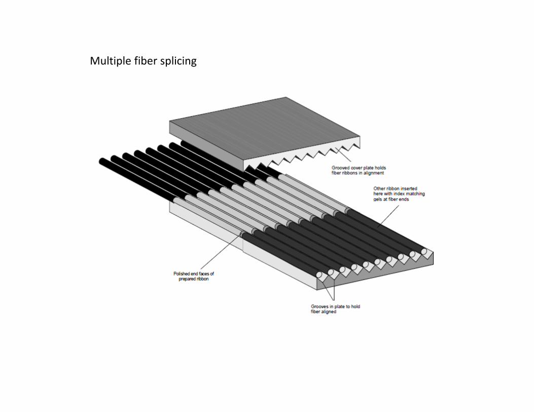
Multiple fiber splicing


Press Release
6 October 2009
The Royal Swedish Academy of Sciences has decided to award the Nobel Prize in Physics for
2009 with one half to
Charles K. Kao
Standard Telecommunication Laboratories, Harlow, UK, and Chinese University of Hong Kong
"for groundbreaking achievements concerning the transmission of light in fibers for optical
communication"
and the other half jointly to
Willard S. Boyle and George E. Smith
Bell Laboratories, Murray Hill, NJ, USA
"for the invention of an imaging semiconductor circuit – the CCD sensor"
The masters of light
This year's Nobel Prize in Physics is awarded for two scientific achievements that have helped
to shape the foundations of today’s networked societies. They have created many practical
innovations for everyday life and provided new tools for scientific exploration. In 1966, Charles
K. Kao made a discovery that led to a breakthrough in fiber optics. He carefully calculated how
to transmit light over long distances via optical glass fibers. With a fiber of purest glass it would
be possible to transmit light signals over 100 kilometers, compared to only 20 meters for the
fibers available in the 1960s. Kao's enthusiasm inspired other researchers to share his vision of
the future potential of fiber optics. The first ultrapure fiber was successfully fabricated just
four years later, in 1970.

Today optical fibers make up the circulatory system that nourishes our
communication society. These low-loss glass fibers facilitate global broadband
communication such as the Internet. Light flows in thin threads of glass, and it carries
almost all of the telephony and data traffic in each and every direction. Text, music,
images and video can be transferred around the globe in a split second.
If we were to unravel all of the glass fibers that wind around the globe, we would get
a single thread over one billion kilometers long – which is enough to encircle the
globe more than 25 000 times – and is increasing by thousands of kilometers every
hour.
A large share of the traffic is made up of digital images, which constitute the second
part of the award. In 1969 Willard S. Boyle and George E. Smith invented the firstpart of the award. In 1969 Willard S. Boyle and George E. Smith invented the first
successful imaging technology using a digital sensor, a CCD (Charge-Coupled Device).
The CCD technology makes use of the photoelectric effect, as theorized by Albert
Einstein and for which he was awarded the 1921 year's Nobel Prize. By this effect,
light is transformed into electric signals. The challenge when designing an image
sensor was to gather and read out the signals in a large number of image points,
pixels, in a short time.

The CCD is the digital camera's electronic eye. It revolutionized
photography, as light could now be captured electronically instead of
on film. The digital form facilitates the processing and distribution of
these images. CCD technology is also used in many medical
applications, e.g. imaging the inside of the human body, both for
diagnostics and for microsurgery.
Digital photography has become an irreplaceable tool in many fields
of research. The CCD has provided new possibilities to visualize the
previously unseen. It has given us crystal clear images of distant
places in our universe as well as the depths of the oceans.
Related Documents